handbook of petrochemicals - microsoft · 2017-06-09 · process economics: installed capital cost...
TRANSCRIPT

l I I I i
HANDBOOK OF PETROCHEMICALS
PRODUCTION PROCESSES
Robert A. Meyers, Ph.D. Editor-in-Chief
McGRAW-HILL New York Chicago San Francisco Lisbon London Madrid
Mexico City Milan New Delhi San Juan Seoul Singapore Sydney Toronto

Cataloging-in-Publication Data is on
Copyright© 2005 by The McGraw-Hill Companies, Inc. All rights reserved. Printed in the United States of America. Except as permitted under the United States Copyright Act of 1976, no part of this publication may be reproduced or distributed in any form or by any means, or stored in a data base or retrieval system, without the prior written permission of the publisher.
1 2 3 4 5 6 7 8 9 0 DOC/DOC 0 1 0 9 8 7 6 5 4
ISBN 0-07-141042-2
The sponsoring editor for this book was Kenneth P. McCombs, the editing supervisor was Stephen M. Smith, and the production supervisor was Pamela A. Pelton. It was set in Times Roman by Paul Scozzari of McGraw-Hill Professional's Hightstown, NJ., composition unit. The art director for the cover was Handel Low.
Printed and bound by RR Donnelley.
McGraw-Hill books are available at special quantity discounts to use as premiums and sales promotions, or for use in corporate training programs. For more information, please write to the Director of Special Sales, McGraw-Hill Professional, Two Penn Plaza, New York, NY 10121-2298. Or contact your local bookstore.
This book is printed on acid-free paper.
Information contained in this work has been obtained by The McGraw-Hill Companies, Inc. ("McGraw-Hill") from sources believed to be reliable. However, neither McGraw-Hill nor its authors guarantee the accuracy or completeness of any information published herein, and neither McGraw-Hill nor its authors shall be responsible for any errors, omissions, or damages arising out of use of this information. This work is published with the understanding that McGraw-Hill and its authors are supplying information but are not attempting to render engineering or other professional services. If such services are required, the assistance of an appropriate professional should be sought.

CONTENTS
Contributors xix
Preface xxi
Acknowledgments xxiii
Part 1 Acetic Acid
Chapter 1.1. Chiyoda Acetic Acid Process ACETICA® Yasuo Hosono and Minoru Tasaki, P.E. 1.3
Introduction I 1.3 Chemistry I 1.4 Process Features I 1. 7 Process Description I 1. 7 Product Specifications I 1.11 Process Yield and Emissions I 1.11 Economics of the Chiyoda ACETICA Technology I 1.11 Scope ofChiyoda's Package of Services I 1.12 Experience I 1.12 References I 1.13
Part 2 Aniline
Chapter 2.1. DuPont/KBR Aniline Process Eric W. Wong and Ronald Birkhoff
Introduction I 2.3 Aniline Market Overview I 2.4 Process Chemistry I 2.5 Process Description I 2.5 Technology Features I 2.6 Operating Requirements I 2. 7 Product Quality I 2. 7 Wastes and Emissions I 2. 7 References I 2.8
Part 3 1 ,3-Butadiene
2.3
Chapter 3.1. BASF Butadiene Extraction Technology Robert Brummer 3.3
Introduction I 3.3 Process Perspective I 3.3 Process Description I 3.4 Economics I 3.7 Environmental Considerations I 3.8 Summary of Process Features I 3.8
v

Process Performance I 5.21 Commercial Experience I 5.21
CONTENTS
Chapter 5.3. ExxonMobii/Badger Ethylbenzene Technology Brian Maerz and C. Morris Smith
Introduction I 5.23 Ethylbenzene Manufacturing I 5.23 Properties of Ethylbenzene I 5.25 EBMax Process Catalysts I 5.26 Process Chemistry and EBMax Catalyst Performance I 5.28 Process Description I 5.31 Process Design Customization and Optimization I 5.33 EBMax Process Designs for Dilute Ethylene Feedstocks I 5.33 Technology Conversion and Capacity Expansion with EBMax I 5.34 Ethylbenzene Product Quality I 5.35 Raw Materials and Utilities Consumption I 5.37 Catalyst Requirements I 5.37 EBMax Plant Design I 5.38 Reference I 5.38
Part 6 Ethylene
Chapter 6~1. ABB Lummus Global SRT® Cracking Technology for the Production of Ethylene Sanjeev Kapur
Introduction I 6.3 Development and Commercial History I 6.4 Process Chemistry I 6.5 Cracking Heater I 6. 8 Ethylene Process Flow Schematic I 6.11 Refinery and Ethylene Plant Integration I 6.15 Recent Technology Advances I 6.16 Commercial Operations I 6.19 Economic Aspects I 6.19
vii
5.23
6.3
Chapter 6.2. Stone & Webster Ethylene Technology Colin P. Bowen 6.21
Introduction I 6.21 Economic Drivers I 6.21 Development History: Pyrolysis I 6.23 Development History: Recovery I 6.27 Process Description I 6.29 Megaplant Design Issues I 6.44 Project Execution Aspects I 6.47 References I 6.49
Chapter 6.3. KBR SCORE™ Ethylene Technology Steven Borsos and Stephen Ronczy
Development and History I 6.51 Selective Cracking Furnace Technology I 6.52 Optimum Recovery-Section Design I 6.57 Future [)evelopments I 6.63
6.51
vi CONTENTS
Chapter 3.2. UOP KLP 1,3-Butadiene from Acetylene Process Steve Krupa, Tim Foley, and Stephen McColl
Introduction I 3.11 Butadiene I 3.11 The KLP Process I 3.12 Process Chemistry I 3.12 Commercial Experience I 3.13 Economics and Operating Costs I 3.13
Part 4 Cumene
Chapter 4.1. ABB Lummus Global Cumene Production via CDCumene®
3.11
Technology Stephen Pohl and Sanjeev Ram 4.3
Introduction I 4.3 Process Perspective I 4.4 Process Chemistry I 4.4 Process Description I 4.4 Process Economics I 4.7 Summary of Process Features I 4.9
Chapter 4.2. UOP 0-Max™ Process Gary A. Peterson and Robert J. Schmidt
Introduction I 4.11 Process Chemistry I 4.12 Description of the Process Flow I 4.14 Feedstock Considerations I 4.15 Process Perfomance I 4.18 Case Study I 4.18 Commercial Experience I 4.19 Bibliography I 4.d 9
Part 5 Ethylbenzene
Chapter 5.1. Lummus/UOP Liquid-Phase EBOne Process and CDTECH E£11!> Process Stephen Pohl and Sanjeev Ram
Introduction I 5.3 Process Perspective I 5.4 Process Chemistry I 5.4 Process Description I 5.5 Economics I 5.9 Summary of Process Features I 5.12
Chapter 5.2. Polimeri Europa Ethylbenzene Process Fabio Assandri
4.11
5.3
and Elena Bencini 5.13
Introduction I 5.13 Description of the Process Flow I 5.16 Process and Catalyst Advanced Features I 5.20
viii CONTENTS
Part 7 Methanol
Chapter 7 .1. Lurgi MegaMethanol® Technology Alexander Frei
History I 7. 3 MegaMethanol Technology I 7.4 Process Description I 7.5 Latest Lurgi Methanol Project References I 7.17
Part 8 Oxo Alcohols
Chapter 8.1. Johnson Matthey Oxo Alcohols Process™ Jane Butcher
7.3
and Geoff Reynolds 8.3
Introduction I 8.3 Process Description I 8.3 Process Flow sheet I 8. 7 Benefits of the Johnson Matthey Technology I 8.9 Feed Specifications I 8.10 Process Economics I 8.12 Capital Costs I 8.12 Operational Experience I 8.13 Reference I 8.13
Part 9 Phenols and Acetone
Chapter 9.1. Polimeri Europa Cumene-Phenol Processes Maurizio Ghirardini and Maurizio Tampieri
Introduction I 9.3 Cumene Technology I 9.3 Phenol Technology I 9.8
Chapter 9.2. Sunoco/UOP Phenol Process Robert J. Schmidt
Introduction I 9.13 Cumene Production I 9.13 Phenol P-roduction I 9.14 Sunoco!UOP Cumene Peroxidation Route to Phenol Production I 9.15 Overall Process Description/Chemistry I 9.15 Process Flow and Recent Technology Advances I 9.16 Conclusion I 9.28 References I 9.29
Chapter 9.3. KBR Phenol Process Alan Moore and Ronald Birkhoff
Introduction I 9.31 History I 9.31 Markets I 9.32 Process Chemistry I 9.34 Process Description I 9.36 Feedstock and Product Properties I 9.41 Production Yields I 9.43
9.3
9.13
9.31

ACKNOWLEDGMENTS
A distinguished group of 72 engineers prepared the 53 chapters of this handbook, and I thank them for their good work. I also wish to thank the 18 petrochemicals process research and development and licensing firms that developed and market the technologies presented.
Many thanks to my wife Ilene for encouraging my efforts in bringing together these inventive concepts in handbook form and also for her direct participation in the preparation of the index.
xxiii
xxii PREFACE
The reader of this handbook is specially directed to the section on gas-to-liquid technologies in the Handbook of Petroleum Refining Processes, which includes methanol production and also conversion to ethylene and propylene, as well as to the section on aromatics complexes for additional information on licensable petrochemical technologies.
Robert A. Meyers, PhD.
/

PREFACE
This handbook is a reference and guide to present-day real-world petrochemicals (intermediates, monomers, and plastics) production methods, product properties, and economics. There is no other single source of such information. The focus is on the most economically important petrochemicals (which together represent a $200 billion market): acetic acid, aniline, 1,3-butadiene, cumene, ethylbenzene, ethylene, methanol, oxo alcohols, phenols and acetone, propylene and light olefins, styrene, terephthalic acid, xylenes, low-density/linear low-density and high-density polyethylenes and copolymers, polyethylene terephthalate, polypropylene, polystyrene, and vinyl chloride and polyvinyl chloride.
In order to present the global technology base adequately, it was decided to ask major licensers to contribute to this handbook the processes and economics of their most advanced and utilized licensable technologies (the reports were to be in a common format, to allow for side-by-side comparison). This resulted in a total of 53 technologies offered by 18 of the largest firms in the petrochemicals licensing business. These firms also represent a large fraction of global petrochemicals production. The information given in this handbook will let engineers make a first evaluation of licensable processes for new production and will allow engineering students to perform class exercises that compare the various characteristics of today' s most-used technologies.
Each licenser was asked to follow the chapter format below as closely as possible:
General process description: including feed definition and product yield and a simplified flow diagram.
Process chemistry and thermodynamics: for each major processing unit as applicable.
Process perspective: developers, locations, and specifications of all test and commercial plants, and near-term and long-term plans.
Detailed process description: process flow diagram with mass and energy balances for major process variations, and feeds and details on unique or key equipment.
Product and by-product specifications: detailed analyses of all process products and by-products as a function of processing variations and feeds.
Wastes and emissions: process solid, liquid, and gas wastes and emissions as a function of processing variations and feeds.
Process economics: installed capital cost by major section, total capital investment, operating costs, annualized capital costs with the basis, and price range for each product if applicable.
This handbook is a companion to the Handbook of Petroleum Refining Processes, Third Edition (McGraw-Hill), published last year. That handbook, with the same format as this one, consists of 61 licenser technology chapters for the processing of petroleum to gasoline and other fuels as well as some petrochemical intermediates. The two handbooks together provide a comprehensive set of technologies for converting crude oil to fuels, intermediates, commodity chemicals, and the major plastics.
xxi

XX CONTRIBUTORS
Jouni Kivela Borealis Polymers 0/Y, Porvoo, Finland (Chap. 16.3)
Tarja Korvenoja Borealis Polymers 0/Y, Porvoo, Finland (Chaps. 14.2, 16.3)
Steve Krupa UOP LLC, Des Plaines, Illinois (Chap. 3.2)
Dr. Reinhard Kuehl Basell Polyolefine GmbH, Frankfurt, Germany (Chap. 14.6)
Waldemar Liebner Lurgi AG, Frankfurt am Main, Germany (Chap. 10.1)
Brian Maerz Badger Licensing LLC, Cambridge, Massachusetts (Chap. 5.3)
Stephen McColl UOP LLC, Des Plaines, Illinois (Chap. 3.2)
James F. McGehee UOP LLC, Des Plaines, Illinois (Chap. 15.1)
Stephen M. Metro UOP LLC, Des Plaines, Illinois (Chap. 15.1)
George Mignin Dow Chemical Company, Midland, Michigan (Chap. 9.4)
Mauro Mirra Polimeri Europa, Milan, Italy (Chap. 14.5)
Alan Moore Kellogg Brown & Root, Inc. (KBR), Houston, Texas (Chap. 9.3)
Klaus Nyfors Borealis Polymers 0/Y, Porvoo, Finland (Chap. 14.2)
Francesco Pasquali "C. Buonerba" Research Centre, Mantova, Italy (Chaps. 17.3, 17.5)
Gary A. Peterson UOP LLC, Des Plaines, Illinois (Chap. 4.2)
Stephen Pohl ABB Lummus Global, Bloomfield, New Jersey (Chaps. 4.1, 5.1, 11.1)
Peter R. Pujad6 UOP LLC, Des Plaines, Illinois (Chap. 10.2)
Sanjeev Ram ABB Lummus Global, Bloomfield, New Jersey (Chaps. 4.1, 5.1, 11.1)
Geoff Reynolds Johnson Matthey Catalysts, Billingham, England (Chap. 8.1)
Riccardo Rinaldi Basell Polyolefine GmbH, Frankfurt, Germany (Chap. 16.2)
Stephen Ronczy Kellogg Brown & Root, Inc. (KBR), Houston, Texas (Chap. 6.3)
Robert J. Schmidt UOP LLC, Des Plaines, Illinois (Chaps. 4.2, 9.2)
Charles E. Schuster ExxonMobil Chemical Company, Baytown, Texas (Chap. 14.4)
Takeshi Shiraishi Chisso Corporation, Tokyo, Japan (Chap. 16.5)
C. Morris Smith Badger Licensing LLC, Cambridge, Massachusetts (Chap. 5.3)
Mike Smith Chevron Phillips Chemical Company LP, Kingwood, Texas (Chap. 14.3)
Robert Stepanian ABB Lummus Global, Bloomfield, New Jersey (Chaps. 17.1, 17.2)
Maurizio Tampieri Polimeri Europa, San Donato Milanese, Italy (Chap. 9.1)
Minoru Tasaki, P.E. Chiyoda Corporation, Yokohama, Japan (Chap. 1.1)
Gijs ten Berge Basell Polyolefine GmbH, Frankfurt, Germany (Chaps. 14.1, 14.6, 14.7, 14.8, 16.1, 16.2)
Leonardo Trentini "C. Buonerba" Research Centre, Mantova, Italy (Chap. 11.3)
Seiichi Uchida Chisso Corporation, Tokyo, Japan (Chap. 18.2)
Daniel Wei UOP LLC, Des Plaines, Illinois (Chap. 10.3)
Vincent Welch Badger Licensing LLC, Cambridge, Masachusetts (Chap. 11.2)
Don West Dow Chemical Company, Midland, Michigan (Chap. 9.4)
Keith Wiseman NOVA Chemicals Corporation, Calgary, Alberta, Canada (Chap. 14.10)
Ulrich Woike Vinnolit GmbH & Co. KG, Ismaning, Germany (Chap. 18.1)
Eric W. Wong Kellogg Brown & Root, Inc. (KBR), Houston, Texas (Chap. 2.1)
James T. C. Wu ABB Lummus Global, Houston, Texas (Chap. 10.4)

CONTRIBUTORS
Cyrus Ahmadzade Basel! Polyolefine GmbH, Franlifurt, Germany (Chap. 14.7)
James M. Andersen UOP LLC, Des Plaines, Illinois (Chap. 10.2)
Henrik Andtsjo Borealis Polymers 0/Y, Porvoo, Finland (Chap. 14.2)
V. K. Arora ABB Lummus Global, Bloomfield, New Jersey (Chap. 10.5)
Fabio Assandri "C. Buonerba" Research Centre, Mantova, Italy (Chap. 5.2)
Franco Balestri "C. Buonerba" Research Centre, Mantova, Italy (Chap. 17.5)
Elena Bencini "C. Buonerba" Research Centre, Mantova, Italy (Chap. 5.2)
Gunnar Berggren Borealis Polymers 0/Y, Porvoo, Finland (Chap. 14.2)
Catherine A. Berra ABB Lummus Global, Houston, Texas (Chap. 10.4)
Ronald Birkhoff Kellogg Brown & Root, Inc. (KBR), Houston, Texas (Chaps. 2.1, 9.3)
Steven Borsos Kellogg Brown & Root, Inc. (KBR), Houston, Texas (Chap. 6.3)
Colin P. Bowen Stone & Webster, Inc., Houston, Texas (Chap. 6.2)
Terry W. Bradley ExxonMobil Chemical Company, Baytown, Texas (Chaps. 13.1, 13.2)
Robert Brummer ABB Lummus Global, Bloomfield, New Jersey (Chap. 3.1)
Jane Butcher Johnson Matthey Catalysts, Billingham, England (Chap. 8.1)
Frank Castillo-Welter Lurgi Oel Gas Chemie GmbH, Franlifurt am Main, Germany (Chap. 12.1)
Scott E. Commissaris UOP LLC, Des Plaines, Illinois (Chap. 13.3)
Maurizio Dorini Basel! Polyolefine GmbH, Franlifurt, Germany (Chaps. 14.1, 16.1)
Barry R. Engle Dow Chemical Company, Danbury, Connecticut (Chap. 16.4)
Andre-Armand Finette Basel! Polyolefine GmbH, Franlifurt, Germany (Chap. 14.8)
Tim Foley UOP LLC, Des Plaines, Illinois (Chap. 3.2)
Ed Fraini Dow Chemical Company, Midland, Michigan (Chap. 9.4)
Alexander Frei Lurgi Oel Gas Chemie GmbH, Franlifurt am Main, Germany (Chap. 7.1)
Armando Galeotti "C. Buonerba" Research Centre, Mantova, Italy (Chap. 11.3)
Dario Ghidoni "C. Buonerba" Research Centre, Mantova, Italy (Chap. 17.4)
Maurizio Ghirardini Polimeri Europa, San Donato Milanese, Italy (Chap. 9.1)
Helge Grande Borealis Polymers 0/Y, Porvoo, Finland (Chap. 16.3)
Joseph Gregor UOP LLC, Des Plaines, Illinois (Chap. 10.3)
Yasuo Hosono Chiyoda Corporation, Yokohama, Japan (Chap. 1.1)
Riccardo Inglese "C. Buonerba" Research Centre, Mantova, Italy (Chaps. 17.3, 17.4)
Peter Kammerhofer Vinnolit GmbH & Co. KG, Ismaning, Germany (Chap. 18.1)
Sanjeev Kapur ABB Lummus Global, Houston, Texas (Chap. 6.1)
Mardee McCown Kaus Univation Technologies LLC, Houston, Texas (Chap. 14.9)
xix
CONTENTS
Part 18 Vinyl Chloride and Polyvinyl Chloride
Chapter 18.1. Vinnolit Vinyl Chloride and Suspension Polyvinyl Chloride Technologies Ulrich Woike and Peter Kammerhofer
Company Introduction I 18.3 Process Perspective I 18.4 Vinnolit Vinyl Chloride Monomer (VCM) Process I 18.4 Vinnolit Direct Chlorination Process I 18.7 Vinnolit Oxychlorination Process I 18.12 Vinnolit Thermal Cracking Process of 1,2-Dichloroethane to Vinyl Chloride I 18.18 Vinnolit Suspension Polyvinyl Chloride (S-PVC) Process I 18.21 Abbreviations and Acronyms I 18.33 References I 18.35
Chapter 18.2. Chisso Polyvinyl Chloride Suspension Process Technology and Vinyl Chloride Monomer Removal Technology Seiichi Uchida
Chisso Polyvinyl Chloride Suspension Process Technology I 18.37 Chisso Vinyl Chloride Monomer Removal Process Technology I 18.43
Index follows Chapter 18.2
xvii
18.3
18.37

xvi
Process Economics I 17.5 Summary of Process Features I 17. 7 Reference I 17. 7
CONTENTS
Chapter 17.2. BP/Lummus Technology for the Production of General-Purpose and High-Impact Polystyrenes Robert Stepanian 17.9
Introduction I 17.9 Operating Plants I 17.10 Process Chemistry I 17.10 Process Description I 17.10 Feedstock and Product Specifications I 17.12 Waste and Emissions I 17.15 Process Economics I 17.15 Summary of Process Features I 17.15 References I 17.17 "
Chapter 17 .3. Polimeri Europa General-Purpose Polystyrene Process Technology Francesco Pasquali and Riccardo Inglese
Introduction I 17.19 Process Chemistry I 17.20 Description of the Process Flow I 17.22 Process Advanced Design Features I 17.23 Process Performance I 17.24 Plant Capacity I 17.24 Commercial Experience I 17.25 The Edistir GPPS Product Portfolio I 17.25
Chapter 17 .4. Polimeri Europa Expandable Polystyrene Process Technology Daria Ghidoni and Riccardo Inglese
Introduction I 17.27 Process Chemistry I 17.28 Description of Process Flow I 17.30 Process Advanced Design Features I 17.31 Process Performance I 17.32 Plant Capacity I 17.32 Commercial Experience I 17.32 The Extir EPS Product Portfolio I 17.32
Chapter 17 .5. Polimeri Europa High-Impact Polystyrene Process Technology Francesco Pasquali and Franco Balestri
Introduction I 17.35 Process Chemistry I 17.36 Description of Process Flow I 17.37 Process Advanced Design Features I 17.38 Process Performance I 17.39 Plant Capacity I 17.39 Commercial Experience I 17.40 The Edistir HIPS Product Portfolio I 17.40
17.19
17.27
17.35

Spherizone Process Perspective I 16.30 Process Description I 16.30 Economics I 16.37 Products and Applications I 16.37
CONTENTS
Chapter 16.3. Borstar Polypropylene Technology Jouni Kivela, Helge Grande, and Tarja Korvenoja
Introduction I 16.41 Features of the Borstar PP Process Technology I 16.43 Process Description I 16.44 Production Cycle and Grade Transitions I 16.47 Advanced Process Control I 16.48 Catalyst I 16.49 Environment I 16.49 Operating Requirements I 16.50 Products I 16.50
Chapter 16.4. UNIPOL TM Polypropylene Process Technology Barry R. Engle
General UNIPOL PP Process Description I 16.57 Process Chemistry I 16.60 Process Perspective I 16.62 Products and By-Products I 16.64 UNIPOL PP Product Attributes Summary I 16.65 Wastes and Emissions I 16.67 Process Economics I 16.68
Chapter 16.5. Chisso Gas-Phase Polypropylene Process Takeshi Shiraishi
Technology Background and History I 16.71 Polymerization Mechanism and Polymer Type I 16.71 Process Features I 16.74 Process Description I 16.76 Safety and Environmental Considerations I 16.78 Product Capabilities I 16. 78 Economics I 16. 79 Reference Plants I 16. 79
Part 17 Polystyrene
Chapter 17.1. BP/Lummus Technology for the Production of Expandable Polystyrene Robert Stepanian
Introduction I 17.3 Operating Plants I 17.3 Process Chemistry I 17.3 Process Description I 17.4 Feedstock/Product Specifications I 17.4 Waste and Emissions I 17.5
XV
16.41
16.57
16.71
17.3

xiv CONTENTS
Chapter 14.1 0. NOVA Chemicals SCLAIRTECH™ LLDPE/HDPE Swing Technology Keith Wiseman
Introduction I 14.131 Chemistry and Catalysis I 14.132 Process Overview I 14.134 Advantages of the SCLAIRTECH Technology Platform I 14.138 Economics I 14.140 Product Capability I 14.140 Commercial Installations I 14.143 Summary I 14.143 Acknowledgment I 14.144 Disclaimer I 14.144
Part 15 Polyethylene Terephthalate
Chapter 15.1. UOP Sinco Solid-State Polymerization Process for th~Production of PET Resin and Technical Fibers Stephen M. Metro and James F. McGehee
Introduction I 15.3 Melt-Phase Polymerization I 15.5 SSP Process Chemistry I 15.6 Crystallization of PET I 15.8 Sticking Tendency of PET I 15.10 Detailed Process Description I 15.10 Reactions of the Catalytic Nitrogen Purification System I 15.13 Oxidation of PET I 15.14 Process Variables I 15.14 Feed Properties I 15.14 Product Properties I 15.16 Product Yield I 15.16 Wastes and Emissions I 15.16 Utilities I 15.16 Equipment Considerations I 15.17 Commercial Experience I 15.17 References I 15.18
Part 16 Polypropylene
Chapter 16.1. Basell Spheripo/Technology for PP Production Maurizio Dorini and Gijs ten Berge
General Process Description I 16.3 Process Chemistry and Thermodynamics I 16.3 Spheripol Process Perspective I 16.13 Process Description I 16.13 Process Economics I 16.17 Products and Applications I 16.17
Chapter 16.2. Basell Spherizone Technology for PP Production Riccardo Rinaldi and Gijs ten Berge
General Process Description I 16.21 Process Chemistry and Thermodynamics I 16.21
14.131
15.3
16.3
16.21

CONTENTS
Chapter 14.5. Polimeri Europa Polyethylene High-Pressure Technologies Mauro Mirra
Introduction I 14.59 Polimeri Europa Trademarks I 14.60 Chemistry and Thermodynamics I 14.61 High-Pressure Reactor Technologies I 14.63 Detailed Process Description I 14.65 Reactor Safety Discharge System I 14.67 Process Performance I 14.69 Plant Battery Limits I 14.69
Chapter 14.6. Basell Hostalen Technology for Bimodal HOPE Production Dr. Reinhard Kuehl and Gijs ten Berge
General Process Description I 14. 71 Process Chemistry I 14. 71 Hostalen Process Perspective I 14.74 Process Description I 14.75 Product Range and Applications I 14.82 Process Economics I 14.85
Chapter 14.7. Basell Lupotech G Technology for HOPE and MOPE Production Cyrus Ahmadzade and Gijs ten Berge
General Process Description I 14.87 Process Chemistry and Thermodynamics I 14.87 Lupotech G Process Perspective I 14.88 Process Description I 14.89 Product Specifications I 14.92 Process Economics I 14.93
Chapter 14.8. Basell Lupotech T Technology for LOPE and "
xiii
14.59
14.71
14.87
EVA-Copolymer Production Andre-Armand Finette and Gijs ten Berge 14.95
General Process Description I 14.95 Process Chemistry and Thermodynamics I 14.95 Lupotech T Process Perspective I 14.102 Process Description I 14.104 Product Specifications I 14.110 Process Economics I 14.111
Chapter 14.9. UNIPOL™ PE Gas-Phase Process: Delivering Value to the PE Industry Mardee McCown Kaus
Introduction I 14.113 History I 14.114 General Process Description I 14.115 Process Perspective I 14.119 Product and By-Product Specifications I 14.120 Wastes and Emissions I 14.122 Process Economics I 14.124
14.113
xii
Feedstock Considerations I 13.26 Description of the Process Flow I 13.26 Equipment Considerations I 13.28 Case Study I 13.29 Commercial Experience I 13.29 Bibliography I 13.30
Part 14 Polyethylene
CONTENTS
Chapter 14.1. Basell Spherilene Technology for LLOPE and HOPE Production Maurizio Dorini and Gijs ten Berge
General Proc.ess Description I 14.3 Process Chemistry and Thermodynamics I 14.3 Spherilene Process Perspective I 14.7 Process Description I 14.8 Products and Applications I 14.10 Process Economics I 14.12
Chapter 14.2. Borstar LLOPE and HOPE Technology Tarja Korvenoja, Henrik Andtsjo, Klaus Nyfors, and Gunnar Berggren
Process Description I 14.15 Advanced Process Control I 14.21 Capacities and Locations of Borstar PE Plants I 14.23 Borstar PE Products I 14.23 Process Economics I 14.29
Chapter 14.3. Chevron Phillips Slurry-Loop-Reactor Process for Polymerizing Linear Polyethylene Mike Smith
History I 14.31 Process Description I 14.32 Slurry-Loop Reactor I 14.35 Polymer Finishing and Packaging I 14.37 Utilities I 14.37 Technical Advantages of the Chevron Phillips Slurry-Loop Process for PE I 14.38 Summary I 14.44
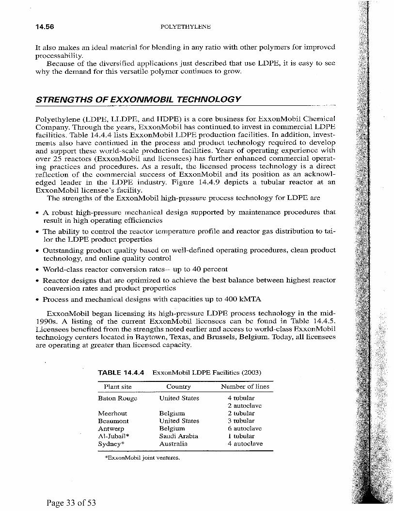
Chapter 14.4. ExxonMobil High-Pressure Process Technology for LOPE Charles E. Schuster
Introduction I 14.45 Reaction Mechanism I 14.46 Process Overview/Description I 14.48 LDPE versus LLDPE I 14.53 Product Capability/Grade Slate I 14.54 :J..,DPE Markets I 14.54 Strengths ofExxonMobil Technology I 14.56 Summary I 14.57 Reference I 14.58 Disclaimer I 14.58
14.3
14.15
14.31
14.45

CONTENTS
Description of the Process Flow I 11.27 Process and Mechanical Design Advanced Features I 11.32 Process Performance I 11.33 Commercial Experience I 11.34
Part 12 Terephthalic Acid
Chapter 12.1. E PTA: The Lurgi/Eastman/SK Process Frank Castillo-Welter
Introduction I 12.3 Chemistry Overview and Product Specification I 12.4 Process Description I 12.4 Highlights and Benefits ofE PTA Technology I 12.9 Economics of E PTA Technology I 12.10 Commercial Experience I 12.11
Part 13 Xylenes
Chapter 13.1. ExxonMobil PxMax8 M p-Xylene from Toluene Terry W. Bradley
Introduction I 13.3 Process Chemistry I 13.4 Process Description I 13.5 Operating Performance I 13.5 PxMax Retrofit and Debottleneck Applications I 13. 7 Aromatics Complex and PxMax Unit Description I 13.8 Case I: Grassroots PxMax Unit I 13.8 Case II: Retrofit of Selective TDP to PxMax I 13.11 Case III: Retrofit of Nonselective TDP to PxMax I 13.12 Conclusion I 13.13
Chapter 13.2. ExxonMobil XyMax8 M Xylene Isomerization Terry W. Bradley
Introduction I 13.15 Process Chemistry I 13.16 Process Description I 13.17 Operating Performance I 13.18 XyMax Cycle Length I 13.20 Commercial Experience I 13.21
Chapter 13.3. UOP Parex™ Process for p-Xylene Production Scott E. Commissaris
Introduction I 13.23 Parex versus Crystallization I 13.23 Process Performance I 13.26
xi
12.3
13.3
13.15
13.23

X
Process Chemistry I I 0.37 Process Description I I 0.37 Process Economics I I 0.38 Summary of Process Features I I 0.40 Conclusion I I0.4I
CONTENTS
Chapter 10.5. Propylene via CATOFIN® Propane Dehydrogenation Technology V. K. Arora
Introduction I I 0.43 Process Chemistry I I0.44 Process Description I I 0.44 Process Economics I I 0.47 Feedstock and Utility Consumption I I 0.47 Product Quality and By-Products I I0.47 Catalyst and Chemical Consumption I I0.49 Environmental Emissions I I 0.49 Summary of Technology Features I I 0.49
Part 11 Styrene
Chapter 11.1. Lummus/UOP 11Ciassic 11 Styrene Technology and Lummus/UOP SMART8 M Styrene Technology Stephen Pohl and SanjeevRam
Introduction I 11.3 Process Perspective I II.4 Process Chemistry I 11.5 Process Descriptions I 11.6 Economics I 11.9 Summary of Process Features I II.II
Chapter 11.2. Stone & Webster (Badger) Styrene Technology Vincent Welch
Introduction I II.I3 Styrene Industry I II.I3 Use of Styrene Monomer I II.I4 Properties I II.I5 Styrene Manufacturing I 11.I5 Process Chemistry I II.I6 Process Description I ll.I8 Product Specification I IJ.23
'Operating Economics I II.23
Chapter 11.3. Polimeri Europa Styrene Process Technology Leonardo Trentini and Armando Galeotti
Introduction I II.25 Process Chemistry I Il.26
10.43
11.3
11.13
11.25
Utility Requirements I 9.43 Product Storage and Shipping I 9.43 Environmental Features I 9.44 Safety I 9.45 Operating Economics I 9.46 Investment/Economies of Scale I 9.46 Acetone Netback I 9.48 Technology Advantages I 9.49 Bibliography I 9.50
CONTENTS
Chapter 9.4. OBIS™ Process for High-Purity Bisphenol A Ed Fraini,
ix
Don West, and George Mignin 9.51
Overview I 9.51 Commercial Experience I 9.56 Wastes and Emissions: Expected Performance I 9.57
Part 10 Propylene and Light Olefins
Chapter 1 0.1. Lurgi MTP® Technology Waldemar Liebner
Introduction I 10.3 Process Overview I 10.3 Detailed Process Description I 10.4 Products, By-Products, Wastes, and Emissions I 10.9 Technical and Commercial Status I 10.10 Process Economics I 10.11 Bibliography I 10.13
Chapter 1 0.2. UOP /Hydro MTO Process Peter R. Pujad6 and James M. Andersen
Introduction I 10.15 MTO Technology I 10.18 Economic Basis I 10.20 Investment Estimates I 10.20 Economic Comparisons I 10.23 Economic Sensitivity I 10.25 Conclusions I 10.26 References I 10.26
Chapter 1 0.3. UOP Oleflex™ Process Joseph Gregor and Daniel Wei
Introduction I 10.27 Process Description I 10.27 Dehydrogenation Plants I 10.29 Propylene Production Economics I 10.31
Chapter 10.4. ABB Lummus Global Propylene Production via Olefins Conversion Technology Catherine A. Berra and James T. C. Wu
Introduction I 10.35 Development and Commercial History I 10.36
10.3
10.15
10.27
10.35


EXXONMOBIL HP PROCESS TECHNOLOGY FOR LDPE 14.49
Tubular Reactor
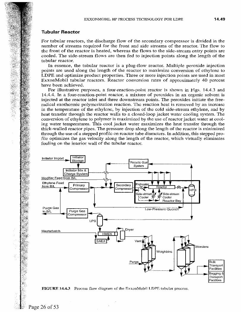
For tubular reactors, the discharge flow of the secondary compressor is divided in the number of streams required for the front and side streams of the reactor. The flow to the front of the reactor is heated, whereas the flows to the side-stream entry points are cooled. The side-stream flows are then fed to injection points along the length of the tubular reactor.
In essence, the tubular reactor is a plug-flow reactor. Multiple peroxide injection points are used along the length of the reactor to maximize conversion of ethylene to LDPE and optimize product properties. Three or more injection points are used in most ExxonMobil tubular reactors. Reactor conversion rates of approximately 40 percent have been achieved.
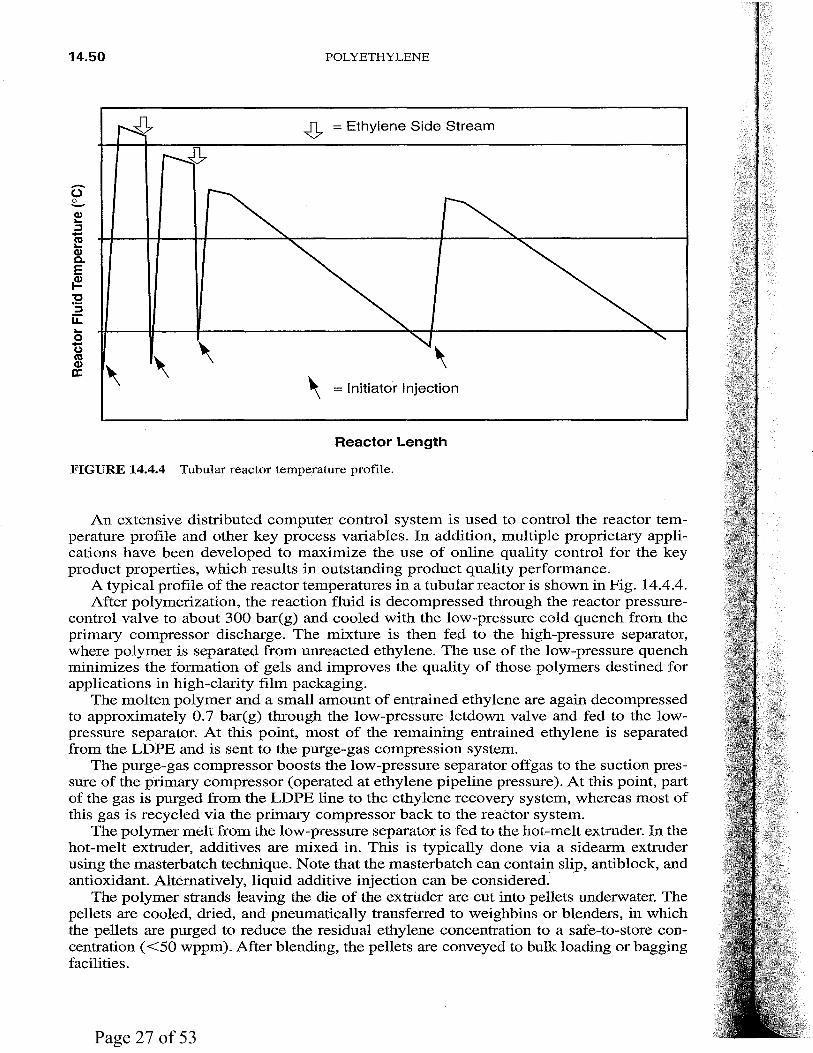
For illustrative purposes, a four-reaction-point reactor is shown in Figs. 14.4.3 and 14.4.4. In a four-reaction-point reactor, a mixture of peroxides in an organic solvent is injected at the reactor inlet and three downstream points. The peroxides initiate the freeradical exothermic polymerization reaction. The reaction heat is removed by an increase in the temperature of the ethylene, by injection of the cold side-stream ethylene, and by heat transfer through the reactor walls to a closed-loop jacket water cooling system. The conversion of ethylene to polymer is maximized by the use of reactor jacket water at cooling water temperatures. This cool jacket water maximizes the heat transfer through the thick-walled reactor pipes. The pressure drop along the length of the reactor is minimized through the use of a stepped profile on reactor tube diameters. In addition, this stepped profile optimizes the gas velocity along the length of the reactor, which virtually eliminates fouling on the interior wall of the tubular reactor.
Initiator Mix & Charge Systeml-----'>11<,-----------.rJI~~_.,.
Modifier Feed from B/L
Ethylene Feed from B/L
Masterbatch
Side-stream Cooler Reactor Bay
Low-Pressure Quench
Weighbins
..r---...____.,-tBagging & Transport Facilities
FIGURE 14.4.3 Process flow diagram of the ExxonMobil LDPE tubular process.
14.50 POLYETHYLENE
..J>. = Ethylene Side Stream
-(.) 0 -C1) ... ::::J -ctl ... C1) a. E ~ :2
::::J u::: ... 0 -(.) ctl
\ C1)
\ a: \ = Initiator Injection
Reactor Length
FIGURE 14.4.4 Tubular reactor temperature profile.
An extensive distributed computer control system is used to control the reactor temperature profile and other key process variables. In addition, multiple proprietary applications have been developed to maximize the use of online quality control for the key product properties, which results in outstanding product quality performance.
A typical profile of the reactor temperatures in a tubular reactor is shown in Fig. 14.4.4. After polymerization, the reaction fluid is decompressed through the reactor pressure
control valve to about 300 bar(g) and cooled with the low-pressure cold quench from the primary compressor discharge. The mixture is then fed to the high-pressure separator, where polymer is separated from unreacted ethylene. The use of the low-pressure quench minimizes the formation of gels and improves the quality of those polymers destined for applications in high-clarity film packaging.
The molten polymer and a small amount of entrained ethylene are again decompressed to approximately 0. 7 bar(g) through the low-pressure letdown valve and fed to the lowpressure separator. At this point, most of the remaining entrained ethylene is separated from the LDPE and is sent to the purge-gas compression system.
The purge-gas compressor boosts the low-pressure separator offgas to the suction pressure of the primary compressor (operated at ethylene pipeline pressure). At this point, part of the gas is purged from the LDPE line to the ethylene recovery system, whereas most of this gas is recycled via the primary compressor back to the reactor system.
The polymer melt from the low-pressure separator is fed to the hot-melt extruder. In the hot-melt extruder, additives are mixed in. This is typically done via a sidearm extruder using the masterbatch technique. Note that the masterbatch can contain slip, antiblock, and antioxidant. Alternatively, liquid additive injection can be considered. ·
The polymer strands leaving the die of the extrUder are cut into pellets underwater. The pellets are cooled, dried, and pneumatically transferred to weighbins or blenders, in which the· pellets are purged to reduce the residual ethylene concentration to a safe-to-store concentration (<50 wppm). After blending, the pellets are conveyed to bulk loading or bagging facilities.


CHAPTER 14.8 BAS ELL LUPOTECH T
TECHNOLOGY FOR LOPE AND EVA-COPOLYMER
PRODUCTION
Andre-Armand Finette and Gijs ten Berge Basel! Polyolefine GmbH
Frankfurt, Germany
GENERAL PROCESS DESCRIPTION
The Lupotech T process technology is designed to produce from ethylene low-density polyethylene (LDPE) polymer or ethylene vinyl acetate (EVA) copolymers by copolymerization with comonomers such as vinyl acetate or acrylates. Single-line capacity of 400,000 metric tons per annum (MTA) can be offered.
The polymerization, after initiation by feeding of small amounts of initiator such as peroxide or oxygen, takes place at high pressure in a tubular reactor. The tubular reactor system can be offered in a single-feed configuration or a multiple-feed configuration. The polymer produced in the reactor is separated from the residual ethylene. The polymer is additivated and extruded to solid pellets, and the monomer is recycled and recompressed to operating pressure. Flow schemes for Lupotech TS and TM are given below.
PROCESS CHEMISTRY AND THERMODYNAMICS
Reaction Mechanism
The free-radical polymerization process for LDPE manufacture can be illustrated in a detailed kinetic scheme. This scheme allows the calculation of structural properties such as molecular weight distribution and branching frequencies. Therefore, it distinguishes several reaction steps, e.g., initiator decomposition, radical chain propagation, chain trans-
14.95
14.96 POLYETHYLENE
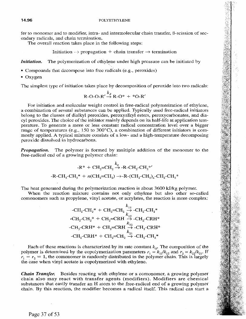
fer to monomer and to modifier, intra- and intermolecular chain transfer, B-scission of secondary radicals, and chain termination.
The overall reaction takes place in the following steps:
Initiation -7 propagation + chain transfer -7 termination
Initiation. The polymerization of ethy~ene under high pressure can be initiated by
• Compounds that decompose into free radicals (e.g., peroxides)
• Oxygen
The simplest type of initiation takes place by decomposition of peroxide into two radicals:
ka R-0-0-R' -7 R-0* + *0-R'
For initiation and molecular weight control in free-radical polymerization of ethylene, a combination of several substances can be applied. Typically used free-radical initiators belong to the classes of dialkyl peroxides, peroxyalkyl esters, peroxycarbonates, and diacyl peroxides. The choice of the initiator mainly depends on its half-life at application temperature. To generate a more or less constant radical concentration level over a bigger range of temperatures (e.g., 150 to 300°C), a combination of different initiators is commonly applied. A typical mixture consists of a low- and a high-temperature decomposing peroxide dissolved in hydrocarbons.
Propagation. The polymer is formed by multiple addition of the monomer to the free-radical end of a growing polymer chain:
k -R* + CH2=CH2 ~ -R-CH2-CH2*'
-R-CH2-CH2* + n(CH2=CH2 ) -7-R-(CH2-CH2)n-CH2-CH2 *
The heat generated during the polymerization reaction is about 3600 kJ/kg polymer. When the reaction mixture contains not only ethylene but also other so-called
comonomers such as propylene, vinyl acetate, or acrylates, the reaction is more complex:
kll -CH2-CH2 * + CH2=CH2 -7 -CH2-CH2 *
k -CH2-CH2 * + CH2=CRH ~ -CH2-CRH*
k22 -CH2-CRH* + CH2=CRH -7 -CH2-CRH*
k -CH2-CRH* + CH2=CH2 ~ -CH2-CH2 *
Each of these reactions is characterized by its rate constant ku. The composition of the polymer is determined by the copolymerization parameters r 1 = k11/k12 and r2 = k2/k21 • If r 1 = r2 = 1, the comonomer is randomly distributed in the polymer chain. This is largely the case when vinyl acetate is copolymerized with ethylene.
Chain Transfer. Besides reacting with ethylene or a comonomer, a growing polymer chain also may react with transfer agents (modifiers). Modifiers are chemical substances that easily transfer an H atom to the free-radical end of a growing polymer chain. By this reaction, the modifier becomes a radical itself. This radical can start a
BASELL LUPOTECH T TECHNOLOGY 14.97
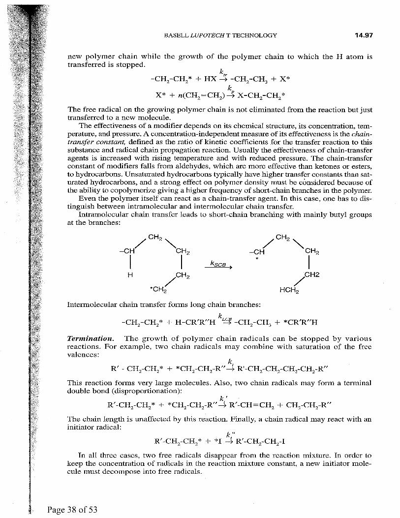
new polymer chain while the growth of the polymer chain to which the H atom is transferred is stopped.
ktr -CH2 -CH2 * + HX --7 -CH2 -CH3 + X*
k X*+ n(CH =CH )-4 X-CH -CH * 2 2 2 2
The free radical on the growing polymer chain is not eliminated from the reaction but just transferred to a new molecule.
The effectiveness of a modifier depends on its chemical structure, its concentration, temperature, and pressure. A concentration-independent measure of its effectiveness is the chaintransfer constant, defined as the ratio of kinetic coefficients for the transfer reaction to this substance and radical chain propagation reaction. Usually the effectiveness of chain-transfer agents is increased with rising temperature and with reduced pressure. The chain-transfer constant of modifiers falls from aldehydes, which are more effective than ketones or esters, to hydrocarbons. Unsaturated hydrocarbons typically have higher transfer constants than saturated hydrocarbons, and a strong effect on polymer density must be considered because of the ability to copolymerize giving a higher frequency of short-chain branches in the polymer.
Even the polymer itself can react as a chain-transfer agent. In this case, one has to distinguish between intramolecular and intermolecular chain transfer.
Intramolecular chain transfer leads to short-chain branching with mainly butyl groups at the branches:
ksca )
·cH2
/ HCH2
Intermolecular chain transfer forms long chain branches:
k -CH2-CH2* + H-CR'R"H ~ -CH2-CH3 + *CR'R"H
Termination. The growth of polymer chain radicals can be stopped by various reactions. For example, two chain radicals may combine with saturation of the free valences:
k R' - CH2-CH2 * + *CH2-CH2-R" ~ R'-CH2-CH2-CH2-CH2-R"
This reaction forms very large molecules. Also, two chain radicals may form a terminal double bond (disproportionation):
k' R'-CH -CH * + *CH -CH -R" ~ R'-CH=CH + CH -CH -R" 2 2 2 2 2 3 2
The chain length is unaffected by this reaction. Finally, a chain radical may react with an initiator radical:
k" R'-CH2-CH2 * + *I ~ R'-CH2-CH2-I
In all three cases, two free radicals disappear from the reaction mixture. In order to keep the concentration of radicals in the reaction mixture constant, a new initiator molecule must decompose into free radicals.
14.98 POLYETHYLENE
Reaction Kinetics. All the preceding reactions take place simultaneously in a polymerization reactor. However, the rates of the individual reactions depend on the concentration of the reactants involved in the reaction and the individual reaction rate constants ki. These rate constants are largely dependent on pressure and temperature:
- [ A Ei + ~vi (P - p o) J k.- A. exp ---------
• I RT
Each rate constant ki is characterized by a particular value of the factor Ai, the activation energy A Ei, and the activation volume ~Vi.
For polymerization at constant pressures, we can write
Copolymerization
High-pressure conditions can be applied to polymerize ethylene with a large variety of chemically different monomers via a free-radical kinetic mechanism. Polar comonomers such as acrylic and methacrylic acid and their esters, as well as vinyl acetate, are used in large-scale production. The product properties in these copolymers are very different from those of homopolyethylene (LDPE) and depend strongly on the type of comonomer and the built-in ratio of the monomers. The fundamental technologies of high-pressure manufacturing processes have been described already in detail above. Depending on the nature of the comonomers, the process is selected with regard to its back-mixing capability. The residence-time distribution of the reaction mixture and the applied polymerization concept have a strong impact on polymer structure, product homogeneity, and process operability.
In general, three different cases of copolymerization behavior have to be distinguished: the copolymerization of ethylene with comonomers with higher reactivity (e.g., acrylates, methacrylates, styrene), with monomers of equal reactivity (e.g., vinylacetate), and with monomers of minor reactivity (e.g., vinylethers, propylene, and higher olefins). Copolymerization with vinylacetate proceeds nearly ideally, which means that the polymer has nearly the same composition as the comonomer mixture at any time during the polymerization. On the other hand, acrylic and methacrylic acid and their esters polymerize much more rapidly than ethylene, so a polymer with high comonomer content can be formed from a monomer mixture with only small quantities of the coinonomer.
Aside from the composition and comonomer distribution along the copolymer chain, the molecular weight distribution (MWD) and the degree of branching are of special importance for their application. Thus, for example, copolymer products of ethylene and acrylic acid with higher degrees of polymerization have improved adhesion-promoting properties in steel pipe coating applications. Molecular weight can be controlled by adding modifiers, e.g., aldehydes or ketones, despite the fact that most comonomers themselves have a high radical chain-transfer capability, restricting the highest achievable polymer molecular weight. Chain-transfer-rate coefficients of comonomers must be considered in the polymerization process, although these values often are uncertain for appropriate reaction conditions.
Polymerization Techniques
Heat Control. During the polymerization of ethylene, a large amount of heat is generated. For a smoothly running process it is essential to control the heat balance of
BASELL LUPOTECH T TECHNOLOGY 14.99
the polymerization reaction very closely. The thermodynamic stability of the ethylene demands that the peak temperature of the reaction mixture does not exceed 350°C. Therefore, more than half the heat generated must be removed from the reaction mixture by heat transfer through the wall of the tubes.
The overall heat transfer is determined by the temperature differential between the reaction mixture and the cooling medium in the jackets and by the heat transfer
1. From the reaction mixture to the inner surface of the reactor tubes
2. From the reactor tubes to the hot water in the jackets
For a good heat transfer to the inner surface of the reactor tubes, it is important to maintain a turbulent flow in the tubes. Therefore, it is necessary to increase the velocity in the tubes from time to time by "kicking" (reducing the reactor pressure some 100 bar). To remove the heat from the tubes, it is important to avoid any vaporization of the cooling medium in the jackets. Therefore, the flow of the cooling medium in the jackets must be throttled to build up a reasonable pressure at the outlet of each cooling circle.
Depending on the reaction pressure, an oxygen-initiated reaction starts at a temperature of about 170 to 180°C. Low-temperature-decomposing peroxides may initiate the reaction at temperatures of 140 to 150°C.
Control of Product Properties
Density and Melt-Flow Index. The correlation between density D of a polymer, on the one hand, and the peak temperature T and the reaction pressure P, on the other hand, can be described by
D = a0 - a 1 X T + a2 X P
In this equation, a 1 and a 2 are constants, whereas a0 is a function of both the melt-flow index and the type of modifier.
The reason for the decrease in density with an increasing peak temperature is the increase in short-chain branching due to intramolecular chain transfer with increasing temperature. However, as the pressure increases, the short-chain branching is suppressed in favor of the chain growth. This is the reason why the density increases with increasing pressure at a constant peak temperature.
A correlation between density and conversion can be derived qualitatively from the preceding equation. Because the conversion is largely determined by the difference between starting temperature and peak temperature, the conversion must increase with an increasing temperature peak. The consequence of this is that
1. Increasing pressure increases conversion at the same density.
2. At constant pressure, conversion is higher for low-density materials than for high-density materials.
The melt-flow index (MFI) is controlled by the modifier used during polymerization. However, there is an important difference between so-called strong modifiers and weak modifiers such as propane and propylene.
The chain-transfer activity of a strong modifier such as aldehydes is only slightly influenced by the temperature. The MFI of the product is determined almost exclusively by the concentration of the modifier in the reaction mixture; the MFI increases with the amount of modifier fed into the reactor per hour.
The behavior of a weak modifier such as hydrocarbons is quite different from that of a strong one. The chain-transfer activity of a weak modifier depends mainly on the reaction temperature, whereas changes in concentration have only a slight effect on the MFI.

14.100 POLYETHYLENE
Therefore, in order to change the MFI with a weak modifier, it is necessary to change the peak temperature. This is done normally by changing the initiator concentration (varying the peroxide flow) to the reactor, but changing temperature also will change density. To keep density constant in this case, one has to adjust the pressure, the peak temperature, and the modifier flow at the same time.
Controlling Conversion. The conversion in a tubular reactor is determined by the heat balance. The equation for the overall heat balance is
where
Q = G X H X dU = G X C X dT + 'IT X D X k X (T - T ) X dL p g g w
G = mass flow through tubes H =enthalpy U = conversion CP = specific heat of the reaction mixture T
8 = temperature of the reaction mixture
Q = generated heat D = inner diameter of the reactor tubes k = overall heat-transfer coefficient Tw = water temperature in the jackets L = effective length of reaction zone
From this equation one can easily derive that the conversion U will increase
• With an increasing dT8
of the reaction mixture
• With a larger heat-transfer coefficient k
• With an increasing difference between reaction temperature T8
and water temperature Tw
• With a larger effective length of the reaction zone
The terms G, H, CF' and D are constant for a given design of a reactor and cannot be changed.
The increase in dT8
is limited on the one hand by the starting temperature of the initiator and on the other hand by the peak temperature, which is determined by the required product density. The heat-transfer coefficient k can be influenced by opening the pressure control valve of the reactor periodically. This will increase the flow rate of the reaction mixture and improve the turbulent heat transfer to the wall of the tubes. However, because "kicking" causes very strong stress loads on the tube material, it is recommend to minimize the amplitude and frequency of these pulses.
At a given peak temperature T8
the temperature difference T - T.v can be influenced only by the jacket temperature Tw. Lowering Tw not only will increi'se the temperature difference T
8 - Tw but also will shift the temperature profile downstream and increase the effective
length L of the actual reaction area. If the jacket temperature is lowered too much, the heattransfer coefficient k will be decreased because of increasing thickness of the wall layer.
Controlling Temperature Profile. The temperature profile is further controlled by the temperature of the reactor preheater, by the reaction pressure P, and by initiator concentration. The ranges of all these controlling measures are given by the intended density and MFI of the product and by the stability of the reaction.
Effect of Reaction Conditions on Product Properties. The effect of pressure, peak temperature, and type of modifier on the polymer density has already been described. The influence of peak temperature and type and concentration of modifier on the MFI also has been explained. Besides these correlations, pressure, peak temperature,

Rei. frequency (%)
BASELL LUPOTECH T TECHNOLOGY
I
,.., / ' I \
I \ I \
I \
Good flowability and stiffness Low warpage
I \
I ' I \
I ' I '
/ ' ~ ' , ' Molecular weight
FIGURE 14.8.1 Narrow MWD for injection-molded parts.
Rei. frequency (%)
Low molecular mass fraction: Good flowability and stiffness
High molecular mass fraction: High ESCR and impact strength
Molecular weight
FIGURE 14.8.2 Broad MWD for blow molding and film.
14.101
initiator concentration, type and concentration of modifier have an influence on the molecular structure of the polymer (Figs. 14.8.1 and 14.8.2).
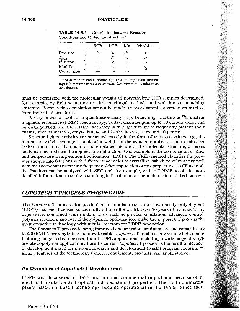
Increasing temperature will narrow the molecular mass distribution (MMD), which will result in improved film properties. Increasing peak temperature and initiator concentration will broaden the MMD and deteriorate film properties. High modifier concentration will give a narrow MMD (Table 14.8.1).
It was mentioned earlier that the properties of LDPE depend originally on the MWD and the distribution of chain branches regarding their length and frequency. Size-exclusion chromatography (SEC) may be the most important method for analyzing the MWD of polymer material because of its simplicity and applicability over a wide range of molecular weights. The original value analyzed by this method is the quantity of polymer molecules fractionated with respect to their hydrodynamic volume. This hydrodynamic volume depends not only of the molecular weight but also on the branching structure of the molecule (especially on long-chain branching). This means that the SEC hydrodynamic volume
14.102 POLYETHYLENE
TABLE 14.8.1 Conelation between Reaction Conditions and Molecular Structure*
SCB LCB Mn Mw/Mn
Pressure 1' "" "" /'I "" Tpeak 1' 1' /'I "" /'I Initiator 1' ~ /'I ..j, /'I Modifier 1' ~ ,j.. t "" Conversion 1' ~ /'I ~ 1'
*SCB =short-chain branching; LCB =long-chain branching; Mn = number molecular mass; Mn/Mw = molecular mass distribution.
must be correlated with the molecular weight of polyethylene (PE) samples determined, for example, by light scattering or ultracentrifugal methods and with known branching structure. Because this correlation cannot be made for every sample, a certain error arises from individual structures.
A very powerful tool for a quantitative analysis of branching structure is 13C nuclear magnetic resonance (NMR) spectroscopy. Today, chain lengths up to 10 carbon atoms can be distinguished, and the relative accuracy with respect to more frequently present short chains, such as methyl-, ethyl-, butyl-, and 2-ethylhexyl-, is around 10 percent.
Structural characteristics are presented mostly in the form of averaged values, e.g., the number or weight average of molecular weight or the average number of short chains per 1000 carbon atoms. To obtain a more detailed picture of the molecular structure, different analytical methods can be applied in combination. One example is the combination of SEC and temperature-rising elution fractionation (TREF). The TREF method classifies the polymer sample into fractions with different tendencies to crystallize, which correlates very well with the short-chain branching frequency. After application of this preparative TREF method, the fractions can be analyzed with SEC and, for example, with 13C NMR to obtain more detailed information about the chain-length distribution of the main chain and the branches.
LUPOTECH T PROCESS PERSPECTIVE
The Lupotech T process for production in tubular reactors of low-density polyethylene (LDPE) has been licensed successfully all over the world. Over 50 years of manufacturing experience, combined with modem tools such as process simulation, advanced control, polymer research, and material/equipment optimization, make the Lupotech T process the most attractive technology with tubular reactors for LDPE production.
The Lupotech T process is being improved and upscaled continuously, and capacities up to 400 kMTA per single line are now feasible. Lupotech T products cover the whole manufacturing range and can be used for all LDPE applications, including a wide range of vinylacetate copolymer applications. Basell's current Lupotech T process is the result of decades of development based on a strong research and development (R&D) program focusing on all key features of the technology (process, equipment, products, and applications).
An Overview of Lupotech T Development
LDPE was discovered in 1933 and attained commercial importance because of its electrical insulation and optical and mechanical properties. The first commercial plants based on Basell technology became operational in the 1950s. Since then,

BAS ELL LUPOTECH T TECHNOLOGY 14.103
through R&D, significant advances have made the Lupotech T process a world-class technology.
In the 1970s, a major breakthrough in terms of process safety, plant reliability, and operating windows was the introduction of modified high-pressure steels with increased toughness as base material for the reactor piping. This resulted in superior plant integrity and also enabled higher operating pressures, which expanded the LDPE product portfolio with higher-density LDPE grades and an increase in film quality.
In the 1980s, organic peroxides were introduced as radical initiators, leading to both higher conversion rates and more efficient process control. In the 1990s, R&D refocused on process upscaling, process simulation and modeling, and advanced control.
The introduction of Luposim T, Basell's proprietary simulation program for high-pressure tubular reactors, created a powerful tool for process and product development/improvement. In terms of scale-up, Lupotech T technology achieved a breakthrough in January 2001 with the startup of the world's largest LDPE plant at Aubette, France, with a single-line capacity of 320 kMTA. The successful operation of this unique plant is a showcase for the process technology.
Based on advanced process simulation, which has been validated in existing plants and has proven its capabilities with the scale-up of the 320-kMTA LDPE plant, Basell is now in the position to offer plant capacities of up to 400 kMTA single line with dedicated customer design.
Key Characteristics
The Lupotech T process is a high-pressure tubular reactor technology developed for the whole range of LDPE products, including hydrolyzed EVA (HEVA) copolymers.
Safety and Loss Prevention. Polymerization of ethylene under high pressure in a tubular reactor takes place in supercritical ethylene as diluent. Therefore, no additional solvent is required.
Plants using the Lupotech T process can meet all environmental and safety requirements. Around the world, over 50 million metric tons have been produced with Lupotech T technology without major incidents.
Reducing Resource Intensity. In the Lupotech T process, unreacted monomers are recovered and recycled constantly. If necessary, discontinuous hydrocarbon purges can be sent for "thermal recovery" or to a flare system. Since hydrocarbons as solvent are not needed, there are no major effluent streams.
Design Capability/Flexibility. Single-line capacities up to 400 kMTA (based on 8000 operating hours per year) can be provided, covering the whole range of LDPE products.
Process Versatility. Related to specific process features, Lupotech T technology can produce the whole range of LDPE products, including HEVA and N-butylacrylatemodified LDPE. Fast grade changes ensure that the amount of off-grade material is kept very low, allowing a broad grade slate to be produced in one reactor.
Product Quality. Lupotech T technology delivers a very homogeneous product quality with a low gel level, which means blending/homogenizing silos are not required.
Economical. Capital costs for the Lupotech T process are low as a result of highly efficient design. Based on low raw materials and energy consumption figures,

14.104 POLYETHYLENE
Lupotech T technology is characterized by competitive operating costs, whereas the final product is sold at a premium over other PE products. The combination of low investment and low operating costs makes the Lupotech T process an attractive highpressure PE process.
PROCESS DESCRIPTION
In the Lupotech T process, ethylene is polymerized to LDPE at temperatures above 150°C and pressures between 2000 and 3100 bar. For the production of copolymers, specific comonomers such as vinylacetate or butylacrylate are used.
The overall manufacturing process can be divided into the following steps/process units:
• Precompression of ethylene
• Compression to reaction conditions
• Polymerization reaction
• Polymer-gas separation
• Recycling of unreacted gases
• Extrusion, pelletizing
• Degassing
• Storage and packaging
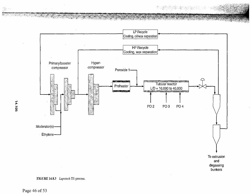
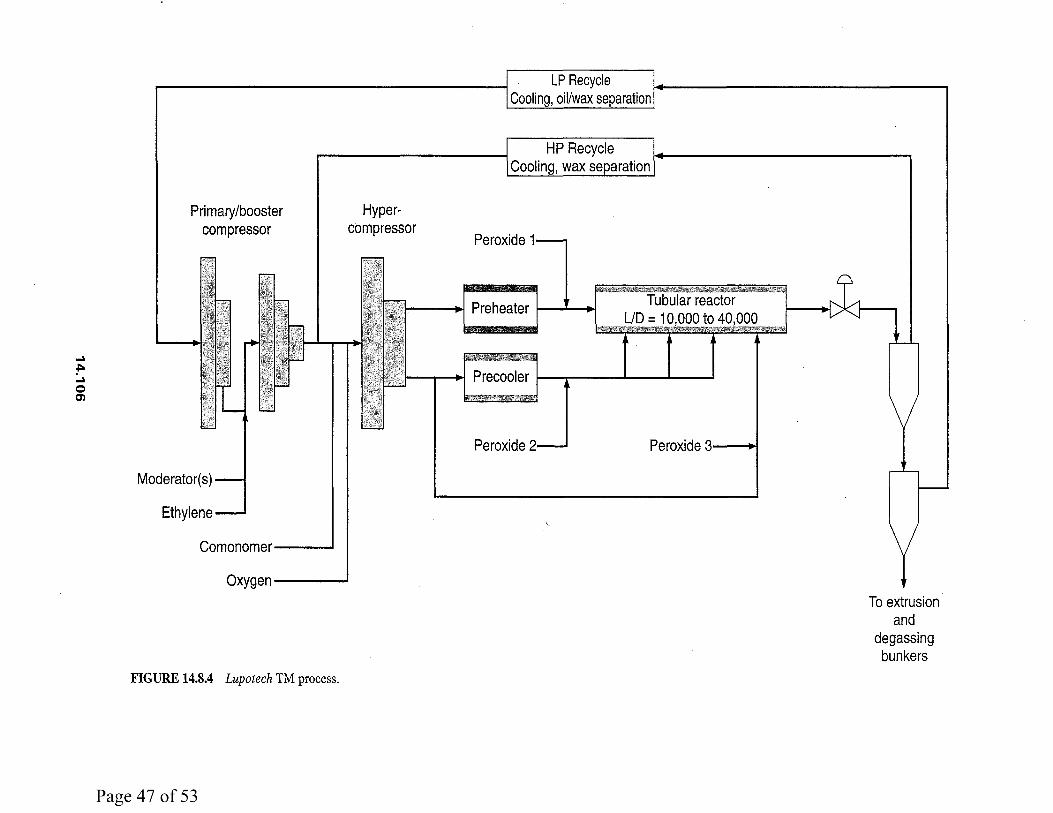
High-pressure tubular reactors are offered in two generally different forms, as shown in Figs. 14.8.3 and 14.8.4.
In a TS reactor, the total ethylene flow from the hypercompressor is preheated to 150 to 180°C and fed to the inlet of the first reaction zone. Reaction is initiated by injection of organic peroxides. As the reaction mixture cools after the first reaction peak, additional peroxide initiator is added to start a second reaction zone. There can be further peroxide injection points, giving a total of three to five reaction zones.
In a TM reactor (multiple cold gas injection), the compressed ethylene is split into several streams and fed into the reactor at a number of positions. In addition, the ethylene can be dosed with oxygen prior to compression. Approximately 40 to 70 percent of the total ethylene is preheated to 150 to 180°C before addition of peroxide, which, together with the oxygen, sets off the first reaction zone. The other 30 to 60 percent of the ethylene is cooled and further split into more or less equal quantities, which are injected at different locations along the reactor. Together with addition of initiator, this results in the desired number of reaction zones. Additional reaction zones can be created by dosing peroxide directly to the reactor.
Reaction heat in this reactor type can be absorbed by the cold gas feeds, having the disadvantage that this part of the gas feed has only a reduced residence time in the reactor. The balance of these two effects can result in higher conversion rates, depending on the product grade. The TM reactor can have a stepwise increase in reactor diameter, and the reaction mixture flow velocity can change significantly owing to the additional gas feeds. This reactor is equipped with a similar pressure-control valve as a TS reactor.
LDPE Process Sections
1. Precompression of ethylene. Polymer-grade ethylene and recycled ethylene are compressed by a primary compressor to approximately 300 bar. A modifier (e.g., hydrocarbons, ketones, or aldehydes) to control the molecular weight is added.
-. f"o -. 0 (J'1
Primary/booster compressor
FIGURE 14.8.3 Lupotech TS process.
Hypercompressor
LP Recycle Cooling, oil/wax separation
HP Recycle Cooling, wax separation
Peroxide 1
1 •I Preheater 1 • •I Tubular reactor
UD = 10,000 to 40,000
P02 P03 P04
To extrusion and
degassing bunkers
~
~ ~
0 en
Primary/booster compressor
Comonomer---..1
Hypercompressor
Peroxide 1
1 .. 1 Preheater 1 ' .. 1
j<; :c!if*i~,l 1 .,I Precooler l--__,...----"--.1...----1
Peroxide Peroxide :1 .,,
Oxygen ___ _.
FIGURE 14.8.4 Lupotech TM process.
To extrusion and
degassing bunkers
BASELL LUPOTECH T TECHNOLOGY 14.107
2. Compression to reaction conditions. The ethylene stream, together with the recycled ethylene out of the high-pressure recycle loop, is further compressed by the hypercompressor up to 3100 bar. The hypercompressor is a symmetric two-stage compressor in two lines (streams A and B). In the :first stage, the compressor feed gas is compressed from about 270 bar(g) to approximately 1250 bar(g). Cooling of the gas is carried out after stage 1 only. The gas in both streams is compressed in the second stage to pressures up to 3200 bar. After each stage, the gas passes through a discharge pulsation dampener. The ethylene finally discharged has to be further heated for the reaction to take place.
3. Polymerization reaction. The reaction mixture leaving the hypercompressor is fed to a tubular reactor consisting of three different segments. In the preheater, the reaction mixture is heated to the initiator temperature of about 150 to 180°C, followed by a sequence of reaction and cooling zones. The reactor consists of a large number of jacketed tubes with a total length-to-diameter ratio between 10,000 to 40,000. The inner diameter of the high-pressure tubes can vary between 10 and 100 mm, having a monomer throughput of between 10 and 190 t/h.
Polymerization pressure is typically between 2000 and 3200 bar, and maximum temperatures are below 350°C. Under polymerization conditions, the polymer is dissolved in the supercritical ethylene, resulting in a one-phase reaction mixture.
In the reaction zones, the polymerization is initiated by adding the polymerization initiator (oxygen or peroxide). Owing to the exothermic nature of ethylene polymerization, the reaction mixture heats up, and the resulting polyethylene remains dissolved in the supercritical ethylene. Temperature is controlled by the concentration and type of added initiators, as well as by the hot water circuit. Side streams of cooled fresh ethylene can be used for a fast cooldown of the reaction mixture and restart of the initiation. The conversion of more than 35 percent per pass can be achieved by this procedure.
4. Polymer-gas separation. At the end of the reactor, the mixture of polymer and unreacted ethylene is depressurized, passes a postreactor cooler, and enters the high-pressure product separator. The unreacted ethylene is separated from the polymer melt at approximately 300 bar. The polymer melt is let down through the product valve into the low-pressure product separator (approximately 0.2 to 2.0 bar) to remove the remaining ethylene from the resin.
5. Recycling of unreacted gases. Ethylene streams from both separators are recycled to the respective compressors by stepwise cooling. The high-pressure stream is recycled to the hypercompressor and the low-pressure stream to the booster stage of the primary compressor. To avoid accumulation of impurities and inerts in the loops, a minor quantity of ethylene is withdrawn as a purge gas stream and sent to the ethylene recovery at battery limits.
6. Extrusion, pelletizing. The melt, still containing minor quantities of ethylene, is passed from the low-pressure product separator into the extruder for further degassing, for the incorporation of additives, if demanded, and for pelletizing by an underwater face-cutter system. The extruder can be a single-screw machine or a twin-screw machine.
7. Degassing. After passing through the extruder, the pellets still contain traces of ethylene and are sent to the degassing silos, which are purged by a constant flow of air. Within a certain period of time, the remaining hydrocarbons diffuse out of the pellets. Airflow is designed to keep the concentration level of ethylene safe.
8. Storage, bagging. Pellets are conveyed pneumatically into storage silos; from there the products can be shipped in bulk or bagged.

14.108 POLYETHYLENE
Process Safety
Basell has a safety record unmatched in the industry. By 2003, combined Basell technologies have achieved nearly 7 million operating hours without a major incident.
Specific Safety Features of Lupotech T
1. Fast-acting safety chain (thermocouples, pressure transmitters, hydraulic system)
2. Fast depressurization of the reactor system in case of a reactor safety shutdown (RSD program) to safe levels
3. Autofrettage of high-pressure reactor equipment manufactured of K 10 X-steel material (result: leak before break)
4. TV cameras for an overall view of reactor and plant area
5. Inertization system for pellet degassing silos in case of elevated ethylene concentrations in the silo atmosphere or additional spare blowers for air
Automatic Reactor Safety Relief System. The polymerization process is secured by up-to-date safety systems installed independently in addition to the distributed control system. This safety system is hardwired and therefore extremely reliable. It fulfills all standards for such production plants.
This reactor shutdown (RSD) program transfers the reactor unit into a safe condition by depressurizing the compressors and the reactor. Shortly after, the reactor system is ready for another startup.
The LDPE plant is fitted with "conventional" mechanically operated relief devices to protect against overpressure. The high-pressure reaction and high-pressure recycle sections also contain emergency expansion valves to rapidly depressurize the plant in the event of abnormal operating conditions occurring, and these are activated via trip systems.
Active depressurizing systems are critical to the safety of high-pressure tubular reactors. Requirements are
• Early detection of a reactor exotherm
• Quick-acting response to rapidly depressurize the reactor
• Reactor contents discharged safely
• Polymer removed to reduce pollution from dust
• Key system components that are reliable, effective, and affordable
The relief systems consist of
• Hydraulically operated emergency expansion valves on the reactor and high-pressure recycle systems that open in response to initiation of safeguarding system trips. The valves open automatically in the event of hydraulic oil pressure failure.
• High-pressure spring-loaded relief valves or bursting disks in the reactor and high-pressure recycle systems.
• Normal spring-loaded relief valves or bursting disks on parts of the process operating below 300 bar(g).
The overall philosophy is that hydrocarbon releases to atmosphere are avoided wherever possible. To this end,
• Relief valves on hydrocarbon duty are routed to flare (however, bursting disks are routed to atmosphere).
• For those sections working above 20 bar(g), and in particular at 325 or 1600 bar, very cold temperatures may occur downstream of the relief valve, and t;he relief/flare system must be designed accordingly.

BASELL LUPOTECH T TECHNOLOGY 14.109
• Vents, which may contain polymer or waxes, are steam-jacketed where necessary to protect against blocking with polymer. These vents are checked routinely for possible blockages by purging with nitrogen.
In vent systems, low points should be avoided where practicable, with those remaining being fitted with a boot to collect liquid with level alarms at the low points to warn of any liquid accumulation.
Emergency Shutdown. The main hazard affecting the reaction section is relevant to the decomposition reaction of ethylene. Thermal decomposition of ethylene (as well as the polymerization reaction for this process) is a radical reaction, leading to the formation of carbon (soot), hydrogen, and methane. The reaction is favored by high pressure and high temperature and is strongly exothermic, although other factors (impurities, iron oxides, or other metal oxides) are supposed to facilitate initiation of this reaction. Decomposition reactions will take place at approximately 3100 bar and 355°C.
Ethylene decomposition is strongly exothermic and favored by high pressure. The associated reaction heat causes a simultaneous temperature and pressure increase inside the reactor, resulting in self-acceleration of the decomposition reaction. This can lead to extremely high pressures and temperatures in a few seconds. Whenever an abnormal situation is detected in the reactor section, the plant must be shut down and depressurized by an intrinsic safe system.
Apart from the ethylene decomposition reaction, there are other hazards related to the high-pressure part of the LDPE plant:
• Major damage to the hypercompressor
• Major gas releases in the compressor, reactor, or high-pressure recycle sections
The ultimate safeguard for these hazards is also plant shutdown by rapid depressurization. As explained earlier, this is the only way to immediately mitigate the hazards related to the high operating pressure. Figure 14.8.5 shows the polymerization unit of a 320-kMTA plant.
FIGURE 14.8.5 Polymerization unit, 320-kMTA plant.

14.110 POLYETHYLENE
PRODUCT SPECIFICATIONS
Overview
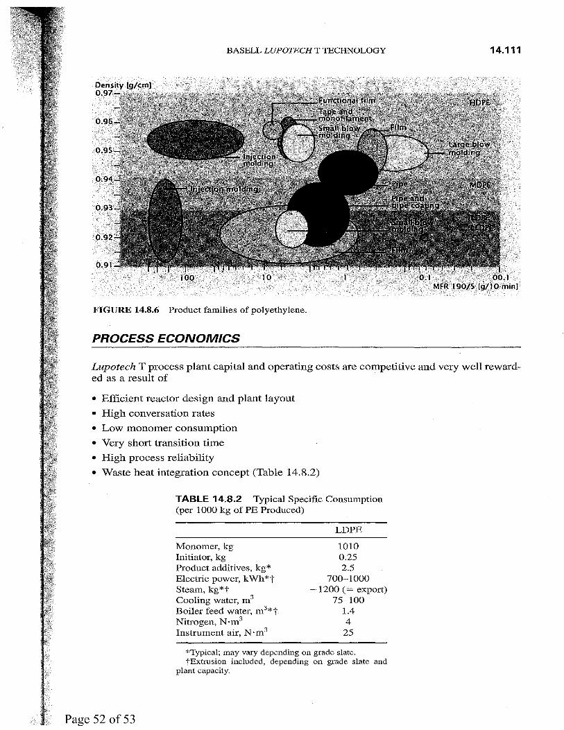
By means of variations in process conditions, a wide range of products can be obtained, ranging from standard LDPE grades to EVA copolymers or N-butylacrylate-modified copolymer. The process has no limitations to the number of reactor grades, and the product mix can be adjusted to match market demand and economical product ranges (Fig. 14.8.6). Reactor grades from MFR 0.15 to 50 and from density 0.917 to 0.934 g/cm3 can be produced. For copolymers, the fraction of comonomer may range from 3 percent up to 28 percent and has the most important influence on the key product parameters, especially rubber-like properties for HEVA grades. Commonly available additives, as used worldwide in the LDPE business, can be easily incorporated directly into the product to yield the final product.
Lupolen LDPE is the trade name for the Basell line of polyethylene low-density resins, which includes homopolymers and copolymers. The range of applications consists of products for film, injection moldings, blow moldings, sheathings for cables and wires and steel pipes, profiles, and sheets. Special features of Lupolen LDPE are the large scope, easy processing, good resistance to environmental stress cracking, well-balanced property combination of good mechanics/opticals/drawdown, and an overall excellent product consistency.
Applications of LOPE
Depending on the kind of application and demanded property mix, the specific Lupolen grade can be selected, including an appropriate additive mix (e.g., slip, antiblock, and stabilizers for specific applications). EVA grades are especially suited for low-temperature applications. Other outstanding properties are enhanced stress crack resistance, flexibility, and transparency.
Film. The wide range of products for both homopolymers and copolymers enables a wide range of film applications, including shrink and heavy-duty packing films, films for laminates, carrier bags, composite and crack films, deep freeze bags, and agricultural films such as mulch and greenhouse films.
Injection Molding and Blow Molding. Both homopolymers and copolymers are used for many standard applications. For parts in the medical and pharmaceutical sector, Lupolen LDPE homopolymers are especially suitable owing to their high purity. The product line matches the technical properties required, namely, flowability, rigidity, and stress cracking resistance. The range of grades includes specialty products for pharmaceutical applications and products with good organoleptic properties.
Pipe Coating. Lupolen grades for coating steel pipes provide effective corrosion protection with a well-balanced property profile, including good long-term properties, excellent processing, high mechanical strength, and good chemical resistance.
Cable and Wire. Lupolen LDPE homopolymers cover the area of cable applications from power cables, insulation for coaxial cables, and telephone cable cores to sheathing material with very high resistance to environmental stress cracking.
BAS ELL LUPOTECH T TECHNOLOGY 14.111
FIGURE 14.8.6 Product families of polyethylene.
PROCESS ECONOMICS
Lupotech T process plant capital and operating costs are competitive and very well rewarded as a result of
• Efficient reactor design and plant layout
• High conversation rates
• Low monomer consumption
• Very short transition time
• High process reliability
• Waste heat integration concept (Table 14.8.2)
TABLE 14.8.2 Typical Specific Consumption (per 1000 kg of PE Produced)
Monomer, kg Initiator, kg Product additives, kg* Electric power, kWh*t Steam, kg*t Cooling water, m 3
Boiler feed water, m 3*t Nitrogen, N·m3
Instrument air, N·m3
LDPE
1010 0.25 2.5
700-1000 -1200 (= export)
75-100 1.4 4
25
*Typical; may vary depending on grade slate. "tExtrusion included, depending on grade slate and
plant capacity.

This unique reference is the only
one-stop source for details on licensed
petrochemical processes for the major
organic chemicals, a $200 billion
annual market. With chapters prepared
by some of the largest petrochemical
and petroleum companies in the world,
Handbook of Petrochemicals
Production Processes provides
in-depth process detail for commercial
evaluation and covers plastics and
polymers such as ethylene and
polyethylene; propylene; ethylbenzene,
styrene, and polystyrenes; vinyl
chloride and polyvinyl chloride; and
many others. This handbook answers
questions on yields, unit operations,
chemical and physical values,
economics, and much more.
Visit us on the World Wide Web at www.bboks.mcgraw-hill.com
-~'~'!'f•'"¥%1ift~','-1'"'18-r-~~·~"' . --~}-~'W-""'"':.'?'"'"'
tli3RAR¥ OF CONGRESS
0 013 567 427 8
ISBN 0-07-141042-2 59999
I I II Ill 9 78007<1 410427