hand-held transceiver tester (hatt) · hand-held transceiver tester (hatt) approved for public...
TRANSCRIPT

Jeffrey Blanco
Jordan Brauer
Daniel Lent
16 October 2013
Hand-held Transceiver Tester
(HATT)
Approved for public release.
This work was sponsored by the Department of the Air Force under Air Force Contract #FA8721-05-C-0002. Opinions, interpretations,
recommendations and conclusions are those of the authors and are not necessarily endorsed by the United States Government.

The HATT - 2
JLB JTB DWL 10/16/13
• Introduction
• System Design
• Approach
• Summary and Future Work
Outline

The HATT - 3
JLB JTB DWL 10/16/13
Moving Target Simulator
• Used to evaluate detection
performance of airborne radar systems

The HATT - 4
JLB JTB DWL 10/16/13
Moving Target Simulator
• Used to evaluate detection
performance of airborne radar systems
• Modulates signal with Doppler offset
to simulate a target moving on the
ground at a constant velocity
• Field Test Outline:
– Months of preparation
– Test runs come at a substantial
amount of cost and time to
sponsor
The HATT - 5
JLB JTB DWL 10/16/13
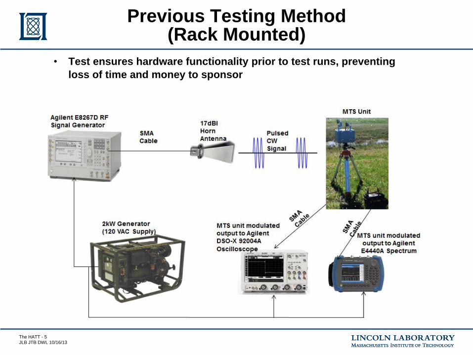
Previous Testing Method (Rack Mounted)
• Test ensures hardware functionality prior to test runs, preventing
loss of time and money to sponsor

The HATT - 6
JLB JTB DWL 10/16/13
Project Definition
200 Hz tone
• Prototype Design Includes:
– Radio Frequency Hardware
– Analog Hardware
– Digital Hardware
Audio Feedback
Visual Feedback
LCD Displays 200 Hz Doppler
Offset & Received Peak Power
from MTS Unit

The HATT - 7
JLB JTB DWL 10/16/13
• Introduction
• System Design
– Design Requirements
– Top Level Block Diagram
• Approach
• Summary and Future Work
• Demo
Outline
The HATT - 8
JLB JTB DWL 10/16/13
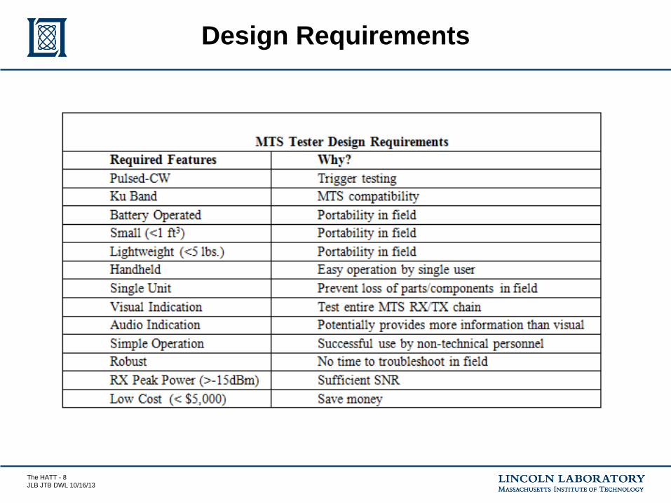
Design Requirements

The HATT - 9
JLB JTB DWL 10/16/13
HATT Block Diagram

The HATT - 10
JLB JTB DWL 10/16/13
• Introduction
• System Design
• Approach
– RF Hardware
– Analog Hardware
– Digital Hardware
– Enclosure
• Summary and Future Work
Outline

The HATT - 11
JLB JTB DWL 10/16/13
RF Hardware

The HATT - 12
JLB JTB DWL 10/16/13
Transmit Chain: Continuous Wave (CW) Tone
• A dielectric resonant oscillator (DRO) was used
– Outputs a CW tone at 16.72 dBm
The HATT - 13
JLB JTB DWL 10/16/13
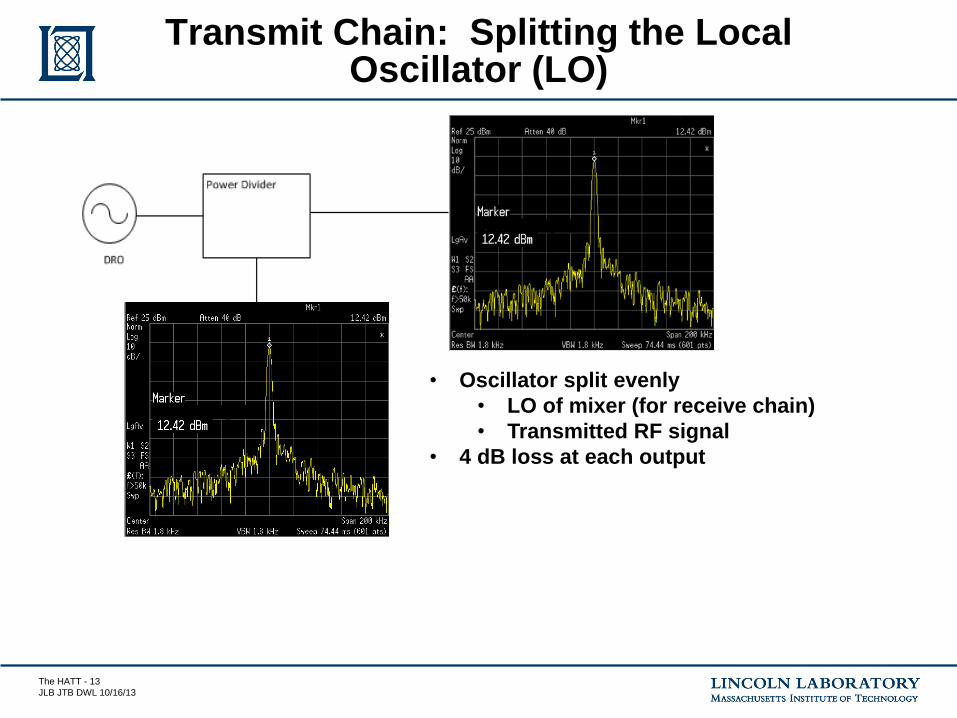
Transmit Chain: Splitting the Local Oscillator (LO)
• Oscillator split evenly
• LO of mixer (for receive chain)
• Transmitted RF signal
• 4 dB loss at each output

The HATT - 14
JLB JTB DWL 10/16/13
Pulsed Continuous Wave
• RF Single Pole Single
Throw (SPST) switch
used to gate oscillator
output
• 250 µs pulse repetition
interval (PRI) and 50 µs
pulse width
The HATT - 15
JLB JTB DWL 10/16/13
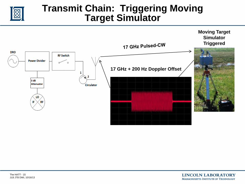
Transmit Chain: Triggering Moving Target Simulator
17 GHz + 200 Hz Doppler Offset
Moving Target
Simulator
Triggered

The HATT - 16
JLB JTB DWL 10/16/13
Receive Chain: Mixer and Schottky Power Detector Diode Output
Mixer Output
Scottky Diode
Output

The HATT - 17
JLB JTB DWL 10/16/13
Analog Hardware

The HATT - 18
JLB JTB DWL 10/16/13
Low Pass Filter Output
• 7 pole Butterworth filter
– Sallen Key topology
• 2 kHz corner frequency
• Attenuates pulse envelope by ~ 36 dB
Input from Mixer Output of LPF: 200 Hz Doppler
Offset Retrieved

The HATT - 19
JLB JTB DWL 10/16/13
Audio and Visual Indication of Doppler Offset
• Frequency-to-voltage converter measures
Doppler offset at IF port
– Voltage proportional to the input signal’s frequency

The HATT - 20
JLB JTB DWL 10/16/13
Visual Indication of Received Peak Power
• Inverting buffer converts negative voltage
output of Schottky diode to a positive
voltage.
– Microprocessor unable to read negative
voltages
Inverting Amplifier Output:
Positive Voltage
Inverting Amplifier Input from
Scottky Diode: Negative
Voltage

The HATT - 21
JLB JTB DWL 10/16/13
Digital Hardware

The HATT - 22
JLB JTB DWL 10/16/13
Signals Sampled into Microprocessor
Frequency to Voltage
Converter Output Inverted Schottky Peak
Detector Diode Output

The HATT - 23
JLB JTB DWL 10/16/13
Digital Subsystem
Microprocessor – Arduino Uno:
• Fully Open Source
• Monitors battery voltage
• Generates PWM signal

The HATT - 24
JLB JTB DWL 10/16/13
HATT Block Diagram

The HATT - 25
JLB JTB DWL 10/16/13
• Designed in Solidworks and fabricated using 3D printer
Enclosure Top View

The HATT - 26
JLB JTB DWL 10/16/13
HATT Interior Component Placement
PCB
Audio
Amplifier
25.9V Lithium-
Ion Battery w/
recharging plug
Arduino
RF Hardware

The HATT - 27
JLB JTB DWL 10/16/13
User Interface
LCD Screen
Volume Knob
¼” Headphone
Jack
Toggle On/Off
Power Switch

The HATT - 28
JLB JTB DWL 10/16/13
HATT Exterior
Handle enables
portable, hand-
held feature
Rexolite window
protects system
against
environmental
conditions

The HATT - 29
JLB JTB DWL 10/16/13
• Introduction
• System Design
• Approach
• Lab Testing
• Summary and Future Work
Outline
The HATT - 30
JLB JTB DWL 10/16/13
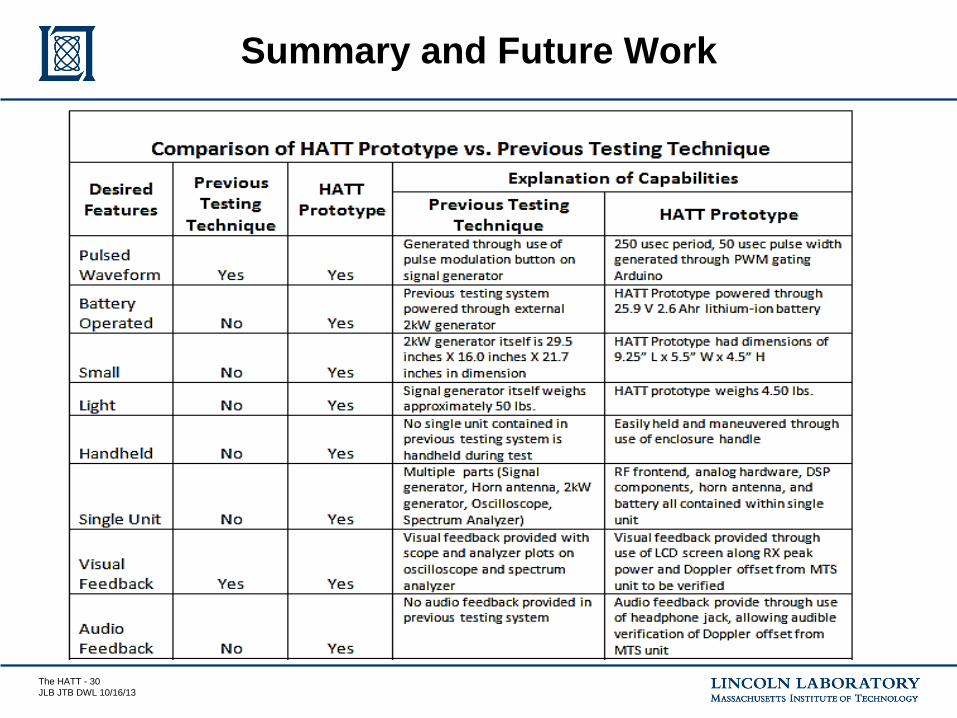
Summary and Future Work

The HATT - 31
JLB JTB DWL 10/16/13
Comparison of HATT Prototype to Previous Testing Technique Continued
The HATT - 32
JLB JTB DWL 10/16/13
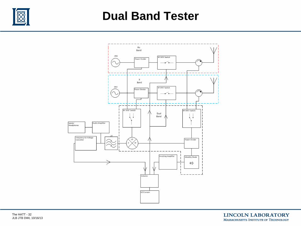
Dual Band Tester