hand gesture recognition with a novel ir time-of-flight ...cg/veroeffentlichungen/breuereckes... ·...
TRANSCRIPT

Hand Gesture Recognition with a novel IRTime-of-Flight Range Camera – A pilot study
Pia Breuer1, Christian Eckes2, and Stefan Muller3
1 Universitat [email protected]
2 Fraunhofer Institute Intelligente Analysis- and Informationsystems [email protected]
3 Universitat [email protected]
Abstract We present a gesture recognition system for recogniz-ing hand movements in near realtime. The system uses a infra-redtime-of-flight range camera with up to 30 Hz framerate to measure3d-surface points captured from the hand of the user. The mea-sured data is transformed into a cloud of 3d-points after depth key-ing and suppression of camera noise by median filtering. Principlecomponent analysis (PCA) is used to obtain a first crude estimateon the location and orientation of the hand. An articulated handmodel is fitted to the data to refine the first estimate. The unop-timized system is able to estimate the first 7 Degrees of Freedomof the hand within 200 ms. The reconstructed hand is visualizedin AVANGO/Performer and can be utilized to implement a natu-ral man-machine interface. The work reviews relevant publications,underlines the advantages and shortcomings of the approach andprovides an outlook on future improvements.
Keywords: gesture recognition, range camera, PCA, segmentation, human com-puter interaction, AVANGO, SGI Performer, computer graphics, computer vi-sion, model based matching
1 Introduction
Human computer interaction (HCI) plays a important role in many applicationstoday. It exists the desire to realize more natural forms of interaction betweenhumans and machines. One of these forms is the interaction via gestures, e.g. byrecognizing natural hand- or full-body movements. Many researchers have fo-cused on measuring the articulation of the whole body neglecting the handposture since full-body posture is in itself already a complex task, even whenproblems due to clothing, self-occlusion and non-rigid tissue can be avoided. Onthe other hand, the human hand has more that 24 degrees-of-freedom in fin-ger/thumb articulation and forms a very difficult problem on its own. Solutionsto both problems have been developed but they violate an important aspect inHCI, which is called “come as you are”. This paradigm is one of the most in-fluential goals in HCI but also the most difficult one to achieve: The intentions
of the human user must be recognized effortlessly and non-invasive, e.g. withoutattaching any special hardware to the human body. Data gloves, suits, inertialtracking devices and optical markers attached to the hand, face or body of thehuman user must be avoided.
Hence, we present in this paper an approach for non-invasive gesture recog-nition in real time. We focus on making the hand and its movements useful forhuman computer interaction. We regard hand gesture recognition as a compo-sition of two separate problems, namely reconstruction and recognition. Recon-struction deals with the problem of inferring the various degrees-of-freedom ofthe hand from sensor data, e.g. by matching and aligning domain knowledge inform of an articulated 3d-model with sensed data. The second step, recognition,classifies the gesture as belonging to an instance stemming from a predefined setof relevant gestures. There exist many well-known methods for classifying time-dependent data stemming from the reconstruction, for instance methods basedon hidden Markov models (HMM) are the most common ones. We consider theproblem of recognition as solved (or at least, as easier) and focus in our studyon the problem of reconstruction, instead.
We decided to investigate the usefulness of the new Swissranger SR2 minia-ture time-of-flight range camera for gesture recognition, as this new hardwareexhibits significant advantages over more traditional type of camera sensors: Itis able to deliver range data in real time, namely with a framerate of 30 Hz with-out the need to solve the correspondence problem, as it is mandatory in depthestimation by means of stereo triangulation. Furthermore no special backgroundor skin color model is required for the segmentation of the hand, so it can beused at many different places. The camera is based on active IR illuminationand is therefore more robust against illumination changes than an optical handlocalization based on skin color would be. However, despite these advantages itremains to be investigated in this study how useful the Swissranger SR2 reallyis for gesture recognition, where its weaknesses and limits are and how theseproblems might be investigated by further studies.
After reviewing some relevant previous work (Sect. 2) this paper presents theworking principle of the range camera (Sect. 3.1). This is followed by explainingin detail how the camera is calibrated (Sect. 3.1). The following sections presentour approach to reduce sensor noise (Sect. 3.1), how the hand can be segmentedfrom the background (Sect. 3.1) and we show how a first estimation of the handpose can be obtained from a PCA (Sect. 3.2). The next sections deal with themodel based fine-matching (Sect. 3.2), present the results (Sect. 4) and concludethis paper with a final discussion. Let us now start with Sect. 2 by looking atsome related work.
2 Previous work
A common method for real-time range-scanning is the use of structured-light.Hall-Holt and Rusinkiewicz [1] use a standard video camera and a DLP projectorto produce range images at 60 Hz. Infra-red structured light pattern togetherwith stereo reconstruction are used by Ypsilos et al. [2].
One of the first who worked with range data for hand gesture recognitionwere Malassiotis et al. [3]: 3D information was acquired following a structuredlight approach with a frame rate of twelve image pairs per second. But they didnot use range data exclusively, since the hand is segmented from the backgroundby means of skin color segmentation. Bray et al. [4] applied a similar methodby using also structured light to generate depth maps in combination with askin color model to eliminate the background. Perrin et al. [5] worked with atarget-oriented laser beam and two mirrors to perform 3D tracking. The authorsdetermine distance measurements by using the absolute value of the reflectedlight but the system cannot be used in real time.
Using IR range data from a time-of-flight camera in gesture recognition isrelatively new. One of the few authors following this approach are Liu and Fu-jimura [6]. Their system works in real-time, but it uses the range data only forsegmentation to cut out the region nearest to the camera. The model parametersare estimated by doing shape comparisons on basis of 2D images.
Our work is also motivated by the project “Virtual Cyberglove” of the Com-puter Graphics Group of the University of Bonn (cp. [7] and [8]). This projectaims at estimating global position and all degrees of freedom of a hand (e.g. ofthe back of the hand) by using multiple video cameras.
A careful selection of the hand model is also relevant for efficient hand gesturerecognition. We use the model developed by [9] which aims at achieving ananatomically correct reconstruction and animation of human hand.
3 Gesture recognition with the Swissranger SR2
3.1 The Swissranger ToF camera
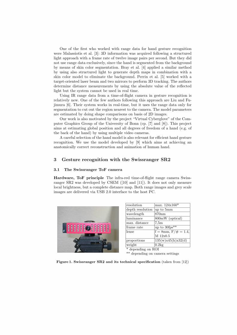
Hardware, ToF principle The infra-red time-of-flight range camera Swiss-ranger SR2 was developed by CSEM ([10] and [11]). It does not only measurelocal brightness, but a complete distance map. Both range images and grey scaleimages are delivered via USB 2.0 interface to the host PC.
resolution max. 124x160*depth resolution up to 5mmwavelength 870nmluminance 800mW (optical)max. distance 7,5mframe rate up to 30fps**lense f = 8mm, F/# = 1.4,
M 12x0.5proportions 135(w)x45(h)x32(d)weight 0.2kg* depending on ROI** depending on camera settings
Figure 1. Swissranger SR2 and its technical specification (taken from [12])

The emitter sends out a radio-frequency modulated light field, which is re-flected by the scene and sensed by the camera. The distances between the cameraand the scene objects are computed by using the time-of-flight principle, e.g. bymeasuring the time the light needs for reaching the objects and becoming re-flected back to the sensor of the camera.
TOF =2D
cwith speed of light c = 3 · 108m/s
Instead of emitting impulses, the SR2 sends out continuously modulated lightwaves with a modulation frequency of 20 MHz. Demodulation is done by sam-pling. The incoming signal gets sampled four times per period (each sampleshifted by 90◦), whereby the signal can be clearly reconstructed. Every samplingcorresponds to an integration of the photo generated electrons over the relevantpart of the period. To reduce the signal-to-noise rate the integration values aresummed up over many periods. So not the time is measured but the phase shift-ing between emitted and detected wave. The ambiguity distance is 7.5m, beforea phase shift of 2π is reached.
Hence, the distance is computed according to
D = L · ϕ
2 · πwith L =
c
2 · fm
ϕ = arctan(
c(τ3)−c(τ1)c(τ0)−c(τ2)
)phase shift
L: unambiguous distance rangec: speed of lightfm: (radiofrequency) RF modulation frequency
This algorithm is called four buckets or four steps method because of sam-pling four times each period. More detailed information about the camera canbe found in [13] and [14].
Calibation A comprehensive calibration turned out to be very difficult (cp.[15] and [16]). Gut [17] even talks about the necessity of multiple calibration.We decided to do it as follows: To analyze the output of the camera, we madea experimental setup composed of a container with fixed wheels and two booksplaced at different distances. We established a z value of 8000 from the cameracorresponding to a range of 1000mm.
To convert the pixel values (u,v) to a position in the real world dependingon the range, we use the following formula:
x ≡
xyz
=
uv0
+
−u−vf
· d√u2 + v2 + f2
(1)
(x y z)T : 3D coordinates(u v)T : camera coordinatesf : focal lengthd: measured range
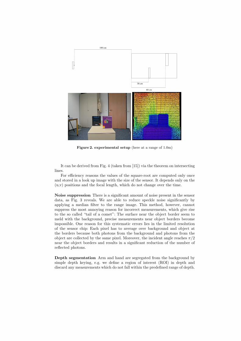
60 cm
100 cm
30 cm
Figure 2. experimental setup (here at a range of 1.0m)
It can be derived from Fig. 4 (taken from [15]) via the theorem on intersectinglines.
For efficiency reasons the values of the square-root are computed only onceand stored in a look up image with the size of the sensor. It depends only on the(u,v) positions and the focal length, which do not change over the time.
Noise suppression There is a significant amount of noise present in the sensordata, as Fig. 3 reveals. We are able to reduce speckle noise significantly byapplying a median filter to the range image. This method, however, cannotsuppress the most annoying reason for incorrect measurements, which give riseto the so called “tail of a comet”: The surface near the object border seem tomeld with the background, precise measurements near object borders becomeimpossible. One reason for this systematic errors lies in the limited resolutionof the sensor chip: Each pixel has to average over background and object atthe borders because both photons from the background and photons from theobject are collected by the same pixel. Moreover, the incident angle reaches π/2near the object borders and results in a significant reduction of the number ofreflected photons.
Depth segmentation Arm and hand are segregated from the background bysimple depth keying, e.g. we define a region of interest (ROI) in depth anddiscard any measurements which do not fall within the predefined range of depth.

Figure 3. visualization of the measured data (here at a range of 1.0m): represen-tation with SR2-Tool (left) with MatLab (right)
Figure 4. model to determine the coordinates [15]
The depth range defines also a working point for our recognition system asit marks the optimal trade off between two conflicting properties: The handshould cover as much area of the camera sensor as possible, but any overexposuremust be avoided. Overexposure results in serious errors as it impairs the depthmeasurements of the complete scene significantly. The last image in Fig. 5 showsthe effect: The background in the lower area seems to be nearer to the cameracompared to the initial state (image at the upper middle), but has in fact notmoved at all. Due to this effect, there exist an optimal distance between handand camera for which the depth measurements works best. For these purposes wescrutinized the correlation between distance, sensor coverage and overexposureand analyzed measurements of a hand at different distances. Fig. 5 shows aselection of the results.
Overexposure can also be reduced by decreasing the integration time. Weuse a depth range between 0.5m and 1.0m, which correspond to z-values of thecamera between 4000 and 8000. We solve the segmentation problem by perform-ing connected component analysis and selecting the largest remaining connectedsub-segment as input to the reconstruction methods.
3.2 Measuring hand geometry
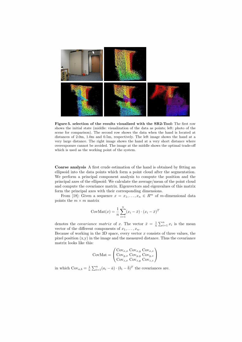
Figure 5. selection of the results visualized with the SR2-Tool: The first rowshows the initial state (middle: visualization of the data as points; left: photo of thescene for comparison). The second row shows the data when the hand is located atdistances of 2.0m, 1.0m and 0.5m, respectively. The left image shows the hand at avery large distance. The right image shows the hand at a very short distance whereoverexposure cannot be avoided. The image at the middle shows the optimal trade-offwhich is used as the working point of the system.
Coarse analysis A first crude estimation of the hand is obtained by fitting anellipsoid into the data points which form a point cloud after the segmentation.We perform a principal component analysis to compute the position and theprincipal axes of the ellipsoid: We calculate the average/mean of the point cloudand compute the covariance matrix. Eigenvectors and eigenvalues of this matrixform the principal axes with their corresponding dimensions.
From [18]: Given a sequence x = x1, . . . , xn ∈ Rm of m-dimensional datapoints the m×m matrix
CovMat(x) =1n
n∑i=1
(xi − x) · (xi − x)T
denotes the covariance matrix of x. The vector x = 1n
∑ni=1 xi is the mean
vector of the different components of x1, . . . , xn.Because of working in the 3D space, every vector x consists of three values, thepixel position (x,y) in the image and the measured distance. Thus the covariancematrix looks like this:
CovMat =
Covx,x Covx,y Covx,z
Covy,x Covy,y Covy,z
Covz,x Covz,y Covz,z
in which Cova,b = 1
n
∑ni=1(ai − a) · (bi − b)T the covariances are.

Figure 6. point cloud with principal axes
Figure 6 shows the point cloud with its principal axes visualized in AVANGO/Performer. The processing performed so far can already be used for a simple andcrude gesture interface: By tracking the center of mass of the human hand cloud,the user might control a pointer or an object on the screen in which the principalaxes can also provide the direction. Think about playing darts: The center ofmass should mark the position to drop and the largest of the principles axismarks the direction the dart is thrown away.
Fine matching The center of mass and the principal axes of the point cloudprovide a good estimate for fitting an articulated hand model to the point cloud,as the visualization of the results have revealed. The aim of this first fine match-ing is to determine translation, rotation and scaling of the model accordingly. Askeleton of three dimensional hand model should be placed into the point cloudso that the distance of the surface points to the measured data is minimized.For these purposes we used a three dimensional hand model. It consists of 1,515vertices and 3,000 triangles and corresponds to a human hand with anatomicalstructure. It was build for real time animation using a physically based musclesimulation and elastic skin attributes. Mrs. Irene Albrecht [9] made it availableto us for this work. In our work we do not use the muscle model, we use onlythe triangle mesh and the vertices respectively.
The next step in our gesture recognition systems is the fitting process whichaims at minimizing the distance between model and point cloud based on the sumof point-to-point distances. In this case, the Hausdorff distance may be used asa metric. On the other hand, metrics based on pure pairwise distances betweenpoint clouds do not take benefit from the more explicit surface properties ofthe hand model since it “only” tries to position the point clouds together asnear as possible (similar to ICP registration). Alternatively, one might comparethe surfaces/visual hulls between model and reconstructed surface patches byminimizing the volumne between surface patches directly since the model alsoconsist of a triangle mesh.
More formally, the model must be placed at a good starting position insideof the point cloud to provide an adequate starting point for registration. Thuswe look at the solution of the correspondence problem, e.g. matching the modeldata to the sensor data. The correspondences are needed to be able to compute
the absolute distances between model points and point cloud the algorithm triesto minimize. We define the following cost function for the sum of minimal squaredistances, in which we first aim at parameterization of the first 7 DoFs:
K(α, t) :=∑
<i,j>
[[x
(P )i (t)− x
(M)j (α)
]2
Mij
]
α = (tx, ty, tz, φx, φy, φz, s): vector including the possible DoFs (three for trans-lation, three for rotation and one for scaling).x
(P )i (t): ith point of the point cloud at time t
x(M)j (α): jth model point after executing all of the transformations in α
Mij ∈ {0, 1}: this matrix represents the correspondences between 3D point iand model vertex j; is there found a 3D point i being nearest to the consideredmodel point j, the matrix gets the value 1 at the position ij; the pairs with thesmallest distances are defined by these correspondences.
The system aims at finding a minimum of this cost function depending on theparameters α. However, one problem complicates the minimization procedure,the self-occlusion of the model: not all points of the model are visible for thecamera: A point of a model is regarded as visible if it is not placed outside thefield of view and the normal of the corresponding triangle does not point awayfrom the camera. Hence, the articulation must discard (self)-occluded surfacepoints automatically. The PCA deliveres the rough position of the point cloud,which correspond as the rough position of the skeleton. First the skeleton ismoved to the measured center of mass (global translation) and rotated to becomealigned to the second principal axis. By calculating the ”length” of the objectwithin the field of view (expansion of the point cloud along the second principalaxis) using the bounding box, the model can be moved along this axis (theforearm) accordingly, so that the finger tips are at the border of the point cloud.Finally the model has to be scaled because of the perspective distortion anddistance from the camera sensor.
So we pursued an iterative approach during optimization: With every itera-tion the scaling factor of the model gets heightened or lowered by 0.1 until nomore scaling causes decreasing of the point distances, i.e. the cost function getsminimized. Visibility of each point is classified using the above mentioned criteriaat each iteration step – only visible model points contribute to the cost function.On the other hand, the less vertices are visible, the less are used in the cost func-tion and may cause a lower sum of square distances. To make the cost functioninvariant to the total number of vertices, we normalize all distances by dividingthe cost by the number of visible point pairs. However, as the estimation of theDoF must be statistically significant, we use an some additional constrains: Ifless than one third of the model points are visible the reconstruction is stopped,as we must avoid situations in which an incorrectly upscaled hand model withminimal visible points still fits a part of the point cloud, since only a part of thehand model matches with the sensor data.

Figure 7. work flow upper left: moved to the center of mass; upper right: rotated onthe second principal axis; lower left: moved into the point cloud; lower right: scaled
Figure 8. image sequence 1 (frontal view): shows a small movement downward

4 Results
Figure 9. image sequence 1 (side view): shows the same movement as Fig. 8 fromanother perspective
Figs. 8 and 9 document a felicitous recognition. The hand model is well fittedinto the point cloud and follows it as the frontal and side view demonstrate. Fig.10 shows an more problematic recognition: the algorithm has difficulty in de-tecting the hand moving into the scene. The entry orientation has been detectedwrong in image 1. Image 2 shows how the algorithm tries to fit the model intothe small point cloud. The usage of the median distance had not the intendedeffect, as also image 9 and 11 reveal. Moreover, the scaling is also incorrect. Theremaining images show how the model is fitted into the point cloud correctly.
We achieved a recognition of seven DoFs within a frame rate of 2-3fps, usinga 3.00GHz Intel Pentium 4 with 2GByte RAM. However, the algorithms notbeing optimized for speed and efficiency. One of the main objectives of thispaper was to investigate gesture recognition with the new special hardware, theSwissranger SR2, and to summarize the advantages and disadvantages of suchan approach.
The primary advantage of the special hardware is to be able to receive imageswith the depth information of the scene with considerable high frame rates.Furthermore there is no special background necessary. Worst-case problems invideo-based segmentation, e.g. ”blue pullover in front of a blue wall” or ”a handin front of a skin colored background” loose their horror. On the other hand, ifthere is a lot of sun/light the range camera gets interfered. One can observe twofundamental effects: On the one hand the intensive background light generatesa lot of additional electrons which causes higher photon shot noise. Thereby itinfluences the preciseness of the measurement negatively. And on the other hand

Figure 10. image sequence 2: shows the incoming of the hand into the field of viewand the following movement downwards
the electrons generated by the background light over-saturate the pixel sensorand thereby completely overload their capacity.
Despite these rather technical advantages and shortcomings due the specialhards, the correspondences search remains a considerable difficult problem forwhich efficient and robust methods are rare. Two problems have also be kept inmind:
1. visibility and occlusion: The problem of self-occlusion has to be considered,since the range camera delivers 2 1
2D data (by sampling surface points fromthe cameras point of view) but the model and the objects are an real 3-dimensional objects. Moreover, the objects may only be partly visible due tothe limited frustrum volume and the depth segmentation. On this accountthese points become extraneous to the ”marriage” of the model with thepoint cloud because the camera also does only see the front of the scene(quasi 2 1
2D). Only a correct classification as invisible points may help whichcan only be performed after correct registration – an classical “chicken andegg problem”, which we have tried to solve by using iterations.
2. tail of a comet: The “tail of a comet” produces many problematic 3D-pointswhich cannot be matched correctly with any model. We have circumventedthe problem by using some ad-hoc constraints - first principal axis points to

the depth, second axis specifies the direction of the forearm and the thirdaxis determines the ”thickness” of the arm - to minimize its influence onthe recognition. However, it is our believe that a more careful analysis willreplace our constrains in the future.
Last but not least, it is important to use a good model. The model currentlyused is qualified because of its anatomical structure and its real time capability.It can be animated and fitted into the point cloud.
5 Conclusion and Outlook5.1 ConclusionWe have described a pilot study of doing hand gesture recognition with a novelIR time-of-flight range camera. After calibration and noise reduction to get use-ful measured data we defined a region of interest and interpreted the remainingdata as a point cloud. This approach gave us the opportunity to do a principalcomponent analysis on it, which returned the principal axes of the point cloudbeing a clue for the precise positioning of the model. Visualization of the inter-mediate results showed how good PCA works on the measured data, i.e. howgood the clue is. After showing some already possible ways for human-computerinteraction we continued with the fine matching. A realistic 3D hand model wasfitted into the point cloud. The correspondence problem and classification ofvisibility have been analyzed and were solved in an iterated algorithm aiming atminimizing a cost function based on point-to-point distances. Finally we identi-fied global translation, rotation and scaling to fit the model into the data at thebest possible rate. The system was able to recognize 7DoFs of a human handwith 2-3 Hz framerate. This is a promising result and defines a road map forfurther research in the future.
5.2 OutlookCurrent work aims at improving the robustness of the system against out-linersby registering the model to the sensor point clouds with more robust algorithms,such as Random Sample Consensus (RANSAC). The introduction of a trackingmode, e.g. by adding a particle filter to the system might significantly decreasethe processing time. The fast tracking mode might refine the hand model ina highly reduced search space and should support significant higher framerate.Another promising field of research lies in exploiting the currently discarded IRintensity measurements. Moreover, data stemming from additional calibratedhigh-resolution video cameras may further increase the precision of the recon-structed hand parameters. Image processing algorithms and sensor fusion meth-ods may combine the depth, IR and sensor data from the visible acquisitionhardware in a consistent manner.
Last but not least, the new model of the 3D-camera, the Swissranger 3000,has recently been made available by CSEM. The new hardware supports to setthe integration time for each pixel individually. Hence, smaller distances betweencamera and the human hand without over-saturation of the photo integratorsbecome feasible and may result in an increased sample density. Thereby, moredetail of the hand becomes visible and might also increase the number of recog-nizable DoF significantly.

6 Acknowedgement
This work was funded by the German research project “Virtual Human” underthe grand 01IMB01.
References
1. Hall-Holt, O., Rusinkiewicz, S.: Stripe boundary codes for real-time structured-light range scanning of moving objects. In: Eighth International Conference onComputer Vision (ICCV). (2001)
2. Ypsilos, I.A., Hilton, A., Rowe, S.: Video-rate capture of dynamic face shape andappearance. fgr (2004) 117
3. Malassiotis, S., Tsalakanidou, F., Mavridis, N., Giagourta, V., Grammalidis, N.,Strintzis, M.G.: A face and gesture recognition system based on an active stereosensor. In: Proceedings 2001 ICIP, Thessaloniki, Greece, 7-10 Oct. 2001, vol.3.(2001) 955–8
4. Bray, M., Koller-Meier, E., van Gool, L.: Smart particle filtering for 3d handtracking. In: Proceedings. FGR2004, Seoul, South Korea, 17-19 May 2004. (2004)675–80
5. Perrin, S., Cassinelli, A., Ishikawa, M.: Gesture recognition using laser-based track-ing system. In: Proceedings. FGR2004, Seoul, South Korea, 17-19 May 2004, IEEEComput. Soc (2004) 541–6
6. Liu, X., Fujimura, K.: Hand gesture recognition using depth data. In: Proceedings.FGR2004, Seoul, South Korea, 17-19 May 2004, IEEE Comput. Soc (2004) 529–34
7. : computer graphik, universitat bonn. http://cg.cs.uni-bonn.de/ (2005)8. Bendels, G.H., Kahlesz, F., Klein, R.: Towards the next generation of 3d content
creation. In: Proceedings. AVI ’04. (2004) 283–899. Albrecht, I., Haber, J., Seidel, H.P.: Construction and animation of anatomically
based human hand models. In: SCA ’03: Proceedings of the 2003 ACM SIG-GRAPH/Eurographics Symposium on Computer animation. (2003) 98–109
10. : Swiss center for electronics and microtechnology. www.csem.ch/ (2005)11. : Swissranger sr-2 miniature time of flight camera. www.swissranger.ch/ (2005)12. CSEM: Swiss ranger sr-2 datasheet. www.swissranger.ch/ pdf/SR-2 DataSheet.pdf
(2005)13. Oggier, T., Michael Lehmann, Rolf Kaufmann, M.S., Richter, M., Metzler, P.,
Lang, G., Lustenberger, F., Blanc, N.: An all-solid-state optical range camera for3d real-time imaging with sub-centimeter depth resolution (swissranger). In: SPIE,conference on optical system design, St. Etienne, September 2003. (2003)
14. Oggier, T., Buttgen, B., Lustenberger, F., Becker, G., Ruegg, B., Hodac, A.: Swis-sranger sr3000 and first experiences based on miniaturized 3d-tof cameras. In: Pro-ceedings, 1st Range Imaging Research Day, September 8/9, 2005 at ETH ZurichSwitzerland. (2005) 97–108
15. Kahlmann, T., Ingensand, H.: Calibration and improvements of the high-resolutionrange-imaging camera swissranger. In: Proceedings of SPIE Vol. 5665; Videomet-rics VIII; 16-20 January 2005, San Jose, California, USA. (2005)
16. Kahlmann, T., Ingensand, H.: Range imaging sensor properties and calibration.In: Proceedings, 1st Range Imaging Research Day, September 8/9, 2005 at ETHZurich Switzerland. (2005) 71–80
17. Gut, O.: Untersuchungen des 3d-sensors swissranger. Master’s thesis, ETH Zurich(2004)
18. Dreiseitl, S.: Skriptum zu mat3 ws2004/05 (2005)