hamrock, jacobson and schmid©1998 mcgraw-hill chapter 18: flexible machine elements scientists...
TRANSCRIPT
Hamrock, Jacobson and Schmid©1998 McGraw-Hill
Chapter 18: Flexible Machine Elements
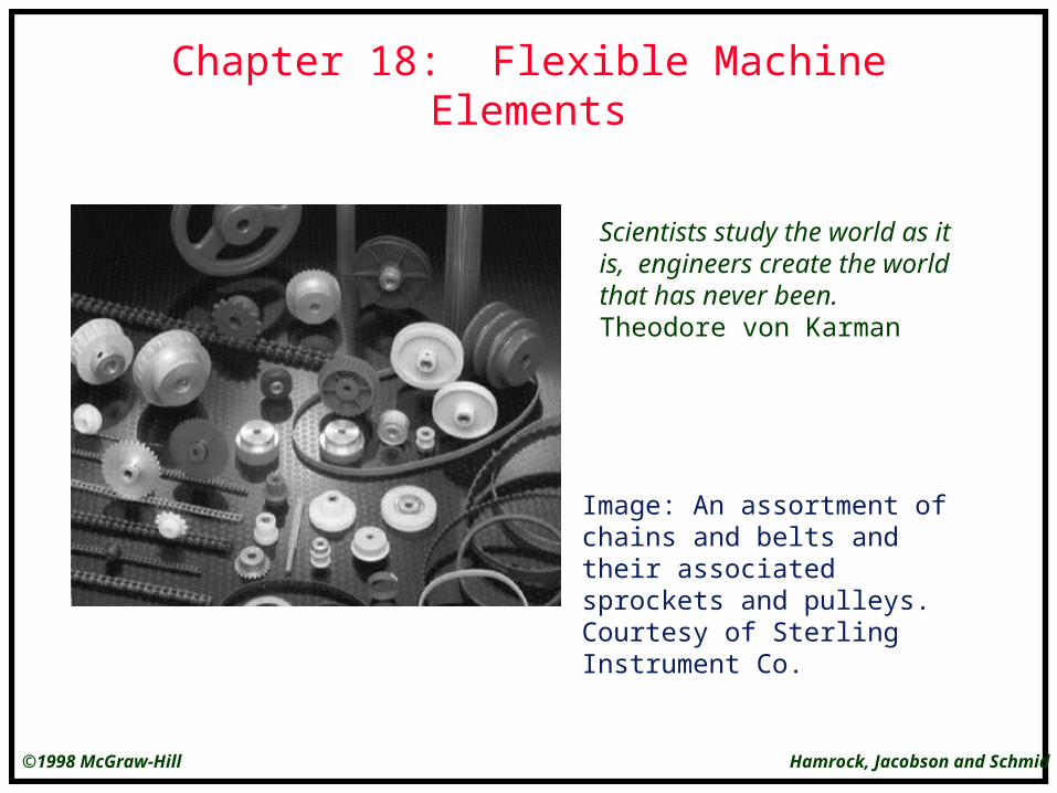
Scientists study the world as it is, engineers create the world that has never been.Theodore von Karman
Image: An assortment of chains and belts and their associated sprockets and pulleys. Courtesy of Sterling Instrument Co.

Hamrock, Jacobson and Schmid©1998 McGraw-Hill
Open Flat Belt
Figure 18.1 Dimensions, angles of contact, and center distance of open flat belt.
Text Reference: Figure 18.1, page 828
Hamrock, Jacobson and Schmid©1998 McGraw-Hill
Weighted Idler
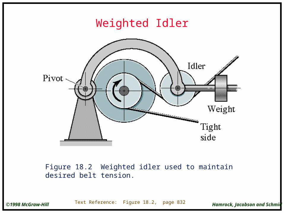
Figure 18.2 Weighted idler used to maintain desired belt tension.
Text Reference: Figure 18.2, page 832

Hamrock, Jacobson and Schmid©1998 McGraw-Hill
Timing Belt
Text Reference: Figure 18.3, page 832
Figure 18.3 Synchronous, or timing, belt.
Hamrock, Jacobson and Schmid©1998 McGraw-Hill
V-Belt in Sheave Groove
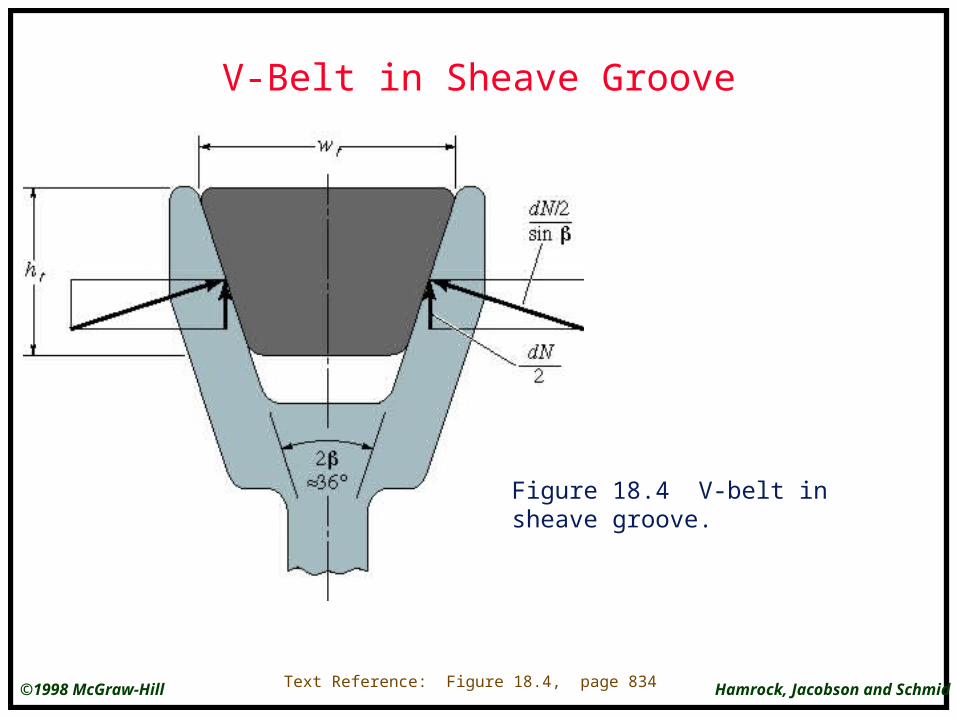
Figure 18.4 V-belt in sheave groove.
Text Reference: Figure 18.4, page 834
Hamrock, Jacobson and Schmid©1998 McGraw-Hill
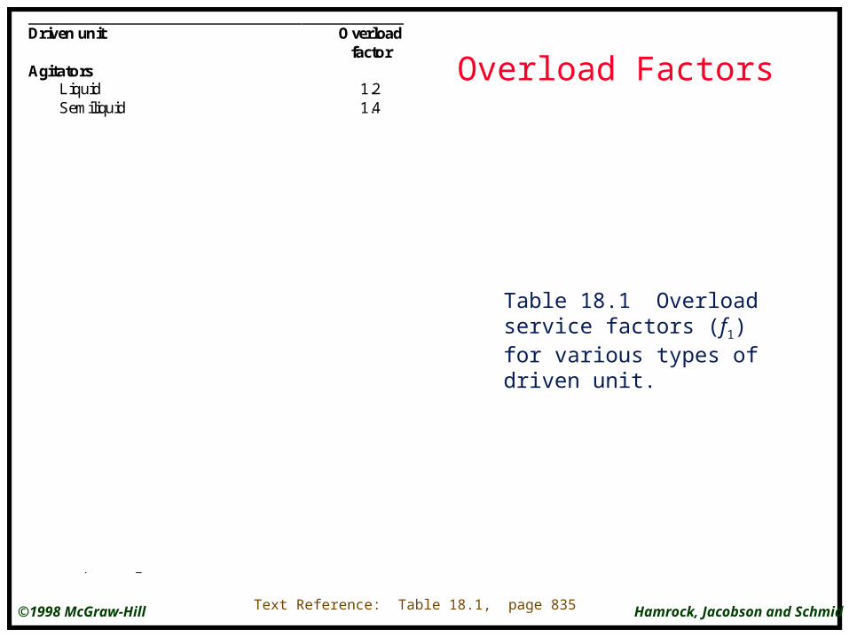
Overload FactorsDriven unit Overload
factorAgitators
LiquidSemiliquid
1.21.4
CompressorCentrifugalReciprocating
1.21.4
Conveyors and elevatorsPackage, ovenBelt
1.21.4
Fans and blowersCentrifugal, calculatingExhausters
1.21.4
Food machinersSlicersGrinders and mixers
1.21.4
GeneratorsFarm lighting and exciters 1.2
Heating and ventilatingFans and oil burnersStokers
1.22.4
Laundry machineryDryers and ironersWashers
1.21.4
Machine toolsHome workshop and woodworking 1.4
PumpsCentrifugalRecprocating
1.21.4
Table 18.1 Overload service factors (f1) for various types of driven unit.
Text Reference: Table 18.1, page 835
Hamrock, Jacobson and Schmid©1998 McGraw-Hill
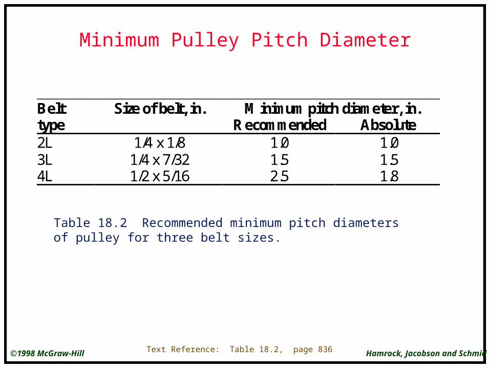
Minimum Pulley Pitch Diameter
Table 18.2 Recommended minimum pitch diameters of pulley for three belt sizes.
Text Reference: Table 18.2, page 836
Belt Size of belt, in. Minimum pitch diameter, in.type Recommended Absolute2L3L4L
1/4 x 1/81/4 x 7/321/2 x 5/16
1.01.52.5
1.01.51.8

Hamrock, Jacobson and Schmid©1998 McGraw-Hill
Recommended Pulley Diameter
Text Reference: Table 18.3, page 836
Table 18.3 Recommended pulley diameters in inches for three electric motor sizes.
Motor speed, rpmMotor 575 695 870 1160 1750horsepower, hp Recommended pulley diameter, in.
0.500.751.00
2.503.003.00
2.502.503.00
2.502.502.50
-2.502.50
--
2.25
Hamrock, Jacobson and Schmid©1998 McGraw-Hill
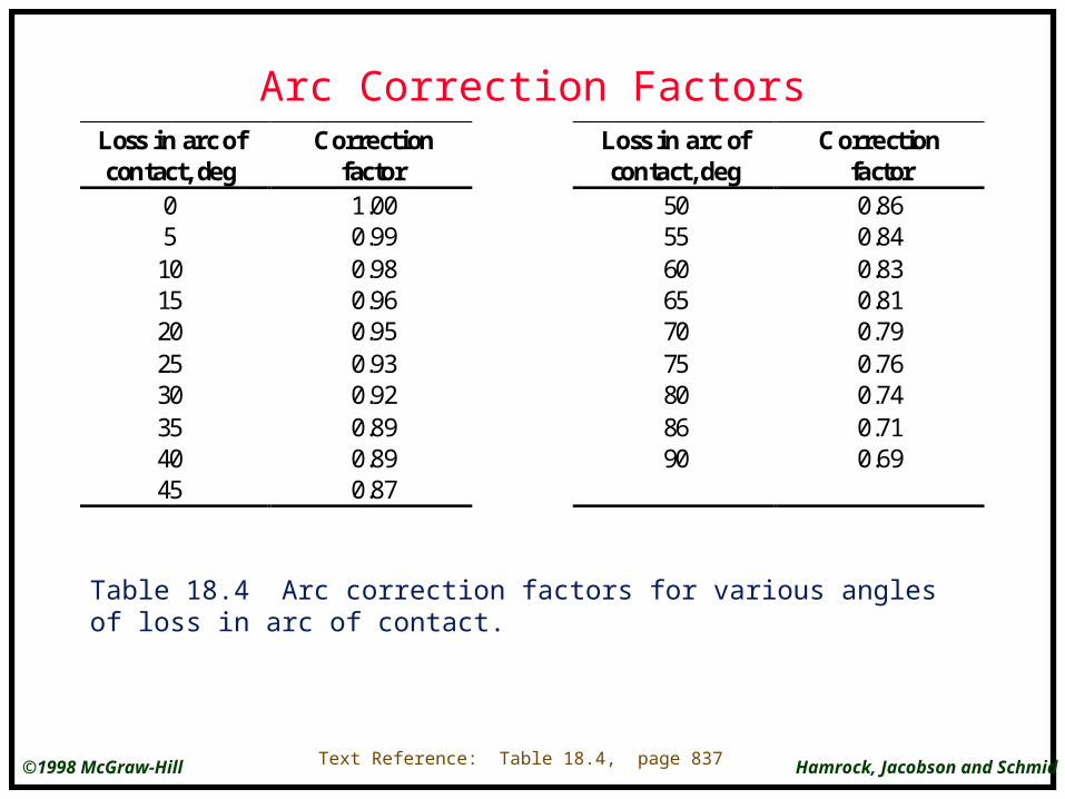
Arc Correction FactorsLoss in arc ofcontact, deg
Correctionfactor
Loss in arc ofcontact, deg
Correctionfactor
051015202530354045
1.000.990.980.960.950.930.920.890.890.87
505560657075808690
0.860.840.830.810.790.760.740.710.69
Table 18.4 Arc correction factors for various angles of loss in arc of contact.
Text Reference: Table 18.4, page 837
Hamrock, Jacobson and Schmid©1998 McGraw-Hill
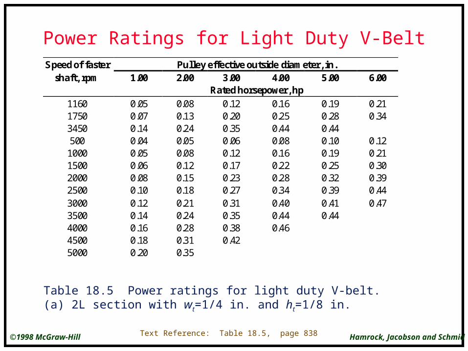
Power Ratings for Light Duty V-BeltSpeed of faster Pulley effective outside diameter, in.
shaft, rpm 1.00 2.00 3.00 4.00 5.00 6.00Rated horsepower, hp
116017503450500
100015002000250030003500400045005000
0.050.070.140.040.050.060.080.100.120.140.160.180.20
0.080.130.240.050.080.120.150.180.210.240.280.310.35
0.120.200.350.060.120.170.230.270.310.350.380.42
0.160.250.440.080.160.220.280.340.400.440.46
0.190.280.440.100.190.250.320.390.410.44
0.210.34
0.120.210.300.390.440.47
Table 18.5 Power ratings for light duty V-belt. (a) 2L section with wt=1/4 in. and ht=1/8 in.
Text Reference: Table 18.5, page 838

Hamrock, Jacobson and Schmid©1998 McGraw-Hill
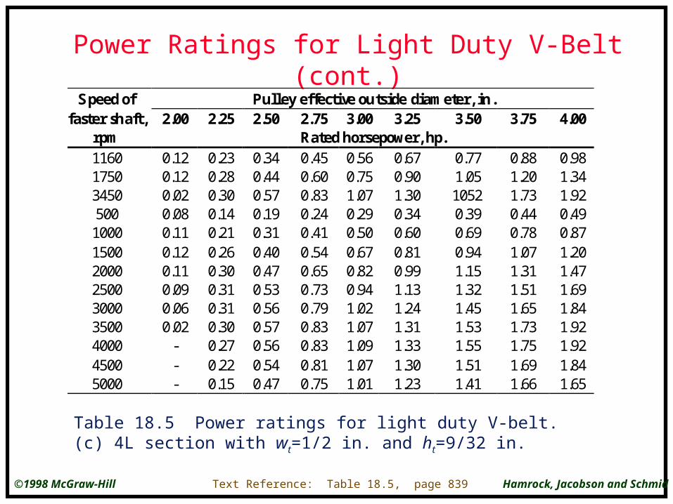
Power Ratings for Light Duty V-Belt (cont.)
Table 18.5 Power ratings for light duty V-belt. (b) 3L section with wt=3/8 in. and ht=1/4 in.
Text Reference: Table 18.5, page 838
S peed of Pul ley effective outside diameter, in.
faster shaft, 1.50 1.75 2.00 2.25 2.50 2.75 3.00rpm Rated horsepower, hp116017503450500
100015002000250030003500400045005000
0.070.090.110.040.070.090.100.110.110.110.110.100.09
0.130.170.250.070.120.150.190.210.230.250.260.250.26
0.180.250.380.090.160.220.270.310.350.380.400.420.42
0.230.320.500.120.210.290.350.410.450.500.540.560.57
0.280.390.620.140.250.350.430.510.570.620.660.680.69
0.340.460.730.170.300.410.510.600.680.740.780.800.80
0.390.540.830.190.340.470.590.690.780.840.880.900.89
Hamrock, Jacobson and Schmid©1998 McGraw-Hill
Power Ratings for Light Duty V-Belt (cont.)
Table 18.5 Power ratings for light duty V-belt. (c) 4L section with wt=1/2 in. and ht=9/32 in.
Text Reference: Table 18.5, page 839
S peed of Pulley effective outside diameter, in.faster shaft, 2.00 2.25 2.50 2.75 3.00 3.25 3.50 3.75 4.00
rpm Rated horsepower, hp.116017503450500
100015002000250030003500400045005000
0.120.120.020.080.110.120.110.090.060.02
---
0.230.280.300.140.210.260.300.310.310.300.270.220.15
0.340.440.570.190.310.400.470.530.560.570.560.540.47
0.450.600.830.240.410.540.650.730.790.830.830.810.75
0.560.751.070.290.500.670.820.941.021.071.091.071.01
0.670.901.300.340.600.810.991.131.241.311.331.301.23
0.771.0510520.390.690.941.151.321.451.531.551.511.41
0.881.201.730.440.781.071.311.511.651.731.751.691.66
0.981.341.920.490.871.201.471.691.841.921.921.841.65

Hamrock, Jacobson and Schmid©1998 McGraw-Hill
Center DistancesPulley combination Normal center distance
Driver pitch Driver pitch Short center Medium center
diameter, in. diameter, in. Beltnumber
Centerdistance,
in.
Beltnumber
Centerdistance,
in.2.03.02.02.03.02.02.02.252.53.02.02.03.02.02.02.0.1.5
2.03.02.53.04.53.54.04.55.06.05.06.09.07.09.010.09.0
3L2003L2503L2103L2203L2903L2403L2503L2703L2903L3303L2503L3103L4103L3403L3903L4203L390
6.47.46.66.78.27.37.27.78.18.98.08.610.39.29.910.410.1
3L2503L3103L2703L2803L3503L3003L3103L3303L3503L3903L3403L3703L4703L4003L4503L4803L450
9.410.49.69.711.210.310.310.711.111.911.011.613.412.213.013.613.3
Table 18.6 Center distances for various pitch diameters of driver and driven pulleys. (a) 3L type of V-belt.
Text Reference: Table 18.6, page 839
Hamrock, Jacobson and Schmid©1998 McGraw-Hill
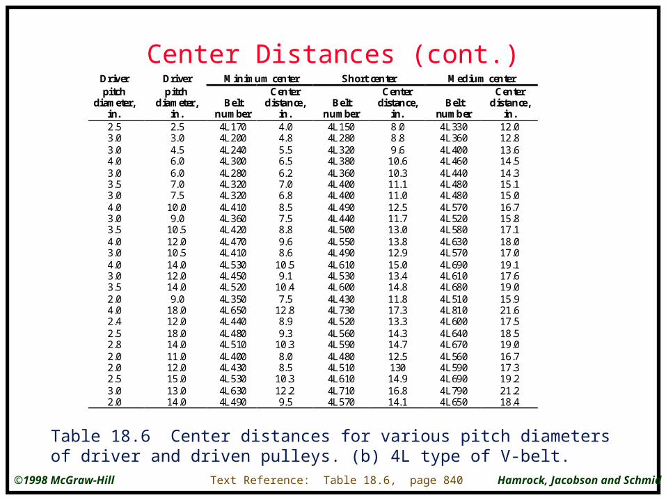
Center Distances (cont.)
Table 18.6 Center distances for various pitch diameters of driver and driven pulleys. (b) 4L type of V-belt.
Text Reference: Table 18.6, page 840
Driver Driver Minimum center Short center Medium centerpitch
diameter,in.
pitchdiameter,
in.Belt
number
Centerdistance,
in.Belt
number
Centerdistance,
in.Belt
number
Centerdistance,
in.2.53.03.04.03.03.53.04.03.03.54.03.04.03.03.52.04.02.42.52.82.02.02.53.02.0
2.53.04.56.06.07.07.5
10.09.0
10.512.010.514.012.014.09.0
18.012.018.014.011.012.015.013.014.0
4L1704L2004L2404L3004L2804L3204L3204L4104L3604L4204L4704L4104L5304L4504L5204L3504L6504L4404L4804L5104L4004L4304L5304L6304L490
4.04.85.56.56.27.06.88.57.58.89.68.6
10.59.1
10.47.5
12.88.99.3
10.38.08.5
10.312.29.5
4L1504L2804L3204L3804L3604L4004L4004L4904L4404L5004L5504L4904L6104L5304L6004L4304L7304L5204L5604L5904L4804L5104L6104L7104L570
8.08.89.6
10.610.311.111.012.511.713.013.812.915.013.414.811.817.313.314.314.712.513014.916.814.1
4L3304L3604L4004L4604L4404L4804L4804L5704L5204L5804L6304L5704L6904L6104L6804L5104L8104L6004L6404L6704L5604L5904L6904L7904L650
12.012.813.614.514.315.115.016.715.817.118.017.019.117.619.015.921.617.518.519.016.717.319.221.218.4

Hamrock, Jacobson and Schmid©1998 McGraw-Hill
Wire Rope
Figure 18.5 Cross section of wire rope.
Text Reference: Figure 18.5, page 841

Hamrock, Jacobson and Schmid©1998 McGraw-Hill
Rope Lay
Figure 18.6 Two lays of wire rope. (a) Lang; (b) regular.
Text Reference: Figure 18.6, page 842

Hamrock, Jacobson and Schmid©1998 McGraw-Hill
Wire Rope Data
Rope
Weightper
height,lb/f t
Minimum sheavediameter,
in.
Ropediameter,
d, in.Material
Si ze ofouterwires
Modulusof
elasticitya
psiStrengthb
psi
6 x 7 Haulage
6 x 19Standardhoi st ing
6 x 37 Specialfl exibl e
8 x 19 Ext rafl exibl e
7 x 7 Aircraft
7 x 9 Aircraft
19-Wi reaircraft
1 .50d2
1.60d2
1.55d2
1.45d2
1.70d2
1.75d2
2.15d2
42d
26d-34d
18d
21d-26d
-
-
-
1/4 - 1 1/2
1/4 - 2 3/4
1/4 - 3 1/2
1/4 - 1 1/2
1/16 - 3/8
1/8 - 1 3/8
1/32 - 5/16
Monitor s teelP low st eel
Mild plow s teelMonitor s teel
P low st eelMild plow s teelMonitor s teel
P low st eelMonitor s teel
P low st eelCorros ion-
res is tant s teelCarbon s teelCorros ion-
res is tant s teelCarbon s teelCorros ion-
res is tant s teelCarbon s teel
d /9d /9d /9
d /13-d /16d /13-d /16d /13-d /16
d / 22d / 22
d /15-d /19d /15-d /19
-
--
--
-
14 x 106
14 x 106
14 x 106
12 x 106
12 x 106
12 x 106
11 x 106
11 x 106
10 x 106
10 x 106
-
--
--
-
100 x 103
88 x 103
76 x 103
106 x 103
93 x 103
80 x 103
100 x 103
88 x 103
92 x 103
80 x 103
124 x 103
124 x 103
135 x 103
143 x 103
165 x 103
165 x 103
aThe modulus of el as ti city is only approximate; it is affected by the loads on t he rope and, in general , i ncreaseswi th the l ife of the rope.bThe s trength i s based on t he nominal area of t he rope. The figures given are only approximate and are based on 1-in. rope si zes and 1/4 in . ai rcraft cable s izes.
Table 18.7 Wire rope data [From Shigley and Mitchell (1983)]
Text Reference: Table 18.7, page 843
Hamrock, Jacobson and Schmid©1998 McGraw-Hill
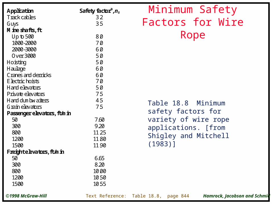
Minimum Safety Factors for Wire Rope
Application Safety factora, ns
Track cablesGuysMine shafts, ft
Up to 5001000-20002000-3000Over 3000
HoistingHaulageCranes and derricksElectric hoistsHand elevatorsPrivate elevatorsHand dumbwaitersGrain elevatorsPassenger elevators, ft/min
5030080012001500
Freight elevators, ft/min5030080012001500
3.23.5
8.07.06.05.05.06.06.07.05.07.54.57.5
7.609.20
11.2511.8011.90
6.658.20
10.0010.5010.55
Table 18.8 Minimum safety factors for variety of wire rope applications. [from Shigley and Mitchell (1983)]
Text Reference: Table 18.8, page 844
Hamrock, Jacobson and Schmid©1998 McGraw-Hill
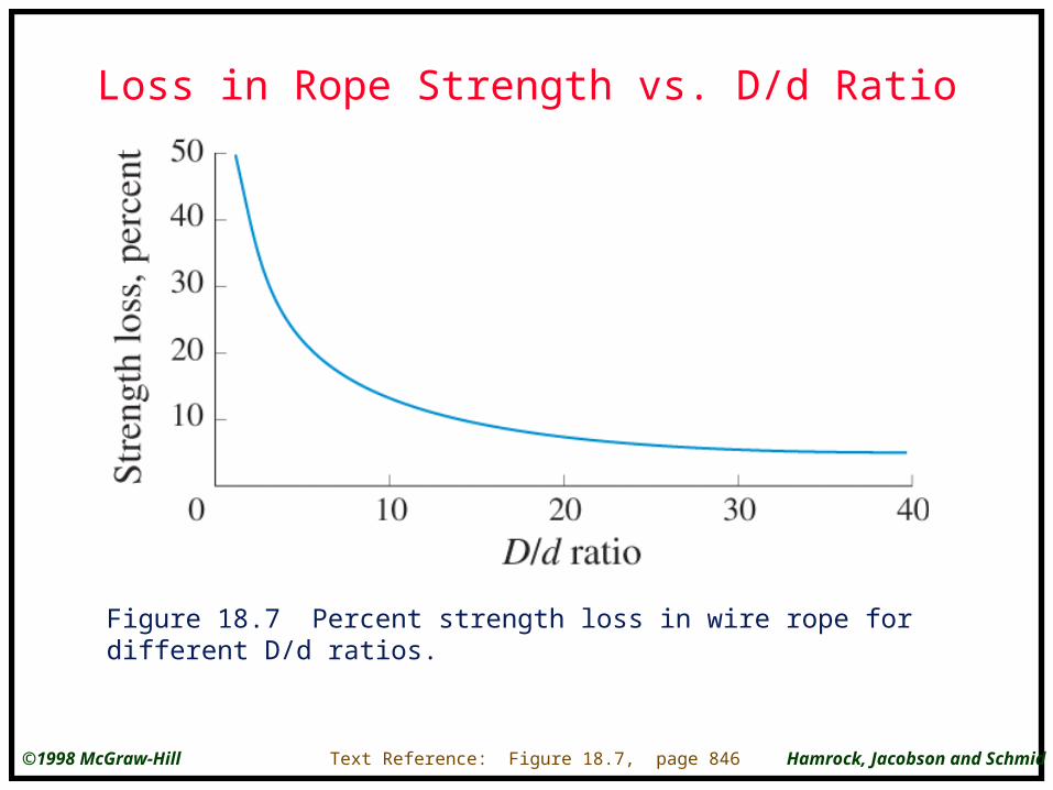
Loss in Rope Strength vs. D/d Ratio
Figure 18.7 Percent strength loss in wire rope for different D/d ratios.
Text Reference: Figure 18.7, page 846

Hamrock, Jacobson and Schmid©1998 McGraw-Hill
Service Life vs. D/d ratio
Figure 18.8 Service life for different D/d ratios.
Text Reference: Figure 18.8, page 846
Hamrock, Jacobson and Schmid©1998 McGraw-Hill
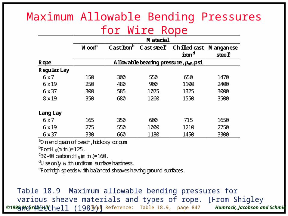
Maximum Allowable Bending Pressures for Wire Rope
MaterialWooda Cast Ironb Cast stee lc Chilled cast
irondManganese
stee le
Rope Allowable be aring pressure, pall, psiRegular Lay
6 x 76 x 196 x 378 x 19
Lang Lay6 x 76 x 196 x 37
150250300350
165275330
300480585680
350550660
550900
10751260
60010001180
650110013251550
71512101450
1470240030003500
165027503300
aOn end grain of beech, hickory or gumbFor HB(min.)=125.c30-40 carbon; HB(min.)=160.dUse only with uniform surface hardness.eFor high sp eeds with balanced sheaves having ground surfaces.
Table 18.9 Maximum allowable bending pressures for various sheave materials and types of rope. [From Shigley and Mitchell (1983)]
Text Reference: Table 18.9, page 847

Hamrock, Jacobson and Schmid©1998 McGraw-Hill
Rolling Chain
Text Reference: Figure 18.9, page 849
Figure 18.9 Various parts of a rolling chain.

Hamrock, Jacobson and Schmid©1998 McGraw-Hill
Strengths of Rolling ChainsRoller Pin Link Average
Chainnumber
PitchPt, in.
Diameterin.
Width,in.
diameter, d, in.
platethickness,
a
ultimatestrength,
Su, lbf
Weightper foot,
lbf25
a
35a
41b
40506080
100120140160180200240
1/43/81/21/25/83/41
1 1/41 1/21 3/4
22 1/42 1/2
3
0.1300.200a
0.3065/162/5
15/325/83/47/81
1 1/81 13/321 9/161 7/8
1/83/161/4
5/163/81/25/83/411
1 1/41 13/32
1 1/21 7/8
0.09050.1410.1410.1560.2000.2340.3120.3750.4370.5000.5620.6870.7810.937
0.0300.0500.0500.0600.0800.0940.1250.1560.1870.2190.2500.2810.3120.375
87521002000370061008500
14500240003400046000580007600095000130000
0.0840.210.280.410.681.001.692.493.674.936.438.7010.5116.90
aWithout ro llersbLightweight rollers
Text Reference: Table 18.10, page 850
Table 18.10 Standard sizes and strengths of rolling chains.
Hamrock, Jacobson and Schmid©1998 McGraw-Hill
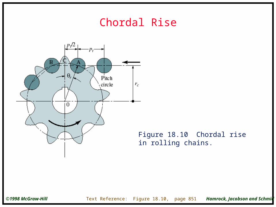
Chordal Rise
Text Reference: Figure 18.10, page 851
Figure 18.10 Chordal rise in rolling chains.
Hamrock, Jacobson and Schmid©1998 McGraw-Hill
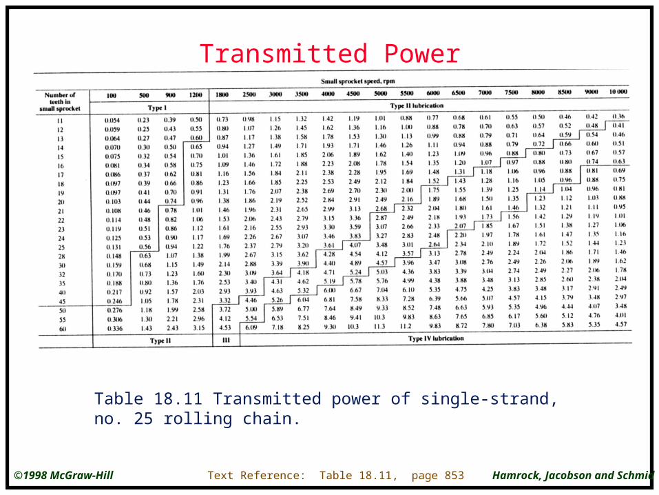
Transmitted Power
Table 18.11 Transmitted power of single-strand, no. 25 rolling chain.
Text Reference: Table 18.11, page 853
Hamrock, Jacobson and Schmid©1998 McGraw-Hill
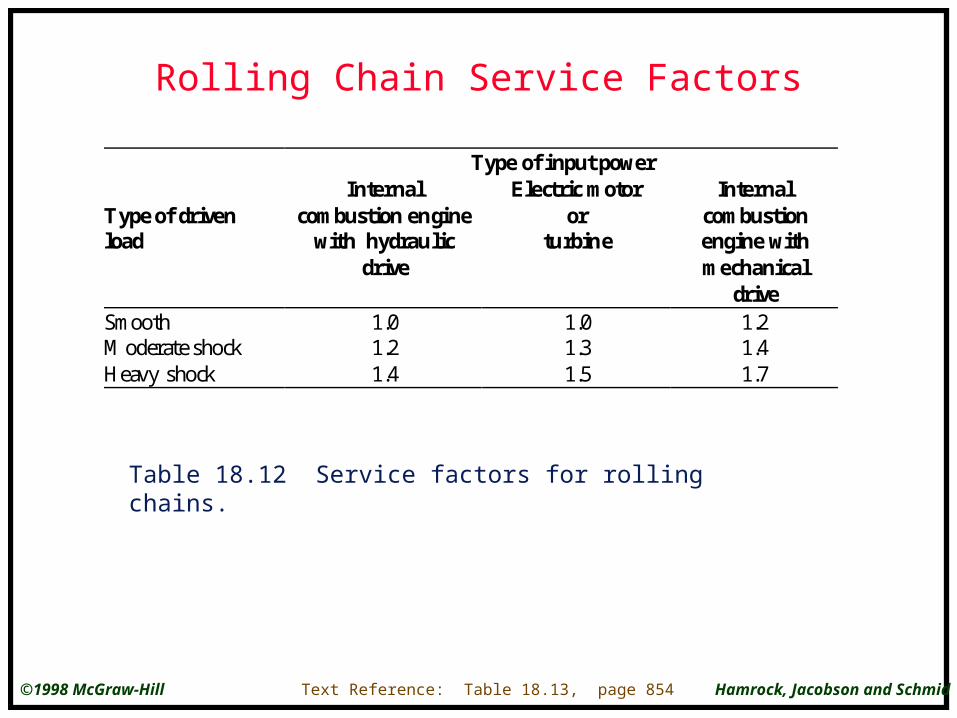
Rolling Chain Service Factors
Type of input power
Type of drivenload
Internalcombustion engine
with hydraulicdrive
Electric motoror
turbine
Internalcombustionengine withmechanical
driveSmoothModerate shockHeavy shock
1.01.21.4
1.01.31.5
1.21.41.7
Table 18.12 Service factors for rolling chains.
Text Reference: Table 18.13, page 854
Hamrock, Jacobson and Schmid©1998 McGraw-Hill
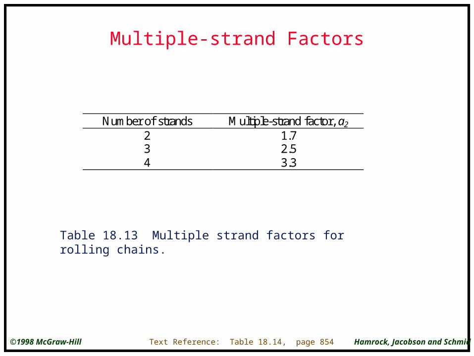
Multiple-strand Factors
Number of strands Multiple-strand factor, a2
234
1.72.53.3
Table 18.13 Multiple strand factors for rolling chains.
Text Reference: Table 18.14, page 854

Hamrock, Jacobson and Schmid©1998 McGraw-Hill
Dragline
Figure 18.11 Typical dragline.
Text Reference: Figure 18.11, page 856