hammond xlk-5 owner's manual - 鈴木楽器製作所 · h-bus from organ jack use a...
TRANSCRIPT
Model:
Owner’s Manual
Congratulations on your purchase of a new Hammond instrument.Th e XLK-5 is intended to be used as a Lower Keyboard for the model XK-5 Drawbar Keyboard.Please take a moment to review this manual thoroughly in order to famil-iarize yourself with the features of this keyboard as well as the installation procedures. Keep this manual for future reference.
English
日本語Open Here
Page 9
Owner’s Manual
2
Do not open (or modify in any way) the unit.
Do not attempt to repair the unit, or replace parts in it. Refer all servicing to your retailer, the nearest Ham-mond Dealer, or an authorized Hammond distributor, as listed on the “Service” page.
Never use or store the unit in places that are: Subject to temperature extremes (e.g., direct sun-
light in an enclosed vehicle, near a heating duct, on top of heat generating equipment)
Damp (e.g., baths, washrooms, on wet fl oors) Humid Exposed to rain Dusty Subject to high levels of vibration
Use only with the cart, stand, tripod, bracket, or table specifi ed by the manufacturer, or sold with the appara-tus. When cart is used: use caution when moving the cart/apparatus combination to avoid injury from tip-over.
Do not allow any objects (e.g., fl ammable material, coins, pins); or liquids of any kind (water, soft drinks, etc.) to penetrate the unit.
Immediately turn the power off , remove the AC cable from the outlet, and request servicing by your retailer, the nearest Hammond Dealer, or an authorized Ham-mond distributor, as listed on the “Service” page when: Th e AC adaptor, the power-supply cord, or the plug
has been damaged; or If smoke or unusual odor occurs Objects have fallen into, or liquid has been spilled
onto the unit; or Th e unit has been exposed to rain (or otherwise has
become wet); or Th e unit does not appear to operate normally or ex-
hibits a marked change in performance.
In households with small children, an adult should pro-vide supervision until the child is capable of following all the rules essential for the safe operation of the unit.
Protect the unit from strong impact. (Do not drop it!)
Never climb on top of, nor place heavy objects on the unit.
Before moving the unit, disconnect the AC adaptor and all cords coming from external devices.
Be sure to grasp the plug when unplugging it from the unit. Pulling on the cord can damage it, and create the danger of fi re and electrical shock.
Turn off all devices before hook up. Follow all instruc-tions and use only designated cables.
Make sure not to pinch your fi ngers when you assemble or disassemble this unit.
IMPORTANT SAFETY INSTRUCTIONS
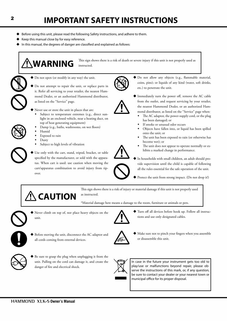
Before using this unit, please read the following Safety instructions, and adhere to them. Keep this manual close by for easy reference. In this manual, the degrees of danger are classifi ed and explained as follows:
Th is sign shows there is a risk of death or severe injury if this unit is not properly used as instructed.
Th is sign shows there is a risk of injury or material damage if this unit is not properly used as instructed.
*Material damage here means a damage to the room, furniture or animals or pets.
In case in the future your instrument gets too old to play/use or malfunctions beyond repair, please ob-serve the instructions of this mark, or, if any question, be sure to contact your dealer or your nearest town or municipal offi ce for its proper disposal.
3
取扱説明書
Upstream Downstream
CU-1
NAMES AND FUNCTIONS
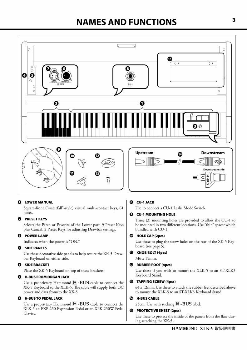
❶ LOWER MANUALSquare-front (“waterfall”-style) virtual multi-contact keys, 61 notes.
❷ PRESET KEYSSelects the Patch or Favorite of the Lower part. 9 Preset Keys plus Cancel, 2 Preset Keys for adjusting Drawbar settings.
❸ POWER LAMPIndicates when the power is “ON.”
❹ SIDE PANELSUse these decorative side panels to help secure the XK-5 Draw-bar Keyboard on either side.
❺ SIDE BRACKETPlace the XK-5 Keyboard on top of these brackets.
❻ H-BUS FROM ORGAN JACKUse a proprietary Hammond cable to connect the XK-5 Keyboard to the XLK-5. Th e cable will supply both DC power and data from/to the XK-5.
❼ H-BUS TO PEDAL JACKUse a proprietary Hammond cable to connect the XLK-5 an EXP-250 Expression Pedal or an XPK-250W Pedal Clavier.
❽ CU-1 JACKUse to connect a CU-1 Leslie Mode Switch.
❾ CU-1 MOUNTING HOLETh ree (3) mounting holes are provided to allow the CU-1 to be mounted in two diff erent locations. Use “thin” spacer which bundled with CU-1.
10 HOLE CAP (2pcs)Use these to plug the screw holes on the rear of the XK-5 Key-board (see page 5).
11 KNOB BOLT (4pcs)M6 x 15mm.
12 RUBBER FOOT (4pcs)Use these if you wish to mount the XLK-5 to an ST-XLK3 Keyboard Stand.
13 TAPPING SCREW (4pcs)ø4 x 12mm. Use these to attach the rubber feet described above to mount the XLK-5 to an ST-XLK3 Keyboard Stand.
14 H-BUS CABLE25cm. Use with sticking label.
15 PROTECTIVE SHEET (2pcs)Use these to protect the inside of the panels from the fl aw dur-ing attaching the XK-5.
Downstream side
❸
❹ ❺
❷
❼
14
❻
❶
10
❽
❾
11
12
13
15
Owner’s Manual
4 ASSEMBLY PROCEDURE
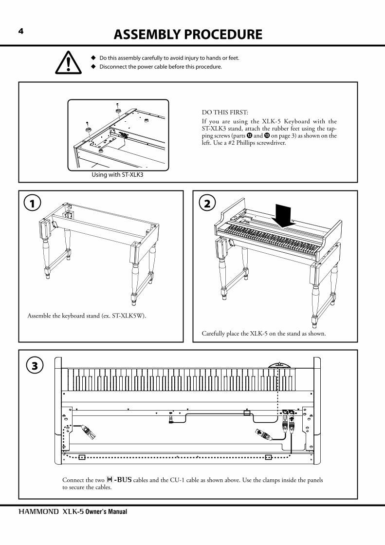
Do this assembly carefully to avoid injury to hands or feet. Disconnect the power cable before this procedure.
1
Assemble the keyboard stand (ex. ST-XLK5W).
2
Carefully place the XLK-5 on the stand as shown.
3
Connect the two cables and the CU-1 cable as shown above. Use the clamps inside the panels to secure the cables.
DO THIS FIRST:If you are using the XLK-5 Keyboard with the ST-XLK3 stand, attach the rubber feet using the tap-ping screws (parts 12 and 13 on page 3) as shown on the left. Use a #2 Phillips screwdriver.
Using with ST-XLK3

5
取扱説明書
5Remove the side panels of the XK-5 Keyboard as shown above.
7
Carefully place the XK-5 on the XLK-5 as shown above.Remove the protective sheets.
8Fix the XK-5 and XLK-5 by using attached 4 knob bolts.Use the four Knob Bolts (part 11 on page 3) to secure both the XK-5 and the XLK-5.
4
Carefully place the XK-5 Keyboard on a towel or other soft surface to
avoid damage, then remove the 6 screws (for rear, “B” 2 - M4 x 16, for
bottom, “A” 4 - ø4 x 10) shown on the left using a #2 Phillips screwdriver.
Insert the hole caps into the two holes on the rear panel.
6
Attach the protective sheets inside the side panels of the XLK-5.
Fold with stickers are bottom side.

Owner’s Manual
6 HOOK UP
CU-1
HEADPHONES
CU-1
TO KEYBOARD PEDAL
H-BUS
Upstream Downstream
HOOK UP WITH XK-5, XLK-5, XPK-250W, CU-1, ST-XLK5W
Connect the cables as shown in the diagram above. IMPORTANT: Th e interface provides for DC power as well as system
communication, therefore it is not necessary to utilize the “DC IN” jack on the Expression Pedal when connecting to the XK-5.
In addition, no special confi guration is required. Each device is confi gured auto-matically.
NOTE: The above diagram shows only the connections for the Pedalboard and Expression
Pedal. For information on other connections such as AC power, audio, Leslie, etc.
Please consult the XK-5 Owner’s Manual.
Th is keyboard uses Hammond’s new interface which will supply both DC power and data transfer using a single connection.IMPORTANT: Use the cable provided with this instrument for all connections. DO NOT use a 4-pin XLR or other type of connector. Doing so may result in damage to the instrument.
7SPECIFICATIONS
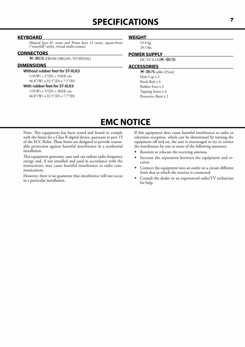
KEYBOARDMusical keys 61 notes and Preset keys 12 notes, square-front (“waterfall”-style), virtual multi-contact
CONNECTORS (FROM ORGAN, TO PEDAL)
DIMENSIONSWithout rubber feet for ST-XLK3
119(W) × 57(D) × 19(H) cm46.8”(W) x 22.5”(D) x 7.5”(H)
With rubber feet for ST-XLK3119(W) × 57(D) × 20(H) cm46.8”(W) x 22.5”(D) x 7.7”(H)
WEIGHT13.4 kg29.5 lbs
POWER SUPPLYDC 5V 0.1A()
ACCESSORIES cable (25cm)Hole Cap x 2Knob Bolt x 4Rubber Foot x 4Tapping Screw x 4Protective Sheet x 2
Note: Th is equipment has been tested and found to comply with the limits for a Class B digital device, pursuant to part 15 of the FCC Rules. Th ese limits are designed to provide reason-able protection against harmful interference in a residential installation. Th is equipment generates, uses and can radiate radio frequency energy and, if not installed and used in accordance with the instructions, may cause harmful interference to radio com-munications.However, there is no guarantee that interference will not occur in a particular installation.
If this equipment does cause harmful interference to radio or television reception, which can be determined by turning the equipment off and on, the user is encouraged to try to correct the interference by one or more of the following measures: Reorient or relocate the receiving antenna. Increase the separation between the equipment and re-
ceiver. Connect the equipment into an outlet on a circuit diff erent
from that to which the receiver is connected. Consult the dealer or an experienced radio/TV technician
for help.
EMC NOTICE
Owner’s Manual
8 SERVICE
Hammond maintains a policy of continuously improving and upgrading its instruments and therefore reserves the right to change specifi cations without notice. Although every attempt has been made to insure the accuracy of the descriptive contents of this Manual, total accuracy cannot be guaranteed.Should the owner require further assistance, inquiries should fi rst be made to your Authorized Hammond Dealer.If you still need further assistance, contact Hammond at the following addresses:
Technical materials are available and can be obtained by mailing a request to the appropriate address listed above marked ATTENTION: SERVICE DEPARTMENT.
In the United States Contact:HAMMOND SUZUKI USA, Inc.743 Annoreno Drive, Addison, Illinois
60101UNITED STATES
Tel: (630) 543-0277Fax: (630) 543-0279
Web site: www.hammondorganco.comE-mail: [email protected]
In European countries contact:HAMMOND SUZUKI EUROPE B. V.IR. D. S. Tuynmanweg 4a 4131 PN Vianen
THE NETHERLANDSTel: (+31) 347-370 594
Web site: www.hammond.euE-mail: [email protected]
Please contact Suzuki Corpora-tion for other countries.
HAMMOND SUZUKI Ltd.2-25-11, Ryoke, Naka-ku, Hamamatsu,
Shizuoka Pref. 430-0852JAPAN
Tel: (+81) 53-460-3781Fax: (+81) 53-460-3783
E-mail: [email protected]
Manufacturer:SUZUKI MUSICAL INSTRUMENT MFG. Co., Ltd.
2-25-12, Ryoke, Naka-ku, Hamamatsu, Shizuoka Pref. 430-0852JAPAN
Product Registrationhttp://hammondorganco.com/support/
online-product-registration/
Product Registrationhttp://www.hammond.eu/support/online-
product-registration/
9
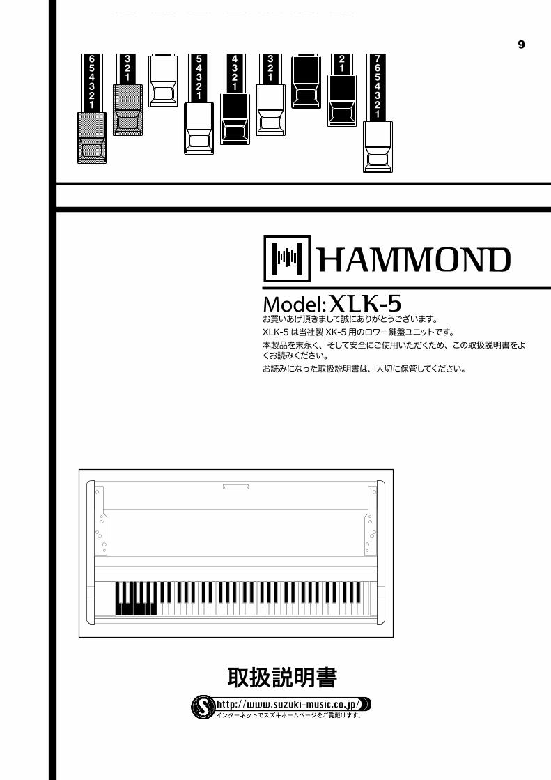
Model:
取扱説明書
お買いあげ頂きまして誠にありがとうございます。XLK-5は当社製XK-5用のロワー 盤ユニットです。本製品を末永く、そして安全にご使用いただくため、この取扱説明書をよくお読みください。お読みになった取扱説明書は、大切に保管してください。
Owner’s Manual
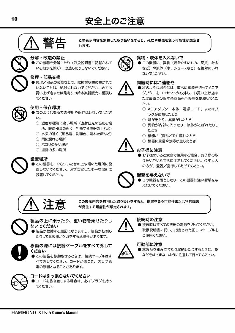
10 安全上のご注意
分解・改造の禁止● この機器を分解したり(取扱説明書に記載されている指示を除く)、改造したりしないでください。
修理・部品交換● 修理/部品の交換などで、取扱説明書に書かれていないことは、絶対にしないでください。必ずお買い上げ店または最寄りの鈴木楽器販売に相談してください。
使用・保存環境● 次のような場所での使用や保存はしないでください。○ 湿度が極端に高い場所(直射日光の当たる場所、暖房器具の近く、発熱する機器の上など)
○ 水気の近く(風呂場、洗面台、濡れた床など)○ 雨に濡れる場所○ ホコリの多い場所○ 振動の多い場所
設置場所● この機器を、ぐらついた台の上や傾いた場所に設置しないでください。必ず安定した水平な場所に設置してください。
異物・液体を入れないで● この機器に、異物(燃えやすいもの、硬貨、針金など)や液体(水、ジュースなど)を絶対にいれないでください。
問題時にはご連絡を● 次のような場合には、直ちに電源を切ってACアダプターをコンセントから外し、お買い上げ店または最寄りの鈴木楽器販売へ修理を依頼してください。○ ACアダプター本体、電源コード、またはプラグが破損したとき
○ 煙が出たり、異臭がしたとき○ 異物が内部に入ったり、液体がこぼれたりしたとき
○ 機器が(雨などで)濡れたとき○ 機器に異常や故障が生じたとき
お子様に注意● お子様のいるご家庭で使用する場合、お子様の取り扱いやいたずらに注意してください。必ず大人の方が、監視/指導してあげてください。
衝撃を与えないで● この機器を落としたり、この機器に強い衝撃を与えないでください。
製品の上に乗ったり、重い物を乗せたりしないでください● 製品が故障する原因になりますし、製品が転倒したりしてお客様がケガをする危険性があります。
移動の際には接続ケーブルをすべて外してください● この製品を移動させるときは、接続ケーブルはすべて外してください。コードが傷つき、火災や感電の原因となることがあります。
コードは引っ張らないでください● コードを抜き差しする場合は、必ずプラグを持ってください。
接続時の注意● 接続時はすべての機器の電源を切ってください。 取扱説明書に従い、指定された正しいケーブルをご使用ください。
可動部に注意● 本製品を組み立てたり収納したりするときは、指などをはさまないように注意して行ってください。
警告 この表示内容を無視した取り扱いをすると、死亡や重傷を負う可能性が想定されます。
注意 この表示内容を無視した取り扱いをすると、傷害を負う可能性または物的障害が発生する可能性が想定されます。

11
取扱説明書
各部の名称と働き
❶ ロワー 盤61 、ウォーターフォール形、仮想マルチコンタクトの 盤です。
❷ プリセットキーLロ ワ ー
OWERパートのパッチやフェイバリットを選択します。
❸ 電源ランプ本機の動作中に点灯します。
❹ サイドウッドXK-5を格納できるサイドウッドです。
❺ サイドブラケットXK-5を乗せるためのブラケットです。
❻ H-Bバ ス
US Fフ ロ ム
ROM Oオ ル ガ ン
RGANジャック対応の親機(XK-5)に接続します。電源供給と演奏情報が1本のケーブルで送られます。
❼ H-Bバ ス
US Tトゥ
O Pペ ダ ル
EDALジャック対応の子機(XPK-250、EXP-250)に接続します。
❽ CU-1ジャックレスリーモードスイッチCU-1を接続します。
❾ CU-1取付穴CU-1を2つのポジションで取り付けられる3穴です。CU-1付属のスペーサー(薄)をご使用ください。
10 穴埋めキャップ(2個)XK-5背面のねじ穴を塞ぎます。
11 ノブボルト(4個)M6×15mm
12 ゴム脚(4個)本機をキーボードスタンドST-XLK3に載せる場合に、タッピングねじ13と共に使用します。
13 タッピングねじ(4個)φ4×12mm
14 H-Bバ ス
USケーブル25cm。ラベルを貼り付けて使用します。
15 保護シート(2枚)本機にXK-5を取り付ける際に、側板の内側をキズから保護します。
Upstream Downstream
CU-1
Downstream side
❸
❹ ❺
❷
❼
14
❻
❶
10
❽
❾
11
12
13
15
Owner’s Manual
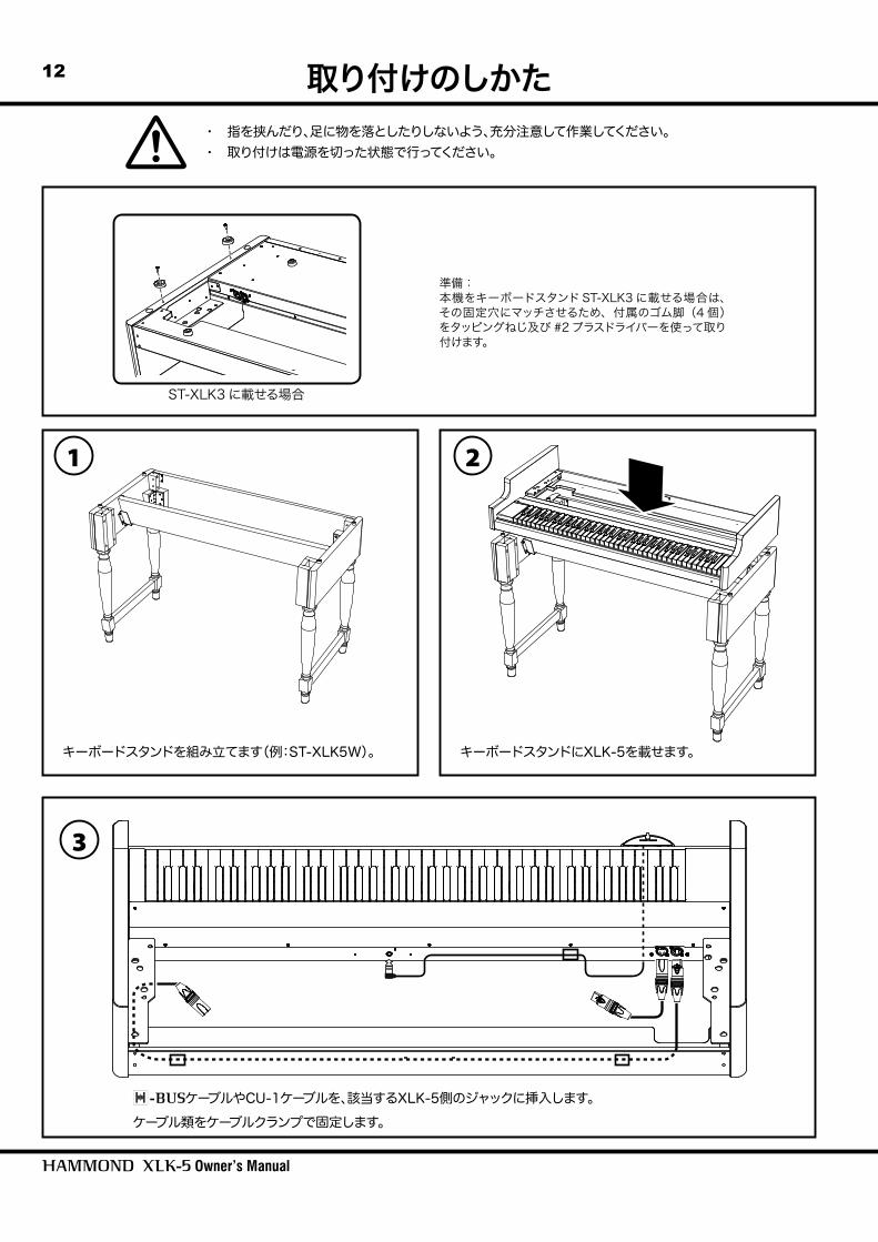
12 取り付けのしかた・ 指を挟んだり、足に物を落としたりしないよう、充分注意して作業してください。・ 取り付けは電源を切った状態で行ってください。
1
キーボードスタンドを組み立てます(例:ST-XLK5W)。
2
キーボードスタンドにXLK-5を載せます。
3
ケーブルやCU-1ケーブルを、該当するXLK-5側のジャックに挿入します。ケーブル類をケーブルクランプで固定します。
準備:本機をキーボードスタンドST-XLK3に載せる場合は、その固定穴にマッチさせるため、付属のゴム脚(4個)をタッピングねじ及び#2プラスドライバーを使って取り付けます。
ST-XLK3に載せる場合

13
取扱説明書
XK-5の、左図で示された6個のネジ(背面:“B” M4×16を2個、底面:“A” ø4×10を4個)を、#2プラスドライバーで外します。
※ キズ付きを防ぐため、楽器を布やマットに置いて作業してください。
背面2カ所の穴に、穴埋めキャップを差し込みます。
4
XK-5の側板を外します。
7
XK-5をXLK-5に載せます。キズを防ぐため、作業は静かに行ってください。保護シートを外します。
8
ノブボルト4個(付属品)を使用し、XK-5とXLK-5とを固定します。
5
本機側板の内側に、保護シートを貼り付けます。
6 粘着材が下になるよう折り曲げる
Owner’s Manual
14 接続のしかた
CU-1
HEADPHONES
CU-1
TO KEYBOARD PEDAL
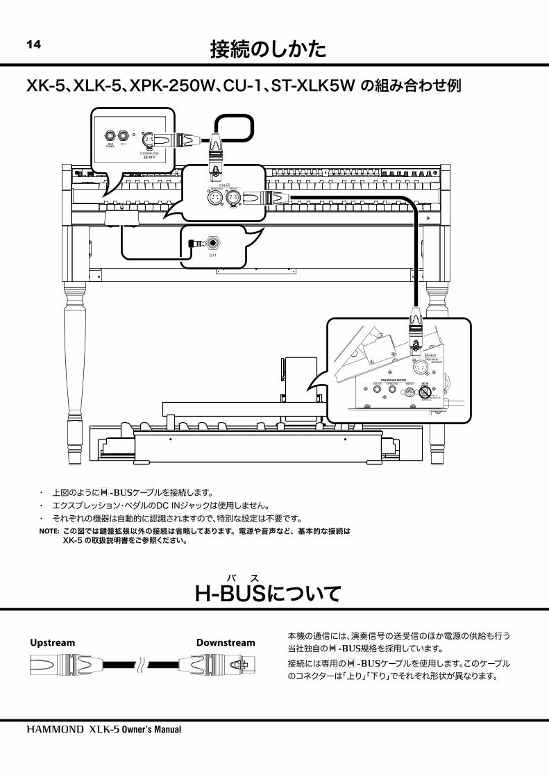
・ 上図のようにケーブルを接続します。・ エクスプレッション・ペダルのDC INジャックは使用しません。・ それぞれの機器は自動的に認識されますので、特別な設定は不要です。NOTE: この図では 盤拡張以外の接続は省略してあります。電源や音声など、基本的な接続は
XK-5の取扱説明書をご参照ください。
H-Bバ ス
USについて
Upstream Downstream本機の通信には、演奏信号の送受信のほか電源の供給も行う当社独自の規格を採用しています。接続には専用のケーブルを使用します。このケーブルのコネクターは「上り」「下り」でそれぞれ形状が異なります。
XK-5、XLK-5、XPK-250W、CU-1、ST-XLK5W の組み合わせ例
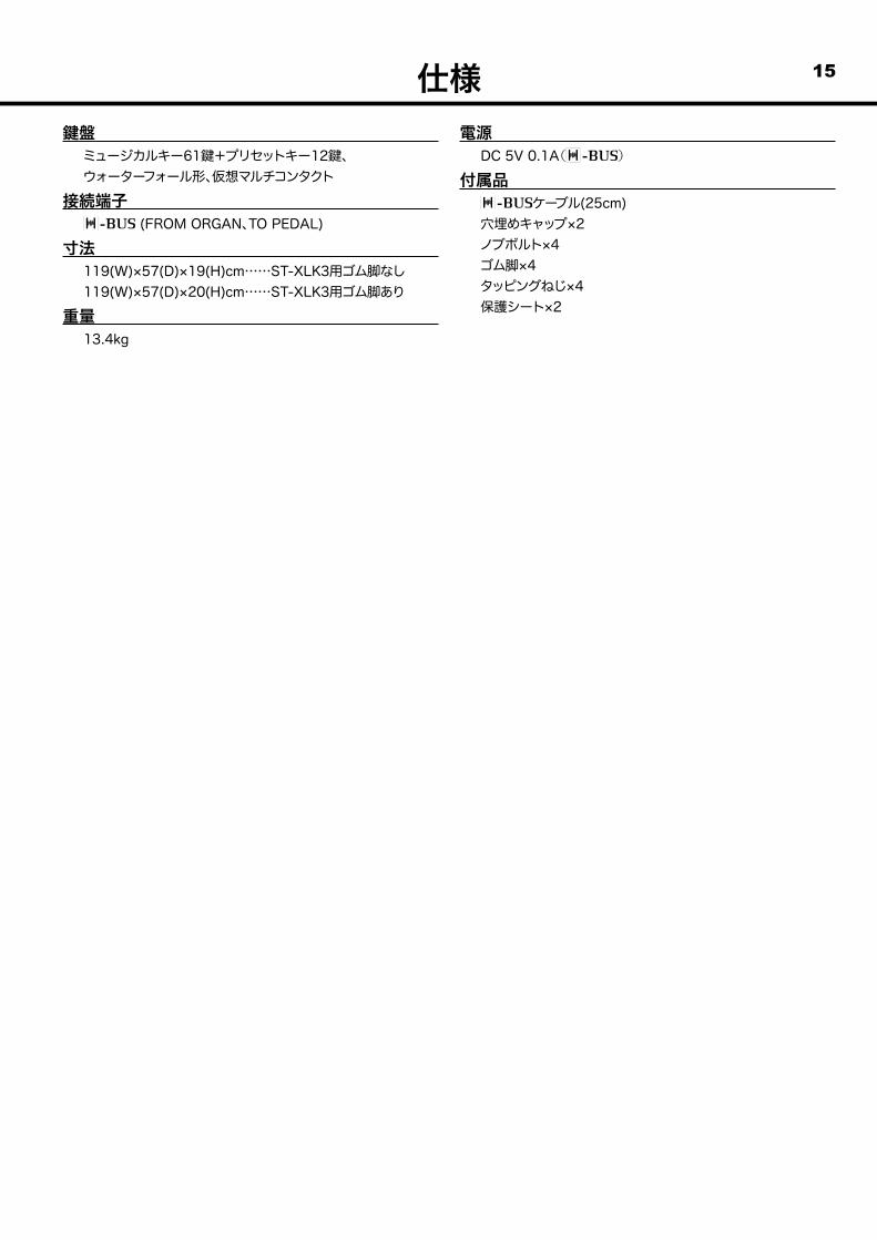
15仕様盤ミュージカルキー61 +プリセットキー12 、ウォーターフォール形、仮想マルチコンタクト
接続端子 (FROM ORGAN、TO PEDAL)
寸法119(W)×57(D)×19(H)cm……ST-XLK3用ゴム脚なし119(W)×57(D)×20(H)cm……ST-XLK3用ゴム脚あり
重量13.4kg
電源DC 5V 0.1A()
付属品ケーブル(25cm)穴埋めキャップ×2ノブボルト×4ゴム脚×4タッピングねじ×4保護シート×2
サービスについてこの商品には保証書を下記添付しております。所定の事項の記入後、記載内容をご確認の上、大切に保管してください。保証期間はお買いあげ日より1年間です。保証書の記載内容によりお買いあげ販売店が修理いたします。その他、詳細は保証書をご覧ください。保証期間が切れましても、修理によって機能が維持できる場合はお客様のご要望により有料修理いたします。アフターサービスについてご不明の場合は、お買いあげの販売店またはもよりの営業所にお問い合わせください。
Printed in Japan00457-40198 V1.03-180313