halogen exam light iii - welch allyn exam light iii with fiberoptic light pipe model #’s - 48700,...
TRANSCRIPT

Halogen Exam Light III with Fiberoptic Light PipeModel #’s - 48700, 48722, 48724, 48726, 48728
Halogen Exam Light III with Fiberoptic Light CableModel #’s - 48780, 48782, 48784, 48786, 48788
Halogen Exam Light III with Neonate Light PipeModel #’s - 48760, 48762, 48764, 48766, 48768
Halogen Exam Light III Light Box with Power CordModel #’s - 48740, 48742, 48744, 48746, 48748
INTRODUCTIONThank you for purchasing the Welch Allyn Halogen Exam Light III. We believe that it is the highest quality product of its kind available in the world today. By following the simple guidelines found within this manual, you should be rewarded with years of dependable, trouble free performance. If you have any questions or concerns please feel free to contact our customer or technical service departments at (800) 535-6663 during normal business hours.
Welch Allyn remains committed to providing innovative, quality diagnostic products for healthcare professionals. Call us at (800) 535-6663 to request a full line product catalog or visit us at our Web Site, www.WelchAllyn.com.
SYMBOL DESCRIPTIONS
Attention: Consult user’s manual for additional information.
Warning: Risk of fire. Replace fuses as marked.
Caution: High Temperatures
Caution: High Intensity Light
WARNINGS & CAUTIONS
WARNING: The user of this equipment should be thoroughly trained in the medical procedures appropriate to the utilization of this instrumentation. Furthermore, time should be taken to read and understand the instructions contained within this manual prior to use of this product. Instructions for other equipment used in conjunction with the Exam Light III (for example: suction machines, electrosurgical generators, etc.) should also be read and understood. Failure to understand the operating requirements for this product may result in injury to yourself, the patient and/or may damage the instrument.
CAUTION: Electric Shock Hazard - Remove power cord from electrical outlet and allow lamp to cool before replacing (Welch Allyn lamp # 04200).
DANGER: Risk of explosion if used in the presence of flammable anesthetics.
CAUTION: Federal Law restricts this device to sale by or on the order of a physician.
CAUTION: Illumination is intense - Do not stare at the light source in operation. May be harmful to eyes.
CAUTION: Use the examination light in its intended working range of 12 to 24 inches. Exposures at closer distances may be harmful to skin.
WARNING: Do not perform neonatal trans-illumination without the use of the #48210 neonatal trans-illuminator (with U.V. filter). Do not remove the focusing sleeve from the light pipe and use the light pipe for trans-illumination. Severe burns may result.
General practices to minimize risk of harm to the skin from optical radiation hazards include: minimizing illumination intensity at the tis-sue examination site, minimizing exposure times, and taking addi-tional precautions when skin sensitivity has been altered through tissue trauma or the use of anesthesia.
General good practices to minimize risk of harm to the eyes from optical radiation hazards include: avoid looking at bright light sources and their reflections, and protect eyes where normal pupil sizes and aversion responses are not present.
There are no user serviceable/replaceable parts other than lamp and fuses. Please refer any other service to qualified and authorized service centers.
COMPONENTS
Standard
Light Box, Power Cord and Wall MountModel 48740 (Domestic)Model 48742 (Europe)Model 48744 (UK)Model 48746 (Australia)Model 48748 (Japan)
Fiberoptic Light Pipe (shown with focusing sleeve)Model 48200 (Included only with Model #’s 48700, 48722, 48724, 48726, and 48728)
Fiberoptic Light Cable (shown with focusing sleeve)Model 48220 (Included only with Model #’s 48780, 48782, 48784, 48786, and 48788)
Neonatal TransilluminatorModel 48210(Included only with Model #’s 48760, 48762, 48764, 48766, and 48768)
Focusing SleeveModel 48605
(Included only with Model #’s 48700, 48722, 48724, 48726, 48728, 48780, 48782, 48784, 48786, and 48788)
Accessories
Fiberoptic Light Pipe (Shown with Focusing Sleeve)Model 48200
Fiberoptic Light Cable (Shown with Focusing Sleeve)Model 48220
Focusing SleeveModel 48605
Neonatal TransilluminatorModel 48210The optional neonatal Light Pipe/transilluminator is used to assist in the diagnosis of pneumothorax, to locate blood vessels, etc. This transilluminator incorporates a permanently attached ultraviolet filter that minimizes the transmission of ultraviolet light. The standard Fiberoptic Light Pipe or Fiberoptic Light Cable should NOT be used for transillumination of neonates.
Table Mount BracketModel 48859
Mobile StandModel 48850
Disposable SheathsModel 52640
Disposable Sheath DispenserModel 52641
35W Halogen Replacement LampModel 04200
MOUNTING Use one of the following three mounting options in order to ensure proper operation of the light box.
Wall MountChoose appropriate mounting location. The length of the light pipe is 4 feet totally extended (fiberoptic light cable is 7.5 feet). When choosing a mounting location, keep these dimensions in mind in addition to accounting for the actual application the light will be used for and what portion of the examination table will need to be accessed.
1. Using the mounting plate as a template, mark drilling holes as needed (depending on your wall type).
2. Dry Wall, Paneling, Plywood or Plaster (1/8 inch (.3 cm) to 5/8 inch (1.6 cm) thick) - drill four (4) 3/8 inch (1cm) holes, insert hollow metal wall anchor assembly.
3. Concrete Block - drill four (4) 3/16 inch (.5 cm) holes, insert plastic anchors. Use #8 x 1/2 inch screws to secure.
4. Metal Panel or Plywood walls greater than 5/8 inch (1.60 cm) thick - drill four (4) 1/8 inch (.3 cm) holes. Use #8 x 1 inch screws to secure.
5. Once holes are drilled, install the mounting plate with the appropriate screws. Completely tighten the screw so there is no gap between the screw head and the mounting plate.
6. Mount the Light Box to the plate by inserting the pins on the back of the light box into the slots on the mounting plate. Let the light box drop down to position the pins into the narrow portion of the mounting slots ��.
7. To secure the Light Box to the plate, insert two (2) .50” (1.27cm) screws through the bottom of the mounting plate and tighten into the bottom of the Light Box using a phillips head screwdriver ��.
NOTE: Some exam table manufacturers supply mounting hardware for installation of the Exam Light III. Check with your table supplier for availability.
WARNING: It is the responsibility of the health facility of user to ensure that the mounting bracket is securely anchored to the wall or table, or that the mobile stand is securely assembled, and the exam light is securely fastened to the bracket or stand as directed below. Give consideration to the load that is placed upon the mount. Welch Allyn, Inc. does not accept responsibility for any installation, nor for damage or injury arising from the installation of any mounting bracket or mobile stand, regardless of the type of fasteners and technique used.
1. Determine the side of the table that is most optimal for mounting the light. Consider the location of the nearest power outlet and patient traffic.
NOTE: Verify that the top of the mounting bracket is at least 10 inches (25.4 cm) below the table top cushion and that the mounting position will not interfere with the operation of the table.
2. Using the mounting plate as a template, mark the hole locations on the table and drill four (4) .25 inch (.64 cm) holes in the table.
3. Using four 8-32 screws with lock washers and nuts, install the mounting plate to the table as shown in the diagram.
4. Mount the light box to the plate by inserting the pins on the back of the light box into the slots on the mounting plate. Let the light box drop down to position the pins into the narrow portion of the mounting slots.
5. To secure the Light Box to the mounting plate, insert two (2) .50” (1.27 cm) screws through the bottom of the mounting plate and tighten into the bottom of the Light Box using a Phillips head screwdriver.
NOTE: Some tables require additional reinforcement of the mounting bracket to support the mounted light. In this case, we recommend using a 1” (2.5 cm) thick piece of plywood. When employing this reinforcement to the bracket, please follow instructions 6 - 11 below.
6. Trace the outline of the mounting plate and mark the hole locations on a 3/4 inch (1.9cm) thick piece of plywood.
7. Cut the piece of wood to the outline size and drill four .25 inch (.64cm) holes.
8. Using the mounting plate as a template, mark the hole locations on the table and drill (4) .25 inch (.64 cm) holes in the table.
9. Using four 8-32 x 2 inch (5.08 cm) screws with lock washers and nuts, install the block of wood and mounting plate to the table as shown in the diagram.
10. Mount the light box to the plate by inserting the pins on the back of the light box into the slots on the mounting plate. Let the light box drop down to position the pins into the narrow portion of the mounting slots.
11. To secure the Light Box to the mounting plate, insert two (2) .50” (1.27cm) screws through the bottom of the mounting plate and tighten into the bottom of the Light Box using a phillips head screwdriver.
Halogen Exam Light III
�� ��

Mobile Stand (Model # 48850)
Caster/Base Assembly Instructions ��:
Push casters into the holes of the base until they “snap” into place. Alternate casters as shown.
Base/Column Assembly Instructions ��:
1. Insert column into center hole of base.
2. Insert .25 inch (.64 cm) lock washer, .75 inch (1.9 cm) flat washer and 1 1/4” (3.2 cm) socket head bolt into center hole. Tighten socket head bolt with hex socket wrench.
Exam Light/Mounting Plate Instructions ��:
1. Place the keyhole pins on the back of the Exam Light into the slots on the top of the mounting plate and slide down.
2. Line up the screw holes on the bottom of the Exam Light with the screw holes on the mounting plate.
3. Insert the .50 inch (1.27 cm) screws through the bottom of the mounting plate and tighten with a phillips head screw driver (not included).
SET-UP AND OPERATION
Set Up
1. Secure the Light Box to one of the mounting options per the appropriate instructions.
2. Insert the Fiberoptic Light Pipe, Fiberoptic Light Cable, or Neonate Light Pipe into the light pipe receptacle on the top of the Light Box.
3. Plug the power cord into the base of the Light Box and the remaining end into a grounded AC outlet.
4. Toggle the light switch to the “ON” position to operate.
NOTE: Remember that the Fiberoptic Light Pipe, Fiberoptic Light Cable, and Neonate Light Pipe contain several thousand individual optical fibers, therefore appropriate handling is required to ensure long fiber life. Do not bend the flexible portions of the light pipe at acute angles as this will break individual fibers and reduce light transmission. For example, do not bend the semi-flexible middle portion of the Fiberoptic Light Pipe more than 180 degrees and do not bend the proximal and distal sections more than 90 degrees. Be careful not to pull on the Fiberoptic Light Cable as this may cause fibers to break.
Operation Of Light Pipe The flexible portions of the Fiberoptic Light Pipe are designed to be articulated, but not twisted. Twisting or applying torque to the flexible sections will greatly decrease the life of the Light Pipe. This type of movement will cause premature drooping of the Light Pipe (will not stay in place once positioned) and eventually will result in breakage of the fiberoptic bundle. For best results, always position the Light Pipe by moving it in the same direction as gravity. For example, if the pipe needs to be raised, raise it above the desired position and then lower it into place.
NOTE: Upon manufacture, the Light Pipe is tested to assure maintenance of positioning and to verify the absence of noise upon articulation. Over a period of time and use, it is normal for the Light Pipe positioning capability to reduce and soften becoming less obedient. Abnormal softening or occurrence of noise upon articulation should be reported to Welch Allyn Technical Service (315-685-4560) immediately.
Operation of Focusing SleeveThe focusing sleeve at the end of the Fiberoptic Light Pipe and Fiberoptic Light Cable provides adjustment of the illumination spot size. Twisting the knurled portion of the focusing sleeve in a clockwise direction will make the spot smaller. Twisting the knurled portion of the focusing sleeve in a counterclockwise direction will increase the spot size.
LAMP REPLACEMENT
CAUTION: Lamp may be hot. Allow the lamp to cool before replacing.
1. Turn the unit off and unplug the power cord from both the wall outlet and the Light Box.
2. Remove the unit from the patient area.
3. Using a screwdriver, loosen the single panel fastener that protrudes from the bottom of the unit. As the screw is loosened, there will be a noticeable “drop” as the front cover is released. ��
4. Slightly lift the bottom of the front cover toward you and then slide the cover up to remove it.��
5. For initial lamp replacement only: Grasp wire clip at top of lamp. Rotate clip toward the base of the unit until it pops out.�� Discard clip. It was for shipping purposes only.
6. Grasp the lamp connector and pull the lamp straight out of its holder. ��
7. Pull the lamp from its connector and replace it with Welch Allyn Replacement Lamp #04200.��
8. Push the lamp back into the holder.
9. Attach the front cover by sliding the tabs at the top of the cover into the slots at the top of the back housing and then tightening the screw at the bottom of the unit.
10. Return the unit to the patient area and plug power cord back into bottom of unit and wall outlet.
FUSE REPLACEMENT1. Turn the unit off and remove the power cord from both the wall outlet
and the light box.
2. Press the tabs on both ends of the fuse drawer in and pull the fuse drawer out. ��
3. Remove and replace new fuses of the same type. There is no required orientation of the fuses. Be sure to replace both fuses.��
4. Reinsert the fuse holder by pressing it into the power connector until it snaps into place.
5. If the new fuses blow, immediately contact Welch Allyn Technical Service (315-685-4560).
CLEANINGFocusing Sleeve For best results, use the disposable sheath model #52640.
1. Remove the focusing sleeve from the Fiberoptic Light Pipe or Fiberoptic Light Cable by rotating it counterclockwise to unthread.
2. Use a cotton swab soaked in warm water and mild detergent to clean the distal end of the Fiberoptic Light Pipe or Light Cable, the proximal side of the Focusing Sleeve (small end), and distal window on the large end on the Focusing Sleeve.
3. Dry using a new cotton swab.
4. Reassemble the Focusing Sleeve to the Light Pipe or Light Cable by rotating clockwise.
WARNING: Do not clean any part of the focusing sleeve with alcohol. Clean only with a mild detergent and water.
NOTE: The focusing sleeve should not be sterilized or immersed.
Fiberoptic Light Pipe, Light Cable, Neonate Light PipeFor best results, use the disposable sheath model #52640.
External surfaces may be cleaned with a solution of warm water and mild detergent.
NOTE: The Fiberoptic Light Pipe, Light Cable, and Neonate Light Pipe should not be sterilized or immersed.
Light BoxNote: The Light Box should not be sterilized or immersed.
1. Prior to cleaning, turn power off and disconnect the power cord from both the wall outlet and the Light Box.
2. The external surfaces may be cleaned by wiping with a cloth dampened with mild soap and water or by using the following cleaning/disinfecting solutions. DO NOT IMMERSE.
• 70% Isopropyl Alcohol• 10% mild bleach solution• 10% Iodine Based Solution
The power cord may be wiped clean using the same cleaning/disinfecting solutions listed above. Wipe dry with a clean cloth. Care must be taken not to get the prongs wet. DO NOT IMMERSE.
TROUBLESHOOTING
MAINTENANCE AND REPAIRFor minor trouble, refer to the troubleshooting section in this manual for possible causes and corrective action. Only qualified personnel should make electrical inspections of the Welch Allyn Light Box. To locate qualified personnel, contact your local authorized Welch Allyn distributor, or call Welch Allyn directly at 315-685-4560. Tampering with the unit will automatically void all warranties expressed or implied.
WARRANTYLight Box - Welch Allyn guarantees that the Light Box is free of any manufacturing defects or Welch Allyn will repair or replace, free of charge, any parts proven to be defective through causes other than misuse, neglect, damage in shipment and normal wear and tear. The warranty is for a one year period from the original date of purchase.
Fiberoptic Light Pipe - The fiberoptic light pipe has been designed to not drift to a new position once positioned for an exam if the Light Box is mounted vertically according to the instructions. The warranty is for a one year period from the original date of purchase provided that the light pipe has not been tampered with or abused. Any Light Pipe that does not meet these performance requirements will be repaired or replaced at no charge to the customer.
SPECIFICATIONS
Electrical
Power Cord #18AWG, 3 wire grounded cord set, 8 feet (2.5 meters) long.
Physical CharacteristicsWeight: 4.75 lb (2.16 Kg), light box onlyLight Box H: 8.75 inches (22.23 cm)Dimensions: W: 5.25 inches (13.34 cm)
D: 3.50 inches (8.89 cm)
EnvironmentOperating: 60°F (15°C) to 104°F (40°C), 75%
R.H. Max, 500 hPa - 1060 hPa AltitudeTransport/Storage: -4°F (-20°C) to 120°F (49°C), 95%
R.H. Max, 500 hPa - 1060 hPa Altitude
Equipment ClassificationClass I, Continuous Operation
IPXØ: Not protected against the ingress of water.
ApprovalsIEC 60601-1, UL 2601-1, CAN/CSA C22.2 No 601.1, AS3200.1, IEC 60601-1-2
EMC Framework of Australia
The CE mark on this product indicates that it has been tested to and conforms with the provisions noted within the 93/42/EEC Medical Device Directive.
Authorized European Representative Address:European Regulatory ManagerWelch Allyn Ltd.,Kells Road, Navan,County Meath, Republic of Ireland.Tel.: 353-46-79060Fax: 353-46-27128
NOTE: This product complies with current required standards for electromagnetic interference and should not present problems to other equipment or be affected by other devices. As a precaution, avoid using this device in close proximity to other equipment.
NOTE: This product contains no hazardous materials. Its disposal will not contaminate or harm the environment, or present any risk to individuals disposing of the product. As a precaution, it is recommended you contact your local disposal and/or recycling authority for information regarding the disposal of the equipment.
Locking Caster
LockingCaster
Base
��
Hex Socket Wrench(Allen Wrench)
Socket Head Bolt
.25 inch (.64 cm)Lock Washer
.75 inch (1.9 cm)Flat Washer
Base
Column
Mounting Plate
��
.50 inch (1.27 cm) mounting screw
Exam Light
Keyhole Pin in slot.
��
����
��
��
��
�� ��Fuse Tabs
If lamp is not illuminating
and…Possible Cause Solution
fan is not oper-ating.
Light box is not plugged into either
the wall outlet or the power cord socket.
Plug the power cord into the wall outlet and power cord socket at bottom of
unit.
Power switch is not turned on.
Depress the green side of the power switch.
One or both fuses have blown.
Replace both fuses. Follow the instructions in the fuse
replacement section. If fuses continue to blow, return Light Box to an
authorized repair center.
Power cord is dam-aged. This may cause
intermittent opera-tion.
Replace the power cord with a new Welch Allyn
power cord.
No power is sup-plied to the wall out-
let.
Verify that the wall outlet has power by checking the circuit breaker status and by operating other equip-ment at that wall outlet.
fan is operating. The lamp has burned out.
Replace with a new Welch Allyn lamp, model # 04200. Refer to the Lamp Replace-
ment Section.
If light output seems low.
Lamp is not in opti-mal orientation.
Rotate lamp 90° in the lamp holder.
Ref Model
Input Output Fuse
48740 120VAC∼60Hz, 400mA
12VAC, 3.0A
T500mAL, 250V
48742 230VAC∼50Hz, 250mA
12VAC, 3.0A
T315mAL, 250V
48744 230/240VAC∼50Hz,
250mA
12VAC, 3.0A
T315mAL, 250V
48748 100VAC∼50/60Hz, 500mA
12VAC, 3.0A
T630mAL, 250V
US
WELCH ALLYN AUSTRALIA PTY LTD18-20 ORION ROADLAND COVE, NSW 2066AUSTRALIA
488119E Rev. A

Halogen Exam Light III avec conduit de lumière à fibre optiqueREF - 48700, 48722, 48724, 48726, 48728
Halogen Exam Light III à câble de transmission à fibre optiqueREF - 48780, 48782, 48784, 48786, 48788
Halogen Exam Light III avec conduit de lumière à fibre optique pour nouveau-nésREF - 48760, 48762, 48764, 48766, 48768
Boîte à lumière de Halogen Exam Light III avec cordon d’alimentationREF - 48740, 48742, 48744, 48746, 48748
Merci d’avoir acheté la lampe d’examen Halogen Exam Light III de Welch Allyn. Nous pensons qu’il s’agit du produit de la plus haute qualité de cette sorte qui existe actuellement au monde. Si vous suivez les simples directives présentées dans ce manuel, ce dispositif vous fournira une performance fiable et sans problème pendant de nombreuses années. En cas de questions ou de problèmes, n’hésitez pas à contacter nos services clientèle ou technique au (800) 535-6663 aux heures normales de bureau.
Welch Allyn poursuit son engagement à fournir des produits diagnostiques novateurs de qualité aux spécialistes médicaux. Appelez-nous au (800) 535-6663 pour recevoir un catalogue de notre ligne de produits ou visitez notre site Web au www.WelchAllyn.com.
DESCRIPTION DES SYMBOLESAttention : Consulter le Manuel d’utilisation pour des informations supplémentaires.
Avertissement : Risque d’incendie. Remplacer les fusibles selon les indications.
Attention : Températures élevées
Attention : Lumière à haute intensité
DESCRIPTION DES SYMBOLESAVERTISSEMENT : L’utilisateur de ce matériel doit avoir reçu une formation approfondie sur les techniques médicales appropriées quant à l’utilisation de cet instrument. Il convient par ailleurs, de prendre le temps de lire attentivement les instructions présentées dans ce manuel avant d’utiliser ce dispositif. Il convient également de lire attentivement le mode d’emploi des autres appareils utilisés en conjonction avec l’Exam Light III (par exemple, machines d’aspiration, générateurs électrochirurgicaux, etc.). Une compréhension incomplète des exigences de fonctionnement de ce dispositif peut être à l’origine de lésions de l’utilisateur, du patient et/ou de détériorations de l’instrument.
ATTENTION : Risque de décharge électrique. Débrancher le cordon d’alimentation de la prise électrique et laisser l’ampoule se refroidir
avant de la remplacer (ampoule Welch Allyn no 04200).
DANGER : Risque d’explosion si ce dispositif est utilisé en présence d’anesthésiques inflammables.
ATTENTION : La réglementation américaine n'autorise la vente de ce produit que sur prescription médicale.
ATTENTION : L’éclairage est intense. Ne pas regarder la source lumineuse lorsqu’elle est allumée. Risque d’effet nocif pour les yeux.
ATTENTION : Utiliser la lampe d’examen à la distance de travail prévue de 30 à 60 cm. Une exposition à des distances plus rapprochées peut avoir un effet nocif sur la peau.
AVERTISSEMENT : Ne pas réaliser une transillumination néonatale
sans utiliser le transilluminateur néonatal no 48210 (pourvu d’un filtre UV). Ne pas retirer le manchon de mise au point du conduit de lumière pour utiliser celui-ci à des fins de transillumination, sous risque de sévères brûlures.
Les pratiques générales pour minimiser les risques d’effet nuisible pour la peau provenant des rayonnements optiques comprennent : la minimisation de l’intensité de l’éclairage au site d’examen des tissus, la minimisation des durées d’exposition et la prise de précautions supplémentaires lorsque la sensibilité de la peau a été altérée par un traumatisme tissulaire ou l’emploi d’anesthésique.
Les bonnes pratiques générales pour minimiser les risques d’effet nuisible pour les yeux provenant des rayonnements optiques comprennent : éviter de regarder directement les puissantes sources de lumière et leurs réflexions, et protéger les yeux lorsque la taille des pupilles est normale et que les réactions d’aversion sont absentes.
Ce dispositif ne contient pas de pièces réparables ou remplaçables par l’utilisateur autres que l’ampoule et les fusibles. Veuillez confier toute autre réparation à un centre de réparation habilité et agréé.
COMPOSANTSModèle standard
Boîte à lumière, cordon d’alimentation et monture murale
Modèle 48740 (États-Unis)Modèle 48742 (Europe)Modèle 48744 (Royaume-Uni)Modèle 48746 (Australie)Modèle 48748 (Japon)
Conduit de lumière à fibre optique (illustré avec le manchon de mise au point)
Modèle 48200(Inclus seulement avec les modèles n° 48700, 48722, 48724, 48726 et 48728)
Câble de transmission à fibre optique (illustré avec le manchon de mise au point)
Modèle 48220(Inclus seulement avec les modèles n° 48780, 48782, 48784, 48786 et 48788)
Transilluminateur néonatalModèle 48210(Inclus seulement avec les modèles n° 48760, 48762, 48764, 48766 et 48768)
Manchon de mise au pointModèle 48605(Inclus seulement avec les modèles n° 48700, 48722, 48724, 48726, 48728, 48780, 48782, 48784, 48786 et 48788)
Accessoires
Conduit de lumière à fibre optique (illustré avec le manchon de mise au point)
Modèle 48200
Câble de transmission à fibre optique (illustré avec le manchon de mise au point)
Modèle 48220
Manchon de mise au pointModèle 48605
Transilluminateur néonatalModèle 48210Le conduit de lumière/transilluminateur néonatal optionnel est conçu en tant qu’aide dans le cadre du diagnostic d’un pneumothorax pour repérer les vaisseaux sanguins et autres structures. Ce transilluminateur comprend un filtre ultraviolet incorporé de façon permanente qui minimise la transmission des rayons UV. Ceci évite une élévation de la température cutanée à plus de 4 °C lorsque le dispositif est en contact avec la peau pendant cinq minutes ou plus longtemps. Ne pas utiliser le conduit de lumière standard pour une transillumination chez des nouveau-nés.
Support pour monture sur tableModèle 48859
Support mobileModèle 48850
Gaines jetablesModèle 52640
Distributeur de gaines jetablesModèle 52641
Ampoule halogène 35 W de rechangeModèle 04200
MONTAGE Faire appel à l’une des trois options de montage suivantes afin d’assurer le bon fonctionnement de la boîte à lumière.
Monture muraleChoisir un endroit de montage approprié. Le conduit de lumière mesure 1,20 m lorsqu’il est complètement déployé (le câble de transmission à fibre optique mesure 2,30 m). Au moment de choisir l’endroit de montage, conserver ces dimensions à l’esprit outre l’application actuelle pour laquelle la lampe sera utilisée et la partie de la table d’examen à laquelle on aura besoin d’avoir accès.
1. En utilisant la plaque de montage comme modèle, marquer les trous à percer selon les besoins (en fonction du type de mur).
• Cloison sèche, lambris d’appui, contreplaqué ou plâtre (0,3 cm à 1,6 cm d’épaisseur) : percer quatre (4) trous de 1 cm et insérer des chevilles métalliques creuses.
• Bloc en béton°: percer quatre (4) trous de 0,5 cm et insérer des chevilles en plastique. Fixer en place à l’aide de vis n° 8 de 1,3 cm.
• Panneau métallique ou murs en contreplaqué de plus de 1,6 cm d’épaisseur : percer quatre (4) trous de 0,3 cm. Fixer en place à l’aide de vis n° 8 de 2,5 cm.
2. Une fois les trous percés, installer la plaque de montage à l’aide des vis appropriées. Serrer les vis à fond pour éliminer tout espace entre les têtes de vis et la plaque de montage.
3. Monter la boîte à lumière sur la plaque en insérant les broches situées au dos de la boîte à lumière dans les fentes de la plaque de montage. Laisser la boîte à lumière retomber en place afin de positionner les broches dans la partie étroite des fentes de montage.��
4. Pour fixer la boîte à lumière à la plaque, insérer deux (2) vis de 1,27 cm par la partie inférieure de la plaque de montage et serrer dans la partie inférieure de la boîte à lumière à l’aide d’un tournevis cruciforme. ��.
Monture sur table (Modèle n° 48859)REMARQUE : Certains fabricants de tables d’examen fournissent le matériel nécessaire pour l’installation de la lampe Exam Light III. Vérifier sa disponibilité auprès du fournisseur de la table.AVERTISSEMENT : Il incombe à l'établissement médical de l'utilisateur de s'assurer que le support de montage est bien fixé au mur ou à la table ou que le support mobile est bien assemblé, et que la lampe d'examen est correctement fixée sur son support, conformément aux directives ci-dessous. On doit tenir compte de la charge placée sur la monture. Welch Allyn, Inc. décline responsabilité pour toute installation, ainsi que pour tout dommage ou blessure provenant de l'installation d'un support de montage ou d'un support mobile, quel que soit le type de fixation et de technique utilisées.
1. Déterminer le côté de la table où le montage de la lampe sera optimal. Tenir compte de l’emplacement de la prise de courant la plus proche et du passage des patients.
REMARQUE : S’assurer que le dessus du support de montage est situé à au moins 25,4 cm en dessous du coussin recouvrant la table et que la position du montage ne gêne pas le fonctionnement de la table.
2. En utilisant la plaque de montage comme modèle, marquer les emplacements des trous sur la table et perforer quatre (4) trous de 0,64 cm dans la table.
3. À l’aide de quatre vis n° 8 de 5,08 cm pourvues de rondelles de blocage et d’écrous, fixer le bloc de bois et la plaque de montage à la table ainsi qu’illustré sur le schéma.
4. À l'aide de 4 vis 8-32 munies de rondelles et d'écrous, fixer la plaque de montage à la table ainsi que l'illustre le schéma. Fixer la boîte à lumière à la plaque en insérant les broches au dos de la boîte à lumière
dans les fentes de la plaque de montage. Laisser la boîte à lumière s'abaisser afin de positionner les broches dans la partie étroite des fentes de montage.
5. Pour fixer la boîte à lumière à la plaque de montage, insérer deux (2) vis de 1,27 cm par la partie inférieure de la plaque de montage et serrer dans la partie inférieure de la boîte à lumière à
l’aide d’un tournevis cruciforme.
REMARQUE : Certaines tables nécessitent un renforcement supplémentaire du support de montage pour soutenir la lampe montée. Dans ce cas, il est recommandé d'utiliser un épais morceau de contreplaqué (2,5 cm). Si l'on recourt au renforcement du support, suivre les étapes 6 à 11 décrites ci-dessous.
6. Tracer le contour de la plaque de montage et marquer l’emplacement des trous sur un morceau de contreplaqué de 1,9 cm d’épaisseur.
7. Couper le morceau de bois à la taille du contour et percer quatre (4) trous de 0,64 cm.
8. En utilisant la plaque de montage comme modèle, marquer les emplacements des trous sur la table et perforer quatre (4) trous de 0,64 cm dans la table.
9. À l’aide de quatre vis n° 8 de 5,08 cm pourvues de rondelles de blocage et d’écrous, fixer le bloc de bois et la plaque de montage à la table ainsi qu’illustré sur le schéma.
10. Fixer la boîte à lumière à la plaque en insérant les broches au dos de la boîte à lumière dans les fentes de la plaque de montage. Laisser la boîte à lumière s'abaisser afin de positionner les broches dans la partie étroite des fentes de montage.
11. Pour fixer la boîte à lumière à la plaque de montage, insérer deux (2) vis de 1,27 cm par la partie inférieure de la plaque de montage et serrer dans la partie inférieure de la boîte à lumière à l’aide d’un tournevis cruciforme.
Support mobile(Modèle n° 48850)
Montage des roulettes et de la base ��:Enfoncer les roulettes dans les trous de la base jusqu’à ce qu’elles s’enclenchent en place. L’illustration montre des roulettes de rechange.
Montage de la base et de la colonne ��:
1. Insérer la colonne dans le trou au centre de la base.
2. Insérer une de 0,64 cm, une rondelle plate de 1,9 cm et un boulon à tête creuse dans le trou central. Serrer le boulon à tête creuse avec une clé six-pans.
Halogen Exam Light III
�� ��
Roulette à blocage
Roulette à blocage
Base
��
Clé six-pans (clé Allen)
Boulon à tête creuse
Rondelle plate
Rondelle de blocage
Base
Colonne
Plaque de montage
��

Montage de la lampe Exam Light à la plaque de montage��:
1. Placer les broches de blocage sur la partie postérieure de la lampe Exam Light dans les fentes situées sur la partie supérieure de la plaque de montage et les glisser vers le bas.
2. Aligner les trous de vis situés sur la partie inférieure de la lampe Exam Light avec les trous de vis situés sur la plaque de montage.
3. Insérer les vis de 1,27 cm par la partie inférieure de la plaque de montage et serrer à l’aide d’un tournevis cruciforme (non inclus)..
INSTALLATION ET FONCTIONNEMENTInstallation
1. Fixer la boîte à lumière à l’une des options de montage conformément aux instructions correspondantes.
2. Insérer le conduit de lumière à fibre optique, le câble de transmission ou le conduit de lumière pour nouveau-nés dans le logement du conduit de lumière situé sur la partie supérieure de la boîte à lumière.
3. Brancher le cordon d’alimentation dans la base de la boîte à lumière et l’autre extrémité dans une prise secteur mise à la terre.
4. Basculer l’interrupteur en position ON (marche) pour allumer le dispositif.
REMARQUE : Le conduit de lumière à fibre optique, le câble de transmission et le conduit de lumière pour nouveau-nés contiennent plusieurs milliers de fibres optiques individuelles qui nécessitent une manipulation appropriée pour leur assurer une longue durée de service. Ne pas courber les parties flexibles du conduit de lumière selon un angle prononcé sous risque de briser les fibres individuelles et de réduire la transmission lumineuse. Par exemple, ne pas courber la partie centrale semi-flexible du conduit de lumière à fibre optique selon un angle de plus de 180° et ne pas courber les sections proximale et distale selon un angle de plus de 90°. Veiller à ne pas tirer sur le câble de transmission à fibre optique sous risque de briser les fibres.
Fonctionnement du conduit de lumière Les parties flexibles du conduit de lumière à fibre optique sont conçues pour être articulées mais non pour être tordues. Une torsion ou l’application d’un couple sur les sections flexibles réduit considérablement la durée de vie utile du conduit de lumière. Ce type de mouvement peut aboutir à une perte de position prématurée du conduit de lumière (ne reste pas en place une fois positionné) et éventuellement à la rupture du faisceau de fibres optiques. Pour obtenir les meilleurs résultats, toujours positionner le conduit de lumière en le déplaçant dans la même direction que la gravité. Si, par exemple, le conduit doit être relevé, l’élever au-dessus de la position voulue pour l’abaisser en place.
REMARQUE : Lors de sa fabrication, le conduit de lumière est testé pour assurer le maintien de son positionnement et vérifier l’absence de bruit lors
de son articulation. À travers le temps et à l’usage, on peut s’attendre à une réduction de sa capacité de positionnement et à un amoindrissement de sa rigidité le rendant moins contrôlable. Signaler immédiatement une perte de flexibilité anormale ou la présence d’un bruit lors de son articulation au service technique de Welch Allyn en appelant le 315-685-4560.
Fonctionnement du manchon de mise au pointLe manchon de mise au point situé à l’extrémité du conduit de lumière et du câble de transmission à fibre optique permet le réglage de la taille du spot. Tourner la partie à molette du manchon de mise au point dans le sens des aiguilles d’une montre pour diminuer la taille du spot. Tourner la partie à molette du manchon de mise au point dans le sens contraire des aiguilles d’une montre pour augmenter la taille du spot.
REMPLACEMENT DE L’AMPOULEATTENTION: L’ampoule peut être très chaude. La laisser refroidir avant de la remplacer.
1. Mettre l’unité hors tension et débrancher le cordon d’alimentation de la prise murale et de la boîte à lumière.
2. Enlever l’unité de la zone patient.
3. À l’aide d’un tournevis, desserrer le dispositif de fixation à un seul panneau qui dépasse de la partie postérieure de l’unité. Une fois la vis desserrée, on constate une « chute » perceptible lors de la libération du panneau avant. ��
4. Soulever légèrement la partie inférieure du panneau avant vers l’utilisateur, puis glisser le panneau vers le haut et le retirer.��
5. Pour la mise en place initiale de l’ampoule seulement : Saisir le clip métallique sur le dessus de l’ampoule. Tourner le clip vers la base de l’unité jusqu’à ce qu’il se dégage.�� Jeter le clip, qui n’était réservé qu’aux fins d’expédition.
6. Saisir le connecteur de l’ampoule et retirer l’ampoule en la tirant tout droit hors de son support. �
7. Retirer l’ampoule du connecteur et la remplacer par une ampoule de rechange Welch Allyn no 04200.�
8. Pousser la nouvelle ampoule dans le support.
9. Fixer le panneau avant en place en glissant les ergots situés sur la partie supérieure du panneau dans les fentes situées sur la partie supérieure du boîtier, puis serrer la vis de la partie inférieure de l’unité.
10. Replacer l’unité dans la zone patient et brancher le cordon d’alimentation dans la partie inférieure de l’unité et la prise murale.
REMPLACEMENT DES FUSIBLES1. Mettre l’unité hors tension et débrancher le cordon d’alimentation de la
prise murale et de la boîte à lumière.
2. Appuyer sur les ergots situés aux deux extrémités du porte-fusibles et tirer pour dégager le porte-fusibles. ��
3. Retirer les fusibles et les remplacer par des fusibles neufs du même type. Leur orientation n’a pas d’importance. Veiller à remplacer les deux fusibles.��
4. Réinsérer le porte-fusibles en le pressant sur le connecteur d’alimentation jusqu’à ce qu’il s’enclenche en place.
5. Si les nouveaux fusibles sautent, contacter immédiatement le service technique Welch Allyn au (315-685-4560).
NETTOYAGEManchon de mise au point Pour obtenir les meilleurs résultats, utiliser le modèle de gaine n°52640.
1. Retirer le manchon de mise au point du conduit de lumière ou du câble de transmission à fibre optique en le dévissant dans le sens contraire des aiguilles d’une montre.
2. Nettoyer l’extrémité distale du conduit de lumière ou du câble de transmission à fibre optique, le côté proximal du manchon de mise au point (petite extrémité) et la fenêtre distale de la grande extrémité du manchon de mise au point à l’aide d’un tampon de coton trempé dans de l’eau tiède et un détergent doux.
3. Sécher à l’aide d’un autre tampon de coton.
4. Remonter le manchon de mise au point au conduit de lumière ou au câble de transmission en vissant dans le sens des aiguilles d’une montre.
AVERTISSEMENT: Ne nettoyer aucune partie du manchon de mise au point à l’alcool. Le nettoyer uniquement avec de l’eau et un détergent doux.
REMARQUE: Ne pas stériliser ni immerger le manchon de mise au point.
Conduit de lumière à fibre optique, Câble de transmission, Conduit de lumière pour nouveau-nésPour obtenir les meilleurs résultats, utiliser le modèle de gaine n° 52640.
Les surfaces externes doivent être nettoyées avec une solution d’eau tiède et de détergent doux.
REMARQUE : Ne pas stériliser ni immerger le conduit de lumière à fibre optique, le câble de transmission ou le conduit de lumière pour nouveau-nés.
Boîte à lumièreRemarque : Ne pas stériliser ni immerger la boîte à lumière.
1. Avant le nettoyage, mettre la lampe hors tension et débrancher le cordon d’alimentation de la prise murale et de la boîte à lumière.
2. Les surfaces externes peuvent être nettoyées en les essuyant avec un chiffon humecté avec de l’eau et un détergent doux ou à l’aide de l’une des solutions de nettoyage/désinfection suivantes. NE PAS IMMERGER.
• Isopropanol à 70 %• Solution d’eau de Javel à 10 %• Solution d’iode à 10 %
3. Nettoyer le cordon d’alimentation en l’essuyant avec les mêmes solutions de nettoyage/désinfection décrites ci-dessus. Le sécher avec un chiffon propre. Veiller à ne pas mouiller les broches. NE PAS IMMERGER.
4. Ne pas brancher la lampe dans une prise murale avant qu’elle ne soit bien sèche.
GUIDE DE DÉPANNAGE
ENTRETIEN ET RÉPARATION
Pour des problèmes mineurs, se reporter à la section Guide de dépannage de ce manuel pour des causes possibles et les mesures à prendre. Les inspections électriques de la boîte à lumière Welch Allyn sont réservées à un personnel habilité. Pour trouver ce personnel, contacter le distributeur Welch Allyn local agréé ou appeler directement Welch Allyn au 315-685-4560. Une modification de l’unité annule automatiquement toutes garanties expresses ou implicites.
GARANTIE
Boîte à lumière - Welch Allyn garantit que la boîte à lumière est exempte de tous défauts de fabrication, sinon Welch Allyn réparera ou remplacera gratuitement toutes pièces s’étant révélées défectueuses pour des raisons autres qu’un mauvais usage, une négligence, des dégâts d’expédition et l’usure normale. Cette garantie couvre une période d’un an à compter de la date d’achat originale.
Conduit de lumière à fibre optique – Le conduit de lumière à fibre optique a été conçu pour ne pas changer de position une fois positionné pour un examen si la boîte à lumière est montée verticalement conformément aux instructions. Cette garantie couvre une période d’un an à compter de la date d’achat originale, pour autant que la boîte à lumière n’est pas été soumise à une modification ou un usage abusif. Toute boîte à lumière ne se conformant pas à ces exigences de performance sera réparée ou remplacée gratuitement.
CARACTÉRISTIQUES TECHNIQUESCaractéristiques électriquesl
NdT : dans mAL, L signifie « Low breaking capacity » ou « faible pouvoir de coupure
Cordon d’alimentation N° 18AWG, cordon trois conducteurs avec mise à la terre, 2,5 m de
long.
Caractéristiques physiquesPoids : 2,16 kg, boîte à lumière seulementDimensions de la H : 22,23 cmboîte à lumière : l : 13,34 cm
Prof. : 8,89 cm
Contraintes ambiantesFonctionnement : 15 °C à 40 °C,
Hum. rel. max 75 %, Altitude 500 hPa à 1060 hPa
Transport/Stockage : -20 °C à 49 °C, Hum. rel. max 95 %, Altitude 500 hPa à 1060 hPa
Classification du matérielClasse I, Fonctionnement continu
IPXØ : Non protégé contre la pénétration de l’eau.
Homologations
CEI 60601-1, UL 2601-1, CAN/CSA C22.2 No 601.1, AS3200.1, CEI 60601-1-2
Normes Framework of Australia pour CEM
La marque CE sur ce produit indique qu’il a été testé et est conforme aux dispositions mentionnées dans la Directive sur les dispositifs médicaux 93/42 de la CEE.
Adresse du représentant agréé en Europe: Directeur des règlements européensWelch Allyn Ltd.,Kells Road, Navan,County Meath, République d’IrlandeTél. : 353-46-79060Fax : 353-46-27128
REMARQUE : Ce dispositif est conforme aux normes actuelles exigées sur les interférences électromagnétiques et ne doit pas présenter de problème pour d’autres appareils ni être affecté par leur fonctionnement. À titre de précaution, éviter d’utiliser ce dispositif en proximité étroite avec d’autres appareils.
REMARQUE : Ce dispositif ne contient aucune matière dangereuse. Sa mise au rebut ne risque pas de contaminer ou d’avoir un effet nocif sur l’environnement, ni de présenter un danger aux personnes chargées de sa mise au rebut. À titre de précaution, il est recommandé de contacter l’organisme de mise au rebut et/ou de recyclage local pour des informations sur la mise au rebut de cet appareil.
Vis de montage de 1,27 cm
Lampe Exam Light
Broche de blocage dans la fente
��
����
��
��
��
�� ��Ergots des fusibles
Si l’ampoule ne s’allume
pas et...Cause possible Solution
le ventilateur ne fonctionne pas
La boîte à lumière n’est pas branchée à la prise murale ou au cordon d’alimenta-
tion.
Brancher le cordon d’alimen-tation à la prise murale et à celle en partie inférieure de
la lampe.
L’interrupteur d’ali-mentation n’est pas
sur marche.
Appuyer sur le côté vert de l’interrupteur d’alimentation.
L’un ou les deux fusi-bles ont sauté.
Remplacer les deux fusi-bles. Suivre les instructions de la section Remplacement des fusibles. Si les fusibles continuent à sauter, envoyer la boîte à lumière à un cen-
tre de réparation agréé.
Le cordon d’alimen-tation est endom-magé, ce qui peut provoquer un fonc-
tionnement intermit-tent.
Le remplacer par un cordon d’alimentation Welch Allyn
neuf.
La prise murale ne reçoit pas d’alimen-
tation.
S’assurer que la prise murale est alimentée en
vérifiant l’état du disjoncteur et en faisant fonctionner
d’autres appareils dans cette prise murale.
le ventilateur fonctionne
L’ampoule a brûlé. La remplacer par une ampoule Welch Allyn neuve,
n°de modèle 04200. Se reporter à la section Rem-placement de l’ampoule.
Si l’émission lumineuse sem-
ble faible
L’ampoule n’est pas orientée de façon
optimale.
Tourner l’ampoule à 90° dans son support.
N° de modéle
Entrée Sortie Fusible
48740 120V c.a. ∼60Hz, 400µA
12V c.a., 3.0A
T500mAL, 250V
48742 230V c.a. ∼50Hz, 250µA
12Vc.a., 3.0A
T315mAL, 250V
48744 230/240V c.a. ∼50Hz, 250µA
12V c.a., 3.0A
T315mAL, 250V
48748 100V c.a. ∼50/60Hz, 500µA
12V c.a., 3.0A
T630mAL, 250V
488119F Rev. A

Luz halogênea para exame Exam Light III com haste de iluminação de fibra ópticaREF - 48700, 48722, 48724, 48726, 48728
Luz halogênea para exame Exam Light III com cabo de iluminação de fibra ópticaREF - 48780, 48782, 48784, 48786, 48788
Luz halogênea para exame Exam Light III com haste de iluminação para neonatosREF - 48760, 48762, 48764, 48766, 48768
Caixa de iluminação com fio de alimentação da luz halogênea para exame Exam Light IIIREF - 48740, 48742, 48744, 48746, 48748Obrigado por comprar a Luz halogênea para exame Exam Light III da Welch Allyn. Acreditamos que é um produto da mais alta qualidade do seu gênero atualmente disponível no mercado mundial. Basta seguir as diretrizes simples encontradas neste manual para poder desfrutar por muitos anos de um desempenho confiável e sem problemas. No caso de dúvidas ou preocupações, entre em contato com nosso departamento de assistência ao cliente ou de assistência técnica no (800) 535-6663 durante o horário comercial.
A Welch Allyn está comprometida em oferecer aos profissionais da área de saúde produtos para diagnóstico inovadores e de qualidade. Ligue para (800) 535-6663 e solicite um catálogo da linha completa de produtos da Welch Allyn ou visite-nos na Internet no www.WelchAllyn.com.
DESCRIÇÕES DE SÍMBOLOSAtenção: Consulte o manual do usuário para obter mais informações.
Advertência: Perigo de incêndio. Substitua os fusíveis conforme marcado.
Atenção: Temperaturas altas
Atenção: Luz de alta intensidade
ADVERTÊNCIAS E PRECAUÇÕESADVERTÊNCIA: O usuário desse equipamento deve ser plenamente treinado nos procedimentos médicos adequados para a utilização desses instrumentos. Além disso, o usuário deve ler e compreender as instruções contidas nesse manual antes de usar o produto. As instruções para os outros equipamentos usados juntamente com a Luz para Exame Exam Light III (por exemplo: máquinas de sucção, geradores eletrocirúrgicos, etc.) também devem ser lidas e compreendidas. Se não houver uma boa compreensão dos requisitos operacionais desse produto poderá ocorrer dano ao usuário, paciente e/ou ao instrumento.
ATENÇÃO: Perigo de choque elétrico – Remova o fio elétrico da tomada e aguarde a lâmpada esfriar antes de substituí-la (lâmpada Welch Allyn no. 04200).
PERIGO: Perigo de explosão se usado na presença de anestésicos inflamáveis.
ATENÇÃO: Pelos regulamentos federais este dispositivo só pode ser vendido por encomenda de um médico.
ATENÇÃO: Iluminação intensa – Não olhe diretamente para a fonte de luz quando ela estiver em operação. Pode causar dano aos olhos.
ATENÇÃO: Use a luz de exame na faixa operacional para que foi projetada, de 30 cm a 60 cm (12 a 24 polegadas). Exposições a distâncias menores podem causar dano à pele.
ADVERTÊNCIA: Não realize transiluminação neonatal sem o uso do transiluminador neonatal modelo 48210(com filtro U.V.). Não remova a manga de focalização da haste de iluminação e não use a haste para transiluminação, pois isso pode causar queimaduras graves.
O método em geral usado para minimizar o risco de dano à pele pela radiação óptica é: minimizar a intensidade da iluminação no local de exame do tecido, minimizar o tempo de exposição, além de tomar outras precauções quando a sensibilidade da pele estiver alterada por trauma ao tecido ou uso de anestesia.
O método em geral usado para minimizar o risco de dano aos olhos pela radiação óptica é: evitar olhar para fontes de luz forte e seus reflexos e proteger os olhos quando o tamanho da pupila não estiver normal e não houver reações de aversão.
As únicas peças que podem ser consertadas/substituídas são a lâmpada e os fusíveis. Entre em contato com os centros de serviços qualificados e autorizados para qualquer outro tipo de serviço.
COMPONENTESPadrão
Caixa de iluminação, fio de alimentação e suporte de parede
Modelo 48740 (EUA)Modelo 48742 (Europa)Modelo 48744 (Reino Unido)Modelo 48746 (Austrália)Model0 48748 (Japão)
Haste de iluminação de fibra óptica (ilustrada com a manga de focalização)
Modelo 48200 (Incluída somente com os modelos 48700, 48722, 48724, 48726 e 48728)
Cabo de iluminação de fibra óptica (ilustrado com a manga de focalização)
Modelo 48220 (Incluído somente com os modelos 48780, 48782, 48784, 48786 e 48788)
Transiluminador neonatalModelo 48210(Incluído somente com os modelos 48760, 48762, 48764, 48766 e 48768)
Manga de focalizaçãoModelo 48605(Incluída somente com os modelos 48700, 48722, 48724, 48726, 48728, 48780, 48782, 48784, 48786 e 48788)
Acessórios
Haste de iluminação de fibra óptica (ilustrada com a manga de focalização)
Modelo 48200
Cabo de iluminação de fibra óptica (ilustrado com a manga de focalização)
Modelo 48220
Manga de focalizaçãoModelo 48605
Transiluminador neonatalModelo 48210
A haste de iluminação/transiluminador neonatal opcional é usada para facilitar a localização de vasos sangüíneos, etc., durante o diagnóstico do pneu-motórax. Esse transiluminador incorpora um filtro ultravioleta permanentemente anexado ao mesmo que minimiza a transmissão de luz ultravioleta. Isso evita que a temperatura da pele passe de 39°F (4°C) quando estiver em contato com o transiluminador por cinco minutos ou mais tempo. A haste de luz padrão NÃO deve ser usada para a transiluminação de neo-natos.
Suporte de montagem de mesa Modelo 48859
Suporte móvelModelo 48850
Revestimentos descartáveisModelo 52640
Distribuidor de revestimentos descartáveisModelo 52641
Lâmpada halogênea de substituição de 35WModelo 04200
MONTAGEM Use uma das três opções de montagem a seguir a fim de assegurar a operação correta da caixa de iluminação.
Montagem de paredeEscolha um local adequado para a montagem. O comprimento da haste de iluminação é de 120 cm (4 pés), totalmente estendida (o cabo de iluminação
de fibra óptica tem 225 cm (7,5 pés). Leve em consideração essas dimensões quando for escolher um local para a montagem, além da aplicação real para a qual a luz será usada e quanto da mesa de exame precisará ser acessado.
1. Usando a placa de montagem como modelo, marque os orifícios que devem ser feitos, conforme necessário (dependendo do tipo da parede).
• Parede sem argamassa, painéis, madeira compensada ou emplastro (0,3 cm (1/8 polegadas) a 1,6 cm (5/8 polegadas) de espessura) – faça quatro (4) orifícios de 1 cm (3/8 polegadas) e insira a montagem de âncora metálica para parede oca.
• Bloco de concreto – faça quatro (4) orifícios de 0,5 cm (3/16 polegadas) e insira as âncoras plásticas. Use parafusos nº 8 x 1,25 cm (1/2 polegada) para prender.
• Painéis de metal ou paredes de madeira compensada com mais de 1, 60 cm (5/8 de polegadas) de espessura – faça quatro (4) orifícios de 0,3 cm (1/8 de polegada). Use parafusos nº 8 x 2,50 cm (1 polegada) para prender.
2. Depois que os orifícios forem feitos, instale a placa de montagem usando os parafusos adequados. Aperte o parafuso completamente para que não fique um espaço entre a cabeça do parafuso e a placa de montagem.
3. Coloque a caixa de iluminação na placa inserindo os pinos da parte posterior da caixa nas ranhuras localizadas na placa de montagem. Permita que a caixa de iluminação desça ligeiramente para posicionar os pinos na porção estreita das ranhuras da montagem ��.
4. Para prender a caixa de iluminação à placa, insira dois (2) parafusos de 0,50” pol. (1,27 cm) na parte inferior da placa de montagem e aperte-os na parte inferior da caixa usando uma chave de fenda Phillips ��.
Suporte de mesa (Modelo 48859)OBSERVAÇÃO: Alguns fabricantes de mesa de exame fornecem peças para a instalação da Luz para Exame Exam Light III. Consulte o fabricante da sua mesa para obter informações quanto à disponibilidade dessas peças.
ADVERTÊNCIA: É da responsabilidade da instituição de saúde onde o utilizador trabalha, garantir que o braço de montagem está bem fixo à parede ou à mesa, ou que o suporte móvel está montado com segurança e a luz para exame está bem fixa ao braço ou ao suporte, conforme as instruções seguintes. Tenha em consideração a carga que irá ser apoiada sobre o suporte. A Welch Allyn, Inc. não aceita qualquer responsabilidade por nenhuma instalação, nem por danos ou lesões resultantes da instalação de qualquer braço de montagem ou suporte móvel, independentemente do tipo de fixadores e da técnica utilizada.
1. Determine o lado da mesa mais adequado para montar a luz. Tenha em consideração a localização da tomada eléctrica mais próxima e o local de passagem do doente.
NOTA: Confirme que o topo do braço de montagem se encontra a pelo menos 25,4 cm (10 pol.) abaixo da protecção do tampo da mesa e que a posição de montagem não interfere com o funcionamento da mesa.
2. Usando a placa de montagem como modelo, marque os locais dos orifícios na mesa e faça quatro (4) orifícios de 0,64 cm (0,25 polegadas) na mesa.
3. Utilizando quatro (4) parafusos nº 8-32 x 5,08 cm (2 polegadas) com arruelas de segurança e porcas, instale a placa de montagem na mesa, conforme ilustrado no diagrama.
4. Monte a caixa de iluminação na placa introduzindo os pinos na parte posterior da caixa de iluminação dentro das ranhuras localizadas na placa de montagem. Deixe a caixa de iluminação descer ligeiramente para posicionar os pinos na porção estreita das ranhuras da montagem.
5. Para prender a caixa de iluminação à placa de montagem, insira dois (2) parafusos de 1,27 cm (0,50 polegadas) na parte inferior da placa de montagem e aperte na parte inferior da caixa de luz usando uma chave de fenda
Phillips..
NOTA: Algumas mesas necessitam de um reforço adicional para suportar a luz montada. Neste caso, recomendamos a utilização de um contraplacado com uma espessura de 2,5 cm (1 pol.). Quando aplicar este reforço ao suporte, siga as instruções 6-11 apresentadas em baixo.
6. Trace o contorno da placa de montagem e marque os locais dos orifícios em um pedaço de madeira compensada de 1,9 cm (1 polegada) de espessura.
7. Corte o pedaço de madeira no tamanho do contorno e faça quatro orifícios de 0,64 cm (0,25 polegada).
8. Usando a placa de montagem como modelo, marque os locais dos orifícios na mesa e faça quatro (4) orifícios de 0,64 cm (0,25 polegadas) na mesa.
9. Usando quatro (4) parafusos nº 8-32 x 5,08 cm (2 polegadas) com arruelas de segurança e porcas, instale o bloco de madeira e a placa de montagem na mesa, conforme ilustrado no diagrama.
10. Monte a caixa de iluminação na placa introduzindo os pinos na parte posterior da caixa de iluminação dentro das ranhuras localizadas na placa de montagem. Deixe a caixa de iluminação descer ligeiramente para posicionar os pinos na porção estreita das ranhuras da montagem.
11. Para prender a caixa de iluminação à placa de montagem, insira dois (2) parafusos de 1,27 cm (0,50 polegadas) na parte inferior da placa de montagem e aperte na parte inferior da caixa de luz usando uma chave de fenda Phillips.
Suporte móvel (Modelo 48850)
Instruções para insta-lação das rodas/base ��:Empurre as rodas para dentro dos orifícios da base até ouvir um estalido indicando que se encaixaram na posição correta. Alterne as rodas, conforme a ilustração.
Instruções para insta-lação da base/coluna ��:
1. Insira a coluna no orifício central da base.
2. Insira a arruela de segurança de 0,64 cm (0,25 polegadas), a arruela plana de 1,9 cm (0,75 polegadas) e o parafuso com encaixe na cabeça (Allen) de 3,2 cm (1 ¼ polegadas) no orifício central. Aperte o parafuso com encaixe na cabeça com uma chave de caixa para parafusos sextavados.
Halogen Exam Light III
�� ��
Roda com trava
Roda com trava
Base
��
Chave de fenda para parafuso sextavado (Chave de fenda Allen)
Parafuso com encaixe na cabeça (Allen)
Arruela de segurança de 0,64 cm ( 0,25 polegadas)
Arruela plana de 1,9 cm (0,75 polegadas)
Base
Coluna
Placa de montagem
��

Instruções da luz para exame/placa de montagem ��:
1. Coloque os pinos da parte traseira da luz de exame nas ranhuras localizadas na parte superior da placa de montagem e deslize para baixo.
2. Alinhe os orifícios para parafusos localizados na parte inferior da luz de exame com os orifícios para parafusos da placa de montagem.
3. Insira os parafusos de 1, 27 cm (0,50 polegadas) na parte inferior da placa de montagem e aperte-os com uma chave de fenda Phillips (não foi incluída).
INSTALAÇÃO E OPERAÇÃOInstalação
1. Prenda a caixa de luz usando uma das opções de montagem e seguindo as instruções adequadas.
2. Insira a haste de iluminação de fibra óptica, o cabo de iluminação de fibra óptica ou a haste de iluminação para neonatos no receptáculo da haste de iluminação localizado na parte superior da caixa de iluminação.
3. Conecte o fio de alimentação à base da caixa de iluminação e a outra extremidade a uma tomada terra CA.
4. Posicione o interruptor de luz em “ON” (LIGADO) para que funcione.
OBSERVAÇÃO: Lembre-se de que a haste de iluminação de fibra óptica, o cabo de iluminação e a haste de iluminação para neonatos contêm milhares de fibras ópticas individuais, portanto é preciso manuseá-los com cautela para garantir que a fibra dure por bastante tempo. Não dobre as partes flexíveis da haste de luz em ângulos exagerados, pois isso pode fazer com que as fibras se rompam, reduzindo a transmissão de luz. Por exemplo, não dobre a parte semiflexível do meio da haste de luz de fibra óptica em um ângulo maior do que 180 graus e não dobre as seções proximal e distal em mais de 90 graus. Tome cuidado para não puxar a haste de luz de fibra óptica, pois isso pode causar o rompimento das fibras.
Operação da haste de iluminação As partes flexíveis da haste de iluminação de fibra óptica foram projetadas para ser articuladas, mas não torcidas. Torcer ou usar torque nas seções flexíveis diminuirá significativamente o tempo de vida da haste de iluminação. Esse tipo de movimento causará a frouxidão prematura da haste (ela não ficará posicionada corretamente) e, finalmente, resultará no rompimento do conjunto de fibras ópticas. Para obter melhores resultados, sempre posicione a haste de iluminação movendo-a na mesma direção da gravidade. Por exemplo, se a haste precisar ser elevada, eleve-a acima da posição desejada e, a seguir, abaixe-a para que fique na posição correta.
OBSERVAÇÃO: Depois de fabricada, a haste de iluminação é testada para assegurar a manutenção do posicionamento e para confirmar a ausência de
ruído durante sua articulação. Depois de um determinado período de tempo e uso, é normal que a capacidade de posicionamento da haste de luz seja reduzida e que ela fique mais frouxa, portanto se tornando mais resistente ao posicionamento. Se houver frouxidão anormal ou ocorrência de ruído, esse fato deve ser informado imediatamente ao departamento de assistência técnica da Welch Allyn (315-685-4560).
Operação da manga de focalizaçãoA manga de focalização localizada na extremidade da haste de iluminação de fibra óptica e do cabo de luz de fibra óptica proporciona o ajuste do tamanho do ponto de iluminação. Torcer a parte recartilhada da manga de focalização em sentido horário diminuirá o ponto de iluminação. Torcer a parte recartilhada da manga de focalização em sentido anti-horário aumentará o tamanho do ponto de iluminação.
SUSBTITUIÇÃO DE LÂMPADAATENÇÃO: A lâmpada pode estar quente. Espere até que a lâmpada esfrie antes de substitui-la.
1. Desligue a unidade e desconecte o fio de alimentação da tomada de parede e da caixa de iluminação.
2. Retire a unidade da área para pacientes.
3. Usando uma chave de fenda, solte o prendedor único do painel saliente localizado na parte inferior da unidade. Conforme o parafuso é solto, será possível observar uma “queda” enquanto a tampa frontal é solta. ��
4. Erga levemente a parte inferior da tampa frontal na sua direção e, a seguir, deslize a tampa para cima a fim de removê-la.��
5. Somente para a primeira substituição de lâmpada: Segure o grampo localizado na parte superior da lâmpada. Gire o grampo em direção à base da unidade até que salte para fora.�� Elimine o grampo, pois ele é usado somente para fins de remessa.
6. Segure o conector da lâmpada e puxe a lâmpada em linha reta para fora do seu receptáculo. ��
7. Tire a lâmpada do seu conector e a substitua pela lâmpada de substituição da Welch Allyn modelo 04200.��
8. Coloque a lâmpada novamente no receptáculo.
9. Prenda a tampa frontal deslizando as lingüetas da parte superior da tampa para dentro das ranhuras localizadas na parte superior do compartimento traseiro e, a seguir, aperte o parafuso localizado na parte inferior da unidade.
10. Retorne a unidade para a área de pacientes e conecte o fio de alimentação novamente à parte inferior da unidade e à tomada de parede.
FUSE REPLACEMENT1. Desligue a unidade e desconecte o fio de alimentação da tomada de
parede e da caixa de luz.
2. Pressione as lingüetas localizadas em ambas as extremidades da gaveta de fusível para dentro e puxe a gaveta de fusível. ��
3. Remova os fusíveis e substitua-os por novos do mesmo tipo. Não há uma orientação obrigatória com relação à posição dos fusíveis. Certifique-se de substituir ambos os fusíveis.��
4. Insira novamente o compartimento de fusível pressionando-o para dentro do conector de força até que se encaixe na posição correta.
5. Se os novos fusíveis queimarem, entre em contato com o departamento de assistência técnica da Welch Allyn (315-685-4560) imediatamente.
LIMPEZAManga de focalização Para obter melhores resultados, use o revestimento descartável modelo 52640.
1. Remova a manga de focalização da haste de iluminação de fibra óptica ou do cabo de iluminação de fibra óptica girando-a em sentido anti-horário para que desatarraxe.
2. Use um cotonete saturado em água quente e detergente neutro para limpar a extremidade distal da haste ou do cabo de luz de fibra óptica, o lado proximal da manga de focalização (extremidade pequena) e a janela distal localizada na extremidade grande da manga de focalização.
3. Seque usando um novo cotonete.
4. Coloque novamente a manga de focalização na haste ou cabo de luz de fibra óptica girando-a em sentido horário.
ADVERTÊNCIA: Não limpe nenhuma parte da manga de focalização com álcool. Somente limpe com detergente neutro e água.
OBSERVAÇÃO: A manga de focalização não deve ser esterilizada nem imersa.
Haste de iluminação de fibra óptica, cabo de iluminação e haste de iluminação para neonatosPara obter melhores resultados, use o revestimento descartável modelo 52640.
As superfícies externas podem ser limpadas com uma solução de água quente e detergente neutro.
OBSERVAÇÃO: A haste de iluminação de fibra óptica, o cabo de iluminação e a haste de iluminação para neonatos não devem ser esterilizados nem imersos.
Caixa de iluminaçãoObservação: A caixa de iluminação não deve ser esterilizada nem imersa.
1. Antes de limpar, desligue a unidade e desconecte o fio de alimentação da tomada de parede e da caixa de iluminação.
2. As superfícies externas podem ser limpadas com um pano umedecido com água e sabão neutro ou passando um pano umedecido com as soluções de limpeza/desinfecção a seguir. NÃO IMERJA A CAIXA DE ILUMINAÇÃO.
• Álcool isopropílico a 70% • Solução alvejante neutra a10%• Solução com base em iodo a 10%
3. O fio de alimentação pode ser limpado com as mesmas soluções para limpeza/desinfecção listadas acima. Seque com um pano limpo. Cuidado para não molhar as pontas. NÃO IMERJA O FIO DE ALIMENTAÇÃO.
4. Somente conecte a unidade à tomada de parede quando estiver completamente seca.
SOLUÇÃO DE PROBLEMAS
MANUTENÇÃO E CONSERTOPara problemas simples, consulte a seção de solução de problemas deste manual para descobrir as causas possíveis e suas soluções. Somente profissionais qualificados devem fazer as inspeções elétricas da caixa de luz da Welch Allyn. Para localizar profissionais qualificados, entre em contato com seu distribuidor autorizado da Welch Allyn ou ligue diretamente para a Welch Allyn no 315-685-4560. A adulteração da unidade automaticamente anula todas as garantias explícitas ou implícitas.
GARANTIACaixa de luz – A Welch Allyn garante que a caixa de iluminação não apresenta defeitos de fabricação. Caso contrário, a Welch Allyn consertará ou substituirá, gratuitamente, todas as peças que apresentarem defeitos que comprovadamente não tenham sido causados por mau uso, negligência, dano causado durante a remessa e gasto normal. A garantia é válida por um ano, a partir da data da compra original.
Haste de iluminação de fibra óptica – A haste de iluminação de fibra óptica foi projetada para não se deslocar da posição definida para um exame se a caixa de iluminação estiver instalada verticalmente, de acordo com as instruções. A garantia é valida por um ano, a partir da data da compra original, desde que a haste de iluminação não seja adulterada nem mal usada. Qualquer haste de iluminação que não satisfizer esses requisitos de desempenho será consertada ou substituída gratuitamente.
SPECIFICATIONSElectrical
Fio de alimentação #18AWG, 3 conjuntos de fio terra de 2,5 metros (8 pés) de
comprimento.
Características físicasPeso: 2,16 Kg (4,75 lb), somente a caixa de
iluminação
Dimensões da Altura: 22, 23 cm (8,75 polegadas)caixa de iluminação: Largura: 13,34 cm (5,25 polegadas)
Profundidade: 8,89 cm (3,50 polegadas)
Ambiente de operação:15°C (60°F) a 40°C (104°F) , 75%
de umidade relativa. Max, 500 hPa - 1060 hPa Altitude
Transporte/ -4°F (-20°C) to 120°F (49°C), 95%armazenamento: de umidade relativa, 500 hPa - 1060 hPa
Altitude
Classificação do equipamentoClasse I, operação contínuaIPXØ: Não é protegido contra a entrada de água.
Aprovações
IEC 60601-1, UL 2601-1, CAN/CSA C22.2 No 601.1, AS3200.1, IEC 60601-1-2
Estrutura EMC da Austrália
A marca CE nesse produto indica que foi testado e está em conformidade com as disposições mencionadas na Diretiva para Aparelhos Médicos 93/42/EEC.
Endereço do representante europeu autorizado:European Regulatory ManagerWelch Allyn Ltd.,Kells Road, Navan,County Meath, República da Irlanda.Tel.: 353-46-79060Fax: 353-46-27128
OBSERVAÇÃO: Este produto está em conformidade com os padrões exigidos vigentes para interferência eletromagnética e não deve causar problemas a outros equipamentos ou ser afetado por outros dispositivos. Como medida de precaução, evite usá-lo muito próximo a outros equipamentos.
OBSERVAÇÃO: Este produto não contém materiais tóxicos. Sua eliminação não irá contaminar nem prejudicar o meio ambiente, assim como não apresentará risco aos encarregados da eliminação do produto. Como medida de precaução, é recomendável contatar as autoridades locais encarregadas da eliminação e/ou reciclagem de materiais para obter informações com respeito à eliminação do equipamento.
Parafuso de montagem de 1, 27 c
Luz para exame
Pino na ranhura.
��
��
��
��
�� ��Lingüetas de fusível
Se a lâmpada não está
iluminando e…
Possível causa Solução
o ventilador não está funcionando.
A caixa de ilumi-nação não está
conectada à tomada de parede ou ao
soquete do fio de ali-mentação.
Conecte o fio de alimen-tação à tomada de parede e
ao soquete do fio de ali-mentação localizado na
parte inferior da unidade.
O interruptor de força está desligado.
Pressione o lado verde do interruptor de força.
Um ou ambos os fusíveis estão quei-
mados.
Substitua ambos os fusíveis. Sigas as
instruções da seção de sub-stituição de fusível. Se os
fusíveis continuarem a que-imar, leve a caixa de luz a
um centro de conserto autorizado.
O fio de alimentação está danificado. Isso
pode causar oper-ação com inter-
rupções.
Substitua o fio de alimen-tação por um novo fio de alimentação da Welch
Allyn.
A tomada de parede não está recebendo
força elétrica.
Certifique-se de que a tomada de parede está
recebendo força elétrica verificando o estado do dis-
juntor de circuito e oper-ando outro equipamento
conectado à mesma tomada de parede.
o ventilador está funcionando.
A lâmpada queimou. Substitua por uma nova lâmpada da Welch Allyn, modelo 04200. Consulte a seção de substituição de
lâmpada.
Se a saída de luz parecer baixa.
A lâmpada não está na melhor posição.
Gire a lâmpada 90° no receptáculo.
Ref Model
Input Output Fuse
48740 120VAC∼60Hz, 400mA
12VAC, 3.0A
T500mAL, 250V
48742 230VAC∼50Hz, 250mA
12VAC, 3.0A
T315mAL, 250V
48744 230/240VAC∼50Hz,
250mA
12VAC, 3.0A
T315mAL, 250V
48748 100VAC∼50/60Hz, 500mA
12VAC, 3.0A
T630mAL, 250V
US
WELCH ALLYN AUSTRALIA PTY LTD18-20 ORION ROADLAND COVE, NSW 2066AUSTRALIA
488119P Rev. A

Luz de examen halógena Exam Light III con tubo lumi-noso de fibra ópticaREF - 48700, 48722, 48724, 48726, 48728
Luz de examen halógena Exam Light III con cable lumi-noso de fibra ópticaREF - 48780, 48782, 48784, 48786, 48788
Luz de examen halógena Exam Light III con tubo lumi-noso para recién nacidosREF- 48760, 48762, 48764, 48766, 48768
Cajetín de iluminación para la luz de examen halógena Exam Light III con cable de alimentaciónREF - 48740, 48742, 48744, 48746, 48748
Gracias por adquirir la luz de examen halógena Exam Light III de Welch Allyn. Este producto es, en nuestra opinión, el de mejor calidad entre los de su clase disponible en el mercado hoy día. Siguiendo las sencillas directrices de este manual, tendrá garantizados años de rendimiento fiable y sin problemas. Si tiene alguna pregunta o preocupación, no dude en ponerse en contacto con nuestros departamentos de atención al cliente y servicio técnico llamando al (800) 535-6663 durante las horas laborales normales.
Welch Allyn está comprometido con ofrecer productos de diagnóstico, innovadores y de calidad, para los profesionales de la atención médica. Llame al (800) 535-6663 para solicitar el catálogo de nuestra línea completa de productos o visite nuestro sitio web en www.WelchAllyn.com.
DESCRIPCIÓN DE LOS SÍMBOLOSAtención: Consulte el manual del usuario para información adicional.
Advertencia: Peligro de incendio. Cambie los fusibles según lo especificado.
Precaución: Temperaturas altas
Precaución: Luz de alta intensidad
ADVERTENCIAS Y PRECAUCIONESADVERTENCIA: El usuario de este equipo deberá estar adecuadamente entrenado en los procedimientos médicos adecuados para la utilización de esta instrumentación. Es más, se deberá tomar el tiempo necesario para leer y entender las instrucciones contenidas en este manual antes de utilizar este producto, así como para leer y entender las instrucciones de todo equipo adicional utilizado junto con la luz de examen Exam Light III (por ejemplo: aparatos de aspiración, generadores electroquirúrgicos, etc.). La no comprensión de los requisitos de funcionamiento para este producto podría ser causa de lesiones personales, lesiones al paciente o daño al instrumento.PRECAUCIÓN: Peligro de descarga eléctrica - retire el cable de alimentación del enchufe eléctrico y deje que la lámpara se enfríe antes de cambiarla (lámpara Welch Allyn Nº 04200).PELIGRO: Peligro de explosión si se usa en presencia de anestésicos inflamables.PRECAUCIÓN: La ley federal restringe la venta de este dispositivo a un médico o por orden facultativa.PRECAUCIÓN: La iluminación es intensa - no mire directamente a la fuente de luz mientras ésta esté encendida; podría ser dañino para los ojos.PRECAUCIÓN: Utilice la luz de examen dentro del rango de trabajo de 12 a 24 pulgadas (30,5 a 61 cm) para el que ha sido diseñada. La exposición a distancias más cortas podría ser dañina para la piel.
ADVERTENCIA: No efectúe una transiluminación neonatal sin el uso del transiluminador neonatal modelo Nº 48210 (con filtro ultravioleta). No quite el tubo focalizador del tubo luminoso y utilice el tubo luminoso para la transiluminación. De lo contrario, podrían producirse quemaduras graves.
Las prácticas generales para minimizar el riesgo de daño a la piel debido a los peligros de la radiación óptica son: minimizar la intensidad de la iluminación en el lugar de examen del tejido, minimizar los tiempos de exposición y tomar precauciones adicionales cuando la sensibilidad de la piel se haya visto alterada a causa de un trauma tisular o del empleo de anestesia.Las buenas prácticas generales para minimizar el riesgo de daño a los ojos debido a los peligros de la radiación óptica son: no mirar directamente a las fuentes de luz intensas ni a sus reflexiones, y proteger los ojos siempre que no se cuente con tamaños de pupilas y respuestas de aversión normales.
No hay ninguna pieza que el usuario pueda reparar o cambiar aparte de la lámpara y los fusibles. Remita todo otro servicio a centros de servicio autorizados y cualificados.
COMPONENTESEstándar
Cajetín de iluminación, cable de alimentación y soporte de pared
Modelo 48740 (EE.UU.)Modelo 48742 (Europa)Modelo 48744 (Reino Unido)Modelo 48746 (Australia)Modelo 48748 (Japón)
Tubo luminoso de fibra óptica (mostrado con tubo focalizador)
Modelo 48200 (Incluido sólo con los modelos Nº 48700, 48722, 48724, 48726, y 48728)
Cable luminoso de fibra óptica (mostrado con tubo focalizador)
Modelo 48220 (Incluido sólo con los modelos Nº 48780, 48782, 48784, 48786, y 48788)
Transiluminador neonatalModelo 48210(Incluido sólo con los modelos Nº 48760, 48762, 48764, 48766, y 48768)
Tubo focalizadorModelo 48605(Incluido sólo con los modelos Nº 48700, 48722, 48724, 48726, 48728, 48780, 48782, 48784, 48786, y 48788)
Accesorios
Tubo luminoso de fibra óptica (mostrado con tubo focalizador)Modelo 48200
Cable luminoso de fibra óptica (mostrado con tubo focalizador)Modelo 48220
Tubo focalizadorModelo 48605
Transiluminador neonatalModelo 48210El tubo luminoso/transiluminador neonatal opcional se utiliza para asistir en la diagnosis de neumotórax, para localizar vasos sanguíneos, etc. Este transiluminador incorpora un filtro ultravioleta permanentemente fijo que minimiza la transmisión de luz ultravioleta. Esto impide que las temperaturas de la piel aumenten por encima de los 39 °F (4 °C) cuando está en contacto con la piel durante cinco minutos o más. El tubo luminoso estándar NO debe usarse para la transiluminación de recién nacidos.
Abrazadera del soporte de mesaModelo 48859
Soporte móvilModelo 48850
Vainas desechablesModelo 52640
Dispensador de vainas desechablesModelo 52641
Repuesto de lámpara halógena de 35 WModelo 04200
MONTAJEUtilice una de las tres opciones de montaje siguientes a fin de asegurar el funcionamiento correcto del cajetín de iluminación.
Soporte de paredElija el lugar adecuado para el montaje. El tubo luminoso tiene una longitud de 4 pies (1,2 metros) totalmente extendido (el cable luminoso de fibra óptica es de 7,5 pies o 2,25 metros). Al elegir el lugar de montaje, tenga presente estas dimensiones además de tener en cuenta la aplicación propiamente dicha para la que se va a utilizar la luz y la porción de la mesa de examen a la que necesitará llegar.
1. Utilizando la placa de montaje como una plantilla, marque los lugares donde necesita taladrar agujeros (dependiendo del tipo de pared).
• Mampostería en seco, paneles de madera, madera contrachapada o yeso (de 1/8 de pulgada (0,3 cm) a 5/8 de pulgada (1,6 cm) de grosor) - taladre cuatro (4) agujeros de 3/8 de pulgada (1 cm), inserte un conjunto de anclaje metálico hueco para pared.
• Bloques de hormigón - taladre cuatro (4) agujeros de 3/16 de pulgada (0,5 cm), inserte anclajes de plástico. Utilice tornillos de 8 x 1/2 pulgada para sujetarlo.
• Paneles metálicos o paredes de madera contrachapada de más de 5/8 de pulgada (1,60 cm) de grosor - taladre cuatro (4) agujeros de 1/8 de pulgada (0,3 cm). Utilice tornillos de 8 x 1 pulgada para sujetarlo.
2. Una vez taladrados los agujeros, coloque la placa de montaje sujetándola con los tornillos adecuados. Apriete los tornillos completamente de manera que no quede ningún espacio entre la cabeza del tornillo y la placa de montaje.
3. Monte el cajetín de iluminación en la placa insertando en las ranuras de la placa de montaje los pasadores de la parte posterior del cajetín de iluminación. Deje caer el cajetín de iluminación hacia abajo de manera que los pasadores entren en la porción estrecha de las ranuras de montaje. ��.
4. Para sujetar el cajetín de iluminación a la placa, inserte dos (2) tornillos de 0,50 pulgadas (1,27 cm) a través de la parte inferior de la placa de montaje y apriételos con un destornillador de cabeza Phillips. ��.
Soporte de mesa(Modelo Nº 48859)NOTA: Algunos fabricantes de mesas de examen suministran el equipo de montaje para la instalación de la luz de examen Exam Light III. Póngase en contacto con el proveedor de su mesa para ver la disponibilidad.
ADVERTENCIA: Es responsabilidad del centro médico del usuario asegurar que el soporte de montaje esté bien sujeto a la pared o a la mesa, o que el soporte móvil esté bien montado, y que la luz de examen esté bien afianzada al soporte elegido, según las instrucciones dadas a continuación. Tenga en cuenta la carga que se va a colocar sobre el soporte. Welch Allyn, Inc. no asume responsabilidad alguna por ninguna instalación, ni por ningún daño o lesión que se produzca como resultado de la instalación de un soporte de montaje o móvil, independientemente del tipo de sujetadores y de la técnica utilizados.
1. Determine qué lado de la mesa será el mejor para montar la luz. Deberá tenerse en cuenta dónde está situado el enchufe eléctrico más próximo y el tráfico de pacientes.
NOTA: Compruebe que la parte superior del soporte de pared quede por lo menos 10 pulgadas (25,4 cm) por debajo de la colchoneta de la mesa y de que no interfiera con el funcionamiento de ésta.
2. Usando la placa de montaje como plantilla, marque la posición de los agujeros en la mesa y taladre cuatro (4) agujeros de 0,25 pulgadas (0,64 cm) en ella.
3. Con la ayuda de cuatro tornillos de 8-32 con arandelas de fijación y tuercas, instale la placa de montaje en la mesa tal como se muestra en el diagrama.
4. Sujete el cajetín de iluminación a la placa. Para ello, inserte los pasadores de la parte posterior del cajetín en las ranuras de la placa. Deje que el cajetín se desplace hacia abajo para situar los pasadores en la parte estrecha de las ranuras de montaje.
5. Para asegurar el cajetín de iluminación a la placa de montaje, inserte dos (2) tornillos de 0,50 pulgadas (1,27 cm) a través de la parte inferior de la placa de montaje y apriételos a la parte inferior del cajetín de iluminación con un destornillador de cabeza Phillips.
NOTA: Algunas mesas requieren que se dote de refuerzo adicional al soporte de montaje para que éste pueda sostener la luz. En este caso, recomendamos usar un trozo grueso de 1 pulgada (2,5 cm) de madera contrachapada. Si utiliza este refuerzo con el soporte, siga las instrucciones 6-11 a continuación.
6. Dibuje el contorno de la placa de montaje y marque los lugares de los agujeros en un trozo de madera contrachapada de 1 pulgada (1,9 cm) de grosor.
7. Corte el trozo de madera por el contorno trazado y taladre cuatro (4) agujeros de 0,25 pulgadas (0,64 cm).
8. Usando la placa de montaje como plantilla, marque la posición de los agujeros en la mesa y taladre cuatro (4) agujeros de 0,25 pulgadas (0,64 cm) en ella.
9. Con la ayuda de cuatro (4) tornillos de 8-32 x 2 pulgadas (5,08 cm) con arandelas de fijación y tuercas, fije el bloque de madera y la placa de montaje a la mesa tal como se muestra en el diagrama.
10. Sujete el cajetín de iluminación a la placa. Para ello, inserte los pasadores de la parte posterior del cajetín en las ranuras de la placa. Deje que el cajetín se desplace hacia abajo para situar los pasadores en la parte estrecha de las ranuras de montaje.
11. Para asegurar el cajetín de iluminación a la placa de montaje, inserte dos (2) tornillos de 0,50 pulgadas (1,27 cm) a través de la parte inferior de la placa de montaje y apriételos a la parte inferior del cajetín de iluminación con un destornillador de cabeza Phillips.
Soporte móvil(Modelo Nº 48850)
Instrucciones de montaje de las ruedas en la base: ��:Introduzca las ruedas en los agujeros de la base hasta que encajen con un chasquido en su lugar. Alterne las ruedas tal como se muestra en la ilustración.
Instrucciones de montaje de la columna en la base: ��:
1. Inserte la columna en el orificio del centro de la base.
2. Inserte la arandela de fijación de 0,25 pulgadas (0,64 cm), la arandela plana de 0,75 pulgadas (1,9 cm) y el perno de cabeza hexagonal de 1 1/4 de pulgada (3,2 cm) en el orificio central. Apriete el perno de cabeza hexagonal con la llave de tubo hexagonal.
Halogen Exam Light III
�� ��
Rueda de bloqueo
Rueda de bloqueo
Base
��
Llave de tubo hexagonal (llave Allen)
Perno de cabeza hexagonal
Arandela de sujeción de 0,25 pulgadas (0,64 cm)
Arandela plana de 0,75 pulgadas (1,9 cm)
Base
Columna
Placa de montaje
��

Instrucciones de montaje de la placa en la luz de examen:
��:
1. Coloque los pasadores de bocallave de la parte posterior de la luz de examen en las ranuras de la parte superior de la placa de montaje y deslice la luz hacia abajo.
2. Alinee los agujeros de los tornillos en la parte inferior de la luz de examen con los agujeros de los tornillos en la placa de montaje.
3. Inserte los tornillos de 0,50 pulgadas (1,27 cm) a través de la parte inferior de la placa de montaje y apriételos con un destornillador de cabeza Phillips (no incluido).
INSTALACIÓN Y FUNCIONAMIENTOInstalación
1. Asegure el cajetín de iluminación a uno de los soportes opcionales de acuerdo con las instrucciones pertinentes.
2. Inserte el tubo luminoso de fibra óptica, el cable luminoso de fibra óptica o el tubo luminoso para recién nacidos al receptáculo del tubo luminoso en la parte superior del cajetín de iluminación.
3. Enchufe un extremo del cable de alimentación en la base del cajetín de iluminación y el otro extremo en un enchufe de corriente alterna con conexión a tierra.
4. Ponga el interruptor en la posición “ON” para encender la unidad.
NOTA: Recuerde que el tubo luminoso de fibra óptica, el cable luminoso de fibra óptica y el tubo luminoso para recién nacidos contienen miles de fibras ópticas individuales, por lo que se requiere un manejo adecuado para asegurar la larga duración de las fibras. No doble las porciones flexibles del tubo luminoso formando ángulos agudos ya que esto ocasionará la rotura de las fibras individuales y la reducción de la transmisión de luz. Por ejemplo, no doble la porción central semiflexible del tubo luminoso de fibra óptica más de 180 grados y no doble las secciones proximal y distal más de 90 grados. Tenga cuidado de no tirar del cable luminoso de fibra óptica ya que esto hará que se rompan las fibras.
Funcionamiento del tubo luminosoLas porciones flexibles del tubo luminoso de fibra óptica están diseñadas para poderse articular, pero no torsionar. La torsión o la aplicación de un par de torsión a las secciones flexibles disminuirá enormemente la vida útil del tubo luminoso. Este tipo de movimiento hará que el tubo luminoso pierda tersura (no se mantendrá en su lugar una vez colocado) y con el tiempo provocará la rotura del haz de fibras ópticas. Para obtener resultados óptimos, al colocar el tubo luminoso muévalo siempre en la misma dirección que la gravedad. Por ejemplo, si el tubo necesita elevarse, elévelo por encima de la posición deseada y luego bájelo hasta colocarlo en su lugar.
NOTA: Al fabricarse, el tubo luminoso es sometido a prueba con el fin de asegurar que mantendrá su posición y verificar la ausencia de ruido al
articularlo. A lo largo de un período de tiempo y uso, es normal que disminuya la capacidad de posicionamiento del tubo luminoso y que el tubo se ablande resultando menos obediente. Un ablandamiento o un ruido al articularlo anormales deberá ser notificado inmediatamente al Servicio técnico de Welch Allyn (315-685-4560).
Funcionamiento del tubo focalizadorEl tubo focalizador al final del tubo luminoso de fibra óptica y del cable luminoso de fibra óptica permite el ajuste del tamaño del punto de iluminación. Girando la parte estriada del tubo focalizador hacia la derecha se reduce el tamaño del punto y girando dicha parte hacia la izquierda se agranda.
CAMBIO DE LA LÁMPARAPRECAUCIÓN: Es posible que la lámpara esté caliente. Deje que la lámpara se enfríe antes de cambiarla.
1. Apague la unidad y desenchufe el cable de alimentación del enchufe de pared y del cajetín de iluminación.
2. Retire la unidad del área del paciente.
3. Con un destornillador, afloje el sujetador del panel que sobresale de la parte inferior de la unidad. A medida que el tornillo se afloja, se percibirá una “caída” al abrirse la cubierta frontal. ��
4. Levante ligeramente la parte inferior de la cubierta frontal hacia usted y luego deslice la cubierta hacia arriba para retirarla.��
5. Para el reemplazo inicial de la lámpara solamente: agarre la grapa del cable en la parte superior de la lámpara. Gire la grapa hacia la base de la unidad hasta que salte.�� Deseche la grapa. Esta grapa se incluye únicamente para el transporte.
6. Agarre el conector de la lámpara y tire de la lámpara recto hacia fuera del portalámparas. ��
7. Tire de la lámpara para desprenderla del conector y cámbiela por una lámpara de repuesto Welch Allyn Nº 04200.��
8. Inserte la lámpara de nuevo en el portalámparas.
9. Acople la cubierta delantera deslizando las lengüetas en la parte superior de la cubierta en las ranuras en la parte superior del alojamiento posterior y luego apretando el tornillo en la parte inferior de la unidad.
10. Devuelva la unidad al área del paciente y enchufe el cable de alimentación de nuevo en la parte inferior de la unidad y en el enchufe de pared.
CAMBIO DE LOS FUSIBLES1. Apague la unidad y retire el cable de alimentación del enchufe de
pared y del cajetín de iluminación.
2. Presione las lengüetas en ambos extremos del portafusibles hacia dentro y tire del portafusibles hacia fuera. ��
3. Saque los fusibles y cámbielos por otros nuevos del mismo tipo. No se requiere una orientación especial de los fusibles. Asegúrese de cambiar ambos fusibles..��
4. Vuelva a insertar el portafusibles ejerciendo presión sobre él para introducirlo en el conector de potencia hasta que encaje con un chasquido en su lugar.
5. Si los nuevos fusibles se funden, póngase en contacto inmediatamente con el Servicio técnico de Welch Allyn (315-685-4560).
LIMPIEZATubo focalizador Para obtener resultados óptimos, use la vaina desechable, modelo Nº 52640.
1. Retire el tubo focalizador del tubo luminoso de fibra óptica o del cable luminoso de fibra óptica girándolo hacia la izquierda para desenroscarlo.
2. Use un trozo de algodón empapado con agua templada y un detergente suave para limpiar el extremo distal del tubo luminoso de fibra óptica o del cable luminoso, el lado proximal del tubo focalizador (extremo pequeño) y la ventanilla distal en el extremo grande del tubo focalizador.
3. Seque con un nuevo trozo de algodón.
4. Vuelva a montar el tubo focalizador al tubo luminoso o al cable luminoso girándolo hacia la derecha.
ADVERTENCIA: No limpie ninguna parte del tubo focalizador con alcohol. Límpielo únicamente con un detergente suave y agua.
NOTA: El tubo focalizador no debe esterilizarse ni sumergirse en líquidos.
Tubo luminoso de fibra óptica, cable luminoso, tubo luminoso para recién nacidosPara obtener resultados óptimos, use la vaina desechable, modelo Nº 52640.
Las superficies externas pueden limpiarse con una solución de agua templada y detergente suave.
NOTA: El tubo luminoso de fibra óptica, el cable luminoso y el tubo luminoso para recién nacidos no deben esterilizarse ni sumergirse en líquidos.
Cajetín de iluminaciónNota: El cajetín de iluminación no debe esterilizarse ni sumergirse en líquidos.
1. Antes de limpiarlo, apague la unidad y desconecte el cable de alimentación del enchufe de la pared y del cajetín de iluminación.
2. Las superficies externas pueden limpiarse con un paño humedecido con un jabón suave y agua o usando las siguientes soluciones limpiadoras y desinfectantes. NO SUMERJA EN LÍQUIDOS.
• Alcohol isopropílico al 70 %• Solución de lejía suave al 10 %• Solución de tintura de iodo al 10 %
3. El cable de alimentación puede limpiarse con un paño usando las mismas soluciones limpiadoras y desinfectantes indicadas más arriba. Séquelo con un paño limpio. Debe tenerse cuidado de no mojar las patillas. NO SUMERJA EN LÍQUIDOS.
4. No enchufe la unidad en un enchufe de pared hasta que esté completamente seca.
SOLUCIÓN DE PROBLEMAS
MANTENIMIENTO Y REPARACIÓNPara problemas menores, consulte la sección de solución de problemas en este manual para posibles causas y acciones correctivas. Únicamente personal cualificado debería realizar las inspecciones eléctricas de la cajetín de iluminación de Welch Allyn. Para localizar a personal cualificado, póngase en contacto con el distribuidor autorizado de Welch Allyn en su localidad, o llame directamente a Welch Allyn al 315-685-4560. La manipulación de la unidad anulará automáticamente todas las garantías, ya sean expresas o implícitas.
GARANTÍACajetín de iluminación - Welch Allyn garantiza el cajetín de iluminación contra todo defecto de fabricación; Welch Allyn reparará o sustituirá, sin cargo alguno, cualquier pieza que demuestre ser defectuosa por causas que no sean mal uso, negligencia, daño durante el transporte o el desgaste y rotura normales. La garantía se ofrece por un período de un año a partir de la fecha de compra original.
Tubo luminoso de fibra óptica - El tubo luminoso de fibra óptica ha sido diseñado para que no se desplace a una nueva posición una vez colocado para un examen si el cajetín de iluminación se monta verticalmente según las instrucciones. La garantía se ofrece por un período de un año a partir de la fecha de compra original siempre y cuando el tubo luminoso no haya sido objeto de manipulación o abuso. Todo tubo luminoso que no satisfaga los requisitos de rendimiento indicados será reparado o sustituido sin cargo alguno para el cliente.
ESPECIFICACIONESEléctricas
Cable de alimentación18AWG, conjunto de cable puesto a tierra de 3 hilos, de 8 pies (2,5
metros) de longitud.
Cable de alimentación
Peso: 4,75 lb (2,16 kg), cajetín de iluminación solamente
Dimensiones del Alto: 8,75 pulgadas (22,23 cm)cajetín de iluminación: Ancho: 5,25 pulgadas (13,34 cm)
Prof: 3,50 pulgadas (8,89 cm)
Medio ambienteFuncionamiento: 60 °F (15 °C) a 104 °F (40 °C), 75 %
H.R. máx, 500 hPa - 1060 hPa de altitudTransporte/ -4 °F (-20 °C) a 120 °F (49 °C), 95 %Almacenamiento: H.R. máx, 500 hPa - 1060 hPa de altitud
Clasificación del equipoClase I, Funcionamiento continuo
IPXØ: Sin protección contra el ingreso de agua.
AprobacionesIEC 60601-1, UL 2601-1, CAN/CSA C22.2 No 601.1, AS3200.1, IEC 60601-1-2
Marco EMC de Australia
La marca CE en este producto indica que ha sido puesto a prueba y que cumple con las provisiones indicadas en la Directiva de Dispositivos Médicos 93/42/EEC.
Dirección del representante europeo autorizado:Director europeo con poder reguladorWelch Allyn Ltd.,Kells Road, Navan,County Meath, República de Irlanda.Tel.: 353-46-79060Fax: 353-46-27128
NOTA: Este producto cumple con las normas actualmente vigentes para interferencia electromagnética y no debería presentar problemas para otros equipos ni verse afectado por otros dispositivos. Como precaución, evite utilizar este dispositivo muy cerca de otros equipos.
NOTA: Este producto no contiene materiales peligrosos. Su desecho no contaminará ni perjudicará el medio ambiente, ni presenta ningún riesgo para las personas a cargo del desecho del producto. Como precaución, se recomienda que contacte con el organismo local competente en materia de eliminación y reciclaje para obtener información acerca de la eliminación del equipo.
Tornillo de montaje de 0,50 pulg
Luz de examen
Pasador de bocallave en la ranura.
��
����
��
��
��
�� ��Lengüetas del fusible
Si la lámpara no ilumina y
…Causa posible Solución
el ventilador no está funcionando.
El cajetín de ilumi-nación no está ench-ufado al enchufe de
pared o a la toma del cable de aliment-
ación.
Enchufe el cable de alimen-tación en el enchufe de pared y en la toma del
cable de alimentación en la parte inferior de la unidad.
El interruptor no está encendido.
Oprima el lado verde del interruptor.
Uno o ambos fusibles se han fundido.
Cambie ambos fusibles. Siga las instrucciones de la sección de cambio de los fusibles. Si los fusibles
vuelven a fundirse, envíe el cajetín de iluminación a un
centro de reparaciones autorizado.
El cable de aliment-ación está dañado.
Esto puede ser causa de un funciona-
miento intermitente.
Cambie el cable de alimen-tación por un cable de ali-mentación de Welch Allyn
nuevo.
El enchufe de pared no recibe corriente.
Compruebe que el enchufe de pared tiene corriente
examinando el estado del disyuntor y enchufando otro equipo al enchufe de pared.
el ventilador está funcionando.
La lámpara se ha fun-dido.
Cambie la lámpara por una lámpara de Welch Allyn
nueva, modelo Nº 04200. Consulte la sección de cambio de la lámpara.
Si la potencia luminosa es baja.
La lámpara no está en la orientación
óptima.
Gire la lámpara 90° en el portalámparas.
Ref. del modelo
Entrada Salida Fusible
48740 120V CA∼60Hz,
400mA
12V CA, 3.0A
T500mAL, 250V
48742 230V CA∼50Hz,
250mA
12V CA, 3.0A
T315mAL, 250V
48744 230/240V CA ∼50Hz, 250mA
12V CA, 3.0A
T315mAL, 250V
48748 100V CA∼50/60Hz, 500mA
12V CA, 3.0A
T630mAL, 250V
US
WELCH ALLYN AUSTRALIA PTY LTD18-20 ORION ROADLAND COVE, NSW 2066AUSTRALIA
488119S Rev. A

Halogen undersøgelseslampe EXAM LIGHT III med fiberoptisk lysrørREF - 48700, 48722, 48724, 48726, 48728
Halogen undersøgelseslampe EXAM LIGHT III med fiberoptisk lyskabelREF - 48780, 48782, 48784, 48786, 48788
Halogen undersøgelseslampe EXAM LIGHT III med neonatalt lysrørREF - 48760, 48762, 48764, 48766, 48768
Halogen undersøgelseslampe EXAM LIGHT III lyskasse med stærkstrømskabelREF - 48740, 48742, 48744, 48746, 48748
Tak for valget af Welch Allyn Halogen undersøgelseslampe EXAM LIGHT III. Vi mener, at det er det bedste produkt af denne slags på markedet i dag. Ved at følge de enkle retningslinjer i denne håndbog vil De blive belønnet med mange års pålidelig og problemfri drift. Skulle De have yderligere spørgsmål, kan De kontakte vores kunde- eller teknisk serviceafdeling på (800) 535-6663.
Welch Allyn er til stadighed forpligtet til at levere nyskabende, diagnostiske kvalitetsprodukter til sundhedsvæsenet. Ring til (800) 535-6663 for at få tilsendt et katalog med alle vore produkter, eller besøg vores webside, www.WelchAllyn.com.
SYMBOLBESKRIVELSERBemærk: Der henvises til brugerhåndbogen for yderligere information.
Advarsel: Brandfare. Udskift sikringerne som markeret.
Bemærk: Høje temperaturer
Bemærk: Høj intensitetslys
ADVARSLER OG FORHOLDSREGLERADVARSEL: Brugeren af dette udstyr bør være grundigt uddannet i de medicinske indgreb, hvortil dette produkt anvendes. Desuden bør brugeren tage sig tid til at læse og forstå vejledningerne i denne håndbog, inden dette produkt tages i brug. Vejledning til andet udstyr, der anvendes i forbindelse med undersøgelseslampe EXAM LIGHT III (for eksempel: sugemaskiner, elektrokirurgiske generatorer, osv.) bør også læses og forstås. Mangel på forståelse af betjeningskravene for dette produkt kan resultere i skade på Dem, patienten og/eller beskadigelse af instrumentet.
ADVARSEL: Fare for elektrisk stød - Tag stærkstrømskablet ud af stikket, og lad lampen køle af, inden den udskiftes (Welch Allyn lampe nr. 04200).
FARE: Eksplosionsrisiko ved anvendelse i nærheden af brandfarlige anæstesimidler.
ADVARSEL: Ifølge amerikansk lovgivning må dette apparat kun sælges af en læge eller efter dennes anvisning.
ADVARSEL: Belysningen er intens - Undlad at se direkte på lyskilden. Kan være skadeligt for øjnene.
ADVARSEL: Anvend undersøgelseslampen i dens tiltænkte arbejdsområde på mellem 30 og 60 cm. Belysning tættere på kan være skadelig for huden.
ADVARSEL: Der må ikke udføres neonatal trans-illumination uden anvendelse af neonatal trans-illuminator nr. 48210 (med U.V. filter). Fokuseringsmanchetten må ikke tages af lysrøret for derefter at anvende lysrøret til trans-illumination. Dette kan medføre kraftige forbrændinger.
Generelle metoder til at formindske risikoen for beskadelse af huden fra optisk bestråling omfatter: formindskning af bestrålingsintensiteten på det undersøgte væv, formindskning af eksponeringstid, og iagttagelse af yderligere forholdsregler, når hudsensitiviteten er blevet ændret pga vævstraume eller anven-delse af anæstesi.
Generelle gode metoder til at formindske risikoen for beskadelse af øjnene fra optisk bestråling omfatter: undgå at se direkte på lyskilderne og deres spejlbilleder, og beskyt øjne, som ikke har normal pupilstørrelse og lukkereflekser.
Der er ingen dele, der kan serviceres eller udskiftes af brugeren, bortset fra pæren og sikringerne. Enhver anden form for service bør sendes til et kvalificeret og autoriseret servicecenter.
KOMPONENTER
StandardLyskasse, stærkstrømskabel og vægmontering
Model 48740 (USA)Model 48742 (Europa)Model 48744 (UK)Model 48746 (Australien)Model 48748 (Japan)
Fiberoptisk lysrør (vist med fokuseringsmanchet)Model 48200 (kun vedlagt modelnumre 48700, 48722, 48724, 48726, og 48728)
Fiberoptisk lyskabel (vist med fokuseringsmanchet)Model 48220 (kun vedlagt modelnumre 48780, 48782, 48784, 48786, og 48788)
Neonatal trans-illuminatorModel 48210(kun vedlagt modelnumre 48760, 48762, 48764, 48766, og 48768)
FokuseringsmanchetModel 48605(kun vedlagt modelnumre 48700, 48722, 48724, 48726, 48728, 48780, 48782, 48784, 48786, og 48788)
Ekstra-udstyr
Fiberoptisk lysrør (vist med fokuseringsmanchet)Model 48200
Fiberoptisk lyskabel (vist med fokuseringsmanchet)Model 48220
FokuseringsmanchetModel 48605
Neonatal trans-illuminatorModel 48210Det valgfri neonatale lysrør/transilluminator anvendes som en hjælp til at diagnosticere pneumothorax, til lokalisering af blodkar, osv. Denne transilluminator inkorporerer et permanent fastsat ultraviolet filter, der formindsker transmissionen af ultraviolet lys. Dette forhindrer hudtemperaturen i at stige mere end 4°C ved kontakt med huden i fem minutter eller mere. Standard lysrøret bør IKKE anvendes til trans-illumination af neonatale.
Klamme til bordmontering Model 48859
Mobil stander Model 48850
Hylstre til engangsbrugModel 52640
Hylsterdispenser til engangsbrugModel 52641
35W Halogen udskiftningspæreModel 04200
MONTERINGAnvend en af de tre følgende monteringsmuligheder for at sikre korrekt drift af lyskassen.
VægmonteringVælg et passende monteringssted. Fuldt udstrakt måler lysrøret 1,3 m (det fiberoptiske lyskabel er 2,5 m). Når der vælges et monteringssted bør man holde sig både disse dimensioner for øje, såvel som de aktuelle formål som
lampen skal anvendes til, som hvilke dele af undersøgelseslejet der skal være adgang til.
1. Brug monteringspladen som en skabelon, og marker de nødvendige borehuller (afhængigt af vægtypen).
•• Tørmur, paneler, krydsfiner eller
gips (fra 0,3 cm til 1,6 cm tyk) - bor fire (4) huller på 1 cm, og indsæt hule metalmurankre.
• Betonblok - bor fire (4) 0,5 cm huller, indsæt plastankre. Brug nr. 8 x 1/2 tomme skruer til at skrue dem fast.
• Metalpanel eller krydsfinervægge tykkere end 5/8 tommer (1,60 cm) - bor fire (4) 0,3 cm huller. Brug nr. 8 x 1 tomme skruer til at skrue dem fast.
2. Når hullerne er borede, installeres monteringspladen med de dertil passende skruer. Stram skruen helt til, så der ikke er noget mellemrum mellem skruehovedet og monteringspladen.
3. Monter lyskassen på pladen ved at sætte stifterne bagpå lyskassen ind i rillerne på monteringspladen. Lad lyskassen falde på plads, så stifterne glider ind i den smalle del af monteringsrillerne !. ��.
4. Lyskassen skrues fast til pladen med to (2) 1,27 cm skruer gennem bunden af monteringspladen og strammes til i bunden af lyskassen med en stjerneskruetrækker". ��..
Bordmontering (Modelnr. 48859)BEMÆRK : Nogle af fabrikanterne af undersøgelseslejer vedlægger monteringsbeslag til installering af undersøgelseslampe EXAM LIGHT III. Kontakt fabrikanten for information om beslag.ADVARSEL: Det er brugerens institutions ansvar at sikre, at monteringsstangens klamme er korrekt og sikkert fastsat til væggen eller lejet, eller at den mobile stander er korrekt og sikkert sat sammen, samt at undersøgelseslampen er sat korrekt og sikkert fast på klammen eller standeren, som beskrevet nedenfor. Den vægt, der påføres beslaget, skal tages i betragtning. Welch Allyn, Inc. er ikke ansvarlig for nogen installering, og heller ikke for eventuel beskadigelse eller personskade opstået ved en installeringen af et monteringsbeslag eller en mobil stander, uanset hvilken type forankringer og metoder der anvendes.
1. Det skal afgøres, hvilken side af lejet vil være mest hensigtsmæssig til montering af lampen. Der skal derfor overvejes, hvor den nærmeste stikkontakt er, og på patientadgang til lejet.
BEMÆRK: Sørg for, at monteringsstedet er mindst 25,4 cm under lejets øverste pude, og at monteringsstillingen ikke vil komme til at hindre betjeningen af lejet.
2. Brug monteringspladen som skabelon, og marker hullerne på lejet, og bor fire (4) 0,64 cm huller i lejet.
3. Brug fire 8-32 skruer med sikringsskiver og møtrikker, og sæt monteringspladen fast til lejet som vist i diagrammet.
4. Monter lyskassen på pladen ved at sætte stifterne bagpå lyskassen ind i rillerne på monteringspladen. Lad lyskassen falde på plads, så stifterne glider ind i den smalle del af monteringsrillerne.
5. Lyskassen skrues fast til pladen med to (2) 1,25 cm skruer gennem bunden af monteringspladen og strammes til i bunden af lyskassen med en stjerneskruetrækker.
BEMÆRK: Til visse lejer er det påkrævet at anvende yderligere forstærkning af monteringsklammen for at kunne bære den monterede lampe. I så tilfælde anbefales det at benytte en 2,5 cm tyk krydsfinerplade. Når denne forstærkning anvendes, følges nedenstående brugsanvisninger nr. 6-11.
6. Tegn rundt om yderkanten af monteringspladen og marker hulplaceringerne på en 2,5 cm tyk krydsfinerplade.
7. Skær krydsfineren til så den passer til yderkanten, og bor fire 0,64 cm huller.
8. Brug monteringspladen som skabelon, og marker hullerne på lejet, og bor fire (4) 0,64 cm huller i lejet.
9. Brug fire 8-32 x 2 tommer (5 cm) skruer med sikringsskiver og møtrikker, og sæt krydsfineren og monteringspladen fast til lejet som vist i diagrammet.
10. Monter lyskassen på pladen ved at sætte stifterne bagpå lyskassen ind i rillerne på monteringspladen. Lad lyskassen falde på plads, så stifterne glider ind i den smalle del af monteringsrillerne.
11. Lyskassen skrues fast til pladen med to (2) 1,25 cm skruer gennem bunden af monteringspladen og strammes til i bunden af lyskassen med en stjerneskruetrækker.
Mobil stander (Modelnr. 48850)
Vejledninger til hjul/sokkel-montering: ��:Tryk hjulene ind i soklens huller, indtil de “klikker” på plads. Skift mellem hjulene som vist.
Vejledninger til sokkel/søjlemontering":��:
1. Sæt søjlen ind i det midterste hul på soklen.
2. Sæt en 0,25 tommer (0,64 cm) sikringsskive, en 0,75 tommer (1,9 cm) flad spændskive og 1 1/4” (3,2 cm) sekskantet topbolt ind i det midterste hul. Stram topbolten med en sekskantet indstiksnøgle.
Vejledninger til undersøgelseslampe/monteringsplade:��
1. Sæt nøglehulsstifterne bagpå undersøgelseslampen ind i rillerne øverst på monteringspladen og lad den glide ned.
2. Ret skruehullerne på bunden af undersøgelseslampen op med skruehullerne på monteringspladen.
Halogen Exam Light III
�� ��
Låsning af hjulene
Låsning af hjulene
Sokkel
��
Sekskantet indstiksnøgle (unbraconøgle)
sekskantet topbolt
0,25 tomme (0,64 cm) sikringsskiver
0,75 tomme (1,9 cm) flad spændskive
Sokkel
Søjle
Monteringsplade
��

3. Sæt 0,50 tommer (1,27 cm) skruerne ind gennem bunden af monteringspladen og stram dem til med en stjerneskruetrækker (ikke vedlagt)
OPSTILLING OG BETJENING
Opstilling
1. Sæt lyskassen til et af monteringsstederne ifølge vejledningerne.
2. Sæt det fiberoptiske lysrør, fiberoptiske lyskabel, eller neonatale lysrør ind i stikdåsen til lysrøret øverst på lyskassen.
3. Indsæt den ene ende af stærkstrømskablet ind i soklen på lyskassen og den anden ende ind i et jordet vekselstrømsstik.
4. Tænd lyskontakten ved at den vippe den til “ON” stilling.
BEMÆRK : Husk at det fiberoptiske lysrør, fiberoptiske lyskabel og neonatale lysrør indeholder flere tusinde individuelle optiske fibre, og at det derfor er nødvendigt med forsigtig håndtering for at sikre langt fiberliv. Undlad at bøje de fleksible dele af lysrøret i spidse vinkler, da dette kan knække individuelle fibre og formindske lystransmissionen. For eksempel må den semi-fleksible midterste del af det fiberoptiske lysrør ikke bøjes mere end 180 grader, og de proksimale og distale dele må ikke bøjes mere end 90 grader. Vær forsigtig ikke at trække i det fiberoptiske lyskabel, da dette kan medføre fiberknæk.
Betjening af lysrør De fleksible dele af det fiberoptiske lysrør er fremstillet til at blive bøjet, men ikke vredet. Vridning af de fleksible dele vil nedsætte lysrørets levetid. Denne type bevægelse vil resultere i at lysrøret ikke vil kunne bevare den stilling det bliver sat i, men vil have tendens til at falde, og vil tilsidst føre til beskadigelse af det fiberoptiske bundt. For bedst mulige resultater skal lysrøret altid flyttes i tyngdekraftens retning. For eksempel, hvis det er nødvendigt at løfte lysrøret, skal det løftes højere end den ønskede stilling, og derefter sænkes på plads.
BEMÆRK: Efter fremstilling er lysrøret blevet afprøvet for at sikre vedligeholdelse af dets stilling og for at kontrollere, at det ikke laver støj ved bøjning. Efter en hvis tidsperiode og anvendelse er det normalt, at lysrørets evne til at holde sin stilling formindskes og bliver mere eftergivende. Unormal eftergivenhed eller støj bør straks rapporteres til Welch Allyn Tekniske service (USA: 315-685-4560).
Betjening af fokuseringsmanchet Fokuseringsmanchetten for enden af det fiberoptiske lysrør og fiberoptiske lyskabel kan bruges til at justere størrelsen på belysningsområdet. Hvis den riflede del af fokuseringsmanchetten drejes i urets retning vil området gøres mindre. Hvis den riflede del af fokuseringsmanchetten drejes modsat urets retning, vil området gøres større.
UDSKIFTNING AF PÆRE
ADVARSEL: Pæren kan være varm. Lad den køle af inden udskiftning.
1. Sluk for lampen, og tag stærkstrømskablets stik ud af både vægkontakten og lyskassen.
2. Tag lampen væk fra patientområdet.
3. Brug en skruetrækker til at løsne den enkelte panelholder, der stikker ud af bunden på lampen. Når skruen løsnes, mærkes et tydeligt “fald”, når det forreste omslag frigøres. ��
4. Løft bunden af omslaget lidt op, og skub det derefter op for at fjerne det.".��
5. Første gang pæren udskiftes: Tag fat i wireclipsen øverst på lampen. Drej clipsen mod lampesoklen, indtil den falder ud.�� Kassér clipsen. Den var kun nødvendig under forsendelsen.
6. Tag fat i pærens konnektor, og træk pæren lige ud af dens holder. ��
7. Træk pæren ud af dens konnektor og udskift den med Welch Allyn udskiftningspære nr. 04200.��
8. Skub pæren tilbage i holderen.
9. Sæt foromslaget fast ved at skubbe klapperne øverst på omslaget ind i rillerne øverst på det bageste hylster, og stram derefter skruen i bunden af lampen.
10. Bring lampen tilbage til patientområdet, og sæt stærkstrømskablet tilbage i bunden af lampen og vægkontakten.
UDSKIFTNING AF SIKRINGER 1. Sluk for lampen, og tag stærkstrømskablet ud af både vægkontakten og
lyskassen.
2. Tryk på klapperne på begge ender af sikringsskuffen, og træk den ud. ��
3. Udskift sikringerne med nye sikringer af samme slags. Sikringerne behøver ikke at lægges i en speciel retning. Sørg for at udskifte begge sikringer.��
4. Sæt sikringsholderen tilbage ved at trykke den ind i kraftforsyningskonnektoren til den klikker på plads.
5. Hvis de nye sikringer går, bedes De straks kontakte Welch Allyn Tekniske service (315-685-4560).
RENGØRING
Fokuseringsmanchet For bedst mulige resultater skal engangshylster, model nr. 52640 anvendes.
1. Fjern fokuseringsmanchetten fra det fiberoptiske lysrør eller det fiberoptiske lyskabel ved at dreje det løst mod urets retning.
2. Brug en vatpind med varmt vand og mildt sæbemiddel til at rengøre den distale ende af det fiberoptiske lysrør eller lyskabel, den proksimale side af fokuseringsmanchetten (snævre ende) og det distale vindue på den brede ende af fokuseringsmanchetten.
3. Tør efter med en ren vatpind.
4. Sæt fokuseringsmanchetten fast til lysrøret eller lyskablet igen ved at dreje det i urets retning.WARNING: Do not clean any part of the focusing sleeve with alcohol. Clean only with a mild detergent and water.
ADVARSEL: Ingen af fokuseringsmanchettens dele må rengøres med sprit. Der må kun anvendes et mildt sæbemiddel og vand.
BEMÆRK: Fokuseringsmanchetten bør ikke steriliseres eller nedsænkes i væske.
Fiberoptisk lysrør, lyskabel, neonatalt lysrørFor bedst mulige resultater skal engangshylster, model nr. 52640 anvendes.
Udvendige overflader kan rengøres med en opløsning af varmt vand og mildt sæbemiddel.
BEMÆRK: Det fiberoptiske lysrør, lyskabel, og det neonatale lysrør må hverken steriliseres eller nedsænkes i væske.
LyskasseBemærk: Lyskassen bør hverken steriliseres eller nedsænkes i væske.
1. Inden rengøring, skal der slukkes for strømmen, og stærkstrømskablet skal fjernes fra både vægkontakten og lyskassen.
2. De udvendige overflader kan rengøres med en klud, der er gjort fugtig med mild sæbe og vand eller med en af de følgende rengørings-/desinficeringsmidler. MÅ IKKE NEDSÆNKES I VÆSKE.
• 70% isopropylalkohol• 10% mildt blegemiddel• 10% jodbaseret opløsning
3. Stærkstrømskablet kan tørres rent med ovenstående rengørings-/desinficeringsmidler. Tør efter med en ren klud. Vær forsigtig så stikbenene ikke bliver gjort våde. MÅ IKKE NEDSÆNKES I VÆSKE.
4. Må ikke sættes i en vægkontakt, før den er helt tør.
FEJLFINDING
VEDLIGEHOLDELSE OG REPARATION
For mindre problemer henvises der til afsnittet om fejlfinding i denne håndbog for mulige årsager og korrektioner. Kun kvalificeret personale bør foretage elektrisk eftersyn af Welch Allyn lyskassen. Kvalificeret personale kan findes ved at kontakte den lokale autoriserede Welch Allyn distributør, eller ring til Welch Allyn direkte på 1- 315-685-4560. Hvis der pilles ved apparatet, vil dette automatisk annullere alle garantier, såvel udtrykte som underforståede.
GARANTILyskasse - Welch Allyn garanterer, at lyskassen er fri for forarbejdningsfejl, ellers reparerer eller udskifter Welch Allyn gratis enhver del, der har vist sig at være defekt pga af andre årsager end misbrug, vanrøgt, beskadigelse ved forsendelse og normalt slid. Garantien gælder for en et-års periode fra den oprindelige salgsdato.
Fiberoptisk lysrør - det fiberoptiske lysrør er designet til ikke at flytte sig til en anden stilling, når det er blevet indstillet til en undersøgelse, hvis lyskassen er monteret lodret ifølge vejledningerne. Garantien gælder for en et-års periode fra den oprindelige salgsdato på betingelse af, at lysrøret ikke er blevet misbrugt på nogen måde. Ethvert lysrør, der ikke opfylder disse funktionskrav, vil blive repareret eller udskiftet gratis.
SPECIFIKATIONER
Elektrisk
Stærkstrømskabel Nr. 18AWG, 3-wire jordet ledningsæt på 2,5 meter.
Fysiske egenskaber Vægt 2,16 kg, kun lyskasse Lyskasse H: 22,23 cmDimensioner: B: 13,34 cm
D: 8,89 cm
MiljøUnder drift: 15°C til 40°C, 75%
R.H. Maks., 500 hPa - 1060 hPa højdeTransport/ -20°C til 49°C, 95%Opbevaring: R.H. Maks., 500 hPa - 1060 hPa højde
Klassifikation af udstyr Klasse I, kontinuerlig drift
IPXØ: Ikke beskyttet mod indtrægning af vand.
GodkendelserIEC 60601-1, UL 2601-1, CAN/CSA C22.2 Nr 601.1, AS3200.1, IEC 60601-1-2
EMC Framework of Australia
CE mærket på dette produkt betyder, at det er blevet testet og er i overensstemmelse med de forskrifter, der er beskrevet i 93/42/EEC direktivet om medicinske anordninger.
Autoriseret europæisk repræsentant:European Regulatory ManagerWelch Allyn Ltd.,Kells Road, Navan,County Meath, Republic af Ireland.Tlf.: 353-46-79060Fax: 353-46-27128
BEMÆRK: Dette produkt er i overensstemmelse med nuværende påkrævede standarder for elektromagnetisk interferens og burde ikke forårsage problemer for andet udstyr eller blive påvirket af andre apparaturer. Som en forholdsregel bør det undgås at anvende dette produkt i nærheden af andet udstyr.
BEMÆRK: Dette produkt indeholder ingen farlige materialer. Kassering af produktet vil hverken kontaminere eller skade miljøet eller de personer, der kasserer det. Som en forholdsregel anbefales det at kontakte de lokale affalds- og genbrugsmyndigheder for information angående kassering af udstyret.
0,50 tomme (1,27 cm) monteringsskrue
Undersøgelseslampe
Nøglehulsstift i rille.
��
����
��
��
��
�� ��Sikringsklapper
Hvis lampen ikke lyser
og…Mulig årsag Løsning
viften virker ikke.
Lyskassen er ikke tilsluttet enten
vægkontakten eller stærkstrømskablets
stik.
Slut stærkstrømskablet til vægkontakten og stærk-
strømskablets stik til bunden af kassen.
Der er ikke tændt for kontakten.
Tryk på den grønne side af kontakten.
En eller begge sikringer kan være
gået.
Udskift begge sikringer. Følg vejledningerne i afsnit-
tet om udskiftning af sikringer. Hvis sikringerne bliver ved med at gå, skal
lyskassen sendes til et autoriseret reparations-
center.
Stærkstrømskablet er beskadiget. Dette kan forårsage inter-
mitterende drift.
Udskift stærkstrømskablet med et nyt Welch Allyn
stærkstrømskabel.
Der er ingen strøm i vægkontakten.
Kontrollér at vægkontakten har strøm ved at tjekke
kredsløbsafbryderens sta-tus og ved at afprøve andet
udstyr i samme kontakt.
viften er i drift. Pæren er brændt ud. Udskift den med en ny Welch Allyn pære, model nr. 04200. Se afsnittet om
Udskiftning af pære.
Hvis belysnin-gen synes lav.
Pæren er ikke sat i bedst muligt.
Drej pæren 90° i holderen.
Ref Model
Indgang Udgang Sikring
48740 120VAC∼60Hz, 400mA
12VAC, 3.0A
T500mAL, 250V
48742 230VAC∼50Hz, 250mA
12VAC, 3.0A
T315mAL, 250V
48744 230/240VAC∼50Hz,
250mA
12VAC, 3.0A
T315mAL, 250V
48748 100VAC∼50/60Hz, 500mA
12VAC, 3.0A
T630mAL, 250V
US
WELCH ALLYN AUSTRALIA PTY LTD18-20 ORION ROADLAND COVE, NSW 2066AUSTRALIA
488120DA Rev. A

Halogeen onderzoeklicht Exam Light III met vezeloptische lichtbuisREF - 48700, 48722, 48724, 48726, 48728
Halogeen onderzoeklicht Exam Light III met vezelop-tische lichtkabelREF - 48780, 48782, 48784, 48786, 48788
Halogeen onderzoeklicht Exam Light III met lichtbuis voor pasgeborenenREF - 48760, 48762, 48764, 48766, 48768
Lichtbak met stroomsnoer voor halogeen onderzoekli-cht Exam Light IIIREF - 48740, 48742, 48744, 48746, 48748
Wij danken u voor uw aankoop van het Welch Allyn halogeen onderzoeklicht Exam Light III. Het onderzoeklicht Exam Light III is een verplaatsbare lichtbron die gebruikt kan worden voor het plaatselijk onderzoeken van de huid en de vagina. Wij zijn van oordeel dat het in zijn categorie één van de beste producten ter wereld is. Als u de in deze handleiding vervatte eenvoudige richtlijnen volgt, mag u op jaren betrouwenswaardige en probleemloze werking rekenen. Als u enige vragen of twijfels hebt, kunt u tijdens normale werkuren gerust contact opnemen met onze klantendienst of met onze technische serviceafdeling op het nummer (800) 535-6663.
Welch Allyn blijft zich inzetten om innoverende diagnostische producten van de hoogste kwaliteit aan medische deskundigen te leveren. Bel ons op het nummer (800) 535-6663 om een catalogus met de volledige productlijn te bestellen of bezoek onze website op www.WelchAllyn.com.
BESCHRIJVING VAN DE SYMBOLENAttentie: Raadpleeg de gebruikershandleiding voor nadere informatie.
Waarschuwing: Brandgevaar. Vervang de zekeringen volgens de aanwijzingen.
Let op: Hoge temperaturen
Let op: Licht met hoge intensiteit
WAARSCHUWINGEN EN VOORZORGSMAATREGELENWAARSCHUWING: De gebruiker van deze apparatuur dient een grondige opleiding te hebben genoten in de voor het gebruik van dit instrument benodigde medische procedures. Hij dient bovendien, alvorens dit product te gebruiken, de tijd te nemen om de in deze handleiding vervatte aanwijzingen te lezen en te begrijpen. Aanwijzingen voor andere, in conjunctie met het onderzoeklicht Exam Light III gebruikte apparatuur (zoals bijv: afzuigmachines, elektrochirurgische generators, enz.) dienen ook te worden gelezen en begrepen. Het niet begrijpen van de bedieningsvereisten van dit product kan leiden tot letsel aan de gebruiker en de patiënt en/of kan het instrument beschadigen.
LET OP: Gevaar voor elektrische schokken. Verwijder het stroomsnoer uit het stopcontact en laat de lamp afkoelen alvorens deze te vervangen (Welch Allyn lamp nummer 04200).
GEVAAR: Ontploffingsgevaar indien gebruikt in de buurt van ontvlambare anesthetica.
LET OP: Krachtens de federale wet (van de VS) mag dit product uitsluitend door of op voorschrift van een arts worden verkocht.
LET OP: De verlichting is zeer sterk - kijk niet naar de lichtbron tijdens gebruik. Kan de ogen beschadigen.
LET OP: Gebruik het onderzoeklicht op de bedoelde werkafstand van 30,5 tot 61 cm. Blootstelling op een kortere afstand kan slecht zijn voor de huid.
WAARSCHUWING: Voer nooit transilluminatie op een pasgeborene uit zonder de transilluminator voor pasgeborenen nummer 48210 (met UV-filter). Verwijder de scherpstellingmouw niet van de lichtbuis om de lichtbuis voor transilluminatie te gebruiken. Dit kan leiden tot ernstige brandwonden.
De algemene richtlijnen om de kans op huidletsel tengevolge van optisch stralingsgevaar tot een minimum te beperken omvatten: de lichtsterkte op de plaats van huidonderzoek tot een minimum beperken, blootstellingtijd tot een minimum beperken, en bijko-mende voorzorgsmaatregelen treffen wanneer de huid gevoe-liger is geworden tengevolge van huidtrauma of gebruik van een anestheticum.
De algemene richtlijnen om de kans op oogletsel tengevolge van optisch stralingsgevaar tot een minimum te beperken omvatten: niet rechtstreeks naar heldere lichtbronnen en hun weer-spiegelingen kijken, en de ogen beschermen bij afwezigheid van normale pupilgrootte of aversiereactie.
Buiten de lamp en de zekeringen zijn er geen door de gebruiker te onderhouden of te vervangen onderdelen. Verwijs enig ander onderhoud naar bevoegde en geautoriseerde servicecentra.
ONDERDELEN
Standard
Lichtbak, stroomsnoer en muurmontagemodel 48740 (VS)model 48742 (Europa)model 48744 (VK)model 48746 (Australië)model 48748 (Japan)
Vezeloptische lichtbuis (afgebeeld met scherpstellingmouw)
model 48200 (Uitsluitend bij modelnummers 48700, 48722, 48724, 48726 en 48728 geleverd)
Vezeloptische lichtkabel (afgebeeld met scherpstellingmouw)
model 48220 (Uitsluitend bij modelnummers 48780, 48782, 48784, 48786 en 48788 geleverd)
Transilluminator voor pasgeborenenmodel 48210(Uitsluitend bij modelnummers 48760, 48762, 48764, 48766 en 48768 geleverd)
Scherpstellingmouwmodel 48605(Uitsluitend bij modelnummers 48700, 48722, 48724, 48726 en 48728 geleverd)
Accessoires
Vezeloptische lichtbuis (afgebeeld met scherpstellingmouw)
model 48200
Vezeloptische lichtkabel (afgebeeld met scherpstellingmouw)
model 48220
Scherpstellingmouwmodel 48605
Transilluminator voor pasgeborenenmodel 48210De als optie verkrijgbare lichtbuis/transilluminator voor pasgeborenen wordt als hulpmiddel gebruikt bij de diagnose van pneumothorax, het vinden van bloedvaten, enz. Deze transilluminator bevat een permanent bevestigde ultravioletfilter dat de overdracht van ultraviolet licht tot een minimum beperkt. Dit voorkomt dat de huidtemperatuur meer dan 4º C (39 ºF) stijgt wanneer het contact met de huid vijf minuten of langer duurt. De standaard lichtbuis mag NIET worden gebruikt voor transilluminatie bij pasgeborenen.
Tafelmontagebeugelmodel 48859
Mobiele standaardmodel 48850
Disposable hulzenmodel 52640
Dispenser voor disposable hulzenmodel 52641
Halogeen vervangingslamp van 35 Wmodel 04200
MONTEREN Volg een van de volgende drie montageopties teneinde een juiste werking van de lichtbak te garanderen.
Op een muur monterenKies de geschikte montagelocatie. De lichtbuis is, wanneer volledig uitgestrekt, 1,22 meter lang (de vezeloptische lichtkabel is 2,29 meter lang). Houd bij het kiezen van een montagelocatie rekening met deze lengtes alsmede met het daadwerkelijke doel waarvoor het licht gebruikt zal worden en welk deel van de onderzoektafel bereikbaar moet zijn.
1. Gebruik de montageplaat als een sjabloon en markeer de benodigde boorgaten (afhankelijk van het soort muur).
• Gipsplaten, paneelwand, triplex of gipswand (0,3 cm tot 1,6 cm dik): boor vier (4) gaten van 1 cm en steek er de holle metalen muurverankering in.
• Betonblokken: boor vier (4) gaten van 0,5 cm en steek er de plastic verankeringen in. Gebruik nr. 8 schroeven van 1,27 cm om het geheel te bevestigen.
• Metalen panelen of muren van triplex dikker dan 1,60 cm: boor vier (4) gaten van 0,3 cm. Gebruik nr. 8 schroeven van 2,5 cm om het geheel te bevestigen.
2. Nadat de gaten zijn geboord, installeert u de montageplaat met de geschikte schroeven. Draai de schroeven volledig aan zodat er geen spleet is tussen de schroefkop en de montageplaat.
3. Monteer de lichtbak op de plaat door de pennen op de achterkant van de lichtbak in de gleuven op de montageplaat te steken. Laat de lichtbak zakken om de pennen in het smalle gedeelte van de montagegleuven te plaatsen ��.
4. Tom de lichtbak op de plaat te bevestigen steekt u twee (2) schroeven van 1,27 cm door de onderkant van de montageplaat en draait u ze met een Phillips-schroevendraaier in de onderkant van de lichtbak vast. ��.
Tafelmontage modelnummer 48859OPMERKING: Sommige fabrikanten van onderzoektafels leveren montageonderdelen om het onderzoeklicht Exam Light III te installeren. Controleer met de leverancier van uw tafel of dit het geval is.WAARSCHUWING: Het behoort tot de verantwoordelijkheid van de zorgverlenende instelling te verzekeren dat de montagebeugel veilig aan de muur of de tafel is bevestigd, dat de mobiele standaard veilig is geassembleerd en dat het onderzoeklicht veilig aan de beugel of de standaard is vastgemaakt, volgens de hieronder vermelde aanwijzingen. Houd rekening met de lading die op de montering geplaatst zal worden. Welch Allyn, Inc. aanvaardt geen verantwoordelijkheid voor enige installatie, noch voor schade of letsel tengevolge van de installatie van een montagebeugel of mobiele standaard, ongeacht de soort bevestigers of de gebruikte techniek.
1. Bepaal welke kant van de tafel het beste geschikt is om het licht te monteren. U dient de plaatsing van het dichtstbijzijnde stopcontact en het patiëntenverkeer in overweging te nemen.
OPMERKING: Controleer of bovenkant van de montagebeugel zich ten minste 25,4 cm lager dan het hoofdkussen op de tafel bevindt, en dat de montagepositie de bediening van de tafel niet belemmert.
2. Gebruik de montageplaat als sjabloon, markeer de plaats van de gaten op de tafel en boor vervolgens u vier (4) gaten van 0,64 cm in de tafel.
3. Gebruik vier 8-32 schroeven met borgschijfjes en moeren om de montageplaat op de tafel te monteren, zoals in het schema is afgebeeld.
4. Monteer de lichtbak op de plaat door de pennen op de achterkant van de lichtbak in de gleuven van de montageplaat te steken. Laat de lichtbak zakken om de pennen in het smalle gedeelte van de montagegleuven te plaatsen.
5. Om de lichtbak op de plaat te bevestigen, steekt u twee (2) schroeven van 1,27 cm door de onderkant van de montageplaat en draait u ze met een phillips-schroevendraaier in de onderkant van de lichtbak vast.
OPMERKING: Bij sommige tafels moet de montagebeugel worden ver-stevigd om het gemonteerde licht te kunnen ondersteunen. In dit geval raden wij aan 2,5 cm dikke triplex te gebruiken. Volg a.u.b. stappen 6 tot 11 hieronder bij gebruik van deze versteviging van de beugel.
6. Traceer de omtrek van de montageplaat en markeer de plaatsing van de gaten op een stuk triplex van 1,9 cm dik.
7. Snij de omtrek uit het stuk hout en boor vier gaten van 0,64 cm.
8. Gebruik de montageplaat als sjabloon, markeer de plaats van de gaten op de tafel en boor vervolgens u vier (4) gaten van 0,64 cm in de tafel.
9. Gebruik vier 8-32 schroeven van 5,08 cm met borgschijfjes en moeren om het houten blok en de montageplaat op de tafel te monteren, zoals in het schema is afgebeeld.
10. Monteer de lichtbak op de plaat door de pennen op de achterkant van de lichtbak in de gleuven op de montageplaat te steken. Laat de lichtbak zakken om de pennen in het smalle gedeelte van de montagegleuven te plaatsen.
11. Om de lichtbak op de plaat te bevestigen, steekt u twee (2) schroeven van 1,27 cm door de onderkant van de montageplaat en draait u ze met een phillips-schroevendraaier in de onderkant van de lichtbak vast.
Mobiele standaard (modelnummer 48850)
Aanwijzingen voor assem-blage caster/basis: ��:Duw de casters in de gaten van de basis tot ze op hun plaats vastklikken. Wissel de casters af zoals afgebeeld.
Aanwijzingen voor assem-blage basis/kolom: ��:
1. Steek de kolom in het middelste gat van de basis.
2. Steek een borgschijfje van 0,64 cm, een platte onderlegring van 1,9 cm en een inbuskop-bout van 3,2 cm in het middengat. Draai de inbuskop-bout vast met een binnenzeskantsleutel.
Halogen Exam Light III
�� ��
Vergrendelende caster
Vergrendelende caster
Basis
��
Binnenzeskantsleutel (Allen-moersleutel)
Inbuskop-bout
Borgschijfje van 0,64 cmr
Platte onderlegring van 1,9 cm
Basis
Kolom
Montageplaat
��
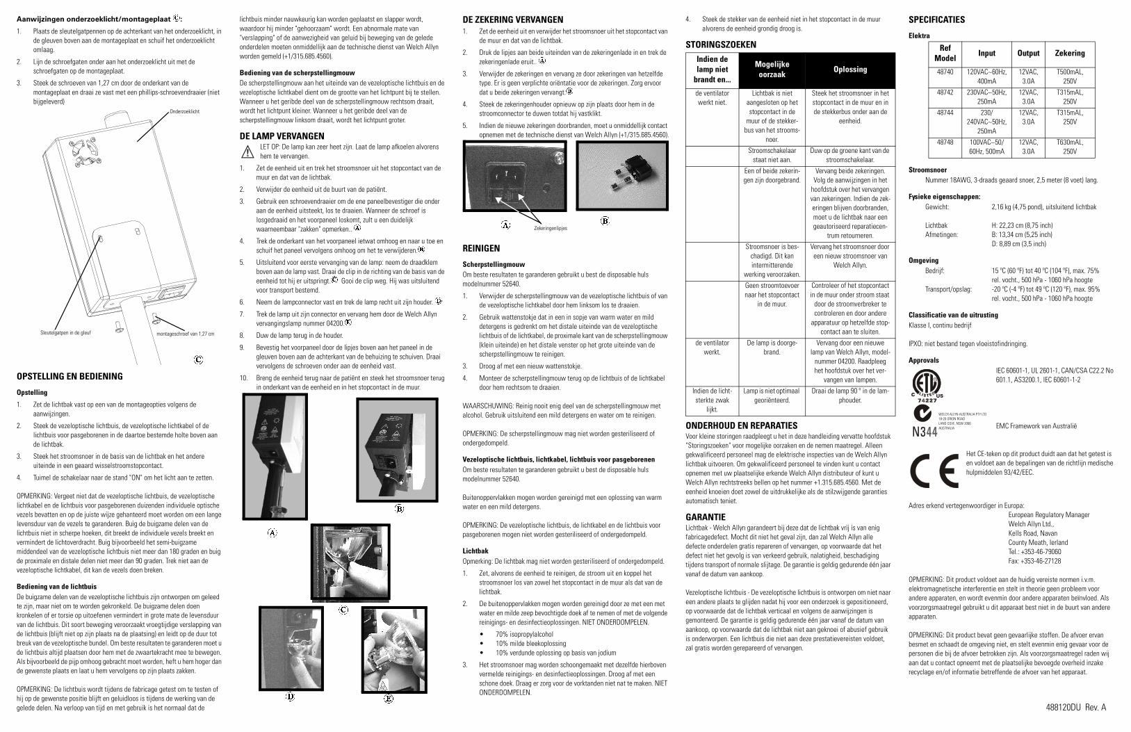
Aanwijzingen onderzoeklicht/montageplaat ��:
1. Plaats de sleutelgatpennen op de achterkant van het onderzoeklicht, in de gleuven boven aan de montageplaat en schuif het onderzoeklicht omlaag.
2. Lijn de schroefgaten onder aan het onderzoeklicht uit met de schroefgaten op de montageplaat.
3. Steek de schroeven van 1,27 cm door de onderkant van de montageplaat en draai ze vast met een phillips-schroevendraaier (niet bijgeleverd)
OPSTELLING EN BEDIENING
Opstelling
1. Zet de lichtbak vast op een van de montageopties volgens de aanwijzingen.
2. Steek de vezeloptische lichtbuis, de vezeloptische lichtkabel of de lichtbuis voor pasgeborenen in de daartoe bestemde holte boven aan de lichtbak.
3. Steek het stroomsnoer in de basis van de lichtbak en het andere uiteinde in een geaard wisselstroomstopcontact.
4. Tuimel de schakelaar naar de stand "ON" om het licht aan te zetten.
OPMERKING: Vergeet niet dat de vezeloptische lichtbuis, de vezeloptische lichtkabel en de lichtbuis voor pasgeborenen duizenden individuele optische vezels bevatten en op de juiste wijze gehanteerd moet worden om een lange levensduur van de vezels te garanderen. Buig de buigzame delen van de lichtbuis niet in scherpe hoeken, dit breekt de individuele vezels breekt en vermindert de lichtoverdracht. Buig bijvoorbeeld het semi-buigzame middendeel van de vezeloptische lichtbuis niet meer dan 180 graden en buig de proximale en distale delen niet meer dan 90 graden. Trek niet aan de vezeloptische lichtkabel, dit kan de vezels doen breken.
Bediening van de lichtbuis De buigzame delen van de vezeloptische lichtbuis zijn ontworpen om geleed te zijn, maar niet om te worden gekronkeld. De buigzame delen doen kronkelen of er torsie op uitoefenen vermindert in grote mate de levensduur van de lichtbuis. Dit soort beweging veroorzaakt vroegtijdige verslapping van de lichtbuis (blijft niet op zijn plaats na de plaatsing) en leidt op de duur tot breuk van de vezeloptische bundel. Om beste resultaten te garanderen moet u de lichtbuis altijd plaatsen door hem met de zwaartekracht mee te bewegen. Als bijvoorbeeld de pijp omhoog gebracht moet worden, heft u hem hoger dan de gewenste plaats en laat u hem vervolgens op zijn plaats zakken.
OPMERKING: De lichtbuis wordt tijdens de fabricage getest om te testen of hij op de gewenste positie blijft en geluidloos is tijdens de werking van de gelede delen. Na verloop van tijd en met gebruik is het normaal dat de
lichtbuis minder nauwkeurig kan worden geplaatst en slapper wordt, waardoor hij minder "gehoorzaam" wordt. Een abnormale mate van "verslapping" of de aanwezigheid van geluid bij beweging van de gelede onderdelen moeten onmiddellijk aan de technische dienst van Welch Allyn worden gemeld (+1/315.685.4560).
Bediening van de scherpstellingmouwDe scherpstellingmouw aan het uiteinde van de vezeloptische lichtbuis en de vezeloptische lichtkabel dient om de grootte van het lichtpunt bij te stellen. Wanneer u het geribde deel van de scherpstellingmouw rechtsom draait, wordt het lichtpunt kleiner. Wanneer u het geribde deel van de scherpstellingmouw linksom draait, wordt het lichtpunt groter.
DE LAMP VERVANGENLET OP: De lamp kan zeer heet zijn. Laat de lamp afkoelen alvorens hem te vervangen.
1. Zet de eenheid uit en trek het stroomsnoer uit het stopcontact van de muur en dat van de lichtbak.
2. Verwijder de eenheid uit de buurt van de patiënt.
3. Gebruik een schroevendraaier om de ene paneelbevestiger die onder aan de eenheid uitsteekt, los te draaien. Wanneer de schroef is losgedraaid en het voorpaneel loskomt, zult u een duidelijk waarneembaar "zakken" opmerken.. ��
4. Trek de onderkant van het voorpaneel ietwat omhoog en naar u toe en schuif het paneel vervolgens omhoog om het te verwijderen.��
5. Uitsluitend voor eerste vervanging van de lamp: neem de draadklem boven aan de lamp vast. Draai de clip in de richting van de basis van de eenheid tot hij er uitspringt.�� Gooi de clip weg. Hij was uitsluitend voor transport bestemd.
6. Neem de lampconnector vast en trek de lamp recht uit zijn houder. ��
7. Trek de lamp uit zijn connector en vervang hem door de Welch Allyn vervangingslamp nummer 04200.��
8. Duw de lamp terug in de houder.
9. Bevestig het voorpaneel door de lipjes boven aan het paneel in de gleuven boven aan de achterkant van de behuizing te schuiven. Draai vervolgens de schroeven onder aan de eenheid vast.
10. Breng de eenheid terug naar de patiënt en steek het stroomsnoer terug in onderkant van de eenheid en in het stopcontact in de muur.
DE ZEKERING VERVANGEN1. Zet de eenheid uit en verwijder het stroomsnoer uit het stopcontact van
de muur en dat van de lichtbak.
2. Druk de lipjes aan beide uiteinden van de zekeringenlade in en trek de zekeringenlade eruit.. ��
3. Verwijder de zekeringen en vervang ze door zekeringen van hetzelfde type. Er is geen verplichte oriëntatie voor de zekeringen. Zorg ervoor dat u beide zekeringen vervangt.��
4. Steek de zekeringenhouder opnieuw op zijn plaats door hem in de stroomconnector te duwen totdat hij vastklikt.
5. Indien de nieuwe zekeringen doorbranden, moet u onmiddellijk contact opnemen met de technische dienst van Welch Allyn (+1/315.685.4560).
REINIGEN
Scherpstellingmouw Om beste resultaten te garanderen gebruikt u best de disposable huls modelnummer 52640.
1. Verwijder de scherpstellingmouw van de vezeloptische lichtbuis of van de vezeloptische lichtkabel door hem linksom los te draaien.
2. Gebruik wattenstokje dat in een in sopje van warm water en mild detergens is gedrenkt om het distale uiteinde van de vezeloptische lichtbuis of de lichtkabel, de proximale kant van de scherpstellingmouw (klein uiteinde) en het distale venster op het grote uiteinde van de scherpstellingmouw te reinigen.
3. Droog af met een nieuw wattenstokje.
4. Monteer de scherpstellingmouw terug op de lichtbuis of de lichtkabel door hem rechtsom te draaien.
WAARSCHUWING: Reinig nooit enig deel van de scherpstellingmouw met alcohol. Gebruik uitsluitend een mild detergens en water om te reinigen.
OPMERKING: De scherpstellingmouw mag niet worden gesteriliseerd of ondergedompeld.
Vezeloptische lichtbuis, lichtkabel, lichtbuis voor pasgeborenenOm beste resultaten te garanderen gebruikt u best de disposable huls modelnummer 52640.
Buitenoppervlakken mogen worden gereinigd met een oplossing van warm water en een mild detergens.
OPMERKING: De vezeloptische lichtbuis, de lichtkabel en de lichtbuis voor pasgeborenen mogen niet worden gesteriliseerd of ondergedompeld.
LichtbakOpmerking: De lichtbak mag niet worden gesteriliseerd of ondergedompeld.
1. Zet, alvorens de eenheid te reinigen, de stroom uit en koppel het stroomsnoer los van zowel het stopcontact in de muur als dat van de lichtbak.
2. De buitenoppervlakken mogen worden gereinigd door ze met een met water en milde zeep bevochtigde doek af te nemen of met de volgende reinigings- en desinfectieoplossingen. NIET ONDERDOMPELEN.
• 70% isopropylalcohol• 10% milde bleekoplossing• 10% verdunde oplossing op basis van jodium
3. Het stroomsnoer mag worden schoongemaakt met dezelfde hierboven vermelde reinigings- en desinfectieoplossingen. Droog af met een schone doek. Draag er zorg voor de vorktanden niet nat te maken. NIET ONDERDOMPELEN.
4. Steek de stekker van de eenheid niet in het stopcontact in de muur alvorens de eenheid grondig droog is.
STORINGSZOEKEN
ONDERHOUD EN REPARATIESVoor kleine storingen raadpleegt u het in deze handleiding vervatte hoofdstuk "Storingszoeken" voor mogelijke oorzaken en de nemen maatregel. Alleen gekwalificeerd personeel mag de elektrische inspecties van de Welch Allyn lichtbak uitvoeren. Om gekwalificeerd personeel te vinden kunt u contact opnemen met uw plaatselijke erkende Welch Allyn distributeur of kunt u Welch Allyn rechtstreeks bellen op het nummer +1.315.685.4560. Met de eenheid knoeien doet zowel de uitdrukkelijke als de stilzwijgende garanties automatisch teniet.
GARANTIELichtbak - Welch Allyn garandeert bij deze dat de lichtbak vrij is van enig fabricagedefect. Mocht dit niet het geval zijn, dan zal Welch Allyn alle defecte onderdelen gratis repareren of vervangen, op voorwaarde dat het defect niet het gevolg is van verkeerd gebruik, nalatigheid, beschadiging tijdens transport of normale slijtage. De garantie is geldig gedurende één jaar vanaf de datum van aankoop.
Vezeloptische lichtbuis - De vezeloptische lichtbuis is ontworpen om niet naar een andere plaats te glijden nadat hij voor een onderzoek is gepositioneerd, op voorwaarde dat de lichtbak verticaal en volgens de aanwijzingen is gemonteerd. De garantie is geldig gedurende één jaar vanaf de datum van aankoop, op voorwaarde dat de lichtbak niet aan geknoei of abusief gebruik is onderworpen. Een lichtbuis die niet aan deze prestatievereisten voldoet, zal gratis worden gerepareerd of vervangen.
SPECIFICATIES
Elektra
Stroomsnoer Nummer 18AWG, 3-draads geaard snoer, 2,5 meter (8 voet) lang.
Fysieke eigenschappen:Gewicht: 2,16 kg (4,75 pond), uitsluitend lichtbak
Lichtbak H: 22,23 cm (8,75 inch)Afmetingen: B: 13,34 cm (5,25 inch)
D: 8,89 cm (3,5 inch)
OmgevingBedrijf: 15 ºC (60 ºF) tot 40 ºC (104 ºF), max. 75%
rel. vocht., 500 hPa - 1060 hPa hoogteTransport/opslag: -20 ºC (-4 ºF) tot 49 ºC (120 ºF), max. 95%
rel. vocht., 500 hPa - 1060 hPa hoogte
Classificatie van de uitrustingKlasse I, continu bedrijf
IPXO: niet bestand tegen vloeistofindringing.
ApprovalsIEC 60601-1, UL 2601-1, CAN/CSA C22.2 No 601.1, AS3200.1, IEC 60601-1-2
EMC Framework van Australië
Het CE-teken op dit product duidt aan dat het getest is en voldoet aan de bepalingen van de richtlijn medische hulpmiddelen 93/42/EEC.
Adres erkend vertegenwoordiger in Europa:European Regulatory ManagerWelch Allyn Ltd.,Kells Road, NavanCounty Meath, IerlandTel.: +353-46-79060Fax: +353-46-27128
OPMERKING: Dit product voldoet aan de huidig vereiste normen i.v.m. elektromagnetische interferentie en stelt in theorie geen probleem voor andere apparaten, en wordt evenmin door andere apparaten beïnvloed. Als voorzorgsmaatregel gebruikt u dit apparaat best niet in de buurt van andere apparaten.
OPMERKING: Dit product bevat geen gevaarlijke stoffen. De afvoer ervan besmet en schaadt de omgeving niet, en stelt evenmin enig gevaar voor de personen die bij de afvoer betrokken zijn. Als voorzorgsmaatregel raden wij aan dat u contact opneemt met de plaatselijke bevoegde overheid inzake recyclage en/of informatie betreffende de afvoer van het apparaat.
montageschroef van 1,27 cm
Onderzoeklicht
Sleutelgatpen in de gleuf
��
����
��
��
��
�� ��Zekeringenlipjes
Indien de lamp niet
brandt en...
Mogelijke oorzaak
Oplossing
de ventilator werkt niet.
Lichtbak is niet aangesloten op het stopcontact in de
muur of de stekker-bus van het strooms-
noer.
Steek het stroomsnoer in het stopcontact in de muur en in de stekkerbus onder aan de
eenheid.
Stroomschakelaar staat niet aan.
Duw op de groene kant van de stroomschakelaar.
Een of beide zekerin-gen zijn doorgebrand.
Vervang beide zekeringen. Volg de aanwijzingen in het
hoofdstuk over het vervangen van zekeringen. Indien de zek-eringen blijven doorbranden, moet u de lichtbak naar een geautoriseerd reparatiecen-
trum retourneren.
Stroomsnoer is bes-chadigd. Dit kan intermitterende
werking veroorzaken.
Vervang het stroomsnoer door een nieuw stroomsnoer van
Welch Allyn.
Geen stroomtoevoer naar het stopcontact
in de muur.
Controleer of het stopcontact in de muur onder stroom staat
door de stroomverbreker te controleren en door andere
apparatuur op hetzelfde stop-contact aan te sluiten.
de ventilator werkt.
De lamp is doorge-brand.
Vervang door een nieuwe lamp van Welch Allyn, model-
nummer 04200. Raadpleeg het hoofdstuk over het ver-
vangen van lampen.
Indien de licht-sterkte zwak
lijkt.
Lamp is niet optimaal georiënteerd.
Draai de lamp 90 º in de lam-phouder.
Ref Model
Input Output Zekering
48740 120VAC∼60Hz, 400mA
12VAC, 3.0A
T500mAL, 250V
48742 230VAC∼50Hz, 250mA
12VAC, 3.0A
T315mAL, 250V
48744 230/240VAC∼50Hz,
250mA
12VAC, 3.0A
T315mAL, 250V
48748 100VAC∼50/60Hz, 500mA
12VAC, 3.0A
T630mAL, 250V
US
WELCH ALLYN AUSTRALIA PTY LTD18-20 ORION ROADLAND COVE, NSW 2066AUSTRALIA
488120DU Rev. A

Halogen-Untersuchungsleuchte Exam Light III mit fase-roptischer LichtleitungREF - 48700, 48722, 48724, 48726, 48728
Halogen-Untersuchungsleuchte Exam Light III mit fase-roptischem LichtkabelREF- 48780, 48782, 48784, 48786, 48788
Halogen-Untersuchungsleuchte Exam Light III mit Neo-natal-LichtleitungREF - 48760, 48762, 48764, 48766, 48768
Halogen-Untersuchungsleuchte Exam Light III Licht-kasten mit NetzkabelREF - 48740, 48742, 48744, 48746, 48748
Wir bedanken uns, dass Sie sich zum Kauf einer Welch Allyn Untersuchungsleuchte Exam Light III entschlossen haben. Wir glauben, dass diese Halogenleuchte heute weltweit das qualitativ hochwertigste Gerät seiner Art ist. Befolgen Sie die einfachen Richtlinien in dieser Anleitung und sichern Sie sich damit eine zuverlässige und störungsfreie Geräteleistung für viele Jahre. Bei Fragen oder Problemen wenden Sie sich bitte während der normalen Geschäftszeiten unter der Nummer (800) 535-6663 an unseren Kundendienst bzw. technischen Dienst.
Welch Allyn setzt sich auch weiterhin engagiert für die Lieferung innovativer und qualitativ hochwertiger Diagnoseprodukte für den medizinischen Fachbereich ein. Für einen Katalog unserer gesamten Produktpalette setzen Sie sich bitte mit uns unter der Nummer (800) 535-6663 in Verbindung oder besuchen Sie unsere Website unter www.WelchAllyn.com.
ERLÄUTERUNG DER SYMBOLEVorsicht: Weitere Informationen bitte dem Benutzerhandbuch entnehmen.
Warnung: Feuergefahr. Sicherungen anhand der Markierungen austauschen.
Vorsicht: Hohe Temperaturen
Vorsicht: Hochintensives Licht
WARNHINWEISE UND VORSICHTSMASSNAHMENWARNUNG: Zur Bedienung dieses Geräts müssen Sie in den für den Umgang mit diesem Instrument geeigneten medizinischen Verfahren gründlich ausgebildet sein. Nehmen Sie sich die Zeit, die in der vorliegenden Betriebsanleitung enthaltenen Anweisungen vor dem Gebrauch dieses Produkts gründlich durchzulesen, damit Sie sie gut verstehen. Die Anleitungen für zusätzliche, mit der Untersuchungsleuchte Exam Light III gemeinsam benutzte Geräte (z.B. Absaugapparate, elektrochirurgische Generatoren usw.) sollten Sie ebenfalls lesen und gut verstehen. Wenn Sie das Gerät benutzen, ohne mit seinen Betriebsvoraussetzungen gut vertraut zu sein, können Sie bzw. der Patient verletzt und/oder das Gerät beschädigt werden.
VORSICHT: Gefahr eines elektrischen Schlages - Das Netzkabel aus der Steckdose ziehen und die Lampe vor dem Austausch abkühlen lassen (Welch Allyn Lampe Nr. 04200).
GEFAHR: Bei Gebrauch in der Nähe entzündlicher Anästhetika besteht Explosionsgefahr.
VORSICHT: Gemäß US-Bundesrecht darf dieses Gerät nur durch einen Arzt bzw. auf Anordnung eines Arztes verkauft werden.
VORSICHT: Die Beleuchtung ist intensiv - Nicht längere Zeit in die eingeschaltete Lichtquelle blicken, da dies zu Augenschäden führen kann.
VORSICHT: Die Untersuchungsleuchte im angezeigten Arbeitsabstand von 30 bis 60 cm verwenden. Bei Benutzung in geringerem Abstand kann es zu Hautverletzungen kommen.
WARNUNG: Ohne Einsatz des Neonatal-Transilluminators Nr. 48210 (mit UV-Filter) keine Neugeborenendurchleuchtung vornehmen. Den Fokussierungsaufsatz nicht von der Lichtleitung abnehmen und die Lichtleitung nicht zur Durchleuchtung verwenden. Andernfalls kann es zu schweren Verbrennungen kommen.
Zu den empfohlenen allgemeinen Maßnahmen zur Minimierung von Hautschäden aufgrund optischer Strahlungsgefahren gehören: Minimierung der Beleuchtungsintensität an der Untersuchungsstelle, Minimierung der Beleuchtungsdauer und Anwendung weiterer Vorsichtsmaßnahmen, wenn die Sensibilität der Haut aufgrund von Gewebstrauma oder Anästhesie beeinflusst wurde.
Zu den empfohlenen allgemeinen Maßnahmen zur Minimierung der Gefahr von Augenschäden aufgrund optischer Strahlungsgefahren gehören: Nicht in helle Lichtquellen und deren Reflektionen blicken und die Augen bei Abwesenheit normaler Pupillengrößen und automatischer Aversionsreaktionen schützen.
Außer den Lampen und Sicherungen enthält das Gerät keine Teile, die vom Bediener gewartet bzw. ausgetauscht werden können. Bitte wenden Sie sich für jegliche anderen Wartungsarbeiten an die qualifizierten und autorisierten Kundendienstcenter.
KOMPONENTEN
Standard
Lichtkasten, Netzkabel und WandhalterungModell 48740 (USA)Modell 48742 (Europa)Modell 48744 (GB)Modell 48746 (Australien)Modell 48748 (Japan)
Faseroptische Lichtleitung (abgebildet mit dem Fokussierungsaufsatz)
Modell 48200 (Inbegriffen nur bei Modell-Nr. 48700, 48722, 48724, 48726 und 48728)
Faseroptisches Lichtkabel (abgebildet mit dem Fokussierungsaufsatz)
Modell 48220 (Inbegriffen nur bei Modell-Nr. 48780, 48782, 48784, 48786 und 48788)
Neonatal-TransilluminatorModell 48210(Inbegriffen nur bei Modell-Nr. 48760, 48762, 48764, 48766 und 48768)
FokussierungsaufsatzModell 48605(Inbegriffen nur bei Modell-Nr. 48700, 48722, 48724, 48726, 48728, 48780, 48782, 48784, 48786 und 48788)
Zubehör
Faseroptische Lichtleitung (abgebildet mit dem Fokussierungsaufsatz)
Modell 48200
Faseroptisches Lichtkabel (abgebildet mit dem Fokussierungsaufsatz)
Modell 48220
FokussierungsaufsatzModell 48605
Neonatal-TransilluminatorModell 48210Die Option Neonatal-Lichtleitung/-Transilluminator unterstützt die Diagnose eines Pneumothorax, das Auffinden von Blutgefäßen usw. Zu diesem Transilluminator gehört ein permanent angebrachter Ultraviolettfilter, der die Übertragung von ultraviolettem Licht auf ein Minimum reduziert. Dadurch wird bei einem Hautkontakt, der fünf Minuten oder länger dauert, die Erhöhung der Hauttemperatur um mehr als 4 °C verhindert. Die Standard-Lichtleitung sollte NICHT zur Durchleuchtung von Neugeborenen benutzt werden.
TischhalterungsarmModell 48859
Fahrbares StativModell 48850
EinweghüllenModell 52640
Einweghüllen-SpenderModell 52641
Halogen-Ersatzlampe (35 Watt)Modell 04200
BEFESTIGUNG Um den sachgemäßen Betrieb des Lichtkastens zu gewährleisten, muss eine der folgenden drei Befestigungsmöglichkeiten gewählt werden.
WandhalterungEine geeignete Befestigungsstelle aussuchen. Die Länge der Lichtleitung beträgt im ausgezogenen Zustand 1,20 m (das faseroptische Lichtkabel ist 2,30 m lang). Beim Aussuchen einer Befestigungsstelle müssen diese Maße zusätzlich zum Einsatzabstand der Leuchte und Teil des Untersuchungstisches, der benutzt werden soll, berücksichtigt werden.
1. Die Montageplatte als Vorlage nehmen und nach Bedarf Bohrlöcher markieren (je nach Wandtyp).
• Trockenmauer, Täfelung, Sperrholz oder Verputz (0,3 cm bis 1,6 cm dick) - vier (4) Löcher (1 cm) bohren und hohle Wandankereinheiten aus Metall einsetzen.
• Betonblockstein - vier (4) Löcher (0,5 cm) bohren und Anker aus Kunststoff einsetzen. Mit 8 x 1/2-Zoll-Schrauben sichern.
• Metallverkleidete oder Sperrholzwände mit einer Dicke von mehr als 1,6 cm - vier (4) Löcher (0,3 cm) bohren. Mit 8 x 1-Zoll-Schrauben sichern.
2. Wenn die Löcher gebohrt sind, die Montageplatte mit den entsprechenden Schrauben installieren. Die Schrauben fest anziehen, so das zwischen den Schraubenköpfen und der Montageplatte keine Ritzen bleiben.
3. Den Lichtkasten an der Platte befestigen, indem die Stifte auf der Rückseite des Lichtkastens in die Schlitze an der Montageplatte gesteckt werden. Den Lichtkasten absenken, bis die Stifte im engen Teil der Montageschlitze positioniert sind ��.
4. Zur Befestigung des Lichtkastens an der Platte zwei Schrauben (1,27 cm) durch die Unterseite der Montageplatte führen und mit einem Kreuzschlitzschraubenzieher im Boden des Lichtkastens festziehen ��.
Tischhalterung(Modell-Nr. 48859)HINWEIS: Manche Hersteller von Untersuchungstischen liefern die Teile zur Befestigung der Untersuchungsleuchte Exam Light III mit. Wenden Sie sich an den Hersteller Ihres Tisches, um herauszufinden, ob dies der Fall ist.WARNUNG: Die Gesundheitseinrichtung bzw. der Benutzer muss verantwortlich sicherstellen, dass die Montagehalterung sicher an der Wand bzw. am Tisch befestigt bzw. das fahrbare Stativ sicher zusammengebaut und die Untersuchungsleuchte sicher an der Halterung bzw. am Ständer angebracht ist, wie nachfolgend erläutert wird. Beziehen Sie die Belastung, der die Halterung widerstehen muss, in Ihre Überlegungen mit ein. Welch Allyn, Inc. übernimmt ungeachtet der Art der Halterungen und der angewendeten Methode keine Verantwortung für Installationen oder Schäden und Körperverletzungen, die aufgrund der Installation einer Montagehalterung oder eines fahrbaren Ständers entstehen.
1. Bestimmen, welche Seite des Tisches sich am besten für die Befestigung der Leuchte eignet. Dabei den Abstand zur nächsten Steckdose und den Fußverkehr um den Tisch herum berücksichtigen.
HINWEIS: Vergewissern Sie sich, dass sich die Befestigungsstelle mindestens 25,4 cm unterhalb des Tischpolsters befindet und dass sie den Betrieb des Tisches nicht beeinträchtigt.
2. Die Montageplatte als Vorlage nehmen und die Stellen für die Löcher auf dem Tisch markieren und vier (4) Löcher (0,64 cm) in den Tisch bohren.
3. Die Montageplatte mit vier 8-32 Schrauben mit Unterlegscheiben und Muttern wie im Diagramm gezeigt am Tisch befestigen.
4. Den Lichtkasten an der Platte befestigen, indem die Stifte auf der Rückseite des Lichtkastens in die Schlitze an der Montageplatte
gesteckt werden. Den Lichtkasten absenken, bis die Stifte im engen Teil der Montageschlitze positioniert sind.
5. Zur Befestigung des Lichtkastens an der Platte zwei Schrauben (1,27 cm) durch die Unterseite der Montageplatte führen und mit einem Kreuzschlitzschraubenzieher im Boden des Lichtkastens festziehen.
HINWEIS: Einige Tische benötigen eine Verstärkung der Montagehalterungen, um die befestigte Leuchte zu stützen. In einem solchen Fall empfehlen wir die Verwendung eines 2,5 cm dicken Stücks Sperrholz. Befolgen Sie bitte zur Verstärkung der Halterung Schritte 6-11.
6. Den Umriss der Montageplatte anzeichnen und die Stellen für die Löcher auf einer1,9 cm dicken Sperrholzplatte markieren.
7. Die Holzplatte entlang des angezeichneten Umrisses ausschneiden und vier Löcher (0,64 cm) bohren.
8. Die Montageplatte als Vorlage nehmen und die Stellen für die Löcher auf dem Tisch markieren und vier (4) Löcher (0,64 cm) in den Tisch bohren.
9. Den Holzblock und die Montageplatte mit vier 8-32 x 2-Zoll-Schrauben mit Unterlegscheiben und Muttern wie im Diagramm gezeigt am Tisch befestigen.
10. Den Lichtkasten an der Platte befestigen, indem die Stifte auf der Rückseite des Lichtkastens in die Schlitze an der Montageplatte gesteckt werden. Den Lichtkasten absenken, bis die Stifte im engen Teil der Montageschlitze positioniert sind.
11. Zur Befestigung des Lichtkastens an der Platte zwei Schrauben (1,27 cm) durch die Unterseite der Montageplatte führen und mit einem Kreuzschlitzschraubenzieher im Boden des Lichtkastens festziehen.
Fahrbares Stativ (Modell-Nr. 48850)
Anleitung für den Zusam-menbau der Rollen und des Trägers ��:Die Rollen in die Löcher am Träger stecken, bis sie einschnappen. Die verschiedenen Rollen wie abgebildet abwechselnd verwenden.
Anleitung für den Zusam-menbau des Trägers und des Ständers ��:
1. Den Ständer in das mittlere Loch am Träger stecken.
2. In das mittlere Loch einen Federring (0,64 cm), eine flache Unterlegscheibe (1,9 cm) und eine Inbusschraube (3,2 cm) einsetzen. Die Inbusschraube mit einem Innensechskantschlüssel festziehen.
Anleitung für die Untersuchungsleuchte/Montageplatte: ��
1. Die Schlüssellochstifte an der Rückseite der Untersuchungsleuchte in die Schlitze oben an der Montageplatte einsetzen und nach unten schieben.
2. Die Schraubenlöcher an der Unterseite der Untersuchungsleuchte mit den Schraubenlöchern in der Montageplatte ausrichten.
Halogen Exam Light III
�� ��
Sperrrolle
Sperrrolle
Träger
��
Innensechskantschlüssel
Inbusschraube
Federring (0,64 cm)
Flache Unterlegscheibe (1,9 cm)
Träger
Ständer
Montageplatte
��

3. Die Schrauben (1,27 cm) durch den Boden der Montageplatte führen und mit einem Kreuzschlitzschraubenzieher (nicht im Lieferumfang enthalten) festziehen..
AUFBAU UND BETRIEB
Aufbau
1. Den Lichtkasten gemäß der entsprechenden Anleitung an einer der Halterungsoptionen befestigen.
2. Die faseroptische Lichtleitung, das faseroptische Lichtkabel oder die Neonatal-Lichtleitung in den Lichtleitungsanschluss oben am Lichtkasten einführen.
3. Das Netzkabel in das Gehäuse des Lichtkastens und in eine geerdete Wechselstromquelle einstecken.
4. Den Lichtschalter zur Inbetriebnahme in die Stellung „ON“ (EIN) bringen.
HINWEIS: Bedenken Sie, dass die faseroptische Lichtleitung, das faseroptische Lichtkabel und die Neonatal-Lichtleitung mehrere Tausend einzelne optische Fasern enthalten und zur Gewährleistung der langen Lebensdauer dieser Fasern sachgemäß gehandhabt werden müssen. Die flexiblen Teile der Lichtleitung nicht in einem spitzen Winkel biegen, da dies zum Bruch einzelner Fasern und zur Reduzierung der übertragenen Lichtleistung führt. Das halbflexible Mittelteil der faseroptischen Lichtleitung nicht um mehr als 180 Grad und die proximalen und distalen Teile nicht um mehr als 90 Grad biegen. Nicht am faseroptischen Lichtkabel ziehen, da dies zum Bruch von Fasern führen kann.
Bedienung der Lichtleitung Die biegsamen Teile der faseroptischen Lichtleitung sind so konzipiert, dass sie zwar geschwenkt, nicht jedoch verdreht werden sollten. Das Verdrehen oder gewaltsame Krümmen der biegsamen Teile führt zu einer wesentlichen Verkürzung der Lebensdauer der Lichtleitung. Diese Art Bewegung verursacht vorzeitiges Absinken der Lichtleitung (so dass sie nach dem Platzieren nicht fest an ihrem Platz bleibt) und schließlich den Bruch des Glasfaserbündels. Die Lichtleitung für beste Leistung stets in einer Bewegung in Richtung Schwerkraft positionieren. Soll die Leitung zum Beispiel höher gestellt werden, diese über die gewünschte Position hinaus nach oben ziehen und dann nach unten an ihren Platz absinken lassen.
HINWEIS: Die Lichtleitung wird bei der Herstellung getestet, um sicherzustellen, dass sie zuverlässig positioniert werden kann, und um zu prüfen, dass bei der Positionierung keine Geräusche auftreten. Es ist jedoch normal, dass die Positionierfreundlichkeit der Lichtleitung im Laufe der Zeit und bei normalem Gebrauch nachlässt und die Lichtleitung daher weniger leicht zu handhaben ist. Übermäßiges Nachlassen bzw. Auftreten eines
Geräusches bei der Positionierung sollten dem technischen Dienst von Welch Allyn (Tel.: +001-315-685-4560) unverzüglich mitgeteilt werden.
Bedienung des FokussierungsaufsatzesDer Fokussierungsaufsatz am Ende der faseroptischen Lichtleitung und des faseroptischen Lichtkabels ermöglicht die Einstellung der Punktstrahlgröße bei der Beleuchtung. Durch Drehen des gerändelten Teils des Fokussierungsaufsatzes im Uhrzeigersinn wird der Punktstrahl kleiner. Das Drehen des gerändelten Teils des Fokussierungsaufsatzes gegen den Uhrzeigersinn vergrößert den Punktstrahl.
AUSTAUSCH DER LAMPEVORSICHT: Die Lampe kann sehr heiß sein, daher vor dem Austausch abkühlen lassen.
1. Das Gerät ausschalten und das Netzkabel sowohl aus der Wandsteckdose als auch aus dem Lichtkasten abziehen.
2. Das Gerät aus dem Patientenbereich entfernen.
3. Das Verbindungselement, das aus dem Boden des Geräts ragt, mit einem Schraubenzieher lösen. Beim Freigeben der Frontverkleidung ist dann ein hörbares „Fallen“ vernehmbar. ��
4. Den unteren Teil der Frontverkleidung leicht nach vorne und nach oben ziehen und die Frontverkleidung abnehmen.��
5. Nur beim erstmaligen Austausch der Lampe: Die Drahtklammer oben an der Lampe greifen und in Richtung des Gerätegehäuses drehen, bis sie herausspringt. Die Klammer wegwerfen.�� Sie wird nur zu Versandzwecken gebraucht.
6. Den Lampenanschluss greifen und die Lampe gerade aus der Halterung ziehen. ��
7. Die Lampe aus dem Anschluss ziehen und durch eine Welch Allyn Ersatzlampe Nr. 04200 ersetzen.��
8. Die Lampe wieder in die Halterung hineindrücken.
9. Die Frontverkleidung wieder befestigen: Dazu die Laschen am Oberteil der Verkleidung in die Schlitze oben am hinteren Gehäuse stecken und die Schraube unten am Gerät festziehen.
10. Das Gerät wieder an seinen Platz im Patientenbereich bringen und das Netzkabel wieder im Boden des Geräts und in die Wandsteckdose einstecken.
AUSTAUSCH DER SICHERUNGEN1. Das Gerät ausschalten und das Netzkabel sowohl aus der
Wandsteckdose als auch aus dem Lichtkasten abziehen.
2. Auf die Laschen an beiden Enden der Sicherungslade drücken und die Sicherungslade herausziehen. ��
3. Die Sicherungen herausnehmen und durch neue Sicherungen desselben Typs ersetzen. Die Sicherungen müssen nicht in einer bestimmten Richtung eingelegt werden. Unbedingt beide Sicherungen austauschen.��
4. Die Sicherungslade wieder einsetzen, indem sie bis zum Einschnappen in den Netzanschluss gerückt wird.
5. Brennen die neuen Sicherungen durch, unverzüglich mit dem technischen Dienst von Welch Allyn (Tel.: +001-315-685-4560) Kontakt aufnehmen..
REINIGUNG
FokussierungsaufsatzFür optimale Leistung die Einweghülle Modell-Nr. 52640 verwenden.
1. Den Fokussierungsaufsatz durch Drehen gegen den Uhrzeigersinn von der faseroptischen Lichtleitung bzw. dem faseroptischen Lichtkabel abnehmen.
2. Das distale Ende der faseroptischen Lichtleitung bzw. des faseroptischen Lichtkabels, die proximale Seite des Fokussierungsaufsatzes (das kleine Ende) sowie das große Ende des Fokussierungsaufsatzes mit einem in warmem Wasser und einem milden Reinigungsmittel angefeuchteten Wattestäbchen reinigen.
3. Mit einem neuen Wattestäbchen abtrocknen.
4. Den Fokussierungsaufsatz durch Drehen im Uhrzeigersinn wieder mit der Lichtleitung bzw. dem Lichtkabel verbinden.
WARNUNG: Die Teile des Fokussierungsaufsatzes nicht mit Alkohol, sondern ausschließlich mit einem milden Reinigungsmittel und Wasser reinigen. HINWEIS: Den Fokussierungsaufsatz nicht sterilisieren oder in Flüssigkeiten eintauchen.
Faseroptische Lichtleitung, faseroptisches Lichtkabel, Neonatal-LichtleitungFür optimale Leistung die Einweghülle Modell-Nr. 52640 verwenden.
Die Außenflächen können mit einer Lösung aus warmem Wasser und mildem Reinigungsmittel gereinigt werden.
HINWEIS: Die faseroptische Lichtleitung, das faseroptische Lichtkabel und die Neonatal-Lichtleitung nicht sterilisieren oder in Flüssigkeiten eintauchen.
LichtkastenHinweis: Den Lichtkasten nicht sterilisieren oder in Flüssigkeiten eintauchen.
1. Vor der Reinigung den Strom abschalten und das Netzkabel sowohl aus der Wandsteckdose als auch dem Lichtkasten abziehen.
2. Die Außenflächen können mit einem mit milder Seife und Wasser angefeuchteten Tuch oder mit den folgenden Reinigungs-/Desinfektionslösungen gereinigt werden. NICHT IN FLÜSSIGKEITEN EINTAUCHEN.
• 70%iger Isopropylalkohol• 10%ige milde Bleichmittellösung• 10%ige jodhaltige Lösung
3. Das Netzkabel kann mit den oben genannten Reinigungs-/Desinfektionslösungen saubergewischt werden. Mit einem sauberen Tuch trockenreiben. Sorgfältig darauf achten, dass die Stifte nicht nass werden. NICHT IN FLÜSSIGKEITEN EINTAUCHEN.
4. Das Gerät erst dann an die Wandsteckdose anschliessen, wenn es gründlich getrocknet ist.
FEHLERSUCHE
WARTUNG UND REPARATURBei geringen Problemen konsultieren Sie bitte zunächst den Abschnitt „Fehlersuche“ in der vorliegenden Betriebsanleitung für mögliche Ursachen und Abhilfemaßnahmen. Inspektionen der Elektrik des Welch Allyn Lichtkastens sollten ausschließlich von qualifiziertem Personal durchgeführt werden. Nehmen Sie dazu mit Ihrem örtlichen Welch Allyn-Vertriebshändler Kontakt auf oder wenden Sie sich direkt an Welch Allyn unter der Telefonnummer +001-315-685-4560. Unbefugte Eingriffe in das Gerät haben automatisch die Ungültigmachung aller ausdrücklichen und stillschweigenden Garantien zur Folge.
GARANTIELichtkasten - Welch Allyn garantiert, dass der Lichtkasten frei von Herstellungsfehlern ist. Teile, die nachweislich durch andere Ursachen als Missbrauch, Unterlassung, Beschädigungen während des Versands und normaler Abnutzung defekt sind, werden von Welch Allyn kostenlos repariert oder ersetzt. Diese Garantie ist für die Dauer eines Jahres ab Originalkaufdatum gültig.
Faseroptische Lichtleitung - Die faseroptische Lichtleitung wurde so konzipiert, dass sie bei vertikal und gemäß der Anleitung befestigtem Lichtkasten nach der Positionierung für eine Untersuchung nicht mehr abschwenkt. Die Garantie ist für die Dauer eines Jahres ab Originalkaufdatum gültig, vorausgesetzt, in die Lichtleitung wurde weder unbefugt eingegriffen noch wurde sie missbraucht. Alle Lichtleitungen, die diese Leistungsvoraussetzungen nicht erfüllen, werden kostenlos für den Kunden repariert oder ersetzt.
TECHNISCHE DATEN
Elektrik
TECHNISCHE DATEN #18AWG, geerdeter Kabelsatz mit 3 Drähten, 2,5 m lang.
Gewicht und AbmessungenGewicht: 2,16 kg, nur LichtkastenAbmessungen des Höhe: 22,23 cmLichtkastens: Breite: 13,34 cm
Tiefe: 8,89 cm
UmgebungsdatenBetrieb: 15 °C bis 40 °C, max. 75 %
rel. Luftfeuchtigkeit, 500 hPa - 1060 hPa HöheTransport/Lagerung: -20 °C bis 49 °C, max.. 95 %
rel. Luftfeuchtigkeit, 500 hPa - 1060 hPa Höhe
GeräteklassifizierungKlasse I, Dauerbetrieb
IPXØ: Kein Schutz gegen eindringendes Wasser.
Genehmigungen
IEC 60601-1, UL 2601-1, CAN/CSA C22.2 Nr. 601.1, AS3200.1, IEC 60601-1-2
EMV-Richtlinien für Australien
Das CE-Zeichen an diesem Produkt weist darauf hin, dass es gemäß der Richtlinie 93/42/EEC für medizinische Geräte getestet wurde und die Anforderungen dieser Richtlinie erfüllt.
Autorisierte europäische Vertretung:European Regulatory ManagerWelch Allyn Ltd.,Kells Road, Navan,County Meath, Republik Irland.Tel.: 353-46-79060Fax: 353-46-27128
HINWEIS: Dieses Produkt entspricht den derzeit gültigen Normen für elektromagnetische Interferenz und sollte den Betrieb anderer Geräte nicht beeinträchtigen bzw. nicht von anderen Geräten in seinem Betrieb beeinträchtigt werden. Das Gerät vorsichtshalber nicht in unmittelbarer Nähe anderer Geräte verwenden.
HINWEIS: Dieses Produkt enthält keine Gefahrenstoffe. Seine Entsorgung stellt kein Risiko für Personen dar und die Umwelt wird weder verseucht noch belastet. Es wird jedoch empfohlen, vorsichtshalber mit den örtlichen Entsorgungs- und/oder Recycling-Behörden Kontakt aufzunehmen, um Hinweise bezüglich der Entsorgung des Geräts zu erhalten.
Montageschraube (1,27 cm)
Untersuchungsleuchte
Schlüssellochstift im Schlitz.
��
����
��
��
��
�� ��Fuse Tabs
Wenn die Lampe nicht leuchtet und
…
Mögliche Ursache
Abhilfemaßnahme
das Gebläse nicht funktioniert.
Der Lichtkasten ist entweder nicht in die Wandsteckdose oder die Netzkabelbuchse
eingesteckt.
Das Netzkabel in die Wand-steckdose und die Netzka-belbuchse im Boden des
Geräts einstecken.
Der Netzschalter ist nicht eingeschaltet.
Die grüne Seite des Netzschalters drücken.
Eine oder beide Sicherungen durch-
gebrannt.
Beide Sicherungen austaus-chen. Den Anleitungen im Abschnitt „Austausch der
Sicherungen“ folgen. Bren-nen die Sicherungen auch weiterhin durch, muss der Lichtkasten an ein autorisi-ertes Kundendienstcenter
weitergeleitet werden.
Das Netzkabel ist beschädigt. Dies kann zu unterbro-chenem Betrieb
führen.
Das Netzkabel durch ein neues Netzkabel von Welch
Allyn ersetzen.
Die Wandsteckdose führt keinen Strom.
Sicherstellen, dass die Wandsteckdose Strom führt,
indem der Stromunterbre-cher überprüft wird und
andere Geräte an dieselbe Wandsteckdose angeschlos-sen und ausprobiert werden.
das Gebläse funk-tioniert.
Die Lampe ist durch-gebrannt.
Durch eine neue Lampe von Welch Allyn, Modell-Nr. 04200, ersetzen. Siehe
Abschnitt „Austausch der Lampe“.
Slå av enheten och koppla ur elslad-
den från både väg-guttaget och
ljusboxen.
Die Lampe ist nicht optimal ausgerichtet.
Die Lampe in der Lampen-halterung um 90° drehen.
Modell-Nr.
Eingangsspannung
Ausgabespannung
Sicherung
48740 120VAC∼60Hz, 400mA
12VAC, 3.0A T500mAL, 250V
48742 230VAC∼50Hz, 250mA
12VAC, 3.0A T315mAL, 250V
48744 230/240VAC∼50Hz,
250mA
12VAC, 3.0A T315mAL, 250V
48748 100VAC∼50/60Hz, 500mA
12VAC, 3.0A T630mAL, 250V
US
WELCH ALLYN AUSTRALIA PTY LTD18-20 ORION ROADLAND COVE, NSW 2066AUSTRALIA
488120G Rev. A

Sistema di illuminazione a lampada alogena Exam Light III con guida di luce a fibre otticheREF - 48700, 48722, 48724, 48726, 48728
Sistema di illuminazione a lampada alogena Exam Light III con cavo luminoso a fibre otticheREF - 48780, 48782, 48784, 48786, 48788
Sistema di illuminazione a lampada alogena Exam Light III con guida di luce a fibre ottiche per neonatiREF - 48760, 48762, 48764, 48766, 48768
Illuminatore con cavo di alimentazione per il sistema di illuminazione a lampada alogena Exam Light IIIREF - 48740, 48742, 48744, 48746, 48748
Vi ringraziamo per aver acquistato il sistema di illuminazione a lampada alogena Exam Light III della Welch Allyn. Crediamo che questo prodotto sia il migliore fra tutti quelli oggi disponibili al mondo. Seguendo le semplici istruzioni contenute nel presente manuale, il sistema di illuminazione vi offrirà moltissimi anni di servizio eccezionale, e senza problemi. In caso di dubbi di alcun genere su questo prodotto, rivolgetevi pure al rappresentante Welch Allyn della vostra zona o, dagli USA, potete chiamare i nostri reparti di assistenza clienti e assistenza tecnica al numero (800) 535-6663.
La Welch Allyn conferma il proprio impegno ad offrire prodotti diagnostici di qualità e innovativi per il settore sanitario. Richiedete al nostro rappresentante il catalogo completo di tutti i nostri prodotti al numero (800) 535-6663, oppure visitate il nostro sito Web: www.WelchAllyn.com.
DESCRIZIONE DEI SIMBOLIAttenzione: per maggiori informazioni, consultare il manuale dell’utente.Avvertenza: rischio di incendio. Sostituire i fusibili come indicato.
Attenzione: temperature elevate
Attenzione: luce ad alta intensità
AVVERTENZE E PRECAUZIONIAVVERTENZA: l’utente di questa unità deve essere esperto nelle procedure mediche appropriate per l’utilizzo di questo strumento. Inoltre, è necessario leggere e capire le istruzioni contenute nel presente manuale prima di usare questo prodotto. Leggere e capire anche le istruzioni relative alle altre unità usate insieme al sistema Exam Light III (quali per esempio strumenti aspiranti, generatori per elettrochirurgia, ecc.). La mancata comprensione dei requisiti di funzionamento di questo prodotto può diventare causa di infortuni alla propria persona e a quella del paziente, oltre a causare danni allo strumento.
ATTENZIONE: pericolo di scossa elettrica. Rimuovere il cavo di alimentazione dalla presa di corrente elettrica e attendere che la lampada si raffreddi prima di sostituirla (lampada: articolo Welch Allyn n. 04200).]
PERICOLO: rischio di esplosione se usato in presenza di anestetici infiammabili.
ATTENZIONE: la legge federale statunitense limita la vendita di questo prodotto ad un medico o su ordine di un medico.
ATTENZIONE: intensa illuminazione. Non guardare in maniera fissa la fonte luminosa accesa. Pericolo di danni alla vista.
ATTENZIONE: usare il sistema di illuminazione per esami a 30-60 cm di distanza; distanze più ravvicinate possono danneggiare la pelle.
AVVERTENZA: eseguire la transilluminazione neonatale solamente usando il transilluminatore neonatale (art. n. 48210) con filtro U.V. Per evitare il pericolo di gravi ustioni, non rimuovere il manicotto riflettore dalla guida di luce a fibre ottiche né usare la guida di luce a fibre ottiche per la transilluminazione.
Per ridurre il rischio di danni alla pelle causati da radiazioni ottiche, seguire queste indicazioni generali: ridurre al minimo l’intensità dell’illuminazione sul sito tessutale oggetto di esame, ridurre al minimo i tempi di esposizione e adottare ulteriori misure precauzionali nei casi in cui la sensibilità della pelle risulta alterata da trauma o dall’uso di anestetici.Per ridurre il rischio di danni agli occhi causati da radiazioni ottiche, seguire queste indicazioni generali: evitare di guardare sorgenti luminose intense e i riflessi di esse, proteggere gli occhi se le pupille non sono di dimensioni normali o se gli occhi non reagiscono con avversione.
Tranne la lampada e i fusibili, il prodotto non contiene parti riparabili dall’utente. Per la manutenzione o la riparazione, rivolgersi ad un centro di servizio qualificato e autorizzato.
COMPONENTIStandard
Illuminatore, cavo di alimentazione, montaggio a muro
Modello 48740 (USA)Modello 48742 (Europa)Modello 48744 (Regno Unito)Modello 48746 (Australia)Modello 48748 (Giappone)
Guida di luce a fibre ottiche (mostrato con il manicotto riflettore)
Modello 48200(consegnato solamente con i modelli nn. 48700, 48722, 48724, 48726 e 48728)
Cavo luminoso a fibre ottiche (mostrato con il manicotto riflettore)
Modello 48220(consegnato solamente con i modelli nn. 48780, 48782, 48784, 48786 e 48788)
Transilluminatore neonataleModello 48210(consegnato solamente con i modelli nn. 48760, 48762, 48764, 48766 e 48768)
Manicotto riflettoreModello 48605(consegnato solamente con i modelli nn. 48700, 48722, 48724, 48726, 48728, 48780, 48782, 48784, 48786 e 48788)
Accessori
Guida di luce a fibre ottiche (mostrato con il manicotto riflettore)
Modello 48200
Cavo luminoso a fibre ottiche (mostrato con il manicotto riflettore)
Modello 48220
Manicotto riflettoreModello 48605
Transilluminatore neonataleModello 48210Il transilluminatore/guida di luce a fibre ottiche neonatale, opzionale, assiste nella diagnosi del pneumotorace, per localizzare vasi sanguigni, ecc. Questo transilluminatore incorpora in maniera permanente un filtro UV che riduce la trasmissione dei raggi ultravioletti. In tal modo, si evita il rischio che le temperature della pelle superino i 4oC (39oF) quando il contatto della luce con la pelle dura cinque minuti o più a lungo. NON usare la guida di luce a fibre ottiche standard per la transilluminazione di neonati.
Mensola per il montaggio su tavoloModello 48859
Supporto mobileModello 48850
Guaine monousoModello 52640
Distributore delle guaine monousoModello 52641
Lampada alogena di ricambio da 35WModello 04200
MONTAGGIO Per il corretto funzionamento dell’illuminatore, installarlo in uno dei seguenti tre modi.
Montaggio alla pareteScegliere un punto di installazione appropriato. Le lunghezza della guida di luce completamente allungata è di 1,30 metri (il cavo luminoso a fibre ottiche è lungo 2,45 metri). Nel decidere il punto di installazione, tenere a mente queste misure oltre al tipo di impiego per cui verrà usata la fonte luminosa e quale sarà il lato del tavolo di esame a cui accedere.
1. Usando la piastra di montaggio come sagoma, contrassegnare i fori da perforare secondo necessità (a seconda del tipo di parete)
• Muro a secco, pannellatura, legno compensato, intonaco (spessore: da 0,3 cm a 1,6 cm) - trapanare quattro (4) fori di 1 cm, inserire il dispositivo di ancoraggio di metallo cavo per parete.
• Blocco di cemento - trapanare quattro (4) fori di 0,5 cm, inserire i dispositivi di ancoraggio. Serrare con viti n.8 x ½ pollice.
• Pannelli di metallo o legno compensato spessi più di 1,60 cm - trapanare quattro (4) fori di 0,3 cm. Serrare con viti n.8 x 1 pollice.
2. Dopo aver creato i fori, installare la piastra di montaggio con le viti appropriate. Stringere completamente le viti in modo che non vi sia spazio libero fra le teste delle viti e la piastra di montaggio.
3. Montare l’illuminatore sulla piastra inserendo i perni sul retro dell’illuminatore nelle fessure sulla piastra di montaggio. Lasciare cadere l’illuminatore per posizionare i perni nella parte stretta delle fessure di montaggio. ��.
4. Per serrare l’illuminatore sulla piastra, inserire due viti da 1,27 cm attraverso il fondo della piastra di montaggio e avvitare le viti nel fondo dell’illuminatore servendosi un cacciavite a stella. ��..
Montaggio su un tavolo(Modello n. 48859)NOTA: alcuni produttori di tavoli per esami forniscono anche i dispositivi di fissaggio per l’installazione di Exam Light III. Controllare presso il fornitore la disponibilità di questi dispositivi .
AVVERTENZA: è responsabilità dell'istituzione ospedaliera dell'utente di assicurarsi che la staffa di montaggio sia ancorata in maniera sicura al muro o al tavolo, o che lo stand mobile sia ben assemblato e che la luce per esame sia ben fissata alla staffa o allo stand come descritto più avanti. Tenere in considerazione il carico che viene posto sul montaggio. La Welch Allyn, Inc. non si assume alcuna responsabilità per una qualsiasi installazione, né per danni o lesioni causate dall'installazione di una staffa di montaggio o uno stand mobile, indipendentemente dal tipo di fissaggio o tecnica usati.
1. Determinare il lato del tavolo migliore per l’installazione della fonte luminosa. Considerare l’ubicazione della presa di corrente più vicina e il movimento dei pazienti.
NOTA: accertarsi che la parte superiore della staffa di montaggio sia almeno 25,4 cm (10 pollici) al di sotto del cuscino del piano del tavolo e che la posizione di montaggio non interferisca con l’uso del tavolo.
2. Usando la piastra di montaggio come sagoma, contrassegnare le posizioni dei fori sul tavolo e trapanare quattro (4) fori di 0,64 cm sul tavolo.
3. Usando quattro viti da 5,08 cm (8-32) con rondelle di sicurezza e controdadi, installare la piastra di montaggio sul tavolo, come mostrato nel diagramma.
4. Montare l'illuminatore sulla piastra inserendo i perni sul retro dell'illuminatore nelle fessure sulla piastra di montaggio. Far calare l'illuminatore fino a quando i perni non si trovino in posizione nella porzione stretta delle fessure.
5. Per serrare l’illuminatore sulla piastra, inserire due (2) viti da 1,27 cm attraverso il fondo della piastra di montaggio e avvitare le viti nel fondo dell’illuminatore servendosi un cacciavite con
intaglio a croce.
NOTA: alcuni tavoli necessitano di ulteriore rinforzo della staffa di montaggio per sostenere la fonte luminosa montata. In questo caso consigliamo l'uso di un pezzo di legno compensato dello spessore di 2,5 cm (1 pollice). Quando viene utilizzato questo rinforzo per la staffa, seguire le istruzioni ai punti 6-11 indicate di seguito.
6. Tracciare il profilo della piastra di montaggio e contrassegnare le posizioni dei fori su un pezzo di legno compensato spesso 1,9 cm.
7. Tagliare il pezzo di legno nella misura del profilo e trapanare quattro fori di 0,64 cm.
8. Usando la piastra di montaggio come sagoma, contrassegnare le posizioni dei fori sul tavolo e trapanare quattro (4) fori di 0,64 cm sul tavolo.
9. Usando quattro viti da 5,08 cm con rondelle di sicurezza e dadi di bloccaggio, installare il blocco di legno e la piastra di montaggio sul tavolo, come mostrato nel diagramma.
10. Montare l'illuminatore sulla piastra inserendo i perni sul retro dell'illuminatore nelle fessure sulla piastra di montaggio. Far calare l'illuminatore fino a quando i perni non si trovino in posizione nella porzione stretta delle fessure.
11. Per serrare l’illuminatore sulla piastra, inserire due (2) viti da 1,27 cm attraverso il fondo della piastra di montaggio e avvitare le viti nel fondo dell’illuminatore servendosi un cacciavite con intaglio a croce.
Supporto mobile(Modello n. 48850)
Istruzioni per l’assemblag-gio delle ruote orientabili sulla base ��:Spingere le ruote orientabili nei fori della base fino a quando le ruote “scattano” in posizione. Alternare le ruote nel modo indicato nella figura.
Istruzioni per l’assemblag-gio della colonna sulla base ��:
1. Inserire la colonna nel foro centrale della base.
2. Nel foro centrale, inserire la rondella di sicurezza di 0,64 cm, la rondella piatta di 1,9 cm e una brugola di 3,2 cm. Stringere la brugola con una chiave a bussola.
Halogen Exam Light III
�� ��
Ruota orientabile di bloccaggio
Ruota orientabile di bloccaggio
Base
��
Chiave a bussola (chiave esagonale)
Brugola
Rondella di sicurezza di 0,64 cm
Rondella piatta di 1,9 cm
Base
Colonna
Piastra di montaggio
��

Istruzioni per l’installazione di Exam Light sulla piastra di
montaggio ��:
1. Mettere le chiavette sul retro di Exam Light nelle fessure sulla parte superiore della piastra di montaggio, quindi far scorrere in basso.
2. Allineare i fori per le viti sul fondo di Exam Light con i fori corrispondenti sulla piastra di montaggio.
3. Inserire le viti di 1,27 cm attraverso il fondo della piastra di montaggio e avvitare le viti servendosi un cacciavite con intaglio a croce (non fornito).
PREPARAZIONE E FUNZIONAMENTOPreparazione
1. Montare l’illuminatore in uno dei modi sopra indicati, seguendo le istruzioni appropriate.
2. Inserire la guida di luce a fibre ottiche, il cavo luminoso a fibre ottiche o la guida di luce per neonati nell’apposita presa sul lato superiore dell’illuminatore.
3. Inserire il cavo di alimentazione nella base dell’illuminatore e l’altra estremità in una presa di corrente alternata collegata a massa.
4. Per accendere, spostare l’interruttore in posizione “ON”.
NOTA: ricordarsi che la guida di luce a fibre ottiche, il cavo luminoso a fibre ottiche e la guida di luce per neonati contengono diverse migliaia di fibre ottiche individuali; pertanto, per assicurare una lunga durata delle fibre è necessario maneggiare i suddetti elementi nel modo appropriato. Non piegare ad angolo acuto le sezioni flessibili della guida di luce, in quanto le singole fibre si romperebbero riducendo la trasmissione della luce. Per esempio, non piegare la parte centrale semiflessibile della guida di luce a fibre ottiche più di 180 gradi e non piegare le sezioni prossimale e distale più di 90 gradi. Fare attenzione a non tirare il cavo luminoso a fibre ottiche in quanto ciò potrebbe causare la rottura delle fibre.
Funzionamento della guida di luce a fibre otticheLe parti flessibili della guida di luce a fibre ottiche sono intese per essere piegate in diverse direzioni, ma non attorcigliate. L’attorcigliamento di queste sezioni, o l’applicazione di momenti di forza su di esse, ridurrà significativamente la durata utile della guida di luce. Questo tipo di movimento ne causerà il prematuro afflosciamento (cioè, non rimarrà ferma a posto dopo il suo posizionamento) portando infine alla rottura del fascio delle fibre ottiche. Per ottenere i migliori risultati, posizionare sempre la guida di luce muovendola nella stessa direzione della gravità. Per esempio, se la guida deve essere alzata, sollevarla al di sopra della posizione desiderata, quindi abbassarla a posto.
NOTA: durante la fabbricazione, la guida di luce viene testata per accertarne il mantenimento della posizione e per verificare l’assenza di rumori quando viene orientata. Con il tempo e l’uso, è normale che le capacità di
posizionamento della guida di luce si riducano e si affievoliscano, diventando meno efficienti. Informare immediatamente la Welch Allyn di un eventuale cedimento anormale della guida, o la presenza di rumori durante la sua articolazione, chiamando il servizio di assistenza tecnica al numero +315-685-4560.
Funzionamento del manicotto riflettoreIl manicotto riflettore sull’estremità della guida di luce a fibre ottiche e del cavo luminoso a fibre ottiche permette di regolare la dimensione del punto di illuminazione. Per ridurre il punto di illuminazione, ruotare in senso orario la sezione zigrinata del manicotto riflettore. Per ingrandirlo, ruotare in senso antiorario.
SOSTITUZIONE DELLA LAMPADAATTENZIONE: la lampada può essere molto calda. Prima di sostituirla, attendere che si raffreddi.
1. Spegnere l’unità e scollegare il cavo di alimentazione dalla presa di corrente e dall’illuminatore.
2. Rimuovere l’unità dall’area del paziente.
3. Con un cacciavite, allentare il dispositivo di fissaggio del pannello che si estende dal fondo dell’unità. Mentre la vite si allenta, si noterà una “caduta” quando la copertura anteriore diventa libera. ��
4. Sollevare leggermente in avanti verso se stessi il fondo della copertura, quindi farla scorrere in alto e rimuoverla.��
5. Solo per la prima sostituzione della lampada: afferrare il fermaglio di filo metallico in cima alla lampada. Ruotare il fermaglio verso la base dell’unità fino a quando scatta in fuori.�� Gettare via il fermaglio, usato solamente per la spedizione.
6. Afferrare il connettore della lampada e tirare via la lampada dal suo portalampada. ��
7. Tirare la lampada dal suo connettore e sostituirla con la lampada di ricambio Welch Allyn, articolo n. 04200.��
8. Spingere di nuovo la lampada nel portalampada.
9. Montare la copertura anteriore facendo scorrere le linguette in alto sulla copertura nelle fessure in alto sulla custodia posteriore, quindi stringere le viti sul fondo dell’unità.
10. Portare di nuovo l’unità nell’area del paziente e collegare il cavo di alimentazione sul fondo dell’unità e alla presa di corrente.
SOSTITUZIONE DEI FUSIBILI1. Spegnere l’unità e scollegare il cavo di alimentazione dalla presa di
corrente e dall’illuminatore.
2. Premere le due linguette sulle estremità del portafusibili ed estrarre il portafusibili. ��
3. Rimuovere i vecchi fusibili e sostituirli con nuovi fusibili dello stesso tipo. I fusibili possono essere orientati in qualsiasi modo. Ricordarsi di sostituire entrambi i fusibili.��
4. Reinserire il portafusibili premendolo nel connettore dell’alimentazione fino a quando scatta a posto.
5. Se i nuovi fusibili si bruciano, rivolgersi immediatamente al servizio di assistenza tecnica della Welch Allyn chiamando il numero +315-685-4560..
PULIZIAManicotto riflettore Per ottenere i migliori risultati, utilizzare il manicotto monouso, modello n. 52640.
1. Rimuovere il manicotto riflettore dalla guida di luce a fibre ottiche o dal cavo luminoso a fibre ottiche ruotandolo in senso antiorario per svitarlo.
2. Con un tampone di cotone bagnato con acqua calda e detergente delicato, pulire l’estremità distale della guida di luce a fibre ottiche o del cavo luminoso a fibre ottiche, il lato prossimale del manicotto riflettore (estremità piccola) e la finestra distale sull’estremità grande del manicotto riflettore.
3. Asciugare con un nuovo tampone di cotone.
4. Riassemblare il manicotto riflettore sulla guida di luce o sul cavo luminoso, ruotando in senso orario.
AVVERTENZA: non usare alcol per pulire alcuna parte del manicotto riflettore. Pulire solo con acqua e detergente delicato.
NOTA: non immergere né sterilizzare mai il manicotto riflettore.
Guida di luce a fibre ottiche, Cavo luminoso a fibre ottiche, Guida di luce a fibre ottiche per neonatiPer ottenere i milgiori risultati, utilizzare il manicotto monouso, modello n. 52640.
Le superfici esterne possono essere pulite con una soluzione di acqua calda e detergente delicato.
NOTA: non immergere né sterilizzare mai la guida di luce a fibre ottiche, il cavo luminoso a fibre ottiche o la guida di luce a fibre ottiche per neonati.
IlluminatoreNOTA: non immergere né sterilizzare mai l’illuminatore.
1. Prima di pulire, spegnere l’unità e scollegare il cavo di alimentazione dalla presa di corrente e dall’illuminatore.
2. Le superfici esterne possono essere pulite strofinando con un panno bagnato in una soluzione di acqua e detergente delicato, oppure utilizzando una delle seguenti soluzioni di pulizia/disinfezione. NON IMMERGERE.
• soluzione al 70 % di alcol isopropilico
• soluzione al 10% di candeggina leggera
• soluzione al 10% a base di iodio
3. Il cavo di alimentazione può essere pulito usando le stesse soluzioni detergenti/disinfettanti sopra indicate. Asciugare con un panno pulito. Fare attenzione a non bagnare i poli della spina. NON IMMERGERE.
Collegare l’unità alla presa di corrente solo quando è completamente asciutta.
RISOLUZIONE DEI PROBLEM
MANUTENZIONE E RIPARAZIONEPer problemi di minore entità, consultare la sezione sulla risoluzione dei problemi in questo manuale per vedere quali sono le cause e i rimedi possibili. I controlli elettrici dell’illuminatore Welch Allyn devono essere fatti solamente da personale qualificato. Per sapere come contattare un tecnico qualificato, rivolgersi al distributore locale autorizzato Welch Allyn o chiamare il numero +315-685-4560. La manomissione dell’unità comporta automaticamente l’annullamento di ogni garanzia esplicita o implicita.
GARANZIAIlluminatore - La Welch Allyn garantisce che l’illuminatore è privo di difetti di produzione; se l’illuminatore risulta difettoso per cause diverse da uso improprio, negligenza, danno nella spedizione e normale logorio d’uso, la Welch Allyn riparerà o sostituirà, gratuitamente, le parti difettose. La garanzia vale un anno dalla data d’acquisto originale.
Guida di luce a fibre ottiche - La guida di luce a fibre ottiche è fabbricata in modo da non spostarsi dalla posizione in cui viene messa per eseguire un esame medico, se l’illuminatore è montato verticalmente secondo le istruzioni impartite. La garanzia vale un anno dalla data d’acquisto originale, ammesso che la guida di luce non sia stata manomessa o abusata. Se la guida luminosa non soddisfa i requisiti di funzionamento promessi, essa verrà riparata o sostituita gratuitamente.
SPECIFICHEElettriche
Cavo di alimentazione
Cavo a 3 fili collegato a massa, #18AWG, lungo 2,5 metri
Cavo di alimentazione
Peso: 2,16 Kg, solo illuminatoreDimensioni A: 22,23 cmdell’illuminatore: L: 13,34 cm
P: 8,89 cm
Requisiti ambientali
In esercizio: Temp. da 15°C (60°F) a 40°C (104°F), umidità relativa 75% max, altitudine 500 hPa -
1060 hPaTrasporto/ Temp. da -20°C (-4°F) a 49°C (120°F), Magazzino: umidità relativa 95% max, altitudine 500 hPa -
1060 hPa
Classificazione dell’unitàClasse I, funzionamento continuo
IPXØ: non protetto contro l’ingresso dell’acqua.
Omologazioni
IEC 60601-1, UL 2601-1, CAN/CSA C22.2 n. 601.1, AS3200.1, IEC 60601-1-2
EMC Framework of Australia
Il marchio CE su questo prodotto indica che è stato testato e trovato conforme con le disposizioni contenute nella direttiva sugli apparecchi medicali 93/42/EEC.
Indirizzo del rappresentante europeo autorizzato:European Regulatory ManagerWelch Allyn Ltd.,Kells Road, Navan,County Meath, Republic of Ireland.Tel.: +353-46-79060Fax: +353-46-27128
NOTA: questo prodotto soddisfa i requisiti attuali per quanto riguarda l’interferenza elettromagnetica e non dovrebbe presentare problemi ad altre apparecchiature né essere influenzato da esse. Come precauzione, si consiglia di evitare l’uso di questo dispositivo in prossimità ravvicinata di altre apparecchiature.
NOTA: questo prodotto non contiene materiali dannosi. L’eliminazione di questo prodotto non contamina né danneggia l’ambiente, né presenta alcun rischio alle persone che eseguono l’eliminazione del prodotto. Come precauzione, si raccomanda di informarsi presso l’ente locale che si occupa dell’eliminazione e/o del riciclaggio dei rifiuti circa l’eliminazione di questo prodotto.
Vite di montaggio da 1,27 cm
Exam Light
Chiavetta nella fessura
��
����
��
��
��
�� ��Fuse Tabs
Se la lampada non si accende
e…
Causa possibile Soluzione
la ventola non funziona.
L’illuminatore non è collegato alla presa
di corrente o alla presa del cavo di ali-
mentazione.
Inserire il cavo di alimen-tazione nella presa di cor-rente e nell’apposita presa
in basso sull’unità.
L’interruttore dell’ali-mentazione non è
acceso.
Premere il lato verde dell’interruttore dell’ali-
mentazione.
Uno o entrambi i fus-ibili sono bruciati.
Sostituire entrambi i fus-ibili. Seguire le istruzioni
indicate nelle sezione sulla sostituzione dei fusibili. Se i fusibili continuano a bru-
ciarsi, portare l’illuminatore ad un centro di servizio
autorizzato.
Il cavo di alimentazi-one è danneggiato. Ciò può causare un
funzionamento inter-mittente
Sostituire il cavo di alimen-tazione con uno nuovo
Welch Allyn.
La presa di corrente non fornisce l’ali-
mentazione.
Verificare che alla presa di corrente arrivi l’alimentazi-one: controllare le condiz-
ioni dell’interruttore automatico e usando altre
apparecchiature sulla stessa presa di corrente.
la ventola funzi-ona.
La lampada è bruci-ata.
Sostituire con una nuova lampada Welch Allyn, mod-
ello n. 04200. Vedere la sezione sulla sostituzione
della lampada.
Se l’uscita lumi-nosa sembra
bassa.
La lampada non è ori-entata nella posiz-
ione ottimale.
Ruotare di 90° la lampada nel portalampada.
Modello Ingresso Uscita Fusibile
48740 120V CA∼60Hz, 400mA
12V CA, 3.0A
T500mAL, 250V
48742 230V CA∼50Hz, 250mA
12V CA, 3.0A
T315mAL, 250V
48744 230/240V CA∼50Hz, 250mA
12V CA, 3.0A
T315mAL, 250V
48748 100V CA∼50/60Hz, 500mA
12V CA, 3.0A
T630mAL, 250V
US
WELCH ALLYN AUSTRALIA PTY LTD18-20 ORION ROADLAND COVE, NSW 2066AUSTRALIA
488120I Rev. A

Halogen Exam Light III Undersökningslampa med Fiberoptisk "Light Pipe"REF - 48700, 48722, 48724, 48726, 48728
Halogen Exam Light III Undersökningslampa med Fiberoptisk ljuskabelREF - 48780, 48782, 48784, 48786, 48788
Halogen Exam Light III Undersökningslampa med Neo-natal "Light Pipe"REF- 48760, 48762, 48764, 48766, 48768
Halogen Exam Light III Ljusbox med elsladdREF - 48740, 48742, 48744, 48746, 48748
Tack för att du har köpt Welch Allyn Halogen Exam Light III! Denna produkt är enligt vår mening den bästa i sitt slag som för närvarande finns tillgänglig på hela världsmarknaden. Om de enkla anvisningar som beskrivs i denna handledning efterföljs, bör produkten kunna fungera problemfritt och tillförlitligt i många år. Vid frågor eller problem kan vår kundtjänst- eller tekniska serviceavdelning kontaktas, på tel. (800) 535-6663 (gäller endast i USA och Kanada) under normal kontorstid.
Welch Allyn har som målsättning att fortlöpande tillhandahålla hälso- och sjukvårdspersonal innovativa diagnostiska produkter av hög kvalitet. Ring till oss på tel. (800) 535-6663 (gäller endast i USA och Kanada) för att beställa en katalog över samtliga produktlinjer, eller besök vår websida, www.WelchAllyn.com.
SYMBOLBESKRIVNINGAR
Obs! Se användarhandledningen för ytterligare information.
Varning: Brandrisk. Byt ut säkringar enligt märkdata.
Varning: Stark värme
Varning: Mycket starkt ljus
VARNINGAR OCH FÖRSIKTIGHETSBEAKTANDEN
VARNING: Användaren av denna utrustning skall besitta en grundlig utbildning i de medicinska förfaranden som kan komma ifråga vid användning av detta instrument. Dessutom skall anvisningarna i denna handledning noga läsas igenom och förstås innan detta instrument tas i bruk. Sådana anvisningar som gäller annan utrustning som används tillsammans med Exam Light III, (t.ex. sugutrustning, diatermiapparater, m.m.), skall också läsas igenom och förstås. Bristande förståelse för kraven vad gäller användning av denna produkt kan medföra skador på användaren, patienten och/eller instrumentet.
VARNING: Risk för elstöt - Koppla ur elsladden från vägguttaget och låt lampan svalna före lampbyte (Welch Allyn lampa nr. 04200).
FARA: Explosionsrisk föreligger om produkten används i närvaro av brandfarliga anestetika.
VARNING: Enligt amerikansk federal lag får denna produkt endast säljas till eller på order av läkare.
VARNING: Mycket intensivt ljus - Se ej direkt in i ljuskällan vid användning! Kan skada ögonen.
VARNING: Undersökningslampan skall användas på det avsedda arbetsavståndet på 30 till 60 cm. Kortare avstånd kan skada huden.
VARNING: Neonatal transillumination får ENDAST utföras med Neonatal transilluminator nr. 48210 (med UV-filter) - annan Halogen Exam Light III-anordning FÅR EJ användas för detta ändamål! Fokuseringshylsan FÅR EJ tas av från de fiberoptiska kablarna i syfte att utföra transillumination! Om dessa anvisningar inte följs helt och hållet, kan patienten drabbas av allvarliga brännskador.
Allmänna försiktighetsåtgärder för att minimera risken för hudskador orsakade av den optiska strålningen innefattar: minimering av ljusintensiteten vid undersökningsstället, minimering av exponeringstiden och vidtagande av ytterligare försiktighetsåtgärder vid nedsatt hudsensibilitet på grund av hudtrauma eller bedövning.
Allmänna lämpliga åtgärder för att minimera risken för ögonskador orsakade av den optiska strålningen innefattar att: undvika att se in i starka ljuskällor och reflekterat ljus ifrån dessa, samt att skydda ögonen i händelse av att pupillen inte är av normal storlek och skyddsreflexer inte föreligger.
Apparaten innehåller inga andra delar som kan servas av användaren än lampa och säkringar. Service skall överlåtas till kvalificerade och auktoriserade serviceavdelningar.
COMPONENTSStandard
Ljusbox, elsladd och väggmontageModell 48740 (USA)Modell 48742 (Europa)Modell 48744 (Storbritannien)Modell 48746 (Australien)Modell 48748 (Japan)
Fiberoptisk "Light Pipe" (visas med fokuseringshylsa)Modell 48200(Medföljer endast modellerna 48700, 48722, 48724, 48726 samt 48728)
Fiberoptisk ljuskabel (visas med fokuseringshylsa)Modell 48220(Medföljer endast modellerna 48780, 48782, 48784, 48786 samt 48788)
Neonatal transilluminatorModell 48210(Medföljer endast modellerna 48760, 48762, 48764, 48766 samt 48768)
FokuseringshylsaModell 48605(Medföljer endast modellerna 48700, 48722, 48724, 48726, 48728, 48780, 48782, 48784, 48786 samt 48788)
Tillbehör
Fiberoptisk "Light Pipe" (visas med fokuseringshylsa)Modell 48200
Fiberoptisk ljuskabel (visas med fokuseringshylsa)Modell 48220
FokuseringshylsaModell 48605
Neonatal transilluminatorModell 48210Det extra tillbehöret Neonatal "Light Pipe"/transilluminator används för att underlätta diagnosticering av pneumothorax, lokalisera blodkärl, m.m. Denna transilluminator har ett permanent fastsatt UV-filter som minimerar transmission av ultraviolett ljus. Detta hindrar hudtemperaturen från att stiga med mer än 4°C vid kontakt med huden under fem minuter eller längre. Standardfiberkablarna får EJ användas för transillumination av nyfödda!
Fäste för bordsmonteringModell 48859
Flyttbart stativModell 48850
EngångshylsorModell 52640
Dispenserare för engångshylsorModell 52641
Halogenlampa, reserv, 35 WModell 04200
MONTERING Använd ett av följande tre monteringsalternativ för att säkerställa att ljusboxen fungerar korrekt.
VäggmonteringVälj en lämplig plats för montering. Fiberoptisk "Light Pipe" är 122 cm lång (Fiberoptisk ljuskabel är 229 cm lång). Vid val av monteringsplats bör man beakta dessa längder, och även vad ljusapparaturen skall användas för, samt vilken del av undersökningsbordet man behöver ha tillgång till.
1. Använd monteringsplattan som mall och märk ut borrhålen efter behov (beroende på väggtyp).
• Gipsplatta, panel, plywood eller rappad vägg (0,3 - 1,6 cm tjock): Borra fyra (4) 1 cm-hål och sätt in ihåliga väggankare av metall.
• Betongblock: Borra fyra (4) 0,5 cm-hål och sätt in plastankare. Använd skruvar nr. 8 x 1/2" för fastskruvning.
• Metallpanel- eller plywoodväggar tjockare än 1,6 cm: Borra fyra (4) 0,3 cm-hål. Använd skruvar nr. 8 x 1" för fastskruvning.
2. Efter att hålen borrats, skruva fast monteringsplattan med lämpliga skruvar. Dra åt skruvarna fullständigt, så att det inte finns något mellanrum mellan skruvhuvud och monteringsplatta.
3. Montera ljusboxen på plattan genom att föra in stiften på ljusboxens baksida i slitsarna på monteringsplattan. Sänk ned ljusboxen så att stiften placeras i monteringsslitsarnas smala del. ��.
4. Gör fast ljusboxen i plattan genom att sätta in två (2) skruvar 1,27 cm (1/2") via monteringsplattans undersida och skruva i dem i ljusboxens undersida med en kryssmejsel. ��.
Bordsmontering
(Modell nr. 48859)
VARNING: Det åligger sjukhuset eller vårdcentralen att tillförsäkra att monteringsfästet sitter säkert förankrat vid väggen eller bordet, eller att det flyttbara stativet är säkert monterat och att undersökningslampan är fastsatt ordentligt i fästet eller stativet enligt anvisningarna nedan. Beakta den belastning som fästet utsätts för. Welch Allyn, Inc. ansvarar inte för någon installation, eller för skada på person eller egendom som uppstår till följd av installationen av ett monteringsfäste eller rörligt stativ oberoende av vilken typ av fästen och teknik som har använts.
1. Fastställ vilken sida av bordet som är bäst för montering av lampan. Beakta placeringen av närmaste vägguttag och patienttrafik.
OBS! Kontrollera att monteringsfästets ovansida är minst 25,4 cm från bordets övre dyna och att placeringen inte blir till ett hinder vid användningen av bordet.
2. Använd fyra skruvar, 8-32 x 5,08 cmmed låsbricka och -mutter, och montera plywoodstycket och monteringsplattan på bordet såsom visas i diagrammet.
3. Använd fyra stycken 8-32 skruvar med låsbrickor och muttrar och installera monteringsplattan enligt diagrammet.
4. Montera ljusboxen mot plattan genom att föra in stiften på ljusboxens baksida i monteringsplattans slitsar. Låt
ljusboxen sänkas ned så att stiften placeras i monteringsslitsarnas smala del.
5. Gör fast ljusboxen i monteringsplattan genom att sätta in två (2) skruvar 1,27 cm genom monteringsplattans undersida och skruva i dem i ljusboxens underdel med en kryssmejsel.
OBS! Vissa bord kräver ytterligare förstärkning av monteringsfästet för att detta ska kunna bära upp den monterade lampan. I sådana fall bör ett stycke plywood, 2,5 cm tjockt, användas. Följ anvisningarna 6-11 nedan, då sådan förstärkning används till fästet.
6. Kalkera monteringsplattans kontur och markera hålens plats på ett stycke plywood, 1,9 cm tjockt.
7. Såga till plywoodstycket efter konturen och borra fyra hål, 0,64 cm.
8. Använd monteringsplattan som mall, markera borrhålens plats på bordet och borra fyra (4) hål, 0,64 cm i bordet.
9. Använd fyra skruvar, 8-32 x 5,08 cmmed låsbricka och -mutter, och montera plywoodstycket och monteringsplattan på bordet såsom visas i diagrammet.
10. Montera ljusboxen mot plattan genom att föra in stiften på ljusboxens baksida i monteringsplattans slitsar. Låt ljusboxen sänkas ned så att stiften placeras i monteringsslitsarnas smala del.
11. Gör fast ljusboxen i monteringsplattan genom att sätta in två (2) skruvar 1,27 cm genom monteringsplattans undersida och skruva i dem i ljusboxens underdel med en kryssmejsel.
Flyttbart stativ(Modell nr. 48850)
Anvisningar för hopsättning av hjul och stativfot ��:
Tryck in hjulen i hålen i stativfoten tills de "snäpper" på plats. Placera hjulen i alternerande ordning, såsom visas i figuren.
Anvisningar för hopsättning av stativfot och -stång ��:
1. För in stången i stativfotens mitthål.
2. För in låsbrickan, 0,64 cm (1/4"), den plana brickan, 1,9 cm (3/4"), samt insexbulten, 3,2 cm (1 1/4"), i mitthålet. Dra åt insexbulten med sexkantnyckeln.
Anvisningar för montering av undersökningslampa/mon-
teringsplatta ��:
1. Sätt in nyckelhålsstiften på undersökningslampans baksida i slitsarna överst på monteringsplattan och dra dem nedåt.
2. Rikta in skruvhålen på undersökningslampans undersida med skruvhålen på monteringsplattan.
Halogen Exam Light III
�� ��
Låsbart hjul
Låsbart hjul
Stativfot
��
Sexkantnyckel (nyckel för insexhål)
Insexbult
Låsbricka 0,64 cm (1/4")
Plan bricka 1,9 cm (3/4")
Stativfot
Stativstång
Monteringsplatta
��

3. Sätt in skruvarna, 1,27 cm (1/2"), genom monteringsplattans undersida och dra åt dem med en kryssmejsel (medföljer ej).
IORDNINGSTÄLLNING OCH ANVÄNDNINGIordningställning
1. Gör fast ljusboxen vid ett av monteringsalternativen, enligt tillämpliga anvisningar.
2. Anslut Fiberoptisk ljuskabel, Fiberoptisk "Light Pipe" eller Neonatal "Light Pipe" till uttaget för fiberoptisk ljuskabel på ljusboxens ovansida.
3. Anslut elsladden till ljusboxens undersida och anslut den andra änden till ett jordat nätuttag.
4. Slå på ljuskontakten till läge "ON" för användning.
ANM: Tänk på att Fiberoptisk ljuskabel, Fiberoptisk "Light Pipe" och Neonatal "Light Pipe" består af flera tusen enskilda optiska fibrer, som måste hanteras på rätt sätt för att kunna hålla så länge som möjligt. Fiberkablarnas flexibla delar får inte böjas i skarp vinkel, eftersom detta medför att enskilda fibrer bryts, med reducerad ljusöverföring som följd. Man får t.ex. inte böja den halvflexibla mittdelen på Fiberoptisk "Light Pipe" mer än 180 grader och de proximala och distala delarna får inte böjas i skarpare vinkel än 90 grader. Var noga med att inte dra i den fiberoptiska ljuskabeln, eftersom detta kan medföra att fibrerna bryts.
Användning av Fiberoptisk "Light Pipe"De flexibla delarna på Fiberoptisk "Light Pipe" är konstruerade föra att kunna böjas, dock ej vridas. Om de flexibla delarna vrids eller skruvas kommer livstiden för Fiberoptisk "Light Pipe" att drastiskt nedsättas. Denna typ av rörelse kommer att medföra att fiberkabeln sjunker nedåt för tidigt (inte håller sig i det läge som man placerat den i) och kommer till sist att resultera i brott på fiberbunten. För bästa resultat skall fiberkabeln alltid placeras i läge genom att föras i tyngdkraftens riktning. Om man till exempel behöver höja kabeln, skall man först höja den ovanför det önskade läget och därefter sänka ned den på plats.
ANM: Vid tillverkningen kontrolleras att fiberkabeln håller kvar inställt läge och att inget ljud hörs vid böjning. Det är normalt att fiberkabeln efterhand förlorar en viss del av förmågan att hålla kvar inställt läge, och mjuknar så att den blir mindre inställningsbar. Om fiberkabeln är onormalt mjuk eller om det hörs något ljud när den böjs, skall Welch Allyn Technical Service omedelbart kontaktas, på tel. +1 315-685-4560.
Användning av fokuseringshylsaFokuseringshylsan i änden på Fiberoptisk "Light Pipe" och Fiberoptisk ljuskabel används för att justera storleken på den belysta fläcken. För att minska fläckens storlek vrids fokuseringshylsans räfflade del medurs. För att öka fläckens storlek vrids fokuseringshylsans räfflade del moturs.
LAMPBYTE
VARNING: Lampan kan vara het. Låt lampan svalna före byte.
1. Slå av enheten och koppla ur elsladden från både vägguttaget och ljusboxen.
2. Flytta undan enheten från patientområdet.
3. Lossa panelskruven som sticker ut under enheten, med hjälp av en skruvmejsel. När skruven lossats faller det främre höljet märkbart ned något, i och med att det öppnas.. ��
4. Lyft det främre höjets nedre del något mot dig och för höljet sedan uppåt för att ta av det.��
5. Gäller endast vid första lampbytet: Fatta i ståltrådsklämman längst upp på lampan. Vrid klämman mot enhetens nedre del tills klämman hoppar ut..�� Kasta klämman. Denna klämma används endast vid transport av enheten från fabriken.
6. Fatta i lampkontakten och dra lampan rakt ut ur hållaren. ��
7. Dra ut lampan ur hållaren och byt ut den med Welch Allyn reservlampa nr. 04200.��
8. Tryck in den nya lampan i hållaren.
9. Sätt tillbaka det främre höljet genom att föra in nabbarna upptill på höljet i slitsarna längst upp på det bakre höljet och dra sedan åt skruven under enheten.
10. För tillbaka enheten till patientområdet och anslut elsladden till ljusboxens undersida och till vägguttaget.
SÄKRINGSBYTE1. Slå av enheten och koppla ur elsladden från både vägguttaget och
ljusboxen.
2. Tryck in nabbarna på säkringshållarens båda sidor och dra ut säkringshållaren. ��
3. Ta ut de gamla säkringarna och byt ut mot nya med samma märkdata. Säkringarna behöver inte sättas in åt något visst håll. Var noga med att byta ut båda säkringarna.��
4. Sätt tillbaka säkringshållaren genom att trycka tillbaka den i kontaktdonet tills den snäpper på plats.
5. Om de nya säkringarna går, skall Welch Allyn Technical Service omedelbart kontaktas, på tel. 315-685-4560.
RENGÖRINGFokuseringshylsa Använd engångshylsan, modell nr. 52640, för bästa resultat.
1. Fokuseringshylsan skruvas av från Fiberoptisk "Light Pipe" eller Fiberoptisk ljuskabel genom att man vrider den moturs.
2. Använd en bomullspinne fuktad med varmt vatten och ett milt rengöringsmedel för rengöring av den distala änden på Fiberoptisk "Light Pipe" eller Fiberoptisk ljuskabel, fokuseringshylsans proximala ände (den smala änden) och det distala fönstret i fokuseringshylsans breda ände.
3. Torka torrt med en ny bomullspinne.
4. Sätt ihop fokuseringshylsan med Fiberoptisk "Light Pipe" eller Fiberoptisk ljuskabel, genom att vrida den medurs.
VARNING: Alkohol får ej användas för rengöring av någon del på fokuseringshylsan. Använd endast milt rengöringsmedel och vatten för rengöring.
ANM: Fokuseringshylsan får inte steriliseras eller sänkas ned i vätska.
Fiberoptisk "Light Pipe", Fiberoptisk ljuskabel och Neonatal "Light Pipe"Använd engångshylsan, modell nr. 52640, för bästa resultat.
Utvändiga ytor kan rengöras med en lösning av varmt vatten och ett milt rengöringsmedel.
ANM: Fiberoptisk "Light Pipe", Fiberoptisk ljuskabel och Neonatal "Light Pipe" får inte steriliseras eller sänkas ned i vätska.
LjusboxObs! Ljusboxen får inte steriliseras eller sänkas ned i vätska.
1. Slå av strömmen och koppla ur elsladden från både vägguttaget och ljusboxen före rengöring.
2. Utvändiga ytor kan torkas rena med en duk fuktad med vatten och ett milt rengöringsmedel eller med användning av följande rengörings-/desinfektionslösningar. FÅR EJ NEDSÄNKAS I VÄTSKA.
• 70% isopropylalkohol• Mild blekmedelslösning (Klorin), 10%• 10 % jodlösning
3. Elsladden kan torkas ren med samma rengörings-/desinfektionslösningar som anges ovan. Torka torrt med en ren duk. Se noga till att inte kontaktstiften blir våta. FÅR EJ NEDSÄNKAS I VÄTSKA.
4. Enheten får ej anslutas till vägguttag förrän alla delar är fullständigt torra
FELSÖKNING
UNDERHÅLL OCH REPARATIONVid mindre problem, se felsökningsavsnittet i denna handledning för information om möjliga orsaker och åtgärder. Elektriska inspektioner av Welch Allyn Ljusbox får endast utföras av kvalificerad personal. Kontakta lokal auktoriserad Welch Allyn-distributör eller ring direkt till Welch Allyn på tel. +1 315-685-4560 för att komma i kontakt med kvalificerad servicepersonal. All åverkan på enheten medför automatiskt att alla uttryckliga eller underförstådda garantier upphör att gälla.
GARANTI
Ljusbox: Welch Allyn garanterar att ljusboxen är fri från tillverkningsdefekter eller kommer att kostnadsfritt reparera eller byta ut varje del som befinnes vara defekt av annan orsak än felanvändning, försumlighet, transportskada och normalt slitage. Garantin gäller i ett år från och med ursprungligt inköpsdatum.
Fiberoptisk "Light Pipe"/ljuskabel: Fiberoptisk "Light Pipe"/ljuskabel är konstruerade för att ej ändra läge efter lägesinställning för en undersökning, förutsatt att ljusboxen är monterad vertikalt, enligt anvisningarna. Garantin gäller i ett år från och med ursprungligt inköpsdatum, under förutsättning att Fiberoptisk "Light Pipe"/ljuskabel inte har utsatts för åverkan eller missbruk. Varje Fiberoptisk "Light Pipe"/ljuskabel som ej uppfyller funktionskraven kommer att kostnadsfritt repareras eller bytas ut.
SPECIFIKATIONERElektriska
ElsladdNr. 18AWG, 3-lednings jordat sladdset, längd 2,5 m
Fysikaliska dataVikt: 2,16 kg, endast ljusbox
Ljusbox H: 22,23 cmDimensioner: B: 13,34 cm
D: 8,89 cm
MiljökravVid drift: 15 - 40°C, max. 75%
relativ luftfuktighet, höjd 500 - 1060 hPa Vid transport/: -20 - 49°C, max 95%förvaring relativ luftfuktighet, höjd 500 - 1060 hPa
Utrustningens klassificeringKlass I, kontinuerlig driftIPXØ: Ej skyddad mot inträngande vatten.
Godkännanden
IEC 60601-1, UL 2601-1, CAN/CSA C22.2 Nr 601.1, AS3200.1, IEC 60601-1-2
EMC Framework of Australia
CE-märkningen på denna produkt anger att produkten testats och befunnits uppfylla kraven i 93/42/EEC Medical Device Directive.
Adress till auktoriserad europeisk representant:European Regulatory ManagerWelch Allyn Ltd.,Kells Road, Navan,County Meath, IrlandTel.: +353 46-79060Fax: +353 46-27128
NOTE: This product complies with current required standards for electromagnetic interference and should not present problems to other equipment or be affected by other devices. As a precaution, avoid using this device in close proximity to other equipment.
NOTE: This product contains no hazardous materials. Its disposal will not contaminate or harm the environment, or present any risk to individuals disposing of the product. As a precaution, it is recommended you contact your local disposal and/or recycling authority for information regarding the disposal of the equipment.
Monteringsskruv 1,27 cm (1/2")
Undersökningslampa
Nyckelhålsstift infört i slitsen.
��
����
��
��
��
�� ��Säkringshållarens nabbar
Om lampan inte tänds
och…Möjlig orsak Åtgärd
fläkten är inte igång.
Elsladden är inte ansluten till väggut-
taget eller ljusboxens elsladduttag.
Anslut elsladden till väggut-taget och elsladduttaget på
enhetens undersida.
Strömbrytaren är inte påslagen.
Tryck ned strömbrytarens gröna sida.
En eller båda säkrin-garna har gått.
Byt ut båda säkringarna. Följ anvisningarna i avsnittet om
säkringsbyte. Om säkringarna fortsätter att gå sönder, skall ljusboxen sändas till en auk-
toriserad reparationsverkstad.
Elsladden är trasig. Detta kan orsaka
upprepade avbrott i driften.
Byt ut elsladden mot en ny elsladd från Welch Allyn.
Ingen strömtillförsel till vägguttaget.
Kontrollera att vägguttaget har strömförsörjning genom att
kontrollera överspänningsskyd-dets tillstånd och prova att driva andra apparater från
samma vägguttag.
fläkten är igång. Lampan är utbränd. Byt ut lampan mot en ny Welch Allyn lampa modell nr. 04200.
Se avsnittet om lampbyte.
Om ljuset lyser svagt.
Lampan är inte opti-malt inriktad.
Vrid lampan 90° i lamphållaren.
Modell nr.
Ingång Utgång Säkring
48740 120V 120 V växelström
∼60Hz, 400mA
12V 120 V växelström, 3.0A
T500mAL, 250V
48742 230V 120 V växelström
∼50Hz, 250mA
12V 120 V växelström, 3.0A
T315mAL, 250V
48744 230/240V 120 V växelström
∼50Hz, 250mA
12V 120 V växelström, 3.0A
T315mAL, 250V
48748 100V 120 V växelström ∼50/60Hz,
500mA
12V 120 V växelström, 3.0A
T630mAL, 250V
US
WELCH ALLYN AUSTRALIA PTY LTD18-20 ORION ROADLAND COVE, NSW 2066AUSTRALIA
488120SW Rev. A