hallite - rce distribution - garnitures mécaniques ... · rod seals using minimum rod Ø and...
TRANSCRIPT


HalliteVee pack sets
01/02
OPERATING CONDITIONS
MAXIMUM SPEED 0.5 m/sec 1.5 ft/secTEMPERATURE RANGE -30°C + 100°C -22°F + 212°F
MAXIMUM PRESSURE 700 bar 10,000 p.s.i.
MAXIMUM EXTRUSION GAP Figures show the maximum permissible gap all on one side using minimum rod Ø and maximum clearance Ø.
PRESSURE bar 1 6 0 2 5 0 4 0 0 7 0 0MAXIMUM GAP mm 0 . 4 0 . 3 0 . 2 0 . 1
PRESSURE p.s.i. 2400 3750 6000 10,000MAXIMUM GAP in 0.016 0.012 0.008 0.004
SURFACE ROUGHNESS µ m R a µ m R t µin CLA µ i n R M S
DYNAMIC SEALING FACE Ød1 0.1 ↔ 0 . 4 4 max 4 ↔ 1 6 5 ↔ 1 8STATIC SEALING FACE ØD1 1.6 max 10 max 63 max 70 maxSTATIC HOUSING FACES L1 3.2 max 16 max 125 max 140 max
CHAMFERS & RADII
GROOVE SECTION ≤ S mm 7 . 5 1 0 . 0 1 2 . 5 1 5 . 0MIN CHAMFER C mm 4 . 0 5 . 0 6 . 5 7 . 5
MAX FILLET RAD r2 m m 0 . 8 0 . 8 0 . 8 1 . 6
GROOVE SECTION ≤ S in 0 . 2 5 0 0 . 3 1 2 0 . 3 7 5 0 . 5 0 0MIN CHAMFER C in 0 . 1 2 5 0 . 1 5 6 0 . 1 8 7 0 . 2 5 0
MAX FILLET RAD r2 i n 0 . 0 3 1 0 . 0 3 1 0 . 0 3 1 0 . 0 3 1
T O L E R A N C E S Ø d1 Ø D1 L1 m m L1 i n
f9 Js11 +0.25 -0 +0.010 -0
TECHNICAL DETAILSM E T R I C I N C H
DESIGNThe Hallite 07 is a multi lip rod seal, formedium to heavy duty applications,composed of a header ring, vee rings anda female adaptor.
The header ring is the primary seal. It is abonded construction of a rubberised fabricvee ring and rubber. When installed thesection is pre-loaded to seal at lowpressure but has the strength and durabilityof the fabric to operate at higher pressures.Rubberised fabric is also used for the veerings. These provide secondary sealing aspressure acting on the header ring spreadsthe vee rings increasing the sealing area.The female adaptor provides the supportand protection from extrusion damage.It is manufactured in either polyacetal orhard rubberised fabric. The assembly is apressure activated packing that does notrequire any axial pre-load.
The range has a header ring, a femaleadaptor and 2 vee rings. Other sizes andconstructions are available on request.
FEATURES• EFFECTIVE DRI-ROD SEAL UNDER
BOTH LOW AND HIGH PRESSURECONDITIONS
• PRECISION MOULDED VEE RINGS• PRESSURE ACTIVATED• NO ADJUSTMENT NECESSARY
ØD1Ød1
S
CC L1
r2
20° 30°
20° 30°
17

ØD1Ød1
L1
metric
01/0218
Ød1 TOL ØD1 TOL L1 PARTf9 Js11 +0.25-0 No.
Ød1 TOL ØD1 TOL L1 PARTf9 Js11 +0.25-0 No.
25 -0.020 40 +0.08 22.50 6630720- 0 . 0 7 2 - 0 . 0 8
30 -0.020 45 +0.08 22.50 0400820- 0 . 0 7 2 - 0 . 0 8
32 -0.025 47 +0.08 22.50 6630820- 0 . 0 8 7 - 0 . 0 8
35 -0.025 50 +0.08 22.50 0339520- 0 . 0 8 7 - 0 . 0 8
36 -0.025 51 +0.10 22.50 1251120- 0 . 0 8 7 - 0 . 1 0
40 -0.025 55 +0.10 22.50 6532620- 0 . 0 8 7 - 0 . 1 0
45 -0.025 60 +0.10 22.50 0385020- 0 . 0 8 7 - 0 . 1 0
50 -0.025 70 +0.10 30.00 6631020- 0 . 0 8 7 - 0 . 1 0
55 -0.030 75 +0.10 30.00 6631120- 0 . 1 0 4 - 0 . 1 0
56 -0.030 76 +0.10 30.00 0338220- 0 . 1 0 4 - 0 . 1 0
60 -0.030 80 +0.10 30.00 0892520- 0 . 1 0 4 - 0 . 1 0
63 -0.030 83 +0.11 30.00 0467120- 0 . 1 0 4 - 0 . 1 1
65 -0.030 85 +0.11 30.00 0467720- 0 . 1 0 4 - 0 . 1 1
70 -0.030 90 +0.11 30.00 6631220- 0 . 1 0 4 - 0 . 1 1
75 -0.030 95 +0.11 30.00 0446620- 0 . 1 0 4 - 0 . 1 1
80 -0.030 100 +0.11 30.00 6631320- 0 . 1 0 4 - 0 . 1 1
85 -0.036 105 +0.11 30.00 6631420- 0 . 1 2 3 - 0 . 1 1
90 -0.036 110 +0.11 30.00 6631520- 0 . 1 2 3 - 0 . 1 1
100 -0.036 120 +0.11 30.00 6631620- 0 . 1 2 3 - 0 . 1 1
110 -0.036 130 +0.13 30.00 0308420- 0 . 1 2 3 - 0 . 1 3
125 -0.043 140 +0.13 22.50 1362820- 0 . 1 4 3 - 0 . 1 3
125 -0.043 145 +0.13 30.00 2179620- 0 . 1 4 3 - 0 . 1 3
125 -0.043 150 +0.13 37.00 1365620- 0 . 1 4 3 - 0 . 1 3
140 -0.043 160 +0.13 30.00 1272320- 0 . 1 4 3 - 0 . 1 3
150 -0.043 170 +0.13 30.00 0044920- 0 . 1 4 3 - 0 . 1 3
180 -0.043 210 +0.15 47.00 0090320- 0 . 1 4 3 - 0 . 1 5
200 -0.050 230 +0.15 45.00 1282720- 0 . 1 6 5 - 0 . 1 5
230 -0.050 260 +0.16 45.00 1220620- 0 . 1 6 5 - 0 . 1 6
255 -0.050 285 +0.16 45.00 0137220- 0 . 1 6 5 - 0 . 1 6
280 -0.056 310 +0.16 45.00 1342820- 0 . 1 8 6 - 0 . 1 6
330 -0.062 370 +0.18 60.00 2018920- 0 . 2 1 2 - 0 . 1 8
380 -0.062 420 +0.22 60.00 2017920- 0 . 2 1 2 - 0 . 2 2
0 7HalliteVee pack sets

0 7Hallite
Vee pack sets
ØD1Ød1
L1
01/02 19
Ød1 TOL ØD1 TOL L1 PARTf9 Js11 +0.010 - 0 No.
Ød1 TOL ØD1 TOL L1 PARTf9 Js11 +0.010 - 0 No.
2.500 -0.0012 3.125 +0.004 1.000 0819220- 0 . 0 0 4 1 - 0 . 0 0 4
2.750 -0.0012 3.375 +0.004 1.000 0819920- 0 . 0 0 4 1 - 0 . 0 0 4
3.000 -0.0012 3.625 +0.004 1.000 0893020- 0 . 0 0 4 1 - 0 . 0 0 4
3.250 -0.0014 4.000 +0.004 1.125 0207320- 0 . 0 0 4 8 - 0 . 0 0 4
3.500 -0.0014 4.250 +0.004 1.125 0818420- 0 . 0 0 4 8 - 0 . 0 0 4
3.750 -0.0014 4.500 +0.004 1.125 1014420- 0 . 0 0 4 8 - 0 . 0 0 4
4.000 -0.0014 4.750 +0.005 1.125 1356620- 0 . 0 0 4 8 - 0 . 0 0 5
4.500 -0.0014 5.250 +0.005 1.125 0354120- 0 . 0 0 4 8 - 0 . 0 0 5
1.000 -0.0008 1.500 +0.003 0.750 0820120- 0 . 0 0 2 8 - 0 . 0 0 3
1.125 -0.0008 1.625 +0.003 0.750 0379320- 0 . 0 0 2 8 - 0 . 0 0 3
1.250 -0.0010 1.750 +0.003 0.750 0821420- 0 . 0 0 3 4 - 0 . 0 0 3
1.500 -0.0010 2.000 +0.004 0.750 0618620- 0 . 0 0 3 4 - 0 . 0 0 4
1.625 -0.0010 2.125 +0.004 0.750 0206420- 0 . 0 0 3 4 - 0 . 0 0 4
1.750 -0.0010 2.250 +0.004 0.750 0889320- 0 . 0 0 3 4 - 0 . 0 0 4
2.000 -0.0012 2.500 +0.004 0.750 0617220- 0 . 0 0 4 1 - 0 . 0 0 4
2.250 -0.0012 2.750 +0.004 0.750 6630620- 0 . 0 0 4 1 - 0 . 0 0 4
2.375 -0.0012 3.000 +0.004 0.937 0207220- 0 . 0 0 4 1 - 0 . 0 0 4
inch

N o t e s
01/0220

HalliteVee pack sets
01/02 21
OPERATING CONDITIONS
MAXIMUM SPEED 0.5 m/sec 1.5 ft/secTEMPERATURE RANGE -30°C + 100°C -22°F + 212°F
MAXIMUM PRESSURE 400 bar 6000 p.s.i.
MAXIMUM EXTRUSION GAP Figures show the maximum permissible gap all on one side ,forrod seals using minimum rod Ø and maximum clearance Ø and forpiston seals using the minimum clearance Ø and maximum bore Ø
PRESSURE bar 1 0 0 1 7 5 2 5 0 4 0 0MAXIMUM GAP mm 0 . 4 5 0 . 4 0 . 3 0 . 2
PRESSURE p.s.i. 1500 2250 3500 6000MAXIMUM GAP in 0.018 0.015 0.010 0.007
SURFACE ROUGHNESS µ m R a µ m R t µin CLA µ i n R M S
DYNAMIC SEALING FACE - ROD Ød1 0.1 ↔ 0 . 4 4 max 4 ↔ 1 6 5 ↔ 1 8STATIC SEALING FACE - ROD ØD1 1.6 max 10 max 63 max 70 max
DYNAMIC SEALING FACE - PISTON Ød1 0.1 ↔ 0 . 4 4 max 4 ↔ 1 6 5 ↔ 1 8STATIC SEALING FACE - PISTON ØD1 1.6 max 10 max 63 max 70 max
STATIC HOUSING FACES L1 3.2 max 16 max 125 max 140 max
CHAMFERS & RADII
GROOVE SECTION ≤ S mm 5 . 0 7 . 5 1 0 . 0 1 2 . 5 1 5 . 0MIN CHAMFER C mm 3 . 0 5 . 0 6 . 5 7 . 0 7 . 5
MAX FILLET RAD r1 m m 0 . 5 0 . 8 0 . 8 0 . 8 0 . 8
GROOVE SECTION ≤ S in 0 . 1 8 7 0 . 2 5 0 0 . 3 1 2 0 . 3 7 5 0 . 5 0 0MIN CHAMFER C in 0 . 0 9 3 0 . 1 2 5 0 . 1 5 6 0 . 1 8 7 0 . 2 5 0
MAX FILLET RAD r1 i n 0 . 0 2 0 0 . 0 3 1 0 . 0 3 1 0 . 0 3 1 0 . 0 3 1
T O L E R A N C E S Ø d1 Ø D1 L1 m m L1 i n
R O D f9 Js11 +0.75 -0.0 +0.030 -0P I S T O N js11 H9 +0.75 -0.0 +0.030 -0
TECHNICAL DETAILSM E T R I C I N C H
DESIGN
Hallite 09 vee packings incorporate the Hallite 08vee ring manufactured from fabric reinforcedhigh grade nitrile rubber, which is normally usedin multiples in a set with a male and femaleadaptor.The parts are "stacked" together andmust be lubricated liberally with clean operatingfluid prior to assembly.
The packing must be axially pre-loaded bythe housing. This preload works through themale adaptor on the pressure side, exerting ahinging action on the vees, forcing the sealinglips apart to ensure a low pressure seal. As thepressure increases, so the hinging actionincreases, increasing the effectiveness of theseal even where severe vibration, shock loadingand knuckling may occur.
The standard Hallite 09 comprises of threevees and two adaptors, available in metric andimperial inch sizes. In addition to the ranges theHallite 09 is also available for standard Americaninch housings. Some adaptors are rubber fabricwhile others are polyacetal resin. Individual veerings are stocked to supplement the sets, but itshould be noted that individual adaptors areonly available in special circumstances.
For sizes not listed or for special requirements,please contact your Hallite sales office.
ØD1Ød1
S
CC L1
r1
20° 30°
20° 30°
ØD1Ød1
S
20° 30°
CL1
r1

Ød1 TOL ØD1 TOL L1 PARTf9 js11 tol +0.75 No.
-0.0
Ød1 TOL ØD1 TOL L1 PARTf9 js11 tol +0.75 No.
-0.0
ØD1Ød1
ØD1Ød1
L1
metric
01/0222
1 2 . 0 0 - 0 . 0 1 6 2 2 . 0 0 + 0 . 0 5 5 1 6 . 0 0 0 1 8 8 7 3 0
- 0 . 0 5 9 - 0 . 0 5 5
1 4 . 0 0 - 0 . 0 1 6 2 4 . 0 0 + 0 . 0 5 5 1 6 . 0 0 0 1 8 9 0 3 0
- 0 . 0 5 9 - 0 . 0 5 5
1 5 . 0 0 - 0 . 0 1 6 2 5 . 0 0 + 0 . 0 5 5 1 6 . 0 0 0 1 8 9 5 3 0
- 0 . 0 5 9 - 0 . 0 5 5
1 6 . 0 0 - 0 . 0 1 6 2 6 . 0 0 + 0 . 0 5 5 1 6 . 0 0 0 1 9 0 1 3 0
- 0 . 0 5 9 - 0 . 0 5 5
1 8 . 0 0 - 0 . 0 1 6 2 8 . 0 0 + 0 . 0 5 5 1 6 . 0 0 0 1 9 0 5 3 0
- 0 . 0 5 9 - 0 . 0 5 5
2 0 . 0 0 - 0 . 0 2 0 3 0 . 0 0 + 0 . 0 6 5 1 6 . 0 0 0 1 9 0 9 3 0
- 0 . 0 7 2 - 0 . 0 6 5
2 2 . 0 0 - 0 . 0 2 0 3 2 . 0 0 + 0 . 0 6 5 1 6 . 0 0 0 1 9 1 7 3 0
- 0 . 0 7 2 - 0 . 0 6 5
2 5 . 0 0 - 0 . 0 2 0 4 0 . 0 0 + 0 . 0 6 5 2 2 . 5 0 0 1 9 2 6 3 0
- 0 . 0 7 2 - 0 . 0 6 5
2 8 . 0 0 - 0 . 0 2 0 4 3 . 0 0 + 0 . 0 6 5 2 2 . 5 0 0 1 9 3 4 3 0
- 0 . 0 7 2 - 0 . 0 6 5
3 0 . 0 0 - 0 . 0 2 0 4 5 . 0 0 + 0 . 0 6 5 2 2 . 5 0 0 1 9 3 9 3 0
- 0 . 0 7 2 - 0 . 0 6 5
3 2 . 0 0 - 0 . 0 2 5 4 7 . 0 0 + 0 . 0 8 0 2 2 . 5 0 0 1 9 4 3 3 0
- 0 . 0 8 7 - 0 . 0 8 0
3 5 . 0 0 - 0 . 0 2 5 5 0 . 0 0 + 0 . 0 8 0 2 2 . 5 0 0 1 9 5 1 3 0
- 0 . 0 8 7 - 0 . 0 8 0
3 6 . 0 0 - 0 . 0 2 5 5 1 . 0 0 + 0 . 0 8 0 2 2 . 5 0 0 1 9 6 0 3 0
- 0 . 0 8 7 - 0 . 0 8 0
4 0 . 0 0 - 0 . 0 2 5 5 5 . 0 0 + 0 . 0 8 0 2 2 . 5 0 0 1 9 6 5 3 0
- 0 . 0 8 7 - 0 . 0 8 0
4 2 . 0 0 - 0 . 0 2 5 5 7 . 0 0 + 0 . 0 8 0 2 2 . 5 0 0 1 9 6 8 3 0
- 0 . 0 8 7 - 0 . 0 8 0
4 5 . 0 0 - 0 . 0 2 5 6 0 . 0 0 + 0 . 0 8 0 2 2 . 5 0 0 1 9 7 4 3 0
- 0 . 0 8 7 - 0 . 0 8 0
4 8 . 0 0 - 0 . 0 2 5 6 3 . 0 0 + 0 . 0 8 0 2 2 . 5 0 0 1 9 7 7 3 0
- 0 . 0 8 7 - 0 . 0 8 0
5 0 . 0 0 - 0 . 0 2 5 7 0 . 0 0 + 0 . 0 8 0 3 0 . 0 0 1 2 0 8 4 3 0
- 0 . 0 8 7 - 0 . 0 8 0
5 5 . 0 0 - 0 . 0 3 0 7 5 . 0 0 + 0 . 0 9 5 3 0 . 0 0 1 2 0 8 2 3 0
- 0 . 1 0 4 - 0 . 0 9 5
5 6 . 0 0 - 0 . 0 3 0 7 6 . 0 0 + 0 . 0 9 5 3 2 . 0 0 1 2 0 8 6 3 0
- 0 . 1 0 4 - 0 . 0 9 5
6 0 . 0 0 - 0 . 0 3 0 8 0 . 0 0 + 0 . 0 9 5 3 2 . 0 0 1 2 0 8 9 3 0
- 0 . 1 0 4 - 0 . 0 9 5
6 3 . 0 0 - 0 . 0 3 0 8 3 . 0 0 + 0 . 0 9 5 3 2 . 0 0 1 2 0 9 1 3 0
- 0 . 1 0 4 - 0 . 0 9 5
6 5 . 0 0 - 0 . 0 3 0 8 5 . 0 0 + 0 . 0 9 5 3 0 . 0 0 1 2 0 9 2 3 0
- 0 . 1 0 4 - 0 . 0 9 5
7 0 . 0 0 - 0 . 0 3 0 9 0 . 0 0 + 0 . 0 9 5 3 0 . 0 0 1 2 0 9 3 3 0
- 0 . 1 0 4 - 0 . 0 9 5
7 5 . 0 0 - 0 . 0 3 0 9 5 . 0 0 + 0 . 0 9 5 3 0 . 0 0 1 2 0 9 5 3 0
- 0 . 1 0 4 - 0 . 0 9 5
8 0 . 0 0 - 0 . 0 3 0 1 0 0 . 0 0 + 0 . 0 9 5 3 0 . 0 0 1 2 0 9 6 3 0
- 0 . 1 0 4 - 0 . 0 9 5
8 0 . 0 0 - 0 . 0 3 0 1 0 5 . 0 0 + 0 . 0 9 5 4 4 . 0 0 0 9 8 4 2 3 0
- 0 . 1 0 4 - 0 . 0 9 5
8 5 . 0 0 - 0 . 0 3 6 1 0 5 . 0 0 + 0 . 1 1 0 3 0 . 0 0 1 2 0 9 8 3 0
- 0 . 1 2 3 - 0 . 1 1 0
9 0 . 0 0 - 0 . 0 3 6 1 1 0 . 0 0 + 0 . 0 9 5 3 0 . 0 0 1 2 1 0 6 3 0
- 0 . 1 2 3 - 0 . 1 1 0
1 0 0 . 0 0 - 0 . 0 3 6 1 2 0 . 0 0 + 0 . 0 9 5 3 0 . 0 0 1 2 1 0 7 3 0
- 0 . 1 2 3 - 0 . 1 1 0
1 0 4 . 0 0 - 0 . 0 3 6 1 3 0 . 0 0 + 0 . 0 9 5 3 6 . 0 0 4 1 2 1 2 3 0
- 0 . 1 2 3 - 0 . 1 1 0
1 0 5 . 0 0 - 0 . 0 3 6 1 2 5 . 0 0 + 0 . 0 9 5 3 0 . 0 0 1 2 0 3 1 3 0
- 0 . 1 2 3 - 0 . 1 1 0
1 1 0 . 0 0 - 0 . 0 3 6 1 3 0 . 0 0 + 0 . 0 9 5 3 0 . 0 0 1 1 9 5 0 3 0
- 0 . 1 2 3 - 0 . 1 1 0
1 1 5 . 0 0 - 0 . 0 3 6 1 4 0 . 0 0 + 0 . 0 9 5 3 4 . 0 0 1 2 1 5 0 3 0
- 0 . 1 2 3 - 0 . 1 1 0
1 2 0 . 0 0 - 0 . 0 3 6 1 4 0 . 0 0 + 0 . 0 9 5 3 0 . 0 0 4 1 3 7 8 3 0
- 0 . 1 2 3 - 0 . 1 1 0
1 2 5 . 0 0 - 0 . 4 3 1 5 0 . 0 0 + 0 . 1 2 5 3 4 . 0 0 1 2 1 5 3 3 0
- 0 . 1 4 3 - 0 . 1 2 5
1 3 5 . 0 0 - 0 . 0 4 3 1 6 0 . 0 0 + 0 . 1 2 5 3 4 . 0 0 1 1 9 7 6 3 0
- 0 . 1 4 3 - 0 . 1 2 5
1 4 0 . 0 0 - 0 . 0 4 3 1 6 0 . 0 0 + 0 . 1 2 5 3 3 . 0 0 0 6 7 7 1 3 0
- 0 . 1 4 3 - 0 . 1 2 5
1 4 0 . 0 0 - 0 . 0 4 3 1 6 5 . 0 0 + 0 . 1 2 5 3 5 . 0 0 1 2 1 9 9 3 0
- 0 . 1 4 3 - 0 . 1 2 5
1 5 0 . 0 0 - 0 . 0 4 3 1 8 0 . 0 0 + 0 . 1 2 5 4 5 . 0 0 1 2 2 0 1 3 0
- 0 . 1 4 3 - 0 . 1 2 5
1 6 0 . 0 0 - 0 . 0 4 3 1 9 0 . 0 0 + 0 . 1 2 5 4 5 . 0 0 1 2 2 1 2 3 0
- 0 . 1 4 3 - 0 . 1 2 5
1 7 0 . 0 0 - 0 . 0 4 3 2 0 0 . 0 0 + 0 . 1 2 5 4 5 . 0 0 1 2 2 4 9 3 0
- 0 . 1 4 3 - 0 . 1 2 5
1 8 0 . 0 0 - 0 . 0 4 3 2 1 0 . 0 0 + 0 . 1 2 5 4 5 . 0 0 1 2 2 5 2 3 0
- 0 . 1 4 3 - 0 . 1 2 5
1 9 0 . 0 0 - 0 . 0 5 0 2 2 0 . 0 0 + 0 . 1 4 5 4 5 . 0 0 1 2 2 5 5 3 0
- 0 . 1 6 5 - 0 . 1 4 5
2 0 0 . 0 0 + 0 . 0 5 0 2 3 0 . 0 0 + 0 . 1 4 5 4 5 . 0 0 1 2 2 5 8 3 0
- 0 . 1 6 5 - 0 . 1 4 5
For bore tolerancesrefer to datasheet.
0 9HalliteVee pack sets

ØD1Ød1
ØD1Ød1
L1
01/02 23
Ød1 TOL ØD1 TOL L1 PARTf9 js11 tol +0.030 No.
-0.0
Ød1 TOL ØD1 TOL L1 PARTf9 js11 tol +0.030 No.
-0.0
2 . 3 7 5 - 0 . 0 0 1 2 3 . 0 0 0 + 0 . 0 0 4 0 . 9 9 0 4 1 2 9 5 3 0
- 0 . 0 0 4 1 - 0 . 0 0 4
2 . 5 0 0 - 0 . 0 0 1 2 3 . 0 0 0 + 0 . 0 0 4 0 . 7 7 7 0 3 3 4 3 3 0
- 0 . 0 0 4 1 - 0 . 0 0 4
2 . 5 0 0 - 0 . 0 0 1 2 3 . 1 2 5 + 0 . 0 0 5 0 . 9 6 1 4 1 2 2 2 3 0
- 0 . 0 0 4 1 - 0 . 0 0 5
2 . 5 0 0 - 0 . 0 0 1 2 3 . 2 5 0 + 0 . 0 0 5 1 . 2 2 2 4 0 0 2 5 3 0
- 0 . 0 0 4 1 - 0 . 0 0 5
2 . 7 5 0 - 0 . 0 0 1 2 3 . 2 5 0 + 0 . 0 0 5 0 . 7 9 5 4 1 8 2 4 3 0
- 0 . 0 0 4 1 - 0 . 0 0 5
2 . 7 5 0 - 0 . 0 0 1 2 3 . 5 0 0 + 0 . 0 0 5 0 . 9 7 8 4 0 0 8 4 3 0
- 0 . 0 0 4 1 - 0 . 0 0 5
3 . 0 0 0 - 0 . 0 0 1 4 3 . 5 0 0 + 0 . 0 0 5 0 . 7 2 5 4 1 3 0 7 3 0
- 0 . 0 0 4 8 - 0 . 0 0 5
3 . 0 0 0 - 0 . 0 0 1 4 3 . 6 2 5 + 0 . 0 0 5 0 . 9 1 8 4 0 0 1 5 3 0
- 0 . 0 0 4 8 - 0 . 0 0 5
3 . 0 0 0 - 0 . 0 0 1 4 3 . 7 5 0 + 0 . 0 0 5 1 . 1 5 9 0 6 3 6 9 3 0 *
- 0 . 0 0 4 8 - 0 . 0 0 5
3 . 2 5 0 - 0 . 0 0 1 4 4 . 0 0 0 + 0 . 0 0 5 0 . 9 6 0 4 0 0 8 3 3 0
- 0 . 0 0 4 8 - 0 . 0 0 5
3 . 3 7 5 - 0 . 0 0 1 4 4 . 0 0 0 + 0 . 0 0 5 0 . 8 3 3 4 0 0 2 7 3 0
- 0 . 0 0 4 8 - 0 . 0 0 5
3 . 3 7 5 - 0 . 0 0 1 4 4 . 1 2 5 + 0 . 0 0 5 1 . 2 3 6 4 1 3 4 0 3 0
- 0 . 0 0 4 8 - 0 . 0 0 5
3 . 5 0 0 - 0 . 0 0 1 4 4 . 0 0 0 + 0 . 0 0 5 0 . 8 2 5 1 4 6 1 1 3 0
- 0 . 0 0 4 8 - 0 . 0 0 5
3 . 5 0 0 - 0 . 0 0 1 4 4 . 2 5 0 + 0 . 0 0 5 1 . 0 8 6 4 1 1 5 8 3 0
- 0 . 0 0 4 8 - 0 . 0 0 5
3 . 7 5 0 - 0 . 0 0 1 4 4 . 3 7 5 + 0 . 0 0 5 0 . 9 0 0 1 3 6 5 3 3 0
- 0 . 0 0 4 8 - 0 . 0 0 5
3 . 7 5 0 - 0 . 0 0 1 4 4 . 5 0 0 + 0 . 0 0 5 1 . 0 9 0 0 7 5 5 7 3 1 *
- 0 . 0 0 4 8 - 0 . 0 0 5
3 . 8 7 5 - 0 . 0 0 1 4 4 . 5 0 0 + 0 . 0 0 5 0 . 8 7 8 4 0 0 1 9 3 0
- 0 . 0 0 4 8 - 0 . 0 0 5
4 . 0 0 0 - 0 . 0 0 1 4 4 . 5 0 0 + 0 . 0 0 5 0 . 7 7 5 6 5 6 5 9 3 0
- 0 . 0 0 4 8 - 0 . 0 0 5
4 . 0 0 0 - 0 . 0 0 1 4 4 . 7 5 0 + 0 . 0 0 5 1 . 0 0 0 6 5 7 3 1 3 0
- 0 . 0 0 4 8 - 0 . 0 0 5
0 . 5 0 0 - 0 . 0 0 0 6 1 . 0 0 0 + 0 . 0 0 3 0 . 7 1 5 6 5 3 0 8 3 0
- 0 . 0 0 2 3 - 0 . 0 0 3
0 . 7 5 0 - 0 . 0 0 0 8 1 . 2 5 0 + 0 . 0 0 3 0 . 8 7 5 1 7 3 5 1 4 0
- 0 . 0 0 2 8 - 0 . 0 0 3
0 . 8 7 5 - 0 . 0 0 0 8 1 . 3 7 5 + 0 . 0 0 3 0 . 8 2 5 4 1 3 5 9 3 0
- 0 . 0 0 2 8 - 0 . 0 0 3
1 . 0 0 0 - 0 . 0 0 0 8 1 . 3 7 5 + 0 . 0 0 3 0 . 6 7 5 4 1 3 8 6 3 0
- 0 . 0 0 2 8 - 0 . 0 0 3
1 . 0 0 0 - 0 . 0 0 0 8 1 . 5 0 0 + 0 . 0 0 3 0 . 7 1 0 0 1 8 3 3 3 0
- 0 . 0 0 2 8 - 0 . 0 0 3
1 . 1 2 5 - 0 . 0 0 0 8 1 . 6 2 5 + 0 . 0 0 3 0 . 7 5 5 4 1 3 6 0 3 0
- 0 . 0 0 2 8 - 0 . 0 0 3
1 . 1 2 5 - 0 . 0 0 1 0 1 . 7 5 0 + 0 . 0 0 3 1 . 0 6 5 4 1 1 5 3 3 0
- 0 . 0 0 3 4 - 0 . 0 0 3
1 . 2 5 0 - 0 . 0 0 1 0 1 . 7 5 0 + 0 . 0 0 3 0 . 7 8 5 4 1 0 2 5 3 0
- 0 . 0 0 3 4 - 0 . 0 0 3
1 . 5 0 0 - 0 . 0 0 1 0 2 . 0 0 0 + 0 . 0 0 4 0 . 7 1 0 4 0 0 7 6 3 0
- 0 . 0 0 3 4 - 0 . 0 0 4
1 . 5 0 0 - 0 . 0 0 1 0 2 . 1 2 5 + 0 . 0 0 4 1 . 0 0 0 4 0 0 2 1 3 0
- 0 . 0 0 3 4 - 0 . 0 0 4
1 . 7 5 0 - 0 . 0 0 1 0 2 . 2 5 0 + 0 . 0 0 4 0 . 8 2 5 1 4 6 1 5 3 0
- 0 . 0 0 3 4 - 0 . 0 0 4
1 . 7 5 0 - 0 . 0 0 1 0 2 . 3 7 5 + 0 . 0 0 4 1 . 0 0 0 4 1 3 5 1 3 0
- 0 . 0 0 3 4 - 0 . 0 0 4
1 . 8 7 5 - 0 . 0 0 1 0 2 . 5 0 0 + 0 . 0 0 4 0 . 9 5 0 4 1 3 6 2 3 0
- 0 . 0 0 3 4 - 0 . 0 0 4
2 . 0 0 0 - 0 . 0 0 1 2 2 . 5 0 0 + 0 . 0 0 4 0 . 7 1 5 4 0 0 7 4 3 0
- 0 . 0 0 4 1 - 0 . 0 0 4
2 . 0 0 0 - 0 . 0 0 1 2 2 . 6 2 5 + 0 . 0 0 4 0 . 8 9 8 6 5 5 7 9 4 0
- 0 . 0 0 4 1 - 0 . 0 0 4
2 . 0 0 0 - 0 . 0 0 1 2 2 . 7 5 0 + 0 . 0 0 4 0 . 9 8 6 6 5 7 5 7 3 0
- 0 . 0 0 4 1 - 0 . 0 0 4
2 . 2 5 0 - 0 . 0 0 1 2 2 . 7 5 0 + 0 . 0 0 4 0 . 7 0 5 6 5 5 5 2 3 0
- 0 . 0 0 4 1 - 0 . 0 0 4
2 . 2 5 0 - 0 . 0 0 1 2 2 . 8 7 5 + 0 . 0 0 4 0 . 9 3 7 6 5 3 0 7 3 0
- 0 . 0 0 4 1 - 0 . 0 0 4
2 . 2 5 0 - 0 . 0 0 1 2 3 . 0 0 0 + 0 . 0 0 4 0 . 9 6 0 4 0 0 8 0 3 0
- 0 . 0 0 4 1 - 0 . 0 0 4
inchFor bore tolerances
refer to datasheet.
0 9Hallite
Vee pack sets

Ød1 TOL ØD1 TOL L1 PARTf9 js11 tol +0.030 No.
-0.0
Ød1 TOL ØD1 TOL L1 PARTf9 js11 tol +0.030 No.
-0.0
5 . 5 0 0 - 0 . 0 0 1 6 6 . 5 0 0 + 0 . 0 0 5 1 . 1 7 2 0 0 4 8 4 3 0
- 0 . 0 0 5 6 - 0 . 0 0 5
6 . 0 0 0 - 0 . 0 0 1 6 6 . 5 0 0 + 0 . 0 0 5 0 . 6 7 5 1 2 0 7 0 3 0
- 0 . 0 0 5 6 - 0 . 0 0 5
* Supplied with OD anti-extrusion ring.
01/0224
4 . 0 0 0 - 0 . 0 0 1 4 5 . 0 0 0 + 0 . 0 0 5 1 . 4 4 0 0 5 6 3 6 3 0
- 0 . 0 0 4 8 - 0 . 0 0 5
4 . 2 5 0 - 0 . 0 0 1 4 5 . 0 0 0 + 0 . 0 0 5 1 . 0 9 0 0 2 9 9 3 3 0
- 0 . 0 0 4 8 - 0 . 0 0 5
5 . 0 0 0 - 0 . 0 0 1 6 6 . 0 0 0 + 0 . 0 0 5 1 . 7 6 5 0 3 0 7 5 3 0 *
- 0 . 0 0 5 6 - 0 . 0 0 5
5 . 2 5 0 - 0 . 0 0 1 6 6 . 0 0 0 + 0 . 0 0 5 1 . 0 5 5 0 4 1 1 1 3 0
- 0 . 0 0 5 6 - 0 . 0 0 5
ØD1Ød1
ØD1Ød1
L1
0 9HalliteVee pack sets
inchFor bore tolerancesrefer to datasheet.

HalliteVee pack sets
01/02 25
OPERATING CONDITIONS
MAXIMUM SPEED 0.5 m/sec 1.5 ft/secTEMPERATURE RANGE -30°C + 100°C -22°F + 212°F
MAXIMUM PRESSURE 400 bar 6,000 p.s.i.
MAXIMUM EXTRUSION GAP Figures show the maximum permissible gap all on one side using minimum rod Ø and maximum clearance Ø.
PRESSURE bar 1 0 0 1 6 0 2 5 0 4 0 0MAXIMUM GAP mm 0 . 4 5 0 . 4 0 . 3 0 . 2
PRESSURE p.s.i. 1500 2400 3750 6000
SURFACE ROUGHNESS µ m R a µ m R t µin CLA µ i n R M S
DYNAMIC SEALING FACE Ød1 0.1 ↔ 0 . 4 4 max 4 ↔ 1 6 5 ↔ 1 8STATIC SEALING FACE ØD1 1.6 max 10 max 63 max 70 maxSTATIC HOUSING FACES L1 3.2 max 16 max 125 max 140 max
CHAMFERS & RADII
GROOVE SECTION ≤ S mm 7 . 5 1 0 . 0 1 2 . 5 1 5 . 0MIN CHAMFER C mm 4 . 0 5 . 0 6 . 5 7 . 5
MAX FILLET RAD r2 m m 0 . 4 1 . 2 1 . 6 1 . 6
T O L E R A N C E S Ø d1 Ø D1 L1 m m
f9 H11 +0.2 -0
TECHNICAL DETAILSM E T R I C I N C H
DESIGNThe Hallite 11 is a vee pack rod seal formedium duty applications offering excellentperformance and long life even underdifficult operating conditions such aspressure surges , vibration and somemisalignment. The seal consists of a maleand female adaptor and 5 vee rings. The male adaptor is usually manufacturedfrom polyacetal but some of the larger sizesuse rubberised fabric. It has grooves acrossone face to ensure equal pressure to thesealing edges of the vee ring.
All sizes have three vee ringsmanufactured from rubberised fabricbecause this has strength and durabilityand permits an oil film to lubricate the otherparts of the seal. Two rubber vee rings aresupplied between the rubberised fabric veerings (up to and including 140mm diameter)to aid low pressure sealing.
The female adaptor uses a hardrubberised fabric to support the vee ringsand protect them from extrusion damage.At high pressure the lips of the adaptor actsas a secondary seal.
The proportions of the range have been determined to give asatisfactory performance when used withthe recommended operating conditions.
FEATURES• PRECISION MOULDED VEE RINGS• PRESSURE DISTRIBUTION
ADAPTORS• RELIABLE SEALING
ØD1Ød1
S
CC L1
r2
20° 30°
20° 30°

ØD1Ød1
L1
1 1HalliteVee pack sets
metric
01/0226
Ød1 TOL ØD1 TOL L1 PARTf9 H11 +0.2-0 No.
Ød1 TOL ØD1 TOL L1 PARTf9 H11 +0.2-0 No.
20 -0.020 30 +0.13 18.50 4201750- 0 . 0 7 2 + 0 . 0 0
25 -0.020 37 +0.16 22.50 4198950- 0 . 0 7 2 + 0 . 0 0
28 -0.020 40 +0.16 22.50 4202050- 0 . 0 7 2 + 0 . 0 0
30 -0.020 42 +0.16 22.50 4202150- 0 . 0 7 2 + 0 . 0 0
32 -0.025 44 +0.16 22.50 4202250- 0 . 0 8 7 + 0 . 0 0
35 -0.025 47 +0.16 22.50 4202350- 0 . 0 8 7 + 0 . 0 0
36 -0.025 48 +0.16 22.50 4202450- 0 . 0 8 7 + 0 . 0 0
40 -0.025 52 +0.19 22.50 4202550- 0 . 0 8 7 + 0 . 0 0
42 -0.025 54 +0.19 22.50 4202650- 0 . 0 8 7 + 0 . 0 0
45 -0.025 60 +0.19 22.50 4202750- 0 . 0 8 7 + 0 . 0 0
50 -0.025 65 +0.19 22.50 4199050- 0 . 0 8 7 + 0 . 0 0
55 -0.030 70 +0.19 22.50 4202950- 0 . 1 0 4 + 0 . 0 0
56 -0.030 71 +0.19 22.50 4203050- 0 . 1 0 4 + 0 . 0 0
60 -0.030 75 +0.19 22.50 4203150- 0 . 1 0 4 + 0 . 0 0
63 -0.030 78 +0.19 22.50 4203250- 0 . 1 0 4 + 0 . 0 0
65 -0.030 80 +0.19 22.50 4203350- 0 . 1 0 4 + 0 . 0 0
70 -0.030 85 +0.22 22.50 4203450- 0 . 1 0 4 + 0 . 0 0
75 -0.030 90 +0.22 22.50 4203550- 0 . 1 0 4 + 0 . 0 0
80 -0.030 95 +0.22 22.50 4203650- 0 . 1 0 4 + 0 . 0 0
85 -0.036 100 +0.22 22.50 4203750- 0 . 1 2 3 + 0 . 0 0
90 -0.036 105 +0.22 22.50 4203850- 0 . 1 2 3 + 0 . 0 0
100 -0.036 115 +0.22 30.00 4203950- 0 . 1 2 3 + 0 . 0 0
110 -0.036 125 +0.25 30.00 4204050- 0 . 1 2 3 + 0 . 0 0
125 -0.043 140 +0.25 34.00 4204250- 0 . 1 4 3 + 0 . 0 0
140 -0.043 155 +0.25 34.00 4199250- 0 . 1 4 3 + 0 . 0 0
150 -0.043 170 +0.25 40.00 2196650- 0 . 1 4 3 + 0 . 0 0
160 -0.043 180 +0.25 40.00 2196750- 0 . 1 4 3 + 0 . 0 0
180 -0.043 200 +0.29 40.00 2196850- 0 . 1 4 3 + 0 . 0 0
200 -0.050 220 +0.29 40.00 2196950- 0 . 1 6 5 + 0 . 0 0

HalliteVee pack sets
01/02 27
OPERATING CONDITIONS
MAXIMUM SPEED 0.5 m/sec 1.5 ft/secTEMPERATURE RANGE -30°C + 100°C -22°F + 212°F
MAXIMUM PRESSURE 400 bar 6,000 p.s.i.
MAXIMUM EXTRUSION GAP Figures show the maximum permissible gap all on one side using minimum rod Ø and maximum clearance Ø.
PRESSURE bar 1 0 0 1 6 0 2 5 0 4 0 0MAXIMUM GAP mm 0 . 4 5 0 . 4 0 . 3 0 . 2
PRESSURE p.s.i. 1500 2400 3750 6000
SURFACE ROUGHNESS µ m R a µ m R t µin CLA µ i n R M S
DYNAMIC SEALING FACE Ød1 0.1 ↔ 0 . 4 4 max 4 ↔ 1 6 5 ↔ 1 8STATIC SEALING FACE ØD1 1.6 max 10 max 63 max 70 maxSTATIC HOUSING FACES L1 3.2 max 16 max 125 max 140 max
CHAMFERS & RADII
GROOVE SECTION ≤ S mm 7 . 5 1 0 . 0MIN CHAMFER C mm 4 . 0 5 . 0
MAX FILLET RAD r2 m m 0 . 8 1 . 2
T O L E R A N C E S Ø d1 Ø D1 L1 m m
f9 H11 +0.2 -0
TECHNICAL DETAILSM E T R I C I N C H
DESIGNThe Hallite 12 is a vee pack rod seal formedium duty applications offeringexcellent performance and long life evenunder difficult operating conditions such aspressure surges, vibration and somemisalignment. The seal consists of a maleand female adaptor and 3 vee rings. Themale adaptor is usually manufactured frompolyacetal but some of the larger sizes userubberised fabric. It has grooves across oneface to ensure equal pressure to thesealing edges of the vee ring.
All the sizes have two vee ringsmanufactured from rubberised fabricbecause this has strength and durabilityand permits an oil film to lubricate theother parts of the seal. A rubber vee ring issupplied between the rubberised fabricvee rings (up to and including 140mmdiameter) to aid low pressure sealing.
The female adaptor uses a hardrubberised fabric to support the vee ringsand protect them from extrusion damage.At high pressures the lips of the adaptor actas a secondary seal.
The proportions of the range have beendetermined to give a satisfactoryperformance when used with therecommended operating conditions.
FEATURES• PRECISION MOULDED VEE RINGS• PRESSURE DISTRIBUTION
ADAPTORS• RELIABLE SEALING
ØD1Ød1
S
CC L1
r2
20° 30°
20° 30°

ØD1Ød1
L1
1 2HalliteVee pack sets
metric
01/0228
Ød1 TOL ØD1 TOL L1 PARTf9 H11 +0.2-0 No.
Ød1 TOL ØD1 TOL L1 PARTf9 H11 +0.2-0 No.
20 -0.020 30 +0.13 13.50 4201730- 0 . 0 7 2 + 0 . 0 0
25 -0.020 37 +0.16 16.50 4198930- 0 . 0 7 2 + 0 . 0 0
28 -0.020 40 +0.16 16.50 4202030- 0 . 0 7 2 + 0 . 0 0
30 -0.020 42 +0.16 16.50 4202130- 0 . 0 7 2 + 0 . 0 0
32 -0.025 44 +0.16 16.50 4202230- 0 . 0 8 7 + 0 . 0 0
35 -0.025 47 +0.16 16.50 4202330- 0 . 0 8 7 + 0 . 0 0
36 -0.025 48 +0.16 16.50 4202430- 0 . 0 8 7 + 0 . 0 0
40 -0.025 52 +0.019 16.50 4202530
-0.087 +0.00
42 -0.025 54 +0.19 16.50 4202630- 0 . 0 8 7 + 0 . 0 0
45 -0.025 60 +0.19 16.50 4202730- 0 . 0 8 7 + 0 . 0 0
50 -0.025 65 +0.19 16.50 4199030- 0 . 0 8 7 + 0 . 0 0
55 -0.030 70 +0.19 16.50 4202930- 0 . 1 0 4 + 0 . 0 0
56 -0.030 71 +0.19 16.50 4203030- 0 . 1 0 4 + 0 . 0 0
60 -0.030 75 +0.19 16.50 4203130- 0 . 1 0 4 + 0 . 0 0
63 -0.030 78 +0.19 16.50 4203230- 0 . 1 0 4 + 0 . 0 0
65 -0.030 80 +0.19 16.50 4203330- 0 . 1 0 4 + 0 . 0 0
70 -0.030 85 +0.22 16.50 4203430- 0 . 1 0 4 + 0 . 0 0
75 -0.030 90 +0.22 16.50 4203530- 0 . 1 0 4 + 0 . 0 0
80 -0.030 95 +0.22 16.50 4203630- 0 . 1 0 4 + 0 . 0 0
85 -0.036 100 +0.22 16.50 4203730- 0 . 1 2 3 + 0 . 0 0
90 -0.036 105 +0.22 16.50 4203830- 0 . 1 2 3 + 0 . 0 0
100 -0.036 115 +0.22 22.00 4203930- 0 . 1 2 3 + 0 . 0 0
110 -0.036 125 +0.25 22.00 4204030- 0 . 1 2 3 + 0 . 0 0
125 -0.043 140 +0.25 26.00 4204230- 0 . 1 4 3 + 0 . 0 0
140 -0.043 155 +0.25 26.00 4199230- 0 . 1 4 3 + 0 . 0 0
150 -0.043 170 +0.25 30.00 2196630- 0 . 1 4 3 + 0 . 0 0
160 -0.043 180 +0.25 30.00 2196730- 0 . 1 4 3 + 0 . 0 0
180 -0.043 200 +0.29 30.00 2196830- 0 . 1 4 3 + 0 . 0 0
200 -0.050 220 +0.29 30.00 2196930- 0 . 1 6 5 + 0 . 0 0

HalliteVee pack sets
01/02 29
OPERATING CONDITIONS
MAXIMUM SPEED 0.5 m/sec 1.5 ft/secTEMPERATURE RANGE -30°C + 100°C -22°F + 212°F
MAXIMUM PRESSURE 700 bar 10,000 p.s.i.
MAXIMUM EXTRUSION GAP Figures show the maximum permissible gap all on one side using minimum rod Ø and maximum clearance Ø.
PRESSURE bar 1 6 0 2 5 0 4 0 0 7 0 0MAXIMUM GAP mm 0 . 4 0 . 3 0 . 2 0 . 1
PRESSURE p.s.i. 2400 3750 6000 10,000
SURFACE ROUGHNESS µ m R a µ m R t µ i n C L A µ i n R M S
DYNAMIC SEALING FACE Ød1 0.1 ↔ 0 . 4 4 max 4 ↔ 1 6 5 ↔ 1 8STATIC SEALING FACE ØD1 1.6 max 10 max 63 max 70 maxSTATIC HOUSING FACES L1 3.2 max 16 max 125 max 140 max
CHAMFERS & RADII
GROOVE SECTION ≤ S mm 6 . 0 7 . 5 1 0 . 0 1 2 . 5 1 5 . 0 2 0 . 0MIN CHAMFER C mm 3 . 0 4 . 0 5 . 0 6 . 5 7 . 5 1 0 . 0
MAX FILLET RAD r2 m m 0 . 4 0 . 4 1 . 2 1 . 6 1 . 6 1 . 6
T O L E R A N C E S Ø d1 Ø D1 L1 m m
f9 H11 +0.2 -0
TECHNICAL DETAILSM E T R I C I N C H
DESIGNThe Hallite 13 is a Vee pack rod seal forheavy duty applications offering excellentperformance and long life even underdifficult operating conditions such aspressure surges, vibration and somemisalignment. The seal assembly consists amale and female adaptor and 5 vee rings.
The male adaptor is usuallymanufactured from polyacetal but someof the larger sizes use rubberised fabric. Ithas grooves across one face to ensureequal pressure to the sealing edges of thevee ring.
All sizes have vee rings manufacturedfrom rubberised fabric because this hasstrength and durability and permits an oilfilm to lubricate the other parts of the seal.Some sizes are supplied with rubber veerings between the rubberised fabric veerings. The number and type of vee ringsused are :
Up to 90 mm Ø Above89 mm Ø 139mm Ø 139mmØ
RubberisedFabric vee’s 3 4 5Rubber vee’s 2 1
The female adaptor uses a hard rubberisedfabric to support the vee rings and protectthem from extrusion damage. At highpressures the lips of the adaptor act as asecondary seal.
FEATURES• PRECISION MOULDED VEE RINGS• PRESSURE DISTRIBUTION
ADAPTORS• RELIABLE SEALING
ØD1Ød1
S
CC L1
r2
20° 30°
20° 30°

ØD1Ød1
L1
1 3HalliteVee pack sets
metric
01/0230
Ød1 TOL ØD1 TOL L1 PARTf9 H11 +0.2-0 No.
Ød1 TOL ØD1 TOL L1 PARTf9 H11 +0.2-0 No.
20 -0.020 32 +0.13 22.50 4204950- 0 . 0 7 2 + 0 . 0 0
25 -0.020 40 +0.16 22.50 4205050- 0 . 0 7 2 + 0 . 0 0
30 -0.020 45 +0.16 22.50 4205150- 0 . 0 7 2 + 0 . 0 0
35 -0.025 50 +0.16 22.50 4205250- 0 . 0 8 7 + 0 . 0 0
40 -0.025 55 +0.19 22.50 4205350- 0 . 0 8 7 + 0 . 0 0
45 -0.025 65 +0.19 27.50 4205450- 0 . 0 8 7 + 0 . 0 0
50 -0.025 70 +0.19 30.00 4205550- 0 . 0 8 7 + 0 . 0 0
55 -0.030 75 +0.19 30.00 4205650- 0 . 1 0 4 + 0 . 0 0
60 -0.030 80 +0.19 37.00 4205750- 0 . 1 0 4 + 0 . 0 0
65 -0.030 85 +0.22 40.00 4205850- 0 . 1 0 4 + 0 . 0 0
70 -0.030 90 +0.22 40.00 4205950- 0 . 1 0 4 + 0 . 0 0
75 -0.030 95 +0.22 40.00 4206050- 0 . 1 0 4 + 0 . 0 0
80 -0.030 100 +0.22 40.00 4206150- 0 . 1 0 4 + 0 . 0 0
90 -0.036 110 +0.22 40.00 4206250- 0 . 1 2 3 + 0 . 0 0
100 -0.036 120 +0.22 40.00 4199150- 0 . 1 2 3 + 0 . 0 0
110 -0.036 130 +0.25 40.00 4206350- 0 . 1 2 3 + 0 . 0 0
115 -0.036 140 +0.25 46.00 4206450- 0 . 1 2 3 +0 00
125 -0.043 150 +0.25 46.00 4206550- 0 . 1 4 3 + 0 . 0 0
140 -0.043 165 +0.25 46.00 4206650- 0 . 1 4 3 + 0 . 0 0
150 -0.043 180 +0.25 60.00 4206750- 0 . 1 4 3 + 0 . 0 0
160 -0.043 190 +0.29 60.00 4206850- 0 . 1 4 3 + 0 . 0 0
180 -0.043 210 +0.29 60.00 4206950- 0 . 1 4 3 + 0 . 0 0
195 -0.050 225 +0.29 62.50 6582150- 0 . 1 6 5 + 0 . 0 0
200 -0.050 230 +0.29 60.00 4207050- 0 . 1 6 5 + 0 . 0 0
220 -0.050 250 +0.29 62.50 6582350- 0 . 1 6 5 + 0 . 0 0
245 -0.050 275 +0.32 62.50 6582450- 0 . 1 6 5 + 0 . 0 0
270 -0.056 300 +0.32 62.50 6582550- 0 . 1 8 6 + 0 . 0 0
290 -0.056 320 +0.36 64.00 6582650- 0 . 1 8 6 + 0 . 0 0
320 -0.062 360 +0.36 78.00 6582750- 0 . 2 1 2 + 0 . 0 0
380 -0.062 420 +0.40 80.00 6584050- 0 . 2 1 2 + 0 . 0 0

HalliteVee pack sets
01/02 31
OPERATING CONDITIONS
MAXIMUM SPEED 0.5 m/sec 1.5 ft/secTEMPERATURE RANGE -30°C + 100°C -22°F + 212°F
MAXIMUM PRESSURE 700 bar 10,000 p.s.i.
MAXIMUM EXTRUSION GAP Figures show the maximum permissible gap all on one side using minimum rod Ø and maximum clearance Ø.
PRESSURE bar 1 6 0 2 5 0 4 0 0 7 0 0MAXIMUM GAP mm 0 . 4 0 . 3 0 . 2 0 . 1
PRESSURE p.s.i. 2400 3750 6000 10,000
SURFACE ROUGHNESS µ m R a µ m R t µ i n C L A µ i n R M S
DYNAMIC SEALING FACE Ød1 0.1 ↔ 0 . 4 4 max 4 ↔ 1 6 5 ↔ 1 8STATIC SEALING FACE ØD1 1.6 max 10 max 63 max 70 maxSTATIC HOUSING FACES L1 3.2 max 16 max 125 max 140 max
CHAMFERS & RADII
GROOVE SECTION ≤ S mm 6 . 0 7 . 5 1 0 1 2 . 5 1 5 . 0 2 0 . 0MIN CHAMFER C mm 3 . 0 4 . 0 5 . 0 6 . 5 7 . 5 1 0 . 0
MAX FILLET RAD r2 m m 0 . 4 0 . 4 1 . 2 1 . 6 1 . 6 1 . 6
T O L E R A N C E S Ø d1 Ø D1 L1 m m
f9 H11 +0.2 -0
TECHNICAL DETAILSM E T R I C I N C H
DESIGNThe Hallite 14 is a vee pack rod seal forheavy duty applications offering excellentperformance and long life even underdifficult operating conditions such aspressure surges, vibration and somemisalignment. The seal consists of a maleand female adaptor and three vee rings.
The male adaptor is usuallymanufactured from polyacetal but someof the larger sizes use rubberised fabric. Ithas grooves across one face to ensureequal pressure to the sealing edges of thevee ring.
All sizes have vee rings manufacturedfrom rubberised fabric because this hasstrength and durability and permits an oilfilm to lubricate the other parts of the seal.The smaller sizes are supplied with a rubbervee ring between the rubberised fabricvee rings. The number and type of veerings used are :
Up to Above139mm Ø 140mm Ø
Rubberised fabricvee ring 2 3
Rubber vee ring 1
The female adaptor uses a hard rubberisedfabric to support the vee rings and protectthem from extrusion damage. At highpressures the lips of the adaptor act as asecondary seal.
FEATURES• PRECISION MOULDED VEE RINGS• PRESSURE DISTRIBUTION ADAPTORS• RELIABLE SEALING
ØD1Ød1
S
CC L1
r2
20° 30°
20° 30°

ØD1Ød1
L1
1 4HalliteVee pack sets
metric
01/0232
Ød1 TOL ØD1 TOL L1 PARTf9 H11 +0.2-0 No.
Ød1 TOL ØD1 TOL L1 PARTf9 H11 +0.2-0 No.
20 -0.020 32 +0.16 16.50 4204930- 0 . 0 7 2 + 0 . 0 0
25 -0.020 40 +0.16 16.50 4205030- 0 . 0 7 2 + 0 . 0 0
30 -0.020 45 +0.16 16.50 4205130- 0 . 0 7 2 + 0 . 0 0
35 -0.025 50 +0.16 16.50 4205230- 0 . 0 8 7 + 0 . 0 0
40 -0.025 55 +0.19 16.50 4205330- 0 . 0 8 7 + 0 . 0 0
45 -0.025 65 +0.19 20.50 4205430- 0 . 0 8 7 + 0 . 0 0
50 -0.025 70 +0.19 22.00 4205530- 0 . 0 8 7 + 0 . 0 0
55 -0.030 75 +0.19 22.00 4205630- 0 . 1 0 4 + 0 . 0 0
60 -0.030 80 +0.19 27.00 4205730- 0 . 1 0 4 + 0 . 0 0
65 -0.030 85 +0.22 30.00 4205830- 0 . 1 0 4 + 0 . 0 0
70 -0.030 90 +0.22 30.00 4205930- 0 . 1 0 4 + 0 . 0 0
75 -0.030 95 +0.22 30.00 4206030- 0 . 1 0 4 + 0 . 0 0
80 -0.030 100 +0.22 30.00 4206130- 0 . 1 0 4 + 0 . 0 0
90 -0.036 110 +0.22 30.00 4206230- 0 . 1 2 3 + 0 . 0 0
100 -0.036 120 +0.22 30.00 4199130- 0 . 1 2 3 + 0 . 0 0
110 -0.036 130 +0.25 30.00 4206330- 0 . 1 2 3 + 0 . 0 0
115 -0.036 140 +0.25 34.00 4206430- 0 . 1 2 3 + 0 . 0 0
125 -0.043 150 +0.25 34.00 4206530- 0 . 1 4 3 + 0 . 0 0
140 -0.043 165 +0.25 34.00 4206630- 0 . 1 4 3 + 0 . 0 0
150 -0.043 180 +0.25 45.00 4206730- 0 . 1 4 3 + 0 . 0 0
160 -0.043 190 +0.29 45.00 4206830- 0 . 1 4 3 + 0 . 0 0
180 -0.043 210 +0.29 45.00 4206930- 0 . 1 4 3 + 0 . 0 0
195 -0.050 225 +0.29 47.50 6582130- 0 . 1 6 5 + 0 . 0 0
200 -0.050 230 +0.29 45.00 4207030- 0 . 1 6 5 + 0 . 0 0
220 -0.050 250 +0.29 47.50 6582330- 0 . 1 6 5 + 0 . 0 0
245 -0.050 275 +0.32 47.50 6582430- 0 . 1 6 5 + 0 . 0 0
270 -0.056 300 +0.32 47.50 6582530- 0 . 1 8 6 + 0 . 0 0
290 -0.056 320 +0.36 49.00 6582630- 0 . 1 8 6 + 0 . 0 0
320 -0.062 360 +0.36 58.00 6582730- 0 . 2 1 2 + 0 . 0 0
380 -0.062 420 +0.40 60.00 6584030- 0 . 2 1 2 + 0 . 0 0

10/98 1
HalliteRod seals
OPERATING CONDITIONS
MAXIMUM SPEED 0.5 m/sec 1.5 ft/secMAXIMUM TEMPERATURE -30°C + 100°C -22°F + 212°F
MAXIMUM PRESSURE 300 bar 4500 p.s.i.
MAXIMUM EXTRUSION GAP Figures show the maximum permissible gap all on one side using minimum rod Ø and maximum clearance Ø.
PRESSURE bar 1 0 0 1 6 0 2 5 0 3 0 0MAXIMUM GAP mm 0 . 4 5 0 . 4 0 . 3 0 . 2 5
PRESSURE p.s.i. 1500 2400 3750 4500MAXIMUM GAP in 0.018 0.016 0.012 0.010
SURFACE ROUGHNESS µ m R a µ m R t µ i n C L A µ i n R M S
DYNAMIC SEALING FACE Ød1 0.1 ↔ 0 . 4 4 max 4 ↔ 1 6 5 ↔ 1 8STATIC SEALING FACE ØD1 1.6 max 10 max 63 max 70 maxSTATIC HOUSING FACES L1 3.2 max 16 max 125 max 140 max
CHAMFERS & RADII
GROOVE SECTION ≤ S mm 4.0 5.0 6.0 7.5 10.0MIN CHAMFER C mm 2.0 2.5 3.0 4.0 5.0
MAX FILLET RAD r1 m m 0.2 0.4 0.8 0.8 0.8MAX FILLET RAD r2 m m 0.4 0.8 1.2 1.2 1.2
GROOVE SECTION ≤ S in 0.250 0.312 0.375 0.500MIN CHAMFER C in 0.125 0.156 0.187 0.217
MAX FILLET RAD r1 i n 0.016 0.032 0.032 0.032MAX FILLET RAD r2 i n 0.032 0.047 0.047 0.047
T O L E R A N C E S Ø d1 Ø D1 L1 m m L1 i n
f9 Js11 +0.25 -0 +0.010 -0
TECHNICAL DETAILSM E T R I C I N C H
DESIGNThe Hallite 15 rod seal has been wellproven in many applications requiring acompact, low friction seal to workefficiently both at low and high pressures.
The seal comprises a rubberised fabric U ring to give strength and durability, towhich is moulded a rubber header. It isdesigned to have a controlled pre-loadacross the angled rubber lips which areaccurately machine trimmed, to ensure agood seal at low pressure.
The seal becomes more effective as thepressure increases and the rubberisedfabric deforms to the housing increasingthe seal contact area. The surface of thefabric has pockets which retain lubricationto reduce friction and wear.
The proportions of the range have beendetermined to give a satisfactoryperformance when used with therecommended operating conditions.Many other sizes are available outside this range.
20° 30°
20° 30°
C C
S
ØD1Ød1
r2
L1
r1
FEATURES• WELL PROVEN SEAL• CONTAMINATION RESISTANCE• GOOD WEAR RESISTANCE

L1
ØD1Ød1
03/012
1 5HalliteRod seals
inch
Ød1 TOL ØD1 TOL L1 PARTf9 Js11 +0.010 -0 No.
Ød1 TOL ØD1 TOL L1 PARTf9 Js11 +0.010 -0 No.
0.375 -0.0005 0.750 +0.003 0.281 0036400- 0 . 0 0 1 9 - 0 . 0 0 3
0.750 -0.0008 1.250 +0.003 0.375 0893300- 0 . 0 0 2 8 - 0 . 0 0 3
0.875 -0.0008 1.375 +0.003 0.375 0893800- 0 . 0 0 2 8 - 0 . 0 0 3
1.000 -0.0008 1.500 +0.003 0.375 0623400- 0 . 0 0 2 8 - 0 . 0 0 3
1.250 -0.0010 1.875 +0.003 0.437 0332400- 0 . 0 0 3 4 - 0 . 0 0 3
1.375 -0.0010 2.000 +0.004 0.437 0981500- 0 . 0 0 3 4 - 0 . 0 0 4
1.500 -0.0010 2.125 +0.004 0.437 0894900- 0 . 0 0 3 4 - 0 . 0 0 4
1.625 -0.0010 2.250 +0.004 0.437 0895000- 0 . 0 0 3 4 - 0 . 0 0 4
1.750 -0.0010 2.375 +0.004 0.437 0895100- 0 . 0 0 3 4 - 0 . 0 0 4
1.875 -0.0010 2.500 +0.004 0.437 0895200- 0 . 0 0 3 4 - 0 . 0 0 4
2.000 -0.0012 2.625 +0.004 0.437 0895300- 0 . 0 0 4 1 - 0 . 0 0 4
2.250 -0.0012 3.000 +0.004 0.562 0897100- 0 . 0 0 4 1 - 0 . 0 0 4
2.500 -0.0012 3.000 +0.004 0.312 0974500- 0 . 0 0 4 1 - 0 . 0 0 4
2.500 -0.0012 3.250 +0.004 0.562 0897400- 0 . 0 0 4 1 - 0 . 0 0 4
2.750 -0.0012 3.500 +0.004 0.562 0897500- 0 . 0 0 4 1 - 0 . 0 0 4
3.000 -0.0012 3.625 +0.004 0.375 0389100- 0 . 0 0 4 1 - 0 . 0 0 4
3.000 -0.0012 3.750 +0.004 0.562 0897700- 0 . 0 0 4 1 - 0 . 0 0 4
3.250 -0.0014 4.000 +0.004 0.562 0897800- 0 . 0 0 4 8 - 0 . 0 0 4
3.375 -0.0014 3.875 +0.004 0.437 2190500- 0 . 0 0 4 8 - 0 . 0 0 4
3.500 -0.0014 4.250 +0.004 0.562 0897900- 0 . 0 0 4 8 - 0 . 0 0 4
3.750 -0.0014 4.750 +0.005 0.750 0898800- 0 . 0 0 4 8 - 0 . 0 0 5
4.000 -0.0014 5.000 +0.005 0.750 0898900- 0 . 0 0 4 8 - 0 . 0 0 5
4.500 -0.0014 5.500 +0.005 0.750 0081200- 0 . 0 0 4 8 - 0 . 0 0 5
4.750 -0.0017 5.750 +0.005 0.750 1190300- 0 . 0 0 5 6 - 0 . 0 0 5
5.000 -0.0017 5.750 +0.005 0.500 0179600- 0 . 0 0 5 6 - 0 . 0 0 5
6.000 -0.0017 7.000 +0.005 0.750 0045400- 0 . 0 0 5 6 - 0 . 0 0 5
8.000 -0.0020 8.500 +0.006 0.375 2190800- 0 . 0 0 6 5 - 0 . 0 0 6

L1
ØD1Ød1
03/01 3
Ød1 TOL ØD1 TOL L1 PARTf9 Js11 +0.25-0 No.
Ød1 TOL ØD1 TOL L1 PARTf9 Js11 +0.25-0 No.
45 -0.025 60 +0.10 10.0 1022800- 0 . 0 8 7 - 0 . 1 0
50 -0.025 60 +0.10 8.0 1204400- 0 . 0 8 7 - 0 . 1 0
55 -0.030 65 +0.10 8.0 0208700- 0 . 1 0 4 - 0 . 1 0
56 -0.030 66 +0.10 8.0 2138000- 0 . 1 0 4 - 0 . 1 0
56 -0.030 71 +0.10 12.0 0332600- 0 . 1 0 4 - 0 . 1 0
60 -0.030 70 +0.10 8.0 0208500- 0 . 1 0 4 - 0 . 1 0
60 -0.030 80 +0.10 14.0 0391400- 0 . 1 0 4 - 0 . 1 0
63 -0.030 75 +0.10 9.6 2138100- 0 . 1 0 4 - 0 . 1 0
65 -0.030 77 +0.10 9.6 2138200- 0 . 1 0 4 - 0 . 1 0
70 -0.030 80 +0.10 7.5 0057700- 0 . 1 0 4 - 0 . 1 0
70 -0.030 82 +0.11 9.6 2146800- 0 . 1 0 4 - 0 . 1 1
70 -0.030 85 +0.11 12.0 0384500- 0 . 1 0 4 - 0 . 1 1
80 -0.030 92 +0.11 9.6 2138300- 0 . 1 0 4 - 0 . 1 1
90 -0.036 102 +0.11 9.6 2138400- 0 . 1 2 3 - 0 . 1 1
90 -0.036 105 +0.11 9.5 2174600- 0 . 1 2 3 - 0 . 1 1
100 -0.036 115 +0.11 12.0 2138500- 0 . 1 2 3 - 0 . 1 1
100 -0.036 120 +0.11 15.0 0466100- 0 . 1 2 3 - 0 . 1 1
110 -0.036 125 +0.13 12.0 0749300- 0 . 1 2 3 - 0 . 1 3
115 -0.036 130 +0.13 12.0 2136900- 0 . 1 2 3 - 0 . 1 3
150 -0.043 170 +0.13 14.0 1704300- 0 . 1 4 3 - 0 . 1 3
15 -0.016 25 +0.07 9.0 1798200- 0 . 0 5 9 - 0 . 0 7
16 -0.016 24 +0.07 6.4 2174100- 0 . 0 5 9 - 0 . 0 7
16 -0.016 26 +0.07 8.0 0754300- 0 . 0 5 9 - 0 . 0 7
18 -0.016 26 +0.07 6.0 0074800- 0 . 0 5 9 - 0 . 0 7
20 -0.020 28 +0.07 6.4 2137000- 0 . 0 7 2 - 0 . 0 7
22 -0.020 30 +0.07 6.4 2137100- 0 . 0 7 2 - 0 . 0 7
22 -0.020 32 +0.08 9.0 0377300- 0 . 0 7 2 - 0 . 0 8
25 -0.020 33 +0.08 6.4 2137200- 0 . 0 7 2 - 0 . 0 8
28 -0.020 36 +0.08 6.4 2137300- 0 . 0 7 2 - 0 . 0 8
28 -0.020 40 +0.08 9.0 0690700- 0 . 0 7 2 - 0 . 0 8
30 -0.020 38 +0.08 6.4 2137400- 0 . 0 7 2 - 0 . 0 8
30 -0.020 40 +0.08 7.5 0032400- 0 . 0 7 2 - 0 . 0 8
32 -0.025 40 +0.08 6.4 2137500- 0 . 0 8 7 - 0 . 0 8
35 -0.025 43 +0.08 6.4 2137600- 0 . 0 8 7 - 0 . 0 8
35 -0.025 50 +0.08 11.0 0874400- 0 . 0 8 7 - 0 . 0 8
36 -0.025 44 +0.08 6.4 2137700- 0 . 0 8 7 - 0 . 0 8
36 -0.025 48 +0.08 9.0 0690600- 0 . 0 8 7 - 0 . 0 8
40 -0.025 48 +0.08 6.4 2137800- 0 . 0 8 7 - 0 . 0 8
40 -0.025 50 +0.08 7.5 0188600- 0 . 0 8 7 - 0 . 0 8
40 -0.025 50 +0.08 10.5 1252100- 0 . 0 8 7 - 0 . 0 8
45 -0.025 55 +0.10 8.0 2137900- 0 . 0 8 7 - 0 . 1 0
1 5Hallite
Rod seals
metric

03/014
N o t e s

HalliteRod Seals
01/02 37
OPERATING CONDITIONS
MAXIMUM SPEED 4.0 m/sec 12.0 ft/secTEMPERATURE RANGE -30°C + 100°C -22°F + 212°F
MAXIMUM PRESSURE 300 bar 4500 p.s.i.
MAXIMUM EXTRUSION GAP Figures show the maximum permissible gap all on one side using minimum rod Ø and maximum clearance Ø.
PRESSURE bar 1 0 0 1 5 0 2 5 0 3 0 0MAXIMUM GAP mm 0 . 6 0 . 5 0 . 4 5 0 . 4
PRESSURE p.s.i. 1500 2400 3750 4500
SURFACE ROUGHNESS µ m R a µ m R t µ i n C L A µ i n R M S
DYNAMIC SEALING FACE Ød1 0.1 ↔ 0 . 4 4 max 4 ↔ 1 6 5 ↔ 1 8STATIC SEALING FACE ØD1 1.6 max 10 max 63 max 70 maxSTATIC HOUSING FACES L1 3.2 max 16 max 125 max 140 max
CHAMFERS & RADII
GROOVE SECTION ≤ S mm 3.75 5.50 7.75 10.50 12.25MIN CHAMFER C mm 2.00 3.00 5.00 7.50 8.00
MAX FILLET RAD r1 m m 0.40 0.80 1.20 1.50 1.50
T O L E R A N C E S Ø d1 Ø D1 L1 m m
f9 H11 +0.2 -0
TECHNICAL DETAILSM E T R I C I N C H
FEATURES• ULTRA LOW FRICTION
• COMPACT HOUSING
• INCH SIZES AVAILABLE ON REQUEST
• THE SEAL RING COMPONENT IS • MACHINED BY HALLITE, THEREFORE • ANY SIZE CAN BE CATERED FOR
MATERIALSlast two digits of
Face material - O-Ring part number
Standard material15% Glass/PTFE - NBR _ _ _ _ _ 10
Material options:15% Glass/PTFE - FKM _ _ _ _ _ 11
Bronze/PTFE - NBR _ _ _ _ _ 20
Bronze/PTFE - FKM _ _ _ _ _ 21
Technical details shown are for 15%Glass/PTFE and NBR energiser. Technicaldetails for material options should berequested from Hallite Seals.
DESIGNUsed in tandem, the Hallite 16 rod seal providesthe designer with a compact low friction seal forlight to medium duty hydraulic cylinders.
It has a special filled PTFE ring with a pre-loaded lip energised by an O ring. The lip is designed to have a contact area withthe rod adequate to retain the media at low pressure. As high pressure acts on the Oring it compresses the lip against the rodincreasing the contact area and theeffectiveness of the seal.
The special PTFE ring has the low frictionalproperties normally associated with this materialbut is strengthened by additives to reducecreep. It has a low breakout friction so stick-slip iseliminated.
Standard seals are supplied with a nitrile O ring but other materials can be provided.
For the best results it is recommended twoseals are fitted. The PTFE ring should always bemounted with the sealing lip on the pressureside. Sizes above 30mm are easily installed bydeforming the PTFE ring into a kidney shape, sizesunder 30mm are best installed using a tool,details of which can be provided.
A number of material options can beprovided to extend operating conditions. Pleaseensure that the correct part number is specifiedfor the material option as indicated.
NB: Part numbers suffixed by “‡” indicatehousing sizes to meet ISO7425-2.
Part numbers suffixed by “†” are designed tosuit popular Asian housings.
ØD1Ød1
Sr1
L1C
20° 30°

ØD1Ød1
Sr1
L1C
20° 30°
1 6HalliteRod Seals
metric
01/0238
Ød1 TOL ØD1 TOL L1 PARTf9 H11 +0.2-0 No.
Ød1 TOL ØD1 TOL L1 PARTf9 H11 +0.2-0 No.
12 -0.016 19.5 +0.13 3.2 86106_ _‡- 0 . 0 5 9 + 0 . 0 0
14 -0.016 21.5 +0.13 3.2 86098_ _‡- 0 . 0 5 9 + 0 . 0 0
15 -0.016 22.5 +0.13 3.2 86179_ _- 0 . 0 5 9 + 0 . 0 0
16 -0.016 23.5 +0.13 3.2 66225_ _‡- 0 . 0 5 9 + 0 . 0 0
18 -0.016 25.5 +0.13 3.2 66226_ _‡- 0 . 0 5 9 + 0 . 0 0
20 -0.020 31.0 +0.16 4.2 65948_ _‡- 0 . 0 7 2 + 0 . 0 0
2 2 - 0 . 0 2 0 2 9 . 5 + 0 . 1 6 3 . 2 8 6 2 3 1 0
- 0 . 0 7 2 + 0 . 0 0
22 -0.020 33.0 +0.16 4.2 65949_ _‡- 0 . 0 7 2 + 0 . 0 0
25 -0.020 36.0 +0.16 4.2 65950_ _‡- 0 . 0 7 2 + 0 . 0 0
28 -0.020 39.0 +0.16 4.2 66227_ _‡- 0 . 0 7 2 + 0 . 0 0
30 -0.020 41.0 +0.16 4.2 65951_ _- 0 . 0 7 2 + 0 . 0 0
32 -0.025 43.0 +0.16 4.2 65952_ _‡- 0 . 0 8 7 + 0 . 0 0
35 -0.025 46.0 +0.16 4.2 66228_ _- 0 . 0 8 7 + 0 . 0 0
36 -0.025 47.0 +0.16 4.2 65953_ _‡- 0 . 0 8 7 + 0 . 0 0
40 -0.025 55.5 +0.19 6.3 65954_ _- 0 . 0 8 7 + 0 . 0 0
43 -0.025 58.5 +0.19 6.3 86075_ _- 0 . 0 8 7 + 0 . 0 0
45 -0.025 60.5 +0.19 6.3 65955_ _- 0 . 0 8 7 + 0 . 0 0
50 -0.025 65.5 +0.19 6.3 65956_ _- 0 . 0 8 7 + 0 . 0 0
56 -0.030 71.5 +0.19 6.3 65957_ _- 0 . 1 0 4 + 0 . 0 0
60 -0.030 75.5 +0.19 6.3 65958_ _- 0 . 1 0 4 + 0 . 0 0
63 -0.030 78.5 +0.19 6.3 65959_ _‡- 0 . 1 0 4 + 0 . 0 0
65 -0.030 80.5 +0.22 6.3 65960_ _- 0 . 1 0 4 + 0 . 0 0
70 -0.030 85.5 +0.22 6.3 65961_ _‡- 0 . 1 0 4 + 0 . 0 0
75 -0.030 90.5 +0.22 6.3 65962_ _- 0 . 1 0 4 + 0 . 0 0
78 -0.030 93.5 +0.22 6.3 86112_ _- 0 . 1 0 4 + 0 . 0 0
80 -0.030 95.5 +0.22 6.3 65963_ _‡- 0 . 1 0 4 + 0 . 0 0
85 -0.036 100.5 +0.22 6.3 65964_ _- 0 . 1 2 3 + 0 . 0 0
90 -0.036 105.5 +0.22 6.3 65965_ _‡- 0 . 1 2 3 + 0 . 0 0
95 -0.036 110.5 +0.22 6.3 65966_ _- 0 . 1 2 3 + 0 . 0 0
97 -0.036 112.5 +0.22 6.3 86113_ _- 0 . 1 2 3 + 0 . 0 0
100 -0.036 115.5 +0.22 6.3 65967_ _‡- 0 . 1 2 3 + 0 . 0 0
105 -0.036 120.5 +0.25 6.3 86478_ _†- 0 . 1 2 3 + 0 . 0 0
110 -0.036 125.5 +0.25 6.3 66229_ _‡- 0 . 1 2 3 + 0 . 0 0
115 -0.036 130.5 +0.25 6.3 66391_ _- 0 . 1 2 3 + 0 . 0 0
120 -0.043 135.5 +0.25 6.3 86099_ _†- 0 . 1 4 3 + 0 . 0 0
125 -0.043 140.5 +0.25 6.3 66392_ _‡- 0 . 1 4 3 + 0 . 0 0
130 -0.043 145.5 +0.25 6.3 86102_ _- 0 . 1 4 3 + 0 . 0 0
135 -0.043 150.5 +0.25 6.3 86103_ _- 0 . 1 4 3 + 0 . 0 0
140 -0.043 155.5 +0.25 6.3 66393_ _‡- 0 . 1 4 3 + 0 . 0 0
145 -0.043 160.5 +0.25 6.3 86156_ _- 0 . 1 4 3 + 0 . 0 0
150 -0.043 165.5 +0.25 6.3 86157_ _- 0 . 1 4 3 + 0 . 0 0
160 -0.043 175.5 +0.25 6.3 66394_ _‡- 0 . 1 4 3 + 0 . 0 0
170 -0.043 185.5 +0.25 6.3 86083_ _- 0 . 1 4 3 + 0 . 0 0
180 -0.043 195.5 +0.29 6.3 66395_ _‡- 0 . 1 4 3 + 0 . 0 0
190 -0.050 205.5 +0.29 6.3 86074_ _- 0 . 1 6 5 + 0 . 0 0
200 -0.050 221.0 +0.29 8.1 66396_ _‡- 0 . 1 6 5 + 0 . 0 0

01/02 39
Ød1 TOL ØD1 TOL L1 PARTf9 H11 +0.2-0 No.
Ød1 TOL ØD1 TOL L1 PARTf9 H11 +0.2-0 No.
330 -0.062 354.5 +0.36 8.1 86196_ _- 0 . 2 1 1 + 0 . 0 0
340 -0.062 364.5 +0.36 8.1 86197_ _- 0 . 2 1 1 + 0 . 0 0
350 -0.062 374.5 +0.36 8.1 86198_ _- 0 . 2 1 1 + 0 . 0 0
360 -0.062 384.5 +0.36 8.1 86199_ _‡- 0 . 2 1 1 + 0 . 0 0
370 -0.062 394.5 +0.36 8.1 86200_ _- 0 . 2 1 1 + 0 . 0 0
380 -0.062 404.5 +0.40 8.1 86201_ _- 0 . 2 1 1 + 0 . 0 0
390 -0.062 414.5 +0.40 8.1 86202_ _- 0 . 2 1 1 + 0 . 0 0
400 -0.062 424.5 +0.40 8.1 86203_ _- 0 . 2 1 1 + 0 . 0 0
210 -0.050 231.0 +0.29 8.1 86094_ _- 0 . 1 6 5 + 0 . 0 0
220 -0.050 241.0 +0.29 8.1 66397_ _‡- 0 . 1 6 5 + 0 . 0 0
240 -0.050 261.0 +0.29 8.1 86159_ _- 0 . 1 6 5 + 0 . 0 0
250 -0.050 271.0 +0.32 8.1 66398_ _‡- 0 . 1 6 5 + 0 . 0 0
270 -0.056 294.5 +0.32 8.1 86069_ _- 0 . 1 8 6 + 0 . 0 0
280 -0.056 304.5 +0.32 8.1 66399_ _‡- 0 . 1 8 6 + 0 . 0 0
290 -0.056 314.5 +0.32 8.1 86173_ _- 0 . 1 8 6 + 0 . 0 0
300 -0.056 324.5 +0.36 8.1 66400_ _- 0 . 1 8 6 + 0 . 0 0
320 -0.062 344.5 +0.36 8.1 86082_ _‡- 0 . 2 1 1 + 0 . 0 0
ØD1Ød1
Sr1
L1C
20° 30°
1 6Hallite
Rod Seals
metric

N o t e s
01/0240
HalliteRod/Piston seals
01/02 41
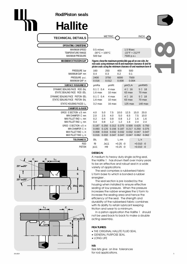
OPERATING CONDITIONS
MAXIMUM SPEED 0.5 m/sec 1.5 ft/secTEMPERATURE RANGE -30°C + 100°C -22°F + 212°F
MAXIMUM PRESSURE 500 bar 7500 p.s.i.
MAXIMUM EXTRUSION GAP Figures show the maximum permissible gap all on one side ,forrod seals using minimum rod Ø and maximum clearance Ø and forpiston seals using the minimum clearance Ø and maximum bore Ø
PRESSURE bar 1 6 0 2 5 0 4 0 0 5 0 0MAXIMUM GAP mm 0 . 4 0 . 3 0 . 2 0 . 1
PRESSURE p.s.i. 2400 3750 6000 7500MAXIMUM GAP in 0.016 0.012 0.008 0.004
SURFACE ROUGHNESS µ m R a µ m R t µ i n C L A µ i n R M S
DYNAMIC SEALING FACE - ROD Ød1 0.1 ↔ 0 . 4 4 max 4 ↔ 1 6 5 ↔ 1 8STATIC SEALING FACE - ROD ØD1 1.6 max 10 max 63 max 70 max
DYNAMIC SEALING FACE - PISTON ØD1 0.1 ↔ 0 . 4 4 max 4 ↔ 1 6 5 ↔ 1 8STATIC SEALING FACE - PISTON Ød1 1.6 max 10 max 63 max 70 max
STATIC HOUSING FACES L1 3.2 max 16 max 125 max 140 max
CHAMFERS & RADII
GROOVE SECTION ≤ S mm 4.0 5.0 7.5 10.0 12.5 15.0 20.0MIN CHAMFER C mm 2.0 2.5 4.0 5.0 6.5 7.5 10.0
MAX FILLET RAD r1 m m 0.2 0.4 0.8 0.8 1.2 1.6 1.6MAX FILLET RAD r2 m m 0.4 0.8 1.2 1.2 1.6 2.4 2.4
GROOVE SECTION ≤ S in 0.187 0.250 0.312 0.375 0.500 0.625 0.750MIN CHAMFER C in 0.093 0.125 0.156 0.187 0.217 0.250 0.375
MAX FILLET RAD r1 i n 0.008 0.016 0.032 0.032 0.032 0.047 0.047MAX FILLET RAD r2 i n 0.016 0.032 0.047 0.047 0.047 0.062 0.062
T O L E R A N C E S Ø d1 Ø D1 L1 m m L1 i n
R O D f9 Js11 +0.25 -0 +0.010 -0P I S T O N js11 H9 +0.25 -0 +0.010 -0
TECHNICAL DETAILSM E T R I C I N C H
DESIGN
A medium to heavy duty single acting seal,the Hallite 18 has shown itself over many yearsto be an effective and robust seal in a widevariety of applications.
The seal comprises a rubberised fabric U form base to which is bonded a rubberenergiser .
The seal section is pre-loaded by thehousing when installed to ensure effectivesealing at low pressure. When the pressureincreases the rubber energises the U form toincrease the sealing area and hence theefficiency of the seal. The strength anddurability of the rubberised fabric combineswith its ability to retain lubricant keepingfriction and wear to a minimum.
In a piston application the Hallite 18 shouldnot be used back to back to make a doubleacting assembly.
FEATURES
• THE ORIGINAL HALLITE FLUID SEAL• GENERAL PURPOSE SEAL• LONG LIFE
NB:Size lists give "on line" tolerances for rod applications.
20° 30°
20° 30°
C C
S
ØD1Ød1
r2
L1
r1
S
C
r2
r1
20° 30°
Ød1 ØD1
L1

Ød1 ØD1
L1
ØD1Ød1
1
1 8HalliteRod/Piston seals
metric
01/02
For bore tolerancesrefer to datasheet.
42
Ød1 TOL ØD1 TOL L1 PARTf9 Js11 +0.25-0 No.
Ød1 TOL ØD1 TOL L1 PARTf9 Js11 +0.25-0 No.
6 -0.013 14 +0.05 6.0 0202200- 0 . 0 4 9 - 0 . 0 5
8 -0.013 16 +0.05 6.0 0202400- 0 . 0 4 9 - 0 . 0 5
10 -0.016 18 +0.06 6.0 0202500- 0 . 0 5 9 - 0 . 0 6
12 -0.016 20 +0.07 6.0 0202600- 0 . 0 5 9 - 0 . 0 7
12 -0.016 25 +0.07 10.0 0615800- 0 . 0 5 9 - 0 . 0 7
14 -0.016 24 +0.07 7.5 0202700- 0 . 0 5 9 - 0 . 0 7
15 -0.016 25 +0.07 7.5 0202800- 0 . 0 5 9 - 0 . 0 7
16 -0.016 26 +0.07 7.5 0615900- 0 . 0 5 9 - 0 . 0 7
18 -0.016 28 +0.07 7.5 0202900- 0 . 0 5 9 - 0 . 0 7
20 -0.020 30 +0.07 7.5 0200500- 0 . 0 7 2 - 0 . 0 7
22 -0.020 30 +0.07 6.0 0817600- 0 . 0 7 2 - 0 . 0 7
22 -0.020 32 +0.08 7.5 0203300- 0 . 0 7 2 - 0 . 0 8
25 -0.020 40 +0.08 11.0 0472800- 0 . 0 7 2 - 0 . 0 8
28 -0.020 43 +0.08 11.0 0204300- 0 . 0 7 2 - 0 . 0 8
30 -0.020 45 +0.08 11.0 0204400- 0 . 0 7 2 - 0 . 0 8
30 -0.020 50 +0.08 14.0 0282100- 0 . 0 7 2 - 0 . 0 8
32 -0.025 47 +0.08 11.0 0204600- 0 . 0 8 7 - 0 . 0 8
35 -0.025 45 +0.08 7.5 0052300- 0 . 0 8 7 - 0 . 0 8
35 -0.025 50 +0.08 11.0 0474600- 0 . 0 8 7 - 0 . 0 8
36 -0.025 44 +0.08 6.0 1204900- 0 . 0 8 7 - 0 . 0 8
36 -0.025 51 +0.10 11.0 0978800- 0 . 0 8 7 - 0 . 1 0
40 -0.025 50 +0.08 10.5 0202000- 0 . 0 8 7 - 0 . 0 8
40 -0.025 55 +0.10 11.0 0475000- 0 . 0 8 7 - 0 . 1 0
45 -0.025 60 +0.10 11.0 0979400- 0 . 0 8 7 - 0 . 1 0
45 -0.025 65 +0.10 14.0 0281700- 0 . 0 8 7 - 0 . 1 0
50 -0.025 60 +0.10 7.5 0179300- 0 . 0 8 7 - 0 . 1 0
50 -0.025 65 +0.10 10.0 0208400- 0 . 0 8 7 - 0 . 1 0
50 -0.025 65 +0.10 11.0 0383800- 0 . 0 8 7 - 0 . 1 0
50 -0.025 70 +0.10 14.0 0294600- 0 . 0 8 7 - 0 . 1 0
55 -0.030 65 +0.10 8.0 0242600- 0 . 1 0 4 - 0 . 1 0
56 -0.030 76 +0.10 14.0 0646100- 0 . 1 0 4 - 0 . 1 0
60 -0.030 72 +0.10 9.5 1397700- 0 . 1 0 4 - 0 . 1 0
60 -0.030 80 +0.10 14.0 0294900- 0 . 1 0 4 - 0 . 1 0
63 -0.030 83 +0.11 14.0 0646300- 0 . 1 0 4 - 0 . 1 1
65 -0.030 80 +0.11 11.0 0740700- 0 . 1 0 4 - 0 . 1 1
70 -0.030 90 +0.11 14.0 0296000- 0 . 1 0 4 - 0 . 1 1
75 -0.030 90 +0.11 12.0 0740600- 0 . 1 0 4 - 0 . 1 1
75 -0.030 95 +0.11 14.0 0412700- 0 . 1 0 4 - 0 . 1 1
80 -0.030 95 +0.11 12.0 0732700- 0 . 1 0 4 - 0 . 1 1
80 -0.030 100 +0.11 14.0 0295100- 0 . 1 0 4 - 0 . 1 1
90 -0.036 110 +0.11 10.0 0306700- 0 . 1 2 3 - 0 . 1 1
90 -0.036 110 +0.11 14.0 0071700- 0 . 1 2 3 - 0 . 1 1
90 -0.036 110 +0.11 15.0 0712400- 0 . 1 2 3 - 0 . 1 1
100 -0.036 115 +0.11 12.0 0740500- 0 . 1 2 3 - 0 . 1 1
100 -0.036 120 +0.11 14.0 0296100- 0 . 1 2 3 - 0 . 1 1
100 -0.036 125 +0.13 19.0 0418600- 0 . 1 2 3 - 0 . 1 3

01/02
For bore tolerancesrefer to datasheet.
43
Ød1 TOL ØD1 TOL L1 PARTf9 Js11 +0.25-0 No.
Ød1 TOL ØD1 TOL L1 PARTf9 Js11 +0.25-0 No.
180 -0.043 210 +0.15 24.0 0087200- 0 . 1 4 3 - 0 . 1 5
200 -0.050 220 +0.15 15.0 1284100- 0 . 1 6 5 - 0 . 1 5
200 -0.050 230 +0.15 24.0 2010000- 0 . 1 6 5 - 0 . 1 5
220 -0.050 250 +0.15 22.0 0958900- 0 . 1 6 5 - 0 . 1 5
250 -0.050 280 +0.16 24.0 1055500- 0 . 1 6 5 - 0 . 1 6
270 -0.056 300 +0.16 24.0 0094800- 0 . 1 8 6 - 0 . 1 6
280 -0.056 310 +0.16 24.0 0094900- 0 . 1 8 6 - 0 . 1 6
300 -0.056 330 +0.18 24.0 0095000- 0 . 1 8 6 - 0 . 1 8
320 -0.062 360 +0.18 30.0 1054000- 0 . 2 1 2 - 0 . 1 8
360 -0.062 400 +0.18 30.0 1054300- 0 . 2 1 2 - 0 . 1 8
380 -0.062 420 +0.20 30.0 0095100- 0 . 2 1 2 - 0 . 2 0
400 -0.062 440 +0.20 30.0 0095200- 0 . 2 1 2 - 0 . 2 0
420 -0.068 460 +0.20 30.0 0095300- 0 . 2 2 3 - 0 . 2 0
110 -0.036 125 +0.13 11.0 0558300- 0 . 1 2 3 - 0 . 1 3
110 -0.036 135 +0.13 19.0 0304300- 0 . 1 2 3 - 0 . 1 3
115 -0.036 135 +0.13 14.0 0639900- 0 . 1 2 3 - 0 . 1 3
120 -0.036 140 +0.13 12.0 0250500- 0 . 1 2 3 - 0 . 1 3
120 -0.036 145 +0.13 19.0 0070400- 0 . 1 2 3 - 0 . 1 3
125 -0.043 150 +0.13 19.0 0070500- 0 . 1 4 3 - 0 . 1 3
130 -0.043 145 +0.13 11.3 0634500- 0 . 1 4 3 - 0 . 1 3
135 -0.043 160 +0.13 19.0 0080400- 0 . 1 4 3 - 0 . 1 3
140 -0.043 160 +0.13 14.0 0304600- 0 . 1 4 3 - 0 . 1 3
140 -0.043 165 +0.13 19.0 0080500- 0 . 1 4 3 - 0 . 1 3
150 -0.043 170 +0.13 14.0 0303300- 0 . 1 4 3 - 0 . 1 3
160 -0.043 180 +0.13 15.0 1283100- 0 . 1 4 3 - 0 . 1 3
160 -0.043 190 +0.15 24.0 0136100- 0 . 1 4 3 - 0 . 1 5
175 -0.043 200 +0.15 19.0 0838800- 0 . 1 4 3 - 0 . 1 5
Ød1 ØD1
L1
ØD1Ød1
1
1 8HalliteRod/Piston seals
metric

Ød1 ØD1
L1
ØD1Ød1
L1
1 8HalliteRod/Piston seals
inch
01/02
For bore tolerancesrefer to datasheet.
44
Ød1 TOL ØD1 TOL L1 PARTf9 Js11 +0.010 -0 No.
Ød1 TOL ØD1 TOL L1 PARTf9 Js11 +0.010 -0 No.
1.875 -0.0010 2.500 +0.004 0.437 0867200- 0 . 0 0 3 4 - 0 . 0 0 4
2.000 -0.0012 2.625 +0.004 0.437 1371000- 0 . 0 0 4 1 - 0 . 0 0 4
2.000 -0.0012 2.750 +0.004 0.562 1369100- 0 . 0 0 4 1 - 0 . 0 0 4
2.250 -0.0012 2.875 +0.004 0.437 0424300- 0 . 0 0 4 1 - 0 . 0 0 4
2.250 -0.0012 3.000 +0.004 0.562 1098400- 0 . 0 0 4 1 - 0 . 0 0 4
2.375 -0.0012 3.000 +0.004 0.469 0716600- 0 . 0 0 4 1 - 0 . 0 0 4
2.500 -0.0012 3.000 +0.004 0.312 0641200- 0 . 0 0 4 1 - 0 . 0 0 4
2.500 -0.0012 3.250 +0.004 0.562 0782400- 0 . 0 0 4 1 - 0 . 0 0 4
2.750 -0.0012 3.500 +0.004 0.562 0437800- 0 . 0 0 4 1 - 0 . 0 0 4
3.000 -0.0012 3.750 +0.004 0.562 0410500- 0 . 0 0 4 1 - 0 . 0 0 4
3.250 -0.0014 4.000 +0.004 0.562 1407700- 0 . 0 0 4 8 - 0 . 0 0 4
3.500 -0.0014 4.000 +0.004 0.375 1468200- 0 . 0 0 4 8 - 0 . 0 0 4
3.500 -0.0014 4.250 +0.004 0.562 1128800- 0 . 0 0 4 8 - 0 . 0 0 4
3.750 -0.0014 4.500 +0.004 0.500 1414800- 0 . 0 0 4 8 - 0 . 0 0 4
4.000 -0.0014 4.875 +0.005 0.656 1424100- 0 . 0 0 4 8 - 0 . 0 0 5
4.000 -0.0014 5.000 +0.005 0.750 0443000- 0 . 0 0 4 8 - 0 . 0 0 5
4.250 -0.0014 5.250 +0.005 0.750 0892200- 0 . 0 0 4 8 - 0 . 0 0 5
4.500 -0.0014 5.250 +0.005 0.469 0447800- 0 . 0 0 4 8 - 0 . 0 0 5
4.500 -0.0014 5.500 +0.005 0.750 0133200- 0 . 0 0 4 8 - 0 . 0 0 5
5.000 -0.0017 6.000 +0.005 0.750 1367000- 0 . 0 0 5 6 - 0 . 0 0 5
5.250 -0.0017 6.000 +0.005 0.562 0487700- 0 . 0 0 5 6 - 0 . 0 0 5
5.500 -0.0017 6.500 +0.005 0.750 1164100- 0 . 0 0 5 6 - 0 . 0 0 5
6.000 -0.0017 7.000 +0.005 0.750 1188800- 0 . 0 0 5 6 - 0 . 0 0 5
0.375 -0.0005 0.750 +0.003 0.281 1379300- 0 . 0 0 1 9 - 0 . 0 0 3
0.500 -0.0006 0.875 +0.003 0.281 0406700- 0 . 0 0 2 3 - 0 . 0 0 3
0.625 -0.0006 0.875 +0.003 0.187 1435600- 0 . 0 0 2 3 - 0 . 0 0 3
0.625 -0.0006 1.000 +0.003 0.281 1247600- 0 . 0 0 2 3 - 0 . 0 0 3
0.750 -0.0008 1.093 +0.003 0.281 1364200- 0 . 0 0 2 8 - 0 . 0 0 3
0.750 -0.0008 1.250 +0.003 0.375 0403700- 0 . 0 0 2 8 - 0 . 0 0 3
0.812 -0.0008 1.375 +0.003 0.500 0413800- 0 . 0 0 2 8 - 0 . 0 0 3
0.875 -0.0008 1.375 +0.003 0.375 0401300- 0 . 0 0 2 8 - 0 . 0 0 3
1.000 -0.0008 1.375 +0.003 0.250 0282600- 0 . 0 0 2 8 - 0 . 0 0 3
1.000 -0.0008 1.500 +0.003 0.375 0422400- 0 . 0 0 2 8 - 0 . 0 0 3
1.125 -0.0008 1.500 +0.003 0.375 0525100- 0 . 0 0 2 8 - 0 . 0 0 3
1.125 -0.0008 1.625 +0.003 0.281 0287000- 0 . 0 0 2 8 - 0 . 0 0 3
1.125 -0.0008 1.750 +0.003 0.437 0778200- 0 . 0 0 2 8 - 0 . 0 0 3
1.250 -0.0010 1.625 +0.003 0.281 0282400- 0 . 0 0 3 4 - 0 . 0 0 3
1.250 -0.0010 1.875 +0.003 0.437 0404100- 0 . 0 0 3 4 - 0 . 0 0 3
1.375 -0.0010 2.000 +0.004 0.437 0778400- 0 . 0 0 3 4 - 0 . 0 0 4
1.500 -0.0010 2.000 +0.004 0.281 1447800- 0 . 0 0 3 4 - 0 . 0 0 4
1.500 -0.0010 2.125 +0.004 0.437 0967600- 0 . 0 0 3 4 - 0 . 0 0 4
1.500 -0.0010 2.375 +0.004 0.687 0403100- 0 . 0 0 3 4 - 0 . 0 0 4
1.625 -0.0010 2.250 +0.004 0.437 1432600- 0 . 0 0 3 4 - 0 . 0 0 4
1.687 -0.0010 2.500 +0.004 0.625 1382600- 0 . 0 0 3 4 - 0 . 0 0 4
1.750 -0.0010 2.250 +0.004 0.312 1404300- 0 . 0 0 3 4 - 0 . 0 0 4
1.750 -0.0010 2.375 +0.004 0.437 0939800- 0 . 0 0 3 4 - 0 . 0 0 4

01/02
For bore tolerancesrefer to datasheet.
45
1 8HalliteRod/Piston seals
inch
Ød1 ØD1
L1
ØD1Ød1
L1
Ød1 TOL ØD1 TOL L1 PARTf9 Js11 +0.010 -0 No.
Ød1 TOL ØD1 TOL L1 PARTf9 Js11 +0.010 -0 No.
6.500 -0.0017 7.000 +0.005 0.375 1431600- 0 . 0 0 5 6 - 0 . 0 0 5
6.500 -0.0017 7.750 +0.006 1.000 1192700- 0 . 0 0 5 6 - 0 . 0 0 6
7.000 -0.0017 8.000 +0.006 0.875 6501200- 0 . 0 0 5 6 - 0 . 0 0 6
7.000 -0.0017 8.125 +0.006 0.750 1054100- 0 . 0 0 5 6 - 0 . 0 0 6
7.000 -0.0017 8.250 +0.006 1.000 1219200- 0 . 0 0 5 6 - 0 . 0 0 6
7.500 -0.0020 8.750 +0.006 1.000 0418100- 0 . 0 0 6 5 - 0 . 0 0 6
8.000 -0.0020 9.000 +0.006 0.750 1269400- 0 . 0 0 6 5 - 0 . 0 0 6
8.000 -0.0020 9.250 +0.006 1.000 0455700- 0 . 0 0 6 5 - 0 . 0 0 6
8.500 -0.0020 9.750 +0.006 1.000 1332300- 0 . 0 0 6 5 - 0 . 0 0 6
9.000 -0.0020 10.250 +0.006 1.000 0437500- 0 . 0 0 6 5 - 0 . 0 0 6
9.500 -0.0020 10.750 +0.006 1.000 1320400- 0 . 0 0 6 5 - 0 . 0 0 6
10.000 -0.0022 11.250 +0.006 1.000 0452200- 0 . 0 0 7 3 - 0 . 0 0 6
10.500 -0.0022 11.750 +0.006 1.000 1331300- 0 . 0 0 7 3 - 0 . 0 0 0
11.000 -0.0022 12.250 +0.006 1.000 1331000- 0 . 0 0 7 3 - 0 . 0 0 6
11.500 -0.0022 12.750 +0.007 1.000 1331800- 0 . 0 0 7 3 - 0 . 0 0 7
12.000 -0.0022 13.250 +0.007 1.000 1329100- 0 . 0 0 7 3 - 0 . 0 0 7
13.000 -0.0024 14.250 +0.007 1.000 0864800- 0 . 0 0 8 3 - 0 . 0 0 7
14.000 -0.0024 15.250 +0.007 1.208 0174900- 0 . 0 0 8 3 - 0 . 0 0 7
14.500 -0.0024 16.000 +0.008 1.500 1345000- 0 . 0 0 8 3 - 0 . 0 0 8
15.000 -0.0024 17.000 +0.008 1.500 1345300- 0 . 0 0 8 3 - 0 . 0 0 8
16.500 -0.0027 17.750 +0.008 1.000 1318800- 0 . 0 0 8 8 - 0 . 0 0 8
17.000 -0.0027 17.750 +0.008 0.625 1345900- 0 . 0 0 8 8 - 0 . 0 0 8
18.000 -0.0027 19.250 +0.008 1.250 1314500- 0 . 0 0 8 8 - 0 . 0 0 8
19.000 -0.0027 20.750 +0.009 1.312 1342200- 0 . 0 0 8 8 - 0 . 0 0 9
20.000 -0.0030 21.500 +0.009 1.750 0093600- 0 . 0 0 9 9 - 0 . 0 0 9
21.500 -0.0030 23.500 +0.009 1.750 0150500- 0 . 0 0 9 9 - 0 . 0 0 9
23.000 -0.0030 25.000 +0.010 1.500 0158700- 0 . 0 0 9 9 - 0 . 0 1 0
27.000 -0.0031 29.000 +0.010 1.500 2003500- 0 . 0 1 1 0 - 0 . 0 1 0
30.000 -0.0031 32.000 +0.011 1.500 2109700- 0 . 0 1 1 0 - 0 . 0 1 1
38.000 -0.0034 39.500 +0.011 1.125 0159200- 0 . 0 1 2 4 - 0 . 0 1 1

N o t e s
01/0246

HalliteRod seals
01/02 47
OPERATING CONDITIONS
MAXIMUM SPEED 0.5 m/sec 1.5 ft/secTEMPERATURE RANGE -30°C + 100°C -22°F + 212°F
MAXIMUM PRESSURE 400 bar 6000 p.s.i.
MAXIMUM EXTRUSION GAP Figures show the maximum permissible gap all on one side using minimum rod Ø and maximum clearance Ø.
PRESSURE bar 1 0 0 1 6 0 2 5 0 4 0 0MAXIMUM GAP mm 1 . 0 0 . 9 0 . 8 0 . 6
PRESSURE p.s.i. 1500 2400 3750 6000MAXIMUM GAP in 0.040 0.036 0.032 0.024
SURFACE ROUGHNESS µ m R a µ m R t µ i n C L A µ i n R M S
DYNAMIC SEALING FACE Ød1 0.1 ↔ 0 . 4 4 max 4 ↔ 1 6 5 ↔ 1 8STATIC SEALING FACE ØD1 1.6 max 10 max 63 max 70 maxSTATIC HOUSING FACES L1 3.2 max 16 max 125 max 140 max
CHAMFERS & RADII
GROOVE SECTION ≤ S mm 4.0 5.0 7.5 10.0 12.5 15.0MIN CHAMFER C mm 2.0 2.5 4.0 5.0 6.5 7.5
MAX FILLET RAD r2 m m 0.2 0.4 0.8 0.8 1.2 1.6
GROOVE SECTION ≤ S in 0.187 0.250 0.312 0.375MIN CHAMFER C in 0.093 0.125 0.156 0.187
MAX FILLET RAD r2 i n 0.008 0.016 0.032 0.032
T O L E R A N C E S Ø d1 Ø D1 L1 m m L1 i n
f9 Js11 +0.25 -0 +0.010 -0
TECHNICAL DETAILSM E T R I C I N C H
DESIGNThe Hallite 21 is a compact, low frictionseal with the advantage of an internal anti-extrusion ring.
A rubberised fabric U ring, which givesstrength and durability, and a rubberheader are moulded together forming theseal. It is designed to have a controlledpre-load across the angled rubber lips,which are accurately machine trimmed, toensure a good seal at low pressure. Theseal becomes more effective as thepressure increases and the rubberisedfabric deforms to the housing, increasingthe seal contact area. The surface of thefabric has pockets which retain lubricationto reduce friction and wear.
The range has a reinforced plastic anti-extrusion ring at the internal heel of theseal, to protect it against damage byextrusion, which enables the designer touse a large clearance. Where possible,triangular anti-extrusion rings are used, butin some cases a rectangular section maybe supplied. Certain sizes are designed tosuit housing requirements of ISO 5597.
The proportions of the range have beendetermined to give a satisfactoryperformance when used with therecommended operating conditions.
Many other sizes are available outsidethis range, please contact your local Hallitesales office for additional information.
20° 30°
20° 30°
C C
S
ØD1Ød1
r2
L1
FEATURES• HIGH PRESSURE CAPABILITY• CONTAMINATION RESISTANT• GENERAL PURPOSE SEAL• LONG LIFE
NB: Part numbers suffixed by “‡”indicate housing sizes to meetISO5597.

ØD1Ød1
2 1HalliteRod seals
metric
inch
01/0248
Ød1 TOL ØD1 TOL L1 PARTf9 Js11 +0.25-0 No.
Ød1 TOL ØD1 TOL L1 PARTf9 Js11 +0.25-0 No.
20 -0.020 30 +0.08 8.0 2176120‡- 0 . 0 7 2 - 0 . 0 8
28 -0.020 38 +0.08 8.0 6583220‡- 0 . 0 7 2 - 0 . 0 8
30 -0.020 45 +0.08 9.0 2176420- 0 . 0 7 2 - 0 . 0 8
32 -0.025 42 +0.08 8.0 6583320‡- 0 . 0 8 7 - 0 . 0 8
36 -0.025 46 +0.08 8.0 6583420‡- 0 . 0 8 7 - 0 . 0 8
40 -0.025 50 +0.08 8.0 6583520‡- 0 . 0 8 7 - 0 . 0 8
40 -0.025 55 +0.10 10.5 2176920- 0 . 0 8 7 - 0 . 1 0
45 -0.025 55 +0.10 8.0 6583620‡- 0 . 0 8 7 - 0 . 1 0
50 -0.025 60 +0.10 8.0 2192722‡- 0 . 0 8 7 - 0 . 1 0
55 -0.030 65 +0.10 10.5 2177320- 0 . 1 0 4 - 0 . 1 0
56 -0.030 71 +0.10 12.5 6583720‡- 0 . 1 0 4 - 0 . 1 0
63 -0.030 78 +0.10 12.5 2192822‡- 0 . 1 0 4 - 0 . 1 0
70 -0.030 85 +0.11 12.5 6583820‡- 0 . 1 0 4 - 0 . 1 1
75 -0.030 95 +0.11 14.0 0896220- 0 . 1 0 4 - 0 . 1 1
80 -0.030 95 +0.11 12.5 2192922‡- 0 . 1 0 4 - 0 . 1 1
90 -0.036 105 +0.11 12.5 6583920‡- 0 . 1 2 3 - 0 . 1 1
100 -0.036 120 +0.11 14.0 2178720- 0 . 1 2 3 - 0 . 1 1
100 -0.036 120 +0.11 16.0 6581720‡- 0 . 1 2 3 - 0 . 1 1
110 -0.036 130 +0.13 16.0 2193022‡- 0 . 1 2 3 - 0 . 1 3
125 -0.043 145 +0.13 16.0 6581820‡- 0 . 1 4 3 - 0 . 1 3
140 -0.043 160 +0.13 16.0 2193122‡- 0 . 1 4 3 - 0 . 1 3
160 -0.043 176 +0.13 12.0 2120120- 0 . 1 4 3 - 0 . 1 3
160 -0.043 185 +0.15 20.0 6581920‡- 0 . 1 4 3 - 0 . 1 5
180 -0.043 205 +0.15 20.0 6582020‡- 0 . 1 4 3 - 0 . 1 5
200 -0.050 225 +0.15 20.0 6582220‡- 0 . 1 6 5 -0.15
220 -0.050 250 +0.15 25.0 6592120‡- 0 . 1 6 5 - 0 . 1 5
Ød1 TOL ØD1 TOL L1 PARTf9 Js11 +0.010 -0 No.
Ød1 TOL ØD1 TOL L1 PARTf9 Js11 +0.010 -0 No.
1.250 -0.020 1.750 +0.08 0.375 2187920- 0 . 0 7 2 - 0 . 0 8
1.500 -0.020 2.000 +0.08 0.470 2186720- 0 . 0 7 2 - 0 . 0 8
1.750 -0.020 2.125 +0.08 0.276 0064620- 0 . 0 7 2 - 0 . 0 8
2.000 -0.020 2.500 +0.08 0.375 2187020- 0 . 0 7 2 - 0 . 0 8
2.000 -0.020 2.750 +0.08 0.625 2186820- 0 . 0 7 2 - 0 . 0 8
2.250 -0.020 2.750 +0.08 0.375 2163820- 0 . 0 7 2 - 0 . 0 8
2.500 -0.020 3.000 +0.08 0.312 2187120- 0 . 0 7 2 - 0 . 0 8
2.625 -0.020 3.375 +0.08 0.562 2186920- 0 . 0 7 2 - 0 . 0 8

HalliteWipers
01/02 49
M E T R I C I N C H
DESIGNThe Hallite 33 wiper has a lip designed toremove lightly adhered dirt from the rod i.e.mud, dust or moisture.
The wiper is manufactured from a hardnitrile rubber suitable for installing in agrooved housing. Rod diameters (Ød1) of20mm and below require a two piecehousing .
To prevent dirt passing the outside of thewiper and to reduce the pumping action,the outside diameter is an interference fitwith the housing. Certain sizes of thestandard Hallite 33 metric range aresuitable for ISO 6195 Housing Type A.
It should also be noted that the Hallite 33inch profile differs from the metric profile,and is also available in Hythane 181.
FEATURES• GENERAL PURPOSE SEAL• PRECISION TRIMMED SEALING LIP• WIDE SIZE RANGES• EFFECTIVE SEAL ON HOUSING AS
WELL AS ROD
NB: Part numbers suffixed by “‡” i n d i c a t ehousing sizes to meet ISO6195A. Many of themetric sizes are also available as polyesterwipers - see Hallite 38.
Hallite 33: the metric and inchprofiles differ as illustrated above.
r1
ØD1
L1
Ød1
r2
ØD2
r1
ØD1
L1
Ød1
r2
ØD2
OPERATING CONDITIONS
MAXIMUM SPEED 4.0 m/sec 12.0 ft/secTEMPERATURE RANGE -30°C + 100°C -22°F + 212°F
SURFACE ROUGHNESS µ m R a µ m R t µ i n C L A µ i n R M S
DYNAMIC SEALING FACE Ød1 0.1 ↔ 0 . 4 4 max 4 ↔ 1 6 5 ↔ 1 8STATIC SEALING FACE ØD1 Ø D2 2.5 max 16 max 100 max 111 max
STATIC HOUSING FACES L1 2.5 max 16 max 100 max 111 max
R A D I I
ROD DIAMETER Ød1 m m ≤ 50 ≤ 90 ≤ 200 > 200MAX FILLET RAD r1 m m 0.4 0.4 0.4 0.8MAX FILLET RAD r2 m m 0.2 0.4 0.6 0.8
ROD DIAMETER Ød1 i n allMAX FILLET RAD r1 i n 0.010MAX FILLET RAD r2 i n 0.020
T O L E R A N C E S Ø d1 Ø D1 Ø D2 L1
m m f9 H11 H11 +0.2 -0i n f9 +0.020 +0.010 ±0.005 +0.020 +0.010
TECHNICAL DETAILSM E T R I C I N C H

3 3HalliteWipers
metric
Ød1 TOL ØD1 TOL ØD2 TOL L1 L2 PARTf9 H11 H11 +0.2 - 0 No.
01/02
ØD1
L1
ØD2 Ød1ØD1 ØD2 Ød1ØD1 ØD2 Ød1
metric
50
12 -0.016 20.0 +0.13 16.0 +0.11 4.0 6.0 2232500- 0 . 0 5 9 + 0 . 0 0 + 0 . 0 0
14 -0.016 22.0 +0.13 18.0 +0.11 4.0 6.0 2232600- 0 . 0 5 9 + 0 . 0 0 + 0 . 0 0
16 -0.016 24.0 +0.13 20.0 +0.13 4.0 6.0 2232800- 0 . 0 5 9 + 0 . 0 0 + 0 . 0 0
18 -0.016 26.0 +0.13 22.0 +0.13 4.0 6.0 2232900- 0 . 0 5 9 + 0 . 0 0 + 0 . 0 0
20 -0.020 28.0 +0.13 24.0 +0.13 4.0 6.0 2233000- 0 . 0 7 2 + 0 . 0 0 + 0 . 0 0
22 -0.020 30.0 +0.13 26.0 +0.13 4.0 6.0 2233100- 0 . 0 7 2 + 0 . 0 0 + 0 . 0 0
25 -0.020 33.0 +0.16 29.0 +0.13 4.0 6.0 2233200- 0 . 0 7 2 + 0 . 0 0 + 0 . 0 0
25 -0.020 33.0 +0.16 30.5 +0.16 5.0 6.4 6586200‡- 0 . 0 7 2 + 0 . 0 0 + 0 . 0 0
28 -0.020 36.0 +0.16 32.0 +0.16 4.0 6.0 2233300- 0 . 0 7 2 + 0 . 0 0 + 0 . 0 0
28 -0.020 36.0 +0.16 33.5 +0.16 5.0 6.4 6586300‡- 0 . 0 7 2 + 0 . 0 0 + 0 . 0 0
30 -0.020 42.0 +0.16 36.0 +0.16 6.0 9.0 2233400- 0 . 0 7 2 + 0 . 0 0 + 0 . 0 0
32 -0.025 40.0 +0.16 37.5 +0.16 5.0 6.4 6586400‡- 0 . 0 8 7 + 0 . 0 0 + 0 . 0 0
32 -0.025 44.0 +0.16 38.0 +0.16 6.0 9.0 2233500- 0 . 0 8 7 + 0 . 0 0 + 0 . 0 0
35 -0.025 47.0 +0.16 41.0 +0.16 6.0 9.0 2233600- 0 . 0 8 7 + 0 . 0 0 + 0 . 0 0
36 -0.025 44.0 +0.16 41.5 +0.16 5.0 6.4 6586500‡- 0 . 0 8 7 + 0 . 0 0 + 0 . 0 0
36 -0.025 48.0 +0.16 42.0 +0.16 6.0 9.0 2233700- 0 . 0 8 7 + 0 . 0 0 + 0 . 0 0
40 -0.025 48.0 +0.16 45.5 +0.16 5.0 6.4 6586600‡- 0 . 0 8 7 + 0 . 0 0 + 0 . 0 0
40 -0.025 52.0 +0.19 46.0 +0.16 6.0 9.0 2233800- 0 . 0 8 7 + 0 . 0 0 + 0 . 0 0
42 -0.025 54.0 +0.19 48.0 +0.16 6.0 9.0 2233900- 0 . 0 8 7 + 0 . 0 0 + 0 . 0 0
45 -0.025 53.0 +0.19 50.5 +0.19 5.0 6.4 6586700‡- 0 . 0 8 7 + 0 . 0 0 + 0 . 0 0
45 -0.025 57.0 +0.19 51.0 +0.19 6.0 9.0 2234000- 0 . 0 8 7 + 0 . 0 0 + 0 . 0 0
50 -0.025 58.0 +0.19 55.5 +0.19 5.0 6.4 6586800‡- 0 . 0 8 7 + 0 . 0 0 + 0 . 0 0
50 -0.025 62.0 +0.19 55.0 +0.19 6.0 9.0 2234200- 0 . 0 8 7 + 0 . 0 0 + 0 . 0 0

3 3Hallite
Wipers
metric
Ød1 TOL ØD1 TOL ØD2 TOL L1 L2 PARTf9 H11 H11 +0.2 - 0 No.
01/02 51
ØD1
L1
ØD2 Ød1ØD1 ØD2 Ød1ØD1 ØD2 Ød1
metric
55 -0.030 67.0 +0.19 61.0 +0.19 6.0 9.0 2234300- 0 . 1 0 4 + 0 . 0 0 + 0 . 0 0
56 -0.030 66.0 +0.19 63.0 +0.19 6.3 8.1 6586900‡- 0 . 1 0 4 + 0 . 0 0 + 0 . 0 0
56 -0.030 68.0 +0.19 62.0 +0.19 6.0 9.0 2234400- 0 . 1 0 4 + 0 . 0 0 + 0 . 0 0
60 -0.030 72.0 +0.19 66.0 +0.19 6.0 9.0 2234500- 0 . 1 0 4 + 0 . 0 0 + 0 . 0 0
63 -0.030 73.0 +0.19 70.0 +0.19 6.3 8.1 6587000‡- 0 . 1 0 4 + 0 . 0 0 + 0 . 0 0
63 -0.030 75.0 +0.19 69.0 +0.19 6.0 9.0 2234600- 0 . 1 0 4 + 0 . 0 0 + 0 . 0 0
65 -0.030 77.0 +0.19 71.0 +0.19 6.0 9.0 2234700- 0 . 1 0 4 + 0 . 0 0 + 0 . 0 0
70 -0.030 80.0 +0.22 77.0 +0.19 6.3 8.1 6587100‡- 0 . 1 0 4 + 0 . 0 0 + 0 . 0 0
70 -0.030 82.0 +0.22 76.0 +0.19 6.0 9.0 2234800- 0 . 1 0 4 + 0 . 0 0 + 0 . 0 0
80 -0.030 90.0 +0.22 87.0 +0.22 6.3 8.1 6587200‡- 0 . 1 0 4 + 0 . 0 0 + 0 . 0 0
90 -0.036 100.0 +0.22 97.0 +0.22 6.3 8.1 6587300‡- 0 . 1 2 3 + 0 . 0 0 + 0 . 0 0
90 -0.036 106.0 +0.22 98.0 +0.22 8.0 12.0 2235200- 0 . 1 2 3 + 0 . 0 0 + 0 . 0 0
100 -0.036 115.0 +0.22 110.0 +0.22 9.5 12.5 6587400‡- 0 . 1 2 3 + 0 . 0 0 + 0 . 0 0
100 -0.036 116.0 +0.22 108.0 +0.22 8.0 12.0 2235300- 0 . 1 2 3 + 0 . 0 0 + 0 . 0 0
105 -0.036 121.0 +0.25 113.0 +0.22 8.0 12.0 2235400- 0 . 1 2 3 + 0 . 0 0 + 0 . 0 0
110 -0.036 125.0 +0.25 120.0 +0.22 9.5 12.5 6587500‡- 0 . 1 2 3 + 0 . 0 0 + 0 . 0 0
125 -0.043 140.0 +0.25 135.0 +0.25 9.5 12.5 6587600‡- 0 . 1 4 3 + 0 . 0 0 + 0 . 0 0
140 -0.043 155.0 +0.25 150.0 +0.25 9.5 12.5 6587700‡- 0 . 1 4 3 + 0 . 0 0 + 0 . 0 0
140 -0.043 156.0 +0.25 148.0 +0.25 8.0 12.0 1222800- 0 . 1 4 3 + 0 . 0 0 + 0 . 0 0
150 -0.043 166.0 +0.25 158.0 +0.25 8.0 12.0 1222900- 0 . 1 4 3 + 0 . 0 0 + 0 . 0 0
160 -0.043 175.0 +0.25 170.0 +0.25 9.5 12.5 6587800‡- 0 . 1 4 3 + 0 . 0 0 + 0 . 0 0
160 -0.043 176.0 +0.25 168.0 +0.25 8.0 12.0 1223000- 0 . 1 4 3 + 0 . 0 0 + 0 . 0 0
180 -0.043 200.0 +0.29 190.0 +0.29 10.0 15.0 1226300- 0 . 1 4 3 + 0 . 0 0 + 0 . 0 0

01/02
ØD1
L1
ØD2 Ød1ØD1 ØD2 Ød1ØD1 ØD2 Ød1
metric
Ød1 TOL ØD1 TOL ØD2 TOL L1 L2 PARTf9 H11 H11 +0.2 - 0 No.
190 -0.050 210.0 +0.29 200.0 +0.29 10.0 15.0 1226400- 0 . 1 6 5 + 0 . 0 0 + 0 . 0 0
200 -0.050 215.0 +0.29 210.0 +0.29 9.5 12.5 6588000‡- 0 . 1 6 5 + 0 . 0 0 + 0 . 0 0
200 -0.050 220.0 +0.29 210.0 +0.29 10.0 15.0 1226500- 0 . 1 6 5 + 0 . 0 0 + 0 . 0 0
220 -0.050 240.0 +0.29 233.5 +0.29 12.5 16.6 6588100‡- 0 . 1 6 5 + 0 . 0 0 + 0 . 0 0
250 -0.056 270.0 +0.32 263.5 +0.32 12.5 16.6 6588200‡- 0 . 1 8 6 + 0 . 0 0 + 0 . 0 0
3 3HalliteWipers
metric
52

01/02 53
ØD1
L1
ØD2 Ød1ØD1 ØD2 Ød1ØD1 ØD2 Ød1
inch
Ød1 TOL ØD1 TOL ØD2 TOL L1 L2 PARTf9 +0.020 +0.010 ±0.005 +0.020 +0.010 No.
0.500 -0.0006 0.900 +0.020 0.700 +0.005 0.125 0.250 1464100- 0 . 0 0 2 3 + 0 . 0 1 0 - 0 . 0 0 5
0.625 -0.0006 1.025 +0.020 0.828 +0.005 0.125 0.250 1470700- 0 . 0 0 2 3 + 0 . 0 1 0 - 0 . 0 0 5
0.750 -0.0008 1.150 +0.020 0.950 +0.005 0.125 0.250 1347700- 0 . 0 0 2 8 + 0 . 0 1 0 - 0 . 0 0 5
0.875 -0.0008 1.275 +0.020 1.075 +0.005 0.125 0.250 1056700- 0 . 0 0 2 8 + 0 . 0 1 0 - 0 . 0 0 5
1.000 -0.0008 1.400 +0.020 1.200 +0.005 0.125 0.250 1456300- 0 . 0 0 2 8 + 0 . 0 1 0 - 0 . 0 0 5
1.125 -0.0008 1.625 +0.020 1.425 +0.005 0.125 0.375 1476700- 0 . 0 0 2 8 + 0 . 0 1 0 - 0 . 0 0 5
1.250 -0.0010 1.750 +0.020 1.550 +0.005 0.125 0.375 1453100- 0 . 0 0 3 4 + 0 . 0 1 0 - 0 . 0 0 5
1.375 -0.0010 1.875 +0.020 1.675 +0.005 0.125 0.375 1471800- 0 . 0 0 3 4 + 0 . 0 1 0 - 0 . 0 0 5
1.500 -0.0010 2.000 +0.020 1.800 +0.005 0.125 0.375 0696900- 0 . 0 0 3 4 + 0 . 0 1 0 - 0 . 0 0 5
1.625 -0.0010 2.125 +0.020 1.925 +0.005 0.125 0.375 0269600- 0 . 0 0 3 4 + 0 . 0 1 0 - 0 . 0 0 5
1.750 -0.0010 2.250 +0.020 2.050 +0.005 0.125 0.375 0266400- 0 . 0 0 3 4 + 0 . 0 1 0 - 0 . 0 0 5
1.875 -0.0010 2.375 +0.020 2.175 +0.005 0.125 0.375 0230700- 0 . 0 0 3 4 + 0 . 0 1 0 - 0 . 0 0 5
2.000 -0.0012 2.500 +0.020 2.300 +0.005 0.125 0.375 0228100- 0 . 0 0 4 1 + 0 . 0 1 0 - 0 . 0 0 5
2.250 -0.0012 2.750 +0.020 2.550 +0.005 0.125 0.375 0851100- 0 . 0 0 4 1 + 0 . 0 1 0 - 0 . 0 0 5
2.500 -0.0012 3.000 +0.020 2.800 +0.005 0.125 0.375 1450000- 0 . 0 0 4 1 + 0 . 0 1 0 - 0 . 0 0 5
2.750 -0.0012 3.250 +0.020 3.050 +0.005 0.125 0.375 2222400- 0 . 0 0 4 1 + 0 . 0 1 0 - 0 . 0 0 5
3.000 -0.0012 3.500 +0.020 3.300 +0.005 0.125 0.375 0951300- 0 . 0 0 4 1 + 0 . 0 1 0 - 0 . 0 0 5
3.250 -0.0014 4.000 +0.020 3.650 +0.005 0.187 0.500 1472500- 0 . 0 0 4 8 + 0 . 0 1 0 - 0 . 0 0 5
3.375 -0.0014 4.125 +0.020 3.775 +0.005 0.187 0.500 1474200- 0 . 0 0 4 8 + 0 . 0 1 0 - 0 . 0 0 5
3.500 -0.0014 4.250 +0.020 3.900 +0.005 0.187 0.500 1445000- 0 . 0 0 4 8 + 0 . 0 1 0 - 0 . 0 0 5
4.000 -0.0014 4.750 +0.020 4.400 +0.005 0.187 0.500 1453300- 0 . 0 0 4 8 + 0 . 0 1 0 - 0 . 0 0 5
4.500 -0.0014 5.250 +0.020 4.900 +0.005 0.187 0.500 1613600- 0 . 0 0 4 8 + 0 . 0 1 0 - 0 . 0 0 5
5.000 -0.0017 5.750 +0.020 5.400 +0.005 0.187 0.500 0258600- 0 . 0 0 5 6 + 0 . 0 1 0 - 0 . 0 0 5
3 3Hallite
Wipers

01/02
ØD1
L1
ØD2 Ød1ØD1 ØD2 Ød1ØD1 ØD2 Ød1
inch
Ød1 TOL ØD1 TOL ØD2 TOL L1 L2 PARTf9 +0.020 +0.010 ±0.005 +0.020 +0.010 No.
5.500 -0.0017 6.250 +0.020 5.900 +0.005 0.187 0.500 0223500- 0 . 0 0 5 6 + 0 . 0 1 0 - 0 . 0 0 5
6.000 -0.0017 6.750 +0.020 6.400 +0.005 0.187 0.500 0222500- 0 . 0 0 5 6 + 0 . 0 1 0 - 0 . 0 0 5
6.500 -0.0017 7.500 +0.020 7.000 +0.005 0.250 0.625 1613100- 0 . 0 0 5 6 + 0 . 0 1 0 - 0 . 0 0 5
7.000 -0.0017 8.000 +0.020 7.500 +0.005 0.250 0.625 1614600- 0 . 0 0 5 6 + 0 . 0 1 0 - 0 . 0 0 5
8.000 -0.0020 9.000 +0.020 8.500 +0.005 0.250 0.625 0786500- 0 . 0 0 6 5 + 0 . 0 1 0 - 0 . 0 0 5
3 3HalliteWipers
54

HalliteWipers
01/02 5
DESIGNThe Hallite 38 wiper has been designed sothat the proportions of the wiping lip ensureit maintains contact with the rod surface toremove heavily deposited mud, ice etc.The outside diameter contacts the housingand has a sealing lip to prevent moistureentering the groove. A polyester basedmaterial is used to provide a toughabrasion resistant wiper for the difficultconditions usually found in mining or earthmoving applications. All the range can beused with a split housing, however, themajority can be installed in a blind housingwith care.
FEATURES• OUTSIDE LIP FOR EFFECTIVE
HOUSING SEAL• PRESSURE RELIEF RIBS• EFFECTIVE SCRAPING LIP• PRECISION TRIMMED WIPING LIP
NB: Part numbers suffixed by “‡” indicatehousing sizes to meet ISO 6195A.
ØD1 ØD2 Ød1
L 1
r1
r2
OPERATING CONDITIONS
MAXIMUM SPEED 4.0 m/sec 12.0 ft/secTEMPERATURE RANGE -40°C + 120°C -40°F + 250°F
SURFACE ROUGHNESS µ m R a µ m R t µ i n C L A µ i n R M S
DYNAMIC SEALING FACE Ød1 0.1 ↔ 0 . 4 4 max 4 ↔ 1 6 5 ↔ 1 8STATIC SEALING FACE ØD1, ØD2 1.6 max 10 max 100 max 70 max
STATIC HOUSING FACES L1 3.2 max 16 max 125 max 140 max
CHAMFERS & RADII
ROD DIAMETER Ød1 m m ≤ 50 ≤ 90 ≤ 200 > 200MAX FILLET RAD r1 m m 0.4 0.4 0.4 0.8MAX FILLET RAD r2 m m 0.2 0.4 0.6 0.8
T O L E R A N C E S Ø d1 Ø D1 Ø D2 L1
m m f9 H11 H11 +0.5 -0
TECHNICAL DETAILSM E T R I C I N C H

ØD1
L1
ØD2 Ød1ØD1 ØD2 Ød1
3 8HalliteWipers
metric
01/026
Ød1 TOL ØD1 TOL ØD2 TOL L1 L2 PARTf9 H11 H11 +0.2 - 0 No.
18 -0.016 24.0 +0.13 21.0 +0.13 5.0 7.0 4392000- 0 . 0 5 9 + 0 . 0 0 + 0 . 0 0
20 -0.020 28.0 +0.13 25.5 +0.13 5.0 8.0 4321900‡- 0 . 0 7 2 + 0 . 0 0 + 0 . 0 0
22 -0.020 30.0 +0.13 27.5 +0.13 5.0 8.0 4322000‡- 0 . 0 7 2 + 0 . 0 0 + 0 . 0 0
25 -0.020 33.0 +0.16 30.5 +0.16 5.0 8.0 6617700‡- 0 . 0 7 2 + 0 . 0 0 + 0 . 0 0
28 -0.020 36.0 +0.16 33.5 +0.16 5.0 8.0 6617800‡- 0 . 0 7 2 + 0 . 0 0 + 0 . 0 0
30 -0.020 38.0 +0.16 35.5 +0.16 5.0 8.0 4419200- 0 . 0 7 2 + 0 . 0 0 + 0 . 0 0
30 -0.020 41.2 +0.16 37.0 +0.16 7.5 10.0 4528900- 0 . 0 7 2 + 0 . 0 0 + 0 . 0 0
32 -0.025 40.0 +0.16 37.5 +0.16 5.0 8.0 6617900‡- 0 . 0 8 7 + 0 . 0 0 + 0 . 0 0
3 5 - 0 . 0 2 5 4 3 . 0 + 0 . 1 6 4 0 . 5 + 0 . 1 6 5 . 0 8 . 0 4 7 2 4 8 0 0
- 0 . 0 8 7 + 0 . 0 0 + 0 . 0 0
36 -0.025 44.0 +0.16 41.5 +0.16 5.0 8.0 6618000‡- 0 . 0 8 7 + 0 . 0 0 + 0 . 0 0
40 -0.025 48.0 +0.16 45.5 +0.16 5.0 8.0 6618100‡- 0 . 0 8 7 + 0 . 0 0 + 0 . 0 0
41.3 -0.025 49.3 +0.16 46.8 +0.16 5.0 8.0 4599900- 0 . 0 8 7 + 0 . 0 0 + 0 . 0 0
45 -0.025 53.0 +0.19 50.5 +0.19 5.0 8.0 6618200‡- 0 . 0 8 7 + 0 . 0 0 + 0 . 0 0
50 -0.025 58.0 +0.19 55.5 +0.19 5.0 8.0 6618300‡- 0 . 0 8 7 + 0 . 0 0 + 0 . 0 0
50 -0.025 58.6 +0.19 53.0 +0.19 5.3 7.0 4300400- 0 . 0 8 7 + 0 . 0 0 + 0 . 0 0
50 -0.025 60.6 +0.19 53.0 +0.19 5.3 7.0 4458000- 0 . 0 8 7 + 0 . 0 0 + 0 . 0 0
56 -0.030 66.0 +0.19 63.0 +0.19 6.3 10.0 6618400‡- 0 . 1 0 4 + 0 . 0 0 + 0 . 0 0
56 -0.030 66.6 +0.19 59.0 +0.19 5.3 7.0 4458100- 0 . 1 0 4 + 0 . 0 0 + 0 . 0 0
60 -0.030 70.0 +0.19 66.0 +0.19 5.3 7.0 4386200- 0 . 1 0 4 + 0 . 0 0 + 0 . 0 0
60 -0.030 70.0 +0.19 67.0 +0.19 6.3 10.0 4270200- 0 . 1 0 4 + 0 . 0 0 + 0 . 0 0
60 -0.030 70.6 +0.19 63.0 +0.19 5.3 7.0 4456400- 0 . 1 0 4 + 0 . 0 0 + 0 . 0 0
63 -0.030 73.0 +0.19 70.0 +0.19 6.3 10.0 6618500‡- 0 . 1 0 4 + 0 . 0 0 + 0 . 0 0
63 -0.030 73.6 +0.19 66.0 +0.19 5.3 7.0 4283600- 0 . 1 0 4 + 0 . 0 0 + 0 . 0 0

65 -0.030 75.0 +0.19 72.0 +0.19 6.3 10.0 4343800- 0 . 1 0 4 + 0 . 0 0 + 0 . 0 0
70 -0.030 80.0 +0.19 77.0 +0.19 6.3 10.0 6618600‡- 0 . 1 0 4 + 0 . 0 0 + 0 . 0 0
70 -0.030 80.6 +0.22 73.0 +0.19 5.3 7.0 4454000- 0 . 1 0 4 + 0 . 0 0 + 0 . 0 0
70 -0.030 82.2 +0.22 76.0 +0.19 7.2 12.0 4243900- 0 . 1 0 4 + 0 . 0 0 + 0 . 0 0
75 -0.030 83.6 +0.22 78.0 +0.19 5.3 7.0 4539500- 0 . 1 0 4 + 0 . 0 0 + 0 . 0 0
75 -0.030 85.0 +0.22 82.0 +0.22 6.3 10.0 4532500- 0 . 1 0 4 + 0 . 0 0 + 0 . 0 0
75 -0.030 87.2 +0.22 81.0 +0.22 7.2 12.0 4384400- 0 . 1 0 4 + 0 . 0 0 + 0 . 0 0
80 -0.030 90.0 +0.22 87.0 +0.22 6.3 10.0 6618700‡- 0 . 1 0 4 + 0 . 0 0 + 0 . 0 0
80 -0.030 91.0 +0.22 85.0 +0.22 7.5 11.0 4493200- 0 . 1 0 4 + 0 . 0 0 + 0 . 0 0
80 -0.030 92.2 +0.22 86.0 +0.22 7.2 12.0 4242800- 0 . 1 0 4 + 0 . 0 0 + 0 . 0 0
82.6 -0.036 92.2 +0.22 85.7 +0.22 5.3 7.1 4415500- 0 . 1 2 3 + 0 . 0 0 + 0 . 0 0
85 -0.036 93.6 +0.22 88.0 +0.22 5.3 7.0 4292100- 0 . 1 2 3 + 0 . 0 0 + 0 . 0 0
85 -0.036 98.0 +0.22 92.0 +0.22 7.5 11.5 4332800- 0 . 1 2 3 + 0 . 0 0 + 0 . 0 0
88 -0.036 100.2 +0.22 94.0 +0.22 7.2 12.0 4269400- 0 . 1 2 3 + 0 . 0 0 + 0 . 0 0
90 -0.036 100.0 +0.22 97.0 +0.22 6.3 10.0 6618800‡- 0 . 1 2 3 + 0 . 0 0 + 0 . 0 0
90 -0.036 102.2 +0.22 96.0 +0.22 7.2 12.0 4324500- 0 . 1 2 3 + 0 . 0 0 + 0 . 0 0
95 -0.036 107.2 +0.22 101.0 +0.22 7.2 12.0 6667600- 0 . 1 2 3 + 0 . 0 0 + 0 . 0 0
100 -0.036 110.6 +0.22 104.0 +0.22 5.3 7.0 4300200- 0 . 1 2 3 + 0 . 0 0 + 0 . 0 0
100 -0.036 112.2 +0.22 106.0 +0.22 7.2 12.0 4324600- 0 . 1 2 3 + 0 . 0 0 + 0 . 0 0
100 -0.036 115.0 +0.22 110.0 +0.22 9.5 14.0 6618900‡- 0 . 1 2 3 + 0 . 0 0 + 0 . 0 0
101.6 -0.036 116.6 +0.22 111.6 +0.22 9.5 14.0 6619010- 0 . 1 2 3 + 0 . 0 0 + 0 . 0 0
105 -0.036 113.0 +0.22 110.5 +0.22 5.0 8.0 4290300- 0 . 1 2 3 + 0 . 0 0 + 0 . 0 0
105 -0.036 120.0 +0.22 112.0 +0.22 7.2 12.0 4539100- 0 . 1 2 3 + 0 . 0 0 + 0 . 0 0
ØD1
L1
ØD2 Ød1ØD1 ØD2 Ød1
3 8Hallite
Wipers
metric
Ød1 TOL ØD1 TOL ØD2 TOL L1 L2 PARTf9 H11 H11 +0.2 - 0 No.
01/02 7

110 -0.036 122.2 +0.25 116.0 +0.22 7.2 12.0 4459200- 0 . 1 2 3 + 0 . 0 0 + 0 . 0 0
110 -0.036 125.0 +0.25 120.0 +0.22 9.5 14.0 6619000‡- 0 . 1 2 3 + 0 . 0 0 + 0 . 0 0
115 -0.036 127.2 +0.25 121.0 +0.25 7.2 12.0 4324800- 0 . 1 2 3 + 0 . 0 0 + 0 . 0 0
120 -0.036 132.2 +0.25 126.0 +0.25 7.2 12.0 4454300- 0 . 1 2 3 + 0 . 0 0 + 0 . 0 0
120 -0.036 135.0 +0.25 130.0 +0.25 9.5 14.0 4385600- 0 . 1 2 3 + 0 . 0 0 + 0 . 0 0
125 -0.043 133.0 +0.25 130.8 +0.25 5.3 7.0 4393000- 0 . 1 4 3 + 0 . 0 0 + 0 . 0 0
125 -0.043 137.2 +0.25 131.0 +0.25 7.7 12.0 4233500- 0 . 1 4 3 + 0 . 0 0 + 0 . 0 0
125 -0.043 140.0 +0.25 135.0 +0.25 9.5 14.0 6619100‡- 0 . 1 4 3 + 0 . 0 0 + 0 . 0 0
128 -0.043 143.0 +0.25 138.0 +0.25 9.5 14.0 4581800- 0 . 1 4 3 + 0 . 0 0 + 0 . 0 0
130 -0.043 142.2 +0.25 136.0 +0.25 7.2 12.0 4304300- 0 . 1 4 3 + 0 . 0 0 + 0 . 0 0
132 -0.043 144.2 +0.25 138.0 +0.25 7.2 12.0 4269500- 0 . 1 4 3 + 0 . 0 0 + 0 . 0 0
135 -0.043 150.0 +0.25 145.0 +0.25 9.5 14.0 4278700- 0 . 1 4 3 + 0 . 0 0 + 0 . 0 0
140 -0.043 152.2 +0.25 146.0 +0.25 7.7 12.0 4324900- 0 . 1 4 3 + 0 . 0 0 + 0 . 0 0
140 -0.043 155.0 +0.25 150.0 +0.25 9.5 14.0 6619200‡- 0 . 1 4 3 + 0 . 0 0 + 0 . 0 0
145 -0.043 160.0 +0.25 155.0 +0.25 9.5 14.0 4560600- 0 . 1 4 3 + 0 . 0 0 + 0 . 0 0
150 -0.043 162.2 +0.25 156.0 +0.25 7.7 12.0 4278900- 0 . 1 4 3 + 0 . 0 0 + 0 . 0 0
150 -0.043 165.0 +0.25 157.6 +0.25 10.2 16.0 4342500- 0 . 1 4 3 + 0 . 0 0 + 0 . 0 0
1 5 0 - 0 . 0 4 3 1 6 5 . 0 + 0 . 2 5 1 5 8 . 8 + 0 . 2 5 7 . 2 1 2 . 0 6 6 6 8 5 0 0
- 0 . 1 4 3 + 0 . 0 0 + 0 . 0 0
150 -0.043 165.0 +0.25 158.6 +0.25 7.2 12.0 6668500- 0 . 1 4 3 + 0 . 0 0 + 0 . 0 0
150 -0.043 166.0 +0.25 161.0 +0.25 8.0 12.0 4336700- 0 . 1 4 3 + 0 . 0 0 + 0 . 0 0
155 -0.043 163.0 +0.25 160.5 +0.25 5.0 8.0 4290200- 0 . 1 4 3 + 0 . 0 0 + 0 . 0 0
155 -0.043 167.2 +0.25 161.0 +0.25 7.7 12.0 4288200- 0 . 1 4 3 + 0 . 0 0 + 0 . 0 0
155 -0.043 175.0 +0.25 165.0 +0.25 10.2 18.0 4226400- 0 . 1 4 3 + 0 . 0 0 + 0 . 0 0
ØD1
L1
ØD2 Ød1ØD1 ØD2 Ød1
3 8HalliteWipers
metric
01/028
Ød1 TOL ØD1 TOL ØD2 TOL L1 L2 PARTf9 H11 H11 +0.2 - 0 No.

160 -0.043 172.2 +0.25 166.0 +0.25 7.7 12.0 4405700- 0 . 1 4 3 + 0 . 0 0 + 0 . 0 0
160 -0.043 175.0 +0.25 170.0 +0.25 9.5 14.0 6619300‡- 0 . 1 4 3 + 0 . 0 0 + 0 . 0 0
160 -0.043 175.0 +0.25 167.0 +0.25 10.2 16.0 4454100- 0 . 1 4 3 + 0 . 0 0 + 0 . 0 0
165 -0.043 180.0 +0.25 175.0 +0.25 9.5 14.0 4537000- 0 . 1 4 3 + 0 . 0 0 + 0 . 0 0
1 7 0 - 0 . 0 4 3 1 8 0 . 6 + 0 . 2 5 1 7 4 . 0 + 0 . 2 5 5 . 3 7 . 0 4 7 3 2 3 0 0
- 0 . 1 4 3 + 0 . 0 0 + 0 . 0 0
170 -0.043 182.2 +0.29 176.0 +0.25 7.7 12.0 4233600- 0 . 1 4 3 + 0 . 0 0 + 0 . 0 0
177 -0.043 192.0 +0.29 187.0 +0.29 9.5 14.0 4287900- 0 . 1 4 3 + 0 . 0 0 + 0 . 0 0
180 -0.043 195.0 +0.29 190.0 +0.29 9.5 14.0 6619400‡- 0 . 1 4 3 + 0 . 0 0 + 0 . 0 0
180 -0.043 200.0 +0.29 190.0 +0.29 10.2 18.0 4460900- 0 . 1 4 3 + 0 . 0 0 + 0 . 0 0
195 -0.050 210.0 +0.29 202.5 +0.29 10.2 16.0 4325100- 0 . 1 6 5 + 0 . 0 0 + 0 . 0 0
200 -0.050 208.6 +0.29 203.0 +0.29 5.3 7.0 4391600- 0 . 1 6 5 + 0 . 0 0 + 0 . 0 0
200 -0.050 215.0 +0.29 210.0 +0.29 9.5 14.0 6619500‡- 0 . 1 6 5 + 0 . 0 0 + 0 . 0 0
200 -0.050 220.0 +0.29 210.0 +0.29 10.2 18.0 4387100- 0 . 1 6 5 + 0 . 0 0 + 0 . 0 0
205 -0.050 220.0 +0.29 215.0 +0.29 9.5 14.0 4560500- 0 . 1 6 5 + 0 . 0 0 + 0 . 0 0
210 -0.050 225.0 +0.29 220.0 +0.29 9.5 14.0 4598000- 0 . 1 6 5 + 0 . 0 0 + 0 . 0 0
210 -0.050 226.0 +0.29 221.0 +0.29 8.0 12.0 4336600- 0 . 1 6 5 + 0 . 0 0 + 0 . 0 0
210 -0.050 230.0 +0.29 220.0 +0.29 10.2 18.0 4325300- 0 . 1 6 5 + 0 . 0 0 + 0 . 0 0
212 -0.050 232.0 +0.29 225.5 +0.29 12.5 18.0 4293900- 0 . 1 6 5 + 0 . 0 0 + 0 . 0 0
220 -0.050 235.0 +0.29 227.6 +0.29 10.2 16.0 4325400- 0 . 1 6 5 + 0 . 0 0 + 0 . 0 0
220 -0.050 240.0 +0.29 233.5 +0.29 12.5 18.0 6619600‡- 0 . 1 6 5 + 0 . 0 0 + 0 . 0 0
225 -0.050 240.0 +0.29 235.0 +0.29 9.5 14.0 4287800- 0 . 1 6 5 + 0 . 0 0 + 0 . 0 0
225 -0.050 245.0 +0.29 235.0 +0.29 10.2 18.0 4325500- 0 . 1 6 5 + 0 . 0 0 + 0 . 0 0
230 -0.050 238.6 +0.29 233.0 +0.29 5.3 7.0 4514000- 0 . 1 6 5 + 0 . 0 0 + 0 . 0 0
ØD1
L1
ØD2 Ød1ØD1 ØD2 Ød1
3 8Hallite
Wipers
metric
Ød1 TOL ØD1 TOL ØD2 TOL L1 L2 PARTf9 H11 H11 +0.2 - 0 No.
01/02 9

230 -0.050 246.0 +0.29 240.7 +0.29 7.5 12.0 4290700- 0 . 1 6 5 + 0 . 0 0 + 0 . 0 0
235 -0.050 255.0 +0.32 245.0 +0.29 10.2 18.0 4325700- 0 . 1 6 5 + 0 . 0 0 + 0 . 0 0
240 -0.050 260.0 +0.32 250.0 +0.29 10.2 18.0 4520900- 0 . 1 6 5 + 0 . 0 0 + 0 . 0 0
245 -0.050 265.0 +0.32 258.5 +0.32 12.5 18.0 4539600- 0 . 1 6 5 + 0 . 0 0 + 0 . 0 0
250 -0.050 270.0 +0.32 260.0 +0.32 10.2 18.0 4460100- 0 . 1 6 5 + 0 . 0 0 + 0 . 0 0
250 -0.050 270.0 +0.32 263.5 +0.32 12.5 18.0 6619700‡- 0 . 1 6 5 + 0 . 0 0 + 0 . 0 0
255 -0.050 270.0 +0.32 265.0 +0.32 9.5 14.0 4578200- 0 . 1 6 5 + 0 . 0 0 + 0 . 0 0
260 -0.056 275.0 +0.32 270.0 +0.32 9.5 14.0 4573100- 0 . 1 8 6 + 0 . 0 0 + 0 . 0 0
260 -0.056 280.0 +0.32 270.5 +0.32 10.2 18.0 4325900- 0 . 1 8 6 + 0 . 0 0 + 0 . 0 0
265 -0.056 285.0 +0.32 275.0 +0.32 10.2 15.0 4560400- 0 . 1 8 6 + 0 . 0 0 + 0 . 0 0
270 -0.056 278.6 +0.32 273.0 +0.32 5.3 7.0 4391700- 0 . 1 8 6 + 0 . 0 0 + 0 . 0 0
2 8 0 - 0 . 0 5 6 2 9 5 + 0 . 3 2 2 9 0 . 0 + 0 . 3 2 9 . 5 1 4 . 0 4 7 1 6 1 0 0
- 0 . 1 8 6 + 0 . 0 0 +0.00
285 -0.056 305.0 +0.32 298.5 +0.32 12.5 18.0 4537100- 0 . 1 8 6 + 0 . 0 0 + 0 . 0 0
288 -0.056 308.0 +0.32 301.5 +0.32 10.2 18.0 4265300- 0 . 1 8 6 + 0 . 0 0 + 0 . 0 0
290 -0.056 310.0 +0.32 303.5 +0.32 12.5 18.0 4467300- 0 . 1 8 6 + 0 . 0 0 + 0 . 0 0
295 -0.056 315.0 +0.32 308.5 +0.32 12.5 18.0 4598100- 0 . 1 8 6 + 0 . 0 0 + 0 . 0 0
300 -0.056 316.0 +0.36 310.7 +0.32 7.5 12.0 4290800- 0 . 1 8 6 + 0 . 0 0 + 0 . 0 0
300 -0.056 320.0 +0.36 313.5 +0.32 12.5 18.0 4525300- 0 . 1 8 6 + 0 . 0 0 + 0 . 0 0
305 -0.056 325.0 +0.36 318.5 +0.36 12.5 18.0 4473200- 0 . 1 8 6 + 0 . 0 0 + 0 . 0 0
320 -0.062 340.0 +0.36 330.0 +0.36 10.2 18.0 4454200- 0 . 2 1 2 + 0 . 0 0 + 0 . 0 0
330 -0.062 346.0 +0.36 340.7 +0.36 7.5 12.0 4587300- 0 . 2 1 2 + 0 . 0 0 + 0 . 0 0
3 4 0 - 0 . 0 6 2 3 6 0 + 0 . 3 6 3 5 0 + 0 . 3 6 1 0 . 2 1 8 . 0 4 7 3 2 5 0 0
- 0 . 2 1 2 + 0 . 0 0 + 0 . 0 0
3 5 0 - 0 . 0 6 2 3 7 0 + 0 . 3 6 3 6 0 . 0 + 0 . 3 6 1 0 . 2 1 4 . 0 4 7 1 7 9 0 0
- 0 . 2 1 2 + 0 . 0 0 + 0 . 0 0
ØD1
L1
ØD2 Ød1ØD1 ØD2 Ød1
3 8HalliteWipers
metric
01/0210
Ød1 TOL ØD1 TOL ØD2 TOL L1 L2 PARTf9 H11 H11 +0.2 - 0 No.

355 -0.062 375.0 +0.36 365.0 +0.36 10.2 18.0 4578300- 0 . 2 1 2 + 0 . 0 0 + 0 . 0 0
3 7 0 - 0 . 0 6 2 3 9 0 . 0 + 0 . 3 6 3 8 3 . 5 + 0 . 3 6 1 2 . 5 1 8 . 0 4 5 7 9 8 0 0
- 0 . 2 1 2 + 0 . 0 0 + 0 . 0 0
ØD1
L1
ØD2 Ød1ØD1 ØD2 Ød1
3 8Hallite
Wipers
metric
01/02
Ød1 TOL ØD1 TOL ØD2 TOL L1 L2 PARTf9 H11 H11 +0.2 - 0 No.

N o t e s
01/0210

Hallite
01/02 6161
Piston seals
OPERATING CONDITIONS
MAXIMUM SPEED 0.5 m/sec 1.5 ft/secTEMPERATURE RANGE -30°C + 100°C -22°F + 212°F
MAXIMUM PRESSURE 350 bar 5000 p.s.i.
SURFACE ROUGHNESS µ m R a µ m R t µ i n C L A µ i n R M S
DYNAMIC SEALING FACE ØD1 0.1 ↔ 0 . 4 4 max 4 ↔ 1 6 5 ↔ 1 8STATIC SEALING FACE Ød1 Ø d2 1.6 max 10 max 63 max 70 max
STATIC HOUSING FACES Ød3 L1 L2 3.2 max 16 max 125 max 140 max
CHAMFERS & RADII
GROOVE SECTION ≤ S mm 4.0 5.0 7.5 10.0MIN CHAMFER C mm 2.0 2.5 4.0 5.0
MAX FILLET RAD r1 m m 0.4 0.4 0.4 0.4MAX FILLET RAD r2 m m 0.4 0.4 0.4 0.4
T O L E R A N C E S Ø D1 Ø d1 Ø d2 Ø d3 L1 L2
m m H10 h9 h9 h11 +0.35 +0.1 +0.1 -0
DESIGNThe Hallite 50 is a double acting sealdesigned for light duty applications using either one piece or split pistons to ISO 6547 housings.
It comprises of a rubber seal, two splitsupport rings and two split bearings,located either side of the seal. The nitrilerubber seal has proved itself to beextremely wear resistant in service. It is designed to be compressed by thehousing to ensure a low pressure seal andwhen pressurised be protected fromextrusion damage by the extending lips of the support ring. A tough flexiblepolymer is used for the support ring which is scarf cut for assembly and to protect the seal from damage.
A rectangular reinforced nylon bearingcompletes the assembly and provides theseal and piston with support and guidance.
The proportions of this range of pistonseals have been determined to give asatisfactory performance when used withthe recommended operating conditions.
Note : Other sizes of this design of sealare shown under Hallite 53, 64 and 68.
FEATURES• COMPACT GROOVE DESIGN• EASY ASSEMBLY• POSITIVE NO DRIFT SEAL
NB: Part numbers suffixed by “‡” indicatehousing sizes to meet ISO 6547.
L2
Ød3 Ød2 Ød1 ØD1
L2L1
TECHNICAL DETAILSM E T R I C I N C H

Ød3 Ød2 Ød1 ØD15 0HallitePiston seals
metric
01/0262
Ø D1 T O L Ø d1 T O L Ø d2 T O L Ø d3 T O L L1 L2 P A R TH 1 0 h 9 h 9 h 1 1 + 0.35 + 0.1 + 0.1 - 0 N o .
25 +0.08 17 +0.00 22.0 +0.000 24.0 +0.00 10.0 4.0 6607810‡+ 0 . 0 0 - 0 . 0 4 - 0 . 0 5 2 - 0 . 1 3
32 +0.10 24 +0.00 29.0 +0.000 31.0 +0.00 10.0 4.0 6607910‡+ 0 . 0 0 - 0 . 0 5 - 0 . 0 5 2 - 0 . 1 6
40 +0.10 32 +0.00 37.0 +0.000 39.0 +0.00 10.0 4.0 6608010‡+ 0 . 0 0 - 0 . 0 6 - 0 . 0 6 2 - 0 . 1 6
50 +0.10 40 +0.00 47.0 +0.000 49.0 +0.00 12.5 4.0 6608110‡+ 0 . 0 0 - 0 . 0 6 - 0 . 0 6 2 - 0 . 1 6
63 +0.12 53 +0.00 60.0 +0.000 62.0 +0.00 12.5 4.0 2199513‡+ 0 . 0 0 - 0 . 0 7 - 0 . 0 7 4 - 0 . 1 9
80 +0.12 65 +0.00 76.0 +0.000 78.5 +0.00 20.0 5.0 6608210‡+ 0 . 0 0 - 0 . 0 7 - 0 . 0 7 4 - 0 . 1 9
100 +0.14 85 +0.00 96.0 +0.000 98.5 +0.00 20.0 5.0 6608310‡+ 0 . 0 0 - 0 . 0 9 - 0 . 0 8 7 - 0 . 2 2
125 +0.16 105 +0.00 120.0 +0.000 123.0 +0.00 25.0 6.3 6608410‡+ 0 . 0 0 - 0 . 0 9 - 0 . 0 8 7 - 0 . 2 5
140 +0.16 120 +0.00 135.0 +0.000 138.0 +0.00 25.0 6.3 2317030+ 0 . 0 0 - 0 . 0 9 - 0 . 0 8 7 - 0 . 2 5
160 +0.16 140 +0.00 155.0 +0.000 158.0 +0.00 25.0 6.3 6608510‡+ 0 . 0 0 - 0 . 1 0 - 0 . 1 0 0 - 0 . 2 5

HallitePiston seals
01/02 63
OPERATING CONDITIONS
MAXIMUM SPEED 0.5 m/sec 1.5 ft/secTEMPERATURE RANGE -30°C + 100°C -22°F + 212°F
MAXIMUM PRESSURE 700 bar 10,000 p.s.i.
MAXIMUM EXTRUSION GAP Figures show the maximum permissible gap all on one side using the minimum clearance Ø and maximum bore Ø
PRESSURE bar 1 6 0 2 5 0 4 0 0 7 0 0MAXIMUM GAP mm 0 . 3 5 0 . 3 0 . 2 0 . 1
PRESSURE p.s.i. 2400 3750 6000 10,000
SURFACE ROUGHNESS µ m R a µ m R t µ i n C L A µ i n R M S
DYNAMIC SEALING FACE ØD1 0.1 ↔ 0 . 4 4 max 4 ↔ 1 6 5 ↔ 1 8STATIC SEALING FACE Ød1 1.6 max 10 max 63 max 70 maxSTATIC HOUSING FACES L1 3.2 max 16 max 125 max 140 max
CHAMFERS & RADII
GROOVE SECTION ≤ S mm 7 . 5 1 0 . 0 1 2 . 5 1 5 . 0MIN CHAMFER C mm 4 . 0 5 . 0 6 . 5 7 . 5
MAX FILLET RAD r2 m m 0 . 8 1 . 2 1 . 6 1 . 6
T O L E R A N C E S Ø D1 Ø d1 Ø d3 L1
m m H9 h11 +0 -0.3 +0.25 -0
TECHNICAL DETAILSM E T R I C I N C H
DESIGNThe Hallite 51 is a heavy duty piston sealwhich, when installed in pairs, provides anexcellent double acting piston design. It isparticularly suitable for difficult operatingconditions such as pressure surging,vibration or some misalignment.
The seal is an assembly of three parts, amale adaptor, a V ring and a femaleadaptor. Both the V ring and the femaleadaptor are made from rubberised fabricwhich has durability and strength, it alsoretains lubricant at the sliding surfaces sofriction and wear are kept to a minimum.The V ring being the primary seal is moreflexible than the adaptor which supports itand prevents extrusion damage. At higherpressures the adaptor deforms andbecomes a secondary seal.
The polyacetal male adaptor hasgrooves across the face to ensure pressureis evenly applied to the V ring.
FEATURES• EFFECTIVE SEAL FOR EXTREME
APPLICATIONS• PRECISION MOULDED VEE PACKS • HIGH LOAD CAPABILITY• PRESSURE ACTIVATING GROOVES
ØD1Ød1
CL1
Sr2
20° 30°
Ød3

ØD1Ød1
r2
Ød3
5 1HallitePiston seals
metric
01/0264
ØD1 TOL Ød1 TOL Ød3 L1 PARTH9 h11 Tol +0 -0.3 +0.25-0 No.
ØD1 TOL Ød1 TOL Ød3 L1 PARTH9 h11 Tol +0 -0.3 +0.25-0 No.
30 +0.05 20 +0.00 29.0 9.30 4208310+ 0 . 0 0 - 0 . 1 3
40 +0.06 25 +0.00 39.0 11.50 4208010+ 0 . 0 0 - 0 . 1 3
50 +0.06 35 +0.00 49.0 11.50 4207610+ 0 . 0 0 - 0 . 1 6
55 +0.07 40 +0.00 54.0 11.50 4207110+ 0 . 0 0 - 0 . 1 6
60 +0.07 45 +0.00 59.0 11.50 4207210+ 0 . 0 0 - 0 . 1 6
63 +0.07 48 +0.00 62.0 13.00 4207410+ 0 . 0 0 - 0 . 1 6
70 +0.07 50 +0.00 68.5 15.20 4208210+ 0 . 0 0 - 0 . 1 6
80 +0.07 60 +0.00 78.5 15.20 4208110+ 0 . 0 0 - 0 . 1 9
90 +0.09 70 +0.00 88.5 21.20 4207710+ 0 . 0 0 - 0 . 1 9
100 +0.09 80 +0.00 98.5 21.20 4207510+ 0 . 0 0 - 0 . 1 9
110 +0.09 90 +0.00 108.5 21.20 4207910+ 0 . 0 0 - 0 . 2 2
125 +0.10 100 +0.00 123.5 25.80 4207810+ 0 . 0 0 - 0 . 2 2
140 +0.10 115 +0.00 138.5 25.80 4208410+ 0 . 0 0 - 0 . 2 2
150 +0.10 120 +0.00 148.0 29.00 4208510+ 0 . 0 0 - 0 . 2 2
160 +0.10 130 +0.00 158.0 29.00 4208710+ 0 . 0 0 - 0 . 2 5
180 +0.10 150 +0.00 178.0 31.50 4208610+ 0 . 0 0 - 0 . 2 5
200 +0.12 170 +0.00 198.0 33.50 4209010+ 0 . 0 0 - 0 . 2 5
225 +0.12 195 +0.00 223.0 33.50 6582110+ 0 . 0 0 - 0 . 2 9
250 +0.12 220 +0.00 248.0 33.50 6582310+ 0 . 0 0 - 0 . 2 9
275 +0.13 245 +0.00 273.0 33.50 6582410+ 0 . 0 0 - 0 . 2 9
300 +0.13 270 +0.00 298.0 33.50 6582510+ 0 . 0 0 - 0 . 3 2
320 +0.14 290 +0.00 318.0 33.50 6582610+ 0 . 0 0 - 0 . 3 6

HallitePiston seals
01/02 65
OPERATING CONDITIONS
MAXIMUM SPEED 0.8 m/sec 2.4 ft/secTEMPERATURE RANGE -30°C + 100°C -22°F + 212°F
MAXIMUM PRESSURE 600 bar 9000 p.s.i.
MAXIMUM EXTRUSION GAP Figures show the maximum permissible gap all on one side using the minimum clearance Ø and maximum bore Ø
PRESSURE bar 1 6 0 2 5 0 4 0 0 6 0 0MAXIMUM GAP mm 0 . 3 5 0 . 3 0 . 2 0 . 1
PRESSURE p.s.i. 2400 3750 6000 9000
SURFACE ROUGHNESS µ m R a µ m R t µ i n C L A µ i n R M S
DYNAMIC SEALING FACE ØD1 0.1 ↔ 0 . 4 4 max 4 ↔ 1 6 5 ↔ 1 8STATIC SEALING FACE Ød1 1.6 max 10 max 63 max 70 maxSTATIC HOUSING FACES L1 3.2 max 16 max 125 max 140 max
CHAMFERS & RADII
GROOVE SECTION ≤ S mm 5 . 0 7 . 5 1 0 . 0 1 2 . 5 1 5 . 0MIN CHAMFER C mm 2 . 5 4 . 0 5 . 0 6 . 5 7 . 5
MAX FILLET RAD r2 m m 0 . 8 0 . 8 0 . 8 1 . 2 1 . 6
T O L E R A N C E S Ø D1 Ø d1 Ø d3 L1
m m H9 h11 +0 -0.3 +0.3 -0
TECHNICAL DETAILSM E T R I C I N C H
DESIGNThe Hallite 52 is a two piece piston seal forheavy duty applications which, wheninstalled in pairs, provides an excellentdouble-acting piston design. It is suitable fordifficult operating conditions such as pressuresurging, vibration or some misalignment .
Both parts are manufactured fromrubberised fabric which gives strength anddurability and retains lubrication to keepfriction low and reduce wear. By extending the centre of the seal past thesealing edges, they are protected fromdamage should inter-seal pressure force theseal against the housing wall. Grooves acrossthe protruding face allow pressure to reachboth sealing edges.
The support ring is manufactured from ahard rubberised fabric to protect the sealfrom extrusion damage. The ‘U’ shape of thering provides a secondary seal as pressuredeforms the lips to increase the sealing area.
NB: Part numbers suffixed by “‡” indicatehousing sizes to meet ISO 5597.
FEATURES• EFFECTIVE SEAL FOR EXTREME
APPLICATIONS• PRECISION MOULDED VEE PACKS• HIGH LOAD CAPABILITY• PRESSURE ACTIVATING GROOVES
20° 30°
ØD1Ød1
CL1
Sr2
Ød3

ØD1Ød1
L1
Ød3
5 2HallitePiston seals
metric
01/0266
ØD1 TOL Ød1 TOL Ød3 L1 PARTH9 h11 Tol +0 -0.3 +0.3 -0 No.
ØD1 TOL Ød1 TOL Ød3 L1 PARTH9 h11 Tol +0 -0.3 +0.3 -0 No.
25 +0.05 15 +0.00 24.0 6.30 6619810‡+ 0 . 0 0 - 0 . 1 1
32 +0.06 20 +0.00 31.0 7.80 1791610+ 0 . 0 0 - 0 . 1 3
32 +0.06 22 +0.00 31.0 6.30 6619910‡+ 0 . 0 0 - 0 . 1 3
40 +0.06 25 +0.00 39.0 10.00 2149810+ 0 . 0 0 - 0 . 1 3
40 +0.06 30 +0.00 39.0 6.30 6620010‡+ 0 . 0 0 - 0 . 1 3
45 +0.06 30 +0.00 44.0 10.00 2150010+ 0 . 0 0 - 0 . 1 3
50 +0.06 35 +0.00 49.0 9.50 2150210‡+ 0 . 0 0 - 0 . 1 6
55 +0.07 40 +0.00 54.0 10.00 2150410+ 0 . 0 0 - 0 . 1 6
60 +0.07 45 +0.00 59.0 10.00 2150610+0 00 - 0 . 1 6
63 +0.07 48 +0.00 62.0 9.50 2150810‡+ 0 . 0 0 - 0 . 1 6
70 +0.07 50 +0.00 68.5 13.00 2151010+0 00 - 0 . 1 6
80 +0.07 60 +0.00 78.5 12.50 2151210‡+ 0 . 0 0 - 0 . 1 9
90 +0.09 70 +0.00 88.5 13.00 2151410+ 0 . 0 0 - 0 . 1 9
100 +0.09 80 +0.00 98.5 12.50 2151610‡+ 0 . 0 0 - 0 . 1 9
110 +0.09 90 +0.00 108.5 13.00 2151810+ 0 . 0 0 - 0 . 2 2
125 +0.10 100 +0.00 123.5 16.00 2152010‡+ 0 . 0 0 - 0 . 2 2
140 +0.10 115 +0.00 138.5 16.20 2152210+ 0 . 0 0 - 0 . 2 2
160 +0.10 130 +0.00 158.0 19.80 2152410+ 0 . 0 0 - 0 . 2 5
160 +0.10 135 +0.00 158.0 16.00 6620110‡+ 0 . 0 0 - 0 . 2 5
180 +0.10 150 +0.00 178.0 19.80 2152610+ 0 . 0 0 - 0 . 2 5
200 +0.12 170 +0.00 198.0 20.00 2152810‡+ 0 . 0 0 - 0 . 2 5
225 +0.12 195 +0.00 223.0 19.80 2197010+ 0 . 0 0 - 0 . 2 9
250 +0.12 220 +0.00 248.0 20.00 2197210‡+ 0 . 0 0 - 0 . 2 9
275 +0.13 245 +0.00 273.0 19.80 2197410+ 0 . 0 0 - 0 . 2 9
300 +0.13 270 +0.00 298.0 19.80 2188310+ 0 . 0 0 - 0 . 3 2
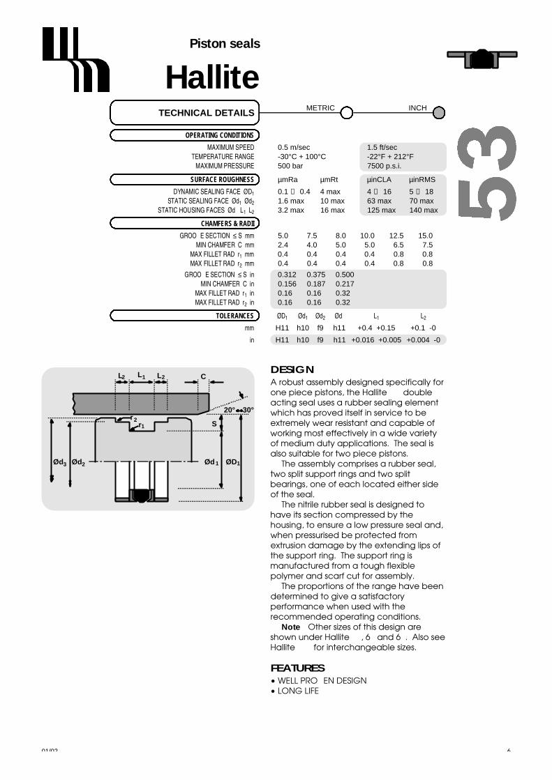
HallitePiston seals
01/02 67
OPERATING CONDITIONS
MAXIMUM SPEED 0.5 m/sec 1.5 ft/secTEMPERATURE RANGE -30°C + 100°C -22°F + 212°F
MAXIMUM PRESSURE 500 bar 7500 p.s.i.
SURFACE ROUGHNESS µ m R a µ m R t µ i n C L A µ i n R M S
DYNAMIC SEALING FACE ØD1 0.1 ↔ 0 . 4 4 max 4 ↔ 1 6 5 ↔ 1 8STATIC SEALING FACE Ød1 Ø d2 1.6 max 10 max 63 max 70 max
STATIC HOUSING FACES Ød3 L1 L2 3.2 max 16 max 125 max 140 max
CHAMFERS & RADII
GROOVE SECTION ≤ S mm 5.0 7.5 8.0 10.0 12.5 15.0MIN CHAMFER C mm 2.4 4.0 5.0 5.0 6.5 7.5
MAX FILLET RAD r1 m m 0.4 0.4 0.4 0.4 0.8 0.8MAX FILLET RAD r2 m m 0.4 0.4 0.4 0.4 0.8 0.8
GROOVE SECTION ≤ S in 0.312 0.375 0.500MIN CHAMFER C in 0.156 0.187 0.217
MAX FILLET RAD r1 i n 0.16 0.16 0.32MAX FILLET RAD r2 i n 0.16 0.16 0.32
T O L E R A N C E S Ø D1 Ø d1 Ø d2 Ø d3 L1 L2
m m H11 h10 f9 h11 +0.4 +0.15 +0.1 -0
i n H11 h10 f9 h11 +0.016 +0.005 +0.004 -0
TECHNICAL DETAILSM E T R I C I N C H
DESIGNA robust assembly designed specifically forone piece pistons, the Hallite 53 doubleacting seal uses a rubber sealing elementwhich has proved itself in service to beextremely wear resistant and capable ofworking most effectively in a wide varietyof medium duty applications. The seal isalso suitable for two piece pistons.
The assembly comprises a rubber seal,two split support rings and two splitbearings, one of each located either sideof the seal.
The nitrile rubber seal is designed tohave its section compressed by thehousing, to ensure a low pressure seal and,when pressurised be protected fromextrusion damage by the extending lips ofthe support ring. The support ring ismanufactured from a tough flexiblepolymer and scarf cut for assembly.
The proportions of the range have beendetermined to give a satisfactoryperformance when used with therecommended operating conditions.
Note : Other sizes of this design areshown under Hallite 50, 64 and 68. Also seeHallite 753 for interchangeable sizes.
FEATURES• WELL PROVEN DESIGN• LONG LIFE
20° 30°
S
C
r1
L2
r2
Ød3 Ød2 Ød1 ØD1
L2L1

2
Ød3 Ød2 Ød1 ØD1
21
5 3HallitePiston seals
metric
01/0268
Ø D1 T O L Ø d1 T O L Ø d2 T O L Ø d3 T O L L1 L2 P A R TH 1 1 h 1 0 f 9 h 1 1 + 0.4 + 0.15 + 0.1 - 0 N o .
25 +0.13 17 +0.00 22.1 -0.020 24.0 +0.00 8.0 4.00 2249212+ 0 . 0 0 - 0 . 0 7 - 0 . 0 7 2 - 0 . 1 3
32 +0.16 22 +0.00 28.5 -0.020 31.0 +0.00 10.0 5.00 2249312+ 0 . 0 0 - 0 . 0 8 - 0 . 0 7 2 - 0 . 1 6
40 +0.16 30 +0.00 36.5 -0.025 39.0 +0.00 10.0 5.00 2249412+ 0 . 0 0 - 0 . 0 8 - 0 . 0 8 7 - 0 . 1 6
45 +0.16 35 +0.00 40.4 -0.025 44.0 +0.00 16.4 6.35 2199411+ 0 . 0 0 - 0 . 1 0 - 0 . 0 8 7 - 0 . 1 6
50 +0.16 34 +0.00 45.4 -0.025 49.0 +0.00 18.0 6.35 0209912+ 0 . 0 0 - 0 . 1 0 - 0 . 0 8 7 - 0 . 1 6
50 +0.16 35 +0.00 46.0 -0.025 49.0 +0.00 15.0 7.5 0074012+ 0 . 0 0 - 0 . 1 0 - 0 . 0 8 7 - 0 . 1 6
55 +0.19 39 +0.00 50.4 -0.030 54.0 +0.00 18.0 6.35 1352212+ 0 . 0 0 - 0 . 1 0 - 0 . 1 0 4 - 0 . 1 9
60 +0.19 44 +0.00 55.4 -0.030 58.5 +0.00 18.0 6.35 1361412+ 0 . 0 0 - 0 . 1 0 - 0 . 1 0 4 - 0 . 1 9
63 +0.19 47 +0.00 58.4 -0.030 61.5 +0.00 19.0 6.35 0209712+ 0 . 0 0 - 0 . 1 0 - 0 . 1 0 4 - 0 . 1 9
65 +0.19 50 +0.00 60.4 -0.030 63.5 +0.00 18.0 6.35 1350512+ 0 . 0 0 - 0 . 1 0 - 0 . 1 0 4 - 0 . 1 9
70 +0.19 50 +0.00 64.0 -0.030 68.0 +0.00 22.0 10.00 0075112+ 0 . 0 0 - 0 . 1 0 - 0 . 1 0 4 - 0 . 1 9
70 +0.19 50 +0.00 64.2 -0.030 68.0 +0.00 22.0 6.35 0075122+ 0 . 0 0 - 0 . 1 0 - 0 . 1 0 4 - 0 . 1 9
75 +0.19 55 +0.00 69.0 -0.030 73.0 +0.00 22.0 10.00 0075612+ 0 . 0 0 - 0 . 1 2 - 0 . 1 0 4 - 0 . 1 9
75 +0.19 55 +0.00 69.2 -0.030 73.0 +0.00 22.0 6.35 0075622+ 0 . 0 0 - 0 . 1 2 - 0 . 1 0 4 - 0 . 1 9
80 +0.19 60 +0.00 74.0 -0.030 78.0 +0.00 22.0 10.00 0073812+ 0 . 0 0 - 0 . 1 2 - 0 . 1 0 4 - 0 . 1 9
80 +0.19 60 +0.00 74.2 -0.030 78.0 +0.00 22.0 6.35 0073822+ 0 . 0 0 - 0 . 1 2 - 0 . 1 0 4 - 0 . 1 9
85 +0.22 65 +0.00 79.2 -0.030 83.0 +0.00 22.0 6.35 0075722+ 0 . 0 0 - 0 . 1 2 - 0 . 1 0 4 - 0 . 2 2
90 +0.22 70 +0.00 84.0 -0.036 88.0 +0.00 22.0 10.00 0075812+ 0 . 0 0 - 0 . 1 2 - 0 . 1 2 3 - 0 . 2 2
90 +0.22 70 +0.00 84.2 -0.036 88.0 +0.00 22.0 6.35 0075822+ 0 . 0 0 - 0 . 1 2 - 0 . 1 2 3 - 0 . 2 2
95 +0.22 75 +0.00 89.2 -0.036 93.0 +0.00 22.0 6.35 1352512+ 0 . 0 0 - 0 . 1 2 - 0 . 1 2 3 - 0 . 2 2
100 +0.22 75 +0.00 93.2 -0.036 98.0 +0.00 22.0 6.35 0073712+ 0 . 0 0 - 0 . 1 2 - 0 . 1 2 3 - 0 . 2 2
100 +0.22 80 +0.00 94.0 -0.036 98.0 +0.00 22.0 10.00 0083612+ 0 . 0 0 - 0 . 1 2 - 0 . 1 2 3 - 0 . 2 2
105 +0.22 80 +0.00 98.1 -0.036 103.0 +0.00 22.0 6.35 1352812+ 0 . 0 0 - 0 . 1 2 - 0 . 1 2 3 - 0 . 2 2
110 +0.22 85 +0.00 103.1 -0.036 108.0 +0.00 22.0 6.35 0091113+ 0 . 0 0 - 0 . 1 4 - 0 . 1 2 3 - 0 . 2 2

01/02 69
Ø D1 T O L Ø d1 T O L Ø d2 T O L Ø d3 T O L L1 L2 P A R TH 1 1 h 1 0 f 9 h 1 1 + 0.4 + 0.15 + 0.1 - 0 N o .
115 +0.22 90 +0.00 108.1 -0.036 113.0 +0.00 22.0 6.35 0084222+ 0 . 0 0 - 0 . 1 4 - 0 . 1 2 3 - 0 . 2 2
120 +0.22 95 +0.00 113.1 -0.036 118.0 +0.00 22.0 6.35 0090012+ 0 . 0 0 - 0 . 1 4 - 0 . 1 2 3 - 0 . 2 2
125 +0.25 100 +0.00 118.1 -0.036 123.0 +0.00 25.0 6.35 0087522+ 0 . 0 0 - 0 . 1 4 - 0 . 1 2 3 - 0 . 2 5
130 +0.25 105 +0.00 122.6 -0.043 128.0 +0.00 25.0 9.52 0089622+ 0 . 0 0 - 0 . 1 4 - 0 . 1 4 3 - 0 . 2 5
135 +0.25 110 +0.00 127.6 -0.043 133.0 +0.00 25.0 9.52 0091222+ 0 . 0 0 - 0 . 1 4 - 0 . 1 4 3 - 0 . 2 5
135 +0.25 110 +0.00 128.0 -0.043 133.0 +0.00 25.0 12.70 0091212+ 0 . 0 0 - 0 . 1 4 - 0 . 1 4 3 - 0 . 2 5
140 +0.25 115 +0.00 132.6 -0.043 138.0 +0.00 25.0 6.35 0091032+ 0 . 0 0 - 0 . 1 4 - 0 . 1 4 3 - 0 . 2 5
140 +0.25 115 +0.00 132.6 -0.043 138.0 +0.00 25.0 9.52 0091022+ 0 . 0 0 - 0 . 1 4 - 0 . 1 4 3 - 0 . 2 5
145 +0.25 120 +0.00 137.6 -0.043 143.0 +0.00 25.0 9.52 0091422+ 0 . 0 0 - 0 . 1 4 - 0 . 1 4 3 - 0 . 2 5
150 +0.25 125 +0.00 142.6 -0.043 148.0 +0.00 25.0 9.52 0091522+ 0 . 0 0 - 0 . 1 6 - 0 . 1 4 3 - 0 . 2 5
150 +0.25 125 +0.00 143.0 -0.043 148.0 +0.00 25.0 12.70 0091512+ 0 . 0 0 - 0 . 1 6 - 0 . 1 4 3 - 0 . 2 5
155 +0.25 130 +0.00 147.6 -0.043 153.0 +0.00 25.0 9.52 0091622+ 0 . 0 0 - 0 . 1 6 - 0 . 1 4 3 - 0 . 2 5
160 +0.25 135 +0.00 152.6 -0.043 158.0 +0.00 25.0 9.52 0089922+ 0 . 0 0 - 0 . 1 6 - 0 . 1 4 3 - 0 . 2 5
165 +0.25 140 +0.00 158.0 -0.043 163.0 +0.00 25.0 12.70 1257612+ 0 . 0 0 - 0 . 1 6 - 0 . 1 4 3 - 0 . 2 5
170 +0.25 145 +0.00 161.7 -0.043 168.0 +0.00 25.0 12.70 0088012+ 0 . 0 0 - 0 . 1 6 - 0 . 1 4 3 - 0 . 2 5
175 +0.25 150 +0.00 166.7 -0.043 173.0 +0.00 25.0 12.70 1260712+ 0 . 0 0 - 0 . 1 6 - 0 . 1 4 3 - 0 . 2 5
180 +0.25 155 +0.00 171.7 -0.043 178.0 +0.00 25.0 12.70 0091712+ 0 . 0 0 - 0 . 1 6 - 0 . 1 4 3 - 0 . 2 5
190 +0.29 165 +0.00 181.7 -0.050 188.0 +0.00 25.0 12.70 1270012+ 0 . 0 0 - 0 . 1 6 - 0 . 1 6 5 - 0 . 2 9
195 +0.29 170 +0.00 186.7 -0.050 193.0 +0.00 25.0 12.70 1265412+ 0 . 0 0 - 0 . 1 6 - 0 . 1 6 5 - 0 . 2 9
200 +0.29 170 +0.00 192.0 -0.050 197.0 +0.00 30.0 15.00 1270112+ 0 . 0 0 - 0 . 1 6 - 0 . 1 6 5 - 0 . 2 9
200 +0.29 175 +0.00 191.6 -0.050 198.0 +0.00 25.0 12.70 0089712+ 0 . 0 0 - 0 . 1 6 - 0 . 1 6 5 - 0 . 2 9
220 +0.29 190 +0.00 212.0 -0.050 217.0 +0.00 30.0 15.00 1714810+ 0 . 0 0 - 0 . 1 9 - 0 . 1 6 5 - 0 . 2 9
250 +0.29 220 +0.00 242.0 -0.050 247.0 +0.00 30.0 15.00 1264312+ 0 . 0 0 - 0 . 1 9 - 0 . 1 6 5 - 0 . 2 9
280 +0.29 250 +0.00 272.0 -0.056 277.0 +0.00 30.0 15.00 1261712+ 0 . 0 0 - 0 . 1 9 - 0 . 1 8 6 - 0 . 3 2
Ød3 Ød2 Ød1 ØD1 5 3Hallite
Piston seals
metric

Ød3 Ød2 Ød1 ØD15 3HallitePiston seals
inch
01/0270
Ø D1 T O L Ø d1 T O L Ø d2 T O L Ø d3 T O L L1 L2 P A R TH 1 1 h 1 0 f 9 h 1 1 + 0.016 + 0.005 + 0.004 - 0 N o .
2.000 +0.007 1.375 +0.000 1.821 -0.001 1.950 +0.000 0.750 0.250 6593410+ 0 . 0 0 0 - 0 . 0 0 4 - 0 . 0 0 3 - 0 . 0 0 7
2.250 +0.007 1.625 +0.000 2.071 -0.001 2.200 +0.000 0.750 0.250 6593510+ 0 . 0 0 0 - 0 . 0 0 4 - 0 . 0 0 4 - 0 . 0 0 7
2.500 +0.007 1.875 +0.000 2.321 -0.001 2.450 +0.000 0.750 0.250 6593610+ 0 . 0 0 0 - 0 . 0 0 4 - 0 . 0 0 4 - 0 . 0 0 7
2.750 +0.007 2.000 +0.000 2.524 -0.001 2.690 +0.000 0.937 0.250 6593710+ 0 . 0 0 0 - 0 . 0 0 5 - 0 . 0 0 4 - 0 . 0 0 7
3.000 +0.007 2.250 +0.000 2.774 -0.001 2.940 +0.000 0.937 0.250 1377612+ 0 . 0 0 0 - 0 . 0 0 5 - 0 . 0 0 4 - 0 . 0 0 7
3.250 +0.009 2.500 +0.000 3.023 -0.001 3.190 +0.000 0.937 0.250 6593910+ 0 . 0 0 0 - 0 . 0 0 5 - 0 . 0 0 4 - 0 . 0 0 9
3.500 +0.009 2.750 +0.000 3.274 -0.001 3.440 +0.000 0.937 0.250 0082412+ 0 . 0 0 0 - 0 . 0 0 5 - 0 . 0 0 5 - 0 . 0 0 9
3.750 +0.009 3.000 +0.000 3.524 -0.001 3.690 +0.000 0.937 0.250 2361010+ 0 . 0 0 0 - 0 . 0 0 6 - 0 . 0 0 5 - 0 . 0 0 9
4.000 +0.009 3.250 +0.000 3.773 -0.001 3.940 +0.000 0.937 0.250 0082313+ 0 . 0 0 0 - 0 . 0 0 6 - 0 . 0 0 5 - 0 . 0 0 9
4.250 +0.009 3.500 +0.000 4.024 -0.001 4.187 +0.000 0.937 0.250 0082211+ 0 . 0 0 0 - 0 . 0 0 6 - 0 . 0 0 5 - 0 . 0 0 9
4.500 +0.009 3.500 +0.000 4.232 -0.001 4.428 +0.000 1.250 0.250 6594210+ 0 . 0 0 0 - 0 . 0 0 6 - 0 . 0 0 5 - 0 . 0 0 9
4.750 +0.010 3.750 +0.000 4.463 -0.001 4.660 +0.000 1.250 0.375 2360910+ 0 . 0 0 0 - 0 . 0 0 6 - 0 . 0 0 5 - 0 . 0 1 0
5.000 +0.010 4.000 +0.000 4.712 -0.001 4.910 +0.000 1.250 0.375 6594310+ 0 . 0 0 0 - 0 . 0 0 6 - 0 . 0 0 5 - 0 . 0 1 0
5.500 +0.010 4.500 +0.000 5.213 -0.002 5.410 +0.000 1.250 0.375 6594410+ 0 . 0 0 0 - 0 . 0 0 6 - 0 . 0 0 6 - 0 . 0 1 0
6.000 +0.010 5.000 +0.000 5.713 -0.002 5.910 +0.000 1.250 0.375 6594510+ 0 . 0 0 0 - 0 . 0 0 6 - 0 . 0 0 6 - 0 . 0 1 0

HallitePiston seals
01/02 71
OPERATING CONDITIONS
MAXIMUM SPEED 4.0 m/sec 12.0 ft/secTEMPERATURE RANGE -30°C + 100°C -22°F + 212°F
MAXIMUM PRESSURE 350 bar 5000 p.s.i.
MAXIMUM EXTRUSION GAP Figures show the maximum permissible gap all on one side using the minimum clearance Ø and maximum bore Ø
PRESSURE bar 1 0 0 1 6 0 2 5 0 3 5 0MAXIMUM GAP mm 0 . 6 0 0 . 5 0 0 . 4 5 0 . 3 5
PRESSURE p.s.i. 1500 2400 3750 5250MAXIMUM GAP in 0.024 0.020 0.018 0.014
SURFACE ROUGHNESS µ m R a µ m R t µ i n C L A µ i n R M S
DYNAMIC SEALING FACE ØD1 0.1 ↔ 0 . 4 4 max 4 ↔ 1 6 5 ↔ 1 8STATIC SEALING FACE Ød1 1.6 max 10 max 63 max 70 maxSTATIC HOUSING FACES L1 3.2 max 16 max 125 max 140 max
CHAMFERS & RADII
GROOVE SECTION ≤ S mm 3.75 5.50 7.75 10.50 12.25MIN CHAMFER C mm 2.00 2.50 5.00 7.50 10.00
MAX FILLET RAD r1 m m 0.40 0.80 1.20 1.60 2.00
GROOVE SECTION ≤ S in 0.147 0.216 0.305 0.413 0.483MIN CHAMFER C in 0.093 0.125 0.156 0.187 0.305
MAX FILLET RAD r1 i n 0.016 0.016 0.032 0.032 0.032
T O L E R A N C E S Ø D1 Ø d1 L1
m m H9 f8 +0.2 -0
i n H9 f8 +0.008 -0
TECHNICAL DETAILSM E T R I C I N C H
DESIGNThe Hallite 54 double acting piston seal providesthe designer with a compact, low friction seal forlight to medium duty hydraulic cylinders.
It comprises a PTFE ring, strengthened withadditives to resist creep, which is pre-loaded byan O ring to be effective for the operatingpressure range recommended. As the pressurerises the O ring deforms and compresses the PTFEring against the tube wall increasing the sealingforce and the effectiveness of the seal. As onlythe PTFE ring is in contact with the sliding surface,friction is very low and stick-slip movement iseliminated.
The housing width allows the designer to use anarrow width piston, but it is recommended anadequate bearing is mounted either side of theseal as shown.*
A number of material options can beprovided to extend operating conditions.Please ensure that the correct part number isspecified for the material option as indicated.Technical details shown are for 15% Glass/PTFEand NBR energiser. Technical details formaterial options should be requested fromHallite Seals. The Hallite 54 seal is notrecommended for applications where it isnecessary for the pressurised cylinder to maintainthe load in a set position.
*See Hallite 87 and 506 wear ring data sheets.NB: Part numbers suffixed by “‡” i n d i c a t ehousing sizes to meet ISO 7425-1.
ØD1Ød1
S
C
r1
L1
20° 30°
FEATURES• LOW STICK/SLIP• LOW BREAKOUT & RUNNING FRICTION• HIGH MAXIMUM SPEED• COMPACT PISTON DESIGN• THE SEAL RING COMPONENT CAN BE
MACHINED TO ANY SIZE
MATERIALSlast two digits of
Face material - O-Ring part number
Standard material15% Glass/PTFE - NBR _ _ _ _ _ 10
Material options:15% Glass/PTFE - FKM _ _ _ _ _ 11
Bronze/PTFE - NBR _ _ _ _ _ 20
Bronze/PTFE - FKM _ _ _ _ _ 21

ØD1Ød1
L1
5 4HallitePiston seals
metric
01/0272
ØD1 TOL Ød1 TOL L1 PARTH9 f8 + 0.2 - 0 No.
ØD1 TOL Ød1 TOL L1 PARTH9 f8 + 0.2 - 0 No.
12 +0.04 7.1 -0.01 2.20 66239_ _+ 0 . 0 0 - 0 . 0 4
15 +0.04 7.5 -0.01 3.20 86163_ _+ 0 . 0 0 - 0 . 0 4
16 +0.04 8.5 -0.01 3.20 66240_ _ ‡+ 0 . 0 0 - 0 . 0 4
20 +0.05 12.5 -0.02 3.20 66241_ _ ‡+ 0 . 0 0 - 0 . 0 4
24 +0.05 16.5 -0.02 3.20 66154_ _+ 0 . 0 0 - 0 . 0 4
25 +0.05 17.5 -0.02 3.20 66242_ _ ‡+ 0 . 0 0 - 0 . 0 4
30 +0.05 22.5 -0.02 3.20 65968_ _+ 0 . 0 0 - 0 . 0 5
32 +0.06 24.5 -0.02 3.20 65969_ _ ‡+ 0 . 0 0 - 0 . 0 5
35 +0.06 27.5 -0.02 3.20 65970_ _+ 0 . 0 0 - 0 . 0 5
38 +0.06 30.5 -0.03 3.20 66475_ _+ 0 . 0 0 - 0 . 0 6
40 +0.06 29.0 -0.02 4.20 65971_ _ ‡+ 0 . 0 0 - 0 . 0 5
42 +0.06 31.0 -0.03 4.20 65972_ _+ 0 . 0 0 - 0 . 0 6
45 +0.06 34.0 -0.03 4.20 65973_ _+ 0 . 0 0 - 0 . 0 6
50 +0.06 39.0 -0.03 4.20 65974_ _ ‡+ 0 . 0 0 - 0 . 0 6
55 +0.07 44.0 -0.03 4.20 65975_ _+ 0 . 0 0 - 0 . 0 6
60 +0.07 49.0 -0.03 4.20 65976_ _+ 0 . 0 0 - 0 . 0 6
63 +0.07 52.0 -0.03 4.20 66243_ _ ‡+ 0 . 0 0 - 0 . 0 8
65 +0.07 54.0 -0.03 4.20 86118_ _+ 0 . 0 0 - 0 . 0 8
70 +0.07 59.0 -0.03 4.20 65977_ _+ 0 . 0 0 - 0 . 0 8
75 +0.07 64.0 -0.03 4.20 66244_ _+ 0 . 0 0 - 0 . 0 8
80 +0.07 64.5 -0.03 6.30 65978_ _ ‡+ 0 . 0 0 - 0 . 0 8
90 +0.09 74.5 -0.03 6.30 65979_ _+ 0 . 0 0 - 0 . 0 8
95 +0.09 79.5 -0.03 6.30 86084_ _+ 0 . 0 0 - 0 . 0 8
100 +0.09 84.5 -0.04 6.30 65980_ _ ‡+ 0 . 0 0 - 0 . 0 9
110 +0.09 94.5 -0.04 6.30 65981_ _+ 0 . 0 0 - 0 . 0 9
115 +0.09 99.5 -0.04 6.30 65982_ _+ 0 . 0 0 - 0 . 0 9
120 +0.09 104.5 -0.04 6.30 66361_ _+ 0 . 0 0 - 0 . 0 9
125 +0.10 109.5 -0.04 6.30 65983_ _ ‡+ 0 . 0 0 - 0 . 0 9
130 +0.10 114.5 -0.04 6.30 66476_ _+ 0 . 0 0 - 0 . 0 9
135 +0.10 114.0 -0.04 8.10 66477_ _+ 0 . 0 0 - 0 . 0 9
140 +0.10 119.0 -0.04 8.10 65984_ _+ 0 . 0 0 - 0 . 0 9
145 +0.10 124.0 -0.04 8.10 86080_ _+ 0 . 0 0 - 0 . 1 1
150 +0.10 129.0 -0.04 8.10 65985_ _+ 0 . 0 0 - 0 . 1 1
155 +0.10 134.0 -0.04 8.10 86177_ _+ 0 . 0 0 - 0 . 1 1
160 +0.10 139.0 -0.04 8.10 65986_ _ ‡+ 0 . 0 0 - 0 . 1 1
165 +0.10 144.0 -0.04 8.10 66491_ _+ 0 . 0 0 - 0 . 1 1
170 +0.10 149.0 -0.04 8.10 65987_ _+ 0 . 0 0 - 0 . 1 1
180 +0.10 159.0 -0.04 8.10 65988_ _+ 0 . 0 0 - 0 . 1 1
185 +0.12 164.0 -0.04 8.10 66478_ _+ 0 . 0 0 - 0 . 1 1
190 +0.12 169.0 -0.04 8.10 65989_ _+ 0 . 0 0 - 0 . 1 1
200 +0.12 179.0 -0.04 8.10 65990_ _ ‡+ 0 . 0 0 - 0 . 1 1
210 +0.12 189.0 -0.05 8.10 86146_ _+ 0 . 0 0 - 0 . 1 2
220 +0.12 199.0 -0.05 8.10 66245_ _+ 0 . 0 0 - 0 . 1 2
225 +0.12 204.0 -0.05 8.10 66246_ _+ 0 . 0 0 - 0 . 1 2
230 +0.12 209.0 -0.05 8.10 66247_ _+ 0 . 0 0 - 0 . 1 2
240 +0.12 219.0 -0.05 8.10 86154_ _+ 0 . 0 0 - 0 . 1 2

01/02 73
ØD1 TOL Ød1 TOL L1 PARTH9 f8 + 0.2 - 0 No.
ØD1 TOL Ød1 TOL L1 PARTH9 f8 + 0.2 - 0 No.
350 +0.13 325.5 -0.06 8.10 86155_ _+ 0 . 0 0 - 0 . 1 4
360 +0.13 335.5 -0.06 8.10 86218_ _+ 0 . 0 0 - 0 . 1 4
370 +0.13 345.5 -0.06 8.10 86219_ _+ 0 . 0 0 - 0 . 1 4
380 +0.13 355.5 -0.06 8.10 86220_ _+ 0 . 0 0 - 0 . 1 4
390 +0.13 365.5 -0.06 8.10 86221_ _+ 0 . 0 0 - 0 . 1 4
400 +0.13 375.5 -0.06 8.10 66482_ _ ‡+ 0 . 0 0 - 0 . 1 4
250 +0.12 229.0 -0.05 8.10 66401_ _ ‡+ 0 . 0 0 - 0 . 1 2
260 +0.12 239.0 -0.05 8.10 66479_ _+ 0 . 0 0 - 0 . 1 2
280 +0.13 259.0 -0.06 8.10 66402_ _+ 0 . 0 0 - 0 . 1 4
300 +0.13 279.0 -0.06 8.10 66403_ _+ 0 . 0 0 - 0 . 1 4
310 +0.13 289.0 -0.06 8.10 66480_ _+ 0 . 0 0 - 0 . 1 4
320 +0.13 299.0 -0.06 8.10 86086_ _ ‡+ 0 . 0 0 - 0 . 1 4
330 +0.13 305.5 -0.06 8.10 86081_ _+ 0 . 0 0 - 0 . 1 4
340 +0.13 315.5 -0.06 8.10 66481_ _+ 0 . 0 0 - 0 . 1 4
ØD1Ød1
L1
5 4Hallite
Piston seals
metric

ØD1Ød1
L1
5 4HallitePiston seals
inch
01/0274
ØD1 TOL Ød1 TOL L1 PARTH9 f8 + 0.008 - 0 No.
ØD1 TOL Ød1 TOL L1 PARTH9 f8 + 0.008 - 0 No.
1.000 +0.002 0.704 -0.0008 0.125 66248_ _+0.000 -0.0020
1.500 +0.002 1.204 -0.0010 0.125 66249_ _+0.000 -0.0026
2.000 +0.003 1.568 -0.0012 0.165 66250_ _+0.000 -0.0030
2.500 +0.003 2.068 -0.0012 0.165 66251_ _+0.000 -0.0030
3.000 +0.003 2.568 -0.0012 0.165 66252_ _+0.000 -0.0030
3.250 +0.003 2.640 -0.0014 0.250 66253_ _+0.000 -0.0036
3.500 +0.003 2.890 -0.0014 0.250 66254_ _+0.000 -0.0036
4.000 +0.003 3.390 -0.0014 0.250 66255_ _+0.000 -0.0036
4.500 +0.003 3.890 -0.0014 0.250 66256_ _+0.000 -0.0036
5.000 +0.004 4.390 -0.0016 0.250 66257_ _+0.000 -0.0041
6.000 +0.004 5.174 -0.0016 0.320 66258_ _+0.000 -0.0041
7.000 +0.004 6.174 -0.0016 0.320 66259_ _+0.000 -0.0041
8.000 +0.004 7.174 -0.0020 0.320 66260_ _+0.000 -0.0048

HallitePiston seals
OPERATING CONDITIONS
MAXIMUM SPEED 0.5 m/sec 1.5 ft/secTEMPERATURE RANGE -30°C + 100°C -22°F + 212°F
MAXIMUM PRESSURE 500 bar 7500 p.s.i.
MAXIMUM EXTRUSION GAP Figures show the maximum permissible gap all on one side using the minimum clearance Ø and maximum bore Ø
PRESSURE bar 1 6 0 2 5 0 4 0 0 5 0 0MAXIMUM GAP mm 0 . 3 5 0 . 3 0 . 2 0 . 1
PRESSURE p.s.i. 2400 3750 6000 7500MAXIMUM GAP in 0 . 0 1 6 0 . 0 1 2 0 . 0 0 8 0 . 0 0 4
SURFACE ROUGHNESS µ m R a µ m R t µ i n C L A µ i n R M S
DYNAMIC SEALING FACE ØD1 0.1 ↔ 0 . 4 4 max 4 ↔ 1 6 5 ↔ 1 8STATIC SEALING FACE Ød1 1.6 max 10 max 63 max 70 maxSTATIC HOUSING FACES L1 3.2 max 16 max 125 max 140 max
CHAMFERS & RADII
GROOVE SECTION ≤ S mm 5.0 7.5 8.0 10.0 12.5MIN CHAMFER C mm 2.4 4.0 5.0 5.0 6.5
MAX FILLET RAD r1 m m 0.4 0.8 0.8 1.2 1.6
GROOVE SECTION ≤ S in 0.250 0.312 0.375 0.500 0.625MIN CHAMFER C in 0.125 0.156 0.187 0.217 0.250
MAX FILLET RAD r1 i n 0.016 0.016 0.032 0.032 0.046
T O L E R A N C E S Ø D1 Ø d1 L1
m m H11 js11 +0.25 +0
i n H11 js11 +0.030 +0.020
TECHNICAL DETAILSM E T R I C I N C H
DESIGNA medium to heavy duty double acting seal,the Hallite 56 has shown itself over many yearsto be an effective and robust piston seal in awide variety of applications. Designed for splitpistons it offers the benefits in terms of sealingefficiency and low friction gained fromrubber/fabric and a specific proportion ofrubber in contact with the cylinder surface.
The centre of the seal is rubber which isbonded to two ‘U’ section bases ofrubberised fabric, and is compressed by thehousing to obtain an effective low pressureseal. When the pressure increases the rubberenergises the ‘U’ section and deforms it to thehousing, increasing the sealing area andimproving the seal.
Rubberised fabric is used to protect therubber because it has strength and durabilitywhich combines with its ability to retainlubricant, to help keep friction low andreduce wear.
The proportions of the range have beendetermined to give a satisfactoryperformance when used with therecommended operating conditions. Many other sizes are available outsidethis range.
01/02 75
FEATURES• WELL PROVEN DESIGN• TOLERANT TO CONTAMINATION• WIDE RANGE OF NON STANDARD SIZES
S
ØD1Ød1
r1
L1 C
20° 30°

30 +0.13 20 +0.07 12.5 0200540+ 0 . 0 0 - 0 . 0 7
40 +0.16 25 +0.07 19.0 0472840+ 0 . 0 0 - 0 . 0 7
50 +0.16 35 +0.08 19.0 0474640+ 0 . 0 0 - 0 . 0 8
55 +0.19 40 +0.08 19.0 0475040+ 0 . 0 0 - 0 . 0 8
60 +0.19 40 +0.08 25.0 0282040+ 0 . 0 0 - 0 . 0 8
60 +0.19 45 +0.08 19.0 0979440+ 0 . 0 0 - 0 . 0 8
63 +0.19 43 +0.08 25.0 0646740+ 0 . 0 0 - 0 . 0 8
65 +0.19 50 +0.08 19.0 0383840+ 0 . 0 0 - 0 . 0 8
70 +0.19 50 +0.08 25.0 0294640+ 0 . 0 0 - 0 . 0 8
75 +0.19 55 +0.10 25.0 0818640+ 0 . 0 0 - 0 . 1 0
80 +0.19 60 +0.10 25.0 0294940+ 0 . 0 0 - 0 . 1 0
85 +0.22 65 +0.10 25.0 0388640+ 0 . 0 0 - 0 . 1 0
90 +0.22 70 +0.10 25.0 0296040+ 0 . 0 0 - 0 . 1 0
100 +0.22 80 +0.10 25.0 0295140+ 0 . 0 0 - 0 . 1 0
110 +0.22 90 +0.11 25.0 0712440+ 0 . 0 0 - 0 . 1 1
120 +0.22 100 +0.11 25.0 0296140+ 0 . 0 0 - 0 . 1 1
125 +0.25 100 +0.11 19.0 1007440+ 0 . 0 0 - 0 . 1 1
125 +0.25 100 +0.11 32.0 0418640+ 0 . 0 0 - 0 . 1 1
140 +0.25 120 +0.11 25.0 0250540+ 0 . 0 0 - 0 . 1 1
150 +0.25 120 +0.11 38.0 1289540+ 0 . 0 0 - 0 . 1 1
160 +0.25 135 +0.13 32.0 0080440+ 0 . 0 0 - 0 . 1 3
170 +0.25 150 +0.13 25.0 0303340+ 0 . 0 0 - 0 . 1 3
180 +0.25 160 +0.13 25.0 1283140+ 0 . 0 0 - 0 . 1 3
190 +0.29 160 +0.13 38.0 0838440+ 0 . 0 0 - 0 . 1 3
200 +0.29 170 +0.13 38.0 0087140+ 0 . 0 0 - 0 . 1 3
220 +0.29 190 +0.15 38.0 0087340+ 0 . 0 0 - 0 . 1 5
230 +0.29 200 +0.15 38.0 2010040+ 0 . 0 0 - 0 . 1 5
240 +0.29 210 +0.15 38.0 0094340+ 0 . 0 0 - 0 . 1 5
250 +0.29 220 +0.15 38.0 1056340+ 0 . 0 0 - 0 . 1 5
260 +0.32 230 +0.15 38.0 0094540+ 0 . 0 0 - 0 . 1 5
300 +0.32 270 +0.16 38.0 0094840+ 0 . 0 0 - 0 . 1 6
310 +0.32 280 +0.16 38.0 0094940+ 0 . 0 0 - 0 . 1 6
330 +0.36 300 +0.16 38.0 0095040+ 0 . 0 0 - 0 . 1 6
360 +0.36 320 +0.18 45.0 1054040+ 0 . 0 0 - 0 . 1 8
400 +0.36 360 +0.18 45.0 1054340+ 0 . 0 0 - 0 . 1 8
420 +0.40 380 +0.20 45.0 0095140+ 0 . 0 0 - 0 . 2 0
460 +0.40 420 +0.20 45.0 0095340+ 0 . 0 0 - 0 . 2 0
480 +0.40 440 +0.20 45.0 0095440+ 0 . 0 0 - 0 . 2 0
500 +0.40 460 +0.20 45.0 0134740+ 0 . 0 0 - 0 . 2 0
540 +0.44 500 +0.20 45.0 2018240+ 0 . 0 0 - 0 . 2 0
580 +0.44 540 +0.22 50.0 2020940+ 0 . 0 0 - 0 . 2 2
ØD1Ød1
L1
5 6HallitePiston seals
metric
01/0276
Ø D1 T O L Ø d1 T O L L1 P A R TH 1 1 j s 1 1 + 0.25 - 0 N o .
Ø D1 T O L Ø d1 T O L L1 P A R TH 1 1 j s 1 1 + 0.25 - 0 N o .

1.000 +0.005 0.625 +0.002 0.469 1247640+ 0 . 0 0 0 - 0 . 0 0 2
1.250 +0.006 0.750 +0.003 0.625 0403740+ 0 . 0 0 0 - 0 . 0 0 3
1.500 +0.006 1.000 +0.003 0.625 0422440+ 0 . 0 0 0 - 0 . 0 0 3
1.750 +0.006 1.125 +0.003 0.750 0778240+ 0 . 0 0 0 - 0 . 0 0 3
2.000 +0.007 1.375 +0.003 0.750 0778440+ 0 . 0 0 0 - 0 . 0 0 3
2.250 +0.007 1.625 +0.003 0.750 1432640+ 0 . 0 0 0 - 0 . 0 0 3
2.375 +0.007 1.750 +0.003 0.750 0939840+ 0 . 0 0 0 - 0 . 0 0 3
2.500 +0.007 1.875 +0.003 0.750 0867240+ 0 . 0 0 0 - 0 . 0 0 3
2.750 +0.007 2.000 +0.004 0.937 1369140+ 0 . 0 0 0 - 0 . 0 0 4
2.875 +0.007 2.125 +0.004 0.937 0779640+ 0 . 0 0 0 - 0 . 0 0 4
3.000 +0.007 2.250 +0.004 0.937 1098440+ 0 . 0 0 0 - 0 . 0 0 4
3.250 +0.009 2.500 +0.004 0.937 0782440+ 0 . 0 0 0 - 0 . 0 0 4
3.375 +0.009 2.625 +0.004 0.937 0773840+ 0 . 0 0 0 - 0 . 0 0 4
3.500 +0.009 2.750 +0.004 0.937 0437840+ 0 . 0 0 0 - 0 . 0 0 4
3.750 +0.009 3.000 +0.004 0.937 0410540+ 0 . 0 0 0 - 0 . 0 0 4
4.000 +0.009 3.250 +0.004 0.716 6504740+ 0 . 0 0 0 - 0 . 0 0 4
4.000 +0.009 3.250 +0.004 0.937 1407740+ 0 . 0 0 0 - 0 . 0 0 4
4.250 +0.009 3.500 +0.004 0.937 1128840+ 0 . 0 0 0 - 0 . 0 0 4
4.500 +0.009 3.500 +0.004 1.250 0448840+ 0 . 0 0 0 - 0 . 0 0 4
4.625 +0.009 3.625 +0.004 1.250 0449040+ 0 . 0 0 0 - 0 . 0 0 4
4.750 +0.010 3.750 +0.004 1.250 1007040+ 0 . 0 0 0 - 0 . 0 0 4
5.000 +0.010 4.000 +0.004 1.250 0443040+ 0 . 0 0 0 - 0 . 0 0 4
5.250 +0.010 4.250 +0.004 1.250 0892240+ 0 . 0 0 0 - 0 . 0 0 4
5.500 +0.010 4.500 +0.004 1.250 0133240+ 0 . 0 0 0 - 0 . 0 0 4
6.000 +0.010 5.000 +0.005 1.250 1367040+ 0 . 0 0 0 - 0 . 0 0 5
6.500 +0.010 5.500 +0.005 1.250 1164140+ 0 . 0 0 0 - 0 . 0 0 5
7.000 +0.010 6.000 +0.005 1.250 1188840+ 0 . 0 0 0 - 0 . 0 0 5
7.250 +0.011 6.500 +0.005 1.625 0424140+ 0 . 0 0 0 - 0 . 0 0 5
7.500 +0.011 6.250 +0.005 1.625 1255240+ 0 . 0 0 0 - 0 . 0 0 5
7.750 +0.011 6.500 +0.005 1.625 1192740+ 0 . 0 0 0 - 0 . 0 0 5
8.000 +0.011 6.750 +0.005 1.625 0426540+ 0 . 0 0 0 - 0 . 0 0 5
8.000 +0.011 7.000 +0.005 1.000 0224340+ 0 . 0 0 0 - 0 . 0 0 5
8.250 +0.011 7.000 +0.005 1.625 1219240+ 0 . 0 0 0 - 0 . 0 0 5
8.500 +0.011 7.250 +0.005 1.625 1286440+ 0 . 0 0 0 - 0 . 0 0 5
8.750 +0.011 7.500 +0.005 1.625 0418140+ 0 . 0 0 0 - 0 . 0 0 5
9.000 +0.011 7.750 +0.006 1.625 1266640+ 0 . 0 0 0 - 0 . 0 0 6
9.250 +0.011 8.000 +0.006 1.625 0455740+ 0 . 0 0 0 - 0 . 0 0 6
9.500 +0.011 8.250 +0.006 1.625 1332240+ 0 . 0 0 0 - 0 . 0 0 6
9.750 +0.011 8.500 +0.006 1.625 1332340+ 0 . 0 0 0 - 0 . 0 0 6
10.000 +0.013 8.750 +0.006 1.625 0436140+ 0 . 0 0 0 - 0 . 0 0 6
10.250 +0.013 9.000 +0.006 1.625 0437540+ 0 . 0 0 0 - 0 . 0 0 6
10.500 +0.013 9.250 +0.006 1.625 1331940+ 0 . 0 0 0 - 0 . 0 0 6
10.750 +0.013 9.500 +0.006 1.625 1320440+ 0 . 0 0 0 - 0 . 0 0 6
11.000 +0.013 9.750 +0.006 1.625 0433940+ 0 . 0 0 0 - 0 . 0 0 6
11.250 +0.013 10.250 +0.006 1.625 1331640+ 0 . 0 0 0 - 0 . 0 0 6
12.000 +0.013 10.750 +0.006 1.625 1331440+ 0 . 0 0 0 - 0 . 0 0 6
01/02 77
Ø D1 T O L Ø d1 T O L L1 P A R TH 1 1 j s 1 1 + 0.030 + 0.020 N o .
Ø D1 T O L Ø d1 T O L L1 P A R TH 1 1 j s 1 1 + 0.030 + 0.020 N o .
ØD1Ød1
L1
5 6Hallite
Piston seals
inch

12.500 +0.013 11.250 +0.006 1.625 0436340+ 0 . 0 0 0 - 0 . 0 0 6
13.000 +0.013 11.750 +0.006 1.625 0436540+ 0 . 0 0 0 - 0 . 0 0 6
14.500 +0.013 13.000 +0.006 1.500 0270940+ 0 . 0 0 0 - 0 . 0 0 6
15.000 +0.013 13.750 +0.007 1.500 0787040+ 0 . 0 0 0 - 0 . 0 0 7
16.000 +0.016 14.750 +0.007 1.800 2117440+ 0 . 0 0 0 - 0 . 0 0 7
17.000 +0.016 15.000 +0.007 2.250 1345340+ 0 . 0 0 0 - 0 . 0 0 7
18.000 +0.016 16.000 +0.008 2.062 2002040+ 0 . 0 0 0 - 0 . 0 0 8
19.500 +0.016 18.000 +0.008 2.500 2108240+ 0 . 0 0 0 - 0 . 0 0 8
20.000 +0.017 18.500 +0.009 1.750 2111240+ 0 . 0 0 0 - 0 . 0 0 9
ØD1Ød1
L1
5 6HallitePiston seals
inch
01/0278
Ø D1 T O L Ø d1 T O L L1 P A R TH 1 1 j s 1 1 + 0.030 + 0.020 N o .
Ø D1 T O L Ø d1 T O L L1 P A R TH 1 1 j s 1 1 + 0.030 + 0.020 N o .

HallitePiston seals
01/02 79
DESIGNThe Hallite 58 double acting piston sealcombines the Hallite 56 seal with bearingrings to give a very robust heavy duty sealassembly for split pistons. It enables thedesigner to use larger clearances and, withthe integral bearing rings, to restrict thepiston length.
The assembly comprises a seal and twoL shaped bearings. The centre of the seal isrubber which is bonded to two ‘U’ sectionbases of rubberised fabric, and iscompressed by the housing to obtain aneffective low pressure seal. When thepressure increases the rubber energises the‘U’ section and deforms it to the housing,increasing the sealing area and improvingthe seal.
Rubberised fabric is used to protect therubber, because it has strength anddurability which combines with its ability toretain lubricant to help keep friction lowand reduce wear.
Supporting the seal at either end is apolyacetal bearing proportioned to reactto the pressure on the seal to preventextrusion damage, and support the pistonand its side load.
FEATURES• WELL PROVEN DESIGN• TOLERANT TO C O N T A M I N A T I O N• HIGH PRESSURE CAPABILITY
S
C
r1
L2
r2
Ød3
20° 30°
Ød2 Ød1 ØD1
L2L1
C1 x 45°
OPERATING CONDITIONS
MAXIMUM SPEED 0.5 m/sec 1.5 ft/secTEMPERATURE RANGE -30°C + 100°C -22°F + 212°F
MAXIMUM PRESSURE 700 bar 10,000 p.s.i.
SURFACE ROUGHNESS µ m R a µ m R t µ i n C L A µ i n R M S
DYNAMIC SEALING FACE ØD1 0.1 ↔ 0 . 4 4 max 4 ↔ 1 6 5 ↔ 1 8STATIC SEALING FACE Ød1 Ø d2 1.6 max 10 max 63 max 70 max
STATIC HOUSING FACES Ød3 L1 L2 3.2 max 16 max 125 max 140 max
CHAMFERS & RADII
GROOVE SECTION ≤ S mm 5.0 7.5 10.0 12.5 15.0MIN CHAMFER C mm 2.5 4.0 5.0 6.5 7.5
MIN CHAMFER C1 m m 1.0 1.0 1.0 1.5 1.5MAX FILLET RAD r1 m m 0.2 0.2 0.2 0.4 0.4MAX FILLET RAD r2 m m 0.2 0.2 0.2 0.4 0.4
GROOVE SECTION ≤ S in 0.187 0.250 0.312 0.375 0.500 0.625MIN CHAMFER C in 0.093 0.125 0.156 0.187 0.217 0.250
MIN CHAMFER C1 i n 0.032 0.032 0.032 0.062 0.062 0.062MAX FILLET RAD r1 i n 0.008 0.008 0.008 0.008 0.016 0.016MAX FILLET RAD r2 i n 0.008 0.008 0.008 0.008 0.016 0.016
T O L E R A N C E S Ø D1 Ø d1 Ø d2 Ø d3 L1 L2
m m H11 js11 h9 js11 +0.25 -0 0 -0.15
i n H11 js11 h9 js11 +0.035 +0.025 0 -0.005
TECHNICAL DETAILSM E T R I C I N C H

Ød3 Ød2 Ød1 ØD15 8HallitePiston seals
metric
01/0280
Ø D1 T O L Ø d1 T O L Ø d2 T O L Ø d3 T O L L1 L2 P A R TH 1 1 j s 1 1 h 9 j s 1 1 + 0.25 - 0 0 - 0.15 N o .
40 +0.16 25 +0.07 34.85 +0.000 39.0 +0.08 24.0 6.00 0472850+ 0 . 0 0 - 0 . 0 7 - 0 . 0 6 2 - 0 . 0 8
50 +0.16 35 +0.08 44.85 +0.000 48.5 +0.08 24.0 6.00 0474650+ 0 . 0 0 - 0 . 0 8 - 0 . 0 6 2 - 0 . 0 8
55 +0.19 40 +0.08 49.85 +0.000 53.5 +0.10 24.0 6.00 0475050+ 0 . 0 0 - 0 . 0 8 - 0 . 0 6 2 - 0 . 1 0
60 +0.19 40 +0.08 53.85 +0.000 58.5 +0.10 31.0 7.00 0282050+ 0 . 0 0 - 0 . 0 8 - 0 . 0 7 4 - 0 . 1 0
63 +0.19 43 +0.08 56.85 +0.000 61.5 +0.10 31.0 7.00 0646750+ 0 . 0 0 - 0 . 0 8 - 0 . 0 7 4 - 0 . 1 0
63 +0.19 48 +0.08 57.85 +0.000 61.5 +0.10 24.0 6.00 0205250+ 0 . 0 0 - 0 . 0 8 - 0 . 0 7 4 - 0 . 1 0
65 +0.19 50 +0.08 59.85 +0.000 63.5 +0.10 24.0 6.00 0383850+ 0 . 0 0 - 0 . 0 8 - 0 . 0 7 4 - 0 . 1 0
70 +0.19 50 +0.08 63.85 +0.000 68.0 +0.10 31.0 7.00 0294650+ 0 . 0 0 - 0 . 0 8 - 0 . 0 7 4 - 0 . 1 0
75 +0.19 55 +0.10 68.85 +0.000 73.0 +0.10 31.0 7.00 0818650+ 0 . 0 0 - 0 . 1 0 - 0 . 0 7 4 - 0 . 1 0
80 +0.19 60 +0.10 73.85 +0.000 78.0 +0.10 31.0 7.00 0294950+ 0 . 0 0 - 0 . 1 0 - 0 . 0 7 4 - 0 . 1 0
85 +0.19 65 +0.10 78.85 +0.000 83.0 +0.11 31.0 7.00 0388650+ 0 . 0 0 - 0 . 1 0 - 0 . 0 7 4 - 0 . 1 1
90 +0.22 70 +0.10 83.85 +0.000 88.0 +0.11 31.0 7.00 0296050+ 0 . 0 0 - 0 . 1 0 - 0 . 0 8 7 - 0 . 1 1
95 +0.22 75 +0.10 88.85 +0.000 93.0 +0.11 31.0 7.00 0412750+ 0 . 0 0 - 0 . 1 0 - 0 . 0 8 7 - 0 . 1 1
100 +0.22 75 +0.10 93.24 +0.000 98.0 +0.11 22.0 6.45 0034950+ 0 . 0 0 - 0 . 1 0 - 0 . 0 8 7 - 0 . 1 1
100 +0.22 75 +0.10 93.85 +0.000 98.0 +0.11 26.0 9.50 0891650+ 0 . 0 0 - 0 . 1 0 - 0 . 0 8 7 - 0 . 1 1
100 +0.22 80 +0.10 93.85 +0.000 98.0 +0.11 31.0 7.00 0295150+ 0 . 0 0 - 0 . 1 0 - 0 . 0 8 7 - 0 . 1 1
105 +0.22 80 +0.11 98.85 +0.000 103.0 +0.11 38.0 9.50 0413150+ 0 . 0 0 - 0 . 1 1 - 0 . 0 8 7 - 0 . 1 1
110 +0.22 85 +0.11 103.50 +0.000 108.0 +0.11 22.0 6.45 1188250+ 0 . 0 0 - 0 . 1 1 - 0 . 0 8 7 - 0 . 1 1
110 +0.22 85 +0.11 103.50 +0.000 108.0 +0.11 25.0 6.45 0820650+ 0 . 0 0 - 0 . 1 1 - 0 . 0 8 7 - 0 . 1 1
110 +0.22 90 +0.11 103.85 +0.000 108.0 +0.11 31.0 7.00 0712450+ 0 . 0 0 - 0 . 1 1 - 0 . 0 8 7 - 0 . 1 1
115 +0.22 95 +0.11 108.85 +0.000 113.0 +0.11 31.0 7.00 0796450+ 0 . 0 0 - 0 . 1 1 - 0 . 0 8 7 - 0 . 1 1
120 +0.22 100 +0.11 113.85 +0.000 118.0 +0.11 31.0 7.00 0296150+ 0 . 0 0 - 0 . 1 1 - 0 . 0 8 7 - 0 . 1 1
125 +0.25 100 +0.11 118.50 +0.000 123.0 +0.13 25.0 6.45 1007450+ 0 . 0 0 - 0 . 1 1 - 0 . 0 8 7 - 0 . 1 3

01/02 81
Ø D1 T O L Ø d1 T O L Ø d2 T O L Ø d3 T O L L1 L2 P A R TH 1 1 j s 1 1 h 9 j s 1 1 + 0.25 - 0 0 - 0.15 N o .
125 +0.25 100 +0.11 118.85 +0.000 123.0 +0.13 38.0 9.50 0418650+ 0 . 0 0 - 0 . 1 1 - 0 . 0 8 7 - 0 . 1 3
130 +0.25 104 +0.11 123.85 +0.000 128.0 +0.13 38.0 9.50 0244350+ 0 . 0 0 - 0 . 1 1 - 0 . 1 0 0 - 0 . 1 3
130 +0.25 105 +0.11 123.50 +0.000 128.0 +0.13 25.0 6.45 0044850+ 0 . 0 0 - 0 . 1 1 - 0 . 1 0 0 - 0 . 1 3
135 +0.25 110 +0.11 128.35 +0.000 133.0 +0.13 38.0 9.50 0304350+ 0 . 0 0 - 0 . 1 1 - 0 . 1 0 0 - 0 . 1 3
140 +0.25 115 +0.11 133.50 +0.000 138.0 +0.13 25.0 6.45 1008450+ 0 . 0 0 - 0 . 1 1 - 0 . 1 0 0 - 0 . 1 3
140 +0.25 120 +0.11 133.85 +0.000 138.0 +0.13 31.0 7.00 0250550+ 0 . 0 0 - 0 . 1 1 - 0 . 1 0 0 - 0 . 1 3
145 +0.25 125 +0.11 138.85 +0.000 143.0 +0.13 31.0 7.00 0640150+ 0 . 0 0 - 0 . 1 1 - 0 . 1 0 0 - 0 . 1 3
150 +0.25 120 +0.11 143.85 +0.000 148.0 +0.13 44.0 9.50 1289550+ 0 . 0 0 - 0 . 1 1 - 0 . 1 0 0 - 0 . 1 3
160 +0.25 130 +0.13 153.50 +0.000 158.0 +0.13 25.0 6.45 1008250+ 0 . 0 0 - 0 . 1 3 - 0 . 1 0 0 - 0 . 1 3
160 +0.25 135 +0.13 153.85 +0.000 158.0 +0.13 38.0 9.50 0080450+ 0 . 0 0 - 0 . 1 3 - 0 . 1 0 0 - 0 . 1 3
160 +0.25 140 +0.13 153.85 +0.000 158.0 +0.13 31.0 7.00 0304650+ 0 . 0 0 - 0 . 1 3 - 0 . 1 0 0 - 0 . 1 3
170 +0.25 140 +0.13 162.54 +0.000 168.0 +0.13 25.0 6.45 1222250+ 0 . 0 0 - 0 . 1 3 - 0 . 1 0 0 - 0 . 1 3
170 +0.25 150 +0.13 163.85 +0.000 168.0 +0.13 31.0 7.00 0303350+ 0 . 0 0 - 0 . 1 3 - 0 . 1 0 0 - 0 . 1 3
180 +0.25 150 +0.13 173.00 +0.000 178.0 +0.13 35.0 6.45 0679850+ 0 . 0 0 - 0 . 1 3 - 0 . 1 0 0 - 0 . 1 3
180 +0.25 160 +0.13 173.85 +0.000 178.0 +0.13 31.0 7.00 1283150+ 0 . 0 0 - 0 . 1 3 - 0 . 1 0 0 - 0 . 1 3
190 +0.29 160 +0.13 183.85 +0.000 188.0 +0.15 44.0 9.50 0838450+ 0 . 0 0 - 0 . 1 3 - 0 . 1 1 5 - 0 . 1 5
200 +0.29 170 +0.13 193.85 +0.000 198.0 +0.15 44.0 12.00 0087150+ 0 . 0 0 - 0 . 1 3 - 0 . 1 1 5 - 0 . 1 5
200 +0.29 175 +0.13 193.85 +0.000 198.0 +0.15 38.0 9.5 0838850+ 0 . 0 0 - 0 . 1 3 - 0 . 1 1 5 - 0 . 1 5
210 +0.29 180 +0.13 203.13 +0.000 208.0 +0.15 31.7 6.45 1198450+ 0 . 0 0 - 0 . 1 3 - 0 . 1 1 5 - 0 . 1 5
220 +0.29 200 +0.15 213.85 +0.000 218.0 +0.15 31.0 7.0 1056450+ 0 . 0 0 - 0 . 1 5 - 0 . 1 1 5 - 0 . 1 5
250 +0.29 220 +0.15 243.85 +0.000 248.0 +0.15 44.0 12.0 1056350+ 0 . 0 0 - 0 . 1 5 - 0 . 1 1 5 - 0 . 1 5
280 +0.32 250 +0.15 273.85 +0.000 278.0 +0.16 44.0 12.0 1055550+ 0 . 0 0 - 0 . 1 5 - 0 . 1 3 0 - 0 . 1 6
2
Ød3 Ød2 Ød1 ØD1
L21
5 8Hallite
Piston seals
metric

1.000 +0.005 0.500 +0.002 0.864 +0.000 0.960 +0.003 0.625 0.188 0723850+ 0 . 0 0 0 - 0 . 0 0 2 - 0 . 0 0 2 - 0 . 0 0 3
1.000 +0.005 0.625 +0.002 0.868 +0.000 0.968 +0.003 0.594 0.187 1247650+ 0 . 0 0 0 - 0 . 0 0 2 - 0 . 0 0 2 - 0 . 0 0 3
1.125 +0.006 0.625 +0.002 0.990 +0.000 1.093 +0.003 0.750 0.250 0855050+ 0 . 0 0 0 - 0 . 0 0 2 - 0 . 0 0 2 - 0 . 0 0 3
1.250 +0.006 0.750 +0.003 1.118 +0.000 1.218 +0.003 0.750 0.250 0403750+ 0 . 0 0 0 - 0 . 0 0 3 - 0 . 0 0 2 - 0 . 0 0 3
1.375 +0.006 0.875 +0.003 1.234 +0.000 1.343 +0.003 0.625 0.254 6503550+ 0 . 0 0 0 - 0 . 0 0 3 - 0 . 0 0 2 - 0 . 0 0 3
1.375 +0.006 0.875 +0.003 1.241 +0.000 1.343 +0.003 0.750 0.250 0401350+ 0 . 0 0 0 - 0 . 0 0 3 - 0 . 0 0 2 - 0 . 0 0 3
1.500 +0.006 1.000 +0.003 1.362 +0.000 1.460 +0.003 0.625 0.188 6504850+ 0 . 0 0 0 - 0 . 0 0 3 - 0 . 0 0 2 - 0 . 0 0 3
1.500 +0.006 1.000 +0.003 1.362 +0.000 1.460 +0.003 0.625 0.254 1441150+ 0 . 0 0 0 - 0 . 0 0 3 - 0 . 0 0 2 - 0 . 0 0 3
1.500 +0.006 1.000 +0.003 1.371 +0.000 1.468 +0.003 0.750 0.250 0422450+ 0 . 0 0 0 - 0 . 0 0 3 - 0 . 0 0 2 - 0 . 0 0 3
1.625 +0.006 1.000 +0.003 1.428 +0.000 1.562 +0.003 0.937 0.250 0540650+ 0 . 0 0 0 - 0 . 0 0 3 - 0 . 0 0 2 - 0 . 0 0 3
1.750 +0.006 1.125 +0.003 1.555 +0.000 1.687 +0.003 0.937 0.250 0778250+ 0 . 0 0 0 - 0 . 0 0 3 - 0 . 0 0 2 - 0 . 0 0 3
1.750 +0.006 1.125 +0.003 1.572 +0.000 1.710 +0.003 0.750 0.254 6504450+ 0 . 0 0 0 - 0 . 0 0 3 - 0 . 0 0 2 - 0 . 0 0 3
1.875 +0.006 1.250 +0.003 1.678 +0.000 1.812 +0.003 0.937 0.250 0404150+ 0 . 0 0 0 - 0 . 0 0 3 - 0 . 0 0 2 - 0 . 0 0 3
2.000 +0.007 1.375 +0.003 1.805 +0.000 1.937 +0.004 0.937 0.250 0778450+ 0 . 0 0 0 - 0 . 0 0 3 - 0 . 0 0 2 - 0 . 0 0 4
2.000 +0.007 1.375 +0.003 1.822 +0.000 1.962 +0.004 0.750 0.254 0639150+ 0 . 0 0 0 - 0 . 0 0 3 - 0 . 0 0 2 - 0 . 0 0 4
2.125 +0.007 1.500 +0.003 1.928 +0.000 2.062 +0.004 0.937 0.250 0967650+ 0 . 0 0 0 - 0 . 0 0 3 - 0 . 0 0 2 - 0 . 0 0 4
2.250 +0.007 1.625 +0.003 2.055 +0.000 2.187 +0.004 0.937 0.250 1432650+ 0 . 0 0 0 - 0 . 0 0 3 - 0 . 0 0 3 - 0 . 0 0 4
2.250 +0.007 1.625 +0.003 2.071 +0.000 2.211 +0.004 0.750 0.254 0640450+ 0 . 0 0 0 - 0 . 0 0 3 - 0 . 0 0 3 - 0 . 0 0 4
2.375 +0.007 1.750 +0.003 2.180 +0.000 2.312 +0.004 0.750 0.250 0890850+ 0 . 0 0 0 - 0 . 0 0 3 - 0 . 0 0 3 - 0 . 0 0 4
2.375 +0.007 1.750 +0.003 2.180 +0.000 2.312 +0.004 0.937 0.250 0939850+ 0 . 0 0 0 - 0 . 0 0 3 - 0 . 0 0 3 - 0 . 0 0 4
2.500 +0.007 1.875 +0.003 2.305 +0.000 2.437 +0.004 0.937 0.250 0867250+ 0 . 0 0 0 - 0 . 0 0 3 - 0 . 0 0 3 - 0 . 0 0 4
2.500 +0.007 1.875 +0.003 2.321 +0.000 2.460 +0.004 0.750 0.254 6502250+ 0 . 0 0 0 - 0 . 0 0 3 - 0 . 0 0 3 - 0 . 0 0 4
2.625 +0.007 2.000 +0.004 2.428 +0.000 2.562 +0.004 0.937 0.250 1371050+ 0 . 0 0 0 - 0 . 0 0 4 - 0 . 0 0 3 - 0 . 0 0 4
Ød3 Ød2 Ød1 ØD15 8HallitePiston seals
inch
01/0282
Ø D1 T O L Ø d1 T O L Ø d2 T O L Ø d3 T O L L1 L2 P A R TH 1 1 j s 1 1 h 9 j s 1 1 + 0.035 + 0.025 0 - 0.005 N o .

2.750 +0.007 2.000 +0.004 2.485 +0.000 2.687 +0.004 1.187 0.250 1369150+ 0 . 0 0 0 - 0 . 0 0 4 - 0 . 0 0 3 - 0 . 0 0 4
2.750 +0.007 2.000 +0.004 2.524 +0.000 2.710 +0.004 0.937 0.254 0783250+ 0 . 0 0 0 - 0 . 0 0 4 - 0 . 0 0 3 - 0 . 0 0 4
2.875 +0.007 2.125 +0.004 2.610 +0.000 2.812 +0.004 1.187 0.250 0779650+ 0 . 0 0 0 - 0 . 0 0 4 - 0 . 0 0 3 - 0 . 0 0 4
3.000 +0.007 2.250 +0.004 2.735 +0.000 2.937 +0.004 1.187 0.250 1098450+ 0 . 0 0 0 - 0 . 0 0 4 - 0 . 0 0 3 - 0 . 0 0 4
3.000 +0.007 2.250 +0.004 2.774 +0.000 2.960 +0.004 0.937 0.254 6502450+ 0 . 0 0 0 - 0 . 0 0 4 - 0 . 0 0 3 - 0 . 0 0 4
3.125 +0.007 2.375 +0.004 2.858 +0.000 3.062 +0.004 1.187 0.250 1024850+ 0 . 0 0 0 - 0 . 0 0 4 - 0 . 0 0 3 - 0 . 0 0 4
3.250 +0.009 2.500 +0.004 2.985 +0.000 3.187 +0.004 1.187 0.250 0782450+ 0 . 0 0 0 - 0 . 0 0 4 - 0 . 0 0 3 - 0 . 0 0 4
3.250 +0.009 2.500 +0.004 3.024 +0.000 3.210 +0.004 0.937 0.254 1154150+ 0 . 0 0 0 - 0 . 0 0 4 - 0 . 0 0 3 - 0 . 0 0 4
3.375 +0.009 2.625 +0.004 3.108 +0.000 3.312 +0.004 1.187 0.250 0773850+ 0 . 0 0 0 - 0 . 0 0 4 - 0 . 0 0 3 - 0 . 0 0 4
3.375 +0.009 2.625 +0.004 3.110 +0.000 3.312 +0.004 1.000 0.250 2199650+ 0 . 0 0 0 - 0 . 0 0 4 - 0 . 0 0 3 - 0 . 0 0 4
3.500 +0.009 2.750 +0.004 3.235 +0.000 3.437 +0.004 1.187 0.250 0437850+ 0 . 0 0 0 - 0 . 0 0 4 - 0 . 0 0 3 - 0 . 0 0 4
3.500 +0.009 2.750 +0.004 3.273 +0.000 3.460 +0.004 0.937 0.254 6500550+ 0 . 0 0 0 - 0 . 0 0 4 - 0 . 0 0 3 - 0 . 0 0 4
3.625 +0.009 2.875 +0.004 3.360 +0.000 3.562 +0.004 1.187 0.250 1474550+ 0 . 0 0 0 - 0 . 0 0 4 - 0 . 0 0 3 - 0 . 0 0 4
3.750 +0.009 3.000 +0.004 3.485 +0.000 3.687 +0.004 1.187 0.250 0410550+ 0 . 0 0 0 - 0 . 0 0 4 - 0 . 0 0 3 - 0 . 0 0 4
3.875 +0.009 3.125 +0.004 3.610 +0.000 3.812 +0.004 1.187 0.250 0295850+ 0 . 0 0 0 - 0 . 0 0 4 - 0 . 0 0 3 - 0 . 0 0 4
4.000 +0.009 3.250 +0.004 3.735 +0.000 3.937 +0.004 1.187 0.250 1407750+ 0 . 0 0 0 - 0 . 0 0 4 - 0 . 0 0 3 - 0 . 0 0 4
4.000 +0.009 3.250 +0.004 3.772 +0.000 3.958 +0.004 0.937 0.254 6504750+ 0 . 0 0 0 - 0 . 0 0 4 - 0 . 0 0 3 - 0 . 0 0 4
4.250 +0.009 3.500 +0.004 3.985 +0.000 4.187 +0.004 1.187 0.250 1128850+ 0 . 0 0 0 - 0 . 0 0 4 - 0 . 0 0 3 - 0 . 0 0 4
4.250 +0.009 3.500 +0.004 4.022 +0.000 4.210 +0.004 0.937 0.254 6504550+ 0 . 0 0 0 - 0 . 0 0 4 - 0 . 0 0 3 - 0 . 0 0 4
4.500 +0.009 3.500 +0.004 4.234 +0.000 4.437 +0.004 1.500 0.375 0448850+ 0 . 0 0 0 - 0 . 0 0 4 - 0 . 0 0 3 - 0 . 0 0 4
4.625 +0.009 3.625 +0.004 4.355 +0.000 4.582 +0.004 1.250 0.254 6504350+ 0 . 0 0 0 - 0 . 0 0 4 - 0 . 0 0 3 - 0 . 0 0 4
4.750 +0.010 3.750 +0.004 4.483 +0.000 4.700 +0.005 1.250 0.254 0038250+ 0 . 0 0 0 - 0 . 0 0 4 - 0 . 0 0 3 - 0 . 0 0 5
4.750 +0.010 3.750 +0.004 4.485 +0.000 4.687 +0.005 1.500 0.375 1007050+ 0 . 0 0 0 - 0 . 0 0 4 - 0 . 0 0 3 - 0 . 0 0 5
01/02 83
Ø D1 T O L Ø d1 T O L Ø d2 T O L Ø d3 T O L L1 L2 P A R TH 1 1 j s 1 1 h 9 j s 1 1 + 0.035 + 0.025 0 - 0.005 N o .
Ød3 Ød2 Ød1 ØD1 5 8Hallite
Piston seals
inch

5.000 +0.010 4.000 +0.004 4.730 +0.000 4.956 +0.005 1.250 0.254 6500650+ 0 . 0 0 0 - 0 . 0 0 4 - 0 . 0 0 4 - 0 . 0 0 5
5.000 +0.010 4.000 +0.004 4.735 +0.000 4.937 +0.005 1.500 0.375 0443050+ 0 . 0 0 0 - 0 . 0 0 4 - 0 . 0 0 4 - 0 . 0 0 5
5.250 +0.010 4.250 +0.004 4.980 +0.000 5.187 +0.005 1.500 0.375 0892250+ 0 . 0 0 0 - 0 . 0 0 4 - 0 . 0 0 4 - 0 . 0 0 5
5.500 +0.010 4.500 +0.004 5.236 +0.000 5.437 +0.005 1.500 0.375 0133250+ 0 . 0 0 0 - 0 . 0 0 4 - 0 . 0 0 4 - 0 . 0 0 5
5.500 +0.010 4.500 +0.004 5.235 +0.000 5.456 +0.005 1.250 0.254 6504150+ 0 . 0 0 0 - 0 . 0 0 4 - 0 . 0 0 4 - 0 . 0 0 5
5.750 +0.010 4.750 +0.005 5.484 +0.000 5.687 +0.005 1.500 0.375 1366950+ 0 . 0 0 0 - 0 . 0 0 5 - 0 . 0 0 4 - 0 . 0 0 5
6.000 +0.010 5.000 +0.005 5.728 +0.000 5.954 +0.005 1.250 0.254 0557950+ 0 . 0 0 0 - 0 . 0 0 5 - 0 . 0 0 4 - 0 . 0 0 5
6.000 +0.010 5.000 +0.005 5.736 +0.000 5.937 +0.005 1.500 0.375 1367050+ 0 . 0 0 0 - 0 . 0 0 5 - 0 . 0 0 4 - 0 . 0 0 5
6.250 +0.010 5.250 +0.005 5.984 +0.000 6.187 +0.005 1.500 0.375 0083350+ 0 . 0 0 0 - 0 . 0 0 5 - 0 . 0 0 4 - 0 . 0 0 5
6.500 +0.010 5.500 +0.005 6.227 +0.000 6.454 +0.005 1.250 0.254 6504650+ 0 . 0 0 0 - 0 . 0 0 5 - 0 . 0 0 4 - 0 . 0 0 5
6.500 +0.010 5.500 +0.005 6.236 +0.000 6.437 +0.005 1.500 0.375 1164150+ 0 . 0 0 0 - 0 . 0 0 5 - 0 . 0 0 4 - 0 . 0 0 5
6.750 +0.010 5.750 +0.005 6.484 +0.000 6.687 +0.005 1.500 0.375 1286150+ 0 . 0 0 0 - 0 . 0 0 5 - 0 . 0 0 4 - 0 . 0 0 5
7.000 +0.010 6.000 +0.005 6.736 +0.000 6.937 +0.005 1.500 0.375 1188850+ 0 . 0 0 0 - 0 . 0 0 5 - 0 . 0 0 4 - 0 . 0 0 5
7.500 +0.010 6.250 +0.005 7.240 +0.000 7.437 +0.006 1.875 0.375 1255250+ 0 . 0 0 0 - 0 . 0 0 5 - 0 . 0 0 4 - 0 . 0 0 6
8.000 +0.011 7.000 +0.005 7.740 +0.000 7.937 +0.006 1.250 0.375 0224350+ 0 . 0 0 0 - 0 . 0 0 5 - 0 . 0 0 5 - 0 . 0 0 6
9.000 +0.011 7.750 +0.006 8.740 +0.000 8.937 +0.006 1.875 0.375 1266650+ 0 . 0 0 0 - 0 . 0 0 6 - 0 . 0 0 5 - 0 . 0 0 6
9.000 +0.011 8.000 +0.006 8.736 +0.000 8.937 +0.006 1.250 0.375 1273750+ 0 . 0 0 0 - 0 . 0 0 6 - 0 . 0 0 5 - 0 . 0 0 6
10.000 +0.013 9.000 +0.006 9.740 +0.000 9.937 +0.006 1.250 0.375 0697650+ 0 . 0 0 0 - 0 . 0 0 6 - 0 . 0 0 5 - 0 . 0 0 6
Ød3 Ød2 Ød1 ØD15 8HallitePiston seals
inch
01/0284
Ø D1 T O L Ø d1 T O L Ø d2 T O L Ø d3 T O L L1 L2 P A R TH 1 1 j s 1 1 h 9 j s 1 1 + 0.035 + 0.025 0 - 0.005 N o .

OPERATING CONDITIONS
MAXIMUM SPEED 0.5 m/sec 1.5 ft/secTEMPERATURE RANGE -30°C + 100°C -22°F + 212°F
MAXIMUM PRESSURE 400 bar 6000 p.s.i.
SURFACE ROUGHNESS µ m R a µ m R t µ i n C L A µ i n R M S
DYNAMIC SEALING FACE ØD1 0.1 ↔ 0 . 4 4 max 4 ↔ 1 6 5 ↔ 1 8STATIC SEALING FACE Ød1 Ø d2 1.6 max 10 max 63 max 70 max
STATIC HOUSING FACES Ød3 L1 L2 3.2 max 16 max 125 max 140 max
CHAMFERS & RADII
GROOVE SECTION ≤ S mm 5.0 7.0 8.0 9.0 11.0 12.5MIN CHAMFER C mm 2.5 4.0 5.0 5.0 6.5 6.5
MAX FILLET RAD r1 m m 0.4 0.4 0.4 0.4 0.4 0.4MAX FILLET RAD r2 m m 0.2 0.2 0.2 0.2 0.4 0.4
T O L E R A N C E S Ø D1 Ø d1 Ø d2 Ø d3 L1 L2
m m H10 h9 h9 h11 +0.2 -0 +0.1 -0
DESIGNA robust seal assembly designedspecifically for one piece pistons, theHallite 64 double acting seal uses a rubbersealing element which has proved itself inservice to be extremely wear resistant andcapable of working most effectively in awide variety of medium to heavy dutyapplications.
The assembly comprises a rubber seal,two split support rings and two splitbearings, one of each located either sideof the seal. The nitrile rubber seal isdesigned to have its section compressedby the housing, to ensure a low pressureseal, and when pressurised be protectedfrom extrusion damage by the extendinglips of the support ring. The support ring ismanufactured from a tough but flexiblepolymer and scarf cut for assembly.
L section bearings provide the supportand guidance for the piston and the otherparts of the seal.
For seals up to 90mm diameter Ød3 isnot required. Above 90mm diameter theseals benefit from the additional support ofthe L-section bearings.
All seals are also suitable for two piecehousings.
Note : Other sizes of this design of seal areshown under Hallite 50, 53 and 68. Also seeHallite 753 for interchangeable sizes.
HallitePiston seals
01/02 85
S
C
r1
L2
r2
Ød3
20° 30°
Ød2 Ød1 ØD1
L2L1
FEATURES• COMPACT SEAL DESIGN• EASY ASSEMBLY• POSITIVE NO DRIFT SEAL
TECHNICAL DETAILSM E T R I C I N C H

L2
Ød3 Ød2 Ød1 ØD1
L2L1
6 4HallitePiston seals
metric
01/0286
Ø D1 T O L Ø d1 T O L Ø d2 T O L Ø d3 T O L L1 L2 P A R TH 1 0 h 9 h 9 h 1 1 + 0.2 - 0 + 0.1 - 0 N o .
32 +0.10 22 +0.00 28.0 +0.000 31.0 +0.00 15.5 2.60 6600100+ 0 . 0 0 - 0 . 0 5 - 0 . 0 5 2 - 0 . 1 6
40 +0.10 26 +0.00 36.0 +0.000 39.0 +0.00 15.5 2.60 6600200+ 0 . 0 0 - 0 . 0 5 - 0 . 0 6 2 - 0 . 1 6
50 +0.10 34 +0.00 46.0 +0.000 49.0 +0.00 20.5 3.10 6600300+ 0 . 0 0 - 0 . 0 6 - 0 . 0 6 2 - 0 . 1 6
55 +0.12 39 +0.00 51.0 +0.000 54.0 +0.00 20.5 3.10 6600400+ 0 . 0 0 - 0 . 0 6 - 0 . 0 7 4 - 0 . 1 9
60 +0.12 44 +0.00 56.0 +0.000 59.0 +0.00 20.5 3.10 6600500+ 0 . 0 0 - 0 . 0 6 - 0 . 0 7 4 - 0 . 1 9
63 +0.12 47 +0.00 59.0 +0.000 62.0 +0.00 20.5 3.10 6600600+ 0 . 0 0 - 0 . 0 6 - 0 . 0 7 4 - 0 . 1 9
65 +0.12 49 +0.00 61.0 +0.000 64.0 +0.00 20.5 3.10 1705210+ 0 . 0 0 - 0 . 0 6 - 0 . 0 7 4 - 0 . 1 9
70 +0.12 54 +0.00 66.0 +0.000 69.0 +0.00 20.5 3.10 6600700+ 0 . 0 0 - 0 . 0 7 - 0 . 0 7 4 - 0 . 1 9
80 +0.12 62 +0.00 76.0 +0.000 79.0 +0.00 22.5 3.60 1705110+ 0 . 0 0 - 0 . 0 7 - 0 . 0 7 4 - 0 . 1 9
90 +0.14 72 +0.00 86.0 +0.000 89.0 +0.00 22.5 3.60 6600800+ 0 . 0 0 - 0 . 0 7 - 0 . 0 8 7 - 0 . 2 2
100 +0.14 82 +0.00 96.0 +0.000 99.0 +0.00 22.5 3.60 6600900+ 0 . 0 0 - 0 . 0 9 - 0 . 0 8 7 - 0 . 2 2
110 +0.14 92 +0.00 106.0 +0.000 109.0 +0.00 22.5 3.60 6601000+ 0 . 0 0 - 0 . 0 9 - 0 . 0 8 7 - 0 . 2 2
125 +0.16 103 +0.00 121.0 +0.000 124.0 +0.00 26.5 5.10 6601100+ 0 . 0 0 - 0 . 0 9 - 0 . 1 0 0 - 0 . 2 5
140 +0.16 118 +0.00 136.0 +0.000 139.0 +0.00 26.5 5.10 6601200+ 0 . 0 0 - 0 . 0 9 - 0 . 1 0 0 - 0 . 2 5
160 +0.16 138 +0.00 156.0 +0.000 159.0 +0.00 26.5 5.10 6601300+ 0 . 0 0 - 0 . 1 0 - 0 . 1 0 0 - 0 . 2 5
250 +0.19 225 +0.00 246.0 +0.000 249.0 +0.00 31.5 6.60 6601400+ 0 . 0 0 - 0 . 1 2 - 0 . 1 1 5 - 0 . 2 9

DESIGNIdeal for light to medium duty one piecepiston applications, the Hallite 65 doubleacting seal is a simple, effective andeconomical design for pressures up to 200bar/3000 p.s.i. Its compact dimensionsenable the designer to keep the length ofthe piston to a minimum.
It is an assembly of a continuous rubberseal and two scarf cut bearings.
The nitrile rubber seal is designed to bepre-loaded by the housing to ensure aneffective seal at low pressure. The outwardthrust of the rubber seal on the bearings asit reacts to increasing pressure preventsany extrusion damage in the sealing area.
The polyacetal bearings areproportioned to support the piston and itsside load.
FEATURES• COMPACT DESIGN• EASY ASSEMBLY• LOW WEAR• LONG LIFE
S
C
r1
L2
r2
Ød3
20° 30°
Ød2 Ød1 ØD1
L2L1
Breakcorner0.25mm (0.010")max rad.
HallitePiston seals
01/02 87
OPERATING CONDITIONS
MAXIMUM SPEED 0.5 m/sec 1.5 ft/secTEMPERATURE RANGE -30°C + 100°C -22°F + 212°F
MAXIMUM PRESSURE 200 bar 3000 p.s.i.
SURFACE ROUGHNESS µ m R a µ m R t µ i n C L A µ i n R M S
DYNAMIC SEALING FACE ØD1 0.1 ↔ 0 . 4 4 max 4 ↔ 1 6 5 ↔ 1 8STATIC SEALING FACE Ød1 Ø d2 1.6 max 10 max 63 max 70 max
STATIC HOUSING FACES Ød3 L1 L2 3.2 max 16 max 125 max 140 max
CHAMFERS & RADII
GROOVE SECTION ≤ S mm 3.75 5.00 6.50 8.00 10.00MIN CHAMFER C mm 2.00 2.50 4.00 5.00 5.00
MAX FILLET RAD r1 m m 0.40 0.40 0.40 0.80 0.80MAX FILLET RAD r2 m m 0.20 0.20 0.20 0.40 0.40
GROOVE SECTION ≤ S in 0.156 0.187 0.250 0.312 0.375MIN CHAMFER C in 0.078 0.093 0.125 0.156 0.187
MAX FILLET RAD r1 i n 0.016 0.016 0.016 0.032 0.032MAX FILLET RAD r2 i n 0.008 0.008 0.008 0.016 0.016
T O L E R A N C E S Ø D1 Ø d1 Ø d2 Ø d3 L1 L2
m m H10 h9 h9 h11 +0.4 +0.13 0 -0.13
i n H10 h9 h9 h11 +0.015 +0.005 0 -0.005
TECHNICAL DETAILSM E T R I C I N C H

25 +0.08 17.5 +0.00 21.3 +0.000 24.0 +0.00 8.50 3.25 2218210+ 0 . 0 0 - 0 . 0 4 - 0 . 0 5 2 - 0 . 1 3
32 +0.10 22 +0.00 27.5 +0.000 31.0 +0.00 11.00 4.00 2218110+ 0 . 0 0 - 0 . 0 5 - 0 . 0 5 2 - 0 . 1 6
40 +0.10 30 +0.00 35.5 +0.000 39.0 +0.00 11.00 4.00 2218010+ 0 . 0 0 - 0 . 0 5 - 0 . 0 6 2 - 0 . 1 6
50 +0.10 40 +0.00 45.5 +0.000 49.0 +0.00 11.00 4.00 2217910+ 0 . 0 0 - 0 . 0 6 - 0 . 0 6 2 - 0 . 1 6
63 +0.12 53 +0.00 58.5 +0.000 61.5 +0.00 11.00 4.00 2217810+ 0 . 0 0 - 0 . 0 7 - 0 . 0 7 4 - 0 . 1 9
80 +0.12 70 +0.00 75.5 +0.000 78.5 +0.00 11.00 4.00 2217610+ 0 . 0 0 - 0 . 0 7 - 0 . 0 7 4 - 0 . 1 9
92 +0.14 82 +0.00 87.5 +0.000 90.5 +0.00 11.00 4.00 2240410+ 0 . 0 0 - 0 . 0 9 - 0 . 0 8 7 - 0 . 2 2
100 +0.14 87 +0.00 93.8 +0.000 98.5 +0.00 14.00 6.00 0352510+ 0 . 0 0 - 0 . 0 9 - 0 . 0 8 7 - 0 . 2 2
125 +0.16 112 +0.00 118.8 +0.000 123.5 +0.00 14.00 6.00 0315810+ 0 . 0 0 - 0 . 0 9 - 0 . 0 8 7 - 0 . 2 5
140 +0.16 124 +0.00 132.0 +0.000 138.5 +0.00 17.50 8.75 0317710+ 0 . 0 0 - 0 . 1 0 - 0 . 1 0 0 - 0 . 2 5
160 +0.16 140 +0.00 151.4 +0.000 158.5 +0.00 25.00 12.50 0315910+ 0 . 0 0 - 0 . 1 0 - 0 . 1 0 0 - 0 . 2 5
180 +0.16 160 +0.00 171.4 +0.000 178.5 +0.00 25.00 12.50 0316010+ 0 . 0 0 - 0 . 1 0 - 0 . 1 0 0 - 0 . 2 5
200 +0.19 180 +0.00 191.4 +0.000 198.5 +0.00 25.00 12.50 0316910+ 0 . 0 0 - 0 . 1 0 - 0 . 1 1 5 - 0 . 2 9
L2
Ød3 Ød2 Ød1 ØD1
L2L1
6 5HallitePiston seals
metric
01/0288
Ø D1 T O L Ø d1 T O L Ø d2 T O L Ø d3 T O L L1 L2 P A R TH 1 0 h 9 h 9 h 1 1 + 0.4 + 0.13 0 - 0.13 N o .

1.000 +0.003 0.687 +0.000 0.829 +0.000 0.937 +0.000 0.343 0.125 2221210+ 0 . 0 0 0 - 0 . 0 0 2 - 0 . 0 0 2 - 0 . 0 0 5
1.250 +0.004 0.937 +0.000 1.079 +0.000 1.187 +0.000 0.343 0.125 2221310+ 0 . 0 0 0 - 0 . 0 0 2 - 0 . 0 0 2 - 0 . 0 0 6
1.500 +0.004 1.125 +0.000 1.324 +0.000 1.437 +0.000 0.437 0.150 2219610+ 0 . 0 0 0 - 0 . 0 0 2 - 0 . 0 0 2 - 0 . 0 0 6
1.750 +0.004 1.375 +0.000 1.574 +0.000 1.687 +0.000 0.437 0.150 2220910+ 0 . 0 0 0 - 0 . 0 0 2 - 0 . 0 0 2 - 0 . 0 0 6
2.000 +0.005 1.625 +0.000 1.824 +0.000 1.937 +0.000 0.437 0.150 2224010+ 0 . 0 0 0 - 0 . 0 0 2 - 0 . 0 0 2 - 0 . 0 0 6
2.250 +0.005 1.875 +0.000 2.075 +0.000 2.187 +0.000 0.437 0.150 2221110+ 0 . 0 0 0 - 0 . 0 0 2 - 0 . 0 0 3 - 0 . 0 0 7
2.500 +0.005 2.125 +0.000 2.325 +0.000 2.437 +0.000 0.437 0.150 2224110+ 0 . 0 0 0 - 0 . 0 0 3 - 0 . 0 0 3 - 0 . 0 0 7
2.750 +0.005 2.375 +0.000 2.575 +0.000 2.687 +0.000 0.437 0.150 2219510+ 0 . 0 0 0 - 0 . 0 0 3 - 0 . 0 0 3 - 0 . 0 0 7
2.875 +0.005 2.500 +0.000 2.700 +0.000 2.812 +0.000 0.437 0.150 2225210+ 0 . 0 0 0 - 0 . 0 0 3 - 0 . 0 0 3 - 0 . 0 0 7
3.000 +0.005 2.625 +0.000 2.825 +0.000 2.937 +0.000 0.437 0.150 2224210+ 0 . 0 0 0 - 0 . 0 0 3 - 0 . 0 0 3 - 0 . 0 0 7
3.250 +0.006 2.875 +0.000 3.075 +0.000 3.187 +0.000 0.437 0.150 2219710+ 0 . 0 0 0 - 0 . 0 0 3 - 0 . 0 0 3 - 0 . 0 0 9
3.500 +0.006 3.000 +0.000 3.270 +0.000 3.437 +0.000 0.562 0.210 0177610+ 0 . 0 0 0 - 0 . 0 0 3 - 0 . 0 0 3 - 0 . 0 0 9
3.750 +0.006 3.250 +0.000 3.520 +0.000 3.687 +0.000 0.562 0.210 0178810+ 0 . 0 0 0 - 0 . 0 0 3 - 0 . 0 0 3 - 0 . 0 0 9
4.000 +0.006 3.500 +0.000 3.770 +0.000 3.937 +0.000 0.562 0.210 1172310+ 0 . 0 0 0 - 0 . 0 0 3 - 0 . 0 0 3 - 0 . 0 0 9
4.250 +0.006 3.750 +0.000 4.020 +0.000 4.187 +0.000 0.562 0.210 0309210+ 0 . 0 0 0 - 0 . 0 0 3 - 0 . 0 0 3 - 0 . 0 0 9
4.500 +0.006 4.000 +0.000 4.270 +0.000 4.437 +0.000 0.562 0.210 0418910+ 0 . 0 0 0 - 0 . 0 0 3 - 0 . 0 0 3 - 0 . 0 0 9
4.750 +0.006 4.250 +0.000 4.520 +0.000 4.687 +0.000 0.562 0.210 1155810+ 0 . 0 0 0 - 0 . 0 0 3 - 0 . 0 0 3 - 0 . 0 0 9
5.000 +0.006 4.375 +0.000 4.689 +0.000 4.937 +0.000 0.687 0.344 1175410+ 0 . 0 0 0 - 0 . 0 0 3 - 0 . 0 0 3 - 0 . 0 1 0
5.250 +0.006 4.625 +0.000 4.938 +0.000 5.187 +0.000 0.687 0.344 1173710+ 0 . 0 0 0 - 0 . 0 0 3 - 0 . 0 0 4 - 0 . 0 1 0
5.500 +0.006 4.875 +0.000 5.188 +0.000 5.437 +0.000 0.687 0.344 1173610+ 0 . 0 0 0 - 0 . 0 0 4 - 0 . 0 0 4 - 0 . 0 1 0
6.000 +0.006 5.250 +0.000 5.712 +0.000 5.937 +0.000 1.000 0.500 0300110+ 0 . 0 0 0 - 0 . 0 0 4 - 0 . 0 0 4 - 0 . 0 1 0
6.500 +0.006 5.750 +0.000 6.212 +0.000 6.437 +0.000 1.000 0.500 0047010+ 0 . 0 0 0 - 0 . 0 0 4 - 0 . 0 0 4 - 0 . 0 1 0
7.000 +0.006 6.250 +0.000 6.712 +0.000 6.937 +0.000 1.000 0.500 0314110+ 0 . 0 0 0 - 0 . 0 0 4 - 0 . 0 0 4 - 0 . 0 1 0
01/02 89
Ø D1 T O L Ø d1 T O L Ø d2 T O L Ø d3 T O L L1 L2 P A R TH 1 0 h 9 h 9 h 1 1 + 0.015 + 0.005 0 - 0.005 N o .
L2
Ød3 Ød2 Ød1 ØD1
L2L1
6 5Hallite
Piston seals
inch

7.500 +0.007 6.750 +0.000 7.212 +0.000 7.437 +0.000 1.000 0.500 0363410+ 0 . 0 0 0 - 0 . 0 0 4 - 0 . 0 0 5 - 0 . 0 1 1
8.000 +0.007 7.250 +0.000 7.712 +0.000 7.937 +0.000 1.000 0.500 0045110+ 0 . 0 0 0 - 0 . 0 0 5 - 0 . 0 0 5 - 0 . 0 1 1
9.000 +0.007 8.250 +0.000 8.712 +0.000 8.937 +0.000 1.000 0.500 0045510+ 0 . 0 0 0 - 0 . 0 0 5 - 0 . 0 0 5 - 0 . 0 1 1
L2
Ød3 Ød2 Ød1 ØD1
L2L1
6 5HallitePiston seals
inch
01/0290
Ø D1 T O L Ø d1 T O L Ø d2 T O L Ø d3 T O L L1 L2 P A R TH 1 0 h 9 h 9 h 1 1 + 0.015 + 0.005 0 - 0.005 N o .

DESIGNHallite 66 fabric cup seal is designed forpistons in either single or double actingmedium duty applications. Manufacturedfrom rubberised fabric, this provides theseal with a lip which has strength anddurability, capable of operating in widetolerance tube with a generous surfacefinish. Wear and friction are kept to aminimum because of the ability of therubberised fabric to retain lubricant in theseal area. The standard range is designedto give a satisfactory performance whenused with the recommended operatingconditions and installation details. Eachsize in the standard range can be suppliedwith different diameter centre holes, Ød1,by specifying the appropriate number forthe sixth digit in the part number. Manyother sizes are available so if yourrequirements are not met by the standardrange please contact your Halliterepresentative.
FEATURES• PRECISION MOULDED• LONG LIFE• WIDE SIZE RANGE• TOLERATES CONTAMINATION
ØD1Ød1
L1
r1
C
20° 30°
SL
OPERATING CONDITIONS
MAXIMUM SPEED 0.5 m/sec 1.5 ft/secTEMPERATURE RANGE -30°C + 100°C -22°F + 212°F
MAXIMUM PRESSURE 170 bar 2500 p.s.i.
MAXIMUM EXTRUSION GAP Figures show the maximum permissible gap all on one sideusing the minimum clearance Ø and maximum bore Ø
PRESSURE bar 50 100 140 170
PRESSURE p.s.i. 750 1500 2000 2500MAXIMUM GAP mm 0.020 0.018 0.017 0.016
SURFACE ROUGHNESS µmRa µmRt µinCLA µinRMS
DYNAMIC SEALING FACE ØD1 0.8 max 5 max 32 max 35 maxSTATIC SEALING FACE Ød1 1.6 max 10 max 63 max 70 maxSTATIC HOUSING FACES L1 3.2 max 16 max 125 max 140 max
CHAMFERS & RADII
SEAL DIAMETER ≤ ØD1 in 2.000 3.000 6.500MIN CHAMFER C in 0.187 0.217 0.250
MAX FILLET RAD r1 in 0.062 0.093 0.125
TOLERANCES ØD1 Ød1 Ød2 L1
in See overleaf h11 max 0 -0.005
TECHNICAL DETAILSMETRIC INCH
66
HallitePiston seals
09/00

01/02
DESIGNA robust seal assembly designedspecifically for one piece pistons, theHallite 68 double acting seal uses a rubbersealing element which has proved itself inservice to be extremely wear resistant andcapable of working most effectively in awide variety of medium to heavy dutyapplications. The seal is also suitable fortwo piece pistons.
The assembly comprises a rubber seal,two split support rings and two splitbearings, one of each located either sideof the seal. The nitrile rubber seal isdesigned to have its section compressedby the housing, to ensure a low pressureseal, and when pressurised be protectedfrom extrusion damage by the extendinglips of the support ring. The support ring ismanufactured from a tough but flexiblepolymer and scarf cut for assembly.
Polyacetal rectangular section bearingsprovide the support and guidance for thepiston and the other parts of the seal.
NB: All sizes are suitable for the larger radialsection housings to ISO 6547 and aresuffixed ‡
Other sizes of this design of seal are shownunder Hallite 50, 53 and 64.
S
C
r1
L2
r2
Ød3 Ød2 Ød1 ØD1
L2L1
20° 30°
FEATURES• ISO 6547 HOUSING• COMPACT GROOVE DESIGN• POSITIVE NO DRIFT SEAL
OPERATING CONDITIONS
MAXIMUM SPEED 0.5 m/sec 1.5 ft/secTEMPERATURE RANGE -30°C + 100°C -22°F + 212°F
MAXIMUM PRESSURE 500 bar 7500 p.s.i.
SURFACE ROUGHNESS µ m R a µ m R t µ i n C L A µ i n R M S
DYNAMIC SEALING FACE ØD1 0.1 ↔ 0 . 4 4 max 4 ↔ 1 6 5 ↔ 1 8STATIC SEALING FACE Ød1 Ø d2 1.6 max 10 max 63 max 70 max
STATIC HOUSING FACES Ød3 L1 L2 3.2 max 16 max 125 max 140 max
CHAMFERS & RADII
GROOVE SECTION ≤ S mm 5.0 7.5 10.0 12.5 15.0MIN CHAMFER C mm 2.5 4.0 5.0 6.5 7.5
MAX FILLET RAD r1 m m 0.4 0.4 0.4 0.8 0.8MAX FILLET RAD r2 m m 0.4 0.4 0.4 0.8 0.8
T O L E R A N C E S Ø D1 Ø d1 Ø d2 Ø d3 L1 L2
m m H10 h9 h9 h11 +0.35 +0.1 +0.1 -0
HallitePiston seals
93

L2
Ød3 Ød2 Ød1 ØD1
L2L1
6 8HallitePiston seals
metric
01/0294
Ø D1 T O L Ø d1 T O L Ø d2 T O L Ø d3 T O L L1 L2 P A R TH 1 0 h 9 h 9 h 1 1 + 0.35 + 0.1 + 0.1 - 0 N o .
25 +0.08 15 +0.00 22.0 +0.000 24.0 +0.00 12.50 4.0 6594610‡+ 0 . 0 0 - 0 . 0 4 - 0 . 0 5 2 - 0 . 1 3
32 +0.10 22 +0.00 29.0 +0.000 31.0 +0.00 12.50 4.0 2249320‡+ 0 . 0 0 - 0 . 0 5 - 0 . 0 5 2 - 0 . 1 6
40 +0.10 30 +0.00 37.0 +0.000 39.0 +0.00 12.50 4.0 2249420‡+ 0 . 0 0 - 0 . 0 5 - 0 . 0 6 2 - 0 . 1 6
50 +0.10 35 +0.00 46.0 +0.000 48.5 +0.00 20.00 5.0 0074020‡+ 0 . 0 0 - 0 . 0 6 - 0 . 0 6 2 - 0 . 1 6
63 +0.12 48 +0.00 59.0 +0.000 61.5 +0.00 20.00 5.0 6594710‡+ 0 . 0 0 - 0 . 0 6 - 0 . 0 7 4 - 0 . 1 9
80 +0.12 60 +0.00 75.0 +0.000 78.0 +0.00 25.00 6.3 0073830‡+ 0 . 0 0 - 0 . 0 7 - 0 . 0 7 4 - 0 . 1 9
100 +0.14 80 +0.00 95.0 +0.000 98.0 +0.00 25.00 6.3 0083620‡+ 0 . 0 0 - 0 . 0 7 - 0 . 0 8 7 - 0 . 2 2
125 +0.16 100 +0.00 119.0 +0.000 123.0 +0.00 32.00 10.0 0087540‡+ 0 . 0 0 - 0 . 0 9 - 0 . 0 8 7 - 0 . 2 5
160 +0.16 135 +0.00 154.0 +0.000 158.0 +0.00 32.00 10.0 0089930‡+ 0 . 0 0 - 0 . 1 0 - 0 . 1 0 0 - 0 . 2 5
200 +0.l9 170 +0.00 192.0 +0.000 197.0 +0.00 36.00 12.5 1270120‡+ 0 . 0 0 - 0 . 1 0 - 0 . 1 1 5 - 0 . 2 9
250 +0.19 220 +0.00 242.0 +0.000 247.0 +0.00 36.00 12.5 1264320‡+ 0 . 0 0 - 0 . 1 2 - 0 . 1 1 5 - 0 . 2 9

01/02
DESIGNThe Hallite 71 single acting fluid sealassembly consists of the standard Hallite 18single acting fluid seal and the Hallite 62L shaped bearing ring (wear ring).Manufactured in very hard wearingpolyacetal resin, the bearing ring wasoriginally designed to replaceconventional bronze or cast iron pistonbearings, reducing the problem of cylinderbore scoring to a minimum and allowingthe designer to use compact, strong, costeffective steel pistons. The inherent natureof the material enables it to settle to thebore size once it has been pressurized,therefore providing an excellent anti-extrusion member and also increasing seal life.
Due to its flexibility it should not be usedprimarily as a bearing where severeknuckling or excessive side loading mayoccur. Under these conditions we suggestthe use of conventional bronze or cast ironbearings or the additional use of the Hallite506 bearings.
The proportions of the range have beendetermined to give a satisfactoryperformance when used with therecommended operating conditions.
Other sizes are available outside this range.
HallitePiston seals
95
S
C
r1
r2
20° 30°
Ød1 ØD1
L1L2
C1 x 45°
Ød3 Ød2
OPERATING CONDITIONS
MAXIMUM SPEED 0.5 m/sec 1.5 ft/secTEMPERATURE RANGE -30°C + 100°C -22°F + 212°F
MAXIMUM PRESSURE 700 bar 10,000 p.s.i.
SURFACE ROUGHNESS µ m R a µ m R t µ i n C L A µ i n R M S
DYNAMIC SEALING FACE ØD1 0.1 ↔ 0 . 4 4 max 4 ↔ 1 6 5 ↔ 1 8STATIC SEALING FACE Ød1 Ø d2 1.6 max 10 max 63 max 70 max
STATIC HOUSING FACES Ød3 L1 L2 3.2 max 16 max 125 max 140 max
CHAMFERS & RADII
GROOVE SECTION ≤ S mm 5.0 7.5 10.0 12.5 15.0MIN CHAMFER C mm 2.5 4.0 5.0 6.5 7.5
MIN CHAMFER C1 m m 1.0 1.0 1.0 1.5 1.5MAX FILLET RAD r1 m m 0.2 0.2 0.2 0.4 0.4MAX FILLET RAD r2 m m 0.2 0.2 0.2 0.4 0.4
GROOVE SECTION ≤ S in 0.187 0.250 0.312 0.375 0.500 0.625MIN CHAMFER C in 0.093 0.125 0.156 0.187 0.217 0.250
MIN CHAMFER C1 i n 0.032 0.032 0.032 0.062 0.062 0.062MAX FILLET RAD r1 i n 0.008 0.008 0.008 0.008 0.016 0.016MAX FILLET RAD r2 i n 0.008 0.008 0.008 0.008 0.016 0.016
T O L E R A N C E S Ø D1 Ø d1 Ø d1 Ø d1 L1 L2
m m H8 js11 h9 js11 +0.50 +0.25 0 -0.15i n H8 js11 h9 js11 +0.02 +0.01 0 -0.005
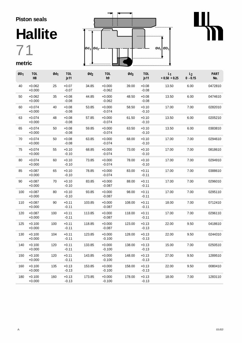
40 +0.062 25 +0.07 34.85 +0.000 39.00 +0.08 13.50 6.00 0472810+ 0 . 0 0 0 - 0 . 0 7 - 0 . 0 6 2 - 0 . 0 8
50 +0.062 35 +0.08 44.85 +0.000 48.50 +0.08 13.50 6.00 0474610+ 0 . 0 0 0 - 0 . 0 8 - 0 . 0 6 2 - 0 . 0 8
60 +0.074 40 +0.08 53.85 +0.000 58.50 +0.10 17.00 7.00 0282010+ 0 . 0 0 0 - 0 . 0 8 - 0 . 0 7 4 - 0 . 1 0
63 +0.074 48 +0.08 57.85 +0.000 61.50 +0.10 13.50 6.00 0205210+ 0 . 0 0 0 - 0 . 0 8 - 0 . 0 7 4 - 0 . 1 0
65 +0.074 50 +0.08 59.85 +0.000 63.50 +0.10 13.50 6.00 0383810+ 0 . 0 0 0 - 0 . 0 8 - 0 . 0 7 4 - 0 . 1 0
70 +0.074 50 +0.08 63.85 +0.000 68.00 +0.10 17.00 7.00 0294610+ 0 . 0 0 0 - 0 . 0 8 - 0 . 0 7 4 - 0 . 1 0
75 +0.074 55 +0.10 68.85 +0.000 73.00 +0.10 17.00 7.00 0818610+ 0 . 0 0 0 - 0 . 1 0 - 0 . 0 7 4 - 0 . 1 0
80 +0.074 60 +0.10 73.85 +0.000 78.00 +0.10 17.00 7.00 0294910+ 0 . 0 0 0 - 0 . 1 0 - 0 . 0 7 4 - 0 . 1 0
85 +0.087 65 +0.10 78.85 +0.000 83.00 +0.11 17.00 7.00 0388610+ 0 . 0 0 0 - 0 . 1 0 - 0 . 0 7 4 - 0 . 1 1
90 +0.087 70 +0.10 83.85 +0.000 88.00 +0.11 17.00 7.00 0296010+ 0 . 0 0 0 - 0 . 1 0 - 0 . 0 8 7 - 0 . 1 1
100 +0.087 80 +0.10 93.85 +0.000 98.00 +0.11 17.00 7.00 0295110+ 0 . 0 0 0 - 0 . 1 0 - 0 . 0 8 7 - 0 . 1 1
110 +0.087 90 +0.11 103.85 +0.000 108.00 +0.11 18.00 7.00 0712410+ 0 . 0 0 0 - 0 . 1 1 - 0 . 0 8 7 - 0 . 1 1
120 +0.087 100 +0.11 113.85 +0.000 118.00 +0.11 17.00 7.00 0296110+ 0 . 0 0 0 - 0 . 1 1 - 0 . 0 8 7 - 0 . 1 1
125 +0.100 100 +0.11 118.85 +0.000 123.00 +0.13 22.00 9.50 0418610+ 0 . 0 0 0 - 0 . 1 1 - 0 . 0 8 7 - 0 . 1 3
130 +0.100 104 +0.11 123.85 +0.000 128.00 +0.13 22.00 9.50 0244310+ 0 . 0 0 0 - 0 . 1 1 - 0 . 1 0 0 - 0 . 1 3
140 +0.100 120 +0.11 133.85 +0.000 138.00 +0.13 15.00 7.00 0250510+ 0 . 0 0 0 - 0 . 1 1 - 0 . 1 0 0 - 0 . 1 3
150 +0.100 120 +0.11 143.85 +0.000 148.00 +0.13 27.00 9.50 1289510+ 0 . 0 0 0 - 0 . 1 1 - 0 . 1 0 0 - 0 . 1 3
160 +0.100 135 +0.13 153.85 +0.000 158.00 +0.13 22.00 9.50 0080410+ 0 . 0 0 0 - 0 . 1 3 - 0 . 1 0 0 - 0 . 1 3
180 +0.100 160 +0.13 173.85 +0.000 178.00 +0.13 18.00 7.00 1283110+ 0 . 0 0 0 - 0 . 1 3 - 0 . 1 0 0 - 0 . 1 3
Ød1 ØD1
L1L2
Ød3 Ød27 1HallitePiston seals
metric
01/0296
Ø D1 T O L Ø d1 T O L Ø d2 T O L Ø d3 T O L L1 L2 P A R TH 8 j s 1 1 h 9 j s 1 1 + 0.50 + 0.25 0 - 0.15 N o .

1.000 +0.002 0.625 +0.002 0.868 +0.000 0.968 +0.003 0.343 0.187 1247610+ 0 . 0 0 0 - 0 . 0 0 2 - 0 . 0 0 2 - 0 . 0 0 3
1.250 +0.002 0.750 +0.003 1.118 +0.000 1.218 +0.003 0.437 0.250 0403710+ 0 . 0 0 0 - 0 . 0 0 3 - 0 . 0 0 2 - 0 . 0 0 3
1.375 +0.002 0.875 +0.003 1.238 +0.000 1.343 +0.003 0.437 0.250 0401310+ 0 . 0 0 0 - 0 . 0 0 3 - 0 . 0 0 2 - 0 . 0 0 3
1.500 +0.002 1.000 +0.003 1.371 +0.000 1.468 +0.003 0.437 0.250 0422410+ 0 . 0 0 0 - 0 . 0 0 3 - 0 . 0 0 2 - 0 . 0 0 3
1.750 +0.002 1.125 +0.003 1.555 +0.000 1.687 +0.003 0.531 0.250 0778210+ 0 . 0 0 0 - 0 . 0 0 3 - 0 . 0 0 2 - 0 . 0 0 3
2.000 +0.003 1.375 +0.003 1.805 +0.000 1.937 +0.004 0.531 0.250 0778410+ 0 . 0 0 0 - 0 . 0 0 3 - 0 . 0 0 2 - 0 . 0 0 4
2.250 +0.003 1.625 +0.003 2.055 +0.000 2.187 +0.004 0.531 0.250 1432610+ 0 . 0 0 0 - 0 . 0 0 3 - 0 . 0 0 3 - 0 . 0 0 4
2.375 +0.003 1.750 +0.003 2.180 +0.000 2.312 +0.004 0.531 0.250 0939810+ 0 . 0 0 0 - 0 . 0 0 3 - 0 . 0 0 3 - 0 . 0 0 4
2.500 +0.003 1.875 +0.003 2.305 +0.000 2.437 +0.004 0.531 0.250 0867210+ 0 . 0 0 0 - 0 . 0 0 3 - 0 . 0 0 3 - 0 . 0 0 4
2.625 +0.003 2.000 +0.004 2.428 +0.000 2.562 +0.004 0.531 0.250 1371010+ 0 . 0 0 0 - 0 . 0 0 4 - 0 . 0 0 3 - 0 . 0 0 4
2.750 +0.003 2.000 +0.004 2.485 +0.000 2.687 +0.004 0.687 0.250 1369110+ 0 . 0 0 0 - 0 . 0 0 4 - 0 . 0 0 3 - 0 . 0 0 4
3.000 +0.003 2.250 +0.004 2.735 +0.000 2.937 +0.004 0.687 0.250 1098410+ 0 . 0 0 0 - 0 . 0 0 4 - 0 . 0 0 3 - 0 . 0 0 4
3.125 +0.003 2.375 +0.004 2.860 +0.000 3.062 +0.004 0.687 0.250 1024810+ 0 . 0 0 0 - 0 . 0 0 4 - 0 . 0 0 3 - 0 . 0 0 4
3.250 +0.003 2.500 +0.004 2.985 +0.000 3.187 +0.004 0.687 0.250 0782410+ 0 . 0 0 0 - 0 . 0 0 4 - 0 . 0 0 3 - 0 . 0 0 4
3.500 +0.003 2.750 +0.004 3.235 +0.000 3.437 +0.004 0.687 0.250 0437810+ 0 . 0 0 0 - 0 . 0 0 4 - 0 . 0 0 3 - 0 . 0 0 4
3.750 +0.003 3.000 +0.004 3.485 +0.000 3.687 +0.004 0.687 0.250 0410510+ 0 . 0 0 0 - 0 . 0 0 4 - 0 . 0 0 3 - 0 . 0 0 4
4.000 +0.003 3.250 +0.004 3.735 +0.000 3.937 +0.004 0.687 0.250 1407710+ 0 . 0 0 0 - 0 . 0 0 4 - 0 . 0 0 3 - 0 . 0 0 4
4.250 +0.003 3.500 +0.004 3.985 +0.000 4.187 +0.004 0.687 0.250 1128810+ 0 . 0 0 0 - 0 . 0 0 4 - 0 . 0 0 3 - 0 . 0 0 4
4.500 +0.003 3.500 +0.004 4.234 +0.000 4.437 +0.004 0.875 0.375 0448810+ 0 . 0 0 0 - 0 . 0 0 4 - 0 . 0 0 3 - 0 . 0 0 4
4.750 +0.004 3.750 +0.004 4.485 +0.000 4.687 +0.004 0.875 0.375 1007010+ 0 . 0 0 0 - 0 . 0 0 4 - 0 . 0 0 3 - 0 . 0 0 4
5.000 +0.004 4.000 +0.004 4.735 +0.000 4.937 +0.005 0.875 0.375 0443010+ 0 . 0 0 0 - 0 . 0 0 4 - 0 . 0 0 4 - 0 . 0 0 5
5.250 +0.004 4.250 +0.004 4.985 +0.000 5.187 +0.005 0.875 0.375 0892210+ 0 . 0 0 0 - 0 . 0 0 4 - 0 . 0 0 4 - 0 . 0 0 5
5.500 +0.004 4.500 +0.004 5.236 +0.000 5.437 +0.005 0.875 0.375 0133210+ 0 . 0 0 0 - 0 . 0 0 4 - 0 . 0 0 4 - 0 . 0 0 5
01/02 97
Ø D1 T O L Ø d1 T O L Ø d2 T O L Ø d3 T O L L1 L2 P A R TH 8 j s 1 1 h 9 j s 1 1 + 0.02 + 0.01 0 - 0.005 N o .
Ød1 ØD1
L1L2
Ød3 Ød2 7 1Hallite
Piston seals
inch

6.000 +0.004 5.000 +0.005 5.736 +0.000 5.937 +0.005 0.875 0.375 1367010+ 0 . 0 0 0 - 0 . 0 0 5 - 0 . 0 0 4 - 0 . 0 0 5
6.500 +0.004 5.500 +0.005 6.236 +0.000 6.437 +0.005 0.875 0.375 1164110+ 0 . 0 0 0 - 0 . 0 0 5 - 0 . 0 0 4 - 0 . 0 0 5
7.000 +0.004 6.000 +0.005 6.736 +0.000 6.937 +0.005 0.875 0.375 1188810+ 0 . 0 0 0 - 0 . 0 0 5 - 0 . 0 0 4 - 0 . 0 0 5
Ød1 ØD1Ød3 Ød27 1HallitePiston seals
inch
01/0298
Ø D1 T O L Ø d1 T O L Ø d2 T O L Ø d3 T O L L1 L2 P A R TH 8 j s 1 1 h 9 j s 1 1 + 0.50 + 0.25 0 - 0.15 N o .

DESIGNIdeal for light to medium duty one piecepiston applications, the Hallite 77 seal is asimple, effective and economical design.Its compact dimensions enable thedesigner to keep the length of the piston toa minimum.
It is an assembly of a continuous rubberseal and two scarf cut bearings.
The nitrile rubber seal is designed to bepre-loaded by the housing to ensure aneffective seal at low pressure. The outwardthrust of the rubber seal on the bearings asit reacts to increasing pressure preventsany extrusion damage in the sealing area.
The pair of polyacetal bearings areproportioned to support the piston and itsside load.
FEATURES• COMPACT DESIGN• EASY ASSEMBLY• LOW WEAR• LONG LIFE
S
C
r1
L2
r2
Ød3
20° 30°
Ød2 Ød1 ØD1
L2L1
HallitePiston seals
01/02 99
OPERATING CONDITIONS
MAXIMUM SPEED 0.5 m/sec 1.5 ft/secTEMPERATURE RANGE -30°C + 100°C -22°F + 212°F
MAXIMUM PRESSURE 350 bar 6000 p.s.i.
SURFACE ROUGHNESS µ m R a µ m R t µ i n C L A µ i n R M S
DYNAMIC SEALING FACE ØD1 0.1 ↔ 0 . 4 4 max 4 ↔ 1 6 5 ↔ 1 8STATIC SEALING FACE Ød1 Ø d2 1.6 max 10 max 63 max 70 max
STATIC HOUSING FACES Ød3 L1 L2 3.2 max 16 max 125 max 140 max
CHAMFERS & RADII
GROOVE SECTION ≤ S mm 3.75 5.00 6.50MIN CHAMFER C mm 2.00 2.50 4.00
MAX FILLET RAD r1 m m 0.40 0.40 0.40MAX FILLET RAD r2 m m 0.20 0.20 0.20
GROOVE SECTION ≤ S in 0.156 0.187 0.250MIN CHAMFER C in 0.078 0.093 0.125
MAX FILLET RAD r1 i n 0.016 0.016 0.016MAX FILLET RAD r2 i n 0.008 0.008 0.008
T O L E R A N C E S Ø D1 Ø d1 Ø d2 Ø d3 L1 L2
m m H10 h9 h9 h11 +0.4 +0.13 0 -0.13
i n H10 h9 h9 h11 +0.015 +0.005 0 -0.005

L2
Ød3 Ød2 Ød1 ØD1
L2L1
7 7HallitePiston seals
metric
01/02100
Ø D1 T O L Ø d1 T O L Ø d2 T O L Ø d3 T O L L1 L2 P A R TH 1 0 h 9 h 9 h 1 1 + 0.4 + 0.13 0 - 0.13 N o .
25 +0.08 17.5 +0.00 21.3 +0.000 24.0 +0.00 8.50 3.25 6111410+ 0 . 0 0 - 0 . 0 4 - 0 . 0 5 2 - 0 . 1 3
40 +0.10 30 +0.00 35.5 +0.000 39.0 +0.00 11.00 4.00 6111210+ 0 . 0 0 - 0 . 0 5 - 0 . 0 6 2 - 0 . 1 6
50 +0.10 40 +0.00 45.5 +0.000 49.0 +0.00 11.00 4.00 2326110+ 0 . 0 0 - 0 . 0 6 - 0 . 0 6 2 - 0 . 1 6
60 +0.10 48 +0.00 55.9 +0.000 59.2 +0.00 20.50 4.30 2326210+ 0 . 0 0 - 0 . 0 6 - 0 . 0 6 2 - 0 . 1 6
63 +0.12 53 +0.00 58.5 +0.000 61.5 +0.00 11.00 4.00 2325810+ 0 . 0 0 - 0 . 0 7 - 0 . 0 7 4 - 0 . 1 9
80 +0.12 70 +0.00 75.5 +0.000 78.5 +0.00 11.00 4.00 2325710+ 0 . 0 0 - 0 . 0 7 - 0 . 0 7 4 - 0 . 1 9
100 +0.14 87 +0.00 93.8 +0.000 98.5 +0.00 14.00 6.00 2326010+ 0 . 0 0 - 0 . 0 9 - 0 . 0 8 7 - 0 . 2 2
1 2 5 + 0 . 1 6 1 1 2 + 0 . 0 0 1 1 8 . 8 + 0 . 0 0 0 1 2 3 . 5 + 0 . 0 0 1 4 . 0 0 6 . 0 0 2 3 2 5 9 1 0
+ 0 . 0 0 - 0 . 0 9 - 0 . 0 8 7 - 0 . 2 5
inch
Ø D1 T O L Ø d1 T O L Ø d2 T O L Ø d3 T O L L1 L2 P A R TH 1 0 h 9 h 9 h 1 1 + 0.015 + 0.005 0 - 0.005 N o .
1.250 +0.004 0.937 +0.000 1.097 +0.000 1.187 +0.000 0.343 0.125 6567790+ 0 . 0 0 0 - 0 . 0 0 2 - 0 . 0 0 2 - 0 . 0 0 5
2.375 +0.005 2.000 +0.000 2.000 +0.000 2.312 +0.00 0.437 0.150 6918060+ 0 . 0 0 0 - 0 . 0 0 3 - 0 . 0 0 3 - 0 . 0 0 5
2.500 +0.005 2.125 +0.000 2.325 +0.000 2.437 +0.000 0.437 0.150 2360210+ 0 . 0 0 0 - 0 . 0 0 3 - 0 . 0 0 3 - 0 . 0 0 5
3.250 +0.005 2.875 +0.000 3.270 +0.000 3.437 +0.000 0.437 0.150 2360310+ 0 . 0 0 0 - 0 . 0 0 3 - 0 . 0 0 4 - 0 . 0 0 5

01/02
C
S
L1
ØD1Ød1
r1
20° 30°
OPERATING CONDITIONS
MAXIMUM SPEED 1.0 m/sec 3.0 ft/secTEMPERATURE RANGE -45°C + 110°C -50°F + 230°F
MAXIMUM PRESSURE 350 bar 5000 p.s.i.
SURFACE ROUGHNESS µ m R a µ m R t µ i n C L A µ i n R M S
DYNAMIC SEALING FACE Ød1 0.1 ↔ 0 . 4 4 max 4 ↔ 1 6 5 ↔ 1 8STATIC SEALING FACE ØD1 1.6 max 10 max 63 max 70 maxSTATIC HOUSING FACES L1 3.2 max 16 max 125 max 140 max
CHAMFERS & RADII
GROOVE SECTION ≤ S mm 5.2MIN CHAMFER C mm 2.4
MAX FILLET RAD r1 m m 0.4
T O L E R A N C E S Ø d1 Ø D1 L1m m f8 H10 +0.3 -0.0
TECHNICAL DETAILSM E T R I C I N C H
HalliteRotary pressure seals
101
DESIGNThe Hallite 80 rotary pressure seal is a sealdesigned specifically for use in hydraulicswivel joints.
The Hallite 80 is manufactured in Hallite’shigh specification polyurethane, Hythane 181, to provide ease of installationand excellent sealing characteristics.
Please call your local Hallite sales office forfurther details.

01/02
ØD1Ød1
1
S
8 0HalliteRotary pressure seals
metric
102
Ød1 TOL ØD1 TOL L1 PARTf8 H10 +0.3 -0.0 No.
Ød1 TOL ØD1 TOL L1 PARTf8 H10 +0.3 -0.0 No.
80.00 -0.036 90.00 +0.14 5.00 4563000- 0 . 0 9 0 - 0 . 0 0
90.00 -0.036 100.00 +0.14 5.00 4563100- 0 . 0 9 0 - 0 . 0 0
100.00 -0.036 110.00 +0.14 5.00 4563200- 0 . 0 9 0 - 0 . 0 0
125.00 -0.043 135.40 +0.16 5.00 4578800- 0 . 1 0 6 - 0 . 0 0

Piston Seal Double Acting
Hallite 83
ANTI EXTRUSION RINGSYNTHETIC RUBBER SEALING MEMBER
OPERATING CONDITIONS
MAXIMUM WORKING PRESSURE
MAXIMUM SPEED T E M P E R ATURE RANGE T E M P E R ATURE RANGE
m / s e c —30°C + 80°C —30°C + 100°C
0 . 5 250 bar /.3750 p.s.i 160 bar / 2400 p.s.i.
0 . 1 5 400 bar / 6000 p.s.i. 200 bar / 3000 p.s.i.
SURFACE ROUGHNESS
µ m R a µ m R t µin CLA
DYNAMIC SEALING FA C E Ø D1 0.1 to 0.4 4 max 4 to 16
S TATIC SEALING FA C E Ø d1, Ø d2 1.6 max 10 max 63 max
S TATIC HOUSING FACES Ø d3, L1, L2 3.2 max 16 max 125 max
CHAMFERS & RADII in
S E A LS E C T I O N S 0 . 1 8 7 0 . 2 5 0 0 . 3 7 5
MIN CHAMFER C 0 . 1 5 6 0 . 1 8 7 0 . 2 5 0
MAX FILLET R A D r1 0 . 0 1 0 0 . 0 1 6 0 . 0 1 6
MAX FILLET R A D r2 0 . 0 1 0 0 . 0 1 6 0 . 0 1 6
®
DesignThe Hallite Tri-Seal assembly offers the engineer many advantages when considering the design of cast iron,bronze,alloy etc.one-piece pistons in double-acting hydraulic cylinders, not the least being cost effectiveness with longand efficient seal life.
The Tri-Seal consists of two split plastic anti-extrusion rings and a nitrile syntheticrubber sealing member.Under pressure, the seal exerts a wedging action on theanti-extrusion ring, reducing the clearance between the cylinder bore and thepiston, thus minimising the possibility of extrusion of the seal.
Wear rings are also available for this assembly, allowing the designer to benefitfrom the following advantages :
•Eliminate metal to metal contact in the bore •One piece steel piston
•Improved alignment for optimum seal life •Smoother operation
All our activities conform to the highest quality assurance systems. Hallite SealsI n t e rnational quality management systems are a c c redited to ISO 9001 and area p p roved by many of the world’s f o remost OEM’s.
FEATURES• EFFICIENT SEALING• LOW COST• INTERCHANGEABLE• WITH MOST • COMPETITIVE DESIGNS • ROBUST CONSTRUCTION• LOW FRICTION • SIMPLE MACHINING • LONG LIFE • EASY ASSEMBLY
INSTALLATIONFast assembly of the seal is carried out asfollows:The intermediate seal is stretched over thepiston into the recess.The split anti-extrusion rings are positionedwith the concave face against the seal.
MEDIASeals are suitable for mineral basedhydraulic fluid, water soluble and water gly-col fluids. The temperature for the standardrange can be -40°C for intermittent use. Other materials are available which canextend the temperature range down to -60°C or up to +135 °C and to suit esterbased or synthetic non-flammable fluids.

INCH
Piston Seal Double Acting
Hallite 83
1.500 +0.005 1.125 +0.005 1.321 -0.001 1.450 +0.005 0.452 0.250 6111910*-0.005 -0.005 -0.003 -0.005
2.000 +0.005 1.500 +0.005 1.821 -0.001 1.950 +0.005 0.587 0.250 2326310*-0.005 -0.005 -0.003 -0.005
2.500 +0.005 2.000 +0.005 2.321 -0.001 2.450 +0.005 0.587 0.250 2122010*-0.005 -0.005 -0.004 -0.005
3.000 +0.005 2.500 +0.005 2.774 -0.001 2.940 +0.005 0.587 0.250 2122110*-0.005 -0.005 -0.004 -0.005
3.250 +0.005 2.750 +0.005 3.023 -0.001 3.190 +0.005 0.587 0.250 2327610*-0.005 -0.005 -0.004 -0.005
3.500 +0.005 3.000 +0.005 3.274 -0.001 3.440 +0.005 0.587 0.250 2122210*-0.005 -0.005 -0.005 -0.005
4.000 +0.005 3.250 +0.005 3.773 -0.001 3.940 +0.005 0.780 0.250 2326410*-0.005 -0.005 -0.005 -0.005
5.000 +0.005 4.250 +0.005 4.713 -0.001 4.910 +0.005 0.780 0.375 2326510*-0.005 -0.005 -0.005 -0.005
6.000 +0.005 5.250 +0.005 5.713 -0.001 5.910 +0.005 0.780 0.375 2326610*-0.005 -0.005 -0.005 -0.005
* When ordering Type 83 with wear rings please replace the last digit of the part number with 9. eg : Type 83 2.500 x 2.000, without wear rings part number 2122010, with wear rings 2122019
Note : For availability of sizes not listed please consult your local Hallite sales department.
B O R E TO L H O U S I N G TO L B E A R I N G TO L P I S TO N TO L H O U S I N G B E A R I N G PA R TD I A D I A D I A D I A LENGTH L1 LENGTH L2 N U M B E RØ D1 Ø d1 Ø d2 Ø d3 TOL + 0.005 TOL + 0.004 - 0
S
Ød ØD
20° — 30°
CL
rF S
Ød ØD
20° — 30°
CL
r
Ød
L L
r
Ød
WITH WEAR RINGSWITHOUT WEAR RINGS
MAXIMUM EXTRUSION GAP F
P R E S S U R E p . s . i . 2 4 0 0 3 7 5 0 6 0 0 0
MAXIMUM GAP i n 0 . 0 2 4 0 . 0 2 0 0 . 0 1 6
EXTRUSION GAPPlease note that the figures shown for the extrusion gap F relate to the maximumpermissible, worst case situation with the gap all on one side.
Note also that extrusion is closely linked to pressure and temperature and thatin general, the smaller the gap the better the seal performs.

03/01 1
HalliteBearings
OPERATING CONDITIONS
MAXIMUM SPEED 5.0 m/sec 15.0 ft/secMAXIMUM TEMPERATURE -50°C + 200°C -58°F + 390°F
TYPICAL PHYSICAL PROPERTIES
SPECIFIC GRAVITY 3 . 1 3 . 1COMPRESSION STRESS AT YIELD 2 3 ° C 20 MN/m2 7 3 ° F 2900 p.s.i.COMPRESSION STRESS AT YIELD 80°C 9 MN/m2 1 7 6 ° F 1300 p.s.i.
COEFFICIENT OF THERMAL CONDUCTIVITY 2.5 W/mK 1.4Btu/hft°F
COEFFICIENT OF THERMAL EXPANSION L E N G T H & T H I C K N E S S6.5 x 10 -5 per °C
COEFFICIENT OF DYNAMIC FRICTION D r y L u b r i c a t e d0.25 0.05
BEARING STRIP TOLERANCES L1 S-0.1 -0.5 +0.03 -0.05
SURFACE ROUGHNESS µ m R a µ m R t µ i n C L A µ i n R M S
DYNAMIC SEALING FACE Ød1 Ø D1 0 . 4 4 max 1 6 1 8STATIC HOUSING FACES ØD1 L1 Ø D2 3.2 max 16 max 125 max 140 max
HOUSING DETAILS & TOLERANCES
R O D Ø d1 f 9Ø D2= Ø d1+ 2 S up to: Ø80 H10
above: Ø80 H9Ø D3= Ø d1+ G G min / maxL1 -0 + 0.2
P I S T O N Ø D1 H 1 1Ø d2= Ø D1- 2 S f 9Ø d3= Ø D1+ G G min / maxL1 -0 + 0.2
TECHNICAL DETAILSM E T R I C I N C H
DESIGNHallite 87 bearing strip has the ability to supportside loads and eliminate ‘stick slip’ betweenmoving parts. The accurately dimensionedrectangular cross section is produced from aspecial combination of PTFE and Bronze materials.It has excellent heat resistance and strength toresist creep, making it suitable for bearings withreciprocating, oscillating or rotary movement,whether lubricated or not. Our standard range ofcross section sizes are proportioned to bewrapped around a wide range of rod or pistondiameters. Installation of the bearing is an easytask. Calculate and measure length L2 (seeoverleaf), cut the strip with a sharp blade and fitto the groove. If required we will be pleased tosupply bearings to your sizes. Independent testinghas established the typical properties which makethe Hallite 87 worthwhile considering for manyapplications other than hydraulic or pneumaticcylinders. When using the compressive stress atyield in your calculation it is suggested a 4:1 factorof safety is applied.
The material is compatible with hydraulicmineral oil, lubricating oil, water based andsynthetic fire resistant fluids and lubricating grease.Although the material is rated at 200°C, therecommended maximum temperature forbearing applications is 60°C.
FEATURES• LOW FRICTION• INFINITE LENGTH RANGE• EASY INSTALLATION• EXTREMELY FLEXIBLE
Please send us details of yourapplication for advice on this or anyother problem where the Hallite 87 maysolve your bearing problem.
ØD3ØD2 Ød1
L1
G2
G2
Ød3Ød2 ØD1
0.2maxRAD
S
S
L1
0.2maxRAD
L1 L1
G min controls the minimum metal to metal clearancebetween the gland and rod or bore and piston.G max controls the maximum extrusion gap seen by a seal associated with the bearing.
Typically, G min should be 0.028” / 0.7mm but can be reduced when required by the extrusion gap for the seal and the build up of tolerances. The absolute minimum metal to metal clearancerecommended is 0.004” / 0.1mmFor applications not using a seal G max - see overleaf.
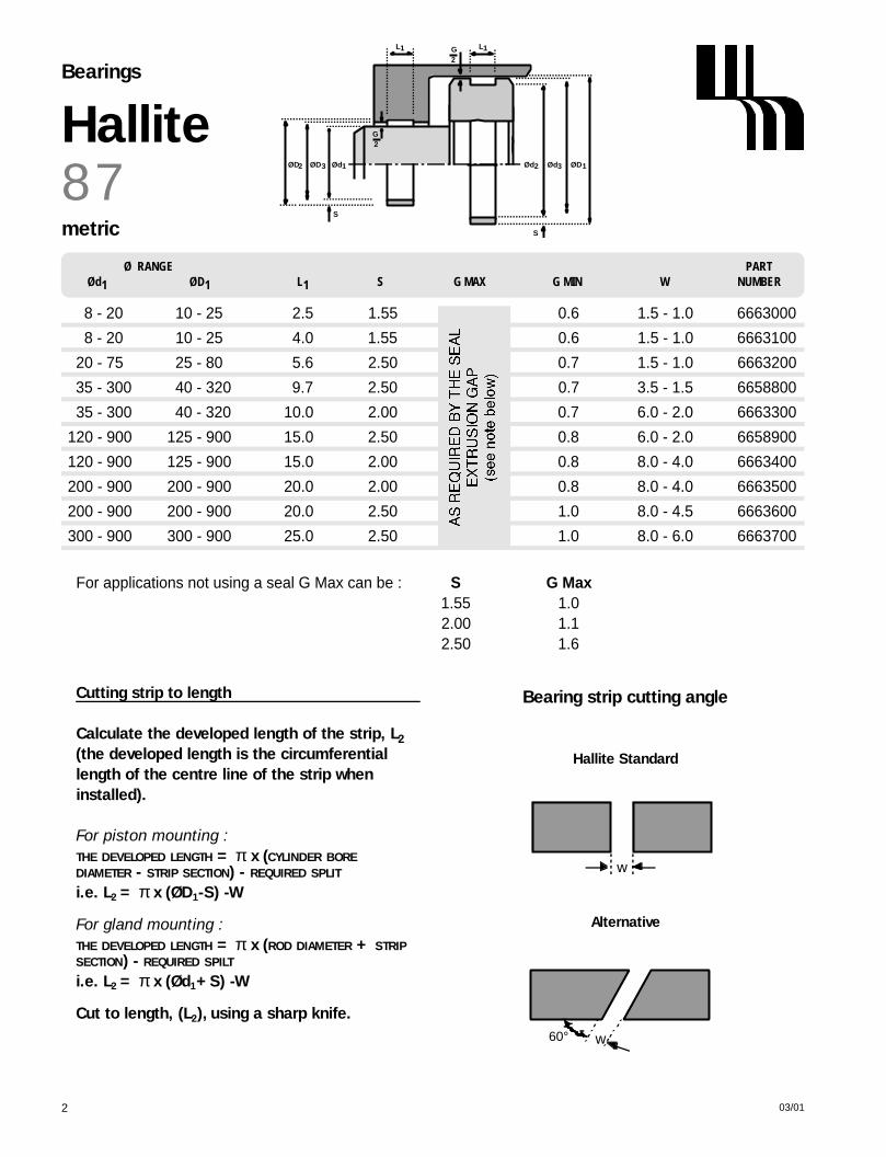
ØD3ØD2 Ød1
L1
G2
G2
Ød3Ød2 ØD1
S
S
L1
03/012
8 7HalliteBearings
metric
Ø RANGE PARTØd1 ØD1 L1 S G MAX G MIN W NUMBER
8 - 20 10 - 25 2.5 1.55 0.6 1.5 - 1.0 6663000
8 - 20 10 - 25 4.0 1.55 0.6 1.5 - 1.0 6663100
20 - 75 25 - 80 5.6 2.50 0.7 1.5 - 1.0 6663200
35 - 300 40 - 320 9.7 2.50 0.7 3.5 - 1.5 6658800
35 - 300 40 - 320 10.0 2.00 0.7 6.0 - 2.0 6663300
120 - 900 125 - 900 15.0 2.50 0.8 6.0 - 2.0 6658900
120 - 900 125 - 900 15.0 2.00 0.8 8.0 - 4.0 6663400
200 - 900 200 - 900 20.0 2.00 0.8 8.0 - 4.0 6663500
200 - 900 200 - 900 20.0 2.50 1.0 8.0 - 4.5 6663600
300 - 900 300 - 900 25.0 2.50 1.0 8.0 - 6.0 6663700
For applications not using a seal G Max can be : S G Max1.55 1.02.00 1.12.50 1.6
Cutting strip to length
Calculate the developed length of the strip, L2
(the developed length is the circumferentiallength of the centre line of the strip wheninstalled).
For piston mounting :THE DEVELOPED LENGTH = π x (CYLINDER BORE
DIAMETER - STRIP SECTION) - REQUIRED SPLIT
i.e. L2 = π x (ØD1-S) -W
For gland mounting :THE DEVELOPED LENGTH = π x (ROD DIAMETER + STRIP
SECTION) - REQUIRED SPILT
i.e. L2 = π x (Ød1+S) -W
Cut to length, (L2), using a sharp knife.
w60°
Bearing strip cutting angle
Hallite Standard
Alternative
w

01/02
DESIGNHallite 506 bearing strip is available in three forms: cut rings,spiral lengths and flat coils. Hallite 506 provides anextremely effective, hard wearing and easy to usebearing material.
Manufactured to very tight tolerances and providingbearing solutions for reciprocating, oscillating and slowrotary movement applications, Hallite 506 bearing strip isused in many of today’s most arduous hydraulicapplications around the world.
Commonly fitted in reciprocating cylinders as rod andpiston bearings, Hallite 506 is capable of withstandingextreme side-loads preventing metal to metal contact.The material’s design incorporates micro indentations onthe bearing strip’s surface to trap fluid and provide built-inlubrication to the bearing.
The 506 bearing strip is manufactured by a patentedprocess, using a woven fabric reinforced polyester resinmaterial and is proven to be compatible with a widerange of fluids, including mineral oils, water based fluidsand phosphate esters, to produce a rectangular sectionstrip which is available in a wide range of inch and metricsizes including cross sections specified in ISO 10766.
HalliteBearings
105
TECHNICAL DETAILSM E T R I C I N C H
S
ØD1
0.4maxrad
S
0.4maxrad
Ød3
G2
Ød2ØD2 ØD3 Ød1
G2
L1L1
L1
L1
G min controls the minimum metal to metalclearance between the gland and rod or bore and piston.G max controls the maximum extrusion gap seenby a seal associated with the bearing.
Typically, G min should be 0.7mm / 0.028” but can be reduced when required by the extrusiongap for the seal and the build up of tolerances. The absolute minimum metal to metal clearancerecommended is 0.1mm / 0.004”. For applicationsnot using a seal G max can be 0.6 x S
* Please note that for reciprocating applications, thecompressive stress at yield should be used fordesign calculations. For rotary shafts use thelimiting P.V. values. It is suggested that a 2:1 factorof safety is applied.
OPERATING CONDITIONS
TEMPERATURE RANGE -40°C + 120°C -40°F + 250°F
LIMITING PV VALUES LUBRICATED* Speed m/sec Pressure MN/m2 Speed ft/sec Pressure p.s.i.0.1 10.0 0.3 15001.0 6.0 3.0 9005.0 0.8 16.0 120
TYPICAL PHYSICAL PROPERTIES
SPECIFIC GRAVITY 1.27 1.27
COMPRESSION STRESS AT FAILURE (Temp 23°C) 450 MN/m2 (Temp 73°F) 65,000 p.s.i.
COMPRESSION STRESS AT YIELD* (Temp 23°C) 115 MN/m2 (Temp 73°F) 16,500 p.s.i.
COMPRESSION STRESS AT YIELD* (Temp 80°C) 58 MN/m2 (Temp 176°F) 8,500 p.s.i.
COEFFICIENT OF THERMAL CONDUCTIVITY 0.27 W/mK 0.16 Btu/hft °FCOEFFICIENT OF THERMAL EXPANSION Length Thickness Length Thickness
9 X 10 - 5 per ° C 13 X 10 - 5 per ° C 5 X 10 - 5 per ° F 7.3 X 10 - 5 per ° FCOEFFICIENT OF DYNAMIC FRICTION Dry Lubricated Dry Lubricated
on steel surface (0.2 µm Ra) / (8 µin C L A) 0 . 5 0 0 . 0 6 0 . 5 0 0 . 0 6
SURFACE ROUGHNESS
µm Ra µm Rt µm CLA µm RMSDYNAMIC SEALING FACE Ød1 0.4 4 max 16 18
STATIC SEALING FACE ØD1 L1 3.2 max 16 max 125 max 140 max
BEARING STRIP TOLERANCES
L1 S L1 S-0.1 to -0.6 -0.02 to -0.1 -0.005 to -0.015 -0.001 to -0.004
WIDTH OF BEARING SPLIT - W
Ø d1 / Ø D1 W Ø d1 / Ø D1 W
Up to 50 3.00 - 1.50 Up to 2” 0.12 - 0.06Up to 120 5.00 - 3.50 Up to 5” 0.19 - 0.14Up to 250 9.00 - 7.25 Up to 10” 0.35 - 0.29Up to 550 17.00 - 15.00 Up to 22” 0.67 - 0.59
HOUSING DETAILS & TOLERANCES
ROD Ød1 f9 Ød1 f9ØD2 = Ød1 + 2S up to : Ø80 H10 ØD2 = Ød1 + 2S up to : Ø3” H10
above : Ø80 H9 above : Ø3” H9ØD3 = Ød1 + G G min / max ØD3 = Ød1 + G G min / maxL1 + 0.2 -0 mm + 0.008 -0 mm
PISTON ØD1 H11 ØD1 H11Ød2=ØD1-2S f9 Ød2=ØD1-2S f9Ød3 = ØD1 + G G min / max Ød3 = ØD1 + G G min / maxL1 + 0.2 -0 mm L1 + 0.008 -0 mm

HalliteBearings
01/02106
FEATURES• HIGH LOAD CAPABILITY• INFINITE LENGTH RANGE• VIRTUALLY ZERO SWELL
• SELF LUBRICATING• LOW FRICTION• CUT TO LENGTH
• VERY LARGE RANGE OF SIZES
Hallite 506 bearing strip is available in three forms:
CUT RINGS
Ready made bearings, cut to size and to customerspecifications, and ready for installation, Hallite 506bearings have become an industry standard favoured bydesigners and specifiers alike. Generally produced for themedium to high volume user.
SPIRAL LENGTHS
Available in a wide range of preformed diameters, spiralsare supplied in continuous lengths to suit a range of insideand outside diameters. Ideal for lower volume usersrequiring various diameters.
FLAT COILS
Packaged in a dispenser for ease of storage and handling,flat coils are supplied in 10 metre lengths suitable for a widerange of diameters and are ideal for those using orsupplying one off bearings for small volume requirements.
The ranges shown on the following pages are Hallite’s mostpopular sizes. The section ranges identify section andgroove width; from these nearly any diameter of cut ring orspiral length can be manufactured. If you cannot find thesize you are looking for, please contact your local Hallitesales office for additional size information.
All standard bearing strip is printed with a size reference andincludes distance marking every 100mm on metric size sectionsand every six inches on inch size sections for guidance only.
When ordering please clearly state whether cut rings, spiral lengthsor flat coils are required. For cut rings and spiral lengths pleasestate whether rod or piston application and provide inside (Ød) oroutside (ØD) diameters, groove width (L1) and section (S)dimensions and where spiral lengths are ordered also specifylength required. For flat coils please specify groove width (L1) andsection (S) dimensions.
Cutting bearing strip to size1. Select the groove width (L1) and section (S) required.
2. In the case of a rod bearing, position the bearing strip around the rod
or in the case of a piston bearing, place it in the piston groove and
mark the point of overlap. Determine the correct width of bearing
split (W) for the Ød or ØD being used, as indicated in the technical
details, and make a second mark.
3. Remove the strip and cut at the second marked position to the
desired angle using secateurs or other similar cutting tool.
It is recommended that the standard cutting angle is used for the
majority of applications.
Bearing split cutting angle
S T A N D A R D
A L T E R N A T I V E
w
w60°

HalliteBearings
25 - 41 45 - 90 2.0 10.0 0.7 8501310
35 - 70 74 - 160 2.0 10.0 0.7 8502610
70 - 155 159 - 310 2.0 10.0 0.7 8502252
35 - 50 54 - 110 2.0 15.0 0.7 8503357
50 -100 104 - 210 2.0 15.0 0.7 8503175
90 - 180 184 - 370 2.0 15.0 0.7 8503358
25 - 30 35 - 70 2.5 5.6 0.7 8502000‡
25 - 50 55 - 110 2.5 5.6 0.7 8502020‡
50 - 100 105 - 210 2.5 5.6 0.7 8502040‡
25 - 40 45 - 90 2.5 9.7 0.7 8502100‡
35 - 70 75 - 150 2.5 9.7 0.7 8502120‡
70 - 150 155 - 310 2.5 9.7 0.7 8502140‡
40 - 50 55 - 110 2.5 13.0 0.7 8502200
50 - 100 105 - 210 2.5 13.0 0.7 8502220
90 - 180 185 - 370 2.5 13.0 0.8 8502230
40 - 50 55 - 110 2.5 15.0 0.7 8502300‡
50 - 100 105 - 210 2.5 15.0 0.7 8502330‡
90 - 180 185 - 370 2.5 15.0 0.8 8502350‡
50 - 80 85 - 170 2.5 20.0 0.7 8502400
75 - 150 155 - 310 2.5 20.0 0.8 8502410
125 - 250 255 - 510 2.5 20.0 0.8 8502430
60 - 80 85 - 170 2.5 25.0 0.7 8502500‡
70 - 150 155 - 310 2.5 25.0 0.8 8502520‡
125 - 250 255 - 510 2.5 25.0 0.8 8502530‡
40 - 50 56 - 100 3.0 9.7 0.8 8503369
50 - 100 106 - 210 3.0 9.7 0.8 8503370
100 - 150 156 - 310 3.0 9.7 0.8 8503371
01/02 107
S
ØD1
S
G2
Ød1
G2
L1L1
5 0 6
Ø RANGE PARTØd1 ØD1 S L1 G MAX G MIN* No.
metric - spiral lengths
** Denotes non standard product.Within the size range, items suffixed ‡ indicate cross sections to ISO 10766.
metric - section range inch - section range
S L1 S L1S L1 S L1
1.50 5.6
2.00 9.7
2.00 10.0
2.00 15.0
2.50 5.6 ‡
2.50 8.0
2.50 9.7 ‡
2.50 13.0
2.50 15.0 ‡
2.52 19.5
0.062 0.375
0.125 0.375
0.125 0.500
0.125 0.625
0.125 0.750
0.125 1.000
0.125 1.500
2.50 20.0
2.50 25.0 ‡
2.52 30.0
2.77 15.0 **
2.77 20.0 **
2.77 25.0 **
3.00 9.7
3.00 12.8
3.00 20.0
3.02 15.0
3.20 9.7
3.20 19.7
3.50 25.0
4.00 6.1
4.00 9.7
4.00 20.0
4.00 25.0 ‡
4.00 30.0
4.00 40.1

Ø RANGE PARTØd1 ØD1 S L1 G MAX G MIN* No.
HalliteBearings
1.000 - 1.375 2.625 - 3.500 0.125 0.375 0.031 8502098
1.250 - 1.875 2.125 - 4.250 0.125 0.375 0.031 8502099
1.250 - 1.750 2.000 - 4.000 0.125 0.500 0.031 8502089
1.750 - 3.500 3.750 - 6.250 0.125 0.500 0.031 8502090
3.500 - 6.000 6.250 - 10.000 0.125 0.500 0.031 8502091
8.000 - 12.500 12.750 - 25.000 0.125 0.500 0.031 8502720
2.000 - 3.500 3.750 - 6.250 0.125 0.625 0.031 8502092
3.500 - 6.000 6.250 - 10.000 0.125 0.625 0.031 8502093
2.000 - 3.500 3.750 - 6.250 0.125 0.375 0.031 8502183
2.000 - 3.500 3.750 - 6.250 0.125 0.750 0.031 8502094
3.500 - 6.000 6.250 - 10.000 0.125 0.750 0.031 8502095
2.500 - 3.500 3.750 - 6.250 0.125 1.000 0.031 8502096
3.500 - 6.000 6.250 - 10.000 0.125 1.000 0.031 8502097
8.000 - 12.500 12.750 - 25.000 0.125 1.000 0.031 8502222
S
ØD1
S
G2
Ød1
G2
L1L1
5 0 6
01/02108
metric - spiral lengths
inch - spiral lengths
Ø RANGE PARTØd1 ØD1 S L1 G MAX G MIN* No.
50 - 60 66 - 120 3.0 12.8 0.7 8503037
60 - 104 110 - 220 3.0 12.8 0.8 8503038
90 - 149 155 - 300 3.0 12.8 0.8 8503039
55 - 80 86 - 170 3.0 20.0 0.8 8503124
80 - 150 156 - 310 3.0 20.0 0.8 8502635
140 - 250 256 - 510 3.0 20.0 0.8 8503189
50 - 75 81 - 160 3.02 15.0 0.7 8502734
60 - 80 68 - 170 4.0 6.1 0.8 8503359
80 - 150 158 - 310 4.0 6.1 0.8 8503360
150 - 250 258 - 510 4.0 6.1 0.8 8503361
60 - 80 88 - 170 4.0 9.7 0.8 8503362
80 - 150 158 - 310 4.0 9.7 0.8 8503363
150 - 250 258 - 510 4.0 9.7 0.8 8503364
60 - 80 88 - 170 4.0 20.0 0.8 8503365
80 - 150 158 - 310 4.0 20.0 0.8 8503366
150 - 250 258 - 510 4.0 20.0 0.8 8503191
120 -150 158 - 310 4.0 25.0 0.8 8503367‡
150 - 250 258 - 510 4.0 25.0 0.8 8503192‡
120 -150 158 - 310 4.0 30.0 0.8 8503368
150 - 250 258 - 510 4.0 30.0 0.8 8503193
170 - 200 208 - 410 4.0 40.0 0.8 8503179
200 - 300 308 - 610 4.0 40.0 0.8 8503180
Within the size range, items suffixed ‡ indicate cross sections to ISO 10766.

HalliteBearings
01/02 109
Ø RANGE PARTID OD S L1 G MAX G MIN* No.
S
ØD1
S
G2
Ød1
G2
L1L1
5 0 6metric - flat coils
140 210 2.0 15.0 0.7 8581210
140 230 2.5 5.6 0.7 8580010‡
140 230 2.5 9.7 0.7 8580110‡
140 230 2.5 13.0 0.7 8581110
140 230 2.5 15.0 0.7 8580210‡
140 230 2.5 20.0 0.8 8580310
140 230 2.5 25.0 0.8 8580410‡
140 240 3.0 9.7 0.7 8581410
140 240 3.0 12.8 0.7 8581010
140 240 3.0 20.0 0.7 8581510
5.500 9.750 0.125 0.375 0.031 8580510
5.500 9.750 0.125 0.500 0.031 8580610
5.500 9.750 0.125 0.625 0.031 8580710
5.500 9.750 0.125 0.750 0.031 8580810
5.500 9.750 0.125 1.000 0.031 8580910
Within the size range, items suffixed ‡ indicate cross sections to ISO 10766. ID and OD are indicated as approximate values for guidance only.
If necessary coil diameters can be re-sized by curing on a suitable mandrel in an ovenfor 1 hr at 120°C / 250°F and allowing to cool on the mandrel.
inch - flat coils
ID OD
* This value can be reduced if required by the seal’s maximum extrusiongap - see housing design page 16.

N o t e s
01/02110

HalliteRod/Piston seals
01/02
DESIGNThe Hallite 511 is a standard profile loaded Ucup utilising a polyurethane or polyester shellenergised by a high specification resilient Oring.
At zero or low pressure, the O ring helps toincrease the sealing force preventing anybypass. As pressure rises the sealing forceincreases and the O ring ensures complete lipactuation under most conditions.
The symmetry of the seal allows it to beused on both rod and piston applications andits flexibility enables easy installation. Ideallysuited for single acting applications, theHallite 511 can also be fitted back to back foruse in double acting applications. Althoughused as a rod seal, other profiles such as 513,605 or 621 are a better option.
FEATURES• FLEXIBLE FOR EASY INSTALLATION• EXCELLENT RESISTANCE TO ABRASION• POSITIVE LIP ACTUATION• KNIFE TRIMMED PRECISION SEALING LIPS• COMPACT HOUSING• WIDE RANGE OF SIZES• MATERIAL OPTIONS
MATERIALSlast digit of
Seal material - O-Ring part number
Standard material:Polyurethane - NBR _ _ _ _ _ 10
Material options:Polyester - NBR _ _ _ _ _ 11Polyester - FKM _ _ _ _ _ 12
OPERATING CONDITIONS
MAXIMUM SPEED 0.5 m/sec 1.5 ft/secTEMPERATURE RANGE -40°C + 110°C -40°F + 230°F
MAXIMUM PRESSURE 350 bar 5000 p.s.i.
MAXIMUM EXTRUSION GAP Figures show the maximum permissible gap all on one side ,forrod seals using minimum rod Ø and maximum clearance Ø and for
(1/4” section and above) piston seals using the minimum clearance Ø and maximum bore Ø
PRESSURE bar 1 6 0 2 5 0 3 5 0
PRESSURE p.s.i. 2400 3750 5000MAXIMUM GAP in 0.024 0.020 0.016
SURFACE ROUGHNESS µ m R a µ m R t µ i n C L A µ i n R M S
DYNAMIC SEALING FACE - ROD Ød1 0.1 ↔ 0 . 4 4 max 4 ↔ 1 6 5 ↔ 1 8STATIC SEALING FACE - ROD ØD1 1.6 max 10 max 63 max 70 max
DYNAMIC SEALING FACE - PISTON ØD1 0.1 ↔ 0 . 4 4 max 4 ↔ 1 6 5 ↔ 1 8STATIC SEALING FACE - PISTON Ød1 1.6 max 10 max 63 max 70 max
STATIC HOUSING FACES L1 3.2 max 16 max 125 max 140 max
CHAMFERS & RADII
GROOVE SECTION ≤ S in 0.125 0.187 0.250 0.312 0.375 0.500 0.625MIN CHAMFER C in 0.093 0.093 0.125 0.156 0.187 0.187 0.217
MAX FILLET RAD r1 i n 0.008 0.008 0.016 0.032 0.032 0.032 0.047MAX FILLET RAD r2 i n 0.016 0.016 0.032 0.047 0.047 0.047 0.062
T O L E R A N C E S Please refer to specified tolerances in the introduction - Housing & installation data - Hallite 500 Series
TECHNICAL DETAILSM E T R I C I N C H
Technical details shown are forstandard material option.
20° 30°
C L1
Sr2r1
ØD1Ød1
ØD1Ød1
CL1
Sr2F
20° 30°
r1
Ød2
111

01/02112
1/8 CROSS SECTION
0.13 0.38 0.13 0.138 2500125 8900810
0.19 0.44 0.13 0.138 12500187 8800110
0.25 0.50 0.13 0.138 12500250 8800210
0.25 0.25 0.13 0.138 12500312 8902810
0.38 0.63 0.13 0.138 12500375 8800410
0.50 0.75 0.13 0.138 12500500 8800610
0.81 0.81 0.13 0.138 12500562 8844610
0.63 0.88 0.13 0.138 12500625 8800810
0.69 0.94 0.13 0.138 12500687 8801010
0.75 1.00 0.13 0.138 12500750 8801110
0.81 1.06 0.13 0.138 12500812 8815310
0.88 1.13 0.13 0.138 12500875 8801410
0.94 1.19 0.13 0.138 12500937 8844810
1.00 1.25 0.13 0.138 12501000 8801610
1.06 1.31 0.13 0.138 12501062 8801810
1.13 1.38 0.13 0.138 12501125 8801910
1.25 1.50 0.13 0.138 12501250 8802210
1.38 1.63 0.13 0.138 12501375 8802410
1.50 1.75 0.13 0.138 12501500 8802610
1.63 1.88 0.13 0.138 12501625 8802810
1.75 2.00 0.13 0.138 12501750 8803010
1.88 2.13 0.13 0.138 12501875 8803210
2.00 2.25 0.13 0.138 12502000 8803410
2.25 2.50 0.13 0.138 12502250 8803810
2.38 2.63 0.13 0.138 12502375 8815610
2.50 2.75 0.13 0.138 12502500 8800310
2.75 3.00 0.13 0.138 12502750 8817910
2.88 3.13 0.13 0.138 12502875 8814210
3.00 3.25 0.13 0.138 12503000 8804510
3.25 3.50 0.13 0.138 12503250 8819610
3.50 3.75 0.13 0.138 12503500 8815810
3.75 4.00 0.13 0.138 12503750 8818710
3.88 4.13 0.13 0.138 12503875 8816510
4.00 4.25 0.13 0.138 12504000 8805210
4.25 4.50 0.13 0.138 12504250 8819710
4.75 5.00 0.13 0.138 12504750 8818110
4.88 5.13 0.13 0.138 12504875 8816710
5 5/32 CROSS SECTION
1.00 1.31 0.16 0.172 15601000 8810110
1.19 1.50 0.16 0.172 15601187 8811010
1.25 1.56 0.16 0.172 15601250 8813810
1.38 1.69 0.16 0.172 15601375 8813910
3/16 CROSS SECTION
0.38 0.88 0.19 0.207 18700375 8902910
0.50 0.88 0.19 0.207 18700500 8800710
0.63 1.00 0.19 0.207 18700625 8800910
0.75 1.13 0.19 0.207 18700750 8801210
0.88 1.25 0.19 0.207 18700875 8801510
1.00 1.38 0.19 0.207 18701000 8801710
1.13 1.50 0.19 0.207 18701125 8802010
1.19 1.56 0.19 0.207 18701187 8851710
1.25 1.63 0.19 0.207 18701250 8802310
1.38 1.75 0.19 0.207 18701375 8802510
1.50 1.88 0.19 0.207 18701500 8802710
1.63 2.00 0.19 0.207 18701625 8802910
1.75 2.13 0.19 0.207 18701750 8803110
1.88 2.25 0.19 0.207 18701875 8803310
2.00 2.38 0.19 0.207 18702000 8803510
2.13 2.50 0.19 0.207 18702125 8803710
2.25 2.63 0.19 0.207 18702250 8803910
2.38 2.75 0.19 0.207 18702375 8804010
2.50 2.88 0.19 0.207 18702500 8804110
2.63 3.00 0.19 0.207 18702625 8804210
2.75 3.13 0.19 0.207 18702750 8804410
2.88 3.25 0.19 0.207 18702875 8851010
3.00 3.38 0.19 0.207 18703000 8804610
3.13 3.50 0.19 0.207 18703125 8804710
3.25 3.63 0.19 0.207 18703250 8804810
3.38 3.75 0.19 0.207 18703375 8854210
3.50 3.88 0.19 0.207 18703500 8805010
3.63 4.00 0.19 0.207 18703625 8805110
3.75 4.13 0.19 0.207 18703750 8879410
3.88 4.25 0.19 0.207 18703875 8823510
4.00 4.38 0.19 0.207 18704000 8805310
4.13 4.50 0.19 0.207 18704125 8805410
4.25 4.63 0.19 0.207 18704250 8805510
4.38 4.75 0.19 0.207 18704375 8854310
4.50 4.88 0.19 0.207 18704500 8805710
4.63 5.00 0.19 0.207 18704625 8879510
4.88 5.25 0.19 0.207 18704875 8823610
1/4 CROSS SECTION
SL
L1
SL
ØD1
L1
Ød1
ØD1Ød1
5 1 1HalliteRod/Piston seals
inch
Ød1 ØD1 SL L1 STD. PARTREF. No.
Ød1 ØD1 SL L1 STD. PARTREF. No.

01/02 113
7.00 7.50 0.25 0.275 25007000 8813310
7.25 7.75 0.25 0.275 25007250 8856710
7.50 8.00 0.25 0.275 25007500 8813410
8.00 8.50 0.25 0.275 25008000 8813610
8.25 8.75 0.25 0.275 25008250 8856810
8.50 9.00 0.25 0.275 25008500 8813710
5/16 CROSS SECTION
0.38 1.00 0.31 0.344 31200375 8824910
1.00 1.63 0.31 0.344 31201000 8806910
1.13 1.75 0.31 0.344 31201125 8807110
1.25 1.88 0.31 0.344 31201250 8870010
1.38 2.00 0.31 0.344 31201375 8807410
1.50 2.13 0.31 0.344 31201500 8807610
1.63 2.25 0.31 0.344 31201625 8850910
1.75 2.38 0.31 0.344 31201750 8807910
1.88 2.50 0.31 0.344 31201875 8808110
2.00 2.63 0.31 0.344 31202000 8808310
2.13 2.75 0.31 0.344 31202125 8808510
2.25 2.88 0.31 0.344 31202250 8808710
2.38 3.00 0.31 0.344 31202375 8808910
2.50 3.13 0.31 0.344 31202500 8870110
2.63 3.25 0.31 0.344 31202625 8851110
2.75 3.38 0.31 0.344 31202750 8809310
2.88 3.50 0.31 0.344 31202875 8809510
3.00 3.63 0.31 0.344 31203000 8809710
3.13 3.75 0.31 0.344 31203125 8809910
3.25 3.88 0.31 0.344 31203250 8879610
3.38 4.00 0.31 0.344 31203375 8810210
3.50 4.13 0.31 0.344 31203500 8810410
3.50 4.13 0.31 0.344 31203500 8899510
3.63 4.25 0.31 0.344 31203625 8851210
3.75 4.38 0.31 0.344 31203750 8870210
3.88 4.50 0.31 0.344 31203875 8870310
4.00 4.63 0.31 0.344 31204000 8810910
4.13 4.75 0.31 0.344 31204125 8811110
4.25 4.88 0.31 0.344 31204250 8811310
4.38 5.00 0.31 0.344 31204375 8811510
4.50 5.13 0.31 0.344 31204500 8811710
4.75 5.38 0.31 0.344 31204750 8879710
5.00 5.63 0.31 0.344 31205000 8812110
5.25 5.88 0.31 0.344 31205250 8856910
5.38 6.00 0.31 0.344 31205375 8812310
0.38 0.88 0.25 0.275 25000375 8865810
0.50 1.00 0.25 0.275 25000500 8806310
0.63 1.13 0.25 0.275 25000625 8806410
0.75 1.25 0.25 0.275 25000750 8806510
0.88 1.38 0.25 0.275 25000875 8806610
1.00 1.50 0.25 0.275 25001000 8806810
1.13 1.63 0.25 0.275 25001125 8807010
1.25 1.75 0.25 0.275 25001250 8807210
1.38 1.88 0.25 0.275 25001375 8807310
1.50 2.00 0.25 0.275 25001500 8807510
1.63 2.13 0.25 0.275 25001625 8807710
1.75 2.25 0.25 0.275 25001750 8807810
1.88 2.38 0.25 0.275 25001875 8808010
2.00 2.50 0.25 0.275 25002000 8808210
2.13 2.63 0.25 0.275 25002125 8808410
2.25 2.75 0.25 0.275 25002250 8808610
2.38 2.88 0.25 0.275 25002375 8808810
2.50 3.00 0.25 0.275 25002500 8809010
2.63 3.13 0.25 0.275 25002625 8809110
2.75 3.25 0.25 0.275 25002750 8809210
2.88 3.38 0.25 0.275 25002875 8809410
3.00 3.50 0.25 0.275 25003000 8809610
3.25 3.75 0.25 0.275 25003250 8810010
3.38 3.88 0.25 0.275 25003375 8850710
3.50 4.00 0.25 0.275 25003500 8810310
3.63 4.13 0.25 0.275 25003625 8810510
3.75 4.25 0.25 0.275 25003750 8810610
3.88 4.38 0.25 0.275 25003875 8810710
4.00 4.50 0.25 0.275 25004000 8810810
4.25 4.75 0.25 0.275 25004250 8811210
4.38 4.88 0.25 0.275 25004375 8811410
4.50 5.00 0.25 0.275 25004500 8811610
4.63 5.13 0.25 0.275 25004625 8811810
4.75 5.25 0.25 0.275 25004750 8811910
4.88 5.38 0.25 0.275 25004875 8856510
5.00 5.50 0.25 0.275 25005000 8812010
5.25 5.75 0.25 0.275 25005250 8812210
5.50 6.00 0.25 0.275 25005500 8812410
5.75 6.25 0.25 0.275 25005750 8812610
6.00 6.50 0.25 0.275 25006000 8812810
6.25 6.75 0.25 0.275 25006250 8856610
6.50 7.00 0.25 0.275 25006500 8813110
6.75 7.25 0.25 0.275 25006750 8813210
Ød1 ØD1 SL L1 STD. PARTREF. No.
Ød1 ØD1 SL L1 STD. PARTREF. No.
SL
L1
SL
ØD1
L1
Ød1
ØD1Ød1
5 1 1HalliteRod/Piston seals
inch

01/02114
5.50 6.13 0.31 0.344 31205500 8812510
5.75 6.38 0.31 0.344 31205750 8857010
6.00 6.63 0.31 0.344 31206000 8812910
6.25 6.88 0.31 0.344 31206250 8857110
6.38 7.00 0.31 0.344 31206375 8813010
6.50 7.13 0.31 0.344 31206500 8876610
6.75 7.38 0.31 0.344 31206750 8857210
7.00 7.63 0.31 0.344 31207000 8879310
7.25 7.88 0.31 0.344 31207250 8857310
7.38 8.00 0.31 0.344 31207375 8876710
7.50 8.13 0.31 0.344 31207500 8813510
7.75 8.38 0.31 0.344 31207750 8857410
8.00 8.63 0.31 0.344 31208000 8876910
8.25 8.88 0.31 0.344 31208250 8857510
8.50 9.13 0.31 0.344 31208500 8857610
3/8 CROSS SECTION
1.00 1.75 0.38 0.413 37501000 8819110
1.25 2.00 0.38 0.413 37501250 8814310
1.38 2.13 0.38 0.413 37501375 8814410
1.50 2.25 0.38 0.413 37501500 8814510
1.63 2.38 0.38 0.413 37501625 8814710
1.75 2.50 0.38 0.413 37501750 8814810
2.00 2.75 0.38 0.413 37502000 8814910
2.13 2.88 0.38 0.413 37502125 8815110
2.25 3.00 0.38 0.413 37502250 8869910
2.50 3.25 0.38 0.413 37502500 8815410
2.75 3.50 0.38 0.413 37502750 8815710
3.00 3.75 0.38 0.413 37503000 8815910
3.25 4.00 0.38 0.413 37503250 8816210
3.38 4.13 0.38 0.413 37503375 8857710
3.50 4.25 0.38 0.413 37503500 8816410
3.63 4.38 0.38 0.413 37503625 8824610
3.75 4.50 0.38 0.413 37503750 8816610
3.88 4.63 0.38 0.413 37503875 8819210
4.00 4.75 0.38 0.413 37504000 8816810
4.13 4.88 0.38 0.413 37504125 8853210
4.25 5.00 0.38 0.413 37504250 8817010
4.50 5.25 0.38 0.413 37504500 8817310
4.75 5.50 0.38 0.413 37504750 8817510
5.00 5.75 0.38 0.413 37505000 8817610
5.25 6.00 0.38 0.413 37505250 8817810
5.50 6.25 0.38 0.413 37505500 8818010
5.63 6.38 0.38 0.413 37505625 8814110
5.75 6.50 0.38 0.413 37505750 8818210
6.00 6.75 0.38 0.413 37506000 8818310
6.25 7.00 0.38 0.413 37506250 8818510
6.50 7.25 0.38 0.413 37506500 8818610
6.75 7.50 0.38 0.413 37506750 8818810
7.00 7.75 0.38 0.413 37507000 8877010
7.25 8.00 0.38 0.413 37507250 8818910
7.50 8.25 0.38 0.413 37507500 8877110
7.63 8.38 0.38 0.413 37507625 8814010
7.75 8.50 0.38 0.413 37507750 8853910
8.00 8.75 0.38 0.413 37508000 8869210
8.25 9.00 0.38 0.413 37508250 8851410
1/2 CROSS SECTION
1.50 2.50 0.50 0.550 50001500 8814610
2.00 3.00 0.50 0.550 50002000 8815010
2.13 3.13 0.50 0.550 50002125 8853110
2.12 3.50 0.50 0.550 50002500 8815510
2.75 3.75 0.50 0.550 50002750 8900010
3.00 4.00 0.50 0.550 50003000 8816010
3.38 4.38 0.50 0.550 50003375 8866910
4.00 5.00 0.50 0.550 50004000 8816910
4.25 5.25 0.50 0.550 50004250 8858910
4.50 5.12 0.50 0.550 50004500 8817410
5.00 6.00 0.50 0.550 50005000 8817710
5.13 6.13 0.50 0.550 50005125 8851810
5.38 6.38 0.50 0.550 50005375 8863610
6.00 7.00 0.50 0.550 50006000 8818410
6.25 7.25 0.50 0.550 50006250 8857810
6.50 7.50 0.50 0.550 50006500 8815210
7.00 8.00 0.50 0.550 50007000 8851310
7.25 8.25 0.50 0.550 50007250 8857910
7.38 8.38 0.50 0.550 50007375 8863910
7.50 8.50 0.50 0.550 50007500 8851610
8.00 9.00 0.50 0.550 50008000 8819010
8.13 9.13 0.50 0.550 50008125 8853810
5/8 CROSS SECTION
2.75 4.00 0.63 0.688 62502750 8819310
3.25 4.50 0.63 0.688 62503250 8822410
4.25 5.50 0.63 0.688 62504250 8819810
4.75 6.00 0.63 0.688 62504750 8819410
6.50 8.00 0.63 0.688 62506500 8819910
6.75 8.00 0.63 0.688 62506750 8819510
SL
L1
SL
ØD1
L1
Ød1
ØD1Ød1
5 1 1HalliteRod/Piston seals
inch
Ød1 ØD1 SL L1 STD. PARTREF. No.
Ød1 ØD1 SL L1 STD. PARTREF. No.

01/02
DESIGNThe Hallite 512 is a standard profile loaded Ucup utilising a polyurethane or polyester shellenergised by a high specification O ring.
At zero or low pressure, the O ring helps toincrease the sealing force, preventing any by-pass. As pressure rises, so the sealing forceincreases, with the O ring ensuring completelip actuation under most conditions.
The deep profile of this seal provides extrastability needed to resist rolling in the grooveand together with the knife trimmed precisionsealing lips, the results are improved life andsealing. The 512 can be used for single actingapplications or fitted back to back for doubleacting applications. Although it can also beused as a rod seal, Other profiles like 513, 605or 621 are a better option.Technical details shown are for standardmaterial option.
FEATURES• FLEXIBLE FOR EASY INSTALLATION• EXCELLENT RESISTANCE TO ABRASION• POSITIVE LIP ACTUATION• DEEP PROFILE FOR STABILITY• WIDE RANGE OF SIZES AND
MATERIAL OPTIONS
MATERIALSlast digit of
Seal material - O-Ring part number
Standard material:Polyurethane - NBR _ _ _ _ _ 10
Material options:Polyester - NBR _ _ _ _ _ 11Polyester - FKM _ _ _ _ _ 12
20° 30°
C L1
Sr2r1
ØD1Ød1
OPERATING CONDITIONS
MAXIMUM SPEED 0.5 m/sec 1.5 ft/secTEMPERATURE RANGE -40°C + 110°C -40°F + 230°F
MAXIMUM PRESSURE 350 bar 5000 p.s.i.
MAXIMUM EXTRUSION GAP Figures show the maximum permissible gap all on one side ,forrod seals using minimum rod Ø and maximum clearance Ø and for
(1/4” section and above) piston seals using the minimum clearance Ø and maximum bore Ø
PRESSURE bar 1 6 0 2 5 0 3 5 0
PRESSURE p.s.i. 2400 3750 5000MAXIMUM GAP in 0.024 0.020 0.016
SURFACE ROUGHNESS µ m R a µ m R t µ i n C L A µ i n R M S
DYNAMIC SEALING FACE Ød1 0.1 ↔ 0 . 4 4 max 4 ↔ 1 6 5 ↔ 1 8STATIC SEALING FACE ØD1 1.6 max 10 max 63 max 70 maxSTATIC HOUSING FACES L1 3.2 max 16 max 125 max 140 max
CHAMFERS & RADII
GROOVE SECTION ≤ S in 0.125 0.187 0.250 0.312 0.375 0.500MIN CHAMFER C in 0.093 0.093 0.125 0.156 0.187 0.187
MAX FILLET RAD r1 i n 0.008 0.008 0.016 0.032 0.032 0.032MAX FILLET RAD r2 i n 0.016 0.016 0.032 0.047 0.047 0.047
T O L E R A N C E S Please refer to specified tolerances in the introduction - Housing & installation data - Hallite 500 Series
TECHNICAL DETAILSM E T R I C I N C H
HalliteRod/Piston seals
115
ØD1Ød1
CL1
Sr2
20° 30°
r1

01/02116
1/8 CROSS SECTION
0 . 2 5 0 0 . 5 0 0 0 . 2 5 0 0 . 2 7 5 1 2 5 0 0 2 5 0 - 2 5 0 8 8 2 0 2 1 0
0 . 5 0 0 0 . 7 5 0 0 . 2 5 0 0 . 2 7 5 1 2 5 0 0 5 0 0 - 2 5 0 8 8 7 0 5 1 0
0 . 6 2 5 0 . 8 7 5 0 . 2 5 0 0 . 2 7 5 1 2 5 0 0 6 2 5 - 2 5 0 8 8 2 0 5 1 0
0 . 7 5 0 1 . 0 0 0 0 . 2 5 0 0 . 2 7 5 1 2 5 0 0 7 5 0 - 2 5 0 8 8 2 0 7 1 0
1 . 0 0 0 1 . 2 5 0 0 . 2 5 0 0 . 2 7 5 1 2 5 0 1 0 0 0 - 2 5 0 8 8 2 1 2 1 0
1 . 1 2 5 1 . 3 7 5 0 . 2 5 0 0 . 2 7 5 1 2 5 0 1 1 2 5 - 2 5 0 8 8 5 4 9 1 0
1 . 1 8 7 1 . 4 3 8 0 . 1 8 7 0 . 2 0 7 1 2 5 0 1 1 8 7 - 1 8 7 8 8 5 8 0 1 0
1 . 2 5 0 1 . 5 0 0 0 . 2 5 0 0 . 2 7 5 1 2 5 0 1 2 5 0 - 2 5 0 8 8 2 1 8 1 0
1 . 3 7 5 1 . 6 2 5 0 . 2 5 0 0 . 2 7 5 1 2 5 0 1 3 7 5 - 2 5 0 8 8 2 2 1 1 0
1 . 5 0 0 1 . 7 5 0 0 . 2 5 0 0 . 2 7 5 1 2 5 0 1 5 0 0 - 2 5 0 8 8 2 2 3 1 0
1 . 6 2 5 1 . 8 7 5 0 . 2 5 0 0 . 2 7 5 1 2 5 0 1 6 2 5 - 2 5 0 8 8 7 0 6 1 0
1 . 7 5 0 2 . 0 0 0 0 . 2 5 0 0 . 2 7 5 1 2 5 0 1 7 5 0 - 2 5 0 8 8 2 2 8 1 0
2 . 0 0 0 2 . 2 5 0 0 . 2 5 0 0 . 2 7 5 1 2 5 0 2 0 0 0 - 2 5 0 8 8 2 3 1 1 0
3/16 CROSS SECTION
0 . 7 5 0 1 . 1 2 5 0 . 3 1 2 0 . 3 4 4 1 8 7 0 0 7 5 0 - 3 1 2 8 8 2 0 8 1 0
1 . 0 0 0 1 . 3 7 5 0 . 3 1 2 0 . 3 4 4 1 8 7 0 1 0 0 0 - 3 1 2 8 8 2 1 3 1 0
1 . 1 2 5 1 . 5 0 0 0 . 2 5 0 0 . 2 7 5 1 8 7 0 1 1 2 5 - 2 5 0 8 8 2 0 6 1 0
1 . 1 2 5 1 . 5 0 0 0 . 3 1 2 0 . 3 4 4 1 8 7 0 1 1 2 5 - 3 1 2 8 8 2 1 7 1 0
1 . 2 5 0 1 . 6 2 5 0 . 3 1 2 0 . 3 4 4 1 8 7 0 1 2 5 0 - 3 1 2 8 8 2 1 9 1 0
1 . 3 7 5 1 . 7 5 0 0 . 3 1 2 0 . 3 4 4 1 8 7 0 1 3 7 5 - 3 1 2 8 8 2 2 2 1 0
1 . 3 7 5 1 . 7 5 0 0 . 3 7 5 0 . 4 1 3 1 8 7 0 1 3 7 5 - 3 7 5 8 8 7 0 7 1 0
1 . 5 0 0 1 . 8 7 5 0 . 3 7 5 0 . 4 1 3 1 8 7 0 1 5 0 0 - 3 7 5 8 8 2 2 5 1 0
1 . 6 2 5 2 . 0 0 0 0 . 3 1 2 0 . 3 4 4 1 8 7 0 1 6 2 5 - 3 1 2 8 8 5 8 1 1 0
1 . 6 2 5 2 . 0 0 0 0 . 3 7 5 0 . 4 1 3 1 8 7 0 1 6 2 5 - 3 7 5 8 8 2 2 7 1 0
1 . 7 5 0 2 . 1 2 5 0 . 3 7 5 0 . 4 1 3 1 8 7 0 1 7 5 0 - 3 7 5 8 8 2 2 9 1 0
1 . 8 7 5 2 . 2 5 0 0 . 3 7 5 0 . 4 1 3 1 8 7 0 1 8 7 5 - 3 7 5 8 8 7 0 8 1 0
2 . 0 0 0 2 . 3 7 5 0 . 3 7 5 0 . 4 1 3 1 8 7 0 2 0 0 0 - 3 7 5 8 8 2 3 2 1 0
2 . 1 2 5 2 . 5 0 0 0 . 2 5 0 0 . 2 7 5 1 8 7 0 2 1 2 5 - 2 5 0 8 8 6 5 5 1 0
2 . 1 2 5 2 . 5 0 0 0 . 3 7 5 0 . 4 1 3 1 8 7 0 2 1 2 5 - 3 7 5 8 8 7 0 9 1 0
2 . 1 8 7 2 . 5 6 3 0 . 3 7 5 0 . 4 1 3 1 8 7 0 2 1 8 7 - 3 7 5 8 8 5 8 2 1 0
2 . 2 5 0 2 . 6 2 5 0 . 3 1 2 0 . 3 4 4 1 8 7 0 2 2 5 0 - 3 1 2 8 8 5 8 3 1 0
2 . 2 5 0 2 . 6 2 5 0 . 3 7 5 0 . 4 1 3 1 8 7 0 2 2 5 0 - 3 7 5 8 8 2 3 4 1 0
2 . 3 7 5 2 . 7 5 0 0 . 3 7 5 0 . 4 1 3 1 8 7 0 2 3 7 5 - 3 7 5 8 8 5 8 4 1 0
2 . 5 0 0 2 . 8 7 5 0 . 3 7 5 0 . 4 1 3 1 8 7 0 2 5 0 0 - 3 7 5 8 8 7 1 0 1 0
2 . 6 2 5 3 . 0 0 0 0 . 3 1 2 0 . 3 4 4 1 8 7 0 2 6 2 5 - 3 1 2 8 8 5 8 5 1 0
2 . 6 2 5 3 . 0 0 0 0 . 3 7 5 0 . 4 1 3 1 8 7 0 2 6 2 5 - 3 7 5 8 8 2 3 7 1 0
2 . 7 5 0 3 . 1 2 5 0 . 3 7 5 0 . 4 1 3 1 8 7 0 2 7 5 0 - 3 7 5 8 8 7 1 1 1 0
2 . 8 7 5 3 . 2 5 0 0 . 2 5 0 0 . 2 7 5 1 8 7 0 2 8 7 5 - 2 5 0 8 8 6 5 6 1 0
3 . 0 0 0 3 . 3 7 5 0 . 3 7 5 0 . 4 1 3 1 8 7 0 3 0 0 0 - 3 7 5 8 8 2 3 9 1 0
3 . 1 2 5 3 . 5 0 0 0 . 2 5 0 0 . 2 7 5 1 8 7 0 3 1 2 5 - 2 5 0 8 8 6 7 3 1 0
3 . 1 2 5 3 . 5 0 0 0 . 3 7 5 0 . 4 1 3 1 8 7 0 3 1 2 5 - 3 7 5 8 8 7 1 2 1 0
3 . 1 8 7 3 . 5 6 3 0 . 3 7 5 0 . 4 1 3 1 8 7 0 3 1 8 7 - 3 7 5 8 8 5 8 6 1 0
3 . 2 5 0 3 . 6 2 5 0 . 3 1 2 0 . 3 4 4 1 8 7 0 3 2 5 0 - 3 1 2 8 8 5 8 7 1 0
3 . 2 5 0 3 . 6 2 5 0 . 3 7 5 0 . 4 1 3 1 8 7 0 3 2 5 0 - 3 7 5 8 8 2 4 0 1 0
3 . 3 7 5 3 . 7 5 0 0 . 3 7 5 0 . 4 1 3 1 8 7 0 3 3 7 5 - 3 7 5 8 8 5 8 8 1 0
3 . 5 0 0 3 . 8 7 5 0 . 3 7 5 0 . 4 1 3 1 8 7 0 3 5 0 0 - 3 7 5 8 8 2 4 1 1 0
3 . 6 2 5 4 . 0 0 0 0 . 3 1 2 0 . 3 4 4 1 8 7 0 3 6 2 5 - 3 1 2 8 8 6 4 0 1 0
3 . 6 2 5 4 . 0 0 0 0 . 3 7 5 0 . 4 1 3 1 8 7 0 3 6 2 5 - 3 7 5 8 8 2 4 2 1 0
3 . 7 5 0 4 . 1 2 5 0 . 3 7 5 0 . 4 1 3 1 8 7 0 3 7 5 0 - 3 7 5 8 8 5 5 0 1 0
3 . 8 7 5 4 . 2 5 0 0 . 2 5 0 0 . 2 7 5 1 8 7 0 3 8 7 5 - 2 5 0 8 8 2 0 9 1 0
4 . 0 0 0 4 . 3 7 5 0 . 3 7 5 0 . 4 1 3 1 8 7 0 4 0 0 0 - 3 7 5 8 8 2 4 3 1 0
4 . 1 2 5 4 . 5 0 0 0 . 2 5 0 0 . 2 7 5 1 8 7 0 4 1 2 5 - 2 5 0 8 8 6 7 2 1 0
4 . 1 2 5 4 . 5 0 0 0 . 3 7 5 0 . 4 1 3 1 8 7 0 4 1 2 5 - 3 7 5 8 8 7 1 3 1 0
4 . 1 8 7 4 . 5 6 3 0 . 3 7 5 0 . 4 1 3 1 8 7 0 4 1 8 7 - 3 7 5 8 8 5 9 0 1 0
4 . 2 5 0 4 . 6 2 5 0 . 3 1 2 0 . 3 4 4 1 8 7 0 4 2 5 0 - 3 1 2 8 8 5 9 1 1 0
4 . 2 5 0 4 . 6 2 5 0 . 3 7 5 0 . 4 1 3 1 8 7 0 4 2 5 0 - 3 7 5 8 8 2 4 4 1 0
4 . 3 7 5 4 . 7 5 0 0 . 3 7 5 0 . 4 1 3 1 8 7 0 4 3 7 5 - 3 7 5 8 8 5 9 2 1 0
4 . 5 0 0 4 . 8 7 5 0 . 3 7 5 0 . 4 1 3 1 8 7 0 4 5 0 0 - 3 7 5 8 8 2 4 5 1 0
4 . 6 2 5 5 . 0 0 0 0 . 3 1 2 0 . 3 4 4 1 8 7 0 4 6 2 5 - 3 1 2 8 8 5 9 3 1 0
4 . 6 2 5 5 . 0 0 0 0 . 3 7 5 0 . 4 1 3 1 8 7 0 4 6 2 5 - 3 7 5 8 8 5 5 4 1 0
4 . 8 7 5 5 . 2 5 0 0 . 2 5 0 0 . 2 7 5 1 8 7 0 4 8 7 5 - 2 5 0 8 8 2 1 5 1 0
1/4 CROSS SECTION
0 . 7 5 0 1 . 2 5 0 0 . 3 7 5 0 . 4 1 3 2 5 0 0 0 7 5 0 - 3 7 5 8 8 2 5 0 1 0
1 . 0 0 0 1 . 5 0 0 0 . 3 7 5 0 . 4 1 3 2 5 0 0 1 0 0 0 - 3 7 5 8 8 2 5 2 1 0
1 . 1 2 5 1 . 6 2 5 0 . 3 7 5 0 . 4 1 3 2 5 0 0 1 1 2 5 - 3 7 5 8 8 4 7 6 1 0
1 . 2 5 0 1 . 7 5 0 0 . 3 7 5 0 . 4 1 3 2 5 0 0 1 2 5 0 - 3 7 5 8 8 2 5 4 1 0
1 . 3 7 5 1 . 8 7 5 0 . 3 7 5 0 . 4 1 3 2 5 0 0 1 3 7 5 - 3 7 5 8 8 2 5 6 1 0
1 . 5 0 0 2 . 0 0 0 0 . 3 1 2 0 . 3 4 4 2 5 0 0 1 5 0 0 - 3 1 2 8 8 2 1 0 1 0
1 . 5 0 0 2 . 0 0 0 0 . 3 7 5 0 . 4 1 3 2 5 0 0 1 5 0 0 - 3 7 5 8 8 2 5 7 1 0
1 . 7 5 0 2 . 2 5 0 0 . 3 7 5 0 . 4 1 3 2 5 0 0 1 7 5 0 - 3 7 5 8 8 2 5 9 1 0
2 . 0 0 0 2 . 5 0 0 0 . 3 7 5 0 . 4 1 3 2 5 0 0 2 0 0 0 - 3 7 5 8 8 2 6 2 1 0
2 . 1 2 5 2 . 6 2 5 0 . 3 7 5 0 . 4 1 3 2 5 0 0 2 1 2 5 - 3 7 5 8 8 2 6 4 1 0
2 . 2 5 0 2 . 7 5 0 0 . 3 7 5 0 . 4 1 3 2 5 0 0 2 2 5 0 - 3 7 5 8 8 2 6 5 1 0
SL
L1
SL
ØD1
L1
Ød1
ØD1Ød1
5 1 2HalliteRod/Piston seals
inch
Ød1 ØD1 SL L1 STD. PARTREF. No.
Ød1 ØD1 SL L1 STD. PARTREF. No.

01/02 117
1 . 8 7 5 2 . 5 0 0 0 . 5 0 0 0 . 5 5 0 3 1 2 0 1 8 7 5 - 5 0 0 8 8 2 6 1 1 0
2 . 0 0 0 2 . 6 2 5 0 . 5 0 0 0 . 5 5 0 3 1 2 0 2 0 0 0 - 5 0 0 8 8 2 6 3 1 0
2 . 2 5 0 2 . 8 7 5 0 . 5 0 0 0 . 5 5 0 3 1 2 0 2 2 5 0 - 5 0 0 8 8 7 1 7 1 0
2 . 3 7 5 3 . 0 0 0 0 . 5 0 0 0 . 5 5 0 3 1 2 0 2 3 7 5 - 5 0 0 8 8 2 6 7 1 0
2 . 5 0 0 3 . 1 2 5 0 . 5 0 0 0 . 5 5 0 3 1 2 0 2 5 0 0 - 5 0 0 8 8 7 1 8 1 0
2 . 7 5 0 3 . 3 7 5 0 . 5 0 0 0 . 5 5 0 3 1 2 0 2 7 5 0 - 5 0 0 8 8 7 1 9 1 0
2 . 8 7 5 3 . 5 0 0 0 . 5 0 0 0 . 5 5 0 3 1 2 0 2 8 7 5 - 5 0 0 8 8 7 2 0 1 0
3 . 0 0 0 3 . 6 2 5 0 . 5 0 0 0 . 5 5 0 3 1 2 0 3 0 0 0 - 5 0 0 8 8 2 7 1 1 0
3 . 3 7 5 4 . 0 0 0 0 . 5 0 0 0 . 5 5 0 3 1 2 0 3 3 7 5 - 5 0 0 8 8 7 2 1 1 0
3 . 5 0 0 4 . 1 2 5 0 . 5 0 0 0 . 5 5 0 3 1 2 0 3 5 0 0 - 5 0 0 8 8 2 7 7 1 0
3 . 7 5 0 4 . 3 7 5 0 . 5 0 0 0 . 5 5 0 3 1 2 0 3 7 5 0 - 5 0 0 8 8 7 2 2 1 0
3 . 8 7 5 4 . 5 0 0 0 . 5 0 0 0 . 5 5 0 3 1 2 0 3 8 7 5 - 5 0 0 8 8 7 2 3 1 0
4 . 3 7 5 5 . 0 0 0 0 . 5 0 0 0 . 5 5 0 3 1 2 0 4 3 7 5 - 5 0 0 8 8 2 8 4 1 0
4 . 3 7 5 5 . 0 0 0 0 . 6 2 5 0 . 6 8 8 3 1 2 0 4 3 7 5 - 6 2 5 8 8 7 2 4 1 0
4 . 5 0 0 5 . 1 2 5 0 . 6 2 5 0 . 6 8 8 3 1 2 0 4 5 0 0 - 6 2 5 8 8 7 2 5 1 0
5 . 3 7 5 6 . 0 0 0 0 . 6 2 5 0 . 6 8 8 3 1 2 0 5 3 7 5 - 6 2 5 8 8 7 2 6 1 0
6 . 3 7 5 7 . 0 0 0 0 . 6 2 5 0 . 6 8 8 3 1 2 0 6 3 7 5 - 6 2 5 8 8 2 9 4 1 0
7 . 0 0 0 7 . 6 2 5 0 . 6 2 5 0 . 6 8 8 3 1 2 0 7 0 0 0 - 6 2 5 8 8 5 9 7 1 0
7 . 3 7 5 8 . 0 0 0 0 . 6 2 5 0 . 6 8 8 3 1 2 0 7 3 7 5 - 6 2 5 8 8 5 5 3 1 0
3/8 CROSS SECTION
1 . 5 0 0 2 . 2 5 0 0 . 5 0 0 0 . 5 5 0 3 7 5 0 1 5 0 0 - 5 0 0 8 8 7 2 7 1 0
1 . 5 0 0 2 . 2 5 0 0 . 6 2 5 0 . 6 8 8 3 7 5 0 1 5 0 0 - 6 2 5 8 8 7 2 8 1 0
1 . 7 5 0 2 . 5 0 0 0 . 5 0 0 0 . 5 5 0 3 7 5 0 1 7 5 0 - 5 0 0 8 8 3 0 0 1 0
2 . 0 0 0 2 . 7 5 0 0 . 5 0 0 0 . 5 5 0 3 7 5 0 2 0 0 0 - 5 0 0 8 8 3 0 3 1 0
2 . 0 0 0 2 . 7 5 0 0 . 6 2 5 0 . 6 8 8 3 7 5 0 2 0 0 0 - 6 2 5 8 8 3 0 4 1 0
2 . 2 5 0 3 . 0 0 0 0 . 5 0 0 0 . 5 5 0 3 7 5 0 2 2 5 0 - 5 0 0 8 8 7 2 9 1 0
2 . 2 5 0 3 . 0 0 0 0 . 6 2 5 0 . 6 8 8 3 7 5 0 2 2 5 0 - 6 2 5 8 8 7 3 0 1 0
2 . 5 0 0 3 . 2 5 0 0 . 5 0 0 0 . 5 5 0 3 7 5 0 2 5 0 0 - 5 0 0 8 8 7 9 2 1 0
2 . 5 0 0 3 . 2 5 0 0 . 6 2 5 0 . 6 8 8 3 7 5 0 2 5 0 0 - 6 2 5 8 8 3 0 5 1 0
2 . 7 5 0 3 . 5 0 0 0 . 5 0 0 0 . 5 5 0 3 7 5 0 2 7 5 0 - 5 0 0 8 8 3 0 7 1 0
2 . 7 5 0 3 . 5 0 0 0 . 6 2 5 0 . 6 8 8 3 7 5 0 2 7 5 0 - 6 2 5 8 8 3 0 8 1 0
3 . 0 0 0 3 . 7 5 0 0 . 5 0 0 0 . 5 5 0 3 7 5 0 3 0 0 0 - 5 0 0 8 8 3 1 0 1 0
3 . 0 0 0 3 . 7 5 0 0 . 6 2 5 0 . 6 8 8 3 7 5 0 3 0 0 0 - 6 2 5 8 8 7 8 7 1 0
3 . 2 5 0 4 . 0 0 0 0 . 5 0 0 0 . 5 5 0 3 7 5 0 3 2 5 0 - 5 0 0 8 8 3 1 1 1 0
3 . 2 5 0 4 . 0 0 0 0 . 6 2 5 0 . 6 8 8 3 7 5 0 3 2 5 0 - 6 2 5 8 8 3 1 2 1 0
3 . 3 7 5 4 . 1 2 5 0 . 6 2 5 0 . 6 8 8 3 7 5 0 3 3 7 5 - 6 2 5 8 8 5 5 9 1 0
3 . 5 0 0 4 . 2 5 0 0 . 5 0 0 0 . 5 5 0 3 7 5 0 3 5 0 0 - 5 0 0 8 8 7 8 8 1 0
2 . 2 5 0 2 . 7 5 0 0 . 5 6 2 0 . 6 1 9 2 5 0 0 2 2 5 0 - 5 6 2 8 8 6 4 1 1 0
2 . 5 0 0 3 . 0 0 0 0 . 3 1 2 0 . 3 4 4 2 5 0 0 2 5 0 0 - 3 1 2 8 8 2 1 1 1 0
2 . 5 0 0 3 . 0 0 0 0 . 3 7 5 0 . 4 1 3 2 5 0 0 2 5 0 0 - 3 7 5 8 8 2 6 8 1 0
2 . 7 5 0 3 . 2 5 0 0 . 3 7 5 0 . 4 1 3 2 5 0 0 2 7 5 0 - 3 7 5 8 8 2 6 9 1 0
3 . 0 0 0 3 . 5 0 0 0 . 3 7 5 0 . 4 1 3 2 5 0 0 3 0 0 0 - 3 7 5 8 8 2 7 0 1 0
3 . 0 0 0 3 . 5 0 0 0 . 5 6 2 0 . 6 1 9 2 5 0 0 3 0 0 0 - 5 6 2 8 8 5 0 6 1 0
3 . 1 2 5 3 . 6 2 5 0 . 3 7 5 0 . 4 1 3 2 5 0 0 3 1 2 5 - 3 7 5 8 8 5 9 5 1 0
3 . 2 5 0 3 . 7 5 0 0 . 3 7 5 0 . 4 1 3 2 5 0 0 3 2 5 0 - 3 7 5 8 8 2 7 3 1 0
3 . 5 0 0 4 . 0 0 0 0 . 3 1 2 0 . 3 4 4 2 5 0 0 3 5 0 0 - 3 1 2 8 8 6 5 7 1 0
3 . 5 0 0 4 . 0 0 0 0 . 3 7 5 0 . 4 1 3 2 5 0 0 3 5 0 0 - 3 7 5 8 8 2 7 5 1 0
3 . 7 5 0 4 . 2 5 0 0 . 3 7 5 0 . 4 1 3 2 5 0 0 3 7 5 0 - 3 7 5 8 8 2 7 8 1 0
4 . 0 0 0 4 . 5 0 0 0 . 3 7 5 0 . 4 1 3 2 5 0 0 4 0 0 0 - 3 7 5 8 8 2 7 9 1 0
4 . 0 0 0 4 . 5 0 0 0 . 5 6 2 0 . 6 1 9 2 5 0 0 4 0 0 0 - 5 6 2 8 8 2 8 0 1 0
4 . 1 2 5 4 . 6 2 5 0 . 3 7 5 0 . 4 1 3 2 5 0 0 4 1 2 5 - 3 7 5 8 8 5 9 6 1 0
4 . 2 5 0 4 . 7 5 0 0 . 3 7 5 0 . 4 1 3 2 5 0 0 4 2 5 0 - 3 7 5 8 8 2 8 2 1 0
4 . 2 5 0 4 . 7 5 0 0 . 5 6 2 0 . 6 1 9 2 5 0 0 4 2 5 0 - 5 6 2 8 8 3 3 7 1 0
4 . 5 0 0 5 . 0 0 0 0 . 3 1 2 0 . 3 4 4 2 5 0 0 4 5 0 0 - 3 1 2 8 8 2 1 4 1 0
4 . 5 0 0 5 . 0 0 0 0 . 3 7 5 0 . 4 1 3 2 5 0 0 4 5 0 0 - 3 7 5 8 8 2 8 6 1 0
4 . 5 0 0 5 . 0 0 0 0 . 5 6 2 0 . 6 1 9 2 5 0 0 4 5 0 0 - 5 6 2 8 8 2 8 7 1 0
5 . 0 0 0 5 . 5 0 0 0 . 3 7 5 0 . 4 1 3 2 5 0 0 5 0 0 0 - 3 7 5 8 8 7 1 5 1 0
5 . 0 0 0 5 . 5 0 0 0 . 5 6 2 0 . 6 1 9 2 5 0 0 5 0 0 0 - 5 6 2 8 8 2 8 8 1 0
5 . 5 0 0 6 . 0 0 0 0 . 3 7 5 0 . 4 1 3 2 5 0 0 5 5 0 0 - 3 7 5 8 8 2 9 1 1 0
5 . 5 0 0 6 . 0 0 0 0 . 5 6 2 0 . 6 1 9 2 5 0 0 5 5 0 0 - 5 6 2 8 8 2 9 2 1 0
6 . 0 0 0 6 . 5 0 0 0 . 5 6 2 0 . 6 1 9 2 5 0 0 6 0 0 0 - 5 6 2 8 8 2 9 3 1 0
6 . 5 0 0 7 . 0 0 0 0 . 3 7 5 0 . 4 1 3 2 5 0 0 6 5 0 0 - 3 7 5 8 8 2 9 5 1 0
6 . 5 0 0 7 . 0 0 0 0 . 5 6 2 0 . 6 1 9 2 5 0 0 6 5 0 0 - 5 6 2 8 8 2 9 7 1 0
7 . 0 0 0 7 . 5 0 0 0 . 3 7 5 0 . 4 1 3 2 5 0 0 7 0 0 0 - 3 7 5 8 8 2 2 6 1 0
7 . 0 0 0 7 . 5 0 0 0 . 5 6 2 0 . 6 1 9 2 5 0 0 7 0 0 0 - 5 6 2 8 8 7 7 2 1 0
7 . 5 0 0 8 . 0 0 0 0 . 3 7 5 0 . 4 1 3 2 5 0 0 7 5 0 0 - 3 7 5 8 8 2 9 6 1 0
7 . 5 0 0 8 . 0 0 0 0 . 5 6 2 0 . 6 1 9 2 5 0 0 7 5 0 0 - 5 6 2 8 8 7 7 3 1 0
8 . 5 0 9 . 0 0 0 0 . 3 7 5 0 . 4 1 3 2 5 0 0 8 5 0 0 - 3 7 5 8 8 2 9 8 1 0
8 . 5 0 0 9 . 0 0 0 0 . 5 6 2 0 . 6 1 9 2 5 0 0 8 5 0 0 - 5 6 2 8 8 5 5 1 1 0
5/16 CROSS SECTION
1 . 0 0 0 1 . 6 2 5 0 . 5 0 0 0 . 5 5 0 3 1 2 0 1 0 0 0 - 5 0 0 8 8 2 5 3 1 0
1 . 3 7 5 2 . 0 0 0 0 . 5 0 0 0 . 5 5 0 3 1 2 0 1 3 7 5 - 5 0 0 8 8 7 1 6 1 0
1 . 5 0 0 2 . 1 2 5 0 . 5 0 0 0 . 5 5 0 3 1 2 0 1 5 0 0 - 5 0 0 8 8 2 5 8 1 0
1 . 7 5 0 2 . 3 7 5 0 . 5 0 0 0 . 5 5 0 3 1 2 0 1 7 5 0 - 5 0 0 8 8 2 6 0 1 0
Ød1 ØD1 SL L1 STD. PARTREF. No.
Ød1 ØD1 SL L1 STD. PARTREF. No.
SL
L1
SL
ØD1
L1
Ød1
ØD1Ød1
5 1 2HalliteRod/Piston seals
inch

01/02118
3 . 5 0 0 4 . 2 5 0 0 . 6 2 5 0 . 6 8 8 3 7 5 0 3 5 0 0 - 6 2 5 8 8 3 1 3 1 0
3 . 7 5 0 4 . 5 0 0 0 . 5 0 0 0 . 5 5 0 3 7 5 0 3 7 5 0 - 5 0 0 8 8 3 1 4 1 0
4 . 0 0 0 4 . 7 5 0 0 . 5 0 0 0 . 5 5 0 3 7 5 0 4 0 0 0 - 5 0 0 8 8 7 8 9 1 0
4 . 0 0 0 4 . 7 5 0 0 . 6 2 5 0 . 6 8 8 3 7 5 0 4 0 0 0 - 6 2 5 8 8 3 1 6 1 0
4 . 2 5 0 5 . 0 0 0 0 . 5 0 0 0 . 5 5 0 3 7 5 0 4 2 5 0 - 5 0 0 8 8 3 1 8 1 0
4 . 2 5 0 5 . 0 0 0 0 . 6 2 5 0 . 6 8 8 3 7 5 0 4 2 5 0 - 6 2 5 8 8 3 1 9 1 0
4 . 5 0 0 5 . 2 5 0 0 . 5 0 0 0 . 5 5 0 3 7 5 0 4 5 0 0 - 5 0 0 8 8 3 2 0 1 0
4 . 5 0 0 5 . 2 5 0 0 . 6 2 5 0 . 6 8 8 3 7 5 0 4 5 0 0 - 6 2 5 8 8 3 2 1 1 0
4 . 7 5 0 5 . 5 0 0 0 . 6 2 5 0 . 6 8 8 3 7 5 0 4 7 5 0 - 6 2 5 8 8 3 2 2 1 0
5 . 0 0 0 5 . 7 5 0 0 . 5 0 0 0 . 5 5 0 3 7 5 0 5 0 0 0 - 5 0 0 8 8 7 9 1 1 0
5 . 0 0 0 5 . 7 5 0 0 . 6 2 5 0 . 6 8 8 3 7 5 0 5 0 0 0 - 6 2 5 8 8 3 2 3 1 0
5 . 2 5 0 6 . 0 0 0 0 . 6 2 5 0 . 6 8 8 3 7 5 0 5 2 5 0 - 6 2 5 8 8 3 2 6 1 0
5 . 7 5 0 6 . 5 0 0 0 . 5 0 0 0 . 5 5 0 3 7 5 0 5 7 5 0 - 5 0 0 8 8 2 9 0 1 0
5 . 7 5 0 6 . 5 0 0 0 . 6 2 5 0 . 6 8 8 3 7 5 0 5 7 5 0 - 6 2 5 8 8 3 2 8 1 0
6 . 0 0 0 6 . 7 5 0 0 . 6 2 5 0 . 6 8 8 3 7 5 0 6 0 0 0 - 6 2 5 8 8 3 3 0 1 0
6 . 2 5 0 7 . 0 0 0 0 . 5 0 0 0 . 5 5 0 3 7 5 0 6 2 5 0 - 5 0 0 8 8 3 3 2 1 0
6 . 2 5 0 7 . 0 0 0 0 . 6 2 5 0 . 6 8 8 3 7 5 0 6 2 5 0 - 6 2 5 8 8 3 3 3 1 0
6 . 5 0 0 7 . 2 5 0 0 . 6 2 5 0 . 6 8 8 3 7 5 0 6 5 0 0 - 6 2 5 8 8 3 3 4 1 0
6 . 7 5 0 7 . 5 0 0 0 . 6 2 5 0 . 6 8 8 3 7 5 0 6 7 5 0 - 6 2 5 8 8 5 0 8 1 0
7 . 0 0 0 7 . 7 5 0 0 . 5 0 0 0 . 5 5 0 3 7 5 0 7 0 0 0 - 5 0 0 8 8 5 9 8 1 0
7 . 0 0 0 7 . 7 5 0 0 . 6 2 5 0 . 6 8 8 3 7 5 0 7 0 0 0 - 6 2 5 8 8 7 7 6 1 0
7 . 2 5 0 8 . 0 0 0 0 . 6 2 5 0 . 6 8 8 3 7 5 0 7 2 5 0 - 6 2 5 8 8 3 3 5 1 0
7 . 7 5 0 8 . 5 0 0 0 . 6 2 5 0 . 6 8 8 3 7 5 0 7 7 5 0 - 6 2 5 8 8 5 9 9 1 0
8 . 2 5 0 9 . 0 0 0 0 . 5 0 0 0 . 5 5 0 3 7 5 0 8 2 5 0 - 5 0 0 8 8 6 0 0 1 0
8 . 2 5 0 9 . 0 0 0 0 . 6 2 5 0 . 6 8 8 3 7 5 0 8 2 5 0 - 6 2 5 8 8 5 3 7 1 0
1/2 CROSS SECTION
1 . 5 0 0 2 . 5 0 0 0 . 7 5 0 0 . 8 2 5 5 0 0 0 1 5 0 0 - 7 5 0 8 8 2 0 3 1 0
2 . 0 0 0 3 . 0 0 0 0 . 7 5 0 0 . 8 2 5 5 0 0 0 2 0 0 0 - 7 5 0 8 8 5 3 4 1 0
3 . 0 0 0 4 . 0 0 0 0 . 7 5 0 0 . 8 2 5 5 0 0 0 3 0 0 0 - 7 5 0 8 8 5 0 5 1 0
3 . 5 0 0 4 . 5 0 0 0 . 7 5 0 0 . 8 2 5 5 0 0 0 3 5 0 0 - 7 5 0 8 8 2 3 0 1 0
4 . 0 0 0 5 . 0 0 0 0 . 7 5 0 0 . 8 2 5 5 0 0 0 4 0 0 0 - 7 5 0 8 8 5 3 5 1 0
5 . 0 0 0 6 . 0 0 0 0 . 7 5 0 0 . 8 2 5 5 0 0 0 5 0 0 0 - 7 5 0 8 8 3 2 4 1 0
5 . 5 0 0 6 . 5 0 0 0 . 7 5 0 0 . 8 2 5 5 0 0 0 5 5 0 0 - 7 5 0 8 8 2 3 3 1 0
6 . 0 0 0 7 . 0 0 0 0 . 7 5 0 0 . 8 2 5 5 0 0 0 6 0 0 0 - 7 5 0 8 8 3 3 1 1 0
7 . 0 0 0 8 . 0 0 0 0 . 7 5 0 0 . 8 2 5 5 0 0 0 7 0 0 0 - 7 5 0 8 8 5 1 9 1 0
7 . 5 0 0 8 . 5 0 0 0 . 7 5 0 0 . 8 2 5 5 0 0 0 7 5 0 0 - 7 5 0 8 8 2 0 4 1 0
8 . 0 0 0 9 . 0 0 0 0 . 7 5 0 0 . 8 2 5 5 0 0 0 8 0 0 0 - 7 5 0 8 8 5 5 2 1 0
SL
L1
SL
ØD1
L1
Ød1
ØD1Ød1
5 1 2HalliteRod/Piston seals
inch
Ød1 ØD1 SL L1 STD. PARTREF. No.
Ød1 ØD1 SL L1 STD. PARTREF. No.

DESIGNThe Hallite 513 is a standard profile loaded U cup utilising a polyurethane or polyestershell energised by a high specification resilient O ring.
At zero or low pressure, the O ring helps toincrease the sealing force preventing anybypass. As pressure rises the sealing forceincreases and the O ring provides completelip actuation under most conditions. The precision trimmed sealing lips ensureoptimum sealing action.
FEATURES• FLEXIBLE FOR EASY INSTALLATION• EXCELLENT RESISTANCE TO ABRASION• POSITIVE LIP ACTUATION• KNIFE TRIMMED PRECISION SEALING LIPS• COMPACT HOUSING• WIDE RANGE OF SIZES• MATERIAL OPTIONS
MATERIALSlast digit of
Seal material - O-Ring part number
Standard material:Polyurethane - NBR _ _ _ _ _ 10
Material options:Polyester - NBR _ _ _ _ _ 11Polyester - FKM _ _ _ _ _ 12
ØD1Ød1
20° 30°
C L1
Sr2r1
OPERATING CONDITIONS
MAXIMUM SPEED 0.5 m/sec 1.5 ft/secTEMPERATURE RANGE -40°C + 110°C -40°F + 230°F
MAXIMUM PRESSURE 350 bar 5000 p.s.i.
MAXIMUM EXTRUSION GAP Figures show the maximum permissible gap all on one side using minimum rod Ø and maximum clearance Ø.
(1/4” section and above)
PRESSURE bar 1 6 0 2 5 0 3 5 0
PRESSURE p.s.i. 2400 3750 5000MAXIMUM GAP in 0.024 0.020 0.016
SURFACE ROUGHNESS µ m R a µ m R t µ i n C L A µ i n R M S
DYNAMIC SEALING FACE Ød1 0.1 ↔ 0 . 4 4 max 4 ↔ 1 6 5 ↔ 1 8STATIC SEALING FACE ØD1 1.6 max 10 max 63 max 70 maxSTATIC HOUSING FACES L1 3.2 max 16 max 125 max 140 max
CHAMFERS & RADII
GROOVE SECTION ≤ S in 0.125 0.187 0.250 0.312 0.375 0.500MIN CHAMFER C in 0.093 0.093 0.125 0.156 0.187 0.187
MAX FILLET RAD r1 i n 0.008 0.008 0.016 0.032 0.032 0.032MAX FILLET RAD r2 i n 0.016 0.016 0.032 0.047 0.047 0.047
T O L E R A N C E S Please refer to specified tolerances in the introduction - Housing & installation data - Hallite 500 Series
TECHNICAL DETAILSM E T R I C I N C H
HalliteRod Seals
01/02 119

01/02120
1/8 CROSS SECTION
.250 .500 .187 .207 12500250-187B 8845910
.250 .500 .250 .275 12500250-250B 8878510
.375 .625 .250 .275 12500375-250B 8823810
.437 .687 .250 .275 12500437-250B 8846910
.500 .750 .250 .275 12500500-250B 8834010
.625 .875 .187 .207 12500625-187B 8848710
.625 .875 .250 .275 12500625-250B 8834110
.750 1.000 .250 .275 12500750-250B 8834210
.875 .125 .250 .275 12500875-250B 8845310
.875 1.125 .250 .275 12500937-250B 8845310
1.000 1.250 .187 .207 12501000-187B 8860110
1.000 1.250 .250 .275 12501000-250B 8834410
1.062 1.312 .250 .275 12501062-250B 8847510
1.125 1.375 .125 .275 12501125-125B 8899910
1.125 1.375 .250 .275 12501125-250B 8855610
1.125 1.375 .312 .344 12501125-312B 8848810
1.187 1.437 .250 .275 12501187-250B 8848910
1.250 1.500 .187 .207 12501250-187B 8860210
1.250 1.500 .250 .275 12501250-250B 8834710
1.375 1.625 .187 .207 12501375-187B 8860310
1.375 1.625 .250 .275 12501375-250B 8834910
1.437 1.687 .250 .275 12501437-250B 8849010
1.500 1.750 .250 .275 12501500-250B 8835210
1.625 1.875 .187 .207 12501625-187B 8849110
1.625 1.875 .250 .275 12501625-250B 8873110
1.750 2.000 .250 .275 12501750-250B 8835610
1.875 2.125 .187 .207 12501875-187B 8845810
1.875 2.125 .250 .275 12501875-250B 8845410
2.000 2.250 .187 .207 12502000-187B 8860410
2.000 2.250 .250 .275 12502000-250B 8873210
2.500 2.750 .250 .275 12502500-250B 8902210
2.875 3.125 .250 .275 12502875-250B 8844710
3.875 4.125 .250 .275 12503875-250B 8845510
4.875 5.125 .250 .275 12504875-250B 8845610
3/16 CROSS SECTIONB
.500 .875 .250 .275 18700500-250B 8848010
.500 .875 .312 .344 18700500-312B 8852910
.750 1.125 .187 .207 18700750-187B 8849810
.750 1.125 .250 .275 18700750-250B 8846010
.750 1.125 .312 .344 18700750-312B 8834310
.750 1.125 .375 .413 18700750-375B 8855810
.875 1.250 .312 .344 18700875-312B 8900210
1.000 1.375 .187 .207 18701000-187B 8806110
1.000 1.375 .250 .275 18701000-250B 8860510
1.000 1.375 .312 .344 18701000-312B 8834510
1.062 1.437 .312 .344 18701062-312B 8850010
1.125 1.500 .250 .275 18701125-250B 8844910
1.125 1.500 .312 .344 18701125-312B 8834610
1.187 1.600 .312 .344 18701187-312B 8902310
1.250 1.625 .250 .275 18701250-250B 8860610
1.250 1.625 .312 .344 18701250-312B 8834810
1.250 1.625 .375 .413 18701250-375B 8860710
1.375 1.750 .250 .275 18701375-250B 8844710
1.375 1.750 .312 .344 18701375-312B 8835010
1.375 1.750 .375 .413 18701375-375B 8835110
1.500 1.875 .187 .275 18701500-187B 8851510
1.500 1.875 .250 .275 18701500-250B 8835310
1.500 1.875 .312 .344 18701500-312B 8849710
1.500 1.875 .375 .413 18701500-375B 8835410
1.500 1.875 .406 .447 18701500-406B 8848110
1.625 2.000 .250 .275 18701625-250B 8868410
1.625 2.000 .312 .344 18701625-312B 8864210
1.625 2.000 .375 .413 18701625-375B 8835510
1.750 2.125 .230 .250 18701750-230B 8852010
1.750 2.125 .312 .344 18701750-312B 8865410
1.750 2.125 .375 .413 18701750-375B 8835710
1.875 2.250 .375 .413 18701875-375B 8835810
2.000 2.375 .230 .250 18702000-230B 8806210
2.000 2.375 .250 .275 18702000-250B 8868110
2.000 2.375 .312 .344 18702000-312B 8860810
2.000 2.375 .375 .413 18702000-375B 8835910
2.125 2.500 .250 .275 18702125-250B 8845010
2.125 2.500 .375 .413 18702125-375B 8836010
2.250 2.625 .312 .344 18702250-312B 8860910
2.250 2.625 .375 .413 18702250-375B 8873310
2.375 2.750 .375 .413 18702375-375B 8861010
2.500 2.875 .375 .413 18702500-375B 8836210
2.625 3.000 .250 .275 18702625-250B 8868510
2.625 3.000 .312 .344 18702625-312B 8864310
2.625 3.000 .375 .413 18702625-375B 8836310
2.750 3.125 .187 .207 18702750-187B 8849910
2.750 3.125 .312 .344 18702750-312B 8846110
ØD1Ød1
1
SL
5 1 3HalliteRod seals
inch
Ød1 ØD1 SL L1 STD. PARTREF. No.
Ød1 ØD1 SL L1 STD. PARTREF. No.

01/02 121
1.000 1.500 .375 .413 25001000-375B 8837910
1.125 1.625 .250 .413 25001125-250B 8804910
1.125 1.625 .375 .413 25001125-375B 8856110
1.250 1.750 .375 .413 25001250-375B 8838110
1.375 1.875 .375 .413 25001375-375B 8878610
1.375 2.250 .250 .413 25001500-312B 8805610
1.500 2.000 .312 .344 25001500-375B 8867710
1.500 2.000 .375 .413 25001625-375B 8838310
1.625 2.125 .375 .413 25001750-250B 8849610
1.750 2.250 .375 .413 250017503-75B 8838510
1.875 2.375 .375 .413 25001875-375B 8859410
2.000 2.500 .250 .413 25002000-250B 8856010
2.000 2.500 .375 .413 25002000-375B 8838610
2.125 2.625 .375 .413 25002125-250B 8856310
2.175 2.625 .250 .413 25002125-375B 8805810
2.250 2.750 .375 .413 25002250-375B 8838710
2.375 2.875 .375 .413 25002375-375B 8850110
2.375 2.875 .562 .413 25002375-562B 8900610
2.500 3.000 .312 .344 25002500-312B 8867810
2.500 3.000 .375 .413 25002500-375B 8839010
2.625 3.125 .375 .413 25002625-375B 8849310
2.750 3.250 .250 .413 25002750-250B 8805910
2.750 3.250 .375 .413 25002750-375B 8839110
2.875 3.375 .562 .619 25002875-375B 8900610
3.000 3.500 .375 .413 25003000-375B 8839310
3.000 3.500 .500 .550 25003000-500B 8842110
3.000 3.500 .562 .619 25003000-562B 8852210
3.125 3.625 .250 .413 25003125-250B 8848510
3.125 3.625 .375 .413 25003125-375B 8856210
3.250 3.750 .375 .413 25003250-375B 8839410
3.375 3.875 .375 .413 25003375-375B 8849410
3.375 3.875 .562 .619 25003375-562B 8900710
3.500 4.000 .312 .344 25003500-312B 8867910
3.500 4.000 .375 .413 25003500-375B 8839510
3.625 4.125 .375 .413 25003625-375B 8849510
3.750 4.250 .250 .413 25003750-250B 884610
3.750 4.250 .375 .413 25003750-375B 8839710
3.750 4.250 .562 .619 25003750-562B 8839810
3.875 4.375 .375 .413 25003875-375B 8832510
4.000 4.500 .375 .413 25004000-375B 8840010
4.000 4.500 .500 .550 25004000-500B 8867510
4.000 4.500 .562 .619 25004000-562B 8840110
2.750 3.125 .375 .413 18702750-375B 8836410
2.875 3.250 .375 .413 18702875-375B 8861110
3.000 3.375 .187 .207 18703000-187B 8806710
3.000 3.375 .250 .275 18703000-250B 8868210
3.000 3.375 .312 .344 18703000-312B 8861210
3.000 3.375 .375 .413 18703000-375B 8836510
3.125 3.500 .250 .275 18703125-250B 8845110
3.125 3.500 .375 .413 18703125-375B 8836610
3.250 3.625 .312 .344 18703250-312B 8861310
3.250 3.625 .375 .413 18703250-375B 8873410
3.375 3.750 .375 .413 18703375-375B 8836710
3.500 3.875 .375 .413 18703500-375B 8836810
3.625 4.000 .250 .275 18703625-250B 8868610
3.625 4.000 .312 .344 18703625-312B 8864410
3.625 4.000 .375 .413 18703625-375B 8836910
3.750 4.125 .187 .207 18703750-187B 8850210
3.750 4.125 .312 .344 18703750-312B 8846210
3.750 4.125 .375 .413 18703750-375B 8837010
3.875 4.250 .375 .413 18703875-375B 8861410
4.000 4.375 .187 .207 18704000-187B 8820010
4.000 4.375 .250 .275 18704000-250B 8868310
4.000 4.375 .312 .344 18704000-312B 8861510
4.000 4.375 .375 .413 18704000-375B 8837110
4.125 4.500 .250 .275 18704125-250B 8845210
4.125 4.500 .375 .413 18704125-375B 8837210
4.250 4.625 .312 .344 18704250-312B 8861610
4.250 4.625 .375 .413 18704250-375B 8837310
4.375 4.750 .375 .413 18704375-375B 8861710
4.500 4.875 .375 .413 18704500-375B 8837510
4.625 5.000 .250 .275 18704625-250B 8868710
4.625 5.000 .312 .344 18704625-312B 8864510
4.625 5.000 .375 .413 18704625-375B 8837610
4.750 5.125 .375 .413 18704750-375B 8846610
4.875 5.250 .375 .413 18704875-375B 8861810
5.000 5.375 .375 .413 18705000-375B 8842510
1/4 CROSS SECTION
.500 1.000 .375 .413 25000500-375B 8837710
.625 1.125 .312 .344 25000625-312B 8849210
.750 1.250 .375 .413 25000750-375B 8837810
.875 1.375 .312 .344 25000875-312B 8830210
.875 1.375 .375 .413 25000875-375B 8864610
Ød1 ØD1 SL L1 STD. PARTREF. No.
Ød1 ØD1 SL L1 STD. PARTREF. No.
ØD1Ød1
SL
5 1 3Hallite
Rod seals
inch

01/02122
4.125 4.625 .250 .413 25004125-250B 8806010
4.125 4.625 .375 .413 25004125-375B 8856410
4.250 4.750 .375 .413 25004250-375B 8840210
4.375 4.875 .250 .413 25004375-250B 8848310
4.375 4.875 .562 .616 25004375-562B 8900510
4.500 5.000 .250 .344 25004500-250B 8817110
4.500 5.000 .312 .344 25004500-312B 8868010
4.500 5.000 .375 .413 25004500-375B 8840510
4.500 5.000 .500 .550 25004500-500B 8864710
4.500 5.000 .562 .619 25004500-562B 8840610
4.625 5.125 .250 .413 25004500-250B 8848410
4.750 5.250 .375 .413 25004750-375B 8861910
4.750 5.250 .500 .550 25004750-500B 8846310
4.750 5.250 .562 .619 25004750-562B 8840910
4.875 5.375 .375 .413 25004875-375B 8832910
5.000 5.500 .375 .413 25005000-375B 8841010
5.000 5.500 .500 .550 25005000-500B 8866810
5.000 5.500 .562 .619 25005000-562B 8841110
5.250 5.750 .562 .619 25005250-562B 8862010
5.500 6.000 .375 .413 25005500-375B 8841310
5.500 6.000 .500 .413 25005500-500B 8833610
5.500 6.000 .562 .619 25005500-562B 8841410
5.750 6.250 .375 .413 25005750-375B 8866410
5.750 6.250 .562 .619 25005750-562B 8841610
6.000 6.500 .375 .413 25006000-375B 8852310
6.000 6.500 .500 .550 25006000-500B 8867610
6.000 6.500 .562 .619 25006000-562B 8841710
6.500 7.000 .250 .275 25006500-250B 8899410
6.500 7.000 .375 .413 25006500-375B 8852610
6.500 7.000 .500 .550 25006500-500B 8846410
6.500 7.000 .562 .619 25006500-562B 8841910
6.750 7.250 .375 .413 25006750-375B 8865910
6.750 7.250 .500 .550 25006750-500B 8866010
6.750 7.250 .562 .619 25006750-562B 8866310
7.000 7.500 .375 .413 25007000-375B 8852410
7.000 7.500 .500 .550 25007000-500B 8842410
7.000 7.500 .562 .619 25007000-562B 8877910
7.250 7.750 .562 .619 25007250-562B 8862110
7.500 8.000 .375 .413 25007500-375B 8852510
7.500 8.000 .500 .550 25007500-500B 8833810
7.500 8.000 .562 .619 25007500-562B 8852810
8.000 8.500 .250 .275 25008000-250B 8899710
8.000 8.500 .562 .619 25008000-562B 8842310
8.500 9.000 .375 .413 25008500-375B 8852710
8.500 9.000 .500 .550 25008500-500B 8833910
8.500 9.000 .562 .619 25008500-562B 8853010
5/16 CROSS SECTION
1.000 1.625 .375 .413 31201000-375B 8828310
1.000 1.625 .500 .550 31201000-500B 8838010
1.125 1.750 .500 .550 31201125-500B 8879810
1.250 1.875 .312 .550 31201250-312B 8809810
1.250 1.875 .500 .550 31201250-500B 8838210
1.375 2.000 .312 .550 31201375-312B 8825110
1.375 2.000 .500 .550 31201375-500B 8873510
1.500 2.125 .375 .413 31201500-375B 8846510
1.500 2.125 .500 .550 31201500-500B 8838410
1.750 2.375 .375 .413 31201750-375B 8868810
1.750 2.375 .500 .550 31201750-500B 8873610
1.875 2.500 .500 .550 31201875-500B 8873710
2.000 2.625 .500 .550 31202000-500B 8873810
2.000 2.625 .562 .619 31202000-562B 8862210
2.125 2.750 .500 .550 31202125-500B 8879910
2.125 2.750 .625 .688 31202125-625B 8864810
2.250 2.875 .312 .550 31202250-312B 8816310
2.250 2.875 .500 .550 31202250-500B 8838810
2.375 3.000 .031 .550 31202375-312B 8827210
2.375 3.000 .500 .550 31202375-500B 8838910
2.500 3.125 .375 .413 31202500-375B 8836110
2.500 3.125 .500 .550 31202500-500B 8873910
2.750 3.375 .375 .413 31202750-375B 8868910
2.750 3.375 .500 .550 31202750-500B 8839210
2.875 3.500 .500 .550 31202875-500B 8874010
3.000 3.625 .375 .413 31203000-375B 8828510
3.000 3.625 .500 .550 31203000-500B 8874110
3.125 3.750 .500 .550 31203125-500B 8869810
3.250 3.875 .425 .550 31203250-312B 8820110
3.250 3.875 .500 .550 31203250-500B 8869710
3.375 4.000 .312 .550 31203375-312B 8827410
3.375 4.000 .500 .550 31203375-500B 8874210
3.500 4.125 .375 .413 31203500-375B 8837410
3.500 4.125 .500 .550 31203500-500B 8874310
3.750 4.375 .375 .413 31203750-375B 8869010
3.750 4.375 .500 .550 31203750-500B 8874410
ØD1Ød1
1
SL
5 1 3HalliteRod seals
inch
Ød1 ØD1 SL L1 STD. PARTREF. No.
Ød1 ØD1 SL L1 STD. PARTREF. No.

01/02 123
2.625 3.375 .625 .688 37502625-625B 8863710
2.750 3.500 .500 .550 37502750-500B 8875410
2.750 3.500 .625 .688 37502750-625B 8843110
3.000 3.750 .500 .550 37503000-500B 8875510
3.000 3.750 .625 .688 37503000-625B 8843210
3.125 3.875 .625 .688 37503125-625B 8900310
3.250 4.000 .500 .550 37503250-500B 8875610
3.250 4.000 .625 .688 37503250-625B 8843310
3.375 4.125 .625 .688 37503375-625B 8852110
3.500 4.250 .500 .550 37503500-500B 8875710
3.500 4.250 .625 .688 37503500-625B 8843410
3.625 4.375 .625 .688 37503625-625B 8865310
3.750 4.500 .500 .550 37503750-500B 8875810
3.750 4.500 .625 .688 37503750-625B 8875910
4.000 4.750 .500 .550 37504000-500B 8876010
4.000 4.750 .625 .688 37504000-625B 8843510
4.250 5.000 .038 .550 37504250-375B 8867410
4.250 5.000 .500 .550 37504250-500B 8876110
4.250 5.000 .625 .688 37504250-625B 8843610
4.500 5.250 .500 .550 37504500-500B 8876210
4.500 5.250 .625 .688 37504500-625B 8843710
4.750 5.500 .500 .550 37504750-500B 8876310
4.750 5.500 .625 .688 37504750-625B 8876410
5.000 5.750 .500 .550 37505000-500B 8876510
5.000 5.750 .625 .688 37505000-625B 8843810
5.250 6.000 .500 .550 37505250-500B 8865010
5.250 6.000 .625 .688 37505250-625B 8843910
5.250 6.000 .750 .825 37505250-750B 8854410
5.500 6.250 .500 .550 37505500-500B 8863010
5.500 6.250 .625 .688 37505500-625B 8844010
5.750 6.500 .500 .550 37505750-500B 8866110
5.750 6.500 .625 .688 37505750-625B 8878010
5.875 6.500 .625 .688 37505875-625B 8900410
6.000 6.750 .500 .550 37506000-500B 8866210
6.000 6.750 .625 .688 37506000-625B 8844110
6.250 7.000 .500 .688 37506250-500B 8902410
6.250 7.000 .625 .688 37506250-625B 8844210
6.500 7.250 .500 .550 37506500-500B 8853310
6.500 7.250 .625 .688 37506500-625B 8844310
6.750 7.500 .500 .550 37506750-500B 8854610
6.750 7.500 .625 .688 37506750-625B 8854710
7.000 7.750 .500 .550 37507000-500B 8854010
3.875 4.500 .500 .550 31203875-500B 8839910
4.000 4.625 .500 .550 31204000-500B 8874510
4.000 4.625 .562 .619 31204000-562B 8862310
4.125 4.750 .500 .550 31204125-500B 8869610
4.125 4.750 .625 .688 31204125-625B 8869510
4.250 4.875 .312 .550 31204250-312B 8821610
4.250 4.875 .500 .550 31204250-500B 8869410
4.375 5.000 .312 .550 31204375-312B 8827610
4.375 5.000 .500 .550 31204375-500B 8874610
4.375 5.000 .625 .688 31204375-625B 8840410
4.500 5.125 .375 .413 31204500-375B 8840710
4.500 5.125 .625 .688 31204500-625B 8840810
4.750 5.375 .500 .550 31204750-500B 8869310
4.750 5.375 .625 .688 31204750-625B 8862410
5.000 5.625 .625 .688 31205000-625B 8874710
5.250 5.875 .625 .688 31205250-625B 8862510
5.375 6.000 .625 .688 31205375-625B 8841210
6.000 6.625 .625 .688 31206000-625B 8862610
6.375 7.000 .625 .688 31206375-625B 8841810
6.500 7.125 .625 .688 31206500-625B 8869110
6.750 7.375 .625 .688 31206750-625B 8862710
7.000 7.625 .625 .688 31207000-625B 8854810
7.250 7.875 .625 .688 31207250-625B 8862810
7.375 8.000 .500 .550 31207375-500B 8842610
7.375 8.000 .625 .688 31207375-625B 8864910
8.000 8.625 .500 .550 31208000-500B 8866610
8.500 9.125 .625 .688 31208500-625B 8862910
3/8 CROSS SECTION
1.250 2.000 .500 .550 37501250-500B 8842010
1.500 2.250 .500 .550 37501500-500B 8874810
1.500 2.250 .625 .688 37501625-375B 8842710
1.625 2.375 .375 .550 37501500-625B 8901010
1.750 2.500 .500 .550 37501750-500B 8874910
1.750 2.500 .625 .688 37501750-625B 8875010
2.000 2.750 .500 .550 37502000-500B 8875110
2.000 2.750 .625 .688 37502000-625B 8842810
2.250 3.000 .500 .550 37502250-500B 8875210
2.250 3.000 .625 .688 37502250-625B 8842910
2.375 3.125 .625 .688 37502375-625B 8846810
2.500 3.250 .500 .550 37502500-500B 8875310
2.500 3.250 .625 .688 37502500-625B 8843010
Ød1 ØD1 SL L1 STD. PARTREF. No.
Ød1 ØD1 SL L1 STD. PARTREF. No.
ØD1Ød1
SL
5 1 3Hallite
Rod seals
inch

HalliteRod seals
01/02124
2.000 3.000 .750 .825 50002000-750B 8876810
2.500 3.500 .750 .825 50002500-750B 8847110
3.000 4.000 .750 .825 50003000-750B 8863310
4.000 5.000 .750 .825 50004000-750B 8877410
4.250 5.250 .750 .825 50004250-750B 8847210
4.500 5.500 .750 .825 50004500-750B 8847310
5.250 6.250 .750 .825 50005250-750B 8847510
6.000 7.000 .750 .825 50006000-750B 8863410
6.250 7.250 .750 .825 50006250-750B 8847710
7.000 8.000 .750 .825 50007000-750B 8870410
7.250 8.250 .750 .825 50007250-750B 8847810
7.750 8.750 .750 .825 50007750-750B 8847910
8.000 9.000 .750 .825 50008000-750B 8863510
7.000 7.750 .625 .688 37507000-625B 8844410
7.250 8.000 .500 .550 37507250-500B 8865110
7.250 8.000 .625 .688 37507250-625B 8844510
7.250 8.000 .750 .825 37507250-750B 8854510
7.500 8.250 .500 .550 37507500-500B 8863210
7.500 8.250 .625 .688 37507500-625B 8878110
7.750 8.500 .500 .550 37507750-500B 8865210
7.750 8.500 .625 .688 37507750-625B 8853610
8.000 8.750 .625 .688 37508000-625B 8878210
8.250 9.000 .625 .688 37508250-625B 8854110
1/2 CROSS SECTION
1.750 2.750 .750 .825 50001750-750B 8847010
Ød1 ØD1 SL L1 STD. PARTREF. No.
Ød1 ØD1 SL L1 STD. PARTREF. No.
ØD1Ød1
SL
5 1 3inch

01/02
DESIGNThe Hallite 520 snap-in rod wiper has beendesigned to fit "Universal" style housings.The proportions of the wiping lip ensurethat contact is maintained with the surfaceof the rod to remove heavily depositedmud, ice, etc. The outside diametercontacts the housing diameter and has asealing lip to prevent moisture entering thegroove. The moulded ribs on the internaldiameter provides extra stability to the sealand help prevent pressure trapping.
The Hallite 520 is available inpolyurethane or a polyester basedcompound and can be used with a splithousing, however the majority can beinstalled in a blind housing with care.
FEATURES• PRECISION TRIMMED SEALING LIP• ‘CRUSH LIP’ AND ‘FACE BEAD’• PROVIDE EFFECTIVE SEAL ON HOUSING• LOW WEAR LONG LIFE• COST EFFECTIVE• PRESSURE RELIEF RIBS• POLYESTER MATERIAL FOR
HEAVY DUTY APPLICATIONS
MATERIAL OPTIONThe part numbers shown are forpolyurethane. If you require this product inpolyester, please add a ‘P’ after the partnumber when ordering. For example:
8880910 = polyurethane8880910P = polyester.
r1
ØD1
L1
Ød1
r2
ØD2
OPERATING CONDITIONS
MAXIMUM SPEED 4.0 m/sec 12.0 ft/secTEMPERATURE RANGE -40°C + 110°C -40°F + 230°F
SURFACE ROUGHNESS µ m R a µ m R t µ i n C L A µ i n R M S
DYNAMIC SEALING FACE Ød1 0.1 ↔ 0 . 4 4 max 4 ↔ 1 6 5 ↔ 1 8STATIC SEALING FACE ØD1 Ø D2 1.6 max 10 max 63 max 70 max
STATIC HOUSING FACES L1 3.2 max 16 max 125 max 140 max
R A D I I
MAX FILLET RAD r1 i n 0.016MAX FILLET RAD r2 i n 0.016
T O L E R A N C E S Ø d1 Ø D1 Ø D2 L1
i n f9 ±0.003 ±0.005 +0.004 -0
TECHNICAL DETAILSM E T R I C I N C H
HalliteWipers
125

ØD1
L1
ØD2 Ød1
2
ØD1 ØD2 Ød15 2 0HalliteWipers
inch
01/02126
Ød1 TOL ØD1 TOL ØD2 TOL L1 L2 PARTf9 +0.004 -0 No.
0.500 -0.0005 0.750 +0.003 0.665 +0.005 0.125 0.187 8880210- 0 . 0 0 1 9 - 0 . 0 0 3 - 0 . 0 0 5
0.625 -0.0006 0.875 +0.003 0.790 +0.005 0.125 0.187 8880310- 0 . 0 0 2 3 - 0 . 0 0 3 - 0 . 0 0 5
0.750 -0.0008 1.125 +0.003 1.000 +0.005 0.187 0.281 8880410- 0 . 0 0 2 8 - 0 . 0 0 3 - 0 . 0 0 5
0.875 -0.0008 1.250 +0.003 1.125 +0.005 0.187 0.281 8880510- 0 . 0 0 2 8 - 0 . 0 0 3 - 0 . 0 0 5
1.000 -0.0008 1.375 +0.003 1.250 +0.005 0.187 0.281 8880610- 0 . 0 0 2 8 - 0 . 0 0 3 - 0 . 0 0 5
1.125 -0.0008 1.500 +0.003 1.375 +0.005 0.187 0.281 8880710- 0 . 0 0 2 8 - 0 . 0 0 3 - 0 . 0 0 5
1.187 -0.0008 1.562 +0.003 1.437 +0.005 0.187 0.281 8880810- 0 . 0 0 2 8 - 0 . 0 0 3 - 0 . 0 0 5
1.250 -0.0010 1.625 +0.003 1.500 +0.005 0.187 0.281 8880910- 0 . 0 0 3 4 - 0 . 0 0 3 - 0 . 0 0 5
1.375 -0.0010 1.750 +0.003 1.625 +0.005 0.187 0.281 8881110- 0 . 0 0 3 4 - 0 . 0 0 3 - 0 . 0 0 5
1.500 -0.0010 1.875 +0.003 1.750 +0.005 0.187 0.281 8881210- 0 . 0 0 3 4 - 0 . 0 0 3 - 0 . 0 0 5
1.625 -0.0010 2.000 +0.003 1.875 +0.005 0.187 0.281 8881310- 0 . 0 0 3 4 - 0 . 0 0 3 - 0 . 0 0 5
1.750 -0.0010 2.125 +0.003 2.000 +0.005 0.187 0.281 8881410- 0 . 0 0 3 4 - 0 . 0 0 3 - 0 . 0 0 5
2.000 -0.0012 2.500 +0.003 2.332 +0.005 0.250 0.375 8881510- 0 . 0 0 4 1 - 0 . 0 0 3 - 0 . 0 0 5
2.250 -0.0012 2.750 +0.003 2.582 +0.005 0.250 0.375 8881610- 0 . 0 0 4 1 - 0 . 0 0 3 - 0 . 0 0 5
2.375 -0.0012 2.875 +0.003 2.707 +0.005 0.250 0.375 8887210- 0 . 0 0 4 1 - 0 . 0 0 3 - 0 . 0 0 5
2.500 -0.0012 3.000 +0.003 2.832 +0.005 0.250 0.375 8881710- 0 . 0 0 4 1 - 0 . 0 0 3 - 0 . 0 0 5
2.750 -0.0012 3.250 +0.003 3.082 +0.005 0.250 0.375 8881810- 0 . 0 0 4 1 - 0 . 0 0 3 - 0 . 0 0 5
3.000 -0.0012 3.500 +0.003 3.332 +0.005 0.250 0.375 8881910- 0 . 0 0 4 1 - 0 . 0 0 3 - 0 . 0 0 5
3.250 -0.0014 3.750 +0.003 3.582 +0.005 0.250 0.375 8882010- 0 . 0 0 4 8 - 0 . 0 0 3 - 0 . 0 0 5
3.500 -0.0014 4.000 +0.003 3.832 +0.005 0.250 0.375 8882110- 0 . 0 0 4 8 - 0 . 0 0 3 - 0 . 0 0 5
3.750 -0.0014 4.250 +0.003 4.082 +0.005 0.250 0.375 8882210- 0 . 0 0 4 8 - 0 . 0 0 3 - 0 . 0 0 5
3.875 -0.0014 4.375 +0.003 4.207 +0.005 0.250 0.375 8888810- 0 . 0 0 4 8 - 0 . 0 0 3 - 0 . 0 0 5
4.000 -0.0014 4.500 +0.003 4.332 +0.005 0.250 0.375 8882310- 0 . 0 0 4 8 - 0 . 0 0 3 - 0 . 0 0 5

01/02 127
Ød1 TOL ØD1 TOL ØD2 TOL L1 L2 PARTf9 +0.004 -0 No.
4.250 -0.0014 4.750 +0.003 4.582 +0.005 0.250 0.375 8882410- 0 . 0 0 4 8 - 0 . 0 0 3 - 0 . 0 0 5
4.500 -0.0014 5.250 +0.003 4.998 +0.005 0.375 0.562 8882510- 0 . 0 0 4 8 - 0 . 0 0 3 - 0 . 0 0 5
4.750 -0.0014 5.500 +0.003 5.248 +0.005 0.375 0.562 8887310- 0 . 0 0 4 8 - 0 . 0 0 3 - 0 . 0 0 5
5.000 -0.0017 5.500 +0.003 5.332 +0.005 0.250 0.375 8887910- 0 . 0 0 5 6 - 0 . 0 0 3 - 0 . 0 0 5
5.000 -0.0017 5.750 +0.003 5.498 +0.005 0.375 0.562 8882610- 0 . 0 0 5 6 - 0 . 0 0 3 - 0 . 0 0 5
5.250 -0.0017 6.000 +0.003 5.748 +0.005 0.375 0.562 8882710- 0 . 0 0 5 6 - 0 . 0 0 3 - 0 . 0 0 5
5.500 -0.0017 6.250 +0.003 5.998 +0.005 0.375 0.562 8882810- 0 . 0 0 5 6 - 0 . 0 0 3 - 0 . 0 0 5
6.000 -0.0017 6.500 +0.003 6.332 +0.005 0.250 0.375 8888010- 0 . 0 0 5 6 - 0 . 0 0 3 - 0 . 0 0 5
6.000 -0.0017 6.750 +0.003 6.498 +0.005 0.375 0.562 8882910- 0 . 0 0 5 6 - 0 . 0 0 3 - 0 . 0 0 5
7.000 -0.0017 7.500 +0.003 7.332 +0.005 0.250 0.375 8888310- 0 . 0 0 5 6 - 0 . 0 0 3 - 0 . 0 0 5
7.000 -0.0017 7.750 +0.003 7.498 +0.005 0.375 0.562 8883210- 0 . 0 0 5 6 - 0 . 0 0 3 - 0 . 0 0 5
8.000 -0.0020 8.750 +0.003 8.498 +0.005 0.375 0.562 8883310- 0 . 0 0 6 5 - 0 . 0 0 3 - 0 . 0 0 5
8.125 -0.0020 8.625 +0.003 8.457 +0.005 0.250 0.375 8888410- 0 . 0 0 6 5 - 0 . 0 0 3 - 0 . 0 0 5
ØD1
L1
ØD2 Ød1
2
ØD1 ØD2 Ød1 5 2 0Hallite
Wipers
inch

N o t e s
01/02128

01/02
DESIGNHallite 533 glass filled nylon wear rings aredesigned for reciprocating piston and rodbearing applications.
The material is heat stabilised 33% glassreinforced nylon 66, which offers excellentbearing properties. The material iscompatible with hydraulic and lubricatingoils. The material is not recommended foruse in water based fluids (H.F.A) or wheresignificant water is present, due to the swell of the nylon. For these applicationsthe use of Hallite 506 or Hallite 63 bearingsare recommended.
NOTE : Metric sizes are also available uponrequest. For further information aboutthese and any other sizes that you arelooking for, please contact your localHallite sales office.
FEATURES• MOULDED TO SIZE• EASY INSTALLATION• ROBUST• LONG LIFE
S
ØD1
S
Ød3
G2
Ød2ØD2 ØD3 Ød1
G2
L1L1
L1
L1
r1
r1
TECHNICAL DETAILSM E T R I C I N C H
OPERATING CONDITIONS
MAXIMUM SPEED 5.0 m/sec 15.0 ft/secTEMPERATURE RANGE -40°C + 120°C -40°F + 250°F
SURFACE ROUGHNESS
µ m R a µ m R t µ m C L A µ m R M SR O D DYNAMIC SEALING FACE Ød1 0.4 4 max 16 18
STATIC SEALING FACE ØD2 L1 3.2max 16max 125max 140 max
P I S T O N DYNAMIC SEALING FACE ØD1 0.4 4 max 16 18STATIC SEALING FACE Ød2 L1 3.2 max 16 max 125 max 140 max
HOUSING DETAILS & TOLERANCES
L1 i n +0.015 +0.010r1 i n 0.016 max
ROD Ø d1 i n f9Ø D2 i n Ød1 + 2S +0.004 -0.000Ø D3 i n Ød1 + G
PISTON Ø D1 i n H11Ø d2 i n ØD1 -2S +0.000 -0.004Ø d3 i n ØD1 - G
1/8 nominal cross sections - in S = 0.126 G max 0.080 G min 0.0313/3 2 nominal cross sections - in S = 0.093 G max 0.060 G min 0.031
HalliteBearings
129

ØD1Ød1
L1L1
5 3 3HalliteBearings
inch
01/02130
ØD1 Ød1 L1 PARTNo.
1 . 2 5 0 1 . 0 0 0 1 . 0 0 0 F 3 0 2 2 0
1 . 5 0 0 1 . 2 5 0 0 . 2 5 0 F 3 0 0 0 5
1 . 5 0 0 1 . 2 5 0 0 . 3 7 5 F 3 0 0 0 6
1 . 5 0 0 1 . 2 5 0 0 . 5 0 0 F 3 0 3 0 5
1 . 5 0 0 1 . 3 1 2 0 . 1 8 7 F 3 0 0 0 4
1 . 5 0 0 1 . 3 1 2 0 . 3 7 5 F 3 0 3 5 2
1 . 7 5 0 1 . 5 0 0 0 . 1 9 0 F 3 0 2 3 4
1 . 7 5 0 1 . 5 0 0 0 . 3 7 5 F 3 0 2 0 1
1 . 7 5 0 1 . 5 0 0 0 . 5 0 0 F 3 0 0 1 3
1 . 8 7 5 1 . 6 2 5 0 . 1 9 0 F 3 0 1 7 9
1 . 8 7 5 1 . 6 2 5 0 . 3 7 5 F 3 0 2 3 5
1 . 8 7 5 1 . 6 2 5 0 . 5 0 0 F 3 0 3 0 6
2 . 0 0 0 1 . 7 5 0 0 . 1 8 7 F 4 0 0 0 1
2 . 0 0 0 1 . 7 5 0 0 . 2 5 0 F 3 0 0 1 8
2 . 0 0 0 1 . 7 5 0 0 . 3 1 2 F 3 0 0 2 0
2 . 0 0 0 1 . 7 5 0 0 . 3 7 5 F 3 0 0 2 2
2 . 0 0 0 1 . 7 5 0 0 . 5 0 0 F 3 0 0 2 4
2 . 0 0 0 1 . 7 5 0 0 . 7 5 0 F 3 0 0 2 5
2 . 0 0 0 1 . 8 1 2 0 . 3 7 5 F 3 0 3 2 5
2 . 1 2 5 1 . 8 7 5 0 . 3 7 5 F 2 0 0 2 6
2 . 2 5 0 2 . 0 0 0 0 . 1 8 7 F 4 0 0 2 9
2 . 2 5 0 2 . 0 0 0 0 . 2 5 0 F 3 0 1 9 6
2 . 2 5 0 2 . 0 0 0 0 . 3 1 2 F 3 0 0 3 2
2 . 2 5 0 2 . 0 0 0 0 . 3 7 5 F 3 0 0 3 3
2 . 2 5 0 2 . 0 0 0 0 . 5 0 0 F 3 0 0 3 5
2 . 2 5 0 2 . 0 0 0 0 . 6 2 5 F 3 0 0 3 6
2 . 2 5 0 2 . 0 0 0 0 . 7 5 0 F 3 0 0 3 7
2 . 3 7 5 2 . 1 2 5 0 . 5 0 0 F 3 0 0 3 8
2 . 5 0 0 2 . 2 5 0 0 . 1 8 7 F 3 0 0 4 0
2 . 5 0 0 2 . 2 5 0 0 . 2 5 0 F 3 0 0 4 1
2 . 5 0 0 2 . 2 5 0 0 . 3 1 2 F 3 0 0 4 3
2 . 5 0 0 2 . 2 5 0 0 . 3 7 5 F 3 0 0 4 4
2 . 5 0 0 2 . 2 5 0 0 . 5 0 0 F 3 0 0 4 5
2 . 5 0 0 2 . 2 5 0 0 . 6 2 5 F 3 0 0 4 7
2 . 5 0 0 2 . 2 5 0 0 . 7 5 0 F 3 0 0 4 8
2 . 5 0 0 2 . 2 5 0 1 . 0 0 0 F 3 0 2 8 6
2 . 5 0 0 2 . 3 1 2 0 . 3 7 5 F 3 0 3 2 6
2 . 6 2 5 2 . 3 7 5 0 . 3 7 5 F 2 0 1 7 9
2 . 6 2 5 2 . 3 7 5 0 . 6 2 5 F 3 0 2 8 5
2 . 7 5 0 2 . 5 0 0 0 . 2 5 0 F 3 0 2 0 9
ØD1 Ød1 L1 PARTNo.
2 . 7 5 0 2 . 5 0 0 0 . 3 7 5 F 3 0 0 5 1
2 . 7 5 0 2 . 5 0 0 0 . 5 0 0 F 3 0 0 5 2
2 . 7 5 0 2 . 5 0 0 0 . 6 2 5 F 3 0 0 5 4
2 . 7 5 0 2 . 5 0 0 0 . 7 5 0 F 3 0 0 5 5
2 . 7 5 0 2 . 5 0 0 1 . 0 0 0 F 3 0 0 5 6
3 . 0 0 0 2 . 7 5 0 0 . 2 5 0 F 3 0 0 6 1
3 . 0 0 0 2 . 7 5 0 0 . 3 1 2 F 3 0 0 6 2
3 . 0 0 0 2 . 7 5 0 0 . 3 7 5 F 3 0 0 6 3
3 . 0 0 0 2 . 7 5 0 0 . 5 0 0 F 3 0 0 6 4
3 . 0 0 0 2 . 7 5 0 0 . 6 2 5 F 3 0 1 9 1
3 . 0 0 0 2 . 7 5 0 0 . 7 5 0 F 3 0 0 6 6
3 . 0 0 0 2 . 7 5 0 1 . 0 0 0 F 3 0 0 6 7
3 . 0 0 0 2 . 8 1 2 0 . 3 7 5 F 3 0 3 2 7
3 . 2 5 0 3 . 0 0 0 0 . 2 5 0 F 3 0 2 0 7
3 . 2 5 0 3 . 0 0 0 0 . 3 1 2 F 3 0 2 5 9
3 . 2 5 0 3 . 0 0 0 0 . 3 7 5 F 3 0 0 6 9
3 . 2 5 0 3 . 0 0 0 0 . 5 0 0 F 3 0 0 7 0
3 . 2 5 0 3 . 0 0 0 0 . 6 2 5 F 3 0 2 8 7
3 . 2 5 0 3 . 0 0 0 0 . 7 5 0 F 3 0 0 7 2
3 . 2 5 0 3 . 0 0 0 1 . 0 0 0 F 3 0 0 7 4
3 . 2 5 0 3 . 0 6 2 0 . 3 7 5 F 3 0 3 5 3
3 . 5 0 0 3 . 2 5 0 0 . 2 5 0 F 3 0 0 7 9
3 . 5 0 0 3 . 2 5 0 0 . 3 1 2 F 3 0 2 5 5
3 . 5 0 0 3 . 2 5 0 0 . 3 7 5 F 3 0 0 8 0
3 . 5 0 0 3 . 2 5 0 0 . 5 0 0 F 3 0 0 8 3
3 . 5 0 0 3 . 2 5 0 0 . 6 2 5 F 3 0 0 8 5
3 . 5 0 0 3 . 2 5 0 0 . 7 5 0 F 3 0 0 8 7
3 . 5 0 0 3 . 2 5 0 1 . 0 0 0 F 3 0 2 7 5
3 . 5 0 0 3 . 3 1 2 0 . 3 7 5 F 3 0 3 2 8
3 . 6 2 5 3 . 3 7 5 0 . 5 0 0 F 3 0 0 9 0
3 . 6 2 5 3 . 3 7 5 1 . 0 0 0 F 3 0 0 9 1
3 . 7 5 0 3 . 5 0 0 0 . 2 5 0 F 4 0 0 2 7
3 . 7 5 0 3 . 5 0 0 0 . 3 1 2 F 3 0 2 6 0
3 . 7 5 0 3 . 5 0 0 0 . 3 7 5 F 3 0 0 9 2
3 . 7 5 0 3 . 5 0 0 0 . 5 0 0 F 3 0 0 9 3
3 . 7 5 0 3 . 5 0 0 0 . 6 2 5 F 3 0 0 9 4
3 . 7 5 0 3 . 5 0 0 0 . 7 5 0 F 3 0 0 9 5
4 . 0 0 0 3 . 7 5 0 0 . 2 5 0 F 3 0 1 0 0
4 . 0 0 0 3 . 7 5 0 0 . 3 1 2 F 3 0 2 5 6
4 . 0 0 0 3 . 7 5 0 0 . 3 7 5 F 3 0 1 0 1

01/02 131
ØD1 Ød1 L1 PARTNo.
4 . 0 0 0 3 . 7 5 0 0 . 5 0 0 F 3 0 1 0 2
4 . 0 0 0 3 . 7 5 0 0 . 6 2 5 F 3 0 1 0 4
4 . 0 0 0 3 . 7 5 0 0 . 7 5 0 F 3 0 1 0 5
4 . 0 0 0 3 . 7 5 0 1 . 0 0 0 F 3 0 2 1 9
4 . 2 5 0 4 . 0 0 0 0 . 3 1 2 F 3 0 2 6 1
4 . 2 5 0 4 . 0 0 0 0 . 3 7 5 F 3 0 1 0 7
4 . 2 5 0 4 . 0 0 0 0 . 5 0 0 F 3 0 1 0 8
4 . 2 5 0 4 . 0 0 0 0 . 6 2 5 F 3 0 1 0 9
4 . 2 5 0 4 . 0 0 0 0 . 7 5 0 F 3 0 1 1 0
4 . 2 5 0 4 . 0 0 0 1 . 0 0 0 F 3 0 1 1 2
4 . 5 0 0 4 . 2 5 0 0 . 3 1 2 F 3 0 2 6 2
4 . 5 0 0 4 . 2 5 0 0 . 3 7 5 F 3 0 1 1 4
4 . 5 0 0 4 . 2 5 0 0 . 5 0 0 F 3 0 1 1 5
4 . 5 0 0 4 . 2 5 0 0 . 6 2 5 F 3 0 1 1 8
4 . 5 0 0 4 . 2 5 0 0 . 7 5 0 F 3 0 1 2 0
4 . 5 0 0 4 . 2 5 0 1 . 0 0 0 F 3 0 2 7 8
4 . 7 5 0 4 . 5 0 0 0 . 3 7 5 F 3 0 1 9 4
4 . 7 5 0 4 . 5 0 0 0 . 5 0 0 F 3 0 1 2 1
4 . 7 5 0 4 . 5 0 0 0 . 7 5 0 F 3 0 1 2 3
4 . 7 5 0 4 . 5 0 0 1 . 0 0 0 F 3 0 1 2 4
5 . 0 0 0 4 . 7 5 0 0 . 3 7 5 F 3 0 1 2 6
5 . 0 0 0 4 . 7 5 0 0 . 5 0 0 F 3 0 1 2 7
5 . 0 0 0 4 . 7 5 0 0 . 6 2 5 F 3 0 1 2 8
5 . 0 0 0 4 . 7 5 0 0 . 7 5 0 F 3 0 1 2 9
5 . 0 0 0 4 . 7 5 0 1 . 0 0 0 F 3 0 1 6 9
5 . 2 5 0 5 . 0 0 0 0 . 5 0 0 F 3 0 1 3 1
5 . 2 5 0 5 . 0 0 0 0 . 6 2 5 F 3 0 1 3 2
5 . 2 5 0 5 . 0 0 0 0 . 7 5 0 F 3 0 1 3 3
5 . 2 5 0 5 . 0 0 0 1 . 0 0 0 F 3 0 2 6 9
5 . 5 0 0 5 . 2 5 0 0 . 3 7 5 F 3 0 1 3 5
5 . 5 0 0 5 . 2 5 0 0 . 5 0 0 F 3 0 1 3 6
5 . 5 0 0 5 . 2 5 0 0 . 6 2 5 F 3 0 1 3 8
5 . 5 0 0 5 . 2 5 0 0 . 7 5 0 F 3 0 1 4 0
5 . 5 0 0 5 . 2 5 0 1 . 0 0 0 F 3 0 1 4 1
5 . 7 5 0 5 . 5 0 0 0 . 7 5 0 F 3 0 1 4 3
5 . 7 5 0 5 . 5 0 0 1 . 0 0 0 F 3 0 1 4 4
6 . 0 0 0 5 . 7 5 0 0 . 5 0 0 F 3 0 1 4 5
6 . 0 0 0 5 . 7 5 0 0 . 6 2 5 F 3 0 1 4 7
6 . 0 0 0 5 . 7 5 0 0 . 7 5 0 F 3 0 2 0 8
ØD1 Ød1 L1 PARTNo.
6 . 0 0 0 5 . 7 5 0 1 . 0 0 0 F 3 0 1 4 9
6 . 2 5 0 6 . 0 0 0 0 . 5 0 0 F 3 0 2 7 9
6 . 2 5 0 6 . 0 0 0 0 . 6 2 5 F 3 0 1 5 1
6 . 2 5 0 6 . 0 0 0 0 . 7 5 0 F 3 0 1 5 2
6 . 2 5 0 6 . 0 0 0 1 . 0 0 0 F 3 0 1 5 3
6 . 5 0 0 6 . 2 5 0 0 . 5 0 0 F 3 0 1 5 4
6 . 5 0 0 6 . 2 5 0 0 . 7 5 0 F 3 0 1 9 9
6 . 5 0 0 6 . 2 5 0 1 . 0 0 0 F 3 0 1 5 7
6 . 7 5 0 6 . 5 0 0 1 . 0 0 0 F 3 0 2 7 6
7 . 0 0 0 6 . 7 5 0 0 . 5 0 0 F 3 0 1 5 8
7 . 0 0 0 6 . 7 5 0 0 . 6 2 5 F 3 0 1 5 9
7 . 0 0 0 6 . 7 5 0 0 . 7 5 0 F 3 0 2 7 7
7 . 0 0 0 6 . 7 5 0 1 . 0 0 0 F 3 0 1 6 0
7 . 2 5 0 7 . 0 0 0 0 . 5 0 0 F 3 0 2 8 1
7 . 2 5 0 7 . 0 0 0 0 . 7 5 0 F 3 0 2 8 4
7 . 2 5 0 7 . 0 0 0 1 . 0 0 0 F 3 0 2 8 9
7 . 5 0 0 7 . 2 5 0 0 . 5 0 0 F 3 0 1 6 2
7 . 5 0 0 7 . 2 5 0 0 . 7 5 0 F 3 0 1 6 5
7 . 5 0 0 7 . 2 5 0 1 . 0 0 0 F 3 0 1 6 6
7 . 7 5 0 7 . 5 0 0 0 . 5 0 0 F 2 0 1 6 0
7 . 7 5 0 7 . 5 0 0 1 . 0 0 0 F 3 0 2 4 7
8 . 0 0 0 7 . 7 5 0 1 . 0 0 0 F 3 0 2 3 1
8 . 2 5 0 8 . 0 0 0 1 . 0 0 0 F 3 0 2 4 8
8 . 5 0 0 8 . 2 5 0 0 . 5 0 0 F 3 0 1 6 8
8 . 5 0 0 8 . 2 5 0 1 . 0 0 0 F 3 0 2 4 6
8 . 7 5 0 8 . 5 0 0 1 . 0 0 0 F 3 0 2 4 9
9 . 0 0 0 8 . 7 5 0 1 . 0 0 0 F 3 0 2 3 0
9 . 2 5 0 9 . 0 0 0 1 . 0 0 0 F 3 0 2 5 3
9 . 5 0 0 9 . 2 5 0 1 . 0 0 0 F 3 0 2 5 4
9 . 7 5 0 9 . 5 0 0 1 . 0 0 0 F 3 0 2 5 0
1 0 . 0 0 0 9 . 7 5 0 1 . 0 0 0 F 3 0 2 2 1
1 0 . 2 5 0 1 0 . 0 0 0 1 . 0 0 0 F 3 0 2 5 8
1 0 . 5 0 0 1 0 . 2 5 0 1 . 0 0 0 F 3 0 2 5 7
1 1 . 0 0 0 1 0 . 7 5 0 1 . 0 0 0 F 3 0 2 2 2
1 1 . 2 5 0 1 1 . 0 0 0 1 . 0 0 0 F 3 0 2 5 1
1 1 . 5 0 0 1 1 . 2 5 0 1 . 0 0 0 F 3 0 2 5 2
1 2 . 0 0 0 1 1 . 7 5 0 1 . 0 0 0 F 3 0 2 2 3
1 3 . 0 0 0 1 2 . 7 5 0 1 . 0 0 0 F 3 0 2 2 4
ØD1Ød1
L1L1
5 3 3Hallite
Bearings
inch

N o t e s
01/02132

01/02
OPERATING CONDITIONS
MAXIMUM SPEED 1.0 m/sec 3.0 ft/secTEMPERATURE RANGE -45°C + 110°C -50°F + 230°F
MAXIMUM PRESSURE 400 bar* 6,000 p.s.i.*
MAXIMUM EXTRUSION GAP Figures show the maximum permissible gap all on one side ,forrod seals using minimum rod Ø and maximum clearance Ø and forpiston seals using the minimum clearance Ø and maximum bore Ø
PRESSURE bar 1 6 0 2 5 0 4 0 0MAXIMUM GAP mm 0 . 6 0 . 5 0 . 4
PRESSURE p.s.i. 2400 3750 6000MAXIMUM GAP in 0.024 0.020 0.016
SURFACE ROUGHNESS µ m R a µ m R t µ i n C L A µ i n R M S
DYNAMIC SEALING FACE - ROD Ød1 0.1 ↔ 0 . 4 4 max 4 ↔ 1 6 5 ↔ 1 8STATIC SEALING FACE - ROD ØD1 1.6 max 10 max 63 max 70 max
DYNAMIC SEALING FACE - PISTON ØD1 0.1 ↔ 0 . 4 4 max 4 ↔ 1 6 5 ↔ 1 8STATIC SEALING FACE - PISTON Ød1 1.6 max 10 max 63 max 70 max
STATIC HOUSING FACES L1 3.2 max 16 max 125 max 140 max
CHAMFERS & RADII
GROOVE SECTION ≤ S mm 4.0 5.0 7.5 10.0 12.5 15.0 20.0MIN CHAMFER C mm 3.0 3.5 5.0 6.5 7.0 8.0 10.0
MAX FILLET RAD r1 m m 0.2 0.4 0.8 0.8 1.2 1.6 1.6MAX FILLET RAD r2 m m 0.4 0.8 1.2 1.2 1.6 2.4 2.4
GROOVE SECTION ≤ S in 0.125 0.187 0.250 0.312 0.375 0.500MIN CHAMFER C in 0.093 0.093 0.125 0.156 0.187 0.217
MAX FILLET RAD r1 i n 0.008 0.008 0.016 0.032 0.032 0.032MAX FILLET RAD r2 i n 0.016 0.016 0.032 0.047 0.047 0.047
T O L E R A N C E S Ø d1 Ø D1 L1 m m L1 i n
R O D f9 Js11 +0.25 -0 +0.010 -0P I S T O N js11 H9 +0.25 -0 +0.010 -0
* Pressure rating of seal can be extended to 700 bar /10,000p.s.i. with the use of a back up ring. If this option is required seek advice from your local Hallite Seals sales office.
TECHNICAL DETAILSM E T R I C I N C H
HalliteRod/Piston seals
133133
DESIGNThe Hallite 601 is a high performancegeneral purpose seal suitable for rod andpiston use.
Manufactured in Hythane® 181 -Hallite’s 601 is engineered to effect a goodseal in most industrial cylinder applications.
The sealing lips are accurately machinetrimmed to ensure good low pressuresealing while the material resists extrusion athigh pressures.
FEATURES• GENERAL PURPOSE SEAL • EXCELLENT TEMPERATURE RESISTANCE• EASE OF INSTALLATION
NB: Hallite 606 is a preferred option for back toback piston applications.
Part numbers commencing 46 . . . . . are designed to suit popular Asian housings.
Part numbers suffixed by “‡” indicate housingsizes to meet ISO5597.
Size lists give "on line" tolerances for rodapplications.
C
S
L1
ØD1Ød1
r1 r2
20° 30°
ØD1Ød1
20° 30°
L1 C
r1
C
20° 30°Sr2

01/02
4.5 -0.010 12.5 +0.03 4.4 5.0 4506701- 0 . 0 4 0 - 0 . 0 3
5 -0.010 12 +0.03 5.5 6.5 4508601- 0 . 0 4 0 - 0 . 0 3
6 -0.010 13 +0.03 8.0 9.0 4460300- 0 . 0 4 0 - 0 . 0 3
10 -0.016 18 +0.06 6.0 6.6 4299900- 0 . 0 5 9 - 0 . 0 6
10 -0.016 20 +0.07 8.0 9.0 4600000- 0 . 0 5 9 - 0 . 0 7
12 -0.016 18 +0.07 6.0 7.0 4621300- 0 . 0 5 9 - 0 . 0 7
12 -0.016 20 +0.07 4.4 5.0 4182501‡- 0 . 0 5 9 - 0 . 0 7
12 -0.016 25 +0.07 8.0 9.0 4600100- 0 . 0 5 9 - 0 . 0 7
14 -0.016 22 +0.07 4.4 5.0 4182601‡- 0 . 0 5 9 - 0 . 0 7
14 -0.016 22 +0.07 5.0 5.7 4604000- 0 . 0 5 9 - 0 . 0 7
14 -0.016 24 +0.07 8.0 9.0 4600200- 0 . 0 5 9 - 0 . 0 7
15 -0.016 25 +0.07 8.0 9.0 4600300- 0 . 0 5 9 - 0 . 0 7
16 -0.016 24 +0.07 4.4 5.0 4182701‡- 0 . 0 5 9 - 0 . 0 7
16 -0.016 24 +0.07 5.0 5.7 4604100- 0 . 0 5 9 - 0 . 0 7
16 -0.016 26 +0.07 8.0 9.0 4600400- 0 . 0 5 9 - 0 . 0 7
18 -0.016 26 +0.07 4.4 5.0 4182901‡- 0 . 0 5 9 - 0 . 0 7
18 -0.016 26 +0.07 5.0 5.7 4604200- 0 . 0 5 9 - 0 . 0 7
18 -0.016 28 +0.07 7.3 8.0 4547900- 0 . 0 5 9 - 0 . 0 7
18 -0.016 28 +0.07 8.0 9.0 4600500- 0 . 0 5 9 - 0 . 0 7
20 -0.020 28 +0.07 4.4 5.0 4183001‡- 0 . 0 7 2 - 0 . 0 7
20 -0.020 28 +0.07 5.0 5.7 4604300- 0 . 0 7 2 - 0 . 0 7
20 -0.020 30 +0.07 8.0 9.0 4600600- 0 . 0 7 2 - 0 . 0 7
22 -0.020 30 +0.07 4.4 5.0 4183101‡- 0 . 0 7 2 - 0 . 0 7
22 -0.020 35 +0.08 10.0 11.0 4600700- 0 . 0 7 2 - 0 . 0 8
22 -0.020 40 +0.08 10.0 11.0 4572900- 0 . 0 7 2 - 0 . 0 8
22.4 -0.020 30 +0.07 5.0 5.7 4604400- 0 . 0 7 2 - 0 . 0 7
22.4 -0.020 32.4 +0.08 8.0 9.0 4600800- 0 . 0 7 2 - 0 . 0 8
25 -0.020 33 +0.08 4.4 5.0 4183301‡- 0 . 0 7 2 - 0 . 0 8
25 -0.020 33 +0.08 5.0 5.7 4604500- 0 . 0 7 2 - 0 . 0 8
25 -0.020 35 +0.08 8.0 9.0 4600900- 0 . 0 7 2 - 0 . 0 8
25 -0.020 35 +0.08 10.0 11.0 4362600- 0 . 0 7 2 - 0 . 0 8
25 -0.020 38 +0.08 8.0 9.0 4601000- 0 . 0 7 2 - 0 . 0 8
25 -0.020 38 +0.08 10.0 11.0 4621400- 0 . 0 7 2 - 0 . 0 8
25 -0.020 40 +0.08 10.0 11.0 4601100- 0 . 0 7 2 - 0 . 0 8
26 -0.020 40 +0.08 9.2 10.0 4584900- 0 . 0 7 2 - 0 . 0 8
28 -0.020 35.5 +0.08 5.0 5.7 4604600- 0 . 0 7 2 - 0 . 0 8
28 -0.020 36 +0.08 6.5 7.1 4506201- 0 . 0 7 2 - 0 . 0 8
28 -0.020 38 +0.08 5.6 6.3 4183401‡- 0 . 0 7 2 - 0 . 0 8
28 -0.020 40 +0.08 10.0 11.0 4601200- 0 . 0 7 2 - 0 . 0 8
28 -0.020 43 +0.08 10.0 11.0 4601300- 0 . 0 7 2 - 0 . 0 8
30 -0.020 37 +0.08 6.0 7.0 4596800- 0 . 0 7 2 - 0 . 0 8
30 -0.020 40 +0.08 5.6 6.3 4183501- 0 . 0 7 2 - 0 . 0 8
30 -0.020 40 +0.08 6.0 7.0 4604700- 0 . 0 7 2 - 0 . 0 8
30 -0.020 40 +0.08 8.0 9.0 4596900- 0 . 0 7 2 - 0 . 0 8
30 -0.020 40 +0.08 10.0 11.0 4362700- 0 . 0 7 2 - 0 . 0 8
30 -0.020 45 +0.08 10.0 11.0 4601400- 0 . 0 7 2 - 0 . 0 8
SL
ØD1Ød1
L1
ØD1Ød1
SL
6 0 1HalliteRod/Piston seals
metric
Ød1 TOL ØD1 TOL SL L1 PARTf9 Js11 +0.25-0 No.
Ød1 TOL ØD1 TOL SL L1 PARTf9 Js11 +0.25-0 No.
For bore tolerancesrefer to datasheet.
134

01/02
45 -0.025 55 +0.10 6.0 7.0 4605400- 0 . 0 8 7 - 0 . 1 0
45 -0.025 55 +0.10 10.0 11.0 4363000- 0 . 0 8 7 - 0 . 1 0
45 -0.025 56 +0.10 7.0 8.0 4605500- 0 . 0 8 7 - 0 . 1 0
45 -0.025 60 +0.10 10.0 11.0 4601800- 0 . 0 8 7 - 0 . 1 0
45 -0.025 65 +0.10 10.0 11.0 4575000- 0 . 0 8 7 - 0 . 1 0
46 -0.025 56 +0.10 6.0 7.0 4543900- 0 . 0 8 7 - 0 . 1 0
48 -0.025 63 +0.10 10.0 11.0 4601900- 0 . 0 8 7 - 0 . 1 0
50 -0.025 60 +0.10 5.6 6.3 4184001‡- 0 . 0 8 7 - 0 . 1 0
50 -0.025 60 +0.10 6.0 7.0 4605600- 0 . 0 8 7 - 0 . 1 0
50 -0.025 60 +0.10 10.0 11.0 4363100- 0 . 0 8 7 - 0 . 1 0
50 -0.025 65 +0.10 10.0 11.0 4602000- 0 . 0 8 7 - 0 . 1 0
50 -0.025 70 +0.10 12.0 13.0 4602100- 0 . 0 8 7 - 0 . 1 0
52 -0.025 62 +0.10 10.0 11.0 4559000- 0 . 0 8 7 - 0 . 1 0
53 -0.030 63 +0.10 6.0 7.0 4605700- 0 . 1 0 4 - 0 . 1 0
55 -0.030 65 +0.10 6.0 7.0 4605800- 0 . 1 0 4 - 0 . 1 0
55 -0.030 75 +0.10 12.0 13.0 4602200- 0 . 1 0 4 - 0 . 1 0
56 -0.030 66 +0.10 6.0 7.0 4605900- 0 . 1 0 4 - 0 . 1 0
56 -0.030 71 +0.10 8.4 9.5 4184201‡- 0 . 1 0 4 - 0 . 1 0
60 -0.030 70 +0.10 6.0 7.0 4606000- 0 . 1 0 4 - 0 . 1 0
60 -0.030 70 +0.10 10.0 11.0 4363200- 0 . 1 0 4 - 0 . 1 0
60 -0.030 71 +0.10 7.0 8.0 4606100- 0 . 1 0 4 - 0 . 1 0
60 -0.030 76 +0.10 12.0 13.0 4608000- 0 . 1 0 4 - 0 . 1 0
60 -0.030 80 +0.10 12.0 13.0 4602300- 0 . 1 0 4 - 0 . 1 0
31.5 -0.025 41.5 +0.08 6.0 7.0 4604800- 0 . 0 8 7 - 0 . 0 8
32 -0.025 42 +0.08 5.6 6.3 4183601‡- 0 . 0 8 7 - 0 . 0 8
32 -0.025 42 +0.08 6.0 7.0 4604900- 0 . 0 8 7 - 0 . 0 8
32 -0.025 42 +0.08 10.0 11.0 4362800- 0 . 0 8 7 - 0 . 0 8
32 -0.025 47 +0.08 10.0 11.0 4621200- 0 . 0 8 7 - 0 . 0 8
35 -0.025 45 +0.08 6.0 7.0 4605000- 0 . 0 8 7 - 0 . 0 8
35 -0.025 45 +0.08 7.0 8.0 4496000- 0 . 0 8 7 - 0 . 0 8
35 -0.025 48 +0.08 10.0 11.0 4360300- 0 . 0 8 7 - 0 . 0 8
35 -0.025 50 +0.08 10.0 11.0 4601500- 0 . 0 8 7 - 0 . 0 8
35.5 -0.025 45 +0.08 6.0 7.0 4605100- 0 . 0 8 7 - 0 . 0 8
35.5 -0.025 50.5 +0.08 10.0 11.0 4621100- 0 . 0 8 7 - 0 . 0 8
36 -0.025 46 +0.08 5.6 6.3 4183701‡- 0 . 0 8 7 - 0 . 0 8
38 -0.025 48 +0.08 6.0 7.0 4605200- 0 . 0 8 7 - 0 . 0 8
38 -0.025 50 +0.08 9.0 10.0 4709400- 0 . 0 8 7 - 0 . 0 8
38 -0.025 55 +0.10 9.7 11.0 4366000- 0 . 0 8 7 - 0 . 1 0
38 -0.025 58 +0.10 9.7 11.0 4560100- 0 . 0 8 7 - 0 . 1 0
40 -0.025 50 +0.08 5.6 6.3 4183801‡- 0 . 0 8 7 - 0 . 0 8
40 -0.025 50 +0.08 6.0 7.0 4605300- 0 . 0 8 7 - 0 . 0 8
40 -0.025 50 +0.08 10.0 11.0 4362900- 0 . 0 8 7 - 0 . 0 8
40 -0.025 55 +0.10 9.9 11.0 4388500- 0 . 0 8 7 - 0 . 1 0
40 -0.025 55 +0.10 10.0 11.0 4601600- 0 . 0 8 7 - 0 . 1 0
40 -0.025 60 +0.10 12.0 13.0 4601700- 0 . 0 8 7 - 0 . 1 0
45 -0.025 55 +0.10 5.6 6.3 4183901‡- 0 . 0 8 7 - 0 . 1 0
Ød1 TOL ØD1 TOL SL L1 PARTf9 Js11 +0.25-0 No.
Ød1 TOL ØD1 TOL SL L1 PARTf9 Js11 +0.25-0 No.
SL
ØD1Ød1
L1
ØD1Ød1
SL
6 0 1HalliteRod/Piston seals
metric
For bore tolerancesrefer to datasheet.
135

01/02136
63 -0.030 73 +0.10 6.0 7.0 4606200- 0 . 1 0 4 - 0 . 1 0
63 -0.030 73 +0.10 11.8 13.0 4363300- 0 . 1 0 4 - 0 . 1 0
63 -0.030 78 +0.10 8.4 9.5 4184301‡- 0 . 1 0 4 - 0 . 1 0
65 -0.030 75 +0.10 6.0 7.0 4606300- 0 . 1 0 4 - 0 . 1 0
65 -0.030 80 +0.10 8.4 9.5 4184401‡- 0 . 1 0 4 - 0 . 1 0
65 -0.030 85 +0.11 12.0 13.0 4602400- 0 . 1 0 4 - 0 . 1 1
70 -0.030 80 +0.10 6.0 7.0 4606400- 0 . 1 0 4 - 0 . 1 0
70 -0.030 80 +0.10 11.8 13.0 4363400- 0 . 1 0 4 - 0 . 1 0
70 -0.030 85 +0.11 8.4 9.5 4184501‡- 0 . 1 0 4 - 0 . 1 1
70 -0.030 90 +0.11 12.0 13.0 4602500- 0 . 1 0 4 - 0 . 1 1
70 -0.030 92 +0.11 12.0 13.0 4602600- 0 . 1 0 4 - 0 . 1 1
71 -0.030 80 +0.10 6.0 7.0 4606500- 0 . 1 0 4 - 0 . 1 0
75 -0.030 85 +0.11 6.0 7.0 4606600- 0 . 1 0 4 - 0 . 1 1
75 -0.030 85 +0.11 11.8 13.0 4363500- 0 . 1 0 4 - 0 . 1 1
75 -0.030 95 +0.11 12.0 13.0 4602700- 0 . 1 0 4 - 0 . 1 1
75 -0.030 100 +0.11 22.0 24.0 4584700- 0 . 1 0 4 - 0 . 1 1
80 -0.030 90 +0.11 6.0 7.0 4606700- 0 . 1 0 4 - 0 . 1 1
80 -0.030 90 +0.11 8.0 8.7 4159001- 0 . 1 0 4 - 0 . 1 1
80 -0.030 90 +0.11 11.8 13.0 4363600- 0 . 1 0 4 - 0 . 1 1
80 -0.030 95 +0.11 8.4 9.5 4184601‡- 0 . 1 0 4 - 0 . 1 1
80 -0.030 100 +0.11 12.0 13.0 4602800- 0 . 1 0 4 - 0 . 1 1
85 -0.036 100 +0.11 8.4 9.5 4184701‡- 0 . 1 2 3 - 0 . 1 1
85 -0.036 100 +0.11 8.9 10.0 4606800- 0 . 1 2 3 - 0 . 1 1
85 -0.036 105 +0.11 12.0 13.0 4602900- 0 . 1 2 3 - 0 . 1 1
90 -0.036 100 +0.11 11.8 13.0 4363700- 0 . 1 2 3 - 0 . 1 1
90 -0.036 105 +0.11 8.4 9.5 4184801‡- 0 . 1 2 3 - 0 . 1 1
90 -0.036 105 +0.11 8.9 10.0 4606900- 0 . 1 2 3 - 0 . 1 1
90 -0.036 110 +0.11 12.0 13.0 4603000- 0 . 1 2 3 - 0 . 1 1
95 -0.036 110 +0.11 8.9 10.0 4607000- 0 . 1 2 3 - 0 . 1 1
95 -0.036 115 +0.11 12.0 13.0 4603100- 0 . 1 2 3 - 0 . 1 1
100 -0.036 115 +0.11 8.9 10.0 4607100- 0 . 1 2 3 - 0 . 1 1
100 -0.036 120 +0.11 11.0 12.5 4184901‡- 0 . 1 2 3 - 0 . 1 1
100 -0.036 120 +0.11 12.0 13.0 4603200- 0 . 1 2 3 - 0 . 1 1
105 -0.036 125 +0.13 11.4 12.5 4185001‡- 0 . 1 2 3 - 0 . 1 3
105 -0.036 125 +0.13 15.0 17.0 4603300- 0 . 1 2 3 - 0 . 1 3
110 -0.036 130 +0.13 11.0 12.5 4185101‡- 0 . 1 2 3 - 0 . 1 3
110 -0.036 130 +0.13 15.0 17.0 4603400- 0 . 1 2 3 - 0 . 1 3
112 -0.036 125 +0.13 8.9 10.0 4607200- 0 . 1 2 3 - 0 . 1 3
115 -0.036 135 +0.13 15.0 17.0 4608100- 0 . 1 2 3 - 0 . 1 3
120 -0.036 140 +0.13 14.5 16.0 4319600- 0 . 1 2 3 - 0 . 1 3
120 -0.036 140 +0.13 15.0 17.0 4603500- 0 . 1 2 3 - 0 . 1 3
125 -0.043 140 +0.13 8.9 10.0 4607300- 0 . 1 4 3 - 0 . 1 3
125 -0.043 145 +0.13 11.0 12.5 4185201‡- 0 . 1 4 3 - 0 . 1 3
125 -0.043 145 +0.13 15.0 17.0 4603600- 0 . 1 4 3 - 0 . 1 3
130 -0.043 150 +0.13 15.0 17.0 4603700- 0 . 1 4 3 - 0 . 1 3
136 -0.043 150 +0.13 8.5 9.5 4607400- 0 . 1 4 3 - 0 . 1 3
SL
ØD1Ød1
L1
ØD1Ød1
SL
6 0 1HalliteRod/Piston seals
metric
Ød1 TOL ØD1 TOL SL L1 PARTf9 Js11 +0.25-0 No.
Ød1 TOL ØD1 TOL SL L1 PARTf9 Js11 +0.25-0 No.
For bore tolerancesrefer to datasheet.

01/02 137
190 -0.050 215 +0.15 15.0 17.0 4609300- 0 . 1 6 5 - 0 . 1 5
200 -0.050 220 +0.15 12.0 13.0 4609400- 0 . 1 6 5 - 0 . 1 5
200 -0.050 225 +0.15 15.0 17.0 4609500- 0 . 1 6 5 - 0 . 1 5
210 -0.050 235 +0.15 18.0 20.0 4609600- 0 . 1 6 5 - 0 . 1 5
220 -0.050 240 +0.15 12.0 13.0 4609700- 0 . 1 6 5 - 0 . 1 5
220 -0.050 250 +0.15 17.0 19.2 4426600- 0 . 1 6 5 - 0 . 1 5
230 -0.050 250 +0.15 12.0 13.0 4609800- 0 . 1 6 5 - 0 . 1 5
240 -0.050 260 +0.16 12.0 13.0 4621000- 0 . 1 6 5 - 0 . 1 6
240 -0.050 265 +0.16 18.0 20.0 4609900- 0 . 1 6 5 - 0 . 1 6
250 -0.050 275 +0.15 18.0 20.0 4610000- 0 . 1 6 5 - 0 . 1 5
260 -0.056 290 +0.16 18.0 20.0 4620100- 0 . 1 8 6 - 0 . 1 6
265 -0.056 295 +0.16 18.0 20.0 4620200- 0 . 1 8 6 - 0 . 1 6
270 -0.056 300 +0.16 18.0 20.0 4620300- 0 . 1 8 6 - 0 . 1 6
280 -0.056 310 +0.16 18.0 20.0 4620400- 0 . 1 8 6 - 0 . 1 6
290 -0.056 320 +0.18 18.0 20.0 4620500- 0 . 1 8 6 - 0 . 1 8
300 -0.056 330 +0.18 18.0 20.0 4620600- 0 . 1 8 6 - 0 . 1 8
375 -0.062 405 +0.18 22.0 24.0 4620700- 0 . 2 1 2 - 0 . 1 8
400 -0.062 425 +0.20 25.0 27.0 4620800- 0 . 2 1 2 - 0 . 2 0
450 -0.068 485 +0.20 25.0 27.0 4620900- 0 . 2 2 3 - 0 . 2 0
140 -0.043 154 +0.13 9.0 10.0 4607900- 0 . 1 4 3 - 0 . 1 3
140 -0.043 155 +0.13 8.9 10.0 4607500- 0 . 1 4 3 - 0 . 1 3
140 -0.043 160 +0.13 15.0 17.0 4603800- 0 . 1 4 3 - 0 . 1 3
145 -0.043 160 +0.13 8.9 10.0 4607600- 0 . 1 4 3 - 0 . 1 3
145 -0.043 165 +0.13 15.0 17.0 4608200- 0 . 1 4 3 - 0 . 1 3
150 -0.043 165 +0.13 8.9 10.0 4607700- 0 . 1 4 3 - 0 . 1 3
150 -0.043 170 +0.13 15.0 17.0 4603900- 0 . 1 4 3 - 0 . 1 3
155 -0.043 180 +0.13 15.0 17.0 4608300- 0 . 1 4 3 - 0 . 1 3
160 -0.043 175 +0.13 9.0 10.0 4608400- 0 . 1 4 3 - 0 . 1 3
160 -0.043 185 +0.15 15.0 17.0 4608500- 0 . 1 4 3 - 0 . 1 5
165 -0.043 180 +0.13 9.0 10.0 4608600- 0 . 1 4 3 - 0 . 1 3
165 -0.043 183 +0.15 10.0 11.0 4607800- 0 . 1 4 3 - 0 . 1 5
165 -0.043 190 +0.15 15.0 17.0 4608700- 0 . 1 4 3 - 0 . 1 5
170 -0.043 195 +0.15 15.0 17.0 4608800- 0 . 1 4 3 - 0 . 1 5
175 -0.043 200 +0.15 15.0 17.0 4608900- 0 . 1 4 3 - 0 . 1 5
180 -0.043 200 +0.15 12.0 13.0 4609000- 0 . 1 4 3 - 0 . 1 5
180 -0.043 205 +0.15 15.0 17.0 4609100- 0 . 1 4 3 - 0 . 1 5
190 -0.050 210 +0.15 12.0 13.0 4609200- 0 . 1 6 5 - 0 . 1 5
Ød1 TOL ØD1 TOL SL L1 PARTf9 Js11 +0.25-0 No.
Ød1 TOL ØD1 TOL SL L1 PARTf9 Js11 +0.25-0 No.
SL
ØD1Ød1
L1
ØD1Ød1
SL
6 0 1HalliteRod/Piston seals
metric
For bore tolerancesrefer to datasheet.

6 0 1HalliteRod/Piston seals
For bore tolerancesrefer to datasheet.
Ød1 TOL ØD1 TOL SL L1 PARTf9 Js11 +0.010 -0 No.
Ød1 TOL ØD1 TOL SL L1 PARTf9 Js11 +0.010 -0 No.
2.000 -0.0012 2.625 +0.004 0.562 0.619 4159801- 0 . 0 0 4 1 - 0 . 0 0 4
2.125 -0.0012 2.500 +0.004 0.250 0.275 4508201- 0 . 0 0 4 1 - 0 . 0 0 4
2.125 -0.0012 2.625 +0.004 0.375 0.413 4156101- 0 . 0 0 4 1 - 0 . 0 0 4
2.250 -0.0012 2.750 +0.004 0.375 0.413 4128701- 0 . 0 0 4 1 - 0 . 0 0 4
2.375 -0.0012 3.000 +0.004 0.312 0.344 4107201- 0 . 0 0 4 1 - 0 . 0 0 4
2.500 -0.0012 3.000 +0.004 0.375 0.413 4119501- 0 . 0 0 4 1 - 0 . 0 0 4
2.500 -0.0012 3.125 +0.004 0.312 0.344 4124401- 0 . 0 0 4 1 - 0 . 0 0 4
2.625 -0.0012 3.125 +0.004 0.375 0.413 4224701- 0 . 0 0 4 1 - 0 . 0 0 4
2.750 -0.0012 3.375 +0.004 0.562 0.619 4250701- 0 . 0 0 4 1 - 0 . 0 0 4
2.875 -0.0012 3.500 +0.004 0.325 0.360 4129701- 0 . 0 0 4 1 - 0 . 0 0 4
3.000 -0.0012 3.625 +0.004 0.562 0.619 4160001- 0 . 0 0 4 1 - 0 . 0 0 4
3.750 -0.0014 4.500 +0.004 0.375 0.413 4119201- 0 . 0 0 4 8 - 0 . 0 0 4
4.000 -0.0014 4.500 +0.004 0.511 0.562 4373400- 0 . 0 0 4 8 - 0 . 0 0 4
4.000 -0.0014 4.750 +0.004 0.375 0.413 4120501- 0 . 0 0 4 8 - 0 . 0 0 4
4.000 -0.0014 4.750 +0.005 0.536 0.600 4422500- 0 . 0 0 4 8 - 0 . 0 0 5
4.500 -0.0014 5.000 +0.005 0.375 0.413 4129801- 0 . 0 0 4 8 - 0 . 0 0 5
4.750 -0.0017 5.500 +0.005 0.360 0.437 4154701- 0 . 0 0 5 6 - 0 . 0 0 5
5.000 -0.0017 5.750 +0.005 0.482 0.539 4224801- 0 . 0 0 5 6 - 0 . 0 0 5
5.500 -0.0017 6.250 +0.005 0.375 0.413 4119301- 0 . 0 0 5 6 - 0 . 0 0 5
5.750 -0.0017 6.500 +0.005 0.375 0.413 4135301- 0 . 0 0 5 6 - 0 . 0 0 5
7.000 -0.0017 8.000 +0.006 0.500 0.550 4124901- 0 . 0 0 5 6 - 0 . 0 0 6
0.500 -0.0006 0.750 +0.003 0.250 0.275 4566500- 0 . 0 0 2 3 - 0 . 0 0 3
0.500 -0.0006 0.875 +0.003 0.197 0.218 4300000- 0 . 0 0 2 3 - 0 . 0 0 3
0.500 -0.0006 1.000 +0.003 0.250 0.275 4110201- 0 . 0 0 2 3 - 0 . 0 0 3
0.625 -0.0006 1.000 +0.003 0.190 0.218 4298300- 0 . 0 0 2 3 - 0 . 0 0 3
0.625 -0.0006 1.125 +0.003 0.250 0.275 4509101- 0 . 0 0 2 3 - 0 . 0 0 3
0.750 -0.0008 1.250 +0.003 0.250 0.275 4102901- 0 . 0 0 2 8 - 0 . 0 0 3
0.875 -0.0008 1.375 +0.003 0.250 0.275 4507101- 0 . 0 0 2 8 - 0 . 0 0 3
1.000 -0.0008 1.500 +0.003 0.250 0.275 4111101- 0 . 0 0 2 8 - 0 . 0 0 3
1.250 -0.0010 1.750 +0.003 0.250 0.275 4502701- 0 . 0 0 3 4 - 0 . 0 0 3
1.250 -0.0010 1.750 +0.003 0.375 0.413 4107001- 0 . 0 0 3 4 - 0 . 0 0 3
1.375 -0.0010 1.750 +0.003 0.375 0.413 4353400- 0 . 0 0 3 4 - 0 . 0 0 3
1.375 -0.0010 2.000 +0.004 0.266 0.312 4236201- 0 . 0 0 3 4 - 0 . 0 0 4
1.500 -0.0010 2.000 +0.004 0.250 0.275 4111001- 0 . 0 0 3 4 - 0 . 0 0 4
1.750 -0.0010 2.250 +0.004 0.250 0.275 4502601- 0 . 0 0 3 4 - 0 . 0 0 4
1.750 -0.0010 2.250 +0.004 0.375 0.413 4140901- 0 . 0 0 3 4 - 0 . 0 0 4
1.750 -0.0010 2.375 +0.004 0.266 0.312 4236301- 0 . 0 0 3 4 - 0 . 0 0 4
1.750 -0.0010 2.375 +0.004 0.562 0.619 4250901- 0 . 0 0 3 4 - 0 . 0 0 4
2.000 -0.0012 2.375 +0.004 0.250 0.275 4508301- 0 . 0 0 4 1 - 0 . 0 0 4
2.000 -0.0012 2.375 +0.004 0.312 0.344 4509201- 0 . 0 0 4 1 - 0 . 0 0 4
2.000 -0.0012 2.500 +0.004 0.375 0.413 4353500- 0 . 0 0 4 1 - 0 . 0 0 4
2.000 -0.0012 2.625 +0.004 0.500 0.550 4225101- 0 . 0 0 4 1 - 0 . 0 0 4
SL
ØD1Ød1
L1
ØD1Ød1
SLinch
01/02138

01/02
OPERATING CONDITIONS
MAXIMUM SPEED 1.0 m/sec 3.0 ft/secT E M P E R A T U R E R A N G E -45°C + 110°C -50°F + 230°F
MAXIMUM PRESSURE 400 bar 6000 p.s.i.
MAXIMUM EXTRUSION GAP Figures show the maximum permissible gap all on one side using minimum rod Ø and maximum clearance Ø.
PRESSURE bar 1 6 0 2 5 0 4 0 0MAXIMUM GAP mm 0 . 6 0 . 5 0 . 4
PRESSURE p.s.i. 2400 3750 6000MAXIMUM GAP in 0.024 0.020 0.016
SURFACE ROUGHNESS µ m R a µ m R t µ i n C L A µ i n R M S
DYNAMIC SEALING FACE Ød1 0.1 ↔ 0 . 4 4 max 4 ↔ 1 6 5 ↔ 1 8STATIC SEALING FACE ØD1 1.6 max 10 max 63 max 70 maxSTATIC HOUSING FACES L1 3.2 max 16 max 125 max 140 max
CHAMFERS & RADII
GROOVE SECTION ≤ S mm 4.0 5.0 7.5 10.0 12.5 15.0MIN CHAMFER C mm 3.0 3.5 5.0 6.5 7.0 8.0
MAX FILLET RAD r1 m m 0.2 0.4 0.8 0.8 1.2 1.6MAX FILLET RAD r2 m m 0.4 0.8 1.2 1.2 1.6 2.4
GROOVE SECTION ≤ S in 0.125 0.187 0.250 0.312 0.375 0.500MIN CHAMFER C in 0.093 0.093 0.125 0.156 0.187 0.217
MAX FILLET RAD r1 i n 0.008 0.008 0.016 0.032 0.032 0.032MAX FILLET RAD r2 i n 0.016 0.016 0.032 0.047 0.047 0.047
T O L E R A N C E S Ø d1 Ø D1 L1 m m L1 i n
f9 Js11 +0.25 -0 +0.010 -0
TECHNICAL DETAILSM E T R I C I N C H
HalliteRod Seals
139
DESIGNThe Hallite 605 is an asymmetric sealoffering superlative dry rod sealing for lightand medium duty applications.
The 605 has become an industrystandard seal worldwide owing to its twinlip profile and consistent performance.
Manufactured in Hythane® - 181, theHallite 605 is an extremely flexible sealmaking installation very easy.
The ranges cover most standardhousings used in Europe, North Americaand Asia.
FEATURES• TWIN LIP DESIGN OFFERING:
LOWER FRICTION,IMPROVED SEALING,PRIMARY LIP PROTECTION, INCREASED SEAL STABILITY.
• EASY INSTALLATION
NB: Part numbers commencing46 . . . . . or suffixed by “†” aredesigned to suit popularAsian housings.
Part numbers suffixed by “‡”indicate housing sizes to meetISO5597.
C
S
L1
ØD1Ød1
r1 r2
20° 30°

01/02140
6 -0.016 16 +0.06 7.0 8.0 4580600- 0 . 0 5 9 - 0 . 0 6
8 -0.016 18 +0.06 7.0 8.0 4580500- 0 . 0 5 9 - 0 . 0 6
10 -0.016 15 +0.06 3.6 4.0 4402300- 0 . 0 5 9 - 0 . 0 6
12 -0.016 18 +0.06 4.0 4.5 4578000- 0 . 0 5 9 - 0 . 0 6
12 -0.016 18 +0.06 5.7 6.3 4314900- 0 . 0 5 9 - 0 . 0 6
12 -0.016 19 +0.07 4.5 5.0 4341600- 0 . 0 5 9 - 0 . 0 7
1 2 - 0 . 0 1 6 1 9 + 0 . 0 7 5 . 1 5 . 6 4 7 1 0 0 0 0
- 0 . 0 5 9 - 0 . 0 7
12 -0.016 20 +0.07 5.7 6.3 4310900‡- 0 . 0 5 9 - 0 . 0 7
12 -0.016 22 +0.07 7.7 9.0 4315000- 0 . 0 5 9 - 0 . 0 7
12.7 -0.016 18 +0.06 5.5 6.0 4370400- 0 . 0 5 9 - 0 . 0 6
13 -0.016 20 +0.07 4.5 5.0 4351600- 0 . 0 5 9 - 0 . 0 7
1 4 - 0 . 0 1 6 2 1 + 0 . 0 7 5 . 1 5 . 6 4 7 1 0 1 0 0
- 0 . 0 5 9 - 0 . 0 7
14 -0.016 22 +0.07 5.7 6.3 4311000‡- 0 . 0 5 9 - 0 . 0 7
14 -0.016 24 +0.07 7.3 8.0 4310000‡- 0 . 0 5 9 - 0 . 0 7
15.37 -0.016 25.5 +0.07 6.35 7.4 4333800- 0 . 0 5 9 - 0 . 0 7
16 -0.016 22 +0.07 4.5 5.0 4341700- 0 . 0 5 9 - 0 . 0 7
16 -0.016 22 +0.07 5.0 6.0 4314100- 0 . 0 5 9 - 0 . 0 7
16 -0.016 24 +0.07 5.8 6.3 4295200‡- 0 . 0 5 9 - 0 . 0 7
16 -0.016 26 +0.07 7.7 9.0 4311100- 0 . 0 5 9 - 0 . 0 7
1 8 - 0 . 0 1 6 2 4 + 0 . 0 7 4 . 5 5 . 0 4 7 1 2 0 0 0
- 0 . 0 5 9 - 0 . 0 7
18 -0.016 25 +0.07 5.0 6.0 4314200- 0 . 0 5 9 - 0 . 0 7
18 -0.016 26 +0.07 5.0 5.7 4611000- 0 . 0 5 9 - 0 . 0 7
18 -0.016 26 +0.07 5.7 6.3 4311200‡- 0 . 0 5 9 - 0 . 0 7
18 -0.016 26 +0.07 6.0 7.0 4333900- 0 . 0 5 9 - 0 . 0 7
18 -0.016 28 +0.07 7.7 9.0 4305100- 0 . 0 5 9 - 0 . 0 7
20 -0.020 25 +0.07 3.2 3.5 4332100- 0 . 0 7 2 - 0 . 0 7
20 -0.020 26 +0.07 5.0 5.5 4315100- 0 . 0 7 2 - 0 . 0 7
20 -0.020 27 +0.07 6.1 6.7 4702900- 0 . 0 7 2 - 0 . 0 7
20 -0.020 28 +0.07 5.0 5.7 4611100- 0 . 0 7 2 - 0 . 0 7
20 -0.020 28 +0.07 5.7 6.3 4362100‡- 0 . 0 7 2 - 0 . 0 7
20 -0.020 30 +0.07 6.0 7.0 4611200- 0 . 0 7 2 - 0 . 0 7
20 -0.020 30 +0.07 7.7 9.0 4305200- 0 . 0 7 2 - 0 . 0 7
20 -0.020 30 +0.07 10.0 11.0 4310300- 0 . 0 7 2 - 0 . 0 7
22 -0.020 30 +0.07 5.7 6.3 4305300‡- 0 . 0 7 2 - 0 . 0 7
22 -0.020 30 +0.07 7.3 8.0 4356800- 0 . 0 7 2 - 0 . 0 7
22 -0.020 32 +0.08 7.3 8.0 4310800‡- 0 . 0 7 2 - 0 . 0 8
22 -0.020 32 +0.08 10.0 11.0 4311300- 0 . 0 7 2 - 0 . 0 8
22.4 -0.020 30 +0.08 5.0 5.7 4611300- 0 . 0 7 2 - 0 . 0 8
2 2 . 4 - 0 . 0 2 0 3 0 + 0 . 0 8 8 . 0 9 . 0 4 6 1 6 6 0 0
- 0 . 0 7 2 - 0 . 0 8
25 -0.020 33 +0.08 5.0 5.7 4610100- 0 . 0 7 2 - 0 . 0 8
25 -0.020 33 +0.08 5.7 6.3 4305400‡- 0 . 0 7 2 - 0 . 0 8
25 -0.020 33 +0.08 6.8 7.5 4333500- 0 . 0 7 2 - 0 . 0 8
25 -0.020 33 +0.08 10.0 11.0 4315200- 0 . 0 7 2 - 0 . 0 8
25 -0.020 35 +0.08 7.3 8.0 4512000‡- 0 . 0 7 2 - 0 . 0 8
25 -0.020 35 +0.08 7.7 9.0 4311400- 0 . 0 7 2 - 0 . 0 8
25 -0.020 35 +0.08 10.0 11.0 4310500- 0 . 0 7 2 - 0 . 0 8
SL
ØD1Ød1
6 0 5HalliteRod seals
metric
Ød1 TOL ØD1 TOL SL L1 PARTf9 Js11 +0.25 -0 No.
Ød1 TOL ØD1 TOL SL L1 PARTf9 Js11 +0.25 -0 No.

01/02 141
32 -0.025 47 +0.08 9.1 10.0 4329600- 0 . 0 8 7 - 0 . 0 8
32 -0.025 47 +0.08 10.0 11.0 4338900- 0 . 0 8 7 - 0 . 0 8
32 -0.025 48 +0.08 10.0 11.0 4492500- 0 . 0 8 7 - 0 . 0 8
35 -0.025 43 +0.08 5.7 6.3 4703200- 0 . 0 8 7 - 0 . 0 8
35 -0.025 43 +0.08 6.3 7.0 4402800- 0 . 0 8 7 - 0 . 0 8
35 -0.025 43 +0.08 8.2 9.0 4309000- 0 . 0 8 7 - 0 . 0 8
35 -0.025 45 +0.08 6.0 7.0 4611500- 0 . 0 8 7 - 0 . 0 8
35 -0.025 45 +0.08 7.7 9.0 4314300- 0 . 0 8 7 - 0 . 0 8
35 -0.025 45 +0.08 10.0 11.0 4305700- 0 . 0 8 7 - 0 . 0 8
35 -0.025 50 +0.08 9.0 10.0 4611600- 0 . 0 8 7 - 0 . 0 8
35 -0.025 50 +0.08 10.0 11.0 4322500- 0 . 0 8 7 - 0 . 0 8
36 -0.025 44 +0.08 6.4 7.5 4373900- 0 . 0 8 7 - 0 . 0 8
36 -0.025 44 +0.08 8.2 9.0 4395000- 0 . 0 8 7 - 0 . 0 8
36 -0.025 46 +0.08 5.7 6.3 4372100‡- 0 . 0 8 7 - 0 . 0 8
36 -0.025 46 +0.08 7.3 8.0 4304900‡- 0 . 0 8 7 - 0 . 0 8
36 -0.025 46 +0.08 10.0 11.0 4305000- 0 . 0 8 7 - 0 . 0 8
38 -0.025 48 +0.08 10.0 11.0 4515500- 0 . 0 8 7 - 0 . 0 8
38 -0.025 50 +0.08 10.0 11.0 4586300- 0 . 0 8 7 - 0 . 0 8
38 -0.025 53 +0.08 10.0 11.0 4480900- 0 . 0 8 7 - 0 . 0 8
40 -0.025 48 +0.08 5.7 6.3 4703300- 0 . 0 8 7 - 0 . 0 8
40 -0.025 48 +0.08 8.2 9.0 4396800- 0 . 0 8 7 - 0 . 0 8
40 -0.025 49.5 +0.08 9.5 10.5 4334200- 0 . 0 8 7 - 0 . 0 8
40 -0.025 50 +0.08 6.0 7.0 4610300- 0 . 0 8 7 - 0 . 0 8
25 -0.020 37 +0.08 10.0 11.0 4379900- 0 . 0 7 2 - 0 . 0 8
25 -0.020 40 +0.08 10.0 11.0 4322900- 0 . 0 7 2 - 0 . 0 8
26 -0.020 36 +0.08 7.0 8.0 4459400- 0 . 0 7 2 - 0 . 0 8
28 -0.020 35.5 +0.08 5.0 5.7 4611400- 0 . 0 7 2 - 0 . 0 8
28 -0.020 36 +0.08 5.7 6.3 4703000- 0 . 0 7 2 - 0 . 0 8
28 -0.020 38 +0.08 7.3 8.0 4305500‡- 0 . 0 7 2 - 0 . 0 8
28 -0.020 43 +0.08 11.4 12.5 4399000‡- 0 . 0 7 2 - 0 . 0 8
30 -0.020 38 +0.08 5.7 6.3 4704500- 0 . 0 7 2 - 0 . 0 8
30 -0.020 38 +0.08 6.3 7.0 4402700- 0 . 0 7 2 - 0 . 0 8
30 -0.020 40 +0.08 6.0 7.0 4610200- 0 . 0 7 2 - 0 . 0 8
30 -0.020 40 +0.08 7.0 7.7 4703100- 0 . 0 7 2 - 0 . 0 8
30 -0.020 40 +0.08 10.0 11.0 4304600- 0 . 0 7 2 - 0 . 0 8
30 -0.020 42 +0.08 10.9 12.0 4383100- 0 . 0 7 2 - 0 . 0 8
30 -0.020 50 +0.08 10.0 11.0 4328500- 0 . 0 7 2 - 0 . 0 8
32 -0.025 40 +0.08 6.0 7.0 4310700- 0 . 0 8 7 - 0 . 0 8
32 -0.025 40 +0.08 6.7 7.7 4334000- 0 . 0 8 7 - 0 . 0 8
32 -0.025 40 +0.08 7.7 9.0 4315300- 0 . 0 8 7 - 0 . 0 8
32 -0.025 41.5 +0.08 7.9 8.9 4334100- 0 . 0 8 7 - 0 . 0 8
32 -0.025 42 +0.08 5.7 6.3 4360100‡- 0 . 0 8 7 - 0 . 0 8
32 -0.025 42 +0.08 6.0 7.0 4616100- 0 . 0 8 7 - 0 . 0 8
32 -0.025 42 +0.08 7.3 8.0 4374200‡- 0 . 0 8 7 - 0 . 0 8
32 -0.025 42 +0.08 10.0 11.0 4305600- 0 . 0 8 7 - 0 . 0 8
32 -0.025 45 +0.08 10.0 11.0 4597700- 0 . 0 8 7 - 0 . 0 8
Ød1 TOL ØD1 TOL SL L1 PARTf9 Js11 +0.25 -0 No.
Ød1 TOL ØD1 TOL SL L1 PARTf9 Js11 +0.25 -0 No.
SL
ØD1Ød1
6 0 5Hallite
Rod seals
metric

01/02142
40 -0.025 50 +0.08 7.3 8.0 4311600‡- 0 . 0 8 7 - 0 . 0 8
40 -0.025 50 +0.08 10.0 11.0 4293800- 0 . 0 8 7 - 0 . 0 8
40 -0.025 52 +0.10 10.9 12.0 4381800- 0 . 0 8 7 - 0 . 1 0
40 -0.025 55 +0.10 7.3 8.0 4703400- 0 . 0 8 7 - 0 . 1 0
40 -0.025 55 +0.10 9.0 10.0 4611700- 0 . 0 8 7 - 0 . 1 0
40 -0.025 55 +0.10 10.0 11.0 4328300- 0 . 0 8 7 - 0 . 1 0
42 -0.025 50 +0.08 7.5 8.0 4373800- 0 . 0 8 7 - 0 . 0 8
42 -0.025 52 +0.08 10.0 11.0 4338200- 0 . 0 8 7 - 0 . 0 8
45 -0.025 53 +0.10 8.1 9.0 4402900- 0 . 0 8 7 - 0 . 1 0
45 -0.025 53 +0.10 11.8 13.0 4315600- 0 . 0 8 7 - 0 . 1 0
45 -0.025 55 +0.10 5.6 6.3 4479700‡- 0 . 0 8 7 - 0 . 1 0
45 -0.025 55 +0.10 6.0 7.0 4610400- 0 . 0 8 7 - 0 . 1 0
45 -0.025 55 +0.10 7.3 8.0 4305900‡- 0 . 0 8 7 - 0 . 1 0
45 -0.025 55 +0.10 10.0 11.0 4302600- 0 . 0 8 7 - 0 . 1 0
45 -0.025 57.7 +0.10 9.5 10.5 4322800- 0 . 0 8 7 - 0 . 1 0
45 -0.025 60 +0.10 10.0 11.0 4315400- 0 . 0 8 7 - 0 . 1 0
45 -0.025 65 +0.10 10.0 11.0 4315500- 0 . 0 8 7 - 0 . 1 0
48 -0.025 60 +0.10 10.0 11.0 4432600- 0 . 0 8 7 - 0 . 1 0
50 -0.025 57 +0.10 9.0 10.0 4538600- 0 . 0 8 7 - 0 . 1 0
50 -0.025 60 +0.10 6.0 7.0 4611800- 0 . 0 8 7 - 0 . 1 0
50 -0.025 60 +0.10 7.3 8.0 4306000‡- 0 . 0 8 7 - 0 . 1 0
50 -0.025 60 +0.10 10.0 11.0 4304500- 0 . 0 8 7 - 0 . 1 0
50 -0.025 60 +0.10 11.8 13.0 4314400- 0 . 0 8 7 - 0 . 1 0
50 -0.025 62.7 +0.10 9.5 10.5 4334400- 0 . 0 8 7 - 0 . 1 0
50 -0.025 65 +0.10 9.0 10.0 4611900- 0 . 0 8 7 - 0 . 1 0
50 -0.025 65 +0.10 9.5 l0.5 4344000- 0 . 0 8 7 - 0 . 1 0
5 0 - 0 . 0 2 5 6 5 + 0 . 1 0 1 0 . 0 1 1 . 0 4 6 1 7 0 0 0
- 0 . 0 8 7 - 0 . 1 0
50 -0.025 65 +0.10 10.9 12.0 4291700- 0 . 0 8 7 - 0 . 1 0
50 -0.025 65 +0.10 14.5 16.0 4381900- 0 . 0 8 7 - 0 . 1 0
50 -0.025 70 +0.10 12.0 13.0 4612000- 0 . 0 8 7 - 0 . 1 0
53 -0.030 65 +0.10 9.0 10.0 4371700- 0 . 1 0 4 - 0 . 1 0
55 -0.030 65 +0.10 6.0 7.0 4615600- 0 . 1 0 4 - 0 . 1 0
55 -0.030 65 +0.10 7.3 8.0 4703500- 0 . 1 0 4 - 0 . 1 0
55 -0.030 65 +0.10 8.2 9.0 4360400- 0 . 1 0 4 - 0 . 1 0
55 -0.030 65 +0.10 10.0 11.0 4306100- 0 . 1 0 4 - 0 . 1 0
55 -0.030 65 +0.10 11.8 13.0 4323400- 0 . 1 0 4 - 0 . 1 0
55 -0.030 68 +0.10 10.0 11.0 4593800- 0 . 1 0 4 - 0 . 1 0
55 -0.030 70 +0.10 9.0 10.0 4612100- 0 . 1 0 4 - 0 . 1 0
55 -0.030 70 +0.10 11.8 13.0 4319200- 0 . 1 0 4 - 0 . 1 0
55 -0.030 75 +0.10 12.0 13.0 4612200- 0 . 1 0 4 - 0 . 1 0
56 -0.030 66 +0.10 10.0 11.0 4311800- 0 . 1 0 4 - 0 . 1 0
56 -0.030 71 +0.10 10.0 11.0 4311900- 0 . 1 0 4 - 0 . 1 0
56 -0.030 71 +0.10 11.4 12.5 4306200‡- 0 . 1 0 4 - 0 . 1 0
60 -0.030 68 +0.10 11.0 12.5 4538000- 0 . 1 0 4 - 0 . 1 0
60 -0.030 70 +0.10 6.0 7.0 4610500- 0 . 1 0 4 - 0 . 1 0
60 -0.030 70 +0.10 7.3 8.0 4703600- 0 . 1 0 4 - 0 . 1 0
SL
ØD1Ød1
6 0 5HalliteRod seals
metric
Ød1 TOL ØD1 TOL SL L1 PARTf9 Js11 +0.25 -0 No.
Ød1 TOL ØD1 TOL SL L1 PARTf9 Js11 +0.25 -0 No.

01/02 143
65 -0.030 85 +0.10 12.0 13.0 4612700- 0 . 1 0 4 - 0 . 1 0
67 -0.030 77 +0.10 6.0 7.0 4612800- 0 . 1 0 4 - 0 . 1 0
70 -0.030 80 +0.10 6.0 7.0 4615800- 0 . 1 0 4 - 0 . 1 0
70 -0.030 80 +0.10 11.8 13.0 4312300- 0 . 1 0 4 - 0 . 1 0
70 -0.030 82 +0.11 8.7 9.6 4494700- 0 . 1 0 4 - 0 . 1 1
70 -0.030 82 +0.11 10.0 11.0 4323600- 0 . 1 0 4 - 0 . 1 1
70 -0.030 83 +0.11 10.0 11.0 4616400- 0 . 1 0 4 - 0 . 1 1
70 -0.030 85 +0.11 9.0 10.0 4612900- 0 . 1 0 4 - 0 . 1 1
70 -0.030 85 +0.11 10.0 11.0 4302700- 0 . 1 0 4 - 0 . 1 1
70 -0.030 85 +0.11 11.4 12.5 4301200‡- 0 . 1 0 4 - 0 . 1 1
70 -0.030 85 +0.11 20.5 22.5 4401400- 0 . 1 0 4 - 0 . 1 1
70 -0.030 90 +0.11 12.0 13.0 4613000- 0 . 1 0 4 - 0 . 1 1
7 5 - 0 . 0 3 0 8 3 + 0 . 1 1 1 1 . 4 1 2 . 5 4 7 0 6 3 0 0
- 0 . 1 0 4 - 0 . 1 1
7 5 - 0 . 0 3 0 8 5 + 0 . 1 1 6 . 0 7 . 0 4 6 1 6 8 0 0
- 0 . 1 0 4 - 0 . 1 1
75 -0.030 85 +0.11 11.8 13.0 4312400- 0 . 1 0 4 -0.11
75 -0.030 88 +0.11 10.0 11.0 4616300- 0 . 1 0 4 - 0 . 1 1
7 5 -0.030 90 +0.11 9.0 10.0 4613100- 0 . 1 0 4 - 0 . 1 1
75 -0.030 95 +0.11 12.0 13.0 4613200- 0 . 1 0 4 - 0 . 1 1
78 -0.030 86 +0.11 9.0 10.0 4538700- 0 . 1 0 4 - 0 . 1 1
80 -0.030 90 +0.11 6.0 7.0 4616000- 0 . 1 0 4 - 0 . 1 1
80 -0.030 90 +0.11 10.0 11.0 4390400- 0 . 1 0 4 - 0 . 1 1
80 -0.030 90 +0.11 11.8 13.0 4312500- 0 . 1 0 4 - 0 . 1 1
80 -0.030 92 +0.11 8.7 9.6 4494800- 0 . 1 0 4 - 0 . 1 1
60 -0.030 70 +0.10 10.0 11.0 4310600- 0 . 1 0 4 - 0 . 1 0
60 -0.030 70 +0.10 11.8 13.0 4306300- 0 . 1 0 4 - 0 . 1 0
60 -0.030 71 +0.10 7.0 8.0 4615700- 0 . 1 0 4 - 0 . 1 0
60 -0.030 72 +0.10 10.0 11.0 4323500- 0 . 1 0 4 - 0 . 1 0
60 -0.030 73 +0.10 10.0 11.0 4593900- 0 . 1 0 4 - 0 . 1 0
60 -0.030 75 +0.10 9.0 10.0 4612300- 0 . 1 0 4 - 0 . 1 0
60 -0.030 75 +0.10 10.0 11.0 4378700- 0 . 1 0 4 - 0 . 1 0
60 -0.030 75 +0.10 11.8 13.0 4306400- 0 . 1 0 4 - 0 . 1 0
60 -0.030 75 +0.10 20.5 22.5 4391800- 0 . 1 0 4 - 0 . 1 0
60 -0.030 80 +0.10 11.4 12.5 4514300- 0 . 1 0 4 - 0 . 1 0
60 -0.030 80 +0.10 12.0 13.0 4612400- 0 . 1 0 4 - 0 . 1 0
63 -0.030 73 +0.10 6.0 7.0 4612500- 0 . 1 0 4 - 0 . 1 0
63 -0.030 73 +0.10 11.8 13.0 4312000- 0 . 1 0 4 - 0 . 1 0
63 -0.030 78 +0.10 10.0 11.0 4312100- 0 . 1 0 4 - 0 . 1 0
63 -0.030 78 +0.10 11.4 12.5 4306500‡- 0 . 1 0 4 - 0 . 1 0
65 -0.030 75 +0.10 6.0 7.0 4615900- 0 . 1 0 4 - 0 . 1 0
65 -0.030 75 +0.10 7.7 9.0 4314500- 0 . 1 0 4 - 0 . 1 0
65 -0.030 75 +0.10 11.8 13.0 4306600- 0 . 1 0 4 - 0 . 1 0
65 -0.030 77 +0.10 9.0 10.0 4703700- 0 . 1 0 4 - 0 . 1 0
65 -0.030 77.7 +0.10 9.5 10.5 4334500- 0 . 1 0 4 - 0 . 1 0
65 -0.030 78 +0.10 10.0 11.0 4616200- 0 . 1 0 4 - 0 . 1 0
65 -0.030 80 +0.10 9.0 10.0 4612600- 0 . 1 0 4 - 0 . 1 0
65 -0.030 80 +0.10 11.8 13.0 4312200- 0 . 1 0 4 - 0 . 1 0
Ød1 TOL ØD1 TOL SL L1 PARTf9 Js11 +0.25 -0 No.
Ød1 TOL ØD1 TOL SL L1 PARTf9 Js11 +0.25 -0 No.
SL
ØD1Ød1
6 0 5Hallite
Rod seals
metric

01/02144
80 -0.030 93 +0.11 10.0 11.0 4615200- 0 . 1 0 4 - 0 . 1 1
80 -0.030 95 +0.11 9.0 10.0 4613300- 0 . 1 0 4 - 0 . 1 1
80 -0.030 95 +0.11 10.0 11.0 4383500- 0 . 1 0 4 - 0 . 1 1
80 -0.030 95 +0.11 11.8 13.0 4306700- 0 . 1 0 4 - 0 . 1 1
80 -0.030 100 +0.11 12.0 13.0 4613400- 0 . 1 0 4 - 0 . 1 1
80 -0.030 100 +0.11 14.5 16.0 4382800‡- 0 . 1 0 4 - 0 . 1 1
80 -0.030 110 +0.11 16.4 18.0 4342900- 0 . 1 0 4 - 0 . 1 1
85 -0.036 93 +0.11 10.0 11.0 4392700- 0 . 1 2 3 - 0 . 1 1
85 -0.036 93 +0.11 11.0 12.5 4537900- 0 . 1 2 3 - 0 . 1 1
85 -0.036 100 +0.11 9.0 10.0 4610600- 0 . 1 2 3 - 0 . 1 1
85 -0.036 100 +0.11 10.0 11.0 4615300- 0 . 1 2 3 - 0 . 1 1
85 -0.036 100 +0.11 11.8 13.0 4306800- 0 . 1 2 3 - 0 . 1 1
85 -0.036 105 +0.11 12.0 13.0 4613500- 0 . 1 2 3 - 0 . 1 1
9 0 - 0 . 0 3 6 9 8 + 0 . 1 1 1 1 . 4 1 2 . 5 4 7 0 6 4 0 0
- 0 . 1 2 3 - 0 . 1 1
90 -0.036 100 +0.11 6.8 7.5 4493500‡- 0 . 1 2 3 - 0 . 1 1
90 -0.036 100 +0.11 9.0 10.0 4366900- 0 . 1 2 3 - 0 . 1 1
90 -0.036 100 +0.11 11.8 13.0 4314600- 0 . 1 2 3 - 0 . 1 1
90 -0.036 102 +0.11 8.7 9.6 4333000- 0 . 1 2 3 - 0 . 1 1
90 -0.036 105 +0.11 9.0 10.0 4613600- 0 . 1 2 3 - 0 . 1 1
90 -0.036 105 +0.11 10.0 11.0 4615400- 0 . 1 2 3 - 0 . 1 1
90 -0.036 105 +0.11 11.4 12.5 4306900‡- 0 . 1 2 3 - 0 . 1 1
90 -0.036 110 +0.11 12.0 13.0 4613700- 0 . 1 2 3 - 0 . 1 1
95 -0.036 110 +0.11 9.0 10.0 4610700- 0 . 1 2 3 - 0 . 1 1
95 -0.036 110 +0.11 10.0 11.0 4615500- 0 . 1 2 3 - 0 . 1 1
95 -0.036 115 +0.11 12.0 13.0 4613800- 0 . 1 2 3 - 0 . 1 1
96 -0.036 104 +0.11 10.9 12.0 4380300- 0 . 1 2 3 - 0 . 1 1
100 -0.036 110 +0.11 10.9 12.0 4461700- 0 . 1 2 3 - 0 . 1 1
100 -0.036 115 +0.11 9.0 10.0 4610800- 0 . 1 2 3 - 0 . 1 1
1 0 0 - 0 . 0 3 6 1 1 5 + 0 . 1 1 1 0 . 0 1 1 . 0 4 6 1 7 1 0 0
- 0 . 1 2 3 - 0 . 1 1
100 -0.036 115 +0.11 11.8 13.0 4312600- 0 . 1 2 3 - 0 . 1 1
100 -0.036 120 +0.11 11.8 13.0 4312700†- 0 . 1 2 3 - 0 . 1 1
100 -0.036 120 +0.11 14.5 16.0 4307000‡- 0 . 1 2 3 - 0 . 1 1
105 -0.036 113 +0.11 10.0 11.0 4392800- 0 . 1 2 3 - 0 . 1 1
105 -0.036 115 +0.11 13.2 14.5 4390500- 0 . 1 2 3 - 0 . 1 1
1 0 5 - 0 . 0 3 6 1 2 0 + 0 . 1 1 1 0 . 0 1 1 . 0 4 6 1 7 2 0 0
- 0 . 1 2 3 - 0 . 1 1
105 -0.036 120 +0.11 14.5 16.0 4379500- 0 . 1 2 3 - 0 . 1 1
108 -0.036 123 +0.13 10.9 12.0 4329100- 0 . 1 2 3 - 0 . 1 3
110 -0.036 125 +0.13 9.0 10.0 4459700†- 0 . 1 2 3 - 0 . 1 3
110 -0.036 125 +0.13 11.0 12.0 4537800- 0 . 1 2 3 - 0 . 1 3
110 -0.036 125 +0.13 14.5 16.0 4481600- 0 . 1 2 3 - 0 . 1 3
110 -0.036 130 +0.13 11.8 13.0 4312800†- 0 . 1 2 3 - 0 . 1 3
110 -0.036 130 +0.13 14.5 16.0 4307100‡- 0 . 1 2 3 - 0 . 1 3
110 -0.036 135 +0.13 14.5 16.0 4343000- 0 . 1 2 3 - 0 . 1 3
112 -0.036 125 +0.13 9.0 10.0 4610900- 0 . 1 2 3 - 0 . 1 3
115 -0.036 130 +0.13 9.0 10.0 4459800- 0 . 1 2 3 - 0 . 1 3
115 -0.036 130 +0.13 10.9 12.0 4434600- 0 . 1 2 3 - 0 . 1 3
SL
ØD1Ød1
6 0 5HalliteRod seals
metric
Ød1 TOL ØD1 TOL SL L1 PARTf9 Js11 +0.25 -0 No.
Ød1 TOL ØD1 TOL SL L1 PARTf9 Js11 +0.25 -0 No.

01/02 145
150 -0.043 160 +0.13 11.0 12.0 4595200‡- 0 . 1 4 3 - 0 . 1 3
150 -0.043 165 +0.13 9.0 10.0 4614700- 0 . 1 4 3 - 0 . 1 3
150 -0.043 170 +0.13 12.0 13.0 4614800- 0 . 1 4 3 - 0 . 1 3
150 -0.043 170 +0.13 13.2 14.5 4367100- 0 . 1 4 3 - 0 . 1 3
150 -0.043 170 +0.13 14.5 16.0 4342800- 0 . 1 4 3 - 0 . 1 3
151 -0.043 159 +0.13 9.0 10.0 4538800- 0 . 1 4 3 - 0 . 1 3
155 -0.043 170 +0.13 14.5 16.0 4342700- 0 . 1 4 3 - 0 . 1 3
160 -0.043 175 +0.13 9.0 10.0 4614900- 0 . 1 4 3 - 0 . 1 3
160 -0.043 175 +0.13 10.9 12.0 4462000- 0 . 1 4 3 - 0 . 1 3
160 -0.043 180 +0.13 12.0 13.0 4615000- 0 . 1 4 3 - 0 . 1 3
160 -0.043 180 +0.13 14.5 16.0 4345000- 0 . 1 4 3 - 0 . 1 3
165 -0.043 180 +0.13 9.0 10.0 4616500- 0 . 1 4 3 - 0 . 1 3
170 -0.043 190 +0.15 14.5 16.0 4398800- 0 . 1 4 3 - 0 . 1 5
180 -0.043 200 +0.15 11.8 13.0 4314700†- 0 . 1 4 3 - 0 . 1 5
180 -0.043 200 +0.15 14.5 16.0 4560900- 0 . 1 4 3 - 0 . 1 5
185 -0.050 200 +0.15 10.9 12.0 4462100- 0 . 1 6 5 - 0 . 1 5
200 -0.050 220 +0.15 12.0 13.0 4615100- 0 . 1 6 5 - 0 . 1 5
200 -0.050 220 +0.15 14.5 16.0 4380200- 0 . 1 6 5 - 0 . 1 5
205 -0.050 220 +0.15 12.2 13.5 4522400- 0 . 1 6 5 - 0 . 1 5
220 -0.050 240 +0.15 14.5 16.0 4555400- 0 . 1 6 5 - 0 . 1 5
330 -0.062 350 +0.18 18.2 20.0 4587400- 0 . 2 1 2 - 0 . 1 8
115 -0.036 130 +0.13 14.5 16.0 4342600- 0 . 1 2 3 - 0 . 1 3
1 2 0 - 0 . 0 3 6 1 2 8 + 0 . 1 3 1 1 . 4 1 2 . 5 4 7 0 6 5 0 0
- 0 . 1 2 3 - 0 . 1 3
120 -0.036 130 +0.13 10.9 12.0 4461800- 0 . 1 2 3 - 0 . 1 3
120 -0.036 135 +0.13 9.0 10.0 4614000- 0 . 1 2 3 - 0 . 1 3
120 -0.036 140 +0.13 12.0 13.0 4614100- 0 . 1 2 3 - 0 . 1 3
120 -0.036 140 +0.13 14.5 16.0 4312900- 0 . 1 2 3 - 0 . 1 3
125 -0.043 133 +0.13 10.0 11.0 4392900- 0 . 1 4 3 - 0 . 1 3
125 -0.043 140 +0.13 9.0 10.0 4614200- 0 . 1 4 3 - 0 . 1 3
125 -0.043 145 +0.13 12.0 13.0 4614300- 0 . 1 4 3 - 0 . 1 3
125 -0.043 145 +0.13 14.5 16.0 4307300‡- 0 . 1 4 3 - 0 . 1 3
125 -0.043 150 +0.13 12.5 14.0 4367000- 0 . 1 4 3 - 0 . 1 3
130 -0.043 140 +0.13 14.5 16.0 4390600- 0 . 1 4 3 - 0 . 1 3
130 -0.043 145 +0.13 9.0 10.0 4614400- 0 . 1 4 3 - 0 . 1 3
130 -0.043 150 +0.13 12.0 13.0 4614500- 0 . 1 4 3 - 0 . 1 3
130 -0.043 150 +0.13 14.5 16.0 4313000- 0 . 1 4 3 - 0 . 1 3
132.5 -0.043 157.5 +0.13 13.2 14.5 4329400- 0 . 1 4 3 - 0 . 1 3
135 -0.043 150 +0.13 11.0 12.5 4537700- 0 . 1 4 3 - 0 . 1 3
140 -0.043 150 +0.13 10.9 12.0 4461900- 0 . 1 4 3 - 0 . 1 3
140 -0.043 155 +0.13 9.0 10.0 4614600- 0 . 1 4 3 - 0 . 1 3
140 -0.043 155 +0.13 11.8 13.0 4555300- 0 . 1 4 3 - 0 . 1 3
140 -0.043 160 +0.13 11.8 13.0 4313100†- 0 . 1 4 3 - 0 . 1 3
140 -0.043 160 +0.13 14.5 16.0 4307400‡- 0 . 1 4 3 - 0 . 1 3
Ød1 TOL ØD1 TOL SL L1 PARTf9 Js11 +0.25 -0 No.
Ød1 TOL ØD1 TOL SL L1 PARTf9 Js11 +0.25 -0 No.
SL
ØD1Ød1
6 0 5Hallite
Rod seals
metric

01/02146
1.000 -0.0008 1.500 +0.003 0.341 0.375 4330100- 0 . 0 0 2 8 - 0 . 0 0 3
1.000 -0.0008 1.500 +0.003 0.375 0.413 4308400- 0 . 0 0 2 8 - 0 . 0 0 3
1.062 -0.0008 1.302 +0.003 0.187 0.203 4410300- 0 . 0 0 2 8 - 0 . 0 0 3
1.062 -0.0008 1.312 +0.003 0.250 0.275 4394500- 0 . 0 0 2 8 - 0 . 0 0 3
1.125 -0.0008 1.365 +0.003 0.192 0.211 4384500- 0 . 0 0 2 8 - 0 . 0 0 3
1.125 -0.0008 1.375 +0.003 0.187 0.207 4442700- 0 . 0 0 2 8 - 0 . 0 0 3
1.125 -0.0008 1.375 +0.003 0.250 0.275 4388000- 0 . 0 0 2 8 - 0 . 0 0 3
1.125 -0.0008 1.399 +0.003 0.187 0.211 4371900- 0 . 0 0 2 8 - 0 . 0 0 3
1.125 -0.0008 1.500 +0.003 0.312 0.344 4392600- 0 . 0 0 2 8 - 0 . 0 0 3
1.125 -0.0008 1.562 +0.003 0.325 0.360 4568800- 0 . 0 0 2 8 - 0 . 0 0 3
1.125 -0.0008 1.625 +0.003 0.250 0.275 4370900- 0 . 0 0 2 8 - 0 . 0 0 3
1.125 -0.0008 1.750 +0.003 0.397 0.437 4373000- 0 . 0 0 2 8 - 0 . 0 0 3
1.187 -0.0008 1.562 +0.003 0.250 0.275 4458600 - 0 . 0 0 2 8 - 0 . 0 0 3
1.250 -0.0010 1.500 +0.003 0.250 0.275 4345300- 0 . 0 0 3 4 - 0 . 0 0 3
1.250 -0.0010 1.625 +0.003 0.187 0.207 4552600- 0 . 0 0 3 4 - 0 . 0 0 3
1.250 -0.0010 1.625 +0.003 0.227 0.250 4330200- 0 . 0 0 3 4 - 0 . 0 0 3
1.250 -0.0010 1.625 +0.003 0.250 0.275 4460600- 0 . 0 0 3 4 - 0 . 0 0 3
1.250 -0.0010 1.625 +0.003 0.312 0.344 4346000- 0 . 0 0 3 4 - 0 . 0 0 3
1.250 -0.0010 1.750 +0.003 0.250 0.275 4513500- 0 . 0 0 3 4 - 0 . 0 0 3
1.250 -0.0010 1.750 +0.003 0.375 0.413 4335800- 0 . 0 0 3 4 - 0 . 0 0 3
1.250 -0.0010 1.875 +0.003 0.397 0.437 4330300- 0 . 0 0 3 4 - 0 . 0 0 3
1.375 -0.0010 1.625 +0.003 0.250 0.275 4345400- 0 . 0 0 3 4 - 0 . 0 0 3
1.375 -0.0010 1.687 +0.003 0.219 0.241 4493900- 0 . 0 0 3 4 - 0 . 0 0 3
1.375 -0.0010 1.750 +0.003 0.187 0.207 4552800- 0 . 0 0 3 4 - 0 . 0 0 3
0.375 -0.0005 0.625 +0.002 0.198 0.218 4544300- 0 . 0 0 1 9 - 0 . 0 0 2
0.375 -0.0005 0.750 +0.003 0.312 0.343 4710500- 0 . 0 0 1 9 - 0 . 0 0 3
0.500 -0.0006 0.750 +0.003 0.187 0.207 4576100- 0 . 0 0 2 3 - 0 . 0 0 3
0.562 -0.0006 0.813 +0.003 0.187 0.207 4576200- 0 . 0 0 2 3 - 0 . 0 0 3
0.625 -0.0006 0.875 +0.003 0.187 0.207 4493700- 0 . 0 0 2 3 - 0 . 0 0 3
0.625 -0.0006 0.875 +0.003 0.241 0.265 4329000- 0 . 0 0 2 3 - 0 . 0 0 3
0.625 -0.0006 1.000 +0.003 0.281 0.312 4447200- 0 . 0 0 2 3 - 0 . 0 0 3
0.687 -0.0006 0.937 +0.003 0.187 0.207 4572000- 0 . 0 0 2 3 - 0 . 0 0 3
0.750 -0.0008 1.000 +0.003 0.125 0.138 4552900- 0 . 0 0 2 8 - 0 . 0 0 3
0.750 -0.0008 1.000 +0.003 0.187 0.207 4571000- 0 . 0 0 2 8 - 0 . 0 0 3
0.750 -0.0008 1.000 +0.003 0.250 0.275 4345100- 0 . 0 0 2 8 - 0 . 0 0 3
0.750 -0.0008 1.125 +0.003 0.312 0.344 4512200- 0 . 0 0 2 8 - 0 . 0 0 3
0.812 -0.0008 1.062 +0.003 0.250 0.275 4558700- 0 . 0 0 2 8 - 0 . 0 0 3
0.812 -0.0008 1.062 +0.003 0.187 0.207 4576300- 0 . 0 0 2 8 - 0 . 0 0 3
0.875 -0.0008 1.125 +0.003 0.187 0.207 4576400- 0 . 0 0 2 8 - 0 . 0 0 3
0.875 -0.0008 1.125 +0.003 0.250 0.275 4442500- 0 . 0 0 2 8 - 0 . 0 0 3
0.875 -0.0008 1.375 +0.003 0.341 0.375 4373100- 0 . 0 0 2 8 - 0 . 0 0 3
1.000 -0.0008 1.240 +0.003 0.187 0.211 4371800- 0 . 0 0 2 8 - 0 . 0 0 3
1.000 -0.0008 1.250 +0.003 0.187 0.207 4442600- 0 . 0 0 2 8 - 0 . 0 0 3
1.000 -0.0008 1.250 +0.003 0.250 0.275 4345200- 0 . 0 0 2 8 - 0 . 0 0 3
1.000 -0.0008 1.312 +0.003 0.219 0.241 4493800- 0 . 0 0 2 8 - 0 . 0 0 3
1.000 -0.0008 1.375 +0.003 0.250 0.275 4456800- 0 . 0 0 2 8 - 0 . 0 0 3
1.000 -0.0008 1.375 +0.003 0.312 0.344 4345900- 0 . 0 0 2 8 - 0 . 0 0 3
1.000 -0.0008 1.500 +0.003 0.255 0.275 4430200- 0 . 0 0 2 8 - 0 . 0 0 3
6 0 5HalliteRod seals
inch
Ød1 TOL ØD1 TOL SL L1 PARTf9 Js11 +0.25 -0 No.
Ød1 TOL ØD1 TOL SL L1 PARTf9 Js11 +0.25 -0 No.
SL
ØD1Ød1

01/02 147
1.375 -0.0010 1.750 +0.003 0.312 0.344 4346100- 0 . 0 0 3 4 - 0 . 0 0 3
1.375 -0.0010 1.875 +0.003 0.375 0.413 4403100- 0 . 0 0 3 4 - 0 . 0 0 3
1.375 -0.0010 2.000 +0.004 0.397 0.437 4330400- 0 . 0 0 3 4 - 0 . 0 0 4
1.437 -0.0010 1.812 +0.003 0.312 0.344 4442800- 0 . 0 0 3 4 - 0 . 0 0 3
1.500 -0.0010 1.750 +0.003 0.250 0.275 4345500- 0 . 0 0 3 4 - 0 . 0 0 3
1.500 -0.0010 1.875 +0.003 0.187 0.207 4576600- 0 . 0 0 3 4 - 0 . 0 0 3
1.500 -0.0010 1.875 +0.003 0.250 0.275 4322100- 0 . 0 0 3 4 - 0 . 0 0 3
1.500 -0.0010 1.875 +0.003 0.312 0.344 4346200- 0 . 0 0 3 4 - 0 . 0 0 3
1.500 -0.0010 1.875 +0.003 0.375 0.413 4385400- 0 . 0 0 3 4 - 0 . 0 0 3
1.500 -0.0010 2.000 +0.004 0.250 0.275 4394400- 0 . 0 0 3 4 - 0 . 0 0 4
1.500 -0.0010 2.000 +0.004 0.341 0.375 4330500- 0 . 0 0 3 4 - 0 . 0 0 4
1.500 -0.0010 2.000 +0.004 0.375 0.413 4322200- 0 - 0 0 3 4 - 0 . 0 0 4
1.500 -0.0010 2.125 +0.004 0.375 0.413 4442900- 0 - 0 0 3 4 - 0 . 0 0 4
1.500 -0.0010 2.125 +0.004 0.397 0.437 4330600- 0 . 0 0 3 4 - 0 . 0 0 4
1.625 -0.0010 1.875 +0.003 0.250 0.275 4345600- 0 . 0 0 3 4 - 0 . 0 0 3
1.625 -0.0010 2.000 +0.004 0.281 0.312 4542800- 0 . 0 0 3 4 - 0 . 0 0 4
1.625 -0.0010 2.000 +0.004 0.312 0.344 4443000- 0 . 0 0 3 4 - 0 . 0 0 4
1.625 -0.0010 2.000 +0.004 0.375 0.413 4443100- 0 . 0 0 3 4 - 0 . 0 0 4
1.625 -0.0010 2.125 +0.004 0.375 0.413 4512100- 0 . 0 0 3 4 - 0 . 0 0 4
1.750 -0.0010 2.000 +0.004 0.250 0.275 4345700- 0 . 0 0 3 4 - 0 . 0 0 4
1.750 -0.0010 2.125 +0.004 0.250 0.275 4357200- 0 . 0 0 3 4 - 0 . 0 0 4
1.750 -0.0010 2.125 +0.004 0.312 0.344 4346300- 0 . 0 0 3 4 - 0 . 0 0 4
1.750 -0.0010 2.125 +0.004 0.375 0.413 4366800- 0 . 0 0 3 4 - 0 . 0 0 4
1.750 -0.0010 2.250 +0.004 0.250 0.275 4552700- 0 . 0 0 3 4 - 0 . 0 0 4
1.750 -0.0010 2.250 +0.004 0.341 0.375 4330700- 0 . 0 0 3 4 - 0 . 0 0 4
1.750 -0.0010 2.250 +0.004 0.375 0.413 4337000- 0 . 0 0 3 4 - 0 . 0 0 4
1.750 -0.0010 2.250 +0.004 0.500 0.550 4376800- 0 . 0 0 3 4 - 0 . 0 0 4
1.750 -0.0010 2.375 +0.004 0.437 0.481 4443200- 0 . 0 0 3 4 - 0 . 0 0 4
1.875 -0.0010 2.250 +0.004 0.375 0.413 4476200- 0 . 0 0 3 4 - 0 . 0 0 4
1.875 -0.0010 2.375 +0.004 0.375 0.413 4391200- 0 . 0 0 3 4 - 0 . 0 0 4
1.875 -0.0010 2.500 +0.004 0.397 0.437 4331500- 0 . 0 0 3 4 - 0 . 0 0 4
2.000 -0.0012 2.250 +0.004 0.250 0.275 4345800- 0 . 0 0 4 1 - 0 . 0 0 4
2.000 -0.0012 2.375 +0.004 0.250 0.275 4458700- 0 . 0 0 4 1 - 0 . 0 0 4
2.000 -0.0012 2.375 +0.004 0.312 0.344 4346400- 0 . 0 0 4 1 - 0 . 0 0 4
2.000 -0.0012 2.375 +0.004 0.375 0.413 4380100- 0 . 0 0 4 1 - 0 . 0 0 4
2.000 -0.0012 2.500 +0.004 0.250 0.275 4496900- 0 . 0 0 4 1 - 0 . 0 0 4
2.000 -0.0012 2.500 +0.004 0.312 0.344 4382900- 0 . 0 0 4 1 - 0 . 0 0 4
2.000 -0.0012 2.500 +0.004 0.341 0.375 4330900- 0 . 0 0 4 1 - 0 . 0 0 4
2.000 -0.0012 2.500 +0.004 0.375 0.413 4337100- 0 . 0 0 4 1 - 0 . 0 0 4
2.000 -0.0012 2.500 +0.004 0.781 0.859 4491400- 0 . 0 0 4 1 - 0 . 0 0 4
2.000 -0.0012 2.625 +0.004 0.312 0.344 4333100- 0 . 0 0 4 1 - 0 . 0 0 4
2.000 -0.0012 2.625 +0.004 0.397 0.437 4331000- 0 . 0 0 4 1 - 0 . 0 0 4
2.000 -0.0012 2.625 +0.004 0.500 0.550 4346500- 0 . 0 0 4 1 - 0 . 0 0 4
2.000 -0.0012 2.750 +0.004 0.625 0.688 4347300- 0 . 0 0 4 1 - 0 . 0 0 4
2.125 -0.0012 2.500 +0.004 0.375 0.413 4443300- 0 . 0 0 4 1 - 0 . 0 0 4
2.250 -0.0012 2.625 +0.004 0.335 0.375 4372200- 0 . 0 0 4 1 - 0 . 0 0 4
2.250 -0.0012 2.750 +0.004 0.341 0.375 4331100- 0 . 0 0 4 1 - 0 . 0 0 4
2.250 -0.0012 2.750 +0.004 0.375 0.413 4337200- 0 . 0 0 4 1 - 0 . 0 0 4
Ød1 TOL ØD1 TOL SL L1 PARTf9 Js11 +0.010 -0 No.
Ød1 TOL ØD1 TOL SL L1 PARTf9 Js11 +0.010 -0 No.
6 0 5Hallite
Rod seals
inchSL
ØD1Ød1
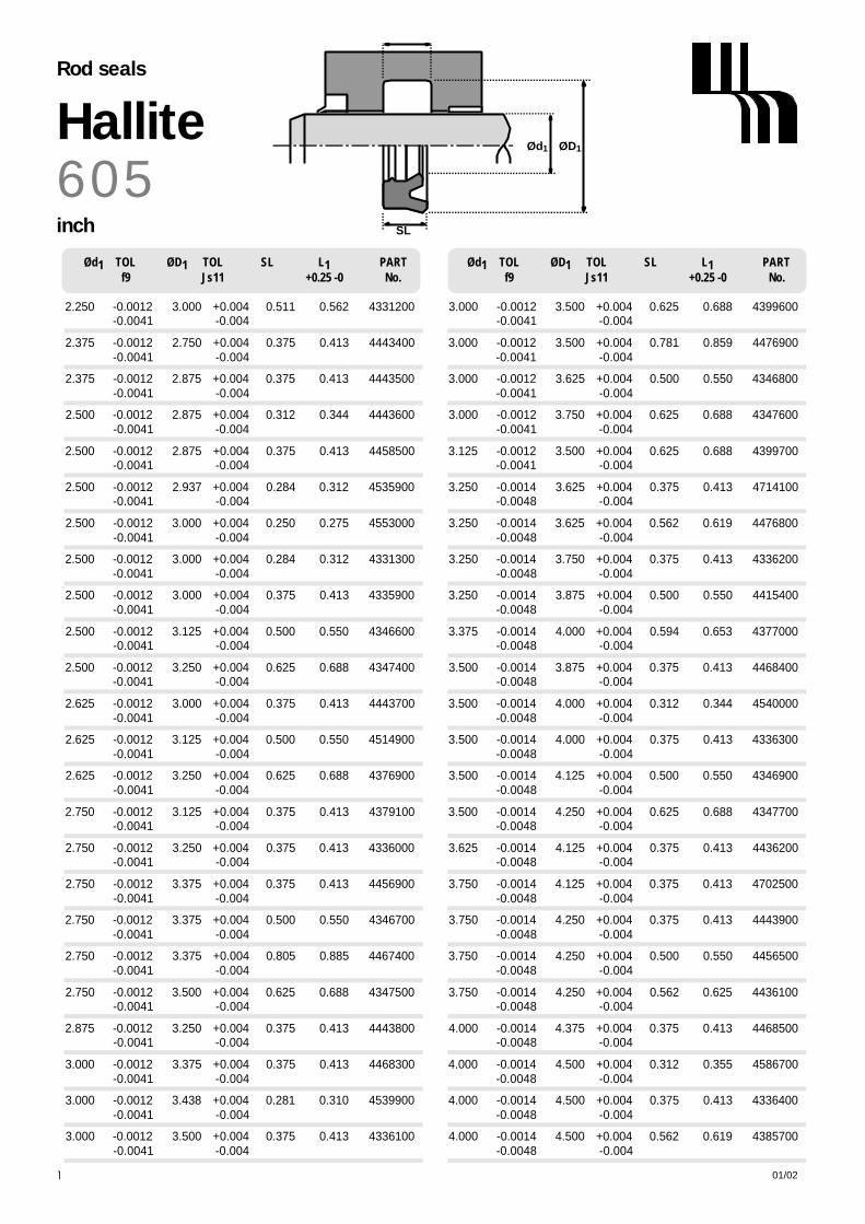
6 0 5HalliteRod seals
inch
01/02148
Ød1 TOL ØD1 TOL SL L1 PARTf9 Js11 +0.25 -0 No.
Ød1 TOL ØD1 TOL SL L1 PARTf9 Js11 +0.25 -0 No.
3.000 -0.0012 3.500 +0.004 0.625 0.688 4399600- 0 . 0 0 4 1 - 0 . 0 0 4
3.000 -0.0012 3.500 +0.004 0.781 0.859 4476900- 0 . 0 0 4 1 - 0 . 0 0 4
3.000 -0.0012 3.625 +0.004 0.500 0.550 4346800- 0 . 0 0 4 1 - 0 . 0 0 4
3.000 -0.0012 3.750 +0.004 0.625 0.688 4347600- 0 . 0 0 4 1 - 0 . 0 0 4
3.125 -0.0012 3.500 +0.004 0.625 0.688 4399700- 0 . 0 0 4 1 - 0 . 0 0 4
3.250 -0.0014 3.625 +0.004 0.375 0.413 4714100- 0 . 0 0 4 8 - 0 . 0 0 4
3.250 -0.0014 3.625 +0.004 0.562 0.619 4476800- 0 . 0 0 4 8 - 0 . 0 0 4
3.250 -0.0014 3.750 +0.004 0.375 0.413 4336200- 0 . 0 0 4 8 - 0 . 0 0 4
3.250 -0.0014 3.875 +0.004 0.500 0.550 4415400- 0 . 0 0 4 8 - 0 . 0 0 4
3.375 -0.0014 4.000 +0.004 0.594 0.653 4377000- 0 . 0 0 4 8 - 0 . 0 0 4
3.500 -0.0014 3.875 +0.004 0.375 0.413 4468400- 0 . 0 0 4 8 - 0 . 0 0 4
3.500 -0.0014 4.000 +0.004 0.312 0.344 4540000- 0 . 0 0 4 8 - 0 . 0 0 4
3.500 -0.0014 4.000 +0.004 0.375 0.413 4336300- 0 . 0 0 4 8 - 0 . 0 0 4
3.500 -0.0014 4.125 +0.004 0.500 0.550 4346900- 0 . 0 0 4 8 - 0 . 0 0 4
3.500 -0.0014 4.250 +0.004 0.625 0.688 4347700- 0 . 0 0 4 8 - 0 . 0 0 4
3.625 -0.0014 4.125 +0.004 0.375 0.413 4436200- 0 . 0 0 4 8 - 0 . 0 0 4
3.750 -0.0014 4.125 +0.004 0.375 0.413 4702500- 0 . 0 0 4 8 - 0 . 0 0 4
3.750 -0.0014 4.250 +0.004 0.375 0.413 4443900- 0 . 0 0 4 8 - 0 . 0 0 4
3.750 -0.0014 4.250 +0.004 0.500 0.550 4456500- 0 . 0 0 4 8 - 0 . 0 0 4
3.750 -0.0014 4.250 +0.004 0.562 0.625 4436100- 0 . 0 0 4 8 - 0 . 0 0 4
4.000 -0.0014 4.375 +0.004 0.375 0.413 4468500- 0 . 0 0 4 8 - 0 . 0 0 4
4.000 -0.0014 4.500 +0.004 0.312 0.355 4586700- 0 . 0 0 4 8 - 0 . 0 0 4
4.000 -0.0014 4.500 +0.004 0.375 0.413 4336400- 0 . 0 0 4 8 - 0 . 0 0 4
4.000 -0.0014 4.500 +0.004 0.562 0.619 4385700- 0 . 0 0 4 8 - 0 . 0 0 4
2.250 -0.0012 3.000 +0.004 0.511 0.562 4331200- 0 . 0 0 4 1 - 0 . 0 0 4
2.375 -0.0012 2.750 +0.004 0.375 0.413 4443400- 0 . 0 0 4 1 - 0 . 0 0 4
2.375 -0.0012 2.875 +0.004 0.375 0.413 4443500- 0 . 0 0 4 1 - 0 . 0 0 4
2.500 -0.0012 2.875 +0.004 0.312 0.344 4443600- 0 . 0 0 4 1 - 0 . 0 0 4
2.500 -0.0012 2.875 +0.004 0.375 0.413 4458500- 0 . 0 0 4 1 - 0 . 0 0 4
2.500 -0.0012 2.937 +0.004 0.284 0.312 4535900- 0 . 0 0 4 1 - 0 . 0 0 4
2.500 -0.0012 3.000 +0.004 0.250 0.275 4553000- 0 . 0 0 4 1 - 0 . 0 0 4
2.500 -0.0012 3.000 +0.004 0.284 0.312 4331300- 0 . 0 0 4 1 - 0 . 0 0 4
2.500 -0.0012 3.000 +0.004 0.375 0.413 4335900- 0 . 0 0 4 1 - 0 . 0 0 4
2.500 -0.0012 3.125 +0.004 0.500 0.550 4346600- 0 . 0 0 4 1 - 0 . 0 0 4
2.500 -0.0012 3.250 +0.004 0.625 0.688 4347400- 0 . 0 0 4 1 - 0 . 0 0 4
2.625 -0.0012 3.000 +0.004 0.375 0.413 4443700- 0 . 0 0 4 1 - 0 . 0 0 4
2.625 -0.0012 3.125 +0.004 0.500 0.550 4514900- 0 . 0 0 4 1 - 0 . 0 0 4
2.625 -0.0012 3.250 +0.004 0.625 0.688 4376900- 0 . 0 0 4 1 - 0 . 0 0 4
2.750 -0.0012 3.125 +0.004 0.375 0.413 4379100- 0 . 0 0 4 1 - 0 . 0 0 4
2.750 -0.0012 3.250 +0.004 0.375 0.413 4336000- 0 . 0 0 4 1 - 0 . 0 0 4
2.750 -0.0012 3.375 +0.004 0.375 0.413 4456900- 0 . 0 0 4 1 - 0 . 0 0 4
2.750 -0.0012 3.375 +0.004 0.500 0.550 4346700- 0 . 0 0 4 1 - 0 . 0 0 4
2.750 -0.0012 3.375 +0.004 0.805 0.885 4467400- 0 . 0 0 4 1 - 0 . 0 0 4
2.750 -0.0012 3.500 +0.004 0.625 0.688 4347500- 0 . 0 0 4 1 - 0 . 0 0 4
2.875 -0.0012 3.250 +0.004 0.375 0.413 4443800- 0 . 0 0 4 1 - 0 . 0 0 4
3.000 -0.0012 3.375 +0.004 0.375 0.413 4468300- 0 . 0 0 4 1 - 0 . 0 0 4
3.000 -0.0012 3.438 +0.004 0.281 0.310 4539900- 0 . 0 0 4 1 - 0 . 0 0 4
3.000 -0.0012 3.500 +0.004 0.375 0.413 4336100- 0 . 0 0 4 1 - 0 . 0 0 4
SL
ØD1Ød1

01/02 149
Ød1 TOL ØD1 TOL SL L1 PARTf9 Js11 +0.010 -0 No.
Ød1 TOL ØD1 TOL SL L1 PARTf9 Js11 +0.010 -0 No.
SL
ØD1Ød1
4.000 -0.0014 4.500 +0.004 0.781 0.859 4399800- 0 . 0 0 4 8 - 0 . 0 0 4
4.000 -0.0014 4.625 +0.004 0.375 0.413 4520100- 0 . 0 0 4 8 - 0 . 0 0 4
4.000 -0.0014 4.625 +0.004 0.500 0.550 4347000- 0 . 0 0 4 8 - 0 . 0 0 4
4.000 -0.0014 4.750 +0.004 0.500 0.550 4444000- 0 . 0 0 4 8 - 0 . 0 0 4
4.000 -0.0014 4.750 +0.005 0.625 0.688 4347800- 0 . 0 0 4 8 - 0 . 0 0 5
4.250 -0.0014 5.000 +0.005 0.625 0.688 4347900- 0 . 0 0 4 8 - 0 . 0 0 5
4.500 -0.0014 5.000 +0.005 0.375 0.413 4379200- 0 . 0 0 4 8 - 0 . 0 0 5
4.500 -0.0014 5.125 +0.005 0.500 0.550 4347100- 0 . 0 0 4 8 - 0 . 0 0 5
4.500 -0.0014 5.125 +0.005 0.625 0.688 4444100- 0 . 0 0 4 8 - 0 . 0 0 5
4.500 -0.0014 5.250 +0.005 0.625 0.688 4348000- 0 . 0 0 4 8 - 0 . 0 0 5
4.625 -0.0014 5.250 +0.005 0.625 0.688 4377100- 0 . 0 0 4 8 - 0 . 0 0 5
4.750 -0.0014 5.125 +0.005 0.375 0.413 4714200- 0 . 0 0 4 8 - 0 . 0 0 5
4.750 -0.0014 5.250 +0.005 0.625 0.688 4451100- 0 . 0 0 4 8 - 0 . 0 0 5
5.000 -0.0017 5.500 +0.005 0.375 0.413 4495000- 0 . 0 0 5 6 - 0 . 0 0 5
5.000 -0.0017 5.500 +0.005 0.562 0.619 4386100- 0 . 0 0 5 6 - 0 . 0 0 5
5.000 -0.0017 5.500 +0.005 0.781 0.859 4399900- 0 . 0 0 5 6 - 0 . 0 0 5
5.000 -0.0017 5.531 +0.005 0.557 0.619 4391400- 0 . 0 0 5 6 - 0 . 0 0 5
5.000 -0.0017 5.625 +0.005 0.500 0.550 4347200- 0 . 0 0 5 6 - 0 . 0 0 5
5.000 -0.0017 5.750 +0.005 0.625 0.688 4348100- 0 . 0 0 5 6 - 0 . 0 0 5
5.125 -0.0017 5.625 +0.005 0.562 0.619 4436000- 0 . 0 0 5 6 - 0 . 0 0 5
5.125 -0.0017 6.000 +0.005 0.500 0.550 4444200- 0 . 0 0 5 6 - 0 . 0 0 5
5.375 -0.0017 5.875 +0.005 0.625 0.688 4475800- 0 . 0 0 5 6 - 0 . 0 0 5
5.375 -0.0017 6.000 +0.005 0.625 0.688 4448300- 0 . 0 0 5 6 - 0 . 0 0 5
5.500 -0.0017 6.000 +0.005 0.375 0.413 4379300- 0 . 0 0 5 6 - 0 . 0 0 5
5.500 -0.0017 6.000 +0.005 0.562 0.619 4468600- 0 . 0 0 5 6 - 0 . 0 0 5
5.500 -0.0017 6.125 +0.005 0.312 0.344 4540100- 0 . 0 0 5 6 - 0 . 0 0 5
5.500 -0.0017 6.250 +0.005 0.625 0.688 4348200- 0 . 0 0 5 6 - 0 . 0 0 5
5.625 -0.0017 6.125 +0.005 0.375 0.413 4714300- 0 . 0 0 5 6 - 0 . 0 0 5
6.000 -0.0017 6.500 +0.005 0.562 0.619 4436500- 0 . 0 0 5 6 - 0 . 0 0 5
6.000 -0.0017 6.500 +0.005 0.781 0.859 4400000- 0 . 0 0 5 6 - 0 . 0 0 5
6.000 -0.0017 6.531 +0.005 0.562 0.619 4391000- 0 . 0 0 5 6 - 0 . 0 0 5
6.000 -0.0017 6.750 +0.005 0.625 0.688 4348300- 0 . 0 0 5 6 - 0 . 0 0 5
6.500 -0.0017 7.250 +0.006 0.625 0.688 4348400- 0 . 0 0 5 6 - 0 . 0 0 6
7.000 -0.0017 7.500 +0.006 0.562 0.619 4436600- 0 . 0 0 5 6 - 0 . 0 0 6
7.000 -0.0017 7.500 +0.006 0.780 0.859 4456600- 0 . 0 0 5 6 - 0 . 0 0 6
7.000 -0.0017 7.531 +0.006 0.562 0.619 4391100- 0 . 0 0 5 6 - 0 . 0 0 6
7.000 -0.0017 7.750 +0.006 0.625 0.688 4348500- 0 . 0 0 5 6 - 0 . 0 0 6
7.500 -0.0017 8.000 +0.006 0.375 0.413 4714400- 0 . 0 0 5 6 - 0 . 0 0 6
7.750 -0.0020 8.500 +0.006 0.625 0.688 4353900- 0 . 0 0 6 5 - 0 . 0 0 6
8.000 -0.0020 8.500 +0.006 0.562 0.619 4468700- 0 . 0 0 6 5 - 0 . 0 0 6
8.000 -0.0020 8.750 +0.006 0.625 0.688 4510500- 0 . 0 0 6 5 - 0 . 0 0 6
8.125 -0.0020 8.625 +0.006 0.781 0.859 4477000- 0 . 0 0 6 5 - 0 . 0 0 6
9.000 -0.0020 9.500 +0.006 0.562 0.619 4468800- 0 . 0 0 6 5 - 0 . 0 0 6
9.250 -0.0020 10.000 +0.006 0.625 0.688 4499300- 0 . 0 0 6 5 - 0 . 0 0 6
9.375 -0.0020 9.875 +0.006 0.781 0.859 4477100- 0 . 0 0 6 5 - 0 . 0 0 6
10.000 -0.0022 10.500 +0.006 0.562 0.619 4468900- 0 . 0 0 7 3 - 0 . 0 0 6
6 0 5Hallite
Rod seals
inch

N o t e s
01/02150

01/02
OPERATING CONDITIONS
MAXIMUM SPEED 1.0 m/sec 3.0 ft/secT E M P E R A T U R E R A N G E -45°C + 110°C -50°F + 230°F
MAXIMUM PRESSURE 400 bar* 6,000 p.s.i.*
MAXIMUM EXTRUSION GAP Figures show the maximum permissible gap all on one sideusing the minimum clearance Ø and maximum bore Ø
PRESSURE bar 1 6 0 2 5 0 4 0 0MAXIMUM GAP mm 0 . 6 0 . 5 0 . 4
PRESSURE p.s.i. 2400 3750 6000MAXIMUM GAP in 0.024 0.020 0.016
SURFACE ROUGHNESS µ m R a µ m R t µ i n C L A µ i n R M S
DYNAMIC SEALING FACE ØD1 0.1 ↔ 0 . 4 4 max 4 ↔ 1 6 5 ↔ 1 8STATIC SEALING FACE Ød1 1.6 max 10 max 63 max 70 maxSTATIC HOUSING FACES L1 3.2 max 16 max 125 max 140 max
CHAMFERS & RADII
GROOVE SECTION ≤ S mm 4.0 5.0 7.5 10.0MIN CHAMFER C mm 3.0 3.5 5.0 6.5
MAX FILLET RAD r1 m m 0.2 0.4 0.8 0.8
GROOVE SECTION ≤ S in 0.125 0.187 0.250 0.312 0.375 0.500MIN CHAMFER C in 0.093 0.093 0.125 0.156 0.187 0.217
MAX FILLET RAD r1 i n 0.008 0.008 0.016 0.032 0.032 0.032
T O L E R A N C E S Ø D1 Ø d1 L1 m m L1 i n
H9 js11 +0.25 -0 +0.010 -0
* Pressure rating of seal can be extended to 700 bar /10,000p.s.i. with the use of a back up ring. If this option is required seek advice from your local Hallite Seals sales office.
TECHNICAL DETAILSM E T R I C I N C H
HallitePiston seals
151
DESIGNThe Hallite 606 is an asymmetric piston sealdesigned to offer effective bore sealing ina wide variety of applications.
The outer dynamic lip is shorter andmore robust to provide improved sealingand compression set characteristics overconventional U rings.
The seal can be used by itself as a single acting seal or fitted back to back in separate grooves for doubleacting applications.
Manufactured in Hallite's highperformance polyurethane Hythane 181,The Hallite 606 provides the following benefits:
FEATURES• FLEXIBLE FOR EASY INSTALLATION• EXCELLENT WEAR RESISTANCE• HIGH RESISTANCE TO EXTRUSION• ROBUST DESIGN• WIDE TEMPERATURE RANGE
NB: Part numbers suffixed by “‡” indicatehousing sizes to meet ISO5597.
S
20° 30°
CL1
20° 30°
Ød1 ØD1
C
r1

SL
Ød1 ØD1
6 0 6HallitePiston seals
metric
01/02152
ØD1 TOL Ød1 TOL SL L1 PARTH9 js11 +0.25-0 No.
ØD1 TOL Ød1 TOL SL L1 PARTH9 js11 +0.25-0 No.
25 +0.05 15 +0.06 8.2 9.0 4390100+ 0 . 0 0 - 0 . 0 6
25 +0.05 17 +0.06 5.7 6.3 4418000+ 0 . 0 0 - 0 . 0 6
30 +0.05 20 +0.07 8.0 9.0 4354200+ 0 . 0 0 - 0 . 0 7
32 +0.06 24 +0.07 5.7 6.3 4351900‡+ 0 . 0 0 - 0 . 0 7
35 +0.06 25 +0.07 7.3 8.0 4365700+ 0 . 0 0 - 0 . 0 7
37 +0.06 21 +0.07 11.8 13.0 4354100+ 0 . 0 0 - 0 . 0 7
3 8 + 0 . 0 6 3 1 + 0 . 0 7 5 . 2 6 . 0 4 7 2 8 0 0 0
+ 0 . 0 0 - 0 . 0 7
40 +0.06 30 +0.07 7.3 8.0 4299500‡+ 0 . 0 0 - 0 . 0 7
40 +0.06 30 +0.07 10.0 11.0 4400900+ 0 . 0 0 - 0 . 0 7
45 +0.06 35 +0.08 7.3 8.0 4315700+ 0 . 0 0 - 0 . 0 8
50 +0.06 40 +0.08 7.3 8.0 4319500‡+ 0 . 0 0 - 0 . 0 8
55 +0.07 45 +0.08 7.3 8.0 4380000+ 0 . 0 0 - 0 . 0 8
60 +0.07 45 +0.08 10.0 11.0 4407000+ 0 . 0 0 - 0 . 0 8
63 +0.07 48 +0.08 11.4 12.5 4383200+ 0 . 0 0 - 0 . 0 8
63 +0.07 53 +0.10 7.3 8.0 4341500‡+ 0 . 0 0 - 0 . 1 0
63 +0.07 53 +0.10 11.8 13.0 4318800+ 0 . 0 0 - 0 . 1 0
6 5 + 0 . 0 7 5 5 + 0 . 1 0 7 . 3 8 . 0 4 4 2 4 1 0 0
+ 0 . 0 0 - 0 . 1 0
70 +0.07 55 +0.10 10.0 11.0 4448000+ 0 . 0 0 - 0 . 1 0
7 0 + 0 . 0 7 6 0 + 0 . 1 0 8 . 1 9 . 0 4 7 0 9 5 0 0
+ 0 . 0 0 - 0 . 1 0
71 +0.07 61 +0.10 6.0 7.0 4492600+ 0 . 0 0 - 0 . 1 0
75 +0.07 67 +0.10 8.8 9.7 4322300+ 0 . 0 0 - 0 . 1 0
80 +0.07 65 +0.10 11.4 12.5 4363800‡+ 0 . 0 0 - 0 . 1 0
80 +0.07 70 +0.10 6.8 7.5 4370300+ 0 . 0 0 - 0 . 1 0
8 0 + 0 . 0 7 7 0 + 0 . 1 0 8 . 0 9 . 0 4 7 0 9 6 0 0
+ 0 . 0 0 - 0 . 1 0
8 5 + 0 . 0 7 7 5 + 0 . 1 0 8 . 0 9 . 0 4 7 0 9 7 0 0
+ 0 . 0 0 - 0 . 1 0
85.7 +0.09 70.7+0.10 10.3 11.4 4493400+ 0 . 0 0 - 0 . 1 0
100 +0.09 85 +0.11 11.4 12.5 4363900‡+ 0 . 0 0 - 0 . 1 1
100 +0.09 90 +0.11 6.8 7.5 4375900+ 0 . 0 0 - 0 . 1 1
110 +0.09 100 +0.11 8.0 9.0 4533100+ 0 . 0 0 - 0 . 1 1
125 +0.10 105 +0.11 14.5 16.0 4364000‡+ 0 . 0 0 - 0 . 1 1
150 +0.10 130 +0.13 14.5 16.0 4390200+ 0 . 0 0 - 0 . 1 3
150 +0.10 140 +0.13 13.6 15.0 4390300+ 0 . 0 0 - 0 . 1 3
160 +0.10 140 +0.13 18.2 20.0 4364100+ 0 . 0 0 - 0 . 1 3
200 +0.12 180 +0.13 14.5 16.0 4392300+ 0 . 0 0 - 0 . 1 3

3.250 +0.003 2.625 +0.004 0.500 0.550 4376200+ 0 . 0 0 0 - 0 . 0 0 4
3.250 +0.003 2.750 +0.004 0.250 0.275 4516700+ 0 . 0 0 0 - 0 . 0 0 4
3.250 +0.003 2.750 +0.004 0.375 0.413 4474400+ 0 . 0 0 0 - 0 . 0 0 4
3.250 +0.003 2.875 +0.004 0.250 0.275 4427100+ 0 . 0 0 0 - 0 . 0 0 4
3.500 +0.003 2.750 +0.004 0.500 0.550 4444600+ 0 . 0 0 0 - 0 . 0 0 4
3.500 +0.003 2.750 +0.004 0.625 0.688 4376300+ 0 . 0 0 0 - 0 . 0 0 4
3.500 +0.003 2.875 +0.004 0.312 0.344 4571100+ 0 . 0 0 0 - 0 . 0 0 4
3.500 +0.003 2.875 +0.004 0.500 0.550 4364800+ 0 . 0 0 0 - 0 . 0 0 4
3.500 +0.003 3.000 +0.004 0.250 0.275 4516800+ 0 . 0 0 0 - 0 . 0 0 4
3.500 +0.003 3.000 +0.004 0.375 0.413 4364900+ 0 . 0 0 0 - 0 . 0 0 4
3.500 +0.003 3.125 +0.004 0.275 0.302 4572200+ 0 . 0 0 0 - 0 . 0 0 4
3.500 +0.003 3.125 +0.004 0.375 0.413 4444500+ 0 . 0 0 0 - 0 . 0 0 4
3.750 +0.003 3.250 +0.004 0.375 0.413 4444700+ 0 . 0 0 0 - 0 . 0 0 4
4.000 +0.003 3.250 +0.004 0.375 0.413 4517400+ 0 . 0 0 0 - 0 . 0 0 4
4.000 +0.003 3.250 +0.004 0.500 0.550 4444900+ 0 . 0 0 0 - 0 . 0 0 4
4.000 +0.003 3.250 +0.004 0.625 0.688 4376400+ 0 . 0 0 0 - 0 . 0 0 4
4.000 +0.003 3.375 +0.004 0.500 0.550 4365000+ 0 . 0 0 0 - 0 . 0 0 4
4.000 +0.003 3.500 +0.004 0.250 0.275 4516900+ 0 . 0 0 0 - 0 . 0 0 4
4.000 +0.003 3.500 +0.004 0.312 0.344 4427200+ 0 . 0 0 0 - 0 . 0 0 4
4.000 +0.003 3.500 +0.004 0.375 0.413 4365100+ 0 . 0 0 0 - 0 . 0 0 4
4.000 +0.003 3.625 +0.004 0.375 0.413 4444800+ 0 . 0 0 0 - 0 . 0 0 4
4.250 +0.003 3.750 +0.004 0.375 0.413 4445000+ 0 . 0 0 0 - 0 . 0 0 4
4.500 +0.003 3.750 +0.004 0.625 0.688 4371000+ 0 . 0 0 0 - 0 . 0 0 4
0.750 +0.002 0.375 +0.002 0.312 0.344 4707100+ 0 . 0 0 0 - 0 . 0 0 2
1.125 +0.003 0.750 +0.003 0.312 0.344 4565600+ 0 . 0 0 0 - 0 . 0 0 3
1.500 +0.003 1.125 +0.003 0.250 0.275 4426700+ 0 . 0 0 0 - 0 . 0 0 3
1.500 +0.003 1.250 +0.003 0.250 0.275 4426800+ 0 . 0 0 0 - 0 . 0 0 3
2.000 +0.003 1.375 +0.003 0.500 0.550 4364200+ 0 . 0 0 0 - 0 . 0 0 3
2.000 +0.003 1.500 +0.003 0.375 0.413 4376000+ 0 . 0 0 0 - 0 . 0 0 3
2.000 +0.003 1.625 +0.003 0.187 0.206 4426900+ 0 . 0 0 0 - 0 . 0 0 3
2.000 +0.003 1.625 +0.003 0.312 0.344 4444300+ 0 . 0 0 0 - 0 . 0 0 3
2.000 +0.003 1.625 +0.003 0.375 0.413 4364400+ 0 . 0 0 0 - 0 . 0 0 3
2.250 +0.003 1.750 +0.003 0.375 0.413 4476500+ 0 . 0 0 0 - 0 . 0 0 3
2.250 +0.003 1.875 +0.003 0.375 0.413 4479600+ 0 . 0 0 0 - 0 . 0 0 3
2.500 +0.003 1.625 +0.003 0.500 0.550 4364500+ 0 . 0 0 0 - 0 . 0 0 3
2.500 +0.003 1.875 +0.003 0.500 0.550 4376100+ 0 . 0 0 0 - 0 . 0 0 3
2.500 +0.003 2.000 +0.004 0.250 0.275 4516500+ 0 . 0 0 0 - 0 . 0 0 4
2.500 +0.003 2.000 +0.004 0.375 0.413 4391900+ 0 . 0 0 0 - 0 . 0 0 4
2.500 +0.003 2.125 +0.004 0.250 0.275 4427000+ 0 . 0 0 0 - 0 . 0 0 4
2.500 +0.003 2.125 +0.004 0.312 0.344 4444400+ 0 . 0 0 0 - 0 . 0 0 4
2.500 +0.003 2.125 +0.004 0.375 0.413 4451300+ 0 . 0 0 0 - 0 . 0 0 4
3.000 +0.003 2.250 +0.004 0.455 0.500 4375000+ 0 . 0 0 0 - 0 . 0 0 4
3.000 +0.003 2.375 +0.004 0.500 0.550 4364600+ 0 . 0 0 0 - 0 . 0 0 4
3.000 +0.003 2.500 +0.004 0.250 0.275 4516600+ 0 . 0 0 0 - 0 . 0 0 4
3.000 +0.003 2.500 +0.004 0.375 0.413 4364700+ 0 . 0 0 0 - 0 . 0 0 4
3.000 +0.003 2.625 +0.004 0.375 0.413 4458400+ 0 . 0 0 0 - 0 . 0 0 4
01/02 153
ØD1 TOL Ød1 TOL SL L1 PARTH9 js11 +0.010 -0 No.
ØD1 TOL Ød1 TOL SL L1 PARTH9 js11 +0.010 -0 No.
SL
Ød1 ØD1
6 0 6Hallite
Piston seals
inch

4.500 +0.003 4.000 +0.004 0.375 0.413 4448100+ 0 . 0 0 0 - 0 . 0 0 4
4.750 +0.003 4.379 +0.004 0.275 0.302 4493600+ 0 . 0 0 0 - 0 . 0 0 4
5.000 +0.004 4.250 +0.004 0.375 0.413 4517500+ 0 . 0 0 0 - 0 . 0 0 4
5.000 +0.004 4.250 +0.004 0.500 0.550 4445100+ 0 . 0 0 0 - 0 . 0 0 4
5.000 +0.004 4.250 +0.004 0.625 0.688 4371100+ 0 . 0 0 0 - 0 . 0 0 4
5.000 +0.004 4.500 +0.004 0.250 0.275 4517000+ 0 . 0 0 0 - 0 . 0 0 4
5.000 +0.004 4.500 +0.004 0.375 0.413 4365200+ 0 . 0 0 0 - 0 . 0 0 4
5.000 +0.004 4.500 +0.004 0.562 0.619 4495900+ 0 . 0 0 0 - 0 . 0 0 4
5.250 +0.004 4.500 +0.004 0.500 0.550 4445200+ 0 . 0 0 0 - 0 . 0 0 4
5.500 +0.004 4.750 +0.005 0.625 0.688 4371200+ 0 . 0 0 0 - 0 . 0 0 5
6.000 +0.004 5.250 +0.005 0.375 0.413 4517600+ 0 . 0 0 0 - 0 . 0 0 5
6.000 +0.004 5.250 +0.005 0.500 0.550 4445300+ 0 . 0 0 0 - 0 . 0 0 5
6.000 +0.004 5.250 +0.005 0.625 0.688 4371300+ 0 . 0 0 0 - 0 . 0 0 5
6.000 +0.004 5.500 +0.005 0.250 0.275 4517100+ 0 . 0 0 0 - 0 . 0 0 5
6.000 +0.004 5.500 +0.005 0.375 0.413 4365300+ 0 . 0 0 0 - 0 . 0 0 5
6.000 +0.004 5.500 +0.005 0.562 0.619 4393400+ 0 . 0 0 0 - 0 . 0 0 5
6.250 +0.004 5.750 +0.005 0.562 0.619 4458300+ 0 . 0 0 0 - 0 . 0 0 5
7.000 +0.004 6.250 +0.005 0.375 0.413 4517700+ 0 . 0 0 0 - 0 . 0 0 5
7.000 +0.004 6.250 +0.005 0.500 0.550 4445500+ 0 . 0 0 0 - 0 . 0 0 5
7.000 +0.004 6.250 +0.005 0.625 0.688 4371400+ 0 . 0 0 0 - 0 . 0 0 5
7.000 +0.004 6.500 +0.005 0.250 0.275 4517200+ 0 . 0 0 0 - 0 . 0 0 5
7.000 +0.004 6.500 +0.005 0.375 0.413 4445400+ 0 . 0 0 0 - 0 . 0 0 5
8.000 +0.005 7.250 +0.006 0.625 0.688 4371500+ 0 . 0 0 0 - 0 . 0 0 6
8.000 +0.005 7.500 +0.006 0.250 0.275 4517300+ 0 . 0 0 0 - 0 . 0 0 6
9.000 +0.005 8.000 +0.006 0.750 0.825 4371600+ 0 . 0 0 0 - 0 . 0 0 6
10.000+0.005 9.000 +0.006 0.750 0.825 4536200+ 0 . 0 0 0 - 0 . 0 0 6
10.000+0.005 9.250 +0.006 0.375 0.413 4575100+ 0 . 0 0 0 - 0 . 0 0 6
SL
Ød1 ØD1
6 0 6HallitePiston seals
inch
01/02154
ØD1 TOL Ød1 TOL SL L1 PARTH9 js11 +0.010 -0 No.
ØD1 TOL Ød1 TOL SL L1 PARTH9 js11 +0.010 -0 No.


01/02
OPERATING CONDITIONS
MAXIMUM SPEED 1.0 m/sec 3.0 ft/secT E M P E R A T U R E R A N G E -45°C + 110°C -50°F + 230°F
MAXIMUM PRESSURE 400 bar 6000 p.s.i.
MAXIMUM EXTRUSION GAP Figures show the maximum permissible gap all on one side using minimum rod Ø and maximum clearance Ø.
PRESSURE bar 1 6 0 2 5 0 4 0 0MAXIMUM GAP mm 0 . 6 0 . 5 0 . 4
PRESSURE p.s.i. 2400 3750 6000
SURFACE ROUGHNESS µ m R a µ m R t µ i n C L A µ i n R M S
DYNAMIC SEALING FACE Ød1 0.1 ↔ 0 . 4 4 max 4 ↔ 1 6 5 ↔ 1 8STATIC SEALING FACE ØD1 1.6 max 10 max 63 max 70 maxSTATIC HOUSING FACES L1 3.2 max 16 max 125 max 140 max
CHAMFERS & RADII
GROOVE SECTION ≤ S mm 4.0 5.0 7.5MIN CHAMFER C mm 3.0 3.5 5.0
MAX FILLET RAD r1 m m 0.2 0.4 0.8MAX FILLET RAD r2 m m 0.4 0.8 1.2
T O L E R A N C E S Ø d1 Ø D1 L1 m m
f9 Js11 +0.25 -0
TECHNICAL DETAILSM E T R I C I N C H
DESIGNThe Hallite 610 is an asymmetric “solid” sealoffering excellent dry rod sealing for lightand medium duty applications.
It is designed to be less sensitive topressure fluctuations than Hallite 605 ‘U’ring design.
Manufactured in Hallite’s highperformance polyurethane - Hythane® ~181 - the type 610 is an extremely flexibleseal making installation very easy
FEATURES:• INSENSITIVE TO PRESSURE
FLUCTUATION.• TWIN LIP DESIGN OFFERING:
LOWER FRICTION,IMPROVED SEALING,PRIMARY LIP PROTECTION, INCREASED SEAL STABILITY.
NB: Part numbers suffixed by “‡” indicatehousing sizes to meet ISO5597.
C
S
L1
ØD1Ød1
r1 r2
20° 30°
HalliteRod Seals
155

S
ØD1Ød1
SL
6 1 0HalliteRod seals
metric
01/02156
Ød1 TOL ØD1 TOL SL L1 PARTf9 Js11 +0.25-0 No.
Ød1 TOL ØD1 TOL SL L1 PARTf9 Js11 +0.25-0 No.
8 -0.013 16 +0.06 5.3 6.0 4581000- 0 . 0 4 9 - 0 . 0 6
14 -0.016 22 +0.07 5.3 6.0 4580900- 0 . 0 5 9 - 0 . 0 7
16 -0.016 24 +0.07 6.0 7.0 4319300- 0 . 0 5 9 - 0 . 0 7
18 -0.016 25 +0.07 4.6 5.6 4334600‡- 0 . 0 5 9 - 0 . 0 7
20 -0.020 26 +0.07 4.5 5.5 4319400- 0 . 0 7 2 - 0 . 0 7
20 -0.020 28 +0.07 6.0 7.0 4307500- 0 . 0 7 2 - 0 . 0 7
22 -0.020 28 +0.07 4.5 5.5 4356000- 0 . 0 7 2 - 0 . 0 7
22 -0.020 29 +0.07 4.6 5.6 4324200‡- 0 . 0 7 2 - 0 . 0 7
22 -0.020 30 +0.07 6.0 7.0 4316100- 0 . 0 7 2 - 0 . 0 7
22 -0.020 30 +0.07 7.0 8.0 4389300- 0 . 0 7 2 - 0 . 0 7
25 -0.020 33 +0.08 6.0 7.0 4316200- 0 . 0 7 2 - 0 . 0 8
25 -0.020 33 +0.08 8.0 9.0 4299000- 0 . 0 7 2 - 0 . 0 8
28 -0.020 36 +0.08 5.3 6.3 4334700‡- 0 . 0 7 2 - 0 . 0 8
28 -0.020 36 +0.08 6.0 7.0 4323200- 0 . 0 7 2 - 0 . 0 8
28 -0.020 36 +0.08 8.0 9.0 4307700- 0 . 0 7 2 - 0 . 0 8
30 -0.020 38 +0.08 6.0 7.0 4308900- 0 . 0 7 2 - 0 . 0 8
30 -0.020 38 +0.08 8.0 9.0 4362400- 0 . 0 7 2 - 0 . 0 8
30 -0.020 40 +0.08 7.0 8.0 4558300- 0 . 0 7 2 - 0 . 0 8
32 -0.025 40 +0.08 6.0 7.0 4316300- 0 . 0 8 7 - 0 . 0 8
35 -0.025 43 +0.08 6.0 7.0 4301700- 0 . 0 8 7 - 0 . 0 8
35 -0.025 43 +0.08 8.0 9.0 4592800- 0 . 0 8 7 - 0 . 0 8
35 -0.025 45 +0.08 10.0 11.0 4299300- 0 . 0 8 7 - 0 . 0 8
36 -0.025 44 +0.08 5.3 6.3 4324300‡- 0 . 0 8 7 - 0 . 0 8
36 -0.025 44 +0.08 8.0 9.0 4308000- 0 . 0 8 7 - 0 . 0 8
36 -0.025 46 +0.08 10.0 11.0 4299400- 0 . 0 8 7 - 0 . 0 8
40 -0.025 48 +0.08 5.4 6.4 4329200- 0 . 0 8 7 - 0 . 0 8
40 -0.025 48 +0.08 6.5 7.5 4323300- 0 . 0 8 7 - 0 . 0 8
40 -0.025 48 +0.08 8.0 9.0 4301800- 0 . 0 8 7 - 0 . 0 8
45 -0.025 52 +0.10 10.0 11.0 4330000- 0 . 0 8 7 - 0 . 1 0
45 -0.025 53 +0.10 5.3 6.3 4334800‡- 0 . 0 8 7 - 0 . 1 0
45 -0.025 53 +0.10 6.0 7.0 4711000- 0 . 0 8 7 - 0 . 1 0
45 -0.025 53 +0.10 8.0 9.0 4308100- 0 . 0 8 7 - 0 . 1 0
45 -0.025 55 +0.10 10.0 11.0 4389400- 0 . 0 8 7 - 0 . 1 0
50 -0.025 58 +0.10 5.3 6.3 4356900- 0 . 0 8 7 - 0 . 1 0
5 0 - 0 . 0 2 5 5 8 + 0 . 1 0 8 . 0 9 . 0 4 2 9 9 1 0 0- 0 . 0 8 7 - 0 . 1 0
50 -0.025 60 +0.10 10.0 11.0 4389500- 0 . 0 8 7 - 0 . 1 0
55 0.030 63 +0.10 8.0 9.0 4323000- 0 . 1 0 4 - 0 . 1 0
55 -0.030 65 +0.10 7.0 8.0 4385500- 0 . 1 0 4 - 0 . 1 0
55 -0.030 65 +0.10 10.0 11.0 4389600- 0 . 1 0 4 - 0 . 1 0
55 -0.030 65 +0.10 11.8 13.0 4389700- 0 . 1 0 4 - 0 . 1 0
56 -0.030 64 +0.10 8.0 9.0 4316400- 0 . 1 0 4 - 0 . 1 0
56 -0.030 66 +0.10 6.8 7.5 4334900‡- 0 . 1 0 4 - 0 . 1 0
60 -0.030 68 +0.10 8.0 9.0 4299200- 0 . 1 0 4 - 0 . 1 0
60 -0.030 68 +0.10 11.4 12.5 4329900- 0 . 1 0 4 - 0 . 1 0
60 -0.030 70 +0.10 7.0 8.0 4303200- 0 . 1 0 4 - 0 . 1 0
60 -0.030 70 +0.10 11.8 13.0 4389800- 0 . 1 0 4 - 0 . 1 0

01/02 157
Ød1 TOL ØD1 TOL SL L1 PARTf9 Js11 +0.25-0 No.
Ød1 TOL ØD1 TOL SL L1 PARTf9 Js11 +0.25-0 No.
75 -0.030 83 +0.10 8.0 9.0 4539400- 0 . 1 0 4 - 0 . 1 0
80 -0.030 88 +0.11 8.0 9.0 4316700- 0 . 1 0 4 - 0 . 1 0
85 -0.036 97 +0.11 9.0 10.0 4328100- 0 . 1 2 3 - 0 . 1 1
87 -0.036 95 +0.11 8.0 9.0 4323700- 0 . 1 2 3 - 0 . 1 1
90 -0.036 98 +0.11 8.0 9.0 4316800- 0 . 1 2 3 - 0 . 1 1
100 -0.036 108 +0.11 8.0 9.0 4316900- 0 . 1 2 3 - 0 . 1 1
134 -0.043 147 +0.13 12.0 13.3 4588100- 0 . 1 4 3 - 0 . 1 3
63 -0.030 71 +0.10 8.0 9.0 4316500- 0 . 1 0 4 - 0 . 1 0
63 -0.030 75 +0.10 8.6 9.6 4360500- 0 . 1 0 4 - 0 . 1 0
65 -0.030 73 +0.10 8.0 9.0 4362500- 0 . 1 0 4 - 0 . 1 0
65 -0.030 75 +0.10 11.8 13.0 4389900- 0 . 1 0 4 - 0 . 1 0
70 -0.030 78 +0.10 8.0 9.0 4316600- 0 . 1 0 4 - 0 . 1 0
70 -0.030 80 +0.10 6.5 7.5 4335000‡- 0 . 1 0 4 - 0 . 1 0
70 -0.030 80 +0.10 11.8 13.0 4390000- 0 . 1 0 4 - 0 . 1 0
S
ØD1Ød1
SL
6 1 0Hallite
Rod seals
metric

N o t e s
01/02158

01/02
DESIGNThe Hallite 616 is a revolutionary seal fromHallite. Incorporating the sealing efficiencyof the Hallite 605 with the compactgrooves used by PTFE rod seals.
Hallite’s 616 is an asymmetric twin lipseal, designed for light and medium dutyapplications where space and friction areat a premium.
Manufactured in Hallite’s highperformance polyurethane Hythane 181,the Hallite 616 is an extremely flexible sealmaking installation very easy.
FEATURES:• EASY ASSEMBLY• TWIN LIP PERFORMANCE• ISO 7425 HOUSINGS
NB: Part numbers suffixed by “‡” indicatehousing sizes to meet ISO7425-2.
ØD1Ød1
Sr1
L1C
20° 30°
OPERATING CONDITIONS
MAXIMUM SPEED 1.0 m/sec 3.0 ft/secT E M P E R A T U R E R A N G E -45°C + 110°C -50°F + 230°F
MAXIMUM PRESSURE 240 bar 3500 p.s.i.
MAXIMUM EXTRUSION GAP Figures show the maximum permissible gap all on one side using minimum rod Ø and maximum clearance Ø.
PRESSURE bar 1 6 0 2 4 0MAXIMUM GAP mm 0 . 6 0 . 5
PRESSURE p.s.i. 2400 3750
SURFACE ROUGHNESS µ m R a µ m R t µ i n C L A µ i n R M S
DYNAMIC SEALING FACE Ød1 0.1 ↔ 0 . 4 4 max 4 ↔ 1 6 5 ↔ 1 8STATIC SEALING FACE ØD1 1.6 max 10 max 63 max 70 maxSTATIC HOUSING FACES L1 3.2 max 16 max 125 max 140 max
CHAMFERS & RADII
GROOVE SECTION ≤ S mm 3.75 5.50 7.75MIN CHAMFER C mm 2.00 3.00 5.00
MAX FILLET RAD r1 m m 0.40 0.80 1.20
T O L E R A N C E S Ø d1 Ø D1 L1 m m
f9 H11 +0.25 -0
TECHNICAL DETAILSM E T R I C I N C H
HalliteRod Seals
159
NOTEHallite 616 is used either as a singleseal or in a combination with Hallite 16. The latter arrangement isrecommended when pressurepeaks can occur, as in cylinderswith cushioning, in this case theHallite 16 is fitted into the pressureside of the housing while the Hallite 616 ensures minimal leakage sealing.
It is recommended that theHallite technical department beconsulted when considering thisarrangement.

ØD1Ød1
6 1 6HalliteRod seals
metric
01/02160
Ød1 TOL ØD1 TOL SL L1 PARTf9 H11 +0.25-0 No.
Ød1 TOL ØD1 TOL SL L1 PARTf9 H11 +0.25-0 No.
14 -0.016 21.5 +0.13 2.8 3.2 4577700‡- 0 . 0 5 9 + 0 . 0 0
18 -0.016 25.5 +0.13 2.8 3.2 4341800‡- 0 . 0 5 9 + 0 . 0 0
2 0 - 0 . 0 1 6 2 7 . 5 + 0 . 1 3 2 . 8 3 . 2 4 7 2 1 7 0 0
- 0 . 0 5 9 + 0 . 0 0
20 -0.020 31.0 +0.16 3.9 4.2 4367400‡- 0 . 0 7 2 + 0 . 0 0
22 -0.020 33.0 +0.16 3.9 4.2 4341900‡- 0 . 0 7 2 + 0 . 0 0
2 5 - 0 . 0 2 0 3 2 . 5 + 0 . 1 6 3 . 9 3 . 2 4 7 2 1 8 0 0
- 0 . 0 7 2 + 0 . 0 0
25 -0.020 36.0 +0.16 3.9 4.2 4367500‡- 0 . 0 7 2 + 0 . 0 0
25.4 -0.020 32.9 +0.16 2.8 3.2 4469000- 0 . 0 7 2 + 0 . 0 0
28 -0.020 39.0 +0.16 3.9 4.2 4367600‡- 0 . 0 7 2 + 0 . 0 0
30 -0.020 41.0 +0.16 3.9 4.2 4404500- 0 . 0 7 2 + 0 . 0 0
3 2 - 0 . 0 2 5 3 9 . 5 + 0 . 1 6 3 . 9 3 . 2 4 7 1 4 8 0 0
- 0 . 0 7 2 + 0 . 0 0
32 -0.025 43.0 +0.16 3.9 4.2 4367700‡- 0 . 0 8 7 + 0 . 0 0
36 -0.025 47.0 +0.16 3.9 4.2 4353100‡- 0 . 0 8 7 + 0 . 0 0
4 0 - 0 . 0 2 5 5 1 . 0 + 0 . 1 6 3 . 9 4 . 2 4 7 2 2 9 0 0
- 0 . 0 8 7 + 0 . 0 0
40 -0.025 55.5 +0.19 6.0 6.3 4367800- 0 . 0 8 7 + 0 . 0 0
45 -0.025 56.0 +0.19 3.9 4.2 4556300‡- 0 . 0 8 7 + 0 . 0 0
45 -0.025 60.5 +0.19 6.0 6.3 4367900- 0 . 0 8 7 + 0 . 0 0
5 0 - 0 . 0 2 5 6 1 . 0 + 0 . 1 9 6 . 0 4 . 2 4 7 2 3 0 0 0
- 0 . 0 8 7 + 0 . 0 0
50 -0.025 65.5 +0.19 6.0 6.3 4368000- 0 . 0 8 7 + 0 . 0 0
56 -0.030 71.5 +0.19 6.0 6.3 4368100‡- 0 . 1 0 4 + 0 . 0 0
60 -0.030 70.6 +0.19 3.9 4.2 4410800- 0 . 1 0 4 + 0 . 0 0
6 0 - 0 . 0 3 0 7 5 . 5 + 0 . 1 9 6 . 0 6 . 3 4 7 2 7 1 0 0
- 0 . 1 0 4 + 0 . 0 0
63 -0.030 78.5 +0.19 6.0 6.3 4368200‡- 0 . 1 0 4 + 0 . 0 0
65 -0.030 80.5 +0.19 6.0 6.3 4548000- 0 . 1 0 4 + 0 . 0 0
70 -0.030 85.5 +0.22 6.0 6.3 4368300‡- 0 . 1 0 4 + 0 . 0 0
7 5 - 0 . 0 3 0 9 0 . 5 + 0 . 2 2 6 . 0 6 . 3 4 7 2 8 2 0 0
- 0 . 1 0 4 + 0 . 0 0
80 -0.030 95.5 +0.22 6.0 6.3 4368400‡- 0 . 1 0 4 + 0 . 0 0
85 -0.036 100.5 +0.22 6.0 6.3 4538400- 0 . 1 2 3 + 0 . 0 0
90 -0.036 105.5 +0.22 6.0 6.3 4368500‡- 0 . 1 2 3 + 0 . 0 0
95 -0.036 110.5 +0.22 6.0 6.3 4538500- 0 . 1 2 3 + 0 . 0 0
100 -0.036 115.5 +0.22 6.0 6.3 4368600‡- 0 . 1 2 3 + 0 . 0 0
110 -0.036 125.5 +0.25 6.0 6.3 4545400‡- 0 . 1 2 3 + 0 . 0 0
125 -0.043 140.5 +0.25 6.0 6.3 4545500‡- 0 . 1 4 3 + 0 . 0 0
140 -0.043 155.5 +0.25 6.0 6.3 4545600‡- 0 . 1 4 3 + 0 . 0 0
160 -0.043 175.5 +0.25 6.0 6.3 4548100‡- 0 . 1 4 3 + 0 . 0 0

01/02
OPERATING CONDITIONS
MAXIMUM SPEED 1.0 m/sec 3.0 ft/secT E M P E R A T U R E R A N G E -45°C + 110°C -50°F + 230°F
MAXIMUM PRESSURE 700 bar 10,000 p.s.i.
MAXIMUM EXTRUSION GAP Figures show the maximum permissible gap all on one side using minimum rod Ø and maximum clearance Ø.
PRESSURE bar 1 6 0 2 5 0 4 0 0 5 0 0 7 0 0MAXIMUM GAP mm 1 . 0 0 . 8 0 . 6 0 . 4 0 . 2 5
PRESSURE p.s.i. 2400 3750 6000 7500 10,000MAXIMUM GAP in 0.040 0.032 0.024 0.016 0.010
SURFACE ROUGHNESS µ m R a µ m R t µ i n C L A µ i n R M S
DYNAMIC SEALING FACE Ød1 0.1 ↔ 0 . 4 4 max 4 ↔ 1 6 5 ↔ 1 8STATIC SEALING FACE ØD1 1.6 max 10 max 63 max 70 maxSTATIC HOUSING FACES L1 3.2 max 16 max 125 max 140 max
CHAMFERS & RADII
GROOVE SECTION ≤ S mm 4.0 5.0 7.5 10.0 12.5 15.0MIN CHAMFER C mm 3.0 3.5 5.0 6.5 7.0 8.0
MAX FILLET RAD r1 m m 0.2 0.4 0.8 0.8 1.2 1.6MAX FILLET RAD r2 m m 0.4 0.8 1.2 1.2 1.6 2.4
GROOVE SECTION ≤ S in 0.125 0.187 0.250 0.312 0.375 0.500MIN CHAMFER C in 0.093 0.093 0.125 0.156 0.187 0.217
MAX FILLET RAD r1 i n 0.008 0.008 0.016 0.016 0.032 0.032MAX FILLET RAD r2 i n 0.016 0.016 0.032 0.032 0.047 0.047
T O L E R A N C E S Ø d1 Ø D1 L1 m m L1 i n
f9 Js11 +0.25 -0 +0.010 -0
TECHNICAL DETAILSM E T R I C I N C H
HalliteRod seals
161
DESIGNThe Hallite 621 is a top of the range highpressure rod seal. The design of the sealincorporates a unique profiled NBRenergiser to ensure complete lip actuationunder all pressure conditions and tocushion the seal against shock loadings.
The shell is moulded in Hallite’s highperformance polyurethane Hythane 181,ensuring flexibility for installation andperformance at low temperatures.The Hallite 621 also benefits from Hallite’stwin lip profile for dry rod sealing.
FEATURES• HIGH PRESSURE/SHOCK LOAD CAPABILITY• TWIN LIP DESIGN OFFERING:
LOWER FRICTIONIMPROVED SEALINGPRIMARY LIP PROTECTIONINCREASED SEAL STABILITY
• POLYACETAL ANTI-EXTRUSION RING.
NB: Part numbers suffixed by “†” aredesigned to suit popular Asian housings.
Part numbers suffixed by “‡” indicatehousing sizes to meet ISO5597.
C
S
L1
ØD1Ød1
r1 r220° 30°

ØD1Ød1
SL
6 2 1HalliteRod seals
metric
01/02162
Ød1 TOL ØD1 TOL SL L1 PARTf9 Js11 +0.25-0 No.
Ød1 TOL ØD1 TOL SL L1 PARTf9 Js11 +0.25-0 No.
14 -0.016 21.5 +0.13 2.8 3.2 4577700‡- 0 . 0 5 9 + 0 . 0 0
18 -0.016 25.5 +0.13 2.8 3.2 4341800‡- 0 . 0 5 9 + 0 . 0 0
2 0 - 0 . 0 1 6 2 7 . 5 + 0 . 1 3 2 . 8 3 . 2 4 7 2 1 7 0 0
- 0 . 0 5 9 + 0 . 0 0
20 -0.020 31.0 +0.16 3.9 4.2 4367400‡- 0 . 0 7 2 + 0 . 0 0
22 -0.020 33.0 +0.16 3.9 4.2 4341900‡- 0 . 0 7 2 + 0 . 0 0
2 5 - 0 . 0 2 0 3 2 . 5 + 0 . 1 6 3 . 9 3 . 2 4 7 2 1 8 0 0
- 0 . 0 7 2 + 0 . 0 0
25 -0.020 36.0 +0.16 3.9 4.2 4367500‡- 0 . 0 7 2 + 0 . 0 0
25.4 -0.020 32.9 +0.16 2.8 3.2 4469000- 0 . 0 7 2 + 0 . 0 0
28 -0.020 39.0 +0.16 3.9 4.2 4367600‡- 0 . 0 7 2 + 0 . 0 0
30 -0.020 41.0 +0.16 3.9 4.2 4404500- 0 . 0 7 2 + 0 . 0 0
3 2 - 0 . 0 2 5 3 9 . 5 + 0 . 1 6 3 . 9 3 . 2 4 7 1 4 8 0 0
- 0 . 0 7 2 + 0 . 0 0
32 -0.025 43.0 +0.16 3.9 4.2 4367700‡- 0 . 0 8 7 + 0 . 0 0
36 -0.025 47.0 +0.16 3.9 4.2 4353100‡- 0 . 0 8 7 + 0 . 0 0
4 0 - 0 . 0 2 5 5 1 . 0 + 0 . 1 6 3 . 9 4 . 2 4 7 2 2 9 0 0
- 0 . 0 8 7 + 0 . 0 0
40 -0.025 55.5 +0.19 6.0 6.3 4367800- 0 . 0 8 7 + 0 . 0 0
45 -0.025 56.0 +0.19 3.9 4.2 4556300‡- 0 . 0 8 7 + 0 . 0 0
45 -0.025 60.5 +0.19 6.0 6.3 4367900- 0 . 0 8 7 + 0 . 0 0
5 0 - 0 . 0 2 5 6 1 . 0 + 0 . 1 9 6 . 0 4 . 2 4 7 2 3 0 0 0
- 0 . 0 8 7 + 0 . 0 0
50 -0.025 65.5 +0.19 6.0 6.3 4368000- 0 . 0 8 7 + 0 . 0 0
56 -0.030 71.5 +0.19 6.0 6.3 4368100‡- 0 . 1 0 4 + 0 . 0 0
60 -0.030 70.6 +0.19 3.9 4.2 4410800- 0 . 1 0 4 + 0 . 0 0
6 0 - 0 . 0 3 0 7 5 . 5 + 0 . 1 9 6 . 0 6 . 3 4 7 2 7 1 0 0
- 0 . 1 0 4 + 0 . 0 0
63 -0.030 78.5 +0.19 6.0 6.3 4368200‡- 0 . 1 0 4 + 0 . 0 0
65 -0.030 80.5 +0.19 6.0 6.3 4548000- 0 . 1 0 4 + 0 . 0 0
70 -0.030 85.5 +0.22 6.0 6.3 4368300‡- 0 . 1 0 4 + 0 . 0 0
7 5 - 0 . 0 3 0 9 0 . 5 + 0 . 2 2 6 . 0 6 . 3 4 7 2 8 2 0 0
- 0 . 1 0 4 + 0 . 0 0
80 -0.030 95.5 +0.22 6.0 6.3 4368400‡- 0 . 1 0 4 + 0 . 0 0
85 -0.036 100.5 +0.22 6.0 6.3 4538400- 0 . 1 2 3 + 0 . 0 0
90 -0.036 105.5 +0.22 6.0 6.3 4368500‡- 0 . 1 2 3 + 0 . 0 0
95 -0.036 110.5 +0.22 6.0 6.3 4538500- 0 . 1 2 3 + 0 . 0 0
100 -0.036 115.5 +0.22 6.0 6.3 4368600‡- 0 . 1 2 3 + 0 . 0 0
110 -0.036 125.5 +0.25 6.0 6.3 4545400‡- 0 . 1 2 3 + 0 . 0 0
125 -0.043 140.5 +0.25 6.0 6.3 4545500‡- 0 . 1 4 3 + 0 . 0 0
140 -0.043 155.5 +0.25 6.0 6.3 4545600‡- 0 . 1 4 3 + 0 . 0 0
160 -0.043 175.5 +0.25 6.0 6.3 4548100‡- 0 . 1 4 3 + 0 . 0 0

01/02 163
Ød1 TOL ØD1 TOL SL L1 PARTf9 Js11 +0.010 -0 No.
Ød1 TOL ØD1 TOL SL L1 PARTf9 Js11 +0.010 -0 No.
3.500 -0.0014 4.125 +0.004 0.500 0.550 4486910- 0 . 0 0 4 8 - 0 . 0 0 4
3.500 -0.0014 4.250 +0.004 0.625 0.688 4573610- 0 . 0 0 4 8 - 0 . 0 0 4
3.750 -0.0014 4.125 +0.004 0.375 0.413 4709310- 0 . 0 0 4 8 - 0 . 0 0 4
4.000 -0.0014 4.500 +0.004 0.375 0.413 4486010- 0 . 0 0 4 8 - 0 . 0 0 4
4.000 -0.0014 4.500 +0.004 0.562 0.619 4486110- 0 . 0 0 4 8 - 0 . 0 0 4
4.000 -0.0014 4.625 +0.004 0.562 0.619 4487010- 0 . 0 0 4 8 - 0 . 0 0 4
4.000 -0.0014 4.750 +0.005 0.625 0.688 4483310- 0 . 0 0 4 8 - 0 . 0 0 5
4.500 -0.0014 5.000 +0.005 0.375 0.413 4486210- 0 . 0 0 4 8 - 0 . 0 0 5
4.500 -0.0014 5.000 +0.005 0.562 0.619 4486310- 0 . 0 0 4 8 - 0 . 0 0 5
4.500 -0.0014 5.125 +0.005 0.625 0.688 4486410- 0 . 0 0 4 8 - 0 . 0 0 5
4.500 -0.0014 5.250 +0.005 0.625 0.688 4483410- 0 . 0 0 4 8 - 0 . 0 0 5
5.000 -0.0017 5.500 +0.005 0.562 0.619 4486510- 0 . 0 0 5 6 - 0 . 0 0 5
5.000 -0.0017 5.625 +0.005 0.625 0.688 4487110- 0 . 0 0 5 6 - 0 . 0 0 5
5.000 -0.0017 5.750 +0.005 0.625 0.688 4483510- 0 . 0 0 5 6 - 0 . 0 0 5
5.500 -0.0017 6.000 +0.005 0.562 0.619 4486610- 0 . 0 0 5 6 - 0 . 0 0 5
6.000 -0.0017 6.500 +0.005 0.562 0.619 4486710- 0 . 0 0 5 6 - 0 . 0 0 5
6.000 -0.0017 6.750 +0.005 0.625 0.688 4487210- 0 . 0 0 5 6 - 0 . 0 0 5
7.000 -0.0017 7.750 +0.005 0.625 0.688 4588210- 0 . 0 0 5 6 - 0 . 0 0 5
8.000 -0.0020 8.750 +0.006 0.625 0.688 4573210- 0 . 0 0 6 5 - 0 . 0 0 6
1.375 -0.0010 1.875 +0.003 0.375 0.413 4707710- 0 . 0 0 3 4 - 0 . 0 0 3
1.500 -0.0010 1.875 +0.003 0.250 0.275 4484410- 0 . 0 0 3 4 - 0 . 0 0 3
1.500 -0.0010 1.875 +0.003 0.312 0.344 4484510- 0 . 0 0 3 4 - 0 . 0 0 3
1.500 -0.0010 2.000 +0.004 0.375 0.413 4484910- 0 . 0 0 3 4 - 0 . 0 0 4
1.750 -0.0010 2.125 +0.004 0.250 0.275 4484610- 0 . 0 0 3 4 - 0 . 0 0 4
1.750 -0.0010 2.125 +0.004 0.375 0.413 4484710- 0 . 0 0 3 4 - 0 . 0 0 4
1.750 -0.0010 2.250 +0.004 0.375 0.413 4485010- 0 . 0 0 3 4 - 0 . 0 0 4
2.000 -0.0012 2.375 +0.004 0.375 0.413 4484810- 0 . 0 0 4 1 - 0 . 0 0 4
2.000 -0.0012 2.500 +0.004 0.375 0.413 4485110- 0 . 0 0 4 1 - 0 . 0 0 4
2.125 -0.0012 2.625 +0.004 0.375 0.413 4592510- 0 . 0 0 4 1 - 0 . 0 0 4
2.250 -0.0012 2.750 +0.004 0.375 0.413 4485210- 0 . 0 0 4 1 - 0 . 0 0 4
2.375 -0.0012 2.875 +0.004 0.375 0.413 4485310- 0 . 0 0 4 1 - 0 . 0 0 4
2.500 -0.0012 3.000 +0.004 0.375 0.413 4485410- 0 . 0 0 4 1 - 0 . 0 0 4
2.750 -0.0012 3.250 +0.004 0.375 0.413 4485510- 0 . 0 0 4 1 - 0 . 0 0 4
3.000 -0.0012 3.500 +0.004 0.375 0.413 4485610- 0 . 0 0 4 1 - 0 . 0 0 4
3.000 -0.0012 3.625 +0.004 0.500 0.550 4486810- 0 . 0 0 4 1 - 0 . 0 0 4
3.000 -0.0012 3.750 +0.004 0.625 0.688 4489310- 0 . 0 0 4 1 - 0 . 0 0 4
3.250 -0.0014 3.750 +0.004 0.375 0.413 4485710- 0 . 0 0 4 8 - 0 . 0 0 4
3.500 -0.0014 4.000 +0.004 0.375 0.413 4485810- 0 . 0 0 4 8 - 0 . 0 0 4
ØD1Ød1
SL
6 2 1Hallite
Rod seals
inch

N o t e s
01/02164

01/02
DESIGNThe Hallite 631 is a high pressure rod seal.
The thermoplastic polyester elastomer sealgenerally has an O ring energiser to ensurecomplete lip actuation under all pressureconditions and to cushion the seal againstshock loadings. The Hallite 631 is alsoavailable without an anti extrusion ring(Hallite 630). The operating conditionsgiven are for general use with hydraulicmineral oil.
FEATURES:• HIGH PRESSURE/SHOCK LOAD
CAPABILITY• POLYACETAL ANTI-EXTRUSION RING
OPERATING CONDITIONS
MAXIMUM SPEED 0.5 m/sec 1.5 ft/secT E M P E R A T U R E R A N G E -45°C + 110°C -50°F + 230°F
MAXIMUM PRESSURE 700 bar 10,000 p.s.i.
MAXIMUM EXTRUSION GAP Figures show the maximum permissible gap all on one side using minimum rod Ø and maximum clearance Ø.
PRESSURE bar 1 6 0 2 5 0 4 0 0 5 0 0 7 0 0MAXIMUM GAP mm 1 . 0 0 . 8 0 . 6 0 . 4 0 . 2 5
PRESSURE p.s.i. 2400 3750 6000 7500 10,000
SURFACE ROUGHNESS µ m R a µ m R t µ i n C L A µ i n R M S
DYNAMIC SEALING FACE Ød1 0.1 ↔ 0 . 4 4 max 4 ↔ 1 6 5 ↔ 1 8STATIC SEALING FACE ØD1 1.6 max 10 max 63 max 70 maxSTATIC HOUSING FACES L1 3.2 max 16 max 125 max 140 max
CHAMFERS & RADII
GROOVE SECTION ≤ S mm 4.0 5.0 7.5 10.0 12.5 15.0MIN CHAMFER C mm 3.0 3.5 5.0 6.5 7.0 8.0
MAX FILLET RAD r1 m m 0.2 0.4 0.8 0.8 1.2 1.6MAX FILLET RAD r2 m m 0.4 0.8 1.2 1.2 1.6 2.4
T O L E R A N C E S Ø d1 Ø D1 L1 m m
f9 Js11 +0.25 -0
TECHNICAL DETAILSM E T R I C I N C H
HalliteRod seals
165
C
S
L1
ØD1Ød1
r1 r220° 30°

ØD1Ød1
SL
6 3 1HalliteRod seals
metric
01/02166
Ød1 TOL ØD1 TOL SL L1 PARTf9 Js11 +0.25 -0 No.
Ød1 TOL ØD1 TOL SL L1 PARTf9 Js11 +0.25 -0 No.
32.0 -0.025 44.0 +0.08 8.1 9.6 4344110- 0 . 0 8 7 - 0 . 0 8
40.0 -0.025 52.0 +0.10 8.7 9.6 4326310- 0 . 0 8 7 - 0 . 1 0
50.0 -0.025 62.0 +0.10 8.7 9.6 4326410- 0 . 0 8 7 - 0 . 1 0
60.0 -0.030 72.0 +0.10 8.7 9.6 4344210*- 0 . 1 0 4 - 0 . 1 0
60.0 -0.030 75.0 +0.10 11.8 13.0 4451210- 0 . 1 0 4 - 0 . 1 0
63.0 -0.030 75.0 +0.10 8.7 9.6 4326510*- 0 . 1 0 4 - 0 . 1 0
70.0 -0.030 82.0 +0.11 8.7 9.6 4344310*- 0 . 1 0 4 - 0 . 1 1
80.0 -0.030 95.0 +0.11 14.5 16.0 4446510- 0 . 1 0 4 - 0 . 1 1
85.0 -0.036 97.0 +0.11 8.7 9.6 4344510*- 0 . 1 2 3 - 0 . 1 1
90.0 -0.036 105.0 +0.11 14.5 16.0 4428010- 0 . 1 2 3 - 0 . 1 1
100.0 -0.036 115.0 +0.11 14.5 16.0 4397610*- 0 . 1 2 3 - 0 . 1 1
110.0 -0.036 125.0 +0.13 14.5 16.0 4445610- 0 . 1 2 3 - 0 . 1 3
115.0 -0.036 130.0 +0.13 14.5 16.0 4455410- 0 . 1 2 3 - 0 . 1 3
120.0 -0.036 135.0 +0.13 14.5 16.0 4452010- 0 . 1 2 3 - 0 . 1 3
125.0 -0.043 140.0 +0.13 14.5 16.0 4446910- 0 . 1 4 3 - 0 . 1 3
128.0 -0.043 143.0 +0.13 14.5 16.0 4581610- 0 . 1 4 3 - 0 . 1 3
150.0 -0.043 165.0 +0.13 14.5 16.0 4389110*- 0 . 1 4 3 - 0 . 1 3
160.0 -0.043 175.0 +0.13 14.5 16.0 4405010*- 0 . 1 4 3 - 0 . 1 3
160.0 -0.043 185.0 +0.13 18.8 20.0 4401710*- 0 . 1 4 3 - 0 . 1 3
165.0 -0.043 182.0 +0.15 14.5 16.0 4537410- 0 . 1 4 3 - 0 . 1 5
177.0 -0.043 192.0 +0.15 14.5 16.0 4445710- 0 . 1 4 3 - 0 . 1 5
185.0 -0.050 210.0 +0.15 18.2 20.0 4546610- 0 . 1 6 5 - 0 . 1 5
190.0 -0.050 205.0 +0.15 14.5 16.0 4430810- 0 . 1 6 5 - 0 . 1 5
195.0 -0.050 210.0 +0.15 14.5 16.0 4459310- 0 . 1 6 5 - 0 . 1 5
195.0 -0.050 215.0 +0.15 14.5 16.0 4550510- 0 . 1 6 5 - 0 . 1 5
200.0 -0.050 220.0 +0.15 14.5 16.0 4387610*- 0 . 1 6 5 - 0 . 1 5
210.0 -0.050 230.0 +0.15 14.5 16.0 4472910- 0 . 1 6 5 - 0 . 1 5
225.0 -0.050 240.0 +0.15 14.5 16.0 4445810- 0 . 1 6 5 - 0 . 1 5
225.0 -0.050 250.0 +0.15 18.2 20.0 4537510- 0 . 1 6 5 - 0 . 1 5
230.0 -0.050 249.3 +0.15 14.5 16.0 4439410- 0 . 1 6 5 - 0 . 1 5
230.0 -0.050 255.0 +0.16 22.8 25.0 4555510- 0 . 1 6 5 - 0 . 1 6
240.0 -0.050 260.0 +0.16 14.5 16.0 4496510- 0 . 1 6 5 - 0 . 1 6
245.0 -0.050 270.0 +0.16 18.2 20.0 4546710- 0 . 1 6 5 - 0 . 1 6
260.0 -0.056 280.0 +0.16 16.4 18.0 4499010- 0 . 1 8 6 - 0 . 1 6
285.0 -0.056 310.0 +0.16 18.2 20.0 4537610- 0 . 1 8 6 - 0 . 1 6
290.0 -0.056 310.0 +0.16 16.4 18.0 4475110- 0 . 1 8 6 - 0 . 1 6
305.0 -0.056 325.0 +0.18 16.4 18.0 4473010- 0 . 1 8 6 - 0 . 1 8
305.0 -0.056 330.0 +0.18 18.2 20.0 4546810- 0 . 1 8 6 - 0 . 1 8
325.0 -0.062 355.0 +0.18 18.2 20.0 4555710- 0 . 2 1 2 - 0 . 1 8
335.0 -0.062 355.0 +0.18 16.4 18.0 4496610- 0 . 2 1 2 - 0 . 1 8
* Supplied with profiled energiser - see Hallite 621

01/02
C
S
L1
ØD1Ød1
r1 r2
20° 30°
DESIGNThe Hallite 652 is a high pressure rod sealdesigned specifically for longwall miningapplications. The seal design comprisesthree elements; a unique profiled NBRenergiser*, a polyurethane shell and apolyacetal anti-extrusion ring.The shell is manufactured in Hythane 181 to provide flexibility for installation andresponsiveness to the sealing lip. Therubber energiser ensures complete lipactuation under all pressure conditions and cushions the seal against shockloadings. The anti-extrusion ring enablesthe seal to withstand side loads andextreme pressure peaks during operation,even with the extrusion gaps which are theresult of using remote plastic bearing stripssuch as Hallite 506.
*In some cases an O ring energiser is used
FEATURES• HIGH PRESSURE/SHOCK LOAD CAPABILITY• POLYACETAL ANTI-EXTRUSION RING.• RESPONSIVE SEALING
OPERATING CONDITIONS
MAXIMUM SPEED 1.0 m/sec 3.0 ft/secT E M P E R A T U R E R A N G E -45°C + 110°C -50°F + 230°F
MAXIMUM PRESSURE 700 bar 10,000 p.s.i.
MAXIMUM EXTRUSION GAP Figures show the maximum permissible gap all on one side using minimum rod Ø and maximum clearance Ø.
PRESSURE bar 1 6 0 2 5 0 4 0 0 5 0 0 7 0 0MAXIMUM GAP mm 1 . 0 0 . 8 0 . 6 0 . 4 0 . 2 5
PRESSURE p.s.i. 2400 3750 6000 7500 10,000
SURFACE ROUGHNESS µ m R a µ m R t µ i n C L A µ i n R M S
DYNAMIC SEALING FACE Ød1 0.1 ↔ 0 . 4 4 max 4 ↔ 1 6 5 ↔ 1 8STATIC SEALING FACE ØD1 1.6 max 10 max 63 max 70 maxSTATIC HOUSING FACES L1 3.2 max 16 max 125 max 140 max
CHAMFERS & RADII
GROOVE SECTION ≤ S mm 4.0 5.0 7.5 10.0 12.5 15.0MIN CHAMFER C mm 3.0 3.5 5.0 6.5 7.0 8.0
MAX FILLET RAD r1 m m 0.2 0.4 0.8 0.8 1.2 1.6MAX FILLET RAD r2 m m 0.4 0.8 1.2 1.2 1.6 2.4
T O L E R A N C E S Ø d1 Ø D1 L1 m m
f9 Js11 +0.25 -0
TECHNICAL DETAILSM E T R I C I N C H
HalliteRod seals
167

Ød1 TOL ØD1 TOL SL L1 PARTf9 Js11 +0.25-0 No.
Ød1 TOL ØD1 TOL SL L1 PARTf9 Js11 +0.25-0 No.
ØD1Ød1
SL
6 5 2HalliteRod seals
metric
01/02168
40 -0.025 52 +0.095 8.7 9.6 4326311
-0.087 -0.095
50 -0.025 62 +0.095 8.7 9.6 4326411
-0.087 -0.095
56 -0.030 71 +0.095 11.4 12.5 4557110
-0.104 -0.095
60 -0.030 69.8 +0.095 11.4 12.5 4534910
-0.104 -0.095
60 -0.030 72 +0.095 8.7 9.6 4344211
-0.104 -0.095
60 -0.030 75 +0.095 11.9 13 4451211
-0.104 -0.095
63 -0.030 75 +0.095 8.7 9.6 4326511
-0.104 -0.095
70 -0.030 82 +0.110 8.7 9.6 4344311
-0.104 -0.110
75 -0.030 95 +0.110 12.5 14 4547810
-0.104 -0.110
80 -0.030 95 +0.110 14.5 16 4446511
-0.104 -0.110
90 -0.036 105 +0.110 14.5 16 4428011
-0.123 -0.110
100 -0.036 115 +0.110 11 12 4528010
-0.123 -0.110
100 -0.036 115 +0.110 14.5 16 4397611
-0.123 -0.110
105 -0.036 120 +0.110 11.8 13 4406711
-0.123 -0.110
110 -0.036 125 +0.125 14.5 16 4445611
-0.123 -0.125
115 -0.036 130 +0.125 14.5 16 4455411
-0.123 -0.125
125 -0.043 140 +0.125 14.5 16 4446911
-0.143 -0.125
135 -0.043 155 +0.125 13.6 15 4475410
-0.143 -0.125
150 -0.043 165 +0.125 14.5 16 4389111
-0.143 -0.125
160 -0.043 175 +0.125 11.7 12.8 4484010
-0.143 -0.125
160 -0.043 175 +0.125 14.5 16 4405011
-0.143 -0.125
160 -0.043 177 +0.125 12.3 13.5 4483110
-0.143 -0.125
165 -0.043 182 +0.145 14.5 16 4537411
-0.143 -0.145
177 -0.043 192 +0.145 14.5 16 4445711
-0.143 -0.145
195 -0.050 210 +0.145 14.5 16 4459311
-0.165 -0.145
195 -0.050 215 +0.145 14.5 16 4550511
-0.165 -0.145
200 -0.050 220 +0.145 14.5 16 4387611
-0.165 -0.145
210 -0.050 230 +0.145 14.5 16 4472911
-0.165 -0.145
220 -0.050 240 +0.145 14.5 16 4544510
-0.165 -0.145
225 -0.050 240 +0.145 14.5 16 4445811
-0.165 -0.145
225 -0.050 250 +0.145 18 20 4537511
-0.165 -0.145
230 -0.050 249.3 +0.160 14.5 16 4439411
-0.165 -0.160
230 -0.050 250 +0.160 14.5 16 4707210
-0.165 -0.160
230 -0.050 255 +0.160 22.8 25 4555511
-0.165 -0.160
240 -0.050 260 +0.160 14.5 16 4496511
-0.165 -0.160
245 -0.050 270 +0.160 18 20 4546711
-0.165 -0.160
250 -0.056 270 +0.160 16 4728810
-0.186 -0.160
255 -0.056 275 +0.160 14.5 16 4578611
-0.186 -0.160
260 -0.056 275 +0.160 16.4 18 4499011
-0.186 -0.160
265 -0.056 255 +0.160 14.5 16 4722110
-0.186 -0.160
265 -0.056 285 +0.160 16 4722110
-0.186 -0.160
260 -0.056 280 +0.160 16.4 18 4499011
-0.186 -0.160
280 -0.056 300 +0.160 14.5 16 4713910
-0.186 -0.160
285 -0.056 310 +0.160 18 20 4537611
-0.186 -0.160
290 -0.056 310 +0.160 16.4 18 4475111
-0.186 -0.160
295 -0.056 315 +0.160 16.4 18 4598211
-0.186 -0.160

L1
ØD1Ød1
SL
6 5 2Hallite
Rod seals
metric
Ød1 TOL ØD1 TOL SL L1 PARTf9 Js11 +0.25-0 No.
Ød1 TOL ØD1 TOL SL L1 PARTf9 Js11 +0.25-0 No.
300 -0.056 320 +0.180 14.5 16 4525110
-0.186 -0.180
305 -0.056 325 +0.180 18 4473011
-0.186 -0.180
305 -0.056 330 +0.180 18 20 4546811
-0.186 -0.180
305 -0.056 335 +0.180 16.5 18 4721910
-0.186 -0.180
320 -0.062 340 +0.180 14.5 16 4544410
-0.202 -0.180
320 -0.062 340 +0.180 16.4 18 4707310
-0.202 -0.180
325 -0.062 355 +0.180 18 20 4555711
-0.202 -0.180
335 -0.062 355 +0.180 16.4 18 4496611
-0.202 -0.180
340 -0.062 365 +0.180 18 20 4732810
-0.202 -0.180
350 -0.062 375 +0.180 18 20 4718010
-0.202 -0.180
355 -0.062 380 +0.180 18 20 4578411
-0.202 -0.180
370 -0.062 395 +0.180 18 20 4579710
-0.202 -0.180
390 -0.062 415 +0.180 18 20 4730010
-0.202 -0.180
* Indicates products fitted with an O ring energiser.
16901/02

N o t e s
01/02170
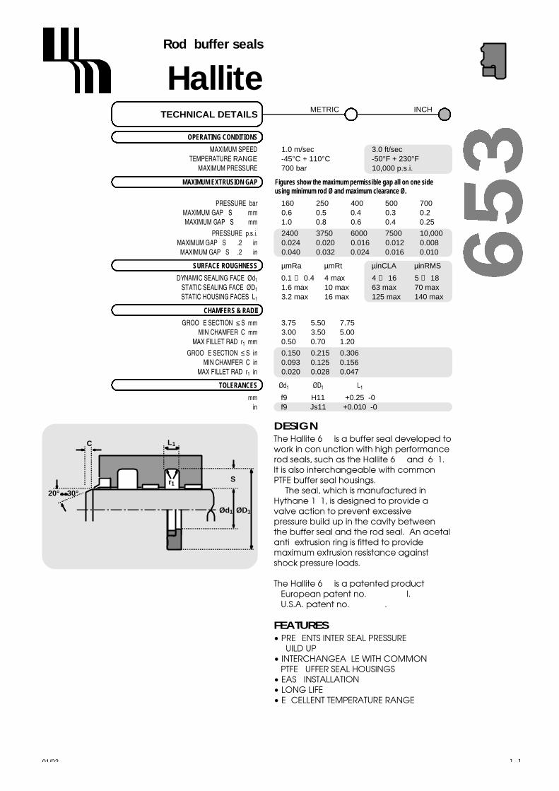
01/02
OPERATING CONDITIONS
MAXIMUM SPEED 1.0 m/sec 3.0 ft/secT E M P E R A T U R E R A N G E -45°C + 110°C -50°F + 230°F
MAXIMUM PRESSURE 700 bar 10,000 p.s.i.
MAXIMUM EXTRUSION GAP Figures show the maximum permissible gap all on one side using minimum rod Ø and maximum clearance Ø.
PRESSURE bar 1 6 0 2 5 0 4 0 0 5 0 0 7 0 0MAXIMUM GAP (S <=6) mm 0 . 6 0 . 5 0 . 4 0 . 3 0 . 2MAXIMUM GAP (S > 6) mm 1 . 0 0 . 8 0 . 6 0 . 4 0 . 2 5
PRESSURE p.s.i. 2400 3750 6000 7500 10,000MAXIMUM GAP (S <=0.250) in 0.024 0.020 0.016 0.012 0.008
MAXIMUM GAP (S >0.250) in 0.040 0.032 0.024 0.016 0.010
SURFACE ROUGHNESS µ m R a µ m R t µ i n C L A µ i n R M S
DYNAMIC SEALING FACE Ød1 0.1 ↔ 0 . 4 4 max 4 ↔ 1 6 5 ↔ 1 8STATIC SEALING FACE ØD1 1.6 max 10 max 63 max 70 maxSTATIC HOUSING FACES L1 3.2 max 16 max 125 max 140 max
CHAMFERS & RADII
GROOVE SECTION ≤ S mm 3.75 5.50 7.75MIN CHAMFER C mm 3.00 3.50 5.00
MAX FILLET RAD r1 m m 0.50 0.70 1.20
GROOVE SECTION ≤ S in 0.150 0.215 0.306MIN CHAMFER C in 0.093 0.125 0.156
MAX FILLET RAD r1 i n 0.020 0.028 0.047
T O L E R A N C E S Ø d1 Ø D1 L1
m m f9 H11 +0.25 -0i n f9 Js11 +0.010 -0
TECHNICAL DETAILSM E T R I C I N C H
HalliteRod buffer seals
171
DESIGNThe Hallite 653 is a buffer seal developed towork in conjunction with high performancerod seals, such as the Hallite 605 and 621. It is also interchangeable with commonPTFE buffer seal housings.
The seal, which is manufactured inHythane 181, is designed to provide avalve action to prevent excessive pressure build up in the cavity between the buffer seal and the rod seal. An acetalanti- extrusion ring is fitted to providemaximum extrusion resistance againstshock pressure loads.
The Hallite 653 is a patented product : European patent no. 0427554BI.U.S.A. patent no. 5088747.
FEATURES• PREVENTS INTER-SEAL PRESSURE
BUILD UP• INTERCHANGEABLE WITH COMMON
PTFE BUFFER SEAL HOUSINGS• EASY INSTALLATION• LONG LIFE• EXCELLENT TEMPERATURE RANGE
C
S
L1
ØD1Ød1
r1
20° 30°

L1
ØD1Ød1
6 5 3HalliteRod buffer seals
metric
inch
01/02172
Ød1 TOL ØD1 TOL L1 PARTf9 H11 +0.25 -0 No.
Ød1 TOL ØD1 TOL L1 PARTf9 H11 +0.25 -0 No.
Ød1 TOL ØD1 TOL L1 PARTf9 Js11 +0.010 -0 No.
Ød1 TOL ØD1 TOL L1 PARTf9 Js11 +0.010 -0 No.
45.0 -0.025 56.0 +0.19 4.2 4575510- 0 . 0 8 7 + 0 . 0 0
50.0 -0.025 65.5 +0.19 6.3 4403210- 0 . 0 8 7 + 0 . 0 0
55.0 -0.030 70.5 +0.19 6.3 4403310- 0 . 1 0 4 + 0 . 0 0
60.0 -0.030 75.5 +0.19 6.3 4403410- 0 . 1 0 4 + 0 . 0 0
90.0 -0.036 105.5 +0.22 6.3 4523710- 0 . 1 2 3 + 0 . 0 0
215.0 -0.050 236.0 +0.29 8.1 4705710- 0 . 1 6 5 + 0 . 0 0
2.000 -0.0012 2.424 +0.004 0.166 4521310- 0 . 0 0 4 1 - 0 . 0 0 4
2.500 -0.0012 2.924 +0.004 0.166 4514610- 0 . 0 0 4 1 - 0 . 0 0 4
2.750 -0.0012 3.174 +0.004 0.166 4533510- 0 . 0 0 4 1 - 0 . 0 0 4
3.000 -0.0012 3.616 +0.004 0.247 4515910- 0 . 0 0 4 1 - 0 . 0 0 4
3.500 -0.0014 4.116 +0.004 0.247 4514810- 0 . 0 0 4 8 - 0 . 0 0 4
4.000 -0.0014 4.616 +0.004 0.247 4524610- 0 . 0 0 4 8 - 0 . 0 0 4
7.000 -0.0016 7.610 +0.006 0.247 4588310- 0 . 0 0 5 6 - 0 . 0 0 6

01/02 219
HalliteFlange seals
DESIGNThe Hallite 657 has been designedespecially to fit SAE J518 flanges. High pressure and pumping are commonproblems which prevent reliable sealing inapplications where O rings are fitted.Hallite’s type 657 over comes these. Manufactured as standard in Hallite’s highquality Hythane 181, the material providesexcellent extrusion resistance and is able toperform at both low and hightemperatures. The seal’s profile is designedto ensure that pumping is prevented andto provide reliable sealing of the flange.
In addition to the high specificationmaterial, the Hallite 657 is alsomanufactured in an industrial standardpolyurethane.
Please ensure that the correct partnumber is specified for the material optionthat is required. See left for details.
N.B. Also listed, two non-SAE seal sizes formetric flanges.
FEATURES• HIGH SPECIFICATION MATERIAL
• INDUSTRIAL GRADE MATERIAL OPTION
• SAE FLANGE SIZES
MATERIAL OPTIONSLast two digits
Material of part number
Hythane – – – – – 00
93 IRHD Polyester Polyurethane (AU) – – – – – 01
NB. Temperature rating for 93 IRHD Polyester
Polyurethane (AU) changes to:
-30°C +100°C -22°F +212°F
3 µmRa120 µinCLA
Mating Face (T)
Sealingface
Sealingface
0° 5°
r1
OPERATING CONDITIONS
S P E E D Static S t a t i cMAXIMUM TEMPERATURE -45°C + 110°C -50°F + 230°F
MAXIMUM PRESSURE 600 bar 8500 p.s.i.
SURFACE ROUGHNESS µ m R a µ m R t µ i n C L A µ i n R M S
SEALING FACES 0 . 8 6.3 3 2 3 5MATING FACE 3 20 ↔ 3 0 1 2 0 1 2 0
R A D I I
MAX FILLET RAD r1 m m 0.80MAX FILLET RAD r1 i n 0.03
T O L E R A N C E S Ø D1 S L1 L2
m m ±0.100 ±0.025 ±0.050 +0 -0.25i n +0.005 -0 ±0.015 +0.005 -0 +0 -0.010
TECHNICAL DETAILSM E T R I C I N C H
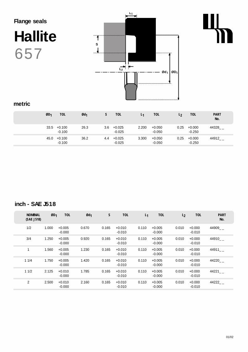
ØD1 TOL Ød1 S TOL L1 TOL L2 TOL PARTNo.
L1
ØD1Ød1
S
L2
01/02220
6 5 7HalliteFlange seals
inch - SAE J518
NOMINAL ØD1 TOL Ød1 S TOL L1 TOL L2 TOL PART(SAE J518) No.
1/2 1.000 +0.005 0.670 0.165 +0.010 0.110 +0.005 0.010 +0.000 44909_ _- 0 . 0 0 0 - 0 . 0 1 0 - 0 . 0 0 0 - 0 . 0 1 0
3/4 1.250 +0.005 0.920 0.165 +0.010 0.110 +0.005 0.010 +0.000 44910_ _- 0 . 0 0 0 - 0 . 0 1 0 - 0 . 0 0 0 - 0 . 0 1 0
1 1.560 +0.005 1.230 0.165 +0.010 0.110 +0.005 0.010 +0.000 44911_ _- 0 . 0 0 0 - 0 . 0 1 0 - 0 . 0 0 0 - 0 . 0 1 0
1 1/4 1.750 +0.005 1.420 0.165 +0.010 0.110 +0.005 0.010 +0.000 44220_ _- 0 . 0 0 0 - 0 . 0 1 0 - 0 . 0 0 0 - 0 . 0 1 0
1 1/2 2.125 +0.010 1.785 0.165 +0.010 0.110 +0.005 0.010 +0.000 44221_ _- 0 . 0 0 0 - 0 . 0 1 0 - 0 . 0 0 0 - 0 . 0 1 0
2 2.500 +0.010 2.160 0.165 +0.010 0.110 +0.005 0.010 +0.000 44222_ _- 0 . 0 0 0 - 0 . 0 1 0 - 0 . 0 0 0 - 0 . 0 1 0
metric
33.5 +0.100 26.3 3.6 +0.025 2.200 +0.050 0.25 +0.000 44328_ _- 0 . 1 0 0 - 0 . 0 2 5 - 0 . 0 5 0 - 0 . 2 5 0
45.0 +0.100 36.2 4.4 +0.025 3.300 +0.050 0.25 +0.000 44912_ _- 0 . 1 0 0 - 0 . 0 2 5 - 0 . 0 5 0 - 0 . 2 5 0

OPERATING CONDITIONS
MAXIMUM SPEED 1.0 m/sec 3.0 ft/secT E M P E R A T U R E R A N G E -45°C + 110°C -50°F + 230°F
MAXIMUM PRESSURE 400 bar 6000 p.s.i.
MAXIMUM EXTRUSION GAP Figures show the maximum permissible gap all on one sideusing the minimum clearance Ø and maximum bore Ø
PRESSURE bar 1 6 0 2 5 0 4 0 0MAXIMUM GAP mm 0.6 0.5 0.4
PRESSURE p.s.i. 2400 3750 6000MAXIMUM GAP in 0.024 0.020 0.016
SURFACE ROUGHNESS µ m R a µ m R t µ i n C L A µ i n R M S
DYNAMIC SEALING FACE ØD1 0.1 ↔ 0 . 4 4 max 4 ↔ 1 6 5 ↔ 1 8STATIC SEALING FACE Ød1 1.6 max 10 max 63 max 70 maxSTATIC HOUSING FACES L1 3.2 max 16 max 125 max 140 max
CHAMFERS & RADII
GROOVE SECTION ≤ S mm 4.0 5.0 7.5MIN CHAMFER C mm 3.0 3.5 5.0
MAX FILLET RAD r1 m m 0.2 0.4 0.8
GROOVE SECTION ≤ S in 0.125 0.187 0.250MIN CHAMFER C in 0.093 0.093 0.125
MAX FILLET RAD r1 i n 0.008 0.008 0.016
T O L E R A N C E S Ø D1 Ø d1 L1
m m H9 js11 +0.25 -0
i n +0.004 -0 0 -0.002 +0.010 -0
TECHNICAL DETAILSM E T R I C I N C H
HallitePiston seals
01/02 175
DESIGNThe Hallite 659 is an asymmetric piston sealdesigned to offer effective bore sealing ina wide variety of applications.
The outer dynamic lip is shorter andmore robust to provide improved sealingand compression set characteristics overconventional U rings. The seal also features a secondary lip that provides apocket for lubrication as well as thebenefits listed below.
For use in single acting applications only,the seal is manufactured in Hallite's highperformance polyurethane Hythane 181.The Hallite 659 provides the following benefits:
Note: Variations of this seal are available in other sizes, please contact your local Hallite sales office for additionalinformation and technical details.
FEATURES• FLEXIBLE FOR EASY INSTALLATION• EXCELLENT WEAR RESISTANCE• HIGH RESISTANCE TO EXTRUSION• WIDE TEMPERATURE RANGE• TWIN LIP DESIGN FOR:
IMPROVED SEALINGLOWER FRICTIONINCREASED SEAL STABILITYPRIMARY LIP PROTECTION
S
20° 30°
CL1
20° 30°
Ød1 ØD1
C
r1

SL
Ød1 ØD1
6 5 9HallitePiston seals
metric
inch
01/02176
ØD1 TOL Ød1 TOL SL L1 PARTH9 js11 + 0.25 -0 No.
ØD1 TOL Ød1 TOL SL L1 PARTH9 js11 + 0.25 -0 No.
100.00 +0.09 80.00 +0.11 14.50 16.00 4580300+ 0 . 0 0 - 0 . 1 1
110.00 +0.09 90.00 +0.11 14.50 16.00 4580400+ 0 . 0 0 - 0 . 1 1
ØD1 TOL Ød1 TOL SL L1 PART+ 0.010 -0 No.
ØD1 TOL Ød1 TOL SL L1 PART+ 0.010 -0 No.
1.250 +0.004 1.000 +0.000 0.171 0.187 4416600- 0 . 0 0 0 - 0 . 0 0 2
1.500 +0.004 1.250 +0.000 0.187 0.205 4372400- 0 . 0 0 0 - 0 . 0 0 2
1.750 +0.004 1.250 +0.000 0.375 0.413 4528600- 0 . 0 0 0 - 0 . 0 0 2
2.000 +0.004 1.630 +0.000 0.250 0.281 4563300∆- 0 . 0 0 0 - 0 . 0 0 2
2.375 +0.004 1.750 +0.000 0.437 0.481 4528500- 0 . 0 0 0 - 0 . 0 0 2
2.500 +0.004 2.130 +0.000 0.250 0.281 4563400∆- 0 . 0 0 0 - 0 . 0 0 2
3.000 +0.004 2.250 +0.000 0.500 0.550 4528400- 0 . 0 0 0 - 0 . 0 0 2
3.000 +0.004 2.630 +0.000 0.250 0.281 4563500∆- 0 . 0 0 0 - 0 . 0 0 2
3.500 +0.004 3.130 +0.000 0.250 0.281 4563600∆- 0 . 0 0 0 - 0 . 0 0 2
3.625 +0.004 2.875 +0.000 0.562 0.618 4528300- 0 . 0 0 0 - 0 . 0 0 2
4.000 +0.004 3.630 +0.000 0.250 0.281 4563700∆- 0 . 0 0 0 - 0 . 0 0 2
4.250 +0.004 3.500 +0.000 0.562 0.618 4528200- 0 . 0 0 0 - 0 . 0 0 2
5.000 +0.004 4.000 +0.000 0.731 0.804 4528100- 0 . 0 0 0 - 0 . 0 0 2
6.000 +0.004 5.000 +0.000 0.731 0.804 4530200- 0 . 0 0 0 - 0 . 0 0 2
7.000 +0.004 6.000 +0.000 0.731 0.804 4529700- 0 . 0 0 0 - 0 . 0 0 2
∆ Denotes parts designed to fit inch standard O ring grooves.

Hallite SealsInternational Limited130 Oldfield Road, Hampton
Middlesex. TW12 2HTTel : 020 8941 2244Fax : 020 8783 1669
e-mail: [email protected]
AustraliaHallite Seals Australia Pty Limited
1/1 St.James PlaceSeven Hills, N.S.W. 2147
(PO Box 91)Tel : 02 9620 7300Fax : 02 9620 7400
e-mail: [email protected]
CanadaHallite Seals (Canada) Limited
83 Galaxy Boulevard. # 12Toronto, Ontario.
Canada. M9W 6A4Tel : (416) 675 2505 Fax : (416) 675 4341
e-mail: [email protected]
FranceHallite (France) Limited
Z.A. Les Petits Carreaux, 1 Av Des Lys94385 Bonneuil-sur-marne, Cedex.
Tel : 01 43 77 85 50Fax : 01 43 77 93 93
e-mail: [email protected]
GermanyDichtelemente Hallite GmbH
Billwerder Ring 1721035 Hamburg
Tel : (040) 73 47 48-0Fax : (040) 73 47 48 49e-mail: [email protected]
ItalyHallite Italia S.r.l.Via Umbria, 33
57017 Stagno - Collesalvetti(Livorno) Italia.
Tel : 0586 943666Fax : 0586 943700
e-mail: [email protected]
USAHallite Seals Inc.
3820 Merchant RoadFort Wayne, Indiana. 46818
Tel : (219) 489 0002 Fax : (219) 489 5119
e-mail: [email protected]
www.hallite.co.uk
All our activities conform to the highest qualityassurance systems. Hallite Seals Intern a t i o n a lquality management systems are accredited
to ISO 9001 and are approved by manyof the world’s foremost OEM’s. F0A20H010H
FEATURES• Face expands for easy
installation
• Passes over ports
• Excellent wear &
abrasion resistance
• Static load holding
capability
• Replaces multiple piston
rings
• Increases cylinder
effectiveness
• Ideal for re-phasing
cylinders
• Ingests contamination
• Compact housing
Piston Seal
Hallite 714
For further information, including non-standardmaterial options available, please contact your local Hallite Seals sales office.
Profiles of actual seals may differ from those illustrated.
Hallite’s commitment to continuous productdevelopment means that specifications may
sometimes change without notice.
T h e rm o p l a st i c
Sealing face
Sta n d a rd Mate ri a l s
E n e rg i s e r
N B R
I N C H M E T R I C
MAX. SPEED 6.0 ft/sec 2.0 m/secT E M P E R ATURE RANGE -40°F + 230°F -40°C + 110°C
MAX. PRESSURE 7300 p.s.i. 500 bar
The Hallite 714 is a double acting seal capable of passing over ports. The reinforced,heat stabilised, thermoplastic sealing face,expands and contracts to fill the gap betweenthe piston and the cylinder wall and has a step-cut joint for ease of installation.
It will tolerate a considerable extrusion gap,thus reducing the possibility of piston-to-borecontact, and it of fers excellent static load holding capability.
The square section nitrile rubber energiserresponds quickly to pressure changes, providingexcellent sealing characteristcs under all pressure conditions.

For over 30 years the world’s largest equipment manufacturers have been able to take advantage of ourUnitized Piston to enhance their hydraulic cylinder performance and eliminate the need to stock and assem-ble piston seals and wear rings. This special technology is now available to all cylinder builders with theHallite 720 Standard Unitized Piston. The Hallite 720 is an excellent problem solver for:
• Man/Aerial Lifts• Construction Equipment• Industrial Cylinders• Mobile Equipment
Commercial Features
Separate piston, seal and bearing partnumbers are replaced by one simple seven digit part number.
No need or lead-time for sub assembly.The piston is ready to install.
Multiple quality inspections are reduced or completely eliminated.
Procurement is simple. One purchase order delivers a piston ready for work.
The Hallite 720 is a complete, self-contained piston, bearing and seal in one assembly that can solve difficultassembly problems or be used as a cost effective alternative to the traditional piston assembly with a separately fitted seal and bearing.
Extended Seal LifeThe Hallite 720 provides improved stability and has smaller extrusion gaps that extend the life of the piston seal.Molding the bearing material over the outer diameter gives an extremely tight fit between the piston and thecylinder inner diameter. The piston diameter is tightly controlled, reducing the number of critical tolerance variables resulting in increased performance.
A Standard SealThe Hallite 720 is engineered to be a ready-made, off-the-shelf product that can be fitted to arange of applications. For this reason, the Standard Unitized Piston uses a proprietary lowfriction filled PTFE seal that has been proven in the Unitized Piston for many years.
Technical Features
Maximum bearing surface area for the piston lengthSide load capacity increaseImproves supply chain managementLess affected by fluid contaminationProduct improvementExtended seal lifeHelps increase manufacturing capacityEliminates metal-to-metal contactReduces warranty claimsWorks on a variety of cylinder bore finishesReduces inventoryCompact design enables increase in strokeor reduction in overall cylinder length
All our activities conform to the highest quality assurance systems. Hallite Seals Internationalquality management systems are accredited to ISO 9001 and are approved by manyof the world’s foremost OEM’s.
Standard Unitized Piston
Hallite 720

I N C H
20º - 30º
L1
125 µin CLA MAX
ØD2 ØD1
0.125 x 45º CHAM
r1
Standard Unitized Piston
Hallite 720
erialse materials used for the Standard Unitized Piston are selected to handle a broad range of applicaion ameters.
s constructed using four components:
• High strength steel body• Non-metallic bearing• Rubber loading ring• Filled PTFE seal ring
e piston body is machined to exact dimensions. The non-metallic bearing material is molded to the pistonng a special proprietary process. It is then machined to the final precise OD dimension and the seal isalled. It is ready supplied for use in a cylinder.
deringwith other Hallite products, the Standard Unitized Piston can be described by its product group code 720 and
es can be ordered by their short seven digit part number. Custom sizing, including alternative seals, can bevided on request.
Temperature Range -40ºF to 275ºFMax Pressure 5,000 p.s.iMax Speed 3 ft/sec
PERATING CONDITIONS
Housing Diagram

HallitePiston Seals
17701/02
OPERATING CONDITIONS
MAXIMUM SPEED 1.5 m/sec 4.5 ft/secT E M P E R A T U R E R A N G E -40°C +120°C -40°F + 250°F
MAXIMUM PRESSURE 500 bar 7500 p.s.i.
MAXIMUM EXTRUSION GAP Figures show the maximum permissible gap all on one side using the minimum clearance Ø and maximum bore Ø
PRESSURE bar 1 6 0 2 5 0 4 0 0 5 0 0MAXIMUM GAP mm 1 . 0 0 . 8 0 . 6 0 . 5
PRESSURE p.s.i. 2400 3750 6000 7500MAXIMUM GAP in 0.040 0.030 0.024 0.020
SURFACE ROUGHNESS µ m R a µ m R t µ i n C L A µ i n R M S
DYNAMIC SEALING FACE ØD1 0.1 ↔ 0 . 4 4 max 4 ↔ 1 6 5 ↔ 1 8STATIC SEALING FACE Ød1 1.6 max 10 max 63 max 70 maxSTATIC HOUSING FACES L1 3.2 max 16 max 125 max 140 max
CHAMFERS & RADII
GROOVE SECTION ≤ S mm 7.0 7.5 11.5 14.0MIN CHAMFER C mm 4.0 5.0 7.0 8.0
MAX FILLET RAD r1 m m 0.8 0.8 0.8 0.8
GROOVE SECTION ≤ S in 0.187 0.240 0.365 0.470MIN CHAMFER C in 0.160 0.200 0.250 0.280
MAX FILLET RAD r1 i n 0.016 0.016 0.035 0.035
T O L E R A N C E S Ø D1 Ø d1 L1
m m H9 +0 -0.2 +0.2 -0
i n H9 *see below +0.01 -0
Ø D1 i n ≤ 3 . 0 0 0 ≤ 4 . 5 0 0 ≥ 4 . 5 0 0* Ø d1 Tol = +0 - 0.002 +0 - 0.003 +0 - 0.004
*N B Part numbers 710600_ and 710800_ Tol = ± 0 . 0 0 3
TECHNICAL DETAILSM E T R I C I N C H
DESIGNHallite’s 735 is a compact double actingpiston seal assembly designed for onepiece pistons and is suitable for low to highpressure, medium to heavy dutyapplications. The assembly comprises asstandard a self lubricating wear resistantbronze filled or glass / MoS2 filled PTFE capring, which is loaded by a NBR energiser.Thermoplastic split anti-extrusion ringssupport the seal on both sides and preventcontamination of the the energiser andcap ring.
Hallite’s 735 piston seal is designed to beused in a variety of equipment and isparticularly suited to use in earthmovingand other off-highway equipment.
The range consists of seals to suitpopular North American and Asianhousings.
FEATURES• HIGH PRESSURE• HEAVY DUTY • PTFE CAP R I N G• COMPACT DESIGN• LOW FRICTION• LONG LIFE• RANGE OF MATERIAL OPTIONS TO EXTEND• SERVICE TEMPERATURE RANGE
S
20° 30°
ØD1Ød1
L1 C
r1
MATERIALSPlease ensure the correct partnumber is used for the requiredcap ring.
PTFE, 40% bronzeLast digit of part no. _ _ _ _ _ _ 0
or
PTFE, 15% glass 5% MoS2Last digit of part no. _ _ _ _ _ _ 1
Products suffixed † are designed tosuit popular Asian housings
For information about other material
options available, please contact your
local Hallite Seals office.

ØD1Ød1
L1
735HallitePiston seals
metric
01/02178
ØD1 TOL Ød1 TOL L1 PARTH9 +0.2 -0 .0 No.
ØD1 TOL Ød1 TOL L1 PARTH9 +0.2 -0 .0 No.
50 +0.06 36 +0.00 9.0 715100_†+ 0 . 0 0 - 0 . 2 0
60 +0.07 46 +0.00 9.0 715150_†+ 0 . 0 0 - 0 . 2 0
63 +0.07 48 +0.00 11.0 715200_†+ 0 . 0 0 - 0 . 2 0
65 +0.07 50 +0.00 11.0 715250_†+ 0 . 0 0 - 0 . 2 0
70 +0.07 55 +0.00 11.0 715300_†+ 0 . 0 0 - 0 . 2 0
75 +0.07 60 +0.00 11.0 715350_†+ 0 . 0 0 - 0 . 2 0
80 +0.07 65 +0.00 11.0 715400_†+ 0 . 0 0 - 0 . 2 0
85 +0.09 70 +0.00 11.0 715450_†+ 0 . 0 0 - 0 . 2 0
90 +0.09 75 +0.00 11.0 715500_†+ 0 . 0 0 - 0 . 2 0
95 +0.09 80 +0.00 11.0 715550_†+ 0 . 0 0 - 0 . 2 0
100 +0.09 85 +0.00 12.5 715600_†+ 0 . 0 0 - 0 . 2 0
105 +0.09 90 +0.00 12.5 715650_†+ 0 . 0 0 - 0 . 2 0
110 +0.09 95 +0.00 12.5 715700_†+ 0 . 0 0 - 0 . 2 0
115 +0.09 100 +0.00 12.5 715750_†+ 0 . 0 0 - 0 . 2 0
120 +0.09 105 +0.00 12.5 715800_†+ 0 . 0 0 - 0 . 2 0
125 +0.10 102 +0.00 16.0 715850_+ 0 . 0 0 - 0 . 2 0
130 +0.10 107 +0.00 16.0 715900_†+ 0 . 0 0 - 0 . 2 0
135 +0.10 112 +0.00 16.0 715950_†+ 0 . 0 0 - 0 . 2 0
140 +0.10 117 +0.00 16.0 716000_†+ 0 . 0 0 - 0 . 2 0
145 +0.10 122 +0.00 16.0 716050_†+ 0 . 0 0 - 0 . 2 0
150 +0.10 127 +0.00 16.0 716100_†+ 0 . 0 0 - 0 . 2 0
160 +0.10 137 +0.00 16.0 716150_†+ 0 . 0 0 - 0 . 2 0
165 +0.10 142 +0.00 16.0 716200_†+ 0 . 0 0 - 0 . 2 0
170 +0.10 147 +0.00 16.0 716250_†+ 0 . 0 0 - 0 . 2 0
175 +0.10 152 +0.00 16.0 716280_†+ 0 . 0 0 - 0 . 2 0
180 +0.10 157 +0.00 16.0 716300_†+ 0 . 0 0 - 0 . 2 0
185 +0.12 162 +0.00 16.0 716350_†+ 0 . 0 0 - 0 . 2 0
190 +0.12 167 +0.00 16.0 716400_†+ 0 . 0 0 - 0 . 2 0
200 +0.12 177 +0.00 16.0 716450_†+ 0 . 0 0 - 0 . 2 0
210 +0.12 187 +0.00 16.0 716500_†+ 0 . 0 0 - 0 . 2 0
215 +0.12 192 +0.00 16.0 716530_†+ 0 . 0 0 - 0 . 2 0
220 +0.12 197 +0.00 16.0 716550_†+ 0 . 0 0 - 0 . 2 0
225 +0.12 202 +0.00 16.0 716600_†+ 0 . 0 0 - 0 . 2 0
230 +0.12 207 +0.00 16.0 716650_†+ 0 . 0 0 - 0 . 2 0
240 +0.12 217 +0.00 16.0 716700_†+ 0 . 0 0 - 0 . 2 0
250 +0.12 222 +0.00 17.5 716750_†+ 0 . 0 0 - 0 . 2 0
260 +0.13 232 +0.00 17.5 716800_†+ 0 . 0 0 - 0 . 2 0
350 +0.14 322 +0.00 17.5 716950_†+ 0 . 0 0 - 0 . 2 0

01/02 179
ØD1 TOL Ød1 TOL L1 PARTH9 +0.010 -0 .000 No.
ØD1 TOL Ød1 TOL L1 PARTH9 +0.010 -0 .000 No.
6.500 +0.004 5.594 +0.000 0.630 710740_- 0 . 0 0 0 - 0 . 0 0 4
6.500 +0.004 5.774 +0.000 0.750 710750_- 0 . 0 0 0 - 0 . 0 0 4
6.500 +0.004 6.022 +0.000 0.579 710800_- 0 . 0 0 0 - 0 . 0 0 3
7.000 +0.004 6.094 +0.000 0.630 710840_- 0 . 0 0 0 - 0 . 0 0 4
7.000 +0.004 6.274 +0.000 0.750 710850_- 0 . 0 0 0 - 0 . 0 0 4
7.250 +0.005 6.344 +0.000 0.630 710860_- 0 . 0 0 0 - 0 . 0 0 4
7.500 +0.005 6.594 +0.000 0.630 710890_- 0 . 0 0 0 - 0 . 0 0 4
7.500 +0.005 6.774 +0.000 0.750 710900_- 0 . 0 0 0 - 0 . 0 0 4
7.750 +0.005 6.844 +0.000 0.630 710920_- 0 . 0 0 0 - 0 . 0 0 4
8.000 +0.005 7.274 +0.000 0.750 710950_- 0 . 0 0 0 - 0 . 0 0 4
8.250 +0.005 7.344 +0.000 0.630 710970_- 0 . 0 0 0 - 0 . 0 0 4
8.500 +0.005 7.594 +0.000 0.630 710990_- 0 . 0 0 0 - 0 . 0 0 4
8.500 +0.005 7.774 +0.000 0.750 711000_- 0 . 0 0 0 - 0 . 0 0 4
9.000 +0.005 8.274 +0.000 0.750 711050_- 0 . 0 0 0 - 0 . 0 0 4
10.000 +0.005 8.898 +0.000 0.687 711090_- 0 . 0 0 0 - 0 . 0 0 4
10.000 +0.005 9.275 +0.000 0.750 711100_- 0 . 0 0 0 - 0 . 0 0 4
10.500 +0.005 9.398 +0.000 0.687 711120_- 0 . 0 0 0 - 0 . 0 0 4
11.000 +0.005 10.275 +0.000 0.750 711150_- 0 . 0 0 0 - 0 . 0 0 4
11.500 +0.005 10.398 +0.000 0.687 711170_- 0 . 0 0 0 - 0 . 0 0 4
12.000 +0.005 11.275 +0.000 0.750 711200_- 0 . 0 0 0 - 0 . 0 0 4
1 2 . 5 0 0 + 0 . 0 0 5 1 1 . 7 7 5 + 0 . 0 0 0 0 . 7 5 0 7 1 1 2 2 0 1
- 0 . 0 0 0 - 0 . 0 0 4
14.000 +0.005 12.898 +0.000 0.687 711270_- 0 . 0 0 0 - 0 . 0 0 4
15.000 +0.005 14.275 +0.000 0.750 711300_- 0 . 0 0 0 - 0 . 0 0 4
1.750 +0.002 1.377 +0.000 0.424 710030_- 0 . 0 0 0 - 0 . 0 0 2
2.000 +0.002 1.627 +0.000 0.424 710050_- 0 . 0 0 0 - 0 . 0 0 2
2.500 +0.002 2.127 +0.000 0.424 710070_- 0 . 0 0 0 - 0 . 0 0 2
3.000 +0.003 2.522 +0.000 0.579 710100_- 0 . 0 0 0 - 0 . 0 0 3
3.250 +0.003 2.772 +0.000 0.579 710150_- 0 . 0 0 0 - 0 . 0 0 3
3.500 +0.003 3.022 +0.000 0.579 710200_- 0 . 0 0 0 - 0 . 0 0 3
3.750 +0.003 3.272 +0.000 0.579 710250_- 0 . 0 0 0 - 0 . 0 0 3
4.000 +0.003 3.522 +0.000 0.579 710300_- 0 . 0 0 0 - 0 . 0 0 3
4.250 +0.003 3.772 +0.000 0.579 710350_- 0 . 0 0 0 - 0 . 0 0 3
4.500 +0.003 3.909 +0.000 0.492 710390_- 0 . 0 0 0 - 0 . 0 0 3
4.500 +0.003 4.022 +0.000 0.579 710400_- 0 . 0 0 0 - 0 . 0 0 3
4.750 +0.004 4.159 +0.000 0.492 710420_- 0 . 0 0 0 - 0 . 0 0 3
5.000 +0.004 4.094 +0.000 0.630 710440_- 0 . 0 0 0 - 0 . 0 0 3
5.000 +0.004 4.274 +0.000 0.750 710450_- 0 . 0 0 0 - 0 . 0 0 4
5.250 +0.004 4.524 +0.000 0.750 710500_- 0 . 0 0 0 - 0 . 0 0 4
5.500 +0.004 4.594 +0.000 0.630 710540_- 0 . 0 0 0 - 0 . 0 0 4
5.500 +0.004 4.774 +0.000 0.750 710550_- 0 . 0 0 0 - 0 . 0 0 4
5.500 +0.004 5.022 +0.000 0.579 710600_- 0 . 0 0 0 - 0 . 0 0 3
6.000 +0.004 5.094 +0.000 0.630 710640_- 0 . 0 0 0 - 0 . 0 0 4
6.000 +0.004 5.274 +0.000 0.750 710650_- 0 . 0 0 0 - 0 . 0 0 4
6.250 +0.004 5.344 +0.000 0.630 710680_- 0 . 0 0 0 - 0 . 0 0 4
6.250 +0.004 5.772 +0.000 0.579 710690_- 0 . 0 0 0 - 0 . 0 0 4
6.250 +0.004 5.524 +0.000 0.750 710700_- 0 . 0 0 0 - 0 . 0 0 4
6.250 +0.004 5.772 +0.000 0.579 710690_- 0 . 0 0 0 - 0 . 0 0 4
ØD1Ød1
L1
735Hallite
Piston seals
inch

N o t e s
01/02180

HallitePiston seals
01/02 181
OPERATING CONDITIONS
MAXIMUM SPEED 0.5 m/sec 1.5 ft/secT E M P E R A T U R E R A N G E -30°C + 100°C -22°F + 212°F
MAXIMUM PRESSURE 400 bar 5000 p.s.i.
SURFACE ROUGHNESS µ m R a µ m R t µ i n C L A µ i n R M S
DYNAMIC SEALING FACE ØD1 0.1 ↔ 0 . 4 4 max 4 ↔ 1 6 5 ↔ 1 8STATIC SEALING FACE Ød1 Ø d2 1.6 max 10 max 63 max 70 max
STATIC HOUSING FACES Ød3 L1 L2 3.2 max 16 max 125 max 140 max
CHAMFERS & RADII
GROOVE SECTION ≤ S mm 5.0 7.5 8.0 10.0 12.5 15.0MIN CHAMFER C1 m m 4.0 4.0 5.0 5.0 6.5 7.5
MAX FILLET RAD r1 m m 0.2 0.2 0.4 0.4 0.4 0.8MAX FILLET RAD r2 m m 0.2 0.2 0.2 0.2 0.2 0.4
T O L E R A N C E S Ø D1 Ø d1 Ø d2 Ø d3 L1 L2
m m H11 h10 f9 h11 +0.4 +0.1 -0
TECHNICAL DETAILSM E T R I C I N C H
PROFILE A PROFILE B
DESIGNThe Hallite 753 is a compact assemblydesigned and developed specifically forone piece pistons.
The assembly comprises a wear-resistantpolyurethane slip ring which is loaded byan NBR ring. There are split 'L' shaped anti-extrusion bearings made from polyacetalresin on both sides of the seal.
The proportions of the range have beendetermined to give a satisfactoryperformance when used with therecommended operating conditions.
FEATURES• LONG LIFE - DUE TO THE WEAR-
RESISTANT POLYURETHANE SLIP RINGS• EASY INSTALLATION
S
C
r1
L2
r2
Ød3
20° 30°
Ød2 Ød1 ØD1
L2L1
C1 x 45º
Hallite 753 is manufactured usingtwo different profiles as illustratedabove. The parts list clearlyindicates which profile is used foreach size.

Profile A
Profile B
L2
Ød3 Ød2 Ød1 ØD1
L2L1
7 5 3HallitePiston seals
metric
01/02182
Ø D1 T O L Ø d1 T O L Ø d2 T O L Ø d3 T O L L1 L2 P R O F I L E P A R TH 1 1 h 1 0 f 9 h 1 1 + 0.4 + 0.1 - 0 N o .
40 +0.16 26 +0.00 39.00 -0.025 36.00 +0.00 15.5 2.60 B 6916500+ 0 . 0 0 - 0 . 0 8 - 0 . 0 8 7 - 0 . 1 6
40 +0.16 30 +0.00 36.50 -0.025 39.00 +0.00 10.0 5.00 A 6915100*+ 0 . 0 0 - 0 . 0 8 - 0 . 0 8 7 - 0 . 1 6
50 +0.16 34 +0.00 46.00 -0.025 49.00 +0.00 20.5 3.10 B 6916600+ 0 . 0 0 - 0 . 1 0 - 0 . 0 8 7 - 0 . 1 6
50 +0.16 34 +0.00 45.40 -0.025 48.50 +0.00 18.4 6.35 A 6915200+ 0 . 0 0 - 0 . 1 0 - 0 . 0 8 7 - 0 . 1 6
60 +0.19 44 +0.00 56.00 -0.030 58.50 +0.00 20.5 3.10 A 6916300+ 0 . 0 0 - 0 . 1 0 - 0 . 1 0 4 - 0 . 1 9
60 +0.19 44 +0.00 55.40 -0.030 58.50 +0.00 18.4 6.35 A 8 6 7 2 1 1 0
+ 0 . 0 0 - 0 . 1 0 - 0 . 1 0 4 - 0 . 1 9
63 +0.19 47 +0.00 58.40 -0.030 61.50 +0.00 18.4 6.35 A 6915300+ 0 . 0 0 - 0 . 1 0 - 0 . 1 0 4 - 0 . 1 9
63 +0.19 47 +0.00 59.00 -0.030 62.00 +0.00 20.5 3.10 A 6916100+ 0 . 0 0 - 0 . 0 6 - 0 . 1 0 4 - 0 . 1 9
65 +0.19 49 +0.00 61.00 -0.030 64.00 +0.00 20.5 3.10 B 6916700+ 0 . 0 0 - 0 . 1 0 - 0 . 1 0 4 - 0 . 1 9
70 +0.19 50 +0.00 64.20 -0.030 68.30 +0.00 22.4 6.35 A 6915400+ 0 . 0 0 - 0 . 1 0 - 0 . 1 0 4 - 0 . 1 9
70 +0.19 54 +0.00 66.00 -0.030 69.00 +0.00 20.5 3.10 B 6916800+ 0 . 0 0 - 0 . 1 2 - 0 . 1 0 4 - 0 . 1 9
80 +0.19 60 +0.00 74.15 -0.030 78.30 +0.00 22.4 6.35 A 6915500+ 0 . 0 0 - 0 . 1 2 - 0 . 1 0 4 - 0 . 1 9
80 +0.19 62 +0.00 76.00 -0.030 79.00 +0.00 22.4 3.60 B 6916400+ 0 . 0 0 - 0 . 1 2 - 0 . 1 0 4 - 0 . 1 9
80 +0.19 62 +0.00 76.00 -0.030 79.00 +0.00 22.5 3.60 A 6916000+ 0 . 0 0 - 0 . 1 2 - 0 . 1 0 4 - 0 . 1 9
90 +0.22 70 +0.00 84.15 -0.036 88.30 +0.00 22.4 6.35 A 6915600+ 0 . 0 0 - 0 . 1 2 - 0 . 1 2 3 - 0 . 2 2
90 +0.22 72 +0.00 86.00 -0.036 89.00 +0.00 22.5 3.60 B 6916900+ 0 . 0 0 - 0 . 1 2 - 0 . 1 2 3 - 0 . 2 2
100 +0.22 75 +0.00 93.15 -0.036 98.00 +0.00 22.4 6.35 A 6915700+ 0 . 0 0 - 0 . 1 2 - 0 . 1 2 3 - 0 . 2 2
110 +0.22 85 +0.00 103.10 -0.036 108.00 +0.00 22.4 6.35 A 6915800+ 0 . 0 0 - 0 . 1 4 - 0 . 1 2 3 - 0 . 2 2
125 +0.25 100 +0.00 118.10 -0.036 123.00 +0.00 25.4 6.35 A 6915900+ 0 . 0 0 - 0 . 1 4 - 0 . 1 2 3 - 0 . 2 5
125 +0.25 103 +0.00 121.00 -0.042 124.00 +0.00 26.5 5.10 B 6917000+ 0 . 0 0 - 0 . 1 4 - 0 . 1 4 3 - 0 . 2 5
1 2 5 + 0 . 2 5 1 0 3 + 0 . 0 0 1 2 1 . 0 0 - 0 . 0 4 2 1 2 4 . 0 0 + 0 . 0 0 2 6 . 5 5 . 1 0 A 6 9 1 9 8 0 0
+ 0 . 0 0 - 0 . 1 4 - 0 . 1 4 3 - 0 . 2 5
140 +0.25 118 +0.00 136.00 -0.042 139.00 +0.00 26.5 5.10 A 2356010+ 0 . 0 0 - 0 . 1 4 - 0 . 1 4 3 - 0 . 2 5
150 +0.25 128 +0.00 146.00 -0.042 149.00 +0.00 26.5 5.10 A 2349910+ 0 . 0 0 - 0 . 1 4 - 0 . 1 4 3 - 0 . 2 5

01/02 183
Ø D1 T O L Ø d1 T O L Ø d2 T O L Ø d3 T O L L1 L2 P R O F I L E P A R TH 1 1 h 1 0 f 9 h 1 1 + 0.4 + 0.1 - 0 N o .
160 +0.25 138 +0.00 156.00 -0.042 159.00 +0.00 26.5 5.10 A 2349810+ 0 . 0 0 - 0 . 1 4 - 0 . 1 4 3 - 0 . 2 5
1 6 5 + 0 . 2 5 1 4 3 + 0 . 0 0 1 6 1 . 0 0 - 0 . 0 4 2 1 6 4 . 0 0 + 0 . 0 0 2 6 . 5 5 . 1 0 A 2 3 6 2 3 1 0
+ 0 . 0 0 - 0 . 1 4 - 0 . 1 4 3 - 0 . 2 5
180 +0.25 158 +0.00 176.00 -0.042 179.00 +0.00 26.5 5.10 A 2349510+ 0 . 0 0 - 0 . 1 6 - 0 . 1 4 3 - 0 . 2 5
200 +0.29 175 +0.00 196.00 -0.050 199.00 +0.00 31.5 6.60 A 2347010+ 0 . 0 0 - 0 . 1 6 - 0 . 1 6 5 - 0 . 2 9
250 +0.29 220 +0.00 242.90 -0.050 247.85 +0.00 35.4 6.35 A 2340710+ 0 . 0 0 - 0 . 1 8 - 0 . 1 6 5 - 0 . 2 9
* OWING TO THE SEAL SECTION, DIAMETER 40 IS MANUFACTURED USING ONLY 3 PARTS
Profile A
Profile B
L2
Ød3 Ød2 Ød1 ØD1
L2L1
7 5 3Hallite
Piston seals
metric

N o t e s
01/02184

OPERATING CONDITIONS
MAXIMUM SPEED 1.0 m/sec 3.0 ft/secT E M P E R A T U R E R A N G E -40°C + 110°C -40°F + 230°F
MAXIMUM PRESSURE 350 bar 5000 p.s.i.
MAXIMUM EXTRUSION GAP Figures show the maximum permissible gap all on one side using the minimum clearance Ø and maximum bore Ø
PRESSURE bar 1 0 0 1 6 0 2 5 0 3 5 0MAXIMUM GAP (S>7) mm 1 . 0 0 . 8 0 . 6 0 . 4MAXIMUM GAP (S<7) mm 0 . 8 0 . 6 0 . 5 0 . 3
PRESSURE p.s.i. 1500 2400 3750 5000
SURFACE ROUGHNESS µ m R a µ m R t µ i n C L A µ i n R M S
DYNAMIC SEALING FACE ØD1 0.1 ↔ 0 . 4 4 max 4 ↔ 1 6 5 ↔ 1 8STATIC SEALING FACE Ød1 1.6 max 10 max 63 max 70 maxSTATIC HOUSING FACES L1 3.2 max 16 max 125 max 140 max
CHAMFERS & RADII
GROOVE SECTION ≤ S mm 3.75 5.50 7.50 10.50MIN CHAMFER C mm 2.00 2.50 5.00 5.00
MAX FILLET RAD r1 m m 0.40 0.80 1.20 1.60
T O L E R A N C E S Ø D1 Ø d1 L1
m m H9 f8 +0.2 -0
TECHNICAL DETAILSM E T R I C I N C H
ØD1Ød1
S
C
r1
L1
20° 30°
C
DESIGNThe Hallite 754 double acting piston seal isa compact low friction seal for light tomedium duty hydraulic cylinders. Asstandard, it comprises a tough, wearresistant thermoplastic elastomer face, (seeleft for face material options) which is pre-loaded by an O ring. The housing widthallows a narrow width piston to be used,but it is recommended that an adequatebearing is mounted on one or both sides ofthe seal. Housing dimensions for use withHallite 87 and 506 bearing strip are given inthe installation details. For further details ofbearing strip grooves, please refer to theappropriate data sheets.
NB: Part numbers suffixed by “‡” i n d i c a t ehousing sizes to meet ISO 7425-1.
FEATURES• LOW BREAK-OUT AND OPERATING
FRICTION LEVELS.• RAPID RECOVERY OF FACE AFTER
ASSEMBLY. UNLIKE COMMON PTFEFACES, NO RE-SIZING IS REQUIRED.
• MORE TOLERANT TO CONTAMINATIONTHAN COMMON PTFE EQUIVALENTS.
• EXCELLENT POSITION HOLDINGCHARACTERISTICS UNDER LOAD
• COMPATIBLE WITH MOST HYDRAULIC FLUIDS.
• EXCELLENT WEAR RESISTANCE.• OPERATES ON A WIDE RANGE OF
SURFACE FINISHES.• IDEAL FOR USE WITH HALLITE 506 OR 87
BEARING STRIP.• ISO 7425 HOUSINGS.
HallitePiston seals
01/02 185185
M ATERIAL OPTIONSFace material
Polyester elastomer - standard (Red 55D)Last digit of part no. _ _ _ _ _ _ 0
Lubricated polyester elastomerLast digit of part no. _ _ _ _ _ _ 2
Hydrolysis stabilised polyester elastomer (Red 72D)Last digit of part no. _ _ _ _ _ _ 3
Hythane 181 - A limited number of sizes are available in this material optionLast digit of part no. _ _ _ _ _ _ 4
For full details and availability please contact your local Hallite sales office.Technical details shown are for standardRed 55D polyester elastomer.

ØD1Ød1
L1
7 5 4HallitePiston seals
metric
01/02186
ØD1 TOL Ød1 TOL L1 PARTH9 f8 + 0.2 - 0 No.
ØD1 TOL Ød1 TOL L1 PARTH9 f8 + 0.2 - 0 No.
15 +0.04 7.5 -0.01 3.20 444641_+ 0 . 0 0 - 0 . 0 4
16 +0.04 8.5 -0.01 3.20 440061_‡+ 0 . 0 0 - 0 . 0 4
20 +0.05 12.5 -0.02 3.20 436231_‡+ 0 . 0 0 - 0 . 0 4
25 +0.05 17.5 -0.02 3.20 433961_‡+ 0 . 0 0 - 0 . 0 4
30 +0.05 22.5 -0.02 3.20 433971_+ 0 . 0 0 - 0 . 0 5
32 +0.06 24.5 -0.02 3.20 433981_‡+ 0 . 0 0 - 0 . 0 5
35 +0.06 27.5 -0.02 3.20 435241_+ 0 . 0 0 - 0 . 0 5
38.1 +0.06 27.1 -0.02 4.20 443231_+ 0 . 0 0 - 0 . 0 5
38.1 +0.06 30.6 -0.03 3.20 442871_+ 0 . 0 0 - 0 . 0 6
40 +0.06 29.0 -0.02 4.20 433921_‡+ 0 . 0 0 - 0 . 0 5
45 +0.06 34.0 -0.03 4.20 434231_+ 0 . 0 0 - 0 . 0 6
50 +0.06 34.5 -0.03 6.30 442741_‡+ 0 . 0 0 - 0 . 0 6
50 +0.06 39.0 -0.03 4.20 432711_‡+ 0 . 0 0 - 0 . 0 6
50.8 +0.06 39.8 -0.03 4.20 432711_+ 0 . 0 0 - 0 . 0 6
55 +0.07 39.5 -0.03 6.30 435561_+ 0 . 0 0 - 0 . 0 6
55 +0.07 44.0 -0.03 4.20 446551_+ 0 . 0 0 - 0 . 0 6
60 +0.07 44.5 -0.03 6.3 439071_+ 0 . 0 0 - 0 . 0 6
60 +0.07 49.0 -0.03 4.20 432701_+ 0 . 0 0 - 0 . 0 6
63 +0.07 47.5 -0.03 6.30 443111_‡+ 0 . 0 0 - 0 . 0 8
63 +0.07 50.0 -0.03 6.30 447231_+ 0 . 0 0 - 0 . 0 8
63 +0.07 52.0 -0.03 4.20 432691_‡+ 0 . 0 0 - 0 . 0 8
63.5 +0.07 52.5 -0.03 4.20 432691_+ 0 . 0 0 - 0 . 0 8
65 +0.07 49.5 -0.03 6.30 436201_+ 0 . 0 0 - 0 . 0 6
65 +0.07 52.0 -0.03 6.30 438491_+ 0 . 0 0 - 0 . 0 8
65 +0.07 54.0 -0.03 4.20 435301_+ 0 . 0 0 - 0 . 0 8
70 +0.07 57.0 -0.03 6.30 439081_+ 0 . 0 0 - 0 . 0 8
70 +0.07 59.0 -0.03 4.20 432681_+ 0 . 0 0 - 0 . 0 8
75 +0.07 59.5 -0.03 6.30 470491_+ 0 . 0 0 - 0 . 0 8
7 5 + 0 . 0 7 5 9 . 5 - 0 . 0 3 6 . 3 0 4 6 2 1 3 0 0
+ 0 . 0 0 - 0 . 0 8
7 5 + 0 . 0 7 5 9 . 5 - 0 . 0 3 6 . 3 0 4 6 3 1 6 0 0
+ 0 . 0 0 - 0 . 0 8
75 +0.07 64.0 -0.03 4.20 433991_+ 0 . 0 0 - 0 . 0 8
7 5 + 0 . 0 7 6 8 . 0 - 0 . 0 3 6 . 3 0 4 6 3 1 7 0 0
+ 0 . 0 0 - 0 . 0 8
80 +0.07 64.5 -0.03 6.30 427091_‡+ 0 . 0 0 - 0 . 0 8
82.5 +0.09 67.0 -0.03 6.30 442881_+ 0 . 0 0 - 0 . 0 8
85 +0.09 69.5 -0.03 6.30 456401_+ 0 . 0 0 - 0 . 0 8
90 +0.09 74.5 -0.03 6.30 437271_+ 0 . 0 0 - 0 . 0 8
95 +0.09 79.5 -0.03 6.30 456951_+ 0 . 0 0 - 0 . 0 8
100 +0.09 84.5 -0.04 6.30 433931_‡+ 0 . 0 0 - 0 . 0 9
101.6 +0.09 86.1 -0.04 6.30 442891_+ 0 . 0 0 - 0 . 0 9
105 +0.09 89.5 -0.04 6.30 437251_+ 0 . 0 0 - 0 . 0 9
110 +0.09 94.5 -0.04 6.30 441931_+ 0 . 0 0 - 0 . 0 9
115 +0.09 99.5 -0.04 6.30 435581_+ 0 . 0 0 - 0 . 0 9
120 +0.10 99.0 -0.04 8.10 453501_+ 0 . 0 0 - 0 . 0 9
120 +0.10 104.5 -0.04 6.30 446541_+ 0 . 0 0 - 0 . 0 9
125 +0.10 104.0 -0.04 8.10 437651_‡+ 0 . 0 0 - 0 . 0 9
125 +0.10 109.5 -0.04 6.30 434001_‡+ 0 . 0 0 - 0 . 0 9

01/02 187
ØD1 TOL Ød1 TOL L1 PARTH9 f8 + 0.2 - 0 No.
ØD1 TOL Ød1 TOL L1 PARTH9 f8 + 0.2 - 0 No.
180 +0.10 159.0 -0.04 8.10 434041_+ 0 . 0 0 - 0 . 1 1
190 +0.12 169.0 -0.04 8.10 434241_+ 0 . 0 0 - 0 . 1 1
200 +0.12 179.0 -0.04 8.10 434051_‡+ 0 . 0 0 - 0 . 1 1
210 +0.12 189.0 -0.05 8.10 435151_+ 0 . 0 0 - 0 . 1 2
225 +0.12 204.0 -0.05 8.10 451281_+ 0 . 0 0 - 0 . 1 2
240 +0.12 219.0 -0.05 8.10 455361_+ 0 . 0 0 - 0 . 1 2
250 +0.12 229.0 -0.05 8.10 439371_‡+ 0 . 0 0 - 0 . 1 2
300 +0.13 279.0 -0.06 8.10 457281_+ 0 . 0 0 - 0 . 1 4
127 +0.10 111.5 -0.04 6.30 442901_+ 0 . 0 0 - 0 . 0 9
130 +0.10 109.0 -0.04 8.10 440241_+ 0 . 0 0 - 0 . 0 9
130 +0.10 114.5 -0.04 6.30 434221_+ 0 . 0 0 - 0 . 0 9
135 +0.10 114.0 -0.04 8.10 453511_+ 0 . 0 0 - 0 . 0 9
140 +0.10 119.0 -0.04 8.10 434011_+ 0 . 0 0 - 0 . 0 9
140 +0.10 124.5 -0.04 6.30 449941_+ 0 . 0 0 - 0 . 1 1
150 +0.10 129.0 -0.04 8.10 439691_+ 0 . 0 0 - 0 . 1 1
160 +0.10 139.0 -0.04 8.10 434021_‡+ 0 . 0 0 - 0 . 1 1
165 +0.10 144.0 -0.04 8.10 445221_+ 0 . 0 0 - 0 . 1 1
170 +0.10 149.0 -0.04 8.10 434031_+ 0 . 0 0 - 0 . 1 1
ØD1Ød1
L1
7 5 4Hallite
Piston seals
metric

N o t e s
01/02188

01/02
OPERATING CONDITIONS
MAXIMUM SPEED 1.0 m/sec 3.0 ft/secT E M P E R A T U R E R A N G E -40°C + 110°C -40°F + 230°F
MAXIMUM PRESSURE 350 bar 5000 p.s.i.
MAXIMUM EXTRUSION GAP Figures show the maximum permissible gap all on one side using the minimum clearance Ø and maximum bore Ø
PRESSURE bar 1 0 0 1 6 0 2 5 0 3 5 0
PRESSURE p.s.i. 1500 2400 3750 5000MAXIMUM GAP (S>0.280) in 0 . 0 3 0 0 . 0 2 5 0 . 0 2 0 0 . 0 1 0MAXIMUM GAP (S<0.280) in 0 . 0 2 5 0 . 0 2 0 0 . 0 1 5 0 . 0 0 5
SURFACE ROUGHNESS µ m R a µ m R t µ i n C L A µ i n R M S
DYNAMIC SEALING FACE ØD1 0.1 ↔ 0 . 4 4 max 4 ↔ 1 6 5 ↔ 1 8STATIC SEALING FACE Ød1 1.6 max 10 max 63 max 70 maxSTATIC HOUSING FACES L1 3.2 max 16 max 125 max 140 max
CHAMFERS & RADII
GROOVE SECTION ≤ S in 0 . 1 5 4 0 . 2 6 9 0 . 3 7 3 0 . 4 3 1MIN CHAMFER C in 0 . 1 0 0 0 . 1 5 0 0 . 2 0 0 0 . 2 0 0
MAX FILLET RAD r1 i n 0 . 0 1 6 0 . 0 1 6 0 . 0 1 6 0 . 0 1 6
T O L E R A N C E S Ø D1 Ø d1
i n H 9 j s 1 0
L1 i n = 0 . 1 2 9 = 0.283 > 0 . 2 8 3L1 ± 0.002 ± 0 . 0 0 3 ± 0 . 0 0 4
TECHNICAL DETAILSM E T R I C I N C H
HallitePiston seals
189189
DESIGNThe Hallite 755 seal is a compact, low frictionseal for light to medium duty hydrauliccylinders. Designed originally to the NorthAmerican housing standards, the 755 is aninch version of Hallite’s 754. It comprises of avery tough elastomeric face (see materialoptions) which is pre-loaded by a squaresection ring (as North American convention).Please note part numbers marked * aresupplied with an O ring energiser.
It is recommended that an adequatebearing is mounted on both sides of the seal.See Hallite 506 bearing strip.
For full details and availability please contact your local Hallite sales office.
FEATURES• LOW BREAK-OUT AND OPERATING
FRICTION LEVELS.• RAPID RECOVERY OF FACE AFTER
ASSEMBLY. UNLIKE COMMON PTFEFACES, NO RE-SIZING IS REQUIRED.
• MORE TOLERANT TO DIRT ANDCONTAMINATION THAN COMMONPTFE EQUIVALENTS.
• EXCELLENT POSITION HOLDINGCHARACTERISTICS UNDER LOAD
• COMPATIBLE WITH MOSTHYDRAULIC FLUIDS.
• EXCELLENT WEAR RESISTANCE.• OPERATES ON A WIDE RANGE OF
SURFACE FINISHES.• IDEAL FOR USE WITH HALLITE’S
506 BEARING STRIP
ØD1Ød1
S
C
r1
L1
20° 30°
C
M AT E R I A L SStandard face material:Polyester elastomer - (red 55D)Last digit of part no. _ _ _ _ _ _ 0
Face material options:Hydrolysis stabilised polyester elastomer (Grey 55D)Last digit of part no. _ _ _ _ _ _ 1
Lubricated polyester elastomerLast digit of part no. _ _ _ _ _ _ 2
Hydrolysis stabilised polyester elastomer (Red 72D)Last digit of part no. _ _ _ _ _ _ 3
Hythane 181 - A limited number of sizes are available in this material optionLast digit of part no. _ _ _ _ _ _ 4
Technical details shown are for standard Red 55D polyester elastomer.
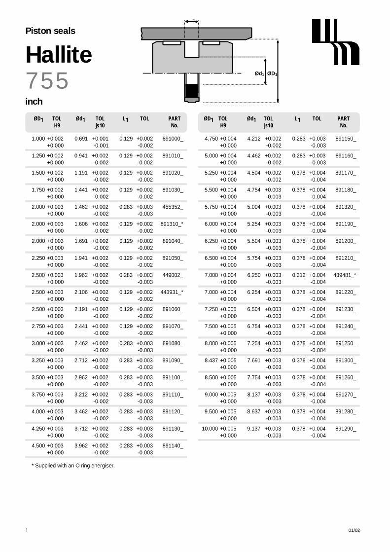
ØD1Ød1
L1
7 5 5HallitePiston seals
inch
01/02190
* Supplied with an O ring energiser.
ØD1 TOL Ød1 TOL L1 TOL PARTH9 js10 No.
ØD1 TOL Ød1 TOL L1 TOL PARTH9 js10 No.
1.000 +0.002 0.691 +0.001 0.129 +0.002 891000_+ 0 . 0 0 0 - 0 . 0 0 1 - 0 . 0 0 2
1.250 +0.002 0.941 +0.002 0.129 +0.002 891010_+ 0 . 0 0 0 - 0 . 0 0 2 - 0 . 0 0 2
1.500 +0.002 1.191 +0.002 0.129 +0.002 891020_+ 0 . 0 0 0 - 0 . 0 0 2 - 0 . 0 0 2
1.750 +0.002 1.441 +0.002 0.129 +0.002 891030_+ 0 . 0 0 0 - 0 . 0 0 2 - 0 . 0 0 2
2.000 +0.003 1.462 +0.002 0.283 +0.003 455352_+ 0 . 0 0 0 - 0 . 0 0 2 - 0 . 0 0 3
2.000 +0.003 1.606 +0.002 0.129 +0.002 891310_*+ 0 . 0 0 0 - 0 . 0 0 2 - 0 . 0 0 2
2.000 +0.003 1.691 +0.002 0.129 +0.002 891040_+ 0 . 0 0 0 - 0 . 0 0 2 - 0 . 0 0 2
2.250 +0.003 1.941 +0.002 0.129 +0.002 891050_+ 0 . 0 0 0 - 0 . 0 0 2 - 0 . 0 0 2
2.500 +0.003 1.962 +0.002 0.283 +0.003 449002_+ 0 . 0 0 0 - 0 . 0 0 2 - 0 . 0 0 3
2.500 +0.003 2.106 +0.002 0.129 +0.002 443931_*+ 0 . 0 0 0 - 0 . 0 0 2 - 0 . 0 0 2
2.500 +0.003 2.191 +0.002 0.129 +0.002 891060_+ 0 . 0 0 0 - 0 . 0 0 2 - 0 . 0 0 2
2.750 +0.003 2.441 +0.002 0.129 +0.002 891070_+ 0 . 0 0 0 - 0 . 0 0 2 - 0 . 0 0 2
3.000 +0.003 2.462 +0.002 0.283 +0.003 891080_+ 0 . 0 0 0 - 0 . 0 0 2 - 0 . 0 0 3
3.250 +0.003 2.712 +0.002 0.283 +0.003 891090_+ 0 . 0 0 0 - 0 . 0 0 2 - 0 . 0 0 3
3.500 +0.003 2.962 +0.002 0.283 +0.003 891100_+ 0 . 0 0 0 - 0 . 0 0 2 - 0 . 0 0 3
3.750 +0.003 3.212 +0.002 0.283 +0.003 891110_+ 0 . 0 0 0 - 0 . 0 0 2 - 0 . 0 0 3
4.000 +0.003 3.462 +0.002 0.283 +0.003 891120_+ 0 . 0 0 0 - 0 . 0 0 2 - 0 . 0 0 3
4.250 +0.003 3.712 +0.002 0.283 +0.003 891130_+ 0 . 0 0 0 - 0 . 0 0 2 - 0 . 0 0 3
4.500 +0.003 3.962 +0.002 0.283 +0.003 891140_+ 0 . 0 0 0 - 0 . 0 0 2 - 0 . 0 0 3
4.750 +0.004 4.212 +0.002 0.283 +0.003 891150_+ 0 . 0 0 0 - 0 . 0 0 2 - 0 . 0 0 3
5.000 +0.004 4.462 +0.002 0.283 +0.003 891160_+ 0 . 0 0 0 - 0 . 0 0 2 - 0 . 0 0 3
5.250 +0.004 4.504 +0.002 0.378 +0.004 891170_+ 0 . 0 0 0 - 0 . 0 0 2 - 0 . 0 0 4
5.500 +0.004 4.754 +0.003 0.378 +0.004 891180_+ 0 . 0 0 0 - 0 . 0 0 3 - 0 . 0 0 4
5.750 +0.004 5.004 +0.003 0.378 +0.004 891320_+ 0 . 0 0 0 - 0 . 0 0 3 - 0 . 0 0 4
6.000 +0.004 5.254 +0.003 0.378 +0.004 891190_+ 0 . 0 0 0 - 0 . 0 0 3 - 0 . 0 0 4
6.250 +0.004 5.504 +0.003 0.378 +0.004 891200_+ 0 . 0 0 0 - 0 . 0 0 3 - 0 . 0 0 4
6.500 +0.004 5.754 +0.003 0.378 +0.004 891210_+ 0 . 0 0 0 - 0 . 0 0 3 - 0 . 0 0 4
7.000 +0.004 6.250 +0.003 0.312 +0.004 439481_*+ 0 . 0 0 0 - 0 . 0 0 3 - 0 . 0 0 4
7.000 +0.004 6.254 +0.003 0.378 +0.004 891220_+ 0 . 0 0 0 - 0 . 0 0 3 - 0 . 0 0 4
7.250 +0.005 6.504 +0.003 0.378 +0.004 891230_+ 0 . 0 0 0 - 0 . 0 0 3 - 0 . 0 0 4
7.500 +0.005 6.754 +0.003 0.378 +0.004 891240_+ 0 . 0 0 0 - 0 . 0 0 3 - 0 . 0 0 4
8.000 +0.005 7.254 +0.003 0.378 +0.004 891250_+ 0 . 0 0 0 - 0 . 0 0 3 - 0 . 0 0 4
8.437 +0.005 7.691 +0.003 0.378 +0.004 891300_+ 0 . 0 0 0 - 0 . 0 0 3 - 0 . 0 0 4
8.500 +0.005 7.754 +0.003 0.378 +0.004 891260_+ 0 . 0 0 0 - 0 . 0 0 3 - 0 . 0 0 4
9.000 +0.005 8.137 +0.003 0.378 +0.004 891270_+ 0 . 0 0 0 - 0 . 0 0 3 - 0 . 0 0 4
9.500 +0.005 8.637 +0.003 0.378 +0.004 891280_+ 0 . 0 0 0 - 0 . 0 0 3 - 0 . 0 0 4
10.000 +0.005 9.137 +0.003 0.378 +0.004 891290_+ 0 . 0 0 0 - 0 . 0 0 3 - 0 . 0 0 4

HallitePiston Seals
19101/02
OPERATING CONDITIONS
MAXIMUM SPEED 1.0 m/sec 3.0 ft/secT E M P E R A T U R E R A N G E -40°C + 110°C -40°F + 230°F
MAXIMUM PRESSURE 350 bar 5000 p.s.i.
MAXIMUM EXTRUSION GAP Figures show the maximum permissible gap all on one side using the minimum clearance Ø and maximum bore Ø
PRESSURE bar 1 0 0 1 6 0 2 5 0 3 5 0
PRESSURE p.s.i. 1500 2400 3750 5000MAXIMUM GAP in 0 . 0 3 0 0 . 0 2 5 0 . 0 2 0 0 . 0 1 0
SURFACE ROUGHNESS µ m R a µ m R t µ i n C L A µ i n R M S
DYNAMIC SEALING FACE ØD1 0.1 ↔ 0 . 4 4 max 4 ↔ 1 6 5 ↔ 1 8STATIC SEALING FACE Ød1 1.6 max 10 max 63 max 70 maxSTATIC HOUSING FACES L1 3.2 max 16 max 125 max 140 max
CHAMFERS & RADII
GROOVE SECTION ≤ S in 0 . 1 2 5 0 . 1 8 7 0 . 2 5 0MIN CHAMFER C in 0 . 1 0 0 0 . 1 5 0 0 . 2 0 0
MAX FILLET RAD r1 i n 0 . 0 1 6 0 . 0 1 6 0 . 0 1 6
T O L E R A N C E Ø D1 Ø d1 Ø d2 L1
i n +0.002 -0 +0 -0.002 +0 -0.001 +0.005 -0
TECHNICAL DETAILSM E T R I C I N C H
DESIGNThe Hallite 770 seal is a double actingcompact, low friction seal for light to mediumduty hydraulic cylinders. It has been designedto fit standard inch O ring housings. Itcomprises a tough self lubricated elastomericface which is pre-loaded by a rectangularcross-section expander. It can be used on SGiron pistons or on a piston where there is anadequate remote bearing (see Hallite 506and 533 bearings).
The standard material is only suitable forhydraulic mineral oil applications. Othermaterial options are available for waterbased (HFA and HFB) fluids and syntheticesters (HEES). In certain sizes a Hythane facematerial option is available, particularly forintermittent single acting applications.
For full details and availability please contactyour local Hallite Sales office.
FEATURES• LOW BREAK-OUT AND OPERATING
FRICTION LEVELS.• RAPID RECOVERY OF FACE AFTER
ASSEMBLY. UNLIKE COMMON PTFEFACES, NO RE-SIZING IS REQUIRED.
• MORE TOLERANT TO DIRT ANDCONTAMINATION THAN COMMONPTFE EQUIVALENTS.
• EXCELLENT WEAR RESISTANCE.• OPERATES ON A WIDE RANGE OF
SURFACE FINISHES.• IDEAL FOR USE WITH HALLITE
HALLITE 506 OR 533 GFN WEAR RINGS
ØD1Ød1
S
C
r1
L1
20° 30°
C
ØD1Ød1
S
C
r1
L1
20° 30°
F
C
Ød2
M ATERIAL OPTIONSStandard face material: (Brown 55D)Lubricated polyester elastomer Last digit of part no. _ _ _ _ _ _ 2
Face material options:Polyester elastomer (Red 55D)Last digit of part no. _ _ _ _ _ _ 0
Hydrolysis stabilised polyester elastomer (Grey 55D)Last digit of part no. _ _ _ _ _ _ 1
Hydrolysis stabilised polyester elastomer (Red 72D)Last digit of part no. _ _ _ _ _ _ 3
Hythane 181 - A limited number of sizes are available in this material optionLast digit of part no. _ _ _ _ _ _ 4Technical details shown are for standard Brown 55D lubricated polyester elastomer.
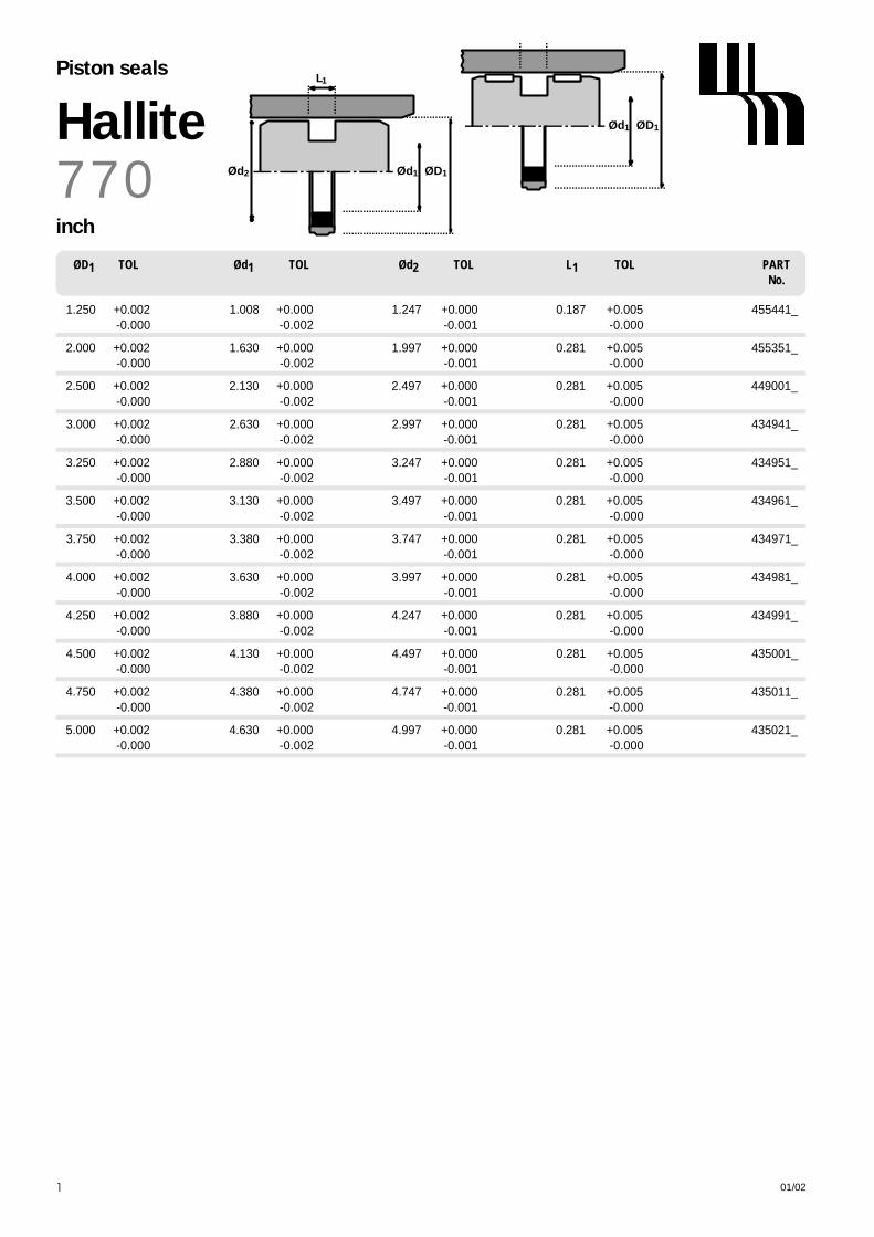
ØD1Ød1
Ød2
L1
ØD1Ød17 7 0HallitePiston seals
inch
01/02192
ØD1 TOL Ød1 TOL Ød2 TOL L1 TOL PARTNo.
1.250 +0.002 1.008 +0.000 1.247 +0.000 0.187 +0.005 455441_- 0 . 0 0 0 - 0 . 0 0 2 - 0 . 0 0 1 - 0 . 0 0 0
2.000 +0.002 1.630 +0.000 1.997 +0.000 0.281 +0.005 455351_- 0 . 0 0 0 - 0 . 0 0 2 - 0 . 0 0 1 - 0 . 0 0 0
2.500 +0.002 2.130 +0.000 2.497 +0.000 0.281 +0.005 449001_- 0 . 0 0 0 - 0 . 0 0 2 - 0 . 0 0 1 - 0 . 0 0 0
3.000 +0.002 2.630 +0.000 2.997 +0.000 0.281 +0.005 434941_- 0 . 0 0 0 - 0 . 0 0 2 - 0 . 0 0 1 - 0 . 0 0 0
3.250 +0.002 2.880 +0.000 3.247 +0.000 0.281 +0.005 434951_- 0 . 0 0 0 - 0 . 0 0 2 - 0 . 0 0 1 - 0 . 0 0 0
3.500 +0.002 3.130 +0.000 3.497 +0.000 0.281 +0.005 434961_- 0 . 0 0 0 - 0 . 0 0 2 - 0 . 0 0 1 - 0 . 0 0 0
3.750 +0.002 3.380 +0.000 3.747 +0.000 0.281 +0.005 434971_- 0 . 0 0 0 - 0 . 0 0 2 - 0 . 0 0 1 - 0 . 0 0 0
4.000 +0.002 3.630 +0.000 3.997 +0.000 0.281 +0.005 434981_- 0 . 0 0 0 - 0 . 0 0 2 - 0 . 0 0 1 - 0 . 0 0 0
4.250 +0.002 3.880 +0.000 4.247 +0.000 0.281 +0.005 434991_- 0 . 0 0 0 - 0 . 0 0 2 - 0 . 0 0 1 - 0 . 0 0 0
4.500 +0.002 4.130 +0.000 4.497 +0.000 0.281 +0.005 435001_- 0 . 0 0 0 - 0 . 0 0 2 - 0 . 0 0 1 - 0 . 0 0 0
4.750 +0.002 4.380 +0.000 4.747 +0.000 0.281 +0.005 435011_- 0 . 0 0 0 - 0 . 0 0 2 - 0 . 0 0 1 - 0 . 0 0 0
5.000 +0.002 4.630 +0.000 4.997 +0.000 0.281 +0.005 435021_- 0 . 0 0 0 - 0 . 0 0 2 - 0 . 0 0 1 - 0 . 0 0 0

Rotary pressure seal
1
OPERATING CONDITIONS
MAXIMUM SPEED 0.2 m/sTEMPERATURE RANGE -30°C + 80°C
MAXIMUM PRESSURE 350 barLIMITING PV VALUES LUBRICATED 25 bar m/s
MAXIMUM EXTRUSION GAP
PRESSUE bar 1 0 0 2 0 0 3 5 0MAXIMUM GAP L1 4.2 mm 0 . 2 0 0 . 1 0 H7/f7 ToleranceMAXIMUM GAP L1 6.3 mm 0 . 3 0 0 . 2 5 H7/f7 Tolerance
SURFACE ROUGHNESS µ m R a µ m R t
DYNAMIC SEALING FACE- ROD Ød1 0.1 ↔ 0 . 3 2.5 maxSTATIC SEALING FACE - ROD ØD1 1.6 max 10 max
STATIC HOUSING FACES L1 2.5 max 16 max
CHAMFERS & RADII
GROOVE SECTION ≤ S mm 5.5 7.75MIN. CHAMFER C mm 3.0 5.0
MAX. FILLET RAD r1 m m 0.8 1.2
T O L E R A N C E S Ø d1 Ø D1 L1
m m f 9 H 1 1 +0.2 -0
TECHNICAL DETAILSM E T R I C
DESIGNApatented seal designed specifically forhydraulic swivels.Manufactured in the high grade Hythane ®181, Hallite’s Ro800 is engineeredas a one piece seal. No relative motionbetween the seal and the energiser caneffect the lifetime of this seal, which is oftenmainly the problem of two piece swivel seals.The special design of the Ro800 is minimizingthe friction.Optional anti-extrusions rings made fromacetal are allowing larger extrusion gaps. Theseal without anti-extrusion rings are made forapplications with a very good guidance orlow working pressure. Therefor please contactour technical service. Ro800 is designed fordouble acting conditions. Designs areavailable for piston or rod applications.The seal is easy to install in one piecehousings.
FEATURES
• ONE PIECE SEAL• NO ROTATTION WITHIN THE GROOVE• AVAILABLE FOR ROD AND PISTON • VERY LOW FRICTION • EASY TO INSTALL• LOW ABRASION AND GOOD WEAR RESISTANCE • SIMPLE AND SMALL SEAL GROOVES
C
S
L1
ØD1Ød1
20° 30°
r1 Fr1

C
S
L1
ØD1Ød1
20° 30°
r1 Fr1
Rotary pressure seal
Ød1 ØD1 L1 PARTNo.
R O 8 0 0
2
metric
Rod sealing Bore sealing
4 5 . 0 5 6 . 0 4.2 4743400*
5 6 . 0 6 7 . 0 4.2 4748000*
7 0 . 0 8 0 . 0 5.0 4727800*
1 3 0 . 0 1 4 5 . 5 6.3 4720610
ØD1 Ød1 L1 PARTNo.
8 0 . 0 6 9 . 3 4.2 4748100*
1 4 5 . 0 1 2 9 . 5 6.3 4712710
1 6 0 . 0 1 4 4 . 5 6.3 4712810
1 8 0 . 0 1 6 4 . 5 6.3 4720710
* Without back-Ring

01/02
DESIGNThe Hallite 831 wiper is designed to snapinto a standard housing and providereliable medium duty dirt exclusion. The proportions of the precision trimmedwiping lip ensure that it remains in contactwith the rod surface to remove all depositsof mud and other forms of contaminationexcept for those found in heavy dutyindustrial applications.
The outside diameter of the sealincorporates a 'crush lip’ to provideinterference fit with the housing and a‘face bead’ to ensure that the crush lip isnot trapped in the corner of the housing.The inside diameter of the seal is providedwith ribs to prevent the possibility of blow-out due to pressure trapping of the mainrod seal.
The Hallite 831 is precision moulded inpolyurethane for maximum wear resistanceand is interchangeable with manycommon European wiper styles.
FEATURES• PRECISION TRIMMED SEALING LIP• ‘CRUSH LIP’ AND ‘FACE BEAD’
PROVIDE EFFECTIVE SEAL ONHOUSING
• LOW WEAR LONG LIFE• COST EFFECTIVE• PRESSURE RELIEF RIBS
OPERATING CONDITIONS
MAXIMUM SPEED 4.0 m/sec 12.0 ft/secT E M P E R A T U R E R A N G E -30°C + 100°C -22°F + 212°F
SURFACE ROUGHNESS µ m R a µ m R t µ i n C L A µ i n R M S
DYNAMIC SEALING FACE Ød1 0.1 ↔ 0 . 4 4 max 4 ↔ 1 6 5 ↔ 1 8STATIC SEALING FACE ØD1 Ø D2 1.6 max 10 max 63 max 70 max
STATIC HOUSING FACES L1 3.2 max 16 max 125 max 140 max
R A D I I
ROD DIAMETER Ød1 m m ≤ 90 > 90MAX FILLET RAD r1 m m 0.2 0.4MAX FILLET RAD r2 m m 0.4 0.4
T O L E R A N C E S Ø d1 Ø D1 Ø D2 L1
m m f9 H11 H11 +0.2 -0
TECHNICAL DETAILSM E T R I C I N C H
HalliteWipers
193193
ØD1 ØD2 Ød1
L 1
r1
r2

ØD1
L1
ØD2 Ød1
L
ØD1 ØD2 Ød18 3 1HalliteWipers
metric
01/02194
Ød1 TOL ØD1 TOL ØD2 TOL L1 L2 PARTf9 H11 H11 +0.2 - 0 No.
12 -0.016 18.6 +0.13 15.0 +0.11 3.8 5.3 4565800- 0 . 0 5 9 + 0 . 0 0 + 0 . 0 0
14 -0.016 20.6 +0.13 17.0 +0.11 3.8 5.3 4580000- 0 . 0 5 9 + 0 . 0 0 + 0 . 0 0
16 -0.016 24.6 +0.13 19.0 +0.13 5.3 7.0 4703800- 0 . 0 5 9 + 0 . 0 0 + 0 . 0 0
18 -0.016 24.6 +0.13 21.0 +0.13 3.8 5.3 4580100- 0 . 0 5 9 + 0 . 0 0 + 0 . 0 0
18 -0.016 26.6 +0.13 21.0 +0.13 5.3 7.0 4703900- 0 . 0 5 9 + 0 . 0 0 + 0 . 0 0
20 -0.020 28.6 +0.13 23.0 +0.13 5.3 7.0 4530600- 0 . 0 7 2 + 0 . 0 0 + 0 . 0 0
22 -0.020 30.6 +0.16 25.0 +0.13 5.3 7.0 4530700- 0 . 0 7 2 + 0 . 0 0 + 0 . 0 0
25 -0.020 33.6 +0.16 28.0 +0.13 5.3 7.0 4530800- 0 . 0 7 2 + 0 . 0 0 + 0 . 0 0
28 -0.020 36.6 +0.16 31.0 +0.16 5.3 7.0 4565900- 0 . 0 7 2 + 0 . 0 0 + 0 . 0 0
30 -0.020 38.6 +0.16 33.0 +0.16 5.3 7.0 4530900- 0 . 0 7 2 + 0 . 0 0 + 0 . 0 0
32 -0.025 40.6 +0.16 35.0 +0.16 5.3 7.0 4534500- 0 . 0 8 7 + 0 . 0 0 + 0 . 0 0
35 -0.025 43.6 +0.16 38.0 +0.16 5.3 7.0 4531000- 0 . 0 8 7 + 0 . 0 0 + 0 . 0 0
36 -0.025 44.6 +0.16 39.0 +0.16 5.3 7.0 4580200- 0 . 0 8 7 + 0 . 0 0 + 0 . 0 0
40 -0.025 48.6 +0.16 43.0 +0.16 5.3 7.0 4531100- 0 . 0 8 7 + 0 . 0 0 + 0 . 0 0
45 -0.025 53.6 +0.19 48.0 +0.16 5.3 7.0 4533800- 0 . 0 8 7 + 0 . 0 0 + 0 . 0 0
45 -0.025 55.6 +0.19 48.0 +0.16 5.3 7.0 4531200- 0 . 0 8 7 + 0 . 0 0 + 0 . 0 0
50 -0.025 58.6 +0.19 53.0 +0.19 5.3 7.0 4533900- 0 . 0 8 7 + 0 . 0 0 + 0 . 0 0
50 -0.025 60.6 +0.19 53.0 +0.19 5.3 7.0 4531300- 0 . 0 8 7 + 0 . 0 0 + 0 . 0 0
55 -0.030 63.6 +0.19 58.0 +0.19 5.3 7.0 4534000- 0 . 1 0 4 + 0 . 0 0 + 0 . 0 0
55 -0.030 65.6 +0.19 58.0 +0.19 5.3 7.0 4531400- 0 . 1 0 4 + 0 . 0 0 + 0 . 0 0
56 -0.030 64.6 +0.19 59.0 +0.19 5.3 7.0 4566000- 0 . 1 0 4 + 0 . 0 0 + 0 . 0 0
56 -0.030 66.6 +0.19 59.0 +0.19 5.3 7.0 4704000- 0 . 1 0 4 + 0 . 0 0 + 0 . 0 0
60 -0.030 68.6 +0.19 63.0 +0.19 5.3 7.0 4534100- 0 . 1 0 4 + 0 . 0 0 + 0 . 0 0

01/02 195
Ød1 TOL ØD1 TOL ØD2 TOL L1 L2 PARTf9 H11 H11 +0.2 - 0 No.
60 -0.030 70.6 +0.19 63.0 +0.19 5.3 7.0 4531500- 0 . 1 0 4 + 0 . 0 0 + 0 . 0 0
70 -0.030 78.6 +0.19 73.0 +0.19 5.3 7.0 4534200- 0 . 1 0 4 + 0 . 0 0 + 0 . 0 0
70 -0.030 80.6 +0.22 73.0 +0.19 5.3 7.0 4531600- 0 . 1 0 4 + 0 . 0 0 + 0 . 0 0
80 -0.030 88.6 +0.22 83.0 +0.22 5.3 7.0 4534300- 0 . 1 0 4 + 0 . 0 0 + 0 . 0 0
80 -0.030 92.2 +0.22 86.0 +0.22 7.1 12.0 4531700- 0 . 1 0 4 + 0 . 0 0 + 0 . 0 0
85 -0.036 93.6 +0.22 88.0 +0.22 5.3 7.0 4534400- 0 . 1 2 3 + 0 . 0 0 + 0 . 0 0
85 -0.036 97.2 +0.22 91.0 +0.22 7.1 12.0 4531800- 0 . 1 2 3 + 0 . 0 0 + 0 . 0 0
90 -0.036 102.2 +0.22 96.0 +0.22 7.1 12.0 4531900- 0 . 1 2 3 + 0 . 0 0 + 0 . 0 0
100 -0.036 112.2 +0.22 106.0 +0.22 7.1 12.0 4532000- 0 . 1 2 3 + 0 . 0 0 + 0 . 0 0
110 -0.036 122.2 +0.25 116.0 +0.22 7.1 12.0 4538200- 0 . 1 2 3 + 0 . 0 0 + 0 . 0 0
135 -0.043 147.2 +0.25 141.0 +0.25 7.1 12.0 4538100- 0 . 1 4 3 + 0 . 0 0 + 0 . 0 0
ØD1
L1
ØD2 Ød1
L
ØD1 ØD2 Ød1 8 3 1Hallite
Wipers
metric

N o t e s
01/02196

01/02
DESIGNThe Hallite 834 wiper is designed to snapinto a standard housing and providereliable medium duty dirt exclusion. Theproportions of the wiping lip ensure that itremains in contact with the rod surface toremove all deposits of mud and other formsof contamination except for those found inthe heavy duty environment such as steelworks and cement factories.
The inside diameter of the seal isprovided with ribs to prevent the possibilityof blow out due to pressure trapping of themain rod seal.
The Hallite 834 is precision moulded inHythane 181 for maximum wear resistance.
FEATURES• SNUG FIT PROVIDES EFFECTIVE SEALING• LOW WEAR - LONG LIFE• EASY INSTALLATION• PRESSURE RELIEF RIBS• PRECISION TRIMMED WIPING LIP
OPERATING CONDITIONS
MAXIMUM SPEED 4.0 m/sec 12.0 ft/secT E M P E R A T U R E R A N G E -45°C + 110°C -50°F + 230°F
SURFACE ROUGHNESS µ m R a µ m R t µ i n C L A µ i n R M S
DYNAMIC SEALING FACE Ød1 0.1 ↔ 0 . 4 4 max 4 ↔ 1 6 5 ↔ 1 8STATIC SEALING FACE ØD1 Ø D2 1.6 max 10 max 63 max 70 max
STATIC HOUSING FACES L1 3.2 max 16 max 125 max 140 max
R A D I I
MAX FILLET RAD r1 m m 0.4MAX FILLET RAD r2 m m 0.2
T O L E R A N C E S Ø d1 Ø D1 Ø D2 L1
m m f9 H11 H11 +0.2 -0
TECHNICAL DETAILSM E T R I C I N C H
HalliteWipers
197197
ØD1 ØD2 Ød1
L1
r1
r2

ØD1
h L1
ØD2 Ød1ØD1 ØD2 Ød18 3 4HalliteWiper
metric
01/02198
18 -0.016 26.0 +0.13 24.0 +0.13 4.0 7.0 1.0 4367200- 0 . 0 5 9 + 0 . 0 0 + 0 . 0 0
20 -0.020 28.0 +0.13 26.0 +0.13 4.0 7.0 1.0 4391300- 0 . 0 7 2 + 0 . 0 0 + 0 . 0 0
22 -0.020 30.0 +0.13 28.0 +0.13 4.0 7.0 1.0 4370600- 0 . 0 7 2 + 0 . 0 0 + 0 . 0 0
25 -0.020 33.0 +0.16 31.0 +0.16 4.0 7.0 1.0 4343900- 0 . 0 7 2 + 0 . 0 0 + 0 . 0 0
26 -0.020 34.0 +0.16 32.0 +0.16 4.0 7.0 1.0 4514400- 0 . 0 7 2 + 0 . 0 0 + 0 . 0 0
28 -0.020 36.0 +0.16 34.0 +0.16 4.0 7.0 1.0 4373500- 0 . 0 7 2 + 0 . 0 0 + 0 . 0 0
30 -0.020 38.0 +0.16 36.0 +0.16 4.0 7.0 1.0 4378800- 0 . 0 7 2 + 0 . 0 0 + 0 . 0 0
32 -0.025 40.0 +0.16 38.0 +0.16 4.0 7.0 1.0 4373600- 0 . 0 8 7 + 0 . 0 0 + 0 . 0 0
35 -0.025 43.0 +0.16 41.0 +0.16 4.0 7.0 1.0 4398400- 0 . 0 8 7 + 0 . 0 0 + 0 . 0 0
36 -0.025 44.0 +0.16 42.0 +0.16 4.0 7.0 1.0 4370700- 0 . 0 8 7 + 0 . 0 0 + 0 . 0 0
37 -0.025 45.0 +0.16 43.0 +0.16 4.0 7.0 1.0 4514500- 0 . 0 8 7 + 0 . 0 0 + 0 . 0 0
38 -0.025 46.0 +0.16 44.0 +0.16 4.0 7.0 1.0 4515400- 0 . 0 8 7 + 0 . 0 0 + 0 . 0 0
40 -0.025 48.0 +0.16 46.0 +0.16 4.0 7.0 1.0 4378900- 0 . 0 8 7 + 0 . 0 0 + 0 . 0 0
45 -0.025 53.0 +0.19 51.0 +0.19 4.0 7.0 1.0 4370800- 0 . 0 8 7 + 0 . 0 0 + 0 . 0 0
46 -0.025 54.0 +0.19 52.0 +0.19 4.0 7.0 1.0 4515200- 0 . 0 8 7 + 0 . 0 0 + 0 . 0 0
48 -0.025 56.0 +0.19 54.0 +0.19 4.0 7.0 1.0 4432700- 0 . 0 8 7 + 0 . 0 0 + 0 . 0 0
50 -0.025 58.0 +0.19 56.0 +0.19 4.0 7.0 1.0 4379000- 0 . 0 8 7 + 0 . 0 0 + 0 . 0 0
55 -0.030 63.0 +0.19 61.0 +0.19 4.0 7.0 1.0 4515100- 0 . 1 0 4 + 0 . 0 0 + 0 . 0 0
56 -0.030 64.0 +0.19 62.0 +0.19 4.0 7.0 1.0 4385100- 0 . 1 0 4 + 0 . 0 0 + 0 . 0 0
60 -0.030 68.0 +0.19 66.0 +0.19 4.0 7.0 1.0 4385200- 0 . 1 0 4 + 0 . 0 0 + 0 . 0 0
63 -0.030 71.0 +0.19 69.0 +0.19 4.0 7.0 1.0 4385300- 0 . 1 0 4 + 0 . 0 0 + 0 . 0 0
65 -0.030 73.0 +0.19 71.0 +0.19 4.0 7.0 1.0 4394200- 0 . 1 0 4 + 0 . 0 0 + 0 . 0 0
70 -0.030 78.0 +0.19 76.0 +0.19 4.0 7.0 1.0 4373700- 0 . 1 0 4 + 0 . 0 0 + 0 . 0 0
Ød1 TOL ØD1 TOL ØD2 TOL L1 L2 h PARTf9 H11 H11 +0.2 - 0 No.

01/02 199
75 -0.030 83.0 +0.22 81.0 +0.22 4.0 7.0 1.0 4711900- 0 . 1 0 4 + 0 . 0 0 + 0 . 0 0
80 -0.030 88.0 +0.22 86.0 +0.22 4.0 7.0 1.0 4398500- 0 . 1 0 4 + 0 . 0 0 + 0 . 0 0
90 -0.036 98.0 +0.22 96.0 +0.22 4.0 7.0 1.0 4398600- 0 . 1 2 3 + 0 . 0 0 + 0 . 0 0
100 -0.036 108.0 +0.22 106.0 +0.22 4.0 7.0 1.0 4394300- 0 . 1 2 3 + 0 . 0 0 + 0 . 0 0
110 -0.036 118.0 +0.22 116.0 +0.22 4.0 7.0 1.0 4448200- 0 . 1 2 3 + 0 . 0 0 + 0 . 0 0
140 -0.043 152.0 +0.25 149.0 +0.25 5.5 10.0 1.0 4456100- 0 . 1 4 3 + 0 . 0 0 + 0 . 0 0
ØD1
h L1
ØD2 Ød1ØD1 ØD2 Ød1 8 3 4Hallite
Wiper
metric
Ød1 TOL ØD1 TOL ØD2 TOL L1 L2 h PARTf9 H11 H11 +0.2 - 0 No.

N o t e s
01/02200

Hallite
201
Wipers
01/02
OPERATING CONDITIONS
MAXIMUM SPEED 4.0 m/sec 12.0 ft/secMAXIMUM TEMPERATURE -45°C + 110°C -50°F + 230°F
SURFACE ROUGHNESS µ m R a µ m R t µ i n C L A µ i n R M S
DYNAMIC SEALING FACE Ød1 0.1 ÷ 0.4 4 max 4 ÷ 16 5 ÷ 18STATIC SEALING FACE ØD1 Ø D2 1.6 max 10 max 63 max 70 max
STATIC HOUSING FACES L1 3.2 max 16 max 125 max 140 max
R A D I I
ROD DIAMETER Ød1 m m ≤ 90 > 90MAX FILLET RAD r1 m m 0.2 0.4MAX FILLET RAD r2 m m 0.4 0.4
T O L E R A N C E S Ø d1 Ø D1 Ø D2 L1839 mm f 9 H 1 1 H 1 1 +0.2 -0
839n mm f9 +0-0.2 +0.1 +0.4 -0
TECHNICAL DETAILSM E T R I C I N C H
DESIGNThe Hallite 839 wiper is precision moulded inHallite's high performance polyurethane -Hythane 181 for maximum wear resistance,and is designed to exclude dirt andmoisture from entering the cylinder and tocollect traces of fluid passing the rod seal.
Opposite the wiper lip are two sealinglips accurately produced andproportioned to provide the secondarysealing function. To obtain stability andimprove the seal the outside diameter is ininterference with the housing.
The Hallite 839N wiper is designed to suitpopular Asian housings and has a texturedwiping lip for improved performance.
FEATURES• TWIN LIP ENSURES DRIER
SEALING SYSTEM.• HARD WEARING MATERIAL FOR
LONG LIFE
NB: Part numbers suffixed by “‡” indicate housingsizes to meet ISO 6195C.
ØD1 ØD2 Ød1
L1
r1
r2
ØD1 ØD2 Ød1
L1
r1
r2
839N Textured Wiper Lip

L2
ØD1
L1
ØD2 Ød1ØD1 ØD2 Ød1
8 3 9HalliteWipers
metric
01/02202
Ød1 TOL ØD1 TOL ØD2 TOL L1 L2 PARTf9 H11 H11 +0.2 - 0 No.
12 -0.016 18.0 +0.11 14.5 +0.11 4.0 7.0 4436800‡- 0 . 0 5 9 + 0 . 0 0 + 0 . 0 0
14 -0.016 20.0 +0.13 16.5 +0.11 4.0 7.0 4436900‡- 0 . 0 5 9 + 0 . 0 0 + 0 . 0 0
18 -0.016 24.0 +0.13 20.5 +0.13 4.0 7.0 4437000‡- 0 . 0 5 9 + 0 . 0 0 + 0 . 0 0
20 -0.020 26.0 +0.13 22.5 +0.13 4.0 6.0 4415000‡- 0 . 0 7 2 + 0 . 0 0 + 0 . 0 0
22 -0.020 28.0 +0.13 24.5 +0.13 4.0 7.0 4437100‡- 0 . 0 7 2 + 0 . 0 0 + 0 . 0 0
28 -0.020 36.0 +0.16 31.0 +0.16 5.0 8.0 4437200‡- 0 . 0 7 2 + 0 . 0 0 + 0 . 0 0
30 -0.020 38.0 +0.16 33.0 +0.16 5.0 8.0 4519200- 0 . 0 7 2 + 0 . 0 0 + 0 . 0 0
32 -0.025 40.0 +0.16 35.0 +0.16 5.0 8.0 4594000‡- 0 . 0 8 7 + 0 . 0 0 + 0 . 0 0
36 -0.025 44.0 +0.16 39.0 +0.16 5.0 8.0 4437300‡- 0 . 0 8 7 + 0 . 0 0 + 0 . 0 0
40 -0.025 48.0 +0.16 43.0 +0.16 5.0 8.0 4591600‡- 0 . 0 8 7 + 0 . 0 0 + 0 . 0 0
45 -0.025 53.0 +0.19 48.0 +0.16 5.0 8.0 4437400‡- 0 . 0 8 7 + 0 . 0 0 + 0 . 0 0
50 -0.025 58.0 +0.19 53.0 +0.19 5.0 8.0 4584400‡- 0 . 0 8 7 + 0 . 0 0 + 0 . 0 0
55 -0.030 65.0 +0.19 58.0 +0.19 6.0 9.7 4575200- 0 . 1 0 4 + 0 . 0 0 + 0 . 0 0
56 -0.030 66.0 +0.19 59.0 +0.19 6.0 9.7 4437500‡- 0 . 1 0 4 + 0 . 0 0 + 0 . 0 0
65 -0.030 75.0 +0.19 68.0 +0.19 6.0 9.7 4575300- 0 . 1 0 4 + 0 . 0 0 + 0 . 0 0
70 -0.030 80.0 +0.19 73.0 +0.19 6.0 9.7 4437600‡- 0 . 1 0 4 + 0 . 0 0 + 0 . 0 0
90 -0.036 100.0 +0.22 93.0 +0.22 6.0 9.7 4437700‡- 0 . 1 2 3 + 0 . 0 0 + 0 . 0 0
110 -0.036 125.0 +0.25 114.0 +0.22 8.5 13.0 4437800‡- 0 . 1 2 3 + 0 . 0 0 + 0 . 0 0
140 -0.043 155.0 +0.25 144.0 +0.25 8.5 13.0 4437900‡- 0 . 1 4 3 + 0 . 0 0 + 0 . 0 0
180 -0.043 196.0 +0.29 184.0 +0.29 9.5 14.0 4595600- 0 . 1 4 3 + 0 . 0 0 + 0 . 0 0

01/02 203
Ød1 TOL ØD1 ØD2 L1 L2 PARTf9 +0 - 0.2 +0.1 +0.4 - 0 No.
ØD1
L1
ØD2 Ød1ØD1 ØD2 Ød1
8 3 9 NHallite
Wipers
metric
14 -0.016 22.0 18.3 4.8 7.0 4632000
-0.059
16 -0.016 24.0 20.3 4.8 7.0 4632100
-0.059
18 -0.016 26.0 22.3 4.8 7.0 4630800- 0 . 0 5 9
20 -0.020 28.0 24.3 4.8 7.0 4630900- 0 . 0 7 2
22.4 -0.020 30.4 26.7 4.8 7.0 4630100- 0 . 0 7 2
25 -0.020 33.0 29.3 4.8 7.0 4631000- 0 . 0 7 2
28 -0.020 36.0 32.3 4.8 7.0 4631100- 0 . 0 7 2
30 -0.020 38.0 34.0 5.8 8.0 4630200- 0 . 0 7 2
3 1 . 5 - 0 . 0 2 5 3 9 . 5 3 5 . 5 5 . 8 8 . 0 4 6 3 2 2 0 0
- 0 . 0 8 7
32 -0.025 40.0 36.0 5.8 8.0 4632300
-0.087
35 -0.025 43.0 39.0 5.8 8.0 4630300- 0 . 0 8 7
35.5 -0.025 43.5 39.5 5.8 8.0 4630400- 0 . 0 8 7
3 8 - 0 . 0 2 5 4 6 . 0 4 2 . 0 5 . 8 8 . 0 4 6 3 2 4 0 0
- 0 . 0 8 7
40 -0.025 48.0 44.0 5.8 8.0 4630500- 0 . 0 8 7
45 -0.025 53.0 49.0 5.8 8.0 4630600- 0 . 0 8 7
50 -0.025 58.0 54.0 5.8 8.0 4630000- 0 . 0 8 7
5 3 - 0 . 0 3 0 6 1 . 0 5 7 . 0 5 . 8 8 . 0 4 6 3 2 5 0 0
- 0 . 1 0 4
55 -0.030 63.0 58.0 5.8 8.0 4630700- 0 . 1 0 4
5 6 - 0 . 0 3 0 6 4 . 0 6 0 . 0 5 . 8 8 . 0 4 6 3 2 6 0 0
- 0 . 1 0 4
60 -0.030 68.0 64.0 5.8 8.0 4631200- 0 . 1 0 4
6 3 - 0 . 0 3 0 7 1 . 0 6 7 . 0 5 . 8 8 . 0 4 6 3 7 0 0
- 0 . 1 0 4
65 -0.030 73.0 69.0 5.8 8.0 4631300- 0 . 1 0 4

01/02204
Ød1 TOL ØD1 ØD2 L1 L2 PARTf9 +0 - 0.2 +0.1 +0.4 - 0 No.
ØD1
L1
ØD2 Ød1ØD1 ØD2 Ød1
8 3 9 NHallite
Wipers
metric
70 -0.030 80.0 75.0 6.8 10.0 4631400- 0 . 1 0 4
75 -0.030 85.0 80.0 6.8 10.0 4631500- 0 . 0 7 6
80 -0.030 90.0 85.0 6.8 10.0 4631600- 0 . 0 7 6
90 -0.036 100.0 95.0 6.8 10.0 4631700- 0 . 1 2 3
95 -0.036 105.0 100.0 6.8 10.0 4631900- 0 . 1 2 3
100 -0.036 110.0 105.0 6.8 10.0 4631800- 0 . 1 2 3
1 1 0 - 0 . 0 3 6 1 2 0 . 0 1 1 5 . 0 6 . 8 1 0 . 0 4 6 3 3 0 0 0
- 0 . 1 2 3
1 1 2 - 0 . 0 3 6 1 2 2 . 0 1 1 7 . 0 6 . 8 1 0 . 0 4 6 3 3 1 0 0
- 0 . 1 2 3
1 2 5 - 0 . 0 4 3 1 3 8 . 0 1 3 2 . 0 7 . 8 1 1 . 0 4 6 3 3 2 0 0
- 0 . 1 2 3
1 3 6 - 0 . 0 4 3 1 4 9 . 0 1 4 3 . 0 7 . 8 1 1 . 0 4 6 3 3 3 0 0
- 0 . 1 2 3
1 4 0 - 0 . 0 4 3 1 5 3 . 0 1 4 7 . 0 7 . 8 1 1 . 0 4 6 3 3 4 0 0
- 0 . 1 2 3
1 4 5 - 0 . 0 4 3 1 5 8 . 0 1 5 2 . 0 7 . 8 1 1 . 0 4 6 3 3 5 0 0
- 0 . 1 2 3
1 6 0 - 0 . 0 4 3 1 7 4 . 0 1 6 7 . 0 7 . 8 1 1 . 0 4 6 3 3 6 0 0
- 0 . 1 2 3

HalliteWipers
01/02 205
OPERATING CONDITIONS
MAXIMUM SPEED 4.0 m/sec 12.0 ft/secTEMPERATURE RANGE -45°C + 110°C -50°F + 230°F
SURFACE ROUGHNESS µ m R a µ m R t µ i n C L A µ i n R M S
DYNAMIC SEALING FACE Ød1 0.1 ↔ 0 . 4 4 max 4 ↔ 1 6 5 ↔ 1 8STATIC SEALING FACE ØD1 Ø D2 1.6 max 10 max 63 max 70 max
STATIC HOUSING FACES L1 3.2 max 16 max 125 max 140 max
R A D I I
ROD DIAMETER Ød1 ≤ 50 ≤ 90 ≤ 200 > 200MAX FILLET RAD r1 m m 0.4 0.4 0.4 0.8MAX FILLET RAD r2 m m 0.2 0.4 0.6 0.8
ROD DIAMETER Ød1 ≤ 2.000 ≤ 3.500 ≤ 7.875 > 7.875MAX FILLET RAD r1 i n 0.016 0.016 0.016 0.032MAX FILLET RAD r2 i n 0.008 0.016 0.024 0.032
T O L E R A N C E S Ø d1 Ø D1 Ø D2 L1 h
m m f9 H11 H11 +0.2 -0 +0.10 +0i n f9 H11 H11 +0.008 -0 +0.004 +0
TECHNICAL DETAILSM E T R I C I N C H
r1
ØD1
L1
Ød1
r2
ØD2
h
DESIGNThe Hallite 842 rod wiper is designed toprevent the ingress of foreign particles andmoisture into the cylinder. The profile hasbeen specially developed for harshenvironments, in particular the longwallmining industry.
The special feature is the flap on thewiping lip which covers the gland housing,preventing the water/slurry trap socommon with conventional wipers andthus ingress of contamination around theoutside of the wiper. The internal ribs onthe inside diameter prevent the possibilityof pressure trapping between the glandseal and the wiper and ensure correctsupport and guidance of the wiping lip,even in cases of high eccentricity as canoccur between the outer stage gland andthe inner cylinder of a roof support leg.
The Hallite 842 is manufactured inHallite’s high performance polyurethane,Hythane 181. The material has excellentcompression set characteristics, excellentwear and abrasive resistance, provencompatibility with HFA (95/5) fluids, as used inlongwall mining equipment, and withmineral oil.
NB: Part numbers suffixed by “‡” indicatehousing sizes to meet ISO6195A.

L2
ØD1
L1
Ød1
h
ØD2
8 4 2HalliteWipers
metric
01/02206
Ød1 TOL ØD1 TOL ØD2 TOL L1 L2 h PARTf9 H11 H11 +0.2 - 0 +0.1 - 0 No.
32 -0.025 40.0 +0.16 37.5 +0.16 5.0 8.0 1.50 4714900‡- 0 . 0 8 7 + 0 . 0 0 + 0 . 0 0
35 -0.025 45.0 +0.16 42.0 +0.16 6.3 10.0 1.50 4515300- 0 . 0 8 7 + 0 . 0 0 + 0 . 0 0
36 -0.025 44.0 +0.16 41.5 +0.16 5.0 8.0 1.50 4715000‡- 0 . 0 8 7 + 0 . 0 0 + 0 . 0 0
38 -0.025 46.0 +0.16 43.0 +0.16 5.3 8.0 1.50 4568700- 0 . 0 8 7 + 0 . 0 0 + 0 . 0 0
40 -0.025 48.0 +0.16 45.0 +0.16 5.0 8.0 1.50 4536500‡- 0 . 0 8 7 + 0 . 0 0 + 0 . 0 0
45 -0.025 53.0 +0.19 50.5 +0.19 5.0 8.0 1.50 4715100‡- 0 . 0 8 7 + 0 . 0 0 + 0 . 0 0
50 -0.025 58.0 +0.19 55.0 +0.19 5.0 8.0 1.50 4533600‡- 0 . 0 8 7 + 0 . 0 0 + 0 . 0 0
56 -0.030 66.0 +0.19 63.0 +0.19 6.3 10.0 1.50 4715200‡- 0 . 1 0 4 + 0 . 0 0 + 0 . 0 0
60 -0.030 70.0 +0.19 67.0 +0.19 6.3 10.0 1.50 4557800- 0 . 1 0 4 + 0 . 0 0 + 0 . 0 0
63 -0.030 73.0 +0.19 70.0 +0.19 6.3 10.0 1.50 4536600‡- 0 . 1 0 4 + 0 . 0 0 + 0 . 0 0
70 -0.030 82.6 +0.22 78.4 +0.19 8.0 12.0 2.00 4480800- 0 . 1 0 4 + 0 . 0 0 + 0 . 0 0
80 -0.030 90.0 +0.22 87.0 +0.22 6.3 10.0 1.50 4715300‡- 0 . 1 0 4 + 0 . 0 0 + 0 . 0 0
85 -0.036 97.6 +0.22 93.4 +0.22 8.0 12.0 2.00 4521800- 0 . 1 2 3 + 0 . 0 0 + 0 . 0 0
90 -0.036 102.6 +0.22 98.4 +0.22 8.0 12.0 2.00 4512500- 0 . 1 2 3 + 0 . 0 0 + 0 . 0 0
95 -0.036 110.0 +0.22 105.0 +0.22 9.5 14.0 2.80 4536900- 0 . 1 2 3 + 0 . 0 0 + 0 . 0 0
100 -0.036 114.0 +0.22 109.9 +0.22 8.0 12.0 1.50 4536000- 0 . 1 2 3 + 0 . 0 0 + 0 . 0 0
100 -0.036 115.0 +0.22 108.4 +0.22 9.5 14.0 2.00 4589500‡- 0 . 1 2 3 + 0 . 0 0 + 0 . 0 0
105 -0.036 120.0 +0.22 115.0 +0.22 9.5 14.0 2.50 4532100- 0 . 1 2 3 + 0 . 0 0 + 0 . 0 0
110 -0.036 125.0 +0.25 120.0 +0.22 9.5 14.0 2.50 4715400‡- 0 . 1 2 3 + 0 . 0 0 + 0 . 0 0
120 -0.036 135.0 +0.25 130.0 +0.25 9.5 14.0 2.00 4580800- 0 . 1 2 3 + 0 . 0 0 + 0 . 0 0
125 -0.043 140.0 +0.25 135.0 +0.25 9.5 14.0 2.00 4715500‡- 0 . 1 4 3 + 0 . 0 0 + 0 . 0 0
130 -0.043 145.0 +0.25 140.0 +0.25 9.5 14.0 2.25 4491700- 0 . 1 4 3 + 0 . 0 0 + 0 . 0 0
140 -0.043 155.0 +0.25 150.0 +0.25 9.5 14.0 2.00 4555900‡- 0 . 1 4 3 + 0 . 0 0 + 0 . 0 0

01/02 207
Ød1 TOL ØD1 TOL ØD2 TOL L1 L2 h PARTf9 H11 H11 +0.2 - 0 +0.1 - 0 No.
145 -0.043 160.0 +0.25 155.0 +0.25 9.5 14.0 2.25 4570200- 0 . 1 4 3 + 0 . 0 0 + 0 . 0 0
155 -0.043 170.0 +0.25 165.0 +0.25 9.5 12.0 2.25 4535200- 0 . 1 4 3 + 0 . 0 0 + 0 . 0 0
175 -0.043 190.0 +0.29 185.0 +0.29 9.5 14.0 2.25 4552100- 0 . 1 4 3 + 0 . 0 0 + 0 . 0 0
180 -0.043 195.0 +0.29 190.0 +0.29 9.5 14.0 2.25 4491300‡- 0 . 1 4 3 + 0 . 0 0 + 0 . 0 0
215 -0.050 230 +0.29 225.0 +0.29 9.5 14.0 2.00 4705500- 0 . 1 6 5 + 0 . 0 0 + 0 . 0 0
L2
ØD1
L1
Ød1
h
ØD2
8 4 2Hallite
Wipers
metric
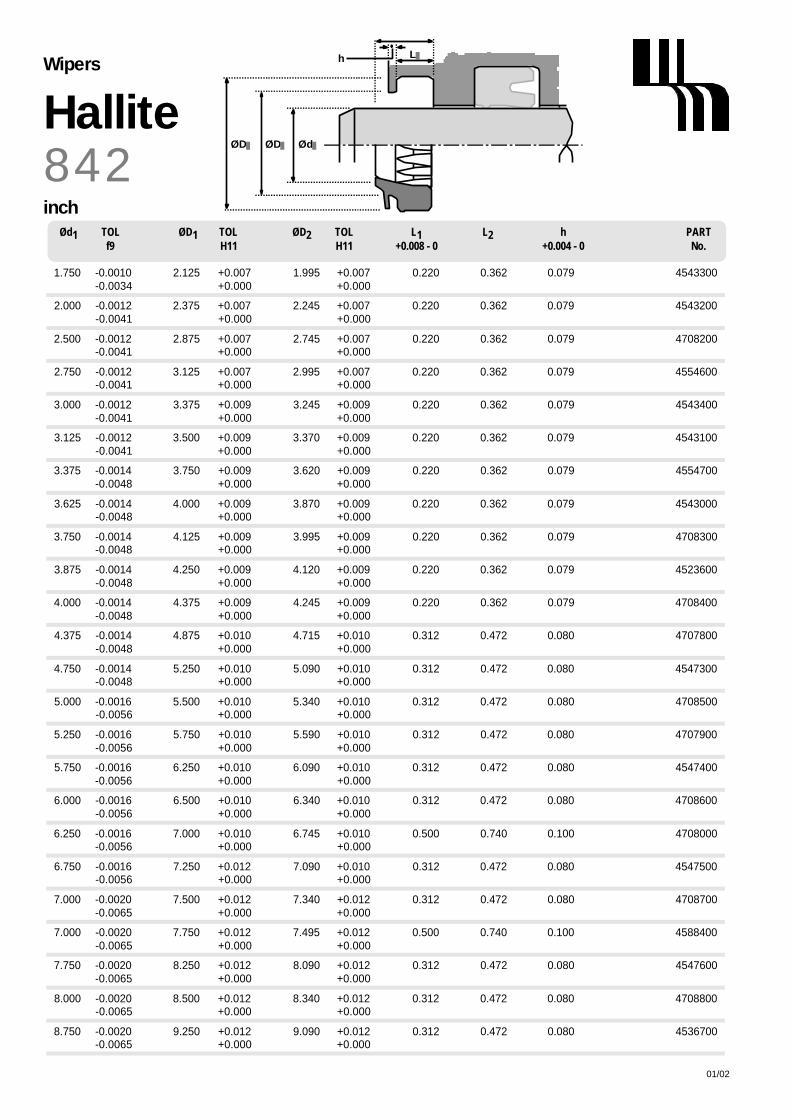
ØD
L
Ød
h
ØD
01/02208
Ød1 TOL ØD1 TOL ØD2 TOL L1 L2 h PARTf9 H11 H11 +0.008 - 0 +0.004 - 0 No.
1.750 -0.0010 2.125 +0.007 1.995 +0.007 0.220 0.362 0.079 4543300- 0 . 0 0 3 4 + 0 . 0 0 0 + 0 . 0 0 0
2.000 -0.0012 2.375 +0.007 2.245 +0.007 0.220 0.362 0.079 4543200- 0 . 0 0 4 1 + 0 . 0 0 0 + 0 . 0 0 0
2.500 -0.0012 2.875 +0.007 2.745 +0.007 0.220 0.362 0.079 4708200- 0 . 0 0 4 1 + 0 . 0 0 0 + 0 . 0 0 0
2.750 -0.0012 3.125 +0.007 2.995 +0.007 0.220 0.362 0.079 4554600- 0 . 0 0 4 1 + 0 . 0 0 0 + 0 . 0 0 0
3.000 -0.0012 3.375 +0.009 3.245 +0.009 0.220 0.362 0.079 4543400- 0 . 0 0 4 1 + 0 . 0 0 0 + 0 . 0 0 0
3.125 -0.0012 3.500 +0.009 3.370 +0.009 0.220 0.362 0.079 4543100- 0 . 0 0 4 1 + 0 . 0 0 0 + 0 . 0 0 0
3.375 -0.0014 3.750 +0.009 3.620 +0.009 0.220 0.362 0.079 4554700- 0 . 0 0 4 8 + 0 . 0 0 0 + 0 . 0 0 0
3.625 -0.0014 4.000 +0.009 3.870 +0.009 0.220 0.362 0.079 4543000- 0 . 0 0 4 8 + 0 . 0 0 0 + 0 . 0 0 0
3.750 -0.0014 4.125 +0.009 3.995 +0.009 0.220 0.362 0.079 4708300- 0 . 0 0 4 8 + 0 . 0 0 0 + 0 . 0 0 0
3.875 -0.0014 4.250 +0.009 4.120 +0.009 0.220 0.362 0.079 4523600- 0 . 0 0 4 8 + 0 . 0 0 0 + 0 . 0 0 0
4.000 -0.0014 4.375 +0.009 4.245 +0.009 0.220 0.362 0.079 4708400- 0 . 0 0 4 8 + 0 . 0 0 0 + 0 . 0 0 0
4.375 -0.0014 4.875 +0.010 4.715 +0.010 0.312 0.472 0.080 4707800- 0 . 0 0 4 8 + 0 . 0 0 0 + 0 . 0 0 0
4.750 -0.0014 5.250 +0.010 5.090 +0.010 0.312 0.472 0.080 4547300- 0 . 0 0 4 8 + 0 . 0 0 0 + 0 . 0 0 0
5.000 -0.0016 5.500 +0.010 5.340 +0.010 0.312 0.472 0.080 4708500- 0 . 0 0 5 6 + 0 . 0 0 0 + 0 . 0 0 0
5.250 -0.0016 5.750 +0.010 5.590 +0.010 0.312 0.472 0.080 4707900- 0 . 0 0 5 6 + 0 . 0 0 0 + 0 . 0 0 0
5.750 -0.0016 6.250 +0.010 6.090 +0.010 0.312 0.472 0.080 4547400- 0 . 0 0 5 6 + 0 . 0 0 0 + 0 . 0 0 0
6.000 -0.0016 6.500 +0.010 6.340 +0.010 0.312 0.472 0.080 4708600- 0 . 0 0 5 6 + 0 . 0 0 0 + 0 . 0 0 0
6.250 -0.0016 7.000 +0.010 6.745 +0.010 0.500 0.740 0.100 4708000- 0 . 0 0 5 6 + 0 . 0 0 0 + 0 . 0 0 0
6.750 -0.0016 7.250 +0.012 7.090 +0.010 0.312 0.472 0.080 4547500- 0 . 0 0 5 6 + 0 . 0 0 0 + 0 . 0 0 0
7.000 -0.0020 7.500 +0.012 7.340 +0.012 0.312 0.472 0.080 4708700- 0 . 0 0 6 5 + 0 . 0 0 0 + 0 . 0 0 0
7.000 -0.0020 7.750 +0.012 7.495 +0.012 0.500 0.740 0.100 4588400- 0 . 0 0 6 5 + 0 . 0 0 0 + 0 . 0 0 0
7.750 -0.0020 8.250 +0.012 8.090 +0.012 0.312 0.472 0.080 4547600- 0 . 0 0 6 5 + 0 . 0 0 0 + 0 . 0 0 0
8.000 -0.0020 8.500 +0.012 8.340 +0.012 0.312 0.472 0.080 4708800- 0 . 0 0 6 5 + 0 . 0 0 0 + 0 . 0 0 0
8.750 -0.0020 9.250 +0.012 9.090 +0.012 0.312 0.472 0.080 4536700- 0 . 0 0 6 5 + 0 . 0 0 0 + 0 . 0 0 0
8 4 2HalliteWipers
inch

HalliteWipers
01/02 209
OPERATING CONDITIONS
MAXIMUM SPEED 4.0 m/sec 12.0 ft/secTEMPERATURE RANGE -45°C + 110°C -50°F + 230°F
SURFACE ROUGHNESS µ m R a µ m R t µ i n C L A µ i n R M S
DYNAMIC SEALING FACE Ød1 0.1 ↔ 0 . 4 4 max 4 ↔ 1 6 5 ↔ 1 8STATIC SEALING FACE ØD1 Ø D2 1.6 max 10 max 63 max 70 max
STATIC HOUSING FACES L1 3.2 max 16 max 125 max 140 max
R A D I I
ROD DIAMETER Ød1 m m ≤90 >90MAX FILLET RAD r1 m m 0.4 0.4MAX FILLET RAD r2 m m 0.2 0.4
T O L E R A N C E S Ø d1 Ø D1 Ø D2 L1 L2
m m f9 H11 H11 +0.2 -0 +0.2 -0
TECHNICAL DETAILSM E T R I C I N C H
DESIGNThe Hallite 846 wiper is designed to excludedirt and moisture from entering the cylinderand to collect traces of fluid passing therod seal.
One special feature of the wiper designare the thin membranes which burst whenexcessive fluid pressure is trapped betweenthe wiper and the rod seal and prevent thewiper being forced out of its housing . After release of this pressure, themembranes close to protect againstcontamination from the outside. Thisfeature removes the requirement for anexpensive vent hole in the gland.
A second feature is the sealing flap onthe wiping lip that completely seals themetal housing groove, preventing theingress of dirt and moisture around theoutside diameter of the wiper.
Precision moulded in Hallite’s highperformance polyurethane, Hythane 181,for maximum wear resistance andtemperature range, the wiper is designedto remove lightly adhered dirt, dust andmoisture from the rod.
FEATURES• TWIN LIP - NO LEAKAGE• TRAPPED PRESSURE
AUTOMATICALLY RELEASED THROUGH BURSTING MEMBRANES
• NO PUSH OUT OF THE WIPERTHROUGH BUILD UP OF PRESSURE
• NO GLAND VENT HOLE NECESSARY• SEALING FLAP PROTECTS AGAINST
INGRESS OF DIRT AND MOISTUREAROUND THE OUTSIDE DIAMETER
r1
ØD1
L1
Ød1
r2
ØD2
h
Textured surface
Sealing flap
Membrane

ØD1
L1
ØD2 Ød1
L2 L2*/
8 4 6HalliteWipers
metric
01/02210
Ød1 TOL ØD1 TOL ØD2 TOL L1 L2 L2* L3 PARTf9 H11 H11 +0.2 - 0 +0.2 - 0 +0.2 - 0 No.
25 -0.020 33.0 +0.16 31.0 +0.16 4.0 5.0 6.0 8.7 4556600- 0 . 0 7 2 + 0 . 0 0 + 0 . 0 0
26 -0.020 34.0 +0.16 32.0 +0.16 4.0 5.0 6.0 8.7 4588700- 0 . 0 7 2 + 0 . 0 0 + 0 . 0 0
28 -0.020 36.0 +0.16 34.0 +0.16 4.0 5.0 6.0 8.7 4556700- 0 . 0 7 2 + 0 . 0 0 + 0 . 0 0
30 -0.020 38.0 +0.16 36.0 +0.16 4.0 5.0 6.0 8.7 4584500- 0 . 0 7 2 + 0 . 0 0 + 0 . 0 0
32 -0.025 40.0 +0.16 38.0 +0.16 4.0 5.0 6.0 8.7 4568900- 0 . 0 8 7 + 0 . 0 0 + 0 . 0 0
36 -0.025 44.0 +0.16 42.0 +0.16 4.0 5.0 6.0 8.7 4588800- 0 . 0 8 7 + 0 . 0 0 + 0 . 0 0
40 -0.025 48.0 +0.16 46.0 +0.16 4.0 5.0 6.0 8.7 4549200- 0 . 0 8 7 + 0 . 0 0 + 0 . 0 0
45 -0.025 53.0 +0.19 51.0 +0.19 4.0 5.0 6.0 8.7 4589900- 0 . 0 8 7 + 0 . 0 0 + 0 . 0 0
50 -0.025 58.0 +0.19 56.0 +0.19 4.0 5.0 6.0 8.7 4597200- 0 . 0 8 7 + 0 . 0 0 + 0 . 0 0
56 -0.030 64.0 +0.19 62.0 +0.19 4.0 5.0 6.0 8.7 4588900- 0 . 1 0 4 + 0 . 0 0 + 0 . 0 0
60 -0.030 68.0 +0.19 66.0 +0.19 4.0 5.0 6.0 8.7 4596600- 0 . 1 0 4 + 0 . 0 0 + 0 . 0 0
65 -0.030 73.0 +0.19 71.0 +0.19 4.0 5.0 6.0 8.7 4597500- 0 . 1 0 4 + 0 . 0 0 + 0 . 0 0
70 -0.030 78.0 +0.19 81.0 +0.19 4.0 5.0 6.0 8.7 4556800- 0 . 1 0 4 + 0 . 0 0 + 0 . 0 0
75 -0.030 83.0 +0.22 76.0 +0.19 4.0 5.0 6.0 8.7 4597600- 0 . 1 0 4 + 0 . 0 0 + 0 . 0 0
80 -0.030 88.0 +0.22 86.0 +0.22 4.0 5.0 6.0 8.7 4590000- 0 . 1 0 4 + 0 . 0 0 + 0 . 0 0
90 -0.036 98.0 +0.22 96.0 +0.22 4.0 5.0 6.0 8.7 4557700- 0 . 1 2 3 + 0 . 0 0 + 0 . 0 0
1 0 0 - 0 . 0 3 6 1 1 0 . 0 + 0 . 2 2 1 0 7 . 0 + 0 . 2 2 6 . 3 8 . 3 6 . 0 1 1 . 5 4 7 2 3 6 0 0
- 0 . 1 2 3 + 0 . 0 0 + 0 . 0 0
NB - The housing length shows options for L2 and L2* . L2 is the preferred dimension but either can be used.

HalliteWipers
01/02 211
OPERATING CONDITIONS
MAXIMUM SPEED 1.0 m/sec 3.0 ft/secTEMPERATURE RANGE -40°C +100°C -40°F +212°F
SURFACE ROUGHNESS µ m R a µ m R t µ i n C L A µ i n R M S
DYNAMIC SEALING FACE Ød1 0.1 ↔ 0 . 4 4 max 4 ↔ 1 6 5 ↔ 1 8STATIC SEALING FACE ØD1 1.6 max 10 max 63 max 70 maxSTATIC HOUSING FACES L1 3.2 max 16 max 125 max 140 max
CHAMFERS & RADII
ROD DIAMETER Ød1 m m ≤ 19 > 19MIN CHAMFER C mm 0.5 1.0
MAX FILLET RAD r1 m m 0.4 0.4
ROD DIAMETER Ød1 i n < 0.75 ≥ 0.75MIN CHAMFER C in 0.020 0.040
MAX FILLET RAD r1 i n 0.016 0.016
T O L E R A N C E S Ø d1 Ø D1 L1 m m L1 i n
f9 H8 +0.5 -0 +0.020 -0
TECHNICAL DETAILSM E T R I C I N C H
DESIGNThe Hallite 860 is a metal cased wiper,designed to press-fit into open groovehousings. Hallite’s 860 wiper comprises aprecisely trimmed polyurethane wipingelement which is securely bonded to ametal case treated with a rust inhibitor.Capable of operating in dirty conditions,the proportions of the polyurethane wipinglip allow it to follow the side movement ofthe rod and to clear away heavilydeposited dirt.
Suitable for light, medium and heavyduty applications, the wiper has beendesigned to provide ease of installationand offers excellent durability in service.The Hallite 860 offers a range of sizessuitable for ISO 6195 type B housings and a range for standard Asian housings.
FEATURES• EASE OF ASSEMBLY• LONG LIFE• PRECISION TRIMMED WIPING LIP• METAL CASE TREATED WITH A
RUST INHIBITOR• WIDE RANGE OF APPLICATION USES• RANGE INCLUDES ISO & STANDARD
ASIAN HOUSINGS.
NB: Part numbers suffixed by “†” aredesigned for Asian housings.
Part numbers suffixed by “‡” indicatehousing sizes to meet ISO 6195 type B.
ØD1 Ød1
L1
C30°
r1

ØD1 Ød1
1
L2
8 6 0HalliteWipers
metric
01/02212
Ød1 TOL ØD1 TOL L1 L2 PARTf9 H8 +0.5 - 0 No.
15 -0.016 25 +0.033 5.0 7.0 6950000- 0 . 0 5 9 + 0 . 0 0 0
16 -0.016 22 +0.033 3.0 4.0 6950010- 0 . 0 5 9 + 0 . 0 0 0
18 -0.016 28 +0.033 5.0 7.0 6950020- 0 . 0 5 9 + 0 . 0 0 0
20 -0.020 30 +0.033 5.0 8.0 6950030- 0 . 0 7 2 + 0 . 0 0 0
25 -0.020 35 +0.039 5.0 8.0 6950040- 0 . 0 7 2 + 0 . 0 0 0
25 -0.020 37 +0.039 6.0 9.0 6950050†- 0 . 0 7 2 + 0 . 0 0 0
28 -0.020 38 +0.039 5.0 8.0 6950060- 0 . 0 7 2 + 0 . 0 0 0
30 -0.020 40 +0.039 5.0 8.0 6950070- 0 . 0 7 2 + 0 . 0 0 0
30 -0.020 42 +0.039 6.0 9.0 6950080†- 0 . 0 7 2 + 0 . 0 0 0
32 -0.025 42 +0.039 5.0 8.0 6950090- 0 . 0 8 7 + 0 . 0 0 0
35 -0.025 45 +0.039 7.0 10.0 6950100- 0 . 0 8 7 + 0 . 0 0 0
35 -0.025 47 +0.039 7.0 10.0 6950110†- 0 . 0 8 7 + 0 . 0 0 0
38 -0.025 48 +0.039 7.0 10.0 6950470- 0 . 0 8 7 + 0 . 0 0 0
40 -0.025 50 +0.039 7.0 10.0 6950120‡- 0 . 0 8 7 + 0 . 0 0 0
40 -0.025 52 +0.046 7.0 10.0 6950130†- 0 . 0 8 7 + 0 . 0 0 0
45 -0.025 55 +0.046 7.0 10.0 6950140‡- 0 . 0 8 7 + 0 . 0 0 0
45 -0.025 57 +0.046 7.0 10.0 6950150†- 0 . 0 8 7 + 0 . 0 0 0
50 -0.025 60 +0.046 7.0 10.0 6950160‡- 0 . 0 8 7 + 0 . 0 0 0
50 -0.025 62 +0.046 7.0 10.0 6950170†- 0 . 0 8 7 + 0 . 0 0 0
55 -0.030 65 +0.046 7.0 10.0 6950180- 0 . 1 0 4 + 0 . 0 0 0
55 -0.030 69 +0.046 8.0 11.0 6950190†- 0 . 1 0 4 + 0 . 0 0 0
60 -0.030 70 +0.046 7.0 10.0 6950200- 0 . 1 0 4 + 0 . 0 0 0
60 -0.030 74 +0.046 8.0 11.0 6950210†- 0 . 1 0 4 + 0 . 0 0 0
65 -0.030 75 +0.046 7.0 10.0 6950220- 0 . 1 0 4 + 0 . 0 0 0
Ød1 TOL ØD1 TOL L1 L2 PARTf9 H8 +0.5 - 0 No.
65 -0.030 79 +0.046 8.0 11.0 6950230†- 0 . 1 0 4 + 0 . 0 0 0
70 -0.030 80 +0.046 7.0 10.0 6950240‡- 0 . 1 0 4 + 0 . 0 0 0
70 -0.030 84 +0.054 8.0 11.0 6950250†- 0 . 1 0 4 + 0 . 0 0 0
75 -0.030 85 +0.054 7.0 10.0 6950260- 0 . 1 0 4 + 0 . 0 0 0
75 -0.030 89 +0.054 8.0 11.0 6950270†- 0 . 1 0 4 + 0 . 0 0 0
80 -0.030 90 +0.054 7.0 10.0 6950280‡- 0 . 1 0 4 + 0 . 0 0 0
80 -0.030 94 +0.054 8.0 11.0 6950290†- 0 . 1 0 4 + 0 . 0 0 0
85 -0.036 95 +0.054 7.0 10.0 6950300- 0 . 1 2 3 + 0 . 0 0 0
85 -0.036 99 +0.054 8.0 11.0 6950310†- 0 . 1 2 3 + 0 . 0 0 0
90 -0.036 100 +0.054 7.0 10.0 6950320‡- 0 . 1 2 3 + 0 . 0 0 0
90 -0.036 104 +0.054 8.0 11.0 6950330†- 0 . 1 2 3 + 0 . 0 0 0
95 -0.036 109 +0.054 8.0 11.0 6950340†- 0 . 1 2 3 + 0 . 0 0 0
100 -0.036 110 +0.054 7.0 10.0 6950350- 0 . 1 2 3 + 0 . 0 0 0
100 -0.036 114 +0.054 8.0 11.0 6950360†- 0 . 1 2 3 + 0 . 0 0 0
105 -0.036 121 +0.063 9.0 12.0 6950370†- 0 . 1 2 3 + 0 . 0 0 0
110 -0.036 120 +0.054 7.0 10.0 6950380- 0 . 1 2 3 + 0 . 0 0 0
110 -0.036 126 +0.063 9.0 12.0 6950390†- 0 . 1 2 3 + 0 . 0 0 0
115 -0.036 131 +0.063 9.0 12.0 6950400†- 0 . 1 2 3 + 0 . 0 0 0
120 -0.036 130 +0.063 7.0 10.0 6950410- 0 . 1 2 3 + 0 . 0 0 0
120 -0.036 136 +0.063 9.0 12.0 6950420†- 0 . 1 2 3 + 0 . 0 0 0
130 -0.043 146 +0.063 9.0 12.0 6950430†- 0 . 1 4 3 + 0 . 0 0 0
140 -0.043 160 +0.063 10.0 14.0 6950440†- 0 . 1 4 3 + 0 . 0 0 0
150 -0.043 170 +0.063 10.0 14.0 6950450†- 0 . 1 4 3 + 0 . 0 0 0
160 -0.043 180 +0.063 10.0 14.0 6950460†- 0 . 1 4 3 + 0 . 0 0 0

01/02 213
Ød1 TOL ØD1 TOL L1 L2 PARTf9 H8 +0.020 - 0 No.
2.000 -0.0012 2.375 +0.0018 0.187 0.281 6955200- 0 . 0 0 4 1 + 0 . 0 0 0 0
2.250 -0.0012 2.625 +0.0018 0.187 0.281 6955220- 0 . 0 0 4 1 + 0 . 0 0 0 0
2.500 -0.0012 2.875 +0.0018 0.187 0.281 6955240- 0 . 0 0 4 1 + 0 . 0 0 0 0
2.750 -0.0012 3.125 +0.0018 0.187 0.281 6955260- 0 . 0 0 4 1 + 0 . 0 0 0 0
3.000 -0.0012 3.375 +0.0021 0.187 0.281 6955280- 0 . 0 0 4 1 + 0 . 0 0 0 0
Ød1 TOL ØD1 TOL L1 L2 PARTf9 H8 +0.020 - 0 No.
0.750 -0.0008 1.125 +0.0013 0.187 0.281 6955100- 0 . 0 0 2 8 + 0 . 0 0 0 0
1.000 -0.0008 1.375 +0.0015 0.187 0.281 6955120- 0 . 0 0 2 8 + 0 . 0 0 0 0
1.250 -0.0010 1.625 +0.0015 0.187 0.281 6955140- 0 . 0 0 3 4 + 0 . 0 0 0 0
1.500 -0.0010 1.875 +0.0015 0.187 0.281 6955160- 0 . 0 0 3 4 + 0 . 0 0 0 0
1.750 -0.0010 2.125 +0.0018 0.187 0.281 6955180- 0 . 0 0 3 4 + 0 . 0 0 0 0
ØD1 Ød1
1
L2
8 6 0Hallite
Wipers
inch

N o t e s
01/02214

HalliteWipers
01/02 215
OPERATING CONDITIONS
MAXIMUM SPEED 1.0 m/sec 3.0 ft/secTEMPERATURE RANGE -40°C +100°C -40°F +212°F
SURFACE ROUGHNESS µ m R a µ m R t µ i n C L A µ i n R M S
DYNAMIC SEALING FACE Ød1 0.1 ↔ 0 . 4 4 max 4 ↔ 1 6 5 ↔ 1 8STATIC SEALING FACE ØD1 1.6 max 10 max 63 max 70 maxSTATIC HOUSING FACES L1 3.2 max 16 max 125 max 140 max
CHAMFERS & RADII
MIN CHAMFER C in 0.040MAX FILLET RAD r1 i n 0.016
T O L E R A N C E S Ø d1 Ø D1 L1
i n f9 H8 +0.020 -0
TECHNICAL DETAILSM E T R I C I N C H
DESIGNThe Hallite 862 is a metal cased wiper,designed to press-fit into open groovehousings. Hallite’s 862 comprises aprecisely trimmed polyurethane wipingelement which is securely bonded to ametal case treated with a rust inhibitor.Capable of operating in dirty conditions,the proportions of the polyurethane wipinglip allow it to follow the side movement ofthe rod and to clear away heavilydeposited dirt.
Suitable for light, medium and heavyduty applications, the wiper has beendesigned to provide ease of installationand offers excellent durability in service.
The Hallite 862 offers a range of sizessuitable for standard American inchhousings.
FEATURES• EASE OF ASSEMBLY• LONG LIFE• PRECISION TRIMMED WIPING LIP• METAL CASE TREATED WITH A
RUST INHIBITOR• WIDE RANGE OF APPLICATION USES
ØD1 Ød1
C
30°
r1
L1
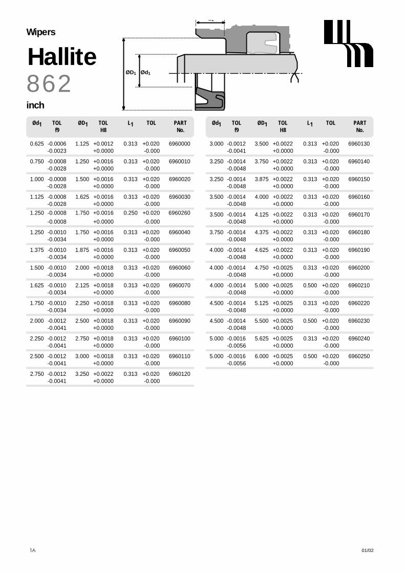
ØD1 Ød1
L1
8 6 2HalliteWipers
inch
01/02216
Ød1 TOL ØD1 TOL L1 TOL PARTf9 H8 No.
0.625 -0.0006 1.125 +0.0012 0.313 +0.020 6960000- 0 . 0 0 2 3 + 0 . 0 0 0 0 - 0 . 0 0 0
0.750 -0.0008 1.250 +0.0016 0.313 +0.020 6960010- 0 . 0 0 2 8 + 0 . 0 0 0 0 - 0 . 0 0 0
1.000 -0.0008 1.500 +0.0016 0.313 +0.020 6960020- 0 . 0 0 2 8 + 0 . 0 0 0 0 - 0 . 0 0 0
1.125 -0.0008 1.625 +0.0016 0.313 +0.020 6960030- 0 . 0 0 2 8 + 0 . 0 0 0 0 - 0 . 0 0 0
1 . 2 5 0 - 0 . 0 0 0 8 1 . 7 5 0 + 0 . 0 0 1 6 0 . 2 5 0 + 0 . 0 2 0 6 9 6 0 2 6 0
- 0 . 0 0 0 8 + 0 . 0 0 0 0 - 0 . 0 0 0
1.250 -0.0010 1.750 +0.0016 0.313 +0.020 6960040- 0 . 0 0 3 4 + 0 . 0 0 0 0 - 0 . 0 0 0
1.375 -0.0010 1.875 +0.0016 0.313 +0.020 6960050- 0 . 0 0 3 4 + 0 . 0 0 0 0 - 0 . 0 0 0
1.500 -0.0010 2.000 +0.0018 0.313 +0.020 6960060- 0 . 0 0 3 4 + 0 . 0 0 0 0 - 0 . 0 0 0
1.625 -0.0010 2.125 +0.0018 0.313 +0.020 6960070- 0 . 0 0 3 4 + 0 . 0 0 0 0 - 0 . 0 0 0
1.750 -0.0010 2.250 +0.0018 0.313 +0.020 6960080- 0 . 0 0 3 4 + 0 . 0 0 0 0 - 0 . 0 0 0
2.000 -0.0012 2.500 +0.0018 0.313 +0.020 6960090- 0 . 0 0 4 1 + 0 . 0 0 0 0 - 0 . 0 0 0
2.250 -0.0012 2.750 +0.0018 0.313 +0.020 6960100- 0 . 0 0 4 1 + 0 . 0 0 0 0 - 0 . 0 0 0
2.500 -0.0012 3.000 +0.0018 0.313 +0.020 6960110- 0 . 0 0 4 1 + 0 . 0 0 0 0 - 0 . 0 0 0
2.750 -0.0012 3.250 +0.0022 0.313 +0.020 6960120- 0 . 0 0 4 1 + 0 . 0 0 0 0 - 0 . 0 0 0
Ød1 TOL ØD1 TOL L1 TOL PARTf9 H8 No.
3.000 -0.0012 3.500 +0.0022 0.313 +0.020 6960130- 0 . 0 0 4 1 + 0 . 0 0 0 0 - 0 . 0 0 0
3.250 -0.0014 3.750 +0.0022 0.313 +0.020 6960140- 0 . 0 0 4 8 + 0 . 0 0 0 0 - 0 . 0 0 0
3.250 -0.0014 3.875 +0.0022 0.313 +0.020 6960150- 0 . 0 0 4 8 + 0 . 0 0 0 0 - 0 . 0 0 0
3.500 -0.0014 4.000 +0.0022 0.313 +0.020 6960160- 0 . 0 0 4 8 + 0 . 0 0 0 0 - 0 . 0 0 0
3.500 -0.0014 4.125 +0.0022 0.313 +0.020 6960170- 0 . 0 0 4 8 + 0 . 0 0 0 0 - 0 . 0 0 0
3.750 -0.0014 4.375 +0.0022 0.313 +0.020 6960180- 0 . 0 0 4 8 + 0 . 0 0 0 0 - 0 . 0 0 0
4.000 -0.0014 4.625 +0.0022 0.313 +0.020 6960190- 0 . 0 0 4 8 + 0 . 0 0 0 0 - 0 . 0 0 0
4.000 -0.0014 4.750 +0.0025 0.313 +0.020 6960200- 0 . 0 0 4 8 + 0 . 0 0 0 0 - 0 . 0 0 0
4.000 -0.0014 5.000 +0.0025 0.500 +0.020 6960210- 0 . 0 0 4 8 + 0 . 0 0 0 0 - 0 . 0 0 0
4.500 -0.0014 5.125 +0.0025 0.313 +0.020 6960220- 0 . 0 0 4 8 + 0 . 0 0 0 0 - 0 . 0 0 0
4.500 -0.0014 5.500 +0.0025 0.500 +0.020 6960230- 0 . 0 0 4 8 + 0 . 0 0 0 0 - 0 . 0 0 0
5.000 -0.0016 5.625 +0.0025 0.313 +0.020 6960240- 0 . 0 0 5 6 + 0 . 0 0 0 0 - 0 . 0 0 0
5.000 -0.0016 6.000 +0.0025 0.500 +0.020 6960250- 0 . 0 0 5 6 + 0 . 0 0 0 0 - 0 . 0 0 0

Materials & fluid compatibilityMax. continuous working temperatures C° and temperature ranges for materials, within fluid power fluids
* Denotes that values vary greatly for individual elastomers within this group NS Denotes that the elastomer is not suitableThe work of the BFPA technical working group ‘TC16/WG8’in the compilation of this table is acknowledged.
100
160
NS
*130
NS
160
100
100
100
100
100
160
160
100
160
Temperature rangefor fluid °C
+ 100- 30
+ 200- 20
+ 120- 50
+ 200- 55
+ 130- 30
+ 120- 40
+300 +200+40 -20
+ 100- 30
+ 100- 40
+ 100- 40
+ 100- 40
+ 100- 45
+ 200- 40
+ 200- 200
+ 100- 50
+ 250- 65
+ 120- 30
+ 250- 20
+ 150- 50
+ 250- 55
+ 150- 30
+ 140- 40
+ 110- 30
+ 110- 45
+ 120- 40
+ 120- 40
+ 120- 45
+ 200- 40
+ 200- 200
+ 130- 200
+ 300- 65
100
150
NS
*130
NS
150
100
100
100
100
100
150
150
100
150
90
150
NS
*110
NS
150
100
100
100
100
100
150
150
100
150
100
100
NS
*100
NS
100
100
100
100
100
100
100
100
100
100
100
100
NS
100
100
NS
100
100
100
100
100
100
100
100
100
100
*150
NS
NS
*NS
150
60
60
60
100
100
150
150
100
150
*150
NS
NS
*NS
150
60
60
60
100
100
150
150
100
150
*150
NS
NS
*NS
150
60
60
60
100
100
150
150
100
150
NBR 70 IRHDNBR 90 IRHD
Nitrile (medium)
+ 150- 40
+ 150- 40
+ 100- 30
+ 160- 50
+ 100- 30
100
200
120
*130
120
200
100
100
100
100
100
200
200
100
250
+ 250- 50
FKM 75 IRHDFKM 90 IRHD
Fluoro-elastomer
EPDM 70 IRHDEPDM 80 IRHD
VMQ 70 IRHDSilicone
HNBR 75 IRHDHydrogenated
nitrile
IIRButyl
FFKMPerfluoro-elastomer
AU Polyester PU
EUPolyether PU
Polyesterelastomer
PAPolyamide
POMAcetal
PPS Polyphenylene
sulphide
PTFEPolytetra-
fluoroethylene
Thermosettingpolyester resin
PEEKPolyether-
etherketone
FuelsGreasesFluids based on mineral oils
SERVICE FLUIDS
Maximum continuous service temperature in fluids °C
Hallite Seals

Materials & fluid compatibilityMax. continuous working temperatures C° and temperature ranges for materials, within fluid power fluids
+ 150- 50
In view of the variations in formulation of both oils and polymers, the compatibility of all combinations should be confirmed by testing and field service performance for each application.(1) Temperature range for water in fluid power applications.
60
80
NS
NS
80
NS
100
60
60
60
100
100
100
100
100
100
100
150
NS
*130
NS
150
100
100
100
100
100
150
150
100
150
+ 100- 50
60
60
NS
NS
60
NS
60
40
60
60
60
60
60
60
60
60
60
60
NS
NS
60
NS
60
40
60
60
60
60
60
60
60
60
60
NS
60
NS
60
60
60
NS
40
NS
60
60
60
60
40
60
NS
NS
80
NS
NS
100
100
NS
NS
NS
100
100
100
100
100
100
NS
150
80
NS
NS
120
150
NS
NS
NS
100
100
150
150
100
150
60
60
NS
NS
60
NS
60
60
60
60
60
60
60
60
60
60
60
100
NS
NS
60
NS
100
60
80
80
100
100
100
100
100
100
80
100
120
100
130
120
150
40
60
60
60
80
150
150
80
150
100
200
120
200
130
120
200
40
80
80
80
80
200
200
100
200
NS
NS
120
80
NS
80
130
NS
NS
NS
80
80
130
130
NS
130
Fire-resistant hydraulic fluids
SERVICE FLUIDS
Environmentally acceptable fluids Other service fluids
+ 60+ 5
+ 60+ 5
+ 150- 0
+ 60- 30
+ 100- 50
+ 60- 10
+ 100- 40
+ 60 (1)+ 5.......
+ 200+ 2
+ 130- 50
Maximum continuous service temperature in fluids °C
Hallite Seals