halli001 ptfe catalog 8.5x11 inside-tapsincluded fa 9-16 · 2016-11-14 · hallite seals as a...
TRANSCRIPT

SECOND EDITION
SECOND EDITION
Including an Introduction to Spring Energized OptiSeal®
HALLITEARMORLENE® PTFE PRODUCT CATALOG
HALLITE SEALS
As a global provider of high-performance sealing solutions,
Hallite’s reputation is backed by 100 years of excellence in
engineering, manufacturing, sustained technical support, and
customer service. With some of the industry’s shortest lead
times, we bring to market a diverse portfolio of cataloged and
customized sealing solutions made from materials that are
formulated for performance-critical environments. From the
off-highway equipment used in construction and infrastructure
to the landing gear used in aerospace, Hallite fluid seals are
key components utilized in the most demanding applications.
To meet growing worldwide demand, Hallite combines
carefully chosen and managed inventory in local markets,
supported by fast-track molding and machining capabilities
to provide high service levels. Hallite offers a broad range
of catalog products, OEM custom molded and machined
designs and custom on-demand machining capabilities
from design to shipment.
Hallite operations can be found in strategic geographies
throughout Asia Pacific, Western Europe, and North America.
Combining an expansive global footprint with a dense
network of strategic service partners completes our global
presence; ensuring that the full range of Hallite products,
capabilities, and expertise are always available when and
where you need them most.
UNITED KINGDOM Hallite Seals International Ltd.
130 Oldfield RoadHampton Middlesex TW12 2HTT: +44 (0)20 8941 2244F: +44 (0)20 8783 [email protected]
GERMANY Dichtelemente Hallite GmbH
Billwerder Ring 1721035 HamburgT: +49 (0)40 73 47 48-0F: +49 (0)40 73 47 48 [email protected]
AUSTRALIA Hallite Seals Australia Pty. Ltd.
Unit 2, 1A Bessemer Street Blacktown NSW 2148 T: +61 (0) 2 9620 7300 F: +61 (0) 2 9620 7400 [email protected]
INDIA Hallite Seals India Pvt. Ltd.
Special Plot #10, 3rd Main1st Stage, Peenya Industrial EstateBangalore 560 058T: +91 (0)80 2372 6000 F: +91 (0)80 2372 [email protected]
ITALYHallite Italia srl
Via Francia 21Loc. Guasticce57017 Collesalvetti - LivornoT: +39 (0) 58 642 8287 F: +39 (0) 58 642 [email protected]
CANADAHallite Seals (Canada) Ltd.
5630 Kennedy RoadMississaugaOntario L4Z 2A9T: +1 (905) 361-2350F: +1 (905) [email protected]
CHINA Hallite Shanghai Co. Ltd.
785 Xing Rong RoadJiading Industrial ParkJiading DistrictShanghai 201807T: +86 (0)21 3351 7272F: +86 (0)21 3351 [email protected]
UNITED STATES Hallite Seals Americas
50777 Varsity CourtWixomMichigan 48393T: +1 (248) 668 5200F: +1 (248) 668 [email protected]
WWW.HALLITE.COM
Hallite-CG-PTFE-R2-Sept16-US
Including an Introduction to Spring Energized OptiSeal ®
HALLITEARM
ORLENE® PTFE PRODUCT CATALOG

INTRODUCTION
Select It & Forget It 4
Major Industries 5
Tried & Trusted 6
Hallite Armorlene® PTFE Portfolio 7
Global Quality Certifications 8
Manufacturing Locations 9
MATERIALS
Materials 10
Filled PTFE 11
Hallite High-Performance Armorlene® Materials 12
Hallite High-Performance Hythane® Materials 14
Master Energizer Materials 15
Materials & Fluid Compatibility 16
OVERVIEW
Hallite Seal Design & Selection Index 18
Other Hallite Products Index 22
Cylinder Operating Conditions 24
Use & Fitting of Seals 25
Face Ring & Optiseal® Installation 26
Specified Tolerance Tables 27
Housing Designs and Extrusion Gaps 29
Storage of Seals 31
Surface Finish 33
TABLE OF CONTENTS
Legal Liabilities
All descriptions, design and performance information, and recommended uses for the products described herein are based generally on our design and manufacturing experience, product testing in specific conditions, and industry standards. The catalog is for general guidance only, does not constitute professional advice or a guarantee or warranty of design or warranty of performance and should not be relied upon or treated as a substitute for specific consideration and advice relevant to particular circumstances. The information provided herein is provided “as is,” and we reserve the right to make product changes from time to time, without prior notification, which may change some of the information provided herein. Hallite and its affiliated companies disclaim all express and implied warranties with regard to the information, materials, and opinions contained in this brochure, including without limitation implied warranties of merchantability, fitness for a particular purpose, compatibility, and non-infringement. All warranties applicable to Hallite products are found exclusively in the terms and conditions of sale, as stated in sales contracts related to the sale of such products. Each purchaser of such products must decide if the products are suitable to the intended use of such purchaser.
This edition supersedes all previous brochures.
© 2016 Fenner Group
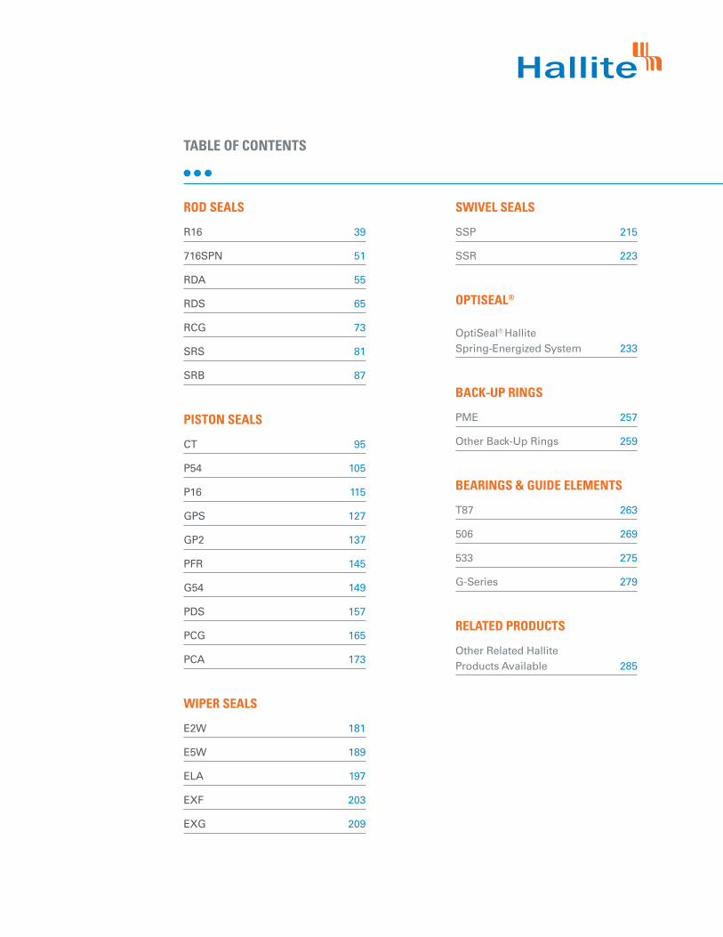
ROD SEALS
R16 39
716SPN 51
RDA 55
RDS 65
RCG 73
SRS 81
SRB 87
PISTON SEALS
CT 95
P54 105
P16 115
GPS 127
GP2 137
PFR 145
G54 149
PDS 157
PCG 165
PCA 173
WIPER SEALS
E2W 181
E5W 189
ELA 197
EXF 203
EXG 209
SWIVEL SEALS
SSP 215
SSR 223
OPTISEAL®
OptiSeal® Hallite Spring-Energized System 233
BACK-UP RINGS
PME 257
Other Back-Up Rings 259
BEARINGS & GUIDE ELEMENTS
T87 263
506 269
533 275
G-Series 279
RELATED PRODUCTS
Other Related Hallite Products Available 285
TABLE OF CONTENTS

SELE
CT IT
&
FORG
ET IT
At Hallite, we want to help you forget about your seals. It’s not that we don’t understand the critical role they play in the performance and productivity of your equipment — quite the contrary. After all, as a leading manufacturer of high-performance sealing solutions, we’ve been developing and delivering high-quality seals for a wide variety of markets for over a century.
Now, with our new PTFE fluid seals offering, we’ve expanded our portfolio again, continuing to offer our customers around the world the reliable products and services they depend upon from Hallite.
Developed from material and compound production expertise within Hallite and our sister companies, CDI Energy Products and EGC Critical Components, our PTFE seals come in a complete range of product profiles, forming one of the most comprehensive collections of its kind in the industry. Plus, as with all of our seals, they come with the technical services to help provide the advice necessary in developing tailored product solutions.
And that’s precisely the point: when you partner with Hallite, you CAN forget about your seals. Because you’re purchasing more than our proven products; You’re buying into a relationship that you can trust will deliver the peace of mind you deserve.
MAJOR INDUSTRIES
• Agriculture
• Chemical Processing
• Construction & Forestry
• Food & Beverage
• General Industry
• Hydro-Power
• Injection Molding
• Machine Tools
• Marine
• Material Handling
• Mining & Mineral Extraction
• Mobile Hydraulics/Off-Highway
• Oil & Gas
• Steel & Aluminum Processing
• Transportation
WWW.HALLITE.COM 5

TRIED
&
TRUS
TED HALLITE ARMORLENE® PTFE PORTFOLIO
PTFE is the most chemical-resistant thermoplastic polymer available. PTFE offers low friction, exceptional chemical resistance, and sealability not found in most plastic materials.
The Hallite PTFE material and product portfolio is a fit-for-purpose solution designed for dynamic and static sealing applications, where high speeds up to 15 m/s (50 ft/s), low friction, temperatures ranging from -200 to 260°C (-328 to 500°F), strong wear performance,
broad fluid compatibility and high pressure capabilities up to 600 bar (8700 psi) are required. Our material technology, enhanced by the company's deep technical and testing expertise, enables Hallite to engineer unique, custom sealing solutions. Hallite engineers can help you select which high-performance compounds made from filler combinations of glass, bronze or other metals, PPS, graphite, MoS2, carbon, mineral, carbon fiber, and other fillers will optimize performance in your application.
Whatever You Need, We Can Help A robust portfolio of cataloged products and value-added engineering and manufacturing services that meet and exceed customer needs and expectations.
One High Standard, EverywhereA commitment to global quality and production standards that ensure consistency everywhere in the world.
Service As Realiable As Our SealsA dedication to getting it done right and on time — the first time. Ensuring products and value-added services are delivered on time and to exact specifications.
For over 100 years, Hallite Seals has been a leading supplier and pioneer of high-quality fluid sealing technologies and engineered sealing solutions. As a global organization with a keen focus on worldwide delivery through regional manufacturing sites and fabrication centers, we are able to leverage our expertise in engineering design, superior quality, and advanced manufacturing and production processes to meet your supply needs when and where you need them the most. From high-volume production runs to bespoke sealing solutions, the longevity of our success in meeting the demands of OEMs, distributors and aftermarket specialists can be attributed to doing things the “Hallite Way.”
We bring to market a blend of cataloged and fit-for-purpose, quality products that offer cost-performance. Over the years, we have refined our business approach to provide services to our customers that are searching for both engineered solutions and off-the-shelf products from a single-source supplier.
We are constantly adding to our range of profiles and sizes for ISO standard and Asian housing. Please review the product catalog for a complete list of products or contact your nearest Hallite sales office or official Hallite distributor for further information.
THE HALLITE WAY
WWW.HALLITE.COM 7

GLOB
AL Q
UALIT
Y
CERT
IFICA
TIONS
It’s more than simply what we do, it’s who we are.
At Hallite, quality, health, safety, and environmental concerns are more than checklist items. Our focus on QHSE is ingrained into our company culture and is an integral component of corporate responsibility. A safe, healthy work environment positions our global team to provide the highest quality, on-time delivery, and service excellence. Industry standards such as the ISO 14001, ISO 9001:2010, and the OHSAS 18001 management systems help us continually improve on all elements of QHSE while ensuring regulatory compliance.
Our commitment to QHSE comes from genuine concern about our people, our customers, the environment, and corporate responsibility. The health and safety culture at Hallite is based on personal empowerment, encouraging each employee to take personal responsibility in following the protocols and procedures that ensure QHSE compliance.
HAMBURG
DAYTONA BEACH
TORONTO
BANGALORE
SYDNEY
NEWCASTLE
SINGAPORE
WIXOM
LEEDS
STAVANGER
LIVORNO
SHANGHAI
PERTH
HOUSTON
HAMPTON
HAMBURG, GERMANY
• ISO 9001 Quality
• ISO 14001 Environmental
• OHSAS 18001 Health and Safety
BANGALORE, INDIA
• ISO 9001 Quality
• ISO 14001 Environmental
JIADING, SHANGHAI, CHINA
• ISO 9001 Quality
• OHSAS 18001 Health and Safety
AUSTRALIA
• ISO 9001 Quality
WIXOM, MI, USA
• ISO 9001 Quality
• ISO 14001 Environmental
• OHSAS 18001 Health and Safety
TORONTO, ON, CANADA
• ISO 9001 Quality
HAMPTON, UK • ISO 9001 Quality
• AS 9100 Aerospace Quality
• ISO 14001 Environmental
• OHSAS 18001 Health and Safety
LIVORNO, ITALY
• ISO 9001 Quality
MANUFACTURING FACILITIES WITH QHSE CERTIFICATIONS
CDI ENERGY PRODUCTS
• Houston, TX, USA
• Singapore
• Leeds, UK
• Stavanger, Norway
• Hampton, UK
EGC CRITICAL COMPONENTS
• Houston, TX, USA
AIP PRECISION MACHINING
• Daytona Beach, FL, USA
OTHER DIVISIONAL MANUFACTURING SITES
WWW.HALLITE.COM 9

FILLED PTFEMATERIALS
In spite of its remarkable properties, pure unmixed PTFE has limited use for applications where high mechanical loading is required, due to its tendency towards cold extrusion (creep). While maintaining its inherent properties and characteristics in material compounds, PTFE can benefit from the improved mechanical strength, stability, and wear resistance provided by an additive. Hallite uses various fillers to optimize PTFE characteristics such as glass, carbon, graphite, MoS2, bronze, and mineral.
Hallite’s experienced team of engineers can help you carefully select fillers based on the application media and seal geometry. We can also custom blend if you need material properties that go beyond the limits of our listed materials. Give us a call and we can partner with you to find the best material choice for your application.
Proper material selection and compatibility rank high among the factors that contribute to good sealability. In seal design, materials are chosen for the physical attributes, performance properties, and performance characteristics required by the application.
The application environment, including temperature, pressure, and dynamic conditions, as well as design factors such as squeeze and seal geometry and energizer selection, are essential in material selection. The materials used with Hallite seal profiles perform exceptionally well in applications with variations in temperature, pressure and media. The result is a sealing solution capable of performing in dynamic, hostile environments where standard elastomeric seals fail.
IDEAL FOR Filled PTFE has improved mechanical properties and is excellent for dynamic applications and high pressures (up to 6000 psi). Different fillers provide different properties.
ADVANTAGES• Improved wear resistance• Improved heat transfer• Increase in mechanical strength
• Improved extrusion resistance• Decreased friction• Increase in thermal conductivity
DISADVANTAGES • Less flexibility in processing (requires machining)
COMMON FILLERS
Glass Fibers The most common filler. Minor effect on electrical properties. Increased abrasion on mating metal surfaces.
Carbon/Carbon Fibers Low abrasion and wear. Good deformation and extrusion resistance.
Graphite Non-abrasive. Low friction. Minor effect on deformation properties.
MoS2
Lowers break-in wear and starting friction.
Bronze Very high wear resistance and load-bearing capability. Poor chemical resistance.
Mineral Properties similar to glass, but less abrasive.
TEMPERATURE RANGE(DRY HEAT) -200 to 260°C -328 to 500°F
COMMON MATERIALS
PTFE
• Thermal stability across broad temperature range
• Low coefficient of friction• Inherent lubricating properties• Excellent chemical and
corrosion capabilities
• Reduced stick-slip• Unlimited shelf life• No swelling due to moisture absorption• Safe for vacuum conditions• Excellent dielectrical properties
UHMWPE• High toughness• High abrasion resistance• Self-lubricating
• Low coefficient of friction• Broad chemical resistance
ELASTOMER
• Great sealability• High toughness• Very flexible
• Broad selection of polymer types with unique properties
• Available in both thermoset and thermoplastic
FILLERS AND THEIR RELATIVE EFFECTS ON PTFE
WEA
R RE
SIST
AN
CE
FRIC
TIO
N
CREE
P RE
SIST
AN
CE
THER
MA
L CO
ND
UCT
IVIT
Y
MAT
ING
M
ETA
L W
EAR
ELEC
TRIC
AL
RESI
STA
NCE
GLASS FIBERS
CARBON
GRAPHITE
MOS2
BRONZE
CARBON FIBERS
MINERAL
HIGH-TEMPERATURE POLYMERS
= Slight Increase
= Moderate Increase
= Significant Increase
= Slight Decrease
= Moderate Decrease
= Significant Decrease
KEY
= No Effect
WWW.HALLITE.COM10 WWW.HALLITE.COM 11

HALLITE HIGH-PERFORMANCE ARMORLENE® MATERIALS HALLITE HIGH-PERFORMANCE ARMORLENE® MATERIALS
MATERIAL FEATURES AND APPLICATIONS FILLER MATERIAL
DESIGNATOR COLOR TEMPERATURE RANGE°C
TEMPERATURE RANGE°F
ARMORLENE® 701• Excellent in lubricating and non-lubricating
hydraulic fluids• Excellent extrusion resistance• Good chemical resistance• Good dielectrical properties
25% Glass 701 Off- White -73 to 260°C -100 to 500°F
ARMORLENE® 711• Excellent in all lubricating fluids and
pneumatic applications• High chemical resistance• Excellent extrusion resistance• Excellent wear properties
25% Carbon/Graphite 711 Black -73 to 288°C -100 to 550°F
ARMORLENE® 734• Excellent in all lubricating fluids and
pneumatic applications• High chemical resistance• Excellent extrusion resistance
10% Carbon/Graphite 734 Black -73 to 260°C -100 to 500°F
ARMORLENE® 716• Excellent in all lubricating fluids and
pneumatic applications• High chemical resistance
Graphite 716 Black -73 to 260°C -100 to 500°F
ARMORLENE® 713• High compressive strength• Excellent extrusion resistance• Excellent wear properties
60% Bronze Content 713 Bronze -73 to 288°C -100 to 550°F
ARMORLENE® HQ6• Standard material for G16 and G54 profiles• Excellent in lubricating and non-lubricating
hydraulic fluids• Excellent extrusion resistance• Excellent chemical resistance
Special Glass Compound HQ6 White -73 to 288°C -100 to 550°F
ARMORLENE® 782• Good abrasion resistance• Recommended for lubricating and
non-lubricating fluids• Recommended for high frequency and
short-stroke applications• Not recommended for electrical conductive fluids
Modified Carbon Fiber
Filled782 Black -73 to 260°C -100 to 500°F
ARMORLENE® H1G• Excellent in lubricating and non-lubricating fluids• Excellent extrusion resistance• Good chemical resistance• Good dialectical properties
15% Glass H1G Gold -73 to 260°C -100 to 500°F
ARMORLENE® H2B• Excellent in lubricating and non-lubricating fluids• Excellent extrusion resistance• Good chemical resistance• Good dialectical properties
25% Glass H2B Blue -73 to 260°C -100 to 500°F
ARMORLENE® PME• Special formulated PTFE for PME back up rings• Does not require resizing after assembly• Provides excellent extrusion resistance
Unfilled PME White -184 to 204°C -300 to 400°F
MATERIAL FEATURES AND APPLICATIONS FILLER MATERIAL
DESIGNATOR COLOR TEMPERATURE RANGE°C
TEMPERATURE RANGE°F
ARMORLENE® HLX• Standard material for hydraulic applications• High compressive strength• Excellent extrusion resistance• Extended wear resistance
Special Bronze Compound HLX Gold -73 to 288°C -100 to 550°F
ARMORLENE® HLA• Excellent in all hydraulic fluids• Excellent wear resistance• Excellent low-friction properties• Good extrusion resistance
Special Mineral Compound HLA Gray -73 to 260°C -100 to 500°F
ARMORLENE® 702• Excellent in lubricating and non-lubricating
hydraulic fluids• Good low-friction properties• Excellent extrusion resistance• Good chemical resistance
Glass Molybdenum
Disulfide702 Gray -73 to 260°C -100 to 500°F
ARMORLENE® HCF• Excellent in lubricating and non-lubricating hydraulic
fluids (includes water) w/o zinc content• Not recommended for gas sealing applications• Not recommended for electrical conductive fluids
Carbon Fiber Filled HCF Gray/
Black -73 to 260°C -100 to 500°F
ARMORLENE® HCV• Recommended for lubricating and
non-lubricating fluids• Excellent for high-frequency and
short-stroke applications• Not recommended for gas sealing applications• Not recommended for electrical conductive fluids
High Carbon Fiber Filled HCV Gray/
Black -73 to 260°C -100 to 500°F
ARMORLENE® 700• Excellent in all hydraulic fluids• Recommended for hard mating surfaces only• Low friction and no stick-slip
Unfilled 700 White -184 to 204°C -300 to 400°F
ARMORLENE® 780• Excellent in all hydraulic fluids• Recommended for hard mating surfaces only• Low friction and no stick-slip
Unfilled 780 Turquoise -184 to 232°C -300 to 450°F
ARMORLENE® 706• Excellent in lubricating and non-lubricating
hydraulic fluids• Excellent extrusion resistance• Good chemical resistance• Good dielectrical properties
15% Glass 706 Off- White -73 to 260°C -100 to 500°F
WWW.HALLITE.COM12 WWW.HALLITE.COM 13

HALLITE HIGH-PERFORMANCE HYTHANE® MATERIALS
MATERIAL FEATURES AND APPLICATIONS FILLER MATERIAL
DESIGNATOR COLOR TEMPERATURE RANGE°C
TEMPERATURE RANGE°F
HYTHANE® 9270061 - POLYESTER, 55D• Positive position load holding• High chemical resistance• Excellent extrusion resistance• Excellent wear properties
Standard 061 Red -40 to 120°C -40 to 250°F
HYTHANE® 9270111 - POLYESTER, 55D• Positive position load holding• Hydrolysis stabilized• Strong chemical resistance• Excellent extrusion resistance• Excellent wear properties
Hydrolysis Stabilized 111 Gray -40 to 120°C -40 to 250°F
HYTHANE® 9270261 - POLYESTER, 55D• Positive position load holding• Internal lubrication provides extended wear
in high-speed applications• Excellent extrusion resistance• Excellent wear resistance
Internally Lubricated 261 Off-
White -40 to 120°C -40 to 250°F
HU5 - POLYURETHANE, 55D • Positive position load holding• Excellent extrusion resistance• Excellent wear resistance
Standard HU5 Yellow -20 to 115°C -4 to 240°F
HU9 - POLYURETHANE, 95A• Positive position load holding• Excellent extrusion resistance• Excellent wear resistance
Standard HU9 Red -20 to 115°C -4 to 240°F
HE5 - POLYESTER, 55D• Positive position load holding• Excellent extrusion resistance• Excellent wear resistance
Standard HE5 Gray/ Black -20 to 115°C -20 to 240°F
748 - UHMWPE• Excellent impact resistance• Good dielectrical properties• Excellent abrasion resistance• Low coefficient of friction
Standard 748 Translucent -184 to 82°C -300 to 180°F
7HP - UHMWPE• High temperature resistance• Good dielectrical properties• Excellent abrasion and impact resistance• Low coefficient of friction
Modified 7HP Translucent -30 to 135°C -22 to 275°F
MASTER ENERGIZER MATERIALS
ENERGIZER MATERIAL (SHORE A)
ENERGIZER TYPE
ENERGIZER DESIGNATION
ENERGIZER OPERATING TEMPERATURE°C
ENERGIZER OPERATING TEMPERATURE°F
NBR - 70A O-ring N -30 to 100°C -22 to 212°F
NBR - 70A Low temp. O-ring L -45 to 80°C -49 to 176°F
FKM - 75A O-ring F -10 to 200°C 14 to 392°F
EPDM - 70A O-ring E -45 to 145°C -49 to 293°F
HNBR - 70A O-ring H -25 to 150°C -13 to 302°F
NBR - 90A O-ring Q -30 to 100°C -22 to 212°F
HNBR - 90A O-ring U -25 to 150°C -13 to 302°F
NBR - 70A (GPS Inch, PDA and PFR only) Square R -30 to 100°C -22 to 212°F
FKM - 75A NBR - 70A (GPS Inch and PDA) Square K -10 to 200°C 14 to 392°F
No Energizer* None X - -
NBR - 80A Capped T N -30 to 100°C -22 to 212°F
NBR - 80A Low temp. Capped T L -45 to 80°C -50 to 175°F
HNBR - 80A Capped T H -25 to 150°C -13 to 300°F
FKM - 85A Capped T F -10 to 200°C 15 to 400°F
NBR - 85A O-ring A -30 to 110°C -22 to 230°F
NBR - 80A Low temp. O-ring C -50 to 110°C -58 to 230°F
FKM - 85A O-ring G -20 to 200°C -4 to 392°F
EPDM - 85A O-ring M -45 to 130°C -49 to 266°F
HNBR - 90A O-ring T -20 to 150°C -4 to 302°F
NBR - 85A Square/Capped T B -30 to 110°C -22 to 230°F
NBR - 80A Low temp. Square/Capped T D -50 to 110°C -58 to 230°F
FKM - 85A Square/Capped T J -20 to 210°C -4 to 392°F
EPDM - 85A Square P -45 to 130°C -49 to 266°F
HNBR - 90A Square/Capped T S -20 to 150°C -4 to 302°F
*Seal ratings are based upon capabilities of its matched material components. Hallite cannot rate seal performance when the seal is mixed with other manufacturers’ energizers/components.
Often PTFE seals utilize an elastomeric energizer to provide proper contact load on initial sealing. The choice of elastomer depends on the operating temperature and media. Please refer to the Master Energizer Index below for elastomer type and service temperature limits. For most hydraulic applications, bronze-filled PTFE with 70A NBR O-ring is commonly used throughout this catalog.
OTHER OPTIONS
The above data provides guidance to maximum operating values of the profile. Both values are not to be used at the same time. Maximum speeds and pressures are dependent upon type of material being used, gap, and operating temperature of the application. If you do not find the material that you require, please contact your local Hallite sales office.
NO
TE
WWW.HALLITE.COM14 WWW.HALLITE.COM 15

MATERIALS & FLUID COMPATIBILITY
MATERIAL FEATURES AND APPLICATIONS
FILL
ER
COLO
R
AB
RASI
ON
RE
SIST
AN
CE
MET
AL
MAT
ING
WEA
R
RELA
TIVE
SE
ALA
BIL
ITY
RELA
TIVE
EXT
RUSI
ON
RE
SIST
AN
CE
HYD
ROCA
RBO
NS
OXY
GEN
ATED
SO
LVEN
TS
STEA
M
ACI
DS
BA
SES
Armorlene® HLX Special Bronze Compound Gold E M A G E E E NR W
Armorlene® HLA Special Mineral Compound Gray G M G G E E E W S
Armorlene® 702Glass
Molybdenum Disulfide
Gray E H G G E E E S S
Armorlene® HCF Carbon Fiber Filled
Gray/ Black G M G G E E E S S
Armorlene® HCV High Carbon Fiber Filled
Gray/ Black G M G G E E E S S
Armorlene® 700 Unfilled White P L E P E E E S S
Armorlene® 780 Unfilled Turquoise A L E A E E E S S
Armorlene® 706 15% Glass Off- White E H G G E E E S S
Armorlene® 701 25% Glass Off- White E H G G E E E S S
Armorlene® 711 25% Carbon/Graphite Black G M G E E E E S S
Armorlene® 734 10% Carbon/Graphite Black G M G G E E E S S
KEY
E = Excellent G = Good H = High A = Average M = Medium
L = Low P = Poor NR = Not Recommended W = Resistant to weak acid/base S = Resistant to strong acid/base
MATERIALS & FLUID COMPATIBILITY
MATERIAL FEATURES AND APPLICATIONS
FILL
ER
COLO
R
AB
RASI
ON
RE
SIST
AN
CE
MET
AL
MAT
ING
WEA
R
RELA
TIVE
SE
ALA
BIL
ITY
RELA
TIVE
EXT
RUSI
ON
RE
SIST
AN
CE
HYD
ROCA
RBO
NS
OXY
GEN
ATED
SO
LVEN
TS
STEA
M
ACI
DS
BA
SES
Armorlene® 716 Graphite Black A M E G E E E S S
Armorlene® 713 60% Bronze Content Bronze E M A G E E E NR W
Armorlene® HQ6 Special Glass Compound White E H G G E E E S S
Armorlene® 782 Modified Car-bon Fiber Filled Black G M G G E E E S S
Armorlene® H1G 15% Glass Gold E H G G E E E S S
Armorlene® H2B 25% Glass Blue E H G G E E E S S
HYTHANE® 9270061 - POLYESTER Standard Red E E E E E NR L NR NR
HYTHANE® 9270111 - POLYESTER Hydrolysis Stabilized Gray E E E E E NR L NR NR
HYTHANE® 9270261 - POLYESTER Internally Lubricated
Off- White E E E E E NR L NR NR
HU5 - POLYURETHANE, 55D Standard Yellow E E E E E NR L NR NR
HU9 - POLYURETHANE, 95A Standard Red E E E E E NR L NR NR
HE5 - POLYESTER Standard Gray/ Black E E E E E NR L NR NR
748 - UHMWPE Standard Translucent E L E G E E E S S
7HP - UHMWPE Standard Translucent E L E G E E E S S
WWW.HALLITE.COM16 WWW.HALLITE.COM 17

PRO
FILE
D
ESIG
NAT
ION
OPERATING CONDITIONS
MA
X D
IAM
ETER
SIN
GLE
OR
DO
UB
LE A
CTIN
G
APPLICATION CONSIDERATIONS
PAG
E #
PARA
MET
ER
MET
RIC
INCH
LIG
HT
DU
TY
MED
IUM
DU
TY
HEA
VY D
UTY
HIG
H S
PEED
HIGH
FRE
QUEN
CY
(DIT
HER)
PNEU
MAT
IC
ROD
SEA
LS (C
ON
TIN
UED
)
SRS
Maximum SpeedUp to
4.0m/secUp to
12.0ft/sec
2600mm (103in) Single o + o o o o 81
Temperature Range*
-45 to 200°C
-49 to 392°F
Maximum Dynamic Pressure** 400 bar 5800 psi
SRB
Maximum Speed Up to 4.0m/sec
Up to 12.0ft/sec
2600mm (103in) Single o o + o o o 87Temperature
Range*-45 to 200°C
-49 to 392°F
Maximum Dynamic Pressure** 600 bar 8700 psi
PIST
ON
SEA
LS
CT
Maximum Speed Up to 1.5m/sec
Up to 5.0ft/sec
1270mm (50in) Double o o + o o o 95
Temperature Range*
-45 to 200°C
-49 to 392°F
Maximum Dynamic Pressure** 600 bar 8700 psi
P54
Maximum Speed Up to 15.0m/sec
Up to 50.0ft/sec
2600mm (103in) Double o + o o o o 105Temperature
Range*-45 to 200°C
-49 to 392°F
Maximum Dynamic Pressure** 600 bar 8700 psi
P16
Maximum Speed Up to 15.0m/sec
Up to 50.0ft/sec
2600mm (103in) Single o + o + o o 115Temperature
Range*-45 to 200°C
-49 to 392°F
Maximum Dynamic Pressure** 600 bar 8700 psi
GPS
Maximum Speed Up to 2.0m/sec
Up to 6.5ft/sec
1270mm (50in) Double o + o + o o 127Temperature
Range*-45 to 200°C
-49 to 392°F
Maximum Dynamic Pressure** 500 bar 7200 psi
HALLITE SEAL DESIGN AND SELECTION INDEX
*Dependent upon energizer used (NBR, FKM, etc.). **For pressures above the maximum pressure listed, contact Hallite Engineering.
KEY+ = Preferred o = Acceptable – = Not Recommended
HALLITE SEAL DESIGN AND SELECTION INDEX
PRO
FILE
D
ESIG
NAT
ION
OPERATING CONDITIONS
MA
X D
IAM
ETER
SIN
GLE
OR
DO
UB
LE A
CTIN
G
APPLICATION CONSIDERATIONS
PAG
E #
PARA
MET
ER
MET
RIC
INCH
LIG
HT
DU
TY
MED
IUM
DU
TY
HEA
VY D
UTY
HIG
H S
PEED
HIGH
FRE
QUEN
CY
(DIT
HER)
PNEU
MAT
IC
ROD
SEA
LS
R16
Maximum SpeedUp to
15.0m/secUp to
50.0ft/sec
2600mm (103in) Single o + – + + – 39
Temperature Range*
-45 to 200°C
-49 to 392°F
Maximum Dynamic Pressure** 600 bar 8700 psi
716S
PN
Maximum Speed Up to 1.0m/sec
Up to 3.3ft/sec
2500mm (98in) Single o + o o
(+)o
(+) o 51Temperature Range*
-40 to 100°C
-40 to 212°F
Maximum Dynamic Pressure** 400 bar 5800 psi
RDA
Maximum Speed Up to 15.0m/sec
Up to 50.0ft/sec
2600mm (103in) Double o + o o o o 55Temperature
Range*-45 to 200°C
-49 to 392°F
Maximum Dynamic Pressure** 600 bar 8700 psi
RDS
Maximum Speed Up to 15.0m/sec
Up to 50.0ft/sec
2600mm (103in) Double o + - o o – 65Temperature
Range*-45 to 200°C
-49 to 392°F
Maximum Dynamic Pressure 350 bar 5000 psi
RCG
Maximum Speed Up to 15.0m/sec
Up to 50.0ft/sec
2600mm (103in) Double + o o o o o 73
Temperature Range*
-45 to 200°C
-49 to 392°F
Maximum Dynamic Pressure 200 bar 2900 psi
The Seal Design and Selection Index is designed to aid the customer in narrowing down practical seal design options for common applications. As such, we have used variables such as applications, groove efficiency, seal size, typical industry materials, and cost-effectiveness to create the ratings.
This should not be expressly interpreted as an indication that a seal design will not perform well in an application given an “acceptable” rating, for example. Rather it may be more costly than other seal design choices, and therefore its rating is not noted as preferred. These are general guidelines to help narrow down seal design options and are not intended to replace the specific technical application assistance your Hallite technical representatives can provide.
*Dependent upon energizer used (NBR, FKM, etc.). **For pressures above the maximum pressure listed, contact Hallite Engineering.
KEY+ = Preferred o = Acceptable – = Not Recommended
(+) When working as secondary rod seal
WWW.HALLITE.COM18 WWW.HALLITE.COM 19

HALLITE SEAL DESIGN AND SELECTION INDEX HALLITE SEAL DESIGN AND SELECTION INDEX
PRO
FILE
D
ESIG
NAT
ION
OPERATING CONDITIONS
MA
X D
IAM
ETER
SIN
GLE
OR
DO
UB
LE A
CTIN
G
APPLICATION CONSIDERATIONS
PAG
E #
PARA
MET
ER
MET
RIC
INCH
LIG
HT
DU
TY
MED
IUM
DU
TY
HEA
VY D
UTY
HIG
H S
PEED
HIGH
FRE
QUEN
CY
(DIT
HER)
PNEU
MAT
IC
PIST
ON
SEA
LS (C
ON
TIN
UED
)
GP2
Maximum SpeedUp to
3.0m/secUp to
10.0ft/sec
1270mm (50in) Double o o + + o o 137Temperature
Range*-45 to 200°C
-49 to 392°F
Maximum Dynamic Pressure** 600 bar 8700 psi
PFR
Maximum Speed Up to 4.0m/sec
Up to 13.0ft/sec
1270mm (50in) Double o + o o o o 145Temperature
Range*-45 to 200°C
-49 to 392°F
Maximum Dynamic Pressure 350 bar 5000 psi
G54
Maximum Speed Up to 4.0m/sec
Up to 12.0ft/sec
2600mm (103in) Double o + o o o o 149Temperature
Range*-45 to 200°C
-49 to 392°F
Maximum Dynamic Pressure** 400 bar 5800 psi
PDS
Maximum Speed Up to 15.0m/sec
Up to 50.0ft/sec
2600mm (103in) Double o + – o o – 157Temperature
Range*-45 to 200°C
-49 to 392°F
Maximum Dynamic Pressure 350 bar 5000 psi
PCG
Maximum Speed Up to 15.0m/sec
Up to 50.0ft/sec
2600mm (103in) Double o + o o o o 165Temperature
Range*-45 to 200°C
-49 to 392°F
Maximum Dynamic Pressure 200 bar 2900 psi
PCA
Maximum Speed Up to 4.0m/sec
Up to 13.0ft/sec
1270mm (50in) Double o + o o o o 173Temperature
Range*-45 to 200°C
-49 to 392°F
Maximum Dynamic Pressure** 350 bar 5000 psi
*Dependent upon energizer used (NBR, FKM, etc.). **For pressures above the maximum pressure listed, contact Hallite Engineering.
*Dependent upon energizer used (NBR, FKM, etc.). **For pressures above the maximum pressure listed, contact Hallite Engineering.
PRO
FILE
D
ESIG
NAT
ION
OPERATING CONDITIONS
MA
X D
IAM
ETER
APPLICATION CONSIDERATIONS
PAG
E #
PARA
MET
ER
MET
RIC
INCH
LIG
HT
DU
TY
MED
IUM
DU
TY
HEA
VY D
UTY
HIG
H S
PEED
HIGH
FRE
QUEN
CY
(DIT
HER)
PNEU
MAT
IC
WIP
ERS
E2W
MAXIMUM SPEEDUp to
15.0m/secUp to
50.0ft/sec2600mm (103in) o + o + + o 181
TEMPERATURE RANGE* -45 to 200°C -49 to 392°F
E5W
MAXIMUM SPEED Up to 15.0m/sec
Up to 50.0ft/sec
2600mm (103in) o o + + o o 189
TEMPERATURE RANGE* -45 to 200°C -49 to 392°F
ELA
MAXIMUM SPEED Up to 4.0m/sec
Up to 13.0ft/sec
2600mm (103in) o + o + + + 197
TEMPERATURE RANGE* -45 to 200°C -49 to 392°F
EXF
MAXIMUM SPEED Up to 15.0m/sec
Up to 50.0ft/sec
2600mm (103in) o o + + o o 203
TEMPERATURE RANGE* -45 to 200°C -49 to 392°F
EXG
MAXIMUM SPEED Up to 5.0m/sec
Up to 16.4ft/sec
2600mm (103in) o o + + o o 209
TEMPERATURE RANGE* -45 to 200°C -49 to 392°F
KEY+ = Preferred o = Acceptable – = Not Recommended
KEY+ = Preferred o = Acceptable – = Not Recommended
WWW.HALLITE.COM20 WWW.HALLITE.COM 21

OTHER HALLITE PRODUCTS INDEX OTHER HALLITE PRODUCTS INDEX
PROFILE DESIGNATION
OPERATING CONDITIONS
PAG
E #
PARAMETER METRIC INCH
BEA
RIN
GS
AN
D G
UID
E EL
EMEN
TS
T87
Maximum Speed Up to 5.0m/sec Up to 16.4ft/sec
263
Temperature Range −50 to 200°C −58 to 390°F
506
Maximum Speed Up to 5.0m/sec Up to 16.4ft/sec
269
Temperature Range −40 to 120°C −40 to 250°F
533
Maximum Speed Up to 5.0m/sec Up to 16.4ft/sec
275
Temperature Range −40 to 120°C −40 to 250°F
G-S
ERIE
S Maximum Speed Up to 5.0m/sec Up to 16.4ft/sec
279
Temperature Range -200 to 300°C -328 to 572°F
Data given are maximum values and can apply depending on specific application. Maximum ratings of temperature, pressure, or operating speeds are dependent on fluid medium, surface, gap value, and other variables such as dynamic or static service. Maximum values are not intended for use together at the same time, e.g. max temperature and max pressure. Please contact your Hallite technical representative for application support.
NO
TE
PROFILE DESIGNATION DESCRIPTION
PAG
E #
RELA
TED
PRO
DU
CTS
ROD SEALSHallite offers many less common seal profiles that are often made out of Armolene® PTFE materials. In addition, Hallite custom designs and manufactures seals developed for specific applications as a standard service. Over the years, this has resulted in accumulating an extensive library of profiles and designs that are purpose-built to suit demanding applications. Custom seals usually can be manufactured in short lead times and often do not require large volume minimums to be met.
In this section, we show some common Armorlene® based design variants that are semi-standard for your reference. If you do not see what you need or would like Hallite to purpose-design a seal for your application, please contact your Hallite technical representative.
285
PISTON SEALS
WIPERS SEALS
SWIVEL SEALS
PROFILE DESIGNATION
OPERATING CONDITIONS
PAG
E #
PARAMETER METRIC INCH
BA
CK-U
P RI
NG
S PME
Temperature Range −30 to 200°C −22 to 392°F 257
OTH
ER
BA
CK-U
P RI
NG
S
Temperature Range −30 to 200°C −22 to 392°F 259
PROFILE DESIGNATION DESCRIPTION
PAG
E #
OPT
ISEA
L® Complete Range of spring-energized OptiSeal®, designed for application.
OptiSeal® is designed using a wide range of jacket materials including filled virgin PEEK, various Armorlene® PTFE compounds, UHMWPE, and POM. Paired with V-springs, J-springs, and canted and helical flat coils made out of a variety of alloys.
233
PROFILE DESIGNATION
OPERATING CONDITIONS
PAG
E #
PARAMETER METRIC INCH
SWIV
EL S
EALS
SSP
Maximum Speed Up to 2.0m/sec Up to 6.5ft/sec
215Temperature Range* −45 to 200°C −49 to 392°F
Maximum Dynamic Pressure** 300 bar 4350 psi
SSR
Maximum Speed Up to 2.0m/sec Up to 6.5ft/sec
223Temperature Range* −45 to 200°C −49 to 392°F
Maximum Dynamic Pressure** 300 bar 4350 psi
*Dependent upon energizer used (NBR, FKM, etc.). **For pressures above the maximum pressure listed, contact Hallite Engineering.
Application limit PV ≤ 25 bar m/s (40 bar for interrupted rotary).
WWW.HALLITE.COM22 WWW.HALLITE.COM 23

USE & FITTING OF SEALS
Our quality control methods for material and manufacturing processes ensure that all seals leaving our factories are in a condition capable of giving a long and reliable service life. We have found, from many years of experience, that premature seal failure can be avoided if the following recommendations are considered at the design and manufacturing stage of the cylinder:
1 Specify piston and gland bearings which are adequately proportioned to support the cylinder loads. As a result of mounting misalignments and/or the working action of the cylinder, piston and gland bearings will be subjected to sideloading, causing damage to the rod or the tube surface and hence the seal, if the bearings are inadequate.
2 Ensure that seals are stored distortion free in a cool, dry, and dark place prior to fitting. See “Storage of Seals” directions.
3 Check that the seal housing is free from damage likely to harm the seal. Remove all sharp edges and burrs from metal parts, paying particular attention to ports, grooves, and threads over or through which the seal passes during assembly.
4 Clean all seal housing areas, ensuring that all metallic particles and other contaminants have been removed. Check that other surfaces adjacent to the passage of the seal upon fitting are also free of dirt, swarf, or other contaminants. Check that both static and dynamic housing surface finishes meet specifications.
5 Where the difference between a thread diameter over which the seal must pass and the seal diameter is small, use some form of protection over the thread, such as a fitting sleeve made of hard plastic.
6 Check that the seal is of the correct type, part number, and size, and that the specified material is correct. If there is any doubt regarding the material, contact your local Hallite sales office.
7 Lubricate all seals and metal components liberally with clean operating fluid or a compatible grease prior to assembly. N.B. Silicone grease should not be used in normal hydraulic applications.
8 Where seals fitted to sub-assemblies, such as pistons, are awaiting further fitting operations, ensure that the seals are not subjected to any misaligned or localized loading which will cause local deformation. Ensure that sub-assemblies remain clean.
9 The use of metal levers is not recommended, but should they be used it is imperative that they are completely smooth and free from nicks and burrs. When using them, ensure that the metal surfaces adjacent to the seal are not damaged.
10 Flush the hydraulic system thoroughly before connecting the cylinder to it.
CYLINDER OPERATING CONDITIONS
PRESSURE, SPEED, AND TEMPERATURE RANGE
From many years of application experience with sealing hydraulic equipment, supported by the results from an extensive test program, we know that it is necessary to link the three main operating features — speed, pressure, and temperature — to achieve a satisfactory seal performance. After carefully considering each product, we are able to specify the maximum speed and pressure with a temperature range within which the seal will operate safely. If your operating conditions do not comply with those recommended, please send details to your local Hallite sales office.
CYLINDER SPECIFICATION LIGHT DUTY MEDIUM DUTY HEAVY DUTY
PRES
SURE
Max 350 bar 5000 psi 500 bar 7500 psi 700 bar 10000 psi
Normal 160 bar 2300 psi 250 bar 3625 psi 400 bar 5800 psi
Working No pressure peaks Intermittent pressure peaks Regular pressure peaks
Design Lower operating stresses. Rigid well- aligned mounting, minimal side loading.
Steady operating stresses with intermittent high stress, some side loading.
Highly stressed for the majority of its working life. Side loading common.
Condition of Fluid Good system filtration. No cylinder contamination likely.
Good system filtration, but some cylinder contamination likely.
Contamination unavoidable from internal and external sources.
Working Environment Clean and inside a building. Operating temperature variations limited.
Mixture of indoors and outdoors but some protection from the weather.
Outdoors all the time or dirty indoor area. Wide variations in temperature, both ambient and working. Difficult service conditions.
UsageIrregular with short section of stroke at working pressures. Regular usage but at low pressure.
Regular usage with most of the stroke at working pressure.
Large amount of usage at high pressure with peaks throughout the stroke.
Typical Applications
• Machine tools• Lifting equipment• Mechanical handling• Injection molding machines• Control and robot equipment• Agricultural machinery• Packaging equipment• Aircraft equipment• Light duty tippers
• Heavy duty lifting equipment• Agricultural equipment• Light duty off-road vehicles• Cranes and lifting platforms• Heavy duty machine tools• Injection molding machines• Some auxiliary mining machinery• Aircraft equipment• Presses• Heavy duty tippers (telescopic)• Heavy duty mechanical handling
• Foundry and metal fabrication plant• Mining machinery• Roof supports• Heavy duty earthmoving machinery• Heavy duty off-road vehicles• Heavy duty presses
NO
TE
Data given are maximum values and can apply depending on specific application. Maximum ratings of temperature, pressure, or operating speeds are dependent on fluid medium, surface, gap value, and other variables such as dynamic or static service. Maximum values are not intended for use together at the same time, e.g. max temperature and max pressure. Please contact your Hallite technical representative for application support.
3
3
3
3
3
3
6
6
6
1
1
5
4
4
4
WWW.HALLITE.COM24 WWW.HALLITE.COM 25

SPECIFIED TOLERANCE TABLES
250
200
150
100
50
00 20 40 60
Hallite 506
Acetal
Hallite 87
GFN
Compressive Strain %
Compressive bearing stress versus strain for non-metallic materials
Stre
ss M
Pa
HALLITE 87, 506 & 533 BEARING STRIPHallite 87 strip is a low-friction bronze-filled PTFE compound produced in a flat tape style ready to be cut to size to suit individual applications. It is particularly effective in friction-conscious applications, such as servo cylinders.
Hallite 506 can be supplied in spiral lengths, generally in 10 meter lengths, as individual cut bearings, and also in 10 meter lengths, packed flat in a box dispenser. Hallite 506 bearing strip is manufactured to extremely accurate thickness tolerances, ensuring reliable cylinder alignment. Other sizes of type 506 are available on request; special sections and diameters can also be produced to suit individual requirements.
Hallite 533 are formed glass-filled nylon rings made for many different housing sizes.
BEARING TYPE STANDARD MATERIAL
87 PTFE + Bronze
506 Polyester + PTFE
533 GFN
METRIC INCH
HALLITE 506 SPECIFIED TOLERANCES
BEA
RIN
G L
ENG
TH
BEA
RIN
G C
ROSS
SE
CTIO
N
BEA
RIN
G L
ENG
TH
BEA
RIN
G C
ROSS
SE
CTIO
N
L1 S L1 S
Tolerances -0.1 to -0.6 -0.02 to -0.08 -0.005 to -0.025 -0.001 to -0.003
HALLITE 533 SPECIFIED TOLERANCES
BEA
RIN
G L
ENG
TH
BEA
RIN
G C
ROSS
SE
CTIO
N
L1 S
Tolerances (in) -0.000 to -0.010 -0.001 to -0.004
HALLITE 87 SPECIFIED TOLERANCES
BEA
RIN
G L
ENG
TH
BEA
RIN
G C
ROSS
SE
CTIO
N
L1 S
Tolerances (mm) -0.1 to -0.5 +0.03 to -0.05
BEARING STRIP HOUSING TOLERANCESPlease refer to the detailed bearing information located at the back of this catalog or in the EMEA catalog.
FACE RING AND OPTISEAL® INSTALLATION
For OptiSeal® installations, it is highly recommended that the two-piece, step-cut, or snap-ring gland be used. A full one-piece gland should only be used when modification of the existing gland is impossible. The following applies only to one-piece gland installation.
Both PTFE face ring and OptiSeal® are subjected to stretch during installation, and care must be taken to not damage the seal. Avoid the use of any sharp objects to push the seal into the groove. If possible, heating the seal in a conventional oven or soaking in hot water at 100°C for 10 to 15 minutes will make the installation process much easier.
ONE-PIECE PISTON GROOVEPlace the installation cone on the piston. For OptiSeal® place it on the cone so that the spring faces the installed direction on the piston. For an energized face seal assembly, install the energizer into the groove, then place the face ring on the cone. Push seal over the cone and into the groove using the installation expander.
If the seal does not return to its original size, use the resizing sleeve to reshape the seal. The installation cone, expander, and resizing sleeve are all available from Hallite. Additional tooling can be designed and manufactured for step-cut glands. Please contact your sales representative for more information, or submit your inquiry to [email protected].
ONE-PIECE ROD GROOVEFor OptiSeal®, this type of gland should not be used for rods less than 1.500in (38mm). Below this diameter a two-piece or step-cut gland must be used.
Begin installation by squeezing the seal into an elliptical shape, enabling it to fit onto the gland bore. With fingers or a radiused tool, push approximately 1/3 of the seal into the grove, being careful the seal component does not sustain damage.
Following this step, use a pusher tool the same diameter as the rod to push the remainder of the seal into the groove.
WWW.HALLITE.COM26 WWW.HALLITE.COM 27

HOUSING DESIGNS AND EXTRUSION GAPSSPECIFIED TOLERANCE TABLES
NOMINAL SIZES mm
SHAFTS (OUTSIDE DIAMETER) UNITS 0.01 mm
BORE (INSIDE DIAMETER) UNITS 0.01 mm
over to f8 f9 h8 h9 h10 h11 js10 js11 H8 H9 H10 H11 Js11
1.6 3 -6 -20
-6 -31
0 -14
0 -25
0 -40
0 -60
+20 -20
+30 -30
+14 0
+25 0
+40 0
+60 0
+30 -30
3 6 -10 -28
-10 -40
0 -18
0 -30
0 -48
0 -75
+24 -24
+37.5 -37.5
+18 0
+30 0
+48 0
+75 0
+37.5 -37.5
6 10 -13 -35
-13 -49
0 -22
0 -36
0 -58
0 -90
+29 -29
+45 -45
+22 0
+36 0
+58 0
+90 0
+45 -45
10 18 -16 -43
-16 -59
0 -27
0 -43
0 -70
0 -110
+35 -35
+55 -55
+27 0
+43 0
+70 0
+110 0
+55 -55
18 30 -20 -53
-20 -72
0 -33
0 -52
0 -84
0 -130
+42 -42
+65 -65
+33 0
+52 0
+84 0
+130 0
+65 -65
30 50 -25 -64
-25 -87
0 -39
0 -62
0 -100
0 -160
+50 -50
+80 -80
+39 0
+62 0
+100 0
+160 0
+80 -80
50 80 -30 -76
-30 -104
0 -46
0 -74
0 -120
0 -190
+60 -60
+95 -95
+46 0
+74 0
+120 0
+190 0
+95 -95
80 120 -36 -90
-36 -123
0 -54
0 -87
0 -140
0 -220
+70 -70
+110 -110
+54 0
+87 0
+140 0
+220 0
+110 -110
120 180 -43 -106
-43 -143
0 -63
0 -100
0 -160
0 -250
+80 -80
+125 -125
+63 0
+100 0
+160 0
+250 0
+125 -125
180 250 -50 -122
-50 -165
0 -72
0 -115
0 -185
0 -290
+92 -92
+145 -145
+72 0
+115 0
+185 0
+290 0
+145 -145
250 315 -56 -137
-56 -186
0 -81
0 -130
0 -210
0 -320
+105 -105
+160 -160
+81 0
+130 0
+210 0
+320 0
+160 -160
315 400 -62 -151
-62 -202
0 -89
0 -140
0 -230
0 -360
+115 -115
+180 -180
+89 0
+140 0
+230 0
+360 0
+180 -180
400 500 -68 -165
-68 -223
0 -97
0 -155
0 -250
0 -400
+125 -125
+200 -200
+97 0
+155 0
+250 0
+400 0
+200 -200
500 630 -76 -186
-76 -251
0 -110
0 -175
0 -280
0 -440
+140 -140
+220 -220
+110 0
+175 0
+280 0
+440 0
+220 -220
630 800 -80 -205
-80 -280
0 -125
0 -200
0 -320
0 -500
+160 -160
+250 -250
+125 0
+200 0
+320 0
+500 0
+250 -250
CYLINDER HOUSING AND ROD, PISTON, BORE, AND GLAND TOLERANCES
NOMINAL SIZES in
SHAFTS (OUTSIDE DIAMETER) UNITS 0.001 in
BORE (INSIDE DIAMETER) UNITS 0.001 in
over to f8 f9 h8 h9 h10 h11 js10 js11 H8 H9 H10 H11 Js11
0.04 0.12 -0.3 -0.9
-0.3 -1.2
0 -0.6
0 -1.0
0 -1.6
0 -2.5
+0.8 -0.8
+1.3 -1.3
+0.6 0
+1.0 0
+1.6 0
+2.5 0
+1.3 -1.3
0.12 0.24 -0.4 -1.1
-0.4 -1.6
0 -0.7
0 -1.2
0 -1.8
0 -3.0
+0.9 -0.9
+1.5 -1.5
+0.7 0
+1.2 0
+1.8 0
+3.0 0
+1.5 -1.5
0.24 0.40 -0.5 -1.4
-0.5 -1.9
0 -0.9
0 -1.4
0 -2.2
0 -3.5
+1.1 -1.1
+1.8 -1.8
+0.9 0
+1.4 0
+2.2 0
+3.5 0
+1.8 -1.8
0.40 0.71 -0.6 -1.6
-0.6 -2.3
0 -1.0
0 -1.6
0 -2.8
0 -4.0
+1.4 -1.4
+2.0 -2.0
+1.0 0
+1.6 0
+2.8 0
+4.0 0
+2.0 -2.0
0.71 1.19 -0.8 -2.0
-0.8 -2.8
0 -1.2
0 -2.0
0 -3.5
0 -5.0
+1.8 -1.8
+2.5 -2.5
+1.2 0
+2.0 0
+3.5 0
+5.0 0
+2.5 -2.5
1.19 1.97 -1.0 -2.6
-1.0 -3.4
0 -1.6
0 -2.5
0 -4.0
0 -6.0
+2.0 -2.0
+3.0 -3.0
+1.6 0
+2.5 0
+4.0 0
+6.0 0
+3.0 -3.0
1.97 3.15 -1.2 -3.0
-1.2 -4.1
0 -1.8
0 -3.0
0 -4.5
0 -7.0
+2.3 -2.3
+3.5 -3.5
+1.8 0
+3.0 0
+4.5 0
+7.0 0
+3.5 -3.5
3.15 4.73 -1.4 -3.6
-1.4 -4.8
0 -2.2
0 -3.5
0 -5.0
0 -9.0
+2.5 -2.5
+4.5 -4.5
+2.2 0
+3.5 0
+5.0 0
+9.0 0
+4.5 -4.5
4.73 7.09 -1.6 -4.1
-1.6 -5.6
0 -2.5
0 -4.0
0 -6.0
0 -10.0
+3.0 -3.0
+5.0 -5.0
+2.5 0
+4.0 0
+6.0 0
+10.0 0
+5.0 -5.0
7.09 9.85 -2.0 -4.8
-2.0 -6.5
0 -2.8
0 -4.5
0 -7.0
0 -12.0
+3.5 -3.5
+6.0 -6.0
+2.8 0
+4.5 0
+7.0 0
+12.0 0
+6.0 -6.0
9.85 12.41 -2.2 -5.2
-2.2 -7.3
0 -3.0
0 -5.0
0 -8.0
0 -12.0
+4.0 -4.0
+6.0 -6.0
+3.0 0
+5.0 0
+8.0 0
+13.0 0
+6.0 -6.0
12.41 15.75 -2.5 -6.0
-2.8 -8.0
0 -3.5
0 -6.0
0 -9.0
0 -14.0
+4.5 -4.5
+7.0 -7.0
+3.5 0
+6.0 0
+9.0 0
+14.0 0
+7.0 -7.0
15.75 19.69 -2.8 -6.5
-2.8 -8.8
0 -4.0
0 -6.0
0 -10.0
0 -16.0
+5.0 -5.0
+8.0 -8.0
+4.0 0
+6.0 0
+10.0 0
+16.0 0
+8.0 -8.0
19.69 24.80 -3.0 -7.0
-3.0 -9.9
0 -4.3
0 -6.9
0 -11.0
0 -17.3
+5.5 -5.5
+8.7 -8.7
+4.3 0
+6.9 0
+11.0 0
+17.3 0
+8.7 -8.7
24.80 31.49 -3.1 -8.1
-3.1 -11.0
0 -4.9
0 -7.9
0 -12.6
0 -19.7
+6.3 -6.3
+9.8 -9.8
+4.9 0
+7.9 0
+12.6 0
+19.7 0
+9.8 -9.8
HALLITE 87, 506 & 533 BEARING STRIPHallite Seals’ product data sheets give information indicating the allowable extrusion gap a seal can see at pressure during its working life. The extrusion gap can be calculated using the tolerance build-ups within the cylinder and any dilation that may occur under pressure.
• Maximum extrusion gap = F max (see drawing below).
• F max is the maximum extrusion gap for the seal.
• Minimum metal-to-metal clearance = F min (see drawing below).
F min for cylinders with minimal side loading should be >0.1mm (0.004”).
RODS
Maximum extrusion gap
F max = (ØD3 max + ØD2 max) - S min - Ød1 min
2
Minimum metal-to-metal clearance (extrusion gap)
F min = S min - (ØD2 max - ØD3 min)
2
PISTONS
Maximum extrusion gap
F max = ØD1 max - S min - (Ød3 min + Ød2 min) + dilation
2
Minimum metal-to-metal clearance (extrusion gap)
F min = S min - (Ød3 max - Ød2 min)
2
Calculate both F max and F min
Ensure the F min is greater than 0.1mm (0.004”) and F max is less than the maximum extrusion gap stated on the seal data sheet at the application’s working pressure.
For built-in metal bearings, the extrusion gap calculation is simpler.
For F max:
Rod = ØD3 max - Ød1 minPiston = ØD1 max - Ød3 min + dilation
F min must be zero.
ROD BEARINGNote: Rod is not concentric with gland, because of clearances. (shown exaggerated)
PISTON BEARINGNote: Piston is not concentric with cylinder bore, because of clearances. (shown exaggerated)
Glandbore
diameterØD
Roddiameter
Ød
Bearinghousingdiameter
ØD
F min
F max
S
Rod
Housing
Rod sealgroove
2
1
3
F max
Bearinghousingdiameter
Ød
Pistondiameter
Ød
SBearingsection
F min
Borediameter
ØD
Cylinder
Piston
Piston sealgroove
3
2
1
WWW.HALLITE.COM28 WWW.HALLITE.COM 29

HOUSING DESIGNS
EXTRUSION GAPS AND METAL-TO-METAL CLEARANCEThe use of remote bearing strips, such as Hallite 506, often creates a conflict between maximizing the metal-to-metal clearance, avoiding metal-to-metal contact, and minimizing the extrusion gap for the seal. The design decisions that have to be made in this respect are not trivial. The following examples show the effects of looser and tighter tolerances on the minimum metal-to-metal clearance and the maximum extrusion gap. The values have been calculated using the housing design formula. No allowance has been made for the deflection of the bearings under side load or for the cylinder dilation, in the case of the piston example.
Once the maximum extrusion gap has been calculated, the correct seal can be specified with regard to the required operating pressure of the cylinder. For further advice, please contact Hallite Seals.
Gland for 50mm rod using ‘standard’ tolerances. Piston for 80mm bore using ‘standard’ tolerances.
Gland for 50mm rod with tighter tolerances, showing that the minimum metal-to-metal clearance can be increased and the maximum extrusion gap reduced.
Piston for 80mm bore with tighter tolerances showing that minimum metal-to-metal clearance can be increased and maximum extrusion gap reduced.
STORAGE OF SEALS
STORAGE CONDITIONSMost polymeric items, including vulcanized rubber and other elastomers, tend to change their properties during storage and may become unserviceable. This may be due to hardening, softening, cracking, crazing, or other degradation and may be the result of oxygen, ozone, light, heat, and/or humidity.
The following recommendations indicate the most suitable conditions for storing elastomeric items, whether as a single item or composite product.
1 Temperature - Storage temperatures should not exceed 50ºC. Low temperatures are not permanently harmful, provided the rubber items are handled carefully and not distorted. When taken from low temperatures, items should be raised to approximately 30ºC before they are used.
2 Humidity - Optimum humidity is about 65% in a draft-free atmosphere.
3 Light - Protection from direct sunlight and strong artificial light with a high ultraviolet content is important. Unless packed in opaque containers, it is advisable to cover windows with red or orange screens or coatings.
4 Oxygen and Ozone - Wrapping, storage in airtight containers, or other suitable means should be used for vulcanized rubber items. Storage in containers that limit exposure to environmental conditions (e.g. sealed plastic bags) should be used for all materials when possible.
5 Deformation - Where possible, rubber items should be stored in a relaxed position, free from tension or compression. Laying the item flat and avoiding suspension or crushing keeps it free from strain and minimizes deformation.
6 Contact with Liquid and Semi-Solid Material - Contact with liquids and semi-solid materials, particularly solvents, such as oils or greases should be avoided unless so packed by the manufacturer.
7 Contact with Metals - Metals such as manganese, iron, copper, or copper alloys can have a harmful effect on rubber. A layer of paper, polyethylene, or cellophane will keep these separated.
8 Contact with Non-Metals - Contact with other rubbers or creosotes should be avoided.
9 Stock Rotation - Elastomers should be stored for as short a period as possible, and strict stock rotation should be practiced.
10 Cleaning - Organic solvents such as trichloroethylene, carbon tetrachloride, and petroleum are the most harmful agents. Soap, water, and methylated spirits are the least harmful, and all parts should be dried at room temperature before use.
11 Shelf Life - The table on the next page shows the storage life of seal components made from the more common materials under ideal conditions. Storing under less-than-ideal conditions will reduce the life of the component.
Careful inspection for the following should be made before installation and after storage:
• Mechanical damage • Permanent distortion • Cracks or surface crazing • Tackiness or surface softening/hardening
Thin components (less than 1.6mm {1/16in}) tend to be more critically affected.
The appearance of bloom is relatively unimportant, except in certain non-toxic applications.
WWW.HALLITE.COM30 WWW.HALLITE.COM 31

STORAGE OF SEALS
BASE POLYMER (ISO DESIGNATION)
PRIMARY STORAGE PERIOD (YEARS)
EXTENSION OF STORAGE PERIOD AFTER RE-INSPECTION (YEARS)
FLUOROCARBON (FKM) ETHYLENE PROPYLENE (EPDM) 10 5
NITRILE (NBR) HYTHANE® (EU) HYTHANE (TPE) ARMORLENE®
7 3
POLYURETHANE (AU) 5 2
ENGINEERING THERMOPLASTICS: ACETAL (POM) POLYAMIDE (PA) GLASS FILLED NYLON (PA) PTFE POLYPHENYLENE SULPHIDE (PPS)
UNLIMITED -
ENGINEERING THERMOSETS: T560 BEARING STRIP UNLIMITED -
SURFACE FINISH
SURFACE FINISH
The dynamic surface finish has an immense influence on operation and service life of a sealing component. If the surface is too smooth, it will not properly retain lubrication and will cause excessive seal wear due to frictional heat. If the surface is too coarse, premature seal failure may occur due to the roughness of the surface, hence causing small cuts or scores in the sealing lip. Proper surface finish is critical in assuring maximum seal performance and life within a given application.
The static sealing and housing surface also has a significant influence on the operation and service life of a seal. Though the surface finish requirements are not as severe, it is critical to ensure surface finish recommendations are met to maximize seal performance and life.
DYNAMIC SURFACE FINISHESPiston rods are generally hard chrome plated. The hardness target should be at least 67 Rockwell C (900 HV/10). This gives an excellent tribological surface, and provided the rods are produced by an established supplier within a surface finish range of 0.1 to 0.3 µm Ra (4-12 µin Ra), no major problem should ensue. The optimum surface finish may also depend on the seal material. Bore surface finishes can be more problematic. The typical methods of achieving bore finishes are summarized in the figure below and bulleted details:
• Drawn Over Mandrel (DOM) tubing as produced, can be either adequate or inadequate depending on the actual surface texture achieved and the application.
• Special Smooth Inside Diameter (SSID) DOM: With the advent of improved manufacturing processes, SSID tubing is more commonplace than it was years ago. In certain circumstances however, SSID finishes, just like its rougher finish relative DOM tube, can lead to premature wear of the seal through flow erosion. Careful specification and regular quality inspections are recommended if SSID tube is to be used.
• Optimally, Skived & Roller Burnished or Honed Tube is preferred.
o Skived & Roller Burnished tubing is very smooth (less than 0.1µm Ra) (4 µin Ra). Rubber sealing elements are more susceptible to damage due to the smoother surfaces.
o Honed Tube (produced between 0.1 and 0.4 µm Ra) (4-16 µin Ra) is potentially the most expensive, but has the best finish and is known to be the friendliest to mating sealing elements.
STATIC SURFACE FINISHESThe static sealing surface finish must not be ignored in the control of leakage. Generally, these are fine tuned and should be free from chatter marks.
Rolled & Welded TubeHot Drawn Tube
Cold Drawn Over Mandrel (DOM)
(This improves mechanical properties by work hardening)
METHODS OF MANUFACTURING OF TUBES FOR HYDRAULIC CYLINDERS AND RESULTING SURFACE TEXTURES
Fine Finished DOM (i.e. as drawn)
Surface Finish >0.1µm Ra (>4 µin Ra)
Surface Texture Matt Gray (possibly with axial lines) (SSID tubing is reflective)
Skived and Roller Burnished
Surface Finish <0.1µm Ra (<4 µin Ra)
Surface Texture Characteristic circumferential lines (optical effect)
Honed (internally ground)
Surface Finish >0.1 - 1.6 µm Ra (>4 - 64 µin Ra)
Typically 0.4 µm Ra (16 µin Ra)
Surface Texture Characteristic cross-hatched pattern of fine grooves (emery lap-one direction)
WWW.HALLITE.COM32 WWW.HALLITE.COM 33
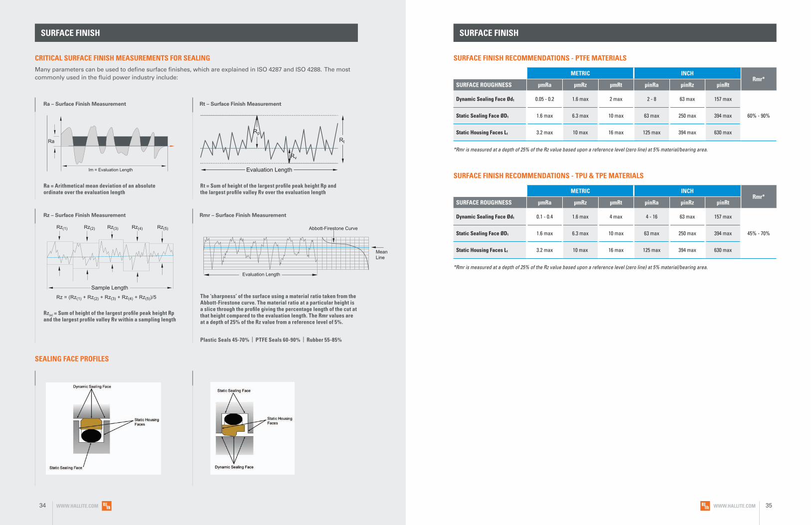
SURFACE FINISH RECOMMENDATIONS - PTFE MATERIALS
SURFACE FINISH RECOMMENDATIONS - TPU & TPE MATERIALS
SURFACE FINISH
*Rmr is measured at a depth of 25% of the Rz value based upon a reference level (zero line) at 5% material/bearing area.
*Rmr is measured at a depth of 25% of the Rz value based upon a reference level (zero line) at 5% material/bearing area.
METRIC INCHRmr*
SURFACE ROUGHNESS μmRa μmRz μmRt μinRa μinRz μinRt
Dynamic Sealing Face Ød1 0.05 - 0.2 1.6 max 2 max 2 - 8 63 max 157 max
60% - 90%Static Sealing Face ØD1 1.6 max 6.3 max 10 max 63 max 250 max 394 max
Static Housing Faces L1 3.2 max 10 max 16 max 125 max 394 max 630 max
METRIC INCHRmr*
SURFACE ROUGHNESS μmRa μmRz μmRt μinRa μinRz μinRt
Dynamic Sealing Face Ød1 0.1 - 0.4 1.6 max 4 max 4 - 16 63 max 157 max
45% - 70%Static Sealing Face ØD1 1.6 max 6.3 max 10 max 63 max 250 max 394 max
Static Housing Faces L1 3.2 max 10 max 16 max 125 max 394 max 630 max
CRITICAL SURFACE FINISH MEASUREMENTS FOR SEALINGMany parameters can be used to define surface finishes, which are explained in ISO 4287 and ISO 4288. The most commonly used in the fluid power industry include:
SURFACE FINISH
Ra – Surface Finish Measurement
Ra = Arithmetical mean deviation of an absolute ordinate over the evaluation length
Rz – Surface Finish Measurement
Rz(n) = Sum of height of the largest profile peak height Rp and the largest profile valley Rv within a sampling length
Rt – Surface Finish Measurement
Rt = Sum of height of the largest profile peak height Rp and the largest profile valley Rv over the evaluation length
Abbott-Firestone Curve
MeanLine
Evaluation Length
Sample Length
Rz = (Rz(1) + Rz(2) + Rz(3) + Rz(4) + Rz(5))/5
Rz(1) Rz(2) Rz(3) Rz(4) Rz(5)
Ra
Im = Evaluation Length Evaluation Length
Rp
Rt
Rv
Rmr – Surface Finish Measurement
The ‘sharpness’ of the surface using a material ratio taken from the Abbott-Firestone curve. The material ratio at a particular height is a slice through the profile giving the percentage length of the cut at that height compared to the evaluation length. The Rmr values are at a depth of 25% of the Rz value from a reference level of 5%.
Plastic Seals 45-70% | PTFE Seals 60-90% | Rubber 55-85%
SEALING FACE PROFILES
WWW.HALLITE.COM34 WWW.HALLITE.COM 35
ROD
SEAL
S

R16
• Low break-away force
• Design elminates occurrence of stick-slip
• Design offers excellent dynamic and static sealing properties
• Long wear and high extrusion resistance
• Able to absorb shock loads created from pressure spikes
F E A T U R E S
TECHNICAL DETAILS
The Hallite R16 is a single-acting, O-ring energized, low-friction rod seal proven to be
ideal in a variety of applications. The seal is made with our high-quality Armorlene®
products combined with an elastomer energizer for superior performance. High
performance Armorlene® materials, like HLX, provide outstanding wear and extrusion-
resistance properties as well as large range of temperature and media compatibility.
Unlike other designs, the R16 can be used in tandem installations to provide optimum
sealing in high-speed applications. The R16 is also commonly used as a pressure
buffer seal protecting the primary rod seal from high-frequency pressure spikes that
might be found in a system. This design also fits standard ISO 7425-2 grooves and is
offered in a wide range of metric and inch options.
R16 M R 00500 ___
Part Number StructureR16MR00500NHLX _
PROFILE DESIGNATION
UNIT OF MEASUREMENT
M = Metric E = Inch
APPLICATION
Refer to Installation Recommendations and use designator for desired application
ROD DIAMETER
Metric = mm X 10
Inch = inches X 1000
ENERGIZER MATERIAL
Refer to Energizer Table for desired energizer material
PTFE MATERIAL
Refer to Material Table for desired PTFE (face) material
SPECIAL FEATURE
Blank = Std profile
N HLX
ROD SEALSingle-Acting
WWW.HALLITE.COM 39

R16 OPERATING CONDITIONS MATERIALS
SURFACE FINISH RECOMMENDATIONS
*Rmr is measured at a depth of 25% of the Rz value based upon a reference level (zero line) at 5% material/bearing area.
METRIC INCHRmr*
SURFACE ROUGHNESS μmRa μmRz μmRt μinRa μinRz μinRt
Dynamic Sealing Face Ød1 0.05 - 0.2 1.6 max 2 max 2 - 8 63 max 157 max
60% - 90%Static Sealing Face ØD1 1.6 max 6.3 max 10 max 63 max 250 max 394 max
Static Housing Faces L1 3.2 max 10 max 16 max 125 max 394 max 630 max
ENERGIZER TABLE
ENERGIZER MATERIAL (SHORE A)
ENERGIZER TYPE
ENERGIZER DESIGNATION
ENERGIZER OPERATING TEMPERATURE°C
ENERGIZER OPERATING TEMPERATURE°F
NBR - 70A O-ring N -30 to 100°C -22 to 212°F
NBR - 70A Low temp. O-ring L -45 to 80°C -49 to 176°F
FKM - 75A O-ring F -10 to 200°C 14 to 392°F
EPDM - 70A O-ring E -45 to 145°C -49 to 293°F
HNBR - 70A O-ring H -25 to 150°C -13 to 302°F
NBR - 90A O-ring Q -30 to 100°C -22 to 212°F
HNBR - 90A O-ring U -25 to 150°C -13 to 302°F
No Energizer* None X - -
*Seal ratings are based upon capabilities of its matched material components. Hallite cannot rate seal performance when the seal is mixed with other manufacturers’ energizers/components.
For other material options consult the Master Materials Index at the front of the catalog. If you do not find the material that you require, please contact your local Hallite sales office.
METRIC INCH
Maximum Speed Up to 15.0m/sec Up to 50.0ft/sec
Temperature Range* -45 to 200°C -49 to 392°F
Maximum Dynamic Pressure** 600 bar 8700 psi
Used as Buffer Seal / Pressure Spikes 800 bar 11000 psi
*Dependent upon energizer used (NBR, FKM, etc.). **For pressures above 400 bar (5800 psi), contact Hallite Engineering.
Data given are maximum values and can apply depending on specific application. Maximum ratings of temperature, pressure, or operating speeds are dependent on fluid medium, surface, gap value, and other variables such as dynamic or static service. Maximum values are not intended for use together at the same time, e.g. max temperature and max pressure. Please contact your Hallite technical representative for application support.
NO
TE
MATERIAL FEATURES AND APPLICATIONS
FILL
ER
MAT
ERIA
L D
ESIG
NAT
OR
COLO
R
TEM
PERA
TURE
RA
NG
E°C
TEM
PERA
TURE
RA
NG
E°F
MA
XIM
UM
D
YNA
MIC
PR
ESSU
RE -
BA
R
MA
XIM
UM
D
YNA
MIC
PR
ESSU
RE -
PSI
ARMORLENE® HLX• Standard material for hydraulic applications• High compressive strength• Excellent extrusion resistance• Extended wear resistance
Special Bronze
CompoundHLX Gold -73 to 288°C -100 to 550°F 500 bar 7250 psi
ARMORLENE® 713• High compressive strength• Excellent extrusion resistance• Excellent wear properties
60% Bronze Content 713 Bronze -73 to 288°C -100 to 550°F 600 bar 8700 psi
ARMORLENE® HCF• Excellent in lubricating and non-lubricating
hydraulic fluids (includes water) w/o zinc content• Not recommended for gas sealing applications• Not recommended for electrical conductive fluids
Carbon Fiber Filled HCF Gray/
Black -73 to 260°C -100 to 500°F 250 bar 3600 psi
ARMORLENE® HCV• Recommended for lubricating and
non-lubricating fluids• Excellent for high-frequency and
short-stroke applications• Not recommended for gas sealing applications• Not recommended for electrical
conductive fluids
High Carbon Fiber Filled HCV Gray/
Black -73 to 260°C -100 to 500°F 300 bar 4350 psi
ARMORLENE® 700• Excellent in all hydraulic fluids• Recommended for hard mating surfaces only• Low friction and no stick-slip
Unfilled 700 White -184 to 204°C -300 to 400°F 200 bar 2900 psi
ARMORLENE® 706• Excellent in lubricating and non-lubricating
hydraulic fluids• Excellent extrusion resistance• Good chemical resistance• Good dielectrical properties
15% Glass 706 Off- White -73 to 260°C -100 to 500°F 400 bar 5800 psi
ARMORLENE® 702• Excellent in lubricating and non-lubricating
hydraulic fluids• Good low-friction properties• Excellent extrusion resistance• Good chemical resistance
Glass Molybdenum
Disulfide702 Gray -73 to 260°C -100 to 500°F 400 bar 5800 psi
ARMORLENE® 711• Excellent in all lubricating fluids and
pneumatic applications• High chemical resistance• Excellent extrusion resistance• Excellent wear properties
25% Carbon/Graphite 711 Black -73 to 288°C -100 to 550°F 400 bar 5800 psi
ARMORLENE® HLA• Excellent in all hydraulic fluids• Excellent wear resistance• Excellent low-friction properties• Good extrusion resistance
Special Mineral
Compound HLA Gray -73 to 260°C -100 to 500°F 500 bar 7250 psi
ARMORLENE® 782• Good abrasion resistance• Recommended for lubricating and
non-lubricating fluids• Recommended for high frequency and
short-stroke applications• Not recommended for electrical and
conductive fluids
Modified Carbon Fiber
Filled782 Black -73 to 260°C -100 to 500°F 300 bar 4350 psi
748 - UHMWPE• Excellent impact resistance• Good dielectrical properties• Excellent abrasion resistance• Low coefficient of friction
Standard 748 Translucent -184 to 82°C -300 to 180°F 350 bar 5000 psi
For other material options consult the Master Materials Index at the front of the catalog. If you do not find the material that you require, please contact your local Hallite sales office.
WWW.HALLITE.COM40 WWW.HALLITE.COM 41

INSTALLATION RECOMMENDATIONS
At pressure >400 bar use diameter tolerance f8/H8. *Radial Clearance G max. = maximum permissible gap all on one side using min. rod diameter and max. clearance diameter.
METRIC
ROD DIAMETER Ød1 f8/h9G
ROO
VE D
IAM
ETER
GRO
OVE
WID
TH
RAD
IUS
CHA
MFE
R
GRO
OVE
SEC
TIO
N
RAD
IAL
CLEA
RAN
CE
G M
AX*
O-R
ING
CR
OSS
SEC
TIO
N
DIAMETER RANGE ØD1 H9 L1 + 0.2 R1 C S Up to
100 bar Up to
200 bar Up to
400 bar O-ringStandard Duty Application - R
Light Duty Application - L
Heavy Duty Application - H
3.0 - 7.9 8.0 - 18.9 - d1 + 4.9 2.2 0.4 2.0 2.45 0.30 0.20 0.15 1.78
8.0 - 18.9 19.0 - 37.9 - d1 + 7.5 3.2 0.6 3.0 3.75 0.40 0.25 0.15 2.62
19.0 - 37.9 38.0 - 199.9 8.0 - 18.9 d1 + 11.0 4.2 1.0 4.0 5.50 0.50 0.30 0.20 3.53
38.0 - 199.9 200.0 - 255.9 19.0 - 37.9 d1 + 15.5 6.3 1.3 6.0 7.75 0.70 0.40 0.25 5.33
200.0 - 255.9 256.0 - 649.9 38.0 - 199.9 d1 + 21.0 8.1 1.8 8.0 10.50 0.80 0.60 0.35 6.99
256.0 - 649.9 650.0 - 1000.0 200.0 - 255.9 d1 + 24.5 8.1 2.5 9.0 12.25 0.90 0.70 0.40 6.99
650.0 - 1000.0 - 256.0 - 649.9 d1 + 28.0 9.5 3.0 10.0 14.00 1.00 0.80 0.50 8.40
> 1000.0 - 650.0 - 1000.0 d1 + 38.0 13.8 3.0 10.0 19.00 1.20 0.90 0.60 12.00
INCH
ROD DIAMETER Ød1 f8/h9
GRO
OVE
DIA
MET
ER
GRO
OVE
WID
TH
RAD
IUS
CHA
MFE
R
GRO
OVE
SEC
TIO
N
RAD
IAL
CLEA
RAN
CE
G M
AX*
O-R
ING
CR
OSS
SEC
TIO
N
DIAMETER RANGE ØD1 H9 L1 + .008 R1 C S
Up to 1500 PSI
Up to 2900 PSI
Up to 5800 PSI
O-ringStandard Duty Application - R
Light Duty Application - L
Heavy Duty Application - H
0.125 - 0.311 0.312 - 0.749 - d1 + 0.193 0.087 0.016 0.079 0.097 0.012 0.008 0.006 0.070
0.312 - 0.749 0.750 - 1.500 - d1 + 0.287 0.126 0.024 0.118 0.144 0.016 0.010 0.006 0.103
0.750 - 1.500 1.501 - 7.874 0.312 - 0.749 d1 + 0.421 0.165 0.039 0.157 0.211 0.020 0.012 0.008 0.139
1.501 - 7.874 7.875 - 9.999 0.750 - 1.500 d1 + 0.594 0.248 0.051 0.236 0.297 0.028 0.016 0.010 0.210
7.875 - 9.999 10.000 - 25.499 1.500 - 7.874 d1 + 0.807 0.319 0.071 0.315 0.404 0.031 0.024 0.014 0.275
10.000 - 25.499 25.500 - 39.999 7.875 - 9.999 d1 + 0.945 0.319 0.071 0.315 0.473 0.035 0.028 0.016 0.275
25.500 - 39.999 > 40.000 10.000 - 25.499 d1 + 1.075 0.374 0.098 0.354 0.538 0.039 0.031 0.020 0.331
At pressure >5800 psi use diameter tolerance f8/H8. *Radial Clearance G max. = maximum permissible gap all on one side using min. rod diameter and max. clearance diameter.
R16
PART NUMBER RANGE (METRIC)*
36.0 47.0 4.2 R16MR00360**** Also Fits 36.0 46.7 4.2
36.0 43.5 3.2 R16ML00360**** Also Fits 36.0 43.3 3.2
40.0 55.5 6.3 R16MR00400**** Also Fits 40.0 55.1 6.3
40.0 51.0 4.2 R16ML00400**** Also Fits 40.0 50.7 4.2
43.0 58.5 6.3 R16MR00430**** Also Fits 43.0 58.1 6.3
42.0 53.0 4.2 R16ML00420**** Also Fits 42.0 52.7 4.2
45.0 60.5 6.3 R16MR00450**** Also Fits 45.0 60.1 6.3
45.0 56.0 4.2 R16ML00450**** Also Fits 45.0 55.7 4.2
50.0 65.5 6.3 R16MR00500**** Also Fits 50.0 65.1 6.3
50.0 61.0 4.2 R16ML00500**** Also Fits 50.0 60.7 4.2
55.0 70.5 6.3 R16MR00550**** Also Fits 55.0 70.1 6.3
55.0 66.0 4.2 R16ML00550**** Also Fits 55.0 65.7 4.2
56.0 71.5 6.3 R16MR00560**** Also Fits 56.0 71.1 6.3
56.0 67.0 4.2 R16ML00560**** Also Fits 56.0 66.7 4.2
56.0 77.0 8.1 R16MH00560**** Also Fits 56.0 76.5 8.1
60.0 75.5 6.3 R16MR00600**** Also Fits 60.0 75.1 6.3
60.0 71.0 4.2 R16ML00600**** Also Fits 60.0 70.7 4.2
60.0 81.0 8.1 R16MH00600**** Also Fits 60.0 80.5 8.1
63.0 78.5 6.3 R16MR00630**** Also Fits 63.0 78.1 6.3
63.0 74.0 4.2 R16ML00630**** Also Fits 63.0 73.7 4.2
63.0 84.0 8.1 R16MH00630**** Also Fits 63.0 83.5 8.1
65.0 80.5 6.3 R16MR00650**** Also Fits 65.0 80.1 6.3
65.0 76.0 4.2 R16ML00650**** Also Fits 65.0 75.7 4.2
65.0 86.0 8.1 R16MH00650**** Also Fits 65.0 85.5 8.1
70.0 85.5 6.3 R16MR00700**** Also Fits 70.0 85.1 6.3
70.0 81.0 4.2 R16ML00700**** Also Fits 70.0 80.7 4.2
70.0 91.0 8.1 R16MH00700**** Also Fits 70.0 90.5 8.1
75.0 90.5 6.3 R16MR00750**** Also Fits 75.0 90.1 6.3
8.0 15.5 3.2 R16MR00080**** Also Fits 8.0 15.3 3.2
8.0 12.9 2.2 R16ML00080**** Also Fits - - -
10.0 17.5 3.2 R16MR00100**** Also Fits 10.0 17.3 3.2
10.0 14.9 2.2 R16ML00100**** Also Fits - - -
12.0 19.5 3.2 R16MR00120**** Also Fits 12.0 19.3 3.2
12.0 16.9 2.2 R16ML00120**** Also Fits - - -
14.0 21.5 3.2 R16MR00140**** Also Fits 14.0 21.3 3.2
14.0 18.9 2.2 R16ML00140**** Also Fits - - -
15.0 22.5 3.2 R16MR00150**** Also Fits 15.0 22.3 3.2
15.0 19.9 2.2 R16ML00150**** Also Fits - - -
16.0 23.5 3.2 R16MR00160**** Also Fits 16.0 23.3 3.2
16.0 20.9 2.2 R16ML00160**** Also Fits - - -
18.0 25.5 3.2 R16MR00180**** Also Fits 18.0 25.3 3.2
18.0 22.9 2.2 R16ML00180**** Also Fits - - -
20.0 31.0 4.2 R16MR00200**** Also Fits 20.0 30.7 4.2
20.0 27.5 3.2 R16ML00200**** Also Fits 20.0 27.3 3.2
22.0 33.0 4.2 R16MR00220**** Also Fits 22.0 32.7 4.2
22.0 29.5 3.2 R16ML00220**** Also Fits 22.0 29.3 3.2
25.0 36.0 4.2 R16MR00250**** Also Fits 25.0 35.7 4.2
25.0 32.5 3.2 R16ML00250**** Also Fits 25.0 32.3 3.2
28.0 39.0 4.2 R16MR00280**** Also Fits 28.0 38.7 4.2
28.0 35.5 3.2 R16ML00280**** Also Fits 28.0 35.3 3.2
30.0 41.0 4.2 R16MR00300**** Also Fits 30.0 40.7 4.2
30.0 37.5 3.2 R16ML00300**** Also Fits 30.0 37.3 3.2
32.0 43.0 4.2 R16MR00320**** Also Fits 32.0 42.7 4.2
32.0 39.5 3.2 R16ML00320**** Also Fits 32.0 39.3 3.2
35.0 46.0 4.2 R16MR00350**** Also Fits 35.0 45.7 4.2
35.0 42.5 3.2 R16ML00350**** Also Fits 35.0 42.3 3.2
R16ROD SEALSingle-Acting
Applications with maximum radial clearance that are using nylon, phenolic, or PTFE bearings must ensure proper clearance in accordance with the bearing recommendations to avoid metal-to-metal contact.
Please refer to Hallite Type 87, Type 506, and Type 533 Specification Sheets for this information.
METRIC
Ød 1
ØD
1
L 1
PART
NU
MB
ER
Ød 1
ØD
1
L 1
Tol. f8/h9
Tol. H9
Tol. +0.2
Tol. f8/h9
Tol. H9
Tol. +0.2
METRIC
Ød 1
ØD
1
L 1
PART
NU
MB
ER
Ød 1
ØD
1
L 1
Tol. f8/h9
Tol. H9
Tol. +0.2
Tol. f8/h9
Tol. H9
Tol. +0.2
WWW.HALLITE.COM42 WWW.HALLITE.COM 43

PART NUMBER RANGE (METRIC)*
75.0 96.0 8.1 R16MH00750**** Also Fits 75.0 95.5 8.1
78.0 93.5 6.3 R16MR00780**** Also Fits 78.0 93.1 6.3
78.0 99.0 8.1 R16MH00780**** Also Fits 78.0 98.5 8.1
80.0 95.5 6.3 R16MR00800**** Also Fits 80.0 95.1 6.3
80.0 101.0 8.1 R16MH00800**** Also Fits 80.0 100.5 8.1
85.0 100.5 6.3 R16MR00850**** Also Fits 85.0 100.1 6.3
85.0 106.0 8.1 R16MH00850**** Also Fits 85.0 105.5 8.1
90.0 105.5 6.3 R16MR00900**** Also Fits 90.0 105.1 6.3
90.0 111.0 8.1 R16MH00900**** Also Fits 90.0 110.5 8.1
95.0 110.5 6.3 R16MR00950**** Also Fits 95.0 110.1 6.3
95.0 116.0 8.1 R16MH00950**** Also Fits 95.0 115.5 8.1
97.0 112.5 6.3 R16MR00970**** Also Fits 97.0 112.1 6.3
97.0 118.0 8.1 R16MH00970**** Also Fits 97.0 117.5 8.1
100.0 115.5 6.3 R16MR01000**** Also Fits 100.0 115.1 6.3
100.0 121.0 8.1 R16MH01000**** Also Fits 100.0 120.5 8.1
105.0 120.5 6.3 R16MR01050**** Also Fits 105.0 120.1 6.3
105.0 126.0 8.1 R16MH01050**** Also Fits 105.0 125.5 8.1
110.0 125.5 6.3 R16MR01100**** Also Fits 110.0 125.1 6.3
110.0 131.0 8.1 R16MH01100**** Also Fits 110.0 130.5 8.1
115.0 130.5 6.3 R16MR01150**** Also Fits 115.0 130.1 6.3
115.0 136.0 8.1 R16MH01150**** Also Fits 115.0 135.5 8.1
120.0 135.5 6.3 R16MR01200**** Also Fits 120.0 135.1 6.3
120.0 141.0 8.1 R16MH01200**** Also Fits 120.0 140.5 8.1
125.0 140.5 6.3 R16MR01250**** Also Fits 125.0 140.1 6.3
125.0 146.0 8.1 R16MH01250**** Also Fits 125.0 145.5 8.1
130.0 145.5 6.3 R16MR01300**** Also Fits 130.0 145.1 6.3
130.0 151.0 8.1 R16MH01300**** Also Fits 130.0 150.5 8.1
135.0 150.5 6.3 R16MR01350**** Also Fits 135.0 150.1 6.3
135.0 156.0 8.1 R16MH01350**** Also Fits 135.0 155.5 8.1
140.0 155.5 6.3 R16MR01400**** Also Fits 140.0 155.1 6.3
140.0 161.0 8.1 R16MH01400**** Also Fits 140.0 160.5 8.1
145.0 160.5 6.3 R16MR01450**** Also Fits 145.0 160.1 6.3
145.0 166.0 8.1 R16MH01450**** Also Fits 145.0 165.5 8.1
150.0 165.5 6.3 R16MR01500**** Also Fits 150.0 165.1 6.3
150.0 171.0 8.1 R16MH01500**** Also Fits 150.0 170.5 8.1
155.0 170.5 6.3 R16MR01550**** Also Fits 155.0 170.1 6.3
155.0 176.0 8.1 R16MH01550**** Also Fits 155.0 175.5 8.1
160.0 175.5 6.3 R16MR01600**** Also Fits 160.0 175.1 6.3
160.0 181.0 8.1 R16MH01600**** Also Fits 160.0 180.5 8.1
170.0 185.5 6.3 R16MR01700**** Also Fits 170.0 185.1 6.3
170.0 191.0 8.1 R16MH01700**** Also Fits 170.0 190.5 8.1
180.0 195.5 6.3 R16MR01800**** Also Fits 180.0 195.1 6.3
180.0 201.0 8.1 R16MH01800**** Also Fits 180.0 200.5 8.1
190.0 205.5 6.3 R16MR01900**** Also Fits 190.0 205.1 6.3
190.0 211.0 8.1 R16MH01900**** Also Fits 190.0 210.5 8.1
200.0 215.5 6.3 R16ML02000**** Also Fits 200.0 215.1 6.3
200.0 221.0 8.1 R16MR02000**** Also Fits 200.0 220.5 8.1
200.0 224.5 8.1 R16MH02000**** Also Fits 200.0 224.0 8.1
210.0 231.0 8.1 R16MR02100**** Also Fits 210.0 230.5 8.1
210.0 234.5 8.1 R16MH02100**** Also Fits 210.0 234.0 8.1
220.0 241.0 8.1 R16MR02200**** Also Fits 220.0 240.5 8.1
220.0 244.5 8.1 R16MH02200**** Also Fits 220.0 244.0 8.1
225.0 246.0 8.1 R16MR02250**** Also Fits 225.0 245.5 8.1
225.0 249.5 8.1 R16MH02250**** Also Fits 225.0 249.0 8.1
240.0 261.0 8.1 R16MR02400**** Also Fits 240.0 260.5 8.1
240.0 264.5 8.1 R16MH02400**** Also Fits 240.0 264.0 8.1
250.0 271.0 8.1 R16MR02500**** Also Fits 250.0 270.5 8.1
250.0 274.5 8.1 R16MH02500**** Also Fits 250.0 274.0 8.1
260.0 284.5 8.1 R16MR02600**** Also Fits 260.0 284.0 8.1
260.0 288.0 9.5 R16MH02600**** Also Fits 260.0 287.3 9.5
270.0 294.5 8.1 R16MR02700**** Also Fits 270.0 294.0 8.1
270.0 298.0 9.5 R16MH02700**** Also Fits 270.0 297.3 9.5
280.0 304.5 8.1 R16MR02800**** Also Fits 280.0 304.0 8.1
280.0 308.0 9.5 R16MH02800**** Also Fits 280.0 307.3 9.5
290.0 314.5 8.1 R16MR02900**** Also Fits 290.0 314.0 8.1
290.0 318.0 9.5 R16MH02900**** Also Fits 290.0 317.3 9.5
300.0 324.5 8.1 R16MR03000**** Also Fits 300.0 324.0 8.1
300.0 328.0 9.5 R16MH03000**** Also Fits 300.0 327.3 9.5
320.0 344.5 8.1 R16MR03200**** Also Fits 320.0 344.0 8.1
320.0 348.0 9.5 R16MH03200**** Also Fits 320.0 347.3 9.5
330.0 354.5 8.1 R16MR03300**** Also Fits 330.0 354.0 8.1
330.0 358.0 9.5 R16MH03300**** Also Fits 330.0 357.3 9.5
340.0 364.5 8.1 R16MR03400**** Also Fits 340.0 364.0 8.1
340.0 368.0 9.5 R16MH03400**** Also Fits 340.0 367.3 9.5
350.0 374.5 8.1 R16MR03500**** Also Fits 350.0 374.0 8.1
350.0 378.0 9.5 R16MH03500**** Also Fits 350.0 377.3 9.5
360.0 384.5 8.1 R16MR03600**** Also Fits 360.0 384.0 8.1
360.0 388.0 9.5 R16MH03600**** Also Fits 360.0 387.3 9.5
370.0 394.5 8.1 R16MR03700**** Also Fits 370.0 394.0 8.1
370.0 398.0 9.5 R16MH03700**** Also Fits 370.0 397.3 9.5
380.0 404.5 8.1 R16MR03800**** Also Fits 380.0 404.0 8.1
380.0 408.0 9.5 R16MH03800**** Also Fits 380.0 407.3 9.5
390.0 414.5 8.1 R16MR03900**** Also Fits 390.0 414.0 8.1
390.0 418.0 9.5 R16MH03900**** Also Fits 390.0 417.3 9.5
400.0 424.5 8.1 R16MR04000**** Also Fits 400.0 424.0 8.1
400.0 428.0 9.5 R16MH04000**** Also Fits 400.0 427.3 9.5
410.0 434.5 8.1 R16MR04100**** Also Fits 410.0 437.3 9.5
410.0 438.0 9.5 R16MH04100**** Also Fits 410.0 437.3 9.5
420.0 444.5 8.1 R16MR04200**** Also Fits 420.0 444.0 8.1
420.0 448.0 9.5 R16MH04200**** Also Fits 420.0 447.3 9.5
450.0 474.5 8.1 R16MR04500**** Also Fits 450.0 474.0 8.1
450.0 478.0 9.5 R16MH04500**** Also Fits 450.0 477.3 9.5
460.0 484.5 8.1 R16MR04600**** Also Fits 460.0 484.0 8.1
460.0 488.0 9.5 R16MH04600**** Also Fits 460.0 487.3 9.5
480.0 504.5 8.1 R16MR04800**** Also Fits 480.0 504.0 8.1
480.0 508.0 9.5 R16MH04800**** Also Fits 480.0 507.3 9.5
500.0 524.5 8.1 R16MR05000**** Also Fits 500.0 524.0 8.1
500.0 528.0 9.5 R16MH05000**** Also Fits 500.0 527.3 9.5
520.0 544.5 8.1 R16MR05200**** Also Fits 520.0 544.0 8.1
520.0 548.0 9.5 R16MH05200**** Also Fits 520.0 547.3 9.5
550.0 574.5 8.1 R16MR05500**** Also Fits 550.0 574.0 8.1
550.0 578.0 9.5 R16MH05500**** Also Fits 550.0 577.3 9.5
560.0 584.5 8.1 R16MR05600**** Also Fits 560.0 584.0 8.1
560.0 588.0 9.5 R16MH05600**** Also Fits 560.0 587.3 9.5
590.0 614.5 8.1 R16MR05900**** Also Fits 590.0 614.0 8.1
590.0 618.0 9.5 R16MH05900**** Also Fits 590.0 617.3 9.5
600.0 624.5 8.1 R16MR06000**** Also Fits 600.0 624.0 8.1
600.0 628.0 9.5 R16MH06000**** Also Fits 600.0 627.3 9.5
625.0 649.5 8.1 R16MR06250**** Also Fits 625.0 649.0 8.1
625.0 653.0 9.5 R16MH06250**** Also Fits 625.0 652.3 9.5
650.0 678.0 9.5 R16MR06500**** Also Fits 650.0 677.3 9.5
700.0 728.0 9.5 R16MR07000**** Also Fits 700.0 727.3 9.5
R16 R16
ROD SEALSingle-Acting
PART NUMBER RANGE (METRIC)*
METRIC
Ød 1
ØD
1
L 1
PART
NU
MB
ER
Ød 1
ØD
1
L 1
Tol. f8/h9
Tol. H9
Tol. +0.2
Tol. f8/h9
Tol. H9
Tol. +0.2
METRIC
Ød 1
ØD
1
L 1
PART
NU
MB
ER
Ød 1
ØD
1
L 1
Tol. f8/h9
Tol. H9
Tol. +0.2
Tol. f8/h9
Tol. H9
Tol. +0.2
METRIC
Ød 1
ØD
1
L 1
PART
NU
MB
ER
Ød 1
ØD
1
L 1
Tol. f8/h9
Tol. H9
Tol. +0.2
Tol. f8/h9
Tol. H9
Tol. +0.2
METRIC
Ød 1
ØD
1
L 1
PART
NU
MB
ER
Ød 1
ØD
1
L 1
Tol. f8/h9
Tol. H9
Tol. +0.2
Tol. f8/h9
Tol. H9
Tol. +0.2
WWW.HALLITE.COM44 WWW.HALLITE.COM 45

PART NUMBER RANGE (INCH)*
750.0 778.0 9.5 R16MR07500**** Also Fits 750.0 777.3 9.5
800.0 828.0 9.5 R16MR08000**** Also Fits 800.0 827.3 9.5
850.0 878.0 9.5 R16MR08500**** Also Fits 850.0 877.3 9.5
900.0 928.0 9.5 R16MR09000**** Also Fits 900.0 927.3 9.5
950.0 978.0 9.5 R16MR09500**** Also Fits 950.0 977.3 9.5
1000.0 1038.0 13.8 R16MR10000**** Also Fits - - -
1050.0 1088.0 13.8 R16MR10500**** Also Fits - - -
1100.0 1138.0 13.8 R16MR11000**** Also Fits - - -
1150.0 1188.0 13.8 R16MR11500**** Also Fits - - -
1200.0 1238.0 13.8 R16MR12000**** Also Fits - - -
1250.0 1288.0 13.8 R16MR12500**** Also Fits - - -
1300.0 1338.0 13.8 R16MR13000**** Also Fits - - -
1350.0 1388.0 13.8 R16MR13500**** Also Fits - - -
PART NUMBER RANGE (METRIC)* PART NUMBER RANGE (INCH)*
*Please contact Hallite for custom sizes, material selection, or seal design.
R16
METRIC
Ød 1
ØD
1
L 1
PART
NU
MB
ER
Ød 1
ØD
1
L 1
Tol. f8/h9
Tol. H9
Tol. +0.2
Tol. f8/h9
Tol. H9
Tol. +0.2
R16ROD SEALSingle-Acting
0.312 0.505 0.087 R16EL00312****
0.312 0.599 0.126 R16ER00312****
0.312 0.733 0.165 R16EH00312****
0.375 0.568 0.087 R16EL00375****
0.375 0.662 0.126 R16ER00375****
0.375 0.796 0.165 R16EH00375****
0.437 0.630 0.087 R16EL00437****
0.437 0.724 0.126 R16ER00437****
0.437 0.858 0.165 R16EH00437****
0.500 0.693 0.087 R16EL00500****
0.500 0.787 0.126 R16ER00500****
0.500 0.921 0.165 R16EH00500****
0.562 0.755 0.087 R16EL00562****
0.562 0.850 0.126 R16ER00562****
0.562 0.983 0.165 R16EH00562****
0.625 0.818 0.087 R16EL00625****
0.625 0.912 0.126 R16ER00625****
0.625 1.046 0.165 R16EH00625****
0.687 0.800 0.087 R16EL00687****
0.687 0.975 0.126 R16ER00687****
0.687 1.108 0.165 R16EH00687****
0.750 1.037 0.126 R16EL00750****
0.750 1.171 0.165 R16ER00750****
0.750 1.344 0.248 R16EH00750****
0.812 1.099 0.126 R16EL00812****
0.812 1.234 0.165 R16ER00812****
0.812 1.406 0.248 R16EH00812****
0.875 1.162 0.126 R16EL00875****
0.875 1.296 0.165 R16ER00875****
0.875 1.469 0.248 R16EH00875****
0.937 1.224 0.126 R16EL00937****
0.937 1.359 0.165 R16ER00937****
0.937 1.531 0.248 R16EH00937****
1.000 1.287 0.126 R16EL01000****
1.000 1.421 0.165 R16ER01000****
1.000 1.594 0.248 R16EH01000****
1.062 1.349 0.126 R16EL01062****
1.062 1.484 0.165 R16ER01062****
1.062 1.656 0.248 R16EH01062****
1.125 1.412 0.126 R16EL01125****
1.125 1.546 0.165 R16ER01125****
1.125 1.719 0.248 R16EH01125****
1.187 1.474 0.126 R16EL01187****
1.187 1.608 0.165 R16ER01187****
1.187 1.781 0.248 R16EH01187****
1.250 1.537 0.126 R16EL01250****
1.250 1.671 0.165 R16ER01250****
1.250 1.844 0.248 R16EH01250****
1.312 1.599 0.126 R16EL01312****
1.312 1.733 0.165 R16ER01312****
1.312 1.906 0.248 R16EH01312****
1.375 1.662 0.126 R16EL01375****
1.375 1.796 0.165 R16ER01375****
1.375 1.969 0.248 R16EH01375****
1.437 1.724 0.126 R16EL01437****
1.437 1.858 0.165 R16ER01437****
1.437 2.031 0.248 R16EH01437****
1.500 1.787 0.126 R16EL01500****
1.500 1.921 0.165 R16ER01500****
1.500 2.094 0.248 R16EH01500****
1.562 1.983 0.165 R16EL01562****
1.562 2.156 0.248 R16ER01562****
1.562 2.369 0.319 R16EH01562****
1.625 2.046 0.165 R16EL01625****
1.625 2.219 0.248 R16ER01625****
1.625 2.432 0.319 R16EH01625****
1.687 2.108 0.165 R16EL01687****
1.687 2.281 0.248 R16ER01687****
1.687 2.494 0.319 R16EH01687****
1.750 2.171 0.165 R16EL01750****
1.750 2.344 0.248 R16ER01750****
1.750 2.557 0.319 R16EH01750****
1.812 2.233 0.165 R16EL01812****
1.812 2.406 0.248 R16ER01812****
1.812 2.619 0.319 R16EH01812****
1.875 2.296 0.165 R16EL01875****
1.875 2.469 0.248 R16ER01875****
1.875 2.682 0.319 R16EH01875****
1.937 2.358 0.165 R16EL01937****
1.937 2.531 0.248 R16ER01937****
1.937 2.744 0.319 R16EH01937****
2.000 2.421 0.165 R16EL02000****
2.000 2.594 0.248 R16ER02000****
2.000 2.807 0.319 R16EH02000****
INCH
Ød 1
ØD
1
L 1
PART
NU
MB
ER
Tol. f8/h9 Tol. H9 Tol. +0.008
INCH
Ød 1
ØD
1
L 1
PART
NU
MB
ER
Tol. f8/h9 Tol. H9 Tol. +0.008
INCH
Ød 1
ØD
1
L 1
PART
NU
MB
ER
Tol. f8/h9 Tol. H9 Tol. +0.008
WWW.HALLITE.COM46 WWW.HALLITE.COM 47

PART NUMBER RANGE (INCH)* PART NUMBER RANGE (INCH)*
R16 R16
ROD SEALSingle-Acting
3.25 3.844 0.248 R16ER03250****
3.25 4.057 0.319 R16EH03250****
3.375 3.796 0.165 R16EL03375****
3.375 3.969 0.248 R16ER03375****
3.375 4.182 0.319 R16EH03375****
3.500 3.921 0.165 R16EL03500****
3.500 4.094 0.248 R16ER03500****
3.500 4.307 0.319 R16EH03500****
3.625 4.046 0.165 R16EL03625****
3.625 4.219 0.248 R16ER03625****
3.625 4.432 0.319 R16EH03625****
3.750 4.171 0.165 R16EL03750****
3.750 4.344 0.248 R16ER03750****
3.750 4.557 0.319 R16EH03750****
3.875 4.296 0.165 R16EL03875****
3.875 4.469 0.248 R16ER03875****
3.875 4.682 0.319 R16EH03875****
4.000 4.421 0.165 R16EL04000****
4.000 4.594 0.248 R16ER04000****
4.000 4.807 0.319 R16EH04000****
4.125 4.546 0.165 R16EL04125****
4.125 4.719 0.248 R16ER04125****
4.125 4.932 0.319 R16EH04125****
4.250 4.671 0.165 R16EL04250****
4.250 4.844 0.248 R16ER04250****
4.250 5.057 0.319 R16EH04250****
4.375 4.796 0.165 R16EL04375****
4.375 4.969 0.248 R16ER04375****
4.375 5.182 0.319 R16EH04375****
4.500 4.921 0.165 R16EL04500****
4.500 5.094 0.248 R16ER04500****
4.500 5.307 0.319 R16EH04500****
4.625 5.046 0.165 R16EL04625****
4.625 5.219 0.248 R16ER04625****
4.625 5.432 0.319 R16EH04625****
4.750 5.171 0.165 R16EL04750****
4.750 5.344 0.248 R16ER04750****
4.750 5.557 0.319 R16EH04750****
4.875 5.296 0.165 R16EL04875****
4.875 5.469 0.248 R16ER04875****
4.875 5.682 0.319 R16EH04875****
5.000 5.421 0.165 R16EL05000****
5.000 5.594 0.248 R16ER05000****
5.000 5.807 0.319 R16EH05000****
5.125 5.546 0.165 R16EL05125****
5.125 5.719 0.248 R16ER05125****
5.125 5.932 0.319 R16EH05125****
5.250 5.671 0.165 R16EL05250****
5.250 5.844 0.248 R16ER05250****
5.250 6.057 0.319 R16EH05250****
5.375 5.796 0.165 R16EL05375****
5.375 5.969 0.248 R16ER05375****
5.375 6.182 0.319 R16EH05375****
5.500 5.921 0.165 R16EL05500****
5.500 6.094 0.248 R16ER05500****
5.500 6.307 0.319 R16EH05500****
5.625 6.046 0.165 R16EL05625****
5.625 6.219 0.248 R16ER05625****
5.625 6.432 0.319 R16EH05625****
5.750 6.171 0.165 R16EL05750****
5.750 6.344 0.248 R16ER05750****
5.750 6.557 0.319 R16EH05750****
6.000 6.421 0.165 R16EL06000****
6.000 6.594 0.248 R16ER06000****
6.000 6.807 0.319 R16EH06000****
6.250 6.671 0.165 R16EL06250****
6.250 6.844 0.248 R16ER06250****
6.250 7.057 0.319 R16EH06250****
6.500 6.921 0.165 R16EL06500****
6.500 7.094 0.248 R16ER06500****
6.500 7.307 0.319 R16EH06500****
6.750 7.171 0.165 R16EL06750****
6.750 7.344 0.248 R16ER06750****
6.750 7.557 0.319 R16EH06750****
7.000 7.421 0.165 R16EL07000****
7.000 7.594 0.248 R16ER07000****
7.000 7.807 0.319 R16EH07000****
7.250 7.671 0.165 R16EL07250****
7.250 7.844 0.248 R16ER07250****
7.250 8.057 0.319 R16EH07250****
7.500 7.921 0.165 R16EL07500****
7.500 8.094 0.248 R16ER07500****
7.500 8.307 0.319 R16EH07500****
7.750 8.171 0.165 R16EL07750****
2.125 2.546 0.165 R16EL02125****
2.125 2.719 0.248 R16ER02125****
2.125 2.932 0.319 R16EH02125****
2.250 2.671 0.165 R16EL02250****
2.250 2.844 0.248 R16ER02250****
2.250 3.057 0.319 R16EH02250****
2.375 2.796 0.165 R16EL02375****
2.375 2.969 0.248 R16ER02375****
2.375 3.182 0.319 R16EH02375****
2.500 2.921 0.165 R16EL02500****
2.500 3.094 0.248 R16ER02500****
2.500 3.307 0.319 R16EH02500****
2.625 3.046 0.165 R16EL02625****
2.625 3.219 0.248 R16ER02625****
2.625 3.432 0.319 R16EH02625****
2.750 3.171 0.165 R16EL02750****
2.750 3.344 0.248 R16ER02750****
2.750 3.557 0.319 R16EH02750****
2.875 3.296 0.165 R16EL02875****
2.875 3.469 0.248 R16ER02875****
2.875 3.682 0.319 R16EH02875****
3.000 3.421 0.165 R16EL03000****
3.000 3.594 0.248 R16ER03000****
3.000 3.807 0.319 R16EH03000****
3.125 3.546 0.165 R16EL03125****
3.125 3.719 0.248 R16ER03125****
3.125 3.932 0.319 R16EH03125****
3.250 3.671 0.165 R16EL03250****
INCH
Ød 1
ØD
1
L 1
PART
NU
MB
ER
Tol. f8/h9 Tol. H9 Tol. +0.008
INCH
Ød 1
ØD
1
L 1
PART
NU
MB
ER
Tol. f8/h9 Tol. H9 Tol. +0.008
INCH
Ød 1
ØD
1
L 1
PART
NU
MB
ER
Tol. f8/h9 Tol. H9 Tol. +0.008
INCH
Ød 1
ØD
1
L 1
PART
NU
MB
ER
Tol. f8/h9 Tol. H9 Tol. +0.008
WWW.HALLITE.COM48 WWW.HALLITE.COM 49

PART NUMBER RANGE (INCH)*
R16
*Please contact Hallite for custom sizes, material selection, or seal design.
716SPN
• Low break-away force
• Design minimizes occurrence of stick-slip
• Design offers excellent dynamic and static sealing properties
• Long wear and high extrusion resistance
• Excellent performance as a single or tandem seal system
F E A T U R E S
TECHNICAL DETAILS
The Hallite 716SPN is a single-acting, O-ring energized rod seal proven to be ideal
for a variety of applications. This seal is typically made out of our high-quality
Hythane® materials combined with an elastomer energizer design optimized for
superior performance.
The Hallite 716SPN can be used as a single rod seal or incorporated into a rod
sealing system as the secondary seal. The 716SPN is paired with an R16 made from
an Armorlene® PTFE material which becomes the primary seal in the system
(see drawing above) with the 716SPN as the secondary seal in the system. This tandem
arrangement is ideal for long- stroke and high-speed applications, providing optimum
sealing performance.
This design fits standard ISO 7425-2 grooves and is offered in a wide range of metric
and inch options.
716 M R 00500 ___
Part Number Structure716MR00500N111_
PROFILE DESIGNATION
UNIT OF MEASUREMENT
M = Metric E = Inch
APPLICATION
Refer to Installation Recommendations and use designator for desired application
ROD DIAMETER
Metric = mm X 10
Inch = inches X 1000
ENERGIZER MATERIAL
Refer to Energizer Table for desired energizer material
MATERIAL
Refer to Material Table for desired (face) material
SPECIAL FEATURE
Blank = Std profile
N 111
ROD SEALSingle-Acting
7.750 8.344 0.248 R16ER07750****
7.750 8.557 0.319 R16EH07750****
8.000 8.594 0.248 R16EL08000****
8.000 8.807 0.319 R16ER08000****
8.000 8.945 0.319 R16EH08000****
8.250 8.844 0.248 R16EL08250****
8.250 9.057 0.319 R16ER08250****
8.250 9.195 0.319 R16EH08250****
8.500 9.094 0.248 R16EL08500****
8.500 9.307 0.319 R16ER08500****
8.500 9.445 0.319 R16EH08500****
8.750 9.344 0.248 R16EL08750****
8.750 9.557 0.319 R16ER08750****
8.750 9.695 0.319 R16EH08750****
9.000 9.594 0.248 R16EL09000****
9.000 9.807 0.319 R16ER09000****
9.000 9.945 0.319 R16EH09000****
9.250 9.844 0.248 R16EL09250****
9.250 10.057 0.319 R16ER09250****
9.250 10.195 0.319 R16EH09250****
9.500 10.094 0.248 R16EL09500****
9.500 10.307 0.319 R16ER09500****
9.500 10.445 0.319 R16EH09500****
9.750 10.344 0.248 R16EL09750****
9.750 10.557 0.319 R16ER09750****
9.750 10.695 0.319 R16EH09750****
10.000 10.807 0.319 R16EL10000****
10.000 10.945 0.319 R16ER10000****
10.000 11.075 0.374 R16EH10000****
10.500 11.307 0.319 R16EL10500****
10.500 11.445 0.319 R16ER10500****
10.500 11.575 0.374 R16EH10500****
11.000 11.807 0.319 R16EL11000****
11.000 11.945 0.319 R16ER11000****
11.000 12.075 0.374 R16EH11000****
11.500 12.307 0.319 R16EL11500****
11.500 12.445 0.319 R16ER11500****
11.500 12.575 0.374 R16EH11500****
12.000 12.945 0.319 R16ER12000****
12.500 13.445 0.319 R16ER12500****
12.500 13.575 0.374 R16EH12500****
13.000 13.945 0.319 R16ER13000****
13.500 14.445 0.319 R16ER13500****
14.000 14.945 0.319 R16ER14000****
14.500 15.445 0.319 R16ER14500****
15.000 15.945 0.319 R16ER15000****
15.500 16.445 0.319 R16ER15500****
16.000 16.945 0.319 R16ER16000****
16.500 17.445 0.319 R16ER16500****
17.000 17.945 0.319 R16ER17000****
17.500 18.445 0.319 R16ER17500****
18.000 18.945 0.319 R16ER18000****
18.500 19.445 0.319 R16ER18500****
19.000 19.945 0.319 R16ER19000****
19.500 20.445 0.319 R16ER19500****
20.000 20.945 0.319 R16ER20000****
INCH
Ød 1
ØD
1
L 1
PART
NU
MB
ER
Tol. f8/h9 Tol. H9 Tol. +0.008
INCH
Ød 1
ØD
1
L 1
PART
NU
MB
ER
Tol. f8/h9 Tol. H9 Tol. +0.008
WWW.HALLITE.COM50 WWW.HALLITE.COM 51

OPERATING CONDITIONS MATERIALS
SURFACE FINISH RECOMMENDATIONS
*Rmr is measured at a depth of 25% of the Rz value based upon a reference level (zero line) at 5% material/bearing area. For sealing systems where a PTFE rod seal is used, please refer to the PTFE road seal surface finish requirements.
METRIC INCHRmr*
SURFACE ROUGHNESS μmRa μmRz μmRt μinRa μinRz μinRt
Dynamic Sealing Face Ød1 0.1 - 0.4 1.6 max 2.5 max 4 - 16 63 max 157 max
45% - 70% Static Sealing Face ØD1 1.6 max 6.3 max 10 max 63 max 250 max 394 max
Static Housing Faces L1 3.2 max 10 max 16 max 125 max 394 max 630 max
ENERGIZER TABLE
ENERGIZER MATERIAL (SHORE A)
ENERGIZER TYPE
ENERGIZER DESIGNATION
ENERGIZER OPERATING TEMPERATURE°C
ENERGIZER OPERATING TEMPERATURE°F
NBR - 70A O-ring N -30 to 100°C -22 to 212°F
NBR - 70A Low temp. O-ring L -45 to 80°C -49 to 176°F
FKM - 75A O-ring F -10 to 200°C 14 to 392°F
EPDM - 70A O-ring E -45 to 145°C -49 to 293°F
HNBR - 70A O-ring H -25 to 150°C -13 to 302°F
NBR - 90A O-ring Q -30 to 100°C -22 to 212°F
HNBR - 90A O-ring U -25 to 150°C -13 to 302°F
No Energizer* None X - -
*Seal ratings are based upon capabilities of its matched material components. Hallite cannot rate seal performance when the seal is mixed with other manufacturers’ energizers/components.
MATERIAL FEATURES AND APPLICATIONS
FILL
ER
MAT
ERIA
L D
ESIG
NAT
OR
COLO
R
TEM
PERA
TURE
RA
NG
E°C
TEM
PERA
TURE
RA
NG
E°F
MA
XIM
UM
D
YNA
MIC
PR
ESSU
RE -
BA
R
MA
XIM
UM
D
YNA
MIC
PR
ESSU
RE -
PSI
HYTHANE® 9270111 - POLYESTER, 55D• Positive position load holding• Hydrolysis stabilized• Strong chemical resistance• Excellent extrusion resistance• Excellent wear properties• Available up to 1400mm (55 inches) diameter
Hydrolysis Stabilized 111 Gray -40 to 120°C -40 to 250°F 250 bar 3600 psi
HYTHANE® 9270261 - POLYESTER, 55D• Positive position load holding• Internal lubrication provides extended wear in
high-speed applications• Excellent extrusion resistance• Excellent wear resistance• Available up to 500mm (19.5 inches) diameter
Internally Lubricated 261 Off-
White -40 to 120°C -40 to 250°F 250 bar 3600 psi
HU5 - POLYURETHANE, 55D• Positive position load holding• Excellent extrusion resistance • Excellent wear resistance• Available up to 2540mm (100 inches) diameter
Standard HU5 Yellow -20 to 115°C -20 to 240°F 250 bar 3600 psi
HU9 - POLYURETHANE, 95A• Positive position load holding• Excellent extrusion resistance• Excellent wear resistance• Available up to 2540mm (100 inches) diameter
Standard HU9 Red -20 to 115°C -20 to 240°F 250 bar 3600 psi
HE5 - POLYESTER, 55D• Positive position load holding• Excellent extrusion resistance• Excellent wear resistance• Available up to 2540mm (100 inches) diameter
Standard HE5 Gray/ Black -20 to 115°C -20 to 240°F 250 bar 3600 psi
HYTHANE® 9220371 - POLYURETHANE, 55D• Positive load holding• Excellent extrusion resistance• Excellent wear resistance• Available up to 500mm (19.5 inches) diameter
Standard 371 Green -40 to 100°C -40 to 212°F 250 bar 3600 psi
For other material options consult the Master Materials Index at the front of the catalog. If you do not find the material that you require, please contact your local Hallite sales office.
METRIC INCH
Maximum Speed Up to 1.0m/sec Up to 3.3ft/sec
Temperature Range* -40 to 100°C -40 to 212°F
Maximum Dynamic Pressure** 250 bar 3600 psi
When used in Tandem with R16*** 400 bar 5800 psi
*Dependent upon energizer used (NBR, FKM, etc.). **For pressures above 250 bar (3600 psi), contact Hallite Engineering. ***For pressures above 400 bar (5800 psi), contact Hallite Engineering.
Data given are maximum values and can apply depending on specific application. Maximum ratings of temperature, pressure, or operating speeds are dependent on fluid medium, surface, gap value, and other variables such as dynamic or static service. Maximum values are not intended for use together at the same time, e.g. max temperature and max pressure. Please contact your Hallite technical representative for application support.
NO
TE
716S
PN
WWW.HALLITE.COM52 WWW.HALLITE.COM 53

INSTALLATION RECOMMENDATIONS
At pressure >250 bar use diameter tolerance f8/H8. *Radial Clearance G max. = maximum permissible gap all on one side using min. rod diameter and max. clearance diameter.
METRIC
ROD DIAMETER Ød1 f8/h9G
ROO
VE D
IAM
ETER
GRO
OVE
WID
TH
RAD
IUS
CHA
MFE
R
GRO
OVE
SEC
TIO
N
RAD
IAL
CLEA
RAN
CE
G M
AX*
O-R
ING
CR
OSS
SEC
TIO
N
DIAMETER RANGE ØD1 H9 L1 + 0.2 R1 C S Up to
100 bar Up to
200 bar Up to
400 bar O-ringStandard Duty Application - R
Light Duty Application - L
Heavy Duty Application - H
5.0 - 7.9 8.0 - 18.9 - d1 + 4.9 2.2 0.4 2.0 2.45 0.30 0.20 0.15 1.78
8.0 - 18.9 19.0 - 37.9 - d1 + 7.5 3.2 0.6 3.0 3.75 0.40 0.25 0.15 2.62
19.0 - 37.9 38.0 - 199.9 8.0 - 18.9 d1 + 11.0 4.2 1.0 4.0 5.50 0.50 0.30 0.20 3.53
38.0 - 199.9 200.0 - 255.9 19.0 - 37.9 d1 + 15.5 6.3 1.3 6.0 7.75 0.70 0.40 0.25 5.33
200.0 - 255.9 256.0 - 649.9 38.0 - 199.9 d1 + 21.0 8.1 1.8 8.0 10.50 0.80 0.60 0.35 6.99
256.0 - 649.9 650.0 - 1000.0 200.0 - 255.9 d1 + 24.5 8.1 2.5 9.0 12.25 1.00 0.80 0.50 6.99
650.0 - 1000.0 - 256.0 - 650.0 d1 + 28.0 9.5 3.0 10.0 14.00 1.20 0.90 0.60 8.40
> 1000.0 - - d1 + 38.0 13.8 3.0 10.0 19.00 1.20 0.90 0.60 12.00
INCH
ROD DIAMETER Ød1 f8/h9
GRO
OVE
DIA
MET
ER
GRO
OVE
WID
TH
RAD
IUS
CHA
MFE
R
GRO
OVE
SEC
TIO
N
RAD
IAL
CLEA
RAN
CE
G M
AX*
O-R
ING
CR
OSS
SEC
TIO
N
DIAMETER RANGE ØD1 H9 L1 + .008 R1 C S
Up to 1500 PSI
Up to 2900 PSI
Up to 5800 PSI
O-ringStandard Duty Application - R
Light Duty Application - L
Heavy Duty Application - H
0.125 - 0.311 0.312 - 0.749 - d1 + 0.193 0.087 0.016 0.079 0.097 0.012 0.008 0.006 0.070
0.312 - 0.749 0.750 - 1.499 - d1 + 0.287 0.126 0.024 0.118 0.144 0.016 0.010 0.006 0.103
0.750 - 1.499 1.500 - 7.874 0.312 - 0.749 d1 + 0.421 0.165 0.039 0.157 0.211 0.020 0.012 0.008 0.139
1.500 - 7.874 7.875 - 9.999 0.750 - 1.499 d1 + 0.594 0.248 0.051 0.236 0.297 0.028 0.016 0.010 0.210
7.875 - 9.999 10.000 - 25.499 1.500 - 7.874 d1 + 0.807 0.319 0.071 0.315 0.404 0.031 0.024 0.014 0.275
10.000 - 25.499 25.500 - 39.999 7.875 - 9.999 d1 + 0.945 0.319 0.071 0.315 0.473 0.035 0.028 0.016 0.275
25.500 - 39.999 > 40.000 10.000 - 25.499 d1 + 1.075 0.374 0.098 0.354 0.538 0.039 0.031 0.020 0.331
At pressure >3600 psi use diameter tolerance f8/H8. *Radial Clearance G max. = maximum permissible gap all on one side using min. rod diameter and max. clearance diameter.
716S
PN
Applications with maximum radial clearance that are using nylon, phenolic, or PTFE bearings must ensure proper clearance in accordance with the bearing recommendations to avoid metal-to-metal contact.
Please refer to Hallite Type 87, Type 506, and Type 533 Specification Sheets for this information.
RDA M R 00700
PROFILE DESIGNATION
UNIT OF MEASUREMENT
M = Metric E = Inch
APPLICATION
Refer to Installation Recommendations and use designator for desired application
ROD DIAMETER
Metric = mm X 10
Inch = inches X 1000
ENERGIZER MATERIAL
Refer to Energizer Table for desired energizer material
PTFE MATERIAL
Refer to Material Table for desired PTFE (face) material
___
SPECIAL FEATURE
Blank = Std profile (with notches) X = No Notches
N HLX
RDA
• Compact design to save metal spacing
• Low breakout friction and elimination of stick-slip action
• Excellent in high-speed applications
• High service temperature, long wear, and high extrusion resistance
F E A T U R E S
TECHNICAL DETAILS
The Hallite RDA is a double-acting, O-ring energized, low-friction rod seal that
performs well in both high-and-low pressure systems. High-performance Armorlene®
materials, like HLX, provide outstanding wear and extrusion-resistance properties as
well as large range of temperature and media compatibility. The standard RDA seal
face includes pressure notches, which makes the seal very responsive to changes in
pressure or direction of travel.
Hallite’s RDA seal has been used successfully for years in machine tool, injection
molding, and many other industrial applications in both single- and double-acting
systems. This design also fits standard ISO 7425-2 grooves and is offered in a wide
range of metric and inch options. The Hallite RDA, with proper guidance (see Hallite
Bearings section), is an excellent long-lasting sealing solution.
This seal is available in a variety of Hallite’s high performance Armorlene® and
Hythane® materials to suit a wide range of demanding applications.
Part Number StructureRDAMR00700NHLX _
ROD SEALDouble-Acting
Notches not offered with groove widths (L1) of 2.2mm (0.087in) or 3.2mm (0.126in)
WWW.HALLITE.COM54 WWW.HALLITE.COM 55

RDA OPERATING CONDITIONS
METRIC INCH
Maximum Speed Up to 15.0m/sec Up to 50.0ft/sec
Temperature Range* -45 to 200°C -49 to 392°F
Maximum Dynamic Pressure** 600 bar 8700 psi
*Dependent upon energizer used (NBR, FKM, etc.). **For pressures above 400 bar (5800 psi), contact Hallite Engineering.
MATERIALS
SURFACE FINISH RECOMMENDATIONS
*Rmr is measured at a depth of 25% of the Rz value based upon a reference level (zero line) at 5% material/bearing area.
METRIC INCHRmr*
SURFACE ROUGHNESS μmRa μmRz μmRt μinRa μinRz μinRt
Dynamic Sealing Face Ød1 0.05 - 0.2 1.6 max 2 max 2 - 8 63 max 157 max
60% - 90%Static Sealing Face ØD1 1.6 max 6.3 max 10 max 63 max 250 max 394 max
Static Housing Faces L1 3.2 max 10 max 16 max 125 max 394 max 630 max
ENERGIZER TABLE
ENERGIZER MATERIAL (SHORE A)
ENERGIZER TYPE
ENERGIZER DESIGNATION
ENERGIZER OPERATING TEMPERATURE°C
ENERGIZER OPERATING TEMPERATURE°F
NBR - 70A O-ring N -30 to 100°C -22 to 212°F
NBR - 70A Low temp. O-ring L -45 to 80°C -49 to 176°F
FKM - 75A O-ring F -10 to 200°C 14 to 392°F
EPDM - 70A O-ring E -45 to 145°C -49 to 293°F
HNBR - 70A O-ring H -25 to 150°C -13 to 302°F
NBR - 90A O-ring Q -30 to 100°C -22 to 212°F
HNBR - 90A O-ring U -25 to 150°C -13 to 302°F
No Energizer* None X - -
*Seal ratings are based upon capabilities of its matched material components. Hallite cannot rate seal performance when the seal is mixed with other manufacturers’ energizers/components.
Data given are maximum values and can apply depending on specific application. Maximum ratings of temperature, pressure, or operating speeds are dependent on fluid medium, surface, gap value, and other variables such as dynamic or static service. Maximum values are not intended for use together at the same time, e.g. max temperature and max pressure. Please contact your Hallite technical representative for application support.
NO
TE
MATERIAL FEATURES AND APPLICATIONS
FILL
ER
MAT
ERIA
L DE
SIGN
ATOR
COLO
R
TEM
PERA
TURE
RA
NGE
°C
TEM
PERA
TURE
RA
NGE
°F
MA
XIM
UM
D
YNA
MIC
PR
ESSU
RE -
BA
RM
AXI
MU
M
DYN
AM
IC
PRES
SURE
- P
SI
ARMORLENE® HLX• Standard material for hydraulic applications• High compressive strength• Excellent extrusion resistance• Extended wear resistance
Special Bronze Compound HLX Gold -73 to 288°C -100 to 550°F 500 bar 7250 psi
ARMORLENE® HLA• Excellent in all hydraulic fluids• Excellent wear resistance• Excellent low-friction properties• Good extrusion resistance
Special Mineral Compound HLA Gray -73 to 260°C -100 to 500°F 500 bar 7250 psi
ARMORLENE® 702• Excellent in lubricating and non-lubricating hydraulic fluids• Good low-friction properties• Excellent extrusion resistance• Good chemical resistance
Glass Molybdenum
Disulfide702 Gray -73 to 260°C -100 to 500°F 400 bar 5800 psi
ARMORLENE® 706• Excellent in lubricating and non-lubricating hydraulic fluids• Excellent extrusion resistance• Good chemical resistance• Good dielectrical properties
15% Glass 706 Off- White -73 to 260°C -100 to 500°F 400 bar 5800 psi
ARMORLENE® 700• Excellent in all hydraulic fluids• Recommended for hard mating surfaces only• Low friction and no stick-slip
Unfilled 700 White -184 to 204°C -300 to 400°F 200 bar 2900 psi
ARMORLENE® HCF• Excellent in lubricating and non-lubricating hydraulic fluids
(includes water) w/o zinc content• Not recommended for gas sealing applications• Not recommended for electrical conductive fluids
Carbon Fiber Filled HCF Gray/
Black -73 to 260°C -100 to 500°F 250 bar 3600 psi
ARMORLENE® HCV• Recommended for lubricating and non-lubricating fluids• Excellent for high-frequency and short-stroke applications• Not recommended for gas sealing applications• Not recommended for electrical conductive fluids
High Carbon Fiber Filled HCV Gray/
Black -73 to 260°C -100 to 500°F 300 bar 4350 psi
ARMORLENE® 711• Excellent in all lubricating fluids and pneumatic applications• High chemical resistance• Excellent extrusion resistance• Excellent wear properties
25% Carbon/Graphite 711 Black -73 to 288°C -100 to 550°F 400 bar 5800 psi
ARMORLENE® 713• High compressive strength• Excellent extrusion resistance• Excellent wear properties
60% Bronze Content 713 Bronze -73 to 288°C -100 to 550°F 600 bar 8700 psi
748 - UHMWPE• Excellent impact resistance• Good dielectrical properties• Excellent abrasion resistance• Low coefficient of friction
Standard 748 Translucent -184 to 82°C -300 to 180°F 350 bar 5000 psi
HU5 - POLYURETHANE, 55D• Positive position load holding• Excellent extrusion resistance• Excellent wear resistance
Standard HU5 Yellow -20 to 115°C -20 to 240°F 500 bar 7250 psi
HYTHANE® 9270111 - POLYESTER, 55D• Positive position load holding• Hydrolysis stabilized• Strong chemical resistance• Excellent extrusion resistance• Excellent wear properties• Available up to 1400mm (55 inches) diameter
Hydrolysis Stabilized 111 Gray -40 to 120°C -40 to 250°F 500 bar 7250 psi
HYTHANE® 9270261 - POLYESTER, 55D• Positive position load holding• Internal lubrication provides extended wear
in high-speed applications• Excellent extrusion resistance• Excellent wear resistance• Available up to 500mm (19.5 inches) diameter
Internally Lubricated 261 Off-
White -40 to 120°C -40 to 250°F 500 bar 7250 psi
HE5 - POLYESTER, 55D• Positive position load holding• Excellent extrusion resistance• Excellent wear resistance
Standard HE5 Gray/Black -20 to 115°C -20 to 240°F 500 bar 7250 psi
For other material options consult the Master Materials Index at the front of the catalog. If you do not find the material that you require, please contact your local Hallite sales office.
WWW.HALLITE.COM56 WWW.HALLITE.COM 57

PART NUMBER RANGE (METRIC)*
8.0 15.5 3.2 RDAMR00080****
8.0 12.9 2.2 RDAML00080****
10.0 17.5 3.2 RDAMR00100****
10.0 14.9 2.2 RDAML00100****
12.0 19.5 3.2 RDAMR00120****
12.0 16.9 2.2 RDAML00120****
14.0 21.5 3.2 RDAMR00140****
14.0 18.9 2.2 RDAML00140****
15.0 22.5 3.2 RDAMR00150****
15.0 19.9 2.2 RDAML00150****
16.0 23.5 3.2 RDAMR00160****
16.0 20.9 2.2 RDAML00160****
18.0 25.5 3.2 RDAMR00180****
18.0 22.9 2.2 RDAML00180****
20.0 31.0 4.2 RDAMR00200****
20.0 27.5 3.2 RDAML00200****
22.0 33.0 4.2 RDAMR00220****
22.0 29.5 3.2 RDAML00220****
25.0 36.0 4.2 RDAMR00250****
25.0 32.5 3.2 RDAML00250****
28.0 39.0 4.2 RDAMR00280****
28.0 35.5 3.2 RDAML00280****
30.0 41.0 4.2 RDAMR00300****
30.0 37.5 3.2 RDAML00300****
32.0 43.0 4.2 RDAMR00320****
32.0 39.5 3.2 RDAML00320****
35.0 46.0 4.2 RDAMR00350****
35.0 42.5 3.2 RDAML00350****
36.0 47.0 4.2 RDAMR00360****
36.0 43.5 3.2 RDAML00360****
40.0 55.5 6.3 RDAMR00400****
40.0 51.0 4.2 RDAML00400****
43.0 58.5 6.3 RDAMR00430****
42.0 53.0 4.2 RDAML00420****
45.0 60.5 6.3 RDAMR00450****
45.0 56.0 4.2 RDAML00450****
50.0 65.5 6.3 RDAMR00500****
50.0 61.0 4.2 RDAML00500****
55.0 70.5 6.3 RDAMR00550****
55.0 66.0 4.2 RDAML00550****
56.0 71.5 6.3 RDAMR00560****
56.0 67.0 4.2 RDAML00560****
56.0 77.0 8.1 RDAMH00560****
60.0 75.5 6.3 RDAMR00600****
60.0 71.0 4.2 RDAML00600****
60.0 81.0 8.1 RDAMH00600****
63.0 78.5 6.3 RDAMR00630****
63.0 74.0 4.2 RDAML00630****
63.0 84.0 8.1 RDAMH00630****
65.0 80.5 6.3 RDAMR00650****
65.0 76.0 4.2 RDAML00650****
65.0 86.0 8.1 RDAMH00650****
70.0 85.5 6.3 RDAMR00700****
70.0 81.0 4.2 RDAML00700****
70.0 91.0 8.1 RDAMH00700****
75.0 90.5 6.3 RDAMR00750****
RDA
INSTALLATION RECOMMENDATIONS
METRIC
ROD DIAMETER Ød1 f8/h9
GRO
OVE
D
IAM
ETER
GRO
OVE
WID
TH
RAD
IUS
CHA
MFE
R
GRO
OVE
SEC
TIO
N
RAD
IAL
CLEA
RAN
CE
G M
AX*
O-R
ING
CR
OSS
SEC
TIO
N
DIAMETER RANGE ØD1 H9 L1 + 0.2 R1 C S Up to
100 bar Up to
200 bar Up to
400 bar O-ringStandard Duty Application - R
Light Duty Application - L
Heavy Duty Application - H
3.0 - 7.9 8.0 - 18.9 - d1 + 4.9 2.2 0.4 2.0 2.45 0.30 0.20 0.15 1.78
8.0 - 18.9 19.0 - 37.9 - d1 + 7.5 3.2 0.6 3.0 3.75 0.40 0.25 0.15 2.62
19.0 - 37.9 38.0 - 199.9 8.0 - 18.9 d1 + 11.0 4.2 1.0 4.0 5.50 0.50 0.30 0.20 3.53
38.0 - 199.9 200.0 - 255.9 19.0 - 37.9 d1 + 15.5 6.3 1.3 6.0 7.75 0.70 0.40 0.25 5.33
200.0 - 255.9 256.0 - 649.9 38 .0 - 199.9 d1 + 21.0 8.1 1.8 8.0 10.50 0.80 0.60 0.35 6.99
256.0 - 649.9 650.0 - 1000.0 200.0 - 255.9 d1 + 24.5 8.1 2.5 9.0 12.25 1.00 0.80 0.50 6.99
650.0 - 1000.0 - 256.0 - 650.0 d1 + 28.0 9.5 3.0 10.0 14.00 1.20 0.90 0.60 8.40
> 1000.0 - - d1 + 38.0 13.8 3.0 10.0 19.00 1.20 0.90 0.60 12.00
INCH
ROD DIAMETER Ød1 f8/h9
GRO
OVE
D
IAM
ETER
GRO
OVE
WID
TH
RAD
IUS
CHA
MFE
R
GRO
OVE
SEC
TIO
N
RAD
IAL
CLEA
RAN
CE
G M
AX*
O-R
ING
CR
OSS
SEC
TIO
N
DIAMETER RANGE ØD1 H9 L1 +
0.008 R1 C S Up to 1500 PSI
Up to 2900 PSI
Up to 5800 PSI
O-ringStandard Duty Application - R
Light Duty Application - L
Heavy Duty Application - H
0.312 - 0.624 0.625 - 1.624 - d1 + 0.193 0.087 0.015 0.079 0.097 0.020 0.012 0.008 0.070
0.625 - 1.624 1.625 - 3.249 - d1 + 0.287 0.126 0.025 0.118 0.147 0.024 0.016 0.008 0.103
1.625 - 3.249 3.250 - 5.374 0.625 - 1.624 d1 + 0.421 0.165 0.025 0.157 0.216 0.024 0.016 0.008 0.139
3.250 - 5.374 5.375 - 12.999 1.625 - 3.249 d1 + 0.594 0.248 0.035 0.236 0.305 0.031 0.020 0.012 0.210
5.375 - 12.999 13.000 - 26.000 3.250 - 5.374 d1 + 0.807 0.319 0.035 0.315 0.413 0.031 0.020 0.012 0.275
13.000 - 26.000 - 5.375 - 13.000 d1 + 0.945 0.319 0.035 0.354 0.483 0.035 0.020 0.016 0.275
At pressure >400 bar use diameter tolerance f8/H8. *Radial Clearance G max. = maximum permissible gap all on one side using min. rod diameter and max. clearance diameter.
At pressure >5800 psi use diameter tolerance f8/H8. *Radial Clearance G max. = maximum permissible gap all on one side using min. rod diameter and max. clearance diameter.
RDAROD SEAL
Double-Acting
Applications with maximum radial clearance that are using nylon, phenolic, or PTFE bearings must ensure proper clearance in accordance with the bearing recommendations to avoid metal-to-metal contact.
Please refer to Hallite Type 87, Type 506, and Type 533 Specification Sheets for this information.
METRIC
Ød 1
ØD
1
L 1
PART
NU
MB
ER
Tol. f8/h9 Tol. H9 Tol. +0.2
METRIC
Ød 1
ØD
1
L 1
PART
NU
MB
ER
Tol. f8/h9 Tol. H9 Tol. +0.2
WWW.HALLITE.COM58 WWW.HALLITE.COM 59

PART NUMBER RANGE (METRIC)* PART NUMBER RANGE (METRIC)*
75.0 96.0 8.1 RDAMH00750****
78.0 93.5 6.3 RDAMR00780****
78.0 99.0 8.1 RDAMH00780****
80.0 95.5 6.3 RDAMR00800****
80.0 101.0 8.1 RDAMH00800****
85.0 100.5 6.3 RDAMR00850****
85.0 106.0 8.1 RDAMH00850****
90.0 105.5 6.3 RDAMR00900****
90.0 111.0 8.1 RDAMH00900****
95.0 110.5 6.3 RDAMR00950****
95.0 116.0 8.1 RDAMH00950****
97.0 112.5 6.3 RDAMR00970****
97.0 118.0 8.1 RDAMH00970****
100.0 115.5 6.3 RDAMR01000****
100.0 121.0 8.1 RDAMH01000****
105.0 120.5 6.3 RDAMR01050****
105.0 126.0 8.1 RDAMH01050****
110.0 125.5 6.3 RDAMR01100****
110.0 131.0 8.1 RDAMH01100****
115.0 130.5 6.3 RDAMR01150****
115.0 136.0 8.1 RDAMH01150****
120.0 135.5 6.3 RDAMR01200****
120.0 141.0 8.1 RDAMH01200****
125.0 140.5 6.3 RDAMR01250****
125.0 146.0 8.1 RDAMH01250****
130.0 145.5 6.3 RDAMR01300****
130.0 151.0 8.1 RDAMH01300****
135.0 150.5 6.3 RDAMR01350****
135.0 156.0 8.1 RDAMH01350****
140.0 155.5 6.3 RDAMR01400****
140.0 161.0 8.1 RDAMH01400****
145.0 160.5 6.3 RDAMR01450****
145.0 166.0 8.1 RDAMH01450****
150.0 165.5 6.3 RDAMR01500****
150.0 171.0 8.1 RDAMH01500****
155.0 170.5 6.3 RDAMR01550****
155.0 176.0 8.1 RDAMH01550****
160.0 175.5 6.3 RDAMR01600****
160.0 181.0 8.1 RDAMH01600****
170.0 185.5 6.3 RDAMR01700****
170.0 191.0 8.1 RDAMH01700****
180.0 195.5 6.3 RDAMR01800****
180.0 201.0 8.1 RDAMH01800****
190.0 205.5 6.3 RDAMR01900****
190.0 211.0 8.1 RDAMH01900****
200.0 215.5 6.3 RDAML02000****
200.0 224.5 8.1 RDAMR02000****
210.0 231.0 8.1 RDAMR02100****
210.0 234.5 8.1 RDAMH02100****
220.0 241.0 8.1 RDAMR02200****
220.0 244.5 8.1 RDAMH02200****
225.0 246.0 8.1 RDAMR02250****
225.0 249.5 8.1 RDAMH02250****
240.0 261.0 8.1 RDAMR02400****
240.0 264.5 8.1 RDAMH02400****
250.0 271.0 8.1 RDAMR02500****
250.0 274.5 8.1 RDAMH02500****
260.0 284.5 8.1 RDAMR02600****
260.0 288.0 9.5 RDAMH02600****
270.0 294.5 8.1 RDAMR02700****
270.0 298.0 9.5 RDAMH02700****
280.0 304.5 8.1 RDAMR02800****
280.0 308.0 9.5 RDAMH02800****
290.0 314.5 8.1 RDAMR02900****
290.0 318.0 9.5 RDAMH02900****
300.0 324.5 8.1 RDAMR03000****
300.0 328.0 9.5 RDAMH03000****
320.0 344.5 8.1 RDAMR03200****
320.0 348.0 9.5 RDAMH03200****
330.0 354.5 8.1 RDAMR03300****
330.0 358.0 9.5 RDAMH03300****
340.0 364.5 8.1 RDAMR03400****
340.0 368.0 9.5 RDAMH03400****
350.0 374.5 8.1 RDAMR03500****
350.0 378.0 9.5 RDAMH03500****
360.0 384.5 8.1 RDAMR03600****
360.0 388.0 9.5 RDAMH03600****
370.0 394.5 8.1 RDAMR03700****
370.0 398.0 9.5 RDAMH03700****
380.0 404.5 8.1 RDAMR03800****
380.0 408.0 9.5 RDAMH03800****
390.0 414.5 8.1 RDAMR03900****
390.0 418.0 9.5 RDAMH03900****
400.0 424.5 8.1 RDAMR04000****
400.0 428.0 9.5 RDAMH04000****
410.0 434.5 8.1 RDAMR04100****
410.0 438.0 9.5 RDAMH04100****
420.0 444.5 8.1 RDAMR04200****
420.0 448.0 9.5 RDAMH04200****
450.0 474.5 8.1 RDAMR04500****
450.0 478.0 9.5 RDAMH04500****
460.0 484.5 8.1 RDAMR04600****
460.0 488.0 9.5 RDAMH04600****
480.0 504.5 8.1 RDAMR04800****
480.0 508.0 9.5 RDAMH04800****
500.0 524.5 8.1 RDAMR05000****
500.0 528.0 9.5 RDAMH05000****
520.0 544.5 8.1 RDAMR05200****
520.0 548.0 9.5 RDAMH05200****
550.0 574.5 8.1 RDAMR05500****
550.0 578.0 9.5 RDAMH05500****
560.0 584.5 8.1 RDAMR05600****
560.0 588.0 9.5 RDAMH05600****
590.0 614.5 8.1 RDAMR05900****
590.0 618.0 9.5 RDAMH05900****
600.0 624.5 8.1 RDAMR06000****
600.0 628.0 9.5 RDAMH06000****
625.0 649.5 8.1 RDAMR06250****
625.0 653.0 9.5 RDAMH06250****
650.0 678.0 9.5 RDAMR06500****
700.0 728.0 9.5 RDAMR07000****
750.0 778.0 9.5 RDAMR07500****
RDA RDA
ROD SEALDouble-Acting
METRIC
Ød 1
ØD
1
L 1
PART
NU
MB
ER
Tol. f8/h9 Tol. H9 Tol. +0.2
METRIC
Ød 1
ØD
1
L 1
PART
NU
MB
ER
Tol. f8/h9 Tol. H9 Tol. +0.2
METRIC
Ød 1
ØD
1
L 1
PART
NU
MB
ER
Tol. f8/h9 Tol. H9 Tol. +0.2
METRIC
Ød 1
ØD
1
L 1
PART
NU
MB
ER
Tol. f8/h9 Tol. H9 Tol. +0.2
WWW.HALLITE.COM60 WWW.HALLITE.COM 61

PART NUMBER RANGE (METRIC)* PART NUMBER RANGE (INCH)*
800.0 828.0 9.5 RDAMR08000****
850.0 878.0 9.5 RDAMR08500****
900.0 928.0 9.5 RDAMR09000****
950.0 978.0 9.5 RDAMR09500****
1000.0 1038.0 13.8 RDAMR10000****
1050.0 1088.0 13.8 RDAMR10500****
1100.0 1138.0 13.8 RDAMR11000****
1150.0 1188.0 13.8 RDAMR11500****
1200.0 1238.0 13.8 RDAMR12000****
1250.0 1288.0 13.8 RDAMR12500****
1300.0 1338.0 13.8 RDAMR13000****
1350.0 1388.0 13.8 RDAMR13500****
PART NUMBER RANGE (INCH)*
0.500 0.693 0.087 RDAER00500****
0.562 0.755 0.087 RDAER00562****
0.625 0.912 0.126 RDAER00625****
0.687 0.974 0.126 RDAER00687****
0.750 1.037 0.126 RDAER00750****
0.812 1.099 0.126 RDAER00812****
0.875 1.162 0.126 RDAER00875****
0.937 1.224 0.126 RDAER00937****
1.000 1.287 0.126 RDAER01000****
1.062 1.349 0.126 RDAER01062****
1.125 1.412 0.126 RDAER01125****
1.187 1.474 0.126 RDAER01187****
1.250 1.537 0.126 RDAER01250****
1.312 1.599 0.126 RDAER01312****
1.375 1.662 0.126 RDAER01375****
1.437 1.724 0.126 RDAER01437****
1.500 1.787 0.126 RDAER01500****
1.562 1.849 0.126 RDAER01562****
1.625 2.046 0.165 RDAER01625****
1.687 2.108 0.165 RDAER01687****
1.750 2.171 0.165 RDAER01750****
1.812 2.233 0.165 RDAER01812****
1.875 2.296 0.165 RDAER01875****
1.937 2.358 0.165 RDAER01937****
2.000 2.421 0.165 RDAER02000****
2.125 2.546 0.165 RDAER02125****
2.250 2.671 0.165 RDAER02250****
2.375 2.796 0.165 RDAER02375****
2.500 2.921 0.165 RDAER02500****
2.625 3.046 0.165 RDAER02625****
2.750 3.171 0.165 RDAER02750****
2.875 3.296 0.165 RDAER02875****
3.000 3.421 0.165 RDAER03000****
3.125 3.546 0.165 RDAER03125****
3.250 3.844 0.248 RDAER03250****
3.375 3.969 0.248 RDAER03375****
3.500 4.094 0.248 RDAER03500****
3.625 4.219 0.248 RDAER03625****
3.750 4.344 0.248 RDAER03750****
3.875 4.469 0.248 RDAER03875****
4.000 4.594 0.248 RDAER04000****
4.125 4.719 0.248 RDAER04125****
4.250 4.844 0.248 RDAER04250****
4.375 4.969 0.248 RDAER04375****
4.500 5.094 0.248 RDAER04500****
4.625 5.219 0.248 RDAER04625****
4.750 5.344 0.248 RDAER04750****
4.875 5.469 0.248 RDAER04875****
5.000 5.594 0.248 RDAER05000****
5.125 5.719 0.248 RDAER05125****
5.250 5.844 0.248 RDAER05250****
5.375 6.182 0.319 RDAER05375****
5.500 6.307 0.319 RDAER05500****
5.625 6.432 0.319 RDAER05625****
5.750 6.557 0.319 RDAER05750****
6.000 6.807 0.319 RDAER06000****
6.250 7.057 0.319 RDAER06250****
6.500 7.307 0.319 RDAER06500****
6.750 7.557 0.319 RDAER06750****
7.000 7.807 0.319 RDAER07000****
7.250 8.057 0.319 RDAER07250****
7.500 8.307 0.319 RDAER07500****
7.750 8.557 0.319 RDAER07750****
8.000 8.807 0.319 RDAER08000****
8.250 9.057 0.319 RDAER08250****
8.500 9.307 0.319 RDAER08500****
8.750 9.557 0.319 RDAER08750****
9.000 9.807 0.319 RDAER09000****
9.250 10.057 0.319 RDAER09250****
9.500 10.307 0.319 RDAER09500****
9.750 10.557 0.319 RDAER09750****
10.000 10.807 0.319 RDAER10000****
10.500 11.307 0.319 RDAER10500****
11.000 11.807 0.319 RDAER11000****
11.500 12.307 0.319 RDAER11500****
12.000 12.945 0.319 RDAEH12000****
12.500 13.445 0.319 RDAEH12500****
13.000 13.945 0.319 RDAER13000****
13.500 14.445 0.319 RDAER13500****
14.000 14.945 0.319 RDAER14000****
14.500 15.445 0.319 RDAER14500****
15.000 15.945 0.319 RDAER15000****
15.500 16.445 0.319 RDAER15500****
16.000 16.945 0.319 RDAER16000****
RDA RDA
ROD SEALDouble-Acting
*Please contact Hallite for custom sizes, material selection, or seal design.
METRIC
Ød 1
ØD
1
L 1
PART
NU
MB
ER
Tol. f8/h9 Tol. H9 Tol. +0.2
INCH
Ød 1
ØD
1
L 1
PART
NU
MB
ER
Tol. f8/h9 Tol. H9 Tol. +0.008
INCH
Ød 1
ØD
1
L 1
PART
NU
MB
ER
Tol. f8/h9 Tol. H9 Tol. +0.008
INCH
Ød 1
ØD
1
L 1
PART
NU
MB
ER
Tol. f8/h9 Tol. H9 Tol. +0.008
WWW.HALLITE.COM62 WWW.HALLITE.COM 63
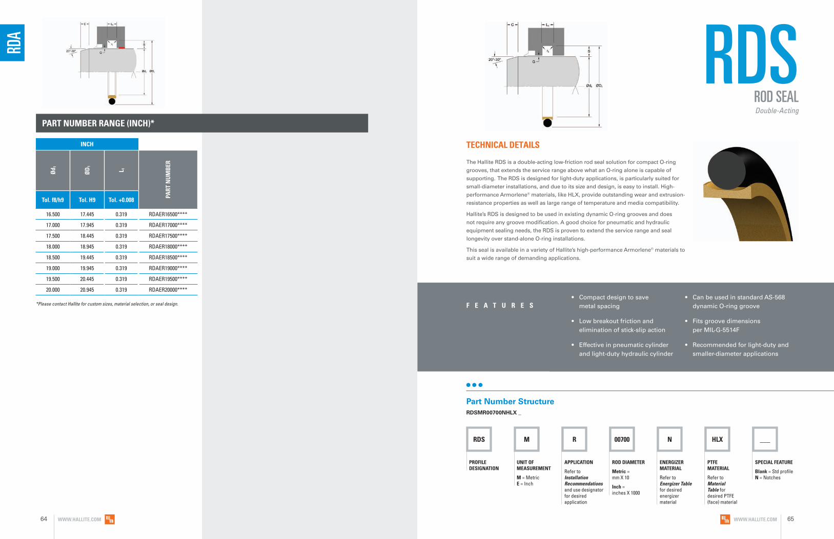
PART NUMBER RANGE (INCH)*
16.500 17.445 0.319 RDAER16500****
17.000 17.945 0.319 RDAER17000****
17.500 18.445 0.319 RDAER17500****
18.000 18.945 0.319 RDAER18000****
18.500 19.445 0.319 RDAER18500****
19.000 19.945 0.319 RDAER19000****
19.500 20.445 0.319 RDAER19500****
20.000 20.945 0.319 RDAER20000****
RDA
*Please contact Hallite for custom sizes, material selection, or seal design.
RDS M R 00700 ___
PROFILE DESIGNATION
UNIT OF MEASUREMENT
M = Metric E = Inch
APPLICATION
Refer to Installation Recommendations and use designator for desired application
ROD DIAMETER
Metric = mm X 10
Inch = inches X 1000
ENERGIZER MATERIAL
Refer to Energizer Table for desired energizer material
PTFE MATERIAL
Refer to Material Table for desired PTFE (face) material
SPECIAL FEATURE
Blank = Std profile N = Notches
N HLX
RDS
• Compact design to save metal spacing
• Low breakout friction and elimination of stick-slip action
• Effective in pneumatic cylinder and light-duty hydraulic cylinder
• Can be used in standard AS-568 dynamic O-ring groove
• Fits groove dimensions per MIL-G-5514F
• Recommended for light-duty and smaller-diameter applications
F E A T U R E S
TECHNICAL DETAILS
The Hallite RDS is a double-acting low-friction rod seal solution for compact O-ring
grooves, that extends the service range above what an O-ring alone is capable of
supporting. The RDS is designed for light-duty applications, is particularly suited for
small-diameter installations, and due to its size and design, is easy to install. High-
performance Armorlene® materials, like HLX, provide outstanding wear and extrusion-
resistance properties as well as large range of temperature and media compatibility.
Hallite’s RDS is designed to be used in existing dynamic O-ring grooves and does
not require any groove modification. A good choice for pneumatic and hydraulic
equipment sealing needs, the RDS is proven to extend the service range and seal
longevity over stand-alone O-ring installations.
This seal is available in a variety of Hallite’s high-performance Armorlene® materials to
suit a wide range of demanding applications.
Part Number StructureRDSMR00700NHLX _
ROD SEALDouble-Acting
INCH
Ød 1
ØD
1
L 1
PART
NU
MB
ER
Tol. f8/h9 Tol. H9 Tol. +0.008
WWW.HALLITE.COM64 WWW.HALLITE.COM 65

MATERIALS
RDS OPERATING CONDITIONS
METRIC INCH
Maximum Speed Up to 15.0m/sec Up to 50.0ft/sec
Temperature Range* -45 to 200°C -49 to 392°F
Maximum Dynamic Pressure 350 bar 5000 psi
*Dependent upon energizer used (NBR, FKM, etc.).
SURFACE FINISH RECOMMENDATIONS
*Rmr is measured at a depth of 25% of the Rz value based upon a reference level (zero line) at 5% material/bearing area.
METRIC INCHRmr*
SURFACE ROUGHNESS μmRa μmRz μmRt μinRa μinRz μinRt
Dynamic Sealing Face Ød1 0.05 - 0.2 1.6 max 2 max 2 - 8 63 max 157 max
60% - 90%Static Sealing Face ØD1 1.6 max 6.3 max 10 max 63 max 250 max 394 max
Static Housing Faces L1 3.2 max 10 max 16 max 125 max 394 max 630 max
ENERGIZER TABLE
ENERGIZER MATERIAL (SHORE A)
ENERGIZER TYPE
ENERGIZER DESIGNATION
ENERGIZER OPERATING TEMPERATURE°C
ENERGIZER OPERATING TEMPERATURE°F
NBR - 70A O-ring N -30 to 100°C -22 to 212°F
NBR - 70A Low temp. O-ring L -45 to 80°C -49 to 176°F
FKM - 75A O-ring F -10 to 200°C 14 to 392°F
EPDM - 70A O-ring E -45 to 145°C -49 to 293°F
HNBR - 70A O-ring H -25 to 150°C -13 to 302°F
NBR - 90A O-ring Q -30 to 100°C -22 to 212°F
HNBR - 90A O-ring U -25 to 150°C -13 to 302°F
No Energizer* None X - -
*Seal ratings are based upon capabilities of its matched material components. Hallite cannot rate seal performance when the seal is mixed with other manufacturers’ energizers/components.
For other material options consult the Master Materials Index at the front of the catalog. If you do not find the material that you require please contact your local Hallite sales office.
Data given are maximum values and can apply depending on specific application. Maximum ratings of temperature, pressure, or operating speeds are dependent on fluid medium, surface, gap value, and other variables such as dynamic or static service. Maximum values are not intended for use together at the same time, e.g. max temperature and max pressure. Please contact your Hallite technical representative for application support.
NO
TE
MATERIAL FEATURES AND APPLICATIONS
FILL
ER
MAT
ERIA
L D
ESIG
NAT
OR
COLO
R
TEM
PERA
TURE
RA
NG
E°C
TEM
PERA
TURE
RA
NG
E°F
MA
XIM
UM
DYN
AM
IC
PRES
SURE
- B
AR
MA
XIM
UM
DYN
AM
IC
PRES
SURE
- PS
I
ARMORLENE® HLX• Standard material for hydraulic applications• High compressive strength• Excellent extrusion resistance• Extended wear resistance
Special Bronze
CompoundHLX Gold -73 to 288°C -100 to 550°F 350 bar 5000 psi
ARMORLENE® 711• Excellent in all lubricating fluids and
pneumatic applications• High chemical resistance• Excellent extrusion resistance• Excellent wear properties
25% Carbon/
Graphite711 Black -73 to 288°C -100 to 550°F 350 bar 5000 psi
ARMORLENE® 700• Excellent in all hydraulic fluids• Recommended for use with soft
mating surfaces • Low friction and no stick-slip
Unfilled 700 White -184 to 204°C -300 to 400°F 200 bar 2900 psi
For other material options consult the Master Materials Index at the front of the catalog. If you do not find the material that you require, please contact your local Hallite sales office.
WWW.HALLITE.COM66 WWW.HALLITE.COM 67
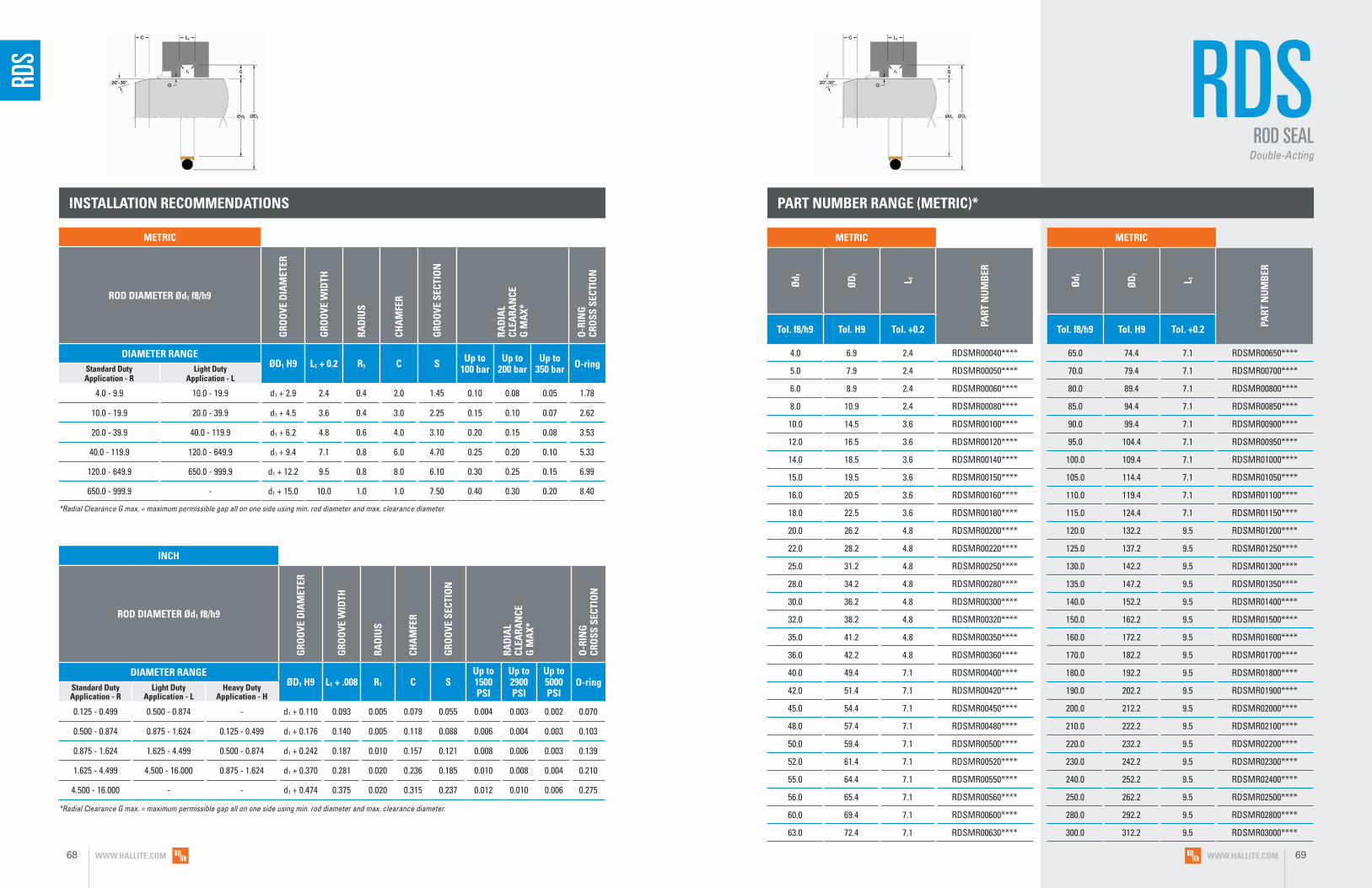
PART NUMBER RANGE (METRIC)*
4.0 6.9 2.4 RDSMR00040****
5.0 7.9 2.4 RDSMR00050****
6.0 8.9 2.4 RDSMR00060****
8.0 10.9 2.4 RDSMR00080****
10.0 14.5 3.6 RDSMR00100****
12.0 16.5 3.6 RDSMR00120****
14.0 18.5 3.6 RDSMR00140****
15.0 19.5 3.6 RDSMR00150****
16.0 20.5 3.6 RDSMR00160****
18.0 22.5 3.6 RDSMR00180****
20.0 26.2 4.8 RDSMR00200****
22.0 28.2 4.8 RDSMR00220****
25.0 31.2 4.8 RDSMR00250****
28.0 34.2 4.8 RDSMR00280****
30.0 36.2 4.8 RDSMR00300****
32.0 38.2 4.8 RDSMR00320****
35.0 41.2 4.8 RDSMR00350****
36.0 42.2 4.8 RDSMR00360****
40.0 49.4 7.1 RDSMR00400****
42.0 51.4 7.1 RDSMR00420****
45.0 54.4 7.1 RDSMR00450****
48.0 57.4 7.1 RDSMR00480****
50.0 59.4 7.1 RDSMR00500****
52.0 61.4 7.1 RDSMR00520****
55.0 64.4 7.1 RDSMR00550****
56.0 65.4 7.1 RDSMR00560****
60.0 69.4 7.1 RDSMR00600****
63.0 72.4 7.1 RDSMR00630****
65.0 74.4 7.1 RDSMR00650****
70.0 79.4 7.1 RDSMR00700****
80.0 89.4 7.1 RDSMR00800****
85.0 94.4 7.1 RDSMR00850****
90.0 99.4 7.1 RDSMR00900****
95.0 104.4 7.1 RDSMR00950****
100.0 109.4 7.1 RDSMR01000****
105.0 114.4 7.1 RDSMR01050****
110.0 119.4 7.1 RDSMR01100****
115.0 124.4 7.1 RDSMR01150****
120.0 132.2 9.5 RDSMR01200****
125.0 137.2 9.5 RDSMR01250****
130.0 142.2 9.5 RDSMR01300****
135.0 147.2 9.5 RDSMR01350****
140.0 152.2 9.5 RDSMR01400****
150.0 162.2 9.5 RDSMR01500****
160.0 172.2 9.5 RDSMR01600****
170.0 182.2 9.5 RDSMR01700****
180.0 192.2 9.5 RDSMR01800****
190.0 202.2 9.5 RDSMR01900****
200.0 212.2 9.5 RDSMR02000****
210.0 222.2 9.5 RDSMR02100****
220.0 232.2 9.5 RDSMR02200****
230.0 242.2 9.5 RDSMR02300****
240.0 252.2 9.5 RDSMR02400****
250.0 262.2 9.5 RDSMR02500****
280.0 292.2 9.5 RDSMR02800****
300.0 312.2 9.5 RDSMR03000****
INSTALLATION RECOMMENDATIONS
METRIC
ROD DIAMETER Ød1 f8/h9G
ROO
VE D
IAM
ETER
GRO
OVE
WID
TH
RAD
IUS
CHA
MFE
R
GRO
OVE
SEC
TIO
N
RAD
IAL
CLEA
RAN
CE
G M
AX*
O-R
ING
CR
OSS
SEC
TIO
N
DIAMETER RANGE ØD1 H9 L1 + 0.2 R1 C S Up to
100 barUp to
200 barUp to
350 bar O-ringStandard Duty Application - R
Light Duty Application - L
4.0 - 9.9 10.0 - 19.9 d1 + 2.9 2.4 0.4 2.0 1.45 0.10 0.08 0.05 1.78
10.0 - 19.9 20.0 - 39.9 d1 + 4.5 3.6 0.4 3.0 2.25 0.15 0.10 0.07 2.62
20.0 - 39.9 40.0 - 119.9 d1 + 6.2 4.8 0.6 4.0 3.10 0.20 0.15 0.08 3.53
40.0 - 119.9 120.0 - 649.9 d1 + 9.4 7.1 0.8 6.0 4.70 0.25 0.20 0.10 5.33
120.0 - 649.9 650.0 - 999.9 d1 + 12.2 9.5 0.8 8.0 6.10 0.30 0.25 0.15 6.99
650.0 - 999.9 - d1 + 15.0 10.0 1.0 1.0 7.50 0.40 0.30 0.20 8.40
*Radial Clearance G max. = maximum permissible gap all on one side using min. rod diameter and max. clearance diameter.
INCH
ROD DIAMETER Ød1 f8/h9
GRO
OVE
DIA
MET
ER
GRO
OVE
WID
TH
RAD
IUS
CHA
MFE
R
GRO
OVE
SEC
TIO
N
RAD
IAL
CLEA
RAN
CE
G M
AX*
O-R
ING
CR
OSS
SEC
TIO
N
DIAMETER RANGE ØD1 H9 L1 + .008 R1 C S
Up to 1500 PSI
Up to 2900 PSI
Up to 5000 PSI
O-ringStandard Duty Application - R
Light Duty Application - L
Heavy Duty Application - H
0.125 - 0.499 0.500 - 0.874 - d1 + 0.110 0.093 0.005 0.079 0.055 0.004 0.003 0.002 0.070
0.500 - 0.874 0.875 - 1.624 0.125 - 0.499 d1 + 0.176 0.140 0.005 0.118 0.088 0.006 0.004 0.003 0.103
0.875 - 1.624 1.625 - 4.499 0.500 - 0.874 d1 + 0.242 0.187 0.010 0.157 0.121 0.008 0.006 0.003 0.139
1.625 - 4.499 4.500 - 16.000 0.875 - 1.624 d1 + 0.370 0.281 0.020 0.236 0.185 0.010 0.008 0.004 0.210
4.500 - 16.000 - - d1 + 0.474 0.375 0.020 0.315 0.237 0.012 0.010 0.006 0.275
*Radial Clearance G max. = maximum permissible gap all on one side using min. rod diameter and max. clearance diameter.
RDS RDS
ROD SEALDouble-Acting
METRIC
Ød 1
ØD
1
L 1
PART
NU
MB
ER
Tol. f8/h9 Tol. H9 Tol. +0.2
METRIC
Ød 1
ØD
1
L 1
PART
NU
MB
ER
Tol. f8/h9 Tol. H9 Tol. +0.2
WWW.HALLITE.COM68 WWW.HALLITE.COM 69

PART NUMBER RANGE (METRIC)* PART NUMBER RANGE (INCH)*
320.0 332.2 9.5 RDSMR03200****
350.0 362.2 9.5 RDSMR03500****
360.0 372.2 9.5 RDSMR03600****
400.0 412.2 9.5 RDSMR04000****
500.0 512.2 9.5 RDSMR05000****
600.0 612.2 9.5 RDSMR06000****
650.0 665.0 10.0 RDSMR06500****
700.0 715.0 10.0 RDSMR07000****
800.0 815.0 10.0 RDSMR08000****
900.0 915.0 10.0 RDSMR09000****
950.0 965.0 10.0 RDSMR09500****
0.500 0.610 0.093 RDSEL00500****
0.562 0.672 0.093 RDSEL00562****
0.625 0.735 0.093 RDSEL00625****
0.687 0.797 0.093 RDSEL00687****
0.750 0.860 0.093 RDSEL00750****
0.812 0.922 0.093 RDSEL00812****
0.875 1.051 0.140 RDSEL00875****
0.937 1.113 0.140 RDSEL00937****
1.000 1.176 0.140 RDSEL01000****
1.062 1.238 0.140 RDSEL01062****
1.125 1.301 0.140 RDSEL01125****
1.187 1.363 0.140 RDSEL01187****
1.250 1.426 0.140 RDSEL01250****
1.312 1.488 0.140 RDSEL01312****
1.375 1.551 0.140 RDSEL01375****
1.437 1.613 0.140 RDSEL01437****
1.500 1.676 0.140 RDSEL01500****
1.562 1.738 0.140 RDSEL01562****
1.625 1.867 0.187 RDSEL01625****
1.687 1.929 0.187 RDSEL01687****
1.750 1.992 0.187 RDSEL01750****
1.812 2.054 0.187 RDSEL01812****
1.875 2.117 0.187 RDSEL01875****
1.937 2.179 0.187 RDSEL01937****
2.000 2.242 0.187 RDSEL02000****
2.062 2.304 0.187 RDSEL02062****
2.125 2.367 0.187 RDSEL02125****
2.187 2.429 0.187 RDSEL02187****
PART NUMBER RANGE (INCH)*
2.250 2.492 0.187 RDSEL02250****
2.312 2.554 0.187 RDSEL02312****
2.375 2.617 0.187 RDSEL02375****
2.437 2.679 0.187 RDSEL02437****
2.500 2.742 0.187 RDSEL02500****
2.625 2.867 0.187 RDSEL02625****
2.750 2.992 0.187 RDSEL02750****
2.875 3.117 0.187 RDSEL02875****
3.000 3.242 0.187 RDSEL03000****
3.125 3.367 0.187 RDSEL03125****
3.250 3.492 0.187 RDSEL03250****
3.375 3.617 0.187 RDSEL03375****
3.500 3.742 0.187 RDSEL03500****
3.625 3.867 0.187 RDSEL03625****
3.750 3.992 0.187 RDSEL03750****
3.875 4.117 0.187 RDSEL03875****
4.000 4.242 0.187 RDSEL04000****
4.125 4.367 0.187 RDSEL04125****
4.250 4.492 0.187 RDSEL04250****
4.375 4.617 0.187 RDSEL04375****
4.500 4.870 0.281 RDSEL04500****
4.625 4.995 0.281 RDSEL04625****
4.750 5.120 0.281 RDSEL04750****
4.875 5.245 0.281 RDSEL04875****
5.000 5.474 0.375 RDSER05000****
5.125 5.599 0.375 RDSER05125****
5.250 5.724 0.375 RDSER05250****
5.375 5.849 0.375 RDSER05375****
5.500 5.974 0.375 RDSER05500****
5.625 6.099 0.375 RDSER05625****
5.750 6.224 0.375 RDSER05750****
5.875 6.349 0.375 RDSER05875****
6.000 6.474 0.375 RDSER06000****
6.250 6.724 0.375 RDSER06250****
6.500 6.974 0.375 RDSER06500****
6.750 7.224 0.375 RDSER06750****
7.000 7.474 0.375 RDSER07000****
7.250 7.724 0.375 RDSER07250****
7.500 7.974 0.375 RDSER07500****
7.750 8.224 0.375 RDSER07750****
8.000 8.474 0.375 RDSER08000****
8.500 8.974 0.375 RDSER08500****
9.000 9.474 0.375 RDSER09000****
9.500 9.974 0.375 RDSER09500****
10.000 10.474 0.375 RDSER10000****
METRIC
Ød 1
ØD
1
L 1
PART
NU
MB
ER
Tol. f8/h9 Tol. H9 Tol. +0.2
RDS RDS
ROD SEALDouble-Acting
*Please contact Hallite for custom sizes, material selection, or seal design.
*Please contact Hallite for custom sizes, material selection, or seal design.
INCH
Ød 1
ØD
1
L 1
PART
NU
MB
ER
Tol. f8/h9 Tol. H9 Tol. +0.008
INCH
Ød 1
ØD
1
L 1
PART
NU
MB
ER
Tol. f8/h9 Tol. H9 Tol. +0.008
INCH
Ød 1
ØD
1
L 1
PART
NU
MB
ER
Tol. f8/h9 Tol. H9 Tol. +0.008
WWW.HALLITE.COM70 WWW.HALLITE.COM 71

RCG M R 00400 ___
PROFILE DESIGNATION
UNIT OF MEASUREMENT
M = Metric E = Inch
APPLICATION
Refer to Installation Recommendations and use designator for desired application
ROD DIAMETER
Metric = mm X 10
Inch = inches X 1000
ENERGIZER MATERIAL
Refer to Energizer Table for desired energizer material
PTFE MATERIAL
Refer to Material Table for desired PTFE (face) material
SPECIAL FEATURE
Blank = Std profile N = Notches
N HLX
RCG
• Low breakout friction and elimination of stick-slip action
• Compact design to save metal spacing
• High service temperature, long wear, and high extrusion resistance
F E A T U R E S
TECHNICAL DETAILS
The Hallite RCG is a double-acting, O-ring energized, low-friction rod seal designed
for low- and medium-pressure systems. High-performance Armorlene® materials, like
HLX, provide outstanding wear and extrusion-resistance properties as well as large
range of temperature and media compatibility.
The compact design of the RCG provides an ideal sealing solution where housing
space is limited. This seal is available in a variety of Hallite’s high-performance
Armorlene® materials to suit a wide range of demanding applications.
Part Number StructureRCGMR00400NHLX _
ROD SEALDouble-Acting
WWW.HALLITE.COM 73

RCG OPERATING CONDITIONS
METRIC INCH
Maximum Speed Up to 15.0m/sec Up to 50.0ft/sec
Temperature Range* -45 to 200°C -49 to 392°F
Maximum Dynamic Pressure 200 bar 2900 psi
*Dependent upon energizer used (NBR, FKM, etc.).
MATERIALS
SURFACE FINISH RECOMMENDATIONS
*Rmr is measured at a depth of 25% of the Rz value based upon a reference level (zero line) at 5% material/bearing area.
METRIC INCHRmr*
SURFACE ROUGHNESS μmRa μmRz μmRt μinRa μinRz μinRt
Dynamic Sealing Face Ød1 0.05 - 0.2 1.6 max 2 max 2 - 8 63 max 157 max
60% - 90%Static Sealing Face ØD1 1.6 max 6.3 max 10 max 63 max 250 max 394 max
Static Housing Faces L1 3.2 max 10 max 16 max 125 max 394 max 630 max
ENERGIZER TABLE
ENERGIZER MATERIAL (SHORE A)
ENERGIZER TYPE
ENERGIZER DESIGNATION
ENERGIZER OPERATING TEMPERATURE°C
ENERGIZER OPERATING TEMPERATURE°F
NBR - 70A O-ring N -30 to 100°C -22 to 212°F
NBR - 70A Low temp. O-ring L -45 to 80°C -49 to 176°F
FKM - 75A O-ring F -10 to 200°C 14 to 392°F
EPDM - 70A O-ring E -45 to 145°C -49 to 293°F
HNBR - 70A O-ring H -25 to 150°C -13 to 302°F
NBR - 90A O-ring Q -30 to 100°C -22 to 212°F
HNBR - 90A O-ring U -25 to 150°C -13 to 302°F
No Energizer* None X - -
*Seal ratings are based upon capabilities of its matched material components. Hallite cannot rate seal performance when the seal is mixed with other manufacturers’ energizers/components.
Data given are maximum values and can apply depending on specific application. Maximum ratings of temperature, pressure, or operating speeds are dependent on fluid medium, surface, gap value, and other variables such as dynamic or static service. Maximum values are not intended for use together at the same time, e.g. max temperature and max pressure. Please contact your Hallite technical representative for application support.
NO
TE
MATERIAL FEATURES AND APPLICATIONS
FILL
ER
MAT
ERIA
L D
ESIG
NAT
OR
COLO
R
TEM
PERA
TURE
RA
NG
E°C
TEM
PERA
TURE
RA
NG
E°F
MA
XIM
UM
DYN
AM
IC
PRES
SURE
- B
AR
MA
XIM
UM
DYN
AM
IC
PRES
SURE
- PS
I
ARMORLENE® HLX• Standard material for hydraulic applications• High compressive strength• Excellent extrusion resistance• Extended wear resistance
Special Bronze
CompoundHLX Gold -73 to 288°C -100 to 550°F 200 bar 2900 psi
ARMORLENE® HCF• Excellent in lubricating and non-lubricating
hydraulic fluids (includes water) w/o zinc content
• Not recommended for gas sealing applications
• Not recommended for electrical conductive fluids
Carbon Fiber Filled HCF Gray/
Black -73 to 260°C -100 to 500°F 200 bar 2900 psi
ARMORLENE® 700• Excellent in all hydraulic fluids• Recommended for hard mating
surfaces only• Low friction and no stick-slip
Unfilled 700 White -184 to 204°C -300 to 400°F 200 bar 2900 psi
ARMORLENE® 711• Excellent in all lubricating fluids and
pneumatic applications• High chemical resistance• Excellent extrusion resistance• Excellent wear properties
25% Carbon/Graphite 711 Black -73 to 288°C -100 to 550°F 200 bar 2900 psi
748 - UHMWPE• Excellent impact resistance• Good dielectrical properties• Excellent abrasion resistance• Low coefficient of friction
Standard 748 Translucent -184 to 82°C -300 to 180°F 200 bar 2900 psi
For other material options consult the Master Materials Index at the front of the catalog. If you do not find the material that you require, please contact your local Hallite sales office.
WWW.HALLITE.COM74 WWW.HALLITE.COM 75

PART NUMBER RANGE (METRIC)*
7.0 11.0 2.00 RCGMR00070****
9.0 15.0 2.85 RCGMR00090****
10.0 16.0 2.85 RCGMR00100****
10.0 16.2 3.20 RCGMS00100****
12.0 18.0 2.85 RCGMR00120****
12.0 18.2 3.20 RCGMS00120****
14.0 20.0 2.85 RCGMR00140****
14.0 20.2 3.20 RCGMS00140****
15.0 21.2 3.20 RCGMS00150****
16.0 22.0 2.85 RCGMR00160****
16.0 22.2 3.20 RCGMS00160****
18.0 24.0 2.85 RCGMR00180****
18.0 24.2 3.20 RCGMS00180****
20.0 26.2 3.20 RCGMS00200****
20.0 27.5 3.80 RCGMR00200****
22.0 28.2 3.20 RCGMS00220****
22.0 29.5 3.80 RCGMR00220****
25.0 32.5 3.80 RCGMR00250****
25.0 32.2 4.00 RCGMS00250****
28.0 35.5 3.80 RCGMR00280****
28.0 35.2 4.00 RCGMS00280****
30.0 37.5 3.80 RCGMR00300****
30.0 37.2 4.00 RCGMS00300****
32.0 39.5 3.80 RCGMR00320****
32.0 39.2 4.00 RCGMS00320****
35.0 42.5 3.80 RCGMR00350****
35.0 42.2 4.00 RCGMS00350****
36.0 43.5 3.80 RCGMR00360****
36.0 43.2 4.00 RCGMS00360****
38.0 45.2 4.00 RCGMS00380****
40.0 47.2 4.00 RCGMS00400****
40.0 52.5 5.60 RCGMR00400****
42.0 49.2 4.00 RCGMS00420****
42.0 54.5 5.60 RCGMR00420****
45.0 52.2 4.00 RCGMS00450****
45.0 57.5 5.60 RCGMR00450****
48.0 55.2 4.00 RCGMS00480****
50.0 57.2 4.00 RCGMS00500****
50.0 62.5 5.60 RCGMR00500****
52.0 59.2 4.00 RCGMS00520****
55.0 62.2 4.00 RCGMS00550****
55.0 67.5 5.60 RCGMR00550****
56.0 63.2 4.00 RCGMS00560****
60.0 72.2 7.50 RCGMS00600****
60.0 72.5 5.60 RCGMR00600****
63.0 75.2 7.50 RCGMS00630****
63.0 75.5 5.60 RCGMR00630****
65.0 77.2 7.50 RCGMS00650****
65.0 77.5 5.60 RCGMR00650****
70.0 82.2 7.50 RCGMS00700****
70.0 82.5 5.60 RCGMR00700****
75.0 87.2 7.50 RCGMS00750****
75.0 87.5 5.60 RCGMR00750****
80 92.2 7.50 RCGMS00800****
80 92.5 5.60 RCGMR00800****
85 97.2 7.50 RCGMS00850****
INSTALLATION RECOMMENDATIONS
METRIC
ROD DIAMETER ØD1 F7/H8
GRO
OVE
D
IAM
ETER
GRO
OVE
W
IDTH
RAD
IUS
GRO
OVE
SE
CTIO
N
RAD
IAL
CLEA
RAN
CE
G M
AX*
O-R
ING
CR
OSS
SE
CTIO
N
DIAMETER RANGE ØD1 H9 L1 + 0.2 r1 S Up to
200 bar O-ringStandard Duty Application - S
10.0 - 22.0 d1 + 6.2 3.20 0.5 3.1 0.08 2.40
22.1 - 56.0 d1 + 7.2 4.00 0.5 3.6 0.08 3.00
56.1 - 100.0 d1 + 12.2 7.50 0.9 6.1 0.10 5.70
*Radial Clearance G max. = maximum permissible gap all on one side using min. rod diameter and max. clearance diameter.
METRIC
ROD DIAMETER Ød1 f8/h9
GRO
OVE
D
IAM
ETER
GRO
OVE
W
IDTH
RAD
IUS
GRO
OVE
SE
CTIO
N
RAD
IAL
CLEA
RAN
CE
G M
AX*
O-R
ING
CR
OSS
SE
CTIO
N
DIAMETER RANGE ØD1 H9 L1 + 0.2 r1 S Up to
200 bar O-ringStandard Duty Application - R
4.0 - 7.9 d1 + 4.0 2.00 0.5 2.00 0.05 1.78
8.0 - 18.9 d1 + 6.0 2.85 0.5 3.00 0.08 2.62
19.0 - 37.9 d1 + 7.5 3.80 0.5 3.75 0.08 3.53
38.0 - 119.9 d1 + 12.5 5.60 0.9 6.25 0.10 5.33
120.0 - 164.9 d1 + 15.0 7.55 0.9 7.50 0.10 6.99
165.0 - 219.9 d1 + 18.0 7.55 0.9 9.00 0.10 6.99
220.0 - 400.0 d1 + 24.0 7.55 0.9 12.00 0.10 6.99
*Radial Clearance G max. = maximum permissible gap all on one side using min. rod diameter and max. clearance diameter.
RCG
INCH
ROD DIAMETER Ød1 f8/h9
GRO
OVE
D
IAM
ETER
GRO
OVE
W
IDTH
RAD
IUS
RAD
IAL
CLEA
RAN
CE
G M
AX*
O-R
ING
CR
OSS
SE
CTIO
N
DIAMETER RANGE ØD1 H9 L1 + 0.008 r1
Up to 2900 psi O-ringStandard Duty
Application - RLight Duty
Application - L
0.250 - 0.999 1.000 - 2.499 d1 + 0.172 0.079 0.020 0.002 0.070
1.000 - 2.499 2.500 - 3.499 d1 + 0.236 0.112 0.020 0.003 0.103
2.500 - 3.499 3.500 - 4.499 d1 + 0.363 0.149 0.030 0.003 0.139
3.500 - 4.499 4.500 - 5.999 d1 + 0.491 0.221 0.050 0.004 0.210
4.500 - 5.999 - d1 + 0.593 0.297 0.060 0.004 0.275
6.000 - 7.999 - d1 + 0.718 0.297 0.060 0.004 0.275
8.000 - 15.000 - d1 + 0.968 0.297 0.060 0.004 0.275
*Radial Clearance G max. = maximum permissible gap all on one side using min. rod diameter and max. clearance diameter.
RCGROD SEAL
Double-Acting
METRIC
Ød 1
ØD
1
L 1
PART
NU
MB
ER
Tol. f8/h9 Tol. H9 Tol. +0.2
METRIC
Ød 1
ØD
1
L 1
PART
NU
MB
ER
Tol. f8/h9 Tol. H9 Tol. +0.2
WWW.HALLITE.COM76 WWW.HALLITE.COM 77
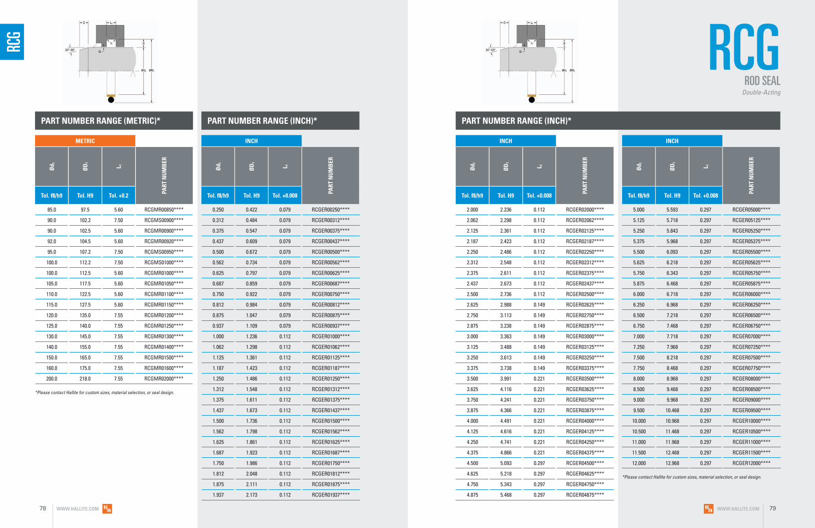
PART NUMBER RANGE (INCH)*
2.000 2.236 0.112 RCGER02000****
2.062 2.298 0.112 RCGER02062****
2.125 2.361 0.112 RCGER02125****
2.187 2.423 0.112 RCGER02187****
2.250 2.486 0.112 RCGER02250****
2.312 2.548 0.112 RCGER02312****
2.375 2.611 0.112 RCGER02375****
2.437 2.673 0.112 RCGER02437****
2.500 2.736 0.112 RCGER02500****
2.625 2.988 0.149 RCGER02625****
2.750 3.113 0.149 RCGER02750****
2.875 3.238 0.149 RCGER02875****
3.000 3.363 0.149 RCGER03000****
3.125 3.488 0.149 RCGER03125****
3.250 3.613 0.149 RCGER03250****
3.375 3.738 0.149 RCGER03375****
3.500 3.991 0.221 RCGER03500****
3.625 4.116 0.221 RCGER03625****
3.750 4.241 0.221 RCGER03750****
3.875 4.366 0.221 RCGER03875****
4.000 4.491 0.221 RCGER04000****
4.125 4.616 0.221 RCGER04125****
4.250 4.741 0.221 RCGER04250****
4.375 4.866 0.221 RCGER04375****
4.500 5.093 0.297 RCGER04500****
4.625 5.218 0.297 RCGER04625****
4.750 5.343 0.297 RCGER04750****
4.875 5.468 0.297 RCGER04875****
5.000 5.593 0.297 RCGER05000****
5.125 5.718 0.297 RCGER05125****
5.250 5.843 0.297 RCGER05250****
5.375 5.968 0.297 RCGER05375****
5.500 6.093 0.297 RCGER05500****
5.625 6.218 0.297 RCGER05625****
5.750 6.343 0.297 RCGER05750****
5.875 6.468 0.297 RCGER05875****
6.000 6.718 0.297 RCGER06000****
6.250 6.968 0.297 RCGER06250****
6.500 7.218 0.297 RCGER06500****
6.750 7.468 0.297 RCGER06750****
7.000 7.718 0.297 RCGER07000****
7.250 7.968 0.297 RCGER07250****
7.500 8.218 0.297 RCGER07500****
7.750 8.468 0.297 RCGER07750****
8.000 8.968 0.297 RCGER08000****
8.500 9.468 0.297 RCGER08500****
9.000 9.968 0.297 RCGER09000****
9.500 10.468 0.297 RCGER09500****
10.000 10.968 0.297 RCGER10000****
10.500 11.468 0.297 RCGER10500****
11.000 11.968 0.297 RCGER11000****
11.500 12.468 0.297 RCGER11500****
12.000 12.968 0.297 RCGER12000****
85.0 97.5 5.60 RCGMR00850****
90.0 102.2 7.50 RCGMS00900****
90.0 102.5 5.60 RCGMR00900****
92.0 104.5 5.60 RCGMR00920****
95.0 107.2 7.50 RCGMS00950****
100.0 112.2 7.50 RCGMS01000****
100.0 112.5 5.60 RCGMR01000****
105.0 117.5 5.60 RCGMR01050****
110.0 122.5 5.60 RCGMR01100****
115.0 127.5 5.60 RCGMR01150****
120.0 135.0 7.55 RCGMR01200****
125.0 140.0 7.55 RCGMR01250****
130.0 145.0 7.55 RCGMR01300****
140.0 155.0 7.55 RCGMR01400****
150.0 165.0 7.55 RCGMR01500****
160.0 175.0 7.55 RCGMR01600****
200.0 218.0 7.55 RCGMR02000****
0.250 0.422 0.079 RCGER00250****
0.312 0.484 0.079 RCGER00312****
0.375 0.547 0.079 RCGER00375****
0.437 0.609 0.079 RCGER00437****
0.500 0.672 0.079 RCGER00500****
0.562 0.734 0.079 RCGER00562****
0.625 0.797 0.079 RCGER00625****
0.687 0.859 0.079 RCGER00687****
0.750 0.922 0.079 RCGER00750****
0.812 0.984 0.079 RCGER00812****
0.875 1.047 0.079 RCGER00875****
0.937 1.109 0.079 RCGER00937****
1.000 1.236 0.112 RCGER01000****
1.062 1.298 0.112 RCGER01062****
1.125 1.361 0.112 RCGER01125****
1.187 1.423 0.112 RCGER01187****
1.250 1.486 0.112 RCGER01250****
1.312 1.548 0.112 RCGER01312****
1.375 1.611 0.112 RCGER01375****
1.437 1.673 0.112 RCGER01437****
1.500 1.736 0.112 RCGER01500****
1.562 1.798 0.112 RCGER01562****
1.625 1.861 0.112 RCGER01625****
1.687 1.923 0.112 RCGER01687****
1.750 1.986 0.112 RCGER01750****
1.812 2.048 0.112 RCGER01812****
1.875 2.111 0.112 RCGER01875****
1.937 2.173 0.112 RCGER01937****
PART NUMBER RANGE (METRIC)* PART NUMBER RANGE (INCH)*
RCG RCG
ROD SEALDouble-Acting
*Please contact Hallite for custom sizes, material selection, or seal design.
*Please contact Hallite for custom sizes, material selection, or seal design.
INCH
Ød 1
ØD
1
L 1
PART
NU
MB
ER
Tol. f8/h9 Tol. H9 Tol. +0.008
METRIC
Ød 1
ØD
1
L 1
PART
NU
MB
ER
Tol. f8/h9 Tol. H9 Tol. +0.2
INCH
Ød 1
ØD
1
L 1
PART
NU
MB
ER
Tol. f8/h9 Tol. H9 Tol. +0.008
INCH
Ød 1
ØD
1
L 1
PART
NU
MB
ER
Tol. f8/h9 Tol. H9 Tol. +0.008
WWW.HALLITE.COM78 WWW.HALLITE.COM 79

SRS M R 00700 N HLX ___
PROFILE DESIGNATION
UNIT OF MEASUREMENT
M = Metric E = Inch
APPLICATION
Refer to Installation Recommendations and use designator for desired application
ENERGIZER MATERIAL
Refer to Energizer Table for desired energizer material
PTFE MATERIAL
Refer to Material Table for desired PTFE (face) material
SPECIAL FEATURE
Blank = Std profile
ROD DIAMETER
Metric = mm X 10
Inch = inches X 1000
SRS
• Self-relieving design prevents pressure trapping
• Low breakout friction and elimination of stick-slip action
• Excellent in high-speed applications
• Wide range of materials for both face ring and energizer available for special applications
• High service temperature, long wear, and high extrusion resistance
F E A T U R E S
TECHNICAL DETAILS
The Hallite SRS is a single-acting, low-friction rod buffer seal, designed to be
utilized in conjunction with a primary pressure seal. The buffer is designed from
proprietary Armorlene® material face ring paired with a specially profiled
energizer. The Armorlene® face ring offers low friction and the elimination of
stick-slip. High-performance Armorlene® materials, like HLX, provide outstanding
wear and extrusion- resistance properties as well as large range of temperature
and media compatibility.
The SRS is a pressure buffer seal that protects the primary rod seal from
high-frequency pressure spikes in a system. The design allows oil to pass through
to the rod seal while holding back pressure spikes. The Hallite SRS also allows
pressure to pass back into the system, preventing a pressure trap situation between
the rod seal and the buffer seal. The SRS is an excellent addition to demanding
sealing applications, offering extended sealing system life and performance.
Part Number StructureSRSMR00700NHLX _
ROD BUFFER SEAL
WWW.HALLITE.COM 81

SRS OPERATING CONDITIONS
METRIC INCH
Maximum Speed Up to 4.0m/sec Up to 12.0ft/sec
Temperature Range* -45 to 200°C -49 to 392°F
Maximum Dynamic Pressure** 400 bar 5800 psi
*Dependent upon energizer used (NBR, FKM, etc.). **For pressures above 400 bar, contact Hallite Engineering.
MATERIALS
SURFACE FINISH RECOMMENDATIONS
METRIC INCHRmr*
SURFACE ROUGHNESS μmRa μmRz μmRt μinRa μinRz μinRt
Dynamic Sealing Face Ød1 0.05 - 0.2 1.6 max 2 max 2 - 8 63 max 157 max
60% - 90%Static Sealing Face ØD1 1.6 max 6.3 max 10 max 63 max 250 max 394 max
Static Housing Faces L1 3.2 max 10 max 16 max 125 max 394 max 630 max
*Rmr is measured at a depth of 25% of the Rz value based upon a reference level (zero line) at 5% material/bearing area.
ENERGIZER TABLE*
ENERGIZER MATERIAL (SHORE A) ENERGIZER TYPE ENERGIZER DESIGNATION ENERGIZER OPERATING
TEMPERATURE °C
NBR - 85A Square/Profile N -30 to 100°C
HNBR - 85A Square/Profile H -20 to 150°C
FKM - 82A Square/Profile F -10 to 200°C
NBR - 80A Low temp. Square/Profile B -45 to 80°C
*Other energizer materials are available. Please contact your local Hallite sales office for further information.
MATERIAL FEATURES AND APPLICATIONS
FILL
ER
MAT
ERIA
L D
ESIG
NAT
OR
COLO
R
TEM
PERA
TURE
RA
NG
E°C
TEM
PERA
TURE
RA
NG
E°F
MA
XIM
UM
DYN
AM
IC
PRES
SURE
- B
AR
MA
XIM
UM
DYN
AM
IC
PRES
SURE
- PS
I
ARMORLENE® HLX• Standard material for hydraulic applications• High compressive strength• Excellent extrusion resistance• Extended wear resistance
Special Bronze
CompoundHLX Gold -73 to 288°C -100 to 550°F 500 bar 7250 psi
ARMORLENE® HLA• Excellent in all hydraulic fluids• Excellent wear resistance• Excellent low-friction properties• Good extrusion resistance
Special Mineral
Compound HLA Gray -73 to 260°C -100 to 500°F 500 bar 7250 psi
ARMORLENE® HCF• Excellent in lubricating and non-lubricating
hydraulic fluids (includes water) w/o zinc content
• Not recommended for gas sealing applications
• Not recommended for electrical conductive fluids
Carbon Fiber Filled HCF Gray/
Black -73 to 260°C -100 to 500°F 250 bar 3625 psi
ARMORLENE® 713• High compressive strength• Excellent extrusion resistance• Excellent wear properties
60% Bronze Content 713 Bronze -73 to 288°C -100 to 550°F 500 bar 7250 psi
For other material options consult the Master Materials Index at the front of the catalog. If you do not find the material that you require, please contact your local Hallite sales office.
Data given are maximum values and can apply depending on specific application. Maximum ratings of temperature, pressure, or operating speeds are dependent on fluid medium, surface, gap value, and other variables such as dynamic or static service. Maximum values are not intended for use together at the same time, e.g. max temperature and max pressure. Please contact your Hallite technical representative for application support.
NO
TE
WWW.HALLITE.COM82 WWW.HALLITE.COM 83

PART NUMBER RANGE (METRIC)*
40.0 55.1 6.3 SRSMR00400****
45.0 60.1 6.3 SRSMR00450****
50.0 65.1 6.3 SRSMR00500****
55.0 70.1 6.3 SRSMR00550****
60.0 75.1 6.3 SRSMR00600****
65.0 80.1 6.3 SRSMR00650****
70.0 85.1 6.3 SRSMR00700****
75.0 90.1 6.3 SRSMR00750****
80.0 95.1 6.3 SRSMR00800****
85.0 100.1 6.3 SRSMR00850****
90.0 105.1 6.3 SRSMR00900****
95.0 110.1 6.3 SRSMR00950****
100.0 115.1 6.3 SRSMR01000****
105.0 120.1 6.3 SRSMR01050****
110.0 125.1 6.3 SRSMR01100****
115.0 130.1 6.3 SRSMR01150****
120.0 135.1 6.3 SRSMR01200****
125.0 140.1 6.3 SRSMR01250****
130.0 145.1 6.3 SRSMR01300****
135.0 150.1 6.3 SRSMR01350****
140.0 155.1 6.3 SRSMR01400****
145.0 160.1 6.3 SRSMR01450****
150.0 165.1 6.3 SRSMR01500****
155.0 170.1 6.3 SRSMR01550****
160.0 175.1 6.3 SRSMR01600****
165.0 180.1 6.3 SRSMR01650****
170.0 185.1 6.3 SRSMR01700****
175.0 190.1 6.3 SRSMR01750****
180.0 195.1 6.3 SRSMR01800****
185.0 200.1 6.3 SRSMR01850****
190.0 205.1 6.3 SRSMR01900****
195.0 210.1 6.3 SRSMR01950****
200.0 215.1 6.3 SRSML02000****
205.0 220.1 6.3 SRSML02050****
210.0 225.1 6.3 SRSML02100****
215.0 230.1 6.3 SRSML02150****
220.0 235.1 6.3 SRSML02200****
225.0 240.1 6.3 SRSML02250****
230.0 245.1 6.3 SRSML02300****
235.0 250.1 6.3 SRSML02350****
240.0 255.1 6.3 SRSML02400****
245.0 260.1 6.3 SRSML02450****
250.0 265.1 6.3 SRSML02500****
INSTALLATION RECOMMENDATIONS
METRIC
ROD DIAMETER Ød1 f8/h9
GRO
OVE
D
IAM
ETER
GRO
OVE
WID
TH
RAD
IUS
CHA
MFE
R
GRO
OVE
SEC
TIO
N
RAD
IAL
CLEA
RAN
CE
G m
ax*
DIAMETER RANGE ØD1 H9 L1 + 0.2 r1 C S Up to
100 barUp to
200 barUp to
400 barStandard Duty Application - R Light Duty Application - L
40.0 - 199.9 200.0 - 255.9 d1 + 15.1 6.3 0.4 2.0 7.55 0.50 0.30 0.20
At pressure >400 bar use diameter tolerance f8/h8. *Radial Clearance G max. = maximum permissible gap all on one side using min. rod diameter and max. clearance diameter.
METRIC
Ød 1
ØD
1
L 1
PART
NU
MB
ER
Tol. f8/h9 Tol. H9 Tol. +0.2 - 0
METRIC
Ød 1
ØD
1
L 1
PART
NU
MB
ER
Tol. f8/h9 Tol. H9 Tol. +0.2 - 0
SRS SRS
ROD BUFFER SEAL
*Please contact Hallite for custom sizes, material selection, or seal design.
Applications with maximum radial clearance that are using nylon, phenolic, or PTFE bearings must ensure proper clearance in accordance with the bearing recommendations to avoid metal-to-metal contact.
Please refer to Hallite Type 87, Type 506, and Type 533 Specification Sheets for this information.
WWW.HALLITE.COM84 WWW.HALLITE.COM 85

SRB M R 00700 N HLX ___
PROFILE DESIGNATION
UNIT OF MEASUREMENT
M = Metric E = Inch
APPLICATION
Refer to Installation Recommendations and use designator for desired application
ROD DIAMETER
Metric = mm X 10
Inch = inches X 1000
ENERGIZER MATERIAL
Refer to Energizer Table for desired energizer material
PTFE MATERIAL
Refer to Material Table for desired PTFE (face) material
AE RING MATERIAL
Blank = POM A = PA MoS2 Filled B = Virgin PEEK
SRB
• Self-relieving design prevents pressure trapping
• Low breakout friction and elimination of stick-slip action
• Wide range of materials for both face ring and energizer available for special applications
• Excellent in high-speed applications
• Extended pressure rating through included high extrusion-resistant anti-extrusion ring
• High service temperature, long wear, and high extrusion resistance
F E A T U R E S
TECHNICAL DETAILS
The Hallite SRB is a single-acting, low-friction rod buffer seal, designed to be utilized
in conjunction with a primary pressure seal. The buffer is designed from proprietary
Armorlene® material face ring paired with a specially profiled energizer and an
integrated anti-extrusion ring. The Armorlene® face ring offers low friction and the
elimination of stick-slip. High-performance Armorlene® materials, like HLX, provide
outstanding wear and extrusion-resistance properties as well as large range of
temperature and media compatibility.
The SRB is a pressure buffer seal that protects the primary rod seal from
high-frequency pressure spikes in a system. The design allows oil to pass through
to the rod seal while holding back pressure spikes. The Hallite SRB also allows
pressure to pass back into the system, preventing a pressure trap situation between
the rod seal and the buffer seal. The SRB is an excellent pressure buffer option in
heavy-duty applications, offering extended sealing system life and performance.
Part Number StructureSRBMR00700NHLX _
ROD BUFFER SEALWith AE Ring
WWW.HALLITE.COM 87

SRB OPERATING CONDITIONS MATERIALS
*Dependent upon energizer used (NBR, FKM, etc.) and AE ring material. **For pressures above 600 bar, contact Hallite Engineering.
METRIC INCH
Maximum Speed Up to 4.0m/sec Up to 12.0ft/sec
Temperature Range* -45 to 200°C -49 to 392°F
Maximum Dynamic Pressure** 600 bar 8700 psi
Maximum Pressure Peaks (Spikes) 800 bar 11000 psi
SURFACE FINISH RECOMMENDATIONS
METRIC INCHRmr*
SURFACE ROUGHNESS μmRa μmRz μmRt μinRa μinRz μinRt
Dynamic Sealing Face Ød1 0.05 - 0.2 1.6 max 2 max 2 - 8 63 max 157 max
60% - 90%Static Sealing Face ØD1 1.6 max 6.3 max 10 max 63 max 250 max 394 max
Static Housing Faces L1 3.2 max 10 max 16 max 125 max 394 max 630 max
*Rmr is measured at a depth of 25% of the Rz value based upon a reference level (zero line) at 5% material/bearing area.
ANTI-EXTRUSION RING TABLE*
AE RING MATERIAL AE RING DESIGNATION AE RING OPERATING TEMPERATURE °C
POM - -45 to 100°C
PA - MoS2 Filled A -45 to 100°C
Virgin PEEK B -45 to 200°C
*Other energizer materials are available. Please contact your local Hallite sales office for further information.
ENERGIZER TABLE*
*Other energizer materials are available. Please contact your local Hallite sales office for further information.
ENERGIZER MATERIAL (SHORE A) ENERGIZER TYPE ENERGIZER DESIGNATION ENERGIZER OPERATING
TEMPERATURE °C
NBR - 85A Square/Profile N -30 to 100°C
HNBR - 85A Square/Profile H -20 to 150°C
FKM - 82A Square/Profile F -10 to 200°C
NBR - 80A Low temp. Square/Profile B -45 to 80°C
MATERIAL FEATURES AND APPLICATIONS
FILL
ER
MAT
ERIA
L D
ESIG
NAT
OR
COLO
R
TEM
PERA
TURE
RA
NG
E°C
TEM
PERA
TURE
RA
NG
E°F
MA
XIM
UM
DYN
AM
IC
PRES
SURE
- B
AR
MA
XIM
UM
DYN
AM
IC
PRES
SURE
- PS
I
ARMORLENE® HLX• Standard material for hydraulic applications• High compressive strength• Excellent extrusion resistance• Extended wear resistance
Special Bronze
CompoundHLX Gold -73 to 288°C -100 to 550°F 600 bar 8700 psi
ARMORLENE® HLA• Excellent in all hydraulic fluids• Excellent wear resistance• Excellent low-friction properties• Good extrusion resistance
Special Mineral
Compound HLA Gray -73 to 260°C -100 to 500°F 600 bar 8700 psi
ARMORLENE® HCF• Excellent in lubricating and non-lubricating
hydraulic fluids (includes water) w/o zinc content
• Not recommended for gas sealing applications
• Not recommended for electrical conductive fluids
Carbon Fiber Filled HCF Gray/
Black -73 to 260°C -100 to 500°F 250 bar 3625 psi
ARMORLENE® 713• High compressive strength• Excellent extrusion resistance• Excellent wear properties
60% Bronze Content 713 Bronze -73 to 288°C -100 to 550°F 600 bar 8700 psi
For other material options consult the Master Materials Index at the front of the catalog. If you do not find the material that you require, please contact your local Hallite sales office.
Data given are maximum values and can apply depending on specific application. Maximum ratings of temperature, pressure, or operating speeds are dependent on fluid medium, surface, gap value, and other variables such as dynamic or static service. Maximum values are not intended for use together at the same time, e.g. max temperature and max pressure. Please contact your Hallite technical representative for application support.
NO
TE
WWW.HALLITE.COM88 WWW.HALLITE.COM 89

PART NUMBER RANGE (METRIC)*
40.0 55.1 6.3 SRBMR00400****
45.0 60.1 6.3 SRBMR00450****
50.0 65.1 6.3 SRBMR00500****
55.0 70.1 6.3 SRBMR00550****
60.0 75.1 6.3 SRBMR00600****
65.0 80.1 6.3 SRBMR00650****
70.0 85.1 6.3 SRBMR00700****
75.0 90.1 6.3 SRBMR00750****
80.0 95.1 6.3 SRBMR00800****
85.0 100.1 6.3 SRBMR00850****
90.0 105.1 6.3 SRBMR00900****
95.0 110.1 6.3 SRBMR00950****
100.0 115.1 6.3 SRBMR01000****
105.0 120.1 6.3 SRBMR01050****
110.0 125.1 6.3 SRBMR01100****
115.0 130.1 6.3 SRBMR01150****
120.0 135.1 6.3 SRBMR01200****
125.0 140.1 6.3 SRBMR01250****
130.0 145.1 6.3 SRBMR01300****
135.0 150.1 6.3 SRBMR01350****
140.0 155.1 6.3 SRBMR01400****
145.0 160.1 6.3 SRBMR01450****
150.0 165.1 6.3 SRBMR01500****
155.0 170.1 6.3 SRBMR01550****
160.0 175.1 6.3 SRBMR01600****
165.0 180.1 6.3 SRBMR01650****
170.0 185.1 6.3 SRBMR01700****
175.0 190.1 6.3 SRBMR01750****
180.0 195.1 6.3 SRBMR01800****
185.0 200.1 6.3 SRBMR01850****
190.0 205.1 6.3 SRBMR01900****
195.0 210.1 6.3 SRBMR01950****
200.0 215.1 6.3 SRBML02000****
205.0 220.1 6.3 SRBML02050****
210.0 225.1 6.3 SRBML02100****
215.0 230.1 6.3 SRBML02150****
220.0 235.1 6.3 SRBML02200****
225.0 240.1 6.3 SRBML02250****
230.0 245.1 6.3 SRBML02300****
235.0 250.1 6.3 SRBML02350****
240.0 255.1 6.3 SRBML02400****
245.0 260.1 6.3 SRBML02450****
250.0 265.1 6.3 SRBML02500****
INSTALLATION RECOMMENDATIONS
METRIC
ROD DIAMETER Ød1 f8/h9
GRO
OVE
D
IAM
ETER
GRO
OVE
WID
TH
RAD
IUS
CHA
MFE
R
GRO
OVE
SEC
TIO
N
RAD
IAL
CLEA
RAN
CE
G m
ax*
DIAMETER RANGE ØD1 H9 L1 + 0.2 r1 C S Up to
100 barUp to
400 barUp to
600 barStandard Duty Application - R Light Duty Application - L
40.0 - 199.9 200.0 - 255.9 d1 + 15.1 6.3 0.4 2.0 7.55 0.50 0.30 0.20
At pressure >600 bar use diameter tolerance f8/h8. *Radial Clearance G max. = maximum permissible gap all on one side using min. rod diameter and max. clearance diameter.
METRIC
Ød 1
ØD
1
L 1
PART
NU
MB
ER
Tol. f8/h9 Tol. H9 Tol. +0.2 - 0
METRIC
Ød 1
ØD
1
L 1
PART
NU
MB
ER
Tol. f8/h9 Tol. H9 Tol. +0.2 - 0
SRB SRB
ROD BUFFER SEALWith AE Ring
*Please contact Hallite for custom sizes, material selection, or seal design.
Applications with maximum radial clearance that are using nylon, phenolic, or PTFE bearings must ensure proper clearance in accordance with the bearing recommendations to avoid metal-to-metal contact.
Please refer to Hallite Type 87, Type 506, and Type 533 Specification Sheets for this information.
WWW.HALLITE.COM90 WWW.HALLITE.COM 91

PISTO
N SE
ALS

CT E R 08000 N HLX 27
PROFILE DESIGNATION
UNIT OF MEASUREMENT
M = Metric E = Inch
APPLICATION
Refer to Installation Recommendations and use designator for desired application (R, L, and N)
BORE DIAMETER
Metric = mm X 10
Inch = inches X 1000
ENERGIZER MATERIAL
Refer to Energizer Table for desired energizer material
PTFE MATERIAL
Refer to Material Table for desired PTFE (face) material
AE RING MATERIAL
Refer to Anti-extrusion Ring Table
CT
• Heavy-duty
• High-pressure capability
• PTFE cap ring
• Compact design
• Low friction
• Long life
• Range of material options to extend service application range
F E A T U R E S
TECHNICAL DETAILS
The Hallite Capped T seal is a compact, double-acting, high-performance piston seal design
capable of handling the high pressure and pressure spikes associated with high-performance
systems. Hallite’s industry-leading design maximizes performance by employing thicker
anti-extrusion rings that protect the seal face and energizer from damaging high-pressure
shocks well beyond what standard industry designs are capable of. This design, along with
our exclusive high-performance Armorlene® HLX material and high-grade elastomers are what
make Hallite’s CT a high-performing seal.
The CT consists of a filled PTFE cap, high-grade elastomeric energizer, and two precision
anti-extrusion rings. Hallite’s CT is suitable for a wide range of PTFE materials, the most
common being bronze, moly-glass, or carbon filled. MoS2 filled PA AE rings are the most
commonly used for fluid power service, though glass filled, PA, virgin PEEK, and other
high-performance materials are also available to suit your needs. The most commonly used
energizer is the NBR Shore 80A. However, your CT seal can be configured using several
different elastomer compounds including HNBR, low temp. NBR, and FKM.
Part Number StructureCTER08000NHLX27
HEAVY-DUTY CAPPED SEALFeaturing special anti-extrusion technology
WWW.HALLITE.COM 95

OPERATING CONDITIONS
METRIC INCH
Maximum Speed Up to 1.5m/sec Up to 5.0ft/sec
Temperature Range* -45 to 200°C -49 to 392°F
Maximum Dynamic Pressure** 600 bar 8700 psi
*Dependent upon energizer used (NBR, FKM, etc.). **For pressures above 500 bar (7250 psi), contact Hallite Engineering.
MATERIALS
SURFACE FINISH RECOMMENDATIONS
*Rmr is measured at a depth of 25% of the Rz value based upon a reference level (zero line) at 5% material/bearing area.
METRIC INCHRmr*
SURFACE ROUGHNESS μmRa μmRz μmRt μinRa μinRz μinRt
Dynamic Sealing Face ØD1 0.05 - 0.2 1.6 max 2 max 2 - 8 63 max 157 max
60% - 90%Static Sealing Face Ød1 1.6 max 6.3 max 10 max 63 max 250 max 394 max
Static Housing Faces L1 3.2 max 10 max 16 max 125 max 394 max 630 max
ENERGIZER TABLE
ENERGIZER MATERIAL, (SHORE A)
ENERGIZER TYPE
ENERGIZER DESIGNATION
ENERGIZER OPERATING TEMPERATURE °C
ENERGIZER OPERATING TEMPERATURE °F
NBR - 80A Capped T N -30 to 100°C -22 to 212°F
NBR - 80A Low temp. Capped T L -45 to 80°C -50 to 175°F
HNBR - 80A Capped T H -25 to 150°C -13 to 300°F
FKM - 85A Capped T F -10 to 200°C 15 to 400°F
MACHINED PRECISION (AE RING TABLE)
AE RING MATERIAL
AE RING DESCRIPTION
AE RING MATERIAL COLOR
NOMENCLATURE PREFIX
TEMPERATURE RANGE °C
TEMPERATURE RANGE °F
MoS2 Filled PA 707 Black - -57 to 130°C -70 to 265°F
Glass Filled PA 710 Green 10 -57 to 150°C -70 to 300°F
Glass Filled PA 727 Black 27 -57 to 150°C -70 to 300°F
POM 728 White 28 -57 to 130°C -70 to 265°F
Virgin PEEK 745 Tan 45 -45 to 200°C -49 to 392°F
MATERIAL FEATURES AND APPLICATIONS
FILL
ER
MAT
ERIA
L D
ESIG
NAT
OR
COLO
R
TEM
PERA
TURE
RA
NG
E°C
TEM
PERA
TURE
RA
NG
E°F
MA
XIM
UM
D
YNA
MIC
PR
ESSU
RE -
BA
RM
AXI
MU
M
DYN
AM
IC
PRES
SURE
- P
SI
ARMORLENE® HLX• Standard material for hydraulic applications• High compressive strength• Excellent extrusion resistance• Extended wear resistance
Special Bronze
CompoundHLX Gold -73 to 288°C -100 to 550°F 500 bar 7250 psi
ARMORLENE® 702• Excellent in lubricating and non-lubricating
hydraulic fluids• Good low-friction properties• Excellent extrusion resistance• Good chemical resistance
Glass Molybdenum
Disulfide702 Gray -73 to 260°C -100 to 500°F 400 bar 5800 psi
ARMORLENE® 706• Excellent in lubricating and non-lubricating
hydraulic fluids• Excellent extrusion resistance• Good chemical resistance• Good dielectrical properties
15% Glass 706 Off- White -73 to 260°C -100 to 500°F 400 bar 5800 psi
ARMORLENE® 713• High compressive strength• Excellent extrusion resistance• Excellent wear properties
60% Bronze Content 713 Bronze -73 to 288°C -100 to 550°F 600 bar 8700 psi
HYTHANE® 9270061 - POLYESTER. 55D• Positive position load holding• High chemical resistance• Excellent extrusion resistance• Excellent wear properties
Standard 061 Red -40 to 120°C -40 to 250°F 500 bar 7250 psi
HYTHANE® 9270111 - POLYESTER, 55D• Positive position load holding• Hydrolysis stabilized• Strong chemical resistance• Excellent extrusion resistance• Excellent wear properties
Hydrolysis Stabilized 111 Gray -40 to 120°C -40 to 250°F 500 bar 7250 psi
HYTHANE® 9270261 - POLYESTER, 55D• Positive position load holding• Internal lubrication provides extended wear
in high-speed applications• Excellent extrusion resistance• Excellent wear resistance
Internally Lubricated 261 Off-
White -40 to 120°C -40 to 250°F 500 bar 7250 psi
HU5 - POLYURETHANE, 55D• Positive position load holding• Excellent extrusion resistance• Excellent wear resistance
Standard HU5 Yellow -20 to 115°C -20 to 240°F 500 bar 7250 psi
HU9 - POLYURETHANE, 95A• Positive position load holding• Excellent extrusion resistance• Excellent wear resistance
Standard HU9 Red -20 to 115°C -20 to 240°F 500 bar 7250 psi
HE5 - POLYESTER, 55D• Positive position load holding• Excellent extrusion resistance• Excellent wear resistance
Standard HE5 Gray/ Black -20 to 115°C -20 to 240°F 500 bar 7250 psi
ARMORLENE® H1G• Excellent in lubricating and
non-lubricating fluids• Excellent extrusion resistance• Good chemical resistance• Good dialectical properties
15% Glass H1G Gold -73 to 260°C -100 to 500°F 300 bar 4350 psi
ARMORLENE® H2B• Excellent in lubricating and
non-lubricating fluids• Excellent extrusion resistance• Good chemical resistance• Good dialectical properties
25% Glass H2B Blue -73 to 260°C -100 to 500°F 500 bar 7250 psi
For other material options consult the Master Materials Index at the front of the catalog. If you do not find the material that you require, please contact your local Hallite sales office.
Data given are maximum values and can apply depending on specific application. Maximum ratings of temperature, pressure, or operating speeds are dependent on fluid medium, surface, gap value, and other variables such as dynamic or static service. Maximum values are not intended for use together at the same time, e.g. max temperature and max pressure. Please contact your Hallite technical representative for application support.
NO
TE
CT
WWW.HALLITE.COM96 WWW.HALLITE.COM 97
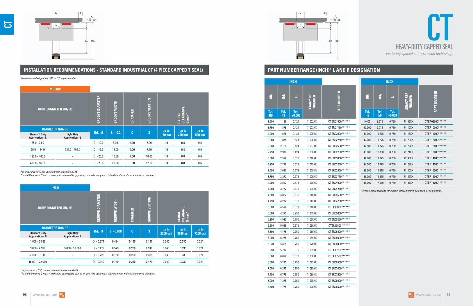
INSTALLATION RECOMMENDATIONS - STANDARD INDUSTRIAL CT (4 PIECE CAPPED T SEAL)
INCH
BORE DIAMETER ØD1 H9
GRO
OVE
DIA
MET
ER
GRO
OVE
WID
TH
CHA
MFE
R
GRO
OVE
SEC
TIO
N
RAD
IAL
CLEA
RAN
CE
G m
ax*
DIAMETER RANGE Ød1 h9 L1 +0.008 C S up to
2300 psiup to
3625 psiup to
7250 psiStandard Duty Application - R
Light Duty Application - L
1.000 - 2.999 - D1 - 0.374 0.424 0.160 0.187 0.040 0.030 0.024
3.000 - 4.999 5.000 - 16.000 D1 - 0.478 0.579 0.200 0.240 0.040 0.030 0.024
5.000 - 16.000 - D1 - 0.725 0.750 0.250 0.365 0.040 0.030 0.024
16.001 - 22.000 - D1 - 0.940 0.750 0.250 0.470 0.040 0.030 0.024
METRIC
BORE DIAMETER ØD1 H9
GRO
OVE
DIA
MET
ER
GRO
OVE
WID
TH
CHA
MFE
R
GRO
OVE
SEC
TIO
N
RAD
IAL
CLEA
RAN
CE
G m
ax*
DIAMETER RANGE Ød1 h9 L1 + 0.2 C S up to
160 barup to
250 barup to
500 barStandard Duty Application - R
Light Duty Application - L
25.0 - 74.0 - D1 - 10.0 8.00 4.00 5.00 1.0 0.8 0.6
75.0 - 124.0 125.0 - 405.0 D1 - 15.0 12.00 5.00 7.50 1.0 0.8 0.6
125.0 - 405.0 - D1 - 20.0 16.00 7.00 10.00 1.0 0.8 0.6
406.0 - 560.0 - D1 - 25.0 20.00 8.00 12.50 1.0 0.8 0.6
Nomeclature designation: “R” or “L” in part number
For pressures >500 bar use diameter tolerance H7/f8. *Radial Clearance G max. = maximum permissible gap all on one side using max. tube diameter and min. clearance diameter.
For pressures >7250 psi use diameter tolerance H7/f8. *Radial Clearance G max. = maximum permissible gap all on one side using max. tube diameter and min. clearance diameter.
PART NUMBER RANGE (INCH)* L AND R DESIGNATION
9.000 8.275 0.750 71105XX CTER09000******
10.000 9.275 0.750 71110XX CTER10000******
11.000 10.275 0.750 71115XX CTER11000******
12.000 11.275 0.750 71120XX CTER12000******
12.500 11.775 0.750 71122XX CTER12500******
13.000 12.700 0.750 71124XX CTER13000******
14.000 13.275 0.750 71140XX CTER14000******
14.500 13.775 0.750 71128XX CTER14500******
15.000 14.275 0.750 71130XX CTER15000******
16.000 15.275 0.750 71132XX CTER16000******
18.000 17.060 0.750 71138XX CTER18000******
CTHEAVY-DUTY CAPPED SEAL
Featuring special anti-extrusion technology
CT
*Please contact Hallite for custom sizes, material selection, or seal design.
INCH
ØD
1
Ød 1 L 1
LEG
ACY
REF
N
UM
BER
PART
NU
MB
ER
Tol. H9
Tol. h9
Tol. +0.008
1.500 1.126 0.424 71002XX CTER01500******
1.750 1.376 0.424 71003XX CTER01750******
2.000 1.626 0.424 71005XX CTER02000******
2.250 1.876 0.424 71006XX CTER02250******
2.500 2.126 0.424 71007XX CTER02500******
2.750 2.376 0.424 71008XX CTER02750******
3.000 2.522 0.579 71010XX CTER03000******
3.250 2.772 0.579 71015XX CTER03250******
3.500 3.022 0.579 71020XX CTER03500******
3.750 3.272 0.579 71025XX CTER03750******
4.000 3.522 0.579 71030XX CTER04000******
4.250 3.772 0.579 71035XX CTER04250******
4.500 4.022 0.579 71040XX CTER04500******
4.750 4.272 0.579 71043XX CTER04750******
5.000 4.522 0.579 71048XX CTEL05000******
5.000 4.275 0.750 71045XX CTER05000******
5.250 4.525 0.750 71050XX CTER05250******
5.500 5.025 0.579 71060XX CTEL05500******
5.500 4.775 0.750 71055XX CTER05500******
6.000 5.275 0.750 71065XX CTER06000******
6.030 5.305 0.750 71070XX CTER06030******
6.250 5.772 0.579 71069XX CTEL06250******
6.500 6.022 0.579 71080XX CTEL06500******
6.500 5.775 0.750 71075XX CTER06500******
7.000 6.275 0.750 71085XX CTER07000******
7.500 6.775 0.750 71090XX CTER07500******
8.000 7.275 0.750 71095XX CTER08000******
8.500 7.775 0.750 71100XX CTER08500******
INCH
ØD
1
Ød 1 L 1
LEG
ACY
REF
N
UM
BER
PART
NU
MB
ER
Tol. H9
Tol. h9
Tol. +0.008
WWW.HALLITE.COM98 WWW.HALLITE.COM 99
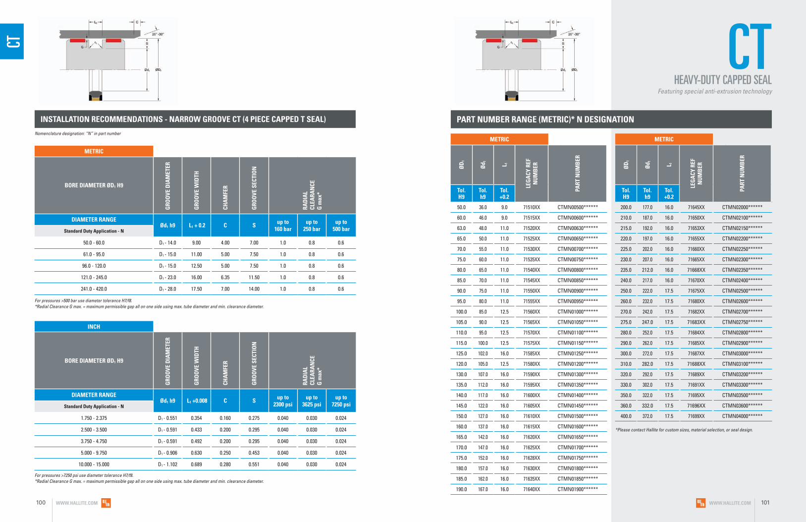
PART NUMBER RANGE (METRIC)* N DESIGNATION
50.0 36.0 9.0 71510XX CTMN00500******
60.0 46.0 9.0 71515XX CTMN00600******
63.0 48.0 11.0 71520XX CTMN00630******
65.0 50.0 11.0 71525XX CTMN00650******
70.0 55.0 11.0 71530XX CTMN00700******
75.0 60.0 11.0 71535XX CTMN00750******
80.0 65.0 11.0 71540XX CTMN00800******
85.0 70.0 11.0 71545XX CTMN00850******
90.0 75.0 11.0 71550XX CTMN00900******
95.0 80.0 11.0 71555XX CTMN00950******
100.0 85.0 12.5 71560XX CTMN01000******
105.0 90.0 12.5 71565XX CTMN01050******
110.0 95.0 12.5 71570XX CTMN01100******
115.0 100.0 12.5 71575XX CTMN01150******
125.0 102.0 16.0 71585XX CTMN01250******
120.0 105.0 12.5 71580XX CTMN01200******
130.0 107.0 16.0 71590XX CTMN01300******
135.0 112.0 16.0 71595XX CTMN01350******
140.0 117.0 16.0 71600XX CTMN01400******
145.0 122.0 16.0 71605XX CTMN01450******
150.0 127.0 16.0 71610XX CTMN01500******
160.0 137.0 16.0 71615XX CTMN01600******
165.0 142.0 16.0 71620XX CTMN01650******
170.0 147.0 16.0 71625XX CTMN01700******
175.0 152.0 16.0 71628XX CTMN01750******
180.0 157.0 16.0 71630XX CTMN01800******
185.0 162.0 16.0 71635XX CTMN01850******
190.0 167.0 16.0 71640XX CTMN01900******
200.0 177.0 16.0 71645XX CTMN02000******
210.0 187.0 16.0 71650XX CTMN02100******
215.0 192.0 16.0 71653XX CTMN02150******
220.0 197.0 16.0 71655XX CTMN02200******
225.0 202.0 16.0 71660XX CTMN02250******
230.0 207.0 16.0 71665XX CTMN02300******
235.0 212.0 16.0 71668XX CTMN02350******
240.0 217.0 16.0 71670XX CTMN02400******
250.0 222.0 17.5 71675XX CTMN02500******
260.0 232.0 17.5 71680XX CTMN02600******
270.0 242.0 17.5 71682XX CTMN02700******
275.0 247.0 17.5 71683XX CTMN02750******
280.0 252.0 17.5 71684XX CTMN02800******
290.0 262.0 17.5 71685XX CTMN02900******
300.0 272.0 17.5 71687XX CTMN03000******
310.0 282.0 17.5 71688XX CTMN03100******
320.0 292.0 17.5 71689XX CTMN03200******
330.0 302.0 17.5 71691XX CTMN03300******
350.0 322.0 17.5 71695XX CTMN03500******
360.0 332.0 17.5 71696XX CTMN03600******
400.0 372.0 17.5 71699XX CTMN04000******
INSTALLATION RECOMMENDATIONS - NARROW GROOVE CT (4 PIECE CAPPED T SEAL)
METRIC
BORE DIAMETER ØD1 H9
GRO
OVE
DIA
MET
ER
GRO
OVE
WID
TH
CHA
MFE
R
GRO
OVE
SEC
TIO
N
RAD
IAL
CLEA
RAN
CE
G m
ax*
DIAMETER RANGE Ød1 h9 L1 + 0.2 C S up to
160 barup to
250 barup to
500 barStandard Duty Application - N
50.0 - 60.0 D1 - 14.0 9.00 4.00 7.00 1.0 0.8 0.6
61.0 - 95.0 D1 - 15.0 11.00 5.00 7.50 1.0 0.8 0.6
96.0 - 120.0 D1 - 15.0 12.50 5.00 7.50 1.0 0.8 0.6
121.0 - 245.0 D1 - 23.0 16.00 6.35 11.50 1.0 0.8 0.6
241.0 - 420.0 D1 - 28.0 17.50 7.00 14.00 1.0 0.8 0.6
INCH
BORE DIAMETER ØD1 H9
GRO
OVE
DIA
MET
ER
GRO
OVE
WID
TH
CHA
MFE
R
GRO
OVE
SEC
TIO
N
RAD
IAL
CLEA
RAN
CE
G m
ax*
DIAMETER RANGE Ød1 h9 L1 +0.008 C S up to
2300 psiup to
3625 psiup to
7250 psiStandard Duty Application - N
1.750 - 2.375 D1 - 0.551 0.354 0.160 0.275 0.040 0.030 0.024
2.500 - 3.500 D1 - 0.591 0.433 0.200 0.295 0.040 0.030 0.024
3.750 - 4.750 D1 - 0.591 0.492 0.200 0.295 0.040 0.030 0.024
5.000 - 9.750 D1 - 0.906 0.630 0.250 0.453 0.040 0.030 0.024
10.000 - 15.000 D1 - 1.102 0.689 0.280 0.551 0.040 0.030 0.024
For pressures >500 bar use diameter tolerance H7/f8. *Radial Clearance G max. = maximum permissible gap all on one side using max. tube diameter and min. clearance diameter.
For pressures >7250 psi use diameter tolerance H7/f8. *Radial Clearance G max. = maximum permissible gap all on one side using max. tube diameter and min. clearance diameter.
Nomenclature designation: “N” in part number
CT CTHEAVY-DUTY CAPPED SEAL
Featuring special anti-extrusion technology
*Please contact Hallite for custom sizes, material selection, or seal design.
METRIC
ØD
1
Ød 1 L 1
LEG
ACY
REF
N
UM
BER
PART
NU
MB
ER
Tol. H9
Tol. h9
Tol. +0.2
METRIC
ØD
1
Ød 1 L 1
LEG
ACY
REF
N
UM
BER
PART
NU
MB
ER
Tol. H9
Tol. h9
Tol. +0.2
WWW.HALLITE.COM100 WWW.HALLITE.COM 101
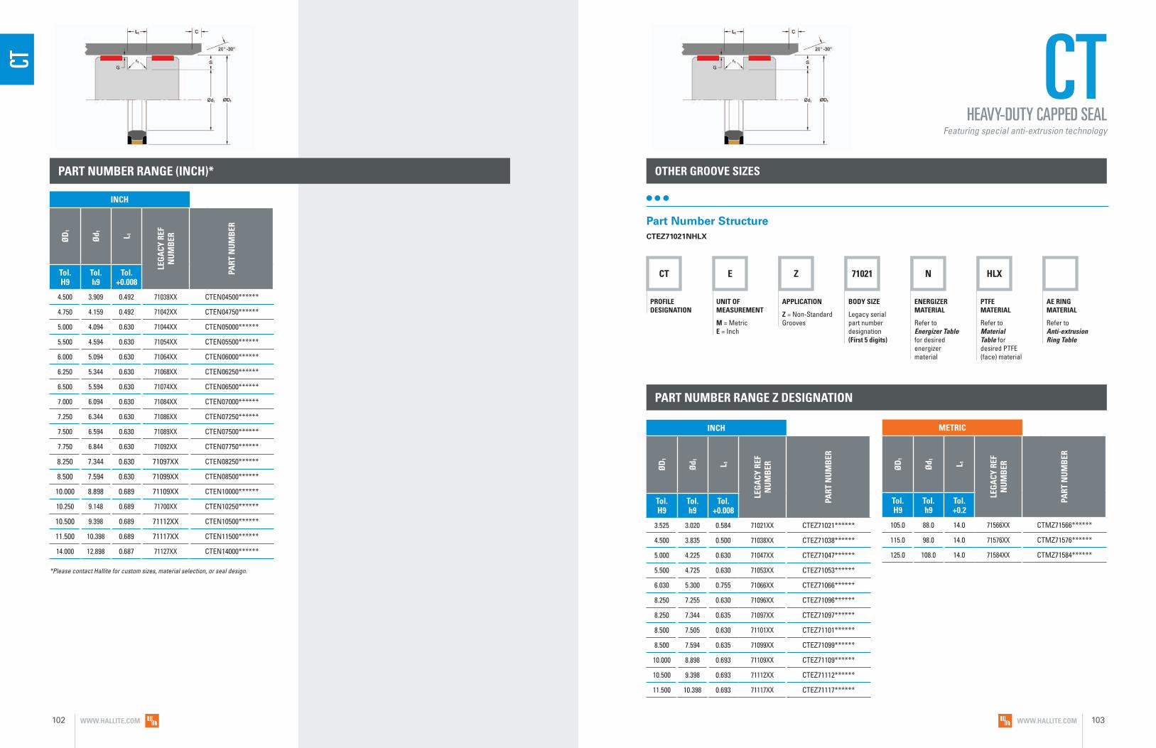
PART NUMBER RANGE (INCH)*
4.500 3.909 0.492 71039XX CTEN04500******
4.750 4.159 0.492 71042XX CTEN04750******
5.000 4.094 0.630 71044XX CTEN05000******
5.500 4.594 0.630 71054XX CTEN05500******
6.000 5.094 0.630 71064XX CTEN06000******
6.250 5.344 0.630 71068XX CTEN06250******
6.500 5.594 0.630 71074XX CTEN06500******
7.000 6.094 0.630 71084XX CTEN07000******
7.250 6.344 0.630 71086XX CTEN07250******
7.500 6.594 0.630 71089XX CTEN07500******
7.750 6.844 0.630 71092XX CTEN07750******
8.250 7.344 0.630 71097XX CTEN08250******
8.500 7.594 0.630 71099XX CTEN08500******
10.000 8.898 0.689 71109XX CTEN10000******
10.250 9.148 0.689 71700XX CTEN10250******
10.500 9.398 0.689 71112XX CTEN10500******
11.500 10.398 0.689 71117XX CTEN11500******
14.000 12.898 0.687 71127XX CTEN14000******
CTHEAVY-DUTY CAPPED SEAL
Featuring special anti-extrusion technology
CT
OTHER GROOVE SIZES
CT E Z 71021 N HLX
PROFILE DESIGNATION
UNIT OF MEASUREMENT
M = Metric E = Inch
APPLICATION
Z = Non-Standard Grooves
BODY SIZE
Legacy serial part number designation (First 5 digits)
ENERGIZER MATERIAL
Refer to Energizer Table for desired energizer material
PTFE MATERIAL
Refer to Material Table for desired PTFE (face) material
AE RING MATERIAL
Refer to Anti-extrusion Ring Table
Part Number StructureCTEZ71021NHLX
PART NUMBER RANGE Z DESIGNATION
3.525 3.020 0.584 71021XX CTEZ71021******
4.500 3.835 0.500 71038XX CTEZ71038******
5.000 4.225 0.630 71047XX CTEZ71047******
5.500 4.725 0.630 71053XX CTEZ71053******
6.030 5.300 0.755 71066XX CTEZ71066******
8.250 7.255 0.630 71096XX CTEZ71096******
8.250 7.344 0.635 71097XX CTEZ71097******
8.500 7.505 0.630 71101XX CTEZ71101******
8.500 7.594 0.635 71099XX CTEZ71099******
10.000 8.898 0.693 71109XX CTEZ71109******
10.500 9.398 0.693 71112XX CTEZ71112******
11.500 10.398 0.693 71117XX CTEZ71117******
*Please contact Hallite for custom sizes, material selection, or seal design.
105.0 88.0 14.0 71566XX CTMZ71566******
115.0 98.0 14.0 71576XX CTMZ71576******
125.0 108.0 14.0 71584XX CTMZ71584******
INCH
ØD
1
Ød 1 L 1
LEG
ACY
REF
N
UM
BER
PART
NU
MB
ER
Tol. H9
Tol. h9
Tol. +0.008
INCH
ØD
1
Ød 1 L 1
LEG
ACY
REF
N
UM
BER
PART
NU
MB
ER
Tol. H9
Tol. h9
Tol. +0.008
METRIC
ØD
1
Ød 1 L 1
LEG
ACY
REF
N
UM
BER
PART
NU
MB
ER
Tol. H9
Tol. h9
Tol. +0.2
WWW.HALLITE.COM102 WWW.HALLITE.COM 103

P54 M R 00900 N HLX
PROFILE DESIGNATION
UNIT OF MEASUREMENT
M = Metric E = Inch
APPLICATION
Refer to Installation Recommendations and use designator for desired application
ENERGIZER MATERIAL
Refer to Energizer Table for desired energizer material
PTFE MATERIAL
Refer to Material Table for desired PTFE (face) material
BORE DIAMETER
Metric = mm X 10
Inch = inches X 1000
P54
• No stick-slip
• Low breakout and running friction
• Excellent in high-speed applications
• Compact piston design
• Seal ring component can be machined to any size
• Pressure notches to optimize seal response at all pressures
F E A T U R E S
TECHNICAL DETAILS
The Hallite P54 is a double-acting, O-ring energized, low-friction piston seal that performs
well in both high- and low-pressure systems. High-performance Armorlene® materials,
like HLX, provide outstanding wear and extrusion-resistance properties as well as large
range of temperature and media compatibility. The P54 has a proven design pedigree
as a high-performance seal used in demanding applications. The standard P54 seal face
includes pressure notches, which makes the seal very responsive to changes in pressure
or direction of travel. Used successfully for years in performance-critical applications in
construction equipment, machine tools, material handling, agricultural equipment, and
other industries, the Hallite P54 is a workhorse compact, double- acting, piston-sealing
solution. Its design fits a variety of housing sizes, including ISO 7425-1 grooves, and is
offered in a wide range of metric and inch options. Hallite recommends proper guidance
be used with this seal in heavy-duty applications (see Hallite Bearings section).
This seal is available in a variety of Hallite’s high-performance Armorlene® and Hythane®
materials to suit a wide range of demanding applications.
Part Number StructureP54MR00900NHLX _
PISTON SEALDouble-Acting
___
SPECIAL FEATURE
Blank = Std profile (with notches) X = No NotchesNotches not offered with groove widths (L1) of 2.2mm (0.087in) or 3.2mm (0.126in)
WWW.HALLITE.COM 105

P54 OPERATING CONDITIONS
METRIC INCH
Maximum Speed Up to 15m/sec Up to 50.0ft/sec
Temperature Range* -45 to 200°C -49 to 392°F
Maximum Dynamic Pressure** 600 bar 8700 psi
*Dependent upon energizer used (NBR, FKM, etc.). **For pressures above 400 bar (5800 psi), contact Hallite Engineering.
MATERIALS
SURFACE FINISH RECOMMENDATIONS
*Rmr is measured at a depth of 25% of the Rz value based upon a reference level (zero line) at 5% material/bearing area.
METRIC INCHRmr*
SURFACE ROUGHNESS μmRa μmRz μmRt μinRa μinRz μinRt
Dynamic Sealing Face ØD1 0.05 - 0.2 1.6 max 2 max 2 - 8 63 max 157 max
60% - 90%Static Sealing Face Ød1 1.6 max 6.3 max 10 max 63 max 250 max 394 max
Static Housing Faces L1 3.2 max 10 max 16 max 125 max 394 max 630 max
ENERGIZER TABLE
ENERGIZER MATERIAL (SHORE A)
ENERGIZER TYPE
ENERGIZER DESIGNATION
ENERGIZER OPERATING TEMPERATURE°C
ENERGIZER OPERATING TEMPERATURE°F
NBR - 70A O-ring N -30 to 100°C -22 to 212°F
NBR - 70A Low temp. O-ring L -45 to 80°C -49 to 176°F
FKM - 75A O-ring F -10 to 200°C 14 to 392°F
EPDM - 70A O-ring E -45 to 145°C -49 to 293°F
HNBR - 70A O-ring H -25 to 150°C -13 to 302°F
NBR - 90A O-ring Q -30 to 100°C -22 to 212°F
HNBR - 90A O-ring U -25 to 150°C -13 to 302°F
No Energizer* None X - -
*Seal ratings are based upon capabilities of its matched material components. Hallite cannot rate seal performance when the seal is mixed with other manufacturers’ energizers/components.
MATERIAL FEATURES AND APPLICATIONS
FILL
ER
MAT
ERIA
L DE
SIGN
ATOR
COLO
R
TEM
PERA
TURE
RA
NGE
°C
TEM
PERA
TURE
RA
NGE
°F
MA
XIM
UM
D
YNA
MIC
PR
ESSU
RE -
BA
RM
AXI
MU
M
DYN
AM
IC
PRES
SURE
- P
SI
ARMORLENE® HLX• Standard material for hydraulic applications• High compressive strength• Excellent extrusion resistance• Extended wear resistance
Special Bronze Compound HLX Gold -73 to 288°C -100 to 550°F 500 bar 7250 psi
ARMORLENE® HLA• Excellent in all hydraulic fluids• Excellent wear resistance• Excellent low-friction properties• Good extrusion resistance
Special Mineral Compound HLA Gray -73 to 260°C -100 to 500°F 500 bar 7250 psi
ARMORLENE® 702• Excellent in lubricating and non-lubricating hydraulic fluids• Good low-friction properties• Excellent extrusion resistance• Good chemical resistance
Glass Molybdenum Disulfide 702 Gray -73 to 260°C -100 to 500°F 300 bar 4350 psi
ARMORLENE® 706• Excellent in lubricating and non-lubricating hydraulic fluids• Excellent extrusion resistance• Good chemical resistance• Good dielectrical properties
15% Glass 706 Off- White -73 to 260°C -100 to 500°F 300 bar 4350 psi
ARMORLENE® 700• Excellent in all hydraulic fluids• Recommended for use with soft mating surfaces • Low friction and no stick-slip
Unfilled 700 White -184 to 204°C -300 to 400°F 200 bar 2900 psi
ARMORLENE® HCF• Excellent in lubricating and non-lubricating hydraulic fluids
(includes water) w/o zinc content• Not recommended for gas sealing applications• Not recommended for electrical conductive fluids
Carbon Fiber Filled HCF Gray/
Black -73 to 260°C -100 to 500°F 250 bar 3600 psi
ARMORLENE® HCV• Recommended for lubricating and non-lubricating fluids• Excellent for high-frequency and short-stroke applications• Not recommended for gas sealing applications• Not recommended for electrical conductive fluids
High Carbon Fiber Filled HCV Gray/
Black -73 to 260°C -100 to 500°F 300 bar 4350 psi
ARMORLENE® 711• Excellent in all lubricating fluids and pneumatic applications• High chemical resistance• Excellent extrusion resistance• Excellent wear properties
25% Carbon/Graphite 711 Black -73 to 288°C -100 to 550°F 400 bar 5800 psi
ARMORLENE® 713• High compressive strength• Excellent extrusion resistance• Excellent wear properties
60% Bronze Content 713 Bronze -73 to 288°C -100 to 550°F 600 bar 8700 psi
HU9 - POLYURETHANE, 95A• Positive position load holding• Excellent extrusion resistance• Excellent wear resistance
Standard HU9 Red -20 to 115°C -4 to 240°F 500 bar 7250 psi
HU5 - POLYURETHANE, 55D• Positive position load holding• Excellent extrusion resistance• Excellent wear resistance
Standard HU5 Yellow -20 to 115°C -4 to 240°F 500 bar 7250 psi
HYTHANE® 9270111 - POLYESTER, 55D• Positive position load holding• Hydrolysis stabilized• Strong chemical resistance• Excellent extrusion resistance• Excellent wear properties
Hydrolysis Stabilized 111 Gray -40 to 120°C -40 to 250°F 500 bar 7250 psi
HYTHANE® 9270261 - POLYESTER, 55D• Positive position load holding• Internal lubrication provides extended wear
in high-speed applications• Excellent extrusion resistance• Excellent wear resistance
Internally Lubricated 261 Off-
White -40 to 120°C -40 to 250°F 500 bar 7250 psi
HE5 - POLYESTER, 55D• Positive position load holding• Excellent extrusion resistance• Excellent wear resistance
Standard HE5 Gray/ Black -20 to 115°C -40 to 240°F 500 bar 7250 psi
748 - UHMWPE• Excellent impact resistance• Good dielectrical properties• Excellent abrasion resistance• Low coefficient of friction
Standard 748 Translucent -184 to 82°C -300 to 180°F 350 bar 5000 psi
For other material options consult the Master Materials Index at the front of the catalog. If you do not find the material that you require, please contact your local Hallite sales office.
Data given are maximum values and can apply depending on specific application. Maximum ratings of temperature, pressure, or operating speeds are dependent on fluid medium, surface, gap value, and other variables such as dynamic or static service. Maximum values are not intended for use together at the same time, e.g. max temperature and max pressure. Please contact your Hallite technical representative for application support.
NO
TE
WWW.HALLITE.COM106 WWW.HALLITE.COM 107

PART NUMBER RANGE (METRIC)*INSTALLATION RECOMMENDATIONS
At pressure >400 bar use diameter tolerance H8/f7. *Radial Clearance G max. = maximum permissible gap all on one side using max. tube diameter and min. clearance diameter.
METRIC
BORE DIAMETER ØD1 H9G
ROO
VE D
IAM
ETER
GRO
OVE
WID
TH
RAD
IUS
CHA
MFE
R
GRO
OVE
SEC
TIO
N
RAD
IAL
CLEA
RAN
CE
G m
ax*
O-R
ING
CR
OSS
SEC
TIO
N
DIAMETER RANGE Ød1 h9 L1 + 0.2 r1 C S Up to
100 barUp to
200 barUp to
400 bar O-ringStandard Duty Application - R
Light Duty Application - L
Heavy Duty Application - H
8.0 - 14.9 15.0 - 39.9 - D1 - 4.9 2.2 0.4 2.0 2.45 0.30 0.20 0.15 1.78
15.0 - 39.9 40.0 - 79.9 - D1 - 7.5 3.2 0.6 3.0 3.75 0.40 0.25 0.15 2.62
40.0 - 79.9 80.0 - 132.9 15.0 - 39.9 D1 - 11.0 4.2 1.0 4.0 5.50 0.40 0.25 0.20 3.53
80.0 - 132.9 133.0 - 329.9 40.0 - 79.9 D1 - 15.5 6.3 1.3 6.0 7.75 0.50 0.30 0.20 5.33
133.0 - 329.9 330.0 - 669.9 80.0 - 132.9 D1 - 21.0 8.1 1.8 8.0 10.50 0.60 0.35 0.25 6.99
330.0 - 669.9 670.0 - 999.9 133.0 - 329.9 D1 - 24.5 8.1 1.8 8.0 12.25 0.60 0.35 0.25 6.99
670.0 - 999.9 ≥ 1000.0 330.0 - 669.9 D1 - 28.0 9.5 2.5 9.0 14.00 0.70 0.50 0.30 8.40
≥ 1000.0 - 670.0 - 999.9 D1 - 38.0 13.8 3.0 10.0 19.00 1.00 0.70 0.60 12.00
At pressure >5800 psi use diameter tolerance H8/f7. *Radial Clearance G max. = maximum permissible gap all on one side using max. tube diameter and min. clearance diameter.
INCH
BORE DIAMETER ØD1 H9
GRO
OVE
DIA
MET
ER
GRO
OVE
WID
TH
RAD
IUS
CHA
MFE
R
GRO
OVE
SEC
TIO
N
RAD
IAL
CLEA
RAN
CE
G m
ax*
O-R
ING
CR
OSS
SEC
TIO
N
DIAMETER RANGE Ød1 h9 L1 + .008 r1 C S Up to
1500 psiUp to
2900 psiUp to
5800 psi O-ringStandard Duty Application - R
Light Duty Application - L
Heavy Duty Application - H
0.312 - 0.562 0.563 - 1.562 - D1 - 0.193 0.087 0.015 0.079 0.097 0.012 0.008 0.006 0.070
0.563 - 1.562 1.563 - 3.125 - D1 - 0.295 0.126 0.025 0.118 0.148 0.016 0.010 0.006 0.103
1.563 - 3.125 3.126 - 5.250 0.563 - 1.562 D1 - 0.433 0.165 0.025 0.157 0.217 0.016 0.010 0.008 0.139
3.126 - 5.250 5.251 - 12.500 1.563 - 3.125 D1 - 0.610 0.248 0.035 0.236 0.305 0.020 0.012 0.008 0.210
5.251 - 12.500 12.501 - 26.000 3.126 - 5.250 D1 - 0.827 0.319 0.035 0.315 0.414 0.024 0.014 0.010 0.275
12.501 - 26.000 - 5.251 - 12.500 D1 - 0.965 0.319 0.035 0.354 0.483 0.024 0.014 0.010 0.275
8.0 3.1 2.2 P54MR00080****
10.0 5.1 2.2 P54MR00100****
12.0 7.1 2.2 P54MR00120****
14.0 9.1 2.2 P54MR00140****
15.0 7.5 3.2 P54MR00150****
16.0 11.1 2.2 P54ML00160****
16.0 8.5 3.2 P54MR00160****
18.0 13.1 2.2 P54ML00180****
18.0 10.5 3.2 P54MR00180****
20.0 15.1 2.2 P54ML00200****
20.0 12.5 3.2 P54MR00200****
21.0 13.5 3.2 P54MR00210****
22.0 17.1 2.2 P54ML00220****
22.0 14.5 3.2 P54MR00220****
24.0 16.5 3.2 P54MR00240****
24.0 19.1 2.2 P54ML00240****
25.0 20.1 2.2 P54ML00250****
25.0 17.5 3.2 P54MR00250****
25.0 14.0 4.2 P54MH00250****
28.0 20.5 3.2 P54MR00280****
30.0 22.5 3.2 P54MR00300****
32.0 27.1 2.2 P54ML00320****
32.0 24.5 3.2 P54MR00320****
32.0 21.0 4.2 P54MH00320****
35.0 27.5 3.2 P54MR00350****
35.0 24.0 4.2 P54MH00350****
36.0 28.5 3.2 P54MR00360****
38.0 30.5 3.2 P54MR00380****
40.0 32.5 3.2 P54ML00400****
40.0 29.0 4.2 P54MR00400****
42.0 31.0 4.2 P54MR00420****
45.0 34.0 4.2 P54MR00450****
48.0 37.0 4.2 P54MR00480****
50.0 42.5 3.2 P54ML00500****
50.0 39.0 4.2 P54MR00500****
50.0 34.5 6.3 P54MH00500****
50.8 43.3 3.2 P54ML00508****
50.8 39.8 4.2 P54MR00508****
52.0 41.0 4.2 P54MR00520****
53.0 42.0 4.2 P54MR00530****
55.0 44.0 4.2 P54MR00550****
57.0 46.0 4.2 P54MR00570****
58.0 47.0 4.2 P54MR00580****
60.0 49.0 4.2 P54MR00600****
62.0 51.0 4.2 P54MR00620****
63.0 52.0 4.2 P54MR00630****
63.0 47.5 6.3 P54MH00630****
65.0 54.0 4.2 P54MR00650****
68.0 57.0 4.2 P54MR00680****
70.0 59.0 4.2 P54MR00700****
70.0 54.5 6.3 P54MH00700****
75.0 64.0 4.2 P54MR00750****
75.0 59.5 6.3 P54MH00750****
80.0 69.0 4.2 P54ML00800****
80.0 64.5 6.3 P54MR00800****
80.0 59.0 8.1 P54MH00800****
P54 P54
PISTON SEALDouble-Acting
Applications with maximum radial clearance that are using nylon, phenolic, or PTFE bearings must ensure proper clearance in accordance with the bearing recommendations to avoid metal-to-metal contact.
Please refer to Hallite Type 87, Type 506, and Type 533 Specification Sheets for this information.
METRIC
ØD
1
Ød 1 L 1
PART
NU
MB
ER
Tol. H9 Tol. H9 Tol. +0.2
METRIC
ØD
1
Ød 1 L 1
PART
NU
MB
ER
Tol. H9 Tol. H9 Tol. +0.2
WWW.HALLITE.COM108 WWW.HALLITE.COM 109

PART NUMBER RANGE (METRIC)*PART NUMBER RANGE (METRIC)*
82.5 67.0 6.3 P54MR00825****
85.0 69.5 6.3 P54MR00850****
85.0 64.0 8.1 P54MH00850****
90.0 79.0 4.2 P54ML00900****
90.0 74.5 6.3 P54MR00900****
90.0 69.0 8.1 P54MH00900****
95.0 84.0 4.2 P54ML00950****
95.0 79.5 6.3 P54MR00950****
95.0 74.0 8.1 P54MH00950****
100.0 89.0 4.2 P54ML01000****
100.0 84.5 6.3 P54MR01000****
100.0 79.0 8.1 P54MH01000****
101.6 86.1 6.3 P54MR01016****
105.0 94.0 4.2 P54ML01050****
105.0 89.5 6.3 P54MR01050****
108.0 92.5 6.3 P54MR01080****
110.0 99.0 4.2 P54ML01100****
110.0 94.5 6.3 P54MR01100****
110.0 89.0 8.1 P54MH01100****
115.0 99.5 6.3 P54MR01150****
120.0 109.0 4.2 P54ML01200****
120.0 104.5 6.3 P54MR01200****
120.0 99.0 8.1 P54MH01200****
125.0 114.0 4.2 P54ML01250****
125.0 109.5 6.3 P54MR01250****
125.0 104.0 8.1 P54MH01250****
127.0 111.5 6.3 P54MR01270****
130.0 114.5 6.3 P54MR01300****
130.0 109.0 8.1 P54MH01300****
132.0 121.0 4.2 P54ML01320****
135.0 114.0 8.1 P54MR01350****
140.0 124.5 6.3 P54ML01400****
140.0 119.0 8.1 P54MR01400****
145.0 129.5 6.3 P54ML01450****
145.0 124.0 8.1 P54MR01450****
150.0 134.5 6.3 P54ML01500****
150.0 129.0 8.1 P54MR01500****
155.0 134.0 8.1 P54MR01550****
160.0 144.5 6.3 P54ML01600****
160.0 139.0 8.1 P54MR01600****
165.0 144.0 8.1 P54MR01650****
170.0 149.0 8.1 P54MR01700****
175.0 154.0 8.1 P54MR01750****
180.0 164.5 6.3 P54ML01800****
180.0 159.0 8.1 P54MR01800****
185.0 164.0 8.1 P54MR01850****
190.0 169.0 8.1 P54MR01900****
194.0 178.5 6.3 P54ML01940****
200.0 184.5 6.3 P54ML02000****
200.0 179.0 8.1 P54MR02000****
205.0 184.0 8.1 P54MR02050****
210.0 189.0 8.1 P54MR02100****
215.0 194.0 8.1 P54MR02150****
220.0 199.0 8.1 P54MR02200****
225.0 204.0 8.1 P54MR02250****
230.0 214.5 6.3 P54ML02300****
230.0 209.0 8.1 P54MR02300****
240.0 219.0 8.1 P54MR02400****
250.0 229.0 8.1 P54MR02500****
250.0 225.5 8.1 P54MH02500****
250.0 234.5 6.3 P54ML02500****
254.0 233.0 8.1 P54MR02540****
260.0 239.0 8.1 P54MR02600****
265.0 244.0 8.1 P54MR02650****
268.0 247.0 8.1 P54MR02680****
270.0 249.0 8.1 P54MR02700****
280.0 259.0 8.1 P54MR02800****
290.0 269.0 8.1 P54MR02900****
300.0 279.0 8.1 P54MR03000****
300.0 275.5 8.1 P54MH03000****
304.8 283.8 8.1 P54MR03048****
310.0 289.0 8.1 P54MR03100****
320.0 299.0 8.1 P54MR03200****
320.0 295.5 8.1 P54MH03200****
330.0 305.5 8.1 P54MR03300****
340.0 315.5 8.1 P54MR03400****
350.0 325.5 8.1 P54MR03500****
360.0 335.5 8.1 P54MR03600****
370.0 345.5 8.1 P54MR03700****
380.0 355.5 8.1 P54MR03800****
390.0 365.5 8.1 P54MR03900****
400.0 375.5 8.1 P54MR04000****
420.0 395.5 8.1 P54MR04200****
430.0 405.5 8.1 P54MR04300****
440.0 415.5 8.1 P54MR04400****
450.0 425.5 8.1 P54MR04500****
460.0 435.5 8.1 P54MR04600****
480.0 455.5 8.1 P54MR04800****
500.0 475.5 8.1 P54MR05000****
555.0 530.5 8.1 P54MR05550****
600.0 575.5 8.1 P54MR06000****
640.0 615.5 8.1 P54MR06400****
660.0 635.5 8.1 P54MR06600****
700.0 672.0 9.5 P54MR07000****
710.0 682.0 9.5 P54MR07100****
740.0 712.0 9.5 P54MR07400****
780.0 752.0 9.5 P54MR07800****
800.0 772.0 9.5 P54MR08000****
900.0 872.0 9.5 P54MR09000****
1000.0 972.0 9.5 P54ML10000****
1000.0 962.0 13.8 P54MR10000****
1050.0 1022.0 9.5 P54ML10500****
1065.0 1027.0 13.8 P54MR10650****
1070.0 1032.0 13.8 P54MR10700****
1200.0 1172.0 9.5 P54ML12000****
1200.0 1162.0 13.8 P54MR12000****
1225.0 1187.0 13.8 P54MR12250****
P54 P54
PISTON SEALDouble-Acting
*Please contact Hallite for custom sizes, material selection, or seal design.
METRIC
ØD
1
Ød 1 L 1
PART
NU
MB
ER
Tol. H9 Tol. H9 Tol. +0.2
METRIC
ØD
1
Ød 1 L 1
PART
NU
MB
ER
Tol. H9 Tol. H9 Tol. +0.2
METRIC
ØD
1
Ød 1 L 1
PART
NU
MB
ER
Tol. H9 Tol. H9 Tol. +0.2
METRIC
ØD
1
Ød 1 L 1
PART
NU
MB
ER
Tol. H9 Tol. H9 Tol. +0.2
WWW.HALLITE.COM110 WWW.HALLITE.COM 111

PART NUMBER RANGE (INCH)* PART NUMBER RANGE (INCH)*
0.500 0.307 0.087 P54ER00500****
0.562 0.369 0.087 P54ER00562****
0.625 0.330 0.126 P54ER00625****
0.687 0.392 0.126 P54ER00687****
0.750 0.455 0.126 P54ER00750****
0.812 0.517 0.126 P54ER00812****
0.875 0.580 0.126 P54ER00875****
0.937 0.642 0.126 P54ER00937****
1.000 0.705 0.126 P54ER01000****
1.062 0.767 0.126 P54ER01062****
1.125 0.830 0.126 P54ER01125****
1.187 0.892 0.126 P54ER01187****
1.250 0.955 0.126 P54ER01250****
1.312 1.017 0.126 P54ER01312****
1.375 1.080 0.126 P54ER01375****
1.437 1.142 0.126 P54ER01437****
1.500 1.205 0.126 P54ER01500****
1.562 1.267 0.126 P54ER01562****
1.625 1.192 0.165 P54ER01625****
1.687 1.254 0.165 P54ER01687****
1.750 1.317 0.165 P54ER01750****
1.812 1.379 0.165 P54ER01812****
1.875 1.442 0.165 P54ER01875****
1.937 1.504 0.165 P54ER01937****
2.000 1.567 0.165 P54ER02000****
2.125 1.692 0.165 P54ER02125****
2.250 1.817 0.165 P54ER02250****
2.375 1.942 0.165 P54ER02375****
2.500 2.067 0.165 P54ER02500****
2.625 2.192 0.165 P54ER02625****
2.750 2.317 0.165 P54ER02750****
2.875 2.442 0.165 P54ER02875****
3.000 2.567 0.165 P54ER03000****
3.125 2.692 0.165 P54ER03125****
3.250 2.640 0.248 P54ER03250****
3.375 2.765 0.248 P54ER03375****
3.500 2.890 0.248 P54ER03500****
3.625 3.015 0.248 P54ER03625****
3.750 3.140 0.248 P54ER03750****
3.875 3.265 0.248 P54ER03875****
4.000 3.390 0.248 P54ER04000****
4.125 3.515 0.248 P54ER04125****
4.250 3.640 0.248 P54ER04250****
4.375 3.765 0.248 P54ER04375****
4.500 3.890 0.248 P54ER04500****
4.625 4.015 0.248 P54ER04625****
4.750 4.140 0.248 P54ER04750****
4.875 4.265 0.248 P54ER04875****
5.000 4.390 0.248 P54ER05000****
5.125 4.515 0.248 P54ER05125****
5.250 4.640 0.248 P54EL05250****
5.375 4.548 0.319 P54ER05375****
5.500 4.673 0.319 P54ER05500****
5.625 4.798 0.319 P54ER05625****
5.750 4.923 0.319 P54ER05750****
6.000 5.173 0.319 P54ER06000****
6.250 5.423 0.319 P54ER06250****
6.500 5.673 0.319 P54ER06500****
6.750 5.923 0.319 P54ER06750****
7.000 6.173 0.319 P54ER07000****
7.250 6.423 0.319 P54ER07250****
7.500 6.673 0.319 P54ER07500****
7.750 6.923 0.319 P54ER07750****
8.000 7.173 0.319 P54ER08000****
8.250 7.423 0.319 P54ER08250****
8.500 7.673 0.319 P54ER08500****
8.750 7.923 0.319 P54ER08750****
9.000 8.173 0.319 P54ER09000****
9.250 8.423 0.319 P54ER09250****
9.500 8.673 0.319 P54ER09500****
9.750 8.923 0.319 P54ER09750****
10.000 9.173 0.319 P54ER10000****
10.500 9.673 0.319 P54ER10500****
11.000 10.173 0.319 P54ER11000****
11.500 10.673 0.319 P54ER11500****
12.000 11.173 0.319 P54ER12000****
12.500 11.673 0.319 P54ER12500****
13.000 12.035 0.319 P54ER13000****
13.500 12.535 0.319 P54ER13500****
14.000 13.035 0.319 P54ER14000****
14.500 13.535 0.319 P54ER14500****
15.000 14.035 0.319 P54ER15000****
15.500 14.535 0.319 P54ER15500****
16.000 15.035 0.319 P54ER16000****
16.500 15.535 0.319 P54ER16500****
17.000 16.035 0.319 P54ER17000****
17.500 16.535 0.319 P54ER17500****
18.000 17.035 0.319 P54ER18000****
18.500 17.535 0.319 P54ER18500****
19.000 18.035 0.319 P54ER19000****
19.500 18.535 0.319 P54ER19500****
20.000 19.035 0.319 P54ER20000****
P54 P54
PISTON SEALDouble-Acting
*Please contact Hallite for custom sizes, material selection, or seal design.
INCH
ØD
1
Ød 1 L 1
PART
NU
MB
ER
Tol. H9 Tol. H9 Tol. +0.008
INCH
ØD
1
Ød 1 L 1
PART
NU
MB
ER
Tol. H9 Tol. H9 Tol. +0.008
INCH
ØD
1
Ød 1 L 1
PART
NU
MB
ER
Tol. H9 Tol. H9 Tol. +0.008
INCH
ØD
1
Ød 1 L 1
PART
NU
MB
ER
Tol. H9 Tol. H9 Tol. +0.008
WWW.HALLITE.COM112 WWW.HALLITE.COM 113

P16 M R 00500 N HLX
PROFILE DESIGNATION
UNIT OF MEASUREMENT
M = Metric E = Inch
APPLICATION
Refer to Installation Recommendations and use designator for desired application
ENERGIZER MATERIAL
Refer to Energizer Table for desired energizer material
PTFE MATERIAL
Refer to Material Table for desired PTFE (face) material
SPECIAL FEATURE
Blank = Std profile
___
BORE DIAMETER
Metric = mm X 10
Inch = inches X 1000
P16
• Low breakout friction and elimination of stick-slip action
• Excellent dynamic and static sealability
• Long wear and high extrusion resistance
• Ability to absorb shock loads from pressure spikes
F E A T U R E S
TECHNICAL DETAILS
The Hallite P16 is a single-acting, O-ring energized, low-friction piston seal especially
useful where smooth movement and location accuracy is required. The P16 design
is based on the very successful R16 rod-seal design which has been proven in the
market to be an excellent seal. High- performance Armorlene® materials, like HLX,
provide outstanding wear and extrusion-resistance properties as well as large range
of temperature and high-speed capabilities.
The P16’s design eliminates the potential for stick-slip and its very low running friction
makes it ideal for high-speed applications. In particular, this seal is well-suited for
use in piston accumulators in conjunction with other Hallite piston seals. The P16 is
designed to fit a variety of inch and metric grooves, including ISO 7425-1 standard.
This seal is available in a variety of Hallite’s high-performance Armorlene® materials
to suit a wide range of demanding applications. A tandem arrangement using the
P54 or P16 in an Armorlene® material is effective in sealing high-frequency and
long-stroke applications.
Part Number StructureP16MR00500NHLX __
PISTON SEALSingle-Acting
WWW.HALLITE.COM 115

P16 OPERATING CONDITIONS
METRIC INCH
Maximum Speed Up to 15.0m/sec Up to 50.0ft/sec
Temperature Range* -45 to 200°C -49 to 392°F
Maximum Dynamic Pressure** 600 bar 8700 psi
*Dependent upon energizer used (NBR, FKM, etc.). **For pressures above 400 bar (5800 psi), contact Hallite Engineering.
SURFACE FINISH RECOMMENDATIONS
*Rmr is measured at a depth of 25% of the Rz value based upon a reference level (zero line) at 5% material/bearing area.
METRIC INCHRmr*
SURFACE ROUGHNESS μmRa μmRz μmRt μinRa μinRz μinRt
Dynamic Sealing Face ØD1 0.05 - 0.2 1.6 max 2 max 2 - 8 63 max 157 max
60% - 90%Static Sealing Face Ød1 1.6 max 6.3 max 10 max 63 max 250 max 394 max
Static Housing Faces L1 3.2 max 10 max 16 max 125 max 394 max 630 max
ENERGIZER TABLE
ENERGIZER MATERIAL (SHORE A)
ENERGIZER TYPE
ENERGIZER DESIGNATION
ENERGIZER OPERATING TEMPERATURE°C
ENERGIZER OPERATING TEMPERATURE°F
NBR - 70A O-ring N -30 to 100°C -22 to 212°F
NBR - 70A Low temp. O-ring L -45 to 80°C -49 to 176°F
FKM - 75A O-ring F -10 to 200°C 14 to 392°F
EPDM - 70A O-ring E -45 to 145°C -49 to 293°F
HNBR - 70A O-ring H -25 to 150°C -13 to 302°F
NBR - 90A O-ring Q -30 to 100°C -22 to 212°F
HNBR - 90A O-ring U -25 to 150°C -13 to 302°F
No Energizer* None X - -
*Seal ratings are based upon capabilities of its matched material components. Hallite cannot rate seal performance when the seal is mixed with other manufacturers’ energizers/components.
Data given are maximum values and can apply depending on specific application. Maximum ratings of temperature, pressure, or operating speeds are dependent on fluid medium, surface, gap value, and other variables such as dynamic or static service. Maximum values are not intended for use together at the same time, e.g. max temperature and max pressure. Please contact your Hallite technical representative for application support.
NO
TEMATERIALS
MATERIAL FEATURES AND APPLICATIONS
FILL
ER
MAT
ERIA
L D
ESIG
NAT
OR
COLO
R
TEM
PERA
TURE
RA
NG
E°C
TEM
PERA
TURE
RA
NG
E°F
MA
XIM
UM
D
YNA
MIC
PR
ESSU
RE -
BA
R
MA
XIM
UM
D
YNA
MIC
PR
ESSU
RE -
PSI
ARMORLENE® HLX• Standard material for hydraulic applications• High compressive strength• Excellent extrusion resistance• Extended wear resistance
Special Bronze
CompoundHLX Gold -73 to 288°C -100 to 550°F 500 bar 7250 psi
ARMORLENE® 713• High compressive strength• Excellent extrusion resistance• Excellent wear properties
60% Bronze Content 713 Bronze -73 to 288°C -100 to 550°F 600 bar 8700 psi
ARMORLENE® HCF• Excellent in lubricating and non-lubricating hydraulic
fluids (includes water) w/o zinc content• Not recommended for gas sealing applications• Not recommended for electrical conductive fluids
Carbon Fiber Filled HCF Gray/
Black -73 to 260°C -100 to 500°F 250 bar 3600 psi
ARMORLENE® HCV• Recommended for lubricating and
non-lubricating fluids• Excellent for high-frequency and
short-stroke applications• Not recommended for gas sealing applications• Not recommended for electrical
conductive fluids
High Carbon Fiber Filled HCV Gray/
Black -73 to 260°C -100 to 500°F 300 bar 4350 psi
ARMORLENE® 700• Excellent in all hydraulic fluids• Recommended for use with soft mating surfaces • Low friction and no stick-slip
Unfilled 700 White -184 to 204°C -300 to 400°F 200 bar 2900 psi
ARMORLENE® 706• Excellent in lubricating and non-lubricating
hydraulic fluids• Excellent extrusion resistance• Good chemical resistance• Good dielectrical properties
15% Glass 706 Off- White -73 to 260°C -100 to 500°F 400 bar 5800 psi
ARMORLENE® 702• Excellent in lubricating and non-lubricating
hydraulic fluids• Good low-friction properties• Excellent extrusion resistance• Good chemical resistance
Glass Molybdenum
Disulfide702 Gray -73 to 260°C -100 to 500°F 400 bar 5800 psi
ARMORLENE® 711• Excellent in all lubricating fluids and
pneumatic applications• High chemical resistance• Excellent extrusion resistance• Excellent wear properties
25% Carbon/Graphite 711 Black -73 to 288°C -100 to 550°F 400 bar 5800 psi
ARMORLENE® HLA• Excellent in all hydraulic fluids• Excellent wear resistance• Excellent low-friction properties• Good extrusion resistance
Special Mineral
Compound HLA Gray -73 to 260°C -100 to 500°F 500 bar 7250 psi
ARMORLENE® 782• Good abrasion resistance• Recommended for lubricating and
non-lubricating fluids• Recommended for high frequency and
short-stroke applications• Not recommended for electrical and
conductive fluids
Modified Carbon Fiber
Filled782 Black -73 to 260°C -100 to 500°F 300 bar 4350 psi
748 - UHMWPE• Excellent impact resistance• Good dielectrical properties• Excellent abrasion resistance• Low coefficient of friction
Standard 748 Translucent -184 to 82°C -300 to 180°F 350 bar 5000 psi
For other material options consult the Master Materials Index at the front of the catalog. If you do not find the material that you require, please contact your local Hallite sales office.
WWW.HALLITE.COM116 WWW.HALLITE.COM 117

PART NUMBER RANGE (METRIC)*INSTALLATION RECOMMENDATIONS
At pressure >400 bar use diameter tolerance H8/f7. *Radial Clearance G max. = maximum permissible gap all on one side using max. tube diameter and min. clearance diameter.
METRIC
BORE DIAMETER ØD1 H9G
ROO
VE D
IAM
ETER
GRO
OVE
WID
TH
RAD
IUS
CHA
MFE
R
GRO
OVE
SEC
TIO
N
RAD
IAL
CLEA
RAN
CE
G m
ax*
O-R
ING
CR
OSS
SEC
TIO
N
DIAMETER RANGE Ød1 h9 L1 + 0.2 r1 C S Up to
100 barUp to
200 barUp to
400 bar O-ringStandard Duty Application - R
Light Duty Application - L
Heavy Duty Application - H
8.0 - 16.9 17.0 - 26.9 - D1 - 4.9 2.2 0.4 2.0 2.45 0.30 0.20 0.15 1.78
17.0 - 26.9 27.0 - 59.9 - D1 - 7.5 3.2 0.6 3.0 3.75 0.40 0.25 0.15 2.62
27.0 - 59.9 60.0 - 199.9 17.0 - 26.9 D1 - 11.0 4.2 1.0 4.0 5.50 0.50 0.30 0.20 3.53
60.0 - 199.9 200.0 - 255.9 27.0 - 59.9 D1 - 15.5 6.3 1.3 6.0 7.75 0.70 0.40 0.25 5.33
200.0 - 255.9 256.0 - 669.9 60.0 - 199.9 D1 - 21.0 8.1 1.8 8.0 10.50 0.80 0.60 0.35 6.99
256.0 - 669.9 670.0 - 999.9 200.0 - 255.9 D1 - 24.5 8.1 1.8 8.0 12.25 0.90 0.70 0.40 6.99
670.0 - 999.9 ≥1000.0 256.0 - 669.9 D1 - 28.0 9.5 2.5 9.0 14.00 1.00 0.80 0.60 8.40
≥1000.0 - 670.0 - 999.9 D1 - 38.0 13.8 3.0 10.0 19.00 1.20 0.90 0.60 12.00
INCH
BORE DIAMETER ØD1 H9
GRO
OVE
DIA
MET
ER
GRO
OVE
WID
TH
RAD
IUS
CHA
MFE
R
GRO
OVE
SEC
TIO
N
RAD
IAL
CLEA
RAN
CE
G m
ax*
O-R
ING
CR
OSS
SEC
TIO
N
DIAMETER RANGEØd1 h9 L1 + 0.008 r1 C S Up to
1500 psiUp to
2900 psiUp to
5800 psi O-ringStandard Duty Application - R
Light Duty Application - L
Heavy Duty Application - H
0.312 - 0.749 0.750 - 1.499 - D1 - 0.193 0.087 0.020 0.079 0.097 0.012 0.009 0.007 0.070
0.750 - 1.499 1.500 - 2.499 - D1 - 0.287 0.126 0.020 0.118 0.144 0.016 0.012 0.008 0.103
1.500 - 2.499 2.500 - 7.999 0.625 - 1.499 D1 - 0.421 0.165 0.025 0.157 0.211 0.016 0.012 0.009 0.139
2.500 - 7.999 8.000 - 9.999 1.000 - 2.499 D1 - 0.594 0.248 0.030 0.236 0.297 0.020 0.014 0.010 0.210
8.000 - 9.999 10.000 - 26.000 3.125 - 7.999 D1 -0.807 0.319 0.035 0.315 0.404 0.024 0.017 0.012 0.275
10.000 - 26.000 - 8.000 - 9.999 D1 - 0.945 0.319 0.035 0.315 0.473 0.024 0.017 0.012 0.275
At pressure >5800 psi use diameter tolerance H8/f7. *Radial Clearance G max. = maximum permissible gap all on one side using max. tube diameter and min. clearance diameter.
8.0 3.1 2.2 P16MR00080**** Also Fits - - -
9.0 4.1 2.2 P16MR00090**** Also Fits - - -
10.0 5.1 2.2 P16MR00100**** Also Fits - - -
12.0 7.1 2.2 P16MR00120**** Also Fits - - -
14.0 9.1 2.2 P16MR00140**** Also Fits - - -
15.0 10.1 2.2 P16MR00150**** Also Fits - - -
16.0 11.1 2.2 P16MR00160**** Also Fits - - -
18.0 10.5 3.2 P16MR00180**** Also Fits 18.0 10.7 3.2
18.0 13.1 2.2 P16ML00180**** Also Fits - - -
20.0 12.5 3.2 P16MR00200**** Also Fits 20.0 12.7 3.2
20.0 15.1 2.2 P16ML00200**** Also Fits - - -
20.0 9.0 4.2 P16MH00200**** Also Fits 20.0 9.3 4.2
22.0 14.5 3.2 P16MR00220**** Also Fits 22.0 14.7 3.2
22.0 11.0 4.2 P16MH00220**** Also Fits 22.0 11.3 4.2
25.0 17.5 3.2 P16MR00250**** Also Fits 25.0 17.7 3.2
25.0 20.1 2.2 P16ML00250**** Also Fits - - -
25.0 14.0 4.2 P16MH00250**** Also Fits 25.0 14.3 4.2
28.0 17.0 4.2 P16MR00280**** Also Fits 28.0 17.3 4.2
28.0 20.5 3.2 P16ML00280**** Also Fits 28.0 20.7 3.2
28.0 12.5 6.3 P16MH00280**** Also Fits 28.0 12.9 6.3
30.0 19.0 4.2 P16MR00300**** Also Fits 30.0 19.3 4.2
30.0 22.5 3.2 P16ML00300**** Also Fits 30.0 22.7 3.2
30.0 14.5 6.3 P16MH00300**** Also Fits 30.0 14.9 6.3
32.0 21.0 4.2 P16MR00320**** Also Fits 32.0 21.3 4.2
32.0 24.5 3.2 P16ML00320**** Also Fits 32.0 24.7 3.2
35.0 24.0 4.2 P16MR00350**** Also Fits 35.0 24.3 4.2
35.0 27.5 3.2 P16ML00350**** Also Fits 35.0 27.7 3.2
36.0 25.0 4.2 P16MR00360**** Also Fits 36.0 25.3 4.2
36.0 28.5 3.2 P16ML00360**** Also Fits 36.0 28.7 3.2
40.0 29.0 4.2 P16MR00400**** Also Fits 40.0 29.3 4.2
40.0 32.5 3.2 P16ML00400**** Also Fits 40.0 32.7 3.2
40.0 24.5 6.3 P16MH00400**** Also Fits 40.0 24.9 6.3
42.0 31.0 4.2 P16MR00420**** Also Fits 42.0 31.3 4.2
42.0 34.5 3.2 P16ML00420**** Also Fits 42.0 34.7 3.2
43.0 27.5 6.3 P16MH00430**** Also Fits 43.0 27.9 6.3
45.0 34.0 4.2 P16MR00450**** Also Fits 45.0 34.3 4.2
45.0 37.5 3.2 P16ML00450**** Also Fits 45.0 37.7 3.2
45.0 29.5 6.3 P16MH00450**** Also Fits 45.0 29.9 6.3
48.0 40.5 3.2 P16ML00480**** Also Fits 48.0 40.7 3.2
50.0 39.0 4.2 P16MR00500**** Also Fits 50.0 39.3 4.2
50.0 42.5 3.2 P16ML00500**** Also Fits 50.0 42.7 3.2
50.0 34.5 6.3 P16MH00500**** Also Fits 50.0 34.9 6.3
52.0 44.5 3.2 P16ML00520**** Also Fits 52.0 44.7 3.2
55.0 44.0 4.2 P16MR00550**** Also Fits 55.0 44.3 4.2
55.0 47.5 3.2 P16ML00550**** Also Fits 55.0 47.7 3.2
55.0 39.5 6.3 P16MH00550**** Also Fits 55.0 39.9 6.3
56.0 45.0 4.2 P16MR00560**** Also Fits 56.0 45.3 4.2
56.0 40.5 6.3 P16MH00560**** Also Fits 56.0 40.9 6.3
60.0 44.5 6.3 P16MR00600**** Also Fits 60.0 44.9 6.3
60.0 49.0 4.2 P16ML00600**** Also Fits 60.0 49.3 4.2
63.0 47.5 6.3 P16MR00630**** Also Fits 63.0 47.9 6.3
63.0 52.0 4.2 P16ML00630**** Also Fits 63.0 52.3 4.2
65.0 49.5 6.3 P16MR00650**** Also Fits 65.0 49.9 6.3
65.0 54.0 4.2 P16ML00650**** Also Fits 65.0 54.3 4.2
70.0 54.5 6.3 P16MR00700**** Also Fits 70.0 54.9 6.3
70.0 59.0 4.2 P16ML00700**** Also Fits 70.0 59.3 4.2
P16PISTON SEAL
Single-Acting
Applications with maximum radial clearance that are using nylon, phenolic, or PTFE bearings must ensure proper clearance in accordance with the bearing recommendations to avoid metal-to-metal contact.
Please refer to Hallite Type 87, Type 506, and Type 533 Specification Sheets for this information.
P16
METRIC
ØD
1
Ød 1 L 1
PART
NU
MB
ER
ØD
1
Ød 1 L 1
Tol. f8/h9
Tol. H9
Tol. +0.2
Tol. f8/h9
Tol. H9
Tol. +0.2
METRIC
ØD
1
Ød 1 L 1
PART
NU
MB
ER
ØD
1
Ød 1 L 1
Tol. f8/h9
Tol. H9
Tol. +0.2
Tol. f8/h9
Tol. H9
Tol. +0.2
WWW.HALLITE.COM118 WWW.HALLITE.COM 119

PART NUMBER RANGE (METRIC)* PART NUMBER RANGE (METRIC)*
75.0 59.5 6.3 P16MR00750**** Also Fits 75.0 59.9 6.3
75.0 64.0 4.2 P16ML00750**** Also Fits 75.0 63.3 4.2
78.0 62.5 6.3 P16MR00780**** Also Fits 78.0 62.9 6.3
78.0 67.0 4.2 P16ML00780**** Also Fits 78.0 66.3 4.2
80.0 64.5 6.3 P16MR00800**** Also Fits 80.0 64.9 6.3
80.0 69.0 4.2 P16ML00800**** Also Fits 80.0 69.3 4.2
80.0 59.0 8.1 P16MH00800**** Also Fits 80.0 59.5 8.1
85.0 69.5 6.3 P16MR00850**** Also Fits 85.0 69.9 6.3
85.0 74.0 4.2 P16ML00850**** Also Fits 85.0 74.3 4.2
85.0 64.0 8.1 P16MH00850**** Also Fits 85.0 64.5 8.1
90.0 74.5 6.3 P16MR00900**** Also Fits 90.0 74.9 6.3
90.0 79.0 4.2 P16ML00900**** Also Fits 90.0 79.3 4.2
90.0 69.0 8.1 P16MH00900**** Also Fits 90.0 69.5 8.1
95.0 79.5 6.3 P16MR00950**** Also Fits 95.0 79.9 6.3
95.0 84.0 4.2 P16ML00950**** Also Fits 95.0 84.3 4.2
95.0 74.0 8.1 P16MH00950**** Also Fits 95.0 74.5 8.1
97.0 81.5 6.3 P16MR00970**** Also Fits 97.0 81.9 6.3
97.0 76.0 8.1 P16MH00970**** Also Fits 97.0 76.5 8.1
100.0 84.5 6.3 P16MR01000**** Also Fits 100.0 84.9 6.3
100.0 89.0 4.2 P16ML01000**** Also Fits 100.0 89.3 4.2
100.0 79.0 8.1 P16MH01000**** Also Fits 100.0 79.5 8.1
105.0 89.5 6.3 P16MR01050**** Also Fits 105.0 89.9 6.3
105.0 94.0 4.2 P16ML01050**** Also Fits 105.0 94.3 4.2
105.0 84.0 8.1 P16MH01050**** Also Fits 105.0 84.5 8.1
110.0 94.5 6.3 P16MR01100**** Also Fits 110.0 94.9 6.3
110.0 99.0 4.2 P16ML01100**** Also Fits 110.0 99.3 4.2
110.0 89.0 8.1 P16MH01100**** Also Fits 110.0 89.5 8.1
115.0 99.5 6.3 P16MR01150**** Also Fits 115.0 99.9 6.3
115.0 104.0 4.2 P16ML01150**** Also Fits 115.0 99.3 4.2
115.0 94.0 8.1 P16MH01150**** Also Fits 115.0 94.5 8.1
120.0 104.5 6.3 P16MR01200**** Also Fits 120.0 104.9 6.3
120.0 109.0 4.2 P16ML01200**** Also Fits 120.0 104.3 4.2
120.0 99.0 8.1 P16MH01200**** Also Fits 120.0 99.5 8.1
125.0 109.5 6.3 P16MR01250**** Also Fits 125.0 109.9 6.3
125.0 114.0 4.2 P16ML01250**** Also Fits 125.0 109.3 4.2
125.0 104.0 8.1 P16MH01250**** Also Fits 125.0 104.5 8.1
130.0 114.5 6.3 P16MR01300**** Also Fits 130.0 114.9 6.3
130.0 119.0 4.2 P16ML01300**** Also Fits 130.0 114.3 4.2
130.0 109.0 8.1 P16MH01300**** Also Fits 130.0 109.5 8.1
135.0 119.5 6.3 P16MR01350**** Also Fits 135.0 119.9 6.3
135.0 124.0 4.2 P16ML01350**** Also Fits 135.0 124.3 4.2
135.0 114.0 8.1 P16MH01350**** Also Fits 135.0 114.5 8.1
140.0 124.5 6.3 P16MR01400**** Also Fits 140.0 124.9 6.3
140.0 129.0 4.2 P16ML01400**** Also Fits 140.0 129.3 4.2
140.0 119.0 8.1 P16MH01400**** Also Fits 140.0 119.5 8.1
145.0 129.5 6.3 P16MR01450**** Also Fits 145.0 129.9 6.3
145.0 134.0 4.2 P16ML01450**** Also Fits 145.0 134.3 4.2
145.0 124.0 8.1 P16MH01450**** Also Fits 145.0 124.5 8.1
150.0 134.5 6.3 P16MR01500**** Also Fits 150.0 134.9 6.3
150.0 139.0 4.2 P16ML01500**** Also Fits 150.0 139.3 4.2
150.0 129.0 8.1 P16MH01500**** Also Fits 150.0 129.5 8.1
155.0 139.5 6.3 P16MR01550**** Also Fits 155.0 139.9 6.3
155.0 144.0 4.2 P16ML01550**** Also Fits 155.0 144.3 4.2
155.0 134.0 8.1 P16MH01550**** Also Fits 155.0 134.5 8.1
160.0 144.5 6.3 P16MR01600**** Also Fits 160.0 144.9 6.3
160.0 149.0 4.2 P16ML01600**** Also Fits 160.0 149.3 4.2
160.0 139.0 8.1 P16MH01600**** Also Fits 160.0 139.5 8.1
165.0 154.0 4.2 P16ML01650**** Also Fits 165.0 154.3 4.2
170.0 154.5 6.3 P16MR01700**** Also Fits 170.0 154.9 6.3
170.0 159.0 4.2 P16ML01700**** Also Fits 170.0 159.3 4.2
170.0 149.0 8.1 P16MH01700**** Also Fits 170.0 149.5 8.1
175.0 164.0 4.2 P16ML01750**** Also Fits 175.0 164.3 4.2
180.0 164.5 6.3 P16MR01800**** Also Fits 180.0 164.9 6.3
180.0 169.0 4.2 P16ML01800**** Also Fits 180.0 169.3 4.2
180.0 159.0 8.1 P16MH01800**** Also Fits 180.0 159.5 8.1
190.0 174.5 6.3 P16MR01900**** Also Fits 190.0 174.9 6.3
190.0 179.0 4.2 P16ML01900**** Also Fits 190.0 179.3 4.2
190.0 169.0 8.1 P16MH01900**** Also Fits 190.0 169.5 8.1
200.0 179.0 8.1 P16MR02000**** Also Fits 200.0 179.5 8.1
200.0 184.5 6.3 P16ML02000**** Also Fits 200.0 184.9 6.3
205.0 189.5 6.3 P16ML02050**** Also Fits 205.0 189.9 6.3
210.0 189.0 8.1 P16MR02100**** Also Fits 210.0 189.5 8.1
210.0 194.5 6.3 P16ML02100**** Also Fits 210.0 194.9 6.3
210.0 185.5 8.1 P16MH02100**** Also Fits 210.0 186.0 8.1
220.0 199.0 8.1 P16MR02200**** Also Fits 220.0 199.5 8.1
220.0 204.5 6.3 P16ML02200**** Also Fits 220.0 204.9 6.3
220.0 195.5 8.1 P16MH02200**** Also Fits 220.0 196.0 8.1
225.0 204.0 8.1 P16MR02250**** Also Fits 225.0 204.5 8.1
225.0 200.5 8.1 P16MH02250**** Also Fits 225.0 201.0 8.1
230.0 214.5 6.3 P16ML02300**** Also Fits 230.0 214.9 6.3
240.0 219.0 8.1 P16MR02400**** Also Fits 240.0 219.5 8.1
240.0 224.5 6.3 P16ML02400**** Also Fits 240.0 224.9 6.3
240.0 215.5 8.1 P16MH02400**** Also Fits 240.0 216.0 8.1
250.0 229.0 8.1 P16MR02500**** Also Fits 250.0 229.5 8.1
250.0 234.5 6.3 P16ML02500**** Also Fits 250.0 234.9 6.3
250.0 225.5 8.1 P16MH02500**** Also Fits 250.0 226.0 8.1
260.0 235.5 8.1 P16MR02600**** Also Fits 260.0 236.0 8.1
260.0 239.0 8.1 P16ML02600**** Also Fits 260.0 239.5 8.1
260.0 232.0 9.5 P16MH02600**** Also Fits - - -
270.0 245.5 8.1 P16MR02700**** Also Fits 270.0 246.0 8.1
270.0 249.0 8.1 P16ML02700**** Also Fits 270.0 249.5 8.1
270.0 242.0 9.5 P16MH02700**** Also Fits - - -
280.0 255.5 8.1 P16MR02800**** Also Fits 280.0 256.0 8.1
280.0 259.0 8.1 P16ML02800**** Also Fits 280.0 259.5 8.1
280.0 252.0 9.5 P16MH02800**** Also Fits - - -
290.0 265.5 8.1 P16MR02900**** Also Fits 290.0 266.0 8.1
290.0 269.0 8.1 P16ML02900**** Also Fits 290.0 269.5 8.1
300.0 275.5 8.1 P16MR03000**** Also Fits 300.0 276.0 8.1
300.0 279.0 8.1 P16ML03000**** Also Fits 300.0 279.5 8.1
300.0 272.0 9.5 P16MH03000**** Also Fits - - -
310.0 282.0 9.5 P16MH03100**** Also Fits - - -
320.0 295.5 8.1 P16MR03200**** Also Fits 320.0 296.0 8.1
320.0 299.0 8.1 P16ML03200**** Also Fits 320.0 299.5 8.1
320.0 292.0 9.5 P16MH03200**** Also Fits - - -
330.0 305.5 8.1 P16MR03300**** Also Fits 330.0 306.0 8.1
330.0 309.0 8.1 P16ML03300**** Also Fits 330.0 309.5 8.1
330.0 302.0 9.5 P16MH03300**** Also Fits - - -
340.0 315.5 8.1 P16MR03400**** Also Fits 340.0 316.0 8.1
340.0 319.0 8.1 P16ML03400**** Also Fits 340.0 319.5 8.1
340.0 312.0 9.5 P16MH03400**** Also Fits - - -
345.0 320.5 8.1 P16MR03450**** Also Fits 345.0 321.0 8.1
350.0 325.5 8.1 P16MR03500**** Also Fits 350.0 326.0 8.1
P16PISTON SEAL
Single-Acting
P16
METRIC
ØD
1
Ød 1 L 1
PART
NU
MB
ER
ØD
1
Ød 1 L 1
Tol. f8/h9
Tol. H9
Tol. +0.2
Tol. f8/h9
Tol. H9
Tol. +0.2
METRIC
ØD
1
Ød 1 L 1
PART
NU
MB
ER
ØD
1
Ød 1 L 1
Tol.
f8/h9Tol. H9
Tol. +0.2
Tol. f8/h9
Tol. H9
Tol. +0.2
METRIC
ØD
1
Ød 1 L 1
PART
NU
MB
ER
ØD
1
Ød 1 L 1
Tol. f8/h9
Tol. H9
Tol. +0.2
Tol. f8/h9
Tol. H9
Tol. +0.2
METRIC
ØD
1
Ød 1 L 1
PART
NU
MB
ER
ØD
1
Ød 1 L 1
Tol. f8/h9
Tol. H9
Tol. +0.2
Tol. f8/h9
Tol. H9
Tol. +0.2
WWW.HALLITE.COM120 WWW.HALLITE.COM 121
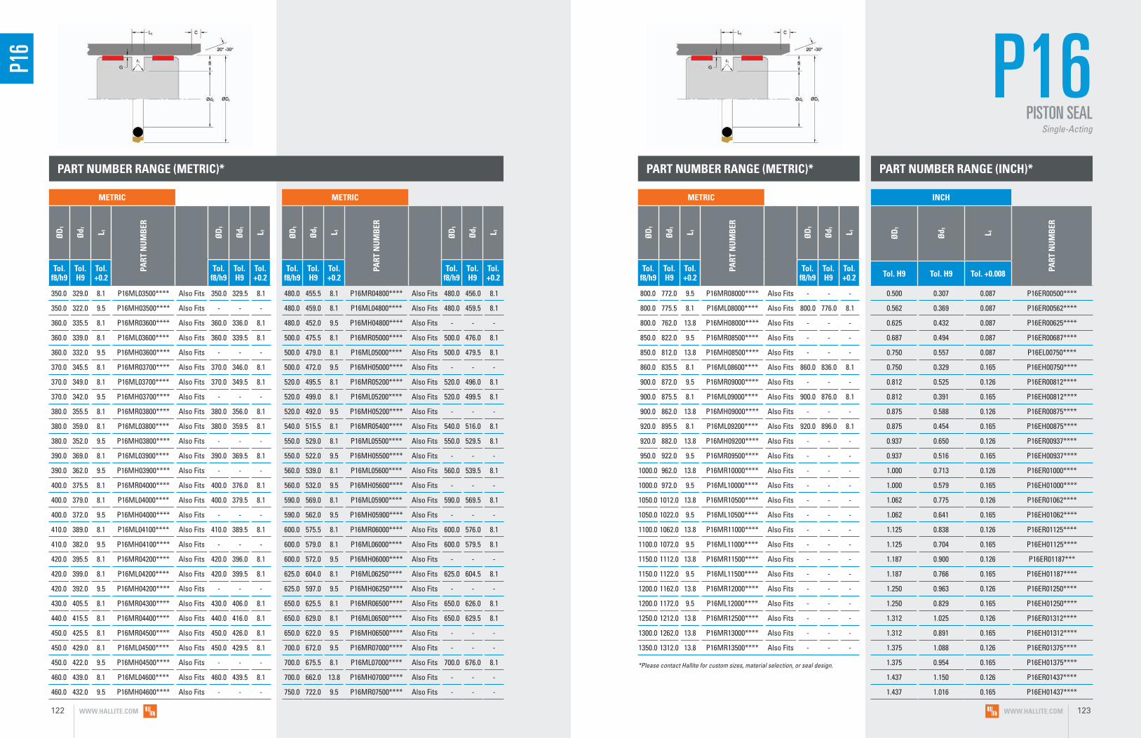
350.0 329.0 8.1 P16ML03500**** Also Fits 350.0 329.5 8.1
350.0 322.0 9.5 P16MH03500**** Also Fits - - -
360.0 335.5 8.1 P16MR03600**** Also Fits 360.0 336.0 8.1
360.0 339.0 8.1 P16ML03600**** Also Fits 360.0 339.5 8.1
360.0 332.0 9.5 P16MH03600**** Also Fits - - -
370.0 345.5 8.1 P16MR03700**** Also Fits 370.0 346.0 8.1
370.0 349.0 8.1 P16ML03700**** Also Fits 370.0 349.5 8.1
370.0 342.0 9.5 P16MH03700**** Also Fits - - -
380.0 355.5 8.1 P16MR03800**** Also Fits 380.0 356.0 8.1
380.0 359.0 8.1 P16ML03800**** Also Fits 380.0 359.5 8.1
380.0 352.0 9.5 P16MH03800**** Also Fits - - -
390.0 369.0 8.1 P16ML03900**** Also Fits 390.0 369.5 8.1
390.0 362.0 9.5 P16MH03900**** Also Fits - - -
400.0 375.5 8.1 P16MR04000**** Also Fits 400.0 376.0 8.1
400.0 379.0 8.1 P16ML04000**** Also Fits 400.0 379.5 8.1
400.0 372.0 9.5 P16MH04000**** Also Fits - - -
410.0 389.0 8.1 P16ML04100**** Also Fits 410.0 389.5 8.1
410.0 382.0 9.5 P16MH04100**** Also Fits - - -
420.0 395.5 8.1 P16MR04200**** Also Fits 420.0 396.0 8.1
420.0 399.0 8.1 P16ML04200**** Also Fits 420.0 399.5 8.1
420.0 392.0 9.5 P16MH04200**** Also Fits - - -
430.0 405.5 8.1 P16MR04300**** Also Fits 430.0 406.0 8.1
440.0 415.5 8.1 P16MR04400**** Also Fits 440.0 416.0 8.1
450.0 425.5 8.1 P16MR04500**** Also Fits 450.0 426.0 8.1
450.0 429.0 8.1 P16ML04500**** Also Fits 450.0 429.5 8.1
450.0 422.0 9.5 P16MH04500**** Also Fits - - -
460.0 439.0 8.1 P16ML04600**** Also Fits 460.0 439.5 8.1
460.0 432.0 9.5 P16MH04600**** Also Fits - - -
480.0 455.5 8.1 P16MR04800**** Also Fits 480.0 456.0 8.1
480.0 459.0 8.1 P16ML04800**** Also Fits 480.0 459.5 8.1
480.0 452.0 9.5 P16MH04800**** Also Fits - - -
500.0 475.5 8.1 P16MR05000**** Also Fits 500.0 476.0 8.1
500.0 479.0 8.1 P16ML05000**** Also Fits 500.0 479.5 8.1
500.0 472.0 9.5 P16MH05000**** Also Fits - - -
520.0 495.5 8.1 P16MR05200**** Also Fits 520.0 496.0 8.1
520.0 499.0 8.1 P16ML05200**** Also Fits 520.0 499.5 8.1
520.0 492.0 9.5 P16MH05200**** Also Fits - - -
540.0 515.5 8.1 P16MR05400**** Also Fits 540.0 516.0 8.1
550.0 529.0 8.1 P16ML05500**** Also Fits 550.0 529.5 8.1
550.0 522.0 9.5 P16MH05500**** Also Fits - - -
560.0 539.0 8.1 P16ML05600**** Also Fits 560.0 539.5 8.1
560.0 532.0 9.5 P16MH05600**** Also Fits - - -
590.0 569.0 8.1 P16ML05900**** Also Fits 590.0 569.5 8.1
590.0 562.0 9.5 P16MH05900**** Also Fits - - -
600.0 575.5 8.1 P16MR06000**** Also Fits 600.0 576.0 8.1
600.0 579.0 8.1 P16ML06000**** Also Fits 600.0 579.5 8.1
600.0 572.0 9.5 P16MH06000**** Also Fits - - -
625.0 604.0 8.1 P16ML06250**** Also Fits 625.0 604.5 8.1
625.0 597.0 9.5 P16MH06250**** Also Fits - - -
650.0 625.5 8.1 P16MR06500**** Also Fits 650.0 626.0 8.1
650.0 629.0 8.1 P16ML06500**** Also Fits 650.0 629.5 8.1
650.0 622.0 9.5 P16MH06500**** Also Fits - - -
700.0 672.0 9.5 P16MR07000**** Also Fits - - -
700.0 675.5 8.1 P16ML07000**** Also Fits 700.0 676.0 8.1
700.0 662.0 13.8 P16MH07000**** Also Fits - - -
750.0 722.0 9.5 P16MR07500**** Also Fits - - -
PART NUMBER RANGE (METRIC)*
P16
800.0 772.0 9.5 P16MR08000**** Also Fits - - -
800.0 775.5 8.1 P16ML08000**** Also Fits 800.0 776.0 8.1
800.0 762.0 13.8 P16MH08000**** Also Fits - - -
850.0 822.0 9.5 P16MR08500**** Also Fits - - -
850.0 812.0 13.8 P16MH08500**** Also Fits - - -
860.0 835.5 8.1 P16ML08600**** Also Fits 860.0 836.0 8.1
900.0 872.0 9.5 P16MR09000**** Also Fits - - -
900.0 875.5 8.1 P16ML09000**** Also Fits 900.0 876.0 8.1
900.0 862.0 13.8 P16MH09000**** Also Fits - - -
920.0 895.5 8.1 P16ML09200**** Also Fits 920.0 896.0 8.1
920.0 882.0 13.8 P16MH09200**** Also Fits - - -
950.0 922.0 9.5 P16MR09500**** Also Fits - - -
1000.0 962.0 13.8 P16MR10000**** Also Fits - - -
1000.0 972.0 9.5 P16ML10000**** Also Fits - - -
1050.0 1012.0 13.8 P16MR10500**** Also Fits - - -
1050.0 1022.0 9.5 P16ML10500**** Also Fits - - -
1100.0 1062.0 13.8 P16MR11000**** Also Fits - - -
1100.0 1072.0 9.5 P16ML11000**** Also Fits - - -
1150.0 1112.0 13.8 P16MR11500**** Also Fits - - -
1150.0 1122.0 9.5 P16ML11500**** Also Fits - - -
1200.0 1162.0 13.8 P16MR12000**** Also Fits - - -
1200.0 1172.0 9.5 P16ML12000**** Also Fits - - -
1250.0 1212.0 13.8 P16MR12500**** Also Fits - - -
1300.0 1262.0 13.8 P16MR13000**** Also Fits - - -
1350.0 1312.0 13.8 P16MR13500**** Also Fits - - -
0.500 0.307 0.087 P16ER00500****
0.562 0.369 0.087 P16ER00562****
0.625 0.432 0.087 P16ER00625****
0.687 0.494 0.087 P16ER00687****
0.750 0.557 0.087 P16EL00750****
0.750 0.329 0.165 P16EH00750****
0.812 0.525 0.126 P16ER00812****
0.812 0.391 0.165 P16EH00812****
0.875 0.588 0.126 P16ER00875****
0.875 0.454 0.165 P16EH00875****
0.937 0.650 0.126 P16ER00937****
0.937 0.516 0.165 P16EH00937****
1.000 0.713 0.126 P16ER01000****
1.000 0.579 0.165 P16EH01000****
1.062 0.775 0.126 P16ER01062****
1.062 0.641 0.165 P16EH01062****
1.125 0.838 0.126 P16ER01125****
1.125 0.704 0.165 P16EH01125****
1.187 0.900 0.126 P16ER01187***
1.187 0.766 0.165 P16EH01187****
1.250 0.963 0.126 P16ER01250****
1.250 0.829 0.165 P16EH01250****
1.312 1.025 0.126 P16ER01312****
1.312 0.891 0.165 P16EH01312****
1.375 1.088 0.126 P16ER01375****
1.375 0.954 0.165 P16EH01375****
1.437 1.150 0.126 P16ER01437****
1.437 1.016 0.165 P16EH01437****
PART NUMBER RANGE (METRIC)* PART NUMBER RANGE (INCH)*
P16PISTON SEAL
Single-Acting
*Please contact Hallite for custom sizes, material selection, or seal design.
METRIC
ØD
1
Ød 1 L 1
PART
NU
MB
ER
ØD
1
Ød 1 L 1
Tol.
f8/h9Tol. H9
Tol. +0.2
Tol. f8/h9
Tol. H9
Tol. +0.2
METRIC
ØD
1
Ød 1 L 1
PART
NU
MB
ER
ØD
1
Ød 1 L 1
Tol. f8/h9
Tol. H9
Tol. +0.2
Tol. f8/h9
Tol. H9
Tol. +0.2
INCH
ØD
1
Ød 1 L 1
PART
NU
MB
ER
Tol. H9 Tol. H9 Tol. +0.008
METRIC
ØD
1
Ød 1 L 1
PART
NU
MB
ER
ØD
1
Ød 1 L 1
Tol. f8/h9
Tol. H9
Tol. +0.2
Tol. f8/h9
Tol. H9
Tol. +0.2
WWW.HALLITE.COM122 WWW.HALLITE.COM 123
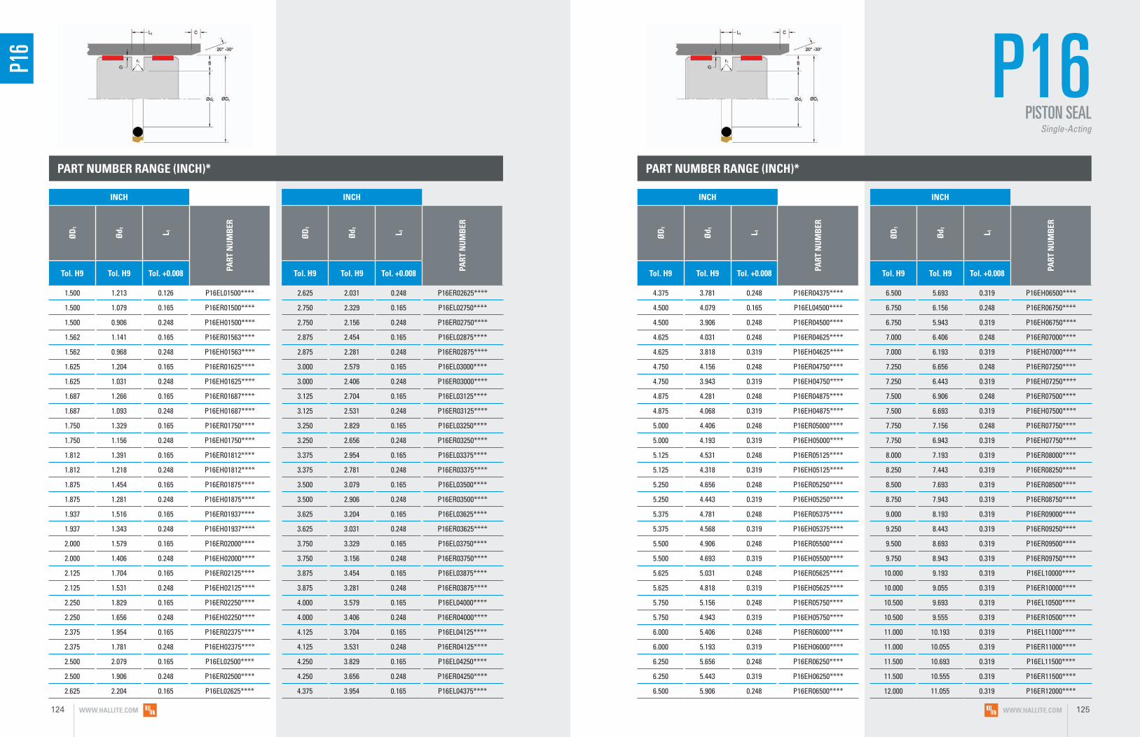
PART NUMBER RANGE (INCH)* PART NUMBER RANGE (INCH)*
1.500 1.213 0.126 P16EL01500****
1.500 1.079 0.165 P16ER01500****
1.500 0.906 0.248 P16EH01500****
1.562 1.141 0.165 P16ER01563****
1.562 0.968 0.248 P16EH01563****
1.625 1.204 0.165 P16ER01625****
1.625 1.031 0.248 P16EH01625****
1.687 1.266 0.165 P16ER01687****
1.687 1.093 0.248 P16EH01687****
1.750 1.329 0.165 P16ER01750****
1.750 1.156 0.248 P16EH01750****
1.812 1.391 0.165 P16ER01812****
1.812 1.218 0.248 P16EH01812****
1.875 1.454 0.165 P16ER01875****
1.875 1.281 0.248 P16EH01875****
1.937 1.516 0.165 P16ER01937****
1.937 1.343 0.248 P16EH01937****
2.000 1.579 0.165 P16ER02000****
2.000 1.406 0.248 P16EH02000****
2.125 1.704 0.165 P16ER02125****
2.125 1.531 0.248 P16EH02125****
2.250 1.829 0.165 P16ER02250****
2.250 1.656 0.248 P16EH02250****
2.375 1.954 0.165 P16ER02375****
2.375 1.781 0.248 P16EH02375****
2.500 2.079 0.165 P16EL02500****
2.500 1.906 0.248 P16ER02500****
2.625 2.204 0.165 P16EL02625****
2.625 2.031 0.248 P16ER02625****
2.750 2.329 0.165 P16EL02750****
2.750 2.156 0.248 P16ER02750****
2.875 2.454 0.165 P16EL02875****
2.875 2.281 0.248 P16ER02875****
3.000 2.579 0.165 P16EL03000****
3.000 2.406 0.248 P16ER03000****
3.125 2.704 0.165 P16EL03125****
3.125 2.531 0.248 P16ER03125****
3.250 2.829 0.165 P16EL03250****
3.250 2.656 0.248 P16ER03250****
3.375 2.954 0.165 P16EL03375****
3.375 2.781 0.248 P16ER03375****
3.500 3.079 0.165 P16EL03500****
3.500 2.906 0.248 P16ER03500****
3.625 3.204 0.165 P16EL03625****
3.625 3.031 0.248 P16ER03625****
3.750 3.329 0.165 P16EL03750****
3.750 3.156 0.248 P16ER03750****
3.875 3.454 0.165 P16EL03875****
3.875 3.281 0.248 P16ER03875****
4.000 3.579 0.165 P16EL04000****
4.000 3.406 0.248 P16ER04000****
4.125 3.704 0.165 P16EL04125****
4.125 3.531 0.248 P16ER04125****
4.250 3.829 0.165 P16EL04250****
4.250 3.656 0.248 P16ER04250****
4.375 3.954 0.165 P16EL04375****
4.375 3.781 0.248 P16ER04375****
4.500 4.079 0.165 P16EL04500****
4.500 3.906 0.248 P16ER04500****
4.625 4.031 0.248 P16ER04625****
4.625 3.818 0.319 P16EH04625****
4.750 4.156 0.248 P16ER04750****
4.750 3.943 0.319 P16EH04750****
4.875 4.281 0.248 P16ER04875****
4.875 4.068 0.319 P16EH04875****
5.000 4.406 0.248 P16ER05000****
5.000 4.193 0.319 P16EH05000****
5.125 4.531 0.248 P16ER05125****
5.125 4.318 0.319 P16EH05125****
5.250 4.656 0.248 P16ER05250****
5.250 4.443 0.319 P16EH05250****
5.375 4.781 0.248 P16ER05375****
5.375 4.568 0.319 P16EH05375****
5.500 4.906 0.248 P16ER05500****
5.500 4.693 0.319 P16EH05500****
5.625 5.031 0.248 P16ER05625****
5.625 4.818 0.319 P16EH05625****
5.750 5.156 0.248 P16ER05750****
5.750 4.943 0.319 P16EH05750****
6.000 5.406 0.248 P16ER06000****
6.000 5.193 0.319 P16EH06000****
6.250 5.656 0.248 P16ER06250****
6.250 5.443 0.319 P16EH06250****
6.500 5.906 0.248 P16ER06500****
6.500 5.693 0.319 P16EH06500****
6.750 6.156 0.248 P16ER06750****
6.750 5.943 0.319 P16EH06750****
7.000 6.406 0.248 P16ER07000****
7.000 6.193 0.319 P16EH07000****
7.250 6.656 0.248 P16ER07250****
7.250 6.443 0.319 P16EH07250****
7.500 6.906 0.248 P16ER07500****
7.500 6.693 0.319 P16EH07500****
7.750 7.156 0.248 P16ER07750****
7.750 6.943 0.319 P16EH07750****
8.000 7.193 0.319 P16ER08000****
8.250 7.443 0.319 P16ER08250****
8.500 7.693 0.319 P16ER08500****
8.750 7.943 0.319 P16ER08750****
9.000 8.193 0.319 P16ER09000****
9.250 8.443 0.319 P16ER09250****
9.500 8.693 0.319 P16ER09500****
9.750 8.943 0.319 P16ER09750****
10.000 9.193 0.319 P16EL10000****
10.000 9.055 0.319 P16ER10000****
10.500 9.693 0.319 P16EL10500****
10.500 9.555 0.319 P16ER10500****
11.000 10.193 0.319 P16EL11000****
11.000 10.055 0.319 P16ER11000****
11.500 10.693 0.319 P16EL11500****
11.500 10.555 0.319 P16ER11500****
12.000 11.055 0.319 P16ER12000****
P16 P16
PISTON SEALSingle-Acting
INCH
ØD
1
Ød 1 L 1
PART
NU
MB
ER
Tol. H9 Tol. H9 Tol. +0.008
INCH
ØD
1
Ød 1 L 1
PART
NU
MB
ER
Tol. H9 Tol. H9 Tol. +0.008
INCH
ØD
1
Ød 1 L 1
PART
NU
MB
ER
Tol. H9 Tol. H9 Tol. +0.008
INCH
ØD
1
Ød 1 L 1
PART
NU
MB
ER
Tol. H9 Tol. H9 Tol. +0.008
WWW.HALLITE.COM124 WWW.HALLITE.COM 125

PART NUMBER RANGE (INCH)*
12.500 11.555 0.319 P16ER12500****
13.000 12.055 0.319 P16ER13000****
13.500 12.555 0.319 P16ER13500****
14.000 13.055 0.319 P16ER14000****
14.500 13.555 0.319 P16ER14500****
15.000 14.055 0.319 P16ER15000****
15.500 14.555 0.319 P16ER15500****
16.000 15.055 0.319 P16ER16000****
16.500 15.555 0.319 P16ER16500****
17.000 16.055 0.319 P16ER17000****
17.500 16.555 0.319 P16ER17500****
18.000 17.055 0.319 P16ER18000****
18.500 17.555 0.319 P16ER18500****
19.000 18.055 0.319 P16ER19000****
19.500 18.555 0.319 P16ER19500****
20.000 19.055 0.319 P16ER20000****
*Please contact Hallite for custom sizes, material selection, or seal design.
P16
GPS M R 00550 N HLX
PROFILE DESIGNATION
UNIT OF MEASUREMENT
M = Metric E = Inch N = Inch/Square Energizer
APPLICATION
Refer to Installation Recommendations and use designator for desired application
ENERGIZER MATERIAL
Refer to Energizer Table for desired energizer material
PTFE MATERIAL
Refer to Material Table for desired PTFE (face) material
BORE DIAMETER
Metric = mm X 10
Inch = inches X 1000
___
SPECIAL FEATURE
Blank = Std profile (with notches) X = No notches
GPS
• Excellent in separation of two different fluids under pressure
• Compact design and groove structure allow interchangability with the Hallite P54
• Low breakaway friction and no issues with stick-slip
• Uses energizer and x-ring to maximize sealing response at all pressure ranges to ensure best performance
F E A T U R E S
TECHNICAL DETAILS
The Hallite GPS is a double-acting piston seal utilizing Hallite’s high-performance
Armorlene® HLX PTFE paired with an elastomer energizer and x-ring for optimum
performance and durability. The Armorlene® PTFE seal ring and the x-ring together
provides the dynamic sealing function, while the elastomeric energizer provides the
static sealing. The standard GPS seal face includes pressure notches, which makes
the seal very responsive to changes in pressure or direction of travel.
Hallite GPS seals are especially effective in applications where two different types
of media need to be separated such as in piston accumulators, intensifiers, and
position-holding applications. This makes this seal a good choice for applications
such as stabilizers, accumulators, manlifts, and industrial presses. Designed for
basic grooves, the GPS seal fits the same ISO 7425-1 housing as the Hallite P16
and P54 series.
Part Number StructureGPSMR00550NHLX _
PISTON SEALDouble-Acting
INCH
ØD
1
Ød 1 L 1
PART
NU
MB
ER
Tol. H9 Tol. H9 Tol. +0.008
INCH
ØD
1
Ød 1 L 1
PART
NU
MB
ER
Tol. H9 Tol. H9 Tol. +0.008
WWW.HALLITE.COM126 WWW.HALLITE.COM 127

GPS MATERIALS
SURFACE FINISH RECOMMENDATIONS
*Rmr is measured at a depth of 25% of the Rz value based upon a reference level (zero line) at 5% material/bearing area.
METRIC INCHRmr*
SURFACE ROUGHNESS μmRa μmRz μmRt μinRa μinRz μinRt
Dynamic Sealing Face ØD1 0.05 - 0.2 1.6 max 2 max 2 - 8 63 max 157 max
60% - 90%Static Sealing Face Ød1 1.6 max 6.3 max 10 max 63 max 250 max 394 max
Static Housing Faces L1 3.2 max 10 max 16 max 125 max 394 max 630 max
SQUARE ENERGIZER AND X-RING TABLE Available for inch sizes only
ENERGIZER AND X-RING MATERIAL (SHORE A)
ENERGIZER TYPE
ENERGIZER DESIGNATION
ENERGIZER OPERATING TEMPERATURE°C
ENERGIZER OPERATING TEMPERATURE°F
NBR - 70A Square/X-Ring R -30 to 100°C -22 to 212°F
FKM - 75A Square/X-Ring K -10 to 200°C 14 to 392°F
No Energizer or X-Ring* - X - -
*Seal ratings are based upon capabilities of its matched material components. Hallite cannot rate seal performance when the seal is mixed with other manufacturers’ energizers/components.
ENERGIZER AND X-RING TABLE
ENERGIZER AND X-RING MATERIAL (SHORE A) ENERGIZER TYPE ENERGIZER
DESIGNATIONENERGIZER OPERATING
TEMPERATURE°CENERGIZER OPERATING
TEMPERATURE°F
NBR - 70A O-ring/X-Ring N -30 to 100°C -22 to 212°F
NBR - 70A Low temp. O-ring/X-Ring L -45 to 80°C -49 to 176°F
FKM - 75A O-ring/X-Ring F -10 to 200°C 14 to 392°F
EPDM - 70A O-ring/X-Ring E -45 to 145°C -49 to 293°F
HNBR - 70A O-ring/X-Ring H -25 to 150°C -13 to 302°F
NBR - 90A O-ring/X-Ring Q -30 to 100°C -22 to 212°F
HNBR - 90A O-ring/X-Ring U -25 to 150°C -13 to 302°F
No O-ring Energizer or X-Ring* - X - -
*Seal ratings are based upon capabilities of its matched material components. Hallite cannot rate seal performance when the seal is mixed with other manufacturers’ energizers/components.
MATERIAL FEATURES AND APPLICATIONS
FILL
ER
MAT
ERIA
L D
ESIG
NAT
OR
COLO
R
TEM
PERA
TURE
RA
NG
E°C
TEM
PERA
TURE
RA
NG
E°F
MA
XIM
UM
DYN
AM
IC
PRES
SURE
- B
AR
MA
XIM
UM
DYN
AM
IC
PRES
SURE
- PS
I
ARMORLENE® HLX• Standard material for hydraulic applications• High compressive strength• Excellent extrusion resistance• Extended wear resistance
Special Bronze
CompoundHLX Gold -73 to 288°C -100 to 550°F 400 bar 5800 psi
ARMORLENE® HLA• Excellent in all hydraulic fluids• Excellent wear resistance• Excellent low-friction properties• Good extrusion resistance
Special Mineral
Compound HLA Gray -73 to 260°C -100 to 500°F 400 bar 5800 psi
ARMORLENE® HCF• Excellent in lubricating and non-lubricating
hydraulic fluids (includes water) w/o zinc content
• Not recommended for gas sealing applications
• Not recommended for electrical conductive fluids
Carbon Fiber Filled HCF Gray/
Black -73 to 260°C -100 to 500°F 250 bar 3625 psi
ARMORLENE® 700• Excellent in all hydraulic fluids• Recommended for use with soft
mating surfaces
• Low friction and no stick-slip
Unfilled 700 White -184 to 204°C -300 to 400°F 200 bar 2900 psi
ARMORLENE® 713• High compressive strength• Excellent extrusion resistance• Excellent wear properties
60% Bronze Content 713 Bronze -73 to 288°C -100 to 550°F 500 bar 7250 psi
For other material options consult the Master Materials Index at the front of the catalog. If you do not find the material that you require, please contact your local Hallite sales office.
OPERATING CONDITIONS
METRIC INCH
Maximum Speed Up to 2.0m/sec Up to 6.5ft/sec
Temperature Range* -45 to 200°C -49 to 392°F
Maximum Dynamic Pressure** 500 bar 7200 psi
*Dependent upon energizer used (NBR, FKM, etc.). **For pressures above 400 bar (5800 psi), contact Hallite Engineering.
Data given are maximum values and can apply depending on specific application. Maximum ratings of temperature, pressure, or operating speeds are dependent on fluid medium, surface, gap value, and other variables such as dynamic or static service. Maximum values are not intended for use together at the same time, e.g. max temperature and max pressure. Please contact your Hallite technical representative for application support.
NO
TE
WWW.HALLITE.COM128 WWW.HALLITE.COM 129

PART NUMBER RANGE (METRIC)*INSTALLATION RECOMMENDATIONS
METRIC
BORE DIAMETER ØD1 H9
GRO
OVE
D
IAM
ETER
GRO
OVE
WID
TH
RAD
IUS
CHA
MFE
R
GRO
OVE
SEC
TIO
N
RAD
IAL
CLEA
RAN
CE
G m
ax*
O-R
ING
CR
OSS
SEC
TIO
N
X-RI
NG
CR
OSS
SEC
TIO
N
DIAMETER RANGE Ød1 h9 L1 + 0.2 r1 C S Up to
100 bar Up to
200 bar Up to
400 bar O-ring X-RingStandard Duty Application - R Light Duty
Application - L
15.0 - 39.9 40.0 - 79.9 D1 - 11.0 4.2 1.0 2.0 5.5 0.25 0.15 0.10 3.53 1.78
40.0 - 79.9 80.0 - 132.9 D1 - 15.5 6.3 1.3 2.5 7.75 0.30 0.20 0.15 5.33 1.78
80.0 - 132.9 133.0 - 252.9 D1 - 21.0 8.1 1.8 5.0 10.5 0.30 0.20 0.15 6.99 2.62
133.0 - 252.9 - D1 - 24.5 8.1 1.8 7.5 12.25 0.30 0.20 0.15 6.99 2.62
253.0 - 462.9 - D1 - 28.0 9.5 2.5 10.0 14.0 0.45 0.30 0.25 8.40 3.53
463.0 - 700.0 - D1 - 35.0 11.5 3.0 10.0 17.5 0.55 0.40 0.35 10.00 5.33
At pressure >400 bar use diameter tolerance H8/f7. *Radial Clearance G max. = maximum permissible gap all on one side using max. tube diameter and min. clearance diameter.
At pressure >5800 psi use diameter tolerance H8/f7. *Radial Clearance G max. = maximum permissible gap all on one side using max. tube diameter and min. clearance diameter.
INCH
BORE DIAMETER ØD1 H9
GRO
OVE
D
IAM
ETER
GRO
OVE
WID
TH
RAD
IUS
CHA
MFE
R
GRO
OVE
SEC
TIO
N
RAD
IAL
CLEA
RAN
CE
G m
ax*
O-R
ING
CR
OSS
SEC
TIO
N
X-RI
NG
CR
OSS
SEC
TIO
N
DIAMETER RANGE Ød1 h9 L1 +
0.008 r1 C S Up to 1500 psi
Up to 2900 psi
Up to 5800 psi O-ring X-Ring
Standard Duty Application - R Light Duty Application - L
0.500 - 1.562 1.563 - 3.125 D1 - 0.433 0.165 0.040 0.016 0.217 0.010 0.006 0.004 0.139 0.070
1.563 - 3.125 3.126 - 5.250 D1 - 0.610 0.248 0.050 0.016 0.305 0.012 0.008 0.006 0.21 0.070
3.126 - 5.250 5.251 - 9.999 D1 - 0.827 0.319 0.070 0.032 0.414 0.012 0.008 0.006 0.275 0.103
5.251 - 9.999 - D1 - 0.965 0.319 0.070 0.032 0.483 0.012 0.008 0.006 0.275 0.103
10.000 - 18.000 - D1 - 1.102 0.374 0.100 0.032 0.551 0.018 0.012 0.010 0.33 0.139
18.001 - 27.500 - D1 - 1.378 0.453 0.120 0.032 0.689 0.022 0.016 0.014 0.394 0.210
16.0 5.0 4.2 GPSMR00160****
18.0 7.0 4.2 GPSMR00180****
20.0 9.0 4.2 GPSMR00200****
22.0 11.0 4.2 GPSMR00220****
25.0 14.0 4.2 GPSMR00250****
28.0 17.0 4.2 GPSMR00280****
30.0 19.0 4.2 GPSMR00300****
32.0 21.0 4.2 GPSMR00320****
35.0 24.0 4.2 GPSMR00350****
40.0 29.0 4.2 GPSML00400****
42.0 31.0 4.2 GPSML00420****
45.0 34.0 4.2 GPSML00450****
48.0 37.0 4.2 GPSML00480****
50.0 39.0 4.2 GPSML00500****
50.0 34.5 6.3 GPSMR00500****
50.8 39.8 4.2 GPSML00508****
52.0 41.0 4.2 GPSML00520****
55.0 44.0 4.2 GPSML00550****
60.0 49.0 4.2 GPSML00600****
63.0 52.0 4.2 GPSML00630****
63.0 47.5 6.3 GPSMR00630****
63.5 42.5 4.2 GPSML00635****
65.0 54.0 4.2 GPSML00650****
70.0 59.0 4.2 GPSML00700****
70.0 54.5 6.3 GPSMR00700****
75.0 64.0 4.2 GPSML00750****
80.0 64.5 6.3 GPSML00800****
80.0 59.5 8.1 GPSMR00800****
85.0 69.5 6.3 GPSML00850****
85.0 64.0 8.1 GPSMR00850****
90.0 74.5 6.3 GPSML00900****
90.0 69.0 8.1 GPSMR00900****
95.0 79.5 6.3 GPSML00950****
95.0 74.0 8.1 GPSMR00950****
100.0 84.5 6.3 GPSML01000****
100.0 79.0 8.1 GPSMR01000****
105.0 89.5 6.3 GPSML01050****
105.0 84.0 8.1 GPSMR01050****
110.0 94.5 6.3 GPSML01100****
110.0 89.0 8.1 GPSMR01100****
115.0 99.5 6.3 GPSML01150****
115.0 94.0 8.1 GPSMR01150****
120.0 104.5 6.3 GPSML01200****
120.0 99.0 8.1 GPSMR01200****
125.0 109.5 6.3 GPSML01250****
125.0 104.0 8.1 GPSMR01250****
130.0 114.5 6.3 GPSML01300****
130.0 109.0 8.1 GPSMR01300****
135.0 114.0 8.1 GPSML01350****
140.0 119.0 8.1 GPSML01400****
145.0 124.0 8.1 GPSMR01450****
150.0 129.0 8.1 GPSML01500****
155.0 134.0 8.1 GPSMR01550****
160.0 139.0 8.1 GPSML01600****
165.0 144.0 8.1 GPSMR01650****
170.0 149.0 8.1 GPSML01700****
GPSPISTON SEAL
Double-Acting
Applications with maximum radial clearance that are using nylon, phenolic, or PTFE bearings must ensure proper clearance in accordance with the bearing recommendations to avoid metal-to-metal contact.
Please refer to Hallite Type 87, Type 506, and Type 533 Specification Sheets for this information.
GPS
METRIC
ØD
1
Ød 1 L 1
PART
NU
MB
ER
Tol. H9 Tol. H9 Tol. +0.2
METRIC
ØD
1
Ød 1 L 1
PART
NU
MB
ER
Tol. H9 Tol. H9 Tol. +0.2
WWW.HALLITE.COM130 WWW.HALLITE.COM 131

175.0 154.0 8.1 GPSMR01750****
180.0 159.0 8.1 GPSML01800****
190.0 169.0 8.1 GPSML01900****
200.0 179.0 8.1 GPSML02000****
210.0 189.0 8.1 GPSML02100****
220.0 199.0 8.1 GPSML02200****
230.0 209.0 8.1 GPSMl02300****
240.0 219.0 8.1 GPSML02400****
250.0 229.0 8.1 GPSML02500****
250.0 225.5 8.1 GPSMR02500****
280.0 252.0 9.5 GPSMR02800****
300.0 272.0 9.5 GPSMR03000****
310.0 282.0 9.5 GPSMR03100****
320.0 292.0 9.5 GPSMR03200****
350.0 322.0 9.5 GPSMR03500****
400.0 372.0 9.5 GPSMR04000****
420.0 392.0 9.5 GPSMR04200****
450.0 422.0 9.5 GPSMR04500****
480.0 445.0 11.5 GPSMR04800****
500.0 465.0 11.5 GPSMR05000****
600.0 565.0 11.5 GPSMR06000****
700.0 665.0 11.5 GPSMR07000****
1.500 1.067 0.165 GPSER01500****
1.562 1.129 0.165 GPSER01562****
1.625 1.192 0.165 GPSEL01625****
1.687 1.254 0.165 GPSEL01687****
1.750 1.317 0.165 GPSEL01750****
1.812 1.379 0.165 GPSEL01812****
1.875 1.442 0.165 GPSEL01875****
1.937 1.504 0.165 GPSEL01937****
2.000 1.567 0.165 GPSEL02000****
2.125 1.692 0.165 GPSEL02125****
2.250 1.817 0.165 GPSEL02250****
2.375 1.942 0.165 GPSEL02375****
2.500 2.067 0.165 GPSEL02500****
2.625 2.192 0.165 GPSEL02625****
2.750 2.317 0.165 GPSEL02750****
2.875 2.442 0.165 GPSEL02875****
3.000 2.567 0.165 GPSEL03000****
3.125 2.692 0.165 GPSEL03125****
3.250 2.640 0.248 GPSEL03250****
3.375 2.765 0.248 GPSEL03375****
3.500 2.890 0.248 GPSEL03500****
3.625 3.015 0.248 GPSEL03625****
3.750 3.140 0.248 GPSEL03750****
3.875 3.265 0.248 GPSEL03875****
4.000 3.390 0.248 GPSEL04000****
4.125 3.515 0.248 GPSEL04125****
4.250 3.640 0.248 GPSEL04250****
4.375 3.765 0.248 GPSEL04375****
PART NUMBER RANGE (METRIC)* PART NUMBER RANGE (INCH)*
GPSPISTON SEAL
Double-Acting
4.500 3.890 0.248 GPSEL04500****
4.625 4.015 0.248 GPSEL04625****
4.750 4.140 0.248 GPSEL04750****
4.875 4.265 0.248 GPSEL04875****
5.000 4.390 0.248 GPSEL05000****
5.125 4.515 0.248 GPSEL05125****
5.250 4.423 0.319 GPSER05250****
5.375 4.548 0.319 GPSEL05375****
5.500 4.673 0.319 GPSEL05500****
5.625 4.798 0.319 GPSEL05625****
5.750 4.923 0.319 GPSEL05750****
6.000 5.173 0.319 GPSEL06000****
6.250 5.423 0.319 GPSEL06250****
6.500 5.673 0.319 GPSEL06500****
6.750 5.923 0.319 GPSEL06750****
7.000 6.173 0.319 GPSEL07000****
7.250 6.423 0.319 GPSEL07250****
7.500 6.673 0.319 GPSEL07500****
7.750 6.923 0.319 GPSEL07750****
8.000 7.173 0.319 GPSEL08000****
8.250 7.423 0.319 GPSEL08250****
8.500 7.673 0.319 GPSEL08500****
8.750 7.923 0.319 GPSEL08750****
9.000 8.173 0.319 GPSEL09000****
9.250 8.423 0.319 GPSEL09250****
9.500 8.673 0.319 GPSEL09500****
9.750 8.923 0.319 GPSEL09750****
10.000 8.898 0.374 GPSER10000****
10.500 9.398 0.374 GPSER10500****
11.000 9.898 0.374 GPSER11000****
11.500 10.398 0.374 GPSER11500****
12.000 10.898 0.374 GPSER12000****
12.500 11.398 0.374 GPSER12500****
13.000 11.898 0.374 GPSER13000****
13.500 12.398 0.374 GPSER13500****
14.000 12.898 0.374 GPSER14000****
14.500 13.398 0.374 GPSER14500****
15.000 13.898 0.374 GPSER15000****
15.500 14.398 0.374 GPSER15500****
16.000 14.898 0.374 GPSER16000****
16.500 15.398 0.374 GPSER16500****
17.000 15.898 0.374 GPSER17000****
17.500 16.398 0.374 GPSER17500****
18.000 16.898 0.374 GPSER18000****
18.500 17.122 0.453 GPSER18500****
19.000 17.622 0.453 GPSER19000****
19.500 18.122 0.453 GPSER19500****
20.000 18.622 0.453 GPSER20000****
PART NUMBER RANGE (INCH)*
*Please contact Hallite for custom sizes, material selection, or seal design.
*Please contact Hallite for custom sizes, material selection, or seal design.
GPS
INCH
ØD
1
Ød 1 L 1
PART
NU
MB
ER
Tol. H9 Tol. H9 Tol. +0.008
METRIC
ØD
1
Ød 1 L 1
PART
NU
MB
ER
Tol. H9 Tol. H9 Tol. +0.2
INCH
ØD
1
Ød 1 L 1
PART
NU
MB
ER
Tol. H9 Tol. H9 Tol. +0.008
INCH
ØD
1
Ød 1 L 1
PART
NU
MB
ER
Tol. H9 Tol. H9 Tol. +0.008
WWW.HALLITE.COM132 WWW.HALLITE.COM 133

SQUARE ENERGIZER PART NUMBER RANGE (INCH)*
9.000 8.165 0.375 GPSNR09000****
9.250 8.420 0.375 GPSNR09250****
9.500 8.665 0.375 GPSNR09500****
9.750 8.920 0.375 GPSNR09750****
10.000 9.165 0.375 GPSNR10000****
10.250 9.340 0.375 GPSNR10250****
10.500 9.580 0.375 GPSNR10500****
10.750 9.840 0.375 GPSNR10750****
11.000 10.080 0.375 GPSNR11000****
11.250 10.340 0.375 GPSNR11250****
11.500 10.580 0.375 GPSNR11500****
11.750 10.840 0.375 GPSNR11750****
12.000 11.080 0.375 GPSNR12000****
12.250 10.340 0.375 GPSNR12250****
12.500 11.580 0.375 GPSNR12500****
12.750 11.840 0.375 GPSNR12750****
13.000 12.080 0.375 GPSNR13000****
13.250 12.335 0.375 GPSNR13250****
13.500 12.580 0.375 GPSNR13500****
13.750 12.840 0.375 GPSNR13750****
14.000 13.080 0.375 GPSNR14000****
GPSPISTON SEAL
Double-Acting
SQUARE ENERGIZER PART NUMBER RANGE (INCH)*
4.500 3.884 0.288 GPSNR04500****
4.625 4.009 0.288 GPSNR04625****
4.750 4.134 0.288 GPSNR04750****
4.875 4.259 0.288 GPSNR04875****
5.000 4.384 0.288 GPSNR05000****
5.125 4.509 0.288 GPSNR05125****
5.250 4.634 0.288 GPSNR05250****
5.375 4.535 0.375 GPSNR05375****
5.500 4.660 0.375 GPSNR05500****
5.625 4.785 0.375 GPSNR05625****
5.750 4.910 0.375 GPSNR05750****
5.875 5.035 0.375 GPSNR05875****
6.000 5.160 0.375 GPSNR06000****
6.125 5.285 0.375 GPSNR06125****
6.250 5.415 0.375 GPSNR06250****
6.375 5.540 0.375 GPSNR06375****
6.500 5.665 0.375 GPSNR06500****
6.625 5.795 0.375 GPSNR06625****
6.750 5.920 0.375 GPSNR06750****
6.875 6.045 0.375 GPSNR06875****
7.000 6.170 0.375 GPSNR07000****
7.250 6.420 0.375 GPSNR07250****
7.500 6.670 0.375 GPSNR07500****
7.750 6.915 0.375 GPSNR07750****
8.000 7.170 0.375 GPSNR08000****
8.250 7.415 0.375 GPSNR08250****
8.500 7.665 0.375 GPSNR08500****
8.750 7.915 0.375 GPSNR08750****
1.000 0.576 0.210 GPSNR01000****
1.125 0.701 0.210 GPSNR01125****
1.250 0.826 0.210 GPSNR01250****
1.375 0.951 0.210 GPSNR01375****
1.500 1.076 0.210 GPSNR01500****
1.625 1.201 0.210 GPSNR01625****
1.750 1.326 0.210 GPSNR01750****
1.875 1.451 0.210 GPSNR01875****
2.000 1.384 0.288 GPSNR02000****
2.125 1.509 0.288 GPSNR02125****
2.250 1.634 0.288 GPSNR02250****
2.375 1.759 0.288 GPSNR02375****
2.500 1.884 0.288 GPSNR02500****
2.625 2.009 0.288 GPSNR02625****
2.750 2.134 0.288 GPSNR02750****
2.875 2.259 0.288 GPSNR02875****
3.000 2.384 0.288 GPSNR03000****
3.125 2.509 0.288 GPSNR03125****
3.250 2.634 0.288 GPSNR03250****
3.375 2.759 0.288 GPSNR03375****
3.500 2.884 0.288 GPSNR03500****
3.625 3.009 0.288 GPSNR03625****
3.750 3.134 0.288 GPSNR03750****
3.875 3.259 0.288 GPSNR03875****
4.000 3.384 0.288 GPSNR04000****
4.125 3.509 0.288 GPSNR04125****
4.250 3.634 0.288 GPSNR04250****
4.375 3.759 0.288 GPSNR04375****
SQUARE ENERGIZERGPS is also available in a square energizer variant,with alternative part numbers.
*Please contact Hallite for custom sizes, material selection, or seal design.
GPS
INCH
ØD
1
Ød 1 L 1
PART
NU
MB
ER
Tol. H9 Tol. H9 Tol. +0.008
INCH
ØD
1
Ød 1 L 1
PART
NU
MB
ER
Tol. H9 Tol. H9 Tol. +0.008
INCH
ØD
1
Ød 1 L 1
PART
NU
MB
ER
Tol. H9 Tol. H9 Tol. +0.008
INCH
ØD
1
Ød 1 L 1
PART
NU
MB
ER
Tol. H9 Tol. H9 Tol. +0.008
WWW.HALLITE.COM134 WWW.HALLITE.COM 135

GP2 M R 00550 N HLX ___
PROFILE DESIGNATION
UNIT OF MEASUREMENT
M = Metric E = Inch
APPLICATION
Refer to Installation Recommendations and use designator for desired application
ENERGIZER MATERIAL
Refer to Energizer Table for desired energizer material
PTFE MATERIAL
Refer to Material Table for desired PTFE (face) material
SPECIAL FEATURE
Blank = Std profile N = Notches
BORE DIAMETER
Metric = mm X 10
Inch = inches X 1000
GP2
• Excellent sealing in applications that require separation of two different fluids
• Low breakout friction and elimination of stick-slip action
• Higher pressure rating than original GPS
• Uses an x-ring and 2 energizers to maximize sealing response at all pressure ranges to ensure best performance
F E A T U R E S
TECHNICAL DETAILS
The Hallite GP2 is a double-acting piston seal utilizing Hallite’s proprietary
high- performance Armorlene® HLX PTFE paired with twin premium O-ring
energizers and an x-ring for optimum performance and durability. The
Armorlene® PTFE seal ring and the x-ring together provides the dynamic
sealing function, while the O-ring energizers provide the static sealing.
Hallite’s GP2 seals are especially effective in applications where two different
types of media need to be separated such as in piston accumulators, intensifiers,
and position-holding applications. This makes this seal a good choice for applications
in stabilizers, accumulators, manlifts, industrial machinery, and hydraulic suspension.
The GP2 is well-suited for larger-diameter heavy-duty systems.
Part Number StructureGP2MR00550NHLX _
PISTON SEALDouble-Acting
WWW.HALLITE.COM 137

OPERATING CONDITIONS
METRIC INCH
Maximum Speed Up to 3.0m/sec Up to 10.0ft/sec
Temperature Range* -45 to 200°C -49 to 392°F
Maximum Dynamic Pressure** 600 bar 8700 psi
*Dependent upon energizer used (NBR, FKM, etc.). **For pressures above 300 bar (4350 psi), contact Hallite Engineering.
MATERIALS
SURFACE FINISH RECOMMENDATIONS
*Rmr is measured at a depth of 25% of the Rz value based upon a reference level (zero line) at 5% material/bearing area.
METRIC INCHRmr*
SURFACE ROUGHNESS μmRa μmRz μmRt μinRa μinRz μinRt
Dynamic Sealing Face ØD1 0.05 - 0.2 1.6 max 2 max 2 - 8 63 max 157 max
60% - 90%Static Sealing Face Ød1 1.6 max 6.3 max 10 max 63 max 250 max 394 max
Static Housing Faces L1 3.2 max 10 max 16 max 125 max 394 max 630 max
ENERGIZER AND X-RING TABLE
ENERGIZER AND X-RING MATERIAL (SHORE A) ENERGIZER TYPE ENERGIZER
DESIGNATIONENERGIZER OPERATING
TEMPERATURE°CENERGIZER OPERATING
TEMPERATURE°F
NBR - 70A O-ring/X-Ring N -30 to 100°C -22 to 212°F
NBR - 70A Low temp. O-ring/X-Ring L -45 to 80°C -49 to 176°F
FKM - 75A O-ring/X-Ring F -10 to 200°C 14 to 392°F
EPDM - 70A O-ring/X-Ring E -45 to 145°C -49 to 293°F
HNBR - 70A O-ring/X-Ring H -25 to 150°C -13 to 302°F
NBR - 90A O-ring/X-Ring Q -30 to 100°C -22 to 212°F
HNBR - 90A O-ring/X-Ring U -25 to 150°C -13 to 302°F
No O-ring Energizers or X-Ring* - X - -
*Seal ratings are based upon capabilities of its matched material components. Hallite cannot rate seal performance when the seal is mixed with other manufacturers’ energizers/components.
MATERIAL FEATURES AND APPLICATIONS
FILL
ER
MAT
ERIA
L D
ESIG
NAT
OR
COLO
R
TEM
PERA
TURE
RA
NG
E°C
TEM
PERA
TURE
RA
NG
E°F
MA
XIM
UM
DYN
AM
IC
PRES
SURE
- B
AR
MA
XIM
UM
DYN
AM
IC
PRES
SURE
- PS
I
ARMORLENE® HLX• Standard material for hydraulic applications• High compressive strength• Excellent extrusion resistance• Extended wear resistance
Special Bronze
CompoundHLX Gold -73 to 288°C -100 to 550°F 500 bar 7250 psi
ARMORLENE® HLA• Excellent in all hydraulic fluids• Excellent wear resistance• Excellent low-friction properties• Good extrusion resistance
Special Mineral
Compound HLA Gray -73 to 260°C -100 to 500°F 500 bar 7250 psi
ARMORLENE® HCF• Excellent in lubricating and non-lubricating
hydraulic fluids (includes water) w/o zinc content
• Not recommended for gas sealing applications
• Not recommended for electrical conductive fluids
Carbon Fiber Filled HCF Gray/
Black -73 to 260°C -100 to 500°F 250 bar 3625 psi
ARMORLENE® 700• Excellent in all hydraulic fluids• Recommended for use with soft
mating surfaces • Low friction and no stick-slip
Unfilled 700 White -184 to 204°C -300 to 400°F 200 bar 2900 psi
ARMORLENE® 713• High compressive strength• Excellent extrusion resistance• Excellent wear properties
60% Bronze Content 713 Bronze -73 to 288°C -100 to 550°F 600 bar 8700 psi
For other material options consult the Master Materials Index at the front of the catalog. If you do not find the material that you require, please contact your local Hallite sales office.
Data given are maximum values and can apply depending on specific application. Maximum ratings of temperature, pressure, or operating speeds are dependent on fluid medium, surface, gap value, and other variables such as dynamic or static service. Maximum values are not intended for use together at the same time, e.g. max temperature and max pressure. Please contact your Hallite technical representative for application support.
NO
TE
GP2
WWW.HALLITE.COM138 WWW.HALLITE.COM 139

PART NUMBER RANGE (METRIC)*INSTALLATION RECOMMENDATIONS
At pressure >300 bar use diameter tolerance H8/f7. *Radial Clearance G max. = maximum permissible gap all on one side using max. tube diameter and min. clearance diameter.
METRIC
BORE DIAMETER ØD1 H9
GRO
OVE
DIA
MET
ER
GRO
OVE
WID
TH
RAD
IUS
CHA
MFE
R
GRO
OVE
SEC
TIO
N
RAD
IAL
CLEA
RAN
CE
G m
ax*
O-R
ING
CR
OSS
SEC
TIO
N
X-RI
NG
CR
OSS
SEC
TIO
N
DIAMETER RANGE Ød1 h9 L1 + 0.2 r1 C S Up to
100 bar Up to
200 bar Up to
300 bar O-ring X-RingStandard Duty Application - R Heavy Duty
Application - H
40.0 - 79.9 25.0 - 39.9 D1 - 10.0 6.3 0.6 2.5 5.00 0.30 0.20 0.15 2.62 1.78
80.0 - 132.9 50.0 - 79.9 D1 - 13.0 8.3 1.0 5 6.50 0.40 0.30 0.15 3.53 2.62
133.0 - 462.9 100.0 - 132.9 D1 - 18.0 12.3 1.3 7.5 9.00 0.40 0.30 0.20 5.33 3.53
463.0 - 700.0 425.0 - 462.9 D1 - 31.0 16.3 1.8 10 15.50 0.50 0.40 0.30 6.99 5.33
40.0 30.0 6.3 GP2MR00400****
42.0 32.0 6.3 GP2MR00420****
45.0 35.0 6.3 GP2MR00450****
48.0 38.0 6.3 GP2MR00480****
50.0 40.0 6.3 GP2MR00500****
52.0 42.0 6.3 GP2MR00520****
55.0 45.0 6.3 GP2MR00550****
60.0 50.0 6.3 GP2MR00600****
63.0 53.0 6.3 GP2MR00630****
65.0 55.0 6.3 GP2MR00650****
70.0 60.0 6.3 GP2MR00700****
75.0 65.0 6.3 GP2MR00750****
80.0 67.0 8.3 GP2MR00800****
85.0 72.0 8.3 GP2MR00850****
90.0 77.0 8.3 GP2MR00900****
95.0 82.0 8.3 GP2MR00950****
100.0 87.0 8.3 GP2MR01000****
105.0 92.0 8.3 GP2MR01050****
110.0 97.0 8.3 GP2MR01100****
115.0 102.0 8.3 GP2MR01150****
120.0 107.0 8.3 GP2MR01200****
125.0 112.0 8.3 GP2MR01250****
130.0 117.0 8.3 GP2MR01300****
135.0 117.0 12.3 GP2MR01350****
140.0 122.0 12.3 GP2MR01400****
150.0 132.0 12.3 GP2MR01500****
160.0 142.0 12.3 GP2MR01600****
170.0 152.0 12.3 GP2MR01700****
180.0 162.0 12.3 GP2MR01800****
190.0 172.0 12.3 GP2MR01900****
200.0 182.0 12.3 GP2MR02000****
210.0 192.0 12.3 GP2MR02100****
220.0 202.0 12.3 GP2MR02200****
230.0 212.0 12.3 GP2MR02300****
240.0 222.0 12.3 GP2MR02400****
250.0 232.0 12.3 GP2MR02500****
280.0 262.0 12.3 GP2MR02800****
300.0 282.0 12.3 GP2MR03000****
320.0 302.0 12.3 GP2MR03200****
350.0 332.0 12.3 GP2MR03500****
400.0 382.0 12.3 GP2MR04000****
420.0 402.0 12.3 GP2MR04200****
450.0 432.0 12.3 GP2MR04500****
480.0 449.0 16.3 GP2MR04800****
500.0 469.0 16.3 GP2MR05000****
600.0 569.0 16.3 GP2MR06000****
700.0 669.0 16.3 GP2MR07000****
At pressure >4350 psi use diameter tolerance H8/f7. *Radial Clearance G max. = maximum permissible gap all on one side using max. tube diameter and min. clearance diameter.
INCH
BORE DIAMETER ØD1 H9
GRO
OVE
DIA
MET
ER
GRO
OVE
WID
TH
RAD
IUS
CHA
MFE
R
GRO
OVE
SEC
TIO
N
RAD
IAL
CLEA
RAN
CE
G m
ax*
O-R
ING
CR
OSS
SEC
TIO
N
X-RI
NG
CR
OSS
SEC
TIO
N
DIAMETER RANGE Ød1 h9 L1 + 0.2 r1 C S Up to
1500 psi Up to
4350 psi O-ring X-RingStandard Duty Application - R Heavy Duty
Application - H
1.500 - 2.999 - D1 - 0.394 0.248 0.005 2.500 0.197 0.012 0.009 0.103 0.070
3.000 - 4.999 1.500 - 2.999 D1 - 0.512 0.326 0.010 5.000 0.256 0.013 0.010 0.139 0.103
5.000 - 11.999 3.000 - 4.999 D1 - 0.709 0.484 0.015 7.500 0.354 0.014 0.011 0.210 0.139
12.000 - 26.999 5.000 - 11.999 D1 - 1.220 0.642 0.015 10.000 0.610 0.016 0.013 0.275 0.210
GP2 GP2
PISTON SEALDouble-Acting
*Please contact Hallite for custom sizes, material selection, or seal design.
Applications with maximum radial clearance that are using nylon, phenolic, or PTFE bearings must ensure proper clearance in accordance with the bearing recommendations to avoid metal-to-metal contact.
Please refer to Hallite Type 87, Type 506, and Type 533 Specification Sheets for this information.
METRIC
ØD
1
Ød 1 L 1
PART
NU
MB
ER
Tol. H9 Tol. H9 Tol. +0.2
METRIC
ØD
1
Ød 1 L 1
PART
NU
MB
ER
Tol. H9 Tol. H9 Tol. +0.2
WWW.HALLITE.COM140 WWW.HALLITE.COM 141

PART NUMBER RANGE (INCH)*PART NUMBER RANGE (INCH)*
1.500 1.106 0.248 GP2ER01500****
1.562 1.168 0.248 GP2ER01562****
1.625 1.231 0.248 GP2ER01625****
1.687 1.293 0.248 GP2ER01687****
1.750 1.356 0.248 GP2ER01750****
1.812 1.418 0.248 GP2ER01812****
1.875 1.481 0.248 GP2ER01875****
1.937 1.543 0.248 GP2ER01937****
2.000 1.606 0.248 GP2ER02000****
2.125 1.731 0.248 GP2ER02125****
2.250 1.856 0.248 GP2ER02250****
2.375 1.981 0.248 GP2ER02375****
2.500 2.106 0.248 GP2ER02500****
2.625 2.231 0.248 GP2ER02625****
2.750 2.356 0.248 GP2ER02750****
2.875 2.481 0.248 GP2ER02875****
3.000 2.488 0.326 GP2ER03000****
3.125 2.613 0.326 GP2ER03125****
3.250 2.738 0.326 GP2ER03250****
3.375 2.863 0.326 GP2ER03375****
3.500 2.988 0.326 GP2ER03500****
3.625 3.113 0.326 GP2ER03625****
3.750 3.238 0.326 GP2ER03750****
3.875 3.363 0.326 GP2ER03875****
4.000 3.488 0.326 GP2ER04000****
4.125 3.613 0.326 GP2ER04125****
4.250 3.738 0.326 GP2ER04250****
4.375 3.863 0.326 GP2ER04375****
4.500 3.988 0.326 GP2ER04500****
4.625 4.113 0.326 GP2ER04625****
4.750 4.238 0.326 GP2ER04750****
4.875 4.363 0.326 GP2ER04875****
5.000 4.291 0.484 GP2ER05000****
5.125 4.416 0.484 GP2ER05125****
5.250 4.541 0.484 GP2ER05250****
5.375 4.666 0.484 GP2ER05375****
5.500 4.791 0.484 GP2ER05500****
5.625 4.916 0.484 GP2ER05625****
5.750 5.041 0.484 GP2ER05750****
5.875 5.166 0.484 GP2ER05875****
6.000 5.291 0.484 GP2ER06000****
6.250 5.541 0.484 GP2ER06250****
6.500 5.791 0.484 GP2ER06500****
6.750 6.041 0.484 GP2ER06750****
7.000 6.291 0.484 GP2ER07000****
7.250 6.541 0.484 GP2ER07250****
7.500 6.791 0.484 GP2ER07500****
7.750 7.041 0.484 GP2ER07750****
8.000 7.291 0.484 GP2ER08000****
8.250 7.541 0.484 GP2ER08250****
8.500 7.791 0.484 GP2ER08500****
8.750 8.041 0.484 GP2ER08750****
9.000 8.291 0.484 GP2ER09000****
9.250 8.541 0.484 GP2ER09250****
9.500 8.791 0.484 GP2ER09500****
9.750 9.041 0.484 GP2ER09750****
10.000 9.291 0.484 GP2ER10000****
10.500 9.791 0.484 GP2ER10500****
11.000 10.291 0.484 GP2ER11000****
11.500 10.791 0.484 GP2ER11500****
12.000 10.78 0.642 GP2ER12000****
12.500 11.28 0.642 GP2ER12500****
13.000 11.78 0.642 GP2ER13000****
13.500 12.28 0.642 GP2ER13500****
14.000 12.78 0.642 GP2ER14000****
14.500 13.28 0.642 GP2ER14500****
15.000 13.78 0.642 GP2ER15000****
15.500 14.28 0.642 GP2ER15500****
16.000 14.78 0.642 GP2ER16000****
16.500 15.28 0.642 GP2ER16500****
17.000 15.78 0.642 GP2ER17000****
17.500 16.28 0.642 GP2ER17500****
18.000 16.78 0.642 GP2ER18000****
18.500 17.28 0.642 GP2ER18500****
19.000 17.78 0.642 GP2ER19000****
19.500 18.28 0.642 GP2ER19500****
20.000 18.78 0.642 GP2ER20000****
GP2 GP2
PISTON SEALDouble-Acting
*Please contact Hallite for custom sizes, material selection, or seal design.
INCH
ØD
1
Ød 1 L 1
PART
NU
MB
ER
Tol. H9 Tol. H9 Tol. +0.008
INCH
ØD
1
Ød 1 L 1
PART
NU
MB
ER
Tol. H9 Tol. H9 Tol. +0.008
INCH
ØD
1
Ød 1 L 1
PART
NU
MB
ER
Tol. H9 Tol. H9 Tol. +0.008
INCH
ØD
1
Ød 1 L 1
PART
NU
MB
ER
Tol. H9 Tol. H9 Tol. +0.008
WWW.HALLITE.COM142 WWW.HALLITE.COM 143

PFR E R 01250 R HLX
PROFILE DESIGNATION
UNIT OF MEASUREMENT
M = Metric E = Inch
APPLICATION
Refer to Installation Recommendations and use designator for desired application
ENERGIZER MATERIAL
Refer to Energizer Table for desired energizer material
PTFE MATERIAL
Refer to Material Table for desired PTFE (face) material
SPECIAL FEATURE
Blank = Std profile N Notches
___
BORE DIAMETER
Metric = mm X 10
Inch = inches X 1000
PFR
• Precision machined bronze/PTFE cap ring
• High-strength compression- molded material
• Chamfered corners for easier installation
• Low friction, no stick-slip issues
• Wide range of materials availableF E A T U R E S
TECHNICAL DETAILS
The Hallite PFR is a chamfered, double-acting piston seal that performs well in both
high- and low-pressure systems. The PFR has chamfers on the primary sealing face
paired with either a square or an O-ring elastomer energizer. Typically, the square
energizer is preferred for heavy-duty applications, as it provides superior interference
and stability in the groove. High-performance Armorlene® materials, like HLX, provide
outstanding wear and extrusion-resistance properties as well as large range of
temperature and media compatibility.
Hallite’s PFR seal is well-suited for a variety of hydraulic and pneumatic reciprocating
applications. Hallite recommends proper guidance (see Hallite Bearings section) be
used with this seal in heavy-duty applications. The PFR seal is available in a variety
of Hallite’s high-performance Armorlene® materials to suit a wide range of
demanding applications.
This seal is designed to fit the ANSI B93.32-1973 and NFPA T3.19.18 housing size.
Part Number StructurePFRER01250NHLX _
PISTON SEALDouble-Acting
WWW.HALLITE.COM 145

OPERATING CONDITIONS
METRIC INCH
Maximum Speed Up to 4.0m/sec Up to 13.0ft/sec
Temperature Range* -45 to 200°C -49 to 392°F
Maximum Dynamic Pressure 350 bar 5000 psi
*Dependent upon energizer used (NBR, FKM, etc.).
MATERIALS
INSTALLATION RECOMMENDATIONS
*Radial Clearance G max. = maximum permissible gap all on one side using max. tube diameter and min. clearance diameter.
INCH
BORE DIAMETER ØD1 H9
GRO
OVE
DIA
MET
ER
GRO
OVE
WID
TH
RAD
IUS
CHA
MFE
R
GRO
OVE
SEC
TIO
N
RAD
IAL
CLEA
RAN
CE
G m
ax*
Standard Duty Application - R
Heavy Duty Application - H Ød1 h9 L1 + 0.008 r1 C S Up to
1000 psiUp to
3000 psi Up to
5000 psi
1.000 – 2.999 - D1 - 0.308 0.129 0.016 0.125 0.154 0.026 0.010 0.006
3.000 – 5.000 1.000 - 2.999 D1 - 0.555 0.284 0.024 0.260 0.278 0.040 0.030 0.007
5.001 – 8.999 3.000 - 5.001 D1 - 0.762 0.379 0.032 0.325 0.381 0.050 0.033 0.008
9.000 – 15.000 5.001 – 8.999 D1 - 0.878 0.379 0.032 0.325 0.439 0.064 0.044 0.009
15.001 - 50.000 9.000-15.000 D1 - 1.396 0.505 0.032 0.325 0.698 0.078 0.055 0.010
PFR
SURFACE FINISH RECOMMENDATIONS
*Rmr is measured at a depth of 25% of the Rz value based upon a reference level (zero line) at 5% material/bearing area.
METRIC INCHRmr*
SURFACE ROUGHNESS μmRa μmRz μmRt μinRa μinRz μinRt
Dynamic Sealing Face ØD1 0.05 - 0.2 1.6 max 2 max 2 - 8 63 max 157 max
60% - 90%Static Sealing Face Ød1 1.6 max 6.3 max 10 max 63 max 250 max 394 max
Static Housing Faces L1 3.2 max 10 max 16 max 125 max 394 max 630 max
ENERGIZER TABLE
ENERGIZER MATERIAL (SHORE A)
ENERGIZER TYPE
ENERGIZER DESIGNATION
ENERGIZER OPERATING TEMPERATURE°C
ENERGIZER OPERATING TEMPERATURE°F
NBR - 70A Square R -30 to 100°C -22 to 212°F
No Energizer* None X - -
*Seal ratings are based upon capabilities of its matched material components. Hallite cannot rate seal performance when the seal is mixed with other manufacturers’ energizers/components.
MATERIAL FEATURES AND APPLICATIONS
FILL
ER
MAT
ERIA
L D
ESIG
NAT
OR
COLO
R
TEM
PERA
TURE
RA
NG
E°C
TEM
PERA
TURE
RA
NG
E°F
MA
XIM
UM
DYN
AM
IC
PRES
SURE
- B
AR
MA
XIM
UM
DYN
AM
IC
PRES
SURE
- PS
I
ARMORLENE® HLX• Standard material for hydraulic applications• High compressive strength• Excellent extrusion resistance• Extended wear resistance
Special Bronze
CompoundHLX Gold -73 to 288°C -100 to 550°F 350 bar 5000 psi
ARMORLENE® 702• Excellent in lubricating and non-lubricating
hydraulic fluids• Good low-friction properties• Excellent extrusion resistance• Good chemical resistance
Glass Molybdenum
Disulfide702 Gray -73 to 260°C -100 to 500°F 300 bar 4350 psi
ARMORLENE® 706• Excellent in lubricating and non-lubricating
hydraulic fluids• Excellent extrusion resistance• Good chemical resistance• Good dielectrical properties
15% Glass 706 Off- White -73 to 260°C -100 to 500°F 300 bar 4350 psi
ARMORLENE® 701• Excellent in lubricating and non-lubricating
hydraulic fluids• Excellent extrusion resistance• Good chemical resistance• Good dielectrical properties
25% Glass 701 Off- White -73 to 260°C -100 to 500°F 350 bar 5000 psi
For other material options consult the Master Materials Index at the front of the catalog. If you do not find the material that you require please contact your local Hallite sales office.
Data given are maximum values and can apply depending on specific application. Maximum ratings of temperature, pressure, or operating speeds are dependent on fluid medium, surface, gap value, and other variables such as dynamic or static service. Maximum values are not intended for use together at the same time, e.g. max temperature and max pressure. Please contact your Hallite technical representative for application support.
NO
TE
WWW.HALLITE.COM146 WWW.HALLITE.COM 147
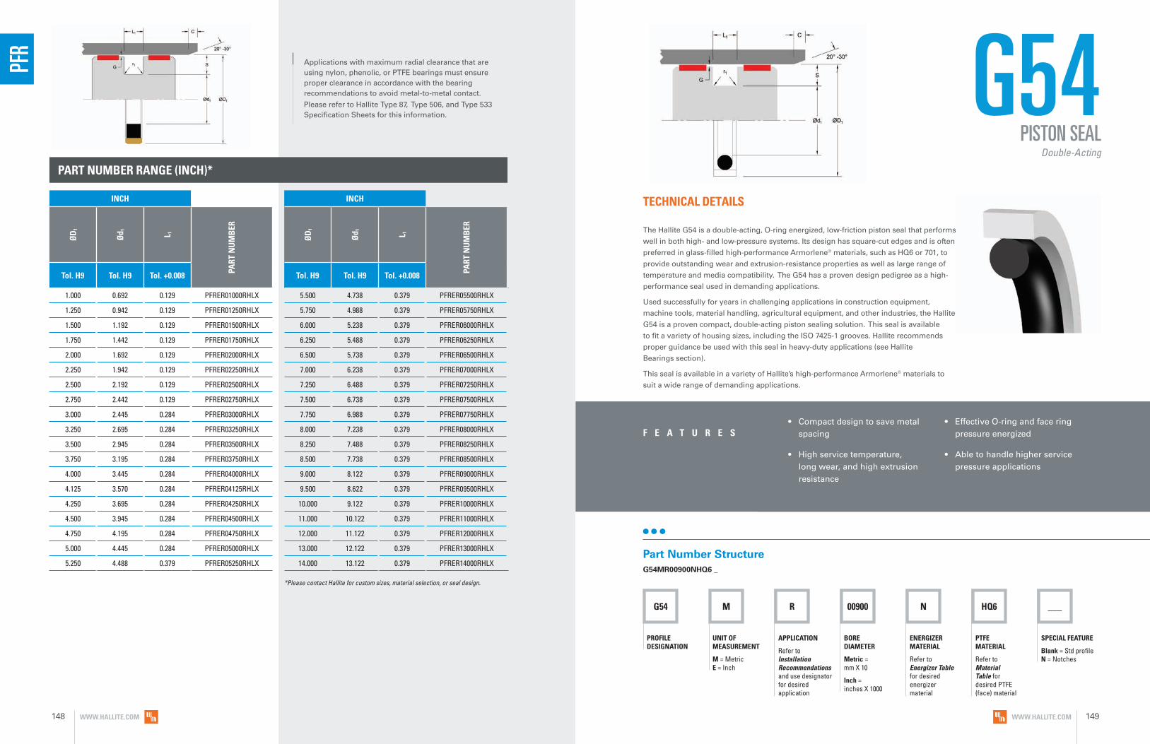
PART NUMBER RANGE (INCH)*
1.000 0.692 0.129 PFRER01000RHLX
1.250 0.942 0.129 PFRER01250RHLX
1.500 1.192 0.129 PFRER01500RHLX
1.750 1.442 0.129 PFRER01750RHLX
2.000 1.692 0.129 PFRER02000RHLX
2.250 1.942 0.129 PFRER02250RHLX
2.500 2.192 0.129 PFRER02500RHLX
2.750 2.442 0.129 PFRER02750RHLX
3.000 2.445 0.284 PFRER03000RHLX
3.250 2.695 0.284 PFRER03250RHLX
3.500 2.945 0.284 PFRER03500RHLX
3.750 3.195 0.284 PFRER03750RHLX
4.000 3.445 0.284 PFRER04000RHLX
4.125 3.570 0.284 PFRER04125RHLX
4.250 3.695 0.284 PFRER04250RHLX
4.500 3.945 0.284 PFRER04500RHLX
4.750 4.195 0.284 PFRER04750RHLX
5.000 4.445 0.284 PFRER05000RHLX
5.250 4.488 0.379 PFRER05250RHLX
5.500 4.738 0.379 PFRER05500RHLX
5.750 4.988 0.379 PFRER05750RHLX
6.000 5.238 0.379 PFRER06000RHLX
6.250 5.488 0.379 PFRER06250RHLX
6.500 5.738 0.379 PFRER06500RHLX
7.000 6.238 0.379 PFRER07000RHLX
7.250 6.488 0.379 PFRER07250RHLX
7.500 6.738 0.379 PFRER07500RHLX
7.750 6.988 0.379 PFRER07750RHLX
8.000 7.238 0.379 PFRER08000RHLX
8.250 7.488 0.379 PFRER08250RHLX
8.500 7.738 0.379 PFRER08500RHLX
9.000 8.122 0.379 PFRER09000RHLX
9.500 8.622 0.379 PFRER09500RHLX
10.000 9.122 0.379 PFRER10000RHLX
11.000 10.122 0.379 PFRER11000RHLX
12.000 11.122 0.379 PFRER12000RHLX
13.000 12.122 0.379 PFRER13000RHLX
14.000 13.122 0.379 PFRER14000RHLX
PFR
*Please contact Hallite for custom sizes, material selection, or seal design.
Applications with maximum radial clearance that are using nylon, phenolic, or PTFE bearings must ensure proper clearance in accordance with the bearing recommendations to avoid metal-to-metal contact.
Please refer to Hallite Type 87, Type 506, and Type 533 Specification Sheets for this information.
G54 M R 00900 N HQ6 ___
PROFILE DESIGNATION
UNIT OF MEASUREMENT
M = Metric E = Inch
APPLICATION
Refer to Installation Recommendations and use designator for desired application
ENERGIZER MATERIAL
Refer to Energizer Table for desired energizer material
PTFE MATERIAL
Refer to Material Table for desired PTFE (face) material
SPECIAL FEATURE
Blank = Std profile N = Notches
BORE DIAMETER
Metric = mm X 10
Inch = inches X 1000
G54
• Compact design to save metal spacing
• High service temperature, long wear, and high extrusion resistance
• Effective O-ring and face ring pressure energized
• Able to handle higher service pressure applications
F E A T U R E S
TECHNICAL DETAILS
The Hallite G54 is a double-acting, O-ring energized, low-friction piston seal that performs
well in both high- and low-pressure systems. Its design has square-cut edges and is often
preferred in glass-filled high-performance Armorlene® materials, such as HQ6 or 701, to
provide outstanding wear and extrusion-resistance properties as well as large range of
temperature and media compatibility. The G54 has a proven design pedigree as a high-
performance seal used in demanding applications.
Used successfully for years in challenging applications in construction equipment,
machine tools, material handling, agricultural equipment, and other industries, the Hallite
G54 is a proven compact, double-acting piston sealing solution. This seal is available
to fit a variety of housing sizes, including the ISO 7425-1 grooves. Hallite recommends
proper guidance be used with this seal in heavy-duty applications (see Hallite
Bearings section).
This seal is available in a variety of Hallite’s high-performance Armorlene® materials to
suit a wide range of demanding applications.
Part Number StructureG54MR00900NHQ6 _
PISTON SEALDouble-Acting
INCH
ØD
1
Ød 1 L 1
PART
NU
MB
ER
Tol. H9 Tol. H9 Tol. +0.008
INCH
ØD
1
Ød 1 L 1
PART
NU
MB
ER
Tol. H9 Tol. H9 Tol. +0.008
WWW.HALLITE.COM148 WWW.HALLITE.COM 149
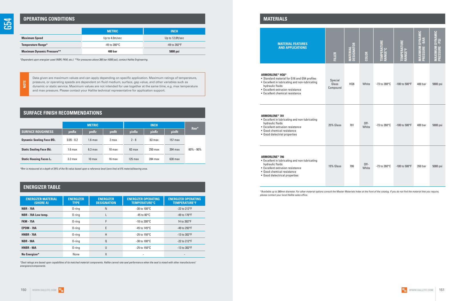
G54 OPERATING CONDITIONS
METRIC INCH
Maximum Speed Up to 4.0m/sec Up to 12.0ft/sec
Temperature Range* -45 to 200°C -49 to 392°F
Maximum Dynamic Pressure** 400 bar 5800 psi
*Dependent upon energizer used (NBR, FKM, etc.). **For pressures above 300 bar (4350 psi), contact Hallite Engineering.
MATERIALS
SURFACE FINISH RECOMMENDATIONS
*Rmr is measured at a depth of 25% of the Rz value based upon a reference level (zero line) at 5% material/bearing area.
METRIC INCHRmr*
SURFACE ROUGHNESS μmRa μmRz μmRt μinRa μinRz μinRt
Dynamic Sealing Face ØD1 0.05 - 0.2 1.6 max 2 max 2 - 8 63 max 157 max
60% - 90%Static Sealing Face Ød1 1.6 max 6.3 max 10 max 63 max 250 max 394 max
Static Housing Faces L1 3.2 max 10 max 16 max 125 max 394 max 630 max
ENERGIZER TABLE
ENERGIZER MATERIAL (SHORE A)
ENERGIZER TYPE
ENERGIZER DESIGNATION
ENERGIZER OPERATING TEMPERATURE°C
ENERGIZER OPERATING TEMPERATURE°F
NBR - 70A O-ring N -30 to 100°C -22 to 212°F
NBR - 70A Low temp. O-ring L -45 to 80°C -49 to 176°F
FKM - 75A O-ring F -10 to 200°C 14 to 392°F
EPDM - 70A O-ring E -45 to 145°C -49 to 293°F
HNBR - 70A O-ring H -25 to 150°C -13 to 302°F
NBR - 90A O-ring Q -30 to 100°C -22 to 212°F
HNBR - 90A O-ring U -25 to 150°C -13 to 302°F
No Energizer* None X - -
*Seal ratings are based upon capabilities of its matched material components. Hallite cannot rate seal performance when the seal is mixed with other manufacturers’ energizers/components.
MATERIAL FEATURES AND APPLICATIONS
FILL
ER
MAT
ERIA
L D
ESIG
NAT
OR
COLO
R
TEM
PERA
TURE
RA
NG
E°C
TEM
PERA
TURE
RA
NG
E°F
MA
XIM
UM
DYN
AM
IC
PRES
SURE
- B
AR
MA
XIM
UM
DYN
AM
IC
PRES
SURE
- PS
I
ARMORLENE® HQ6*• Standard material for G16 and G54 profiles• Excellent in lubricating and non-lubricating
hydraulic fluids• Excellent extrusion resistance• Excellent chemical resistance
Special Glass
CompoundHQ6 White -73 to 288°C -100 to 500°F 400 bar 5800 psi
ARMORLENE® 701• Excellent in lubricating and non-lubricating
hydraulic fluids• Excellent extrusion resistance• Good chemical resistance• Good dielectrial properties
25% Glass 701 Off- White -73 to 260°C -100 to 500°F 400 bar 5800 psi
ARMORLENE® 706• Excellent in lubricating and non-lubricating
hydraulic fluids• Excellent extrusion resistance• Good chemical resistance• Good dielectrical properties
15% Glass 706 Off- White -73 to 260°C -100 to 500°F 350 bar 5000 psi
*Available up to 380mm diameter. For other material options consult the Master Materials Index at the front of the catalog. If you do not find the material that you require, please contact your local Hallite sales office.
Data given are maximum values and can apply depending on specific application. Maximum ratings of temperature, pressure, or operating speeds are dependent on fluid medium, surface, gap value, and other variables such as dynamic or static service. Maximum values are not intended for use together at the same time, e.g. max temperature and max pressure. Please contact your Hallite technical representative for application support.
NO
TE
WWW.HALLITE.COM150 WWW.HALLITE.COM 151

INSTALLATION RECOMMENDATIONS
At pressure >300 bar use diameter tolerance H8/f7. *Radial Clearance G max. = maximum permissible gap all on one side using max. tube diameter and min. clearance diameter.
METRIC
BORE DIAMETER ØD1 H9G
ROO
VE D
IAM
ETER
GRO
OVE
WID
TH
RAD
IUS
CHA
MFE
R
GRO
OVE
SEC
TIO
N
RAD
IAL
CLEA
RAN
CE
G m
ax*
O-R
ING
CR
OSS
SEC
TIO
N
DIAMETER RANGE Ød1 h9 L1 + 0.2 r1 C S Up to
100 barUp to
200 barUp to
300 bar O-ring Standard Duty Application - R
Light Duty Application - L
Heavy Duty Application - H
8.0 - 14.9 15.0 - 39.9 - D1 - 4.9 2.2 0.4 2.0 2.45 0.30 0.20 0.15 1.78
15.0 - 39.9 40.0 - 79.9 - D1 - 7.5 3.2 0.6 3.0 3.75 0.40 0.25 0.15 2.62
40.0 - 79.9 80.0 - 132.9 15.0 - 39.9 D1 - 11.0 4.2 1.0 4.0 5.50 0.40 0.25 0.20 3.53
80.0 - 132.9 133.0 - 329.9 40.0 - 79.9 D1 - 15.5 6.3 1.3 6.0 7.75 0.50 0.30 0.20 5.33
133.0 - 329.9 330.0 - 669.9 80.0 - 132.9 D1 - 21.0 8.1 1.8 8.0 10.50 0.60 0.35 0.25 6.99
330.0 - 669.9 670.0 - 999.9 133.0 - 329.9 D1 - 24.5 8.1 1.8 8.0 12.25 0.60 0.35 0.25 6.99
670.0 - 999.9 ≥ 1000.0 330.0 - 669.9 D1 - 28.0 9.5 2.5 9.0 14.00 0.70 0.50 0.30 8.40
≥ 1000.0 - 670.0 - 999.9 D1 - 38.0 13.8 3.0 10.0 19.00 1.00 0.70 0.60 12.00
Temperature Range °C -30 TO 80 -30 TO 100
Max. Pressure Bar 300 200 240 160
At Speed v m/s 2 4 2 4
PART NUMBER RANGE (METRIC)*
8.0 3.1 2.2 G54MR00080****
10.0 5.1 2.2 G54MR00100****
12.0 7.1 2.2 G54MR00120****
14.0 9.1 2.2 G54MR00140****
15.0 7.5 3.2 G54MR00150****
16.0 11.1 2.2 G54ML00160****
16.0 8.5 3.2 G54MR00160****
18.0 13.1 2.2 G54ML00180****
18.0 10.5 3.2 G54MR00180****
20.0 15.1 2.2 G54ML00200****
20.0 12.5 3.2 G54MR00200****
21.0 13.5 3.2 G54MR00210****
22.0 17.1 2.2 G54ML00220****
22.0 14.5 3.2 G54MR00220****
24.0 16.5 3.2 G54MR00240****
25.0 20.1 2.2 G54ML00250****
25.0 17.5 3.2 G54MR00250****
25.0 14.0 4.2 G54MH00250****
28.0 20.5 3.2 G54MR00280****
30.0 22.5 3.2 G54MR00300****
32.0 27.1 2.2 G54ML00320****
32.0 24.5 3.2 G54MR00320****
32.0 21.0 4.2 G54MH00320****
35.0 27.5 3.2 G54MR00350****
35.0 24.0 4.2 G54MH00350****
36.0 28.5 3.2 G54MR00360****
38.0 30.5 3.2 G54MR00380****
40.0 32.5 3.2 G54ML00400****
40.0 29.0 4.2 G54MR00400****
42.0 31.0 4.2 G54MR00420****
45.0 34.0 4.2 G54MR00450****
48.0 37.0 4.2 G54MR00480****
50.0 42.5 3.2 G54ML00500****
50.0 39.0 4.2 G54MR00500****
50.0 34.5 6.3 G54MH00500****
50.8 43.3 3.2 G54ML00508****
50.8 39.8 4.2 G54MR00508****
52.0 41.0 4.2 G54MR00520****
53.0 42.0 4.2 G54MR00530****
55.0 44.0 4.2 G54MR00550****
57.0 46.0 4.2 G54MR00570****
58.0 47.0 4.2 G54MR00580****
60.0 49.0 4.2 G54MR00600****
62.0 51.0 4.2 G54MR00620****
63.0 52.0 4.2 G54MR00630****
63.0 47.5 6.3 G54MH00630****
65.0 54.0 4.2 G54MR00650****
68.0 57.0 4.2 G54MR00680****
70.0 59.0 4.2 G54MR00700****
70.0 54.5 6.3 G54MH00700****
75.0 64.0 4.2 G54MR00750****
75.0 59.5 6.3 G54MH00750****
80.0 69.0 4.2 G54ML00800****
80.0 64.5 6.3 G54MR00800****
80.0 59.0 8.1 G54MH00800****
82.5 67.0 6.3 G54MR00825****
G54PISTON SEAL
Double-Acting
Applications with maximum radial clearance that are using nylon, phenolic, or PTFE bearings must ensure proper clearance in accordance with the bearing recommendations to avoid metal-to-metal contact.
Please refer to Hallite Type 87, Type 506, and Type 533 Specification Sheets for this information.
G54
METRIC
ØD
1
Ød 1 L 1
PART
NU
MB
ER
Tol. H9 Tol. H9 Tol. +0.2
METRIC
ØD
1
Ød 1 L 1
PART
NU
MB
ER
Tol. H9 Tol. H9 Tol. +0.2
WWW.HALLITE.COM152 WWW.HALLITE.COM 153

PART NUMBER RANGE (METRIC)* PART NUMBER RANGE (METRIC)*
85.0 69.5 6.3 G54MR00850****
85.0 64.0 8.1 G54MH00850****
90.0 79.0 4.2 G54ML00900****
90.0 74.5 6.3 G54MR00900****
90.0 69.0 8.1 G54MH00900****
95.0 84.0 4.2 G54ML00950****
95.0 79.5 6.3 G54MR00950****
95.0 74.0 8.1 G54MH00950****
100.0 89.0 4.2 G54ML01000****
100.0 84.5 6.3 G54MR01000****
100.0 79.0 8.1 G54MH01000****
101.6 86.1 6.3 G54MR01016****
105.0 94.0 4.2 G54ML01050****
105.0 89.5 6.3 G54MR01050****
108.0 92.5 6.3 G54MR01080****
110.0 99.0 4.2 G54ML01100****
110.0 94.5 6.3 G54MR01100****
110.0 89.0 8.1 G54MH01100****
115.0 99.5 6.3 G54MR01150****
120.0 109.0 4.2 G54ML01200****
120.0 104.5 6.3 G54MR01200****
120.0 99.0 8.1 G54MH01200****
125.0 114.0 4.2 G54ML01250****
125.0 109.5 6.3 G54MR01250****
125.0 104.0 8.1 G54MH01250****
127.0 111.5 6.3 G54MR01270****
130.0 114.5 6.3 G54MR01300****
130.0 109.0 8.1 G54MH01300****
132.0 121.0 4.2 G54ML01320****
135.0 114.0 8.1 G54MR01350****
140.0 124.5 6.3 G54ML01400****
140.0 119.0 8.1 G54MR01400****
145.0 129.5 6.3 G54ML01450****
145.0 124.0 8.1 G54MR01450****
150.0 134.5 6.3 G54ML01500****
150.0 129.0 8.1 G54MR01500****
155.0 134.0 8.1 G54MR01550****
160.0 144.5 6.3 G54ML01600****
160.0 139.0 8.1 G54MR01600****
165.0 144.0 8.1 G54MR01650****
170.0 149.0 8.1 G54MR01700****
175.0 154.0 8.1 G54MR01750****
180.0 164.5 6.3 G54ML01800****
180.0 159.0 8.1 G54MR01800****
190.0 169.0 8.1 G54MR01900****
194.0 178.5 6.3 G54ML01940****
200.0 184.5 6.3 G54ML02000****
200.0 179.0 8.1 G54MR02000****
205.0 184.0 8.1 G54MR02050****
210.0 189.0 8.1 G54MR02100****
215.0 194.0 8.1 G54MR02150****
220.0 199.0 8.1 G54MR02200****
230.0 214.5 6.3 G54ML02300****
230.0 209.0 8.1 G54MR02300****
240.0 219.0 8.1 G54MR02400****
250.0 229.0 8.1 G54MR02500****
250.0 225.5 8.1 G54MR02500****
250.0 234.5 6.3 G54ML02500****
254.0 233.0 8.1 G54MR02540****
260.0 239.0 8.1 G54MR02600****
265.0 244.0 8.1 G54MR02650****
268.0 247.0 8.1 G54MR02680****
270.0 249.0 8.1 G54MR02700****
280.0 259.0 8.1 G54MR02800****
290.0 269.0 8.1 G54MR02900****
300.0 279.0 8.1 G54MR03000****
300.0 275.5 8.1 G54ML03000****
304.8 283.8 8.1 G54MR03048****
310.0 289.0 8.1 G54MR03100****
320.0 299.0 8.1 G54MR03200****
320.0 295.5 8.1 G54ML03200****
330.0 305.5 8.1 G54MR03300****
340.0 315.5 8.1 G54MR03400****
350.0 325.5 8.1 G54MR03500****
360.0 335.5 8.1 G54MR03600****
370.0 345.5 8.1 G54MR03700****
380.0 355.5 8.1 G54MR03800****
400.0 375.5 8.1 G54MR04000****
420.0 395.5 8.1 G54MR04200****
430.0 405.5 8.1 G54MR04300****
440.0 415.5 8.1 G54MR04400****
450.0 425.5 8.1 G54MR04500****
460.0 435.5 8.1 G54MR04600****
480.0 455.5 8.1 G54MR04800****
500.0 475.5 8.1 G54MR05000****
555.0 530.5 8.1 G54MR05550****
600.0 575.5 8.1 G54MR06000****
640.0 615.5 8.1 G54MR06400****
660.0 635.5 8.1 G54MR06600****
700.0 672.0 9.5 G54MR07000****
710.0 682.0 9.5 G54MR07100****
740.0 712.0 9.5 G54MR07400****
780.0 752.0 9.5 G54MR07800****
800.0 772.0 9.5 G54MR08000****
900.0 872.0 9.5 G54MR09000****
1000.0 972.0 9.5 G54ML10000****
1000.0 962.0 13.8 G54MR10000****
1050.0 1022.0 9.5 G54ML10500****
1065.0 1027.0 13.8 G54MR10650****
1070.0 1032.0 13.8 G54MR10700****
1200.0 1172.0 9.5 G54ML12000****
1200.0 1162.0 13.8 G54MR12000****
1225.0 1187.0 13.8 G54MR12250****
G54PISTON SEAL
Double-Acting
*Please contact Hallite for custom sizes, material selection, or seal design.
G54
METRIC
ØD
1
Ød 1 L 1
PART
NU
MB
ER
Tol. H9 Tol. H9 Tol. +0.2
METRIC
ØD
1
Ød 1 L 1
PART
NU
MB
ER
Tol. H9 Tol. H9 Tol. +0.2
METRIC
ØD
1
Ød 1 L 1
PART
NU
MB
ER
Tol. H9 Tol. H9 Tol. +0.2
METRIC
ØD
1
Ød 1 L 1
PART
NU
MB
ER
Tol. H9 Tol. H9 Tol. +0.2
WWW.HALLITE.COM154 WWW.HALLITE.COM 155

PDS M R 00700 N HLX
PROFILE DESIGNATION
UNIT OF MEASUREMENT
M = Metric E = Inch
APPLICATION
Refer to Installation Recommendations and use designator for desired application
ENERGIZER MATERIAL
Refer to Energizer Table for desired energizer material
PTFE MATERIAL
Refer to Material Table for desired PTFE (face) material
SPECIAL FEATURE
Blank = Std profile N = Notches
___
BORE DIAMETER
Metric = mm X 10
Inch = inches X 1000
PDS
• Compact design to save metal spacing
• Low breakout friction and elimination of stick-slip action
• Effective in pneumatic cylinder and light-duty hydraulic cylinder
• Can be used in standard AS-568 dynamic O-ring groove
• Fits groove dimensions per MIL-G-5514F
• Recommended for light-duty and small-diameter applications
F E A T U R E S
TECHNICAL DETAILS
The Hallite PDS is a double-acting low-friction piston seal solution for compact
O-ring grooves, that extends the service range above what an O-ring alone
is capable of supporting. The PDS is designed for light-duty applications, is
particularly suited for small-diameter installations, and due to its size and
design, is easy to install. High-performance Armorlene® materials, like HLX,
provide outstanding wear and extrusion-resistance properties as well as large
range of temperature and media compatibility.
Hallite’s PDS is designed to be used in existing dynamic O-ring grooves and does
not require any groove modification. A good choice for pneumatic and hydraulic
equipment sealing needs, the PDS is proven to extend the service range and seal
longevity over stand-alone O-ring installations.
This seal is available in a variety of Hallite’s high-performance Armorlene®
materials to suit a wide range of demanding applications.
Part Number StructurePDSMR00700NHLX _
PISTON SEALDouble-Acting
WWW.HALLITE.COM 157

PDS OPERATING CONDITIONS
METRIC INCH
Maximum Speed Up to 15.0m/sec Up to 50.0ft/sec
Temperature Range* -45 to 200°C -49 to 392°F
Maximum Dynamic Pressure 350 bar 5000 psi
*Dependent upon energizer used (NBR, FKM, etc.).
MATERIALS
SURFACE FINISH RECOMMENDATIONS
*Rmr is measured at a depth of 25% of the Rz value based upon a reference level (zero line) at 5% material/bearing area.
METRIC INCHRmr*
SURFACE ROUGHNESS μmRa μmRz μmRt μinRa μinRz μinRt
Dynamic Sealing Face ØD1 0.05 - 0.2 1.6 max 2 max 2 - 8 63 max 157 max
60% - 90%Static Sealing Face Ød1 1.6 max 6.3 max 10 max 63 max 250 max 394 max
Static Housing Faces L1 3.2 max 10 max 16 max 125 max 394 max 630 max
ENERGIZER TABLE
ENERGIZER MATERIAL (SHORE A)
ENERGIZER TYPE
ENERGIZER DESIGNATION
ENERGIZER OPERATING TEMPERATURE°C
ENERGIZER OPERATING TEMPERATURE°F
NBR - 70A O-ring N -30 to 100°C -22 to 212°F
NBR - 70A Low temp. O-ring L -45 to 80°C -49 to 176°F
FKM - 75A O-ring F -10 to 200°C 14 to 392°F
EPDM - 70A O-ring E -45 to 145°C -49 to 293°F
HNBR - 70A O-ring H -25 to 150°C -13 to 302°F
NBR - 90A O-ring Q -30 to 100°C -22 to 212°F
HNBR - 90A O-ring U -25 to 150°C -13 to 302°F
No Energizer* None X - -
*Seal ratings are based upon capabilities of its matched material components. Hallite cannot rate seal performance when the seal is mixed with other manufacturers’ energizers/components.
MATERIAL FEATURES AND APPLICATIONS
FILL
ER
MAT
ERIA
L D
ESIG
NAT
OR
COLO
R
TEM
PERA
TURE
RA
NG
E°C
TEM
PERA
TURE
RA
NG
E°F
MA
XIM
UM
DYN
AM
IC
PRES
SURE
- B
AR
MA
XIM
UM
DYN
AM
IC
PRES
SURE
- PS
I
ARMORLENE® HLX• Standard material for hydraulic applications• High compressive strength• Excellent extrusion resistance• Extended wear resistance
Special Bronze
CompoundHLX Gold -73 to 288°C -100 to 550°F 350 bar 5000 psi
ARMORLENE® 711• Excellent in all lubricating fluids and
pneumatic applications• High chemical resistance• Excellent extrusion resistance• Excellent wear properties
25% Carbon Graphite 711 Black -73 to 288°C -100 to 550°F 350 bar 5000 psi
ARMORLENE® 700• Excellent in all hydraulic fluids• Recommended for use with soft
mating surfaces
• Low friction and no stick-slip
Unfilled 700 White -184 to 204°C -300 to 400°F 200 bar 2900 psi
For other material options consult the Master Materials Index at the front of the catalog. If you do not find the material that you require, please contact your local Hallite sales office.
Data given are maximum values and can apply depending on specific application. Maximum ratings of temperature, pressure, or operating speeds are dependent on fluid medium, surface, gap value, and other variables such as dynamic or static service. Maximum values are not intended for use together at the same time, e.g. max temperature and max pressure. Please contact your Hallite technical representative for application support.
NO
TE
WWW.HALLITE.COM158 WWW.HALLITE.COM 159

PART NUMBER RANGE (METRIC)*INSTALLATION RECOMMENDATIONS
*Radial Clearance G max. = maximum permissible gap all on one side using max. tube diameter and min. clearance diameter.
METRIC
BORE DIAMETER ØD1 H9
GRO
OVE
DIA
MET
ER
GRO
OVE
WID
TH
RAD
IUS
CHA
MFE
R
GRO
OVE
SEC
TIO
N
RAD
IAL
CLEA
RAN
CE
G m
ax*
O-R
ING
CR
OSS
SEC
TIO
N
DIAMETER RANGEØd1 h9 L1 +
0.2 r1 C S Up to 20 bar
Up to 100 bar
Up to 200 bar
Up to 350 bar O-ringStandard Duty
Application - RLight Duty
Application - L
5.0 - 13.9 14.0 - 24.9 D1 - 2.9 2.4 0.4 2.0 1.45 0.10 0.10 0.08 0.05 1.78
14.0 - 24.9 25.0 - 45.9 D1 - 4.5 3.6 0.4 3.0 2.25 0.15 0.15 0.10 0.07 2.62
25.0 - 45.9 46.0 - 124.9 D1 - 6.2 4.8 0.6 4.0 3.10 0.25 0.20 0.15 0.08 3.53
46.0 - 124.9 125.0 - 669.9 D1 - 9.4 7.1 0.8 6.0 4.70 0.35 0.25 0.20 0.10 5.33
125.0 - 669.9 670.0 - 999.9 D1 - 12.2 9.5 0.8 8.0 6.10 0.50 0.30 0.25 0.15 6.99
670.0 - 999.9 > 999.9 D1 - 15.0 10.0 1.0 1.0 7.50 0.60 0.40 0.30 0.20 8.40
*Radial Clearance G max. = maximum permissible gap all on one side using max. tube diameter and min. clearance diameter.
INCH
BORE DIAMETER ØD1 H9
GRO
OVE
DIA
MET
ER
GRO
OVE
WID
TH
RAD
IUS
CHA
MFE
R
GRO
OVE
SEC
TIO
N
RAD
IAL
CLEA
RAN
CE
G m
ax*
O-R
ING
CR
OSS
SEC
TIO
N
DIAMETER RANGEØd1 h9 L1 +
.008 r1 C S Up to 290 psi
Up to 1500 psi
Up to 2900 psi
Up to 5000 psi O-ringStandard Duty
Application - RLight Duty
Application - L
0.250 - 0.312 0.313 -0.999 D1 -0.110 0.093 0.016 0.079 0.055 0.004 0.004 0.003 0.002 0.070
0.313 - 0.999 1.000 - 2.500 D1 - 0.176 0.140 0.016 0.118 0.088 0.006 0.006 0.004 0.003 0.103
1.000 - 2.500 2.501 - 4.999 D1 - 0.242 0.187 0.024 0.157 0.121 0.010 0.008 0.006 0.003 0.139
2.501 - 4.999 - D1 - 0.370 0.281 0.032 0.236 0.185 0.014 0.010 0.008 0.004 0.210
5.000 - 16.000 - D1 - 0.474 0.375 0.032 0.315 0.237 0.020 0.012 0.010 0.006 0.275
6.0 3.1 2.4 PDSMR00060****
8.0 5.1 2.4 PDSMR00080****
9.0 6.1 2.4 PDSMR00090****
10.0 7.1 2.4 PDSMR00100****
11.0 8.1 2.4 PDSMR00110****
12.0 9.1 2.4 PDSMR00120****
12.7 9.8 2.4 PDSMR00127****
14.0 9.5 3.6 PDSMR00140****
15.0 10.5 3.6 PDSMR00150****
16.0 11.5 3.6 PDSMR00160****
18.0 13.5 3.6 PDSMR00180****
20.0 15.5 3.6 PDSMR00200****
22.0 17.5 3.6 PDSMR00220****
24.0 19.5 3.6 PDSMR00240****
25.0 18.8 4.8 PDSMR00250****
25.4 19.2 4.8 PDSMR00254****
27.0 20.8 4.8 PDSMR00270****
28.0 21.8 4.8 PDSMR00280****
30.0 23.8 4.8 PDSMR00300****
32.0 25.8 4.8 PDSMR00320****
35.0 28.8 4.8 PDSMR00350****
40.0 33.8 4.8 PDSMR00400****
42.0 35.8 4.8 PDSMR00420****
45.0 38.8 4.8 PDSMR00450****
48.0 38.6 7.1 PDSMR00480****
50.0 40.6 7.1 PDSMR00500****
50.8 41.4 7.1 PDSMR00508****
52.0 42.6 7.1 PDSMR00520****
55.0 45.6 7.1 PDSMR00550****
56.0 46.6 7.1 PDSMR00560****
60.0 50.6 7.1 PDSMR00600****
63.0 53.6 7.1 PDSMR00630****
65.0 55.6 7.1 PDSMR00650****
70.0 60.6 7.1 PDSMR00700****
75.0 65.6 7.1 PDSMR00750****
80.0 70.6 7.1 PDSMR00800****
85.0 75.6 7.1 PDSMR00850****
90.0 80.6 7.1 PDSMR00900****
95.0 85.6 7.1 PDSMR00950****
100.0 90.6 7.1 PDSMR01000****
110.0 100.6 7.1 PDSMR01100****
115.0 105.6 7.1 PDSMR01150****
120.0 110.6 7.1 PDSMR01200****
125.0 112.8 9.5 PDSMR01250****
130.0 117.8 9.5 PDSMR01300****
135.0 122.8 9.5 PDSMR01350****
140.0 127.8 9.5 PDSMR01400****
150.0 137.8 9.5 PDSMR01500****
160.0 147.8 9.5 PDSMR01600****
170.0 157.8 9.5 PDSMR01700****
180.0 167.8 9.5 PDSMR01800****
190.0 177.8 9.5 PDSMR01900****
200.0 187.8 9.5 PDSMR02000****
210.0 197.8 9.5 PDSMR02100****
220.0 207.8 9.5 PDSMR02200****
230.0 217.8 9.5 PDSMR02300****
PDS PDS
PISTON SEALDouble-Acting
METRIC
ØD
1
Ød 1 L 1
PART
NU
MB
ER
Tol. H9 Tol. H9 Tol. +0.2
METRIC
ØD
1
Ød 1 L 1
PART
NU
MB
ER
Tol. H9 Tol. H9 Tol. +0.2
WWW.HALLITE.COM160 WWW.HALLITE.COM 161

PART NUMBER RANGE (METRIC)* PART NUMBER RANGE (INCH)* PART NUMBER RANGE (INCH)*
0.250 0.140 0.093 PDSER00250****
0.281 0.171 0.093 PDSER00281****
0.312 0.202 0.093 PDSER00312****
0.344 0.234 0.093 PDSEL00344****
0.375 0.265 0.093 PDSEL00375****
0.437 0.327 0.093 PDSEL00437****
0.500 0.390 0.093 PDSEL00500****
0.562 0.452 0.093 PDSEL00562****
0.625 0.515 0.093 PDSEL00625****
0.687 0.577 0.093 PDSEL00687****
0.750 0.640 0.093 PDSEL00750****
0.812 0.702 0.093 PDSEL00812****
0.875 0.765 0.093 PDSEL00875****
0.937 0.827 0.093 PDSEL00937****
1.000 0.824 0.140 PDSEL01000****
1.062 0.886 0.140 PDSEL01062****
1.125 0.949 0.140 PDSEL01125****
1.187 1.011 0.140 PDSEL01187****
1.250 1.074 0.140 PDSEL01250****
1.312 1.136 0.140 PDSEL01312****
1.375 1.199 0.140 PDSEL01375****
1.437 1.261 0.140 PDSEL01437****
1.500 1.324 0.140 PDSEL01500****
1.562 1.386 0.140 PDSEL01562****
1.625 1.449 0.140 PDSEL01625****
1.687 1.511 0.140 PDSEL01687****
1.750 1.574 0.140 PDSEL01750****
1.812 1.636 0.140 PDSEL01812****
1.875 1.699 0.187 PDSEL01875****
1.937 1.761 0.187 PDSEL01937****
2.000 1.824 0.187 PDSEL02000****
2.062 1.886 0.187 PDSEL02062****
2.125 1.949 0.187 PDSEL02125****
2.187 2.011 0.187 PDSEL02187****
2.250 2.074 0.187 PDSEL02250****
2.312 2.136 0.187 PDSEL02312****
2.375 2.199 0.187 PDSEL02375****
2.437 2.261 0.187 PDSEL02437****
2.500 2.324 0.187 PDSEL02500****
2.625 2.383 0.187 PDSEL02625****
2.750 2.508 0.187 PDSEL02750****
2.875 2.633 0.187 PDSEL02875****
3.000 2.758 0.187 PDSEL03000****
3.125 2.883 0.187 PDSEL03125****
3.250 3.008 0.187 PDSEL03250****
3.375 3.133 0.187 PDSEL03375****
3.500 3.258 0.187 PDSEL03500****
3.625 3.383 0.187 PDSEL03625****
3.750 3.508 0.187 PDSEL03750****
3.875 3.633 0.187 PDSEL03875****
4.000 3.758 0.187 PDSEL04000****
4.125 3.883 0.187 PDSEL04125****
4.250 4.008 0.187 PDSEL04250****
4.375 4.133 0.187 PDSEL04375****
4.500 4.258 0.187 PDSEL04500****
4.625 4.383 0.187 PDSEL04625****
4.750 4.508 0.187 PDSEL04750****
4.875 4.633 0.187 PDSEL04875****
5.000 4.526 0.375 PDSER05000****
5.125 4.651 0.375 PDSER05125****
5.250 4.776 0.375 PDSER05250****
5.375 4.901 0.375 PDSER05375****
5.500 5.026 0.375 PDSER05500****
5.625 5.151 0.375 PDSER05625****
5.750 5.276 0.375 PDSER05750****
5.875 5.401 0.375 PDSER05875****
6.000 5.526 0.375 PDSER06000****
6.125 5.651 0.375 PDSER06125****
6.250 5.776 0.375 PDSER06250****
6.375 5.901 0.375 PDSER06375****
6.500 6.026 0.375 PDSER06500****
6.750 6.276 0.375 PDSER06750****
7.000 6.526 0.375 PDSER07000****
7.250 6.776 0.375 PDSER07250****
7.500 7.026 0.375 PDSER07500****
7.750 7.276 0.375 PDSER07750****
8.000 7.526 0.375 PDSER08000****
8.250 7.776 0.375 PDSER08250****
8.500 8.026 0.375 PDSER08500****
240.0 227.8 9.5 PDSMR02400****
250.0 237.8 9.5 PDSMR02500****
280.0 267.8 9.5 PDSMR02800****
300.0 287.8 9.5 PDSMR03000****
320.0 307.8 9.5 PDSMR03200****
350.0 337.8 9.5 PDSMR03500****
400.0 387.8 9.5 PDSMR04000****
420.0 407.8 9.5 PDSMR04200****
450.0 437.8 9.5 PDSMR04500****
480.0 467.8 9.5 PDSMR04800****
500.0 487.8 9.5 PDSMR05000****
600.0 587.8 9.5 PDSMR06000****
650.0 637.8 9.5 PDSMR06500****
PDS PDS
PISTON SEALDouble-Acting
*Please contact Hallite for custom sizes, material selection, or seal design.
*Please contact Hallite for custom sizes, material selection, or seal design.
INCH
ØD
1
Ød 1 L 1
PART
NU
MB
ER
Tol. H9 Tol. H9 Tol. +0.008
INCH
ØD
1
Ød 1 L 1
PART
NU
MB
ER
Tol. H9 Tol. H9 Tol. +0.008
INCH
ØD
1
Ød 1 L 1
PART
NU
MB
ER
Tol. H9 Tol. H9 Tol. +0.008
METRIC
ØD
1
Ød 1 L 1
PART
NU
MB
ER
Tol. H9 Tol. H9 Tol. +0.2
WWW.HALLITE.COM162 WWW.HALLITE.COM 163

PCG M R 00400 N HLX
PROFILE DESIGNATION
UNIT OF MEASUREMENT
M = Metric E = Inch
APPLICATION
Refer to Installation Recommendations and use designator for desired application
ENERGIZER MATERIAL
Refer to Energizer Table for desired energizer material
PTFE MATERIAL
Refer to Material Table for desired PTFE (face) material
SPECIAL FEATURE
Blank = Std profile N = Notches
___
BORE DIAMETER
Metric = mm X 10
Inch = inches X 1000
PCG
• Low breakout friction and elimination of stick-slip action
• Compact design to save metal spacing
• High service temperature, long wear, and high extrusion resistanceF E A T U R E S
TECHNICAL DETAILS
The Hallite PCG is a double-acting, O-ring energized, low-friction piston seal
designed for low- and medium-pressure systems. High-performance Armorlene®
materials, like HLX, provide outstanding wear and extrusion-resistance properties
as well as large range of temperature and media compatibility.
The compact design of the PCG piston seal provides an ideal sealing solution
where housing space is limited. This seal is available in a variety of Hallite’s
high- performance Armorlene® materials to suit a wide range of
demanding applications.
Part Number StructurePCGMR00400NHLX _
PISTON SEALDouble-Acting
WWW.HALLITE.COM 165

PCG OPERATING CONDITIONS
METRIC INCH
Maximum Speed Up to 15.0m/sec Up to 50.0ft/sec
Temperature Range* -45 to 200°C -49 to 392°F
Maximum Dynamic Pressure 200 bar 2900 psi
*Dependent upon energizer used (NBR, FKM, etc.).
MATERIALS
SURFACE FINISH RECOMMENDATIONS
*Rmr is measured at a depth of 25% of the Rz value based upon a reference level (zero line) at 5% material/bearing area.
METRIC INCHRmr*
SURFACE ROUGHNESS μmRa μmRz μmRt μinRa μinRz μinRt
Dynamic Sealing Face ØD1 0.05 - 0.2 1.6 max 2 max 2 - 8 63 max 157 max
60% - 90%Static Sealing Face Ød1 1.6 max 6.3 max 10 max 63 max 250 max 394 max
Static Housing Faces L1 3.2 max 10 max 16 max 125 max 394 max 630 max
ENERGIZER TABLE
ENERGIZER MATERIAL (SHORE A)
ENERGIZER TYPE
ENERGIZER DESIGNATION
ENERGIZER OPERATING TEMPERATURE°C
ENERGIZER OPERATING TEMPERATURE°F
NBR - 70A O-ring N -30 to 100°C -22 to 212°F
NBR - 70A Low temp. O-ring L -45 to 80°C -49 to 176°F
FKM - 75A O-ring F -10 to 200°C 14 to 392°F
EPDM - 70A O-ring E -45 to 145°C -49 to 293°F
HNBR - 70A O-ring H -25 to 150°C -13 to 302°F
NBR - 90A O-ring Q -30 to 100°C -22 to 212°F
HNBR - 90A O-ring U -25 to 150°C -13 to 302°F
No Energizer* None X - -
*Seal ratings are based upon capabilities of its matched material components. Hallite cannot rate seal performance when the seal is mixed with other manufacturers’ energizers/components.
MATERIAL FEATURES AND APPLICATIONS
FILL
ER
MAT
ERIA
L D
ESIG
NAT
OR
COLO
R
TEM
PERA
TURE
RA
NG
E°C
TEM
PERA
TURE
RA
NG
E°F
MA
XIM
UM
DYN
AM
IC
PRES
SURE
- B
AR
MA
XIM
UM
DYN
AM
IC
PRES
SURE
- PS
I
ARMORLENE® HLX• Standard material for hydraulic applications• High compressive strength• Excellent extrusion resistance• Extended wear resistance
Special Bronze
CompoundHLX Gold -73 to 288°C -100 to 550°F 200 bar 2900 psi
ARMORLENE® HCF• Excellent in lubricating and non-lubricating
hydraulic fluids (includes water) w/o zinc content
• Not recommended for gas sealing applications
• Not recommended for electrical conductive fluids
Carbon Fiber Filled HCF Gray/
Black -73 to 260°C -100 to 500°F 200 bar 2900 psi
ARMORLENE® 700• Excellent in all hydraulic fluids• Recommended for use with soft
mating surfaces • Low friction and no stick-slip
Unfilled 700 White -184 to 204°C -300 to 400°F 200 bar 2900 psi
ARMORLENE® 711• Excellent in all lubricating fluids and
pneumatic applications• High chemical resistance• Excellent extrusion resistance• Excellent wear properties
25% Carbon/ Graphite 711 Black -73 to 288°C -100 to 550°F 200 bar 2900 psi
748 - UHMWPE• Excellent impact resistance• Good dielectrical properties• Excellent abrasion resistance• Low coefficient of friction
Standard 748 Translucent -184 to 82°C -300 to 180°F 200 bar 2900 psi
For other material options consult the Master Materials Index at the front of the catalog. If you do not find the material that you require, please contact your local Hallite sales office.
Data given are maximum values and can apply depending on specific application. Maximum ratings of temperature, pressure, or operating speeds are dependent on fluid medium, surface, gap value, and other variables such as dynamic or static service. Maximum values are not intended for use together at the same time, e.g. max temperature and max pressure. Please contact your Hallite technical representative for application support.
NO
TE
WWW.HALLITE.COM166 WWW.HALLITE.COM 167

PART NUMBER RANGE (METRIC)*INSTALLATION RECOMMENDATIONS
*Radial Clearance G max. = maximum permissible gap all on one side using max. tube diameter and min. clearance diameter.
METRIC
BORE DIAMETER ØD1 H9G
ROO
VE D
IAM
ETER
GRO
OVE
WID
TH
RAD
IUS
GRO
OVE
SEC
TIO
N
RAD
IAL
CLEA
RAN
CE
G m
ax*
O-R
ING
CR
OSS
SEC
TIO
N
DIAMETER RANGE Ød1 h9 L1 + 0.2 r1 S Up to
100 barUp to
200 bar O-ringStandard Duty Application - R
7.0 - 15.9 D1 - 4.0 2.00 0.50 2.20 0.08 0.08 1.78
16.0 - 26.9 D1 - 6.0 2.85 0.50 3.00 0.08 0.08 2.62
27.0 - 49.9 D1 - 7.5 3.8 0.80 3.75 0.08 0.08 3.53
50.0 - 129.9 D1 - 12.5 5.6 1.30 6.25 0.10 0.10 5.33
130.0 - 179.9 D1 - 15.0 7.55 1.50 7.50 0.10 0.10 6.99
180.0 - 239.9 D1 - 18.0 7.55 1.50 9.00 0.10 0.10 6.99
240.0 - 420.0 D1 - 24.0 7.55 1.50 12.00 0.10 0.10 6.99
*Radial Clearance G max. = maximum permissible gap all on one side using max. tube diameter and min. clearance diameter.
INCH
BORE DIAMETER ØD1 H9
GRO
OVE
DIA
MET
ER
GRO
OVE
WID
TH
RAD
IUS
GRO
OVE
SEC
TIO
N
RAD
IAL
CLEA
RAN
CE
G m
ax*
O-R
ING
CR
OSS
SEC
TIO
N
DIAMETER RANGE Ød1 h9 L1 + 0.008 r1 S Up to
1500 psiUp to
2900 psi O-ringStandard Duty Application - R Light Duty Application - L
0.250 - 0.937 0.938 - 2.500 D1 - 0.172 0.079 0.02 0.086 0.002 0.002 0.070
0.938- 2.500 2.501 - 3.875 D1 - 0.236 0.112 0.02 0.118 0.003 0.003 0.103
2.501 - 3.875 3.876 - 5.000 D1 - 0.363 0.149 0.03 0.182 0.003 0.003 0.139
3.876 - 5.000 5.001 - 6.500 D1 - 0.491 0.221 0.05 0.246 0.004 0.004 0.210
5.001 - 6.500 6.501 - 8.500 D1 - 0.593 0.297 0.06 0.297 0.004 0.004 0.275
6.501 - 8.500 8.501 - 25.500 D1 - 0.718 0.297 0.06 0.359 0.004 0.004 0.275
8.501 - 25.500 - D1 - 0.968 0.297 0.06 0.484 0.004 0.004 0.275
7.0 3.0 2.00 PCGMR00070****
8.0 4.0 2.00 PCGMR00080****
9.0 5.0 2.00 PCGMR00090****
10.0 6.0 2.00 PCGMR00100****
11.0 7.0 2.00 PCGMR00110****
12.0 8.0 2.00 PCGMR00120****
14.0 10.0 2.00 PCGMR00140****
16.0 10.0 2.85 PCGMR00160****
18.0 12.0 2.85 PCGMR00180****
19.0 13.0 2.85 PCGMR00190****
20.0 14.0 2.85 PCGMR00200****
22.0 16.0 2.85 PCGMR00220****
25.0 19.0 2.85 PCGMR00250****
28.0 20.5 3.80 PCGMR00280****
30.0 22.5 3.80 PCGMR00300****
32.0 24.5 3.80 PCGMR00320****
35.0 27.5 3.80 PCGMR00350****
36.0 28.5 3.80 PCGMR00360****
38.0 30.5 3.80 PCGMR00380****
40.0 32.5 3.80 PCGMR00400****
42.0 34.5 3.80 PCGMR00420****
45.0 37.5 3.80 PCGMR00450****
48.0 40.5 3.80 PCGMR00480****
50.0 37.5 5.60 PCGMR00500****
55.0 42.5 5.60 PCGMR00550****
60.0 47.5 5.60 PCGMR00600****
63.0 50.5 5.60 PCGMR00630****
65.0 52.5 5.6 PCGMR00650****
70.0 57.5 5.6 PCGMR00700****
74.0 61.5 5.60 PCGMR00740****
75.0 62.5 5.60 PCGMR00750****
80.0 67.5 5.60 PCGMR00800****
85.0 72.5 5.60 PCGMR00850****
90.0 77.5 5.60 PCGMR00900****
92.0 79.5 5.60 PCGMR00920****
100.0 87.5 5.60 PCGMR01000****
105.0 92.5 5.60 PCGMR01050****
110.0 97.5 5.60 PCGMR01100****
115.0 102.5 5.60 PCGMR01150****
120.0 107.5 5.60 PCGMR01200****
125.0 112.5 5.60 PCGMR01250****
130.0 115.0 7.55 PCGMR01300****
140.0 125.0 7.55 PCGMR01400****
PCG PCG
PISTON SEALDouble-Acting
*Please contact Hallite for custom sizes, material selection, or seal design.
METRIC
ØD
1
Ød 1 L 1
PART
NU
MB
ER
Tol. H9 Tol. H9 Tol. +0.2
METRIC
ØD
1
Ød 1 L 1
PART
NU
MB
ER
Tol. H9 Tol. H9 Tol. +0.2
WWW.HALLITE.COM168 WWW.HALLITE.COM 169

PART NUMBER RANGE (INCH)* PART NUMBER RANGE (INCH)*
0.250 0.078 0.079 PCGER00250****
0.312 0.140 0.079 PCGER00312****
0.375 0.203 0.079 PCGER00375****
0.437 0.265 0.079 PCGER00437****
0.500 0.328 0.079 PCGER00500****
0.562 0.390 0.079 PCGER00562****
0.625 0.453 0.079 PCGER00625****
0.687 0.515 0.079 PCGER00687****
0.750 0.578 0.079 PCGER00750****
0.812 0.640 0.079 PCGER00812****
0.875 0.703 0.079 PCGER00875****
0.937 0.765 0.079 PCGER00937****
1.000 0.764 0.112 PCGER01000****
1.062 0.826 0.112 PCGER01062****
1.125 0.889 0.112 PCGER01125****
1.187 0.951 0.112 PCGER01187****
1.250 1.014 0.112 PCGER01250****
1.312 1.076 0.112 PCGER01312****
1.375 1.139 0.112 PCGER01375****
1.437 1.201 0.112 PCGER01437****
1.500 1.264 0.112 PCGER01500****
1.562 1.326 0.112 PCGER01562****
1.625 1.389 0.112 PCGER01625****
1.687 1.451 0.112 PCGER01687****
1.750 1.514 0.112 PCGER01750****
1.812 1.576 0.112 PCGER01812****
1.875 1.639 0.112 PCGER01875****
1.937 1.701 0.112 PCGER01937****
2.000 1.764 0.112 PCGER02000****
2.062 1.826 0.112 PCGER02062****
2.125 1.889 0.112 PCGER02125****
2.187 1.951 0.112 PCGER02187****
2.250 2.014 0.112 PCGER02250****
2.312 2.076 0.112 PCGER02312****
2.375 2.139 0.112 PCGER02375****
2.437 2.201 0.112 PCGER02437****
2.500 2.264 0.112 PCGER02500****
2.625 2.262 0.149 PCGER02625****
2.750 2.387 0.149 PCGER02750****
2.875 2.512 0.149 PCGER02875****
3.000 2.637 0.149 PCGER03000****
3.125 2.762 0.149 PCGER03125****
3.250 2.887 0.149 PCGER03250****
3.375 3.012 0.149 PCGER03375****
3.500 3.137 0.149 PCGER03500****
3.625 3.262 0.149 PCGER03625****
3.750 3.387 0.149 PCGER03750****
3.875 3.512 0.149 PCGER03875****
4.000 3.509 0.221 PCGER04000****
4.125 3.634 0.221 PCGER04125****
4.250 3.759 0.221 PCGER04250****
4.375 3.884 0.221 PCGER04375****
4.500 4.009 0.221 PCGER04500****
4.625 4.134 0.221 PCGER04625****
4.750 4.259 0.221 PCGER04750****
4.875 4.384 0.221 PCGER04875****
5.000 4.509 0.221 PCGER05000****
5.125 4.532 0.297 PCGER05125****
5.250 4.657 0.297 PCGER05250****
5.375 4.782 0.297 PC GER05375****
5.500 4.907 0.297 PCGER05500****
5.625 5.032 0.297 PCGER05625****
5.750 5.157 0.297 PCGER05750****
5.875 5.282 0.297 PCGER05875****
6.000 5.407 0.297 PCGER06000****
6.125 5.532 0.297 PCGER06125****
6.250 5.657 0.297 PCGER06250****
6.375 5.782 0.297 PCGER06375****
6.500 5.907 0.297 PCGER06500****
6.750 6.032 0.297 PCGER06750****
7.000 6.282 0.297 PCGER07000****
7.250 6.532 0.297 PCGER07250****
7.500 6.782 0.297 PCGER07500****
7.750 7.032 0.297 PCGER07750****
8.000 7.282 0.297 PCGER08000****
8.250 7.532 0.297 PCGER08250****
8.500 7.782 0.297 PCGER08500****
9.000 8.032 0.297 PCGER09000****
9.500 8.532 0.297 PCGER09500****
10.000 9.032 0.297 PCGER10000****
10.500 9.532 0.297 PCGER10500****
PCG PCG
PISTON SEALDouble-Acting
*Please contact Hallite for custom sizes, material selection, or seal design.
INCH
ØD
1
Ød 1 L 1
PART
NU
MB
ER
Tol. H9 Tol. H9 Tol. +0.008
INCH
ØD
1
Ød 1 L 1
PART
NU
MB
ER
Tol. H9 Tol. H9 Tol. +0.008
INCH
ØD
1
Ød 1 L 1
PART
NU
MB
ER
Tol. H9 Tol. H9 Tol. +0.008
INCH
ØD
1
Ød 1 L 1
PART
NU
MB
ER
Tol. H9 Tol. H9 Tol. +0.008
WWW.HALLITE.COM170 WWW.HALLITE.COM 171

PCA M R 00400 R HLX
PROFILE DESIGNATION
UNIT OF MEASUREMENT
M = Metric E = Inch
APPLICATION
Refer to Installation Recommendations and use designator for desired application
ENERGIZER MATERIAL
Refer to Energizer Table for desired energizer material
PTFE MATERIAL
Refer to Material Table for desired PTFE (face) material
SPECIAL FEATURE
Blank = Std profile N = Notches
___
BORE DIAMETER
Metric = mm X 10
Inch = inches X 1000
PCA
• Low breakout friction and elimination of stick-slip action
• Compact design to save metal spacing
• High service temperature, long wear, and high extrusion resistance
• Compact design allows for smaller grooves in hardware
F E A T U R E S
TECHNICAL DETAILS
The Hallite PCA is a double-acting piston seal that performs well in both high- and
low-pressure systems. The PCA has a square edge design on the primary sealing
face paired with a square elastomer energizer. The square ring provides more stable
pressure loading to the PTFE face ring, therefore it provides exceptional sealability
throughout the pressure ranges. High-performance Armorlene® materials, like HLX,
provide outstanding wear and extrusion-resistance properties as well as large range
of temperature and media compatibility.
The Hallite PCA seal is well-suited for a variety of hydraulic and pneumatic
reciprocating applications. The compact housing allows designers to use a
narrow-width piston, but it is recommended that proper guidance be used with this
seal, especially in heavy-duty applications (see Hallite Bearings section). The PCA seal
is available in a variety of Hallite’s high-performance Armorlene® materials to suit a
wide range of demanding applications.
Part Number StructurePCAMR00400RHLX _
PISTON SEALDouble-Acting
WWW.HALLITE.COM 173

PCA OPERATING CONDITIONS
METRIC INCH
Maximum Speed Up to 15.0m/sec Up to 50.0ft/sec
Temperature Range* -45 to 200°C -49 to 392°F
Maximum Dynamic Pressure** 400 bar 5800 psi
*Dependent upon energizer used (NBR, FKM, etc.). **For pressures above 400 bar, contact Hallite Engineering.
MATERIALS
SURFACE FINISH RECOMMENDATIONS
*Rmr is measured at a depth of 25% of the Rz value based upon a reference level (zero line) at 5% material/bearing area.
METRIC INCHRmr*
SURFACE ROUGHNESS μmRa μmRz μmRt μinRa μinRz μinRt
Dynamic Sealing Face ØD1 0.05 - 0.2 1.6 max 2 max 2 - 8 63 max 157 max
60% - 90%Static Sealing Face Ød1 1.6 max 6.3 max 10 max 63 max 250 max 394 max
Static Housing Faces L1 3.2 max 10 max 16 max 125 max 394 max 630 max
ENERGIZER TABLE
ENERGIZER MATERIAL (SHORE A)
ENERGIZER TYPE
ENERGIZER DESIGNATION
ENERGIZER OPERATING TEMPERATURE°C
ENERGIZER OPERATING TEMPERATURE°F
NBR - 70A Square R -30 to 100°C -22 to 212°F
No Energizer* None X - -
*Seal ratings are based upon capabilities of its matched material components. Hallite cannot rate seal performance when the seal is mixed with other manufacturers’ energizers/components.
MATERIAL FEATURES AND APPLICATIONS
FILL
ER
MAT
ERIA
L D
ESIG
NAT
OR
COLO
R
TEM
PERA
TURE
RA
NG
E°C
TEM
PERA
TURE
RA
NG
E°F
MA
XIM
UM
DYN
AM
IC
PRES
SURE
- B
AR
MA
XIM
UM
DYN
AM
IC
PRES
SURE
- PS
I
ARMORLENE® HLX• Standard material for hydraulic applications• High compressive strength• Excellent extrusion resistance• Extended wear resistance
Special Bronze
CompoundHLX Gold -73 to 288°C -100 to 550°F 500 bar 7250 psi
ARMORLENE® HLA• Excellent in all hydraulic fluids• Excellent wear resistance• Excellent low-friction properties• Good extrusion resistance
Special Mineral
Compound HLA Gray -73 to 260°C -100 to 500°F 500 bar 7250 psi
ARMORLENE® 702• Excellent in lubricating and non-lubricating
hydraulic fluids• Good low-friction properties• Excellent extrusion resistance• Good chemical resistance
Glass Molybdenum
Disulfide702 Gray -73 to 260°C -100 to 500°F 300 bar 4350 psi
Data given are maximum values and can apply depending on specific application. Maximum ratings of temperature, pressure, or operating speeds are dependent on fluid medium, surface, gap value, and other variables such as dynamic or static service. Maximum values are not intended for use together at the same time, e.g. max temperature and max pressure. Please contact your Hallite technical representative for application support.
NO
TE
For other material options consult the Master Materials Index at the front of the catalog. If you do not find the material that you require, please contact your local Hallite sales office.
WWW.HALLITE.COM174 WWW.HALLITE.COM 175

PART NUMBER RANGE (METRIC)*
PART NUMBER RANGE (METRIC)*INSTALLATION RECOMMENDATIONS
*Radial Clearance G max. = maximum permissible gap all on one side using max. tube diameter and min. clearance diameter.
METRIC
BORE DIAMETER ØD1 H9
GRO
OVE
DIA
MET
ER
GRO
OVE
WID
TH
RAD
IUS
CHA
MFE
R
GRO
OVE
SEC
TIO
N
RAD
IAL
CLEA
RAN
CE
G m
ax*
DIAMETER RANGE Ød1 h9 L1 + 0.2 r1 C S Up to
100 barUp to
160 barUp to
250 barUp to
400 barStandard Duty Application - R
20.0 - 60.0 D1 - 10.0 4.5 0.3 4.0 5.00 0.30 0.25 0.22 0.13
61.0 - 107.0 D1 - 15.0 7.5 0.5 6.5 7.50 0.30 0.25 0.22 0.13
108.0 - 160.0 D1 - 16.0 7.5 0.5 6.5 8.00 0.30 0.25 0.22 0.13
161.0 - 250.0 D1 - 22.0 11.0 0.5 6.5 11.00 0.30 0.25 0.22 0.13
251.0 - 400.0 D1 - 24.0 12.0 0.5 10.0 12.00 0.30 0.25 0.22 0.13
401.0 - 900.0 D1 - 30.0 15.0 0.8 15.0 15.00 0.30 0.25 0.22 0.13
> 900.0 D1 - 40.0 20.0 0.8 20.0 20.00 0.30 0.25 0.22 0.13
40.0 30.0 4.5 PCAMR00400****
45.0 35.0 4.5 PCAMR00450****
50.0 40.0 4.5 PCAMR00500****
55.0 45.0 4.5 PCAMR00550****
56.0 46.0 4.5 PCAMR00560****
60.0 50.0 4.5 PCAMR00600****
63.0 48.0 7.5 PCAMR00630****
65.0 50.0 7.5 PCAMR00650****
100.0 85.0 7.5 PCAMR01000****
105.0 90.0 7.5 PCAMR01050****
108.0 92.0 7.5 PCAMR01080****
110.0 94.0 7.5 PCAMR01100****
112.0 96.0 7.5 PCAMR01120****
120.0 104.0 7.5 PCAMR01200****
125.0 109.0 7.5 PCAMR01250****
130.0 114.0 7.5 PCAMR01300****
135.0 119.0 7.5 PCAMR01350****
140.0 124.0 7.5 PCAMR01400****
145.0 129.0 7.5 PCAMR01450****
150.0 134.0 7.5 PCAMR01500****
155.0 139.0 7.5 PCAMR01550****
160.0 144.0 7.5 PCAMR01600****
170.0 148.0 11.0 PCAMR01700****
180.0 158.0 11.0 PCAMR01800****
190.0 168.0 11.0 PCAMR01900****
200.0 178.0 11.0 PCAMR02000****
204.0 182.0 11.0 PCAMR02040****
210.0 188.0 11.0 PCAMR02100****
215.0 193.0 11.0 PCAMR02150****
220.0 198.0 11.0 PCAMR02200****
224.0 202.0 11.0 PCAMR02240****
225.0 203.0 11.0 PCAMR02250****
230.0 208.0 11.0 PCAMR02300****
240.0 218.0 11.0 PCAMR02400****
250.0 228.0 11.0 PCAMR02500****
260.0 236.0 12.0 PCAMR02600****
69.0 54.0 7.5 PCAMR00690****
70.0 55.0 7.5 PCAMR00700****
71.0 56.0 7.5 PCAMR00710****
75.0 60.0 7.5 PCAMR00750****
80.0 65.0 7.5 PCAMR00800****
85.0 70.0 7.5 PCAMR00850****
90.0 75.0 7.5 PCAMR00900****
95.0 80.0 7.5 PCAMR00950****
270.0 246.0 12.0 PCAMR02700****
280.0 256.0 12.0 PCAMR02800****
290.0 266.0 12.0 PCAMR02900****
300.0 276.0 12.0 PCAMR03000****
310.0 286.0 12.0 PCAMR03100****
320.0 296.0 12.0 PCAMR03200****
360.0 336.0 12.0 PCAMR03600****
400.0 376.0 12.0 PCAMR04000****
485.0 455.0 15.0 PCAMR04850****
500.0 470.0 15.0 PCAMR05000****
600.0 570.0 15.0 PCAMR06000****
650.0 620.0 15.0 PCAMR06500****
720.0 690.0 15.0 PCAMR07200****
900.0 870.0 15.0 PCAMR09000****
930.0 890.0 20.0 PCAMR09300****
1000.0 960.0 20.0 PCAMR10000****
1060.0 1020.0 20.0 PCAMR10600****
1120.0 1080.0 20.0 PCAMR11200****
1150.0 1110.0 20.0 PCAMR11500****
1210.0 1170.0 20.0 PCAMR12100****
1250.0 1210.0 20.0 PCAMR12500****
PCA PCA
PISTON SEALDouble-Acting
*Please contact Hallite for custom sizes, material selection, or seal design.
Applications with maximum radial clearance that are using nylon, phenolic, or PTFE bearings must ensure proper clearance in accordance with the bearing recommendations to avoid metal-to-metal contact.
Please refer to Hallite Type 87, Type 506, and Type 533 Specification Sheets for this information.
METRIC
ØD
1
Ød 1 L 1
PART
NU
MB
ER
Tol. H9 Tol. H9 Tol. +0.2
METRIC
ØD
1
Ød 1 L 1
PART
NU
MB
ER
Tol. H9 Tol. H9 Tol. +0.2
METRIC
ØD
1
Ød 1 L 1
PART
NU
MB
ER
Tol. H9 Tol. H9 Tol. +0.2
METRIC
ØD
1
Ød 1 L 1
PART
NU
MB
ER
Tol. H9 Tol. H9 Tol. +0.2
WWW.HALLITE.COM176 WWW.HALLITE.COM 177

WIPE
R SE
ALS

E2W M R 00500 N HLX ___
PROFILE DESIGNATION
UNIT OF MEASUREMENT
M = Metric E = Inch
APPLICATION
Refer to Installation Recommendations and use designator for desired application
ROD DIAMETER
Metric = mm X 10
Inch = inches X 1000
PTFE MATERIAL
Refer to Material Table for desired PTFE (face) material
SPECIAL FEATURE
Blank = Std profile
ENERGIZER MATERIAL
Refer to Energizer Table for desired energizer material
E2W
• Low friction and elimination of stick-slip action
• Self-adjustment for side movement of rod
• High-performance PTFE material as standard offering
• Balanced design keeps contamination out of cylinder while also minimizing oil film on rod
F E A T U R E S
TECHNICAL DETAILS
The Hallite E2W is a double-acting, O-ring energized, rod wiper/excluder designed to include two different unique wiping lip geometries. The two lips combine to scrape debris from the rod and contain residual oil on rod extension, as well as allowing oil to pump back into the cylinder. The O-ring energizer provides the force necessary to maintain the engagement of the wiping lips against the sliding surface and allow the wiper to adjust for deflection.
Typically made from exclusive Hallite Armorlene® materials, this seal is capable of high-speed applications and eliminates any potential for stick-slip. High-performance Armorlene® materials, like HLX, provide outstanding wear and scraping capability as well as large range of temperature and media compatibility.
The Halite E2W works well paired with rod seals that support the requisite dynamic pressure pump-back, like the Hallite R16 rod seal. When paired, they produce a sealing system capable of handling higher speeds, large range of fluid compatibilities, and temperature range of service. For other rod seal arrangements with E2W, it is necessary to make sure the rod seal will provide proper pressure pump-back, or alternatively vent the system. Hallite recommends proper guidance be used with this seal in heavy-duty applications (see Hallite Bearings section). This seal is available in a variety of Hallite’s high-performance Armorlene® and Hythane® materials to
suit a wide range of demanding applications.
*See Hallite 87, 506 or 533 bearing data sheets.
Part Number StructureE2WMR00500NHLX _
WIPER/EXCLUDERDouble-Acting
WWW.HALLITE.COM 181

MATERIALS
SURFACE FINISH RECOMMENDATIONS
OPERATING CONDITIONS
METRIC INCH
Maximum Speed Up to 15.0m/sec Up to 50.0ft/sec
Temperature Range* -45 to 200°C -49 to 392°F
*Dependent upon energizer used (NBR, FKM, etc.).
E2W
*Rmr is measured at a depth of 25% of the Rz value based upon a reference level (zero line) at 5% material/bearing area.
METRIC INCHRmr*
SURFACE ROUGHNESS μmRa μmRz μmRt μinRa μinRz μinRt
Dynamic Sealing Face Ød1 0.05 - 0.2 1.6 max 2 max 2 - 8 63 max 157 max
60% - 90%Static Sealing Face ØD1 and ØD2 1.6 max 6.3 max 10 max 63 max 250 max 394 max
Static Housing Faces L1 3.2 max 10 max 16 max 125 max 394 max 630 max
ENERGIZER TABLE
ENERGIZER MATERIAL (SHORE A)
ENERGIZER TYPE
ENERGIZER DESIGNATION
ENERGIZER OPERATING TEMPERATURE°C
ENERGIZER OPERATING TEMPERATURE°F
NBR - 70A O-ring N -30 to 100°C -22 to 212°F
NBR - 70A Low temp. O-ring L -45 to 80°C -49 to 176°F
FKM - 75A O-ring F -10 to 200°C 14 to 392°F
EPDM - 70A O-ring E -45 to 145°C -49 to 293°F
HNBR - 70A O-ring H -25 to 150°C -13 to 302°F
NBR - 90A O-ring Q -30 to 100°C -22 to 212°F
HNBR - 90A O-ring U -25 to 150°C -13 to 302°F
No Energizer* None X - -
*Seal ratings are based upon capabilities of its matched material components. Hallite cannot rate seal performance when the seal is mixed with other manufacturers’ energizers/components.
MATERIAL FEATURES AND APPLICATIONS
FILL
ER
MAT
ERIA
L D
ESIG
NAT
OR
COLO
R
TEM
PERA
TURE
RA
NG
E°C
TEM
PERA
TURE
RA
NG
E°F
ARMORLENE® HLX• Standard material for hydraulic applications• High compressive strength• Excellent extrusion resistance• Extended wear resistance
Special Bronze
CompoundHLX Gold -73 to 288°C -100 to 550°F
ARMORLENE® HCF• Excellent in lubricating and non-lubricating
hydraulic fluids (includes water) w/o zinc content
• Not recommended for gas sealing applications
• Not recommended for electrical conductive fluids
Carbon Fiber Filled HCF Gray/
Black -73 to 260°C -100 to 500°F
ARMORLENE® 702• Excellent in lubricating and non-lubricating
hydraulic fluids• Good low-friction properties• Excellent extrusion resistance• Good chemical resistance
Glass Molybdenum
Disulfide702 Gray -73 to 260°C -100 to 500°F
ARMORLENE® 711• Excellent in all lubricating fluids and
pneumatic applications• High chemical resistance• Excellent extrusion resistance• Excellent wear properties
25% Carbon/Graphite 711 Black -73 to 288°C -100 to 550°F
ARMORLENE® 700• Excellent in all hydraulic fluids• Recommended for use with soft
mating surfaces • Low friction and no stick-slip
Unfilled 700 White -184 to 204°C -300 to 400°F
748 - UHMWPE• Excellent impact resistance• Good dielectrical properties• Excellent abrasion resistance• Low coefficient of friction
Standard 748 Translucent -184 to 82°C -300 to 180°F
HU5 - POLYURETHANE, 55D• Positive position load holding• Excellent extrusion resistance • Excellent wear resistance• Available up to 2540mm (100 inches) diameter
Standard HU5 Yellow -20 to 115°C -4 to 240°F
HU9 - POLYURETHANE, 95A• Positive position load holding• Excellent extrusion resistance• Excellent wear resistance• Available up to 2540mm (100 inches) diameter
Standard HU9 Red -20 to 115°C -4 to 240°F
Data given are maximum values and can apply depending on specific application. Maximum ratings of temperature, pressure, or operating speeds are dependent on fluid medium, surface, gap value, and other variables such as dynamic or static service. Maximum values are not intended for use together at the same time, e.g. max temperature and max pressure. Please contact your Hallite technical representative for application support.
NO
TE
For other material options consult the Master Materials Index at the front of the catalog. If you do not find the material that you require, please contact your local Hallite sales office.
WWW.HALLITE.COM182 WWW.HALLITE.COM 183

METRIC
ROD DIAMETER Ød1 f8/h9
GRO
OVE
DIA
MET
ER
GRO
OVE
WID
TH
BO
RE D
IAM
ETER
STEP
WID
TH
RAD
IUS
CHA
MFE
R
O-R
ING
CR
OSS
SEC
TIO
N
DIAMETER RANGE* D1 H9 L1 + 0.2 D2 H11 L3 Min r1 C O-ring
Standard Duty Application - R Light Duty Application - L
4.0 - 11.9 12.0 - 64.9 d1 + 4.8 3.7 d1 + 1.5 2.0 0.5 2.0 1.78
12.0 - 64.9 65.0 - 250.9 d1 + 6.8 5.0 d1 + 1.5 2.0 0.5 3.0 2.62
65.0 - 250.9 251.0 - 420.9 d1 + 8.8 6.0 d1 + 1.5 3.0 0.8 4.0 3.53
251.0 - 420.9 421.0 - 650.9 d1 + 12.2 8.4 d1 + 2.0 4.0 1.0 6.0 5.33
421.0 - 650.9 651.0 - 999.9 d1 + 16.0 11.0 d1 + 2.0 4.0 1.5 8.0 6.99
651.0 - 999.9 ≥ 1000.0 d1 + 20.0 14.0 d1 + 2.5 5.0 1.5 8.0 8.40
INCH
ROD DIAMETER Ød1 f8/h9
GRO
OVE
DIA
MET
ER
GRO
OVE
WID
TH
BO
RE D
IAM
ETER
STEP
WID
TH
RAD
IUS
CHA
MFE
R
O-R
ING
CR
OSS
SEC
TIO
N
DIAMETER RANGE*D1 H9 L1 + 0.008 D2 H11 L3 Min r1 C O-ringStandard Duty
Application - RLight Duty
Application - LHeavy Duty
Application - H
0.313 - 0.499 0.500 - 2.499 - d1 + 0.190 0.146 d1 + 0.060 0.079 0.015 0.079 0.070
0.500 - 2.499 2.500 - 9.999 0.375 - 0.499 d1 + 0.270 0.196 d1 + 0.060 0.079 0.015 0.118 0.103
2.500 - 7.999 - 1.000 - 2.499 d1 + 0.345 0.236 d1 + 0.060 0.118 0.015 0.157 0.139
8.000 - 9.999 10.000 - 15.750 - d1 + 0.345 0.236 d1 + 0.060 0.150 0.015 0.157 0.139
10.000 - 16.999 17.000 - 19.999 2.500 - 9.999 d1 + 0.480 0.332 d1 + 0.080 0.150 0.035 0.236 0.210
17.000 - 19.999 20.000 - 25.750 10.000 - 16.999 d1 + 0.630 0.434 d1 + 0.080 0.150 0.035 0.315 0.275
INSTALLATION RECOMMENDATIONS PART NUMBER RANGE (METRIC)*
4.0 8.8 3.7 5.5 2.0 E2WMR00040****+
5.0 9.8 3.7 6.5 2.0 E2WMR00050****+
6.0 10.8 3.7 7.5 2.0 E2WMR00060****+
8.0 12.8 3.7 9.5 2.0 E2WMR00080****+
10.0 14.8 3.7 11.5 2.0 E2WMR00100****+
12.0 18.8 5.0 13.5 2.0 E2WMR00120****+
14.0 20.8 5.0 15.5 2.0 E2WMR00140****+
15.0 21.8 5.0 16.5 2.0 E2WMR00150****
16.0 20.8 3.7 17.5 2.0 E2WML00160****
16.0 22.8 5.0 17.5 2.0 E2WMR00160****+
18.0 22.8 3.7 19.5 2.0 E2WML00180****
18.0 24.8 5.0 19.5 2.0 E2WMR00180****+
20.0 26.8 5.0 21.5 2.0 E2WMR00200****+
22.0 28.8 5.0 23.5 2.0 E2WMR00220****+
25.0 31.8 5.0 26.5 2.0 E2WMR00250****+
28.0 34.8 5.0 29.5 2.0 E2WMR00280****+
30.0 34.8 3.7 31.5 2.0 E2WML00300****
30.0 36.8 5.0 31.5 2.0 E2WMR00300****
32.0 38.8 5.0 33.5 2.0 E2WMR00320****+
35.0 41.8 5.0 36.5 2.0 E2WMR00350****
36.0 42.8 5.0 37.5 2.0 E2WMR00360****+
37.0 43.8 5.0 38.5 2.0 E2WMR00370****
40.0 46.8 5.0 41.5 2.0 E2WMR00400****+
42.0 48.8 5.0 43.5 2.0 E2WMR00420****
45.0 51.8 5.0 46.5 2.0 E2WMR00450****+
49.0 55.8 5.0 50.5 2.0 E2WMR00490****
50.0 56.8 5.0 51.5 2.0 E2WMR00500****+
50.8 57.6 5.0 52.3 2.0 E2WMR00508****
54.0 60.8 5.0 55.5 2.0 E2WMR00540****
55.0 61.8 5.0 56.5 2.0 E2WMR00550****
56.0 62.8 5.0 57.5 2.0 E2WMR00560****+
60.0 66.8 5.0 61.5 2.0 E2WMR00600****
63.0 69.8 5.0 64.5 2.0 E2WMR00630****+
65.0 73.8 6.0 66.5 3.0 E2WMR00650****
70.0 78.8 6.0 71.5 3.0 E2WMR00700****
75.0 83.8 6.0 76.5 3.0 E2WMR00750****
80.0 88.8 6.0 81.5 3.0 E2WMR00800****
85.0 93.8 6.0 86.5 3.0 E2WMR00850****
90.0 98.8 6.0 91.5 3.0 E2WMR00900****
95.0 103.8 6.0 96.5 3.0 E2WMR00950****
100.0 108.8 6.0 101.5 3.0 E2WMR01000****
105.0 113.8 6.0 106.5 3.0 E2WMR01050****
110.0 118.8 6.0 111.5 3.0 E2WMR01100****
115.0 123.8 6.0 116.5 3.0 E2WMR01150****
120.0 128.8 6.0 121.5 3.0 E2WMR01200****
125.0 133.8 6.0 126.5 3.0 E2WMR01250****
130.0 138.8 6.0 131.5 3.0 E2WMR01300****
135.0 143.8 6.0 136.5 3.0 E2WMR01350****
137.0 145.8 6.0 138.5 3.0 E2WMR01370****
140.0 148.8 6.0 141.5 3.0 E2WMR01400****
145.0 153.8 6.0 146.5 3.0 E2WMR01450****
150.0 158.8 6.0 151.5 3.0 E2WMR01500****
160.0 168.8 6.0 161.5 3.0 E2WMR01600****
170.0 178.8 6.0 171.5 3.0 E2WMR01700****
180.0 188.8 6.0 181.5 3.0 E2WMR01800****
190.0 198.8 6.0 191.5 3.0 E2WMR01900****
E2W
+ Fits ISO 6195 Type D grooves.
*For diameters >400 mm Hallite recommends using the E5W.
*For diameters >15.750 inch Hallite recommends using the E5W.
E2WWIPER/EXCLUDER
Double-Acting
METRIC
Ød 1
ØD
1
L 1
ØD
2
STEP
WID
TH
PART
NU
MB
ER
Tol. f8/h9
Tol. H9
Tol. +0.2
Tol. H11
L3 Min
METRIC
Ød 1
ØD
1
L 1
ØD
2
STEP
WID
TH
PART
NU
MB
ER
Tol. f8/h9
Tol. H9
Tol. +0.2
Tol. H11
L3 Min
WWW.HALLITE.COM184 WWW.HALLITE.COM 185

PART NUMBER RANGE (INCH)*
200.0 208.8 6.0 201.5 3.0 E2WMR02000****
210.0 218.8 6.0 211.5 3.0 E2WMR02100****
220.0 228.8 6.0 221.5 3.0 E2WMR02200****
230.0 238.8 6.0 231.5 3.0 E2WMR02300****
240.0 248.8 6.0 241.5 3.0 E2WMR02400****
250.0 258.8 6.0 251.5 3.0 E2WMR02500****
260.0 272.2 8.4 262.0 4.0 E2WMR02600****
280.0 292.2 8.4 282.0 4.0 E2WMR02800****
300.0 312.2 8.4 302.0 4.0 E2WMR03000****
320.0 332.2 8.4 322.0 4.0 E2WMR03200****
350.0 362.2 8.4 352.0 4.0 E2WMR03500****
360.0 372.2 8.4 362.0 4.0 E2WMR03600****
370.0 382.2 8.4 372.0 4.0 E2WMR03700****
400.0 412.2 8.4 402.0 4.0 E2WMR04000****
440.0 456.0 11.0 442.0 4.0 E2WMR04400****
480.0 496.0 11.0 482.0 4.0 E2WMR04800****
600.0 616.0 11.0 602.0 4.0 E2WMR06000****
630.0 646.0 11.0 632.0 4.0 E2WMR06300****
680.0 700.0 14.0 682.5 5.0 E2WMR06800****
700.0 720.0 14.0 702.5 5.0 E2WMR07000****
770.0 790.0 14.0 772.5 5.0 E2WMR07700****
828.0 848.0 14.0 830.5 5.0 E2WMR08280****
880.0 900.0 14.0 882.5 5.0 E2WMR08800****
900.0 920.0 14.0 902.5 5.0 E2WMR09000****
1030.0 1050.0 14.0 1032.5 5.0 E2WML10300****
1180.0 1200.0 14.0 1182.5 5.0 E2WML11800****
PART NUMBER RANGE (METRIC)* PART NUMBER RANGE (INCH)*
1.500 1.770 0.196 1.560 0.079 E2WER01500****
1.562 1.832 0.196 1.623 0.079 E2WER01562****
1.625 1.895 0.196 1.685 0.079 E2WER01625****
1.687 1.957 0.196 1.748 0.079 E2WER01687****
1.750 2.020 0.196 1.810 0.079 E2WER01750****
1.812 2.082 0.196 1.873 0.079 E2WER01812****
1.875 2.145 0.196 1.935 0.079 E2WER01875****
1.937 2.207 0.196 1.998 0.079 E2WER01937****
2.000 2.270 0.196 2.060 0.079 E2WER02000****
2.125 2.395 0.196 2.185 0.079 E2WER02125****
2.250 2.520 0.196 2.310 0.079 E2WER02250****
2.375 2.645 0.196 2.435 0.079 E2WER02375****
2.500 2.845 0.236 2.560 0.118 E2WER02500****
2.625 2.970 0.236 2.685 0.118 E2WER02625****
2.750 3.095 0.236 2.810 0.118 E2WER02750****
2.875 3.220 0.236 2.935 0.118 E2WER02875****
3.000 3.345 0.236 3.060 0.118 E2WER03000****
3.125 3.470 0.236 3.185 0.118 E2WER03125****
3.250 3.595 0.236 3.310 0.118 E2WER03250****
3.375 3.720 0.236 3.435 0.118 E2WER03375****
3.500 3.845 0.236 3.560 0.118 E2WER03500****
3.625 3.970 0.236 3.685 0.118 E2WER03625****
3.750 4.095 0.236 3.810 0.118 E2WER03750****
3.875 4.220 0.236 3.935 0.118 E2WER03875****
4.000 4.345 0.236 4.060 0.118 E2WER04000****
4.125 4.470 0.236 4.185 0.118 E2WER04125****
4.250 4.595 0.236 4.310 0.118 E2WER04250****
4.375 4.720 0.236 4.435 0.118 E2WER04375****
4.500 4.845 0.236 4.560 0.118 E2WER04500****
4.625 4.970 0.236 4.685 0.118 E2WER04625****
4.750 5.095 0.236 4.810 0.118 E2WER04750****
4.875 5.220 0.236 4.935 0.118 E2WER04875****
5.000 5.345 0.236 5.060 0.118 E2WER05000****
5.125 5.470 0.236 5.185 0.118 E2WER05125****
5.250 5.595 0.236 5.310 0.118 E2WER05250****
5.375 5.720 0.236 5.435 0.118 E2WER05375****
5.500 5.845 0.236 5.560 0.118 E2WER05500****
5.625 5.970 0.236 5.685 0.118 E2WER05625****
5.750 6.095 0.236 5.810 0.118 E2WER05750****
6.000 6.345 0.236 6.060 0.118 E2WER06000****
6.250 6.595 0.236 6.310 0.118 E2WER06250****
6.500 6.845 0.236 6.560 0.118 E2WER06500****
6.750 7.095 0.236 6.810 0.118 E2WER06750****
7.000 7.345 0.236 7.060 0.118 E2WER07000****
7.250 7.595 0.236 7.310 0.118 E2WER07250****
7.500 7.845 0.236 7.560 0.118 E2WER07500****
7.750 8.095 0.236 7.810 0.118 E2WER07750****
8.000 8.345 0.236 8.060 0.150 E2WER08000****
8.250 8.595 0.236 8.310 0.150 E2WER08250****
8.500 8.845 0.236 8.560 0.150 E2WER08500****
8.750 9.095 0.236 8.810 0.150 E2WER08750****
9.000 9.345 0.236 9.060 0.150 E2WER09000****
9.250 9.595 0.236 9.310 0.150 E2WER09250****
9.500 9.845 0.236 9.560 0.150 E2WER09500****
9.750 10.095 0.236 9.810 0.150 E2WER09750****
10.000 10.480 0.332 10.080 0.150 E2WER10000****
10.500 10.980 0.332 10.580 0.150 E2WER10500****
11.000 11.480 0.332 11.080 0.150 E2WER11000****
11.500 11.980 0.332 11.580 0.150 E2WER11500****
12.000 12.480 0.332 12.080 0.150 E2WER12000****
12.500 12.980 0.332 12.580 0.150 E2WER12500****
13.000 13.480 0.332 13.080 0.150 E2WER13000****
13.500 13.980 0.332 13.580 0.150 E2WER13500****
14.000 14.480 0.332 14.080 0.150 E2WER14000****
14.500 14.980 0.332 14.580 0.150 E2WER14500****
15.000 15.480 0.332 15.080 0.150 E2WER15000****
15.500 15.980 0.332 15.580 0.150 E2WER15500****
16.000 16.480 0.332 16.080 0.150 E2WER16000****
16.500 16.980 0.332 16.580 0.150 E2WER16500****
17.000 17.630 0.434 17.080 0.150 E2WER17000****
17.500 18.130 0.434 17.580 0.150 E2WER17500****
18.000 18.630 0.434 18.080 0.150 E2WER18000****
18.500 19.130 0.434 18.580 0.150 E2WER18500****
19.000 19.630 0.434 19.080 0.150 E2WER19000****
19.500 20.130 0.434 19.580 0.150 E2WER19500****
20.000 20.630 0.434 20.080 0.150 E2WEL20000****
E2W E2W
WIPER/EXCLUDERDouble-Acting
+ Fits ISO 6195 Type D grooves. *Please contact Hallite for custom sizes, material selection, or seal design.
*Please contact Hallite for custom sizes, material selection, or seal design.
INCH
Ød 1
ØD
1
L 1
ØD
2
STEP
WID
TH
PART
NU
MB
ER
Tol. f8/h9
Tol. H9
Tol. +.008
Tol. H11
L3 Min
INCH
Ød 1
ØD
1
L 1
ØD
2
STEP
WID
TH
PART
NU
MB
ER
Tol. f8/h9
Tol. H9
Tol. +.008
Tol. H11
L3 Min
INCH
Ød 1
ØD
1
L 1
ØD
2
STEP
WID
TH
PART
NU
MB
ER
Tol. f8/h9
Tol. H9
Tol. +.008
Tol. H11
L3 Min
METRIC
Ød 1
ØD
1
L 1
ØD
2
STEP
WID
TH
PART
NU
MB
ER
Tol. f8/h9
Tol. H9
Tol. +0.2
Tol. H11
L3 Min
WWW.HALLITE.COM186 WWW.HALLITE.COM 187
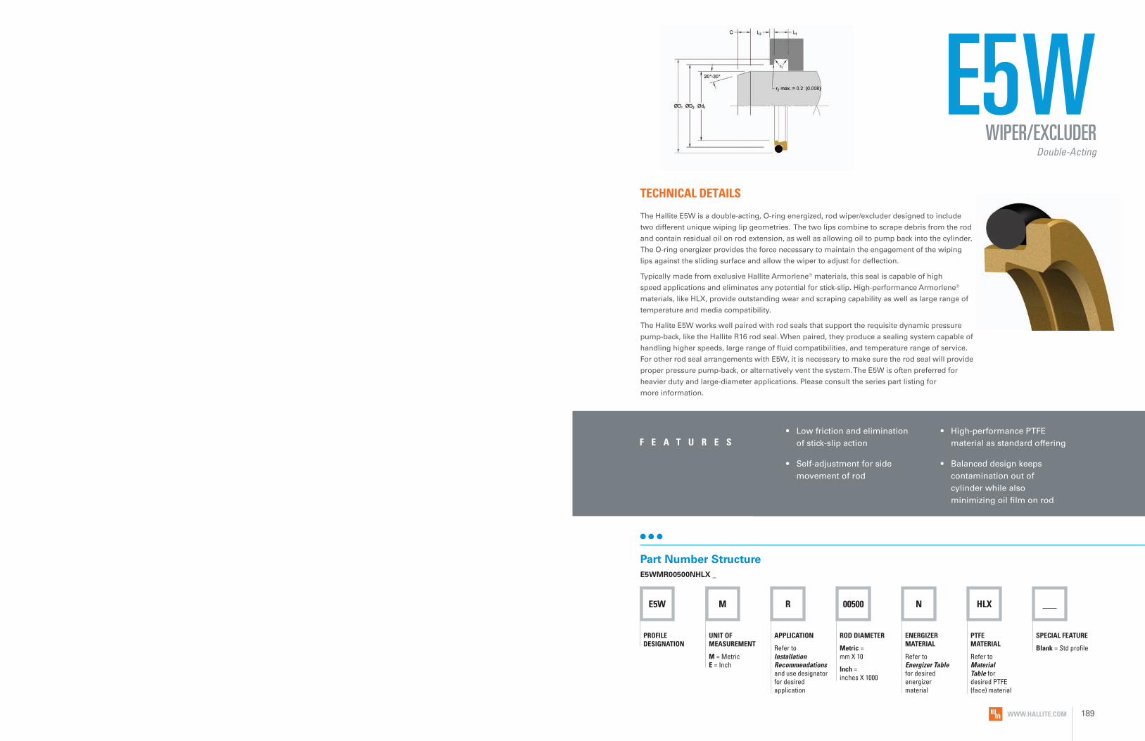
E5W M R 00500 N HLX ___
PROFILE DESIGNATION
UNIT OF MEASUREMENT
M = Metric E = Inch
APPLICATION
Refer to Installation Recommendations and use designator for desired application
ROD DIAMETER
Metric = mm X 10
Inch = inches X 1000
PTFE MATERIAL
Refer to Material Table for desired PTFE (face) material
SPECIAL FEATURE
Blank = Std profile
ENERGIZER MATERIAL
Refer to Energizer Table for desired energizer material
E5W
• Low friction and elimination of stick-slip action
• Self-adjustment for side movement of rod
• High-performance PTFE material as standard offering
• Balanced design keeps contamination out of cylinder while also minimizing oil film on rod
F E A T U R E S
TECHNICAL DETAILS
The Hallite E5W is a double-acting, O-ring energized, rod wiper/excluder designed to include
two different unique wiping lip geometries. The two lips combine to scrape debris from the rod
and contain residual oil on rod extension, as well as allowing oil to pump back into the cylinder.
The O-ring energizer provides the force necessary to maintain the engagement of the wiping
lips against the sliding surface and allow the wiper to adjust for deflection.
Typically made from exclusive Hallite Armorlene® materials, this seal is capable of high
speed applications and eliminates any potential for stick-slip. High-performance Armorlene®
materials, like HLX, provide outstanding wear and scraping capability as well as large range of
temperature and media compatibility.
The Halite E5W works well paired with rod seals that support the requisite dynamic pressure
pump-back, like the Hallite R16 rod seal. When paired, they produce a sealing system capable of
handling higher speeds, large range of fluid compatibilities, and temperature range of service.
For other rod seal arrangements with E5W, it is necessary to make sure the rod seal will provide
proper pressure pump-back, or alternatively vent the system. The E5W is often preferred for
heavier duty and large-diameter applications. Please consult the series part listing for
more information.
Part Number StructureE5WMR00500NHLX _
WIPER/EXCLUDERDouble-Acting
WWW.HALLITE.COM 189

SURFACE FINISH RECOMMENDATIONS
OPERATING CONDITIONS
METRIC INCH
Maximum Speed Up to 15.0m/sec Up to 50.0ft/sec
Temperature Range* -45 to 200°C -49 to 392°F
*Dependent upon energizer used (NBR, FKM, etc.).
ENERGIZER TABLE
*Rmr is measured at a depth of 25% of the Rz value based upon a reference level (zero line) at 5% material/bearing area.
METRIC INCHRmr*
SURFACE ROUGHNESS μmRa μmRz μmRt μinRa μinRz μinRt
Dynamic Sealing Face Ød1 0.05 - 0.2 1.6 max 2 max 2 - 8 63 max 157 max
60% - 90%Static Sealing Face ØD1 and ØD2 1.6 max 6.3 max 10 max 63 max 250 max 394 max
Static Housing Faces L1 3.2 max 10 max 16 max 125 max 394 max 630 max
ENERGIZER MATERIAL (SHORE A)
ENERGIZER TYPE
ENERGIZER DESIGNATION
ENERGIZER OPERATING TEMPERATURE°C
ENERGIZER OPERATING TEMPERATURE°F
NBR - 70A O-ring N -30 to 100°C -22 to 212°F
NBR - 70A Low temp. O-ring L -45 to 80°C -49 to 176°F
FKM - 75A O-ring F -10 to 200°C 14 to 392°F
EPDM - 70A O-ring E -45 to 145°C -49 to 293°F
HNBR - 70A O-ring H -25 to 150°C -13 to 302°F
NBR - 90A O-ring Q -30 to 100°C -22 to 212°F
HNBR - 90A O-ring U -25 to 150°C -13 to 302°F
No Energizer* None X - -
*Seal ratings are based upon capabilities of its matched material components. Hallite cannot rate seal performance when the seal is mixed with other manufacturers’ energizers/components.
Data given are maximum values and can apply depending on specific application. Maximum ratings of temperature, pressure, or operating speeds are dependent on fluid medium, surface, gap value, and other variables such as dynamic or static service. Maximum values are not intended for use together at the same time, e.g. max temperature and max pressure. Please contact your Hallite technical representative for application support.
NO
TEMATERIALS
MATERIAL FEATURES AND APPLICATIONS
FILL
ER
MAT
ERIA
L D
ESIG
NAT
OR
COLO
R
TEM
PERA
TURE
RA
NG
E°C
TEM
PERA
TURE
RA
NG
E°F
ARMORLENE® HLX• Standard material for hydraulic applications• High compressive strength• Excellent extrusion resistance• Extended wear resistance
Special Bronze
CompoundHLX Gold -73 to 288°C -100 to 550°F
ARMORLENE® HCF• Excellent in lubricating and non-lubricating
hydraulic fluids (includes water) w/o zinc content
• Not recommended for gas sealing applications
• Not recommended for electrical conductive fluids
Carbon Fiber Filled HCF Gray/
Black -73 to 260°C -100 to 500°F
ARMORLENE® 702• Excellent in lubricating and non-lubricating
hydraulic fluids• Good low-friction properties• Excellent extrusion resistance• Good chemical resistance
Glass Molybdenum
Disulfide702 Gray -73 to 260°C -100 to 500°F
ARMORLENE® 711• Excellent in all lubricating fluids and
pneumatic applications• High chemical resistance• Excellent extrusion resistance• Excellent wear properties
25% Carbon/Graphite 711 Black -73 to 288°C -100 to 550°F
ARMORLENE® 700• Excellent in all hydraulic fluids• Recommended for use with soft
mating surfaces • Low friction and no stick-slip
Unfilled 700 White -184 to 204°C -300 to 400°F
748 - UHMWPE• Excellent impact resistance• Good dielectrical properties• Excellent abrasion resistance• Low coefficient of friction
Standard 748 Translucent -184 to 82°C -300 to 180°F
HU5 - POLYURETHANE, 55D• Positive position load holding• Excellent extrusion resistance • Excellent wear resistance• Available up to 2540mm (100 INCHes) diameter
Standard HU5 Yellow -20 to 115°C -4 to 240°F
HU9 - POLYURETHANE, 95A• Positive position load holding• Excellent extrusion resistance• Excellent wear resistance• Available up to 2540mm (100 INCHes) diameter
Standard HU9 Red -20 to 115°C -4 to 240°F
For other material options consult the Master Materials Index at the front of the catalog. If you do not find the material that you require, please contact your local Hallite sales office.
E5W
WWW.HALLITE.COM190 WWW.HALLITE.COM 191

METRIC
ROD DIAMETER Ød1 f8/h9
GRO
OVE
DIA
MET
ER
GRO
OVE
WID
TH
BO
RE D
IAM
ETER
STEP
WID
TH
RAD
IUS
CHA
MFE
R
O-R
ING
CR
OSS
SEC
TIO
N
DIAMETER RANGED1 H9 L1 + 0.2 D2 H11 L3 Min r1 C O-ring
Standard Duty Application - R Light Duty Application - L
19.0 - 39.9 40.0 - 69.9 d1 + 7.6 4.2 d1 + 1.5 3.0 0.5 3.0 2.62
40.0 - 69.9 70.0 - 139.9 d1 + 8.8 6.3 d1 + 1.5 3.0 0.8 4.0 2.62
70.0 - 139.9 140.0 - 399.9 d1 + 12.2 8.1 d1 + 2.0 4.0 1.0 6.0 3.53
140.0 - 399.9 400.0 - 649.9 d1 + 16.0 9.5 d1 + 2.5 5.0 1.5 6.0 5.33
400.0 - 649.9 650.0 - 999.9 d1 + 24.0 14.0 d1 + 2.5 8.0 1.5 8.0 6.99
650.0 - 999.9 ≥ 1000.0 d1 + 27.3 16.0 d1 + 2.5 10.0 2.0 9.0 8.40
INCH
ROD DIAMETER Ød1 f8/h9
GRO
OVE
DIA
MET
ER
GRO
OVE
WID
TH
BO
RE D
IAM
ETER
STEP
WID
TH
RAD
IUS
CHA
MFE
R
O-R
ING
CR
OSS
SEC
TIO
N
DIAMETER RANGED1 H9 L1 + .008 D2 H11 L3 Min r1 C O-ringStandard Duty
Application - RLight Duty
Application - LHeavy Duty
Application - H
1.500 - 2.749 2.750 - 5.499 1.188 - 1.499 d1 + 0.346 0.248 d1 + 0.060 0.079 0.015 0.157 0.103
2.750 - 5.499 5.500 - 15.749 1.500 - 2.749 d1 + 0.480 0.319 d1 + 0.080 0.118 0.015 0.236 0.139
5.500 - 7.999 - 2.750 - 5.499 d1 + 0.630 0.374 d1 + 0.100 0.118 0.035 0.236 0.210
8.000 - 15.749 15.750 - 25.500 - d1 + 0.630 0.374 d1 + 0.100 0.150 0.035 0.236 0.210
15.750 - 25.500 - 5.500 - 15.749 d1 + 0.945 0.551 d1 + 0.100 0.150 0.035 0.315 0.275
INSTALLATION RECOMMENDATIONS PART NUMBER RANGE (METRIC)*
20.0 27.6 4.2 21.5 3.0 E5WMR00200****
25.0 32.6 4.2 26.5 3.0 E5WMR00250****
28.0 35.6 4.2 29.5 3.0 E5WMR00280****
30.0 37.6 4.2 31.5 3.0 E5WMR00300****
32.0 39.6 4.2 33.5 3.0 E5WMR00320****
36.0 43.6 4.2 37.5 3.0 E5WMR00360****
40.0 48.8 6.3 41.5 3.0 E5WMR00400****+
42.0 50.8 6.3 43.5 3.0 E5WMR00420****
45.0 53.8 6.3 46.5 3.0 E5WMR00450****+
50.0 58.8 6.3 51.5 3.0 E5WMR00500****+
55.0 63.8 6.3 56.5 3.0 E5WMR00550****
56.0 64.8 6.3 57.5 3.0 E5WMR00560****+
60.0 68.8 6.3 61.5 3.0 E5WMR00600****
63.0 71.8 6.3 64.5 3.0 E5WMR00630****+
65.0 73.8 6.3 66.5 3.0 E5WMR00650****
70.0 78.8 6.3 71.5 3.0 E5WML00700****+
70.0 82.2 8.1 72.0 4.0 E5WMR00700****+
75.0 87.2 8.1 77.0 4.0 E5WMR00750****
80.0 88.8 6.3 81.5 3.0 E5WML00800****+
80.0 92.2 8.1 82.0 4.0 E5WMR00800****+
85.0 97.2 8.1 87.0 4.0 E5WMR00850****
90.0 98.8 6.3 91.5 3.0 E5WML00900****+
90.0 102.2 8.1 92.0 4.0 E5WMR00900****+
97.0 109.2 8.1 99.0 4.0 E5WMR00970****
99.0 111.2 8.1 101.0 4.0 E5WMR00990****
100.0 108.8 6.3 101.5 3.0 E5WML01000****+
100.0 112.2 8.1 102.0 4.0 E5WMR01000****+
110.0 118.8 6.3 111.5 3 E5WML01100****+
110.0 122.2 8.1 112.0 4.0 E5WMR01100****+
115.0 127.2 8.1 117.0 4.0 E5WMR01150****
120.0 132.2 8.1 122.0 4.0 E5WMR01200****
125.0 133.8 6.3 126.5 3.0 E5WML01250****+
125.0 137.2 8.1 127.0 4.0 E5WMR01250****+
125.4 137.6 8.1 127.4 4.0 E5WMR01254****
130.0 142.2 8.1 132.0 4.0 E5WMR01300****
135.0 147.2 8.1 137.0 4.0 E5WMR01350****
140.0 152.2 8.1 142.0 4.0 E5WML01400****+
140.0 156.0 9.5 142.5 5.0 E5WMR01400****+
140.5 156.5 9.5 143.0 5.0 E5WMR01405****
150.0 166.0 9.5 152.5 5.0 E5WMR01500****
153.0 169.0 9.5 155.5 5.0 E5WMR01530****
155.0 171.0 9.5 157.5 5.0 E5WMR01550****
160.0 172.2 8.1 162.0 4.0 E5WML01600****+
160.0 176.0 9.5 162.5 5.0 E5WMR01600****+
165.0 181.0 9.5 167.5 5.0 E5WMR01650****
170.0 186.0 9.5 172.5 5.0 E5WMR01700****
175.0 191.0 9.5 177.5 5.0 E5WMR01750****
180.0 192.2 8.1 182.0 4.0 E5WML01800****+
180.0 196.0 9.5 182.5 5.0 E5WMR01800****+
188.2 204.2 9.5 190.7 5.0 E5WMR01882****
190.0 206.0 9.5 192.5 5.0 E5WMR01900****
192.0 208.0 9.5 194.5 5.0 E5WMR01920****
200.0 212.2 8.1 202.0 4.0 E5WML02000****+
200.0 216.0 9.5 202.5 5.0 E5WMR02000****+
211.0 227.0 9.5 213.5 5 E5WMR02110****
220.0 232.2 8.1 222.0 4 E5WML02200****+
E5WWIPER/EXCLUDER
Double-Acting
+ Fits ISO 6195 Type D grooves.
E5W
METRIC
Ød 1
ØD
1
L 1
ØD
2
STEP
WID
TH
PART
NU
MB
ER
Tol. f8/h9
Tol. H9
Tol. +0.2
Tol. H11
L3 Min
METRIC
Ød 1
ØD
1
L 1
ØD
2
STEP
WID
TH
PART
NU
MB
ER
Tol. f8/h9
Tol. H9
Tol. +0.2
Tol. H11
L3 Min
WWW.HALLITE.COM192 WWW.HALLITE.COM 193
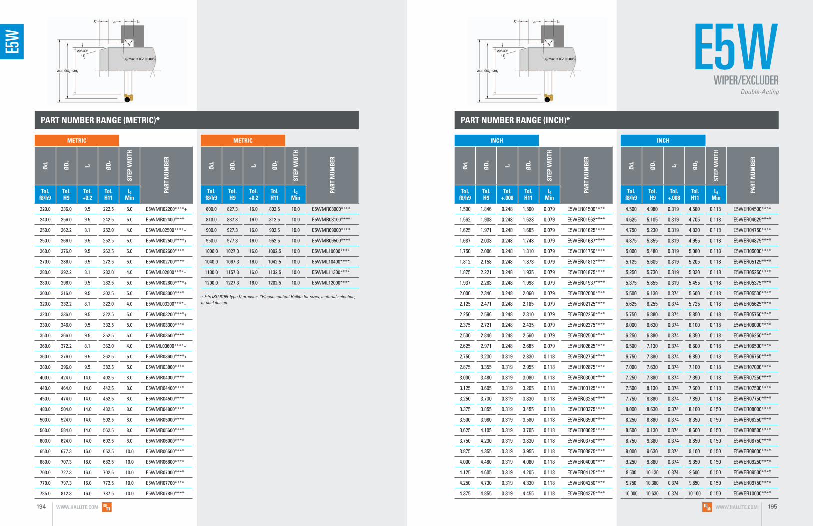
PART NUMBER RANGE (INCH)*
220.0 236.0 9.5 222.5 5.0 E5WMR02200****+
240.0 256.0 9.5 242.5 5.0 E5WMR02400****
250.0 262.2 8.1 252.0 4.0 E5WML02500****+
250.0 266.0 9.5 252.5 5.0 E5WMR02500****+
260.0 276.0 9.5 262.5 5.0 E5WMR02600****
270.0 286.0 9.5 272.5 5.0 E5WMR02700****
280.0 292.2 8.1 282.0 4.0 E5WML02800****+
280.0 296.0 9.5 282.5 5.0 E5WMR02800****+
300.0 316.0 9.5 302.5 5.0 E5WMR03000****
320.0 332.2 8.1 322.0 4.0 E5WML03200****+
320.0 336.0 9.5 322.5 5.0 E5WMR03200****+
330.0 346.0 9.5 332.5 5.0 E5WMR03300****
350.0 366.0 9.5 352.5 5.0 E5WMR03500****
360.0 372.2 8.1 362.0 4.0 E5WML03600****+
360.0 376.0 9.5 362.5 5.0 E5WMR03600****+
380.0 396.0 9.5 382.5 5.0 E5WMR03800****
400.0 424.0 14.0 402.5 8.0 E5WMR04000****
440.0 464.0 14.0 442.5 8.0 E5WMR04400****
450.0 474.0 14.0 452.5 8.0 E5WMR04500****
480.0 504.0 14.0 482.5 8.0 E5WMR04800****
500.0 524.0 14.0 502.5 8.0 E5WMR05000****
560.0 584.0 14.0 562.5 8.0 E5WMR05600****
600.0 624.0 14.0 602.5 8.0 E5WMR06000****
650.0 677.3 16.0 652.5 10.0 E5WMR06500****
680.0 707.3 16.0 682.5 10.0 E5WMR06800****
700.0 727.3 16.0 702.5 10.0 E5WMR07000****
770.0 797.3 16.0 772.5 10.0 E5WMR07700****
785.0 812.3 16.0 787.5 10.0 E5WMR07850****
1.500 1.846 0.248 1.560 0.079 E5WER01500****
1.562 1.908 0.248 1.623 0.079 E5WER01562****
1.625 1.971 0.248 1.685 0.079 E5WER01625****
1.687 2.033 0.248 1.748 0.079 E5WER01687****
1.750 2.096 0.248 1.810 0.079 E5WER01750****
1.812 2.158 0.248 1.873 0.079 E5WER01812****
1.875 2.221 0.248 1.935 0.079 E5WER01875****
1.937 2.283 0.248 1.998 0.079 E5WER01937****
2.000 2.346 0.248 2.060 0.079 E5WER02000****
2.125 2.471 0.248 2.185 0.079 E5WER02125****
2.250 2.596 0.248 2.310 0.079 E5WER02250****
2.375 2.721 0.248 2.435 0.079 E5WER02375****
2.500 2.846 0.248 2.560 0.079 E5WER02500****
2.625 2.971 0.248 2.685 0.079 E5WER02625****
2.750 3.230 0.319 2.830 0.118 E5WER02750****
2.875 3.355 0.319 2.955 0.118 E5WER02875****
3.000 3.480 0.319 3.080 0.118 E5WER03000****
3.125 3.605 0.319 3.205 0.118 E5WER03125****
3.250 3.730 0.319 3.330 0.118 E5WER03250****
3.375 3.855 0.319 3.455 0.118 E5WER03375****
3.500 3.980 0.319 3.580 0.118 E5WER03500****
3.625 4.105 0.319 3.705 0.118 E5WER03625****
3.750 4.230 0.319 3.830 0.118 E5WER03750****
3.875 4.355 0.319 3.955 0.118 E5WER03875****
4.000 4.480 0.319 4.080 0.118 E5WER04000****
4.125 4.605 0.319 4.205 0.118 E5WER04125****
4.250 4.730 0.319 4.330 0.118 E5WER04250****
4.375 4.855 0.319 4.455 0.118 E5WER04375****
4.500 4.980 0.319 4.580 0.118 E5WER04500****
4.625 5.105 0.319 4.705 0.118 E5WER04625****
4.750 5.230 0.319 4.830 0.118 E5WER04750****
4.875 5.355 0.319 4.955 0.118 E5WER04875****
5.000 5.480 0.319 5.080 0.118 E5WER05000****
5.125 5.605 0.319 5.205 0.118 E5WER05125****
5.250 5.730 0.319 5.330 0.118 E5WER05250****
5.375 5.855 0.319 5.455 0.118 E5WER05375****
5.500 6.130 0.374 5.600 0.118 E5WER05500****
5.625 6.255 0.374 5.725 0.118 E5WER05625****
5.750 6.380 0.374 5.850 0.118 E5WER05750****
6.000 6.630 0.374 6.100 0.118 E5WER06000****
6.250 6.880 0.374 6.350 0.118 E5WER06250****
6.500 7.130 0.374 6.600 0.118 E5WER06500****
6.750 7.380 0.374 6.850 0.118 E5WER06750****
7.000 7.630 0.374 7.100 0.118 E5WER07000****
7.250 7.880 0.374 7.350 0.118 E5WER07250****
7.500 8.130 0.374 7.600 0.118 E5WER07500****
7.750 8.380 0.374 7.850 0.118 E5WER07750****
8.000 8.630 0.374 8.100 0.150 E5WER08000****
8.250 8.880 0.374 8.350 0.150 E5WER08250****
8.500 9.130 0.374 8.600 0.150 E5WER08500****
8.750 9.380 0.374 8.850 0.150 E5WER08750****
9.000 9.630 0.374 9.100 0.150 E5WER09000****
9.250 9.880 0.374 9.350 0.150 E5WER09250****
9.500 10.130 0.374 9.600 0.150 E5WER09500****
9.750 10.380 0.374 9.850 0.150 E5WER09750****
10.000 10.630 0.374 10.100 0.150 E5WER10000****
800.0 827.3 16.0 802.5 10.0 E5WMR08000****
810.0 837.3 16.0 812.5 10.0 E5WMR08100****
900.0 927.3 16.0 902.5 10.0 E5WMR09000****
950.0 977.3 16.0 952.5 10.0 E5WMR09500****
1000.0 1027.3 16.0 1002.5 10.0 E5WML10000****
1040.0 1067.3 16.0 1042.5 10.0 E5WML10400****
1130.0 1157.3 16.0 1132.5 10.0 E5WML11300****
1200.0 1227.3 16.0 1202.5 10.0 E5WML12000****
PART NUMBER RANGE (METRIC)*
E5WWIPER/EXCLUDER
Double-Acting
+ Fits ISO 6195 Type D grooves. *Please contact Hallite for sizes, material selection, or seal design.
E5W
INCH
Ød 1
ØD
1
L 1
ØD
2
STEP
WID
TH
PART
NU
MB
ER
Tol. f8/h9
Tol. H9
Tol. +.008
Tol. H11
L3 Min
INCH
Ød 1
ØD
1
L 1
ØD
2
STEP
WID
TH
PART
NU
MB
ER
Tol. f8/h9
Tol. H9
Tol. +.008
Tol. H11
L3 Min
METRIC
Ød 1
ØD
1
L 1
ØD
2
STEP
WID
TH
PART
NU
MB
ER
Tol. f8/h9
Tol. H9
Tol. +0.2
Tol. H11
L3 Min
METRIC
Ød 1
ØD
1
L 1
ØD
2
STEP
WID
TH
PART
NU
MB
ER
Tol. f8/h9
Tol. H9
Tol. +0.2
Tol. H11
L3 Min
WWW.HALLITE.COM194 WWW.HALLITE.COM 195

PART NUMBER RANGE (INCH)*
10.500 11.130 0.374 10.600 0.150 E5WER10500****
11.000 11.630 0.374 11.100 0.150 E5WER11000****
11.500 12.130 0.374 11.600 0.150 E5WER11500****
12.000 12.630 0.374 12.100 0.150 E5WER12000****
12.500 13.130 0.374 12.600 0.150 E5WER12500****
13.000 13.630 0.374 13.100 0.150 E5WER13000****
13.500 14.130 0.374 13.600 0.150 E5WER13500****
14.000 14.630 0.374 14.100 0.150 E5WER14000****
14.500 15.130 0.374 14.600 0.150 E5WER14500****
15.000 15.630 0.374 15.100 0.150 E5WER15000****
15.500 16.130 0.374 15.600 0.150 E5WER15500****
16.000 16.945 0.551 16.100 0.150 E5WER16000****
16.500 17.445 0.551 16.600 0.150 E5WER16500****
17.000 17.945 0.551 17.100 0.150 E5WER17000****
17.500 18.445 0.551 17.600 0.150 E5WER17500****
18.000 18.945 0.551 18.100 0.150 E5WER18000****
18.500 19.445 0.551 18.600 0.150 E5WER18500****
19.000 19.945 0.551 19.100 0.150 E5WER19000****
19.500 20.445 0.551 19.600 0.150 E5WER19500****
20.000 20.945 0.551 20.100 0.150 E5WER20000****
E5W
*Please contact Hallite for custom sizes, material selection, or seal design.
ELA M R 00400 N HLX ___
PROFILE DESIGNATION
UNIT OF MEASUREMENT
M = Metric E = Inch
APPLICATION
Refer to Installation Recommendations and use designator for desired application
ROD DIAMETER
Metric = mm X 10
Inch = inches X 1000
PTFE MATERIAL
Refer to Material Table for desired PTFE (face) material
SPECIAL FEATURE
Blank = Std profile
ENERGIZER MATERIAL
Refer to Energizer Table for desired energizer material
ELATECHNICAL DETAILS
The Hallite ELA rod wiper/excluder uses a single aggressive wiping lip that provides
ingression protection. The ELA wiper uses an O-ring energizer to keep the wiper
centered, helping to compensate for potential side-to-side movement in the
application. Typically made from exclusive Hallite Armorlene® materials, this seal is
capable of high-speed applications and eliminates any potential for stick-slip. The ELA
wiper is a low-friction design, making it an energy-efficient choice. The ELA wiper
follows ISO 6195, Type D dimensions.
Part Number StructureELAMR00400NHLX _
WIPER/EXCLUDERSingle-Acting
• Low friction and elimination of stick-slip
• Excellent in high-speed applications
• More stable design for application with excessive side-to-side movement on rod
F E A T U R E S
INCH
Ød 1
ØD
1
L 1
ØD
2
STEP
WID
TH
PART
NU
MB
ER
Tol. f8/h9
Tol. H9
Tol. +.008
Tol. H11
L3 Min
INCH
Ød 1
ØD
1
L 1
ØD
2
STEP
WID
TH
PART
NU
MB
ER
Tol. f8/h9
Tol. H9
Tol. +.008
Tol. H11
L3 Min
WWW.HALLITE.COM196 WWW.HALLITE.COM 197

SURFACE FINISH RECOMMENDATIONS
OPERATING CONDITIONS
METRIC INCH
Maximum Speed Up to 4.0m/sec Up to 13.0ft/sec
Temperature Range* -45 to 200°C -49 to 392°F
*Dependent upon energizer used (NBR, FKM, etc.).
ELA
ENERGIZER TABLE
*Rmr is measured at a depth of 25% of the Rz value based upon a reference level (zero line) at 5% material/bearing area.
METRIC INCHRmr*
SURFACE ROUGHNESS μmRa μmRz μmRt μinRa μinRz μinRt
Dynamic Sealing Face Ød1 0.05 - 0.2 1.6 max 2 max 2 - 8 63 max 157 max
60% - 90%Static Sealing Face ØD1 and ØD2 1.6 max 6.3 max 10 max 63 max 250 max 394 max
Static Housing Faces L1 3.2 max 10 max 16 max 125 max 394 max 630 max
ENERGIZER MATERIAL (SHORE A)
ENERGIZER TYPE
ENERGIZER DESIGNATION
ENERGIZER OPERATING TEMPERATURE°C
ENERGIZER OPERATING TEMPERATURE°F
NBR - 70A O-ring N -30 to 100°C -22 to 212°F
NBR - 70A Low temp. O-ring L -45 to 80°C -49 to 176°F
FKM - 75A O-ring F -10 to 200°C 14 to 392°F
EPDM - 70A O-ring E -45 to 145°C -49 to 293°F
HNBR - 70A O-ring H -25 to 150°C -13 to 302°F
NBR - 90A O-ring Q -30 to 100°C -22 to 212°F
HNBR - 90A O-ring U -25 to 150°C -13 to 302°F
No Energizer* None X - -
*Seal ratings are based upon capabilities of its matched material components. Hallite cannot rate seal performance when the seal is mixed with other manufacturers’ energizers/components.
Data given are maximum values and can apply depending on specific application. Maximum ratings of temperature, pressure, or operating speeds are dependent on fluid medium, surface, gap value, and other variables such as dynamic or static service. Maximum values are not intended for use together at the same time, e.g. max temperature and max pressure. Please contact your Hallite technical representative for application support.
NO
TEMATERIALS
MATERIAL FEATURES AND APPLICATIONS
FILL
ER
MAT
ERIA
L D
ESIG
NAT
OR
COLO
R
TEM
PERA
TURE
RA
NG
E°C
TEM
PERA
TURE
RA
NG
E°F
ARMORLENE® HLX• Standard material for hydraulic applications• High compressive strength• Excellent extrusion resistance• Extended wear resistance
Special Bronze
CompoundHLX Gold -73 to 288°C -100 to 550°F
ARMORLENE® HCF• Excellent in lubricating and non-lubricating
hydraulic fluids (includes water) w/o zinc content
• Not recommended for gas sealing applications
• Not recommended for electrical conductive fluids
Carbon Fiber Filled HCF Gray/
Black -73 to 260°C -100 to 500°F
ARMORLENE® 702• Excellent in lubricating and non-lubricating
hydraulic fluids• Good low-friction properties• Excellent extrusion resistance• Good chemical resistance
Glass Molybdenum
Disulfide702 Gray -73 to 260°C -100 to 500°F
ARMORLENE® 711• Excellent in all lubricating fluids and
pneumatic applications• High chemical resistance• Excellent extrusion resistance• Excellent wear properties
25% Carbon/Graphite 711 Black -73 to 288°C -100 to 550°F
ARMORLENE® 700• Excellent in all hydraulic fluids• Recommended for use with soft
mating surfaces • Low friction and no stick-slip
Unfilled 700 White -184 to 204°C -300 to 400°F
748 - UHMWPE• Excellent impact resistance• Good dielectrical properties• Excellent abrasion resistance• Low coefficient of friction
Standard 748 Translucent -184 to 82°C -300 to 180°F
HU5 - POLYURETHANE, 55D• Positive position load holding• Excellent extrusion resistance • Excellent wear resistance• Available up to 2540mm (100 inches) diameter
Standard HU5 Yellow -20 to 115°C -4 to 240°F
HU9 - POLYURETHANE, 95A• Positive position load holding• Excellent extrusion resistance• Excellent wear resistance• Available up to 2540mm (100 inches) diameter
Standard HU9 Red -20 to 115°C -4 to 240°F
For other material options consult the Master Materials Index at the front of the catalog. If you do not find the material that you require, please contact your local Hallite sales office.
WWW.HALLITE.COM198 WWW.HALLITE.COM 199

METRIC
ROD DIAMETER Ød1 f8/h9 G
ROO
VE D
IAM
ETER
GRO
OVE
WID
TH
BO
RE D
IAM
ETER
RAD
IUS
CHA
MFE
R
O-R
ING
CR
OSS
SEC
TIO
N
DIAMETER RANGED1 H9 L1 + 0.2 D2 H11 r1 C O-ring
Standard Duty Application - R
6.0 - 11.9 d1 + 4.8 3.7 d1 + 2.7 0.4 3.0 1.78
12.0 - 64.9 d1 + 6.8 5.0 d1 + 3.5 0.4 4.0 2.62
65.0 - 249.9 d1 + 8.8 6.0 d1 + 4.0 0.4 6.0 3.53
250.0 - 419.9 d1 + 12.2 8.4 d1 + 4.5 0.4 8.0 5.33
420.0 - 649.9 d1 + 16.0 11.0 d1 + 5.2 0.4 8.0 6.99
650.0 - 900.0 d1 + 20.0 14.0 d1 + 6.6 0.4 8.0 8.40
INSTALLATION RECOMMENDATIONS
ELA
PART NUMBER RANGE (METRIC)*
4 8.8 3.7 6.7 ELAMR00040****
5 9.8 3.7 7.7 ELAMR00050****
8 12.8 3.7 10.7 ELAMR00080****
10 14.8 3.7 12.7 ELAMR00100****
12 18.8 5.0 15.5 ELAMR00120****
14 20.8 5.0 17.5 ELAMR00140****
15 21.8 5.0 18.5 ELAMR00150****
18 24.8 5.0 21.5 ELAMR00180****
20 26.8 5.0 23.5 ELAMR00200****
24 30.8 5.0 27.5 ELAMR00240****
25 31.8 5.0 28.5 ELAMR00250****
28 34.8 5.0 31.5 ELAMR00280****
30 36.8 5.0 33.5 ELAMR00300****
32 38.8 5.0 35.5 ELAMR00320****
35 41.8 5.0 38.5 ELAMR00350****
38 44.8 5.0 41.5 ELAMR00380****
40 46.8 5.0 43.5 ELAMR00400****
42 48.8 5.0 45.5 ELAMR00420****
45 51.8 5.0 48.5 ELAMR00450****
48 54.8 5.0 51.5 ELAMR00480****
50 56.8 5.0 53.5 ELAMR00500****
55 61.8 5.0 58.5 ELAMR00550****
60 66.8 5.0 63.5 ELAMR00600****
65 73.8 6.0 69.0 ELAMR00650****
70 78.8 6.0 74.0 ELAMR00700****
75 83.8 6.0 79.0 ELAMR00750****
80 88.8 6.0 84.0 ELAMR00800****
85 93.8 6.0 89.0 ELAMR00850****
90 98.8 6.0 94.0 ELAMR00900****
95 103.8 6.0 99.0 ELAMR00950****
100 108.8 6.0 104.0 ELAMR01000****
110 118.8 6.0 114.0 ELAMR01100****
120 128.8 6.0 124.0 ELAMR01200****
125 133.8 6.0 129.0 ELAMR01250****
130 138.8 6.0 134.0 ELAMR01300****
140 148.8 6.0 144.0 ELAMR01400****
150 158.8 6.0 154.0 ELAMR01500****
160 168.8 6.0 164.0 ELAMR01600****
170 178.8 6.0 174.0 ELAMR01700****
175 183.8 6.0 179.0 ELAMR01750****
180 188.8 6.0 184.0 ELAMR01800****
190 198.8 6.0 194.0 ELAMR01900****
195 203.8 6.0 199.0 ELAMR01950****
200 208.8 6.0 204.0 ELAMR02000****
210 218.8 6.0 214.0 ELAMR02100****
220 228.8 6.0 224.0 ELAMR02200****
230 238.8 6.0 234.0 ELAMR02300****
240 248.8 6.0 244.0 ELAMR02400****
250 262.2 8.4 254.5 ELAMR02500****
260 272.2 8.4 264.5 ELAMR02600****
270 282.2 8.4 274.5 ELAMR02700****
280 292.2 8.4 284.5 ELAMR02800****
290 302.2 8.4 294.5 ELAMR02900****
300 312.2 8.4 304.5 ELAMR03000****
310 322.2 8.4 314.5 ELAMR03100****
320 332.2 8.4 324.5 ELAMR03200****
ELAWIPER/EXCLUDER
Single-Acting
METRIC
Ød 1
ØD
1
L 1
ØD
2
PART
NU
MB
ER
Tol. f9/h9
Tol. H9
Tol. +0.2
Tol. H11
METRIC
Ød 1
ØD
1
L 1
ØD
2
PART
NU
MB
ER
Tol. f9/h9
Tol. H9
Tol. +0.2
Tol. H11
WWW.HALLITE.COM200 WWW.HALLITE.COM 201

330 342.2 8.4 334.5 ELAMR03300****
340 352.2 8.4 344.5 ELAMR03400****
350 362.2 8.4 354.5 ELAMR03500****
360 372.2 8.4 364.5 ELAMR03600****
370 382.2 8.4 374.5 ELAMR03700****
380 392.2 8.4 384.5 ELAMR03800****
390 402.2 8.4 394.5 ELAMR03900****
400 412.2 8.4 404.5 ELAMR04000****
410 422.2 8.4 414.5 ELAMR04100****
420 436.0 11.0 425.2 ELAMR04200****
430 446 11.0 435.2 ELAMR04300****
440 456 11.0 445.2 ELAMR04400****
450 466 11.0 455.2 ELAMR04500****
460 476 11.0 465.2 ELAMR04600****
PART NUMBER RANGE (METRIC)*
ELA
470 486 11.0 475.2 ELAMR04700****
480 496 11.0 485.2 ELAMR04800****
490 506 11.0 495.2 ELAMR04900****
500 516 11.0 505.2 ELAMR05000****
520 536 11.0 525.2 ELAMR05200****
550 566 11.0 555.2 ELAMR05500****
570 586 11.0 575.2 ELAMR05700****
600 616 11.0 605.2 ELAMR06000****
620 636 11.0 625.2 ELAMR06200****
640 656 11.0 645.2 ELAMR06400****
650 670 14.0 656.6 ELAMR06500****
700 720 14.0 706.6 ELAMR07000****
800 820 14.0 806.6 ELAMR08000****
900 920 14.0 906.6 ELAMR09000****
*Please contact Hallite for custom sizes, material selection, or seal design.
EXF M R 00400 N HLX
PROFILE DESIGNATION
UNIT OF MEASUREMENT
M = Metric E = Inch
APPLICATION
Refer to Installation Recommendations and use designator for desired application
ROD DIAMETER
Metric = mm X 10
Inch = inches X 1000
PTFE MATERIAL
Refer to Material Table for desired PTFE (face) material
SPECIAL FEATURE
Blank = Std profile
ENERGIZER MATERIAL
Refer to Energizer Table for desired energizer material
___
EXF
• Low friction and elimination of stick-slip
• Excellent in high-speed applications
• More stable design for application with excessive side-to-side movement on rod
• Balanced design keeps contamination out of cylinder while also minimizing oil film on rod
F E A T U R E S
TECHNICAL DETAILS
The Hallite EXF is a double-acting, twin O-ring energized, rod wiper designed to include two
different unique wiping geometries. The two lips combine to scrape debris from the rod and
contain residual oil on rod extension, as well as allowing oil to pump back into the cylinder. The
O-ring energizers provide the force necessary to maintain the engagement of the wiping lips
against the sliding surface and allow the wiper to adjust for deflection.
Typically made from exclusive Hallite Armorlene® materials, this seal is capable of high speed
applications and eliminates any potential for stick-slip. High-performance Armorlene® materials,
like HLX, provide outstanding wear and scraping capability as well as large range of temperature
and media compatibility.
The Halite EXF works well paired with rod seals that support the requisite dynamic pressure
pump-back, like the Hallite R16 rod seal. When paired, they produce a sealing system capable of
handling higher speeds, a large range of fluid compatibilities, and temperature range of service.
For other rod seal arrangements with EXF, it is necessary to make sure the rod seal will provide
proper pressure pump-back, or alternatively vent the system. The Hallite wipers/excluder series
EXF is built to service moderate to slightly heavy-duty applications. It has the advantages of
improved sealing function due to its twin energizer arrangement. Though it is easier to install in
the groove, care must be taken to ensure it is not installed backwards and to ensure the proper fit
of three individual components.
Part Number StructureEXFMR00400NHLX _
WIPER/EXCLUDERDouble-Acting
METRIC
Ød 1
ØD
1
L 1
ØD
2
PART
NU
MB
ER
Tol. f9/h9
Tol. H9
Tol. +0.2
Tol. H11
METRIC
Ød 1
ØD
1
L 1
ØD
2
PART
NU
MB
ER
Tol. f9/h9
Tol. H9
Tol. +0.2
Tol. H11
WWW.HALLITE.COM202 WWW.HALLITE.COM 203

SURFACE FINISH RECOMMENDATIONS
OPERATING CONDITIONS
METRIC INCH
Maximum Speed Up to 15.0m/sec Up to 50.0ft/sec
Temperature Range* -45 to 200°C -49 to 392°F
*Dependent upon energizer used (NBR, FKM, etc.).
EXF
ENERGIZER TABLE
*Rmr is measured at a depth of 25% of the Rz value based upon a reference level (zero line) at 5% material/bearing area.
METRIC INCHRmr*
SURFACE ROUGHNESS μmRa μmRz μmRt μinRa μinRz μinRt
Dynamic Sealing Face Ød1 0.05 - 0.2 1.6 max 2 max 2 - 8 63 max 157 max
60% - 90%Static Sealing Face ØD1 and ØD2 1.6 max 6.3 max 10 max 63 max 250 max 394 max
Static Housing Faces L1 3.2 max 10 max 16 max 125 max 394 max 630 max
ENERGIZER MATERIAL (SHORE A)
ENERGIZER TYPE
ENERGIZER DESIGNATION
ENERGIZER OPERATING TEMPERATURE°C
ENERGIZER OPERATING TEMPERATURE°F
NBR - 70A O-ring N -30 to 100°C -22 to 212°F
NBR - 70A Low temp. O-ring L -45 to 80°C -49 to 176°F
FKM - 75A O-ring F -10 to 200°C 14 to 392°F
EPDM - 70A O-ring E -45 to 145°C -49 to 293°F
HNBR - 70A O-ring H -25 to 150°C -13 to 302°F
NBR - 90A O-ring Q -30 to 100°C -22 to 212°F
HNBR - 90A O-ring U -25 to 150°C -13 to 302°F
No Energizer* None X - -
*Seal ratings are based upon capabilities of its matched material components. Hallite cannot rate seal performance when the seal is mixed with other manufacturers’ energizers/components.
Data given are maximum values and can apply depending on specific application. Maximum ratings of temperature, pressure, or operating speeds are dependent on fluid medium, surface, gap value, and other variables such as dynamic or static service. Maximum values are not intended for use together at the same time, e.g. max temperature and max pressure. Please contact your Hallite technical representative for application support.
NO
TEMATERIALS
MATERIAL FEATURES AND APPLICATIONS
FILL
ER
MAT
ERIA
L D
ESIG
NAT
OR
COLO
R
TEM
PERA
TURE
RA
NG
E°C
TEM
PERA
TURE
RA
NG
E°F
ARMORLENE® HLX• Standard material for hydraulic applications• High compressive strength• Excellent extrusion resistance• Extended wear resistance
Special Bronze
CompoundHLX Gold -73 to 288°C -100 to 550°F
ARMORLENE® HCF• Excellent in lubricating and non-lubricating
hydraulic fluids (includes water) w/o zinc content
• Not recommended for gas sealing applications
• Not recommended for electrical conductive fluids
Carbon Fiber Filled HCF Gray/
Black -73 to 260°C -100 to 500°F
ARMORLENE® 702• Excellent in lubricating and non-lubricating
hydraulic fluids• Good low-friction properties• Excellent extrusion resistance• Good chemical resistance
Glass Molybdenum
Disulfide702 Gray -73 to 260°C -100 to 500°F
ARMORLENE® 711• Excellent in all lubricating fluids and
pneumatic applications• High chemical resistance• Excellent extrusion resistance• Excellent wear properties
25% Carbon/Graphite 711 Black -73 to 288°C -100 to 550°F
ARMORLENE® 700• Excellent in all hydraulic fluids• Recommended for use with soft
mating surfaces • Low friction and no stick-slip
Unfilled 700 White -184 to 204°C -300 to 400°F
748 - UHMWPE• Excellent impact resistance• Good dielectrical properties• Excellent abrasion resistance• Low coefficient of friction
Standard 748 Translucent -184 to 82°C -300 to 180°F
HU5 - POLYURETHANE, 55D• Positive position load holding• Excellent extrusion resistance • Excellent wear resistance• Available up to 2540mm (100 inches) diameter
Standard HU5 Yellow -20 to 115°C -4 to 240°F
HU9 - POLYURETHANE, 95A• Positive position load holding• Excellent extrusion resistance• Excellent wear resistance• Available up to 2540mm (100 inches) diameter
Standard HU9 Red -20 to 115°C -4 to 240°F
For other material options consult the Master Materials Index at the front of the catalog. If you do not find the material that you require, please contact your local Hallite sales office.
WWW.HALLITE.COM204 WWW.HALLITE.COM 205

METRIC
ROD DIAMETER Ød1 f8/h9
GRO
OVE
DIA
MET
ER
GRO
OVE
WID
TH
BO
RE D
IAM
ETER
STEP
WID
TH
RAD
IUS
CHA
MFE
R
O-R
ING
CR
OSS
SEC
TIO
N
DIAMETER RANGED1 H9 L1 + 0.2 D2 H11 L3 min r1 C O-ring
Standard Duty Application - R Light Duty Application - L
19.0 - 39.9 40.0 - 69.9 d1 + 7.6 4.2 d1 + 1.0 3.0 0.4 3.0 1.78
40.0 - 69.9 70.0 - 139.9 d1 + 8.8 6.3 d1 + 1.5 3.0 1.0 4.0 2.62
70.0 - 139.9 140.0 - 399.9 d1 + 12.2 8.1 d1 + 2.0 4.0 1.2 6.0 3.53
140.0 - 399.9 400.0 - 649.9 d1 + 16.0 11.5 d1 + 2.0 5.0 2.0 8.0 5.33
400.0 - 649.9 650.0 - 999.9 d1 + 24.0 15.5 d1 + 2.5 8.0 2.5 8.0 6.99
650.0 - 999.9 ≥ 1000.0 d1 + 27.3 18.0 d1 + 2.5 10.0 2.5 11.0 8.40
INSTALLATION RECOMMENDATIONS
EXF
PART NUMBER RANGE (METRIC)*
20.0 27.6 4.2 21.0 3.0 EXFMR00200****
25.0 32.6 4.2 26.0 3.0 EXFMR00250****
28.0 35.6 4.2 29.0 3.0 EXFMR00280****
30.0 37.6 4.2 31.0 3.0 EXFMR00300****
32.0 39.6 4.2 33.0 3.0 EXFMR00320****
35.0 42.6 4.2 36.0 3.0 EXFMR00350****
36.0 43.6 4.2 37.0 3.0 EXFMR00360****
40.0 48.8 6.3 41.5 3.0 EXFMR00400****+
42.0 50.8 6.3 43.5 3.0 EXFMR00420****
45.0 53.8 6.3 46.5 3.0 EXFMR00450****+
50.0 58.8 6.3 51.5 3.0 EXFMR00500****
55.0 63.8 6.3 56.5 3.0 EXFMR00550****
56.0 64.8 6.3 57.5 3.0 EXFMR00560****
60.0 68.8 6.3 61.5 3.0 EXFMR00600****
63.0 71.8 6.3 64.5 3.0 EXFMR00630****+
65.0 73.8 6.3 66.5 3.0 EXFMR00650****
70.0 82.2 8.1 72.0 4.0 EXFMR00700****+
75.0 87.2 8.1 77.0 4.0 EXFMR00750****
80.0 92.2 8.1 82.0 4.0 EXFMR00800****+
85.0 97.2 8.1 87.0 4.0 EXFMR00850****
90.0 102.2 8.1 92.0 4.0 EXFMR00900****+
100.0 112.2 8.1 102.0 4.0 EXFMR01000****
105.0 117.2 8.1 107.0 4.0 EXFMR01050****
110.0 122.2 8.1 112.0 4.0 EXFMR01100****+
115.0 127.2 8.1 117.0 4.0 EXFMR01150****
120.0 132.2 8.1 122.0 4.0 EXFMR01200****
125.0 137.2 8.1 127.0 4.0 EXFMR01250****+
130.0 142.2 8.1 132.0 4.0 EXFMR01300****
135.0 147.2 8.1 137.0 4.0 EXFMR01350****
140.0 156.0 11.5 142.0 5.0 EXFMR01400****
145.0 161.0 11.5 147.0 5.0 EXFMR01450****
150.0 166.0 11.5 152.0 5.0 EXFMR01500****
155.0 171.0 11.5 157.0 5.0 EXFMR01550****
160.0 176.0 11.5 162.0 5.0 EXFMR01600****+
165.0 181.0 11.5 167.0 5.0 EXFMR01650****
170.0 186.0 11.5 172.0 5.0 EXFMR01700****
175.0 191.0 11.5 177.0 5.0 EXFMR01750****
180.0 196.0 11.5 182.0 5.0 EXFMR01800****
190.0 206.0 11.5 192.0 5.0 EXFMR01900****
200.0 216.0 11.5 202.0 5.0 EXFMR02000****+
210.0 226.0 11.5 212.0 5.0 EXFMR02100****
220.0 236.0 11.5 222.0 5.0 EXFMR02200****
230.0 246.0 11.5 232.0 5.0 EXFMR02300****
240.0 256.0 11.5 242.0 5.0 EXFMR02400****
245.0 261.0 11.5 247.0 5.0 EXFMR02450****
250.0 266.0 11.5 252.0 5.0 EXFMR02500****+
260.0 276.0 11.5 262.0 5.0 EXFMR02600****
265.0 281.0 11.5 267.0 5.0 EXFMR02650****
280.0 296.0 11.5 282.0 5.0 EXFMR02800****+
290.0 306.0 11.5 292.0 5.0 EXFMR02900****
300.0 316.0 11.5 302.0 5.0 EXFMR03000****
310.0 326.0 11.5 312.0 5.0 EXFMR03100****
320.0 336.0 11.5 322.0 5.0 EXFMR03200****+
330.0 346.0 11.5 332.0 5.0 EXFMR03300****
340.0 356.0 11.5 342.0 5.0 EXFMR03400****
350.0 366.0 11.5 352.0 5.0 EXFMR03500****
EXFWIPER/EXCLUDER
Double-Acting
+Fits ISO 6195 Type D Grooves
METRIC
Ød 1
ØD
1
L 1
ØD
2
STEP
WID
TH
PART
NU
MB
ER
Tol. f8/h9
Tol. H9
Tol. +0.2
Tol. H11
L3 Min
METRIC
ØD
1
ØD
1
L 1
ØD
2
STEP
WID
TH
PART
NU
MB
ER
Tol. f8/h9
Tol. H9
Tol. +0.2
Tol. H11
L3 Min
WWW.HALLITE.COM206 WWW.HALLITE.COM 207

355.0 371.0 11.5 357.0 5.0 EXFMR03550****
360.0 376.0 11.5 362.0 5.0 EXFMR03600****+
365.0 381.0 11.5 367.0 5.0 EXFMR03650****
370.0 386.0 11.5 372.0 5.0 EXFMR03700****
375.0 391.0 11.5 377.0 5.0 EXFMR03750****
380.0 396.0 11.5 382.0 5.0 EXFMR03800****
390.0 406.0 11.5 392.0 5.0 EXFMR03900****
400.0 416.0 11.5 402.0 5.0 EXFML04000****
400.0 424.0 15.5 402.5 8.0 EXFMR04000****
410.0 434.0 15.5 412.5 8.0 EXFMR04100****
420.0 444.0 15.5 422.5 8.0 EXFMR04200****
430.0 454.0 15.5 432.5 8.0 EXFMR04300****
440.0 464.0 15.5 442.5 8.0 EXFMR04400****
445.0 469.0 15.5 447.5 8.0 EXFMR04450****
450.0 474.0 15.5 452.5 8.0 EXFMR04500****
460.0 484.0 15.5 462.5 8.0 EXFMR04600****
465.0 489.0 15.5 467.5 8.0 EXFMR04650****
470.0 494.0 15.5 472.5 8.0 EXFMR04700****
475.0 499.0 15.5 477.5 8.0 EXFMR04750****
PART NUMBER RANGE (METRIC)*
495.0 519.0 15.5 497.5 8.0 EXFMR04950****
510.0 534.0 15.5 512.5 8.0 EXFMR05100****
520.0 544.0 15.5 522.5 8.0 EXFMR05200****
525.0 549.0 15.5 527.5 8.0 EXFMR05250****
530.0 554.0 15.5 532.5 8.0 EXFMR05300****
540.0 564.0 15.5 542.5 8.0 EXFMR05400****
570.0 594.0 15.5 572.5 8.0 EXFMR05700****
585.0 609.0 15.5 587.5 8.0 EXFMR05850****
590.0 614.0 15.5 592.5 8.0 EXFMR05900****
600.0 624.0 15.5 602.5 8.0 EXFMR06000****
620.0 644.0 15.5 622.5 8.0 EXFMR06200****
635.0 659.0 15.5 637.5 8.0 EXFMR06350****
675.0 702.3 18.0 677.5 10.0 EXFMR06750****
690.0 717.3 18.0 692.5 10.0 EXFMR06900****
745.0 772.3 18.0 747.5 10.0 EXFMR07450****
800.0 827.3 18.0 802.5 10.0 EXFMR08000****
815.0 842.3 18.0 817.5 10.0 EXFMR08150****
900.0 927.3 18.0 902.5 10.0 EXFMR09000****
910.0 937.3 18.0 912.5 10.0 EXFMR09100****
EXF
+Fits ISO 6195 Type D Grooves *Please contact Hallite for custom sizes, material selection, or seal design.
EXG M R 00400 N HLX ___
PROFILE DESIGNATION
UNIT OF MEASUREMENT
M = Metric E = Inch
APPLICATION
Refer to Installation Recommendations and use designator for desired application
ROD DIAMETER
Metric = mm X 10
Inch = inches X 1000
PTFE MATERIAL
Refer to Material Table for desired PTFE (face) material
SPECIAL FEATURE
Blank = Std profile
ENERGIZER MATERIAL
Refer to Energizer Table for desired energizer material
r1
L1
ØD1 ØD2 Ød1
L3C
20°-30°r2 max. = 0.2
.5 X 45°
EXG
• Low friction and elimination of stick-slip
• Excellent in high-speed applications
• More stable design for application with excessive side-to-side movement on rod
• Balanced design keeps contamination out of cylinder while also minimizing oil film on rod
F E A T U R E S
TECHNICAL DETAILS
The Hallite EXG is a double-acting, two O-ring energized, rod wiper/excluder designed to
include two different unique wiping lip geometries. The EXG wiper is primarily designed
for environments with heavy contamination, particularly when the rod is facing upwards.
The two wiping lips combine to scrape debris from the rod and contain residual oil on rod
extension. Hallite’s innovative Umbrella® wiper technology is designed to eliminate debris
buildup from in front of the primary wiping lip by forcing it to flow to the outer diameter of
the cylinder away from the rod. The EXG design requires two O-ring energizers; one O-ring
energizer provides downward force to maintain the engagement of the inner wiping lip, while
the other O-ring provides the necessary force and static sealing of the primary wiping lip area
to the sliding surface.
Typically made from exclusive Hallite Armorlene® materials, this seal is capable of high-
speed applications and eliminates any potential for stick-slip. High-performance Armorlene®
materials, like HLX, provide outstanding wear and scraping capability as well as large range
of temperature and media compatibility. The Halite EXG wiper employs the same basic
principles of design function as the Hallite E2W, E5W, and EXF, though the EXG wiper may
require a gland drain to properly relieve pressure between the wiper and rod seal.
Part Number StructureEXGMR00400NHLX _
WIPER/EXCLUDERDouble-Acting
METRIC
Ød 1
ØD
1
L 1
ØD
2
STEP
WID
TH
PART
NU
MB
ER
Tol. f8/h9
Tol. H9
Tol. +0.2
Tol. H11
L3 Min
METRIC
ØD
1
ØD
1
L 1
ØD
2
STEP
WID
TH
PART
NU
MB
ER
Tol. f8/h9
Tol. H9
Tol. +0.2
Tol. H11
L3 Min
WWW.HALLITE.COM208 WWW.HALLITE.COM 209

SURFACE FINISH RECOMMENDATIONS
OPERATING CONDITIONS
METRIC INCH
Maximum Speed Up to 5.0m/sec Up to 16.4ft/sec
Temperature Range* -45 to 200°C -49 to 392°F
*Dependent upon energizer used (NBR, FKM, etc.).
EXG
ENERGIZER TABLE
*Rmr is measured at a depth of 25% of the Rz value based upon a reference level (zero line) at 5% material/bearing area.
METRIC INCHRmr*
SURFACE ROUGHNESS μmRa μmRz μmRt μinRa μinRz μinRt
Dynamic Sealing Face Ød1 0.05 - 0.2 1.6 max 2 max 2 - 8 63 max 157 max
60% - 90%Static Sealing Face ØD1 and ØD2 1.6 max 6.3 max 10 max 63 max 250 max 394 max
Static Housing Faces L1 3.2 max 10 max 16 max 125 max 394 max 630 max
ENERGIZER MATERIAL (SHORE A)
ENERGIZER TYPE
ENERGIZER DESIGNATION
ENERGIZER OPERATING TEMPERATURE°C
ENERGIZER OPERATING TEMPERATURE°F
NBR - 70A O-ring N -30 to 100°C -22 to 212°F
NBR - 70A Low temp. O-ring L -45 to 80°C -49 to 176°F
FKM - 75A O-ring F -10 to 200°C 14 to 392°F
EPDM - 70A O-ring E -45 to 145°C -49 to 293°F
HNBR - 70A O-ring H -25 to 150°C -13 to 302°F
NBR - 90A O-ring Q -30 to 100°C -22 to 212°F
HNBR - 90A O-ring U -25 to 150°C -13 to 302°F
No Energizer* None X - -
*Seal ratings are based upon capabilities of its matched material components. Hallite cannot rate seal performance when the seal is mixed with other manufacturers’ energizers/components.
Data given are maximum values and can apply depending on specific application. Maximum ratings of temperature, pressure, or operating speeds are dependent on fluid medium, surface, gap value, and other variables such as dynamic or static service. Maximum values are not intended for use together at the same time, e.g. max temperature and max pressure. Please contact your Hallite technical representative for application support.
NO
TEMATERIALS
MATERIAL FEATURES AND APPLICATIONS
FILL
ER
MAT
ERIA
L D
ESIG
NAT
OR
COLO
R
TEM
PERA
TURE
RA
NG
E°C
TEM
PERA
TURE
RA
NG
E°F
ARMORLENE® HLX• Standard material for hydraulic applications• High compressive strength• Excellent extrusion resistance• Extended wear resistance
Special Bronze
CompoundHLX Gold -73 to 288°C -100 to 550°F
ARMORLENE® HCF• Excellent in lubricating and non-lubricating
hydraulic fluids (includes water) w/o zinc content
• Not recommended for gas sealing applications
• Not recommended for electrical conductive fluids
Carbon Fiber Filled HCF Gray/
Black -73 to 260°C -100 to 500°F
ARMORLENE® 702• Excellent in lubricating and non-lubricating
hydraulic fluids• Good low-friction properties• Excellent extrusion resistance• Good chemical resistance
Glass Molybdenum
Disulfide702 Gray -73 to 260°C -100 to 500°F
ARMORLENE® 711• Excellent in all lubricating fluids and
pneumatic applications• High chemical resistance• Excellent extrusion resistance• Excellent wear properties
25% Carbon/Graphite 711 Black -73 to 288°C -100 to 550°F
ARMORLENE® 700• Excellent in all hydraulic fluids• Recommended for use with soft
mating surfaces • Low friction and no stick-slip
Unfilled 700 White -184 to 204°C -300 to 400°F
748 - UHMWPE• Excellent impact resistance• Good dielectrical properties• Excellent abrasion resistance• Low coefficient of friction
Standard 748 Translucent -184 to 82°C -300 to 180°F
HU5 - POLYURETHANE, 55D• Positive position load holding• Excellent extrusion resistance • Excellent wear resistance• Available up to 2540mm (100 inches) diameter
Standard HU5 Yellow -20 to 115°C -4 to 240°F
HU9 - POLYURETHANE, 95A• Positive position load holding• Excellent extrusion resistance• Excellent wear resistance• Available up to 2540mm (100 inches) diameter
Standard HU9 Red -20 to 115°C -4 to 240°F
For other material options consult the Master Materials Index at the front of the catalog. If you do not find the material that you require, please contact your local Hallite sales office.
WWW.HALLITE.COM210 WWW.HALLITE.COM 211

METRIC
ROD DIAMETER Ød1 f8/h9 G
ROO
VE D
IAM
ETER
GRO
OVE
WID
TH
BO
RE D
IAM
ETER
STEP
WID
TH
RAD
IUS
CHA
MFE
R
O-R
ING
CR
OSS
SEC
TIO
N
O-R
ING
2
CRO
SS S
ECTI
ON
DIAMETER RANGEØD1 H8 L1 + 0.2 D2 H8 L3
+0-0.1 r1 C O-ring O-ringStandard Duty Application - R Extended Range - L
120.0 - 229.9 230.0 - 299.9 d1 + 22.2 6.3 d1 + 10.7 4.2 1.2 4.0 5.33 3.53
230.0 - 299.9 300.0 - 629.9 d1 + 24.2 6.3 d1 + 10.7 4.2 1.2 4.0 5.33 3.53
300.0 - 629.9 630.0 - 999.9 d1 + 33.0 8.1 d1 + 15.1 6.3 1.2 6.0 6.99 5.33
630.0 - 999.9 ≥ 1000.0 d1 + 36.5 9.5 d1 + 15.1 6.3 2.0 6.0 8.40 5.33
INSTALLATION RECOMMENDATIONS
EXG
SWIV
EL SE
ALS
WWW.HALLITE.COM212

SSP M R 00550 N 711 ___
PROFILE DESIGNATION
UNIT OF MEASUREMENT
M = Metric E = Inch
APPLICATION
Refer to Installation Recommendations and use designator for desired application
BORE DIAMETER
Metric = mm X 10
Inch = inches X 1000
PTFE MATERIAL
Refer to Material Table for desired PTFE (face) material
SPECIAL FEATURE
Blank = Std profile (with notches) X = No notches
ENERGIZER MATERIAL
Refer to Energizer Table for desired energizer material
SSP
• High temperature rating, low-friction and wear- resistant face-ring
• Good anti-extrusion resistance
• Compact groove design suitable for narrow spacingF E A T U R E S
TECHNICAL DETAILS
The Hallite SSP is a double-acting, O-ring energized, rotary swivel seal designed to be used
to seal outer diameters of shafts, bores, swivels, and other applications with rotating or
oscillating movement. The SSP rotary seal has one or two machined grooves in the face ring,
depending on the face-ring cross-section, that function to improve sealing against the surface
while trapping lubrication and reducing surface contact area, thereby reducing running
friction. The O-ring serves to energize the seal face ring, exerting a designed downward force,
and also provides static sealing of the housing.
Hallite’s SSP rotary seal has a specially designed circular inner recess that provides for
maximum O-ring contact area to the inner diameter of the seal face, thereby minimizing the
possibility of sealing components spinning relative to each other. The standard SSP seal face
includes pressure notches, which makes the seal very responsive to changes in pressure.
Made from exclusive Hallite Armorlene® 711 or HCF PTFE materials, the SSP rotary seal is
energy-efficient due to its low-friction qualities and eliminates any potential sticking
on start-up.
High-performance Armorlene® materials, like 711, provide outstanding wear resistance and
support a large range of temperature and media compatibilities. The Armorlene® SSP and
SSR rotary swivel seals are designed for slow-speed rotary and swivel applications.
Part Number StructureSSPMR00550N711 _
SWIVEL SEALOD Sealing
WWW.HALLITE.COM 215

MATERIALS
SURFACE FINISH RECOMMENDATIONS
OPERATING CONDITIONS
METRIC INCH
Maximum Speed Up to 2.0m/sec Up to 6.5ft/sec
Temperature Range* -45 to 200°C -49 to 392°F
Maximum Dynamic Pressure** 300 bar 4350 psi
*Dependent upon energizer used (NBR, FKM, etc.). **For pressures above 300 bar (4350 psi), contact Hallite Engineering. Application limit PV ≤ 25 bar m/s (40 bar m/s for interrupted rotary).
SSP
*Rmr is measured at a depth of 25% of the Rz value based upon a reference level (zero line) at 5% material/bearing area.
METRIC INCHRmr*
SURFACE ROUGHNESS μmRa μmRz μmRt μinRa μinRz μinRt
Dynamic Sealing Face ØD1 0.05 - 0.2 1.6 max 2 max 2 - 8 63 max 157 max
60% - 90%Static Sealing Face Ød1 1.6 max 6.3 max 10 max 63 max 250 max 394 max
Static Housing Faces L1 3.2 max 10 max 16 max 125 max 394 max 630 max
ENERGIZER TABLE
ENERGIZER MATERIAL (SHORE A)
ENERGIZER TYPE
ENERGIZER DESIGNATION
ENERGIZER OPERATING TEMPERATURE°C
ENERGIZER OPERATING TEMPERATURE°F
NBR - 70A O-ring N -30 to 100°C -22 to 212°F
NBR - 70A Low temp. O-ring L -45 to 80°C -49 to 176°F
FKM - 75A O-ring F -10 to 200°C 14 to 392°F
EPDM - 70A O-ring E -45 to 145°C -49 to 293°F
HNBR - 70A O-ring H -25 to 150°C -13 to 302°F
NBR - 90A O-ring Q -30 to 100°C -22 to 212°F
HNBR - 90A O-ring U -25 to 150°C -13 to 302°F
No Energizer* None X - -
*Seal ratings are based upon capabilities of its matched material components. Hallite cannot rate seal performance when the seal is mixed with other manufacturers’ energizers/components.
Data given are maximum values and can apply depending on specific application. Maximum ratings of temperature, pressure, or operating speeds are dependent on fluid medium, surface, gap value, and other variables such as dynamic or static service. Maximum values are not intended for use together at the same time, e.g. max temperature and max pressure. Please contact your Hallite technical representative for application support.
NO
TE
MATERIAL FEATURES AND APPLICATIONS
FILL
ER
MAT
ERIA
L D
ESIG
NAT
OR
COLO
R
TEM
PERA
TURE
RA
NG
E°C
TEM
PERA
TURE
RA
NG
E°F
MA
XIM
UM
DYN
AM
IC
PRES
SURE
- B
AR
MA
XIM
UM
DYN
AM
IC
PRES
SURE
- PS
I
ARMORLENE® 711• Excellent in all lubricating fluids and
pneumatic applications• High chemical resistance• Excellent extrusion resistance• Excellent wear properties
25% Carbon/Graphite 711 Black -73 to 288°C -100 to 550°F 300 bar 4350 psi
ARMORLENE® HCF• Excellent in lubricating and non-lubricating
hydraulic fluids (includes water) w/o zinc content
• Not recommended for gas sealing applications
• Not recommended for electrical conductive fluids
Carbon Fiber Filled HCF Gray/
Black -73 to 260°C -100 to 500°F 300 bar 4350 psi
ARMORLENE® HCV• Recommended for lubricating and
non-lubricating fluids• Excellent for high-frequency and
short-stroke applications• Not recommended for gas
sealing applications• Not recommended for electrical
conductive fluids
High Carbon Fiber Filled HCV Gray/
Black -73 to 260°C -100 to 500°F 300 bar 4350 psi
For other material options consult the Master Materials Index at the front of the catalog. If you do not find the material that you require, please contact your local Hallite sales office.
WWW.HALLITE.COM216 WWW.HALLITE.COM 217

INSTALLATION RECOMMENDATIONS
METRIC
BORE DIAMETER ØD1 H9G
ROO
VE D
IAM
ETER
GRO
OVE
WID
TH
RAD
IUS
CHA
MFE
R
GRO
OVE
SEC
TIO
N
RAD
IAL
CLEA
RAN
CE
G m
ax*
NU
MB
ER O
F G
ROO
VES
DIAMETER RANGE Ød1 h9 L1 + 0.2 r1 C S Up to
300 barStandard Duty Application - R
Light Duty Application - L
8.0 - 39.9 40.0 - 79.9 D1 - 4.9 2.2 0.4 2.5 2.45 Tol H8/f7 0
40.0 - 79.9 80.0 - 132.9 D1 - 7.5 3.2 0.6 3.5 3.75 Tol H8/f7 1
80.0 - 132.9 133.0 - 329.9 D1 - 11.0 4.2 1.0 4.0 5.50 Tol H8/f7 1
133.0 - 329.9 330.0 - 649.9 D1 - 15.5 6.3 1.3 6.0 7.75 Tol H8/f7 2
330.0 - 649.9 650.0 - 999.9 D1 - 21.0 8.1 1.8 8.0 10.50 Tol H8/f7 2
650.0 - 999.9 - D1 - 28.0 9.5 2.5 10.0 14.00 Tol H8/f7 2
At pressure >300 bar or greater contact Hallite Engineering. *Radial Clearance G max. = maximum permissible gap all on one side using max. tube diameter and min. clearance diameter.
INCH
BORE DIAMETER ØD1 H9
GRO
OVE
DIA
MET
ER
GRO
OVE
WID
TH
RAD
IUS
CHA
MFE
R
GRO
OVE
SEC
TIO
N
RAD
IAL
CLEA
RAN
CE
G m
ax*
NU
MB
ER O
F G
ROO
VES
DIAMETER RANGE Ød1 h9 L1 + .008 r1 C S Up to
4350 psiStandard Duty Application - R
Light Duty Application - L
0.375 - 1.499 1.500 - 2.999 D1 - 0.193 0.087 0.015 0.100 0.096 Tol H8/f7 0
1.500 - 2.999 3.000 - 5.999 D1 - 0.295 0.126 0.015 0.125 0.147 Tol H8/f7 1
3.000 - 5.999 6.000 - 11.999 D1 - 0.433 0.165 0.015 0.187 0.216 Tol H8/f7 1
6.000 - 11.999 12.000-20.000 D1 - 0.610 0.248 0.035 0.250 0.305 Tol H8/f7 2
12.000-20.000 - D1 - 0.827 0.319 0.035 0.312 0.413 Tol H8/f7 2
At pressure >4350 psi or greater contact Hallite Engineering. *Radial Clearance G max. = maximum permissible gap all on one side using max. tube diameter and min. clearance diameter.
SSP
PART NUMBER RANGE (METRIC)*
16.0 11.1 2.2 SSPMR00160****
18.0 13.1 2.2 SSPMR00180****
20.0 15.1 2.2 SSPMR00200****
22.0 17.1 2.2 SSPMR00220****
25.0 20.1 2.2 SSPMR00250****
28.0 23.1 2.2 SSPMR00280****
30.0 25.1 2.2 SSPMR00300****
32.0 27.1 2.2 SSPMR00320****
35.0 30.1 2.2 SSPMR00350****
40.0 32.5 3.2 SSPMR00400****
42.0 34.5 3.2 SSPMR00420****
45.0 37.5 3.2 SSPMR00450****
48.0 40.5 3.2 SSPMR00480****
50.0 42.5 3.2 SSPMR00500****
52.0 44.5 3.2 SSPMR00520****
55.0 47.5 3.2 SSPMR00550****
60.0 52.5 3.2 SSPMR00600****
63.0 55.5 3.2 SSPMR00630****
65.0 57.5 3.2 SSPMR00650****
70.0 62.5 3.2 SSPMR00700****
75.0 67.5 3.2 SSPMR00750****
80.0 69.0 4.2 SSPMR00800****
85.0 74.0 4.2 SSPMR00850****
90.0 79.0 4.2 SSPMR00900****
95.0 84.0 4.2 SSPMR00950****
100.0 89.0 4.2 SSPMR01000****
105.0 94.0 4.2 SSPMR01050****
110.0 99.0 4.2 SSPMR01100****
115.0 104.0 4.2 SSPMR01150****
120.0 109.0 4.2 SSPMR01200****
125.0 114.0 4.2 SSPMR01250****
130.0 119.0 4.2 SSPMR01300****
135.0 119.5 6.3 SSPMR01350****
140.0 124.5 6.3 SSPMR01400****
150.0 134.5 6.3 SSPMR01500****
160.0 144.5 6.3 SSPMR01600****
170.0 154.5 6.3 SSPMR01700****
180.0 164.5 6.3 SSPMR01800****
190.0 174.5 6.3 SSPMR01900****
200.0 184.5 6.3 SSPMR02000****
210.0 194.5 6.3 SSPMR02100****
220.0 204.5 6.3 SSPMR02200****
230.0 214.5 6.3 SSPMR02300****
240.0 224.5 6.3 SSPMR02400****
250.0 234.5 6.3 SSPMR02500****
280.0 264.5 6.3 SSPMR02800****
300.0 284.5 6.3 SSPMR03000****
320.0 304.5 6.3 SSPMR03200****
350.0 329.0 8.1 SSPMR03500****
360.0 339.0 8.1 SSPMR03600****
400.0 379.0 8.1 SSPMR04000****
420.0 399.0 8.1 SSPMR04200****
450.0 429.0 8.1 SSPMR04500****
480.0 459.0 8.1 SSPMR04800****
500.0 479.0 8.1 SSPMR05000****
600.0 579.0 8.1 SSPMR06000****
SSPSWIVEL SEAL
OD Sealing
*Please contact Hallite for custom sizes, material selection, or seal design.
METRIC
ØD
1
Ød 1 L 1
PART
NU
MB
ER
Tol. H9 Tol. H9 Tol. +0.2
METRIC
ØD
1
Ød 1 L 1
PART
NU
MB
ER
Tol. H9 Tol. H9 Tol. +0.2
WWW.HALLITE.COM218 WWW.HALLITE.COM 219

PART NUMBER RANGE (INCH)*PART NUMBER RANGE (INCH)*
7.500 6.890 0.248 SSPER07500****
7.750 7.140 0.248 SSPER07750****
8.000 7.390 0.248 SSPER08000****
8.250 7.640 0.248 SSPER08250****
8.500 7.890 0.248 SSPER08500****
8.750 8.140 0.248 SSPER08750****
9.000 8.390 0.248 SSPER09000****
9.250 8.640 0.248 SSPER09250****
9.500 8.890 0.248 SSPER09500****
9.750 9.140 0.248 SSPER09750****
10.000 9.390 0.248 SSPER10000****
10.500 9.890 0.248 SSPER10500****
11.000 10.390 0.248 SSPER11000****
11.500 10.890 0.248 SSPER11500****
12.000 11.173 0.319 SSPER12000****
12.500 11.673 0.319 SSPER12500****
0.375 0.182 0.087 SSPER00375****
0.437 0.244 0.087 SSPER00437****
0.500 0.307 0.087 SSPER00500****
0.562 0.369 0.087 SSPER00562****
0.625 0.432 0.087 SSPER00625****
0.687 0.494 0.087 SSPER00687****
0.750 0.557 0.087 SSPER00750****
0.812 0.619 0.087 SSPER00812****
0.875 0.682 0.087 SSPER00875****
0.937 0.744 0.087 SSPER00937****
1.000 0.807 0.087 SSPER01000****
1.125 0.932 0.087 SSPER01125****
1.250 1.057 0.087 SSPER01250****
1.375 1.182 0.087 SSPER01375****
1.500 1.205 0.126 SSPER01500****
1.625 1.330 0.126 SSPER01625****
1.750 1.455 0.126 SSPER01750****
1.875 1.580 0.126 SSPER01875****
2.000 1.705 0.126 SSPER02000****
2.125 1.830 0.126 SSPER02125****
2.250 1.955 0.126 SSPER02250****
2.375 2.080 0.126 SSPER02375****
2.500 2.205 0.126 SSPER02500****
2.625 2.330 0.126 SSPER02625****
2.750 2.455 0.126 SSPER02750****
2.875 2.580 0.126 SSPER02875****
3.000 2.567 0.165 SSPER03000****
3.125 2.692 0.165 SSPER03125****
13.000 12.173 0.319 SSPER13000****
13.500 12.673 0.319 SSPER13500****
14.000 13.173 0.319 SSPER14000****
14.500 13.673 0.319 SSPER14500****
15.000 14.173 0.319 SSPER15000****
15.500 14.673 0.319 SSPER15500****
16.000 15.173 0.319 SSPER16000****
16.500 15.673 0.319 SSPER16500****
17.000 16.173 0.319 SSPER17000****
17.500 16.673 0.319 SSPER17500****
18.000 17.173 0.319 SSPER18000****
18.500 17.673 0.319 SSPER18500****
19.000 18.173 0.319 SSPER19000****
19.500 18.673 0.319 SSPER19500****
20.000 19.173 0.319 SSPER20000****
3.250 2.817 0.165 SSPER03250****
3.375 2.942 0.165 SSPER03375****
3.500 3.067 0.165 SSPER03500****
3.625 3.192 0.165 SSPER03625****
3.750 3.317 0.165 SSPER03750****
3.875 3.442 0.165 SSPER03875****
4.000 3.567 0.165 SSPER04000****
4.125 3.692 0.165 SSPER04125****
4.250 3.817 0.165 SSPER04250****
4.375 3.942 0.165 SSPER04375****
4.500 4.067 0.165 SSPER04500****
4.625 4.192 0.165 SSPER04625****
4.750 4.317 0.165 SSPER04750****
4.875 4.442 0.165 SSPER04875****
5.000 4.567 0.165 SSPER05000****
5.125 4.692 0.165 SSPER05125****
5.250 4.817 0.165 SSPER05250****
5.375 4.942 0.165 SSPER05375****
5.500 5.067 0.165 SSPER05500****
5.625 5.192 0.165 SSPER05625****
5.750 5.317 0.165 SSPER05750****
5.875 5.442 0.165 SSPER05875****
6.000 5.390 0.248 SSPER06000****
6.250 5.640 0.248 SSPER06250****
6.500 5.890 0.248 SSPER06500****
6.750 6.140 0.248 SSPER06750****
7.000 6.390 0.248 SSPER07000****
7.250 6.640 0.248 SSPER07250****
SSP SSP
SWIVEL SEALOD Sealing
*Please contact Hallite for custom sizes, material selection, or seal design.
INCH
ØD
1
Ød 1 L 1
PART
NU
MB
ER
Tol. H9 Tol. H9 Tol. +0.008
INCH
ØD
1
Ød 1 L 1
PART
NU
MB
ER
Tol. H9 Tol. H9 Tol. +0.008
INCH
ØD
1
Ød 1 L 1
PART
NU
MB
ER
Tol. H9 Tol. H9 Tol. +0.008
INCH
ØD
1
Ød 1 L 1
PART
NU
MB
ER
Tol. H9 Tol. H9 Tol. +0.008
WWW.HALLITE.COM220 WWW.HALLITE.COM 221
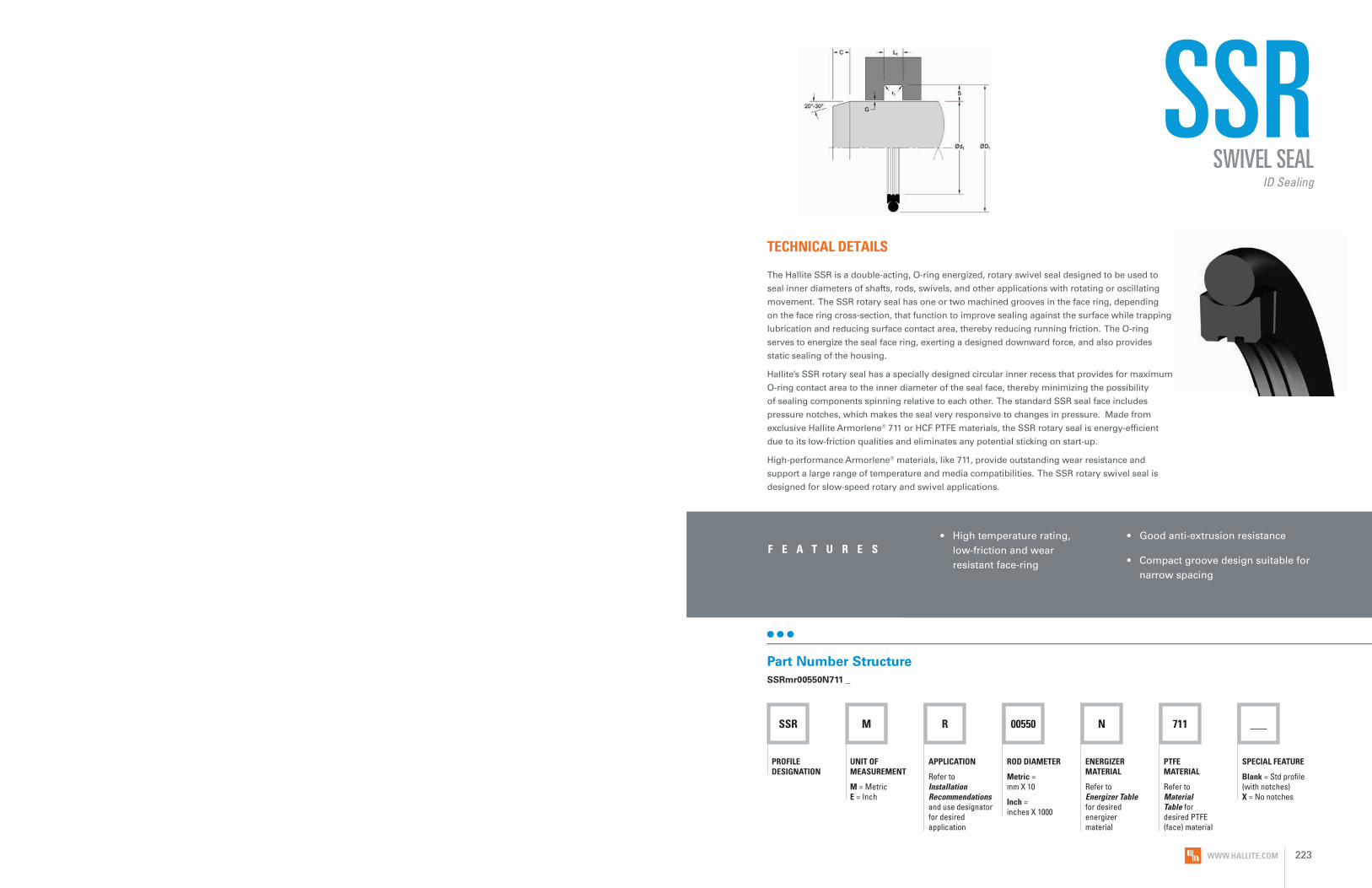
SSR M R 00550 N 711
PROFILE DESIGNATION
UNIT OF MEASUREMENT
M = Metric E = Inch
APPLICATION
Refer to Installation Recommendations and use designator for desired application
ROD DIAMETER
Metric = mm X 10
Inch = inches X 1000
PTFE MATERIAL
Refer to Material Table for desired PTFE (face) material
ENERGIZER MATERIAL
Refer to Energizer Table for desired energizer material
___
SPECIAL FEATURE
Blank = Std profile (with notches) X = No notches
SSR
• High temperature rating, low-friction and wear resistant face-ring
• Good anti-extrusion resistance
• Compact groove design suitable for narrow spacing
F E A T U R E S
TECHNICAL DETAILS
The Hallite SSR is a double-acting, O-ring energized, rotary swivel seal designed to be used to
seal inner diameters of shafts, rods, swivels, and other applications with rotating or oscillating
movement. The SSR rotary seal has one or two machined grooves in the face ring, depending
on the face ring cross-section, that function to improve sealing against the surface while trapping
lubrication and reducing surface contact area, thereby reducing running friction. The O-ring
serves to energize the seal face ring, exerting a designed downward force, and also provides
static sealing of the housing.
Hallite’s SSR rotary seal has a specially designed circular inner recess that provides for maximum
O-ring contact area to the inner diameter of the seal face, thereby minimizing the possibility
of sealing components spinning relative to each other. The standard SSR seal face includes
pressure notches, which makes the seal very responsive to changes in pressure. Made from
exclusive Hallite Armorlene® 711 or HCF PTFE materials, the SSR rotary seal is energy-efficient
due to its low-friction qualities and eliminates any potential sticking on start-up.
High-performance Armorlene® materials, like 711, provide outstanding wear resistance and
support a large range of temperature and media compatibilities. The SSR rotary swivel seal is
designed for slow-speed rotary and swivel applications.
Part Number StructureSSRmr00550N711 _
SWIVEL SEALID Sealing
WWW.HALLITE.COM 223

SURFACE FINISH RECOMMENDATIONS
OPERATING CONDITIONS
METRIC INCH
Maximum Speed Up to 2.0m/sec Up to 6.5ft/sec
Temperature Range* -45 to 200°C -49 to 392°F
Maximum Dynamic Pressure** 300 bar 4350 psi
SSR
*Rmr is measured at a depth of 25% of the Rz value based upon a reference level (zero line) at 5% material/bearing area.
METRIC INCHRmr*
SURFACE ROUGHNESS μmRa μmRz μmRt μinRa μinRz μinRt
Dynamic Sealing Face Ød1 0.05 - 0.2 1.6 max 2 max 2 - 8 63 max 157 max
60% - 90%Static Sealing Face ØD1 1.6 max 6.3 max 10 max 63 max 250 max 394 max
Static Housing Faces L1 3.2 max 10 max 16 max 125 max 394 max 630 max
ENERGIZER TABLE
*Dependent upon energizer used (NBR, FKM, etc.). **For pressures above 300 bar (4350 psi), contact Hallite Engineering. Application limit PV ≤ 25 bar m/s (40 bar for interrupted rotary).
ENERGIZER MATERIAL (SHORE A)
ENERGIZER TYPE
ENERGIZER DESIGNATION
ENERGIZER OPERATING TEMPERATURE°C
ENERGIZER OPERATING TEMPERATURE°F
NBR - 70A O-ring N -30 to 100°C -22 to 212°F
NBR - 70A Low temp. O-ring L -45 to 80°C -49 to 176°F
FKM - 75A O-ring F -10 to 200°C 14 to 392°F
EPDM - 70A O-ring E -45 to 145°C -49 to 293°F
HNBR - 70A O-ring H -25 to 150°C -13 to 302°F
NBR - 90A O-ring Q -30 to 100°C -22 to 212°F
HNBR - 90A O-ring U -25 to 150°C -13 to 302°F
No Energizer* None X - -
*Seal ratings are based upon capabilities of its matched material components. Hallite cannot rate seal performance when the seal is mixed with other manufacturers’ energizers/components.
Data given are maximum values and can apply depending on specific application. Maximum ratings of temperature, pressure, or operating speeds are dependent on fluid medium, surface, gap value, and other variables such as dynamic or static service. Maximum values are not intended for use together at the same time, e.g. max temperature and max pressure. Please contact your Hallite technical representative for application support.
NO
TEMATERIALS
MATERIAL FEATURES AND APPLICATIONS
FILL
ER
MAT
ERIA
L D
ESIG
NAT
OR
COLO
R
TEM
PERA
TURE
RA
NG
E°C
TEM
PERA
TURE
RA
NG
E°F
MA
XIM
UM
DYN
AM
IC
PRES
SURE
- B
AR
MA
XIM
UM
DYN
AM
IC
PRES
SURE
- PS
I
ARMORLENE® 711• Excellent in all lubricating fluids and
pneumatic applications• High chemical resistance• Excellent extrusion resistance• Excellent wear properties
25% Carbon/Graphite 711 Black -73 to 288°C -100 to 550°F 300 bar 4350 psi
ARMORLENE® HCF• Excellent in lubricating and non-lubricating
hydraulic fluids (includes water) w/o zinc content
• Not recommended for gas sealing applications
• Not recommended for electrical conductive fluids
Carbon Fiber Filled HCF Gray/Black -73 to 260°C -100 to 500°F 300 bar 4350 psi
ARMORLENE® HCV• Recommended for lubricating and
non-lubricating fluids• Excellent for high-frequency and
short-stroke applications• Not recommended for gas
sealing applications• Not recommended for electrical
conductive fluids
High Carbon Fiber Filled HCV Gray/Black -73 to 260°C -100 to 500°F 300 bar 4350 psi
For other material options consult the Master Materials Index at the front of the catalog. If you do not find the material that you require, please contact your local Hallite sales office.
WWW.HALLITE.COM224 WWW.HALLITE.COM 225

PART NUMBER RANGE (METRIC)*
12.0 16.9 2.2 SSRmr00120****
14.0 18.9 2.2 SSRmr00140****
15.0 19.9 2.2 SSRmr00150****
16.0 20.9 2.2 SSRmr00160****
18.0 22.9 2.2 SSRmr00180****
20.0 27.5 3.2 SSRmr00200****
22.0 29.5 3.2 SSRmr00220****
25.0 32.5 3.2 SSRmr00250****
28.0 35.5 3.2 SSRmr00280****
30.0 37.5 3.2 SSRmr00300****
32.0 39.5 3.2 SSRmr00320****
35.0 42.5 3.2 SSRmr00350****
36.0 43.5 3.2 SSRmr00360****
40.0 51.0 4.2 SSRmr00400****
42.0 53.0 4.2 SSRmr00420****
45.0 56.0 4.2 SSRmr00450****
48.0 59.0 4.2 SSRmr00480****
50.0 61.0 4.2 SSRmr00500****
52.0 63.0 4.2 SSRmr00520****
55.0 66.0 4.2 SSRmr00550****
56.0 67.0 4.2 SSRmr00560****
60.0 71.0 4.2 SSRmr00600****
63.0 74.0 4.2 SSRmr00630****
65.0 76.0 4.2 SSRmr00650****
70.0 81.0 4.2 SSRmr00700****
75.0 86.0 4.2 SSRmr00750****
80.0 91.0 4.2 SSRmr00800****
85.0 96.0 4.2 SSRmr00850****
90.0 101.0 4.2 SSRmr00900****
95.0 106.0 4.2 SSRmr00950****
100.0 111.0 4.2 SSRmr01000****
105.0 116.0 4.2 SSRmr01050****
110.0 121.0 4.2 SSRmr01100****
115.0 126.0 4.2 SSRmr01150****
120.0 131.0 4.2 SSRmr01200****
125.0 136.0 4.2 SSRmr01250****
130.0 141.0 4.2 SSRmr01300****
135.0 146.0 4.2 SSRmr01350****
140.0 151.0 4.2 SSRmr01400****
150.0 161.0 4.2 SSRmr01500****
160.0 171.0 4.2 SSRmr01600****
170.0 181.0 4.2 SSRmr01700****
180.0 191.0 4.2 SSRmr01800****
190.0 201.0 4.2 SSRmr01900****
200.0 215.5 6.3 SSRmr02000****
210.0 225.5 6.3 SSRmr02100****
220.0 235.5 6.3 SSRmr02200****
230.0 245.5 6.3 SSRmr02300****
240.0 255.5 6.3 SSRmr02400****
250.0 265.5 6.3 SSRmr02500****
280.0 301.0 8.1 SSRmr02800****
300.0 321.0 8.1 SSRmr03000****
320.0 341.0 8.1 SSRmr03200****
350.0 371.0 8.1 SSRmr03500****
360.0 381.0 8.1 SSRmr03600****
400.0 421.0 8.1 SSRmr04000****
INSTALLATION RECOMMENDATIONS
METRIC
ROD DIAMETER Ød1 f8G
ROO
VE D
IAM
ETER
GRO
OVE
WID
TH
RAD
IUS
CHA
MFE
R
GRO
OVE
SEC
TIO
N
RAD
IAL
CLEA
RAN
CE
G m
ax*
NU
MB
ER O
F G
ROO
VES
DIAMETER RANGE ØD1 H9 L1 + 0.2 r1 C S Up to
300 barStandard Duty Application - R
Light Duty Application - L
6.0 - 18.9 19.0 - 37.9 d1 + 4.9 2.2 0.4 2.5 2.45 Tol H8/f7 0
19.0 - 37.9 38.0 - 199 9 d1 + 7.5 3.2 0.6 3.5 3.75 Tol H8/f7 1
38.0 - 199.9 200.0 - 255.9 d1 + 11.0 4.2 1.0 4.0 5.50 Tol H8/f7 1
200.0 - 255.9 256.0 - 649.9 d1 + 15.5 6.3 1.3 6.0 7.75 Tol H8/f7 2
256.0 - 649.9 650.0 - 999.9 d1 + 21.0 8.1 1.8 8.0 10.50 Tol H8/f7 2
650.0 - 999.9 - d1 + 28.0 9.5 2.5 10.0 14.00 Tol H8/f7 2
At pressure >300 bar or greater contact Hallite Engineering. *Radial Clearance G max. = maximum permissible gap all on one side using min. rod diameter and max. clearance diameter.
INCH
ROD DIAMETER Ød1 f8
GRO
OVE
DIA
MET
ER
GRO
OVE
WID
TH
RAD
IUS
CHA
MFE
R
GRO
OVE
SEC
TIO
N
RAD
IAL
CLEA
RAN
CE
G m
ax*
NU
MB
ER O
F G
ROO
VES
DIAMETER RANGE ØD1 H9 L1 + .008 r1 C S Up to
4350 psiStandard Duty Application - R
Light Duty Application - L
1.000 - 1.499 1.500 - 2.999 d1 + 0.193 0.087 0.015 0.098 0.096 Tol H8/f7 0
1.500 - 2.999 3.000 - 5.999 d1 + 0.295 0.126 0.015 0.138 0.147 Tol H8/f7 1
3.000 - 5.999 6.000 - 11.999 d1 + 0.433 0.165 0.015 0.157 0.216 Tol H8/f7 1
6.000 - 11.999 12.000 - 20.000 d1 + 0.610 0.248 0.035 0.236 0.305 Tol H8/f7 2
12.000 - 20.000 - d1 + 0.827 0.319 0.035 0.315 0.413 Tol H8/f7 2
At pressure >4350 psi or greater contact Hallite Engineering. *Radial Clearance G max. = maximum permissible gap all on one side using min. rod diameter and max. clearance diameter.
SSRSWIVEL SEAL
ID Sealing
SSR
METRIC
ØD
1
Ød 1 L 1
PART
NU
MB
ER
Tol. H9 Tol. H9 Tol. +0.2
METRIC
ØD
1
Ød 1 L 1
PART
NU
MB
ER
Tol. H9 Tol. H9 Tol. +0.2
WWW.HALLITE.COM226 WWW.HALLITE.COM 227

PART NUMBER RANGE (INCH)*
420.0 441.0 8.1 SSRmr04200****
450.0 471.0 8.1 SSRmr04500****
480.0 501.0 8.1 SSRmr04800****
PART NUMBER RANGE (METRIC)* PART NUMBER RANGE (INCH)*
1.000 1.193 0.087 SSRER01000****
1.125 1.318 0.087 SSRER01125****
1.250 1.443 0.087 SSRER01250****
1.375 1.568 0.087 SSRER01375****
1.500 1.795 0.126 SSRER01500****
1.625 1.920 0.126 SSRER01625****
1.750 2.045 0.126 SSRER01750****
1.875 2.170 0.126 SSRER01875****
2.000 2.295 0.126 SSRER02000****
2.125 2.420 0.126 SSRER02125****
2.250 2.545 0.126 SSRER02250****
2.375 2.670 0.126 SSRER02375****
2.500 2.795 0.126 SSRER02500****
2.625 2.920 0.126 SSRER02625****
2.750 3.045 0.126 SSRER02750****
2.875 3.170 0.126 SSRER02875****
3.000 3.433 0.165 SSRER03000****
3.125 3.558 0.165 SSRER03125****
3.250 3.683 0.165 SSRER03250****
3.375 3.808 0.165 SSRER03375****
3.500 3.933 0.165 SSRER03500****
3.625 4.058 0.165 SSRER03625****
3.750 4.183 0.165 SSRER03750****
3.875 4.308 0.165 SSRER03875****
4.000 4.433 0.165 SSRER04000****
4.125 4.558 0.165 SSRER04125****
4.250 4.683 0.165 SSRER04250****
4.375 4.808 0.165 SSRER04375****
4.500 4.933 0.165 SSRER04500****
4.625 5.058 0.165 SSRER04625****
4.750 5.183 0.165 SSRER04750****
4.875 5.308 0.165 SSRER04875****
5.000 5.433 0.165 SSRER05000****
5.125 5.558 0.165 SSRER05125****
5.250 5.683 0.165 SSRER05250****
5.375 5.808 0.165 SSRER05375****
5.500 5.933 0.165 SSRER05500****
5.625 6.058 0.165 SSRER05625****
5.750 6.183 0.165 SSRER05750****
5.875 6.308 0.165 SSRER05875****
6.000 6.610 0.248 SSRER06000****
6.250 6.860 0.248 SSRER06250****
6.500 7.110 0.248 SSRER06500****
6.750 7.360 0.248 SSRER06750****
7.000 7.610 0.248 SSRER07000****
7.250 7.860 0.248 SSRER07250****
7.500 8.110 0.248 SSRER07500****
7.750 8.360 0.248 SSRER07750****
8.000 8.610 0.248 SSRER08000****
8.250 8.860 0.248 SSRER08250****
8.500 9.110 0.248 SSRER08500****
8.750 9.360 0.248 SSRER08750****
9.000 9.610 0.248 SSRER09000****
9.250 9.860 0.248 SSRER09250****
9.500 10.110 0.248 SSRER09500****
9.750 10.360 0.248 SSRER09750****
10.000 10.610 0.248 SSRER10000****
10.500 11.110 0.248 SSRER10500****
11.000 11.610 0.248 SSRER11000****
11.500 12.110 0.248 SSRER11500****
12.000 12.827 0.319 SSRER12000****
12.500 13.327 0.319 SSRER12500****
13.000 13.827 0.319 SSRER13000****
13.500 14.327 0.319 SSRER13500****
14.000 14.827 0.319 SSRER14000****
14.500 15.327 0.319 SSRER14500****
15.000 15.827 0.319 SSRER15000****
15.500 16.327 0.319 SSRER15500****
16.000 16.827 0.319 SSRER16000****
16.500 17.327 0.319 SSRER16500****
17.000 17.827 0.319 SSRER17000****
17.500 18.327 0.319 SSRER17500****
18.000 18.827 0.319 SSRER18000****
18.500 19.327 0.319 SSRER18500****
19.000 19.827 0.319 SSRER19000****
19.500 20.327 0.319 SSRER19500****
20.000 20.827 0.319 SSRER20000****
SSRSWIVEL SEAL
ID Sealing
SSR
*Please contact Hallite for custom sizes, material selection, or seal design.
*Please contact Hallite for custom sizes, material selection, or seal design.
METRIC
ØD
1
Ød 1 L 1
PART
NU
MB
ER
Tol. H9 Tol. H9 Tol. +0.2
INCH
ØD
1
Ød 1 L 1
PART
NU
MB
ER
Tol. H9 Tol. H9 Tol. +0.008
INCH
ØD
1
Ød 1 L 1
PART
NU
MB
ER
Tol. H9 Tol. H9 Tol. +0.008
INCH
ØD
1
Ød 1 L 1
PART
NU
MB
ER
Tol. H9 Tol. H9 Tol. +0.008
WWW.HALLITE.COM228 WWW.HALLITE.COM 229
OPTIS
EAL®

OPTISEAL®
• Thermal stability across broad temperature range
• Low coefficient of friction
• Inherent lubricating properties
• Excellent chemical and corrosion capabilities
• Reduced stick-slip
• Unlimited shelf life
• No explosive decompression
• No swelling due to moisture absorption
• Safe for vacuum conditions
• Excellent dielectrical properties
• Sealing across broad pressure range
• Static and dynamic applications
• Flanged and rotating applications
F E A T U R E S
TECHNICAL DETAILS
The OptiSeal® system is a high-performance, low-friction, full-spectrum sealing solution. This widely used
spring-energized seal offers performance benefits ranging from enhanced media compatibility to superior
performance in broad temperature ranges. The basic design consists of a U-shaped jacket made from inert
thermoplastic materials specifically selected for the application. The addition of a metal spring actuates
the jacket material used in the system, which provides sealing at low system pressures. At higher system
pressures, the seal becomes pressure-energized by the fluid media—a sealing combination that ensures
adequate sealing throughout the entire pressure range. By coupling the OptiSeal® system with other
specialty components such as anti-extrusion devices, PakRings, V-Rings, adapters, bushings, and bearings,
users can achieve an expanded operational envelope.
With diameters from 0.040in (1mm) to 110in (2.8m), customizable heights and special geometries, the
OptiSeal® system can be configured to fit in almost any hardware, making it the ideal choice for
critical-service sealing.
HALLITE SPRING-ENERGIZED SYSTEM
WWW.HALLITE.COM 233

OPTIS
EAL® SPECIALTY JACKET MATERIALS
COM
POU
ND
POLY
MER
FILL
ER
COLO
R
AB
RASI
AN
RES
ISTA
NCE
MET
AL
MAT
ING
WEA
R
RELA
TIVE
SEA
LAB
ILIT
Y
RELA
TIVE
EXT
RUSI
ON
RES
ISTA
NCE MEDIA RESISTANCE
OPE
RATI
NG
TEM
PATU
RES
NO
RSO
K M
710
COM
POU
ND
HYD
ROCA
RBO
NS
OXY
GEN
ATED
SO
LVEN
TS
STEA
M
ACI
DS
BA
SES
F° C°
703 PTFE PPS, Carbon, MoS2
Black E M G E - E E E S S -100 to 550°F -73 to 288°C
712 PTFE 5% MoS2 Gray A L E A - E E E S S -200 to 450°F -129 to 232°C
716 PTFE 15% Graphite Black A M E G Yes E E E S S -100 to 500°F -73 to 260°C
720 PTFE 2% Carbon Black A L E A - E E E S S -200 to 500°F -129 to 260°C
733 PTFE 15% Carbon/ Graphite Black G M G G - E E E S S -100 to 500°F -73 to 260°C
734 PTFE 10% Carbon/ Graphite Black G M G G - E E E S S -100 to 500°F -73 to 260°C
780 PTFE None Turquoise A L E A - E E E S S -300 to 450°F -184 to 232°C
728 ACETAL None Black A M A G - E E E W W -70 to 300°F -56 to 149°C
Arylex™ 745 PEEK None Beige A M G G Yes E E E S S -70 to 500°F -56 to 260°C
748 UHMWPE None Translucent E L E G - E E E S S -300 to 180°F -184 to 82°C
HLA PTFE Mineral White G M G G - E E E W S -100 to 500°F -73 to 260°C
HCV PTFE Carbon Fiber Gray/ Black G M G G - E E E S S -100 to 500°F -73 to 260°C
7HP UHMWPE None Translucent E L E G - E E E S S -22 to 275°F -30 to 135°C
Conditions shown are approximate. Actual operating conditions are contingent upon media, pressure, and design factors as well as polymer types. Testing in your assembly is always recommended, especially when applications approach or exceed the conditions shown above.
COMMON PTFE JACKET MATERIALSCO
MPO
UN
D
POLY
MER
FILL
ER
COLO
R
AB
RASI
AN
RES
ISTA
NCE
MET
AL
MAT
ING
WEA
R
RELA
TIVE
SEA
LAB
ILIT
Y
RELA
TIVE
EXT
RUSI
ON
RES
ISTA
NCE MEDIA RESISTANCE
OPE
RATI
NG
TEM
PATU
RES
NO
RSO
K M
710
COM
POU
ND
HYD
ROCA
RBO
NS
OXY
GEN
ATED
SO
LVEN
TS
STEA
M
ACI
DS
BA
SES
F° C°
700 PTFE None White P L E P Yes E E E S S -300 to 400°F -184 to 204°C
701 PTFE 25% Glass White E H G E Yes E E E S S -100 to 550°F -73 to 288°C
702 PTFE Glass, MoS2 Gray E H G G - E E E S S -100 to 500°F -73 to 260°C
711 PTFE 25% Carbon/ Graphite Black G M G E Yes E E E S S -100 to 550°F -73 to 288°C
777 MPTFE Premium Virgin White P L E G Yes E E E S S -300 to 450°F -184 to 232°C
HLX PTFE Special Bronze Gold G M G G - E E E S S -100 to 550°F -73 to 288°C
HCF PTFE Carbon Fiber Gray/ Black G M G G - E E E S S -100 to 500°F -73 to 260°C
Conditions shown are approximate. Actual operating conditions are contingent upon media, pressure, and design factors as well as polymer types. Testing in your assembly is always recommended, especially when applications approach or exceed the conditions shown above.
KEY
E = Excellent G = Good P = Poor
H = High M = Medium L = Low
NR = Not Recommended W = Resistant to weak acid/base S = Resistant to strong acid/base
KEY
E = Excellent G = Good A = Average P = Poor
H = High M = Medium L = Low
NR = Not Recommended W = Resistant to weak acid/base S = Resistant to strong acid/base
WWW.HALLITE.COM 235WWW.HALLITE.COM234

FILLERS JACKET MATERIAL SUGGESTIONS
While maintaining its inherent properties and characteristics in material compounds, PTFE can benefit from the improved mechanical strength, stability, and wear resistance provided by an additive. The various mechanical properties of PTFE can be enhanced by adding a range of fillers, including glass fiber, carbon, and bronze.
To enhance performance capabilities, a range of fillers and additives can be added to materials. Reinforcing fibers, conductive fillers, and colorants are among the additives available.
The Hallite material portfolio contains additional compounds that are not mentioned in this listing. Our specialists can work with you to provide the ideal engineering solution for your specific needs. If your application requires a custom compound or material that is not listed, visit Hallite.com to submit your inquiry, or submit an inquiry at [email protected], or contact your Hallite representative.
Conditions shown are approximate. Actual operating conditions are contingent upon media, pressure, and design factors as well as polymer types. Testing in your assembly is always recommended, especially when applications approach or exceed the conditions shown above.
= Slight Increase
= Moderate Increase
= Significant Increase
= Slight Decrease
= Moderate Decrease
= Significant Decrease
KEY
= No Effect
COMMON FILLERS
Glass Fibers The most common filler. Minor effect on electrical properties. Increased abrasion on mating metal surfaces.
Carbon/Carbon FibersLow abrasion and wear. Good deformation and extrusion resistance.
Graphite Non-abrasive. Low friction. Minor effect on deformation properties.
MoS2
Lowers break-in wear and starting friction.
Bronze Very high wear resistance and load-bearing capability. Poor chemical resistance.
Stainless SteelHigh wear resistance and load-bearing capability. Wider chemical resistance than bronze.
PPSLow wear and abrasion. Excellent deformation and extrusion resistance. Large reduction in tensile and elongation values.
CAF2 Hydrofluoric acid service.
MineralProperties similar to glass, but less abrasive.
APPLICATIONS
STATIC
LOW
PRE
SSU
RE
MED
IUM
PRE
SSU
RE
HIG
H P
RESS
URE
ROTATING OSCILLATING RECIPROCATING
LOW SPEED HIGH SPEED LOW SPEED HIGH SPEED LOW SPEED HIGH SPEED
LOW
PRE
SSU
RE
HIG
H P
RESS
URE
LOW
PRE
SSU
RE
HIG
H P
RESS
URE
LOW
PRE
SSU
RE
HIG
H P
RESS
URE
LOW
PRE
SSU
RE
HIG
H P
RESS
URE
LOW
PRE
SSU
RE
HIG
H P
RESS
URE
LOW
PRE
SSU
RE
HIG
H P
RESS
URE
Hydrocarbon Oils and Lubrication Typically fuels and lubricants of petroleum-based products
700 777711
703745701
716720780
HLXHCF
755HCF
HLXHCF
716720780
HLXHCF711
HCF755
HLXHCF
780720712
HLX7027HP711748
HLX711
HLX7HP748
Pneumatic and GasesPrimarily for air and other gases
7007777HP748
7777HP748
7777HP745748
780777
755HCF
711755HCF
HCF756
780777
755HCF
HCF755
HCF756
780777
7HP777PS3748
711HCF
HLX711
Chemical ProcessingTypical service includesthe handling and dispensing of acidic and basic products
700711
7777HP748
703745701
716720
HCF711
755HCF
711703
716720712
HCF711
HCF755
711703
720712
7HP711748
711703
7HP703748
OPTIS
EAL®
FILLERS AND THEIR RELATIVE EFFECTS ON PTFE
WEA
R RE
SIST
AN
CE
FRIC
TIO
N
CREE
P RE
SIST
AN
CE
THER
MAL
CO
NDU
CTIV
ITY
MET
AL
MAT
ING
W
EAR
ELEC
TRIC
AL
RESI
STA
NCE
GLASS FIBERS
CARBON
GRAPHITE
MoS2
BRONZE
CARBON FIBERS
MINERAL
STAINLESS STEEL
HIGH-TEMPERATURE POLYMERS
WWW.HALLITE.COM236 WWW.HALLITE.COM 237

KEY
E = Excellent P = Poor
W = Resistant to weak acid/base S = Resistant to strong acid/base
SPRING MATERIALS
MAT
ERIA
L
APP
LICA
TIO
N D
ESCR
IPTI
ON
MEDIA RESISTANCE
OPE
RATI
NG
TEM
PATU
RES
SPRI
NG
TYP
E
HYD
ROCA
RBO
NS
OXY
GEN
ATED
SO
LVEN
TS
STEA
M
ACI
DS
BA
SES
F° C° V HELICAL
301 Stainless Steel*
General Service Hydraulics E E E W S -300 to 400°F -184 to 204°C Yes Yes
Elgiloy Alloy Harsh Service, NACE MR-01-75 E E E S S -300 to 800°F -184 to 427°C Yes Yes
301 SS/Silicone Filled
Food and Pharmaceuticals P E E W W -300 to 400°F -184 to 204°C Yes No
Hastalloy E E E S S -300 to 800°F -184 to 427°C No Yes
SPRING TYPES
The addition of a metal spring or elastomer actuates the jacket material used in the system. Upon seal installation, the spring energizer responds with an outward force, thereby energizing the jacket material and providing positive sealing. Characteristics such as load value, deflection range, and corrosion resistance are among the primary spring factors that affect seal performance in a given application.
V-SPRINGThe most versatile of all the spring types, the V-Spring design is suited for use in a wide range of applications and services, from static applications to those with rotary or reciprocating motion. The materials used in this design option enhance sealing performance without degradation of material properties. Available in our internal and external pressure face seal design, the V-Spring energizer features a wide deflection range and can be designed with medium or heavy spring loads. This spring is a good choice for glands with wide tolerance variations.
FLAT BAND HELICALFor applications with less dynamic operating conditions, the flat band helical spring design is an ideal choice because of its small deflection range. The high unit load of this spring-energized design makes it the optimal solution for static applications where wear and friction are not great concerns. In addition, it is the preferred design for cryogenic services.
CANTED COILThis spring offers light constant loading over a wide deflection range, reducing frictional drag and seal wear. Typically, applications include measurement and instrumentation, high-speed/low pressure, and single-seal applications.
J-SPRINGThe J-spring has been designed to allow for high flexibility while also providing high loads. Primarily used in large rotating equipment such as FPSO swivels, the J-spring allows for a more robust, heavy cross-section design that can withstand the extremes of high pressure in applications for decades.
FULL CONTACT SPRINGThis heavy-duty spring provides a constant ultra high load over the entire sealing lip. Available in either internal or external face seal configurations, this spring provides the high sealing loads needed for cryogenic fluids, tight gas sealing, and ultra-high vacuum applications.
*Certain applications require higher grades of stainless steel; grades such as 300, 304/316 are available.
OPTIS
EAL®
WWW.HALLITE.COM238 WWW.HALLITE.COM 239

PROFILE & CODE
S
A BA A B C D E F J
V-Spring Lip Profiles
C DA A B C D E F J
V-Spring Lip Profiles
E F J
RECIPROCATING Preferred Preferred Preferred Preferred Preferred Preferred Preferred Preferred
ROTATING Preferred Preferred Neutral Preferred Neutral Neutral Preferred Preferred
STATIC Preferred Neutral Preferred Neutral Neutral Neutral Neutral Neutral
OSCILLATING Preferred Preferred Neutral Preferred Neutral Neutral Preferred Preferred
HIGH SEALABILITY Preferred Neutral Preferred Neutral Neutral Neutral Neutral Neutral
EXCLUSION Neutral Neutral Neutral Neutral Preferred Preferred Preferred Preferred
LOW-FRICTION Neutral Preferred Neutral Neutral Preferred Preferred Neutral Neutral
STEP GLAND Do Not Use Neutral Neutral Neutral Preferred Preferred Preferred Preferred
<3/16” ID Do Not Use Do Not Use Preferred Do Not Use Preferred Preferred Do Not Use Do Not Use
V-SPRING LIP PROFILES V-SPRING PROFILE USAGE GUIDE
Seal characteristics such as sealability, wear, and friction are greatly affected by lip-profile construction and seal geometry. In addition to our standard forms, lip profiles can be customized for specific gland configurations such as highly abrasive environments and rough surface finishes.
SEALABILITY = Medium WEAR = Medium FRICTION = Medium SEALABILITY = Low WEAR = Low FRICTION = Low
S LIP DOUBLE RADIUS LIPThe S lip is the standard lip profile design. It offers redundant sealing surfaces with radiused contact areas for medium unit loading. This design feature provides the best combination of wear and sealability, making the S lip suitable for the widest range of applications.
A LIP SINGLE RADIUS LIPThe A lip employs a large radius, and therefore low unit loading, resulting in low friction and low wear. This lip profile is recommended for applications with high surface speeds or those that require low friction. The profile also facilitates installation in glands with insufficient lead-in chamfers.
SEALABILITY = High WEAR = High FRICTION = High SEALABILITY = High WEAR = High FRICTION = High
B LIP BEVEL LIPThe B lip profile produces the highest unit loading of all of the lip profiles offered by Hallite. The B lip is recommended for use in static applications and is required when the OptiSeal® component diameter is less than 3/16” (4.7mm).
C LIP FLAT LIPThe C lip provides a flat sealing surfacewhich allows for a constant wear rateover the life of the seal, making it idealfor rotary applications where extendingseal life is the primary goal.
SEALABILITY = Medium WEAR = Low FRICTION = Medium SEALABILITY = Medium WEAR = Low FRICTION = Medium
D LIP SCRAPER LIPThe D lip profile’s low unit loading characteristics offer long wear, with somewhat less effective sealing than higher unit loaded seals. This design is particularly well-suited for reciprocating applications.
E LIP RADIUS END LIPThe E lip profile is a radiused lip profile similar to the S lip, but with a single point of contact. This lip profile generates the lowest friction of any V-Spring Optiseal® and has extremelyhigh sealability. This lip is best suited for static sealing applications and light oscillating applications where tightsealing is required.
SEALABILITY = Medium WEAR = Medium FRICTION = Low SEALABILITY = Medium WEAR = Medium FRICTION = Medium
F LIP DUAL SCRAPER LIPThe F lip features a profile suitable for systems contaminated with abrasives. Lower unit loadings offer extended seal life in rotary applications.
J LIP SCRAPER RADIUS LIPThe J lip also has redundant sealing surfaces, with the sharp front edge protecting the secondary, radiused surface from abrasive media. Besides use in scraping applications, this lip is also used with step-cut glands and is the preferred profile for use with high-viscosity media.
OPTIS
EAL®
WWW.HALLITE.COM240 WWW.HALLITE.COM 241
LIP PROFILE USAGE GUIDE
SEALABILITY = Medium WEAR = Medium FRICTION = Medium
SEALABILITY = High WEAR = High FRICTION = High
SEALABILITY = Medium WEAR = Medium FRICTION = Low
SEALABILITY = Low WEAR = Low FRICTION = Low
SEALABILITY = Medium WEAR = Low FRICTION = Medium
SEALABILITY = Medium WEAR = Medium FRICTION = Medium
LIP PROFILES
Seal characteristics such as sealability, wear, and friction are greatly affected by lip-profile construction and seal geometry. In addition to our standard forms, lip profiles can be customized for specific gland configurations such as highly abrasive environments and rough surface finishes.
K LIP SINGLE RADIUS LIPThe K lip is similar to the A lip for V-Springs but designed for circularsprings in mind. The radiused lip profileprovides low unit loading which resultsin low friction. The radius also allowsfor easy installation in glands with insufficient lead-in chamfers. Typical applications include high-speed rotary,gas sealing, and cryogenics.
L LIP SINGLE RADIUS LIP FOR BACK PRESSUREThe L lip is designed for applications where a single seal is desired and significant back pressure will be seen. The extended lips of this seal protect the sealing surfaces from damage as pressure is reversed. Radial slots through the lips allow pressure to re-energize the seal once normal pressure is restored, preventing fluid blow-by.
M LIP SCRAPER RADIUS LIPThe M lip is similar in function to the Jlip but designed for use with circularsprings. The scraper lip helps to protectthe radius lip from damage by abrasivemedia and acts as a redundant sealingsurface. Additionally, the scraper portion of the lip allows this seal to be installed in step cut glands.
N LIP POINT CONTACT LIPThe N lip profile features a pointed contact surface, ensuring minimal contact area and maximum unit loading. This profile, when used in conjunction with a helical coil spring, allows for tight sealing of gas and low- viscosity liquids in static applications.
P LIP SUPPORTED HEEL FLAT LIPThe P lip untilizes a flat sealing surface, allowing for a constant wear rate over the life of the seal. The high load spring is ideal for heavy cross-section geometries used in large rotating equipment. The heel support ensures that seals made from softer materials like PTFE remain parallel to gland walls without distortion.
R LIP FLAT LIPThe R lip is similar to the P lip, but doesnot have the additional heel support.This geometry is ideal when used withmore rigid materials like UHMW-PE.Additionally, the lack of heel supportmakes this geometry lower friction than the P lip.
PROFILE & CODE
K L M N PKK L M N P
LK L M N PMK L M N PNK L M N PPK L M N P R
RECIPROCATING Neutral Preferred Preferred Neutral Preferred Preferred
ROTATING Neutral Neutral Neutral Neutral Preferred Preferred
STATIC Preferred Neutral Preferred Preferred Preferred Preferred
OSCILLATING Preferred Preferred Preferred Neutral Preferred Preferred
HIGH SEALABILITY Neutral Neutral Neutral Preferred Neutral Neutral
EXCLUSION Neutral Neutral Neutral Neutral Neutral Neutral
LOW-FRICTION Preferred Preferred Preferred Neutral Neutral Neutral
STEP GLAND Neutral Neutral Preferred Do Not Use Neutral Neutral
<3/16” ID Do Not Use Do Not Use Do Not Use Preferred Do Not Use Do Not Use
OPTIS
EAL®
WWW.HALLITE.COM242 WWW.HALLITE.COM 243

SPECIALITY TYPES CUSTOM SEAL CHARACTERISTICS
Components based on the basic seal design can be further customized to provide sealing performance that is application- and industry-specific. Our engineering team is able to incorporate a variety of shapes and geometries to optimize seal performance and versatility.
In addition to jacket and material customization, the standard OptiSeal® design can be further customized based on the service conditions of the individual application, enabling it to perform in a wide range of services and applications.
OPTIFACE™ SEALOptiFace seals are used in static seal applications and feature an axial squeeze design offered for either external or internal pressure. As compression against the seal is increased, the lips of the jacket are pressed against the gland surface, providing resistance and sealability while ensuring stability within the gland. The beveled lip featured in this design provides excellent sealability in applications that require high unit loading. The internal or external preload is based on the application. For components such as flanges and swivel joints, the design is configured for internal pressure. In sealing vacuum applications, the design can be configured for external pressure.
NESTED SPRINGS OPTISEAL®
Multiple or nested springs are used when greater sealing force isrequired, such as in low-pressure or low-temperature applications. Thisdesign is able to increase the force exerted by the sealing lips withoutincreasing the lip interference. Examples of such applications are valvestems, choke seals, and low-pressure systems.
FLANGED OPTISEAL® COMPONENTBest suited for rotary applications, this seal is designed to prevent seal movement on the static gland surface. The clamped flange prevents seal movement and blocks potential leak paths. In cryogenic applications, the clamped flange also reduces the thermal contraction of the seal OD away from the gland.
LARGE CROSS SECTION OPTISEAL®
In larger diameter applications where existing glands have radial crosssections greater than 0.600” (15.2mm) or have limited axial lengths,two springs may be radially spaced. Dual springs are also used whenretrofitting existing glands where the axial gland length is less than theradial gland cross section. This allows the sealing system to be employedin cross sections that are greater than 1” (25.4mm).
OPTI-OIL™ SEALThe Opti-Oil seal is the ideal choice for low-pressure, dynamic shaft seals. The outer diameter of this configuration is tightly sealed with an O-ring, reducing slippage on the static surface in rotary applications. The inner diameter contact surface of this seal features a low-friction, spring-loaded jacket, enabling adequate sealing along the surface of the shaft.
SILICONE-FILLED CAVITY OPTISEAL®
In sanitary applications, the spring cavity of the OptiSeal® system canfeature a silicone filling to effectively protect against contamination. Thisconfiguration prevents media from becoming trapped in the cavity,enabling excess media to be completely flushed out if necessary.
A6R OPTISEAL®
When tight shutoff is required and space is limited, the A6R Optiseal® outperforms
PTFE seals. This hybrid elastomer/PTFE seal couples the high sealing capabilities
of elastomers with the low-friction characteristics of PTFE. The PTFE ID limits the
amount of elastomer contact on the running surface, resulting in significantly
lower friction.
OPTIS
EAL®
WWW.HALLITE.COM244 WWW.HALLITE.COM 245

BACK-UP RINGS/ANTI-EXTRUSION DEVICESADDITIONAL CUSTOM DESIGNS
FDA
APP
ROVE
D
COM
POU
ND
POLY
MER
FILL
ER
COLO
R
AB
RASI
AN
RES
ISTA
NCE
MET
AL
MAT
ING
WEA
R
RELA
TIVE
SEA
LAB
ILIT
Y
RELA
TIVE
EXT
RUSI
ON
RES
ISTA
NCE MEDIA RESISTANCE
OPE
RATI
NG
TEM
PATU
RE
HYD
ROCA
RBO
NS
OXY
GEN
ATED
SO
LVEN
TS
STEA
M
ACI
DS
BA
SES
F° C°
Yes 728 ACETAL None Black A M A G E G G W W -70 to 300°F -56 to 149°C
No 744 PPS Glass Grey G H P E E E E S S -70 to 500°F -56 to 260°C
Yes Arylex™ 745 PEEK None Beige A M G G E E E S S -70 to 500°F -56 to 260°C
No Arylex™ 747 PEEK Glass Beige G H P E E E E S S -70 to 550°F -56 to 288°C
Yes 748 UHMWPE None Translucent E L E G G G P S S -300 to 180°F -184 to 82°C
No Arylex™ 754 PEEK Carbon Black G H P E E E E S S -70 to 550°F -56 to 288°C
KEY
E = Excellent G = Good A = Average P = Poor
H = High M = Medium L = Low
NR = Not Recommended W = Resistant to weak acid/base S = Resistant to strong acid/base
BACK-UP AND ADAPTER MATERIAL SELECTION
The materials and compounds selected in a seal’s design will differ in their ability to resist seal extrusion once installed in a given application. The effects that temperature, pressure, and media have on the compound used are key considerations. When determining whether or not a sealing system requires the use of a back-up ring or anti-extrusion device, the magnitude of pressure a seal must contain and the clearance gap should be considered. The properties of the jacket materials used in the seal design provide varying levels of resistance to seal extrusion in a given application.
BIDIRECTIONAL SPRING-ENERGIZED FLOATING PISTON SEAL
FLANGED SEAL WITH INTERNAL SPRING ENERGIZER
OptiSeal® design principles can be applied to a variety of custom configurations. For custom seal geometries, please contact your Hallite representative.
OPTIS
EAL®
WWW.HALLITE.COM246 WWW.HALLITE.COM 247

GLAND DESIGN OPTIONS
FACE SEAL GLANDFace seal gland design and seal design are different from the design of radial seals. Gland recommendations are available from Hallite for individual applications, or OptiFace seals may be proposed based upon existing gland dimensions.
PRESSURE PRESSURE
STEP-CUT GLANDThis modification of the one-piece gland minimizes the deformation of the OptiSeal® jacket during installation and eliminates the need for a separate retaining piece. Dimensions for step-cut glands are available upon request.
PRES
SURE
PRES
SURE
TWO-PIECE GLANDThe two-piece gland eliminates deformation during installation and is required for small-diameter or large cross-section designs. In reciprocating applications, the gland must be carefully designed, or a PakRing must be used to prevent the sealing lips from shifting on to the installation bevel.
PRES
SURE PR
ESSU
RE
ONE-PIECE GLANDThe one-piece gland is used only for OptiSeal® systems with larger diameters or small cross sections to prevent damage from stretching or buckling during installation. Please consult Hallite for installation tools and instruction before installing OptiSeal® components into this gland configuration.
PRES
SURE
PRES
SURE
BACK-UP RING DESIGN OPTIONS
When back-up or auxiliary devices are required, Hallite can provide a range of components that prevent seal extrusion. Several geometries are used for anti-extrusion devices that allow the extrusion-resistant material to move into the clearance gap quickly and efficiently. Constructed from materials that are stronger than the seal jacket, the back-up ring blocks extrusion paths, allowing for maximum seal life in high-temperature and high-pressure applications.
OPTIBACK™ COMPONENTThe standard back-up ring offered by Hallite features a close-tolerance rectangular OptiBack design. The chamfered edges on the OptiBack ring aid in installation.
DELTA BACK-UP RINGThe Delta Back-Up uses system pressure to prevent seal extrusion when using the OptiSeal® system. The force induced by the system pressure will cause the Delta Back-Up to move into the extrusion gap and close it off.
INTEGRAL BACK-UP RINGThe Integral Back-Up is placed at the corner of the seal where the extrusion gap is located. This configuration is ideal when the axial gland length is so short as to prevent the use of a standard back-up. Its snap-in feature also eliminates loose components, thereby providing easier installation.
OPTIS
EAL®
WWW.HALLITE.COM248 WWW.HALLITE.COM 249
GLAND RECOMMENDATIONS: OPTIGLAND
PISTON SEALS: 8-STEP PROCESS
Larger gland diameters require greater tolerances to manufacture at reasonable and comparable costs. OptiSeal® components have a “designed-in” squeeze on the cross section, but manufacturing tolerances determine the minimum and maximum. If the minimum squeeze is too small, the seal can tolerate less wear before it fails. If the maximum squeeze is too large, the friction and wear will be unacceptable.
The Hallite OptiGland system of gland dimension recommendations is centered around the active gland diameter (the bore diameter for piston seals and the rod diameter for rod seals) and takes into account manufacturing capabilities, wear and friction concern, extrusion gaps, and expenses incurred during manufacturing. The OptiGland system calculates the optimal cross-section for a given active gland diameter or, working backwards, the optimal active diameter for a given cross section, giving consideration to the rationale of tolerance selection.
The result is a set of gland dimensions that balances the best seal performance and longevity with the lowest manufacturing costs required for that gland. The processes and examples below demonstrate how to effectively use OptiGland measurements.
Step 1: Determine the active gland diameter. For piston seals, “A” equals the bore diameter and is the minimum gland OD.
Step 2: Determine the minimum gland cross section. This value is based on A and can be found in the Gland Dimension Examples tables on the following pages.
Step 3: Determine the non-active gland diameter. For piston seals, “B” equals A-2S and is the maximum gland ID.
Step 4: Determine tolerances for gland diameters. Tolerances are given in the Gland Dimension Examples tables on the following pages, dependent only upon cross section in order to control seal squeeze.
Step 5: Determine the minimum axial gland length. For pressures less than 10,000 psi (690 bar), use the value L1. Value L2 accommodates the addition of an OptiBack back-up ring and can be used for pressure above 10,000 psi (690 bar) up to 17,000 psi (1,172 bar). For pressures above 17,000 psi (1,172 bar), please consult Hallite. The tolerance for both L1 and L2 is 0.010in (0.25mm).
Step 6: Determine the minimum installation bevel length. This value is also given in the Gland Dimension Examples tables on the following pages, according to the cross section.
Step 7: Determine the minimum and maximum diametrical clearance. These values are shown in the table. The minimum diametrical clearance will be used to calculate “C”—the gland clearance diameter.
Step 8: Determine the gland clearance diameter and tolerance. For piston seals, C equals A-E minimum and is the maximum clearance diameter. Shaft and hole tolerances can be applied to these values using the table.
A S B L F E C
Active gland diameter
Minimum gland cross section
Non-active gland diameter
Minimum axial gland length
Minimum installation
bevel length
Diametrical clearance
Gland clearance diameter
DIAGRAM 1 PISTOL SEAL RECOMMENDATION
F F.5E
20° 20°
A
C
B
S
L
ROD SEALS: 8-STEP PROCESS
SUGGESTED GLAND SURFACE FINISHES
Step 1: Determine the active gland diameter. For rod seals, “A” equals the rod diameter and is the maximum gland ID.
Step 2: Determine the minimum gland cross section. This value is based on A and can be found in the Gland Dimension Examples tables on the following pages.
Step 3: Determine the non-active gland diameter. For rod seals, “B” equals A+2S and is the minimum gland ØD.
Step 4: Determine tolerances for gland diameters. Tolerances are given in the Gland Dimension Examples tables on the following pages, dependent only upon cross section in order to control seal squeeze.
Step 5: Determine the minimum axial gland length. For pressures less than 10,000 psi (690 bar), use the value L1. Value L2 accommodates the addition of an OptiBack back-up ring and can be used for pressure above 10,000 psi (690 bar) up to 17,000 psi (1,172 bar). For pressures above 17,000 (1,172 bar), please consult Hallite. The tolerance for both L1 and L2 is 0.010in (0.25mm).
Step 6: Determine the minimum installation bevel length. This value is also given in the Gland Dimension Examples tables on the following pages, according to the cross section.
Step 7: Determine the minimum and maximum diametrical clearance. These values are shown in the table. The minimum diametrical clearance will be used to calculate “C”—the gland clearance diameter.
Step 8: Determine the gland clearance diameter and tolerance. For rod seals, C equals A+E min and is the minimum clearance diameter.
A S B L F E C
Active gland diameter
Minimum gland cross section
Non-active gland diameter
Minimum axial gland length
Minimum installation
bevel length
Diametrical clearance
Gland clearance diameter
STATIC DYNAMIC
Ra 32 max Ra 16 max
Ra 0.8 µm max. Ra 0.4 µm max.
DIAGRAM 2 ROD SEAL RECOMMENDATION
F F.5E
20° 20°
C
B
A
S
L
OPTIS
EAL®
WWW.HALLITE.COM250 WWW.HALLITE.COM 251

GLAND DIMENSION EXAMPLES
These examples show a relationship between active diameter and gland cross section.
METRIC
ROD
DIA
MET
ER O
R CY
LIN
DER
BO
RE
NO
MIN
AL
GLA
ND
CR
OSS
SEC
TIO
N
MIN
IMU
M G
LAN
D
CRO
SS S
ECTI
ON
MIN
IMU
M A
XIA
L G
LAN
D L
ENG
TH
MIN
IMU
M A
XIA
L G
LAN
D L
ENG
TH
MIN
IMU
M IN
STA
LLAT
ION
B
EVEL
LEN
GTH
MIN
IMU
M D
IAm
etri
cAL
CLEA
RAN
CE
MA
XIM
UM
DIA
met
ricA
L CL
EARA
NCE
SHA
FT
TOLE
RAN
CE
HO
LE
TOLE
RAN
CE
A S L1 + 0.25 L2 + 0.25 F min. E min. E max. -.xxx +.xxx
5.0 - 14.9 3.00 2.98 4.06 5.45 0.86 0.02 0.11 0.03 0.06
15.0 - 24.9 4.00 3.97 5.37 7.19 1.14 0.04 0.17 0.05 0.08
25.0 - 59.9 5.00 4.96 6.64 8.92 1.43 0.05 0.20 0.06 0.09
60.0 - 169.9 7.50 7.44 9.82 13.24 2.14 0.09 0.33 0.10 0.14
170.0 - 409.9 10.00 9.92 13.01 17.53 2.85 0.12 0.45 0.15 0.18
410.0 - 500.0 12.50 12.41 16.16 21.81 3.56 0.17 0.60 0.20 0.23
METRIC
NOMINAL GLAND CROSS SECTION
200mm ROD, 125 bar
DIMENSION TOLERANCE
Max. Gland ID 181.16 -0.15
Min. Gland OD 200.00 +0.18
Nom. Gland Cross Section 10.00 Nominal
Min. Gland Cross Section 9.92 Minimum
Min. Axial Gland Length 13.01 +0.25
Min. Installation Bevel Length 2.85 Minimum
Min. Diametrical Clearance 0.12 Minimum
Gland Clearance Diameter 199.88 +0.15
Max. Diametrical Clearance 0.45 Maximum
INCH
NOMINAL GLAND CROSS SECTION
4” ROD, 15,000 PSI
DIMENSION TOLERANCE
Max. Gland ID 4.000 -0.004
Min. Gland OD 4.496 +0.005
Nom. Gland Cross Section 0.250 Nominal
Min. Gland Cross Section 0.248 Minimum
Min. Axial Gland Length 0.443 0.010
Min. Installation Bevel Length 0.071 Minimum
Min. Diametrical Clearance 0.003 Minimum
Gland Clearance Diameter 4.003 +0.005
Max. Diametrical Clearance 0.012 Maximum
INCH
ROD
DIA
MET
ER O
R CY
LIN
DER
BO
RE
NO
MIN
AL
GLA
ND
CR
OSS
SEC
TIO
N
MIN
IMU
M G
LAN
D
CRO
SS S
ECTI
ON
MIN
IMU
M A
XIA
L G
LAN
D L
ENG
TH
MIN
IMU
M A
XIA
L G
LAN
D L
ENG
TH
MIN
IMU
M IN
STA
LLAT
ION
B
EVEL
LEN
GTH
MIN
IMU
M D
IAm
etri
cAL
CLEA
RAN
CE
MA
XIM
UM
DIA
met
ricA
L CL
EARA
NCE
SHA
FT
TOLE
RAN
CE
HO
LE
TOLE
RAN
CE
A S L1 + .010 L2 + .010 F min. E min. E max -.xxx +.xxx
0.215 - 0.749 0.125 0.124 0.169 0.226 0.036 0.001 0.004 0.001 0.002
0.750 - 2.499 0.188 0.186 0.250 0.336 0.054 0.002 0.009 0.003 0.004
2.500 - 6.499 0.250 0.248 0.329 0.443 0.071 0.003 0.012 0.004 0.005
6.500 - 16.999 0.375 0.372 0.488 0.658 0.107 0.005 0.018 0.006 0.007
17.000 - 20.000 0.500 0.496 0.646 0.872 0.142 0.007 0.023 0.007 0.009
GLAND DIMENSION EXAMPLES
Notes: For pressures less than 10,000 psi (690 bar), the OptiSeal® system can be used without back-up ring and axial gland length L1. For pressures greater than or equal to 10,000 psi (690 bar) but less than 17,000 psi (1,172 bar), the OptiBack back-up ring can be used with the OptiSeal® system and axial gland length L2. Contact Hallite regarding: all pressures exceeding 17,000 psi (1,172 bar), and regarding piston seals with bore diameters of .500in/.254m or less.
OPTIS
EAL®
WWW.HALLITE.COM 253WWW.HALLITE.COM252

BACK
-UP
RINGS

OPERATING CONDITIONS
METRIC INCH
Temperature Range -30 to 200°C -22 to 392°F
• More extrusion resistant than conventional PTFE back-up rings
• No spiral or cut design; rings will not wrap around the rod jack and be sheared off
• Economical assembly of series with assembling tool
• Uncut design ensures no gap will endanger the O-ring
• Immediate reconversion after termination of assembly so that the back-up ring fits tightly on the bottom of the groove
• Simple assembly of small quantities with synthetic strip
F E A T U R E S
TECHNICAL DETAILS
Hallite PME back-up rings are uncut back-up rings made from specific conditioned
PTFE to be assembled into one-piece external grooves. PME back-up rings are
designed to support O-rings mainly in static applications. The cold flow feature of
the specially conditioned virgin PTFE grade reliably closes the extrusion gap and
protects the O-ring from extruding into the gap and helps to reasonably increase the
acceptable system pressure. Hallite PME back-up rings are produced from stocked
material and can be supplied on short notice.
PMEUNCUT BACK-UP RINGS
For External Grooves
Data given are maximum values and can apply depending on specific application. Maximum ratings of temperature, pressure, or operating speeds are dependent on fluid medium, surface, gap value, and other variables such as dynamic or static service. Maximum values are not intended for use together at the same time, e.g. max temperature and max pressure. Please contact your Hallite technical representative for application support.
NO
TE
WWW.HALLITE.COM 257

PME INSTALLATION RECOMMENDATIONS
SMALL QUANTITY ASSEMBLY – PME BACK-UP RINGS*When assembling small quantities of PME back-up rings, a synthetic strip can be used to
best fit the back-up ring into the groove. The back-up ring should first be fitted into the
groove at one part of the circumference and held in place in the groove. Work the ring
into the groove around the part, using circular motions as quickly as possible. Note that
the faster the assembly of the part into the groove, the faster the part will resize into the
groove, minimizing time before the seal can be assembled.
LARGE QUANTITY ASSEMBLY – PME BACK-UP RINGS* When assembling large quantities of PME back-up rings, the use of an assembly cone can minimize time needed to
assemble. With this method, the O-ring and PME back-up can be assembled at the same time. This method provides quick
assembly, as the back-up ring will immediately resize in the groove with the O-ring, making the assembly ready for use.
*If you choose to heat the part for easier assembly, you will need to verify that the ring has properly resized in the groove as the heat may interfere with the self-sizing function of the part.
OPERATING CONDITIONS
METRIC INCH
Temperature Range -30 to 200°C -22 to 392°F
BACK-UP RINGS
OTHER
TECHNICAL DETAILS
Back-up rings offer additional support to a sealing element, extending the performance and durability of the seal. Back-up components also provide protection against extrusion, allowing the applications to operate at higher pressures. Back-up rings are offered in many different configurations from full face to integrated designs. Designs are also available for static and dynamic applications. Depending on the application, Hallite offers a full range of materials to ensure maximum production of the sealing element. Hallite offers a full range of sizes that may be available in small quantities within 24 hours.
Data given are maximum values and can apply depending on specific application. Maximum ratings of temperature, pressure, or operating speeds are dependent on fluid medium, surface, gap value, and other variables such as dynamic or static service. Maximum values are not intended for use together at the same time, e.g. max temperature and max pressure. Please contact your Hallite technical representative for application support.
NO
TE
WWW.HALLITE.COM258 WWW.HALLITE.COM 259

OTHE
R BA
CK-U
P RIN
GSOTHER BACK-UP RING TYPES
RECTANGULAR BACK-UP AND ANTI-DIESEL RINGS
This is the most common profile used for protecting an O-ring or rod seal from extrusion. This profile is offered in both endless and split profiles for ease of installation and maximum performance. Another common application is anti-contamination/anti-diesel rings. All profiles are available for both static and dynamic applications. Hallite offers many material options for various applications such as Armorlene® PTFE compounds, PEEK, POM, PA, Composites, TPU, TPE, PPS, NBR, HNBR, and FKM.
45º
60º90º
B01 Endless B14 45° Split B16 60° Split B19 90° Split
CONTOURED BACK-UP RINGS
The contoured back-up ring design is used with an O-ring to provide additional support and protection from extrusion. The concave feature of this back-up ring offers a pocket that keeps the O-ring centered on the back-up ring, assuring maximum protection in the application. This protection allows the O-ring to function at higher pressures without the occurrence of extrusion. Hallite offers many material options for various applications such as Armorlene® PTFE compounds, PEEK, POM, PA, Composites, TPU, TPE, PPS, NBR, HNBR, and FKM.
45º
60º90º
B09 Endless B94 45° Split B96 60° Split B99 90° Split
INTEGRATED BACK-UP RINGS
Integrated back-up rings are specially designed to be integrated into the sealing element in order to provide maximum extrusion protection. Hallite offers several different designs to maximize performance of the seal as well as many material options for various applications such as Armorlene® PTFE compounds, PEEK, POM, PA, Composites, TPU, TPE, PPS, NBR, HNBR, and FKM.
45º
60º90º
B03 Endless B34 45° Split B36 60° Split B39 90° Split
B04 Endless B44 45° Split B46 60° Split B49 90° Split
45º
60º90º
B05 Endless B54 45° Split B56 60° Split B59 90° Split
B06 Endless B64 45° Split B66 60° Split B69 90° Split
45º
60º90º
45º
60º90º
BEAR
INGS
AND
GU
IDE E
LEM
ENTS
WWW.HALLITE.COM260

L L1 1G2
ØD ØD Ød Ød Ød ØD2 3 1 132
S
S
T87
• Low friction
• Infinite length range
• Easy installation
• Extremely flexibleF E A T U R E S
CS B E 1500 R B 03125
CS = Cut Strip MATERIAL
Refer to Material Table
UNITS FOR ALL DIMENSIONS
M = Metric E = Inch
WIDTH OF STRIP
Metric = XX.XX Inch = X.XXX
CUT TYPE
B = Butt A = 30° (Angle) F = 45° S = Special
LENGTH OF STRIP
Metric = XXX.XX Inch = XX.XXX
Refer to Cross-Section Table
TECHNICAL DETAILS
The Hallite T87 bearing strip has the ability to support side loads and eliminate stick-slip
between moving parts. It is produced from a special combination of PTFE and bronze
materials. It has excellent heat resistance and strength to resist creep, making it suitable for
bearings with reciprocating, oscillating, or rotary movement, whether lubricated or not. Our
standard range of cross-section sizes are proportioned to be wrapped around a wide range
of rod or piston diameters. The Hallite T87 may also be used in many applications other than
hydraulic or pneumatic cyclinders.
The material is compatible with hydraulic mineral oil, lubricating oil, water-based and
synthetic fire-resistant fluids, and lubricating grease. Although the material is rated at 200°C,
the recommended maximum temperature for bearing applications is 150°C. Hallite T87 is
offered in uncut strips by the meter or foot. It can also be supplied in cut lengths as defined by
the customer. Hallite also offers cut and formed pieces for either a piston or rod application.
Part Number StructureCSBE1500RB03125
WWW.HALLITE.COM 263

T87
SURFACE FINISH RECOMMENDATIONS*
μmRa μmRt μinRa μinRt
Dynamic Sealing Face Ød1 ØD1 0.4 4 max 16 158
Static Housing Faces ØD2 L1 Ød2 3.2 max 16 max 125 max 630 max
TYPICAL PHYSICAL PROPERTIES
METRIC INCH
Specific Gravity 3.1 3.1
Compression Stress at Yield23°C 20 MN/m2 73°F 2900 psi
80°C 9 MN/m2 176°F 1300 psi
Coefficient of Thermal Conductivity 2.5 W/mK 1.48tu/hft°F
Coefficient of Thermal Expansion Length & Thickness: 6.5 x 10⁻⁵ per °C
Coefficient of Dynamic Friction Dry 0.25 Lubricated 0.05 -
FOR APPLICATIONS NOT USING A SEAL G MAX
*G min gives the minimum metal-to-metal clearance that is required at all times. G/2 specifies the minimum metal-to-metal clearance on either position of the rod or piston at all times.
HOUSING DETAILS & TOLERANCES WITH RADIAL CLEARANCE RECOMMENDATIONS
Rod
Ød1 f8/h9
ØD2=Ød1+2S up to: Ø80 H10 above: Ø80 H9
ØD3=Ød1+2G G min / max
L1 -0 + 0.2mm
Piston
ØD1 H11
Ød2=ØD1−2S h8
Ød3=ØD1−2G G min / max
L1 −0 + 0.2mm
*Or surface finish of seal being used.
METRIC INCH
NOMINAL DIAMETER RANGE G MIN* (mm) G MAX NOMINAL DIAMETER
RANGE G MIN* (mm) G MAX
8.0 - 20.0 0.6
AS REQUIRED BY THE SEAL
EXTRUSION GAP (see note below)
0.315 - 0.787 0.024
AS REQUIRED BY THE SEAL
EXTRUSION GAP (see note below)
> 20.0 - 120.0 0.7 > 0.787 - 4.725 0.028
> 120.0 - 500.0 0.8 > 4.725 - 19.685 0.031
500.0 - 1000.0 1.0 > 19.685 - 39.370 0.039
1000.0 1.2 > 39.370 0.047
METRIC INCH
S G MIN* (mm) G MAX (mm)
1.50 - 1.55 1.0 0.039
> 1.55 - 2.00 1.1 0.043
> 2.00 1.6 0.063
G min controls the minimum metal-to-metal clearance between the gland and rod, or bore and piston. G max controls the maximum extrusion gap seen by a seal associated with the bearing. Typically G min should be 0.7mm (0.028”) but can be reduced when required by the extrusion gap for the seal and the build-up of tolerances. The absolute minimum metal-to-metal clearance recommended is 0.1mm (0.004”). For applications not using a seal G max, see the table below.
OPERATING CONDITIONS*
METRIC INCH
Maximum Speed 5.0m/sec 16.4ft/sec
Temperature Range −50 to 200°C −58 to 390°F
Data given are maximum values and can apply depending on specific application. Maximum ratings of temperature, pressure, or operating speeds are dependent on fluid medium, surface, gap value, and other variables such as dynamic or static service. Maximum values are not intended for use together at the same time, e.g. max temperature and max pressure. Please contact your Hallite technical representative for application support.
NO
TE
*When using the compressive stress at yield in your calculation, it is suggested a 4:1 factor of saftey is applied.
WWW.HALLITE.COM264 WWW.HALLITE.COM 265

CUTTING STRIP TO LENGTH
BEARING STRIP CUTTING ANGLES
60° W45°
Calculating Strip Length:
Piston Applications L2 = Pi X (ØD1-S) * 0.99 -0.8mm / 0.03in
Rod Applications L2 = Pi X (Ød1+S) x 0.99 -0.8mm / 0.03in
Calculating Proper Gap:
Metric: gap W = cut length L2 x 0.01 + 0.8mm Inch: gap W = cut length L2 x 0.01 + 0.03in
CALCULATING CUT LENGTH
L2 Length of strip
Pi 3.1415
ØD1 Cylinder bore diameter
Ød1 Rod diameter
S Cross section of strip
W Width of gap
MATERIALS
MATERIAL FEATURES AND APPLICATIONS
MAT
ERIA
L D
ESIG
NAT
OR
COLO
R
TEM
PERA
TURE
RA
NG
E °C
TEM
PERA
TURE
RA
NG
E °F
BRONZE FILLED• Standard material for hydraulic applications• High compressive strength• Extended wear resistance
B Bronze -60 to 200°C -76 to 392°F
BRONZE/MoS2 FILLED• High compressive strength• Excellent extrusion resistance• Very low running friction
T Dark Bronze -60 to 200°C -76 to 392°F
CARBON FILLED• Excellent in all lubricating fluids and
pneumatic applications• High chemical resistance
C Black -60 to 200°C -76 to 392°F
CARBON FILLED (BAM CERTIFIED)• Excellent in all lubricating fluids and
pneumatic applications• High chemical resistance• Approved for use with oxygen (BAM certified)
G Black -60 to 200°C -76 to 392°F
CROSS SECTIONS & DESIGNATION
BEARING STRIP TOLERANCES
L1 S
-0.1mm +0.000in -0.5mm -0.008in +0.00mm +0.000in -0.05mm -0.002in
METRIC INCH
CROSS SECTION TABLE DESIGNATION CROSS SECTION TABLE DESIGNATION
1.00 A 0.062 M
1.50 C 0.093 N
1.55 D 0.125 R
2.00 E - -
2.20 F - -
2.50 G - -
3.00 H - -
3.50 J - -
4.00 K - -
5.00 L - -
For other material options consult the Master Materials Index at the front of the catalog. If you do not find the material that you require, please contact your local Hallite sales office.
T87
WWW.HALLITE.COM266 WWW.HALLITE.COM 267

OPERATING CONDITIONS
METRIC INCH
Temperature Range -40 to 120°C -40 to 250°F
Limiting PV Values Lubricated*
Speed m/sec Pressure MN/m2 Speed ft/sec Pressure psi
0.1 10.0 0.3 1500
1.0 6.0 3.0 900
5.0 0.8 16.0 120
L L1 1G2
ØD ØD Ød Ød Ød ØD2 3 1 132
S
S
G2
L1
L1
0.4 max rad
0.4 max rad
*Please note that for reciprocating applications, the compressive stress at yield should be used for design calculations. For rotary shafts use the limiting P.V. values, it is suggested that a 2:1 factor of safety is applied.
506
• Ultra low friction
• Compact housing
• Inch sizes available upon request
• Available in ready-made bearings cut to size and to customer specifications
• Available in coil lengths and flat coils
F E A T U R E S
TECHNICAL DETAILS
The Hallite 506 bearing strip is available in three forms: cut rings, spiral lengths and flat
coils. Hallite 506 provides an extremely effective, hard wearing, and easy-to-use
bearing material.
Manufactured to very tight tolerances and providing bearing solutions for reciprocating,
oscillating, and slow rotary movement applications, the Hallite 506 bearing strip is used
in many of today’s most arduous hydraulic applications around the world. Commonly
fitted in reciprocating cylinders as rod and piston bearings, the Hallite 506 is capable of
withstanding extreme side-loads, preventing metal-to-metal contact.
The material’s design incorporates micro-indentations on the bearing strip’s surface to trap
fluid and provide built-in lubrication to the bearing. The 506 bearing strip is manufactured
by a patented process, using a woven fabric reinforced polyester resin material, and is
proven to be compatible with a wide-range of fluids, including mineral oils, water-based
fluids, and phosphate esters. The rectangular section strip is available in a wide range of
inch and metric sizes, including cross sections specified in ISO 10766.
Data given are maximum values and can apply depending on specific application. Maximum ratings of temperature, pressure, or operating speeds are dependent on fluid medium, surface, gap value, and other variables such as dynamic or static service. Maximum values are not intended for use together at the same time, e.g. max temperature and max pressure. Please contact your Hallite technical representative for application support.
NO
TE
WWW.HALLITE.COM 269

SURFACE FINISH RECOMMENDATIONS
μmRa μmRt μinRa μinRt
Dynamic Sealing Face Ød1 ØD1 0.4 4 max 16 158
Static Housing Faces ØD2 L1 Ød2 3.2 max 16 max 125 max 630 max
TYPICAL PHYSICAL PROPERTIES
METRIC INCH
Specific Gravity 1.27 1.27
Compression Stress at Failure 23°C 450 MN/m2 73°F 65,000 psi
Compression Stress at Yield
23°C 115 MN/m2 73°F 16,500 psi
80°C 58 MN/m2 176°F 8,500 psi
Coefficient of Thermal Conductivity 0.27 W/mK 0.16 Btu/hft °F
Coefficient of Thermal Expansion
Length Thickness Length Thickness
9x10⁻⁵ per °C 13x10-5 per °C 5x10⁻⁵ per °F 7.3x10⁻⁵ per °F
Coefficient of Dynamic Friction on Steel Surface (0.2 μmRa) / (8 μinCLA) Dry 0.50 Lubricated 0.06 Dry 0.50 Lubricated 0.06
HOUSING DETAILS & TOLERANCES
Rod
Ød1 f8/h9 Ød1 f9
ØD2 = Ød1+2Sup to : Ø80 H10
ØD2 = Ød1+2Sup to : Ø3in H10
above : Ø80 H9 above : Ø3in H9
ØD3 = Ød1+2G G min / max ØD3 = Ød1+2G G min / max
L1 + 0.2 -0 mm + 0.008 -0 in
Piston
ØD1 H11 ØD1 H11
Ød2 = ØD1−2S h8 Ød2 =ØD1-2S f9
Ød3 = ØD1−2G G min / max Ød3 = ØD1-2G G min / max
L1 + 0.2 -0 mm L1 + 0.008 -0 in
506 RADIAL CLEARANCE RECOMMENDATIONS
METRIC - SPIRAL LENGTHS
S L1 G MAX G MIN*Ø RANGE
Ød1 ØD1
25.0 - 41.0 45.0 - 90.0 2.0 10.0
AS REQUIRED BY THE SEAL
EXTRUSION GAP
For applications not using a seal,
G MAX can be 1.6mm
0.7
35.0 - 70.0 74.0 - 160.0 2.0 10.0 0.7
70.0 -155.0 159.0 -310.0 2.0 10.0 0.7
35.0 - 50.0 54.0 -110.0 2.0 15.0 0.7
50.0 - 100.0 104.0 -210.0 2.0 15.0 0.7
90.0 - 180.0 184.0 - 370.0 2.0 15.0 0.7
25.0 - 30.0 35.0 - 70.0 2.5 5.6 0.7
25.0 - 50.0 55.0 - 110.0 2.5 5.6 0.7
50.0 - 100.0 105.0 - 210.0 2.5 5.6 0.7
25.0 - 40.0 45.0 - 90.0 2.5 9.7 0.7
35.0 - 70.0 75.0 - 150.0 2.5 9.7 0.7
70.0-150.0 155.0 - 310.0 2.5 9.7 0.7
40.0 - 50.0 55.0 - 110.0 2.5 13.0 0.7
50.0 - 100.0 105.0 - 210.0 2.5 13.0 0.7
90.0 - 180.0 185.0 - 370.0 2.5 13.0 0.8
40.0 - 50.0 55.0 - 110.0 2.5 15.0 0.7
50.0 - 100.0 105.0 - 210.0 2.5 15.0 0.7
90.0 - 180.0 185.0 - 370.0 2.5 15.0 0.8
50.0 - 80.0 85.0 - 170.0 2.5 20.0 0.7
75.0 - 150.0 155.0 - 310.0 2.5 20.0 0.8
125.0 - 250.0 255.0 - 510.0 2.5 20.0 0.8
60.0 - 80.0 85.0 - 170.0 2.5 25.0 0.7
70.0 - 150.0 155.0 - 310.0 2.5 25.0 0.8
125.0 - 250.0 255.0 - 510.0 2.5 25.0 0.8
40.0 - 50.0 56.0 - 100.0 3.0 9.7 0.8
50.0 - 100.0 106.0 - 210.0 3.0 9.7 0.8
100.0 - 150.0 156.0 - 310.0 3.0 9.7 0.8
50.0 - 60.0 66.0 - 120.0 3.0 12.8 0.7
60.0 - 104.0 110.0 - 220.0 3.0 12.8 0.8
90.0 - 149.0 155.0 - 300.0 3.0 12.8 0.8
55.0 - 80.0 86.0 - 170.0 3.0 20.0 0.8
80.0 - 150.0 156.0 - 310.0 3.0 20.0 0.8
140.0 - 250.0 256.0 - 510.0 3.0 20.0 0.8
50.0 - 75.0 81.0 - 160.0 3.02 15.0 0.7
WWW.HALLITE.COM270 WWW.HALLITE.COM 271

METRIC INCH
L1 S L1 S
-0.1 to -0.6mm -0.02 to -0.08mm -0.005 to -0.025in -0.001 to -0.003in
ØD1 / ØD1 W ØD1 / ØD1 W
Up to 50 3.00 - 1.50 Up to 2" 0.12 - 0.60
Up to 120 5.00 - 3.50 Up to 5" 0.19 - 0.14
Up to 250 9.00 - 7.25 Up tp 10" 0.35 - 0.29
Up to 550 17.00 - 15.00 Up to 22" 0.67 - 0.59
BEARING STRIP TOLERANCES
WIDTH OF BEARING SPLIT - W
METRIC - SPIRAL LENGTHS
S L1 G MAX G MIN*Ø RANGE
Ød1 ØD1
60.0 - 80.0 68.0 - 170.0 4.0 6.1
AS REQUIRED BY THE SEAL
EXTRUSION GAP
For applications not using a seal,
G MAX can be 1.6mm
0.8
80.0 - 150.0 158.0 - 310.0 4.0 6.1 0.8
150.0 - 250.0 258.0 - 510.0 4.0 6.1 0.8
60.0 - 80.0 88.0 - 170.0 4.0 9.7 0.8
80.0 - 150.0 158.0 - 310.0 4.0 9.7 0.8
150.0 - 250.0 258.0 - 510.0 4.0 9.7 0.8
60.0 - 80.0 88.0 - 170.0 4.0 20.0 0.8
80.0 - 150.0 158.0 - 310.0 4.0 20.0 0.8
150.0 - 250.0 258.0 - 510.0 4.0 20.0 0.8
120.0 -150.0 158.0 - 310.0 4.0 25.0 0.8
150.0 - 250.0 258.0 - 510.0 4.0 25.0 0.8
120.0 -150.0 158.0 - 310.0 4.0 30.0 0.8
150.0 - 250.0 258.0 - 510.0 4.0 30.0 0.8
170.0 - 200.0 208.0 - 410.0 4.0 40.1 0.8
200.0 - 300.0 308.0 - 610.0 4.0 40.1 0.8
INCH - SPIRAL LENGTHS
S L1 G MAX G MIN*Ø RANGE
Ød1 ØD1
1.000 - 1.375 1.625 - 3.500 0.125 0.375
AS REQUIRED BY THE SEAL
EXTRUSION GAP
For applications not using a seal,
G MAX can be 0.080in
0.031
1.250 - 1.875 2.125 - 4.250 0.125 0.375 0.031
2.000 - 3.500 3.750 - 6.250 0.125 0.375 0.031
1.250 - 1.750 2.000 - 4.000 0.125 0.500 0.031
1.750 - 3.500 3.750 - 6.250 0.125 0.500 0.031
3.500 - 6.000 6.250 - 10.000 0.125 0.500 0.031
8.000 - 12.500 12.750 - 25.000 0.125 0.500 0.031
2.000 - 3.500 3.750 - 6.250 0.125 0.625 0.031
3.500 - 6.000 6.250 - 10.000 0.125 0.625 0.031
2.000 - 3.500 3.750 - 6.250 0.125 0.750 0.031
3.500 - 6.000 6.250 - 10.000 0.125 0.750 0.031
2.500 - 3.500 3.750 - 6.250 0.125 1.000 0.031
3.500 - 6.000 6.250 - 10.000 0.125 1.000 0.031
8.000 - 12.500 12.750 - 25.000 0.125 1.000 0.031
RADIAL CLEARANCE RECOMMENDATIONS
*This value can be reduced if required by the seal’s maximum extrusion gap - Refer to Housing Design section.
506
WWW.HALLITE.COM272 WWW.HALLITE.COM 273

OPERATING CONDITIONS
METRIC INCH
Maximum Speed 5.0m/sec 16.4ft/sec
Temperature Range -40 to 120°C -40 to 250°F
ØD1Ød1
L1L1
S
ØD1
S
Ød3Ød2ØD2 ØD3 Ød1
L1L1
L1L1
r1
r1
2G
2G
T Bearing
T Bearing
Groove
Standard
533
• Molded to size
• Easy Installation
• Robust
• Long life
• EconomicalF E A T U R E S
TECHNICAL DETAILS
The Hallite 533 glass-filled polyamide wear rings are designed for reciprocating piston
and rod bearing applications. The material is heat-stabilized 33% glass reinforced
polyamide 6/6, which offers excellent bearing properties. The material is compatible
with hydraulic and lubricating oils. The material is not recommended for use in
water-based fluids (HFA) or where significant water is present, due to the swell of the
polyamide. For these applications the use of Hallite 506 or Hallite 63 bearings
are recommended.
Note: Metric sizes are also available upon request. For further information about
these and any other sizes that you are looking for, please contact your local Hallite
sales office.
Data given are maximum values and can apply depending on specific application. Maximum ratings of temperature, pressure, or operating speeds are dependent on fluid medium, surface, gap value, and other variables such as dynamic or static service. Maximum values are not intended for use together at the same time, e.g. max temperature and max pressure. Please contact your Hallite technical representative for application support.
NO
TE
WWW.HALLITE.COM 275

TYPICAL PHYSICAL PROPERTIES
HOUSING DETAILS & TOLERANCES
SURFACE FINISH RECOMMENDATIONS
µmRa μmRt μinRa μinRt
Dynamic Sealing Face – Rod Ød 0.4 4 max 16 158
Static Sealing Face – Rod ØD2 L1 3.2 max 16 max 125 max 630 max
Dynamic Sealing Face – Piston Ød1 L1 0.4 4 max 16 158
Static Sealing Face – Piston Ød2 L1 3.2 max 16 max 125 max 630 max
PROPERTY TEST METHOD UNITS VALUE
Tensile Strength at Yield ASTM D638 psi (Mpa) 27,000 (186)
Elongation at Break ASTM D638 % 3
Flexural Strength at Yield ASTM D790 psi (Mpa) 38,000 (262)
Flexural Modulus ASTM D790 psi (Mpa) 1,300,000 (8,965)
Izod Impact ASTM D256 ft-lb/in (J/m) 2.1 (112)
Specific Gravity ASTM D792 1.41
Compressive Strength ASTM D695 psi (Mpa) 25,500 (176)
Water Absorption ASTM D570 % 0.7
Hardness - Rockwell ASTM D785 R 120
Deformation Under Load at 4,000 psi ASTM D621 % 0.8
Shear Strength ASTM D732 psi (Mpa) 12,500 (86)
Shrinkage Flow Direction ASTM D955 in/in 0.003
L1 in 0.015 +0.010 - -
r1 in 0.016 max - -
Rod Ød1 in f9 - -
ØD2 in Ød1+2S +0.004 -0.000 -
ØD3 in Ød1+2G - -
Piston ØD1 in H11 - -
Ød2 in ØD1-2S +0.000 -0.0004 -
Ød3 in ØD1-2G - -
1/8 Nominal Cross Sections - in S = 0.126 G max 0.080 G min 0.031
3/32 Nominal Cross Sections - in S = 0.093 G max 0.060 G min 0.031
533 RADIAL CLEARANCE RECOMMENDATIONS
INCH
G MIN (MINIMUM GAP) G MAX (MAXIMUM GAP)
1/8 inch (0.125 inch) nominal cross section 0.031 0.080
3/32 inch (0.093 inch) nominal cross section 0.031 0.060
1/16 inch (0.062 inch) nominal cross section 0.031 0.040
WWW.HALLITE.COM276 WWW.HALLITE.COM 277

OPERATING CONDITIONS
METRIC INCH
Maximum Speed 5.0m/sec 16.4ft/sec
Temperature Range -200 to 130°C -328 to 266°F
G-SERIES
• High allowable loads
• Low friction value
• Excellent wear resistance
• Water inert – Does not swell
• Available up to 1270mm (50 inches) diameter
• Available in a variety of widths
• Precision machined to suit application
• Offered in wide range of profiles
• High degree of customizability to suit
• Proven performance replacement for bronze
F E A T U R E S
TECHNICAL DETAILS
Hallite G-Series guide elements are commonly constructed from high-performance
composite materials and produced in several different high-performance bearing
material families including: POM, PA, Armorlene® PTFE, UHMWPE, PEEK, and PPS.
The Hallite G-Series is machined to precise tolerances, assuring no metal-to-metal
contact of components, even in heavy load-bearing applications.
Popular for a myriad of applications, Hallite’s composite materials consist of synthetic
fibers, modern resins, and internal lubricating additives. The results are bearings,
bushings, and other wear products that support a diverse range of applications
including hydraulic cylinders, guides, valves, and pumps.
Hallite’s R1 composite material has excellent compressive strength and wear
characteristics and can operate in either lubricated or dry run situations. Hallite
G-Series composite bearings have limited stick-slip and frictional drag, as compared
to typical hard plastic bearings, and are ideal for use in high loading applications
where smooth operation is a must. Additionally, the R1 material is compatible with
water, is capable of running immersed, and — since it does not absorb moisture
— is a very dimensionally stable material. The R1 material is internally lubricated
with PTFE, supporting lower friction, higher speeds, and longevity in applications
where lubrication is limited. Being virtually inert, reactions with food and cleaning
substances almost never occur.
Data given are maximum values and can apply depending on specific application. Maximum ratings of temperature, pressure, or operating speeds are dependent on fluid medium, surface, gap value, and other variables such as dynamic or static service. Maximum values are not intended for use together at the same time, e.g. max temperature and max pressure. Please contact your Hallite technical representative for application support.
NO
TE
WWW.HALLITE.COM 279

G-SE
RIES
PROPERTY UNIT VALUE
Hardness Rockwell M 107
Compressive Strength (Flatwise) N/mm2 (Psi) 338 (49,033)
Compressive Strength (Edgewise) N/mm2 (Psi) 95 (13,756)
Density g/cc 1.27
Tensile Strength N/mm2 (Psi) 64 (9,250)
Coefficient Of Thermal Expansion 10-5/oF 6
Operating Temperatures C -200° to 130°
R1 POLYESTER RESIN MATERIAL HALLITE G-SERIES BEARINGS
HALLITE G-SERIES BEARINGS
R1 is a high load composite bearing material made from impregnating synthetic fabric into a thermosetting resin system. PTFE is added to reduce friction.
RECTANGULAR BACK UP RINGS - SQUARE CUT
L BEARINGS - LEFT AND RIGHT FACING
T BEARINGS - ID AND OD
RECTANGULAR BEARINGS - CHAMFERED EDGES
The above values are typical.
G02 Endless Bearing
30º
G23 - 30° Split
45º
G24 - 45° Split
90º
G29 - 90° Split
G01 Endless Bearing
30º
G13 - 30° Split
45º
G14 - 45° Split
90º
G19 - 90° Split
30º
G33 - 30° Split
45º
G34 - 45° Split
90º
G39 - 90° Split
G04 Endless Bearing
30º
G43 - 30° Split
45º
G44 - 45° Split
90º
G49 - 90° Split
G03 Endless Bearing
30º
G53 - 30° Split
45º
GH4 - 45° Split
90º
G59 - 90° Split
G06 Endless Bearing
30º
G63 - 30° Split
45º
G64 - 45° Split
90º
G69 - 90° Split
G05 Endless Bearing
WWW.HALLITE.COM280 WWW.HALLITE.COM 281
HALLITE G-SERIES BEARINGS
U BEARINGS - ID AND OD
30º
G73 - 30° Split
45º
G74 - 45° Split
90º
G79 - 90° Split
G08 Endless Bearing
30º
G83 - 30° Split
45º
G84 - 45° Split
90º
G89 - 90° Split
G07 Endless Bearing
G-SE
RIES
RELA
TED
PROD
UCTS
WWW.HALLITE.COM282

OTHER RELATED HALLITE PRODUCTS AVAILABLE
ROD SEALS
R09 R82 R38 R29
W41
WIPERS
SWIVEL SEALS
S10 S11
P22
P82
P32
PISTON SEALS
P59 P86 P75
P38 P98-Step Cut P62 P25
WWW.HALLITE.COM 285


SECOND EDITION
SECOND EDITION
Including an Introduction to Spring Energized OptiSeal®
HALLITEARMORLENE® PTFE PRODUCT CATALOG
HALLITE SEALS
As a global provider of high-performance sealing solutions,
Hallite’s reputation is backed by 100 years of excellence in
engineering, manufacturing, sustained technical support, and
customer service. With some of the industry’s shortest lead
times, we bring to market a diverse portfolio of cataloged and
customized sealing solutions made from materials that are
formulated for performance-critical environments. From the
off-highway equipment used in construction and infrastructure
to the landing gear used in aerospace, Hallite fluid seals are
key components utilized in the most demanding applications.
To meet growing worldwide demand, Hallite combines
carefully chosen and managed inventory in local markets,
supported by fast-track molding and machining capabilities
to provide high service levels. Hallite offers a broad range
of catalog products, OEM custom molded and machined
designs and custom on-demand machining capabilities
from design to shipment.
Hallite operations can be found in strategic geographies
throughout Asia Pacific, Western Europe, and North America.
Combining an expansive global footprint with a dense
network of strategic service partners completes our global
presence; ensuring that the full range of Hallite products,
capabilities, and expertise are always available when and
where you need them most.
UNITED KINGDOM Hallite Seals International Ltd.
130 Oldfield RoadHampton Middlesex TW12 2HTT: +44 (0)20 8941 2244F: +44 (0)20 8783 [email protected]
GERMANY Dichtelemente Hallite GmbH
Billwerder Ring 1721035 HamburgT: +49 (0)40 73 47 48-0F: +49 (0)40 73 47 48 [email protected]
AUSTRALIA Hallite Seals Australia Pty. Ltd.
Unit 2, 1A Bessemer Street Blacktown NSW 2148 T: +61 (0) 2 9620 7300 F: +61 (0) 2 9620 7400 [email protected]
INDIA Hallite Seals India Pvt. Ltd.
Special Plot #10, 3rd Main1st Stage, Peenya Industrial EstateBangalore 560 058T: +91 (0)80 2372 6000 F: +91 (0)80 2372 [email protected]
ITALYHallite Italia srl
Via Francia 21Loc. Guasticce57017 Collesalvetti - LivornoT: +39 (0) 58 642 8287 F: +39 (0) 58 642 [email protected]
CANADAHallite Seals (Canada) Ltd.
5630 Kennedy RoadMississaugaOntario L4Z 2A9T: +1 (905) 361-2350F: +1 (905) [email protected]
CHINA Hallite Shanghai Co. Ltd.
785 Xing Rong RoadJiading Industrial ParkJiading DistrictShanghai 201807T: +86 (0)21 3351 7272F: +86 (0)21 3351 [email protected]
UNITED STATES Hallite Seals Americas
50777 Varsity CourtWixomMichigan 48393T: +1 (248) 668 5200F: +1 (248) 668 [email protected]
WWW.HALLITE.COM
Hallite-CG-PTFE-R2-Sept16-US
Including an Introduction to Spring Energized OptiSeal ®
HALLITEARM
ORLENE® PTFE PRODUCT CATALOG