hal3s data sheet - proaudio.com
TRANSCRIPT

HAL3sMultiprocessor
Data Sheet - 1
In addition, the HAL Multiprocessor and Halogen™ software check the status, location, CAT 5 wiring integrity, and that audio is flowing in all peripheral devices, so you know your system is properly connected and ready to go. Does your DSP troubleshoot the cable install for you and offer a “Get on the Plane” indicator showing you that the installers have finished their job? It should.
Halogen software includes Ethernet control support for third-party control systems such as AMX®, Crestron® and Stardraw Control™, including well-documented examples. Standard TCP/IP set and get ASCII text messages control levels, selectors, presets and toggle software actions. Since the same Halogen software code runs on both Windows® and within HAL hardware, third-party control developers can test all their code using only the Halogen Windows software. Use only software for complete system design and validation. Buy the hardware only when the install date arrives and completely skip needing it early solely for control system programming verification.
Analog audio has always offered “plug it in, it works.” With HAL’s modern DSP system, finally digital audio offers “plug it in, it works.” Without IP anything, without DHCP servers, without unblocking ports, without firmware mismatches, without hours (or days?) of bad cable termination or swapped cable-pull troubleshooting, and other troubles caused by Ethernet and other supposedly modern digital audio and control transports.Download Halogen and design a system now!rane.com/halApplications, installations, and solutions are atblog.rane.com
New HAL3sRane has replaced the HAL3 model with the updated HAL3s. The HAL3s does everything the HAL3 does and more!• New analog Mic/Line-Plus input stage adds support for 2
microphone inputs, with or without 48 V phantom power.• Additional RAD port: one DR port becomes a RAD port. This
makes the HAL3s a 6-input, 10-output DSP (the HAL3 was 4 x 8). More audio channels means more applications solved.
• 10 dB quieter: the dynamic range is improved 10 dB — now with 108 dB dynamic range!
• Best of all, the new HAL3s has the same price as the HAL3.Note that your existing HAL3 software configuration files
are not compatible with the new HAL3s. This means system designers should either create brand new HAL3s files to use with the new model, or copy and paste all the HAL3 DSP blocks and wires into a new HAL3s file. Then recreate links, presets or paging management settings. You’ll find HAL3s support in the latest ver-sion of Halogen software.
HAL System DescriptionHAL is more than just another DSP drag-and-drop system. It has revolutionized system design and installation.
HAL is an expert in room combining, paging and distributed audio systems. This groundbreaking architecture is dimensions beyond any solution in any industry. HAL easily guides even novice users through what used to be complex tasks in just minutes. No intricate matrix mixing or presets are required for room combining and paging. No virtual wiring is required to distribute pages and background music to multiple, even hundreds of zones.
Seamlessly interface HAL to your application with web controls and/or a broad variety of peripheral devices including smart Digital Remotes, a 7-inch programmable touchscreen, Remote Audio Devices (RADs), portable or rack automixers, expansion devices for logic, wall sensors, ambient sensing mics, and an advanced Paging Station. Control HAL functions from a web browser in any smartphone, computer or tablet – including iPads, iPhones, Androids, Samsung, etc. The Event Manager can trigger events using time-of-day.
Data Sheet
Includes Customizable Web Controls
HAL3sMultiprocessor
Data Sheet - 2
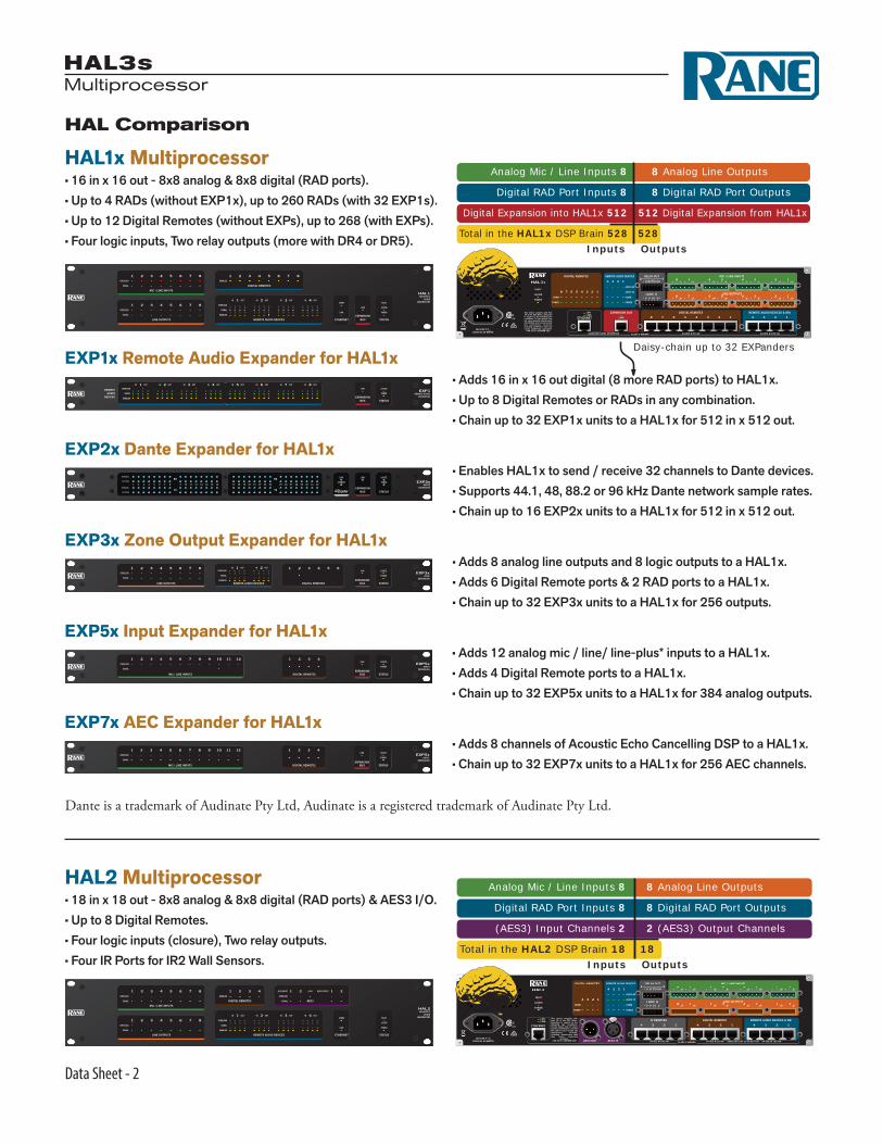
EXP5x Input Expander for HAL1x • Adds 12 analog mic / line/ line-plus* inputs to a HAL1x. • Adds 4 Digital Remote ports to a HAL1x. • Chain up to 32 EXP5x units to a HAL1x for 384 analog outputs.
EXP7x AEC Expander for HAL1x • Adds 8 channels of Acoustic Echo Cancelling DSP to a HAL1x. • Chain up to 32 EXP7x units to a HAL1x for 256 AEC channels.
HAL Comparison
HAL2 Multiprocessor• 18 in x 18 out - 8x8 analog & 8x8 digital (RAD ports) & AES3 I/O.• Up to 8 Digital Remotes.• Four logic inputs (closure), Two relay outputs.• Four IR Ports for IR2 Wall Sensors.
This device complies with Part 15 of the FCC Rules. Operation is subject to the following two conditions: (1) this device may not cause harmful interference, and (2) this device must accept any interference received, including interference that may cause undesired
operation.CAN ICES-3 (B)/NMB-3(B)
(AES3) Input Channels 2
Total in the HAL2 DSP Brain 18 18
2 (AES3) Output Channels
Inputs Outputs
Digital RAD Port Inputs 8 8 Digital RAD Port Outputs
Analog Mic / Line Inputs 8 8 Analog Line Outputs
HAL2HEURISTIC
AUDIOLABORATORY
HAL1x Multiprocessor• 16 in x 16 out - 8x8 analog & 8x8 digital (RAD ports).• Up to 4 RADs (without EXP1x), up to 260 RADs (with 32 EXP1s).• Up to 12 Digital Remotes (without EXPs), up to 268 (with EXPs).• Four logic inputs, Two relay outputs (more with DR4 or DR5).
+ – + –
+ – + –
+ – + –
+ – + –
+ – + –
+ – + –
+ – + –
+ – + –
REMOTE AUDIO DEVICES & DRsDIGITAL REMOTESEXPANSION BUS
ETHERNET
REMOTE AUDIO DEVICESDIGITAL REMOTES
123412345678
4
12345678
3 2 1
LINK
LANLINK
COMM
POWER
COMM
POWER
AUDIO TX
AUDIO RX
MIC / LINE INPUTS
LINE OUTPUTS8 7 6 5 4 3 2 1
8 7 6 5 4 3 2 1RELAY OUT
LOGIC IN
C NC NO C NC NO
G 4 3 2 1 G
2 1
SHIELDED CAT5e OR BETTER 24 VDC @ 100 mA24 VDC @ 50 mA
HAL1X
100-240 V50/60 Hz 55 WATTS
CLASS 2 WIRING
Digital Expansion into HAL1x 512
Total in the HAL1x DSP Brain 528 528
512 Digital Expansion from HAL1x
Inputs Outputs
Digital RAD Port Inputs 8 8 Digital RAD Port Outputs
Analog Mic / Line Inputs 8 8 Analog Line Outputs
Daisy-chain up to 32 EXPandersEXP1x Remote Audio Expander for HAL1x • Adds 16 in x 16 out digital (8 more RAD ports) to HAL1x. • Up to 8 Digital Remotes or RADs in any combination. • Chain up to 32 EXP1x units to a HAL1x for 512 in x 512 out.
STATUSEXPANSION
BUS
LINK LOCATE
POWER
5 6 7 8IN OUT IN OUT IN OUT IN OUT
OVERLOAD
SIGNAL
ENABLED
4IN OUT3IN OUT2IN OUT1IN OUT
1 2 1 2 1 2 1 2 1 2 1 2 1 2 1 2
1 2 1 2
1 2 1 2
1 2 1 2
1 2 1 2
1 2 1 2
1 2 1 2
1 2 1 2
1 2 1 2
1 2 1 2 1 2 1 2 1 2 1 2 1 2 1 2
EXP1REMOTE AUDIO
EXPANSION
REMOTEAUDIO
DEVICES
EXP3x Zone Output Expander for HAL1x • Adds 8 analog line outputs and 8 logic outputs to a HAL1x. • Adds 6 Digital Remote ports & 2 RAD ports to a HAL1x. • Chain up to 32 EXP3x units to a HAL1x for 256 outputs.
EXP2x Dante Expander for HAL1x • Enables HAL1x to send / receive 32 channels to Dante devices. • Supports 44.1, 48, 88.2 or 96 kHz Dante network sample rates. • Chain up to 16 EXP2x units to a HAL1x for 512 in x 512 out.
LINE OUTPUTS REMOTE AUDIO DEVICES
1 2 3 4 5 6 7 8OVERLOAD
SIGNAL
DIGITAL REMOTESEXPANSION
BUS
1 2
STATUS
IN 1 OUT IN 2 OUTOVERLOAD
SIGNAL
ENABLED
3 4 5 6EXP3x
ZONEEXPANSION
RX
TX
RX
TXSTATUS
EXPANSIONBUS
1 2 3 4 5 6 7 8 9 10 11 12 13 14 15 16 17 18 19 20 21 22 23 24 25 26 27 28 29 30 31 32SIGNAL
ACTIVE
SIGNAL
ACTIVE EXP2xDANTE
EXPANSION
MIC / LINE INPUTS
1 2 3 4 5 6 7 8OVERLOAD
SIGNALEXPANSION
BUS STATUS
9 1110 12
DIGITAL REMOTES
1 2 3 4EXP5x
INPUTEXPANSION
MIC / LINE INPUTS
1 2 3 4 5 6 7 8OVERLOAD
SIGNALEXPANSION
BUS STATUS
9 1110 12
DIGITAL REMOTES
1 2 3 4EXP5x
INPUTEXPANSION
Dante is a trademark of Audinate Pty Ltd, Audinate is a registered trademark of Audinate Pty Ltd.

HAL3sMultiprocessor
Data Sheet - 3
HAL Comparison
HAL4 Multiprocessor*• 2 Mic/Line/Line-Plus Inputs can wire “mic level,” "mic with phantom," “line level balanced,” or “unbalanced L/R monoed.”• 2 balanced line outputs.• One Digital Remote Port.
HAL3s Multiprocessor• 6 in x 10 out - 2x6 analog & 4x4 digital (RAD port).• 2 Mic/Line/ Line-Plus Inputs*.• Up to four Digital Remotes.• Four logic inputs (contact closure).
CLASS 2 WIRING
HAL4
100-240 V50/60 Hz 12 WATTS
LINE OUTPUTS MIC / LINE-PLUS INPUTS
+ – + –
2 12 1ETHERNET
SHIELDED CAT 5e OR BETTER
L R L R
+ – + –MAY BE WIRED
BALANCEDOR
UNBALANCEDLEFT &RIGHT
MONO’ED
LOCATE LINK
24 VDC @ 50 mA
DIGITAL REMOTE
Total in the HAL4 DSP Brain 2 2Inputs Outputs
Analog Mic/Line-Plus Inputs 2 2 Analog Line Outputs
CLASS 2 WIRING
HAL3S
100-240 V50/60 Hz 20 WATTS
LINE OUTPUTS MIC/LINE-PLUS INPUTS
+ – + –
R L R
+ – + – + – + – + – + –2 16 5 4 3 2 1
LANLINK
COMMPOWER
COMMPOWER
ETHERNET DIGITAL REMOTES REMOTE AUDIO DEVICES
2 12 1 2 1
LOGIC IN
G 4 3 2 1 G
24 VDC @ 50 mA 24 VDC @ 100 mA|SHIELDED CAT 5e OR BETTER
AUDIO RXAUDIO TX
or DRsFAULT
LOCATE
POWER
MADE IN U.S.A. RANE CORP.
Total in the HAL3s DSP Brain 6 10Inputs Outputs
Digital RAD Port Inputs 4 4 Digital RAD Port Outputs
Analog Line-Plus Inputs 2 6 Analog Line Outputs
OUTPUTS
OVERLOAD
SIGNAL
ENABLED COMM
LINK
FAULT POWER
LOCATE
INPUTS DIGITAL REMOTE ETHERNET STATUS
HAL4HEURISTIC
AUDIOLABORATORY
MIC / LINE INPUTS LINE OUTPUTS
1 2 3 4 5 6OVERLOAD
SIGNAL
DIGITALREMOTES
11 221 2OVERLOAD
SIGNAL
ETHERNETREMOTE AUDIO DEVICES STATUS
IN OUT IN OUT
OVERLOAD
SIGNAL
ENABLED
HAL3sHEURISTIC
AUDIOLABORATORY
Latency
RAD and DR Cable Lengths
1 2 1 2 1 2 1 2 1 2 1 2 1 2 1 2
1 2 1 2 1 2 1 2 1 2 1 2 1 2 1 21 2 3 4 5 6 7 8
LINE OUTPUTS
MIC / LINE INPUTS
OVERLOAD
SIGNAL
1 2 3 4 5 6 7 8OVERLOAD
SIGNAL
1 2 3 4IN OUT IN OUT IN OUT IN OUT
OVERLOAD
SIGNAL
ENABLED
ENABLED
1 2 3 4 5 6 7 8
DIGITAL REMOTES
REMOTE AUDIO DEVICES ETHERNET STATUS
COMM
LINK
LOCATE
FAULT
POWER
HAL2HEURISTIC
AUDIOLABORATORY
MICROPHONEMICROPHONE
SIG / OL
AUDIO RX AUDIO TX
RAD1
SIG / OL
POWER COMM
LINE OUTPUT LINE OUTPUT
SIG / OL SIG / OL
POWER COMM AUDIO RX AUDIO TX
RAD4
Analog In to Analog Out= 2.39 ms
HAL2or HAL3s
RAD In toAnalog Out= 1.85 ms
Analog In toRAD Out= 2.25 ms
RAD In toRAD Out= 1.71 ms
1 2 1 2 1 2 1 2 1 2 1 2 1 2 1 2
1 2 1 2 1 2 1 2 1 2 1 2 1 2 1 21 2 3 4 5 6 7 8
LINE OUTPUTS
MIC / LINE INPUTS
OVERLOAD
SIGNAL
1 2 3 4 5 6 7 8OVERLOAD
SIGNAL
1 2 3 4IN OUT IN OUT IN OUT IN OUT
OVERLOAD
SIGNAL
ENABLED
ENABLED
1 2 3 4 5 6 7 8
DIGITAL REMOTES
REMOTE AUDIO DEVICES ETHERNET STATUSEXPANSION
BUS
COMM
LINK
LINK LOCATE
FAULT
POWER
HAL1xHEURISTIC
AUDIOLABORATORY
STATUSEXPANSION
BUS
LINK LOCATE
POWER
5 6 7 8IN OUT IN OUT IN OUT IN OUT
OVERLOAD
SIGNAL
ENABLED
4IN OUT3IN OUT2IN OUT1IN OUT
1 2 1 2 1 2 1 2 1 2 1 2 1 2 1 2
1 2 1 2
1 2 1 2
1 2 1 2
1 2 1 2
1 2 1 2
1 2 1 2
1 2 1 2
1 2 1 2
1 2 1 2 1 2 1 2 1 2 1 2 1 2 1 2
EXP1xREMOTE AUDIO
EXPANSION
REMOTEAUDIO
DEVICES
STATUSEXPANSION
BUS
LINK LOCATE
POWER
5 6 7 8IN OUT IN OUT IN OUT IN OUT
OVERLOAD
SIGNAL
ENABLED
4IN OUT3IN OUT2IN OUT1IN OUT
1 2 1 2 1 2 1 2 1 2 1 2 1 2 1 2
1 2 1 2
1 2 1 2
1 2 1 2
1 2 1 2
1 2 1 2
1 2 1 2
1 2 1 2
1 2 1 2
1 2 1 2 1 2 1 2 1 2 1 2 1 2 1 2
EXP1REMOTE AUDIO
EXPANSION
REMOTEAUDIO
DEVICES
STATUSEXPANSION
BUS
LINK LOCATE
POWER
5 6 7 8IN OUT IN OUT IN OUT IN OUT
OVERLOAD
SIGNAL
ENABLED
4IN OUT3IN OUT2IN OUT1IN OUT
1 2 1 2 1 2 1 2 1 2 1 2 1 2 1 2
1 2 1 2
1 2 1 2
1 2 1 2
1 2 1 2
1 2 1 2
1 2 1 2
1 2 1 2
1 2 1 2
1 2 1 2 1 2 1 2 1 2 1 2 1 2 1 2
EXP1xREMOTE AUDIO
EXPANSION
REMOTEAUDIO
DEVICES
VOLUME ……… SOURCE <more>◊Mic 1•Mic 2◊CD Player◊Page <more>
SCROLL
PUSH TO SELECT
DR3
Equipment Rack
Other Rane DRDigital Remotes
MICROPHONEMICROPHONE
SIG / OL
AUDIO RX AUDIO TX
RAD1
SIG / OL
POWER COMM
Rane RAD,PAGER1 or AM unit
Any Ethernet Device
or Rane HAL Expander*
*Gbit Ethernet media converters are supported.300 feet 500 feet 1000 feet
100 meters 150 meters 300 meters
DR6 or RAD26with RPI supply
HAL3sMultiprocessor
Data Sheet - 4
HAL3s Specifications
Parameter Specification Limit Conditions/Comments
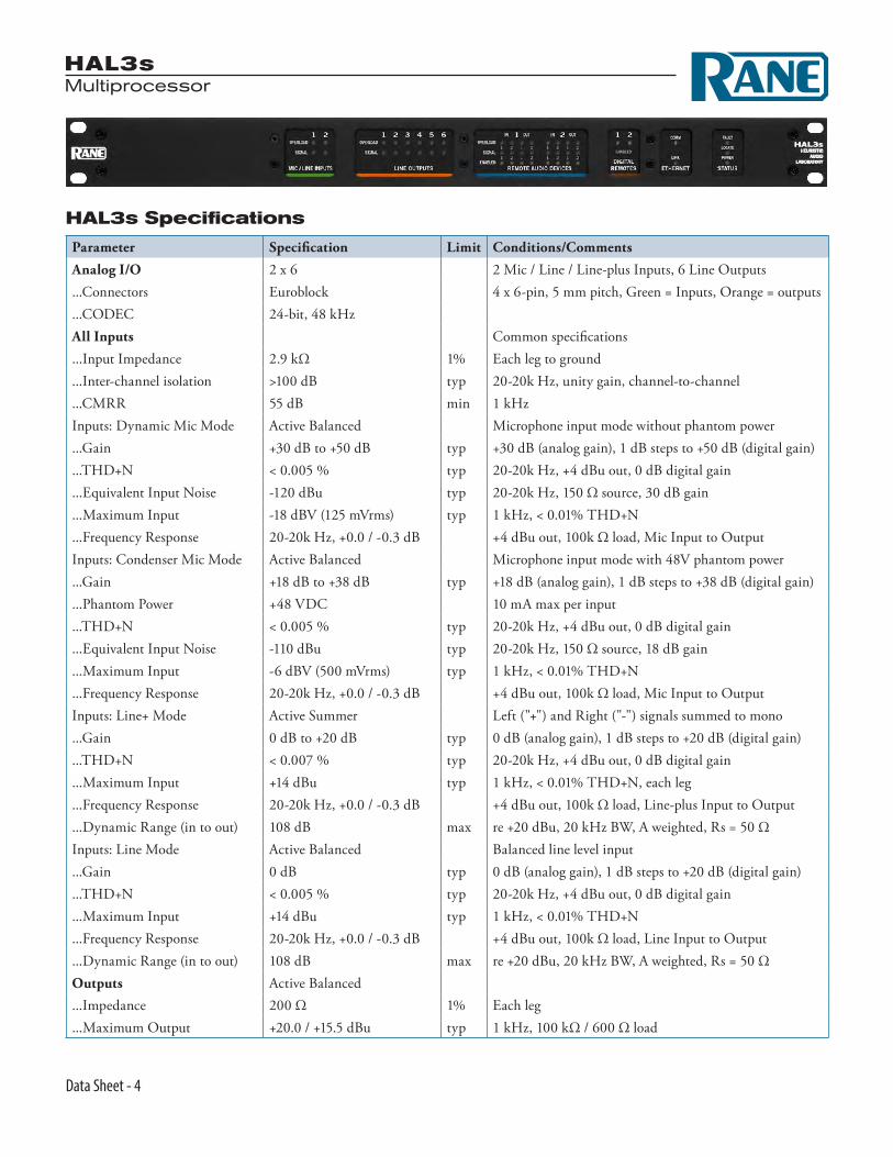
Analog I/O 2 x 6 2 Mic / Line / Line-plus Inputs, 6 Line Outputs...Connectors Euroblock 4 x 6-pin, 5 mm pitch, Green = Inputs, Orange = outputs...CODEC 24-bit, 48 kHz All Inputs Common specifications...Input Impedance 2.9 kΩ 1% Each leg to ground...Inter-channel isolation >100 dB typ 20-20k Hz, unity gain, channel-to-channel...CMRR 55 dB min 1 kHzInputs: Dynamic Mic Mode Active Balanced Microphone input mode without phantom power...Gain +30 dB to +50 dB typ +30 dB (analog gain), 1 dB steps to +50 dB (digital gain)...THD+N < 0.005 % typ 20-20k Hz, +4 dBu out, 0 dB digital gain...Equivalent Input Noise -120 dBu typ 20-20k Hz, 150 Ω source, 30 dB gain...Maximum Input -18 dBV (125 mVrms) typ 1 kHz, < 0.01% THD+N...Frequency Response 20-20k Hz, +0.0 / -0.3 dB +4 dBu out, 100k Ω load, Mic Input to OutputInputs: Condenser Mic Mode Active Balanced Microphone input mode with 48V phantom power...Gain +18 dB to +38 dB typ +18 dB (analog gain), 1 dB steps to +38 dB (digital gain)...Phantom Power +48 VDC 10 mA max per input...THD+N < 0.005 % typ 20-20k Hz, +4 dBu out, 0 dB digital gain...Equivalent Input Noise -110 dBu typ 20-20k Hz, 150 Ω source, 18 dB gain...Maximum Input -6 dBV (500 mVrms) typ 1 kHz, < 0.01% THD+N...Frequency Response 20-20k Hz, +0.0 / -0.3 dB +4 dBu out, 100k Ω load, Mic Input to OutputInputs: Line+ Mode Active Summer Left ("+") and Right ("-") signals summed to mono...Gain 0 dB to +20 dB typ 0 dB (analog gain), 1 dB steps to +20 dB (digital gain)...THD+N < 0.007 % typ 20-20k Hz, +4 dBu out, 0 dB digital gain...Maximum Input +14 dBu typ 1 kHz, < 0.01% THD+N, each leg...Frequency Response 20-20k Hz, +0.0 / -0.3 dB +4 dBu out, 100k Ω load, Line-plus Input to Output...Dynamic Range (in to out) 108 dB max re +20 dBu, 20 kHz BW, A weighted, Rs = 50 ΩInputs: Line Mode Active Balanced Balanced line level input...Gain 0 dB typ 0 dB (analog gain), 1 dB steps to +20 dB (digital gain)...THD+N < 0.005 % typ 20-20k Hz, +4 dBu out, 0 dB digital gain...Maximum Input +14 dBu typ 1 kHz, < 0.01% THD+N...Frequency Response 20-20k Hz, +0.0 / -0.3 dB +4 dBu out, 100k Ω load, Line Input to Output...Dynamic Range (in to out) 108 dB max re +20 dBu, 20 kHz BW, A weighted, Rs = 50 ΩOutputs Active Balanced ...Impedance 200 Ω 1% Each leg...Maximum Output +20.0 / +15.5 dBu typ 1 kHz, 100 kΩ / 600 Ω load

HAL3sMultiprocessor
Data Sheet - 5
Parameter Specification Limit Conditions/Comments
Indicators
...Signal -50 dBFS typ Green LED, peak-reading
...Overload -0.5 dBFS typ Red LED, peak-readingPropagation Delays See the Latency graphic on page page 3....RAD In to RAD Out 1.71 ms typ Tested with RAD23...RAD In to Analog Out 1.85 ms typ...Analog In to RAD Out 2.25 ms typ...Analog In to Analog Out 2.39 ms typDSP
...Processing Power 2400 MIPS max 1 DSP @ 300 MHz with up to 8 instructions / cycle
...Word Length 32 / 64-bit Floating Point
...Delay Memory 20 seconds maxComputer Interface
...Type Ethernet 1000 base-T Zeroconf service discovery protocol for easy set up
...Cable Shielded CAT 5e or better RJ-45 connector
...Length 100 meters / 300 feet max Standard Ethernet cable length limitRAD Port 2 RJ-45 connectors...Audio Channels 2 in x 2 out Each port 2 in x 2 out, control channel, 24-bit, 48 kHz...Power 24 VDC @ 100 mA max Each port...Length 152 meters / 500 feet max Shielded CAT 5e cable or betterDR Ports 4 RJ-45 connectors...Power 24 VDC @ 50 mA max Each port...Length 300 meters / 1000 feet max Shielded CAT 5e cable or betterLogic Inputs 4...Connector Mini Euroblock 6-pin, 3.81 mm pitch, Black...Internal Pull-up 51.1 kΩ, 5.0 V Protected to +24 V, reverse polarity protected...Vin High > 2.2 V min Normal state...Vin Low < 0.7 V max External circuit sinks > 22 µA to assertWiring Class 2 All rear panel terminalsPower Requirement 100 to 240 VAC 50/60 Hz, 20 W maxAmbient Room Temp. 40 °C max Maximum external loadingUnit: Conformity CE, FCC, CCSAUSUnit: Size 1.73"H x 19"W x 8.25"D (4.4 cm x 48.3 cm x 20.9 cm)...Weight 4.75 lb (2.2 kg)Shipping: Size 4.25" x 20.3" x 13.75" (11 cm x 52 cm x 35 cm)...Weight 9 lb (3.8 kg)
HAL3sMultiprocessor
Data Sheet - 6
LINE INPUT LINE INPUT
RAD3
POWER COMM
SIG / OLSIG / OL
AUDIO RX AUDIO TX
LINE INPUT LINE INPUT
RAD3
SIG / OL
POWER COMM
SIG / OL
AUDIO RX AUDIO TX
LINE INPUT LINE INPUT
POWER COMM
SIG / OL SIG / OL
AUDIO RX AUDIO TX
RAD3
MICROPHONE MICROPHONE
RAD1
SIG / OL
AUDIO RX AUDIO TXPOWER COMM
SIG / OL
MICROPHONE MICROPHONE
RAD1
SIG / OL
AUDIO RX AUDIO TX
SIG / OL
POWER COMM
MICROPHONEMICROPHONE
SIG / OL
AUDIO RX AUDIO TX
RAD1
SIG / OL
POWER COMM
LINE OUTPUT LINE OUTPUT
RAD4
SIG / OLSIG / OL
POWER COMM AUDIO RX AUDIO TX
LINE OUTPUT LINE OUTPUT
RAD4
POWER COMM
SIG / OL SIG / OL
AUDIO RX AUDIO TX
LINE OUTPUT LINE OUTPUT
SIG / OL SIG / OL
POWER COMM AUDIO RX AUDIO TX
RAD4
MICROPHONE LINE INPUT
RAD2
SIG / OL
AUDIO RX AUDIO TXPOWER COMM
SIG / OL
MICROPHONE LINE INPUT
RAD2
SIG / OL
AUDIO RX AUDIO TX
SIG / OL
POWER COMM
LINE INPUTMICROPHONE
SIG / OL
AUDIO RX AUDIO TX
RAD2
SIG / OL
POWER COMM
MICROPHONE LINE INPUT
RAD7
POWER COMM
SIG / OLSIG / OL
AUDIO RX AUDIO TX
MICROPHONE LINE INPUT
RAD7
SIG / OL
POWER COMM
SIG / OL
AUDIO RX AUDIO TX
MICROPHONE LINE INPUT
POWER COMM
SIG / OL SIG / OL
AUDIO RX AUDIO TX
RAD7
MICROPHONE LINE OUTPUT
RAD9
SIG / OL
AUDIO RX AUDIO TXPOWER COMM
SIG / OL
MICROPHONE LINE OUTPUT
RAD9
SIG / OL
AUDIO RX AUDIO TX
SIG / OL
POWER COMM
LINE OUTPUTMICROPHONE
SIG / OL
AUDIO RX AUDIO TX
SIG / OL
POWER COMM
RAD9
LINE OUTPUTLINE INPUT
RAD6
SIG / OL
AUDIO RX AUDIO TXPOWER COMM
SIG / OL
LINE OUTPUTLINE INPUT
RAD6
SIG / OL
AUDIO RX AUDIO TX
SIG / OL
POWER COMM
LINE OUTPUTLINE INPUT
SIG / OL
AUDIO RX AUDIO TX
SIG / OL
POWER COMM
RAD6
LINE OUTPUTMICROPHONE
RAD8
SIG / OL
AUDIO RX AUDIO TXPOWER COMM
SIG / OL
LINE OUTPUTMICROPHONE
RAD8
SIG / OL
AUDIO RX AUDIO TX
SIG / OL
POWER COMM
LINE OUTPUTMICROPHONE
SIG / OL
AUDIO RX AUDIO TX
SIG / OL
POWER COMM
RAD8
RAD11
MICROPHONE LINE INPUT LINE OUTPUT
SIG / OL
AUDIO RX AUDIO TX
SIG / OL
POWER COMM
SIG / OL
LINE INPUTMICROPHONE LINE OUTPUT
SIG / OL
AUDIO RX AUDIO TX
SIG / OL
POWER COMM
SIG / OL
RAD11RAD11
MICROPHONE LINE INPUT LINE OUTPUT
SIG / OL
AUDIO RX AUDIO TXPOWER COMM
SIG / OL SIG / OL
MICROPHONE MICROPHONE LINE OUTPUT LINE OUTPUT
RAD12
SIG / OL
AUDIO RX AUDIO TXPOWER COMM
SIG / OL SIG / OLSIG / OL
MICROPHONE MICROPHONE LINE OUTPUT LINE OUTPUT
RAD12
SIG / OL
AUDIO RX AUDIO TX
SIG / OL
POWER COMM
SIG / OLSIG / OL
MICROPHONEMICROPHONE LINE OUTPUTLINE OUTPUT
SIG / OL
AUDIO RX AUDIO TX
SIG / OL
POWER COMM
SIG / OLSIG / OL
RAD12
MICROPHONE LINE INPUT LINE OUTPUT LINE OUTPUT
RAD14
SIG / OL
AUDIO RX AUDIO TXPOWER COMM
SIG / OL SIG / OLSIG / OL
MICROPHONE LINE INPUT LINE OUTPUT LINE OUTPUT
RAD14
SIG / OL
AUDIO RX AUDIO TX
SIG / OL
POWER COMM
SIG / OLSIG / OL
LINE INPUTMICROPHONE LINE OUTPUTLINE OUTPUT
SIG / OL
AUDIO RX AUDIO TX
SIG / OL
POWER COMM
SIG / OLSIG / OL
RAD14
LINE INPUT LINE INPUT LINE OUTPUT LINE OUTPUT
RAD15
SIG / OL
AUDIO RX AUDIO TXPOWER COMM
SIG / OL SIG / OLSIG / OL
LINE INPUT LINE INPUT LINE OUTPUT LINE OUTPUT
RAD15
SIG / OL
AUDIO RX AUDIO TX
SIG / OL
POWER COMM
SIG / OLSIG / OL
LINE INPUTLINE INPUT LINE OUTPUTLINE OUTPUT
SIG / OL
AUDIO RX AUDIO TX
SIG / OL
POWER COMM
SIG / OLSIG / OL
RAD15
MICROPHONE LINE INPUT
RAD18
SIG / OL
AUDIO RX AUDIO TXPOWER COMM
SIG / OL
MICROPHONE LINE INPUT
RAD18
SIG / OL
AUDIO RX AUDIO TX
SIG / OL
POWER COMM
LINE INPUTMICROPHONE
SIG / OL
AUDIO RX AUDIO TX
RAD18
SIG / OL
POWER COMM
LINE INPUT LINE OUTPUT
RAD23
SIG / OL
AUDIO RX AUDIO TXPOWER COMM
SIG / OL
LINE INPUT LINE OUTPUT
RAD23
SIG / OL
AUDIO RX AUDIO TX
SIG / OL
POWER COMM
LINE OUTPUTLINE INPUT
SIG / OL
AUDIO RX AUDIO TX
SIG / OL
POWER COMM
RAD23
AES3 INPUT AES3 OUTPUT
RAD5
AUDIO RX AUDIO TXPOWER COMM
LOCK
AES3 INPUT AES3 OUTPUT
RAD5
AUDIO RX AUDIO TX
LOCK
POWER COMM
AES3 OUTPUTAES3 INPUT
AUDIO RX AUDIO TX
LOCK
POWER COMM
RAD5
RAD PORT
RADX
RAD PORT
RADX
RAD PORT
RADX
BUSY
CAUTION
OVERLOAD
SIGNAL
READY
PAGER1
AM1AUTOMIXER
POWERLOCATE
PHONESMIX
SIG OL SIG OLLEVEL SIG OLLEVEL SIG OLLEVEL
MIC MIX
SIG OLLEVEL
AUX 1
SIG OLLEVEL
AUX 2
SIG OLLEVEL
USB
SIG OLLEVEL
OUTPUT
SIG OLLEVEL
AUX 2AUX 1 USB
MICS OUTPUT
SOURCE
LEVELLEVEL
MIC INPUTS1 2 3 4
USB AUDIO
RAD27
POWER COMM
AUDIO RX AUDIO TX
PLAY RECORD
INPUT OUTPUT
USB AUDIO
RAD27
POWER COMM
AUDIO RX AUDIO TX
PLAY RECORD
INPUT OUTPUT
USB AUDIO
POWER COMM
AUDIO RX AUDIO TX
PLAY RECORD
INPUT OUTPUT
RAD27
INPUT OUTPUT INPUT MODE AUDIO INOUT 12 12INPUTSOUTPUTSLOGIC
RAD PORT -+ -+ -+ -+2 1 2 1
PAGER1 MADE IN U.S.A. RAD PORT
POWER COMM AUDIO RX AUDIO TX
SHIELDED CAT 5e OR BETTER
SourceBG MusicPhone / LineMic
Room ARoom BHallwayMute All
East Wing
SUITABLE FOR USE IN AIR-HANDLING SPACES. COMMERCIAL AUDIO EQUIPMENT 24TJ
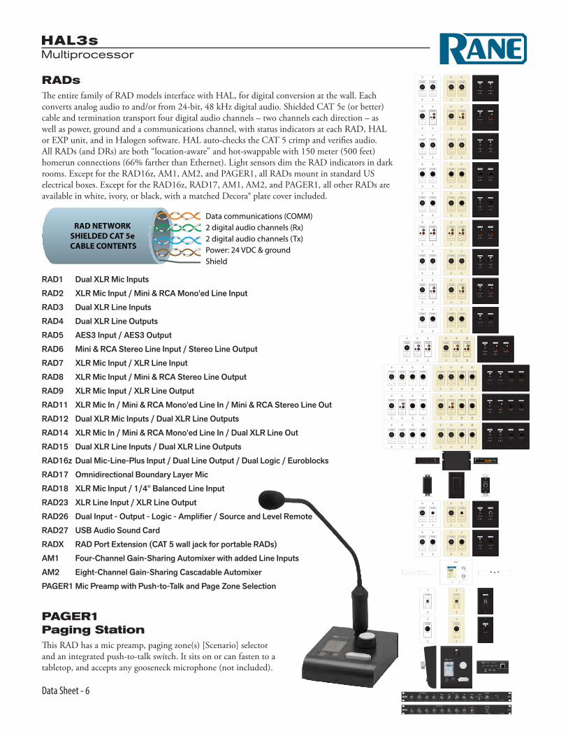
RADsThe entire family of RAD models interface with HAL, for digital conversion at the wall. Each converts analog audio to and/or from 24-bit, 48 kHz digital audio. Shielded CAT 5e (or better) cable and termination transport four digital audio channels – two channels each direction – as well as power, ground and a communications channel, with status indicators at each RAD, HAL or EXP unit, and in Halogen software. HAL auto-checks the CAT 5 crimp and verifies audio. All RADs (and DRs) are both “location-aware” and hot-swappable with 150 meter (500 feet) homerun connections (66% farther than Ethernet). Light sensors dim the RAD indicators in dark rooms. Except for the RAD16z, AM1, AM2, and PAGER1, all RADs mount in standard US electrical boxes. Except for the RAD16z, RAD17, AM1, AM2, and PAGER1, all other RADs are available in white, ivory, or black, with a matched Decora® plate cover included.
2 digital audio channels (Rx)2 digital audio channels (Tx)
Data communications (COMM)
Power: 24 VDC & groundShield
RAD NETWORKSHIELDED CAT 5e
CABLE CONTENTS
PAGER1 Paging StationThis RAD has a mic preamp, paging zone(s) [Scenario] selector and an integrated push-to-talk switch. It sits on or can fasten to a tabletop, and accepts any gooseneck microphone (not included).
RAD1 Dual XLR Mic Inputs
RAD2 XLR Mic Input / Mini & RCA Mono'ed Line Input
RAD3 Dual XLR Line Inputs
RAD4 Dual XLR Line Outputs
RAD5 AES3 Input / AES3 Output
RAD6 Mini & RCA Stereo Line Input / Stereo Line Output
RAD7 XLR Mic Input / XLR Line Input
RAD8 XLR Mic Input / Mini & RCA Stereo Line Output
RAD9 XLR Mic Input / XLR Line Output
RAD11 XLR Mic In / Mini & RCA Mono'ed Line In / Mini & RCA Stereo Line Out
RAD12 Dual XLR Mic Inputs / Dual XLR Line Outputs
RAD14 XLR Mic In / Mini & RCA Mono'ed Line In / Dual XLR Line Out
RAD15 Dual XLR Line Inputs / Dual XLR Line Outputs
RAD16z Dual Mic-Line-Plus Input / Dual Line Output / Dual Logic / Euroblocks
RAD17 Omnidirectional Boundary Layer Mic
RAD18 XLR Mic Input / 1/4" Balanced Line Input
RAD23 XLR Line Input / XLR Line Output
RAD26 Dual Input - Output - Logic - Amplifier / Source and Level Remote
RAD27 USB Audio Sound Card
RADX RAD Port Extension (CAT 5 wall jack for portable RADs)
AM1 Four-Channel Gain-Sharing Automixer with added Line Inputs
AM2 Eight-Channel Gain-Sharing Cascadable Automixer
PAGER1 Mic Preamp with Push-to-Talk and Page Zone Selection

HAL3sMultiprocessor
Data Sheet - 7
DR2 DR2PUSH TO SELECT
SCROLL
PUSH TO SELECT
SCROLL
DR3PUSH TO SELECT
SCROLL
DR3PUSH TO SELECT
SCROLL
Single Level & List of Toggles / Commands List of Levels
DR3PUSH TO SELECT
SCROLL
Single Level & Selector
Single Selector
Level Control
List of Toggles / Commands
DR1
DR1 Digital Volume Remote
DR2 Digital Selection Remote
DR3 Digital Volume and Selection Remote
Digital RemotesThree Digital Remotes simplify end user control and eliminate installer brain fatigue. Use Digital Remotes for volume control, preset recall, source selection, or resetting or toggling system states. All offer customizable backlit LCD screens for intuitive end user labeling. Home run shielded CAT 5e (or better) connections to a HAL or EXP eliminate addressing, external power, and the need to test the cables.
The DR1 supports Level Control.
The DR2 offers Single Selector or List of Toggles/Commands behavior.
The DR3 has three behaviors: Single Level & List of Toggles/Commands, List of Levels for either multizone volume control and/or input source mixing, and Single Level plus Selector.
Control LinkingIn Halogen blocks, drag the purple control chain icons atop one another to create links between Levels, Toggles, Selectors, Commands, Digital Remotes, Web Controls and/or 3rd-party controls. The above screen shows linking a DR1 volume onto the Meeting Room Output Level control. Four Control Link types and behaviors are supported: Level, Select, Toggle or Command. Activation and Priorities work together for incredible flexibility. Link simple analog remote level controls, contact closures and IR remote wall sensors by adding a DR4 Logic I/O Expander.

HAL3sMultiprocessor
Data Sheet - 8
DR4
100-240 V50/60 Hz 22 WATTS
RANE CORPORATION
CLASS 2 WIRING
DIGITAL REMOTE PORT LOGIC IN
G 4 3 2 1 G
LOGIC OUT
G 4 3 2 1 G
G 8 7 6 5 GG 8 7 6 5 G
Vr 2 G Vr 1 G
ANALOG CONTROL INPUTS: 0-5 VDC
Vr 6 G Vr 5 G
Vr 4 G Vr 3 GVr 8 G Vr 7 G
IR REMOTES: 24 VDC @ 100 mA
123
456
123
456
DR4 Logic I/O ExpanderThe DR4 Digital Remote adds additional logic input and output ports to any HAL, enabling simple analog level and logic I/O controls plus IR2 remotes for wall sensing. The DR4 offers eight logic ins and outs, six IR ports and eight analog input ports for
pot-on-a-wall level control. Multiple DR4's can connect to Digi-tal Remote Ports on any HAL, up to 300 meters (1000 feet) away.See the Logic Inputs, Control Inputs and Logic Outputs on the next page.
DR5 Switch Controller RemoteThe DR5 Digital Remote offers additional logic input and output ports, enabling the use of simple analog switch controls in any HAL system. Lighted switch panels for room combine applications are easily integrated into a HAL system using the eight switch inputs and eight LEDs outputs on the DR5. Unlike the HAL and DR4 Logic I/O, the DR5 Logic Out is intended to drive the LED indicator on a room combine panel, and is a writable parameter. The DR5 is designed to fit in a standard US dual-gang electrical box or mount directly near a room combine panel.
Shielded CAT 5e (or better)300 meters1,000 feet
To a RAD or DR Porton any HAL or EXP unit.
LS
G
LS
G
PanelLockoption

HAL3sMultiprocessor
Data Sheet - 9
DR6 Touchscreen RemoteThe DR6 is a fully customizable touchscreen remote for the HAL family. It supports multiple pages or tabs and any set of levels, toggles, selectors and/or commands. Drag, drop and resize controls any way that’s desired. Use custom background images and logos in full-color on the 7-inch LCD display.
Screw the included wall-mount bracket over U.S. or interna-tional electrical boxes, or flush mount the ¾" thick DR6 with a 2-inch hole in the wall to accommodate the cable. The optional DS1 desk stand accessory (shown) allows the DR6 to mount on a horizontal surface. The optional RB1 rack bracket in-stalls the DR6 in a 19" equipment rack.
The included midspan power injector connects CAT5e (or better) cables between any HAL and the DR6 to deliver communi-cations and the extra power needed for the display.
Optional, on-screen User Access logins secure management pages from public or staff use, and a programmable ambient light sensor automatically dims the backlight.
The Control Page Designer in Halogen 5.0 allows you to create one set of pages and use them in a web control design, DR6 display or both.
Shielded CAT 5e or betterdata to and from the rack.
Shielded CAT 5e or betterdata and power to and from the remote.
REMOTE AUDIO DEVICES & DRsDIGITAL REMOTES
ETHERNET 123412345678
LANLINK
HAL
The RPI can go anywhere in between.
REMOTEPOWERINJECTOR
TO REMOTEDATA OUTPUT
TO RACKDATA INPUT
Any HAL
RPI
DR6
100 meters (325 feet) maxFrom HAL to DR6
DS1 Desk Stand Accessory• All steel, painted white.• Rubber bottom protects the desktop.• Kensington security hole.• Holes in the bottom to fasten to a desktop.• Larger hole in bottom to thread CAT 5
cable through the desktop.
RB1 Rack Bracket Accessory• All steel, painted black, 3U rack height.
DS1 Desk Stand available separately

HAL3sMultiprocessor
Data Sheet - 10
Halogen Web ControlsControl the Levels, Selectors, Toggles and Commands in any HAL System from any device with a web browser. Halogen’s Web Controls feature allows creation of custom HTML GUI control screens. Define the quantity of control pages, and the layout, labeling and size of each control, and completely test them using your default web browser from within Halogen.
Access any control page from any browser-enabled device on the network with a HAL device. Just open a browser and type in the customizable IP/webpage address for the HTML page – and bookmark it for easy access. Type in an optional User Access code, and voilà, the trick, she is done! Control your HAL system wire-lessly from one or more tablets, smart phones, laptops or desktop computers. The HAL web server is multi-client, allowing control across many devices and many rooms. You can link Rane’s wired DR remote controls (DR1, DR2, DR3 & DR6) and wireless devices and they’ll automatically track each other.
Customers are asking for “iPad control” and Halogen’s Web Controls is the solution. It is not Apple®-centric — no iTunes® store or app installs required. We’ll save a lot of ink on this page not listing all the possible devices that support web browsers and wireless Eth-ernet. Besides, the list will change before the ink dries.
HAL3sMultiprocessor
Data Sheet - 11
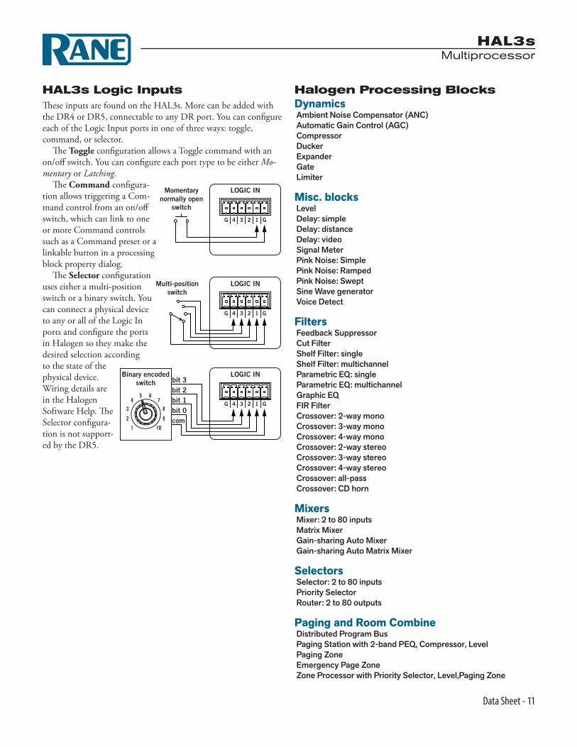
HAL3s Logic InputsThese inputs are found on the HAL3s. More can be added with the DR4 or DR5, connectable to any DR port. You can configure each of the Logic Input ports in one of three ways: toggle, command, or selector.
The Toggle configuration allows a Toggle command with an on/off switch. You can configure each port type to be either Mo-mentary or Latching.
The Command configura-tion allows triggering a Com-mand control from an on/off switch, which can link to one or more Command controls such as a Command preset or a linkable button in a processing block property dialog.
The Selector configuration uses either a multi-position switch or a binary switch. You can connect a physical device to any or all of the Logic In ports and configure the ports in Halogen so they make the desired selection according to the state of the physical device. Wiring details are in the Halogen Software Help. The Selector configura-tion is not support-ed by the DR5.
Binary encodedswitch
LOGIC IN
G 4 3 2 1 G
10
2
4
8
9
7
1
3
65
bit 3bit 2bit 1bit 0com
Multi-positionswitch
LOGIC IN
G 4 3 2 1 G
LOGIC INMomentarynormally open
switch
G 4 3 2 1 G
Halogen Processing BlocksDynamics Ambient Noise Compensator (ANC) Automatic Gain Control (AGC) Compressor Ducker Expander Gate Limiter
Misc. blocks Level Delay: simple Delay: distance Delay: video Signal Meter Pink Noise: Simple Pink Noise: Ramped Pink Noise: Swept Sine Wave generator Voice Detect
Filters Feedback Suppressor Cut Filter Shelf Filter: single Shelf Filter: multichannel Parametric EQ: single Parametric EQ: multichannel Graphic EQ FIR Filter Crossover: 2-way mono Crossover: 3-way mono Crossover: 4-way mono Crossover: 2-way stereo Crossover: 3-way stereo Crossover: 4-way stereo Crossover: all-pass Crossover: CD horn
Mixers Mixer: 2 to 80 inputs Matrix Mixer Gain-sharing Auto Mixer Gain-sharing Auto Matrix Mixer
Selectors Selector: 2 to 80 inputs Priority Selector Router: 2 to 80 outputs
Paging and Room Combine Distributed Program Bus Paging Station with 2-band PEQ, Compressor, Level Paging Zone Emergency Page Zone Zone Processor with Priority Selector, Level,Paging Zone
HAL3sMultiprocessor
Data Sheet - 12
CLASS 2 WIRING
HAL3S
100-240 V50/60 Hz 20 WATTS
LINE OUTPUTS MIC/LINE-PLUS INPUTS
+ – + –
R L R
+ – + – + – + – + – + –2 16 5 4 3 2 1
LANLINK
COMMPOWER
COMMPOWER
ETHERNET DIGITAL REMOTES REMOTE AUDIO DEVICES
2 12 1 2 1
LOGIC IN
G 4 3 2 1 G
24 VDC @ 50 mA 24 VDC @ 100 mA|SHIELDED CAT 5e OR BETTER
AUDIO RXAUDIO TX
or DRsFAULT
LOCATE
POWER
PAGER1
RAD6IN THE BAR
CABLE / SATELLITE TV
INTERNET MUSIC SERVICE
DR3 SOURCEAND VOLUMEIN THE BAR
DR1 VOLUMEIN THE
RESTAURANTRESTAURANT (mono) BAR (stereo)
FRONT DESK
SCROLL
PUSH TO SELECT
DR3
dB Headroom dB Headroom dB Headroom dB Headroom
3
6
12
24
Limit
1
Comp
Exp
Fault
Load
Ready
3
6
12
24
Limit
2
Comp
Exp
Fault
Load
Ready
3
6
12
24
Limit
3
Comp
Exp
Fault
Load
Ready
3
6
12
24
Limit
4 ON
Comp
Exp
Fault
Load
Ready
BUSY
CAUTION
OVERLOAD
SIGNAL
READY
PAGER1
4-CHANNEL AMPLIFIER
RANE HAL3s MULTIPROCESSOR
MEN’S ROOM
WOMEN’S ROOM
LINE OUTPUTLINE INPUT
SIG / OL
AUDIO RX AUDIO TX
SIG / OL
POWER COMM
RAD6
TV
PUSH • SELECT
DR1
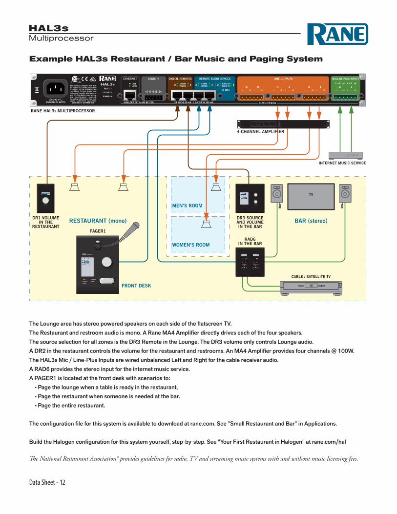
Example HAL3s Restaurant / Bar Music and Paging System
The Lounge area has stereo powered speakers on each side of the flatscreen TV.The Restaurant and restroom audio is mono. A Rane MA4 Amplifier directly drives each of the four speakers.The source selection for all zones is the DR3 Remote in the Lounge. The DR3 volume only controls Lounge audio.A DR2 in the restaurant controls the volume for the restaurant and restrooms. An MA4 Amplifier provides four channels @ 100W.The HAL3s Mic / Line-Plus Inputs are wired unbalanced Left and Right for the cable receiver audio.A RAD6 provides the stereo input for the internet music service.A PAGER1 is located at the front desk with scenarios to: • Page the lounge when a table is ready in the restaurant, • Page the restaurant when someone is needed at the bar. • Page the entire restaurant.
The configuration file for this system is available to download at rane.com. See "Small Restaurant and Bar" in Applications.
Build the Halogen configuration for this system yourself, step-by-step. See "Your First Restaurant in Halogen" at rane.com/hal
The National Restaurant Association® provides guidelines for radio, TV and streaming music systems with and without music licensing fees.
HAL3sMultiprocessor
Data Sheet - 13
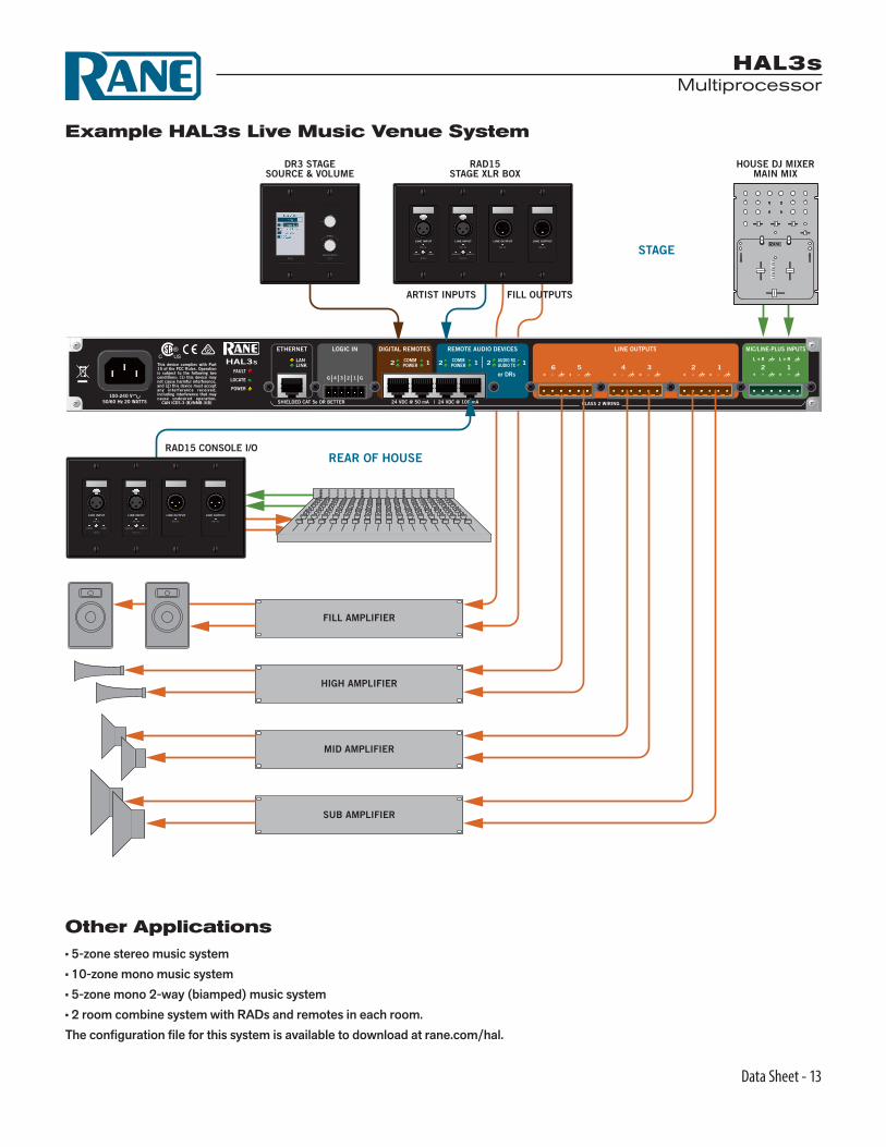
Example HAL3s Live Music Venue System
Other Applications• 5-zone stereo music system• 10-zone mono music system• 5-zone mono 2-way (biamped) music system• 2 room combine system with RADs and remotes in each room.The configuration file for this system is available to download at rane.com/hal.
CLASS 2 WIRING
HAL3S
100-240 V50/60 Hz 20 WATTS
LINE OUTPUTS MIC/LINE-PLUS INPUTS
+ – + –
R L R
+ – + – + – + – + – + –2 16 5 4 3 2 1
LANLINK
COMMPOWER
COMMPOWER
ETHERNET DIGITAL REMOTES REMOTE AUDIO DEVICES
2 12 1 2 1
LOGIC IN
G 4 3 2 1 G
24 VDC @ 50 mA 24 VDC @ 100 mA|SHIELDED CAT 5e OR BETTER
AUDIO RXAUDIO TX
or DRsFAULT
LOCATE
POWER
HOUSE DJ MIXERMAIN MIX
DR3 STAGESOURCE & VOLUME
RAD15STAGE XLR BOX
RAD15 CONSOLE I/O
ARTIST INPUTS FILL OUTPUTS
STAGE
REAR OF HOUSE
FILL AMPLIFIER
HIGH AMPLIFIER
MID AMPLIFIER
SUB AMPLIFIER
SCROLL
PUSH TO SELECT
DR3
LINE INPUTLINE INPUT LINE OUTPUTLINE OUTPUT
SIG / OL
AUDIO RX AUDIO TX
SIG / OL
POWER COMM
SIG / OLSIG / OL
RAD15
LINE INPUTLINE INPUT LINE OUTPUTLINE OUTPUT
SIG / OL
AUDIO RX AUDIO TX
SIG / OL
POWER COMM
SIG / OLSIG / OL
RAD15

HAL3sMultiprocessor
Data Sheet - 14
Cabinet with:Rane HAL3sRane AM1ComputerDVD playerAmplifierMics, headsets, charger
DR3
HC6
Headphones provided for students that need translation.
Podi
um
Mic andPC inputs
Source & volume
RAD2
DR6
Left
Righ
t
Example HAL3s Language Classroom System

HAL3sMultiprocessor
Data Sheet - 15
CLASS 2 WIRING
HAL3S
100-240 V50/60 Hz 20 WATTS
LINE OUTPUTS MIC/LINE-PLUS INPUTS
+ – + –
R L R
+ – + – + – + – + – + –2 16 5 4 3 2 1
LANLINK
COMMPOWER
COMMPOWER
ETHERNET DIGITAL REMOTES REMOTE AUDIO DEVICES
2 12 1 2 1
LOGIC IN
G 4 3 2 1 G
24 VDC @ 50 mA 24 VDC @ 100 mA|SHIELDED CAT 5e OR BETTER
AUDIO RXAUDIO TX
or DRsFAULT
LOCATE
POWER
Main Speakers
Instructor’s Equipment Cabinet
DR3 translator’s booth source & volume mix
Translator’s BoothRane HC6S Headphone Amplifier
Rane AM1 Automixer
Rane MA4 Multichannel Amplifier
Podium
RAD2 mic input & PC input
DR6 control ofsource & volume Hanging Student Mics
LINE INPUTMICROPHONE
SIG / OL
AUDIO RX AUDIO TX
RAD2
SIG / OL
POWER COMM
SCROLL
PUSH TO SELECT
DR3
HC6S
BALANCEDTIP = POSITIVE (+), RING = NEGATIVE (–),
SLEEVE = SHIELDUNBALANCED LINE INPUTS: TIP = LEFT, RING = RIGHT, SLEEVE = GROUND
ALL AUDIO JACKS ARE CLASS 2 WIRING
RIGHT LEFT IN IN IN IN IN INOUT OUT OUT OUT OUT OUT
MASTERINPUTS
6 5 4 3 2 1
ACN 001 345 482
RANE CORP.
COMMERCIAL AUDIOEQUIPMENT 24TJ
R
100-240 V50/60 Hz 12 WATTS
100-240V
PATENT NO. 8,542,849
13 WATTS50/60 Hz
RANE CORP.
USB
LOCATE
FAULT
POWERACN 001 345 482
AM1
MAIN OUTPUT
RAD PORT
AUXINPUTS
MIC INPUTS 12341
2
RECORD
USBAUDIO
POWER
COMM
AUDIO RX
AUDIO TX
MIC
+4
8V
MIC
+0
VW
IRE
LES
S M
IC
MIC
+4
8V
MIC
+0
VW
IRE
LES
S M
IC
MIC
+4
8V
MIC
+0
VW
IRE
LES
S M
IC
MIC
+4
8V
MIC
+0
VW
IRE
LES
S M
IC
5 V
DC
@ 5
00
mA
U
SB
C
HA
RG
EO
NLY
MIC
LIN
E
CLASS 2 WIRING
CASCADESHIELDED CAT 5e OR BETTER • 24 VDC @ 100 mA
DVD
MA 4
100-240V50/60 Hz 500 WATTS
RANE CORP.Class 2 Wiring OUTPUTS
Active Low Use Rane VR 2 or 20 kΩ pot
HIGH-PASS20Hz40Hz60Hz80Hz
ON
4+ – + – + – + – + – + – + – +
REMOTE LEVEL 44FLAG 3 2 1
FAULT
Vr Vc Vr Vc Vr Vc Vr Vc–
+ – + – + – + – + – + – + – + –
3 2 1
MASTERSLAVE
COMP4 3 2 1
1 2 3 4 + – + – + – + –
Vr Vc Vr Vc Vr Vc Vr Vc + – + – + – + –
INPUTSMODE
13
22dBu
SENSITIVITY
4
3
13
22dBu
SENSITIVITY
4
2
13
22dBu
SENSITIVITY
4
1
13
22dBu
SENSITIVITY
4
EXP ON
3INT EXT
LOAD
2INT EXT
LOAD
1INT EXT
LOAD
4INT EXT
LOAD
COMMERCIAL AUDIOEQUIPMENT 24TJ
R
FOR CONTINUED GROUNDING PROTECTION DO NOT REMOVETHIS SCREW.
4321
ON
4321
ON
Translator’s Booth Speakers
HAL3sMultiprocessor
Data Sheet - 16 All features & specifications subject to change without notice. 4-2016
©Rane Corporation 10802 47th Ave. W., Mukilteo WA 98275-5000 USA TEL 425-355-6000 FAX 425-347-7757 WEB rane.com
Trademarks• Heuristic Audio Laboratory (HAL)® • HAL and Halogen are trademarks of Rane Corporation • AMX® and the AMX logo are registered trademarks of AMX • Stardraw Control is a trademark of Stardraw.com Ltd. • Crestron® is a registered trademark of Crestron Electronics, Inc. • Decora® is a registered trademark of Leviton. • Windows® is a registered trademark of Microsoft Corporation in the United States and other countries. • Apple, Mac, Macintosh, iTunes, Safari, QuickTime, GarageBand, and OS X are registered trademarks of Apple Inc., registered in the U.S. and other countries.
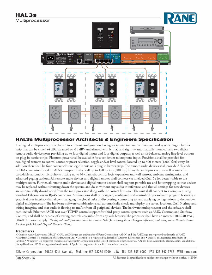
HAL3s Multiprocessor Architects & Engineers SpecificationThe digital multiprocessor shall be a 6 in x 10 out configuration having six inputs: two mic or line-level analog on a plug-in barrier strip that can be either +4 dBu balanced or -10 dBV unbalanced with left (+) and right (-) automatically monoed; and two digital remote audio device ports providing up to four digital inputs and four digital outputs; as well as six balanced analog line-level outputs on plug-in barrier strips. Phantom power shall be available for a condenser microphone input. Provisions shall be provided for two digital remotes to control source or preset selection, toggle and/or level control located up to 300 meters (1,000 feet) away. In addition there shall be four contact closure logic inputs on a plug-in barrier strip. The remote audio devices shall provide A/D and/or D/A conversion based on AES3 transport to the wall up to 150 meters (500 feet) from the multiprocessor, as well as units for cascadable automatic microphone mixing up to 64 channels, control logic expansion and wall sensors, ambient sensing mics, and advanced paging stations. All remote audio devices and digital remotes shall connect via shielded CAT 5e (or better) cable to the multiprocessor. Further, all remote audio devices and digital remote devices shall support portable use and hot swapping so that devices may be replaced without shutting down the system, and do so without any audio interference, and that all settings for new devices are automatically downloaded from the multiprocessor along with the correct firmware. The unit shall connect to a computer using standard Ethernet on an RJ-45 connector. All functions shall be designed, configured and controlled by a software program featuring a graphical user interface that allows managing the global tasks of discovering, connecting to, and applying configurations to the remote digital multiprocessor. The hardware-software combination shall automatically check and display the status, location, CAT 5 crimp and wiring integrity, and that audio is flowing to and/or from all peripheral devices. The hardware multiprocessor and the software shall each include Ethernet ASCII text over TCP/IP control support for third-party control systems such as AMX, Crestron and Stardraw Control, and shall be capable of creating controls accessible from any web browser.The processor shall have an internal 100-240 VAC, 50/60 Hz power supply. The digital multiprocessor shall be a Rane HAL3s running Rane Halogen software, and using Rane Remote Audio Devices (RADs) and Digital Remotes (DRs).
CLASS 2 WIRING
HAL3S
100-240 V50/60 Hz 20 WATTS
LINE OUTPUTS MIC/LINE-PLUS INPUTS
+ – + –
R L R
+ – + – + – + – + – + –2 16 5 4 3 2 1
LANLINK
COMMPOWER
COMMPOWER
ETHERNET DIGITAL REMOTES REMOTE AUDIO DEVICES
2 12 1 2 1
LOGIC IN
G 4 3 2 1 G
24 VDC @ 50 mA 24 VDC @ 100 mA|SHIELDED CAT 5e OR BETTER
AUDIO RXAUDIO TX
or DRsFAULT
LOCATE
POWER
RANE CORPORATION
PUSH • SELECT
SCROLL
DR3
PUSH • SELECT
SCROLL
DR3
PUSH • SELECT
SCROLL
DR3
LINE INPUTMICROPHONE
SIG / OL
AUDIO RX AUDIO TX
RAD2
SIG / OL
POWER COMM
79% 79% 65%