habasit plastic modular belt product guide catalog habasitlink and sprockets beltsmart
DESCRIPTION
Habasit plastic modular belt product guide catalog habasitlink and sprockets beltsmartTRANSCRIPT
ProductsMedia No. 4178
HabasitLINK®Plastic Modular BeltsProduct Guide
Habasit– Solutions in motion

Product liability, application considerationsIf the proper selection and application of Habasit products are not recommended by an authorized Habasit sales specialist, the selection and application of Habasit products, including the related area of product safety, are the responsibility of the customer. All indications / information are recommendations and believed to be reliable, but no representations, guarantees, or warranties of any kind are made as to their accuracy or suitability for particular applications. The data provided herein are based on laboratory work with small-scale test equipment, running at standard conditions, and do not necessarily match product performance in industrial use. New knowledge and experiences can lead to modifi cations and changes within a short time without prior notice. BECAUSE CONDITIONS OF USE ARE OUTSIDE OF HABASIT’S AND ITS AFFILIATED COMPANIES’ CONTROL, WE CANNOT ASSUME ANY LIABILITY CONCERNING THE SUITABILITY AND PROCESS ABILITY OF THE PRODUCTS MENTIONED HEREIN. THIS ALSO APPLIES TO PROCESS RESULTS / OUTPUT / MANUFACTURING GOODS AS WELL AS TO POSSIBLE DEFECTS, DAMAGES, CONSEQUENTIAL DAMAGES, AND FURTHER-REACHING CONSEQUENCES.
! WARNINGHabasit belts and chains are made of various plastics that WILL BURN if exposed to sparks, incendiaries, open fl ame or excessive heat. NEVER expose plastic belts and chains to a potential source of ignition. Flames resulting from burning plastics may emit TOXIC SMOKE and gasses as well as cause SERIOUS INJURIES and PROPERTY DAMAGE. See the Fire Hazard Data Sheet for additional information.
Protection type of all belts IP 2x (DIN EN 60259 / IEC 529) Exceptions (IP1x) : F51, F52, F53, F54, SP615, IS615, SP620, IS620, PR620, PR620 SPS, PR 620TTR, PR620 SPS CT, M2586, M3892, M5290, M5293
3
4178BRO.MOD-en1112HQR
Contents
Getting started – Belt selection criteria 7
Product Information: 0.3" pitch belting
HabasitLINK® series M0870 (straight belts)M0870 Flat Top 0.3" 8M0873 Micropitch Non Slip 0.3" 9SprocketsSprocket series M0800 10 – 12
Product Information: 1⁄2" pitch belting
HabasitLINK® series M1100 (straight belts)M1185 Flush Grid 0.5" 13SprocketsSprocket series M1100 14 – 16
HabasitLINK® series M1200 (straight belts)M1220 Flat Top 0.5" 17M1220 GripTop 0.5" 18M1220 HighGrip-L 0.5" 19M1220 ActivXchange 0.5" 20M1230 Flush Grid 0.5" 21M1233 Flush Grid 0.5" 22M1234 Nub Top Flush Grid 0.5" 23M1280 Flush Grid 0.5" 24M1280 ActivXchange 0.5" 25Sprockets Sprocket series M1200 26 – 28AccessoriesAccessories for series M1200 29 – 30
HabasitLINK® series SM/CM605 (straight belts)SM605 (Smooth Mesh) 31CM605 (Curved Mesh) 32SprocketsSprocket series SM605 / CM605 33
HabasitLINK® series HDS605 (straight belts)HDS605 ST (Flat Top) 34HDS605 TT (Texture Top) 35SprocketsSprocket series HDS605 FT and HDS605 TT 36
HabasitLINK® series RS511/515 (radius belts)RS511 (Tight Turn Radius Flush Grid) 37RS515 (Tight Turn Radius Curved Top) 38SprocketsSprocket series RS511/RS515 39
Product information: 3⁄4" pitch belting
HabasitLINK® Series 106 (straight belts)106 FL (106 Flat Top) 40106 10 (106 Mesh Top 10% Open) 41106 22 (106 Flush Grid 22% Open) 42106 RT (106 Rough Top) 43106 V (Vacuum) 44SprocketsSprocket series 106 45
Product information: 1" pitch belting
HabasitLINK® series M2400 (straight belts)M2420 Flat Top 1" 46M2420 ActivXchange 1" 47M2423 Non Slip 1" 48M2470 Flat Top 1" 49M2470 Flat Top MTW 1" 50M2470 GripTop 1" 52M2470 ActivXchange 1" 53M2472 Perforated Flat Top 1" 54M2480 Flush Grid 1" 55M2480 ActivXchange 1" 56SprocketsSprocket series M2400 57 – 61
HabasitLINK® series M2500 (straight belts)M2510 Flat Top 1" 62M2511 Mesh Top 1" 63M2514 Nub Top 1" 64M2516 Diamond Top 1" 65M2520 Flat Top 1" 66M2520 GripTop 1" 68M2520 Roller Top 1" 69M2527 Minirib 1" 71M2531 Raised Rib 1" 72M2533 Flush Grid 1" 73M2533 GripTop 1" 75M2533 Roller Top 1" 76M2585 Flush Grid 1" 78M2586 Raised Rib 1" 80HabasitLINK® series M2500 (radius belts)M2540 Radius Flush Grid 1" 81M2540 Radius Flush Grid 1" MTW 83M2540 Radius GripTop 1" 85M2540 Roller Top 1" 87M2544 Tight Radius 1" 89M2544 Tight Radius 1" MTW 91M2544 Tight Radius GripTop 1" 92

4178BRO.MOD-en1112HQR
4Contents
SprocketsSprocket series M2500 94 – 98Sprocket series M2500-C2 (M2585/86) 99 – 101AccessoriesAccessories for series M2500 102 – 111
HabasitLINK® series M2600 (straight belts)M2620 Flat Top Heavy Duty 1" 112M2620 GripTop 1" 114M2620 Roller Top - LBP 1" 115M2623 Non Slip 1" 116M2670 Flat Top Heavy Duty 1" 117M2670 Flat Top Heavy Duty 1" MTW 119M2670 GripTop 1" 120M2670 ActivXchange 1" 121SprocketsSprocket series M2600 122 – 125
HabasitLINK® series M2700 (radius belts)M2791 Radius Flush Grid 1" MTW 126SprocketsSprocket series M2700 127
HabasitLINK® series IS610 (straight belts)IS610 GT (Grip Top) 128
HabasitLINK® series IS610/CT610 (radius belts)IS610-R (Radius Flush Grid) 129CT610-R (Radius Curved Top) 130SprocketsSprockets series IS610, CT610-R, IS610 GT 131 HabasitLINK® series ST610/VT610 (straight belts)ST610 (Flat Top) 132VT610 (Vented Top) 133SprocketsSprocket series ST610 / VT610 134 HabasitLINK® series HDS610 (straight belts)HDS610 FT (Flat Top) 135HDS610 CVT (Curved Vented Top) 136SprocketsSprocket series HDS610 FT and HDS610 CVT 137
HabasitLINK® series 208 (straight belts)208 FT (208 Flat Top) 138208 35 (208 Flush Grid 35% Open) 139208 RR (208 Raised Rib) 140SprocketsSprocket Series 208 FT, 208 35, 208 RR 141
HabasitLINK® series MB610 (straight belts)MB610 (Heavy Duty Flat Top) 142MB610 MTW (Heavy Duty Flat Top Mold to Width) 143SprocketsSprocket series MB610 and MB610 MTW 144
Product information: 1.1" pitch belting
HabasitLINK® Series F50 (straight belts)F51 (1⁄2" x 1" Flat Wire) 145F52 Smart Fit (1⁄2" x 1⁄2" Flat Wire) 146F53 Smart Fit (1⁄2" x 1⁄2" Raised Rib Flat Wire) 147F54 (1" x 1" Flat Wire) 148SprocketsSprocket Series F51, F52, F53, F54 149
Product Information – 1-1/5" pitch belting
HabasitLINK® Series PR612 (radius belts)PR612 1.6 (Tight Turn Radius Flush Grid) 150PR612 2.2 (Radius Flush Grid) 151SprocketsSprocket Series PR612 152
Product Information – 1-1⁄2" pitch belting
HabasitLINK® series M3800 (radius belts)M3840 Radius Flush Grid 1.5" 153M3840 Roller Top 1.5" 155M3843 Tight Radius 1.5" 157M3843 Tight Radius GripTop 1.5" 163M3892 Raised Deck 1.5" 161SprocketsSprocket series M3800 163 – 165AccessoriesAccessories for series M3800 166 – 170
HabasitLINK® series SP615/IS615 (straight belts)SP615 171HabasitLINK® series IS615 (radius belts)IS615-R (Radius Flush Grid) 172SprocketsSprocket series SP615 and IS615 173
HabasitLINK® series ST615/VT615 (straight belts)ST615 (Flat Top) 174VT615 (Vented Top) 175
5
4178BRO.MOD-en1112HQR
Contents
SprocketsSprocket series ST615 and VT615 181
Product Information: 1-3⁄4" pitch belting
HabasitLINK® series CC41/42 (straight belts)CC41 (Flat Solid Top) 177CC42 (Vented Top) 178SprocketsSprocket series CC41 and CC42 179
Product information: 2" pitch belting
HabasitLINK® Series M5000 (straight belts)M5010 Flat Top 2" 180M5010 Roller Top 2" 182M5011 Perforated Flat Top 2" 184M5013 Cone Top 2" 186M5014 Nub Top 2" 187M5015 Flat Top 2" 188M5015 GripTop 2" 190M5020 Flat Top Heavy Duty 2" 192M5021 Perforated Flat Top 2" 193M5023 Non Slip 2" 194M5032 Flush Grid Heavy Duty 2" 295M5032 Roller Top 2" 296M5032 Roller Top - 0°, 45°, 90° 2" 298M5033 Flush Grid 2" 199M5033 Roller Top 2" 200M5060 Flat Top 2" 202M5064 Nub Top 2" 204M5065 Flat Top 2" HyCLEAN 206M5067 Minirib 2" 208SprocketsSprocket series M5000 209 –216AccessoriesAccessories for series M5000 218 –222
HabasitLINK® Series M5100 (straight belts)M5131 Raised Rib 2“ 223M5182 Roller Top – 90° 2“ 224SprocketsSprocket series M5100 225 –228AccessoriesCombs for M5131 229 HabasitLINK® Series M5200 (radius belts)M5290 Radius Flush Grid 2“ 230M5293 Tight Radius 2“ 232
SprocketsSprocket series M5200 234 –236AccessoriesAccessories for series M5200 237
HabasitLINK® Series SP620/IS620 (straight belts)SP620 (Flush Grid) 238SE620 (Straight Edge Flush Grid) 239
HabasitLINK® Series IS620 (radius belts)IS620-R (Radius Flush Grid) 240SprocketsSprocket series SP620, IS620, SE620 241
HabasitLINK® Series HDS620 (straight belts)HDS620 (Flat top) 242HDSCT620 (Curved Top) 243HDSEZR620 (Easy Release) 244HDSVT620 (Vented Top) 245SprocketsSprocket series HDS620, HDSCT620, HDSVT620, HDSEZR620 246
HabasitLINK® Series HDU620 (straight belts)HDU620 FT (Flat Top) 247HDU620 VT (Vented Top) 248HDU620 CT (Curved Top) 249HDU620 EZR (Easy Release) 250SprocketsSprocket series HDU620 ST, VT, CT, EZR 251
HabasitLINK® Series FF620 (straight belts)FF620 (Fluid-Flo) 252FF620 WR (Fluid-Flo with Ribs) 253FF620 MC (Fluid-Flo with Mini-Cleat) 254SprocketsSprocket series FF620, FF620 WR, FF620 MC 255
HabasitLINK® Series MB620 (straight belts)MB620 FT (Flat Top) 256MB620 VT (Vented Top) 257MB620 TT (Tread Top) 258SprocketSprocket series MB620 FT, MB620 VT, MB620 TT 259
HabasitLINK® Series PR620 (radius belts)PR620 (Spiral Pro) 260PR620 SPS (Spiral Pro - Small Product Surface) 261PR620 SPS CT (Spiral Pro - Small Product Surface) 262PR620 TTR (Spiral Pro - Tight Turn Radius) 263

4178BRO.MOD-en1112HQR
6Contents
SprocketsSprocket series PR620, PR620 SPS, PR620 TTR 264
Product information: 2.2" pitch belting
HabasitLINK® series M5400 (straight belts)M5482 Roller Top 2.2" 265SprocketsSprocket series M5400 266 – 268
Product information: 2-1⁄2" pitch belting
HabasitLINK® series M6300 (straight belts)M6360 Flat Top 2.5" 269SprocketsSprocket series M6300 270 – 271AccessoriesAccessories for series M6300 272
HabasitLINK® series M6400 (straight belts)M6420 Flat Top Heavy Duty 2.5" 273M6423 Non Slip 2.5" 275M6424 Non Slip Perforated 2.5" 276M6425 Reel Top 2.5" MTW 277SprocketsSprocket series M6400 278 – 280AccessoriesAccessories for series M6400 281
Materials for belts, sprockets, wear strips and guides 282 – 289
Chemical resistance 290 – 293
Agency acceptance 294 – 300
The Habasit Solution 304
7
4178BRO.MOD-en1112HQR
Getting startedBelt selection criteria
What do you need to know to select a belt style? Why are there so many different belts available? Below we have outlined a few things to think about when selecting a belt style. Always try to match the belt style to your application.Refer to other areas of the catalog for specific belt information or conveyor design guidelines.
Belt pathWhen you need to move product in a straight line, you would generally use a straight running belt. If you need to move your product in turns, you would use a turning belt. Straight running belts will generally take higher loads than turning belts.Our turning belts are called “radius” belts. Other manufacturers might refer to them as side flexing belts. In either case, our radius belts operate in both straight and radius applications, conform to the shape of your process, or minimize transfers. Product remains properly orientated while on the belt. Our belts also decrease the amount of drives for certain applications.
Belt surfaceThe top surface of the belt is what your product comes in contact with and what might have an effect on it. If your product is soft, the belt surface could be imprinted on the bottom during the freezing, cooking or cooling stages. If you have sticky goods to convey, you may want to choose a belt surface with reduced contact area and/or a material that offers high release characteristics such as polyethylene or acetal. Some belts have openings to allow for air or fluid to flow in applications such as cooling, washing, sanitizing, sizing, sorting, removal of “fines”, etc.Curved top belt styles allow continuous contact of a scraper to maximize product removal and give tighter transfer of product to a deadplate of another conveyor.Some belts have a raised rib surface and are used with a finger transfer plate. These “fingers” fit between the ribs and as the belt moves, the finger transfer plate lifts the product from the belt.
Belt accessoriesMany belts have accessories such as rollers (for product accumulation or acceleration), ribs or flights (to contain product on incline/declines), side plates (to keep material from falling off), high friction inserts (to keep product from slipping), and hold-down tabs (to keep the belt from rising up in turns).
CleanabilityBelts used in food applications need to be easy to clean and comply with certain regulatory requirements. You will need to determine if the belt you choose meets the cleaning requirements for your application.
Belt pitchBelts come in various pitches (belt pitch: distance pin to pin). Smaller pitch belts generally run smoother, faster and allow tighter transfers. Larger pitch belts generally will take larger loads, more impact and longer runs.
Belt colorMost belts are available in the industry accepted standard colors. Additional colors are available, but may incur additional charges and longer lead-time.
Belt materialThere are many environmental factors that may affect the performance of a conveyor belt. Some of these are:• higher or low temperatures may reduce the belt
strength and affect impact strength• ovens may melt or dry out certain materials• heavy impacts are not achievable with certain
materials• immersion in water can cause materials to swell• cleaning chemicals or solutions can harm belting• abrasive materials can wear out belting prematurely• material additives can make a belt material
detectable by metal detectorsTherefore, it is very important to pick the right material for the right application. Use charts showing material characteristics and chemical resistance.
Pins / RodsOur belts are connected with connection rods or pins. These pins are made from plastic or stainless steel material, and they are subject to the same environmental conditions.
! Belts must not be exposed to direct heat or flames.
4178BRO.MOD-en1112HQR
8
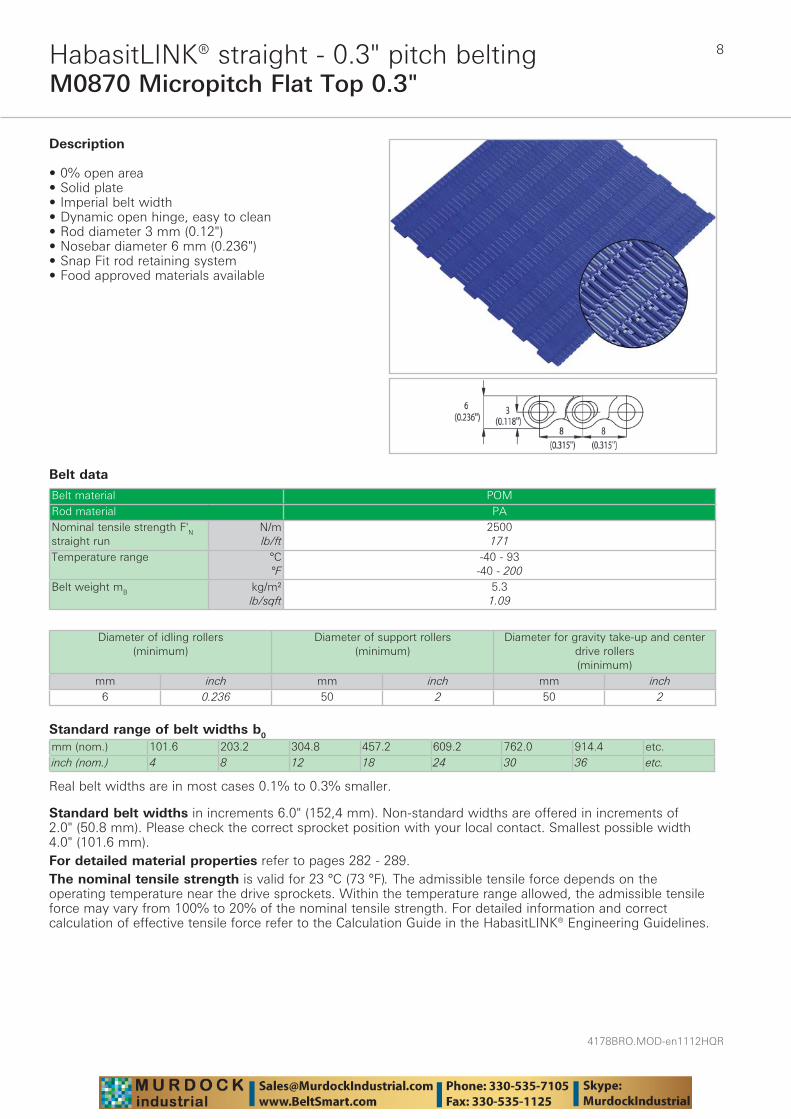
M0870 Micropitch Flat Top 0.3"HabasitLINK® straight - 0.3" pitch belting
Belt data
Standard range of belt widths b0
mm (nom.) 101.6 203.2 304.8 457.2 609.2 762.0 914.4 etc.inch (nom.) 4 8 12 18 24 30 36 etc.
Real belt widths are in most cases 0.1% to 0.3% smaller.
Belt material POMRod material PANominal tensile strength F'N straight run
N/mlb/ft
2500171
Temperature range °C°F
-40 - 93-40 - 200
Belt weight mB kg/m²lb/sqft
5.31.09
Description
• 0% open area • Solid plate • Imperial belt width • Dynamic open hinge, easy to clean • Rod diameter 3 mm (0.12") • Nosebar diameter 6 mm (0.236") • Snap Fit rod retaining system • Food approved materials available
Diameter of idling rollers (minimum)
Diameter of support rollers(minimum)
Diameter for gravity take-up and center drive rollers (minimum)
mm inch mm inch mm inch6 0.236 50 2 50 2
Standard belt widths in increments 6.0" (152,4 mm). Non-standard widths are offered in increments of 2.0" (50.8 mm). Please check the correct sprocket position with your local contact. Smallest possible width 4.0" (101.6 mm).For detailed material properties refer to pages 282 - 289.The nominal tensile strength is valid for 23 °C (73 °F). The admissible tensile force depends on the operating temperature near the drive sprockets. Within the temperature range allowed, the admissible tensile force may vary from 100% to 20% of the nominal tensile strength. For detailed information and correct calculation of effective tensile force refer to the Calculation Guide in the HabasitLINK® Engineering Guidelines.

9
4178BRO.MOD-en1112HQR
M0873 Micropitch Non Slip 0.3"HabasitLINK® straight - 0.3" pitch belting
Belt data
Standard range of belt widths b0
mm (nom.) 305 609 914 1219 1524 etc.inch (nom.) 12 24 36 48 60 etc.
Real belt widths are in most cases 0.1% to 0.3% smaller.
Belt material POMRod material PANominal tensile strength F'N straight run
N/mlb/ft
2500171
Temperature range °C°F
-40 - 93-40 - 200
Belt weight mB kg/m²lb/sqft
5.31.09
Description
• 0% open area • Solid plate • Imperial belt width • Dynamic open hinge, easy to clean • Rod diameter 3 mm (0.12") • Nosebar diameter 6 mm (0.236") • Snap Fit rod retaining system • Food approved materials available
Diameter of idling rollers (minimum)
Diameter of support rollers(minimum)
Diameter for gravity take-up and center drive rollers (minimum)
mm inch mm inch mm inch6 0.236 50 2 50 2
Standard belt widths in increments 12.0" (304.8 mm). Non-standard widths are offered in increments of 2.0" (50.8 mm). Please check the correct sprocket position with your local contact. Smallest possible width 4.0" (101.6 mm).For detailed material properties refer to pages 282 - 289.The nominal tensile strength is valid for 23 °C (73 °F). The admissible tensile force depends on the operating temperature near the drive sprockets. Within the temperature range allowed, the admissible tensile force may vary from 100% to 20% of the nominal tensile strength. For detailed information and correct calculation of effective tensile force refer to the Calculation Guide in the HabasitLINK® Engineering Guidelines.
4178BRO.MOD-en1112HQR
10
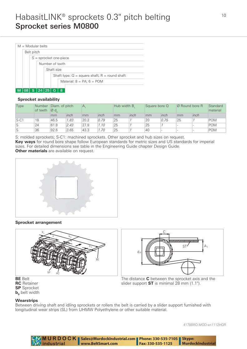
Sprocket series M0800HabasitLINK® sprockets 0.3" pitch belting
M = Modular belts
M 08 8Q2524S
Belt pitch
S = sprocket one-piece
Number of teeth
Shaft size
Shaft type: Q = square shaft; R = round shaft
Material: 8 = PA; 6 = POM
Type Number of teeth
Diam. of pitch Ø dp
A1 Hub width BL Square bore Q Ø Round bore R Standard material
mm inch mm inch mm inch mm inch mm inchS-C1 18 46.5 1.83 20.2 0.79 25 1 20 0.75 25 1 POMS 24 61.8 2.43 27.9 1.10 25 1 25 1 - - POMS 36 92.6 3.65 43.3 1.70 25 1 40 - - - POM
BE BeltRC RetainerSP Sprocketb0 belt width
Sprocket availability
S: molded sprockets; S-C1: machined sprockets. Other sprocket and hub sizes on request.Key ways for round bore shape follow European standards for metric sizes and US standards for imperial sizes. For detailed dimensions see table in the Engineering Guide chapter Design Guide.Other materials are available on request.
The distance C between the sprocket axis and the slider support ST is minimal 28 mm (1.1").
WearstripsBetween driving shaft and idling sprockets or rollers the belt is carried by a slider support furnished with longitudinal wear strips (SL) from UHMW Polyethylene or other suitable material.
Sprocket arrangement
11
4178BRO.MOD-en1112HQR
Sprocket series M0800HabasitLINK® sprockets 0.3" pitch belting
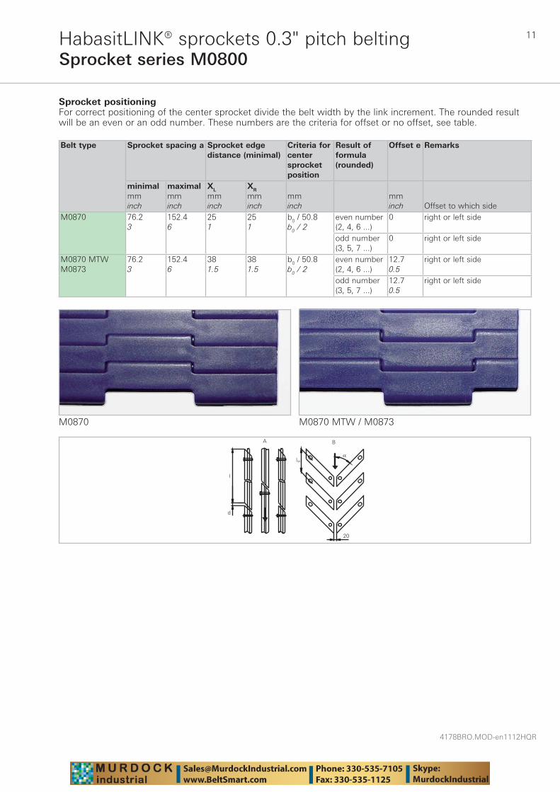
Sprocket positioningFor correct positioning of the center sprocket divide the belt width by the link increment. The rounded result will be an even or an odd number. These numbers are the criteria for offset or no offset, see table.
Belt type Sprocket spacing a Sprocket edgedistance (minimal)
Criteria for center sprocket position
Result of formula (rounded)
Offset e Remarks
minimalmminch
maximalmminch
XL
mminch
XR
mminch
mminch
mminch Offset to which side
M0870 76.23
152.46
251
251
b0 / 50.8b0 / 2
even number (2, 4, 6 ...)
0 right or left side
odd number (3, 5, 7 ...)
0 right or left side
M0870 MTWM0873
76.23
152.46
381.5
381.5
b0 / 50.8b0 / 2
even number (2, 4, 6 ...)
12.70.5
right or left side
odd number (3, 5, 7 ...)
12.70.5
right or left side
M0870
d
l
A
lw
20
α
B
M0870 MTW / M0873
4178BRO.MOD-en1112HQR
12
Sprocket series M0800HabasitLINK® sprockets 0.3" pitch belting
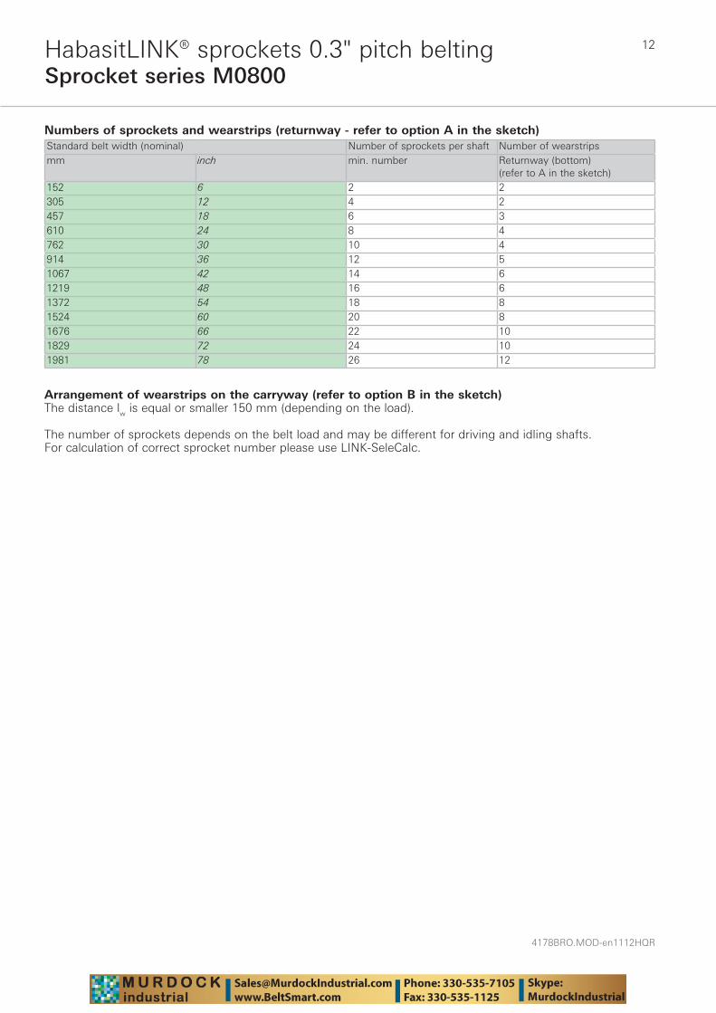
Numbers of sprockets and wearstrips (returnway - refer to option A in the sketch)Standard belt width (nominal) Number of sprockets per shaft Number of wearstripsmm inch min. number Returnway (bottom)
(refer to A in the sketch)152 6 2 2305 12 4 2457 18 6 3610 24 8 4762 30 10 4914 36 12 51067 42 14 61219 48 16 61372 54 18 81524 60 20 81676 66 22 101829 72 24 101981 78 26 12
Arrangement of wearstrips on the carryway (refer to option B in the sketch)The distance lw is equal or smaller 150 mm (depending on the load).
The number of sprockets depends on the belt load and may be different for driving and idling shafts. For calculation of correct sprocket number please use LINK-SeleCalc.
13
4178BRO.MOD-en1112HQR
M1185 Flush Grid 0.5"HabasitLINK® straight - 1/2" pitch belting
Belt data
Standard range of belt widths b0
mm (nom.) 203 254 305 356 406 457 508 559 610 660 711 762 813 864 etc.inch (nom.) 8 10 12 14 16 18 20 22 24 26 28 30 32 24 etc.
Real belt widths are in most cases 0.1% to 0.3% smaller.
Belt material PP POM POM +DE PA PA +USRod material PP POM PA PBT PANominal tensile strength F'N straight run
N/mlb/ft
2600178
3100212
4400301
4250291
4400301
4400301
4400301
Temperature range °C°F
5 - 10540 - 220
5 - 9340 - 200
-40 - 93-40 - 200
-40 - 93-40 - 200
-40 - 93-40 - 200
-46 - 130-50 - 266
-46 - 116-50 - 240
Temperature maximum (short-term)
°C°F
160320
135275
Belt weight mB kg/m²lb/sqft
2.50.51
2.80.57
3.60.75
3.60.75
3.60.75
3.10.64
3.10.64
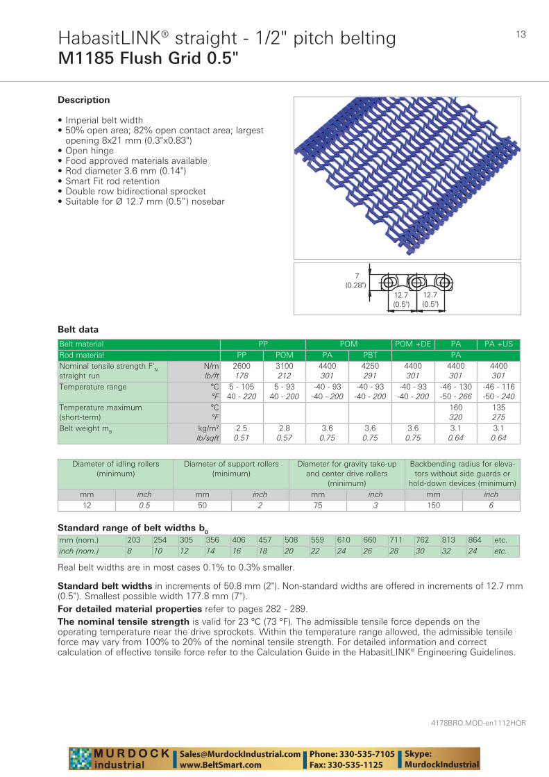
Description
• Imperial belt width• 50% open area; 82% open contact area; largest
opening 8x21 mm (0.3"x0.83") • Open hinge • Food approved materials available• Rod diameter 3.6 mm (0.14") • Smart Fit rod retention • Double row bidirectional sprocket • Suitable for Ø 12.7 mm (0.5”) nosebar
Diameter of idling rollers (minimum)
Diameter of support rollers(minimum)
Diameter for gravity take-up and center drive rollers
(minimum)
Backbending radius for eleva-tors without side guards or
hold-down devices (minimum)mm inch mm inch mm inch mm inch12 0.5 50 2 75 3 150 6
Standard belt widths in increments of 50.8 mm (2"). Non-standard widths are offered in increments of 12.7 mm (0.5"). Smallest possible width 177.8 mm (7").For detailed material properties refer to pages 282 - 289.The nominal tensile strength is valid for 23 °C (73 °F). The admissible tensile force depends on the operating temperature near the drive sprockets. Within the temperature range allowed, the admissible tensile force may vary from 100% to 20% of the nominal tensile strength. For detailed information and correct calculation of effective tensile force refer to the Calculation Guide in the HabasitLINK® Engineering Guidelines.
4178BRO.MOD-en1112HQR
14
Sprocket series M1100HabasitLINK® sprockets 1/2" pitch belting
M = Modular belts
M 11 8Q2517S
Belt pitch
S = sprocket one-piece; Z = split sprocket
Number of teeth
Shaft size
Shaft type: Q = square shaft; R = round shaft
Material: 8 = PA; 6 = POM
Type Number of teeth
Diam. of pitch Ø dp
A1 Hub width BL Square bore Q Ø Round bore R Standard material
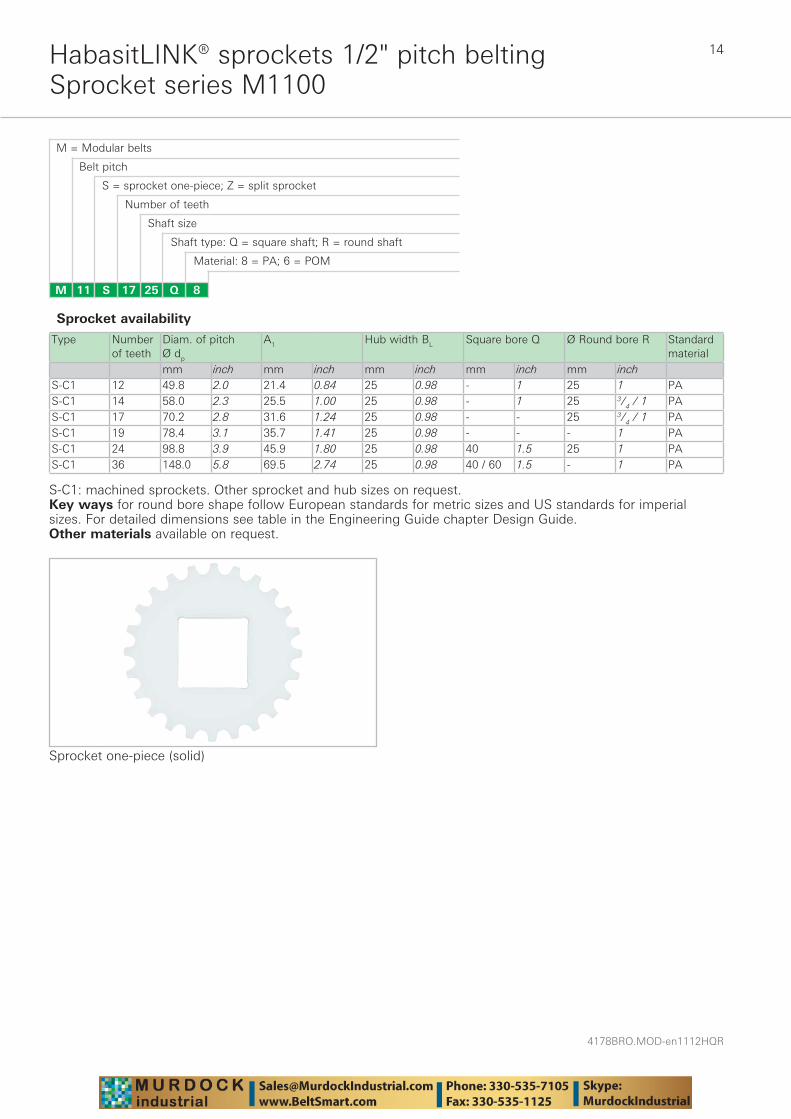
mm inch mm inch mm inch mm inch mm inchS-C1 12 49.8 2.0 21.4 0.84 25 0.98 - 1 25 1 PAS-C1 14 58.0 2.3 25.5 1.00 25 0.98 - 1 25 3/4 / 1 PAS-C1 17 70.2 2.8 31.6 1.24 25 0.98 - - 25 3/4 / 1 PAS-C1 19 78.4 3.1 35.7 1.41 25 0.98 - - - 1 PAS-C1 24 98.8 3.9 45.9 1.80 25 0.98 40 1.5 25 1 PAS-C1 36 148.0 5.8 69.5 2.74 25 0.98 40 / 60 1.5 - 1 PA
Sprocket one-piece (solid)
Sprocket availability
S-C1: machined sprockets. Other sprocket and hub sizes on request.Key ways for round bore shape follow European standards for metric sizes and US standards for imperial sizes. For detailed dimensions see table in the Engineering Guide chapter Design Guide.Other materials available on request.
15
4178BRO.MOD-en1112HQR
Sprocket series M1100HabasitLINK® sprockets 1/2" pitch belting
WearstripsBetween driving shaft and idling sprockets or rollers the belt is carried by a slider support furnished with longitudinal wear strips (SL) from UHMW Polyethylene or other suitable material.
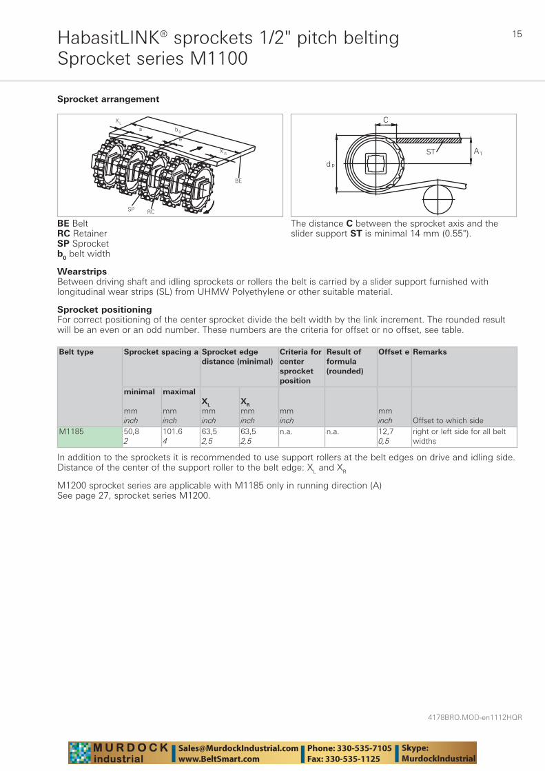
Sprocket arrangement
BE BeltRC RetainerSP Sprocketb0 belt width
The distance C between the sprocket axis and the slider support ST is minimal 14 mm (0.55").
Sprocket positioning For correct positioning of the center sprocket divide the belt width by the link increment. The rounded result will be an even or an odd number. These numbers are the criteria for offset or no offset, see table.
Belt type
Sprocket spacing a Sprocket edgedistance (minimal)
Criteria for center sprocket position
Result of formula (rounded)
Offset e Remarks
minimal mminch
maximal mminch
XL
mminch
XR
mminch
mminch
mminch Offset to which side
M1185 50,82
101.64
63,52,5
63,52,5
n.a. n.a. 12,70,5
right or left side for all belt widths
In addition to the sprockets it is recommended to use support rollers at the belt edges on drive and idling side. Distance of the center of the support roller to the belt edge: XL and XR
M1200 sprocket series are applicable with M1185 only in running direction (A)See page 27, sprocket series M1200.
4178BRO.MOD-en1112HQR
16
Sprocket series M1100HabasitLINK® sprockets 1/2" pitch belting
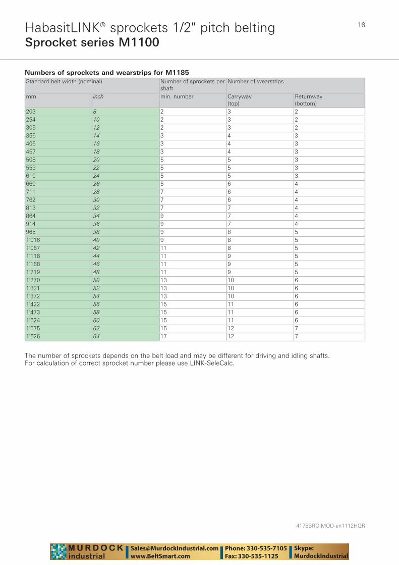
Numbers of sprockets and wearstrips for M1185 Standard belt width (nominal) Number of sprockets per
shaftNumber of wearstrips
mm inch min. number Carryway (top)
Returnway (bottom)
203 8 2 3 2254 10 2 3 2305 12 2 3 2356 14 3 4 3406 16 3 4 3457 18 3 4 3508 20 5 5 3559 22 5 5 3610 24 5 5 3660 26 5 6 4711 28 7 6 4762 30 7 6 4813 32 7 7 4864 34 9 7 4914 36 9 7 4965 38 9 8 51'016 40 9 8 51'067 42 11 8 51'118 44 11 9 51'168 46 11 9 51'219 48 11 9 51'270 50 13 10 61'321 52 13 10 61'372 54 13 10 61'422 56 15 11 61'473 58 15 11 61'524 60 15 11 61'575 62 15 12 71'626 64 17 12 7
The number of sprockets depends on the belt load and may be different for driving and idling shafts. For calculation of correct sprocket number please use LINK-SeleCalc.
17
4178BRO.MOD-en1112HQR
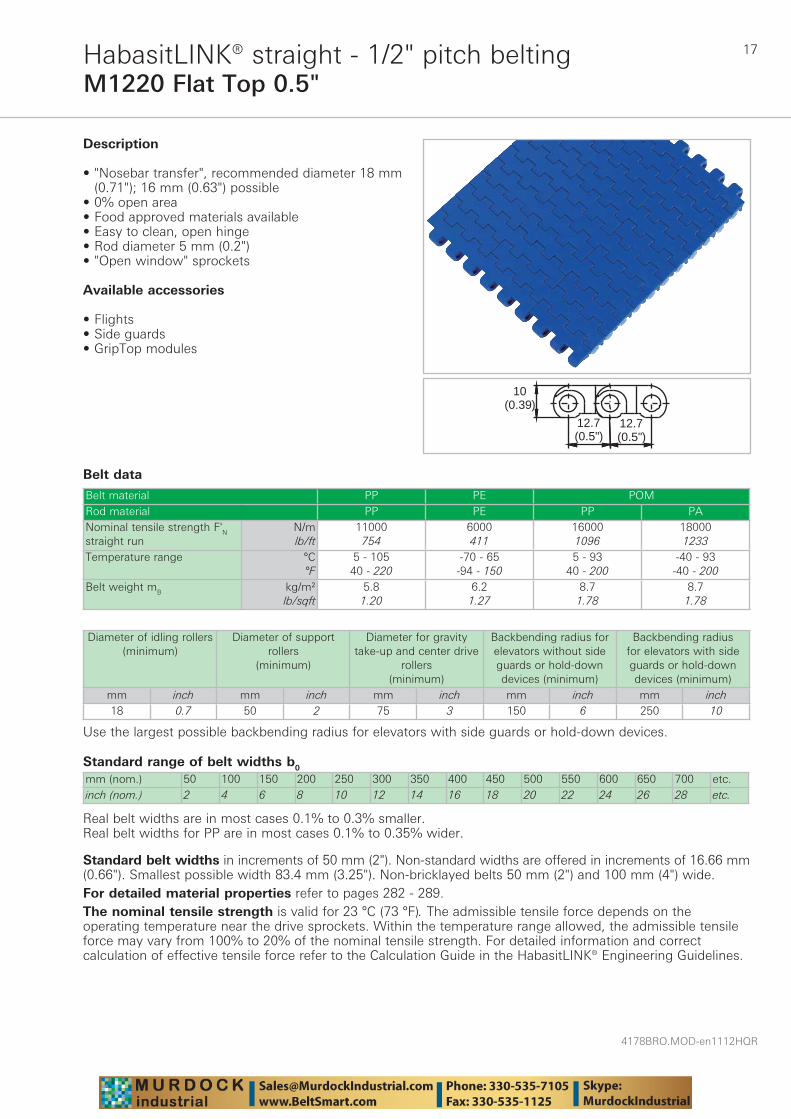
M1220 Flat Top 0.5"HabasitLINK® straight - 1/2" pitch belting
Belt data
Standard range of belt widths b0
mm (nom.) 50 100 150 200 250 300 350 400 450 500 550 600 650 700 etc.inch (nom.) 2 4 6 8 10 12 14 16 18 20 22 24 26 28 etc.
Real belt widths are in most cases 0.1% to 0.3% smaller.Real belt widths for PP are in most cases 0.1% to 0.35% wider.
Belt material PP PE POMRod material PP PE PP PANominal tensile strength F'N straight run
N/mlb/ft
11000754
6000411
160001096
180001233
Temperature range °C°F
5 - 10540 - 220
-70 - 65-94 - 150
5 - 9340 - 200
-40 - 93-40 - 200
Belt weight mB kg/m²lb/sqft
5.81.20
6.21.27
8.71.78
8.71.78
10(0.39)
12.7(0.5")
12.7)(0.5"
Description
• "Nosebar transfer", recommended diameter 18 mm (0.71"); 16 mm (0.63") possible
• 0% open area • Food approved materials available• Easy to clean, open hinge • Rod diameter 5 mm (0.2") • "Open window" sprockets
Available accessories
• Flights • Side guards • GripTop modules
Diameter of idling rollers (minimum)
Diameter of support rollers
(minimum)
Diameter for gravity take-up and center drive
rollers (minimum)
Backbending radius for elevators without side guards or hold-down devices (minimum)
Backbending radius for elevators with side guards or hold-down devices (minimum)
mm inch mm inch mm inch mm inch mm inch18 0.7 50 2 75 3 150 6 250 10
Use the largest possible backbending radius for elevators with side guards or hold-down devices.
Standard belt widths in increments of 50 mm (2"). Non-standard widths are offered in increments of 16.66 mm (0.66"). Smallest possible width 83.4 mm (3.25"). Non-bricklayed belts 50 mm (2") and 100 mm (4") wide.For detailed material properties refer to pages 282 - 289.The nominal tensile strength is valid for 23 °C (73 °F). The admissible tensile force depends on the operating temperature near the drive sprockets. Within the temperature range allowed, the admissible tensile force may vary from 100% to 20% of the nominal tensile strength. For detailed information and correct calculation of effective tensile force refer to the Calculation Guide in the HabasitLINK® Engineering Guidelines.
4178BRO.MOD-en1112HQR
18
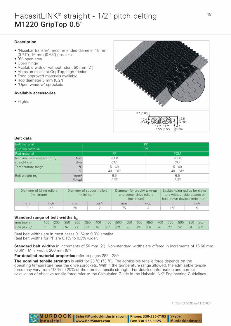
M1220 GripTop 0.5"HabasitLINK® straight - 1/2" pitch belting
Belt data
Standard range of belt widths b0
mm (nom.) 150 200 250 300 350 400 450 500 550 600 650 700 750 800 850 etc.inch (nom.) 6 8 10 12 14 16 18 20 22 24 26 28 30 32 34 etc.
Real belt widths are in most cases 0.1% to 0.3% smaller.Real belt widths for PP are 0.1% to 0.3% wider.
Belt material PPGripTop material TPERod material PP POMNominal tensile strength F'N straight run
N/mlb/ft
9000617
9000617
Temperature range °C°F
5 - 6040 - 140
5 - 6040 - 140
Belt weight mB kg/m²lb/sqft
6.51.33
6.51.33
��������
���������
��������
��������
��������
��������
Description
• "Nosebar transfer", recommended diameter 18 mm (0.71"); 16 mm (0.63") possible
• 0% open area • Open hinge • Available with or without ndent 50 mm (2") • Abrasion resistant GripTop, high friction • Food approved materials available • Rod diameter 5 mm (0.2") • "Open window" sprockets
Available accessories
• Flights
Diameter of idling rollers (minimum)
Diameter of support rollers(minimum)
Diameter for gravity take-up and center drive rollers
(minimum)
Backbending radius for eleva-tors without side guards or
hold-down devices (minimum)mm inch mm inch mm inch mm inch18 0.7 50 2 75 3 150 6
Standard belt widths in increments of 50 mm (2"). Non-standard widths are offered in increments of 16.66 mm (0.66"). Min. width: 200 mm (8")For detailed material properties refer to pages 282 - 289.The nominal tensile strength is valid for 23 °C (73 °F). The admissible tensile force depends on the operating temperature near the drive sprockets. Within the temperature range allowed, the admissible tensile force may vary from 100% to 20% of the nominal tensile strength. For detailed information and correct calculation of effective tensile force refer to the Calculation Guide in the HabasitLINK® Engineering Guidelines.
19
4178BRO.MOD-en1112HQR
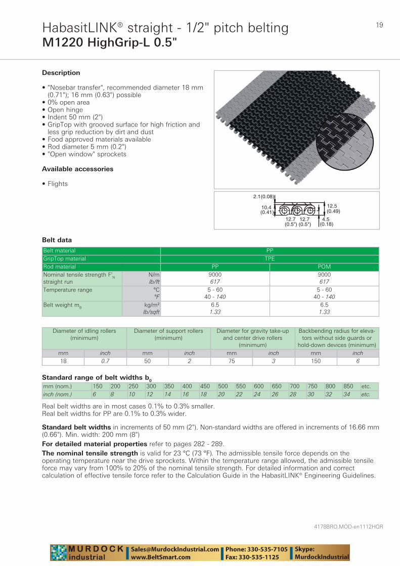
M1220 HighGrip-L 0.5"HabasitLINK® straight - 1/2" pitch belting
Belt data
Standard range of belt widths b0
mm (nom.) 150 200 250 300 350 400 450 500 550 600 650 700 750 800 850 etc.inch (nom.) 6 8 10 12 14 16 18 20 22 24 26 28 30 32 34 etc.
Real belt widths are in most cases 0.1% to 0.3% smaller.Real belt widths for PP are 0.1% to 0.3% wider.
Belt material PPGripTop material TPERod material PP POMNominal tensile strength F'N straight run
N/mlb/ft
9000617
9000617
Temperature range °C°F
5 - 6040 - 140
5 - 6040 - 140
Belt weight mB kg/m²lb/sqft
6.51.33
6.51.33
��������
���������
��������
��������
��������
��������
Description
• "Nosebar transfer", recommended diameter 18 mm (0.71"); 16 mm (0.63") possible
• 0% open area • Open hinge • Indent 50 mm (2") • GripTop with grooved surface for high friction and
less grip reduction by dirt and dust • Food approved materials available• Rod diameter 5 mm (0.2") • "Open window" sprockets
Available accessories
• Flights
Diameter of idling rollers (minimum)
Diameter of support rollers(minimum)
Diameter for gravity take-up and center drive rollers
(minimum)
Backbending radius for eleva-tors without side guards or
hold-down devices (minimum)mm inch mm inch mm inch mm inch18 0.7 50 2 75 3 150 6
Standard belt widths in increments of 50 mm (2"). Non-standard widths are offered in increments of 16.66 mm (0.66"). Min. width: 200 mm (8")For detailed material properties refer to pages 282 - 289.The nominal tensile strength is valid for 23 °C (73 °F). The admissible tensile force depends on the operating temperature near the drive sprockets. Within the temperature range allowed, the admissible tensile force may vary from 100% to 20% of the nominal tensile strength. For detailed information and correct calculation of effective tensile force refer to the Calculation Guide in the HabasitLINK® Engineering Guidelines.
4178BRO.MOD-en1112HQR
20
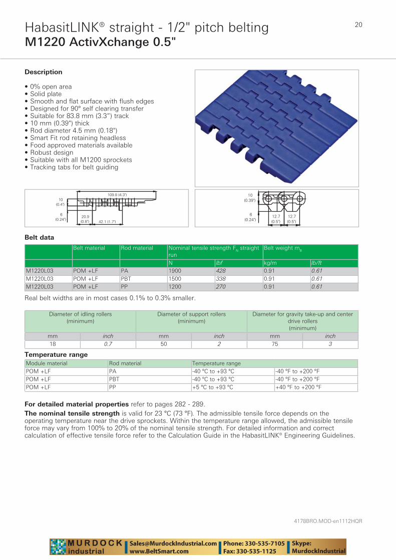
M1220 ActivXchange 0.5"HabasitLINK® straight - 1/2" pitch belting
Belt data
Temperature rangeModule material Rod material Temperature rangePOM +LF PA -40 °C to +93 °C -40 °F to +200 °FPOM +LF PBT -40 °C to +93 °C -40 °F to +200 °FPOM +LF PP +5 °C to +93 °C +40 °F to +200 °F
Description
• 0% open area • Solid plate • Smooth and flat surface with flush edges • Designed for 90° self clearing transfer • Suitable for 83.8 mm (3.3”) track • 10 mm (0.39") thick • Rod diameter 4.5 mm (0.18") • Smart Fit rod retaining headless • Food approved materials available• Robust design • Suitable with all M1200 sprockets • Tracking tabs for belt guiding
Diameter of idling rollers (minimum)
Diameter of support rollers(minimum)
Diameter for gravity take-up and center drive rollers (minimum)
mm inch mm inch mm inch18 0.7 50 2 75 3
Belt material Rod material Nominal tensile strength FN straight run
Belt weight mB
N lbf kg/m lb/ftM1220L03 POM +LF PA 1900 428 0.91 0.61M1220L03 POM +LF PBT 1500 338 0.91 0.61M1220L03 POM +LF PP 1200 270 0.91 0.61
Real belt widths are in most cases 0.1% to 0.3% smaller.
For detailed material properties refer to pages 282 - 289.The nominal tensile strength is valid for 23 °C (73 °F). The admissible tensile force depends on the operating temperature near the drive sprockets. Within the temperature range allowed, the admissible tensile force may vary from 100% to 20% of the nominal tensile strength. For detailed information and correct calculation of effective tensile force refer to the Calculation Guide in the HabasitLINK® Engineering Guidelines.
21
4178BRO.MOD-en1112HQR
M1230 Flush Grid 0.5"HabasitLINK® straight - 1/2" pitch belting
Belt data
Standard range of belt widths b0
mm (nom.) 150 200 250 300 350 400 450 500 550 600 650 700 750 800 etc.inch (nom.) 6 8 10 12 14 16 18 20 22 24 26 28 30 32 etc.
Real belt widths are in most cases 0.1% to 0.3% smaller.Real belt widths for PP are 0.1% to 0.3% wider.
Belt material PP PE POMRod material PP PE PP PANominal tensile strength F'N straight run
N/mlb/ft
11000753
7000480
160001096
180001233
Temperature range °C°F
5 - 10540 - 220
-70 - 65-94 - 150
5 - 9340 - 200
-40 - 93-40 - 200
Belt weight mB kg/m²lb/sqft
5.41.11
5.71.17
7.81.60
7.81.60
10(0.39)
12.7(0.5")
12.7)(0.5"
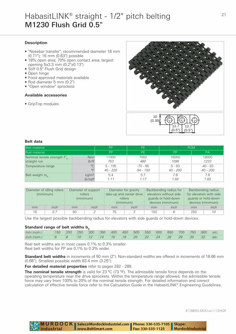
Description
• "Nosebar transfer", recommended diameter 18 mm (0.71"); 16 mm (0.63") possible
• 18% open area; 70% open contact area; largest opening 5x3.3 mm (0.2"x0.13")
• Stiff 0.5" Flush Grid design • Open hinge • Food approved materials available• Rod diameter 5 mm (0.2") • "Open window" sprockets
Available accessories
• GripTop modules
Diameter of idling rollers (minimum)
Diameter of support rollers
(minimum)
Diameter for gravity take-up and center drive
rollers (minimum)
Backbending radius for elevators without side guards or hold-down devices (minimum)
Backbending radius for elevators with side guards or hold-down devices (minimum)
mm inch mm inch mm inch mm inch mm inch18 0.7 50 2 75 3 150 6 250 10
Use the largest possible backbending radius for elevators with side guards or hold-down devices.
Standard belt widths in increments of 50 mm (2"). Non-standard widths are offered in increments of 16.66 mm (0.66"). Smallest possible width 83.4 mm (3.25").For detailed material properties refer to pages 282 - 289.The nominal tensile strength is valid for 23 °C (73 °F). The admissible tensile force depends on the operating temperature near the drive sprockets. Within the temperature range allowed, the admissible tensile force may vary from 100% to 20% of the nominal tensile strength. For detailed information and correct calculation of effective tensile force refer to the Calculation Guide in the HabasitLINK® Engineering Guidelines.
4178BRO.MOD-en1112HQR
22
M1233 Flush Grid 0.5"HabasitLINK® straight - 1/2" pitch belting
Belt data
Standard range of belt widths b0
mm (nom.) 150 200 250 300 350 400 450 500 550 600 650 700 750 800 etc.inch (nom.) 6 8 10 12 14 16 18 20 22 24 26 28 30 32 etc.
Real belt widths are in most cases 0.1% to 0.3% smaller.Real belt widths for PP are 0.1% to 0.3% wider.
Belt material PP PE POM PA +US PARod material PP PE PP PANominal tensile strength F'N straight run
N/mlb/ft
11000750
7000480
8000548
160001096
180001233
170001165
170001165
Temperature range °C°F
5 - 10540 - 220
-70 - 65-94 - 150
-40 - 65-40 - 150
5 - 9340 - 200
-40 - 93-40 - 200
-46 - 118-50 - 245
-46 - 130-50 - 266
Temperature maximum (short-term)
°C°F
135275
160320
Belt weight mB kg/m²lb/sqft
5.21.07
5.41.11
7.21.48
7.21.48
7.21.48
6.71.37
6.71.37
12.7(0.5")
12.7(0.5")
10(0.39)
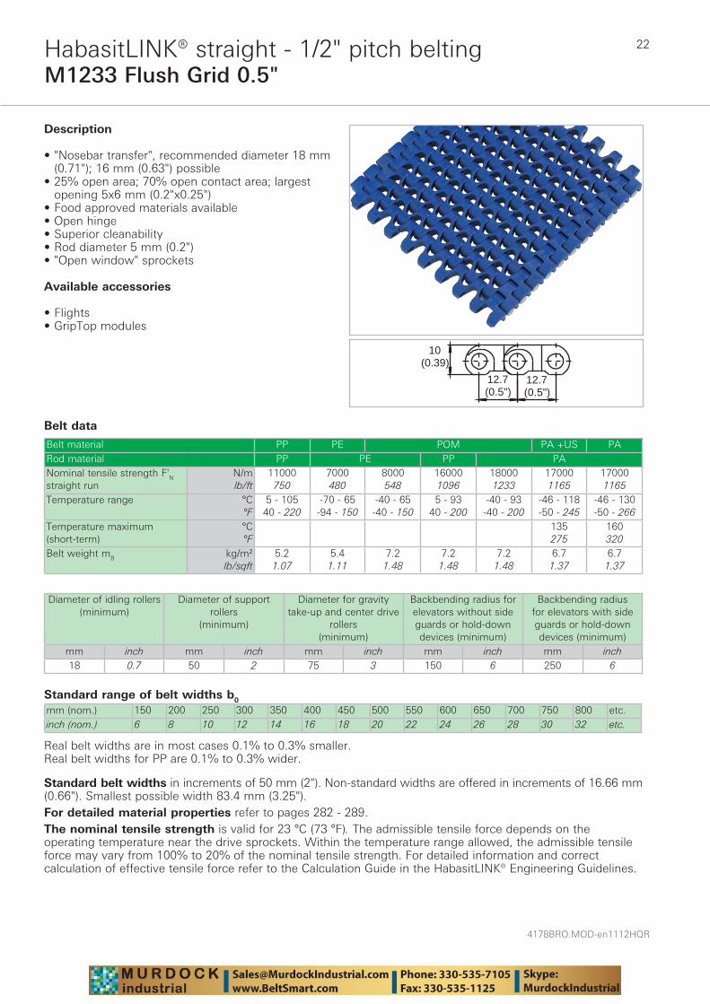
Description
• "Nosebar transfer", recommended diameter 18 mm (0.71"); 16 mm (0.63") possible • 25% open area; 70% open contact area; largest
opening 5x6 mm (0.2"x0.25") • Food approved materials available• Open hinge • Superior cleanability • Rod diameter 5 mm (0.2") • "Open window" sprockets
Available accessories
• Flights • GripTop modules
Diameter of idling rollers (minimum)
Diameter of support rollers
(minimum)
Diameter for gravity take-up and center drive
rollers (minimum)
Backbending radius for elevators without side guards or hold-down devices (minimum)
Backbending radius for elevators with side guards or hold-down devices (minimum)
mm inch mm inch mm inch mm inch mm inch18 0.7 50 2 75 3 150 6 250 6
Standard belt widths in increments of 50 mm (2"). Non-standard widths are offered in increments of 16.66 mm (0.66"). Smallest possible width 83.4 mm (3.25").For detailed material properties refer to pages 282 - 289.The nominal tensile strength is valid for 23 °C (73 °F). The admissible tensile force depends on the operating temperature near the drive sprockets. Within the temperature range allowed, the admissible tensile force may vary from 100% to 20% of the nominal tensile strength. For detailed information and correct calculation of effective tensile force refer to the Calculation Guide in the HabasitLINK® Engineering Guidelines.
23
4178BRO.MOD-en1112HQR
M1234 Nub Top Flush Grid 0.5"HabasitLINK® straight - 1/2" pitch belting
Belt data
Standard range of belt widths b0
mm (nom.) 150 200 250 300 350 400 450 500 550 600 650 700 750 800 etc.inch (nom.) 6 8 10 12 14 16 18 20 22 24 26 28 30 32 etc.
Real belt widths are in most cases 0.1% to 0.3% smaller.Real belt widths for PP are 0.1% to 0.3% wider.
Belt material PP PE POMRod material PP PE PP PANominal tensile strength F'N straight run
N/mlb/ft
11000753
7000480
160001096
180001233
Temperature range °C°F
5 - 10540 - 220
-70 - 65-94 - 150
5 - 9340 - 200
-40 - 93-40 - 200
Belt weight mB kg/m²lb/sqft
5.61.15
5.91.21
8.21.68
8.21.68
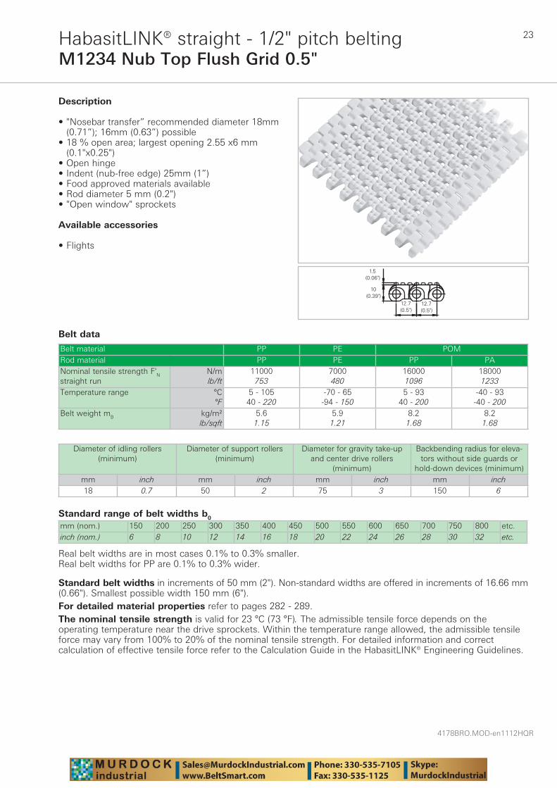
Description
• "Nosebar transfer” recommended diameter 18mm (0.71”); 16mm (0.63”) possible
• 18 % open area; largest opening 2.55 x6 mm (0.1"x0.25")
• Open hinge • Indent (nub-free edge) 25mm (1”) • Food approved materials available• Rod diameter 5 mm (0.2") • "Open window" sprockets
Available accessories
• Flights
Diameter of idling rollers (minimum)
Diameter of support rollers(minimum)
Diameter for gravity take-up and center drive rollers
(minimum)
Backbending radius for eleva-tors without side guards or
hold-down devices (minimum)mm inch mm inch mm inch mm inch18 0.7 50 2 75 3 150 6
Standard belt widths in increments of 50 mm (2"). Non-standard widths are offered in increments of 16.66 mm (0.66"). Smallest possible width 150 mm (6").For detailed material properties refer to pages 282 - 289.The nominal tensile strength is valid for 23 °C (73 °F). The admissible tensile force depends on the operating temperature near the drive sprockets. Within the temperature range allowed, the admissible tensile force may vary from 100% to 20% of the nominal tensile strength. For detailed information and correct calculation of effective tensile force refer to the Calculation Guide in the HabasitLINK® Engineering Guidelines.
4178BRO.MOD-en1112HQR
24
M1280 Flush Grid 0.5"HabasitLINK® straight - 1/2" pitch belting
Belt data
Standard range of belt widths b0
mm (nom.) 152.4 203.2 254.0 304.8 355.6 406.4 457.2 508.0 558.8 609.6 660.4 711.2 762.0 etc.inch (nom.) 6 8 10 12 14 16 18 20 22 24 26 28 30 etc.
Real belt widths are in most cases 0.1% to 0.3% smaller.
Belt material POM +LF POM +EC PBT +FRRod material PA PP PBT PA PP PA PPNominal tensile strength F'N straight run
N/mlb/ft
214001466
13700939
172001178
174001192
13400918
13700939
13400917
Temperature range °C°F
-40 - 93-40 - 200
5 - 9340 - 200
-40 - 93-40 - 200
-40 - 93-40 - 200
5 - 9340 - 200
-40 - 130-40 - 266
5 - 10540 - 220
Belt weight mB kg/m²lb/sqft
7.11.45
7.11.45
7.11.45
7.11.45
7.11.45
7.41.52
7.41.52
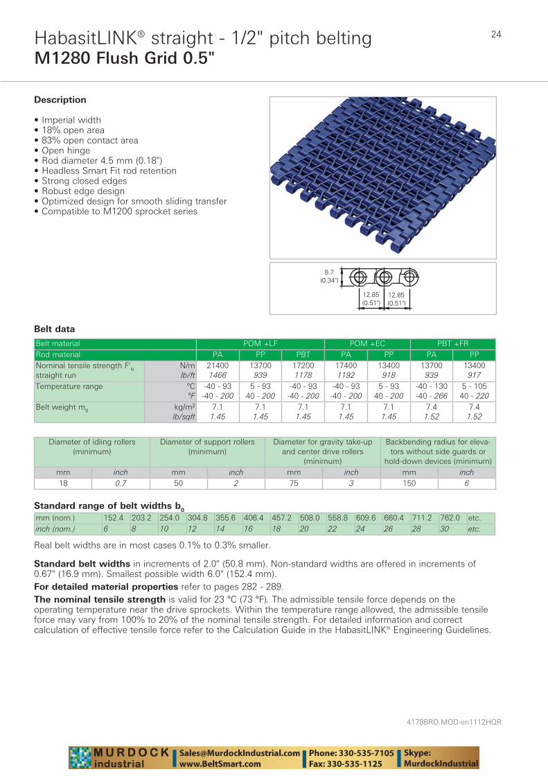
Description
• Imperial width • 18% open area • 83% open contact area • Open hinge • Rod diameter 4.5 mm (0.18")• Headless Smart Fit rod retention • Strong closed edges • Robust edge design • Optimized design for smooth sliding transfer • Compatible to M1200 sprocket series
Diameter of idling rollers (minimum)
Diameter of support rollers(minimum)
Diameter for gravity take-up and center drive rollers
(minimum)
Backbending radius for eleva-tors without side guards or
hold-down devices (minimum)mm inch mm inch mm inch mm inch18 0.7 50 2 75 3 150 6
Standard belt widths in increments of 2.0" (50.8 mm). Non-standard widths are offered in increments of 0.67" (16.9 mm). Smallest possible width 6.0" (152.4 mm).For detailed material properties refer to pages 282 - 289.The nominal tensile strength is valid for 23 °C (73 °F). The admissible tensile force depends on the operating temperature near the drive sprockets. Within the temperature range allowed, the admissible tensile force may vary from 100% to 20% of the nominal tensile strength. For detailed information and correct calculation of effective tensile force refer to the Calculation Guide in the HabasitLINK® Engineering Guidelines.
25
4178BRO.MOD-en1112HQR
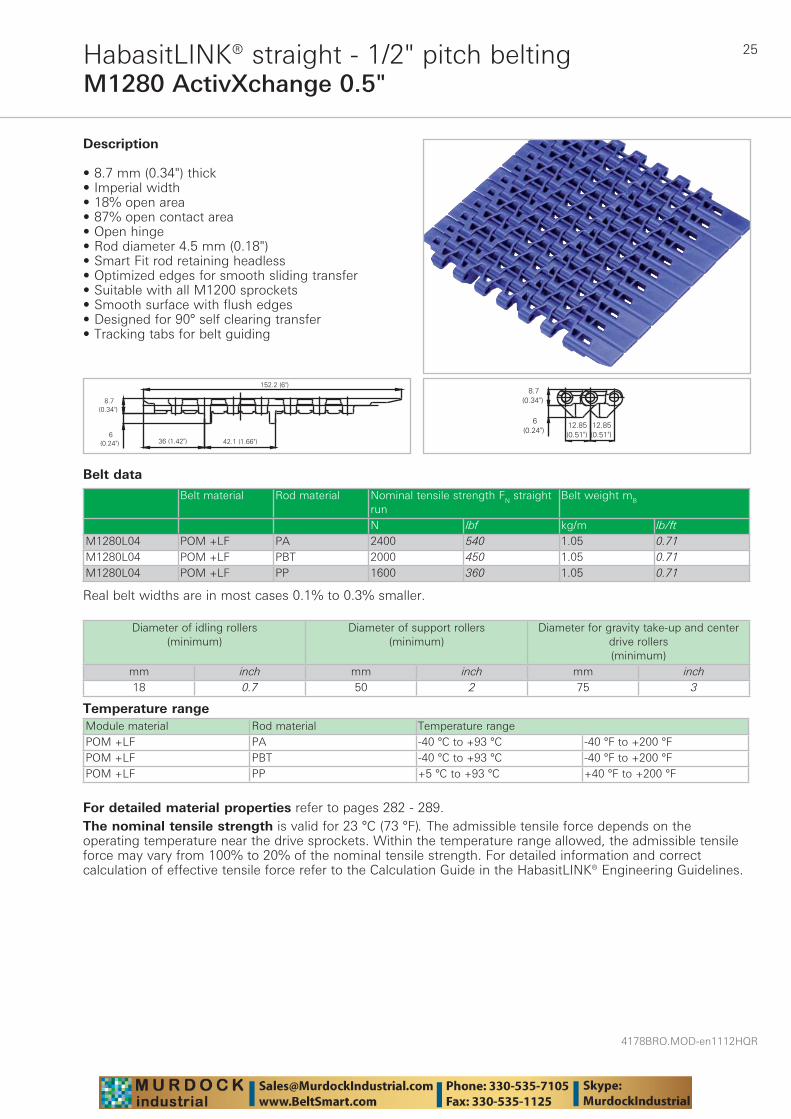
M1280 ActivXchange 0.5"HabasitLINK® straight - 1/2" pitch belting
Belt data
Temperature range Module material Rod material Temperature rangePOM +LF PA -40 °C to +93 °C -40 °F to +200 °FPOM +LF PBT -40 °C to +93 °C -40 °F to +200 °FPOM +LF PP +5 °C to +93 °C +40 °F to +200 °F
Description
• 8.7 mm (0.34") thick • Imperial width • 18% open area • 87% open contact area • Open hinge • Rod diameter 4.5 mm (0.18") • Smart Fit rod retaining headless • Optimized edges for smooth sliding transfer • Suitable with all M1200 sprockets • Smooth surface with flush edges • Designed for 90° self clearing transfer • Tracking tabs for belt guiding
Diameter of idling rollers (minimum)
Diameter of support rollers(minimum)
Diameter for gravity take-up and center drive rollers (minimum)
mm inch mm inch mm inch18 0.7 50 2 75 3
Belt material Rod material Nominal tensile strength FN straight run
Belt weight mB
N lbf kg/m lb/ftM1280L04 POM +LF PA 2400 540 1.05 0.71M1280L04 POM +LF PBT 2000 450 1.05 0.71M1280L04 POM +LF PP 1600 360 1.05 0.71
Real belt widths are in most cases 0.1% to 0.3% smaller.
For detailed material properties refer to pages 282 - 289.The nominal tensile strength is valid for 23 °C (73 °F). The admissible tensile force depends on the operating temperature near the drive sprockets. Within the temperature range allowed, the admissible tensile force may vary from 100% to 20% of the nominal tensile strength. For detailed information and correct calculation of effective tensile force refer to the Calculation Guide in the HabasitLINK® Engineering Guidelines.

4178BRO.MOD-en1112HQR
26
Sprocket series M1200HabasitLINK® sprockets 1/2" pitch belting
M = Modular belts
M 12 6Q2524S
Belt pitch
S = sprocket one-piece; Z = split sprocket
Number of teeth
Shaft size
Shaft type: Q = square shaft; R = round shaft
Material: 6 = POM; 8 = PA
Type Number of teeth
Diam. of pitch Ø dp
A1 Hub width BL Square bore Q Ø Round bore R Standard material
mm inch mm inch mm inch mm inch mm inchS 10 41.2 1.6 16.1 0.63 30 1.18 - - 20 3/4 POMS 15 62.4 2.5 26.7 1.05 30 1.18 25 1 25 1 POMS 19 78.8 3.1 34.4 1.35 30 1.18 - 1.5 - 1 POMS 24 99.2 3.9 45.1 1.78 30 1.18 25 / 40 1.5 25 1 POMS 28 116.5 4.6 53.8 2.12 30 1.18 40 1.5 25 - POMS 36 149.8 5.9 70.4 2.77 30 1.18 40 / 60 1.5 / 2.5 - - POMZ 24 99.2 3.9 45.1 1.78 40 1.57 40 - - - POMZ-H 28 116.5 4.6 53.8 2.12 51 2.00 40 1.5 - 13/16 PA+GSZ-H 36 149.8 5.9 70.4 2.77 51 2.00 40 / 60 1.5 / 2.5 50 1 / 17/16 PA+GS
Sprocket one-piece ("open window")
Sprocket availability
S, Z: molded sprockets; Z-H: Multi-Hub sprockets. Other sprocket and hub sizes on request.Key ways for round bore shape follow European standards for metric sizes and US standards for imperial sizes. For detailed dimensions see table in the Engineering Guide chapter Design Guide.Other materials available on request.
Split sprocket
27
4178BRO.MOD-en1112HQR
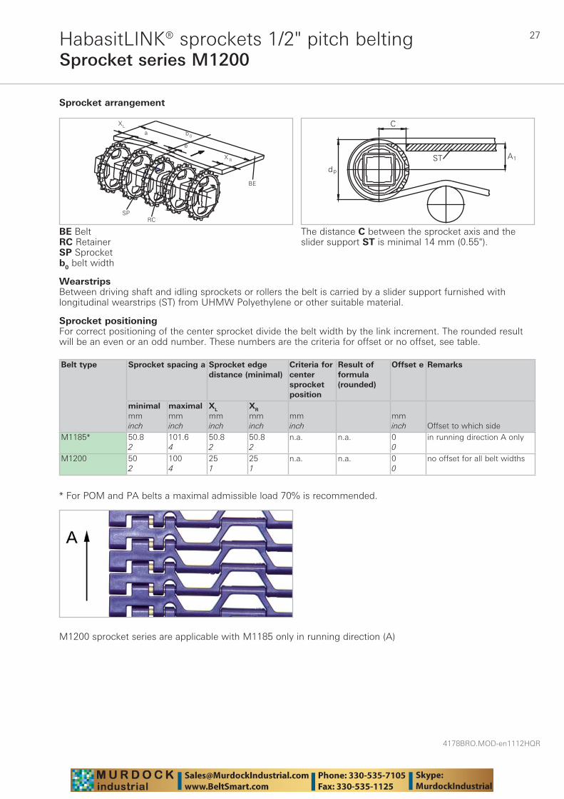
Sprocket series M1200HabasitLINK® sprockets 1/2" pitch belting
Wearstrips Between driving shaft and idling sprockets or rollers the belt is carried by a slider support furnished with longitudinal wearstrips (ST) from UHMW Polyethylene or other suitable material.
Sprocket arrangement
BE BeltRC RetainerSP Sprocketb0 belt width
The distance C between the sprocket axis and the slider support ST is minimal 14 mm (0.55").
Sprocket positioningFor correct positioning of the center sprocket divide the belt width by the link increment. The rounded result will be an even or an odd number. These numbers are the criteria for offset or no offset, see table.
Belt type Sprocket spacing a Sprocket edgedistance (minimal)
Criteria for center sprocket position
Result of formula (rounded)
Offset e Remarks
minimalmminch
maximalmminch
XL
mminch
XR
mminch
mminch
mminch Offset to which side
M1185* 50.82
101.64
50.82
50.82
n.a. n.a. 00
in running direction A only
M1200 502
1004
251
251
n.a. n.a. 00
no offset for all belt widths
* For POM and PA belts a maximal admissible load 70% is recommended.
M1200 sprocket series are applicable with M1185 only in running direction (A)
4178BRO.MOD-en1112HQR
28
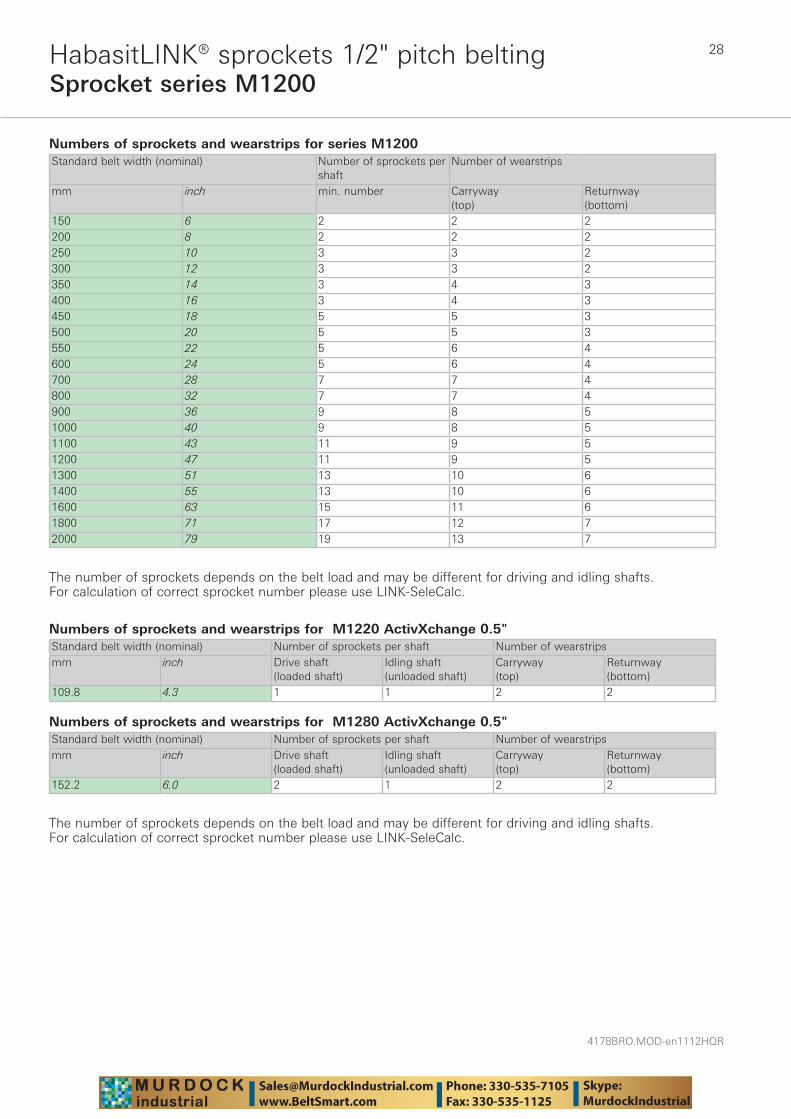
Sprocket series M1200HabasitLINK® sprockets 1/2" pitch belting
Numbers of sprockets and wearstrips for series M1200 Standard belt width (nominal) Number of sprockets per
shaftNumber of wearstrips
mm inch min. number Carryway (top)
Returnway (bottom)
150 6 2 2 2200 8 2 2 2250 10 3 3 2300 12 3 3 2350 14 3 4 3400 16 3 4 3450 18 5 5 3500 20 5 5 3550 22 5 6 4600 24 5 6 4700 28 7 7 4800 32 7 7 4900 36 9 8 51000 40 9 8 51100 43 11 9 51200 47 11 9 51300 51 13 10 61400 55 13 10 61600 63 15 11 61800 71 17 12 72000 79 19 13 7
The number of sprockets depends on the belt load and may be different for driving and idling shafts. For calculation of correct sprocket number please use LINK-SeleCalc.
Numbers of sprockets and wearstrips for M1220 ActivXchange 0.5" Standard belt width (nominal) Number of sprockets per shaft Number of wearstripsmm inch Drive shaft
(loaded shaft)Idling shaft(unloaded shaft)
Carryway (top)
Returnway (bottom)
109.8 4.3 1 1 2 2
Numbers of sprockets and wearstrips for M1280 ActivXchange 0.5" Standard belt width (nominal) Number of sprockets per shaft Number of wearstripsmm inch Drive shaft
(loaded shaft)Idling shaft(unloaded shaft)
Carryway (top)
Returnway (bottom)
152.2 6.0 2 1 2 2
The number of sprockets depends on the belt load and may be different for driving and idling shafts. For calculation of correct sprocket number please use LINK-SeleCalc.
29
4178BRO.MOD-en1112HQR
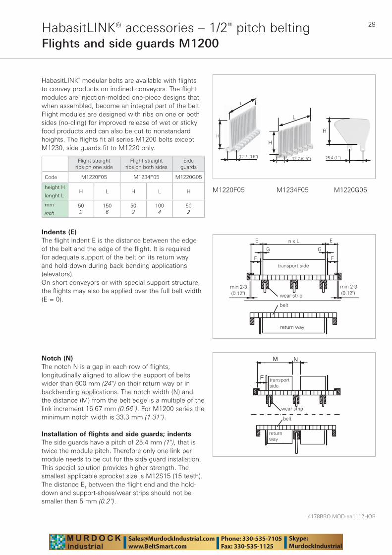
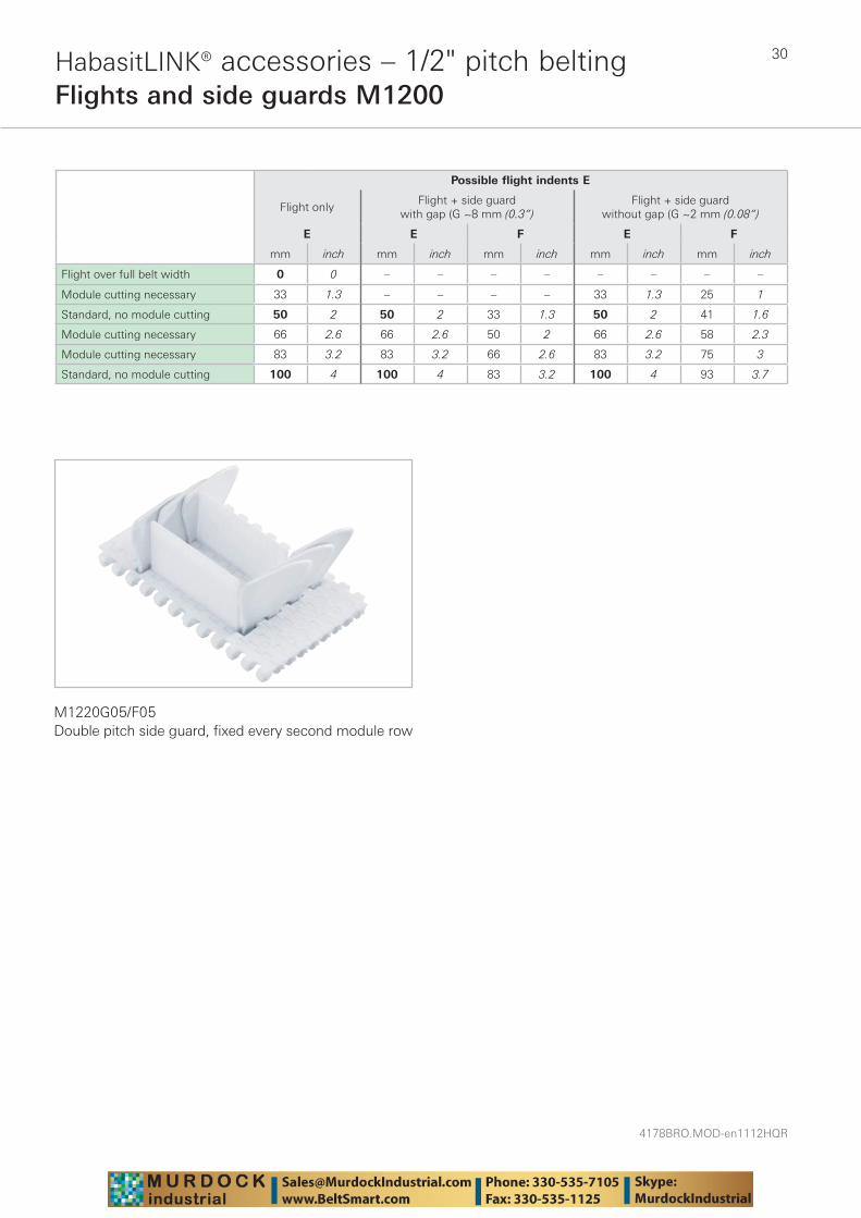
HabasitLINK® accessories – 1/2" pitch beltingFlights and side guards M1200
HabasitLINK® modular belts are available with flights to convey products on inclined conveyors. The flight modules are injection-molded one-piece designs that, when assembled, become an integral part of the belt. Flight modules are designed with ribs on one or both sides (no-cling) for improved release of wet or sticky food products and can also be cut to nonstandard heights. The flights fit all series M1200 belts except M1230, side guards fit to M1220 only.
25.4 (
H
1")
Indents (E)The flight indent E is the distance between the edge of the belt and the edge of the flight. It is required for adequate support of the belt on its return way and hold-down during back bending applications (elevators). On short conveyors or with special support structure, the flights may also be applied over the full belt width (E = 0).
L
H
12.7 (0.5")
wear strip
transp.side
M
F
belt
N
returnway
transport side
return way
wear strip
belt
M1220F05 M1234F05 M1220G05
Flight straightribs on one side
Flight straightribs on both sides
Sideguards
Code M1220F05 M1234F05 M1220G05
height H
lenght LH L H L H
mm
inch502
1506
502
1004
502
Notch (N)The notch N is a gap in each row of flights, longitudinally aligned to allow the support of belts wider than 600 mm (24") on their return way or in back bending applications. The notch width (N) and the distance (M) from the belt edge is a multiple of the link increment 16.67 mm (0.66"). For M1200 series the minimum notch width is 33.3 mm (1.31").
Installation of flights and side guards; indentsThe side guards have a pitch of 25.4 mm (1"), that is twice the module pitch. Therefore only one link per module needs to be cut for the side guard installation. This special solution provides higher strength. The smallest applicable sprocket size is M12S15 (15 teeth). The distance E1 between the flight end and the hold-down and support-shoes/wear strips should not be smaller than 5 mm (0.2").
H
L
12.7 (0.5“) 25.4 (1“)
H
4178BRO.MOD-en1112HQR
30HabasitLINK® accessories – 1/2" pitch beltingFlights and side guards M1200
M1220G05/F05Double pitch side guard, fi xed every second module row
Possible flight indents E
Flight onlyFlight + side guard
with gap (G ~8 mm (0.3“)Flight + side guard
without gap (G ~2 mm (0.08“)
E E F E F
mm inch mm inch mm inch mm inch mm inch
Flight over full belt width 0 0 – – – – – – – –
Module cutting necessary 33 1.3 – – – – 33 1.3 25 1
Standard, no module cutting 50 2 50 2 33 1.3 50 2 41 1.6
Module cutting necessary 66 2.6 66 2.6 50 2 66 2.6 58 2.3
Module cutting necessary 83 3.2 83 3.2 66 2.6 83 3.2 75 3
Standard, no module cutting 100 4 100 4 83 3.2 100 4 93 3.7
31
4178BRO.MOD-en1112HQR
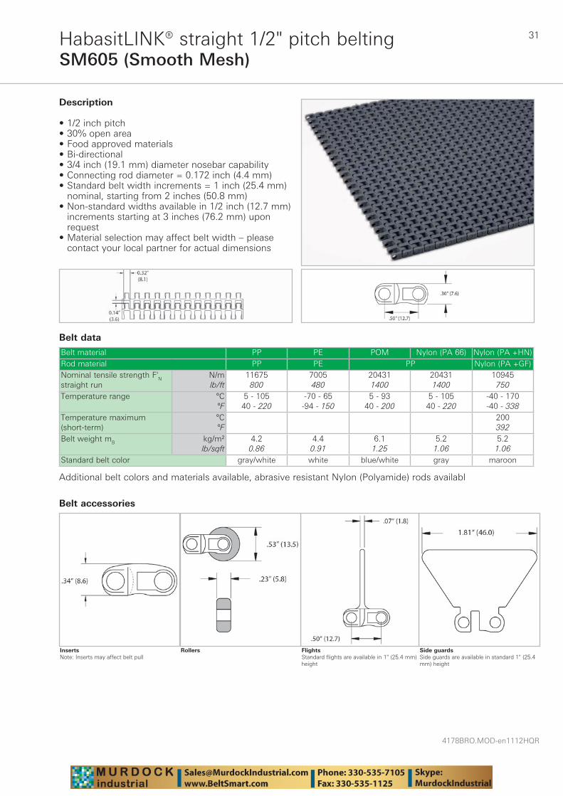
SM605 (Smooth Mesh)HabasitLINK® straight 1/2" pitch belting
Belt data
Belt material PP PE POM Nylon (PA 66) Nylon (PA +HN)Rod material PP PE PP Nylon (PA +GF)Nominal tensile strength F'N straight run
N/mlb/ft
11675800
7005480
204311400
204311400
10945750
Temperature range °C°F
5 - 10540 - 220
-70 - 65-94 - 150
5 - 9340 - 200
5 - 10540 - 220
-40 - 170-40 - 338
Temperature maximum (short-term)
°C°F
200392
Belt weight mB kg/m²lb/sqft
4.20.86
4.40.91
6.11.25
5.21.06
5.21.06
Standard belt color gray/white white blue/white gray maroon
Description
• 1/2 inch pitch • 30% open area • Food approved materials• Bi-directional • 3/4 inch (19.1 mm) diameter nosebar capability • Connecting rod diameter = 0.172 inch (4.4 mm) • Standard belt width increments = 1 inch (25.4 mm)
nominal, starting from 2 inches (50.8 mm) • Non-standard widths available in 1/2 inch (12.7 mm)
increments starting at 3 inches (76.2 mm) upon request
• Material selection may affect belt width – please contact your local partner for actual dimensions
Additional belt colors and materials available, abrasive resistant Nylon (Polyamide) rods availabl
Side guardsSide guards are available in standard 1" (25.4 mm) height
FlightsStandard flights are available in 1" (25.4 mm) height
Rollers
Belt accessories
InsertsNote: Inserts may affect belt pull
4178BRO.MOD-en1112HQR
32
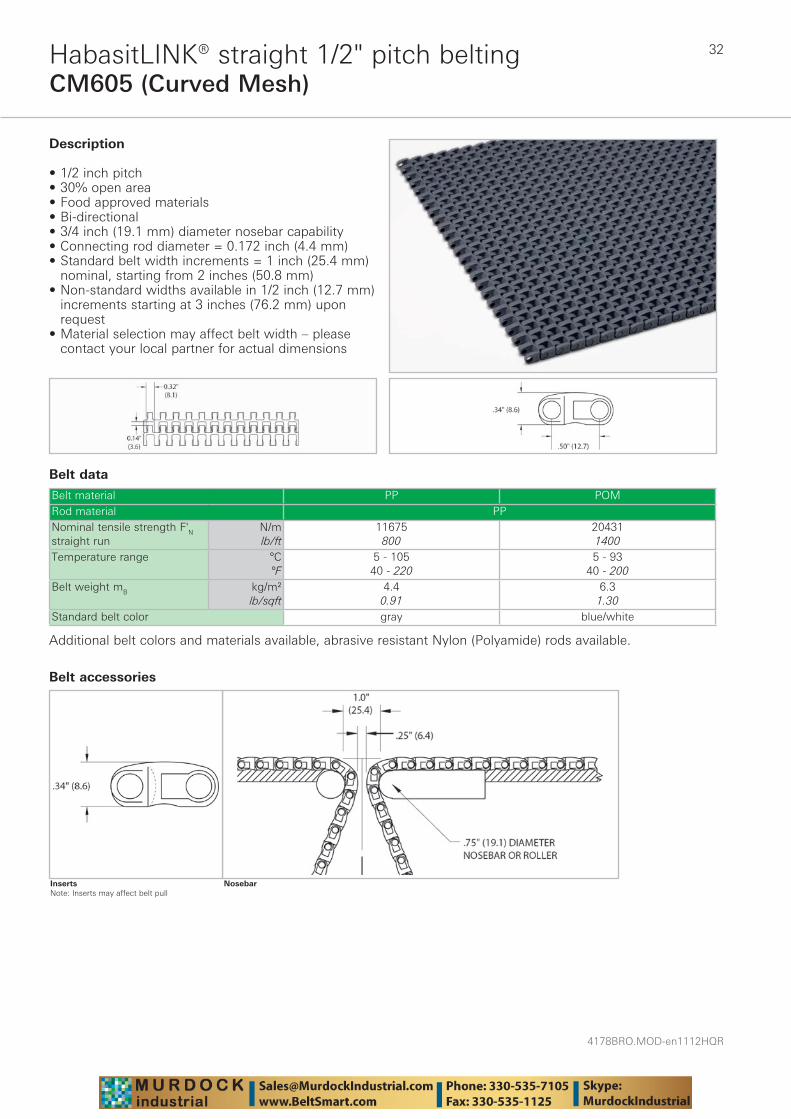
CM605 (Curved Mesh)HabasitLINK® straight 1/2" pitch belting
Belt data
Belt material PP POMRod material PPNominal tensile strength F'N straight run
N/mlb/ft
11675800
204311400
Temperature range °C°F
5 - 10540 - 220
5 - 9340 - 200
Belt weight mB kg/m²lb/sqft
4.40.91
6.31.30
Standard belt color gray blue/white
Description
• 1/2 inch pitch • 30% open area • Food approved materials• Bi-directional • 3/4 inch (19.1 mm) diameter nosebar capability • Connecting rod diameter = 0.172 inch (4.4 mm) • Standard belt width increments = 1 inch (25.4 mm)
nominal, starting from 2 inches (50.8 mm) • Non-standard widths available in 1/2 inch (12.7 mm)
increments starting at 3 inches (76.2 mm) upon request
• Material selection may affect belt width – please contact your local partner for actual dimensions
Additional belt colors and materials available, abrasive resistant Nylon (Polyamide) rods available.
Nosebar
Belt accessories
InsertsNote: Inserts may affect belt pull
33
4178BRO.MOD-en1112HQR
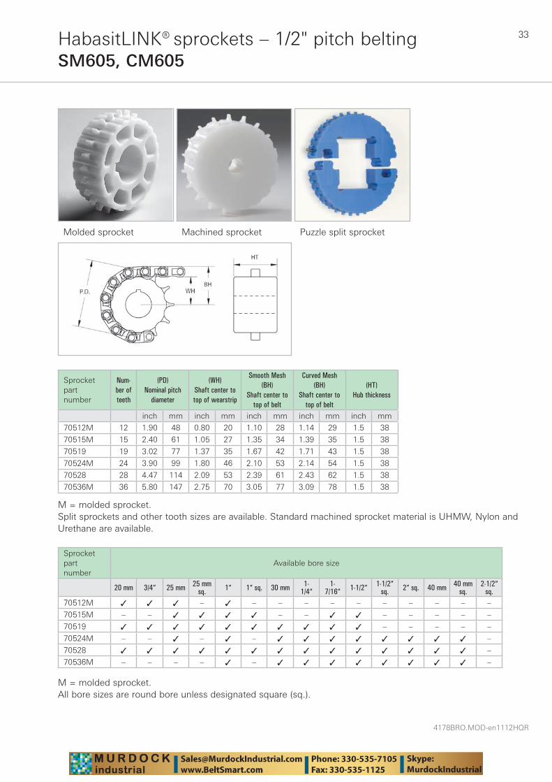
HabasitLINK® sprockets – 1/2" pitch beltingSM605, CM605
Molded sprocket Machined sprocket Puzzle split sprocket
Sprocket part number
Num-ber of teeth
(PD) Nominal pitch
diameter
(WH) Shaft center to top of wearstrip
Smooth Mesh (BH)
Shaft center to top of belt
Curved Mesh (BH)
Shaft center to top of belt
(HT) Hub thickness
inch mm inch mm inch mm inch mm inch mm
70512M 12 1.90 48 0.80 20 1.10 28 1.14 29 1.5 38
70515M 15 2.40 61 1.05 27 1.35 34 1.39 35 1.5 38
70519 19 3.02 77 1.37 35 1.67 42 1.71 43 1.5 38
70524M 24 3.90 99 1.80 46 2.10 53 2.14 54 1.5 38
70528 28 4.47 114 2.09 53 2.39 61 2.43 62 1.5 38
70536M 36 5.80 147 2.75 70 3.05 77 3.09 78 1.5 38
M = molded sprocket. Split sprockets and other tooth sizes are available. Standard machined sprocket material is UHMW, Nylon and Urethane are available.
Sprocket part number
Available bore size
20 mm 3/4“ 25 mm 25 mmsq. 1“ 1“ sq. 30 mm 1-
1/4“1-
7/16“ 1-1/2“ 1-1/2“sq. 2“ sq. 40 mm 40 mm
sq.2-1/2“
sq.70512M ✓ ✓ ✓ – ✓ – – – – – – – – – –
70515M – – ✓ ✓ ✓ ✓ – – ✓ ✓ – – – – –
70519 ✓ ✓ ✓ ✓ ✓ ✓ ✓ ✓ ✓ ✓ – – – – –
70524M – – ✓ – ✓ – ✓ ✓ ✓ ✓ ✓ ✓ ✓ ✓ –
70528 ✓ ✓ ✓ ✓ ✓ ✓ ✓ ✓ ✓ ✓ ✓ ✓ ✓ ✓ –
70536M – – – – ✓ – ✓ ✓ ✓ ✓ ✓ ✓ ✓ ✓ –
M = molded sprocket. All bore sizes are round bore unless designated square (sq.).
4178BRO.MOD-en1112HQR
34
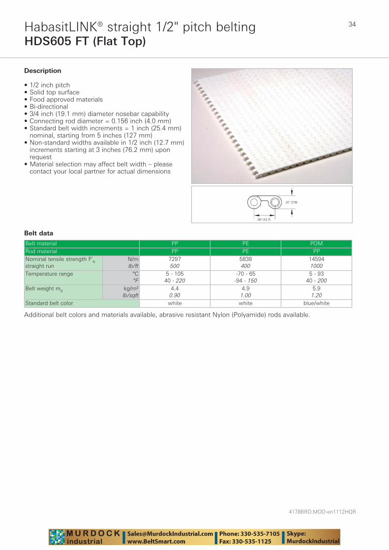
HDS605 FT (Flat Top)HabasitLINK® straight 1/2" pitch belting
Belt data
Belt material PP PE POMRod material PP PE PPNominal tensile strength F'N straight run
N/mlb/ft
7297500
5838400
145941000
Temperature range °C°F
5 - 10540 - 220
-70 - 65-94 - 150
5 - 9340 - 200
Belt weight mB kg/m²lb/sqft
4.40.90
4.91.00
5.91.20
Standard belt color white white blue/white
Description
• 1/2 inch pitch • Solid top surface • Food approved materials• Bi-directional • 3/4 inch (19.1 mm) diameter nosebar capability • Connecting rod diameter = 0.156 inch (4.0 mm) • Standard belt width increments = 1 inch (25.4 mm)
nominal, starting from 5 inches (127 mm) • Non-standard widths available in 1/2 inch (12.7 mm)
increments starting at 3 inches (76.2 mm) upon request
• Material selection may affect belt width – please contact your local partner for actual dimensions
Additional belt colors and materials available, abrasive resistant Nylon (Polyamide) rods available.
35
4178BRO.MOD-en1112HQR
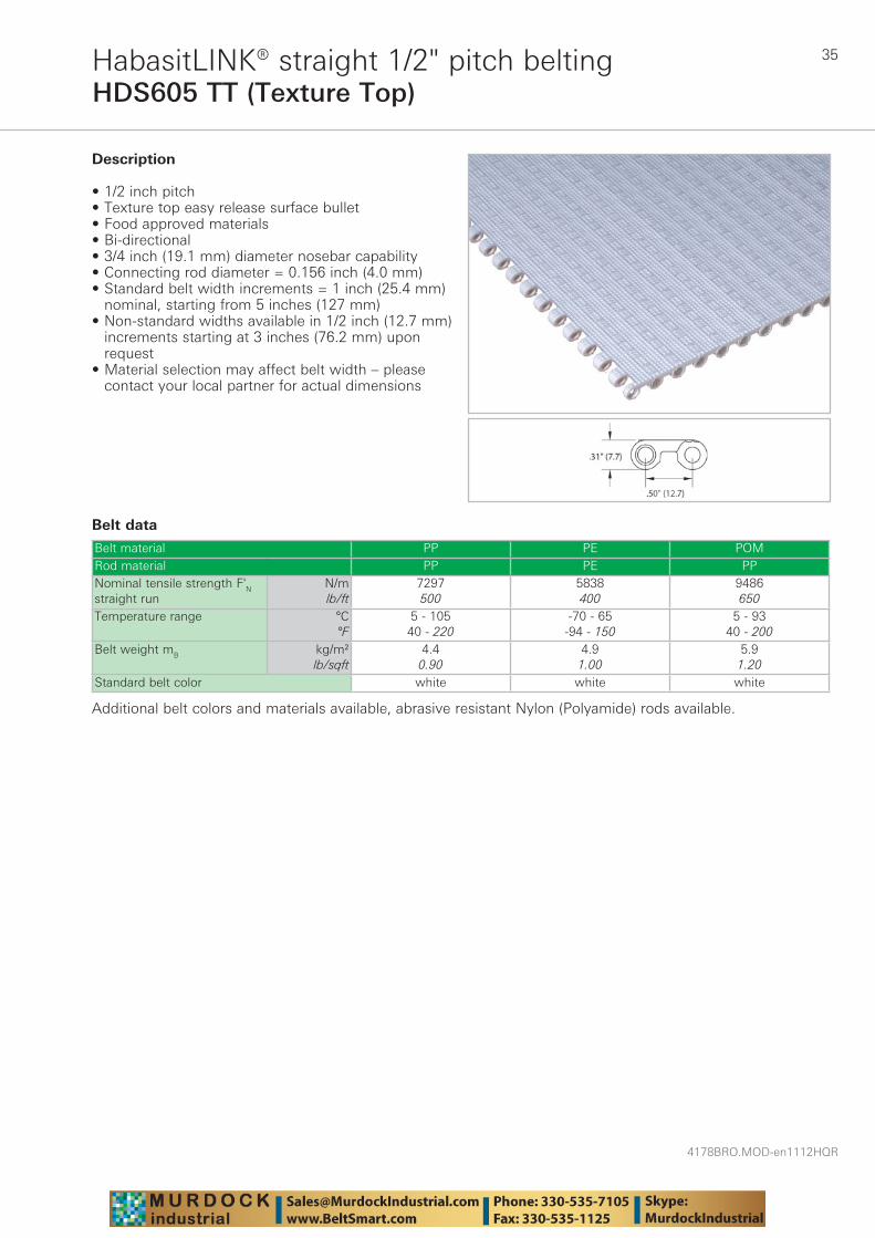
HDS605 TT (Texture Top)HabasitLINK® straight 1/2" pitch belting
Belt data
Belt material PP PE POMRod material PP PE PPNominal tensile strength F'N straight run
N/mlb/ft
7297500
5838400
9486650
Temperature range °C°F
5 - 10540 - 220
-70 - 65-94 - 150
5 - 9340 - 200
Belt weight mB kg/m²lb/sqft
4.40.90
4.91.00
5.91.20
Standard belt color white white white
Description
• 1/2 inch pitch • Texture top easy release surface bullet • Food approved materials• Bi-directional • 3/4 inch (19.1 mm) diameter nosebar capability • Connecting rod diameter = 0.156 inch (4.0 mm) • Standard belt width increments = 1 inch (25.4 mm)
nominal, starting from 5 inches (127 mm) • Non-standard widths available in 1/2 inch (12.7 mm)
increments starting at 3 inches (76.2 mm) upon request
• Material selection may affect belt width – please contact your local partner for actual dimensions
Additional belt colors and materials available, abrasive resistant Nylon (Polyamide) rods available.

4178BRO.MOD-en1112HQR
36HabasitLINK® sprockets – 1/2" pitch beltingHDS605 FT, HDS605 TT
Machined sprocket
Sprocket part number
Num-ber of teeth
(PD) Nominal pitch
diameter
(WH) Shaft center to top of wearstrip
(BH) Shaft center to
top of belt
(HT) Hub thickness
inch mm inch mm inch mm inch mm
HDS70512 12 1.93 49 0.79 20 1.10 28 1 25
HDS70515 15 2.40 61 1.02 26 1.33 34 1 25
HDS70520 20 3.20 81 1.42 36 1.73 44 1 25
HDS70536 36 5.74 146 2.69 68 3.00 76 1 25
Split sprockets and other tooth sizes are available. Standard machined sprocket material is UHMW, Nylon and Urethane are available.
Sprocket part number
Available bore size
1/2“ 3/4“ 20 mm 25 mm 1“ 1“ sq. 30 mm 1-1/4“
1-7/16“ 1-1/2“ 1-1/2“
sq. 40 mm 40 mm sq.
1-15/16“ 50 mm 2“
HDS70512 ✓ ✓ ✓ ✓ ✓ – ✓ – – – – – – – – –
HDS70515 ✓ ✓ ✓ ✓ ✓ – ✓ ✓ ✓ – – – – – – –
HDS70520 ✓ ✓ ✓ ✓ ✓ ✓ ✓ ✓ ✓ ✓ – – – – – –
HDS70536 ✓ ✓ ✓ ✓ ✓ ✓ ✓ ✓ ✓ ✓ ✓ ✓ ✓ ✓ ✓ ✓
All bore sizes are round bore unless designated square (sq.).
37
4178BRO.MOD-en1112HQR
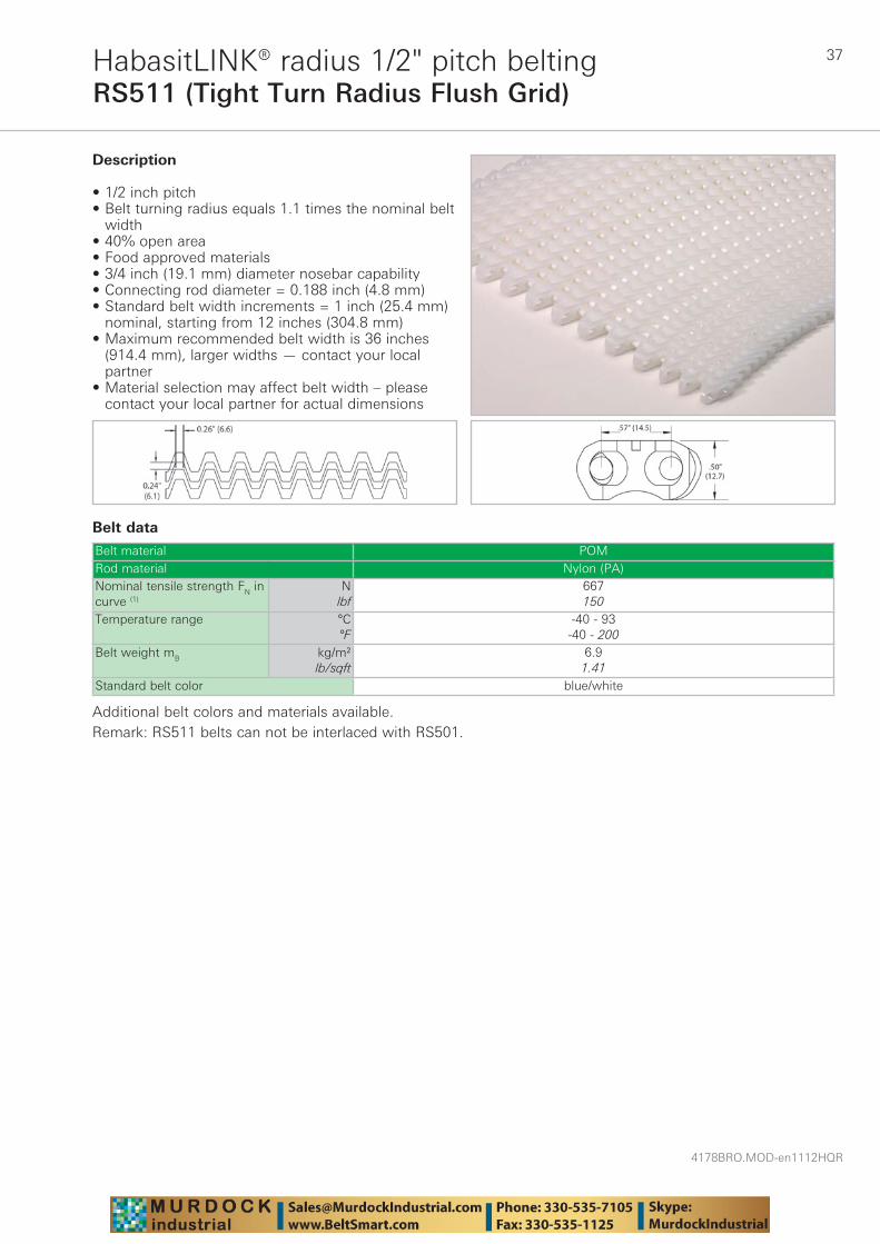
RS511 (Tight Turn Radius Flush Grid)HabasitLINK® radius 1/2" pitch belting
Belt data
Belt material POMRod material Nylon (PA)Nominal tensile strength FN in curve (1)
Nlbf
667150
Temperature range °C°F
-40 - 93-40 - 200
Belt weight mB kg/m²lb/sqft
6.91.41
Standard belt color blue/white
Description
• 1/2 inch pitch • Belt turning radius equals 1.1 times the nominal belt
width • 40% open area • Food approved materials• 3/4 inch (19.1 mm) diameter nosebar capability • Connecting rod diameter = 0.188 inch (4.8 mm) • Standard belt width increments = 1 inch (25.4 mm)
nominal, starting from 12 inches (304.8 mm) • Maximum recommended belt width is 36 inches
(914.4 mm), larger widths — contact your local partner
• Material selection may affect belt width – please contact your local partner for actual dimensions
Additional belt colors and materials available.Remark: RS511 belts can not be interlaced with RS501.
4178BRO.MOD-en1112HQR
38
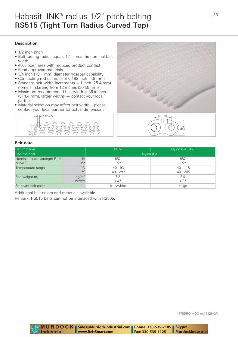
RS515 (Tight Turn Radius Curved Top)HabasitLINK® radius 1/2" pitch belting
Belt data
Belt material POM Nylon (PA 612)Rod material Nylon (PA)Nominal tensile strength FN in curve (1)
Nlbf
667150
667150
Temperature range °C°F
-40 - 93-40 - 200
-40 - 118-40 - 245
Belt weight mB kg/m²lb/sqft
7.21.47
5.91.21
Standard belt color blue/white beige
Description
• 1/2 inch pitch • Belt turning radius equals 1.1 times the nominal belt
width • 40% open area with reduced product contact • Food approved materials• 3/4 inch (19.1 mm) diameter nosebar capability • Connecting rod diameter = 0.188 inch (4.8 mm) • Standard belt width increments = 1 inch (25.4 mm)
nominal, starting from 12 inches (304.8 mm) • Maximum recommended belt width is 36 inches
(914.4 mm), larger widths — contact your local partner
• Material selection may affect belt width – please contact your local partner for actual dimensions
Additional belt colors and materials available.Remark: RS515 belts can not be interlaced with RS505.
39
4178BRO.MOD-en1112HQR
HabasitLINK® sprockets – 1/2" pitch beltingRS511, RS515
Machined sprocketSplit sprockets and other sizes are available.
Sprocket part number
Num-ber of teeth
(PD) Nominal pitch
diameter
(WH) Shaft center to top of wearstrip
(BH) Shaft center to
top of belt
Curved Top (BH)
Shaft center to top of belt curve
(HT) Hub thickness
inch mm inch mm inch mm inch mm inch mm
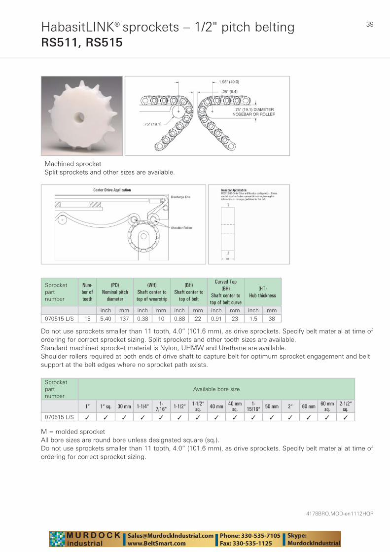
070515 L/S 15 5.40 137 0.38 10 0.88 22 0.91 23 1.5 38
Do not use sprockets smaller than 11 tooth, 4.0” (101.6 mm), as drive sprockets. Specify belt material at time of ordering for correct sprocket sizing. Split sprockets and other tooth sizes are available. Standard machined sprocket material is Nylon, UHMW and Urethane are available. Shoulder rollers required at both ends of drive shaft to capture belt for optimum sprocket engagement and belt support at the belt edges where no sprocket path exists.
Sprocket part number
Available bore size
1“ 1“ sq. 30 mm 1-1/4“ 1-7/16“ 1-1/2“ 1-1/2“
sq. 40 mm 40 mmsq.
1-15/16“ 50 mm 2“ 60 mm 60 mm
sq.2-1/2“
sq.070515 L/S ✓ ✓ ✓ ✓ ✓ ✓ ✓ ✓ ✓ ✓ ✓ ✓ ✓ ✓ ✓
M = molded sprocketAll bore sizes are round bore unless designated square (sq.).Do not use sprockets smaller than 11 tooth, 4.0” (101.6 mm), as drive sprockets. Specify belt material at time of ordering for correct sprocket sizing.
4178BRO.MOD-en1112HQR
40
106 FT (106 Flat Top)HabasitLINK® straight 3/4" pitch belting
Belt data
Belt material PP POM POM LRod material PPNominal tensile strength F'N straight run
N/mlb/ft
3765487
75310989
75310989
Temperature range °C°F
5 - 10540 - 220
5 - 9340 - 200
5 - 9340 - 200
Belt weight mB kg/m²lb/sqft
4.91.00
6.81.40
6.81.40
Standard belt color gray gray/white brown
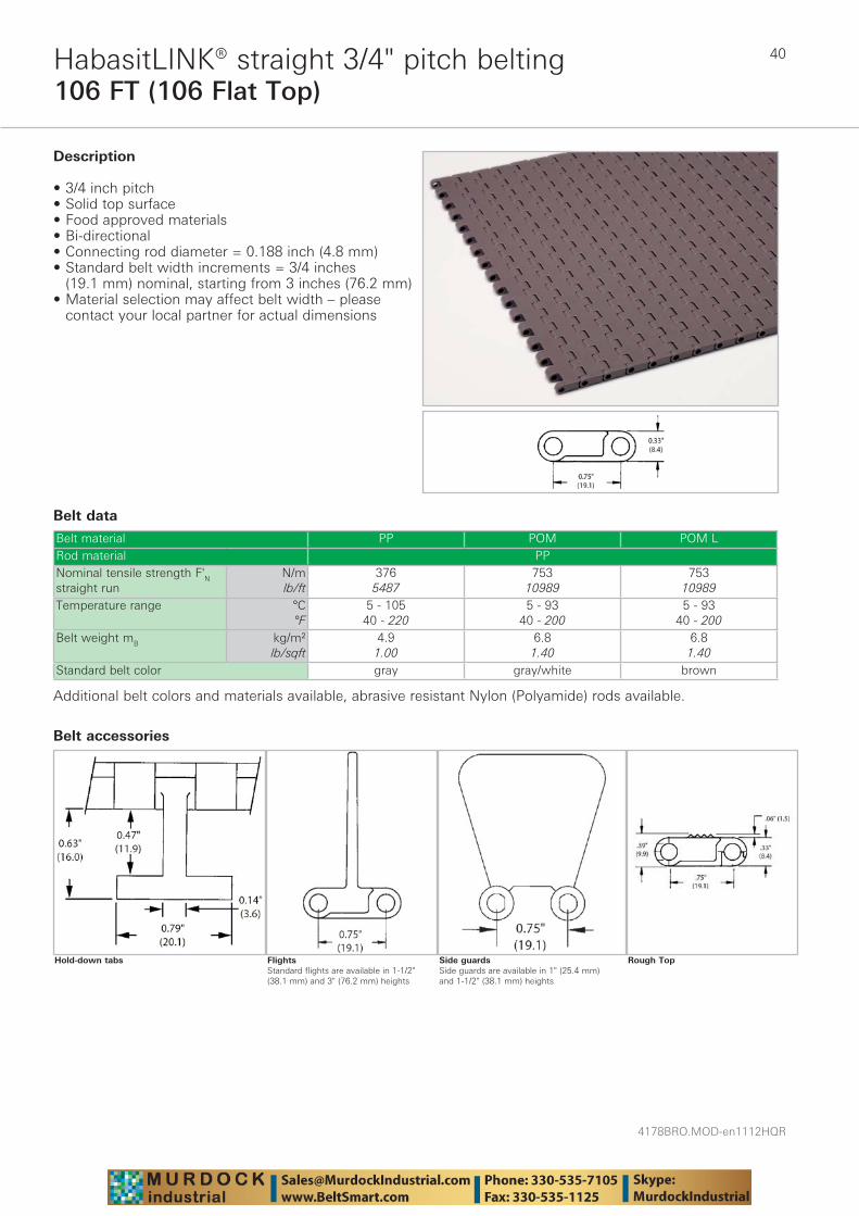
Description
• 3/4 inch pitch • Solid top surface • Food approved materials• Bi-directional • Connecting rod diameter = 0.188 inch (4.8 mm) • Standard belt width increments = 3/4 inches
(19.1 mm) nominal, starting from 3 inches (76.2 mm) • Material selection may affect belt width – please
contact your local partner for actual dimensions
Additional belt colors and materials available, abrasive resistant Nylon (Polyamide) rods available.
Rough TopSide guardsSide guards are available in 1" (25.4 mm) and 1-1/2" (38.1 mm) heights
FlightsStandard flights are available in 1-1/2" (38.1 mm) and 3" (76.2 mm) heights
Belt accessories
Hold-down tabs
41
4178BRO.MOD-en1112HQR
106 10 (106 Mesh Top 10% Open)HabasitLINK® straight 3/4" pitch belting
Belt data
Belt material PP POM URod material PPNominal tensile strength F'N straight run
N/mlb/ft
5487376
10989753
Temperature range °C°F
5 - 10540 - 220
5 - 9340 - 200
Belt weight mB kg/m²lb/sqft
4.70.96
6.41.30
Standard belt color gray green
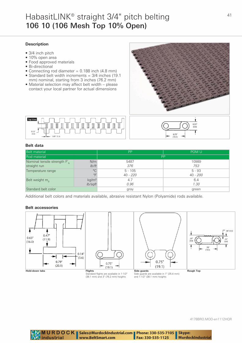
Description
• 3/4 inch pitch • 10% open area • Food approved materials• Bi-directional • Connecting rod diameter = 0.188 inch (4.8 mm) • Standard belt width increments = 3/4 inches (19.1
mm) nominal, starting from 3 inches (76.2 mm) • Material selection may affect belt width – please
contact your local partner for actual dimensions
Additional belt colors and materials available, abrasive resistant Nylon (Polyamide) rods available.
Rough TopSide guardsSide guards are available in 1" (25.4 mm) and 1-1/2" (38.1 mm) heights
FlightsStandard flights are available in 1-1/2" (38.1 mm) and 3" (76.2 mm) heights
Belt accessories
Hold-down tabs
4178BRO.MOD-en1112HQR
42
106 22 (106 Flush Grid 22% Open)HabasitLINK® straight 3/4" pitch belting
Belt data
Belt material PP POM LRod material PPNominal tensile strength F'N straight run
N/mlb/ft
5487376
10989753
Temperature range °C°F
5 - 10540 - 220
5 - 9340 - 200
Belt weight mB kg/m²lb/sqft
4.10.84
5.81.19
Standard belt color gray brown
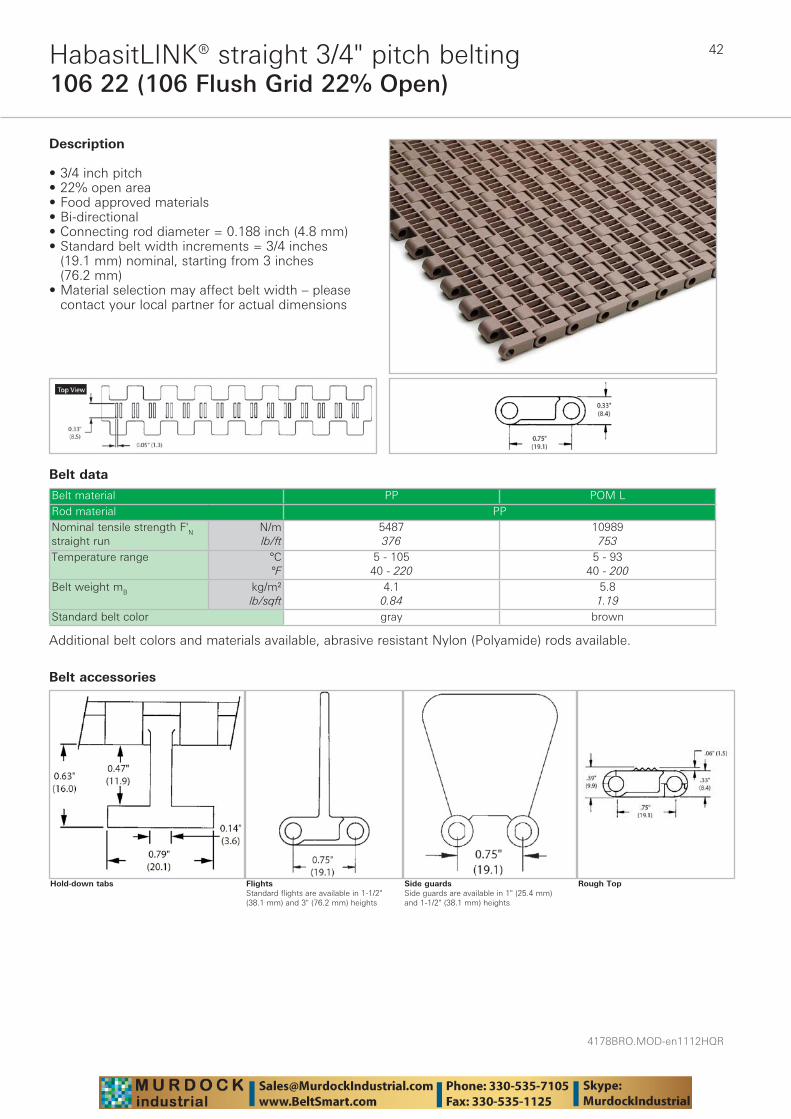
Description
• 3/4 inch pitch • 22% open area • Food approved materials• Bi-directional • Connecting rod diameter = 0.188 inch (4.8 mm) • Standard belt width increments = 3/4 inches
(19.1 mm) nominal, starting from 3 inches (76.2 mm)
• Material selection may affect belt width – please contact your local partner for actual dimensions
Additional belt colors and materials available, abrasive resistant Nylon (Polyamide) rods available.
Rough TopSide guardsSide guards are available in 1" (25.4 mm) and 1-1/2" (38.1 mm) heights
FlightsStandard flights are available in 1-1/2" (38.1 mm) and 3" (76.2 mm) heights
Belt accessories
Hold-down tabs
43
4178BRO.MOD-en1112HQR
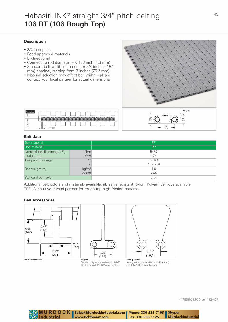
106 RT (106 Rough Top)HabasitLINK® straight 3/4" pitch belting
Belt data
Belt material PPRod material PPNominal tensile strength F'N straight run
N/mlb/ft
5487376
Temperature range °C°F
5 - 10540 - 220
Belt weight mB kg/m²lb/sqft
4.91.00
Standard belt color gray
Description
• 3/4 inch pitch • Food approved materials• Bi-directional • Connecting rod diameter = 0.188 inch (4.8 mm) • Standard belt width increments = 3/4 inches (19.1
mm) nominal, starting from 3 inches (76.2 mm) • Material selection may affect belt width – please
contact your local partner for actual dimensions
Additional belt colors and materials available, abrasive resistant Nylon (Polyamide) rods available.TPE: Consult your local partner for rough top high friction patterns.
Side guardsSide guards are available in 1" (25.4 mm) and 1-1/2" (38.1 mm) heights
FlightsStandard flights are available in 1-1/2" (38.1 mm) and 3" (76.2 mm) heights
Belt accessories
Hold-down tabs
4178BRO.MOD-en1112HQR
44
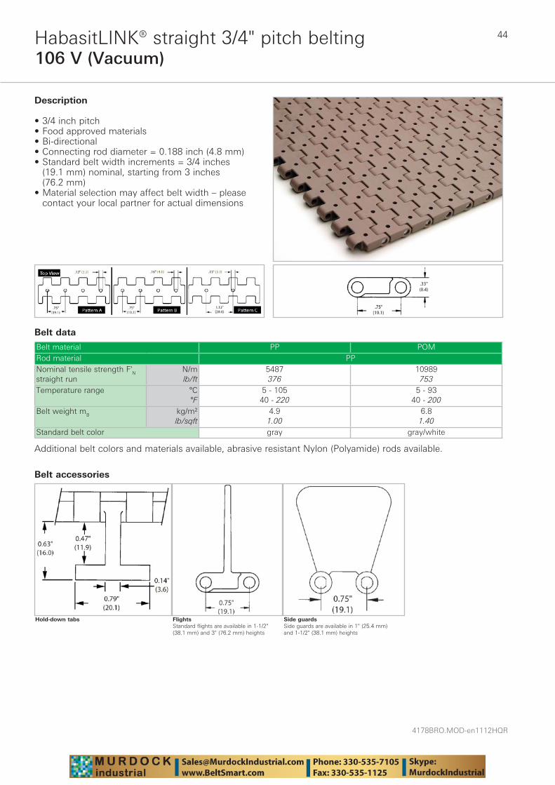
106 V (Vacuum)HabasitLINK® straight 3/4" pitch belting
Belt data
Belt material PP POMRod material PPNominal tensile strength F'N straight run
N/mlb/ft
5487376
10989753
Temperature range °C°F
5 - 10540 - 220
5 - 9340 - 200
Belt weight mB kg/m²lb/sqft
4.91.00
6.81.40
Standard belt color gray gray/white
Description
• 3/4 inch pitch • Food approved materials• Bi-directional • Connecting rod diameter = 0.188 inch (4.8 mm) • Standard belt width increments = 3/4 inches
(19.1 mm) nominal, starting from 3 inches (76.2 mm)
• Material selection may affect belt width – please contact your local partner for actual dimensions
Additional belt colors and materials available, abrasive resistant Nylon (Polyamide) rods available.
Side guardsSide guards are available in 1" (25.4 mm) and 1-1/2" (38.1 mm) heights
FlightsStandard flights are available in 1-1/2" (38.1 mm) and 3" (76.2 mm) heights
Belt accessories
Hold-down tabs
45
4178BRO.MOD-en1112HQR
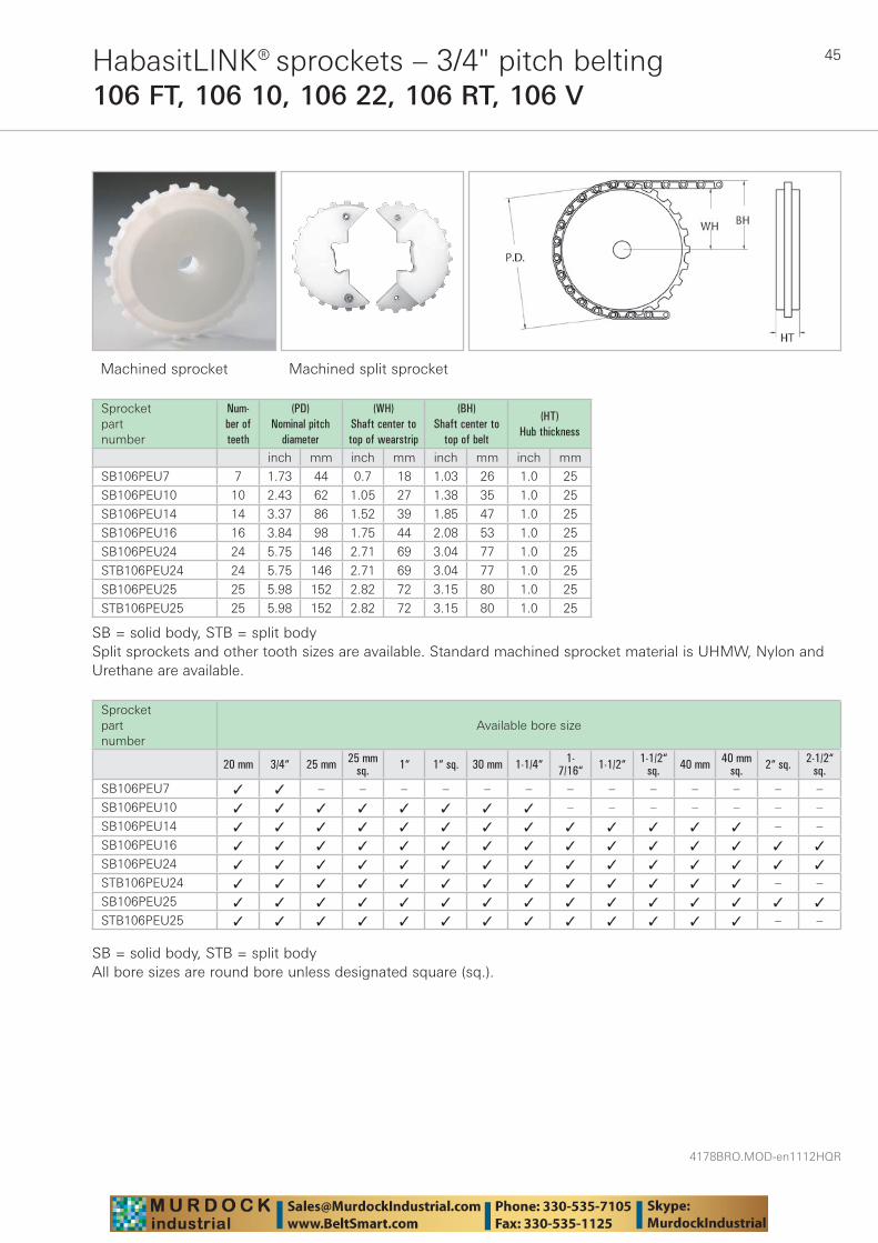
HabasitLINK® sprockets – 3/4" pitch belting106 FT, 106 10, 106 22, 106 RT, 106 V
Machined sprocket Machined split sprocket
Sprocket part number
Num-ber of teeth
(PD) Nominal pitch
diameter
(WH) Shaft center to top of wearstrip
(BH) Shaft center to
top of belt
(HT) Hub thickness
inch mm inch mm inch mm inch mm
SB106PEU7 7 1.73 44 0.7 18 1.03 26 1.0 25
SB106PEU10 10 2.43 62 1.05 27 1.38 35 1.0 25
SB106PEU14 14 3.37 86 1.52 39 1.85 47 1.0 25
SB106PEU16 16 3.84 98 1.75 44 2.08 53 1.0 25
SB106PEU24 24 5.75 146 2.71 69 3.04 77 1.0 25
STB106PEU24 24 5.75 146 2.71 69 3.04 77 1.0 25
SB106PEU25 25 5.98 152 2.82 72 3.15 80 1.0 25
STB106PEU25 25 5.98 152 2.82 72 3.15 80 1.0 25
SB = solid body, STB = split bodySplit sprockets and other tooth sizes are available. Standard machined sprocket material is UHMW, Nylon and Urethane are available.
Sprocket part number
Available bore size
20 mm 3/4“ 25 mm 25 mm sq. 1“ 1“ sq. 30 mm 1-1/4“ 1-
7/16“ 1-1/2“ 1-1/2“sq. 40 mm 40 mm
sq. 2“ sq. 2-1/2“sq.
SB106PEU7 ✓ ✓ – – – – – – – – – – – – –
SB106PEU10 ✓ ✓ ✓ ✓ ✓ ✓ ✓ ✓ – – – – – – –
SB106PEU14 ✓ ✓ ✓ ✓ ✓ ✓ ✓ ✓ ✓ ✓ ✓ ✓ ✓ – –
SB106PEU16 ✓ ✓ ✓ ✓ ✓ ✓ ✓ ✓ ✓ ✓ ✓ ✓ ✓ ✓ ✓
SB106PEU24 ✓ ✓ ✓ ✓ ✓ ✓ ✓ ✓ ✓ ✓ ✓ ✓ ✓ ✓ ✓
STB106PEU24 ✓ ✓ ✓ ✓ ✓ ✓ ✓ ✓ ✓ ✓ ✓ ✓ ✓ – –
SB106PEU25 ✓ ✓ ✓ ✓ ✓ ✓ ✓ ✓ ✓ ✓ ✓ ✓ ✓ ✓ ✓
STB106PEU25 ✓ ✓ ✓ ✓ ✓ ✓ ✓ ✓ ✓ ✓ ✓ ✓ ✓ – –
SB = solid body, STB = split bodyAll bore sizes are round bore unless designated square (sq.).
4178BRO.MOD-en1112HQR
46
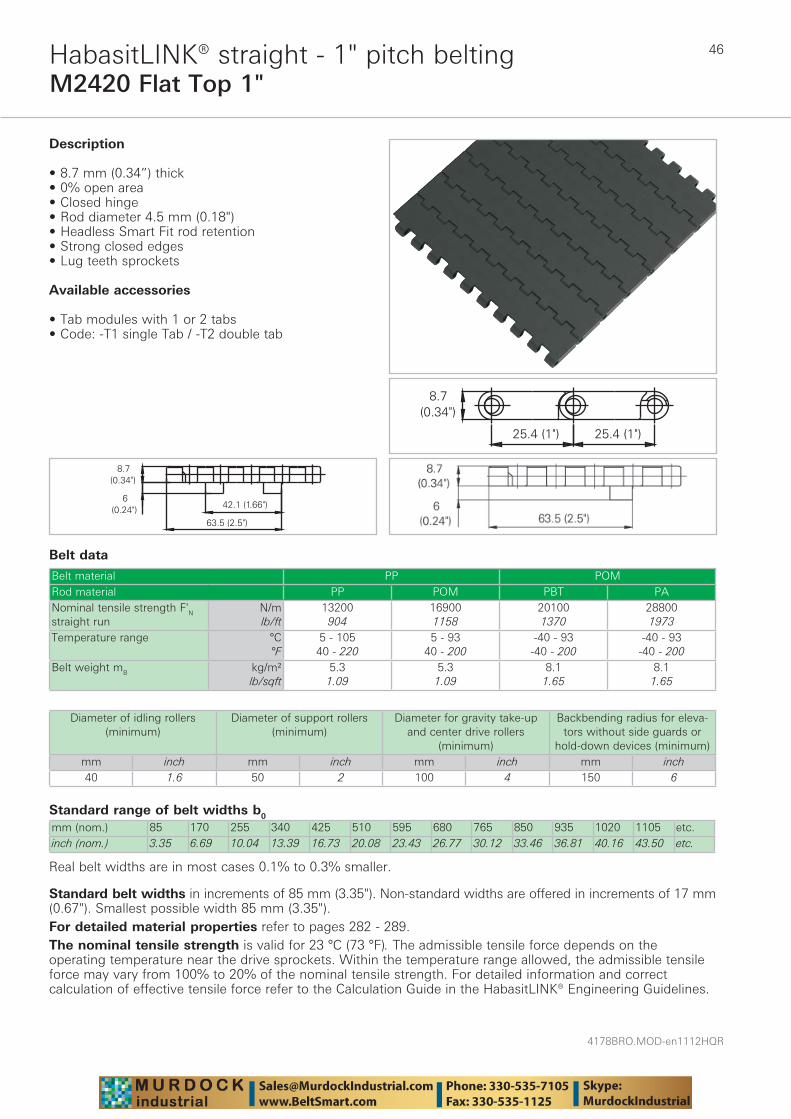
M2420 Flat Top 1"HabasitLINK® straight - 1" pitch belting
Belt data
Standard range of belt widths b0
mm (nom.) 85 170 255 340 425 510 595 680 765 850 935 1020 1105 etc.inch (nom.) 3.35 6.69 10.04 13.39 16.73 20.08 23.43 26.77 30.12 33.46 36.81 40.16 43.50 etc.
Real belt widths are in most cases 0.1% to 0.3% smaller.
Belt material PP POMRod material PP POM PBT PANominal tensile strength F'N straight run
N/mlb/ft
13200904
169001158
201001370
288001973
Temperature range °C°F
5 - 10540 - 220
5 - 9340 - 200
-40 - 93-40 - 200
-40 - 93-40 - 200
Belt weight mB kg/m²lb/sqft
5.31.09
5.31.09
8.11.65
8.11.65
Description
• 8.7 mm (0.34”) thick • 0% open area • Closed hinge • Rod diameter 4.5 mm (0.18") • Headless Smart Fit rod retention • Strong closed edges • Lug teeth sprockets
Available accessories
• Tab modules with 1 or 2 tabs • Code: -T1 single Tab / -T2 double tab
Diameter of idling rollers (minimum)
Diameter of support rollers(minimum)
Diameter for gravity take-up and center drive rollers
(minimum)
Backbending radius for eleva-tors without side guards or
hold-down devices (minimum)mm inch mm inch mm inch mm inch40 1.6 50 2 100 4 150 6
Standard belt widths in increments of 85 mm (3.35"). Non-standard widths are offered in increments of 17 mm (0.67"). Smallest possible width 85 mm (3.35").For detailed material properties refer to pages 282 - 289.The nominal tensile strength is valid for 23 °C (73 °F). The admissible tensile force depends on the operating temperature near the drive sprockets. Within the temperature range allowed, the admissible tensile force may vary from 100% to 20% of the nominal tensile strength. For detailed information and correct calculation of effective tensile force refer to the Calculation Guide in the HabasitLINK® Engineering Guidelines.
47
4178BRO.MOD-en1112HQR
M2420 ActivXchange 1"HabasitLINK® straight - 1" pitch belting
Belt data
Temperature rangeModule material Rod material Temperature rangePOM +LF PA -40 °C to +93 °C -40 °F to +200 °FPOM +LF PBT -40 °C to +93 °C -40 °F to +200 °FPOM +LF PP +5 °C to +93 °C +40 °F to +200 °F
Description
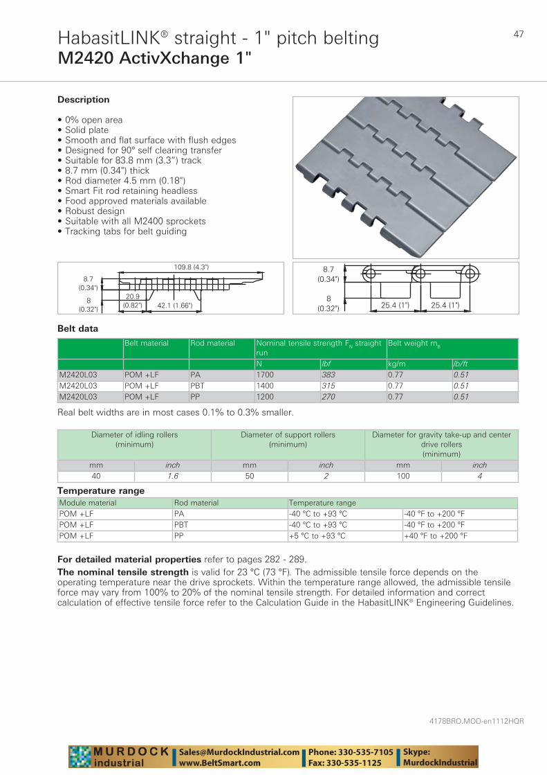
• 0% open area • Solid plate • Smooth and flat surface with flush edges • Designed for 90° self clearing transfer • Suitable for 83.8 mm (3.3”) track • 8.7 mm (0.34") thick • Rod diameter 4.5 mm (0.18") • Smart Fit rod retaining headless • Food approved materials available• Robust design • Suitable with all M2400 sprockets • Tracking tabs for belt guiding
Diameter of idling rollers (minimum)
Diameter of support rollers(minimum)
Diameter for gravity take-up and center drive rollers (minimum)
mm inch mm inch mm inch40 1.6 50 2 100 4
Belt material Rod material Nominal tensile strength FN straight run
Belt weight mB
N lbf kg/m lb/ftM2420L03 POM +LF PA 1700 383 0.77 0.51M2420L03 POM +LF PBT 1400 315 0.77 0.51M2420L03 POM +LF PP 1200 270 0.77 0.51
Real belt widths are in most cases 0.1% to 0.3% smaller.
For detailed material properties refer to pages 282 - 289.The nominal tensile strength is valid for 23 °C (73 °F). The admissible tensile force depends on the operating temperature near the drive sprockets. Within the temperature range allowed, the admissible tensile force may vary from 100% to 20% of the nominal tensile strength. For detailed information and correct calculation of effective tensile force refer to the Calculation Guide in the HabasitLINK® Engineering Guidelines.
4178BRO.MOD-en1112HQR
48
M2423 Non Slip 1"HabasitLINK® straight - 1" pitch belting
Belt data
Standard range of belt widths b0
mm (nom.) 85 170 255 340 425 510 595 680 765 850 935 1020 1105 etc.inch (nom.) 3.35 6.69 10.04 13.39 16.73 20.08 23.43 26.77 30.12 33.46 36.81 40.16 43.50 etc.
Real belt widths are in most cases 0.1% to 0.3% wider.
Belt material PP +AS POM +ASRod material PANominal tensile strength F'N straight run
N/mlb/ft
162001110
229001569
Temperature range °C°F
5 - 10540 - 220
-40 - 90-40 - 195
Belt weight mB kg/m²lb/sqft
5.551.13
8.11.67
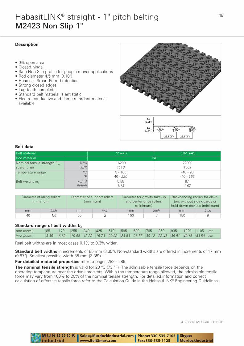
Description
• 0% open area • Closed hinge • Safe Non Slip profile for people mover applications • Rod diameter 4.5 mm (0.18") • Headless Smart Fit rod retention • Strong closed edges • Lug teeth sprockets • Standard belt material is antistatic• Electro conductive and flame retardant materials
available
Diameter of idling rollers (minimum)
Diameter of support rollers(minimum)
Diameter for gravity take-up and center drive rollers
(minimum)
Backbending radius for eleva-tors without side guards or
hold-down devices (minimum)mm inch mm inch mm inch mm inch40 1.6 50 2 100 4 150 6
Standard belt widths in increments of 85 mm (3.35"). Non-standard widths are offered in increments of 17 mm (0.67"). Smallest possible width 85 mm (3.35").For detailed material properties refer to pages 282 - 289.The nominal tensile strength is valid for 23 °C (73 °F). The admissible tensile force depends on the operating temperature near the drive sprockets. Within the temperature range allowed, the admissible tensile force may vary from 100% to 20% of the nominal tensile strength. For detailed information and correct calculation of effective tensile force refer to the Calculation Guide in the HabasitLINK® Engineering Guidelines.
49
4178BRO.MOD-en1112HQR
M2470 Flat Top 1"HabasitLINK® straight - 1" pitch belting
Belt data
Standard range of belt widths b0
mm (nom.) 76 152 229 305 381 457 533 610 686 762 838 914 991 etc.inch (nom.) 3 6 9 12 15 18 21 24 27 30 33 36 39 etc.
Real belt widths are in most cases 0.1% to 0.3% smaller.Real belt widths for PP are 0.1% to 0.3% wider.
Belt material PP POMRod material PP POM PANominal tensile strength F'N straight run
N/mlb/ft
172001178
185001267
300002055
Temperature range °C°F
5 - 10540 - 220
5 - 9340 - 200
-40 - 93-40 - 200
Belt weight mB kg/m²lb/sqft
5.71.17
5.71.17
8.71.79
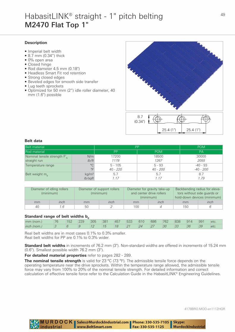
Description
• Imperial belt width • 8.7 mm (0.34”) thick • 0% open area • Closed hinge • Rod diameter 4.5 mm (0.18") • Headless Smart Fit rod retention • Strong closed edges • Beveled edges for smooth side transfer • Lug teeth sprockets • Optimized for 50 mm (2”) idle roller diameter, 40
mm (1.6") possible
Diameter of idling rollers (minimum)
Diameter of support rollers(minimum)
Diameter for gravity take-up and center drive rollers
(minimum)
Backbending radius for eleva-tors without side guards or
hold-down devices (minimum)mm inch mm inch mm inch mm inch40 1.6 50 2 100 4 150 6
Standard belt widths in increments of 76.2 mm (3"). Non-standard widths are offered in increments of 15.24 mm (0.6"). Smallest possible width 76.2 mm (3").For detailed material properties refer to pages 282 - 289.The nominal tensile strength is valid for 23 °C (73 °F). The admissible tensile force depends on the operating temperature near the drive sprockets. Within the temperature range allowed, the admissible tensile force may vary from 100% to 20% of the nominal tensile strength. For detailed information and correct calculation of effective tensile force refer to the Calculation Guide in the HabasitLINK® Engineering Guidelines.
4178BRO.MOD-en1112HQR
50
M2470 Flat Top 1" MTWHabasitLINK® straight - 1" pitch belting
Belt data
Description
• Mold to width flat top belt • Imperial widths • 8.7 mm (0.34”) thick • High strength and stiffness • 0% open area • Closed hinge • Rod diameter 4.5 mm (0.18”) • Headless Smart Fit rod retention • Strong closed edges • Beveled edges for smooth side transfer • Lug teeth sprockets • Two versions: - M2470Kxx (modules without tabs) - M2470Kxx-T20 (modules with 2 tabs)
Available accessories
• For standard guiding profiles, refer to the HabiPLAST® brochure
Diameter of idling rollers (minimum)
Diameter of support rollers(minimum)
Diameter for gravity take-up and center drive rollers (minimum)
mm inch mm inch mm inch40 1.6 50 2 100 4
Nominal belt width b0 A Belt material
Rod mate-rial
Nominal tensile strength FN straight run
Belt weight mB
mm inch mm inch N lbf kg/m lb/ftM2470K03 82.5 3.25 20.1 0.8 POM PP 1300 293 0.72 0.48M2470K03 82.5 3.25 20.1 0.8 POM PBT 1600 360 0.72 0.48M2470K03 82.5 3.25 20.1 0.8 POM PA 1850 416 0.72 0.48M2470K04 114.2 4.5 36 1.4 POM PP 1900 428 0.99 0.67M2470K04 114.2 4.5 36 1.4 POM PBT 2300 518 0.99 0.67M2470K04 114.2 4.5 36 1.4 POM PA 2600 585 0.99 0.67M2470K06 152.3 6.0 55.1 2.2 POM PP 2800 630 1.35 0.91M2470K06 152.3 6.0 55.1 2.2 POM PBT 3400 765 1.35 0.91M2470K06 152.3 6.0 55.1 2.2 POM PA 4300 968 1.35 0.91M2470K07 190.4 7.5 74.1 2.9 POM PP 3600 810 1.66 1.12M2470K07 190.4 7.5 74.1 2.9 POM PBT 4300 968 1.66 1.12M2470K07 190.4 7.5 74.1 2.9 POM PA 5500 1238 1.66 1.12
The belt weights are indicated for belts with tabs, the weight of belts without tabs are lower by circa 0.05 kg/m (0.03 lb/ft).Real belt widths are in most cases 0.1% to 0.3% smaller.
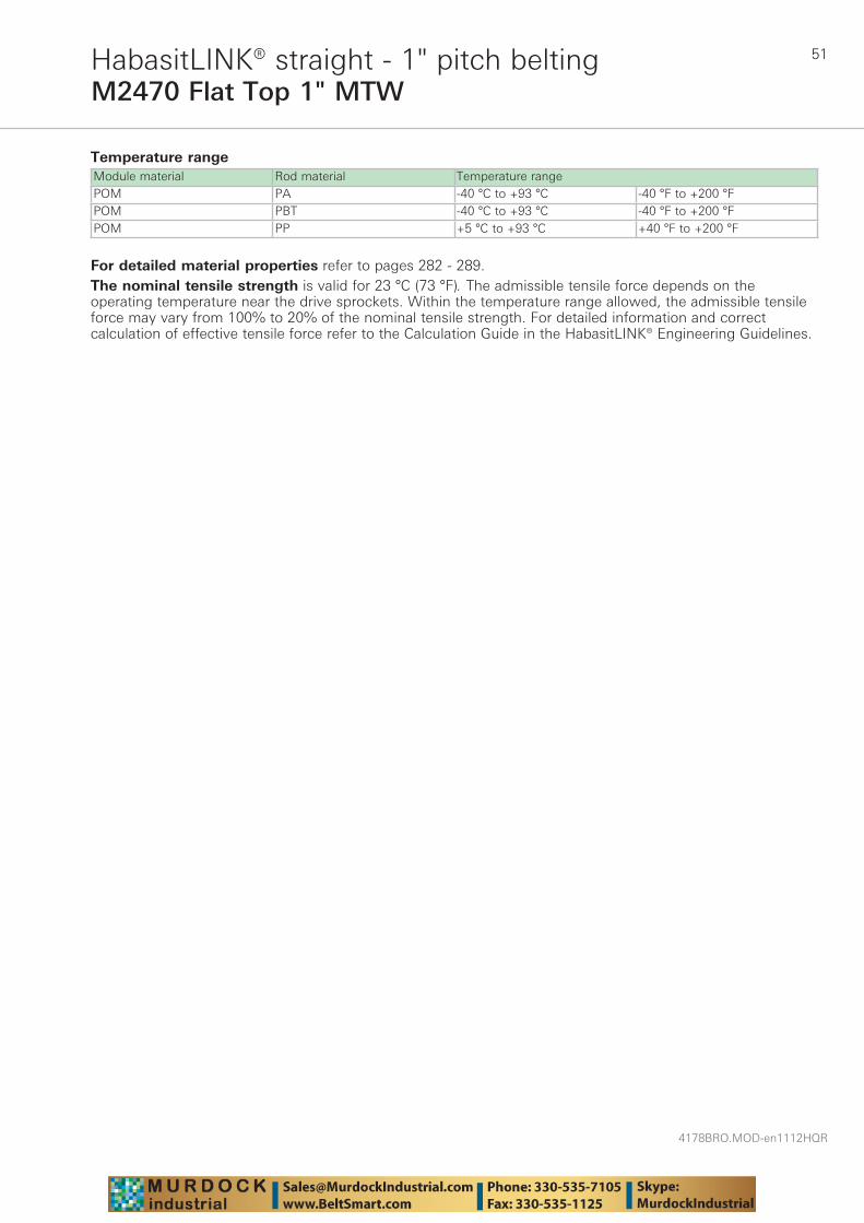
51
4178BRO.MOD-en1112HQR
M2470 Flat Top 1" MTWHabasitLINK® straight - 1" pitch belting
Temperature rangeModule material Rod material Temperature rangePOM PA -40 °C to +93 °C -40 °F to +200 °FPOM PBT -40 °C to +93 °C -40 °F to +200 °FPOM PP +5 °C to +93 °C +40 °F to +200 °F
For detailed material properties refer to pages 282 - 289.The nominal tensile strength is valid for 23 °C (73 °F). The admissible tensile force depends on the operating temperature near the drive sprockets. Within the temperature range allowed, the admissible tensile force may vary from 100% to 20% of the nominal tensile strength. For detailed information and correct calculation of effective tensile force refer to the Calculation Guide in the HabasitLINK® Engineering Guidelines.
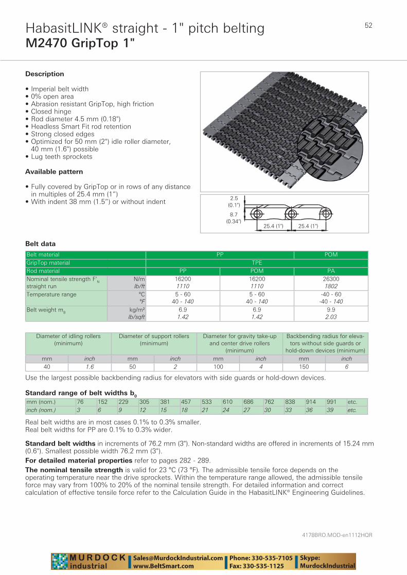
4178BRO.MOD-en1112HQR
52
M2470 GripTop 1"HabasitLINK® straight - 1" pitch belting
Belt data
Standard range of belt widths b0
mm (nom.) 76 152 229 305 381 457 533 610 686 762 838 914 991 etc.inch (nom.) 3 6 9 12 15 18 21 24 27 30 33 36 39 etc.
Real belt widths are in most cases 0.1% to 0.3% smaller.Real belt widths for PP are 0.1% to 0.3% wider.
Belt material PP POMGripTop material TPERod material PP POM PANominal tensile strength F'N straight run
N/mlb/ft
162001110
162001110
263001802
Temperature range °C°F
5 - 6040 - 140
5 - 6040 - 140
-40 - 60-40 - 140
Belt weight mB kg/m²lb/sqft
6.91.42
6.91.42
9.92.03
Description
• Imperial belt width • 0% open area • Abrasion resistant GripTop, high friction • Closed hinge • Rod diameter 4.5 mm (0.18") • Headless Smart Fit rod retention • Strong closed edges • Optimized for 50 mm (2") idle roller diameter,
40 mm (1.6") possible • Lug teeth sprockets
Available pattern
• Fully covered by GripTop or in rows of any distance in multiples of 25.4 mm (1”)
• With indent 38 mm (1.5”) or without indent
Diameter of idling rollers (minimum)
Diameter of support rollers(minimum)
Diameter for gravity take-up and center drive rollers
(minimum)
Backbending radius for eleva-tors without side guards or
hold-down devices (minimum)mm inch mm inch mm inch mm inch40 1.6 50 2 100 4 150 6
Use the largest possible backbending radius for elevators with side guards or hold-down devices.
Standard belt widths in increments of 76.2 mm (3"). Non-standard widths are offered in increments of 15.24 mm (0.6"). Smallest possible width 76.2 mm (3").For detailed material properties refer to pages 282 - 289.The nominal tensile strength is valid for 23 °C (73 °F). The admissible tensile force depends on the operating temperature near the drive sprockets. Within the temperature range allowed, the admissible tensile force may vary from 100% to 20% of the nominal tensile strength. For detailed information and correct calculation of effective tensile force refer to the Calculation Guide in the HabasitLINK® Engineering Guidelines.
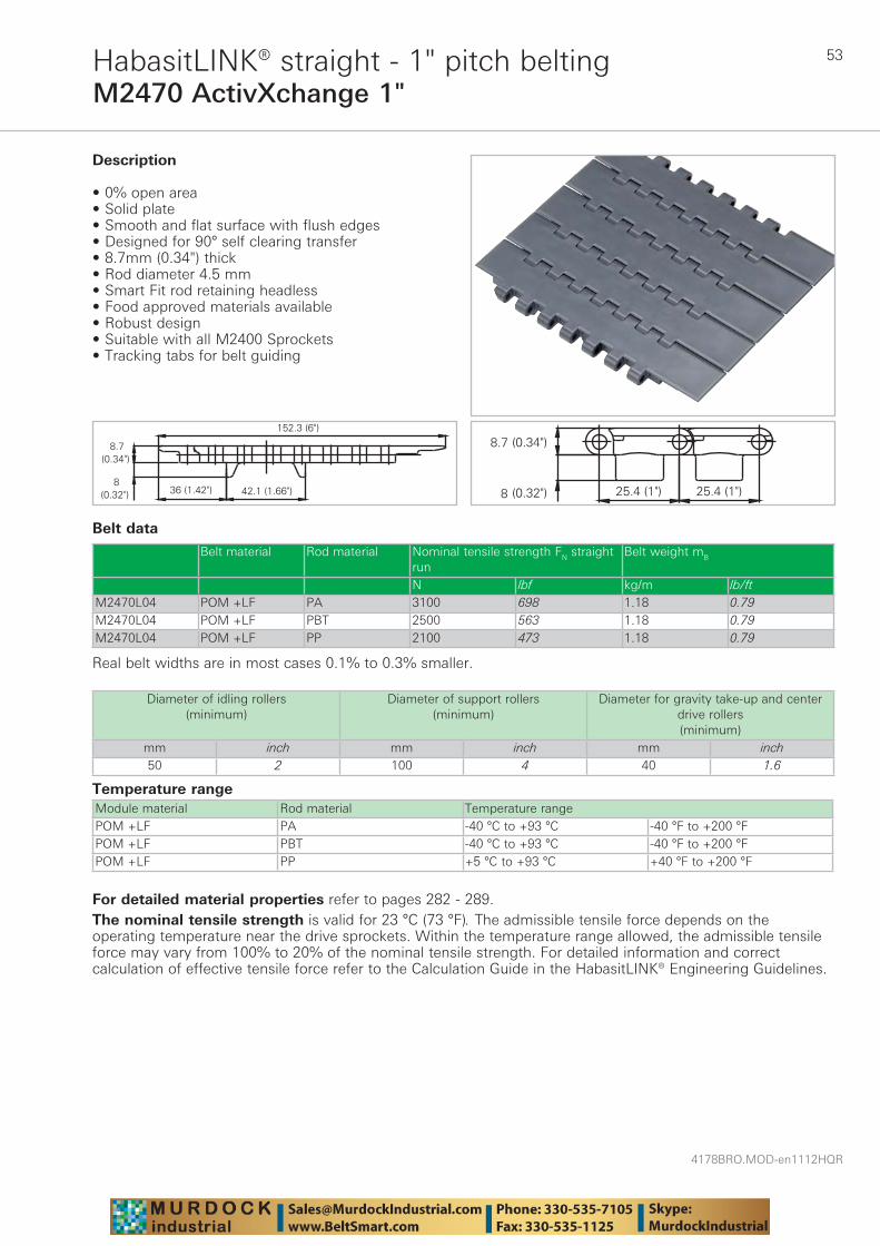
53
4178BRO.MOD-en1112HQR
M2470 ActivXchange 1"HabasitLINK® straight - 1" pitch belting
Belt data
Temperature rangeModule material Rod material Temperature rangePOM +LF PA -40 °C to +93 °C -40 °F to +200 °FPOM +LF PBT -40 °C to +93 °C -40 °F to +200 °FPOM +LF PP +5 °C to +93 °C +40 °F to +200 °F
Description
• 0% open area • Solid plate • Smooth and flat surface with flush edges • Designed for 90° self clearing transfer • 8.7mm (0.34") thick • Rod diameter 4.5 mm • Smart Fit rod retaining headless • Food approved materials available• Robust design • Suitable with all M2400 Sprockets • Tracking tabs for belt guiding
Diameter of idling rollers (minimum)
Diameter of support rollers(minimum)
Diameter for gravity take-up and center drive rollers (minimum)
mm inch mm inch mm inch50 2 100 4 40 1.6
Belt material Rod material Nominal tensile strength FN straight run
Belt weight mB
N lbf kg/m lb/ftM2470L04 POM +LF PA 3100 698 1.18 0.79M2470L04 POM +LF PBT 2500 563 1.18 0.79M2470L04 POM +LF PP 2100 473 1.18 0.79
Real belt widths are in most cases 0.1% to 0.3% smaller.
For detailed material properties refer to pages 282 - 289.The nominal tensile strength is valid for 23 °C (73 °F). The admissible tensile force depends on the operating temperature near the drive sprockets. Within the temperature range allowed, the admissible tensile force may vary from 100% to 20% of the nominal tensile strength. For detailed information and correct calculation of effective tensile force refer to the Calculation Guide in the HabasitLINK® Engineering Guidelines.
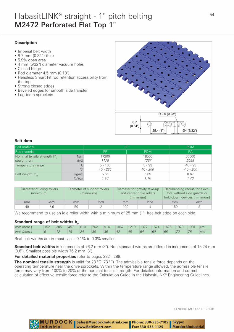
4178BRO.MOD-en1112HQR
54
M2472 Perforated Flat Top 1"HabasitLINK® straight - 1" pitch belting
Belt data
Standard range of belt widths b0
mm (nom.) 152 305 457 610 762 914 1067 1219 1372 1524 1676 1829 1981 etc.inch (nom.) 6 12 18 24 30 36 42 48 54 60 66 72 78 etc.
Real belt widths are in most cases 0.1% to 0.3% smaller.
Belt material PP POMRod material PP POM PANominal tensile strength F'N straight run
N/mlb/ft
172001178
185001267
300002055
Temperature range °C°F
5 - 10540 - 220
5 - 9340 - 200
-40 - 93-40 - 200
Belt weight mB kg/m²lb/sqft
5.651.16
5.651.16
8.671.78
Description
• Imperial belt width • 8.7 mm (0.34”) thick • 5.9% open area • 4 mm (5/32") diameter vacuum holes • Closed hinge • Rod diameter 4.5 mm (0.18") • Headless Smart Fit rod retention accessibility from
the top • Strong closed edges • Beveled edges for smooth side transfer • Lug teeth sprockets
Diameter of idling rollers (minimum)
Diameter of support rollers(minimum)
Diameter for gravity take-up and center drive rollers
(minimum)
Backbending radius for eleva-tors without side guards or
hold-down devices (minimum)mm inch mm inch mm inch mm inch40 1.6 50 2 100 4 150 6
We recommend to use an idle roller width with a minimum of 25 mm (1") free belt edge on each side.
Standard belt widths in increments of 76.2 mm (3"). Non-standard widths are offered in increments of 15.24 mm (0.6"). Smallest possible width 76.2 mm (3").For detailed material properties refer to pages 282 - 289.The nominal tensile strength is valid for 23 °C (73 °F). The admissible tensile force depends on the operating temperature near the drive sprockets. Within the temperature range allowed, the admissible tensile force may vary from 100% to 20% of the nominal tensile strength. For detailed information and correct calculation of effective tensile force refer to the Calculation Guide in the HabasitLINK® Engineering Guidelines.
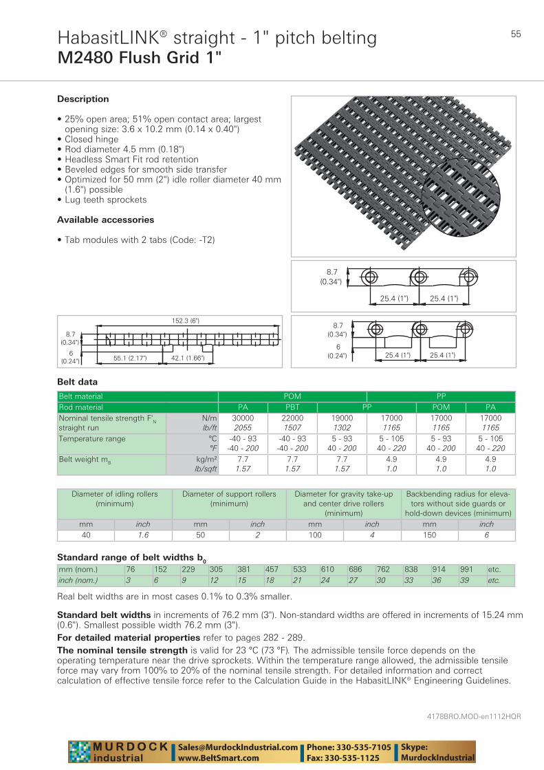
55
4178BRO.MOD-en1112HQR
M2480 Flush Grid 1"HabasitLINK® straight - 1" pitch belting
Belt data
Standard range of belt widths b0
mm (nom.) 76 152 229 305 381 457 533 610 686 762 838 914 991 etc.inch (nom.) 3 6 9 12 15 18 21 24 27 30 33 36 39 etc.
Real belt widths are in most cases 0.1% to 0.3% smaller.
Belt material POM PPRod material PA PBT PP POM PANominal tensile strength F'N straight run
N/mlb/ft
300002055
220001507
190001302
170001165
170001165
170001165
Temperature range °C°F
-40 - 93-40 - 200
-40 - 93-40 - 200
5 - 9340 - 200
5 - 10540 - 220
5 - 9340 - 200
5 - 10540 - 220
Belt weight mB kg/m²lb/sqft
7.71.57
7.71.57
7.71.57
4.91.0
4.91.0
4.91.0
Description
• 25% open area; 51% open contact area; largest opening size: 3.6 x 10.2 mm (0.14 x 0.40")
• Closed hinge • Rod diameter 4.5 mm (0.18") • Headless Smart Fit rod retention • Beveled edges for smooth side transfer • Optimized for 50 mm (2") idle roller diameter 40 mm
(1.6") possible • Lug teeth sprockets
Available accessories
• Tab modules with 2 tabs (Code: -T2)
Diameter of idling rollers (minimum)
Diameter of support rollers(minimum)
Diameter for gravity take-up and center drive rollers
(minimum)
Backbending radius for eleva-tors without side guards or
hold-down devices (minimum)mm inch mm inch mm inch mm inch40 1.6 50 2 100 4 150 6
Standard belt widths in increments of 76.2 mm (3"). Non-standard widths are offered in increments of 15.24 mm (0.6"). Smallest possible width 76.2 mm (3").For detailed material properties refer to pages 282 - 289.The nominal tensile strength is valid for 23 °C (73 °F). The admissible tensile force depends on the operating temperature near the drive sprockets. Within the temperature range allowed, the admissible tensile force may vary from 100% to 20% of the nominal tensile strength. For detailed information and correct calculation of effective tensile force refer to the Calculation Guide in the HabasitLINK® Engineering Guidelines.
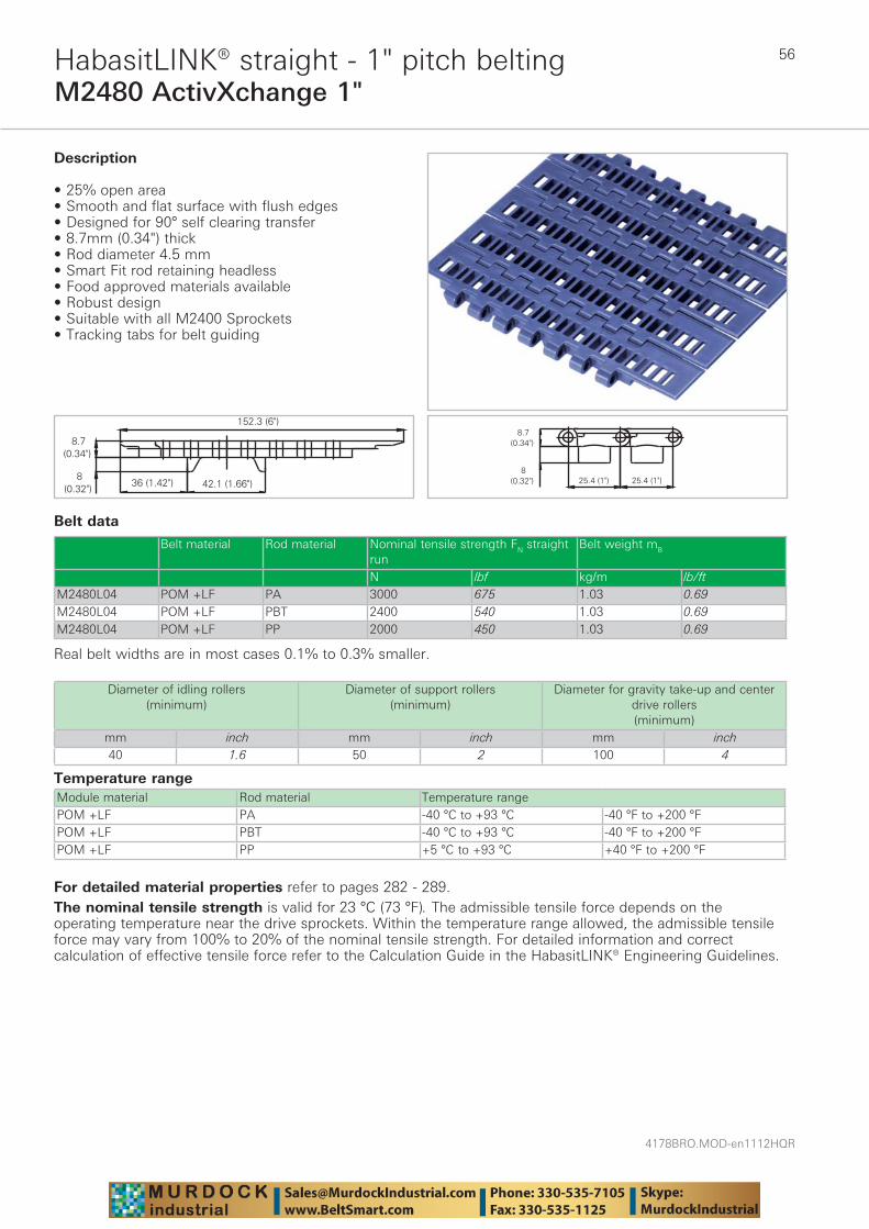
4178BRO.MOD-en1112HQR
56
M2480 ActivXchange 1"HabasitLINK® straight - 1" pitch belting
Belt data
Temperature range Module material Rod material Temperature rangePOM +LF PA -40 °C to +93 °C -40 °F to +200 °FPOM +LF PBT -40 °C to +93 °C -40 °F to +200 °FPOM +LF PP +5 °C to +93 °C +40 °F to +200 °F
Description
• 25% open area • Smooth and flat surface with flush edges • Designed for 90° self clearing transfer • 8.7mm (0.34") thick • Rod diameter 4.5 mm • Smart Fit rod retaining headless • Food approved materials available• Robust design • Suitable with all M2400 Sprockets • Tracking tabs for belt guiding
Diameter of idling rollers (minimum)
Diameter of support rollers(minimum)
Diameter for gravity take-up and center drive rollers (minimum)
mm inch mm inch mm inch40 1.6 50 2 100 4
Belt material Rod material Nominal tensile strength FN straight run
Belt weight mB
N lbf kg/m lb/ftM2480L04 POM +LF PA 3000 675 1.03 0.69M2480L04 POM +LF PBT 2400 540 1.03 0.69M2480L04 POM +LF PP 2000 450 1.03 0.69
Real belt widths are in most cases 0.1% to 0.3% smaller.
For detailed material properties refer to pages 282 - 289.The nominal tensile strength is valid for 23 °C (73 °F). The admissible tensile force depends on the operating temperature near the drive sprockets. Within the temperature range allowed, the admissible tensile force may vary from 100% to 20% of the nominal tensile strength. For detailed information and correct calculation of effective tensile force refer to the Calculation Guide in the HabasitLINK® Engineering Guidelines.
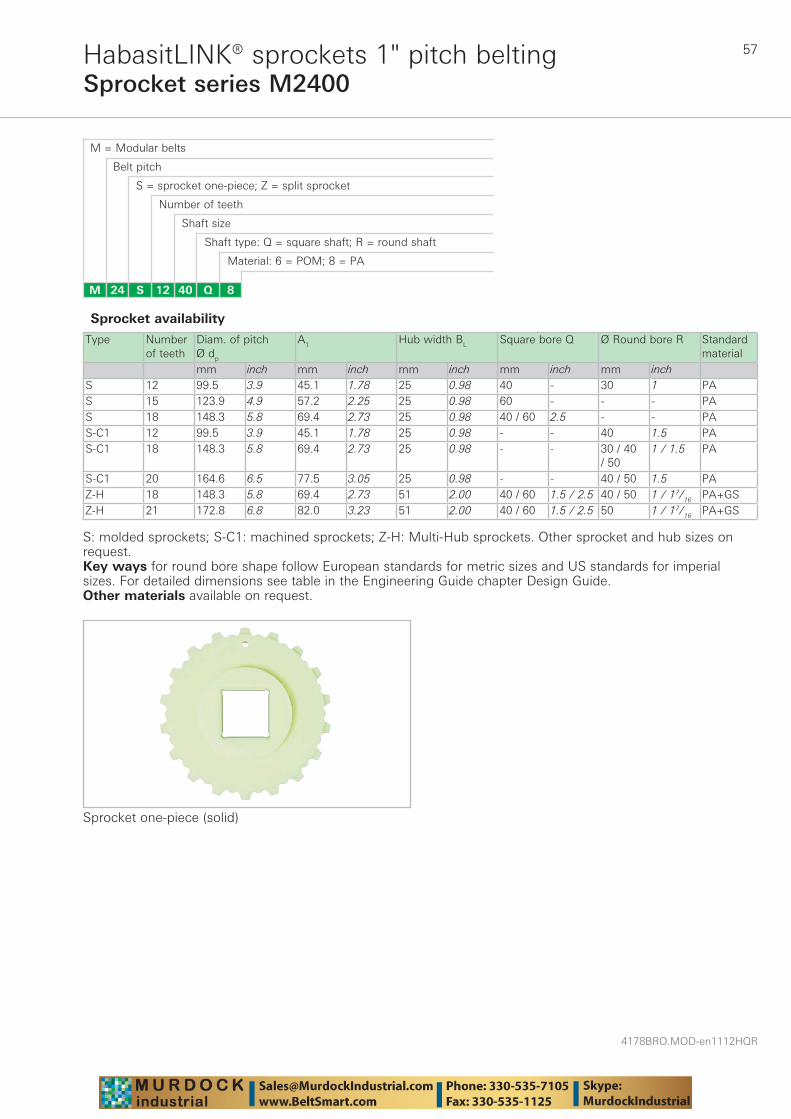
57
4178BRO.MOD-en1112HQR
Sprocket series M2400HabasitLINK® sprockets 1" pitch belting
M = Modular belts
M 24 8Q4012S
Belt pitch
S = sprocket one-piece; Z = split sprocket
Number of teeth
Shaft size
Shaft type: Q = square shaft; R = round shaft
Material: 6 = POM; 8 = PA
Type Number of teeth
Diam. of pitch Ø dp
A1 Hub width BL Square bore Q Ø Round bore R Standard material
mm inch mm inch mm inch mm inch mm inchS 12 99.5 3.9 45.1 1.78 25 0.98 40 - 30 1 PAS 15 123.9 4.9 57.2 2.25 25 0.98 60 - - - PAS 18 148.3 5.8 69.4 2.73 25 0.98 40 / 60 2.5 - - PAS-C1 12 99.5 3.9 45.1 1.78 25 0.98 - - 40 1.5 PAS-C1 18 148.3 5.8 69.4 2.73 25 0.98 - - 30 / 40
/ 501 / 1.5 PA
S-C1 20 164.6 6.5 77.5 3.05 25 0.98 - - 40 / 50 1.5 PAZ-H 18 148.3 5.8 69.4 2.73 51 2.00 40 / 60 1.5 / 2.5 40 / 50 1 / 17/16 PA+GSZ-H 21 172.8 6.8 82.0 3.23 51 2.00 40 / 60 1.5 / 2.5 50 1 / 17/16 PA+GS
Sprocket one-piece (solid)
Sprocket availability
S: molded sprockets; S-C1: machined sprockets; Z-H: Multi-Hub sprockets. Other sprocket and hub sizes on request.Key ways for round bore shape follow European standards for metric sizes and US standards for imperial sizes. For detailed dimensions see table in the Engineering Guide chapter Design Guide.Other materials available on request.
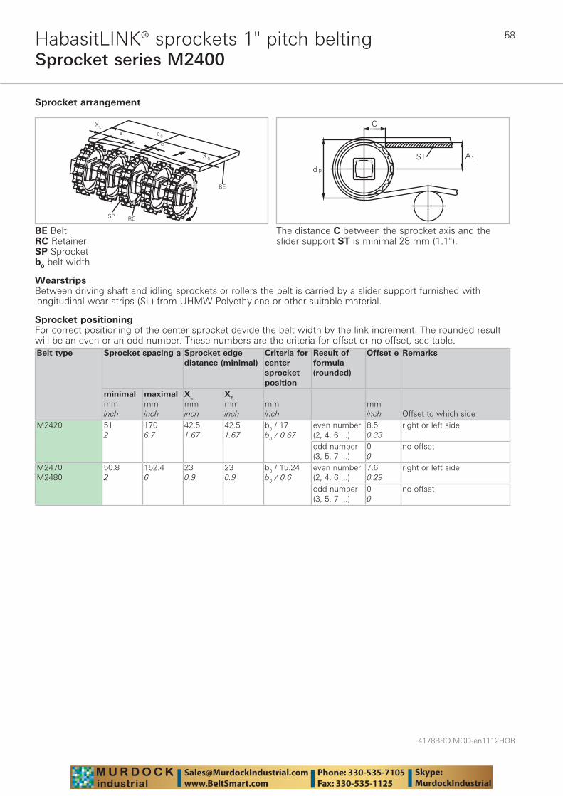
4178BRO.MOD-en1112HQR
58
Sprocket series M2400HabasitLINK® sprockets 1" pitch belting
WearstripsBetween driving shaft and idling sprockets or rollers the belt is carried by a slider support furnished with longitudinal wear strips (SL) from UHMW Polyethylene or other suitable material.
Sprocket arrangement
BE BeltRC RetainerSP Sprocketb0 belt width
The distance C between the sprocket axis and the slider support ST is minimal 28 mm (1.1").
Sprocket positioningFor correct positioning of the center sprocket devide the belt width by the link increment. The rounded result will be an even or an odd number. These numbers are the criteria for offset or no offset, see table.Belt type Sprocket spacing a Sprocket edge
distance (minimal)Criteria for center sprocket position
Result of formula (rounded)
Offset e Remarks
minimalmminch
maximalmminch
XL
mminch
XR
mminch
mminch
mminch Offset to which side
M2420 512
1706.7
42.51.67
42.51.67
b0 / 17b0 / 0.67
even number (2, 4, 6 ...)
8.50.33
right or left side
odd number (3, 5, 7 ...)
00
no offset
M2470M2480
50.82
152.46
230.9
230.9
b0 / 15.24b0 / 0.6
even number (2, 4, 6 ...)
7.60.29
right or left side
odd number (3, 5, 7 ...)
00
no offset
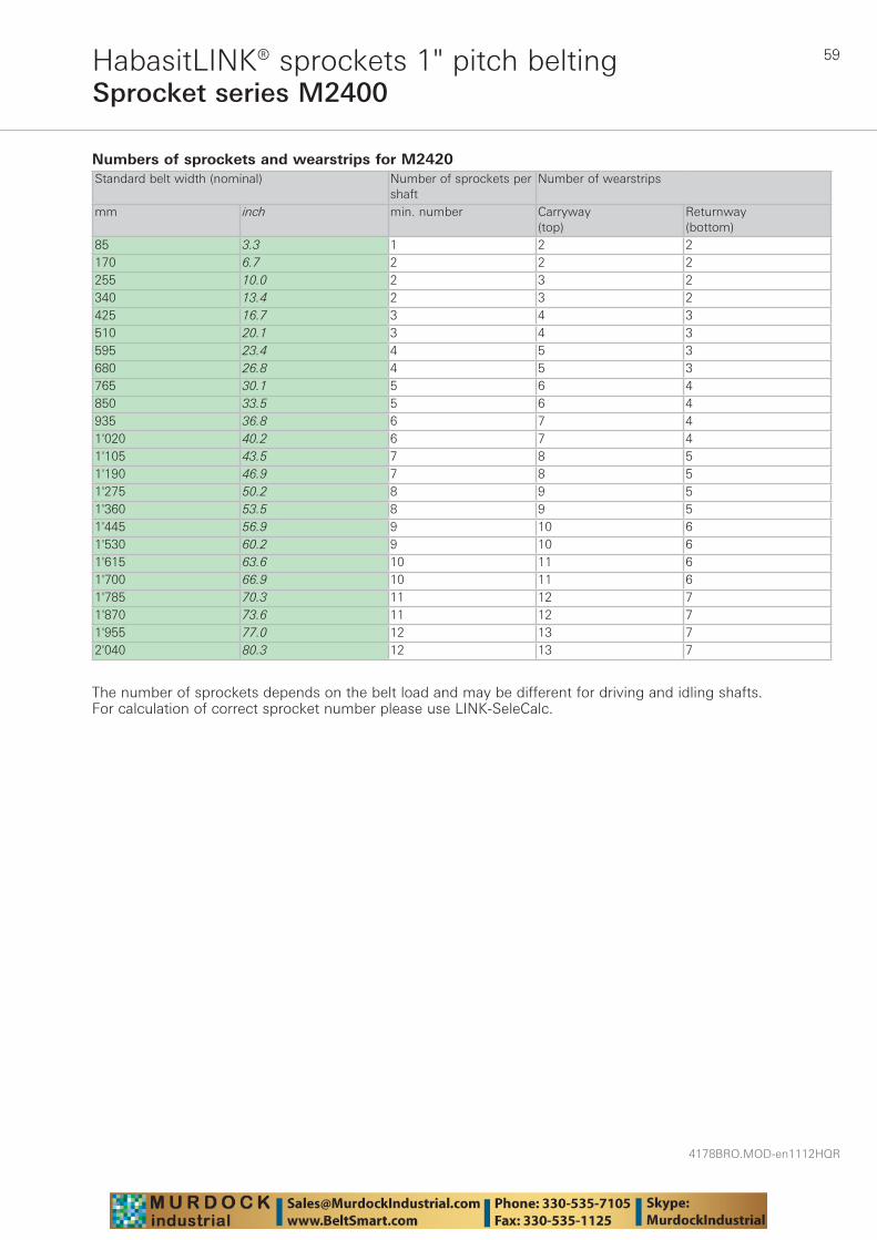
59
4178BRO.MOD-en1112HQR
Sprocket series M2400HabasitLINK® sprockets 1" pitch belting
Numbers of sprockets and wearstrips for M2420 Standard belt width (nominal) Number of sprockets per
shaftNumber of wearstrips
mm inch min. number Carryway (top)
Returnway (bottom)
85 3.3 1 2 2170 6.7 2 2 2255 10.0 2 3 2340 13.4 2 3 2425 16.7 3 4 3510 20.1 3 4 3595 23.4 4 5 3680 26.8 4 5 3765 30.1 5 6 4850 33.5 5 6 4935 36.8 6 7 41'020 40.2 6 7 41'105 43.5 7 8 51'190 46.9 7 8 51'275 50.2 8 9 51'360 53.5 8 9 51'445 56.9 9 10 61'530 60.2 9 10 61'615 63.6 10 11 61'700 66.9 10 11 61'785 70.3 11 12 71'870 73.6 11 12 71'955 77.0 12 13 72'040 80.3 12 13 7
The number of sprockets depends on the belt load and may be different for driving and idling shafts. For calculation of correct sprocket number please use LINK-SeleCalc.
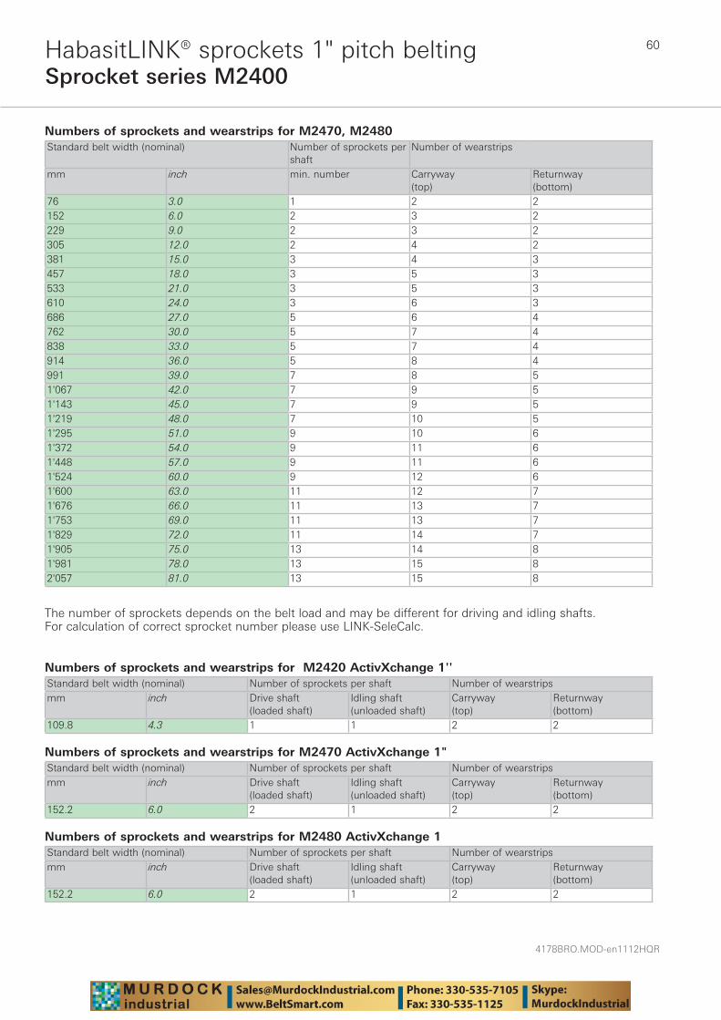
4178BRO.MOD-en1112HQR
60
Sprocket series M2400HabasitLINK® sprockets 1" pitch belting
Numbers of sprockets and wearstrips for M2470, M2480Standard belt width (nominal) Number of sprockets per
shaftNumber of wearstrips
mm inch min. number Carryway (top)
Returnway (bottom)
76 3.0 1 2 2152 6.0 2 3 2229 9.0 2 3 2305 12.0 2 4 2381 15.0 3 4 3457 18.0 3 5 3533 21.0 3 5 3610 24.0 3 6 3686 27.0 5 6 4762 30.0 5 7 4838 33.0 5 7 4914 36.0 5 8 4991 39.0 7 8 51'067 42.0 7 9 51'143 45.0 7 9 51'219 48.0 7 10 51'295 51.0 9 10 61'372 54.0 9 11 61'448 57.0 9 11 61'524 60.0 9 12 61'600 63.0 11 12 71'676 66.0 11 13 71'753 69.0 11 13 71'829 72.0 11 14 71'905 75.0 13 14 81'981 78.0 13 15 82'057 81.0 13 15 8
The number of sprockets depends on the belt load and may be different for driving and idling shafts. For calculation of correct sprocket number please use LINK-SeleCalc.
Numbers of sprockets and wearstrips for M2420 ActivXchange 1''Standard belt width (nominal) Number of sprockets per shaft Number of wearstripsmm inch Drive shaft
(loaded shaft)Idling shaft(unloaded shaft)
Carryway (top)
Returnway (bottom)
109.8 4.3 1 1 2 2
Numbers of sprockets and wearstrips for M2470 ActivXchange 1"Standard belt width (nominal) Number of sprockets per shaft Number of wearstripsmm inch Drive shaft
(loaded shaft)Idling shaft(unloaded shaft)
Carryway (top)
Returnway (bottom)
152.2 6.0 2 1 2 2
Numbers of sprockets and wearstrips for M2480 ActivXchange 1Standard belt width (nominal) Number of sprockets per shaft Number of wearstripsmm inch Drive shaft
(loaded shaft)Idling shaft(unloaded shaft)
Carryway (top)
Returnway (bottom)
152.2 6.0 2 1 2 2
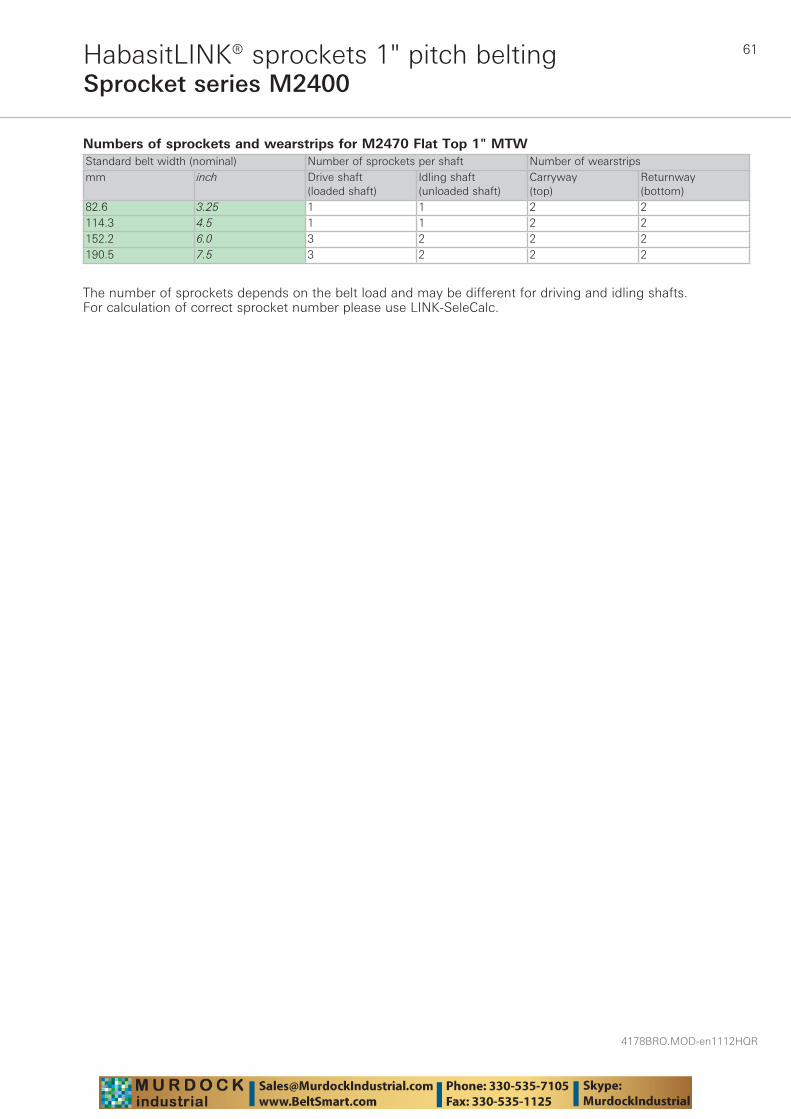
61
4178BRO.MOD-en1112HQR
Sprocket series M2400HabasitLINK® sprockets 1" pitch belting
Numbers of sprockets and wearstrips for M2470 Flat Top 1" MTWStandard belt width (nominal) Number of sprockets per shaft Number of wearstripsmm inch Drive shaft
(loaded shaft)Idling shaft(unloaded shaft)
Carryway (top)
Returnway (bottom)
82.6 3.25 1 1 2 2114.3 4.5 1 1 2 2152.2 6.0 3 2 2 2190.5 7.5 3 2 2 2
The number of sprockets depends on the belt load and may be different for driving and idling shafts. For calculation of correct sprocket number please use LINK-SeleCalc.
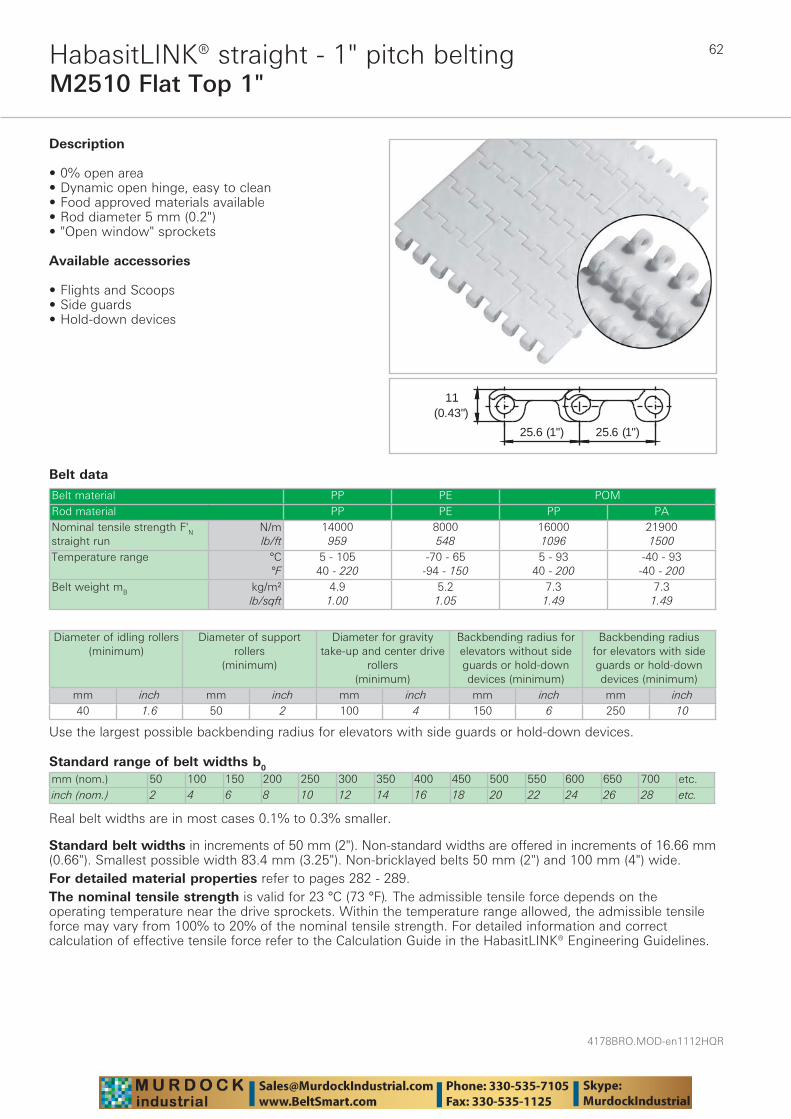
4178BRO.MOD-en1112HQR
62
M2510 Flat Top 1"HabasitLINK® straight - 1" pitch belting
Belt data
Standard range of belt widths b0
mm (nom.) 50 100 150 200 250 300 350 400 450 500 550 600 650 700 etc.inch (nom.) 2 4 6 8 10 12 14 16 18 20 22 24 26 28 etc.
Real belt widths are in most cases 0.1% to 0.3% smaller.
Belt material PP PE POMRod material PP PE PP PANominal tensile strength F'N straight run
N/mlb/ft
14000959
8000548
160001096
219001500
Temperature range °C°F
5 - 10540 - 220
-70 - 65-94 - 150
5 - 9340 - 200
-40 - 93-40 - 200
Belt weight mB kg/m²lb/sqft
4.91.00
5.21.05
7.31.49
7.31.49
(0.43")11
25.6 (1") 25.6 (1")
Description
• 0% open area • Dynamic open hinge, easy to clean • Food approved materials available• Rod diameter 5 mm (0.2") • "Open window" sprockets
Available accessories
• Flights and Scoops • Side guards • Hold-down devices
Diameter of idling rollers (minimum)
Diameter of support rollers
(minimum)
Diameter for gravity take-up and center drive
rollers (minimum)
Backbending radius for elevators without side guards or hold-down devices (minimum)
Backbending radius for elevators with side guards or hold-down devices (minimum)
mm inch mm inch mm inch mm inch mm inch40 1.6 50 2 100 4 150 6 250 10
Use the largest possible backbending radius for elevators with side guards or hold-down devices.
Standard belt widths in increments of 50 mm (2"). Non-standard widths are offered in increments of 16.66 mm (0.66"). Smallest possible width 83.4 mm (3.25"). Non-bricklayed belts 50 mm (2") and 100 mm (4") wide.For detailed material properties refer to pages 282 - 289.The nominal tensile strength is valid for 23 °C (73 °F). The admissible tensile force depends on the operating temperature near the drive sprockets. Within the temperature range allowed, the admissible tensile force may vary from 100% to 20% of the nominal tensile strength. For detailed information and correct calculation of effective tensile force refer to the Calculation Guide in the HabasitLINK® Engineering Guidelines.
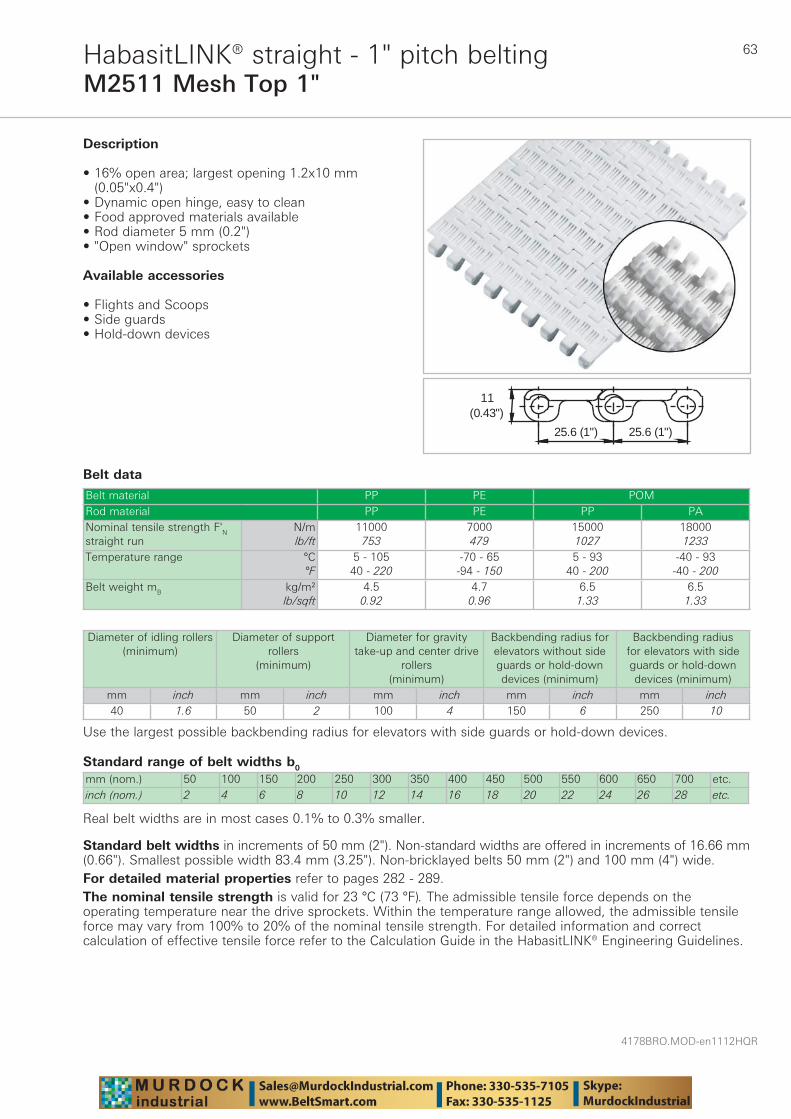
63
4178BRO.MOD-en1112HQR
M2511 Mesh Top 1"HabasitLINK® straight - 1" pitch belting
Belt data
Standard range of belt widths b0
mm (nom.) 50 100 150 200 250 300 350 400 450 500 550 600 650 700 etc.inch (nom.) 2 4 6 8 10 12 14 16 18 20 22 24 26 28 etc.
Real belt widths are in most cases 0.1% to 0.3% smaller.
Belt material PP PE POMRod material PP PE PP PANominal tensile strength F'N straight run
N/mlb/ft
11000753
7000479
150001027
180001233
Temperature range °C°F
5 - 10540 - 220
-70 - 65-94 - 150
5 - 9340 - 200
-40 - 93-40 - 200
Belt weight mB kg/m²lb/sqft
4.50.92
4.70.96
6.51.33
6.51.33
(0.43")11
25.6 (1")25.6 (1")
Description
• 16% open area; largest opening 1.2x10 mm (0.05"x0.4")
• Dynamic open hinge, easy to clean • Food approved materials available• Rod diameter 5 mm (0.2") • "Open window" sprockets
Available accessories
• Flights and Scoops• Side guards • Hold-down devices
Diameter of idling rollers (minimum)
Diameter of support rollers
(minimum)
Diameter for gravity take-up and center drive
rollers (minimum)
Backbending radius for elevators without side guards or hold-down devices (minimum)
Backbending radius for elevators with side guards or hold-down devices (minimum)
mm inch mm inch mm inch mm inch mm inch40 1.6 50 2 100 4 150 6 250 10
Use the largest possible backbending radius for elevators with side guards or hold-down devices.
Standard belt widths in increments of 50 mm (2"). Non-standard widths are offered in increments of 16.66 mm (0.66"). Smallest possible width 83.4 mm (3.25"). Non-bricklayed belts 50 mm (2") and 100 mm (4") wide.For detailed material properties refer to pages 282 - 289.The nominal tensile strength is valid for 23 °C (73 °F). The admissible tensile force depends on the operating temperature near the drive sprockets. Within the temperature range allowed, the admissible tensile force may vary from 100% to 20% of the nominal tensile strength. For detailed information and correct calculation of effective tensile force refer to the Calculation Guide in the HabasitLINK® Engineering Guidelines.

4178BRO.MOD-en1112HQR
64
M2514 Nub Top 1"HabasitLINK® straight - 1" pitch belting
Belt data
Standard range of belt widths b0
mm (nom.) 200 250 300 350 400 450 500 550 600 650 etc.inch (nom.) 8 10 12 14 16 18 20 22 24 26 etc.
Real belt widths are in most cases 0.1% to 0.3% smaller.
Belt material PP PE POMRod material PP PE PANominal tensile strength F'N straight run
N/mlb/ft
14000959
8000548
7000479
219001500
Temperature range °C°F
5 - 10540 - 220
-70 - 65-94 - 150
-40 - 65-40 - 150
-40 - 93-40 - 200
Belt weight mB kg/m²lb/sqft
5.11.05
5.41.11
7.71.57
7.71.57
Description• 0% open area • Non-adhesive due to reduced contact surface • Open hinge, easy to clean • Standard indent 50 mm (2") • Rod diameter 5 mm (0.2") • "Open window" sprockets • Food approved materials available
Available accessories
• Flights and Scoops• Side guards • Hold-down devices
Diameter of idling rollers (minimum)
Diameter of support rollers
(minimum)
Diameter for gravity take-up and center drive
rollers (minimum)
Backbending radius for elevators without side guards or hold-down devices (minimum)
Backbending radius for elevators with side guards or hold-down devices (minimum)
mm inch mm inch mm inch mm inch mm inch40 1.6 50 2 100 4 150 6 250 10
Use the largest possible backbending radius for elevators with side guards or hold-down devices.
Standard belt widths in increments of 50 mm (2"). Non-standard widths are offered in increments of 16.66 mm (0.66"). Min. width: 200 mm (8")For detailed material properties refer to pages 282 - 289.The nominal tensile strength is valid for 23 °C (73 °F). The admissible tensile force depends on the operating temperature near the drive sprockets. Within the temperature range allowed, the admissible tensile force may vary from 100% to 20% of the nominal tensile strength. For detailed information and correct calculation of effective tensile force refer to the Calculation Guide in the HabasitLINK® Engineering Guidelines.

65
4178BRO.MOD-en1112HQR
M2516 Diamond Top 1"HabasitLINK® straight - 1" pitch belting
Belt data
Standard range of belt widths b0
mm (nom.) 50 100 150 200 250 300 350 400 450 500 550 600 650 700 etc.inch (nom.) 2 4 6 8 10 12 14 16 18 20 22 24 26 28 etc.
Real belt widths are in most cases 0.1% to 0.3% smaller.
Belt material PP PE POMRod material PP PE PANominal tensile strength F'N straight run
N/mlb/ft
14000959
8000548
8000548
219001500
Temperature range °C°F
5 - 10540 - 220
-70 - 65-94 - 150
-40 - 65-40 - 150
-40 - 93-40 - 200
Belt weight mB kg/m²lb/sqft
4.91.01
5.21.06
7.51.53
7.51.53
Description
• 0% open area • Non-adhesive due to reduced contact surface • Dynamic open hinge, easy to clean • Rod diameter 5 mm (0.2”) • “Open window” sprockets • Food approved materials available• Optional staggered indent 50/100mm (2”/4”)
Available accessories
• Side guards • Flights and Scoops• Hold-down devices
Diameter of idling rollers (minimum)
Diameter of support rollers
(minimum)
Diameter for gravity take-up and center drive
rollers (minimum)
Backbending radius for elevators without side guards or hold-down devices (minimum)
Backbending radius for elevators with side guards or hold-down devices (minimum)
mm inch mm inch mm inch mm inch mm inch40 1.6 50 2 100 4 150 6 250 10
Use the largest possible backbending radius for elevators with side guards or hold-down devices.
Standard belt widths in increments of 50 mm (2"). Non-standard widths are offered in increments of 16.66 mm (0.66”). Smallest possible width 83.4 mm (3.25"). Non-bricklayed belts 200 mm (8”) wide.For detailed material properties refer to pages 282 - 289.The nominal tensile strength is valid for 23 °C (73 °F). The admissible tensile force depends on the operating temperature near the drive sprockets. Within the temperature range allowed, the admissible tensile force may vary from 100% to 20% of the nominal tensile strength. For detailed information and correct calculation of effective tensile force refer to the Calculation Guide in the HabasitLINK® Engineering Guidelines.
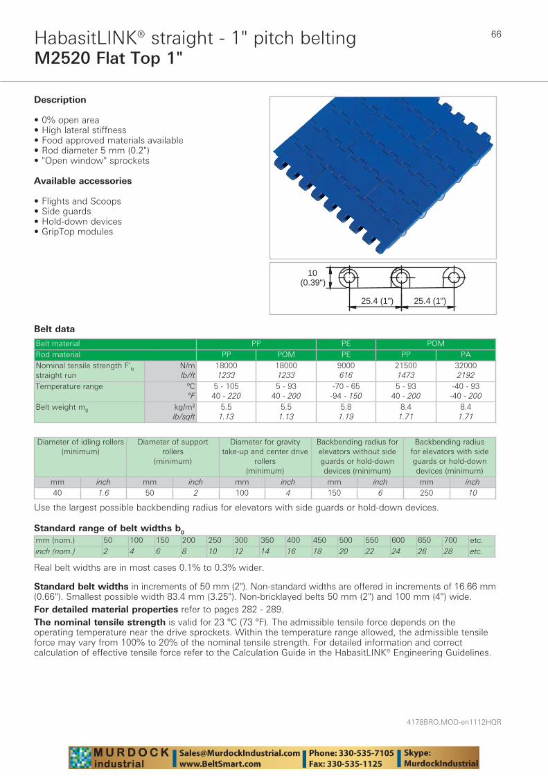
4178BRO.MOD-en1112HQR
66
M2520 Flat Top 1"HabasitLINK® straight - 1" pitch belting
Belt data
Standard range of belt widths b0
mm (nom.) 50 100 150 200 250 300 350 400 450 500 550 600 650 700 etc.inch (nom.) 2 4 6 8 10 12 14 16 18 20 22 24 26 28 etc.
Real belt widths are in most cases 0.1% to 0.3% wider.
Belt material PP PE POMRod material PP POM PE PP PANominal tensile strength F'N straight run
N/mlb/ft
180001233
180001233
9000616
215001473
320002192
Temperature range °C°F
5 - 10540 - 220
5 - 9340 - 200
-70 - 65-94 - 150
5 - 9340 - 200
-40 - 93-40 - 200
Belt weight mB kg/m²lb/sqft
5.51.13
5.51.13
5.81.19
8.41.71
8.41.71
25.4 (1")25.4 (1")
10(0.39")
Description
• 0% open area • High lateral stiffness • Food approved materials available • Rod diameter 5 mm (0.2") • "Open window" sprockets
Available accessories
• Flights and Scoops • Side guards • Hold-down devices • GripTop modules
Diameter of idling rollers (minimum)
Diameter of support rollers
(minimum)
Diameter for gravity take-up and center drive
rollers (minimum)
Backbending radius for elevators without side guards or hold-down devices (minimum)
Backbending radius for elevators with side guards or hold-down devices (minimum)
mm inch mm inch mm inch mm inch mm inch40 1.6 50 2 100 4 150 6 250 10
Use the largest possible backbending radius for elevators with side guards or hold-down devices.
Standard belt widths in increments of 50 mm (2"). Non-standard widths are offered in increments of 16.66 mm (0.66"). Smallest possible width 83.4 mm (3.25"). Non-bricklayed belts 50 mm (2") and 100 mm (4") wide.For detailed material properties refer to pages 282 - 289.The nominal tensile strength is valid for 23 °C (73 °F). The admissible tensile force depends on the operating temperature near the drive sprockets. Within the temperature range allowed, the admissible tensile force may vary from 100% to 20% of the nominal tensile strength. For detailed information and correct calculation of effective tensile force refer to the Calculation Guide in the HabasitLINK® Engineering Guidelines.
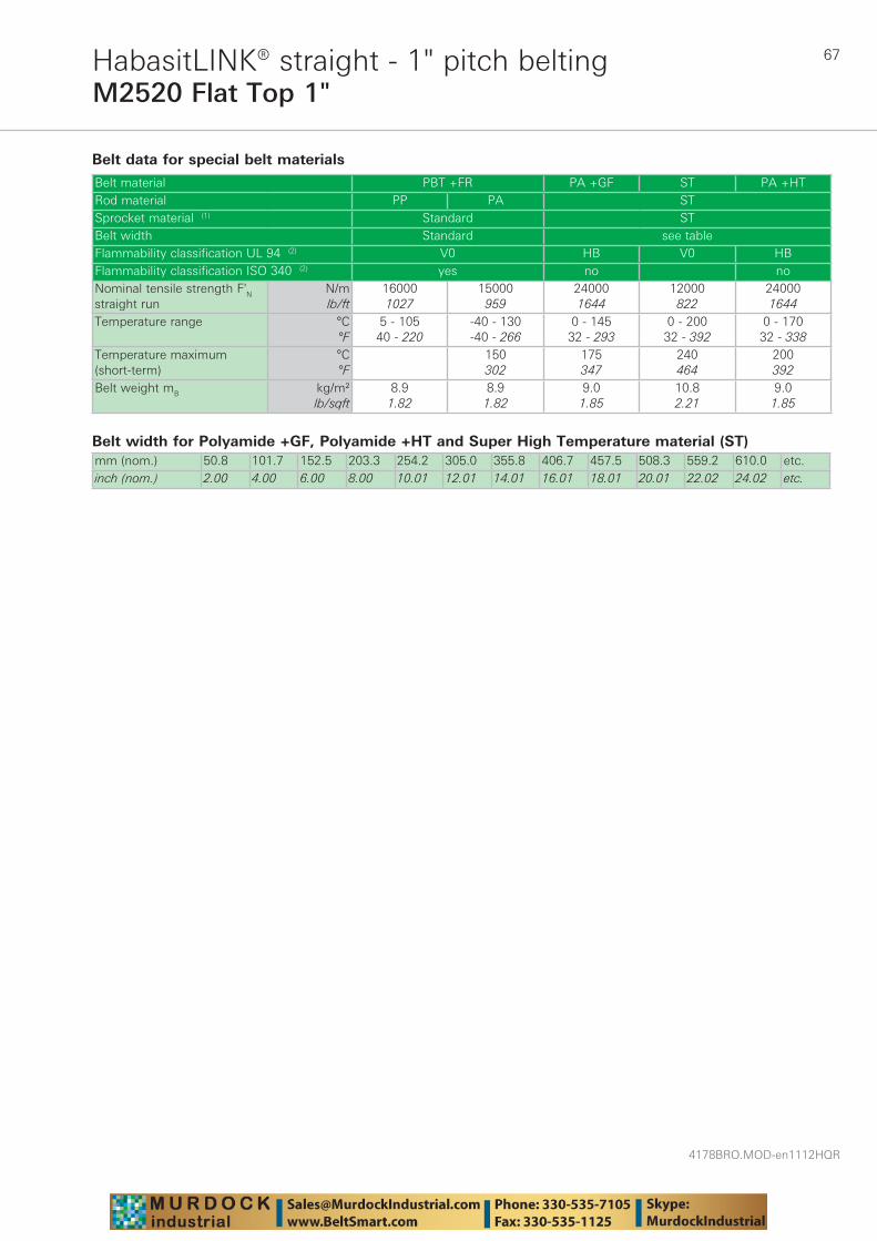
67
4178BRO.MOD-en1112HQR
M2520 Flat Top 1"HabasitLINK® straight - 1" pitch belting
Belt data for special belt materials
Belt width for Polyamide +GF, Polyamide +HT and Super High Temperature material (ST)mm (nom.) 50.8 101.7 152.5 203.3 254.2 305.0 355.8 406.7 457.5 508.3 559.2 610.0 etc.inch (nom.) 2.00 4.00 6.00 8.00 10.01 12.01 14.01 16.01 18.01 20.01 22.02 24.02 etc.
Belt material PBT +FR PA +GF ST PA +HTRod material PP PA STSprocket material (1) Standard STBelt width Standard see tableFlammability classification UL 94 (2) V0 HB V0 HBFlammability classification ISO 340 (2) yes no noNominal tensile strength F'N straight run
N/mlb/ft
160001027
15000959
240001644
12000822
240001644
Temperature range °C°F
5 - 10540 - 220
-40 - 130-40 - 266
0 - 14532 - 293
0 - 20032 - 392
0 - 17032 - 338
Temperature maximum (short-term)
°C°F
150302
175347
240464
200392
Belt weight mB kg/m²lb/sqft
8.91.82
8.91.82
9.01.85
10.82.21
9.01.85
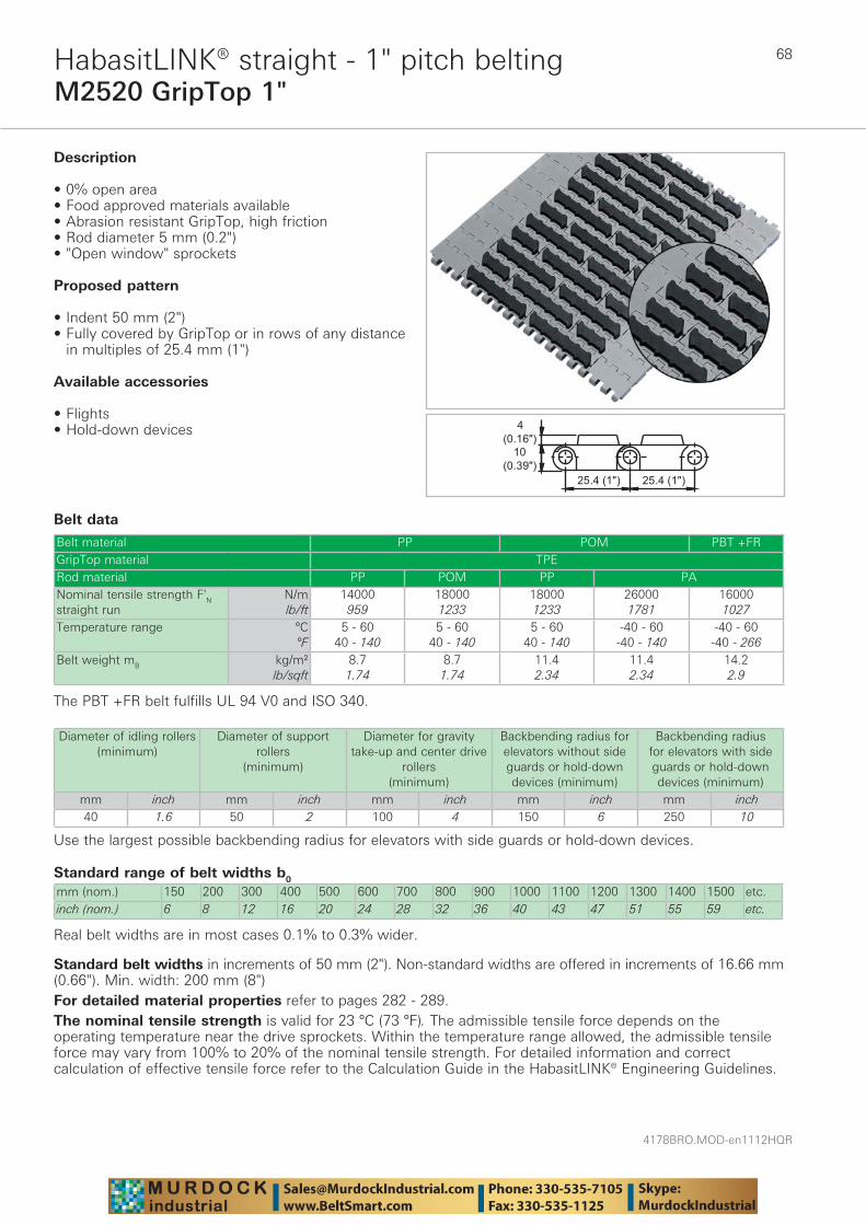
4178BRO.MOD-en1112HQR
68
M2520 GripTop 1"HabasitLINK® straight - 1" pitch belting
Belt data
Standard range of belt widths b0
mm (nom.) 150 200 300 400 500 600 700 800 900 1000 1100 1200 1300 1400 1500 etc.inch (nom.) 6 8 12 16 20 24 28 32 36 40 43 47 51 55 59 etc.
Real belt widths are in most cases 0.1% to 0.3% wider.
Belt material PP POM PBT +FRGripTop material TPERod material PP POM PP PANominal tensile strength F'N straight run
N/mlb/ft
14000959
180001233
180001233
260001781
160001027
Temperature range °C°F
5 - 6040 - 140
5 - 6040 - 140
5 - 6040 - 140
-40 - 60-40 - 140
-40 - 60-40 - 266
Belt weight mB kg/m²lb/sqft
8.71.74
8.71.74
11.42.34
11.42.34
14.22.9
��������������
������
������
Description
• 0% open area • Food approved materials available• Abrasion resistant GripTop, high friction • Rod diameter 5 mm (0.2") • "Open window" sprockets
Proposed pattern
• Indent 50 mm (2") • Fully covered by GripTop or in rows of any distance
in multiples of 25.4 mm (1")
Available accessories
• Flights• Hold-down devices
The PBT +FR belt fulfills UL 94 V0 and ISO 340.
Diameter of idling rollers (minimum)
Diameter of support rollers
(minimum)
Diameter for gravity take-up and center drive
rollers (minimum)
Backbending radius for elevators without side guards or hold-down devices (minimum)
Backbending radius for elevators with side guards or hold-down devices (minimum)
mm inch mm inch mm inch mm inch mm inch40 1.6 50 2 100 4 150 6 250 10
Use the largest possible backbending radius for elevators with side guards or hold-down devices.
Standard belt widths in increments of 50 mm (2"). Non-standard widths are offered in increments of 16.66 mm (0.66"). Min. width: 200 mm (8")For detailed material properties refer to pages 282 - 289.The nominal tensile strength is valid for 23 °C (73 °F). The admissible tensile force depends on the operating temperature near the drive sprockets. Within the temperature range allowed, the admissible tensile force may vary from 100% to 20% of the nominal tensile strength. For detailed information and correct calculation of effective tensile force refer to the Calculation Guide in the HabasitLINK® Engineering Guidelines.
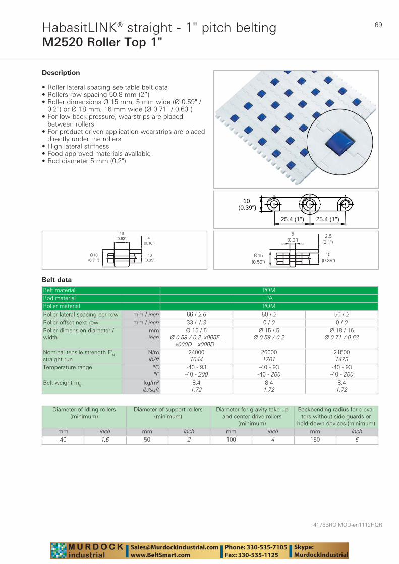
69
4178BRO.MOD-en1112HQR
M2520 Roller Top 1"HabasitLINK® straight - 1" pitch belting
Belt data
Belt material POMRod material PARoller material POMRoller lateral spacing per row mm / inch 66 / 2.6 50 / 2 50 / 2Roller offset next row mm / inch 33 / 1.3 0 / 0 0 / 0Roller dimension diameter / width
mminch
Ø 15 / 5Ø 0.59 / 0.2_x005F_
x000D__x000D_
Ø 15 / 5Ø 0.59 / 0.2
Ø 18 / 16Ø 0.71 / 0.63
Nominal tensile strength F'N straight run
N/mlb/ft
240001644
260001781
215001473
Temperature range °C°F
-40 - 93-40 - 200
-40 - 93-40 - 200
-40 - 93-40 - 200
Belt weight mB kg/m²lb/sqft
8.41.72
8.41.72
8.41.72
25.4 (1")25.4 (1")
10(0.39")
Description
• Roller lateral spacing see table belt data • Rollers row spacing 50.8 mm (2”) • Roller dimensions Ø 15 mm, 5 mm wide (Ø 0.59" /
0.2") or Ø 18 mm, 16 mm wide (Ø 0.71" / 0.63") • For low back pressure, wearstrips are placed
between rollers • For product driven application wearstrips are placed
directly under the rollers • High lateral stiffness • Food approved materials available• Rod diameter 5 mm (0.2")
Diameter of idling rollers (minimum)
Diameter of support rollers(minimum)
Diameter for gravity take-up and center drive rollers
(minimum)
Backbending radius for eleva-tors without side guards or
hold-down devices (minimum)mm inch mm inch mm inch mm inch40 1.6 50 2 100 4 150 6
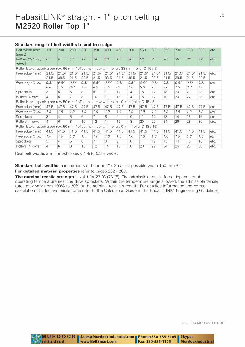
4178BRO.MOD-en1112HQR
70
M2520 Roller Top 1"HabasitLINK® straight - 1" pitch belting
Standard range of belt widths b0 and free edgeBelt width (mm) (nom.)
150 200 250 300 350 400 450 500 550 600 650 700 750 800 etc.
Belt width (inch) (nom.)
6 8 10 12 14 16 18 20 22 24 26 28 30 32 etc.
Roller lateral spacing per row 66 mm / offset next row with rollers 33 mm (roller Ø 15 / 5)Free edge (mm) 21.5/
21.521.5/ 38.5
21.5/ 21.5
21.5/ 38.5
21.5/ 21.5
21.5/ 38.5
21.5/ 21.5
21.5/ 38.5
21.5/ 21.5
21.5/ 38.5
21.5/ 21.5
21.5/ 38.5
21.5/ 21.5
21.5/ 38.5
etc.
Free edge (inch) 0.8/ 0.8
0.8/ 1.5
0.8/ 0.8
0.8/ 1.5
0.8/ 0.8
0.8/ 1.5
0.8/ 0.8
0.8/ 1.5
0.8/ 0.8
0.8/ 1.5
0.8/ 0.8
0.8/ 1.5
0.8/ 0.8
0.8/ 1.5
etc.
Sprockets 3 5 6 8 9 11 12 14 15 17 18 20 21 23 etc.Rollers (4 rows) 4 5 7 8 10 11 13 14 16 17 19 20 22 23 etc.Roller lateral spacing per row 50 mm / offset next row with rollers 0 mm (roller Ø 15 / 5)Free edge (mm) 47.5 47.5 47.5 47.5 47.5 47.5 47.5 47.5 47.5 47.5 47.5 47.5 47.5 47.5 etc.Free edge (inch) 1.9 1.9 1.9 1.9 1.9 1.9 1.9 1.9 1.9 1.9 1.9 1.9 1.9 1.9 etc.Sprockets 3 4 5 6 7 8 9 10 11 12 13 14 15 16 etc.Rollers (4 rows) 4 6 8 10 12 14 16 18 20 22 24 26 28 30 etc.Roller lateral spacing per row 50 mm / offset next row with rollers 0 mm (roller Ø 18 / 16)Free edge (mm) 41.5 41.5 41.5 41.5 41.5 41.5 41.5 41.5 41.5 41.5 41.5 41.5 41.5 41.5 etc.Free edge (inch) 1.6 1.6 1.6 1.6 1.6 1.6 1.6 1.6 1.6 1.6 1.6 1.6 1.6 1.6 etc.Sprockets 3 4 5 6 7 8 9 10 11 12 13 14 15 16 etc.Rollers (4 rows) 4 6 8 10 12 14 16 18 20 22 24 26 28 30 etc.
Real belt widths are in most cases 0.1% to 0.3% wider.
Standard belt widths in increments of 50 mm (2"). Smallest possible width 150 mm (6").For detailed material properties refer to pages 282 - 289.The nominal tensile strength is valid for 23 °C (73 °F). The admissible tensile force depends on the operating temperature near the drive sprockets. Within the temperature range allowed, the admissible tensile force may vary from 100% to 20% of the nominal tensile strength. For detailed information and correct calculation of effective tensile force refer to the Calculation Guide in the HabasitLINK® Engineering Guidelines.
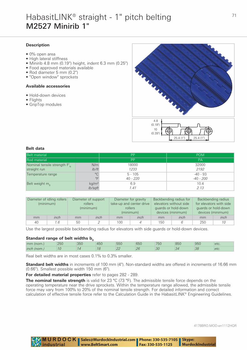
71
4178BRO.MOD-en1112HQR
M2527 Minirib 1"HabasitLINK® straight - 1" pitch belting
Belt data
Standard range of belt widths b0
mm (nom.) 250 350 450 550 650 750 850 950 etc.inch (nom.) 10 14 18 22 26 30 34 38 etc.
Real belt widths are in most cases 0.1% to 0.3% smaller.
Belt material PP POMRod material PP PANominal tensile strength F'N straight run
N/mlb/ft
180001233
320002192
Temperature range °C°F
5 - 10540 - 220
-40 - 93-40 - 200
Belt weight mB kg/m²lb/sqft
6.91.41
10.42.13
Description
• 0% open area • High lateral stiffness • Minirib 4.8 mm (0.19") height, indent 6.3 mm (0.25") • Food approved materials available• Rod diameter 5 mm (0.2") • "Open window" sprockets
Available accessories
• Hold-down devices • Flights • GripTop modules
Diameter of idling rollers (minimum)
Diameter of support rollers
(minimum)
Diameter for gravity take-up and center drive
rollers (minimum)
Backbending radius for elevators without side guards or hold-down devices (minimum)
Backbending radius for elevators with side guards or hold-down devices (minimum)
mm inch mm inch mm inch mm inch mm inch40 1.6 50 2 100 4 150 6 250 10
Use the largest possible backbending radius for elevators with side guards or hold-down devices.
Standard belt widths in increments of 100 mm (4"). Non-standard widths are offered in increments of 16.66 mm (0.66"). Smallest possible width 150 mm (6").For detailed material properties refer to pages 282 - 289.The nominal tensile strength is valid for 23 °C (73 °F). The admissible tensile force depends on the operating temperature near the drive sprockets. Within the temperature range allowed, the admissible tensile force may vary from 100% to 20% of the nominal tensile strength. For detailed information and correct calculation of effective tensile force refer to the Calculation Guide in the HabasitLINK® Engineering Guidelines.
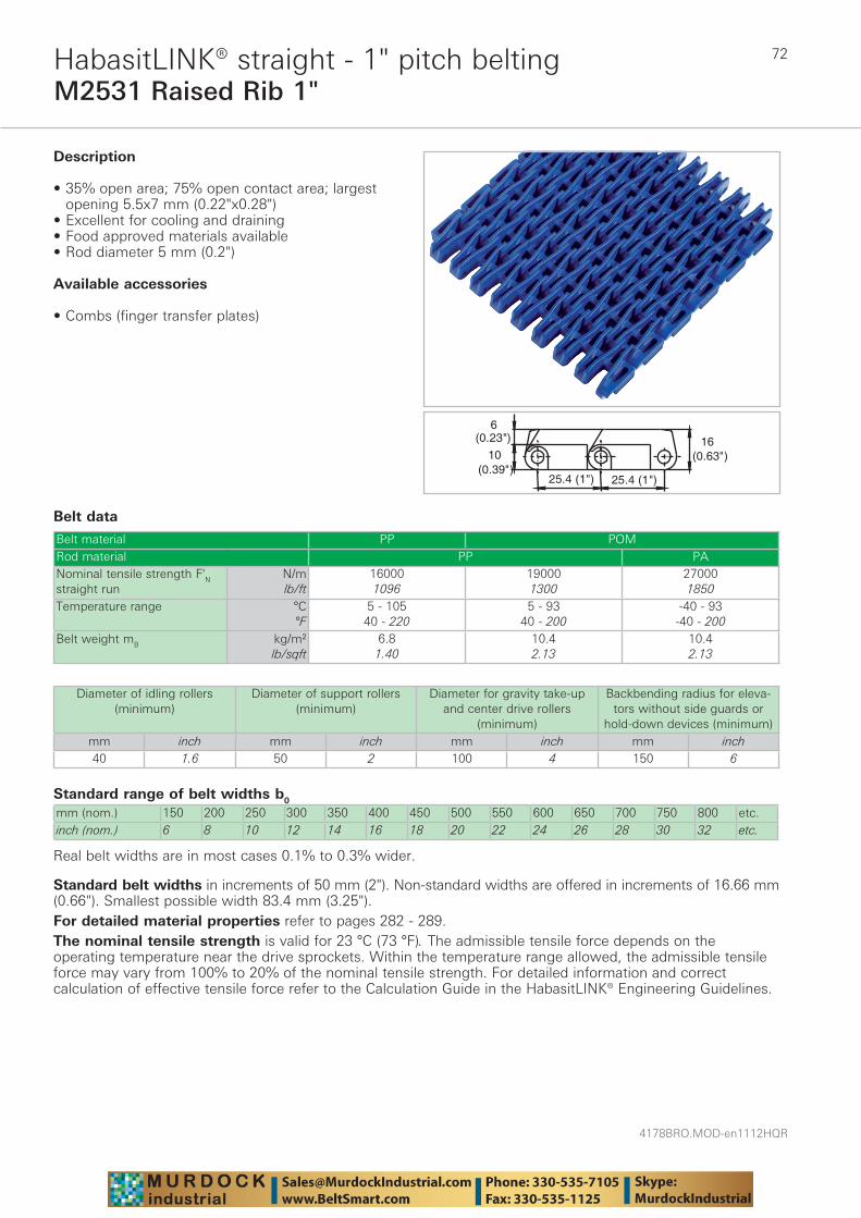
4178BRO.MOD-en1112HQR
72
M2531 Raised Rib 1"HabasitLINK® straight - 1" pitch belting
Belt data
Standard range of belt widths b0
mm (nom.) 150 200 250 300 350 400 450 500 550 600 650 700 750 800 etc.inch (nom.) 6 8 10 12 14 16 18 20 22 24 26 28 30 32 etc.
Real belt widths are in most cases 0.1% to 0.3% wider.
Belt material PP POMRod material PP PANominal tensile strength F'N straight run
N/mlb/ft
160001096
190001300
270001850
Temperature range °C°F
5 - 10540 - 220
5 - 9340 - 200
-40 - 93-40 - 200
Belt weight mB kg/m²lb/sqft
6.81.40
10.42.13
10.42.13
������
������ ��
�����
��������������
Description
• 35% open area; 75% open contact area; largest opening 5.5x7 mm (0.22"x0.28")
• Excellent for cooling and draining • Food approved materials available• Rod diameter 5 mm (0.2")
Available accessories
• Combs (finger transfer plates)
Diameter of idling rollers (minimum)
Diameter of support rollers(minimum)
Diameter for gravity take-up and center drive rollers
(minimum)
Backbending radius for eleva-tors without side guards or
hold-down devices (minimum)mm inch mm inch mm inch mm inch40 1.6 50 2 100 4 150 6
Standard belt widths in increments of 50 mm (2"). Non-standard widths are offered in increments of 16.66 mm (0.66"). Smallest possible width 83.4 mm (3.25").For detailed material properties refer to pages 282 - 289.The nominal tensile strength is valid for 23 °C (73 °F). The admissible tensile force depends on the operating temperature near the drive sprockets. Within the temperature range allowed, the admissible tensile force may vary from 100% to 20% of the nominal tensile strength. For detailed information and correct calculation of effective tensile force refer to the Calculation Guide in the HabasitLINK® Engineering Guidelines.
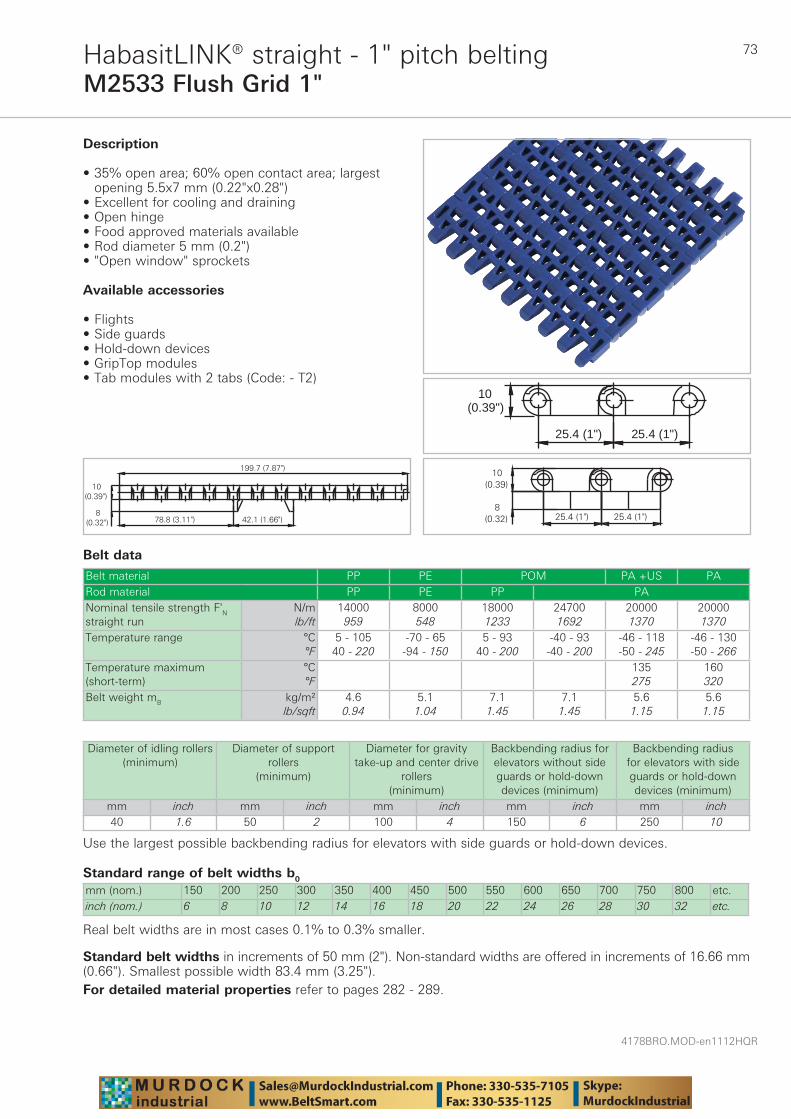
73
4178BRO.MOD-en1112HQR
M2533 Flush Grid 1"HabasitLINK® straight - 1" pitch belting
Belt data
Standard range of belt widths b0
mm (nom.) 150 200 250 300 350 400 450 500 550 600 650 700 750 800 etc.inch (nom.) 6 8 10 12 14 16 18 20 22 24 26 28 30 32 etc.
Real belt widths are in most cases 0.1% to 0.3% smaller.
Belt material PP PE POM PA +US PARod material PP PE PP PANominal tensile strength F'N straight run
N/mlb/ft
14000959
8000548
180001233
247001692
200001370
200001370
Temperature range °C°F
5 - 10540 - 220
-70 - 65-94 - 150
5 - 9340 - 200
-40 - 93-40 - 200
-46 - 118-50 - 245
-46 - 130-50 - 266
Temperature maximum (short-term)
°C°F
135275
160320
Belt weight mB kg/m²lb/sqft
4.60.94
5.11.04
7.11.45
7.11.45
5.61.15
5.61.15
25.4 (1")25.4 (1")
10(0.39")
Description
• 35% open area; 60% open contact area; largest opening 5.5x7 mm (0.22"x0.28")
• Excellent for cooling and draining • Open hinge • Food approved materials available• Rod diameter 5 mm (0.2") • "Open window" sprockets
Available accessories
• Flights • Side guards • Hold-down devices • GripTop modules • Tab modules with 2 tabs (Code: - T2)
Diameter of idling rollers (minimum)
Diameter of support rollers
(minimum)
Diameter for gravity take-up and center drive
rollers (minimum)
Backbending radius for elevators without side guards or hold-down devices (minimum)
Backbending radius for elevators with side guards or hold-down devices (minimum)
mm inch mm inch mm inch mm inch mm inch40 1.6 50 2 100 4 150 6 250 10
Use the largest possible backbending radius for elevators with side guards or hold-down devices.
Standard belt widths in increments of 50 mm (2"). Non-standard widths are offered in increments of 16.66 mm (0.66"). Smallest possible width 83.4 mm (3.25").For detailed material properties refer to pages 282 - 289.
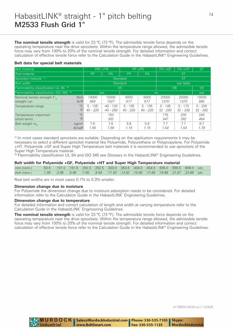
4178BRO.MOD-en1112HQR
74
M2533 Flush Grid 1"HabasitLINK® straight - 1" pitch belting
The nominal tensile strength is valid for 23 °C (73 °F). The admissible tensile force depends on the operating temperature near the drive sprockets. Within the temperature range allowed, the admissible tensile force may vary from 100% to 20% of the nominal tensile strength. For detailed information and correct calculation of effective tensile force refer to the Calculation Guide in the HabasitLINK® Engineering Guidelines.
Belt data for special belt materials
Belt width for Polyamide +GF, Polyamide +HT and Super High Temperature materialmm (nom.) 50.5 101.0 151.5 202.0 252.5 303.0 353.5 404.0 454.5 505.0 555.5 606.0 etc.inch (nom.) 1.99 3.98 5.96 7.95 9.94 11.93 13.92 15.90 17.89 19.88 21.87 23.86 etc.
Real belt widths are in most cases 0.1% to 0.3% smaller.
Belt material PBT +FR PP +FR PA +GF PA +HT STRod material PP PA PP PA STSprocket material (1) Standard STBelt width Standard see tableFlammability classification UL 94 (2) V0 HB V0Flammability classification ISO 340 (2) yes no yesNominal tensile strength F'N straight run
N/mlb/ft
14000959
150001027
9000617
9000617
200001370
200001370
10000685
Temperature range °C°F
5 - 10540 - 220
-40 - 130-40 - 266
5 - 10540 - 220
5 - 10540 - 220
0 - 14532 - 293
0 - 17032 - 338
0 - 20032 - 392
Temperature maximum (short-term)
°C°F
150302
175347
200392
240464
Belt weight mB kg/m²lb/sqft
7.61.56
7.61.56
5.61.15
5.61.15
7.71.54
7.71.54
8.71.78
(1) In most cases standard sprockets are suitable. Depending on the application requirements it may be necessary to select a different sprocket material like Polyamide, Polyurethane or Polypropylene. For Polyamide +HT, Polyamide +GF and Super High Temperature belt materials it is recommended to use sprockets of the Super High Temperature material.(2) Flammability classification UL 94 and ISO 340 see Glossary in the HabasitLINK® Engineering Guidelines.
Dimension change due to moisture For Polyamide the dimension change due to moisture adsorption needs to be considered. For detailed information refer to the Calculation Guide in the HabasitLINK® Engineering Guidelines.Dimension change due to temperature For detailed information and correct calculation of length and width at varying temperature refer to the Calculation Guide in the HabasitLINK® Engineering Guidelines.The nominal tensile strength is valid for 23 °C (73 °F). The admissible tensile force depends on the operating temperature near the drive sprockets. Within the temperature range allowed, the admissible tensile force may vary from 100% to 20% of the nominal tensile strength. For detailed information and correct calculation of effective tensile force refer to the Calculation Guide in the HabasitLINK® Engineering Guidelines.
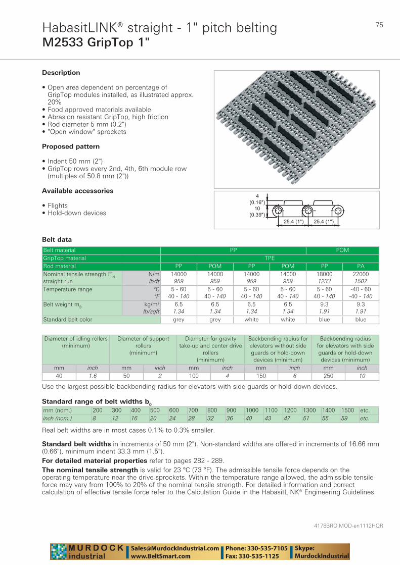
75
4178BRO.MOD-en1112HQR
M2533 GripTop 1"HabasitLINK® straight - 1" pitch belting
Belt data
Standard range of belt widths b0
mm (nom.) 200 300 400 500 600 700 800 900 1000 1100 1200 1300 1400 1500 etc.inch (nom.) 8 12 16 20 24 28 32 36 40 43 47 51 55 59 etc.
Real belt widths are in most cases 0.1% to 0.3% smaller.
Belt material PP POMGripTop material TPERod material PP POM PP POM PP PANominal tensile strength F'N straight run
N/mlb/ft
14000959
14000959
14000959
14000959
180001233
220001507
Temperature range °C°F
5 - 6040 - 140
5 - 6040 - 140
5 - 6040 - 140
5 - 6040 - 140
5 - 6040 - 140
-40 - 60-40 - 140
Belt weight mB kg/m²lb/sqft
6.51.34
6.51.34
6.51.34
6.51.34
9.31.91
9.31.91
Standard belt color grey grey white white blue blue
��������������
������
������
Description
• Open area dependent on percentage of GripTop modules installed, as illustrated approx. 20%
• Food approved materials available• Abrasion resistant GripTop, high friction • Rod diameter 5 mm (0.2") • "Open window" sprockets
Proposed pattern
• Indent 50 mm (2") • GripTop rows every 2nd, 4th, 6th module row
(multiples of 50.8 mm (2"))
Available accessories
• Flights • Hold-down devices
Diameter of idling rollers (minimum)
Diameter of support rollers
(minimum)
Diameter for gravity take-up and center drive
rollers (minimum)
Backbending radius for elevators without side guards or hold-down devices (minimum)
Backbending radius for elevators with side guards or hold-down devices (minimum)
mm inch mm inch mm inch mm inch mm inch40 1.6 50 2 100 4 150 6 250 10
Use the largest possible backbending radius for elevators with side guards or hold-down devices.
Standard belt widths in increments of 50 mm (2"). Non-standard widths are offered in increments of 16.66 mm (0.66"), minimum indent 33.3 mm (1.5").For detailed material properties refer to pages 282 - 289.The nominal tensile strength is valid for 23 °C (73 °F). The admissible tensile force depends on the operating temperature near the drive sprockets. Within the temperature range allowed, the admissible tensile force may vary from 100% to 20% of the nominal tensile strength. For detailed information and correct calculation of effective tensile force refer to the Calculation Guide in the HabasitLINK® Engineering Guidelines.
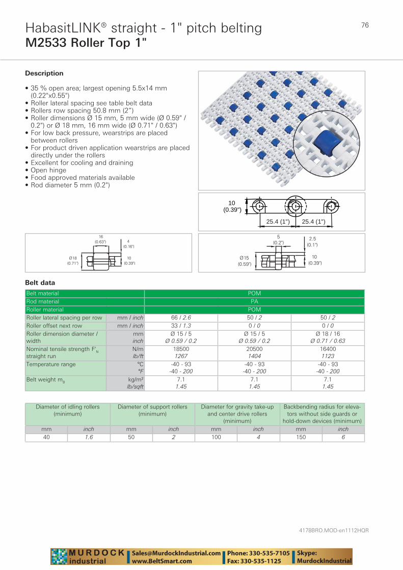
4178BRO.MOD-en1112HQR
76
M2533 Roller Top 1"HabasitLINK® straight - 1" pitch belting
Belt data
Belt material POMRod material PARoller material POMRoller lateral spacing per row mm / inch 66 / 2.6 50 / 2 50 / 2Roller offset next row mm / inch 33 / 1.3 0 / 0 0 / 0Roller dimension diameter / width
mminch
Ø 15 / 5Ø 0.59 / 0.2
Ø 15 / 5Ø 0.59 / 0.2
Ø 18 / 16Ø 0.71 / 0.63
Nominal tensile strength F'N straight run
N/mlb/ft
185001267
205001404
164001123
Temperature range °C°F
-40 - 93-40 - 200
-40 - 93-40 - 200
-40 - 93-40 - 200
Belt weight mB kg/m²lb/sqft
7.11.45
7.11.45
7.11.45
25.4 (1")25.4 (1")
10(0.39")
Description
• 35 % open area; largest opening 5.5x14 mm (0.22"x0.55")
• Roller lateral spacing see table belt data • Rollers row spacing 50.8 mm (2”) • Roller dimensions Ø 15 mm, 5 mm wide (Ø 0.59" /
0.2") or Ø 18 mm, 16 mm wide (Ø 0.71" / 0.63") • For low back pressure, wearstrips are placed
between rollers • For product driven application wearstrips are placed
directly under the rollers • Excellent for cooling and draining • Open hinge • Food approved materials available• Rod diameter 5 mm (0.2")
Diameter of idling rollers (minimum)
Diameter of support rollers(minimum)
Diameter for gravity take-up and center drive rollers
(minimum)
Backbending radius for eleva-tors without side guards or
hold-down devices (minimum)mm inch mm inch mm inch mm inch40 1.6 50 2 100 4 150 6
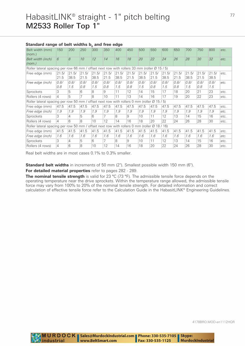
77
4178BRO.MOD-en1112HQR
M2533 Roller Top 1"HabasitLINK® straight - 1" pitch belting
Standard range of belt widths b0 and free edgeBelt width (mm) (nom.)
150 200 250 300 350 400 450 500 550 600 650 700 750 800 etc.
Belt width (inch) (nom.)
6 8 10 12 14 16 18 20 22 24 26 28 30 32 etc.
Roller lateral spacing per row 66 mm / offset next row with rollers 33 mm (roller Ø 15 / 5)Free edge (mm) 21.5/
21.521.5/ 38.5
21.5/ 21.5
21.5/ 38.5
21.5/ 21.5
21.5/ 38.5
21.5/ 21.5
21.5/ 38.5
21.5/ 21.5
21.5/ 38.5
21.5/ 21.5
21.5/ 38.5
21.5/ 21.5
21.5/ 38.5
etc.
Free edge (inch) 0.8/ 0.8
0.8/ 1.5
0.8/ 0.8
0.8/ 1.5
0.8/ 0.8
0.8/ 1.5
0.8/ 0.8
0.8/ 1.5
0.8/ 0.8
0.8/ 1.5
0.8/ 0.8
0.8/ 1.5
0.8/ 0.8
0.8/ 1.5
etc.
Sprockets 3 5 6 8 9 11 12 14 15 17 18 20 21 23 etc.Rollers (4 rows) 4 5 7 8 10 11 13 14 16 17 19 20 22 23 etc.Roller lateral spacing per row 50 mm / offset next row with rollers 0 mm (roller Ø 15 / 5)Free edge (mm) 47.5 47.5 47.5 47.5 47.5 47.5 47.5 47.5 47.5 47.5 47.5 47.5 47.5 47.5 etc.Free edge (inch) 1.9 1.9 1.9 1.9 1.9 1.9 1.9 1.9 1.9 1.9 1.9 1.9 1.9 1.9 etc.Sprockets 3 4 5 6 7 8 9 10 11 12 13 14 15 16 etc.Rollers (4 rows) 4 6 8 10 12 14 16 18 20 22 24 26 28 30 etc.Roller lateral spacing per row 50 mm / offset next row with rollers 0 mm (roller Ø 18 / 16)Free edge (mm) 41.5 41.5 41.5 41.5 41.5 41.5 41.5 41.5 41.5 41.5 41.5 41.5 41.5 41.5 etc.Free edge (inch) 1.6 1.6 1.6 1.6 1.6 1.6 1.6 1.6 1.6 1.6 1.6 1.6 1.6 1.6 etc.Sprockets 3 4 5 6 7 8 9 10 11 12 13 14 15 16 etc.Rollers (4 rows) 4 6 8 10 12 14 16 18 20 22 24 26 28 30 etc.
Real belt widths are in most cases 0.1% to 0.3% smaller.
Standard belt widths in increments of 50 mm (2"). Smallest possible width 150 mm (6").For detailed material properties refer to pages 282 - 289.The nominal tensile strength is valid for 23 °C (73 °F). The admissible tensile force depends on the operating temperature near the drive sprockets. Within the temperature range allowed, the admissible tensile force may vary from 100% to 20% of the nominal tensile strength. For detailed information and correct calculation of effective tensile force refer to the Calculation Guide in the HabasitLINK® Engineering Guidelines.
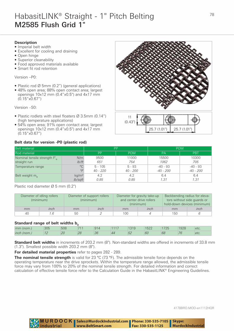
4178BRO.MOD-en1112HQR
78
M2585 Flush Grid 1"HabasitLINK® Straight - 1" Pitch Belting
Belt data for version -P0 (plastic rod)
Standard range of belt widths b0
mm (nom.) 305 508 711 914 1117 1319 1522 1725 1928 etc.inch (nom.) 12 20 28 36 44 52 60 68 76 etc.
Belt material PP POMRod material PP POM PA PBTNominal tensile strength F'N straight run
N/mlb/ft
9500651
11000754
155001062
10300705
Temperature range °C°F
5 - 10540 - 220
5 - 9340 - 200
-40 - 93-40 - 200
-40 - 93-40 - 200
Belt weight mB kg/m²lb/sqft
4.20.85
4.20.85
6.41.31
6.41.31
Description• Imperial belt width• Excellent for cooling and draining • Open hinge • Superior cleanability • Food approved materials available• Smart fit rod retention
Version –P0:
• Plastic rod Ø 5mm (0.2”) (general applications) • 48% open area; 88% open contact area; largest
openings 10x12 mm (0.4”x0.5") and 4x17 mm (0.15”x0.67”)
Version –S0:
• Plastic rodlets with steel floaters Ø 3.5mm (0.14”) (high temperature applications)
• 54% open area; 91% open contact area; largest openings 10x12 mm (0.4”x0.5") and 4x17 mm (0.15”x0.67”)
Plastic rod diameter Ø 5 mm (0.2")
Diameter of idling rollers (minimum)
Diameter of support rollers(minimum)
Diameter for gravity take-up and center drive rollers
(minimum)
Backbending radius for eleva-tors without side guards or
hold-down devices (minimum)mm inch mm inch mm inch mm inch40 1.6 50 2 100 4 150 6
Standard belt widths in increments of 203.2 mm (8"). Non-standard widths are offered in increments of 33.8 mm (1.3"). Smallest possible width 203.2 mm (8").For detailed material properties refer to pages 282 - 289.The nominal tensile strength is valid for 23 °C (73 °F). The admissible tensile force depends on the operating temperature near the drive sprockets. Within the temperature range allowed, the admissible tensile force may vary from 100% to 20% of the nominal tensile strength. For detailed information and correct calculation of effective tensile force refer to the Calculation Guide in the HabasitLINK® Engineering Guidelines.

79
4178BRO.MOD-en1112HQR
M2585 Flush Grid 1"HabasitLINK® Straight - 1" Pitch Belting
Belt data for version -S0 (plastic rodlets, steel floaters)
Standard range of belt widths b0
mm (nom.) 305 508 711 914 1117 1319 1522 1725 1928 etc.inch (nom.) 12 20 28 36 44 52 60 68 76 etc.
Belt material PA +GF PA +HT STRod material ST / SteelNominal tensile strength F'N straight run
N/mlb/ft
200001370
220001507
10000685
Temperature range °C°F
0 - 14532 - 293
0 - 17032 - 338
0 - 20032 - 392
Temperature maximum (short-term)
°C°F
175347
200392
240464
Belt weight mB kg/m²lb/sqft
8.01.64
8.01.64
9.21.88
Plastic rodlets Ø 5 mm (0.2”) and steel floaters Ø 3.5 mm (0.14")
Standard belt widths in increments of 203.2 mm (8"). Non-standard widths are offered in increments of 33.8 mm (1.3"). Smallest possible width 203.2 mm (8").For detailed material properties refer to pages 282 - 289.The nominal tensile strength is valid for 23 °C (73 °F). The admissible tensile force depends on the operating temperature near the drive sprockets. Within the temperature range allowed, the admissible tensile force may vary from 100% to 20% of the nominal tensile strength. For detailed information and correct calculation of effective tensile force refer to the Calculation Guide in the HabasitLINK® Engineering Guidelines.
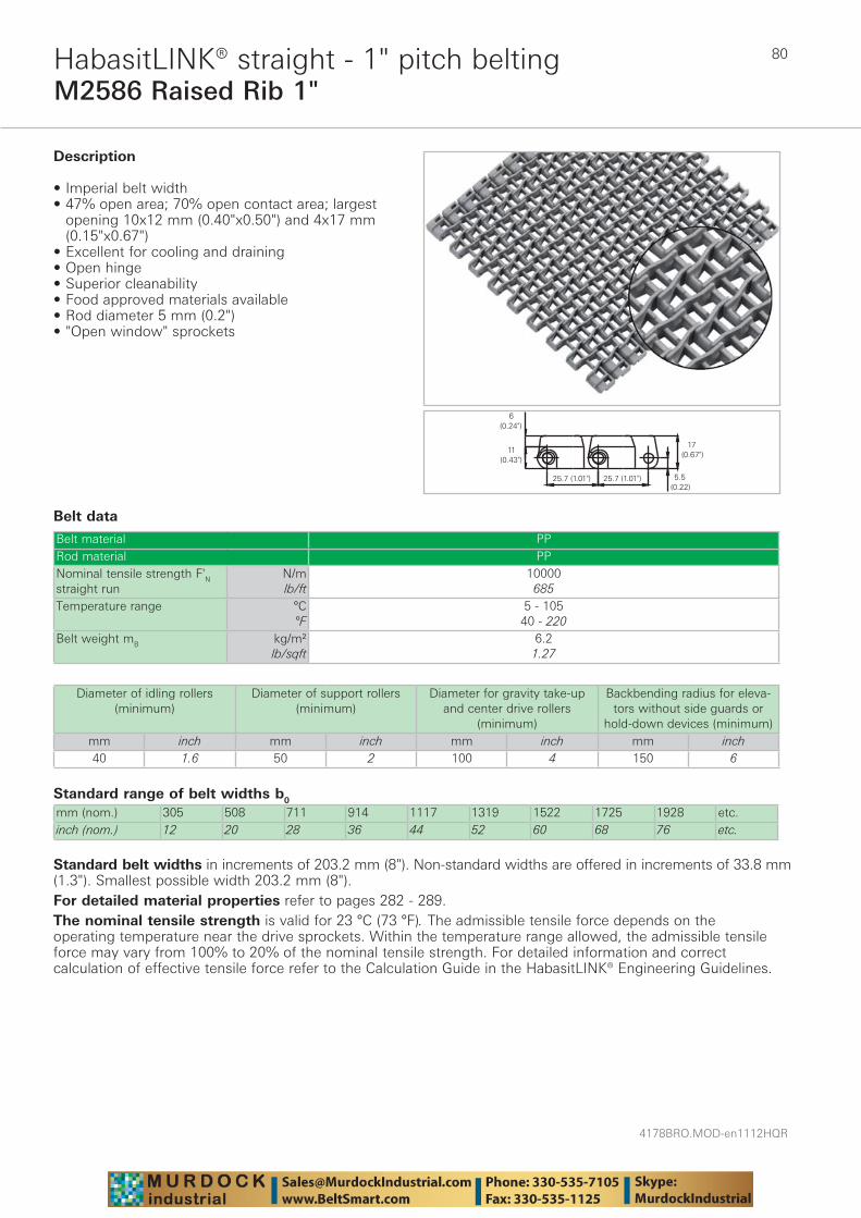
4178BRO.MOD-en1112HQR
80
M2586 Raised Rib 1"HabasitLINK® straight - 1" pitch belting
Belt data
Standard range of belt widths b0
mm (nom.) 305 508 711 914 1117 1319 1522 1725 1928 etc.inch (nom.) 12 20 28 36 44 52 60 68 76 etc.
Belt material PPRod material PPNominal tensile strength F'N straight run
N/mlb/ft
10000685
Temperature range °C°F
5 - 10540 - 220
Belt weight mB kg/m²lb/sqft
6.21.27
Description
• Imperial belt width• 47% open area; 70% open contact area; largest
opening 10x12 mm (0.40"x0.50") and 4x17 mm (0.15"x0.67")
• Excellent for cooling and draining • Open hinge • Superior cleanability • Food approved materials available• Rod diameter 5 mm (0.2") • "Open window" sprockets
Diameter of idling rollers (minimum)
Diameter of support rollers(minimum)
Diameter for gravity take-up and center drive rollers
(minimum)
Backbending radius for eleva-tors without side guards or
hold-down devices (minimum)mm inch mm inch mm inch mm inch40 1.6 50 2 100 4 150 6
Standard belt widths in increments of 203.2 mm (8"). Non-standard widths are offered in increments of 33.8 mm (1.3"). Smallest possible width 203.2 mm (8").For detailed material properties refer to pages 282 - 289.The nominal tensile strength is valid for 23 °C (73 °F). The admissible tensile force depends on the operating temperature near the drive sprockets. Within the temperature range allowed, the admissible tensile force may vary from 100% to 20% of the nominal tensile strength. For detailed information and correct calculation of effective tensile force refer to the Calculation Guide in the HabasitLINK® Engineering Guidelines.

81
4178BRO.MOD-en1112HQR
M2540 Radius Flush Grid 1"HabasitLINK® radius 1" pitch belting
Belt data
Belt material PP POM PA +US PARod material POM PANominal tensile strength F'N straight run
N/mlb/ft
190001300
190001300
270001850
250001713
250001713
Nominal tensile strength FN in curve (1)
Nlbf
1000225
1000225
1500338
1300293
1300293
Temperature range °C°F
5 - 9340 - 200
5 - 10540 - 220
-40 - 93-40 - 200
-46 - 116-50 - 240
-46 - 130-50 - 266
Temperature maximum (short-term)
°C°F
135275
160320
Belt weight mB kg/m²lb/sqft
4.70.96
4.70.96
7.01.44
6.01.23
6.01.23
25.6 (1")25.6 (1")
11(0.43")
Description
• For radius and straight conveying (collapse factor 2.2)
• 35% open area; 53% open contact area; largest opening 6x12.5 mm (0.24"x0.49")
• Excellent for cooling and draining • Easy to clean • Food approved materials available• Rod diameter 5 mm (0.2")
Available accessories
• Hold-down tabs • Hold-down devices• Flights • Side guards • GripTop modules • Lane divider
(1) For b0 > 300 mm (12") higher values admissible. Refer to LINK-SeleCalc
Diameter of idling rollers (minimum)
Diameter of support rollers
(minimum)
Diameter for gravity take-up and center drive
rollers (minimum)
Backbending radius for elevators without side guards or hold-down devices (minimum)
Backbending radius for elevators with side guards or hold-down devices (minimum)
mm inch mm inch mm inch mm inch mm inch40 1.6 50 2 100 4 150 6 250 10
Use the largest possible backbending radius for elevators with side guards or hold-down devices.

4178BRO.MOD-en1112HQR
82
M2540 Radius Flush Grid 1"HabasitLINK® radius 1" pitch belting
Standard range of belt widths b0 and collapse factor Q (Rmin = Q x b0)Belt width mm (nom.)
200 250 300 350 400 450 500 550 600 650 700 750 800 850
Belt width inch (nom.)
8 10 12 14 16 18 20 22 24 26 28 30 32 34
Coll. fact. Q 2.03 2.07 2.10 2.12 2.14 2.15 2.16 2.17 2.18 2.18 2.19 2.19 2.19 2.20Belt width mm (nom.)
900 950 1000 1050 1100 1150 1200
Belt width inch (nom.)
36 38 40 42 43 45 47
Coll. fact. Q 2.20 2.20 2.21 2.21 2.21 2.21 2.21
Belt widths larger than 1200 mm (48") are not recommended; please contact your Habasit representative.Real belt widths are in most cases 0.1% to 0.3% smaller.
Standard belt widths in increments of 50 mm (2"). Non-standard widths are offered in increments of 16.66 mm (0.66"). Smallest possible width 83.4 mm (3.25").For detailed material properties refer to pages 282 - 289.The nominal tensile strength is valid for 23 °C (73 °F). The admissible tensile force depends on the operating temperature near the drive sprockets. Within the temperature range allowed, the admissible tensile force may vary from 100% to 20% of the nominal tensile strength. For detailed information and correct calculation of effective tensile force refer to the Calculation Guide in the HabasitLINK® Engineering Guidelines.

83
4178BRO.MOD-en1112HQR
M2540 Radius Flush Grid 1" MTWHabasitLINK® radius 1" pitch belting
Belt data
Range of belt widths b0 and collapse factor Q (Rmin = Q x b0)Belt width mm (nom.)
206 256 306MTW
356 406 456 506 556 606
Belt width inch (nom.)
8 10 12MTW
14 16 18 20 22 24
Collapse factor Q 2.03 2.07 2.10 2.12 2.14 2.15 2.16 2.17 2.18
Real belt widths are in most cases 0.1% to 0.3% smaller.
Belt material PP POMRod material POM PANominal tensile strength FN straight run
Nlbf
58101307
58101307
82601858
Nominal tensile strength FN in curve (1)
Nlbf
1000225
1000225
1500338
Temperature range °C°F
5 - 9340 - 200
5 - 10540 - 220
-40 - 93-40 - 200
Belt weight mB kg/m²lb/sqft
4.70.96
4.70.96
7.01.44
Description
• Mold to width radius belt 12" (306 mm) wide, for radius and straight conveying
• Hold-down tab on both edges • Collapse factor 2.1 • 35% open area; 53% open contact area; largest
opening 6x12.5 mm (0.24"x0.49") • Excellent for cooling and draining • Easy to clean • Food approved materials available• Rod diameter 5 mm (0.2") • Open window sprockets
Available accessories • Clip-on side guards• Lane divider
(1) The indicated nominal tensile strength refers to 12" (306 mm) belt width. For b0 > 12" higher values admissible, please contact your Habasit representative.
Diameter of idling rollers (minimum)
Diameter of support rollers
(minimum)
Diameter for gravity take-up and center drive
rollers (minimum)
Backbending radius for elevators without side guards or hold-down devices (minimum)
Backbending radius for elevators with side guards or hold-down devices (minimum)
mm inch mm inch mm inch mm inch mm inch50 2 50 2 100 4 150 6 250 10
Use the largest possible backbending radius for elevators with side guards or hold-down devices.

4178BRO.MOD-en1112HQR
84
M2540 Radius Flush Grid 1" MTWHabasitLINK® radius 1" pitch belting
Standard belt widths: The belt is produced as mold to width belt 12" (306 mm).Non-standard belt widths: M2540 MTW can also be used as bricklayed in 50 mm (2") increments. Non-standard widths are offered in increments of 16.66 mm (0.66").
For detailed material properties refer to pages 282 - 289.The nominal tensile strength is valid for 23 °C (73 °F). The admissible tensile force depends on the operating temperature near the drive sprockets. Within the temperature range allowed, the admissible tensile force may vary from 100% to 20% of the nominal tensile strength. For detailed information and correct calculation of effective tensile force refer to the Calculation Guide in the HabasitLINK® Engineering Guidelines.
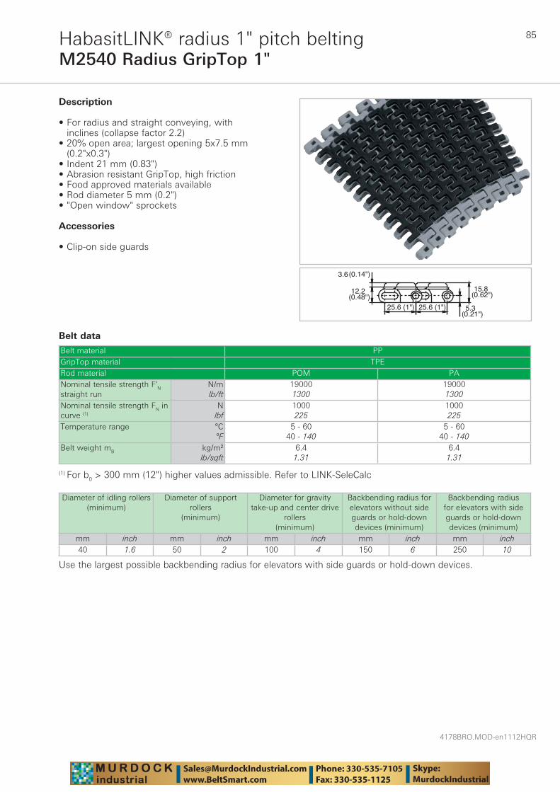
85
4178BRO.MOD-en1112HQR
M2540 Radius GripTop 1"HabasitLINK® radius 1" pitch belting
Belt data
Belt material PPGripTop material TPERod material POM PANominal tensile strength F'N straight run
N/mlb/ft
190001300
190001300
Nominal tensile strength FN in curve (1)
Nlbf
1000225
1000225
Temperature range °C°F
5 - 6040 - 140
5 - 6040 - 140
Belt weight mB kg/m²lb/sqft
6.41.31
6.41.31
12.2(0.48")
25.6 (1")
3.6(0.14")
15.8(0.62")
25.6 (1") 5.3(0.21")
Description
• For radius and straight conveying, with inclines (collapse factor 2.2)
• 20% open area; largest opening 5x7.5 mm (0.2"x0.3")
• Indent 21 mm (0.83")• Abrasion resistant GripTop, high friction• Food approved materials available• Rod diameter 5 mm (0.2")• "Open window" sprockets
Accessories
• Clip-on side guards
(1) For b0 > 300 mm (12") higher values admissible. Refer to LINK-SeleCalc
Diameter of idling rollers (minimum)
Diameter of support rollers
(minimum)
Diameter for gravity take-up and center drive
rollers (minimum)
Backbending radius for elevators without side guards or hold-down devices (minimum)
Backbending radius for elevators with side guards or hold-down devices (minimum)
mm inch mm inch mm inch mm inch mm inch40 1.6 50 2 100 4 150 6 250 10
Use the largest possible backbending radius for elevators with side guards or hold-down devices.
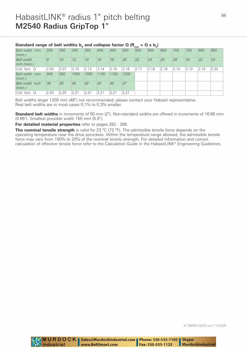
4178BRO.MOD-en1112HQR
86
M2540 Radius GripTop 1"HabasitLINK® radius 1" pitch belting
Standard range of belt widths b0 and collapse factor Q (Rmin = Q x b0)Belt width mm (nom.)
200 250 300 350 400 450 500 550 600 650 700 750 800 850
Belt width inch (nom.)
8 10 12 14 16 18 20 22 24 26 28 30 32 34
Coll. fact. Q 2.03 2.07 2.10 2.12 2.14 2.15 2.16 2.17 2.18 2.18 2.19 2.19 2.19 2.20Belt width mm (nom.)
900 950 1000 1050 1100 1150 1200
Belt width inch (nom.)
36 38 40 42 43 45 47
Coll. fact. Q 2.20 2.20 2.21 2.21 2.21 2.21 2.21
Belt widths larger 1200 mm (48") not recommended; please contact your Habasit representative.Real belt widths are in most cases 0.1% to 0.3% smaller.
Standard belt widths in increments of 50 mm (2"). Non-standard widths are offered in increments of 16.66 mm (0.66"). Smallest possible width 150 mm (5.9").For detailed material properties refer to pages 282 - 289.The nominal tensile strength is valid for 23 °C (73 °F). The admissible tensile force depends on the operating temperature near the drive sprockets. Within the temperature range allowed, the admissible tensile force may vary from 100% to 20% of the nominal tensile strength. For detailed information and correct calculation of effective tensile force refer to the Calculation Guide in the HabasitLINK® Engineering Guidelines.
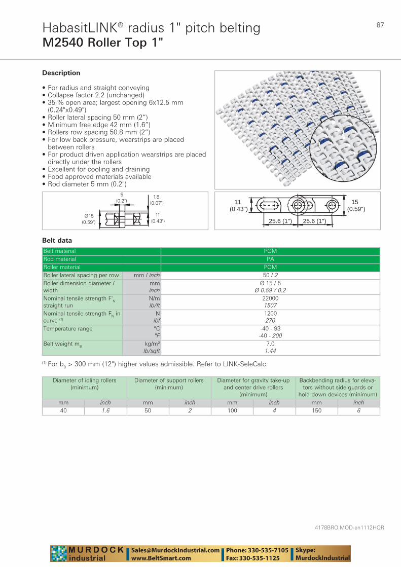
87
4178BRO.MOD-en1112HQR
M2540 Roller Top 1"HabasitLINK® radius 1" pitch belting
Belt data
Belt material POMRod material PARoller material POMRoller lateral spacing per row mm / inch 50 / 2Roller dimension diameter / width
mminch
Ø 15 / 5Ø 0.59 / 0.2
Nominal tensile strength F'N straight run
N/mlb/ft
220001507
Nominal tensile strength FN in curve (1)
Nlbf
1200270
Temperature range °C°F
-40 - 93-40 - 200
Belt weight mB kg/m²lb/sqft
7.01.44
11(0.43")
25.6 (1")25.6 (1")
15(0.59")
Description
• For radius and straight conveying • Collapse factor 2.2 (unchanged) • 35 % open area; largest opening 6x12.5 mm
(0.24"x0.49") • Roller lateral spacing 50 mm (2”) • Minimum free edge 42 mm (1.6”) • Rollers row spacing 50.8 mm (2”) • For low back pressure, wearstrips are placed
between rollers • For product driven application wearstrips are placed
directly under the rollers • Excellent for cooling and draining • Food approved materials available• Rod diameter 5 mm (0.2")
(1) For b0 > 300 mm (12") higher values admissible. Refer to LINK-SeleCalc
Diameter of idling rollers (minimum)
Diameter of support rollers(minimum)
Diameter for gravity take-up and center drive rollers
(minimum)
Backbending radius for eleva-tors without side guards or
hold-down devices (minimum)mm inch mm inch mm inch mm inch40 1.6 50 2 100 4 150 6

4178BRO.MOD-en1112HQR
88
M2540 Roller Top 1"HabasitLINK® radius 1" pitch belting
Standard range of belt widths b0, free edge and collapse factor Q (Rmin = Q x b0)Belt width mm (nom.)
200 250 300 350 400 450 500 550 600 650 700 750 800 850 etc.
Belt width inch (nom.)
8 10 12 14 16 18 20 22 24 26 28 30 32 34 etc.
Coll.fact. Q 2.03 2.07 2.10 2.12 2.14 2.15 2.16 2.17 2.18 2.18 2.19 2.19 2.19 2.20 etc.Free edge mm 42/52 42/52 42/52 42/52 42/52 42/52 42/52 42/52 42/52 42/52 42/52 42/52 42/52 42/52 etc.Free edge inch 1.7/2 1.7/2 1.7/2 1.7/2 1.7/2 1.7/2 1.7/2 1.7/2 1.7/2 1.7/2 1.7/2 1.7/2 1.7/2 1.7/2 etc.Sprocket offset mm
29.1 4.2 29.1 4.2 29.1 4.2 29.1 4.2 29.1 4.2 29.1 4.2 29.1 4.2 etc.
Sprocket offset inch
1.1 0.2 1.1 0.2 1.1 0.2 1.1 0.2 1.1 0.2 1.1 0.2 1.1 0.2 etc.
Sprockets 4 5 6 7 8 9 10 11 12 13 14 15 16 17 etc.Rollers (2 rows) 3 4 5 6 7 8 9 10 11 12 13 14 15 16 etc.
Real belt widths are in most cases 0.1% to 0.3% smaller.
Standard belt widths in increments of 50 mm (2"). Smallest possible width 200 mm (7.9").For detailed material properties refer to pages 282 - 289.The nominal tensile strength is valid for 23 °C (73 °F). The admissible tensile force depends on the operating temperature near the drive sprockets. Within the temperature range allowed, the admissible tensile force may vary from 100% to 20% of the nominal tensile strength. For detailed information and correct calculation of effective tensile force refer to the Calculation Guide in the HabasitLINK® Engineering Guidelines.
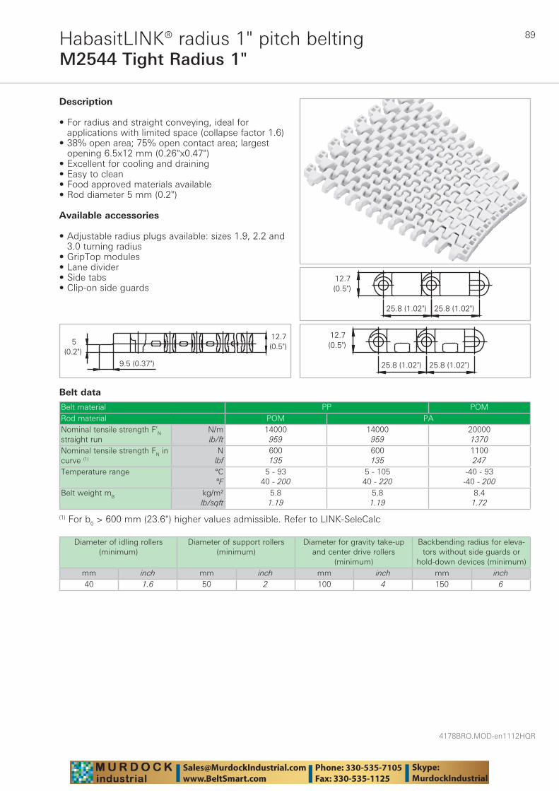
89
4178BRO.MOD-en1112HQR
M2544 Tight Radius 1"HabasitLINK® radius 1" pitch belting
Belt data
Belt material PP POMRod material POM PANominal tensile strength F'N straight run
N/mlb/ft
14000959
14000959
200001370
Nominal tensile strength FN in curve (1)
Nlbf
600135
600135
1100247
Temperature range °C°F
5 - 9340 - 200
5 - 10540 - 220
-40 - 93-40 - 200
Belt weight mB kg/m²lb/sqft
5.81.19
5.81.19
8.41.72
Description
• For radius and straight conveying, ideal for applications with limited space (collapse factor 1.6)
• 38% open area; 75% open contact area; largest opening 6.5x12 mm (0.26"x0.47")
• Excellent for cooling and draining • Easy to clean • Food approved materials available • Rod diameter 5 mm (0.2")
Available accessories
• Adjustable radius plugs available: sizes 1.9, 2.2 and 3.0 turning radius
• GripTop modules • Lane divider • Side tabs • Clip-on side guards
(1) For b0 > 600 mm (23.6") higher values admissible. Refer to LINK-SeleCalc
Diameter of idling rollers (minimum)
Diameter of support rollers(minimum)
Diameter for gravity take-up and center drive rollers
(minimum)
Backbending radius for eleva-tors without side guards or
hold-down devices (minimum)mm inch mm inch mm inch mm inch40 1.6 50 2 100 4 150 6
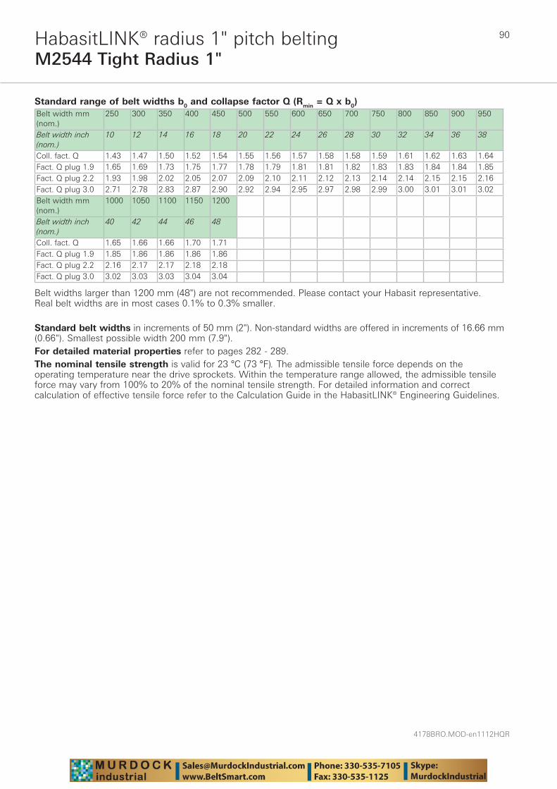
4178BRO.MOD-en1112HQR
90
M2544 Tight Radius 1"HabasitLINK® radius 1" pitch belting
Standard range of belt widths b0 and collapse factor Q (Rmin = Q x b0)Belt width mm (nom.)
250 300 350 400 450 500 550 600 650 700 750 800 850 900 950
Belt width inch (nom.)
10 12 14 16 18 20 22 24 26 28 30 32 34 36 38
Coll. fact. Q 1.43 1.47 1.50 1.52 1.54 1.55 1.56 1.57 1.58 1.58 1.59 1.61 1.62 1.63 1.64 Fact. Q plug 1.9 1.65 1.69 1.73 1.75 1.77 1.78 1.79 1.81 1.81 1.82 1.83 1.83 1.84 1.84 1.85 Fact. Q plug 2.2 1.93 1.98 2.02 2.05 2.07 2.09 2.10 2.11 2.12 2.13 2.14 2.14 2.15 2.15 2.16Fact. Q plug 3.0 2.71 2.78 2.83 2.87 2.90 2.92 2.94 2.95 2.97 2.98 2.99 3.00 3.01 3.01 3.02 Belt width mm (nom.)
1000 1050 1100 1150 1200
Belt width inch (nom.)
40 42 44 46 48
Coll. fact. Q 1.65 1.66 1.66 1.70 1.71Fact. Q plug 1.9 1.85 1.86 1.86 1.86 1.86 Fact. Q plug 2.2 2.16 2.17 2.17 2.18 2.18 Fact. Q plug 3.0 3.02 3.03 3.03 3.04 3.04
Belt widths larger than 1200 mm (48") are not recommended. Please contact your Habasit representative.Real belt widths are in most cases 0.1% to 0.3% smaller.
Standard belt widths in increments of 50 mm (2"). Non-standard widths are offered in increments of 16.66 mm (0.66"). Smallest possible width 200 mm (7.9").For detailed material properties refer to pages 282 - 289.The nominal tensile strength is valid for 23 °C (73 °F). The admissible tensile force depends on the operating temperature near the drive sprockets. Within the temperature range allowed, the admissible tensile force may vary from 100% to 20% of the nominal tensile strength. For detailed information and correct calculation of effective tensile force refer to the Calculation Guide in the HabasitLINK® Engineering Guidelines.
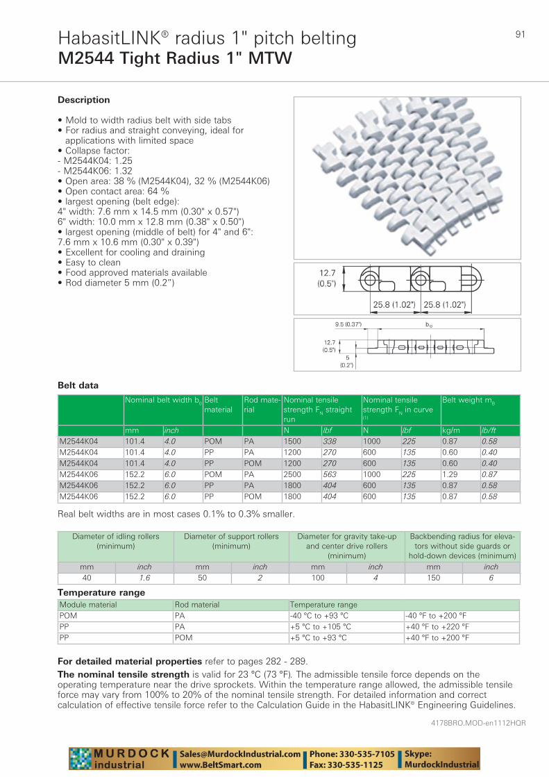
91
4178BRO.MOD-en1112HQR
M2544 Tight Radius 1" MTWHabasitLINK® radius 1" pitch belting
Belt data
Temperature rangeModule material Rod material Temperature rangePOM PA -40 °C to +93 °C -40 °F to +200 °FPP PA +5 °C to +105 °C +40 °F to +220 °FPP POM +5 °C to +93 °C +40 °F to +200 °F
Description
• Mold to width radius belt with side tabs• For radius and straight conveying, ideal for
applications with limited space • Collapse factor:- M2544K04: 1.25- M2544K06: 1.32 • Open area: 38 % (M2544K04), 32 % (M2544K06) • Open contact area: 64 % • largest opening (belt edge):4" width: 7.6 mm x 14.5 mm (0.30" x 0.57")6" width: 10.0 mm x 12.8 mm (0.38" x 0.50") • largest opening (middle of belt) for 4" and 6":7.6 mm x 10.6 mm (0.30" x 0.39") • Excellent for cooling and draining • Easy to clean • Food approved materials available• Rod diameter 5 mm (0.2”)
Diameter of idling rollers (minimum)
Diameter of support rollers(minimum)
Diameter for gravity take-up and center drive rollers
(minimum)
Backbending radius for eleva-tors without side guards or
hold-down devices (minimum)mm inch mm inch mm inch mm inch40 1.6 50 2 100 4 150 6
Nominal belt width b0 Belt material
Rod mate-rial
Nominal tensile strength FN straight run
Nominal tensile strength FN in curve (1)
Belt weight mB
mm inch N lbf N lbf kg/m lb/ftM2544K04 101.4 4.0 POM PA 1500 338 1000 225 0.87 0.58M2544K04 101.4 4.0 PP PA 1200 270 600 135 0.60 0.40M2544K04 101.4 4.0 PP POM 1200 270 600 135 0.60 0.40M2544K06 152.2 6.0 POM PA 2500 563 1000 225 1.29 0.87M2544K06 152.2 6.0 PP PA 1800 404 600 135 0.87 0.58M2544K06 152.2 6.0 PP POM 1800 404 600 135 0.87 0.58
Real belt widths are in most cases 0.1% to 0.3% smaller.
For detailed material properties refer to pages 282 - 289.The nominal tensile strength is valid for 23 °C (73 °F). The admissible tensile force depends on the operating temperature near the drive sprockets. Within the temperature range allowed, the admissible tensile force may vary from 100% to 20% of the nominal tensile strength. For detailed information and correct calculation of effective tensile force refer to the Calculation Guide in the HabasitLINK® Engineering Guidelines.
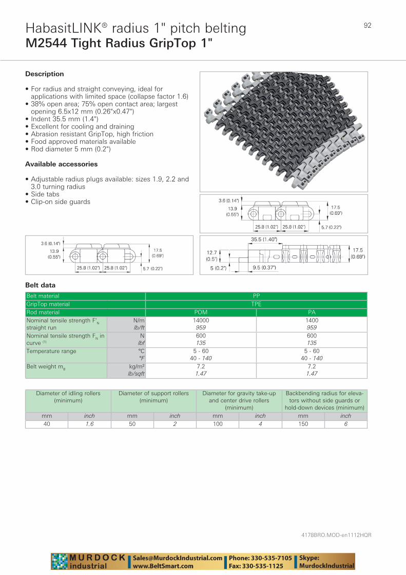
4178BRO.MOD-en1112HQR
92
M2544 Tight Radius GripTop 1"HabasitLINK® radius 1" pitch belting
Belt data
Belt material PPGripTop material TPERod material POM PANominal tensile strength F'N straight run
N/mlb/ft
14000959
1400959
Nominal tensile strength FN in curve (1)
Nlbf
600135
600135
Temperature range °C°F
5 - 6040 - 140
5 - 6040 - 140
Belt weight mB kg/m²lb/sqft
7.21.47
7.21.47
Description
• For radius and straight conveying, ideal for applications with limited space (collapse factor 1.6)
• 38% open area; 75% open contact area; largest opening 6.5x12 mm (0.26"x0.47")
• Indent 35.5 mm (1.4")• Excellent for cooling and draining • Abrasion resistant GripTop, high friction • Food approved materials available • Rod diameter 5 mm (0.2")
Available accessories
• Adjustable radius plugs available: sizes 1.9, 2.2 and 3.0 turning radius
• Side tabs • Clip-on side guards
Diameter of idling rollers (minimum)
Diameter of support rollers(minimum)
Diameter for gravity take-up and center drive rollers
(minimum)
Backbending radius for eleva-tors without side guards or
hold-down devices (minimum)mm inch mm inch mm inch mm inch40 1.6 50 2 100 4 150 6
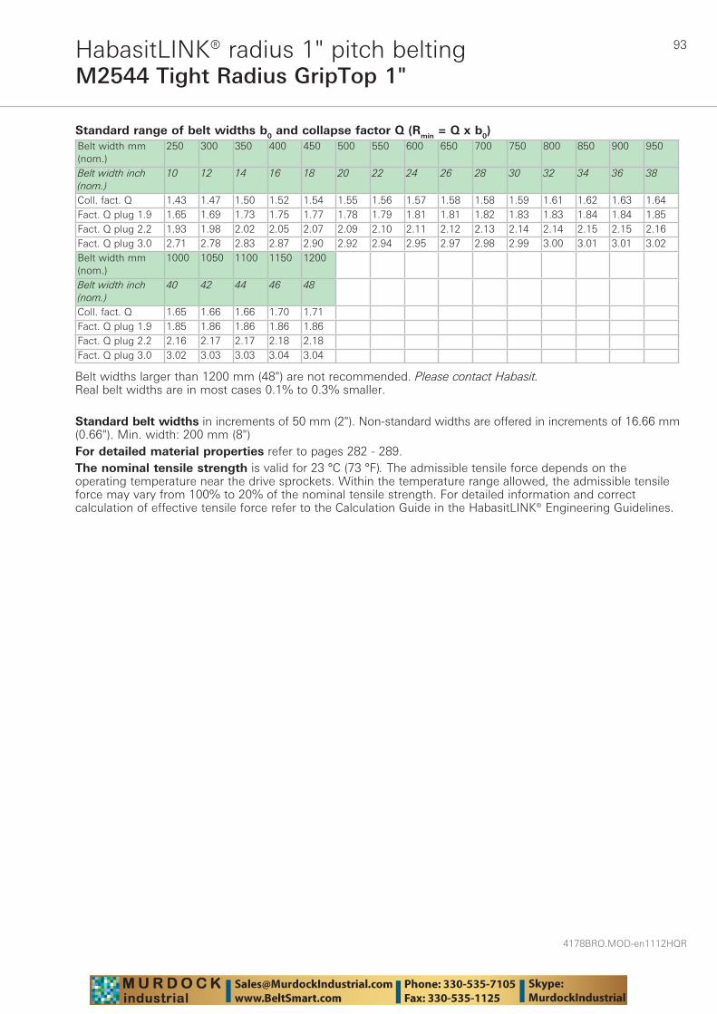
93
4178BRO.MOD-en1112HQR
M2544 Tight Radius GripTop 1"HabasitLINK® radius 1" pitch belting
Standard range of belt widths b0 and collapse factor Q (Rmin = Q x b0)Belt width mm (nom.)
250 300 350 400 450 500 550 600 650 700 750 800 850 900 950
Belt width inch (nom.)
10 12 14 16 18 20 22 24 26 28 30 32 34 36 38
Coll. fact. Q 1.43 1.47 1.50 1.52 1.54 1.55 1.56 1.57 1.58 1.58 1.59 1.61 1.62 1.63 1.64 Fact. Q plug 1.9 1.65 1.69 1.73 1.75 1.77 1.78 1.79 1.81 1.81 1.82 1.83 1.83 1.84 1.84 1.85 Fact. Q plug 2.2 1.93 1.98 2.02 2.05 2.07 2.09 2.10 2.11 2.12 2.13 2.14 2.14 2.15 2.15 2.16Fact. Q plug 3.0 2.71 2.78 2.83 2.87 2.90 2.92 2.94 2.95 2.97 2.98 2.99 3.00 3.01 3.01 3.02 Belt width mm (nom.)
1000 1050 1100 1150 1200
Belt width inch (nom.)
40 42 44 46 48
Coll. fact. Q 1.65 1.66 1.66 1.70 1.71Fact. Q plug 1.9 1.85 1.86 1.86 1.86 1.86 Fact. Q plug 2.2 2.16 2.17 2.17 2.18 2.18 Fact. Q plug 3.0 3.02 3.03 3.03 3.04 3.04
Belt widths larger than 1200 mm (48") are not recommended. Please contact Habasit.Real belt widths are in most cases 0.1% to 0.3% smaller.
Standard belt widths in increments of 50 mm (2"). Non-standard widths are offered in increments of 16.66 mm (0.66"). Min. width: 200 mm (8")For detailed material properties refer to pages 282 - 289.The nominal tensile strength is valid for 23 °C (73 °F). The admissible tensile force depends on the operating temperature near the drive sprockets. Within the temperature range allowed, the admissible tensile force may vary from 100% to 20% of the nominal tensile strength. For detailed information and correct calculation of effective tensile force refer to the Calculation Guide in the HabasitLINK® Engineering Guidelines.
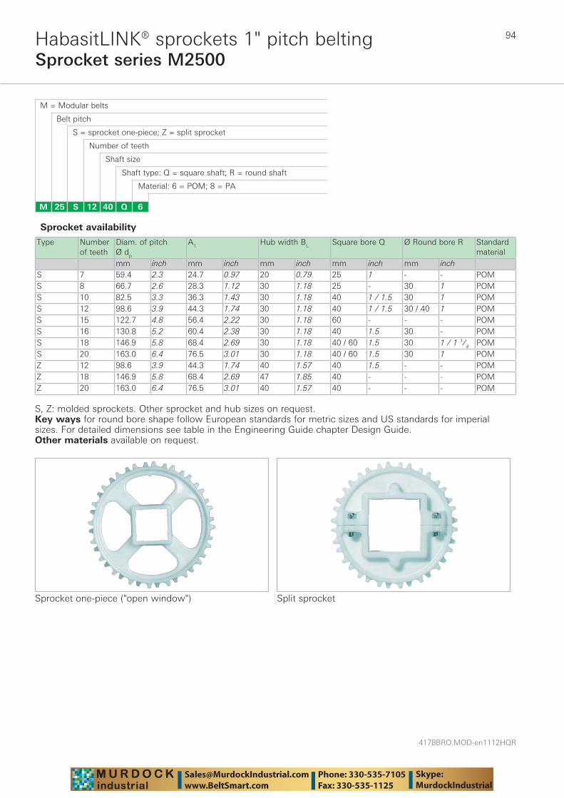
4178BRO.MOD-en1112HQR
94
Sprocket series M2500HabasitLINK® sprockets 1" pitch belting
M = Modular belts
M 25 6Q4012S
Belt pitch
S = sprocket one-piece; Z = split sprocket
Number of teeth
Shaft size
Shaft type: Q = square shaft; R = round shaft
Material: 6 = POM; 8 = PA
Type Number of teeth
Diam. of pitch Ø dp
A1 Hub width BL Square bore Q Ø Round bore R Standard material
mm inch mm inch mm inch mm inch mm inchS 7 59.4 2.3 24.7 0.97 20 0.79 25 1 - - POMS 8 66.7 2.6 28.3 1.12 30 1.18 25 - 30 1 POMS 10 82.5 3.3 36.3 1.43 30 1.18 40 1 / 1.5 30 1 POMS 12 98.6 3.9 44.3 1.74 30 1.18 40 1 / 1.5 30 / 40 1 POMS 15 122.7 4.8 56.4 2.22 30 1.18 60 - - - POMS 16 130.8 5.2 60.4 2.38 30 1.18 40 1.5 30 - POMS 18 146.9 5.8 68.4 2.69 30 1.18 40 / 60 1.5 30 1 / 1 1/4 POMS 20 163.0 6.4 76.5 3.01 30 1.18 40 / 60 1.5 30 1 POMZ 12 98.6 3.9 44.3 1.74 40 1.57 40 1.5 - - POMZ 18 146.9 5.8 68.4 2.69 47 1.85 40 - - - POMZ 20 163.0 6.4 76.5 3.01 40 1.57 40 - - - POM
Sprocket one-piece ("open window")
Sprocket availability
S, Z: molded sprockets. Other sprocket and hub sizes on request.Key ways for round bore shape follow European standards for metric sizes and US standards for imperial sizes. For detailed dimensions see table in the Engineering Guide chapter Design Guide.Other materials available on request.
Split sprocket
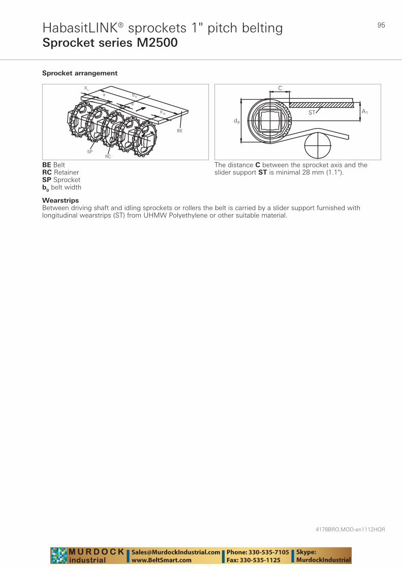
95
4178BRO.MOD-en1112HQR
Sprocket series M2500HabasitLINK® sprockets 1" pitch belting
WearstripsBetween driving shaft and idling sprockets or rollers the belt is carried by a slider support furnished with longitudinal wearstrips (ST) from UHMW Polyethylene or other suitable material.
Sprocket arrangement
BE BeltRC RetainerSP Sprocketb0 belt width
The distance C between the sprocket axis and the slider support ST is minimal 28 mm (1.1").
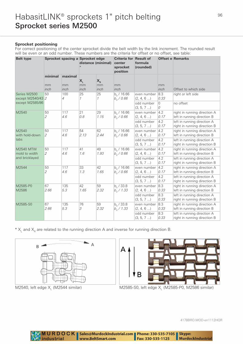
4178BRO.MOD-en1112HQR
96
Sprocket series M2500HabasitLINK® sprockets 1" pitch belting
Sprocket positioning For correct positioning of the center sprocket divide the belt width by the link increment. The rounded result will be even or an odd number. These numbers are the criteria for offset or no offset, see table:Belt type
Sprocket spacing a
Sprocket edgedistance (minimal) *
Criteria for center sprocket position
Result of formula (rounded)
Offset e Remarks
minimal mminch
maximal mminch
XL
mminch
XR
mminch
mminch
mminch Offset to which side
Series M2500 except M2540/43except M2585/86
502
1004
251
251
b0 / 16.66b0 / 0.66
even number (2, 4, 6 ...)
8.30.33
right or left side
odd number (3, 5, 7 ...)
00
no offset
M2540 502
1174.6
210.8
291.15
b0 / 16.66b0 / 0.66
even number (2, 4, 6 ...)
4.20.17
right in running direction Aleft in running direction B
odd number (3, 5, 7 ...)
4.20.17
left in running direction Aright in running direction B
M2540with hold-down tabs
502
1174.6
542.13
622.44
b0 / 16.66b0 / 0.66
even number (2, 4, 6 ...)
4.20.17
right in running direction Aleft in running direction B
odd number (3, 5, 7 ...)
4.20.17
left in running direction Aright in running direction B
M2540 MTW mold to width and bricklayed
502
1174.6
411.6
491.93
b0 / 16.66b0 / 0.66
even number (2, 4, 6 ...)
4.20.17
right in running direction Aleft in running direction B
odd number (3, 5, 7 ...)
4.20.17
left in running direction Aright in running direction B
M2544 502
1174.6
331.3
421.65
b0 / 16.66b0 / 0.66
even number (2, 4, 6 ...)
4.20.17
right in running direction Aleft in running direction B
odd number (3, 5, 7 ...)
4.20.17
left in running direction Aright in running direction B
M2585-P0M2586
672.66
1355.3
421.65
592.32
b0 / 33.8b0 / 1.33
even number (2, 4, 6 ...)
8.30.33
right in running direction Aleft in running direction B
odd number (3, 5, 7 ...)
8.30.33
left in running direction Aright in running direction B
M2585-S0 672.66
1355.3
763
592.32
b0 / 33.8b0 / 1.33
even number (2, 4, 6 ...)
8.30.33
right in running direction Aleft in running direction B
odd number (3, 5, 7 ...)
8.30.33
left in running direction Aright in running direction B
* XL and XR are related to the running direction A and inverse for running direction B.
M2540, left edge XL (M2544 similar) M2585-S0, left edge XL (M2585-P0, M2586 similar)
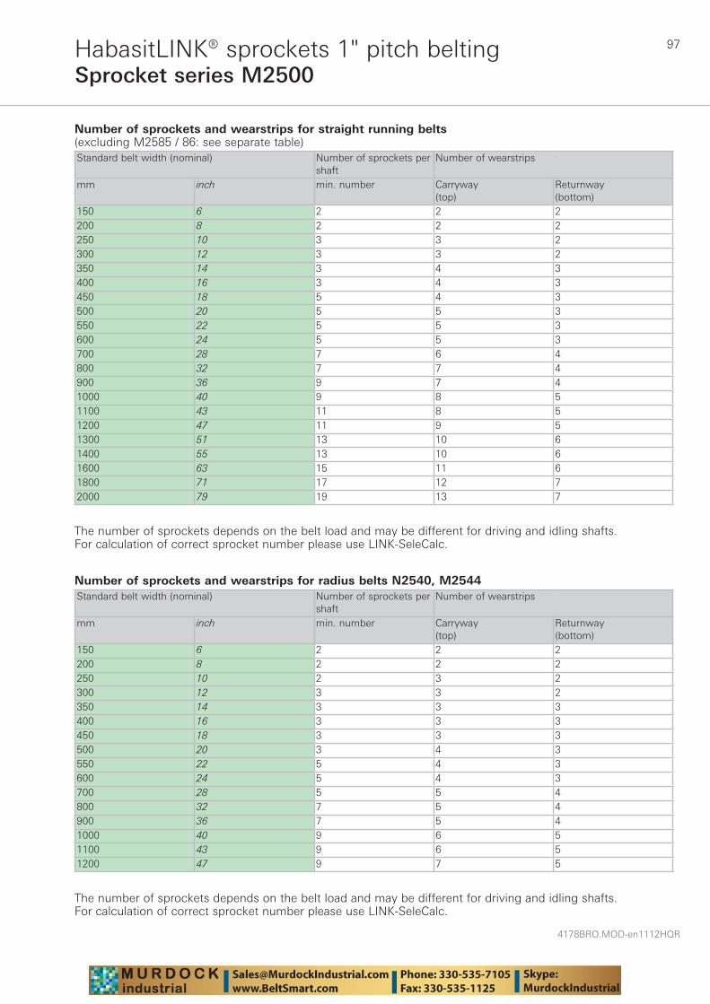
97
4178BRO.MOD-en1112HQR
Sprocket series M2500HabasitLINK® sprockets 1" pitch belting
Number of sprockets and wearstrips for straight running belts(excluding M2585 / 86: see separate table)Standard belt width (nominal) Number of sprockets per
shaftNumber of wearstrips
mm inch min. number Carryway (top)
Returnway (bottom)
150 6 2 2 2200 8 2 2 2250 10 3 3 2300 12 3 3 2350 14 3 4 3400 16 3 4 3450 18 5 4 3500 20 5 5 3550 22 5 5 3600 24 5 5 3700 28 7 6 4800 32 7 7 4900 36 9 7 41000 40 9 8 51100 43 11 8 51200 47 11 9 51300 51 13 10 61400 55 13 10 61600 63 15 11 61800 71 17 12 72000 79 19 13 7
The number of sprockets depends on the belt load and may be different for driving and idling shafts. For calculation of correct sprocket number please use LINK-SeleCalc.
Number of sprockets and wearstrips for radius belts N2540, M2544Standard belt width (nominal) Number of sprockets per
shaftNumber of wearstrips
mm inch min. number Carryway (top)
Returnway (bottom)
150 6 2 2 2200 8 2 2 2250 10 2 3 2300 12 3 3 2350 14 3 3 3400 16 3 3 3450 18 3 3 3500 20 3 4 3550 22 5 4 3600 24 5 4 3700 28 5 5 4800 32 7 5 4900 36 7 5 41000 40 9 6 51100 43 9 6 51200 47 9 7 5
The number of sprockets depends on the belt load and may be different for driving and idling shafts. For calculation of correct sprocket number please use LINK-SeleCalc.
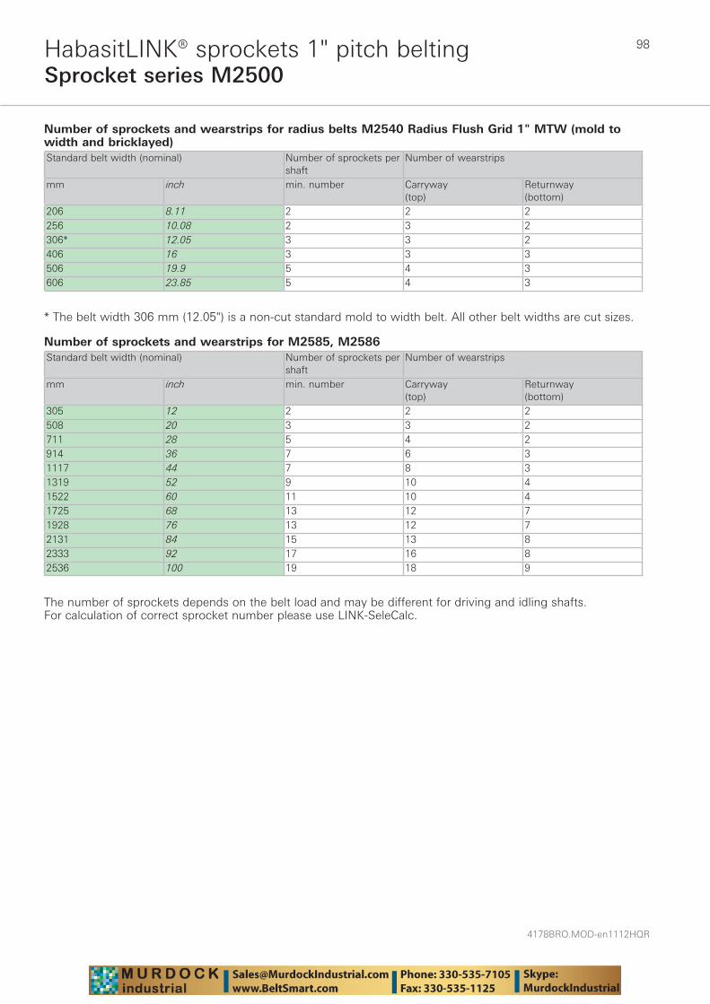
4178BRO.MOD-en1112HQR
98
Sprocket series M2500HabasitLINK® sprockets 1" pitch belting
Number of sprockets and wearstrips for radius belts M2540 Radius Flush Grid 1" MTW (mold to width and bricklayed)Standard belt width (nominal) Number of sprockets per
shaftNumber of wearstrips
mm inch min. number Carryway (top)
Returnway (bottom)
206 8.11 2 2 2256 10.08 2 3 2306* 12.05 3 3 2406 16 3 3 3506 19.9 5 4 3606 23.85 5 4 3
* The belt width 306 mm (12.05") is a non-cut standard mold to width belt. All other belt widths are cut sizes.
Number of sprockets and wearstrips for M2585, M2586Standard belt width (nominal) Number of sprockets per
shaftNumber of wearstrips
mm inch min. number Carryway (top)
Returnway (bottom)
305 12 2 2 2508 20 3 3 2711 28 5 4 2914 36 7 6 31117 44 7 8 31319 52 9 10 41522 60 11 10 41725 68 13 12 71928 76 13 12 72131 84 15 13 82333 92 17 16 82536 100 19 18 9
The number of sprockets depends on the belt load and may be different for driving and idling shafts. For calculation of correct sprocket number please use LINK-SeleCalc.

99
4178BRO.MOD-en1112HQR
Sprocket series M2500-C2 (M2585/86)HabasitLINK® sprockets 1" pitch belting
M = Modular belts
M 25 6Q4012S
Belt pitch
S = sprocket one-piece; Z = split sprocket
Number of teeth
Shaft size
Shaft type: Q = square shaft; R = round shaft
Material: 6 = POM; 8 = PA
Type Number of teeth
Diam. of pitch Ø dp
A1 Hub width BL Square bore Q Ø Round bore R Standard material
mm inch mm inch mm inch mm inch mm inchS-C2 7 59.6 2.4 24.3 0.96 25 0.98 - 1 - - PAS-C2 8 67.7 2.7 28.4 1.12 25 0.98 25 - 30 1 / 1 3/16 PAS-C2 10 83.8 3.3 36.4 1.43 25 0.98 40 1 / 1.5 30 1 / 1 3/16 PAS-C2 12 100.0 3.9 44.5 1.75 25 0.98 40 1 / 1.5 30 / 40 1 / 1 3/16 PAS-C2 15 124.5 4.9 56.8 2.24 25 0.98 60 2.5 - - PAS-C2 16 132.8 5.2 60.9 2.40 25 0.98 40 1.5 - - PAS-C2 18 149.1 5.9 69.1 2.72 25 0.98 40 / 60 1.5 / 2.5 30 1 / 1 3/8 PAS-C2 20 165.5 6.5 77.3 3.04 25 0.98 40 / 60 1.5 / 2.5 30 1 / 1 3/8 PA
Sprocket one-piece (solid)
Sprocket availability
S-C2: machined sprockets. Other sprocket and hub sizes on request.Key ways for round bore shape follow European standards for metric sizes and US standards for imperial sizes. For detailed dimensions see table in the Engineering Guide chapter Design Guide.Other materials available on request.
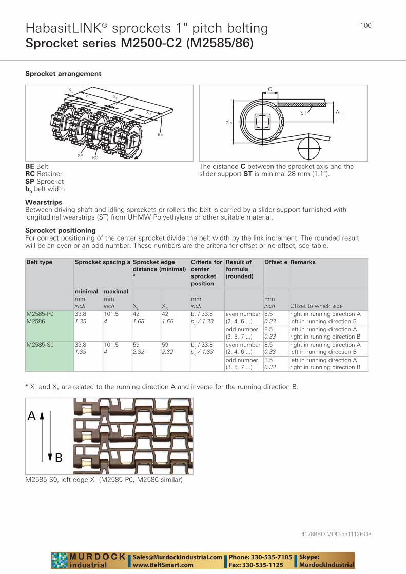
4178BRO.MOD-en1112HQR
100
Sprocket series M2500-C2 (M2585/86)HabasitLINK® sprockets 1" pitch belting
WearstripsBetween driving shaft and idling sprockets or rollers the belt is carried by a slider support furnished with longitudinal wearstrips (ST) from UHMW Polyethylene or other suitable material.
Sprocket arrangement
BE BeltRC RetainerSP Sprocketb0 belt width
The distance C between the sprocket axis and the slider support ST is minimal 28 mm (1.1").
Sprocket positioningFor correct positioning of the center sprocket divide the belt width by the link increment. The rounded result will be an even or an odd number. These numbers are the criteria for offset or no offset, see table.
Belt type Sprocket spacing a Sprocket edge distance (minimal) *
Criteria for center sprocket position
Result of formula (rounded)
Offset e Remarks
minimalmminch
maximalmminch XL XR
mminch
mminch Offset to which side
M2585-P0M2586
33.81.33
101.54
421.65
421.65
b0 / 33.8b0 / 1.33
even number (2, 4, 6 ...)
8.50.33
right in running direction Aleft in running direction B
odd number (3, 5, 7 ...)
8.50.33
left in running direction Aright in running direction B
M2585-S0 33.81.33
101.54
592.32
592.32
b0 / 33.8b0 / 1.33
even number (2, 4, 6 ...)
8.50.33
right in running direction Aleft in running direction B
odd number (3, 5, 7 ...)
8.50.33
left in running direction Aright in running direction B
* XL and XR are related to the running direction A and inverse for the running direction B.
M2585-S0, left edge XL (M2585-P0, M2586 similar)
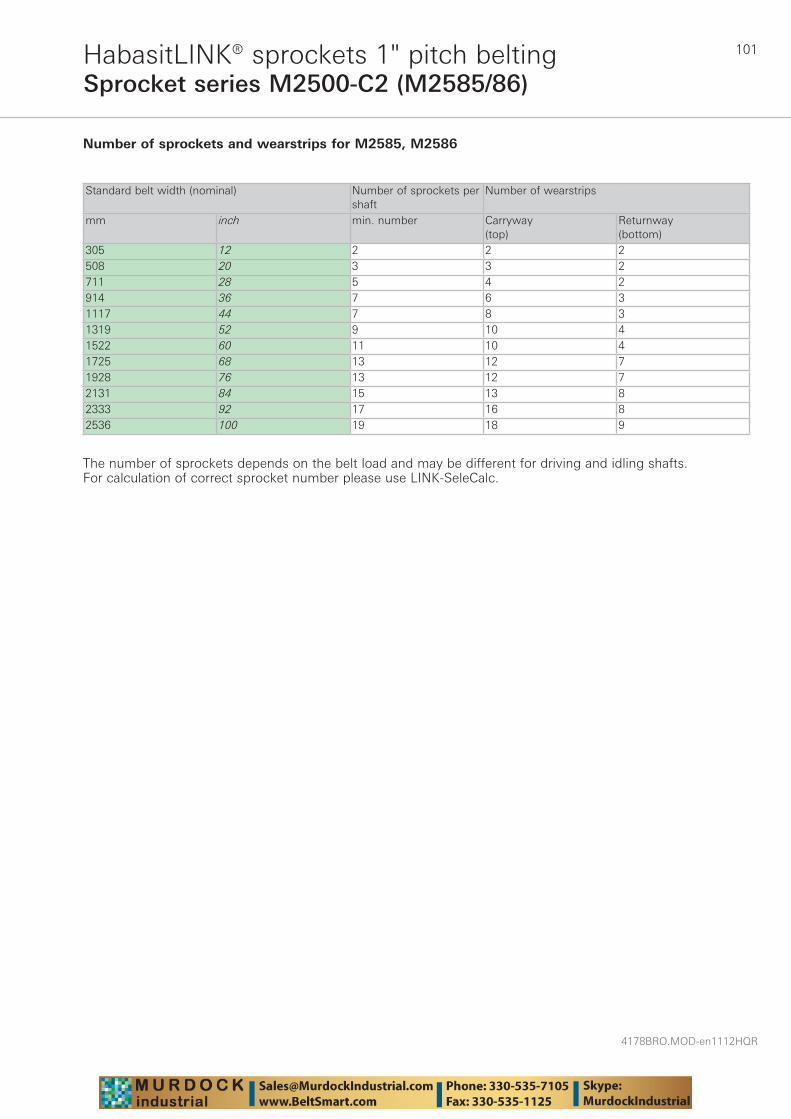
101
4178BRO.MOD-en1112HQR
Sprocket series M2500-C2 (M2585/86)HabasitLINK® sprockets 1" pitch belting
Number of sprockets and wearstrips for M2585, M2586
Standard belt width (nominal) Number of sprockets per shaft
Number of wearstrips
mm inch min. number Carryway (top)
Returnway (bottom)
305 12 2 2 2508 20 3 3 2711 28 5 4 2914 36 7 6 31117 44 7 8 31319 52 9 10 41522 60 11 10 41725 68 13 12 71928 76 13 12 72131 84 15 13 82333 92 17 16 82536 100 19 18 9
The number of sprockets depends on the belt load and may be different for driving and idling shafts. For calculation of correct sprocket number please use LINK-SeleCalc.
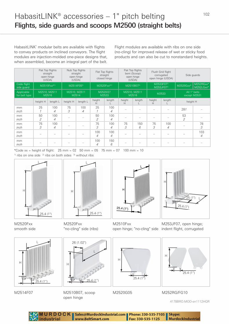
4178BRO.MOD-en1112HQR
102HabasitLINK® accessories – 1" pitch beltingFlights, side guards and scoops M2500 (straight belts)
HabasitLINK® modular belts are available with flights to convey products on inclined conveyors. The flight modules are injection-molded one-piece designs that, when assembled, become an integral part of the belt.
Flight modules are available with ribs on one side (no-cling) for improved release of wet or sticky food products and can also be cut to nonstandard heights.
L
H
25.4 (1")
L
H
25.4 (1")
25.4 (1")
L
H
H
25.4 (1")
L25 (1")
Flat Top flights straight
open hinge (USDA)
Nub Top flights straight
open hinge (USDA)
Flat Top flights straight
closed hinge
Flat Top flights bent (Scoop)open hinge
(USDA)
Flush Grid flight corrugated
open hinge (USDA)Side guards
Code flight side guard
M2510Fxx*1) M2514F052) M2520Fxx*1) M2510B073) M2533F073) M253JF073) M2520Gxx*
M252RGxx*M252LGxx*
Applicablefor belt type
M2510, M2511M2516
M2510, M2511M2514
M2520/27M2533
M2510, M2511M2516
M2533All 1" belts
except M2531
height H length L height H length Lheight
Hlength
Lheight
Hlength
Lheight
Hlength
Lheight H
mminch
251
1004
753
1004
251
1004
– – – – 281 –
mminch
502
1004
– –502
1004
– – – –532
–
mminch
753
1004
– –753
1004
753
1506
753
1004
–783
mminch
– – – –1004
1004
– – – – –1034
mminch
– – – –100
4150
6– – – – – –
*Code xx = height of flight: 25 mm = 02 50 mm = 05 75 mm = 07 100 mm = 101) ribs on one side 2) ribs on both sides 3) without ribs
M2520Fxx smooth side
M2520Fxx"no-cling" side (ribs)
M2510Fxx open hinge; "no-cling" side
M253JF07, open hinge; indent flight, corrugated
M2510B07, scoopopen hinge
M2520G05 M252RG/FG10
H
H
L
26 (1.02")
M2514F07
H
L
H
L
25.4 (1“)
25.4 (1“)
25.4 (1“)
H
25.4 (1“)
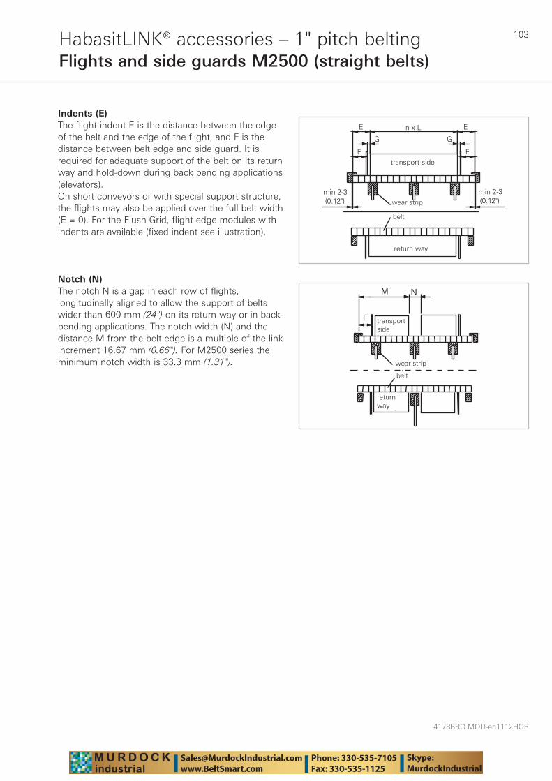
103
4178BRO.MOD-en1112HQR
HabasitLINK® accessories – 1" pitch beltingFlights and side guards M2500 (straight belts)
Indents (E)The flight indent E is the distance between the edge of the belt and the edge of the flight, and F is the distance between belt edge and side guard. It is required for adequate support of the belt on its return way and hold-down during back bending applications (elevators). On short conveyors or with special support structure, the flights may also be applied over the full belt width (E = 0). For the Flush Grid, flight edge modules with indents are available (fixed indent see illustration).
Notch (N)The notch N is a gap in each row of flights, longitudinally aligned to allow the support of belts wider than 600 mm (24") on its return way or in back-bending applications. The notch width (N) and the distance M from the belt edge is a multiple of the link increment 16.67 mm (0.66"). For M2500 series the minimum notch width is 33.3 mm (1.31"). wear strip
transp.side
M
F
belt
N
returnway
transport side
return way
wear strip
belt
wear strip
belt
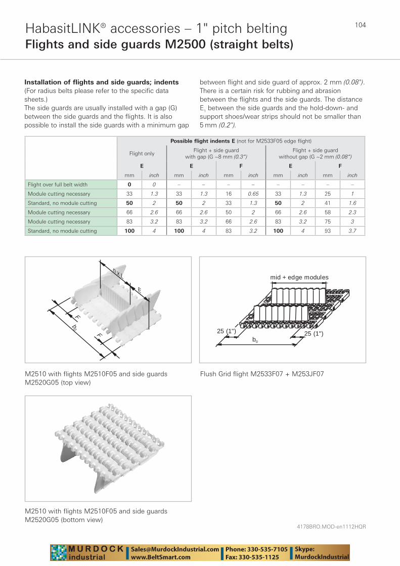
4178BRO.MOD-en1112HQR
104HabasitLINK® accessories – 1" pitch beltingFlights and side guards M2500 (straight belts)
Installation of flights and side guards; indents (For radius belts please refer to the specific data sheets.)The side guards are usually installed with a gap (G) between the side guards and the flights. It is also possible to install the side guards with a minimum gap
between flight and side guard of approx. 2 mm (0.08"). There is a certain risk for rubbing and abrasion between the flights and the side guards. The distance E1 between the side guards and the hold-down- and support shoes/wear strips should not be smaller than 5 mm (0.2").
n x L
E
b0
F
F
mid + edge modules
25 (1") 25 (1")0b
M2510 with flights M2510F05 and side guards M2520G05 (top view)
Flush Grid flight M2533F07 + M253JF07
M2510 with flights M2510F05 and side guards M2520G05 (bottom view)
Possible flight indents E (not for M2533F05 edge flight)
Flight onlyFlight + side guard
with gap (G ~8 mm (0.3“)Flight + side guard
without gap (G ~2 mm (0.08“)
E E F E F
mm inch mm inch mm inch mm inch mm inch
Flight over full belt width 0 0 – – – – – – – –
Module cutting necessary 33 1.3 33 1.3 16 0.65 33 1.3 25 1
Standard, no module cutting 50 2 50 2 33 1.3 50 2 41 1.6
Module cutting necessary 66 2.6 66 2.6 50 2 66 2.6 58 2.3
Module cutting necessary 83 3.2 83 3.2 66 2.6 83 3.2 75 3
Standard, no module cutting 100 4 100 4 83 3.2 100 4 93 3.7

105
4178BRO.MOD-en1112HQR
HabasitLINK® accessories – 1" pitch beltingHold-down devices for M2500 (straight belts)
For elevators with back-bending (Z-conveyors) hold-down devices are used to keep the belt down when it is changing from horizontal to inclined direction. For wide belts (e.g. > 600 mm (23.6") wide), slider shoes on the belt edge are often not sufficient to keep it on the track. In such cases hold-down devices on the bottom side of the belt are used to guide it through the back-bending curve. Further details see design guide.
Compatibility: The hold-down device can be put into M2500 1" HabasitLINK® straight-running modular belt. The modules are inserted into the prepared position, one module every second row. As long as link increment is (16.6 mm) respected, any position over the belt width is possible. For a center positioning consider an offset "e" of 4.2 mm. Allow the necessary distance for the sprocket engagement!
Back bending radius R: min 250 mm (10")
Sprockets: minimum sizeM25S12 with 40 mm / 1.5" square boreM25S12 with 30 mm round boreM25S10 with 1" square boreM25S10 with 30 mm round bore
Standard materials: POM whiteOther materials on request.
M2533 with M2500V01
15(0.59")
8 (0.32")
e = 4.2 (0.16")Belt center line
25.5 (1")
6 max(0.24")
R
guide rail
hold down device
It is very important that the guide rail is very smooth, without joining. It is also important that enough clearance is provided to allow the belt to expand or shrink.
Hold-down device M2500V01
25.5 (1")
16 (0.63")
4 (0.16")
hold-down device
guide rail
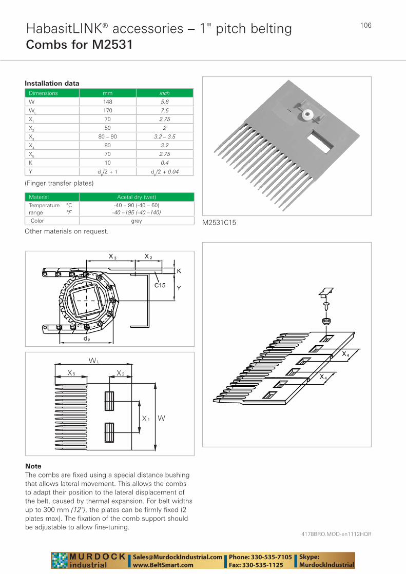
4178BRO.MOD-en1112HQR
106HabasitLINK® accessories – 1" pitch beltingCombs for M2531
X4
X4
NoteThe combs are fixed using a special distance bushing that allows lateral movement. This allows the combs to adapt their position to the lateral displacement of the belt, caused by thermal expansion. For belt widths up to 300 mm (12"), the plates can be firmly fixed (2 plates max). The fixation of the comb support should be adjustable to allow fine-tuning.
Installation dataDimensions mm inch
W 148 5.8
WL 170 7.5
X1 70 2.75
X2 50 2
X3 80 – 90 3.2 – 3.5
X4 80 3.2
X5 70 2.75
K 10 0.4
Y dp/2 + 1 dp/2 + 0.04
(Finger transfer plates)
Material Acetal dry (wet)
Temperature °Crange °F
-40 – 90 (-40 – 60)-40 –195 (-40 –140)
Color grey
Other materials on request.M2531C15
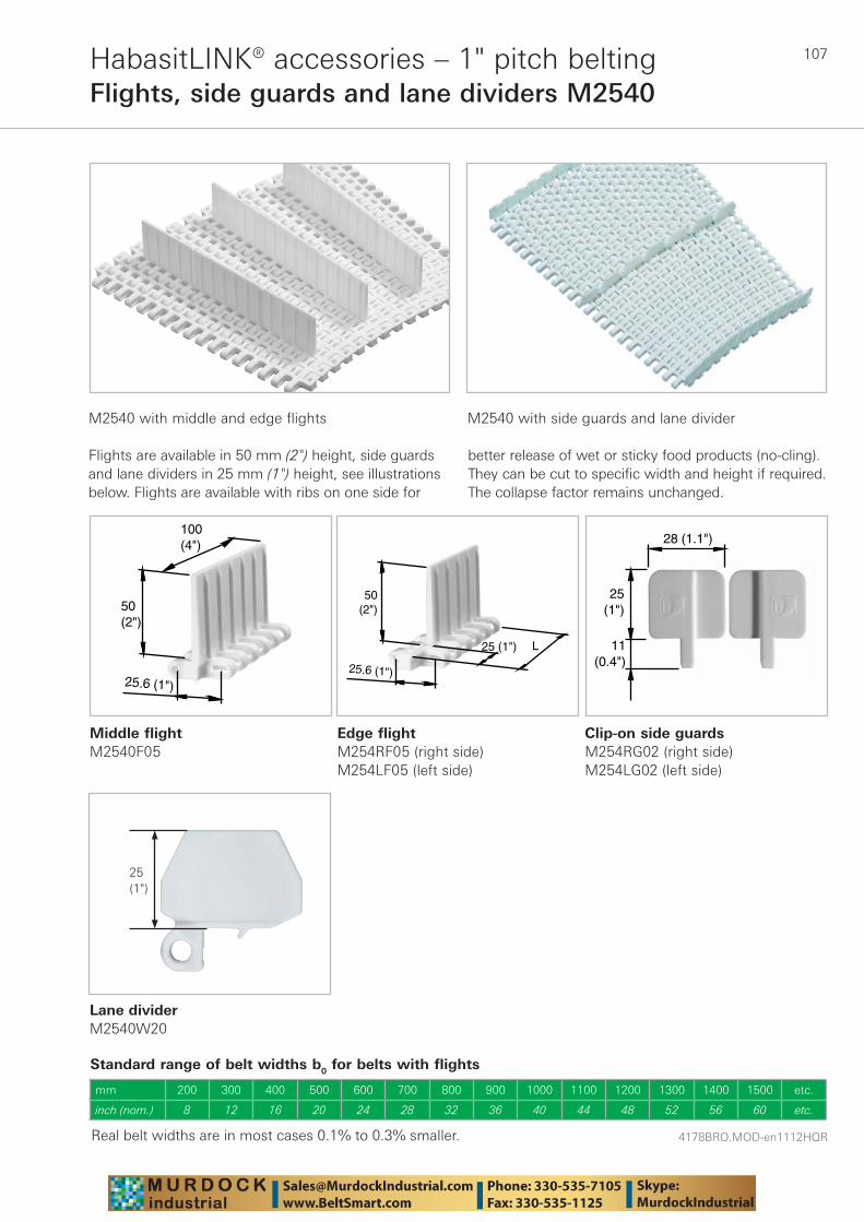
107
4178BRO.MOD-en1112HQR
HabasitLINK® accessories – 1" pitch beltingFlights, side guards and lane dividers M2540
M2540 with middle and edge flights M2540 with side guards and lane divider
Flights are available in 50 mm (2") height, side guards and lane dividers in 25 mm (1") height, see illustrations below. Flights are available with ribs on one side for
better release of wet or sticky food products (no-cling). They can be cut to specific width and height if required. The collapse factor remains unchanged.
Middle flightM2540F05
Standard range of belt widths b0 for belts with flights
25.6 (1")
100(4")
50(2")
25.6 (1")
50(2")
25 (1") L
25(1")
28 (1.1")
11(0.4")
Real belt widths are in most cases 0.1% to 0.3% smaller.
mm 200 300 400 500 600 700 800 900 1000 1100 1200 1300 1400 1500 etc.
inch (nom.) 8 12 16 20 24 28 32 36 40 44 48 52 56 60 etc.
Lane dividerM2540W20
25(1")
Edge flightM254RF05 (right side)M254LF05 (left side)
Clip-on side guardsM254RG02 (right side)M254LG02 (left side)
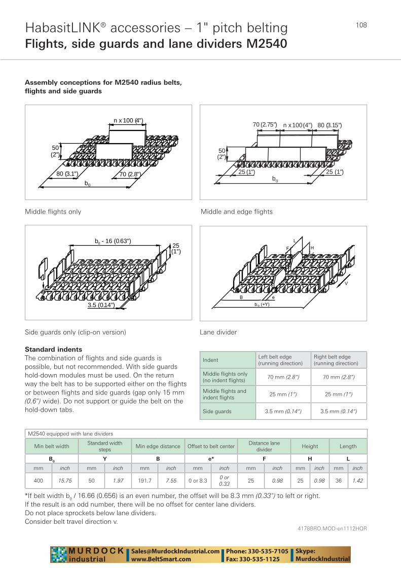
4178BRO.MOD-en1112HQR
108HabasitLINK® accessories – 1" pitch beltingFlights, side guards and lane dividers M2540
Assembly conceptions for M2540 radius belts, flights and side guards
Middle flights only Middle and edge flights
25 (1")25 (1")
50(2")
n x 100 (4")70 (2.75") 80 (3.15")
b0
80 (3.1")
b
n x 100 (4")
70 (2.8")
50(2")
0
25(1")
3.5 (0.14")
b - 16 (0.63")0
Side guards only (clip-on version)
Standard indentsThe combination of flights and side guards is possible, but not recommended. With side guards hold-down modules must be used. On the return way the belt has to be supported either on the flights or between flights and side guards (gap only 15 mm (0.6") wide). Do not support or guide the belt on the hold-down tabs.
Lane divider
IndentLeft belt edge(running direction)
Right belt edge(running direction)
Middle fl ights only (no indent fl ights)
70 mm (2.8“) 70 mm (2.8“)
Middle fl ights and indent fl ights
25 mm (1“) 25 mm (1“)
Side guards 3.5 mm (0.14“) 3.5 mm (0.14“)
M2540 equipped with lane dividers
Min belt widthStandard width
stepsMin edge distance Offset to belt center
Distance lane divider
Height Length
B0 Y B e* F H L
mm inch mm inch mm inch mm inch mm inch mm inch mm inch
400 15.75 50 1.97 191.7 7.55 0 or 8.30 or 0.33
25 0.98 25 0.98 36 1.42
*If belt width b0 / 16.66 (0.656) is an even number, the offset will be 8.3 mm (0.33") to left or right.If the result is an odd number, there will be no offset for center lane dividers. Do not place sprockets below lane dividers.Consider belt travel direction v.
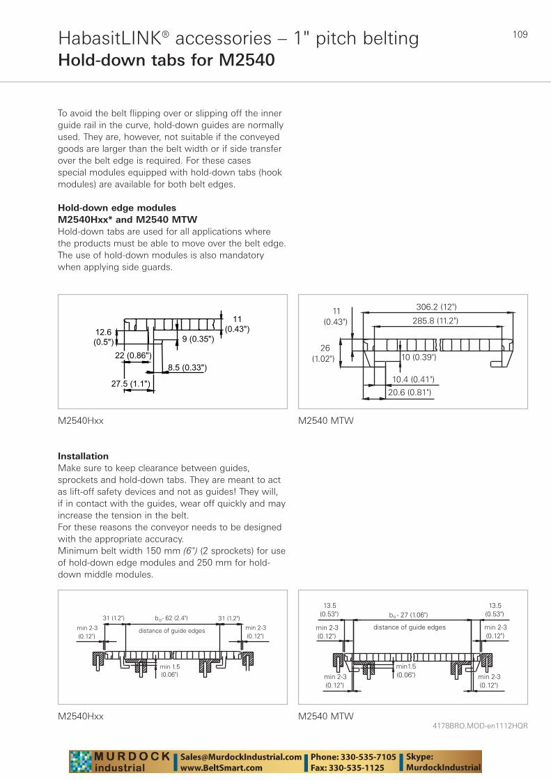
109
4178BRO.MOD-en1112HQR
HabasitLINK® accessories – 1" pitch beltingHold-down tabs for M2540
To avoid the belt flipping over or slipping off the inner guide rail in the curve, hold-down guides are normally used. They are, however, not suitable if the conveyed goods are larger than the belt width or if side transfer over the belt edge is required. For these cases special modules equipped with hold-down tabs (hook modules) are available for both belt edges.
Hold-down edge modules M2540Hxx* and M2540 MTWHold-down tabs are used for all applications where the products must be able to move over the belt edge. The use of hold-down modules is also mandatory when applying side guards.
8.5 (0.33") 22 (0.86")
9 (0.35") 12.6 (0.5")
11 (0.43")
27.5 (1.1")
M2540Hxx M2540 MTW
M2540Hxx M2540 MTW
InstallationMake sure to keep clearance between guides, sprockets and hold-down tabs. They are meant to act as lift-off safety devices and not as guides! They will, if in contact with the guides, wear off quickly and may increase the tension in the belt.For these reasons the conveyor needs to be designed with the appropriate accuracy.Minimum belt width 150 mm (6") (2 sprockets) for use of hold-down edge modules and 250 mm for hold-down middle modules.
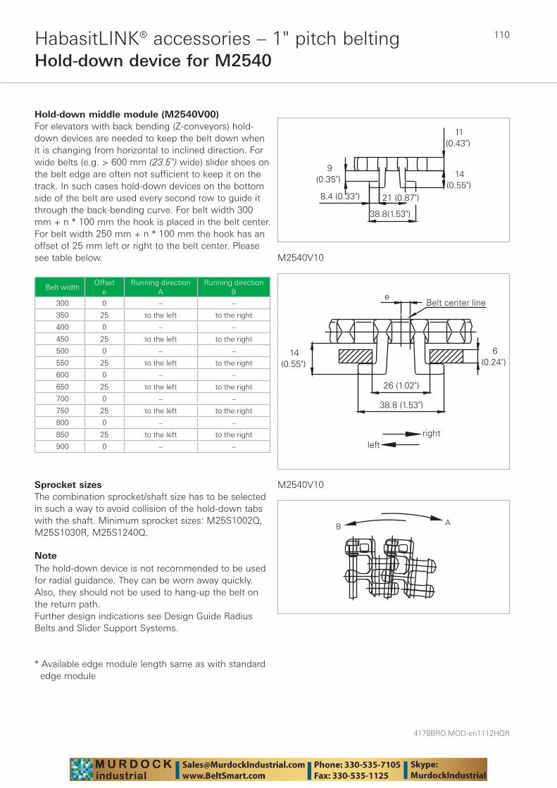
4178BRO.MOD-en1112HQR
110HabasitLINK® accessories – 1" pitch beltingHold-down device for M2540
Hold-down middle module (M2540V00)For elevators with back bending (Z-conveyors) hold-down devices are needed to keep the belt down when it is changing from horizontal to inclined direction. For wide belts (e.g. > 600 mm (23.5") wide) slider shoes on the belt edge are often not sufficient to keep it on the track. In such cases hold-down devices on the bottom side of the belt are used every second row to guide it through the back-bending curve. For belt width 300 mm + n * 100 mm the hook is placed in the belt center. For belt width 250 mm + n * 100 mm the hook has an offset of 25 mm left or right to the belt center. Please see table below.
Belt widthOffset
eRunning direction
ARunning direction
B
300 0 – –
350 25 to the left to the right
400 0 – –
450 25 to the left to the right
500 0 – –
550 25 to the left to the right
600 0 – –
650 25 to the left to the right
700 0 – –
750 25 to the left to the right
800 0 – –
850 25 to the left to the right
900 0 – –
Sprocket sizesThe combination sprocket/shaft size has to be selected in such a way to avoid collision of the hold-down tabs with the shaft. Minimum sprocket sizes: M25S1002Q, M25S1030R, M25S1240Q.
NoteThe hold-down device is not recommended to be used for radial guidance. They can be worn away quickly. Also, they should not be used to hang-up the belt on the return path.Further design indications see Design Guide Radius Belts and Slider Support Systems.
* Available edge module length same as with standard edge module
M2540V10
M2540V10
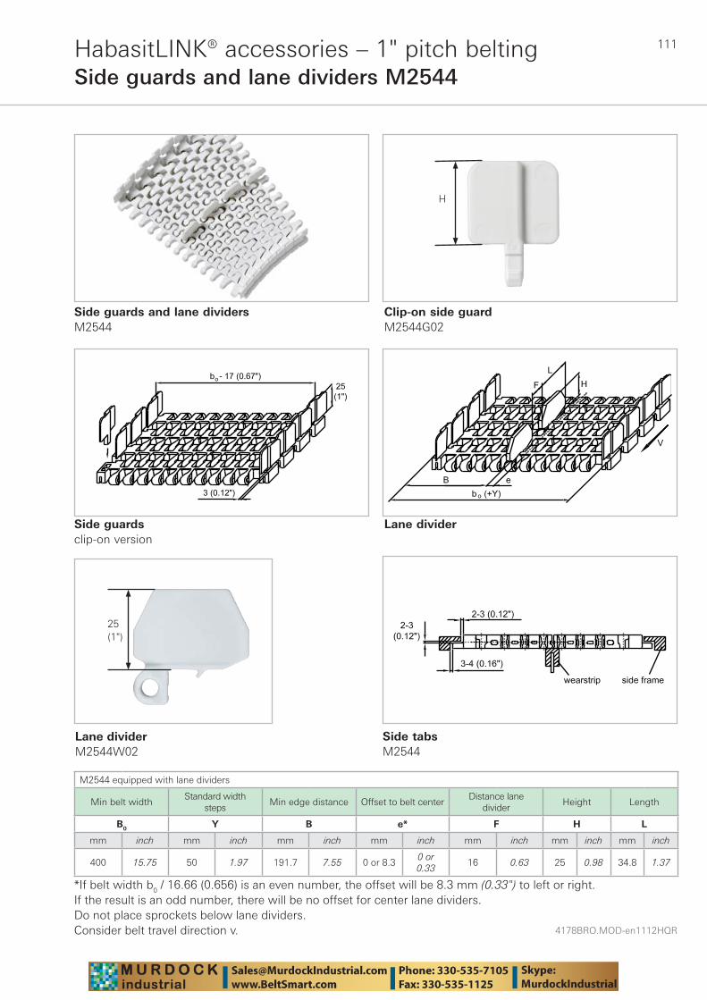
111
4178BRO.MOD-en1112HQR
HabasitLINK® accessories – 1" pitch beltingSide guards and lane dividers M2544
Side guards and lane dividersM2544
Clip-on side guardM2544G02
Side guards clip-on version
Lane divider
M2544 equipped with lane dividers
Min belt widthStandard width
stepsMin edge distance Offset to belt center
Distance lane divider
Height Length
B0 Y B e* F H L
mm inch mm inch mm inch mm inch mm inch mm inch mm inch
400 15.75 50 1.97 191.7 7.55 0 or 8.30 or 0.33
16 0.63 25 0.98 34.8 1.37
*If belt width b0 / 16.66 (0.656) is an even number, the offset will be 8.3 mm (0.33") to left or right.If the result is an odd number, there will be no offset for center lane dividers. Do not place sprockets below lane dividers.Consider belt travel direction v.
H
Lane dividerM2544W02
25(1")
Side tabs M2544
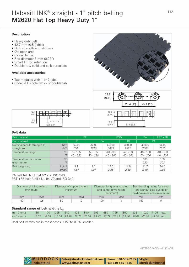
4178BRO.MOD-en1112HQR
112
M2620 Flat Top Heavy Duty 1"HabasitLINK® straight - 1" pitch belting
Belt data
Standard range of belt widths b0
mm (nom.) 85 170 255 340 425 510 595 680 765 850 935 1020 1105 etc.inch (nom.) 3.35 6.69 10.04 13.39 16.73 20.08 23.43 26.77 30.12 33.46 36.81 40.16 43.50 etc.
Real belt widths are in most cases 0.1% to 0.3% smaller.
Belt material PP POM PA PBT +FRRod material PP PA PBT PANominal tensile strength F'N straight run
N/mlb/ft
240001644
265001815
450003083
350002397
450003083
230001575
Temperature range °C°F
5 - 10540 - 220
5 - 10540 - 220
-40 - 93-40 - 200
-40 - 93-40 - 200
-46 - 130-50 - 266
-40 - 130-40 - 266
Temperature maximum (short-term)
°C°F
160320
150302
Belt weight mB kg/m²lb/sqft
9.11.87
9.11.87
14.02.88
14.02.88
11.72.40
14.52.98
25.4 (1")
12.7(0.5")
25.4 (1")
Description
• Heavy duty belt • 12.7 mm (0.5”) thick • High strength and stiffness • 0% open area • Closed hinge • Rod diameter 6 mm (0.22”) • Smart Fit rod retention • Double row solid and split sprockets
Available accessories
• Tab modules with 1 or 2 tabs • Code: -T1 single tab / -T2 double tab
PA belt fulfills UL 94 V2 and ISO 340.PBT +FR belt fulfills UL 94 V0 and ISO 340.
Diameter of idling rollers (minimum)
Diameter of support rollers(minimum)
Diameter for gravity take-up and center drive rollers
(minimum)
Backbending radius for eleva-tors without side guards or
hold-down devices (minimum)mm inch mm inch mm inch mm inch40 1.6 50 2 100 4 150 6
113
4178BRO.MOD-en1112HQR
Standard belt widths in increments of 85 mm (3.35"). Non-standard widths are offered in increments of 17 mm (0.67"). Smallest possible width 85 mm (3.35").For detailed material properties refer to pages 282 - 289.
M2620 Flat Top Heavy Duty 1"HabasitLINK® straight - 1" pitch belting
The nominal tensile strength is valid for 23 °C (73 °F). The admissible tensile force depends on the operating temperature near the drive sprockets. Within the temperature range allowed, the admissible tensile force may vary from 100% to 20% of the nominal tensile strength. For detailed information and correct calculation of effective tensile force refer to the Calculation Guide in the HabasitLINK® Engineering Guidelines.
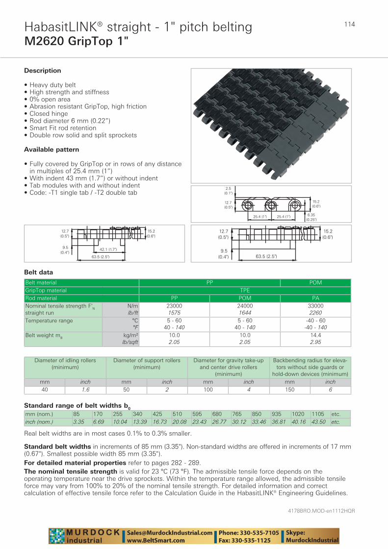
4178BRO.MOD-en1112HQR
114
M2620 GripTop 1"HabasitLINK® straight - 1" pitch belting
Belt data
Standard range of belt widths b0
mm (nom.) 85 170 255 340 425 510 595 680 765 850 935 1020 1105 etc.inch (nom.) 3.35 6.69 10.04 13.39 16.73 20.08 23.43 26.77 30.12 33.46 36.81 40.16 43.50 etc.
Real belt widths are in most cases 0.1% to 0.3% smaller.
Belt material PP POMGripTop material TPERod material PP POM PANominal tensile strength F'N straight run
N/mlb/ft
230001575
240001644
330002260
Temperature range °C°F
5 - 6040 - 140
5 - 6040 - 140
-40 - 60-40 - 140
Belt weight mB kg/m²lb/sqft
10.02.05
10.02.05
14.42.95
Description
• Heavy duty belt • High strength and stiffness • 0% open area • Abrasion resistant GripTop, high friction • Closed hinge • Rod diameter 6 mm (0.22”) • Smart Fit rod retention • Double row solid and split sprockets
Available pattern
• Fully covered by GripTop or in rows of any distance in multiples of 25.4 mm (1”)
• With indent 43 mm (1.7”) or without indent• Tab modules with and without indent• Code: -T1 single tab / -T2 double tab
Diameter of idling rollers (minimum)
Diameter of support rollers(minimum)
Diameter for gravity take-up and center drive rollers
(minimum)
Backbending radius for eleva-tors without side guards or
hold-down devices (minimum)mm inch mm inch mm inch mm inch40 1.6 50 2 100 4 150 6
Standard belt widths in increments of 85 mm (3.35"). Non-standard widths are offered in increments of 17 mm (0.67"). Smallest possible width 85 mm (3.35").For detailed material properties refer to pages 282 - 289.The nominal tensile strength is valid for 23 °C (73 °F). The admissible tensile force depends on the operating temperature near the drive sprockets. Within the temperature range allowed, the admissible tensile force may vary from 100% to 20% of the nominal tensile strength. For detailed information and correct calculation of effective tensile force refer to the Calculation Guide in the HabasitLINK® Engineering Guidelines.
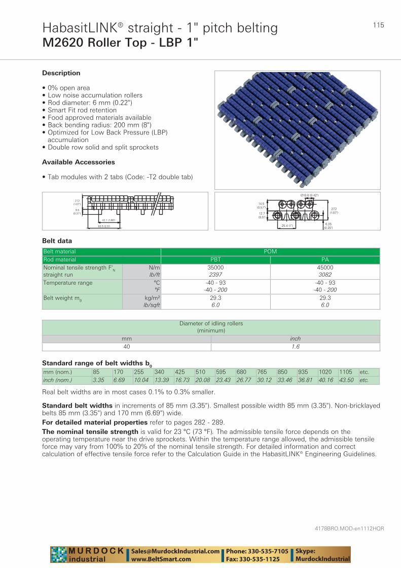
115
4178BRO.MOD-en1112HQR
M2620 Roller Top - LBP 1"HabasitLINK® straight - 1" pitch belting
Belt data
Standard range of belt widths b0
mm (nom.) 85 170 255 340 425 510 595 680 765 850 935 1020 1105 etc.inch (nom.) 3.35 6.69 10.04 13.39 16.73 20.08 23.43 26.77 30.12 33.46 36.81 40.16 43.50 etc.
Real belt widths are in most cases 0.1% to 0.3% smaller.
Belt material POMRod material PBT PANominal tensile strength F'N straight run
N/mlb/ft
350002397
450003082
Temperature range °C°F
-40 - 93-40 - 200
-40 - 93-40 - 200
Belt weight mB kg/m²lb/sqft
29.36.0
29.36.0
Description
• 0% open area • Low noise accumulation rollers • Rod diameter: 6 mm (0.22") • Smart Fit rod retention • Food approved materials available• Back bending radius: 200 mm (8") • Optimized for Low Back Pressure (LBP)
accumulation • Double row solid and split sprockets
Available Accessories
• Tab modules with 2 tabs (Code: -T2 double tab)
Diameter of idling rollers (minimum)
mm inch40 1.6
Standard belt widths in increments of 85 mm (3.35"). Smallest possible width 85 mm (3.35"). Non-bricklayed belts 85 mm (3.35") and 170 mm (6.69") wide.For detailed material properties refer to pages 282 - 289.The nominal tensile strength is valid for 23 °C (73 °F). The admissible tensile force depends on the operating temperature near the drive sprockets. Within the temperature range allowed, the admissible tensile force may vary from 100% to 20% of the nominal tensile strength. For detailed information and correct calculation of effective tensile force refer to the Calculation Guide in the HabasitLINK® Engineering Guidelines.
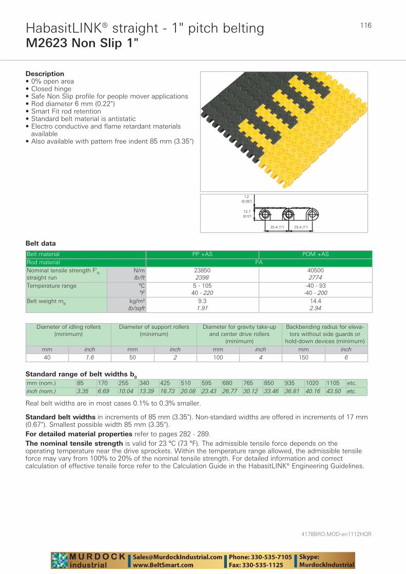
4178BRO.MOD-en1112HQR
116
M2623 Non Slip 1"HabasitLINK® straight - 1" pitch belting
Belt data
Standard range of belt widths b0
mm (nom.) 85 170 255 340 425 510 595 680 765 850 935 1020 1105 etc.inch (nom.) 3.35 6.69 10.04 13.39 16.73 20.08 23.43 26.77 30.12 33.46 36.81 40.16 43.50 etc.
Real belt widths are in most cases 0.1% to 0.3% smaller.
Belt material PP +AS POM +ASRod material PANominal tensile strength F'N straight run
N/mlb/ft
238502398
405002774
Temperature range °C°F
5 - 10540 - 220
-40 - 93-40 - 200
Belt weight mB kg/m²lb/sqft
9.31.91
14.42.94
Description• 0% open area • Closed hinge • Safe Non Slip profile for people mover applications • Rod diameter 6 mm (0.22") • Smart Fit rod retention • Standard belt material is antistatic• Electro conductive and flame retardant materials
available • Also available with pattern free indent 85 mm (3.35")
Diameter of idling rollers (minimum)
Diameter of support rollers(minimum)
Diameter for gravity take-up and center drive rollers
(minimum)
Backbending radius for eleva-tors without side guards or
hold-down devices (minimum)mm inch mm inch mm inch mm inch40 1.6 50 2 100 4 150 6
Standard belt widths in increments of 85 mm (3.35"). Non-standard widths are offered in increments of 17 mm (0.67"). Smallest possible width 85 mm (3.35").For detailed material properties refer to pages 282 - 289.The nominal tensile strength is valid for 23 °C (73 °F). The admissible tensile force depends on the operating temperature near the drive sprockets. Within the temperature range allowed, the admissible tensile force may vary from 100% to 20% of the nominal tensile strength. For detailed information and correct calculation of effective tensile force refer to the Calculation Guide in the HabasitLINK® Engineering Guidelines.
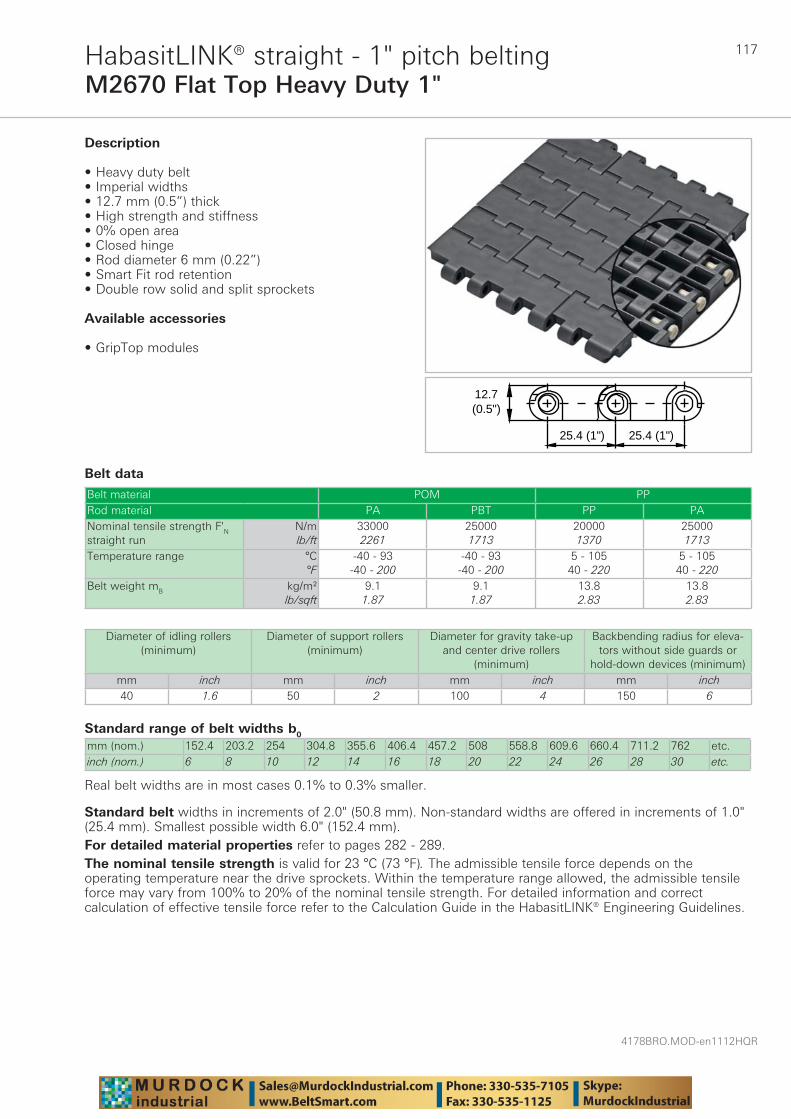
117
4178BRO.MOD-en1112HQR
M2670 Flat Top Heavy Duty 1"HabasitLINK® straight - 1" pitch belting
Belt data
Standard range of belt widths b0
mm (nom.) 152.4 203.2 254 304.8 355.6 406.4 457.2 508 558.8 609.6 660.4 711.2 762 etc.inch (nom.) 6 8 10 12 14 16 18 20 22 24 26 28 30 etc.
Real belt widths are in most cases 0.1% to 0.3% smaller.
Belt material POM PPRod material PA PBT PP PANominal tensile strength F'N straight run
N/mlb/ft
330002261
250001713
200001370
250001713
Temperature range °C°F
-40 - 93-40 - 200
-40 - 93-40 - 200
5 - 10540 - 220
5 - 10540 - 220
Belt weight mB kg/m²lb/sqft
9.11.87
9.11.87
13.82.83
13.82.83
25.4 (1")
12.7(0.5")
25.4 (1")
Description
• Heavy duty belt • Imperial widths • 12.7 mm (0.5”) thick • High strength and stiffness • 0% open area • Closed hinge • Rod diameter 6 mm (0.22”) • Smart Fit rod retention • Double row solid and split sprockets
Available accessories
• GripTop modules
Diameter of idling rollers (minimum)
Diameter of support rollers(minimum)
Diameter for gravity take-up and center drive rollers
(minimum)
Backbending radius for eleva-tors without side guards or
hold-down devices (minimum)mm inch mm inch mm inch mm inch40 1.6 50 2 100 4 150 6
Standard belt widths in increments of 2.0" (50.8 mm). Non-standard widths are offered in increments of 1.0" (25.4 mm). Smallest possible width 6.0" (152.4 mm).For detailed material properties refer to pages 282 - 289.The nominal tensile strength is valid for 23 °C (73 °F). The admissible tensile force depends on the operating temperature near the drive sprockets. Within the temperature range allowed, the admissible tensile force may vary from 100% to 20% of the nominal tensile strength. For detailed information and correct calculation of effective tensile force refer to the Calculation Guide in the HabasitLINK® Engineering Guidelines.
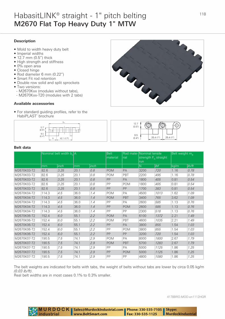
4178BRO.MOD-en1112HQR
118
M2670 Flat Top Heavy Duty 1" MTWHabasitLINK® straight - 1" pitch belting
Belt data
Description
• Mold to width heavy duty belt • Imperial widths • 12.7 mm (0.5”) thick • High strength and stiffness • 0% open area • Closed hinge • Rod diameter 6 mm (0.22”) • Smart Fit rod retention • Double row solid and split sprockets • Two versions: - M2670Kxx (modules without tabs), - M2670Kxx-T20 (modules with 2 tabs)
Available accessories
• For standard guiding profiles, refer to the HabiPLAST® brochure
Nominal belt width b0 A Belt material
Rod mate-rial
Nominal tensile strength FN straight run
Belt weight mB
mm inch mm inch N lbf kg/m lb/ftM2670K03-T2 82.6 3.25 20.1 0.8 POM PA 3200 720 1.16 0.78M2670K03-T2 82.6 3.25 20.1 0.8 POM PBT 2200 495 1.16 0.78M2670K03-T2 82.6 3.25 20.1 0.8 PP PA 1800 405 0.81 0.54M2670K03-T2 82.6 3.25 20.1 0.8 PP POM 1800 405 0.81 0.54M2670K03-T2 82.6 3.25 20.1 0.8 PP PP 1700 383 0.81 0.54M2670K04-T2 114.3 4.5 36.0 1.4 POM PA 4500 1013 1.62 1.09M2670K04-T2 114.3 4.5 36.0 1.4 POM PBT 3400 765 3.62 1.09M2670K04-T2 114.3 4.5 36.0 1.4 PP PA 2600 585 1.13 0.76M2670K04-T2 114.3 4.5 36.0 1.4 PP POM 2600 585 1.13 0.76M2670K04-T2 114.3 4.5 36.0 1.4 PP PP 2300 518 1.13 0.76M2670K06-T2 152.4 6.0 55.1 2.2 POM PA 6100 1372 2.21 1.49M2670K06-T2 152.4 6.0 55.1 2.2 POM PBT 4600 1035 2.21 1.49M2670K06-T2 152.4 6.0 55.1 2.2 PP PA 3800 855 1.54 1.03M2670K06-T2 152.4 6.0 55.1 2.2 PP POM 3800 855 1.54 1.03M2670K06-T2 152.4 6.0 55.1 2.2 PP PP 3200 720 1.54 1.03M2670K07-T2 190.5 7.5 74.1 2.9 POM PA 8000 1800 2.67 1.79M2670K07-T2 190.5 7.5 74.1 2.9 POM PBT 5700 1283 2.67 1.79M2670K07-T2 190.5 7.5 74.1 2.9 PP PA 5000 1125 1.86 1.25M2670K07-T2 190.5 7.5 74.1 2.9 PP POM 5000 1125 1.86 1.25M2670K07-T2 190.5 7.5 74.1 2.9 PP PP 4800 1080 1.86 1.25
The belt weights are indicated for belts with tabs, the weight of belts without tabs are lower by circa 0.05 kg/m (0.03 lb/ft).Real belt widths are in most cases 0.1% to 0.3% smaller.
119
4178BRO.MOD-en1112HQR
M2670 Flat Top Heavy Duty 1" MTWHabasitLINK® straight - 1" pitch belting
Diameter of idling rollers (minimum)
Diameter of support rollers(minimum)
Diameter for gravity take-up and center drive rollers (minimum)
mm inch mm inch mm inch40 1.6 50 2 100 4
Temperature rangeModule material Rod material Temperature rangePOM PA -40 °C to +93 °C -40 °F to +200 °FPOM PBT -40 °C to +93 °C -40 °F to +200 °FPP PA +5 °C to +105 °C +40 °F to +220 °FPP POM +5 °C to +93 °C +40 °F to +200 °FPP PP +5 °C to +105 °C +40 °F to +220 °F
For detailed material properties refer to pages 282 - 289.The nominal tensile strength is valid for 23 °C (73 °F). The admissible tensile force depends on the operating temperature near the drive sprockets. Within the temperature range allowed, the admissible tensile force may vary from 100% to 20% of the nominal tensile strength. For detailed information and correct calculation of effective tensile force refer to the Calculation Guide in the HabasitLINK® Engineering Guidelines.
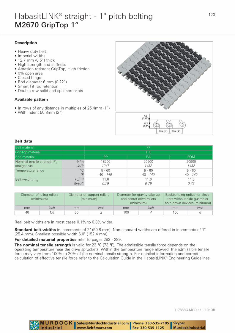
4178BRO.MOD-en1112HQR
120
M2670 GripTop 1“HabasitLINK® straight - 1" pitch belting
Belt data
Real belt widths are in most cases 0.1% to 0.3% wider.
Belt material PPGripTop material TPERod material PP PA POMNominal tensile strength F'N straight run
N/mlb/ft
182001247
209001432
209001432
Temperature range °C°F
5 - 6040 - 140
5 - 6040 - 140
5 - 6040 - 140
Belt weight mB kg/m²lb/sqft
11.60.79
11.60.79
11.60.79
Description
• Heavy duty belt • Imperial widths • 12.7 mm (0.5”) thick • High strength and stiffness • Abrasion resistant GripTop, High friction • 0% open area • Closed hinge • Rod diameter 6 mm (0.22”) • Smart Fit rod retention • Double row solid and split sprockets
Available pattern
• In rows of any distance in multiples of 25.4mm (1”) • With indent 50.8mm (2”)
Diameter of idling rollers (minimum)
Diameter of support rollers(minimum)
Diameter for gravity take-up and center drive rollers
(minimum)
Backbending radius for eleva-tors without side guards or
hold-down devices (minimum)mm inch mm inch mm inch mm inch40 1.6 50 2 100 4 150 6
Standard belt widths in increments of 2" (50.8 mm). Non-standard widths are offered in increments of 1" (25.4 mm). Smallest possible width 6.0" (152.4 mm).For detailed material properties refer to pages 282 - 289.The nominal tensile strength is valid for 23 °C (73 °F). The admissible tensile force depends on the operating temperature near the drive sprockets. Within the temperature range allowed, the admissible tensile force may vary from 100% to 20% of the nominal tensile strength. For detailed information and correct calculation of effective tensile force refer to the Calculation Guide in the HabasitLINK® Engineering Guidelines.
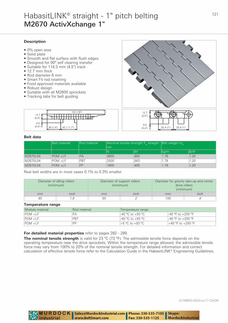
121
4178BRO.MOD-en1112HQR
M2670 ActivXchange 1"HabasitLINK® straight - 1" pitch belting
Belt data
Temperature rangeModule material Rod material Temperature rangePOM +LF PA -40 °C to +93 °C -40 °F to +200 °FPOM +LF PBT -40 °C to +93 °C -40 °F to +200 °FPOM +LF PP +5 °C to +93 °C +40 °F to +200 °F
Description
• 0% open area • Solid plate • Smooth and flat surface with flush edges • Designed for 90° self clearing transfer • Suitable for 114.3 mm (4.5") track • 12.7 mm thick • Rod diameter 6 mm • Smart Fit rod retaining • Food approved materials available • Robust design • Suitable with all M2600 sprockets • Tracking tabs for belt guiding
Diameter of idling rollers (minimum)
Diameter of support rollers(minimum)
Diameter for gravity take-up and center drive rollers (minimum)
mm inch mm inch mm inch40 1.6 50 2 100 4
Belt material Rod material Nominal tensile strength FN straight run
Belt weight mB
N lbf kg/m lb/ftM2670L04 POM +LF PA 3800 855 1.78 1.20M2670L04 POM +LF PBT 2500 563 1.78 1.20M2670L04 POM +LF PP 1800 405 1.78 1.20
Real belt widths are in most cases 0.1% to 0.3% smaller.
For detailed material properties refer to pages 282 - 289.The nominal tensile strength is valid for 23 °C (73 °F). The admissible tensile force depends on the operating temperature near the drive sprockets. Within the temperature range allowed, the admissible tensile force may vary from 100% to 20% of the nominal tensile strength. For detailed information and correct calculation of effective tensile force refer to the Calculation Guide in the HabasitLINK® Engineering Guidelines.
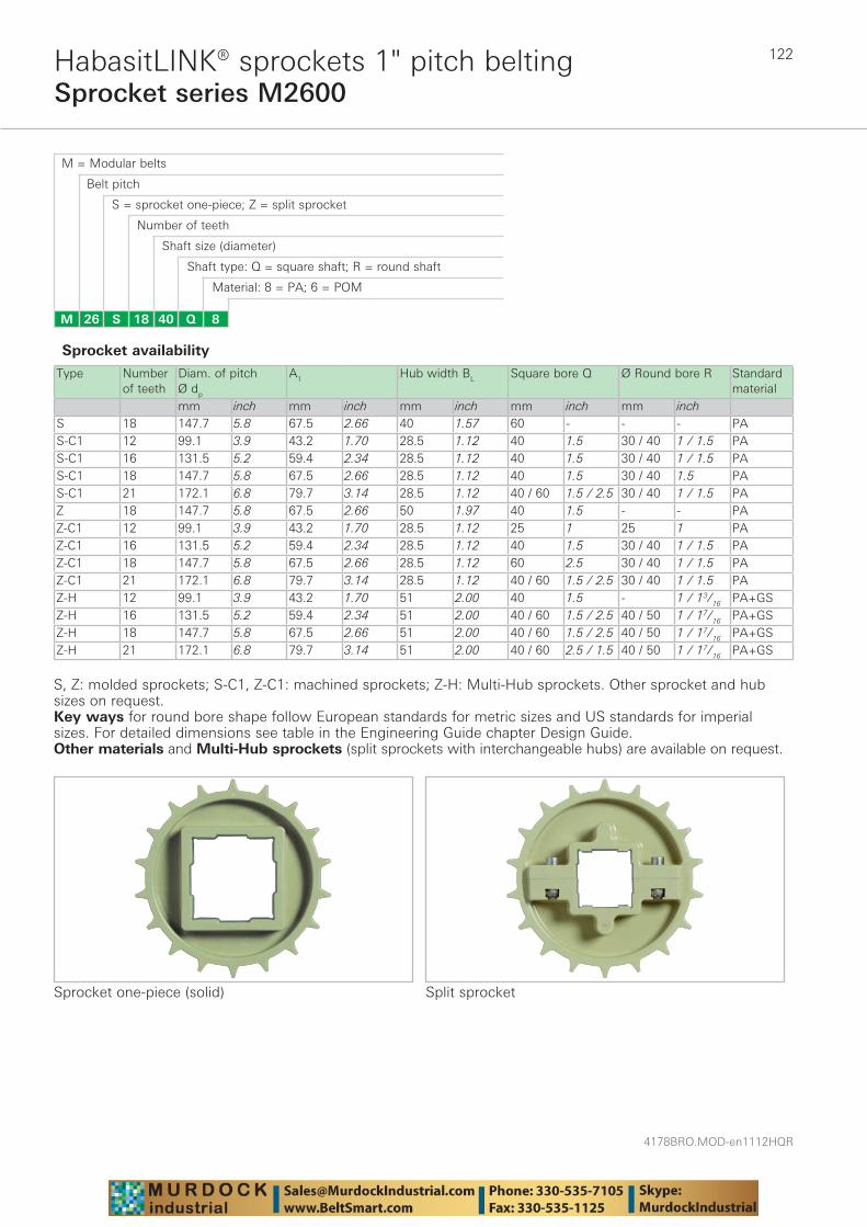
4178BRO.MOD-en1112HQR
122
Sprocket series M2600HabasitLINK® sprockets 1" pitch belting
M = Modular belts
M 26 8Q4018S
Belt pitch
S = sprocket one-piece; Z = split sprocket
Number of teeth
Shaft size (diameter)
Shaft type: Q = square shaft; R = round shaft
Material: 8 = PA; 6 = POM
Type Number of teeth
Diam. of pitch Ø dp
A1 Hub width BL Square bore Q Ø Round bore R Standard material
mm inch mm inch mm inch mm inch mm inchS 18 147.7 5.8 67.5 2.66 40 1.57 60 - - - PAS-C1 12 99.1 3.9 43.2 1.70 28.5 1.12 40 1.5 30 / 40 1 / 1.5 PAS-C1 16 131.5 5.2 59.4 2.34 28.5 1.12 40 1.5 30 / 40 1 / 1.5 PAS-C1 18 147.7 5.8 67.5 2.66 28.5 1.12 40 1.5 30 / 40 1.5 PAS-C1 21 172.1 6.8 79.7 3.14 28.5 1.12 40 / 60 1.5 / 2.5 30 / 40 1 / 1.5 PAZ 18 147.7 5.8 67.5 2.66 50 1.97 40 1.5 - - PAZ-C1 12 99.1 3.9 43.2 1.70 28.5 1.12 25 1 25 1 PAZ-C1 16 131.5 5.2 59.4 2.34 28.5 1.12 40 1.5 30 / 40 1 / 1.5 PAZ-C1 18 147.7 5.8 67.5 2.66 28.5 1.12 60 2.5 30 / 40 1 / 1.5 PAZ-C1 21 172.1 6.8 79.7 3.14 28.5 1.12 40 / 60 1.5 / 2.5 30 / 40 1 / 1.5 PAZ-H 12 99.1 3.9 43.2 1.70 51 2.00 40 1.5 - 1 / 13/16 PA+GSZ-H 16 131.5 5.2 59.4 2.34 51 2.00 40 / 60 1.5 / 2.5 40 / 50 1 / 17/16 PA+GSZ-H 18 147.7 5.8 67.5 2.66 51 2.00 40 / 60 1.5 / 2.5 40 / 50 1 / 17/16 PA+GSZ-H 21 172.1 6.8 79.7 3.14 51 2.00 40 / 60 2.5 / 1.5 40 / 50 1 / 17/16 PA+GS
Sprocket one-piece (solid)
Sprocket availability
S, Z: molded sprockets; S-C1, Z-C1: machined sprockets; Z-H: Multi-Hub sprockets. Other sprocket and hub sizes on request.Key ways for round bore shape follow European standards for metric sizes and US standards for imperial sizes. For detailed dimensions see table in the Engineering Guide chapter Design Guide.Other materials and Multi-Hub sprockets (split sprockets with interchangeable hubs) are available on request.
Split sprocket
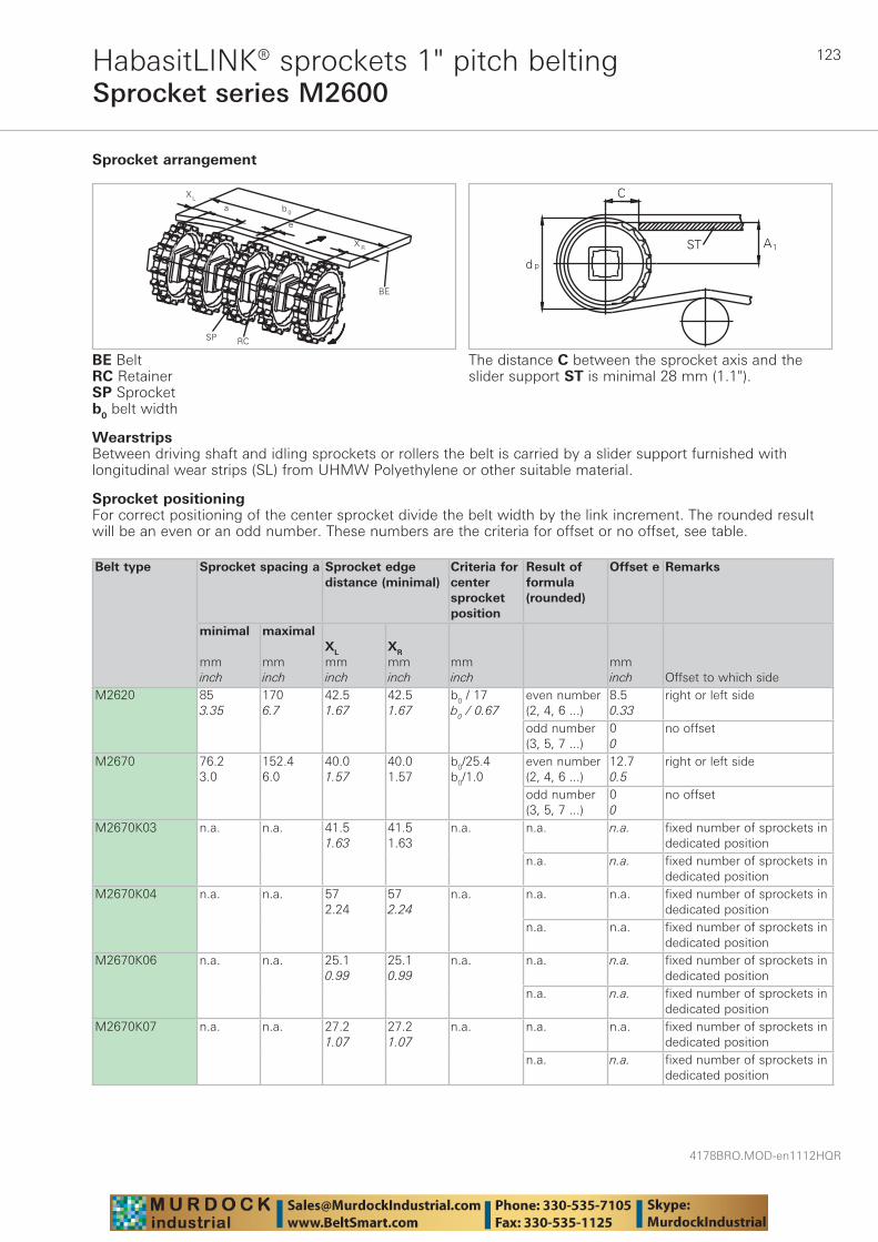
123
4178BRO.MOD-en1112HQR
Sprocket series M2600HabasitLINK® sprockets 1" pitch belting
WearstripsBetween driving shaft and idling sprockets or rollers the belt is carried by a slider support furnished with longitudinal wear strips (SL) from UHMW Polyethylene or other suitable material.
Sprocket arrangement
BE BeltRC RetainerSP Sprocketb0 belt width
The distance C between the sprocket axis and the slider support ST is minimal 28 mm (1.1").
Sprocket positioning For correct positioning of the center sprocket divide the belt width by the link increment. The rounded result will be an even or an odd number. These numbers are the criteria for offset or no offset, see table.
Belt type
Sprocket spacing a
Sprocket edgedistance (minimal)
Criteria for center sprocket position
Result of formula (rounded)
Offset e Remarks
minimal mminch
maximal mminch
XL
mminch
XR
mminch
mminch
mminch Offset to which side
M2620 853.35
1706.7
42.51.67
42.51.67
b0 / 17b0 / 0.67
even number (2, 4, 6 ...)
8.50.33
right or left side
odd number (3, 5, 7 ...)
00
no offset
M2670 76.23.0
152.46.0
40.01.57
40.01.57
b0/25.4b0/1.0
even number (2, 4, 6 ...)
12.70.5
right or left side
odd number (3, 5, 7 ...)
00
no offset
M2670K03 n.a. n.a. 41.51.63
41.51.63
n.a. n.a. n.a. fixed number of sprockets indedicated position
n.a. n.a. fixed number of sprockets indedicated position
M2670K04 n.a. n.a. 572.24
572.24
n.a. n.a. n.a. fixed number of sprockets indedicated position
n.a. n.a. fixed number of sprockets indedicated position
M2670K06 n.a. n.a. 25.10.99
25.10.99
n.a. n.a. n.a. fixed number of sprockets indedicated position
n.a. n.a. fixed number of sprockets indedicated position
M2670K07 n.a. n.a. 27.21.07
27.21.07
n.a. n.a. n.a. fixed number of sprockets indedicated position
n.a. n.a. fixed number of sprockets indedicated position
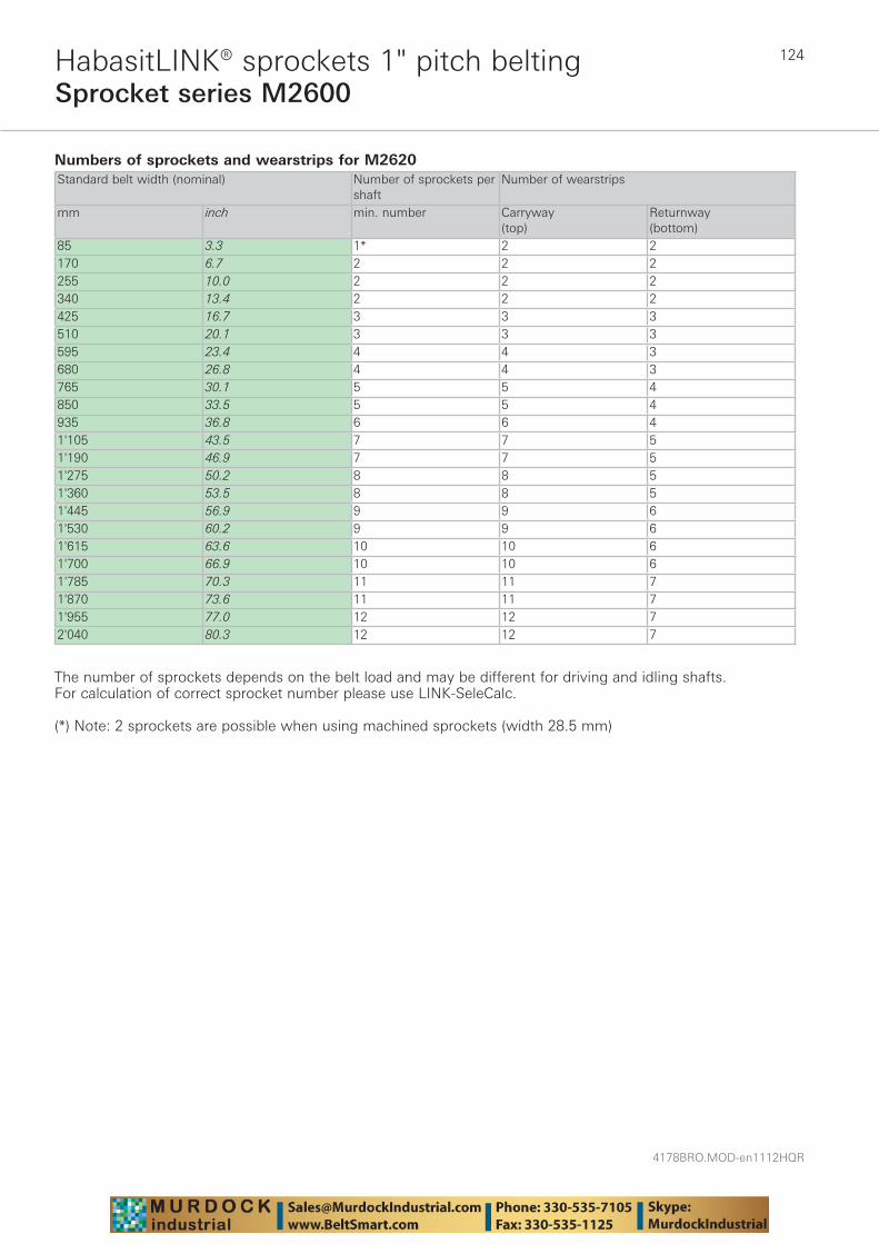
4178BRO.MOD-en1112HQR
124
Sprocket series M2600HabasitLINK® sprockets 1" pitch belting
Numbers of sprockets and wearstrips for M2620 Standard belt width (nominal) Number of sprockets per
shaftNumber of wearstrips
mm inch min. number Carryway (top)
Returnway (bottom)
85 3.3 1* 2 2170 6.7 2 2 2255 10.0 2 2 2340 13.4 2 2 2425 16.7 3 3 3510 20.1 3 3 3595 23.4 4 4 3680 26.8 4 4 3765 30.1 5 5 4850 33.5 5 5 4935 36.8 6 6 41'105 43.5 7 7 51'190 46.9 7 7 51'275 50.2 8 8 51'360 53.5 8 8 51'445 56.9 9 9 61'530 60.2 9 9 61'615 63.6 10 10 61'700 66.9 10 10 61'785 70.3 11 11 71'870 73.6 11 11 71'955 77.0 12 12 72'040 80.3 12 12 7
The number of sprockets depends on the belt load and may be different for driving and idling shafts. For calculation of correct sprocket number please use LINK-SeleCalc.
(*) Note: 2 sprockets are possible when using machined sprockets (width 28.5 mm)

125
4178BRO.MOD-en1112HQR
Sprocket series M2600HabasitLINK® sprockets 1" pitch belting
Numbers of sprockets and wearstrips for M2670 Standard belt width (nominal) Number of sprockets per
shaftNumber of wearstrips
mm inch min. number Carryway (top)
Returnway (bottom)
152 6 2 2 2203 8 2 2 2254 10 2 2 2305 12 2 2 2356 14 3 3 3406 16 3 3 3457 18 3 3 3508 20 5 4 3559 22 5 4 3610 24 5 4 3660 26 5 4 3711 28 5 5 4762 30 5 5 4813 32 5 5 4864 34 5 5 4914 36 7 6 41'067 42 7 7 51'219 48 9 8 51'372 54 9 8 51'524 60 9 9 61'829 72 11 11 62'134 84 13 13 6
The number of sprockets depends on the belt load and may be different for driving and idling shafts. For calculation of correct sprocket number please use LINK-SeleCalc.
Numbers of sprockets and wearstrips for M2670 MTW (M2670Kxx)Standard belt width (nominal) Number of sprockets per shaft Number of wearstripsmm inch Drive shaft
(loaded shaft)Idling shaft(unloaded shaft)
Carryway (top)
Returnway (bottom)
82.6 3.25 1 1 2 2114.3 4.5 1 1 2 2152.4 6.0 3 2 2 2190.5 7.5 3 2 2 2
The number of sprockets depends on the belt load and may be different for driving and idling shafts. For calculation of correct sprocket number please use LINK-SeleCalc.
Numbers of sprockets and wearstrips for M2670 ActivXchange 1"Standard belt width (nominal) Number of sprockets per shaft Number of wearstripsmm inch Drive shaft
(loaded shaft)Idling shaft(unloaded shaft)
Carryway (top)
Returnway (bottom)
152.2 6.0 2 1 2 2
The number of sprockets depends on the belt load and may be different for driving and idling shafts. For calculation of correct sprocket number please use LINK-SeleCalc.
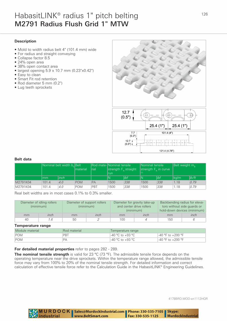
4178BRO.MOD-en1112HQR
126
M2791 Radius Flush Grid 1" MTWHabasitLINK® radius 1" pitch belting
Belt data
Temperature rangeModule material Rod material Temperature rangePOM PBT -40 °C to +93 °C -40 °F to +200 °FPOM PA -40 °C to +93 °C -40 °F to +200 °F
Description
• Mold to width radius belt 4" (101.4 mm) wide • For radius and straight conveying • Collapse factor 8.5 • 24% open area• 38% open contact area• largest opening 5.9 x 10.7 mm (0.23"x0.42") • Easy to clean • Smart Fit rod retention• Rod diameter 5 mm (0.2") • Lug teeth sprockets
Diameter of idling rollers (minimum)
Diameter of support rollers(minimum)
Diameter for gravity take-up and center drive rollers
(minimum)
Backbending radius for eleva-tors without side guards or
hold-down devices (minimum)mm inch mm inch mm inch mm inch40 1.6 50 2 100 4 150 6
Nominal belt width b0 Belt material
Rod mate-rial
Nominal tensile strength FN straight run
Nominal tensile strength FN in curve (1)
Belt weight mB
mm inch N lbf N lbf kg/m lb/ftM2791K04 101.4 4.0 POM PA 1500 338 1500 338 1.18 0.79M2791K04 101.4 4.0 POM PBT 1500 338 1500 338 1.18 0.79
Real belt widths are in most cases 0.1% to 0.3% smaller.
For detailed material properties refer to pages 282 - 289.The nominal tensile strength is valid for 23 °C (73 °F). The admissible tensile force depends on the operating temperature near the drive sprockets. Within the temperature range allowed, the admissible tensile force may vary from 100% to 20% of the nominal tensile strength. For detailed information and correct calculation of effective tensile force refer to the Calculation Guide in the HabasitLINK® Engineering Guidelines.

127
4178BRO.MOD-en1112HQR
Sprocket series M2700HabasitLINK® sprockets 1" pitch belting
M = Modular belts
M 27 8Q4012S
Belt pitch
S = sprocket one-piece
Number of teeth
Shaft size
Shaft type: Q = square shaft; R = round shaft
Material: 8 = PA; 6 = POM
Type Number of teeth
Diam. of pitch Ø dp
A1 Hub width BL Square bore Q Ø Round bore R Standard material
mm inch mm inch mm inch mm inch mm inchS-C1 12 98.7 3.89 43.1 1.69 42.2 1.66 40 1.5 - - PAS-C1 18 147.1 5.79 67.2 2.65 42.2 1.66 60 3 60 1.25 PA
The distance C between the sprocket axis and the slider support ST is minimal 28 mm (1.1").
Sprocket availability
S-C1: machined sprockets. Other sprocket and hub sizes on request.Key ways for round bore shape follow European standards for metric sizes and US standards for imperial sizes. For detailed dimensions see table in the Engineering Guide chapter Design Guide.Other materials are available on request.
WearstripsBetween driving shaft and idling sprockets or rollers the belt is carried by a slider support furnished with longitudinal wear strips (SL) from UHMW Polyethylene or other suitable material.
Wear strip arrangement
Sprocket positioningOne double row sprocket can be applied in the center of the belt only.
Running direction A is recommended
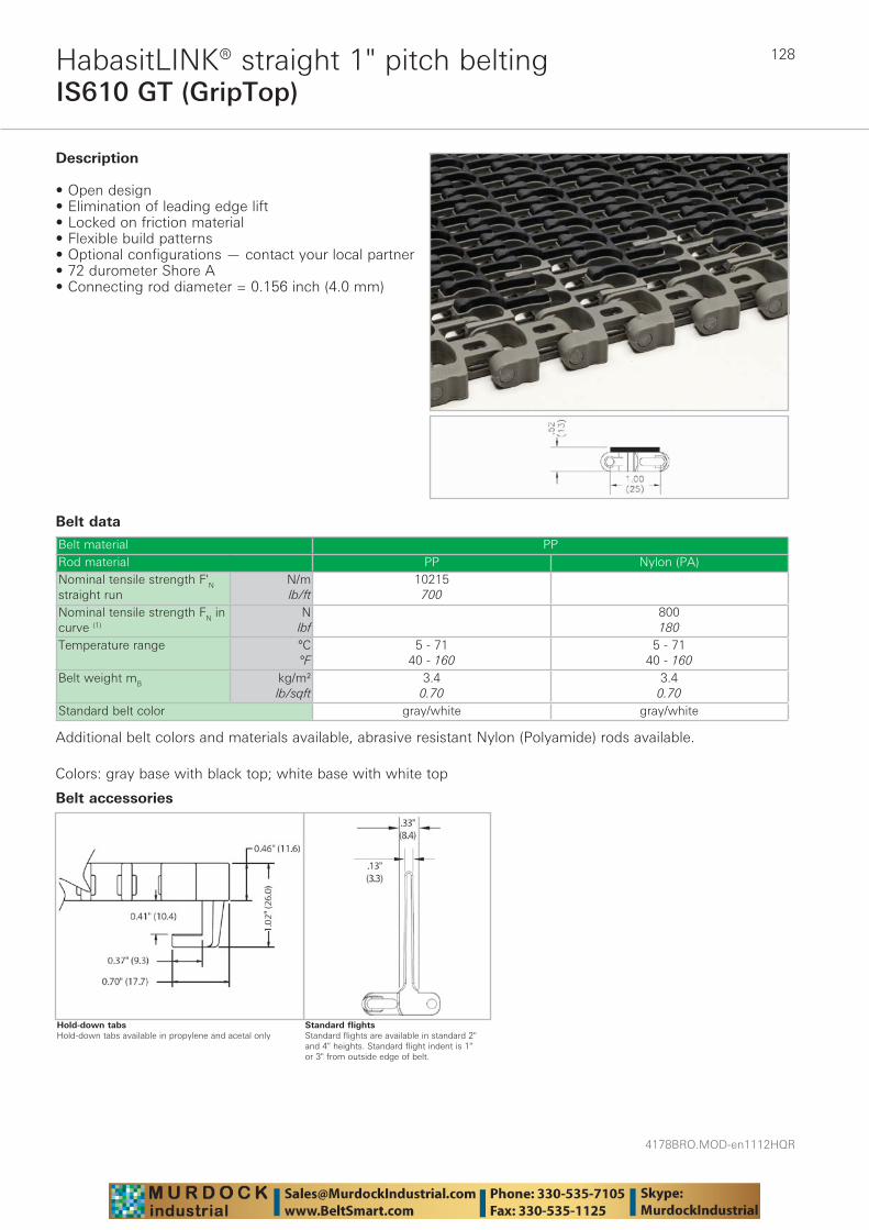
4178BRO.MOD-en1112HQR
128
IS610 GT (GripTop)HabasitLINK® straight 1" pitch belting
Belt data
Belt material PPRod material PP Nylon (PA)Nominal tensile strength F'N straight run
N/mlb/ft
10215700
Nominal tensile strength FN in curve (1)
Nlbf
800180
Temperature range °C°F
5 - 7140 - 160
5 - 7140 - 160
Belt weight mB kg/m²lb/sqft
3.40.70
3.40.70
Standard belt color gray/white gray/white
Description
• Open design • Elimination of leading edge lift • Locked on friction material • Flexible build patterns • Optional configurations — contact your local partner • 72 durometer Shore A • Connecting rod diameter = 0.156 inch (4.0 mm)
Additional belt colors and materials available, abrasive resistant Nylon (Polyamide) rods available.
Colors: gray base with black top; white base with white top
Standard flightsStandard flights are available in standard 2" and 4" heights. Standard flight indent is 1" or 3" from outside edge of belt.
Belt accessories
Hold-down tabsHold-down tabs available in propylene and acetal only
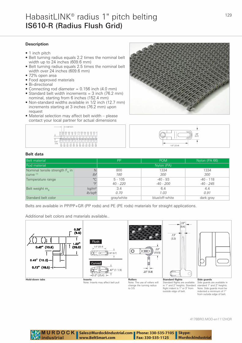
129
4178BRO.MOD-en1112HQR
IS610-R (Radius Flush Grid)HabasitLINK® radius 1" pitch belting
Belt data
Belt material PP POM Nylon (PA 66)Rod material Nylon (PA)Nominal tensile strength FN in curve (1)
Nlbf
800180
1334300
1334300
Temperature range °C°F
5 - 10540 - 220
-40 - 93-40 - 200
-40 - 118-40 - 245
Belt weight mB kg/m²lb/sqft
3.40.70
6.41.03
4.40.91
Standard belt color gray/white blue/off-white dark gray
Description
• 1 inch pitch • Belt turning radius equals 2.2 times the nominal belt
width up to 24 inches (609.6 mm) • Belt turning radius equals 2.5 times the nominal belt
width over 24 inches (609.6 mm) • 72% open area • Food approved materials• Bi-directional • Connecting rod diameter = 0.156 inch (4.0 mm) • Standard belt width increments = 3 inch (76.2 mm)
nominal, starting from 6 inches (152.4 mm)• Non-standard widths available in 1/2 inch (12.7 mm)
increments starting at 3 inches (76.2 mm) upon request
• Material selection may affect belt width – please contact your local partner for actual dimensions
Additional belt colors and materials available..
Side guardsSide guards are available in standard 1" and 2" heights. Note: Side guards must be indented a minimum of 1" from outside edge of belt.
Standard flightsStandard flights are available in 1" and 2" heights. Standard flight indent is 1" or 3" from outside edge of belt.
RollersNote: The use of rollers will change the turning radius to 3.5.
InsertsNote: Inserts may affect belt pull
Hold-down tabs
Belts are available in PP/PP+GR (PP rods) and PE (PE rods) materials for straight applications.
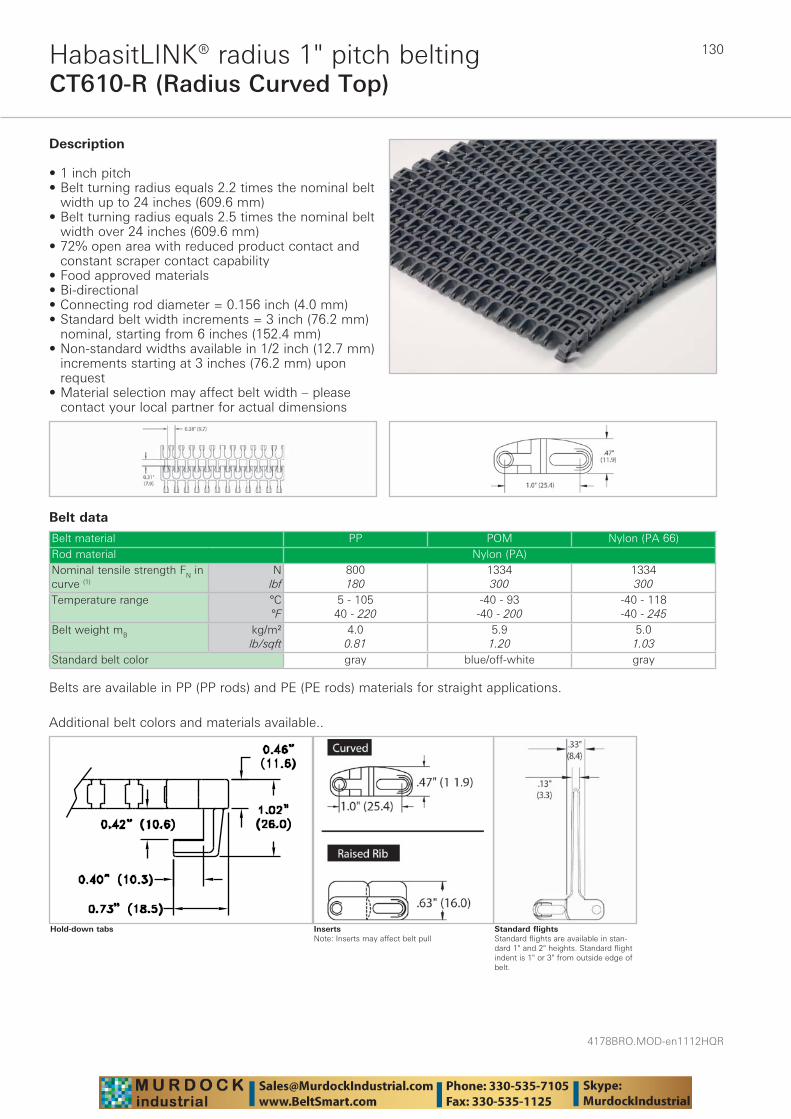
4178BRO.MOD-en1112HQR
130
CT610-R (Radius Curved Top)HabasitLINK® radius 1" pitch belting
Belt data
Belt material PP POM Nylon (PA 66)Rod material Nylon (PA)Nominal tensile strength FN in curve (1)
Nlbf
800180
1334300
1334300
Temperature range °C°F
5 - 10540 - 220
-40 - 93-40 - 200
-40 - 118-40 - 245
Belt weight mB kg/m²lb/sqft
4.00.81
5.91.20
5.01.03
Standard belt color gray blue/off-white gray
Description
• 1 inch pitch • Belt turning radius equals 2.2 times the nominal belt
width up to 24 inches (609.6 mm) • Belt turning radius equals 2.5 times the nominal belt
width over 24 inches (609.6 mm) • 72% open area with reduced product contact and
constant scraper contact capability • Food approved materials• Bi-directional • Connecting rod diameter = 0.156 inch (4.0 mm) • Standard belt width increments = 3 inch (76.2 mm)
nominal, starting from 6 inches (152.4 mm)• Non-standard widths available in 1/2 inch (12.7 mm)
increments starting at 3 inches (76.2 mm) upon request
• Material selection may affect belt width – please contact your local partner for actual dimensions
Additional belt colors and materials available..
Standard flightsStandard flights are available in stan-dard 1" and 2" heights. Standard flight indent is 1" or 3" from outside edge of belt.
InsertsNote: Inserts may affect belt pull
Hold-down tabs
Belts are available in PP (PP rods) and PE (PE rods) materials for straight applications.

131
4178BRO.MOD-en1112HQR
HabasitLINK® sprockets – 1" pitch beltingIS610, IS610 CT, IS610 GT
Molded sprocket Machined sprocket Puzzle split sprocket
Sprocket part number
Num-ber of teeth
(PD) Nominal pitch
diameter
(WH) Shaft center to top of wearstrip
All-in-One (BH)
Shaft center to top of belt
Curved Top (BH)
Shaft center to top of belt curve
Rugged Rib Top
(BH) Shaft center to top of belt rib
Rugged Texture Top
(BH) Shaft center to top of belt rib
(HT) Hub thickness
inch mm inch mm inch mm inch mm inch mm inch mm inch mm71007M* 7 2.31 59 0.97 25 1.34 34 1.43 36 1.6 41 1.36 35 1.5 3871009M* 9 2.92 74 1.27 32 1.65 42 1.74 44 1.91 48 1.67 42 1.5 3871012M 12 3.87 98 1.75 44 2.12 54 2.21 56 2.38 60 2.14 54 1.5 3871015M 15 4.81 122 2.22 56 2.59 66 2.68 68 2.85 72 2.61 66 1.5 38SP71018 18 5.80 147 2.71 69 3.09 78 3.18 81 3.35 85 3.11 79 0.75 19SP71019 19 6.08 154 2.85 72 3.23 82 3.32 84 3.64 92 3.25 83 0.75 19SP71030 30 9.54 242 4.58 116 4.96 126 5.05 128 5.22 132 4.98 126 0.75 19
M = molded sprocket
Split sprockets and other tooth sizes are available. Standard machined sprocket material is UHMW, Nylon and Urethane are
available.
* Cannot be used with belts with hold-down tabs – 9 tooth works with 1” round bores.
Sprocket part number
Available bore size
25 mm 1“ 1“ sq. 30 mm 1-1/4“ 1-7/16“ 1-1/2“ 1-1/2“
sq. 40 mm 40 mmsq.
1-15/16“ 50 mm 2“ sq. 60 mm 60 mm
sq.2-1/2“
sq.71007M* ✓ ✓ ✓ ✓ – – – – – – – – – – – –71009M* ✓ ✓ ✓ ✓ – ✓ ✓ – – – – – – – – –71012M ✓ ✓ ✓ ✓ – ✓ ✓ – – – ✓ – – – – –71015M – ✓ – ✓ ✓ ✓ ✓ ✓ ✓ ✓ ✓ – – – – –SP71018 ✓ ✓ ✓ ✓ ✓ ✓ ✓ ✓ ✓ ✓ ✓ ✓ ✓ ✓ ✓ ✓SP71019 ✓ ✓ ✓ ✓ ✓ ✓ ✓ ✓ ✓ ✓ ✓ ✓ ✓ ✓ ✓ ✓SP71030 ✓ ✓ ✓ ✓ ✓ ✓ ✓ ✓ ✓ ✓ ✓ ✓ ✓ ✓ ✓ ✓
M = molded sprocket
All bore sizes are round bore unless designated square (sq.).
* Cannot be used with belts with hold-down tabs – 9 tooth works with 1” round bores.
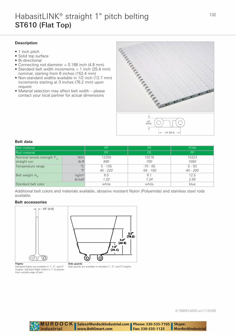
4178BRO.MOD-en1112HQR
132
ST610 (Flat Top)HabasitLINK® straight 1" pitch belting
Belt data
Belt material PP PE POMRod material PP PE PPNominal tensile strength F'N straight run
N/mlb/ft
12259840
10216700
153231050
Temperature range °C°F
5 - 10540 - 220
-70 - 65-94 - 150
5 - 9340 - 200
Belt weight mB kg/m²lb/sqft
6.01.22
6.11.24
12.52.56
Standard belt color white white blue
Description
• 1 inch pitch • Solid top surface • Bi-directional • Connecting rod diameter = 0.188 inch (4.8 mm) • Standard belt width increments = 1 inch (25.4 mm)
nominal, starting from 6 inches (152.4 mm)• Non-standard widths available in 1/2 inch (12.7 mm)
increments starting at 3 inches (76.2 mm) upon request
• Material selection may affect belt width – please contact your local partner for actual dimensions
Additional belt colors and materials available, abrasive resistant Nylon (Polyamide) and stainless steel rods available.
Side guardsSide guards are available in standard 1", 2", and 3" heights
Belt accessories
FlightsStandard flights are available in 1", 2", and 3" heights. Standard flight indent is 1" or greater from outside edge of belt.

133
4178BRO.MOD-en1112HQR
VT610 (Vented Top)HabasitLINK® straight 1" pitch belting
Belt data
Belt material PP PERod material PP PENominal tensile strength F'N straight run
N/mlb/ft
12259840
10216700
Temperature range °C°F
5 - 10540 - 220
-70 - 65-94 - 150
Belt weight mB kg/m²lb/sqft
6.01.22
6.11.25
Standard belt color white white
Description
• 1 inch pitch • 10% open area • Bi-directional • Connecting rod diameter = 0.188 inch (4.8 mm) • Standard belt width increments = 1 inch (25.4 mm)
nominal, starting from 6 inches (152.4 mm)• Non-standard widths available in 1/2 inch (12.7 mm)
increments starting at 3 inches (76.2 mm) upon request
• Material selection may affect belt width – please contact your local partner for actual dimensions
Additional belt colors and materials available, abrasive resistant Nylon (Polyamide) and stainless steel rods available.
Side guardsSide guards are available in standard 1", 2", and 3" heights
Belt accessories
FlightsStandard flights are available in 1", 2", and 3" heights. Standard flight indent is 1" or greater from outside edge of belt.
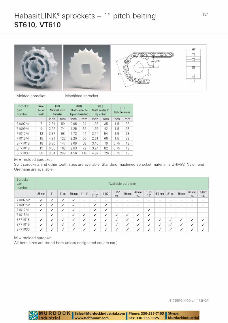
4178BRO.MOD-en1112HQR
134HabasitLINK® sprockets – 1" pitch beltingST610, VT610
Molded sprocket Machined sprocket
Sprocket part number
Num-ber of teeth
(PD) Nominal pitch
diameter
(WH) Shaft center to top of wearstrip
(BH) Shaft center to
top of belt
(HT) Hub thickness
inch mm inch mm inch mm inch mm
71007M 7 2.31 59 0.95 24 1.36 35 1.5 38
71009M 9 2.92 74 1.25 32 1.66 42 1.5 38
71012M 12 3.87 98 1.73 44 2.14 54 1.5 38
71015M 15 4.81 122 2.20 56 2.61 66 1.5 38
SP71018 18 5.80 147 2.69 68 3.10 79 0.75 19
SP71019 19 6.38 162 2.83 72 3.24 82 0.75 19
SP71030 30 9.54 242 4.56 116 4.97 126 0.75 19
M = molded sprocketSplit sprockets and other tooth sizes are available. Standard machined sprocket material is UHMW, Nylon and Urethane are available.
Sprocket part number
Available bore size
25 mm 1“ 1“ sq. 30 mm 1-1/4“ 1-7/16“ 1-1/2“ 1-1/2“
sq. 40 mm 40 mmsq.
1-15/16“ 50 mm 2“ sq. 60 mm 60 mm
sq.2-1/2“
sq.71007M* ✓ ✓ ✓ ✓ – – – – – – – – – – – –
71009M* ✓ ✓ ✓ ✓ – ✓ ✓ – – – – – – – – –
71012M ✓ ✓ ✓ ✓ – ✓ ✓ – – – ✓ – – – – –
71015M – ✓ – ✓ ✓ ✓ ✓ ✓ ✓ ✓ ✓ – – – – –
SP71018 ✓ ✓ ✓ ✓ ✓ ✓ ✓ ✓ ✓ ✓ ✓ ✓ ✓ ✓ ✓ ✓
SP71019 ✓ ✓ ✓ ✓ ✓ ✓ ✓ ✓ ✓ ✓ ✓ ✓ ✓ ✓ ✓ ✓
SP71030 ✓ ✓ ✓ ✓ ✓ ✓ ✓ ✓ ✓ ✓ ✓ ✓ ✓ ✓ ✓ ✓
M = molded sprocketAll bore sizes are round bore unless designated square (sq.)
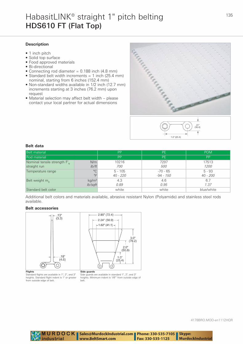
135
4178BRO.MOD-en1112HQR
HDS610 FT (Flat Top)HabasitLINK® straight 1" pitch belting
Belt data
Belt material PP PE POMRod material PP PE PPNominal tensile strength F'N straight run
N/mlb/ft
10216700
7297500
175131200
Temperature range °C°F
5 - 10540 - 220
-70 - 65-94 - 150
5 - 9340 - 200
Belt weight mB kg/m²lb/sqft
4.30.89
4.60.95
6.71.37
Standard belt color white white blue/white
Description
• 1 inch pitch • Solid top surface • Food approved materials• Bi-directional • Connecting rod diameter = 0.188 inch (4.8 mm) • Standard belt width increments = 1 inch (25.4 mm)
nominal, starting from 6 inches (152.4 mm)• Non-standard widths available in 1/2 inch (12.7 mm)
increments starting at 3 inches (76.2 mm) upon request
• Material selection may affect belt width – please contact your local partner for actual dimensions
Additional belt colors and materials available, abrasive resistant Nylon (Polyamide) and stainless steel rods available.
Side guardsSide guards are available in standard 1", 2", and 3" heights. Minimum indent is 1/8"" from outside edge of belt.
Belt accessories
FlightsStandard flights are available in 1", 2", and 3" heights. Standard flight indent is 1" or greater from outside edge of belt.
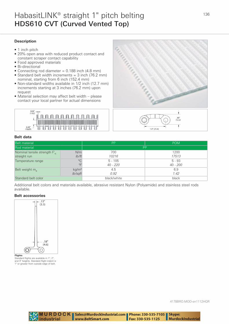
4178BRO.MOD-en1112HQR
136
HDS610 CVT (Curved Vented Top)HabasitLINK® straight 1" pitch belting
Belt data
Belt material PP POMRod material PPNominal tensile strength F'N straight run
N/mlb/ft
70010216
120017513
Temperature range °C°F
5 - 10540 - 220
5 - 9340 - 200
Belt weight mB kg/m²lb/sqft
4.50.92
6.91.42
Standard belt color black/white black
Description
• 1 inch pitch • 20% open area with reduced product contact and
constant scraper contact capability • Food approved materials• Bi-directional • Connecting rod diameter = 0.188 inch (4.8 mm) • Standard belt width increments = 3 inch (76.2 mm)
nominal, starting from 6 inch (152.4 mm)• Non-standard widths available in 1/2 inch (12.7 mm)
increments starting at 3 inches (76.2 mm) upon request
• Material selection may affect belt width – please contact your local partner for actual dimensions
Additional belt colors and materials available, abrasive resistant Nylon (Polyamide) and stainless steel rods available.
Belt accessories
FlightsStandard flights are available in 1", 2", and 3" heights. Standard flight indent is 1" or greater from outside edge of belt.
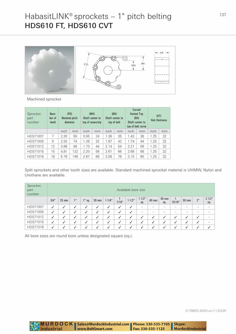
137
4178BRO.MOD-en1112HQR
HabasitLINK® sprockets – 1" pitch beltingHDS610 FT, HDS610 CVT
Machined sprocket
Sprocket part number
Num-ber of teeth
(PD) Nominal pitch
diameter
(WH) Shaft center to top of wearstrip
(BH) Shaft center to
top of belt
Curved Vented Top
(BH) Shaft center to
top of belt curve
(HT) Hub thickness
inch mm inch mm inch mm inch mm inch mm
HDS71007 7 2.30 59 0.95 24 1.36 35 1.43 36 1.25 32
HDS71009 9 2.92 74 1.26 32 1.67 42 1.74 44 1.25 32
HDS71012 12 3.86 98 1.73 44 2.14 54 2.21 56 1.25 32
HDS71015 15 4.81 122 2.20 56 2.61 66 2.68 68 1.25 32
HDS71018 18 5.76 146 2.67 68 3.08 78 3.15 80 1.25 32
Split sprockets and other tooth sizes are available. Standard machined sprocket material is UHMW, Nylon and Urethane are available.
Sprocket part number
Available bore size
3/4“ 25 mm 1“ 1“ sq. 30 mm 1-1/4“ 1-7/16“ 1-1/2“ 1-1/2“
sq. 40 mm 40 mmsq.
1-15/16“ 50 mm 2“ 2-1/2“
sq.HDS71007 ✓ ✓ ✓ ✓ ✓ ✓ ✓ ✓ – – – – – – –
HDS71009 ✓ ✓ ✓ ✓ ✓ ✓ ✓ ✓ – – – – – – –
HDS71012 ✓ ✓ ✓ ✓ ✓ ✓ ✓ ✓ ✓ ✓ ✓ ✓ ✓ ✓ –
HDS71015 ✓ ✓ ✓ ✓ ✓ ✓ ✓ ✓ ✓ ✓ ✓ ✓ ✓ ✓ –
HDS71018 ✓ ✓ ✓ ✓ ✓ ✓ ✓ ✓ ✓ ✓ ✓ ✓ ✓ ✓ ✓
All bore sizes are round bore unless designated square (sq.).
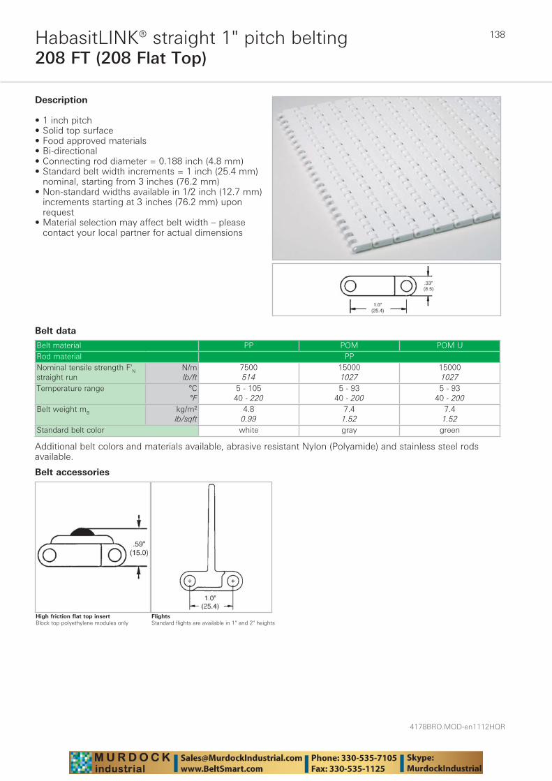
4178BRO.MOD-en1112HQR
138
208 FT (208 Flat Top)HabasitLINK® straight 1" pitch belting
Belt data
Belt material PP POM POM URod material PPNominal tensile strength F'N straight run
N/mlb/ft
7500514
150001027
150001027
Temperature range °C°F
5 - 10540 - 220
5 - 9340 - 200
5 - 9340 - 200
Belt weight mB kg/m²lb/sqft
4.80.99
7.41.52
7.41.52
Standard belt color white gray green
Description
• 1 inch pitch • Solid top surface • Food approved materials• Bi-directional • Connecting rod diameter = 0.188 inch (4.8 mm) • Standard belt width increments = 1 inch (25.4 mm)
nominal, starting from 3 inches (76.2 mm) • Non-standard widths available in 1/2 inch (12.7 mm)
increments starting at 3 inches (76.2 mm) upon request
• Material selection may affect belt width – please contact your local partner for actual dimensions
Additional belt colors and materials available, abrasive resistant Nylon (Polyamide) and stainless steel rods available.
FlightsStandard flights are available in 1" and 2" heights
Belt accessories
High friction flat top insertBlock top polyethylene modules only

139
4178BRO.MOD-en1112HQR
208 35 (208 Flush Grid 35% Open)HabasitLINK® straight 1" pitch belting
Belt data
Belt material PP PE POM POM U POM +ASRod material PP PE PPNominal tensile strength F'N straight run
N/mlb/ft
7500514
4000274
150001027
150001027
7500514
Temperature range °C°F
5 - 10540 - 220
-70 - 65-94 - 150
5 - 9340 - 200
5 - 9340 - 200
5 - 9340 - 200
Belt weight mB kg/m²lb/sqft
4.30.88
4.50.93
6.61.35
6.61.35
6.61.35
Standard belt color gray/white natural gray green black
Description
• 1 inch pitch • 35% open area • Food approved materials• Bi-directional • Connecting rod diameter = 0.188 inch (4.8 mm) • Standard belt width increments = 1 inch (25.4 mm)
nominal, starting from 3 inches (76.2 mm) • Non-standard widths available in 1/2 inch (12.7 mm)
increments starting at 3 inches (76.2 mm) upon request
• Material selection may affect belt width – please contact your local partner for actual dimensions
Additional belt colors and materials available, abrasive resistant Nylon (Polyamide) and stainless steel rods available.
FlightsStandard flights are available in 1" and 2" heights
Belt accessories
High friction flat top insertBlock top polyethylene modules only
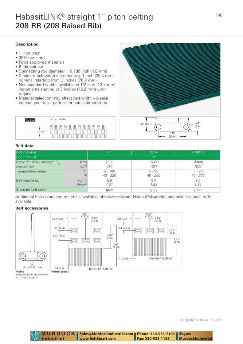
4178BRO.MOD-en1112HQR
140
208 RR (208 Raised Rib)HabasitLINK® straight 1" pitch belting
Belt data
Belt material PP POM POM URod material PPNominal tensile strength F'N straight run
N/mlb/ft
7500514
150001027
150001027
Temperature range °C°F
5 - 10540 - 220
5 - 9340 - 200
5 - 9340 - 200
Belt weight mB kg/m²lb/sqft
5.91.21
9.01.84
9.01.84
Standard belt color gray gray green
Description
• 1 inch pitch • 35% open area • Food approved materials• Bi-directional • Connecting rod diameter = 0.188 inch (4.8 mm) • Standard belt width increments = 1 inch (25.4 mm)
nominal, starting from 3 inches (76.2 mm) • Non-standard widths available in 1/2 inch (12.7 mm)
increments starting at 3 inches (76.2 mm) upon request
• Material selection may affect belt width – please contact your local partner for actual dimensions
Additional belt colors and materials available, abrasive resistant Nylon (Polyamide) and stainless steel rods available.
Transfer plates
Belt accessories
FlightsStandard flights are available in 1" and 2" heights
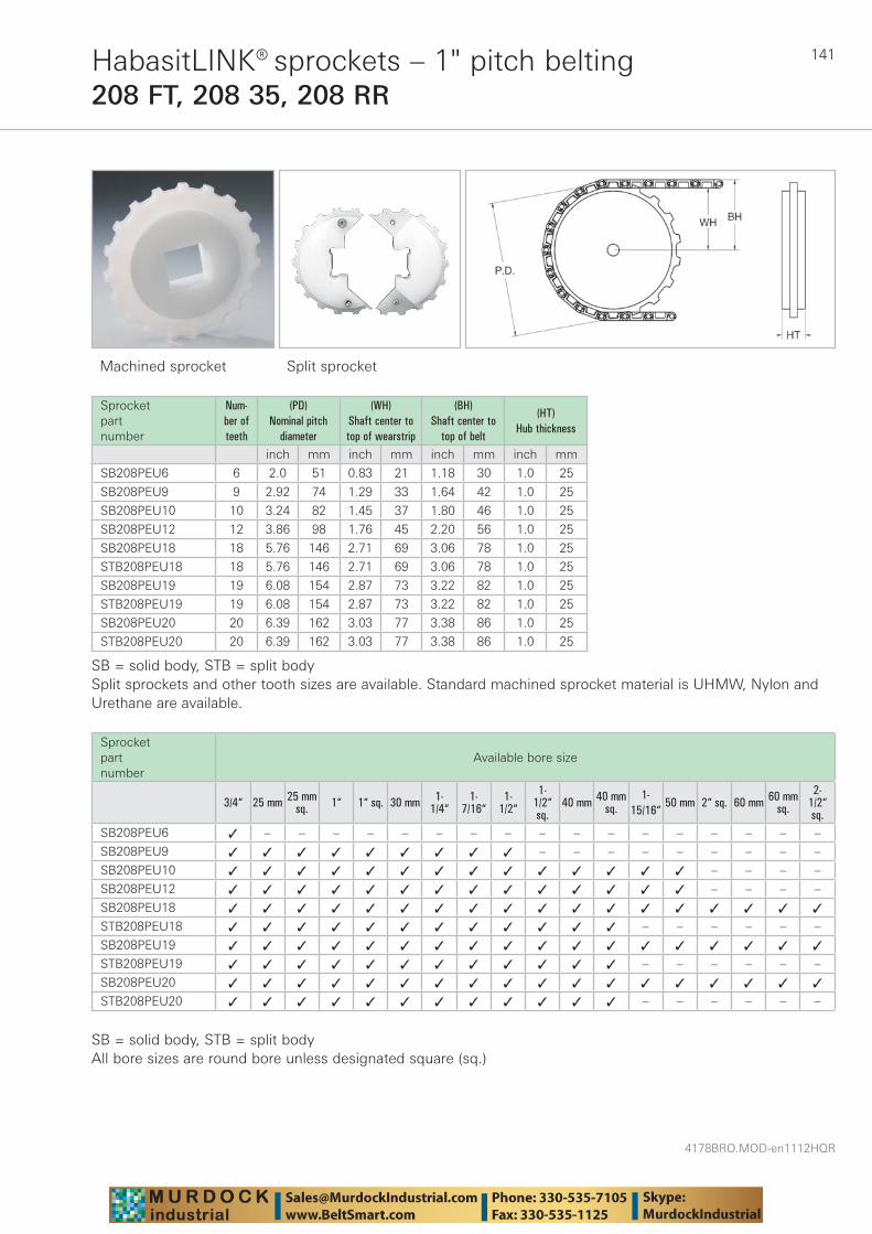
141
4178BRO.MOD-en1112HQR
HabasitLINK® sprockets – 1" pitch belting208 FT, 208 35, 208 RR
Machined sprocket Split sprocket
Sprocket part number
Num-ber of teeth
(PD) Nominal pitch
diameter
(WH) Shaft center to top of wearstrip
(BH) Shaft center to
top of belt
(HT) Hub thickness
inch mm inch mm inch mm inch mm
SB208PEU6 6 2.0 51 0.83 21 1.18 30 1.0 25
SB208PEU9 9 2.92 74 1.29 33 1.64 42 1.0 25
SB208PEU10 10 3.24 82 1.45 37 1.80 46 1.0 25
SB208PEU12 12 3.86 98 1.76 45 2.20 56 1.0 25
SB208PEU18 18 5.76 146 2.71 69 3.06 78 1.0 25
STB208PEU18 18 5.76 146 2.71 69 3.06 78 1.0 25
SB208PEU19 19 6.08 154 2.87 73 3.22 82 1.0 25
STB208PEU19 19 6.08 154 2.87 73 3.22 82 1.0 25
SB208PEU20 20 6.39 162 3.03 77 3.38 86 1.0 25
STB208PEU20 20 6.39 162 3.03 77 3.38 86 1.0 25
SB = solid body, STB = split bodySplit sprockets and other tooth sizes are available. Standard machined sprocket material is UHMW, Nylon and Urethane are available.
Sprocket part number
Available bore size
3/4“ 25 mm 25 mmsq. 1“ 1“ sq. 30 mm 1-
1/4“1-
7/16“1-
1/2“
1-1/2“sq.
40 mm 40 mmsq.
1-15/16“
50 mm 2“ sq. 60 mm 60 mmsq.
2-1/2“sq.
SB208PEU6 ✓ – – – – – – – – – – – – – – – – –
SB208PEU9 ✓ ✓ ✓ ✓ ✓ ✓ ✓ ✓ ✓ – – – – – – – – –
SB208PEU10 ✓ ✓ ✓ ✓ ✓ ✓ ✓ ✓ ✓ ✓ ✓ ✓ ✓ ✓ – – – –
SB208PEU12 ✓ ✓ ✓ ✓ ✓ ✓ ✓ ✓ ✓ ✓ ✓ ✓ ✓ ✓ – – – –
SB208PEU18 ✓ ✓ ✓ ✓ ✓ ✓ ✓ ✓ ✓ ✓ ✓ ✓ ✓ ✓ ✓ ✓ ✓ ✓
STB208PEU18 ✓ ✓ ✓ ✓ ✓ ✓ ✓ ✓ ✓ ✓ ✓ ✓ – – – – – –
SB208PEU19 ✓ ✓ ✓ ✓ ✓ ✓ ✓ ✓ ✓ ✓ ✓ ✓ ✓ ✓ ✓ ✓ ✓ ✓
STB208PEU19 ✓ ✓ ✓ ✓ ✓ ✓ ✓ ✓ ✓ ✓ ✓ ✓ – – – – – –
SB208PEU20 ✓ ✓ ✓ ✓ ✓ ✓ ✓ ✓ ✓ ✓ ✓ ✓ ✓ ✓ ✓ ✓ ✓ ✓
STB208PEU20 ✓ ✓ ✓ ✓ ✓ ✓ ✓ ✓ ✓ ✓ ✓ ✓ – – – – – –
SB = solid body, STB = split bodyAll bore sizes are round bore unless designated square (sq.)
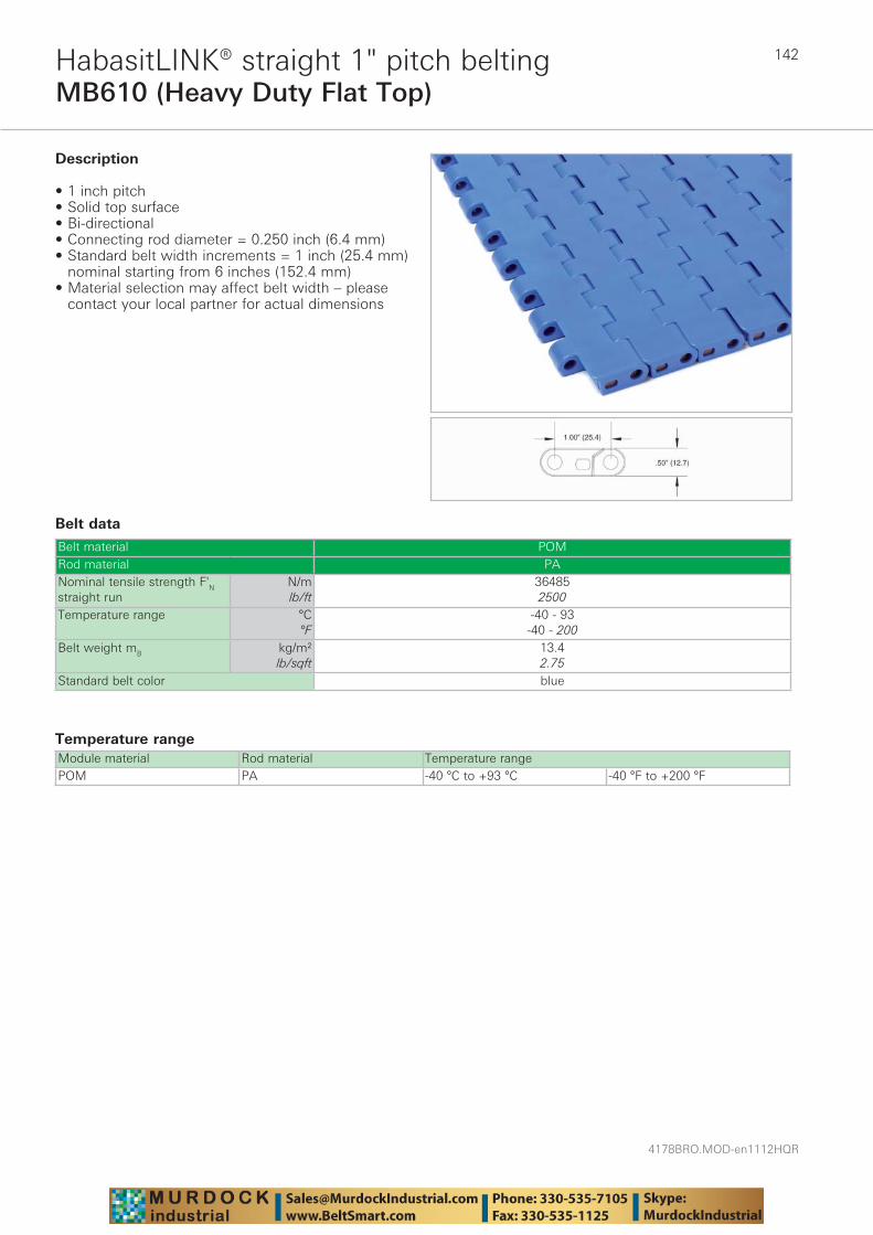
4178BRO.MOD-en1112HQR
142
MB610 (Heavy Duty Flat Top)HabasitLINK® straight 1" pitch belting
Belt data
Temperature range Module material Rod material Temperature rangePOM PA -40 °C to +93 °C -40 °F to +200 °F
Belt material POMRod material PANominal tensile strength F'N straight run
N/mlb/ft
364852500
Temperature range °C°F
-40 - 93-40 - 200
Belt weight mB kg/m²lb/sqft
13.42.75
Standard belt color blue
Description
• 1 inch pitch • Solid top surface • Bi-directional • Connecting rod diameter = 0.250 inch (6.4 mm) • Standard belt width increments = 1 inch (25.4 mm)
nominal starting from 6 inches (152.4 mm) • Material selection may affect belt width – please
contact your local partner for actual dimensions
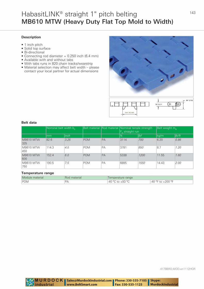
143
4178BRO.MOD-en1112HQR
MB610 MTW (Heavy Duty Flat Top Mold to Width)HabasitLINK® straight 1" pitch belting
Belt data
Temperature range Module material Rod material Temperature rangePOM PA -40 °C to +93 °C -40 °F to +200 °F
Description
• 1 inch pitch • Solid top surface • Bi-directional • Connecting rod diameter = 0.250 inch (6.4 mm) • Available with and without tabs • With tabs runs in 820 chain tracks/wearstrip • Material selection may affect belt width – please
contact your local partner for actual dimensions
Nominal belt width b0 Belt material Rod material Nominal tensile strength FN straight run
Belt weight mB
mm inch N lbf kg/m lb/ftMB610 MTW 325
82.6 3.25 POM PA 3114 700 6.20 0.86
MB610 MTW 450
114.3 4.5 POM PA 3781 850 8.7 1.20
MB610 MTW 600
152.4 6.0 POM PA 5338 1200 11.55 1.60
MB610 MTW 750
190.5 7.5 POM PA 6895 1550 14.43 2.00
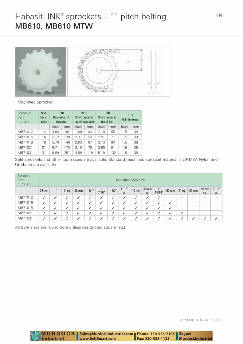
4178BRO.MOD-en1112HQR
144HabasitLINK® sprockets – 1" pitch beltingMB610, MB610 MTW
Machined sprocket
Sprocket part number
Num-ber of teeth
(PD) Nominal pitch
diameter
(WH) Shaft center to top of wearstrip
(BH) Shaft center to
top of belt
(HT) Hub thickness
inch mm inch mm inch mm inch mm
MB71012 12 3.86 98 1.68 43 2.18 55 1.5 38
MB71016 16 5.12 130 2.31 59 2.81 71 1.5 38
MB71018 18 5.76 146 2.63 67 3.13 80 1.5 38
MB71021 21 6.71 170 3.10 79 3.60 91 1.5 38
MB71031 31 9.89 251 4.69 119 5.19 132 1.5 38
Split sprockets and other tooth sizes are available. Standard machined sprocket material is UHMW, Nylon and Urethane are available.
Sprocket part number
Available bore size
25 mm 1“ 1“ sq. 30 mm 1-1/4“ 1-7/16“ 1-1/2“ 1-1/2“
sq. 40 mm 40 mmsq.
1-15/16“ 50 mm 2“ sq. 60 mm 60 mm
sq.2-1/2“
sq.MB71012 ✓ ✓ ✓ ✓ ✓ ✓ ✓ ✓ ✓ ✓ ✓ – – – – –
MB71016 ✓ ✓ ✓ ✓ ✓ ✓ ✓ ✓ ✓ ✓ ✓ ✓ – – – –
MB71018 ✓ ✓ ✓ ✓ ✓ ✓ ✓ ✓ ✓ ✓ ✓ ✓ – – – –
MB71021 ✓ ✓ ✓ ✓ ✓ ✓ ✓ ✓ ✓ ✓ ✓ ✓ ✓ – – –
MB71031 ✓ ✓ ✓ ✓ ✓ ✓ ✓ ✓ ✓ ✓ ✓ ✓ ✓ ✓ ✓ ✓
All bore sizes are round bore unless designated square (sq.).

145
4178BRO.MOD-en1112HQR
F51 (1/2" x 1" Flat Wire)HabasitLINK® straight 1.1" pitch belting
Belt data
Belt material PP PP +GR POM Nylon (PA 612) Nylon (PA +GF)Rod material PP Nylon (PA) Stainless SteelNominal tensile strength F'N straight run
N/mlb/ft
4378300
4378300
8756600
7297500
8766600
Temperature range °C°F
5 - 10540 - 220
5 - 10540 - 220
5 - 9340 - 200
-40 - 118-40 - 245
-40 - 145-40 - 293
Temperature maximum (short-term)
°C°F
175347
Belt weight mB kg/m²lb/sqft
3.00.62
3.00.62
4.40.90
3.70.76
4.50.93
Standard belt color gray/white gray blue beige red
Description
• 1.1 inch pitch • 69% open area — 1/2" x 1" (12.7 mm x 25.4 mm) • Food approved materials• Connecting rod diameter = 0.145 inch (3.7 mm) • Standard belt width increments = 1.33 inches (33.8
mm) nominal, starting from 4 inches (101.6 mm) • Material selection may affect belt width – please
contact your local partner for actual dimensions• Bi-directional
Additional belt colors and materials available, abrasive resistant Nylon (Polyamide) and stainless steel rods available.
Hanging roller assembly
Belt accessories
FlightsStandard flights are available in 1/2", 1", 2" and 3" heights
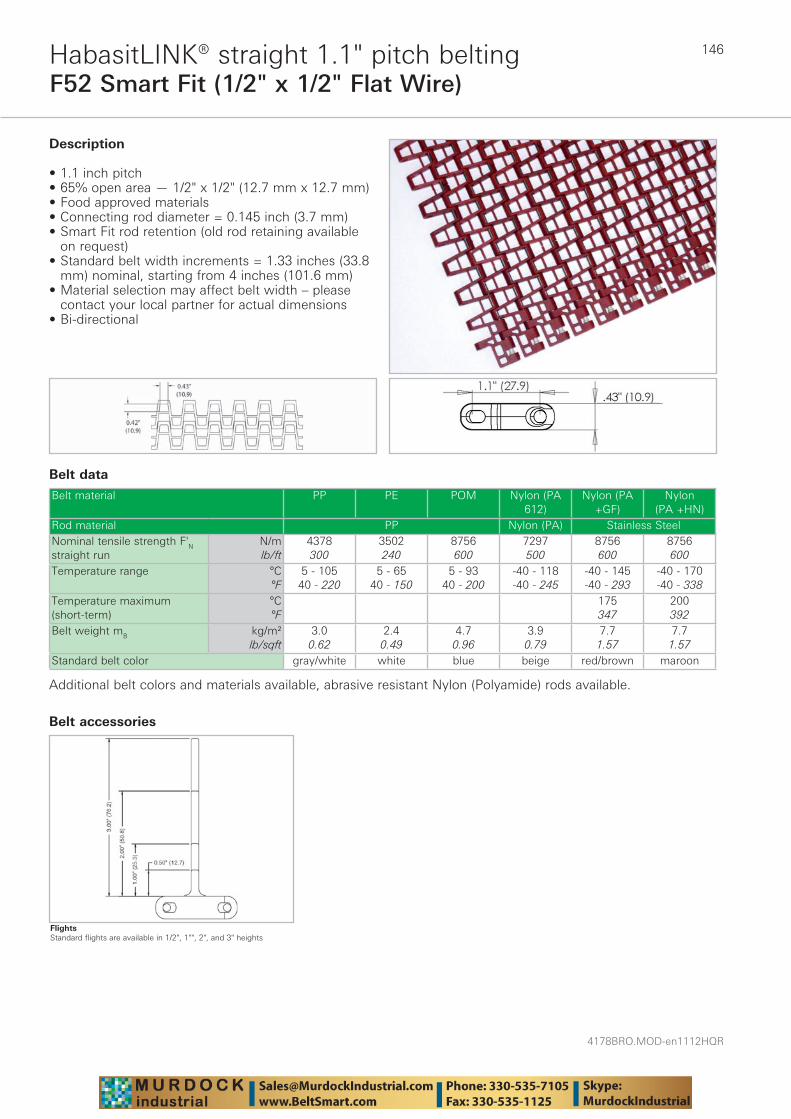
4178BRO.MOD-en1112HQR
146
F52 Smart Fit (1/2" x 1/2" Flat Wire)HabasitLINK® straight 1.1" pitch belting
Belt data
Belt material PP PE POM Nylon (PA 612)
Nylon (PA +GF)
Nylon (PA +HN)
Rod material PP Nylon (PA) Stainless SteelNominal tensile strength F'N straight run
N/mlb/ft
4378300
3502240
8756600
7297500
8756600
8756600
Temperature range °C°F
5 - 10540 - 220
5 - 6540 - 150
5 - 9340 - 200
-40 - 118-40 - 245
-40 - 145-40 - 293
-40 - 170-40 - 338
Temperature maximum (short-term)
°C°F
175347
200392
Belt weight mB kg/m²lb/sqft
3.00.62
2.40.49
4.70.96
3.90.79
7.71.57
7.71.57
Standard belt color gray/white white blue beige red/brown maroon
Description
• 1.1 inch pitch • 65% open area — 1/2" x 1/2" (12.7 mm x 12.7 mm) • Food approved materials • Connecting rod diameter = 0.145 inch (3.7 mm) • Smart Fit rod retention (old rod retaining available
on request)• Standard belt width increments = 1.33 inches (33.8
mm) nominal, starting from 4 inches (101.6 mm) • Material selection may affect belt width – please
contact your local partner for actual dimensions • Bi-directional
Additional belt colors and materials available, abrasive resistant Nylon (Polyamide) rods available.
Belt accessories
FlightsStandard flights are available in 1/2", 1"", 2", and 3" heights
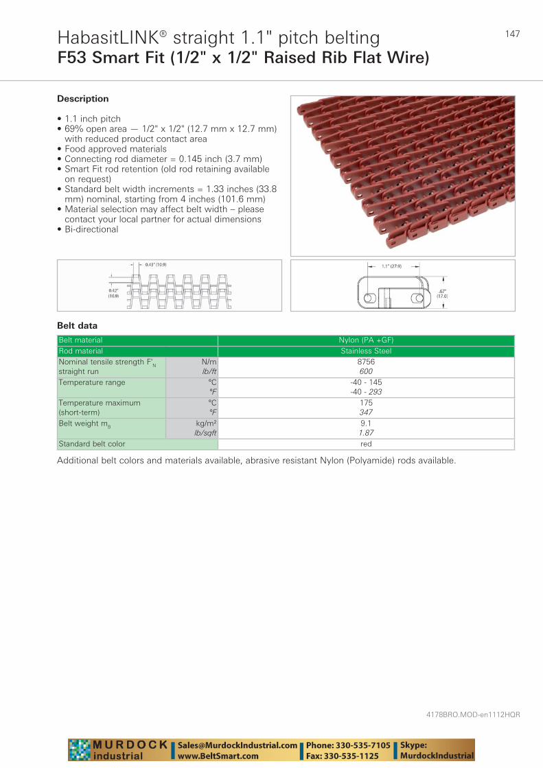
147
4178BRO.MOD-en1112HQR
F53 Smart Fit (1/2" x 1/2" Raised Rib Flat Wire)HabasitLINK® straight 1.1" pitch belting
Belt data
Belt material Nylon (PA +GF)Rod material Stainless SteelNominal tensile strength F'N straight run
N/mlb/ft
8756600
Temperature range °C°F
-40 - 145-40 - 293
Temperature maximum (short-term)
°C°F
175347
Belt weight mB kg/m²lb/sqft
9.11.87
Standard belt color red
Description
• 1.1 inch pitch • 69% open area — 1/2" x 1/2" (12.7 mm x 12.7 mm)
with reduced product contact area • Food approved materials• Connecting rod diameter = 0.145 inch (3.7 mm) • Smart Fit rod retention (old rod retaining available
on request)• Standard belt width increments = 1.33 inches (33.8
mm) nominal, starting from 4 inches (101.6 mm) • Material selection may affect belt width – please
contact your local partner for actual dimensions• Bi-directional
Additional belt colors and materials available, abrasive resistant Nylon (Polyamide) rods available.
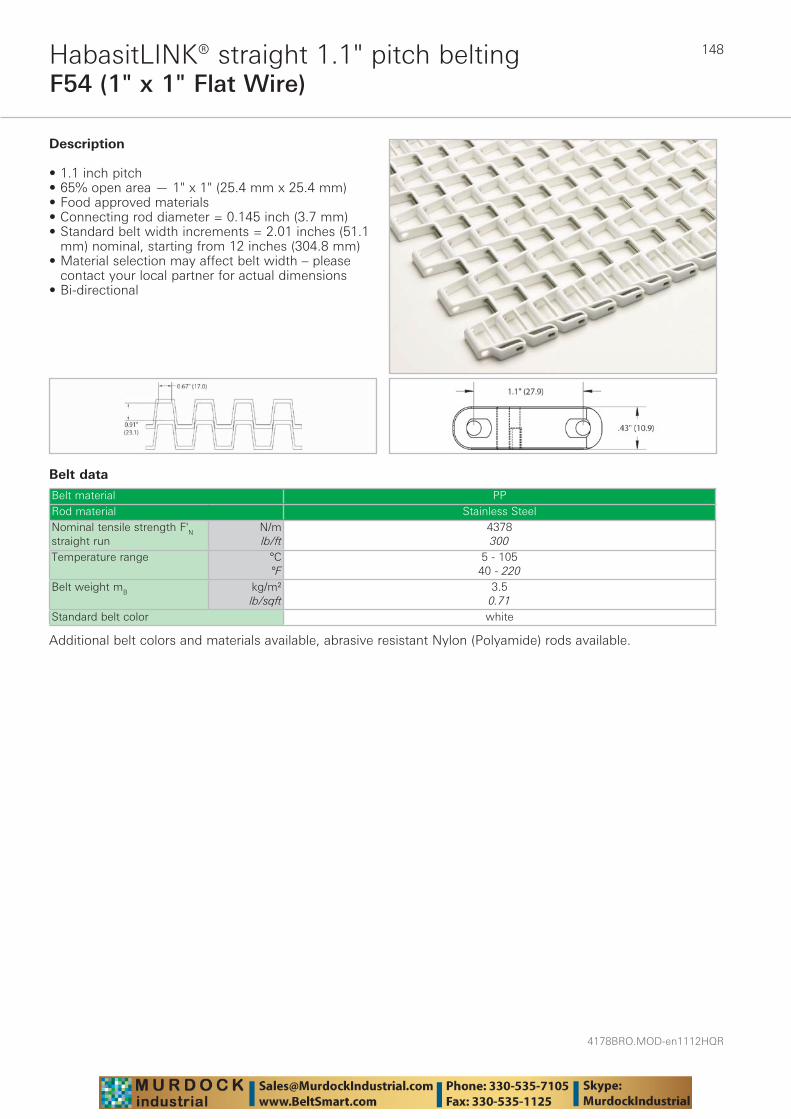
4178BRO.MOD-en1112HQR
148
F54 (1" x 1" Flat Wire)HabasitLINK® straight 1.1" pitch belting
Belt data
Belt material PPRod material Stainless SteelNominal tensile strength F'N straight run
N/mlb/ft
4378300
Temperature range °C°F
5 - 10540 - 220
Belt weight mB kg/m²lb/sqft
3.50.71
Standard belt color white
Description
• 1.1 inch pitch • 65% open area — 1" x 1" (25.4 mm x 25.4 mm) • Food approved materials • Connecting rod diameter = 0.145 inch (3.7 mm) • Standard belt width increments = 2.01 inches (51.1
mm) nominal, starting from 12 inches (304.8 mm) • Material selection may affect belt width – please
contact your local partner for actual dimensions• Bi-directional
Additional belt colors and materials available, abrasive resistant Nylon (Polyamide) rods available.
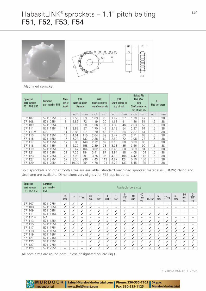
149
4178BRO.MOD-en1112HQR
HabasitLINK® sprockets – 1.1" pitch beltingF51, F52, F53, F54
Machined sprocket
Sprocket part number F51, F52, F53
Sprocket part number F54
Num-ber of teeth
(PD) Nominal pitch
diameter
(WH) Shaft center to top of wearstrip
(BH) Shaft center to
top of belt
Raised Rib Flat Wire
(BH) Shaft center to top of belt rib
(HT) Hub thickness
inch mm inch mm inch mm inch mm inch mm571107 57110754 7 2.50 63 1.03 26 1.47 37 1.70 47 1.5 38571108 57110854 8 2.82 72 1.19 30 1.63 41 1.86 51 1.5 38571109 57110954 9 3.16 80 1.36 35 1.80 46 2.03 52 1.5 38571111 57111154 11 3.83 97 1.70 43 2.13 54 2.37 61 1.5 38571111M NA 11 3.83 97 1.70 43 2.13 54 2.37 61 1.5 38571113 57111354 13 4.51 115 2.04 52 2.47 63 2.71 68 1.5 38571115 57111554 15 5.20 132 2.38 60 2.82 72 3.05 77 1.5 38571117 57111754 17 5.88 149 2.72 69 3.16 80 3.39 86 1.5 38571118 57111854 18 6.22 158 2.89 73 3.33 85 3.56 90 1.5 38571119 57111954 19 6.47 164 3.02 77 3.45 88 3.69 94 1.5 38571121 57112154 21 7.25 184 3.41 87 3.84 98 4.08 104 1.5 38571123 57112354 23 7.93 201 3.75 95 4.18 106 4.42 112 1.5 38571127 57112754 27 9.30 236 4.43 113 4.87 124 5.10 130 1.5 38571129 57112954 29 10.00 254 4.78 121 5.22 133 5.45 139 1.5 38
Split sprockets and other tooth sizes are available. Standard machined sprocket material is UHMW, Nylon and Urethane are available. Dimensions vary slightly for F53 applications.
Sprocket part number F51, F52, F53
Sprocket part number F54
Available bore size
25 mm 1“ 1“ sq. 30
mm1-
1/4“1-
7/16“1-
1/2“
1-1/2“sq.
40 mm
40 mmsq.
1-15/16“
50 mm 2“ sq. 60
mm
60 mmsq.
2-1/2“sq.
571107 57110754 ✓ ✓ ✓ ✓ – – – – – – – – – – – –571108 57110854 ✓ ✓ ✓ ✓ – – – – – – – – – – – –571109 57110954 ✓ ✓ ✓ ✓ ✓ ✓ ✓ ✓ – – – – – – – –571111 57111154 ✓ ✓ ✓ ✓ ✓ ✓ ✓ ✓ ✓ ✓ ✓ ✓ ✓ – – –571111M NA – ✓ – – – – – ✓ – – – – – – – –571113 57111354 ✓ ✓ ✓ ✓ ✓ ✓ ✓ ✓ ✓ ✓ ✓ ✓ ✓ ✓ – –571115 57111554 ✓ ✓ ✓ ✓ ✓ ✓ ✓ ✓ ✓ ✓ ✓ ✓ ✓ ✓ – –571117 57111754 ✓ ✓ ✓ ✓ ✓ ✓ ✓ ✓ ✓ ✓ ✓ ✓ ✓ ✓ ✓ ✓571118 57111854 ✓ ✓ ✓ ✓ ✓ ✓ ✓ ✓ ✓ ✓ ✓ ✓ ✓ ✓ ✓ ✓571119 57111954 ✓ ✓ ✓ ✓ ✓ ✓ ✓ ✓ ✓ ✓ ✓ ✓ ✓ ✓ ✓ ✓571121 57112154 – – – ✓ ✓ ✓ ✓ ✓ ✓ ✓ ✓ ✓ ✓ ✓ ✓ ✓571123 57112354 – – – ✓ ✓ ✓ ✓ ✓ ✓ ✓ ✓ ✓ ✓ ✓ ✓ ✓571127 57112754 – – – ✓ ✓ ✓ ✓ ✓ ✓ ✓ ✓ ✓ ✓ ✓ ✓ ✓571129 57112954 – – – ✓ ✓ ✓ ✓ ✓ ✓ ✓ ✓ ✓ ✓ ✓ ✓ ✓
All bore sizes are round bore unless designated square (sq.).
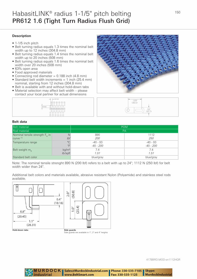
4178BRO.MOD-en1112HQR
150
PR612 1.6 (Tight Turn Radius Flush Grid)HabasitLINK® radius 1-1/5" pitch belting
Belt data
Belt material POMRod material PANominal tensile strength FN in curve (1)
Nlbf
890200
1112250
Temperature range °C°F
-40 - 93-40 - 200
-40 - 93-40 - 200
Belt weight mB kg/m²lb/sqft
7.41.51
7.41.51
Standard belt color blue/gray blue/gray
Description
• 1-1/5 inch pitch • Belt turning radius equals 1.3 times the nominal belt
width up to 12 inches (304.8 mm) • Belt turning radius equals 1.4 times the nominal belt
width up to 20 inches (508 mm) • Belt turning radius equals 1.6 times the nominal belt
width over 20 inches (508 mm) • 63% open area • Food approved materials• Connecting rod diameter = 0.188 inch (4.8 mm) • Standard belt width increments = 1 inch (25.4 mm)
nominal, starting from 12 inches (304.8 mm) • Belt is available with and without hold-down tabs • Material selection may affect belt width – please
contact your local partner for actual dimensions
Note: The nominal tensile strenght 890 N (200 lbf) refers to a belt with up to 24"; 1112 N (250 lbf) for belt width wider than 24".
Additional belt colors and materials available, abrasive resistant Nylon (Polyamide) and stainless steel rods available.
Side guardsSide guards are available in 1", 2" and 4" heights
Hold-down tabs

151
4178BRO.MOD-en1112HQR
PR612 2.2 (Radius Flush Grid)HabasitLINK® radius 1-1/5" pitch belting
Belt data
Belt material POMRod material Nylon (PA)Nominal tensile strength FN in curve (1)
Nlbf
890200
1112250
Temperature range °C°F
-40 - 93-40 - 200
-40 - 93-40 - 200
Belt weight mB kg/m²lb/sqft
7.41.51
7.41.51
Standard belt color blue/gray blue/gray
Description
• 1-1/5 inch pitch • Belt turning radius equals 2.2 times the nominal belt
width • 63% open area • Food approved materials• Connecting rod diameter = 0.188 inch (4.8 mm) • Standard belt width increments = 1 inch (25.4 mm)
nominal, starting from 12 inches (304.8 mm) • Belt is available with and without hold-down tabs• Material selection may affect belt width – please
contact your local partner for actual dimensions
Note: The nominal tensile strenght 890 N (200 lbf) refers to a belt with up to 24"; 1112 N (250 lbf) for belt width wider than 24".
Additional belt colors and materials available, abrasive resistant Nylon (Polyamide) and stainless steel rods available
Hold-down tabs
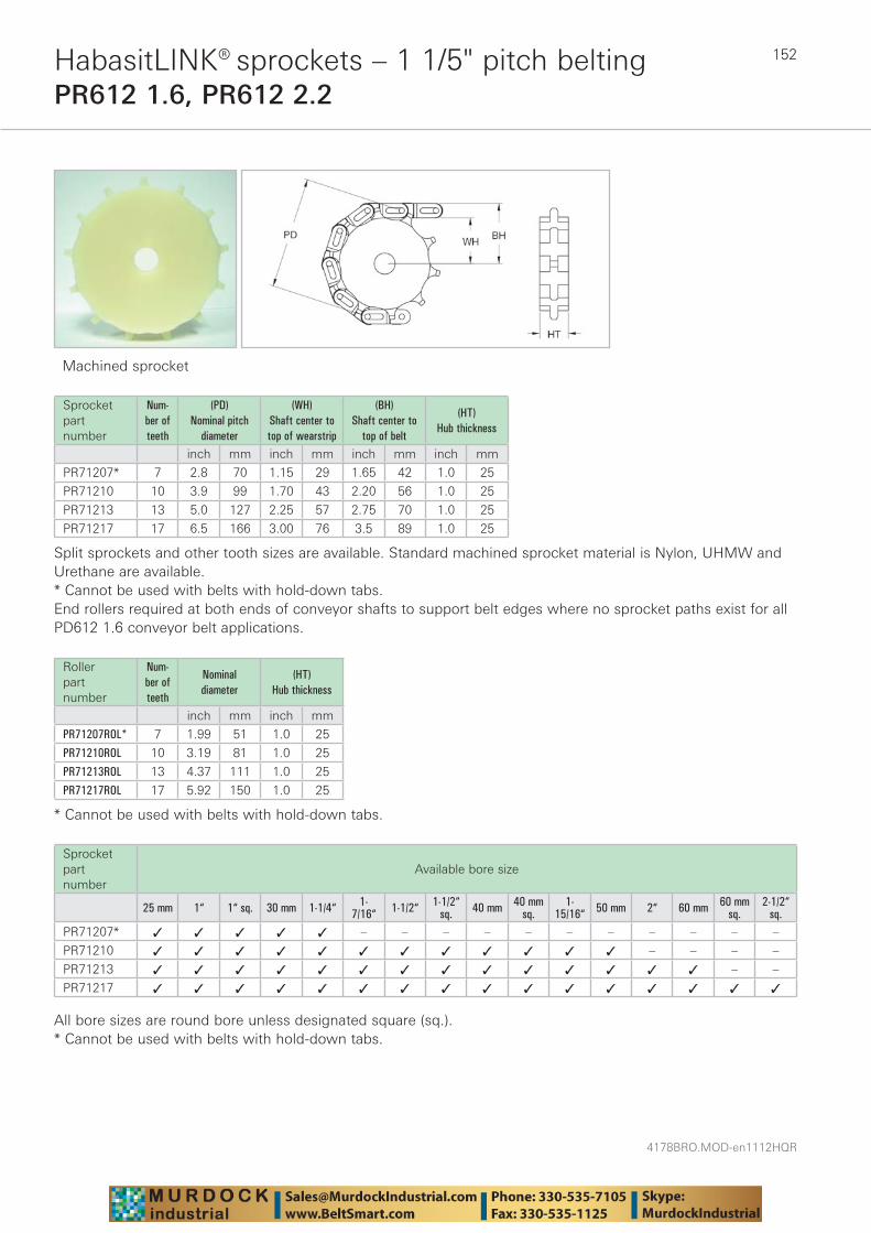
4178BRO.MOD-en1112HQR
152HabasitLINK® sprockets – 1 1/5" pitch beltingPR612 1.6, PR612 2.2
Machined sprocket
Sprocket part number
Num-ber of teeth
(PD) Nominal pitch
diameter
(WH) Shaft center to top of wearstrip
(BH) Shaft center to
top of belt
(HT) Hub thickness
inch mm inch mm inch mm inch mm
PR71207* 7 2.8 70 1.15 29 1.65 42 1.0 25
PR71210 10 3.9 99 1.70 43 2.20 56 1.0 25
PR71213 13 5.0 127 2.25 57 2.75 70 1.0 25
PR71217 17 6.5 166 3.00 76 3.5 89 1.0 25
Split sprockets and other tooth sizes are available. Standard machined sprocket material is Nylon, UHMW and Urethane are available.* Cannot be used with belts with hold-down tabs.End rollers required at both ends of conveyor shafts to support belt edges where no sprocket paths exist for all PD612 1.6 conveyor belt applications.
Rollerpart number
Num-ber of teeth
Nominaldiameter
(HT) Hub thickness
inch mm inch mm
PR71207ROL* 7 1.99 51 1.0 25
PR71210ROL 10 3.19 81 1.0 25
PR71213ROL 13 4.37 111 1.0 25
PR71217ROL 17 5.92 150 1.0 25
* Cannot be used with belts with hold-down tabs.
Sprocket part number
Available bore size
25 mm 1“ 1“ sq. 30 mm 1-1/4“ 1-7/16“ 1-1/2“ 1-1/2“
sq. 40 mm 40 mmsq.
1-15/16“ 50 mm 2“ 60 mm 60 mm
sq.2-1/2“
sq.PR71207* ✓ ✓ ✓ ✓ ✓ – – – – – – – – – – –
PR71210 ✓ ✓ ✓ ✓ ✓ ✓ ✓ ✓ ✓ ✓ ✓ ✓ – – – –
PR71213 ✓ ✓ ✓ ✓ ✓ ✓ ✓ ✓ ✓ ✓ ✓ ✓ ✓ ✓ – –
PR71217 ✓ ✓ ✓ ✓ ✓ ✓ ✓ ✓ ✓ ✓ ✓ ✓ ✓ ✓ ✓ ✓
All bore sizes are round bore unless designated square (sq.).* Cannot be used with belts with hold-down tabs.
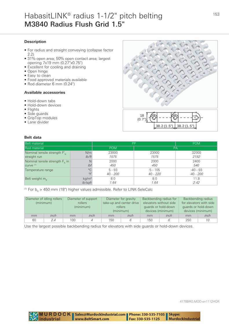
153
4178BRO.MOD-en1112HQR
M3840 Radius Flush Grid 1.5"HabasitLINK® radius 1-1/2" pitch belting
Belt data
Belt material PP POMRod material POM PANominal tensile strength F'N straight run
N/mlb/ft
230001575
230001575
320002192
Nominal tensile strength FN in curve (1)
Nlbf
2000450
2000450
2400540
Temperature range °C°F
5 - 9340 - 200
5 - 10540 - 220
-40 - 93-40 - 200
Belt weight mB kg/m²lb/sqft
8.01.64
8.01.64
11.82.42
38.2 (1 .5") 38.2 (1. 5")
18(0.7")
Description
• For radius and straight conveying (collapse factor 2.2)
• 31% open area; 50% open contact area; largest opening 7x19 mm (0.27"x0.75")
• Excellent for cooling and draining • Open hinge • Easy to clean • Food approved materials available • Rod diameter 6 mm (0.24")
Available accessories
• Hold-down tabs• Hold-down devices• Flights • Side guards • GripTop modules • Lane divider
(1) For b0 > 450 mm (18") higher values admissible. Refer to LINK-SeleCalc
Diameter of idling rollers (minimum)
Diameter of support rollers
(minimum)
Diameter for gravity take-up and center drive
rollers (minimum)
Backbending radius for elevators without side guards or hold-down devices (minimum)
Backbending radius for elevators with side guards or hold-down devices (minimum)
mm inch mm inch mm inch mm inch mm inch60 2.4 100 4 150 6 150 6 250 10
Use the largest possible backbending radius for elevators with side guards or hold-down devices.
4178BRO.MOD-en1112HQR
154
M3840 Radius Flush Grid 1.5"HabasitLINK® radius 1-1/2" pitch belting
Standard range of belt widths b0 and collapse factor Q (Rmin = Q x b0)Belt width mm (nom.)
200 250 300 350 400 450 500 550 600 650 700 750 800 850
Belt width inch (nom.)
8 10 12 14 16 18 20 22 24 26 28 30 32 34
Coll.fact. Q 1.85 1.92 1.96 1.99 2.02 2.03 2.05 2.06 2.07 2.08 2.09 2.09 2.10 2.10Belt width mm (nom.)
900 950 1000 1050 1100 1150 1200 etc.
Belt width inch (nom.)
36 38 40 42 44 46 48 etc.
Coll.fact. Q 2.11 2.11 2.11 2.12 2.12 2.12 2.13 etc.
Belt widths larger than 1200 mm (48") are not recommended; please contact Habasit.Real belt widths are in most cases 0.1% to 0.3% smaller.
Standard belt widths in increments of 50 mm (2"). Non-standard widths are offered in increments of 25 mm (1"). Smallest possible width 175 mm (7").For detailed material properties refer to pages 282 - 289.The nominal tensile strength is valid for 23 °C (73 °F). The admissible tensile force depends on the operating temperature near the drive sprockets. Within the temperature range allowed, the admissible tensile force may vary from 100% to 20% of the nominal tensile strength. For detailed information and correct calculation of effective tensile force refer to the Calculation Guide in the HabasitLINK® Engineering Guidelines.
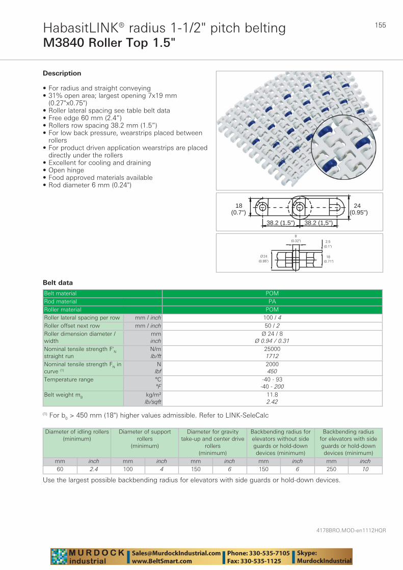
155
4178BRO.MOD-en1112HQR
M3840 Roller Top 1.5"HabasitLINK® radius 1-1/2" pitch belting
Belt data
Belt material POMRod material PARoller material POMRoller lateral spacing per row mm / inch 100 / 4Roller offset next row mm / inch 50 / 2Roller dimension diameter / width
mminch
Ø 24 / 8Ø 0.94 / 0.31
Nominal tensile strength F'N straight run
N/mlb/ft
250001712
Nominal tensile strength FN in curve (1)
Nlbf
2000450
Temperature range °C°F
-40 - 93-40 - 200
Belt weight mB kg/m²lb/sqft
11.82.42
(0.7")18
38.2 (1.5") 38.2 (1,5")
(0.95")24
Description
• For radius and straight conveying • 31% open area; largest opening 7x19 mm
(0.27"x0.75") • Roller lateral spacing see table belt data • Free edge 60 mm (2.4”) • Rollers row spacing 38.2 mm (1.5”) • For low back pressure, wearstrips placed between
rollers • For product driven application wearstrips are placed
directly under the rollers • Excellent for cooling and draining • Open hinge • Food approved materials available• Rod diameter 6 mm (0.24")
(1) For b0 > 450 mm (18") higher values admissible. Refer to LINK-SeleCalc
Diameter of idling rollers (minimum)
Diameter of support rollers
(minimum)
Diameter for gravity take-up and center drive
rollers (minimum)
Backbending radius for elevators without side guards or hold-down devices (minimum)
Backbending radius for elevators with side guards or hold-down devices (minimum)
mm inch mm inch mm inch mm inch mm inch60 2.4 100 4 150 6 150 6 250 10
Use the largest possible backbending radius for elevators with side guards or hold-down devices.
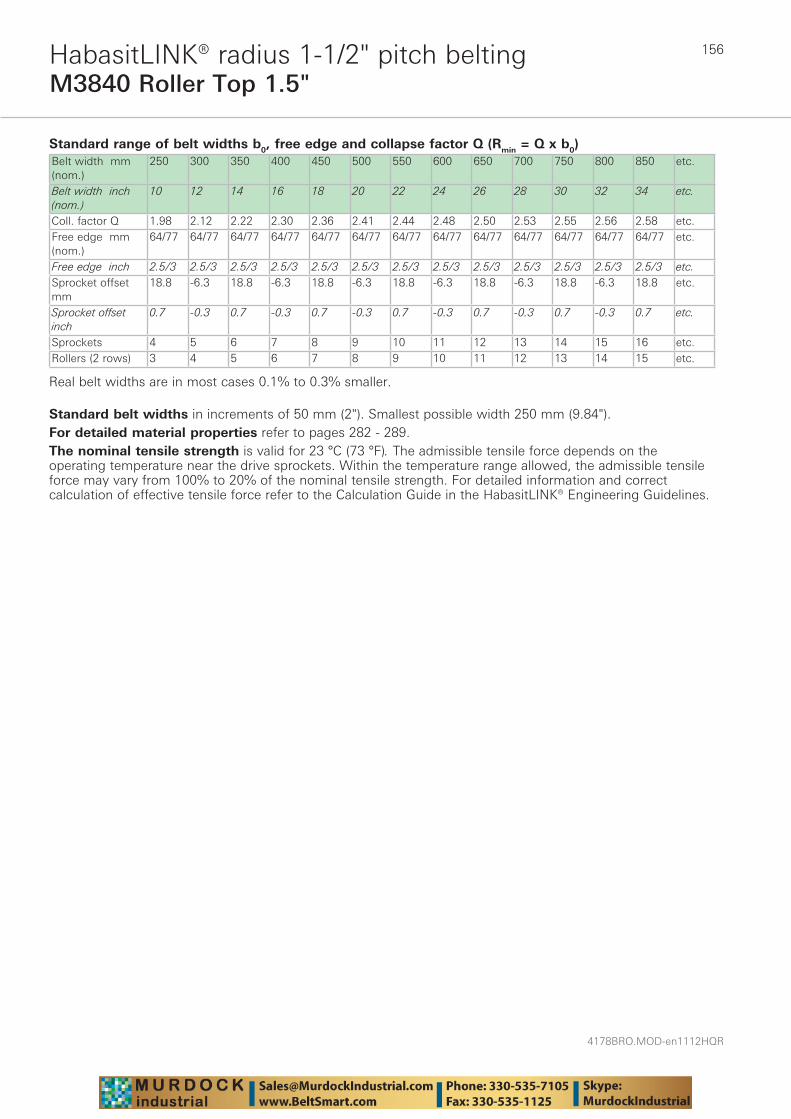
4178BRO.MOD-en1112HQR
156
M3840 Roller Top 1.5"HabasitLINK® radius 1-1/2" pitch belting
Standard range of belt widths b0, free edge and collapse factor Q (Rmin = Q x b0)Belt width mm (nom.)
250 300 350 400 450 500 550 600 650 700 750 800 850 etc.
Belt width inch (nom.)
10 12 14 16 18 20 22 24 26 28 30 32 34 etc.
Coll. factor Q 1.98 2.12 2.22 2.30 2.36 2.41 2.44 2.48 2.50 2.53 2.55 2.56 2.58 etc.Free edge mm (nom.)
64/77 64/77 64/77 64/77 64/77 64/77 64/77 64/77 64/77 64/77 64/77 64/77 64/77 etc.
Free edge inch 2.5/3 2.5/3 2.5/3 2.5/3 2.5/3 2.5/3 2.5/3 2.5/3 2.5/3 2.5/3 2.5/3 2.5/3 2.5/3 etc.Sprocket offset mm
18.8 -6.3 18.8 -6.3 18.8 -6.3 18.8 -6.3 18.8 -6.3 18.8 -6.3 18.8 etc.
Sprocket offset inch
0.7 -0.3 0.7 -0.3 0.7 -0.3 0.7 -0.3 0.7 -0.3 0.7 -0.3 0.7 etc.
Sprockets 4 5 6 7 8 9 10 11 12 13 14 15 16 etc.Rollers (2 rows) 3 4 5 6 7 8 9 10 11 12 13 14 15 etc.
Real belt widths are in most cases 0.1% to 0.3% smaller.
Standard belt widths in increments of 50 mm (2"). Smallest possible width 250 mm (9.84").For detailed material properties refer to pages 282 - 289.The nominal tensile strength is valid for 23 °C (73 °F). The admissible tensile force depends on the operating temperature near the drive sprockets. Within the temperature range allowed, the admissible tensile force may vary from 100% to 20% of the nominal tensile strength. For detailed information and correct calculation of effective tensile force refer to the Calculation Guide in the HabasitLINK® Engineering Guidelines.
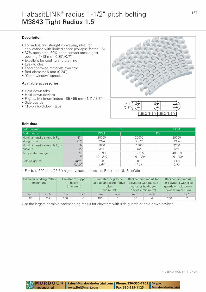
157
4178BRO.MOD-en1112HQR
M3843 Tight Radius 1.5"HabasitLINK® radius 1-1/2" pitch belting
Belt data
Belt material PP POMRod material POM PANominal tensile strength F'N straight run
N/mlb/ft
200001370
200001370
290001986
Nominal tensile strength FN in curve (1)
Nlbf
1800405
1800405
2250506
Temperature range °C°F
5 - 9340 - 200
5 - 10540 - 220
-40 - 93-40 - 200
Belt weight mB kg/m²lb/sqft
8.01.64
8.01.64
11.82.42
38.2 (1 .5") 38.2 (1. 5")
18(0.7")
Description
• For radius and straight conveying, ideal for applications with limited space (collapse factor 1.6)
• 37% open area; 50% open contact area;largest opening 9x18 mm (0.35"x0.7")
• Excellent for cooling and draining • Easy to clean • Food approved materials available• Rod diameter 6 mm (0.24") • "Open window" sprockets
Available accessories
• Hold-down tabs• Hold-down devices• Flights: Minimum indent 105 / 95 mm (4.1" / 3.7") • Side guards • Clip-on hold-down tabs
(1) For b0 > 600 mm (23.6") higher values admissible. Refer to LINK-SeleCalc.
Diameter of idling rollers (minimum)
Diameter of support rollers
(minimum)
Diameter for gravity take-up and center drive
rollers (minimum)
Backbending radius for elevators without side guards or hold-down devices (minimum)
Backbending radius for elevators with side guards or hold-down devices (minimum)
mm inch mm inch mm inch mm inch mm inch60 2.4 100 4 150 6 150 6 250 10
Use the largest possible backbending radius for elevators with side guards or hold-down devices.
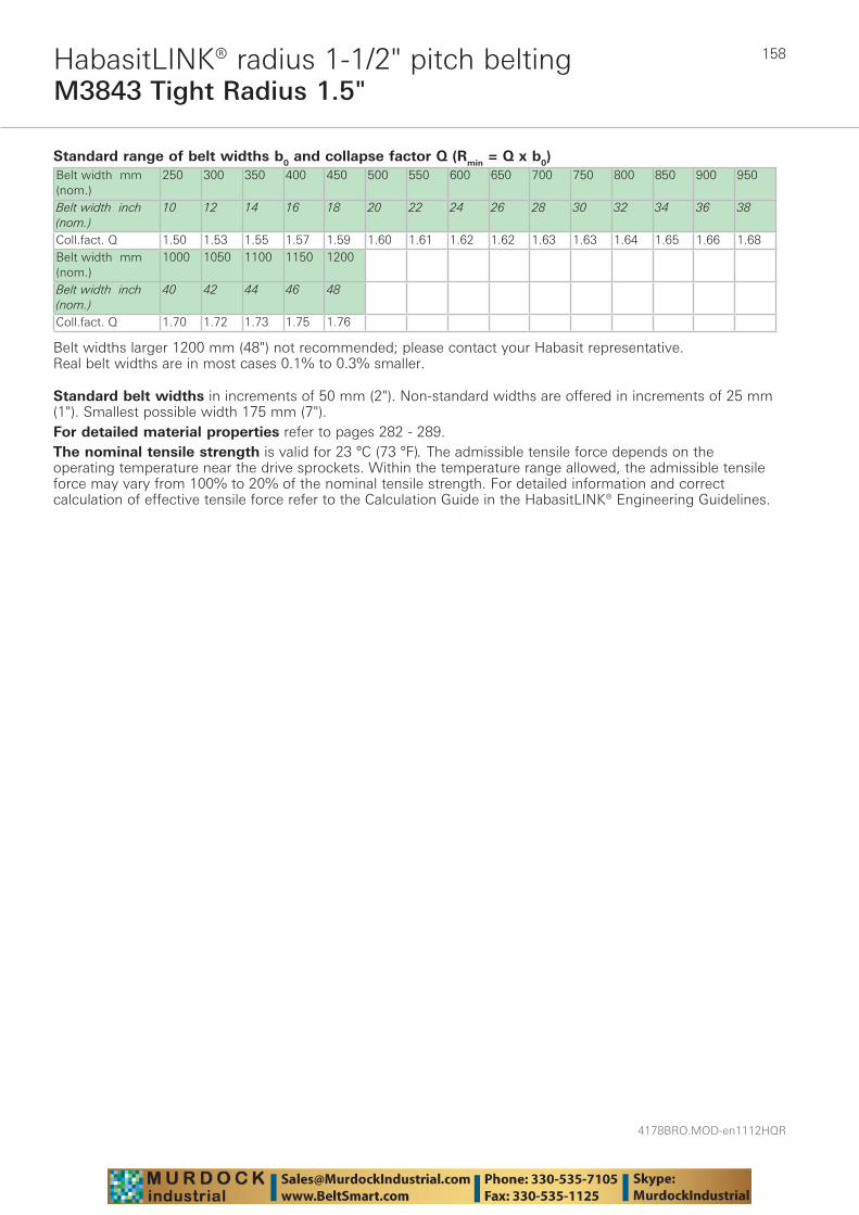
4178BRO.MOD-en1112HQR
158
M3843 Tight Radius 1.5"HabasitLINK® radius 1-1/2" pitch belting
Standard range of belt widths b0 and collapse factor Q (Rmin = Q x b0)Belt width mm (nom.)
250 300 350 400 450 500 550 600 650 700 750 800 850 900 950
Belt width inch (nom.)
10 12 14 16 18 20 22 24 26 28 30 32 34 36 38
Coll.fact. Q 1.50 1.53 1.55 1.57 1.59 1.60 1.61 1.62 1.62 1.63 1.63 1.64 1.65 1.66 1.68Belt width mm (nom.)
1000 1050 1100 1150 1200
Belt width inch (nom.)
40 42 44 46 48
Coll.fact. Q 1.70 1.72 1.73 1.75 1.76
Belt widths larger 1200 mm (48") not recommended; please contact your Habasit representative.Real belt widths are in most cases 0.1% to 0.3% smaller.
Standard belt widths in increments of 50 mm (2"). Non-standard widths are offered in increments of 25 mm (1"). Smallest possible width 175 mm (7").For detailed material properties refer to pages 282 - 289.The nominal tensile strength is valid for 23 °C (73 °F). The admissible tensile force depends on the operating temperature near the drive sprockets. Within the temperature range allowed, the admissible tensile force may vary from 100% to 20% of the nominal tensile strength. For detailed information and correct calculation of effective tensile force refer to the Calculation Guide in the HabasitLINK® Engineering Guidelines.
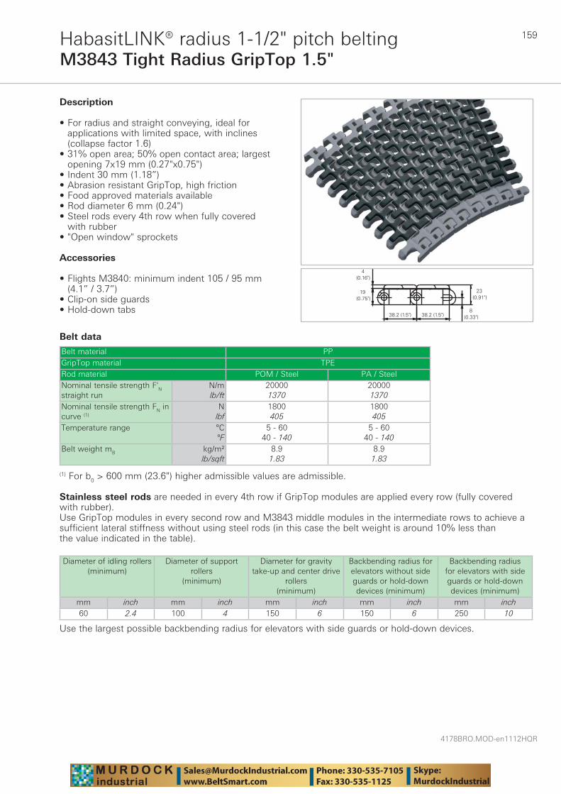
159
4178BRO.MOD-en1112HQR
M3843 Tight Radius GripTop 1.5"HabasitLINK® radius 1-1/2" pitch belting
Belt data
Belt material PPGripTop material TPERod material POM / Steel PA / SteelNominal tensile strength F'N straight run
N/mlb/ft
200001370
200001370
Nominal tensile strength FN in curve (1)
Nlbf
1800405
1800405
Temperature range °C°F
5 - 6040 - 140
5 - 6040 - 140
Belt weight mB kg/m²lb/sqft
8.91.83
8.91.83
Description
• For radius and straight conveying, ideal for applications with limited space, with inclines (collapse factor 1.6)
• 31% open area; 50% open contact area; largest opening 7x19 mm (0.27"x0.75")
• Indent 30 mm (1.18”) • Abrasion resistant GripTop, high friction • Food approved materials available• Rod diameter 6 mm (0.24") • Steel rods every 4th row when fully covered
with rubber• "Open window" sprockets
Accessories
• Flights M3840: minimum indent 105 / 95 mm (4.1” / 3.7”)
• Clip-on side guards • Hold-down tabs
(1) For b0 > 600 mm (23.6") higher admissible values are admissible.
Stainless steel rods are needed in every 4th row if GripTop modules are applied every row (fully covered with rubber). Use GripTop modules in every second row and M3843 middle modules in the intermediate rows to achieve a sufficient lateral stiffness without using steel rods (in this case the belt weight is around 10% less than the value indicated in the table).
Diameter of idling rollers (minimum)
Diameter of support rollers
(minimum)
Diameter for gravity take-up and center drive
rollers (minimum)
Backbending radius for elevators without side guards or hold-down devices (minimum)
Backbending radius for elevators with side guards or hold-down devices (minimum)
mm inch mm inch mm inch mm inch mm inch60 2.4 100 4 150 6 150 6 250 10
Use the largest possible backbending radius for elevators with side guards or hold-down devices.

4178BRO.MOD-en1112HQR
160
M3843 Tight Radius GripTop 1.5"HabasitLINK® radius 1-1/2" pitch belting
Standard range of belt widths b0 and collapse factor Q (Rmin = Q x b0)Belt width mm (nom.)
250 300 350 400 450 500 550 600 650 700 750 800 850 900
Belt width inch (nom.)
10 12 14 16 18 20 22 24 26 28 30 32 34 36
Coll.fact. Q 1.50 1.53 1.55 1.57 1.59 1.60 1.61 1.62 1.62 1.63 1.63 1.64 1.65 1.66Belt width mm (nom.)
950 1000 1050 1100 1150 1200
Belt width inch (nom.)
38 40 42 44 46 48
Coll.fact. Q 1.68 1.70 1.72 1.73 1.75 1.76
Belt widths larger 1200 mm (48") not recommended; please contact your Habasit representative.Real belt widths are in most cases 0.1% to 0.3% smaller.
Standard belt widths in increments of 50 mm (2"). Non-standard widths are offered in increments of 25 mm (1"). Smallest possible width 175 mm (7").For detailed material properties refer to pages 282 - 289.The nominal tensile strength is valid for 23 °C (73 °F). The admissible tensile force depends on the operating temperature near the drive sprockets. Within the temperature range allowed, the admissible tensile force may vary from 100% to 20% of the nominal tensile strength. For detailed information and correct calculation of effective tensile force refer to the Calculation Guide in the HabasitLINK® Engineering Guidelines.

161
4178BRO.MOD-en1112HQR
M3892 Raised Deck 1.5"HabasitLINK® radius 1-1/2" pitch belting
Belt data
Belt material PP POMRod material POM PANominal tensile strength F'N straight run
N/mlb/ft
230001575
230001575
320002192
Nominal tensile strength FN in curve (1)
Nlbf
2000450
2000450
2400540
Temperature range °C°F
5 - 9340 - 200
5 - 10540 - 220
-40 - 93-40 - 200
Belt weight mB kg/m²lb/sqft
11.52.36
11.52.36
17.13.50
Description
• Imperial belt width • For radius and straight conveying, ideal for case
handling (collapse factor 2.2) • 45% open area; 82% open contact area; largest
opening 10.7x20.6 mm (0.42"x0.81") • Indent of 32 mm (1 1/4") • Excellent for shifting goods sidewards on and off
the belt with simple conveyor design • Food approved materials available• Rod diameter 6 mm (0.24") • Smart Fit rod retention • Large distance between wearstrips possible• "Open window" sprockets
(1) For b0 > 600 mm (23.6") higher values admissible.
Diameter of idling rollers (minimum)
Diameter of support rollers
(minimum)
Diameter for gravity take-up and center drive
rollers (minimum)
Backbending radius for elevators without side guards or hold-down devices (minimum)
Backbending radius for elevators with side guards or hold-down devices (minimum)
mm inch mm inch mm inch mm inch mm inch60 2.4 100 4 150 6 150 6 250 10
Use the largest possible backbending radius for elevators with side guards.

4178BRO.MOD-en1112HQR
162
M3892 raised deck 1.5"
M3892 belt type is specificly designed to allow products to be wider than the belt itself. Due to the raised deck design, with stepped belt edges, it is simple to hold the belt down in radius applications. Hold-down tabs are not necessary.
M3892 Raised Deck 1.5"HabasitLINK® radius 1-1/2" pitch belting
Standard range of belt widths b0 and collapse factor Q (Rmin = Q x b0) for nominal factor 2.2 Belt width mm (nom.)
254 304 356 406 457 508 559 609 660 711 762 813 864 914
Belt width inch (nom.)
10 12 14 16 18 20 22 24 26 28 30 32 34 36
Coll.fact. Q 1.86 1.92 1.96 1.99 2.02 2.03 2.05 2.06 2.07 2.08 2.09 2.09 2.10 2.10Belt width mm (nom.)
965 1016 1067 1117 1168 1219 1270
Belt width inch (nom.)
38 40 42 44 46 48 50
Coll.fact. Q 2.11 2.11 2.11 2.12 2.12 2.12 2.13
Belt widths larger than 1270 mm (50") are not recommended; please contact your Habasit representative.Real belt widths are in most cases 0.1% to 0.3% smaller.
Standard belt widths in increments of 2.0" (50.8 mm). Non-standard widths are offered in increments of 1.0" (25.4 mm). Smallest possible width 8.0" (203.2 mm).For detailed material properties refer to pages 282 - 289.The nominal tensile strength is valid for 23 °C (73 °F). The admissible tensile force depends on the operating temperature near the drive sprockets. Within the temperature range allowed, the admissible tensile force may vary from 100% to 20% of the nominal tensile strength. For detailed information and correct calculation of effective tensile force refer to the Calculation Guide in the HabasitLINK® Engineering Guidelines.
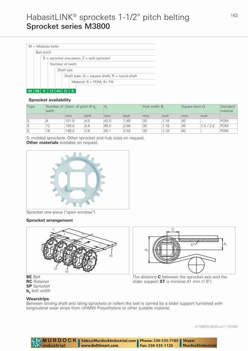
163
4178BRO.MOD-en1112HQR
Sprocket series M3800HabasitLINK® sprockets 1-1/2" pitch belting
M = Modular belts
M 38 6Q4012S
Belt pitch
S = sprocket one-piece; Z = split sprocket
Number of teeth
Shaft size
Shaft type: Q = square shaft; R = round shaft
Material: 6 = POM; 8= PA
Type Number of teeth
Diam. of pitch Ø dp A1 Hub width BL Square bore Q Standard material
mm inch mm inch mm inch mm inchS 8 101.9 4.0 42.0 1.65 30 1.18 40 - POMS 12 150.0 5.9 66.0 2.60 30 1.18 40 1.5 / 2.5 POMS 16 198.2 7.8 90.1 3.55 30 1.18 40 - POM
Sprocket one-piece ("open window")
Sprocket availability
S: molded sprockets. Other sprocket and hub sizes on request.Other materials available on request.
The distance C between the sprocket axis and the slider support ST is minimal 41 mm (1.6").
WearstripsBetween driving shaft and idling sprockets or rollers the belt is carried by a slider support furnished with longitudinal wear strips from UHMW Polyethylene or other suitable material.
Sprocket arrangement
BE BeltRC RetainerSP Sprocketb0 belt width
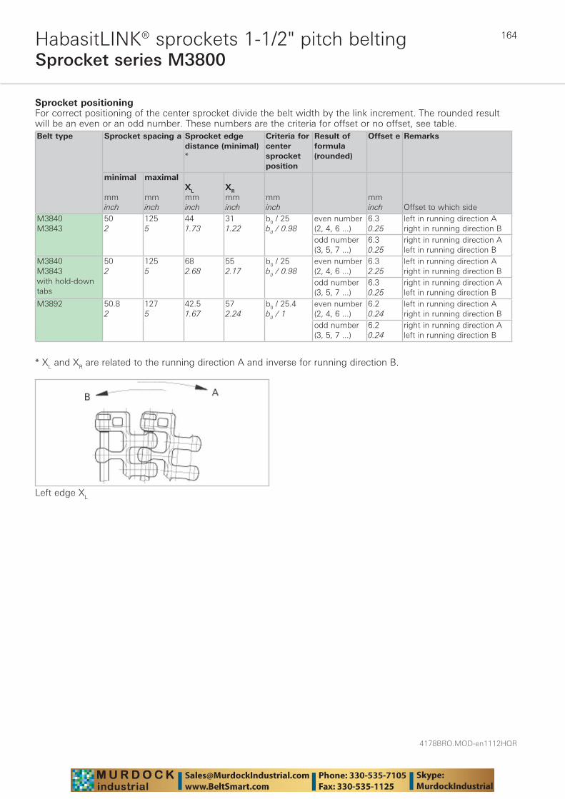
4178BRO.MOD-en1112HQR
164
Sprocket series M3800HabasitLINK® sprockets 1-1/2" pitch belting
Sprocket positioning For correct positioning of the center sprocket divide the belt width by the link increment. The rounded result will be an even or an odd number. These numbers are the criteria for offset or no offset, see table.Belt type
Sprocket spacing a
Sprocket edgedistance (minimal) *
Criteria for center sprocket position
Result of formula (rounded)
Offset e Remarks
minimal mminch
maximal mminch
XL
mminch
XR
mminch
mminch
mminch Offset to which side
M3840M3843
502
1255
441.73
311.22
b0 / 25b0 / 0.98
even number (2, 4, 6 ...)
6.30.25
left in running direction Aright in running direction B
odd number (3, 5, 7 ...)
6.30.25
right in running direction Aleft in running direction B
M3840M3843 with hold-down tabs
502
1255
682.68
552.17
b0 / 25b0 / 0.98
even number (2, 4, 6 ...)
6.32.25
left in running direction Aright in running direction B
odd number (3, 5, 7 ...)
6.30.25
right in running direction Aleft in running direction B
M3892 50.82
1275
42.51.67
572.24
b0 / 25.4b0 / 1
even number (2, 4, 6 ...)
6.20.24
left in running direction Aright in running direction B
odd number (3, 5, 7 ...)
6.20.24
right in running direction Aleft in running direction B
* XL and XR are related to the running direction A and inverse for running direction B.
Left edge XL

165
4178BRO.MOD-en1112HQR
Sprocket series M3800HabasitLINK® sprockets 1-1/2" pitch belting
Numbers of sprockets and wearstrips for M3840, M3843 and M3892Standard belt width (nominal) Number of sprockets per
shaftNumber of wearstrips
mm inch min. number Carryway (top)
Returnway (bottom)
200 8 2 2 2250 10 2 2 2300 12 2 2 2350 14 3 2 2400 16 3 3 3450 18 3 3 3500 20 3 3 3550 22 3 3 3600 24 5 4 3650 26 5 4 3700 28 5 4 3750 30 5 4 3800 32 5 5 4850 34 7 5 4900 36 7 5 4950 38 7 5 41'000 40 7 6 51'050 42 7 6 51'100 44 9 6 51'150 46 9 6 51'200 48 9 7 61'250 50 9 7 6
The number of sprockets depends on the belt load and may be different for driving and idling shafts. For calculation of correct sprocket number please use LINK-SeleCalc.
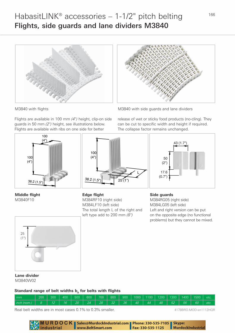
4178BRO.MOD-en1112HQR
166HabasitLINK® accessories – 1-1/2" pitch beltingFlights, side guards and lane dividers M3840
M3840 with flights M3840 with side guards and lane dividers
Flights are available in 100 mm (4") height, clip-on side guards in 50 mm (2") height, see illustrations below. Flights are available with ribs on one side for better
release of wet or sticky food products (no-cling). They can be cut to specific width and height if required. The collapse factor remains unchanged.
Middle flightM3840F10
38.2 (1.5")
100(4")
100(4")
38.2 (1.5")
100(4")
25 (1")
L
50(2")
43 (1.7")
17.6(0.7")
Standard range of belt widths b0 for belts with flights
Real belt widths are in most cases 0.1% to 0.3% smaller.
mm 200 300 400 500 600 700 800 900 1000 1100 1200 1300 1400 1500 etc.
inch (nom.) 8 12 16 20 24 28 32 36 40 44 48 52 56 60 etc.
Lane dividerM3840W02
Edge flightM384RF10 (right side)M384LF10 (left side)The total length L of the right and left type add to 200 mm (8")
Side guardsM384RG05 (right side)M384LG05 (left side)Left and right version can be put on the opposite edge (no functional problems) but they cannot be mixed.
25(1")
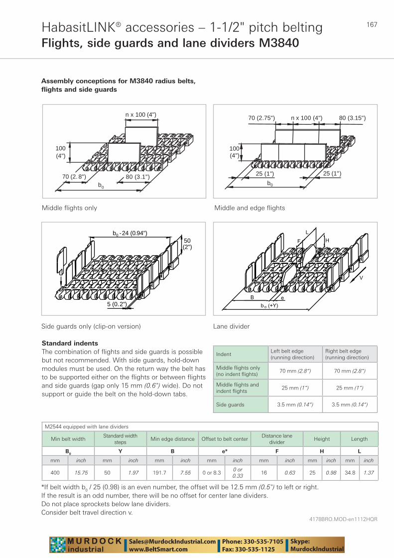
167
4178BRO.MOD-en1112HQR
HabasitLINK® accessories – 1-1/2" pitch beltingFlights, side guards and lane dividers M3840
Assembly conceptions for M3840 radius belts, flights and side guards
Middle flights only Middle and edge flights
25 (1")
b0
25 (1")
100(4")
n x 100 (4")70 (2.75") 80 (3.15")n x 100 (4")
80 (3.1")b0
70 (2. 8")
100(4")
50(2")
b - 24 (0.94")0
5 (0.2")
Side guards only (clip-on version)
Standard indentsThe combination of flights and side guards is possible but not recommended. With side guards, hold-down modules must be used. On the return way the belt has to be supported either on the flights or between flights and side guards (gap only 15 mm (0.6") wide). Do not support or guide the belt on the hold-down tabs.
IndentLeft belt edge(running direction)
Right belt edge(running direction)
Middle fl ights only (no indent fl ights)
70 mm (2.8“) 70 mm (2.8“)
Middle fl ights and indent fl ights
25 mm (1“) 25 mm (1“)
Side guards 3.5 mm (0.14“) 3.5 mm (0.14“)
Lane divider
M2544 equipped with lane dividers
Min belt widthStandard width
stepsMin edge distance Offset to belt center
Distance lane divider
Height Length
B0 Y B e* F H L
mm inch mm inch mm inch mm inch mm inch mm inch mm inch
400 15.75 50 1.97 191.7 7.55 0 or 8.30 or 0.33
16 0.63 25 0.98 34.8 1.37
*If belt width b0 / 25 (0.98) is an even number, the offset will be 12.5 mm (0.5") to left or right.If the result is an odd number, there will be no offset for center lane dividers. Do not place sprockets below lane dividers.Consider belt travel direction v.
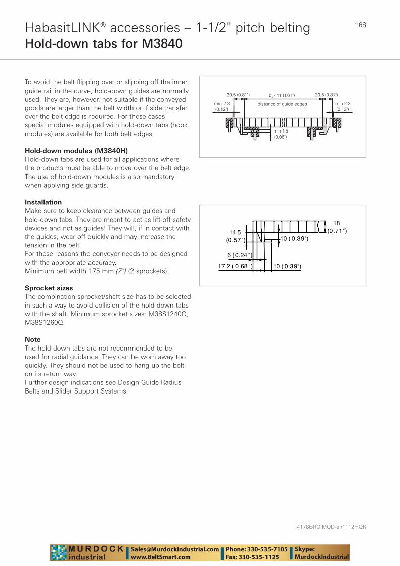
4178BRO.MOD-en1112HQR
168HabasitLINK® accessories – 1-1/2" pitch beltingHold-down tabs for M3840
To avoid the belt flipping over or slipping off the inner guide rail in the curve, hold-down guides are normally used. They are, however, not suitable if the conveyed goods are larger than the belt width or if side transfer over the belt edge is required. For these cases special modules equipped with hold-down tabs (hook modules) are available for both belt edges.
Hold-down modules (M3840H)Hold-down tabs are used for all applications where the products must be able to move over the belt edge. The use of hold-down modules is also mandatory when applying side guards.
InstallationMake sure to keep clearance between guides and hold-down tabs. They are meant to act as lift-off safety devices and not as guides! They will, if in contact with the guides, wear off quickly and may increase the tension in the belt.For these reasons the conveyor needs to be designed with the appropriate accuracy. Minimum belt width 175 mm (7") (2 sprockets).
Sprocket sizesThe combination sprocket/shaft size has to be selected in such a way to avoid collision of the hold-down tabs with the shaft. Minimum sprocket sizes: M38S1240Q, M38S1260Q.
NoteThe hold-down tabs are not recommended to be used for radial guidance. They can be worn away too quickly. They should not be used to hang up the belt on its return way.Further design indications see Design Guide Radius Belts and Slider Support Systems.
10 ( 0.39")
10 ( 0.39")14.5
(0.57")
17.2 ( 0.68 ")
6 (0.24 ")
18(0.71")
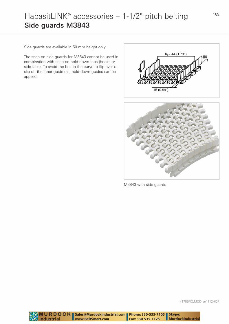
169
4178BRO.MOD-en1112HQR
M3843 with side guards
HabasitLINK® accessories – 1-1/2" pitch beltingSide guards M3843
Side guards are available in 50 mm height only.
15 (0.59")
b - 44 (1.73")050(2")
The snap-on side guards for M3843 cannot be used in combination with snap-on hold-down tabs (hooks or side tabs). To avoid the belt in the curve to flip over or slip off the inner guide rail, hold-down guides can be applied.
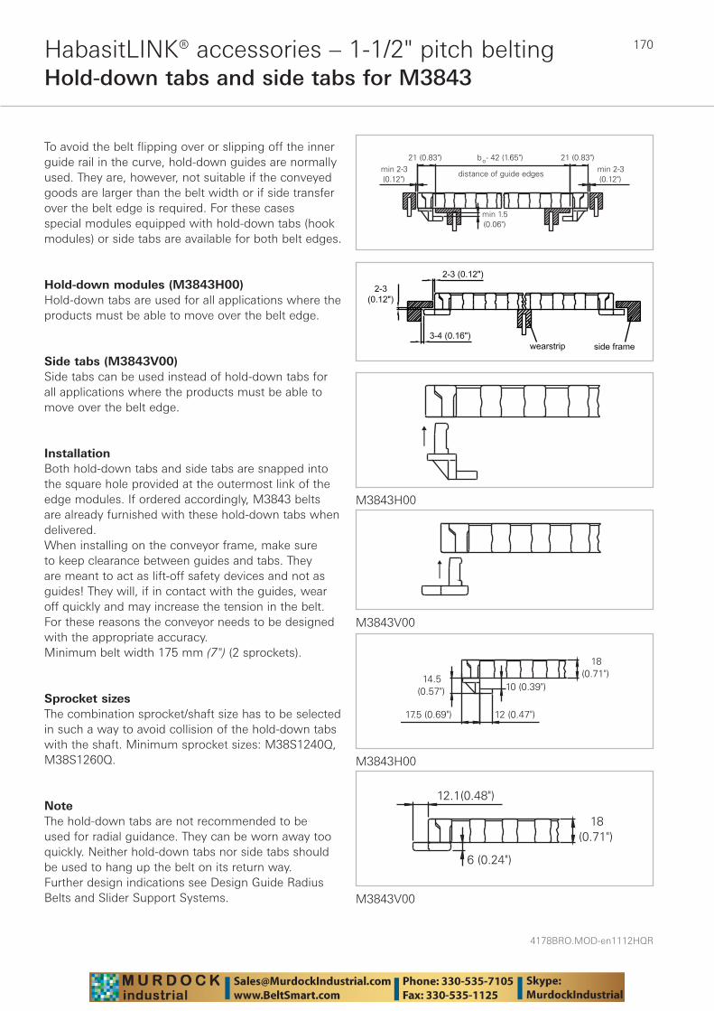
4178BRO.MOD-en1112HQR
170HabasitLINK® accessories – 1-1/2" pitch beltingHold-down tabs and side tabs for M3843
To avoid the belt flipping over or slipping off the inner guide rail in the curve, hold-down guides are normally used. They are, however, not suitable if the conveyed goods are larger than the belt width or if side transfer over the belt edge is required. For these cases special modules equipped with hold-down tabs (hook modules) or side tabs are available for both belt edges.
Hold-down modules (M3843H00)Hold-down tabs are used for all applications where the products must be able to move over the belt edge.
Side tabs (M3843V00)Side tabs can be used instead of hold-down tabs for all applications where the products must be able to move over the belt edge.
InstallationBoth hold-down tabs and side tabs are snapped into the square hole provided at the outermost link of the edge modules. If ordered accordingly, M3843 belts are already furnished with these hold-down tabs when delivered.When installing on the conveyor frame, make sure to keep clearance between guides and tabs. They are meant to act as lift-off safety devices and not as guides! They will, if in contact with the guides, wear off quickly and may increase the tension in the belt.For these reasons the conveyor needs to be designed with the appropriate accuracy. Minimum belt width 175 mm (7") (2 sprockets).
Sprocket sizesThe combination sprocket/shaft size has to be selected in such a way to avoid collision of the hold-down tabs with the shaft. Minimum sprocket sizes: M38S1240Q, M38S1260Q.
NoteThe hold-down tabs are not recommended to be used for radial guidance. They can be worn away too quickly. Neither hold-down tabs nor side tabs should be used to hang up the belt on its return way.Further design indications see Design Guide Radius Belts and Slider Support Systems.
M3843H00
M3843V00
M3843H00
M3843V00
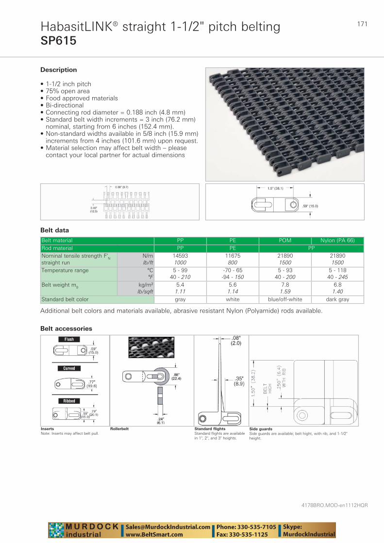
171
4178BRO.MOD-en1112HQR
SP615 HabasitLINK® straight 1-1/2" pitch belting
Belt data
Belt material PP PE POM Nylon (PA 66)Rod material PP PE PPNominal tensile strength F'N straight run
N/mlb/ft
145931000
11675800
218901500
218901500
Temperature range °C°F
5 - 9940 - 210
-70 - 65-94 - 150
5 - 9340 - 200
5 - 11840 - 245
Belt weight mB kg/m²lb/sqft
5.41.11
5.61.14
7.81.59
6.81.40
Standard belt color gray white blue/off-white dark gray
Description
• 1-1/2 inch pitch • 75% open area • Food approved materials• Bi-directional • Connecting rod diameter = 0.188 inch (4.8 mm) • Standard belt width increments = 3 inch (76.2 mm)
nominal, starting from 6 inches (152.4 mm).• Non-standard widths available in 5/8 inch (15.9 mm)
increments from 4 inches (101.6 mm) upon request. • Material selection may affect belt width – please
contact your local partner for actual dimensions
Additional belt colors and materials available, abrasive resistant Nylon (Polyamide) rods available.
Side guardsSide guards are available; belt hight, with rib, and 1-1/2" height.
Standard flightsStandard flights are available in 1", 2", and 3" heights.
Rollerbelt
Belt accessories
InsertsNote: Inserts may affect belt pull.
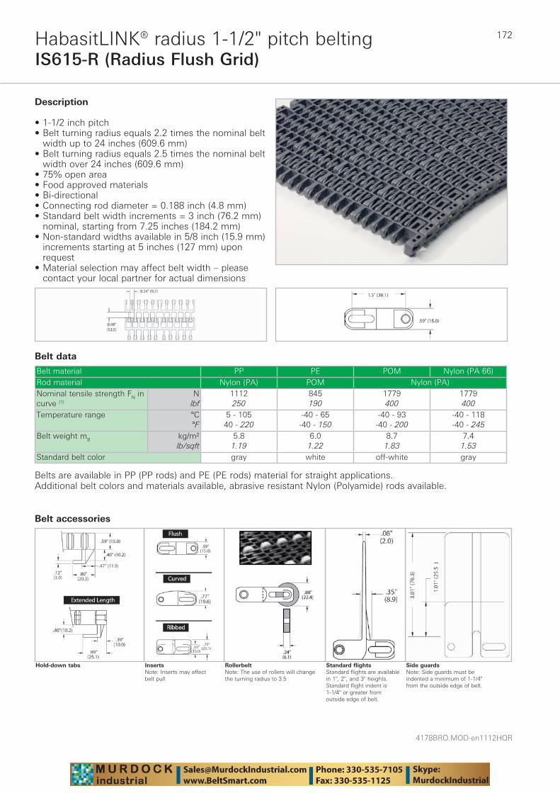
4178BRO.MOD-en1112HQR
172
IS615-R (Radius Flush Grid)HabasitLINK® radius 1-1/2" pitch belting
Belt data
Belt material PP PE POM Nylon (PA 66)Rod material Nylon (PA) POM Nylon (PA)Nominal tensile strength FN in curve (1)
Nlbf
1112250
845190
1779400
1779400
Temperature range °C°F
5 - 10540 - 220
-40 - 65-40 - 150
-40 - 93-40 - 200
-40 - 118-40 - 245
Belt weight mB kg/m²lb/sqft
5.81.19
6.01.22
8.71.83
7.41.53
Standard belt color gray white off-white gray
Description
• 1-1/2 inch pitch • Belt turning radius equals 2.2 times the nominal belt
width up to 24 inches (609.6 mm) • Belt turning radius equals 2.5 times the nominal belt
width over 24 inches (609.6 mm) • 75% open area • Food approved materials• Bi-directional • Connecting rod diameter = 0.188 inch (4.8 mm) • Standard belt width increments = 3 inch (76.2 mm)
nominal, starting from 7.25 inches (184.2 mm)• Non-standard widths available in 5/8 inch (15.9 mm)
increments starting at 5 inches (127 mm) upon request
• Material selection may affect belt width – please contact your local partner for actual dimensions
Additional belt colors and materials available, abrasive resistant Nylon (Polyamide) rods available.
Side guardsNote: Side guards must be indented a minimum of 1-1/4" from the outside edge of belt.
Standard flightsStandard flights are available in 1", 2", and 3" heights. Standard flight indent is 1-1/4" or greater from outside edge of belt.
RollerbeltNote: The use of rollers will change the turning radius to 3.5
InsertsNote: Inserts may affect belt pull
Hold-down tabs
Belts are available in PP (PP rods) and PE (PE rods) material for straight applications.
Belt accessories
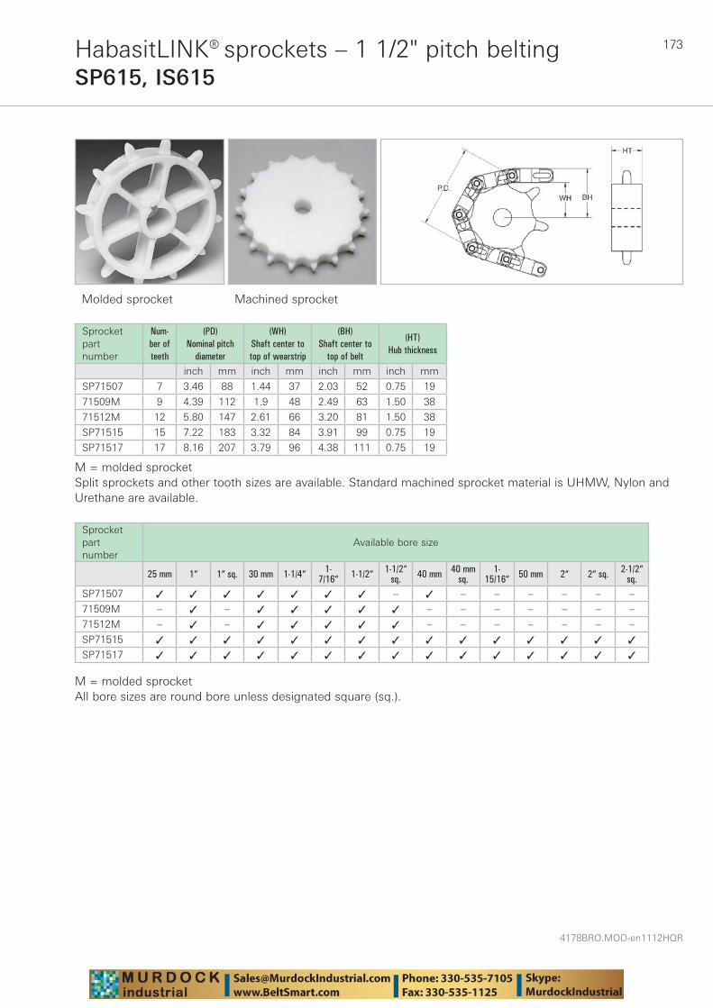
173
4178BRO.MOD-en1112HQR
HabasitLINK® sprockets – 1 1/2" pitch beltingSP615, IS615
Molded sprocket Machined sprocket
Sprocket part number
Num-ber of teeth
(PD) Nominal pitch
diameter
(WH) Shaft center to top of wearstrip
(BH) Shaft center to
top of belt
(HT) Hub thickness
inch mm inch mm inch mm inch mm
SP71507 7 3.46 88 1.44 37 2.03 52 0.75 19
71509M 9 4.39 112 1.9 48 2.49 63 1.50 38
71512M 12 5.80 147 2.61 66 3.20 81 1.50 38
SP71515 15 7.22 183 3.32 84 3.91 99 0.75 19
SP71517 17 8.16 207 3.79 96 4.38 111 0.75 19
M = molded sprocketSplit sprockets and other tooth sizes are available. Standard machined sprocket material is UHMW, Nylon and Urethane are available.
Sprocket part number
Available bore size
25 mm 1“ 1“ sq. 30 mm 1-1/4“ 1-7/16“ 1-1/2“ 1-1/2“
sq. 40 mm 40 mmsq.
1-15/16“ 50 mm 2“ 2“ sq. 2-1/2“
sq.SP71507 ✓ ✓ ✓ ✓ ✓ ✓ ✓ – ✓ – – – – – –
71509M – ✓ – ✓ ✓ ✓ ✓ ✓ – – – – – – –
71512M – ✓ – ✓ ✓ ✓ ✓ ✓ – – – – – – –
SP71515 ✓ ✓ ✓ ✓ ✓ ✓ ✓ ✓ ✓ ✓ ✓ ✓ ✓ ✓ ✓
SP71517 ✓ ✓ ✓ ✓ ✓ ✓ ✓ ✓ ✓ ✓ ✓ ✓ ✓ ✓ ✓
M = molded sprocketAll bore sizes are round bore unless designated square (sq.).
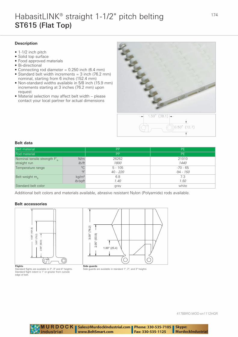
4178BRO.MOD-en1112HQR
174
ST615 (Flat Top)HabasitLINK® straight 1-1/2" pitch belting
Belt data
Belt material PP PERod material PP PENominal tensile strength F'N straight run
N/mlb/ft
262621800
210101440
Temperature range °C°F
5 - 10540 - 220
-70 - 65-94 - 150
Belt weight mB kg/m²lb/sqft
6.81.40
7.31.50
Standard belt color gray white
Description
• 1-1/2 inch pitch • Solid top surface • Food approved materials• Bi-directional • Connecting rod diameter = 0.250 inch (6.4 mm) • Standard belt width increments = 3 inch (76.2 mm)
nominal, starting from 6 inches (152.4 mm) • Non-standard widths available in 5/8 inch (15.9 mm)
increments starting at 3 inches (76.2 mm) upon request
• Material selection may affect belt width – please contact your local partner for actual dimensions
Additional belt colors and materials available, abrasive resistant Nylon (Polyamide) rods available.
Side guardsSide guards are available in standard 1", 2", and 3" heights
Belt accessories
FlightsStandard flights are available in 2", 3" and 4" heights. Standard flight indent is 1" or greater from outside edge of belt.
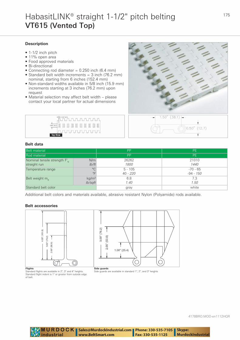
175
4178BRO.MOD-en1112HQR
VT615 (Vented Top)HabasitLINK® straight 1-1/2" pitch belting
Belt data
Belt material PP PERod material PP PENominal tensile strength F'N straight run
N/mlb/ft
262621800
210101440
Temperature range °C°F
5 - 10540 - 220
-70 - 65-94 - 150
Belt weight mB kg/m²lb/sqft
6.81.40
7.31.50
Standard belt color gray white
Description
• 1-1/2 inch pitch • 11% open area • Food approved materials• Bi-directional • Connecting rod diameter = 0.250 inch (6.4 mm) • Standard belt width increments = 3 inch (76.2 mm)
nominal, starting from 6 inches (152.4 mm) • Non-standard widths available in 5/8 inch (15.9 mm)
increments starting at 3 inches (76.2 mm) upon request
• Material selection may affect belt width – please contact your local partner for actual dimensions
Additional belt colors and materials available, abrasive resistant Nylon (Polyamide) rods available.
Side guardsSide guards are available in standard 1", 2", and 3" heights
Belt accessories
FlightsStandard flights are available in 2", 3" and 4" heights. Standard flight indent is 1" or greater from outside edge of belt.
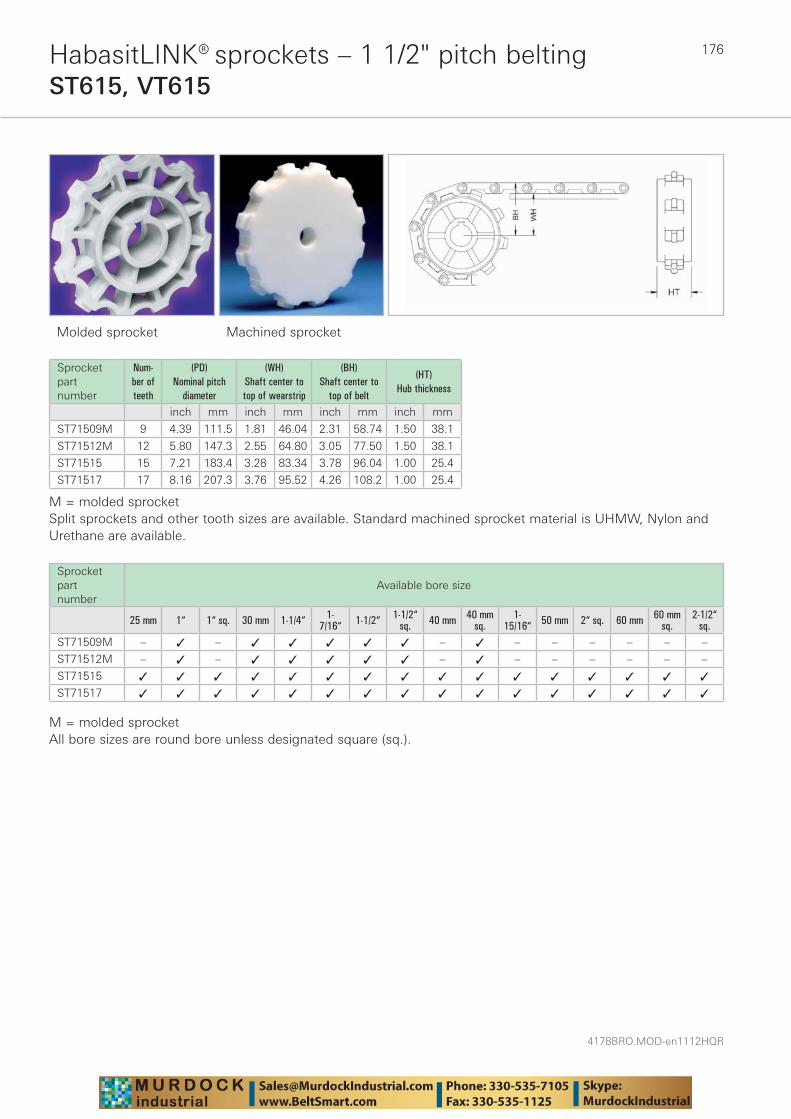
4178BRO.MOD-en1112HQR
176HabasitLINK® sprockets – 1 1/2" pitch beltingST615, VT615
Molded sprocket Machined sprocket
Sprocket part number
Num-ber of teeth
(PD) Nominal pitch
diameter
(WH) Shaft center to top of wearstrip
(BH) Shaft center to
top of belt
(HT) Hub thickness
inch mm inch mm inch mm inch mm
ST71509M 9 4.39 111.5 1.81 46.04 2.31 58.74 1.50 38.1
ST71512M 12 5.80 147.3 2.55 64.80 3.05 77.50 1.50 38.1
ST71515 15 7.21 183.4 3.28 83.34 3.78 96.04 1.00 25.4
ST71517 17 8.16 207.3 3.76 95.52 4.26 108.2 1.00 25.4
M = molded sprocketSplit sprockets and other tooth sizes are available. Standard machined sprocket material is UHMW, Nylon and Urethane are available.
Sprocket part number
Available bore size
25 mm 1“ 1“ sq. 30 mm 1-1/4“ 1-7/16“ 1-1/2“ 1-1/2“
sq. 40 mm 40 mmsq.
1-15/16“ 50 mm 2“ sq. 60 mm 60 mm
sq.2-1/2“
sq.ST71509M – ✓ – ✓ ✓ ✓ ✓ ✓ – ✓ – – – – – –
ST71512M – ✓ – ✓ ✓ ✓ ✓ ✓ – ✓ – – – – – –
ST71515 ✓ ✓ ✓ ✓ ✓ ✓ ✓ ✓ ✓ ✓ ✓ ✓ ✓ ✓ ✓ ✓
ST71517 ✓ ✓ ✓ ✓ ✓ ✓ ✓ ✓ ✓ ✓ ✓ ✓ ✓ ✓ ✓ ✓
M = molded sprocketAll bore sizes are round bore unless designated square (sq.).

177
4178BRO.MOD-en1112HQR
CC41 (Flat Top)HabasitLINK® straight 1-3/4" pitch belting
Belt data
Belt material PP PP +DE PE Nylon (PA 612)Rod material Nylon (PA)Nominal tensile strength F'N straight run
N/mlb/ft
350242400
277281900
233491600
379442600
Temperature range °C°F
5 - 10540 - 220
5 - 10540 - 220
-40 - 65-40 - 150
-40 - 118-40 - 245
Belt weight mB kg/m²lb/sqft
7.31.50
5.91.20
8.01.63
9.01.85
Standard belt color gray/white dark gray white beige
Description
• 1-3/4 inch pitch • Solid top surface • Food approved materials• Connecting rod diameter = 0.250 inch (6.4 mm) • Standard belt width increments = 1 inch (25.4 mm)
nominal, starting from 4 inches (101.6 mm) • Material selection may affect belt width – please
contact your local partner for actual dimensions
Additional belt colors and materials available, stainless steel rods available.
Side guardsSide guards are available in 3" and 4" heights
Tongue & groove flightTongue & groove flights are available in 4" height. Standard flight indent is 2" or greater from outside edge of belt.
Slide flightBucket flightBucket flights are available in 3", 4" and 6" heights
Scoop flightScoop flights are available in 3", 4" and 6" heights
Belt accessories
Standard flightStandard flights are available in 1", 2", and 3" heights. Standard flight indent is 1" or greater from outside edge of belt with all flights.
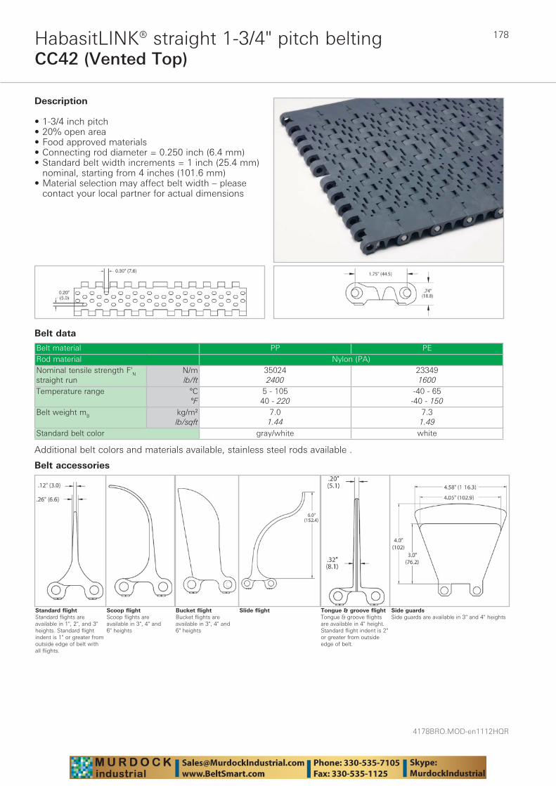
4178BRO.MOD-en1112HQR
178
CC42 (Vented Top)HabasitLINK® straight 1-3/4" pitch belting
Belt data
Belt material PP PERod material Nylon (PA)Nominal tensile strength F'N straight run
N/mlb/ft
350242400
233491600
Temperature range °C°F
5 - 10540 - 220
-40 - 65-40 - 150
Belt weight mB kg/m²lb/sqft
7.01.44
7.31.49
Standard belt color gray/white white
Description
• 1-3/4 inch pitch • 20% open area • Food approved materials• Connecting rod diameter = 0.250 inch (6.4 mm) • Standard belt width increments = 1 inch (25.4 mm)
nominal, starting from 4 inches (101.6 mm) • Material selection may affect belt width – please
contact your local partner for actual dimensions
Additional belt colors and materials available, stainless steel rods available .
Side guardsSide guards are available in 3" and 4" heights
Tongue & groove flightTongue & groove flights are available in 4" height. Standard flight indent is 2" or greater from outside edge of belt.
Slide flightBucket flightBucket flights are available in 3", 4" and 6" heights
Scoop flightScoop flights are available in 3", 4" and 6" heights
Belt accessories
Standard flightStandard flights are available in 1", 2", and 3" heights. Standard flight indent is 1" or greater from outside edge of belt with all flights.
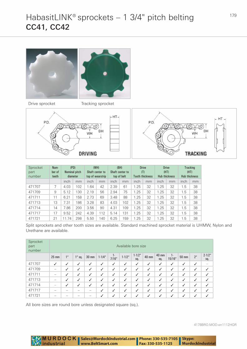
179
4178BRO.MOD-en1112HQR
HabasitLINK® sprockets – 1 3/4" pitch beltingCC41, CC42
Drive sprocket Tracking sprocket
Sprocket part number
Num-ber of teeth
(PD) Nominal pitch
diameter
(WH) Shaft center to top of wearstrip
(BH) Shaft center to
top of belt
Drive (T)
Tooth thickness
Drive (HT)
Hub thickness
Tracking (HT)
Hub thicknessinch mm inch mm inch mm inch mm inch mm inch mm
471707 7 4.03 102 1.64 42 2.39 61 1.25 32 1.25 32 1.5 38
471709 9 5.12 130 2.19 56 2.94 75 1.25 32 1.25 32 1.5 38
471711 11 6.21 158 2.73 69 3.48 88 1.25 32 1.25 32 1.5 38
471713 13 7.31 186 3.28 83 4.03 102 1.25 32 1.25 32 1.5 38
471714 14 7.86 200 3.56 90 4.31 109 1.25 32 1.25 32 1.5 38
471717 17 9.52 242 4.39 112 5.14 131 1.25 32 1.25 32 1.5 38
471721 21 11.74 298 5.50 140 6.25 159 1.25 32 1.25 32 1.5 38
Split sprockets and other tooth sizes are available. Standard machined sprocket material is UHMW, Nylon and Urethane are available.
Sprocket part number
Available bore size
25 mm 1“ 1“ sq. 30 mm 1-1/4“ 1-7/16“ 1-1/2“ 1-1/2“
sq. 40 mm 40 mmsq.
1-15/16“ 50 mm 2“ 2-1/2“
sq.471707 ✓ ✓ ✓ ✓ ✓ ✓ ✓ ✓ ✓ ✓ ✓ ✓ ✓ –
471709 – ✓ ✓ ✓ ✓ ✓ ✓ ✓ ✓ ✓ ✓ ✓ ✓ ✓
471711 – ✓ ✓ ✓ ✓ ✓ ✓ ✓ ✓ ✓ ✓ ✓ ✓ ✓
471713 – ✓ ✓ ✓ ✓ ✓ ✓ ✓ ✓ ✓ ✓ ✓ ✓ ✓
471714 – ✓ ✓ ✓ ✓ ✓ ✓ ✓ ✓ ✓ ✓ ✓ ✓ ✓
471717 – – – – ✓ ✓ ✓ ✓ ✓ ✓ ✓ ✓ ✓ ✓
471721 – – – – ✓ ✓ ✓ ✓ ✓ ✓ ✓ ✓ ✓ ✓
All bore sizes are round bore unless designated square (sq.).
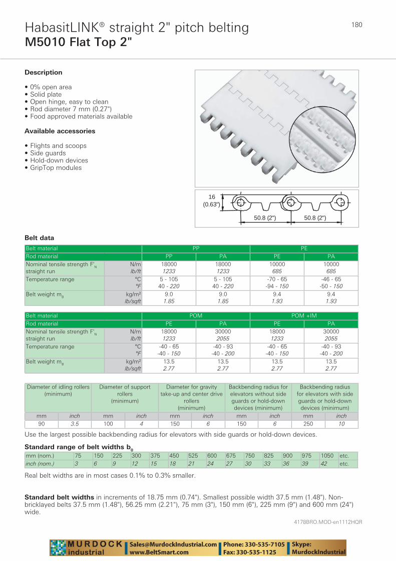
4178BRO.MOD-en1112HQR
180
Belt data
Belt material PP PERod material PP PA PE PANominal tensile strength F'N straight run
N/mlb/ft
180001233
180001233
10000685
10000685
Temperature range °C°F
5 - 10540 - 220
5 - 10540 - 220
-70 - 65-94 - 150
-46 - 65-50 - 150
Belt weight mB kg/m²lb/sqft
9.01.85
9.01.85
9.41.93
9.41.93
16(0.63")
50.8 (2")50.8 (2")
Belt material POM POM +IMRod material PE PA PE PANominal tensile strength F'N straight run
N/mlb/ft
180001233
300002055
180001233
300002055
Temperature range °C°F
-40 - 65-40 - 150
-40 - 93-40 - 200
-40 - 65-40 - 150
-40 - 93-40 - 200
Belt weight mB kg/m²lb/sqft
13.52.77
13.52.77
13.52.77
13.52.77
Diameter of idling rollers (minimum)
Diameter of support rollers
(minimum)
Diameter for gravity take-up and center drive
rollers (minimum)
Backbending radius for elevators without side guards or hold-down devices (minimum)
Backbending radius for elevators with side guards or hold-down devices (minimum)
mm inch mm inch mm inch mm inch mm inch90 3.5 100 4 150 6 150 6 250 10
Use the largest possible backbending radius for elevators with side guards or hold-down devices.
Standard belt widths in increments of 18.75 mm (0.74"). Smallest possible width 37.5 mm (1.48"). Non-bricklayed belts 37.5 mm (1.48"), 56.25 mm (2.21"), 75 mm (3"), 150 mm (6"), 225 mm (9") and 600 mm (24") wide.
M5010 Flat Top 2"HabasitLINK® straight 2" pitch belting
Standard range of belt widths b0
mm (nom.) 75 150 225 300 375 450 525 600 675 750 825 900 975 1050 etc.inch (nom.) 3 6 9 12 15 18 21 24 27 30 33 36 39 42 etc.
Real belt widths are in most cases 0.1% to 0.3% smaller.
Description
• 0% open area• Solid plate• Open hinge, easy to clean• Rod diameter 7 mm (0.27")• Food approved materials available
Available accessories
• Flights and scoops• Side guards• Hold-down devices• GripTop modules
181
4178BRO.MOD-en1112HQR
M5010 Flat Top 2"HabasitLINK® straight 2" pitch belting
For detailed material properties refer to pages 282 - 289.The nominal tensile strength is valid for 23 °C (73 °F). The admissible tensile force depends on the operating temperature near the drive sprockets. Within the temperature range allowed, the admissible tensile force may vary from 100% to 20% of the nominal tensile strength. For detailed information and correct calculation of effective tensile force refer to the Calculation Guide in the HabasitLINK® Engineering Guidelines.

4178BRO.MOD-en1112HQR
182
M5010 Roller Top 2"HabasitLINK® straight 2" pitch belting
Belt data
Belt material POMRod material PARoller material POMRoller lateral spacing per row mm / inch 56 / 2.2 75 / 3 112 / 4.4 150 / 6Roller offset next row mm / inch 0 / 0 0 / 0 56 / 2.2 75 / 3Roller dimension diameter / width
mminch
Ø 23 / 18Ø 0.91 / 0.71
Ø 23 / 18Ø 0.91 / 0.71
Ø 23 / 18Ø 0.91 / 0.71
Ø 23 / 18Ø 0.91 / 0.71
Nominal tensile strength F'N straight run
N/mlb/ft
200001370
210001438
220001507
225001541
Temperature range °C°F
-40 - 93-40 - 200
-40 - 93-40 - 200
-40 - 93-40 - 200
-40 - 93-40 - 200
Belt weight mB kg/m²lb/sqft
13.52.77
13.52.77
13.52.77
13.52.77
��������
����� ������ �
�������
Description
• Largest opening 19x2 mm (0.7"x0.08") • Roller lateral spacing see table belt data • Rollers row spacing 50.8 mm (2") • For low back pressure, wearstrips are placed
between rollers • For product driven application wearstrips are placed
directly under the rollers • Open hinge • Food approved materials available• Rod diameter 7 mm (0.27")
Diameter of idling rollers (minimum)
Diameter of support rollers
(minimum)
Diameter for gravity take-up and center drive
rollers (minimum)
Backbending radius for elevators without side guards or hold-down devices (minimum)
Backbending radius for elevators with side guards or hold-down devices (minimum)
mm inch mm inch mm inch mm inch mm inch90 3.5 100 4 150 6 150 6 250 10
Use the largest possible backbending radius for elevators with side guards or hold-down devices.
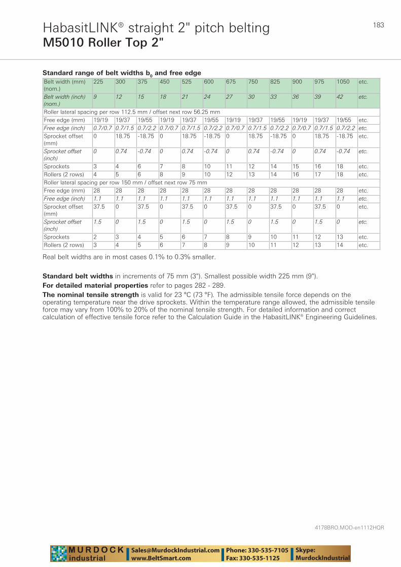
183
4178BRO.MOD-en1112HQR
M5010 Roller Top 2"HabasitLINK® straight 2" pitch belting
Standard range of belt widths b0 and free edgeBelt width (mm) (nom.)
225 300 375 450 525 600 675 750 825 900 975 1050 etc.
Belt width (inch) (nom.)
9 12 15 18 21 24 27 30 33 36 39 42 etc.
Roller lateral spacing per row 112.5 mm / offset next row 56.25 mmFree edge (mm) 19/19 19/37 19/55 19/19 19/37 19/55 19/19 19/37 19/55 19/19 19/37 19/55 etc.Free edge (inch) 0.7/0.7 0.7/1.5 0.7/2.2 0.7/0.7 0.7/1.5 0.7/2.2 0.7/0.7 0.7/1.5 0.7/2.2 0.7/0.7 0.7/1.5 0.7/2.2 etc.Sprocket offset (mm)
0 18.75 -18.75 0 18.75 -18.75 0 18.75 -18.75 0 18.75 -18.75 etc.
Sprocket offset (inch)
0 0.74 -0.74 0 0.74 -0.74 0 0.74 -0.74 0 0.74 -0.74 etc.
Sprockets 3 4 6 7 8 10 11 12 14 15 16 18 etc.Rollers (2 rows) 4 5 6 8 9 10 12 13 14 16 17 18 etc.Roller lateral spacing per row 150 mm / offset next row 75 mmFree edge (mm) 28 28 28 28 28 28 28 28 28 28 28 28 etc.Free edge (inch) 1.1 1.1 1.1 1.1 1.1 1.1 1.1 1.1 1.1 1.1 1.1 1.1 etc.Sprocket offset (mm)
37.5 0 37.5 0 37.5 0 37.5 0 37.5 0 37.5 0 etc.
Sprocket offset (inch)
1.5 0 1.5 0 1.5 0 1.5 0 1.5 0 1.5 0 etc.
Sprockets 2 3 4 5 6 7 8 9 10 11 12 13 etc.Rollers (2 rows) 3 4 5 6 7 8 9 10 11 12 13 14 etc.
Real belt widths are in most cases 0.1% to 0.3% smaller.
Standard belt widths in increments of 75 mm (3"). Smallest possible width 225 mm (9").For detailed material properties refer to pages 282 - 289.The nominal tensile strength is valid for 23 °C (73 °F). The admissible tensile force depends on the operating temperature near the drive sprockets. Within the temperature range allowed, the admissible tensile force may vary from 100% to 20% of the nominal tensile strength. For detailed information and correct calculation of effective tensile force refer to the Calculation Guide in the HabasitLINK® Engineering Guidelines.

4178BRO.MOD-en1112HQR
184
M5011 Perforated Flat Top 2"HabasitLINK® straight 2" pitch belting
Belt data
Standard range of belt widths b0
mm (nom.) 75 150 225 300 375 450 525 600 675 750 825 900 975 1050 etc.inch (nom.) 3 6 9 12 15 18 21 24 27 30 33 36 39 42 etc.
Real belt widths are in most cases 0.1% to 0.3% smaller.
Belt material PP PE POMRod material PP PA PE PA PE PANominal tensile strength F'N straight run
N/mlb/ft
180001233
180001233
10000685
10000685
180001233
300002055
Temperature range °C°F
5 - 10540 - 220
5 - 10540 - 220
-70 - 65-94 - 150
-46 - 65-50 - 150
-40 - 65-40 - 150
-40 - 93-40 - 200
Belt weight mB kg/m²lb/sqft
7.81.60
7.81.60
8.31.70
8.31.70
12.02.46
12.02.46
16(0.63")
50.8 (2") 50.8 (2")
Description
• 18% open area; largest opening 2x10 mm (0.08"x0.4")
• Solid plate • Open hinge, easy to clean • Food approved materials available• Rod diameter 7 mm (0.27")
Available accessories
• Flights and scoops • Side guards • Hold-down devices • GripTop modules
Belt material POM +IMRod material PE PANominal tensile strength F'N straight run
N/mlb/ft
180001233
300002055
Temperature range °C°F
-40 - 65-40 - 150
-40 - 93-40 - 200
Belt weight mB kg/m²lb/sqft
12.02.46
12.02.46
Diameter of idling rollers (minimum)
Diameter of support rollers
(minimum)
Diameter for gravity take-up and center drive
rollers (minimum)
Backbending radius for elevators without side guards or hold-down devices (minimum)
Backbending radius for elevators with side guards or hold-down devices (minimum)
mm inch mm inch mm inch mm inch mm inch90 3.5 100 4 150 6 150 6 250 10
Use the largest possible backbending radius for elevators with side guards or hold-down devices.
Standard belt widths in increments of 75 mm (3"). Non-standard widths are offered in increments of 18.75 mm (0.74"). Smallest possible width 112.5 mm (4.42"). Non-bricklayed belts 75 mm (3") and 150 mm (6") wide.
185
4178BRO.MOD-en1112HQR
M5011 Perforated Flat Top 2"HabasitLINK® straight 2" pitch belting
For detailed material properties refer to pages 282 - 289.The nominal tensile strength is valid for 23 °C (73 °F). The admissible tensile force depends on the operating temperature near the drive sprockets. Within the temperature range allowed, the admissible tensile force may vary from 100% to 20% of the nominal tensile strength. For detailed information and correct calculation of effective tensile force refer to the Calculation Guide in the HabasitLINK® Engineering Guidelines.
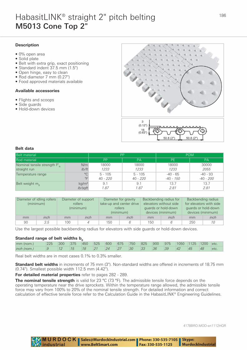
4178BRO.MOD-en1112HQR
186
M5013 Cone Top 2"HabasitLINK® straight 2" pitch belting
Belt data
Standard range of belt widths b0
mm (nom.) 225 300 375 450 525 600 675 750 825 900 975 1050 1125 1200 etc.inch (nom.) 9 12 15 18 21 24 27 30 33 36 39 42 45 48 etc.
Real belt widths are in most cases 0.1% to 0.3% smaller.
Belt material PP POMRod material PP PA PE PANominal tensile strength F'N straight run
N/mlb/ft
180001233
180001233
180001233
300002055
Temperature range °C°F
5 - 10540 - 220
5 - 10540 - 220
-40 - 65-40 - 150
-40 - 93-40 - 200
Belt weight mB kg/m²lb/sqft
9.11.87
9.11.87
13.72.81
13.72.81
��������������
�������
������
Description
• 0% open area• Solid plate• Belt with extra grip, exact positioning• Standard indent 37.5 mm (1.5")• Open hinge, easy to clean• Rod diameter 7 mm (0.27")• Food approved materials available
Available accessories
• Flights and scoops• Side guards• Hold-down devices
Diameter of idling rollers (minimum)
Diameter of support rollers
(minimum)
Diameter for gravity take-up and center drive
rollers (minimum)
Backbending radius for elevators without side guards or hold-down devices (minimum)
Backbending radius for elevators with side guards or hold-down devices (minimum)
mm inch mm inch mm inch mm inch mm inch90 3.5 100 4 150 6 150 6 250 10
Use the largest possible backbending radius for elevators with side guards or hold-down devices.
Standard belt widths in increments of 75 mm (3"). Non-standard widths are offered in increments of 18.75 mm (0.74"). Smallest possible width 112.5 mm (4.42").For detailed material properties refer to pages 282 - 289.The nominal tensile strength is valid for 23 °C (73 °F). The admissible tensile force depends on the operating temperature near the drive sprockets. Within the temperature range allowed, the admissible tensile force may vary from 100% to 20% of the nominal tensile strength. For detailed information and correct calculation of effective tensile force refer to the Calculation Guide in the HabasitLINK® Engineering Guidelines.
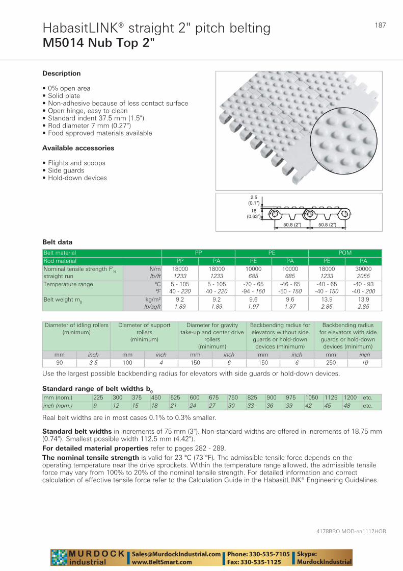
187
4178BRO.MOD-en1112HQR
M5014 Nub Top 2"HabasitLINK® straight 2" pitch belting
Belt data
Standard range of belt widths b0
mm (nom.) 225 300 375 450 525 600 675 750 825 900 975 1050 1125 1200 etc.inch (nom.) 9 12 15 18 21 24 27 30 33 36 39 42 45 48 etc.
Real belt widths are in most cases 0.1% to 0.3% smaller.
Belt material PP PE POMRod material PP PA PE PA PE PANominal tensile strength F'N straight run
N/mlb/ft
180001233
180001233
10000685
10000685
180001233
300002055
Temperature range °C°F
5 - 10540 - 220
5 - 10540 - 220
-70 - 65-94 - 150
-46 - 65-50 - 150
-40 - 65-40 - 150
-40 - 93-40 - 200
Belt weight mB kg/m²lb/sqft
9.21.89
9.21.89
9.61.97
9.61.97
13.92.85
13.92.85
������� �������
�������
�������
Description
• 0% open area• Solid plate• Non-adhesive because of less contact surface• Open hinge, easy to clean• Standard indent 37.5 mm (1.5")• Rod diameter 7 mm (0.27")• Food approved materials available
Available accessories
• Flights and scoops• Side guards• Hold-down devices
Diameter of idling rollers (minimum)
Diameter of support rollers
(minimum)
Diameter for gravity take-up and center drive
rollers (minimum)
Backbending radius for elevators without side guards or hold-down devices (minimum)
Backbending radius for elevators with side guards or hold-down devices (minimum)
mm inch mm inch mm inch mm inch mm inch90 3.5 100 4 150 6 150 6 250 10
Use the largest possible backbending radius for elevators with side guards or hold-down devices.
Standard belt widths in increments of 75 mm (3"). Non-standard widths are offered in increments of 18.75 mm (0.74"). Smallest possible width 112.5 mm (4.42").For detailed material properties refer to pages 282 - 289.The nominal tensile strength is valid for 23 °C (73 °F). The admissible tensile force depends on the operating temperature near the drive sprockets. Within the temperature range allowed, the admissible tensile force may vary from 100% to 20% of the nominal tensile strength. For detailed information and correct calculation of effective tensile force refer to the Calculation Guide in the HabasitLINK® Engineering Guidelines.
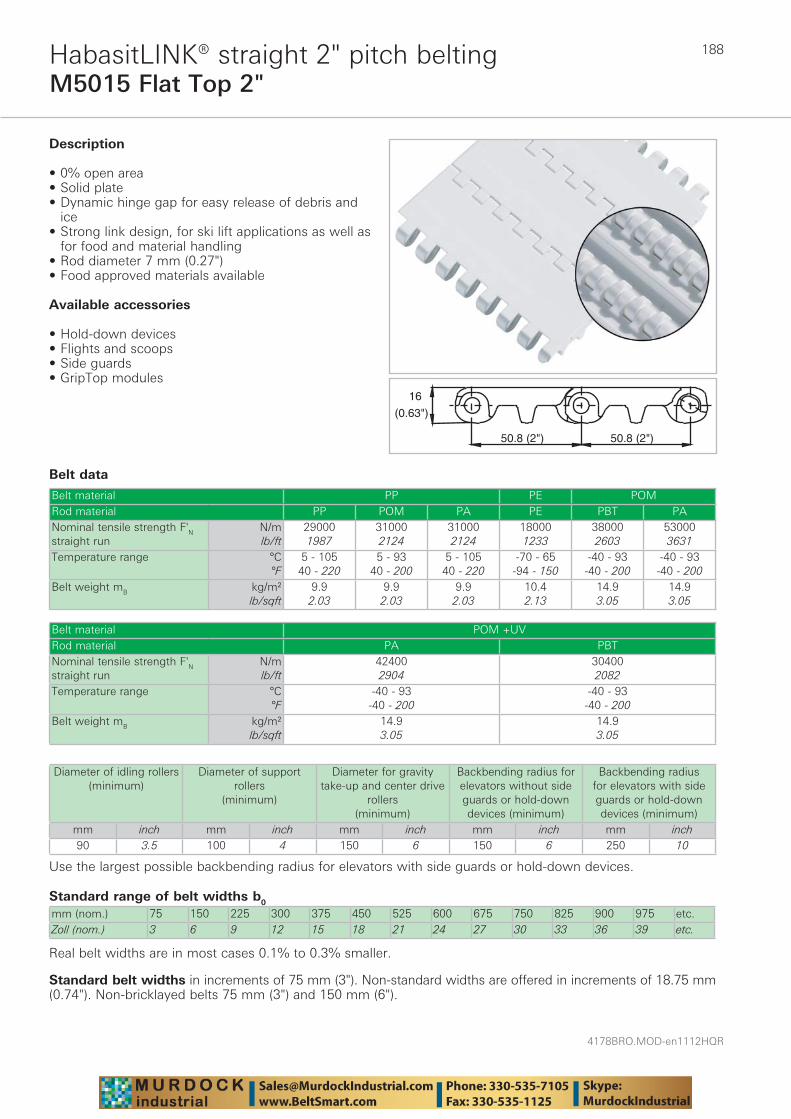
4178BRO.MOD-en1112HQR
188
M5015 Flat Top 2"HabasitLINK® straight 2" pitch belting
Belt data
Standard range of belt widths b0
mm (nom.) 75 150 225 300 375 450 525 600 675 750 825 900 975 etc.Zoll (nom.) 3 6 9 12 15 18 21 24 27 30 33 36 39 etc.
Real belt widths are in most cases 0.1% to 0.3% smaller.
Belt material PP PE POMRod material PP POM PA PE PBT PANominal tensile strength F'N straight run
N/mlb/ft
290001987
310002124
310002124
180001233
380002603
530003631
Temperature range °C°F
5 - 10540 - 220
5 - 9340 - 200
5 - 10540 - 220
-70 - 65-94 - 150
-40 - 93-40 - 200
-40 - 93-40 - 200
Belt weight mB kg/m²lb/sqft
9.92.03
9.92.03
9.92.03
10.42.13
14.93.05
14.93.05
�������
������� �������
Description
• 0% open area • Solid plate • Dynamic hinge gap for easy release of debris and
ice • Strong link design, for ski lift applications as well as
for food and material handling • Rod diameter 7 mm (0.27") • Food approved materials available
Available accessories
• Hold-down devices • Flights and scoops• Side guards • GripTop modules
Belt material POM +UVRod material PA PBTNominal tensile strength F'N straight run
N/mlb/ft
424002904
304002082
Temperature range °C°F
-40 - 93-40 - 200
-40 - 93-40 - 200
Belt weight mB kg/m²lb/sqft
14.93.05
14.93.05
Diameter of idling rollers (minimum)
Diameter of support rollers
(minimum)
Diameter for gravity take-up and center drive
rollers (minimum)
Backbending radius for elevators without side guards or hold-down devices (minimum)
Backbending radius for elevators with side guards or hold-down devices (minimum)
mm inch mm inch mm inch mm inch mm inch90 3.5 100 4 150 6 150 6 250 10
Use the largest possible backbending radius for elevators with side guards or hold-down devices.
Standard belt widths in increments of 75 mm (3"). Non-standard widths are offered in increments of 18.75 mm (0.74"). Non-bricklayed belts 75 mm (3") and 150 mm (6").

189
4178BRO.MOD-en1112HQR
M5015 Flat Top 2"HabasitLINK® straight 2" pitch belting
For detailed material properties refer to pages 282 - 289.The nominal tensile strength is valid for 23 °C (73 °F). The admissible tensile force depends on the operating temperature near the drive sprockets. Within the temperature range allowed, the admissible tensile force may vary from 100% to 20% of the nominal tensile strength. For detailed information and correct calculation of effective tensile force refer to the Calculation Guide in the HabasitLINK® Engineering Guidelines.
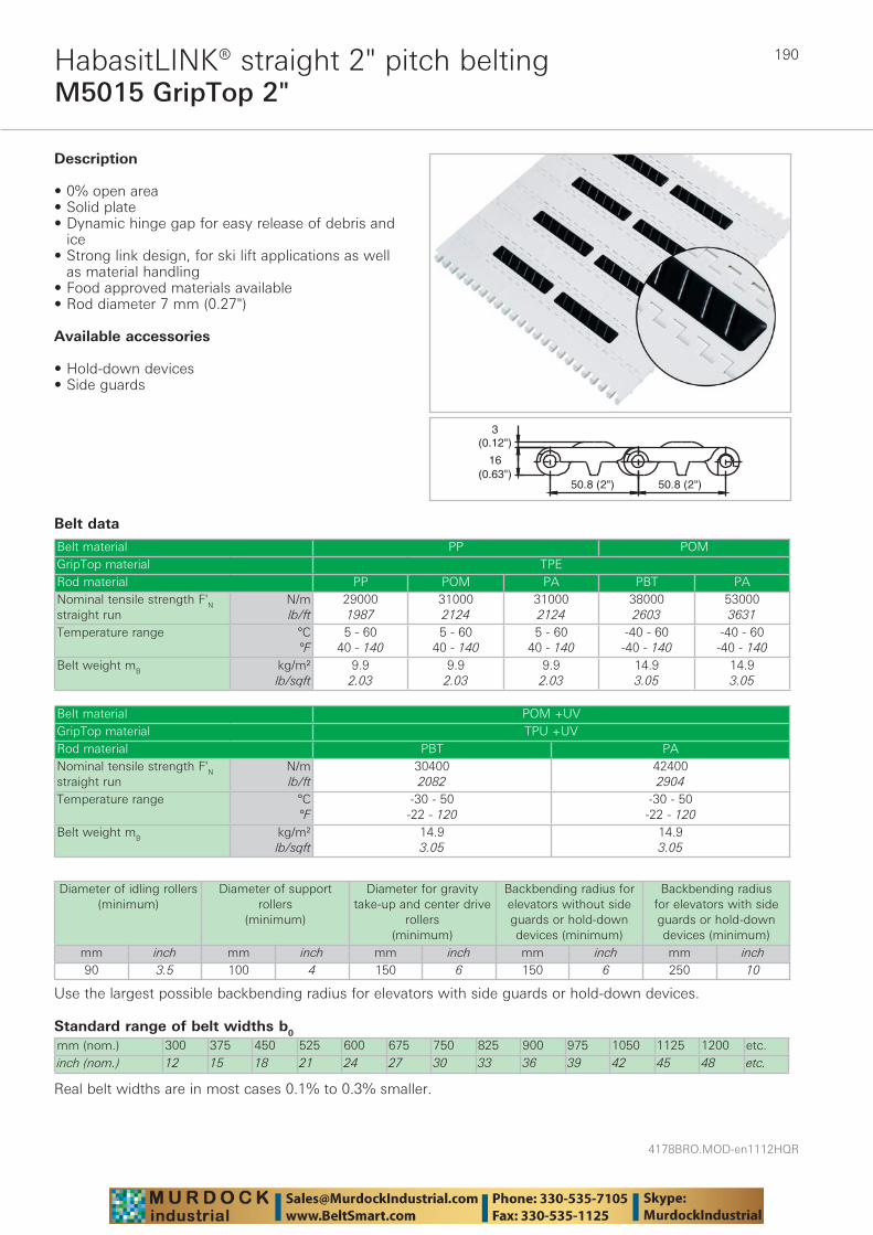
4178BRO.MOD-en1112HQR
190
M5015 GripTop 2"HabasitLINK® straight 2" pitch belting
Belt data
Standard range of belt widths b0
mm (nom.) 300 375 450 525 600 675 750 825 900 975 1050 1125 1200 etc.inch (nom.) 12 15 18 21 24 27 30 33 36 39 42 45 48 etc.
Real belt widths are in most cases 0.1% to 0.3% smaller.
Belt material PP POMGripTop material TPERod material PP POM PA PBT PANominal tensile strength F'N straight run
N/mlb/ft
290001987
310002124
310002124
380002603
530003631
Temperature range °C°F
5 - 6040 - 140
5 - 6040 - 140
5 - 6040 - 140
-40 - 60-40 - 140
-40 - 60-40 - 140
Belt weight mB kg/m²lb/sqft
9.92.03
9.92.03
9.92.03
14.93.05
14.93.05
�����
��������������
��
�
�����
Description
• 0% open area • Solid plate • Dynamic hinge gap for easy release of debris and
ice • Strong link design, for ski lift applications as well
as material handling • Food approved materials available• Rod diameter 7 mm (0.27")
Available accessories
• Hold-down devices • Side guards
Belt material POM +UVGripTop material TPU +UVRod material PBT PANominal tensile strength F'N straight run
N/mlb/ft
304002082
424002904
Temperature range °C°F
-30 - 50-22 - 120
-30 - 50-22 - 120
Belt weight mB kg/m²lb/sqft
14.93.05
14.93.05
Diameter of idling rollers (minimum)
Diameter of support rollers
(minimum)
Diameter for gravity take-up and center drive
rollers (minimum)
Backbending radius for elevators without side guards or hold-down devices (minimum)
Backbending radius for elevators with side guards or hold-down devices (minimum)
mm inch mm inch mm inch mm inch mm inch90 3.5 100 4 150 6 150 6 250 10
Use the largest possible backbending radius for elevators with side guards or hold-down devices.
191
4178BRO.MOD-en1112HQR
Standard belt widths in increments of 75 mm (3"). Non-standard widths are offered in increments of 18.75 mm (0.74"). Smallest possible width 225 mm (9"). Non-bricklayed belts without indent 150 mm (6") wide.For detailed material properties refer to pages 282 - 289.The nominal tensile strength is valid for 23 °C (73 °F). The admissible tensile force depends on the operating temperature near the drive sprockets. Within the temperature range allowed, the admissible tensile force may vary from 100% to 20% of the nominal tensile strength. For detailed information and correct calculation of effective tensile force refer to the Calculation Guide in the HabasitLINK® Engineering Guidelines.
M5015 GripTop 2"HabasitLINK® straight 2" pitch belting
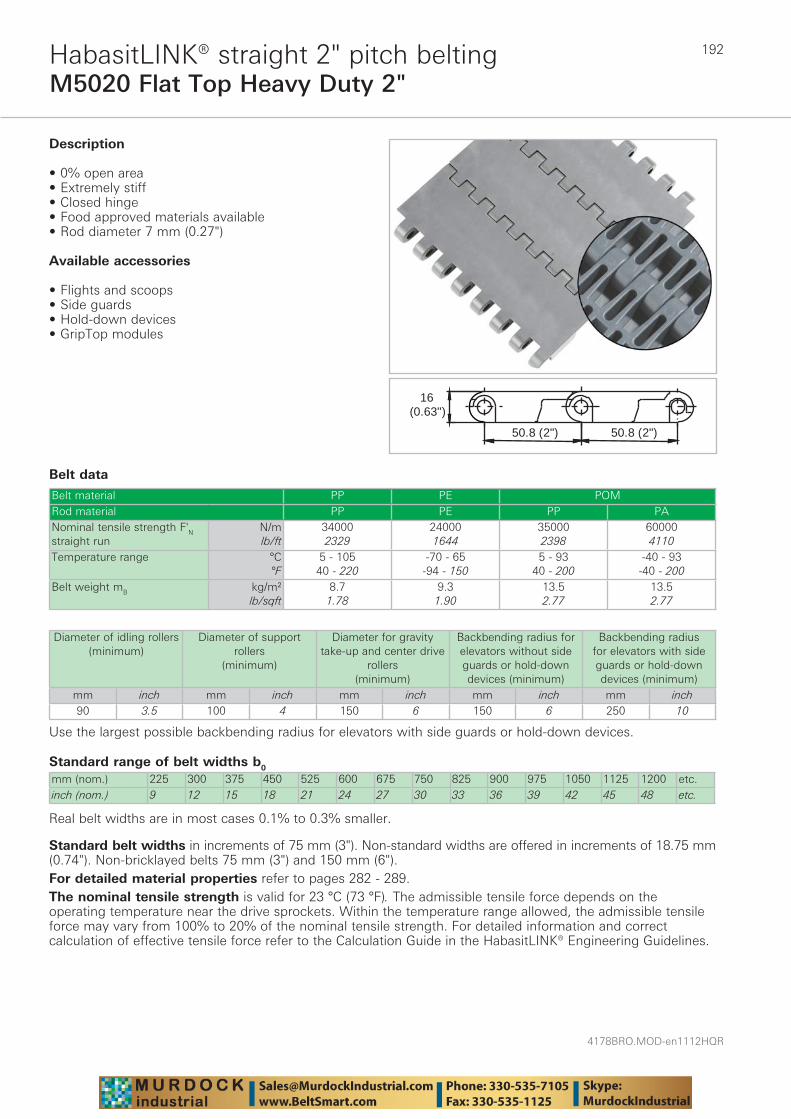
4178BRO.MOD-en1112HQR
192
M5020 Flat Top Heavy Duty 2"HabasitLINK® straight 2" pitch belting
Belt data
Standard range of belt widths b0
mm (nom.) 225 300 375 450 525 600 675 750 825 900 975 1050 1125 1200 etc.inch (nom.) 9 12 15 18 21 24 27 30 33 36 39 42 45 48 etc.
Real belt widths are in most cases 0.1% to 0.3% smaller.
Belt material PP PE POMRod material PP PE PP PANominal tensile strength F'N straight run
N/mlb/ft
340002329
240001644
350002398
600004110
Temperature range °C°F
5 - 10540 - 220
-70 - 65-94 - 150
5 - 9340 - 200
-40 - 93-40 - 200
Belt weight mB kg/m²lb/sqft
8.71.78
9.31.90
13.52.77
13.52.77
16(0.63")
50.8 (2") 50.8 (2")
Description
• 0% open area• Extremely stiff• Closed hinge• Food approved materials available• Rod diameter 7 mm (0.27")
Available accessories
• Flights and scoops• Side guards• Hold-down devices• GripTop modules
Diameter of idling rollers (minimum)
Diameter of support rollers
(minimum)
Diameter for gravity take-up and center drive
rollers (minimum)
Backbending radius for elevators without side guards or hold-down devices (minimum)
Backbending radius for elevators with side guards or hold-down devices (minimum)
mm inch mm inch mm inch mm inch mm inch90 3.5 100 4 150 6 150 6 250 10
Use the largest possible backbending radius for elevators with side guards or hold-down devices.
Standard belt widths in increments of 75 mm (3"). Non-standard widths are offered in increments of 18.75 mm (0.74"). Non-bricklayed belts 75 mm (3") and 150 mm (6").For detailed material properties refer to pages 282 - 289.The nominal tensile strength is valid for 23 °C (73 °F). The admissible tensile force depends on the operating temperature near the drive sprockets. Within the temperature range allowed, the admissible tensile force may vary from 100% to 20% of the nominal tensile strength. For detailed information and correct calculation of effective tensile force refer to the Calculation Guide in the HabasitLINK® Engineering Guidelines.
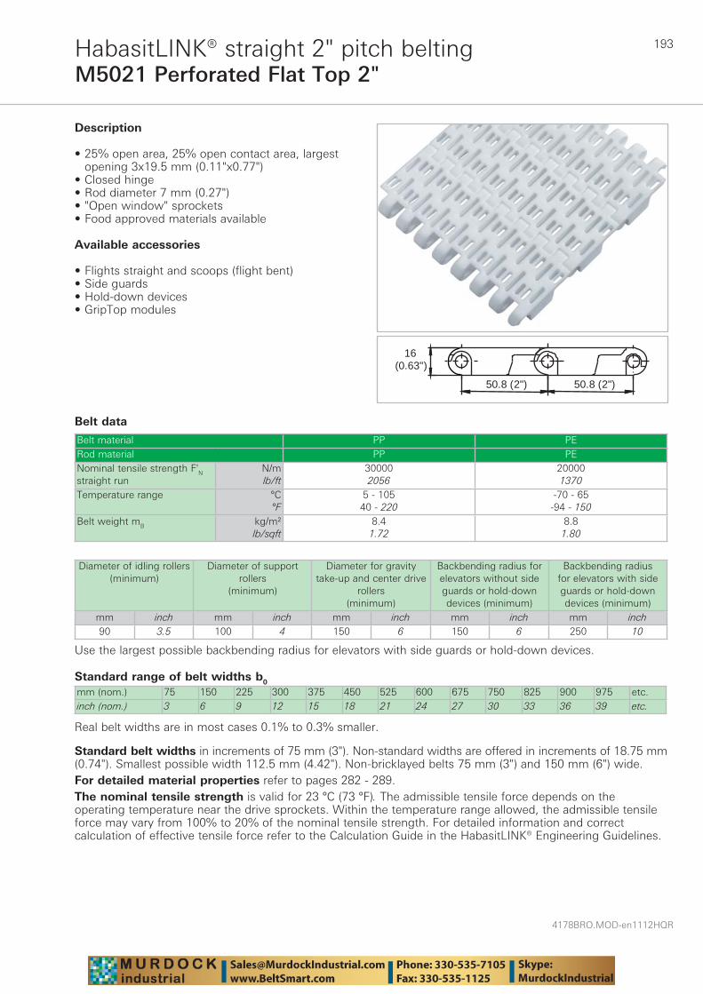
193
4178BRO.MOD-en1112HQR
M5021 Perforated Flat Top 2"HabasitLINK® straight 2" pitch belting
Belt data
Standard range of belt widths b0
mm (nom.) 75 150 225 300 375 450 525 600 675 750 825 900 975 etc.inch (nom.) 3 6 9 12 15 18 21 24 27 30 33 36 39 etc.
Real belt widths are in most cases 0.1% to 0.3% smaller.
Belt material PP PERod material PP PENominal tensile strength F'N straight run
N/mlb/ft
300002056
200001370
Temperature range °C°F
5 - 10540 - 220
-70 - 65-94 - 150
Belt weight mB kg/m²lb/sqft
8.41.72
8.81.80
16(0.63")
50.8 (2") 50.8 (2")
Description
• 25% open area, 25% open contact area, largest opening 3x19.5 mm (0.11"x0.77")
• Closed hinge • Rod diameter 7 mm (0.27") • "Open window" sprockets • Food approved materials available
Available accessories
• Flights straight and scoops (flight bent) • Side guards • Hold-down devices • GripTop modules
Diameter of idling rollers (minimum)
Diameter of support rollers
(minimum)
Diameter for gravity take-up and center drive
rollers (minimum)
Backbending radius for elevators without side guards or hold-down devices (minimum)
Backbending radius for elevators with side guards or hold-down devices (minimum)
mm inch mm inch mm inch mm inch mm inch90 3.5 100 4 150 6 150 6 250 10
Use the largest possible backbending radius for elevators with side guards or hold-down devices.
Standard belt widths in increments of 75 mm (3"). Non-standard widths are offered in increments of 18.75 mm (0.74"). Smallest possible width 112.5 mm (4.42"). Non-bricklayed belts 75 mm (3") and 150 mm (6") wide.For detailed material properties refer to pages 282 - 289.The nominal tensile strength is valid for 23 °C (73 °F). The admissible tensile force depends on the operating temperature near the drive sprockets. Within the temperature range allowed, the admissible tensile force may vary from 100% to 20% of the nominal tensile strength. For detailed information and correct calculation of effective tensile force refer to the Calculation Guide in the HabasitLINK® Engineering Guidelines.
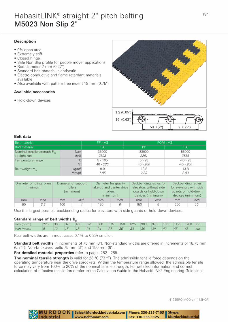
4178BRO.MOD-en1112HQR
194
M5023 Non Slip 2"HabasitLINK® straight 2" pitch belting
Belt data
Standard range of belt widths b0
mm (nom.) 225 300 375 450 525 600 675 750 825 900 975 1050 1125 1200 etc.inch (nom.) 9 12 15 18 21 24 27 30 33 36 39 42 45 48 etc.
Real belt widths are in most cases 0.1% to 0.3% smaller.
Belt material PP +AS POM +ASRod material PA PP PANominal tensile strength F'N straight run
N/mlb/ft
350002398
330002261
560003836
Temperature range °C°F
5 - 10540 - 220
5 - 9340 - 200
-40 - 93-40 - 200
Belt weight mB kg/m²lb/sqft
9.01.85
13.82.83
13.82.83
50.8 (2")50.8 (2")
16 (0.63")
1.2 (0.05")
Description
• 0% open area • Extremely stiff • Closed hinge • Safe Non Slip profile for people mover applications • Rod diameter 7 mm (0.27") • Standard belt material is antistatic • Electro conductive and flame retardant materials
available • Also available with pattern free indent 19 mm (0.75")
Available accessories
• Hold-down devices
Diameter of idling rollers (minimum)
Diameter of support rollers
(minimum)
Diameter for gravity take-up and center drive
rollers (minimum)
Backbending radius for elevators without side guards or hold-down devices (minimum)
Backbending radius for elevators with side guards or hold-down devices (minimum)
mm inch mm inch mm inch mm inch mm inch90 3.5 100 4 150 6 150 6 250 10
Use the largest possible backbending radius for elevators with side guards or hold-down devices.
Standard belt widths in increments of 75 mm (3"). Non-standard widths are offered in increments of 18.75 mm (0.74"). Non-bricklayed belts 75 mm (3") and 150 mm (6").For detailed material properties refer to pages 282 - 289.The nominal tensile strength is valid for 23 °C (73 °F). The admissible tensile force depends on the operating temperature near the drive sprockets. Within the temperature range allowed, the admissible tensile force may vary from 100% to 20% of the nominal tensile strength. For detailed information and correct calculation of effective tensile force refer to the Calculation Guide in the HabasitLINK® Engineering Guidelines.
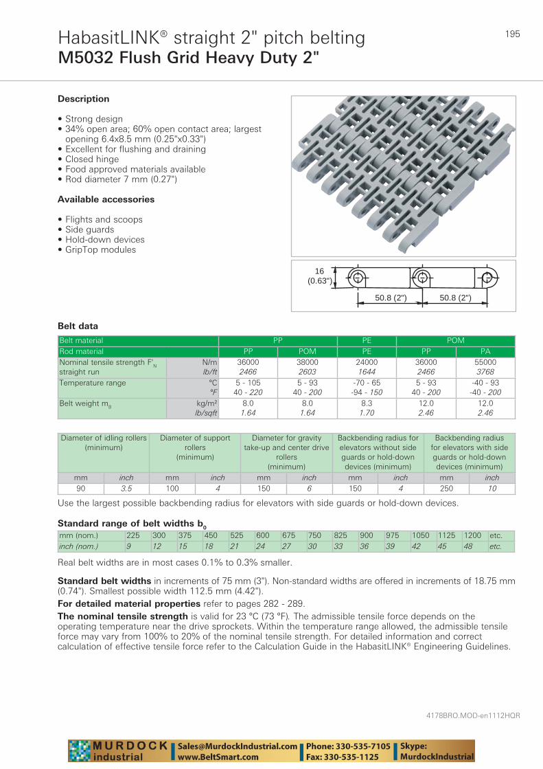
195
4178BRO.MOD-en1112HQR
M5032 Flush Grid Heavy Duty 2"HabasitLINK® straight 2" pitch belting
Belt data
Standard range of belt widths b0
mm (nom.) 225 300 375 450 525 600 675 750 825 900 975 1050 1125 1200 etc.inch (nom.) 9 12 15 18 21 24 27 30 33 36 39 42 45 48 etc.
Real belt widths are in most cases 0.1% to 0.3% smaller.
Belt material PP PE POMRod material PP POM PE PP PANominal tensile strength F'N straight run
N/mlb/ft
360002466
380002603
240001644
360002466
550003768
Temperature range °C°F
5 - 10540 - 220
5 - 9340 - 200
-70 - 65-94 - 150
5 - 9340 - 200
-40 - 93-40 - 200
Belt weight mB kg/m²lb/sqft
8.01.64
8.01.64
8.31.70
12.02.46
12.02.46
50.8 (2")50.8 (2")
16(0.63")
Description
• Strong design• 34% open area; 60% open contact area; largest
opening 6.4x8.5 mm (0.25"x0.33")• Excellent for flushing and draining• Closed hinge• Food approved materials available• Rod diameter 7 mm (0.27")
Available accessories
• Flights and scoops• Side guards• Hold-down devices• GripTop modules
Diameter of idling rollers (minimum)
Diameter of support rollers
(minimum)
Diameter for gravity take-up and center drive
rollers (minimum)
Backbending radius for elevators without side guards or hold-down devices (minimum)
Backbending radius for elevators with side guards or hold-down devices (minimum)
mm inch mm inch mm inch mm inch mm inch90 3.5 100 4 150 6 150 4 250 10
Use the largest possible backbending radius for elevators with side guards or hold-down devices.
Standard belt widths in increments of 75 mm (3"). Non-standard widths are offered in increments of 18.75 mm (0.74"). Smallest possible width 112.5 mm (4.42").For detailed material properties refer to pages 282 - 289.The nominal tensile strength is valid for 23 °C (73 °F). The admissible tensile force depends on the operating temperature near the drive sprockets. Within the temperature range allowed, the admissible tensile force may vary from 100% to 20% of the nominal tensile strength. For detailed information and correct calculation of effective tensile force refer to the Calculation Guide in the HabasitLINK® Engineering Guidelines.
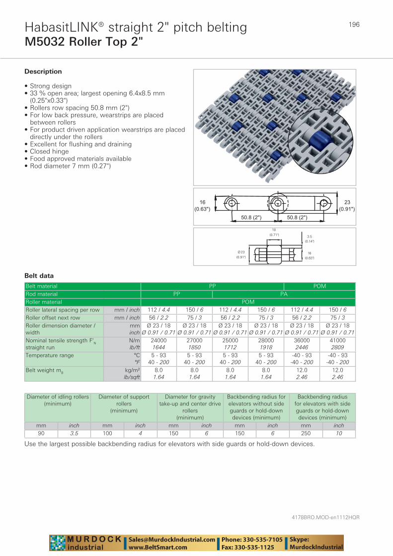
4178BRO.MOD-en1112HQR
196
M5032 Roller Top 2"HabasitLINK® straight 2" pitch belting
Belt data
Belt material PP POMRod material PP PARoller material POMRoller lateral spacing per row mm / inch 112 / 4.4 150 / 6 112 / 4.4 150 / 6 112 / 4.4 150 / 6Roller offset next row mm / inch 56 / 2.2 75 / 3 56 / 2.2 75 / 3 56 / 2.2 75 / 3Roller dimension diameter / width
mminch
Ø 23 / 18Ø 0.91 / 0.71
Ø 23 / 18Ø 0.91 / 0.71
Ø 23 / 18Ø 0.91 / 0.71
Ø 23 / 18Ø 0.91 / 0.71
Ø 23 / 18Ø 0.91 / 0.71
Ø 23 / 18Ø 0.91 / 0.71
Nominal tensile strength F'N straight run
N/mlb/ft
240001644
270001850
250001712
280001918
360002446
410002809
Temperature range °C°F
5 - 9340 - 200
5 - 9340 - 200
5 - 9340 - 200
5 - 9340 - 200
-40 - 93-40 - 200
-40 - 93-40 - 200
Belt weight mB kg/m²lb/sqft
8.01.64
8.01.64
8.01.64
8.01.64
12.02.46
12.02.46
��������������
�������
����� �
Description
• Strong design • 33 % open area; largest opening 6.4x8.5 mm
(0.25"x0.33") • Rollers row spacing 50.8 mm (2") • For low back pressure, wearstrips are placed
between rollers • For product driven application wearstrips are placed
directly under the rollers • Excellent for flushing and draining • Closed hinge • Food approved materials available• Rod diameter 7 mm (0.27")
Diameter of idling rollers (minimum)
Diameter of support rollers
(minimum)
Diameter for gravity take-up and center drive
rollers (minimum)
Backbending radius for elevators without side guards or hold-down devices (minimum)
Backbending radius for elevators with side guards or hold-down devices (minimum)
mm inch mm inch mm inch mm inch mm inch90 3.5 100 4 150 6 150 6 250 10
Use the largest possible backbending radius for elevators with side guards or hold-down devices.

197
4178BRO.MOD-en1112HQR
M5032 Roller Top 2"HabasitLINK® straight 2" pitch belting
Standard range of belt widths b0 and free edgeBelt width (mm) (nom.)
225 300 375 450 525 600 675 750 825 900 975 1050 etc.
Belt width (inch) (nom.)
9 12 15 18 21 24 27 30 33 36 39 42 etc.
Roller lateral spacing per row 112.5 mm / offset next row 56.25 mmFree edge (mm) 19/19 19/37 19/55 19/19 19/37 19/55 19/19 19/37 19/55 19/19 19/37 19/55 etc.Free edge (inch) 0.7/0.7 0.7/1.5 0.7/2.2 0.7/0.7 0.7/1.5 0.7/2.2 0.7/0.7 0.7/1.5 0.7/2.2 0.7/0.7 0.7/1.5 0.7/2.2 etc.Sprocket offset (mm)
0 18.75 -18.75 0 18.75 -18.75 0 18.75 -18.75 0 18.75 -18.75 etc.
Sprocket offset (inch)
0 0.74 -0.74 0 0.74 -0.74 0 0.74 -0.74 0 0.74 -0.74 etc.
Sprockets 3 4 6 7 8 10 11 12 14 15 16 18 etc.Rollers (2 rows) 4 5 6 8 9 10 12 13 14 16 17 18 etc.Roller lateral spacing per row 150 mm / offset next row 75 mmFree edge (mm) 28 28 28 28 28 28 28 28 28 28 28 28 etc.Free edge (inch) 1.1 1.1 1.1 1.1 1.1 1.1 1.1 1.1 1.1 1.1 1.1 1.1 etc.Sprocket offset (mm)
37.5 0 37.5 0 37.5 0 37.5 0 37.5 0 37.5 0 etc.
Sprocket offset (inch)
1.5 0 1.5 0 1.5 0 1.5 0 1.5 0 1.5 0 etc.
Sprockets 2 3 4 5 6 7 8 9 10 11 12 13 etc.Rollers (2 rows) 3 4 5 6 7 8 9 10 11 12 13 14 etc.
Real belt widths are in most cases 0.1% to 0.3% smaller.
Standard belt widths in increments of 75 mm (3"). Smallest possible width 225 mm (9").For detailed material properties refer to pages 282 - 289.The nominal tensile strength is valid for 23 °C (73 °F). The admissible tensile force depends on the operating temperature near the drive sprockets. Within the temperature range allowed, the admissible tensile force may vary from 100% to 20% of the nominal tensile strength. For detailed information and correct calculation of effective tensile force refer to the Calculation Guide in the HabasitLINK® Engineering Guidelines.
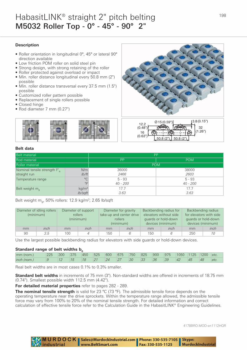
4178BRO.MOD-en1112HQR
198
M5032 Roller Top - 0° - 45° - 90° 2"HabasitLINK® straight 2" pitch belting
Belt data
Standard range of belt widths b0
mm (nom.) 225 300 375 450 525 600 675 750 825 900 975 1050 1125 1200 etc.inch (nom.) 9 12 15 18 21 24 27 30 33 36 39 42 45 48 etc.
Real belt widths are in most cases 0.1% to 0.3% smaller.
Belt material PPRod material PP POMRoller material POMNominal tensile strength F'N straight run
N/mlb/ft
360002466
380002603
Temperature range °C°F
5 - 9340 - 200
5 - 9340 - 200
Belt weight mB kg/m²lb/sqft
17.73.63
17.73.63
��� ���������
�������
�����
� ����
������� �������
�������
��
Description
• Roller orientation in longitudinal 0°, 45° or lateral 90° direction available
• Low friction POM roller on solid steel pin• Strong design, with strong retaining of the roller• Roller protected against overload or impact• Min. roller distance longitudinal every 50.8 mm (2")
possible• Min. roller distance transversal every 37.5 mm (1.5")
possible• Customized roller pattern possible• Replacement of single rollers possible• Closed hinge• Rod diameter 7 mm (0.27")
Belt weight mB, 50% rollers: 12.9 kg/m2; 2.65 lb/sqft
Diameter of idling rollers (minimum)
Diameter of support rollers
(minimum)
Diameter for gravity take-up and center drive
rollers (minimum)
Backbending radius for elevators without side guards or hold-down devices (minimum)
Backbending radius for elevators with side guards or hold-down devices (minimum)
mm inch mm inch mm inch mm inch mm inch90 3.5 100 4 150 6 150 6 250 10
Use the largest possible backbending radius for elevators with side guards or hold-down devices.
Standard belt widths in increments of 75 mm (3"). Non-standard widths are offered in increments of 18.75 mm (0.74"). Smallest possible width 112.5 mm (4.42").For detailed material properties refer to pages 282 - 289.The nominal tensile strength is valid for 23 °C (73 °F). The admissible tensile force depends on the operating temperature near the drive sprockets. Within the temperature range allowed, the admissible tensile force may vary from 100% to 20% of the nominal tensile strength. For detailed information and correct calculation of effective tensile force refer to the Calculation Guide in the HabasitLINK® Engineering Guidelines.
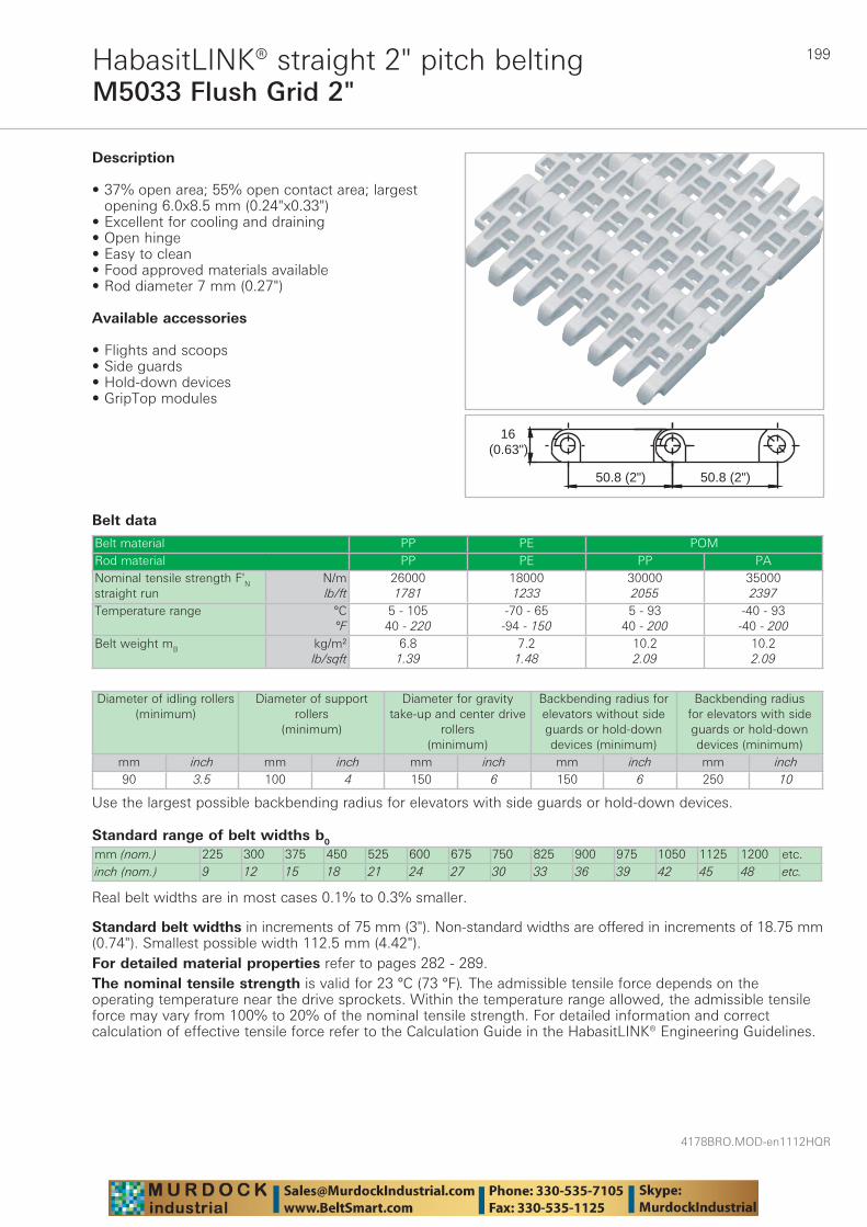
199
4178BRO.MOD-en1112HQR
M5033 Flush Grid 2"HabasitLINK® straight 2" pitch belting
Belt data
Standard range of belt widths b0
mm (nom.) 225 300 375 450 525 600 675 750 825 900 975 1050 1125 1200 etc.inch (nom.) 9 12 15 18 21 24 27 30 33 36 39 42 45 48 etc.
Real belt widths are in most cases 0.1% to 0.3% smaller.
Belt material PP PE POMRod material PP PE PP PANominal tensile strength F'N straight run
N/mlb/ft
260001781
180001233
300002055
350002397
Temperature range °C°F
5 - 10540 - 220
-70 - 65-94 - 150
5 - 9340 - 200
-40 - 93-40 - 200
Belt weight mB kg/m²lb/sqft
6.81.39
7.21.48
10.22.09
10.22.09
16(0.63")
50.8 (2") 50.8 (2")
Description
• 37% open area; 55% open contact area; largest opening 6.0x8.5 mm (0.24"x0.33")
• Excellent for cooling and draining • Open hinge • Easy to clean • Food approved materials available• Rod diameter 7 mm (0.27")
Available accessories
• Flights and scoops • Side guards • Hold-down devices • GripTop modules
Diameter of idling rollers (minimum)
Diameter of support rollers
(minimum)
Diameter for gravity take-up and center drive
rollers (minimum)
Backbending radius for elevators without side guards or hold-down devices (minimum)
Backbending radius for elevators with side guards or hold-down devices (minimum)
mm inch mm inch mm inch mm inch mm inch90 3.5 100 4 150 6 150 6 250 10
Use the largest possible backbending radius for elevators with side guards or hold-down devices.
Standard belt widths in increments of 75 mm (3"). Non-standard widths are offered in increments of 18.75 mm (0.74"). Smallest possible width 112.5 mm (4.42").For detailed material properties refer to pages 282 - 289.The nominal tensile strength is valid for 23 °C (73 °F). The admissible tensile force depends on the operating temperature near the drive sprockets. Within the temperature range allowed, the admissible tensile force may vary from 100% to 20% of the nominal tensile strength. For detailed information and correct calculation of effective tensile force refer to the Calculation Guide in the HabasitLINK® Engineering Guidelines.
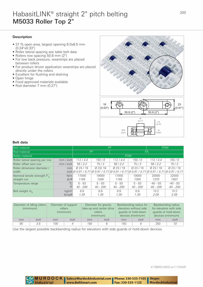
4178BRO.MOD-en1112HQR
200
M5033 Roller Top 2"HabasitLINK® straight 2" pitch belting
Belt data
Belt material PP POMRod material PP PARoller material POMRoller lateral spacing per row mm / inch 112 / 4.4 150 / 6 112 / 4.4 150 / 6 112 / 4.4 150 / 6Roller offset next row mm / inch 56 / 2.2 75 / 3 56 / 2.2 75 / 3 56 / 2.2 75 / 3Roller dimension diameter / width
mminch
Ø 23 / 18Ø 0.91 / 0.71
Ø 23/ 18Ø 0.91 / 0.71
Ø 23 / 18Ø 0.91 / 0.71
Ø 23 / 18Ø 0.91 / 0.71
Ø 23 / 18Ø 0.91 / 0.71
Ø 23 / 18Ø 0.91 / 0.71
Nominal tensile strength F'N straight run
N/mlb/ft
170001165
190001300
170001165
190001300
200001370
220001507
Temperature range °C°F
5 - 9340 - 200
5 - 9340 - 200
5 - 9340 - 200
5 - 9340 - 200
-40 - 93-40 - 200
-40 - 93-40 - 200
Belt weight mB kg/m²lb/sqft
6.81.39
6.81.39
6.81.39
6.81.39
10.22.09
10.22.09
��������������
�������
����� �
Description
• 37 % open area; largest opening 6.0x8.5 mm (0.24"x0.33")
• Roller lateral spacing see table belt data • Rollers row spacing 50.8 mm (2") • For low back pressure, wearstrips are placed
between rollers • For product driven application wearstrips are placed
directly under the rollers • Excellent for flushing and draining • Open hinge • Food approved materials available• Rod diameter 7 mm (0.27")
Diameter of idling rollers (minimum)
Diameter of support rollers
(minimum)
Diameter for gravity take-up and center drive
rollers (minimum)
Backbending radius for elevators without side guards or hold-down devices (minimum)
Backbending radius for elevators with side guards or hold-down devices (minimum)
mm inch mm inch mm inch mm inch mm inch90 3.5 100 4 150 6 150 6 250 10
Use the largest possible backbending radius for elevators with side guards or hold-down devices.

201
4178BRO.MOD-en1112HQR
M5033 Roller Top 2"HabasitLINK® straight 2" pitch belting
Standard range of belt widths b0 and free edgeBelt width (mm) (nom.)
225 300 375 450 525 600 675 750 825 900 975 1050 etc.
Belt width (inch) (nom.)
9 12 15 18 21 24 27 30 33 36 39 42 etc.
Roller lateral spacing per row 112.5 mm / offset next row 56.25 mmFree edge (mm) 19/19 19/37 19/55 19/19 19/37 19/55 19/19 19/37 19/55 19/19 19/37 19/55 etc.Free edge (inch) 0.7/0.7 0.7/1.5 0.7/2.2 0.7/0.7 0.7/1.5 0.7/2.2 0.7/0.7 0.7/1.5 0.7/2.2 0.7/0.7 0.7/1.5 0.7/2.2 etc.Sprocket offset (mm)
0 18.75 -18.75 0 18.75 -18.75 0 18.75 -18.75 0 18.75 -18.75 etc.
Sprocket offset (inch)
0 0.74 -0.74 0 0.74 -0.74 0 0.74 -0.74 0 0.74 -0.74 etc.
Sprockets 3 4 6 7 8 10 11 12 14 15 16 18 etc.Rollers (2 rows) 4 5 6 8 9 10 12 13 14 16 17 18 etc.Roller lateral spacing per row 150 mm / offset next row 75 mmFree edge (mm) 28 28 28 28 28 28 28 28 28 28 28 28 etc.Free edge (inch) 1.1 1.1 1.1 1.1 1.1 1.1 1.1 1.1 1.1 1.1 1.1 1.1 etc.Sprocket offset (mm)
37.5 0 37.5 0 37.5 0 37.5 0 37.5 0 37.5 0 etc.
Sprocket offset (inch)
1.5 0 1.5 0 1.5 0 1.5 0 1.5 0 1.5 0 etc.
Sprockets 2 3 4 5 6 7 8 9 10 11 12 13 etc.Rollers (2 rows) 3 4 5 6 7 8 9 10 11 12 13 14 etc.
Real belt widths are in most cases 0.1% to 0.3% smaller.
Standard belt widths in increments of 75 mm (3"). Smallest possible width 225 mm (9").For detailed material properties refer to pages 282 - 289.The nominal tensile strength is valid for 23 °C (73 °F). The admissible tensile force depends on the operating temperature near the drive sprockets. Within the temperature range allowed, the admissible tensile force may vary from 100% to 20% of the nominal tensile strength. For detailed information and correct calculation of effective tensile force refer to the Calculation Guide in the HabasitLINK® Engineering Guidelines.
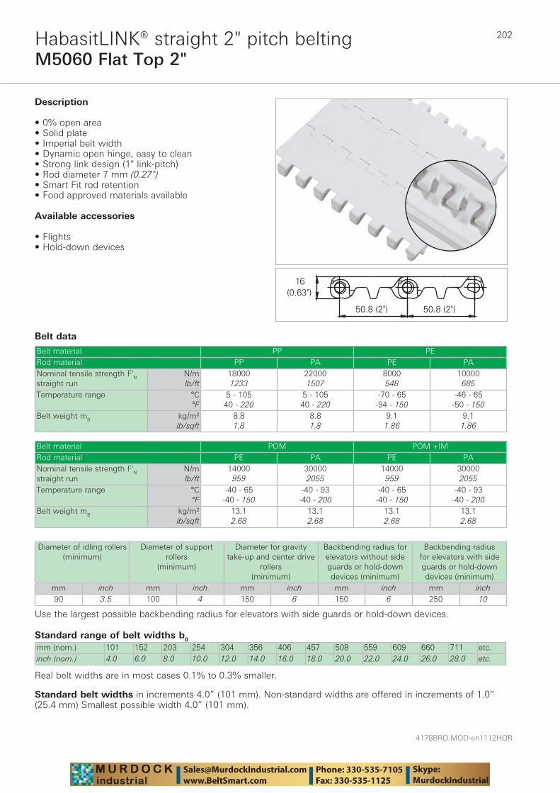
4178BRO.MOD-en1112HQR
202
M5060 Flat Top 2"HabasitLINK® straight 2" pitch belting
Belt data
Standard range of belt widths b0
mm (nom.) 101 152 203 254 304 356 406 457 508 559 609 660 711 etc.inch (nom.) 4.0 6.0 8.0 10.0 12.0 14.0 16.0 18.0 20.0 22.0 24.0 26.0 28.0 etc.
Real belt widths are in most cases 0.1% to 0.3% smaller.
Belt material PP PERod material PP PA PE PANominal tensile strength F'N straight run
N/mlb/ft
180001233
220001507
8000548
10000685
Temperature range °C°F
5 - 10540 - 220
5 - 10540 - 220
-70 - 65-94 - 150
-46 - 65-50 - 150
Belt weight mB kg/m²lb/sqft
8.81.8
8.81.8
9.11.86
9.11.86
Description
• 0% open area • Solid plate • Imperial belt width • Dynamic open hinge, easy to clean• Strong link design (1" link-pitch) • Rod diameter 7 mm (0.27") • Smart Fit rod retention • Food approved materials available
Available accessories
• Flights• Hold-down devices
Belt material POM POM +IMRod material PE PA PE PANominal tensile strength F'N straight run
N/mlb/ft
14000959
300002055
14000959
300002055
Temperature range °C°F
-40 - 65-40 - 150
-40 - 93-40 - 200
-40 - 65-40 - 150
-40 - 93-40 - 200
Belt weight mB kg/m²lb/sqft
13.12.68
13.12.68
13.12.68
13.12.68
Diameter of idling rollers (minimum)
Diameter of support rollers
(minimum)
Diameter for gravity take-up and center drive
rollers (minimum)
Backbending radius for elevators without side guards or hold-down devices (minimum)
Backbending radius for elevators with side guards or hold-down devices (minimum)
mm inch mm inch mm inch mm inch mm inch90 3.5 100 4 150 6 150 6 250 10
Use the largest possible backbending radius for elevators with side guards or hold-down devices.
Standard belt widths in increments 4.0” (101 mm). Non-standard widths are offered in increments of 1.0” (25.4 mm) Smallest possible width 4.0” (101 mm).

203
4178BRO.MOD-en1112HQR
M5060 Flat Top 2"HabasitLINK® straight 2" pitch belting
For detailed material properties refer to pages 282 - 289.The nominal tensile strength is valid for 23 °C (73 °F). The admissible tensile force depends on the operating temperature near the drive sprockets. Within the temperature range allowed, the admissible tensile force may vary from 100% to 20% of the nominal tensile strength. For detailed information and correct calculation of effective tensile force refer to the Calculation Guide in the HabasitLINK® Engineering Guidelines.
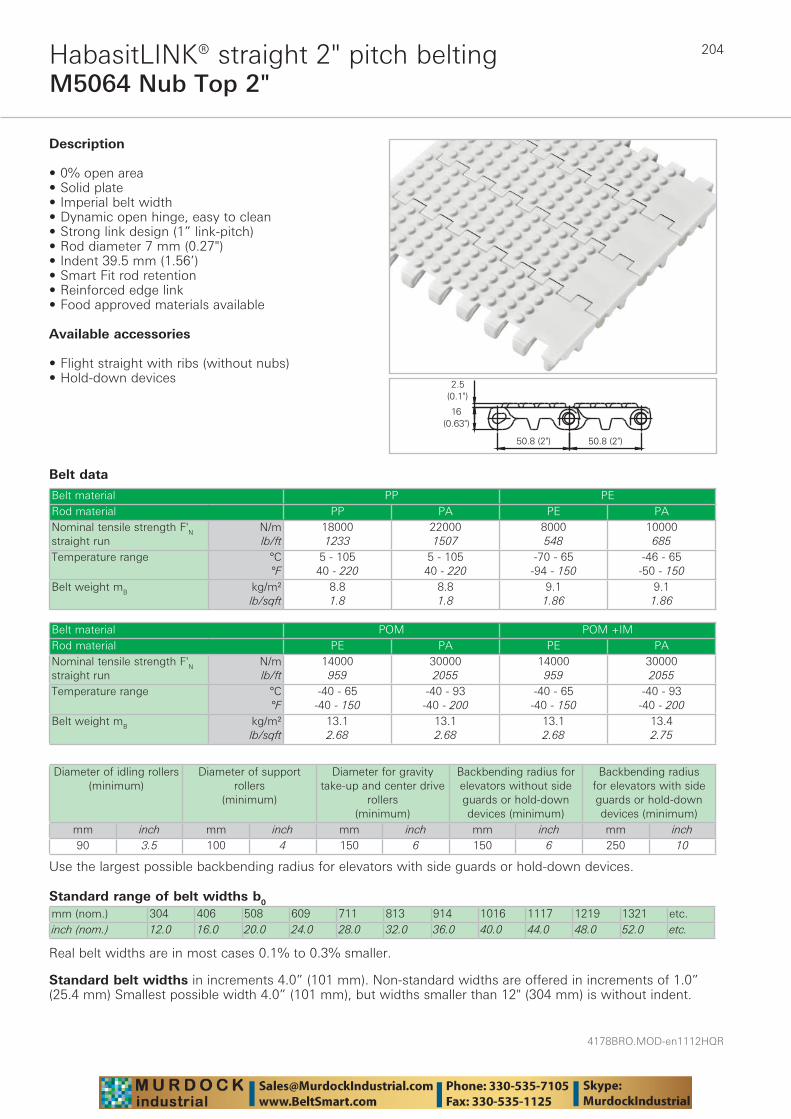
4178BRO.MOD-en1112HQR
204
M5064 Nub Top 2"HabasitLINK® straight 2" pitch belting
Belt data
Standard range of belt widths b0
mm (nom.) 304 406 508 609 711 813 914 1016 1117 1219 1321 etc.inch (nom.) 12.0 16.0 20.0 24.0 28.0 32.0 36.0 40.0 44.0 48.0 52.0 etc.
Real belt widths are in most cases 0.1% to 0.3% smaller.
Belt material PP PERod material PP PA PE PANominal tensile strength F'N straight run
N/mlb/ft
180001233
220001507
8000548
10000685
Temperature range °C°F
5 - 10540 - 220
5 - 10540 - 220
-70 - 65-94 - 150
-46 - 65-50 - 150
Belt weight mB kg/m²lb/sqft
8.81.8
8.81.8
9.11.86
9.11.86
Description
• 0% open area • Solid plate • Imperial belt width • Dynamic open hinge, easy to clean • Strong link design (1” link-pitch) • Rod diameter 7 mm (0.27") • Indent 39.5 mm (1.56’) • Smart Fit rod retention• Reinforced edge link • Food approved materials available
Available accessories
• Flight straight with ribs (without nubs) • Hold-down devices
Belt material POM POM +IMRod material PE PA PE PANominal tensile strength F'N straight run
N/mlb/ft
14000959
300002055
14000959
300002055
Temperature range °C°F
-40 - 65-40 - 150
-40 - 93-40 - 200
-40 - 65-40 - 150
-40 - 93-40 - 200
Belt weight mB kg/m²lb/sqft
13.12.68
13.12.68
13.12.68
13.42.75
Diameter of idling rollers (minimum)
Diameter of support rollers
(minimum)
Diameter for gravity take-up and center drive
rollers (minimum)
Backbending radius for elevators without side guards or hold-down devices (minimum)
Backbending radius for elevators with side guards or hold-down devices (minimum)
mm inch mm inch mm inch mm inch mm inch90 3.5 100 4 150 6 150 6 250 10
Use the largest possible backbending radius for elevators with side guards or hold-down devices.
Standard belt widths in increments 4.0” (101 mm). Non-standard widths are offered in increments of 1.0” (25.4 mm) Smallest possible width 4.0” (101 mm), but widths smaller than 12" (304 mm) is without indent.

205
4178BRO.MOD-en1112HQR
M5064 Nub Top 2"HabasitLINK® straight 2" pitch belting
For detailed material properties refer to pages 282 - 289.The nominal tensile strength is valid for 23 °C (73 °F). The admissible tensile force depends on the operating temperature near the drive sprockets. Within the temperature range allowed, the admissible tensile force may vary from 100% to 20% of the nominal tensile strength. For detailed information and correct calculation of effective tensile force refer to the Calculation Guide in the HabasitLINK® Engineering Guidelines.
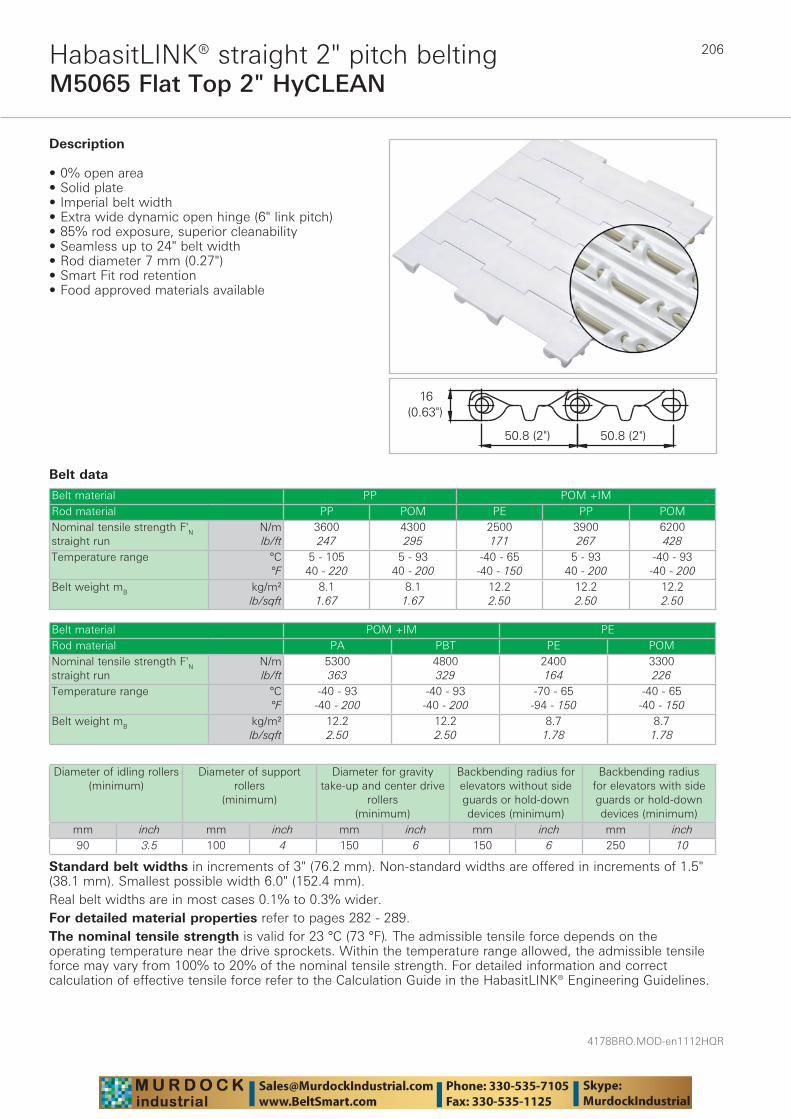
4178BRO.MOD-en1112HQR
206
M5065 Flat Top 2" HyCLEANHabasitLINK® straight 2" pitch belting
Belt data
Belt material PP POM +IMRod material PP POM PE PP POMNominal tensile strength F'N straight run
N/mlb/ft
3600247
4300295
2500171
3900267
6200428
Temperature range °C°F
5 - 10540 - 220
5 - 9340 - 200
-40 - 65-40 - 150
5 - 9340 - 200
-40 - 93-40 - 200
Belt weight mB kg/m²lb/sqft
8.11.67
8.11.67
12.22.50
12.22.50
12.22.50
Description
• 0% open area • Solid plate • Imperial belt width • Extra wide dynamic open hinge (6" link pitch) • 85% rod exposure, superior cleanability • Seamless up to 24" belt width • Rod diameter 7 mm (0.27") • Smart Fit rod retention • Food approved materials available
Belt material POM +IM PERod material PA PBT PE POMNominal tensile strength F'N straight run
N/mlb/ft
5300363
4800329
2400164
3300226
Temperature range °C°F
-40 - 93-40 - 200
-40 - 93-40 - 200
-70 - 65-94 - 150
-40 - 65-40 - 150
Belt weight mB kg/m²lb/sqft
12.22.50
12.22.50
8.71.78
8.71.78
Diameter of idling rollers (minimum)
Diameter of support rollers
(minimum)
Diameter for gravity take-up and center drive
rollers (minimum)
Backbending radius for elevators without side guards or hold-down devices (minimum)
Backbending radius for elevators with side guards or hold-down devices (minimum)
mm inch mm inch mm inch mm inch mm inch90 3.5 100 4 150 6 150 6 250 10
Standard belt widths in increments of 3" (76.2 mm). Non-standard widths are offered in increments of 1.5" (38.1 mm). Smallest possible width 6.0" (152.4 mm).Real belt widths are in most cases 0.1% to 0.3% wider.For detailed material properties refer to pages 282 - 289.The nominal tensile strength is valid for 23 °C (73 °F). The admissible tensile force depends on the operating temperature near the drive sprockets. Within the temperature range allowed, the admissible tensile force may vary from 100% to 20% of the nominal tensile strength. For detailed information and correct calculation of effective tensile force refer to the Calculation Guide in the HabasitLINK® Engineering Guidelines.
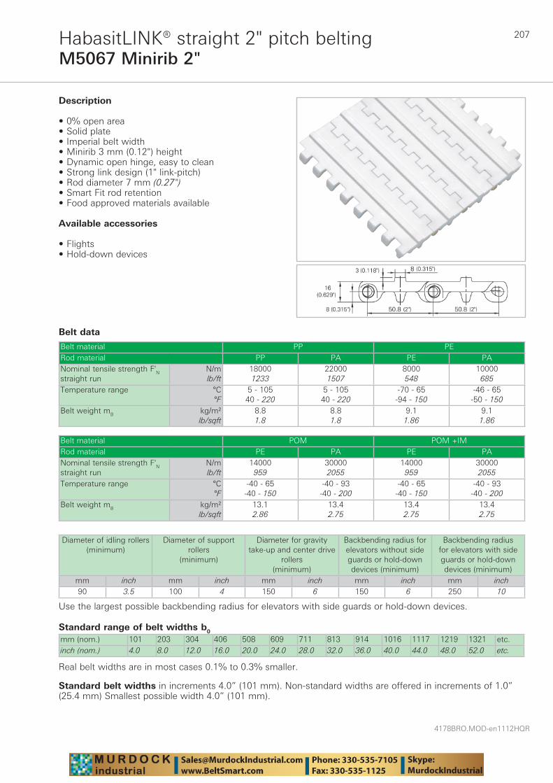
207
4178BRO.MOD-en1112HQR
M5067 Minirib 2"HabasitLINK® straight 2" pitch belting
Belt data
Standard range of belt widths b0
mm (nom.) 101 203 304 406 508 609 711 813 914 1016 1117 1219 1321 etc.inch (nom.) 4.0 8.0 12.0 16.0 20.0 24.0 28.0 32.0 36.0 40.0 44.0 48.0 52.0 etc.
Real belt widths are in most cases 0.1% to 0.3% smaller.
Belt material PP PERod material PP PA PE PANominal tensile strength F'N straight run
N/mlb/ft
180001233
220001507
8000548
10000685
Temperature range °C°F
5 - 10540 - 220
5 - 10540 - 220
-70 - 65-94 - 150
-46 - 65-50 - 150
Belt weight mB kg/m²lb/sqft
8.81.8
8.81.8
9.11.86
9.11.86
Description
• 0% open area • Solid plate • Imperial belt width • Minirib 3 mm (0.12") height • Dynamic open hinge, easy to clean • Strong link design (1" link-pitch) • Rod diameter 7 mm (0.27")• Smart Fit rod retention • Food approved materials available
Available accessories
• Flights • Hold-down devices
Belt material POM POM +IMRod material PE PA PE PANominal tensile strength F'N straight run
N/mlb/ft
14000959
300002055
14000959
300002055
Temperature range °C°F
-40 - 65-40 - 150
-40 - 93-40 - 200
-40 - 65-40 - 150
-40 - 93-40 - 200
Belt weight mB kg/m²lb/sqft
13.12.86
13.42.75
13.42.75
13.42.75
Diameter of idling rollers (minimum)
Diameter of support rollers
(minimum)
Diameter for gravity take-up and center drive
rollers (minimum)
Backbending radius for elevators without side guards or hold-down devices (minimum)
Backbending radius for elevators with side guards or hold-down devices (minimum)
mm inch mm inch mm inch mm inch mm inch90 3.5 100 4 150 6 150 6 250 10
Use the largest possible backbending radius for elevators with side guards or hold-down devices.
Standard belt widths in increments 4.0” (101 mm). Non-standard widths are offered in increments of 1.0” (25.4 mm) Smallest possible width 4.0” (101 mm).

4178BRO.MOD-en1112HQR
208
M5067 Minirib 2"HabasitLINK® straight 2" pitch belting
For detailed material properties refer to pages 282 - 289.The nominal tensile strength is valid for 23 °C (73 °F). The admissible tensile force depends on the operating temperature near the drive sprockets. Within the temperature range allowed, the admissible tensile force may vary from 100% to 20% of the nominal tensile strength. For detailed information and correct calculation of effective tensile force refer to the Calculation Guide in the HabasitLINK® Engineering Guidelines.
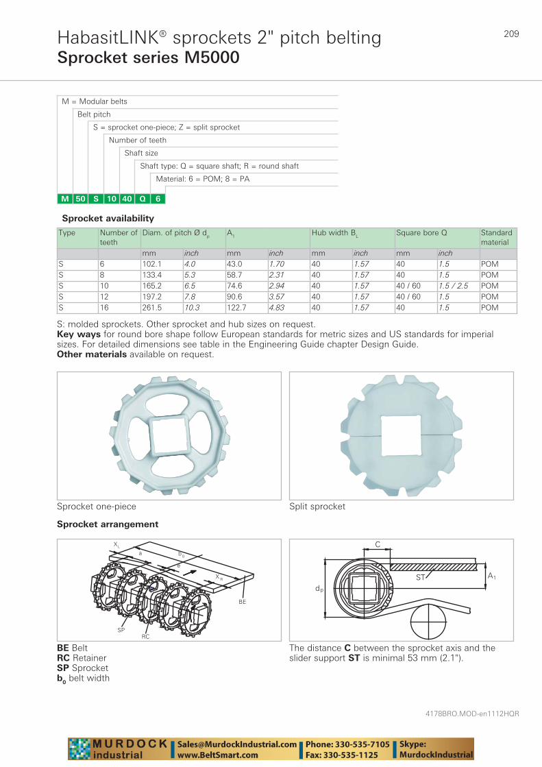
209
4178BRO.MOD-en1112HQR
Sprocket series M5000HabasitLINK® sprockets 2" pitch belting
M = Modular belts
M 50 6Q4010S
Belt pitch
S = sprocket one-piece; Z = split sprocket
Number of teeth
Shaft size
Shaft type: Q = square shaft; R = round shaft
Material: 6 = POM; 8 = PA
Type Number of teeth
Diam. of pitch Ø dp A1 Hub width BL Square bore Q Standard material
mm inch mm inch mm inch mm inchS 6 102.1 4.0 43.0 1.70 40 1.57 40 1.5 POMS 8 133.4 5.3 58.7 2.31 40 1.57 40 1.5 POMS 10 165.2 6.5 74.6 2.94 40 1.57 40 / 60 1.5 / 2.5 POMS 12 197.2 7.8 90.6 3.57 40 1.57 40 / 60 1.5 POMS 16 261.5 10.3 122.7 4.83 40 1.57 40 1.5 POM
Sprocket one-piece
Sprocket availability
S: molded sprockets. Other sprocket and hub sizes on request.Key ways for round bore shape follow European standards for metric sizes and US standards for imperial sizes. For detailed dimensions see table in the Engineering Guide chapter Design Guide.Other materials available on request.
Split sprocket
Sprocket arrangement
BE BeltRC RetainerSP Sprocketb0 belt width
The distance C between the sprocket axis and the slider support ST is minimal 53 mm (2.1").
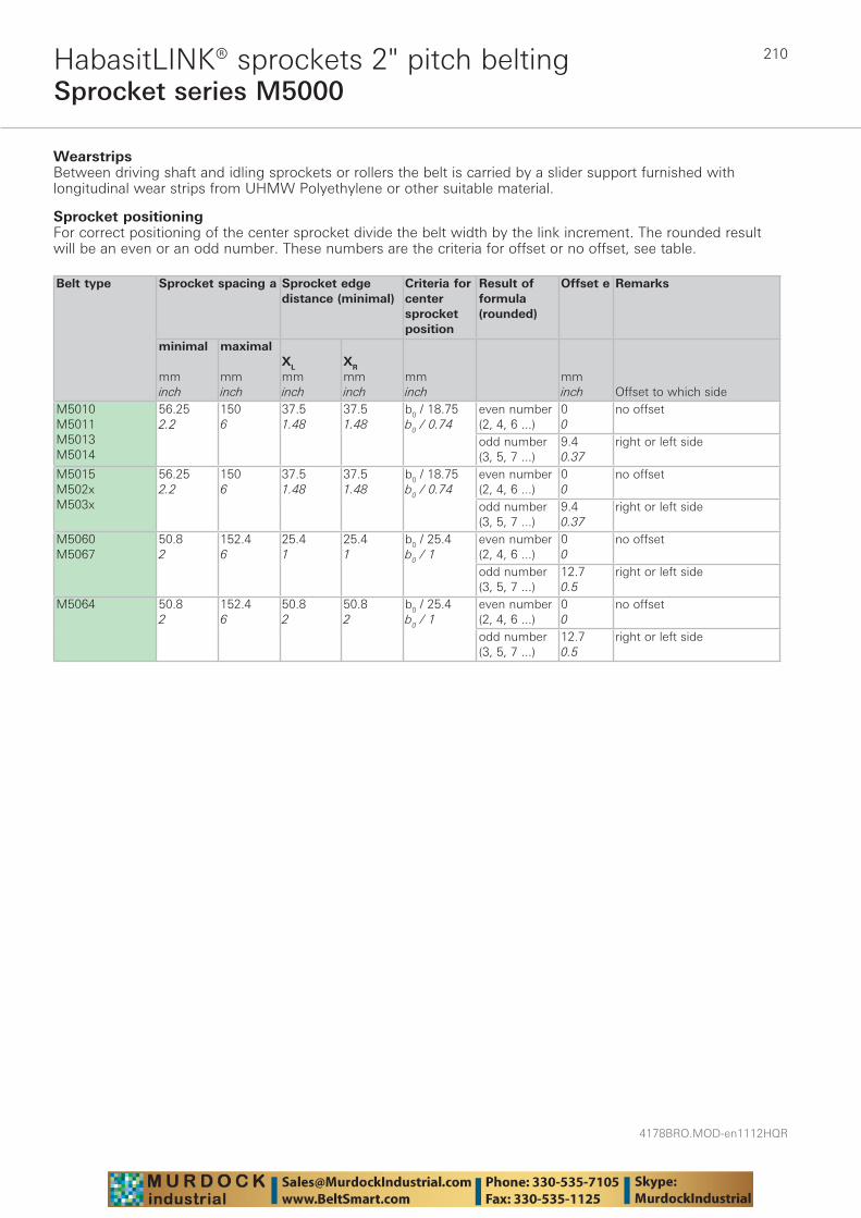
4178BRO.MOD-en1112HQR
210
Sprocket series M5000HabasitLINK® sprockets 2" pitch belting
WearstripsBetween driving shaft and idling sprockets or rollers the belt is carried by a slider support furnished with longitudinal wear strips from UHMW Polyethylene or other suitable material.
Sprocket positioning For correct positioning of the center sprocket divide the belt width by the link increment. The rounded result will be an even or an odd number. These numbers are the criteria for offset or no offset, see table.
Belt type
Sprocket spacing a
Sprocket edgedistance (minimal)
Criteria for center sprocket position
Result of formula (rounded)
Offset e Remarks
minimal mminch
maximal mminch
XL
mminch
XR
mminch
mminch
mminch Offset to which side
M5010M5011M5013M5014
56.252.2
1506
37.51.48
37.51.48
b0 / 18.75b0 / 0.74
even number (2, 4, 6 ...)
00
no offset
odd number (3, 5, 7 ...)
9.40.37
right or left side
M5015M502xM503x
56.252.2
1506
37.51.48
37.51.48
b0 / 18.75b0 / 0.74
even number (2, 4, 6 ...)
00
no offset
odd number (3, 5, 7 ...)
9.40.37
right or left side
M5060M5067
50.82
152.46
25.41
25.41
b0 / 25.4b0 / 1
even number (2, 4, 6 ...)
00
no offset
odd number (3, 5, 7 ...)
12.70.5
right or left side
M5064 50.82
152.46
50.82
50.82
b0 / 25.4b0 / 1
even number (2, 4, 6 ...)
00
no offset
odd number (3, 5, 7 ...)
12.70.5
right or left side
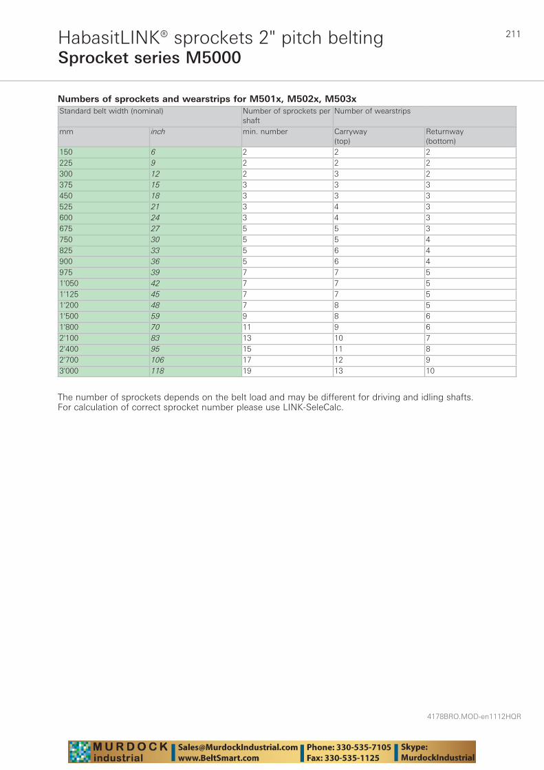
211
4178BRO.MOD-en1112HQR
Sprocket series M5000HabasitLINK® sprockets 2" pitch belting
Numbers of sprockets and wearstrips for M501x, M502x, M503x Standard belt width (nominal) Number of sprockets per
shaftNumber of wearstrips
mm inch min. number Carryway (top)
Returnway (bottom)
150 6 2 2 2225 9 2 2 2300 12 2 3 2375 15 3 3 3450 18 3 3 3525 21 3 4 3600 24 3 4 3675 27 5 5 3750 30 5 5 4825 33 5 6 4900 36 5 6 4975 39 7 7 51'050 42 7 7 51'125 45 7 7 51'200 48 7 8 51'500 59 9 8 61'800 70 11 9 62'100 83 13 10 72'400 95 15 11 82'700 106 17 12 93'000 118 19 13 10
The number of sprockets depends on the belt load and may be different for driving and idling shafts. For calculation of correct sprocket number please use LINK-SeleCalc.

4178BRO.MOD-en1112HQR
212
Sprocket series M5000HabasitLINK® sprockets 2" pitch belting
Numbers of sprockets and wearstrips for M5060, M5064 Standard belt width (nominal) Number of sprockets per
shaftNumber of wearstrips
mm inch min. number Carryway (top)
Returnway (bottom)
102 4 2 2 2203 8 2 2 2305 12 2 3 2406 16 3 3 3508 20 3 3 3610 24 3 4 3711 28 5 4 3813 32 5 5 3914 36 5 5 41'016 40 7 6 41'118 44 7 6 41'219 48 7 7 51'422 56 9 7 51'626 64 11 7 51'829 72 11 8 52'032 80 13 8 62'235 88 15 9 62'438 96 15 10 72'642 104 17 11 82'845 112 19 12 93'048 120 19 13 10
The number of sprockets depends on the belt load and may be different for driving and idling shafts. For calculation of correct sprocket number please use LINK-SeleCalc.
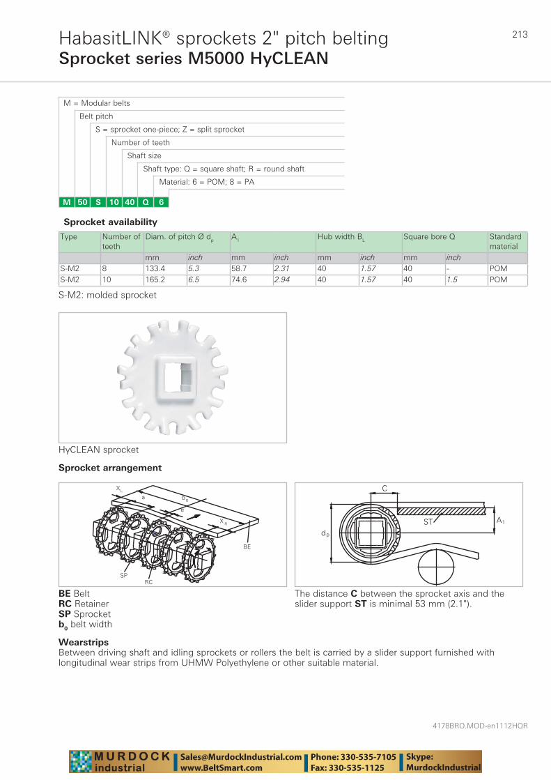
213
4178BRO.MOD-en1112HQR
Sprocket series M5000 HyCLEANHabasitLINK® sprockets 2" pitch belting
M = Modular belts
M 50 6Q4010S
Belt pitch
S = sprocket one-piece; Z = split sprocket
Number of teeth
Shaft size
Shaft type: Q = square shaft; R = round shaft
Material: 6 = POM; 8 = PA
Type Number of teeth
Diam. of pitch Ø dp A1 Hub width BL Square bore Q Standard material
mm inch mm inch mm inch mm inchS-M2 8 133.4 5.3 58.7 2.31 40 1.57 40 - POMS-M2 10 165.2 6.5 74.6 2.94 40 1.57 40 1.5 POM
HyCLEAN sprocket
Sprocket availability
S-M2: molded sprocket
The distance C between the sprocket axis and the slider support ST is minimal 53 mm (2.1").
WearstripsBetween driving shaft and idling sprockets or rollers the belt is carried by a slider support furnished with longitudinal wear strips from UHMW Polyethylene or other suitable material.
Sprocket arrangement
BE BeltRC RetainerSP Sprocketb0 belt width
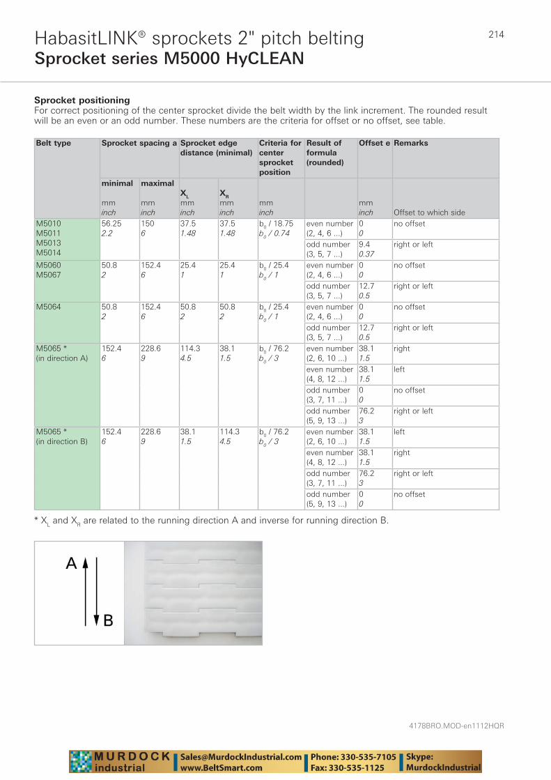
4178BRO.MOD-en1112HQR
214
Sprocket series M5000 HyCLEANHabasitLINK® sprockets 2" pitch belting
Sprocket positioning For correct positioning of the center sprocket divide the belt width by the link increment. The rounded result will be an even or an odd number. These numbers are the criteria for offset or no offset, see table.
Belt type
Sprocket spacing a
Sprocket edgedistance (minimal)
Criteria for center sprocket position
Result of formula (rounded)
Offset e Remarks
minimal mminch
maximal mminch
XL
mminch
XR
mminch
mminch
mminch Offset to which side
M5010M5011M5013M5014
56.252.2
1506
37.51.48
37.51.48
b0 / 18.75b0 / 0.74
even number (2, 4, 6 ...)
00
no offset
odd number (3, 5, 7 ...)
9.40.37
right or left
M5060M5067
50.82
152.46
25.41
25.41
b0 / 25.4b0 / 1
even number (2, 4, 6 ...)
00
no offset
odd number (3, 5, 7 ...)
12.70.5
right or left
M5064 50.82
152.46
50.82
50.82
b0 / 25.4b0 / 1
even number (2, 4, 6 ...)
00
no offset
odd number (3, 5, 7 ...)
12.70.5
right or left
M5065 *(in direction A)
152.46
228.69
114.34.5
38.11.5
b0 / 76.2b0 / 3
even number (2, 6, 10 ...)
38.11.5
right
even number (4, 8, 12 ...)
38.11.5
left
odd number (3, 7, 11 ...)
00
no offset
odd number (5, 9, 13 ...)
76.23
right or left
M5065 *(in direction B)
152.46
228.69
38.11.5
114.34.5
b0 / 76.2b0 / 3
even number (2, 6, 10 ...)
38.11.5
left
even number (4, 8, 12 ...)
38.11.5
right
odd number (3, 7, 11 ...)
76.23
right or left
odd number (5, 9, 13 ...)
00
no offset
* XL and XR are related to the running direction A and inverse for running direction B.
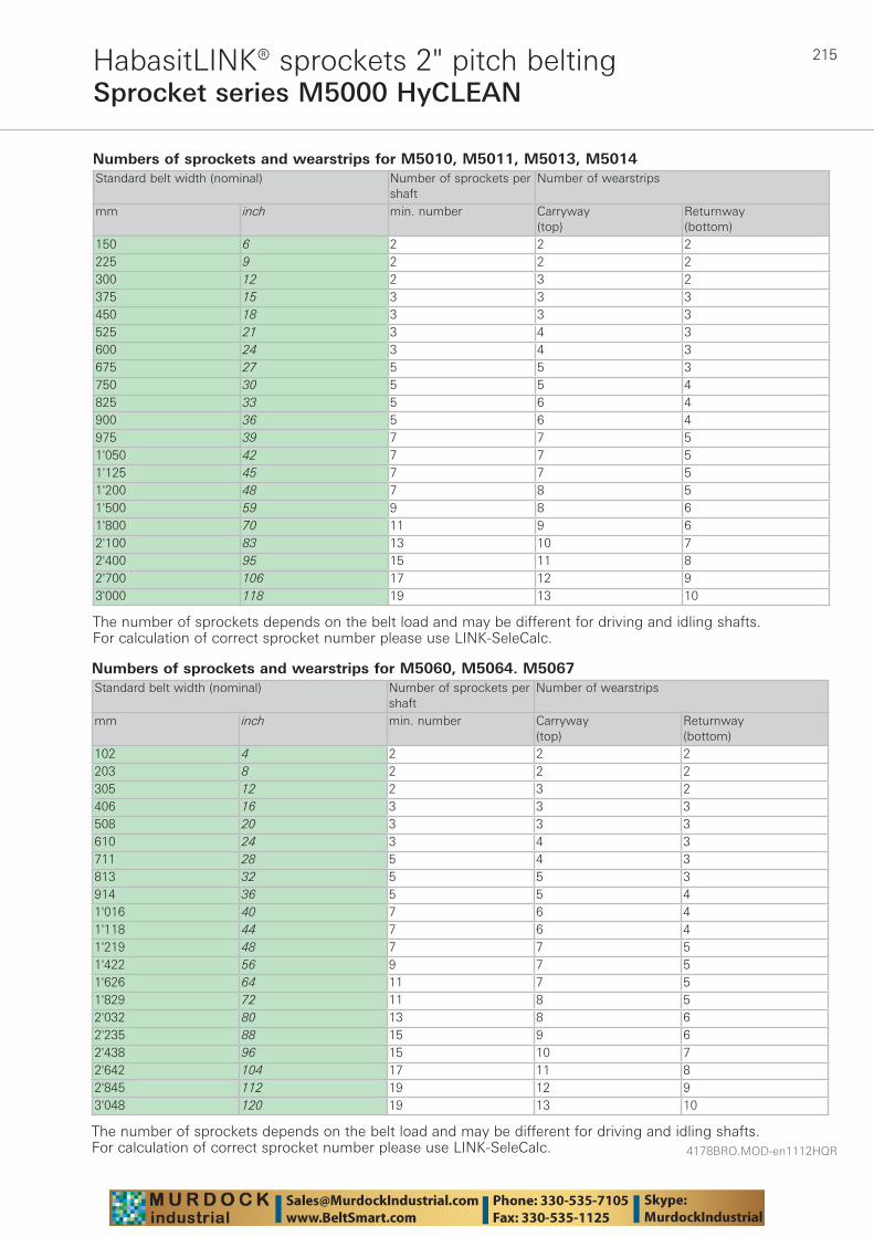
215
4178BRO.MOD-en1112HQR
Sprocket series M5000 HyCLEANHabasitLINK® sprockets 2" pitch belting
Numbers of sprockets and wearstrips for M5010, M5011, M5013, M5014 Standard belt width (nominal) Number of sprockets per
shaftNumber of wearstrips
mm inch min. number Carryway (top)
Returnway (bottom)
150 6 2 2 2225 9 2 2 2300 12 2 3 2375 15 3 3 3450 18 3 3 3525 21 3 4 3600 24 3 4 3675 27 5 5 3750 30 5 5 4825 33 5 6 4900 36 5 6 4975 39 7 7 51'050 42 7 7 51'125 45 7 7 51'200 48 7 8 51'500 59 9 8 61'800 70 11 9 62'100 83 13 10 72'400 95 15 11 82'700 106 17 12 93'000 118 19 13 10
The number of sprockets depends on the belt load and may be different for driving and idling shafts. For calculation of correct sprocket number please use LINK-SeleCalc.
Numbers of sprockets and wearstrips for M5060, M5064. M5067 Standard belt width (nominal) Number of sprockets per
shaftNumber of wearstrips
mm inch min. number Carryway (top)
Returnway (bottom)
102 4 2 2 2203 8 2 2 2305 12 2 3 2406 16 3 3 3508 20 3 3 3610 24 3 4 3711 28 5 4 3813 32 5 5 3914 36 5 5 41'016 40 7 6 41'118 44 7 6 41'219 48 7 7 51'422 56 9 7 51'626 64 11 7 51'829 72 11 8 52'032 80 13 8 62'235 88 15 9 62'438 96 15 10 72'642 104 17 11 82'845 112 19 12 93'048 120 19 13 10
The number of sprockets depends on the belt load and may be different for driving and idling shafts. For calculation of correct sprocket number please use LINK-SeleCalc.
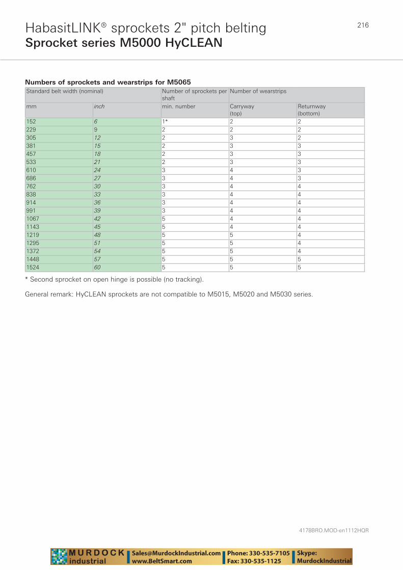
4178BRO.MOD-en1112HQR
216
Sprocket series M5000 HyCLEANHabasitLINK® sprockets 2" pitch belting
Numbers of sprockets and wearstrips for M5065 Standard belt width (nominal) Number of sprockets per
shaftNumber of wearstrips
mm inch min. number Carryway (top)
Returnway (bottom)
152 6 1* 2 2229 9 2 2 2305 12 2 3 2381 15 2 3 3457 18 2 3 3533 21 2 3 3610 24 3 4 3686 27 3 4 3762 30 3 4 4838 33 3 4 4914 36 3 4 4991 39 3 4 41067 42 5 4 41143 45 5 4 41219 48 5 5 41295 51 5 5 41372 54 5 5 41448 57 5 5 51524 60 5 5 5
* Second sprocket on open hinge is possible (no tracking).
General remark: HyCLEAN sprockets are not compatible to M5015, M5020 and M5030 series.

217
4178BRO.MOD-en1112HQR
HabasitLINK® accessories – 2" pitch beltingFlights and side guards M5000
HabasitLINK® modular belts are available with flights to convey products on inclined conveyors. The flight modules are injection-molded one-piece designs that when installed, become an integral part of the belt. Flight modules are available with ribs on one side (no-cling) for improved release of wet or sticky food products and can also be cut to nonstandard heights.
Flights M5000 (except M5060) with link increment 18.75 mm (0.74"); metric belt widths
Flights straight Flights straight Flights corrugated Flights bent (Scoop) Bucket fl ights Side guards
Code fl ight side guard
M5010Fxx1)M5014Fxx2)
M5015Fxx3)M5033Fxx3) M5010Bxx3) M5010Yxx3)
M5010Gxx
M501RGxx
(xx= height) (xx= height) (xx= height) (xx= height) (xx= height) (xx= height)
height Hlenght L
H L H L H L H L H L H
mminch
251
1506
––
––
––
––
––
––
––
––
––
––
mminch
502
1506
––
––
––
––
––
––
––
––
532
––
mminch
753
1506
––
––
––
––
753
1506
––
––
783
––
mminch
1004
1506
1004
1506
1004
1506
1004
1506
1004
1506
1034
––
mminch
1506
1506
––
––
––
––
1506
1506
––
––
––
1456
mminch
1004
2259
––
––
––
––
––
––
––
––
––
––
Flights M5060, M5064, M5067 with link increment 25.4 mm (1"); imperial belt widths
Flights straight Flights straight with indentFlights straight with indents
on both sidesFlights bent (Scoop)
Code fl ight side guard
M5060Fxx1) M506RFxx/LFxx1) M506JFxx3) M5060Bxx3)
(xx= height)(xx=height, L=left side,
R= right side)(xx=height) (xx= height)
height Hlength Lindent E
H L H L E H L E H L
mminch
50.82
1526
50.82
1526
31.71.25
1506
60924
331.3
––
––
mminch
101.64
1526
101.64
1526
31.71.25
––
––
––
101.64
1506
mminch
1526
1526
––
––
––
––
––
––
––
––
mminch
1526
60924
––
––
––
––
––
––
––
––
All flight and scoops can be cut to lower height (min 25 mm) for high-impact applications.
Note: All flights have open hinge design (USDA).
Code 25 mm = 02 50/53 mm = 05 75/78 mm = 07 100/103 mm = 10 145/150 mm = 151) ribs on one side2) ribs on both sides3) without ribs
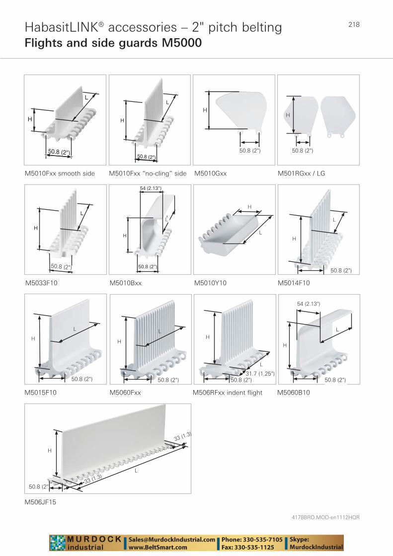
4178BRO.MOD-en1112HQR
218
L
H
50.8 (2")
L
H
50.8 (2")
H
50.8 (2")
L
H
50.8 (2")
L
H
50.8 (2")
54 (2.13")
HabasitLINK® accessories – 2" pitch beltingFlights and side guards M5000
M5010Fxx smooth side M5010Fxx “no-cling” side M5010Gxx
M5033F10 M5010Bxx
M501RGxx / LG
M5010Y10 M5014F10
M5015F10 M5060Fxx M506RFxx indent flight M5060B10
H
H
L
L
H
H
L
H
L
H
L
54 (2.13")
M506JF15
H
L
33 (1.3)
L
50.8 (2")
50.8 (2") 50.8 (2")
50.8 (2")
50.8 (2")50.8 (2")50.8 (2")
33 (1.3)
50.8 (2")
H
L
50.8 (2")31.7 (1.25")
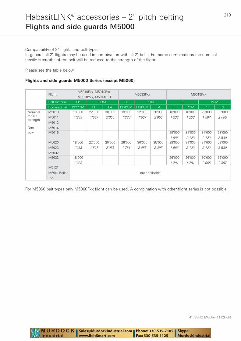
219
4178BRO.MOD-en1112HQR
HabasitLINK® accessories – 2" pitch beltingFlights and side guards M5000
Compatibility of 2" flights and belt typesIn general all 2" flights may be used in combination with all 2" belts. For some combinations the nominal tensile strengths of the belt will be reduced to the strength of the flight.
Please see the table below.
Flights and side guards M5000 Series (except M5060)
FlightM5010Fxx, M5010Bxx
M5010Yxx, M5014F10M5033Fxx M5015Fxx
Belt material PP POM PP POM PP POM
Rod material PP/POM PP PA PP/POM PP/POM PA PP POM PP PA
Nominal tensile strength
N/m
lb/ft
M5010
M5011
M5013
M5014
18’000
1’233
22’000
1’507
30’000
2’055
18’000
1’233
22’000
1’507
30’000
2’055
18’000
1’233
18’000
1’233
22’000
1’507
30’000
2’055
M5015 29’000
1’986
31’000
2’123
31’000
2’123
53’000
3’630M5020
M5023
M5032
18’000
1’233
22’000
1’507
30’000
2’055
26’000
1’781
30’000
2’055
35’000
2’397
29’000
1’986
31’000
2’123
31’000
2’123
53’000
3’630
M5033 18’000
1’233
26’000
1’781
26’000
1’781
30’000
2’055
35’000
2’397M5131
M50xx Roller
Top
not applicable
For M5060 belt types only M5060Fxx flight can be used. A combination with other flight series is not possible.
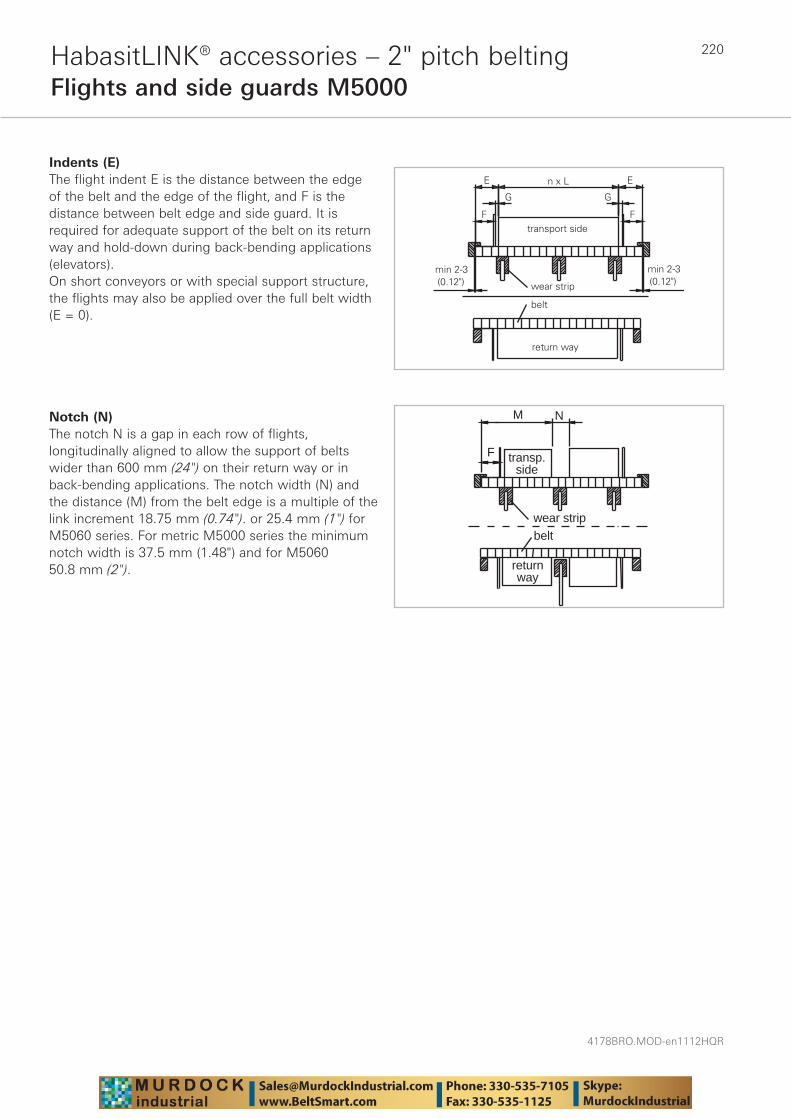
4178BRO.MOD-en1112HQR
220HabasitLINK® accessories – 2" pitch beltingFlights and side guards M5000
Indents (E)The flight indent E is the distance between the edge of the belt and the edge of the flight, and F is the distance between belt edge and side guard. It is required for adequate support of the belt on its return way and hold-down during back-bending applications (elevators). On short conveyors or with special support structure, the flights may also be applied over the full belt width (E = 0).
Notch (N)The notch N is a gap in each row of flights, longitudinally aligned to allow the support of belts wider than 600 mm (24") on their return way or in back-bending applications. The notch width (N) and the distance (M) from the belt edge is a multiple of the link increment 18.75 mm (0.74"). or 25.4 mm (1") for M5060 series. For metric M5000 series the minimum notch width is 37.5 mm (1.48") and for M5060 50.8 mm (2").
wear strip
transp.side
M
F
belt
N
returnway

221
4178BRO.MOD-en1112HQR
HabasitLINK® accessories – 2" pitch beltingFlights and side guards M5000
n x L
EEb0
Installation of flights and side guards; indents The side guards are usually installed with a gap (G) between the side guards and the flights. It is also possible to install the side guards with a minimum gap between flight and side guards of approx. 2 mm
(0.08"). There is a certain risk for rubbing and abrasion between the flights and the side guards. The distance E1 between the side guards and the hold-down and support shoes/wear strips should not be smaller than 5 mm (0.2").
b0 FF
Possible fl ight indents E
Flight onlyFlight + side guard
with gap (G ~ 8 mm (0.31“))Flight + side guard
without gap (G ~2 mm (0.08“))
E E F E F
M5000 except M5060 mm inch mm inch mm inch mm inch mm inch
Flight over full belt width 0 0 – – – – – – – –
Module cutting necessary 37.5 1.47 37.5 1.47 18 0.47 37.5 1.47 28 1.1
Module cutting necessary 56 2.2 56 2.2 37 1.47 56 2.2 46 1.83
Standard, no module cutting 75 3 75 3 56 2.2 75 3 66 2.6
Module cutting necessary 112 4.4 112 4.4 93 3.7 112 4.4 103 4.1
Module cutting necessary 131 5.2 131 5.2 112 4.4 131 5.2 122 4.8
M5060
Flight over full belt width 0 0 – – – – – – – –
Module cutting necessary 50.8 2 50.8 2 34.2 1.35 – – – –
Module cutting necessary 76.2 3 76.2 3 59.6 2.35 – – – –
Standard, no module cutting 101.6 4 101.6 4 85 3.35 – – – –
Module cutting necessary 127 5 127 5 110.4 4.35 – – – –
Module cutting necessary 152.4 6 152.4 6 135.8 5.35 – – – –
Flight with molded indent 33 1.3 – – – – – – – –
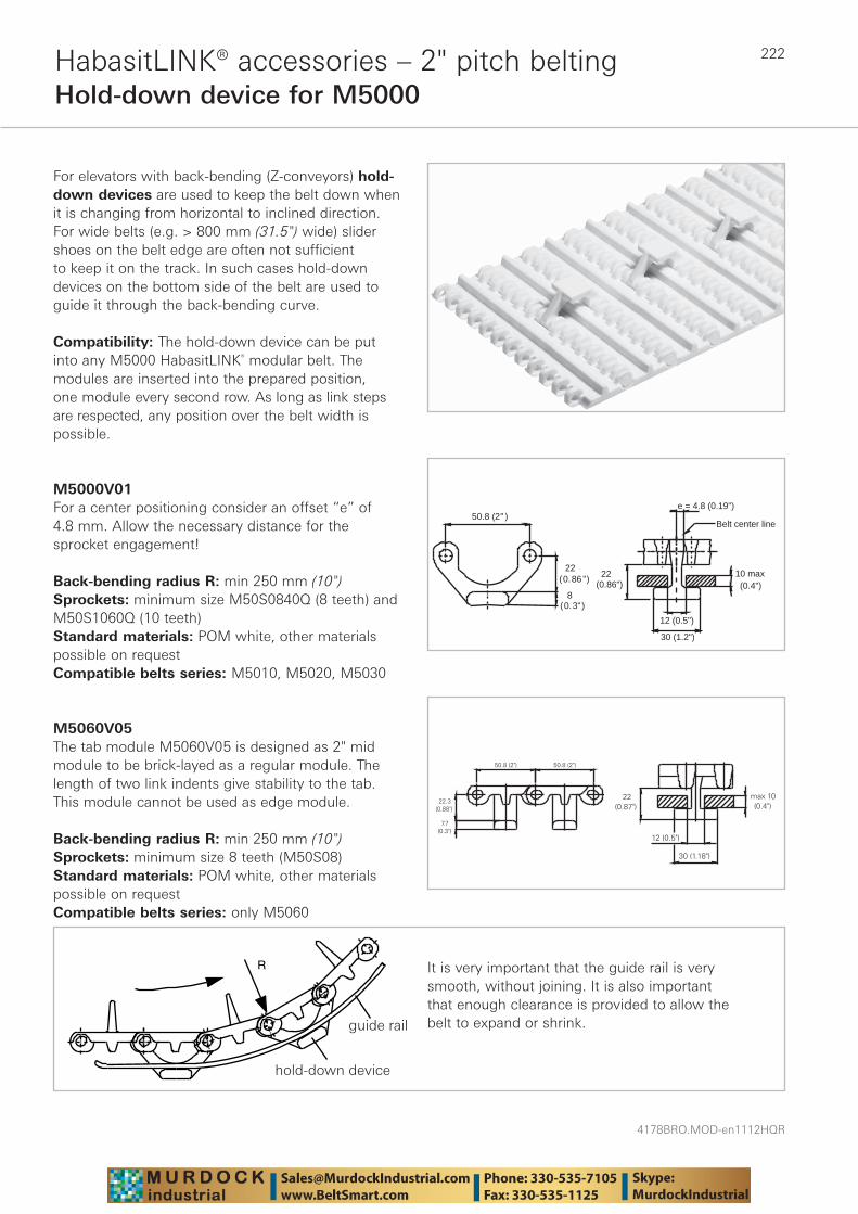
4178BRO.MOD-en1112HQR
222HabasitLINK® accessories – 2" pitch beltingHold-down device for M5000
For elevators with back-bending (Z-conveyors) hold-down devices are used to keep the belt down when it is changing from horizontal to inclined direction. For wide belts (e.g. > 800 mm (31.5") wide) slider shoes on the belt edge are often not sufficient to keep it on the track. In such cases hold-down devices on the bottom side of the belt are used to guide it through the back-bending curve.
Compatibility: The hold-down device can be put into any M5000 HabasitLINK® modular belt. The modules are inserted into the prepared position, one module every second row. As long as link steps are respected, any position over the belt width is possible.
M5000V01For a center positioning consider an offset “e” of 4.8 mm. Allow the necessary distance for the sprocket engagement!
Back-bending radius R: min 250 mm (10")Sprockets: minimum size M50S0840Q (8 teeth) and M50S1060Q (10 teeth)Standard materials: POM white, other materials possible on requestCompatible belts series: M5010, M5020, M5030
M5060V05The tab module M5060V05 is designed as 2" mid module to be brick-layed as a regular module. The length of two link indents give stability to the tab. This module cannot be used as edge module.
Back-bending radius R: min 250 mm (10")Sprockets: minimum size 8 teeth (M50S08)Standard materials: POM white, other materials possible on requestCompatible belts series: only M5060
R
guide rail
hold down device
It is very important that the guide rail is very smooth, without joining. It is also important that enough clearance is provided to allow the belt to expand or shrink.
50.8 (2" )
22(0.86")
8(0.3")
e = 4.8 (0.19")
Belt center line
22(0.86")
30 (1.2")
12 (0.5")
10 max (0.4")
hold-down device
guide rail
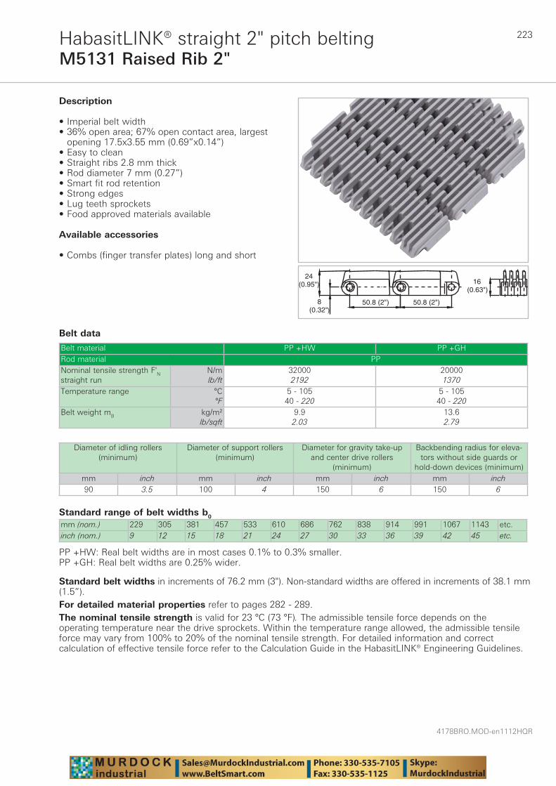
223
4178BRO.MOD-en1112HQR
M5131 Raised Rib 2"HabasitLINK® straight 2" pitch belting
Belt data
Standard range of belt widths b0
mm (nom.) 229 305 381 457 533 610 686 762 838 914 991 1067 1143 etc.inch (nom.) 9 12 15 18 21 24 27 30 33 36 39 42 45 etc.
PP +HW: Real belt widths are in most cases 0.1% to 0.3% smaller.PP +GH: Real belt widths are 0.25% wider.
Belt material PP +HW PP +GHRod material PPNominal tensile strength F'N straight run
N/mlb/ft
320002192
200001370
Temperature range °C°F
5 - 10540 - 220
5 - 10540 - 220
Belt weight mB kg/m²lb/sqft
9.92.03
13.62.79
������
�������
����� �
�������
�������
Description
• Imperial belt width• 36% open area; 67% open contact area, largest
opening 17.5x3.55 mm (0.69”x0.14”) • Easy to clean • Straight ribs 2.8 mm thick • Rod diameter 7 mm (0.27”) • Smart fit rod retention • Strong edges • Lug teeth sprockets • Food approved materials available
Available accessories
• Combs (finger transfer plates) long and short
Diameter of idling rollers (minimum)
Diameter of support rollers(minimum)
Diameter for gravity take-up and center drive rollers
(minimum)
Backbending radius for eleva-tors without side guards or
hold-down devices (minimum)mm inch mm inch mm inch mm inch90 3.5 100 4 150 6 150 6
Standard belt widths in increments of 76.2 mm (3"). Non-standard widths are offered in increments of 38.1 mm (1.5”).For detailed material properties refer to pages 282 - 289.The nominal tensile strength is valid for 23 °C (73 °F). The admissible tensile force depends on the operating temperature near the drive sprockets. Within the temperature range allowed, the admissible tensile force may vary from 100% to 20% of the nominal tensile strength. For detailed information and correct calculation of effective tensile force refer to the Calculation Guide in the HabasitLINK® Engineering Guidelines.
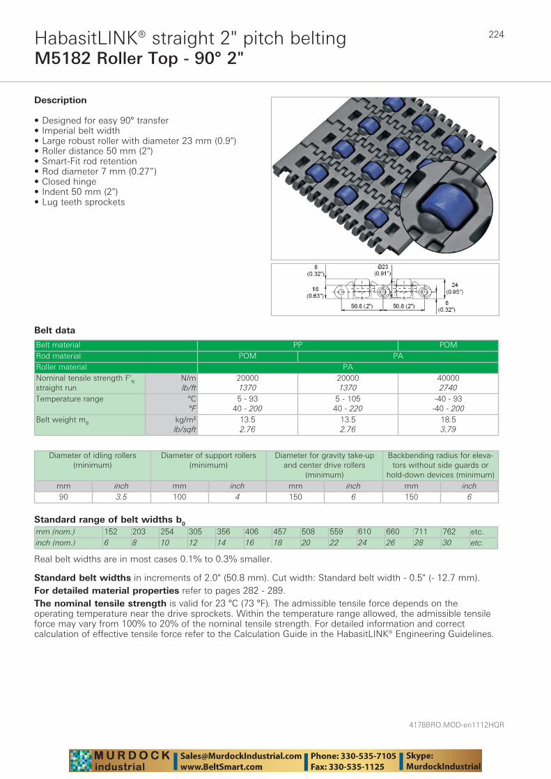
4178BRO.MOD-en1112HQR
224
M5182 Roller Top - 90° 2"HabasitLINK® straight 2" pitch belting
Belt data
Standard range of belt widths b0
mm (nom.) 152 203 254 305 356 406 457 508 559 610 660 711 762 etc.inch (nom.) 6 8 10 12 14 16 18 20 22 24 26 28 30 etc.
Real belt widths are in most cases 0.1% to 0.3% smaller.
Belt material PP POMRod material POM PARoller material PANominal tensile strength F'N straight run
N/mlb/ft
200001370
200001370
400002740
Temperature range °C°F
5 - 9340 - 200
5 - 10540 - 220
-40 - 93-40 - 200
Belt weight mB kg/m²lb/sqft
13.52.76
13.52.76
18.53.79
Description
• Designed for easy 90° transfer• Imperial belt width • Large robust roller with diameter 23 mm (0.9")• Roller distance 50 mm (2")• Smart-Fit rod retention • Rod diameter 7 mm (0.27”) • Closed hinge• Indent 50 mm (2")• Lug teeth sprockets
Diameter of idling rollers (minimum)
Diameter of support rollers(minimum)
Diameter for gravity take-up and center drive rollers
(minimum)
Backbending radius for eleva-tors without side guards or
hold-down devices (minimum)mm inch mm inch mm inch mm inch90 3.5 100 4 150 6 150 6
Standard belt widths in increments of 2.0" (50.8 mm). Cut width: Standard belt width - 0.5" (- 12.7 mm).For detailed material properties refer to pages 282 - 289.The nominal tensile strength is valid for 23 °C (73 °F). The admissible tensile force depends on the operating temperature near the drive sprockets. Within the temperature range allowed, the admissible tensile force may vary from 100% to 20% of the nominal tensile strength. For detailed information and correct calculation of effective tensile force refer to the Calculation Guide in the HabasitLINK® Engineering Guidelines.

225
4178BRO.MOD-en1112HQR
Sprocket series M5100HabasitLINK® sprockets 2" pitch belting
M = Modular belts
M 51 6Q6012S
Belt pitch
S = sprocket one-piece; Z = split sprocket
Number of teeth
Shaft size
Shaft type: Q = square shaft; R = round shaft
Material: 6 = POM; 8 = PA
Type Number of teeth
Diam. of pitch Ø dp
A1 Hub width BL Square bore Q Ø Round bore R Standard material
mm inch mm inch mm inch mm inch mm inchS 16 261.5 10.3 122.8 4.83 45 1.77 90 3.5 - - POMS-C1 10 165.2 6.5 74.6 2.94 30 1.18 40 / 60 1.5 / 2.5 40 / 50
/ 601.5 / 2.5 POM
S-C1 12 197.2 7.8 90.6 3.57 30 1.18 40 / 60 1.5 / 2.5 40 / 60 1.5 / 2.5 POMS-C1 13 213.2 8.4 98.6 3.88 30 1.18 40 / 60
/ 901.5 / 2.5 40 / 60
/ 901.5 / 2.5 POM
S-C1 16 261.5 10.3 122.8 4.83 40 1.57 60 / 90 / 120
1.5 / 2.5 / 3.5
60 / 90 1.5 / 2.5 POM
Sprocket one-piece ("open window")
Sprocket availability
S: molded sprockets; S-C1: machined sprockets. Other sprocket and hub sizes on request.Key ways for round bore shape follow European standards for metric sizes and US standards for imperial sizes. For detailed dimensions see table in the Engineering Guide chapter Design Guide.Other materials available on request.
Sprocket one-piece (solid)
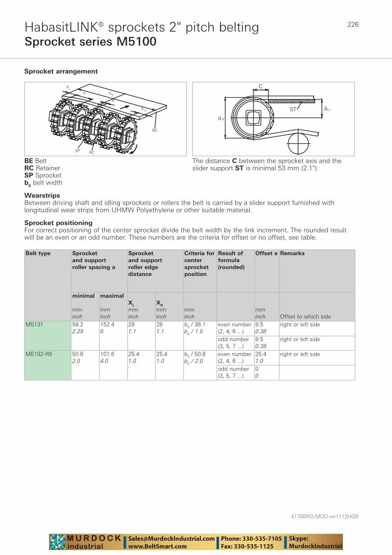
4178BRO.MOD-en1112HQR
226
Sprocket series M5100HabasitLINK® sprockets 2" pitch belting
WearstripsBetween driving shaft and idling sprockets or rollers the belt is carried by a slider support furnished with longitudinal wear strips from UHMW Polyethylene or other suitable material.
Sprocket arrangement
BE BeltRC RetainerSP Sprocketb0 belt width
The distance C between the sprocket axis and the slider support ST is minimal 53 mm (2.1").
Sprocket positioning For correct positioning of the center sprocket divide the belt width by the link increment. The rounded result will be an even or an odd number. These numbers are the criteria for offset or no offset, see table.
Belt type
Sprocket and support roller spacing a
Sprocket and support roller edge distance
Criteria for center sprocket position
Result of formula (rounded)
Offset e Remarks
minimal mminch
maximal mminch
XL
mminch
XR
mminch
mminch
mminch Offset to which side
M5131 58.22.29
152.46
281.1
281.1
b0 / 38.1b0 / 1.5
even number (2, 4, 6 ...)
9.50.38
right or left side
odd number (3, 5, 7 ...)
9.50.38
right or left side
M5182-R9 50.82.0
101.64.0
25.41.0
25.41.0
b0 / 50.8b0 / 2.0
even number (2, 4, 6 ...)
25.41.0
right or left side
odd number (3, 5, 7 ...)
00
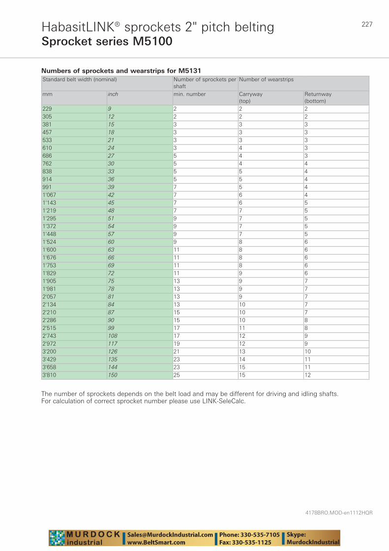
227
4178BRO.MOD-en1112HQR
Sprocket series M5100HabasitLINK® sprockets 2" pitch belting
Numbers of sprockets and wearstrips for M5131 Standard belt width (nominal) Number of sprockets per
shaftNumber of wearstrips
mm inch min. number Carryway (top)
Returnway (bottom)
229 9 2 2 2305 12 2 2 2381 15 3 3 3457 18 3 3 3533 21 3 3 3610 24 3 4 3686 27 5 4 3762 30 5 4 4838 33 5 5 4914 36 5 5 4991 39 7 5 41'067 42 7 6 41'143 45 7 6 51'219 48 7 7 51'295 51 9 7 51'372 54 9 7 51'448 57 9 7 51'524 60 9 8 61'600 63 11 8 61'676 66 11 8 61'753 69 11 8 61'829 72 11 9 61'905 75 13 9 71'981 78 13 9 72'057 81 13 9 72'134 84 13 10 72'210 87 15 10 72'286 90 15 10 82'515 99 17 11 82'743 108 17 12 92'972 117 19 12 93'200 126 21 13 103'429 135 23 14 113'658 144 23 15 113'810 150 25 15 12
The number of sprockets depends on the belt load and may be different for driving and idling shafts. For calculation of correct sprocket number please use LINK-SeleCalc.
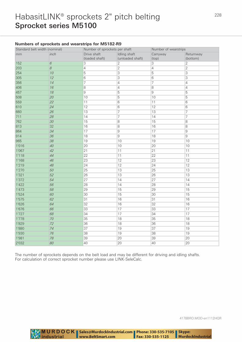
4178BRO.MOD-en1112HQR
228
Sprocket series M5100HabasitLINK® sprockets 2" pitch belting
Numbers of sprockets and wearstrips for M5182-R9 Standard belt width (nominal) Number of sprockets per shaft Number of wearstripsmm inch Drive shaft
(loaded shaft)Idling shaft(unloaded shaft)
Carryway (top)
Returnway (bottom)
152 6 3 2 3 2203 8 4 2 4 2254 10 5 3 5 3305 12 6 3 6 3356 14 7 4 7 4406 16 8 4 8 4457 18 9 5 9 5508 20 10 5 10 5559 22 11 6 11 6610 24 12 6 12 6660 26 13 7 13 7711 28 14 7 14 7762 30 15 8 15 8813 32 16 8 16 8864 34 17 9 17 9914 36 18 9 18 9965 38 19 10 19 101'016 40 20 10 20 101'067 42 21 11 21 111'118 44 22 11 22 111'168 46 23 12 23 121'219 48 24 12 24 121'270 50 25 13 25 131'321 52 26 13 26 131'372 54 27 14 27 141'422 56 28 14 28 141'473 58 29 15 29 151'524 60 30 15 30 151'575 62 31 16 31 161'626 64 32 16 32 161'676 66 33 17 33 171'727 68 34 17 34 171'778 70 35 18 35 181'829 72 36 18 36 181'880 74 37 19 37 191'930 76 38 19 38 191'981 78 39 20 39 202'032 80 40 20 40 20
The number of sprockets depends on the belt load and may be different for driving and idling shafts. For calculation of correct sprocket number please use LINK-SeleCalc.
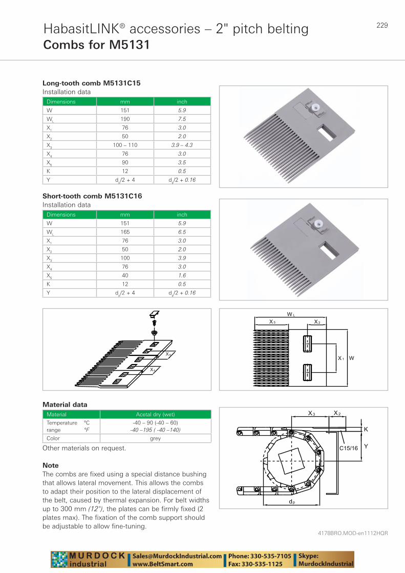
229
4178BRO.MOD-en1112HQR
HabasitLINK® accessories – 2" pitch beltingCombs for M5131
Long-tooth comb M5131C15Installation data
Dimensions mm inch
W 151 5.9
WL 190 7.5
X1 76 3.0
X2 50 2.0
X3 100 – 110 3.9 – 4.3
X4 76 3.0
X5 90 3.5
K 12 0.5
Y dp/2 + 4 dp/2 + 0.16
Short-tooth comb M5131C16Installation data
Dimensions mm inch
W 151 5.9
WL 165 6.5
X1 76 3.0
X2 50 2.0
X3 100 3.9
X4 76 3.0
X5 40 1.6
K 12 0.5
Y dp/2 + 4 dp/2 + 0.16
Material dataMaterial Acetal dry (wet)
Temperature °Crange °F
-40 – 90 (-40 – 60)-40 –195 ( -40 –140)
Color grey
Other materials on request.
NoteThe combs are fixed using a special distance bushing that allows lateral movement. This allows the combs to adapt their position to the lateral displacement of the belt, caused by thermal expansion. For belt widths up to 300 mm (12"), the plates can be firmly fixed (2 plates max). The fixation of the comb support should be adjustable to allow fine-tuning.
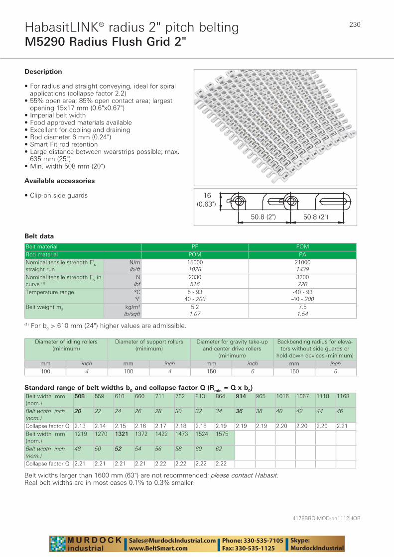
4178BRO.MOD-en1112HQR
230
M5290 Radius Flush Grid 2"HabasitLINK® radius 2" pitch belting
Belt data
Standard range of belt widths b0 and collapse factor Q (Rmin = Q x b0)Belt width mm (nom.)
508 559 610 660 711 762 813 864 914 965 1016 1067 1118 1168
Belt width inch (nom.)
20 22 24 26 28 30 32 34 36 38 40 42 44 46
Collapse factor Q 2.13 2.14 2.15 2.16 2.17 2.18 2.18 2.19 2.19 2.19 2.20 2.20 2.20 2.21Belt width mm (nom.)
1219 1270 1321 1372 1422 1473 1524 1575
Belt width inch (nom.)
48 50 52 54 56 58 60 62
Collapse factor Q 2.21 2.21 2.21 2.21 2.22 2.22 2.22 2.22
Belt widths larger than 1600 mm (63") are not recommended; please contact Habasit.Real belt widths are in most cases 0.1% to 0.3% smaller.
Belt material PP POMRod material POM PANominal tensile strength F'N straight run
N/mlb/ft
150001028
210001439
Nominal tensile strength FN in curve (1)
Nlbf
2330516
3200720
Temperature range °C°F
5 - 9340 - 200
-40 - 93-40 - 200
Belt weight mB kg/m²lb/sqft
5.21.07
7.51.54
Description
• For radius and straight conveying, ideal for spiral applications (collapse factor 2.2)
• 55% open area; 85% open contact area; largest opening 15x17 mm (0.6"x0.67")
• Imperial belt width • Food approved materials available• Excellent for cooling and draining • Rod diameter 6 mm (0.24") • Smart Fit rod retention • Large distance between wearstrips possible; max.
635 mm (25") • Min. width 508 mm (20")
Available accessories
• Clip-on side guards
(1) For b0 > 610 mm (24") higher values are admissible.
Diameter of idling rollers (minimum)
Diameter of support rollers(minimum)
Diameter for gravity take-up and center drive rollers
(minimum)
Backbending radius for eleva-tors without side guards or
hold-down devices (minimum)mm inch mm inch mm inch mm inch100 4 100 4 150 6 150 6

231
4178BRO.MOD-en1112HQR
M5290 Radius Flush Grid 2"HabasitLINK® radius 2" pitch belting
For detailed material properties refer to pages 282 - 289.The nominal tensile strength is valid for 23 °C (73 °F). The admissible tensile force depends on the operating temperature near the drive sprockets. Within the temperature range allowed, the admissible tensile force may vary from 100% to 20% of the nominal tensile strength. For detailed information and correct calculation of effective tensile force refer to the Calculation Guide in the HabasitLINK® Engineering Guidelines.
Non-standard belt widths in increments of 1" (25.4 mm).
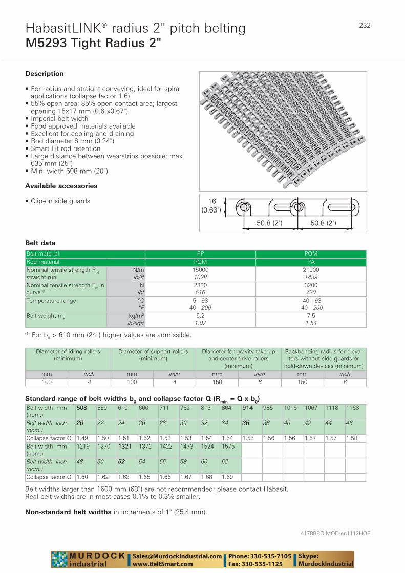
4178BRO.MOD-en1112HQR
232
M5293 Tight Radius 2"HabasitLINK® radius 2" pitch belting
Belt data
Standard range of belt widths b0 and collapse factor Q (Rmin = Q x b0)Belt width mm (nom.)
508 559 610 660 711 762 813 864 914 965 1016 1067 1118 1168
Belt width inch (nom.)
20 22 24 26 28 30 32 34 36 38 40 42 44 46
Collapse factor Q 1.49 1.50 1.51 1.52 1.53 1.53 1.54 1.54 1.55 1.56 1.56 1.57 1.57 1.58Belt width mm (nom.)
1219 1270 1321 1372 1422 1473 1524 1575
Belt width inch (nom.)
48 50 52 54 56 58 60 62
Collapse factor Q 1.60 1.62 1.63 1.65 1.66 1.67 1.68 1.69
Belt widths larger than 1600 mm (63") are not recommended; please contact Habasit.Real belt widths are in most cases 0.1% to 0.3% smaller.
Belt material PP POMRod material POM PANominal tensile strength F'N straight run
N/mlb/ft
150001028
210001439
Nominal tensile strength FN in curve (1)
Nlbf
2330516
3200720
Temperature range °C°F
5 - 9340 - 200
-40 - 93-40 - 200
Belt weight mB kg/m²lb/sqft
5.21.07
7.51.54
Description
• For radius and straight conveying, ideal for spiral applications (collapse factor 1.6)
• 55% open area; 85% open contact area; largest opening 15x17 mm (0.6"x0.67")
• Imperial belt width • Food approved materials available• Excellent for cooling and draining • Rod diameter 6 mm (0.24") • Smart Fit rod retention • Large distance between wearstrips possible; max.
635 mm (25") • Min. width 508 mm (20")
Available accessories
• Clip-on side guards
(1) For b0 > 610 mm (24") higher values are admissible.
Diameter of idling rollers (minimum)
Diameter of support rollers(minimum)
Diameter for gravity take-up and center drive rollers
(minimum)
Backbending radius for eleva-tors without side guards or
hold-down devices (minimum)mm inch mm inch mm inch mm inch100 4 100 4 150 6 150 6
Non-standard belt widths in increments of 1" (25.4 mm).
233
4178BRO.MOD-en1112HQR
M5293 Tight Radius 2"HabasitLINK® radius 2" pitch belting
For detailed material properties refer to pages 282 - 289.The nominal tensile strength is valid for 23 °C (73 °F). The admissible tensile force depends on the operating temperature near the drive sprockets. Within the temperature range allowed, the admissible tensile force may vary from 100% to 20% of the nominal tensile strength. For detailed information and correct calculation of effective tensile force refer to the Calculation Guide in the HabasitLINK® Engineering Guidelines.
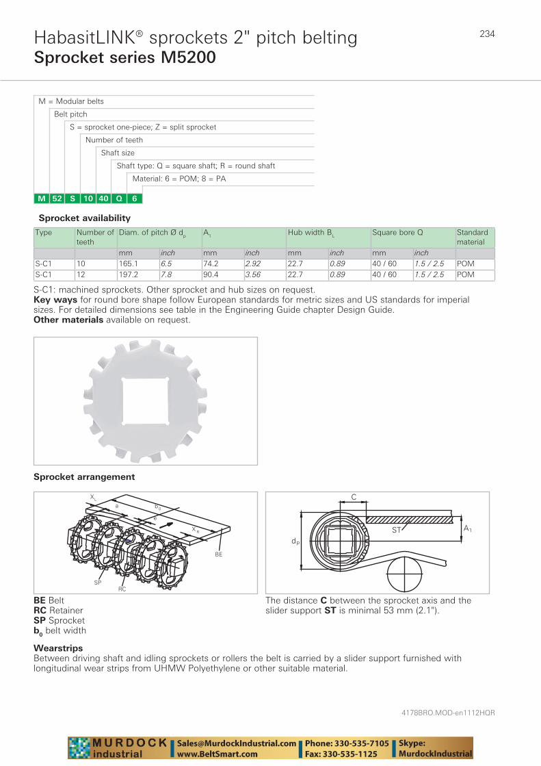
4178BRO.MOD-en1112HQR
234
Sprocket series M5200HabasitLINK® sprockets 2" pitch belting
M = Modular belts
M 52 6Q4010S
Belt pitch
S = sprocket one-piece; Z = split sprocket
Number of teeth
Shaft size
Shaft type: Q = square shaft; R = round shaft
Material: 6 = POM; 8 = PA
Type Number of teeth
Diam. of pitch Ø dp A1 Hub width BL Square bore Q Standard material
mm inch mm inch mm inch mm inchS-C1 10 165.1 6.5 74.2 2.92 22.7 0.89 40 / 60 1.5 / 2.5 POMS-C1 12 197.2 7.8 90.4 3.56 22.7 0.89 40 / 60 1.5 / 2.5 POM
BE BeltRC RetainerSP Sprocketb0 belt width
Sprocket availability
S-C1: machined sprockets. Other sprocket and hub sizes on request.Key ways for round bore shape follow European standards for metric sizes and US standards for imperial sizes. For detailed dimensions see table in the Engineering Guide chapter Design Guide.Other materials available on request.
The distance C between the sprocket axis and the slider support ST is minimal 53 mm (2.1").
WearstripsBetween driving shaft and idling sprockets or rollers the belt is carried by a slider support furnished with longitudinal wear strips from UHMW Polyethylene or other suitable material.
Sprocket arrangement
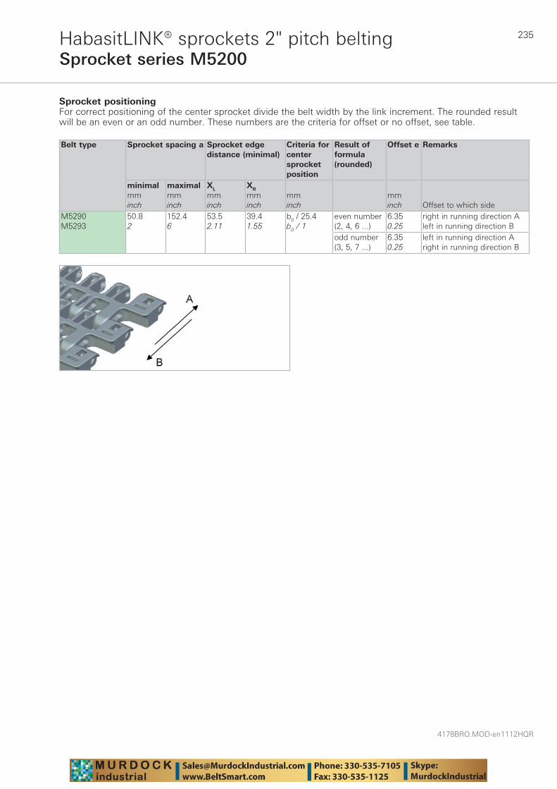
235
4178BRO.MOD-en1112HQR
Sprocket series M5200HabasitLINK® sprockets 2" pitch belting
Sprocket positioningFor correct positioning of the center sprocket divide the belt width by the link increment. The rounded result will be an even or an odd number. These numbers are the criteria for offset or no offset, see table.
Belt type Sprocket spacing a Sprocket edgedistance (minimal)
Criteria for center sprocket position
Result of formula (rounded)
Offset e Remarks
minimalmminch
maximalmminch
XL
mminch
XR
mminch
mminch
mminch Offset to which side
M5290M5293
50.82
152.46
53.52.11
39.41.55
b0 / 25.4b0 / 1
even number (2, 4, 6 ...)
6.350.25
right in running direction Aleft in running direction B
odd number (3, 5, 7 ...)
6.350.25
left in running direction Aright in running direction B
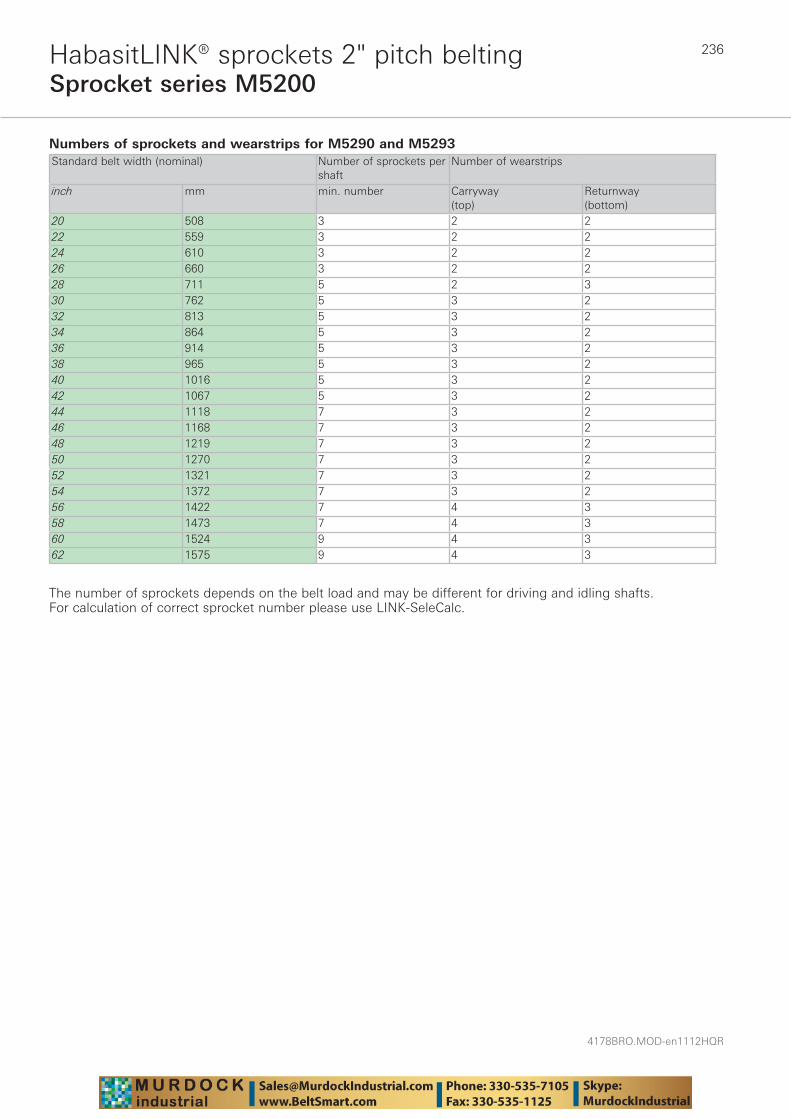
4178BRO.MOD-en1112HQR
236
Sprocket series M5200HabasitLINK® sprockets 2" pitch belting
Numbers of sprockets and wearstrips for M5290 and M5293 Standard belt width (nominal) Number of sprockets per
shaftNumber of wearstrips
inch mm min. number Carryway (top)
Returnway (bottom)
20 508 3 2 222 559 3 2 224 610 3 2 226 660 3 2 228 711 5 2 330 762 5 3 232 813 5 3 234 864 5 3 236 914 5 3 238 965 5 3 240 1016 5 3 242 1067 5 3 244 1118 7 3 246 1168 7 3 248 1219 7 3 250 1270 7 3 252 1321 7 3 254 1372 7 3 256 1422 7 4 358 1473 7 4 360 1524 9 4 362 1575 9 4 3
The number of sprockets depends on the belt load and may be different for driving and idling shafts. For calculation of correct sprocket number please use LINK-SeleCalc.
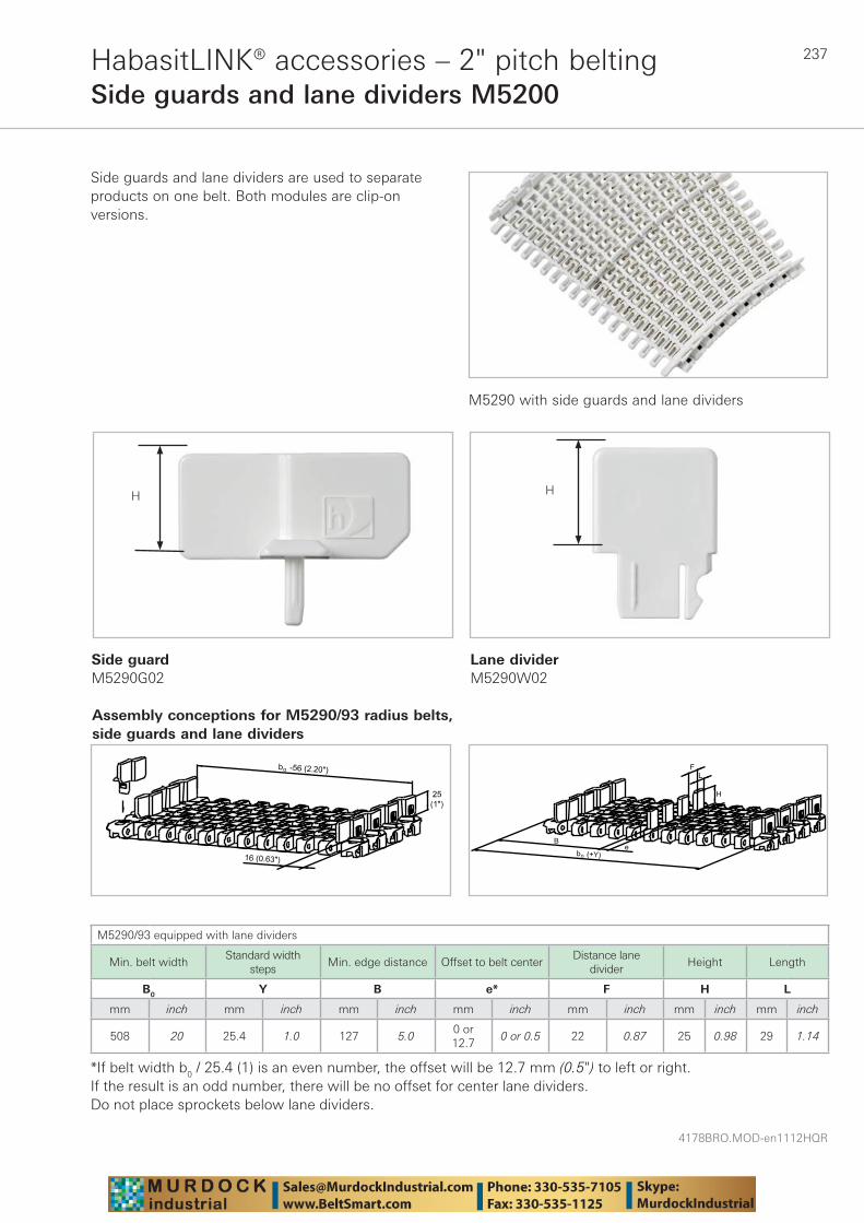
237
4178BRO.MOD-en1112HQR
HabasitLINK® accessories – 2" pitch beltingSide guards and lane dividers M5200
M5290 with side guards and lane dividers
Side guardM5290G02
Lane dividerM5290W02
M5290/93 equipped with lane dividers
Min. belt widthStandard width
stepsMin. edge distance Offset to belt center
Distance lane divider
Height Length
B0 Y B e* F H L
mm inch mm inch mm inch mm inch mm inch mm inch mm inch
508 20 25.4 1.0 127 5.00 or 12.7
0 or 0.5 22 0.87 25 0.98 29 1.14
*If belt width b0 / 25.4 (1) is an even number, the offset will be 12.7 mm (0.5") to left or right.If the result is an odd number, there will be no offset for center lane dividers. Do not place sprockets below lane dividers.
Side guards and lane dividers are used to separate products on one belt. Both modules are clip-on versions.
Assembly conceptions for M5290/93 radius belts, side guards and lane dividers
HH
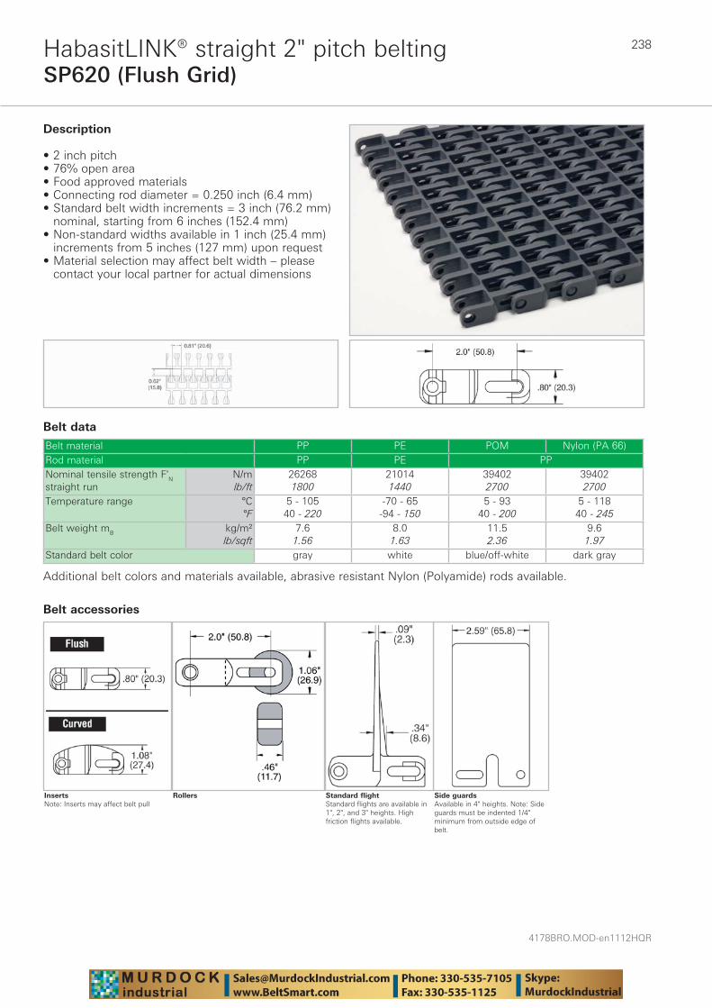
4178BRO.MOD-en1112HQR
238
SP620 (Flush Grid)HabasitLINK® straight 2" pitch belting
Belt data
Belt material PP PE POM Nylon (PA 66)Rod material PP PE PPNominal tensile strength F'N straight run
N/mlb/ft
262681800
210141440
394022700
394022700
Temperature range °C°F
5 - 10540 - 220
-70 - 65-94 - 150
5 - 9340 - 200
5 - 11840 - 245
Belt weight mB kg/m²lb/sqft
7.61.56
8.01.63
11.52.36
9.61.97
Standard belt color gray white blue/off-white dark gray
Description
• 2 inch pitch • 76% open area • Food approved materials• Connecting rod diameter = 0.250 inch (6.4 mm) • Standard belt width increments = 3 inch (76.2 mm)
nominal, starting from 6 inches (152.4 mm)• Non-standard widths available in 1 inch (25.4 mm)
increments from 5 inches (127 mm) upon request• Material selection may affect belt width – please
contact your local partner for actual dimensions
Additional belt colors and materials available, abrasive resistant Nylon (Polyamide) rods available.
Side guardsAvailable in 4" heights. Note: Side guards must be indented 1/4" minimum from outside edge of belt.
Standard flightStandard flights are available in 1", 2", and 3" heights. High friction flights available.
Rollers
Belt accessories
InsertsNote: Inserts may affect belt pull
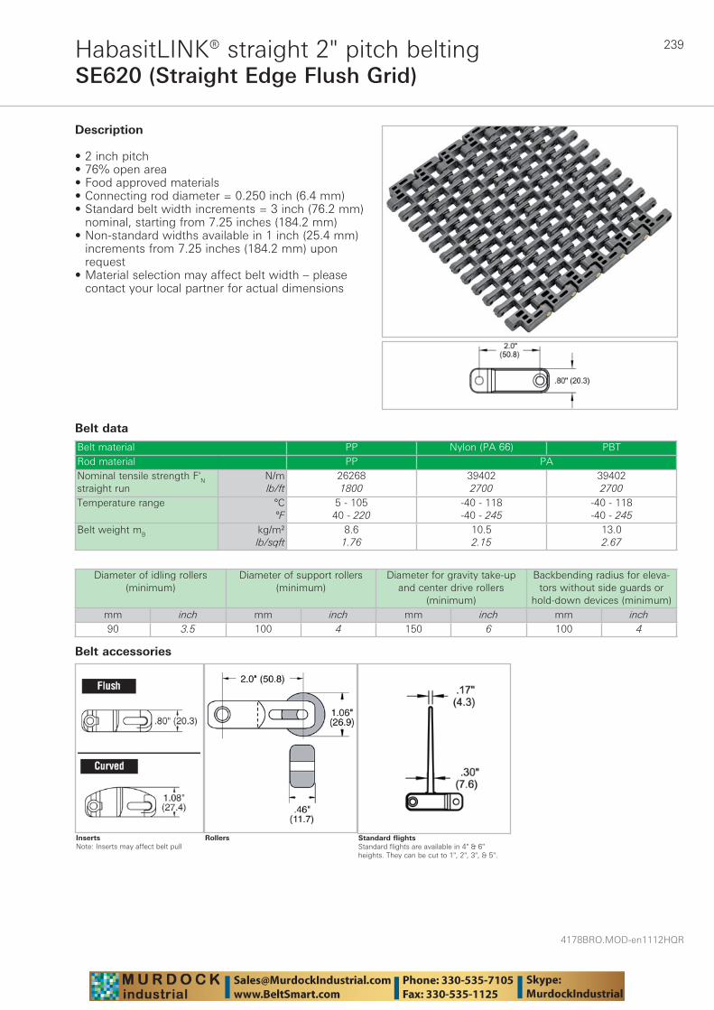
239
4178BRO.MOD-en1112HQR
SE620 (Straight Edge Flush Grid)HabasitLINK® straight 2" pitch belting
Belt data
Belt material PP Nylon (PA 66) PBTRod material PP PANominal tensile strength F'N straight run
N/mlb/ft
262681800
394022700
394022700
Temperature range °C°F
5 - 10540 - 220
-40 - 118-40 - 245
-40 - 118-40 - 245
Belt weight mB kg/m²lb/sqft
8.61.76
10.52.15
13.02.67
Description
• 2 inch pitch • 76% open area • Food approved materials• Connecting rod diameter = 0.250 inch (6.4 mm) • Standard belt width increments = 3 inch (76.2 mm)
nominal, starting from 7.25 inches (184.2 mm) • Non-standard widths available in 1 inch (25.4 mm)
increments from 7.25 inches (184.2 mm) upon request
• Material selection may affect belt width – please contact your local partner for actual dimensions
Diameter of idling rollers (minimum)
Diameter of support rollers(minimum)
Diameter for gravity take-up and center drive rollers
(minimum)
Backbending radius for eleva-tors without side guards or
hold-down devices (minimum)mm inch mm inch mm inch mm inch90 3.5 100 4 150 6 100 4
Standard flightsStandard flights are available in 4" & 6" heights. They can be cut to 1", 2", 3", & 5".
Rollers
Belt accessories
InsertsNote: Inserts may affect belt pull
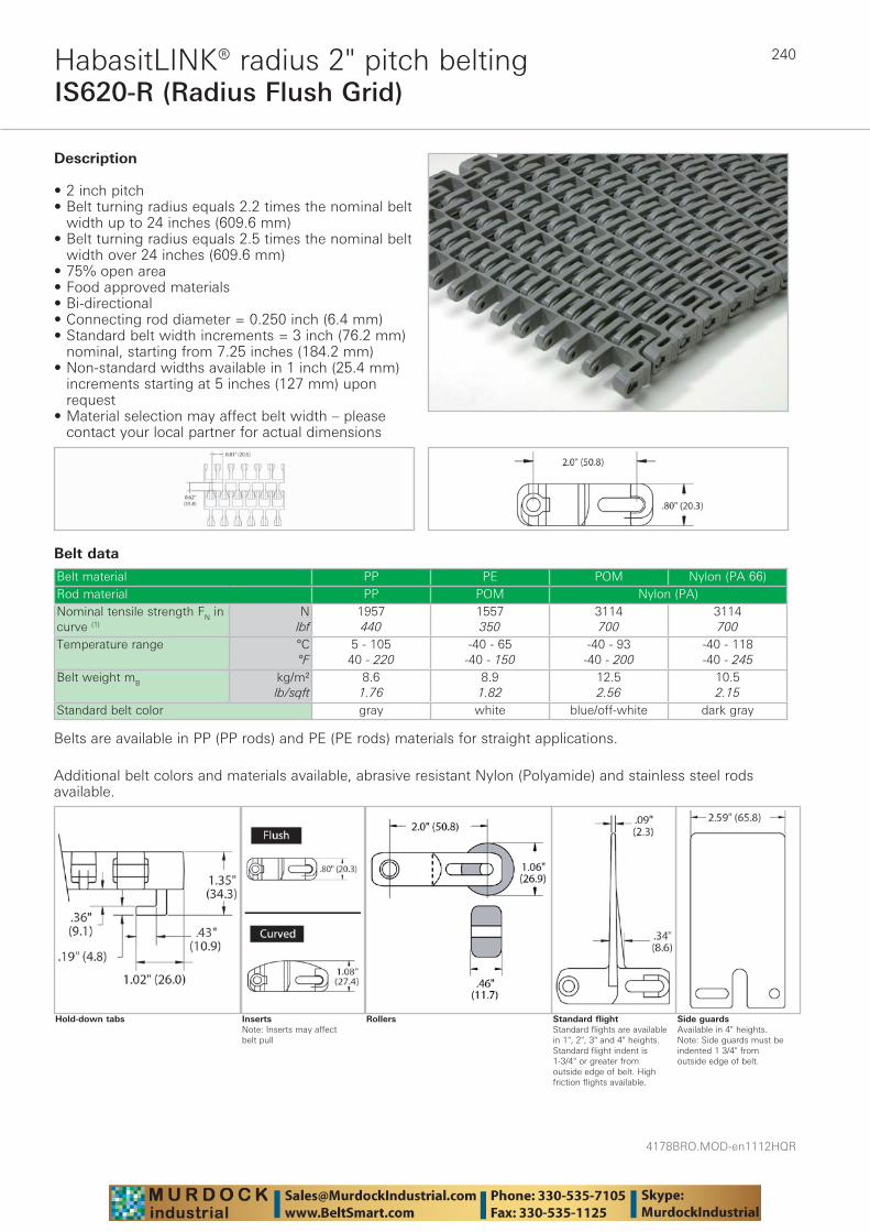
4178BRO.MOD-en1112HQR
240
IS620-R (Radius Flush Grid)HabasitLINK® radius 2" pitch belting
Belt data
Belt material PP PE POM Nylon (PA 66)Rod material PP POM Nylon (PA)Nominal tensile strength FN in curve (1)
Nlbf
1957440
1557350
3114700
3114700
Temperature range °C°F
5 - 10540 - 220
-40 - 65-40 - 150
-40 - 93-40 - 200
-40 - 118-40 - 245
Belt weight mB kg/m²lb/sqft
8.61.76
8.91.82
12.52.56
10.52.15
Standard belt color gray white blue/off-white dark gray
Description
• 2 inch pitch • Belt turning radius equals 2.2 times the nominal belt
width up to 24 inches (609.6 mm) • Belt turning radius equals 2.5 times the nominal belt
width over 24 inches (609.6 mm) • 75% open area • Food approved materials• Bi-directional • Connecting rod diameter = 0.250 inch (6.4 mm) • Standard belt width increments = 3 inch (76.2 mm)
nominal, starting from 7.25 inches (184.2 mm)• Non-standard widths available in 1 inch (25.4 mm)
increments starting at 5 inches (127 mm) upon request
• Material selection may affect belt width – please contact your local partner for actual dimensions
Additional belt colors and materials available, abrasive resistant Nylon (Polyamide) and stainless steel rods available.
Side guardsAvailable in 4" heights. Note: Side guards must be indented 1 3/4" from outside edge of belt.
Standard flightStandard flights are available in 1", 2", 3" and 4" heights. Standard flight indent is 1-3/4" or greater from outside edge of belt. High friction flights available.
RollersInsertsNote: Inserts may affect belt pull
Hold-down tabs
Belts are available in PP (PP rods) and PE (PE rods) materials for straight applications.
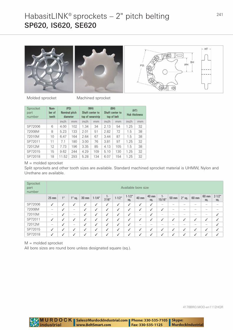
241
4178BRO.MOD-en1112HQR
HabasitLINK® sprockets – 2" pitch beltingSP620, IS620, SE620
Molded sprocket Machined sprocket
Sprocket part number
Num-ber of teeth
(PD) Nominal pitch
diameter
(WH) Shaft center to top of wearstrip
(BH) Shaft center to
top of belt
(HT) Hub thickness
inch mm inch mm inch mm inch mm
SP72006 6 4.00 102 1.34 34 2.13 54 1.25 32
72008M 8 5.23 133 2.01 51 2.82 72 1.5 38
72010M 10 6.47 164 2.64 67 3.44 87 1.5 38
SP72011 11 7.1 180 3.00 76 3.81 97 1.25 32
72012M 12 7.73 196 3.35 85 4.13 105 1.5 38
SP72015 15 9.62 244 4.29 109 5.10 130 1.25 32
SP72018 18 11.52 293 5.28 134 6.07 154 1.25 32
M = molded sprocketSplit sprockets and other tooth sizes are available. Standard machined sprocket material is UHMW, Nylon and Urethane are available.
Sprocket part number
Available bore size
25 mm 1“ 1“ sq. 30 mm 1-1/4“ 1-7/16“ 1-1/2“ 1-1/2“
sq. 40 mm 40 mmsq.
1-15/16“ 50 mm 2“ sq. 60 mm 60 mm
sq.2-1/2“
sq.SP72006 ✓ ✓ ✓ ✓ ✓ ✓ ✓ ✓ ✓ ✓ – – – – – –
72008M – ✓ – ✓ ✓ ✓ ✓ ✓ ✓ ✓ ✓ – – – – –
72010M – ✓ – ✓ ✓ ✓ ✓ ✓ – ✓ – – – – – ✓
SP72011 ✓ ✓ ✓ ✓ ✓ ✓ ✓ ✓ ✓ ✓ ✓ ✓ ✓ ✓ ✓ ✓
72012M – ✓ – ✓ ✓ ✓ ✓ ✓ – – – – – – – ✓
SP72015 ✓ ✓ ✓ ✓ ✓ ✓ ✓ ✓ ✓ ✓ ✓ ✓ ✓ ✓ ✓ ✓
SP72018 ✓ ✓ ✓ ✓ ✓ ✓ ✓ ✓ ✓ ✓ ✓ ✓ ✓ ✓ ✓ ✓
M = molded sprocketAll bore sizes are round bore unless designated square (sq.).

4178BRO.MOD-en1112HQR
242
HDS620 (Flat Top)HabasitLINK® straight 2" pitch belting
Belt data
Belt material PP PP +DE PE POM Nylon (PA +IM)Rod material PP PENominal tensile strength F'N straight run
N/mlb/ft
262681800
210101440
204301400
306462100
306462100
Temperature range °C°F
5 - 10540 - 220
5 - 10540 - 220
-70 - 65-94 - 150
-40 - 93-40 - 200
-40 - 80-40 - 176
Belt weight mB kg/m²lb/sqft
7.81.59
6.21.27
8.01.64
11.52.35
10.02.05
Standard belt color gray/white dark gray blue/white blue/white cream
Description
• 2 inch pitch • Solid top surface • Food approved materials• Bi-directional • Connecting rod diameter = 0.312 inch (7.9 mm) • Standard belt width increments = 1 inch (25.4 mm)
nominal, starting from 4 inches (101.6 mm) • Material selection may affect belt width – please
contact your local partner for actual dimensions
Additional belt colors and materials available, abrasive resistant Nylon (Polyamide) rods available – contact your local partner.
Side guardSide guards available in standard 2" & 4" heights. Do not use with 8 & 10 tooth sprockets. Sprockets must be big enough to keep plates from hitting each other. Note: Side guards must be indented a minimum of 1-1/4" from outside edge of belt.
Curved flightCurved flights available in standard 4" & 6" heights
Rough duty flightEasy release flightNote: Available in 6" height only - all other dimensions are the same as Rough duty flight.
Standard flightStandard flights are available in 1", 2", 4" and 6" heights
Belt accessories
InsertsNote: Inserts may affect belt pull

243
4178BRO.MOD-en1112HQR
HDSCT620 (Curved Top)HabasitLINK® straight 2" pitch belting
Belt data
Belt material PP PP +DE PE POM Nylon (PA +IM)Rod material PP PENominal tensile strength F'N straight run
N/mlb/ft
262681800
210101440
204301400
306462100
306462100
Temperature range °C°F
5 - 10540 - 220
5 - 10540 - 220
-70 - 65-94 - 150
-40 - 93-40 - 200
-40 - 80-40 - 176
Belt weight mB kg/m²lb/sqft
7.81.59
6.21.27
8.01.64
11.52.35
10.02.05
Standard belt color gray/white dark gray blue/white blue/white cream
Description
• 2 inch pitch • Reduced product contact and constant scraper
contact capability • Food approved materials• Bi-directional • Connecting rod diameter = 0.312 inch (7.9 mm) • Standard belt width increments = 1 inch (25.4 mm)
nominal, starting from 4 inches (101.6 mm) • Material selection may affect belt width – please
contact your local partner for actual dimensions
Additional belt colors and materials available, abrasive resistant Nylon (Polyamide) rods available.
Side guardSide guards are available in standard 2" & 4" heights. Do not use with 8 & 10 tooth sprockets. Sprockets must be big enough to keep plates from hitting each other. Note: Side guards must be indented a minimum of 1-1/4" from outside edge of belt.
Curved flightCurved flights are available in standard 4" & 6" heights
Rough duty flightEasy release flightNote: Available in 6" height only - all other dimensions are the same as Rough duty flight.
Belt accessories
Standard flightStandard flights are available in 1", 2", 4" and 6" heights
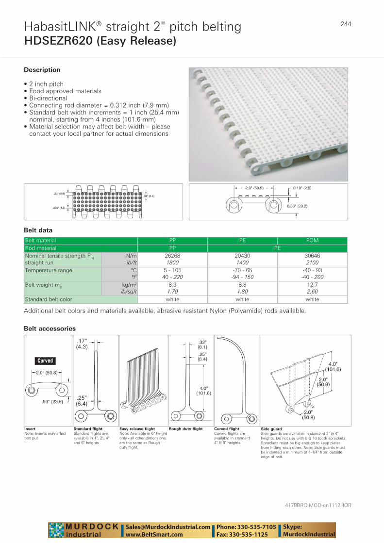
4178BRO.MOD-en1112HQR
244
HDSEZR620 (Easy Release)HabasitLINK® straight 2" pitch belting
Belt data
Belt material PP PE POMRod material PP PENominal tensile strength F'N straight run
N/mlb/ft
262681800
204301400
306462100
Temperature range °C°F
5 - 10540 - 220
-70 - 65-94 - 150
-40 - 93-40 - 200
Belt weight mB kg/m²lb/sqft
8.31.70
8.81.80
12.72.60
Standard belt color white white white
Description
• 2 inch pitch • Food approved materials• Bi-directional • Connecting rod diameter = 0.312 inch (7.9 mm) • Standard belt width increments = 1 inch (25.4 mm)
nominal, starting from 4 inches (101.6 mm) • Material selection may affect belt width – please
contact your local partner for actual dimensions
Additional belt colors and materials available, abrasive resistant Nylon (Polyamide) rods available.
Side guardSide guards are available in standard 2" & 4" heights. Do not use with 8 & 10 tooth sprockets. Sprockets must be big enough to keep plates from hitting each other. Note: Side guards must be indented a minimum of 1-1/4" from outside edge of belt.
Curved flightCurved flights are available in standard 4" & 6" heights
Rough duty flightEasy release flightNote: Available in 6" height only - all other dimensions are the same as Rough duty flight.
Standard flightStandard flights are available in 1", 2", 4" and 6" heights
Belt accessories
InsertNote: Inserts may affect belt pull
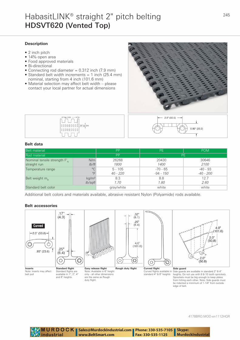
245
4178BRO.MOD-en1112HQR
HDSVT620 (Vented Top)HabasitLINK® straight 2" pitch belting
Belt data
Belt material PP PE POMRod material PP PENominal tensile strength F'N straight run
N/mlb/ft
262681800
204301400
306462100
Temperature range °C°F
5 - 10540 - 220
-70 - 65-94 - 150
-40 - 93-40 - 200
Belt weight mB kg/m²lb/sqft
8.31.70
8.81.80
12.72.60
Standard belt color gray/white white white
Description
• 2 inch pitch • 14% open area • Food approved materials• Bi-directional • Connecting rod diameter = 0.312 inch (7.9 mm) • Standard belt width increments = 1 inch (25.4 mm)
nominal, starting from 4 inch (101.6 mm) • Material selection may affect belt width – please
contact your local partner for actual dimensions
Additional belt colors and materials available, abrasive resistant Nylon (Polyamide) rods available.
Side guardSide guards are available in standard 2" & 4" heights. Do not use with 8 & 10 tooth sprockets. Sprockets must be big enough to keep plates from hitting each other. Note: Side guards must be indented a minimum of 1-1/4" from outside edge of belt.
Curved flightCurved flights available in standard 4" & 6" heights
Rough duty flightEasy release flightNote: Available in 6" height only - all other dimensions are the same as Rough duty flight.
Standard flightStandard flights are available in 1", 2", 4" and 6" heights
Belt accessories
InsertsNote: Inserts may affect belt pull
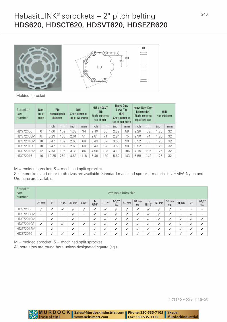
4178BRO.MOD-en1112HQR
246HabasitLINK® sprockets – 2" pitch beltingHDS620, HDSCT620, HDSVT620, HDSEZR620
Molded sprocket
Sprocket part number
Num-ber of teeth
(PD) Nominal pitch
diameter
(WH) Shaft center to top of wearstrip
HDS / HDSVT (BH)
Shaft center to top of belt
Heavy Duty Curve Top
(BH) Shaft center to
top of belt curve
Heavy Duty Easy Release (BH)
Shaft center to top of belt nub
(HT) Hub thickness
inch mm inch mm inch mm inch mm inch mm inch mm
HDS72006 6 4.00 102 1.33 34 2.19 56 2.32 59 2.28 58 1.25 32
HDS72008M 8 5.23 133 2.01 51 2.81 71 2.94 75 2.90 74 1.25 32
HDS72010M 10 6.47 162 2.68 68 3.43 87 3.56 90 3.52 89 1.25 32
HDS72010S 10 6.47 162 2.68 68 3.43 87 3.56 90 3.52 89 1.25 32
HDS72012M 12 7.73 196 3.33 86 4.06 103 4.19 106 4.15 105 1.25 32
HDS72016 16 10.25 260 4.63 118 5.49 139 5.62 143 5.58 142 1.25 32
M = molded sprocket, S = machined split sprocketSplit sprockets and other tooth sizes are available. Standard machined sprocket material is UHMW, Nylon and Urethane are available.
Sprocket part number
Available bore size
25 mm 1“ 1“ sq. 30 mm 1-1/4“ 1-7/16“ 1-1/2“ 1-1/2“
sq. 40 mm 40 mmsq.
1-15/16“ 50 mm 50 mm
sq. 60 mm 2“ 2-1/2“sq.
HDS72006 ✓ ✓ ✓ ✓ ✓ ✓ ✓ ✓ ✓ ✓ ✓ ✓ ✓ – – –
HDS72008M – ✓ – ✓ – ✓ ✓ ✓ ✓ ✓ ✓ ✓ ✓ – ✓ –
HDS72010M – ✓ – ✓ – ✓ ✓ ✓ ✓ ✓ ✓ ✓ ✓ ✓ ✓ ✓
HDS72010S ✓ ✓ ✓ ✓ ✓ ✓ ✓ ✓ ✓ ✓ ✓ ✓ ✓ ✓ ✓ ✓
HDS72012M – ✓ – ✓ – ✓ ✓ ✓ ✓ ✓ ✓ ✓ ✓ ✓ ✓ ✓
HDS72016 ✓ ✓ ✓ ✓ ✓ ✓ ✓ ✓ ✓ ✓ ✓ ✓ ✓ ✓ ✓ ✓
M = molded sprocket, S = machined split sprocketAll bore sizes are round bore unless designated square (sq.).
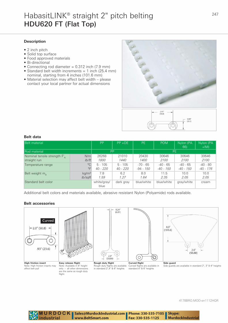
247
4178BRO.MOD-en1112HQR
HDU620 FT (Flat Top)HabasitLINK® straight 2" pitch belting
Belt data
Belt material PP PP +DE PE POM Nylon (PA 66)
Nylon (PA +IM)
Rod material PP PENominal tensile strength F'N straight run
N/mlb/ft
262681800
210101440
204301400
306462100
306462100
306462100
Temperature range °C°F
5 - 10540 - 220
5 - 10540 - 220
-70 - 65-94 - 150
-40 - 65-40 - 150
-40 - 65-40 - 150
-40 - 80-40 - 176
Belt weight mB kg/m²lb/sqft
7.81.59
6.21.27
8.01.64
11.52.35
10.02.05
10.02.05
Standard belt color white/gray/blue
dark gray blue/white blue/white gray/white cream
Description
• 2 inch pitch • Solid top surface • Food approved materials• Bi-directional • Connecting rod diameter = 0.312 inch (7.9 mm) • Standard belt width increments = 1 inch (25.4 mm)
nominal, starting from 4 inches (101.6 mm) • Material selection may affect belt width – please
contact your local partner for actual dimensions
Additional belt colors and materials available, abrasive resistant Nylon (Polyamide) rods available.
Side guardSide guards are available in standard 2", 3" & 4" heights
Curved flightCurved flights are available in standard 4" & 6" heights
Rough duty flightRough duty flights are available in standard 2",4" & 6" heights
Easy release flightNote: Available in 6" height only — all other dimensions are the same as rough duty flight.
Belt accessories
High friction insertNote: High friction inserts may affect belt pull

4178BRO.MOD-en1112HQR
248
HDU620 VT (Vented Top)HabasitLINK® straight 2" pitch belting
Belt data
Belt material PP PE POM Nylon (PA +IM)Rod material PP PENominal tensile strength F'N straight run
N/mlb/ft
262681800
204301400
306462100
306462100
Temperature range °C°F
5 - 10540 - 220
-70 - 65-94 - 150
-40 - 65-40 - 150
-40 - 80-40 - 176
Belt weight mB kg/m²lb/sqft
7.81.59
8.01.64
11.52.35
10.02.05
Standard belt color gray/white white white cream
Description
• 2 inch pitch • 14% open area • Food approved materials• Bi-directional • Connecting rod diameter = 0.312 inch (7.9 mm) • Standard belt width increments = 1 inch (25.4 mm)
nominal, starting from 4 inch (101.6 mm) • Material selection may affect belt width – please
contact your local partner for actual dimensions
Additional belt colors and materials available, abrasive resistant Nylon (Polyamide) rods available.
Side guardSide guards are available in standard 2", 3" & 4" heights
Curved flightCurved flights are available in standard 4" & 6" heights
Rough duty flightRough duty flights are available in standard 2",4" & 6" heights
Easy release flightNote: Available in 6" height only — all other dimensions are the same as Rough duty flight.
Belt accessories
InsertsNote: Inserts may affect belt pull
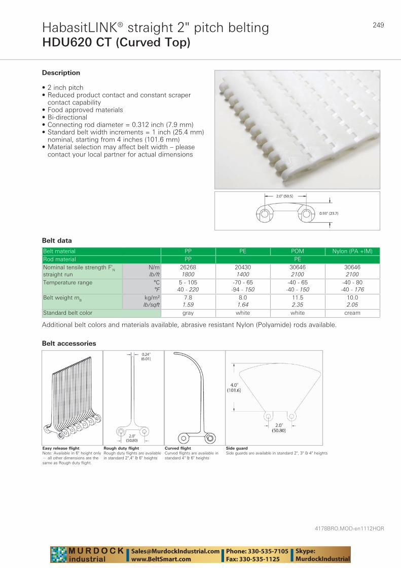
249
4178BRO.MOD-en1112HQR
HDU620 CT (Curved Top)HabasitLINK® straight 2" pitch belting
Belt data
Belt material PP PE POM Nylon (PA +IM)Rod material PP PENominal tensile strength F'N straight run
N/mlb/ft
262681800
204301400
306462100
306462100
Temperature range °C°F
5 - 10540 - 220
-70 - 65-94 - 150
-40 - 65-40 - 150
-40 - 80-40 - 176
Belt weight mB kg/m²lb/sqft
7.81.59
8.01.64
11.52.35
10.02.05
Standard belt color gray white white cream
Description
• 2 inch pitch • Reduced product contact and constant scraper
contact capability • Food approved materials• Bi-directional • Connecting rod diameter = 0.312 inch (7.9 mm) • Standard belt width increments = 1 inch (25.4 mm)
nominal, starting from 4 inches (101.6 mm) • Material selection may affect belt width – please
contact your local partner for actual dimensions
Additional belt colors and materials available, abrasive resistant Nylon (Polyamide) rods available.
Side guardSide guards are available in standard 2", 3" & 4" heights
Curved flightCurved flights are available in standard 4" & 6" heights
Rough duty flightRough duty flights are available in standard 2",4" & 6" heights
Belt accessories
Easy release flightNote: Available in 6" height only — all other dimensions are the same as Rough duty flight.
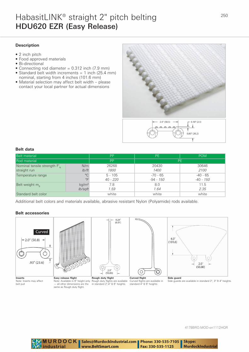
4178BRO.MOD-en1112HQR
250
HDU620 EZR (Easy Release)HabasitLINK® straight 2" pitch belting
Belt data
Belt material PP PE POMRod material PP PENominal tensile strength F'N straight run
N/mlb/ft
262681800
204301400
306462100
Temperature range °C°F
5 - 10540 - 220
-70 - 65-94 - 150
-40 - 65-40 - 150
Belt weight mB kg/m²lb/sqft
7.81.59
8.01.64
11.52.35
Standard belt color white white white
Description
• 2 inch pitch • Food approved materials• Bi-directional • Connecting rod diameter = 0.312 inch (7.9 mm) • Standard belt width increments = 1 inch (25.4 mm)
nominal, starting from 4 inches (101.6 mm) • Material selection may affect belt width – please
contact your local partner for actual dimensions
Additional belt colors and materials available, abrasive resistant Nylon (Polyamide) rods available.
Side guardSide guards are available in standard 2", 3" & 4" heights.
Curved flightCurved flights are available in standard 4" & 6" heights
Rough duty flightRough duty flights are available in standard 2",4" & 6" heights.
Easy release flightNote: Available in 6" height only — all other dimensions are the same as Rough duty flight.
Belt accessories
InsertsNote: Inserts may affect belt pull
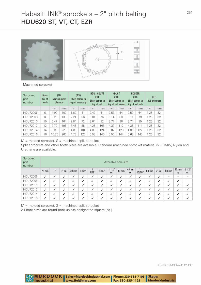
251
4178BRO.MOD-en1112HQR
HabasitLINK® sprockets – 2" pitch beltingHDU620 ST, VT, CT, EZR
Machined sprocket
Sprocket part number
Num-ber of teeth
(PD) Nominal pitch
diameter
(WH) Shaft center to top of wearstrip
HDU / HDUVT (BH)
Shaft center to top of belt
HDUCT (BH)
Shaft center to top of belt curve
HDUEZR (BH)
Shaft center to top of belt nub
(HT) Hub thickness
inch mm inch mm inch mm inch mm inch mm inch mm
HDU72006 6 4.00 102 1.60 41 2.40 61 2.53 64 2.50 64 1.25 32
HDU72008 8 5.23 133 2.21 56 3.01 76 3.14 80 3.11 79 1.25 32
HDU72010 10 6.47 164 2.84 72 3.64 92 3.77 96 3.74 95 1.25 32
HDU72012 12 7.72 196 3.46 88 4.26 108 4.39 112 4.36 111 1.25 32
HDU72014 14 8.99 228 4.09 104 4.89 124 5.02 128 4.99 127 1.25 32
HDU72016 16 10.25 260 4.73 120 5.53 140 5.56 144 5.63 143 1.25 32
M = molded sprocket, S = machined split sprocketSplit sprockets and other tooth sizes are available. Standard machined sprocket material is UHMW, Nylon and Urethane are available.
Sprocket part number
Available bore size
25 mm 1“ 1“ sq. 30 mm 1-1/4“ 1-7/16“ 1-1/2“ 1-1/2“
sq. 40 mm 40 mmsq.
1-15/16“ 50 mm 2“ sq. 80 mm 80 mm
sq.2-1/2“
sq.HDU72006 ✓ ✓ ✓ ✓ ✓ ✓ ✓ ✓ ✓ ✓ ✓ ✓ ✓ – – –
HDU72008 ✓ ✓ ✓ ✓ ✓ ✓ ✓ ✓ ✓ ✓ ✓ ✓ ✓ ✓ ✓ –
HDU72010 ✓ ✓ ✓ ✓ ✓ ✓ ✓ ✓ ✓ ✓ ✓ ✓ ✓ ✓ ✓ ✓
HDU72012 ✓ ✓ ✓ ✓ ✓ ✓ ✓ ✓ ✓ ✓ ✓ ✓ ✓ ✓ ✓ ✓
HDU72014 ✓ ✓ ✓ ✓ ✓ ✓ ✓ ✓ ✓ ✓ ✓ ✓ ✓ ✓ ✓ ✓
HDU72016 ✓ ✓ ✓ ✓ ✓ ✓ ✓ ✓ ✓ ✓ ✓ ✓ ✓ ✓ ✓ ✓
M = molded sprocket, S = machined split sprocketAll bore sizes are round bore unless designated square (sq.).
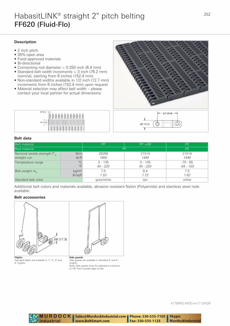
4178BRO.MOD-en1112HQR
252
FF620 (Fluid-Flo)HabasitLINK® straight 2" pitch belting
Belt data
Belt material PP PP +GR PERod material PP PENominal tensile strength F'N straight run
N/mlb/ft
262681800
210141440
210141440
Temperature range °C°F
5 - 10540 - 220
5 - 10540 - 220
-70 - 65-94 - 150
Belt weight mB kg/m²lb/sqft
7.51.53
8.41.72
7.91.62
Standard belt color gray/white tan white
Description
• 2 inch pitch • 35% open area • Food approved materials• Bi-directional • Connecting rod diameter = 0.250 inch (6.4 mm) • Standard belt width increments = 3 inch (76.2 mm)
nominal, starting from 6 inches (152.4 mm)• Non-standard widths available in 1/2 inch (12.7 mm)
increments from 6 inches (152.4 mm) upon request• Material selection may affect belt width – please
contact your local partner for actual dimensions
Additional belt colors and materials available, abrasive resistant Nylon (Polyamide) and stainless steel rods available.
Side guardsSide guards are available in standard 3" and 4" heights.Note: Side guards must be indented a minimum of 1/8" from outside edge of belt.
Belt accessories
FlightsStandard flights are available in 1", 2", 3" and 4" heights
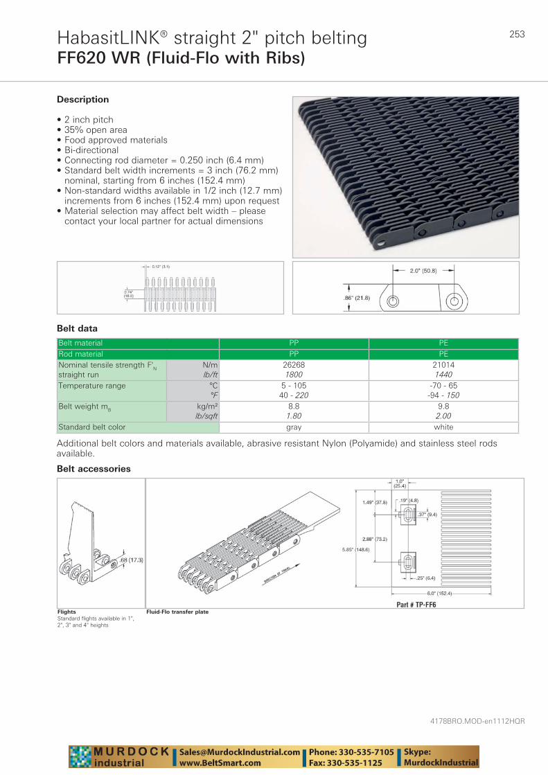
253
4178BRO.MOD-en1112HQR
FF620 WR (Fluid-Flo with Ribs)HabasitLINK® straight 2" pitch belting
Belt data
Belt material PP PERod material PP PENominal tensile strength F'N straight run
N/mlb/ft
262681800
210141440
Temperature range °C°F
5 - 10540 - 220
-70 - 65-94 - 150
Belt weight mB kg/m²lb/sqft
8.81.80
9.82.00
Standard belt color gray white
Description
• 2 inch pitch • 35% open area • Food approved materials• Bi-directional • Connecting rod diameter = 0.250 inch (6.4 mm) • Standard belt width increments = 3 inch (76.2 mm)
nominal, starting from 6 inches (152.4 mm)• Non-standard widths available in 1/2 inch (12.7 mm)
increments from 6 inches (152.4 mm) upon request• Material selection may affect belt width – please
contact your local partner for actual dimensions
Additional belt colors and materials available, abrasive resistant Nylon (Polyamide) and stainless steel rods available.
Fluid-Flo transfer plate
Belt accessories
FlightsStandard flights available in 1", 2", 3" and 4" heights
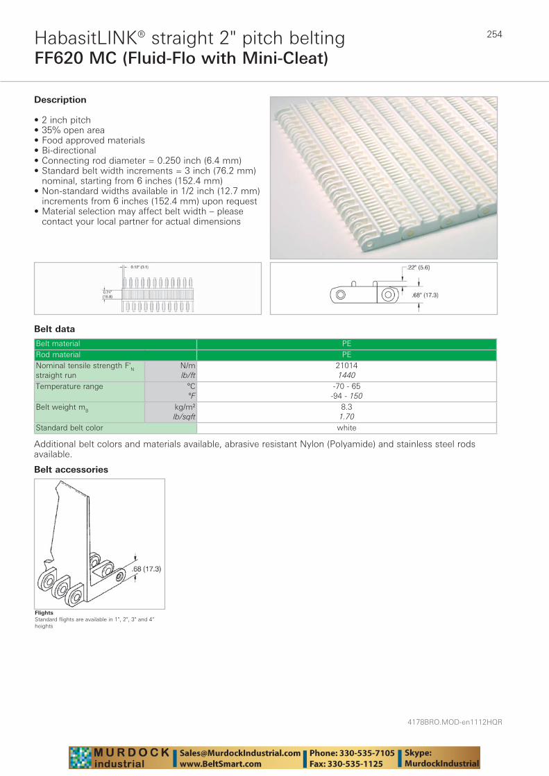
4178BRO.MOD-en1112HQR
254
FF620 MC (Fluid-Flo with Mini-Cleat)HabasitLINK® straight 2" pitch belting
Belt data
Belt material PERod material PENominal tensile strength F'N straight run
N/mlb/ft
210141440
Temperature range °C°F
-70 - 65-94 - 150
Belt weight mB kg/m²lb/sqft
8.31.70
Standard belt color white
Description
• 2 inch pitch • 35% open area • Food approved materials• Bi-directional • Connecting rod diameter = 0.250 inch (6.4 mm) • Standard belt width increments = 3 inch (76.2 mm)
nominal, starting from 6 inches (152.4 mm)• Non-standard widths available in 1/2 inch (12.7 mm)
increments from 6 inches (152.4 mm) upon request• Material selection may affect belt width – please
contact your local partner for actual dimensions
Additional belt colors and materials available, abrasive resistant Nylon (Polyamide) and stainless steel rods available.
Belt accessories
FlightsStandard flights are available in 1", 2", 3" and 4" heights
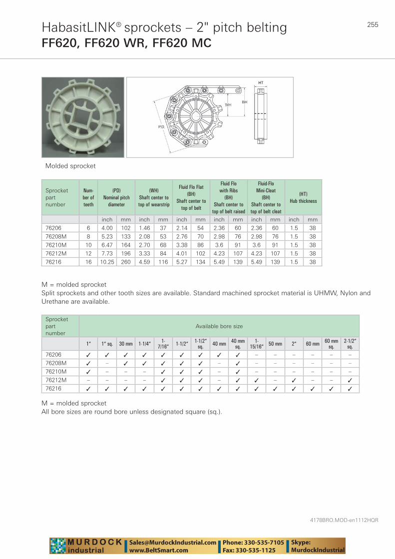
255
4178BRO.MOD-en1112HQR
HabasitLINK® sprockets – 2" pitch beltingFF620, FF620 WR, FF620 MC
Molded sprocket
Sprocket part number
Num-ber of teeth
(PD) Nominal pitch
diameter
(WH) Shaft center to top of wearstrip
Fluid Flo Flat (BH)
Shaft center to top of belt
Fluid Flo with Ribs
(BH) Shaft center to
top of belt raised
Fluid-Flo Mini-Cleat
(BH) Shaft center to top of belt cleat
(HT) Hub thickness
inch mm inch mm inch mm inch mm inch mm inch mm
76206 6 4.00 102 1.46 37 2.14 54 2.36 60 2.36 60 1.5 38
76208M 8 5.23 133 2.08 53 2.76 70 2.98 76 2.98 76 1.5 38
76210M 10 6.47 164 2.70 68 3.38 86 3.6 91 3.6 91 1.5 38
76212M 12 7.73 196 3.33 84 4.01 102 4.23 107 4.23 107 1.5 38
76216 16 10.25 260 4.59 116 5.27 134 5.49 139 5.49 139 1.5 38
M = molded sprocketSplit sprockets and other tooth sizes are available. Standard machined sprocket material is UHMW, Nylon and Urethane are available.
Sprocket part number
Available bore size
1“ 1“ sq. 30 mm 1-1/4“ 1-7/16“ 1-1/2“ 1-1/2“
sq. 40 mm 40 mmsq.
1-15/16“ 50 mm 2“ 60 mm 60 mm
sq.2-1/2“
sq.76206 ✓ ✓ ✓ ✓ ✓ ✓ ✓ ✓ ✓ – – – – – –
76208M ✓ – ✓ ✓ ✓ ✓ ✓ – ✓ – – – – – –
76210M ✓ – – – ✓ ✓ ✓ – ✓ – – – – – –
76212M – – – – ✓ ✓ ✓ – ✓ ✓ – ✓ – – ✓
76216 ✓ ✓ ✓ ✓ ✓ ✓ ✓ ✓ ✓ ✓ ✓ ✓ ✓ ✓ ✓
M = molded sprocketAll bore sizes are round bore unless designated square (sq.).
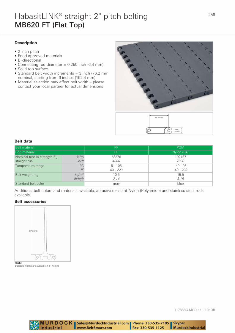
4178BRO.MOD-en1112HQR
256
MB620 FT (Flat Top)HabasitLINK® straight 2" pitch belting
Belt data
Belt material PP POMRod material PP Nylon (PA)Nominal tensile strength F'N straight run
N/mlb/ft
583764000
1021577000
Temperature range °C°F
5 - 10540 - 220
-40 - 93-40 - 200
Belt weight mB kg/m²lb/sqft
10.52.14
15.53.18
Standard belt color gray blue
Description
• 2 inch pitch • Food approved materials• Bi-directional • Connecting rod diameter = 0.250 inch (6.4 mm) • Solid top surface • Standard belt width increments = 3 inch (76.2 mm)
nominal, starting from 6 inches (152.4 mm) • Material selection may affect belt width – please
contact your local partner for actual dimensions
Additional belt colors and materials available, abrasive resistant Nylon (Polyamide) and stainless steel rods available.
Belt accessories
FlightStandard flights are available in 6" height
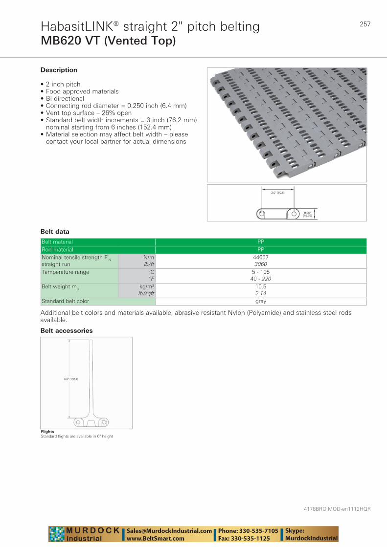
257
4178BRO.MOD-en1112HQR
MB620 VT (Vented Top)HabasitLINK® straight 2" pitch belting
Belt data
Belt material PPRod material PPNominal tensile strength F'N straight run
N/mlb/ft
446573060
Temperature range °C°F
5 - 10540 - 220
Belt weight mB kg/m²lb/sqft
10.52.14
Standard belt color gray
Description
• 2 inch pitch • Food approved materials• Bi-directional • Connecting rod diameter = 0.250 inch (6.4 mm) • Vent top surface – 26% open • Standard belt width increments = 3 inch (76.2 mm)
nominal starting from 6 inches (152.4 mm) • Material selection may affect belt width – please
contact your local partner for actual dimensions
Additional belt colors and materials available, abrasive resistant Nylon (Polyamide) and stainless steel rods available.
Belt accessories
FlightsStandard flights are available in 6" height
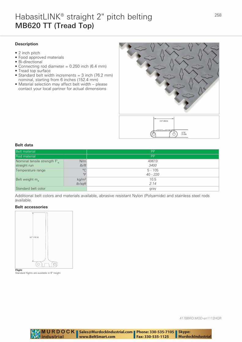
4178BRO.MOD-en1112HQR
258
MB620 TT (Tread Top)HabasitLINK® straight 2" pitch belting
Belt data
Belt material PPRod material PPNominal tensile strength F'N straight run
N/mlb/ft
496193400
Temperature range °C°F
5 - 10540 - 220
Belt weight mB kg/m²lb/sqft
10.52.14
Standard belt color gray
Description
• 2 inch pitch • Food approved materials• Bi-directional • Connecting rod diameter = 0.250 inch (6.4 mm) • Tread top surface • Standard belt width increments = 3 inch (76.2 mm)
nominal, starting from 6 inches (152.4 mm) • Material selection may affect belt width – please
contact your local partner for actual dimensions
Additional belt colors and materials available, abrasive resistant Nylon (Polyamide) and stainless steel rods available.
Belt accessories
FlightStandard flights are available in 6" height
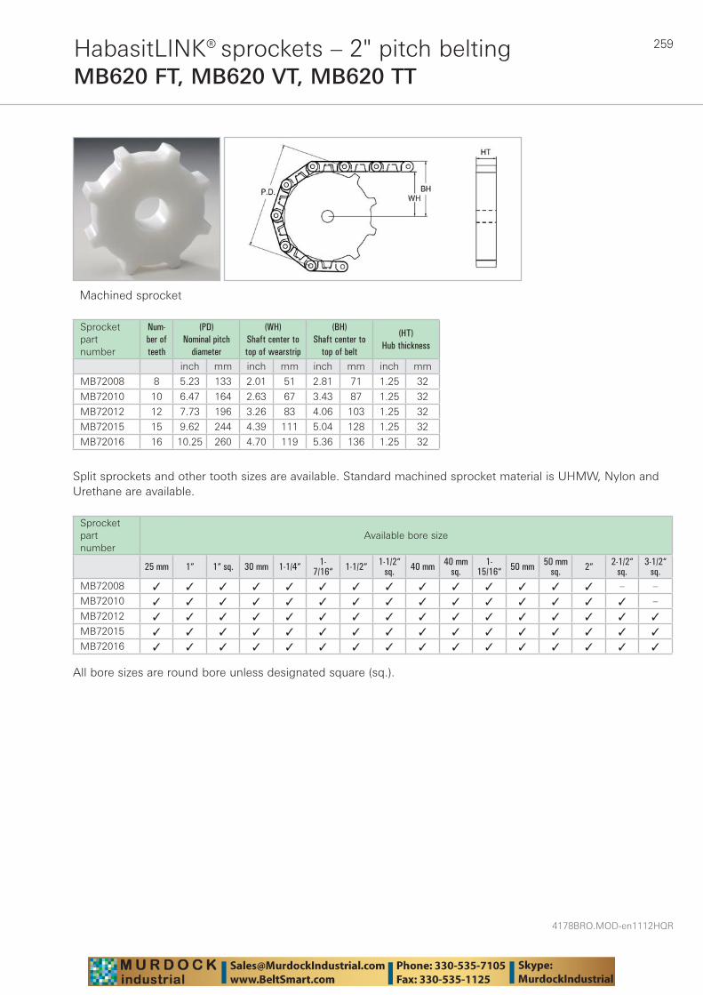
259
4178BRO.MOD-en1112HQR
HabasitLINK® sprockets – 2" pitch beltingMB620 FT, MB620 VT, MB620 TT
Machined sprocket
Sprocket part number
Num-ber of teeth
(PD) Nominal pitch
diameter
(WH) Shaft center to top of wearstrip
(BH) Shaft center to
top of belt
(HT) Hub thickness
inch mm inch mm inch mm inch mm
MB72008 8 5.23 133 2.01 51 2.81 71 1.25 32
MB72010 10 6.47 164 2.63 67 3.43 87 1.25 32
MB72012 12 7.73 196 3.26 83 4.06 103 1.25 32
MB72015 15 9.62 244 4.39 111 5.04 128 1.25 32
MB72016 16 10.25 260 4.70 119 5.36 136 1.25 32
Split sprockets and other tooth sizes are available. Standard machined sprocket material is UHMW, Nylon and Urethane are available.
Sprocket part number
Available bore size
25 mm 1“ 1“ sq. 30 mm 1-1/4“ 1-7/16“ 1-1/2“ 1-1/2“
sq. 40 mm 40 mmsq.
1-15/16“ 50 mm 50 mm
sq. 2“ 2-1/2“sq.
3-1/2“sq.
MB72008 ✓ ✓ ✓ ✓ ✓ ✓ ✓ ✓ ✓ ✓ ✓ ✓ ✓ ✓ – –
MB72010 ✓ ✓ ✓ ✓ ✓ ✓ ✓ ✓ ✓ ✓ ✓ ✓ ✓ ✓ ✓ –
MB72012 ✓ ✓ ✓ ✓ ✓ ✓ ✓ ✓ ✓ ✓ ✓ ✓ ✓ ✓ ✓ ✓
MB72015 ✓ ✓ ✓ ✓ ✓ ✓ ✓ ✓ ✓ ✓ ✓ ✓ ✓ ✓ ✓ ✓
MB72016 ✓ ✓ ✓ ✓ ✓ ✓ ✓ ✓ ✓ ✓ ✓ ✓ ✓ ✓ ✓ ✓
All bore sizes are round bore unless designated square (sq.).
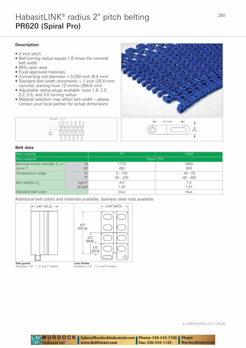
4178BRO.MOD-en1112HQR
260
PR620 (Spiral Pro)HabasitLINK® radius 2" pitch belting
Belt data
Belt material PP POMRod material Nylon (PA)Nominal tensile strength FN in curve (1)
Nlbf
1779400
2669600
Temperature range °C°F
5 - 10540 - 220
-40 - 93-40 - 200
Belt weight mB kg/m²lb/sqft
4.91.00
7.41.51
Standard belt color blue blue
Description
• 2 inch pitch • Belt turning radius equals 1.6 times the nominal
belt width • 65% open area • Food approved materials• Connecting rod diameter = 0.250 inch (6.4 mm) • Standard belt width increments = 1 inch (25.4 mm)
nominal, starting from 12 inches (304.8 mm) • Adjustable radius plugs available: sizes 1.8, 2.0,
2.2, 2.5, and 3.0 turning radius• Material selection may affect belt width – please
contact your local partner for actual dimensions
Additional belt colors and materials available, stainless steel rods available.
Lane DividerAvailable in 1/2", 1", 2" and 4" heights
Side guardsAvailable in 1/2", 1", 2" and 4" heights
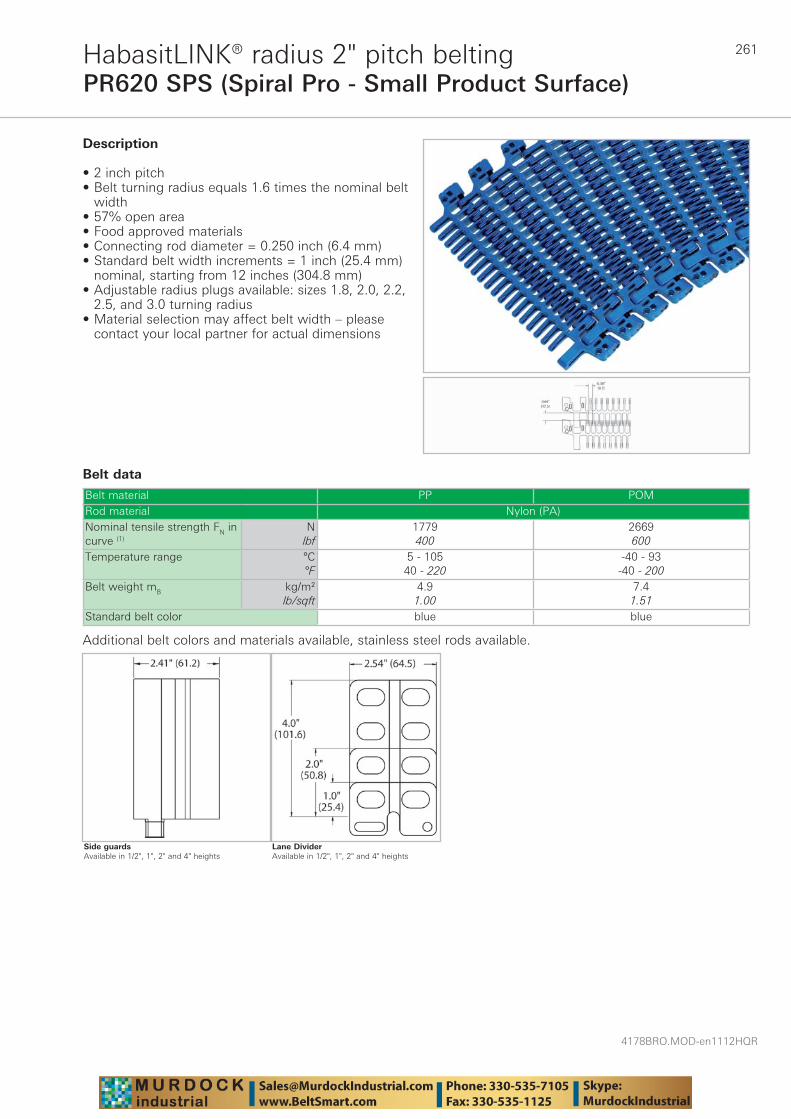
261
4178BRO.MOD-en1112HQR
PR620 SPS (Spiral Pro - Small Product Surface)HabasitLINK® radius 2" pitch belting
Belt data
Belt material PP POMRod material Nylon (PA)Nominal tensile strength FN in curve (1)
Nlbf
1779400
2669600
Temperature range °C°F
5 - 10540 - 220
-40 - 93-40 - 200
Belt weight mB kg/m²lb/sqft
4.91.00
7.41.51
Standard belt color blue blue
Description
• 2 inch pitch • Belt turning radius equals 1.6 times the nominal belt
width • 57% open area • Food approved materials• Connecting rod diameter = 0.250 inch (6.4 mm) • Standard belt width increments = 1 inch (25.4 mm)
nominal, starting from 12 inches (304.8 mm) • Adjustable radius plugs available: sizes 1.8, 2.0, 2.2,
2.5, and 3.0 turning radius• Material selection may affect belt width – please
contact your local partner for actual dimensions
Additional belt colors and materials available, stainless steel rods available.
Lane DividerAvailable in 1/2", 1", 2" and 4" heights
Side guardsAvailable in 1/2", 1", 2" and 4" heights
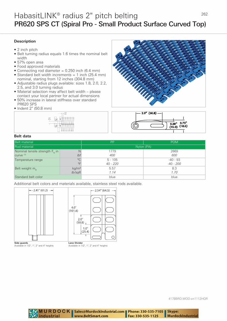
4178BRO.MOD-en1112HQR
262
PR620 SPS CT (Spiral Pro - Small Product Surface Curved Top)HabasitLINK® radius 2" pitch belting
Belt data
Belt material PP POMRod material Nylon (PA)Nominal tensile strength FN in curve (1)
Nlbf
1779400
2669600
Temperature range °C°F
5 - 10540 - 220
-40 - 93-40 - 200
Belt weight mB kg/m²lb/sqft
5.571.14
8.31.70
Standard belt color blue blue
Description
• 2 inch pitch • Belt turning radius equals 1.6 times the nominal belt
width • 57% open area • Food approved materials• Connecting rod diameter = 0.250 inch (6.4 mm) • Standard belt width increments = 1 inch (25.4 mm)
nominal, starting from 12 inches (304.8 mm) • Adjustable radius plugs available: sizes 1.8, 2.0, 2.2,
2.5, and 3.0 turning radius• Material selection may affect belt width – please
contact your local partner for actual dimensions• 50% increase in lateral stiffness over standard
PR620 SPS• Indent 2" (50.8 mm)
Additional belt colors and materials available, stainless steel rods available.
Lane DividerAvailable in 1/2", 1", 2" and 4" heights
Side guardsAvailable in 1/2", 1", 2" and 4" heights
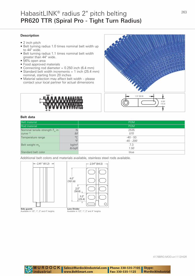
263
4178BRO.MOD-en1112HQR
PR620 TTR (Spiral Pro - Tight Turn Radius)HabasitLINK® radius 2" pitch belting
Belt data
Belt material POMRod material POMNominal tensile strength FN in curve (1)
Nlbf
2535570
Temperature range °C°F
-40 - 93-40 - 200
Belt weight mB kg/m²lb/sqft
7.31.50
Standard belt color blue
Description
• 2 inch pitch• Belt turning radius 1.0 times nominal belt width up
to 44" wide. • Belt turning radius 1.1 times nominal belt width
greater than 44" wide.• 56% open area• Food approved materials• Connecting rod diameter = 0.250 inch (6.4 mm)• Standard belt width increments = 1 inch (25.4 mm)
nominal, starting from 20 inches• Material selection may affect belt width – please
contact your local partner for actual dimensions
Additional belt colors and materials available, stainless steel rods available.
Lane DividerAvailable in 1/2", 1", 2" and 4" heights
Side guardsAvailable in 1/2", 1", 2" and 4" heights

4178BRO.MOD-en1112HQR
264HabasitLINK® sprockets – 2" pitch beltingPR620, PR620 SPS, PR620 TTR
Machined sprocket – PR620
Machined sprocket – PR620 SPS
Sprocket part number
Num-ber of teeth
(PD) Nominal pitch
diameter
(WH) Shaft center to top of wearstrip
(BH) Shaft center to
top of belt
(HT) Hub thickness
inch mm inch mm inch mm inch mm
PR72010 10 6.5 165 2.9 74 3.5 89 1.25 32
PR72010 SPS 10 6.5 165 2.9 74 3.5 89 1.25 32
Split sprockets and other tooth sizes are available. Standard machined sprocket material is UHMW. Nylon and Urethane are available. PR620 TTR belts use a combination of PR620 and PR620 SPS sprockets.
Sprocket part number
Available bore size
25 mm 1“ 1“ sq. 30 mm 1-1/4“ 1-7/16“ 1-1/2“ 1-1/2“
sq. 40 mm 40 mmsq.
1-15/16“ 50 mm 2“ sq. 60 mm 60 mm
sq.2-1/2“
sq.PR72010 ✓ ✓ ✓ ✓ ✓ ✓ ✓ ✓ ✓ ✓ ✓ ✓ ✓ ✓ – –
PR72010 SPS ✓ ✓ ✓ ✓ ✓ ✓ ✓ ✓ ✓ ✓ ✓ ✓ ✓ ✓ – –
All bore sizes are round bore unless designated square (sq.).
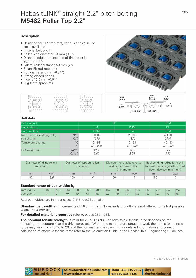
265
4178BRO.MOD-en1112HQR
M5482 Roller Top 2.2"HabasitLINK® straight 2.2" pitch belting
Belt data
Standard range of belt widths b0
mm (nom.) 152 203 254 305 356 406 457 508 559 610 660 711 762 etc.inch (nom.) 6 8 10 12 14 16 18 20 22 24 26 28 30 etc.
Real belt widths are in most cases 0.1% to 0.3% smaller.
Belt material PP POMRod material PA POM PARoller material POM PA POMNominal tensile strength F'N straight run
N/mlb/ft
200001370
200001370
400002740
Temperature range °C°F
5 - 9340 - 200
5 - 9340 - 200
-40 - 93-40 - 200
Belt weight mB kg/m²lb/sqft
12.72.60
12.62.58
17.23.52
Description
• Designed for 90° transfers, various angles in 15° steps available
• Imperial belt width • Roller with diameter 23 mm (0.9")• Distance edge to centerline of first roller is
25.4 mm (1")• Lateral roller distance 50 mm (2")• Smart-Fit rod retention • Rod diameter 6 mm (0.24”) • Strong closed edges• Indent 15.5 mm (0.61")• Lug teeth sprockets
Diameter of idling rollers (minimum)
Diameter of support rollers(minimum)
Diameter for gravity take-up and center drive rollers
(minimum)
Backbending radius for eleva-tors without sideguards or hold
down devices (minimum)mm inch mm inch mm inch mm inch90 3.5 100 4 150 6 150 6
Standard belt widths in increments of 50.8 mm (2"). Non-standard widths are not offered. Smallest possible width 152.4 mm (6").For detailed material properties refer to pages 282 - 289.
The nominal tensile strength is valid for 23 °C (73 °F). The admissible tensile force depends on the operating temperature near the drive sprockets. Within the temperature range allowed, the admissible tensile force may vary from 100% to 20% of the nominal tensile strength. For detailed information and correct calculation of effective tensile force refer to the Calculation Guide in the HabasitLINK® Engineering Guidelines.

4178BRO.MOD-en1112HQR
266
Sprocket series M5400HabasitLINK® sprockets 2.2" pitch belting
M = Modular belts
M 54 6Q6012S
Belt pitch
S = sprocket one-piece; Z = split sprocket
Number of teeth
Shaft size
Shaft type: Q = square shaft; R = round shaft
Material: 6 = POM; 8 = PA
Type Number of teeth
Diam. of pitch Ø dp A1 Hub width BL Square bore Q Ø Round bore R
Standard material
mm inch mm inch mm inch mm inch mmS-C1 9 164.0 6.5 74.0 2.91 30 1.18 40 / 50
/ 602.5 40 PA
S-C1 11 199.1 7.8 92.0 3.62 30 1.18 40 / 60 1.5 / 2.5 - PAS-C1 15 269.8 10.6 127.0 5.00 30 1.18 60 / 90 3.5 - PA
Sprocket one-piece (solid)
Sprocket availability
S: molded sprockets; S-C1: machined sprockets. Other sprocket and hub sizes on request.Key ways for round bore shape follow European standards for metric sizes and US standards for imperial sizes. For detailed dimensions see table in the Engineering Guide chapter Design Guide.Other materials available on request.
The distance C between the sprocket axis and the slider support ST is from 65 to 90 mm (2.5" to 3.5").
Sprocket arrangement
BE BeltRC RetainerSP Sprocketb0 belt width
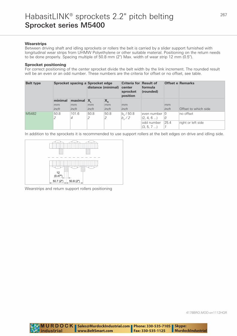
267
4178BRO.MOD-en1112HQR
Sprocket series M5400HabasitLINK® sprockets 2.2" pitch belting
Wearstrips Between driving shaft and idling sprockets or rollers the belt is carried by a slider support furnished with longitudinal wear strips from UHMW Polyethylene or other suitable material. Positioning on the return needs to be done properly. Spacing multiple of 50.8 mm (2") Max. width of wear strip 12 mm (0.5").
Sprocket positioningFor correct positioning of the center sprocket divide the belt width by the link increment. The rounded result will be an even or an odd number. These numbers are the criteria for offset or no offset, see table.
Belt type Sprocket spacing a Sprocket edgedistance (minimal)
Criteria for center sprocket position
Result of formula (rounded)
Offset e Remarks
minimalmminch
maximalmminch
XL
mminch
XR
mminch
mminch
mminch Offset to which side
M5482 50.82
101.64
50.82
50.82
b0 / 50.8b0 / 2
even number (2, 4, 6 ...)
00
no offset
odd number (3, 5, 7 ...)
25.41
right or left side
In addition to the sprockets it is recommended to use support rollers at the belt edges on drive and idling side.
Wearstrips and return support rollers positioning

4178BRO.MOD-en1112HQR
268
Numbers of sprockets and wearstrips for M5482Standard belt width (nominal) Number of sprockets per
shaftNumber of wearstrips
inch mm min. number Carryway (top)
Returnway (bottom)
6 152 2 2 28 202 3 3 210 254 3 3 312 304 3 3 314 355 3 4 316 406 3 4 318 456 3 4 320 507 3 4 322 558 4 5 324 609 5 5 326 660 5 5 428 710 5 5 530 761 5 6 532 812 5 6 534 863 6 6 536 914 7 6 538 964 7 7 540 1015 7 7 542 1066 7 7 644 1118 7 7 746 1168 8 8 748 1219 9 8 750 1270 9 8 752 1320 9 8 754 1371 9 9 756 1422 9 9 758 1472 9 9 760 1523 9 9 762 1574 11 10 864 1625 11 10 8
The number of sprockets depends on the belt load and may be different for driving and idling shafts. For calculation of correct sprocket number please use LINK-SeleCalc.
Sprocket series M5400HabasitLINK® sprockets 2.2" pitch belting
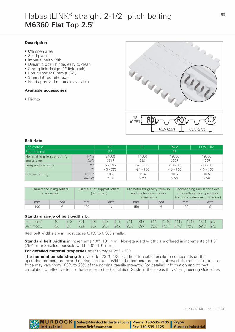
269
4178BRO.MOD-en1112HQR
M6360 Flat Top 2.5"HabasitLINK® straight 2-1/2" pitch belting
Belt data
Standard range of belt widths b0
mm (nom.) 101 203 304 406 508 609 711 813 914 1016 1117 1219 1321 etc.inch (nom.) 4.0 8.0 12.0 16.0 20.0 24.0 28.0 32.0 36.0 40.0 44.0 48.0 52.0 etc.
Real belt widths are in most cases 0.1% to 0.3% smaller.
Belt material PP PE POM POM +IMRod material PP PENominal tensile strength F'N straight run
N/mlb/ft
240001644
14000959
190001301
190001301
Temperature range °C°F
5 - 10540 - 220
-70 - 65-94 - 150
-40 - 65-40 - 150
-40 - 65-40 - 150
Belt weight mB kg/m²lb/sqft
10.72.19
11.42.34
16.53.38
16.53.38
Description
• 0% open area • Solid plate • Imperial belt width • Dynamic open hinge, easy to clean• Strong link design (1” link-pitch) • Rod diameter 8 mm (0.32") • Smart Fit rod retention • Food approved materials available
Available accessories
• Flights
Diameter of idling rollers (minimum)
Diameter of support rollers(minimum)
Diameter for gravity take-up and center drive rollers
(minimum)
Backbending radius for eleva-tors without side guards or
hold-down devices (minimum)mm inch mm inch mm inch mm inch100 4 100 4 150 6 150 6
Standard belt widths in increments 4.0” (101 mm). Non-standard widths are offered in increments of 1.0” (25.4 mm) Smallest possible width 4.0” (101 mm).For detailed material properties refer to pages 282 - 289.The nominal tensile strength is valid for 23 °C (73 °F). The admissible tensile force depends on the operating temperature near the drive sprockets. Within the temperature range allowed, the admissible tensile force may vary from 100% to 20% of the nominal tensile strength. For detailed information and correct calculation of effective tensile force refer to the Calculation Guide in the HabasitLINK® Engineering Guidelines.
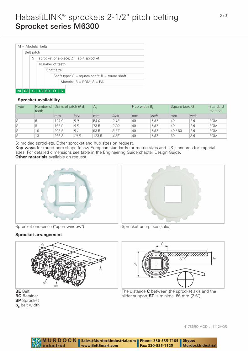
4178BRO.MOD-en1112HQR
270
Sprocket series M6300HabasitLINK® sprockets 2-1/2" pitch belting
M = Modular belts
M 63 6Q6013S
Belt pitch
S = sprocket one-piece; Z = split sprocket
Number of teeth
Shaft size
Shaft type: Q = square shaft; R = round shaft
Material: 6 = POM; 8 = PA
Type Number of teeth
Diam. of pitch Ø dp A1 Hub width BL Square bore Q Standard material
mm inch mm inch mm inch mm inchS 6 127.0 5.0 54.0 2.13 40 1.57 40 1.5 POMS 8 165.9 6.5 73.5 2.90 40 1.57 40 1.5 POMS 10 205.5 8.1 93.5 3.67 40 1.57 40 / 60 1.5 POMS 13 265.3 10.5 123.5 4.85 40 1.57 60 2.5 POM
Sprocket one-piece ("open window")
Sprocket availability
S: molded sprockets. Other sprocket and hub sizes on request.Key ways for round bore shape follow European standards for metric sizes and US standards for imperial sizes. For detailed dimensions see table in the Engineering Guide chapter Design Guide.Other materials available on request.
Sprocket one-piece (solid)
Sprocket arrangement
BE BeltRC Retainer SP Sprocketb0 belt width
The distance C between the sprocket axis and the slider support ST is minimal 66 mm (2.6").
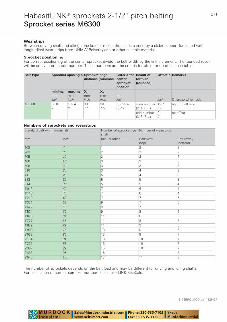
271
4178BRO.MOD-en1112HQR
Sprocket series M6300HabasitLINK® sprockets 2-1/2" pitch belting
WearstripsBetween driving shaft and idling sprockets or rollers the belt is carried by a slider support furnished with longitudinal wear strips from UHMW Polyethylene or other suitable material.
Numbers of sprockets and wearstrips Standard belt width (nominal) Number of sprockets per
shaftNumber of wearstrips
mm inch min. number Carryway (top)
Returnway (bottom)
102 4 1 2 2203 8 2 2 2305 12 2 3 2406 16 3 3 3508 20 3 3 3610 24 3 4 3711 28 5 4 3813 32 5 5 3914 36 5 5 41'016 40 7 6 41'118 44 7 6 41'219 48 7 7 51'321 52 9 7 51'422 56 9 7 51'524 60 9 8 51'626 64 11 8 61'727 68 11 8 61'829 72 11 9 61'930 76 13 9 62'032 80 13 9 72'134 84 13 10 72'235 88 15 10 72'337 92 15 10 72'438 96 15 11 82'540 100 17 11 8
The number of sprockets depends on the belt load and may be different for driving and idling shafts. For calculation of correct sprocket number please use LINK-SeleCalc.
Sprocket positioningFor correct positioning of the center sprocket divide the belt width by the link increment. The rounded result will be an even or an odd number. These numbers are the criteria for offset or no offset, see table.
Belt type Sprocket spacing a Sprocket edgedistance (minimal)
Criteria for center sprocket position
Result of formula (rounded)
Offset e Remarks
minimalmminch
maximalmminch
XL
mminch
XR
mminch
mminch
mminch Offset to which side
M6360 50.82
152.46
381.5
381.5
b0 / 25.4b0 / 1
even number (2, 4, 6 ...)
12.70.5
right or left side
odd number (3, 5, 7 ...)
00
no offset

4178BRO.MOD-en1112HQR
272HabasitLINK® accessories – 2-1/2" pitch beltingFlights M6300
HabasitLINK® modular belts are available with flights to convey products on inclined conveyors. The flight modules are injection-molded one-piece designs that, when installed, become an integral part of the belt. Flight modules for this belt series are available with flat surface only (without ribs). Code: xx = height of flight: 50 mm = 05100 mm = 10150 mm = 15
Note: All flights have open hinge design (USDA).
Flights straight
Code fl ight side guard
M6360Fxx(xx= height)
height H length L
mminch
50.82
1526
mminch
1014
1014
mminch
1526
1526
All flights can be cut to lower height (min 25 mm) for high-impact applications.
Indents (E)The flight indent E is the distance between the edge of the belt and the edge of the flight. It is required for adequate support of the belt on its return way and hold-down during back-bending applications (elevators). On short conveyors or with special support structure, the flights may also be applied over the full belt width (E = 0).Indents are possible in widths as multiples of 1" (25.4 mm), min 2" (50.8 mm)
Notch (N)The notch N is a gap in each row of flights, longitudinally aligned to allow the support of belts wider than 600 mm (24") on their return way or in back-bending applications. The notch width (N) and the distance (M) from the belt edge is a multiple of the link increment 25.4 mm (1"). For M6300 series the minimum notch width is 50.8 mm (2").
H
L
63.5 (2.5“)
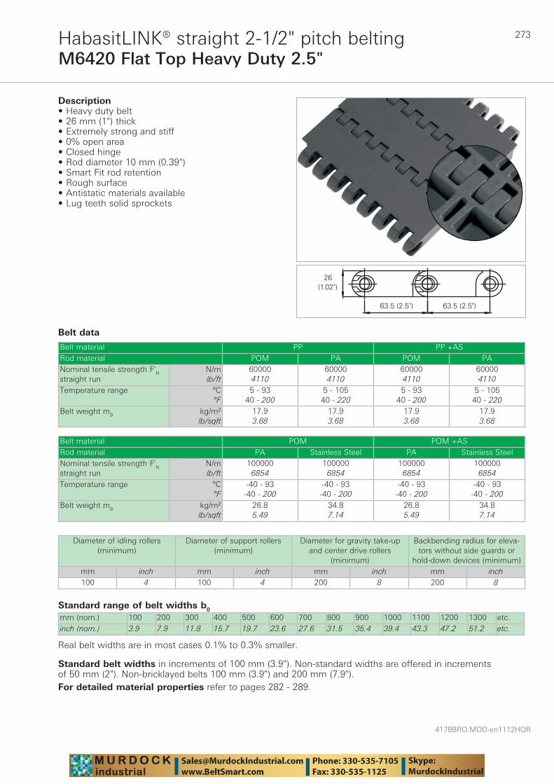
273
4178BRO.MOD-en1112HQR
M6420 Flat Top Heavy Duty 2.5"HabasitLINK® straight 2-1/2" pitch belting
Belt data
Standard range of belt widths b0
mm (nom.) 100 200 300 400 500 600 700 800 900 1000 1100 1200 1300 etc.inch (nom.) 3.9 7.9 11.8 15.7 19.7 23.6 27.6 31.5 35.4 39.4 43.3 47.2 51.2 etc.
Real belt widths are in most cases 0.1% to 0.3% smaller.
Belt material PP PP +ASRod material POM PA POM PANominal tensile strength F'N straight run
N/mlb/ft
600004110
600004110
600004110
600004110
Temperature range °C°F
5 - 9340 - 200
5 - 10540 - 220
5 - 9340 - 200
5 - 10540 - 220
Belt weight mB kg/m²lb/sqft
17.93.68
17.93.68
17.93.68
17.93.68
Description • Heavy duty belt • 26 mm (1") thick • Extremely strong and stiff • 0% open area • Closed hinge • Rod diameter 10 mm (0.39") • Smart Fit rod retention • Rough surface • Antistatic materials available • Lug teeth solid sprockets
Belt material POM POM +ASRod material PA Stainless Steel PA Stainless SteelNominal tensile strength F'N straight run
N/mlb/ft
1000006854
1000006854
1000006854
1000006854
Temperature range °C°F
-40 - 93-40 - 200
-40 - 93-40 - 200
-40 - 93-40 - 200
-40 - 93-40 - 200
Belt weight mB kg/m²lb/sqft
26.85.49
34.87.14
26.85.49
34.87.14
Diameter of idling rollers (minimum)
Diameter of support rollers(minimum)
Diameter for gravity take-up and center drive rollers
(minimum)
Backbending radius for eleva-tors without side guards or
hold-down devices (minimum)mm inch mm inch mm inch mm inch100 4 100 4 200 8 200 8
Standard belt widths in increments of 100 mm (3.9"). Non-standard widths are offered in increments of 50 mm (2"). Non-bricklayed belts 100 mm (3.9") and 200 mm (7.9").For detailed material properties refer to pages 282 - 289.
4178BRO.MOD-en1112HQR
274
M6420 Flat Top Heavy Duty 2.5"HabasitLINK® straight 2-1/2" pitch belting
The nominal tensile strength is valid for 23 °C (73 °F). The admissible tensile force depends on the operating temperature near the drive sprockets. Within the temperature range allowed, the admissible tensile force may vary from 100% to 20% of the nominal tensile strength. For detailed information and correct calculation of effective tensile force refer to the Calculation Guide in the HabasitLINK® Engineering Guidelines.
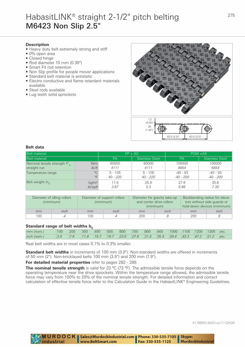
275
4178BRO.MOD-en1112HQR
M6423 Non Slip 2.5"HabasitLINK® straight 2-1/2" pitch belting
Belt data
Standard range of belt widths b0
mm (nom.) 100 200 300 400 500 600 700 800 900 1000 1100 1200 1300 etc.inch (nom.) 3.9 7.9 11.8 15.7 19.7 23.6 27.6 31.5 35.4 39.4 43.3 47.2 51.2 etc.
Real belt widths are in most cases 0.1% to 0.3% smaller.
Belt material PP + AS POM +ASRod material PA Stainless Steel PA Stainless SteelNominal tensile strength F'N straight run
N/mlb/ft
600004111
600004111
1000006854
1000006854
Temperature range °C°F
5 - 10540 - 220
5 - 10540 - 220
-40 - 93-40 - 200
-40 - 93-40 - 200
Belt weight mB kg/m²lb/sqft
17.93.67
25.95.3
27.65.66
35.67.30
Description• Heavy duty belt extremely strong and stiff • 0% open area • Closed hinge• Rod diameter 10 mm (0.39") • Smart Fit rod retention• Non Slip profile for people mover applications • Standard belt material is antistatic• Electro conductive and flame retardant materials
available• Steel rods available • Lug teeth solid sprockets
Diameter of idling rollers (minimum)
Diameter of support rollers(minimum)
Diameter for gravity take-up and center drive rollers
(minimum)
Backbending radius for eleva-tors without side guards or
hold-down devices (minimum)mm inch mm inch mm inch mm inch100 4 100 4 200 8 200 8
Standard belt widths in increments of 100 mm (3.9"). Non-standard widths are offered in increments of 50 mm (2"). Non-bricklayed belts 100 mm (3.9") and 200 mm (7.9").For detailed material properties refer to pages 282 - 289.The nominal tensile strength is valid for 23 °C (73 °F). The admissible tensile force depends on the operating temperature near the drive sprockets. Within the temperature range allowed, the admissible tensile force may vary from 100% to 20% of the nominal tensile strength. For detailed information and correct calculation of effective tensile force refer to the Calculation Guide in the HabasitLINK® Engineering Guidelines.
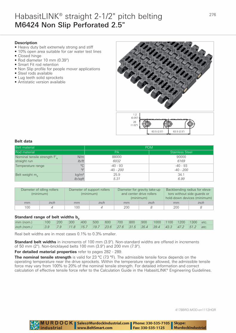
4178BRO.MOD-en1112HQR
276
M6424 Non Slip Perforated 2.5"HabasitLINK® straight 2-1/2" pitch belting
Belt data
Standard range of belt widths b0
mm (nom.) 100 200 300 400 500 600 700 800 900 1000 1100 1200 1300 etc.inch (nom.) 3.9 7.9 11.8 15.7 19.7 23.6 27.6 31.5 35.4 39.4 43.3 47.2 51.2 etc.
Real belt widths are in most cases 0.1% to 0.3% smaller.
Belt material POMRod material PA Stainless SteelNominal tensile strength F'N straight run
N/mlb/ft
880006032
900006169
Temperature range °C°F
-40 - 93-40 - 200
-40 - 93-40 - 200
Belt weight mB kg/m²lb/sqft
25.95.31
34.16.99
Description• Heavy duty belt extremely strong and stiff • 10% open area suitable for car water test lines • Closed hinge • Rod diameter 10 mm (0.39") • Smart Fit rod retention• Non Slip profile for people mover applications • Steel rods available • Lug teeth solid sprockets• Antistatic version available
Diameter of idling rollers (minimum)
Diameter of support rollers(minimum)
Diameter for gravity take-up and center drive rollers
(minimum)
Backbending radius for eleva-tors without side guards or
hold-down devices (minimum)mm inch mm inch mm inch mm inch100 4 100 4 200 8 200 8
Standard belt widths in increments of 100 mm (3.9"). Non-standard widths are offered in increments of 50 mm (2"). Non-bricklayed belts 100 mm (3.9") and 200 mm (7.9").For detailed material properties refer to pages 282 - 289.The nominal tensile strength is valid for 23 °C (73 °F). The admissible tensile force depends on the operating temperature near the drive sprockets. Within the temperature range allowed, the admissible tensile force may vary from 100% to 20% of the nominal tensile strength. For detailed information and correct calculation of effective tensile force refer to the Calculation Guide in the HabasitLINK® Engineering Guidelines.
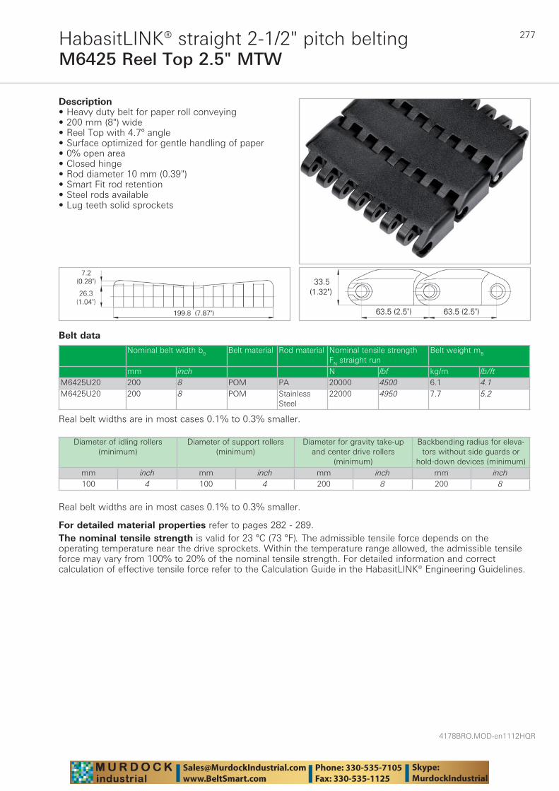
277
4178BRO.MOD-en1112HQR
M6425 Reel Top 2.5" MTWHabasitLINK® straight 2-1/2" pitch belting
Belt data
Real belt widths are in most cases 0.1% to 0.3% smaller.
Description • Heavy duty belt for paper roll conveying • 200 mm (8") wide • Reel Top with 4.7° angle • Surface optimized for gentle handling of paper • 0% open area • Closed hinge • Rod diameter 10 mm (0.39") • Smart Fit rod retention • Steel rods available • Lug teeth solid sprockets
Diameter of idling rollers (minimum)
Diameter of support rollers(minimum)
Diameter for gravity take-up and center drive rollers
(minimum)
Backbending radius for eleva-tors without side guards or
hold-down devices (minimum)mm inch mm inch mm inch mm inch100 4 100 4 200 8 200 8
Nominal belt width b0 Belt material Rod material Nominal tensile strength FN straight run
Belt weight mB
mm inch N lbf kg/m lb/ftM6425U20 200 8 POM PA 20000 4500 6.1 4.1M6425U20 200 8 POM Stainless
Steel22000 4950 7.7 5.2
Real belt widths are in most cases 0.1% to 0.3% smaller.
For detailed material properties refer to pages 282 - 289.The nominal tensile strength is valid for 23 °C (73 °F). The admissible tensile force depends on the operating temperature near the drive sprockets. Within the temperature range allowed, the admissible tensile force may vary from 100% to 20% of the nominal tensile strength. For detailed information and correct calculation of effective tensile force refer to the Calculation Guide in the HabasitLINK® Engineering Guidelines.
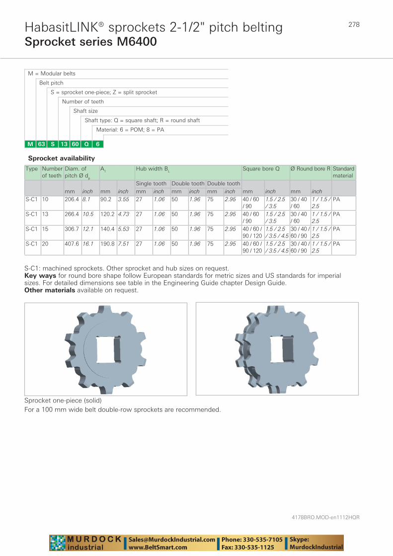
4178BRO.MOD-en1112HQR
278
Sprocket series M6400HabasitLINK® sprockets 2-1/2" pitch belting
M = Modular belts
M 63 6Q6013S
Belt pitch
S = sprocket one-piece; Z = split sprocket
Number of teeth
Shaft size
Shaft type: Q = square shaft; R = round shaft
Material: 6 = POM; 8 = PA
Type Number of teeth
Diam. of pitch Ø dp
A1 Hub width BL Square bore Q Ø Round bore R Standard material
Single tooth Double tooth Double toothmm inch mm inch mm inch mm inch mm inch mm inch mm inch
S-C1 10 206.4 8.1 90.2 3.55 27 1.06 50 1.96 75 2.95 40 / 60 / 90
1.5 / 2.5 / 3.5
30 / 40 / 60
1 / 1.5 / 2.5
PA
S-C1 13 266.4 10.5 120.2 4.73 27 1.06 50 1.96 75 2.95 40 / 60 / 90
1.5 / 2.5 / 3.5
30 / 40 / 60
1 / 1.5 / 2.5
PA
S-C1 15 306.7 12.1 140.4 5.53 27 1.06 50 1.96 75 2.95 40 / 60 / 90 / 120
1.5 / 2.5 / 3.5 / 4.5
30 / 40 / 60 / 90
1 / 1.5 / 2.5
PA
S-C1 20 407.6 16.1 190.8 7.51 27 1.06 50 1.96 75 2.95 40 / 60 / 90 / 120
1.5 / 2.5 / 3.5 / 4.5
30 / 40 / 60 / 90
1 / 1.5 / 2.5
PA
Sprocket one-piece (solid)For a 100 mm wide belt double-row sprockets are recommended.
Sprocket availability
S-C1: machined sprockets. Other sprocket and hub sizes on request.Key ways for round bore shape follow European standards for metric sizes and US standards for imperial sizes. For detailed dimensions see table in the Engineering Guide chapter Design Guide.Other materials available on request.
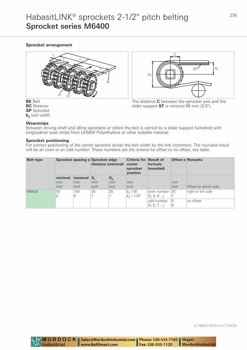
279
4178BRO.MOD-en1112HQR
Sprocket series M6400HabasitLINK® sprockets 2-1/2" pitch belting
WearstripsBetween driving shaft and idling sprockets or rollers the belt is carried by a slider support furnished with longitudinal wear strips from UHMW Polyethylene or other suitable material.
Sprocket arrangement
BE BeltRC RetainerSP Sprocketb0 belt width
The distance C between the sprocket axis and the slider support ST is minimal 66 mm (2.6").
Sprocket positioningFor correct positioning of the center sprocket divide the belt width by the link increment. The rounded result will be an even or an odd number. These numbers are the criteria for offset or no offset, see table.
Belt type Sprocket spacing a Sprocket edgedistance (minimal)
Criteria for center sprocket position
Result of formula (rounded)
Offset e Remarks
minimalmminch
maximalmminch
XL
mminch
XR
mminch
mminch
mminch Offset to which side
M6420 502
1506
251
251
b0 / 50b0 / 1.97
even number (2, 4, 6 ...)
251
right or left side
odd number (3, 5, 7 ...)
00
no offset
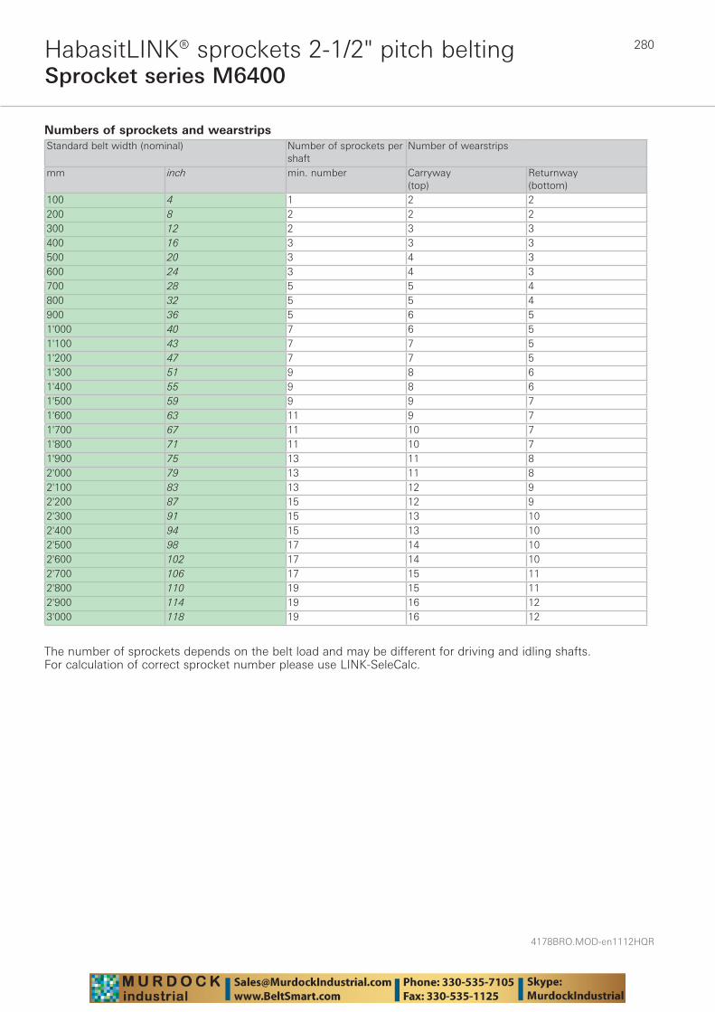
4178BRO.MOD-en1112HQR
280
Sprocket series M6400HabasitLINK® sprockets 2-1/2" pitch belting
Numbers of sprockets and wearstrips Standard belt width (nominal) Number of sprockets per
shaftNumber of wearstrips
mm inch min. number Carryway (top)
Returnway (bottom)
100 4 1 2 2200 8 2 2 2300 12 2 3 3400 16 3 3 3500 20 3 4 3600 24 3 4 3700 28 5 5 4800 32 5 5 4900 36 5 6 51'000 40 7 6 51'100 43 7 7 51'200 47 7 7 51'300 51 9 8 61'400 55 9 8 61'500 59 9 9 71'600 63 11 9 71'700 67 11 10 71'800 71 11 10 71'900 75 13 11 82'000 79 13 11 82'100 83 13 12 92'200 87 15 12 92'300 91 15 13 102'400 94 15 13 102'500 98 17 14 102'600 102 17 14 102'700 106 17 15 112'800 110 19 15 112'900 114 19 16 123'000 118 19 16 12
The number of sprockets depends on the belt load and may be different for driving and idling shafts. For calculation of correct sprocket number please use LINK-SeleCalc.
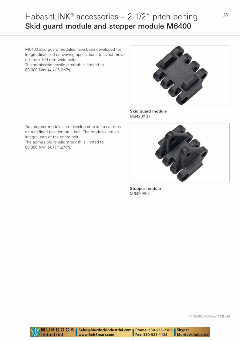
281
4178BRO.MOD-en1112HQR
HabasitLINK® accessories – 2-1/2“ pitch beltingSkid guard module and stopper module M6400
M6400 skid guard modules have been developed for longitudinal skid conveying applications to avoid move off from 100 mm wide belts.The admissible tensile strength is limited to 60,000 N/m (4,111 lbf/ft).
Tire stopper modules are developed to keep car tires on a defined position on a belt. The modules are an integral part of the entire belt.The admissible tensile strength is limited to 60,000 N/m (4,111 lbf/ft).
Skid guard moduleM6420XB1
Stopper moduleM6420S04

4178BRO.MOD-en1112HQR
282Standard belt materials
Material Code DescriptionDensity g/cm3 Temperature range
Polypropylene PP Thermoplastic material with good cost/ performance relation (material for most of the common conveying applications). Excellent chemical resistance to acids and alkalines. * High impacts below 10 °C (50 °F) must be avoided.
0.9 +5 °C to +105 °C (*)+40 °F to +220 °F (*)
Polyethylene PE Thermoplastic material well suited for very low temperatures and/or high impact applications. Excellent chemical resistance to acids and alkalines. Not suitable for abrasive applications.* Below -40 °C (-40 °F), thermal belt shrinkage requires a sprocket pitch diameter adaptation.
0.94 -70 °C to +65 °C (*)-94 °F to +150 °F (*)
Polyoxymethy-lene (Acetal)
POM Thermoplastic material with high strength and low coefficient of friction. Impact and cut resistant surface. Suitable for heavy duty applications and low temperatures. Good chemical resistance to oil and alkalines, but not suitable for long-term contact with high concentration of acids and chlorine.
1.42 Wet conditions:-40 °C to +60 °C-40 °F to +140 °F
Dry conditions:-40 °C to +93 °C-40 °F to +200 °F
Polyamide (Nylon for US market)
PA
Code add. +US
PA 66
Thermoplastic material with high strength and abrasion resistance. Suitable for heavy duty applications at dry conditions and elevated temperatures.Material is modified to keep its good properties stable over a long time at elevated temperatures.
1.14 Wet conditions: not recommended
Dry conditions :-46 °C to +118 °C(short-term +135 °C)-50 °F to +245 °F(short-term +275 °F)
Polyamide (Nylon)
PA Thermoplastic material with high strength and abrasion resistance. Suitable for heavy duty applications at dry conditions and elevated temperatures.Material is specially modified to keep its good properties stable over a long time at elevated temperatures.
1.14 Wet conditions:not recommended
Dry conditions:-46 °C to +130 °C(short-term +160 °C)-50 °F to +266 °F(short-term +320 °F)
For detailed declarations of compliance per material and color, please contact Habasit.
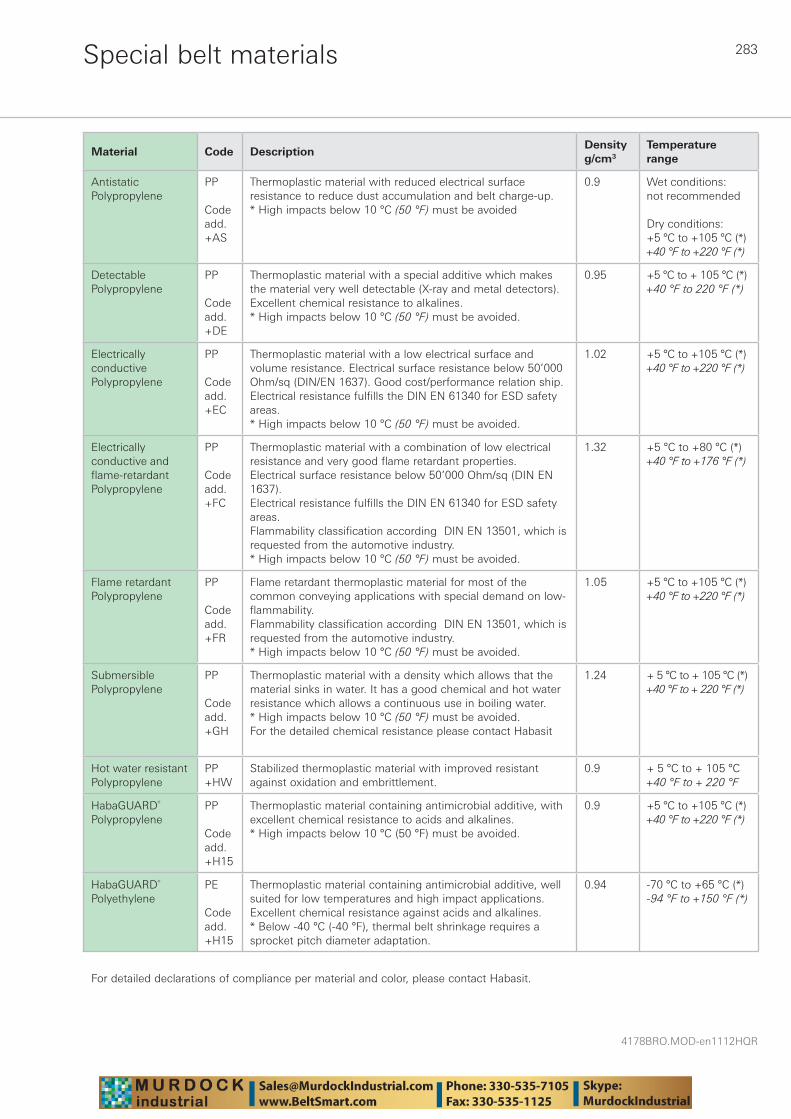
283
4178BRO.MOD-en1112HQR
Special belt materials
Material Code DescriptionDensity g/cm3
Temperature range
Antistatic Polypropylene
PP
Code add. +AS
Thermoplastic material with reduced electrical surface resistance to reduce dust accumulation and belt charge-up.* High impacts below 10 °C (50 °F) must be avoided
0.9 Wet conditions:not recommended
Dry conditions:+5 °C to +105 °C (*)+40 °F to +220 °F (*)
Detectable Polypropylene
PP
Code add. +DE
Thermoplastic material with a special additive which makes the material very well detectable (X-ray and metal detectors). Excellent chemical resistance to alkalines. * High impacts below 10 °C (50 °F) must be avoided.
0.95 +5 °C to + 105 °C (*)+40 °F to 220 °F (*)
Electrically conductive Polypropylene
PP
Code add. +EC
Thermoplastic material with a low electrical surface and volume resistance. Electrical surface resistance below 50’000 Ohm/sq (DIN/EN 1637). Good cost/performance relation ship.Electrical resistance fulfills the DIN EN 61340 for ESD safety areas.* High impacts below 10 °C (50 °F) must be avoided.
1.02 +5 °C to +105 °C (*)+40 °F to +220 °F (*)
Electrically conductive and flame-retardant Polypropylene
PP
Code add. +FC
Thermoplastic material with a combination of low electrical resistance and very good flame retardant properties. Electrical surface resistance below 50’000 Ohm/sq (DIN EN 1637). Electrical resistance fulfills the DIN EN 61340 for ESD safety areas.Flammability classification according DIN EN 13501, which is requested from the automotive industry.* High impacts below 10 °C (50 °F) must be avoided.
1.32 +5 °C to +80 °C (*)+40 °F to +176 °F (*)
Flame retardant Polypropylene
PP
Code add. +FR
Flame retardant thermoplastic material for most of the common conveying applications with special demand on low-flammability.Flammability classification according DIN EN 13501, which is requested from the automotive industry.* High impacts below 10 °C (50 °F) must be avoided.
1.05 +5 °C to +105 °C (*)+40 °F to +220 °F (*)
Submersible Polypropylene
PP
Code add. +GH
Thermoplastic material with a density which allows that the material sinks in water. It has a good chemical and hot water resistance which allows a continuous use in boiling water. * High impacts below 10 °C (50 °F) must be avoided.For the detailed chemical resistance please contact Habasit
1.24 + 5 °C to + 105 °C (*)+40 °F to + 220 °F (*)
Hot water resistant Polypropylene
PP+HW
Stabilized thermoplastic material with improved resistant against oxidation and embrittlement.
0.9 + 5 °C to + 105 °C+40 °F to + 220 °F
HabaGUARD® Polypropylene
PP
Code add.+H15
Thermoplastic material containing antimicrobial additive, with excellent chemical resistance to acids and alkalines. * High impacts below 10 °C (50 °F) must be avoided.
0.9 +5 °C to +105 °C (*)+40 °F to +220 °F (*)
HabaGUARD® Polyethylene
PE
Code add.+H15
Thermoplastic material containing antimicrobial additive, well suited for low temperatures and high impact applications. Excellent chemical resistance against acids and alkalines.* Below -40 °C (-40 °F), thermal belt shrinkage requires a sprocket pitch diameter adaptation.
0.94 -70 °C to +65 °C (*)-94 °F to +150 °F (*)
For detailed declarations of compliance per material and color, please contact Habasit.
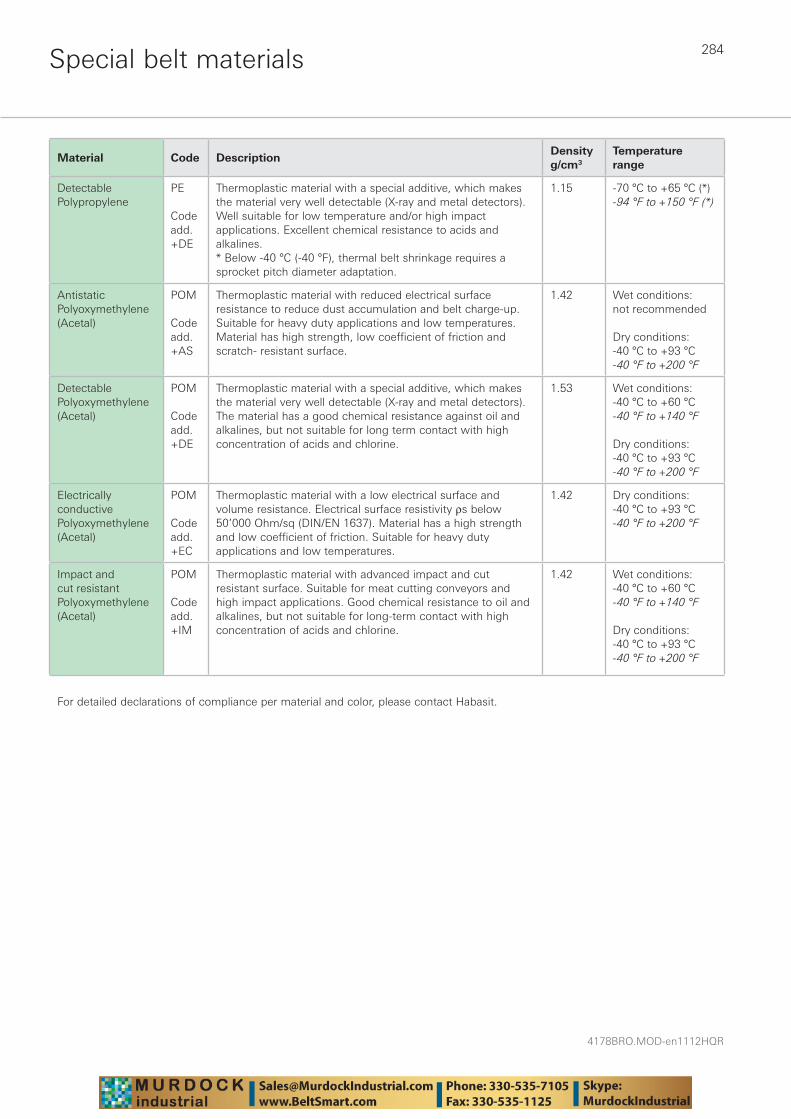
4178BRO.MOD-en1112HQR
284Special belt materials
Material Code DescriptionDensity g/cm3
Temperature range
Detectable Polypropylene
PE
Code add.+DE
Thermoplastic material with a special additive, which makes the material very well detectable (X-ray and metal detectors). Well suitable for low temperature and/or high impact applications. Excellent chemical resistance to acids and alkalines.* Below -40 °C (-40 °F), thermal belt shrinkage requires a sprocket pitch diameter adaptation.
1.15 -70 °C to +65 °C (*)-94 °F to +150 °F (*)
Antistatic Polyoxymethylene (Acetal)
POM
Code add. +AS
Thermoplastic material with reduced electrical surface resistance to reduce dust accumulation and belt charge-up. Suitable for heavy duty applications and low temperatures. Material has high strength, low coefficient of friction and scratch- resistant surface.
1.42 Wet conditions:not recommended
Dry conditions:-40 °C to +93 °C-40 °F to +200 °F
Detectable Polyoxymethy lene (Acetal)
POM
Code add.+DE
Thermoplastic material with a special additive, which makes the material very well detectable (X-ray and metal detectors). The material has a good chemical resistance against oil and alkalines, but not suitable for long term contact with high concentration of acids and chlorine.
1.53 Wet conditions:-40 °C to +60 °C-40 °F to +140 °F
Dry conditions:-40 °C to +93 °C-40 °F to +200 °F
Electrically conductive Polyoxymethy lene (Acetal)
POM
Code add. +EC
Thermoplastic material with a low electrical surface and volume resistance. Electrical surface resistivity ρs below 50’000 Ohm/sq (DIN/EN 1637). Material has a high strength and low coefficient of friction. Suitable for heavy duty applications and low temperatures.
1.42 Dry conditions:-40 °C to +93 °C-40 °F to +200 °F
Impact and cut resistant Polyoxymethylene (Acetal)
POM
Code add. +IM
Thermoplastic material with advanced impact and cut resistant surface. Suitable for meat cutting conveyors and high impact applications. Good chemical resistance to oil and alkalines, but not suitable for long-term contact with high concentration of acids and chlorine.
1.42 Wet conditions:-40 °C to +60 °C-40 °F to +140 °F
Dry conditions:-40 °C to +93 °C-40 °F to +200 °F
For detailed declarations of compliance per material and color, please contact Habasit.
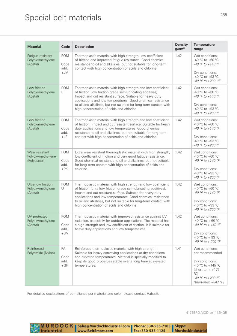
285
4178BRO.MOD-en1112HQR
Special belt materials
Material Code DescriptionDensity g/cm3
Temperature range
Fatigue resistant Polyoxymethylene (Acetal)
POM
Code add. +JM
Thermoplastic material with high strength, low coefficient of friction and improved fatigue resistance. Good chemical resistance to oil and alkalines, but not suitable for long-term contact with high concentration of acids and chlorine.
1.42 Wet conditions:-40 °C to +60 °C-40 °F to +140 °F
Dry conditions:-40 °C to +93 °C-40 °F to +200 °F
Low friction Polyoxymethylene (Acetal)
POM L
Thermoplastic material with high strength and low coefficient of friction (low friction grade self-lubricating additives).Impact and cut resistant surface. Suitable for heavy duty applications and low temperatures. Good chemical resistance to oil and alkalines, but not suitable for long-term contact with high concentration of acids and chlorine.
1.42 Wet conditions:-40 °C to +60 °C-40 °F to +140 °F
Dry conditions:-40 °C to +93 °C-40 °F to +200 °F
Low friction Polyoxamethylene (Acetal)
POM
Code add.+LF
Thermoplastic material with high strength and low coefficient of friction. Impact and cut resistant surface. Suitable for heavy duty applications and low temperatures. Good chemical resistance to oil and alkalines, but not suitable for long-term contact with high concentration of acids and chlorine.
1.42 Wet conditions:-40 °C to +60 °C-40 °F to +140 °F
Dry conditions:-40 °C to +93 °C-40 °F to +200 °F
Wear resistant Polyoxymethy-lene (Polyacetal)
POM
Code add.+PK
Extra wear resistant thermoplastic material with high strength, low coefficient of friction and very good fatigue resistance. Good chemical resistance to oil and alkalines, but not suitable for long-term contact with high concentration of acids and chlorine.
1.42 Wet conditions:-40 °C to +60 °C-40 °F to +140 °F
Dry conditions:-40 °C to +93 °C-40 °F to +200 °F
Ultra low friction Polyoxymethylene (Acetal)
POM U
Thermoplastic material with high strength and low coefficient of friction (ultra low friction grade self-lubricating additives).Impact and cut resistant surface. Suitable for heavy duty applications and low temperatures. Good chemical resistance to oil and alkalines, but not suitable for long-term contact with high concentration of acids and chlorine.
1.42 Wet conditions:-40 °C to +60 °C-40 °F to +140 °F
Dry conditions:-40 °C to +93 °C-40 °F to +200 °F
UV protected Polyoxymethy lene (Acetal)
POM
Code add. +UV
Thermoplastic material with improved resistance against UV radiation, especially for outdoor applications. The material has a high strength and low coefficient of friction. It is suitable for heavy duty applications and low temperatures.
1.42 Wet conditions:-40 °C to + 60 °C-40 °F to + 140 °F
Dry conditions:-40 °C to + 93 °C-40 °F to + 200 °F
Reinforced Polyamide (Nylon)
PA
Code add. +GF
Reinforced thermoplastic material with high strength. Suitable for heavy conveying applications at dry conditions and elevated temperatures. Material is specially modified to keep its good properties stable over a long time at elevated temperatures.
1.41 Wet conditions: not recommended
Dry conditions:-40 °C to +145 °C(short-term +175 °C)-40 °F to +293 °F(short-term +347 °F)
For detailed declarations of compliance per material and color, please contact Habasit.
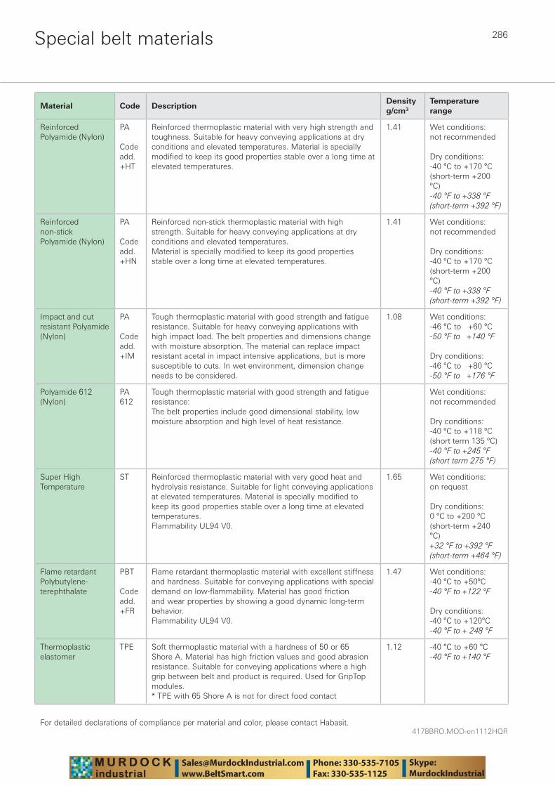
4178BRO.MOD-en1112HQR
286Special belt materials
Material Code DescriptionDensity g/cm3
Temperature range
Reinforced Polyamide (Nylon)
PA
Code add. +HT
Reinforced thermoplastic material with very high strength and toughness. Suitable for heavy conveying applications at dry conditions and elevated temperatures. Material is specially modified to keep its good properties stable over a long time at elevated temperatures.
1.41 Wet conditions: not recommended
Dry conditions:-40 °C to +170 °C(short-term +200 °C)-40 °F to +338 °F(short-term +392 °F)
Reinforced non-stick Polyamide (Nylon)
PA
Code add. +HN
Reinforced non-stick thermoplastic material with high strength. Suitable for heavy conveying applications at dry conditions and elevated temperatures.Material is specially modified to keep its good properties stable over a long time at elevated temperatures.
1.41 Wet conditions: not recommended
Dry conditions:-40 °C to +170 °C(short-term +200 °C)-40 °F to +338 °F(short-term +392 °F)
Impact and cut resistant Polyamide (Nylon)
PA
Code add. +IM
Tough thermoplastic material with good strength and fatigue resistance. Suitable for heavy conveying applications with high impact load. The belt properties and dimensions change with moisture absorption. The material can replace impact resistant acetal in impact intensive applications, but is more susceptible to cuts. In wet environment, dimension change needs to be considered.
1.08 Wet conditions:-46 °C to +60 °C-50 °F to +140 °F
Dry conditions:-46 °C to +80 °C-50 °F to +176 °F
Polyamide 612 (Nylon)
PA 612
Tough thermoplastic material with good strength and fatigue resistance: The belt properties include good dimensional stability, low moisture absorption and high level of heat resistance.
Wet conditions:not recommended
Dry conditions:-40 °C to +118 °C(short term 135 °C)-40 °F to +245 °F(short term 275 °F)
Super High Temperature
ST Reinforced thermoplastic material with very good heat and hydrolysis resistance. Suitable for light conveying applications at elevated temperatures. Material is specially modified to keep its good properties stable over a long time at elevated temperatures. Flammability UL94 V0.
1.65 Wet conditions: on request
Dry conditions:0 °C to +200 °C(short-term +240 °C)+32 °F to +392 °F(short-term +464 °F)
Flame retardant Polybutylene-terephthalate
PBT
Code add. +FR
Flame retardant thermoplastic material with excellent stiffness and hardness. Suitable for conveying applications with special demand on low-flammability. Material has good friction and wear properties by showing a good dynamic long-term behavior.Flammability UL94 V0.
1.47 Wet conditions: -40 °C to +50°C-40 °F to +122 °F
Dry conditions:-40 °C to +120°C-40 °F to + 248 °F
Thermoplastic elastomer
TPE Soft thermoplastic material with a hardness of 50 or 65 Shore A. Material has high friction values and good abrasion resistance. Suitable for conveying applications where a high grip between belt and product is required. Used for GripTop modules.* TPE with 65 Shore A is not for direct food contact
1.12 -40 °C to +60 °C-40 °F to +140 °F
For detailed declarations of compliance per material and color, please contact Habasit.
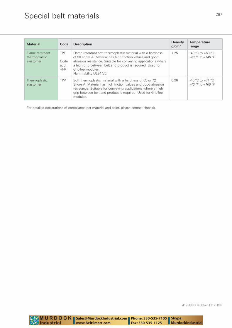
287
4178BRO.MOD-en1112HQR
Special belt materials
Material Code DescriptionDensity g/cm3
Temperature range
Flame retardant thermoplastic elastomer
TPE
Code add. +FR
Flame retardant soft thermoplastic material with a hardness of 50 shore A. Material has high friction values and good abrasion resistance. Suitable for conveying applications where a high grip between belt and product is required. Used for GripTop modules.Flammability UL94 V0.
1.25 -40 °C to +60 °C-40 °F to +140 °F
Thermoplastic elastomer
TPV Soft thermoplastic material with a hardness of 55 or 72 Shore A. Material has high friction values and good abrasion resistance. Suitable for conveying applications where a high grip between belt and product is required. Used for GripTop modules.
0.96 -40 °C to +71 °C-40 °F to +160 °F
For detailed declarations of compliance per material and color, please contact Habasit.
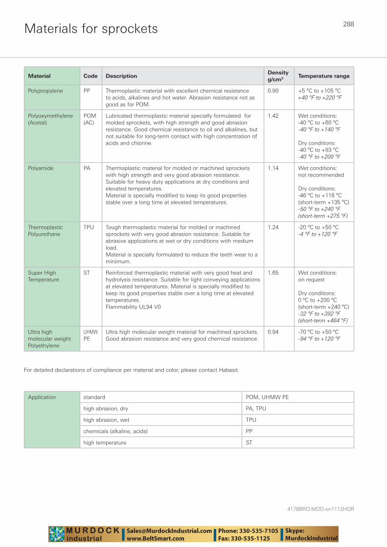
4178BRO.MOD-en1112HQR
288Materials for sprockets
Material Code DescriptionDensity g/cm3 Temperature range
Polypropylene PP Thermoplastic material with excellent chemical resistance to acids, alkalines and hot water. Abrasion resistance not as good as for POM.
0.90 +5 °C to +105 °C+40 °F to +220 °F
Polyoxymethy lene (Acetal)
POM(AC)
Lubricated thermoplastic material specially formulated for molded sprockets, with high strength and good abrasion resistance. Good chemical resistance to oil and alkalines, but not suitable for long-term contact with high concentration of acids and chlorine.
1.42 Wet conditions:-40 °C to +60 °C-40 °F to +140 °F
Dry conditions:-40 °C to +93 °C-40 °F to +200 °F
Polyamide PA Thermoplastic material for molded or machined sprockets with high strength and very good abrasion resistance. Suitable for heavy duty applications at dry conditions and elevated temperatures.Material is specially modified to keep its good properties stable over a long time at elevated temperatures.
1.14 Wet conditions: not recommended
Dry conditions:-46 °C to +116 °C(short-term +135 °C)-50 °F to +240 °F(short-term +275 °F)
Thermoplastic Polyurethane
TPU Tough thermoplastic material for molded or machined sprockets with very good abrasion resistance. Suitable for abrasive applications at wet or dry conditions with medium load.Material is specially formulated to reduce the teeth wear to a minimum.
1.24 -20 °C to +50 °C-4 °F to +120 °F
Super High Temperature
ST Reinforced thermoplastic material with very good heat and hydrolysis resistance. Suitable for light conveying applications at elevated temperatures. Material is specially modified to keep its good properties stable over a long time at elevated temperatures. Flammability UL94 V0
1.65 Wet conditions: on request
Dry conditions:0 °C to +200 °C(short-term +240 °C)-32 °F to +392 °F(short-term +464 °F)
Ultra high molecular weight Polyethylene
UHMW PE
Ultra high molecular weight material for machined sprockets. Good abrasion resistance and very good chemical resistance.
0.94 -70 °C to +50 °C-94 °F to +120 °F
For detailed declarations of compliance per material and color, please contact Habasit.
Application standard POM, UHMW PE
high abrasion, dry PA, TPU
high abrasion, wet TPU
chemicals (alkaline, acids) PP
high temperature ST

289
4178BRO.MOD-en1112HQR
Materials for wear strips and guides
Material Code DescriptionDensity g/cm3
Temperature range
Ultra high molecular weight Polyethylene
UHMW PE (PE 4000)
For heavy conveying applications (high loads); offers reduced wear and longer lifetime. Not suitable for abrasive conditions.
0.94 -70 °C to +65 °C-94 °F to +150 °F
High molecular weight Polyethy lene
HMW PE (PE 1000)
For quite heavy conveying applications (relatively high loads) offers almost the same features of UHMW PE but with slightly harder surface. Not suitable for abrasive conditions.
0.95 -70 °C to +65 °C-94 °F to +150 °F
Medium molecular weight Polyethylene
HDPE (PE 500)
Low cost material suitable for most applications with moderate load and low speed. Not suitable for static nosebars. Not suitable for abrasive conditions.
0.95 -70 °C to +65 °C-94 °F to +150 °F
Cast Polyamide with incorporated Polymer and/or solid lubricating additives
Lubricated PA Cast material with high molecular weight, high strength and very high wear resistance. Due to the incorporated lubricating additives the friction values are very low, and due to the high molecular weight the material is very tough and therefore very abrasion resistant. Suitable for heavy applications and high speeds. Material is hygroscopic (water adsorption should be taken into account).
1.13 -46 °C to +120 °C-50 °F to +248 °F

4178BRO.MOD-en1112HQR
290Material propertiesChemical resistance
The data presented in the following table are based on the information given by the raw material manufacturers and suppliers. It does not relieve of a qualification test of the products for your application. In individual cases the stability of the material in the questionable medium is to be examined.
Code: ■ = good resistance ▼ = conditionally / sometimes resistant ❑ = not resistant (not to be used)
Designation of chemical Poly-propylene
(PP)
also valid for +FR, +AS,
+DE, +HW and +H15
Poly-ethylene
(PE, HD PE or
UHMW PE)
also valid for +DE and
+H15
Polyoxy-methylene
(POM) Acetal (AC)
also valid for +AS, +EC, +DE, +UV,
+UVC, +IM, +JM, +LF,L and U
Polyamide (PA)
also valid for +US, +GF, +HT and
+IM
Super High Temperature Material (ST)
Thermo-plasticPoly-
urethane (TPU)
Thermo-plastic
elastomer (TPE)
also valid for +FR
Flame retardantPoly buty -leneter-
ephthalate (PBT)
also valid for +FR
20 °
C (7
0 °F
)
60 °
C (1
40 °
F)
20 °
C (7
0 °F
)
60 °
C (1
40 °
F)
20 °
C (7
0 °F
)
60 °
C (1
40 °
F)
20 °
C (7
0 °F
)
60 °
C (1
40 °
F)
20 °
C (7
0 °F
)
60 °
C (1
40 °
F)
93 °
C (2
00 °
F)
20 °
C (7
0 °F
)
60 °
C (1
40 °
F)
20 °
C (7
0 °F
)
60 °
C (1
40 °
F)
20 °
C (7
0 °F
)
60 °
C (1
40 °
F)
Acetic Acid > 5% ■ ■ ■ ▼ ▼ ❑ ❑ ❑ ■ ■ ■ ❑ ❑ ▼ ❑
Acetic Acid – 5% ■ ■ ■ ■ ■ ▼ ❑ ■ ■ ■ ❑ ❑ ■ ▼
Acetone ■ ■ ■ ■ ▼ ▼ ■ ■ ■ ■ ■ ❑ ▼ ❑
Alcohol – all types ■ ■ ■ ■ ■ ▼ ■ ■ ■ ■ ■ ❑ ▼ ■ ▼
Aluminum Comp. ■ ■ ■ ■ ■ ■ ■ ■ ■
Ammonia ■ ■ ■ ■ ■ ■ ■ ■ ■ ▼ ❑ ■ ▼ ❑
Ammonium Comp. ■ ■ ■ ■ ■ ■ ■ ■ ■ ▼ ❑
Aniline ■ ■ ■ ❑ ▼ ■ ▼ ❑ ❑ ▼
Aqua Regia ❑ ❑ ■ ❑ ❑ ❑ ❑
Arsenic Acid ■ ■ ■ ■
Barium Comp. ■ ■ ■ ■ ■ ■ ■ ■ ■
Beer ■ ■ ■ ■ ■ ■
Benzene ▼ ❑ ▼ ❑ ▼ ▼ ■ ■ ■ ▼ ❑ ❑ ▼ ❑Benzenesulfonic Acid – 10%
■ ■ ■ ■ ■ ▼ ❑
Benzoic Acid ■ ■ ■ ■ ▼ ▼ ■ ▼ ❑ ■
Beverages (soft drinks) ■ ■ ■ ■ ■ ■ ■ ■
Borax ■ ■ ■ ■ ■ ■ ■
Boric Acid ■ ■ ■ ■ ■ ■ ■
Brine – 10% ■ ■ ■ ■ ■ ■
Butyl Acrylate ❑ ❑ ■ ▼ ■ ■ ■ ■ ▼
Butyric Acid ■ ■ ▼ ■ ■ ■
Carbon Dioxide ■ ■ ■ ■ ■ ■ ■ ■ ■ ■ ■
Carbon Disulfide ▼ ❑ ▼ ❑ ■ ■ ■ ■ ■
Carbon Tetrachloride ▼ ❑ ▼ ❑ ■ ▼ ■ ■ ■ ▼ ❑ ❑
Chloracetic Acid ■ ■ ❑ ❑
Chlorine – Gas ❑ ❑ ▼ ❑ ❑ ❑ ❑ ❑ ❑
Chlorine – Liquid ❑ ❑ ❑ ❑ ❑ ❑ ❑ ❑ ❑
Chlorine Water (0.4% CI) ■ ▼ ■ ▼ ❑ ❑ ❑ ❑ ❑
Chlorobenzene ❑ ❑ ▼ ❑ ▼ ▼ ■ ■ ■ ▼ ❑ ❑ ❑
Chloroform ❑ ❑ ❑ ❑ ❑ ❑ ▼ ■ ▼ ❑ ❑
Chromic Acid – 50% ■ ■ ■ ▼ ❑ ❑ ▼ ❑ ▼
Chromic Acid – 3% ■ ■ ■ ■ ▼ ▼ ❑ ■ ■
Citric Acid – 40% ■ ■ ■ ■ ■ ❑ ■ ■ ■
Citric Acid – 10% ■ ■ ■ ■ ■ ■ ■ ■ ■ ▼
Citrus Juices ■ ■ ■ ■ ■ ■ ■ ■
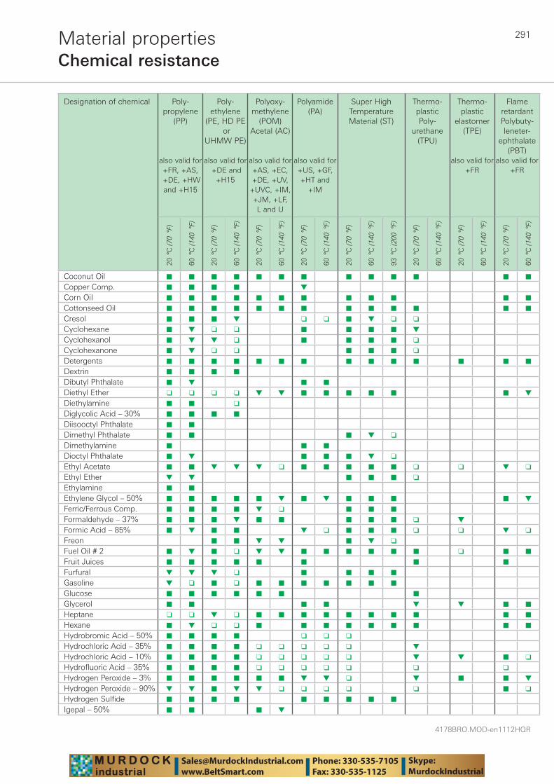
291
4178BRO.MOD-en1112HQR
Material propertiesChemical resistance
Designation of chemical Poly-propylene
(PP)
also valid for +FR, +AS,
+DE, +HW and +H15
Poly-ethylene
(PE, HD PE or
UHMW PE)
also valid for +DE and
+H15
Polyoxy-methylene
(POM) Acetal (AC)
also valid for +AS, +EC, +DE, +UV,
+UVC, +IM, +JM, +LF,L and U
Polyamide (PA)
also valid for +US, +GF, +HT and
+IM
Super High Temperature Material (ST)
Thermo-plasticPoly-
urethane (TPU)
Thermo-plastic
elastomer (TPE)
also valid for +FR
Flame retardantPoly buty -leneter-
ephthalate (PBT)
also valid for +FR
20 °
C (7
0 °F
)
60 °
C (1
40 °
F)
20 °
C (7
0 °F
)
60 °
C (1
40 °
F)
20 °
C (7
0 °F
)
60 °
C (1
40 °
F)
20 °
C (7
0 °F
)
60 °
C (1
40 °
F)
20 °
C (7
0 °F
)
60 °
C (1
40 °
F)
93 °
C (2
00 °
F)
20 °
C (7
0 °F
)
60 °
C (1
40 °
F)
20 °
C (7
0 °F
)
60 °
C (1
40 °
F)
20 °
C (7
0 °F
)
60 °
C (1
40 °
F)
Coconut Oil ■ ■ ■ ■ ■ ■ ■ ■ ■ ■ ■ ■ ■
Copper Comp. ■ ■ ■ ■ ▼
Corn Oil ■ ■ ■ ■ ■ ■ ■ ■ ■ ■ ■ ■
Cottonseed Oil ■ ■ ■ ■ ■ ■ ■ ■ ■ ■ ■ ■ ■
Cresol ■ ■ ■ ▼ ❑ ❑ ■ ▼ ❑ ❑
Cyclohexane ■ ▼ ❑ ❑ ■ ■ ■ ■ ▼
Cyclohexanol ■ ▼ ▼ ❑ ■ ■ ■ ■ ❑
Cyclohexanone ■ ▼ ❑ ❑ ■ ■ ■ ❑
Detergents ■ ■ ■ ■ ■ ■ ■ ■ ■ ■ ■ ■ ■ ■
Dextrin ■ ■ ■ ■
Dibutyl Phthalate ■ ▼ ■ ■
Diethyl Ether ❑ ❑ ❑ ❑ ▼ ▼ ■ ■ ■ ■ ■ ■ ▼
Diethylamine ■ ■ ❑
Diglycolic Acid – 30% ■ ■ ■ ■
Diisooctyl Phthalate ■ ■
Dimethyl Phthalate ■ ■ ■ ▼ ❑
Dimethylamine ■ ■ ■
Dioctyl Phthalate ■ ▼ ■ ■ ■ ▼ ❑
Ethyl Acetate ■ ■ ▼ ▼ ▼ ❑ ■ ■ ■ ■ ■ ❑ ❑ ▼ ❑
Ethyl Ether ▼ ▼ ■ ■ ■ ❑
Ethylamine ■ ■
Ethylene Glycol – 50% ■ ■ ■ ■ ■ ▼ ■ ▼ ■ ■ ■ ■ ▼
Ferric/Ferrous Comp. ■ ■ ■ ■ ▼ ❑ ■ ■ ■
Formaldehyde – 37% ■ ■ ■ ▼ ■ ■ ■ ■ ■ ❑ ▼
Formic Acid – 85% ■ ▼ ■ ■ ▼ ❑ ■ ■ ■ ❑ ❑ ▼ ❑
Freon ■ ■ ▼ ▼ ■ ▼ ❑
Fuel Oil # 2 ■ ▼ ■ ❑ ▼ ▼ ■ ■ ■ ■ ■ ■ ❑ ■ ■
Fruit Juices ■ ■ ■ ■ ■ ■ ■ ■
Furfural ▼ ▼ ▼ ❑ ■ ■ ■ ■
Gasoline ▼ ❑ ■ ❑ ■ ■ ■ ■ ■ ■ ■
Glucose ■ ■ ■ ■ ■ ■ ■
Glycerol ■ ■ ■ ■ ▼ ▼ ■ ■
Heptane ❑ ❑ ▼ ❑ ■ ■ ■ ■ ■ ■ ■ ■ ■ ■
Hexane ■ ▼ ❑ ❑ ■ ■ ■ ■ ■ ■ ■ ■ ■
Hydrobromic Acid – 50% ■ ■ ■ ■ ❑ ❑ ❑
Hydrochloric Acid – 35% ■ ■ ■ ■ ❑ ❑ ❑ ❑ ❑ ▼
Hydrochloric Acid – 10% ■ ■ ■ ■ ❑ ❑ ❑ ❑ ❑ ▼ ▼ ■ ❑
Hydrofluoric Acid – 35% ■ ■ ■ ■ ❑ ❑ ❑ ❑ ❑ ❑ ❑
Hydrogen Peroxide – 3% ■ ■ ■ ■ ■ ■ ▼ ▼ ❑ ▼ ■ ■ ▼
Hydrogen Peroxide – 90% ▼ ▼ ■ ▼ ▼ ❑ ❑ ❑ ❑ ❑ ■ ❑
Hydrogen Sulfide ■ ■ ■ ■ ■ ■ ■ ■ ■
Igepal – 50% ■ ■ ■ ▼
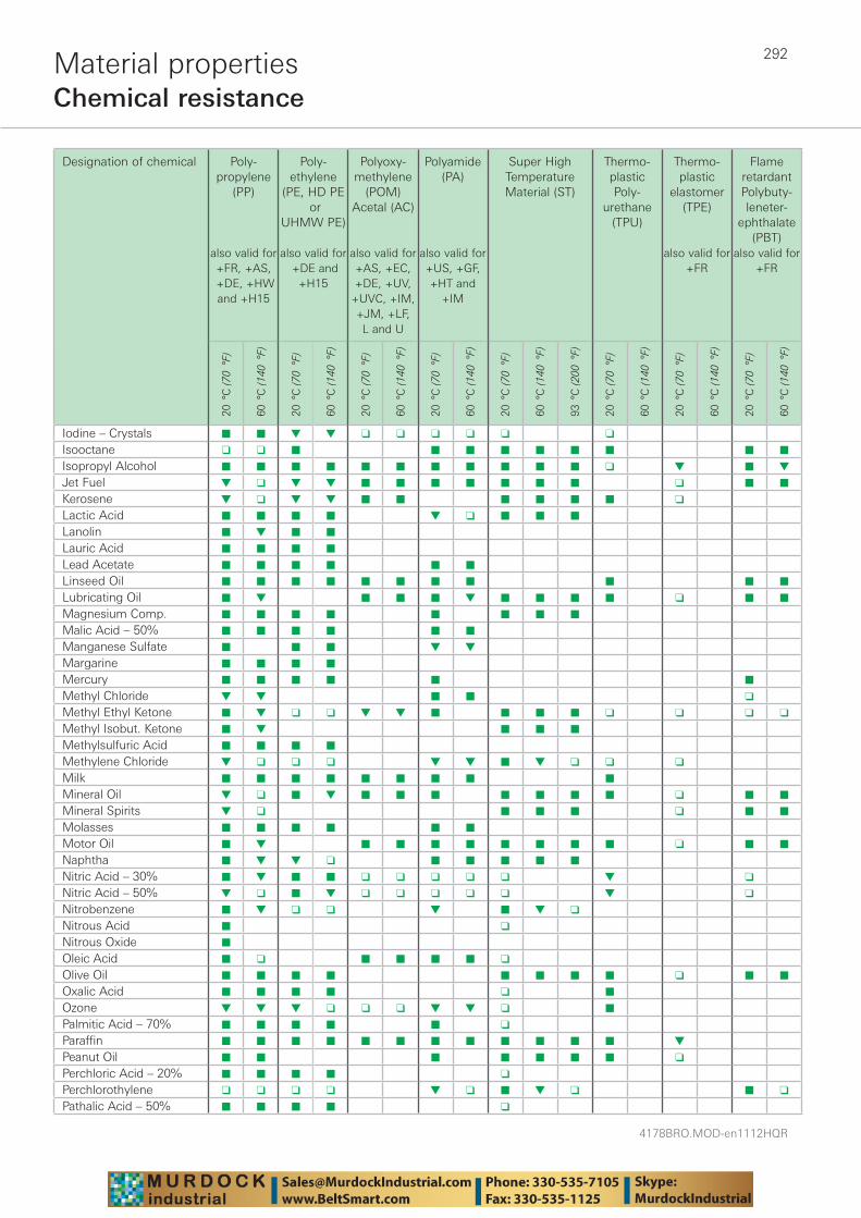
4178BRO.MOD-en1112HQR
292Material propertiesChemical resistance
Designation of chemical Poly-propylene
(PP)
also valid for +FR, +AS,
+DE, +HW and +H15
Poly-ethylene
(PE, HD PE or
UHMW PE)
also valid for +DE and
+H15
Polyoxy-methylene
(POM) Acetal (AC)
also valid for +AS, +EC, +DE, +UV,
+UVC, +IM, +JM, +LF,L and U
Polyamide (PA)
also valid for +US, +GF, +HT and
+IM
Super High Temperature Material (ST)
Thermo-plasticPoly-
urethane (TPU)
Thermo-plastic
elastomer (TPE)
also valid for +FR
Flame retardantPoly buty -leneter-
ephthalate (PBT)
also valid for +FR
20 °
C (7
0 °F
)
60 °
C (1
40 °
F)
20 °
C (7
0 °F
)
60 °
C (1
40 °
F)
20 °
C (7
0 °F
)
60 °
C (1
40 °
F)
20 °
C (7
0 °F
)
60 °
C (1
40 °
F)
20 °
C (7
0 °F
)
60 °
C (1
40 °
F)
93 °
C (2
00 °
F)
20 °
C (7
0 °F
)
60 °
C (1
40 °
F)
20 °
C (7
0 °F
)
60 °
C (1
40 °
F)
20 °
C (7
0 °F
)
60 °
C (1
40 °
F)
Iodine – Crystals ■ ■ ▼ ▼ ❑ ❑ ❑ ❑ ❑ ❑
Isooctane ❑ ❑ ■ ■ ■ ■ ■ ■ ■ ■ ■
Isopropyl Alcohol ■ ■ ■ ■ ■ ■ ■ ■ ■ ■ ■ ❑ ▼ ■ ▼
Jet Fuel ▼ ❑ ▼ ▼ ■ ■ ■ ■ ■ ■ ■ ❑ ■ ■
Kerosene ▼ ❑ ▼ ▼ ■ ■ ■ ■ ■ ■ ❑
Lactic Acid ■ ■ ■ ■ ▼ ❑ ■ ■ ■
Lanolin ■ ▼ ■ ■
Lauric Acid ■ ■ ■ ■
Lead Acetate ■ ■ ■ ■ ■ ■
Linseed Oil ■ ■ ■ ■ ■ ■ ■ ■ ■ ■ ■
Lubricating Oil ■ ▼ ■ ■ ■ ▼ ■ ■ ■ ■ ❑ ■ ■
Magnesium Comp. ■ ■ ■ ■ ■ ■ ■ ■
Malic Acid – 50% ■ ■ ■ ■ ■ ■
Manganese Sulfate ■ ■ ■ ▼ ▼
Margarine ■ ■ ■ ■
Mercury ■ ■ ■ ■ ■ ■
Methyl Chloride ▼ ▼ ■ ■ ❑
Methyl Ethyl Ketone ■ ▼ ❑ ❑ ▼ ▼ ■ ■ ■ ■ ❑ ❑ ❑ ❑
Methyl Isobut. Ketone ■ ▼ ■ ■ ■
Methylsulfuric Acid ■ ■ ■ ■
Methylene Chloride ▼ ❑ ❑ ❑ ▼ ▼ ■ ▼ ❑ ❑ ❑
Milk ■ ■ ■ ■ ■ ■ ■ ■ ■
Mineral Oil ▼ ❑ ■ ▼ ■ ■ ■ ■ ■ ■ ■ ❑ ■ ■
Mineral Spirits ▼ ❑ ■ ■ ■ ❑ ■ ■
Molasses ■ ■ ■ ■ ■ ■
Motor Oil ■ ▼ ■ ■ ■ ■ ■ ■ ■ ■ ❑ ■ ■
Naphtha ■ ▼ ▼ ❑ ■ ■ ■ ■ ■
Nitric Acid – 30% ■ ▼ ■ ■ ❑ ❑ ❑ ❑ ❑ ▼ ❑
Nitric Acid – 50% ▼ ❑ ■ ▼ ❑ ❑ ❑ ❑ ❑ ▼ ❑
Nitrobenzene ■ ▼ ❑ ❑ ▼ ■ ▼ ❑
Nitrous Acid ■ ❑
Nitrous Oxide ■
Oleic Acid ■ ❑ ■ ■ ■ ■ ❑
Olive Oil ■ ■ ■ ■ ■ ■ ■ ■ ❑ ■ ■
Oxalic Acid ■ ■ ■ ■ ❑ ■
Ozone ▼ ▼ ▼ ❑ ❑ ❑ ▼ ▼ ❑ ■
Palmitic Acid – 70% ■ ■ ■ ■ ■ ❑
Paraffin ■ ■ ■ ■ ■ ■ ■ ■ ■ ■ ■ ■ ▼
Peanut Oil ■ ■ ■ ■ ■ ■ ■ ❑
Perchloric Acid – 20% ■ ■ ■ ■ ❑
Perchlorothylene ❑ ❑ ❑ ❑ ▼ ❑ ■ ▼ ❑ ■ ❑
Pathalic Acid – 50% ■ ■ ■ ■ ❑
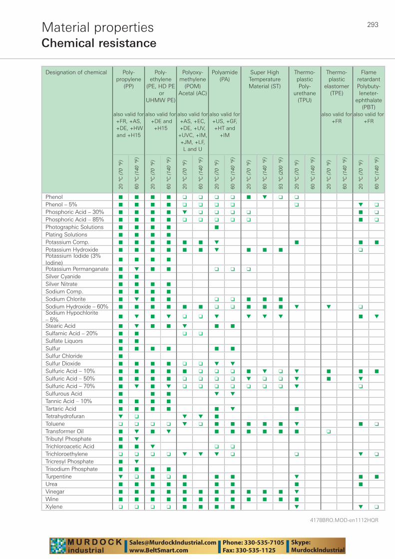
293
4178BRO.MOD-en1112HQR
Material propertiesChemical resistance
Designation of chemical Poly-propylene
(PP)
also valid for +FR, +AS,
+DE, +HW and +H15
Poly-ethylene
(PE, HD PE or
UHMW PE)
also valid for +DE and
+H15
Polyoxy-methylene
(POM) Acetal (AC)
also valid for +AS, +EC, +DE, +UV,
+UVC, +IM, +JM, +LF,L and U
Polyamide (PA)
also valid for +US, +GF, +HT and
+IM
Super High Temperature Material (ST)
Thermo-plasticPoly-
urethane (TPU)
Thermo-plastic
elastomer (TPE)
also valid for +FR
Flame retardantPoly buty -leneter-
ephthalate (PBT)
also valid for +FR
20 °
C (7
0 °F
)
60 °
C (1
40 °
F)
20 °
C (7
0 °F
)
60 °
C (1
40 °
F)
20 °
C (7
0 °F
)
60 °
C (1
40 °
F)
20 °
C (7
0 °F
)
60 °
C (1
40 °
F)
20 °
C (7
0 °F
)
60 °
C (1
40 °
F)
93 °
C (2
00 °
F)
20 °
C (7
0 °F
)
60 °
C (1
40 °
F)
20 °
C (7
0 °F
)
60 °
C (1
40 °
F)
20 °
C (7
0 °F
)
60 °
C (1
40 °
F)
Phenol ■ ■ ■ ■ ❑ ❑ ❑ ❑ ■ ▼ ❑ ❑
Phenol – 5% ■ ■ ■ ■ ❑ ❑ ❑ ❑ ❑ ▼ ❑
Phosphoric Acid – 30% ■ ■ ■ ■ ▼ ❑ ❑ ❑ ❑ ■ ❑
Phosphoric Acid – 85% ■ ■ ■ ■ ❑ ❑ ❑ ❑ ❑ ■ ❑
Photographic Solutions ■ ■ ■ ■ ■
Plating Solutions ■ ■ ■ ■
Potassium Comp. ■ ■ ■ ■ ■ ■ ▼ ■ ■ ■
Potassium Hydroxide ■ ■ ■ ■ ■ ■ ▼ ■ ■ ■ ❑Potassium Iodide (3% Iodine)
■ ■ ■ ■
Potassium Permanganate ■ ▼ ■ ■ ❑ ❑ ❑
Silver Cyanide ■ ■
Silver Nitrate ■ ■ ■ ■
Sodium Comp. ■ ■ ■ ■
Sodium Chlorite ■ ▼ ■ ■ ❑ ❑ ■ ■ ■
Sodium Hydroxide – 60% ■ ■ ■ ■ ■ ■ ❑ ❑ ■ ■ ■ ▼ ▼ ❑Sodium Hypochlorite – 5%
■ ▼ ■ ▼ ❑ ❑ ▼ ▼ ▼ ▼ ■ ▼
Stearic Acid ■ ▼ ■ ■ ▼ ■ ■
Sulfamic Acid – 20% ■ ■ ❑ ❑
Sulfate Liquors ■ ■
Sulfur ■ ■ ■ ■ ■ ■
Sulfur Chloride ■
Sulfur Dioxide ■ ■ ■ ■ ❑ ❑ ▼ ▼
Sulfuric Acid – 10% ■ ■ ■ ■ ■ ❑ ❑ ❑ ■ ▼ ❑ ▼ ■ ■ ■
Sulfuric Acid – 50% ■ ■ ■ ■ ❑ ❑ ❑ ❑ ▼ ❑ ❑ ▼ ■ ▼
Sulfuric Acid – 70% ■ ▼ ■ ▼ ❑ ❑ ❑ ❑ ❑ ❑ ❑ ▼ ❑
Sulfurous Acid ■ ■ ■ ▼ ▼
Tannic Acid – 10% ■ ■ ■ ■
Tartaric Acid ■ ■ ■ ■ ■ ▼ ■
Tetrahydrofuran ▼ ❑ ▼ ▼ ■
Toluene ❑ ❑ ❑ ❑ ▼ ❑ ■ ■ ■ ■ ■ ▼ ■ ❑
Transformer Oil ■ ▼ ■ ▼ ■ ■ ■ ■ ■ ■ ❑
Tributyl Phosphate ■ ▼
Trichloroacetic Acid ■ ■ ▼ ❑ ❑
Trichloroethylene ❑ ❑ ❑ ❑ ▼ ▼ ▼ ❑ ❑ ▼ ❑
Tricresyl Phosphate ■ ▼
Trisodium Phosphate ■ ■ ■ ■
Turpentine ▼ ❑ ■ ❑ ■ ■ ■ ▼ ■ ■
Urea ■ ■ ■ ■ ■ ■ ■ ■ ■
Vinegar ■ ■ ■ ■ ■ ■ ■ ■ ■ ■ ■ ▼
Wine ■ ■ ■ ■ ■ ■ ■ ■ ■ ■ ■ ■
Xylene ❑ ❑ ❑ ❑ ■ ■ ■ ■ ▼ ▼ ❑
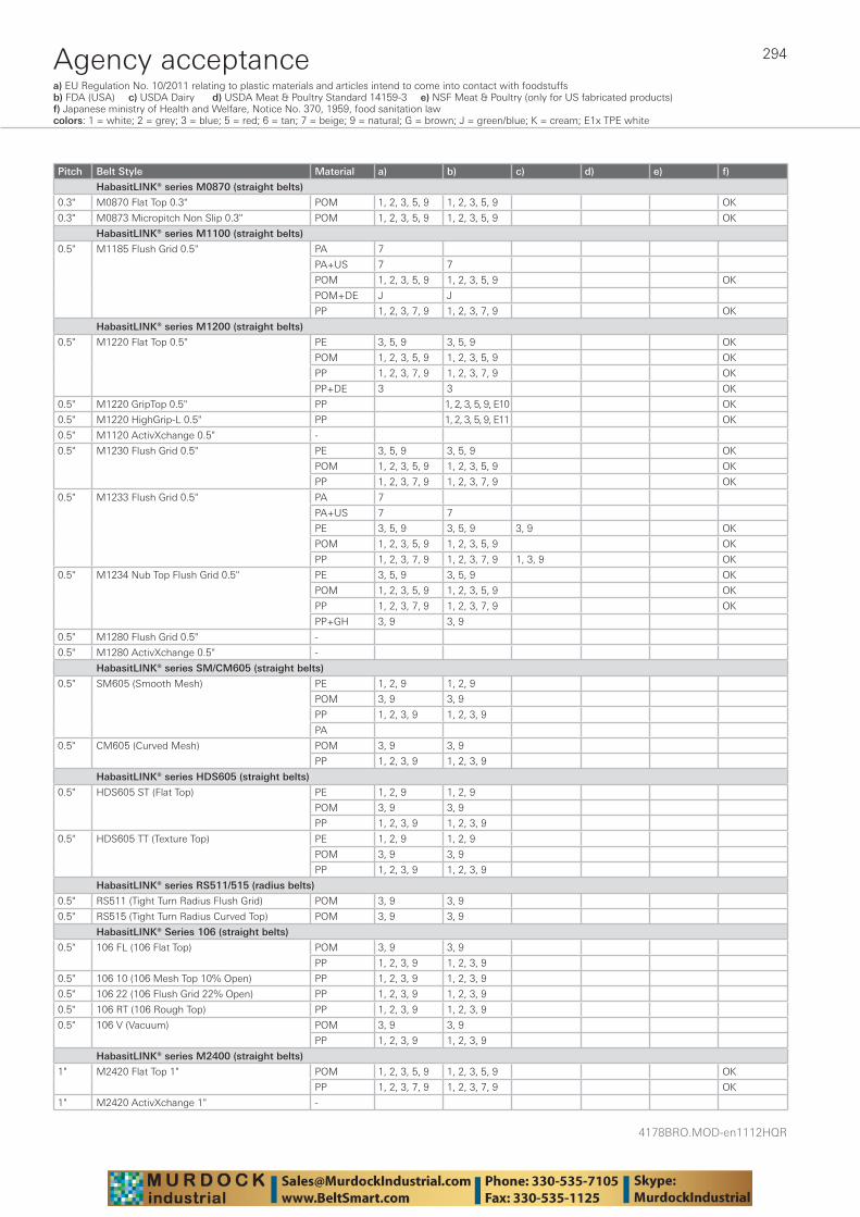
4178BRO.MOD-en1112HQR
294Agency acceptance
Pitch Belt Style Material a) b) c) d) e) f)
HabasitLINK® series M0870 (straight belts)
0.3" M0870 Flat Top 0.3" POM 1, 2, 3, 5, 9 1, 2, 3, 5, 9 OK
0.3" M0873 Micropitch Non Slip 0.3" POM 1, 2, 3, 5, 9 1, 2, 3, 5, 9 OK
HabasitLINK® series M1100 (straight belts)
0.5" M1185 Flush Grid 0.5" PA 7
PA+US 7 7
POM 1, 2, 3, 5, 9 1, 2, 3, 5, 9 OK
POM+DE J J
PP 1, 2, 3, 7, 9 1, 2, 3, 7, 9 OK
HabasitLINK® series M1200 (straight belts)
0.5" M1220 Flat Top 0.5" PE 3, 5, 9 3, 5, 9 OK
POM 1, 2, 3, 5, 9 1, 2, 3, 5, 9 OK
PP 1, 2, 3, 7, 9 1, 2, 3, 7, 9 OK
PP+DE 3 3 OK
0.5" M1220 GripTop 0.5" PP 1, 2, 3, 5, 9, E10 OK
0.5" M1220 HighGrip-L 0.5" PP 1, 2, 3, 5, 9, E11 OK
0.5" M1120 ActivXchange 0.5" -
0.5" M1230 Flush Grid 0.5" PE 3, 5, 9 3, 5, 9 OK
POM 1, 2, 3, 5, 9 1, 2, 3, 5, 9 OK
PP 1, 2, 3, 7, 9 1, 2, 3, 7, 9 OK
0.5" M1233 Flush Grid 0.5" PA 7
PA+US 7 7
PE 3, 5, 9 3, 5, 9 3, 9 OK
POM 1, 2, 3, 5, 9 1, 2, 3, 5, 9 OK
PP 1, 2, 3, 7, 9 1, 2, 3, 7, 9 1, 3, 9 OK
0.5" M1234 Nub Top Flush Grid 0.5" PE 3, 5, 9 3, 5, 9 OK
POM 1, 2, 3, 5, 9 1, 2, 3, 5, 9 OK
PP 1, 2, 3, 7, 9 1, 2, 3, 7, 9 OK
PP+GH 3, 9 3, 9
0.5" M1280 Flush Grid 0.5" -
0.5" M1280 ActivXchange 0.5" -
HabasitLINK® series SM/CM605 (straight belts)
0.5" SM605 (Smooth Mesh) PE 1, 2, 9 1, 2, 9
POM 3, 9 3, 9
PP 1, 2, 3, 9 1, 2, 3, 9
PA
0.5" CM605 (Curved Mesh) POM 3, 9 3, 9
PP 1, 2, 3, 9 1, 2, 3, 9
HabasitLINK® series HDS605 (straight belts)
0.5" HDS605 ST (Flat Top) PE 1, 2, 9 1, 2, 9
POM 3, 9 3, 9
PP 1, 2, 3, 9 1, 2, 3, 9
0.5" HDS605 TT (Texture Top) PE 1, 2, 9 1, 2, 9
POM 3, 9 3, 9
PP 1, 2, 3, 9 1, 2, 3, 9
HabasitLINK® series RS511/515 (radius belts)
0.5" RS511 (Tight Turn Radius Flush Grid) POM 3, 9 3, 9
0.5" RS515 (Tight Turn Radius Curved Top) POM 3, 9 3, 9
HabasitLINK® Series 106 (straight belts)
0.5" 106 FL (106 Flat Top) POM 3, 9 3, 9
PP 1, 2, 3, 9 1, 2, 3, 9
0.5" 106 10 (106 Mesh Top 10% Open) PP 1, 2, 3, 9 1, 2, 3, 9
0.5" 106 22 (106 Flush Grid 22% Open) PP 1, 2, 3, 9 1, 2, 3, 9
0.5" 106 RT (106 Rough Top) PP 1, 2, 3, 9 1, 2, 3, 9
0.5" 106 V (Vacuum) POM 3, 9 3, 9
PP 1, 2, 3, 9 1, 2, 3, 9
HabasitLINK® series M2400 (straight belts)
1" M2420 Flat Top 1" POM 1, 2, 3, 5, 9 1, 2, 3, 5, 9 OK
PP 1, 2, 3, 7, 9 1, 2, 3, 7, 9 OK
1" M2420 ActivXchange 1" -
a) EU Regulation No. 10/2011 relating to plastic materials and articles intend to come into contact with foodstuffs b) FDA (USA) c) USDA Dairy d) USDA Meat & Poultry Standard 14159-3 e) NSF Meat & Poultry (only for US fabricated products) f) Japanese ministry of Health and Welfare, Notice No. 370, 1959, food sanitation lawcolors: 1 = white; 2 = grey; 3 = blue; 5 = red; 6 = tan; 7 = beige; 9 = natural; G = brown; J = green/blue; K = cream; E1x TPE white
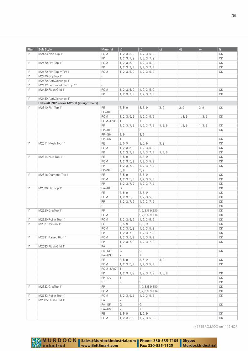
295
4178BRO.MOD-en1112HQR
Pitch Belt Style Material a) b) c) d) e) f)
1" M2423 Non Slip 1" POM 1, 2, 3, 5, 9 1, 2, 3, 5, 9 OK
PP 1, 2, 3, 7, 9 1, 2, 3, 7, 9 OK
1" M2470 Flat Top 1" POM 1, 2, 3, 5, 9 1, 2, 3, 5, 9 OK
PP 1, 2, 3, 7, 9 1, 2, 3, 7, 9 OK
1" M2470 Flat Top MTW 1" POM 1, 2, 3, 5, 9 1, 2, 3, 5, 9 OK
1" M2470 GripTop 1" -
1" M2470 ActivXchange 1" -
1" M2472 Perforated Flat Top 1" -
1" M2480 Flush Grid 1" POM 1, 2, 3, 5, 9 1, 2, 3, 5, 9 OK
PP 1, 2, 3, 7, 9 1, 2, 3, 7, 9 OK
1" M2480 ActivXchange 1" -
HabasitLINK® series M2500 (straight belts)
1" M2510 Flat Top 1" PE 3, 5, 9 3, 5, 9 3, 9 3, 9 3, 9 OK
PE+DE 3 3
POM 1, 2, 3, 5, 9 1, 2, 3, 5, 9 1, 3, 9 1, 3, 9 OK
POM+UVC 1 1
PP 1, 2, 3, 7, 9 1, 2, 3, 7, 9 1, 3, 9 1, 3, 9 1, 3, 9 OK
PP+DE 3 3 OK
PP+GH 3, 9 3, 9
PP+XA 1 1 OK
1" M2511 Mesh Top 1" PE 3, 5, 9 3, 5, 9 3, 9 OK
POM 1, 2, 3, 5, 9 1, 2, 3, 5, 9 OK
PP 1, 2, 3, 7, 9 1, 2, 3, 7, 9 1, 3, 9 OK
1" M2514 Nub Top 1" PE 3, 5, 9 3, 5, 9 OK
POM 1, 2, 3, 5, 9 1, 2, 3, 5, 9 OK
PP 1, 2, 3, 7, 9 1, 2, 3, 7, 9 OK
PP+GH 3, 9 3, 9
1" M2516 Diamond Top 1" PE 3, 5, 9 3, 5, 9 OK
POM 1, 2, 3, 5, 9 1, 2, 3, 5, 9 OK
PP 1, 2, 3, 7, 9 1, 2, 3, 7, 9 OK
1" M2520 Flat Top 1" PA+GF G G OK
PE 3, 5, 9 3, 5, 9 OK
POM 1, 2, 3, 5, 9 1, 2, 3, 5, 9 OK
PP 1, 2, 3, 7, 9 1, 2, 3, 7, 9 OK
ST 9 9 OK
1" M2520 GripTop 1" PP 1, 2, 3, 5, 9, E10 OK
POM 1, 2, 3, 5, 9, E14 OK
1" M2520 Roller Top 1" POM 1, 2, 3, 5, 9 1, 2, 3, 5, 9 OK
1" M2527 Minirib 1" PE 3, 5, 9 3, 5, 9 OK
POM 1, 2, 3, 5, 9 1, 2, 3, 5, 9 OK
PP 1, 2, 3, 7, 9 1, 2, 3, 7, 9 OK
1" M2531 Raised Rib 1" POM 1, 2, 3, 5, 9 1, 2, 3, 5, 9 OK
PP 1, 2, 3, 7, 9 1, 2, 3, 7, 9 OK
1" M2533 Flush Grid 1" PA 7
PA+GF G G OK
PA+US 7 7
PE 3, 5, 9 3, 5, 9 3, 9 OK
POM 1, 2, 3, 5, 9 1, 2, 3, 5, 9 OK
POM+UVC 1 1
PP 1, 2, 3, 7, 9 1, 2, 3, 7, 9 1, 3, 9 OK
PP+XA 1 1 OK
ST 9 9 OK
1" M2533 GripTop 1" PP 1, 2, 3, 5, 9, E10 OK
POM 1, 2, 3, 5, 9, E14 OK
1" M2533 Roller Top 1" POM 1, 2, 3, 5, 9 1, 2, 3, 5, 9 OK
1" M2585 Flush Grid 1" PA 7
PA+GF G G OK
PA+US 7 7
PE 3, 5, 9 3, 5, 9 OK
POM 1, 2, 3, 5, 9 1, 2, 3, 5, 9 OK
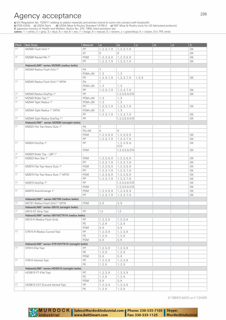
4178BRO.MOD-en1112HQR
296Agency acceptancea) EU Regulation No. 10/2011 relating to plastic materials and articles intend to come into contact with foodstuffs b) FDA (USA) c) USDA Dairy d) USDA Meat & Poultry Standard 14159-3 e) NSF Meat & Poultry (only for US fabricated products) f) Japanese ministry of Health and Welfare, Notice No. 370, 1959, food sanitation lawcolors: 1 = white; 2 = grey; 3 = blue; 5 = red; 6 = tan; 7 = beige; 9 = natural; G = brown; J = green/blue; K = cream; E1x TPE white
Pitch Belt Style Material a) b) c) d) e) f)
1" M2585 Flush Grid 1" PP 1, 2, 3, 7, 9 1, 2, 3, 7, 9 OK
ST 9 9 OK
1" M2586 Raised Rib 1" POM 1, 2, 3, 5, 9 1, 2, 3, 5, 9 OK
PP 1, 2, 3, 7, 9 1, 2, 3, 7, 9 OK
HabasitLINK® series M2500 (radius belts)
1" M2540 Radius Flush Grid 1" PA 7
POM+JM 1, 3 1, 3
PP 1, 2, 3, 7, 9 1, 2, 3, 7, 9 1, 3, 9 OK
1" M2540 Radius Flush Grid 1" MTW PA 7
POM+JM 1, 3 1, 3
PP 1, 2, 3, 7, 9 1, 2, 3, 7, 9 OK
1" M2540 Radius GripTop 1" PP 1, 2, 3, 5, 9, E10 OK
1" M2540 Roller Top 1" POM+JM 1, 3 1, 3
1" M2544 Tight Radius 1" POM+JM 1, 3 1, 3
PP 1, 2, 3, 7, 9 1, 2, 3, 7, 9 OK
1" M2544 Tight Radius 1" MTW POM+JM 1, 3 1, 3
PP 1, 2, 3, 7, 9 1, 2, 3, 7, 9 OK
1" M2544 Tight Radius GripTop 1" PP 1, 2, 3, 5, 9, E10 OK
HabasitLINK® series M2600 (straight belts)
1" M2620 Flat Top Heavy Duty 1" PA 7
PA+IM K K
POM 1, 2, 3, 5, 9 1, 2, 3, 5, 9 OK
PP 1, 2, 3, 7, 9 1, 2, 3, 7, 9 OK
1" M2620 GripTop 1" PP 1, 2, 3, 5, 9, E10
OK
POM 1, 2, 3, 5, 9, E14 OK
1" M2620 Roller Top - LBP 1" -
1" M2623 Non Slip 1" POM 1, 2, 3, 5, 9 1, 2, 3, 5, 9 OK
PP 1, 2, 3, 7, 9 1, 2, 3, 7, 9 OK
1" M2670 Flat Top Heavy Duty 1" POM 1, 2, 3, 5, 9 1, 2, 3, 5, 9 OK
PP 1, 2, 3, 7, 9 1, 2, 3, 7, 9 OK
1" M2670 Flat Top Heavy Duty 1" MTW POM 1, 2, 3, 5, 9 1, 2, 3, 5, 9 OK
PP 1, 2, 3, 7, 9 1, 2, 3, 7, 9 OK
1" M2670 GripTop 1" PP 1, 2, 3, 5, 9, E10 OK
POM 1, 2, 3, 5, 9, E14 OK
1" M2670 ActivXchange 1" POM 1, 2, 3, 5, 9 1, 2, 3, 5, 9 OK
PP 1, 2, 3, 7, 9 1, 2, 3, 7, 9 OK
HabasitLINK® series M2700 (radius belts)
1" M2791 Radius Flush Grid 1" MTW POM 3, 9 3, 9
HabasitLINK® series IS610 (straight belts)
1" IS610 GT (Grip Top) PP 1,2 1,2
HabasitLINK® series IS610/CT610 (radius belts)
1" IS610-R (Radius Flush Grid) PP 1, 2, 3, 9 1, 2, 3, 9
PE 1, 2, 9 1, 2, 9
POM 3, 9 3, 9
1" CT610-R (Radius Curved Top) PP 1, 2, 3, 9 1, 2, 3, 9
PE 1, 2, 9 1, 2, 9
POM 3, 9 3, 9
HabasitLINK® series ST610/VT610 (straight belts)
1" ST610 (Flat Top) PP 1, 2, 3, 9 1, 2, 3, 9
PE 1, 2, 9 1, 2, 9
POM 3, 9 3, 9
1" VT610 (Vented Top) PP 1, 2, 3, 9 1, 2, 3, 9
PE 1, 2, 9 1, 2, 9
HabasitLINK® series HDS610 (straight belts)
1" HDS610 FT (Flat Top) PP 1, 2, 3, 9 1, 2, 3, 9
PE 1, 2, 9 1, 2, 9
POM 3, 9 3, 9
1" HDS610 CVT (Curved Vented Top) PP 1, 2, 3, 9 1, 2, 3, 9
PE 1, 2, 9 1, 2, 9
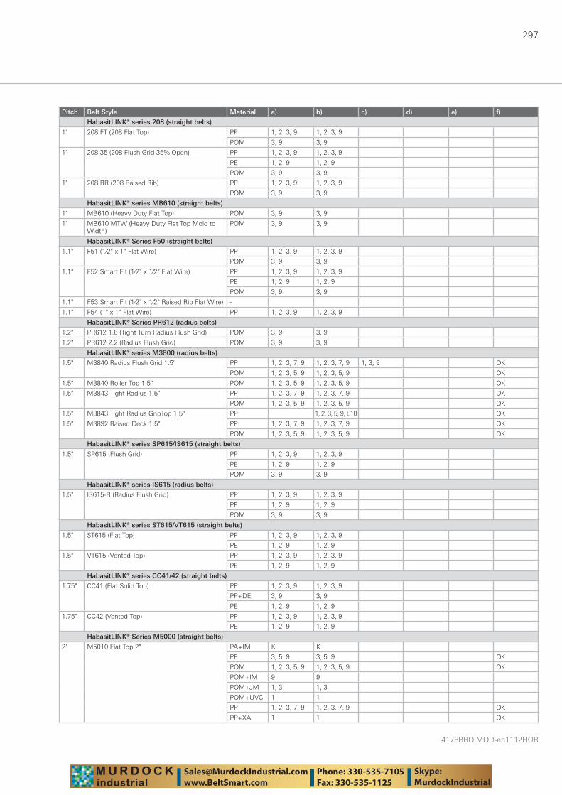
297
4178BRO.MOD-en1112HQR
Pitch Belt Style Material a) b) c) d) e) f)
HabasitLINK® series 208 (straight belts)
1" 208 FT (208 Flat Top) PP 1, 2, 3, 9 1, 2, 3, 9
POM 3, 9 3, 9
1" 208 35 (208 Flush Grid 35% Open) PP 1, 2, 3, 9 1, 2, 3, 9
PE 1, 2, 9 1, 2, 9
POM 3, 9 3, 9
1" 208 RR (208 Raised Rib) PP 1, 2, 3, 9 1, 2, 3, 9
POM 3, 9 3, 9
HabasitLINK® series MB610 (straight belts)
1" MB610 (Heavy Duty Flat Top) POM 3, 9 3, 9
1" MB610 MTW (Heavy Duty Flat Top Mold to Width)
POM 3, 9 3, 9
HabasitLINK® Series F50 (straight belts)
1.1" F51 (1⁄2" x 1" Flat Wire) PP 1, 2, 3, 9 1, 2, 3, 9
POM 3, 9 3, 9
1.1" F52 Smart Fit (1⁄2" x 1⁄2" Flat Wire) PP 1, 2, 3, 9 1, 2, 3, 9
PE 1, 2, 9 1, 2, 9
POM 3, 9 3, 9
1.1" F53 Smart Fit (1⁄2" x 1⁄2" Raised Rib Flat Wire) -
1.1" F54 (1" x 1" Flat Wire) PP 1, 2, 3, 9 1, 2, 3, 9
HabasitLINK® Series PR612 (radius belts)
1.2" PR612 1.6 (Tight Turn Radius Flush Grid) POM 3, 9 3, 9
1.2" PR612 2.2 (Radius Flush Grid) POM 3, 9 3, 9
HabasitLINK® series M3800 (radius belts)
1.5" M3840 Radius Flush Grid 1.5" PP 1, 2, 3, 7, 9 1, 2, 3, 7, 9 1, 3, 9 OK
POM 1, 2, 3, 5, 9 1, 2, 3, 5, 9 OK
1.5" M3840 Roller Top 1.5" POM 1, 2, 3, 5, 9 1, 2, 3, 5, 9 OK
1.5" M3843 Tight Radius 1.5" PP 1, 2, 3, 7, 9 1, 2, 3, 7, 9 OK
POM 1, 2, 3, 5, 9 1, 2, 3, 5, 9 OK
1.5" M3843 Tight Radius GripTop 1.5" PP 1, 2, 3, 5, 9, E10 OK
1.5" M3892 Raised Deck 1.5" PP 1, 2, 3, 7, 9 1, 2, 3, 7, 9 OK
POM 1, 2, 3, 5, 9 1, 2, 3, 5, 9 OK
HabasitLINK® series SP615/IS615 (straight belts)
1.5" SP615 (Flush Grid) PP 1, 2, 3, 9 1, 2, 3, 9
PE 1, 2, 9 1, 2, 9
POM 3, 9 3, 9
HabasitLINK® series IS615 (radius belts)
1.5" IS615-R (Radius Flush Grid) PP 1, 2, 3, 9 1, 2, 3, 9
PE 1, 2, 9 1, 2, 9
POM 3, 9 3, 9
HabasitLINK® series ST615/VT615 (straight belts)
1.5" ST615 (Flat Top) PP 1, 2, 3, 9 1, 2, 3, 9
PE 1, 2, 9 1, 2, 9
1.5" VT615 (Vented Top) PP 1, 2, 3, 9 1, 2, 3, 9
PE 1, 2, 9 1, 2, 9
HabasitLINK® series CC41/42 (straight belts)
1.75" CC41 (Flat Solid Top) PP 1, 2, 3, 9 1, 2, 3, 9
PP+DE 3, 9 3, 9
PE 1, 2, 9 1, 2, 9
1.75" CC42 (Vented Top) PP 1, 2, 3, 9 1, 2, 3, 9
PE 1, 2, 9 1, 2, 9
HabasitLINK® Series M5000 (straight belts)
2" M5010 Flat Top 2" PA+IM K K
PE 3, 5, 9 3, 5, 9 OK
POM 1, 2, 3, 5, 9 1, 2, 3, 5, 9 OK
POM+IM 9 9
POM+JM 1, 3 1, 3
POM+UVC 1 1
PP 1, 2, 3, 7, 9 1, 2, 3, 7, 9 OK
PP+XA 1 1 OK
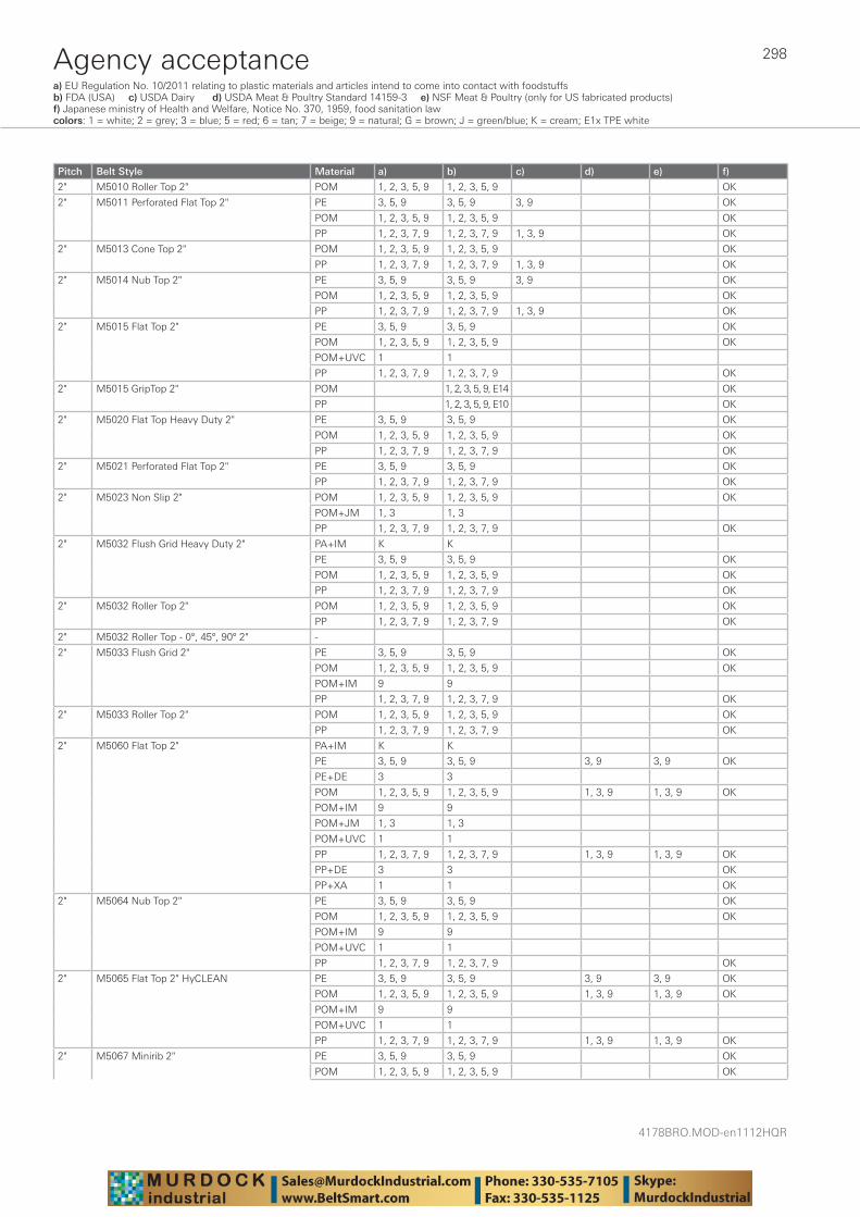
4178BRO.MOD-en1112HQR
298Agency acceptancea) EU Regulation No. 10/2011 relating to plastic materials and articles intend to come into contact with foodstuffs b) FDA (USA) c) USDA Dairy d) USDA Meat & Poultry Standard 14159-3 e) NSF Meat & Poultry (only for US fabricated products) f) Japanese ministry of Health and Welfare, Notice No. 370, 1959, food sanitation lawcolors: 1 = white; 2 = grey; 3 = blue; 5 = red; 6 = tan; 7 = beige; 9 = natural; G = brown; J = green/blue; K = cream; E1x TPE white
Pitch Belt Style Material a) b) c) d) e) f)
2" M5010 Roller Top 2" POM 1, 2, 3, 5, 9 1, 2, 3, 5, 9 OK
2" M5011 Perforated Flat Top 2" PE 3, 5, 9 3, 5, 9 3, 9 OK
POM 1, 2, 3, 5, 9 1, 2, 3, 5, 9 OK
PP 1, 2, 3, 7, 9 1, 2, 3, 7, 9 1, 3, 9 OK
2" M5013 Cone Top 2" POM 1, 2, 3, 5, 9 1, 2, 3, 5, 9 OK
PP 1, 2, 3, 7, 9 1, 2, 3, 7, 9 1, 3, 9 OK
2" M5014 Nub Top 2" PE 3, 5, 9 3, 5, 9 3, 9 OK
POM 1, 2, 3, 5, 9 1, 2, 3, 5, 9 OK
PP 1, 2, 3, 7, 9 1, 2, 3, 7, 9 1, 3, 9 OK
2" M5015 Flat Top 2" PE 3, 5, 9 3, 5, 9 OK
POM 1, 2, 3, 5, 9 1, 2, 3, 5, 9 OK
POM+UVC 1 1
PP 1, 2, 3, 7, 9 1, 2, 3, 7, 9 OK
2" M5015 GripTop 2" POM 1, 2, 3, 5, 9, E14 OK
PP 1, 2, 3, 5, 9, E10 OK
2" M5020 Flat Top Heavy Duty 2" PE 3, 5, 9 3, 5, 9 OK
POM 1, 2, 3, 5, 9 1, 2, 3, 5, 9 OK
PP 1, 2, 3, 7, 9 1, 2, 3, 7, 9 OK
2" M5021 Perforated Flat Top 2" PE 3, 5, 9 3, 5, 9 OK
PP 1, 2, 3, 7, 9 1, 2, 3, 7, 9 OK
2" M5023 Non Slip 2" POM 1, 2, 3, 5, 9 1, 2, 3, 5, 9 OK
POM+JM 1, 3 1, 3
PP 1, 2, 3, 7, 9 1, 2, 3, 7, 9 OK
2" M5032 Flush Grid Heavy Duty 2" PA+IM K K
PE 3, 5, 9 3, 5, 9 OK
POM 1, 2, 3, 5, 9 1, 2, 3, 5, 9 OK
PP 1, 2, 3, 7, 9 1, 2, 3, 7, 9 OK
2" M5032 Roller Top 2" POM 1, 2, 3, 5, 9 1, 2, 3, 5, 9 OK
PP 1, 2, 3, 7, 9 1, 2, 3, 7, 9 OK
2" M5032 Roller Top - 0°, 45°, 90° 2" -
2" M5033 Flush Grid 2" PE 3, 5, 9 3, 5, 9 OK
POM 1, 2, 3, 5, 9 1, 2, 3, 5, 9 OK
POM+IM 9 9
PP 1, 2, 3, 7, 9 1, 2, 3, 7, 9 OK
2" M5033 Roller Top 2" POM 1, 2, 3, 5, 9 1, 2, 3, 5, 9 OK
PP 1, 2, 3, 7, 9 1, 2, 3, 7, 9 OK
2" M5060 Flat Top 2" PA+IM K K
PE 3, 5, 9 3, 5, 9 3, 9 3, 9 OK
PE+DE 3 3
POM 1, 2, 3, 5, 9 1, 2, 3, 5, 9 1, 3, 9 1, 3, 9 OK
POM+IM 9 9
POM+JM 1, 3 1, 3
POM+UVC 1 1
PP 1, 2, 3, 7, 9 1, 2, 3, 7, 9 1, 3, 9 1, 3, 9 OK
PP+DE 3 3 OK
PP+XA 1 1 OK
2" M5064 Nub Top 2" PE 3, 5, 9 3, 5, 9 OK
POM 1, 2, 3, 5, 9 1, 2, 3, 5, 9 OK
POM+IM 9 9
POM+UVC 1 1
PP 1, 2, 3, 7, 9 1, 2, 3, 7, 9 OK
2" M5065 Flat Top 2" HyCLEAN PE 3, 5, 9 3, 5, 9 3, 9 3, 9 OK
POM 1, 2, 3, 5, 9 1, 2, 3, 5, 9 1, 3, 9 1, 3, 9 OK
POM+IM 9 9
POM+UVC 1 1
PP 1, 2, 3, 7, 9 1, 2, 3, 7, 9 1, 3, 9 1, 3, 9 OK
2" M5067 Minirib 2" PE 3, 5, 9 3, 5, 9 OK
POM 1, 2, 3, 5, 9 1, 2, 3, 5, 9 OK
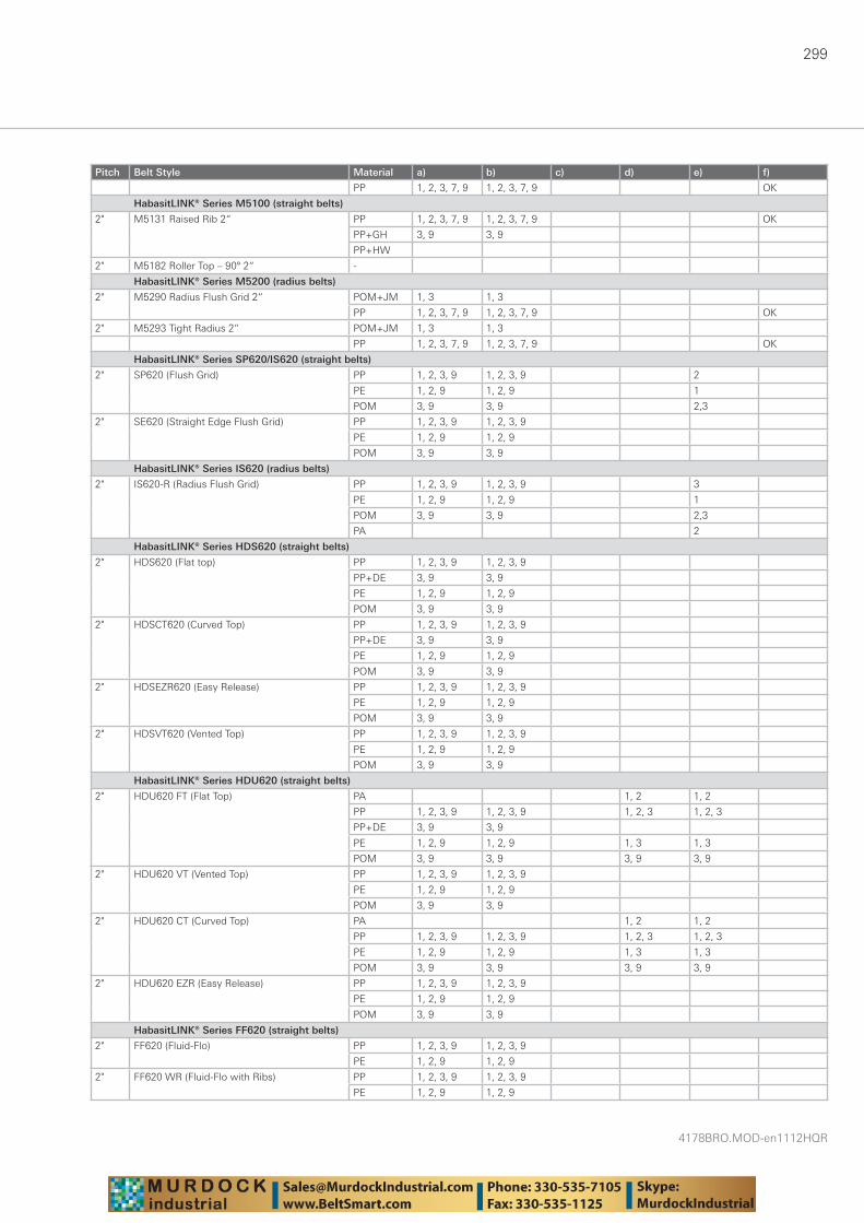
299
4178BRO.MOD-en1112HQR
Pitch Belt Style Material a) b) c) d) e) f)
PP 1, 2, 3, 7, 9 1, 2, 3, 7, 9 OK
HabasitLINK® Series M5100 (straight belts)
2" M5131 Raised Rib 2“ PP 1, 2, 3, 7, 9 1, 2, 3, 7, 9 OK
PP+GH 3, 9 3, 9
PP+HW
2" M5182 Roller Top – 90° 2“ -
HabasitLINK® Series M5200 (radius belts)
2" M5290 Radius Flush Grid 2“ POM+JM 1, 3 1, 3
PP 1, 2, 3, 7, 9 1, 2, 3, 7, 9 OK
2" M5293 Tight Radius 2“ POM+JM 1, 3 1, 3
PP 1, 2, 3, 7, 9 1, 2, 3, 7, 9 OK
HabasitLINK® Series SP620/IS620 (straight belts)
2" SP620 (Flush Grid) PP 1, 2, 3, 9 1, 2, 3, 9 2
PE 1, 2, 9 1, 2, 9 1
POM 3, 9 3, 9 2,3
2" SE620 (Straight Edge Flush Grid) PP 1, 2, 3, 9 1, 2, 3, 9
PE 1, 2, 9 1, 2, 9
POM 3, 9 3, 9
HabasitLINK® Series IS620 (radius belts)
2" IS620-R (Radius Flush Grid) PP 1, 2, 3, 9 1, 2, 3, 9 3
PE 1, 2, 9 1, 2, 9 1
POM 3, 9 3, 9 2,3
PA 2
HabasitLINK® Series HDS620 (straight belts)
2" HDS620 (Flat top) PP 1, 2, 3, 9 1, 2, 3, 9
PP+DE 3, 9 3, 9
PE 1, 2, 9 1, 2, 9
POM 3, 9 3, 9
2" HDSCT620 (Curved Top) PP 1, 2, 3, 9 1, 2, 3, 9
PP+DE 3, 9 3, 9
PE 1, 2, 9 1, 2, 9
POM 3, 9 3, 9
2" HDSEZR620 (Easy Release) PP 1, 2, 3, 9 1, 2, 3, 9
PE 1, 2, 9 1, 2, 9
POM 3, 9 3, 9
2" HDSVT620 (Vented Top) PP 1, 2, 3, 9 1, 2, 3, 9
PE 1, 2, 9 1, 2, 9
POM 3, 9 3, 9
HabasitLINK® Series HDU620 (straight belts)
2" HDU620 FT (Flat Top) PA 1, 2 1, 2
PP 1, 2, 3, 9 1, 2, 3, 9 1, 2, 3 1, 2, 3
PP+DE 3, 9 3, 9
PE 1, 2, 9 1, 2, 9 1, 3 1, 3
POM 3, 9 3, 9 3, 9 3, 9
2" HDU620 VT (Vented Top) PP 1, 2, 3, 9 1, 2, 3, 9
PE 1, 2, 9 1, 2, 9
POM 3, 9 3, 9
2" HDU620 CT (Curved Top) PA 1, 2 1, 2
PP 1, 2, 3, 9 1, 2, 3, 9 1, 2, 3 1, 2, 3
PE 1, 2, 9 1, 2, 9 1, 3 1, 3
POM 3, 9 3, 9 3, 9 3, 9
2" HDU620 EZR (Easy Release) PP 1, 2, 3, 9 1, 2, 3, 9
PE 1, 2, 9 1, 2, 9
POM 3, 9 3, 9
HabasitLINK® Series FF620 (straight belts)
2" FF620 (Fluid-Flo) PP 1, 2, 3, 9 1, 2, 3, 9
PE 1, 2, 9 1, 2, 9
2" FF620 WR (Fluid-Flo with Ribs) PP 1, 2, 3, 9 1, 2, 3, 9
PE 1, 2, 9 1, 2, 9
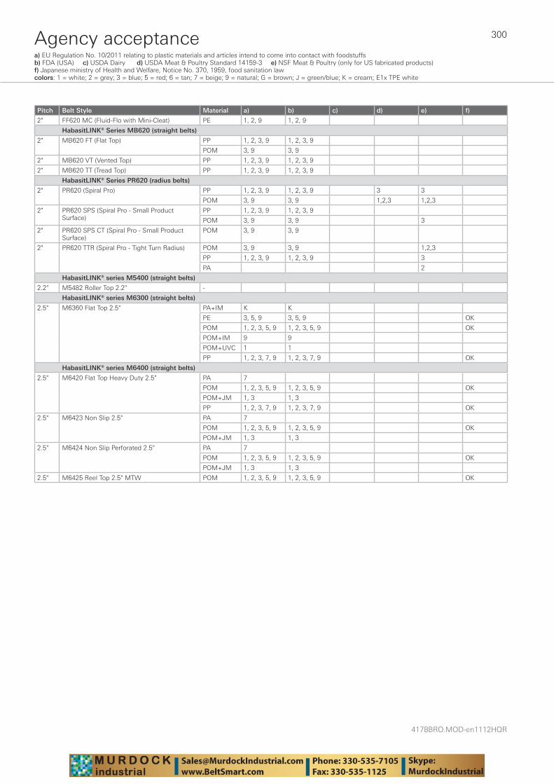
4178BRO.MOD-en1112HQR
300Agency acceptancea) EU Regulation No. 10/2011 relating to plastic materials and articles intend to come into contact with foodstuffs b) FDA (USA) c) USDA Dairy d) USDA Meat & Poultry Standard 14159-3 e) NSF Meat & Poultry (only for US fabricated products) f) Japanese ministry of Health and Welfare, Notice No. 370, 1959, food sanitation lawcolors: 1 = white; 2 = grey; 3 = blue; 5 = red; 6 = tan; 7 = beige; 9 = natural; G = brown; J = green/blue; K = cream; E1x TPE white
Pitch Belt Style Material a) b) c) d) e) f)
2" FF620 MC (Fluid-Flo with Mini-Cleat) PE 1, 2, 9 1, 2, 9
HabasitLINK® Series MB620 (straight belts)
2" MB620 FT (Flat Top) PP 1, 2, 3, 9 1, 2, 3, 9
POM 3, 9 3, 9
2" MB620 VT (Vented Top) PP 1, 2, 3, 9 1, 2, 3, 9
2" MB620 TT (Tread Top) PP 1, 2, 3, 9 1, 2, 3, 9
HabasitLINK® Series PR620 (radius belts)
2" PR620 (Spiral Pro) PP 1, 2, 3, 9 1, 2, 3, 9 3 3
POM 3, 9 3, 9 1,2,3 1,2,3
2" PR620 SPS (Spiral Pro - Small Product Surface)
PP 1, 2, 3, 9 1, 2, 3, 9
POM 3, 9 3, 9 3
2" PR620 SPS CT (Spiral Pro - Small Product Surface)
POM 3, 9 3, 9
2" PR620 TTR (Spiral Pro - Tight Turn Radius) POM 3, 9 3, 9 1,2,3
PP 1, 2, 3, 9 1, 2, 3, 9 3
PA 2
HabasitLINK® series M5400 (straight belts)
2.2" M5482 Roller Top 2.2" -
HabasitLINK® series M6300 (straight belts)
2.5" M6360 Flat Top 2.5" PA+IM K K
PE 3, 5, 9 3, 5, 9 OK
POM 1, 2, 3, 5, 9 1, 2, 3, 5, 9 OK
POM+IM 9 9
POM+UVC 1 1
PP 1, 2, 3, 7, 9 1, 2, 3, 7, 9 OK
HabasitLINK® series M6400 (straight belts)
2.5" M6420 Flat Top Heavy Duty 2.5" PA 7
POM 1, 2, 3, 5, 9 1, 2, 3, 5, 9 OK
POM+JM 1, 3 1, 3
PP 1, 2, 3, 7, 9 1, 2, 3, 7, 9 OK
2.5" M6423 Non Slip 2.5" PA 7
POM 1, 2, 3, 5, 9 1, 2, 3, 5, 9 OK
POM+JM 1, 3 1, 3
2.5" M6424 Non Slip Perforated 2.5" PA 7
POM 1, 2, 3, 5, 9 1, 2, 3, 5, 9 OK
POM+JM 1, 3 1, 3
2.5" M6425 Reel Top 2.5" MTW POM 1, 2, 3, 5, 9 1, 2, 3, 5, 9 OK

Notes

Notes

Notes
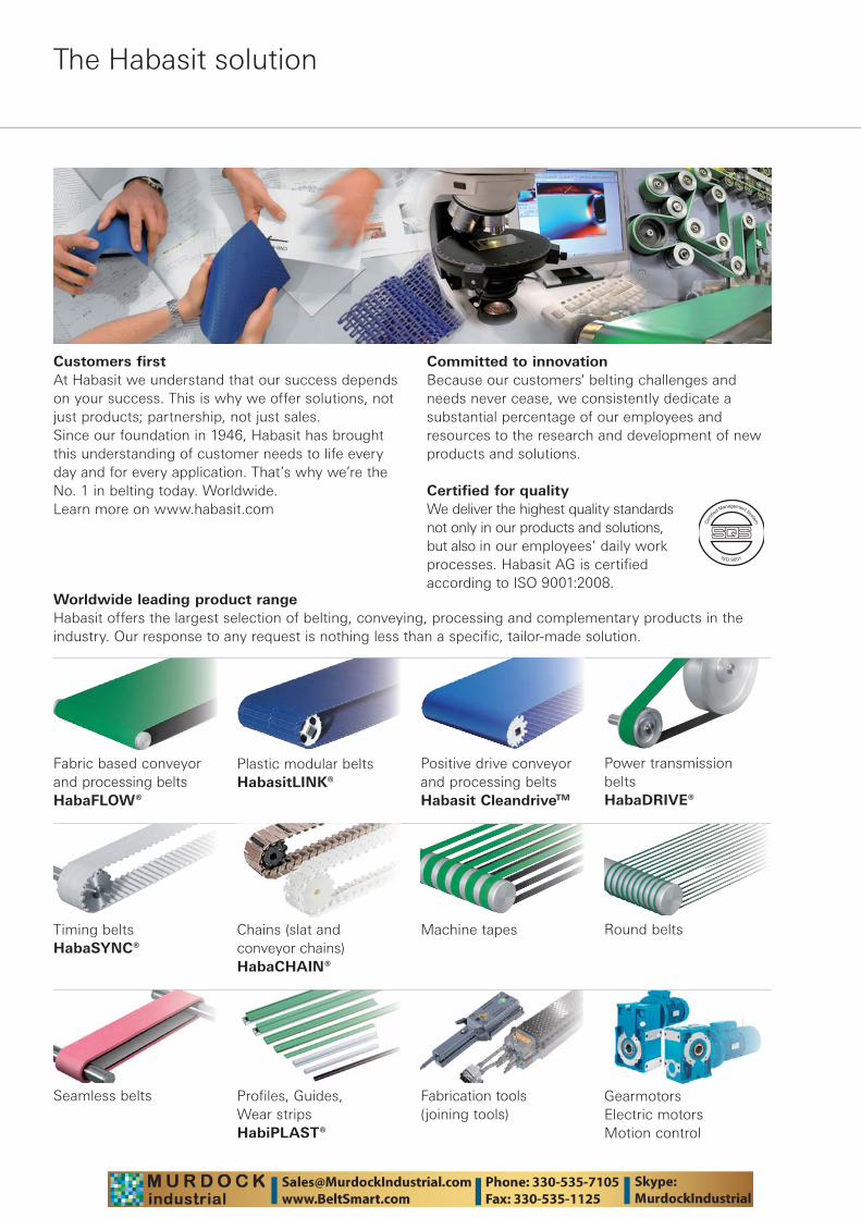
The Habasit solution
Worldwide leading product range Habasit offers the largest selection of belting, conveying, processing and complementary products in the industry. Our response to any request is nothing less than a specific, tailor-made solution.
Fabric based conveyor and processing beltsHabaFLOW®
Plastic modular beltsHabasitLINK®
Power transmission belts HabaDRIVE®
Timing beltsHabaSYNC®
Chains (slat and conveyor chains)HabaCHAIN®
Profiles, Guides, Wear strips HabiPLAST®
Machine tapes
Seamless belts
Round belts
Fabrication tools (joining tools)
GearmotorsElectric motorsMotion control
Positive drive conveyor and processing beltsHabasit CleandriveTM
Customers first At Habasit we understand that our success depends on your success. This is why we offer solutions, not just products; partnership, not just sales.Since our foundation in 1946, Habasit has brought this understanding of customer needs to life every day and for every application. That’s why we’re the No. 1 in belting today. Worldwide.Learn more on www.habasit.com
Committed to innovationBecause our customers' belting challenges and needs never cease, we consistently dedicate a substantial percentage of our employees and resources to the research and development of new products and solutions.
Certified for qualityWe deliver the highest quality standards not only in our products and solutions, but also in our employees’ daily work processes. Habasit AG is certified according to ISO 9001:2008.

text

HeadquartersHabasit AG Römerstrasse 1CH-4153 Reinach, Switzerland Phone +41 61 715 15 15Fax +41 61 715 15 55E-mail [email protected] www.habasit.com
Registered trademarks Copyright Habasit AGSubject to alterationsPrinted in SwitzerlandPublication data: 4178BRO.MOD-en1112HQR
AustriaHabasit GmbHWienPhone: +43 1 690 66www.habasit.at
BelgiumHabasit Belgium N.V.ZaventemPhone: +32 27 250 430www.habasit.be
CanadaHabasit Canada Ltd.OakvillePhone: +1 905 827 41 31www.habasit.ca
ChinaHabasit East Asia Ltd.Hong KongPhone: +85 221 450 150 www.habasit.com.hk
Habasit (Shanghai) Co. Ltd.ShanghaiPhone: +8621 5488 1228Phone: +8621 5488 1218www.habasit.com.hk
FranceHabasit France S.A.S.MulhousePhone: +33 389 338 903 www.habasit.fr
GermanyHabasit GmbHEppertshausenPhone: +49 6071 969 0 www.habasit.de
IndiaHabasit-Iakoka Pvt. Ltd.CoimbatorePhone: +91 422 262 78 79www.habasitiakoka.com
ItalyHabasit Italiana SpACustomer Care:Phone: 199 199 333For int. calls: +39 0438 911 444 www.habasit.it
JapanHabasit Nippon Co. Ltd.YokohamaPhone: +81 45 476 0371www.habasit.co.jp
NetherlandsHabasit Netherlands BVNijkerkPhone: +31 332 472 030 www.habasit.nl
New Zealand Habasit Australasia Ltd.Hornby Phone: +64 3348 5600 www.habasit.co.nz
NorwayHabasit Norge A/S, OsloPhone: +47 815 58 458www.habasit.no
PolandHabasit Polska Sp. zo.o.Dąbrowa GórniczaPhone: +48 32639 02 40www.habasit.pl
RussiaOOO Habasit Ltd.St. PetersburgPhone: +7 812 600 40 80www.habasit.ru
SingaporeHabasit Far East Pte. Ltd.SingaporePhone: +65 686 255 66 www.habasit.com.sg
SpainHabasit Hispanica S.A.Barberà del VallèsPhone: +34 937 191 912 www.habasit.es
SwedenHabasit ABHindasPhone: +46 30 122 600www.habasit.se
SwitzerlandHabasit GmbHReinachPhone: +41 61 577 51 00www.habasit.ch
TaiwanHabasit Rossi (Taiwan) Ltd.Taipei HsienPhone: +886 2 2267 0538www.habasit.com.tw
TurkeyHabasit Kayis San. Ve Tic. Ltd. Sti.Yenibosna-Bahcelievler-IstanbulPhone: +90 212 654 94 04www.habasit.com.tr
UkraineHabasit UkrainaVinnicaPhone: +38 0432 58 47 35www.habasit.ua
United Kingdom and IrelandHabasit (UK) Ltd.Silsden Phone: +44 844 835 9555 www.habasit.co.uk
USAHabasit America Conveyor belts, power transmission belts, gearmotors Suwanee, Georgia Phone: +1 800 458 6431 www.habasitamerica.com
Habasit America Seamless belts, timing belts Middletown, Connecticut Phone: +1 860 632 2211 www.habasitamerica.com
Rossi is one of Europe’s largest manufacturers of gear reducers, gearmotors, inverters, standard and brakemotors, and is a member of the Habasit Group.
Rossi S.p.A. Via Emilia Ovest 915/A41123 Modena – ItalyPhone: +39 059 33 02 [email protected]