h3c s5120-ei series ethernet switches layer 3 ip routing … · 2018-03-07 · static routing and...
TRANSCRIPT

H3C S5120-EI Series Ethernet Switches
Layer 3 IP Routing Configuration Guide
Hangzhou H3C Technologies Co., Ltd. http://www.h3c.com

Copyright © 2003-2010, Hangzhou H3C Technologies Co., Ltd. and its licensors All Rights Reserved
No part of this manual may be reproduced or transmitted in any form or by any means without prior written consent of Hangzhou H3C Technologies Co., Ltd.
Trademarks
H3C, , Aolynk, , H3Care,
, TOP G, , IRF, NetPilot, Neocean, NeoVTL, SecPro, SecPoint, SecEngine, SecPath, Comware, Secware, Storware, NQA, VVG, V2G, VnG, PSPT, XGbus, N-Bus, TiGem, InnoVision and HUASAN are trademarks of Hangzhou H3C Technologies Co., Ltd.
All other trademarks that may be mentioned in this manual are the property of their respective owners. Notice
The information in this document is subject to change without notice. Every effort has been made in the preparation of this document to ensure accuracy of the contents, but all statements, information, and recommendations in this document do not constitute the warranty of any kind, express or implied.
Environmental Protection This product has been designed to comply with the requirements on environmental protection. The storage, use, and disposal of this product must meet the applicable national laws and regulations.

Preface
The H3C S5120-EI documentation set includes 13 configuration guides, which describe the software features for the H3C S5120-EI Series Ethernet Switches and guide you through the software configuration procedures. These configuration guides also provide configuration examples to help you apply software features to different network scenarios.
This preface includes:
• Audience
• Conventions
• About the H3C S5120-EI Documentation Set
• Obtaining Documentation
• Documentation Feedback
Audience This documentation is intended for:
Network planners
Field technical support and servicing engineers
Network administrators working with the S5120-EI series

4
Conventions This section describes the conventions used in this documentation set.
Command conventions
Convention Description
Boldface Bold text represents commands and keywords that you enter literally as shown.
italic Italic text represents arguments that you replace with actual values.
[ ] Square brackets enclose syntax choices (keywords or arguments) that are optional.
{ x | y | ... } Braces enclose a set of required syntax choices separated by vertical bars, from which you select one.
[ x | y | ... ] Square brackets enclose a set of optional syntax choices separated by vertical bars, from which you select one or none.
{ x | y | ... } * Asterisk marked braces enclose a set of required syntax choices separated by vertical bars, from which you select at least one.
[ x | y | ... ] * Asterisk marked square brackets enclose optional syntax choices separated by vertical bars, from which you may select multiple choices or none.
&<1-n> The argument or keyword and argument combination before the ampersand (&) sign can be entered 1 to n times.
# A line that starts with a pound (#) sign is comments.
GUI conventions
Convention Description< > Button names are inside angle brackets. For example, click <OK>.
[ ] Window names, menu items, data table and field names are inside square brackets. For example, pop up the [New User] window.
/ Multi-level menus are separated by forward slashes. For example, [File/Create/Folder].
Symbols
Convention Description
Means reader be extremely careful. Improper operation may cause bodily injury.
Means reader be careful. Improper operation may cause data loss or damage to equipment.
Means an action or information that needs special attention to ensure successful configuration or good performance.
Means a complementary description.
Means techniques helpful for you to make configuration with ease.

5
Network topology icons
Convention Description
Represents a generic network device, such as a router, switch, or firewall.
Represents a routing-capable device, such as a router or Layer 3 switch.
Represents a generic switch, such as a Layer 2 or Layer 3 switch, or a router that supports Layer 2 forwarding and other Layer 2 features.

6
About the H3C S5120-EI documentation set
Category Documents Purposes
Product description and specifications
Marketing brochures Describe product specifications and benefits.
Technology white papers Provide an in-depth description of software features and technologies.
Card datasheets Describe card specifications, features, and standards.
Hardware specifications and installation
Compliance and safety manual
Provides regulatory information and the safety instructions that must be followed during installation.
Quick start Guides you through initial installation and setup procedures to help you quickly set up and use your device with the minimum configuration.
Installation guide Provides a complete guide to hardware installation and hardware specifications.
Card manuals Provide the hardware specifications of cards.
H3C Cabinet Installation and Remodel Introduction
Guides you through installing and remodeling H3C cabinets.
H3C Pluggable SFP [SFP+][XFP] Transceiver Modules Installation Guide
Guides you through installing SFP/SFP+/XFP transceiver modules.
Adjustable Slider Rail Installation Guide
Guides you through installing adjustable slider rails to a rack.
H3C High-End Network Products Hot-Swappable Module Manual
Describes the hot-swappable modules available for the H3C high-end network products, their external views, and specifications.
Software configuration
Configuration guides Describe software features and configuration procedures.
Command references Provide a quick reference to all available commands.
Configuration examples Describe typical network scenarios and provide configuration examples and instructions.
Operations and maintenance
System log messages Explains the system log messages.
Trap messages Explains the trap messages.
MIB Companion Describes the MIBs for the software release.
Release notes
Provide information about the product release, including the version history, hardware and software compatibility matrix, version upgrade information, technical support information, and software upgrading.
Error code reference Explains the error codes.

7
Obtaining documentation
You can access the most up-to-date H3C product documentation on the World Wide Web at http://www.h3c.com.
Click the links on the top navigation bar to obtain different categories of product documentation:
[Technical Support & Documents > Technical Documents] – Provides hardware installation, software upgrading, and software feature configuration and maintenance documentation.
[Products & Solutions] – Provides information about products and technologies, as well as solutions.
[Technical Support & Documents > Software Download] – Provides the documentation released with the software version.
Documentation feedback
You can e-mail your comments about product documentation to [email protected].
We appreciate your comments.

8
Table of Contents
Preface ·········································································································································································· 3 Audience ············································································································································································ 3 Conventions ······································································································································································· 4 About the H3C S5120-EI documentation set ················································································································· 6
IP routing overview······················································································································································· 9 Routing ··············································································································································································· 9
Routing table and FIB table ····································································································································· 9 Routing protocol overview ············································································································································· 11
Static routing and dynamic routing ····················································································································· 11 Routing protocols and routing priority ················································································································ 11
Displaying and maintaining a routing table ··············································································································· 12
Static routing configuration ······································································································································· 14 Introduction ····································································································································································· 14
Static route ····························································································································································· 14 Default route ··························································································································································· 14 Application environment of static routing ··········································································································· 14
Configuring a static route ·············································································································································· 15 Configuration prerequisites ·································································································································· 15 Configuration procedure ······································································································································ 15
Detecting reachability of the static route’s nexthop ···································································································· 16 Detecting nexthop reachability through track ···································································································· 16
Displaying and maintaining static routes ···················································································································· 16 Static route configuration example ······························································································································ 17
Basic static route configuration example ············································································································ 17
IPv6 static routing configuration ································································································································ 20 Introduction to IPv6 static routing ································································································································· 20
Features of IPv6 static routes ································································································································ 20 Default IPv6 route ·················································································································································· 20
Configuring an IPv6 static route ··································································································································· 20 Configuration prerequisites ·································································································································· 20 Configuring an IPv6 static route ·························································································································· 20
Displaying and maintaining IPv6 static routes ············································································································ 21 IPv6 static routing configuration example ··················································································································· 21
Obtaining support for your product ·························································································································· 24 Register your product ····················································································································································· 24 Purchase value-added services ····································································································································· 24 Troubleshoot online ························································································································································ 24 Access software downloads ·········································································································································· 25 Telephone technical support and repair ······················································································································ 25 Contact us ······································································································································································· 25
Acronyms ···································································································································································· 26
Index ··········································································································································································· 42

9
IP routing overview
Routing Routers are responsible for forwarding data packets along networks. Upon receiving a packet, a router determines the optimal path based on the destination address. When the packet reaches the last router in the path, it then forwards the packet to the intended destination host.
Routing provides the path information for guiding the forwarded packets.
The term router in this document refers to a router in a generic sense or a Layer 3 switch.
Routing table and FIB table Routing table
The routing table plays a key role in route selection while the FIB table plays a key role in packet forwarding. Each router maintains a routing table and a FIB table.
Routes in a routing table can be divided into the following categories by origin:
• Direct routes: Routes discovered by data link protocols, also known as interface routes.
• Static routes: Routes that are manually configured.
• Dynamic routes: Routes that are discovered dynamically by routing protocols.
Dynamic routing protocol is not supported on the S5120-EI Series Ethernet Switches.
Each entry in the FIB table specifies the physical interface to which a packet should travel: the next hop (the next router), or directly to its intended destination.
Introduction to routing table
Each router maintains a local routing table, and each routing protocol maintains a protocol routing table.
• Protocol routing table:
A protocol routing table stores routes discovered by the routing protocol.
A routing protocol can redistribute and advertise routes generated by other protocols. For example, OSPF can redistribute direct routes, static routes, and IS-IS routes to the OSPF routing table, and then advertise those routes.
• Local routing table:
A local routing table stores the routes found by all protocols and delivers the optimal routes to the FIB table to guide packet forwarding. The optimal route selection is based on the routing protocol preferences and route metrics.

10
Contents of a routing table
A routing table includes the following key items:
• Destination address: Destination IP address or destination network.
• Network mask: Specifies, in company with the destination address, the address of the destination network. A logical AND operation between the destination address and the network mask yields the address of the destination network. For example, if the destination address is 129.102.8.10 and the mask 255.255.0.0, the address of the destination network is 129.102.0.0. A network mask is made of a certain number of consecutive 1s. It can be expressed in dotted decimal format or by the number of the 1s.
• Outbound interface: Specifies the interface through which the IP packets are to be forwarded.
• IP address of the next hop: Specifies the address of the next router on the path. If only the outbound interface is configured, its address will be the IP address of the next hop.
• Priority for the route: Routes to the same destination but having different nexthops may have different priorities and be found by various routing protocols or manually configured. The optimal route is the one with the highest priority (with the smallest metric).
Routes can be divided into two categories by destination:
• Subnet routes: The destination is a subnet.
• Host routes: The destination is a host.
Based on whether the destination is directly connected to a given router, routes can be divided into:
• Direct routes: The destination is directly connected to the router.
• Indirect routes: The destination is not directly connected to the router.
To prevent the routing table from getting too large, you can configure a default route. All packets without matching any entry in the routing table will be forwarded through the default route.
In Figure 1, the IP address on each cloud represents the address of the network. Router G is connected to three networks and therefore has three IP addresses for its three physical interfaces. Its routing table is shown under the network topology.
Figure 1 A sample routing table

11
Router A
Router B
Router H
Router E
16.0.0.2
17.0.0.3
15.0.0.0 12.0.0.0
17.0.0.0
11.0.0.016.0.0.0
13.0.0.0
14.0.0.0
Router C
Router D
Router F
Router G
11.0.0.1
12.0.0.1
12.0.0.215.0.0.1
15.0.0.2
17.0.0.1
16.0.0.1
13.0.0.1
13.0.0.2
14.0.0.1
14.0.0.2
14.0.0.3
14.0.0.4
17.0.0.2
11.0.0.2
13.0.0.3
Destination Network Nexthop Interface11.0.0.0 11.0.0.1 2 12.0.0.0 12.0.0.1 113.0.0.0 12.0.0.2 114.0.0.0 14.0.0.4 3 15.0.0.0 14.0.0.2 316.0.0.0 14.0.0.2 317.0.0.0 11.0.0.2 2
Routing protocol overview
Static routing and dynamic routing Static routing is easier to configure and requires fewer system resources. It works well in small, stable networks with simple topologies. Its major drawback is that you must reconfigure it whenever the network topology changes; it cannot self-adjust to network changes.
Dynamic routing is based on dynamic routing protocols, which can detect network topology changes and recalculate the routes accordingly; therefore, dynamic routing is suitable for large networks. Its disadvantages are that it is difficult to configure, imposes higher requirements on the system, and consumes network resources.
Routing protocols and routing priority Different routing protocols may find different routes to the same destination. However, not all of those routes are optimal. At a particular moment, only one protocol can uniquely determine the current optimal route to the destination. For the purpose of route selection, each routing protocol (including static routes) is assigned a priority. The route found by the routing protocol with the highest priority is preferred.

12
The following table lists some routing protocols and the default priorities for routes found by them:
Routing approach Priority
DIRECT 0
STATIC 60
UNKNOWN 256
• The smaller the priority value, the higher the priority.
• The priority for a direct route is always 0, which you cannot change. Any other type of routes can have their priorities manually configured.
• Each static route can be configured with a different priority.
• IPv4 and IPv6 routes have their own respective routing tables.
Displaying and maintaining a routing table To do… Use the command… Remarks
Display brief information about the active routes in the routing table
display ip routing-table [ verbose | | { begin | exclude | include } regular-expression ]
Available in any view
Display information about routes to the specified destination
display ip routing-table ip-address [ mask-length | mask ] [ longer-match ] [ verbose ]
Available in any view
Display information about routes with destination addresses in the specified range
display ip routing-table ip-address1 { mask-length | mask } ip-address2 { mask-length | mask } [ verbose ]
Available in any view
Display routes of a routing protocol display ip routing-table protocol protocol [ inactive | verbose ]
Available in any view
Display statistics about the network routing table display ip routing-table statistics
Available in any view
Clear statistics for the routing table reset ip routing-table statistics protocol { all | protocol }
Available in user view
Display brief IPv6 routing table information display ipv6 routing-table
Available in any view
Display verbose IPv6 routing table information display ipv6 routing-table verbose
Available in any view
Display routing information for a specified destination IPv6 address
display ipv6 routing-table ipv6-address prefix-length [ longer-match ] [ verbose ]
Available in any view
Display IPv6 routing information of a routing protocol
display ipv6 routing-table protocol protocol [ inactive | verbose ]
Available in any view
Display IPv6 routing statistics display ipv6 routing-table statistics Available in any view
Display IPv6 routing information for an IPv6 address range
display ipv6 routing-table ipv6-address1 prefix-length1 ipv6-address2 prefix-length2 [ verbose ]
Available in any view
Clear specified IPv6 routing table reset ipv6 routing-table statistics protocol { Available in

13
To do… Use the command… Remarks statistics all | protocol } user view

14
Static routing configuration
Introduction
Static route A static route is manually configured, but if a network’s topology is simple, you only need to configure static routes for the network to function. The proper configuration and usage of static routes can improve network performance and ensure bandwidth for important network applications.
The disadvantage of using static routes is that they cannot adapt to network topology changes. If a fault or a topological change occurs in the network, the routes will be unreachable and the network breaks. In the event of a fault or topological change, the network administrator has to modify the static routes manually.
The term router in this document refers to a router in a generic sense or a Layer 3 switch.
Default route If the packet’s destination address fails to match any entry in the routing table, the packet is discarded.
After a default route is configured on a router, any packet whose destination IP address matches no entry in the routing table can be forwarded to a designated upstream router.
A router selects the default route only when it cannot find any matching entry in the routing table.
• If the destination address of a packet fails to match any entry in the routing table, the router selects the default route to forward the packet.
• If there is no default route and the destination address of the packet fails to match any entry in the routing table, the packet will be discarded and an ICMP packet will be sent to the source to report that the destination or the network is unreachable.
You can configure a default route with both the destination and mask being 0.0.0.0. The router forwards any packet whose destination address fails to match any entry in the routing table to the next hop of the default static route.
Application environment of static routing Before configuring a static route, you need to know the following concepts:
• Destination address and mask:
In the ip route-static command, an IPv4 address is in dotted decimal format and a mask can be either in dotted decimal format or in the form of mask length (the number of consecutive 1s in the mask).
• Output interface and next hop address:

15
While configuring a static route, you can specify either the output interface or the next hop address depending on the specific occasion. For a NULL0 interface, if the output interface has already been configured, there is no need to configure the next hop address
In fact, all the route entries must have a next hop address. When forwarding a packet, a router first searches the routing table for the route to the destination address of the packet. The system can find the corresponding link layer address and forward the packet only after the next hop address is specified. The next hop address can not be a local interface IP address; otherwise, the route configuration will not take effect.
• Other attributes:
You can configure different preferences for different static routes so that route management policies can be applied more flexibly.
Configuring a static route
Configuration prerequisites Before configuring a static route, complete the following tasks:
• Configure the physical parameters for related interfaces
• Configure the link-layer attributes for related interfaces
• Configure the IP addresses for related interfaces
Configuration procedure Follow these steps to configure a static route:
To do… Use the command… Remarks 1. Enter system view system-view —
2. Configure a static route
ip route-static dest-address { mask | mask-length } { next-hop-address | interface-type interface-number [ next-hop-address ] } [ preference preference-value ] [ description description-text ]
Required
By default, preference for static routes is 60 and no description information is configured.
3. Configure the default preference for static routes
ip route-static default-preference default-preference-value
Optional
60 by default
• When configuring a static route, the static route does not take effect if you specify the next hop address first and
then configure it as the IP address of a local interface.
• If you do not specify the preference when configuring a static route, the default preference will be used. Reconfiguring the default preference applies only to newly created static routes.
• If the destination IP address and mask are both configured as 0.0.0.0 with the ip route-static command, the route is the default route.

16
Detecting reachability of the static route’s nexthop If a static route fails due to a topology change or a fault, the connection will be interrupted. To improve network stability, the system needs to detect reachability of the static route’s next hop and switch to a backup route once the next hop is unreachable.
Following method can be used to detect reachability of the static route’s next hop.
Detecting nexthop reachability through track If you specify the nexthop, but not the outgoing interface when configuring a static route, you can associate the static route with a track entry to check the static route validity:
• When the track entry is positive, the static route's nexthop is reachable and the static route takes effect.
• When the track entry is negative, the static route's nexthop is unreachable and the static route is invalid. For details about track, refer to Track Configuration in the High Availability Configuration Guide.
Network requirements
To detect the reachability of a static route's nexthop through a Track entry, you need to create a Track first. For detailed Track configuration procedure, refer to Track Configuration in the High Availability Configuration Guide.
Configuration procedure
Follow these steps to detect the reachability of a static route's nexthop through Track:
To do… Use the command… Remarks1. Enter system view system-view —
2. Associate the static route with a track entry
ip route-static dest-address { mask | mask-length } next-hop-address track track-entry-number [ preference preference-value ] [ description description-text ]
Required
Not configured by default
• To configure this feature for an existing static route, associate the static route with a track entry. For a non-existent
static route, configure it and associate it with a Track entry.
• If a static route needs route recursion, the associated track entry must monitor the nexthop of the recursive route instead of that of the static route; otherwise, a valid route may be mistakenly considered invalid.
Displaying and maintaining static routes To do… Use the command… Remarks
Display the current configuration information display current-configuration
Available in any view
Display the brief information of the IP routing table display ip routing-table
Display the detailed information of the IP routing table display ip routing-table verbose

17
To do… Use the command… Remarks
View information of static routes display ip routing-table protocol static [ inactive | verbose ]
Delete all the static routes delete static-routes all Available In system view
Static route configuration example
Basic static route configuration example Network requirements
The IP addresses and masks of the switches and hosts are shown in Figure 2. Static routes are required for interconnection between any two hosts.
Figure 2 Network diagram for static route configuration
Configuration procedure 1. Configuring IP addresses for interfaces (omitted)
2. Configuring static routes
Configure a default route on Switch A. <SwitchA> system-view
[SwitchA] ip route-static 0.0.0.0 0.0.0.0 1.1.4.2
Configure two static routes on Switch B. <SwitchB> system-view
[SwitchB] ip route-static 1.1.2.0 255.255.255.0 1.1.4.1
[SwitchB] ip route-static 1.1.3.0 255.255.255.0 1.1.5.6
Configure a default route on Switch C <SwitchC> system-view

18
[SwitchC] ip route-static 0.0.0.0 0.0.0.0 1.1.5.5
3. Configure the hosts.
The default gateways for hosts A, B and C are 1.1.2.3, 1.1.6.1 and 1.1.3.1, respectively. The configuration procedure is omitted.
4. Display the configuration.
Display the IP routing table of Switch A. [SwitchA] display ip routing-table
Routing Tables: Public
Destinations : 7 Routes : 7
Destination/Mask Proto Pre Cost NextHop Interface
0.0.0.0/0 Static 60 0 1.1.4.2 Vlan500
1.1.2.0/24 Direct 0 0 1.1.2.3 Vlan300
1.1.2.3/32 Direct 0 0 127.0.0.1 InLoop0
1.1.4.0/30 Direct 0 0 1.1.4.1 Vlan500
1.1.4.1/32 Direct 0 0 127.0.0.1 InLoop0
127.0.0.0/8 Direct 0 0 127.0.0.1 InLoop0
127.0.0.1/32 Direct 0 0 127.0.0.1 InLoop0
Display the IP routing table of Switch B. [SwitchB] display ip routing-table
Routing Tables: Public
Destinations : 10 Routes : 10
Destination/Mask Proto Pre Cost NextHop Interface
1.1.2.0/24 Static 60 0 1.1.4.1 Vlan500
1.1.3.0/24 Static 60 0 1.1.5.6 Vlan600
1.1.4.0/30 Direct 0 0 1.1.4.2 Vlan500
1.1.4.2/32 Direct 0 0 127.0.0.1 InLoop0
1.1.5.4/30 Direct 0 0 1.1.5.5 Vlan600
1.1.5.5/32 Direct 0 0 127.0.0.1 InLoop0
127.0.0.0/8 Direct 0 0 127.0.0.1 InLoop0
127.0.0.1/32 Direct 0 0 127.0.0.1 InLoop0
1.1.6.0/24 Direct 0 0 1.1.6.1 Vlan100
1.1.6.1/32 Direct 0 0 127.0.0.1 InLoop0
Use the ping command on Host B to check reachability to Host A, assuming Windows XP runs on the two hosts. C:\Documents and Settings\Administrator>ping 1.1.2.2
Pinging 1.1.2.2 with 32 bytes of data:
Reply from 1.1.2.2: bytes=32 time=1ms TTL=255
Reply from 1.1.2.2: bytes=32 time=1ms TTL=255
Reply from 1.1.2.2: bytes=32 time=1ms TTL=255
19
Reply from 1.1.2.2: bytes=32 time=1ms TTL=255
Ping statistics for 1.1.2.2:
Packets: Sent = 4, Received = 4, Lost = 0 (0% loss),
Approximate round trip times in milli-seconds:
Minimum = 1ms, Maximum = 1ms, Average = 1ms
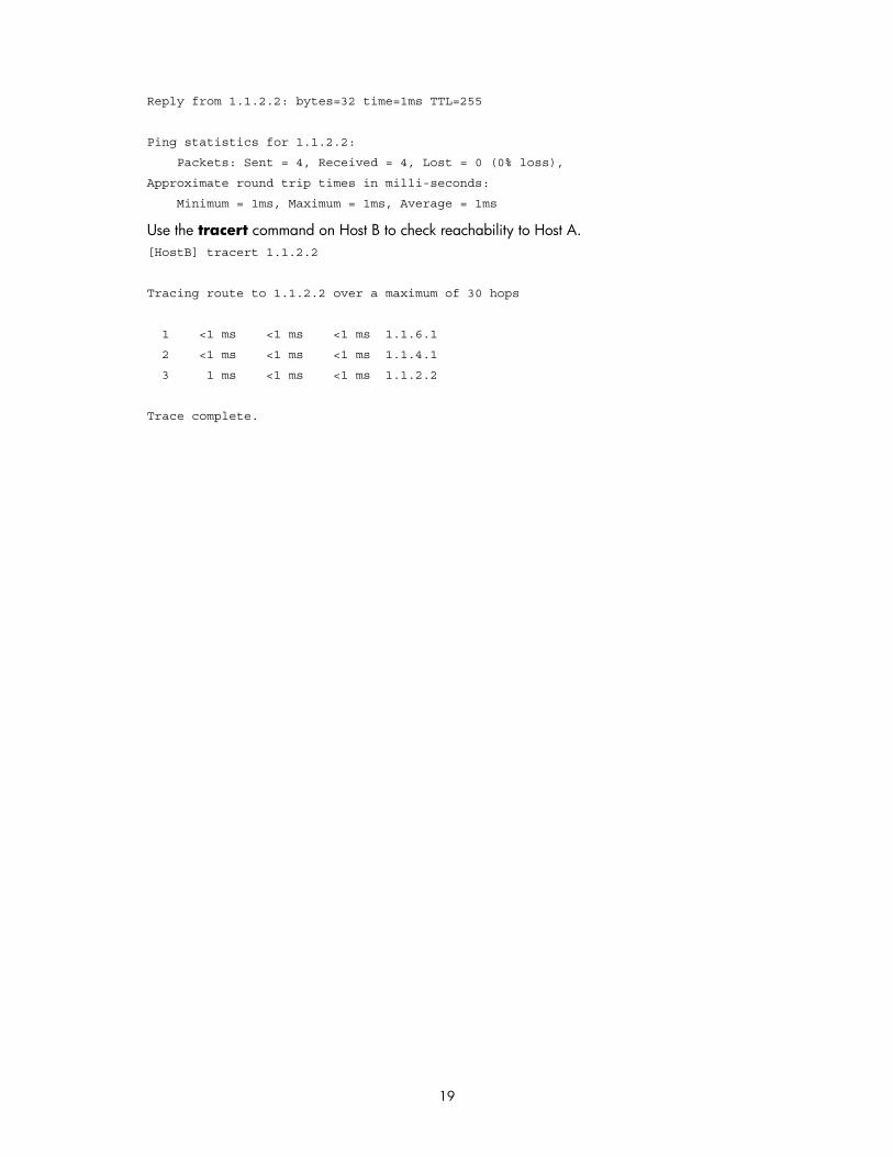
Use the tracert command on Host B to check reachability to Host A. [HostB] tracert 1.1.2.2
Tracing route to 1.1.2.2 over a maximum of 30 hops
1 <1 ms <1 ms <1 ms 1.1.6.1
2 <1 ms <1 ms <1 ms 1.1.4.1
3 1 ms <1 ms <1 ms 1.1.2.2
Trace complete.

20
IPv6 static routing configuration
Introduction to IPv6 static routing A static route is manually configured and works well in simple networks. Proper configuration and use can improve network performance and ensure enough bandwidth for high priority applications.
Unfortunately, static routes also have shortcomings. Any topology changes require manual configuration and modification to the corresponding static routes.
The term router in this document refers to either a router in a generic sense or a Layer 3 switch running routing protocols.
Features of IPv6 static routes Similar to IPv4 static routes, IPv6 static routes work well in simple IPv6 network environments.
The major difference between these two resides in the destination and next hop addresses. IPv6 static routes use IPv6 addresses whereas IPv4 static routes use IPv4 addresses.
Default IPv6 route An IPv6 static route with a destination prefix of ::/0 is a default IPv6 route. The default route is used to forward packets that match no specific routes in the routing table.
Configuring an IPv6 static route In small IPv6 networks, IPv6 static routes can be used to forward packets. In comparison to dynamic routes, it helps to save network bandwidth.
Configuration prerequisites • Configuring parameters for the related interfaces
• Configuring link layer attributes for the related interfaces
• Enabling IPv6 packet forwarding
• Ensuring that the neighboring nodes are IPv6 reachable
Configuring an IPv6 static route To do… Use the commands… Remarks 1. Enter system view system-view —
2. Configure an IPv6 static route
ipv6 route-static ipv6-address prefix-length [ interface-type interface-number ] nexthop-address [
Required
The default preference of

21
To do… Use the commands… Remarks preference preference-value ] IPv6 static routes is 60.
Displaying and maintaining IPv6 static routes To do… Use the command… Remarks
Display IPv6 static route information
display ipv6 routing-table protocol static [ inactive | verbose ]
Available in any view
Remove all IPv6 static routes delete ipv6 static-routes all Available in system view
• Use the undo ipv6 route-static command to delete a single IPv6 static route. The delete ipv6 static-
routes all command deletes all IPv6 static routes including the default route.
• For more information about the display ipv6 routing-table protocol static [ inactive | verbose ] command, refer to IP Routing Table Commands in the Layer 3 - IP Routing Command Reference.
IPv6 static routing configuration example Network requirements
With IPv6 static routes configured, all hosts and switches can interact with each other.
Figure 3 Network diagram for static routes

22
Configuration procedure 1. Configure the IPv6 addresses of all VLAN interfaces (Omitted)
2. Configure IPv6 static routes.
Configure the default IPv6 static route on SwitchA. <SwitchA> system-view
[SwitchA] ipv6 route-static :: 0 4::2
Configure two IPv6 static routes on SwitchB. <SwitchB> system-view
[SwitchB] ipv6 route-static 1:: 64 4::1
[SwitchB] ipv6 route-static 3:: 64 5::1
Configure the default IPv6 static route on SwitchC. <SwitchC> system-view
[SwitchC] ipv6 route-static :: 0 5::2
3. Configure the IPv6 addresses of hosts and gateways.
Configure the IPv6 addresses of all the hosts based upon the network diagram, configure the default gateway of Host A as 1::1, that of Host B as 2::1, and that of Host C as 3::1.
4. Display configuration information
Display the IPv6 routing table of SwitchA. [SwitchA] display ipv6 routing-table
Routing Table :
Destinations : 5 Routes : 5
Destination : :: /128 Protocol : Static
NextHop : FE80::510A:0:8D7:1 Preference : 60
Interface : Vlan-interface200 Cost : 0
Destination : ::1/128 Protocol : Direct
NextHop : ::1 Preference : 0
Interface : InLoop0 Cost : 0
Destination : 1:: /64 Protocol : Direct
NextHop : 1::1 Preference : 0
Interface : Vlan-interface100 Cost : 0
Destination : 1::1/128 Protocol : Direct
NextHop : ::1 Preference : 0
Interface : InLoop0 Cost : 0
Destination : FE80::/10 Protocol : Direct
NextHop : :: Preference : 0
Interface : NULL0 Cost : 0
Verify the connectivity with the ping command. [SwitchA] ping ipv6 3::1
PING 3::1 : 56 data bytes, press CTRL_C to break

23
Reply from 3::1
bytes=56 Sequence=1 hop limit=254 time = 63 ms
Reply from 3::1
bytes=56 Sequence=2 hop limit=254 time = 62 ms
Reply from 3::1
bytes=56 Sequence=3 hop limit=254 time = 62 ms
Reply from 3::1
bytes=56 Sequence=4 hop limit=254 time = 63 ms
Reply from 3::1
bytes=56 Sequence=5 hop limit=254 time = 63 ms
--- 3::1 ping statistics ---
5 packet(s) transmitted
5 packet(s) received
0.00% packet loss
round-trip min/avg/max = 62/62/63 ms

24
Obtaining support for your product
Register your product Warranty and other service benefits start from the date of purchase, so it is important to register your product quickly to ensure you get full use of the warranty and other service benefits available to you.
Warranty and other service benefits are enabled through product registration. Register your product at http://www.h3cnetworks.com, go to Support, Product Registration. Support services are based on accounts that you create or have authorization to access. First time users must apply for a user name and password that provides access to a number of eSupport features including Product Registration, Repair Services, and Service Request. If you have trouble registering your product, please contact 3Com Global Services for assistance.
Purchase value-added services To enhance response times or extend warranty benefits, contact 3Com or your authorized reseller. Value-added services like ExpressSM and GuardianSM can include 24x7 telephone technical support, software upgrades, onsite assistance or advance hardware replacement. Experienced engineers are available to manage your installation with minimal disruption to your network. Expert assessment and implementation services are offered to fill resource gaps and ensure the success of your networking projects. More information on 3Com maintenance and Professional Services is available at http://www.h3cnetworks.com.
Contact your authorized reseller or 3Com for a complete list of the value-added services available in your area.
Troubleshoot online You will find support tools posted on the web site at http://www.h3cnetworks.com/ under Support, Knowledgebase. The Knowledgebase helps you troubleshoot H3C products. This query-based interactive tool contains thousands of technical solutions.

25
Access software downloads Software Updates are the bug fix / maintenance releases for the version of software initially purchased with the product. In order to access these Software Updates you must first register your product on the web site at http://www.h3cnetworks.com, go to Support, Product Registration.
First time users will need to apply for a user name and password. A link to software downloads can be found at http://www.h3cnetworks.com, under Support, Drivers and downloads.
Software Upgrades are the software releases that follow the software version included with your original product. In order to access upgrades and related documentation you must first purchase a service contract from 3Com or your reseller.
Telephone technical support and repair To enable telephone support and other service benefits, you must first register your product at http://www.h3cnetworks.com/
Warranty and other service benefits start from the date of purchase, so it is important to register your product quickly to ensure you get full use of the warranty and other service benefits available to you.
When you contact 3Com for assistance, please have the following information ready:
• Product model name, part number, and serial number
• Proof of purchase, if you have not pre-registered your product
• A list of system hardware and software, including revision level
• Diagnostic error messages
• Details about recent configuration changes, if applicable
To send a product directly to 3Com for repair, you must first obtain a return authorization number (RMA). Products sent to 3Com, without authorization numbers clearly marked on the outside of the package, will be returned to the sender unopened, at the sender’s expense. If your product is registered and under warranty, you can obtain an RMA number online at http://www.h3cnetworks.com under support, Repair & Replacement Request. First time users will need to apply for a user name and password.
Contact us 3Com offers telephone, e-mail and internet access to technical support and repair services. To access these services for your region, use the appropriate telephone number, URL or e-mail address.
Find a current directory of contact information posted on the web site at http://www.h3cnetworks.com under Support, Technical Support Contact.

26
Acronyms
# A B C D E F G H I K L M N O P Q R S T U V W X Z
Acronym Full spelling
# Return
10GE Ten-GigabitEthernet
A Return
AAA Authentication, Authorization and Accounting
ABC Activity Based Costing
ABR Area Border Router
AC Alternating Current
ACK Acknowledgement
ACL Access Control List
ACS Auto-Configuration Server
ADSL Asymmetric Digital Subscriber Line
AES Advanced Encryption Standard
AF Assured Forwarding
AFI Address Family Identifier (and Authority and Format Identifier)
ALG Application Layer Gateway
AM Accounting Management
AMB Active Main Board
ANSI American National Standard Institute
AP Access Point
ARP Address Resolution Protocol
AS Autonomous System
ASBR Autonomous System Boundary Router
ASCII American Standard Code for Information Interchange
ASE Application Service Element or Autonomous System External
ASIC Application Specific Integrated Circuit
ASM Any-Source Multicast
ASN Auxiliary Signal Network
AT Advanced Technology
AT Adjacency Table
ATM Asynchronous Transfer Mode

27
Acronym Full spellingAUX Auxiliary (port)
AVF Active Virtual Forwarder
B Return
BAS Broadband access server
BC Bearer Control
BDR Backup Designated Router
BE Best Effort
BFD Bidirectional Forwarding Detection
BGP Border Gateway Protocol
BIMS Branch Intelligent Management System
BOOTP Bootstrap Protocol
BPDU Bridge Protocol Data Unit
BRI Basic Rate Interface
BSR Bootstrap Router
BT BitTorrent
BS BSR State
BT Burst Tolerance
C Return
C-BSR Candidate Bootstrap Router
C-RP Candidate Rendezvous Point
CA Call Appearance
CA Certificate Authority
CAR Committed Access Rate
CBS Committed Burst Size
CBT Core-Based Tree
CBQ Class Based Queuing
CBR Constant Bit Rate
CBT Core-Based Tree
CCITT International Telephone and Telegraph Consultative Committee
CCM Continuity Check Message
CDP Cisco Discovery Protocol
CE Customer Edge, Customer Edge Device
CF-Card Compact Flash Card
CFD Connectivity Fault Detection
CFM Configuration File Management

28
Acronym Full spellingCHAP Challenge Handshake Authentication Protocol
CIDR Classless Inter-Domain Routing
CIR Committed Information Rate
CIST Common and Internal Spanning Tree
CLI Command Line Interface
CLV Code/Length/Value
CLNP Connectionless Network Protocol
CPE Customer Premise Equipment
CPOS Channelized POS
CPS Certification Practice Statement
CPU Central Processing Unit
CQ Custom Queuing
CR Carriage Return
CRC Cyclic Redundancy Check
CRL Certificate revocation list
CR-LSP Constraint-based Routing LSP
CR-LDP Constraint-based Routing LDP
CSMA/CD Carrier Sense Multiple Access/Collision Detect
CSNP Complete Sequence Number Packet
CSPF Constraint Shortest Path First
CST Common Spanning Tree
CT Call Transfer
CV Connectivity Verification
CVLAN Customer Virtual Local Area Network
D Return
DAD Duplicate Address Detection
DAR Deeper Application Recognition
DCE Data Circuit-terminal Equipment
DD Database Description
DDN Digital Data Network
DES Data Encryption Standard
DHCP Dynamic Host Configuration Protocol
DiffServ Differentiated Service
DIS Designated Intermediate System
DLCI Data Link Connection Identifier

29
Acronym Full spellingDLDP Device Link Detection Protocol
DN Distinguished name
DNS Domain Name System
DoD Downstream on Demand
DoS Denial of Service
DR Designated Router
DSA Digital Signature Algorithm
DSCP Differentiated Services Code point Priority
DSP Digital Signal Processor (and Domain Specific Part)
DSTE DiffServ Aware TE
DTE Data Terminal Equipment
DU Downstream Unsolicited
DUID DHCP Unique Identifier
DUID-LL DUID Based Link Layer Address
D-V Distance Vector Routing Algorithm
DVMRP Distance Vector Multicast Routing Protocol
DWDM Dense Wavelength Division Multiplexing
E Return
EACL Enhanced ACL
EAD Endpoint Admission Defense
EAP Extensible Authentication Protocol
EAPOL Extensible Authentication Protocol over LAN
EAPOR EAP over RADIUS
EBGP External Border Gateway Protocol
EBS Excess Burst Size
EF Expedited Forwarding
EGP Exterior Gateway Protocol
ES End System
ES-IS End System-Intermediate System
F Return
FCoE Fabric Channel over Ethernet
FC Forwarding Class
FCS Frame Check Sequence
FDB Forwarding Database
FDDI Fiber Distributed Data Interface

30
Acronym Full spellingFDI Forward Defect Indication
FEC Forwarding Equivalence Class
FFD Fast Failure Detection
FF Fixed filter
FG Forwarding Group
FIB Forwarding information base
FIFO First In First Out
FQDN Full Qualified Domain Name
FR Frame Relay
FRR Fast Reroute
FRTT Fairness Round Trip Time
FSM Finite State Machine
FT Functional Test
FTP File Transfer Protocol
G Return
GARP Generic Attribute Registration Protocol
GE Gigabit Ethernet
GR Graceful Restart
GRE Generic Routing Encapsulation
GTS Generic Traffic Shaping
GVRP GARP VLAN Registration Protocol
H Return
HA High Availability
HABP HW Authentication Bypass Protocol
HDLC High-level Data Link Control
HEC Header Error Control
HMAC Hash-based Message Authentication Code
HO-DSP High Order Part of Domain Specific Part
HoPE Hierarchy of PE
HoVPN Hierarchy of VPN
HQoS Hierarchical Quality of Service
HSB Hot Standby
HTTP Hyper Text Transport Protocol
HTTPS HTTP Security
H-VPLS Hierarchy of VPLS

31
Acronym Full spellingHVRP Hierarchy VLAN Register Protocol
HWTACACS HUAWEI Terminal Access Controller Access Control System
I Return
IA Incoming Access or Identity Association
IANA Internet Assigned Number Authority
IBGP Internal Border Gateway Protocol
IBM International Business Machines
ICMP Internet Control Message Protocol
ICPIF Calculated Planning Impairment Factor
ICMPv6 Internet Control Message Protocol for IPv6
ID Identification/Identity
IDI Initial Domain Identifier
IDP Initial Domain Part
IEEE Institute of Electrical and Electronics Engineers
IETF Internet Engineering Task Force
IGMP Internet Group Management Protocol
IGMP-Snooping Internet Group Management Protocol Snooping
IGP Interior Gateway Protocol
IIH IS-to-IS Hello Protocol Data Unit
ILM Incoming Label Map
ILS Internet Locator Service
iMC Intelligent Management Center
IN Intelligent Network
IntServ Integrated Service
IP Internet Protocol
IPC Inter-Process Communication
IPng IP Next Generation
IPSec IP Security
IPTN IP Phone Telephony Network
IPv6 Internet protocol version 6
IPX Internet Packet Exchange
IRDP ICMP Router Discovery Protocol
IRF Intelligent Resilient Framework or Intermediate Routing Function
IS Intermediate System
ISATAP Intra-Site Automatic Tunnel Addressing Protocol
32
Acronym Full spellingISDN Integrated Services Digital Network
IS-IS Intermediate System-to-Intermediate System intra-domain routing information exchange protocol
ISO International Organization for Standardization
ISP Internet service provider
ISSU In Service Software Upgrade
IST Internal Spanning Tree
ITU-T International Telecommunication Union - Telecommunication Standardization Sector
K Return
KB Kilobyte
KEK Key-encrypting key
L Return
L2TP Layer 2 Tunneling Protocol
L2VPN Layer 2 Virtual Private Network
L3VPN Layer 3 Virtual Private Network
LACP Link Aggregation Control Protocol
LACPDU Link Aggregation Control Protocol Data Unit
LAN Local Area Network
LAPB Link Access Procedure, Balanced
LB Loopback
LBM Loopback Message
LBR Loopback Reply
LCP Link Control Protocol
LDAP Lightweight Directory Access Protocol
LDP Label Distribution Protocol
LER Label Edge Router
LFIB Label Forwarding Information Base
LIB Label Information Base
LLC Link Layer Control
LLDP Link Layer Discovery Protocol
LLDPDU Link Layer Discovery Protocol Data Units
LLS Link-Local Signaling
LLSP-CDP Link Layer Discovery Protocol-Cisco Discovery Protocol
LOC Loss of continuity
LOG Call Logging

33
Acronym Full spellingLR Line Rate
LRTT Loop Round Trip Time
LS Link State
LSA Link State Advertisement
LSAck Link State Acknowledgment
LSDB Link State Database
LSP Label Switch Path (and Link State Packet)
LSPAGENT Label Switched Path AGENT
LSPDU Link State Protocol Data Unit
LSPM Label Switch Path Management
LSR Link State Request or Label Switching Route
LSR Label Switch Router
LSR-ID Label Switch Router Identity
LSU Link State Update
LT Linktrace
LTM Lintrace Message
LTR Linktrace Reply Message
LVF Listening Virtual Forwarder
M Return
MA Maintenance Association
MAC Media Access Control
MAD Multi-Active Detection
MAFV MAC-based Auth-Fail VLAN
MAN Metropolitan Area Network
MaxBC Max Bandwidth Constraints
MBGP Multicast Border Gateway Protocol
MCE Multi-VPN instance Customer Edge
MD Multicast Domain, Maintenance Domain
MD5 Message-Digest 5
MDI Medium Dependent Interface
MDS Message-Digest Algorithm 5
MDT Multicast Distribution Tree
MD5 Message-Digest Algorithm 5
MED Multi-Exit Discriminator
MEP Maintenance Association End Point

34
Acronym Full spellingMFF MAC Forced Forwarding
MGV Mac-based guest VLAN
MIB Management Information Base
MIP Maintenance Association Intermediate Point
MLD Multicast Listener Discovery Protocol
MLD-Snooping Multicast Listener Discovery Snooping
MMC Meet-Me Conference
MODEM Modulator/Demodulator
MOS Mean Opinion Scores
MP Multilink PPP, Maintenance Point
MP-BGP Multiprotocol extensions for BGP-4
MPE Middle-level PE
MP-group Multilink Point to Point Protocol group
MPLS Multiprotocol Label Switching
MPLSFW Multi-protocol Label Switch Forward
MPM Multicast Port Management
MSC Mobile Switching Center
MSDP Multicast Source Discovery Protocol
MSOH Multiplex Section Overhead
MSTI Multi-Spanning Tree Instance
MSTP Multiple Spanning Tree Protocol
MT Multicast Tunnel
MTBF Mean Time Between Failure
MTI Multicast Tunnel Interface
MTTR Mean Time To Repair
MTU Maximum Transmission Unit
MVRF Multicast VPN Routing and Forwarding
N Return
NA Neighbor Advertisement
NAPT Network Address Port Translation
NAPT-PT Network Address Port Translation – Protocol Translation
NAS Network Access Server
NAT Net Address Translation
NBMA Non Broadcast Multi-Access
NBT NetBIOS over TCP/IP
35
Acronym Full spellingNCP Network Control Protocol
ND Neighborhood discovery
NDA NetStream Data Analyzer
NDC Network Data Collector
NDP Neighbor Discovery Protocol
NET Network Entity Title
NetBIOS Network Basic Input/Output System
NHLFE Next Hop Label Forwarding Entry
NLB Network Load Balancing
NLPID Network Layer Protocol Identifier
NLRI Network Layer Reachability Information
NMS Network Management Station
NPDU Network Protocol Data Unit
NPE Network Provider Edge
NQA Network Quality Analyzer
NS Neighbor Solicitation
NSAP Network Service Access Point
NSC NetStream Collector
N-SEL NSAP Selector
NSR Non-Stop Routing
NSSA Not-So-Stubby Area
NTDP Neighbor Topology Discovery Protocol
NTK Need to Know
NTP Network Time Protocol
O Return
OAM Operation Administration and Maintenance
OAMPDU OAM Protocol Data Units
OC-3 OC-3
OID Object Identifier
OL Optical Line
OOB Out of Band
OS Operating system
OSI Open Systems Interconnection
ORF Outbound Route Filter
OSPF Open Shortest Path First

36
Acronym Full spellingOUI Organizationally Unique Identifier
P Return
P Provider
P2MP Point to MultiPoint
P2P Point To Point
PAP Password Authentication Protocol
PAFV Port-based Auth-Fail VLAN
PBR Policy-Based Route
PCB Printed Circuit Board
PCM Pulse Code Modulation
PD Powered Device, Prefix Delegation or Pure Data
PDU Protocol Data Unit
PE Provider Edge, Provider Edge Device
PGV Port-based Guest VLAN
PHP Penultimate Hop Popping
PHY Physical Layer
PIM Protocol Independent Multicast
PIM-DM Protocol Independent Multicast-Dense Mode
PIM-SM Protocol Independent Multicast-Sparse Mode
PIR Peak Information Rate
PKCS Public Key Cryptography Standards
PKI Public Key Infrastructure
PLR Point of Local Repair
PMTU Path MTU
PoE Power over Ethernet
POP Point Of Presence
POS Packet Over SDH
PPP Point-to-Point Protocol
PPTP Point to Point Tunneling Protocol
PPVPN Provider-provisioned Virtual Private Network
PQ Priority Queuing
PRC Primary Reference Clock
PRI Primary Rate Interface
PS Protection Switching
PSE Power Sourcing Equipment

37
Acronym Full spellingPSNP Partial Sequence Number Packet
PTMP or P2MP Point-to-Multipoint
PTP or P2P Point-to-Point
PVC Permanent Virtual Channel
PW Pseudo wires
PXE Pre-boot Execution Environment
Q Return
QACL QoS/ACL
QinQ 802.1Q in 802.1Q
QoS Quality of Service
QQIC Querier's Query Interval Code
QRV Querier's Robustness Variable
R Return
RA Registration Authority or Router Advertisement
RADIUS Remote Authentication Dial in User Service
RALM RADIUS Authenticated Login using MAC-address
RAM Random-Access Memory
RD Routing Domain
RD Router Distinguisher
RED Random Early Detection
RFC Request For comments
RIB Routing Information Base
RID Router ID
RIP Routing Information Protocol
RIPng RIP next generation
RM Route Management
RMON Remote Monitoring
ROM Read Only Memory
RP Rendezvous Point
RPC Remote Procedure Call
RPF Reverse Path Forwarding
RPR Resilient Packet Ring
RPT Rendezvous Point Tree
RR Route Reflector
RRPP Rapid Ring Protection Protocol

38
Acronym Full spellingRRPPD Rapid Ring Protection Protocol Data Unit
RS Router Solicitation
RSA Revest-Shamir-Adleman Algorithm
RSB Reservation State Block
RSOH Regenerator Section Overhead
RSTP Rapid Spanning Tree Protocol
RSVP Resource Reservation Protocol
RSVP-TE Resource Reservation Protocol – Traffic Engineering
RT Route Target
RTCP Real-time Transport Control Protocol
RTE Route Table Entry
RTP Real-time Transport Protocol
RTP Real-time Transport Protocol
S Return
SA Source Active or Suppress Advertisement
SAFI Subsequent Address Family Identifier
SBM Sub-network Bandwidth Management
SCEP Simple Certificate Enrollment Protocol
SCFF Single Choke Fairness Frame
SD Signal Degrade
SDH Synchronous Digital Hierarchy
SE Shared explicit
SEL Selector
SETS Synchronous Equipment Timing Source
SF Sampling Frequency
SFM Source-Filtered Multicast
SFTP Secure FTP
SHA1 Secure Hash Algorithm 1
Share-MDT Share-Multicast Distribution Tree
SIP Session Initiation Protocol
Site-of-Origin Site-of-Origin
SLA Service Level Agreement
SMB Standby Main Board
SMTP Simple Mail Transfer Protocol
SNAP Sub Network Access Point

39
Acronym Full spellingSNMP Simple Network Management Protocol
SNP Sequence Number Packet
SNPA Sub-network Points of Attachment
SOH Section Overhead
SONET Synchronous Optical Network
SOO Site-of-Origin
SP Strict Priority Queuing
SPE Superstratum PE/Sevice Provider-end PE
SPF Shortest Path First
SPT Shortest Path Tree
SRPT Sub-ring Packet Tunnel
SRPU Switching and Routing Processing Unit
SSH Secure Shell
SSM Synchronization Status Marker
SSM Source-Specific Multicast
ST Shared Tree
STelnet Secure Telnet
STM-1 SDH Transport Module -1
STM-16 SDH Transport Module -16
STM-16c SDH Transport Module -16c
STM-4c SDH Transport Module -4c
STP Spanning Tree Protocol
SVC Signaling Virtual Connection
SVLAN Service Provider Virtual Local Area Network
Switch-MDT Switch-Multicast Distribution Tree
SYN Synchronize
T Return
TA Terminal Adapter
TACACS Terminal Access Controller Access Control System
TDM Time Division Multiplexing
TCP Transmission Control Protocol
TCN Topology Change Notification
TE Traffic Engineering
TEDB Traffic Engineering Database
TFTP Trivial File Transfer Protocol

40
Acronym Full spellingTLS Transparent LAN Service
TLV Type-Length-Value
ToS Type of Service
TP Traffic Policing
TPID Tag Protocol Identifier
TRIP Trigger RIP
TS Traffic Shaping
TTL Time to Live
TTY True Type Terminal
U Return
U/L Universal/Local
UDP User Datagram Protocol
UPE Under-layer PE or User-end PE
URL Uniform Resource Locators
URPF Unicast Reverse Path Forwarding
USM User-Based Security Model
V Return
VBR Variable Bit Rate
VCI Virtual Channel Identifier
VE Virtual Ethernet
VF Virtual Forwarder
VFS Virtual File System
VLAN Virtual Local Area Network
VLL Virtual Leased Lines
VOD Video On Demand
VoIP Voice over IP
VOS Virtual Operate System
VPDN Virtual Private Dial-up Network
VPDN Virtual Private Data Network
VPI Virtual Path Identifier
VPLS Virtual Private Local Switch
VPN Virtual Private Network
VRID Virtual Router ID
VRRP Virtual Router Redundancy Protocol
VSI Virtual Switch Interface

41
Acronym Full spellingVT Virtual Tributary
VTY Virtual Type Terminal
W Return
WAN Wide Area Network
WFQ Weighted Fair Queuing
WINS Windows Internet Naming Service
WLAN Wireless Local Area Network
WRED Weighted Random Early Detection
WRR Weighted Round Robin
WTR Wait-to-Restore
WWW World Wide Web
X Return
XGE Ten-GigabitEthernet
Z Return
ZBR Zone Border Router

42
Index
configuring
basic static route ............................................ 17
IPv6 static routing ..................................... 20, 21
static route ..................................................... 15
static route (IPv6 static routing) ........................ 20
static routing ............................................ 14, 17
default route (IPv6 static routing) ......................... 20
detecting
nexthop reachability ....................................... 16
nexthop reachability through track .................... 16
displaying
routing table (IP routing) .................................. 12
static route (IPv6 static routing) ......................... 21
static routes ................................................... 16
features
IPv6 static routing .......................................... 20
IP routing
displaying routing table ................................... 12
dynamic routing ............................................. 11
FIB table ......................................................... 9
local routing table ........................................... 9
maintaining routing table ................................ 12
overview ........................................................ 9
protocol routing table ....................................... 9
protocols ....................................................... 11
routing priority ............................................... 11
routing table ................................................... 9
routing table contents ...................................... 10
static routing .................................................. 11
IPv6
IPv6 static routing ................. See IPv6 static routing
IPv6 static routing
configuration ........................................... 20, 21
configuring static route .................................... 20
default route .................................................. 20
displaying static route ..................................... 21
features ........................................................ 20
maintaining static route ................................... 21
local routing table (IP routing) ............................... 9
maintaining
routing table (IP routing) .................................. 12
static route (IPv6 static routing) ......................... 21
static routes ................................................... 16
network management
basic static route configuration ......................... 17
IP routing overview ........................................... 9
IPv6 static routing ........................................... 20
IPv6 static routing configuration ....................... 21
procedure
configuring basic static route ........................... 17
configuring IPv6 static routing ............... 20, 21, 22
configuring static route .................................... 15
configuring static route (IPv6 static routing) ........ 20
detecting nexthop reachability ......................... 16
detecting nexthop reachability through track ...... 16
protocol routing table (IP routing) .......................... 9
routing
configuring basic static route ........................... 17
configuring IPv6 static routing .................... 20, 21
configuring static route .................................... 15
configuring static route (IPv6 static routing) ........ 20
configuring static routing ............................ 14, 17

43
default route .................................................. 14
default route (IPv6 static routing) ...................... 20
detecting nexthop reachability ......................... 16
detecting nexthop reachability through track ...... 16
dynamic (IP routing) ........................................ 11
features (IPv6 static routing) ............................ 20
FIB table (IP routing) ........................................ 9
IP routing overview .......................................... 9
local routing table (IP routing) ........................... 9
priority (IP routing) .......................................... 11
protocol routing table (IP routing)....................... 9
protocols (IP routing) ....................................... 11
routing table (IP routing) ................................... 9
routing table contents (IP routing) ...................... 10
static (IP routing) ............................................. 11
static route .................................................... 14
static routing application environment ............... 14
static routing
application environment .................................. 14
configuration ............................................ 14, 17
configuring basic static route ........................... 17
configuring static route .................................... 15
default route .................................................. 14
detecting nexthop reachability ......................... 16
detecting nexthop reachability through track ...... 16
displaying static routes .................................... 16
maintaining static routes ................................. 16
static route .................................................... 14