h2543ip - images-na.ssl-images-amazon.combjja0al.pdfillustrated assembly manual h2543ip-1 ... ⇒...
TRANSCRIPT

K2543
ILLUSTRATED ASSEMBLY MANUAL H2543IP-1
Total solder points: 38 Difficulty level: beginner 1 2 3 4 5 advanced
Gives your car a better starting and
smoother running.
ELECTRONIC TRANSISTOR IGNITION FOR CARS
K2543
ILLUSTRATED ASSEMBLY MANUAL H2543IP-1
Total solder points: 38 Difficulty level: beginner 1 2 3 4 5 advanced
Gives your car a better starting and
smoother running.
ELECTRONIC TRANSISTOR IGNITION FOR CARS

2
Even the most sceptical one has tot admit that the electronic ignition system has a great advantage over the conventional ignition system. Car constructors now mount such a new system on their most expensive models. THE ADVANTAGES ARE : Better ignition Less air pollution Gasoline economy Better running engine, especially at very high and very low speed Visible less wear of the breaking points, which means a constant calibrated state.
Specifications : Completely shockproof Practically test on 2-4-6-8 cylinder engines during a total amount of 2.500.000 km. Principle: transistorized ignition Connection element: Darlington transistor, triple diffused Connection current: 4 A Connection speed : Up to 500 KHz Typical firing period : 2.000 µ second
Features & Specifications

3
Assembly hints
1. Assembly (Skipping this can lead to troubles ! ) Ok, so we have your attention. These hints will help you to make this project successful. Read them carefully. 1.1 Make sure you have the right tools: • A good quality soldering iron (25-40W) with a small tip.
• Wipe it often on a wet sponge or cloth, to keep it clean; then apply solder to the tip, to give it a wet look. This is called ‘thinning’ and will protect the tip, and enables you to make good connections. When solder rolls off the tip, it needs cleaning.
• Thin raisin-core solder. Do not use any flux or grease.
• A diagonal cutter to trim excess wires. To avoid injury when cutting excess leads, hold the lead so they cannot fly towards the eyes.
• Needle nose pliers, for bending leads, or to hold components in place.
• Small blade and Phillips screwdrivers. A basic range is fine.
For some projects, a basic multi-meter is required, or might be handy
1.2 Assembly Hints :
⇒ Make sure the skill level matches your experience, to avoid disappointments. ⇒ Follow the instructions carefully. Read and understand the entire step before you perform each operation. ⇒ Perform the assembly in the correct order as stated in this manual ⇒ Position all parts on the PCB (Printed Circuit Board) as shown on the drawings. ⇒ Values on the circuit diagram are subject to changes. ⇒ Values in this assembly guide are correct* ⇒ Use the check-boxes to mark your progress. ⇒ Please read the included information on safety and customer service
* Typographical inaccuracies excluded. Always look for possible last minute manual updates, indicated as ‘NOTE’ on a separate leaflet.
0.000

4
Assembly hints
1.3 Soldering Hints :
1- Mount the component against the PCB surface and carefully solder the leads
2- Make sure the solder joints are cone-shaped and shiny
3- Trim excess leads as close as possible to the solder joint
REMOVE THEM FROM THE TAPE ONE AT A TIME !
AXIAL COMPONENTS ARE TAPED IN THE CORRECT MOUNTING SEQUENCE !
You will find the colour code for the resistances and the LEDs on our website: http://www.velleman.be/common/service.aspx

5
R1 : 330 (3 - 3 - 1 - B) (1W) R2 : 330 (3 - 3 - 1 - B) (1W) R3 : 150 (1 - 5 - 1 - B) R4 : 100 (1 - 0 - 1 - B) R5 : 150 (1 - 5 - 1 - B) (1W) R6 : 150 (1 - 5 - 1 - B) (1W) R7 : 150 (1 - 5 - 1 - B) (1W)
1. Resistors R...
Construction
C1 : 0,22µF/630VDC
C1
D1 : 1N4007 D2 : 1N4007 D3 : 1N4007 D4 : 1N4007
D...CATHODE
ZD1 : 150V0 ZD2 : 150V0
3. Zenerdiodes. Watch the polarity !
CA T H O D E
ZD ...
T2 : TIP162
6. Transistor T2 + heatsink
T1 : 2N2219A
5. Transistor T1
Insulated washer
Heatsink
Mica insulation
Transistor, metallic side
20mm M3 bolt
Plastic spacer
M3 nut
M3 serrated lock washer
4. Electrolytic Capacitor.
2. Diodes. Watch the polarity !
5
R1 : 330 (3 - 3 - 1 - B) (1W) R2 : 330 (3 - 3 - 1 - B) (1W) R3 : 150 (1 - 5 - 1 - B) R4 : 100 (1 - 0 - 1 - B) R5 : 150 (1 - 5 - 1 - B) (1W) R6 : 150 (1 - 5 - 1 - B) (1W) R7 : 150 (1 - 5 - 1 - B) (1W)
1. Resistors R...
Construction
C1 : 0,22µF/630VDC
C1
D1 : 1N4007 D2 : 1N4007 D3 : 1N4007 D4 : 1N4007
D...CATHODE
ZD1 : 150V0 ZD2 : 150V0
3. Zenerdiodes. Watch the polarity !
CA TH OD E
ZD ...
T2 : TIP162
6. Transistor T2 + heatsink
T1 : 2N2219A
5. Transistor T1
Insulated washer
Heatsink
Mica insulation
Transistor, metallic side
20mm M3 bolt
Plastic spacer
M3 nut
M3 serrated lock washer
4. Electrolytic Capacitor.
2. Diodes. Watch the polarity !

6
First of all, control the breaker points for a correct setting as per the constructors instructions, or better, use a new set of points, before installing the ignition system.
The existing ignition condenser is to be disconnected. This is very important. This condenser may be inside or outside the distributor.
ex.: On a 2 cylinders Citroën, this condenser is fitted to the breakers, thus unscrew the nut and remove out of the car. Supple leads of minimum 1mm square are to be used to make the connections, this to increase the func-
tion security. All connections and contacts are to be checked and must be good. A bad soldering or a bad contact may conduct to some headaches.
These four leads (connections 1, 2, 3 and 4) may already be soldered to the PCB of the ignition system, make them long enough so they could be cut later at the desired length.
Seek for an adequate to mount the ignition system. Do not place the system under the canopy without being boxed or insulated, because the oxidation and other atmospheric circumstances may shorten the life of the transistorized ignition system.
7. Installing in the car
Installing in the car
4 3 2 1 4 3 2 1
BATTERY +
CHASSIS - WIRING : min 1mm²
K2543
+ -
DISCONNECT
breakers
condenser
Coil

7
There are different possibilities to dodge this problem :
(1) Install your system under the dashboard
(2) Spray a non-conductive protective varnisch (available in every retail shop) on the whole system, of which a "Thick" layer must be applied on the components and the circuit side. Once this layer is dried, a second layer may be sprayed. The ignition system may be fixed under the engine canopy.
(3) Build the system into a box well closed, but the heatsink has to be well ventilated. Don't use a plastic bag or another similar material as fixed around the PCB.
(4) Insulate the entire ignition system with resin (also available in retail shops) but do not insulate the heatsink which has to be ventilated.
The heatsink must be contact free from the frame (earth) of your car. The two holes of the heatsink are used as fixing holes. Utilize small screws or Parker-screws. Ensure that the PCB has no contact with the metal part of your vehicle.
Disconnect the lead going from the coil to the breakers points, and disconnect also the condenser.
Follow the instructions on the figure for all connections. Connection 1 of the PCB goes to the + 12V com-ing from the ignition key. This "+ 12V" is also at the PLUS of the coil. If a ballast resistor is used, the con-nection must be made in front of this resistor.
Connection 2 of the PCB goes to the breakers (do not forget to disconnect the condenser on one side).
Connection 3 goes to the connection of the coil, which was previously connected to the breakers.
And now connection 4 goes to the frame (earth) of the car, thus to the MINUS of the battery.
Installing in the car

8
8. Test
Test & maintenance
The installation is now finished. Verify as follows :
The condenser is disconnected (very important) All connections are well fixed No lead is misconnected or mixed with another.
Now the engine may Start.
The ignition system on itself does not require a maintenance. The ignition system maintains the breaker points in a good condition, so they will not be burned, as the bring only a few amount of current to the electric system.
So, a pair of new breakers may stay for 50.000 km on the car without a maintenance, which means there is no more need to verify every 5.000 or 10.000 km for the contact angle and ignition time.
Just clean the points sometimes, with a cloth dipped in acetone, to remove the oil. By buying a pair of new points, you will see they are covered with a protective resin, acting as an insulator. Remove this resin with sandpaper or with a degreasing solvent. After 50.000 km it will wise to change your breaker points because wear of the notch and also for mechanical fatigue.
The sparkplugs also are to be checked as, with bad plugs, the best ignition system will not work. Verify the plugs or buy new plugs. Do not forget that by trying to save on your plugs you will pay for gasoline, whatever ignition system you use. If the electrodes are burned too far, the arcing between the gap of the electrodes will go to the piston, with result into a burned piston.
9. Maintenance

9
PCB
PCB
VE
LLE
MA
N
4 3 2 1
R7
R6
R5
R2
R1
C1 ZD1
ZD2D3
D4
R4
D2
D1
R3
T2
T1
9
PCB
PCB
VE
LLE
MA
N
4 3 2 1
R7
R6
R5
R2
R1
C1 ZD1
ZD2D3
D4
R4
D2
D1
R3
T2
T1
10
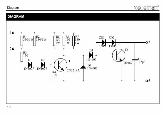
Diagram
DIAGRAM
R1330/1W
R2330/1W
R51501W
R61501W
R71501W
R3150
D1
1N4007
D2
1N4007
T1
2N2219AR4100
1
2
D41N4007
D3
1N4007
T2
TIP162
ZD2
150V
ZD1
150V3
4
C1.22µF
10
Diagram
DIAGRAM
R1330/1W
R2330/1W
R51501W
R61501W
R71501W
R3150
D1
1N4007
D2
1N4007
T1
2N2219AR4100
1
2
D41N4007
D3
1N4007
T2
TIP162
ZD2
150V
ZD1
150V3
4
C1.22µF


Modifications and typographical errors reserved © Velleman Components nv. H2543IP - 2008 - ED1
VELLEMAN Components NV Legen Heirweg 33
9890 Gavere Belgium Europe
www.velleman.be www.velleman-kit.com
5 4 1 0 3 2 9 4 0 9 2 7 2
Modifications and typographical errors reserved © Velleman Components nv. H2543IP - 2008 - ED1
VELLEMAN Components NV Legen Heirweg 33
9890 Gavere Belgium Europe
www.velleman.be www.velleman-kit.com
5 4 1 0 3 2 9 4 0 9 2 7 2