h t p -1 1 6 c h a n n e l h o me t h e a t e r p r o c e
TRANSCRIPT

HTP-1
16 Channel Home Theater Processor
User Manual P/N 37887
Updated January 27, 2021 © 2019-2021 Monoprice Inc. All rights reserved.

HTP-1 Installation and User Guide Release 1.8.4
(This page left blank)
HTP-1 User Manual Page 2 V1.8.4

HTP-1 Installation and User Guide Release 1.8.4
Table of Contents
Table of Contents 3
Safety Warnings and Guidelines 8
Licenses 9
Introduction 9
Customer Service 9
Package Contents 10
Requirements 10
Product Overview 11
Front Panel 11
Rear Panel 12
Front Panel LCD Display 14
Remote Control 16
Web GUI Home Page 18
Basic Setup 20
System Requirements 20
Step by Step 20
Initial WiFi Setup 22
Update the Firmware 22
Interface Description 23
Speaker Configurations 24
Speaker Location Diagrams 26
5.1 vs 7.1 Surround Speakers 28
Top Middle vs High Side 28
Valid Speaker Configurations 29
HTP-1 User Manual Page 3 V1.8.4
HTP-1 Installation and User Guide Release 1.8.4
Multiple Subwoofers and Dirac Live Bass Control™ 31
Mapping Channels to Speakers 31
Speaker Setup 32
Setting Speaker Size 33
Enabling Speakers 34
Dolby® Enabled Speakers 35
Example Speaker Setups 36
Back Panel Mapping Display 37
Example 7.1.4h Speaker Configuration (Upper Level On the Wall) 38
Example 7.2.6 Speaker Configuration (Upper Level On the Ceiling) 39
Example 9.3.4 Speaker Configuration (Upper Level On the Ceiling) 40
Example 9.1.6 Speaker Configuration (Upper Level On the Ceiling) 41
Configure the Bass Manager 42
Calibration 44
Amplifier Connection and Level Adjustment 45
Volume Range and Maximum Output Voltage 46
Recommendations on setting the Maximum Output Level 46
Handling Unmatches Amplifiers 47
Lipsync Delay 47
Dirac Calibration 48
Calibration Steps 49
Dirac Bypass 54
Dirac On 54
Dirac Bypass 54
Dirac Off 55
Tips for a Successful Dirac Calibration 55
Manual Calibration 56
HTP-1 User Manual Page 4 V1.8.4

HTP-1 Installation and User Guide Release 1.8.4
Calibrating for Higher Sample Rates 56
Dirac Live Bass Control 56
A DLBC Tour 58
Signal Generation Page 60
“THX like” band limited noise 61
Louder reference noise 62
Polarity Pulse 62
Left signal as input / Right signal as input 62
Sine Wave 63
EQ Page 64
Using PEQ with Dirac ™ 65
Inputs Page 66
Naming the Audio/Video Sources 67
Watch Video with Other Audio 68
Partial Reset by Changing Inputs 68
PCM Detect Sensitivity 69
USB Audio Input 69
Sound Enhancement Page 70
Using Surround Modes 70
Wide Synth 71
Bass Enhancement (AKA Bass Reinforcement) 72
Audio Features 73
Night Mode 73
Dialog Enhancement 73
Loudness 73
For Highest Quality Audio 75
Connectivity 76
HTP-1 User Manual Page 5 V1.8.4

HTP-1 Installation and User Guide Release 1.8.4
Setting up ARC/eARC and CEC 76
Connecting HTP-1 to TV for ARC/eARC 77
CEC Settings 77
CEC Control Options 78
Alternate TV Input 78
TV Audio Priority 78
System Audio 78
Using Wi-Fi 80
Choosing DHCP or Static IP Address Assignment 80
Bluetooth 81
Resetting the Network Connection 81
System Page 82
Support Features 85
Video Features 86
UHD Support 86
EDID Management 86
Dolby Vision 87
Triggers 87
Using Roon 87
Firmware Updates 88
Feedback 89
Alexa 90
Specifications 91
Signal Processing Flow 92
IR Code Table 93
IR Code Over HTTP Remote Control 94
Third Party Applications 94
HTP-1 User Manual Page 6 V1.8.4

HTP-1 Installation and User Guide Release 1.8.4
Privacy Disclosure 94
Regulatory Compliance 95
Notice for FCC 95
RF Exposure Statement for FCC 96
Notice for Industry Canada 96
Special Thanks 96
Revision History 96
Important Information 97
HTP-1 User Manual Page 7 V1.8.4

HTP-1 Installation and User Guide Release 1.8.4
Safety Warnings and Guidelines
Please read this entire manual before using this device, paying extra attention to these safety warnings
and guidelines. Please keep this manual in a safe place for future reference.
● This device is intended for indoor use only. ● Do not expose this device to water or moisture of any kind. Do not place drinks or other
containers with moisture on or near the device. If moisture does get in or on the device, immediately unplug it from the power outlet and allow it to fully dry before reapplying power.
● Do not touch the device, the power cord, or any other connected cables with wet hands. ● Do not install this device on an unstable surface where it could fall and cause either personal
injury or damage to the device and/or other equipment. ● Do not subject the product to extreme force, shock, or fluctuations in temperature or humidity. ● Do not expose this device to excessively high temperatures. Do not place it in, on, or near a heat
source, such as a fireplace, stove, radiator, etc. Do not leave it in direct sunlight. ● This device ventilates excessive heat through the slots and openings in the case. Do not block or
cover these openings. Ensure that the device is in an open area where it can get sufficient airflow to keep from overheating.
● Do not place or install this device in an area where it can be exposed to excessive amounts of dust, humidity, oil, smoke, or combustible vapors.
● Use only in a well-ventilated area. Do not use in close, confined spaces. Ensure that there is at least 3" of space around and above the device.
● Prior to operation, check the unit and power cord for physical damage. Do not use it if physical damage has occurred.
● Before plugging the unit into a power outlet, ensure that the outlet provides the same type and level of power required by the device.
● This device uses a grounded power cord and requires a ground connection for safe operation. Ensure that the power source has a proper ground connection. Do not modify the plug or use a "cheater" plug to bypass the ground connection.
● Disconnect the unit from the power source when replacing the fuse. Replace the fuse only with the same type. Never bypass the fuse.
● Unplug this device from the power source when not in use. ● Take care to prevent damage to the power cord. Do not allow it to become crimped, pinched,
walked on, or become tangled with other cords. Ensure that the power cord does not present a tripping hazard.
● Never unplug the unit by pulling on the power cord. Always grasp the connector head or adapter body.
● Ensure that power is turned off and disconnected before making any electrical connections. ● Remove the batteries from the controller if it will go unused for a lengthy period of time. ● Clean using a soft, dry cloth only. Do not use chemical cleaners, solvents, or detergents. For
stubborn deposits, moisten the cloth with warm water. ● This device has no user serviceable parts. Do not attempt to open, service, or modify this device.
HTP-1 User Manual Page 8 V1.8.4

HTP-1 Installation and User Guide Release 1.8.4
Licenses This product uses features licensed from several suppliers:
● Manufactured under license from Dolby Laboratories
● Manufactured under license from Xperi / DTS
● Manufactured under license from Auro Technologies
● Manufactured under license from Momentum Data Systems
● Manufactured under license from Dirac Research
Introduction The Monolith™ HTP-1 is an "AVP" or "Audio Video Pre-Processor" designed for use in home theaters. It
supports Dolby Atmos®, DTS:X®, Auro-3D®, and Dirac Live®. It features eight HDMI® Ultra High Definition
(4K UHD) inputs and two HDMI 4K UHD outputs. It has seven digital audio inputs, two stereo analog
inputs, one secondary stereo analog output, and sixteen balanced XLR analog outputs. It has a built-in
web GUI, which allows you to configure it using a computer, smartphone, or tablet, as well as an
infrared remote control for adjusting volume, changing the upmix, and selecting inputs. It is designed for
easy software updates using an Ethernet connection.
This User Guide describes version 1.7 of the HTP-1 software. As a software product, the HTP-1 may be
updated and this user guide may also be updated. Please check for updates on the info page of the
HTP-1 web interface. Do also read the release notes found on the info page. The release note gives the
latest information about what has changed in the software.
Each page of the Web GUI includes a help button.
These bring up brief descriptions of the current page. This User Guide gives more detailed information.
The latest version of the user guide can always be retrieved from the help screens.
Customer Service The Monoprice Customer Service department is dedicated to ensuring that your ordering, purchasing,
and delivery experience is second to none. If you have any problem with your order, please give us an
opportunity to make it right. You can contact a Monoprice Customer Service representative through the
Live Chat link on our website www.monoprice.com or via email at [email protected]. Check the
website for support times and links.
HTP-1 User Manual Page 9 V1.8.4

HTP-1 Installation and User Guide Release 1.8.4
Package Contents Please take an inventory of the package contents to ensure you have all the items listed below. If
anything is missing or damaged, please contact Monoprice Customer Service for a replacement.
1x HTP-1 Home Theater Pre-Processor
1x IR Remote Control
1x Bluetooth®/Wi-Fi® Antenna
1x AC Power Cord
Requirements ● The HTP-1 must be connected to an existing Ethernet wired or wireless network for initial
configuration. Computers or mobile devices connected to the network can be used to control
and configure the HTP-1. The HTP-1 can be operated with no network connection if no more
configuration is required.
● A separate power amplifier or powered speakers are required.
● A laptop or desktop computer with a web browser. Mac’s and PC’s are supported by the Dirac
Live® calibration system.
○ A phone can easily access the Web GUI once initial setup is complete, but a bigger
screen is very helpful for setup.
● A USB connected calibrated microphone (not included) is required to perform a Dirac®
calibration. A smartphone or tablet cannot be used to perform a Dirac calibration. The Dirac web
page (https://www.dirac.com/recommended-microphones) discusses microphones.
HTP-1 User Manual Page 10 V1.8.4

HTP-1 Installation and User Guide Release 1.8.4
Product Overview
Front Panel
1. LCD Display: This 5" [s1] touchscreen displays the volume level, selected input, upmix selection,
and various other system statuses. See the Front Panel LCD Display section below for details.
2. Power Button : If the Master Power Switch on the rear panel is in the ON position, the front
panel Power Button turns the unit on or puts it into standby. A blue LED illuminates the power
button while the unit is powering on or powering off. The LED is extinguished when the unit
reaches a stable state.
3. Volume Knob: Rotate the Volume Knob counterclockwise to decrease the volume level or
clockwise to increase the volume level.
4. IR Receiver: The IR Receiver accepts infrared signals from the included IR Remote Control.
HTP-1 User Manual Page 11 V1.8.4

HTP-1 Installation and User Guide Release 1.8.4
Rear Panel
1. HDMI INPUTS: Eight HDMI® inputs for connecting HDMI source devices. Each input supports the
4K resolution and the HDMI 2.0b and HDCP™ 2.3 standards.
2. ANALOG INPUTS: Two pairs of RCA analog stereo jacks for connecting an analog stereo audio
source.
3. COAXIAL/OPTICAL DIGITAL INPUTS: Three digital coaxial and three digital optical S/PDIF audio
for connecting digital audio inputs. All six inputs are active and can be independently selected.
4. AES/EBU DIGITAL INPUT: Three-pin XLR jack for connecting an audio device that outputs an
AES/EBU (aka AES3) digital audio signal.
5. MIX OUT: One pair of RCA analog stereo jacks for connecting a stereo amplifier or powered
speakers. The main signal is mixed down to a stereo signal.
6. TRIGGER INPUT: A 3.5mm trigger input turns the HTP-1 on when a 12V signal is applied. The
HTP-1 will go into standby mode when the trigger signal is removed. Note that the Master
Power Switch on the rear panel must be in the ON position for the trigger signal to turn the
HTP-1 on.
7. TRIGGER OUTPUTS: Four 3.5mm jacks send a 12V trigger signal when the HTP-1 is powered on.
These triggers are typically used to power on the power amplifiers.
8. HDMI OUTPUTS: Two HDMI® outputs for connecting HDMI displays. The “HDMI 1” output
supports the Audio Return Channel (ARC)/Extended Audio Return Channel (eARC) HDMI
features, which receive audio signals from the connected display. This is necessary if you are
going to stream video from an app on your TV or if you are receiving over-the-air television
broadcasts using an HD antenna.
9. USB AUDIO: A USB Type-B jack for streaming audio from a connected computer.
10. SYSTEM RECOVERY: Mini SD card slot used by the factory for production purposes only. A
factory restore procedure is available using this.
HTP-1 User Manual Page 12 V1.8.4

HTP-1 Installation and User Guide Release 1.8.4
11. ETHERNET/SERVICE: An RJ45 jack for making a wired connection to an existing Ethernet
network. The USB port is for performing service at the factory.
12. ANTENNA: An SMA connector for attaching the included Bluetooth®/Wi-Fi® Antenna.
13. MAIN OUTPUTS: Sixteen balanced XLR jacks for connecting external power amplifiers. The
channel labels on the back panel are supplemented with a diagram labeled in the software for
complex speaker configurations.
14. GND: Screw terminal for making a ground connection to the chassis.
15. POWER SECTION: The POWER SECTION contains the Master Power Switch, the IEC Power
Connector for attaching the included AC Power Cord, and a Fuse Holder. Always disconnect the
power cord from the power source before replacing the fuse, and replace the fuse with the
same type. To assure a completely clean reboot, allow the HTP-1 to be powered down for 15
seconds before powering on again via the master power switch.
HTP-1 User Manual Page 13 V1.8.4

HTP-1 Installation and User Guide Release 1.8.4
Front Panel LCD Display
1. Input: The current active Input is displayed in the upper left corner of the screen. The sample
screenshot above shows Philips as the Input. The text for each input can be configured on the
INPUTS tab on the System Configuration screen in the Web GUI.
2. Program Format: The Program Format displays the audio format of the selected Input. The
sample screenshot above shows Object Audio Dolby Digital Plus (Atmos) as the Program
Format. See the About Speaker Configurations section for details of the number displayed.
3. Volume: The Volume level is displayed in the center of the screen. The sample screenshot above
shows -30dB as the Volume. The decibel (dB) value is relative to the amplifier input sensitivity,
which can be configured on the CALIBRATION tab on the System Configuration screen in the
Web GUI. When the audio is muted, the display changes from white to red. Mute can be toggled
on or off by touching the Volume display on the screen, using the IR remote control, or by
clicking the Volume display on the built-in Web GUI Home Page. 4. Upmix Selection: The current Upmix Selection setting is displayed beneath the Volume on the
screen. The upmix is selected using the IR remote control or with the built-in Web GUI. The
selected mode is only the desired/requested upmix mode. The system will perform the
requested upmix mode only if it is supported. The Listening Format (see 8 below) is displayed
beneath the Setup icon and shows the actual upmix mode algorithm being used, which may not
match the requested mode. See the Using Surround Modes section for details.
5. Special Listening Modes: The status of the NIGHT, DIRAC, LOUDNESS, and DIALOG modes is
displayed beneath the Upmix Selection. 6. IP Address: The current wired IP Address is displayed in the lower left corner. The sample
screenshot above shows the IP Address as 192.168.1.101. You access the built-in Web GUI by
typing the IP Address into the address bar of your web browser. Some browsers default to
https:// before the address, which will not work. The address must begin with http://. 7. Wi-Fi Setup: Touch the gear icon to display the Wi-Fi® Setup screen. See the WI-FI SETUP
section for details. If the icon is yellow, a software update is available for the HTP-1.
HTP-1 User Manual Page 14 V1.8.4

HTP-1 Installation and User Guide Release 1.8.4
8. Listening Format: The Listening Format is displayed beneath the Wi-Fi Setup icon and shows
the actual upmix mode algorithm being used, which may not match the requested mode. See
the Using Surround Modes section for details.
9. Wireless: If the HTP-1 is connected to a wireless connection, the IP Address will be displayed in
the lower right corner. The sample screenshot above shows 169.254.8.119 for the wireless IP
address. The unit can be accessed from either IP address - wired or wireless.ither connection can
be used.
HTP-1 User Manual Page 15 V1.8.4

HTP-1 Installation and User Guide Release 1.8.4
Remote Control
1. POWER: Press the POWER button to
turn the unit on or or to put it into
standby mode.
2. USER INPUTS: Press the number
buttons to select individual inputs. The
numbers map to the visible inputs, from
left to right, that are display on the
Web GUI Home Page. Press the LAST
button to select the last input used.
3. INFO: Press the INFO button to display
the relevant information on the Front
Panel LCD Display. 4. COLORS: The Red, Green, Yellow, and
Blue buttons activate user definable
functions.
5. HDMI+: Press the HDMI+ button to
cycle forward through the eight HDMI®
inputs as well as the TV input. When
using this button the GUI will display
the HDMI input that will be selected
after a short timeout period expires
(about 3 seconds). This allows the user
to rotate through the input options
without actually changing the input
(which can slow things down). This
delayed input change only applies to
this button, not any of the other +
buttons.
6. SURROUND MODES: Press the buttons
to select the NATIVE, DTS®, DIRECT, DOLBY®, or AURO-3D® surround
modes.
7. SPDIF+: Press the SPDIF+ button to
cycle forward through the digital audio
inputs. The cycle order is COAXIAL 1, COAXIAL 2, COAXIAL 3, OPTICAL 1, OPTICAL 2, OPTICAL 3, and AES/EBU.
8. MASTER: Press the + button to increase
the MASTER volume level or press the - button to decrease the MASTER volume
level.
9. LETTERS: The A, B, C, and D buttons
activate user user defined functions.
These may be supported in the future.
10. DIRAC: Press the DIRAC button to
enable or disable Dirac® Room
Correction.
11. NIGHT: Press the NIGHT button rotates
between off, auto and on. Night mode
is designed for low volume movie
viewing. See more details under “Audio
Features”.
12. LOUD: Press the LOUD button to enable
or disable Loudness mode, which
boosts low and high frequencies for low
volume music listening. This is
HTP-1 User Manual Page 16 V1.8.4

HTP-1 Installation and User Guide Release 1.8.4
described in more detail under “Audio
Features”.
13. BT PAIR: Press the BT PAIR button to
initiate Bluetooth® pairing. This is not
connected in v1.1.
14. DIM: Press the DIM button to cycle
through several brightness levels for the
front panel LCD display. When the dim
level is zero, the screen will briefly
brighten to show changes in volume.
15. STRM+: Press the STRM+ button to
cycle through the USB, Roon®, and
Bluetooth® streaming inputs.
16. ANALOG+: Press the ANALOG+ button
to toggle between the two analog audio
inputs.
17. DIALOG: Press the + button to increase
the DIALOG volume level or press the - button to decrease the DIALOG volume
level.
18. MUTE: Press the MUTE button to turn
audio muting of all speakers on or off.
19. NUMBERS: The preset 1, 2, 3, and 4
buttons are designed to activate user
defined functions. These may be
supported in the future.
HTP-1 User Manual Page 17 V1.8.4

HTP-1 Installation and User Guide Release 1.8.4
Web GUI Home Page
1. Active Input: The current Active Input is displayed in the upper left corner. The sample
screenshot above shows Magnavox as the Active Input. The specific text used for each input is
configured on the INPUTS tab of the System Configuration screen.
2. Program Format: The Program Format displays the audio format of the selected input. The
sample screenshot above shows 5.1.5h DTS MA as the Program Format. See the About Speaker
Configurations section for details of the number displayed.
3. Volume: The Volume level is displayed in the center of the screen. The sample screenshot above
shows -31dB as the Volume. The decibel (dB) value is relative to the input sensitivity, which can
be configured on the CALIBRATION tab on the System Configuration screen. When the audio is
muted, the display changes from white to red. Mute can be toggled on or off by touching the
Volume display on the Front Panel LCD Display, using the IR remote control, or by clicking the
Volume display on the Web GUI Home Page. 4. Volume Buttons: Click the volume up and down icons to change the volume level. The Volume
Buttons can be replaced by a Volume Slider using a control on the SYSTEM tab on the System
Configuration screen.
5. Input Select: Click one of the buttons to select one of up to nine inputs. Which inputs are
displayed and how they are named can be configured on the INPUTS tab on the System
Configuration screen.
6. Upmix Select: Click one of the buttons to select one of up to nine upmix/surround modes. The
selected mode is only the desired/requested upmix mode. The system will perform the
requested upmix mode only if it is supported. The Listening Format (see 11 below) shows the
actual upmix mode algorithm being used, which may not match the requested mode. See the
Using Surround Modes section for details.
HTP-1 User Manual Page 18 V1.8.4

HTP-1 Installation and User Guide Release 1.8.4
7. Modes: Click the buttons to toggle the state of the NIGHT, DIRAC, LOUDNESS, and DIALOG
special listening modes.
8. Setup: Click the gear icon to display the System Configuration screen with the SPEAKERS, CALIBRATION, EQ, INPUTS , SOUND ENHANCEMENT, CONNECTIVITY, and SYSTEM setup tabs.
9. Information: Click the i icon to display a screen with detailed status, as well as access to updates
and the ability to roll back the current software installation. If the button is yellow, a software
update is available.
10. Help: Click the ? icon to see useful information about the current tab or page. The User's Manual
is also accessible on the main Help screen.
11. Listening Format: The Listening Format is displayed beneath the Help icon and shows the actual
upmix mode algorithm being used, which may not match the requested mode. See the Using
Surround Modes section for details.
HTP-1 User Manual Page 19 V1.8.4

HTP-1 Installation and User Guide Release 1.8.4
Basic Setup
System Requirements 1. AC power
2. Ethernet connection (initially wired, then WiFi if desired)
3. Audio and video sources
4. Connection to an Amplifier
5. A web browser, preferably on a device larger than a phone. Avoid the Microsoft (MS Edge)
browser for now.
Step by Step The best way to become familiar with the HTP-1 is to simply start using it! Before delving into more
advanced topics, we will connect one HDMI® source, an HDMI display, and a power amplifier in stereo
2.0.0 mode. Perform the following steps connect these devices. The internal signal generator can also
be used as a test source with no external source.
1. Prepare a location for the HTP-1. Ensure that it is not in an enclosed cabinet, that it has at least
3" of space around and above the unit, and that it is in a well-ventilated area to ensure sufficient
cooling airflow. The HTP-1 can operate entirely from a WiFi link, but in the initial software
release it is best to initially connect to a wired Ethernet and then use that to configure the WiFi
network. If your final location does not include a wired Ethernet cable, then see the note below
on “Initial WiFi Setup”.
2. Ensure that all equipment to be connected is powered off and unplugged from its power source.
3. Connect the included Bluetooth®/Wi-Fi® Antenna to the antenna jack on the rear panel.
4. Using a Cat5e or Cat6 Ethernet cable (not included), plug one end into the ETHERNET jack on the
rear panel, then plug the other end into your Wi-Fi® router or Ethernet switch. Note that the
HTP-1 supports Gigabit (1000Mbps) data rates.
5. Using an HDMI Cable (not included), plug one end into the input on your HDMI® display, then
plug the other end into HDMI OUTPUT 1 on the rear panel. A “Premium High Speed” HDMI cable
is specified for UHD/4k operation.
Note that HDMI OUTPUT 1 supports the Audio Return Channel (ARC) and Enhanced Audio Return
Channel (eARC) HDMI features, which sends audio from the connected display back to the amplifier. The
ARC/eARC feature is necessary if you plan on streaming video from the internet using an application on
your TV or if you plan on receiving over-the-air TV broadcasts using an HD antenna connected to the TV.
You must connect the TV to output 1 for (e)ARC to work.
6. Using an appropriate gauge of speaker wire (not included), connect your left and right speakers
to the left and right speaker outputs on your power amplifier. Ensure that there are no stray
wires and that polarity is properly maintained.
7. If your power amplifier has XLR inputs, plug an XLR cable (not included) into the left channel
input on your power amplifier, then plug the other end into the LEFT MAIN OUTPUT on the rear
HTP-1 User Manual Page 20 V1.8.4

HTP-1 Installation and User Guide Release 1.8.4
panel. If your power amplifier only has RCA inputs, use an XLR to RCA cable (not included)
instead. Repeat for the right channel.
8. Using another (Premium High Speed) HDMI® Cable (not included), plug one end into HDMI
INPUT 1 on the rear panel, the plug the other end into the HDMI output on a video source
device (e.g., DVD player, Blu-ray Disc™ player, satellite receiver, cable box, etc.).
9. Ensure that the Master Power Switch on the rear panel is in the OFF position (O side depressed).
10. Plug the included AC Power Cord into the C14 power connector on the rear panel, then plug the
other end into a nearby AC power outlet.
11. Plug in and power on all connected devices. Start video playback on your video source device.
12. Flip the Master Power Switch on the rear panel to the ON position (I side depressed) to boot the
system. You should see the Monolith logo displayed on the front panel in seconds after pressing
the power switch. The front panel power switch should begin flashing blue. After about a minute
the display should show “Almost Ready”. Finally the front panel will display the main screen.
Once the unit has finished booting, the Front Panel LCD Display will look similar to the display in
the PRODUCT OVERVIEW section. The blue light on the front panel power switch goes dark again
when the unit is ready.
13. For normal operation, use the Power/Standby Button on the front panel to turn the unit on or
put it into standby mode, rather than using the Master Power Switch on the rear panel.
Note that the HTP-1 has a slow boot/eco mode and a fast boot mode. By default, the unit is configured
for slow boot, which takes about a minute. The slow boot mode uses a lower power standby mode
(below 500mW). You can configure the HTP-1 for fast boot on the SYSTEM tab on the System
Configuration screen in the Web GUI.
14. Note the IP Address in the bottom left corner of the Front Panel LCD Display.
15. Open a web browser on your computer, then type http:// followed by the IP Address on the
display into the address bar and hit Enter to display the Web GUI Home Page. Note that some
browsers default to using https:// on the address, which will not work. To be safe, it is best to
explicitly type http:// before the address. Create a bookmark in your browser, so you can quickly
access the Web GUI Home Page.
16. If your source connected to HDMI 1 is playing, you should see the front panel and the home
page describe the program format and the listening format. The front panel should display
-50dB as the default initial volume.
17. Slowly turn the Volume Knob on the front panel clockwise until the volume is at a comfortable
level. Verify that both the left and right audio channels are playing audio properly and that there
is video on your display.
Congratulations! You have finished the Basic Setup and are ready to learn more about the advanced
features and functionality of the HTP-1.
18. Click on the gear icon in the upper right corner. This will bring up the configuration pages.
Explore the speaker page and the signal generator page.
HTP-1 User Manual Page 21 V1.8.4

HTP-1 Installation and User Guide Release 1.8.4
Initial WiFi Setup
The HTP-1 serves a web page via its Ethernet connection and this is used for all setup. You must connect
to a network. If you wish to use a WiFi connection exclusively, begin by booting up the HTP-1 with a
wired connection. This is the easiest way to make a WiFi connection. You can setup the WiFi connection
and then move the HTP-1 to its final location.
The section “Using WiFi”, gives further information on WiF in the context of the CONNECTIVITY page.
1. Connect the included Bluetooth®/Wi-Fi® Antenna to the antenna jack on the rear panel.
2. Connect an Ethernet cable to the HTP-1 so that your router can assign an IP address.
3. Following steps 9-13 above, boot up the HTP-1 and connect to its web interface.
4. Click on the gear icon in the upper right of the web GUI home page as illustrated above to bring
up the configuration dialog.
5. Choose the Connectivity pane, second from the right. There will be a short delay as the network
system is prepared. You should see your wired Ethernet connection described as illustrated on
the screen shot of the front panel LCD display.
6. Scroll down to the WiFi section. Ensure that WiFi is enabled and that DHCP is enabled. You
should see your local WiFi connections listed in the left hand pane.
7. Choose a connection (an SSID). Enter the password. You can check to show the password. Click
on “connect”. After a brief delay you should see this connection in the right hand pane and the
connection should be described. The front panel of the HTP-1 should display the WiFi address in
the lower right hand corner of the front panel display.
8. You can now remove the wired Ethernet connection. If necessary you can move the HTP-1 to its
final location and continue with the audio and video connections.
Update the Firmware After you have completed the basic setup is a good time to check for firmware updates. Available
firmware updates are advertised on the info page accessed via the “i” icon in the upper right of the
home page. The update process is described in more detail later in this user guide.
HTP-1 User Manual Page 22 V1.8.4

HTP-1 Installation and User Guide Release 1.8.4
Interface Description If you followed the Basic Connections instructions above you should be ready to use some of the more
advanced features. Click the gear icon in the upper right corner of the Web GUI Home Page to
display the System Configuration screen, as shown below. This system configuration screen has
several tabs across the top. The specific functionalities and options on each tab are described in
the following sections.
The circled question mark in the upper right of most pages brings up a brief discussion of the
current page.
HTP-1 User Manual Page 23 V1.8.4

HTP-1 Installation and User Guide Release 1.8.4
Speaker Configurations A speaker configuration (also called a listening mode) is described by three numbers and an optional
letter. The first field is the number of speakers in the main listening level. These speakers would be
arranged at the ear level of a seated listener. The second field describes the number of subwoofers. The
third field describes the speakers above the listener. These are referred to as height speakers. For
example, 5.1.4h indicates that there are 5 main level speakers (front left, front right, center, and left and
right side surround) with 1 subwoofer, and 4 height (DTS-X) speakers. The ‘h’ indicates that the height
speakers are mounted high on the wall, as opposed to on the ceiling. A 7.1.4h system would add two
additional surround speakers at the back of the listening area. A 9.1.4h system would have two
additional “wide” surround sound speakers. See the following sections for examples of various speaker
configurations.
It’s common to describe speaker configurations with no upper speakers using only two fields. For
example, 5.1 is the same as 5.1.0.
The speaker configuration tab, which is accessed by clicking on the blue gear symbol on the homepage,
is a great reference for understanding various speaker layouts. This is illustrated on the following page.
Note the speaker map link at the top of the page. This should always be your reference for the use of
the 16 output connectors on the back panel. A 9.1.6 speaker configuration (nine mains, one sub, six
uppers) uses the output jacks differently than a 5.5.6 (5 mains, 5 subs, six upper) or 7.5.4 (7 mains, 5
subs, 4 upper).
Dirac room corrections are designed to match the speaker layout. The following screen capture
illustrates the message displayed when a speaker configuration provides for more channels than the
current Dirac filter.
The message near the top of the page also indicates which bass manager is running. Options are the
Dirac bass manager or the HTP-1 bass manager. The Dirac bass manager can chosen when a Dirac
calibration is constructed.
HTP-1 User Manual Page 24 V1.8.4

HTP-1 Installation and User Guide Release 1.8.4
HTP-1 User Manual Page 25 V1.8.4

HTP-1 Installation and User Guide Release 1.8.4
Speaker Location Diagrams These two diagrams illustrate the ideal placement of main level and upper level speakers. Real world
rooms may not allow for ideal placement. This is just a guide. Do the best you can. The main level
speakers should be placed at the ear level of the listener. The upper level speakers should be mounted
high on the wall or on the ceiling. All speakers should be aimed in the direction of the listener.
Dolby Atmos™ favors top speakers on the ceiling. DTS-X™ and Auro3D™ favor height speakers on the
wall. As the following section on mapping channels to speakers points out, the HTP-1 uses standard
compliant mapping techniques to support any of these speaker locations.
Speaker installation references published by Dolby and AuroTechnologies are readily available on the
internet. See
Dolby Atmos® Home Theater Installation Guidelines, dated Dec 2018
and
AURO-3D® HOME THEATER SETUP, Installation Guidelines, version 6 dated 2015.
The official DTS reference is harder to find, but we include it here, with some comment.
HTP-1 User Manual Page 26 V1.8.4

HTP-1 Installation and User Guide Release 1.8.4
Speaker Positions based on DTS recommendations, with comments.
HTP-1 User Manual Page 27 V1.8.4
Speaker Position Speaker
Notation
DTS Azimuth
Range
(degrees)
DTS Elevation
Range
(degrees)
DTS Nominal
(Azimuth,
Elevation) Comment
Center C 0 0 (0,0)
Left L -30 to -45 0 (-30,0)
Right R 30 to 45 0 (30,0)
Left Surround Ls -100 to -120 0 (-110,0) DTS 5.1 layout
Right Surround Rs 100 - 120 0 (110,0) DTS 5.1 layout
LFE 1 LFE1 N/A N/A N/A
Left Rear Surround Lsr -135 to -150 0 (-150,0)
Right Rear Surround Rsr 135 to 150 0 (150,0)
Left Side Surround Lss -90 0 (-90,0) DTS 7.1 Layout
Right Side Surround Rss 90 0 (90,0) DTS 7.1 Layout
Left Front Height Lh -30 to -60 20 - 45 (-45,45)
Right Front Height Rh 30 to 60 20 - 45 (45,45)
Left Wide Lw -50 to -70 0 (-60,0)
Right Wide Rw 50 to 70 0 (60,0)
Left Side Height /
Top Lhs / Ltm -90 20 - 45 (-90,45) wider than Atmos, farther
front than Auro
Right Side Height /
Top Rhs / Rtm 90 20 - 45 (90,45) wider than Atmos, farther
front than Auro
Left Rear Height Lhr -110 to -150 20 - 45 (-135,45)
Right Rear Height Rhr 110 to 150 20 - 45 (135,45)
Left Top Front Ltf -30 to -60 50-70 (-45,60)
Right Top Front Rtf 30 to 60 50-70 (45,60)
Left Top Rear Ltr -110 to -150 50-70 (-135,60)
Right Top Rear Rtr 110 to 150 50-70 (135,60)

HTP-1 Installation and User Guide Release 1.8.4
5.1 vs 7.1 Surround Speakers The surround speakers are illustrated at 90 degrees in the diagram above. The positioning of this
speaker pair is not completely agreed between the three codecs.
90 degrees is recommended by Dolby and DTS for a 7.1 system. DTS refers to these as the “side
surrounds” as opposed to the “surrounds” that are used with a 5.1 system. The other codecs don’t
make this distinction. The various codecs agree that the surround speakers should be located closer to
110 degrees when no rear speakers are present. Auro-3D recommends the surround speakers be at 110
degrees in all cases. Dolby and DTS acknowledge a range of acceptable surround speaker locations from
90 to 110 degrees. Auro-3D consistently recommends 110 degrees. Hence 110 degrees is absolutely
correct for a 5 channel main level system. Dolby and DTS encourage the side surrounds to move
forward to 90 degrees when adding the back speaker pair. Auro-3D does not. You must choose a
compromise based on your listening preferences and your room.
Note also that DTS deals with this discrepancy by “remapping” the two 5.1 native “surround” speakers
to the four 7.1 native side and rear surround speakers. A 5.1 DTS track played on a 7.1 system will be
rendered as a 7.1 signal by splitting the surround speakers. The same effect can be achieved with a
Dolby signal using Dolby Surround or the upmixers from Auro and DTS. They will all similarly split a 5.1
signal to 7.1.
Top Middle vs High Side The Dolby Atmos decoder can be commanded to produce a channel pair labeled “top middle”. If you
only have two upper speakers, Dolby prefers the top middle pair. The DTS and Auro-3D decoders
produce a pair labeled “high side”. Both Dolby and DTS acknowledge that this pair can be placed in
either location (high side or top middel). Auro3D™ specifies a “height side left/right” pair at 110
degrees. Like the surround speakers, the three codecs simply do not agree on the use of the upper
speakers.
If you have only four upper speakers, then the Auro3D™ high side pair will be reproduced through the
upper rear pair. This arrangement is very good for Dolby and DTS but it’s less optimal for Auro3D™. If
you have six upper speakers, then the Auro3D™ high side pair will be reproduced through the top
middle/high side pair. If you are an Auro aficionado you should probably place your top middle speakers
high on the wall. A strict Dolby aficionado will want to use a more closely spaced pair on the ceiling. A
more widely spaced pair on the ceiling splits the difference.
Note that the Auro3D™ “voice of god” speaker channel is reproduced by splitting it between the top
middle speakers.
It’s also important to note that the placement of the upper speakers matters much more for Auro3D™
coded content than it does for the AuroMatic™ upmix. The AuroMatic upmix is generally synthesizing a
pleasing effect while the Auro3D™ decoder can aim to accurately reproduce a carefully recorded signal.
HTP-1 User Manual Page 28 V1.8.4

HTP-1 Installation and User Guide Release 1.8.4
Valid Speaker Configurations The HTP-1 can support up to 16 output channels. There can be up to 9 main level channels, 6
upper/height channels, and up to 5 subwoofers. These can be allocated in various ways. Some of the
more complex ways are discussed in the following sections. The speaker configuration page counts the
number of channels enabled and blocks you with a message if you try to enable more than 16.
The speakers in the main and upper levels are restricted to the following configurations:
*Refer to the table below regarding upper level options.
HTP-1 User Manual Page 29 V1.8.4
Main Level Speaker Count/Configuration Upper Level Options*
2 Speakers: L/R Front 0 or 2 Speakers
3 Speakers: L/R Front + Center 0 or 2 Speakers
4 Speakers: L/R Front +L/R Surround 0, 2, or 4 Speakers
5 Speakers: L/R Front + Center + L/R Surround
0, 2, 4, or 6 Speakers
6 Speakers: L/R Front + L/R Surround + L/R Rear
0, 2, 4, or 6 Speakers
7 Speakers: L/R Front + Center + L/R Surround + L/R Rear/Back
0, 2, 4, or 6 Speakers
8 Speakers: Not Supported 0, 2, 4, or 6 Speakers
9 Speakers: L/R Front + Center + L/R Surround + L/R Rear + L/R Wide
0, 2, 4, or 6 Speakers

HTP-1 Installation and User Guide Release 1.8.4
The HTP-1 can support many different configurations of upper speakers. The upper speakers can be
“high,” which are mounted on the wall, or “top,” which are on the ceiling firing down.
Dolby® Enabled speakers are also supported. Dolby Enabled speakers have two independent drivers
with two independent inputs. One of the drivers points up, so that sound will reflect off the ceiling and
sound like a Top speaker. Dolby Enabled speakers are convenient in that they are integrated with typical
front firing (Front or Surround) speakers. They work best when the ceiling is flat, reflective to sound and
no greater than 10 feet in height.
Dolby content is typically authored with the upper level speakers in the ceiling. DTS® and Auro-3D®
content is typically authored with the speakers High on the walls. The HTP-1 remaps the source material
to match the user-defined speaker configuration. The following table explains the Upper level speaker
options:
HTP-1 User Manual Page 30 V1.8.4
Upper Level Speaker Count/Configuration
Details, Suggestions, and Restrictions
2 Top: middle or top front pair only
Dolby® content is often authored assuming only the top middle speaker pair. If only two upper speakers are available, top middle is the best bet.
2 High: front pair only If your speakers are here, then use this setting. But this is not a preferred speaker arrangement.
4 Top: 4 ceiling mounted (down firing speakers, front and rear left and right)
This is a Dolby® preferred speaker layout. Other formats also support this configuration. Auro3D™ will work, but this is not optimal for Auro3D™.
4 High: 4 wall mounted high speakers, front and rear, left and right
This is a DTS® preferred configuration. Other formats also support this configuration, but it’s not optimal for Auro3D™. See Top Middle vs High Side.
4 Mixed: front high, rear top or front top and rear high
If your speakers are most easily set in such a mixed arrangement, HTP 1 can be configured to map the signal to these configurations.
6 Top: front, middle and rear
Ideal for Dolby. Acceptable for DTS. OK for Auro-3D®. See Top Middle vs High Side.
6 High: front and rear are high on the wall
The signal for the upper middle pair is actually the “top middle" for Dolby, so the pair is separated more widely than Dolby suggests. But this is best for Auro-3D®. See Top Middle vs High Side.

HTP-1 Installation and User Guide Release 1.8.4
Note that only top speakers can be Dolby® Enabled.
The status display will differentiate between “top” and “high” by appending an “h” when the uppers are
high. The modifiers “/” and “\” are used to indicate the mixed configurations. “Top” is higher than “high”
so “/” implies top in the rear and high in front.
The setup allows many choices so you can configure the decoders to drive the speakers that you have.
But a few configurations are preferred:
- The HTP-1 supports up to 5 subwoofers depending on main and upper level channel allocation.
- 5.1.2 is a “minimum object audio” recommendation.
- 7.1.4 is a “normal object audio” configuration.
- Six upper speakers gives a clear advantage to match common source material exactly without
remapping.
Multiple Subwoofers and Dirac Live Bass Control™ The HTP-1 can support up to 5 subwoofers. More than one subwoofer can minimize dead spots in the
low frequency material. The trim (gain) and delay can be independently adjusted for each subwoofer.
Dirac Research offers the sophisticated “Dirac Live Bass Control” system that will automate this process.
A basic Dirac calibration will set the gain and trim for each subwoofer independently but a calibration
without Dirac Live Bass Control will not optimally solve interactions among the subwoofers. Some users
rely on the “Multi Sub Optimizer” or “MSO”. Find it here: Multiple Subwoofers: Optimize Them With
Multi-Sub Optimizer Software. A subsequent section covers Dirac Live Bass Control in more detail.
Your speaker configuration needs to match the number of subwoofers you are using. If you have two
subwoofers, you must configure the system for two subwoofers and use the first two subwoofer outputs
as illustrated on the back panel diagram accessible from the speaker page. If you have three
subwoofers, use 1, 2 and 3. The system adjusts the gains of the subwoofers to account for how many
subs are in the system. Turning on a subwoofer in the speaker page and then not connecting it will
result in a “sub”-optimal experience. This is in fact true for any speaker.
Mapping Channels to Speakers There can be cases in which the channels found in the program material do not exactly match the speakers in the room. The various decoders apply “remap” algorithms to pan the source signal to the best available set of speakers. This is best illustrated with a set of examples:
1) DTS-X ™ material is typically constructed with “high” channels, but a room may have only “top” speakers. DTS applies a “remapping” feature in this case and the resulting signal is heard both from the top speaker as well as from the matching main level speaker. The sound from the front left high speaker is hence panned between the top left high and the top left speaker so that it sounds like it is coming from the high speaker location between these two.
HTP-1 User Manual Page 31 V1.8.4
6 Mixed: top middle plus front high, rear top or front top and rear high
Might be a good compromise with high fronts for Auro and top rears for Dolby.

HTP-1 Installation and User Guide Release 1.8.4
2) A 5.1 DTS stream is usually authored with the surround speakers at 110 degrees from the listening position (see the Speaker Location Diagrams on previous page). A 7.1 speaker setup places surrounds (sides) at 90 degrees and rear speakers at 135 degrees. Hence a 5.1 DTS signal is often presented for a 7.1 configuration with the surround signal split between the side and rear speakers.
3) The full Auro-3D® channel set includes the “Voice of God” (VoG) speaker located directly overhead and the “Front Center High” or “Center Vertical High” (CVH) speaker on the wall above the screen. These signals are not directly supported as they are not generated by the other decoders. Like all of the higher speaker modes, the available signals are mapped to the available speakers. The VoG signal is routed equally to the two “top middle” speakers, if available. In a “.4” configuration, the VoG signal will be routed to all 4 upper speakers. The CVH signal is split between the upper front signals.
4) The Auro-3D® speaker set is in fact “high” channels, not top channels. If you choose to install top speakers, the Auro-3D® high channels are mapped directly to the top speakers.
Dolby Atmos ™ and DTS-X ™ are object audio systems. This means that sound “objects” do not have to
be located in a fixed channel but instead are decoded to match the available set of speakers. This makes
it possible to move sounds around a room reliably with various speaker configurations. On the other
hand, Auro-3D® is a channel-based system. The fixed speaker locations are therefore reproduced by the
available speakers.
Speaker Setup Click on the gear icon in the upper right corner of the Web GUI Home Page to access the System
Configuration screen, then click the SPEAKERS tab.
HTP-1 User Manual Page 32 V1.8.4

HTP-1 Installation and User Guide Release 1.8.4
The speaker configuration is set by clicking on the toggle switches in the left-most column. Blue
indicates that the speaker is enabled. When you have enabled a speaker, or set of speakers, they will
appear in the illustration on the right hand side of the pane, which will help you place the speakers in
the correct position in the room. In the graphic, squares represent subwoofers, circles represent top
speakers and diagonal icons in the corner represent height speakers.
The speaker setup page guides you to enable speakers in supported configurations. This is discussed
below.
Setting Speaker Size “Small” speakers do not handle low frequency sounds well. Hence surround sound systems typically use
a “bass management” system to coax optimum performance from speakers. A more detailed
description of bass management is provided in a following section.
The “Small” button in the middle of the page enables a high pass filter with a user-selectable corner
frequency for bass management. Blue indicates which option is chosen--“Large”, “Small” or “Dolby.” The
following sections contain some examples of speaker configurations. These settings control the normal
HTP-1 User Manual Page 33 V1.8.4

HTP-1 Installation and User Guide Release 1.8.4
HTP-1 bass management system. The Dirac Live Bass Control option can replace this system with Dirac’s
proprietary system.
Most speaker setups will use small speakers. If you are not sure if the speakers are small or large then
they are probably small. A large, full-range speaker does not need a subwoofer to produce the lowest
frequencies. Selecting the “Small” toggle switch causes the bass manager to redirect the lowest
frequencies to the subwoofer(s). This protects the small speaker and allows it to operate more
efficiently. Many speaker manufacturers will provide the frequency response of their speakers. For
example “60Hz to 18KHz” indicates that the speaker is not designed to produce sounds below 60Hz, or
so. In this case you would want to set the corner frequency of the high pass filter to 60Hz or maybe 10Hz
above the cutoff. Choosing a cutoff that is clearly in the linear region of the speaker ensures that the
crossover operates as designed and is not affected by the natural filtering of the speaker. The HTP-1
uses a fourth-order Linkwitz-Riley crossover.
The settings of the speaker sizes do not affect the Dirac® calibration. The bass manager runs before the
Dirac® filter. The Dirac® calibration ensures that the signal sent to the speakers is reproduced as
intended. After doing the Dirac® calibration you can see the cutoff frequencies measured on your
speakers and then complete the configuration of the “Speakers” page by filling the corner frequency for
each pair of speakers. Ideally the corner frequency chosen on the speaker setup page is 5 or 10 hertz
above the frequency at which the speaker begins to roll off. That way you use the fourth-order
Linkwitz-Riley electronic crossover provided by the HTP-1 and don’t rely on the less predictable behavior
of the speakers.
A Dolby® Enabled speaker behaves like a “small” speaker except when a Dirac® calibration is performed.
The calibration preserves the special filters used in Dolby® Enabled speakers.
A link at the top of the page opens to a diagram of the back panel with the speaker assignment labeled.
This assignment can vary as you use all 16 of the possible 20 speaker channels.
Enabling Speakers When you first open the SPEAKERS tab, only the front left and right speakers are enabled. The switches
will not allow you to select an unsupported speaker configuration. Refer to the Valid Speaker
Configurations section above for supported speaker configurations. HTP-1 follows rules set by the Dolby
and DTS decoders. Some of the rules are:
● The L/R rear surround speakers cannot be enabled until the L/R surround speakers are enabled.
● The L/R wide speakers cannot be enabled until the L/R rear surround speakers are enabled.
● Subwoofer 3 cannot be enabled until subwoofer 2 is enabled.
● You cannot have only rear upper speakers. If you have only two upper speakers they must be
front or middle.
● There is no “high” middle speaker. If you want to have six upper speakers, the middle pair will
be configured as “top."
● If you have four upper speakers they must be front and rear. The top middle pair can be used
alone (.2) or in a six upper configuration (.6).
HTP-1 User Manual Page 34 V1.8.4

HTP-1 Installation and User Guide Release 1.8.4
If you have only two upper speakers it is a good idea to choose the top middle pair. Many Dolby tracks
are authored to favor this upper pair. The “5.1.2” Atmos configuration uses the top-middle pair. DTS-X
streams are likely authored using four high speakers. The HTP-1 “remaps” any source arrangement to
match the speaker setup you choose using algorithms provided by the decoder. This is why you should
describe/configure your speaker setup as accurately as possible, though few people will be able to tell
the difference if a pair of speakers labeled “top front” are actually high on the wall in front.
Dolby® Enabled Speakers Dolby® Enabled Speakers have two independent drivers with two independent inputs. One of them
points up so that the sound will reflect off the ceiling and appear to be a speaker on top. A Dolby
Enabled speaker must also include a filter to enhance the illusion of the sound coming from above.
Dolby Enabled speakers otherwise behave like two small speakers. When you specify a speaker as Dolby
Enabled, the Dirac calibration respects this to preserve the psychoacoustic filter included in the up firing
speaker.
HTP-1 User Manual Page 35 V1.8.4

HTP-1 Installation and User Guide Release 1.8.4
Example Speaker Setups The back panel of the unit is shown below along with a diagram of the XLR connectors on the back of the
HTP-1. The diagram will be used in the following sections to show you how to connect an amplifier to
the unit for various speaker configurations. In the diagram, the XLR connectors have been divided into
two rows to make it easier to fit the information on a single page.
As you use all 16 channels, the order of channels assigned to the back panel varies with your choice of
speakers. The actual assignment is displayed at the bottom of the speaker configuration page.
HTP-1 User Manual Page 36 V1.8.4

HTP-1 Installation and User Guide Release 1.8.4
Back Panel Mapping Display The assignment of output channels is always available at a page that is linked from the bottom of the
speaker configuration page. This assignment can vary with the choice of speakers. Note that this picture
shows the speaker mapping, and not their activity. If a speaker isn’t enabled, no sound would be
produced even though it shows on the map.
An example of a mapping:
This display is most helpful when using less common speaker configurations such as 7.5.4 or 9.5.2 as the
location of the subwoofer or wide channels can vary.
HTP-1 User Manual Page 37 V1.8.4

HTP-1 Installation and User Guide Release 1.8.4
Example 7.1.4h Speaker Configuration (Upper Level On the Wall) This speaker configuration uses 7 surround sound speakers, 1 subwoofer and 4 height speakers. The
height speakers are mounted high on the walls, in the corners of the listening area.
HTP-1 User Manual Page 38 V1.8.4

HTP-1 Installation and User Guide Release 1.8.4
Example 7.2.6 Speaker Configuration (Upper Level On the Ceiling)
This speaker configuration uses 7 surround sound speakers, 2 subwoofers and 6 height speakers. The
height speakers are mounted in the ceiling.
HTP-1 User Manual Page 39 V1.8.4

HTP-1 Installation and User Guide Release 1.8.4
Example 9.3.4 Speaker Configuration (Upper Level On the Ceiling)
This speaker configuration uses 9 surround sound speakers, 3 subwoofers and 4 height speakers. The
upper front speakers are mounted in the ceiling. The upper rear speakers are Dolby Enabled.
HTP-1 User Manual Page 40 V1.8.4

HTP-1 Installation and User Guide Release 1.8.4
Example 9.1.6 Speaker Configuration (Upper Level On the Ceiling)
This speaker configuration uses 9 surround sound speakers, 1 subwoofer and 6 height speakers. The
height speakers are mounted high on the walls, in the corners of the listening area.
HTP-1 User Manual Page 41 V1.8.4

HTP-1 Installation and User Guide Release 1.8.4
Configure the Bass Manager Quoting the Wikipedia article on bass management:
“The fundamental principle of bass management (also called LFE crossover) in surround sound replay systems is that bass content in the incoming signal, irrespective of channel, should be directed only to loudspeakers capable of reproducing it, whether the latter are the
main system loudspeakers or one or more special low-frequency speakers (subwoofers).[1] …
The bass manager directs bass frequencies from all channels to one or more subwoofers, not just the content of the LFE channel. However, when there is no subwoofer, the bass manager would direct the LFE channel to the main speakers. This is the only time the LFE channel would not be sent to the subwoofer.
The key concept is that the LFE channel is not the "subwoofer channel".[2]”
The frequency at which this bass “redirection” is accomplished is called the “crossover” frequency. It is
typical to use a symmetric “fourth order Linkwitz-Riley” crossover. Wikipedia gives a reasonable
description of such filters.
The bass management system acknowledges
that many speakers cannot reproduce low
frequency sound. It requires a physically
large device to produce 30 Hz audio.
Subwoofers are optimized for this use. Since
low frequency sound is non-directional, the
bass manager collects all of the low
frequency energy to be reproduced by the
subwoofer.
HTP-1 includes a bass manager typical of
surround sound processors. It requires the
user to describe the low frequency
capabilities of each speaker. If you don’t
have specifications for your speakers, a basic
Dirac Live® calibration run will show the
useful range of your speakers. You can use
this to adjust the bass management cutoff
frequencies. Unless you really have “large”
full-range speakers, select “small” and set the
cutoff frequency to something within the
effective range of the speaker.
HTP-1 User Manual Page 42 V1.8.4

HTP-1 Installation and User Guide Release 1.8.4
HTP-1 User Manual Page 43 V1.8.4

HTP-1 Installation and User Guide Release 1.8.4
The HTP-1 also supports the Dirac Live Bass Control system. This includes an alternate bass manager.
The Dirac system measures the room and automatically suggests crossover frequencies. These can be
adjusted in the Dirac Live program with reference to the measured capabilities of the speakers. The
crossover controls are not displayed on the speaker page when the Dirac Live bass manager is active.
Audio systems support multiple subwoofers because low frequencies can produce standing waves in a
room which causes dead spots. Using several subwoofers is a common technique to minimize this effect.
Dolby Enabled speakers point up toward the ceiling to reflect the sound down. They act as “top”
speakers. Dolby enabled speakers have a cutoff frequency like small speakers.
The HTP-1 bass manager also routes the subwoofer signal through a lowpass filter. The cutoff frequency
of this filter is set to the highest cutoff frequency set in the speaker configuration pane. If all of the
speakers are large, then an 80Hz cutoff is applied to the LFE channel. This is not the case with the Dirac
bass manager.
According to Dolby rules, the LFE (Low Frequency Effects) channel of a surround sound signal is not
reproduced when there is no subwoofer in the system.
The Sound Enhancement page describes a “Bass Reinforcement” feature provided by the HTP-1 bass
manager.
When the Dirac Live Bass Control filter is activated, the regular HTP-1 bass manager is disabled. This is
indicated near the top of the speaker configuration page and on the Dirac button.
Dirac Bass Control engaged:
Dirac Bass Control not engaged:
HTP-1 User Manual Page 44 V1.8.4

HTP-1 Installation and User Guide Release 1.8.4
Calibration Calibration is a critical part of good sound. The HTP-1 collects calibration items on the calibration page.
The calibration page contains a lot of information. This section describes each item to help you
understand.
In this example the “Columbia: Take 3” Dirac calibration is selected. It covers only 5.1 speakers. Hence
you see that the back speakers behave as if they were calibrated to zero. They are bypassed. The
calibration determined a -12.1dB trim for the subwoofer. The six dB of user trim shown here is one way
to experiment with the sound “to taste”. It’s not something that can be defended due to the physics of
the system.
The example system includes several Dirac Live Bass Control calibrations. These are indicated by the
asterisk after their name.
HTP-1 User Manual Page 45 V1.8.4

HTP-1 Installation and User Guide Release 1.8.4
The question mark in the upper right corner brings up a help page that defines terms basically.
Amplifier Connection and Level Adjustment The HTP-1 uses a sophisticated mixture of analog and digital volume controls. The analog volume control
is used as much as possible. The digital volume control is adjusted to provide for processing headroom.
A Maximum Output Level (formerly amplifier sensitivity) control is provided on the CALIBRATION page
so that the output voltage of the HTP-1 can be matched to the input sensitivity of your amplifier. The
input sensitivity of an amplifier is defined as the voltage at which the amplifier is driven to clipping.
The XLR output of the HTP-1 drives up to 2.0 volts RMS into
pin 2 and in the opposite phase into pin 3. Pin 1 is ground.
When pins 2 (hot) and 3 are used as a balanced signal, this
results in 4.0 volts RMS into a balanced load. When driving
an unbalanced load, connect pin 2 as positive and pin 1 as
ground. Leave pin 3 floating. This results in 2.0 volts RMS
into an unbalanced load.
When all amplifiers and speakers are matched, the sound pressure produced in the room will be the
same for a given voltage output. When the amplifiers and speakers are not matched, then the trim
controls must be used to compensate for the difference. Using wildly different amplification across the
channels can result in large negative trims. Positive trim values are to be avoided as filters can add gain
causing clipping.
HTP-1 User Manual Page 46 V1.8.4

HTP-1 Installation and User Guide Release 1.8.4
Volume Range and Maximum Output Voltage Large amplifiers with XLR inputs typically have an input sensitivity between 1 and 2 volts. Amps with RCA
inputs don’t typically report their input sensitivity. Because the RCA connection is unbalanced such
amplifiers typically expect a higher input voltage.
When this control is set correctly, the amplifier should clip just before the HTP-1 clips and a comfortable
listening level should be obtained with the volume control between -10 and -20dB on the front panel.
Clipping should of course only happen at the loudest volume that your amplifiers and speakers support.
That might be painfully loud with the potential to induce system or hearing damage.
To avoid the volume being set to a painful and/or damaging level and to optimize the range of the
volume control, users are allowed to set the maximum and minimum volumes. These will correspond to
the range of the volume slider, if enabled. These volumes function as stops or limits. Typically the lower
limit is set so that you can barely hear it in your listening room and the upper limit is set by your comfort
level with your speakers and amps.
The input sensitivity of an amplifier is commonly reported in its user guide as a specification. The
maximum output voltage should ideally match the input sensitivity of your amplifier. If the input
sensitivity of your amplifier is unknown, begin by setting maximum output level of the HTP-1 to 1 volt.
Set the max listening volume to zero. Run the volume up and see if it gets as loud as you want it to be. If
you think it should be louder, increase the maximum output level. Doubling the maximum output
voltage will increase volume by 6dB. You can repeat this procedure, increasing the maximum output
voltage until the system is as loud as you want it and as loud as your amps and speakers can sustain. 4v
RMS is the maximum supported output level. The maximum output level is designed to match common
balanced amplifiers. If you are using an unbalanced amplifier connection then you should expect to use
a maximum output level twice that of an unbalanced amplifier because it is single ended.
Recommendations on setting the Maximum Output Level 1. A proper technical way to align the volume is to use the signal generator producing “THX-like”
pink noise at -30dBFS. Set the volume control to 0 dB and then adjust the maximum output
level until you register 75 dB on an SPL meter. Feel free to read about the THX calibration
method elsewhere. It’s OK if your system cannot reach this volume using your amplifiers and
speakers. This is quite loud. You will have an idea of how close you can get.
2. Setting the volume control to zero dB causes the output to drive the maximum output level
using a full scale sine wave as a reference signal and having minimal digital headroom. Setting
the volume control above zero dB makes it possible to clip (distort) high level input signals. This
should be appropriate only for very quiet source material.
3. Setting the maximum output level to a high value makes it possible for you to sometimes hear a
small tick when mute is engaged. If you notice this, you might try lowering the maximum output
level.
4. The minimum distortion is measured with the maximum output level near 2.2v. Higher settings
raise the analog gain with the resulting small rise in distortion.
HTP-1 User Manual Page 47 V1.8.4

HTP-1 Installation and User Guide Release 1.8.4
5. If you continually listen at very low volumes (like -40 or -50) you are giving up dynamic range
and operating closer to the noise floor of the system. This may be OK, but it may be better to
lower the maximum output level.
6. If you find yourself turning the output volume up over zero dB you are making it possible for
loud material to distort (clip). It would be better to raise the maximum output level, or invest in
larger amps and/or more sensitive speakers.
Handling Unmatches Amplifiers When 16 channels are in play, it’s not uncommon to use a selection of amplifiers that don’t exactly
match. In a worst case, you may have 8 channels with balanced inputs and 6 channels with unbalanced
inputs in addition to subwoofer(s). The Dirac calibration tool provides what is necessary to match these
speakers. The amplifier with unbalanced inputs likely prefers to have a higher voltage drive suggesting
you to increase the maximum output voltage. This makes the channels using a balanced amplifier too
loud, so you should expect negative trim to be applied to these channels. If any of the amplifiers have
adjustable gain, this can and should be the first line of adjustment to match the levels.
Levels can be measured using the Dirac tool. Common smart phone apps can also be used along with
the noise generator on the signal generator page. The accuracy of smart phone apps may vary.
Lipsync Delay The lipsync delay setting applies to all channels. It can apply up to 200ms of additional delay to the
audio signal. The amount of lipsync delay required typically depends on the type of video system in use.
Systems designed for gaming try to have minimum delay. Advanced motion compensation systems
found in high end TV’s might add more delay to the video signal.
HTP-1 User Manual Page 48 V1.8.4

HTP-1 Installation and User Guide Release 1.8.4
Dirac Calibration The Monolith™ HTP-1 supports Dirac Live® room correction. Using a calibrated microphone, the system
listens to the response of your room and your speakers and applies corrections to make the system
more linear and hence more correct.
The calibration system addresses several aspects of the system:
1. It set the delays on the speakers. Sound travels about one foot per millisecond. The delays are
designed to ensure that sound from all speakers reaches your ears at the same time. If the
delays are not set correctly you are likely to perceive a sound in the center as coming from one
side or the other.
2. It sets the trim for each speaker. Different speakers and amplifiers produce a different sound
level for a given amplifier power. Distance also plays a role. Speaker trims are included so that
the same sound from each speaker reaches your ears with the same loudness.
3. It corrects the frequency response of the system. The frequency response of speakers is often
not flat. The DiracLive system measures the frequency response and renders it flatter.
4. It provides measurements of the frequency response of each of your speakers, allowing you to
set up the crossovers in the bass manager. The frequency response measurement reveals the
low frequency performance (the cutoff frequency) of each speaker. This is the information you
need to set up bass management.
The HTP-1 system makes it easy to do a Dirac® calibration, and you should do such a calibration. Setting
up your speakers correctly is a key part of getting the best sound out of your system. Dirac also offers a
more sophisticated bass management system referred to as Dirac Live Bass Control. This system is
particularly useful when multiple subwoofers are used. Dirac Live Bass Control for multiple subwoofers
analyzes the interaction between the multiple subwoofers and tunes the delays and filters to achieve an
optimized response over the listening area.
The Dirac Live® room correction features make this easy to do using HTP-1, but you still have to follow
the right steps. In outline form:
- Turn off the equalizers (PEQ). If these are enabled during calibration, the Dirac filter will attempt
to nullify the equalizers to a flat response. Some advanced users might wish to enable the
equalizers during calibration, for instance, to address speaker resonances. This is a very
advanced topic. Don’t start with it. Other sound enhancement and equalization features such as
tone control and loudness are automatically disabled.
- Use the SPEAKERS tab on the System Configuration screen to enable all of the speakers you
have. Don’t worry about the size settings yet, but you do need to label Dolby Enabled speakers
accordingly if you use them.
- Perform a Dirac calibration. A calibrated USB microphone is recommended (required) for this
purpose. Using an uncalibrated mic will skew the frequency response of your system. Common
microphones in laptops are definitely unsuitable. The calibration procedure is described in more
detail below.
HTP-1 User Manual Page 49 V1.8.4

HTP-1 Installation and User Guide Release 1.8.4
- Determine the cutoff frequency of each of your speakers by reference to the frequency
response graphs produced by the Dirac tool.
Dirac® calibration requires a PC or Mac Laptop running Dirac Live with an external mic attached to the
laptop. The Dirac web page (https://www.dirac.com/recommended-microphones) discusses
microphones. Dirac recommends using the MiniDSP UMIK-1 as one example. Note that the Dirac
smartphone app does not support running a calibration either with the internal mic or with a mic
attached to the smartphone. That could change in the future, but for now, that is the case.
Calibration Steps Complete the basic setup. Be able to play sound through your speaker set.
1) Download and install the Dirac Live tool. https://live.dirac.com/download/. The current version
is 3.0.2, but the exact version is not critical. Use the latest version for the best results.
2) Attach an appropriate and hopefully calibrated USB microphone to the computer being used to
make the measurement. Using the built-in mic of a PC is a bad idea.
3) Launch DiracLive and log in. You may need to create your login. The ownership of the HTP-1
conveys a license for basic Dirac usage.
4) Open DiracLive and connect to the Monolith HTP-1. The displayed name is set on the SYSTEM
tab of the System Configuration screen. The Dirac Live tool uses common networking protocols
to find the HTP-1.
5) Choose the microphone you have connected.
6) Notice that interaction with the UI of the Monolith HTP-1 is blocked while you are doing a Dirac
calibration.
HTP-1 User Manual Page 50 V1.8.4

HTP-1 Installation and User Guide Release 1.8.4
7) Set the volumes for calibration. The volume control on the left side of the Dirac screen exactly
matches that used by the remote control. You can adjust it with the remote control. The Dirac
program sets the volume initially to -30dB.
8) Press the play arrow under the left front speaker and adjust the master volume to reach
approximately -20dB on the scale for the channel. Note that the noise plays for about 30
seconds. Press play again if you need to. Repeat this for each channel. The volumes don’t have
to be all the same, but they should be close. If several amps are involved, like with a powered
subwoofer, it’s better to get the volumes about even using the amp volumes.
Note that Dolby Enabled speakers are labeled with “Atmos” in the speaker name. Dirac uses a
sweep tailored to preserve the frequency response of Dolby Enabled speakers.
HTP-1 User Manual Page 51 V1.8.4

HTP-1 Installation and User Guide Release 1.8.4
9) Proceed to the measure screen and hear the sweeps. When a measurement is successfully
completed you’ll see the frequency response displayed. While it’s OK to try things out with one
sweep, a good calibration uses more measurements.
If the volume is too low the calibration will fail for “missing samples" or “poor signal to noise
ratio”. If the volume is too high the calibration will fail with clipping. If the calibration run fails,
go back to the volume page and adjust the volumes. Also check that your speaker configuration
is correct. If you set up for 7.1.4 but have only 7.1.2, the speakers not present are “missing
samples”.
10) The Dirac Live® tool encourages you to run sweeps at multiple locations. We suggest you first try
a calibration with one location to become familiar with the process. Then do a calibration with a
full set of measurement locations for better correction.
11) Proceed to the Filter Design screen and see the correction that Dirac® suggests. You can drag
the left and right endpoints. You can investigate the right cutoff frequency for your speakers.
You can grab the dots to adjust the target curve. With Dirac Live Bass Management you can
drag the crossover point and recalculate. Dirac strongly recommends adjusting the target curve.
Their default shows a slight “tilt” to the low end, but must users want more bass. Maybe
something like this:
HTP-1 User Manual Page 52 V1.8.4

HTP-1 Installation and User Guide Release 1.8.4
Here is an example showing the spread:
12) The “groups” at the right allow you to easily see one set of speakers. The illustration above
shows the “spread” between various measurements. The dip at the crossover shows that more
work is required to tune the crossover and the target curve.
HTP-1 User Manual Page 53 V1.8.4

HTP-1 Installation and User Guide Release 1.8.4
13) Choose a slot in which to store this calibration. As illustrated below, the system gives you six
slots. You can store calibrations for different room configurations, like curtains open and closed.
You might also calibrate for different speaker configurations. The system calibrates the channels
that were configured on the SPEAKERS tab on the System Configuration screen. Dirac suggests
the names of interesting physicists and philosophers. This name will be visible in the Monolith
HTP-1 UI, so choose something meaningful to you. The description is not visible in the Monolith
HTP-1 UI.
14) Export the filter. This takes a minute or two. When complete, the resulting filter is installed and
enabled on HTP-1. You can see this on the CALIBRATION tab on the System Configuration
screen
15) Save the session as a Dirac Live® “project” on your PC before you exit. Each project contains one
calibration session. A project is tied to the serial number of your HTP-1 and it knows about the
name of your HTP-1. A project cannot be transferred to a different serial number, but you can
ignore the warning that results from changing the name.
16) Close the Dirac Live® tool. The "UI locked" dialog from step 6 above should close. If it does not,
launch the Dirac Live tool, then close it again.
17) Click the gear icon on the Web GUI Home Page, then click the CALIBRATION tab. The HTP-1 in
the sample screen below is set up for a 5.1 configuration and a 5.1 calibration is chosen. If a
calibration is for less speakers than the current configuration, the uncalibrated channels will
then be passed without any filtering.
18) The “calibration” delay and trim values are as determined by Dirac and they are applied when
Dirac Room Correction is active. Notice that the delay and trim on the right channel are zero.
This indicates that the right speaker was farthest from the microphone.
HTP-1 User Manual Page 54 V1.8.4

HTP-1 Installation and User Guide Release 1.8.4
You can modify the Dirac calibration values with user values. You can also supply User Delay and User
Trim values that are applied even when Dirac calibrations are not enabled. The User Delay and User
Trim values add with the Dirac delays and trims. Total Delay cannot go below zero. Setting the Trim to
high values can work but it sacrifices the headroom that you may want for other filters.
Dirac Bypass Clicking on the Dirac button, whether on the GUI or on the remote control, toggles the Dirac filter
through three states:
Dirac On The Dirac filter is fully engaged. The measured trim and delay values are applied. The user trims and
delays are also applied. Critically, the detailed room correction filter is applied. If a Dirac Live Bass
Control filter is selected, the buttons in the GUI will show “Dirac On BC” and the HTP-1 bass manager is
disabled so that Dirac can handle the bass management.
Dirac Bypass The detailed room correction filter is disabled. The associated delay and trim values are applied. The
HTP-1 bass manager is used. The buttons in the GUI display “Dirac Bypass”. This setting is designed to
allow you to hear your system with the delays and trims set optimally but with no spectral modification
applied by filtering. Note that the crossover frequencies of the HTP-1 bass manager are NOT
automatically aligned with the crossover frequencies used by the Dirac bass manager.
HTP-1 User Manual Page 55 V1.8.4

HTP-1 Installation and User Guide Release 1.8.4
Dirac Off Dirac delay and trim values are ignored. User trims are used. The HTP-1 bass manager is engaged. The
signal is presented without modification. The GUI says "Dirac Off".
This three step cycle is known as the “Dirac bypass loop”. As the result of a Dirac calibration can have
large negative trim values, the system may be much louder with Dirac off. If your system is arranged
this way, you may wish to use the third party provided preset recorder to make buttons to switch
between Dirac On and Bypass modes. Or you may wish to work on your calibration to remove this
discrepancy.
Tips for a Successful Dirac Calibration (with thanks to the AVS forum)
Dirac is generally not too sensitive to small differences between calibrations, but a few tips can help it all
go more easily.
● Make an initial measurement (only one set of sweeps) in the center of the sound stage. This
should be equidistant to and exactly between the front left and front right speakers, even if
there is no seat exactly between these two speakers. After performing the calibration, verify this
location by checking the Dirac Calibration Delay (ms) values for the front left and front right
speakers in the Calibration tab of the HTP-1 configuration. These should be equal to or very
close to each other.
● For the first measurement only, the mic should be at ear height when sitting down in the main
seat. For the UMIK-1, the mic should be pointing straight up, the tip of the mic should be at ear
level, and the 90 degree calibration file should be used.
● While taking a single measurement for the Dirac calibration can be useful for testing purposes, it
will not give Dirac enough information to produce a calibration result that sounds good (it may
sound dry and dull). The more data Dirac is given, the better the results end up being.
● While the sliders on the Dirac volume page can be used to adjust the signals to match more
closely, better results will be achieved if external volume controls can be used. Try to match the
volumes of the various speakers using amplifier volume controls, if possible. If not, Dirac can do
it.
○ It’s important to establish the proper levels for all speakers, including the sub channel,
at the beginning of the Dirac calibration. The final speaker output levels are closely
influenced by which speaker has the lowest level during the calibration. Dirac reduces
the gain on speakers that are too loud, but does not add gain for speakers that are too
quiet. If any speaker, or speaker group, has a level that is too low, all final output levels
will be lowered to match this, requiring a higher master volume setting to reach normal
listening levels. This can be frustrating as there will be a significant volume mismatch
with Dirac on or off. The user trims can be adjusted to accommodate differences of a
few dB, but differences of 10dB really need to be adjusted at the amplifier.
● All remaining measurements should be taken at positions several inches above or below the first
mic position. For example, my ear height when sitting down at the main seat is 41 inches. So
HTP-1 User Manual Page 56 V1.8.4

HTP-1 Installation and User Guide Release 1.8.4
when doing a couch calibration, I take the first measurement in the sweet spot with the mic tip
41 inches high, the next 8 measurements with the mic tip at around 49 inches high, and the
remaining 8 measurements with the mic tip around 33 inches high. While it's not necessary to
be this precise with mic heights besides the first position, it helps me to have a quick and simple
process to follow with every calibration.
● No two mic positions should be too close to each other (~1ft), and no mic positions should be
reused to take multiple measurements in the same position.
● No mic positions should be too close to any reflective boundary (~1ft) if possible. If seat backs
are very close to any mic position, it can help to fully recline all seats while performing the
calibration. This made a big difference on my particular setup and I always recline my seats
when performing Dirac calibrations now.
● For every mic position, the mic tip should have an unobstructed line of sight to every speaker
(besides subwoofers) if possible. Reclining my seats helped me achieve this with some of my
rear speakers.
In our experience, following the guidelines above results in calibrations that are highly repeatable.
Manual Calibration The system can be calibrated manually. The Dirac calibration is preferred as it is very accurate and quite
simply executed. Users who are familiar with the manual calibration process are directed to the
calibration page where delay and trim values can be entered. The details of a manual calibration are not
covered here.
Set delay using 1 millisecond per foot.
Set trim using an SPL meter and a pink noise source from a common blue ray disk.
Calibrating for Higher Sample Rates The Dirac filters do not run at sample rates above 48kHz. A high quality sample rate converter is
engaged to drop the sample rate to the 48k range when the Dirac filter is active. The Dirac Bypass
setting uses the delay and trim values associated with a Dirac preset without engaging the main Dirac
filter and the sample rate converter. And of course you can turn the Dirac filter off and use only the user
delays and trims. You might choose to reserve one filter slot just for a “user only” set of delay and trim
values.
Dirac Live Bass Control HTP-1 software version 1.7 introduces support for Dirac Live Bass Control. The purchase of an HTP-1
conveys the basic license for Dirac Live, but this does not include the advanced aspects of Dirac Live Bass
Control. Without enabling DLBC, the HTP-1 uses its standard bass manager to redirect low frequency
energy from smaller satellite speakers to the subwoofer(s). Licenses for DLBC are purchased on the
Dirac website (https://live.dirac.com/home-audio/). When you have an updated license, the upper right
corner of the Dirac Live 3.0 program shows a control that looks like this:
HTP-1 User Manual Page 57 V1.8.4

HTP-1 Installation and User Guide Release 1.8.4
This allows the user to calibrate correction filters that use the new DLBC features. Without a license you
will not have the choice of the “Full Bass Optimisation”.
Existing owners upgrading from version 1.5 shouldn’t notice any difference in the HTP-1’s operation
until they do a Dirac calibration session using the latest code. All existing filters should still work.
The method by which Dirac filters are stored in the unit has evolved. Newly created filters will be stored
in an updated format. Existing filters are still recognized. If you upgrade and create new calibration
filters and then downgrade the HTP-1 software below the version 1.7, the new filters may be overwritten
as unrecognizable.
There is a way to save and restore your Dirac filters
without relying on the Dirac Live tool. From the system
page, follow the link to the “Dirac Filters Export/Import
Tools”.
You’ll see a page like this allowing you to save and
restore individual filter slots:
You can rename the file but you must not use spaces in the filename.
HTP-1 User Manual Page 58 V1.8.4

HTP-1 Installation and User Guide Release 1.8.4
The volume control used by the Dirac program is the same control used by the remote. The remote
control is able to adjust the volume while the Dirac Live tool is connected. The volume set in the Dirac
program remains when you exit the Dirac program.
Uncalibrated channels are handled somewhat differently. Dirac tends to discourage using a calibration
made for one set of speakers with a different set of speakers. We retain the concept that uncalibrated
channels are passed through. For example, a calibration made with 5.1 speakers and applied to a 5.1.4
configuration will result in the .4 upper speakers being passed through without modification. User trim
and delay can be added, but obviously Dirac didn’t know about these channels. Users are warned of this
situation with magenta text on the calibration and speaker pages:
Things are a little more complicated with subwoofers. If a Dirac Live calibration is made with bass
control for a 5.3 configuration, using it on a 5.1 configuration will result in sound, but you will have only
the primary sub signal. It is not optimal. No warning is given. Similarly, using a 5.3 speaker layout with
a 5.1 calibration will result in the two extra subs getting copies of the first sub. This again is not optimal.
And using a 5.4 speaker configuration with a 5.3 calibration will result in the fourth sub getting a copy of
the first sub. This can be useful to drive a non-speaker transducer like a seat shaker.
A DLBC Tour Open the Dirac Live Tool. The most current version, today V3.04, is preferred. When you connect to
the HTP-1 you should notice that the pass through audio stops immediately. The volume is set to 25% of
the difference between your minimum volume and 0dB..
After checking levels, launch the sweeps. The Dirac tool will complain if you do less than 5 sweeps.
Never-the-less, testing with one sweep is a good idea before you invest fully in measuring. It’s a good
idea to try to achieve fairly even levels without applying the individual trims in the Dirac program. Note
which channel has the highest level when you calibrate. Dirac lowers the level of this channel to match
that of the others.
On the filter design page you can choose “off” or “upmix only”. If you have purchased the additional
license you can choose “full bass optimization”. The “off” setting results in the use of the standard
HTP-1 bass manager. “Upmix only” engages the Dirac bass manager. This allows you to set the
crossover frequencies in the Dirac Live tool.
HTP-1 User Manual Page 59 V1.8.4

HTP-1 Installation and User Guide Release 1.8.4
Finally you must transfer the new filter to a slot. Filters that use the Dirac bass manager are indicated
on the calibration page with an asterisk*.
The Dirac Live system handles speaker dependent delays up to 35ms. This translates to a maximum
difference in the distance from the listener to each speaker of about 35 feet or 10.7 meters. If the
calibration of the room results in a greater delay, the actual applied delay may be zero. Consider this if
you wish to calibrate for a very large room.
HTP-1 User Manual Page 60 V1.8.4

HTP-1 Installation and User Guide Release 1.8.4
Signal Generation Page The HTP-1 provides a set of signal generator functions that can be quite helpful in system setup.
First choose a signal type from the pull down menu. Then choose a channel. The list of channels
matches the speakers you have enabled on the speakers page. Then enable the signal generator using
the on/off button at the top of the page.
The subwoofers are a special case. Their behavior is different depending on whether the HTP-1 bass
manager or the Dirac bass manager is engaged. When the HTP-1 bass manager is engaged (and Dirac is
not), the bass manager is turned off and each subwoofer receives an independent signal. You cannot
generate independent subwoofer signals when the Dirac bass manager is engaged. It applies the
crossover to the main channels and generates all of the subwoofers you have enabled.
HTP-1 User Manual Page 61 V1.8.4

HTP-1 Installation and User Guide Release 1.8.4
The signal generator indicates that it is on with purple text on the main page, and on the front panel.
Several test signals are available:
“THX like” band limited noise The industry commonly uses a reference originally defined by THX. This is a band limited pink noise
signal. Each of these signals is calibrated to be at 30dB below full scale RMS.
The main channel spectrum looks something
like you see to the left.
The left and right hand sides of the spectrum
are 4th order band limiting filters. The slope
downward from 400 to 2000Hz is the “pink”
spectrum falling off as 1/f.
The spectrum of the subwoofer signal is
illustrated here. It is quite different from
the main speaker spectrum. It is
similarly band limited pink noise, but the
band limiting is applied with 8th order
filters at 30 and 80Hz.
HTP-1 User Manual Page 62 V1.8.4

HTP-1 Installation and User Guide Release 1.8.4
Louder reference noise This more generic noise is band limited differently on the mains and on the subs. The band limiting is
not so drastic. The 1/f spectrum is not so accurate. The signal is about 10dB louder than the THX signal.
It might be easier to hear if you are just listening.
Polarity Pulse The polarity pulse is an upward going tick presented
about once per second. This can be helpful in checking
the phase of speakers.
Left signal as input / Right signal as input Here the left (or right) input channel is taken as the input to the signal generator and routed to the
selected channel. This allows you to supply any test signal to the system via a BlueRay player or any
other test source such as REW. Pink Soda’s alternative GUI gives a couple more options useful with
REW.
HTP-1 User Manual Page 63 V1.8.4

HTP-1 Installation and User Guide Release 1.8.4
Sine Wave A sine wave can also be chosen as the signal.
HTP-1 User Manual Page 64 V1.8.4

HTP-1 Installation and User Guide Release 1.8.4
EQ Page The HTP-1 supports extensive equalization features. In addition to traditional tone controls, up to 16
bands of parametric EQ are available. Each PEQ section is a second order filter. This diagram, from the
Wikipedia article on equalization, shows the type of responses you can achieve with PEQ sections.
The equalization page presents tone controls and parametric EQ. The HTP-1 includes a simple interface
to these features. Up to 16 bands of parametric EQ are supported with settings per channel. This fine-
grained control can be used to tune a room. Note the availability of high shelf and low shelf filters.
The coefficients of the PEQ filters are computed using the so-called “Robert Bristow-Johnson” equations.
You may wish to note that there can be differences in the definitions of Q in various audio systems.
HTP-1 User Manual Page 65 V1.8.4

HTP-1 Installation and User Guide Release 1.8.4
With the tone control you can set the corner frequency of the bass and treble filters as well as the
cut/boost. The following plots show the sort of adjustment range achieved by the tone control.
Using PEQ with Dirac ™ The parametric EQ (PEQ) can be used to modify the Dirac calibration. The Dirac calibration can be used
to flatten the response and the PEQ can be used to adjust this after the calibration. It can be argued that
this is equivalent to setting a target curve in Dirac. If this is your intent, be sure to disable PEQ before
doing a Dirac calibration.
PEQ is NOT automatically disabled during a Dirac calibration.
Alternatively PEQ can be used as pre-compensation to make Dirac’s job a bit easier. This is an advanced
technique often used in professional situations. HTP-1 supports it, but you must be careful. This requires
PEQ to run “before” Dirac. The distinction is actually whether PEQ is enabled while the Dirac Live ™
calibration is run. If you wish to use PEQ as pre-compensation, enable and configure PEQ on the
EQUALIZATION tab before doing the calibration. Use the Export feature on the SYSTEM tab to save this
pre-compensation. Depending on your goal, you may then disable this pre-compensation when engaging
the Dirac® filter.
Loudness compensation is discussed further in a subsequent section.
HTP-1 User Manual Page 66 V1.8.4

HTP-1 Installation and User Guide Release 1.8.4
Inputs Page The Inputs page allows you to configure each input. You can select the name, whether or not it is on the
home page and other input specific items. By default, the eight INPUT SELECT buttons on the Web GUI
Home Page are set to a selection of the available inputs, as below. Perform the following steps to
choose a set of inputs useful to you.
Before we configure your active inputs, it’s good to be aware of a quick way to select any input.
On the Web GUI Home Page, click the Active Input in the upper left corner. The system will show all of
the possible input, as shown in the image below. Note that custom names are not displayed here. You
can click on any one of these to quickly select an input.
Note that USB audio is not supported in release 1.1.
HTP-1 User Manual Page 67 V1.8.4

HTP-1 Installation and User Guide Release 1.8.4
Naming the Audio/Video Sources The input setup page allows you to assign “human readable” names for each source. From the
homepage, click on the blue gear icon to open the settings dialog and choose the INPUTS pane. In the
“Labels” column type in the name that you would like to see displayed on the front panel for a given
input. You can choose to make up to nine inputs available for quick selection from the homepage. To
make an input visible on the homepage select the “Visible on Home Page” toggle switch. The first nine
selections will be visible on the homepage.
HTP-1 User Manual Page 68 V1.8.4

HTP-1 Installation and User Guide Release 1.8.4
The USER INPUTS on the IR Remote Control will map to the inputs selected to be visible on the
homepage. For example, for the setup shown below, the user input buttons on the remote control
would be as follows:
(1) Satellite (2) Streaming Stick (3) Cable Box (4) Blu-ray (5) Game Console (6) CD Player (7) Roon
The UHD-CAPABLE switch can be helpful when working with some older HDMI sources. Some older
sources behave poorly if they attempt to create a 4K/UHD output. By de-selecting the UHD-CAPABLE
switch for that input you signal to the source that you prefer only a 2K signal.
BlueTooth devices are connected on this page. Bluetooth is described in the CONNECTIVITY section.
Watch Video with Other Audio If you select a video (HDMI) input and then select a non-video input (analog or SPDIF, etc.), the initially
selected video will continue to be displayed while the new audio is played. There is no way to watch
video from one HDMI source and listen to audio from another HDMI source. This method does allow
you to listen to music from a non-HDMI source while watching an HDMI source. If you wish to blank the
video while listening to audio, just choose an inactive HDMI source before choosing the audio.
Partial Reset by Changing Inputs Changing inputs resets the DSP path but not the entire DSP. In the rare case that a source is not
rendered properly, first try changing inputs. Powering down the unit when in fast boot mode fully
resets the DSP. A cold power cycle from the back panel also resets the HDMI board and all controllers.
HTP-1 User Manual Page 69 V1.8.4

HTP-1 Installation and User Guide Release 1.8.4
PCM Detect Sensitivity There is a hidden advanced setup option on this page. By ticking the “advanced settings” box on the
system page you gain access to a “PCM Detect Sensitivity” selection.
By default the HTP-1 automatically detects the audio format for each signal. There are a few cases
where this automatic detection might not be optimal. This control gives access to them.
The “biased” state biases the detector toward PCM material. The “indicated” state relies on the
PCM/non-PCM bit indicated in the HDMI stream. The “automatic” state is appropriate for most sources.
Choosing the other states can lead to problems like noise (playing coded audio as PCM) or a squeal
(playing the IEC pause packet). You will only know for sure by trying them. Here are some cases when
the other states might be helpful.
1. The “Indicated” state seems to work very well with most HDMI sources. If you have a question,
try the “indicated” state first.
2. If you know that this source always produces PCM and you get drop outs or miss the beginning
of sounds you might try the biased setting if the indicated setting doesn’t work. We have
noticed that a YouTube recording of a news show including a discussion over Skype caused the
automatic detector to find runs of zero data and mute.
3. If you know that this source always produces PCM and you miss the beginning of sounds you
might first try the biased setting if the indicated setting doesn’t work. We notice this with CD
material that has no run in time on each track.
4. If you are using an old AppleTV or some other device that switches between coded audio and
PCM to make beeps, then the biased setting may allow you to hear more of the beeps. But the
indicated setting probably works better.
Try these alternate settings only if necessary.
USB Audio Input Version 1.8 of the HTP-1 software introduces support for a USB audio input. Devices that produce USB
audio can be connected to the (house shaped) type B USB connector on the back panel. HTP-1
advertises itself as capable of accepting 24 or 32 bit audio at 48000Hz.
HTP-1 User Manual Page 70 V1.8.4

HTP-1 Installation and User Guide Release 1.8.4
Sound Enhancement Page The HTP-1 includes a full range of audio features. These are utilities that “make it sound better." As such
their application may be a matter of taste, but they all prove useful in certain situations.
Using Surround Modes The Monolith HTP-1 system supports a number of “surround modes." These control how the input
material is mapped to the current set of speakers. A number of surround modes use proprietary
algorithms to spread sound to more speakers. You are encouraged to listen to them and choose which
one you like best for a given soundtrack or piece of music. While “direct”, “Atmos” and “DTS-X” are by
definition as the producer intended, the other modes are purely a matter of personal taste.
You are requesting a surround mode through the user interface. The requested surround mode may not
be possible. The audio status shows the current sound mode on the front panel display. This is most
often noticed when you request something like Auro-3D but the source is Dolby Atmos. Only the mono
and stereo modes can override Atmos and DTS-X content.
The following table gives some description of each surround mode:
HTP-1 User Manual Page 71 V1.8.4
Surround Mode Name Description Direct The input stream is presented without modification. As an example, this is
appropriate if you have a stereo source and you want to hear it through the two front speakers only. Whether or not the subwoofer is engaged depends on the configuration of the bass management on the speaker setup page.
Dolby Atmos A Dolby Atmos stream is presented in its native format. Proprietary surround modes cannot be applied to an Atmos stream. “mono” and “stereo” can be. This mode cannot be requested.
DTS-X A DTS-X stream is presented in its native format. Proprietary surround modes cannot be applied to a DTS-X stream. “mono” and “stereo” can be. This mode cannot be requested.
Auro-3D An Auro-3D encoded stream is detected and decoded. The channels present in the stream are mapped to the available speakers. See the discussion about “mapping channels to speakers,” above.
Dolby Surround Dolby’s proprietary “Dolby Surround®” algorithm is applied to the input signal. Dolby Surround® is an evolution of the ProLogic® algorithms used in older systems. It uses various cues in the signal to route sound to the speaker set according to rules known only to Dolby. An obvious rule is that material common to the left and right channels is extracted and routed to the center channel. When the setup parameter for “center spread” is engaged, the center signal is also spread to the left and right channels. Dolby Surround can be applied to any signal having 8 or less channels. There is no point in applying it to signals that have more channels.
DTS Neural-X DTS’s proprietary “Neural-X®” algorithm is applied to the input signal. Neural-X® is an evolution of the Neo® algorithms used in older systems. It uses various cues in the signal to route sound to the speaker set according to rules known only to DTS. An obvious rule is that material common to the left and right channels is extracted and routed to the center channel.

HTP-1 Installation and User Guide Release 1.8.4
Wide Synth While Dolby Atmos material can include objects that are located in the “wide” channels, most signals
will not include wide content. The Dolby Surround upmixer does not produce wide channels. The DTS-X
decoder and the Neural-X upmixer produce only 12 channels. While you can configure a system to 9.1.2
so that the DTS tools produce wide signals, it’s more common to configure DTS for 7.1.4 without wides.
The Auro3D system does not produce wide signals.
The “wide synth” button is located at the bottom of the screen as it can apply to any of the surround
modes. When wide synth is enabled, the wide speakers will be fed a mix of the front and side signals,
as well as any wide content that might already be present.
HTP-1 User Manual Page 72 V1.8.4
Neural-X can be applied to any signal having 8 or less channels. There is no point in applying it to signals that have more channels. The Sound Enhancement setup page allows you to enable “wide synth." When this is enabled the 12 channel/ 7.1.4 output of the DTS system is used to “synthesize” wide and “top middle” channels in a 9.1.6 mode. This is described in more detail below.
Auro-Matic Auro Technology’s proprietary “Auro-Matic®” algorithm is applied to the input signal. Auro-Matic uses various cues in the signal to route sound to the speaker set according to rules known only to Auro Tech. An obvious rule is that material common to the left and right channels is extracted and routed to the center channel. The Sound Enhancement setup page allows you to set three different parameters affecting Auro-Matic. The “size” sets a sort of reverb time. The “strength” determines how much of the AuroMatic signal is mixed into the original signal. The defaults are medium and 13 (0dB). The “auro listening mode” is set automatically by your speaker layout. Note that Auro-Matic upmix is not applied to 192kHz content. This is expected behavior. When upper speakers are present, the Auro-Matic effect is known as “Auro 3D” When no upper speakers are present, the Auro-Matic effect is configured a “Auro 2D”.
Native When "native" mode is selected, HTP-1 uses the upmixer native to the decode format. The actual upmixer depends on the input signal. Dolby signals will be processed with Dolby Surround. DTS signals will be processed with Neural-X. Auro-3D encoded signals will be decoded. PCM, Atmos and DTS-X signals will be passed through.
All channel mono The input signal is mixed down to mono and the same mono mix is applied to all speakers.
All channel stereo The input signal is mixed down to stereo and the same left and right channels are applied to all of the speakers on the left and right, respectively. A mono mix is routed to the center channel.

HTP-1 Installation and User Guide Release 1.8.4
The wide synth feature also applies to the top middle channels. When wide synth is enabled with six
upper speakers, and there is no previous content in the top middle speakers the top middle will receive
a mix of upper front and rear.
The level of the wide synth mix is -6dB. Each of the channels that sum into the wide or top middle are
attenuated by 6dB.
Wide Synth is disabled in direct mode.
Bass Enhancement (AKA Bass Reinforcement) The bass reinforcement feature gives you "more bass" if you have both large speakers and program
material with an LFE channel. Bass reinforcement will have no effect on typical stereo material as there
is no LFE signal. It will have no effect if there are no large speakers in the system. It will have no effect if
there is no subwoofer in the system. The switch to enable it is found on the sound enhancement page.
The bass enhancement feature applies only when the HTP-1 bass manager is used. It is not supported
with the Dirac bass manager.
The Sound Enhancement panel of the system configuration gives access to these settings.
HTP-1 User Manual Page 73 V1.8.4

HTP-1 Installation and User Guide Release 1.8.4
Audio Features Some audio features are controlled from the Web GUI Home Page.
Night Mode Action movies are notorious for wide dynamic range. At times the dialog is very quiet. At other times
explosions can rock the house. Night mode is designed to reduce the difference between loud and soft,
as one might wish to do if the children are sleeping. Night mode, also known as Dynamic Range Control,
uses features of the Dolby and DTS coding systems. This means it has little effect on PCM streams. The
subwoofer is also attenuated when night mode is engaged, regardless of the stream type.
Night mode is engaged or disengaged using one of the indicator buttons at the bottom of the
homepage. There are three modes:
Dialog Enhancement Some users enjoy movies more if they can hear the dialog better. The DTS-X coding system includes a
means to control the dialog explicitly. The DTS Dialog indicator is displayed when this feature is
available. When the content does not have DTS Dialog control the dialog enhancement feature uses a
simpler method. It simply adjusts the center speaker volume, as most dialog comes from the center
speaker. You can adjust the dialog between 0dB (as authored) and +6dB. Some users might wish to
boost the center channel further using the user trim on the calibration page.
Loudness Human hearing is non-linear. When the volume is turned down, listeners report that the bass goes away
before the midrange. This phenomenon was first described by Fletcher and Munson in the 1930’s. The
“equal loudness” curves have been repeatedly measured with greater sophistication and are
standardized as ISO 226:2003. Wikipedia has a good article on the equal loudness contours. Older audio
receivers often included a “loudness” button that simply boosted the bass. The HTP-1 uses a six pole
filter designed to match the equal loudness contours as published in ISO 226:2003.
HTP-1 User Manual Page 74 V1.8.4
Night Mode Auto This is the recommended operating mode. Dolby streams specify dynamic
range parameters and auto mode means they are followed. The subwoofer is
not attenuated.
Night Mode On The Dolby and DTS decoders are configured to enable their full dynamic range
compression. The subwoofer is attenuated.
Night Mode Off The Dolby and DTS decoders are configured to disable all of their dynamic
range compression features giving the most contrast between loud and soft
sounds. The subwoofer is not attenuated.
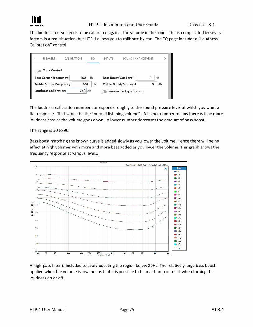
HTP-1 Installation and User Guide Release 1.8.4
The loudness curve needs to be calibrated against the volume in the room This is complicated by several
factors in a real situation, but HTP-1 allows you to calibrate by ear. The EQ page includes a “Loudness
Calibration” control.
The loudness calibration number corresponds roughly to the sound pressure level at which you want a
flat response. That would be the “normal listening volume”. A higher number means there will be more
loudness bass as the volume goes down. A lower number decreases the amount of bass boost.
The range is 50 to 90.
Bass boost matching the known curve is added slowly as you lower the volume. Hence there will be no
effect at high volumes with more and more bass added as you lower the volume. This graph shows the
frequency response at various levels:
A high-pass filter is included to avoid boosting the region below 20Hz. The relatively large bass boost
applied when the volume is low means that it is possible to hear a thump or a tick when turning the
loudness on or off.
HTP-1 User Manual Page 75 V1.8.4

HTP-1 Installation and User Guide Release 1.8.4
For Highest Quality Audio There are a number of guidelines that users should be aware of to achieve the highest possible audio
quality.
1) Engaging any of the surround modes results in the sample rate being limited to 48kHz by a high
quality sample rate converter. Avoid the surround modes if you wish to take advantage of high
sample rates.
2) The Dirac room correction filter limits the sample rate to 48kHz. Turn off Dirac filtering if you
wish to take advantage of high sample rates. You can copy the delay and trims measured by
Dirac into an otherwise empty calibration slot, or you can use the Dirac Bypass setting.
Ensure that the maximum output voltage (formerly amplifier sensitivity) on the calibration page is set
correctly. The best dynamic range (SNR) will be achieved when the output is set to match the amplifier
and the HTP-1 volume is at maximum for the amplifier. The HTP-1 uses a high quality analog volume
control. It also reserves some of its digital dynamic range using a small amount of digital attenuation.
This digital attenuation (and hence your headroom) is at a minimum when the volume is at its maximum
level as set on the calibration page. Remember that if there is no headroom, then adding gain in
equalizers (Dirac, PEQ, tone) and trim controls can result in clipping.
HTP-1 User Manual Page 76 V1.8.4

HTP-1 Installation and User Guide Release 1.8.4
Connectivity The CONNECTIVITY tab of the Web GUI Home Page allows you to configure CEC connectivity to your TV
as well as network connectivity.
The wired Ethernet IP address of the HTP-1 is displayed in the lower left corner of the Front Panel LCD
Display. You can type this IP address into the address bar of a browser to access the Web GUI. The
system has been tested to work well with common browsers.
Setting up ARC/eARC and CEC The HTP-1 supports “ARC” (Audio Return Channel) and the newer “eARC” (Enhanced Audio Return
Channel). The ARC/eARC channel is used to return audio from the TV to the amplifier. The main
difference between ARC and eARC is that eARC can support the transport of higher fidelity audio
formats such as Dolby TrueHD and DTS-HD Master Audio. eARC can also support Dolby Digital Plus while
only some ARC implementations will support this format. The CEC communications protocol (Consumer
HTP-1 User Manual Page 77 V1.8.4

HTP-1 Installation and User Guide Release 1.8.4
Electronic Control) is a key part of ARC while eARC is not dependent on CEC (but some TV vendors
require CEC support to be enabled in the Amp (like HTP-1) in order for eARC to be used). eARC, as a new
standard, will be available only on newer, higher end TV’s. This should change as eARC becomes more
mature.
Most system setups will include a 4k UHD TV as well as one or more 4k sources. Most “smart” TVs will
have a 4k source via built-in apps such as Netflix. This is the most common reason for using an
ARC/eARC path to get audio from the TV to the HTP-1. Also, some sources will be connected directly to
the TV’s HDMI input presenting another reason to use ARC/eARC as the audio path to the HTP-1.
The implementation of CEC and ARC varies with TV models. Some work better than others. It’s quite
common to have to try a few things before settling on a CEC/ARC configuration that satisfies. The HTP-1
has a lot of options for this purpose.
When CEC is enabled, the “TV” will be one of the possible input sources.
Connecting HTP-1 to TV for ARC/eARC Your TV likely has only one input that supports ARC/eARC. Be sure to connect the output of the HTP-1
marked ARC/eARC to that ARC or ARC/eARC-capable input. Failure to use this connection is the most
common problem with ARC/eARC setup.
CEC Settings To access the CEC settings, click the gear icon on the Web GUI Home Page, then click the CONNECTIVITY
tab. By default, CEC should be turned off. The button next to the CEC label shows the current state of
CEC.
Begin by turning on CEC, press the button next to the CEC label and it should change to ON. Then a list of
CEC options is shown below the button. All options should be enabled (switch set to the right, color is
blue) to start with. If they are not all enabled, enable them now.
The options should remain enabled unless needed to disable specific actions of the HTP-1 in response to
requests from other devices on the CEC network. For instance, “allow input changes” is disabled in the
example because the Tivo source doesn’t support it well.
Next you must configure your TV to enable CEC and ARC (if not already enabled). These may have other
names, such as “HDMI control” or… there are too many names for them all to be listed. The ARC on/off
setting is often found under the Speaker or Audio settings. Many TVs will allow at least a basic selection
between TV Speakers and ARC HDMI.
HTP-1 User Manual Page 78 V1.8.4

HTP-1 Installation and User Guide Release 1.8.4
CEC Control Options
CEC implementations by other devices can vary enough that sometimes not all devices work well
together. The various options allow you to selectively disable HTP-1 CEC controls which may help
eliminate undesirable control issues. Note that disabling these controls may result in other possible side
effects.
● allow power keys - Key commands involving Power (on, off, toggle) are enabled.
● allow volume/mute keys - Key commands involving Volume and Mute are enabled.
● allow system audio off - Allows HTP-1 to be commanded to the off state of System Audio (see
System Audio section below).
● allow input changes - Allows the HTP-1 to follow input change requests.
● allow standby - Allows the HTP-1 to be commanded into standby mode (different from power
keys).
Alternate TV Input If your TV does not support ARC/eARC or you must connect the HTP-1 HDMI output to an HDMI TV input
that does not support ARC/eARC, you may use the “Alternate TV input” pop-up menu to specify an
audio connection to the TV using one of the input ports listed in the pop-up. You may choose between
any of the Analog, Coaxial or Optical inputs. Associating one of these inputs with the HTP-1 TV input
allows the HTP-1 to know how to pick up audio from the TV when it receives instructions over the CEC
network to do so. In the screen capture above, we have selected Optical1 as the input to be used when
ARC and eARC are not available. If this alternate TV input is going to be used, be sure to connect up the
proper cable from the TV audio output to the desired HTP-1 input that is selected here.
TV Audio Priority The HTP-1 has three ways to pick up audio from the TV: eARC, ARC or the Alternate user-defined input.
The priority of using these three options is: eARC, ARC, Alternate. When TV is shown as the current input
on the HTP-1 home page, the actual input being used to receive audio is shown on the info screen next
to the label “TV Sound Source."
System Audio CEC has a feature called System Audio. When System Audio is On, the Amplifier (such as HTP-1) is asked
to render the audio for the system. When Off, the TV is asked to render audio for the system. The HTP-1
will always turn on System Audio when it is first powered on and attempt to determine where it should
pick up audio from. If there is an “Active Source” in the system then it will configure itself to pick up
audio from that device. If no active source can be discovered, it will stay on the last input used.
Most TVs have a setting to allow the user to select the audio rendering device (such as TV Speakers or
Amp). When the HTP-1 (or Amp) is de-selected as the audio rendering device, the TV will send a
command setting System Audio to the Off state. When the HTP-1 receives this command it will stop
rendering audio and configure the HDMI board to pass through audio from its inputs to outputs. While
making this transition, the video on the TV will be blanked out while the EDIDs provided by the HTP-1
are updated with the TV(s) audio capabilities so the source devices will provide audio that the TVs can
HTP-1 User Manual Page 79 V1.8.4

HTP-1 Installation and User Guide Release 1.8.4
render. The home page and front panel will replace their display of the HTP-1 volume setting to the
message “TV Audio." Also, all HTP-1 audio settings/status will be removed from these displays.
To get back to having the HTP-1 render audio, there are three options:
● Use the TV speaker settings to select the Amplifier to render audio. This will result in the TV
sending a command to the HTP-1 to turn on System Audio and informs the HTP-1 where to pick
up audio from.
● On the HTP-1 home page, below the “TV Audio” message is a button that has the text “CLICK TO
RETURN TO HTP-1 AUDIO." Pressing this will trigger the HTP-1 turn on System Audio.
● Selection of an audio only source, such as Coax, Optical, USB, etc. will trigger the HTP-1 to turn
on System Audio.
HTP-1 User Manual Page 80 V1.8.4

HTP-1 Installation and User Guide Release 1.8.4
Using Wi-Fi After you have setup the HTP-1 to use a wired Ethernet connection in the BASIC SETUP section, you can
switch over to use a Wi-Fi® connection. Ensure that the antenna that came with the unit is connected to
the gold SMA antenna connector on the rear panel.
With the HTP-1 powered on, note the IP address on the Front Panel LCD Display and enter it into your
browser. Click the gear icon on the Web GUI Home Page to access the System Configuration screen.
Click the CONNECTIVITY tab and click the Enable Wi-Fi slider to turn Wi-Fi on. Enter your network name
(SSID) and password or scan for networks, select your network, and enter the password. You must press
the Apply Network Settings button for these changes to take effect.
Once you have joined the Wi-Fi network, you can unplug the wired connection and use the Wi-Fi IP
address to access the Web GUI Home Page.
Dirac and Wi-Fi: Note that third party tools like the Dirac Live calibration program may not find the
HTP-1 if both network interfaces are enabled. Choose either wired or wireless for calibration.
Choosing DHCP or Static IP Address Assignment DHCP is typically used to automatically assign an IP address. If you wish to use a static assignment, this
can be achieved by turning off DHCP. You may lose your network connection when you change from
DHCP to a static address. The front panel will always display the correct IP address.
HTP-1 User Manual Page 81 V1.8.4

HTP-1 Installation and User Guide Release 1.8.4
Bluetooth The HTP-1 has a Bluetooth® radio that can communicate with your mobile device. Click the gear icon on
the Web GUI Home Page, then click the INPUTS tab. Click the slider to turn Bluetooth on, then click the
Enable Discovery button.
Set the discoverable timeout to something you are comfortable with and then press discovery. This
allows your phone to see the unit for pairing for the specified time.
Your mobile device should now be able to see the HTP-1 and pair. The typical pairing dialog is displayed.
If you are pairing with the HTP-1 and at the same time using your mobile device's web browser to
control the HTP-1, you'll find that switching back and forth clears the pairing dialog and aborts pairing.
Try it again and accept the pairing dialog as soon as you see it.
Resetting the Network Connection There is a way to completely reset the network connections from the front panel. Poke your finger on
the gear icon on the front panel. You may need to move your finger around a bit. The front panel
responds by displaying information about the network connection. A “Reset Ethernet Network” button
is an option. This is designed to bring the Ethernet network back to normal DHCP operation.
HTP-1 User Manual Page 82 V1.8.4

HTP-1 Installation and User Guide Release 1.8.4
System Page The SYSTEM tab of the Configuration page gives access to a number of other controls.
● The unit name set here is used for all other services that the device provides. You should set this
once. Spaces and capital letters are allowed, though the name may be truncated. You should see
this name when using Dirac, Roon and Bluetooth.
● When fast start is off the unit will turn off to a very low power state. CEC features like automatic
power on will not work in the low power state. The system starts much more quickly in fast start
mode. Video pass through (when HTP-1 is off) only works in fast start mode.
○ When the unit is in fast start mode, powering down from the remote or front panel fully
reboots the DSP.
HTP-1 User Manual Page 83 V1.8.4
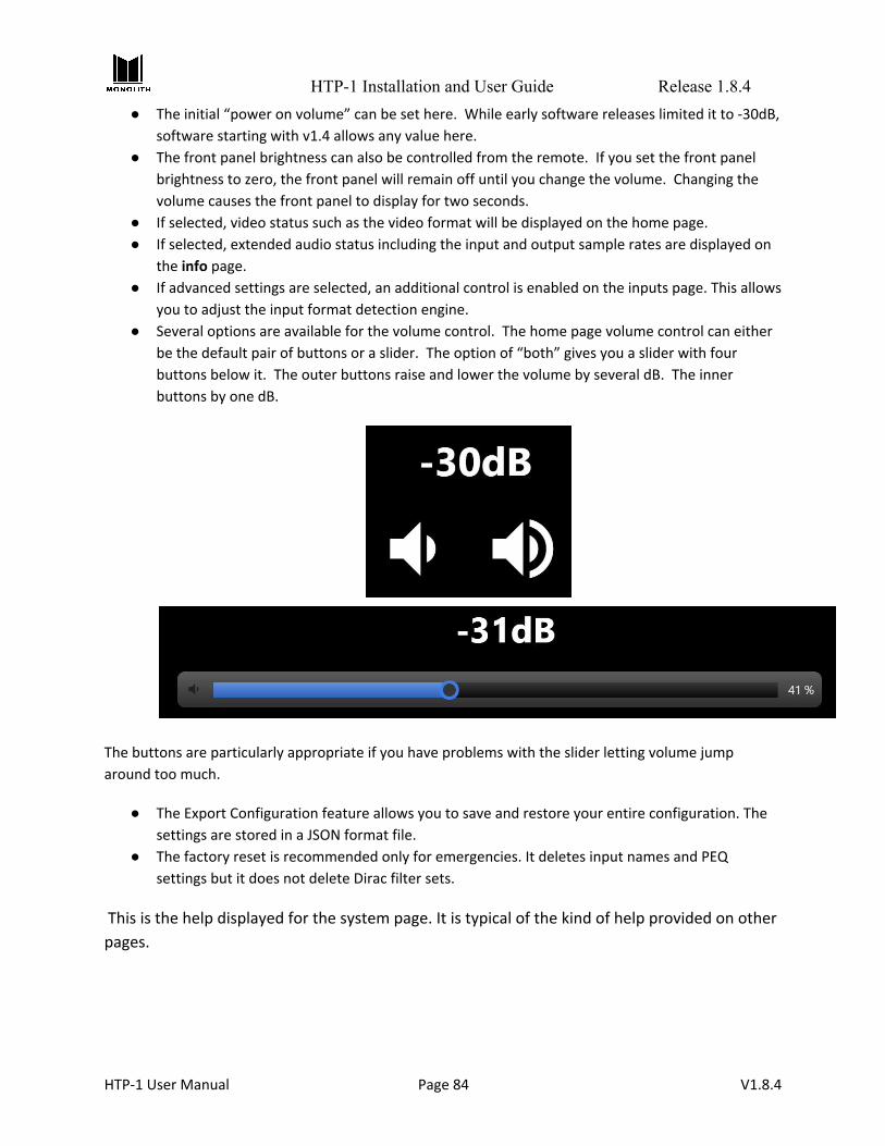
HTP-1 Installation and User Guide Release 1.8.4
● The initial “power on volume” can be set here. While early software releases limited it to -30dB,
software starting with v1.4 allows any value here.
● The front panel brightness can also be controlled from the remote. If you set the front panel
brightness to zero, the front panel will remain off until you change the volume. Changing the
volume causes the front panel to display for two seconds.
● If selected, video status such as the video format will be displayed on the home page.
● If selected, extended audio status including the input and output sample rates are displayed on
the info page.
● If advanced settings are selected, an additional control is enabled on the inputs page. This allows
you to adjust the input format detection engine.
● Several options are available for the volume control. The home page volume control can either
be the default pair of buttons or a slider. The option of “both” gives you a slider with four
buttons below it. The outer buttons raise and lower the volume by several dB. The inner
buttons by one dB.
The buttons are particularly appropriate if you have problems with the slider letting volume jump
around too much.
● The Export Configuration feature allows you to save and restore your entire configuration. The
settings are stored in a JSON format file.
● The factory reset is recommended only for emergencies. It deletes input names and PEQ
settings but it does not delete Dirac filter sets.
This is the help displayed for the system page. It is typical of the kind of help provided on other
pages.
HTP-1 User Manual Page 84 V1.8.4

HTP-1 Installation and User Guide Release 1.8.4
HTP-1 User Manual Page 85 V1.8.4
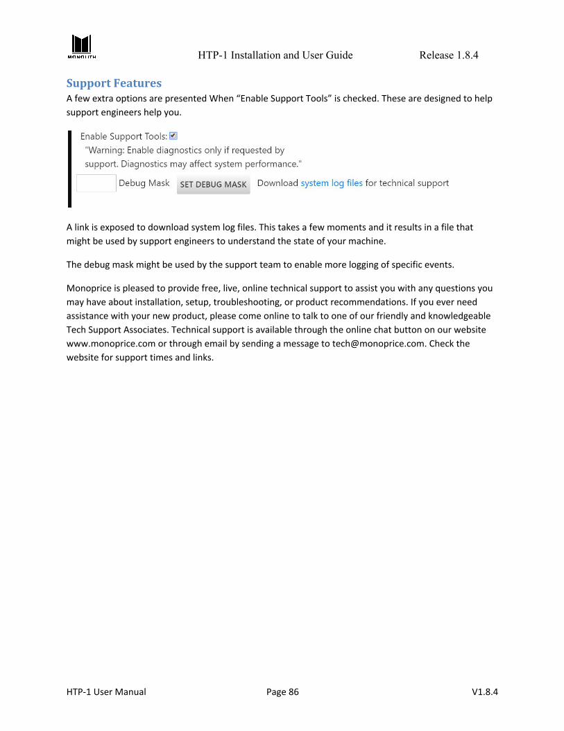
HTP-1 Installation and User Guide Release 1.8.4
Support Features A few extra options are presented When “Enable Support Tools” is checked. These are designed to help
support engineers help you.
A link is exposed to download system log files. This takes a few moments and it results in a file that
might be used by support engineers to understand the state of your machine.
The debug mask might be used by the support team to enable more logging of specific events.
Monoprice is pleased to provide free, live, online technical support to assist you with any questions you
may have about installation, setup, troubleshooting, or product recommendations. If you ever need
assistance with your new product, please come online to talk to one of our friendly and knowledgeable
Tech Support Associates. Technical support is available through the online chat button on our website
www.monoprice.com or through email by sending a message to [email protected]. Check the
website for support times and links.
HTP-1 User Manual Page 86 V1.8.4

HTP-1 Installation and User Guide Release 1.8.4
Video Features The video system of the HTP-1 supports HDMI 2.0b and HDCP 2.3 on all ports. It is the job of the HDMI
“repeater” inside of the HTP-1 to pass video according to the rules of HDMI while extracting the audio
for local decoding. It has two HDMI output ports that output the same content, so the current HDMI
input video content is sent to both output ports. During normal operation, audio is extracted and not
passed through. Selecting a non-video input (audio-only input) will leave the current HDMI input
selected to continue to pass video but the HTP-1 will render audio from the selected audio source.
At system startup (cold start, not the quick start), there will be no video passed through the HTP-1 until
the HTP-1 control system is up and running.
The current video status can be found on the info screen (blue circle i) next to the label “video status:."
Optionally, the video status can be displayed on the bottom of the Home page by enabling its display
from the System settings page. Just check the box next to “Display Video Status on Home Page:."
UHD Support By default, all HDMI inputs have Ultra High Definition (UHD) support enabled. There are some legacy
(older) devices that may have problems with the HTP-1 indicating support for UHD. A problematic
source device might be identified by seeing discolored video on the TV all the time, horrible looking
video on the TV all the time, never getting audio from the source all the time, etc. On the INPUTS tab of
the Web GUI Home Page there is a switch setting for every HDMI input titled “UHD Capable." Setting a
switch to the off position will remove information from the EDID that can cause problems for these
legacy devices. In technical terms, the HDMI Forum Vendor Specific Data Block is removed along with
video timing formats defined in HDMI 2.0 that are found in the Short Video Descriptor block.
This change in the EDID takes effect immediately upon changing the setting on the Inputs page. There
will be a momentary disruption in the video passing to the TV while the EDIDs are being reconfigured.
EDID Management The HTP-1 will read and parse the downstream EDIDs and populate an internal data structure with the
capabilities of each display device connected to the 2 output ports. It then creates a combined EDID
from this data to present to upstream devices (devices connected to the HDMI inputs). The EDIDs are
created with a logical AND approach, meaning that both downstream devices must support a capability
in order for that capability to be enabled in the upstream EDID.
At startup of the HTP-1 (cold start, not the quick start), the EDIDs will not be made available to the
upstream devices until the control system is up and running and can load the audio descriptors with the
correct audio support. After this is completed, the EDID will be presented to the upstream devices.
Turning off a downstream device will NOT result in its EDID capabilities being removed from the
“combined” EDID that is created and presented to upstream devices. In order for HTP-1 to “forget” an
output port EDID, the HDMI cable must be disconnected from the output port and the HTP-1 power
cycled (full power cycle, not the quick start).
HTP-1 User Manual Page 87 V1.8.4
HTP-1 Installation and User Guide Release 1.8.4
Dolby Vision Dolby Vision® is the one exception to the AND rule for capabilities found in the downstream EDIDs. The
Dolby Vision descriptor found in the EDID of the downstream device connected to Output 1 is the only
Dolby Vision descriptor that will be used and provided in the upstream EDID. If only one downstream
device supports Dolby Vision, it must be connected to HTP-1 Output port 1 to have Dolby Vision
recognized.
When Dolby Vision content is received, the EDID of the downstream device connected to Output 2 will
be examined for Dolby Vision support. If supported, Dolby Vision will be allowed to pass to this output. If
not supported, the output port will be disabled. When Dolby Vision content is no longer being received,
it may take up to 10-12 seconds for this output to be enabled again--the HTP-1 is making sure that Dolby
Vision content really has stopped before re-enabling the output port.
Triggers Triggers are typically used to cause the amplifiers to turn on when the HTP-1 turns on. The HTP-1 has
four 3.5mm trigger out jacks to drive up to four amplifiers. The HTP-1 also has one trigger input that can
be used to turn on the HTP-1.
The trigger input is designed to turn on the HTP-1. Applying 12V to the trigger in will cause HTP-1 to turn
on. If you use the trigger input you should not use the remote or the front panel to turn the unit on or
off as the trigger input takes precedence.
The trigger outputs can source 50mA at 12V. They are enabled when the HTP-1 is turned on. The trigger
outputs are over-current protected by a thermistor.
Using Roon The HTP-1 directly supports Roon. It is a “Roon Ready” device. Roon provides a music service designed
to support a locally stored archive of music which includes high quality formats like 96kHz-24 bit and
192kHz. Roon is a service that you must subscribe to. The HTP-1 takes the role of an output device in
your Roon system. You can play stereo audio through Roon.
Please refer to the release notes found in the help section of the web server for the latest information
about the status of Roon.
When you have a Roon subscription, there is a device known as a Roon Server in the system. This can be
a program on your PC. The Roon Server knows where your music is. There must also be a device that can
navigate your music collection and press the play button. The HTP-1 does not perform this role. The
Roon program on a PC can take on this role. The Roon app on your phone can also take on this role.
With your Roon controller ready, select the Roon input on the HTP-1. With the Roon input selected, the
Roon audio is routed through the HTP-1. You can enable upmixing as you desire, or enjoy the pure 192k
sample rate (as available) if preferred.
HTP-1 User Manual Page 88 V1.8.4

HTP-1 Installation and User Guide Release 1.8.4
Firmware Updates The Monolith HTP-1 software may see periodic improvements and it is easy to install an update from the
network when one becomes available. Click on the info button in the lower left of the homepage to
access the update page. The info icon on the homepage, and the gear icon on the front panel, will turn
yellow when there is an update available.
Clicking on “Update the system” will configure your system to have the latest “official” release. As of
v1.8.4, you will be asked to confirm the update. The update process can take several minutes,
depending on what has changed. The unit reboots when the update is complete. User settings are
preserved, but it is good practice to back up a copy of your settings from the system page.
You are encouraged to click on “Release Notes” to see what features have changed in this release as
well as what problems are known.
The “history” link allows you to see a selection of software releases and choose one. Releases on the
“master” branch are recommended for most users. “preview” releases are also available. These are (or
have been) in testing. Choosing one from the list will update the system to this specification with a
reboot following.
HTP-1 User Manual Page 89 V1.8.4

HTP-1 Installation and User Guide Release 1.8.4
Feedback The detailed status page includes this line:
Send feedback to the development team.
and “feedback” is a link to a page hosted on the HTP-1.
HTP-1 includes a number of features designed for diagnostic support. One of these is an option to
provide feedback on your system. Entering “http://YOUR_IP/feedback” in your browser brings up a web
form to provide feedback.
This feedback is anonymous unless you choose to volunteer a contact address. It is optional. This
feedback form is not a customer support request. Consider it a “suggestion box”. You might also use this
form to volunteer to be a beta tester. And if you wish to know about any immediate fixes, do provide an
email address and also contact Monoprice support.
HTP-1 User Manual Page 90 V1.8.4

HTP-1 Installation and User Guide Release 1.8.4
Alexa The Detailed Status page provides a link to register your Alexa device with the Amazon Device Cloud.
Alexa support should be considered preliminary and avid Alexa users might want to consider becoming a
beta tester.
HTP-1 User Manual Page 91 V1.8.4

HTP-1 Installation and User Guide Release 1.8.4
Specifications
HTP-1 User Manual Page 92 V1.8.4
Model HTP-1
Part Number 38788
Video Inputs 8x HDMI®
Audio-Only Inputs 2x analog stereo RCA, 3x digital coaxial, 3x digital optical, 1x
AES/EBU, 1x ARC/eARC
Streaming Inputs USB audio, Bluetooth®
Video Outputs 1x HDMI ARC/eARC, 1x HDMI
Audio Outputs 16-channels balanced XLR line outputs, max level 4.0vRMS.
Unbalanced stereo analog RCA mix output.
Triggers 1x trigger input, 4x trigger outputs
HDMI Version / HDCP™ Version 2.0 / 2.3
Maximum Video Resolution 4K@60Hz UHD
Audio Performance THD+N = 106dB at 1.8Vrms, 20-20 kHz, AES17 Dynamic Range = 116dB, 4Vrms, 20 kHz BW, A-weighted Frequency Response = 20-20 kHz, +1/-0.2 dB
Supported Audio Codecs
Dolby Atmos®, Dolby TrueHD™, Dolby Digital®, Dolby Surround®,
DTS:X®, DTS Neural:X®, DTS-HD Master Audio™, Auro-3D®,
Auro-Matic®
Crossover Variable 4th order Linkwitz-Riley
Room Correction/Equalization Dirac Live® (licensed with HTP-1 ownership)
Built-in Audio Correction Bass and Treble tone controls, 16-band parametric equalizer with
independent speaker control on each band
Connectivity Wired 10/100Mbps Ethernet, Wi-Fi®
Input Power 100 ~ 240 VAC, 50/60 Hz
Dimensions 17.1" x 5.7" x 12.0"

HTP-1 Installation and User Guide Release 1.8.4
Signal Processing Flow This diagram gives a rough idea of the signal flow inside of the HTP-1.
HTP-1 User Manual Page 93 V1.8.4

HTP-1 Installation and User Guide Release 1.8.4
IR Code Table The tables below illustrate the entire set of supported IR codes. The HTP-1 accepts NEC format remote
codes at address 0x36C9. The first table lists the codes sent by the remote.
Note that only the Volume Up and Down keys support the standard NEC repeat code for repeating these
keys. All other keys do not support key repeat.
The second table lists other codes recognized by the HTP-1.
HTP-1 User Manual Page 94 V1.8.4
Function NEC Code Function NEC Code Function NEC Code Power Toggle 02fd User Input 1 609f Red 51ae
Vol Down 09f6 User Input 2 619e Green 52ad Mute Toggle 0af5 User Input 3 629d Yellow 53ac
Vol Up 0bf4 User Input 4 639c Blue 54ab Mode None 1be4 User Input 5 649b A 55aa
Mode Dolby Sur 1ce3 User Input 6 659a B 56a9 Mode Neural-X 1de2 User Input 7 6699 C 57a8
Mode Native 1ee1 User Input 8 6798 D 58a7 Mode Auro 1fe0 User Input 9 6897 Preset 1 03fc
Night Toggle 40bf Last Input 44bb Preset 2 04fb Dialog Up 41be BT Pair 59a6 Preset 3 05fa
Dialog Down 42bd HDMI+ 4db2 Preset 4 06f9 Dirac Toggle 47b8 SPDIF+ 4eb1 Info 43bc
BT Pair 59a6 Analog+ 4fb0 Dim 45ba Loudness Toggle 5aa5 Stream+ 50af
Function NEC Code Function NEC Code Function NEC Code Power Off 25da TV Input 0ef1 In Analog 1 27d8 Power On 26d9 In HDMI 1 0ff0 In Analog 2 28d7
Mute On 4bb4 In HDMI 2 10ef In Optical 1 29d6 Mute Off 4cb3 In HDMI 3 11ee In Optical 2 2ad5 Loud On 3ac5 In HDMI 4 12ed In Optical 3 49b6 Loud Off 3bc4 In HDMI 5 13ec In Coaxial 1 2bd4 Night On 3cc3 In HDMI 6 14eb In Coaxial 2 2cd3 Night Off 3dc2 In HDMI 7 15ea In Coaxial 3 48b7 Dirac On 3ec1 In HDMI 8 17e8 In Roon 4ab5 Dirac Off 3fc0 In Bluetooth 46b9
In USB 2dd2 In AES 5ba4

HTP-1 Installation and User Guide Release 1.8.4
IR Code Over HTTP Remote Control An IR code over HTTP gateway has been added to allow the IR code listed in the above section to be sent
using the HTTP protocol for remote control and automation of the HTP-1. All IR code except “Power
Off” and “Power On” are supported.
The URL for the gateway is http://192.168.1.100/ircmd?code=XXXX where XXXX is the ‘NEC Code’ from
the ‘IR Code Table’ above. You should replace 192.168.1.100 with the actual IP address of your unit.
More than one NEC Code may be sent by separating them with a comma. The IR code must be sent
exactly as described because it is recognized as a text string: it must be 4 characters and lower case. The
following examples demonstrate sending multiple IR code using the ‘wget’ and the ‘curl’ commands:
● Selects HDMI 1, Native upmix mode, unmute:
wget "http://192.168.1.100/ircmd?code=0ff0,1ee1,4cb3"
curl "http://192.168.1.100/ircmd?code=0ff0,1ee1,4cb3"
● Selects HDMI 2, Direct upmix mode, mute:
wget "http://192.168.1.100/ircmd?code=10ef,4bb4,1be4"
curl "http://192.168.1.100/ircmd?code=10ef,4bb4,1be4"
In all cases the HTTP request returns a JSON string of the current system status. This is an advanced
feature that may be useful for automation and control. Note that some properties are self evident
about their meanings but some internal properties are not documented; they are to be ignored.
Third Party Applications A number of third parties have added support for the HTP-1. These are discussed in the HTP-1 section of
the AVS forum. Three that bear special mention are “Pink Soda’s Alternate UI”, the “preset editor” and
the “BEQ” program. The preset editor allows a user to assign actions to the preset buttons on the
remote control. It was designed as an example of how to access the controls as a third party.
The BEQ program allows for sophisticated editing of PEQ settings.
The alternate UI now includes a sophisticated preset editor, as well as enhanced editing of PEQ settings
and more control of the signal generator.
Privacy Disclosure The HTP-1 system has been designed to work with the Amazon Alexa Voice Control Smart Home Skill. As
such, data originated from the unit is sent to Amazon’s Alexa cloud servers in support of the operations
of the Smart Home Skill.
HTP-1 User Manual Page 95 V1.8.4

HTP-1 Installation and User Guide Release 1.8.4
The HTP-1 is designed to operate inside of a home firewall. Exposing its Ethernet interface directly to the
wild internet is strongly discouraged.
On system start up a connection is made to the Amazon Alexa cloud server. A unique identification is
included in this connection such that this unit could be uniquely identified. Such connection is persistent
and is always connected whenever the system is powered up.
When the ‘Unit Name’ or the ‘Input Labels’ of the HTP-1 are changed, a remote database is updated so
that the friendly names can be associated with the physical inputs on the HTP-1.
Periodically system health data such as error logs, software versions, and update status are reported to
assist software development and improvement.
When the Alexa Smart Home Skill has been certified by Amazon and is generally available, and when you
have installed the Smart Home Skill and account linked your HTP-1 to your Amazon account, your
Amazon profile identifier is stored in the database to associate the HTP-1 to your Alexa account.
Without this account linking step the HTP-1 is not personally identifiable.
Regulatory Compliance
Notice for FCC
This device complies with Part 15 of the FCC rules. Operation is subject to the following two conditions:
(1) this device may not cause harmful interference, and (2) this device must accept any interference
received, including interference that may cause undesired operation.
Modifying the equipment without Monoprice's authorization may result in the equipment no longer
complying with FCC requirements for Class B digital devices. In that event, your right to use the
equipment may be limited by FCC regulations, and you may be required to correct any interference to
radio or television communications at your own expense.
This equipment has been tested and found to comply with the limits for a Class B digital device, pursuant
to Part 15 of the FCC Rules. These limits are designed to provide reasonable protection against harmful
interference in a residential installation. This equipment generates, uses and can radiate radio frequency
energy and, if not installed and used in accordance with the instructions, may cause harmful
interference to radio communications. However, there is no guarantee that interference will not occur
in a particular installation. If this equipment does cause harmful interference to radio or television
reception, which can be determined by turning the equipment off and on, the user is encouraged to try
to correct the interference by one or more of the following measures:
● Reorient or relocate the receiving antenna.
HTP-1 User Manual Page 96 V1.8.4

HTP-1 Installation and User Guide Release 1.8.4
● Increase the separation between the equipment and receiver.
● Connect the equipment into an outlet on a circuit different from that to which the receiver is
connected.
● Consult the dealer or an experienced radio/TV technician for help.
RF Exposure Statement for FCC
Caution
This equipment complies with radiation exposure limits set forth for an uncontrolled environment. End
users must follow the specific operating instructions for satisfying RF exposure compliance. This
transmitter must be at least 20 cm from the user and must not be collocated or operated in conjunction
with any other antenna or transmitter.
Notice for Industry Canada This Class B digital apparatus complies with Canadian ICES-003. Cet appareil numérique de la classe B est
conforme à la norme NMB-003 du Canada.
Special Thanks The development team wishes to express a special thank you to all of our beta testers, and especially to
Timo.
Revision History v0.1: Initial version provided from the help menu.
v0.4: Initial public posting.
v1.1: Updated for software release 1.1.
v1.3: Updated for software release 1.3. Search for the italicised terms. Partial reset, Trim and
headroom guidance, Dirac tips from AVS, Not finding Dirac, dim feature, Watch Video with Other Audio,, privacy disclosure.
v1.4: Update for software release 1.4. Search for the italicised terms: Multiple Subwoofers, power on
volume, The option of “both”, Back Panel Mapping Display.
v1.6: Amplifier Sensitivity changed to Maximum Output Level. Auro 2D is mentioned. Signal generator
added.
v1.7: Dirac Live Bass Control updates.
v1.7.1: Added sine wave as a signal generator source.
v1.7.2: Reworked speaker position description. Better wording about PEQ and Dirac.
v1.8.3: Noted differences in Q calculations in PEQ.
v1.8.4: Updated max volume description and info/history/feedback descriptions.
HTP-1 User Manual Page 97 V1.8.4

HTP-1 Installation and User Guide Release 1.8.4
Important Information
Information in this document is provided solely to aid users of the HTP-1 in understanding its operation. Monoprice reserves the right to make changes without further notice to any products herein. Monoprice makes no warranty, representation, or guarantee regarding the suitability of its products for any particular purpose, nor does Monoprice assume any liability arising out of the application or use of any product or circuit, and specifically disclaims any and all liability, including without limitation consequential or incidental damages. Monoprice does not convey any license under its patent rights nor the rights of others.
Monolith™ is a trademark of Monoprice Inc.
Dolby®, Dolby Atmos®, Dolby Surround®, Dolby ProLogic®, Dolby TrueHD™, Dolby Vision™, and the
double-D symbol are trademarks of Dolby Laboratories.
DTS®, DTS:X®, DTS Neural:X®, DTS Neo®, the Symbol, and DTS and the Symbol together are registered
trademarks of DTS, Inc. DTS-HD™ and DTS-HD Master Audio™ are trademarks of DTS, Inc.
Auro-3D®, Auro-Matic® and the Auro-3D logo are registered trademarks of Auro Technologies N.V..
Dirac® and Dirac Live® are registered trademarks of Dirac Research AB.
The Bluetooth® word mark and logos are registered trademarks of Bluetooth SIG, Inc.
Wi-Fi® and Wi-Fi Alliance® are registered trademarks of Wi-Fi Alliance.
HDMI®, the HDMI Logo, and High-Definition Multimedia Interface are trademarks or registered trademarks of
HDMI Licensing LLC in the United States and other countries.
HDCP™ is a trademark of Digital Content Protection LLC.
Blu-ray Disc™, Blu-ray™, and the logos are trademarks of the Blu-ray Disc Association.
Roon® is a trademark of Roon, LLC registered in the U.S. and other countries.
Sony® is a registered trademark of Sony Corporation.
Microsoft®, Windows®, and Microsoft Edge® are either registered trademarks or trademarks of Microsoft
Corporation in the United States and/or other countries.
Apple® and Mac® are trademarks of Apple Inc., registered in the U.S. and other countries.
Netflix® is a registered trademark of Netflix, Inc.
Vudu™ is a trademark of Vudu, Inc.
EDID® is a registered trademark of the Video Electronics Standards Association.
Wikipedia® is a registered trademark of the Wikimedia Foundation, Inc., a non-profit organization.
Google™, Chrome™, and Chrome OS™ are trademarks of Google LLC.
FIREFOX® is a registered trademark of Mozilla Foundation.
NEC® is a registered trademark of NEC Corporation.
© 2019, 2020 Monoprice Inc. All rights reserved.
HTP-1 User Manual Page 98 V1.8.4