h. loomis and b. pettit building science corporation or process disclosed ... unless otherwise...
TRANSCRIPT

Measure Guideline: Deep Energy Enclosure Retrofit for Zero Energy Ready House Flat Roofs H. Loomis and B. Pettit Building Science Corporation
May 2015

NOTICE
This report was prepared as an account of work sponsored by an agency of the United States government. Neither the United States government nor any agency thereof, nor any of their employees, subcontractors, or affiliated partners makes any warranty, express or implied, or assumes any legal liability or responsibility for the accuracy, completeness, or usefulness of any information, apparatus, product, or process disclosed, or represents that its use would not infringe privately owned rights. Reference herein to any specific commercial product, process, or service by trade name, trademark, manufacturer, or otherwise does not necessarily constitute or imply its endorsement, recommendation, or favoring by the United States government or any agency thereof. The views and opinions of authors expressed herein do not necessarily state or reflect those of the United States government or any agency thereof.
Available electronically at http://www.osti.gov/scitech
Available for a processing fee to U.S. Department of Energy and its contractors, in paper, from:
U.S. Department of Energy Office of Scientific and Technical Information P.O. Box 62 Oak Ridge, TN 37831-0062 phone: 865.576.8401 fax: 865.576.5728 email: mailto:[email protected]
Available for sale to the public, in paper, from: U.S. Department of Commerce National Technical Information Service 5285 Port Royal Road Springfield, VA 22161 phone: 800.553.6847 fax: 703.605.6900 email: [email protected] online ordering: http://www.ntis.gov/help/ordermethods.aspx

Measure Guideline: Deep Energy Enclosure Retrofit for Zero Energy Ready House Flat Roofs
Prepared for:
The National Renewable Energy Laboratory
On behalf of the U.S. Department of Energy’s Building America Program
Office of Energy Efficiency and Renewable Energy
15013 Denver West Parkway
Golden, CO 80401
NREL Contract No. DE-AC36-08GO28308
Prepared by:
H. Loomis and B. Pettit
Building Science Corporation
3 Lan Drive, Suite 102
Westford, MA 01886
NREL Technical Monitor: Stacey Rothgeb
Prepared under Subcontract No. KNDJ-0-40337-05
May 2015
iii

The work presented in this report does not represent performance of any product relative to regulated minimum efficiency requirements.
The laboratory and/or field sites used for this work are not certified rating test facilities. The conditions and methods under which products were characterized for this work differ from standard rating conditions, as described.
Because the methods and conditions differ, the reported results are not comparable to rated product performance and should only be used to estimate performance under the measured conditions.
iv

Table of Contents List of Figures ............................................................................................................................................ vi List of Tables .............................................................................................................................................. vi Definitions .................................................................................................................................................. vii Executive Summary ................................................................................................................................. viii Progression Summary: Zero Energy Ready Home Retrofit ................................................................... ix 1 Introduction ........................................................................................................................................... 1 2 Decision-Making Criteria ..................................................................................................................... 2
2.1 Cost and Performance ..........................................................................................................2 2.2 Constructability ....................................................................................................................3 2.3 Moisture Performance ..........................................................................................................4 2.4 Air Leakage Performance ....................................................................................................4
3 Technical Description .............................................................................................................................. 5 3.1 Fundamental Principles ........................................................................................................5 3.2 Climate Zones and Building Environments .......................................................................13
4 Measure Implementation ....................................................................................................................... 17 4.1 Climate-Specific Factors ....................................................................................................17 4.2 Field Inspection ..................................................................................................................18 4.3 Implementation Risks ........................................................................................................18 4.4 Installation Procedure ........................................................................................................19
A. Remove existing cladding and inspect the roof structure .............................................19 B. Remove roof sheathing boards near the roof perimeter and mechanically fasten
pressure-treated plywood to the interior vertical face of the parapet; install a strip of new roof sheathing over the remaining roof sheathing board ...................19
C. Install ccSPF and fibrous insulation in the roof cavity; reinstall roof sheathing boards20 D. Install new roof sheathing and a strip of fully adhered air barrier membrane ..............21 E. Install rigid insulation and cover board .........................................................................22 F. Install roof membrane and flashings..............................................................................23
4.5 Installation Procedure—ALTERNATE OPTION (NO SLEEPERS NEEDED) ...............24 A. Remove existing cladding and inspect the roof structure .............................................24 B. Remove the roof sheathing boards near the perimeter and mechanically fasten the
pressure-treated plywood to the interior vertical face of the parapet.....................24 C. Install ccSPF and fibrous insulation in the roof cavity; reinstall roof sheathing boards25 D. Install a fully adhered air barrier membrane .................................................................25 E. Install rigid insulation and cover board .........................................................................25 F. Install roof membrane and flashings..............................................................................25
References ................................................................................................................................................. 26
v

List of Figures Figure 1. Optimum configuration of control layers for a roof ................................................................ 5 Figure 2. Roof assembly with new roof sheathing as air control layer over existing roof sheathing 6 Figure 3. Roof assembly with air barrier membrane over existing roof sheathing.............................. 6 Figure 4. Wood frame roof assembly with rigid foam board exterior insulation, Lstiburek 2010 ...... 7 Figure 5. Wood frame roof assembly with spray foam exterior-side insulation, Lstiburek 2010 ....... 7 Figure 6. Roof drain water management .................................................................................................. 8 Figure 7. Skylight/mechanical curb water management ......................................................................... 9 Figure 8. PV roof rack blocking water management ............................................................................... 9 Figure 9. Parapet water management ..................................................................................................... 10 Figure 10. U.S. Department of Energy climate zones ............................................................................ 14 Figure 11. Hygrothermal map, Lstiburek 2006a ..................................................................................... 15 Figure 12. Rainfall map, Lstiburek 2006a ............................................................................................... 16 Figure 13. Existing roof cladding to be removed (left) and verification of existing
conditions (right) ................................................................................................................................ 19 Figure 14. Existing boards removed near roof perimeter with pressure-treated plywood
installed at parapet (left); strip of OSB sheathing with integrated water-resistive barrier at parapet (right) ..................................................................................................................................... 20
Figure 15. Spray foam installation connecting masonry wall to roof sheathing (air barrier) ........... 20 Figure 16. Fibrous insulation installed in the rafter cavity with air sealing details ........................... 21 Figure 17. Sleepers over existing board sheathing (left); new roof sheathing at field of
roof (right) ........................................................................................................................................... 22 Figure 18. Rigid insulation in multiple layers with staggered seams (left); insulation cover
board (right) ........................................................................................................................................ 22 Figure 19. Blocking for future PV installation ........................................................................................ 23 Figure 20. Roof membrane with blocking for PV system rack (left); finished roof (right) ................ 23 Figure 21. PV system rack attachment during construction (left) and PV installation completed
(right) ................................................................................................................................................... 24 Figure 22. Skylight installation (left) and metal cap flashing (right) .................................................... 24
Unless otherwise noted, all figures were created by BSC.
List of Tables Table 1. RS Means Unit Costs for Roof Retrofit Components ($/ft2) ..................................................... 3 Table 2. Air-Impermeable Roof Insulation Minimum Thermal Resistance To Control
Condensation for Climate Zones 5, 6, 7, 8, and Marine 4 (from 2009 IRC and 2012 IRC) ........... 12 Table 3. Typical Thermal Resistance of Common Rigid Insulation Materials .................................... 13 Table 4. Typical Thermal Resistance of Common Cavity Insulation Materials .................................. 13 Table 5. Recommended Minimum R-Value for Roof Enclosures ......................................................... 14
Unless otherwise noted, all tables were created by BSC.
vi

Definitions
ccSPF Closed-Cell Spray Polyurethane Foam
DEER Deep Energy Enclosure Retrofit
IBC International Building Code
IECC International Energy Conservation Code
IRC International Residential Code for One- and Two-Family Dwellings
OSB Oriented Strand Board
PIC Polyisocyanurate
PV Photovoltaics
SPF Spray-Applied Polyurethane Foam
TPO Thermoplastic Polyolefin
XPS Extruded Polystyrene
vii

Executive Summary
This Measure Guideline provides design and construction information for a deep energy enclosure retrofit solution of a flat roof assembly. It describes the strategies and procedures for an exterior retrofit of a flat wood-framed roof with brick masonry exterior walls using exterior and interior (framing cavity) insulation. The approach supported in this guide could also be adapted for use with flat wood-framed roofs with wood-framed exterior walls.
Designers, contractors, and building code officials will benefit from the information contained in this Measure Guideline. The guide may also be helpful to building owners who wish to learn more about strategies for deep energy enclosure retrofit of flat roofs.
This Measure Guideline is important to the high-performance retrofit industry because it demonstrates techniques for retrofitting flat roofs from the exterior, which is less disruptive to the living space and allows the structure to remain occupied during the project. It also illustrates a solution for preparing homes to become zero energy ready
.
viii

Progression Summary: Zero Energy Ready Home Retrofit
INSPECT AND ASSESS THE
HOME
Inspect and Assess the Home: Identify and address risks to occupants or to the building that could be aggravated by the work. Verify safe working conditions. Determine whether the building has more urgent problems that must be addressed.
REMOVE EXISTING
CLADDING
Remove Existing Cladding. Remove existing roof cladding and inspect the roof structure. Do not proceed if structural work needs to be performed. Revise the roof assembly as needed.
SPRAY FOAM AND FIBROUS
INSULATION
Install Spray Foam and Fibrous Insulation. Install closed-cell spray polyurethane foam (ccSPF) in the roof cavity at the wall perimeter and fill the rafter cavity with fibrous insulation. Reinstall the roof sheathing boards.
AIR BARRIER
Install Air Barrier. Install OSB sheathing with integrated water-resistive barrier at field of roof and install a strip of membrane at the roof-to-wall connection and extend to top of plywood at parapet to act as an air barrier in the assembly.
Do Not Proceed if: • The house is not structurally sound. • The house includes atmospherically vented combustion appliances (except cooking
appliances). • The house has knob-and-tube wiring or other electrical hazards. • The house contains hazardous materials that pose a risk to occupants or workers. • The house has active water leaks that will not be resolved by the retrofit projects. • Kitchen and/or bath fans are not vented to the exterior. • The home is not equipped with a whole-house ventilation system.
!
1
3
4
5
6
Install Rigid Insulation and Cover Board. Install rigid insulation, butt joints tight. When installing multiple layers, stagger and tape seams. Install cover board and ensure its compatibility with the roof assembly.
Install Roof Membrane and Metal Cap Flashing. Install roof membrane and flashings at parapet and all penetrations per new construction best practices.
RIGID INSULATION AND COVER
BOARD
ROOF MEMBRANE AND FLASHINGS
2
Remove Existing Roof Sheathing Boards. Remove existing boards near the roof perimeter and mechanically attach pressure-treated plywood to parapet. Install a strip of oriented strand board (OSB) sheathing with integrated water-resistive barrier at roof perimeter.
EXISTING ROOF SHEATHING
BOARDS
ALTERNATIVELY, a fully adhered membrane can be installed at field of roof and extended to top of
plywood at parapet to create a continuous air barrier in the assembly.
ix

1 Introduction
This Measure Guideline provides design and construction information for a deep energy enclosure retrofit (DEER) solution for a flat roof assembly. It describes the strategies and procedures for an exterior retrofit of a flat wood-framed roof with brick masonry exterior walls with the use of exterior and interior (framing cavity) insulation. The approach could also be adapted for use with flat wood-framed roofs with wood-framed exterior walls.
An exterior retrofit is generally more favorable than an interior retrofit because it is less disruptive to the living space and typically allows a structure to remain occupied during the project. Exterior retrofit also offers significant advantages for building durability by reducing the likelihood of cold weather condensation within the structure (Straube et al. 2012).
This Measure Guideline includes several distinct sections that cover:
• A review of decision criteria pertinent to retrofitting flat roofs from the exterior
• Fundamental building science and design principles for the use of exterior and interior insulation
• Construction detailing and procedures developed to explain how the various elements of the design are implemented.
Roof failures typically occur from leakage of bulk water (precipitation) or vapor diffusion condensation. Most often, flat roof assemblies are designed and constructed without a proper air-control layer and focus only on the thermal-control system (insulation). By designing the roof enclosure system properly, most if not all failures can be avoided. A successful roof will perform the following tasks per Straube and Grin (2010):
• Provide a water management system to keep precipitation out.
• Provide an air barrier system between the indoors and outdoors.
• Provide a vapor control system to maintain a durable environment that does not allow condensation and does not promote mold growth.
• Provide a thermal control system to keep the heat out during the summer and retain heat during the winter.
In the retrofit world, the order of work to be considered during construction or home improvements is important. Health and safety issues must be addressed first and are more important than durability issues, which are in turn more important than saving energy.
Designers, contractors, and building code officials will benefit from the information contained in this Measure Guideline. The guide may also be helpful to building owners who wish to learn more about strategies for DEER of flat roofs. For the most part this measure will be used as part of a larger building project; therefore, it is highly recommended that a design professional or a qualified contractor be retained.
1

2 Decision-Making Criteria
This section discusses the major decision-making criteria once an exterior retrofit has been chosen and after considering issues such as aesthetics, historic significance, improved comfort, and the lifespan of the building. These issues tend to dominate the decision-making process to determine the type of retrofit to be undertaken.
2.1 Cost and Performance Cost and performance are intricately linked and have to be studied in combination to decide the best choice given the decision maker’s goals and objectives. The decision about the thermal performance depends on the specific requirements of the project. For teams who would like to meet high-energy savings goals, a higher level of insulation must be provided for their projects.
The measure presented in this guide illustrates high levels of insulation; however, the decision about the amount of insulation to be added on the exterior and interior will depend on the existing structure of the roof, the locally adopted building and energy code requirements, and the project budget. The Technical Description section of this Measure Guide discusses the building science principles as well as the requirements of the local building codes about the insulation levels for roof structures. Those requirements need to be met first. However, the homeowner may choose to increase the R-value of the roof assembly; a cost analysis may be performed to evaluate the payoff for the additional insulation.
The potential for thermal bridging must also be evaluated for the retrofit options under consideration. With the rigid insulation being installed on the exterior of the roof assembly there will be very little thermal bridging. This allows for the nominal insulation value to be very close to the in-service or “effective” thermal resistance value. In contrast, the thermal resistance of rafter cavity fill insulation is reduced by the thermal bridging of the framing.
Another aspect to consider is if certain building materials can be substituted for others. Polyisocyanurate (PIC) rigid foam insulation has the highest R-value of all the rigid insulation materials; fiberglass-faced PIC (commonly used in roof installations) is R-6 per inch and foil-faced PIC is R-6.5 per inch. However, extruded polystyrene (XPS) rigid insulation (at R-5 per inch) costs less and could be considered for this type of roof retrofit.
A commonly neglected critical aspect for flat roof assemblies is the air-control layer, which should be located below the layers of rigid insulation (Lstiburek 2011). This guideline shows OSB sheathing with an integrated water-resistive barrier and taped seams that is installed over tapered sleepers (2x lumber ripped with a taper to create a slope). The sleepers are used when slope must be added to the existing roof. If the roof does not need to be sloped, a fully adhered membrane could be applied directly to the existing roof board sheathing as an air-control layer. These decisions should be made based on the existing conditions, the performance goals, and the project budget.
Installation costs for the retrofit solution described in this guideline can be expected to vary widely from estimates in the referred sources because they depend on such factors as contractor experience, prevalent region practices, material costs, and the particular circumstances of the
2

project. Most cost values for the various roof components were obtained from RSMeans CostWorks 2013 (Reed Construction Data 2013), which is a cost-estimating tool that provides the cost of materials, installations, overhead, and profit. Other values are average costs of materials obtained from home improvement and online stores; such values represent the cost of materials only. The values shown in Table 1 are for a project based in Boston, Massachusetts.
Table 1. RS Means Unit Costs for Roof Retrofit Components ($/ft2)
Material Description Nominal R-Value
Cost Range ($/ft2)
½-in. Cover Board – 1.27 ½-in. Plywood Sheathing – 1.70
6-in. Roofing PIC, (3) 2-in. Layers 36 6.39 6-in. XPS, (3) 2-in. Layers 30 5.64
OSB Sheathing With Integrated Water-Resistive Barrier, Taped – 5.60* Fully Adhered Air Barrier Membrane – 0.70*
2-in. ccSPF 12 1.77 12-in. Dense-Pack Cellulose 42 2.78 18-in. Dense-Pack Cellulose 63 3.43
12-in. Blown Fiberglass 42 1.80 18-in. Blown Fiberglass 63 2.70
* Material cost only; price from home improvement and online stores Other items such as self-adhered membrane flashings, metal flashings, and wood blocking are omitted from the table because inclusion of these these items will depend on whether roof elements such as skylights, mechanical curbs, or photovoltaics (PV) are part of the project.
Energy performance versus cost could be further optimized using energy modeling—in particular models that account for both energy savings and increased first cost such as BEopt (Christensen et al. 2006).
2.2 Constructability How easy a measure is to implement can greatly impact the success of a project. Difficult details and construction sequences often lead to increased cost and reduced performance. Efficiency in construction is driven by simple repeatable details and common construction practice. The more that a measure deviates from common construction techniques (or requires overly complicated sequences involving multiple trades) the more likely that the work will not be completed with the intended result.
A key benefit to the use of exterior rigid insulation with cavity insulation in flat roof assemblies is that this approach is considered standard practice. The only variations to this common approach are ensuring that all the control layers are provided in the roof assembly and that they are connected to the control layers of the adjacent assemblies and roof elements. These variations may require additional planning and detailing as well as a change in typical construction sequences.
3

2.3 Moisture Performance Installing exterior rigid insulation on the exterior of the roof assemblies keeps the exterior sheathing warmer and reduces condensation risks. In fact, the benefit is recognized in the building codes, and adding sufficient exterior rigid insulation can allow for the elimination of traditional interior vapor-control layers. However, maintaining a sufficient ratio of exterior insulation to total roof assembly insulation is important. In colder climate zones more exterior (rigid) insulation is needed to maintain the sheathing temperature.
2.4 Air Leakage Performance Air control is often omitted from the design for flat roof assemblies; focus is only on the thermal-control system (insulation). Designing a retrofit assembly that allows significant air leakage is risky; therefore, the air leakage performance of the retrofit strategies must be evaluated before a decision is made. However, experience has shown that air barrier systems formed by careful taping, caulking, and use of appropriate air sealing materials such as spray polyurethane products and fully adhered membranes are quite likely to achieve airtightness when properly installed using standard quality control measures.
4

3 Technical Description
3.1 Fundamental Principles This section provides fundamental information on exterior and interior insulation in flat roof assemblies. The intent is to provide the background physics and logic on how the measure impacts a building’s performance.
Roof assemblies are one component of a building that separates the inside environment from the outside environment. The separation is often referred to as the building enclosure or building envelope. For roof assemblies, control of rainwater, airflow, water vapor flow, and heat flow are key factors to providing a durable enclosure. The control of these elements can be separated into four principal control layers. They are presented in order of importance:
• A water-control layer
• An air-control layer
• A vapor-control layer
• A thermal-control layer. The best place for the control layers is on the outside of the structure to protect the structure, as discussed by Lstiburek (2007). The optimum configuration is presented in Figure 1.
Figure 1. Optimum configuration of control layers for a roof
3.1.1 Flat Roof Assembly The retrofit assembly consists of the existing ceiling plaster under the roof rafter cavity, which is entirely filled with cellulose insulation. The wall perimeter of the roof rafter cavity is covered with 2-in. ccSPF to provide a robust air seal between the existing roof sheathing and the ceiling plane. A strip of pressure-treated plywood is installed at the interior vertical face of the parapet to allow for adequate attachment of the air barrier membrane. The air-control layer (in the form of OSB sheathing with integrated water-resistive barrier and taped seams) is installed over the existing roof sheathing; a strip of air barrier membrane is placed at the perimeter of the roof sheathing and the parapet. The new roof sheathing is installed over sleepers (2x lumber ripped with a taper) to provide a consistent slope to drain. Three 2-in. layers of PIC rigid insulation are installed over the air-control layer with the joints staggered and the seams taped. Insulation cover board is installed over the rigid insulation and in turn covered with the roof membrane (which turns up and over the parapet). Cap flashing with drip edges on either side is installed over the parapet.
5
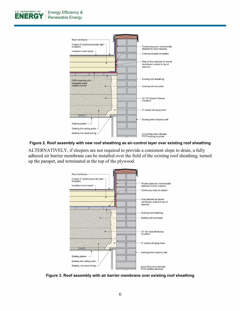
Figure 2. Roof assembly with new roof sheathing as air-control layer over existing roof sheathing
ALTERNATIVELY, if sleepers are not required to provide a consistent slope to drain, a fully adhered air barrier membrane can be installed over the field of the existing roof sheathing, turned up the parapet, and terminated at the top of the plywood.
Figure 3. Roof assembly with air barrier membrane over existing roof sheathing
6

For a wood-frame building, a similar combination of air impermeable insulation is used. Either rigid foam boards (Figure 4) or ccSPF (Figure 5) could be used per Lstiburek (2010). The thickness of the air-impermeable insulation should be changed based on climate zone. The roof air barrier should remain at the structural sheathing layer; air barrier connections to the wall should be based on the wall’s air barrier strategy.
Figure 4. Wood frame roof assembly with rigid foam board exterior insulation, Lstiburek 2010
Figure 5. Wood frame roof assembly with spray foam exterior-side insulation, Lstiburek 2010
3.1.2 Water-Control Layer Controlling rainwater is the single most important factor in the design and construction of durable roof assemblies. The fundamental principle of water management is to shed water by layering materials in such a way that water is directed downward and outward out of the building or away from the building. The key to this fundamental principle is drainage (Lstiburek 2006b).
7

Flat roofs should never be perfectly flat; that is, all flat roofs should be tilted and sloped to drains. Any roof penetrations (drains, skylights, and mechanical curbs) must be properly flashed to prevent water entry. The materials that form the water-control layer (in this case the roof membrane) overlap each other in shingle fashion or are sealed so that water drains down and does not collect on the roof (Lstiburek 2006b).
Figure 6. Roof drain water management
Skylights, mechanical curbs, and other roof penetrations must be integrated into the roof’s drainage plane (membrane) (Figure 7 and Figure 8). Membranes or formable flashings that line these curbed openings are all elements of drainable systems. These approaches work best when they are sloped inward so the rainwater is directed into the roof drain and taken out of the building. Tobiasson (2009) explicitly recommends interior drainage from low-slope roofs. Draining a membrane over the eaves may have lower first costs, but these eave areas are often the weakest part of the waterproofing, so leaks commonly develop there. Similar issues are seen with ice damming of scuppers, which result in roof ponding.
8
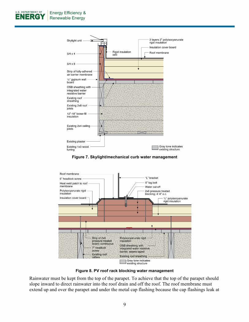
Figure 7. Skylight/mechanical curb water management
Figure 8. PV roof rack blocking water management
Rainwater must be kept from the top of the parapet. To achieve that the top of the parapet should slope inward to direct rainwater into the roof drain and off the roof. The roof membrane must extend up and over the parapet and under the metal cap flashing because the cap flashings leak at
9

joints. The flashing should have drip edges—front and back—to avoid staining the building façade (Lstiburek 2011).
Figure 9. Parapet water management, Courtesy National Research Council of Canada
3.1.3 Air-Control Layer Controlling airflow in a building enclosure is important because of its role in heat and moisture flow. One key strategy in airflow control is the use of air-control layers. Air-control layers are systems of materials designed and constructed to control airflow between a conditioned space and an unconditioned space. The air-control layer is the primary air enclosure boundary that separates indoor (conditioned) air from outdoor (unconditioned) air.
The air-control layer in this flat roof assembly is the OSB sheathing with an integrated water-resistive barrier and taped joints over the existing board roof sheathing (or the fully adhered membrane). This configuration places the air-control layer outside the building’s structure (but inboard of the rigid insulation). The significant advantage of an exterior air-control layer is the ease of installation and the lack of detailing issues related to intersecting partition walls and service partitions. However, installers of an exterior air-control layer must deal with transitions where roof assemblies intersect exterior walls. The air-control layer must be continuous over the entire building enclosure; therefore, special attention is required at the roof-to-wall connection. An additional advantage of exterior air barrier systems is the control of wind washing of fibrous cavity fill insulation. The significant disadvantage of exterior air barriers in cold climates is that they cannot control the entry of air-transported moisture into cavities from the interior. Installing both interior and exterior air barriers addresses the weakness of each; common interior air barrier materials include interior gypsum board (the air drywall approach) and polyethylene film (Lstiburek 2006a).
Air-control layers should be: 1. Impermeable to airflow 2. Continuous over the entire building enclosure 3. Able to withstand the forces that may act on them during and after construction 4. Durable over the expected lifetime of the building.
10

3.1.4 Vapor-Control Layer The fundamental principle of a vapor-control layer is to keep water vapor out of an assembly and to let water vapor out if it gets in. In this regard, the vapor-control layer is in reality more of a vapor-control “strategy” that uses materials with specific vapor-control properties strategically within the assembly. It can be complicated because sometimes the best strategies to keep water vapor out also trap water vapor in.
Vapor-control layers installed on the interior of assemblies prevent them from drying inward. This is a concern in any air-conditioned building or in any building where there is also a vapor-control layer on the exterior—the “double vapor barrier” problem. A “double vapor barrier” is a problem because moisture within the assembly cannot dry to either side. This moisture could come from assemblies that start out wet because of rain, or from the use of wet materials during construction that were not allowed sufficient time to dry before being closed in.
The three principal control approaches to dealing with water in the vapor form are:
• Let the water vapor pass through the assembly from the inside out and from the outside in. A wall assembly can dry to both sides. These are called flow-through assemblies.
• Install a distinctive vapor-control layer to retard the flow of water vapor into the wall assembly from either the inside or the outside. These are called vapor-control layer assemblies. The most common location for a vapor-control layer is on the inside “warm in winter” side of the thermal insulation (typically for cold climates).
• Control the temperature of the surfaces where condensation is likely to occur by raising the surface temperature with insulation. The most common method of doing this is to use rigid insulation on the exterior of assemblies. These are called control of condensing surface temperature assemblies.
Controlling the condensing surface temperature is the most versatile strategy and works well in all climate zones. In cold climates it also provides the best protection against air leakage condensation problems because instead of limiting the movement of moisture it functions by preventing condensation.
When exterior rigid insulation is added outboard of the structural sheathing the interior surface temperature of the structural sheathing is increased in winter because the insulation keeps the sheathing warmer. By raising the temperature of the condensing surface, condensation from interior water vapor migrating into the wall assembly is controlled. This temperature increase allows assemblies to be constructed in cold climates without interior vapor-control layers.
The building codes recognize this and provide guidance about the minimum thermal resistance values of rigid insulation and/or exterior insulation required to control condensation when Class I and II vapor retarders are replaced with Class III retarders (e.g., latex paint) in various climate zones. There is a minimum R-value requirement for “air-impermeable” insulation (e.g., rigid insulation or spray foam) in a roof assembly to control condensation. Table 2 is taken from Table R806.4 Insulation for Condensation Control of the 2009 IRC (ICC 2009a) and Table R806.5 Insulation for Condensation Control of the 2012 IRC (2012a). The table shows the minimum air-
11

impermeable insulation thermal resistance values to control condensation for climate zones 5, 6, 7, 8, and marine 4.
It is important to maintain a sufficient ratio of exterior insulation to total roof assembly insulation. As the outdoor temperature gets colder, the amount of insulation needed to maintain the sheathing temperature increases.
Table 2. Air-Impermeable Roof Insulation Minimum Thermal Resistance To Control Condensation for Climate Zones 5, 6, 7, 8, and Marine 4 (from 2009 IRC and 2012 IRC)
Climate Zone Minimum R-Value 5 20
6 25
7 30
8 35
4C 10
Additional analysis may be required for assemblies that have higher levels of cavity insulation such as the flat roof assembly described in this guideline. The values stated in Table 2 are based on “typical” or code insulation levels. When used appropriately, hygrothermal computer modeling would provide the most refined analysis of the risk. However, analysis at this level is seldom required for residential construction. Other methods can provide reasonable checks against condensation risks. One such method is a dew point calculation that is aimed at limiting the sheathing temperature to 45°F based on the average temperature over the coldest 3 months of the year (assuming interior conditions of 35% relative humidity and 70°F). . This and other methods are discussed by Lstiburek (2006a) and Straube (2011).
3.1.5 Thermal-Control Layer The thermal-control layer controls the flow of heat from the inside to the outside and from the outside to the inside. As with the other control layers, the most important factor to consider when dealing with the thermal-control layer is its continuity.
The addition of exterior rigid insulation can significantly improve the roof assembly’s thermal performance because it provides a continuous insulation layer that diminishes the impact of thermal bridges caused by framing. Typical thermal resistance of common rigid insulation materials are shown in Table 3.
CODE REQUIREMENTS FOR THERMAL INSULATION ARE FOUND IN SECTION 402 OF THE 2009 IECC AND R402 OF THE 2012 IECC.
12

Table 3. Typical Thermal Resistance of Common Rigid Insulation Materials
R-Value/In. Foil-Faced PIC 6.5
Fiberglass-Faced PIC 6.0 XPS 5.0
The amount of exterior thermal rigid insulation added to the assembly will depend on the climate zone and design goals for the project. The minimum levels provided should be based on the minimum requirements for vapor and condensation control (see Section 3.1.4) and minimum requirements based on the current adopted building code and energy code, respectively, for the project. Additional insulation can be added above these minimums to create high R-value roof assemblies.
Loose-fill fibrous insulation can be added to the roof cavity for additional R-value. Typical thermal resistance of common fibrous materials can be seen in Table 4. However, greater amounts of air-permeable fibrous-fill insulation will increase the risks of sheathing condensation, unless the exterior rigid insulation is increased (see Section 3.1.4).
Table 4. Typical Thermal Resistance of Common Cavity Insulation Materials
R-Value/In. Dense-Pack Cellulose 3.5
Blown Fiberglass Insulation 3.5
3.2 Climate Zones and Building Environments Buildings should be suited to their environment. Building enclosures should be designed for a specific hygrothermal region (Figure 11), rain exposure zone (Figure 12), and interior climate.
For most residential buildings, interiors are assumed to be conditioned to around 70°F in the winter and 75°F in the summer. Relative humidities should be no higher than 35% during the coldest month in winter and no higher than 65% in the summer.
These conditions also form the basis for the requirements delineated in the model building codes. The model building codes climate zones referenced in the 2009 IECC (ICC 2009b) and the 2012 IECC (ICC 2012b) can be seen in Figure 10. Table 5 provides the minimum thermal resistance (R-value) requirements specified in the 2009 IECC (ICC 2009b) and the 2012 IECC (ICC 2012b) based on climate zone for the enclosure component addressed in this guide.
13

Table 5. Recommended Minimum R-Value for Roof Enclosures
Climate Zone Framed Roof Minimum R-Value 2009 IECC 2012 IECC
1 30 30 2 30 38 3 30 38
4 Except Marine 38 49 5 and Marine 4 38 49
6 49 49 7 and 8 49 49
Figure 10. U.S. Department of Energy climate zones
14

Figure 11. Hygrothermal map, Lstiburek 2006a
15

Figure 12. Rainfall map, Lstiburek 2006a
16

4 Measure Implementation
ALTERNATE OPTION (NO SLEEPERS NEEDED TO SLOPE DECK) 4.1 Climate-Specific Factors
The building enclosures should be designed for a specific hygrothermal region; their design will be dependent on the design goals for the project. The assemblies should follow the minimum requirements based on the current adopted building code and energy code, respectively, for the project.
Scope of Work A. Remove existing cladding and inspect the structural integrity of the roof. Do not proceed
if structural work needs to be performed. Based on the findings, revise the roof assembly and review specific detailing as needed.
B. Remove existing roof sheathing boards near the roof perimeter leaving one or two boards at the parapet. Mechanically fasten a strip of pressure-treated plywood to the interior vertical face of the parapet.
C. Install ccSPF in the roof cavity at the wall perimeter and fill the rafter cavity with fibrous insulation. Reinstall the roof sheathing boards.
D. Install the fully adhered air barrier membrane and extend it up the parapet to the top of the plywood.
E. Install rigid insulation with staggered joints and tape the seams of each layer. Install insulation cover board over rigid insulation.
F. Install the roof membrane over the insulation cover board and extend it up and over the parapet. Install the metal cap flashing.
Scope of Work A. Remove existing cladding and inspect the structural integrity of the roof. Do not proceed
if structural work needs to be performed. Based on the findings, revise the roof assembly and review specific detailing as needed.
B. Remove existing roof sheathing boards near the roof perimeter. Leave one or two boards at the parapet. Mechanically fasten a strip of pressure-treated plywood to the interior vertical face of the parapet. Install a strip of OSB sheathing with an integrated water-resistive barrier at the roof perimeter adjacent to the parapet on top of the remaining board sheathing.
C. Install ccSPF in the roof cavity at the wall perimeter and fill the rafter cavity with fibrous insulation. Reinstall the roof sheathing boards.
D. Install OSB sheathing with an integrated water-resistive barrier over the field of the roof. Install a strip of fully adhered air barrier membrane at the roof perimeter adjacent to the parapet and extend it up to the top of the plywood.
E. Install rigid insulation with staggered joints and tape the seams of each layer. Install insulation cover board over rigid insulation.
F. Install the roof membrane over the insulation cover board and extend it up and over the parapet. Install flashings at the parapet and any penetrations.
17
4.2 Field Inspection Identify and address risks to occupants or the building that could be aggravated by the work. Verify safe working conditions. Determine whether the building has more urgent problems that must be addressed. Determine the feasibility of the retrofit solution and of options. Inspect and assess the building for:
• Structural integrity of roof framing
• Presence of hazardous materials (e.g. lead, radon, asbestos)
• Safety and serviceability of the electrical system
• Rainwater or plumbing water leaks
• Rot or decay in framing
• Insect/pest damage/activity. Deficiencies or hazards must be remediated before the project begins, or incorporated into the scope of the project.
Given the increased airtightness associated with this retrofit, combustion safety and controlled mechanical ventilation upgrades are required to maintain acceptable indoor air quality.
Identify any atmospherically vented (or naturally aspirated) combustion appliances in the home. With the exception of gas stoves and cooktops, combustion appliances—including fireplaces—should be direct-vented or direct exhaust-vented equipment. Atmospherically vented appliances must be replaced or reconfigured to direct-vented or direct exhaust-vented operation before the project begins or as part of the project scope.
Verify that all kitchen and bathroom exhausts are vented to the exterior of the building. Source control ventilation deficiencies must be corrected either before the project begins or as part of the project scope.
If the home lacks a ventilation system that meets the requirements of the 2012 International Residential Code (2012 IRC, ICC 2012a), Section M1507.3 (or other relevant ventilation standards such as ASHRAE 62.2), a ventilation system meeting this requirement must be installed either before the project begins or as part of the project scope.
4.3 Implementation Risks Construction and renovation work entails inherent risks to workers. All applicable safety procedures must be followed.
18

4.4 Installation Procedure A. Remove existing cladding and inspect the roof structure Remove the existing roof cladding and inspect the structural integrity of the roof. Check the roof framing for any deficiencies, rot, insect damage, etc. Do not proceed if any repairs need to be performed.
Based on the findings, revise the roof assembly and review specific detailing as needed. Follow the minimum requirements of the current adapted building and energy codes.
Figure 13. Existing roof cladding to be removed (left) and verification of existing conditions (right)
B. Remove roof sheathing boards near the roof perimeter and mechanically fasten pressure-treated plywood to the interior vertical face of the parapet; install a strip of new roof sheathing over the remaining roof sheathing board
Remove two or three roof sheathing boards near the perimeter of the roof, leaving one or two boards at the parapet.
Mechanically fasten a strip of treated plywood to the interior vertical face of the parapet to allow for attachment of the strip of fully adhered air barrier membrane.
Install a strip of OSB sheathing with an integrated water-resistive barrier at the roof perimeter adjacent to the parapet on top of the remaining board sheathing. Provide a continuous bead of caulking between the existing board sheathing and a strip of new roof sheathing.
19

Figure 14. Existing boards removed near roof perimeter with pressure-treated plywood installed at
parapet (left); strip of OSB sheathing with integrated water-resistive barrier at parapet (right)
C. Install ccSPF and fibrous insulation in the roof cavity; reinstall roof sheathing boards
Spray 2 in. of ccSPF in the roof cavity at the wall perimeter to create an air barrier between the wall and the roof, and to provide adequate thermal resistance to prevent condensation. The area should be free of debris and dust prior to spraying for adequate adhesion.
Install fibrous insulation (e.g., cellulose) in the rafter cavities to the underside of the existing board roof sheathing. Reinstall the roof sheathing boards.
Figure 15. Spray foam installation connecting masonry wall to roof sheathing (air barrier)
20

Figure 16. Fibrous insulation installed in the rafter cavity with air sealing details
D. Install new roof sheathing and a strip of fully adhered air barrier membrane Install OSB sheathing with an integrated water-resistive barrier and the seams taped over the entire field of the roof as part of the air-control layer. If needed, install sleepers before installing the new roof sheathing to provide a consistent slope to drain.
21

Install a strip of fully adhered air barrier membrane on top of the new roof sheathing at the roof perimeter adjacent to the parapet and extend it to the top of the plywood to form a continuous air-control membrane. Seal all penetrations such as drains, skylights, and mechanical curbs in an airtight and durable manner to the air-control layer.
Figure 17. Sleepers over existing board sheathing (left); new roof sheathing at field of roof (right)
E. Install rigid insulation and cover board Install rigid insulation and butt the joints tightly. When installing multiple layers, offset seams in two directions and tape the seams of each layer. Add a continuous bead of caulking at the perimeter of the roof.
Install blocking for future PV installation.
Install insulation cover board over rigid insulation. Ensure compatibility of the cover board with the roof assembly.
Figure 18. Rigid insulation in multiple layers with staggered seams (left);
insulation cover board (right)
22

Figure 19. Blocking for future PV installation
F. Install roof membrane and flashings Install the roof membrane over the insulation cover board and lap it over the parapet to provide a continuous water-control layer.
Seal all penetrations such as drains, skylights, mechanical curbs, and PV blocking against water leaks per new construction best practices.
Install metal cap flashing at the parapet over the roof membrane. Provide drip edges on either side of the cap flashing to avoid staining the building façade.
Figure 20. Roof membrane with blocking for PV system rack (left); finished roof (right)
23

Figure 21. PV system rack attachment during construction (left) and installation completed (right)
Figure 22. Skylight installation (left) and metal cap flashing (right)
4.5 Installation Procedure—ALTERNATE OPTION (NO SLEEPERS NEEDED) A. Remove existing cladding and inspect the roof structure Remove the existing roof cladding and inspect the structural integrity of the roof. Check the roof framing for any deficiencies, rot, insect damage, etc. Do not proceed if any repairs need to be performed.
Based on the findings, revise the roof assembly and review specific detailing as needed. Follow the minimum requirements of the current adapted building and energy codes.
B. Remove the roof sheathing boards near the perimeter and mechanically fasten the pressure-treated plywood to the interior vertical face of the parapet
Remove two or three roof sheathing boards near the perimeter of the roof, leaving one or two boards at the parapet.
24

Mechanically fasten a strip of treated plywood to the interior vertical face of the parapet to allow for attachment of the fully adhered air barrier membrane.
C. Install ccSPF and fibrous insulation in the roof cavity; reinstall roof sheathing boards
Spray 2 in. of ccSPF in the roof cavity at the wall perimeter to create an air barrier between the wall and the roof and to provide adequate thermal resistance to prevent condensation. The area should be free of debris and dust before spraying for adequate adhesion.
Install fibrous insulation in the rafter cavities to the underside of the existing board roof sheathing. Reinstall the roof sheathing boards.
D. Install a fully adhered air barrier membrane Install a fully adhered air barrier membrane over the entire field of the roof and extend up to the top of the plywood at the parapet to form a continuous air-control layer. Seal all penetrations such as drains, skylights, and mechanical curbs in an airtight and durable manner.
E. Install rigid insulation and cover board Install rigid insulation and butt the joints tightly. When installing multiple layers, offset seams in two directions and tape the seams of each layer. Add a continuous bead of caulking at the perimeter of the roof.
Install blocking for future PV installation.
Install insulation cover board over rigid insulation. Ensure compatibility of the cover board with the roof assembly.
F. Install roof membrane and flashings Install roofing membrane over the insulation cover board and lap it over the parapet to provide a continuous water-control layer.
Seal all penetrations such as drains, skylights, mechanical curbs, and PV blocking against water leaks per new construction best practices.
Install metal cap flashing at the parapet over the roof membrane. Provide drip edges on either side of the cap flashing to avoid staining the building façade.
25

References
Christensen, C.; Anderson, R.; Horowitz, S.; Courtney, A.; Spencer, J. (2006) BEopt Software for Building Energy Optimization: Features and Capabilities. Golden, CO: National Renewable Energy Laboratory, NREL/TP-550-39929. https://beopt.nrel.gov.
ICC (2009a). International Residential Code for One- and Two-Family Dwellings. Country Club Hills, IL: International Code Council, Inc.
ICC (2009b). International Energy Conservation Code. Country Club Hills, IL: International Code Council, Inc.
ICC (2012a). International Residential Code for One- and Two-Family Dwellings. Country Club Hills, IL: International Code Council, Inc.
ICC (2012b). International Energy Conservation Code. Country Club Hills, IL: International Code Council, Inc.
Lstiburek, J. (2006a). Builder’s Guide to Cold Climates. Westford, MA: Building Science Press.
Lstiburek, J. (2006b). Water Management Guide. Westford, MA: Building Science Press.
Lstiburek, J. (2007). “Building Sciences: The Perfect Wall.” ASHRAE Journal May 2007, Atlanta, GA: American Society of Heating, Refrigerating and Air-Conditioning Engineers.
Lstiburek, J. (2010). “Building Sciences: Don’t Be Dense.” ASHRAE Journal August 2010, Atlanta, GA: American Society of Heating, Refrigerating and Air-Conditioning Engineers.
Lstiburek, J. (2011). “Building Sciences: Parapets: Where Roofs Meet Walls.” ASHRAE Journal February 2011, Atlanta, GA: American Society of Heating, Refrigerating and Air-Conditioning Engineers.
Reed Construction Data (2013). RSMeans CostWorks 2013, 17th Annual Edition. Norwell, MA. Retrieved November 7, 2014.
Straube, J.F.; Grin, A. (2010) Building America Special Research Project: High-R Roofs Case Study Analysis. RR-1006. Buildingscience.com.
Straube, J.F. (2011). “Building Science Digest 163: Controlling Cold-Weather Condensation Using Insulation.” Accessed January 2015: http://www.buildingscience.com/documents/digests/bsd-controlling-cold-weather-condensation-using-insulation/.
Straube, J.F.; Ueno, K.; Schumacher, C. (2012). Measure Guideline: Internal Insulation of Masonry Walls.” Washington, DC: Building America Building Technologies Program, Office of Energy Efficiency and Renewable Energy U.S. Department of Energy.
Tobiasson, W. (2009). “Chapter 16 – Roofs” in Moisture Control in Buildings: The Key Factor in Mold Prevention (Trechsel and Bomberg, eds.) West Conshohocken, PA: ASTM International.
26

www.buildingamerica.gov
DOE/GO-102015-4632 ▪ May 2015