gyuuiui
DESCRIPTION
gjyghgfhjkTRANSCRIPT
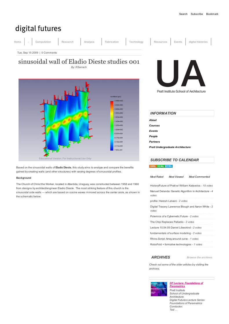
sinusoidal wall of Eladio Dieste studies 001By: RSarrach
Based on the sinusoidal walls of Eladio Dieste, this study aims to analyze and compare the benefits
gained by creating walls (and other structures) with varying degrees of sinusoidal profiles.
Background
The Church of Christ the Worker, located in Atlantida, Uraguay, was constructed between 1958 and 1960
from designs by architect/engineer Eladio Dieste. The most striking feature of this church is the
sinusoidal side walls — which are based on cosine waves mirrored across the center aisle, as shown in
the schematic below.
INFORMATION
About
Courses
Events
People
Partners
Pratt Undergraduate Architecture
SUBSCRIBE TO CALENDAR
Most Rated Most Viewed Most Commented
DF Lecture: Foundations ofParametrics
Pratt Institute
School of UndergraduateArchitecture
Digital Futures Lecture SeriesFoundations of Parametrics
Conductor:
Ted …
Subscribe Bookmark
Tue, Sep 15 2009 | 0 Comments
History/Future of Pratt w/ William Katavolos - 15 votes
Manuel Delanda: Genetic Algorithm in Architecture - 4
votes
profile: Haresh Lalvani - 2 votes
Digital Tracery: Lawrence Blough and Aaron White - 2
votes
Polemics of a Cybernetic Future - 2 votes
The Chip Replaces Palladio - 2 votes
Lecture 10.04.05 Daniel Libeskind - 2 votes
fundamentals of surface modeling - 2 votes
Rhino.Script: Array around curve - 1 votes
RoboFold + formative technologies - 1 votes
ARCHIVES
Check out some of the older articles by visiting the
archives.
Browse the archives
Search
Home - Computation Research Analysis Fabrication Technology Resources Events digital histories

Goal
The goal of this ongoing study is to create models based off of these sinusoidal walls and to compare
them under a variety of loading scenarios. Comparing models with varying degrees of “curviness” —
which is mathematically controlled by increasing/decreasing the amplitude of the cosine waves — will
provide insight into why Dieste would choose to use walls of this type. Such double-curved designs recur
in his works, and as an engineer, he informed these decisions based, at least in part, on the advantages
that these shapes provided with respect to loading.
Description
I started this study by creating a small variety of shapes to “play around with” in SolidWorks. Once I
determined how I would proceed with the study, I went back and normalized all of the parameters so that
valid comparisons could be drawn. I first generated a surface by using two juxtaposed cosine waves as
the top and bottom limits — the peaks of one cosine correlated with the troughs of the other, and vice-
versa. This surface was then thickened. Six shapes were generated from this template — with cosine
amplitudes of 0 (a flat, planar wall), 0.5, 1, 1.5, 2, and 2.5. They are all 24 inches tall and slightly more than
25 inches wide (8 pi, to be exact, since each has a period of 2 pi repeated 4 times).
I then applied a fixed set of conditions using COSMOSWorks. For each model, I applied three different
sets of restraints and pressure loads, all with a fixed value of 10psi compression: (1) bottom fixed and
loaded from the top, (2) bottom fixed and loaded from the sides, and (3) bottom fixed and loaded from the
top and the sides. For those familiar with the software, this is done with a basic static analysis, using PVC
as the material. Each design scenario produces five graphs: stress, strain, deformation, displacement,
and factor of safety. Due to the comparitive nature of these analyses, the graph of interest is that of the
stress analysis.
As part of the ongoing study, with excellent feedback from several instructors and professionals, more
loading scenarios will be included, including changing the restraints (i.e. “real life” wall restraints on all
sides) and the directions of the pressure loads. There will also be analyses of several more shapes
based on Dieste’s designs, including those with simple extruded cosine profiles instead of juxtaposed
ones, and with different materials.
Completed Analysis Images
As it exists now, there is already a fairly large set of images generated. I caution you to note that the scale
of each image is slightly different (”blue” on one graph is not necessarily equal to “blue” on another). The
usefulness of these graphs as images is that they provide insight into where the shapes experience the
highest levels of stress — mechanically, these areas are where the structures are the weakest from a
load-carrying perspective. The basis of the comparison lies in looking at the maximum and minimum
stress values for each iteration, which will be catalogued for comparison at a future date.
I will begin with the planar case, and work in increasing increments. For all cases other than the planar
one, I included screenshots of both sides of the models — because the shapes are based on cosines,
there are more full peaks on one side than on the other, thus creating a “preference” for bending in that
Rhino Bootcamp Workshop Level 1
Digital Futures Workshop SeriesPratt Institute
School of Undergraduate
ArchitectureRhino Workshop …
Symposium 11.04.18: PaoloPortoghesi
Monday, April 18th at 6pm in the
Higgins Hall Auditorium, …
Lecture 11.04.14: Guy Nordenson
Structural Engineer Guy Nordensonwill be speaking on Thursday April
…
Vray Rendering for Rhino, Session1
Description- The workshop will serve
as an introduction to rendering
with …
POPULAR TAGS
3d architect architecture art Associative
Modeling CAD code curve David Mans David Rutten
design drawing event Fabrication future
Grasshopper help John Lobell Lawrence Blough
lecture manufacturing maxwell maya McNeel &
Associates modeLab NURBS parametric
Parametrics pratt Primer Rendering Resources
rhino rhino3d Rhinoceros3D richard sarrach
robot science script scripting software studies
surface symposium Technology tool tools Topology
Vray workshop
GRASSHOPPER
Grasshopper | Dot NET SDK
Grasshopper | Forum
Grasshopper | MAIN
Grasshopper | Scripting Tutorials
LIFT | Grasshopper Primer
PRATT
Pratt Undergraduate Architecture
RHINO
Rhinoscript | Codeshare
Rhinoscript | Design Scripting Library
Rhinoscript | Dritsas’ Scripting and Computational
Geometry
Rhinoscript | ksteinfe’s Rhinoscript Wiki
Rhinoscript | Rhinoscript101

there are more full peaks on one side than on the other, thus creating a “preference” for bending in that
direction. In each image, the green arrows indicate which portion is fixed, and the red arrows indicate on
which face the pressure load is being applied. Blue represents the lowest stress levels, green the
intermediate stress levels, and red the highest stress levels, as per the scale on the right. The scale is
difficult to read at the required image resolution, but it varies for each model.
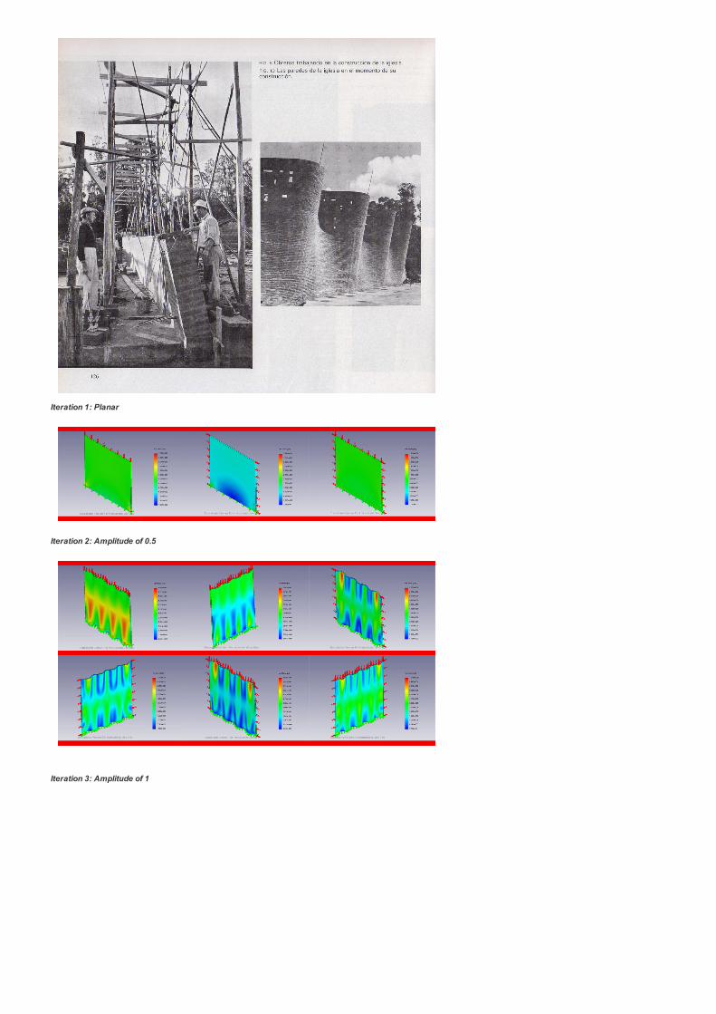
Iteration 1: Planar
Iteration 2: Amplitude of 0.5
Iteration 3: Amplitude of 1

Iteration 4: Amplitude of 1.5
Iteration 5: Amplitude of 2
Iteration 6: Amplitude of 2.5

A Short Note
You can already begin to see, just visually, the effect that adding curvature has on the stress distribution.
Rather than being evenly distributed throughout the body (as in the planar case), the curvature
concentrates the stress in the central, neraly planar area of the body. For example, under the third loading
scenario (bottom fixed, pressure from the top and from the sides), the planar body experiences a max
stress of 18.4 psi, whereas the most curved model (iteration 6) experiences a max stress of 347 psi under
identical conditions. The planar body has an average stress of 9.7 psi, whereas the curved body has an
average stress of 62.3 psi. However, the curved body also has more places wherein the stress is equal to
or lower than that of the planar body, as confirmed by probe sampling of those areas. Will planar surfaces
hold up better than curved ones to loads on the largest faces? Discovering these kinds of trade-offs are
the end goal of these studies.
Study by Gerard Delatour II originally posted on core.form-ula and was produced under the guidance of
Neil Katz + Ajmal Aqtash in the Stevens PAE Skyscraper Design Studio
(1 votes, average: 5.00 out of 5)
Tags: brick, COSMOSWorks, drawing, Eladio Dieste, science, sinusoidal, SolidWorks, Stevens, structure,
studies, Technology
© 2011 digital futures. All rights reserved. Powered by core.form.ula
View all articles by RSarrach
About RSarrach Email | Website
LEAVE A COMMENT
You must be logged in to post a comment.