gyroscope - yonsei universityphylab.yonsei.ac.kr/exp_ref/106_gyroscope_eng_lite.pdf · of the...
TRANSCRIPT
General Physics Lab Department of PHYSICS YONSEI University
Lab Manual (Lite)
Gyroscope Ver.20190409
Gyroscope
NOTICE This LITE version of manual includes only experimental procedures for easier reading on your smartphone. For more information and full instructions of the experiment, see the FULL version of manual.
Procedure
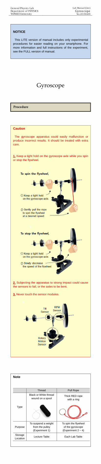
Caution The gyroscope apparatus could easily malfunction or produce incorrect results. It should be treated with extra care. 1. Keep a tight hold on the gyroscope axle while you spin or stop the flywheel.
2. Subjecting the apparatus to strong impact could cause the sensors to fail, or the axles to be bent. 3. Never touch the sensor modules.
Note
Thread Pull Rope
Type
Black or White thread wound on a spool
Thick RED rope with a ring
Purpose To suspend a weight
from the pulley (Experiment 1)
To spin the flywheel of the gyroscope
(Experiment 2 ~ 4)
Storage Location Lecture Table Each Lab Table
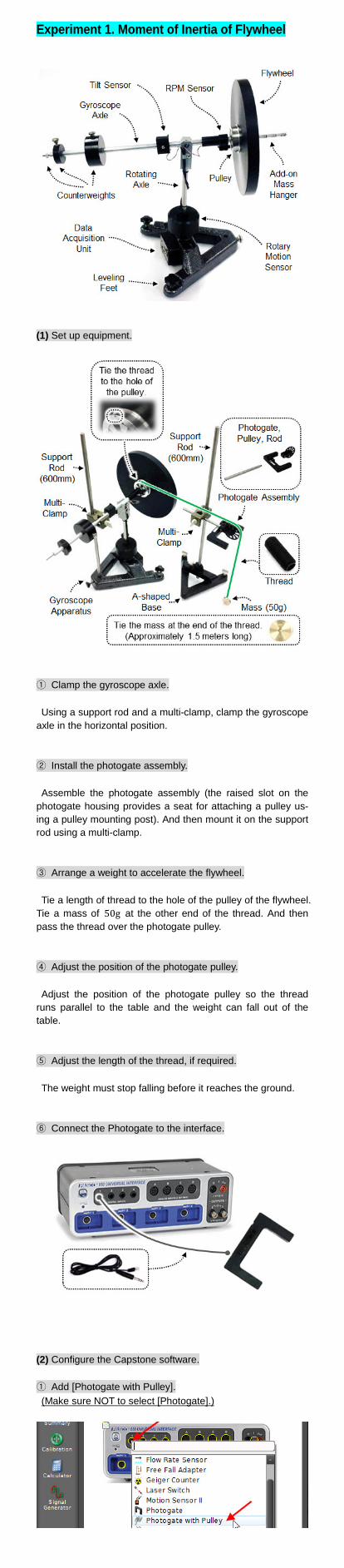
Experiment 1. Moment of Inertia of Flywheel
(1) Set up equipment.
① Clamp the gyroscope axle. Using a support rod and a multi-clamp, clamp the gyroscope axle in the horizontal position. ② Install the photogate assembly. Assemble the photogate assembly (the raised slot on the photogate housing provides a seat for attaching a pulley us-ing a pulley mounting post). And then mount it on the support rod using a multi-clamp. ③ Arrange a weight to accelerate the flywheel. Tie a length of thread to the hole of the pulley of the flywheel. Tie a mass of 50g at the other end of the thread. And then pass the thread over the photogate pulley. ④ Adjust the position of the photogate pulley. Adjust the position of the photogate pulley so the thread runs parallel to the table and the weight can fall out of the table. ⑤ Adjust the length of the thread, if required. The weight must stop falling before it reaches the ground. ⑥ Connect the Photogate to the interface.
(2) Configure the Capstone software. ① Add [Photogate with Pulley]. (Make sure NOT to select [Photogate].)

② Create a timer.
Make sure that [Linear Speed] is checked, the spoke arc length is 0.015m, and the spoke angle is 36°. ③ Create a graph display. 𝑥𝑥-axis: [Time(s)], 𝑦𝑦-axis: [Linear Speed(m/s)]
(3) Wind the thread around the pulley. By rotating the flywheel, wind the thread around of the pulley, until the weight is located near the photogate pulley.
(4) Click [Record].
(5) Release the flywheel. The torque of a tension force rotates the flywheel. Click [Stop] before the weight reaches the ground.

(6) Find the acceleration 𝑎𝑎 of the system.
(7) Calculate 𝐼𝐼 of the flywheel.
𝐼𝐼 = 𝑚𝑚𝑟𝑟2 �𝘨𝘨𝑎𝑎 − 1� (12)
𝑚𝑚 ≒ 0.050 kg : Mass of the weight 𝑟𝑟 ≒ 0.029 m : Radius of the pulley
(8) Repeat the measurement. Repeat the steps (3) to (7) more than three times.
𝑚𝑚 (kg) 𝑟𝑟 (m) 𝑎𝑎 𝐼𝐼
1st
2nd
3rd
…
average
(9) Compare the result value with the theoretical value.
The flywheel part is prepared on lecture table. Measure the mass, the inner radius, and the outer radius of the flywheel, and calculate the theoretical value 𝐼𝐼flywheel of the flywheel. 𝑅𝑅1 = _______ (m) 𝑅𝑅2 = _______ (m) 𝑀𝑀 = _______ (kg) Because the moment of inertia of the pulley is relatively smaller than that of the flywheel, you can ignore it. If required, use the pre-calculated value 𝐼𝐼pulley = 5.51 × 10⁻⁵ kg ⋅ m2. Experiment 2. Motion of Gyroscope, Part 1 (1) Set up equipment. ① Remove the photogate assembly. ② Remove the support rod and the multi-clamp clamping the gyroscope axle. ③ Remove the thread and the weight.
(2) Balance the gyroscope axle in a horizontal direction. Adjust the position of the counterweights, so that the gyro-scope axle is in equilibrium in a horizontal direction.

(3) Observe the motion of the gyroscope when the flywheel remains at rest. Do not spin the flywheel. Tap the end of the gyroscope axle
in a horizontal direction and observe the motion of the gyro-scope.
(4) Observe the motion of the gyroscope while the flywheel is spinning. Spin the flywheel. And then tap the end of the gyroscope axle in a horizontal direction as you did in the step above. Observe the motion of the gyroscope.
(5) Compare the results.
Q Describe the differences of two cases and explain why.
A
Experiment 3. Motion of Gyroscope, Part 2 (1) Spin the flywheel.
Caution When you stop the spinning flywheel, follow the instruc-tions below.

(2) Apply a steady force on the gyroscope axle. Spin the flywheel and pull the gyroscope axle downward using the pull rope (or push it downward using your finger). Observe the motion of the gyroscope.
Q Can you simply swing the gyroscope axle as you pull it? If not, which direction the axle rotates in? Explain why.
A
Q If you change the direction of the force, which direction is the axle moves in? Explain why.
A
Experiment 4. Precession Angular Speed
(1) Set up the equipment. Connect the gyroscope apparatus to the computer using Serial–USB cable. Provide power to the apparatus using 12V DC adapter. (Different type of DC adapter can be provided.)
(2) Run SensorLAB software.
① Connect or disconnect communication. ② Begin or stop recording. ③ Displays the sensor readings. ④ Plots graphs. ⑤ Select graph type. ⑥ Span graphs. ⑦ Converts the value of rotating angle to absolute value. ⑧ Change the sign of sensor values. ⑨ Adjust the ranges. ⑩ Shows data table.
Caution Before you run SensorLAB, you should shut down PAS-CO Capstone. If not, they suddenly crashes and you may lose your experimental data.

(3) Click [Connect] to receive the sensor values.
[Received Data] displays the real-time values of the sensors. Rotation: Rotating angle of the rotating axle ( ° )
(Rotary Motion Sensor) Tilt: Tile of the gyroscope axle ( ° )
(Tilt Sensor) DiskRPM: RPM of the flywheel (revolutions per minute)
(RPM Sensor) (4) Level the gyroscope. Follow the steps below. After you finish leveling the appa-ratus, avoid any movement of the apparatus base, or you may readjust the level of it.
(5) Balance the gyroscope axle. The counterweight arm has three weights. Adjust the posi-tions of these weights so that the gyroscope axle is exactly balanced in the horizontal position.
Note
In this experiment, you will use the gyroscope equipped with several sensors and components on the gyroscope axle. They all act downward force in the 𝑦𝑦-direction. Be-cause we do not know their weights and distances from the pivot, we cannot calculate net torque. If the axle is exactly balanced in the horizontal position by adjusting the position of counterweights, we don’t have to consider the torque of any component (including the flywheel) on the axle. Instead, to produce the turning torque, you will attach an add-on weight to the front of the flywheel. Then you can easily calculate the torque by measuring the mass and the position of the add-on weight.

(6) Hang an add-on weight on the gyroscope axle. To produce a tipping torque, hang the 100g weight on the 𝑅𝑅 = 0.15 m hanger slot. (The slots are 0.15, 0.17, 0.19, or 0.21 m away from the pivot.)
(7) Spin the flywheel. Spin up the flywheel to high speed using the pull rope.
(8) Let the gyroscope precess.
The direction of the gyroscopic precession depends on the rotational direction of the flywheel. If the flywheel spins in the direction as shown in the figure above, the gyroscope will precess counterclockwise. In general cases, i.e. in arbitrary initial conditions, the motion
of the gyroscope is a superposition of precession and nuta-tion. Nutation is caused by a possible small deviation of the vector of own angular momentum from the axis of symmetry. This deviation could be absent only in specific initial condi-tions. It means you should find the appropriate conditions in which the gyroscope precesses without nutation. If you touch the end of the axle, you can feel the rotating force on it and realize how fast the initial rotating speed of the axle would be. Help the gyroscope precessing in the horizon-tal direction without nutation by supporting it along the direc-tion at the correct speed, and then releasing it gently. Make sure not to push it faster or slower than the correct speed, or it will move upward or downward. When it precesses without nutation, begin data collection.

(9) Measure the RPM of the flywheel and the rotation period 𝑇𝑇 of the gyroscope. Place a support rod near the gyroscope. Be sure to avoid any collision with the gyroscope.
① When the end of the gyroscope axle passes the reference line(support rod), start measuring the rotation period 𝑇𝑇 of the gyroscope (Use any timer of your smartphone.) and also read and record the RPM of the flywheel.
② When the end of the gyroscope axle passes the reference line after one complete turn, stop measuring the rotation peri-od 𝑇𝑇 of the gyroscope and also record the RPM of the fly-wheel again. (10) Calculate the precession angular speed. Verify equation (11). Ω =
𝑑𝑑𝑑𝑑𝑑𝑑𝑑𝑑 =
𝜏𝜏𝐿𝐿 =
𝑀𝑀𝘨𝘨𝑅𝑅𝐼𝐼𝐼𝐼 (11)
Experimental value of the precession angular speed is Ω = 2𝜋𝜋/𝑇𝑇, where the period 𝑇𝑇 of the gyroscope is experi-mentally obtained in the step (9). Theoretical value of the precession angular speed is Ω = 𝑀𝑀𝘨𝘨𝑅𝑅 𝐼𝐼𝐼𝐼⁄ , where 𝑀𝑀 is the mass of the add-on weight, 𝑅𝑅 is the distance from the pivot to the add-on weight, 𝐼𝐼 is the moment of inertia of the flywheel which is obtained in the experiment 1, and 𝐼𝐼 is the flywheel angular speed which is obtained in the step (9). (1 rpm = 1 rev/min = 1/60 rev/s =2𝜋𝜋 60⁄ rad/s) (11) Repeat experiments. Vary conditions and repeat experiment. The following condi-
tions are recommended. - 𝑀𝑀 = 0.1 kg
- 𝑅𝑅 = 0.15 m 𝑜𝑜𝑟𝑟 0.17 m (1st or 2nd slot from the flywheel) - 𝐼𝐼 = 300 ~ 500 rpm
𝑀𝑀 𝑅𝑅 𝐼𝐼 𝐼𝐼 Ω =𝑀𝑀𝘨𝘨𝑅𝑅𝐼𝐼𝐼𝐼
Ω =2𝜋𝜋𝑇𝑇
1st
2nd
3rd
…

Please put your equipment in order as shown below.
□ Delete your data files from the lab computer. □ Turn off the Computer and the Interface. □ Keep the Gyroscope Apparatus away from strong impact. Never touch the sensor units of it. □ Unplug the Gyroscope DC Adapter. □ Do not unplug the Serial-USB Cable from the computer. □ Be careful not to knot or tangle the Pull Rope. □ Keep the Flywheel Parts, Spools of Thread, Scissors in the basket on the lecture table at the font of the laboratory.
End of LAB Checklist