gwald-rcbox30 m
DESCRIPTION
xls sheetsTRANSCRIPT
IES-Infrastructure Engineering Services Bridge over Hansa Khad
1
DESIGN CALCULATIONS AND DRAWINGS
FOR
SUPERSTRUCTURE
OF
BRIDGE OVER GWALD KHAD
ON
BARAGRAM TO KALWAL ROAD AT RD 0/643
186/4,Dhadyal,P.O.Bhojpur, Sundernagar,Distt. Mandi (H.P) Pin-174402 Mob-09418010139
IES INFRASTRUCTURE ENGINEERING SERVICES
IES-Infrastructure Engineering Services Bridge over Gwald Khad
2
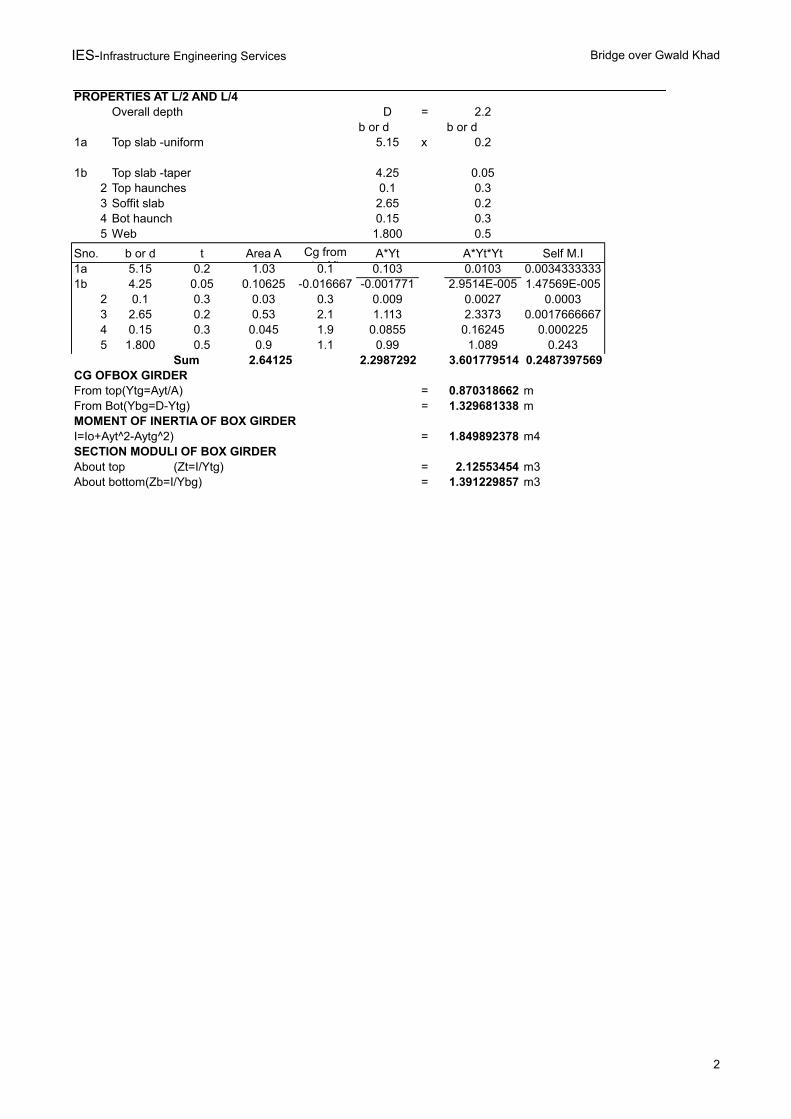
PROPERTIES AT L/2 AND L/4Overall depth D = 2.2
b or d b or d1a Top slab -uniform 5.15 x 0.2
1b Top slab -taper 4.25 0.052 Top haunches 0.1 0.33 Soffit slab 2.65 0.24 Bot haunch 0.15 0.35 Web 1.800 0.5
Sno. b or d t Area A A*Yt A*Yt*Yt Self M.I1a 5.15 0.2 1.03 0.1 0.103 0.0103 0.00343333331b 4.25 0.05 0.10625 -0.016667 -0.001771 2.9514E-005 1.47569E-005
2 0.1 0.3 0.03 0.3 0.009 0.0027 0.00033 2.65 0.2 0.53 2.1 1.113 2.3373 0.00176666674 0.15 0.3 0.045 1.9 0.0855 0.16245 0.0002255 1.800 0.5 0.9 1.1 0.99 1.089 0.243
Sum 2.64125 2.2987292 3.601779514 0.2487397569CG OFBOX GIRDERFrom top(Ytg=Ayt/A) = 0.870318662 mFrom Bot(Ybg=D-Ytg) = 1.329681338 mMOMENT OF INERTIA OF BOX GIRDERI=Io+Ayt^2-Aytg^2) = 1.849892378 m4SECTION MODULI OF BOX GIRDERAbout top (Zt=I/Ytg) = 2.12553454 m3About bottom(Zb=I/Ybg) = 1.391229857 m3
Cg from topYt
IES-Infrastructure Engineering Services Bridge over Gwald Khad
3
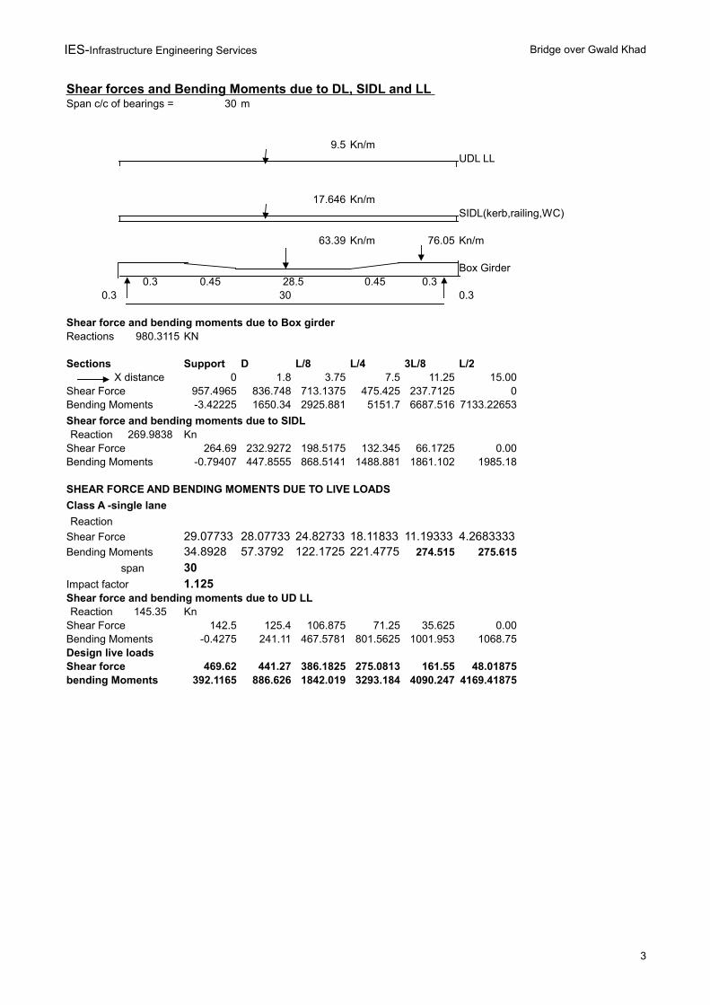
Shear forces and Bending Moments due to DL, SIDL and LL Span c/c of bearings = 30 m
9.5 Kn/mUDL LL
17.646 Kn/mSIDL(kerb,railing,WC)
63.39 Kn/m 76.05 Kn/m
Box Girder0.3 0.45 28.5 0.45 0.3
0.3 30 0.3
Shear force and bending moments due to Box girderReactions 980.3115 KN
Sections Support D L/8 L/4 3L/8 L/2 X distance 0 1.8 3.75 7.5 11.25 15.00
Shear Force 957.4965 836.748 713.1375 475.425 237.7125 0Bending Moments -3.42225 1650.34 2925.881 5151.7 6687.516 7133.22653
Shear force and bending moments due to SIDLReaction 269.9838 Kn
Shear Force 264.69 232.9272 198.5175 132.345 66.1725 0.00Bending Moments -0.79407 447.8555 868.5141 1488.881 1861.102 1985.18
SHEAR FORCE AND BENDING MOMENTS DUE TO LIVE LOADS
Class A -single lane
Reaction
Shear Force 29.07733 28.07733 24.82733 18.11833 11.19333 4.2683333Bending Moments 34.8928 57.3792 122.1725 221.4775 274.515 275.615
span 30Impact factor 1.125Shear force and bending moments due to UD LLReaction 145.35 Kn
Shear Force 142.5 125.4 106.875 71.25 35.625 0.00Bending Moments -0.4275 241.11 467.5781 801.5625 1001.953 1068.75Design live loadsShear force 469.62 441.27 386.1825 275.0813 161.55 48.01875bending Moments 392.1165 886.626 1842.019 3293.184 4090.247 4169.41875
IES-Infrastructure Engineering Services Bridge over Gwald Khad
4
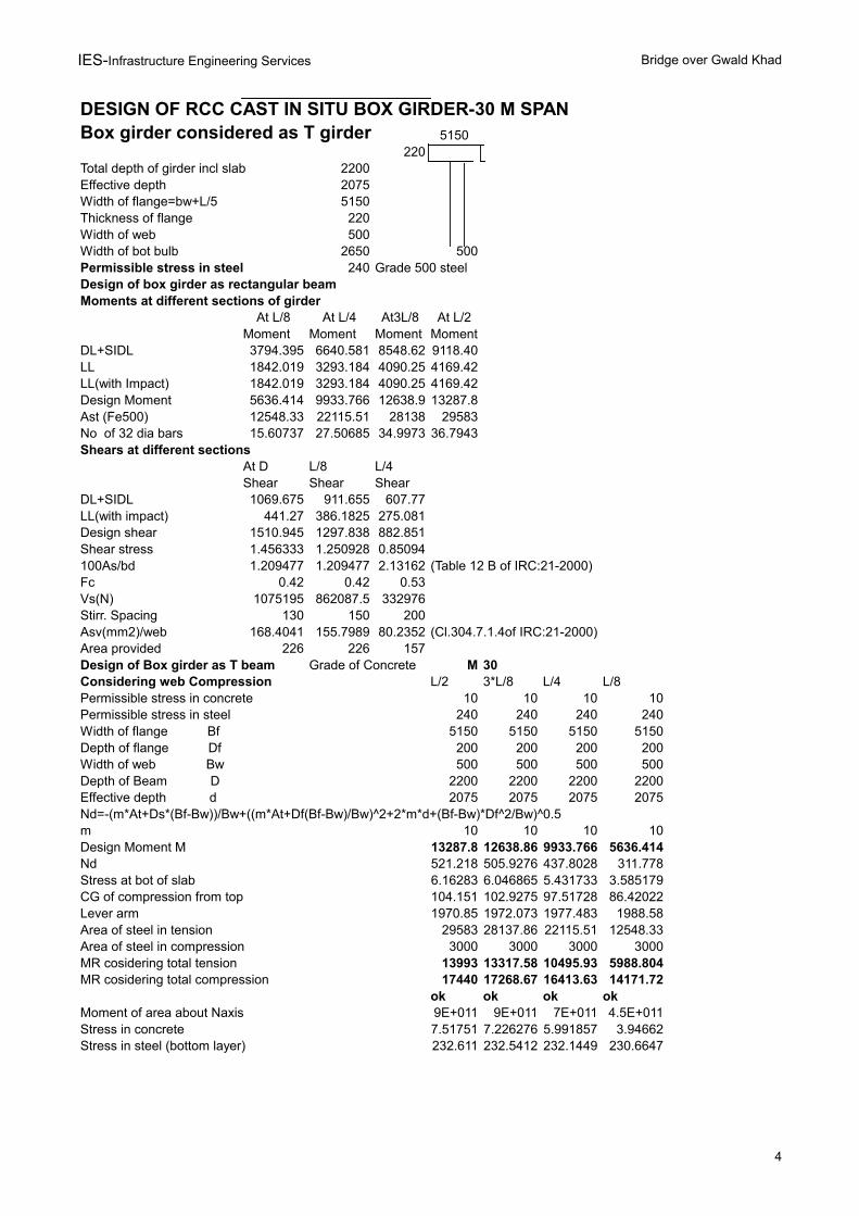
DESIGN OF RCC CAST IN SITU BOX GIRDER-30 M SPANBox girder considered as T girder 5150
220Total depth of girder incl slab 2200Effective depth 2075Width of flange=bw+L/5 5150Thickness of flange 220Width of web 500Width of bot bulb 2650 500Permissible stress in steel 240 Grade 500 steelDesign of box girder as rectangular beamMoments at different sections of girder
At L/8 At L/4 At3L/8 At L/2Moment Moment Moment Moment
DL+SIDL 3794.395 6640.581 8548.62 9118.40LL 1842.019 3293.184 4090.25 4169.42LL(with Impact) 1842.019 3293.184 4090.25 4169.42Design Moment 5636.414 9933.766 12638.9 13287.8Ast (Fe500) 12548.33 22115.51 28138 29583No of 32 dia bars 15.60737 27.50685 34.9973 36.7943Shears at different sections
At D L/8 L/4Shear Shear Shear
DL+SIDL 1069.675 911.655 607.77LL(with impact) 441.27 386.1825 275.081Design shear 1510.945 1297.838 882.851Shear stress 1.456333 1.250928 0.85094100As/bd 1.209477 1.209477 2.13162 (Table 12 B of IRC:21-2000)Fc 0.42 0.42 0.53Vs(N) 1075195 862087.5 332976Stirr. Spacing 130 150 200Asv(mm2)/web 168.4041 155.7989 80.2352 (Cl.304.7.1.4of IRC:21-2000)Area provided 226 226 157Design of Box girder as T beam Grade of Concrete M 30Considering web Compression L/2 3*L/8 L/4 L/8Permissible stress in concrete 10 10 10 10Permissible stress in steel 240 240 240 240Width of flange Bf 5150 5150 5150 5150Depth of flange Df 200 200 200 200Width of web Bw 500 500 500 500Depth of Beam D 2200 2200 2200 2200Effective depth d 2075 2075 2075 2075Nd=-(m*At+Ds*(Bf-Bw))/Bw+((m*At+Df(Bf-Bw)/Bw)^2+2*m*d+(Bf-Bw)*Df^2/Bw)^0.5m 10 10 10 10Design Moment M 13287.8 12638.86 9933.766 5636.414Nd 521.218 505.9276 437.8028 311.778Stress at bot of slab 6.16283 6.046865 5.431733 3.585179CG of compression from top 104.151 102.9275 97.51728 86.42022Lever arm 1970.85 1972.073 1977.483 1988.58Area of steel in tension 29583 28137.86 22115.51 12548.33Area of steel in compression 3000 3000 3000 3000MR cosidering total tension 13993 13317.58 10495.93 5988.804MR cosidering total compression 17440 17268.67 16413.63 14171.72
ok ok ok okMoment of area about Naxis 9E+011 9E+011 7E+011 4.5E+011Stress in concrete 7.51751 7.226276 5.991857 3.94662Stress in steel (bottom layer) 232.611 232.5412 232.1449 230.6647
IES-Infrastructure Engineering Services Bridge over Gwald Khad
5
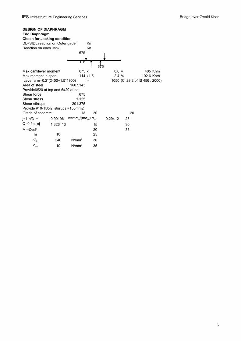
DESIGN OF DIAPHRAGMEnd DiaphragmChech for Jacking conditionDL+SIDL reaction on Outer girder KnReaction on each Jack Kn
675
0.6675
Max cantilever moment 675 x 0.6 = 405 KnmMax moment in span 114 x1.5 2.4 /4 102.6 Knm Lever arm=0.2*(2400+1.5*1900) = 1050 (Cl 29.2 of IS 456 : 2000)Area of steel 1607.143Provide6#20 at top and 6#20 at botShear force 675Shear stress 1.125Shear stirrups 201.375Provide #10-150-2l stirrups =150mm2Grade of concrete M 30 20
j=1-n/3 = 0.901961 0.29412 25
1.326413 15 30
20 35m 10 25
240 30
10 35
n=mcbmcbstQ=0.5cbnj
Mr=Qbd2
st N/mm2
cb N/mm2
IES-Infrastructure Engineering Services Bridge over Gwald Khad
6
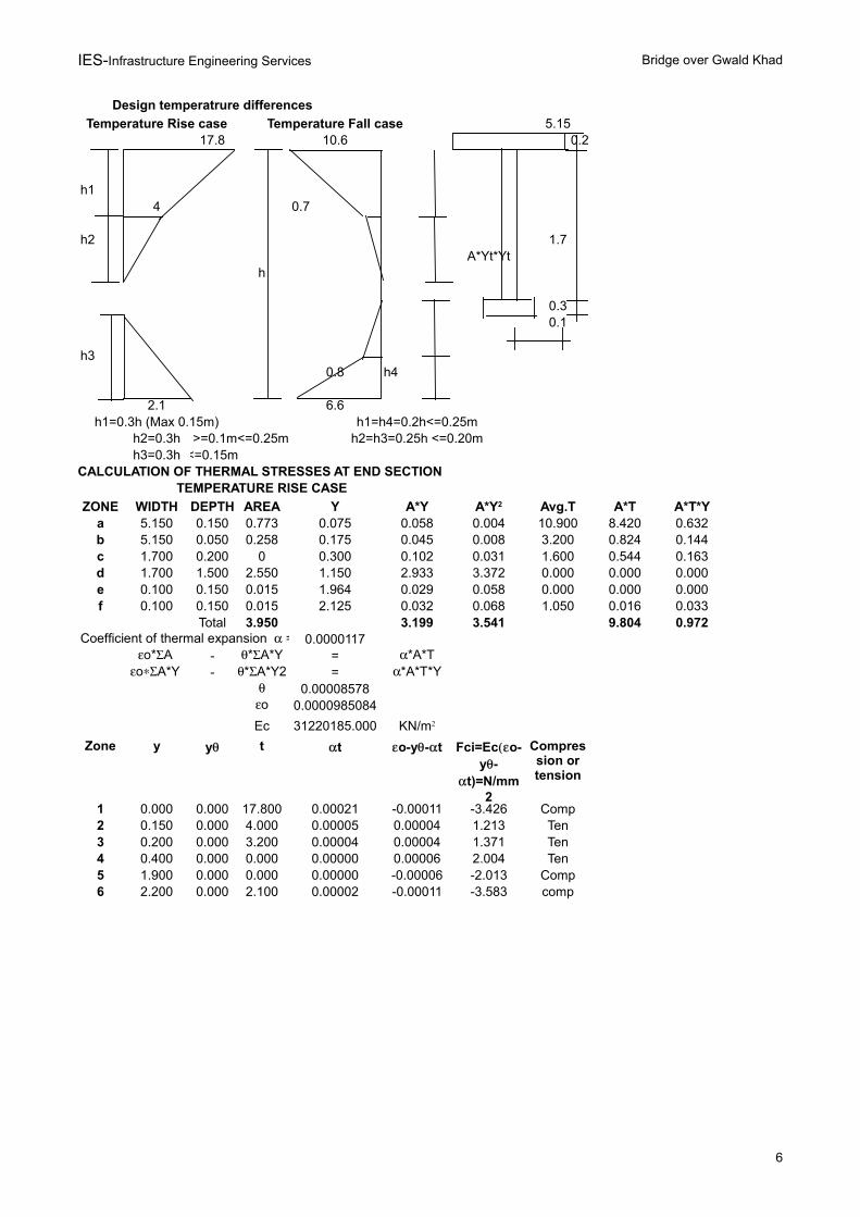
Design temperatrure differences
Temperature Rise case Temperature Fall case 5.1517.8 10.6 0.2
h14 0.7
h2 1.7A*Yt*Yt
h
0.30.1
h30.8 h4
2.1 6.6h1=0.3h (Max 0.15m) h1=h4=0.2h<=0.25m
h2=0.3h >=0.1m<=0.25m h2=h3=0.25h <=0.20mh3=0.3h <=0.15m
CALCULATION OF THERMAL STRESSES AT END SECTION TEMPERATURE RISE CASE
ZONE WIDTH DEPTH AREA Y A*Y Avg.T A*T A*T*Ya 5.150 0.150 0.773 0.075 0.058 0.004 10.900 8.420 0.632b 5.150 0.050 0.258 0.175 0.045 0.008 3.200 0.824 0.144c 1.700 0.200 0 0.300 0.102 0.031 1.600 0.544 0.163d 1.700 1.500 2.550 1.150 2.933 3.372 0.000 0.000 0.000e 0.100 0.150 0.015 1.964 0.029 0.058 0.000 0.000 0.000f 0.100 0.150 0.015 2.125 0.032 0.068 1.050 0.016 0.033
Total 3.950 3.199 3.541 9.804 0.9720.0000117
- =- =
0.000085780.0000985084
Ec 31220185.000
Zone y t
1 0.000 0.000 17.800 0.00021 -0.00011 -3.426 Comp2 0.150 0.000 4.000 0.00005 0.00004 1.213 Ten3 0.200 0.000 3.200 0.00004 0.00004 1.371 Ten4 0.400 0.000 0.000 0.00000 0.00006 2.004 Ten5 1.900 0.000 0.000 0.00000 -0.00006 -2.013 Comp6 2.200 0.000 2.100 0.00002 -0.00011 -3.583 comp
A*Y2
Coefficient of thermal expansion =o*A *A*Y *A*T
oA*Y *A*Y2 *A*T*Yo
KN/m2
y t o-y-t Fci=Eco-y-
t)=N/mm2
Compression or tension
IES-Infrastructure Engineering Services Bridge over Gwald Khad
7
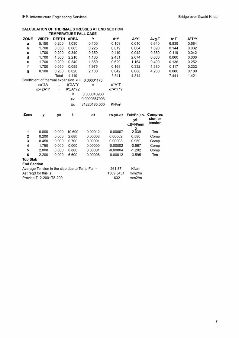
CALCULATION OF THERMAL STRESSES AT END SECTION TEMPERATURE FALL CASE
ZONE WIDTH DEPTH AREA Y A*Y Avg.T A*T A*T*Ya 5.150 0.200 1.030 0.100 0.103 0.010 6.640 6.839 0.684b 1.700 0.050 0.085 0.225 0.019 0.004 1.690 0.144 0.032c 1.700 0.200 0.340 0.350 0.119 0.042 0.350 0.119 0.042d 1.700 1.300 2.210 1.100 2.431 2.674 0.000 0.000 0.000e 1.700 0.200 0.340 1.850 0.629 1.164 0.400 0.136 0.252f 1.700 0.050 0.085 1.975 0.168 0.332 1.380 0.117 0.232g 0.100 0.200 0.020 2.100 0.042 0.088 4.280 0.086 0.180
Total 4.110 3.511 4.314 7.441 1.4210.00001170
- =- =
0.0000439300.0000587093
Ec 31220185.000
Zone y t
1 0.000 0.000 10.600 0.00012 -0.00007 -2.039 Ten2 0.200 0.000 2.680 0.00003 0.00002 0.580 Comp3 0.450 0.000 0.700 0.00001 0.00003 0.960 Comp4 1.750 0.000 0.000 0.00000 -0.00002 -0.567 Comp5 2.000 0.000 0.800 0.00001 -0.00004 -1.202 Comp6 2.200 0.000 6.600 0.00008 -0.00012 -3.595 Ten
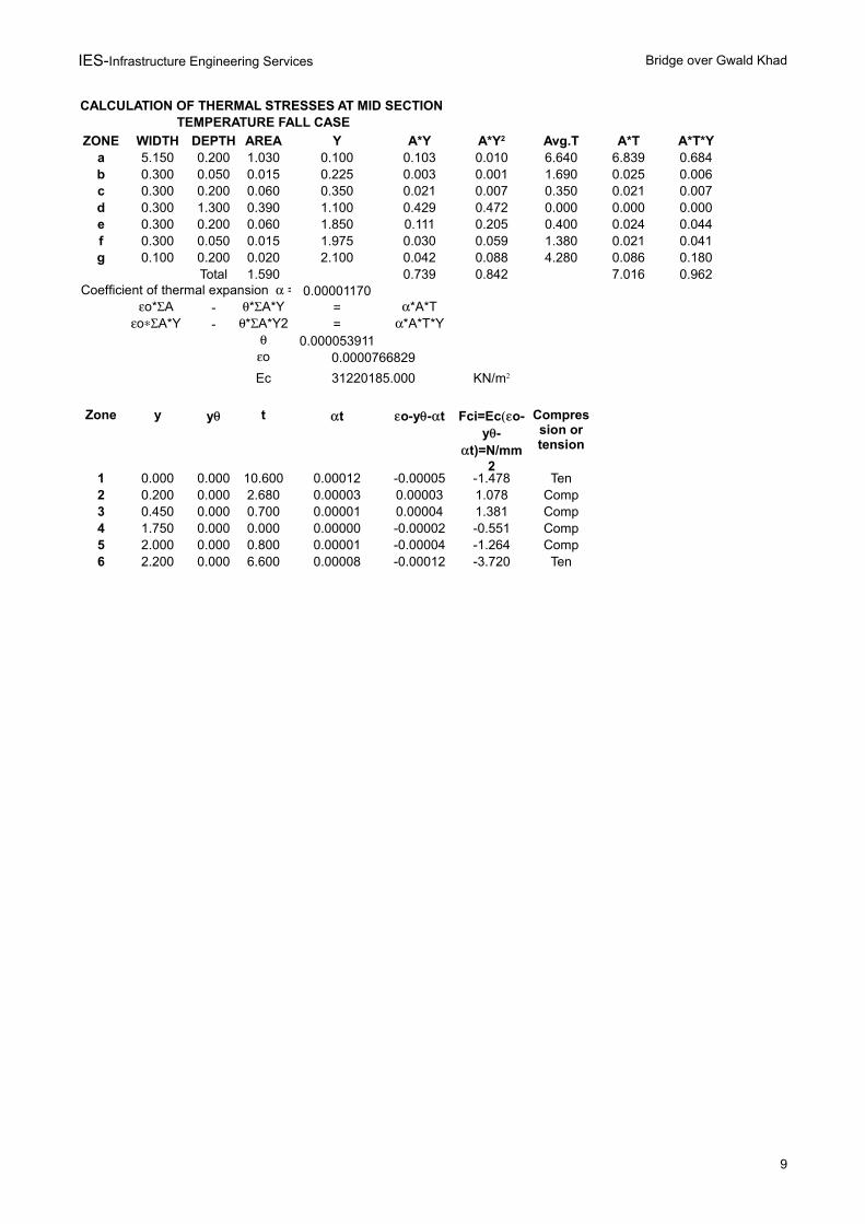
Top SlabEnd SectionAverage Tension in the slab due to Temp Fall = 261.87 KN/mAst reqd for this is 1309.3431 mm2/mProvide T12-200+T8-200 1632 mm2/m
A*Y2
Coefficient of thermal expansion =o*A *A*Y *A*T
oA*Y *A*Y2 *A*T*Yo
KN/m2
y t o-y-t Fci=Eco-y-
t)=N/mm2
Compression or tension
IES-Infrastructure Engineering Services Bridge over Gwald Khad
8
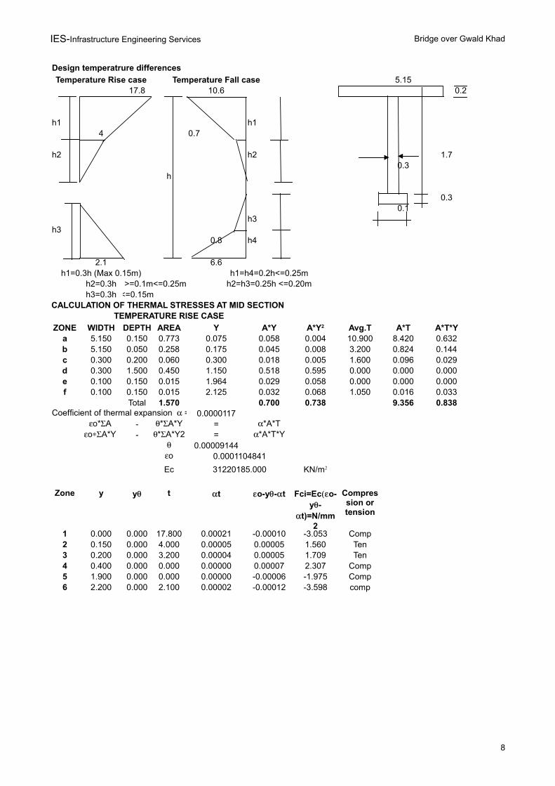
Design temperatrure differences
Temperature Rise case Temperature Fall case 5.1517.8 10.6 0.2
h1 h14 0.7
h2 h2 1.70.3
h
0.30.1
h3h3
0.8 h4
2.1 6.6h1=0.3h (Max 0.15m) h1=h4=0.2h<=0.25m
h2=0.3h >=0.1m<=0.25m h2=h3=0.25h <=0.20mh3=0.3h <=0.15m
CALCULATION OF THERMAL STRESSES AT MID SECTION TEMPERATURE RISE CASE
ZONE WIDTH DEPTH AREA Y A*Y Avg.T A*T A*T*Ya 5.150 0.150 0.773 0.075 0.058 0.004 10.900 8.420 0.632b 5.150 0.050 0.258 0.175 0.045 0.008 3.200 0.824 0.144c 0.300 0.200 0.060 0.300 0.018 0.005 1.600 0.096 0.029d 0.300 1.500 0.450 1.150 0.518 0.595 0.000 0.000 0.000e 0.100 0.150 0.015 1.964 0.029 0.058 0.000 0.000 0.000f 0.100 0.150 0.015 2.125 0.032 0.068 1.050 0.016 0.033
Total 1.570 0.700 0.738 9.356 0.8380.0000117
- =- =
0.000091440.0001104841
Ec 31220185.000
Zone y t
1 0.000 0.000 17.800 0.00021 -0.00010 -3.053 Comp2 0.150 0.000 4.000 0.00005 0.00005 1.560 Ten3 0.200 0.000 3.200 0.00004 0.00005 1.709 Ten4 0.400 0.000 0.000 0.00000 0.00007 2.307 Comp5 1.900 0.000 0.000 0.00000 -0.00006 -1.975 Comp6 2.200 0.000 2.100 0.00002 -0.00012 -3.598 comp
A*Y2
Coefficient of thermal expansion =o*A *A*Y *A*T
oA*Y *A*Y2 *A*T*Yo
KN/m2
y t o-y-t Fci=Eco-y-
t)=N/mm2
Compression or tension
IES-Infrastructure Engineering Services Bridge over Gwald Khad
9
CALCULATION OF THERMAL STRESSES AT MID SECTION TEMPERATURE FALL CASE
ZONE WIDTH DEPTH AREA Y A*Y Avg.T A*T A*T*Ya 5.150 0.200 1.030 0.100 0.103 0.010 6.640 6.839 0.684b 0.300 0.050 0.015 0.225 0.003 0.001 1.690 0.025 0.006c 0.300 0.200 0.060 0.350 0.021 0.007 0.350 0.021 0.007d 0.300 1.300 0.390 1.100 0.429 0.472 0.000 0.000 0.000e 0.300 0.200 0.060 1.850 0.111 0.205 0.400 0.024 0.044f 0.300 0.050 0.015 1.975 0.030 0.059 1.380 0.021 0.041g 0.100 0.200 0.020 2.100 0.042 0.088 4.280 0.086 0.180
Total 1.590 0.739 0.842 7.016 0.9620.00001170
- =- =
0.0000539110.0000766829
Ec 31220185.000
Zone y t
1 0.000 0.000 10.600 0.00012 -0.00005 -1.478 Ten2 0.200 0.000 2.680 0.00003 0.00003 1.078 Comp3 0.450 0.000 0.700 0.00001 0.00004 1.381 Comp4 1.750 0.000 0.000 0.00000 -0.00002 -0.551 Comp5 2.000 0.000 0.800 0.00001 -0.00004 -1.264 Comp6 2.200 0.000 6.600 0.00008 -0.00012 -3.720 Ten
A*Y2
Coefficient of thermal expansion =o*A *A*Y *A*T
oA*Y *A*Y2 *A*T*Yo
KN/m2
y t o-y-t Fci=Eco-y-
t)=N/mm2
Compression or tension
IES-Infrastructure Engineering Services Bridge over Gwald Khad
10
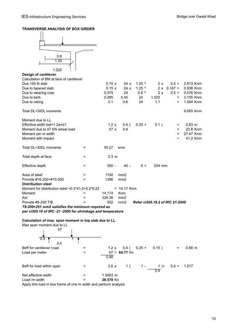
TRANSVERSE ANALYSIS OF BOX GIRDER
0.81.25
1.025Design of cantileverCalculation of BM at face of cantileverDue 150 th slab 0.15 x 24 x 1.25 ^ 2 x 0.5 = 2.813 KnmDue to tapered slab 0.15 x 24 x 1.25 ^ 2 x 0.167 = 0.938 KnmDue to wearing coat 0.075 24 0.8 ^ 2 x 0.5 = 0.576 KnmDue to kerb 0.285 0.45 24 1.025 = 3.155 KnmDue to railing 0.1 0.6 24 1.1 = 1.584 Knm
Total DL+SIDL moments 9.065 Knm
Moment due to LLEffective width bef=1.2a+b1 1.2 x 0.4 ( 0.25 + 0.1 ) = 0.83 mMoment due to 57 KN wheel load 57 x 0.4 = 22.8 KnmMoment per m width = 27.47 KnmMoment with impact = 41.2 Knm
Total DL+SIDL moments = 50.27 knm
Total depth at face = 0.3 m
Effective depth = 300 - 40 - 6 = 254 mm
Area of steel = 1100 mm2Provide #16-200+#10-200 = 1396 mm2Distribution steelMoment for distribution steel =0.3*41.2+0.2*9.23 = 14.17 KnmMoment = 14.174 KnmAst = 326.36 mm2Provide #8-200 T/B = 502 mm2 Refer cl305.18.2 of IRC 21-2000T8-200=251 mm2 satisfies the minimum required as per cl305.10 of IRC -21 -2000 for shrinkage and temperature
Calculation of max. span moment in top slab due to LLMax span moment due to LL
57
0.4 12.4
Beff for cantilever l;oad = 1.2 x 0.4 ( 0.25 + 0.15 ) = 0.88 mLoad per meter = 57 = 64.77 Kn
0.88
Beff for load within span = 2.6 x 1 ( 1 - 1 )+ 0.4 = 1.9172.4
Net effective width = 1.5583 mLoad /m width = 36.578 KnApply this load in box frame of one m width and perform analysis
IES-Infrastructure Engineering Services Bridge over Gwald Khad
11
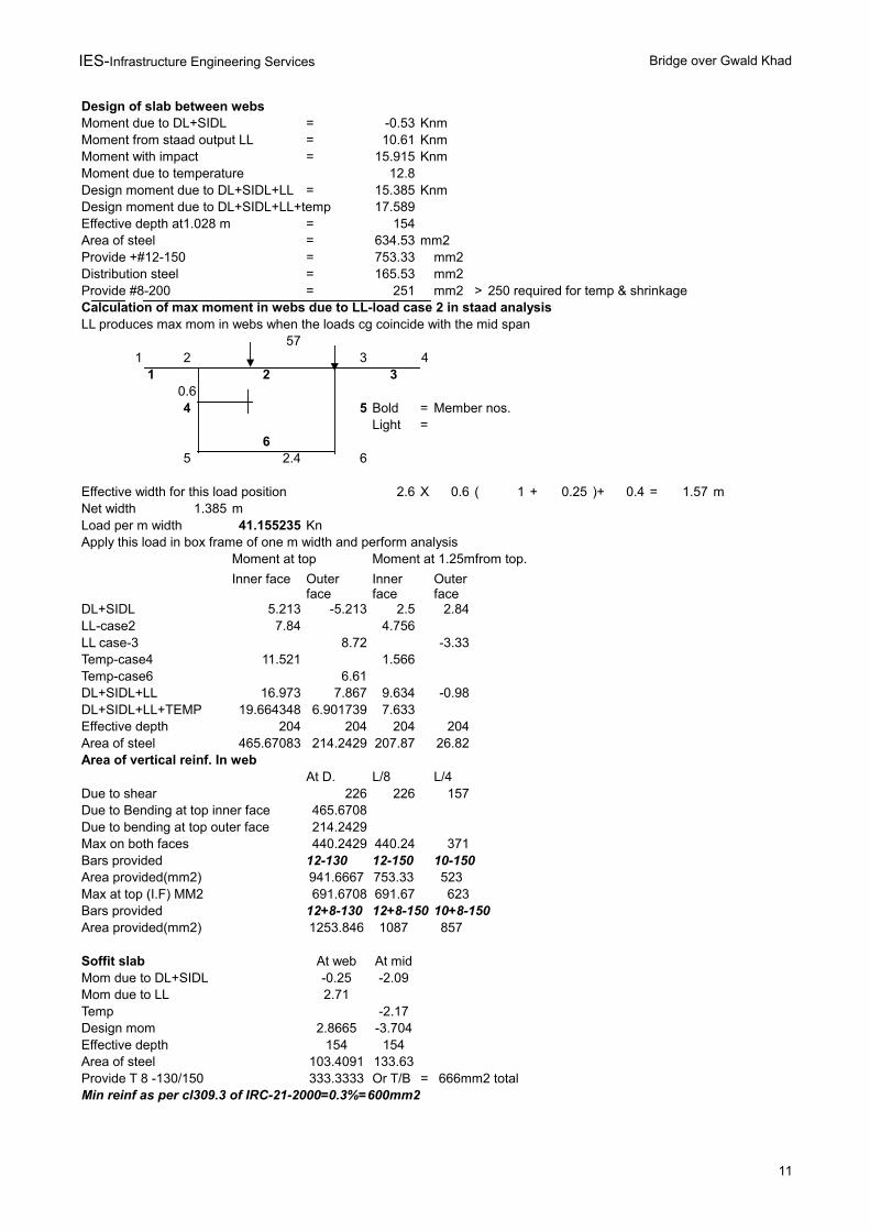
Design of slab between websMoment due to DL+SIDL = -0.53 KnmMoment from staad output LL = 10.61 KnmMoment with impact = 15.915 KnmMoment due to temperature 12.8Design moment due to DL+SIDL+LL = 15.385 KnmDesign moment due to DL+SIDL+LL+temp 17.589Effective depth at1.028 m = 154Area of steel = 634.53 mm2Provide +#12-150 = 753.33 mm2Distribution steel = 165.53 mm2Provide #8-200 = 251 mm2 > 250 required for temp & shrinkageCalculation of max moment in webs due to LL-load case 2 in staad analysisLL produces max mom in webs when the loads cg coincide with the mid span
571 2 3 4
1 2 30.64 5 Bold = Member nos.
Light =6
5 2.4 6
Effective width for this load position 2.6 X 0.6 ( 1 + 0.25 )+ 0.4 = 1.57 mNet width 1.385 mLoad per m width 41.155235 KnApply this load in box frame of one m width and perform analysis
Moment at top Moment at 1.25mfrom top.
Inner face
DL+SIDL 5.213 -5.213 2.5 2.84LL-case2 7.84 4.756LL case-3 8.72 -3.33Temp-case4 11.521 1.566Temp-case6 6.61DL+SIDL+LL 16.973 7.867 9.634 -0.98DL+SIDL+LL+TEMP 19.664348 6.901739 7.633Effective depth 204 204 204 204Area of steel 465.67083 214.2429 207.87 26.82Area of vertical reinf. In web
At D. L/8 L/4Due to shear 226 226 157Due to Bending at top inner face 465.6708Due to bending at top outer face 214.2429Max on both faces 440.2429 440.24 371Bars provided 12-130 12-150 10-150Area provided(mm2) 941.6667 753.33 523Max at top (I.F) MM2 691.6708 691.67 623Bars provided 12+8-130 12+8-150 10+8-150Area provided(mm2) 1253.846 1087 857
Soffit slab At web At midMom due to DL+SIDL -0.25 -2.09Mom due to LL 2.71Temp -2.17Design mom 2.8665 -3.704Effective depth 154 154Area of steel 103.4091 133.63Provide T 8 -130/150 333.3333 Or T/B = 666mm2 totalMin reinf as per cl309.3 of IRC-21-2000=0.3%=600mm2
Outer face
Inner face
Outer face
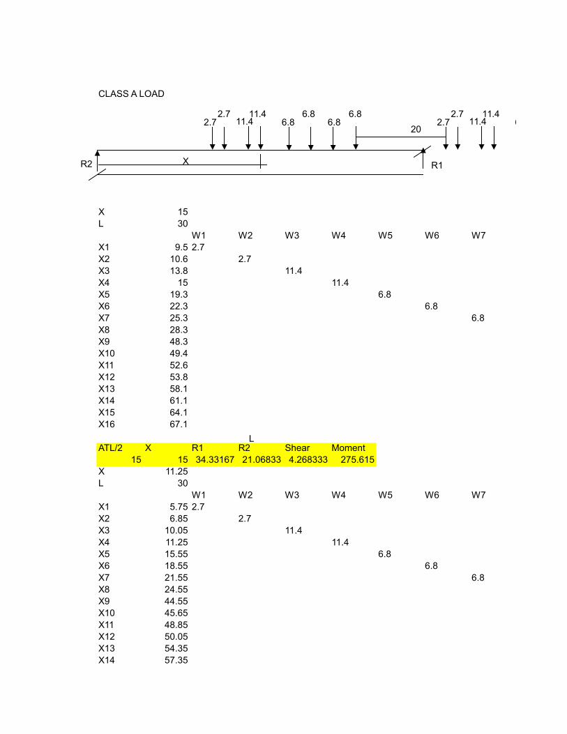
CLASS A LOAD
20
X 15L 30
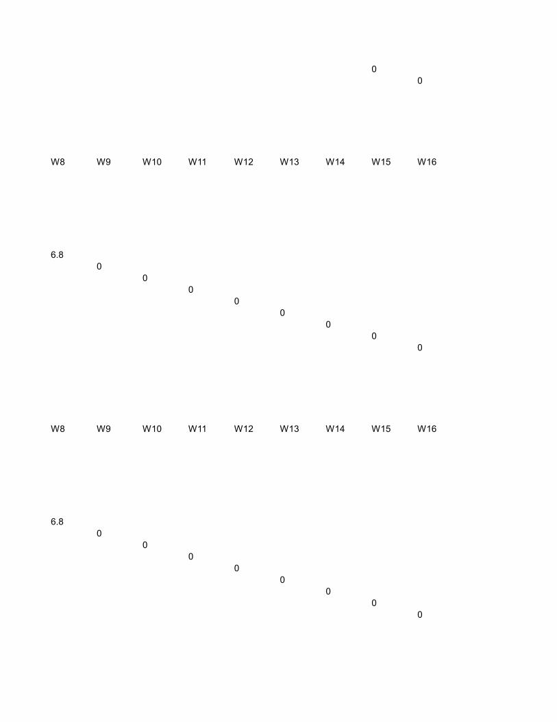
W1 W2 W3 W4 W5 W6 W7X1 9.5 2.7X2 10.6 2.7X3 13.8 11.4X4 15 11.4X5 19.3 6.8X6 22.3 6.8X7 25.3 6.8X8 28.3X9 48.3X10 49.4X11 52.6X12 53.8X13 58.1X14 61.1X15 64.1X16 67.1
ATL/2 X R1 R2 Shear Moment15 15 34.33167 21.06833 4.268333 275.615
X 11.25L 30
W1 W2 W3 W4 W5 W6 W7X1 5.75 2.7X2 6.85 2.7X3 10.05 11.4X4 11.25 11.4X5 15.55 6.8X6 18.55 6.8X7 21.55 6.8X8 24.55X9 44.55X10 45.65X11 48.85X12 50.05X13 54.35X14 57.35
2.72.7 11.4
11.46.8
6.86.8
6.8
L
XR2 R1
2.72.7 11.4
11.46.8
X15 60.35X16 63.35
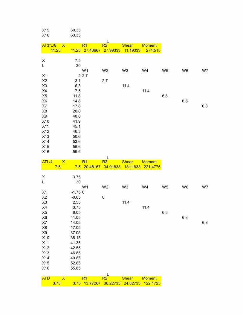
AT3*L/8 X R1 R2 Shear Moment11.25 11.25 27.40667 27.99333 11.19333 274.515
X 7.5L 30
W1 W2 W3 W4 W5 W6 W7X1 2 2.7X2 3.1 2.7X3 6.3 11.4X4 7.5 11.4X5 11.8 6.8X6 14.8 6.8X7 17.8 6.8X8 20.8X9 40.8X10 41.9X11 45.1X12 46.3X13 50.6X14 53.6X15 56.6X16 59.6
ATL/4 X R1 R2 Shear Moment7.5 7.5 20.48167 34.91833 18.11833 221.4775
X 3.75L 30
W1 W2 W3 W4 W5 W6 W7X1 -1.75 0X2 -0.65 0X3 2.55 11.4X4 3.75 11.4X5 8.05 6.8X6 11.05 6.8X7 14.05 6.8X8 17.05X9 37.05X10 38.15X11 41.35X12 42.55X13 46.85X14 49.85X15 52.85X16 55.85
ATD X R1 R2 Shear Moment3.75 3.75 13.77267 36.22733 24.82733 122.1725
L
L
L
L
L
L
L
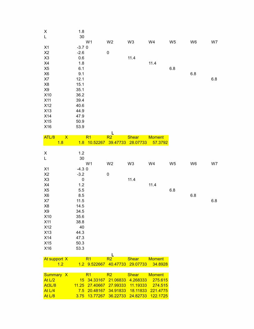
X 1.8L 30
W1 W2 W3 W4 W5 W6 W7X1 -3.7 0X2 -2.6 0X3 0.6 11.4X4 1.8 11.4X5 6.1 6.8X6 9.1 6.8X7 12.1 6.8X8 15.1X9 35.1X10 36.2X11 39.4X12 40.6X13 44.9X14 47.9X15 50.9X16 53.9
ATL/8 X R1 R2 Shear Moment1.8 1.8 10.52267 39.47733 28.07733 57.3792
X 1.2L 30
W1 W2 W3 W4 W5 W6 W7X1 -4.3 0X2 -3.2 0X3 0 11.4X4 1.2 11.4X5 5.5 6.8X6 8.5 6.8X7 11.5 6.8X8 14.5X9 34.5X10 35.6X11 38.8X12 40X13 44.3X14 47.3X15 50.3X16 53.3
At support X R1 R2 Shear Moment1.2 1.2 9.522667 40.47733 29.07733 34.8928
Summary X R1 R2 Shear MomentAt L/2 15 34.33167 21.06833 4.268333 275.615At3L/8 11.25 27.40667 27.99333 11.19333 274.515At L/4 7.5 20.48167 34.91833 18.11833 221.4775At L/8 3.75 13.77267 36.22733 24.82733 122.1725
LLL
LLL
AtD 1.8 10.52267 39.47733 28.07733 57.3792At support 1.2 9.522667 40.47733 29.07733 34.8928
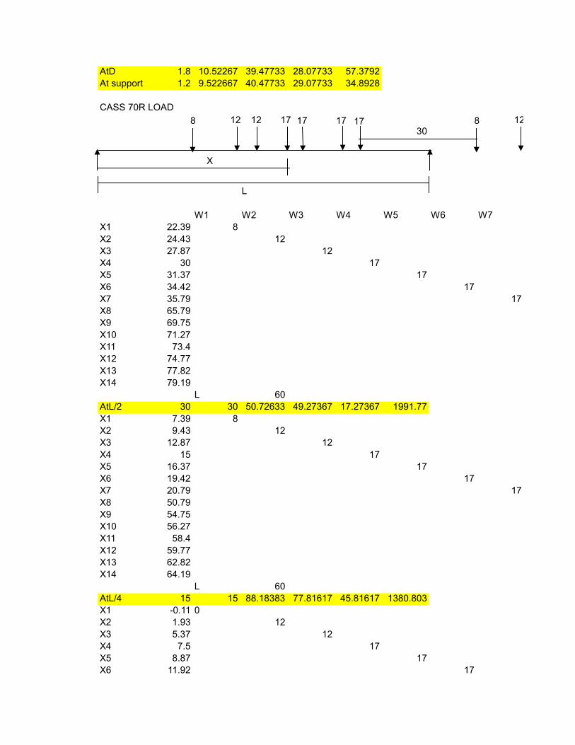
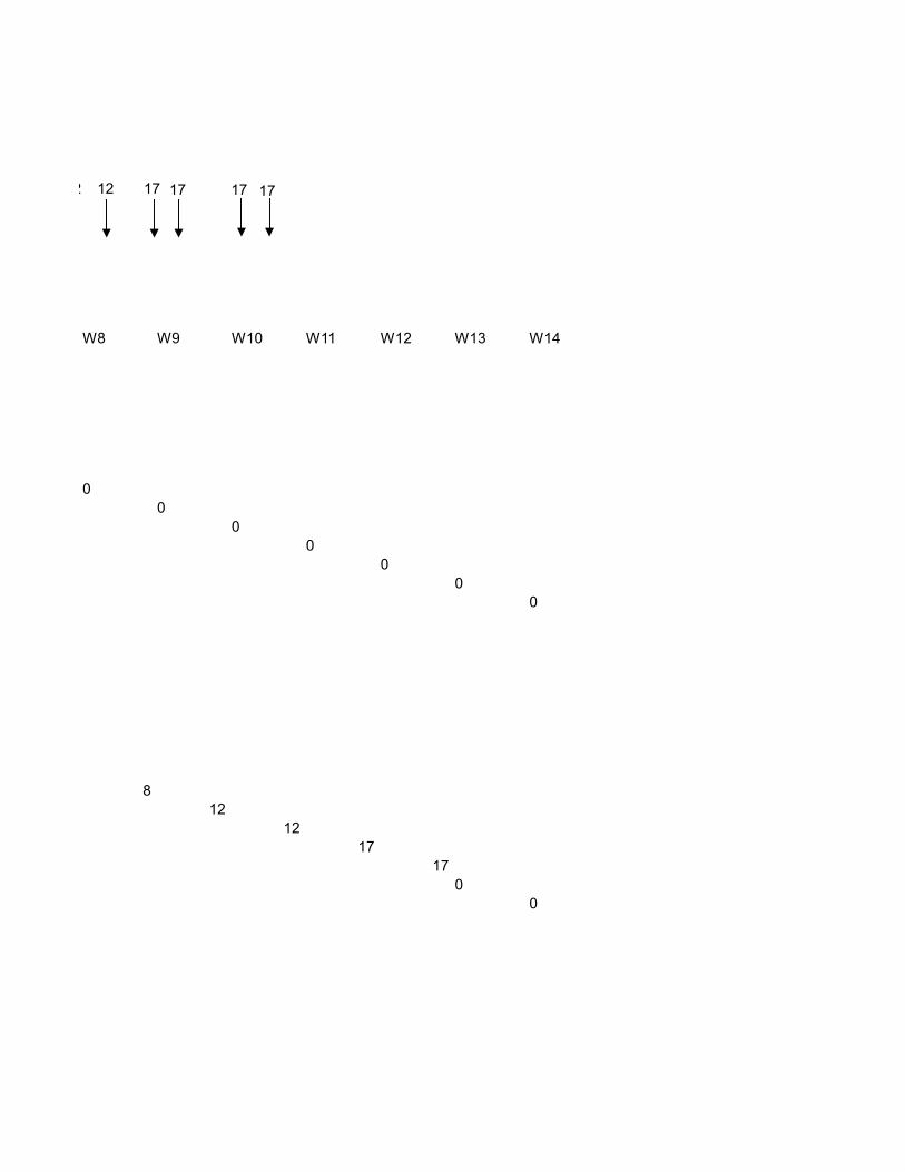
CASS 70R LOAD
30
L
W1 W2 W3 W4 W5 W6 W7X1 22.39 8X2 24.43 12X3 27.87 12X4 30 17X5 31.37 17X6 34.42 17X7 35.79 17X8 65.79X9 69.75X10 71.27X11 73.4X12 74.77X13 77.82X14 79.19
L 60AtL/2 30 30 50.72633 49.27367 17.27367 1991.77X1 7.39 8X2 9.43 12X3 12.87 12X4 15 17X5 16.37 17X6 19.42 17X7 20.79 17X8 50.79X9 54.75X10 56.27X11 58.4X12 59.77X13 62.82X14 64.19
L 60AtL/4 15 15 88.18383 77.81617 45.81617 1380.803X1 -0.11 0X2 1.93 12X3 5.37 12X4 7.5 17X5 8.87 17X6 11.92 17
8 12 12 17 17 17 17
X
8 12
X7 13.29 17X8 43.29X9 47.25X10 48.77X11 50.9X12 52.27X13 55.32X14 56.69
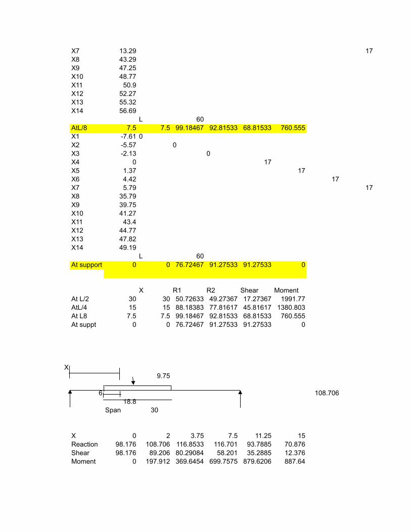
L 60AtL/8 7.5 7.5 99.18467 92.81533 68.81533 760.555X1 -7.61 0X2 -5.57 0X3 -2.13 0X4 0 17X5 1.37 17X6 4.42 17X7 5.79 17X8 35.79X9 39.75X10 41.27X11 43.4X12 44.77X13 47.82X14 49.19
L 60At support 0 0 76.72467 91.27533 91.27533 0
X R1 R2 Shear MomentAt L/2 30 30 50.72633 49.27367 17.27367 1991.77AtL/4 15 15 88.18383 77.81617 45.81617 1380.803At L8 7.5 7.5 99.18467 92.81533 68.81533 760.555At suppt 0 0 76.72467 91.27533 91.27533 0
X9.75
6 108.70618.8
Span 30
X 0 2 3.75 7.5 11.25 15Reaction 98.176 108.706 116.8533 116.701 93.7885 70.876Shear 98.176 89.206 80.29084 58.201 35.2885 12.376Moment 0 197.912 369.6454 699.7575 879.6206 887.64
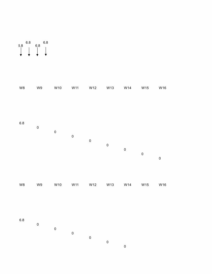
W8 W9 W10 W11 W12 W13 W14 W15 W16
6.80
00
00
00
0
W8 W9 W10 W11 W12 W13 W14 W15 W16
6.80
00
00
0
6.86.8
6.86.8
00
W8 W9 W10 W11 W12 W13 W14 W15 W16
6.80
00
00
00
0
W8 W9 W10 W11 W12 W13 W14 W15 W16
6.80
00
00
00
0
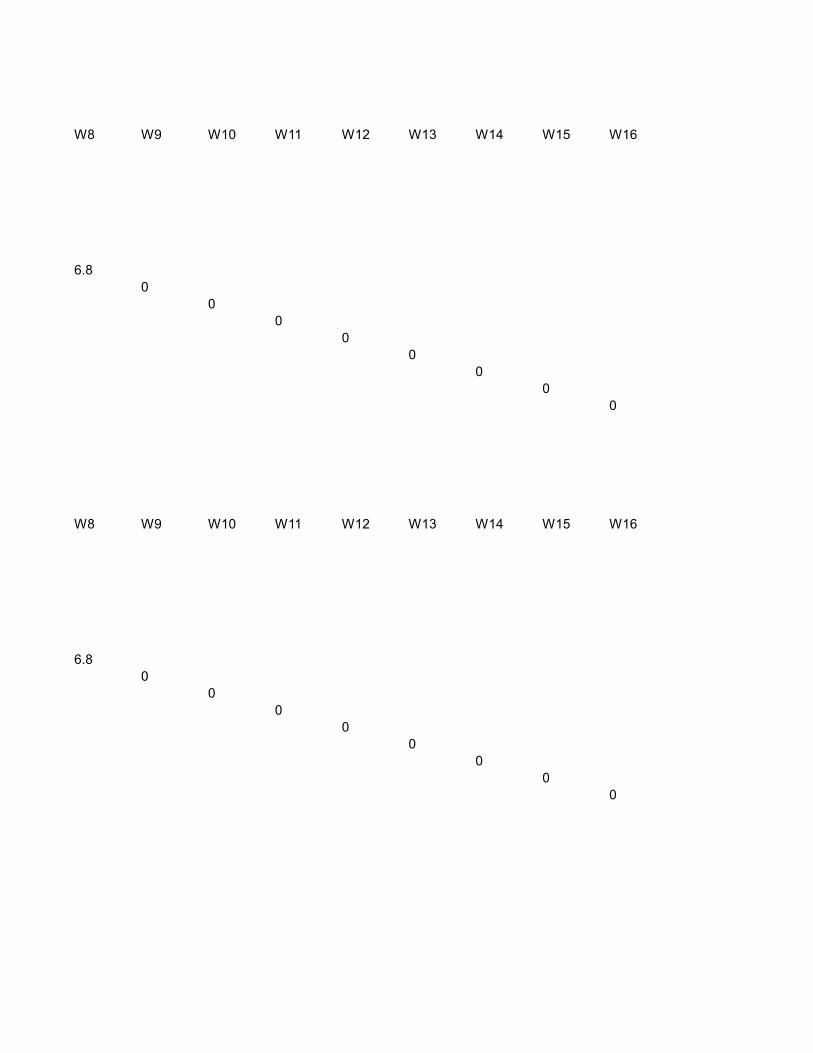
W8 W9 W10 W11 W12 W13 W14 W15 W16
6.80
00
00
00
0
W8 W9 W10 W11 W12 W13 W14 W15 W16
6.80
00
00
00
0
W8 W9 W10 W11 W12 W13 W14
00
00
00
0
812
1217
170
0
12 12 17 17 17 17
812
1217
1717
17
812
1217
1717
17