gv2 / gv3 manual starters and ak5 panel busbar · pdf filegv2 / gv3 manual starters and ak5...
TRANSCRIPT

GV2 / GV3 Manual Starters
and AK5 Panel Busbar System
File 2520
CATALOG CONTENTS GV2 GV3 AK5
Product Description ...................................... 2-3 ................... 2-3 ................. 38-39Product Selection ......................................... 4 ...................... 4 ....................45-46Accessories Selection .................................. 6-11 ................. 28 .................. –Application Information ................................ 5, 49-50 ........... 50 .................. 42-43Specifications ............................................... 16-27 ............... 31-37 .............40-41Wiring Diagrams .......................................... 15 .................... 30 .................. –

2© 1997 Square D All Rights Reserved 12/97
Introduction
The GV manual starter and protector provides manual isolation, manual motor control, andovercurrent protection in one compact unit. Square D offers three different products that make up theGV product family - GV2M, GV2P, and GV3M. These devices are UL Listed as Manual MotorControllers.
The GV2M is the basic starter designed to control motors with full load currents up to 32 A. The GV2Pis a high performance starter that offers a high withstand rating and visible trip indication. The GV3Mstarter is used on large motors with full load currents up to 63 A.
The GV manual starters and protectors are also UL Listed for group installation applications. See page5 for maximum fuse or circuit breaker ratings when used in group installations.
In many European applications, the GV devices are used as circuit breakers because they meet therequirements of IEC 947-2 for circuit breakers. However, the GV starter does not meet North Americancircuit breaker standards such as UL or CSA.
Standard Features
The GV family offers such standard features as:
• Class 10, ambient compensated overload relay
• Single phase sensitivity
• Instantaneous magnetic trip
• Test trip mechanism
• Provision for padlocking in the OFF position
• Fingersafe terminals
• Captive +/- screws with screw driver guide
• North American and European terminal markings
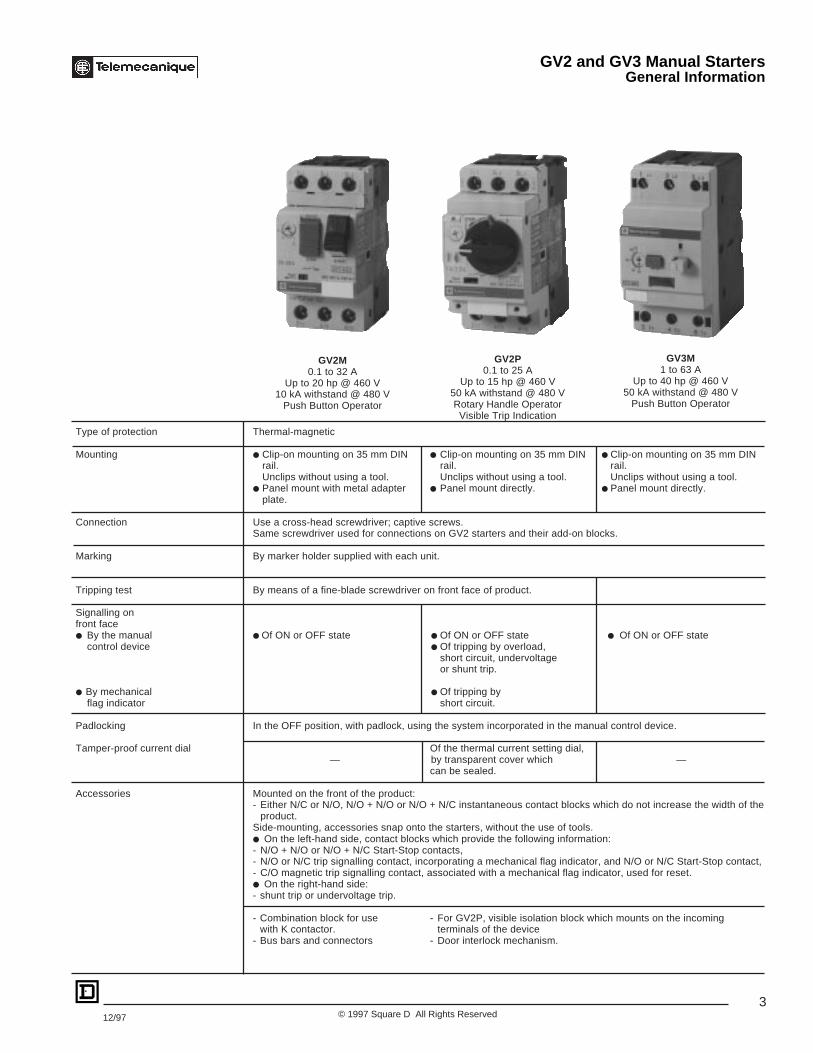
GV2 and GV3 Manual StartersGeneral Information
3© 1997 Square D All Rights Reserved12/97
Type of protection Thermal-magnetic
Mounting ● Clip-on mounting on 35 mm DIN ● Clip-on mounting on 35 mm DIN ● Clip-on mounting on 35 mm DINrail. rail. rail.Unclips without using a tool. Unclips without using a tool. Unclips without using a tool.
● Panel mount with metal adapter ● Panel mount directly. ● Panel mount directly.plate.
Connection Use a cross-head screwdriver; captive screws.Same screwdriver used for connections on GV2 starters and their add-on blocks.
Marking By marker holder supplied with each unit.
Tripping test By means of a fine-blade screwdriver on front face of product.
Signalling onfront face● By the manual ● Of ON or OFF state ● Of ON or OFF state ● Of ON or OFF state
control device ● Of tripping by overload,short circuit, undervoltageor shunt trip.
● By mechanical ● Of tripping byflag indicator short circuit.
Padlocking In the OFF position, with padlock, using the system incorporated in the manual control device.
Tamper-proof current dial Of the thermal current setting dial,— by transparent cover which —
can be sealed.
Accessories Mounted on the front of the product:- Either N/C or N/O, N/O + N/O or N/O + N/C instantaneous contact blocks which do not increase the width of the
product.Side-mounting, accessories snap onto the starters, without the use of tools.● On the left-hand side, contact blocks which provide the following information:- N/O + N/O or N/O + N/C Start-Stop contacts,- N/O or N/C trip signalling contact, incorporating a mechanical flag indicator, and N/O or N/C Start-Stop contact,- C/O magnetic trip signalling contact, associated with a mechanical flag indicator, used for reset.● On the right-hand side:- shunt trip or undervoltage trip.
- Combination block for use - For GV2P, visible isolation block which mounts on the incomingwith K contactor. terminals of the device
- Bus bars and connectors - Door interlock mechanism.
GV2M0.1 to 32 A
Up to 20 hp @ 460 V10 kA withstand @ 480 V
Push Button Operator
GV2P0.1 to 25 A
Up to 15 hp @ 460 V50 kA withstand @ 480 VRotary Handle Operator
Visible Trip Indication
GV3M1 to 63 A
Up to 40 hp @ 460 V50 kA withstand @ 480 V
Push Button Operator
GV2 and GV3 Manual StartersGeneral Information

4© 1997 Square D All Rights Reserved 12/97
Maximum Horsepower RatingsSingle Phase Three Phase GV2M GV2P
Pushbutton Rotary HandleThermal 115 V 230 V 200 V 230 V 460 V 575 V Catalog Catalog
Setting (A) HP HP HP HP HP HP Number Number
0.11-0.16 – – – – – – GV2M01 GV2P01 See pages 6-110.016-0.25 – – – – – – GV2M02 GV2P02 for GV2 accessories
0.25-0.40 – – – – – – GV2M03 GV2P03 and enclosures.0.40-0.63 – – – – – – GV2M04 GV2P04
0.63-1 – – – – 1/2 1/2 GV2M05 GV2P051-1.6 – 1/10 – – 3/4 1 GV2M06 GV2P06
1.6-2.5 – 1/6 1/2 1/2 1 1-1/2 GV2M07 GV2P072.5-4 1/8 1/3 3/4 1 2 3 GV2M08 GV2P084-6.3 1/4 1/2 1-1/2 1-1/2 3 5 GV2M10 GV2P106-10 1/2 1-1/2 2 3 5 7-1/2 GV2M14 GV2P149-14 3/4 2 3 3 10 10 GV2M16 GV2P16
13-18 1 3 5 5 10 15 GV2M20 GV2P2017-23 1-1/2 3 5 7-1/2 15 20 GV2M21 GV2P2120-25 2 3 5 7-1/2 15 20 GV2M22 GV2P2224-32 2 5 10 10 20 30 GV2M321-1.6 – 1/10 – – 3/4 1 GV3M06 See page 28
1.6-2.5 – 1/16 1/2 1/2 1 1-1/2 GV3M07 for GV3 accessories2.5-4 1/8 1/3 3/4 1 2 3 GV3M08 and enclosures.
4-6 1/4 1/2 1-1/2 1-1/2 3 – GV3M106-10 1/2 1-1/2 2 3 5 7-1/2 GV3M14
10-16 1 2 3 5 10 10 GV3M2016-25 2 3 5 7-1/2 15 20 GV3M2525-40 3 7-1/2 10 10 30 30 GV3M4040-63 5 10 20 20 40 60 GV3M63
GV2 and GV3 Manual StartersSelection
GV2M GV2P GV3M
File E164864CCN NLRV
File LR 81630Class 3211 05
®
5© 1997 Square D All Rights Reserved12/97
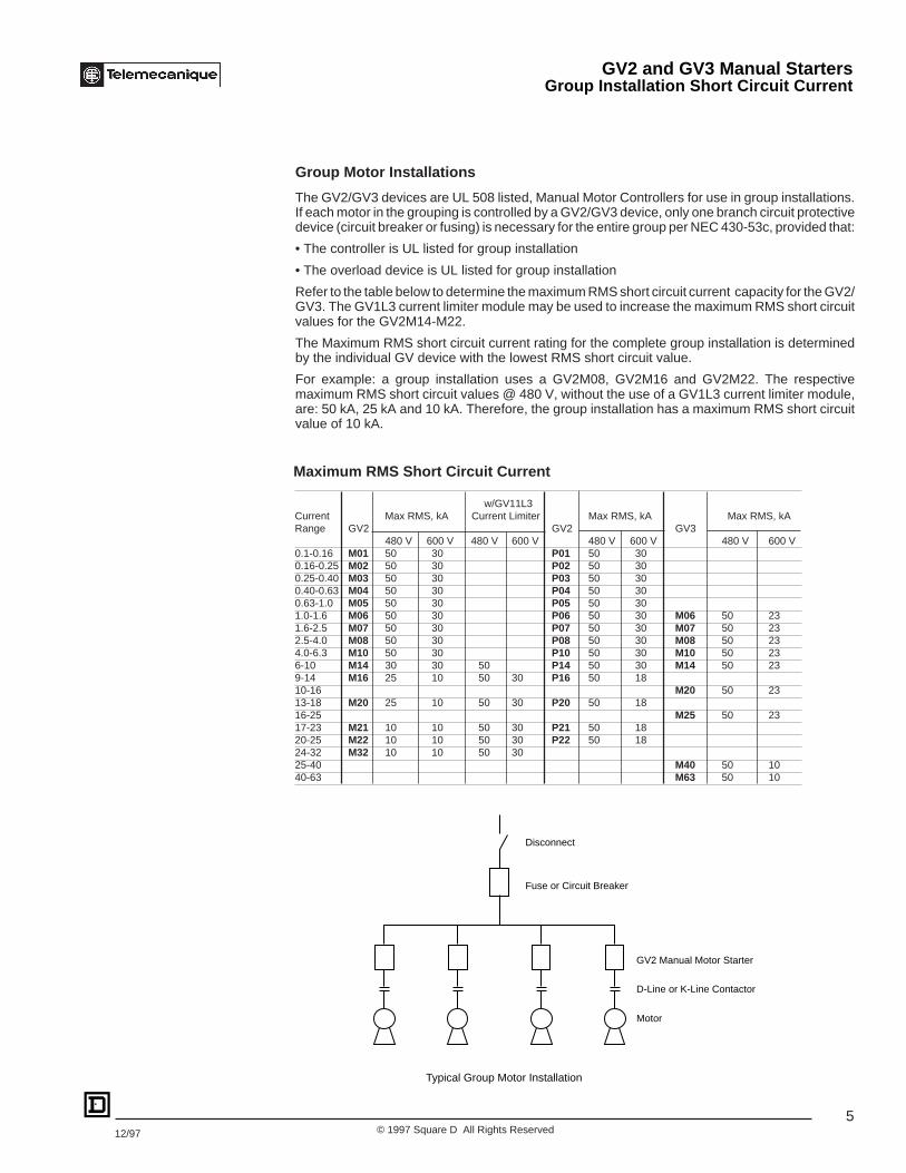
w/GV11L3Current Max RMS, kA Current Limiter Max RMS, kA Max RMS, kARange GV2 GV2 GV3
480 V 600 V 480 V 600 V 480 V 600 V 480 V 600 V0.1-0.16 M01 50 30 P01 50 300.16-0.25 M02 50 30 P02 50 300.25-0.40 M03 50 30 P03 50 300.40-0.63 M04 50 30 P04 50 300.63-1.0 M05 50 30 P05 50 301.0-1.6 M06 50 30 P06 50 30 M06 50 231.6-2.5 M07 50 30 P07 50 30 M07 50 232.5-4.0 M08 50 30 P08 50 30 M08 50 234.0-6.3 M10 50 30 P10 50 30 M10 50 236-10 M14 30 30 50 P14 50 30 M14 50 239-14 M16 25 10 50 30 P16 50 1810-16 M20 50 2313-18 M20 25 10 50 30 P20 50 1816-25 M25 50 2317-23 M21 10 10 50 30 P21 50 1820-25 M22 10 10 50 30 P22 50 1824-32 M32 10 10 50 3025-40 M40 50 1040-63 M63 50 10
Maximum RMS Short Circuit Current
Group Motor Installations
The GV2/GV3 devices are UL 508 listed, Manual Motor Controllers for use in group installations.If each motor in the grouping is controlled by a GV2/GV3 device, only one branch circuit protectivedevice (circuit breaker or fusing) is necessary for the entire group per NEC 430-53c, provided that:
• The controller is UL listed for group installation
• The overload device is UL listed for group installation
Refer to the table below to determine the maximum RMS short circuit current capacity for the GV2/GV3. The GV1L3 current limiter module may be used to increase the maximum RMS short circuitvalues for the GV2M14-M22.
The Maximum RMS short circuit current rating for the complete group installation is determinedby the individual GV device with the lowest RMS short circuit value.
For example: a group installation uses a GV2M08, GV2M16 and GV2M22. The respectivemaximum RMS short circuit values @ 480 V, without the use of a GV1L3 current limiter module,are: 50 kA, 25 kA and 10 kA. Therefore, the group installation has a maximum RMS short circuitvalue of 10 kA.
GV2 and GV3 Manual StartersGroup Installation Short Circuit Current
Disconnect
Fuse or Circuit Breaker
GV2 Manual Motor Starter
D-Line or K-Line Contactor
Typical Group Motor Installation
Motor
6© 1997 Square D All Rights Reserved 12/97
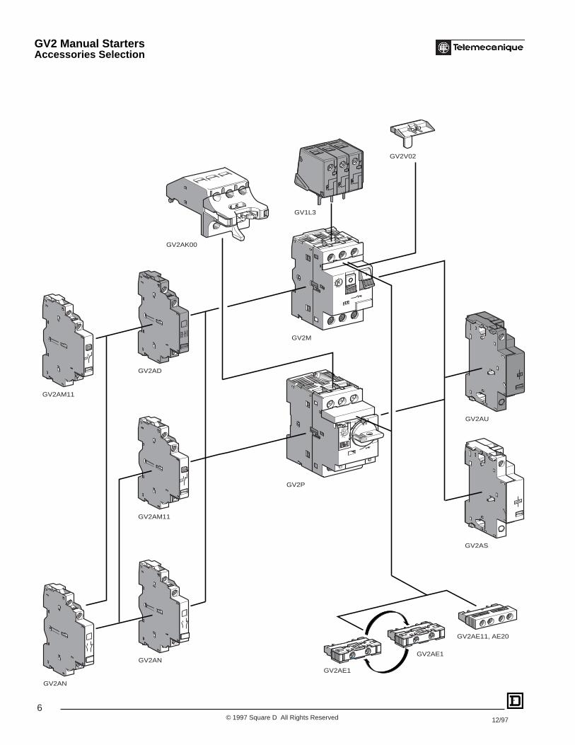
GV2AK00
GV2V02
GV1L3
GV2AD
GV2AM11
GV2AM11
GV2AN
GV2AN
GV2P
GV2M
GV2AU
GV2AS
GV2AE1
GV2AE1
GV2AE11, AE20
GV2 Manual StartersAccessories Selection

7© 1997 Square D All Rights Reserved12/97
Auxiliary contact blocksDescription Mounting Max. No. of Contact Sold in Catalog
Location blocks Types lots of NumberInstantaneous Front (3) 1 N/O OR N/C (1) 10 GV2AE1auxiliary N/O + N/C 10 GV2AE11contacts N/O + N/O 10 GV2AE20
Left Hand Side 2 N/O + N/C 1 GV2AN11N/O + N/O 1 GV2AN20
Fault signalling Left Hand 1 N/O (fault) + N/O 1 GV2AD1010contact + Side (2) N/O (fault) + N/C 1 GV2AD1001instantaneous N/C (fault) + N/O 1 GV2AD0110auxiliary contact N/C (fault) + N/C 1 GV2AD0101Short circuit Left Hand Side 1 SPDT 1 GV2AM11signallingcontact
Voltage tripsDescription Mounting Max. No. of Voltage Catalog
Location blocks NumberUndervoltage Right Hand 1 110-115 V 50 Hz GV2AU115trip Side 60 Hz GV2AU116
220-240 V 50 Hz GV2AU22560 Hz GV2AU226
380-400 V 50 Hz GV2AU38560 Hz GV2AU386
415-440 V 50 Hz GV2AU415440 V 60 Hz GV2AU385500 V 50 Hz GV2AU505600 V 60 Hz GV2AU505
Shunt trip Right Side 1 110-115 V 50 Hz GV2AS115Side 60 Hz GV2AS116
220-240 V 50 Hz GV2AS22560 Hz GV2AS226
380-400 V 50 Hz GV2AS38560 Hz GV2AS386
415-440 V 50 Hz GV2AS415440 V 60 Hz GV2AS385500 V 50 Hz GV2AS505600 V 60 Hz GV2AS606
Add-on contact blocksDescription Mounting Max. No. of Sold in Catalog
Location blocks lots of NumberVisible isolation Front (3) 1 1 GV2AK00block, 3-pole onincoming sideof GV2P100 kA limiter Top 1 1 GV1L3
Sealing kitFor GV2M Front – 10 GV2V02(1) Choice of N/C or N/O contact operation depending on which way the reversible block is mounted.(2) The GV2AD is always mounted next to the manual starter.(3) Can mount either a GV2AE contact block or a GV2AK00 visible isolation block on GV2P.
GV2AK00 GV1L3
GV2AE11
GV2AN11
GV2AD1010
GV2AU
GV2 Manual StartersAccessories Selection

8© 1997 Square D All Rights Reserved 12/97
GV2G454GV1G09 GV2G254
GV2G05
LA9E07
GV2G454
GV1G10
GV2AF01
GV2V03
GV2AP0 ●
GV2AF02
GV1G02
GK2AF01
O
TRIP. +
GV2 Manual StartersAccessories Selection
9© 1997 Square D All Rights Reserved12/97
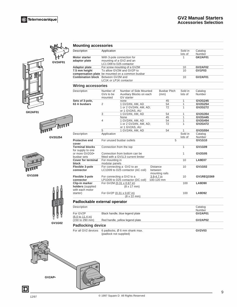
Mounting accessoriesDescription Application Sold in Catalog
lots of NumberMotor starter With 3-pole connection for 1 GK2AF01adaptor plate mounting of a GV2 and an
LC1 D09 to D25 contactorAdaptor plate For screw mounting of a GV2M 10 GV2AF027.5 mm height To allow GV2M and GV2P to 10 GV1F03compensation plate be mounted on a common busbarCombination block Between GV2M and 10 GV2AF01
LC1K or LP1K contactor
Wiring accessoriesDescription Number of Number of Side Mounted Busbar Pitch Sold in Catalog
GVs to be Auxiliary Blocks on each (mm) lots of Numbermounted GV starter
Sets of 3-pole, none 45 1 GV2G24563 A busbars 2 1 GV2AN, AM, AD 54 1 GV2G254
1 or 2 GV2AN, AM, AD; 72 1 GV2G272or 1 GV2AS, AU
3 1 GV2AN, AM, AD 54 1 GV2G354None 45 1 GV2G445
4 1 GV2AN, AM, AD 54 1 GV2G4541 or 2 GV2AN, AM, AD; 72 1 GV2G472or 1 GV2AS, AU
5 1 GV2AN, AM, AD 54 1 GV2G554Description Application Sold in Catalog
lots of NumberProtective end For unused busbar outlets 5 GV1G10coverTerminal blocks Connection from the top 1 GV1G09for supply to oneor more GV2G0• Connection from bottom can be 1 GV2G05busbar sets fitted with a GV1L3 current limiterCover for terminal For mounting in 10 LA9E07block modular panelsFlexible 3-pole For connecting a GV2 to an Distance 10 GV1G02connector LC1D09 to D25 contactor (AC coil) between
mounting railsFlexible 3-pole For connecting a GV2 to a 3.9-4.7 in 10 GV1REQ3369connector LP1D09 to D25 contactor (DC coil) 100-120 mmClip-in marker For GV2M (0.31 x 0.67 in) 100 LA9D90holders (supplied (8 x 17 mm)with each motorstarter) For GV2P (0.31 x 0.87 in) 100 LA9D92
(8 x 22 mm)
Padlockable external operatorDescription Catalog
NumberFor GV2P Black handle, blue legend plate GV2AP01(6.0 to 11.4 in)(150 to 290 mm) Red handle, yellow legend plate GV2AP02
Padlocking deviceFor all GV2 devices 6 padlocks, Ø 6 mm shank max. GV2V03
(padlock not supplied)
O
TRIP. +
GV2AP•
GV2AF01
GK2AF01
GV2G254
GV1G02
GV1G09
GV2 Manual StartersAccessories Selection
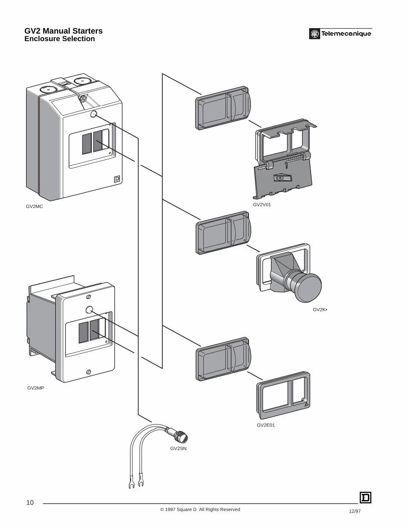
10© 1997 Square D All Rights Reserved 12/97
GV2MC
GV2SN
GV2E01
GV2K•
GV2V01
GV2MP
GV2 Manual StartersEnclosure Selection

11© 1997 Square D All Rights Reserved12/97
GV2M enclosuresApplication Type Degree of protection Catalog
of enclosure NumberFor GV2M manual starters Surface IP 41 GV2MC01
and protectors with or mounting,without accessories double(maximum of 1 accessory on insulated with IP 55 GV2MC02
right and left for GV2MC protectiveand GV2MP01 or MP02, cover.1 accessory only on right for Sealable IP 55 for GV2MC03GV2MP03 and GV2MP04) cover. temperature < + 5 °C
Flush IP 41 (full size) GV2MP01mounting
with IP 41 GV2MP03protective (reduced size)cover.
IP 55 (full size) GV2MP02
IP 55 GV2MP04(reduced size)
Front plateApplication Degree of protection Sold in Catalog
of enclosure lots of NumberPadlocking device (1) 1 GV2V01for GV2M operator(padlocking is only possiblein the"O" position)Mushroom head Spring return 1 GV2K011“stop” pushbutton (1) Latching Key release 1 GV2K021Ø 40 mm, red (key #455)
Turn to release 1 GV2K031Latching/Padlockable Turn to release 1 GV2K04
Sealing kit For enclosures IP 55 10 GV2E01and front plate
IP 55 for 10 GV2E02temperature < + 5 °C
Neutral link 10 GV2N01
Description Voltage Color Sold in CatalogV lots of Number
Neon indicator light 110 Green 10 GV2SN13Red 10 GV2SN14Orange 10 GV2SN15Clear 10 GV2SN17
220/240 Green 10 GV2SN23Red 10 GV2SN24Orange 10 GV2SN25Clear 10 GV2SN27
380/440 Green 10 GV2SN33Red 10 GV2SN34Orange 10 GV2SN35Clear 10 GV2SN37
(1) Supplied with IP 55 sealing kit.
GV2SN•
GV2K•
GV2MC•
GV2 Manual StartersEnclosure Selection

12© 1997 Square D All Rights Reserved 12/97
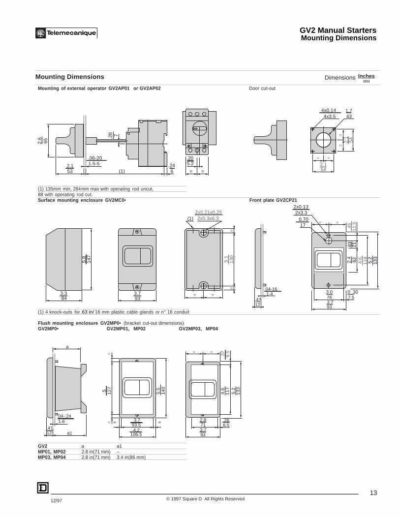
InchesMM
Mounting Dimensions Dimensions
GV2 Manual StartersMounting Dimensions
GV2M GV2AD, AM, AN, AU, AS GV2AE
X1 Electrical clearance = Ue 40 mm for ≤ 690 V
GV2P GV2AD, AM, AN, AU, AS, GV2AK00
X2 = 40 mmX1 Electrical clearance = 40 mm for Ue ≤ 415 V, or 80 mm for Ue = 440 V, or 120 mm for Ue = 500 and 690 V
Mounting of GV2M On panel with adaptor plate GV2AF02 On pre-slotted mounting plate On mounting rail DZ5MB201On 35 mm (rail) AM1PAC = 78.5 on AM1DP200 (35 x 7.5)C = 86 on AM1DE200, ED200 (35 x 15)
Mounting of GV2P On panel On pre-slotted mounting plate Adaptor plate GK2AF01AM1PA
C = 98.5 on AM1DP200 (35 x 7.5)C = 106 on AM1DE200, ED200 (35 x 15)
GV2AF01 GV2M + GV1L3 (current limiter) 7.5 mm height compensation plateGV2M + K contactor combination GV1F03
X1 = 10 mm for Ue = 230 V or 30 mm for 230 V < Ue ≤ 690 V
Block GV2AD, AM, ANBlock GV2AU, AS
Block GV2AD, AM, ANBlock GV2AU, AS
AF1EA4 DZ5MB201GV2AF02
DZ5ME8
AF1EA4
45=
=
44.5 9.3
81(1)
18
15
10
89
82
X1
5026
X2
15
6145
==
9814
44.5
32
80
4.2
35
6050
c
44.5
451.8
35
542.1
105
54.
1 .2
0
351.4
1.4
È5.5.22
5.20
24
135
9.5
451.8 12
9 5.
1
44.51.8
893.5
773.0
X1
X1
401.6
391.5
351.4
13.51
451.8
152
6.0
89
66
X1
4416
X111
.43 .63 1.7
2.6
3.5
1.8
1.8
3.2
.71.379.3.37
.59
.39
1.11.0
3.2.59
3.5
1.8
2.4
44.51.8
9.3
81(1)
183.2
.71.379.3.37
.55 3.9
1.8
1.3
1.8
44.5
1.8
3.1
50/6
01.
1/2.
4
1.4
1.7
351.4
50/6
01.
1/2.
4
2.4
1.1
351.4
15.59
c
44.5
1.8
44.5
1.8
843.3
13.5.53
13.5.53
843.3
.94 .37
5545
2.2
1.8
5.3
793.1
1.8 in/
1.8 in/ 1.8 in/ 3.2 in/ 4.7 in/
1.4 in/
On 35 mm (rail)1.4 in/
.40 in/ 1.2 in/
13© 1997 Square D All Rights Reserved12/97
Mounting Dimensions InchesMM
Dimensions
GV2 Manual StartersMounting Dimensions
Mounting of external operator GV2AP01 or GV2AP02 Door cut-out
(1) 135mm min, 284 mm max with operating rod uncut,88 with operating rod cut.Surface mounting enclosure GV2MC0• Front plate GV2CP21
(1) 4 knock-outs for 16 mm plastic cable glands or n° 16 conduit
Flush mounting enclosure GV2MP0• (bracket cut-out dimensions)GV2MP0• GV2MP01, MP02 GV2MP03, MP04
GV2 a a1MP01, MP02 2.8 in(71 mm) –MP03, MP04 2.8 in(71 mm) 3.4 in(86 mm)
542.1
= =
==
542.1
4x3.54x0.14
43 1.7
1-6.04-.24
a112
140
5.5
=12
75= = 93.5
3.7 =
106.54.2
712.8
933.7
6.5.26
117
4.6
133
5.2
a= =
9.5
.37
147
84
(1) 2x5.3x6.32x0.21x0.25
93=
130
==
=
1.5-5
7
53 (1)
65
6
1-4
12
76
93
7.5
= =
118
21
133
6211
.5
2x3.32x0.13
170.70
2.6
2.1
.06-20
.24
.28
5.2
= =
.20
3.3 3.7
5.8
5.1
.47
.04-16
.45
.83
2.4
4.6
5.2
3.0 0 .30
.47
3.7
.63 in/
14© 1997 Square D All Rights Reserved 12/97
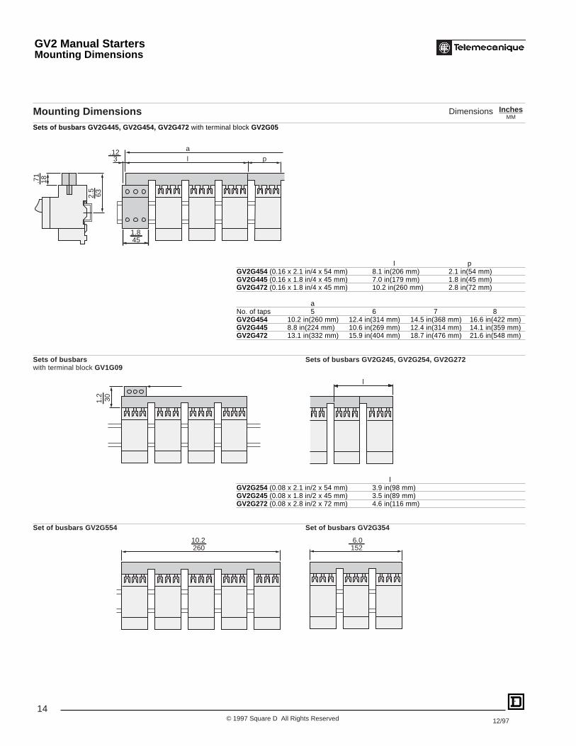
632.5
l3.12 a
18.71
p
451.8
301.2
l
26010.2
1526.0
Mounting DimensionsSets of busbars GV2G445, GV2G454, GV2G472 with terminal block GV2G05
l pGV2G454 (0.16 x 2.1 in/4 x 54 mm) 8.1 in(206 mm) 2.1 in(54 mm)GV2G445 (0.16 x 1.8 in/4 x 45 mm) 7.0 in(179 mm) 1.8 in(45 mm)GV2G472 (0.16 x 1.8 in/4 x 45 mm) 10.2 in(260 mm) 2.8 in(72 mm)
aNo. of taps 5 6 7 8GV2G454 10.2 in(260 mm) 12.4 in(314 mm) 14.5 in(368 mm) 16.6 in(422 mm)GV2G445 8.8 in(224 mm) 10.6 in(269 mm) 12.4 in(314 mm) 14.1 in(359 mm)GV2G472 13.1 in(332 mm) 15.9 in(404 mm) 18.7 in(476 mm) 21.6 in(548 mm)
Sets of busbars Sets of busbars GV2G245, GV2G254, GV2G272with terminal block GV1G09
lGV2G254 (0.08 x 2.1 in/2 x 54 mm) 3.9 in(98 mm)GV2G245 (0.08 x 1.8 in/2 x 45 mm) 3.5 in(89 mm)GV2G272 (0.08 x 2.8 in/2 x 72 mm) 4.6 in(116 mm)
Set of busbars GV2G554 Set of busbars GV2G354
InchesMM
Dimensions
GV2 Manual StartersMounting Dimensions

15© 1997 Square D All Rights Reserved12/97
2/T
1
4/T
2
6/T
3
1/L1
3/L2
5/L3
2/T
1
4/T
2
6/T
3
1/L1
3/L2
5/L3
1/L1
3/L2
5/L3
1314 12
11 1314 22
21 1314
2324
or
GV2M GV2P Current limiter GV1L3
Front mounting add-on contact blocksInstantaneous auxiliary contactsGV2AE1 GV2AE11 GV2AE20
Side mounting add-on contact blocksInstantaneous auxiliary contacts and fault signalling contactsGV2AD0110 GV2AD0101 GV2AD1010 GV2AD1001
Instantaneous auxiliary contacts Short-circuit signalling contactsGV2AN11 GV2AN20 GV2AM11
Voltage tripsGV2AU GV2AS
Use of fault signalling contact andshort-circuit signalling contact
9798
535452
51
969553
549695 97
98
5152
(62) 32
(61) 31 43 (73)
44 (74)
(64) 34
(63) 33 43 (73)
44 (74) 05
0608
D1
D2
C1
C2
Tripsignalling
Short-circuitsignalling
GV2AM11 GV2AD10
N/C or N/OStart-Stop Contact
GV2 Manual StartersWiring Diagrams

16© 1997 Square D All Rights Reserved 12/97
Environment
Type GV2M GV2P
Conforming to standards IEC 947-1, 947-2, 947-4-1, EN 60204, BS 4752, BS 4941, UL 508, CSA C22.2 No. 14, NF C 63-650,NF C 63-120, 79-130, VDE 0113, 0660.
Product approvals DEMKO, NEMKO, SEMKO, CSA. CSA, UL, PTB UL, BV, GL, LROS, DNV, PTB
UL File Number File E164864, CCN NLRV
CSA File Number File LR 81630, Class 3211 05
Pending: CEBEC, ECU, KEMA-KEUR. Pending : ECU, ÖVEMEEI, ÖVE
Protective treatment “TH” “TH”
Degree of protection In enclosure GV2M01: IP 41 –conforming to IEC 529 In enclosure GV2M02: IP 55 –
Shock resistance 30 g 30 gconforming to IEC 68-2-27
Vibration resistance 5 g (5 to 150 Hz) 5 g (5 to 150 Hz)conforming to IEC 68-2-6
Ambient air temperature- storage -40 to +176 °F(-40 to + 80 °C) -40 to +176 °F(-40 to + 80 °C)
- operation -4 to +140 °F(-20 to + 60 °C) -4 to +140 °F(-20 to + 60 °C)
Temperature compensation -4 to +140 °F(-20 to + 60 °C) -4 to +140 °F(-20 to + 60 °C)
Flame resistance 1760 °F(960 °C) 1760 °F(960 °C)conforming to IEC 695-2-1
Maximum operating altitude 6562 ft(2000 m) 6562 ft(2000 m)
Operating positionsin relation to normalvertical mounting position
WiringNumber of conductors and cross Max Min Max Minsectional area (c.s.a.)Solid cable 2-#8 AWG(2-6 mm2) 2-#16 AWG(2-1 mm2) 2-#8 AWG(2-6 mm2) 2-#16 AWG(2-1 mm2)
Flexible cable without cable end 2-#8 AWG(2-6 mm2) 2-#14 AWG(2-1.5 mm2) 2-#8 AWG(2-6 mm2) 2-#14 AWG(2-1.5 mm2)
Flexible cable with cable end 2-#10 AWG(2-4 mm2) 2-#16 AWG(2-1 mm2) 2-#10 AWG(2-4 mm2) 2-#16 AWG(2-1 mm2)Suitable for isolationconforming to IEC 947-1 § 7-1-6 Yes Yes
Tightening torque 15 lb-in(1.7 N•m) 15 lb-in(1.7 N•m)
Resistance to mechanicalimpact 0.5 J 0.5 J
Enclosed : 6 –Sensitivity to phase failure Yes, conforming to IEC 947-4-1, paragraph 7-2-1-5-2
90°90°
30°30°
GV2 Manual StartersSpecifications

17© 1997 Square D All Rights Reserved12/97
Characteristics
Type GV2M GV2P
Utilization categoryconforming to IEC 947-2 A A
conforming to IEC 947-4-1 AC-3 AC-3
Rated operational voltage (Ue)conforming to IEC 947-2 V 690 690
Rated insulation voltage (Ui)conforming to IEC 947-2 V 690 690
conforming to CSA C22.2 No. 14 V 600 600and UL 508
Rated operational frequencyconforming to IEC 947-2 Hz 50/60 50/60
Rated impulse withstandvoltage (U imp) kV 6 6conforming to IEC 947-2
Total power dissipated per pole W 2.5 2.5
Mechanical life ops 100 000 100 000(ops : closing, opening)
Electrical life ops 100 000 100 000for AC-3 duty
Duty class ops/h 25 25(maximum operating rate)
Rated dutyconforming to IEC 947-4-1 Continuous duty Continuous duty
GV2 Manual StartersSpecification

18© 1997 Square D All Rights Reserved 12/97
Characteristics
Type GV2AU GV2AS
Rated insulation voltage (Ui) V 690 690conforming to IEC 947-1
Operational voltage V 0.85-1.1 Ue 0.7-1.1 Ueconforming to IEC 947-1
Drop-out voltage V 0.35-0.7 Ue 0.2-0.75 Ue
Inrush consumption VA 12 14
W 8 10.5
Sealed consumption VA 3.5 5
W 1.1 1.6
Operating time From the moment the voltage reaches its operational value until opening of the GV2conforming to IEC 947-1 msec 10-15
On-load factor 100 %
WiringNumber of conductors and cross Min Maxsectional area (c.s.a.)Solid cable 1-#16 to #12 AWG(1-2.5 mm2) 2-#16 to #12 AWG(1-2.5 mm2)
Flexible cable without cable end 1-#18 to #12 AWG(0.75-2.5 mm2) 2-#18 to #12 AWG(0.75-2.5 mm2)
Flexible cable with cable end 1-#18 to #14 AWG(0.75-1.5 mm2) 2-#18 to #14 AWG(0.75-1.5 mm2)
Tightening torque 12 lb-in(1.4 N•m) max
Mechanical life ops 100 000(ops: closing-opening)
GV2 Manual StartersSpecifications - Trip Modules
19© 1997 Square D All Rights Reserved12/97
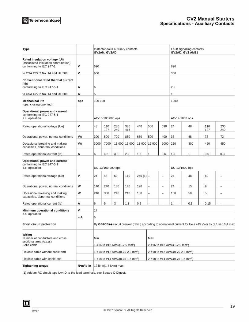
Type Instantaneous auxiliary contacts Fault signalling contactsGV2AN, GV2AD GV2AD, GV2 AM11
Rated insulation voltage (Ui)(associated insulation coordination)conforming to IEC 947-1 V 690 690
to CSA C22.2 No. 14 and UL 508 V 600 300
Conventional rated thermal current(Ith)conforming to IEC 947-5-1 A 6 2.5
to CSA C22.2 No. 14 and UL 508 A 5 1
Mechanical life ops 100 000 1000(ops: closing-opening)
Operational power and currentconforming to IEC 947-5-1a.c. operation AC-15/100 000 ops AC-14/1000 ops
Rated operational voltage (Ue) V 48 110 230 380 440 500 690 24 48 110 230127 240 415 127 240
Operational power, normal conditions VA 300 500 720 850 650 500 400 36 48 72 72
Occasional breaking and making VA 3000 7000 13 000 15 000 13 000 12 000 9000 220 300 450 450capacities, abnormal conditions
Rated operational current (Ie) A 6 4.5 3.3 2.2 1.5 1 0.6 1.5 1 0.5 0.3
Operational power and currentconforming to IEC 947-5-1d.c. operation DC-13/100 000 ops DC-13/1000 ops
Rated operational voltage (Ue) V 24 48 60 110 240 (1) – – 24 48 60 –
Operational power, normal conditions W 140 240 180 140 120 – – 24 15 9 –
Occasional breaking and making W 240 360 240 210 180 – – 100 50 50 –capacities, abnormal conditions
Rated operational current (Ie) A 6 5 3 1.3 0.5 – – 1 0.3 0.15 –
Minimum operational conditions V 17d.c. operation
mA 5
Short circuit protection By GB2CB●● circuit breaker (rating according to operational current for Ue ≤ 415 V) or by gl fuse 10 A max
WiringNumber of conductors and cross Min Maxsectional area (c.s.a.)Solid cable 1-#16 to #12 AWG(1-2.5 mm2) 2-#16 to #12 AWG(1-2.5 mm2)
Flexible cable without cable end 1-#18 to #12 AWG(0.75-2.5 mm2) 2-#18 to #12 AWG(0.75-2.5 mm2)
Flexible cable with cable end 1-#18 to #14 AWG(0.75-1.5 mm2) 2-#18 to #14 AWG(0.75-1.5 mm2)
Tightening torque N•m/lb-in 12 lb-in(1.4 N•m) max
(1) Add an RC circuit type LA4 D to the load terminals, see Square D Digest.
GV2 Manual StartersSpecifications - Auxiliary Contacts

20© 1997 Square D All Rights Reserved 12/97
Type Instantaneous auxiliary contacts GV2AE
Rated insulation voltage (Ui)(associated insulation coordination) V 250 (690 with respect to main circuit)conforming to IEC 947-1
to CSA C22.2 No. 14 and UL 508 V 300
Conventional rated thermal current(Ith) conforming to IEC 947-5-1 A 2.5
to CSA C22.2 No. 14 and UL 508 A 1
Mechanical life ops 100 000
Operational power and currentto IEC 947-5-1. a.c. operation AC-15/100 000 ops (closing / opening)
Rated operational voltage (Ue) V 24 48 110 230127 240
Operational power, normal conditions VA 48 60 120 120Occasional breaking and making VA 480 600 1270 2400capacities, abnormal conditionsRated operational current (Ie) A 2 1.25 1 0.5
Operational power and currentto IEC 947-5-1. d.c. operation DC-13/100 000 ops (closing / opening)
Rated operational voltage (Ue) V 24 48 60 –Operational power, normal conditions W 24 15 9 –Occasional breaking and making W 100 50 50 –capacities, abnormal conditionsRated operational current (Ie) A 1 0.3 0.15 –
Low level switching contact reliability Number of faults for “n” million operating cycles (17 V-5 mA): = 10-6
Short circuit protection By GB2CB06 circuit breaker or gl fuse, 10 A max
WiringNumber of conductors and cross Min Maxsectional areaSolid cable 1-#16 to #12 AWG(1-2.5 mm2) 2-#16 to #12 AWG(1-2.5 mm2)
Flexible cable without cable end 1-#18 to #12 AWG(0.75-2.5 mm2) 2-#18 to #12 AWG(0.75-2.5 mm2)
Flexible cable with cable end 1-#18 to #14 AWG(0.75-1.5 mm2) 2-#18 to #14 AWG(0.75-1.5 mm2)
Tightening torque 12 lb-in(1.4 N•m) max
Contact operationinstantaneous auxiliary contacts
Operation of faultsignalling contacts
GV2AM11Change of state following trippingon short circuit.
GV2AD10 and AD01Change of state following trippingon short circuit, overload or undervoltage.
Power pole
GV2AD01
GV2AD10
Contact open
Contact closed
0 1
GV2AN20
GV2AN11
GV2AE1
GV2AE20
GV2AE11
N/ON/O
N/ON/C
N/ON/C
N/ON/O
N/ON/C
N/O
N/C
GV2 Manual StartersSpecifications - Auxiliary Contacts

21© 1997 Square D All Rights Reserved12/97
3-pole busbars GV1G0 ● and GV2G0 ●
Rated insulation voltage (Ui) Conforming to IEC 947-1 V 690
Conventional rated thermal current Conforming to IEC 439-1 A 63(Ith)
Permissible peak current kA 11(I peak)
Permissible thermal limit kA 2s 104(I2t)
Degree of protection Conforming to IEC 529 IP 20
Terminal blocks GV2G05 and GV1G09Rated insulation voltage (Ui) Conforming to IEC 947-1 V 690
Conventional rated thermal current Conforming to IEC 439-1 A 63(Ith)
Degree of protection Conforming to IEC 529 IP 20
Wiring Solid cable 1-#14 to #2 AWG(1.5 to 25 mm2) conductor or2-#14 to #6 AWG(1.5 to 10 mm2) conductors
Flexible cable 1-#14 to #2 AWG(1.5 to 25 mm2) conductor orwithout cable end 2-#12 to #6 AWG(2.5 to 10 mm2) conductorsFlexible cable 1-#14 to #4 AWG(1.5 to 16 mm2) conductor orwith cable end 2-#14 to #10 AWG(1.5 to 4 mm2) conductors
Tightening torque Connector 20 lb-in(2.2 N•m)
Screw clamp 15 lb-in(1.7 N•m)
Current limiter GV1L3Rated insulation voltage (Ui) Conforming to IEC 947-1 V 690
Conventional rated thermal current Conforming to IEC 947-1 A 63(Ith)
Operating threshold rms current A 1500 (non adjustable threshold)
Wiring Solid cable 1-#14 to #2 AWG(1.5 to 25 mm2) conductor or2-#14 to #6 AWG(1.5 to 10 mm2) conductors
Flexible cable 1-#14 to #2 AWG(1.5 to 25 mm2) conductor orwithout cable end 2-#12 to #6 AWG(2.5 to 10 mm2) conductorsFlexible cable 1-#14 to #4 AWG(1.5 to 16 mm2) conductor orwith cable end 2-#14 to #10 AWG(1.5 to 4 mm2) conductors
Tightening torque 20 lb-in(2.2 N•m)
GV2 Manual StartersSpecifications - Acessories
22© 1997 Square D All Rights Reserved 12/97
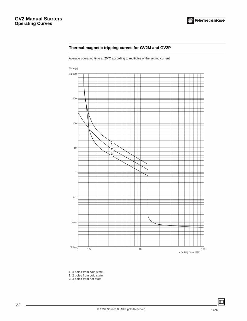
Thermal-magnetic tripping curves for GV2M and GV2P
Average operating time at 20°C according to multiples of the setting current
1 3 poles from cold state2 2 poles from cold state3 3 poles from hot state
Time (s)
x setting current (Ir)
0,001
0,1
1
10
100
0,01
1 1,5 10 100
1000
10 000
32
1
GV2 Manual StartersOperating Curves

23© 1997 Square D All Rights Reserved12/97
Current limitation on short circuit
For GV2M and GV2PThree-phase 400/415 V
Dynamic stressI peak = f (prospective Isc) at 1.05 Ue = 435 V
(1) I peak max. (6) 6-10 A(2) 20-25 A (7) 4-6.3 A(3) 17-23 A (8) 2.5-4 A(4) 13-18 A (9) 1.6-2.5 A(5) 9-14 A (10) 1-1.6 A
(11) Limit of rated ultimate breaking capacity on short circuit ofGV2M (14, 18, 23 and 25 Amp ratings)
Prospective Isc (A)
Maximum peak current (A)
1
5
4
3
2
6
7
8
9
10
100 000
10 000
1000
100100 1000 10 000 100 000
cos
ϕ =
0.95
= 0.
9
= 0.
8
= 0.
7=
0.5
= 0.
3
= 0.
25
15 000 (11)
GV2 Manual StartersOperating Curves

24© 1997 Square D All Rights Reserved 12/97
Thermal limit on short circuit for GV2M
Thermal limit in kA 2 s in the magnetic operating zone
Sum of I2dt = f (prospective Isc) at 1.05 Ue = 435 V
1 20-25 A 6 4-6,3 A2 17-23 A 7 2.5-4 A3 13-18 A 8 1.6-2.5 A4 9-14 A 9 1-1.6 A5 6-10 A
100
10
1
0,1
0,010,1 1 10 100
234
5
6
7
8
9
Prospective Isc (kA)
1
Sum of I2dt (kA2s)
GV2 Manual StartersOperating Curves

25© 1997 Square D All Rights Reserved12/97
Sum of I2dt (kA2s)100
10
1
0,1
0,010,1 1 10 100
123
4
5
6
7
8
9
Prospective Isc (kA)
Thermal limit on short circuit for GV2P
Thermal limit in kA 2 s in the magnetic operating zone
Sum of I2dt = f (prospective Isc) at 1.05 Ue = 435 V
1 20-25 A 6 4-6.3 A2 17-23 A 7 2.5-4 A3 13-18 A 8 1.6-2.5 A4 9-14 A 9 1-1.6 A5 6-10 A
GV2 Manual StartersOperating Curves
26© 1997 Square D All Rights Reserved 12/97
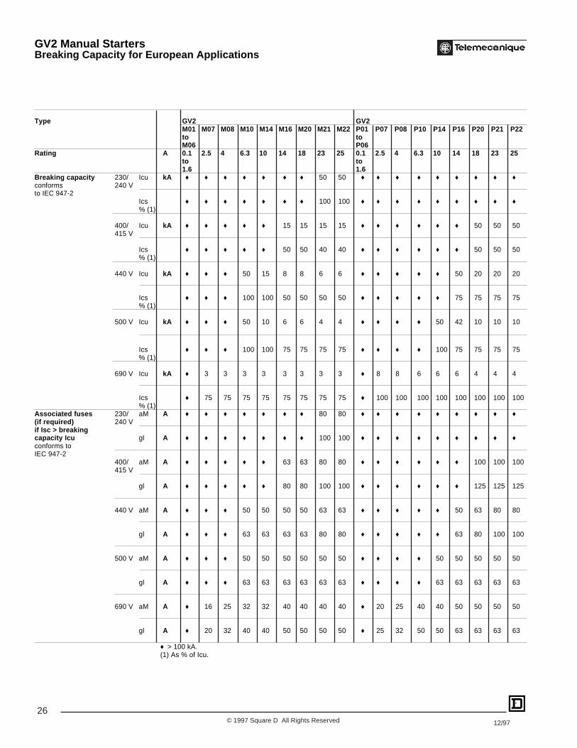
Type GV2 GV2M01 M07 M08 M10 M14 M16 M20 M21 M22 P01 P07 P08 P10 P14 P16 P20 P21 P22to toM06 P06
Rating A 0.1 2.5 4 6.3 10 14 18 23 25 0.1 2.5 4 6.3 10 14 18 23 25to to1.6 1.6
Breaking capacity 230/ Icu kA ♦ ♦ ♦ ♦ ♦ ♦ ♦ 50 50 ♦ ♦ ♦ ♦ ♦ ♦ ♦ ♦ ♦conforms 240 Vto IEC 947-2
Ics ♦ ♦ ♦ ♦ ♦ ♦ ♦ 100 100 ♦ ♦ ♦ ♦ ♦ ♦ ♦ ♦ ♦% (1)
400/ Icu kA ♦ ♦ ♦ ♦ ♦ 15 15 15 15 ♦ ♦ ♦ ♦ ♦ ♦ 50 50 50415 V
Ics ♦ ♦ ♦ ♦ ♦ 50 50 40 40 ♦ ♦ ♦ ♦ ♦ ♦ 50 50 50% (1)
440 V Icu kA ♦ ♦ ♦ 50 15 8 8 6 6 ♦ ♦ ♦ ♦ ♦ 50 20 20 20
Ics ♦ ♦ ♦ 100 100 50 50 50 50 ♦ ♦ ♦ ♦ ♦ 75 75 75 75% (1)
500 V Icu kA ♦ ♦ ♦ 50 10 6 6 4 4 ♦ ♦ ♦ ♦ 50 42 10 10 10
Ics ♦ ♦ ♦ 100 100 75 75 75 75 ♦ ♦ ♦ ♦ 100 75 75 75 75% (1)
690 V Icu kA ♦ 3 3 3 3 3 3 3 3 ♦ 8 8 6 6 6 4 4 4
Ics ♦ 75 75 75 75 75 75 75 75 ♦ 100 100 100 100 100 100 100 100% (1)
Associated fuses 230/ aM A ♦ ♦ ♦ ♦ ♦ ♦ ♦ 80 80 ♦ ♦ ♦ ♦ ♦ ♦ ♦ ♦ ♦(if required) 240 Vif Isc > breakingcapacity Icu gl A ♦ ♦ ♦ ♦ ♦ ♦ ♦ 100 100 ♦ ♦ ♦ ♦ ♦ ♦ ♦ ♦ ♦conforms toIEC 947-2
400/ aM A ♦ ♦ ♦ ♦ ♦ 63 63 80 80 ♦ ♦ ♦ ♦ ♦ ♦ 100 100 100415 V
gl A ♦ ♦ ♦ ♦ ♦ 80 80 100 100 ♦ ♦ ♦ ♦ ♦ ♦ 125 125 125
440 V aM A ♦ ♦ ♦ 50 50 50 50 63 63 ♦ ♦ ♦ ♦ ♦ 50 63 80 80
gl A ♦ ♦ ♦ 63 63 63 63 80 80 ♦ ♦ ♦ ♦ ♦ 63 80 100 100
500 V aM A ♦ ♦ ♦ 50 50 50 50 50 50 ♦ ♦ ♦ ♦ 50 50 50 50 50
gl A ♦ ♦ ♦ 63 63 63 63 63 63 ♦ ♦ ♦ ♦ 63 63 63 63 63
690 V aM A ♦ 16 25 32 32 40 40 40 40 ♦ 20 25 40 40 50 50 50 50
gl A ♦ 20 32 40 40 50 50 50 50 ♦ 25 32 50 50 63 63 63 63
♦ > 100 kA.(1) As % of Icu.
GV2 Manual StartersBreaking Capacity for European Applications

27© 1997 Square D All Rights Reserved12/97
Used in association with current limiter GV1L3
Type GV2M01 M07 M08 M10 M14 M16 M20 M21 M22toM06
Rating A 0.1 to 1.6 2.5 4 6.3 10 14 18 23 25
Breaking capacity 230/ Icu kA ♦ ♦ ♦ ♦ ♦ ♦ ♦ ♦ ♦conforms 240 Vto IEC 947-2 Ics ♦ ♦ ♦ ♦ ♦ ♦ ♦ ♦ ♦
% (1)
400/ Icu kA ♦ ♦ ♦ ♦ ♦ 100 100 100 100415 V
Ics ♦ ♦ ♦ ♦ ♦ 50 50 40 40% (1)
440 V Icu kA ♦ ♦ ♦ ♦ ♦ 50 20 20 20
Ics ♦ ♦ ♦ ♦ ♦ 75 75 75 75% (1)
500 V Icu kA ♦ ♦ ♦ ♦ 50 42 10 10 10
Ics ♦ ♦ ♦ ♦ 100 100 75 75 75% (1)
Type GV2P01 P07 P08 P10 P14 P16 P20 P21 P22toP06
Rating A 0.1 to 1.6 2.5 4 6.3 10 14 18 23 25
Breaking capacity 230/ Icu kA ♦ ♦ ♦ ♦ ♦ ♦ ♦ ♦ ♦conforms 240 Vto IEC 947-2 Ics ♦ ♦ ♦ ♦ ♦ ♦ ♦ ♦ ♦
% (1)
400/ Icu kA ♦ ♦ ♦ ♦ ♦ ♦ ♦ ♦ ♦415 V
Ics ♦ ♦ ♦ ♦ ♦ ♦ ♦ ♦ ♦% (1)
440 V Icu kA ♦ ♦ ♦ ♦ ♦ 100 100 100 100
Ics ♦ ♦ ♦ ♦ ♦ 50 50 50 50% (1)
500 V Icu kA ♦ ♦ ♦ ♦ 100 100 100 100 100
Ics ♦ ♦ ♦ ♦ 50 50 50 50 50% (1)
Type GV2M01 M07 M08 M10 M14 M16 M20 M21 M22toM06
Rating A 0.1 to 1.6 2.5 4 6.3 10 14 18 23 25
Cable protection againstthermal stress in the event ofshort circuit (PVC insulated coppercables) Minimum cross 0.04 in2
sectional area 1 mm2 (3) (3) (3) ≤10kA ≤6kA (2) (2) (2) (2)(c.s.a.) protected 0.06 in2
to 40 °C at 1.5 mm2 (3) (3) (3) ≤20kA ≤10kA (2) (2) (2) (2)Isc max 0.10-0.24 in
2.5-6 mm (3) (3) (3) (3) (3) (3) (3) (3) (3)
♦ > 100 kA. (1) As % of Icu. (2) Cable c.s.a. not protected (3) cable c.s.a. protected.
GV2 Manual StartersBreaking Capacity for European Applications

28© 1997 Square D All Rights Reserved 12/97
Description Characteristics Sold in Cataloglots of Number
Voltage trips (1) Under- 110, 120, 127 V 50 Hz 1 GV3B11(internal mount) voltage 120, 127 V 60 Hz
trips220, 240 V 50 Hz 1 GV3B22240, 277 V 60 Hz
380, 415 V 50 Hz 1 GV3B38480 V 60 Hz
Shunt 110, 120, 127 V 50 Hz 1 GV3D11trips 120, 127 V 60 Hz
220, 240 V 50 Hz 1 GV3D22240, 277 V 60 Hz
380, 415 V 50 Hz 1 GV3D38480 V 60 Hz
Instantaneous Normal early break type contactsauxiliarycontact N/C + N/O 1 GV1A01blocks(1 per breaker) N/O + N/O 1 GV1A02(side-mounted)
N/C + N/O + N/O 1 GV1A03
N/O + N/O + N/O 1 GV1A05
N/O+N/O+2 spare terminal blocks 1 GV1A06
N/C+N/O+2 spare terminal blocks 1 GV1A07Fault signalling N/C 1 GV3A08contacts (1)(internal mount) N/O 1 GV3A09Padlocking device for Start button 5 GV1V02
(1) only 1 voltage trip OR 1 fault signalling contact to be added inside the GV3 device.
Metal enclosureApplication Type Degree of protection Catalog
of enclosure NumberFor GV3 with or Surface IP 55 GV3CE01without accessories mounting
Enclosure accessories (to be ordered separately)Description Reference
Neutral terminal, 2-pole LA9D40959
IP 55 padlocking device for operators (when padlocked, the GV1V01motor circuit is automatically in the Open (OFF) position)Mushroom head Spring return 1 GV2K011“stop” pushbutton (2) Latching Key release 1 GV2K021Ø 40 mm, red (key #455)
Turn to release 1 GV2K031 Latching/Padlockable Turn to release 1 GV2K04Sealing screw for enclosure cover DE1DS4091
(2) Supplied with IP 55 sealing kit.
GV3B
GV3CE01
GV1V01
GV1K011
GV1A01
GV3 Manual StartersAccessories Selection
29© 1997 Square D All Rights Reserved12/97
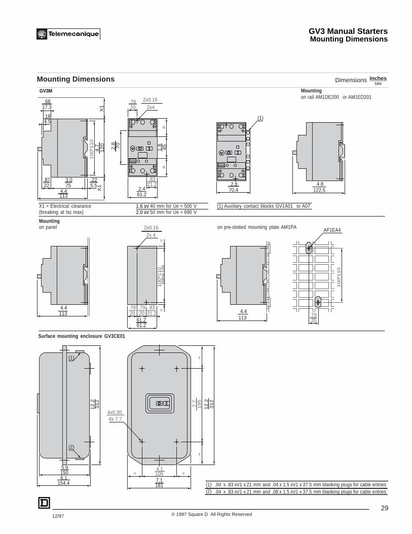
Mounting Dimensions InchesMM
Dimensions
Mountingon rail AM1DE200 or AM1ED201
X1 = Electrical clearance 40 mm for Ue < 500 V (1) Auxiliary contact blocks GV1A01 to A07(breaking at Isc max) 50 mm for Ue = 690 V
Mountingon panel on pre-slotted mounting plate AM1PA
Surface mounting enclosure GV3CE01
10
0 to
11
0
17.3
22.87
753.0
1134.4
10
0º1
10
12
04
.7
5.5.22
X1
X1
45
1.8
==
70
2.461.2
21.2.83
20.79
2x42x0.16
4.5.18
70.4 2.8
(1)
122.5 4.8
113 4.4
10
0º1
10
==
61.261,2
21.2.83
2x 4
20.79
20.79
20.79
10
0º1
10
1134.4
1505.9
154.46.1
31
21
2.2
31
21
2.2
19
57
.7=
=
1817.11054.1
= =
4x 7.74x0.30
(2)
(1)
.68
2.8
AF1EA42x0.16
1.6 in/2.0 in/
(1)(2)
.04 x .83 in/1 x and 21 mm .04 x 1.5 in/1 x 37.5 mm blanking plugs for cable entries
.04 x .83 in/1 x and 21 mm .08 x 1.5 in/1 x 37.5 mm blanking plugs for cable entries
GV3M
GV3 Manual StartersMounting Dimensions

30© 1997 Square D All Rights Reserved 12/97
Motor circuit breakersGV3M
Auxiliary contact blocksGV1A01 GV1A02 GV1A03 GV1A05 GV1A06 GV1A07
Fault signalling contactsGV3A08 GV3A09
Voltage tripsGV3B GV3D
2/T
11/
L1
4/T
23/
L2
6/T
35/
L3
1314 22
21 1314
2324
1314
2324 32
31 1314
2324
3334
1314
2324
3334
2324 32
311314
9695 97
98
D1
D2
U
C1
C2
GV3 Manual StartersWiring Diagrams

31© 1997 Square D All Rights Reserved12/97
GV3 Manual StartersSpecifications
EnvironmentConforming to standards IEC, NF C, BS, IEC, VDE
Approvals ASE, CSA, UL, LROS, ÖVE
UL File Number File E164864, CCN NLRV
CSA File Number File LR 81630, Class 3211 05
Protective treatment Standard version “TC”
Degree of protection Conforming to IEC 529 GV3M open-mounted: IP 20
GV3M in enclosure GV3CE01: IP 55
Shock resistance Conforming to IEC 68-2-27 22 g for 20 ms duration
Vibration resistance Conforming to IEC 68-2-6 2.5 g (0-25 Hz)
Ambient air temperature Storage -40 to +176 °F(-40 to + 80 °C)
Operation -4 to +104 °F(-20 to + 40 °C)
Temperature compensation Conforming to IEC 157-1 -4 to +104 °F(-20 to + 40 °C)
Flame resistance Conforming to IEC 695-2-1 Conforms for 1760 °F(960 °C)
Maximum operating altitude Without derating 9843 ft(3000 m)
Operating position
Type GV3M06 through M20 GV3M25 through M63
WiringNumber of conductors and cross Min Max Min Maxsectional area (c.s.a.)Solid cable 1-#16 to #8 AWG(1-6 mm2) 2-#16 to #8 AWG(1-6 mm2) 1-#12 to #1 AWG(2.5-35 mm2)
Flexible cable without cable end 1-#16 to #8 AWG(1-6 mm2) 2-#16 to #8 AWG(1-6 mm2) 1-#12 to #2 AWG(2.5-25 mm2) 2-#12 to #4 AWG(2.5-16 mm2)
Flexible cable with cable end 1-#16 to #10 AWG(1-4 mm2) 2-#16 to #10 AWG(1-4 mm2) 1-#12 to #2 AWG(2.5-25 mm2) 2-#12 to #4 AWG(2.5-16 mm2)
Technical characteristicsType GV3M06 through M25 GV3M40 through M63
Rated insulation voltage (UI) Conforming to IEC 158-1 V 690
Conforming toCSA C 22.2 No. 14 and UL 508 V 600 (B600)
Maximum conventional rated Conforming to IEC 157-1 A 63thermal current (lth)
Mechanical life ops 100 000 50 000
Electrical life AC-3 duty ops 100 000 50 000ops : Closing-openingMaximum operating rate ops/h 25
30°30°
90°90° 90°90
°
30°30°
OpenEnclosed
OpenEnclosed
32© 1997 Square D All Rights Reserved 12/97
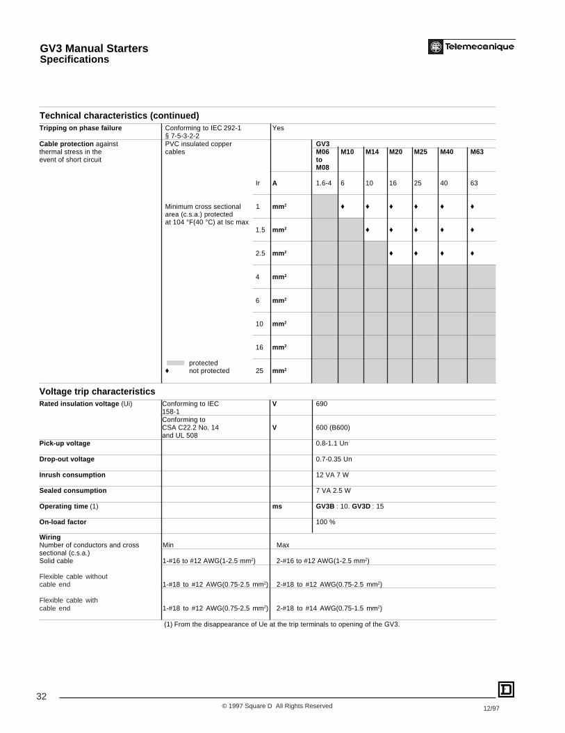
Technical characteristics (continued)Tripping on phase failure Conforming to IEC 292-1 Yes
§ 7-5-3-2-2Cable protection against PVC insulated copper GV3thermal stress in the cables M06 M10 M14 M20 M25 M40 M63event of short circuit to
M08
Ir A 1.6-4 6 10 16 25 40 63
Minimum cross sectional 1 mm 2 ♦ ♦ ♦ ♦ ♦ ♦area (c.s.a.) protectedat 104 °F(40 °C) at Isc max
1.5 mm 2 ♦ ♦ ♦ ♦ ♦
2.5 mm 2 ♦ ♦ ♦ ♦
4 mm 2
6 mm 2
10 mm 2
16 mm 2
protected♦ not protected 25 mm 2
Voltage trip characteristicsRated insulation voltage (Ui) Conforming to IEC V 690
158-1Conforming toCSA C22.2 No. 14 V 600 (B600)and UL 508
Pick-up voltage 0.8-1.1 Un
Drop-out voltage 0.7-0.35 Un
Inrush consumption 12 VA 7 W
Sealed consumption 7 VA 2.5 W
Operating time (1) ms GV3B : 10. GV3D : 15
On-load factor 100 %
WiringNumber of conductors and cross Min Maxsectional (c.s.a.)Solid cable 1-#16 to #12 AWG(1-2.5 mm2) 2-#16 to #12 AWG(1-2.5 mm2)
Flexible cable withoutcable end 1-#18 to #12 AWG(0.75-2.5 mm2) 2-#18 to #12 AWG(0.75-2.5 mm2)
Flexible cable withcable end 1-#18 to #12 AWG(0.75-2.5 mm2) 2-#18 to #14 AWG(0.75-1.5 mm2)
(1) From the disappearance of Ue at the trip terminals to opening of the GV3.
GV3 Manual StartersSpecifications
33© 1997 Square D All Rights Reserved12/97
0 1P
OF
FF
FFO
FF
F
FF
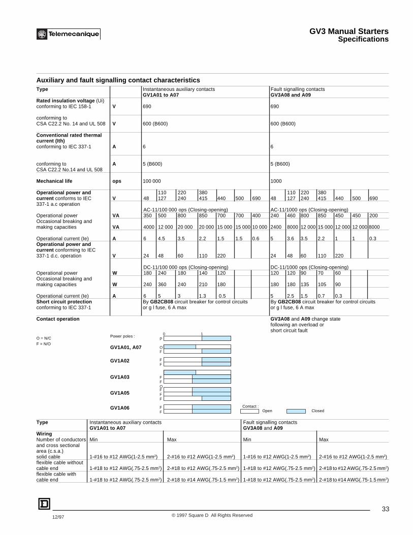
Auxiliary and fault signalling contact characteristicsType Instantaneous auxiliary contacts Fault signalling contacts
GV1A01 to A07 GV3A08 and A09Rated insulation voltage (Ui)conforming to IEC 158-1 V 690 690
conforming toCSA C22.2 No. 14 and UL 508 V 600 (B600) 600 (B600)
Conventional rated thermalcurrent (Ith)conforming to IEC 337-1 A 6 6
conforming to A 5 (B600) 5 (B600)CSA C22.2 No.14 and UL 508
Mechanical life ops 100 000 1000
Operational power and 110 220 380 110 220 380current conforms to IEC V 48 127 240 415 440 500 690 48 127 240 415 440 500 690337-1 a.c operation
AC-11/100 000 ops (Closing-opening) AC-11/1000 ops (Closing-opening)Operational power VA 350 500 800 850 700 700 400 240 460 800 850 450 450 200Occasional breaking andmaking capacities VA 4000 12 000 20 000 20 000 15 000 15 000 10 000 2400 8000 12 000 15 000 12 000 12 000 8000
Operational current (Ie) A 6 4.5 3.5 2.2 1.5 1.5 0.6 5 3.6 3.5 2.2 1 1 0.3Operational power andcurrent conforming to IEC337-1 d.c. operation V 24 48 60 110 220 24 48 60 110 220
DC-11/100 000 ops (Closing-opening) DC-11/1000 ops (Closing-opening)Operational power W 180 240 180 140 120 120 120 90 70 60Occasional breaking andmaking capacities W 240 360 240 210 180 180 180 135 105 90
Operational current (Ie) A 6 5 3 1.3 0.5 5 2.5 1.5 0.7 0.3Short circuit protection By GB2CB08 circuit breaker for control circuits By GB2CB08 circuit breaker for control circuitsconforming to IEC 337-1 or g l fuse, 6 A max or g l fuse, 6 A max
Contact operation GV3A08 and A09 change statefollowing an overload orshort circuit fault
Type Instantaneous auxiliary contacts Fault signalling contactsGV1A01 to A07 GV3A08 and A09
WiringNumber of conductors Min Max Min Maxand cross sectionalarea (c.s.a.)solid cable 1-#16 to #12 AWG(1-2.5 mm2) 2-#16 to #12 AWG(1-2.5 mm2) 1-#16 to #12 AWG(1-2.5 mm2) 2-#16 to #12 AWG(1-2.5 mm2)flexible cable withoutcable end 1-#18 to #12 AWG(.75-2.5 mm2) 2-#18 to #12 AWG(.75-2.5 mm2) 1-#18 to #12 AWG(.75-2.5 mm2) 2-#18 to #12 AWG(.75-2.5 mm2)flexible cable withcable end 1-#18 to #12 AWG(.75-2.5 mm2) 2-#18 to #14 AWG(.75-1.5 mm2) 1-#18 to #12 AWG(.75-2.5 mm2) 2-#18 to #14 AWG(.75-1.5 mm2)
Open ClosedContact :
O = N/CF = N/O
Power poles :
GV1A01, A07
GV1A02
GV1A03
GV1A05
GV1A06
GV3 Manual StartersSpecifications

34© 1997 Square D All Rights Reserved 12/97
Time (s)
X setting current (Ir)
0,001
0,1
1
10
100
0,01
1 10 100
1000
10 000
4
2
3
1
Thermal-magnetic tripping curves for GV3M
Average operating time at 68°F(20 °C) according to multiples of the setting current.
1 3 poles from cold state, rating 1.6-10 A2 3 poles from hot state, rating 1.6-10 A3 3 poles from cold state, rating 16-63 A4 3 poles from hot state, rating 16-63 A
GV3 Manual StartersOperating Curves

35© 1997 Square D All Rights Reserved12/97
Prospective Isc (kA)
1
3
2
100
10
1
0,10,1 1 10 100
cos
ϕ =
0.95
= 0.
9
= 0.
8
= 0.
7=
0.5
= 0.
3
= 0.
25
15
45
6
8
7
9
10
Current limitation on short circuit for GV3M
3-phase 400/415 V
Dynamic stress
I peak = f (prospective Isc) at 1.05 Ue = 435 V
Maximum peak current (kA)
1 I peak max 6 6-10 A2 40-63 A 7 4-6 A3 25-40 A 8 2.5-4 A4 16-25 A 9 1.6-2.5 A5 10-16 A 10 1-1.6 A
GV3 Manual StartersOperating Curves

36© 1997 Square D All Rights Reserved 12/97
Thermal limit on short circuit for GV3M
Thermal limit in kA 2s in the magnetic operating zone
Sum of l2dt = f (prospective Isc) at 1.05 Ue = 435 V
Sum of I2dt (kA2s)
1 40-63 A 5 6-10 A2 25-40 A 6 4-6 A3 16-25 A 7 2.5-4 A4 10-16 A 8 1.6-2.5 A
Prospective Isc (kA)
100
10
1
0,10,1 1 10 10015
21
34
5
6
7
8
GV3 Manual StartersOperating Curves

37© 1997 Square D All Rights Reserved12/97
Type GV3M06 M08 M10 M14 M20 M25 M40 M63andM07
Breaking capacity 230 V kA 100 100 100 100 100 100 100 100(Icn)conforms toIEC 157-1 (P1) 400/415 V kA 100 100 100 100 100 100 35 35
440 V kA 100 100 100 25 25 25 25 25
500 V kA 100 100 100 8 8 8 8 8
690 V kA 100 4 4 4 4 4 4 4
Associated fuses 230 V aM A ♦ ♦ ♦ ♦ ♦ ♦ ♦ ♦(if required), ifIsc > breakingcapacity Icn gl A ♦ ♦ ♦ ♦ ♦ ♦ ♦ ♦
400/415 V aM A ♦ ♦ ♦ ♦ ♦ ♦ 250 315
gl A ♦ ♦ ♦ ♦ ♦ ♦ 315 400
440 V aM A ♦ ♦ ♦ 125 160 200 250 315
gl A ♦ ♦ ♦ 160 200 250 315 400
500 V aM A ♦ ♦ ♦ 80 100 125 160 200
gl A ♦ ♦ ♦ 100 125 160 200 250
690 V aM A ♦ 40 50 80 100 125 160 200
gl A ♦ 50 63 100 125 160 200 250
♦Fuse not required : breaking capacity Icn > Isc.
GV3 Manual StartersBreaking Capacity for European Applications

38© 1997 Square D All Rights Reserved 12/97
File E164867CCN NMTR
File LR89150Class 622801
AK5 Panel Busbar SystemGeneral Information
2 3 41
810
6
11
13
2
1
5 5
7
9
12
5
6
10 15 14
8
12
AK5-ASS-3-Q

39© 1997 Square D All Rights Reserved12/97
Pre-assembled panel busbar system AK5
The assembly of automated control and distribution panels requires the use of products that are not only safe but also simple and quick to mount and cable.
The AK5 pre-assembled busbar system meets these criteria by incorporating prefabricated elements which provide 3 principal functions :
Current supply
Pre-assembled 160 A (at 35 °C) 4-pole busbar system 1.
The busbar systems are available in 6 lengths : 344, 452, 560, 668, 992, 1100 mm (13.5", 17.8", 22", 26.3", 39", 43.3").
An incoming supply terminal block 2 is located at the extreme left of the busbar system.
“Knock-out” partitions allow cabling from above or below to the terminal block connections 3, which are protected by a removable cover 4.
Current distribution
The tap-offs 5 clip onto the busbar system with instantaneous mechanical and electrical connection to the busbars.
2 ratings are available : 16 and 32 A.
The tap-off units not only ensure rapid mounting but also provide visual “symmetry” for the power distribution circuit and complete safety when accessing underlive circuit conditions.
Component mounting
Component mounting plate incorporating electrical tap-off.Tap-off rating : 25 A or 50 A.
The mounting plates clip onto the mounting rail 11, which also supports the busbar system, and at the same time make electrical connection via the incorporatedtap-off.
2 types of mounting plates are available :
-single plate 6 (height 105 mm) with bolt-on 35 mm wide ( rail 7. This omega rail may be bolted in one of two positions, each with a 10 mm vertical step,
-double plate 8 and 14 (height 190 mm) with 2 bolt-on 35 mm wide ( rails 9 mounted on 100 mm mounting centers. Each rail may be bolted in one of four positions,each with a 10 mm vertical step. These mounting plates are supplied with connectors 12 to allow wiring between control and protection devices.
Bolt-on width extension plates 10 are also available for mounting wider components. Using a lateral end stop 15 in conjunction with these plates also supportsthe AK5-JB busbar system when used vertically.
A control terminal block 13, comprising of a support plate bolted onto the single or double mounting plates and a 10-pole plug-in block, enables connection of thecontrol circuit wires (c.s.a. 1.5 mm2 max.).
AK5 Panel Busbar SystemGeneral Information

40© 1997 Square D All Rights Reserved 12/97
Pre-assembled panel busbar system AK5
Characteristics
Busbar system characteristicsConforming to standards IEC 439
Approvals UL, CSA, DNV, LROS
UL File Number E161251 CCN NMTR
CSA File Number LR 89150 Class 6228 01
Degree of protection Against access to live parts IP XXB conforming to IEC 529
Flame resistance Conforming to IEC 695 °C 850 (incandescent wire)
Conforming to UL 94 V0
Number of conductors AK5JB14i 4
Supply current c
Rated operational frequency Hz 50 or 60
Rated operational current Ambient air temperature 35 °C A 160
Derating coefficient K applicable °C 35 40 45 50 55 60
to rated operational current
for ambient temperature greater
than 35 °C K 1 0.96 0.92 0.88 0.83 0.78
Rated insulation voltage - Conforming to IEC 439-1 V 690
- Conforming to UL and CSA V 600
Operational voltage Off-load plugging-in and unplugging, with supply switched on
- Conforming to IEC 439-1 V 400
- Conforming to UL, CSA V 480
Plugging-in and unplugging with supply switched off
- Conforming to IEC 439-1 V 690
- Conforming to UL, CSA V 600
Maximum permissible kA 25peak current
Maximum let-through energy A 2s 1 x 10⁷
Short-circuit (1) and Type of protection Merlin Gerin circuit breaker Fusesoverload protection
161N 161H aM gF
Rating A 160 160 160 160
Prospective short-circuit current kA 25 50 100 100
Operational current A 160 160 160 160
Wiring Maximum c.s.a. Minimum c.s.a.
Flexible cable with cable end mm 2 70 2.5
Solid cable mm 2 70 2.5
Stranded cable AWG 2/0 8
Tightening torque N•m 10 N•m; 88 lb-in
Mounting position Horizontal or vertical (2) Fixing with screws supplied
(1) For conditions where conditional short-circuit current exceeds 25 kA.
(2) Using lateral end stop AK5BT01 in conjunction with mounting plates AK5PA.
AK5 Panel Busbar SystemSpecifications
41© 1997 Square D All Rights Reserved12/97
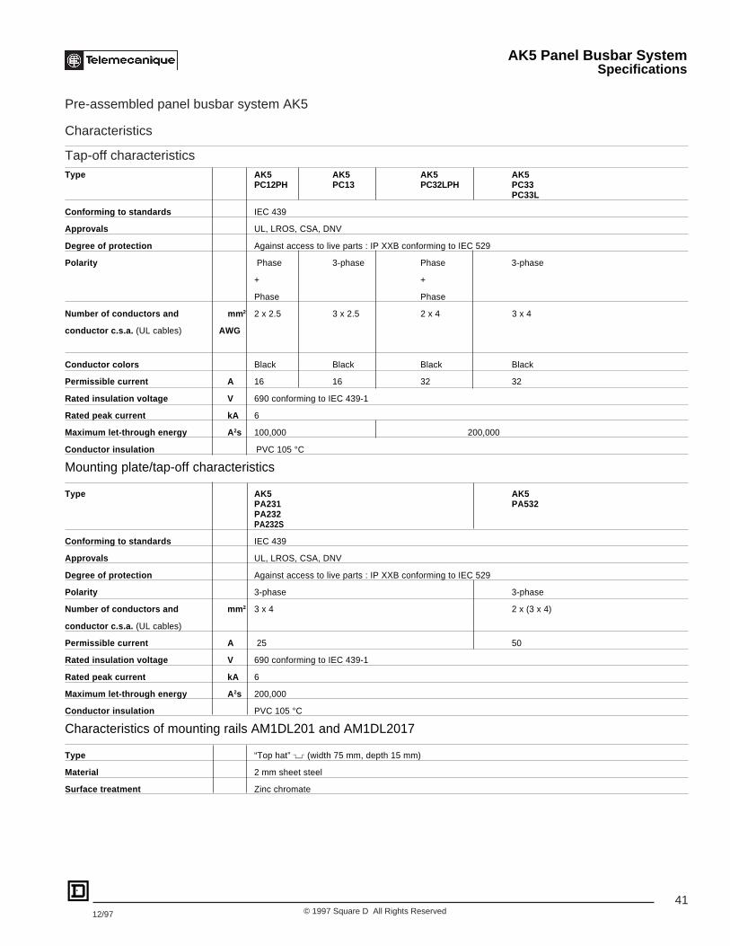
Pre-assembled panel busbar system AK5
Characteristics
Tap-off characteristicsType AK5 AK5 AK5 AK5
PC12PH PC13 PC32LPH PC33PC33L
Conforming to standards IEC 439
Approvals UL, LROS, CSA, DNV
Degree of protection Against access to live parts : IP XXB conforming to IEC 529
Polarity Phase 3-phase Phase 3-phase
+ +
Phase Phase
Number of conductors and mm 2 2 x 2.5 3 x 2.5 2 x 4 3 x 4
conductor c.s.a. (UL cables) AWG
Conductor colors Black Black Black Black
Permissible current A 16 16 32 32
Rated insulation voltage V 690 conforming to IEC 439-1
Rated peak current kA 6
Maximum let-through energy A 2s 100,000 200,000
Conductor insulation PVC 105 °C
Mounting plate/tap-off characteristics
Type AK5 AK5PA231 PA532PA232PA232S
Conforming to standards IEC 439
Approvals UL, LROS, CSA, DNV
Degree of protection Against access to live parts : IP XXB conforming to IEC 529
Polarity 3-phase 3-phase
Number of conductors and mm 2 3 x 4 2 x (3 x 4)
conductor c.s.a. (UL cables)
Permissible current A 25 50
Rated insulation voltage V 690 conforming to IEC 439-1
Rated peak current kA 6
Maximum let-through energy A 2s 200,000
Conductor insulation PVC 105 °C
Characteristics of mounting rails AM1DL201 and AM1DL2017
Type “Top hat” ( (width 75 mm, depth 15 mm)
Material 2 mm sheet steel
Surface treatment Zinc chromate
AK5 Panel Busbar SystemSpecifications

42© 1997 Square D All Rights Reserved 12/97
AK5PA231 AK5PA232 AK5PA232S AK5PA532Width in mm 54 54 108 108
Mounting Plate Height in mm 105 190 190 190with Tap-off No. of 18 mm pitches 3 3 6 6
Rated current 25A 25A 25A 50A
Type of Starter Number of 18 mm pitches used on the busbar system
GV Manual Starters
GV2•01 to •22 (up to 1 side-mount aux block) 3 – – –
GV2•01 to •22 (up to 2 side-mount aux block 4 – – –or 1 side-mount trip unit)
GV2•01 to •22 (up to 2 side-mount aux block 5 – – –and 1 side-mount trip unit)
GV2M32, GV3M01 to M40 (no limit on side- – – – 6mount aux blocks)
GV Manual Starters + Contactor
GV2•01 to •20 (up to 1 side-mount aux block) – 3 – –+ LC1D09 to D18 (no side-mount blocks)
GV2•01 to •20 (up to 2 side-mount aux block – 4 – –or 1 side-mount trip unit)+ LC1D09 to D18 (up to 2 LA8D••• block)
GV2•01 to •20 (up to 2 side-mount aux block – 5 – –and 1 side-mount trip unit)+ LC1D09 to D18 (up to 2 LA8D••• block)
GV2•01 to •22 (up to 2 side-mount aux block – 4 – –or 1 side-mount trip unit)+ LC1D09 to D18 (up to 2 LA8D••• block)◆GV2•01 to •22 (up to 2 side-mount aux block – 5 – –and 1 side-mount trip unit)+ LC1D09 to D18 (up to 2 LA8D••• block)◆
GV3M01 to M40 (with or without GV1•• aux) – – – 7+ LC1D09 to D32 (no LA8 aux)Mounted side by side
GV3M01 to M40 with GV1•• – – – 8+ LC1D09 to D32 (with up to 1 LA8 aux)Mounted side by side
GV Manual Starters + Reversing Contactor
GV2•01 to •20 (no limit on GV aux blocks) – – 6 –+ LC2D09 to D18 (no side-mount blocks)
GV2•01 to •20 (no limit on GV aux blocks) – – 7 –+ LC2D09 to D18 (up to 1 LA8D••• block)
GV2•01 to •20 (no limit on GV aux blocks) – – 8 –+ LC2D09 to D18 (up to 2 LA8D••• blocks)
GV2•01 to •22 (no limit on GV aux blocks) – – 7 –+ LC2D25 to D32 (no side-mount blocks)◆
GV2•01 to •22 (no limit on GV aux blocks) – – 8 –+ LC2D25 to D32 (up to 1 LA8D••• block)◆
GV2•01 to •22 (no limit on GV aux blocks) – – 9 –+ LC2D25 to D32 (up to 2 LA8D••• blocks)◆
◆ Applications up to 25A only.
AK5 Panel Busbar SystemApplication Information

43© 1997 Square D All Rights Reserved12/97
AK5PA231 AK5PA232 AK5PA232S AK5PA532Width in mm 54 54 108 108
Mounting Plate Height in mm 105 190 190 190with Tap-off No. of 18 mm pitches 3 3 6 6
Rated current 25A 25A 25A 50A
Type of Starter Number of 18 mm pitches used on the busbar system
Integral 18 Starter
LD1LB030 (no add-on blocks) 3 – – –
LD1LB030 (up to 2 LA1LB add-on blocks) 4 – – –
LD1LB030 (up to 3 LA1LB add-on blocks) 5 – – –
Integral 32 ® Starter
LD4LC030 (no aux blocks) 4 ◆■ – – 6
LD4LC030 (up to 2 LA1LC aux blocks)▲ 5 ◆■ – – 6
LD4LC030 (up to 3 LA1LC aux blocks)▲ 6 ◆■ – – 6
LD4LC030 (up to 4 LA1LC aux blocks)▲ 7 ◆■ – – 7
LD4LC030 (with 1 LA1LC01• aux block and 1 7◆■ – – 7reset module LA1LC052•, and up to 1LA1LC030 aux block)
LD4LC030 (with 1 LA1LC01• aux block and 1 8 ◆■ – – 8reset module LA1LC052•, and up to 2LA1LC030 aux block)
Reversing Integral 18 Starter
LD5LB130 – – 6 –
LD5LB130 with up to 2 LA1LB add-on blocks – – 7 –
LD5LB130 with up to 3 LA1LB add-on blocks – – 8 –
◆ Applications up to 25 A only.
■ Using AK5PE17 extension plate in combination with AK5PA231 mounting plate.
▲ Auxiliary block LA1LC010 counts as two normal auxiliary blocks. (It is twice the width of the other LA1LC blocks.)
AK5 Panel Busbar SystemApplication Information

44© 1997 Square D All Rights Reserved 12/97
Maximum Number of Components per Busbar System
For combinations of components not shown, refer to table on pages 42-43 to determine spacing required.
Mounting Used With AK5 Bus-barPlate JB143 JB144 JB145 JB146 JB149 JB1410
Integral 18 4 6 8 10 16 18
Integral 18 + 1 aux block 3 5 7 9 15 17
Integral 18 + 2 aux block 3 4 6 7 12 14
Integral 18 + 3 aux block 2 4 5 6 10 12AK5PA231 GV2 + up to 1 side-mount 4 6 8 10 16 18
aux blockGV2 + up to 2 side-mount 3 5 6 8 13 15aux block or 1 side-mounttrip unitGV2 + up to 2 side-mount 2 4 5 6 10 12aux block and 1 side-mounttrip unitIntegral 32 (no aux blocks) ◆ ■ 3 4 6 8 13 14
AK5PA231 Integral 32 (1 aux block) ◆ ■ 2 4 5 6 10 12
+ AK5PE17◆ Integral 32 (2 aux blocks) ◆ ■ 2 3 4 5 9 10
Integral 32 (3 aux blocks) ◆ ■ 2 3 4 5 8 9
Integral 32 (4 aux blocks) ◆ ■ 1 2 3 4 7 8Integral 32 (with 1 LA1LC01• 1 2 3 4 7 8aux block and 1 reset moduleLA1LC052) ◆GV3 (no limit on side-mount 2 3 4 5 8 9aux blocks)
AK5PA532 Integral 32 (up to 3 aux blocks) 2 3 4 5 8 9
Integral 32 (4 aux blocks) 1 2 3 4 7 8Integral 32 (with 1 LA1LC01• 1 2 3 4 7 8aux block and 1 reset moduleLA1LC052) ◆GV2 + LC1D09 to D18 (no 4 6 8 10 16 18aux blocks)GV2 + LC1D09 to D18 (up to 3 5 7 9 15 161 LA8D••• block)
AK5PA232 ▲ GV2 + LC1D09 to D18 (up to 3 4 6 7 12 132 LA8D••• blocks)GV2 + LC1D25 to D32 (up to 3 4 6 7 12 141 LA8D••• block) ◆GV2 + LC1D25 to D32 (up to 2 4 5 6 10 122 LA8D••• block) ◆GV2 + LC2D09 to D18 (no 2 3 4 5 8 9side-mount blocks)GV2 + LC2D09 to D18 (up to 1 2 3 4 7 81 LA8D••• block)
AK5PA232S▲ GV2 + LC2D09 to D18 (up to 1 2 3 4 6 72 LA8D••• blocks)GV2 + LC2D25 to D32 (no 1 2 3 4 6 7side-mount blocks) ◆GV2 + LC2D25 to D32 (up to 1 2 3 3 6 61 LA8D••• block) ◆GV2 + LC2D25 to D32 (up to 1 2 2 3 5 62 LA8D••• block) ◆
■ Auxiliary block LA1LC010 counts as two normal auxiliary blocks. (It is twice the width of the other LA1LC blocks).◆ Applications up to 25 A only.▲ For installations using a GV plus a contactor mounted one above the other, follow the steps below for determining the maximum number of devices
per busbar:1. Determine how many GVs could be installed from the AK5PA231 section above. Be sure to properly select the number of side mounted
auxiliaries that will be used.2. Determine how many contactors could be installed from the AK5PA232 (for non-reversing contactors) or AK5PA232S (for reversing
contactors) section above. Be sure to properly select the number of side mounted auxiliaries that will be used.3. Choose the smaller of the two numbers from step 1 and 2.
AK5 Panel Busbar SystemApplication Information
45© 1997 Square D All Rights Reserved12/97
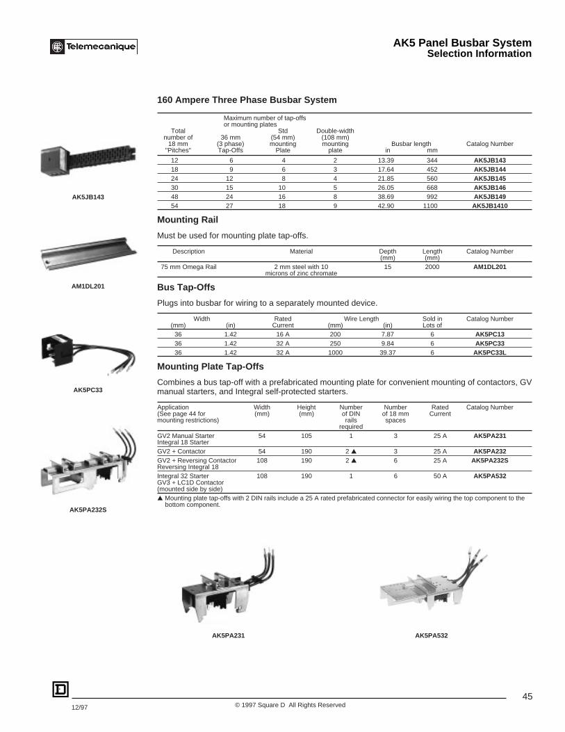
160 Ampere Three Phase Busbar System
Maximum number of tap-offsor mounting plates
Total Std Double-widthnumber of 36 mm (54 mm) (108 mm)
18 mm (3 phase) mounting mounting Busbar length Catalog Number"Pitches" Tap-Offs Plate plate in mm
12 6 4 2 13.39 344 AK5JB14318 9 6 3 17.64 452 AK5JB14424 12 8 4 21.85 560 AK5JB14530 15 10 5 26.05 668 AK5JB14648 24 16 8 38.69 992 AK5JB14954 27 18 9 42.90 1100 AK5JB1410
Mounting Rail
Must be used for mounting plate tap-offs.
Description Material Depth Length Catalog Number(mm) (mm)
75 mm Omega Rail 2 mm steel with 10 15 2000 AM1DL201microns of zinc chromate
Bus Tap-Offs
Plugs into busbar for wiring to a separately mounted device.
Width Rated Wire Length Sold in Catalog Number(mm) (in) Current (mm) (in) Lots of
36 1.42 16 A 200 7.87 6 AK5PC1336 1.42 32 A 250 9.84 6 AK5PC3336 1.42 32 A 1000 39.37 6 AK5PC33L
Mounting Plate Tap-Offs
Combines a bus tap-off with a prefabricated mounting plate for convenient mounting of contactors, GVmanual starters, and Integral self-protected starters.
Application Width Height Number Number Rated Catalog Number(See page 44 for (mm) (mm) of DIN of 18 mm Currentmounting restrictions) rails spaces
requiredGV2 Manual Starter 54 105 1 3 25 A AK5PA231Integral 18 StarterGV2 + Contactor 54 190 2 ▲ 3 25 A AK5PA232GV2 + Reversing Contactor 108 190 2 ▲ 6 25 A AK5PA232SReversing Integral 18Integral 32 Starter 108 190 1 6 50 A AK5PA532GV3 + LC1D Contactor(mounted side by side)▲ Mounting plate tap-offs with 2 DIN rails include a 25 A rated prefabricated connector for easily wiring the top component to the
bottom component.
AK5JB143
AM1DL201
AK5PC33
AK5PA232S
AK5PA231 AK5PA532
AK5 Panel Busbar SystemSelection Information
46© 1997 Square D All Rights Reserved 12/97
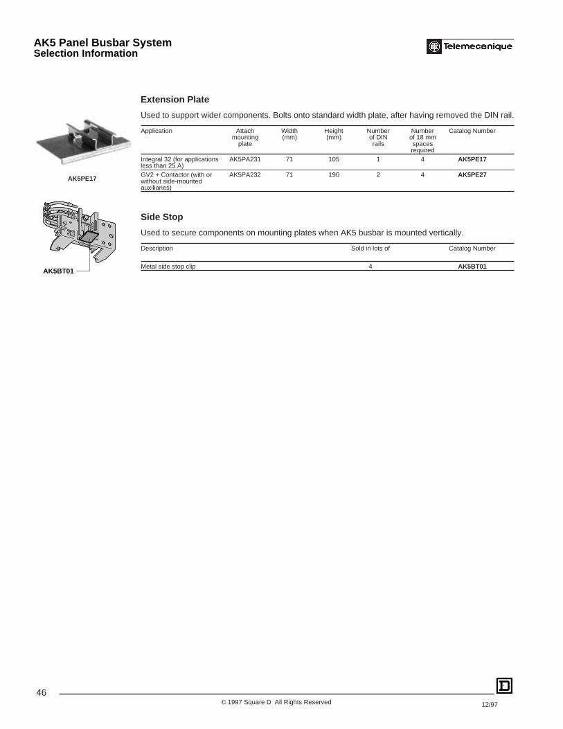
Extension Plate
Used to support wider components. Bolts onto standard width plate, after having removed the DIN rail.
Application Attach Width Height Number Number Catalog Numbermounting (mm) (mm) of DIN of 18 mm
plate rails spacesrequired
Integral 32 (for applications AK5PA231 71 105 1 4 AK5PE17less than 25 A)GV2 + Contactor (with or AK5PA232 71 190 2 4 AK5PE27without side-mountedauxiliaries)
Side Stop
Used to secure components on mounting plates when AK5 busbar is mounted vertically.
Description Sold in lots of Catalog Number
Metal side stop clip 4 AK5BT01AK5BT01
AK5PE17
AK5 Panel Busbar SystemSelection Information

47© 1997 Square D All Rights Reserved12/97
AK5JB iii
AK5 ain (mm)
Gin (mm)
JB143 13.54 (344) 12.99 (330) 12JB144 17.80 (452) 17.24 (438) 18JB145 22.05 (560) 21.50 (546) 24JB146 26.30 (668) 25.75 (654) 30JB149 39.06 (992) 38.50 (978) 48JB1410 43.31 (1100) 42.76 (1086) 54
3.23
82
1.18
30
3.1179
1.77
453.19
81
G
a
Busbar system
No. of 18 mm points
AK5PC33AK5PC33LAK5PC13
1.79
45.5
1.4035.5
1.5038
Dual Dimensions inchesmm
◆ Can be fixed at 1.69 in. (43 mm).
AK5 Panel Busbar SystemDimensions
Mounting plates incorporating tap-offs25 AAK5PA231
1.81460.59
15
2.1354
2.0953 (1)
4.13
105
0.3910
Single widthextension platesAK5PE17
0.287
0.5915
2.8071
2.0953 (1)
4.13
105
0.3910

48© 1997 Square D All Rights Reserved 12/97
Dual Dimensions inchesmm
Mounting plates incorporating tap-offsAK5PA232
1.8146
0.5915
2.1354
3.94
100
0.3910
1.5740
7.48
190
2.0953 (1)
Mounting plates incorporating tap-offAK5PA232S
2.4863
4.17106
0.3910
3.94
100
7.48
190
2.0953 (1)
2.4863
7.48
190
3.6693
4.17106
AK5PA532
2.95 75
25.59650
0.5915
29.53750
28.54725
0.4912.5
0.9825
1.9750 27.56
700
Ø 0.27 x 0.576.8 x 14.5
Mounting rails AM1DL201 (length 2000 undrilled)AM1DL2017
0.266.5
Ø0.266.5
0.27 x 0.576.8 x 14.5 0
.03
0.8
0.6115.5
0.79 20
0.287
0.87 22
0.17 4.2
Side stopAK5BT01
Double width extension plateAK5PE27
0.287
0.5915
2.8071
0.3910
3.94
100
7.48
190
2.0953 (1)
47 0.3910
◆ Can be fixed at 1.69 in. (43 mm).
AK5 Panel Busbar SystemDimensions

49© 1997 Square D All Rights Reserved12/97
Type 2 Coordinated Starters
IEC Standard 947-4-1 defines Type 2 Coordination as a level of protection which assures that a motor starter will be suitable for furtheruse following a short circuit, although small tack welds can easily be broken. Device should be replaced during regular maintenance.Proper combination of GV manual motor starters with LC1D contactors can yield a Type 2 Coordinated installation. Refer to the tablebelow for selection.
Three Phase HP Rating Manual Starter Contactor Max. AvailableFault Current (kA)
200 V 230 V 460 V- - - GV2P02 LC1D09 50- - - GV2P03 LC1D09 50- - - GV2P04 LC1D09 50- - 0.5 GV2P05 LC1D09 50- - 0.75 GV2P06 LC1D09 50
0.5 0.5 1 GV2P07 LC1D09 50 0.75 1 2 GV2P08 LC1D09 50 1.5 1.5 3 GV2P10 LC1D09 50 2 3 5 GV2P14 LC1D09 50 3 3 10 GV2P16 LC1D18 10♦ 5 5 10 GV2P20 LC1D18 10♦ 5 7.5 15 GV2P21 LC1D25 6♦ 5 7.5 15 GV2P22 LC1D25 6♦ 10 10 30 GV3M40 LC1D40 8 20 20 40 GV3M63 LC1D80 8♦With use of additional GV1L3 current limiter, available fault current may be increased to 50 kA.
GV2 and GV3 Manual StartersType 2 Coordination

50© 1997 Square D All Rights Reserved 12/97
Fuse and Circuit Breaker Selection for Group Motor Installations.
Selecting the proper upstream short circuit protection for Group Motor installations can sometimes be a confusing process. SpecificNational Electric Code rules must be applied for Group Motor installations. The examples below illustrate the most common applicationsof GV manual starters with upstream short circuit protection in a Group Motor installation. Refer to NEC Section 430-53 C and D for properconductor ampacity selection.
Two examples are shown below:
Example 1:
8 motors with the sizes shown below are installed on a conveying system. Choose the correct GV manual starter andthe proper size short circuit protection for this application. The user prefers time-delay fuses to circuit breakers.
Motor Qty HP Voltage FLA
1 5 460 7.62 3 460 4.85 2 460 3.4
One GV2M14, two GV2M10, and five GV2M08 manual starters would be selected for this group motor installation.
Per N.E.C. section 430-52 & -53 and N.E.C. table 430-152, the time-delay fuse must be sized as follows:
175% FLA for largest motor + sum of FLAs for all other motors==> (1.75 x 7.6) + (2 x 4.8) + (5 x 3.4) = 39.9 A
N.E.C. 430-52 allows use of the next largest standard size fuse — which in this case is 40 A. If nuisance trippingwas a problem with this fuse selection, N.E.C. does allow 225% of largest motor FLA to be used in lieu of 175%when calculating the size. In this case, the calculation would be as follows:
(2.25 x 7.6) + (2 x 4.8) + (5 x 3.4) = 43.7 A
The next largest standard size in this case is a 45 A fuse.
Example 2:10 motors with the sizes shown below are installed on a packaging machine. Choose the proper size circuit breakerfor this application.
Motor Qty HP Voltage FLA2 10 460 141 5 460 7.62 3 460 4.85 2 460 3.4
Per N.E.C. section 430-52 & -53 and N.E.C. table 430-152, the circuit breaker must be sized as follows:
250% FLA for largest motor + sum of FLAs for all other motors==> (2.5 x 14) + 14 +7.6 + (2 x 4.8) + (5 x 3.4) = 83.2 A
The next largest standard size circuit breaker is 90 A.
If nuisance tripping is a problem, N.E.C. allows 400% of largest motor FLA to be used in lieu of 250% whencalculating the circuit breaker size. For this case:
(4.0 x 14) + 14 +7.6 + (2 x 4.8) + (5 x 3.4) = 104.2 A
The next largest standard size in this case is a 110 A circuit breaker.
GV2 and GV3 Manual StartersFuse and Circuit Breaker Selection for Group Motor Installations
51© 1997 Square D All Rights Reserved12/97
NOTES:
GV2 and GV3 Manual Starters and AK5 Panel Busbar System

Square D CompanyP.O. Box 27446Raleigh, NC 27611, USA(919) 266-3671
Catalog No. 2520CT9501R6/97 December 1997 © 1997 Square D All Rights Reserved.
Replaces 2520CT9501 dated 6/96.
Square D and are registered trademarks of Square D Company.INTEGRAL 32® is a registered tradmark of Schneider Electric SA (Telemecanique)