guyana power and light inc. supply of power …
TRANSCRIPT
GUYANA POWER AND LIGHT INC.
SUPPLY OF POWER TRANSFORMERS
GPL-PD-048-2021
The Guyana Power & Light Inc. is committed to providing our customers with a quality electricity
supply and a level of service that meets and exceeds the expectations of our customers. In an effort to
continually improve our services, GPL is inviting bids from reputable companies, individuals and
contractors for the Supply of Power Transformers.
The following must be clearly stated:
1. Copies of original documents defining the constitution or legal status, place of registration,
principal place of business & Individual/Company TIN/VAT Certificate.
2. Valid National Insurance Certificate (NIS) and Guyana Revenue Authority Compliance
Certificate along with VAT registration are required from all local service providers.
3. Information regarding any current litigation in which the service provider is involved, the
parties’ concerned and disputed amount.
4. Satisfactory evidence of the capability and adequacy of resources to execute the service
efficiently and effectively.
5. Include rates/quotes with your submission.
6. Bids MUST ONLY be submitted electronically to GPL’s Electronic Tender Box
[email protected] on or before 14:00 hrs. on Tuesday, October 12, 2021.
7. Bids submitted to the electronic tender box beyond the deadline will be excluded from the
evaluation process.
8. GPL reserves the right to reject bids if the above details are not stated.
2
Line
UOM
TX Size
TX Spec
Description
of Item Quantity
Estimated Foreign
Cost Estimated
Cost G$ NLL/W LL/W
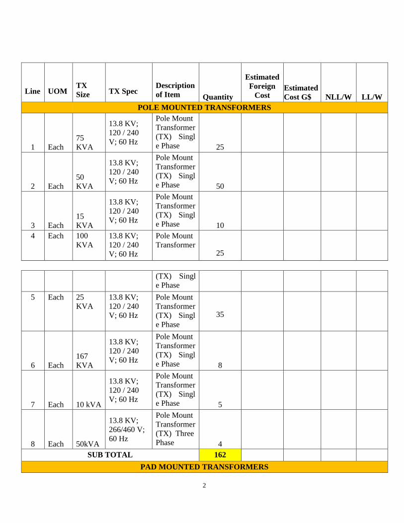
POLE MOUNTED TRANSFORMERS
1 Each 75 KVA
13.8 KV; 120 / 240
V; 60 Hz
Pole Mount Transformer
(TX) Singl
e Phase 25
2 Each 50 KVA
13.8 KV; 120 / 240
V; 60 Hz
Pole Mount Transformer
(TX) Singl
e Phase 50
3 Each
15
KVA
13.8 KV;
120 / 240 V; 60 Hz
Pole Mount Transformer
(TX) Singl
e Phase 10
4 Each 100 KVA
13.8 KV; 120 / 240
V; 60 Hz
Pole Mount
Transformer
25
(TX) Singl
e Phase
5 Each 25 KVA
13.8 KV; 120 / 240
V; 60 Hz
Pole Mount Transformer
(TX) Singl
e Phase
35
6 Each
167
KVA
13.8 KV; 120 / 240 V; 60 Hz
Pole Mount
Transformer
(TX) Singl
e Phase 8
7 Each 10 kVA
13.8 KV; 120 / 240 V; 60 Hz
Pole Mount
Transformer
(TX) Singl
e Phase 5
8 Each 50kVA
13.8 KV;
266/460 V;
60 Hz
Pole Mount
Transformer (TX) Three Phase 4
SUB TOTAL 162
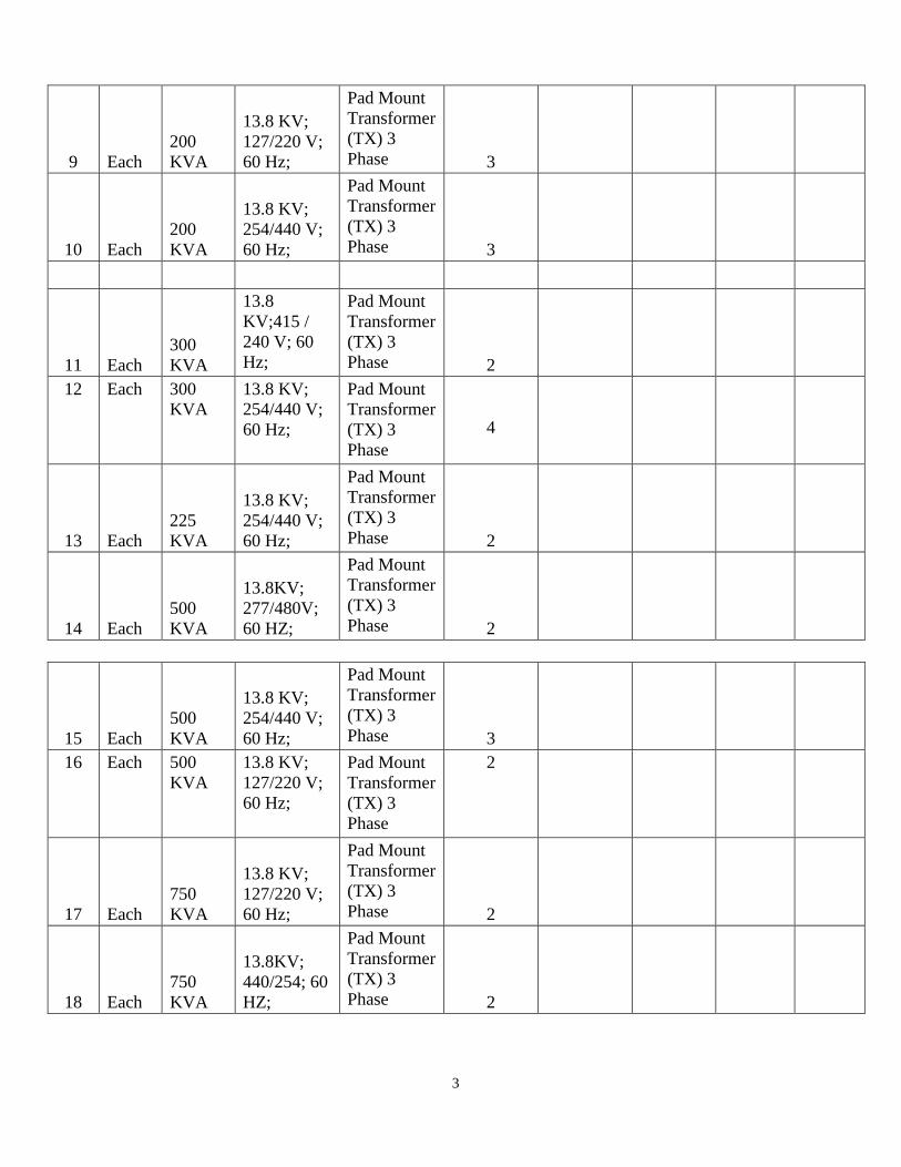
PAD MOUNTED TRANSFORMERS
3
9 Each
200
KVA
13.8 KV; 127/220 V;
60 Hz;
Pad Mount Transformer (TX) 3 Phase 3
10 Each 200 KVA
13.8 KV; 254/440 V; 60 Hz;
Pad Mount
Transformer (TX) 3 Phase 3
11 Each 300 KVA
13.8
KV;415 / 240 V; 60
Hz;
Pad Mount
Transformer (TX) 3
Phase 2
12 Each 300 KVA
13.8 KV; 254/440 V; 60 Hz;
Pad Mount Transformer (TX) 3
Phase
4
13 Each 225 KVA
13.8 KV;
254/440 V; 60 Hz;
Pad Mount Transformer
(TX) 3
Phase 2
14 Each
500
KVA
13.8KV; 277/480V;
60 HZ;
Pad Mount Transformer
(TX) 3 Phase 2
15 Each
500
KVA
13.8 KV;
254/440 V;
60 Hz;
Pad Mount
Transformer (TX) 3
Phase 3
16 Each 500 KVA
13.8 KV; 127/220 V; 60 Hz;
Pad Mount Transformer (TX) 3
Phase
2
17 Each 750 KVA
13.8 KV; 127/220 V; 60 Hz;
Pad Mount Transformer (TX) 3 Phase 2
18 Each 750 KVA
13.8KV; 440/254; 60 HZ;
Pad Mount
Transformer
(TX) 3 Phase 2
4
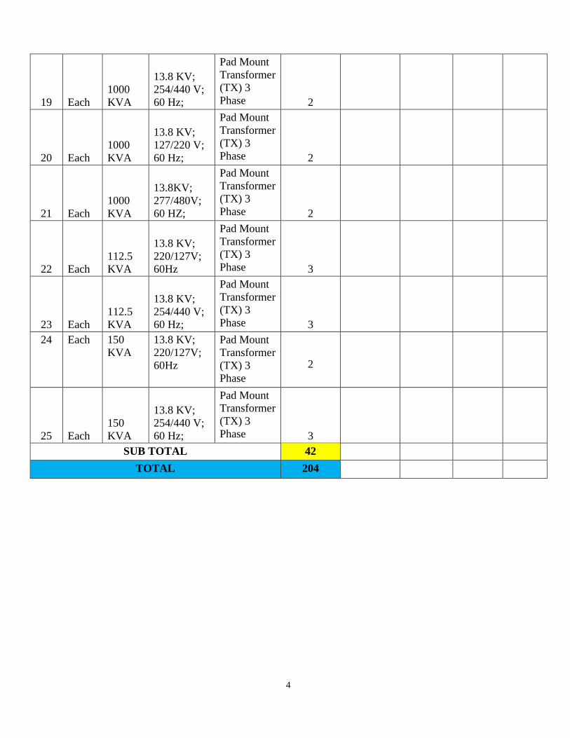
19 Each
1000
KVA
13.8 KV; 254/440 V;
60 Hz;
Pad Mount Transformer (TX) 3 Phase 2
20 Each 1000 KVA
13.8 KV; 127/220 V; 60 Hz;
Pad Mount
Transformer (TX) 3 Phase 2
21 Each
1000
KVA
13.8KV;
277/480V;
60 HZ;
Pad Mount Transformer
(TX) 3 Phase 2
22 Each
112.5
KVA
13.8 KV; 220/127V;
60Hz
Pad Mount
Transformer (TX) 3 Phase 3
23 Each 112.5 KVA
13.8 KV;
254/440 V; 60 Hz;
Pad Mount
Transformer (TX) 3 Phase 3
24 Each 150 KVA
13.8 KV; 220/127V;
60Hz
Pad Mount Transformer
(TX) 3 Phase
2
25 Each
150
KVA
13.8 KV; 254/440 V;
60 Hz;
Pad Mount Transformer (TX) 3
Phase 3
SUB TOTAL 42
TOTAL 204
5
Technical Specifications
Transformers
6
Table of Contents
1. SCOPE ........................................................................................................................ Error! Bookmark not
defined.
2. APPLICABLE STANDARDS
..................................................................................................................................... 8
3. INSTALLATION/SERVICE CONDITIONS
.............................................................................................................. 9
4. ELECTRICAL SYSTEM CONDITIONS
................................................................................................................... 9
5. TYPE OF TRANSFORMER ....................................................................................................................................
10
6. RATINGS ...................................................................................................................................................................
10
7. TAPS AND VOLTAGE REGULATION ..................................................................................................................
11
8. PARALLELLING AND THREE PHASE BANKS ..................................................................................................
11
9. OVERCURRENT PROTECTION ...........................................................................................................................
11
10. IMPEDANCE......................................................................................................................................................... 12
11. SHORT CIRCUIT RATINGS .............................................................................................................................. 12
12. LOSSES ................................................................................................................................................................ 12
13. FLUX DENSITY .................................................................................................................................................... 13
14. NOISE LEVEL ...................................................................................................................................................... 13
15. RADIO INFLUENCE VOLTAGE ........................................................................................................................ 13
16. TAP CHANGING CHARACTERISTICS ........................................................................................................... 13
17. CORE AND WINDINGS ...................................................................................................................................... 14
17.1 CORE................................................................................................................................................................. 14
17.2 WINDINGS ............................................................................................................... ......................................... 14
18. BUSHINGS AND TERMINATIONS ................................................................................................................... 15
18.1 Bushings ............................................................................................................................................................ 15
18.2 Bushing Labels ................................................................................................................ ................................. 15
18.3 EARTHING TERMINALS................................................................................................................................. 15
18.4 LIGHTING ARRESTORS – HV SIDE OF TRANSFORMER .......................................................................
15
19. TANK FABRICATION ................................................................................... ....................................................... 16
20. FITTINGS .................................................................................................................. ............................................ 17
21. TRANSFORMER OIL ........................................................................................................... ............................... 17
22. RATING AND CONNECTION PLATE .............................................................................................................. 17
23. MOUNTING ARRANGEMENT ............................................................................................. .............................. 18
24. SURFACE TREATMENT .................................................................................................................................... 18
25. SUPPRESSION OF HARMONICS ................................................................................................................... 18
26. TESTS ..................................................................................................................... .............................................. 18
27. COMPLIANCE WITH SPECIFICATION ........................................................................................................... 19
28. COMPLIANCE WITH REGULATIONS ............................................................................................................. 19
7
29. QUALITY ASSURANCE, INSPECTION AND TESTING ............................................................................... 19
29.1 General .............................................................................................................................................................. 19
29.2 Quality Assurance System ...............................................................................................................................
20
29.3 Quality Plans ..................................................................................................................................................... 20
29.4 Inspection and Testing ................................................................................................... ..................................
20
29.5 Guarantee .......................................................................................................................................................... 21
30. SPARE PARTS AND SPECIAL TOOLS .......................................................................................................... 21
31. LABELS ................................................................................................................................................................. 22
32. SUBMITTALS REQUIRED WITH THE BID ..................................................................................................... 22
33. NON-COMPLIANCE SCHEDULE ..................................................................................................................... 24
34. TEST CERTIFICATE SCHEDULE .................................................................................................................... 25
35. SHIPPING ............................................................................................................................................................. 26
36. TECHNICAL SCHEDULE ................................................................................................... ................................ 27
8
1. SCOPE
This specification covers the design, engineering, manufacture, testing, supply and
performance requirements of single phase pole mounted distribution transformers for use in
the primary distribution networks of Guyana.
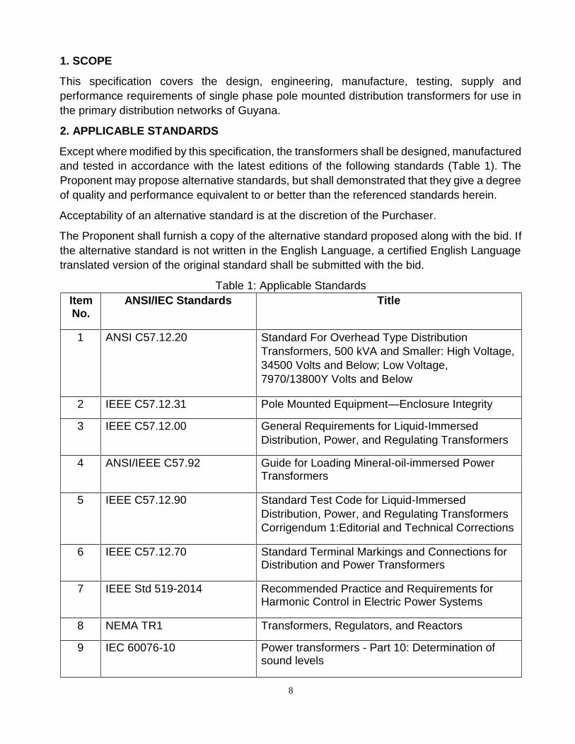
2. APPLICABLE STANDARDS
Except where modified by this specification, the transformers shall be designed, manufactured
and tested in accordance with the latest editions of the following standards (Table 1). The
Proponent may propose alternative standards, but shall demonstrated that they give a degree
of quality and performance equivalent to or better than the referenced standards herein.
Acceptability of an alternative standard is at the discretion of the Purchaser.
The Proponent shall furnish a copy of the alternative standard proposed along with the bid. If
the alternative standard is not written in the English Language, a certified English Language
translated version of the original standard shall be submitted with the bid.
Table 1: Applicable Standards
Item No.
ANSI/IEC Standards Title
1 ANSI C57.12.20 Standard For Overhead Type Distribution
Transformers, 500 kVA and Smaller: High Voltage,
34500 Volts and Below; Low Voltage,
7970/13800Y Volts and Below
2 IEEE C57.12.31 Pole Mounted Equipment—Enclosure Integrity
3 IEEE C57.12.00 General Requirements for Liquid-Immersed
Distribution, Power, and Regulating Transformers
4 ANSI/IEEE C57.92 Guide for Loading Mineral-oil-immersed Power Transformers
5 IEEE C57.12.90 Standard Test Code for Liquid-Immersed
Distribution, Power, and Regulating Transformers
Corrigendum 1:Editorial and Technical Corrections
6 IEEE C57.12.70 Standard Terminal Markings and Connections for Distribution and Power Transformers
7 IEEE Std 519-2014 Recommended Practice and Requirements for Harmonic Control in Electric Power Systems
8 NEMA TR1 Transformers, Regulators, and Reactors
9 IEC 60076-10 Power transformers - Part 10: Determination of sound levels
9
10 IEC 60296 Fluids for electrotechnical applications - Unused mineral insulating oils for transformers and switchgear
In case of conflict, the order of precedence shall be:
• This Technical Specification for Single Phase Distribution Transformers;
• Other Applicable and Recognised Standards for pole mounted distribution
transformers.
3. INSTALLATION/SERVICE CONDITIONS
The installation conditions of the transformers shall be as follows:
1. Maximum altitude above mean sea level less than 1,000 m;
2. Maximum ambient air temperature 400C;
3. Maximum daily average ambient air temperature 300C;
4. Minimum ambient temperature 150C; and
5. Maximum relative humidity 100%.
All outdoor materials, components and equipment shall be designed and protected for use in
exposed, heavily polluted and salty, corrosive and humid tropical coastal atmospheric
conditions.
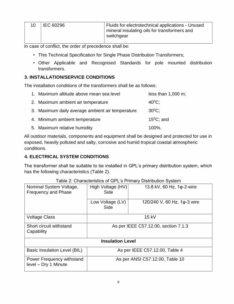
4. ELECTRICAL SYSTEM CONDITIONS
The transformer shall be suitable to be installed in GPL’s primary distribution system, which
has the following characteristics (Table 2).
Table 2: Characteristics of GPL’s Primary Distribution System
Nominal System Voltage, Frequency and Phase
High Voltage (HV) Side
13.8 kV, 60 Hz, 1φ-2-wire
Low Voltage (LV) Side
120/240 V, 60 Hz, 1φ-3 wire
Voltage Class 15 kV
Short circuit withstand Capability
As per IEEE C57.12.00, section 7.1.3
Insulation Level
Basic Insulation Level (BIL) As per IEEE C57.12.00, Table 4
Power Frequency withstand level – Dry 1 Minute
As per ANSI C57.12.00, Table 10
10
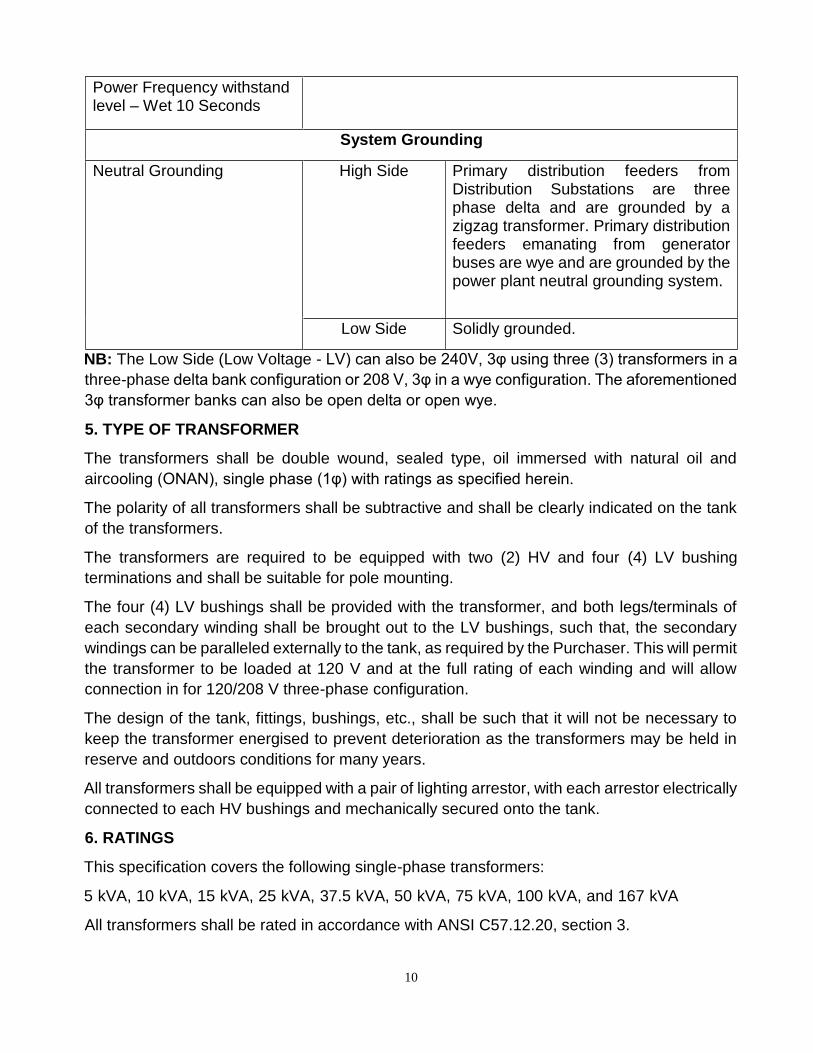
Power Frequency withstand level – Wet 10 Seconds
System Grounding
Neutral Grounding High Side Primary distribution feeders from Distribution Substations are three phase delta and are grounded by a zigzag transformer. Primary distribution feeders emanating from generator buses are wye and are grounded by the power plant neutral grounding system.
Low Side Solidly grounded.
NB: The Low Side (Low Voltage - LV) can also be 240V, 3φ using three (3) transformers in a
three-phase delta bank configuration or 208 V, 3φ in a wye configuration. The aforementioned
3φ transformer banks can also be open delta or open wye.
5. TYPE OF TRANSFORMER
The transformers shall be double wound, sealed type, oil immersed with natural oil and
aircooling (ONAN), single phase (1φ) with ratings as specified herein.
The polarity of all transformers shall be subtractive and shall be clearly indicated on the tank
of the transformers.
The transformers are required to be equipped with two (2) HV and four (4) LV bushing
terminations and shall be suitable for pole mounting.
The four (4) LV bushings shall be provided with the transformer, and both legs/terminals of
each secondary winding shall be brought out to the LV bushings, such that, the secondary
windings can be paralleled externally to the tank, as required by the Purchaser. This will permit
the transformer to be loaded at 120 V and at the full rating of each winding and will allow
connection in for 120/208 V three-phase configuration.
The design of the tank, fittings, bushings, etc., shall be such that it will not be necessary to
keep the transformer energised to prevent deterioration as the transformers may be held in
reserve and outdoors conditions for many years.
All transformers shall be equipped with a pair of lighting arrestor, with each arrestor electrically
connected to each HV bushings and mechanically secured onto the tank.
6. RATINGS
This specification covers the following single-phase transformers:
5 kVA, 10 kVA, 15 kVA, 25 kVA, 37.5 kVA, 50 kVA, 75 kVA, 100 kVA, and 167 kVA
All transformers shall be rated in accordance with ANSI C57.12.20, section 3.
11
All transformers, inclusive of tap changer and other current carrying components, shall accept
emergency overloading as per ANSI/IEEE C57.92, section 4.
7. TAPS AND VOLTAGE REGULATION
Transformers shall have the following voltage transformation ratio and tapping range:
• the nominal primary voltage for single phase transformers shall be 13.8 kV and the
secondary voltage shall be 120 V per winding, where the secondary shall have two
(2) 120 V windings with subtractive polarity;
• tolerance on the voltage ratio shall be in accordance with IEEE C57.12.00, section
9.1;
• taps shall be provided in the high voltage winding (13.8 kV side), with steps of two
(2) 2.5% taps above and below the primary voltage rating (13.8 kV); and
• The bidder shall state in the technical schedule, the percentage regulation at full
load, power factor 1.0 and at full load power factor 0.8 lagging. The primary and
secondary voltage variation shall be based on a winding temperature of 850C.
8. PARALLELLING AND THREE PHASE BANKS
Transformers of different ratings shall be suitable for parallel operation with each other.
Transformers of the same and different ratings shall be suitable for operating as a three-phase
bank connected in Delta-Wye, Delta-Delta, Open Wye and Open Delta.
Both legs of the secondary windings shall be brought out to LV bushings so that the secondary
windings can be paralleled externally to the tank when required to give 120 V at the full rating
of the transformer.
9. OVERCURRENT PROTECTION
Transformers up to and including the rating of 167 kVA shall be equipped with an internally
mounted low-voltage circuit breaker and high voltage protection fuse links.
The operation of the LV breaker and HV protection fuse links shall be coordinated such that
any short circuit and/or overloading on the secondary side of the transformer will first trip the
LV breaker before the HV protective links operate, taking the load off the transformer before
the core and/or coil is/are thermally and/or mechanically damaged.
The operation of the protection devices mentioned above shall be indicated externally on the
tank, and the circuit breaker shall be made to be externally controlled, by a suitable switch
mounted on the tank, using a linesman’s hot stick.
The characteristics of the protection devices shall allow for full usage of the transformer’s
continuous rating and short-time overload capabilities for emergency loading condition (150%
of nominal kVA rating).
12
The Proponent shall submit the characteristic curves of the internal protection devices with
the bid. The characteristic curves shall also include the transformers’ through-fault withstand
capability curves or transformer damage curves.
10. IMPEDANCE
The guaranteed minimum value of impedance measured at 850C, on the nominal tap and at
the rated voltage of the transformer shall be:
• Between 1.2% and 1.3% for 5 kVA to 10 kVA; and
• Between 1.2 % and 2.5% for transformers between 15 kVA to 75 kVA; and
Between 1.3 % and 2.5 % for transformers from 100 kVA to 167 kVA.
Tolerance for transformers’ impedances shall be in accordance with IEEE C57.12.00, section
9.2, for impedance less than 2.5%.
11. SHORT CIRCUIT RATINGS
Bidders must submit all short circuit test results for compliance with IEEE C57.12.00, section
7.1.3.
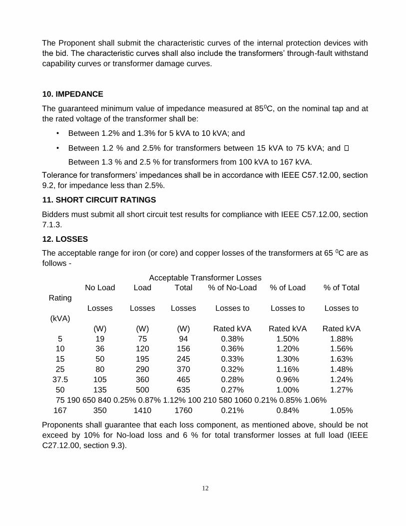
12. LOSSES
The acceptable range for iron (or core) and copper losses of the transformers at 65 0C are as
follows -
Acceptable Transformer Losses
No Load Load Total % of No-Load % of Load % of Total
Rating
Losses Losses Losses Losses to Losses to Losses to
(kVA)
(W) (W) (W) Rated kVA Rated kVA Rated kVA
5 19 75 94 0.38% 1.50% 1.88%
10 36 120 156 0.36% 1.20% 1.56%
15 50 195 245 0.33% 1.30% 1.63%
25 80 290 370 0.32% 1.16% 1.48%
37.5 105 360 465 0.28% 0.96% 1.24%
50 135 500 635 0.27% 1.00% 1.27%
75 190 650 840 0.25% 0.87% 1.12% 100 210 580 1060 0.21% 0.85% 1.06%
167 350 1410 1760 0.21% 0.84% 1.05%
Proponents shall guarantee that each loss component, as mentioned above, should be not
exceed by 10% for No-load loss and 6 % for total transformer losses at full load (IEEE
C27.12.00, section 9.3).
13
The losses proposed by the Bidders shall be measured during routine tests. If the results from
the routine tests indicate that either the copper or iron loss is more significant than the
proponents’ guaranteed values, the Purchaser shall have the right to reject the transformer(s).
Accuracies required for measuring losses shall be in accordance with IEEE C57.12.00,
section 9.4.
The capitalization of guaranteed losses of the transformer shall be calculated and considered
while evaluating the bids as the final bid price. The guaranteed values of no-load losses and
load losses shall be stated in the bid, which should match the corresponding loss figures
mentioned in the short circuit type test report submitted along with the offer by the bidder.
Liquidated damages will be applied to successful bidder for not achieving the quoted
guaranteed figures.
The Total Ownership Cost formula is as follow:
TOC = Bid Price + [(A x NLL) + (B x LL)] Where:
1. TOC is the Total Owning Cost in US$
2. Bid Price in US$
3. A is the No Load-Loss Factor = 14.82 US$/W
4. B is the Load-Loss Factor = 3.63 US$/W
5. NNL is the No-Load Loss in W
6. LL is the Load Loss in W
13. FLUX DENSITY
The flux density at any point of the magnetic circuit, core and winding, when the transformer
is connected on the centre tap and operating at normal voltage and frequency, shall be stated
in the bid and shall not exceed 1.7 Tesla. The transformer must be capable of operating at
10% overvoltage at 97% of rated frequency without resulting in magnetic saturation of the
transformer’s core or the flux density exceeding 1.9 Tesla.
14. NOISE LEVEL
The acceptable audible sound levels for all transformers shall comply with NEMA TR1, table
0-
3.
Bidders shall confirm procedure for noise level measurement according to IEC 60076-10 or
IEEE C57.12.90 and submit audible sound levels test results with the bid document.
14
15. RADIO INFLUENCE VOLTAGE
Radio influence voltage of all transformers, contained herein, shall comply with NEMA TRI,
section 0.03.1.
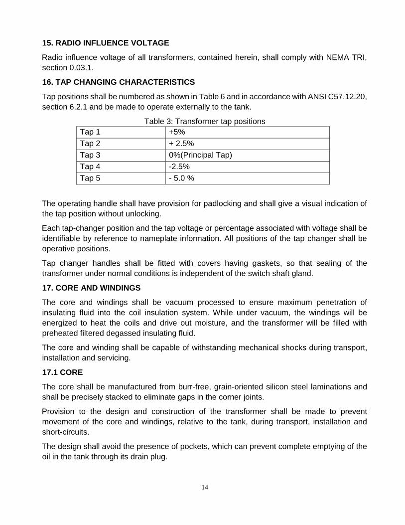
16. TAP CHANGING CHARACTERISTICS
Tap positions shall be numbered as shown in Table 6 and in accordance with ANSI C57.12.20,
section 6.2.1 and be made to operate externally to the tank.
Table 3: Transformer tap positions
Tap 1 +5%
Tap 2 + 2.5%
Tap 3 0%(Principal Tap)
Tap 4 -2.5%
Tap 5 - 5.0 %
The operating handle shall have provision for padlocking and shall give a visual indication of
the tap position without unlocking.
Each tap-changer position and the tap voltage or percentage associated with voltage shall be
identifiable by reference to nameplate information. All positions of the tap changer shall be
operative positions.
Tap changer handles shall be fitted with covers having gaskets, so that sealing of the
transformer under normal conditions is independent of the switch shaft gland.
17. CORE AND WINDINGS
The core and windings shall be vacuum processed to ensure maximum penetration of
insulating fluid into the coil insulation system. While under vacuum, the windings will be
energized to heat the coils and drive out moisture, and the transformer will be filled with
preheated filtered degassed insulating fluid.
The core and winding shall be capable of withstanding mechanical shocks during transport,
installation and servicing.
17.1 CORE
The core shall be manufactured from burr-free, grain-oriented silicon steel laminations and
shall be precisely stacked to eliminate gaps in the corner joints.
Provision to the design and construction of the transformer shall be made to prevent
movement of the core and windings, relative to the tank, during transport, installation and
short-circuits.
The design shall avoid the presence of pockets, which can prevent complete emptying of the
oil in the tank through its drain plug.
15
17.2 WINDINGS
The winding conductor shall be of electrolytic copper or aluminium, to give the optimum
economic and technical results of the transformers.
The windings shall be insulated with B-stage, epoxy coated, diamond pattern, insulating
paper, which shall be thermally cured under pressure to ensure proper bonding of conductor
and paper, and shall be free from any other insulating compounds that are liable to soften,
ooze out, shrink or collapse, and non-catalytic and chemically inert in the transformer oil during
normal servicing. The windings shall be uniformly insulated, and the LV neutral points shall
be insulated for full line-to-line voltage.
The stacks of windings shall receive adequate shrinkage treatment, and the windings and
connections are to be braced to withstand mechanical shocks during transport, switching,
shortcircuit or other transient conditions.
18. BUSHINGS AND TERMINATIONS
18.1 Bushings
Bushings shall be of the outdoor type and easily replaceable. Porcelain bushings are required.
The bushings shall be sufficiently robust (mechanically) to withstand normal transport and
erection hazards.
All bushings shall have a minimum creepage distance of 25 mm/kV for maximum phase-
tophase system voltage, and shall have a continuous rating of 200 % of the transformer
capacity rating.
High Voltage and Low Voltage bushings shall be sized in accordance with the applicable
ANSI/IEEE and/or IEC standards such as ANSI C57-12.20 clause 6.1, and with the following
characteristics:
• High voltage bushings shall have tinned bronze eyebolt type connectors.
• LV terminals shall be bi-metallic clamp type.
Approximately 10% of the transformer to be supplied may be with LV terminals protected with
armoured anti-theft features, and is specifically meant for use in areas with high level of theft.
18.2 Bushing Labels
HV bushings shall be labelled H1 and H2.
LV bushings shall be labelled X1 to X4 in accordance with IEEE C57.12.70 standards.
Marking letters shall be at least 12 mm (or 1/2 inch) high. The means of marking shall conform
to the requirements of the section on Labels in this specification (31) for further details.
18.3 EARTHING TERMINALS
All transformers shall be provided with two earthing/grounding terminals comprising an M12
isometric bolt and nut, which shall be non-ferrous material but not plastic. It shall include a
spring washer and a lock washer.
16
External connecting strip(s) between earthing/grounding terminal and neutral bushing(s)
is/are required.
18.4 LIGHTING ARRESTORS – HV SIDE OF TRANSFORMER
The lightning arrestors shall be capable of discharging lightning and switching surges and
temporary power frequency over voltages, and shall be capable of discharging over voltages
occurring during switching of unloaded transformers and long lines.
The Arrestors shall be capable of withstanding Maximum Continuous Operating Voltages
(M.C.O.V) and rate for operation in 15 kV class distribution system. The reference current of
the arrestors shall be of such value to eliminate the influence of grading and stray capacitance
on the measured reference voltages.
These arrestors shall be of Heavy Duty, Station Class / Distribution Class and Gapless Zinc
Oxide type and shall be hermetically sealed units suitable for outdoor installation and
mounting on distribution transformers. Additionally, the arrestors shall be suitable for heavily
polluted atmospheric conditions as mentioned in section 3.
19. TANK FABRICATION
The tank shall be of sealed construction and fabricated using materials to withstand internal
pressures as per ANSI C57.12.20, section 7.2.6.1. The Proponent shall state if other than
bolted cover construction is used, and shall give full details of such construction.
The interior of the tank shall be sealed to comply with ANSI C57.12.20, section 6.4.2.
The Proponent shall state the top oil temperature that corresponds to the tank’s internal
pressure of 15 psi and steady load at rated capacity and emergency loading condition while
considering an ambient temperature of 400C.
Adequate space shall be provided at the bottom of the tank for collection of sediments.
Transformer tanks shall be designed to allow the unit to be lifted and transported with the
weight of the transformer and oil at the required level, without permanent deformation or oil
leakages. Lifting provisions shall consist of two lifting brackets welded to opposite sides of the
tank.
The tank shall be fabricated of mild steel with a minimum thickness of 3 mm. Top and bottom
covers of the tank shall have a minimum thickness of 5 mm. Thickness below this value will
be considered only in exceptional cases with a written guarantee and/or warranty from the
Proponent and must be submitted along with the bid.
The transformer tank and the top cover shall be designed to confirm with IEEE C57.12.31.
All sealing washers/gaskets shall be made of oil and heat resistant nitrile rubber or neoprene
bonded cork seals suitable for temperatures as stipulated in this specification. Surfaces,
where joints have gaskets, shall be, such that, an even surface is presented to the gasket,
thereby eliminating the necessity for the gasket to take up surface irregularities.
17
All pipes, radiators, stiffeners, or corrugations, which are welded to the tank wall, shall be
welded externally and shall be double welded wherever possible. All welds shall be stress
relieved.
19.1 Pressure Relief Device
The pressure relief valve specified in the standard shall be operable manually by hotstick and
with venting and sealing characteristics that comply with ANSI C57.12.20, section 6.2.5.1.
Proponents shall submit all test results of the pressure relief device with the bid document.
19.2 Oil Level Indication
The oil level marker shall be comply with ANSI C57.12.20, sections 6.2.1, 6.2.3 and 6.2.5.1.
20. FITTINGS
The following standard fittings shall be provided:
• rating, diagram and terminal marking plate;
• tank grounding terminal;
• lifting lugs;
• manual pressure relief device; and drain/sampling valve with plug.
The fittings and accessories listed above are only indicative and any other fittings and
accessories according to the applicable standards herein shall be provided for the
transformers.
21. TRANSFORMER OIL
The transformers shall be supplied with Class 1 mineral oil that conforms to IEC 60296 or
IEEE C57.12.00, section 6.6.1.
The dielectric strength of the oil shall not be less than 40 kV.
22. RATING AND CONNECTION PLATE
Each transformer shall be provided with anodized aluminium laser engraved nameplate, in
accordance with IEEE C57.12, Table 9 - Nameplate C. Additionally, Proponents shall ensure
that the following attributes are indicated on the aforementioned nameplate:
• standard to which it is manufactured and tested;
• identification of internal short-circuit and overload protection devices;
• type of cooling (ONAN);
• rated currents in A;
• chopped wave (short time) impulse voltage withstand level in kV;
• power frequency withstand voltage in kV;
• percentage impedance at 850C;
18
• load loss in kW at rated current;
• no-load loss in kW at rated voltage and frequency;
• continuous ambient temperature at which ratings apply in 0C (40);
• top oil and winding temperature rise at rated load in 0C;
• winding connection diagram;
• total mass (core, windings and oil) in kg;
• mass of core and windings in kg;
• volume of oil in litres;
• Oil with less than 2ppm of PCB; and
• name of the purchaser (Property of Guyana Power & Light Inc.)
The nameplate shall meet Nameplate B per ANSI C57.12.00 and conform to the requirements
of the section on Labels (31) in this specification.
23. MOUNTING ARRANGEMENT
The tank shall include an upper and lower support lug for direct pole mounting in accordance
with ANSI C57.12.20 Type B or equivalent.
24. SURFACE TREATMENT
The transformer tank and all accessories shall be treated in accordance with IEEE C57.12.31
to ensure enclosure and equipment integrity. The transformer shall have a grey color finish.
25. SUPPRESSION OF HARMONICS
Each transformer’s core shall be designed with attention to the suppression of harmonic
voltages and currents, as per IEEE Std 519-2014 in Table 1 for bus voltage between 1 kV
and 69 kV and Table 2 for current distortion limits for systems rated 120 V through 69 kV.
Proponents shall submit results for harmonic suppression tests for voltage and current
distortions.
26. TESTS
In addition to the routine tests required in IEEE C57.12.00, as per section 8 and Table 18, the
following additional tests shall be carried out on all transformers. The following routine
measurements and tests shall be carried out and results shall be submitted to the Purchaser
upon delivery:
a) Measurement of winding resistance at the nominal and extreme tap positions for each
transformer provided;
b) Measurement of impedance;
c) Measurement of no-load loss and no-load currents at full, 90% and 110% voltages;
d) Induced overvoltage withstand test;
19
e) Separate source voltage withstand tests on HV and LV windings;
f) Magnetic balance test;
g) Polarization Index Test. The index shall be not less than 1.5;
h) Oil leakage test: The criterion of leakage shall be discolouration by oil of whitewash
applied externally to suspected parts at an oil temperature of 900C or other method
approved by the Purchaser;
i) Bushings and oil shall be subject to the following routine tests.
a. bushing routine tests
b. oil dielectric and moisture content test.
Routine test certificates shall include in addition to the test results, the Purchaser's order
number, the transformers’ serial numbers, outline drawing number and transformer kVA
rating.
Upon acceptance of Tender, the Manufacturer/Proponent shall provide results of standard
design type tests required in Table 18 of IEEE C57.12.00.
27. COMPLIANCE WITH SPECIFICATION
The transformers shall comply in all respects with the requirements of this specification.
However, any minor departure from the provisions of the specification shall be disclosed at
the time of tendering in the Non-Compliance Schedule in this document (see page 78).
28. COMPLIANCE WITH REGULATIONS
All the transformers/equipment shall comply in all respects with the Laws of Guyana
Governing the Importation of Commercial Items and/or Goods.
The equipment and connections shall be designed and arranged to minimize the risk of fire
and any damage that might be caused in the event of a fire.
29. QUALITY ASSURANCE, INSPECTION AND TESTING
29.1 General
To ensure that the supply and services are in accordance with the Specification herein, with
the regulations of Guyana and with relevant authorized international standards, the Proponent
shall have in place suitable Quality Assurance Programmes and Procedures to ensure that
all activities are being controlled and documented as necessary.
The quality assurance arrangements shall conform to the relevant requirements of ISO 9001
or ISO 9002, as deemed appropriate by the Purchaser and the Proponent.
The systems and procedures that the Proponent will use to ensure that the supply complies
with the specified requirements, shall be defined in the Proponent’s Quality Plan.
The Proponent shall operate systems that implement the following:
20
Hold Point “A stage in the material procurement or workmanship process beyond which work
shall not proceed without the documented approval of designated individuals or
organisations.”
The Purchaser's written approval is required to authorise work to progress beyond the Hold
Points indicated in approved Quality Plans.
Notification Point “A stage in material procurement or workmanship process for which
advance notice of the activity is required to facilitate witness.”
If the Purchaser's representative does not attend after receiving documented notification in
accordance with the agreed procedures and with the correct period of notice then work may
proceed.
29.2 Quality Assurance System
Unless the Proponent’s Quality Assurance System has been audited and approved by the
Purchaser, a Quality Assurance System shall be submitted to the Purchaser for approval
within a minimum of One (1) month from the placement of order, or such other period as shall
be agreed with the Purchaser. The Quality Assurance System shall provide a description of
the Quality Control System for the supply and shall, unless advised otherwise, shall include,
but not limited to the following details:
1. The structure of the organisation;
2. The duties and responsibilities assigned to staff to ensure quality of work;
3. The system for purchasing, taking delivery and verification of the specifications of raw
materials;
4. The system for ensuring the quality of workmanship
5. The system for control of documentation;
6. The system for the retention of records; and
7. The arrangement for the Proponent’s internal auditing.
29.3 Quality Plans
The Quality Plans shall set out the activities in a logical sequence and, unless advised
otherwise, shall include, but limited to the following:
1. An outline of the proposed programme sequence;
2. The duties and responsibilities assigned to staff ensuring the quality of work;
3. Hold and notification points;
4. Submission of engineering documents required by the specification;
5. The inspection of materials and components on receipt;
6. Reference to the Supplier’s procedures appropriate to each activity;
21
7. Inspection during fabrication and assembly; and
8. Final inspection and test.
29.4 Inspection and Testing
The Purchaser shall have free entry at all times, while work on the order is being performed,
to all parts of the manufacturer's working area which are in relation to the processing of the
transformers ordered. The Manufacturer/Proponent shall afford the Purchaser without charge,
all reasonable facilities to assure that the transformers being furnished are in accordance with
the specifications herein.
The equipment shall have successfully passed all tests as described in Section 26.
The Purchaser reserves the right to reject an item of the transformer if the test results do not
comply with the values specified herein.
Tests, including any retests required, shall be carried out by the Supplier at no extra charge,
at the manufacturer's works.
Full details of the proposed methods of testing, including connection diagrams, shall be
submitted to the Purchaser by the Supplier for approval, at least one month before testing.
All costs in connection with the testing, including any necessary re-testing, shall be borne by
the Manufacturer/Proponent.
Any cost incurred by the Purchaser in connection with inspection and re-testing as a result of
the failure of the transformer or any of its components under test or damage during transport
or offloading shall be to the account of the Proponent.
The Proponent shall submit to the Purchaser three signed copies of the test certificates, giving
the results of the tests as required. No materials shall be dispatched until the test certificates
have been received by the Purchaser and the Proponent has been informed that they are
acceptable.
The test certificates must show the actual values obtained from the tests, in the units used in
this specification, and not merely confirm that the requirements have been met.
No inspection or lack of inspection or approval by the Purchaser’s Representative of
equipment or materials whether supplied by the Proponent or a Sub-Proponent, shall relieve
the Proponent from his/her liability to complete the contracted works in accordance with the
contract would exonerate him/her from any of his/her guarantees.
29.5 Guarantee
The Proponent shall guarantee the following:
• Quality and strength of materials used;
• Satisfactory operation during the guarantee period of one (1) year from the date of
commissioning, or 18 months from the date of acceptance of the equipment by the
22
Purchaser following delivery, whichever is the earlier. The Purchaser shall advise the
Proponent of the date of commissioning;
• Performance figures as supplied by the Proponent in the Technical Data Schedule, the
guaranteed copper and iron losses and other particulars;
• The offered surface treatment shall protect the treated metal from corrosion for a period
of not less than ten (10) years from the date of delivery.
30. SPARE PARTS AND SPECIAL TOOLS
The Proponent shall provide a list of recommended spare parts and their individual prices and
shall include HV and LV bushings and bi-metallic connectors for HV and LV bushings. This
list shall identify all essential spares and consumable items for any recommended
maintenance for a period of five (5) years after commissioning.
The Purchaser may order all or any of the spares parts listed at the time of placement of order.
A spare parts catalogue with price list shall be provided and this shall form part of the drawings
and literature to be supplied with the bid.
The Proponent shall give an assurance that spare parts and consumables will continue to be
available through the life span of the equipment/transformers, which shall be 25 years
minimum. However, the Proponent shall give a minimum of 12 months notice to the
Purchaser, in the event that the Proponent or any Sub-supplier, plan to discontinue
manufacturing of any component used in the transformers.
Any spare apparatus, parts or tools shall be subjected to the same specification herein, tests
and conditions as similar main material supplied. They shall be strictly interchangeable and
suitable for use in place of the corresponding parts supplied with the transformer and must be
suitably marked and numbered for identification.
Spare parts shall be delivered suitably packaged and treated for long periods in storage. Each
package shall be clearly and indelibly marked with its contents, including a designation
number corresponding to the spare parts lists in the operation and maintenance instructions.
31. LABELS
All apparatus shall be clearly labelled indicating, where necessary, its purpose and service
positions.
The material of all labels and plates, their dimensions, legend and the method of printing shall
be subject to the approval of the Purchaser.
Colours shall be permanent and free from fading. All labels and plates for outdoor use shall
be of non-corrosive material.
They shall be engraved in English. Nameplates shall carry all the applicable information
specified in the applicable items of the Standards and other details as required in this
specification. No scratching, corrections or changes will be allowed on nameplates.
23
Wherever possible the equipment shall carry the markings "THIS EQUIPMENT IS
PROPERTY OF GPL Inc.".
32. SUBMITTALS REQUIRED WITH THE BID
The following shall are required in duplicate of three (3) copies:
1. completed technical data schedule for each type and rating of the transformer;
2. descriptive literature giving full technical details of equipment offered;
3. Outline dimension drawings for each major component, general arrangement drawing
showing component layout and general schematic diagrams;
4. type test certificates, where available, and sample routine test reports for each type
and rating of the transformer;
5. summary reference list of customers already using equipment offered during the last 5
years with particular emphasis on units of similar design and rating;
6. details of manufacturer's quality assurance standards and programme and ISO 9000
series or equivalent national certification;
7. deviations from this specification. Only deviations approved in writing before
placement of order shall be accepted; and
8. list of recommended spare parts and consumable items for five years of operation with
prices and spare parts catalogue with price list for future requirements.
24
33. NON-COMPLIANCE SCHEDULE
On this schedule, the Proponent shall provide a list of non-compliance with this specification,
documenting the effects that such non-compliance is likely to have on the
transformer/equipment/component life span and operating characteristics. Each
noncompliance shall be referred to the relevant specification clause.
Clause No. Non-Compliance
34.TEST CERTIFICATE SCHEDULE
On this schedule, a list of the test certificates shall be included with the bid. This list shall include
the certificates for the type tests and sample routine test reports. Each certificate listed shall be
referred to the relevant specification clause.
Clause No. Type Test Certificate or Routine Test Report
35.SHIPPING
The Manufacturer/Proponent shall prepare the transformers for shipping in such a manner as
to protect from them from damage or deterioration during shipping and storage, and shall be
responsible for, and make good, any and all damage due to improper preparation for loading,
shipment and storage.
All transformers shall be shipped on open sided trucks or trailers, in such a manner as to facilitate off-
loading, handling and storage.

26
The transformers shall be shipped securely banded with a steel strap or approved synthetic
strap to a pallet. The pallet shall be constructed to accept two fixed 195 mm forks spaced either
65mm or 320 mm apart. At least 90 mm clearance shall be provided under each transformer
pallet and the bottom of the pallet must not be fully covered in order to facilitate the use of pallet
jacks.
27
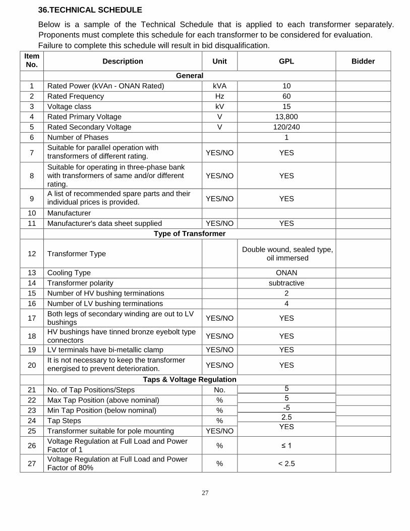
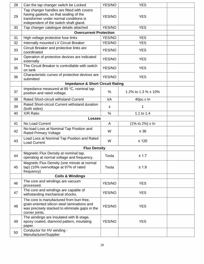
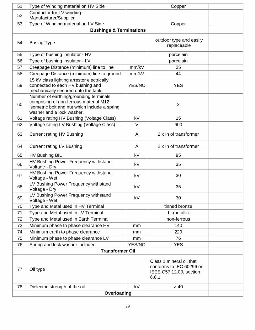
36.TECHNICAL SCHEDULE
Below is a sample of the Technical Schedule that is applied to each transformer separately.
Proponents must complete this schedule for each transformer to be considered for evaluation.
Failure to complete this schedule will result in bid disqualification.
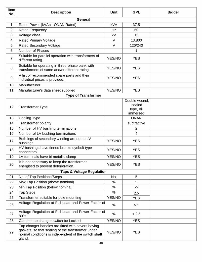
Item No. Description Unit GPL Bidder
General
1 Rated Power (kVAn - ONAN Rated) kVA 10
2 Rated Frequency Hz 60
3 Voltage class kV 15
4 Rated Primary Voltage V 13,800
5 Rated Secondary Voltage V 120/240
6 Number of Phases 1
7 Suitable for parallel operation with transformers of different rating. YES/NO YES
8 Suitable for operating in three-phase bank with transformers of same and/or different rating.
YES/NO YES
9 A list of recommended spare parts and their individual prices is provided. YES/NO YES
10 Manufacturer
11 Manufacturer's data sheet supplied YES/NO YES
Type of Transformer
12 Transformer Type Double wound, sealed type,
oil immersed
13 Cooling Type ONAN
14 Transformer polarity subtractive
15 Number of HV bushing terminations 2
16 Number of LV bushing terminations 4
17 Both legs of secondary winding are out to LV bushings
YES/NO YES
18 HV bushings have tinned bronze eyebolt type connectors
YES/NO YES
19 LV terminals have bi-metallic clamp YES/NO YES
20 It is not necessary to keep the transformer energised to prevent deterioration. YES/NO YES
Taps & Voltage Regulation
21 No. of Tap Positions/Steps No.
22 Max Tap Position (above nominal) %
23 Min Tap Position (below nominal) %
24 Tap Steps %
25 Transformer suitable for pole mounting YES/NO
26 Voltage Regulation at Full Load and Power Factor of 1
% ≤ 1
27 Voltage Regulation at Full Load and Power Factor of 80%
% < 2.5
28
28 Can the tap changer switch be Locked YES/NO YES
29
Tap changer handles are fitted with covers having gaskets, so that sealing of the transformer under normal conditions is independent of the switch shaft gland.
YES/NO YES
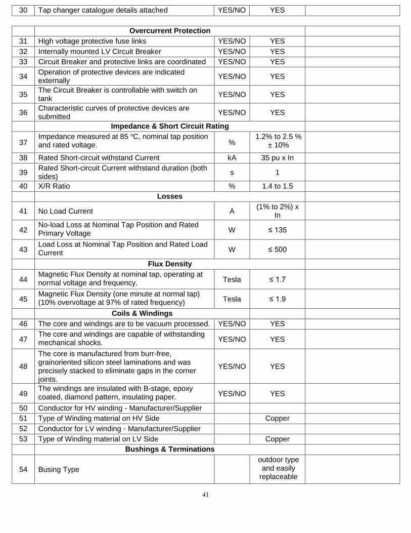
30 Tap changer catalogue details attached YES/NO YES
Overcurrent Protection
31 High voltage protective fuse links YES/NO YES
32 Internally mounted LV Circuit Breaker YES/NO YES
33 Circuit Breaker and protective links are coordinated
YES/NO YES
34 Operation of protective devices are indicated externally
YES/NO YES
35 The Circuit Breaker is controllable with switch on tank
YES/NO YES
36 Characteristic curves of protective devices are submitted
YES/NO YES
Impedance & Short Circuit Rating
37 Impedance measured at 85 oC, nominal tap position and rated voltage. % 1.2% to 1.3 % ± 10%
38 Rated Short-circuit withstand Current kA 40pu x In
39 Rated Short-circuit Current withstand duration (both sides)
s 1
40 X/R Ratio % 1.1 to 1.4
Losses
41 No Load Current A (1% to 2%) x In
42 No-load Loss at Nominal Tap Position and Rated Primary Voltage W ≤ 36
43 Load Loss at Nominal Tap Position and Rated Load Current W ≤ 120
Flux Density
44 Magnetic Flux Density at nominal tap, operating at normal voltage and frequency. Tesla ≤ 1.7
45 Magnetic Flux Density (one minute at normal tap) (10% overvoltage at 97% of rated frequency)
Tesla ≤ 1.9
Coils & Windings
46 The core and windings are vacuum processed.
YES/NO YES
47 The core and windings are capable of withstanding mechanical shocks. YES/NO YES
48
The core is manufactured from burr-free, grain-oriented silicon steel laminations and was precisely stacked to eliminate gaps in the corner joints.
YES/NO YES
49 The windings are insulated with B-stage, epoxy coated, diamond pattern, insulating paper.
YES/NO YES
50 Conductor for HV winding - Manufacturer/Supplier
29
51 Type of Winding material on HV Side Copper
52 Conductor for LV winding - Manufacturer/Supplier
53 Type of Winding material on LV Side Copper
Bushings & Terminations
54 Busing Type outdoor type and easily
replaceable
55 Type of bushing insulator - HV porcelain
56 Type of bushing insulator - LV porcelain
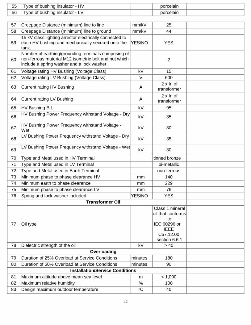
57 Creepage Distance (minimum) line to line mm/kV 25
58 Creepage Distance (minimum) line to ground mm/kV 44
59 15 kV class lighting arrestor electrically connected to each HV bushing and mechanically secured onto the tank.
YES/NO YES
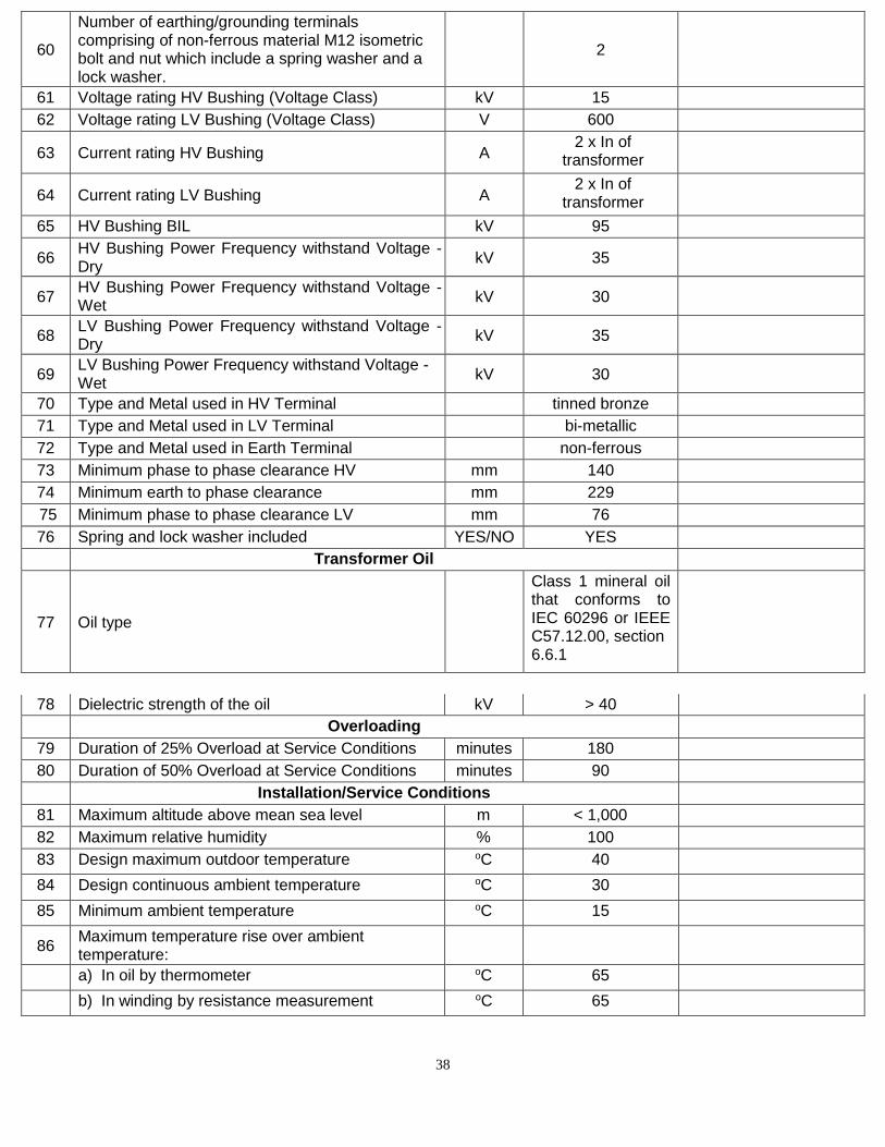
60
Number of earthing/grounding terminals comprising of non-ferrous material M12 isometric bolt and nut which include a spring washer and a lock washer.
2
61 Voltage rating HV Bushing (Voltage Class) kV 15
62 Voltage rating LV Bushing (Voltage Class) V 600
63 Current rating HV Bushing A 2 x In of transformer
64 Current rating LV Bushing A 2 x In of transformer
65 HV Bushing BIL kV 95
66 HV Bushing Power Frequency withstand Voltage - Dry
kV 35
67 HV Bushing Power Frequency withstand Voltage - Wet
kV 30
68 LV Bushing Power Frequency withstand Voltage - Dry
kV 35
69 LV Bushing Power Frequency withstand Voltage - Wet
kV 30
70 Type and Metal used in HV Terminal tinned bronze
71 Type and Metal used in LV Terminal bi-metallic
72 Type and Metal used in Earth Terminal non-ferrous
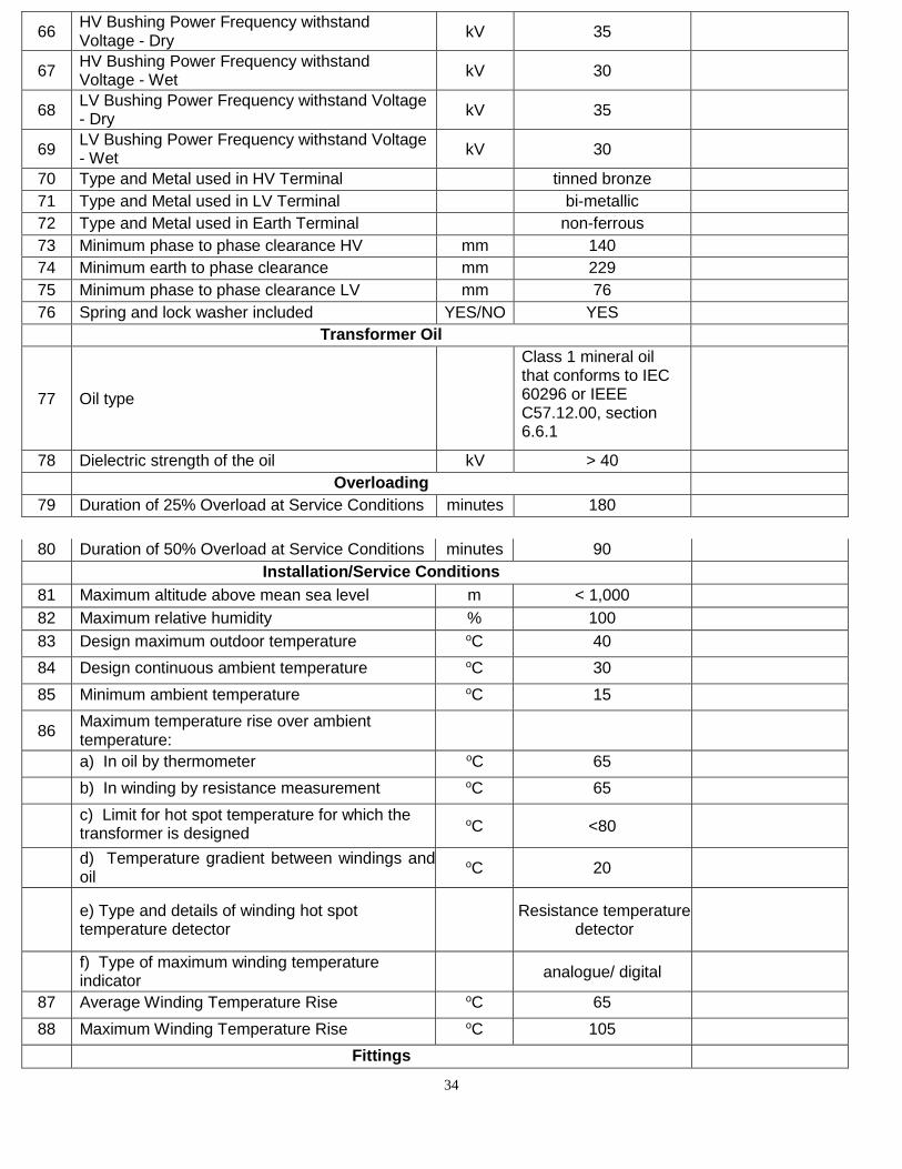
73 Minimum phase to phase clearance HV mm 140
74 Minimum earth to phase clearance mm 229
75 Minimum phase to phase clearance LV mm 76
76 Spring and lock washer included YES/NO YES
Transformer Oil
77 Oil type
Class 1 mineral oil that conforms to IEC 60296 or IEEE C57.12.00, section 6.6.1
78 Dielectric strength of the oil kV > 40
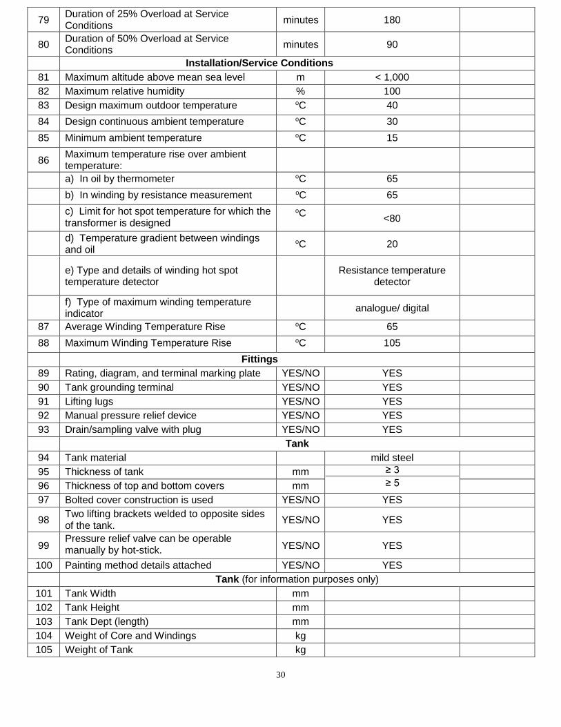
Overloading
30
79 Duration of 25% Overload at Service Conditions
minutes 180
80 Duration of 50% Overload at Service Conditions
minutes 90
Installation/Service Conditions
81 Maximum altitude above mean sea level m < 1,000
82 Maximum relative humidity % 100
83 Design maximum outdoor temperature oC 40
84 Design continuous ambient temperature oC 30
85 Minimum ambient temperature oC 15
86 Maximum temperature rise over ambient temperature:
a) In oil by thermometer oC 65
b) In winding by resistance measurement oC 65
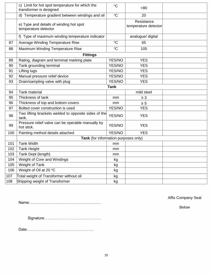
c) Limit for hot spot temperature for which the transformer is designed
oC
<80
d) Temperature gradient between windings and oil
oC 20
e) Type and details of winding hot spot temperature detector
Resistance temperature
detector
f) Type of maximum winding temperature indicator
analogue/ digital
87 Average Winding Temperature Rise oC 65
88 Maximum Winding Temperature Rise oC 105
Fittings
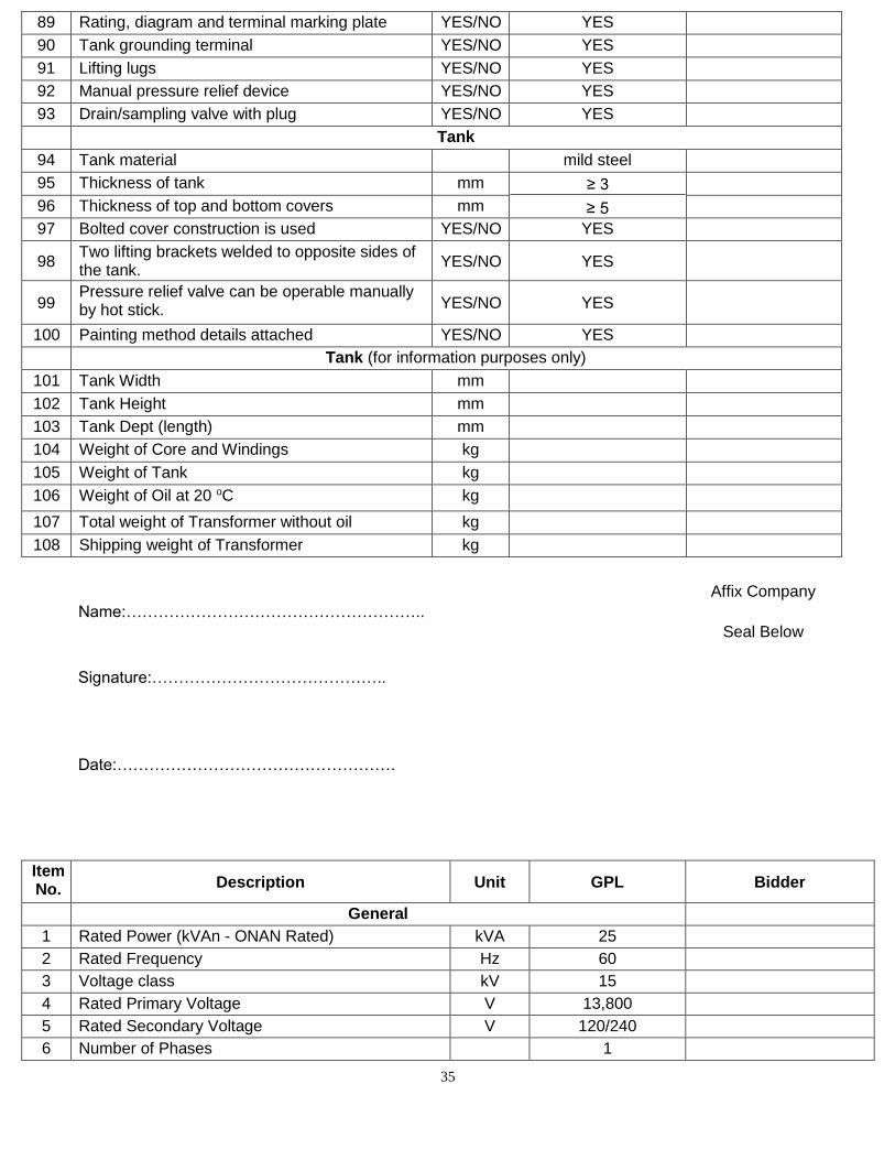
89 Rating, diagram, and terminal marking plate YES/NO YES
90 Tank grounding terminal YES/NO YES
91 Lifting lugs YES/NO YES
92 Manual pressure relief device YES/NO YES
93 Drain/sampling valve with plug YES/NO YES
Tank
94 Tank material mild steel
95 Thickness of tank mm
96 Thickness of top and bottom covers mm
97 Bolted cover construction is used YES/NO YES
98 Two lifting brackets welded to opposite sides of the tank.
YES/NO YES
99 Pressure relief valve can be operable manually by hot-stick. YES/NO YES
100 Painting method details attached YES/NO YES
Tank (for information purposes only)
101 Tank Width mm
102 Tank Height mm
103 Tank Dept (length) mm
104 Weight of Core and Windings kg
105 Weight of Tank kg
31
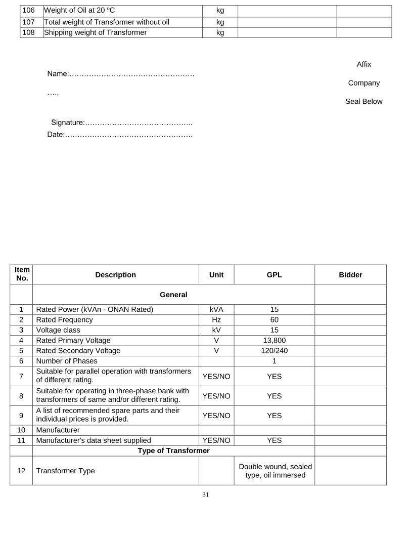
106 Weight of Oil at 20 oC kg
107 Total weight of Transformer without oil kg
108 Shipping weight of Transformer kg
Affix
Name:…………………………………………… Company
….. Seal Below
Signature:……………………………………..
Date:…………………………………………….
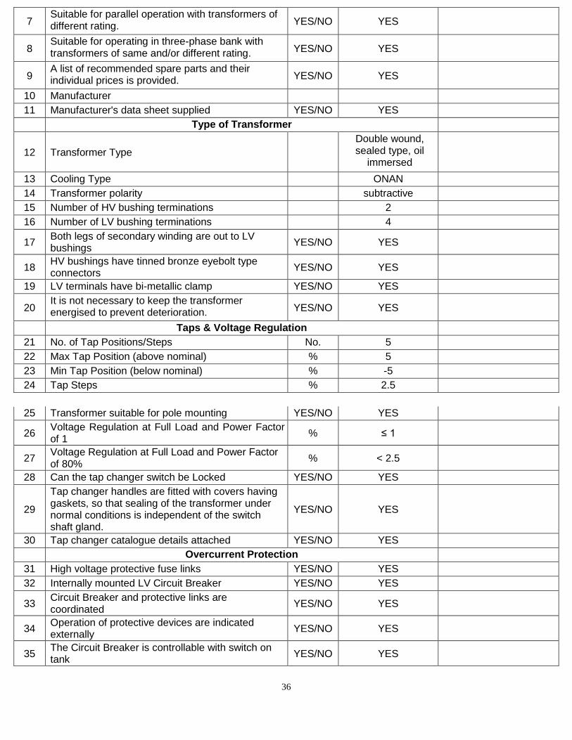
Item No. Description Unit GPL Bidder
General
1 Rated Power (kVAn - ONAN Rated) kVA 15
2 Rated Frequency Hz 60
3 Voltage class kV 15
4 Rated Primary Voltage V 13,800
5 Rated Secondary Voltage V 120/240
6 Number of Phases 1
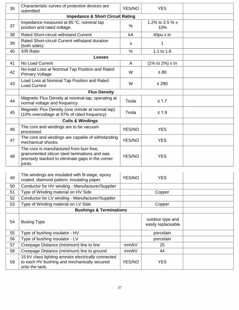
7 Suitable for parallel operation with transformers of different rating. YES/NO YES
8 Suitable for operating in three-phase bank with transformers of same and/or different rating. YES/NO YES
9 A list of recommended spare parts and their individual prices is provided. YES/NO YES
10 Manufacturer
11 Manufacturer's data sheet supplied YES/NO YES
Type of Transformer
12 Transformer Type Double wound, sealed
type, oil immersed
32
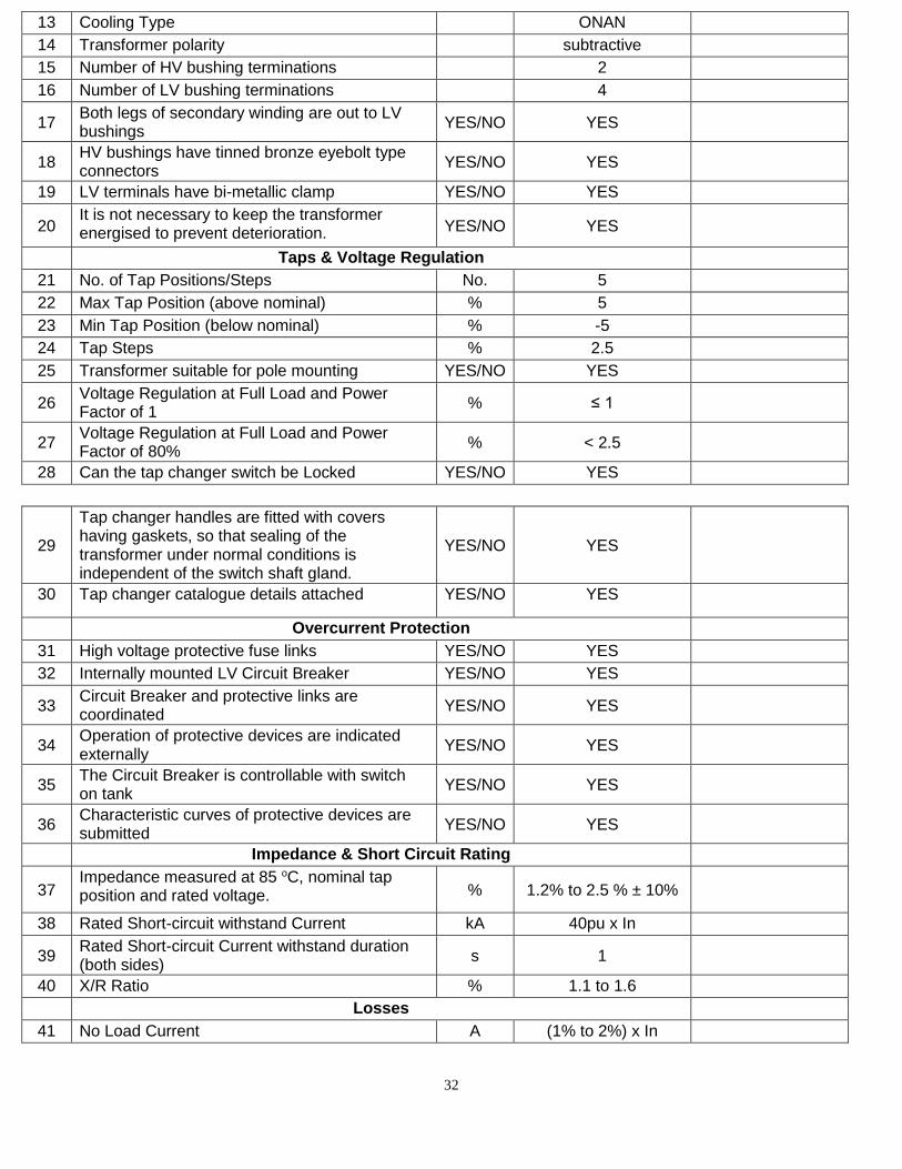
13 Cooling Type ONAN
14 Transformer polarity subtractive
15 Number of HV bushing terminations 2
16 Number of LV bushing terminations 4
17 Both legs of secondary winding are out to LV bushings
YES/NO YES
18 HV bushings have tinned bronze eyebolt type connectors
YES/NO YES
19 LV terminals have bi-metallic clamp YES/NO YES
20 It is not necessary to keep the transformer energised to prevent deterioration. YES/NO YES
Taps & Voltage Regulation
21 No. of Tap Positions/Steps No. 5
22 Max Tap Position (above nominal) % 5
23 Min Tap Position (below nominal) % -5
24 Tap Steps % 2.5
25 Transformer suitable for pole mounting YES/NO YES
26 Voltage Regulation at Full Load and Power Factor of 1
% ≤ 1
27 Voltage Regulation at Full Load and Power Factor of 80%
% < 2.5
28 Can the tap changer switch be Locked YES/NO YES
29
Tap changer handles are fitted with covers having gaskets, so that sealing of the transformer under normal conditions is independent of the switch shaft gland.
YES/NO YES
30 Tap changer catalogue details attached YES/NO YES
Overcurrent Protection
31 High voltage protective fuse links YES/NO YES
32 Internally mounted LV Circuit Breaker YES/NO YES
33 Circuit Breaker and protective links are coordinated
YES/NO YES
34 Operation of protective devices are indicated externally
YES/NO YES
35 The Circuit Breaker is controllable with switch on tank
YES/NO YES
36 Characteristic curves of protective devices are submitted
YES/NO YES
Impedance & Short Circuit Rating
37 Impedance measured at 85 oC, nominal tap position and rated voltage. % 1.2% to 2.5 % ± 10%
38 Rated Short-circuit withstand Current kA 40pu x In
39 Rated Short-circuit Current withstand duration (both sides)
s 1
40 X/R Ratio % 1.1 to 1.6
Losses
41 No Load Current A (1% to 2%) x In
33
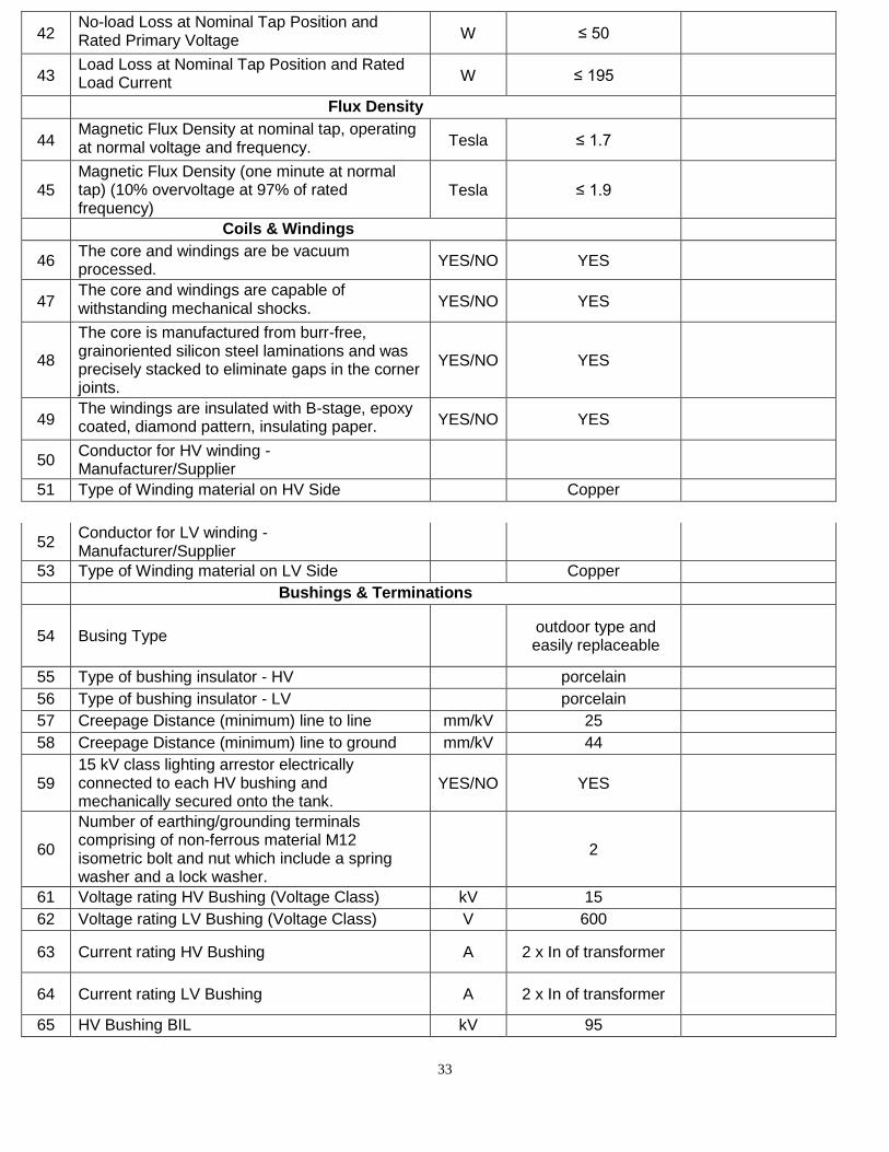
42 No-load Loss at Nominal Tap Position and Rated Primary Voltage W ≤ 50
43 Load Loss at Nominal Tap Position and Rated Load Current W ≤ 195
Flux Density
44 Magnetic Flux Density at nominal tap, operating at normal voltage and frequency. Tesla ≤ 1.7
45 Magnetic Flux Density (one minute at normal tap) (10% overvoltage at 97% of rated frequency)
Tesla ≤ 1.9
Coils & Windings
46 The core and windings are be vacuum processed.
YES/NO YES
47 The core and windings are capable of withstanding mechanical shocks. YES/NO YES
48
The core is manufactured from burr-free, grainoriented silicon steel laminations and was precisely stacked to eliminate gaps in the corner joints.
YES/NO YES
49 The windings are insulated with B-stage, epoxy coated, diamond pattern, insulating paper. YES/NO YES
50 Conductor for HV winding - Manufacturer/Supplier
51 Type of Winding material on HV Side Copper
52 Conductor for LV winding - Manufacturer/Supplier
53 Type of Winding material on LV Side Copper
Bushings & Terminations
54 Busing Type outdoor type and easily replaceable
55 Type of bushing insulator - HV porcelain
56 Type of bushing insulator - LV porcelain
57 Creepage Distance (minimum) line to line mm/kV 25
58 Creepage Distance (minimum) line to ground mm/kV 44
59 15 kV class lighting arrestor electrically connected to each HV bushing and mechanically secured onto the tank.
YES/NO YES
60
Number of earthing/grounding terminals comprising of non-ferrous material M12 isometric bolt and nut which include a spring washer and a lock washer.
2
61 Voltage rating HV Bushing (Voltage Class) kV 15
62 Voltage rating LV Bushing (Voltage Class) V 600
63 Current rating HV Bushing A 2 x In of transformer
64 Current rating LV Bushing A 2 x In of transformer
65 HV Bushing BIL kV 95
34
66 HV Bushing Power Frequency withstand Voltage - Dry
kV 35
67 HV Bushing Power Frequency withstand Voltage - Wet
kV 30
68 LV Bushing Power Frequency withstand Voltage - Dry
kV 35
69 LV Bushing Power Frequency withstand Voltage - Wet
kV 30
70 Type and Metal used in HV Terminal tinned bronze
71 Type and Metal used in LV Terminal bi-metallic
72 Type and Metal used in Earth Terminal non-ferrous
73 Minimum phase to phase clearance HV mm 140
74 Minimum earth to phase clearance mm 229
75 Minimum phase to phase clearance LV mm 76
76 Spring and lock washer included YES/NO YES
Transformer Oil
77 Oil type
Class 1 mineral oil that conforms to IEC 60296 or IEEE C57.12.00, section 6.6.1
78 Dielectric strength of the oil kV > 40
Overloading
79 Duration of 25% Overload at Service Conditions minutes 180
80 Duration of 50% Overload at Service Conditions minutes 90
Installation/Service Conditions
81 Maximum altitude above mean sea level m < 1,000
82 Maximum relative humidity % 100
83 Design maximum outdoor temperature oC 40
84 Design continuous ambient temperature oC 30
85 Minimum ambient temperature oC 15
86 Maximum temperature rise over ambient temperature:
a) In oil by thermometer oC 65
b) In winding by resistance measurement oC 65
c) Limit for hot spot temperature for which the transformer is designed
oC <80
d) Temperature gradient between windings and oil
oC 20
e) Type and details of winding hot spot temperature detector
Resistance temperature
detector
f) Type of maximum winding temperature indicator
analogue/ digital
87 Average Winding Temperature Rise oC 65
88 Maximum Winding Temperature Rise oC 105
Fittings
35
89 Rating, diagram and terminal marking plate YES/NO YES
90 Tank grounding terminal YES/NO YES
91 Lifting lugs YES/NO YES
92 Manual pressure relief device YES/NO YES
93 Drain/sampling valve with plug YES/NO YES
Tank
94 Tank material mild steel
95 Thickness of tank mm ≥ 5
96 Thickness of top and bottom covers mm
97 Bolted cover construction is used YES/NO YES
98 Two lifting brackets welded to opposite sides of the tank.
YES/NO YES
99 Pressure relief valve can be operable manually by hot stick. YES/NO YES
100 Painting method details attached YES/NO YES
Tank (for information purposes only)
101 Tank Width mm
102 Tank Height mm
103 Tank Dept (length) mm
104 Weight of Core and Windings kg
105 Weight of Tank kg
106 Weight of Oil at 20 oC kg
107 Total weight of Transformer without oil kg
108 Shipping weight of Transformer kg
Affix Company
Name:……………………………………………….. Seal Below
Signature:……………………………………..
Date:…………………………………………….
Item No. Description Unit GPL Bidder
General
1 Rated Power (kVAn - ONAN Rated) kVA 25
2 Rated Frequency Hz 60
3 Voltage class kV 15
4 Rated Primary Voltage V 13,800
5 Rated Secondary Voltage V 120/240
6 Number of Phases 1
36
7 Suitable for parallel operation with transformers of different rating. YES/NO YES
8 Suitable for operating in three-phase bank with transformers of same and/or different rating. YES/NO YES
9 A list of recommended spare parts and their individual prices is provided. YES/NO YES
10 Manufacturer
11 Manufacturer's data sheet supplied YES/NO YES
Type of Transformer
12 Transformer Type
Double wound, sealed type, oil
immersed
13 Cooling Type ONAN
14 Transformer polarity subtractive
15 Number of HV bushing terminations 2
16 Number of LV bushing terminations 4
17 Both legs of secondary winding are out to LV bushings
YES/NO YES
18 HV bushings have tinned bronze eyebolt type connectors
YES/NO YES
19 LV terminals have bi-metallic clamp YES/NO YES
20 It is not necessary to keep the transformer energised to prevent deterioration. YES/NO YES
Taps & Voltage Regulation
21 No. of Tap Positions/Steps No. 5
22 Max Tap Position (above nominal) % 5
23 Min Tap Position (below nominal) % -5
24 Tap Steps % 2.5
25 Transformer suitable for pole mounting YES/NO YES
26 Voltage Regulation at Full Load and Power Factor of 1
% ≤ 1
27 Voltage Regulation at Full Load and Power Factor of 80%
% < 2.5
28 Can the tap changer switch be Locked YES/NO YES
29
Tap changer handles are fitted with covers having gaskets, so that sealing of the transformer under normal conditions is independent of the switch shaft gland.
YES/NO YES
30 Tap changer catalogue details attached YES/NO YES
Overcurrent Protection
31 High voltage protective fuse links YES/NO YES
32 Internally mounted LV Circuit Breaker YES/NO YES
33 Circuit Breaker and protective links are coordinated
YES/NO YES
34 Operation of protective devices are indicated externally
YES/NO YES
35 The Circuit Breaker is controllable with switch on tank
YES/NO YES
37
36 Characteristic curves of protective devices are submitted
YES/NO YES
Impedance & Short Circuit Rating
37 Impedance measured at 85 oC, nominal tap position and rated voltage. %
1.2% to 2.5 % ± 10%
38 Rated Short-circuit withstand Current kA 40pu x In
39 Rated Short-circuit Current withstand duration (both sides)
s 1
40 X/R Ratio % 1.1 to 1.8
Losses
41 No Load Current A (1% to 2%) x In
42 No-load Loss at Nominal Tap Position and Rated Primary Voltage W ≤ 80
43 Load Loss at Nominal Tap Position and Rated Load Current W ≤ 290
Flux Density
44 Magnetic Flux Density at nominal tap, operating at normal voltage and frequency. Tesla ≤ 1.7
45 Magnetic Flux Density (one minute at normal tap) (10% overvoltage at 97% of rated frequency) Tesla ≤ 1.9
Coils & Windings
46 The core and windings are to be vacuum processed.
YES/NO YES
47 The core and windings are capable of withstanding mechanical shocks. YES/NO YES
48
The core is manufactured from burr-free, grainoriented silicon steel laminations and was precisely stacked to eliminate gaps in the corner joints.
YES/NO YES
49 The windings are insulated with B-stage, epoxy coated, diamond pattern, insulating paper. YES/NO YES
50 Conductor for HV winding - Manufacturer/Supplier
51 Type of Winding material on HV Side Copper
52 Conductor for LV winding - Manufacturer/Supplier
53 Type of Winding material on LV Side Copper
Bushings & Terminations
54 Busing Type outdoor type and easily replaceable
55 Type of bushing insulator - HV porcelain
56 Type of bushing insulator - LV porcelain
57 Creepage Distance (minimum) line to line mm/kV 25
58 Creepage Distance (minimum) line to ground mm/kV 44
59 15 kV class lighting arrestor electrically connected to each HV bushing and mechanically secured onto the tank.
YES/NO YES
38
60
Number of earthing/grounding terminals comprising of non-ferrous material M12 isometric bolt and nut which include a spring washer and a lock washer.
2
61 Voltage rating HV Bushing (Voltage Class) kV 15
62 Voltage rating LV Bushing (Voltage Class) V 600
63 Current rating HV Bushing A 2 x In of
transformer
64 Current rating LV Bushing A 2 x In of
transformer
65 HV Bushing BIL kV 95
66 HV Bushing Power Frequency withstand Voltage - Dry
kV 35
67 HV Bushing Power Frequency withstand Voltage - Wet
kV 30
68 LV Bushing Power Frequency withstand Voltage - Dry
kV 35
69 LV Bushing Power Frequency withstand Voltage - Wet
kV 30
70 Type and Metal used in HV Terminal tinned bronze
71 Type and Metal used in LV Terminal bi-metallic
72 Type and Metal used in Earth Terminal non-ferrous
73 Minimum phase to phase clearance HV mm 140
74 Minimum earth to phase clearance mm 229
75 Minimum phase to phase clearance LV mm 76
76 Spring and lock washer included YES/NO YES
Transformer Oil
77 Oil type
Class 1 mineral oil that conforms to IEC 60296 or IEEE C57.12.00, section 6.6.1
78 Dielectric strength of the oil kV > 40
Overloading
79 Duration of 25% Overload at Service Conditions minutes 180
80 Duration of 50% Overload at Service Conditions minutes 90
Installation/Service Conditions
81 Maximum altitude above mean sea level m < 1,000
82 Maximum relative humidity % 100
83 Design maximum outdoor temperature oC 40
84 Design continuous ambient temperature oC 30
85 Minimum ambient temperature oC 15
86 Maximum temperature rise over ambient temperature:
a) In oil by thermometer oC 65
b) In winding by resistance measurement oC 65
39
c) Limit for hot spot temperature for which the transformer is designed
oC
<80
d) Temperature gradient between windings and oil oC 20
e) Type and details of winding hot spot temperature detector
Resistance temperature detector
f) Type of maximum winding temperature indicator analogue/ digital
87 Average Winding Temperature Rise oC 65
88 Maximum Winding Temperature Rise oC 105
Fittings
89 Rating, diagram and terminal marking plate YES/NO YES
90 Tank grounding terminal YES/NO YES
91 Lifting lugs YES/NO YES
92 Manual pressure relief device YES/NO YES
93 Drain/sampling valve with plug YES/NO YES
Tank
94 Tank material mild steel
95 Thickness of tank mm ≥ 5
96 Thickness of top and bottom covers mm
97 Bolted cover construction is used YES/NO YES
98 Two lifting brackets welded to opposite sides of the tank.
YES/NO YES
99 Pressure relief valve can be operable manually by hot stick. YES/NO YES
100 Painting method details attached YES/NO YES
Tank (for information purposes only)
101 Tank Width mm
102 Tank Height mm
103 Tank Dept (length) mm
104 Weight of Core and Windings kg
105 Weight of Tank kg
106 Weight of Oil at 20 oC kg
107 Total weight of Transformer without oil kg
108 Shipping weight of Transformer kg
Affix Company Seal
Name:……………………………………………….. Below
Signature:……………………………………..
Date:…………………………………………….
40
Item No. Description Unit GPL Bidder
General
1 Rated Power (kVAn - ONAN Rated) kVA 37.5
2 Rated Frequency Hz 60
3 Voltage class kV 15
4 Rated Primary Voltage V 13,800
5 Rated Secondary Voltage V 120/240
6 Number of Phases 1
7 Suitable for parallel operation with transformers of different rating. YES/NO YES
8 Suitable for operating in three-phase bank with transformers of same and/or different rating. YES/NO YES
9 A list of recommended spare parts and their individual prices is provided. YES/NO YES
10 Manufacturer
11 Manufacturer's data sheet supplied YES/NO YES
Type of Transformer
12 Transformer Type
Double wound, sealed
type, oil immersed
13 Cooling Type ONAN
14 Transformer polarity subtractive
15 Number of HV bushing terminations 2
16 Number of LV bushing terminations 4
17 Both legs of secondary winding are out to LV bushings
YES/NO YES
18 HV bushings have tinned bronze eyebolt type connectors
YES/NO YES
19 LV terminals have bi-metallic clamp YES/NO YES
20 It is not necessary to keep the transformer energised to prevent deterioration. YES/NO YES
Taps & Voltage Regulation
21 No. of Tap Positions/Steps No. 5
22 Max Tap Position (above nominal) % 5
23 Min Tap Position (below nominal) % -5
24 Tap Steps %
YES
25 Transformer suitable for pole mounting YES/NO
26 Voltage Regulation at Full Load and Power Factor of 1
% ≤ 1
27 Voltage Regulation at Full Load and Power Factor of 80%
% < 2.5
28 Can the tap changer switch be Locked YES/NO YES
29
Tap changer handles are fitted with covers having gaskets, so that sealing of the transformer under normal conditions is independent of the switch shaft gland.
YES/NO YES
41
30 Tap changer catalogue details attached YES/NO YES
Overcurrent Protection
31 High voltage protective fuse links YES/NO YES
32 Internally mounted LV Circuit Breaker YES/NO YES
33 Circuit Breaker and protective links are coordinated YES/NO YES
34 Operation of protective devices are indicated externally
YES/NO YES
35 The Circuit Breaker is controllable with switch on tank
YES/NO YES
36 Characteristic curves of protective devices are submitted
YES/NO YES
Impedance & Short Circuit Rating
37 Impedance measured at 85 oC, nominal tap position and rated voltage. %
1.2% to 2.5 % ± 10%
38 Rated Short-circuit withstand Current kA 35 pu x In
39 Rated Short-circuit Current withstand duration (both sides)
s 1
40 X/R Ratio % 1.4 to 1.5
Losses
41 No Load Current A (1% to 2%) x
In
42 No-load Loss at Nominal Tap Position and Rated Primary Voltage W ≤ 135
43 Load Loss at Nominal Tap Position and Rated Load Current W ≤ 500
Flux Density
44 Magnetic Flux Density at nominal tap, operating at normal voltage and frequency. Tesla ≤ 1.7
45 Magnetic Flux Density (one minute at normal tap) (10% overvoltage at 97% of rated frequency) Tesla ≤ 1.9
Coils & Windings
46 The core and windings are to be vacuum processed. YES/NO YES
47 The core and windings are capable of withstanding mechanical shocks. YES/NO YES
48
The core is manufactured from burr-free, grainoriented silicon steel laminations and was precisely stacked to eliminate gaps in the corner joints.
YES/NO YES
49 The windings are insulated with B-stage, epoxy coated, diamond pattern, insulating paper. YES/NO YES
50 Conductor for HV winding - Manufacturer/Supplier
51 Type of Winding material on HV Side Copper
52 Conductor for LV winding - Manufacturer/Supplier
53 Type of Winding material on LV Side Copper
Bushings & Terminations
54 Busing Type
outdoor type and easily
replaceable
42
55 Type of bushing insulator - HV porcelain
56 Type of bushing insulator - LV porcelain
57 Creepage Distance (minimum) line to line mm/kV 25
58 Creepage Distance (minimum) line to ground mm/kV 44
59 15 kV class lighting arrestor electrically connected to each HV bushing and mechanically secured onto the tank.
YES/NO YES
60
Number of earthing/grounding terminals comprising of non-ferrous material M12 isometric bolt and nut which include a spring washer and a lock washer.
2
61 Voltage rating HV Bushing (Voltage Class) kV 15
62 Voltage rating LV Bushing (Voltage Class) V 600
63 Current rating HV Bushing A 2 x In of
transformer
64 Current rating LV Bushing A 2 x In of
transformer
65 HV Bushing BIL kV 95
66 HV Bushing Power Frequency withstand Voltage - Dry
kV 35
67 HV Bushing Power Frequency withstand Voltage - Wet
kV 30
68 LV Bushing Power Frequency withstand Voltage - Dry
kV 35
69 LV Bushing Power Frequency withstand Voltage - Wet
kV 30
70 Type and Metal used in HV Terminal tinned bronze
71 Type and Metal used in LV Terminal bi-metallic
72 Type and Metal used in Earth Terminal non-ferrous
73 Minimum phase to phase clearance HV mm 140
74 Minimum earth to phase clearance mm 229
75 Minimum phase to phase clearance LV mm 76
76 Spring and lock washer included YES/NO YES
Transformer Oil
77 Oil type
Class 1 mineral oil that conforms
to IEC 60296 or
IEEE C57.12.00,
section 6.6.1
78 Dielectric strength of the oil kV > 40
Overloading
79 Duration of 25% Overload at Service Conditions minutes 180
80 Duration of 50% Overload at Service Conditions minutes 90
Installation/Service Conditions
81 Maximum altitude above mean sea level m < 1,000
82 Maximum relative humidity % 100
83 Design maximum outdoor temperature oC 40
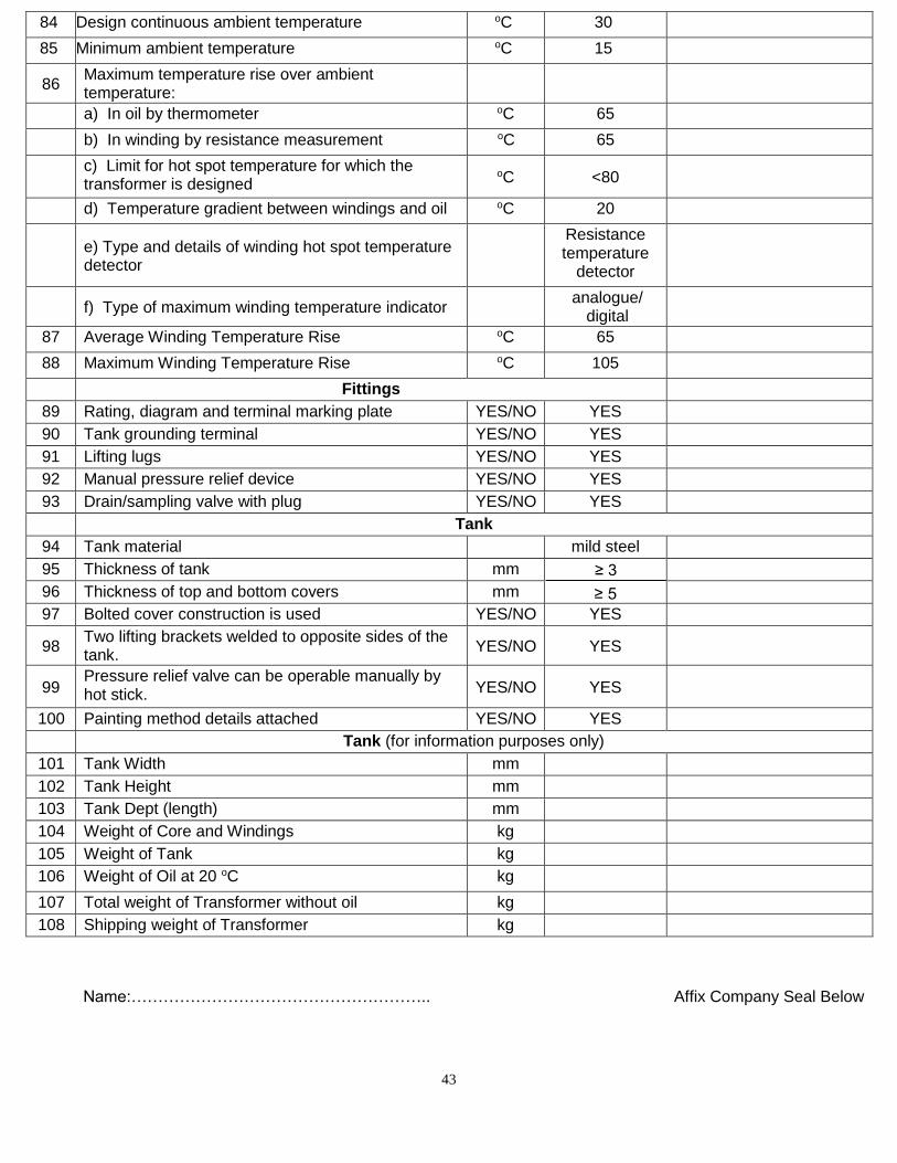
43
84 Design continuous ambient temperature oC 30
85 Minimum ambient temperature oC 15
86 Maximum temperature rise over ambient temperature:
a) In oil by thermometer oC 65
b) In winding by resistance measurement oC 65
c) Limit for hot spot temperature for which the transformer is designed
oC <80
d) Temperature gradient between windings and oil oC 20
e) Type and details of winding hot spot temperature detector
Resistance temperature
detector
f) Type of maximum winding temperature indicator analogue/
digital
87 Average Winding Temperature Rise oC 65
88 Maximum Winding Temperature Rise oC 105
Fittings
89 Rating, diagram and terminal marking plate YES/NO YES
90 Tank grounding terminal YES/NO YES
91 Lifting lugs YES/NO YES
92 Manual pressure relief device YES/NO YES
93 Drain/sampling valve with plug YES/NO YES
Tank
94 Tank material mild steel
95 Thickness of tank mm ≥ 5
96 Thickness of top and bottom covers mm
97 Bolted cover construction is used YES/NO YES
98 Two lifting brackets welded to opposite sides of the tank.
YES/NO YES
99 Pressure relief valve can be operable manually by hot stick. YES/NO YES
100 Painting method details attached YES/NO YES
Tank (for information purposes only)
101 Tank Width mm
102 Tank Height mm
103 Tank Dept (length) mm
104 Weight of Core and Windings kg
105 Weight of Tank kg
106 Weight of Oil at 20 oC kg
107 Total weight of Transformer without oil kg
108 Shipping weight of Transformer kg
Name:……………………………………………….. Affix Company Seal Below
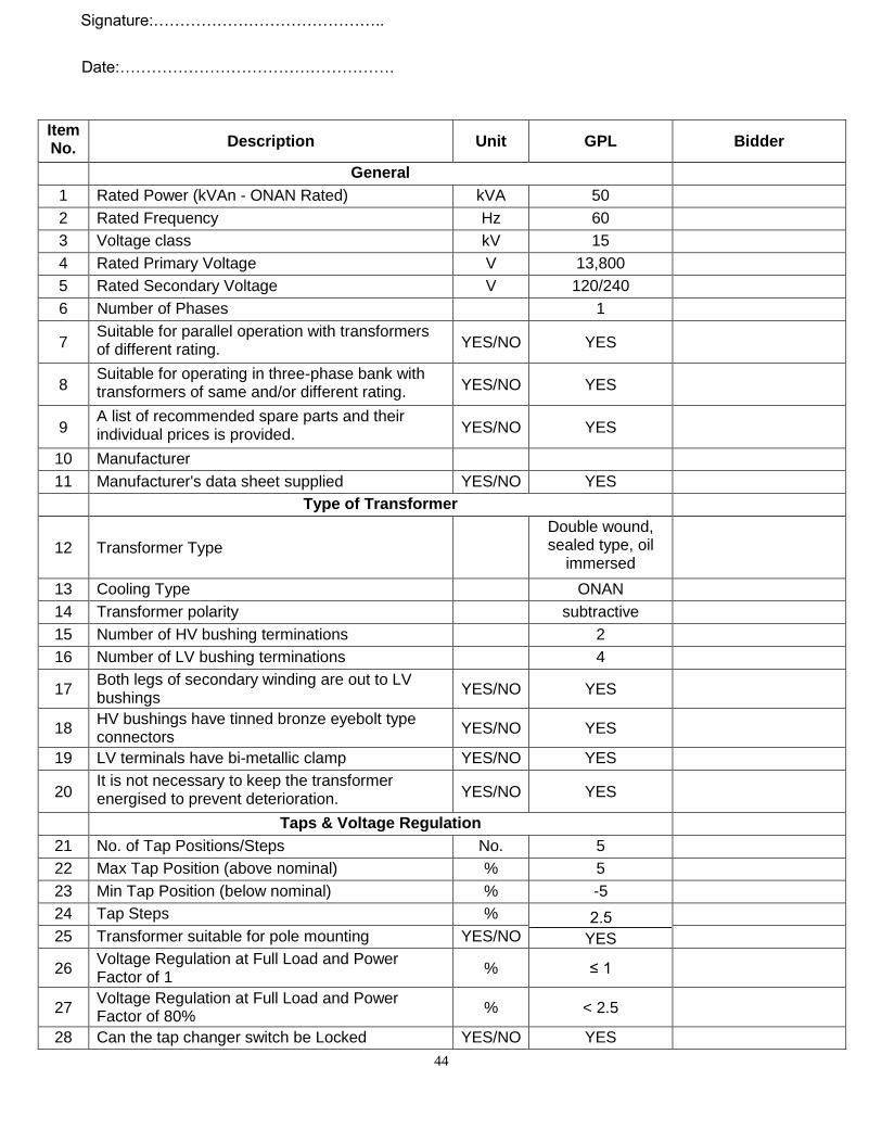
44
Signature:……………………………………..
Date:…………………………………………….
Item No. Description Unit GPL Bidder
General
1 Rated Power (kVAn - ONAN Rated) kVA 50
2 Rated Frequency Hz 60
3 Voltage class kV 15
4 Rated Primary Voltage V 13,800
5 Rated Secondary Voltage V 120/240
6 Number of Phases 1
7 Suitable for parallel operation with transformers of different rating. YES/NO YES
8 Suitable for operating in three-phase bank with transformers of same and/or different rating. YES/NO YES
9 A list of recommended spare parts and their individual prices is provided. YES/NO YES
10 Manufacturer
11 Manufacturer's data sheet supplied YES/NO YES
Type of Transformer
12 Transformer Type
Double wound, sealed type, oil
immersed
13 Cooling Type ONAN
14 Transformer polarity subtractive
15 Number of HV bushing terminations 2
16 Number of LV bushing terminations 4
17 Both legs of secondary winding are out to LV bushings
YES/NO YES
18 HV bushings have tinned bronze eyebolt type connectors
YES/NO YES
19 LV terminals have bi-metallic clamp YES/NO YES
20 It is not necessary to keep the transformer energised to prevent deterioration. YES/NO YES
Taps & Voltage Regulation
21 No. of Tap Positions/Steps No. 5
22 Max Tap Position (above nominal) % 5
23 Min Tap Position (below nominal) % -5
24 Tap Steps %
YES
25 Transformer suitable for pole mounting YES/NO
26 Voltage Regulation at Full Load and Power Factor of 1
% ≤ 1
27 Voltage Regulation at Full Load and Power Factor of 80%
% < 2.5
28 Can the tap changer switch be Locked YES/NO YES
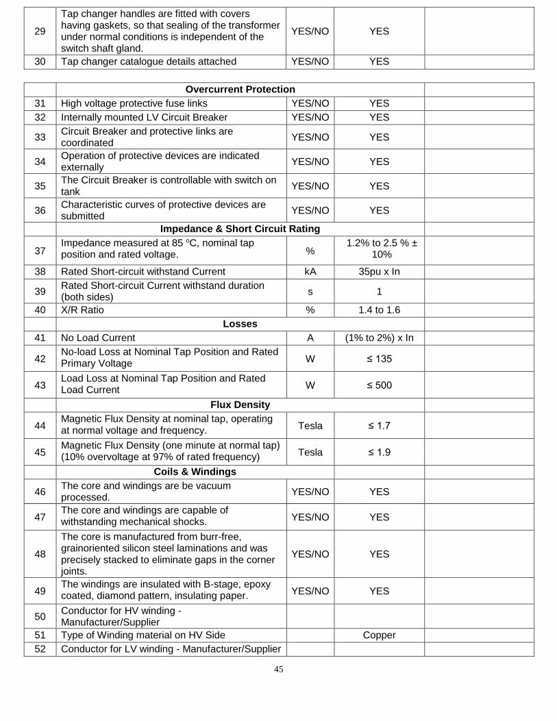
45
29
Tap changer handles are fitted with covers having gaskets, so that sealing of the transformer under normal conditions is independent of the switch shaft gland.
YES/NO YES
30 Tap changer catalogue details attached YES/NO YES
Overcurrent Protection
31 High voltage protective fuse links YES/NO YES
32 Internally mounted LV Circuit Breaker YES/NO YES
33 Circuit Breaker and protective links are coordinated
YES/NO YES
34 Operation of protective devices are indicated externally
YES/NO YES
35 The Circuit Breaker is controllable with switch on tank
YES/NO YES
36 Characteristic curves of protective devices are submitted
YES/NO YES
Impedance & Short Circuit Rating
37 Impedance measured at 85 oC, nominal tap position and rated voltage. %
1.2% to 2.5 % ± 10%
38 Rated Short-circuit withstand Current kA 35pu x In
39 Rated Short-circuit Current withstand duration (both sides)
s 1
40 X/R Ratio % 1.4 to 1.6
Losses
41 No Load Current A (1% to 2%) x In
42 No-load Loss at Nominal Tap Position and Rated Primary Voltage W ≤ 135
43 Load Loss at Nominal Tap Position and Rated Load Current W ≤ 500
Flux Density
44 Magnetic Flux Density at nominal tap, operating at normal voltage and frequency. Tesla ≤ 1.7
45 Magnetic Flux Density (one minute at normal tap) (10% overvoltage at 97% of rated frequency) Tesla ≤ 1.9
Coils & Windings
46 The core and windings are be vacuum processed.
YES/NO YES
47 The core and windings are capable of withstanding mechanical shocks. YES/NO YES
48
The core is manufactured from burr-free, grainoriented silicon steel laminations and was precisely stacked to eliminate gaps in the corner joints.
YES/NO YES
49 The windings are insulated with B-stage, epoxy coated, diamond pattern, insulating paper. YES/NO YES
50 Conductor for HV winding - Manufacturer/Supplier
51 Type of Winding material on HV Side Copper
52 Conductor for LV winding - Manufacturer/Supplier
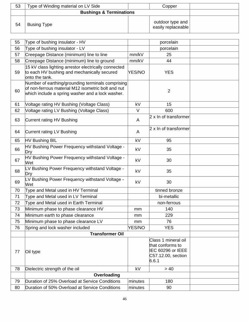
46
53 Type of Winding material on LV Side Copper
Bushings & Terminations
54 Busing Type outdoor type and easily replaceable
55 Type of bushing insulator - HV porcelain
56 Type of bushing insulator - LV porcelain
57 Creepage Distance (minimum) line to line mm/kV 25
58 Creepage Distance (minimum) line to ground mm/kV 44
59 15 kV class lighting arrestor electrically connected to each HV bushing and mechanically secured onto the tank.
YES/NO YES
60
Number of earthing/grounding terminals comprising of non-ferrous material M12 isometric bolt and nut which include a spring washer and a lock washer.
2
61 Voltage rating HV Bushing (Voltage Class) kV 15
62 Voltage rating LV Bushing (Voltage Class) V 600
63 Current rating HV Bushing A 2 x In of transformer
64 Current rating LV Bushing A 2 x In of transformer
65 HV Bushing BIL kV 95
66 HV Bushing Power Frequency withstand Voltage - Dry
kV 35
67 HV Bushing Power Frequency withstand Voltage - Wet
kV 30
68 LV Bushing Power Frequency withstand Voltage - Dry
kV 35
69 LV Bushing Power Frequency withstand Voltage - Wet
kV 30
70 Type and Metal used in HV Terminal tinned bronze
71 Type and Metal used in LV Terminal bi-metallic
72 Type and Metal used in Earth Terminal non-ferrous
73 Minimum phase to phase clearance HV mm 140
74 Minimum earth to phase clearance mm 229
75 Minimum phase to phase clearance LV mm 76
76 Spring and lock washer included YES/NO YES
Transformer Oil
77 Oil type
Class 1 mineral oil that conforms to IEC 60296 or IEEE C57.12.00, section 6.6.1
78 Dielectric strength of the oil kV > 40
Overloading
79 Duration of 25% Overload at Service Conditions minutes 180
80 Duration of 50% Overload at Service Conditions minutes 90
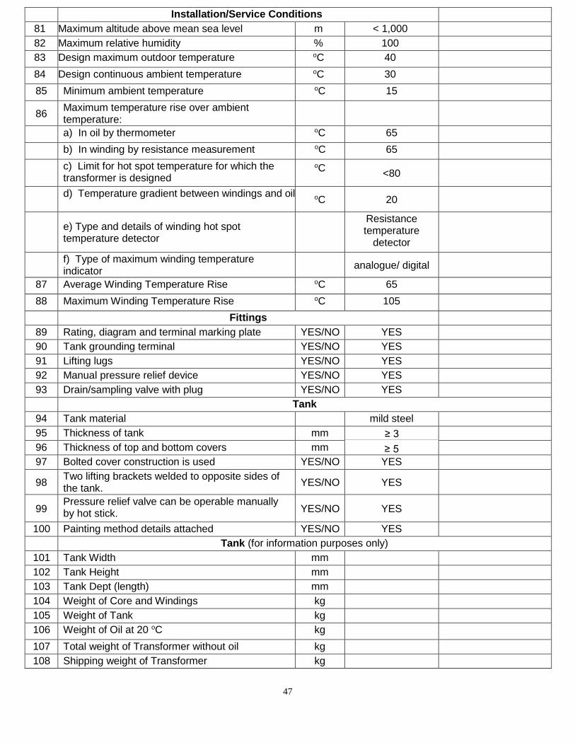
47
Installation/Service Conditions
81 Maximum altitude above mean sea level m < 1,000
82 Maximum relative humidity % 100
83 Design maximum outdoor temperature oC 40
84 Design continuous ambient temperature oC 30
85 Minimum ambient temperature oC 15
86 Maximum temperature rise over ambient temperature:
a) In oil by thermometer oC 65
b) In winding by resistance measurement oC 65
c) Limit for hot spot temperature for which the transformer is designed
oC
<80
d) Temperature gradient between windings and oil oC 20
e) Type and details of winding hot spot temperature detector
Resistance temperature
detector
f) Type of maximum winding temperature indicator
analogue/ digital
87 Average Winding Temperature Rise oC 65
88 Maximum Winding Temperature Rise oC 105
Fittings
89 Rating, diagram and terminal marking plate YES/NO YES
90 Tank grounding terminal YES/NO YES
91 Lifting lugs YES/NO YES
92 Manual pressure relief device YES/NO YES
93 Drain/sampling valve with plug YES/NO YES
Tank
94 Tank material mild steel
95 Thickness of tank mm ≥ 5
96 Thickness of top and bottom covers mm
97 Bolted cover construction is used YES/NO YES
98 Two lifting brackets welded to opposite sides of the tank.
YES/NO YES
99 Pressure relief valve can be operable manually by hot stick. YES/NO YES
100 Painting method details attached YES/NO YES
Tank (for information purposes only)
101 Tank Width mm
102 Tank Height mm
103 Tank Dept (length) mm
104 Weight of Core and Windings kg
105 Weight of Tank kg
106 Weight of Oil at 20 oC kg
107 Total weight of Transformer without oil kg
108 Shipping weight of Transformer kg
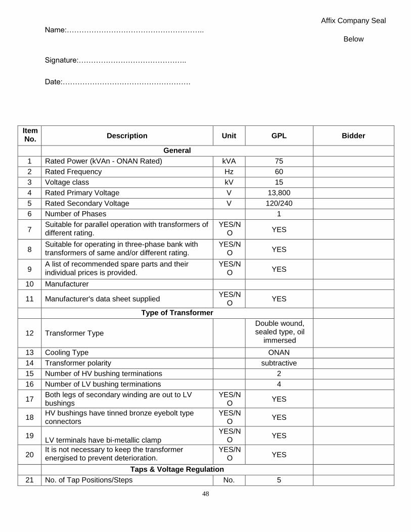
48
Affix Company Seal Name:………………………………………………..
Below
Signature:……………………………………..
Date:…………………………………………….
Item No. Description Unit GPL Bidder
General
1 Rated Power (kVAn - ONAN Rated) kVA 75
2 Rated Frequency Hz 60
3 Voltage class kV 15
4 Rated Primary Voltage V 13,800
5 Rated Secondary Voltage V 120/240
6 Number of Phases 1
7 Suitable for parallel operation with transformers of different rating.
YES/N O YES
8 Suitable for operating in three-phase bank with transformers of same and/or different rating.
YES/N O YES
9 A list of recommended spare parts and their individual prices is provided.
YES/N O YES
10 Manufacturer
11 Manufacturer's data sheet supplied YES/N
O YES
Type of Transformer
12 Transformer Type
Double wound, sealed type, oil
immersed
13 Cooling Type ONAN
14 Transformer polarity subtractive
15 Number of HV bushing terminations 2
16 Number of LV bushing terminations 4
17 Both legs of secondary winding are out to LV bushings
YES/N O
YES
18 HV bushings have tinned bronze eyebolt type connectors
YES/N O
YES
19 LV terminals have bi-metallic clamp
YES/N O
YES
20 It is not necessary to keep the transformer energised to prevent deterioration.
YES/N O YES
Taps & Voltage Regulation
21 No. of Tap Positions/Steps No. 5
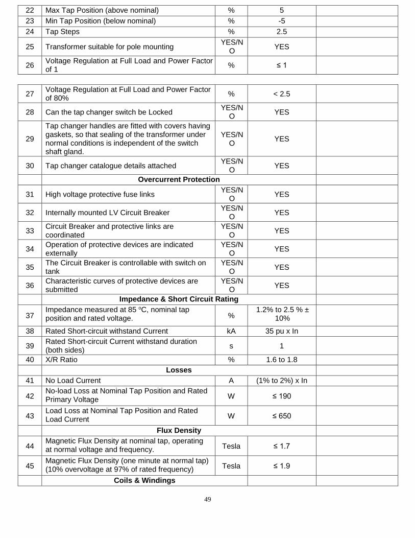
49
22 Max Tap Position (above nominal) % 5
23 Min Tap Position (below nominal) % -5
24 Tap Steps % 2.5
25 Transformer suitable for pole mounting YES/N
O YES
26 Voltage Regulation at Full Load and Power Factor of 1
% ≤ 1
27 Voltage Regulation at Full Load and Power Factor of 80%
% < 2.5
28 Can the tap changer switch be Locked YES/N
O YES
29
Tap changer handles are fitted with covers having gaskets, so that sealing of the transformer under normal conditions is independent of the switch shaft gland.
YES/N O
YES
30 Tap changer catalogue details attached YES/N
O YES
Overcurrent Protection
31 High voltage protective fuse links YES/N
O YES
32 Internally mounted LV Circuit Breaker YES/N
O YES
33 Circuit Breaker and protective links are coordinated
YES/N O
YES
34 Operation of protective devices are indicated externally
YES/N O
YES
35 The Circuit Breaker is controllable with switch on tank
YES/N O
YES
36 Characteristic curves of protective devices are submitted
YES/N O
YES
Impedance & Short Circuit Rating
37 Impedance measured at 85 oC, nominal tap position and rated voltage. %
1.2% to 2.5 % ± 10%
38 Rated Short-circuit withstand Current kA 35 pu x In
39 Rated Short-circuit Current withstand duration (both sides)
s 1
40 X/R Ratio % 1.6 to 1.8
Losses
41 No Load Current A (1% to 2%) x In
42 No-load Loss at Nominal Tap Position and Rated Primary Voltage W ≤ 190
43 Load Loss at Nominal Tap Position and Rated Load Current W ≤ 650
Flux Density
44 Magnetic Flux Density at nominal tap, operating at normal voltage and frequency. Tesla ≤ 1.7
45 Magnetic Flux Density (one minute at normal tap) (10% overvoltage at 97% of rated frequency) Tesla ≤ 1.9
Coils & Windings
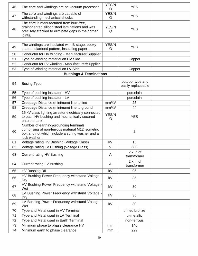
50
46 The core and windings are be vacuum processed. YES/N
O YES
47 The core and windings are capable of withstanding mechanical shocks.
YES/N O YES
48
The core is manufactured from burr-free, grainoriented silicon steel laminations and was precisely stacked to eliminate gaps in the corner joints.
YES/N O
YES
49 The windings are insulated with B-stage, epoxy coated, diamond pattern, insulating paper.
YES/N O YES
50 Conductor for HV winding - Manufacturer/Supplier
51 Type of Winding material on HV Side Copper
52 Conductor for LV winding - Manufacturer/Supplier
53 Type of Winding material on LV Side Copper
Bushings & Terminations
54 Busing Type outdoor type and easily replaceable
55 Type of bushing insulator - HV porcelain
56 Type of bushing insulator - LV porcelain
57 Creepage Distance (minimum) line to line mm/kV 25
58 Creepage Distance (minimum) line to ground mm/kV 44
59 15 kV class lighting arrestor electrically connected to each HV bushing and mechanically secured onto the tank.
YES/N O
YES
60
Number of earthing/grounding terminals comprising of non-ferrous material M12 isometric bolt and nut which include a spring washer and a lock washer.
2
61 Voltage rating HV Bushing (Voltage Class) kV 15
62 Voltage rating LV Bushing (Voltage Class) V 600
63 Current rating HV Bushing A 2 x In of
transformer
64 Current rating LV Bushing A 2 x In of
transformer
65 HV Bushing BIL kV 95
66 HV Bushing Power Frequency withstand Voltage - Dry
kV 35
67 HV Bushing Power Frequency withstand Voltage - Wet
kV 30
68 LV Bushing Power Frequency withstand Voltage - Dry
kV 35
69 LV Bushing Power Frequency withstand Voltage - Wet
kV 30
70 Type and Metal used in HV Terminal tinned bronze
71 Type and Metal used in LV Terminal bi-metallic
72 Type and Metal used in Earth Terminal non-ferrous
73 Minimum phase to phase clearance HV mm 140
74 Minimum earth to phase clearance mm 229
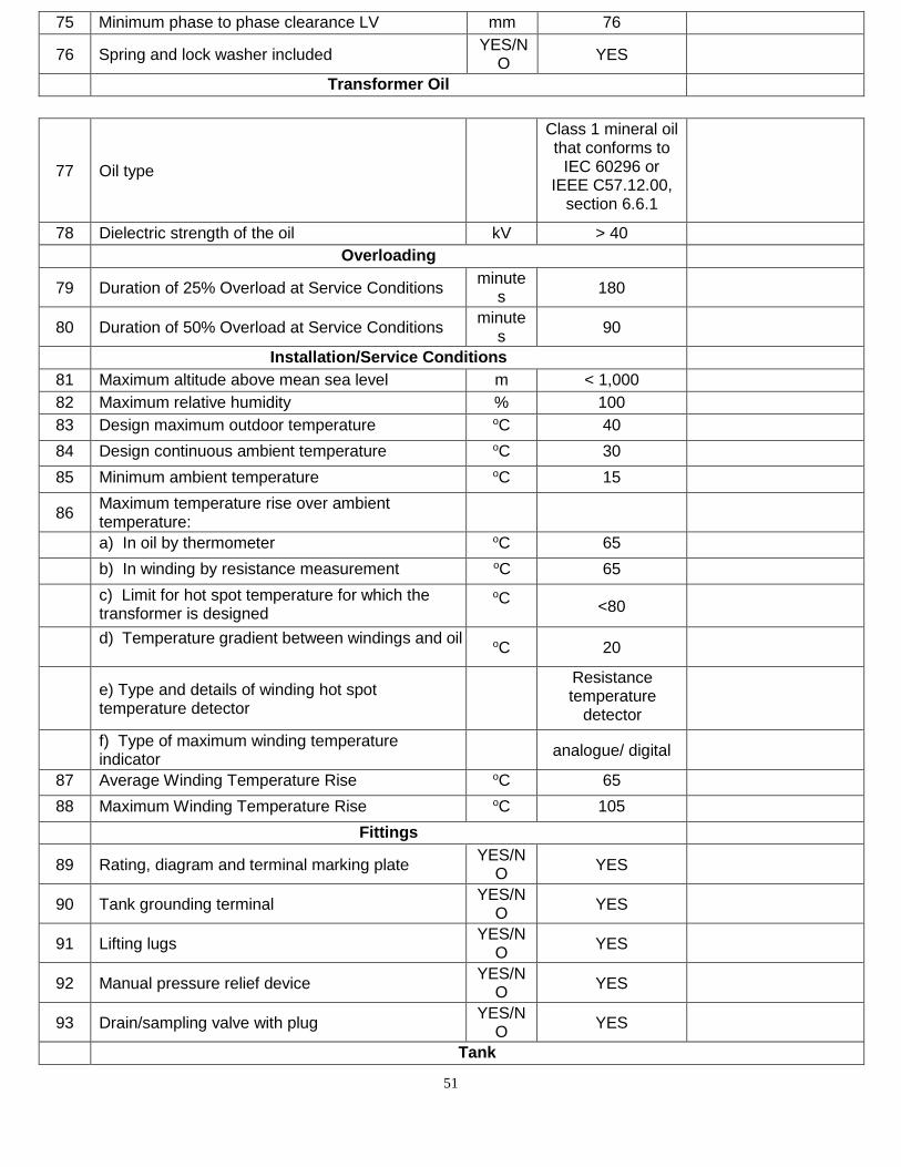
51
75 Minimum phase to phase clearance LV mm 76
76 Spring and lock washer included YES/N
O YES
Transformer Oil
77 Oil type
Class 1 mineral oil that conforms to
IEC 60296 or IEEE C57.12.00,
section 6.6.1
78 Dielectric strength of the oil kV > 40
Overloading
79 Duration of 25% Overload at Service Conditions minute
s 180
80 Duration of 50% Overload at Service Conditions minute
s 90
Installation/Service Conditions
81 Maximum altitude above mean sea level m < 1,000
82 Maximum relative humidity % 100
83 Design maximum outdoor temperature oC 40
84 Design continuous ambient temperature oC 30
85 Minimum ambient temperature oC 15
86 Maximum temperature rise over ambient temperature:
a) In oil by thermometer oC 65
b) In winding by resistance measurement oC 65
c) Limit for hot spot temperature for which the transformer is designed
oC
<80
d) Temperature gradient between windings and oil oC 20
e) Type and details of winding hot spot temperature detector
Resistance temperature
detector
f) Type of maximum winding temperature indicator
analogue/ digital
87 Average Winding Temperature Rise oC 65
88 Maximum Winding Temperature Rise oC 105
Fittings
89 Rating, diagram and terminal marking plate YES/N
O YES
90 Tank grounding terminal YES/N
O YES
91 Lifting lugs YES/N
O YES
92 Manual pressure relief device YES/N
O YES
93 Drain/sampling valve with plug YES/N
O YES
Tank
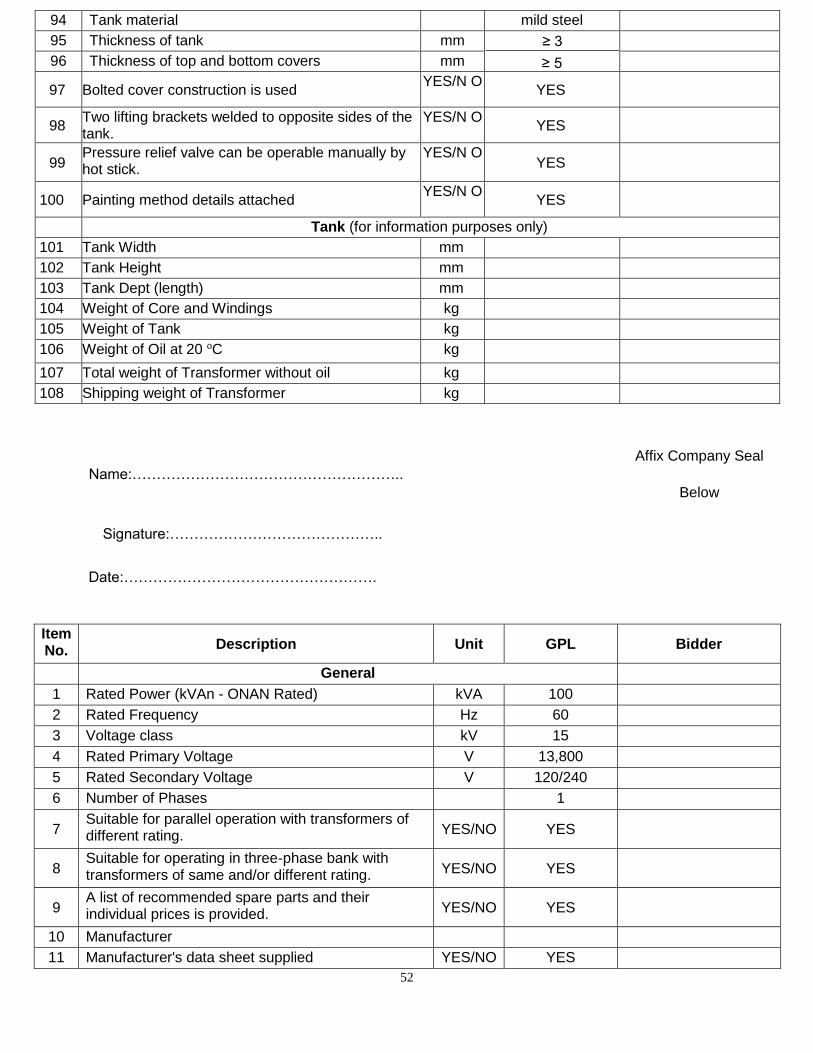
52
94 Tank material mild steel
95 Thickness of tank mm ≥ 5
96 Thickness of top and bottom covers mm
97 Bolted cover construction is used YES/N O
YES
98 Two lifting brackets welded to opposite sides of the tank.
YES/N O YES
99 Pressure relief valve can be operable manually by hot stick.
YES/N O YES
100 Painting method details attached YES/N O
YES
Tank (for information purposes only)
101 Tank Width mm
102 Tank Height mm
103 Tank Dept (length) mm
104 Weight of Core and Windings kg
105 Weight of Tank kg
106 Weight of Oil at 20 oC kg
107 Total weight of Transformer without oil kg
108 Shipping weight of Transformer kg
Affix Company Seal
Name:……………………………………………….. Below
Signature:……………………………………..
Date:…………………………………………….
Item No. Description Unit GPL Bidder
General
1 Rated Power (kVAn - ONAN Rated) kVA 100
2 Rated Frequency Hz 60
3 Voltage class kV 15
4 Rated Primary Voltage V 13,800
5 Rated Secondary Voltage V 120/240
6 Number of Phases 1
7 Suitable for parallel operation with transformers of different rating. YES/NO YES
8 Suitable for operating in three-phase bank with transformers of same and/or different rating. YES/NO YES
9 A list of recommended spare parts and their individual prices is provided. YES/NO YES
10 Manufacturer
11 Manufacturer's data sheet supplied YES/NO YES
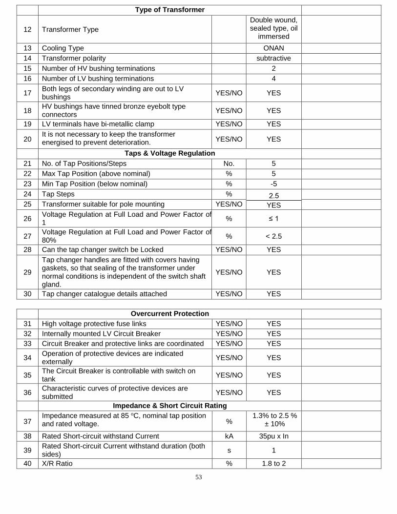
53
Type of Transformer
12 Transformer Type
Double wound, sealed type, oil
immersed
13 Cooling Type ONAN
14 Transformer polarity subtractive
15 Number of HV bushing terminations 2
16 Number of LV bushing terminations 4
17 Both legs of secondary winding are out to LV bushings
YES/NO YES
18 HV bushings have tinned bronze eyebolt type connectors
YES/NO YES
19 LV terminals have bi-metallic clamp YES/NO YES
20 It is not necessary to keep the transformer energised to prevent deterioration. YES/NO YES
Taps & Voltage Regulation
21 No. of Tap Positions/Steps No. 5
22 Max Tap Position (above nominal) % 5
23 Min Tap Position (below nominal) % -5
24 Tap Steps %
YES
25 Transformer suitable for pole mounting YES/NO
26 Voltage Regulation at Full Load and Power Factor of 1
% ≤ 1
27 Voltage Regulation at Full Load and Power Factor of 80%
% < 2.5
28 Can the tap changer switch be Locked YES/NO YES
29
Tap changer handles are fitted with covers having gaskets, so that sealing of the transformer under normal conditions is independent of the switch shaft gland.
YES/NO YES
30 Tap changer catalogue details attached YES/NO YES
Overcurrent Protection
31 High voltage protective fuse links YES/NO YES
32 Internally mounted LV Circuit Breaker YES/NO YES
33 Circuit Breaker and protective links are coordinated YES/NO YES
34 Operation of protective devices are indicated externally
YES/NO YES
35 The Circuit Breaker is controllable with switch on tank
YES/NO YES
36 Characteristic curves of protective devices are submitted
YES/NO YES
Impedance & Short Circuit Rating
37 Impedance measured at 85 oC, nominal tap position and rated voltage. %
1.3% to 2.5 % ± 10%
38 Rated Short-circuit withstand Current kA 35pu x In
39 Rated Short-circuit Current withstand duration (both sides)
s 1
40 X/R Ratio % 1.8 to 2
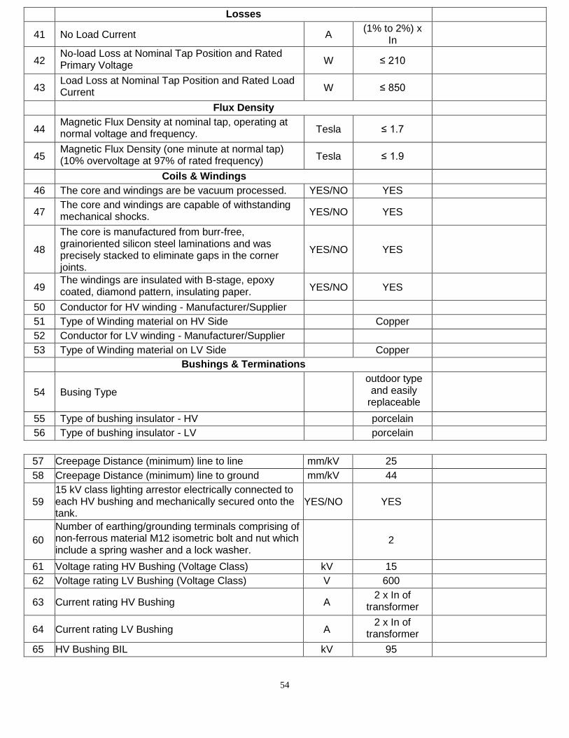
54
Losses
41 No Load Current A (1% to 2%) x
In
42 No-load Loss at Nominal Tap Position and Rated Primary Voltage W ≤ 210
43 Load Loss at Nominal Tap Position and Rated Load Current W ≤ 850
Flux Density
44 Magnetic Flux Density at nominal tap, operating at normal voltage and frequency. Tesla ≤ 1.7
45 Magnetic Flux Density (one minute at normal tap) (10% overvoltage at 97% of rated frequency) Tesla ≤ 1.9
Coils & Windings
46 The core and windings are be vacuum processed. YES/NO YES
47 The core and windings are capable of withstanding mechanical shocks. YES/NO YES
48
The core is manufactured from burr-free, grainoriented silicon steel laminations and was precisely stacked to eliminate gaps in the corner joints.
YES/NO YES
49 The windings are insulated with B-stage, epoxy coated, diamond pattern, insulating paper. YES/NO YES
50 Conductor for HV winding - Manufacturer/Supplier
51 Type of Winding material on HV Side Copper
52 Conductor for LV winding - Manufacturer/Supplier
53 Type of Winding material on LV Side Copper
Bushings & Terminations
54 Busing Type
outdoor type and easily
replaceable
55 Type of bushing insulator - HV porcelain
56 Type of bushing insulator - LV porcelain
57 Creepage Distance (minimum) line to line mm/kV 25
58 Creepage Distance (minimum) line to ground mm/kV 44
59 15 kV class lighting arrestor electrically connected to each HV bushing and mechanically secured onto the tank.
YES/NO YES
60
Number of earthing/grounding terminals comprising of non-ferrous material M12 isometric bolt and nut which include a spring washer and a lock washer.
2
61 Voltage rating HV Bushing (Voltage Class) kV 15
62 Voltage rating LV Bushing (Voltage Class) V 600
63 Current rating HV Bushing A 2 x In of
transformer
64 Current rating LV Bushing A 2 x In of
transformer
65 HV Bushing BIL kV 95
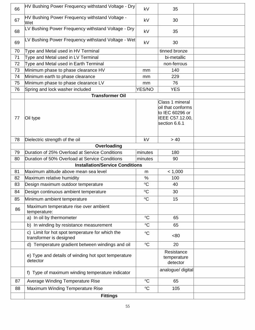
55
66 HV Bushing Power Frequency withstand Voltage - Dry
kV 35
67 HV Bushing Power Frequency withstand Voltage - Wet
kV 30
68 LV Bushing Power Frequency withstand Voltage - Dry
kV 35
69 LV Bushing Power Frequency withstand Voltage - Wet
kV 30
70 Type and Metal used in HV Terminal tinned bronze
71 Type and Metal used in LV Terminal bi-metallic
72 Type and Metal used in Earth Terminal non-ferrous
73 Minimum phase to phase clearance HV mm 140
74 Minimum earth to phase clearance mm 229
75 Minimum phase to phase clearance LV mm 76
76 Spring and lock washer included YES/NO YES
Transformer Oil
77 Oil type
Class 1 mineral oil that conforms to IEC 60296 or IEEE C57.12.00, section 6.6.1
78 Dielectric strength of the oil kV > 40
Overloading
79 Duration of 25% Overload at Service Conditions minutes 180
80 Duration of 50% Overload at Service Conditions minutes 90
Installation/Service Conditions
81 Maximum altitude above mean sea level m < 1,000
82 Maximum relative humidity % 100
83 Design maximum outdoor temperature oC 40
84 Design continuous ambient temperature oC 30
85 Minimum ambient temperature oC 15
86 Maximum temperature rise over ambient temperature:
a) In oil by thermometer oC 65
b) In winding by resistance measurement oC 65
c) Limit for hot spot temperature for which the transformer is designed
oC
<80
d) Temperature gradient between windings and oil oC 20
e) Type and details of winding hot spot temperature detector
Resistance temperature
detector
f) Type of maximum winding temperature indicator analogue/ digital
87 Average Winding Temperature Rise oC 65
88 Maximum Winding Temperature Rise oC 105
Fittings
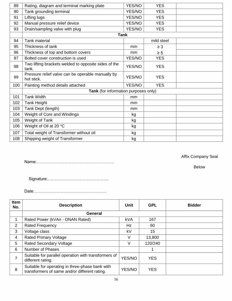
56
89 Rating, diagram and terminal marking plate YES/NO YES
90 Tank grounding terminal YES/NO YES
91 Lifting lugs YES/NO YES
92 Manual pressure relief device YES/NO YES
93 Drain/sampling valve with plug YES/NO YES
Tank
94 Tank material mild steel
95 Thickness of tank mm ≥ 5
96 Thickness of top and bottom covers mm
97 Bolted cover construction is used YES/NO YES
98 Two lifting brackets welded to opposite sides of the tank.
YES/NO YES
99 Pressure relief valve can be operable manually by hot stick. YES/NO YES
100 Painting method details attached YES/NO YES
Tank (for information purposes only)
101 Tank Width mm
102 Tank Height mm
103 Tank Dept (length) mm
104 Weight of Core and Windings kg
105 Weight of Tank kg
106 Weight of Oil at 20 oC kg
107 Total weight of Transformer without oil kg
108 Shipping weight of Transformer kg
Affix Company Seal Name:………………………………………………..
Below
Signature:……………………………………..
Date:…………………………………………….
Item No. Description Unit GPL Bidder
General
1 Rated Power (kVAn - ONAN Rated) kVA 167
2 Rated Frequency Hz 60
3 Voltage class kV 15
4 Rated Primary Voltage V 13,800
5 Rated Secondary Voltage V 120/240
6 Number of Phases 1
7 Suitable for parallel operation with transformers of different rating. YES/NO YES
8 Suitable for operating in three-phase bank with transformers of same and/or different rating. YES/NO YES
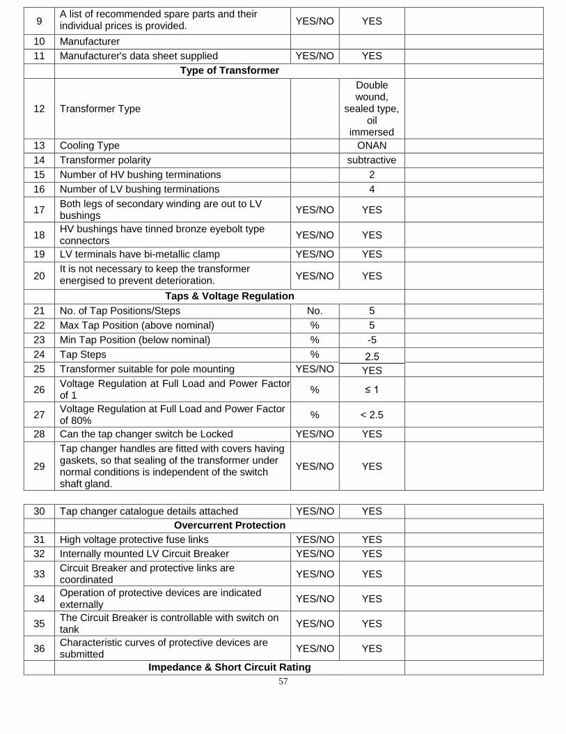
57
9 A list of recommended spare parts and their individual prices is provided. YES/NO YES
10 Manufacturer
11 Manufacturer's data sheet supplied YES/NO YES
Type of Transformer
12 Transformer Type
Double wound,
sealed type, oil
immersed
13 Cooling Type ONAN
14 Transformer polarity subtractive
15 Number of HV bushing terminations 2
16 Number of LV bushing terminations 4
17 Both legs of secondary winding are out to LV bushings
YES/NO YES
18 HV bushings have tinned bronze eyebolt type connectors
YES/NO YES
19 LV terminals have bi-metallic clamp YES/NO YES
20 It is not necessary to keep the transformer energised to prevent deterioration. YES/NO YES
Taps & Voltage Regulation
21 No. of Tap Positions/Steps No. 5
22 Max Tap Position (above nominal) % 5
23 Min Tap Position (below nominal) % -5
24 Tap Steps %
YES
25 Transformer suitable for pole mounting YES/NO
26 Voltage Regulation at Full Load and Power Factor of 1
% ≤ 1
27 Voltage Regulation at Full Load and Power Factor of 80%
% < 2.5
28 Can the tap changer switch be Locked YES/NO YES
29
Tap changer handles are fitted with covers having gaskets, so that sealing of the transformer under normal conditions is independent of the switch shaft gland.
YES/NO YES
30 Tap changer catalogue details attached YES/NO YES
Overcurrent Protection
31 High voltage protective fuse links YES/NO YES
32 Internally mounted LV Circuit Breaker YES/NO YES
33 Circuit Breaker and protective links are coordinated
YES/NO YES
34 Operation of protective devices are indicated externally
YES/NO YES
35 The Circuit Breaker is controllable with switch on tank
YES/NO YES
36 Characteristic curves of protective devices are submitted
YES/NO YES
Impedance & Short Circuit Rating
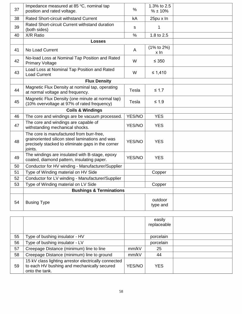
58
37 Impedance measured at 85 oC, nominal tap position and rated voltage. %
1.3% to 2.5 % ± 10%
38 Rated Short-circuit withstand Current kA 25pu x In
39 Rated Short-circuit Current withstand duration (both sides)
s 1
40 X/R Ratio % 1.8 to 2.5
Losses
41 No Load Current A (1% to 2%)
x In
42 No-load Loss at Nominal Tap Position and Rated Primary Voltage W ≤ 350
43 Load Loss at Nominal Tap Position and Rated Load Current W ≤ 1,410
Flux Density
44 Magnetic Flux Density at nominal tap, operating at normal voltage and frequency. Tesla ≤ 1.7
45 Magnetic Flux Density (one minute at normal tap) (10% overvoltage at 97% of rated frequency) Tesla ≤ 1.9
Coils & Windings
46 The core and windings are be vacuum processed. YES/NO YES
47 The core and windings are capable of withstanding mechanical shocks. YES/NO YES
48
The core is manufactured from burr-free, grainoriented silicon steel laminations and was precisely stacked to eliminate gaps in the corner joints.
YES/NO YES
49 The windings are insulated with B-stage, epoxy coated, diamond pattern, insulating paper. YES/NO YES
50 Conductor for HV winding - Manufacturer/Supplier
51 Type of Winding material on HV Side Copper
52 Conductor for LV winding - Manufacturer/Supplier
53 Type of Winding material on LV Side Copper
Bushings & Terminations
54 Busing Type outdoor type and
easily replaceable
55 Type of bushing insulator - HV porcelain
56 Type of bushing insulator - LV porcelain
57 Creepage Distance (minimum) line to line mm/kV 25
58 Creepage Distance (minimum) line to ground mm/kV 44
59 15 kV class lighting arrestor electrically connected to each HV bushing and mechanically secured onto the tank.
YES/NO YES
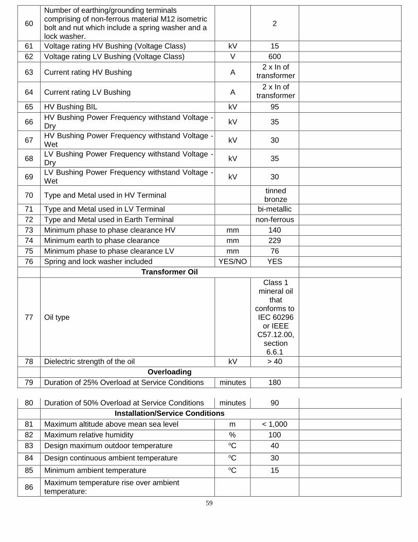
59
60
Number of earthing/grounding terminals comprising of non-ferrous material M12 isometric bolt and nut which include a spring washer and a lock washer.
2
61 Voltage rating HV Bushing (Voltage Class) kV 15
62 Voltage rating LV Bushing (Voltage Class) V 600
63 Current rating HV Bushing A 2 x In of
transformer
64 Current rating LV Bushing A 2 x In of
transformer
65 HV Bushing BIL kV 95
66 HV Bushing Power Frequency withstand Voltage - Dry
kV 35
67 HV Bushing Power Frequency withstand Voltage - Wet
kV 30
68 LV Bushing Power Frequency withstand Voltage - Dry
kV 35
69 LV Bushing Power Frequency withstand Voltage - Wet
kV 30
70 Type and Metal used in HV Terminal tinned bronze
71 Type and Metal used in LV Terminal bi-metallic
72 Type and Metal used in Earth Terminal non-ferrous
73 Minimum phase to phase clearance HV mm 140
74 Minimum earth to phase clearance mm 229
75 Minimum phase to phase clearance LV mm 76
76 Spring and lock washer included YES/NO YES
Transformer Oil
77 Oil type
Class 1 mineral oil
that conforms to IEC 60296
or IEEE C57.12.00,
section 6.6.1
78 Dielectric strength of the oil kV > 40
Overloading
79 Duration of 25% Overload at Service Conditions minutes 180
80 Duration of 50% Overload at Service Conditions minutes 90
Installation/Service Conditions
81 Maximum altitude above mean sea level m < 1,000
82 Maximum relative humidity % 100
83 Design maximum outdoor temperature oC 40
84 Design continuous ambient temperature oC 30
85 Minimum ambient temperature oC 15
86 Maximum temperature rise over ambient temperature:
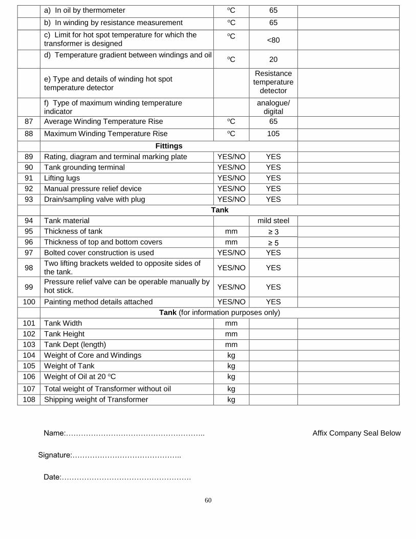
60
a) In oil by thermometer oC 65
b) In winding by resistance measurement oC 65
c) Limit for hot spot temperature for which the transformer is designed
oC
<80
d) Temperature gradient between windings and oil oC 20
e) Type and details of winding hot spot temperature detector
Resistance temperature
detector
f) Type of maximum winding temperature indicator
analogue/
digital
87 Average Winding Temperature Rise oC 65
88 Maximum Winding Temperature Rise oC 105
Fittings
89 Rating, diagram and terminal marking plate YES/NO YES
90 Tank grounding terminal YES/NO YES
91 Lifting lugs YES/NO YES
92 Manual pressure relief device YES/NO YES
93 Drain/sampling valve with plug YES/NO YES
Tank
94 Tank material mild steel
95 Thickness of tank mm ≥ 5
96 Thickness of top and bottom covers mm
97 Bolted cover construction is used YES/NO YES
98 Two lifting brackets welded to opposite sides of the tank.
YES/NO YES
99 Pressure relief valve can be operable manually by hot stick. YES/NO YES
100 Painting method details attached YES/NO YES
Tank (for information purposes only)
101 Tank Width mm
102 Tank Height mm
103 Tank Dept (length) mm
104 Weight of Core and Windings kg
105 Weight of Tank kg
106 Weight of Oil at 20 oC kg
107 Total weight of Transformer without oil kg
108 Shipping weight of Transformer kg
Name:……………………………………………….. Affix Company Seal Below
Signature:……………………………………..
Date:…………………………………………….
61
End of Technical Specification For Pole Mount Transformers
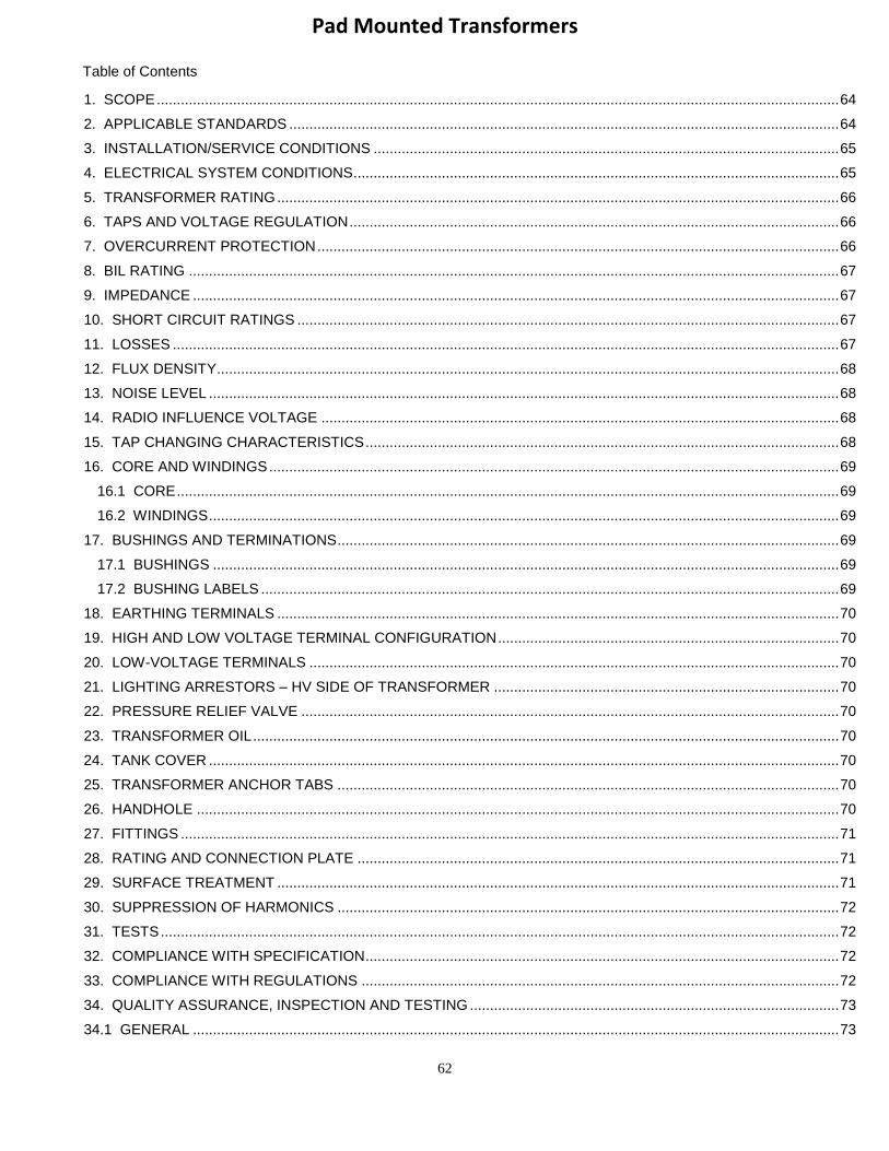
62
Pad Mounted Transformers
Table of Contents
1. SCOPE .......................................................................................................................................................................... 64
2. APPLICABLE STANDARDS ......................................................................................................................................... 64
3. INSTALLATION/SERVICE CONDITIONS .................................................................................................................... 65
4. ELECTRICAL SYSTEM CONDITIONS ......................................................................................................................... 65
5. TRANSFORMER RATING ............................................................................................................................................ 66
6. TAPS AND VOLTAGE REGULATION .......................................................................................................................... 66
7. OVERCURRENT PROTECTION .................................................................................................................................. 66
8. BIL RATING .................................................................................................................................................................. 67
9. IMPEDANCE ................................................................................................................................................................. 67
10. SHORT CIRCUIT RATINGS ....................................................................................................................................... 67
11. LOSSES ...................................................................................................................................................................... 67
12. FLUX DENSITY ........................................................................................................................................................... 68
13. NOISE LEVEL ............................................................................................................................................................. 68
14. RADIO INFLUENCE VOLTAGE ................................................................................................................................. 68
15. TAP CHANGING CHARACTERISTICS ...................................................................................................................... 68
16. CORE AND WINDINGS .............................................................................................................................................. 69
16.1 CORE ..................................................................................................................................................................... 69
16.2 WINDINGS ............................................................................................................................................................. 69
17. BUSHINGS AND TERMINATIONS ............................................................................................................................. 69
17.1 BUSHINGS ............................................................................................................................................................ 69
17.2 BUSHING LABELS ................................................................................................................................................ 69
18. EARTHING TERMINALS ............................................................................................................................................ 70
19. HIGH AND LOW VOLTAGE TERMINAL CONFIGURATION ..................................................................................... 70
20. LOW-VOLTAGE TERMINALS .................................................................................................................................... 70
21. LIGHTING ARRESTORS – HV SIDE OF TRANSFORMER ...................................................................................... 70
22. PRESSURE RELIEF VALVE ...................................................................................................................................... 70
23. TRANSFORMER OIL .................................................................................................................................................. 70
24. TANK COVER ............................................................................................................................................................. 70
25. TRANSFORMER ANCHOR TABS ............................................................................................................................. 70
26. HANDHOLE ................................................................................................................................................................ 70
27. FITTINGS .................................................................................................................................................................... 71
28. RATING AND CONNECTION PLATE ........................................................................................................................ 71
29. SURFACE TREATMENT ............................................................................................................................................ 71
30. SUPPRESSION OF HARMONICS ............................................................................................................................. 72
31. TESTS ......................................................................................................................................................................... 72
32. COMPLIANCE WITH SPECIFICATION ...................................................................................................................... 72
33. COMPLIANCE WITH REGULATIONS ....................................................................................................................... 72
34. QUALITY ASSURANCE, INSPECTION AND TESTING ............................................................................................ 73
34.1 GENERAL ................................................................................................................................................................. 73
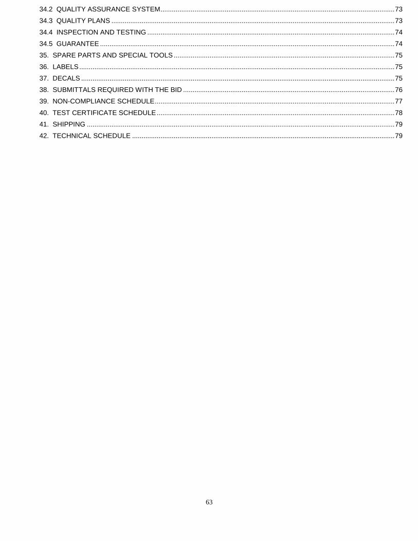
63
34.2 QUALITY ASSURANCE SYSTEM ............................................................................................................................ 73
34.3 QUALITY PLANS ...................................................................................................................................................... 73
34.4 INSPECTION AND TESTING ................................................................................................................................... 74
34.5 GUARANTEE ............................................................................................................................................................ 74
35. SPARE PARTS AND SPECIAL TOOLS ..................................................................................................................... 75
36. LABELS ....................................................................................................................................................................... 75
37. DECALS ...................................................................................................................................................................... 75
38. SUBMITTALS REQUIRED WITH THE BID ................................................................................................................ 76
39. NON-COMPLIANCE SCHEDULE ............................................................................................................................... 77
40. TEST CERTIFICATE SCHEDULE .............................................................................................................................. 78
41. SHIPPING ................................................................................................................................................................... 79
42. TECHNICAL SCHEDULE ........................................................................................................................................... 79
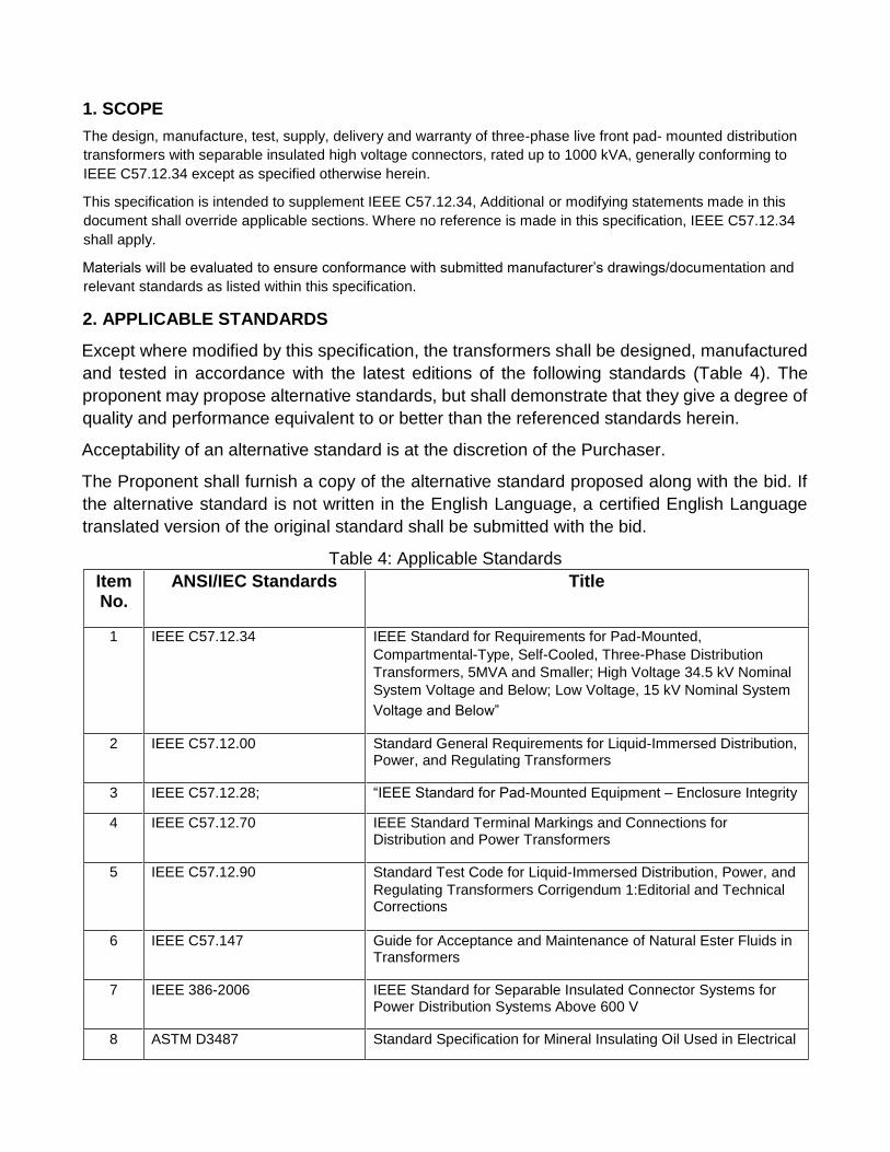
1. SCOPE
The design, manufacture, test, supply, delivery and warranty of three-phase live front pad- mounted distribution
transformers with separable insulated high voltage connectors, rated up to 1000 kVA, generally conforming to
IEEE C57.12.34 except as specified otherwise herein.
This specification is intended to supplement IEEE C57.12.34, Additional or modifying statements made in this
document shall override applicable sections. Where no reference is made in this specification, IEEE C57.12.34
shall apply.
Materials will be evaluated to ensure conformance with submitted manufacturer’s drawings/documentation and
relevant standards as listed within this specification.
2. APPLICABLE STANDARDS
Except where modified by this specification, the transformers shall be designed, manufactured
and tested in accordance with the latest editions of the following standards (Table 4). The
proponent may propose alternative standards, but shall demonstrate that they give a degree of
quality and performance equivalent to or better than the referenced standards herein.
Acceptability of an alternative standard is at the discretion of the Purchaser.
The Proponent shall furnish a copy of the alternative standard proposed along with the bid. If
the alternative standard is not written in the English Language, a certified English Language
translated version of the original standard shall be submitted with the bid.
Table 4: Applicable Standards
Item No.
ANSI/IEC Standards Title
1 IEEE C57.12.34 IEEE Standard for Requirements for Pad-Mounted, Compartmental-Type, Self-Cooled, Three-Phase Distribution Transformers, 5MVA and Smaller; High Voltage 34.5 kV Nominal System Voltage and Below; Low Voltage, 15 kV Nominal System
Voltage and Below”
2 IEEE C57.12.00 Standard General Requirements for Liquid-Immersed Distribution, Power, and Regulating Transformers
3 IEEE C57.12.28; “IEEE Standard for Pad-Mounted Equipment – Enclosure Integrity
4 IEEE C57.12.70 IEEE Standard Terminal Markings and Connections for Distribution and Power Transformers
5 IEEE C57.12.90 Standard Test Code for Liquid-Immersed Distribution, Power, and Regulating Transformers Corrigendum 1:Editorial and Technical Corrections
6 IEEE C57.147 Guide for Acceptance and Maintenance of Natural Ester Fluids in Transformers
7 IEEE 386-2006 IEEE Standard for Separable Insulated Connector Systems for Power Distribution Systems Above 600 V
8 ASTM D3487 Standard Specification for Mineral Insulating Oil Used in Electrical
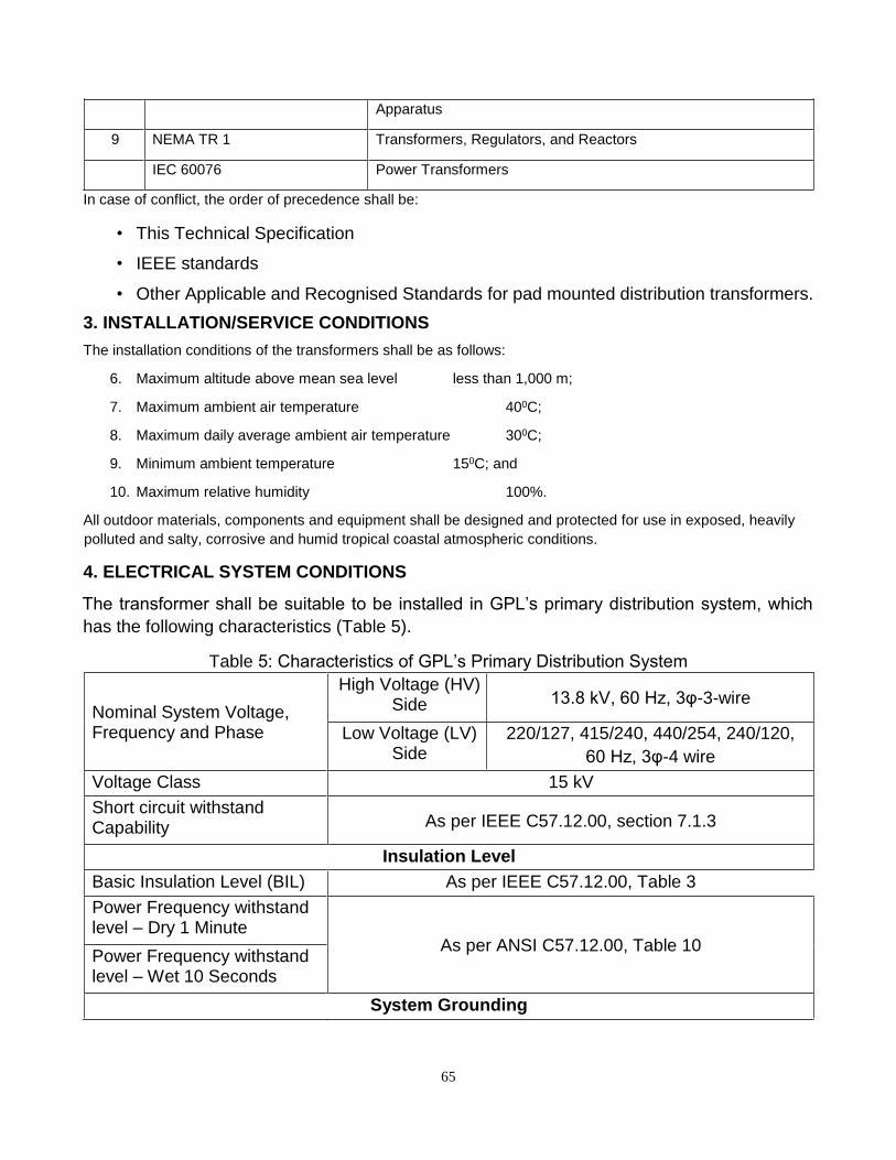
65
Apparatus
9 NEMA TR 1 Transformers, Regulators, and Reactors
IEC 60076 Power Transformers
In case of conflict, the order of precedence shall be:
• This Technical Specification
• IEEE standards
• Other Applicable and Recognised Standards for pad mounted distribution transformers.
3. INSTALLATION/SERVICE CONDITIONS
The installation conditions of the transformers shall be as follows:
6. Maximum altitude above mean sea level less than 1,000 m;
7. Maximum ambient air temperature 400C;
8. Maximum daily average ambient air temperature 300C;
9. Minimum ambient temperature 150C; and
10. Maximum relative humidity 100%.
All outdoor materials, components and equipment shall be designed and protected for use in exposed, heavily
polluted and salty, corrosive and humid tropical coastal atmospheric conditions.
4. ELECTRICAL SYSTEM CONDITIONS
The transformer shall be suitable to be installed in GPL’s primary distribution system, which
has the following characteristics (Table 5).
Table 5: Characteristics of GPL’s Primary Distribution System
Nominal System Voltage, Frequency and Phase
High Voltage (HV) Side 13.8 kV, 60 Hz, 3φ-3-wire
Low Voltage (LV) Side
220/127, 415/240, 440/254, 240/120,
60 Hz, 3φ-4 wire
Voltage Class 15 kV
Short circuit withstand Capability As per IEEE C57.12.00, section 7.1.3
Insulation Level
Basic Insulation Level (BIL) As per IEEE C57.12.00, Table 3
Power Frequency withstand level – Dry 1 Minute
As per ANSI C57.12.00, Table 10 Power Frequency withstand level – Wet 10 Seconds
System Grounding
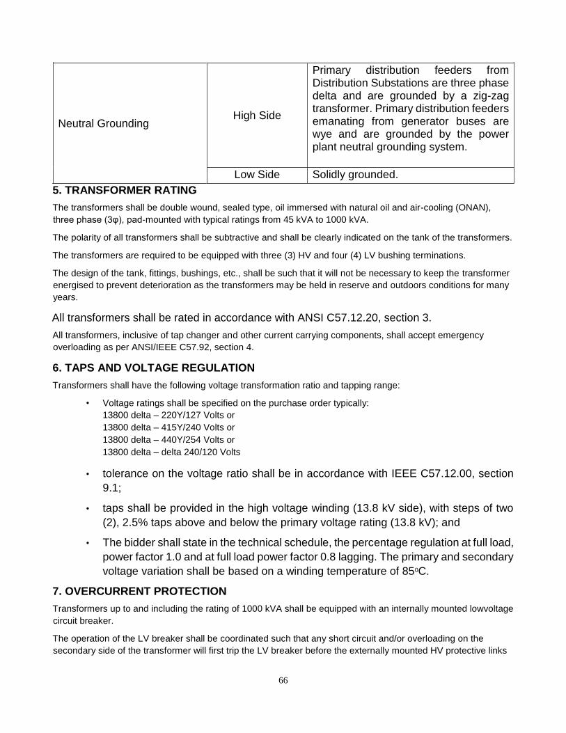
66
Neutral Grounding High Side
Primary distribution feeders from Distribution Substations are three phase delta and are grounded by a zig-zag transformer. Primary distribution feeders emanating from generator buses are wye and are grounded by the power plant neutral grounding system.
Low Side Solidly grounded.
5. TRANSFORMER RATING
The transformers shall be double wound, sealed type, oil immersed with natural oil and air-cooling (ONAN),
three phase (3φ), pad-mounted with typical ratings from 45 kVA to 1000 kVA.
The polarity of all transformers shall be subtractive and shall be clearly indicated on the tank of the transformers.
The transformers are required to be equipped with three (3) HV and four (4) LV bushing terminations.
The design of the tank, fittings, bushings, etc., shall be such that it will not be necessary to keep the transformer
energised to prevent deterioration as the transformers may be held in reserve and outdoors conditions for many
years.
All transformers shall be rated in accordance with ANSI C57.12.20, section 3.
All transformers, inclusive of tap changer and other current carrying components, shall accept emergency
overloading as per ANSI/IEEE C57.92, section 4.
6. TAPS AND VOLTAGE REGULATION
Transformers shall have the following voltage transformation ratio and tapping range:
• Voltage ratings shall be specified on the purchase order typically: 13800 delta – 220Y/127 Volts or 13800 delta – 415Y/240 Volts or 13800 delta – 440Y/254 Volts or 13800 delta – delta 240/120 Volts
• tolerance on the voltage ratio shall be in accordance with IEEE C57.12.00, section
9.1;
• taps shall be provided in the high voltage winding (13.8 kV side), with steps of two
(2), 2.5% taps above and below the primary voltage rating (13.8 kV); and
• The bidder shall state in the technical schedule, the percentage regulation at full load,
power factor 1.0 and at full load power factor 0.8 lagging. The primary and secondary
voltage variation shall be based on a winding temperature of 850C.
7. OVERCURRENT PROTECTION
Transformers up to and including the rating of 1000 kVA shall be equipped with an internally mounted lowvoltage
circuit breaker.
The operation of the LV breaker shall be coordinated such that any short circuit and/or overloading on the
secondary side of the transformer will first trip the LV breaker before the externally mounted HV protective links
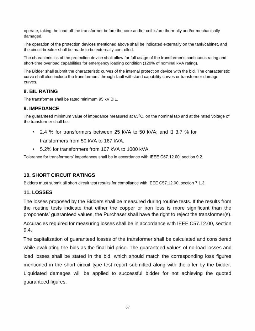
67
operate, taking the load off the transformer before the core and/or coil is/are thermally and/or mechanically
damaged.
The operation of the protection devices mentioned above shall be indicated externally on the tank/cabinet, and
the circuit breaker shall be made to be externally controlled.
The characteristics of the protection device shall allow for full usage of the transformer’s continuous rating and
short-time overload capabilities for emergency loading condition (120% of nominal kVA rating).
The Bidder shall submit the characteristic curves of the internal protection device with the bid. The characteristic
curve shall also include the transformers’ through-fault withstand capability curves or transformer damage
curves.
8. BIL RATING
The transformer shall be rated minimum 95 kV BIL.
9. IMPEDANCE
The guaranteed minimum value of impedance measured at 650C, on the nominal tap and at the rated voltage of
the transformer shall be:
• 2.4 % for transformers between 25 kVA to 50 kVA; and 3.7 % for
transformers from 50 kVA to 167 kVA.
• 5.2% for transformers from 167 kVA to 1000 kVA.
Tolerance for transformers’ impedances shall be in accordance with IEEE C57.12.00, section 9.2.
10. SHORT CIRCUIT RATINGS
Bidders must submit all short circuit test results for compliance with IEEE C57.12.00, section 7.1.3.
11. LOSSES
The losses proposed by the Bidders shall be measured during routine tests. If the results from
the routine tests indicate that either the copper or iron loss is more significant than the
proponents’ guaranteed values, the Purchaser shall have the right to reject the transformer(s).
Accuracies required for measuring losses shall be in accordance with IEEE C57.12.00, section
9.4.
The capitalization of guaranteed losses of the transformer shall be calculated and considered
while evaluating the bids as the final bid price. The guaranteed values of no-load losses and
load losses shall be stated in the bid, which should match the corresponding loss figures
mentioned in the short circuit type test report submitted along with the offer by the bidder.
Liquidated damages will be applied to successful bidder for not achieving the quoted
guaranteed figures.
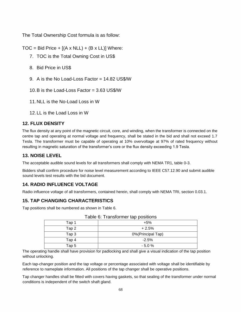
68
The Total Ownership Cost formula is as follow:
TOC = Bid Price + [(A x NLL) + (B x LL)] Where:
7. TOC is the Total Owning Cost in US$
8. Bid Price in US$
9. A is the No Load-Loss Factor = 14.82 US$/W
10. B is the Load-Loss Factor = 3.63 US$/W
11. NLL is the No-Load Loss in W
12. LL is the Load Loss in W
12. FLUX DENSITY
The flux density at any point of the magnetic circuit, core, and winding, when the transformer is connected on the
centre tap and operating at normal voltage and frequency, shall be stated in the bid and shall not exceed 1.7
Tesla. The transformer must be capable of operating at 10% overvoltage at 97% of rated frequency without
resulting in magnetic saturation of the transformer’s core or the flux density exceeding 1.9 Tesla.
13. NOISE LEVEL
The acceptable audible sound levels for all transformers shall comply with NEMA TR1, table 0-3.
Bidders shall confirm procedure for noise level measurement according to IEEE C57.12.90 and submit audible
sound levels test results with the bid document.
14. RADIO INFLUENCE VOLTAGE
Radio influence voltage of all transformers, contained herein, shall comply with NEMA TRI, section 0.03.1.
15. TAP CHANGING CHARACTERISTICS
Tap positions shall be numbered as shown in Table 6.
Table 6: Transformer tap positions Tap 1 +5%
Tap 2 + 2.5%
Tap 3 0%(Principal Tap)
Tap 4 -2.5%
Tap 5 - 5.0 %
The operating handle shall have provision for padlocking and shall give a visual indication of the tap position
without unlocking.
Each tap-changer position and the tap voltage or percentage associated with voltage shall be identifiable by
reference to nameplate information. All positions of the tap changer shall be operative positions.
Tap changer handles shall be fitted with covers having gaskets, so that sealing of the transformer under normal
conditions is independent of the switch shaft gland.
69
16. CORE AND WINDINGS
The core and windings shall be vacuum processed to ensure maximum penetration of insulating fluid into the
coil insulation system. While under vacuum, the windings will be energized to heat the coils and drive out
moisture, and the transformer will be filled with preheated filtered degassed insulating fluid.
The core and winding shall be capable of withstanding mechanical shocks during transport, installation, and
servicing.
16.1 CORE
The core shall be manufactured from burr-free, grain-oriented silicon steel laminations and shall be precisely
stacked to eliminate gaps in the corner joints.
Provision to the design and construction of the transformer shall be made to prevent movement of the core and
windings, relative to the tank, during transport, installation and short-circuits.
The design shall avoid the presence of pockets, which can prevent complete emptying of the oil in the tank
through its drain plug.
16.2 WINDINGS
The winding conductor shall be of electrolytic copper or aluminium, to give the optimum economic and technical
results of the transformers.
The windings shall be insulated with B-stage, epoxy coated, diamond pattern, insulating paper, which shall be
thermally cured under pressure to ensure proper bonding of conductor and paper, and shall be free from any
other insulating compounds that are liable to soften, ooze out, shrink or collapse, and non-catalytic and
chemically inert in the transformer oil during normal servicing. The windings shall be uniformly insulated, and the
LV neutral points shall be insulated for full line-to-line voltage.
The stacks of windings shall receive adequate shrinkage treatment, and the windings and connections are to be
braced to withstand mechanical shocks during transport, switching, short-circuit or other transient conditions.
17. BUSHINGS AND TERMINATIONS
17.1 BUSHINGS
Bushings shall be of the outdoor type and easily replaceable. Cemented types will not be acceptable. The
bushings shall be sufficiently robust (mechanically) to withstand normal transport and erection hazards.
All bushings shall have a minimum creepage distance of 25 mm/kV for maximum phase-to-phase system
voltage and shall have a continuous rating of 200 % of the transformer capacity rating.
17.2 BUSHING LABELS
HV bushings shall be labelled H1, H2 and H3.
LV bushings shall be labelled X1 to X4 in accordance with IEEE C57.12.70 standards.
Marking letters shall be at least 12 mm (or 1/2 inch) high. The means of marking shall conform to the
requirements of the section on Labels in this specification.
Transformers shall be constructed with either a 5-legged core or a triplex core to mitigate ferro-resonant tank
heating.
The core shall be constructed from high grade, non-aging, cold rolled grain-oriented silicon steel laminations or
superior material.
70
18. EARTHING TERMINALS
All transformers shall be provided with two earthing/grounding terminals comprising an M12 isometric bolt and
nut, which shall be non-ferrous material. It shall include a spring washer and a lock washer.
External connecting strip(s) between earthing/grounding terminal and neutral bushing(s) is/are required.
19. HIGH AND LOW VOLTAGE TERMINAL CONFIGURATION
Transformers shall comply with C57.12.34 Figure 4(a) (staggered arrangement), Figure 1 and Figure 2 for
radialfeed transformers.
20. LOW-VOLTAGE TERMINALS
Terminals shall be constructed per IEEE C57.12.34, Section 8.7.3 with an additional ground pad near the low
voltage.
21. LIGHTING ARRESTORS – HV SIDE OF TRANSFORMER
The lightning arrestors shall be capable of discharging lightning and switching surges and temporary power
frequency over voltages and shall be capable of discharging over voltages occurring during switching of
unloaded transformers and long lines.
The Arrestors shall be capable of withstanding Maximum Continuous Operating Voltages (M.C.O.V) and rate for
operation in 15 kV class distribution system. The reference current of the arrestors shall be of such value to
eliminate the influence of grading and stray capacitance on the measured reference voltages.
These arrestors shall be of Heavy Duty, Station Class / Distribution Class and Gapless Zinc Oxide type and shall
be hermetically sealed units suitable for outdoor installation and mounting on distribution transformers.
Additionally, the arrestors shall be suitable for heavily polluted atmospheric conditions as mentioned in section 3
on page 66.
22. PRESSURE RELIEF VALVE
The pressure relief valve provided as per C57.12.34, 8.9.2, shall include an orange or red indicator that
becomes visible only after the valve has vented. The valve shall be covered by a cap with a pull ring which will
separate from the assembly during venting, revealing the orange or red indicator.
23. TRANSFORMER OIL
The transformers shall be supplied filled with class 1 mineral oil conforming to ASTM D3487. The complete first
filling shall be of new oil free from inhibitors and additives. The dielectric strength of the oil shall not be less than
40kV. If an antioxidant inhibitor is recommended, its use shall be subject to the Purchaser’s approval.
24. TANK COVER
The bidder shall state if other than bolted construction is used.
25. TRANSFORMER ANCHOR TABS
Four tabs shall be provided on the tank for mounting the transformer to the pad.
26. HANDHOLE
The tank shall include a handhole to access internal components for testing. The handhole shall have a cover
that can be unbolted from within the terminal compartments to prevent unauthorized access.
71
27. FITTINGS
The following standard fittings shall be provided:
• rating, diagram, and terminal marking plate;
• tank grounding terminal;
• lifting lugs;
• oil level indicator;
• manual pressure relief device; and drain/sampling valve with plug.
The fittings and accessories listed above are only indicative and any other fittings and accessories according to
the applicable standards herein shall be provided for the transformers.
28. RATING AND CONNECTION PLATE
Each transformer shall be provided with anodized aluminium laser engraved nameplate, in accordance with
IEEE C57.12 - Nameplate A and C as necessary. Additionally, Proponents shall ensure that the following
attributes are indicated on the aforementioned nameplate and conform to the requirements of the section on
Labels in this specification:
• standard to which it is manufactured and tested;
• identification of internal short-circuit and overload protection devices;
• type of cooling (ONAN);
• rated currents in A;
• chopped wave (short time) impulse voltage withstand level in kV;
• power frequency withstand voltage in kV;
• percentage impedance at 850C;
• load loss in kW at rated current;
• no-load loss in kW at rated voltage and frequency;
• continuous ambient temperature at which ratings apply in 0C (40);
• top oil and winding temperature rise at rated load in 0C;
• winding connection diagram;
• total mass (core, windings and oil) in kg;
• mass of core and windings in kg;
• volume of oil in litres;
• Oil with less than 2ppm of PCB; and
• name of the purchaser (Property of Guyana Power & Light Inc.)
29. SURFACE TREATMENT
The transformer tank and all accessories shall be treated in accordance with IEEE C57.31 to ensure enclosure
and equipment integrity.
72
30. SUPPRESSION OF HARMONICS
Each transformer’s core shall be designed with attention to the suppression of harmonic voltages and currents,
as per IEEE Std 519-2014 in Table 1 for bus voltage between 1 kV and 69 kV and Table 2 for current distortion
limits for systems rated 120 V through 69 kV.
Proponents shall submit results for harmonic suppression tests for voltage and current distortions.
31. TESTS
In addition to the routine tests required in IEEE C57.12.00, as per section 8 and Table 18, the following
additional tests shall be carried out on all transformers. The following routine measurements and tests shall be
carried out and results shall be submitted to the Purchaser upon delivery:
j) Measurement of winding resistance at the nominal and extreme tap positions for each
transformer provided;
k) Measurement of impedance;
l) Measurement of no-load loss and no-load currents at full, 90% and 110% voltages;
m) Induced overvoltage withstand test;
n) Separate source voltage withstand tests on HV and LV windings;
o) Magnetic balance test;
p) Polarization Index Test. The index shall be not less than 1.5;
q) Oil leakage test: The criterion of leakage shall be discolouration by oil of whitewash
applied externally to suspected parts at an oil temperature of 900C or other method
approved by the Purchaser;
r) Bushings and oil shall be subject to the following routine tests.
a. bushing routine tests
b. oil dielectric and moisture content test.
Routine test certificates shall include in addition to the test results, the Purchaser's order number, the
transformers’ serial numbers, outline drawing number and transformer kVA rating.
Upon acceptance of Tender, the Manufacturer/Proponent shall provide results of standard design type tests
required in Table 18 of IEEE C57.12.00.
32. COMPLIANCE WITH SPECIFICATION
The transformers shall comply in all respects with the requirements of this specification. However, any
minor departure from the provisions of the specification shall be disclosed at the time of tendering in the
NonCompliance Schedule in this document (see page 78).
33. COMPLIANCE WITH REGULATIONS
All the transformers/equipment shall comply in all respects with the Laws of Guyana Governing the Importation
of Commercial Items and/or Goods.
The equipment and connections shall be designed and arranged to minimize the risk of fire and any damage that
might be caused in the event of a fire.
73
34. QUALITY ASSURANCE, INSPECTION AND TESTING
34.1 GENERAL
To ensure that the supply and services are in accordance with the Specification herein, with the regulations of Guyana and with relevant authorized international standards, the Proponent shall have in place suitable Quality
Assurance Programmes and Procedures to ensure that all activities are being controlled and documented, as
necessary.
The quality assurance arrangements shall conform to the relevant requirements of ISO 9001 or ISO 9002, as
deemed appropriate by the Purchaser and the Proponent.
The systems and procedures that the Proponent will use to ensure that the supply complies with the
specified requirements, shall be defined in the Proponent’s Quality Plan. The Proponent shall operate
systems that implement the following:
Hold Point “A stage in the material procurement or workmanship process beyond which work shall not proceed
without the documented approval of designated individuals or organisations.”
The Purchaser's written approval is required to authorise work to progress beyond the Hold Points indicated in
approved Quality Plans.
Notification Point “A stage in material procurement or workmanship process for which advance notice of
the activity is required to facilitate witness.”
If the Purchaser's representative does not attend after receiving documented notification in accordance with the
agreed procedures and with the correct period of notice, then work may proceed.
34.2 QUALITY ASSURANCE SYSTEM
Unless the Proponent’s Quality Assurance System has been audited and approved by the Purchaser, a Quality
Assurance System shall be submitted to the Purchaser for approval within a minimum of One (1) month from the
placement of order, or such other period as shall be agreed with the Purchaser. The Quality Assurance System
shall provide a description of the Quality Control System for the supply and shall, unless advised otherwise, shall
include, but not limited to the following details:
8. The structure of the organisation;
9. The duties and responsibilities assigned to staff to ensure quality of work;
10. The system for purchasing, taking delivery and verification of the specifications of raw materials;
11. The system for ensuring the quality of workmanship
12. The system for control of documentation;
13. The system for the retention of records; and
14. The arrangement for the Proponent’s internal auditing.
34.3 QUALITY PLANS
The Quality Plans shall set out the activities in a logical sequence and, unless advised otherwise, shall include,
but limited to the following:
9. An outline of the proposed programme sequence;
74
10. The duties and responsibilities assigned to staff ensuring the quality of work;
11. Hold and notification points;
12. Submission of engineering documents required by the specification;
13. The inspection of materials and components on receipt;
14. Reference to the Supplier’s procedures appropriate to each activity;
15. Inspection during fabrication and assembly; and
16. Final inspection and test.
34.4 INSPECTION AND TESTING
The Purchaser shall have free entry at all times, while work on the order is being performed, to all parts of the
manufacturer's working area which are in relation to the processing of the transformers ordered. The
Manufacturer/Proponent shall afford the Purchaser without charge, all reasonable facilities to assure that the
transformers being furnished are in accordance with the specifications herein.
The equipment shall have successfully passed all tests as described in Section 26 (see page 18).
The Purchaser reserves the right to reject an item of the transformer if the test results do not comply with the
values specified herein.
Tests, including any retests required, shall be carried out by the Supplier at no extra charge, at the
manufacturer's works.
Full details of the proposed methods of testing, including connection diagrams, shall be submitted to the
Purchaser by the Supplier for approval, at least one month before testing.
All costs in connection with the testing, including any necessary re-testing, shall be borne by the
Manufacturer/Proponent.
Any cost incurred by the Purchaser in connection with inspection and re-testing as a result of the failure of the
transformer or any of its components under test or damage during transport or offloading shall be to the account
of the Proponent.
The Proponent shall submit to the Purchaser three signed copies of the test certificates, giving the results of the
tests as required. No materials shall be dispatched until the test certificates have been received by the
Purchaser and the Proponent has been informed that they are acceptable.
The test certificates must show the actual values obtained from the tests, in the units used in this specification,
and not merely confirm that the requirements have been met.
No inspection or lack of inspection or approval by the Purchaser’s Representative of equipment or materials
whether supplied by the Proponent or a Sub-Proponent, shall relieve the Proponent from his/her liability to
complete the contracted works in accordance with the contract would exonerate him/her from any of his/her
guarantees.
34.5 GUARANTEE
The Proponent shall guarantee the following:
• Quality and strength of materials used;
75
• Satisfactory operation during the guarantee period of one (1) year from the date of
commissioning, or 18 months from the date of acceptance of the equipment by the
Purchaser following delivery, whichever is the earlier. The Purchaser shall advise the
Proponent of the date of commissioning;
• Performance figures as supplied by the Proponent in the Technical Data Schedule, the
guaranteed copper and iron losses and other particulars;
• The offered surface treatment shall protect the treated metal from corrosion for a period
of not less than ten (10) years from the date of delivery.
35. SPARE PARTS AND SPECIAL TOOLS
The Proponent shall provide a list of recommended spare parts and their individual prices and shall include HV
and LV bushings and bi-metallic connectors for HV and LV bushings. This list shall identify all essential spares
and consumable items for any recommended maintenance for a period of five (5) years after commissioning.
The Purchaser may order all or any of the spares parts listed at the time of placement of order.
A spare parts catalogue with price list shall be provided and this shall form part of the drawings and literature to
be supplied with the bid.
The Proponent shall give an assurance that spare parts and consumables will continue to be available through
the life span of the equipment/transformers, which shall be 25 years minimum. However, the Proponent shall
give a minimum of 12 months’ notice to the Purchaser, in the event that the Proponent or any Sub-supplier, plan
to discontinue manufacturing of any component used in the transformers.
Any spare apparatus, parts or tools shall be subjected to the same specification herein, tests and conditions as
similar main material supplied. They shall be strictly interchangeable and suitable for use in place of the
corresponding parts supplied with the transformer and must be suitably marked and numbered for identification.
Spare parts shall be delivered suitably packaged and treated for long periods in storage. Each package shall be
clearly and indelibly marked with its contents, including a designation number corresponding to the spare parts
lists in the operation and maintenance instructions.
36. LABELS
All apparatus shall be clearly labelled indicating, where necessary, its purpose and service positions.
The material of all labels and plates, their dimensions, legend and the method of printing shall be subject to the
approval of the Purchaser.
Colours shall be permanent and free from fading. All labels and plates for outdoor use shall be of non-corrosive
material.
They shall be engraved in English. Nameplates shall carry all the applicable information specified in the
applicable items of the Standards and other details as required in this specification. No scratching, corrections or
changes will be allowed on nameplates.
Wherever possible the equipment shall carry the markings "THIS EQUIPMENT IS PROPERTY OF GPL Inc.".
37. DECALS
“Danger do not open” decal on exterior transformer doors
76
“Danger do not touch” decal on interior transformer doors
Typical decals shown in Appendix A.
38. SUBMITTALS REQUIRED WITH THE BID
The following shall are required in duplicate of three (3) copies:
9. completed technical data schedule for each type and rating of the transformer;
10. descriptive literature giving full technical details of equipment offered;
11. Outline dimension drawings for each major component, general arrangement drawing
showing component layout and general schematic diagrams;
12. type test certificates, where available, and sample routine test reports for each type and
rating of the transformer;
13. summary reference list of customers already using equipment offered during the last 5
years with particular emphasis on units of similar design and rating;
14. details of manufacturer's quality assurance standards and programme and ISO 9000
series or equivalent national certification;
15. deviations from this specification. Only deviations approved in writing before placement
of order shall be accepted; and
16. list of recommended spare parts and consumable items for five years of operation with
prices and spare parts catalogue with price list for future requirements.

39. NON-COMPLIANCE SCHEDULE
On this schedule, the Proponent shall provide a list of non-compliance with this specification, documenting the
effects that such non-compliance is likely to have on the transformer/equipment/component life span and
operating characteristics. Each non-compliance shall be referred to the relevant specification clause.
Clause No. Non-Compliance

78
40. TEST CERTIFICATE SCHEDULE
On this schedule, a list of the test certificates shall be included with the bid. This list shall include the certificates
for the type tests (see page Error! Bookmark not defined.) and sample routine test reports. Each certificate
listed shall be referred to the relevant specification clause.
Clause No. Type Test Certificate or Routine Test Report
79
41. SHIPPING
The Manufacturer/Proponent shall prepare the transformers for shipping in such a manner as to protect from
them from damage or deterioration during shipping and storage, and shall be responsible for, and make good,
any and all damage due to improper preparation for loading, shipment, and storage.
All transformers shall be shipped on open sided trucks or trailers, in such a manner as to facilitate off-loading,
handling and storage.
The transformers shall be shipped securely banded with a steel strap or approved synthetic strap to a pallet. The pallet shall be constructed to accept two fixed 195 mm forks spaced either 65mm or 320 mm apart. At least
90 mm clearance shall be provided under each transformer pallet and the bottom of the pallet must not be fully
covered in order to facilitate the use of pallet jacks.
42. TECHNICAL SCHEDULE
Below is a sample of the Technical Schedule that is applied to each transformer separately. Proponents must
complete this schedule for each transformer to be considered for evaluation. Failure to complete this schedule
will result in bid disqualification.
Please see the attached spreadsheet with the technical criteria for each capacity and voltage requirement.
End of Technical Specification for Pad Mounted Transformers
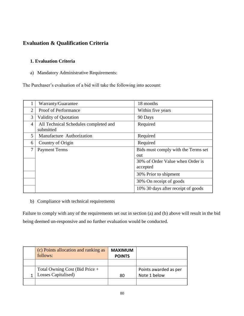
80
Evaluation & Qualification Criteria
1. Evaluation Criteria
a) Mandatory Administrative Requirements:
The Purchaser’s evaluation of a bid will take the following into account:
1 Warranty/Guarantee 18 months
2 Proof of Performance Within five years
3 Validity of Quotation 90 Days
4 All Technical Schedules completed and
submitted
Required
5 Manufacture Authorization Required
6 Country of Origin Required
7 Payment Terms Bids must comply with the Terms set
out
30% of Order Value when Order is
accepted
30% Prior to shipment
30% On receipt of goods
10% 30 days after receipt of goods
b) Compliance with technical requirements
Failure to comply with any of the requirements set out in section (a) and (b) above will result in the bid
being deemed un-responsive and no further evaluation would be conducted.
(c) Points allocation and ranking as
follows: MAXIMUM
POINTS
1
Total Owning Cost (Bid Price +
Losses Capitalised) 80
Points awarded as per Note 1 below
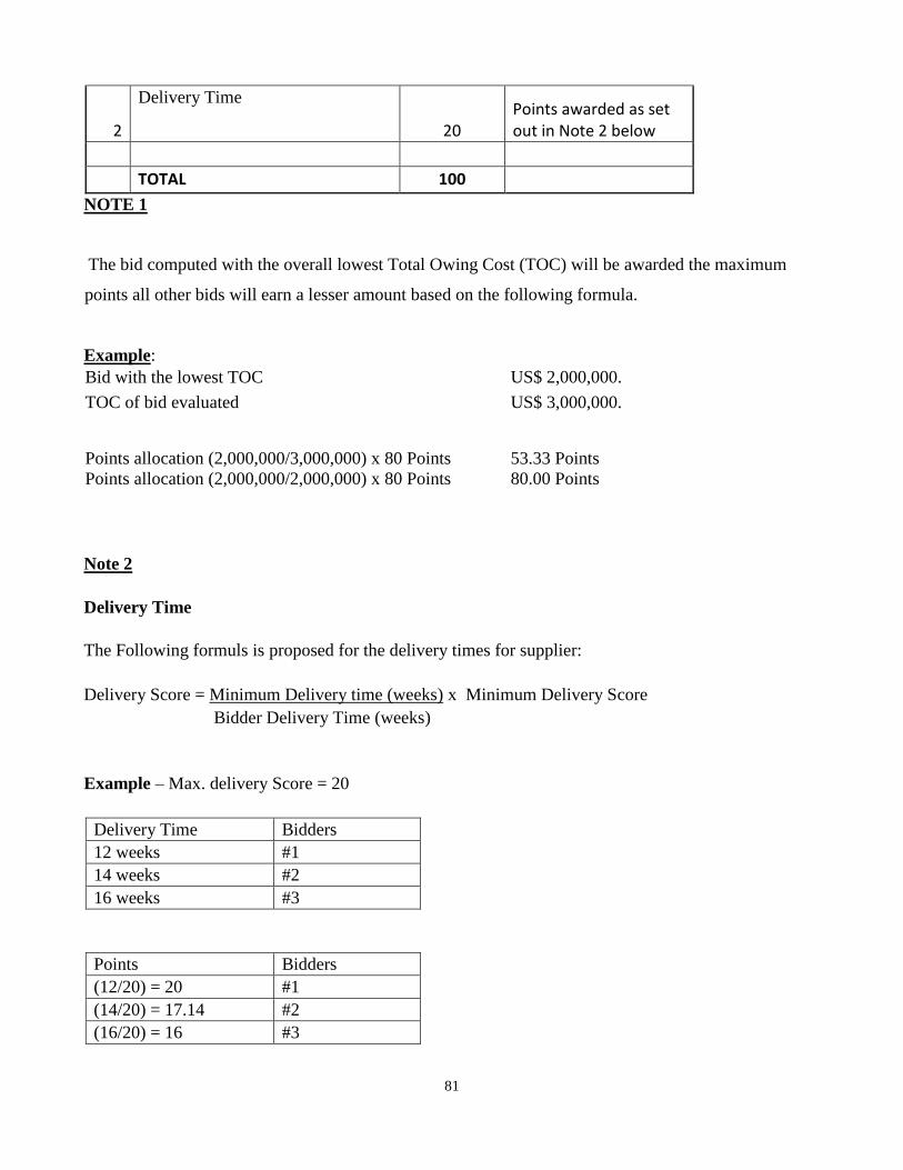
81
2
Delivery Time
20 Points awarded as set out in Note 2 below
TOTAL 100
NOTE 1
The bid computed with the overall lowest Total Owing Cost (TOC) will be awarded the maximum
points all other bids will earn a lesser amount based on the following formula.
Example:
Bid with the lowest TOC US$ 2,000,000.
TOC of bid evaluated
US$ 3,000,000.
Points allocation (2,000,000/3,000,000) x 80 Points 53.33 Points
Points allocation (2,000,000/2,000,000) x 80 Points 80.00 Points
Note 2
Delivery Time
The Following formuls is proposed for the delivery times for supplier:
Delivery Score = Minimum Delivery time (weeks) x Minimum Delivery Score
Bidder Delivery Time (weeks)
Example – Max. delivery Score = 20
Delivery Time Bidders
12 weeks #1
14 weeks #2
16 weeks #3
Points Bidders
(12/20) = 20 #1
(14/20) = 17.14 #2
(16/20) = 16 #3
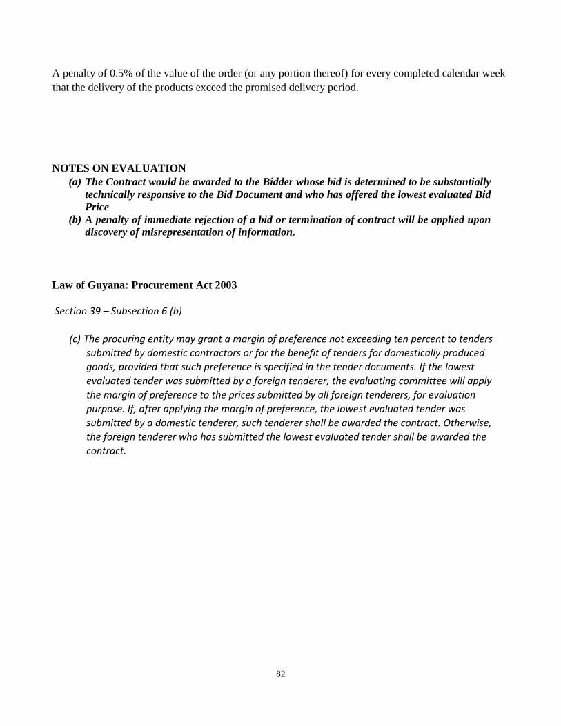
82
A penalty of 0.5% of the value of the order (or any portion thereof) for every completed calendar week
that the delivery of the products exceed the promised delivery period.
NOTES ON EVALUATION
(a) The Contract would be awarded to the Bidder whose bid is determined to be substantially
technically responsive to the Bid Document and who has offered the lowest evaluated Bid
Price
(b) A penalty of immediate rejection of a bid or termination of contract will be applied upon
discovery of misrepresentation of information.
Law of Guyana: Procurement Act 2003
Section 39 – Subsection 6 (b)
(c) The procuring entity may grant a margin of preference not exceeding ten percent to tenders
submitted by domestic contractors or for the benefit of tenders for domestically produced
goods, provided that such preference is specified in the tender documents. If the lowest
evaluated tender was submitted by a foreign tenderer, the evaluating committee will apply
the margin of preference to the prices submitted by all foreign tenderers, for evaluation
purpose. If, after applying the margin of preference, the lowest evaluated tender was
submitted by a domestic tenderer, such tenderer shall be awarded the contract. Otherwise,
the foreign tenderer who has submitted the lowest evaluated tender shall be awarded the
contract.