guidelines for rescue services trucks · the new actros (model 963) with slk-class (model 172) the...
TRANSCRIPT
Guidelines for Rescue ServicesTrucks
Daimler AG, GSP/OI, HPC R 822, D-70546 StuttgartPrinted in Germany – 01/12 Gu
idel
ines
for R
escu
e Ser
vice
s •
Tru
cks

Mercedes-Benz Service
Daimler AG · Technical Information and Workshop Equipment (GSP/OI) · D-70546 Stuttgart, Germany
Guidelines for Rescue ServicesTrucks
2012 Edition

Information and copyright
Product Portfolio
Comprehensive information about our full Product Portfolio can also be found at our Internet Portal: Link: http://aftersales.mercedes-benz.com
Questions and suggestions
If you have any questions or suggestions concerning this product, please write to us. E-mail: [email protected] Fax: +49-(0)18 05/0 10-79 78
or alternatively Address: Daimler AG
GSP/OIS HPC R822, W002 D-70546 Stuttgart, Germany
© 2012 by Daimler AG
This document, including all its parts, is protected by copyright. Any further processing or use requires the previous written consent of Daimler AG, Department GSP/OIS, HPC R822, W002, D-70546 Stuttgart, Germany. This applies in particular to reproduction, distribution, alteration, translation, microfilming and storage and/or processing in electronic systems, including databases and online services.
Image no. of title image: P00.01-3447-00
01/12
Modification notes
3iGuidelines for Rescue Services, Trucks 2012 • Issue Date: January 2012
Changes compared to May 2011 issue
! Observe modification notes
Overview
Dimensions 8
The New Actros (model 963) 13
Fuel tank 20
Disconnecting the vehicle battery 22
Truck accident characteristics
Accident statistics 38
Proper casualty rescue
Air suspension operating unit in the Actros (model 963) 60
Securing the door 68
Removing the door 69
New cutting method 75
Steering wheel adjustment in the Actros (model 963) 88
Driver seat in the Actros (model 963) 91

4 i Guidelines for Rescue Services, Trucks 2012 • Issue Date: January 2012

Contents
5iGuidelines for Rescue Services, Trucks 2012 • Issue Date: January 2012
Preface 7
Overview
Model overview and notes 8
Differences between passenger cars and trucks 18
Fuel tank 20
Disconnecting the vehicle battery 21
Alternative drives/hybrid vehicles 25
Checklist for accidents involving hybrid vehicles 34
GGVS vehicles (hazardous goods vehicles) 35
Truck accident characteristics
Truck damage profiles after a rear-end collision 37
The most frequently occurring accidents 38
Casualty injury patterns 40
The golden hour of shock 43
Tactical procedure 44
Contents
6 i Guidelines for Rescue Services, Trucks 2012 • Issue Date: January 2012
Proper casualty rescue
Introduction 48
Initial access 49
Securing the area 51
Stopping the engine 52
Reducing the rescue height 55
Securing the cab 63
Glass handling 64
Securing the door 68
Remove the door 69
Pushing away the front end 71
New cutting method 75
Safety systems 80
Airbag 81
Seat belt/emergency tensioning retractor 85
Steering wheel adjustment 86
Pneumatic lock 87
Seat adjustment 89
Annex
Literature and sources 92
Index 93

Preface
7iGuidelines for Rescue Services, Trucks 2012 • Issue Date: January 2012
Dear Reader,
One of Daimler's top priorities has traditionally been to guarantee the highest possible standards of safety.
And this is especially true for vehicle safety.
Our comprehensive safety concept also extends to providing rescue crews with specific information about our vehicles and their safety systems.
The top priority of the rescue crew is to save lives. The rescue team must be able to gain access to the casualties as quickly as possible without exposing them or themselves to additional danger.
In order to do this, the rescue services must be prop-erly trained. In addition, knowledge of vehicle-specific accessibility options, of the function and operation of the safety systems, and of the special features of trucks is absolutely essential.
We must emphasize that these guidelines cannot claim to be exhaustive and on no account should they, nor are they intended to, act as a substitute for sound specialist training and the relevant specialized litera-ture.
These guidelines are intended to assist the rescue service in the tactical planning of its rescue opera-tions. As every accident is different, the sequence of actions described here may not be suitable for the actual circumstances of the case at hand.
Daimler AG Technical Information and Workshop Equipment (GSP/OI)
8
Ove
rvie
w
i
Model overview and notes
Guidelines for Rescue Services, Trucks 2012 • Issue Date: January 2012
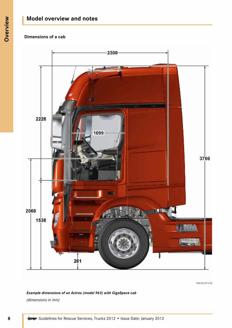
Dimensions of a cab
N00.00-2572-00
Example dimensions of an Actros (model 963) with GigaSpace cab
(dimensions in mm)

Model overview and notes
Ove
rvie
w
9iGuidelines for Rescue Services, Trucks 2012 • Issue Date: January 2012
Special features of trucks
The basic design of all trucks is similar. The basic framework is formed by a so-called ladder-type frame made of high-strength steel profile longitudinal members (must never be cut with hydraulic rescue gear), which are joined to crossmembers. The engine and transmission are installed in the front of this frame and the axles are bolted on. Above the engine is the sprung cab, which is usually mounted on the frame with a 4-point mounting. The cab mounting is designed to allow the cab to be tipped forward in order to service the engine.
The cab is a self-supporting all-steel structure (exception: Econic is an aluminum structure with plastic paneling) and forms a kind of safety cell.
Another option for modern trucks are driver airbags in combination with seat belts and emergency tensioning retractors. The 3-point seat belt is inte-grated in the driver's suspension seat. The suspension seat is fitted with an air suspension system, which enables ergonomic and largely non-tiring sitting. The steering wheel can be adjusted to suit the driver's position, i.e. its height and angle can be adjusted.
Depending on their usage, there are many differences between the vehicles. Long-haul vehicles, usually semitrailer tractors, have bunks behind the seats, for example.
The full air suspension already installed in many vehicles can be utilized to reduce the rescue height to allow proper casualty rescue.
10
Ove
rvie
w
i
Model overview and notes
Guidelines for Rescue Services, Trucks 2012 • Issue Date: January 2012
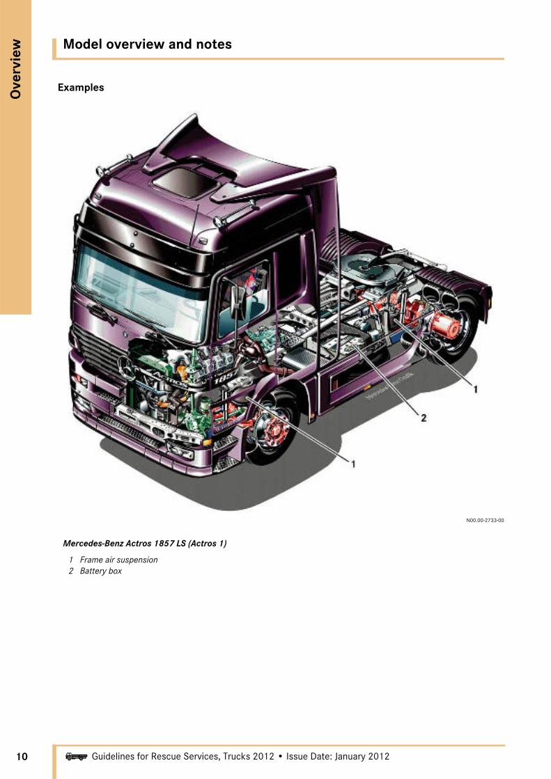
Examples
N00.00-2733-00
Mercedes-Benz Actros 1857 LS (Actros 1)
1 Frame air suspension2 Battery box

Model overview and notes
Ove
rvie
w
11iGuidelines for Rescue Services, Trucks 2012 • Issue Date: January 2012
N00.00-2734-00
Mercedes-Benz Actros 1844 LS (Actros 2)
1 Air springs, cab mounting2 Fuel tank3 Frame air suspension4 Integral rear end

12
Ove
rvie
w
i
Model overview and notes
Guidelines for Rescue Services, Trucks 2012 • Issue Date: January 2012
N00.00-3186-00
Mercedes-Benz Actros 3
Model overview and notes
Ove
rvie
w
13iGuidelines for Rescue Services, Trucks 2012 • Issue Date: January 2012
N00.00-3186-00
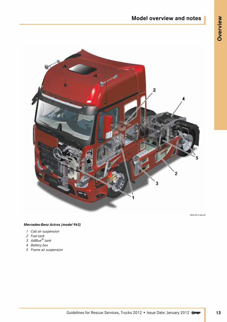
Mercedes-Benz Actros (model 963)
1 Cab air suspension2 Fuel tank3 AdBlue® tank4 Battery box5 Frame air suspension

14
Ove
rvie
w
i
Model overview and notes
Guidelines for Rescue Services, Trucks 2012 • Issue Date: January 2012
N00.00-2735-00
Mercedes-Benz Axor 1
1 Frame air suspension2 Battery box

Model overview and notes
Ove
rvie
w
15iGuidelines for Rescue Services, Trucks 2012 • Issue Date: January 2012
N00.00-3187-00
Mercedes-Benz Axor 2
N00.00-3375-00
Mercedes-Benz Axor 2 (Facelift)

16
Ove
rvie
w
i
Model overview and notes
Guidelines for Rescue Services, Trucks 2012 • Issue Date: January 2012
N00.00-2736-00
Mercedes-Benz Atego 1
1 Air intake2 Batteries
Model overview and notes
Ove
rvie
w
17iGuidelines for Rescue Services, Trucks 2012 • Issue Date: January 2012
N00.00-3188-00
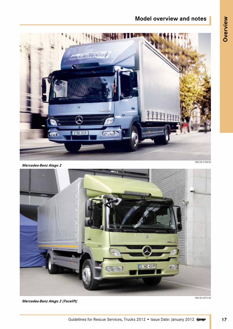
Mercedes-Benz Atego 2
N00.00-3374-00
Mercedes-Benz Atego 2 (Facelift)
18
Ove
rvie
w
i
Differences between passenger cars and trucks
Guidelines for Rescue Services, Trucks 2012 • Issue Date: January 2012
N00.00-2737-00
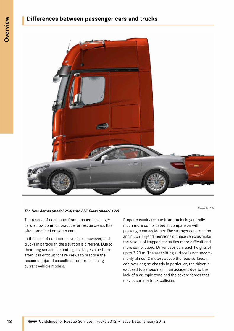
The New Actros (model 963) with SLK-Class (model 172)
The rescue of occupants from crashed passenger cars is now common practice for rescue crews. It is often practiced on scrap cars.
In the case of commercial vehicles, however, and trucks in particular, the situation is different. Due to their long service life and high salvage value there-after, it is difficult for fire crews to practice the rescue of injured casualties from trucks using current vehicle models.
Proper casualty rescue from trucks is generally much more complicated in comparison with passenger car accidents. The stronger construction and much larger dimensions of these vehicles make the rescue of trapped casualties more difficult and more complicated. Driver cabs can reach heights of up to 3.90 m. The seat sitting surface is not uncom-monly almost 2 meters above the road surface. In cab-over-engine chassis in particular, the driver is exposed to serious risk in an accident due to the lack of a crumple zone and the severe forces that may occur in a truck collision.
Differences between passenger cars and trucks
Ove
rvie
w
19iGuidelines for Rescue Services, Trucks 2012 • Issue Date: January 2012
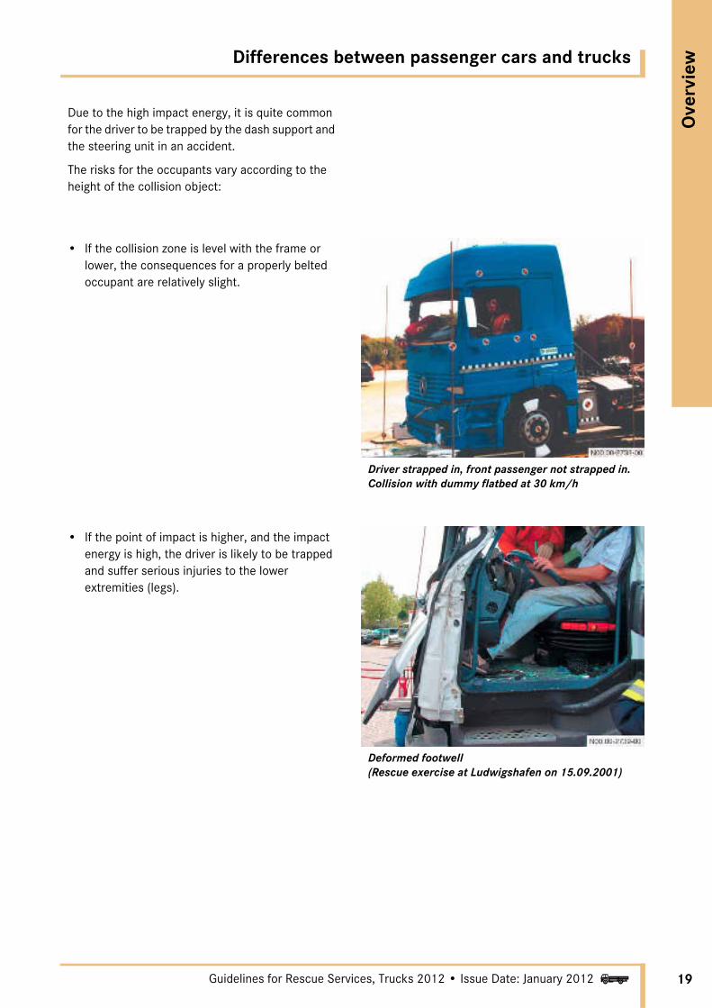
Due to the high impact energy, it is quite common for the driver to be trapped by the dash support and the steering unit in an accident.
The risks for the occupants vary according to the height of the collision object:
• If the collision zone is level with the frame or lower, the consequences for a properly belted occupant are relatively slight.
Driver strapped in, front passenger not strapped in. Collision with dummy flatbed at 30 km/h
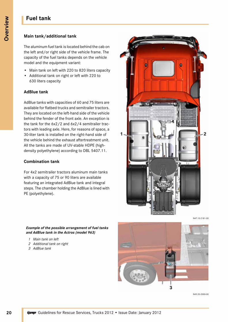
• If the point of impact is higher, and the impact energy is high, the driver is likely to be trapped and suffer serious injuries to the lower extremities (legs).
Deformed footwell (Rescue exercise at Ludwigshafen on 15.09.2001)
20
Ove
rvie
w
i
Fuel tank
Guidelines for Rescue Services, Trucks 2012 • Issue Date: January 2012
Main tank/additional tank
The aluminum fuel tank is located behind the cab on the left and/or right side of the vehicle frame. The capacity of the fuel tanks depends on the vehicle model and the equipment variant:
• Main tank on left with 220 to 820 liters capacity• Additional tank on right or left with 220 to
630 liters capacity
AdBlue tank
AdBlue tanks with capacities of 60 and 75 liters are available for flatbed trucks and semitrailer tractors. They are located on the left-hand side of the vehicle behind the fender of the front axle. An exception is the tank for the 6x2/2 and 6x2/4 semitrailer trac-tors with leading axle. Here, for reasons of space, a 30-liter tank is installed on the right-hand side of the vehicle behind the exhaust aftertreatment unit. All the tanks are made of UV-stable HDPE (high-density polyethylene) according to DBL 5407.11.
Combination tank
For 4x2 semitrailer tractors aluminum main tanks with a capacity of 75 or 90 liters are available featuring an integrated AdBlue tank and integral steps. The chamber holding the AdBlue is lined with PE (polyethylene).
N47.10-2181-00
Example of the possible arrangement of fuel tanks and AdBlue tank in the Actros (model 963)
1 Main tank on left2 Additional tank on right3 AdBlue tank
N49.20-2000-00
Disconnecting the vehicle battery
Ove
rvie
w
21iGuidelines for Rescue Services, Trucks 2012 • Issue Date: January 2012
a DANGER
Battery acid is caustic. Battery acid must not be allowed to come into contact with the skin, eyes or clothing.
Rinse off acid splashes immediately with clean water.
Never bend over batteries when working on them (risk of caustic burns and explosion!)
When handling batteries or battery acid, comply with all safety regulations and precautions (flip down your visor and wear safety glasses and gloves).
a DANGER
A highly explosive gas mixture is produced when batteries are being charged. Therefore there is a risk of explosion if improperly handled!
No fire, sparks, open flames or smoking when handling batteries.
Avoid producing sparks.
Do not place any metal objects on the battery. Otherwise you could cause a short circuit and the highly explosive gas mixture from the battery could ignite.
Do not rub the battery with rags or cloths. An elec-trostatic charge may cause the battery to explode on contact or when a spark crosses over.
In order to dissipate any electrostatic charge that may be present, stand outside the vehicle and touch the bodywork.
Before disconnecting the battery, you should attempt to operate electrical consumers such as the power windows, seat adjustment etc. in a way that would facilitate the rescue. A check of this kind can simplify the further course of action consider-ably.
a DANGER
The suspension seat may move downwards when the EMERGENCY OFF switch is operated (except Actros 3 and New Actros).
In some vehicles, disconnecting the battery can cause the pneumatically adjustable seats to move down (except Actros 3 and New Actros).
Any uncontrolled movement of an injured casualty represents a further risk of injury.
All measures should only be performed in consul-tation with the emergency physician.
22
Ove
rvie
w
i
Disconnecting the vehicle battery
Guidelines for Rescue Services, Trucks 2012 • Issue Date: January 2012
Location of battery
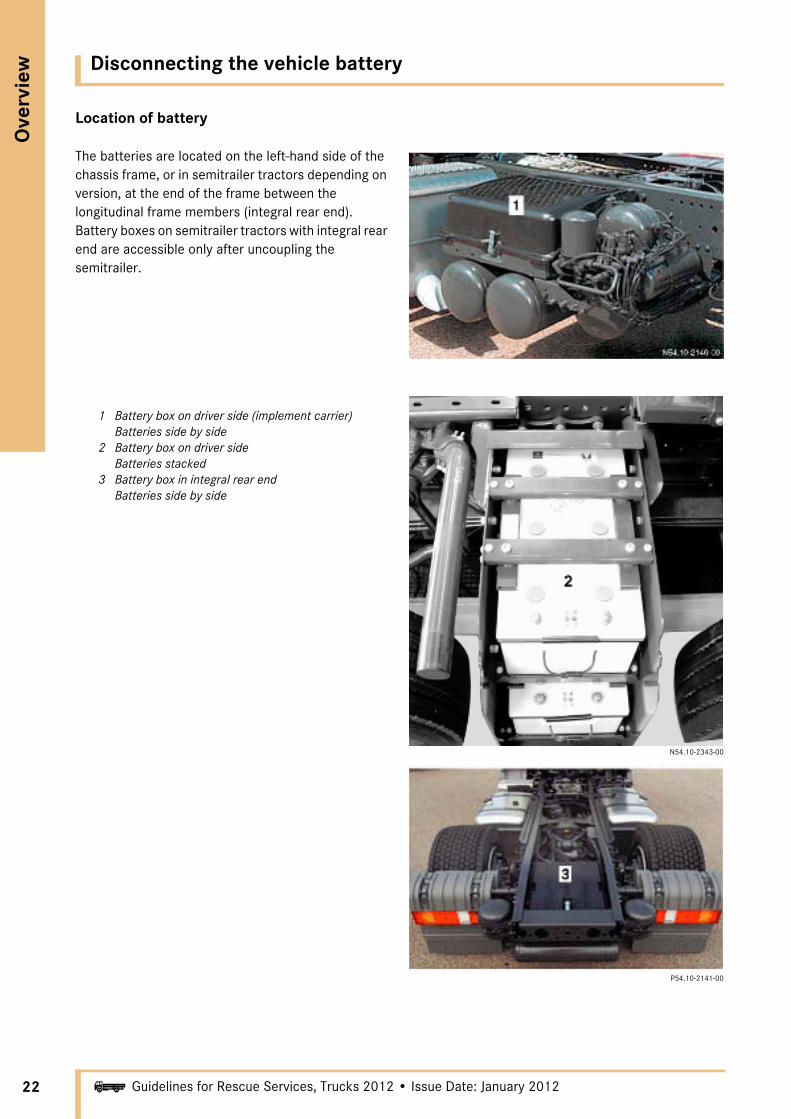
The batteries are located on the left-hand side of the chassis frame, or in semitrailer tractors depending on version, at the end of the frame between the longitudinal frame members (integral rear end). Battery boxes on semitrailer tractors with integral rear end are accessible only after uncoupling the semitrailer.
1 Battery box on driver side (implement carrier) Batteries side by side
2 Battery box on driver side Batteries stacked
3 Battery box in integral rear end Batteries side by side
N54.10-2343-00
P54.10-2141-00

Disconnecting the vehicle battery
Ove
rvie
w
23iGuidelines for Rescue Services, Trucks 2012 • Issue Date: January 2012
Disconnecting the battery
• Remove key from steering wheel lock• Switch off all electrical consumers• Open and remove battery cover• Disconnect negative terminal• Disconnect positive terminal• Hold the positive and negative cables together
in order to discharge any potential that may be stored in the capacitors
• Secure the cables, e.g. with cable ties, to prevent the systems from being switched back on or the cables from being reconnected
Batteries side by side
N54.10-2344-00
Batteries stacked
Integral rear end
1 Positive terminal2 Negative terminal
24
Ove
rvie
w
i
Disconnecting the vehicle battery
Guidelines for Rescue Services, Trucks 2012 • Issue Date: January 2012
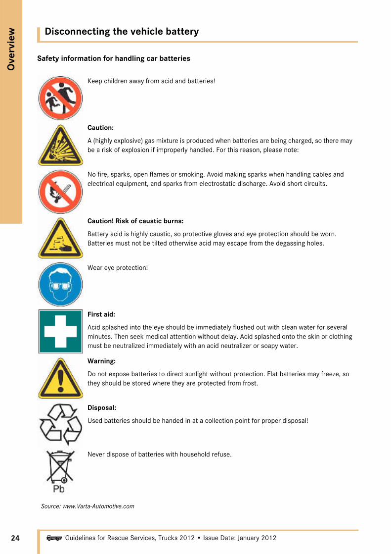
Safety information for handling car batteries
Source: www.Varta-Automotive.com
Keep children away from acid and batteries!
Caution:
A (highly explosive) gas mixture is produced when batteries are being charged, so there may be a risk of explosion if improperly handled. For this reason, please note:
No fire, sparks, open flames or smoking. Avoid making sparks when handling cables and electrical equipment, and sparks from electrostatic discharge. Avoid short circuits.
Caution! Risk of caustic burns:
Battery acid is highly caustic, so protective gloves and eye protection should be worn. Batteries must not be tilted otherwise acid may escape from the degassing holes.
Wear eye protection!
First aid:
Acid splashed into the eye should be immediately flushed out with clean water for several minutes. Then seek medical attention without delay. Acid splashed onto the skin or clothing must be neutralized immediately with an acid neutralizer or soapy water.
Warning:
Do not expose batteries to direct sunlight without protection. Flat batteries may freeze, so they should be stored where they are protected from frost.
Disposal:
Used batteries should be handed in at a collection point for proper disposal!
Never dispose of batteries with household refuse.

Alternative drives/hybrid vehicles
Ove
rvie
w
25iGuidelines for Rescue Services, Trucks 2012 • Issue Date: January 2012
The term "hybrid vehicle" denotes a vehicle containing at least two energy converters and two energy sources. The energy converters may be elec-tric motors or internal combustion engines, for example, while energy sources include the battery or fuel tank.
There are two basic variants of hybrid systems:
• Series hybrid (city bus)• Parallel hybrid (bus, van, truck)
Series hybrid:
The IC engine in a series hybrid vehicle has no mechanical connection with the drivetrain. It is operated within an optimum efficiency range and acts as the powerplant for the generator. The elec-trical energy generated in this way is then trans-mitted to the electric motor to actually propel the vehicle. A part of the electrical energy is also used to charge the high-voltage battery.
N08.30-2002-00
Series hybrid (schematic representation)1 IC engine2 Generator3 Lithium-ion battery4 Electric motor (wheel hub motor)
Parallel hybrid:
The IC engine in a parallel hybrid vehicle is coupled to the drivetrain via an automatic clutch. The elec-tric motor acts either as a generator for charging the high-voltage battery or as the drive unit for the vehicle.
N08.30-2003-00
Parallel hybrid (schematic representation)1 IC engine2 Electric motor/generator3 Lithium-ion battery4 Drivetrain

26
Ove
rvie
w
i
Alternative drives/hybrid vehicles
Guidelines for Rescue Services, Trucks 2012 • Issue Date: January 2012
System description
The hybrid drive systems in trucks are mostly of the parallel hybrid variety. The parallel layout makes it possible to propel the vehicle either with the elec-tric motor alone, or with the diesel engine alone, or with both powerplants together. During purely elec-tric operation, the IC engine runs at idle and is sepa-rated from the drivetrain by the automated clutch.
This guarantees that the assistance of the air brake system and the power steering, for example, continues to operate.
As the vehicle decelerates, the electric motor is operated as a generator and the electrical machine converts kinetic energy into electrical energy (regenerative braking).
N08.30-2004-00
Components (schematic representation)
1 IC engine: Conventional diesel engine2 Automated clutch3 Electrical machine: Permanent magnet
synchronous machine, operating with AC voltage (3-phase AC system), acting as motor and generator
4 Automated manual transmission5 Power inverter: Converts the DC battery voltage
into AC voltage for the electrical machine in motor mode and regulates torque and motor speed. In generator mode the AC voltage is converted into DC voltage and the energy is fed to the battery
6 Battery: High-power lithium-ion battery with integrated battery management system for monitoring the operating states
BMS Battery management control unitGS Gear control control unitHCM Energy management control unitMCU Electric motor control unitMR Engine control control unit
Alternative drives/hybrid vehicles
Ove
rvie
w
27iGuidelines for Rescue Services, Trucks 2012 • Issue Date: January 2012
Identification of HV components (HV=high voltage)
a DANGER
Risk of burn injuries due to arcing!
Due to the high voltages and currents and the high energy capacity of the HV battery, short circuits or the incorrect disconnection of HV line or plug connections can result in arcing.
High DC voltage cables at the inverter and high AC voltage cables at the inverter and electric motor should only be unplugged and plugged in by autho-rized specialist personnel.
To avoid burns from arcing, observe the following instructions:
• Deactivate the high-voltage system.• Do not separate any HV connectors.• Do not cut any high-voltage lines!• Avoid cutting or deforming the bodywork
with rescue equipment in the vicinity of lines and components carrying high voltage!
• Avoid touching damaged orange lines and their damaged connectors!
• Avoid touching damaged components of the drive system!
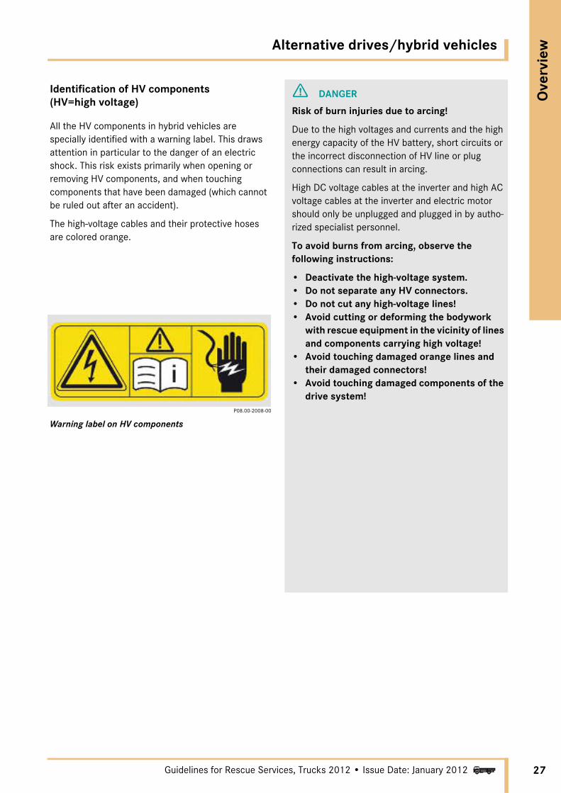
All the HV components in hybrid vehicles are specially identified with a warning label. This draws attention in particular to the danger of an electric shock. This risk exists primarily when opening or removing HV components, and when touching components that have been damaged (which cannot be ruled out after an accident).
The high-voltage cables and their protective hoses are colored orange.
P08.00-2008-00
Warning label on HV components

28
Ove
rvie
w
i
Alternative drives/hybrid vehicles
Guidelines for Rescue Services, Trucks 2012 • Issue Date: January 2012
a DANGER
Risk of death from electric shock!
The hybrid technology in these vehicles means that the components and high-voltage cables used carry voltages in excess of 250 V. Particular caution is required at those locations in the vehicle which are associated with the high voltage. These are identified with the warning label illus-trated above or are color-coded orange. For this reason, any work on the vehicle may only be carried out by authorized specialist personnel.
You may be seriously or fatally injured if you
• remove covers from components marked with warning labels
• tamper with components of the hybrid system• open housings• separate electrical connectors• touch damaged components of the hybrid
system• touch damaged orange high-voltage cables and
their connectors• touch components or orange high-voltage
cables in the high-voltage system of accident vehicles
To avoid injury from electric shock, observe the following instructions:
• Deactivate the high-voltage system.• Do not separate any HV connectors.• Do not cut any high-voltage lines!• Avoid cutting or deforming the bodywork
with rescue equipment in the vicinity of lines and components carrying high voltage!
• Avoid touching damaged orange lines and their damaged connectors!
• Avoid touching damaged components of the drive system!
a WARNING
Do not walk or climb on the high-voltage battery. The battery or its electrical connections could be damaged.

Alternative drives/hybrid vehicles
Ove
rvie
w
29iGuidelines for Rescue Services, Trucks 2012 • Issue Date: January 2012
Overview of components in the Atego Bluetec Hybrid
N08.30-2005-00
1 IC engine2 Adapted clutch housing3 Electric motor/generator4 Power inverter5 Fuel tank6 Lithium-ion battery7 Electric motor/generator and inverter cooling system8 Transmission9 High-voltage wiring
A Conventional componentsB Hybrid componentsC Hybrid cooling system
30
Ove
rvie
w
i
Alternative drives/hybrid vehicles
Guidelines for Rescue Services, Trucks 2012 • Issue Date: January 2012
Procedure for working on an accident vehicle
a WARNING
Do not start working on accident vehicles until the IC engine has stopped and the HV battery is deacti-vated!
i NOTEWhen the ignition has been switched off or the two 12 V batteries have been disconnected (see page 21), electrically and pneumatically adjustable systems such as the steering wheel or seat adjustment can no longer be activated.
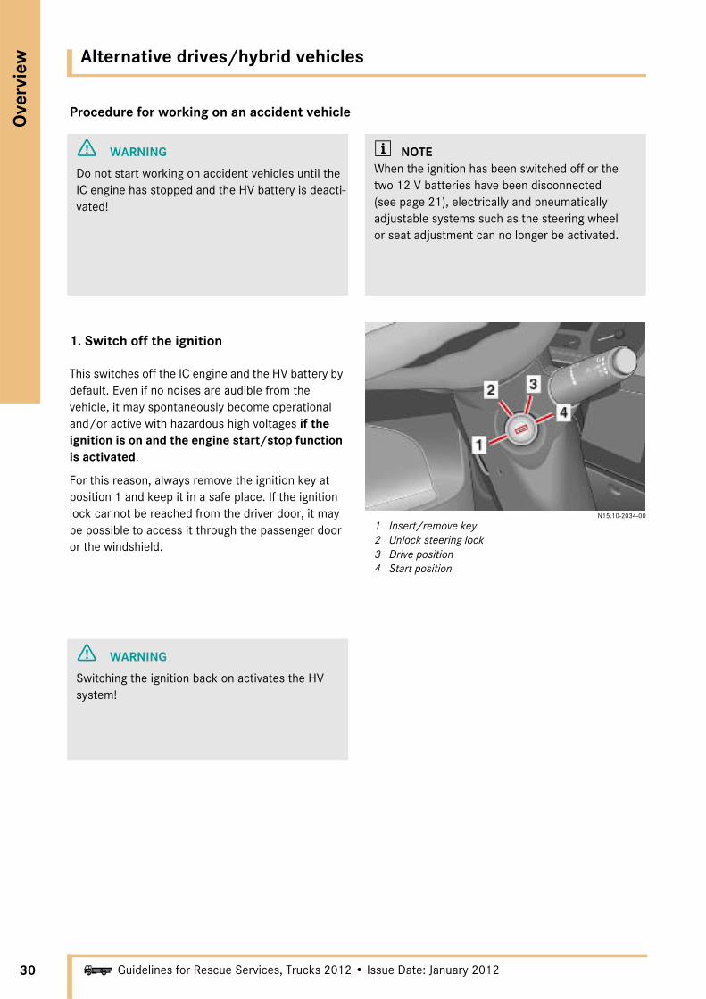
1. Switch off the ignition
This switches off the IC engine and the HV battery by default. Even if no noises are audible from the vehicle, it may spontaneously become operational and/or active with hazardous high voltages if the ignition is on and the engine start/stop function is activated.
For this reason, always remove the ignition key at position 1 and keep it in a safe place. If the ignition lock cannot be reached from the driver door, it may be possible to access it through the passenger door or the windshield.
N15.10-2034-00
1 Insert/remove key2 Unlock steering lock3 Drive position4 Start position
a WARNING
Switching the ignition back on activates the HV system!

Alternative drives/hybrid vehicles
Ove
rvie
w
31iGuidelines for Rescue Services, Trucks 2012 • Issue Date: January 2012
2. Operate the EMERGENCY OFF switch
Hybrid vehicles are equipped with a manual EMERGENCY OFF switch. It is located on the rear panel of the cab on the passenger side.
• Flip the cover (1) up• Flip the switch stalk (2) up
All electrical consumers are disconnected from the batteries with the exception of the tachograph.
N54.25-3600-00
1 Cover2 Switch stalk
a DANGER
The suspension seat may move downwards when the EMERGENCY OFF switch is actuated. Any uncontrolled movement of an injured casualty represents a further risk of injury.
All measures should only be performed in consul-tation with the emergency physician.
a WARNING
Resetting the EMERGENCY OFF switch corre-sponds to switching the ignition back on, and therefore reactivates the HV system!
N54.25-3601-00
1 HV battery2 HV battery disconnect switch
3. Operate the HV battery disconnect switch
The HV battery is located on the left-hand side of the vehicle in front of the rear axle. The HV battery disconnect switch is located at the front end of the HV battery.
Operating the HV battery disconnect switch merely interrupts the energy flow from and to the HV battery. It does not guarantee that the HV system is de-energized. For this the IC engine must also be stopped, e.g. by performing the following steps:
• Switch off the ignition• Operate EMERGENCY OFF switch• Inject CO2 into the intake port
32
Ove
rvie
w
i
Alternative drives/hybrid vehicles
Guidelines for Rescue Services, Trucks 2012 • Issue Date: January 2012
a DANGER
While the IC engine is running, voltage is induced via the electric motor even after the HV battery discon-nect switch is operated. Because of this, high voltage may be present at the high-voltage cables. You could suffer serious or fatal injury if you sepa-rate the electrical connection of a high-voltage cable.
For this reason, never perform any work on the vehicle, and particularly on the high-voltage system, while the IC engine is running!
i NOTESwitching off the IC engine does not guarantee that the system is de-energized. The HV battery discon-nect switch must also be operated.
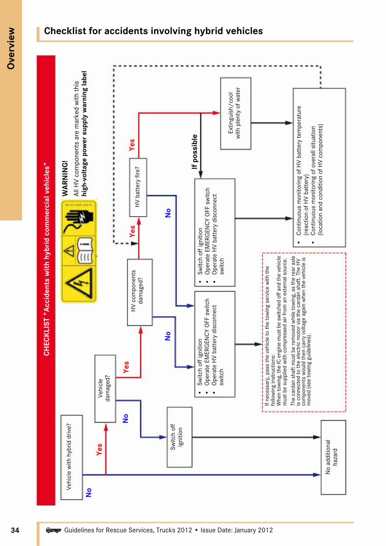
Recommendations in case of fire or overheating of an HV battery
• Comply with the stipulated distances for fog nozzles and multipurpose nozzles (low voltage up to 1000 V) with the extinguishing media
• Extinguish the HV battery quickly with plenty of water from under cover and continue cooling
• Ensure an adequate water supply• Keep checking the temperature of the HV battery,
as the damaged cells may continue to react chemically or electrically

Alternative drives/hybrid vehicles
Ove
rvie
w
33iGuidelines for Rescue Services, Trucks 2012 • Issue Date: January 2012
Notes on HV battery1)
Lithium is a highly reactive metal; the components of a lithium-ion battery are highly combustible. Physical damage can lead to internal short circuits. The high current can damage the housing. There is a high risk of fire. Under certain circumstances the defect may not be immediately detectable. Fire may break out some considerable time after the damage occurred.
Water should not normally be used to extinguish burning lithium-ion batteries because defective lithium cells can react violently with water. Sand or a Class D dry chemical powder should usually be used. As the necessary reaction partners are present in the cell, this does not necessarily halt the reaction, so cooling must be continued in this case.
Because of the high temperatures that can develop, it is important to cool the battery and to take into account the risk of a chemical reaction of the lithium with water. Despite information to the contrary, extinguishing trials with water have on the whole yielded positive results.
1) See Bernd Joss: "Einsatzhinweise für Elektrofahrzeuge" (Operational Notes for Electric Vehicles), January 2011 edition, Baden-Württemberg State Firefighting School
34
Ove
rvie
w
i
Checklist for accidents involving hybrid vehicles
Guidelines for Rescue Services, Trucks 2012 • Issue Date: January 2012
Vehi
cle
with
hyb
rid d
rive?
No
Yes
Vehi
cle
dam
aged
?
No
Yes
Switc
h of
fig
nitio
n
No
addi
tiona
l ha
zard
HV
com
pone
nts
dam
aged
?Ye
s
No
HV
batt
ery
fire?
Yes
No
Extin
guis
h/co
ol
with
ple
nty
of w
ater
•C
ontin
uous
mon
itorin
g of
HV
batt
ery
tem
pera
ture
(r
eact
ion
of H
V ba
tter
y)•
Con
tinuo
us m
onito
ring
of o
vera
ll si
tuat
ion
(loca
tion
and
cond
ition
of H
V co
mpo
nent
s)
•Sw
itch
off i
gniti
on•
Ope
rate
EM
ERG
ENC
Y O
FF s
witc
h•
Ope
rate
HV
batt
ery
disc
onne
ct
switc
h
•Sw
itch
off i
gniti
on•
Ope
rate
EM
ERG
ENC
Y O
FF s
witc
h•
Ope
rate
HV
batt
ery
disc
onne
ct
switc
h
If ne
cess
ary,
pas
s th
e ve
hicl
e to
the
tow
ing
serv
ice
with
the
follo
win
g in
stru
ctio
ns:
Whe
n to
win
g, th
e IC
eng
ine
mus
t be
switc
hed
off a
nd th
e ve
hicl
e m
ust b
e su
pplie
d w
ith c
ompr
esse
d ai
r fro
m a
n ex
tern
al s
ourc
e.
The
card
an s
haft
mus
t be
rem
oved
whi
le to
win
g, a
s th
e re
ar a
xle
is c
onne
cted
to th
e el
ectr
ic m
otor
via
the
card
an s
haft
. The
HV
com
pone
nts
wou
ld th
en c
arry
vol
tage
aga
in w
hen
the
vehi
cle
is
mov
ed (s
ee to
win
g gu
idel
ines
).
If p
ossi
ble
CH
ECK
LIST
"A
ccid
ents
wit
h hy
brid
com
mer
cial
veh
icle
s"
WA
RNIN
G!
All H
V co
mpo
nent
s ar
e m
arke
d w
ith th
is
high
-vol
tage
pow
er s
uppl
y w
arni
ng la
bel

GGVS vehicles (hazardous goods vehicles)
Ove
rvie
w
35iGuidelines for Rescue Services, Trucks 2012 • Issue Date: January 2012
Peculiarities of GGVS vehicles (hazardous goods vehicles)
Vehicles used for transporting hazardous goods are equipped with two manual EMERGENCY OFF switches:
• In the cockpit on the instrument panel• Behind the cab on the passenger side
The switches are used to interrupt the voltage supply in an emergency and to prevent short circuits with sparks which may ignite a fire or an explosion.
The following components remain supplied with electricity when the EMERGENCY OFF switch is actuated:
• Tachograph• Anti-theft alarm system
When the EMERGENCY OFF switch is actuated, the engine is shut off automatically.
Cockpit
The EMERGENCY OFF switch interrupts the voltage supply to the main consumers.
Location of EMERGENCY OFF switch in cockpit
Open the cover and pull the switch pin (1)

36
Ove
rvie
w
i
GGVS vehicles (hazardous goods vehicles)
Guidelines for Rescue Services, Trucks 2012 • Issue Date: January 2012
Passenger side behind the cab
Possible location of EMERGENCY OFF switch on the right behind the cab
The EMERGENCY OFF switch interrupts the voltage supply to the main consumers.
The engine is switched off automatically.
Open the cover and swing the switch (2) upwards
a Danger
The suspension seat may move downwards when the EMERGENCY OFF switch is operated (except Actros 3 and New Actros).
Any uncontrolled movement of an injured casualty represents a further risk of injury.
All measures should only be performed in consul-tation with the emergency physician.

Truck damage profiles after a rear-end collision
Truc
k ac
cide
nt c
hara
cter
isti
cs
37Guidelines for Rescue Services, Trucks 2012 • Issue Date: January 2012i

The most frequently occurring accidents
38
Truc
k ac
cide
nt c
hara
cter
isti
cs
Guidelines for Rescue Services, Trucks 2012 • Issue Date: January 2012i
Accident type and road type
N00-00-2744-00
• Accidents on freeways and federal highways are most common for heavy commercial vehicles.
• Of these, rear-end collisions are the most significant.
• But: All road types are relevant for heavy commercial vehicles.
Trucks > 10 t: Distribution of road type (N = 15212)
Anonymous 50% random sample from Federal Statistical Office, accident year 2009/2010
Perc
enta
ge %
Rear-end
Lane-departure
Head-on
Side-on
Pedestrian
Run-off-road
Other accident type
Freeway N=4601
Federal highway N=4033
State road N=2571
District, local or other road N=4007
Accident type(collision with.../type of collision)

The most frequently occurring accidents
Truc
k ac
cide
nt c
hara
cter
isti
cs
39Guidelines for Rescue Services, Trucks 2012 • Issue Date: January 2012i
Type and severity of accident
N00-00-2745-00
• One third of all fatal accidents involving heavy commercial vehicles are head-on collisions with oncoming traffic. In these, the occupants of passenger cars are at particular risk. These also include accidents of the type "car rear-ends truck".
• Rear-end collisions form the greatest proportion of both accidents with serious injuries and those with minor injuries.
Trucks > 10 t: Distribution of accident severity (N = 15212)
Anonymous 50% random sample from Federal Statistical Office, accident year 2009/2010
Perc
enta
ge %
Accident with
Fatalities 3.2%
Serious injuries 16.1%
Minor injuries 48.6%
Serious property damage 32.1%
Accident type(collision with.../type of collision)
Rear-end
Lane-departure
Head-on
Side-on
Pedestrian
Run-off-road
Other accident type

Casualty injury patterns
40
Truc
k ac
cide
nt c
hara
cter
isti
cs
Guidelines for Rescue Services, Trucks 2012 • Issue Date: January 2012i
These figures were recorded at the Berufsgenossen-schaftliche Unfallklinik (Clinic for Trauma Surgery) in Ludwigshafen/Rhein between 1999 and 2002. A total of 78 traffic accidents was studied involving injured truck occupants who had to be hospitalized at the clinic between 01.01.1996 and 31.12.2001 due to the effects of their injuries.
The study examined the frequency of injury to a partic-ular area of the body on the casualties with no evalua-tion of the severity of injury in all accidents as well as in each individual type of accident. The increased frequency of cranial injuries (48.7% of the total) was conspicuous, as was that of injuries to the upper (42.3%) and lower extremities (65.4%). Almost as expected, injuries to the lower extremities were disproportionately high in collision-type accidents.
Total accidents
A total of 78 traffic accidents with a total of 78 patients was studied. n = number of individual injuries
)
Head n = 38
Thorax n = 21
Abdomen n = 12
Pelvis n = 8
Lower extremities n = 51
Spine n = 24
Upper extremities n = 51

Casualty injury patterns
Truc
k ac
cide
nt c
hara
cter
isti
cs
41Guidelines for Rescue Services, Trucks 2012 • Issue Date: January 2012i
Collisions (53 accidents)
Overturning accidents (19 fatalities)
Head n = 26
Thorax n = 14
Abdomen n = 9
Pelvis n = 7
Lower extremities n = 43
Spine n = 14
Upper extremities n = 23
Head n = 9
Thorax n = 5
Abdomen n = 3
Pelvis n = 1
Lower extremities n = 7
Spine n = 6
Upper extremities n = 9

Casualty injury patterns
42
Truc
k ac
cide
nt c
hara
cter
isti
cs
Guidelines for Rescue Services, Trucks 2012 • Issue Date: January 2012i
Complex accidents
Collision in combination with the vehicle overturning (6 accidents)
Source: Dr. med. Rainer Zinser (Oberschwabenklinik Hospital, Ravensburg)
Head n = 3
Thorax n = 2
Abdomen n = 0
Pelvis n = 0
Lower extremities n = 1
Spine n = 4
Upper extremities n = 1
The golden hour of shock
Truc
k ac
cide
nt c
hara
cter
isti
cs
43Guidelines for Rescue Services, Trucks 2012 • Issue Date: January 2012i
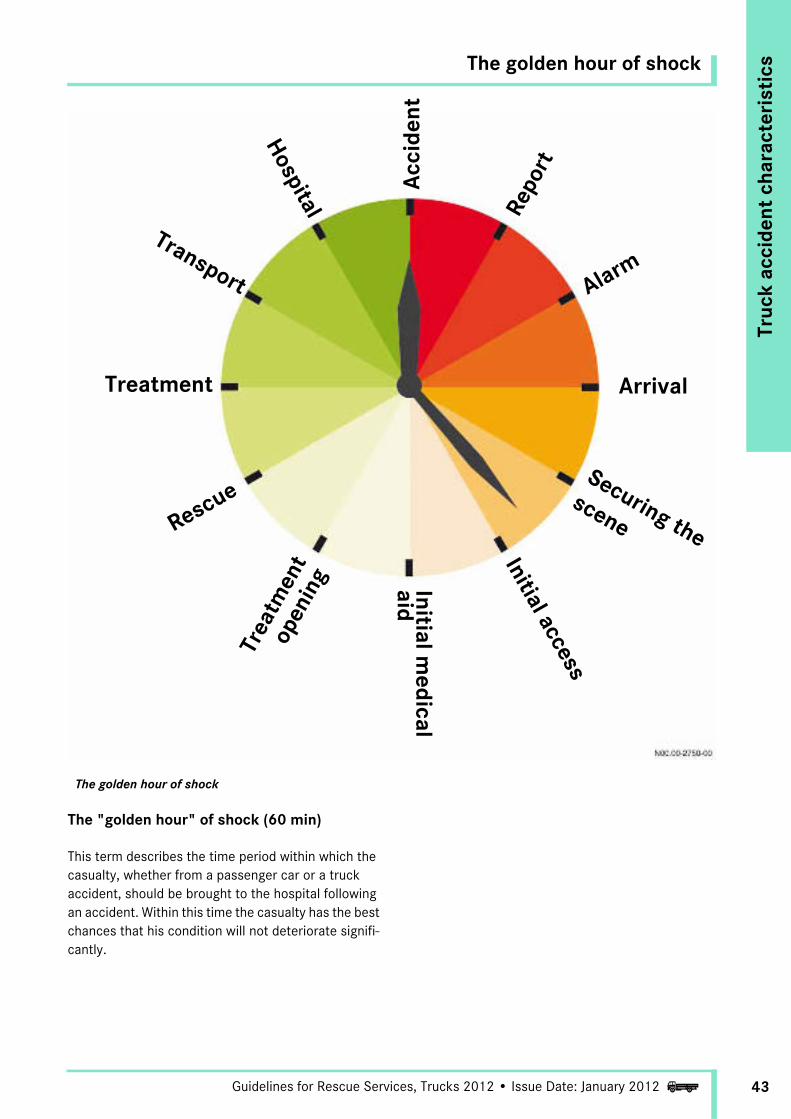
The golden hour of shock
The "golden hour" of shock (60 min)
This term describes the time period within which the casualty, whether from a passenger car or a truck accident, should be brought to the hospital following an accident. Within this time the casualty has the best chances that his condition will not deteriorate signifi-cantly.
Initial access
Securing the
scene
Alarm
Rescue
Transport
Treatment
Hospital
Acc
iden
t
Repo
rt
Trea
tmen
t op
enin
g Initial medical
aidArrival

Tactical procedure
44
Truc
k ac
cide
nt c
hara
cter
isti
cs
Guidelines for Rescue Services, Trucks 2012 • Issue Date: January 2012i
a DANGER a DANGER
When disconnecting batteries or cutting the cables, disconnect the ground line first otherwise there is a risk of short circuit.
If short circuits occur, there is a risk of injury from an electric shock due to the higher voltage and current of truck batteries.
Sparks or the overheating of electrical compo-nents due to short circuits can cause inflam-mable substances to ignite. Any resulting fire or deflagration poses an acute risk of injury for occupants and rescuers alike.
Insulated tools must be used to disconnect or cut the cables. If no insulated tools are available, insu-late the appropriate places by covering them with suitable materials.
Wear protective clothing/safety glasses.
Ensure that sufficient quantities of fire extin-guishing agents are at hand.
On vehicles with the appropriate equipment, disconnecting the battery can cause the pneumati-cally adjustable seats to move down.
Any uncontrolled movement of an injured casualty represents a further risk of injury.
This measure should only be performed in consulta-tion with the emergency physician.

Tactical procedure
Truc
k ac
cide
nt c
hara
cter
isti
cs
45Guidelines for Rescue Services, Trucks 2012 • Issue Date: January 2012i
Procedure in four phases
For proper casualty rescue from trucks, as also from passenger cars, the operation should be divided into four phases:
1st phase: "Initial opening"
2nd phase: "Treatment opening"
3rd phase: "Rescue opening"
4th phase: "Rescue of the casualty"
1st phase: "Initial opening"
In the 1st phase the accident situation is assessed by the crew chiefs and then an access route is made for the emergency physician to conduct an initial evaluation. The purpose of this is to ascertain the overall condition of the casualty. The fire crew at the scene and the medical team under the command of the emergency physician should remain in close contact with each other for the duration of the rescue operation.
Initial access merely requires openings that are large enough to allow a check of the casualty's vital functions and an assessment of the situation inside the vehicle.
Depending on the degree of deformation of the cab, it may still be possible to open the doors. This should always be checked first, as it will facilitate the rescue of the casualty.
Simultaneously all the necessary preliminary measures are in progress. The scene of the opera-tion must be secured, and this involves:• Securing the site
- Protection from moving traffic- Protection against fire by provision of suitable
extinguishing agents- Protection against danger from the cargo
(hazardous goods, cargo shifting etc.)• Protecting against movement of the vehicle:
- Chocking the wheels to prevent movement- Securing the cab (see page 63)- Stopping the engine if it is still running
• Disconnecting the battery• Collecting escaping fluids
Initial assessment, e.g. through the side windows or the windshield
Tactical procedure
46
Truc
k ac
cide
nt c
hara
cter
isti
cs
Guidelines for Rescue Services, Trucks 2012 • Issue Date: January 2012i
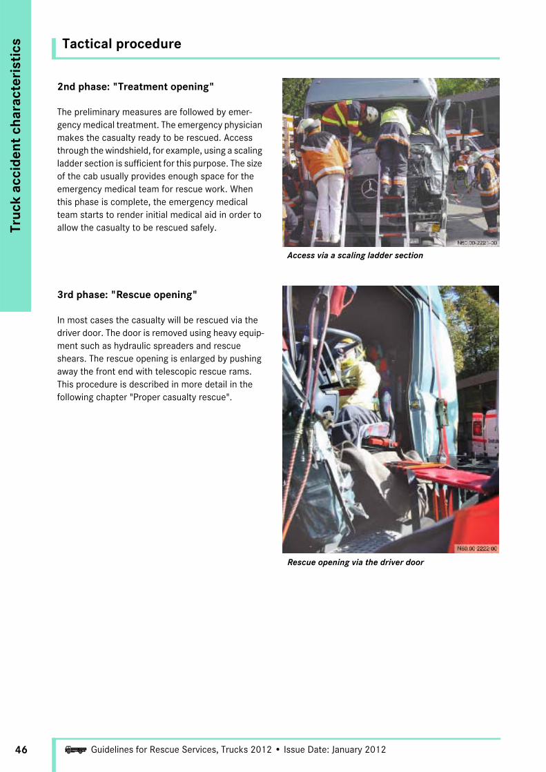
2nd phase: "Treatment opening"
The preliminary measures are followed by emer-gency medical treatment. The emergency physician makes the casualty ready to be rescued. Access through the windshield, for example, using a scaling ladder section is sufficient for this purpose. The size of the cab usually provides enough space for the emergency medical team for rescue work. When this phase is complete, the emergency medical team starts to render initial medical aid in order to allow the casualty to be rescued safely.
Access via a scaling ladder section
3rd phase: "Rescue opening"
In most cases the casualty will be rescued via the driver door. The door is removed using heavy equip-ment such as hydraulic spreaders and rescue shears. The rescue opening is enlarged by pushing away the front end with telescopic rescue rams. This procedure is described in more detail in the following chapter "Proper casualty rescue".
Rescue opening via the driver door
Tactical procedure
Truc
k ac
cide
nt c
hara
cter
isti
cs
47Guidelines for Rescue Services, Trucks 2012 • Issue Date: January 2012i
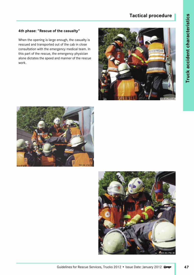
4th phase: "Rescue of the casualty"
When the opening is large enough, the casualty is rescued and transported out of the cab in close consultation with the emergency medical team. In this part of the rescue, the emergency physician alone dictates the speed and manner of the rescue work.
Introduction
48
Prop
er c
asua
lty
resc
ue
Guidelines for Rescue Services, Trucks 2012 • Issue Date: January 2012i
Rescuing the casualty from the cab
Whereas formerly priority was given to quickly rescuing the trapped casualty from his predicament, the primary concern nowadays is medical and psycho-logical assistance. The aim of this is to prepare the casualty as well as possible for the rescue work. The medical and rescue personnel can then work in concert to free the casualty.
The main priority is to render medical and psycholog-ical aid to the casualty!
The most urgent immediate measures are:
• Maintaining or restoring the vital functions (respiration/circulation)
• Keeping the respiratory passages clear and removing respiratory obstructions (clear the mouth and throat, bend the head back slightly and give artificial respiration if necessary)
• Stopping severe bleeding (by holding up the affected body part, pinching off the appropriate artery and applying a pressure bandage if necessary)
• Treating life-threatening injuries• Assessing shock and initiating measures to
stabilize the casualty• Immobilizing certain body parts• Rendering psychological support to the casualty
Proper casualty rescue means freeing the casualty from the accident vehicle as safely as possible without causing additional harm or exacerbating his injuries. In the process, all unnecessary movements of the accident vehicle should be avoided because the trapped person is in direct contact with the vehicle. The medical and rescue personnel work in concert to free the casualty. However, the safety of the medical and rescue crews themselves should not be neglected at any time during the rescue.
The casualty should only be freed from the accident vehicle immediately when there is an imminent risk to the casualty's life, e.g. in the following cases:
• Vehicle on fire• Serious danger from hazardous substances• Danger of hazardous drop• Imminent cardiac failure with no possibility of
treatment inside the vehicle
In this case the situation calls for "CRASH RESCUE".
Assessing the accident situation
The assessment should include the following aspects:
• Evaluation of the danger to the rescue team itself (protecting the scene of the accident, hazardous goods, airbags, escaping fluids, etc.)
• The extent of the accident site and the number of vehicles or casualties involved
• Coordination with other rescue crews• Position reporting and definition of priorities• Are the crews on hand sufficient?
i NoteContact between the fire and rescue crews should be maintained at all times; they should be in constant communication!
All measures should only be performed in consul-tation with the emergency physician!

Initial access
Prop
er c
asua
lty
resc
ue
49Guidelines for Rescue Services, Trucks 2012 • Issue Date: January 2012i
Via the doors
It should first be checked whether access via the doors is possible. If the deformation of the cab is slight, it is often still possible to open the doors by hand or using small tools such as screwdrivers or crowbars.
Heavy hydraulic tools should only be used after the above check has been performed.
a DANGER
When vehicle parts are cut open or cut off from the vehicle, sharp edges are produced with the potential to cause injury to both rescue personnel and the casualties inside the vehicle.
Cover any sharp edges with suitable tarpaulins.
Via the roof hatch
An alternative way of gaining access to the cab is via the roof hatch. As this may be electrically oper-ated, the hatch should only be used if it is already open. (This may require too much time if there are other or better alternatives.)
If the vehicle is lying on its side, however, it may indeed be easier to use the roof hatch as the initial access point even if it is closed. In this case the hatch must be removed or an opening cut in the glass or metal plate.
Opening doors by hand or with small tools Potential access via roof hatch

Initial access
50
Prop
er c
asua
lty
resc
ue
Guidelines for Rescue Services, Trucks 2012 • Issue Date: January 2012i
Via the rear wall
If no access is possible via the alternatives described above, e.g. if several vehicles are wedged together, it may be possible to gain access to the cab via the rear wall. If there are rear windows, access should be through these.
If there are no rear windows, a hole must be drilled/punched in the sheet metal. An opening can then be cut, torn or sawn starting from the hole. To gain access to the rear wall of the cab, it may be neces-sary to remove the side walls beforehand. On semi-trailer tractors it may also be necessary to uncouple the trailer and secure it to prevent it from moving.
Use of the initial access opening
Through the initial access opening the casualty is treated in the cab by a qualified member of the rescue crew, who commences the initial diagnostic and medical work. In doing so, great importance should also be given to his own safety.
Potential access via rear window
i NoteNever move inside the range of an airbag or other restraint systems unless they have already deployed.

Securing the area
Prop
er c
asua
lty
resc
ue
51Guidelines for Rescue Services, Trucks 2012 • Issue Date: January 2012i
Securing the site
In Germany, the scene of the accident must be secured in accordance with the pertinent fire service regulation (FwDv 3).
Fire protection
Protection against fire is guaranteed by the provision of sufficient quantities of suitable extinguishing agents. The fire extinguishers must be constantly manned in order to ensure that they are ready for action quickly. It may be necessary to employ powder, foam and water to contain the fire and stop it spreading.
Securing traffic
The scene of the accident is protected from moving traffic by parking the rescue vehicles in a certain arrangement and by using the appropriate equipment. For Germany, details can be found in the fire service regulation FwDv 1.
Securing the vehicle
Secure the vehicle to prevent it from rolling away (stop the engine if necessary – see next paragraph), from tipping over and from moving in any other way.
In addition, the safety of the cargo should not be neglected, especially in the case of hazardous goods. Escaping fluids are collected by appropriate means.
Regulation FwDv 3 also stipulates how to secure the scene in darkness. If the light level is too low, the scene must be adequately illuminated.
Stopping the engine
52
Prop
er c
asua
lty
resc
ue
Guidelines for Rescue Services, Trucks 2012 • Issue Date: January 2012i
Diesel engines may continue to run after an accident. The engine can be stopped by several methods, depending on the situation and the severity of the accident.
Ignition key
If the ignition switch can be reached, an attempt should be made to stop the engine by switching off the ignition.
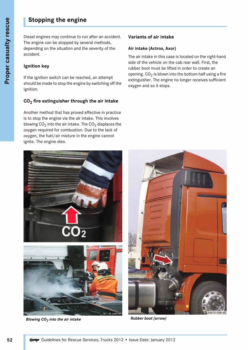
CO2 fire extinguisher through the air intake
Another method that has proved effective in practice is to stop the engine via the air intake. This involves blowing CO2 into the air intake. The CO2 displaces the oxygen required for combustion. Due to the lack of oxygen, the fuel/air mixture in the engine cannot ignite. The engine dies.
Blowing CO2 into the air intake
Variants of air intake
Air intake (Actros, Axor)
The air intake in this case is located on the right-hand side of the vehicle on the cab rear wall. First, the rubber boot must be lifted in order to create an opening. CO2 is blown into the bottom half using a fire extinguisher. The engine no longer receives sufficient oxygen and so it stops.
Rubber boot (arrow)

Stopping the engine
Prop
er c
asua
lty
resc
ue
53Guidelines for Rescue Services, Trucks 2012 • Issue Date: January 2012i
Front air intake (Atego)
The air intake here is located behind the radiator grille. The CO2 cannot be injected directly because there is no access to the air intake. The CO2 is sprayed through the radiator grille in the direction of the air intake using a fire extinguisher.
CO2 injection point (arrow) at air intake
Air intake – air filter
i NoteMake sure there are sufficient CO2 fire extin-guishers available, and spray from both sides (from left and right) simultaneously.

Stopping the engine
54
Prop
er c
asua
lty
resc
ue
Guidelines for Rescue Services, Trucks 2012 • Issue Date: January 2012i
Removing a fuel line
If the cab is torn off, the engine can be stopped by clamping off or cutting the fuel lines. Escaping fuel must be collected immediately because of the possible risk of fire. The engine continues to run until the fuel inside the fuel filter and the feed line has been consumed. But this can take up to 10 min.
a DANGER
Escaping fuel is inflammable and can be ignited by sparks or open flames.
Collect escaping fuel by suitable means.
i NoteFuel lines should be removed only in exceptional cases. The method using the CO2 fire extinguisher is preferable.
Reducing the rescue height
Prop
er c
asua
lty
resc
ue
55Guidelines for Rescue Services, Trucks 2012 • Issue Date: January 2012i
Advantage
Reducing the rescue height makes it easier for the rescue team to work on the cab (even when a rescue platform is available) and facilitates the subsequent rescue of the casualty.
The following options are available:
• Cab mounting air suspension• Front axle air suspension• Tire inflation pressure
a DANGER
When air lines are cut, the cut ends can fly around violently and cause injuries.
When a bellows is pierced, flying parts may constitute a risk of injury due to high pressure.
Perform these steps with the utmost care.
Keep a safe distance.
Wear protective clothing.
a DANGER
When the vehicle is lowered, the injured occupant may possibly be subjected to uncontrolled movements which could pose an additional injury risk.
The vehicle should only be lowered in consultation with the emergency physician.

Reducing the rescue height
56
Prop
er c
asua
lty
resc
ue
Guidelines for Rescue Services, Trucks 2012 • Issue Date: January 2012i
Piercing the air bellows
Another alternative is to pierce the air spring bellows using a spike or similar implement (caution: risk of injury). This must be done carefully.
An appropriate safety distance must be maintained because the bellows is under high pressure. The air bellows may burst when pierced. Flying parts consti-tute an injury risk!
Cab mounting air bellows (1)
Lowering the air suspension
If the vehicle is equipped with cab air suspension, this can be lowered. This reduces the rescue height and immobilizes the cab. The rescue height is the height that must be overcome in order to move the casualty from his seat to the ground.
The air can be released by two different methods:
Cutting the air lines
It is preferable to cut the line to the air bellows. The line must be cut between the bellows and the valve.
Cutting air line at air bellows

Reducing the rescue height
Prop
er c
asua
lty
resc
ue
57Guidelines for Rescue Services, Trucks 2012 • Issue Date: January 2012i
Releasing the tire pressure
The rescue height can be reduced by unscrewing the tire valves. This measure can lower the vehicle by about 150 mm. The tires should never be destroyed (punctured etc.) as this makes salvaging the vehicle more difficult.
Unscrewing the valve to deflate the tire

Reducing the rescue height
58
Prop
er c
asua
lty
resc
ue
Guidelines for Rescue Services, Trucks 2012 • Issue Date: January 2012i
Frame air suspension
Some vehicles feature full air suspension, i.e. the chassis is equipped with an air suspension system. By far the most common variant is that with air suspen-sion on the rear axle only. On vehicles with full air suspension, the rescue height can be reduced by lowering the air suspension. There are three possible alternatives.
1 Operating unit2 Tire inflation connection and
air suspension test connection3 Compressed air reservoir4 Spring bellows

Reducing the rescue height
Prop
er c
asua
lty
resc
ue
59Guidelines for Rescue Services, Trucks 2012 • Issue Date: January 2012i
Lowering with the operating unit
This method requires that the key in the steering wheel lock is in the "drive" position and that the battery is still connected. The vehicle must have been secured beforehand to prevent it from rolling. This can be done via the parking brake, for example, but is better accomplished using wheel chocks.
Steering wheel lock
1 Drive position2 Start position
a WARNING
The vehicle should only be lowered in consultation with the emergency physician.
In order to lower the chassis, use button 3 (front chassis frame) or button 4 (rear chassis frame) on the operating unit to select the axle to be lowered or raised. The indicator lamps 1 and 2 show whether front (1) or rear (2) is selected. Button 9 (down arrow) can now be used to lower the chassis frame in the preselected area (front or rear). The process can be interrupted by pressing the Stop button (10).
Operating unit
1 Indicator lamp for front chassis frame2 Indicator lamp for rear chassis frame3 Front chassis frame4 Rear chassis frame8 Raise chassis frame9 Lower chassis frame
10 Stop (raising/lowering)
Reducing the rescue height
60
Prop
er c
asua
lty
resc
ue
Guidelines for Rescue Services, Trucks 2012 • Issue Date: January 2012i
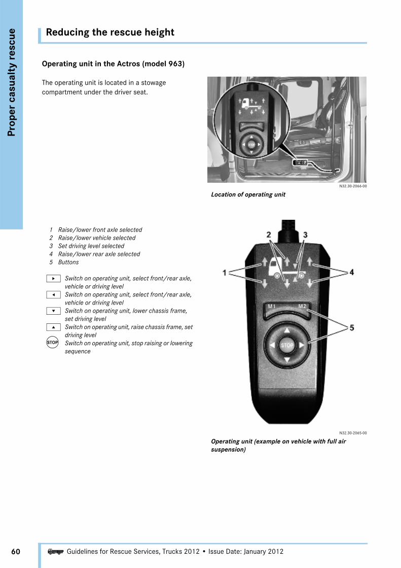
Operating unit in the Actros (model 963)
The operating unit is located in a stowage compartment under the driver seat.
N32.30-2066-00
Location of operating unit
1 Raise/lower front axle selected2 Raise/lower vehicle selected 3 Set driving level selected 4 Raise/lower rear axle selected 5 Buttons
u Switch on operating unit, select front/rear axle, vehicle or driving level
t Switch on operating unit, select front/rear axle, vehicle or driving level
r Switch on operating unit, lower chassis frame, set driving level
s Switch on operating unit, raise chassis frame, set driving level
T Switch on operating unit, stop raising or lowering sequence
N32.30-2065-00
Operating unit (example on vehicle with full air suspension)

Reducing the rescue height
Prop
er c
asua
lty
resc
ue
61Guidelines for Rescue Services, Trucks 2012 • Issue Date: January 2012i
Lowering the chassis frame via the test connections
Another non-destructive way of letting the air out of the air suspension is to release it via the test connec-tions. In order to lower the chassis frame, the valves must be vented (this can be done using a tire inflating hose).
To raise or lower the chassis at the front axle: Pressurize or vent via test connection 1.
To raise or lower the chassis at the rear axle: Pressurize or vent via test connections 2 and 4.
Test connections
1 Front axle2 Left rear axle
3 Air suspension supply (external filling)4 Right rear axle
a WARNING
The vehicle should only be lowered in consultation with the emergency physician.

Reducing the rescue height
62
Prop
er c
asua
lty
resc
ue
Guidelines for Rescue Services, Trucks 2012 • Issue Date: January 2012i
Work platform
For the next phase it is necessary to use a work plat-form (to bridge the height from the road to the cab) in order to facilitate the work of the rescue crews and enable the rescue to be carried out. There are various options for this. For example, rescue platforms in a wide variety of forms are available.
However, the lift gates of trucks, cargo beds on vans, turntable ladders with or without basket, and even pieces of cargo from the accident vehicle's own cargo can all be used as a platform.
Vehicle with lift gate
Flatbed
Scaffold
Turntable ladder with or without basket

Securing the cab
Prop
er c
asua
lty
resc
ue
63Guidelines for Rescue Services, Trucks 2012 • Issue Date: January 2012i
Preparing the cab
To ensure that no further harm comes to the casualty during the rescue, he should not be subjected to any unnecessary movements if at all possible. Conse-quently, the cab suspension and the suspension between the frame and the axle must be rendered inoperable or bypassed in order to prevent the cab from moving.
Securing the cab
In order to prevent any undesirable movements of the cab, it should be lashed fast to the frame by means of a strap passed around the cab and under the frame. This measure prevents the cab from slipping if the cab mounting is destroyed and stops any unnecessary movement of the cab.
In most cases further shoring up of the cab to prevent possible movement is no longer absolutely necessary after this measure.
Strap around frame and cab
Glass handling
64
Prop
er c
asua
lty
resc
ue
Guidelines for Rescue Services, Trucks 2012 • Issue Date: January 2012i
Windows
There are two types of windshield:
• Windows held in a rubber seal• Cemented windows
Windows held in a rubber seal:
If the windshield glass is intact, slit open the rubber seals with a firefighter knife. Pull off the rubber seal. The window is now loose and can be removed.
In some kinds of accident it is possible that the entire windshield has already fallen out due to the force of the impact. In these cases the windshield opening can be used as an initial access point immediately using a section of ladder.
Cemented windows:
Several methods of removing cemented windows have become established from the passenger car sector. One method is to cut out the window using a glass saw.
An opening is first knocked in the glass well away from the hazard area around the casualty (risk of injury).
The casualty is barely exposed to any glass frag-ments inside the vehicle, but should be covered with a tarpaulin or blanket for safety.
This method is only advisable on trucks when the cab has been secured to prevent it from rocking. The back-and-forth movement of the tool causes the cab to sway. This subjects the casualty to substantial movements. Exception: The cab and frame suspension has already been rendered inop-erable. (See "Securing the cab".)
a DANGER
Always remove the windows when working on adjacent components. Windows may shatter resulting in tiny, sharp glass particles flying around which may cause injury to the occupants and rescuers.
Cover the occupants before commencing work.
Always wear protective clothing/safety glasses/dust mask.
Cover any sharp edges with suitable tarpaulins.
a DANGER
Shards of glass on the road in front of the vehicle present a risk of slipping when positioning the scaling ladder!
If the ladder slips or topples over, the rescuers may suffer injuries.
Remove shards of glass from the road in front of the vehicle before positioning the scaling ladder.
Glass handling
Prop
er c
asua
lty
resc
ue
65Guidelines for Rescue Services, Trucks 2012 • Issue Date: January 2012i
Another way of removing a cemented window is to use a hooligan metal cutter tool. It is used in a similar way to the glass saw. It causes less splintering and produces less glass dust than the glass saw. One disadvantage is the edge of the cut. It is coarser and less clean.
This method subjects the cab to hardly any rocking movement because the tool does not need to be moved back and forth to cut the window. First, a hole is knocked in the window (away from the hazard area around the casualty). Then, starting from this hole, the window is ripped open all round. Once cut, the wind-shield can be removed.
A large pair of plate shears is another alternative. A hole is knocked in the bottom of the window at a safe distance from the casualty, and the window is then cut open.
Removing the glass
Windows in parts adjacent to those being worked on must always be removed before using hydraulic tools. This applies above all to the windows in the doors. If the windows are not removed, they will be subjected to considerable pressure, as will the parts which you are attempting to spread.
At a certain compressive force the windows will be unable to withstand the pressure and will burst suddenly and violently. Tiny, sharp glass fragments will be sent flying. These fragments can cause injuries; they spread around the area of the accident, posing an acute danger of cuts.
i NoteTruck windshields have a relatively high dead weight and can weight up to 35 kg.
Glass handling
66
Prop
er c
asua
lty
resc
ue
Guidelines for Rescue Services, Trucks 2012 • Issue Date: January 2012i
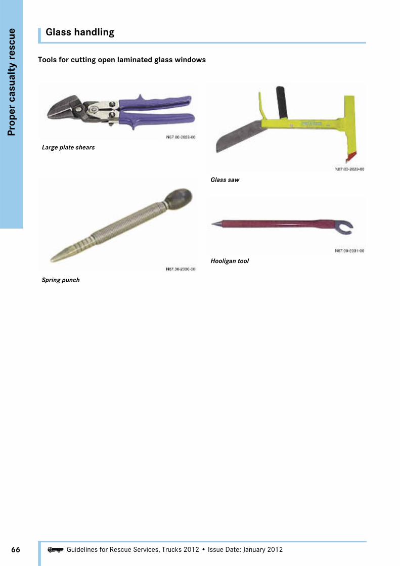
Tools for cutting open laminated glass windows
Large plate shears
Spring punch
Glass saw
Hooligan tool

Glass handling
Prop
er c
asua
lty
resc
ue
67Guidelines for Rescue Services, Trucks 2012 • Issue Date: January 2012i
Removing windows using a spring punch
Windows made of single-pane safety glass (side windows and rear windows) can be removed using a spring punch:
The window to be removed is covered all over with a self-adhesive film or adhesive tape. Then a spring punch is used to punch one corner of the window. The window shatters into small shards which are held together by the film or adhesive tape applied before-hand. The shattered window is carefully removed from the interior compartment.
The method of using adhesive tape and a packing tape roll dispenser has proven particularly effective. This is a quick and inexpensive way of removing single-pane safety glass. If the window is wet, it should be dried first otherwise the moisture on the window will prevent the tape from adhering properly.
1 Spring punch

Securing the door
68
Prop
er c
asua
lty
resc
ue
Guidelines for Rescue Services, Trucks 2012 • Issue Date: January 2012i
Before gaining access via the door, all windows must be removed from the door and from adjacent components. Truck doors are extremely heavy (approx. 80 kg) and must be secured to prevent them from falling before work is performed on them. This can be done using a multipurpose rope, for example. First, the spreader is used to create an adequate door gap at the top of the window frame. A rope is fastened to the cab door with a knot and laid across the cab. The door is then held on the other side by two crewmen.
a DANGER
Windows may shatter resulting in tiny, sharp glass particles flying around which may cause injury to the occupants and rescuers.
Before working on the door, all windows must be removed from the door and from adjacent components.
Because of its high dead weight it is abso-lutely essential that the door is adequately secured to prevent it from falling.
Always wear protective clothing/safety glasses.
N72.00-2087-00
Door gap with spreader
Use the spreader to expand the door gap at the upper hinge to produce a gap large enough to fasten the multipurpose rope.
N72.00-2066-00
Securing the door with a rope

Remove the door
Prop
er c
asua
lty
resc
ue
69Guidelines for Rescue Services, Trucks 2012 • Issue Date: January 2012i
Removing the door with a spreader
When the preparatory measures on and around the door are complete, the door can be forced out.
N72.00-2067-00
Remove the door with the spreader, starting at the top hinge. It is also possible at this point to create a gap for fastening the safety rope to the top of the window frame.
N72.00-2087-00

Remove the door
70
Prop
er c
asua
lty
resc
ue
Guidelines for Rescue Services, Trucks 2012 • Issue Date: January 2012i
If possible, jam a small wedge into the door release on the inside, as the door often opens when spreading the lower hinge. Otherwise the door must be spread open at the lock too.
N72.00-2089-00
Spreading open the lower door hinge.
N72.00-2088-00
Securing the door with the rope beforehand prevents the door from falling, as it would otherwise do due to its high dead weight. To release the last attachment point, operate the door lock.
The door is now no longer connected to the cab. It can be lowered carefully to the ground using the rope and then moved away from the work area.
N72.00-2068-00
Pushing away the front end
Prop
er c
asua
lty
resc
ue
71Guidelines for Rescue Services, Trucks 2012 • Issue Date: January 2012i
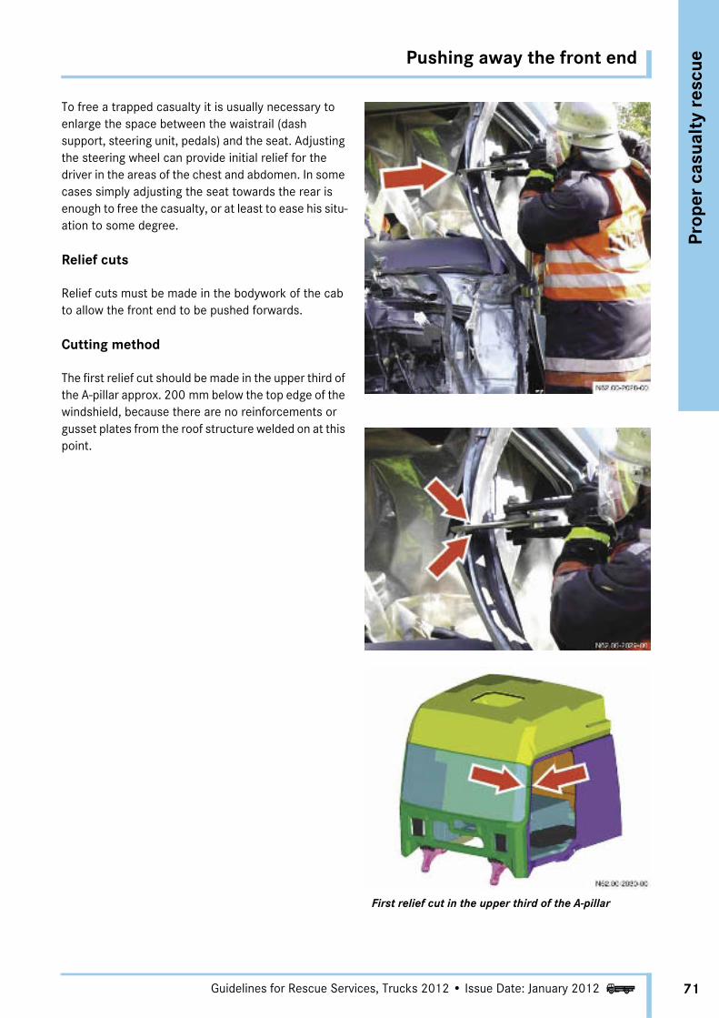
To free a trapped casualty it is usually necessary to enlarge the space between the waistrail (dash support, steering unit, pedals) and the seat. Adjusting the steering wheel can provide initial relief for the driver in the areas of the chest and abdomen. In some cases simply adjusting the seat towards the rear is enough to free the casualty, or at least to ease his situ-ation to some degree.
Relief cuts
Relief cuts must be made in the bodywork of the cab to allow the front end to be pushed forwards.
Cutting method
The first relief cut should be made in the upper third of the A-pillar approx. 200 mm below the top edge of the windshield, because there are no reinforcements or gusset plates from the roof structure welded on at this point.
First relief cut in the upper third of the A-pillar

Pushing away the front end
72
Prop
er c
asua
lty
resc
ue
Guidelines for Rescue Services, Trucks 2012 • Issue Date: January 2012i
The second relief cut should be made in the rocker panel between the A-pillar and B-pillar at a distance of at least 200 mm from the A-pillar. There are no rein-forcement brackets or gusset plates installed here.
As the rocker panel is relatively tall, it is advisable to crush it using a spreader before cutting (especially if using small rescue shears or rescue shears with short blades). After crushing it, first make a V-shaped cut in the rocker panel and then cut all the way through the rocker panel in the middle of the V-cut (to make a Y-shaped cut). This ensures that the rocker panel is severed completely.
i Note• First relief cut in the upper third of the A-pillar• Second relief cut in the front third of the rocker
panel between the A-pillar and B-pillar
Crushing the rocker panel Cutting the rocker panel
Pushing away the front end
Prop
er c
asua
lty
resc
ue
73Guidelines for Rescue Services, Trucks 2012 • Issue Date: January 2012i
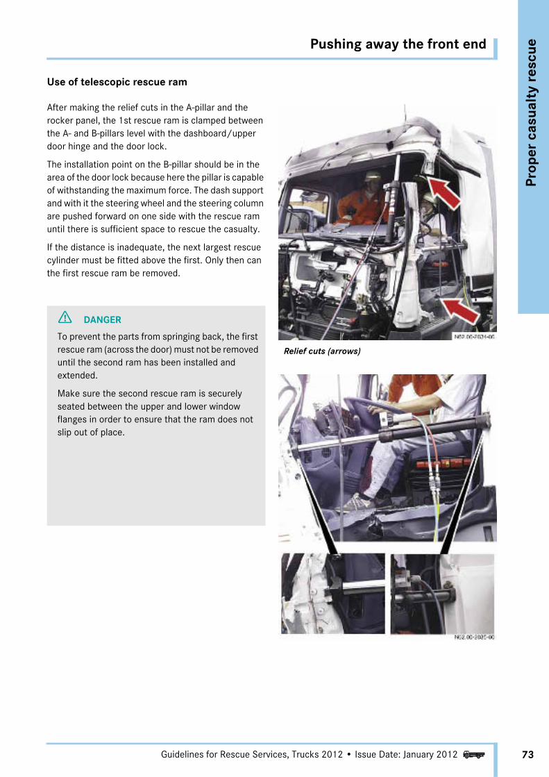
Use of telescopic rescue ram
After making the relief cuts in the A-pillar and the rocker panel, the 1st rescue ram is clamped between the A- and B-pillars level with the dashboard/upper door hinge and the door lock.
The installation point on the B-pillar should be in the area of the door lock because here the pillar is capable of withstanding the maximum force. The dash support and with it the steering wheel and the steering column are pushed forward on one side with the rescue ram until there is sufficient space to rescue the casualty.
If the distance is inadequate, the next largest rescue cylinder must be fitted above the first. Only then can the first rescue ram be removed.
Relief cuts (arrows)
a DANGER
To prevent the parts from springing back, the first rescue ram (across the door) must not be removed until the second ram has been installed and extended.
Make sure the second rescue ram is securely seated between the upper and lower window flanges in order to ensure that the ram does not slip out of place.

Pushing away the front end
74
Prop
er c
asua
lty
resc
ue
Guidelines for Rescue Services, Trucks 2012 • Issue Date: January 2012i
In this position the rescue ram may obstruct the rescue of the casualty. If this is the case, an additional rescue ram should be clamped between the upper and lower windshield flanges. Then the first ram can be removed, and the way is clear to rescue the casualty. This measure should only be employed if there is a substantial impediment to extricating the casualty from the cab.
The door opening may be so badly deformed due to the crash that it may be necessary to use rescue rams of different sizes to enlarge the opening.
i NoteAll action should only be performed in close consultation between the fire brigade and the rescue crew.

New cutting method
Prop
er c
asua
lty
resc
ue
75Guidelines for Rescue Services, Trucks 2012 • Issue Date: January 2012i
Due to design modifications in terms of rigidity and crash behavior, the geometry and strength of the cab longitudinal members have changed. The cab has become intrinsically more rigid. For this reason the cutting method (the cut at the bottom of the A-pillar) has been modified.
N60.80-2289-00
Cab shell in the Actros 1-3
i Note
The modified cutting method can also be used on all other model series (Actros 1-3, Atego, Axor).
N60.80-2290-00
Cab shell in the Actros (model 963)

New cutting method
76
Prop
er c
asua
lty
resc
ue
Guidelines for Rescue Services, Trucks 2012 • Issue Date: January 2012i
Cut marks
On the New Actros (model 963) the locations for the relief cuts on the driver and passenger sides are identified by cut marks (CUT) at the top and bottom of the A-pillar.
N60.80-2291-00
1 Cut mark at top of A-pillar2 Cut mark at bottom of A-pillar
New cutting method
Prop
er c
asua
lty
resc
ue
77Guidelines for Rescue Services, Trucks 2012 • Issue Date: January 2012i
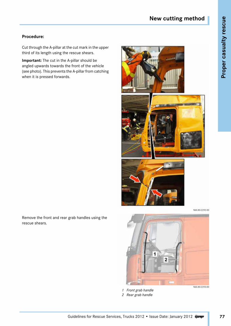
Procedure:
Cut through the A-pillar at the cut mark in the upper third of its length using the rescue shears.
Important: The cut in the A-pillar should be angled upwards towards the front of the vehicle (see photo). This prevents the A-pillar from catching when it is pressed forwards.
N60.80-2292-00
Remove the front and rear grab handles using the rescue shears.
N60.80-2293-00
1 Front grab handle2 Rear grab handle

New cutting method
78
Prop
er c
asua
lty
resc
ue
Guidelines for Rescue Services, Trucks 2012 • Issue Date: January 2012i
Above the lower door hinge and level with the lower cut mark, make a cut approx. 15 cm deep in the A-pillar using the rescue shears, but do not cut all the way through!
N60.80-2294-00
Position the rocker panel attachment on the rocker panel at the B-pillar so that it cannot slip off.
In order to avoid damage to the panel structure, a rocker panel attachment with a tapered corner should be used.
N60.80-2295-00
New cutting method
Prop
er c
asua
lty
resc
ue
79Guidelines for Rescue Services, Trucks 2012 • Issue Date: January 2012i
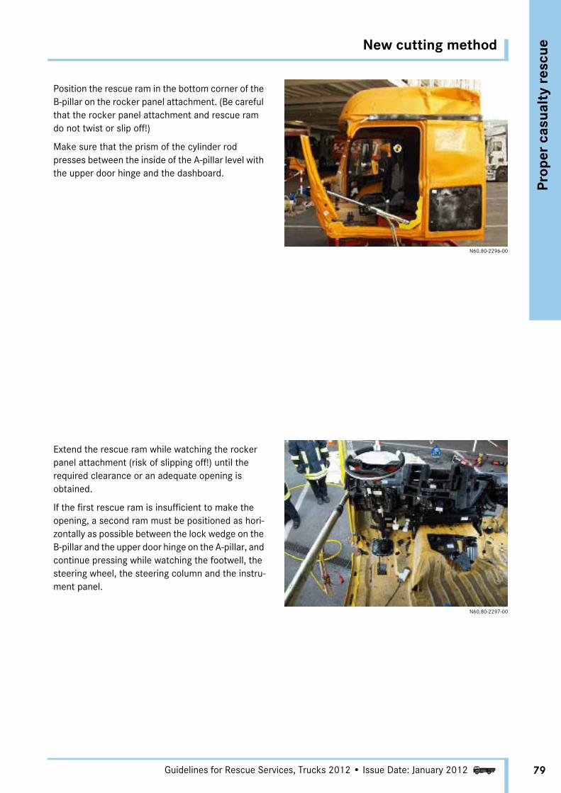
Position the rescue ram in the bottom corner of the B-pillar on the rocker panel attachment. (Be careful that the rocker panel attachment and rescue ram do not twist or slip off!)
Make sure that the prism of the cylinder rod presses between the inside of the A-pillar level with the upper door hinge and the dashboard.
N60.80-2296-00
Extend the rescue ram while watching the rocker panel attachment (risk of slipping off!) until the required clearance or an adequate opening is obtained.
If the first rescue ram is insufficient to make the opening, a second ram must be positioned as hori-zontally as possible between the lock wedge on the B-pillar and the upper door hinge on the A-pillar, and continue pressing while watching the footwell, the steering wheel, the steering column and the instru-ment panel.
N60.80-2297-00
Safety systems
80
Prop
er c
asua
lty
resc
ue
Guidelines for Rescue Services, Trucks 2012 • Issue Date: January 2012i
a DANGER
When disconnecting batteries or cutting the cables, disconnect the ground line first otherwise there is a risk of short circuit.
If short circuits occur, there is a risk of injury from an electric shock due to the higher voltage and current of truck batteries.
Sparks or the overheating of electrical compo-nents due to short circuits can cause inflam-mable substances to ignite. Any resulting fire or deflagration poses an acute risk of injury for occupants and rescuers alike.
If this is not possible, insulated tools must be used to disconnect or cut the cables. If no insulated tools are available, insulate the appropriate places by covering them with suit-able materials.
Wear protective clothing/safety glasses.
Ensure that sufficient quantities of fire extin-guishing agents are at hand.
a DANGER
There is a risk of injury in the deployment area of undeployed airbags.
If, before the battery is disconnected, severe shocks occur in the vicinity of the driver seat and the cab longitudinal member (location of the airbag control unit), or electrical lines or the steering column are cut, it is possible that an airbag or emergency tensioning retractor may be triggered. If this happens, loose objects or glass splinters may be thrown or pressed onto the casualty or the rescuers, causing injuries.
Cover the occupants before commencing work, preferably with a transparent sheet.
Wear protective clothing/safety glasses.
Disconnect all batteries. If this is not possible, keep well away from undeployed airbags.
Do not perform cutting work near undeployed airbags.
Avoid heating near undeployed airbags.
Do not place any objects near undeployed airbags.
i NoteMerely cutting through the steering wheel rim or the spokes will not usually trigger the airbag.
i NoteMost airbag systems are designed so that they can no longer be triggered by the airbag sensor systems after the battery has been disconnected and a short waiting period has elapsed.

Airbag
Prop
er c
asua
lty
resc
ue
81Guidelines for Rescue Services, Trucks 2012 • Issue Date: January 2012i
a DANGER
If using safety devices intended to protect against airbag deployments after an accident, there is a danger that these devices may be cata-pulted by the deploying airbag, presenting an additional injury hazard for the casualty and the rescuers. So-called "safety devices" that are intended to prevent a pressure buildup by piercing holes in the airbag fabric must not be used because, if trig-gered, the hot ignition gases can escape unhin-dered and cause extremely serious burns.
Cover the occupants before commencing work, preferably with a transparent sheet.
Wear protective clothing/safety glasses.
Disconnect all batteries. If this is not possible, keep well away from undeployed airbags.
Do not perform cutting work near undeployed airbags.
Avoid heating near undeployed airbags.
Do not place any objects near undeployed airbags.
a DANGER
From contact with the airbag, occupants may suffer slight reddening of the skin and abra-sions, e.g. on the insides of the forearms or on the chin, due to the necessary high deployment speed. Slight irritation of the respiratory passages cannot be ruled out.
The condition of the casualties must be assessed as accurately as possible before deciding on further precautionary measures.
i NoteThe white, powdery residues left inside the vehicle after deployment of an airbag are non-toxic. They consist for the most part of talcum, which acts as a lubricant for the airbag fabric!

Airbag
82
Prop
er c
asua
lty
resc
ue
Guidelines for Rescue Services, Trucks 2012 • Issue Date: January 2012i
Overview
A driver airbag, identifiable by the "AIRBAG" or "SRS" (Supplemental Restraint System) logo on the padded boss of the steering wheel, in combination with an emergency tensioning retractor is available as a restraint system (special equipment) for Mercedes-Benz trucks. An emergency tensioning retractor in the backrest of the driver seat or front passenger seat is only possible when an airbag is installed. If the airbag system has deployed following an accident, there is no more danger to the casualty and the rescue personnel from an inflating airbag.
Undeployed airbag
Deployed airbag

Airbag
Prop
er c
asua
lty
resc
ue
83Guidelines for Rescue Services, Trucks 2012 • Issue Date: January 2012i
General
The airbag, identifiable by the word "AIRBAG" or "SRS" (Supplemental Restraint System) embossed on the padded boss, is integrated in the steering wheel under the padded boss. The seat belt system for the driver can be supplemented with an emergency tensioning retractor. This is located at the seat belt attachment points inside the seat.
In the event of a collision with a precisely defined deceleration, the airbag control unit triggers a number of propellant charges. One propellant charge deploys the airbag while another charge activates the emer-gency tensioning retractor and pulls the seat belt as tight as possible across the driver's body.
Undeployed airbags
In cases where the rescue or treatment of casualties has to be carried out within the deployment radius of untriggered airbag systems (e.g. if the casualties are trapped or their injuries require immediate treatment), the following points must be observed:
• Switch off ignition! Note: Consultation with the emergency physician is essential because the seat may move downwards under certain conditions (not in the Actros 3 and the New Actros).
• Disconnect cables from battery. Note: Consultation with the emergency physician is essential because the seat may move downwards under certain conditions (not in the Actros 3 and the New Actros).
• Do not perform cutting work near the airbag units concerned!
• Avoid overheating the area around the airbag unit, such as in the vicinity of the steering wheel impact plate. If an airbag unit is heated, e.g. by fire, to over 160 °C, it is likely to be triggered!
• Do not place any objects near undeployed airbags!
i NoteSwitching off the ignition and disconnecting or cutting the battery cables should only be done in consultation with the emergency physician!

Airbag
84
Prop
er c
asua
lty
resc
ue
Guidelines for Rescue Services, Trucks 2012 • Issue Date: January 2012i
Function of airbag
The driver airbag unit (1) is located in the steering wheel (4) and essentially consists of the padding (3), the air sack and the gas generator (5).
The gas generator contains the solid fuel (2) in tablet form (sodium azide or azide-free depending on the year of manufacture). When the airbag control unit delivers an appropriate pulse (ignition energy) via the slip rings or the clock spring contact to the squib inside the gas generator, the solid fuel in the gas generator is ignited. In general, driver airbags with a one-stage gas generator are used.
The fuel burns within a very short time, developing a defined volume of gas under a defined (very high) pressure.
The gas is directed into the air sack through filters. The nylon fabric air sack folded on top of the gas generator tears open the padding of the cover at a predetermined fracture point. The air sack is filled with gas within a few milliseconds. As he moves forward opposite the impact direction, the occupant comes into contact with the inflated air cushion, which reduces his forward speed. The front airbags substan-tially reduce the risk of head, neck and chest injuries if the occupant is wearing a seat belt.
The gas quickly escapes from the air sack through the blow holes or the filter, and the air cushion collapses.
As the solid fuel burns off, the gas generator heats up, but not the steering wheel.
Driver airbag
1 Driver airbag unit2 Solid fuel3 Padding4 Steering wheel5 Gas generator
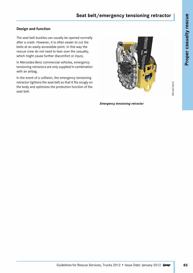
Seat belt/emergency tensioning retractor
Prop
er c
asua
lty
resc
ue
85Guidelines for Rescue Services, Trucks 2012 • Issue Date: January 2012i
Design and function
The seat belt buckles can usually be opened normally after a crash. However, it is often easier to cut the belts at an easily accessible point. In this way the rescue crew do not need to lean over the casualty, which might cause further discomfort or injury.
In Mercedes-Benz commercial vehicles, emergency tensioning retractors are only supplied in combination with an airbag.
In the event of a collision, the emergency tensioning retractor tightens the seat belt so that it fits snugly on the body and optimizes the protection function of the seat belt.
Emergency tensioning retractor

Steering wheel adjustment
86
Prop
er c
asua
lty
resc
ue
Guidelines for Rescue Services, Trucks 2012 • Issue Date: January 2012i
Variants
Adjusting the steering wheel can provide relief for the driver in the areas of the chest and abdomen.
Three variants of steering wheel adjustment are possible.
Manual release
To operate, flip out the lever and adjust the steering wheel
Manual release with locking mechanism
This variant incorporates a locking mechanism (1). This must be operated first in order to be able to flip out the lever to release the steering column.
Manual release
Manual release with locking mechanism
1 Locking mechanism

Pneumatic lock
Prop
er c
asua
lty
resc
ue
87Guidelines for Rescue Services, Trucks 2012 • Issue Date: January 2012i
Pneumatic lock
In the most recent variant, the adjustment facility is secured to prevent unintentional adjustment of the steering wheel by means of a pneumatic lock. This is deactivated automatically after 10 s and must then be reactivated by pressing the switch if it is necessary to adjust the steering column.
The height and angle of the steering wheel are adjusted as follows:
• Press bottom of locking switch The steering column is unlocked
• Move steering wheel to the desired position• Press top of locking switch
The steering column is locked
Pneumatic lock
1 Locking switch
a DANGER
When adjusting the steering wheel, care must be taken to ensure that nobody is injured or trapped by moving parts.
Stop the adjustment immediately if there is a danger of anybody being trapped.
The steering wheel should only be adjusted in consultation with the emergency physician.
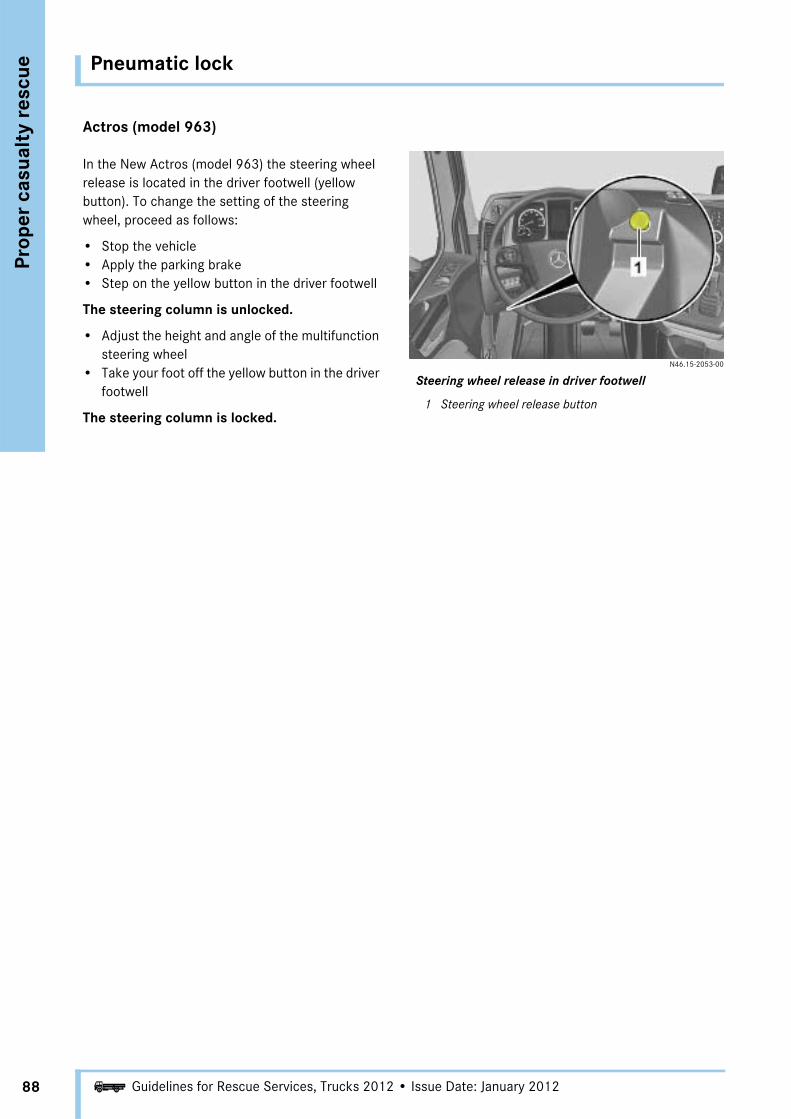
Pneumatic lock
88
Prop
er c
asua
lty
resc
ue
Guidelines for Rescue Services, Trucks 2012 • Issue Date: January 2012i
Actros (model 963)
In the New Actros (model 963) the steering wheel release is located in the driver footwell (yellow button). To change the setting of the steering wheel, proceed as follows:
• Stop the vehicle• Apply the parking brake• Step on the yellow button in the driver footwell
The steering column is unlocked.
• Adjust the height and angle of the multifunction steering wheel
• Take your foot off the yellow button in the driver footwell
The steering column is locked.
N46.15-2053-00
Steering wheel release in driver footwell
1 Steering wheel release button

Seat adjustment
Prop
er c
asua
lty
resc
ue
89Guidelines for Rescue Services, Trucks 2012 • Issue Date: January 2012i
Seat adjustment
Static driver seat Air-sprung suspension seat Air-sprung suspension seat
A wide variety of seats are available for vehicles manu-factured by Mercedes-Benz. The appearance and loca-tion of the seat controls may vary depending on the manufacturer of the seat.
Two different mechanisms are provided for adjusting the seat. One type of seat height adjustment is the static type resembling that in passenger car models. By far the most common variant is the air-sprung suspension seat.
To operate the suspension seat the ignition must be switched on and the air supply must be sufficient. Pressing the button marked 1 allows the seat to be continuously lowered or raised. Pressing the button upwards raises the level of the seat. The seat can be lowered by pressing the button downwards.
On the air-sprung suspension seats, the seat level can also be changed using the "express lowering" button marked 2. Pressing the button once moves the seat all the way down. If the button is pressed again, the seat is raised again to the stored height.
1 Seat height Press up: - RaisePress down:- Lower
2 Express lowering Press once: - Seat is lowered all the wayPress again:- Seat is raised to
the stored height!
Only on suspension seats!

Seat adjustment
90
Prop
er c
asua
lty
resc
ue
Guidelines for Rescue Services, Trucks 2012 • Issue Date: January 2012i
Example of driver seat
Grammer driver seat
1 Seat cushion length adjustment2 Seat inclination adjustment3 Fore/aft adjustment4 Express lowering5 Damper adjustment6 Height adjustment7 Pneumatic lumbar support8 Pneumatic lateral contour support9 Backrest adjustment
10 Seat heater11 Integral 3-point seat belt
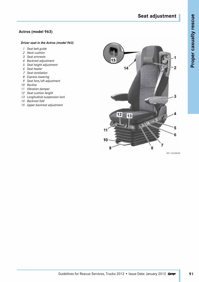
Seat adjustment
Prop
er c
asua
lty
resc
ue
91Guidelines for Rescue Services, Trucks 2012 • Issue Date: January 2012i
Actros (model 963)
Driver seat in the Actros (model 963)
1 Seat belt guide2 Neck cushion3 Seat armrests4 Backrest adjustment5 Seat height adjustment6 Seat heater7 Seat ventilation8 Express lowering9 Seat fore/aft adjustment
10 Recline11 Vibration damper12 Seat cushion length13 Longitudinal suspension lock14 Backrest fold15 Upper backrest adjustment
N91.10-2328-00

Literature and sources
92 i Guidelines for Rescue Services, Trucks 2012 • Issue Date: January 2012
Ann
ex
• "Brandschutz" (Fire Protection) – Deutsche Feuerwehr-Zeitung (German Fire Service News), Issue 3, 1998
• Dr. Rainer Zinser of the Oberschwabenklinik Hospital, Ravensburg
• "Safety of Commercial Vehicles" – 4th DEKRA/VDI Symposium, October 2004, Neumünster
Assistance in carrying out the rescue exercises and taking the photographs was rendered by
• Ludwigshafen Fire Brigade
• Ravensburg Fire Brigade
• Niebüll Fire Brigade
• Nortorf Fire Brigade
• Stuttgart Fire Brigade/Degerloch-Hoffeld Voluntary Fire Department
• Commercial Vehicle Accident Research at Daimler AG

Index
93Guidelines for Rescue Services, Trucks 2012 • Issue Date: January 2012i
Ann
ex
AActros 1 . . . . . . . . . . . . . . . . . . . . . . . 10
Actros 2 . . . . . . . . . . . . . . . . . . . . . . . 11
Actros 3 (models 930-934) . . . . . . . . . . . 12, 13
Air bellows . . . . . . . . . . . . . . . . . . . . . . 56
Air intake . . . . . . . . . . . . . . . . . . . . . 52, 53
Air suspension . . . . . . . . . . . . . . . . . . . . 56
Air suspension test connections . . . . . . . . . . 61
AirbagFunction . . . . . . . . . . . . . . . . . . . . . . 84
Atego 1 . . . . . . . . . . . . . . . . . . . . . . . . 16
Atego 2 . . . . . . . . . . . . . . . . . . . . . . . . 17
Atego 2 (Facelift) . . . . . . . . . . . . . . . . . . 17
Axor 1 . . . . . . . . . . . . . . . . . . . . . . . . . 14
Axor 2 . . . . . . . . . . . . . . . . . . . . . . . . . 15
Axor 2 (Facelift) . . . . . . . . . . . . . . . . . . . 15
BBattery . . . . . . . . . . . . . . . . . . . . . . 22, 24
DDisconnecting the battery . . . . . . . . . . . . . 23
EEMERGENCY OFF switch . . . . . . . . . . . . 31, 35
Emergency tensioning retractor . . . . . . . . . . 85
FFire protection . . . . . . . . . . . . . . . . . . . . 51
Frame air suspension . . . . . . . . . . . . . . . . 58
Fuel line . . . . . . . . . . . . . . . . . . . . . . . 54
GGGVS vehicles (hazardous goods vehicles) . . . . 35
HHV battery . . . . . . . . . . . . . . . . . . . . . . . 33
HV battery disconnect switch . . . . . . . . . . . . 31
HV components . . . . . . . . . . . . . . . . . 27, 29
IIgnition key . . . . . . . . . . . . . . . . . . . . . . 52
Initial accessDoors . . . . . . . . . . . . . . . . . . . . . . . . 49Rear wall . . . . . . . . . . . . . . . . . . . . . . 50Roof hatch . . . . . . . . . . . . . . . . . . . . . 49
Initial opening . . . . . . . . . . . . . . . . . . . . . 45
Integral rear end . . . . . . . . . . . . . . . . 22, 23
LLithium-ion battery . . . . . . . . . . . . . . . . . . 29
PParallel hybrid . . . . . . . . . . . . . . . . . . . . . 25
RRear window . . . . . . . . . . . . . . . . . . . . . . 50
Relief cut . . . . . . . . . . . . . . . . . . . . . . . . 71
Rescue of the casualty . . . . . . . . . . . . . 45, 47
Rescue opening . . . . . . . . . . . . . . . . . 45, 46
SSecuring traffic . . . . . . . . . . . . . . . . . . . . 51
Series hybrid . . . . . . . . . . . . . . . . . . . . . 25
TTelescopic rescue ram . . . . . . . . . . . . . . . . 73
Tools . . . . . . . . . . . . . . . . . . . . . . . . . . 66
Treatment opening . . . . . . . . . . . . . . . 45, 46
WWindows . . . . . . . . . . . . . . . . . . . . . . . . 64
Work platform . . . . . . . . . . . . . . . . . . . . . 62

Guidelines for Rescue ServicesTrucks
Daimler AG, GSP/OI, HPC R 822, D-70546 StuttgartPrinted in Germany – 01/12 Gu
idel
ines
for R
escu
e Ser
vice
s •
Tru
cks