guidelines for generation, tie-line, and substation interconnections · 2018-12-28 · otter tail...
TRANSCRIPT

Guidelines for Generation, Tie-Line, and
Substation Interconnections

Otter Tail Power Company Guidelines for Generation, Tie-Line, and Substation Interconnections ii
Otter Tail Power Company compiled this document with input from others.
Otter Tail Power Company gratefully acknowledges permission granted by Northern States Power and Georgia Power Company to utilize their “Guide for Interconnection Requirements and Parallel Operation of Customer Owned Generation” as a basis for several sections.
Revision Number
Revision Date
Effective Date
Owner
Summary of Changes
2.1
July 12, 2002
JoAnn Thompson
Creation of document
3.1
Nov. 30, 2009
Dec. 30, 2009
Dean Pawlowski
Reorganization and general update
3.2
Oct. 15, 2010
Dec. 30, 2010
Dean Pawlowski
General Update
3.3 Nov 15, 2013 Nov. 25, 2013 Dean Pawlowski
General Update
3.4 Dec 21, 2018 Jan. 1, 2019 Dean Pawlowski
Metering process documentation
Otter Tail Power Company Guidelines for Generation, Tie-line, and Substation Interconnections, Version 3.4 Otter Tail Power Company

Otter Tail Power Company Guidelines for Generation, Tie-Line, and Substation Interconnections iii
215 South Cascade Street Fergus Falls, MN 56538-0496
Otter Tail Power Company Guidelines for Generation, Tie-Line, and Substation Interconnections iv
OTTER TAIL POWER COMPANY GUIDELINES FOR GENERATION, TIE-LINE, AND SUBSTATION INTERCONNECTIONS
Table Of Contents
Page
I. INTRODUCTION ...............................................................................................................1
A. Objectives ................................................................................................................1 B. Authority ..................................................................................................................1 C. Interconnection Procedures ......................................................................................2 D. Otter Tail Power Company as a Balancing Authority Area Operator .....................2
II. GENERAL POLICY AND REQUIREMENTS ..................................................................3
A. Compliance with Interconnection Requirements .....................................................3 B. Responsibility and Approval....................................................................................3 C. Financial Obligation Associated with Interconnection to the Otter Tail System ....3 D. Financial Penalties ...................................................................................................4 E. Requests for Transmission Service ..........................................................................4
III. GENERATION GENERAL INFORMATION ...................................................................4
A. Interconnection Types ..............................................................................................4 B. Generator Classifications .......................................................................................13
1. Self-service Generators ..............................................................................13 2. Net Meter Generator ..................................................................................13 3. Wholesale Generators ................................................................................13
C. Requirements for Generator Testing and Performance ........................................13 1. Generation Testing Requirement ...............................................................13
D. Modeling Requirements for Generation Greater than 5 MW ................................13 E. Isolation Power Transformer .................................................................................14 F. Generator Step-Up Transformer ............................................................................14 G. Automatic Generator Control – 50 MW and Larger ..............................................14 H. Synchronization of Applicant’s Generation...........................................................15
IV. COORDINATION WITH OTHER REGIONAL ENTITIES ...........................................15
A. Coordination of studies (R2.1.1) ..........................................................................15 B. Notifications of modifications (R2.1.2) ................................................................16
V. VOLTAGE LEVEL AND MW AND MVAR CAPACITY OR DEMAND AT POINT OF CONNECTION (R2.1.3) ............................................................................................17
VI. BREAKER DUTY AND SURGE PROTECTION (R2.1.4) ............................................17
VII. PROTECTION REQUIREMENTS (R2.1.5) ..................................................................18
A. For All Interconnections ........................................................................................18 1. Disconnect..................................................................................................19 2. Protective Relay Requirements ..................................................................19 3. Reliability and Redundancy .......................................................................20

Otter Tail Power Company Guidelines for Generation, Tie-Line, and Substation Interconnections v
4. Line Protection ...........................................................................................20 5. Fault-Interrupting Devices .........................................................................22
a. Circuit Breakers ............................................................................ 23 b. Circuit Switchers ........................................................................... 23 c. Fuses ............................................................................................. 23
6. Single-Phase Devices - Fuses/Oil Circuit Reclosers .................................24 7. Automatic Reclosing/Voltage Check Schemes .........................................25
B. Additional Protection For Generation Interconnections .......................................25 1. Special Protection Scheme .........................................................................25 2. Event Recorder...........................................................................................26
VIII. METERING AND TELECOMMUNICATIONS (R2.1.6) ..............................................27
A. Common .................................................................................................................27 1. Metering .....................................................................................................27 2. Metering Accuracy, Testing, and Repair ...................................................28
a. Metering Accuracy ........................................................................ 28 b. Periodic Testing ............................................................................ 28 c. Meter and Telemetry Equipment Repair ....................................... 29
3. Metering and Telemetry Function Requirements ......................................29 5. Energy Losses ....................................................................................................30 6. Meter Reading ............................................................................................31
B. Telemetry ...............................................................................................................31 C. Communication Channel .......................................................................................32
IX. GROUNDING AND SAFETY ISSUES (R2.1.7) ............................................................33
A. Safety and Isolating Devices ..................................................................................33 B. Energization of Otter Tail Equipment by the Applicant ........................................33 C. Substation Grounding ............................................................................................34
X. INSULATION AND INSULATION COORDINATION (R2.1.8) ................................34
A. Surge Protection .....................................................................................................35 B. Lightning Surges ....................................................................................................35 C. Temporary Overvoltages .......................................................................................35
1. Islanding .....................................................................................................36 2. Neutral Shifts .............................................................................................36
XI. VOLTAGE, REACTIVE POWER, AND POWER FACTOR CONTROL (R2.1.9) ......37
A. Voltage ...................................................................................................................37 B. Minimum Power Factor Requirements ..................................................................38
1. Substation-Specific Power Factor Requirements.......................................38 2. Generator-Specific Power Factor Requirements .......................................38
a. Reactive Supply and Voltage Control from Generation Sources Service – 10 MW or Larger .......................................................... 38
XII. POWER QUALITY IMPACTS (R2.1.10) .......................................................................39
A. Flicker ....................................................................................................................39 B. Harmonics ..............................................................................................................40

Otter Tail Power Company Guidelines for Generation, Tie-Line, and Substation Interconnections vi
XIII. EQUIPMENT RATINGS (R2.1.11) .................................................................................42
XIV. SYNCHRONIZING OF FACILITIES (R2.1.12) .............................................................42
A. Synchronizing Relays ............................................................................................42
XV. MAINTENANCE COORDINATION (R2.1.13) .............................................................43
XVI. OPERATIONAL ISSUES (R2.1.14) ..................................................................................44
A. Operating Guidelines .............................................................................................44 B. Fault Current ..........................................................................................................45 C. Frequency During Disturbances ............................................................................45 D. Generator Frequency/Speed Control ......................................................................46
1. 10 MW or Less...........................................................................................46 2. 10MW or Greater .......................................................................................46 3. Excitation System Requirements ...............................................................48
XVII. INSPECTION REQUIREMENTS FOR EXISTING OR NEW FACILITIES (R2.1.15) 48
A. Inspection, Test, Calibration and Maintenance......................................................48 1. Pre-energization Inspection and Testing ....................................................48 2. Calibration and Maintenance .....................................................................49
a. Metering Equipment...................................................................... 49 b. All Other Electrical Equipment .................................................... 49
XVIII. COMMUNICATIONS AND PROCEDURES DURING NORMAL AND EMERGENCY OPERATING CONDITIONS (R2.1.16) ................................................49
A. Dispatching and Maintenance ................................................................................50 1. Emergency Response Requirement ...........................................................50
XIX. MISCELLANEOUS ..........................................................................................................51
A. Station Service .......................................................................................................51 B. Ancillary Services ..................................................................................................51 C. Supervisory Control and Data Acquisition (SCADA) Requirements....................52
XX. PRE-PARALLEL CONTRACT REQUIREMENTS ........................................................52
XXI. GLOSSARY .....................................................................................................................54
XIII. REFERENCES ..................................................................................................................61
Appendix A: Interconnetion Data Submittal ................................................................................63
Appendix B: MN Distributed Generation Requirements...............................................................68
Appendix C: SD Distributed Generation Requirements ...............................................................99

Otter Tail Power Company Guidelines for Generation, Tie-Line, and Substation Interconnections 1
I. INTRODUCTION A. OBJECTIVES
The purpose of this handbook is to provide technical guidelines to assist the applicant desiring to interconnect with the Otter Tail Power Company electric system (“Otter Tail System”) in establishing the interconnection in an efficient and consistent manner to meet the minimum requirements for safe and reliable operation of the parallel interconnection. This document is designed to comply with the North American Electric Reliability Council’s (NERC) compliance directive to establish facility connection standards. These guidelines are not intended to be a design specification or instruction manual but to provide the technical guidance needed to achieve the following:
• Ensure the safety of the general public and Otter Tail personnel. • Maintain the reliability and service of all users of the Otter Tail System. • Minimize the possible damage to the property of the general public, Otter Tail
Customers, and Otter Tail. • Minimize adverse operating conditions on the Otter Tail System. • Permit the applicant to operate in parallel with the Otter Tail System in a safe, reliable
and efficient manner. • Accurately measure and account for all injections and extractions from the
interconnected system.
B. AUTHORITY
State and federal regulatory agencies having jurisdiction over Otter Tail’s System, require Otter Tail to provide safe and reliable service. The Federal Energy Regulatory Commission (FERC), having authority over the entire interconnected electric grid and all wholesale transactions, has established the NERC operating guidelines as the guiding standards and practices for all jurisdictional utilities. Otter Tail adheres to the existing (or amended) manuals, standards, and guidelines of the NERC, MISO, Applicable Reliability Council, or any successor agency assuming or charged with similar responsibilities related to the operation and reliability of the North American electric interconnected transmission grid. The requirements set forth by this document are intended to comply with the Public Utility Regulatory Policies Act (PURPA), the FERC’s final rules on Open Access (FERC Orders 888, 889), all state and federal regulatory agency requirements and other applicable requirements of other entities related to owners and operators of electric Systems and associated interconnected facilities such as NERC, MISO, Applicable Reliability Council, or any successor agency assuming or charged with similar responsibilities related to the operation and reliability of the North American electric interconnected transmission grid. While these requirements are based on today’s industry standards, the electric industry is undergoing a major restructuring and

Otter Tail Power Company Guidelines for Generation, Tie-Line, and Substation Interconnections 2
changes can be expected. The applicant needs to work closely with Otter Tail to keep up to date on the interconnection requirements. Any applicant desiring to interconnect to the Otter Tail System is required to comply with Otter Tail’s requirements.
C. INTERCONNECTION PROCEDURES
The interconnection procedures for establishing interconnection to the Otter Tail Transmission System are pursuant to Attachment X under the MISO Open Access Transmission. Additional information may be found on the Company’s website at http://www.otpco.com. The interconnection procedures for establishing interconnection to the Otter Tail Distribution System are in accordance with the procedures established under the jurisdiction of each state in which Otter Tail provides electric service. A copy of the applicable procedures will be provided to the applicant with a copy of these guidelines. Additional details may also be found on the Company’s website at http://www.otpco.com.
All new interconnection applicants should initiate the interconnection process by contacting:
Interconnection Coordinator Otter Tail Power Company 215 South Cascade Street Fergus Falls, MN 56538-0496 (218) 739-8947 [email protected]
D. OTTER TAIL POWER COMPANY AS A BALANCING AUTHORITY AREA OPERATOR
Otter Tail Power Company is the Local Balancing Area Operator for a large geographic area comprising parts of Minnesota, North Dakota, and South Dakota. In light of this operating responsibility, some requirements set forth in these guidelines will be applicable to all interconnections made within the Otter Tail Balancing Authority Area and not exclusively for Otter Tail Customers. Any operations of interconnected equipment or facilities will fall under the direction of the Balancing Authority Area Operator. All facilities or entities scheduling within, in, or out of the Otter Tail’s Balancing Authority Area will be required to sign the Control Area Services and Operations Tariff (CASOT). New interconnections that will not be participating in wholesale transactions or scheduling within, in, or out of Otter Tail’s Local Balancing Authority Area may be required to sign a modified agreement for control area services, as some balancing area services may still be required for those facilities.

Otter Tail Power Company Guidelines for Generation, Tie-Line, and Substation Interconnections 3
II. GENERAL POLICY AND REQUIREMENTS
A. COMPLIANCE WITH INTERCONNECTION REQUIREMENTS
It is the responsibility of the applicant to obtain all permits and approvals of the governing bodies and to comply with all applicable electrical and safety codes.
The applicant is responsible for ensuring that the interconnection complies with all NERC, MISO, Applicable Reliability Council, and state planning, design, operating standards – including periodic unit testing, MISO procedures, and the appropriate state procedures.
B. RESPONSIBILITY AND APPROVAL
Approval of the proposed interconnection only ensures that Otter Tail has reviewed the inter-connection to make certain that the Otter Tail System can be maintained and that other Otter Tail customers are not adversely affected by operation of the interconnecting Facilities. Otter Tail will not assume any liability or responsibility for applicant-owned equipment.
C. FINANCIAL OBLIGATION ASSOCIATED WITH INTERCONNECTION TO THE OTTER
TAIL SYSTEM
Through appropriate agreement(s), Otter Tail may make provisions to recover costs. The following expense categories are examples of (but not all-inclusive of) items reimbursable to Otter Tail:
• Meter installation, tests, maintenance, parts and related labor • Meter reading and scheduling • Telemetry installation, tests, maintenance, parts and related labor • Operating expenses, including communication circuits • Study analysis and related expenses • Securing NERC Regional Entity or equivalent acceptance • Modifications to the Otter Tail System and related labor/engineering • Protective device installation/equipment cost and related labor • Protective device settings review and coordination • Review of design, inspection and testing costs • Programming costs to incorporate generation and tie-line data into Otter Tail's energy
management system • Land, rights-of-way, licensing, permitting, engineering, etc. • Control Area Services costs

Otter Tail Power Company Guidelines for Generation, Tie-Line, and Substation Interconnections 4
D. FINANCIAL PENALTIES
If operation of the applicant’s Facility causes Otter Tail to be out of compliance with any applicable rules, regulations, and/or requirements of NERC, MISO, Applicable Reliability Council, or any successor agency assuming or charged with similar responsibilities related to the operation and reliability of the North American electric interconnected transmission grid, and if Otter Tail is assessed a penalty, fee, or charge for such non-compliance, said penalty will be passed through to the applicant.
E. REQUESTS FOR TRANSMISSION SERVICE
The ability to interconnect to the Otter Tail System does not mean the applicant can deliver or receive power over Otter Tail's facilities at all times and to any location. This determination is made under the Transmission Provider’s Tariff and through reservation of transmission service. If the applicant intends to wheel power over Otter Tail's transmission facilities, the applicant must contact the MISO concerning obtaining transmission service.
F. Generator Tie Line Interconnections If any interconnection is requested to an Otter Tail generator tie-line facility, the same requirements will be used for this interconnection as to a transmission facility. III. GENERATION GENERAL INFORMATION
For purposes of this handbook, generation is defined as any device producing (or releasing from storage) electrical energy. Such devices include rotating generators driven by steam turbines, internal combustion engines, or hydraulic turbines; windmills; photovoltaic arrays; fuel cells; battery arrays; or other energy sources with a DC to AC inverter or any other electric generating device. Parallel Operation is defined as the operation of applicant-owned generation with output terminals connected directly or through an intermediary’s system to Otter Tail's electric delivery system. Parallel Operation may be long-term or momentary (“make before break,” “hot,” “soft loading limited parallel,” “soft loading extended parallel” “Quick Open”, or “closed-transition transfer”).
A. INTERCONNECTION TYPES Identified within this section are general requirements that apply to generating equipment operated in parallel with the Otter Tail System including three-phase and single-phase generators or inverter installations. Some requirements are dependent upon the size of the installation as will be noted in the requirements. Additionally, the requirements to interconnect generation may vary depending upon:
• Whether the interconnection transfer is open or closed. • The Otter Tail System interconnection voltage. • Interconnection power flow (one-way or two-way).

Otter Tail Power Company Guidelines for Generation, Tie-Line, and Substation Interconnections 5
• The size, type, or location of the proposed interconnection. • The scheduling of energy within Otter Tail’s Balancing Area. • State interconnection requirements
The manner in which the installation will operate (parallel vs. isolated) including the transition methods will dictate the required operating procedures and equipment installation of the generator.
Operating procedures and equipment installation will determine the type of transition scheme implemented. The method of transition implemented will be dependant upon the applicant’s desired terms and conditions of rates and tariffs associated with transactions and/or alternatively, the applicant’s desired method of transition will determine the terms and conditions of rates and tariffs. These conditions can be discussed between the applicant and their Otter Tail interconnection coordinator. For any installation, improper operation will result in action by Otter Tail to remove such hazard in order to safeguard its employees and the general public. The possible transition operating schemes are listed below.
• Open Transition / Break Before Make
With this transfer switch, the load to be supplied from the Generation is first disconnected from the Otter Tail System and then connected to the Generation. The transfer switch typically consists of mechanical interlocks between the two source contactors that drop the Otter Tail System source before the Generation is connected to supply the load.
(1) To qualify as an Open Transition switch and thwith limited protection requirements, mechanical interlocks are required between the two source contacts. This is required to ensure that one of the contacts is always open and the Generation System is never operated in parallel with the Otter Tail System. If the mechanical interlock is not present, the protection requirements are as if the switch is a closed transition switch.
(2) Figure 1 provides a typical one-line of this type of installation.
• Quick Open The load to be supplied from the Generation is first disconnected from the Otter Tail System and then connected to the Generation, similar to the open transition. However, this transition is typically much faster (under 500 ms) than the conventional open transition transfer operation. Voltage and frequency excursions will still occur, sensitive equipment will typically not be affected with a properly designed system. The transfer switch contains mechanical interlocks between the two source contacts that drop the Otter Tail System source before the generation is connected to supply the load.

Otter Tail Power Company Guidelines for Generation, Tie-Line, and Substation Interconnections 6
(1) Mechanical interlocks are required between the two source contacts to ensure
that one of the contacts is always open. If the mechanical interlock is not present, the protection requirements are as if the switch is a closed transition switch.
(2) Figure 2 provides a typical one-line of this type of installation and shows the required protective elements.
• Closed Transition
The Generation is synchronized with the Otter Tail System prior to the transfer occurring. The transfer switch then parallels with the Otter Tail System for a short time (100 msec. Or less) and then the generation system and load disconnects from Otter Tail System. This transfer is less disruptive than the Quick Open Transition because it allows the generation a brief time to pick up the load before the support of the Otter Tail System is lost. With this type of transfer, the load is always being supplied by the Otter Tail System or the generation.
Figure 2 provides a typical one-line of this type of installation and shows the required protective elements. The closed transition switch must include a separate parallel time limit relay, which is not part of the generation control and trips the generation from the system for a failure of the transfer switch and/or the transfer switch controls.
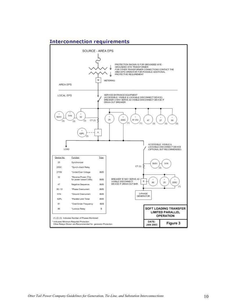
• Soft Loading Transfer Limited Parallel
The generation is paralleled with the Otter Tail System for a limited amount of time (generally less than 1-2 minutes) to gradually transfer the load from the Otter Tail System to the generation system. This minimizes the voltage and frequency problems, by softly loading and unloading the generation system. (1) Figure 3 provides a typical one-line of this type of installation and shows the
required protective elements.
• Soft Loading Transfer Extended Parallel The generation system is paralleled with the Otter Tail System in continuous operation. Special design, coordination and agreements are required before any extended parallel operation will be permitted. An Otter Tail interconnection study could be required to identify the issues involved. (1) Any anticipated use in the extended parallel mode requires special agreements
and special protection coordination.
(2) Figure 4 provides a typical one-line of this type of installation and shows the required protective elements.
• Inverter Connected

Otter Tail Power Company Guidelines for Generation, Tie-Line, and Substation Interconnections 7
This is a continuous parallel connection with the Otter Tail System. Small generation Systems may utilize inverters to interface to the Otter Tail System. Solar, wind and fuel cells are some examples of generation which typically use inverters to connect to the Otter Tail System. The design of such inverters shall either contain all necessary protection to prevent unintentional islanding, or the Interconnection Customer shall install conventional protection to affect the same protection. All required protective elements for a soft-loading transfer switch apply to an inverter connection. Figure 5

Otter Tail Power Company Guidelines for Generation, Tie-Line, and Substation Interconnections 8

Otter Tail Power Company Guidelines for Generation, Tie-Line, and Substation Interconnections 9
Otter Tail Power Company Guidelines for Generation, Tie-Line, and Substation Interconnections 10

Otter Tail Power Company Guidelines for Generation, Tie-Line, and Substation Interconnections 11

Otter Tail Power Company Guidelines for Generation, Tie-Line, and Substation Interconnections 12

Otter Tail Power Company Guidelines for Generation, Tie-Line, and Substation Interconnections 13
B. GENERATOR CLASSIFICATIONS
For the purpose of this document, applicant-owned generators are classified as either “Self-service” or “Wholesale” generators.
1. Self-service Generators
Self-service generators (Open Transfer, Quick Open, Parallel, or Soft Loading) are those whose purpose is to serve only on-site customer loads and not to deliver power over Otter Tail’s or other utilities’ electric facilities. At a minimum, these installations must demonstrate to Otter Tail’s satisfaction their compliance with the Otter Tail design standards. 2. Net Meter Generator
Net meter generators deliever energy to Otter Tail Power in excess of that received by the generator or load from Otter Tail.
3. Wholesale Generators
Wholesale generators (Soft Loading Extended) are those units where the applicant plans to sell power and/or energy to others or deliver such power over Otter Tail’s or another utility’s facilities (wheeling). In order for the generator to sell capacity, the generator must be reviewed and approved by MISO and/or the Applicable Reliability Council. Wholesale Generator installations may also be required to receive MISO or Applicable Reliability Council accreditation.
C. REQUIREMENTS FOR GENERATOR TESTING AND PERFORMANCE
1. Generation Testing Requirement
The Wholesale Generation applicant must agree to perform any and all testing of each generator as required by the Applicable Reliability Council and/or the MISO. The specific testing requirements depend on the type of prime mover for the Facility.
D. MODELING REQUIREMENTS FOR GENERATION GREATER THAN 5 MW All generator/exciter/governor manufacturer data sheets must be available for modeling in transient/voltage stability, short circuit, and relay setting calculation programs. This includes generator reactive capability curves and exciter saturation curves. At OTP’s discretion, the applicant will supply accurate data necessary for transient stability, voltage stability and steady state modeling of the facilities. At a minimum, generator nameplate

Otter Tail Power Company Guidelines for Generation, Tie-Line, and Substation Interconnections 14
data must be specified, including the rated voltage, the MW and MVAR capacity or demand, impedence and the power factor capability of the generator. The actual test data must be provided.
E. ISOLATION POWER TRANSFORMER
To provide maximum operating flexibility for the applicant's generation and to minimize possible adverse effects on other Otter Tail customers, a power transformer may be required between the applicant's generator and Otter Tail-owned equipment. This transformer is usually connected to isolate the zero sequence circuit of the applicant from the zero sequence circuit of the Otter Tail System. During the interconnection process the required transformer connection and grounding configuration will be determined, as well as whether or not a dedicated Otter Tail-owned transformer will be required to serve an applicant with generation. Upgrading of Otter Tail transformer insulation levels and lightning arrester ratings to a higher voltage may be required at the applicant's expense due to the addition of applicant’s generation. For units less than 1 MW, the transformer that provides isolation is likely to be the same one already serving customer load. For those units 1 MW or greater, it is likely a dedicated transformer will be added as part of the new unit.
F. GENERATOR STEP-UP TRANSFORMER
The available voltage taps of the applicant’s step-up transformer must be reviewed by Otter Tail for its suitability with the Otter Tail System. The applicant is expected to request this review before acquiring the transformer. Otter Tail shall determine which voltage taps would be suitable for a step-up transformer for the Applicant’s proposed project. Suitable taps are required to give the transformer the essential capacity for the generator to:
• Deliver maximum reactive power to Otter Tail’s System at the Point of Interconnection (generator operating to at least 95 percent lagging power factor).
• Absorb maximum reactive power from Otter Tail’s System (generator operating to at least 95 percent leading power factor).
• Help maintain a specified voltage profile on Otter Tail’s system for varying operating conditions. Actual voltage tap settings can be different for transformers connected at the same voltage level, depending upon their geographic location.
G. AUTOMATIC GENERATOR CONTROL – 50 MW AND LARGER The applicant’s generator shall be equipped with Automatic Generator Control (“AGC”) equipment to permit remote control of the unit and enable the generation to be increased or decreased via Automatic Generation Control. This requirement does not apply if the plant is exempt under NERC, MISO, or Applicable Reliability Council rules due to prime mover or regulatory limitations. Any remote control that is required will be implemented through the
Otter Tail Power Company Guidelines for Generation, Tie-Line, and Substation Interconnections 15
telemetry equipment identified in Section VIII. Certain additional interface signals will be required to implement the remote control.
H. SYNCHRONIZATION OF APPLICANT’S GENERATION
All applicants, independent of generator size classification, are responsible for synchronization of applicant’s generation to the Otter Tail System. Before synchronization to the Otter Tail System will be permitted, all required studies, tests and inspections, and contracts must be completed and approved. IV. COORDINATION WITH OTHER REGIONAL ENTITIES
A. COORDINATION OF STUDIES (R2.1.1)
An Applicant will be required to submit an interconnection application for any new or modified Facility is seeks to interconnect to the Otter Tail System. Depending on the size, type, and location of a new or modified Facility, a study could be performed by either: (1) Otter Tail; or (2) the MISO; or (3) the Applicable Reliability Council; or (4) a neighboring transmission owner; or (5) a neighboring load serving entity; or (6) a neighboring distribution provider. Otter Tail will have a different role to ensure coordination of studies for either new or modified facilities depending on who performs the study. In the event that a study for a new or modified facility is performed by Otter Tail, the following steps shall be taken:
1. Otter Tail will develop a study scope for the evaluation of a new or modified facility and request participation of interested parties in an ad hoc study group (including neighboring transmission owners, the MISO, the Applicable Reliability Council, neighboring transmission owners, neighboring load serving entities, and neighboring distribution providers).
2. Otter Tail will perform a study of the new or modified facility in accordance with the guidelines and directives of the study scope based on input from the ad hoc study group. The study scope shall include all necessary scenarios to ensure reliability of the System as determined by Otter Tail and its criteria.
3. Otter Tail will share study results and seek input from the ad hoc study group when reviewing study results to formulate coordinated conclusions and recommendations from the study work.
4. Otter Tail will develop a study report documenting study criteria, procedures, assumptions, performance (results), conclusions and jointly developed recommendations for review by the ad hoc study group.
5. Otter Tail will solicit input on the study report by the ad hoc study group and make the necessary revisions based on input from the ad hoc study group.

Otter Tail Power Company Guidelines for Generation, Tie-Line, and Substation Interconnections 16
6. Otter Tail will share the study report with the Applicant once consensus is reached among the members of the ad hoc study group.
When a study for a new or modified facility is performed by a party other than Otter Tail, the following steps shall be taken:
1. Otter Tail will seek involvement to participate in an ad hoc study group for new facilities proposing to interconnect to the Otter Tail System or for existing facilities proposing to be modified.
2. Otter Tail will strive to ensure that the study assumptions, scenerios and procedures proposed by the party performing the study are detailed enough to determine if the new facilities will meet facility connection requirements of Otter Tail.
3. Otter Tail will ensure that criteria are met to maintain acceptable system reliability on the System based on the requirements of Otter Tail.
4. Otter Tail will actively participate in ad hoc study groups and provide comments on study results (when necessary) and assist in formulating conclusions and recommendations of studies.
5. Otter Tail will review study reports and provide comments, as necessary, to ensure that a new facility (or modification of an existing facility) is not degrading the reliability of the System.
B. NOTIFICATIONS OF MODIFICATIONS (R2.1.2)
Upon notification of a new or modified Facility connected to the Otter Tail System, Otter Tail shall take the following steps to ensure that others are informed of the change to the System:
1. Schedule an internal meeting within Otter Tail to gather personnel from all impacted areas (Planning, Operations, Engineering, Relaying, Substations, Communications, etc…)
2. Integrate the system change into the applicable models (MISO (or other Balancing Areas) real-time network and commercial models, MISO (or other Balancing Area) planning model, OTP state estimator model, etc…) and insert (as appropriate) into the MISO (or other Balancing Area) transmission expansion plan process.
3. Depending on the magnitude of the new or modified facility, MISO (or other Balancing Area), the Applicable Reliability Council, neighboring transmission owners, and neighboring load serving entities will be informed, and insert (as appropriate) into the MISO (or other Balancing Authority) transmission expansion plan (through insertion into appropriate process).
Otter Tail Power Company Guidelines for Generation, Tie-Line, and Substation Interconnections 17
V. VOLTAGE LEVEL AND MW AND MVAR CAPACITY OR DEMAND AT POINT OF CONNECTION (R2.1.3)
Any Applicant interested in interconnecting to the Otter Tail System must complete an interconnection application, Appendix A. Among several other characteristics of the planned interconnection, the interconnection application must specify the Point of Interconnection, the voltage level at which the interconnection is desired, and the MW and MVAR capacity (for generation) or MW and MVAR demand (for end-user facilities) expected for the new (or modified) facility. A completed interconnection application must be reviewed by Otter Tail and will not be deemed complete by Otter Tail until all of the appropriate information is included on the application. Otter Tail will then establish communication with the Applicant upon submittal of a completed interconnection application to begin the interconnection process. VI. BREAKER DUTY AND SURGE PROTECTION (R2.1.4)
Please refer to section VII.A.5 for fault criteria and section X.A and X.B for surge requirements.

Otter Tail Power Company Guidelines for Generation, Tie-Line, and Substation Interconnections 18
VII. PROTECTION REQUIREMENTS (R2.1.5)
A. FOR ALL INTERCONNECTIONS
This section specifies the protective and control requirements for interconnection requests. An important objective in the interconnection of facilities to the Otter Tail’s System is minimizing the potential hazard to life and property. A primary safety requirement is the ability to disconnect immediately when a fault on the System is detected. The protection equipment for an interconnected facility must protect against faults within that facility and faults on the Otter Tail System. No new facility on the Otter Tail System should degrade the existing Otter Tail protection and control schemes or lower the levels of safety and reliability to other customers. Otter Tail's minimum protection requirements are designed and intended to protect Otter Tail's system only. As a rule, neither party should depend on the other for the protection of its own equipment. Otter Tail shall assume no liability for damage to applicant-owned Facilities resulting from miscoordination between the applicant’s protective device(s) and Otter Tail’s protective devices. It is the applicant’s responsibility to protect its own system and equipment. Several factors may determine what protective devices are required on the applicant’s interconnection. The following three major factors generally determine the type of protective devices required at the Point of Interconnection:
• The type and size of the applicant’s interconnecting equipment. • The location of the applicant on the Otter Tail System. • The manner in which the installation will operate (one-way vs. two-way energy flow).
The addition of the applicant’s Facility may also require modifying the Otter Tail System. These determinants will be made by Otter Tail during an evaluation of a new interconnection . Each interconnection request will be handled individually and Otter Tail will solely determine the protective devices, System modifications, and/or additions required. Otter Tail will work with the applicant to achieve an installation that meets the requirements of both the applicant and Otter Tail. The applicant shall bear all costs allowed for protective devices and Otter Tail System modifications required to permit the operation of the parallel interconnection. Otter Tail shall operate all Otter Tail-owned protective equipment at the interconnection to ensure that the protection and control requirements and objectives are met. During the interconnection process, Otter Tail will approve the proposed type of interconnection protective devices, ownership, operating details and equipment settings. Do not confuse interconnection protection in this section with applicant-provided Facility Protection. Otter Tail is not liable or responsible for protection of the applicant’s facilities.

Otter Tail Power Company Guidelines for Generation, Tie-Line, and Substation Interconnections 19
1. Disconnect
A manual disconnect device should be installed to isolate the Otter Tail System from the applicant’s Facility. This device must have load break capability or means must be provided to disconnect generation, transmission, or load before operating the disconnect. This disconnect shall open all the poles except the neutral and shall provide a visible air gap to establish required clearances for maintenance and repair work of the Otter Tail system. A breaker that can be racked out into a visibly open position is also acceptable. Otter Tail may require the design to allow the application of safety grounds on the Otter Tail side of the disconnect (or breaker). OSHA lockout/tag requirements must be followed. The disconnect (or breaker) must be accessible at all times to Otter Tail personnel. Disconnects should allow for padlocking in the open position with standard Otter Tail padlock. The applicant shall not remove any padlocks or Otter Tail safety tags. The disconnect (or breaker) should be located outside of the building if possible. If not possible, applicant must provide access to disconnect (or breaker) at all times (24 hour day phone number, guard desk, etc.) The disconnecting equipment must be clearly labeled. The disconnecting equipment shall be National Electrical Manufacturers Association (NEMA) approved for the specific application and location.
2. Protective Relay Requirements
Protective relays are required to promptly sense abnormal operating or fault conditions and initiate the isolation of the faulted area. Protective relays can generally be categorized into two major groups: industrial grade and utility grade. Utility grade relays have a higher degree of reliability and accuracy and are required in most cases. All Tie-line and Substation Interconnections shall use utility grade relays. The use of Otter Tail-approved industrial grade relays or pre-certified, UL approved, may be permitted on generation installations rated less than 100 kW. Protective relay settings on interconnect breakpoints must be approved by Otter Tail.
Otter Tail requires line-protective equipment to either 1) automatically clear a fault and restore power, or 2) rapidly isolate only the faulted section so that the minimum number of customers are affected by any outage. Fault-interrupting equipment should usually be located at the Point of Interconnection or as close to the Point of Interconnectin as practicable. High-speed fault clearing may be required to minimize equipment damage and potential impact to system stability. The need for high speed fault clearing shall be determined on a case-by-case basis by Otter Tail. Additional protective relays are typically needed to protect the Generation Facility adequately. Most line relaying depends on generator size and type, number of
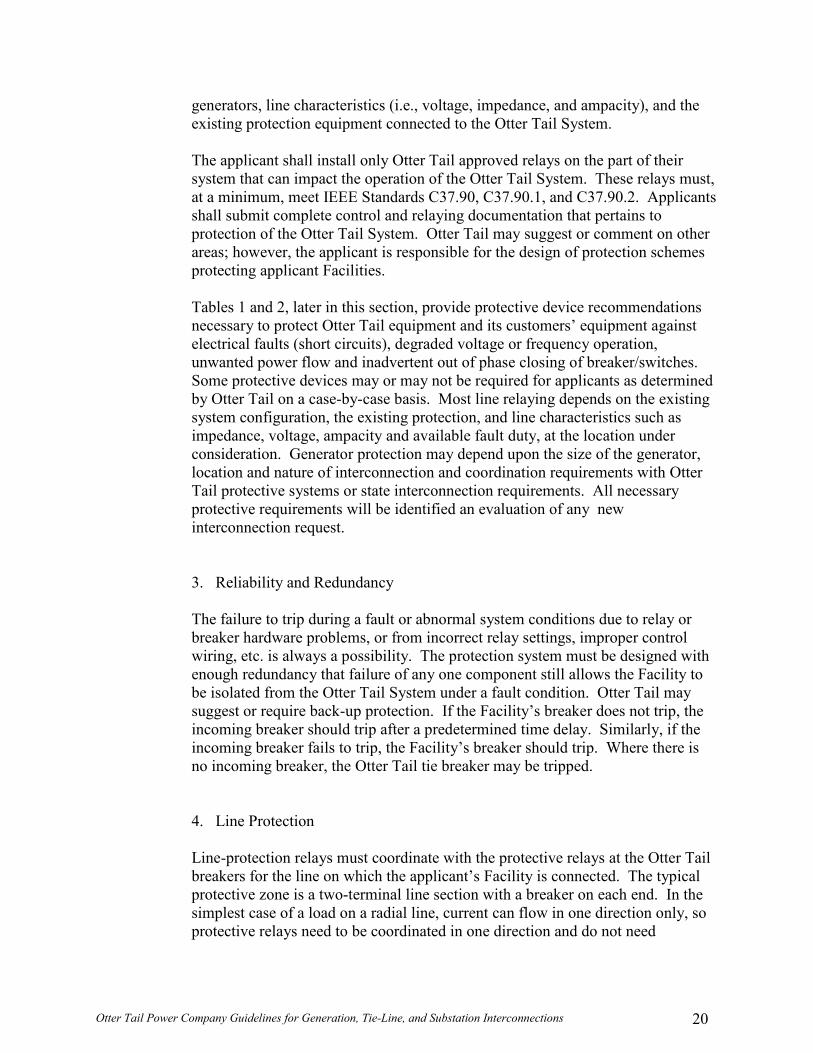
Otter Tail Power Company Guidelines for Generation, Tie-Line, and Substation Interconnections 20
generators, line characteristics (i.e., voltage, impedance, and ampacity), and the existing protection equipment connected to the Otter Tail System.
The applicant shall install only Otter Tail approved relays on the part of their system that can impact the operation of the Otter Tail System. These relays must, at a minimum, meet IEEE Standards C37.90, C37.90.1, and C37.90.2. Applicants shall submit complete control and relaying documentation that pertains to protection of the Otter Tail System. Otter Tail may suggest or comment on other areas; however, the applicant is responsible for the design of protection schemes protecting applicant Facilities. Tables 1 and 2, later in this section, provide protective device recommendations necessary to protect Otter Tail equipment and its customers’ equipment against electrical faults (short circuits), degraded voltage or frequency operation, unwanted power flow and inadvertent out of phase closing of breaker/switches. Some protective devices may or may not be required for applicants as determined by Otter Tail on a case-by-case basis. Most line relaying depends on the existing system configuration, the existing protection, and line characteristics such as impedance, voltage, ampacity and available fault duty, at the location under consideration. Generator protection may depend upon the size of the generator, location and nature of interconnection and coordination requirements with Otter Tail protective systems or state interconnection requirements. All necessary protective requirements will be identified an evaluation of any new interconnection request.
3. Reliability and Redundancy
The failure to trip during a fault or abnormal system conditions due to relay or breaker hardware problems, or from incorrect relay settings, improper control wiring, etc. is always a possibility. The protection system must be designed with enough redundancy that failure of any one component still allows the Facility to be isolated from the Otter Tail System under a fault condition. Otter Tail may suggest or require back-up protection. If the Facility’s breaker does not trip, the incoming breaker should trip after a predetermined time delay. Similarly, if the incoming breaker fails to trip, the Facility’s breaker should trip. Where there is no incoming breaker, the Otter Tail tie breaker may be tripped.
4. Line Protection
Line-protection relays must coordinate with the protective relays at the Otter Tail breakers for the line on which the applicant’s Facility is connected. The typical protective zone is a two-terminal line section with a breaker on each end. In the simplest case of a load on a radial line, current can flow in one direction only, so protective relays need to be coordinated in one direction and do not need

Otter Tail Power Company Guidelines for Generation, Tie-Line, and Substation Interconnections 21
directional elements. However, on the typical transmission system, where current may flow in either direction depending on system conditions, relays must be directional. In addition, the complexity and the required number of protective devices increase dramatically with increases in the number of terminals in each protective zone. With two terminals in a protective zone, there are two paths of current flow. With three terminals, there are six paths of current flow, and so on. In coordinating a multi-terminal scheme, Otter Tail may sometimes require installation of a transmission line protective relay at the applicant’s substation site. This is commonly the case whenever three-terminal permissive overreach transfer trip (POTT) schemes or blocking schemes are employed to protect the line. Because this line relay participates in a scheme to protect the Otter Tail System, Otter Tail must ensure the maintenance, testing and reliability of this particular type of relay. In addition, the breaker’s relays must be set to have overlapping zones of protection in case a breaker within any given zone fails to clear. The line protection schemes must be able to distinguish between generation, inrush, load and fault currents. Multiple terminal lines become even more complex to protect. Existing relay schemes may have to be reset, replaced, or augmented with additional relays at the applicant’s expense, to coordinate with the applicant’s Facility.
The Otter Tail System required relays must be located so that a fault on any phase of the Otter Tail line shall be detected. If transfer trip protection is required by Otter Tail, the applicant shall provide at its expense a communications circuit. This circuit may be a communication line from the telephone company or a dedicated cable. In certain cases power line carrier, fiber optic cable, or microwave communication circuits are also acceptable. The line must have high-voltage protection equipment on the entrance cable so the transfer trip equipment will operate properly during fault conditions. The Otter Tail System is designed for high reliability by having multiple sources and paths to supply customers. Due to the multiple sources and paths, more complex protection schemes are required to properly detect and isolate the faults. The addition of any new interconnected facility to the Otter Tail system must not degrade the existing protection and control schemes or cause existing Otter Tail customers to be exposed to lower levels of safety and/or reliability. Tables 1 and 2 list the minimum protection that Otter Tail typically requires for any new interconnection. Higher voltage interconnections require additional protection due to the greater potential for adverse impact to system stability and the greater number of customers who could be affected. In some special cases, additional requirements or be subject to state interconnection requirements. The acceptability and additional requirements of these interconnection requests shall be determined by Otter Tail on a case-by-case basis.

Otter Tail Power Company Guidelines for Generation, Tie-Line, and Substation Interconnections 22
Table 1. Basic Line Protection Devices (Protection Needs to be redundant at 41.6 kV and above for all interconnections. For lower voltage interconnections redundancy is only required for some specific areas of the System.)
Protection Device Device Number
Less than
41.6 kV
41.6 kV to 69kV 115 kV 230 kV
Phase Overcurrent (Radial systems) 50/51 X X Ground Overcurrent (Radial systems) 50/51N X X Phase Directional Overcurrent 67 X1 Ground Directional Overcurrent or Transformer Neutral
67N 50/51N X1 X1 X1
Distance Relay Zone 1 21Z1 X1 X X Distance Relay Zone 2 21Z2 X1 X X Distance Relay Carrier 21Z2C X1 X Ground Directional Overcurrent Carrier 67NC X1 X Distance Relay Carrier Block 21Z3C X1 X Pilot Wire 87L X1 X Permissive Overreaching Transfer Trip (POTT) or Hybrid 21/67T X1 X
Power Fail Trip3 27 X1 X1 X1 Direct Transfer Trip TT X2 X2 X2
1 May be required depending on local circuit configurations. 2 Transfer trip may be required on interconnections depending on Otter Tail circuit configuration and loading, as
determined by Otter Tail. Typically, transfer trip is required on multi-terminal lines. 3 Power failure tripping may be required on load tie-line interconnections to facilitate restoration of customer
load after a transmission line or area outage.
5. Fault-Interrupting Devices
The fault-interrupting device selected by the applicant must be reviewed and approved by Otter Tail for each particular interconnection. There are three basic types of fault-interrupting devices:
• Circuit Breakers • Circuit Switchers • Fuses
Otter Tail will determine the type of fault-interrupting device required for a Facility based on the available fault duty, the local circuit configuration, the size and type of generation, and the existing Otter Tail protection equipment.

Otter Tail Power Company Guidelines for Generation, Tie-Line, and Substation Interconnections 23
a. Circuit Breakers
Ownership of the intertie circuit breaker will be determined during the interconnection process. However, Otter Tail will have the operational authority to operate all intertie circuit breakers at all installations where the applicant’s generation has been classified as greater than 5 MW and for all substation or tie-line interconnections. Upgrading existing circuit breakers within or outside the area of the interconnection may be required at the applicant’s expense due to the increased fault current levels. A three-phase circuit breaker at the Point of Interconnection automatically separates the applicant’s Facility from the Otter Tail System upon detection of a circuit fault. Additional breakers and protective relays may be installed in the applicant’s Facility for ease in operating and protecting the Facility. The interconnection breaker must have sufficient capacity to interrupt maximum available fault current at its location and be equipped with accessories to:
• Trip the breaker with an external trip signal supplied through a
battery (shunt trip). • Telemeter the breaker status when it is required. • Lockout if operated by protective relays required for
interconnection.
Generally, a three-phase circuit breaker is the required fault-interruption device at the Point of Interconnection, due to its simultaneous three-phase operation and ability to coordinate with Otter Tail devices.
b. Circuit Switchers
A circuit switcher is a three-phase fault-interrupter with limited fault interrupting capability. These devices have typically been used at voltages of 115 kV and below and may substitute for circuit breakers when the fault duty is within the interrupting rating of the circuit switcher. With Otter Tail approval, some circuit switchers with blades can double as the visual open disconnect switch between the metering transformers and the main transformer. Since circuit switchers do not have integral current transformers, they must be installed within 30 feet of the associated current transformers to minimize the length of the unprotected line/bus section.
c. Fuses
Fuses are single-phase, direct-acting sacrificial links that melt to interrupt fault current and protect the equipment. Blown fuses need to be replaced manually after each fault before the Facility can return to service.

Otter Tail Power Company Guidelines for Generation, Tie-Line, and Substation Interconnections 24
Overhead primary fuses shall be replaced by trained, qualified personnel. Because fuses are single-phase devices, all of them may not melt during a fault and therefore would not automatically separate the interconnected Facility from the Otter Tail System. Large primary fuses which do not coordinate with the Otter Tail substation breaker ground relays could cause all the customers on the circuit to lose power due to a fault inside the applicant’s interconnected Facility and therefore will not be allowed. For load-only facilities, Otter Tail may approve the use of fuses if they coordinate with the Otter Tail line-side devices for both phase and ground faults. In limited cases, fuses may be used as a primary protective device (e.g. rural, 60 kV, 70 kV and 115 kV lines, where the applicant’s substation is base rate at 10 MW or less). However, if fuses are approved by Otter Tail, the applicant should consider installing a negative sequence relay and/or other devices to protect its Facility against single-phase conditions.
For generation interconnections, fuses cannot be operated by the protective relays and therefore cannot be used as the primary protection for three-phase generation facilities. Fuses may be used for high-side transformer protection for generation less than 5 MW, provided coordination can be obtained with the existing Otter Tail phase and ground protection and if a separate generator breaker provides the required primary protection. Fuses are not permitted for high-side transformer protection for Facilities of 5 MW or greater.
6. Single-Phase Devices - Fuses/Oil Circuit Reclosers
It may be necessary to replace single-phase devices (line fuses, single-phase automatic circuit reclosers) installed between the Otter Tail source substation and the applicant location with three-phase devices. This is to minimize the possibility of single-phasing an applicant's three-phase generator. Single-phase sectionalizing equipment may be installed on the main circuit past the applicant location, or on radial circuits that tap the main circuit between the source substation and the applicant location.
Because the applicant is responsible for protecting its equipment from the effects of excessive negative sequence currents, the applicant must know if there are single-phase devices located between its Facility and the Otter Tail source substation.

Otter Tail Power Company Guidelines for Generation, Tie-Line, and Substation Interconnections 25
7. Automatic Reclosing/Voltage Check Schemes
Otter Tail normally applies automatic reclosing to all transmission and overhead distribution lines. Prior to automatic reclosing, the applicant must ensure that the applicant’s Facility is disconnected from the Otter Tail System. It may be necessary to install voltage check schemes at various locations on the Otter Tail System to prevent automatic reclosing in the event that an applicant’s Facility remains connected to an isolated, unfaulted section of the Otter Tail System. These voltage check schemes may be located at the Point of Interconnectin, at automatic circuit reclosers on the line feeding the applicant, or on an Otter Tail source substation feeder breaker. These schemes may also be required on alternate circuits that may be used to feed the applicant’s Facilities. Details of any modifications to Otter Tail reclosing practices and/or addition of voltage check schemes will be determined during the evaluation of any new interconnection .
Otter Tail shall assume no responsibility for damage to Applicant's equipment due to out-of-phase reclosing.
In general, reclosing practices should be as follows:
• There should be no automatic reclosing for the incoming breaker. • The Otter Tail substation breaker may have one or more timed
recloses, with the first set at a minimum of 2 seconds. It is expected that either the generator or the tie breaker will open before reclosing takes place.
• Where islanding is possible, the Otter Tail substation breaker may need the function of voltage supervision from the tie-line.
B. ADDITIONAL PROTECTION FOR GENERATION INTERCONNECTIONS
The generating unit must meet all applicable American National Standards Institute (ANSI) and Institute of Electrical and Electronic Engineers (IEEE) standards. The prime mover and the generator should be able to operate within the full range of voltage and frequency excursions that may exist on the Otter Tail system without damage to the unit.
1. Special Protection Scheme
The Otter Tail System has been developed with careful consideration for system stability and reliability during disturbances. The type of connection, size of the load, breaker configurations, load characteristics, and the ability to set protective relays will affect where and how Facility’s operated. However, the application must meet the applicable reliability council and Otter Tail guidelines.
Otter Tail Power Company Guidelines for Generation, Tie-Line, and Substation Interconnections 26
2. Event Recorder All unattended generation facilities with a rating greater than 1 MW and with automatic or remotely initiated paralleling capability must have an event recorder that will enable Otter Tail to make an after-the-fact determination of the status of the generation facility at the time of a system disturbance, should such determination be required. The generation facility operator shall ensure that such time reading is correct and synchronized to an accurate time standard. The event recorder or other recording device(s) at the generation facility must be capable of providing a record of (1) the time of any relay operations and targets of the relay that caused the generation facility to separate, if applicable, (2) the time of any paralleling with and separations from the Otter Tail System and (3) the time of the change in voltage-control device set points (if applicable) and (4) the time of change in the operating status (i.e. opened or closed) of any other voltage-control device (i.e., shunt capacitors or reactors). In addition, for generation facilities with a nameplate rating equal to or greater than 10 MW, the event recorder must also provide a record of deliveries to the Otter Tail System of real power in kW and reactive power in kVAr and output voltage in kV.

Otter Tail Power Company Guidelines for Generation, Tie-Line, and Substation Interconnections 27
Table 2. Basic Generator Protection Devices
Generator Protection Device Device Number
40 kW or Less
41 kW to 400 kW
401 kW and
Larger Phase Overcurrent 50/51 X1 X1 Overvoltage 59 X X X Undervoltage 27 X2 X X Overfrequency 81O X X X Underfrequency 81U X X X Ground Over Voltage (ground fault protection for ungrounded system at the applicant’s end) 59G TBD TBD TBD
Synchronizing and Reclosing Relays 25 TBD TBD TBD Ground Fault Sensing Scheme (Utility Grade) 51N X3 X Overcurrent With Voltage Restraint/Voltage Control or Impedance Relay
51V 21 X4 X
Reverse Power Relay (Self-Service) 32 X5 X5 X5 Out of Step 68 TBD TBD TBD
1 Overcurrent protection must be able to detect a line-end fault condition. A phase instantaneous overcurrent
relay, which can see a line fault under sub-transient conditions, is required. This is not required if a 51V relay is used.
2 For generators 40 kW or less, the undervoltage requirement can be met by the contactor undervoltage release. 3 For induction generators and certified non-islanding inverters aggregating less than 100 kW, ground fault
detection is not required. For synchronous generators aggregating over 40 kW, ground fault detection is required.
4 A group of generators, each less than 400 kW but whose aggregate capacity is greater than 400 kW, must have an impedance relay or an overcurrent relay with voltage restraint located on each generator greater than 100 kW.
5 For “Self-service” generator installations, under the proper system conditions, a set of three single-phase, very sensitive reverse power relays, along with the dedicated transformer may be used in lieu of ground fault protection. The relays shall be set to pick-up on transformer magnetizing current, and trip the main breaker within 0.5 second. Reverse Power (32) toward Otter Tail System where the Generator is not selling power to Otter Tail. Reverse Power (37-50 package) for faults on source line when low side can be looped.
TBD = to be determined on a project-by-project basis
VIII. METERING AND TELECOMMUNICATIONS (R2.1.6)
A. COMMON
1. Metering The metering scheme shall be designed such that energy (kWh) delivered to the transmission system is net generation and energy (kWh) delivered to the customer is load. Thus for a generator interconnect, station service is load, when generator ouput is less than station service.

Otter Tail Power Company Guidelines for Generation, Tie-Line, and Substation Interconnections 28
Modifications to the revenue metering are usually required for any new interconnection. In general, the metering equipment will need to measure both delivered and received energy (both Watts & VArs). This is typically accomplished by replacing an existing watt-hour meter with a multi-function bi-directional meter. This allows proper measurement of both real and reactive energy in both directions. The metering installation shall be electrically connected on the line side of the main generator disconnect, thus allowing the meter to be read even when the generator is not running. Net metering is allowed for generation this is a small qualifying facility (per state jurisdiction). For substation metering, the meter is typically located on the high side of the step-down transformer, thus including the transformer losses.
2. Metering Accuracy, Testing, and Repair
a. Metering Accuracy
The metering shall adhere to the accuracy standard specified in ANSI standard C-12.1 applicable at the time the metering is installed. Any current or potential transformers that are used for metering will adhere to the “Accuracy Classifications for Metering” listed in ANSI standard C-57.13.
b. Periodic Testing
The metering equipment shall be tested periodically, and re-calibrated to maintain the required accuracy. The meter testing frequency shall at a minimum be based on industry accepted practices and guidelines outlined in ANSI standard C-12.1. Otter Tail’s present testing practices are based on the type of metering situation and the jointly agreed to requirements of both parties involved. Typically, the metering equipment at non-Otter Tail sites is tested every three years.
The periodic test frequency for the metering equipment will be decided upon during the evaluation of a new interconnection. Otter Tail and the applicant shall both participate in the periodic testing. The party performing the testing must notify the witnessing party with at least a week’s notice, preferably more. If the proposed date is not acceptable, then an alternative time acceptable to both parties must be worked out.

Otter Tail Power Company Guidelines for Generation, Tie-Line, and Substation Interconnections 29
The owner of the meter shall analyze and distribute any maintenance, repair, and test results to all parties receiving the meter readings.
c. Meter and Telemetry Equipment Repair
The owner of the metering and telemetry equipment is responsible for ensuring that the equipment is adequately maintained and is repaired within a reasonable time after a failure is detected. The repair or replacement of a bad meter must be completed within 24 hours after it has been detected. If the metering cannot be repaired within that time, Otter Tail may request the applicant to open the interconnection until the meter has been repaired. All changes, repairs, and replacements of the meter must be coordinated with the Otter Tail Meter Department. This assures Otter Tail that the meter is functioning properly.
3. Metering and Telemetry Function Requirements
The meter and telemetry requirements define Otter Tail’s required functionality for meters, metering related equipment (phone lines, phone circuits, current transformers, potential transformers, etc.) and telemetry equipment (Remote Terminal Units (RTUs), transmitters, receivers, etc.). They do not represent design standards for the metering equipment. Three major factors generally determine the type of metering and telemetry required:
1. The type and size of the applicant’s Facility equipment. 2. The location of the applicant on the Otter Tail System. 3. The manner in which the installation will operate (one-way vs.
two-way power flow). Each request for interconnection will be handled individually and Otter Tail will solely determine the metering and telemetry modifications and/or additions required. Otter Tail will work with the applicant to achieve an installation that meets the requirements of both the applicant and Otter Tail. The applicant shall bear the costs of metering and telemetry modifications required to permit the operation of a parallel interconnection.
1. Measured Values and Metering Equipment Required For Generating Stations With A Net Output Capacity (generation less auxiliaries) Less than 1 MW

Otter Tail Power Company Guidelines for Generation, Tie-Line, and Substation Interconnections 30
a. Bi-directional Real Energy Usage/Output (Watt-hours) b. Power factor or Reactive Energy Usage (Power Factor or
VAr-hours) c. Interval Recorder to capture hourly energy use
2. Additional Measured Values For Generating Stations With A Net
Output Capacity Greater Than Or Equal to 1 MW a. Bi-directional Real Power Flow (Watts) b. Bi-directional Reactive Power Flow (VArs), at Otter Tail’s
discretion c. Voltage at the Point of Interconnection to Otter Tail System
(Volts), at Otter Tail’s discretion 3. Additional point for units requiring Telemetry Generating Stations
with a net output capacity of 5 MW or greater a. Position (open/close) of generator breaker(s) and incoming
and tie breakers (if present) b. Remote Terminal Unit or Data Link to telemeter all
measured values to Otter Tail’s Energy Management System (EMS).
4. Measured Values and Metering Equipment Required For Transmission Interconnections that create a new boundary between Local Balancing Areas a. bi-directional Real Power Flow (Watts) b. bi-directional Reactive Power Flow (VArs) c. Voltage at the Point of Interconnection to Otter Tail System
(Volts), at Otter Tail’s discretion d. Interval Recorder to capture hourly energy use e. Remote Terminal Unit or Data Link to telemeter all
measured values to Otter Tail’s SCADA System.
5. Measured Values and Metering Equipment Required For Load Interconnections to Transmission System (non-parallel interconnection) a. Real Power Flow (Watts) b. Reactive Power Flow (VArs) c. Interval Recorder to capture hourly energy use
5. Energy Losses If the energy is not measured at the point where the energy exchange between Otter Tail and the applicant has been defined by contract, energy losses must be determined. Accounting for the losses may be either done by attributing losses to the monthly accounting of exchanged energy or by attributing losses directly to the energy registered on the meter. The latter case requires a compensated billing meter. Losses applied internal to the meter frequently result in a more complex
Otter Tail Power Company Guidelines for Generation, Tie-Line, and Substation Interconnections 31
metering and telemetering situation and, therefore, should be evaluated thoroughly before this approach is used. Transmission System Losses may not be applied through a compensated meter. If the energy is not purchased by Otter Tail, and it is wheeled across Otter Tail’s System, Otter Tail will require the Applicant to pay for Transmission System Losses. Energy losses may be subject to change. If the connection to the applicant’s Facility changes or Otter Tail or other utilities files new loss rates, Otter Tail and the applicant must re-evaluate the losses to be applied and incorporate any new loss factors into the metering and/or accounting.
6. Meter Reading General practice within NERC, the MISO, and the Applicable Reliability Council require that meter readings take place at midnight on the meter read day. For most cases, the meter read day will be the last day of the month. A read through midnight of the billing day could be captured by physically reading the meter at midnight, storing the midnight reading and taking a reading of the stored value the following day (for meters with that capability) or remotely reading the meter at midnight (via a phone line or other communication technologies). Energy readings though midnight can also be approximated by using the hourly energy usage captured in Otter Tail’s EMS or on the interval recorder to extrapolate the value from the time the meter was read to midnight on the billing day. The specific method will be decided during the evaluation of a new interconnection. There may be situations where it is cost effective or necessary to access the metering equipment via telephone. Otter Tail is willing to share an existing phone line with the applicant, but it may be necessary to install a new line. The communications circuit cost (telephone lines or other communication technology) to allow remote reading of the meter at a non-Otter Tail Facility should be borne by the party contracting with Otter Tail or the applicant to supply or purchase energy.
B. TELEMETRY
The requirements for telemetry are based on the need of the System Control Center to protect all users of the System from unacceptable disturbances. The need for requiring telemetry may include the ability to monitor the following conditions:
• Detecting Facility backfeed onto otherwise de-energized lines

Otter Tail Power Company Guidelines for Generation, Tie-Line, and Substation Interconnections 32
• Providing information necessary for reliable operation of Otter Tail equipment (feeders, substation, etc.) during normal and emergency operation
• Providing information necessary for the reliable dispatch of generation
Telemetry is required by Otter Tail when:
• The possibility of islanding a portion of Otter Tail’s System exists (typical of smaller feeders).
• 1 MW or larger generator becomes a significant portion of a feeder’s total load (typically 6 to 10 MW).
• There is the potential for multiple applicants to have generators on the same substation and/or feeders.
• There is the potential for backfeeding onto the Otter Tail System. • The Facility plans to provide its own ancillary services. • There is intent to sell power and energy over Otter Tail Facilities. • The Facility is required to meet the manual load shed requirement. • 41.6 kV or 69 kV substations are equipped with circuit breakers and for all
substations classified at 115 kV and above. • FERC requires telemetering for normally open or emergency tie connections.
If “islanding” is a possibility, it will be identified during the evaluation of the enw interconnection. In such instances, the following telemetry may be required:
• Real and reactive power flow for each generator (kW and kVAr) • Voltage representative of the Otter Tail service to the Facility • Status (open/close) of Facility and interconnection breaker(s) • Position of incoming and tie breakers or switches • Energy output of the generators (kWh) • applicant load from Otter Tail service (kW and kVAr)
When telemetry is required, the applicant must provide the communications medium to Otter Tail. If a telephone circuit is used, the applicant must also provide the telephone circuit protection and coordinate the RTU addition with Otter Tail. High capacity interconnections may require redundant metering and telemetering.
C. COMMUNICATION CHANNEL Otter Tail may require that a communication channel and associated communication equipment be installed as part of the protective scheme. This channel may consist of power line carrier, leased telephone line, pilot wire circuit, fiber optic cable, radio, or other means. The communication channel is required in cases where it is necessary to remotely send a signal to remove the applicant's Facility from the Otter Tail System due to a fault or other abnormal

Otter Tail Power Company Guidelines for Generation, Tie-Line, and Substation Interconnections 33
conditions that cannot be sensed by the protective devices at the applicant's location. Some instances may require installation of communication equipment in Otter Tail substations to initiate the protective signals. Otter Tail shall be reimbursed by the applicant for the cost of this equipment and its installation. Another communication channel may be needed for monitoring and control purposes. Telemetry requirements were previously addressed in this section. Specific communication channel requirements will be determined during the interconnection study process. The cost of installation and additional monthly fees for this channel will be the responsibility of the applicant.
IX. GROUNDING AND SAFETY ISSUES (R2.1.7)
A. SAFETY AND ISOLATING DEVICES At the Point of Interconnection to the Otter Tail System, an isolating device, which is typically a disconnect switch, shall be provided that physically and visibly isolates the Otter Tail System from the applicant’s Facilities. All switchgear that could energize equipment shall be visibly identified (tagged), so that all maintenance crews can be made aware of the potential hazards. Such devices shall:
• Simultaneously open all phases (gang-operated) to the connected Facilities. • Be accessible by Otter Tail and may be under Otter Tail System Operator jurisdiction. • Be lockable in the open position by Otter Tail. • Not be operated without advance notice to either party, unless an emergency
condition requires that the device be opened to isolate the Interconnected Facilities. • Be suitable for safe operation under the conditions of use.
Otter Tail personnel may lock the device in the open position and install safety grounds if: • It is necessary for the protection of maintenance personnel when working on de-
energized circuits. • The interconnected Facility or Otter Tail equipment presents a hazardous condition. • The interconnected Facility interferes with the operation of the Otter Tail System. • The Otter Tail System interferes with the operation of the interconnected Facility. B. ENERGIZATION OF OTTER TAIL EQUIPMENT BY THE APPLICANT
No applicants, independent of interconnection type or generator size, shall energize a de-energized Otter Tail circuit. The necessary control devices shall be installed by the applicant on the applicant’s Interconnection Facilities to prevent the energization of a de-energized Otter Tail circuit. Connection may be accomplished only via synchronization with the Otter Tail System. All interconnecting circuit breakers/devices and all breakers/devices that tie another source to the

Otter Tail Power Company Guidelines for Generation, Tie-Line, and Substation Interconnections 34
Otter Tail System will require synchro-check relaying, other than quick open transition (break before make) transfer switch installations. Authorization to energize a circuit may only be provided by the Balancing Authority Area System Operator.
C. SUBSTATION GROUNDING
Each generation site and/or Interconnection substation must have a ground grid that solidly grounds all metallic structures and other non-energized metallic equipment. This grid shall limit the ground potential gradients to such voltage and current levels that will not endanger the safety of people or damage equipment which are in, or immediately adjacent to, the station under normal and fault conditions. The size, type and ground grid requirements are in part based on local soil conditions and available electrical fault current magnitudes. In areas where ground grid voltage rises are not within acceptable and safe limits (due for example to high soil resistivity or limited substation space), grounding rods and wells can be used to reduce the ground grid resistance to acceptable levels.
If the generation site is close to another substation, the two ground grids may be isolated or connected. If the ground grids are to be isolated, there may be no metallic ground connections between the two substation ground grids. Cable shields, cable sheaths, station service ground sheaths, and overhead transmission shield wires can all inadvertently connect ground grids. Fiber-optic cables are an excellent choice for telecommunications and control between two substations to maintain isolated ground grids. If the ground grids are to be interconnected, the interconnecting cables must have sufficient capacity to handle fault currents and control ground grid voltage rises. Otter Tail must approve any connection to an Otter Tail substation ground grid.
The interconnection of lines and/or generation may substantially increase fault current levels at nearby substations. Modifications to the ground grids of existing substations may be necessary to keep grid voltage rises within safe levels. The interconnection study will determine if modifications are required and the estimated cost.
The Reference section of this document supplies a list of ANSI/IEEE technical resources for grounding. X. INSULATION AND INSULATION COORDINATION (R2.1.8)
Power system equipment is designed to withstand voltage stresses associated with expected operation. Adding or connecting new Facilities can change equipment duty, and may require that equipment be replaced or switchgear, telecommunications, shielding, grounding and/or surge protection added to control voltage stress to acceptable levels. Interconnection studies may identify additional requirements to maintain an acceptable level of Otter Tail System availability, reliability, equipment insulation margins, and safety.

Otter Tail Power Company Guidelines for Generation, Tie-Line, and Substation Interconnections 35
Voltage stresses, such as lightning or switching surges, and temporary overvoltages may affect equipment function. Remedies depend on the equipment capability and the type and magnitude of the stress. In general, stations with equipment operated at 15 kV and above, as well as all transformers and reactors, shall be protected against lightning and switching surges. Typically, this includes station shielding against direct lightning strokes, surge arresters on all wound devices, and shielding with rod gaps (or arresters) on the incoming lines. The following requirements may be necessary to meet the intent of Otter Tail’s reliability criteria.
A. SURGE PROTECTION
The Interconnection shall have the capability to withstand voltage and current surges in accordance with the environments defined in IEEE/ANSI C62.41 and IEEE C37.90.1. Otter Tail highly recommends the applicant to install surge arresters for protection of transformers and other vulnerable equipment. Arresters shall be mounted in such a manner as to protect any of Otter Tail’s facilities from surge voltages. In general, all OTP incoming lines shall be protected with surge arresters located on the line side of the disconnect switch. All lines connecting to an Otter Tail substation shall include either rod gaps or surge arresters for substation entrance protection. Otter Tail staff will recommend the appropriate level of entrance protection as well as other specifications for surge arresters during the interconnection process.
B. LIGHTNING SURGES
If the Requester proposes to tap a shielded transmission line, the tap line to the substation must also be shielded. For an unshielded transmission line, the tap line does not typically require shielding beyond that needed for substation entrance. However, special circumstances such as the length of the tap line may affect shielding requirements.
Lines at voltages of 69 kV and higher that terminate at Otter Tail substations must meet additional shielding and/or surge protection requirements. Incoming lines must be shielded for ½ mile at 69-229 kV and 1 mile at 230 kV and higher. Rod gaps must also be installed at the station entrance. For certain customer service substations at 230 kV and below, Otter Tail may require only an arrester at the station entrance in lieu of line shielding, or a reduced shielded zone adjacent to the station. These variations depend on the tap line length, the presence of a power circuit breaker on the transmission side of the transformer, and the size of the transformer. Such exceptions can be discussed with Otter Tail during the interconnection process.
C. TEMPORARY OVERVOLTAGES
Temporary overvoltages can last from seconds to minutes, and are not characterized as surges. These overvoltages are present during islanding, faults, loss of load, or long-line situations. All new and existing equipment must be capable of withstanding these duties. Temporary overvoltages on the Otter Tail System may fall within the voltage range shown on Table 3.

Otter Tail Power Company Guidelines for Generation, Tie-Line, and Substation Interconnections 36
1. Islanding A ‘local island’ condition can expose equipment to higher-than-normal voltages. Special relays to detect this condition and isolate the Interconnection Facility from the Otter Tail System may be required. 2. Neutral Shifts When generation or a source of ‘back-feed’ is connected to the low-voltage side of a delta-grounded wye customer service transformer, remote end breaker operations initiated by the detection of faults on the high-voltage side can cause overvoltages that can affect personnel safety and damage equipment. This type of overvoltage is commonly described as a neutral shift and can increase the voltage on the unfaulted phases to as high as 1.73 per unit. At this voltage, the equipment insulation withstand-duration can be very short. Several alternative remedies are possible:
• Provide an effectively grounded system on the high-voltage side of the
transformer that is independent of other transmission system connections. • Size the high-voltage-side equipment to withstand the amplitude and duration
of the neutral shift. • Rapidly separate the back-feed source from the step-up transformer by
tripping a breaker using either remote relay detection with pilot scheme (transfer trip) or local relay detection of an overvoltage condition.
Effectively grounded is defined as an X0/X1≤3 and R0/X1≤1. Methods available to obtain an effective ground on the high-voltage side of the transformer include:
• A transformer with the transmission voltage (Otter Tail’s) side connected in a
grounded-wye configuration and low voltage (Connection Point) side in closed delta.
• A three-winding transformer with a closed-delta tertiary winding. Both the transmission and distribution side windings are connected in grounded wye.
• Installation of a grounding transformer on the transmission voltage (Otter Tail) side.
Any of these methods result in an effectively grounded system with little risk of damage to surge arresters and other connected equipment.

Otter Tail Power Company Guidelines for Generation, Tie-Line, and Substation Interconnections 37
XI. VOLTAGE, REACTIVE POWER, AND POWER FACTOR CONTROL (R2.1.9)
A. VOLTAGE
The applicant's equipment shall not cause excessive voltage excursions. The applicant shall provide an automatic means of disconnecting its equipment from the Otter Tail System within three seconds if the steady state voltage cannot be maintained within the required tolerance.
Most of Otter Tail's system at 12.5 kV and below is voltage regulated. When the interconnection is with a portion of the Otter Tail delivery system that is regulated, then the applicant shall be capable of tolerating steady-state voltage fluctuations of ± 5 percent of the normal voltage level, unless otherwise stated in the appropriate state rules. For interconnections to the transmission system (generally above 12.5 kV), voltage levels ± 10 percent from normal can be expected. If the applicant’s equipment cannot operate within the range shown in Table 3, the applicant may need to provide regulation equipment to limit voltage level excursions. Table 3 – Voltage Limit on the Otter Tail System
Low Voltage Limit
High Voltage Limit
Normal Operating Conditions1 0.97 p.u. 1.07 p.u. Abnormal Operating Condition2
0.92 p.u. 1.10 p.u.
Transient Condition3 0.70 p.u. 1.20 p.u. 1 Normal Operating Conditions are characterized by all Facilities being in–service during day-to-day operations of the System. High voltage limit of 1.05 p.u. is used on 230 and 345 kV lines. 2 Abnormal Operating Conditions are characterized by the steady state operatig conditions following a system event, such as loss of a transmission line, substation, load, or generator. 3 Transient Conditions are characterized by the short timeframe (ms) in which there is a system event occurring, such as loss of a transmission line, substation, load, generator, or a planned switching event on the transmission system. Wahpeton substation has special transient criteria of 0.80 p.u. to 1.18 p.u. Consistent with the system performance criteria and technical study guidelines, the Otter Tail System is designed to avoid experiencing transient voltage dips below 0.70 pu due to external faults or other disturbance initiators. The applicant should allow sufficient dead band in its voltage regulation equipment control to avoid reacting to transient voltage dips. If the design of the applicant’s Facility is such that islanded conditions are possible, appropriate zero sequence sources must also be provided. The usual customer voltage concern refers to line-line values, but generation installed on distribution lines must also control the line-ground voltage during an islanded condition.

Otter Tail Power Company Guidelines for Generation, Tie-Line, and Substation Interconnections 38
B. MINIMUM POWER FACTOR REQUIREMENTS
The applicant will generally be expected to provide for its own reactive power requirements. Some portions of the Otter Tail power system are in or adjacent to areas where other power suppliers (Municipals or Co-ops) utilize "ripple" load management systems. These systems employ an on/off keyed carrier signal (typically in the range of 150-400 Hz) injected into the power systems to address applicant site load management devices. Installation of shunt capacitor banks, as may be required for power factor correction of induction machines, or for providing capacitive output capability, may cause degradation of the ripple signal strength due to shunting to ground of the ripple signal through the capacitor bank(s). To prevent such degradation, appropriate tuned blocking filters may be required.
1. Substation-Specific Power Factor Requirements
The Otter Tail Transmission System is designed and operated assuming the power factor at the transmission side of the distribution transformer is 90 percent when load is within 10 percent of the forecasted system minimum or maximum. Any interconnecting facility is expected to provide sufficient reactive power (leading or lagging) such that during these load periods the high side power factor does not fall below 90 percent. If during normal operation (system intact or under transmission contingency conditions) the voltage in a portion of the Otter Tail System deviates from the voltage range described in Section X.A., Otter Tail will survey the interconnected substation(s) believed to be contributing to the voltage concern and the applicant may be asked to demonstrate, (either by metered values or by inventory of installed equipment) that the applicant meets its reactive power obligation. Any deviations are required to be corrected immediately.
2. Generator-Specific Power Factor Requirements
Generators connecting to the Otter Tail System will be expected to provide sufficient facilities and controls to operate their generation from 0.95 lead power factor to 0.95 lagging power factor at the Point of Interconnection. Generators interconnection that fall under the state jurisdictions may have different requirements. The voltage set point that the generator needs to maintain will be established and adjusted as necessary by Otter Tail’s System Operations Department. (This is necessary for all generation).
a. Reactive Supply and Voltage Control from Generation Sources Service – 10 MW or Larger
Reactive Supply and Voltage Control from Generation Sources Service is a FERC defined ancillary service. Any generator providing such service

Otter Tail Power Company Guidelines for Generation, Tie-Line, and Substation Interconnections 39
to the Balancing Authority Area Operator must be able to automatically control the voltage level by adjusting the machine’s power factor within a continuous range of between ± 95 percent power factor based on the station’s sum total name plate generating capability. The only exception would be on an interconnection that falls under a state interconnection requirement.
The Voltage Control Response Rate (for synchronous generators, the exciter response ratio) is the speed with which the voltage-controlling device reacts to changes in the system voltage. The minimum response rate for a static excitation system shall have the exciter attain 95 percent of the exciter ceiling (maximum) voltage in 0.1 seconds. The exciter ceiling voltage shall be at least two times the exciter voltage at the rated full load value. For rotary exciters, the exciter response ratio shall be at least 2.0. The response ratio, ceiling voltage, and speed of response are defined in IEEE 421.2 1990.
Applicants choosing to provide Reactive Supply and Voltage Control from Generation Sources service must coordinate with existing voltage regulation devices. In most cases, this will be a concern for those generators connecting to voltage regulated distribution facilities (12.5 kV and below).
3. Generation Frequency / Speed Control
Please see Frequency / Speed Control in Section XVI.
4. Excitation Requirements
Please see Excitation Requirements in Section XVI.
XII. POWER QUALITY IMPACTS (R2.1.10)
A. FLICKER
Voltage fluctuations may be noticeable as visual lighting variations (flicker) and can damage or disrupt the operation of electronic equipment. Generators are not allowed to produce flicker that impacts adjacent customers and that exceeds IEEE 519 and IEEE 1453. Flicker could be caused from a variety of sources including (but not limited to) line switching, switched capacitor banks, load cycling, generator cut-ins or generator cut-outs, motor starting, etc… Evaluation of a new or modified interconnection may involve a study to determine the reliability impacts on the Otter Tail System. This study may include an analysis of system response from switching certain Facilities could result in Flicker concerns. The study will typically include

Otter Tail Power Company Guidelines for Generation, Tie-Line, and Substation Interconnections 40
system intact conditions (all facilities in-service) and contingency conditions (considering critical outages on the System) to determine how the performance of the System at the Point of Interconnection changes for different system conditions. The criteria to be used during the switching analysis include:
• The relative steady state voltage change is limited to 3 percent of the nominal voltage for system intact conditions; and
• The relative steady state voltage change is limited to 5 percent of the nominal voltage for simulations involving a contingency condition; whereas
The relative steady state voltage change is defined as the difference in voltage before and after a switching event. Flicker tests for wind powered sources of generation shall be conducted in accordance with IEC 61000-4-15. Applicants are not allowed to produce flicker to adjacent customers that exceeds the Otter Tail criteria stated above or within IEEE 519 or 1453. If flicker issues arise, Otter Tail will reference the applicable reference curves described in Table A.1 of IEEE 1453-2004 “Recommended Practice of Measurement and Limits of Voltage Fluctuations and Associated Light Flicker on AC Power Systems”. The Applicant will be responsible and liable for corrections if the interconnection Facility is the cause of objectionable flicker levels. In the case where the Applicant owns a dedicated line so that other Otter Tail customers will be protected, a waiver of certain flicker requirements could be permitted.
B. HARMONICS
Harmonics can cause telecommunication interference, increase thermal heating in transformers, disable solid state equipment and create resonant overvoltages. In order to protect equipment from damage, harmonics must be managed and mitigated. The applicant's interconnecting equipment shall not introduce excessive distortion to the Otter Tail System’s voltage and current waveforms per IEEE 519-1992. The harmonic distortion is defined as the ratio of the root mean square (rms) value of the harmonic to the rms value of the fundamental voltage or current. The harmonic distortion measurements shall be made at the Point of Interconnection between the applicant and the Otter Tail System and shall be within the limits specified in the tables below. Otter Tail advises the applicant to account for harmonics during the early planning and design stages of any interconnection project. Refer to Tables 4 and 5 for voltage distortion limits.

Otter Tail Power Company Guidelines for Generation, Tie-Line, and Substation Interconnections 41
Table 4. Voltage Distortion Limits
Bus Voltage At PCC Individual Voltage Distortion IHD %
Total Voltage Distortion THD %
Below 69 kV 3.0 5.0
69 kV to 115 kV 1.5 2.5
115 kV and above 1.0 1.5
Source: IEEE 519, Table 11.1
Table 5. Current Distortion Limits For Non-Linear Loads At The Point Of Common Coupling (PCC) From 120 To 69,000 Volts
Maximum Harmonic Current Distribution in % of Fundamental Harmonic Order (Odd Harmonics)
I(sc)/I(l) <11 11<h<17 17<h<23 23<h<35 35<h THD
20 4.0 2.0 1.5 0.6 0.3 5.0
20-50 7.0 3.5 2.5 1.0 0.5 8.0
50-100 10.0 4.5 4.0 1.5 0.7 12.0
100-1000 12.0 5.5 5.0 2.0 1.0 15.0
1000 15.0 7.0 6.0 2.5 1.4 20.0 Where: I(sc) = Maximum short circuit current at PCC I(l) = Maximum load current (fundamental frequency) at PCC PCC = Point of Common Coupling between applicant and utility Generation equipment is subject to the lowest I(sc)/I(l) values Even harmonics are limited to 25% of odd harmonic limits given above Source: IEEE 519, Table 10.3
A special study will be required for situations when the fault to load ratio is less than 10. Lower order harmonics, particularly the third and ninth harmonics, will often be of more concern to the applicant. These are often related to Facility grounding, and to the type of transformer connections that may be involved. It is to the applicant’s advantage to work these problems out early enough so that applicant and Otter Tail equipment can be acquired to achieve proper control.

Otter Tail Power Company Guidelines for Generation, Tie-Line, and Substation Interconnections 42
XIII. EQUIPMENT RATINGS (R2.1.11) The Applicant and Otter Tail must work closely during the interconnection process. Upon Otter Tail acceptance of a valid interconnection application, the Applicant must provide sufficient information to Otter Tail about the expected equipment ratings (MW, MVAR, kV, Amps, etc.) in order to derive accurate modeling of the interconnection Facilities in any studies and/or evaluations. Through the course of the interconnection process, Otter Tail shall provide the Facility Ratings Methodology (on file within Otter Tail) to the Applicant. The Applicant shall review the Otter Tail Facility Ratings Document to understand Otter Tail’s methodology of determining the appropriate equipment ratings. In determining the appropriate equipment ratings of Applicant-owned Facilities, the Applicant must consider manufacturer specifications of each piece of equipment since they are the basis for determining appropriate equipment ratings. Upon the Applicant’s discretion and review of the Otter Tail facility ratings methodology, the Applicant shall provide Facility ratings to Otter Tail for the Applicant-owned equipment associated with the interconnection. Otter Tail and the Applicant shall jointly review their respective equipment and determine the most limiting equipment associated with the interconnection. The most limiting equipment (whether owned by the Applicant or Otter Tail) shall dictate the overall rating of the interconnection equipment to be used in modeling for both real-time operations and planning studies. All equipment needs to meet Otter Tail rating guidelines, which are established to meet NERC compliance. Equipment shall also meet applicable ANSI and/or IEEE standards XIV. SYNCHRONIZING OF FACILITIES (R2.1.12)
A. SYNCHRONIZING RELAYS
Synchronous generators and other generators with stand-alone capability must use one of the following methods to synchronize with the Otter Tail System:
• Automatic synchronization with automatic synchronizing relay (Device 25) to
synchronize with the Otter Tail System. The automatic synchronizing relay must have all of the following characteristics:
o Slip frequency matching window of 0.1 Hz or less. o Voltage matching window of ±10 percent or less. o Phase angle acceptance window of ± 10 degrees or less. o Breaker closure time compensation.
Note: The automatic synchronizing relay sends a close signal to the breaker after the above conditions are met.

Otter Tail Power Company Guidelines for Generation, Tie-Line, and Substation Interconnections 43
• Automatic synchronization with automatic synchronizer (Device 15/25) to
synchronize with the Otter Tail System. The automatic synchronizer must have all of the following characteristics:
o Slip frequency matching window of 0.1 Hz or less. o Voltage matching window of ±10 percent or less. o Phase angle acceptance window of ± 10 degrees or less. o Breaker closure time compensation. For an automatic synchronizer that
does not have this feature, a tighter frequency window (± 5 degrees) with a one-second time acceptance window shall be used to achieve synchronization within ± 10 degrees phase angle.
Note: The automatic synchronizer has the ability to adjust generator voltage and frequency automatically to match system voltage and frequency, in addition to having the above characteristics.
• Manual synchronization with synchroscope and synch-check relay (Device 25)
supervision. The synch-check relay must have the following characteristics: o Voltage matching window of ±10 percent or less. o Phase angle acceptance window of ± 10 degrees or less.
Generators with greater than 1,000 kW aggregate nameplate rating must have automatic synchronizing relay or automatic synchronizer. XV. MAINTENANCE COORDINATION (R2.1.13)
Interconnection protective devices owned by the applicant (as determined by the interconnection study process) should be maintained and inspected according to manufacturer recommendations and/or industry standards. Procedures must be established for visual and operational inspections. Additionally, provisions should be established for equipment maintenance and testing. Equipment should include, but not be limited to:
• Circuit Breakers • Protective Relays • Control Batteries/Chargers • P-Ts, Fuses, Switches, SCADA Equipment • Metering
Otter Tail maintains the right to review maintenance, calibration and operation data of all protective equipment for the purpose of protecting Otter Tail facilities and other Otter Tail customers. The applicant is responsible for providing the necessary test accessories (such as relay test plugs, instruction manuals, wiring diagrams, etc.) required to allow testing of protective devices. Verification may include the tripping of the intertie breaker.

Otter Tail Power Company Guidelines for Generation, Tie-Line, and Substation Interconnections 44
If Otter Tail performs work on the applicant's premises, an inspection of the work area may be made by Otter Tail. If hazardous working conditions are detected, the applicant will be required to correct the unsafe conditions before Otter Tail will perform the work.
XVI. OPERATIONAL ISSUES (R2.1.14) At OTP’s discretion, the applicant will supply, at its expense, an operating study and any required operating guides completed in coordination with Otter Tail, MISO , the Applicable Reliability Council, and impacted transmission operators and balancing authorities. This would be required before energiztion of the Facility and must be updated as required. This operating study may result in operating guides.
A. OPERATING GUIDELINES
The applicant shall operate its equipment within the guidelines of this handbook and any special requirements set forth by executed agreements with Otter Tail. Where there is conflict or inconsistency with the terms of the agreement(s) and this handbook, the terms in the agreement(s) shall apply. Otter Tail reserves the right to open the intertie circuit breaker or disconnect device for any of the following reasons:
• Otter Tail is performing hot line maintenance work on the Otter Tail System. • Otter Tail System emergency. • Inspection of the applicant's equipment and protective equipment reveals a hazardous
condition. • Failure of the applicant to provide maintenance and testing reports when required. • The applicant's equipment interferes with other customers or with the operation of the
Otter Tail System. • The applicant has modified the equipment or protective devices without the
knowledge or approval of Otter Tail. • Operation, by applicant, of any unapproved interconnection equipment. • Personnel safety is threatened. • Failure of the applicant to comply with applicable OSHA Safety Tagging and
Lockout requirements as well as MISO, Applicable Reliability Council, and Otter Tail switching guides and safety standards or any successor agency assuming or charged with similar responsibilities.
The failure of Otter Tail to open the intertie circuit breaker or disconnect device shall not serve to relieve the applicant of any liability for injury, death or damage attributable to the negligence of the applicant.
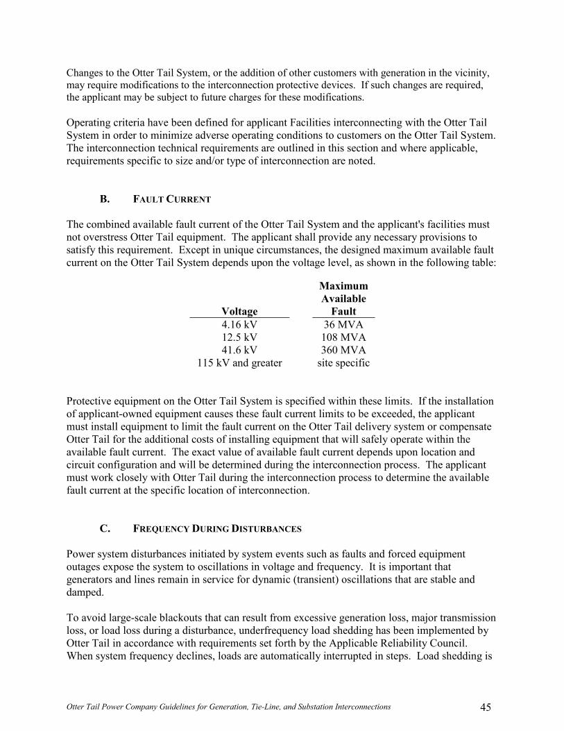
Otter Tail Power Company Guidelines for Generation, Tie-Line, and Substation Interconnections 45
Changes to the Otter Tail System, or the addition of other customers with generation in the vicinity, may require modifications to the interconnection protective devices. If such changes are required, the applicant may be subject to future charges for these modifications.
Operating criteria have been defined for applicant Facilities interconnecting with the Otter Tail System in order to minimize adverse operating conditions to customers on the Otter Tail System. The interconnection technical requirements are outlined in this section and where applicable, requirements specific to size and/or type of interconnection are noted.
B. FAULT CURRENT
The combined available fault current of the Otter Tail System and the applicant's facilities must not overstress Otter Tail equipment. The applicant shall provide any necessary provisions to satisfy this requirement. Except in unique circumstances, the designed maximum available fault current on the Otter Tail System depends upon the voltage level, as shown in the following table:
Maximum Available
Voltage Fault 4.16 kV 36 MVA 12.5 kV 108 MVA 41.6 kV 360 MVA
115 kV and greater site specific
Protective equipment on the Otter Tail System is specified within these limits. If the installation of applicant-owned equipment causes these fault current limits to be exceeded, the applicant must install equipment to limit the fault current on the Otter Tail delivery system or compensate Otter Tail for the additional costs of installing equipment that will safely operate within the available fault current. The exact value of available fault current depends upon location and circuit configuration and will be determined during the interconnection process. The applicant must work closely with Otter Tail during the interconnection process to determine the available fault current at the specific location of interconnection.
C. FREQUENCY DURING DISTURBANCES
Power system disturbances initiated by system events such as faults and forced equipment outages expose the system to oscillations in voltage and frequency. It is important that generators and lines remain in service for dynamic (transient) oscillations that are stable and damped. To avoid large-scale blackouts that can result from excessive generation loss, major transmission loss, or load loss during a disturbance, underfrequency load shedding has been implemented by Otter Tail in accordance with requirements set forth by the Applicable Reliability Council. When system frequency declines, loads are automatically interrupted in steps. Load shedding is

Otter Tail Power Company Guidelines for Generation, Tie-Line, and Substation Interconnections 46
implemented it balance the generation and load. It is important that generators and lines remain connected to the system during frequency declines, both to limit the amount of load shedding required and to help the system avoid a complete collapse. Additional voltage and frequency protection requirements for generators are found in Section VII.
D. GENERATOR FREQUENCY/SPEED CONTROL
1. 10 MW or Less
All applicant generating equipment shall be designed to operate between 59.5 and 60.5 hertz. The operating frequency of the applicant's generating equipment shall not deviate more than 0.5 hertz from a 60-hertz base. For the detection of an island condition, generators must have a means of automatically disconnecting from the Otter Tail System within 0.2 seconds if the frequency cannot be maintained within 0.5 hertz. 2. 10MW or Greater
The applicant will operate its generator consistent with Otter Tail guidelines and requirements concerning frequency control. Generators shall be equipped with governors that sense frequency (unless exempt under NERC, MISO, or Applicable Reliability Council rules due to prime mover or regulatory limitations).
i. Applicant generating equipment must have short-term capability for non-
islanded low frequency operation not less than the following: o 60.0 – 59.5 hertz continuous o 59.5 – 59.3 hertz 10 minutes o 59.3 – 58.7 hertz 10 seconds
Frequency relays must not constrain the operation of the generating facility to less than these values, unless agreed to by Otter Tail. The frequency relays must also be coordinated with Otter Tail and the Applicable Reliability Council or MISO Under-Frequency Load Shed Plan. To ensure "ride-through" capability of the Otter Tail System, the applicant shall implement an under-frequency relay set point for the Facility no greater than 58.5 Hz.
ii. Unless Otter Tail agrees otherwise, if the generator is operated in parallel with Otter Tail's distribution System, the generator will provide appropriate relaying to detect an island condition and provide a means to automatically disconnect from the Otter Tail system within 0.2 seconds if the frequency cannot be maintained within 0.5 hertz.

Otter Tail Power Company Guidelines for Generation, Tie-Line, and Substation Interconnections 47
iii. Frequency control when communications with the System Control Center
has been lost; the Constant Frequency Operating Guide (below) shows the operation expected from all plant operators during major frequency excursions. The operator will respond following this guide to the maximum ability of the applicant's generating equipment.
Figure 6. Constant Frequency Operating Guide

Otter Tail Power Company Guidelines for Generation, Tie-Line, and Substation Interconnections 48
3. Excitation System Requirements
An excitation system is required to regulate generator output voltage. • Static systems shall have a minimum ceiling voltage of 150 percent of
rated full load field voltage with 70 percent of generator terminal voltage and a maximum response time of two cycles (0.033 seconds).
• Rotating systems shall have an ANSI voltage response ratio of 2.0 or faster.
• Excitation systems shall respond to system disturbances equally in both the buck and boost directions.
Under certain conditions, Otter Tail may grant an exemption for generation Facilities that have excitation systems not meeting these requirements
XVII. INSPECTION REQUIREMENTS FOR EXISTING OR NEW
FACILITIES (R2.1.15)
A. INSPECTION, TEST, CALIBRATION AND MAINTENANCE
The applicant has full responsibility for the inspection, testing, calibration and maintenance of their facilities, up to the Point of Interconnection, consistent with the Interconnection and Operating Agreement.
1. Pre-energization Inspection and Testing
Before initial energization, the applicant shall develop an Inspection and Test Plan for pre-energization and energization testing. Otter Tail will review and approve the test plan prior to the test. Any costs incurred by Otter Tail as a result of the inspection and testing will be passed through to the applicant. The applicant will also be responsible for any additional tests that may be required by Otter Tail but were not specified in the applicant’s Inspection and Test Plan. The applicant shall provide Otter Tail with copies of all drawings, specifications, and test records of the interconnection equipment and pertinent to the interconnected operation for Otter Tail’s records. The applicant must have the interconnection installation inspected and certified by a qualified technician or a certified electrical state inspector for proper installation and operation of the interconnection protective devices. The inspection shall include, but not be limited to:
• Verification that the installation is in accordance with the study
results from the interconnection study process. • Verification of the proper operation of the protective schemes.

Otter Tail Power Company Guidelines for Generation, Tie-Line, and Substation Interconnections 49
• Verification that the proper voltages and currents are applied to the interconnection protective relays.
• Verification of proper operation and settings of the interconnection protective relays.
• Verification of synchronizing equipment. • Trip testing of the breaker(s) tripped by the interconnection relays.
2. Calibration and Maintenance
a. Metering Equipment Upon installation of, and at applicant's expense, Otter Tail or applicant shall have the right to inspect and test all metering equipment. Thereafter, the meter testing frequency shall, at a minimum, be based on industry accepted practices and guidelines outlined in ANSI C12.1. Otter Tail's present testing practices are based on the type of metering situation and the jointly agreed-to requirements of both parties involved. Typically, the metering equipment at non-Otter Tail generation/interconnection sites is tested every three years. If requested to do so by applicant, Otter Tail shall inspect or test metering equipment more frequently than every three years, at the expense of the applicant. Any current or potential transformers that are used for metering will adhere to the "Accuracy Classifications for Metering" listed in ANSI C57.13.
b. All Other Electrical Equipment The applicant shall maintain its Facilities and equipment, to the extent they might reasonably be expected to have an impact on the operation of the Otter Tail System: (1) in a safe and reliable manner; (2) in accordance with Good Utility Practice; (3) in accordance with applicable operational and/or reliability criteria, protocols, and directives, including those of NERC, the MISO, Applicable Reliability Council, state or any successor agency assuming or charged with similar responsibilities; and (4) in accordance with the provisions of the Interconnection and Operating Agreement and any attachment, appendix or exhibit thereof.
XVIII. COMMUNICATIONS AND PROCEDURES DURING NORMAL AND EMERGENCY OPERATING CONDITIONS (R2.1.16)
Prior to operation of any new interconnection (generation, tie-line or substation), the Applicant must provide contact information to Otter Tail for the NERC certified operator of the Facilities.

Otter Tail Power Company Guidelines for Generation, Tie-Line, and Substation Interconnections 50
This contact information will serve as a means to establish communications between Otter Tail and the operator of the new interconnection during normal and emergency operating conditions. Furthermore, the applicant will be required to arrange for a Meter Data Management Agent (MDMA). The Applicant may choose to utilize Otter Tail to perform this responsibility, which would require an MDMA agreement. At a minimum, the applicant shall at least inform Otter Tail how this is being handled if Otter Tail is not the MDMA. Maintenance of the facilities is to be coordingated with Otter Tail. The applicant shall also arrange to get real-time SCADA data to the MISO according to the MISO protocols and data compatibility requirements. The applicant may choose to utilize Otter Tail to perform this responsibility, which would be addressed in the CASOT.
A. DISPATCHING AND MAINTENANCE Otter Tail operates and maintains its system to provide reliable customer service while meeting the seasonal and daily peak loads even during equipment outages and disturbances. Project integration requires that the equipment at the Point of Interconnection not restrict timely outage coordination, automatic switching or equipment maintenance scheduling. Preserving reliable service to all Otter Tail customers is essential and may require additional switchgear, equipment redundancy, or bypass capabilities at the Point of Interconnection for acceptable operation of the System.
1. Emergency Response Requirement The substation applicant must agree to follow any load sheding directives by Otter Tail and corrdination of load restoration with Otter Tail. The tie-line applicant must make its facilities available to otter Tail during emergencies as far as physically possible. The generation applicant must agree to make its generation available for call by Otter Tail for MISO emergencies. Unless the generator is out for maintenance or due to mechanical failure, the applicant must be able to bring the unit to full output within the time specified in the emergency offer to the MISO. This capability must be available throughout the season in which the unit is planned to operate. This requirement is not required for installations less than 100 KW. Failure to respond in a timely manner may result in financial penalties if such financial penalties are assessed by MISO and/or the Applicable Reliability Council.
The generator will be expected to supply up to maximum available reactive capability and/or to adjust generation levels including reducing to zero if requested by the System Operator. This will usually be for reliability purposes.

Otter Tail Power Company Guidelines for Generation, Tie-Line, and Substation Interconnections 51
XIX. MISCELLANEOUS
A. STATION SERVICE Power that is provided for local use at a substation to operate lighting, heat and auxiliary equipment is termed station service. Alternate station service is a backup source of power, used only in emergencies or during maintenance when primary station service is not available. Station service power is the responsibility of the applicant. The station service requirements of the new Facilities, including voltage and reactive requirements, shall not impose operating restrictions on the Otter Tail System beyond those specified in applicable NERC, MISO, and Applicable Reliability Council reliability criteria. Appropriate provisions for station service and alternate station service will be determined during the interconnection process. Generally, the local utility will be the preference provider of primary station service unless it is unable to serve the load or costs to connect to the local utility are prohibitive. The applicant must provide metering for station service and alternate station service, as specified by the metering section of this handbook, or work out other acceptable arrangements.
B. ANCILLARY SERVICES
The applicant is required to obtain or provide for ancillary services (or portions of such services as required by FERC or NERC) for any electric load served from the interconnected electric grid. The MISO provides ancillary servicesfor the Otter Tail System. The applicant will be required to sign a Service Agreement under Otter Tail’s CASOT, which will specify which ancillary services the applicant is required to take and/or make provisions for. Otter Tail will then determine the telemetering, controls, and metering that will be required to integrate the load or Facility into the Local Balancing Authority Area and in order to effectuate provision of the required ancillary services. Ancillary services are also required for such an event where the applicant’s generation unit may trip off-line requiring Otter Tail to provide for the applicant’s loss of generation. Therefore, any generation applicant operating in long term parallel configuration to the Otter Tail System to serve its own electric load must provide for the reserve capacity requirements, operating (spinning) and non-spinning reserve, reserved load regulating capability, unit cycling capability to satisfy NERC Control Performance Criteria, have the ability to determine actual after-the-fact load and generation, and have the delivery system capacity to receive emergency power. While it is expected that the applicant will obtain all such services from the MISO, the applicant must confirm with Otter Tail, as applicable, that it is in compliance at all times with these requirements.

Otter Tail Power Company Guidelines for Generation, Tie-Line, and Substation Interconnections 52
C. SUPERVISORY CONTROL AND DATA ACQUISITION (SCADA) REQUIREMENTS SCADA indication of real and reactive power flows and voltage levels is required. If the connection is made directly to another utility’s transmission system, SCADA control and status indication requirements shall be jointly determined. SCADA control and status indication of the power circuit breakers and associated isolating switches used to connect with Otter Tail may be required. SCADA control of breakers and isolating switches that are located at other than the Point of Interconnection is not normally required, although status indication may be necessary. All substations with a circuit breaker rated at 41.6 kV or greater and all generation 5 MW or greater shall provide SCADA for the circuit breaker to the Balancing Authority Area. The following equipment data and status must be provided in a 6 second or less periodicity to the Balancing Authority Area:
• Breaker position • Motor operated disconnect position • Transmission line flow and alarming • Bus voltage and alarming battery and associated equipment status • Protective relaying AC and DC voltage status • Protective relay communication channel status • Transformer and associated equipment status • Lockout relay status • Capacitor/reactor status • Other points as necessary to provide control and indication
XX. PRE-PARALLEL CONTRACT REQUIREMENTS Prior to the actual operation of applicant-owned Facilities interconnected with the Otter Tail System, all equipment modifications must be complete and applicable contracts signed. Applicants may be required to sign the “Interconnection and Operating Agreement.” All facilities or entities scheduling within, in, or out of the Otter Tail’s Balancing Authority Area are required to sign a Control Area Services and Operations Tariff. The CASOT addresses such things as scheduling, system control, and dispatch service; reactive supply and voltage control from generation sources; operating reserves; load regulation and frequency response; generator regulation and frequency response; load following; load imbalance; generator imbalance; generator backup supply; dynamic scheduling and short-interval scheduling. The applicant must enter into a Control Area Services and Operations Tariff with the Company no later than 60 days prior to synchronization.

Otter Tail Power Company Guidelines for Generation, Tie-Line, and Substation Interconnections 53
Otter Tail may, at its option, witness the inspection. The applicant must give Otter Tail not less than seventy-two (72) hours prior written notice of upcoming tests. The certification and test report will be furnished to both the applicant and Otter Tail as soon as practical. Upon performance and certification of the pre-parallel inspection and execution of appropriate contracts/agreements, the applicant shall be granted approval for operation of the Interconnection Facility and equipment in parallel with the Otter Tail System. Neither the inspection nor the granting of approval to the applicant shall relieve the applicant of any liability for injury, death or damage attributable to the negligence of the applicant. The inspection and approval by Otter Tail does not constitute a warranty or relieve the applicant of responsibility for the operating condition or installation of the equipment and may not be relied upon by the applicant for that purpose. Once the Facility is interconnected, Otter Tail will retain the right to inspect the Facility if the operation is suspected of causing problems for other Otter Tail customers, and Otter Tail retains the right to inspect at its discretion.

Otter Tail Power Company Guidelines for Generation, Tie-Line, and Substation Interconnections 54
XXI. GLOSSARY Alternating Current (AC): That form of electric current that alternates or changes in magnitude and polarity (direction) in what is normally a regular pattern for a given time period called frequency. Ampere (AMP): The unit of current flow of electricity. It is to electricity as the number of gallons per minute is to the flow of water. One ampere flow of current is equal to one coulomb per second flow. Apparent Power: For single phase, the current in amperes multiplied by the volts equals the apparent power in volt-amperes. This term is used for alternating current circuits because the current flow is not always in phase with the voltage; hence, amperes multiplied by volts does not necessarily give the true power or watts. Apparent power for three-phase equals the phase to neutral volts multiplied by ampere multiplied by 3. Applicable Reliability Regional Council Entity: The NERC Regional Entity, or its successor, in which the Facility is located. Automatic: Self-acting, operated by its own mechanism when actuated by some impersonal influence as, for example, a change in current strength; not manual; without personal intervention. Automatic Reclosing: A circuit breaker has automatic reclosing when means are provided for closing without manual intervention after it has tripped under abnormal conditions. Automatic Tripping (Automatic Opening; Automatic Disconnecting): The opening of a circuit breaker under predetermined conditions without the intervention of an operator. Balancing Authority Area: A area balancing authority area is an electrical system bound by interconnect (tie- line) metering and telemetry and regulating its generation in order to maintain its interchange schedule with other systems, contributes to frequency regulation of the Interconnection and fulfills its obligations and responsibilities in accordance with NERC and reliability region requirements. Balancing Authority Area Load: Balancing Authority Area Load is the entire demand for energy within a specified Balancing Authority Area. Capacity: The number of amperes of electric current a wire will carry without becoming unduly heated; the capacity of a machine, apparatus or device, is the maximum of which it is capable under existing service conditions; the load for which a transformer, transmission circuit, apparatus, station or system is rated; for a generator, turbine, the URGE rating. Circuit: A conducting path through which an electric current is intended to flow.

Otter Tail Power Company Guidelines for Generation, Tie-Line, and Substation Interconnections 55
Circuit Breaker: A device for interrupting a circuit between separable contacts under normal or fault conditions. Closed Transition: The Distributed Generation is synchronized with Otter Tail Power prior to the transfer occurring. The transfer switch then parallels with Otter Tail Power for a short time (100 msec. Or less) and then the Generation System and load is disconnect from Otter Tail Power. This transfer is less disruptive than the Quick Open Transition because it allows the Distributed Generation a brief time to pick up the load before the support of Otter Tail Power is lost. With this type of transfer, the load is always being supplied by Otter Tail Power or the Distributed Generation. Current: A flow of electric charge measured in amperes. Current Transformer (CT): A transformer intended for metering, protective or control purposes, which is designed to have its primary winding connected in series with a circuit carrying the current to be measured or controlled. A current transformer normally steps down current values to safer levels. A CT secondary circuit must never be open-circuited while energized. Demand: The rate at which electric power is delivered to or by a system; normally expressed in kilowatts, megawatts, or kilovolt-amperes. Direct Current (DC): An electric current flowing in one direction only and substantially constant in value. Disconnect: A device used to isolate a piece of equipment. A disconnect may be gang-operated (all poles switched simultaneously) or individually operated. Dispatchable: Capable of having generator output (real and reactive power) adjusted (“dispatched”) upon request of Otter Tail power system operator. The adjustment includes capability to start-up and shut down generating units. Energy Losses: The general term applied to energy lost in the operation of an electrical system. Losses can be classified as Transformation Losses, Transmission Line Losses or System Losses. EMS: Energy Management System. The computer system Otter Tail uses to provide real-time status and remote control of its electrical transmission system. Facility: The applicant's electric generating, tie-line, or substation facility identified generally in the Generator Interconnection Agreement and more specifically identified in the "as built" drawings provided to the Company in accordance with Section 9.4 of the Generator Interconnection Agreement, together with the other property, facilities, and equipment owned and/or controlled by the applicant on the applicant's side of the Points of Interconnection. FERC: Federal Energy Regulatory Commission. FERC is an independent body within the Department of Energy (DOE) regulating interstate transmission, prices of electricity and natural

Otter Tail Power Company Guidelines for Generation, Tie-Line, and Substation Interconnections 56
gas. It also licenses hydroelectric projects, interconnections, construction work in progress, rates for wholesale customers, and utility accounting practices and procedures. Frequency: The number of cycles occurring in a given interval of time (usually one second) in an electric current. Frequency is commonly expressed in hertz. Fuse: A short piece of conducting material of low melting point that is inserted in a circuit for the purpose of opening the circuit when the current reaches a certain value. Ground: A term used in electrical work in referring to the earth as a conductor or as the zero of potential. For safety purposes, circuits are grounded while any work is being done on or near a circuit or piece of equipment in the circuit; this is usually called protective or safety grounding. Hertz: The term denoting frequency, equivalent to cycles per second. Incoming Breaker: The applicant-owned breaker that connects Otter Tail source of power to the applicant’s bus. Interconnection: The physical system of electrical transmission between the applicant's Facility and the utility. Interrupting Capacity: The amount of current a switch, fuse, or circuit breaker can safely interrupt. Inverter Connection: This is a continuous parallel connection with the system. Small Generation Systems may utilize inverters to interface to Otter Tail Power. Solar, wind and fuel cells are some examples of Generation which typically use inverters to connect to Otter Tail Power. The design of such inverters shall either contain all necessary protection to prevent unintentional islanding, or the Interconnection Customer shall install conventional protection to affect the same protection. All required protective elements for a soft-loading transfer switch apply to an inverter connection. Island: A part of an interconnected system that may be isolated during a system disturbance and start operating as a subsystem with its own generation, transmission and distribution capability. Then the subsystem becomes an island of the main interconnected system without a tie. In such a case, the islanded system and the main interconnected system will operate at different frequencies and voltages. Isolated: In this scheme, the generating unit will supply all of the needs of the connected load. Kilovolt (kV): One thousand volts. Kilovolt-Ampere (kVA): One thousand volt amperes. See the definition for Apparent Power. Kilowatt (kW): An electric unit of power that equals 1,000 watts.

Otter Tail Power Company Guidelines for Generation, Tie-Line, and Substation Interconnections 57
Kilowatthour (kWh): One thousand watts of power supplied for one hour. A basic unit of electric energy equal to the use of 1 kilowatt for a period of one hour. Lagging Power Factor: Occurs when reactive power flows in the same direction as real power. Leading Power Factor: Occurs when reactive power flows in the opposite direction of real power. Line Losses: Electrical energy converted to heat in the resistance of all transmission and/or distribution lines and other electrical equipment. Local Balancing Authority: The entity responsible to NERC for compliance with the subset of NERC Balancing Authority Reliability Standards defined in the Balancing Authority Agreement for its Local Balancing Authority Area within the MISO Balancing Authority Area Local Balancing Authority Area: The collection of generation, transmission, and loads within the metered boundaries of the Local Balancing Authority. NERC: North American Electric Reliability Council. A national organization responsible for establishing the operating and planning standards to assure the reliability of the electric grid. Non-Spinning Reserve: All unloaded generating capability not meeting the Spinning Reserve criteria that can be made fully effective in 10 minutes. This may include generation that shall be made available within 10 minutes by interrupting or curtailing loads or changing schedules. Ohm: The practical unit of electrical impedance equal to the resistance of a circuit in which a potential difference of 1 volt produces a current of 1 ampere. Open Transition: With this transfer switch, the load to be supplied from the Distributed Generation is first disconnected from Otter Tail Power and then connected to the Generation. This transfer can be relatively quick, but voltage and frequency excursions are to be expected during transfer. Computer equipment and other sensitive equipment will shut down and reset. The transfer switch typically consists of a standard UL approved transfer switch with mechanical interlocks between the two source contactors that drop Otter Tail Power source before the Distributed Generation is connected to supply the load. Operating Reserve: The sum of Spinning and Non-Spinning Reserve. Otter Tail Power System: This consists of Transmission, Distribution, and Generator tie-lines owned by Otter Tail Power Company. Parallel Operation: The operation of an applicant-owned generator while connected to the utility's grid. Parallel operation may be required solely for the applicant's operating convenience or for the purpose of delivering power to the utility's grid.

Otter Tail Power Company Guidelines for Generation, Tie-Line, and Substation Interconnections 58
Peak Load: The maximum electric load consumed or produced in a stated period of time. Point of Interconnection: The point or points where the facilities of the applicant interconnect with the facilities of Otter Tail (point of ownership change). Power: Actual, Active or Real Power. The time rate of transferring or transforming energy or the power that accomplishes work. Measured in Watts. Power Factor: The ratio of actual power (kW) to apparent power (kVA). Power Flow: One-way power flow is the condition where the flow of power is entirely into the applicant's Facility. Two-way power flow is the condition where the net flow of power may be either into or out of the applicant's Facility depending on the operation of the generator and other customer load. Power System Stabilizer: Supplemental excitation device for dampening low-frequency oscillations. Protection: All of the relays and other equipment that are used to open the necessary circuit breakers to clear lines or equipment when trouble develops. Quick Open Transition: The load to be supplied from the Distributed Generation is first disconnected from Otter Tail Power and then connected to the Distributed Generation, similar to the open transition. However, this transition is typically much faster (under 500 ms) than the conventional open transition transfer operation. Voltage and frequency excursions will still occur, but some computer equipment and other sensitive equipment will typically not be affected with a properly designed system. The transfer switch consists of a standard UL approved transfer switch, with mechanical interlocaks between the two source contacts that drop Otter Tail Power source before the Distributed Generation is connected to supply the load. Reactive Power: (VAr) The power that oscillates back and forth between inductive and capacitive circuit elements without ever being used. The function of reactive power is to establish and sustain the electric and magnetic fields required to perform useful work. Reclose: To return a circuit breaker to its closed position after it has opened by relay action. Relay: A device that is operative by a variation in the condition of one electric circuit to affect the operation of another device in the same or in another electric circuit. Self-Service Generators: Generators operated in parallel with the Otter Tail System only for the purpose of reducing the applicant’s peak load. These generators are not normally dispatchable by Otter Tail. Soft Loading: With Limited Parallel - The Distributed Generation is paralleled with Otter Tail Power for a limited amount of time (generally less than 1-2 minutes) to gradually transfer the

Otter Tail Power Company Guidelines for Generation, Tie-Line, and Substation Interconnections 59
load from Otter Tail Power to the Generation system. This minimizes the voltage and frequency problems, by softly loading and unloading the Generation System. With Extended Parallel - The Generation System is paralleled with Otter Tail Power in continuous operation. Special deisgn, coordination and agreements are required before any extended parallel operation will be permitted. Otter Tail Power interconnection study will identify the issues involved. Spinning Reserve: The amount of unloaded generating capability of a participant connected to and synchronized with the interconnected system of the participants and ready to take load. Spinning Reserve allocation to any generator shall not exceed the amount of generation increase that can be realized in 10 minutes. (Change to NERC?) Switch: A device for making, breaking or changing the connections in an electric circuit. Synchronism: Expresses the condition across an open circuit wherein the voltage sine wave on one side matches the voltage sine wave on the other side in frequency and amplitude without phase angle difference. System: The entire generating, transmitting and distributing facilities of an electric company. System Control Center: Systems and System Operators used in the coordination and deployment activities required to support the safe and reliable operation of interconnected systems. System Operator: A person authorized to operate or supervise the operation of the interconnected systems within the Balancing Authority Area. Tariff: The Control Area Services and Operations Tariff of Otter Tail Power Company or the MISO tariff. Transformer: An electric device, without continuously moving parts, in which electromagnetic induction transforms electric energy from one or more other circuits at the same frequency, usually with changes of value of voltage and current. Transmission Provider: Entity providing transmission service to the Customer that agrees to purchase Local Balancing Authority Services under the Service Agreement. For transmission service over Company’s transmission facilities, that entity shall be MISO. Transmission Provider’s Tariff: The open access transmission tariff of the Transmission Provider on file with FERC, as it may be amended or superseded, under which unbundled retail transmission service is provided on the Transmission Provider’s Transmission System, or the equivalent transmission and ancillary service rates or tariffs established by non-jurisdictional Transmission Providers Voltage: Electric potential or potential difference expressed in volts. Volt-Ampere: A unit of apparent power in an alternating-current circuit.

Otter Tail Power Company Guidelines for Generation, Tie-Line, and Substation Interconnections 60
VAr: Volt ampere reactive, see Reactive Power. Watt-Hour: A unit of work or energy equivalent to the power of one watt operating for one hour. Wheeling: The use of transmission facilities of one utility system to transmit power to another utility system, or between customer facilities within a single utility system or between systems. Wholesale Generator: A generator operated in parallel with the Otter Tail System and that provides power and energy for Otter Tail’s purchase or for use by another Applicable Reliability Council member or non-member and/or where the Otter Tail System is utilized for delivery. Wye or "Y" Connected Circuit (Star Connected): A three-phase circuit in which windings of all three phases have one common connection.

Otter Tail Power Company Guidelines for Generation, Tie-Line, and Substation Interconnections 61
XIII. REFERENCES American National Standard Code for Electricity Metering, ANSI/IEEE C12.1-1995. Electric Power Systems And Equipment - Voltage Ratings (60 Hz), ANSI C84.1-1995 (R2001). IEC Electromagnetic Compatibility (EMC) – Part 3: Limits – Section 7: Assessment of Emission
Limits for Fluctuating Loads in MV and HV Power Systems, CEI/IEC 1000-3-7:1996. IEC Electromagnetic Compatibility (EMC) – Part 4: Testing and Measurement Techniques,
CEI/IEC 61000-4-15:1997. IEEE Draft Standard for Distributed Resources Interconnected with Electric Power Systems,
IEEE P1547 (draft 6 12/22/00). Please Note: Once this draft has been approved, the approved version will replace this draft.
IEEE Guide for Identification, Testing, and Evaluation of the Dynamic Performance of
Excitation Control Systems, IEEE 421.2-1990. IEEE Guide for Protective Relaying of Utility - Consumer Interconnections, IEEE C37.95-2000. IEEE Guide for the Protection of Network Transformers, ANSI C37.108-1989 (R1994). IEEE Guide for Safety in Substation Grouping, IEEE 80-2000. IEEE Recommended Practices and Requirements for Harmonic Control in Electrical Power
Systems, IEEE Standard 519-1992. IEEE Recommended Practice for Emergency and Standby Power Systems for Industrial and
Commercial Applications - Orange Book, ANSI/IEEE Std. 446-1995. IEEE Recommended Practice for Monitoring Electric Power Quality, IEEE Std. 1159-1995. IEEE Recommended Practice for Protection and Coordination of Industrial and Commercial
Power Systems - Buff Book, ANSI/IEEE Std. 242-1986 (R1991). IEEE Standard for Distributed Resources Interconnected with Electric Power Systems, IEEE
P1547 (DRAFT). IEEE Standard for Relays and Relay Systems Associated with Electric Power Apparatus,
ANSI/IEEE C37.90-1989 (R1994). IEEE Standard Requirements for Instrument Transformers, IEEE C57.13-1993.

Otter Tail Power Company Guidelines for Generation, Tie-Line, and Substation Interconnections 62
IEEE Standard Surge Withstand Capability (SWC) Tests for Protective Relays and Relay Systems, ANSI/IEEE C37.90.1-1989 (R1994).
IEEE Standard Withstand Capability of Relay Systems to Radiated Electromagnetic Interference
from Transceivers, ANSI/IEEE C37.90.2-1995. IEEE Surge Voltages In Low-Voltage AC Power Circuits, IEEE C62.41-1991 (R1995). Integrated Non-Utility Generation, North American Electric Reliability Council, Princeton, NJ
08540, April 1992. MAPP Reliability Manual, Mid-Continent Area Power Pool – or the Reliability Manual of
MISO, Applicable Reliability Council, or its successor. NERC Planning Standards, North American Electric Reliability Council. NERC Operating Manual, North American Electric Reliability Council. National Electrical Code, NFPA 70, National Fire Protection Association, Quincy, MA 02269,
1999 Edition. National Electrical Safety Code, ANSI C2-1997, Institute of Electrical and Electronics
Engineers, Inc. OSHA Safety Tagging and Lock-out Procedures.

Otter Tail Power Company Guidelines for Generation, Tie-Line, and Substation Interconnections 63
Appendix A: Interconnetion Data Submittal For Interconnection to Otter Tail Power Company System WHO SHOULD FILE THIS SUBMITTAL: Anyone requesting interconnection to Otter Tail Power System that does not supply this information through some other formal process. This submittal shall be completed and provided to Otter Tail Power’s Interconnection Coordinator. INFORMATION: This submittal is used to document the interconnection formal process. The Applicant shall complete as much of the form as applicable. The Applicant will be contacted if additional information is required.

Otter Tail Power Company Guidelines for Generation, Tie-Line, and Substation Interconnections 64
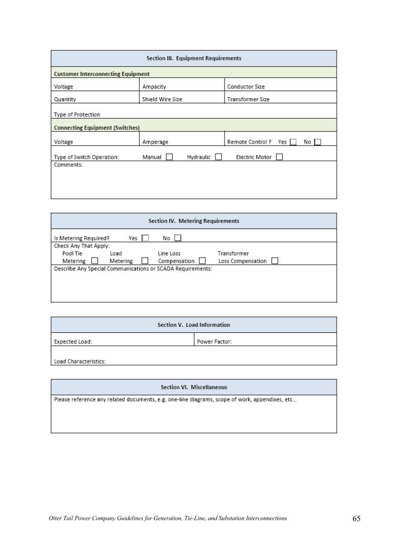
Otter Tail Power Company Guidelines for Generation, Tie-Line, and Substation Interconnections 65

Otter Tail Power Company Guidelines for Generation, Tie-Line, and Substation Interconnections 66

Otter Tail Power Company Guidelines for Generation, Tie-Line, and Substation Interconnections 67

Otter Tail Power Company Guidelines for Generation, Tie-Line, and Substation Interconnections 68
Appendix B: MN Distributed Generation Requirements

Otter Tail Power Company Guidelines for Generation, Tie-Line, and Substation Interconnections 69
STATE OF MINNESOTA
DISTRIBUTED GENERATION INTERCONNECTION REQUIREMENTS
TABLE OF CONTENTS
Foreword 69
1. Introduction 70 2. References 73 3. Types of Interconnections 74 4. Interconnection Issues and Technical Requirements 77 5. Generation Metering, Monitoring and Control 80
Table 5A – Metering, Monitoring and Control Requirements 81
6. Protective Devices and Systems 85 Table 6A – Relay Requirements 87
7. Agreements 88 8. Testing Requirements 89
Attachments: System Diagrams Figure 1 – Open Transition 93 Figure 2 – Closed Transition 94
Figure 3 – Soft Loading Transfer With Limited Parallel Operation 95
Figure 4 – Soft Loading Transfer With Limited Parallel Operation 96 Figure 5 – Extended Parallel With Transfer-Trip 97

Otter Tail Power Company Guidelines for Generation, Tie-Line, and Substation Interconnections 70

Otter Tail Power Company Guidelines for Generation, Tie-Line, and Substation Interconnections 71

Otter Tail Power Company Guidelines for Generation, Tie-Line, and Substation Interconnections 72

Otter Tail Power Company Guidelines for Generation, Tie-Line, and Substation Interconnections 73

Otter Tail Power Company Guidelines for Generation, Tie-Line, and Substation Interconnections 74

Otter Tail Power Company Guidelines for Generation, Tie-Line, and Substation Interconnections 75

Otter Tail Power Company Guidelines for Generation, Tie-Line, and Substation Interconnections 76

Otter Tail Power Company Guidelines for Generation, Tie-Line, and Substation Interconnections 77

Otter Tail Power Company Guidelines for Generation, Tie-Line, and Substation Interconnections 78

Otter Tail Power Company Guidelines for Generation, Tie-Line, and Substation Interconnections 79

Otter Tail Power Company Guidelines for Generation, Tie-Line, and Substation Interconnections 80

Otter Tail Power Company Guidelines for Generation, Tie-Line, and Substation Interconnections 81

Otter Tail Power Company Guidelines for Generation, Tie-Line, and Substation Interconnections 82

Otter Tail Power Company Guidelines for Generation, Tie-Line, and Substation Interconnections 83

Otter Tail Power Company Guidelines for Generation, Tie-Line, and Substation Interconnections 84

Otter Tail Power Company Guidelines for Generation, Tie-Line, and Substation Interconnections 85

Otter Tail Power Company Guidelines for Generation, Tie-Line, and Substation Interconnections 86

Otter Tail Power Company Guidelines for Generation, Tie-Line, and Substation Interconnections 87
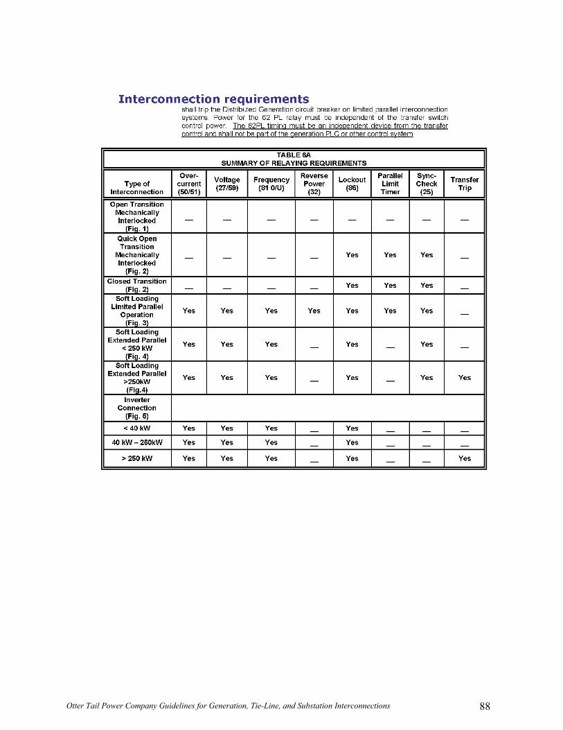
Otter Tail Power Company Guidelines for Generation, Tie-Line, and Substation Interconnections 88

Otter Tail Power Company Guidelines for Generation, Tie-Line, and Substation Interconnections 89

Otter Tail Power Company Guidelines for Generation, Tie-Line, and Substation Interconnections 90

Otter Tail Power Company Guidelines for Generation, Tie-Line, and Substation Interconnections 91

Otter Tail Power Company Guidelines for Generation, Tie-Line, and Substation Interconnections 92

Otter Tail Power Company Guidelines for Generation, Tie-Line, and Substation Interconnections 93

Otter Tail Power Company Guidelines for Generation, Tie-Line, and Substation Interconnections 94

Otter Tail Power Company Guidelines for Generation, Tie-Line, and Substation Interconnections 95

Otter Tail Power Company Guidelines for Generation, Tie-Line, and Substation Interconnections 96

Otter Tail Power Company Guidelines for Generation, Tie-Line, and Substation Interconnections 97

Otter Tail Power Company Guidelines for Generation, Tie-Line, and Substation Interconnections 98

Otter Tail Power Company Guidelines for Generation, Tie-Line, and Substation Interconnections
Appendix C: SD Distributed Generation Requirements
See South Dakota rules 20:10:36 – Small Generator Facility Interconnection