guidelines for commercial craft for... · 4.15 the gz-curve properties..... 79 4.16 rolling with...
TRANSCRIPT

Guidelines for Commercial Craft
Version 2016.2
The objective of the guidelines is to provide a basis for designing and construction of commercial craft
so that a reasonable level of safety and environmental sustainability is achieved.
The guidelines are developed by VTT Expert Services Ltd., Finland, and is primarily used for the
assessment of small commercial craft for statutory compliance

2
Return to the cover page TABLE OF CONTENTS
1 INTRODUCTION AND PRINCIPLES OF APPLICATION ................................................................ 35
1.1 Objective ................................................................................................................................... 35
1.2 Background ............................................................................................................................... 35
1.3 Principles when using ISO-standards ....................................................................................... 35
1.4 The Rules vs. International Conventions .................................................................................. 36
1.5 Unusual arrangements .............................................................................................................. 36
1.6 Scope of the Rules .................................................................................................................... 36
1.6.1 Scope ................................................................................................................................. 36
1.6.2 Length of the craft .............................................................................................................. 36
1.6.3 Types of craft ..................................................................................................................... 37
1.6.4 Hull construction materials ................................................................................................ 37
1.6.5 The definitions “Under Way” and “At Sea” ........................................................................ 37
1.7 Conditions of use ...................................................................................................................... 37
1.7.1 Design Categories ............................................................................................................. 37
1.7.2 Temperatures and water salinity ....................................................................................... 38
1.8 Additional Notations .................................................................................................................. 38
1.8.1 Cargo Transport ................................................................................................................ 38
1.8.2 Towing ............................................................................................................................... 38
1.8.3 Oil Spill Combat ................................................................................................................. 38
1.8.4 Passenger Transport ......................................................................................................... 39
1.8.5 Self-Righting ...................................................................................................................... 39
1.8.6 One Compartment Damage Stability ................................................................................ 39
1.8.7 Winter navigation ............................................................................................................... 39
1.8.8 Deck Crane ........................................................................................................................ 39
1.8.9 Hovercraft .......................................................................................................................... 39
1.9 Procedures for assessment ...................................................................................................... 40
1.9.1 Craft identification .............................................................................................................. 40

3
Return to the cover page
1.9.2 Individual approval............................................................................................................. 40
1.9.3 Sisterships ......................................................................................................................... 40
1.9.4 Type approval plus production control .............................................................................. 40
1.10 Documentation .......................................................................................................................... 40
1.11 Reporting ................................................................................................................................... 40
1.12 Symbols and units commonly used in these Rules .................................................................. 41
1.12.1 The weight and dimensions of crew .................................................................................. 41
1.12.2 Symbols ............................................................................................................................. 42
2 CRAFT CONCEPTS ......................................................................................................................... 44
2.1 Objective ................................................................................................................................... 44
2.2 References ................................................................................................................................ 44
2.3 Selection of craft concepts ........................................................................................................ 44
2.3.1 Fully enclosed craft............................................................................................................ 44
2.3.2 Partially protected craft ...................................................................................................... 45
2.3.3 Craft with buoyancy chambers for remaining afloat .......................................................... 46
2.3.4 Open craft without buoyancy chambers ............................................................................ 47
3 PREVENTION OF DOWNFLOODING ............................................................................................. 48
3.1 Objective ................................................................................................................................... 48
3.2 References ................................................................................................................................ 48
3.3 Documentation .......................................................................................................................... 48
3.4 Openings and closing appliances, general ............................................................................... 48
3.4.1 Application ......................................................................................................................... 48
3.4.2 Exemptions ........................................................................................................................ 49
3.5 Requirements for openings, and closing appliances ................................................................ 49
3.5.1 Properties affecting the requirements ............................................................................... 49
3.6 Definitions for types of openings, and closing appliances ........................................................ 49
3.6.1 Doorways ........................................................................................................................... 49
3.6.2 Hatchways ......................................................................................................................... 49

4
Return to the cover page
3.6.3 Windows and portlights ..................................................................................................... 49
3.6.4 Hull ports............................................................................................................................ 50
3.6.5 Air pipes ............................................................................................................................. 50
3.6.6 Through-hull fittings ........................................................................................................... 50
3.6.7 Openings without closing appliances ................................................................................ 50
3.6.8 Local deck height HD ........................................................................................................ 50
3.7 Application areas for openings ................................................................................................. 50
3.8 Opening’s closing status in operation ....................................................................................... 51
3.9 Definitions and requirements common for all closing appliances ............................................ 51
3.9.1 Coaming- and sill heights .................................................................................................. 51
3.9.2 The length of the shorter side of the opening ................................................................... 53
3.9.3 Degree of Water tightness ................................................................................................. 53
3.9.4 Latches and hinges for locking .......................................................................................... 54
3.9.5 Hinged closing appliances ................................................................................................. 54
3.9.6 Sliding hatches .................................................................................................................. 54
3.9.7 CE-marked closing appliances .......................................................................................... 54
3.9.8 Particular requirements for closing appliances in Application area 1 ............................... 54
3.9.9 Protection of gaskets ......................................................................................................... 55
3.9.10 Closing appliances on cargo decks ................................................................................... 55
3.10 Requirements for openings always open during operation. ..................................................... 55
3.10.1 Allowed locations for openings always open during operation ......................................... 55
3.10.2 Preventing water from entering ......................................................................................... 55
3.11 Requirements for doors ............................................................................................................ 56
3.11.1 Door sills ............................................................................................................................ 56
3.11.2 Direction of opening for doors ........................................................................................... 56
3.11.3 Latches and hinges ........................................................................................................... 56
3.12 Requirements for hatches ......................................................................................................... 56
3.12.1 Special requirements for hatches ...................................................................................... 56

5
Return to the cover page
3.13 Requirements for windows ........................................................................................................ 57
3.13.1 Special requirements for windows .................................................................................... 57
3.14 Requirements for hull ports ....................................................................................................... 57
3.15 Freeboard to the lower edge of hull ports ................................................................................. 57
3.16 Strength ..................................................................................................................................... 57
3.16.1 Water tightness .................................................................................................................. 58
3.16.2 Hinges and latching mechanisms ..................................................................................... 58
3.17 Requirements for air pipes ........................................................................................................ 58
3.18 Through-hulls connected to on-board systems ........................................................................ 58
3.18.1 General .............................................................................................................................. 58
3.18.2 Through-hull fittings and seacocks .................................................................................... 59
3.18.3 Accessibility ....................................................................................................................... 59
3.18.4 Requirements for on-board systems connected to through-hulls ..................................... 60
3.18.5 Galvanic corrosion ............................................................................................................. 60
3.18.6 Hose connections .............................................................................................................. 60
3.19 Penetrations in outboard engine wells ...................................................................................... 60
3.19.1 Cable and hose penetrations ............................................................................................ 60
3.19.2 Ventilation openings .......................................................................................................... 60
4 FREEBOARD AND INTACT STABILITY .......................................................................................... 66
4.1 Objective ................................................................................................................................... 66
4.2 References ................................................................................................................................ 66
4.3 Documentation .......................................................................................................................... 66
4.4 Assessment alternatives and requirements .............................................................................. 67
4.4.1 General .............................................................................................................................. 67
4.5 Definitions and assumptions ..................................................................................................... 73
4.6 Lightweight ................................................................................................................................ 73
4.6.1 Determination of lightweight and center of gravity ............................................................ 73
4.6.2 Maximum load ................................................................................................................... 74

6
Return to the cover page
4.7 Loading conditions .................................................................................................................... 74
4.7.1 Loading conditions to be assessed ................................................................................... 74
4.7.2 Minimum operating condition, loading condition LC1 ....................................................... 75
4.7.3 Fully loaded, departure, loading condition LC2................................................................. 75
4.7.4 Fully loaded, arrival, loading condition LC3 ...................................................................... 75
4.7.5 Offset load, loading condition OFFSET............................................................................. 75
4.8 Assumptions when assessing stability ...................................................................................... 75
4.8.1 Hull model for stability calculation ..................................................................................... 75
4.8.2 Location of loading components ....................................................................................... 76
4.8.3 Free surfaces in the tanks ................................................................................................. 76
4.8.4 Icing ................................................................................................................................... 76
4.9 The effect of recesses on stability ............................................................................................ 76
4.10 Reserve buoyancy .................................................................................................................... 77
4.10.1 General .............................................................................................................................. 77
4.11 The buoyancy of the bow .......................................................................................................... 77
4.12 Downflooding height (all craft) .................................................................................................. 78
4.13 Heeling angle and residuary freeboard with offset load ........................................................... 78
4.13.1 Definitions .......................................................................................................................... 78
4.13.2 The loading condition when measuring heeling angle, and residuary freeboard or
downflooding angle ........................................................................................................................... 79
4.14 Maximum righting moment ........................................................................................................ 79
4.15 The GZ-curve properties ........................................................................................................... 79
4.16 Rolling with wind and waves on the beam (weather criterion) ................................................. 79
4.17 Wind induced heel ..................................................................................................................... 81
4.18 Buoyancy when swamped ........................................................................................................ 81
4.18.1 General .............................................................................................................................. 81
4.18.2 Types of flotation elements and their requirements .......................................................... 82
4.18.3 Arrangements for buoyancy .............................................................................................. 82

7
Return to the cover page
4.18.4 Assessment of buoyancy .................................................................................................. 82
4.19 Multihulls susceptible to inversion ............................................................................................ 83
4.19.1 Susceptible to inversion .................................................................................................... 83
4.19.2 Requirements .................................................................................................................... 83
5 DECK ARRANGEMENT AND RECESSES ..................................................................................... 84
5.1 Purpose ..................................................................................................................................... 84
5.2 References ................................................................................................................................ 84
5.3 Documentation .......................................................................................................................... 84
5.4 Definitions.................................................................................................................................. 85
5.4.1 Recesses ........................................................................................................................... 85
5.4.2 Basic requirements for recesses ....................................................................................... 85
5.4.3 Watertight recess ............................................................................................................... 85
5.5 Requirements for deck arrangements ...................................................................................... 85
5.5.1 Weatherdeck arrangement ................................................................................................ 85
5.5.2 Non-weather tight superstructures in fully enclosed craft ................................................. 85
5.6 Detailed requirement for recesses ............................................................................................ 85
5.6.1 Height of recess bottom above waterline .......................................................................... 86
5.6.2 Maximum draining time ..................................................................................................... 86
5.6.3 Area requirement for drain openings ................................................................................. 87
5.6.4 Example arrangement ....................................................................................................... 87
5.6.5 Drain area per side ............................................................................................................ 88
5.6.6 Draining test ...................................................................................................................... 89
5.6.7 Number and location of drains .......................................................................................... 89
5.6.8 Sill heights ......................................................................................................................... 89
5.6.9 Water tightness .................................................................................................................. 89
6 PREVENTION AND CONTROL OF LEAKS, BILGE SYSTEMS ..................................................... 90
6.1 Purpose ..................................................................................................................................... 90
6.2 References ................................................................................................................................ 90

8
Return to the cover page
6.3 Documentation .......................................................................................................................... 90
6.4 Requirements ............................................................................................................................ 90
6.5 Leak control ............................................................................................................................... 90
6.6 Limited unsinkability .................................................................................................................. 91
6.6.1 Principle ............................................................................................................................. 91
6.6.2 The means for achieving limited unsinkability ................................................................... 91
6.7 Draining arrangements for the bilge ......................................................................................... 92
6.7.1 General .............................................................................................................................. 92
6.7.2 Compartments to be drained ............................................................................................. 92
6.7.3 Requirements for the bilge draining system ...................................................................... 93
6.7.4 Main bilge draining system ................................................................................................ 94
6.7.5 Secondary bilge pumping system ..................................................................................... 96
6.7.6 Measurement of bilge pumping capacity .......................................................................... 97
6.7.7 Multihull bilge draining arrangements ............................................................................... 97
6.7.8 Alarm for high bilge water level ......................................................................................... 98
6.7.9 Material specifications for bilge draining systems ............................................................. 98
6.7.10 Strainers for suction hoses or bilge pumps ....................................................................... 98
7 DESIGN PRESSURES AND LOADS ............................................................................................. 100
7.1 Objective ................................................................................................................................. 100
7.2 References .............................................................................................................................. 100
7.3 Principles ................................................................................................................................. 100
7.3.1 Global loads ..................................................................................................................... 100
7.3.2 Local loads ...................................................................................................................... 100
7.3.3 Extension of loads ........................................................................................................... 100
7.4 Bottom design pressure .......................................................................................................... 101
7.5 Side design pressure .............................................................................................................. 102
7.6 Design pressure for decks ...................................................................................................... 103
7.7 Design pressure for superstructures ....................................................................................... 103

9
Return to the cover page
7.8 Watertight bulkheads .............................................................................................................. 104
7.9 Design pressure for integral tanks .......................................................................................... 104
7.10 Design pressure for multihull wet-decks ................................................................................. 104
7.11 Global loadcases for multihull craft ......................................................................................... 104
7.12 Forces on transoms for high-power outboard motors ............................................................ 105
7.13 Connection of RIB pontoons ................................................................................................... 106
7.14 Design pressure correction factors ......................................................................................... 107
7.14.1 Design category factor .................................................................................................... 107
7.14.2 Area reduction factor ....................................................................................................... 107
7.14.3 Design pressure correction based on longitudinal position ............................................ 108
7.14.4 Design pressure correction based on vertical position ................................................... 109
8 DESIGN PRINCIPLES, FIBRE-REINFORCED PLASTIC .............................................................. 111
8.1 Objective ................................................................................................................................. 111
8.2 References .............................................................................................................................. 111
8.3 Principles of analysis............................................................................................................... 111
8.3.1 Simple assessment method ............................................................................................ 111
8.3.2 Assessment using First Principles .................................................................................. 111
8.3.3 Finite Element Method (FE) ............................................................................................ 111
8.4 Assumptions ............................................................................................................................ 112
8.4.1 Local and global strength/stiffness .................................................................................. 112
8.4.2 Hierarchy of the load carrying elements.......................................................................... 112
8.4.3 Sandwich panels ............................................................................................................. 113
8.5 Global strength and stiffness .................................................................................................. 113
8.6 Requirements for structural arrangement ............................................................................... 114
8.6.1 Displacement craft, design category D ........................................................................... 114
8.6.2 Planing craft ..................................................................................................................... 114
8.6.3 Support for longitudinal stiffeners .................................................................................... 114
8.6.4 Keels, stem and chines ................................................................................................... 114

10
Return to the cover page
8.6.5 Torsion stiffness and -strength ........................................................................................ 114
8.6.6 Superstructure support points ......................................................................................... 114
8.7 Hull stiffeners .......................................................................................................................... 115
8.7.1 Continuity of stiffeners ..................................................................................................... 115
8.7.2 Straightness and local discontinuities of stiffeners ......................................................... 115
8.7.3 Safety against buckling ................................................................................................... 115
8.7.4 Transverse stiffeners ....................................................................................................... 115
8.7.5 Floating framing ............................................................................................................... 115
8.7.6 Other stiffeners ................................................................................................................ 115
8.8 Laminate design ...................................................................................................................... 116
8.8.1 Fibers carry the load ........................................................................................................ 116
8.8.2 Laminate balance ............................................................................................................ 116
8.8.3 Laminates containing several types of fibers .................................................................. 116
8.9 Layer drop-off .......................................................................................................................... 116
8.9.1 Single skin laminates ....................................................................................................... 116
8.10 Sandwich ................................................................................................................................. 117
8.10.1 Transition from sandwich to single skin .......................................................................... 117
8.11 Laminate bonding .................................................................................................................... 117
8.11.1 Bonding of stiffeners ........................................................................................................ 117
8.11.2 Bonding of bulkheads ...................................................................................................... 118
8.11.3 Adhesive bonding ............................................................................................................ 118
8.12 Other structural details ............................................................................................................ 119
8.12.1 Openings in load-bearing structures ............................................................................... 119
8.12.2 Sharp corners .................................................................................................................. 119
8.12.3 Special issues for sandwich construction ....................................................................... 119
8.12.4 Other structural details .................................................................................................... 119
9 FIBRE REINFORCED PLASTICS MATERIAL ............................................................................... 121
9.1 Objective ................................................................................................................................. 121

11
Return to the cover page
9.2 References .............................................................................................................................. 121
9.3 Documentation ........................................................................................................................ 121
9.4 Resins ..................................................................................................................................... 121
9.5 Fiber reinforcement ................................................................................................................. 121
9.6 Compability of fibers with resin ............................................................................................... 121
9.7 Mechanical properties of laminates ........................................................................................ 122
9.8 9.8. Determination of mechanical properties by testing ......................................................... 122
9.9 Determination of mechanical properties by a nominal fiber content ...................................... 122
9.9.1 Nominal fiber content ...................................................................................................... 123
9.9.2 Mechanical properties ..................................................................................................... 123
9.10 Sandwich core materials ......................................................................................................... 123
9.10.1 Mechanical properties of sandwich core materials ......................................................... 123
9.11 Values to be used for scantling determination ........................................................................ 123
9.12 Adhesives ................................................................................................................................ 124
9.13 Other materials ........................................................................................................................ 124
10 SCANTLINGS DETERMINATION, FIBRE REINFORCED PLASTICS ..................................... 134
10.1 Objective ................................................................................................................................. 134
10.2 References .............................................................................................................................. 134
10.3 Documentation ........................................................................................................................ 134
10.4 List of symbols ........................................................................................................................ 134
10.5 Dimension of panels................................................................................................................ 135
10.6 Scantlings requirements, single skin panels ........................................................................... 136
10.7 Scantlings requirement, sandwich panels .............................................................................. 137
10.7.1 Bending strength criterion ............................................................................................... 137
10.7.2 Stiffness criterion ............................................................................................................. 137
10.7.3 Shear criterion ................................................................................................................. 138
10.7.4 Sandwich core minimum compressive strength in hull bottom ....................................... 138
10.8 Minimum amount of fiber reinforcement for local strength ..................................................... 138

12
Return to the cover page
10.9 Correction factors for panels ................................................................................................... 139
10.9.1 Correction for panel curvature ......................................................................................... 139
10.10 Correction based on panel aspect ratio .............................................................................. 140
10.11 Stiffeners ............................................................................................................................. 140
10.11.1 General ........................................................................................................................ 140
10.11.2 Section modulus .......................................................................................................... 140
10.11.3 Second moment of area .............................................................................................. 141
10.11.4 Effective flange ............................................................................................................ 142
10.11.5 Cross-section of stiffener web ..................................................................................... 142
10.11.6 Orthotropic stiffeners ................................................................................................... 143
10.11.7 Buckling of stiffeners ................................................................................................... 143
10.12 Reinforced shell areas ........................................................................................................ 143
10.12.1 Reinforced keel ............................................................................................................ 143
10.12.2 Reinforced stem ........................................................................................................... 143
10.12.3 Reinforced chine .......................................................................................................... 143
10.12.4 Edge of deck and hull/deck joint .................................................................................. 144
10.13 Highly loaded structures ...................................................................................................... 144
10.13.1 Engine foundations ...................................................................................................... 144
10.13.2 Transoms for outboard and sterndrive engines .......................................................... 144
10.13.3 Attachment of mooring and other highly loaded fittings .............................................. 145
10.13.4 Attachment of railings, handholds and lifeline hooking points .................................... 145
10.13.5 Design of attachment points ........................................................................................ 145
10.13.6 Attachment of RIB-pontoon ......................................................................................... 145
10.14 Design stresses ................................................................................................................... 146
11 PRODUCTION OF FIBRE-REINFORCED PLASTIC CRAFT ................................................... 147
11.1 Objective ................................................................................................................................. 147
11.2 References .............................................................................................................................. 147
11.3 Documentation ........................................................................................................................ 147
13
Return to the cover page
11.4 Workshop conditions ............................................................................................................... 147
11.5 Material storage ...................................................................................................................... 148
11.6 Lamination ............................................................................................................................... 148
11.6.1 Requirements for all types of laminates .......................................................................... 148
11.6.2 Polyester- and vinylester laminates ................................................................................ 149
11.6.3 Epoxy laminates .............................................................................................................. 149
11.7 Sandwich construction ............................................................................................................ 149
11.8 Secondary lamination ............................................................................................................. 150
11.8.1 Polyester- and vinylester laminates ................................................................................ 150
11.8.2 Epoxy laminates .............................................................................................................. 150
11.9 Adhesive bonding .................................................................................................................... 150
11.10 Curing .................................................................................................................................. 151
11.11 Thickness gauging .............................................................................................................. 151
11.12 Material testing .................................................................................................................... 151
12 STRUCTURAL DESIGN PRINCIPLES, ALUMINIUM ................................................................ 152
12.1 Objective ................................................................................................................................. 152
12.2 References .............................................................................................................................. 152
12.3 Principles of structural analysis............................................................................................... 152
12.3.1 Simplified calculation method .......................................................................................... 152
12.3.2 Direct calculation of stresses and strains ........................................................................ 152
12.4 Assumptions ............................................................................................................................ 153
12.4.1 Assumptions regarding local vs. global strength and stiffness ....................................... 153
12.4.2 Hierarchy of the load carrying elements.......................................................................... 153
12.5 Global strength and stiffness .................................................................................................. 154
12.6 Structural arrangement ........................................................................................................... 154
12.6.1 Displacement craft, design category D ........................................................................... 154
12.6.2 Planing craft ..................................................................................................................... 155
12.6.3 Support for longitudinal stiffeners .................................................................................... 155

14
Return to the cover page
12.6.4 Keels, stem and chines ................................................................................................... 155
12.6.5 Torsional stiffness and -strength ..................................................................................... 155
12.6.6 Superstructure support points ......................................................................................... 155
12.7 Hull stiffeners .......................................................................................................................... 155
12.7.1 Continuity and termination of stiffeners ........................................................................... 155
12.7.2 Straightness and local discontinuities of stiffeners ......................................................... 155
12.7.3 Safety against buckling ................................................................................................... 156
12.7.4 Transverse stiffeners ....................................................................................................... 156
12.7.5 Floating stiffeners ............................................................................................................ 156
12.8 Other stiffeners ........................................................................................................................ 156
12.9 Construction details................................................................................................................. 156
12.9.1 Joining plates of different thickness ................................................................................ 156
12.9.2 Fastening and joints of stiffeners .................................................................................... 156
12.9.3 Openings in load-bearing structures ............................................................................... 157
12.9.4 Sharp edges .................................................................................................................... 157
12.9.5 Other details .................................................................................................................... 157
12.9.6 Corrosion ......................................................................................................................... 157
12.10 Welding ................................................................................................................................ 158
13 ALUMINIUM MATERIALS .......................................................................................................... 161
13.1 Objective ................................................................................................................................. 161
13.2 References .............................................................................................................................. 161
13.3 Documentation ........................................................................................................................ 161
13.4 Mechanical properties of aluminium alloys ............................................................................. 161
13.4.1 Group 1. Non-heat treatable alloys ................................................................................. 161
13.4.2 Group 2. Heat treatable alloys ........................................................................................ 162
13.4.3 Other alloys ..................................................................................................................... 162
13.5 Welding consumables ............................................................................................................. 163
14 SCANTLINGS DETERMINATION, ALUMINIUM ....................................................................... 164

15
Return to the cover page
14.1 Objective ................................................................................................................................. 164
14.2 References .............................................................................................................................. 164
14.3 Documentation ........................................................................................................................ 164
14.4 List of symbols ........................................................................................................................ 164
14.5 Dimension of panels................................................................................................................ 165
14.6 Scantlings requirements, aluminium panels ........................................................................... 166
14.7 Correction factors for panels ................................................................................................... 166
14.7.1 Correction for alloy strength ............................................................................................ 166
14.7.2 Correction based on panel curvature .............................................................................. 167
14.7.3 Correction based on panel aspect ratio. ......................................................................... 167
14.8 Stiffeners ................................................................................................................................. 168
14.8.1 Section modulus .............................................................................................................. 168
14.8.2 Effective flange ................................................................................................................ 169
14.8.3 Shear area of stiffener webs ........................................................................................... 169
14.9 Reinforcements ....................................................................................................................... 169
14.10 Highly loaded structures ...................................................................................................... 170
14.10.1 Engine foundations ...................................................................................................... 170
14.10.2 Transoms for outboard and sterndrive engines .......................................................... 170
14.10.3 Attachment of mooring and other highly loaded fittings .............................................. 170
14.10.4 Attachment of railings, handholds and lifeline hooking points .................................... 170
14.10.5 Attachment of RIB-pontoon ......................................................................................... 170
14.11 Design stresses ................................................................................................................... 171
15 PRODUCTION OF ALUMINIUM BOATS ................................................................................... 172
15.1 Objective ................................................................................................................................. 172
15.2 References .............................................................................................................................. 172
15.3 Documentation ........................................................................................................................ 172
15.4 Workshop conditions ............................................................................................................... 172
15.5 Materials .................................................................................................................................. 173

16
Return to the cover page
15.6 Cutting and forming ................................................................................................................. 173
15.7 Welding ................................................................................................................................... 173
15.7.1 Welder’s qualification ...................................................................................................... 173
15.7.2 Welding Procedure Specification .................................................................................... 173
15.7.3 Surveys ............................................................................................................................ 174
16 DESIGN PRINCIPLES, STEEL .................................................................................................. 175
16.1 Objective ................................................................................................................................. 175
16.2 References .............................................................................................................................. 175
16.3 Principles of structural analysis............................................................................................... 175
16.3.1 Simplified calculation method .......................................................................................... 175
16.3.2 Direct calculation of stresses and strains ........................................................................ 175
16.4 Assumptions ............................................................................................................................ 175
16.4.1 Assumptions regarding local vs. global strength and stiffness ....................................... 175
16.4.2 Hierarchy of the load carrying elements.......................................................................... 176
16.5 Global strength and stiffness .................................................................................................. 177
16.6 Structural arrangement ........................................................................................................... 177
16.6.1 Displacement craft, design category D ........................................................................... 177
16.6.2 Planing craft ..................................................................................................................... 177
16.6.3 Support for longitudinal stiffeners .................................................................................... 177
16.6.4 Keels, stem and chines ................................................................................................... 177
16.6.5 Torsional stiffness and -strength ..................................................................................... 177
16.6.6 Superstructure support points ......................................................................................... 178
16.7 Hull stiffeners .......................................................................................................................... 178
16.7.1 Continuity and termination of stiffeners ........................................................................... 178
16.7.2 Straightness and local discontinuities of stiffeners ......................................................... 178
16.7.3 Safety against buckling ................................................................................................... 178
16.7.4 Transverse stiffeners ....................................................................................................... 178
16.7.5 Floating stiffeners ............................................................................................................ 178

17
Return to the cover page
16.8 Other stiffeners ........................................................................................................................ 178
16.9 Construction details................................................................................................................. 179
16.9.1 Joining plates of different thickness ................................................................................ 179
16.9.2 Fastening and joints of stiffeners .................................................................................... 179
16.9.3 Openings in load-bearing structures ............................................................................... 179
16.9.4 Sharp edges .................................................................................................................... 180
16.9.5 Other details .................................................................................................................... 180
16.9.6 Corrosion ......................................................................................................................... 180
16.10 Welding ................................................................................................................................ 180
17 STEEL MATERIALS ................................................................................................................... 184
17.1 Normal strength steel .............................................................................................................. 184
17.2 Steel grades for low temperatures .......................................................................................... 184
18 SCANTLINGS DETERMINATION, STEEL ................................................................................ 185
18.1 Objective ................................................................................................................................. 185
18.2 References .............................................................................................................................. 185
18.3 Documentation ........................................................................................................................ 185
18.4 List of symbols ........................................................................................................................ 185
18.5 Dimension of panels................................................................................................................ 186
18.6 Scantlings requirements, steel panels .................................................................................... 186
18.7 Correction factors for panels ................................................................................................... 187
18.7.1 Correction for alloy strength ............................................................................................ 187
18.7.2 Correction based on panel curvature .............................................................................. 187
18.7.3 Correction based on panel aspect ratio. ......................................................................... 188
18.8 Stiffeners ................................................................................................................................. 189
18.8.1 Section modulus .............................................................................................................. 189
18.8.2 Effective flange ................................................................................................................ 190
18.8.3 Shear area of stiffener webs ........................................................................................... 190
18.9 Reinforcements ....................................................................................................................... 190

18
Return to the cover page
18.10 Highly loaded structures ...................................................................................................... 191
18.10.1 Engine foundations ...................................................................................................... 191
18.10.2 Transoms for outboard and sterndrive engines .......................................................... 191
18.10.3 Attachment of mooring and other highly loaded fittings .............................................. 191
18.10.4 Attachment of railings, handholds and lifeline hooking points .................................... 191
18.10.5 Attachment of RIB-pontoon ......................................................................................... 191
18.11 Design stresses ................................................................................................................... 192
19 PRODUCTION OF STEEL BOATS ............................................................................................ 193
19.1 Objective ................................................................................................................................. 193
19.2 References .............................................................................................................................. 193
19.3 Documentation ........................................................................................................................ 193
19.4 Workshop conditions ............................................................................................................... 193
19.5 Materials .................................................................................................................................. 194
19.6 Cutting and forming ................................................................................................................. 194
19.7 Welding ................................................................................................................................... 194
19.7.1 Welder’s qualification ...................................................................................................... 194
19.7.2 Welding Procedure Specification .................................................................................... 194
19.7.3 Surveys ............................................................................................................................ 194
19.7.4 Required weld quality ...................................................................................................... 195
20 RUDDER AND STEERING SYSTEMS ...................................................................................... 196
20.1 Objective ................................................................................................................................. 196
20.2 References .............................................................................................................................. 196
20.3 Documentation ........................................................................................................................ 196
20.4 Steering arrangements ........................................................................................................... 197
20.4.1 Main steering system ...................................................................................................... 197
20.4.2 Emergency steering system ............................................................................................ 197
20.4.3 Requirements for steering systems ................................................................................. 197
20.5 Rudders ................................................................................................................................... 198

19
Return to the cover page
20.5.1 Rudder design, general ................................................................................................... 198
20.5.2 Fail-safe design ............................................................................................................... 198
20.5.3 Rudder dimensioning load ............................................................................................... 200
20.5.4 Spade rudder bending moment and bearing loads ......................................................... 200
20.5.5 Bending moment and bearing loads for rudders supported at their lower end............... 201
20.5.6 Rudder stock diameter .................................................................................................... 202
20.5.7 Rudder bearings .............................................................................................................. 202
20.5.8 Rudder blade ................................................................................................................... 202
20.5.9 Plate and profiled rudders ............................................................................................... 203
20.5.10 Tillers and quadrants ................................................................................................... 203
20.5.11 Upper end of rudder stock casing ............................................................................... 204
20.5.12 Rudder sole piece ........................................................................................................ 204
20.5.13 Rudder stock flange bolted connections ..................................................................... 204
20.5.14 Steering system forces ................................................................................................ 205
21 PROPULSION MACHINERY ...................................................................................................... 206
21.1 Objective ................................................................................................................................. 206
21.2 References .............................................................................................................................. 206
21.3 Documentation ........................................................................................................................ 206
21.4 Application ............................................................................................................................... 206
21.5 Engines ................................................................................................................................... 207
21.5.1 Propulsion engine types .................................................................................................. 207
21.5.2 Portable auxiliaries .......................................................................................................... 207
21.5.3 Power ratings ................................................................................................................... 207
21.5.4 Redundancy .................................................................................................................... 207
21.5.5 Rolling and pitching ......................................................................................................... 208
21.5.6 Hot surfaces .................................................................................................................... 208
21.6 Power transmission ................................................................................................................. 208
21.7 Engine spaces ......................................................................................................................... 208

20
Return to the cover page
21.7.1 Arrangements .................................................................................................................. 208
21.7.2 Installation of outboard engines ...................................................................................... 208
21.8 Cooling systems ...................................................................................................................... 209
21.8.1 General ............................................................................................................................ 209
21.8.2 Cooling systems with sea water intake ........................................................................... 209
21.8.3 Cooling system details .................................................................................................... 210
21.9 Exhaust system ....................................................................................................................... 210
21.9.1 General ............................................................................................................................ 210
21.9.2 Prevention of water intrusion ........................................................................................... 210
21.9.3 Insulation ......................................................................................................................... 211
21.9.4 Engine space ventilation ................................................................................................. 211
21.9.5 Material requirements for the exhaust system ................................................................ 212
21.10 Control and information systems......................................................................................... 212
21.11 Pressure equipment ............................................................................................................ 212
21.11.1 Tanks ........................................................................................................................... 212
21.11.2 Strength ....................................................................................................................... 212
21.11.3 Tank materials ............................................................................................................. 213
22 FUEL SYSTEM ........................................................................................................................... 214
22.1 Purpose ................................................................................................................................... 214
22.2 References .............................................................................................................................. 214
22.3 Documentation ........................................................................................................................ 214
22.4 Design of fuel systems ............................................................................................................ 215
22.5 Requirements for spaces containing fuel tanks ...................................................................... 215
22.6 Fuel tanks ................................................................................................................................ 216
22.6.1 Fuel tank arrangements .................................................................................................. 216
22.6.2 Materials .......................................................................................................................... 216
22.6.3 Fuel tank construction ..................................................................................................... 217
22.6.4 Tank seatings and attachments ...................................................................................... 218

21
Return to the cover page
22.6.5 Testing of fuel tanks ........................................................................................................ 218
22.6.6 Marking of fuel tanks ....................................................................................................... 219
22.7 Fuel system installation ........................................................................................................... 219
22.8 Fuel system piping .................................................................................................................. 219
22.9 Testing ..................................................................................................................................... 220
22.9.1 Pressure testing of the system ........................................................................................ 220
22.9.2 Fire testing ....................................................................................................................... 221
23 POWER TRANSMISSION .......................................................................................................... 222
23.1 Objective ................................................................................................................................. 222
23.2 References .............................................................................................................................. 222
23.3 Documentation ........................................................................................................................ 222
23.4 General requirements ............................................................................................................. 222
23.5 Engine bearers ........................................................................................................................ 222
23.6 Gearboxes ............................................................................................................................... 223
23.7 Requirements for shafting with propeller ................................................................................ 223
23.7.1 Propeller shaft ................................................................................................................. 223
23.7.2 Flexible shaft couplings and constant velocity joints ...................................................... 224
23.7.3 Thrust bearings including bearers ................................................................................... 224
23.7.4 Propeller shaft seals ........................................................................................................ 224
23.7.5 Propeller shaft struts........................................................................................................ 225
23.7.6 Propeller shaft bearings .................................................................................................. 225
23.7.7 Bearing spacing ............................................................................................................... 225
23.8 Requirements for waterjets ..................................................................................................... 226
24 ELECTRICAL INSTALLATION ................................................................................................... 227
24.1 Objective ................................................................................................................................. 227
24.2 References .............................................................................................................................. 227
24.3 Documentation ........................................................................................................................ 227
24.4 Definitions................................................................................................................................ 228

22
Return to the cover page
24.4.1 Main electric source, secondary electric source, and emergency electric source ......... 228
24.4.2 Essential consumers ....................................................................................................... 228
24.4.3 Main voltage .................................................................................................................... 229
24.4.4 Small installations, definition ........................................................................................... 229
24.4.5 Easily accessible ............................................................................................................. 229
24.5 Application ............................................................................................................................... 229
24.5.1 Electrical installations ...................................................................................................... 229
24.5.2 Small installations, alternative standards ........................................................................ 229
24.5.3 Electrical propulsion ........................................................................................................ 229
24.6 General .................................................................................................................................... 230
24.6.1 Selection, planning, dimensioning, and installation ........................................................ 230
24.6.2 Propulsion machinery starting circuit .............................................................................. 230
24.7 Distribution network ................................................................................................................. 230
24.8 Electrical generation on board. ............................................................................................... 230
24.8.1 The main electric source ................................................................................................. 230
24.8.2 The secondary electric source ........................................................................................ 231
24.8.3 The emergency electric source ....................................................................................... 231
24.9 Batteries and battery banks .................................................................................................... 231
24.9.1 General ............................................................................................................................ 231
24.9.2 Battery capacities ............................................................................................................ 231
24.9.3 Battery ventilation ............................................................................................................ 232
24.9.4 Protection against engine room fire and flooding............................................................ 232
24.9.5 Attachment of battery installation .................................................................................... 232
24.10 Generators and chargers .................................................................................................... 232
24.10.1 Charging capacity ........................................................................................................ 232
24.11 Degree of protection for the equipment .............................................................................. 233
24.12 Testing ................................................................................................................................. 233
25 INTERIOR ................................................................................................................................... 234

23
Return to the cover page
25.1 Objective ................................................................................................................................. 234
25.2 References .............................................................................................................................. 234
25.3 Documentation ........................................................................................................................ 234
25.4 Toilets ...................................................................................................................................... 234
25.5 Ventilation................................................................................................................................ 234
25.6 Fresh water systems ............................................................................................................... 235
26 PERSONAL SAFETY ................................................................................................................. 236
26.1 Objective ................................................................................................................................. 236
26.2 References .............................................................................................................................. 236
26.3 Documentation ........................................................................................................................ 236
26.4 Working deck .......................................................................................................................... 236
26.4.1 Definition .......................................................................................................................... 236
26.4.2 Accessibility ..................................................................................................................... 236
26.4.3 Minimum width of working deck ...................................................................................... 236
26.4.4 Working deck continuity .................................................................................................. 237
26.4.5 Prevention of falling overboard ....................................................................................... 237
26.4.6 Slip resistant deck areas ................................................................................................. 237
26.4.7 Foot-stops ........................................................................................................................ 238
26.4.8 Handholds on working decks .......................................................................................... 238
26.4.9 Guard-rails, bulwarks and guard-lines ............................................................................ 238
26.4.10 Seats ............................................................................................................................ 238
26.4.11 Handholds in high speed craft ..................................................................................... 239
26.4.12 Body support in high speed craft ................................................................................. 239
26.4.13 Emergency stop ........................................................................................................... 240
26.4.14 Means of reboarding .................................................................................................... 240
26.5 Minimizing the risk of injury on board ..................................................................................... 240
26.5.1 Doors and passageways ................................................................................................. 240
26.5.2 Sharp edges .................................................................................................................... 240

24
Return to the cover page
26.5.3 Securing of heavy objects ............................................................................................... 240
26.5.4 Hot surfaces .................................................................................................................... 240
26.5.5 Rotating machinery.......................................................................................................... 241
26.5.6 Falling and loosing balance ............................................................................................. 241
26.6 Emergency routes and emergency exits ................................................................................ 241
26.6.1 Open living quarters ........................................................................................................ 241
26.6.2 Closed living quarters ...................................................................................................... 241
26.6.3 Emergency exits .............................................................................................................. 242
26.7 Objective ................................................................................................................................. 243
26.8 References .............................................................................................................................. 243
26.9 Documentation ........................................................................................................................ 243
26.10 Definitions ............................................................................................................................ 244
26.10.1 Fire resisting divisions ................................................................................................. 244
26.10.2 Fire resisting materials ................................................................................................ 244
26.10.3 Non-combustible material ............................................................................................ 244
26.10.4 Steel or other equivalent material ................................................................................ 244
26.10.5 Low flame-spread ........................................................................................................ 244
26.10.6 Fire detection and alarm .............................................................................................. 245
26.10.7 Fire alarm ..................................................................................................................... 245
26.11 Firefighting ........................................................................................................................... 245
26.11.1 General arrangements ................................................................................................. 245
26.11.2 Escape ways and emergency exits ............................................................................. 245
26.11.3 Cooking and heating appliances ................................................................................. 245
26.11.4 LPG gas installations ................................................................................................... 246
26.11.5 Ignition protection ........................................................................................................ 246
26.12 Requirements for material and arrangements .................................................................... 246
26.12.1 General ........................................................................................................................ 246
26.12.2 Fire resisting divisions (for length of hull over 15 m) ................................................... 246

25
Return to the cover page
26.12.3 Restrictions to the use of burning materials (for length of hull over 15 m) ................. 247
26.12.4 Exhaust piping ............................................................................................................. 247
26.13 Ventilation control ................................................................................................................ 247
26.13.1 General (for length of hull over 15 m).......................................................................... 247
26.13.2 Ventilation fan controls ................................................................................................ 247
26.13.3 Fire damper controls (for length of hull over 8 m) ....................................................... 248
26.13.4 Deck penetrations (for length of hull over 15 m) ......................................................... 248
26.14 Fire detection- and alarm systems ...................................................................................... 248
26.14.1 General ........................................................................................................................ 248
26.14.2 Areas to be protected (for length of hull over 15 m) .................................................... 248
26.14.3 Requirements for the system ...................................................................................... 248
26.14.4 Installation requirements ............................................................................................. 249
26.15 Fire-extinguishing systems – general ................................................................................. 249
26.16 Fixed fire-extinguishing systems ......................................................................................... 249
26.16.1 Fixed fire-extinguishing system control ....................................................................... 249
26.16.2 The amount of extinguishing agent ............................................................................. 250
26.16.3 Pressure vessels and tubing ....................................................................................... 250
26.17 Portable extinguishers ......................................................................................................... 250
26.17.1 Location and type ........................................................................................................ 250
26.17.2 Number ........................................................................................................................ 251
26.18 Fire pumps, waterpipes, hydrants and hoses (for length of hull over 15 m) ...................... 251
26.19 Miscellaneous ...................................................................................................................... 252
26.19.1 Doors and hatches in fire protected spaces ................................................................ 252
26.19.2 Fire protection plan (for length of hull over 15 m) ....................................................... 252
27 ANCHORING, MOORING AND TOWING .................................................................................. 253
27.1 Objective ................................................................................................................................. 253
27.2 References .............................................................................................................................. 253
27.3 Documentation ........................................................................................................................ 253

26
Return to the cover page
27.4 Mooring equipment ................................................................................................................. 253
27.5 Anchoring equipment .............................................................................................................. 254
27.6 Towing ..................................................................................................................................... 255
28 MAIN HELM POSITION ARRANGEMENTS AND NAVIGATION LIGHTS................................ 256
28.1 Objective ................................................................................................................................. 256
28.2 References .............................................................................................................................. 256
28.3 Documentation ........................................................................................................................ 256
28.4 Visibility at the main helm position .......................................................................................... 256
28.4.1 General ............................................................................................................................ 256
28.4.2 Horizontal field of visibility ............................................................................................... 257
28.4.3 Vertical field of visibility ................................................................................................... 257
28.4.4 Requirements .................................................................................................................. 257
28.4.5 Illumination ...................................................................................................................... 259
28.4.6 Windows .......................................................................................................................... 259
28.5 Control equipment ................................................................................................................... 259
28.6 Navigation lights ...................................................................................................................... 260
29 HANDLING CHARACTERISTICS AND DETERMINATION OF ENGINE POWER .................. 261
29.1 Objective ................................................................................................................................. 261
29.2 References .............................................................................................................................. 261
29.3 Documentation ........................................................................................................................ 261
29.4 Requirements .......................................................................................................................... 261
29.5 Assessment ............................................................................................................................. 262
29.5.1 Loading and weather conditions ..................................................................................... 262
29.5.2 Keeping a straight course ................................................................................................ 262
29.5.3 Alternating turns at full speed (zig-zag-test) ................................................................... 263
29.5.4 Avoidance test at high speed .......................................................................................... 263
29.5.5 Crash stop ....................................................................................................................... 264
29.5.6 Going astern .................................................................................................................... 264

27
Return to the cover page
29.5.7 Emergency steering......................................................................................................... 264
30 ACCESSIBILITY AND MAINTENANCE ..................................................................................... 265
30.1 Objective ................................................................................................................................. 265
30.2 References .............................................................................................................................. 265
30.3 Documentation ........................................................................................................................ 265
30.4 Definitions................................................................................................................................ 265
30.5 Requirements for accessibility and maintenance ................................................................... 266
30.6 Clarification of some of the requirements ............................................................................... 267
30.6.1 Doorways and hatchways ............................................................................................... 267
30.6.2 Anchoring equipment ...................................................................................................... 267
30.6.3 Engine systems ............................................................................................................... 267
30.6.4 Shut-off valves for seacocks ........................................................................................... 267
30.6.5 Steering gear ................................................................................................................... 267
30.6.6 Emergency steering......................................................................................................... 267
30.6.7 Electrical systems ............................................................................................................ 268
31 PREVENTION OF POLLUTION AND NOISE ............................................................................ 269
31.1 Objective ................................................................................................................................. 269
References .......................................................................................................................................... 269
31.2 Noise on board the craft .......................................................................................................... 269
31.2.1 Test method ..................................................................................................................... 269
31.2.2 Test report ....................................................................................................................... 270
31.2.3 Allowable LpA values ...................................................................................................... 270
31.3 Pass-by noise .......................................................................................................................... 270
31.3.1 Objective .......................................................................................................................... 270
31.3.2 Test method ..................................................................................................................... 271
31.3.3 Allowable acoustic pressure levels LpASmax values .......................................................... 271
31.4 Toilet waste ............................................................................................................................. 271
31.4.1 General ............................................................................................................................ 271

28
Return to the cover page
31.4.2 Installation of a holding tank for waste water .................................................................. 272
31.4.3 Hull penetrations .............................................................................................................. 272
31.4.4 Deck fittings for suction drainage .................................................................................... 272
31.5 Prevention of fuel or lubrication oil leakage ............................................................................ 272
31.5.1 General ............................................................................................................................ 272
31.5.2 Alternatives for arranging bilge water removal from the engine room ............................ 272
32 ADDITIONAL NOTATION “TRANSPORT OF CARGO” ............................................................ 273
32.1 Objective ................................................................................................................................. 273
32.2 Additional notation “Transport of cargo” ................................................................................. 273
32.3 Documentation ........................................................................................................................ 273
32.4 Requirements .......................................................................................................................... 273
32.4.1 General arrangement ...................................................................................................... 273
32.4.2 Load line mark ................................................................................................................. 273
32.4.3 Load distribution .............................................................................................................. 274
32.4.4 Lashing of cargo .............................................................................................................. 274
32.4.5 Stability with shifting deck cargo ..................................................................................... 274
32.4.6 Stability with other types of cargo ................................................................................... 274
33 ADDITIONAL NOTATION “PASSENGER TRANSPORT” ......................................................... 275
33.1 Objective ................................................................................................................................. 275
33.2 Additional Notation ”Passenger Transport” ............................................................................ 275
33.3 References .............................................................................................................................. 275
33.4 Documentation ........................................................................................................................ 275
33.4.1 Scope of application ........................................................................................................ 275
33.5 General requirements ............................................................................................................. 275
33.6 Stability .................................................................................................................................... 275
33.7 Subdivision and water draining arrangements ....................................................................... 276
33.8 Fire safety ................................................................................................................................ 276
33.9 Personal safety ....................................................................................................................... 276

29
Return to the cover page
33.10 Passenger spaces and escapeways ................................................................................... 277
33.11 Accommodation ................................................................................................................... 278
33.12 Electrical system ................................................................................................................. 278
33.13 Propulsion machinery .......................................................................................................... 278
33.14 Fuel system ......................................................................................................................... 278
33.15 Prevention of pollution and noise ........................................................................................ 279
34 ADDITIONAL NOTATION TOWING ........................................................................................... 280
34.1 Objective ................................................................................................................................. 280
34.2 Additional Notation ”Towing” ................................................................................................... 280
34.3 Documentation ........................................................................................................................ 280
34.4 Stability requirements.............................................................................................................. 280
34.5 Heeling moment ...................................................................................................................... 280
34.6 Special requirements .............................................................................................................. 281
34.6.1 Towing hawser ................................................................................................................ 281
34.6.2 Visibility from the helm station ......................................................................................... 281
35 ADDITIONAL NOTATION “OIL SPILL COMBAT” ...................................................................... 282
35.1 Objective ................................................................................................................................. 282
35.2 Additional Notation ”Oil Spill Combat” .................................................................................... 282
35.3 References .............................................................................................................................. 282
35.4 Documentation ........................................................................................................................ 282
35.5 Scope of application ................................................................................................................ 282
35.6 Unsafe and safe areas ............................................................................................................ 283
35.6.1 Unsafe areas ................................................................................................................... 283
35.6.2 Safe areas ....................................................................................................................... 283
35.7 External surface materials ...................................................................................................... 283
35.8 Isolation of unsafe and safe areas .......................................................................................... 283
35.9 Storage tanks for recovered oil ............................................................................................... 283
35.9.1 Arrangement .................................................................................................................... 283
30
Return to the cover page
35.9.2 Tank openings ................................................................................................................. 283
35.9.3 Tank vents ....................................................................................................................... 284
35.9.4 Pumping systems ............................................................................................................ 284
35.10 Engine installation ............................................................................................................... 284
35.10.1 Arrangements .............................................................................................................. 284
35.10.2 Cooling system ............................................................................................................ 284
35.10.3 Exhaust systems .......................................................................................................... 284
35.11 Ventilation of accommodation spaces ................................................................................ 284
35.12 Gas detection system .......................................................................................................... 284
35.13 Electrical equipment ............................................................................................................ 284
35.13.1 Certified equipment ..................................................................................................... 284
35.13.2 Uncertified electrical equipment .................................................................................. 285
35.13.3 Oil recovery equipment ................................................................................................ 285
36 ADDITIONAL NOTATION “SELF-RIGHTING” ........................................................................... 286
36.1 Objective ................................................................................................................................. 286
36.2 Additional Notation ”Self-righting” ........................................................................................... 286
36.3 Documentation ........................................................................................................................ 286
36.4 Stability .................................................................................................................................... 286
36.5 Propulsion engine and its systems ......................................................................................... 286
36.6 Strength of superstructures ..................................................................................................... 286
36.7 Heavy equipment and objects ................................................................................................. 287
36.8 Seating .................................................................................................................................... 287
36.9 Operational capability after capsizing and returning to upright .............................................. 287
37 ADDITIONAL NOTATION “ONE COMPARTMENT DAMAGE STABILITY” .............................. 288
37.1 Objective ................................................................................................................................. 288
37.2 Additional Notation ”One compartment damage stability” ...................................................... 288
37.3 References .............................................................................................................................. 288
37.4 Documentation ........................................................................................................................ 288

31
Return to the cover page
37.5 Definitions................................................................................................................................ 289
37.6 General .................................................................................................................................... 289
37.7 Compartment .......................................................................................................................... 289
37.8 Bulkhead deck ......................................................................................................................... 289
37.9 Margin line ............................................................................................................................... 289
37.10 Space permeability .............................................................................................................. 289
37.10.1 Watertight doors and hatches ..................................................................................... 289
37.10.2 Initial condition ............................................................................................................. 289
37.10.3 Damage condition ........................................................................................................ 289
37.11 Assumptions for the craft subdivision ................................................................................. 290
37.12 Extent of damage ................................................................................................................ 290
37.12.1 Length of damage ........................................................................................................ 290
37.12.2 Bottom damage ........................................................................................................... 290
37.12.3 Side damage ................................................................................................................ 291
37.13 Permeability coefficients for damaged compartments ........................................................ 291
37.14 Flotation equilibrium position after damage ........................................................................ 291
37.15 Heeling moment .................................................................................................................. 292
37.15.1 Offset load moment ..................................................................................................... 292
37.15.2 Wind induced moment ................................................................................................. 292
37.15.3 Alternative to the use of the margin line ...................................................................... 292
37.16 Stability after the damage ................................................................................................... 292
38 ADDITIONAL NOTATION “ICE REINFORCEMENT” ................................................................ 294
38.1 Objective ................................................................................................................................. 294
38.2 References .............................................................................................................................. 294
38.3 Symbols ................................................................................................................................... 294
38.4 Documentation ........................................................................................................................ 294
38.5 Definitions................................................................................................................................ 295
38.5.1 Ice conditions ................................................................................................................... 295

32
Return to the cover page
38.5.2 Ice zone ........................................................................................................................... 295
38.5.3 Ice frame .......................................................................................................................... 296
38.5.4 Ice stringer ....................................................................................................................... 296
38.6 Scope of application ................................................................................................................ 296
38.6.1 Hull type ........................................................................................................................... 296
38.6.2 Hull shape and appendages ............................................................................................ 296
38.6.3 Propulsion and cooling system ....................................................................................... 296
38.6.4 Navigation speed ............................................................................................................. 296
38.6.5 Hull material ..................................................................................................................... 297
38.7 Ice load .................................................................................................................................... 297
38.7.1 The nature of ice load ...................................................................................................... 297
38.7.2 Ice load per contact surface unit length .......................................................................... 298
38.7.3 Correction of the load based on contact surface length ................................................. 300
38.7.4 Ice pressure ..................................................................................................................... 301
38.8 Structure .................................................................................................................................. 301
38.8.1 Structural arrangements in the ice zone ......................................................................... 301
38.8.2 Reinforced areas ............................................................................................................. 302
38.8.3 Keel and stem .................................................................................................................. 302
38.8.4 Sharp chines .................................................................................................................... 303
38.8.5 Hull shell .......................................................................................................................... 303
38.8.6 Frames ............................................................................................................................. 304
38.8.7 Propeller shaft ................................................................................................................. 305
38.8.8 Consideration of side accelerations ................................................................................ 305
38.8.9 Reduction and reverse gear ............................................................................................ 305
38.8.10 Rudder and steering system........................................................................................ 306
38.8.11 Icing on deck and superstructures .............................................................................. 306
39 ADDITIONAL NOTATION “DECK CRANE” ............................................................................... 307
39.1 Objective ................................................................................................................................. 307

33
Return to the cover page
39.2 Additional Notation “Deck Crane” ........................................................................................... 307
39.3 Scope of application ................................................................................................................ 307
39.4 Prevention of overload ............................................................................................................ 307
39.4.1 Restrictions ...................................................................................................................... 307
39.4.2 Stability ............................................................................................................................ 307
39.4.3 Maximum allowed load .................................................................................................... 307
39.5 Documentation of the strength ................................................................................................ 308
39.5.1 The strength of the crane ................................................................................................ 308
39.5.2 The strength of the lifting device attachment .................................................................. 308
40 ADDITIONAL NOTATION HOVERCRAFT................................................................................. 309
40.1 Objective ................................................................................................................................. 309
40.2 Additional Notation ”Hovercraft” .............................................................................................. 309
40.2.1 References ...................................................................................................................... 309
40.3 Documentation ........................................................................................................................ 309
40.4 Scope of application ................................................................................................................ 309
40.5 General requirements ............................................................................................................. 309
40.6 Environmental conditions ........................................................................................................ 309
40.7 Stability and flotation ............................................................................................................... 310
40.8 Structure .................................................................................................................................. 310
40.8.1 Scantlings ........................................................................................................................ 310
40.8.2 Operation on ice .............................................................................................................. 310
40.8.3 Operation on land ............................................................................................................ 310
40.9 Propulsion machinery.............................................................................................................. 311
40.9.1 General ............................................................................................................................ 311
40.9.2 Cooling system ................................................................................................................ 311
40.10 Personal safety .................................................................................................................... 311
40.10.1 Air propeller protection ................................................................................................ 311
40.11 Fire safety ............................................................................................................................ 312
34
Return to the cover page
40.12 Handling characteristics ...................................................................................................... 313
40.12.1 Air cushion supported .................................................................................................. 313
40.12.2 Without air cushion ...................................................................................................... 313
40.13 Noise ................................................................................................................................... 313
40.14 User Manual ........................................................................................................................ 313

35
Return to the cover page
1 INTRODUCTION AND PRINCIPLES OF APPLICATION
1.1 Objective
The objective of these Rules is to assess the safety and environmental sustainability for Commercial
Craft.
In this chapter the Rule principles are described, and some Rule concepts defined.
1.2 Background
These Rules have been developed using the Nordic Boat Standard for Commercial Craft 1990 (NBS-Y
1990) as a framework, as well as the International Standards developed within the ISO TC 188
workgroup.
For boats in the upper range between hull length 15 m to 24 m Load Line length, the requirements are
adapted to "ship rules" where practicable.
1.3 Principles when using ISO-standards
The ISO-standards referred to are mainly developed for CE-certification of boats according to the
directive 2013/53/EU (the Recreational Craft Directive). The scope of these standards is for "small craft"
up to 24 m hull length and as such not restricted to recreational craft only. The principles used in these
standards are often relevant to commercial craft as well, even though the required level for them in the
standards in some instances is too low.
The ISO standards are implemented as follows:
The Rules text is to a large extent based on ISO-standards. Often the requirement level is,
however, higher than in the corresponding ISO-standards. At the beginning of each chapter, in
the section References, the applicable ISO-standards for the chapter are listed.
o These Rules deal with the most common cases, for special cases reference is made to
ISO-standards.
o The Rules text primarily refers for Commercial Craft. In the Rule chapters where
reference is made to ISO-standards, additionally the applicable parts of the standards
refer. In view of this the Rule user should also have access to the standards referred to.
o It is the intention that these Rules will be updated regularly in line with the latest version
of the referenced ISO-standards.

36
Return to the cover page
1.4 The Rules vs. International Conventions
To avoid large differences in safety level at the 24 m length limit (Load Line length), the International
Conventions that apply to ships are taken into account when considered practical for achieving the
intended purpose here.
Of the four design categories that are referred to in these Rules, the most severe, Category A, is
intended for extended voyages, but shall not be regarded as unrestricted service in the same sense as
in the International Conventions. Therefore, the requirements for Category A craft are in many cases
lower than those given in the conventions.
1.5 Unusual arrangements
These Rules are, by their very nature, purely technical. The Rule requirements are primarily aimed at
achieving sufficient structural integrity as well as environmental sustainability.
At the beginning of each chapter, there is a paragraph named ”Objective”, where the risks that the Rule
requirements attempt to cover are described.
In such cases where the unusual arrangement is not in conformity with the intention of these
Commercial Craft Rules as applied, or these Rules do not cover the particular arrangement, the case
shall be described with sufficient accuracy in the inspection report, enabling TraFi to make a decision.
1.6 Scope of the Rules
1.6.1 Scope
The Rules are intended to enable the structural integrity and environmental sustainability of the craft to
be evaluated. Portable safety- and other equipment is not covered by the Rules. Also communication
and navigation electronics are outside the scope.
1.6.2 Length of the craft
The Rules apply to commercial craft with a hull length, according to the International Standard ISO
8666, greater than 5.5 m, and a length according to the International Load Line Convention (ILLC), of
less than 24 m. The Load Line length is taken as the greater of:
96% of the length of the hull measured at a height equal to 85% of the depth (depth of hull from
the top of the keel to the weather deck amidships), or
the horizontal distance from the forward perpendicular (intersection of stem and 85% height
waterline) to the rudderpost at the same height.
37
Return to the cover page
1.6.3 Types of craft
These Rules shall apply primarily to self-propelled surface craft. The Rules can be applied also to
surface vessels without propulsion (barges etc.). Further the Rules can be applied according to Chapter
41 to hovercraft. The Rules do not apply to sailing craft, hydrocopters, nor hydrofoil craft.
1.6.4 Hull construction materials
Fiber-reinforced plastics, aluminium and steel construction are covered in these Rules. The use of other
materials needs to be agreed with TraFi.
1.6.5 The definitions “Under Way” and “At Sea”
The craft is under way when proceeding using its own propulsion.
A craft at sea does not necessarily move, but can also be stationary held by an anchor or some other
means.
1.7 Conditions of use
1.7.1 Design Categories
A boat given Design Category A is considered to be designed to operate in winds up to Beaufort Force
10 and associated wave heights, and to survive in even worse conditions. Such conditions may be
encountered on extended voyages, for example across oceans, or inshore when unsheltered from the
wind and waves for several hundred nautical miles. Winds are assumed to gust to 28 m/s.
A boat given design category B is considered to be designed for up to 4 m significant wave height and
winds up to Beaufort Force 8. Such conditions may be encountered on offshore voyages of sufficient
length or near coasts where shelter may not always be immediately available. Winds are assumed to
gust to 21 m/s.
A boat given design category C is considered to be designed for up to 2 m significant wave height and
winds up to Beaufort Force 6. Such conditions may be encountered on exposed inland waters, in
estuaries and coastal waters in moderate weather conditions. Winds are assumed to gust to 17 m/s.
A boat given design category D is considered to be designed for 0.3 m significant wave height where
some waves may reach 0.5 m, and typical steady winds up to Beaufort Force 4. Such conditions may
be encountered on sheltered inland waters and in coastal waters in good weather. Winds are assumed
to gust to 13 m/s.

38
Return to the cover page Table 1.1 — Summary of Design Category definitions
Design Category A B C D
Wave height up to
approx. 7 m
significant
4 m significant 2 m significant 0.3 m significant
0.5 m max
Typical Beaufort wind force up to 10 up to 8 up to 6 up to 4
The significant wave height is the mean height of the highest one-third of the waves, which
approximately corresponds to the wave height estimated by an experienced observer. Some waves will
be close to double this height.
1.7.2 Temperatures and water salinity
All the materials used in the craft shall stand storing in the temperature range -40...+60 °C. It shall be
possible to use the craft and its systems in the temperature range -10...+50 °C.
All the materials getting into contact with sea water shall stand 5 % salinity.
1.8 Additional Notations
All craft shall meet the requirements in Chapters 1-32, provided they are relevant. The assessment can
be extended to cover particular additional features related to the craft’s special missions. Provided the
special mission remains within the Rules and the craft meets the requirements, an Additional Notation
can be given in the Certificate of Approval. The following Additional Notations are included in the Rules:
1.8.1 Cargo Transport
The Additional Notation is given to craft with a payload exceeding (2.5·LWL· BWL) ·1.5 kg. Special
attention to be paid to the handling, distribution and lashing of cargo. The stability is to be sufficient for
the amount and type of cargo.
1.8.2 Towing
The Additional Notation is given to craft engaged in the towing of floating objects or other vessels.
Special attention to be paid to stability and prevention of water intrusion, as well as safety on deck
particularly around the towing hook.
1.8.3 Oil Spill Combat
The Additional Notation is given to craft intended for collecting oil spill from the sea or shores and/or
transport of the oil spill to the shore or to other vessels. The craft shall be able to operate in an

39
Return to the cover page environment containing explosive gases. Special attention is also paid to hazards involved when
operating outside fairways, safety on deck and fire suppression.
1.8.4 Passenger Transport
The Additional Notation is given to craft transporting more than 12 passengers, which are not part of the
crew. Special attention to be paid to the passenger spaces arrangement and its fast evacuation,
location of life saving appliances, and fire suppression.
Craft with the Additional Notation Passenger Transport can be examined for transfer to Passenger
Vessel.
1.8.5 Self-Righting
The Additional Notation is given to craft having positive stability in the heeling angle range 0...180
degrees in all relevant loading conditions. The engines and other systems shall be arranged so the craft
is in working order after returning to the upright condition.
1.8.6 One Compartment Damage Stability
The Additional Notation is given to craft having an equilibrium flotation position and stability meeting the
requirements in Chapter 38 with one compartment damaged.
1.8.7 Winter navigation
The Additional Notation is given to craft able to operate in ice and sub-zero conditions. Special attention
to be paid in addition to the scantlings and also to the hull shape, the rudder, and the propulsion
arrangements. Additionally, the stability assessment needs to consider icing on decks and
superstructures.
1.8.8 Deck Crane
The Additional Notation is given to craft having a deck crane. Special attention to be given to the crane
attachment as well as the stability while it is in use.
1.8.9 Hovercraft
The Additional Notation is given to hovercraft. The notation is valid while the craft operates in the air-
born mode. In displacement mode the craft shall meet the requirements in Chapters 1-32 with the
exceptions mentioned in the Rule.

40
Return to the cover page
1.9 Procedures for assessment
1.9.1 Craft identification
For identification purposes each craft shall have a CIN-code, yard number, or other permanent hull
marking, which can be referred to in the documentation of the craft
1.9.2 Individual approval
Normally, compliance with these Rules is individually assessed for each craft. This means that each
craft has to be surveyed.
1.9.3 Sisterships
If the craft to be surveyed is the sistership of a previously approved craft, the report can refer to the
earlier made survey for those parts of the craft which are identical with the previous one
1.9.4 Type approval plus production control
For series-built craft type approval can be granted. If this option is chosen, the documentation and
production control are to be sufficiently comprehensive to facilitate the manufacturing of identical
products.
The documentation shall comprise the survey reports listed under 1.10 Documentation for each
Chapter, if applicable.
1.10 Documentation
The manufacturer or his representative shall provide the required information to the assessing authority.
The extent of the documentation depends on the type of craft. The following documents are always
required:
An application mentioning the craft identification marking, the intended Design Category, and
possible Additional Notation;
The craft main particulars and other general information;
General Arrangement drawing.
In addition to this it is necessary to submit the required additional information listed at the beginning of
each Chapter.
1.11 Reporting
The result of the assessment is presented in the Survey Report, and confirmed by the Surveyor with his
signature. The Survey Report shall contain at least the following information:
1. The name of the Survey Report, containing the name of the craft;

41
Return to the cover page
2. The client contact information;
3. The craft identification marking;
4. Specification for the craft containing the following:
Design Category;
Additional Notation;
Hull information;
Engine and propulsion gear information;
Lightweight and deadweight;
Essential equipment;
5. A list of drawings, test protocols, calculations and other documents according to the Document
list at the beginning of each applicable Chapter, as referred to in the Survey Report. The
mentioned documents shall be identifiable with a numerical code and/or headline and date, and
they must be filed together with the Report;
6. The input data for the inspections, tests, and calculations, the methods used as well as the
results and possible deviations;
7. A statement containing at least the following information:
The craft identification marking;
Design Category;
Possible Additional Notation;
Maximum number of persons;
Maximum load;
Possible restrictions to the use of the craft;
Propulsion engine number and power;
Type of propulsion, statement that the craft meets the Rules, and, if applicable, the
limitations
Signatory Authority;
1.12 Symbols and units commonly used in these Rules
1.12.1 The weight and dimensions of crew
In the loading conditions defined for freeboard- and stability calculations, as well as for other Rule
purposes, the following weights and dimensions are to be used, unless the crew uses special
equipment (for example diving gear) requiring increased weight and dimensions:
mass 85 kg
width of seat 0.5 m
height above seat 0.9 m
horizontal dimension from backrest to foot support 0.75 m; and
vertical position of centre of gravity above seat or deck 0.1 m.
For craft with the Additional Marking ”Passenger Transport” the passenger weight and dimensions differ
from the above, and are given in Chapter 34.
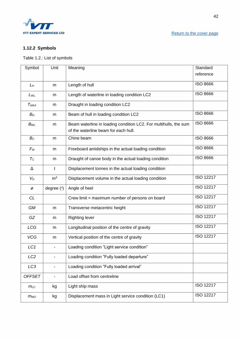
42
Return to the cover page
1.12.2 Symbols
Table 1.2.: List of symbols
Symbol Unit Meaning Standard
reference
LH m Length of hull ISO 8666
LWL m Length of waterline in loading condition LC2 ISO 8666
TMAX m Draught in loading condition LC2
BH m Beam of hull in loading condition LC2 ISO 8666
BWL m Beam waterline in loading condition LC2. For multihulls, the sum
of the waterline beam for each hull.
ISO 8666
BC m Chine beam ISO 8666
FM m Freeboard amidships in the actual loading condition ISO 8666
TC m Draught of canoe body in the actual loading condition ISO 8666
Δ t Displacement tonnes in the actual loading condition
VD m3 Displacement volume in the actual loading condition ISO 12217
ø degree (o) Angle of heel ISO 12217
CL Crew limit = maximum number of persons on board ISO 12217
GM m Transverse metacentric height ISO 12217
GZ m Righting lever ISO 12217
LCG m Longitudinal position of the centre of gravity ISO 12217
VCG m Vertical position of the centre of gravity ISO 12217
LC1 - Loading condition “Light service condition”
LC2 - Loading condition ”Fully loaded departure”
LC3 - Loading condition ”Fully loaded arrival”
OFFSET - Load offset from centreline
mLC kg Light ship mass ISO 12217
mMO kg Displacement mass in Light service condition (LC1) ISO 12217

43
Return to the cover page
mLDC kg Displacement mass in Fully loaded departure condition(LC2) ISO 12217
mLA kg Displacement mass in Fully loaded arrival condition (LC3)
mL kg Mass of the maximum load ISO 12217
RM Nm Righting moment ISO 12217
GM m Transverse metacentric height including free surface corr.
GZ m Righting lever including free surface correction
V kn
m/s
Speed at displacement mLDC ISO 12215
VMAX kn
m/s
Maximum speed
ALV m2 Wind load area in the actual loading condition ISO 12217

44
Return to the cover page
2 CRAFT CONCEPTS
2.1 Objective
The objective in this chapter is to define different types of craft concepts with regard to decking and
weathertight protection as well as prevention of downflooding. Craft concepts are used within the Rules
to assist in applying the requirements in a fair way.
2.2 References
In this Chapter reference is made to the following documents:
ISO 12217-1:2015 Small craft - Stability and buoyancy assessment and categorization
ISO 6185-3:2014 Boats with a hull length less than 8 m with a motor rating of 15 kW and
greater
ISO 6185-4:2011+Corr.2014 Boats with a hull length less than 8 m with a motor rating of 15 kW
and greater
ISO 11812:2001 Small craft - Watertight cockpits and quick-draining cockpits
ISO 12216:2002 Small craft - Windows, portlights and hatches, deadlights and doors - Strength
and water tightness
2.3 Selection of craft concepts
The Rule requirements are in many cases defined considering the general arrangement of the craft.
The decking arrangement, its weather tightness and water drainage is frequently referred to. The Rules
assume that the craft will fit into one of the concepts 2.3.1-2.3.4 below. The selection uses the
principles presented in the international standards ISO 12217 and ISO 6185.
2.3.1 Fully enclosed craft
For fully enclosed craft the horizontal projection comprises the following components in any
combination:
watertight deck and superstructure;
quick-draining recesses complying with Chapter 5, their influence on the stability meeting the
requirements in Chapter 4;
watertight recesses complying with Chapter 5 with a combined volume V not greater than:
[m3] (2.1)
closing appliances complying with Chapter 3.
The surface comprising the sum of the parts listed above is defined as the Weather Deck. The strength
of the parts comprising the weather deck shall meet the requirements in Chapter 10 (FRP), 14
(aluminium) or 18 (steel),

45
Return to the cover page
Figure 2.1.: Fully Enclosed craft.
Features of a Fully Enclosed craft:
Deck arrangement ensures green water coming on board can drain quickly overboard;
The water draining from the recesses does not endanger the stability;
Quickly draining recesses;
Strong and tight decks and superstructures:
Strong and tight windows and hatches;
Sufficient buoyancy reserve;
Adequate bow height;
Weather tight doors with sills
2.3.2 Partially protected craft
A craft in which at least one-third of the horizontal projection consists of weather tight decking,
superstructure, or other rigid covers that are designed to shed water overboard immediately. Included
into this area to be all surfaces within LH/3 from the bow, and also the area 100 mm inboard from the
periphery of the boat. The remaining part may be open.
Doors, windows, and hatches need to comply with the requirements in Chapter 3 only if they are
located within the mentioned LH /3 decking.
The strength of the decking or covering shall meet the requirements in Chapter 10, 14 or 18, depending
on the structural material used. Quick draining recesses shall meet the requirements in Chapter 5, their
closing appliances the requirements in Chapter 3.
In addition, the loaded displacement mass of partially protected craft shall not exceed
)1.5 [kg] (2.2)

46
Return to the cover page
Figure 2.2.: Partially protected craft
The hull sides up to the lowest downflooding point are considered as reserve buoyancy. For a partially
protected craft the highest Design Category is C (coastal), assuming that dangerous amounts of big
waves are not coming on board. It is assumed, that spray water is emptied from the open space by
drain pumps.
2.3.3 Craft with buoyancy chambers for remaining afloat
Within this concept a large part of the total volume consists of closed, fully watertight buoyancy
chambers. These chambers must meet the requirements for floats, and the craft shall with the aid of the
chambers remain afloat when filled with water according to Chapter 4.
In the craft concept it is assumed that in fully loaded condition all spaces except the closed buoyancy
chambers are filled with green water coming onboard, and still sufficient reserve buoyancy must
remain.
Generally commercially used craft with buoyancy chambers are hard-bottomed RIBs (Rigid Inflatable
Boats). For them at least half of the necessary volume consists of fiber reinforced polymer skin tubes or
pontoons, keeping their shape due to internal pressure. The rigid bottom is of FRP, aluminium, or a
similar structural material. The pontoon material shall meet the requirements in the standard ISO
15372, the buoyancy arrangements to meet ISO 6185, and the bottom construction the requirements
for the chosen material in Chapters 10, 14, or 18.
Craft with buoyancy chambers may also have rigid air filled, or foam filled floats.

47
Return to the cover page
Figure 2.3.: Craft with buoyancy chambers
2.3.4 Open craft without buoyancy chambers
Craft which do not meet the requirements for fully or partially enclosed craft, and do not have buoyancy
chambers, are considered open craft. The assumption is that for these the reserve buoyancy comprises
the watertight topsides, which must be continous up to the required freeboard height. If there is a deck
and/or recesses, which are mainly above the waterline in the Minimum Operation Condition, and these
may collect water and thereby reduce stability, the assessment is to proceed as follows:
Freeboard- and stability requirements must be met assuming that the spaces above the
waterline contain an amount of water corresponding to 25% of their volume; or
The deck to be modified so the water collecting above the waterline is led swiftly to craft spaces
below the waterline, and pumped overboard with a bilge pump.
For open craft there is a limit for the loaded displacement
)1.5 [kg] (2.3)

48
Return to the cover page
3 PREVENTION OF DOWNFLOODING
3.1 Objective
The objective in this chapter is to ensure a sufficient safety level against downflooding caused by
improperly located and/or conceived openings or through-hull fittings
3.2 References
In this chapter reference is made to the following documents:
ISO 12216:2002 Small craft - Windows, portlights, hatches, deadlights and doors – Strength
and water tightness
ISO 12217:2015 Small craft – Stability and buoyancy assessment and categorisation
ISO 11812:2001 Small craft – Watertight cockpits and quick-draining cockpits
ISO 9093-1:1994 Small craft – Seacocks and through-hull fittings – Part 1: Metallic
ISO 9093-2:2002 Small craft –Seacocks and trough-hull fittings -- Part 2: Non-metallic
International Load Line Convention 1966 with amendments
3.3 Documentation
For verifying that the requirements presented in this chapter are met, the following documentation is
required:
Location of openings (for instance on general arrangement drawing);
Drawings of purpose-built closing appliances;
Manufacturer and type designation of prefabricated closing appliances;
Layout of seacocks and through-hull fittings; and
Testing protocol of watertight integrity for closing appliances
3.4 Openings and closing appliances, general
3.4.1 Application
When applying the rules in this chapter it ahould be noted that the various types of deck arrangement
(see Chapter 2) have different requirements for the water- and weather tight integrity. Only openings
penetrating a surface requiring water- and weather tight integrity are subject to the requirements.
Note! The location of an opening may also be limited by freeboard and downflooding angle (see
Chapter 4) . Further there may be special requirements for openings related to the Additional Notations
of the craft, (see Chapters 33-42).

49
Return to the cover page
3.4.2 Exemptions
The requirements in this chapter may be disregarded for single openings on the following conditions:
Stability- and freeboard requirements are met also when the space behind the opening is filled
with water, and flooding into other compartments cannot occur.
The craft important functions (see Chapter 24) are not affected although the space in question
is filled with water.
3.5 Requirements for openings, and closing appliances
3.5.1 Properties affecting the requirements
The requirements for openings and their closing appliances are based on the following:
Design Category;
Type;
Location;
Closing status;
Size;
The types of closing appliances are explained under 3.6. Definitions common to all types of appliances
can be found under 3.9. A summary of the requirements for types of closing appliances are given in
Tables 3.1-3.6 and detailed explanations for each type of closing appliance in the text under 3.10-3.17.
3.6 Definitions for types of openings, and closing appliances
The opening may be fitted with a closing appliance, which is a common term for devices protecting an
opening, such as windows, doors, hatches, hull ports and thru-hull fittings.
3.6.1 Doorways
Doorways are approximately vertical openings equipped with closing appliances, enabling a nearly
upright person to pass through.
3.6.2 Hatchways
Hatchways are openings with closing appliances, allowing access to the space behind them. A vertical
hatchway allowing a nearly upright person to pass through, is a doorway.
3.6.3 Windows and portlights
Windows are glassed closing appliances, whose purpose is to pass light into the space where they are
installed. Portlight is a small window with an area of maximum 0.16 m2. Windows and portlights may be

50
Return to the cover page openable under particular conditions. An opening window may, depending on its purpose, also be a
hatchway.
3.6.4 Hull ports
Hull ports are openings with closing appliances in the topside of open or partially protected craft.
3.6.5 Air pipes
Air pipes are small ventilation openings with maximum 50 cm2 cross section. Further they are equipped
with a gooseneck or non-return valve, because of this they are considered weather tight when
evaluating the stability. Examples of these are fuel tank and battery space vent pipes.
3.6.6 Through-hull fittings
Through-hull fittings are openings in the hull, connected to the craft’s on-board systems. They may
include a closing appliance (seacock).
3.6.7 Openings without closing appliances
Openings without closing appliances are openings that cannot be closed weather- or watertight without
affecting the normal use of the craft. For example, the engine air intakes are such openings.
3.6.8 Local deck height HD
The vertical height in meters to the waterline in the fully loaded condition from the deck or similar
surface, from which the edge height or sill is measured at the opening.
3.7 Application areas for openings
The following application areas are defined, see Figure 3.1:
Application area 1 covers the topsides below the weather deck for fully enclosed craft, and to a
height corresponding to the freeboard requirements for open and partially protected craft. For
multihulls also the underside of the bridge (“wet deck”) is included.
Application area 2 covers the weather deck including superstructures up to the second deck
(height h2) excluding nearly forward facing surfaces, which belong to Application area 3.
Application area 3 covers the nearly forward facing vertical superstructure surfaces.
Application area 4 covers the superstructure surfaces above the second deck excluding the
nearly forward facing surfaces, which belong to Application area 3.

51
Return to the cover page
Figure 3.1: Location areas of openings
3.8 Opening’s closing status in operation
The openings are divided into subsections based on their status when the craft is in operation:
Always open at sea means that the opening in question must necessarily be open whenever the
craft is in operation. Such openings are for example the engine air intakes.
Temporarily open means that the opening in question may be open for short spells during
operation, but they can quickly be closed weather- and watertight. Such openings are for
example wheelhouse doors.
Always closed at sea means that the opening in question is kept permanently closed weather-
and watertight whenever the craft is in operation. Behind such openings are weather deck
spaces not requiring access when the craft is in operation.
3.9 Definitions and requirements common for all closing appliances
3.9.1 Coaming- and sill heights
Openings shall be conceived for minimizing the possibility of water entering.
Openings always open at sea are not allowed in Application area 1 and below LH/15 in Design
Categories A and B.
For fully enclosed craft the openings in the weather deck (see definition in Chapter 2) which are
temporarily open at sea must have sills or coamings. Examples of such openings are:
doorways leading to the craft interior
hatchway/doorway leading to the engine space in Design Category A craft

52
Return to the cover page The height of the coaming or sill for an opening is the least vertical height of its lower edge above the
surface below it (deck, superstructure roof, etc.).
In Table 3.1. the coaming- and sill heights are given at the heights h1 and h2. The height h1 is
calculated according to formula (3.1) and h2 according to formula (3.3):
[m] (3.1)
Where kDC is:
1.0 for Design Category A
0.8 for Design Category B
0.75 for Design Category C
0.5 for Design Category D
kL is determined with formula (3.2) as a function of the longitudinal position (from aft end) X/LH
kL = 0.6·X/LH+0.6 min. 1.0 (3.2)
h2 = h1+d (3.3)
d = kDC (0.1·LH – 0.6) min. 0.9·kDC [m] (3.4)
If the local deck height is larger than h1 but smaller than h2, the sill- or coaming height is interpolated
between them using Formula (3.5)
[m] (3.5)
Where
h1 see formula (3.1)
hD local deck height fully loaded, [m] see Figure 3.2
hS1 sill height requirement at the level h1, [m], see Table 3.1
hS2 sill height requirement at the level h2, [m], see Table 3.1
d see Formula (3.4)

53
Return to the cover page
Figure 3.2: The measurements for defining coaming- and sill heights
If the deck height hD at the opening is smaller than the basic height h1, the coaming- or sill height shall
be increased so the lowest edge of the opening is at least h1+hS1 above the deepest (loaded)
waterline.
If the deck height at the opening is larger than h2, the coaming- or sill height hs2 shall be used.
The coaming- or sill height must not be reduced in the forward third of the craft length.
Coaming height is not required provided:
The opening height above the waterline is in all load cases at least d+h1
The size of the hatchway is max. 0.4 m2 in Design Category B
This exemption is, however, not valid for doorways to the interior, they must always have a coaming
height according to Table 3.1.
In Design Category A temporarily open openings must always have coamings.
3.9.2 The length of the shorter side of the opening
This dimension is usually obvious, but in doubtful cases reference is made to the standard ISO 12216.
3.9.3 Degree of Water tightness
The Rules specify two degrees of water tightness:
Watertight closing appliances (Tightness Level 1) stand continuous hydrostatic pressure without
leaking; and
Weather tight closing appliances (Tightness Level 2) stand temporary immersion without
leaking.

54
Return to the cover page The degree of water tightness is defined according to the standard ISO 12216
3.9.4 Latches and hinges for locking
Latches and hinges for closing appliances shall be arranged so the required degree of water tightness
is achieved irrespectively of from which side the appliance is closed. Latches and hinges shall stand the
forces from the pressure in the respective Application area without exceeding the material yield limit.
3.9.5 Hinged closing appliances
Closing appliances which are temporarily openable at sea shall be designed so they stay attached to
the surrounding structure when open. In Application area 1 the openable appliances shall be hinged
and open inwards. The hinges to be sufficiently strong. In doubtful cases the hinges shall be evaluated
according to the standard ISO 12216.
3.9.6 Sliding hatches
In other areas than Application area 1 closing appliances may be sliding hatches or -doors, provided all
relevant requirements in Table 3.1 are met. The depth of the groove to be sufficient for preventing the
closing appliance from tearing out, considering the appropriate loads as well as the stiffness of the
appliance and its surrounding structure. The groove generally to be at least 12 mm deep. When the
latching of the closing appliance is evaluated, a supported groove edge may be considered a sufficient
latch. The closing appliance needs to have stops at each end position, preventing it from sliding off.
3.9.7 CE-marked closing appliances
All closing appliances, including those made by the manufacturer of the craft or subcontracted by him,
shall meet standard ISO 12216 and additionally these Rules where they exceed the requirements in the
standard. Prefabricated commercially available closing appliances may be used without restrictions in
the locations given in Tables 3.1-3.6 provided they are CE-marked, and according to ISO 12216
suitable for the Design Category and Application area in question.
3.9.8 Particular requirements for closing appliances in Application area 1
The following particular requirements refer for closing appliances in Application area 1:
the bottom edge of the closing appliance must be at least at the minimum height above the
waterline given in Table 3.2 in the fully loaded departure condition;
the shorter side of the opening must not exceed 300 mm.;
an opening appliance must open inwards;
no part of the closing appliance must protrude outside a vertical line taken through the widest
point of the craft, such as the hull, deck, or fixed rubbing strake;

55
Return to the cover page
3.9.9 Protection of gaskets
In such applications where Table 3.1 prescribes “protection of gaskets”, the gaskets made of rubber or
other soft materials must be protected against wear for example according to Figure 3.3.
Figure 3.3: Protection of gaskets
3.9.10 Closing appliances on cargo decks
Closing appliances located on cargo decks must not have glazing. Protruding parts like latches must be
very strong, or protected to stand the loads occurring in cargo handling.
3.10 Requirements for openings always open during operation.
A summary of requirements for openings always open during operation is given in Table 3.1.
3.10.1 Allowed locations for openings always open during operation
The number of openings that are always open during operation to be as small as possible. In craft to
Design Category A and B such openings are not allowed in Application area 1 nor below the level
LH/15. Openings necessary for the proper function of the craft must not be located in the forward one
third of Design Category A craft. These requirements do not apply to air pipes meeting the
specifications in item 3.15.
3.10.2 Preventing water from entering
The openings always open during operation must be conceived so the ingress of water is prevented as
far as possible. This requirement is considered met if the intake is equipped with a baffle according to
Figure 3.4, or a corresponding arrangement.
The ventilation openings shall primarily be facing aft, or to the sides.
In Design Category A and B the mentioned openings shall have a collar with a height over the
surrounding deck according to Table 3.1, and be at least LH/15 above the fully loaded waterline.
Gasket to be below dashed line

56
Return to the cover page In Design Category C and D craft the engine air intakes may be in Application area 1 provided they
have arrangements preventing the ingress of water, and the stability and freeboard requirements are
met.
Figure 3.4 Air intake with baffle
3.11 Requirements for doors
3.11.1 Door sills
Half of the required sill height specified in Table 3.1 may be in a semi-fixed sill. The semi-fixed part shall
be attached to the fixed sill part, or be continuously ready for use close to the door.
3.11.2 Direction of opening for doors
Doors in the superstructure sides to have the hinges forward. Hinged doors to open outwards.
3.11.3 Latches and hinges
Irrespective of the maximum distance between latches specified in Table 3.1, Design Category A and B
craft doors shall have at least two latches in addition to the hinges. Doors to be openable from both
sides.
3.12 Requirements for hatches
3.12.1 Special requirements for hatches
Hatches that can be open at sea shall have the possibility to be secured in the open position.
Glazed hatches are not allowed in engine spaces, instead lighting to be arranged according to the
guidelines in Chapter 21.
Hatches below the waterline are allowed only provided all relevant freeboard-, stability, and damage
stability requirements are met, assuming that the space behind the hatch is water filled without any
possibility of leakage into other compartments. Such hatches shall have the same strength as the
Air
Water

57
Return to the cover page surrounding hull structure. The strength of the space in question shall be sufficient to stand the local
sea pressures.
3.13 Requirements for windows
A summary of the requirements is given in Tables 3.3-3.6
3.13.1 Special requirements for windows
The following special requirements are given:
the windows around the control position must not be tinted (see Chapter 29)
windows are not allowed in engine spaces, instead lighting to be arranged according to the
guidelines in Chapter 21.
the thickness of the windows to be at least according to Tables 3.3-3.6 for tempered glass, and
for other materials the window thickness to be determined according to the standard ISO
12216, using, however, the following dimensioning pressures:
o Application area 1, all planning classes, 70 kPa;
o Application area 2, planning classes A and B, 12 kPa;
o Application area 2, planning classes C and D, 9 kPa;
o Application area 3, planning classes A and B, 28 kPa;
o Application area 3, planning classes C and D, 12 kPa;
o Application area 4, planning classes A and B, 12 kPa;
o Application area 4, planning classes C and D, 9 kPa.
for laminated glass with the number of layers n and the thickness of individual layers tn the
compliance is determined using Formula (3.6) and (3.7). treq is the thickness requirement for a
solid window according to Table 3.3-3.6.
[mm]; n = 2 (3.6)
[mm]; n > 2 (3.7)
3.14 Requirements for hull ports
Hull ports are openings leading into the hull, fitted with closing appliances, including hatches in the
bulwark on fully enclosed craft, where the bulwark makes up the forecastle, see 4.10.
3.15 Freeboard to the lower edge of hull ports
The minimum freeboard to the lower edge of hull ports shall be 200 mm.
3.16 Strength
The strength of hull ports to be at least the same as the surrounding structure. If the sea pressure can
load the hinges or latches, they shall be designed to stand these loads.

58
Return to the cover page
3.16.1 Water tightness
Hull ports to be watertight to Tightness Level 2. The gaskets to be protected according to Figure 3.3.
3.16.2 Hinges and latching mechanisms
The hinges to be able to carry the sea pressure loads on the hull port.
The latching mechanism shall force the hull port against its gasket so the required tightness is
achieved.
There must be two alternative latching mechanisms, one of them to be independent of hydraulic
pressure and/or electrical power.
3.17 Requirements for air pipes
The height above the surrounding deck for air pipes leading into the weather tight hull shall be at least
80% of the height required for openings always open at sea in the same position (see Table 3.1), or at
least 250 mm. The cross section must not exceed 50 cm2, and arrangements for preventing the ingress
of water are required.
3.18 Through-hulls connected to on-board systems
3.18.1 General
Through-hulls located lower than 100 mm above the fully loaded waterline shall always have sea cocks
where they penetrate the hull.
For through-hull locations between 100…350 mm above the fully loaded waterline seacocks are
required if the entire system connected to the through-hull is below the 350 mm level, and the system
has an open end inside the craft. If this system inside end is closed, a sea cock is not required. A non-
return valve is considered equivalent to a closed end. A seacock is not required either if the system is
partly above the 350 mm level (gooseneck), equipped with a siphon break, and can stand 15 degrees
of heel without leaking.
For through-hulls located more than 350 mm above the fully loaded waterline, neither seacocks nor
non-return valves are required, provided the through-hulls do not leak at 15 degrees heel in the fully
loaded condition.
The requirements for through-hulls connected to on-board systems are visualized in Figure 3.5.
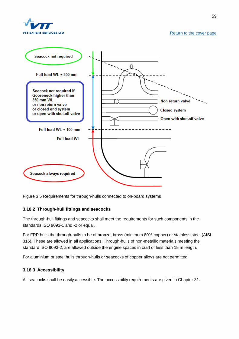
59
Return to the cover page
Figure 3.5 Requirements for through-hulls connected to on-board systems
3.18.2 Through-hull fittings and seacocks
The through-hull fittings and seacocks shall meet the requirements for such components in the
standards ISO 9093-1 and -2 or equal.
For FRP hulls the through-hulls to be of bronze, brass (minimum 80% copper) or stainless steel (AISI
316). These are allowed in all applications. Through-hulls of non-metallic materials meeting the
standard ISO 9093-2, are allowed outside the engine spaces in craft of less than 15 m length.
For aluminium or steel hulls through-hulls or seacocks of copper alloys are not permitted.
3.18.3 Accessibility
All seacocks shall be easily accessible. The accessibility requirements are given in Chapter 31.

60
Return to the cover page
3.18.4 Requirements for on-board systems connected to through-hulls
The hoses connected to through-hulls shall be fabric-reinforced and able to stand the pressures
occurring in the connected systems. For discharging system hoses there are additional requirements in
Chapter 6.
3.18.5 Galvanic corrosion
The combination of materials to be chosen so that galvanic corrosion is avoided.
3.18.6 Hose connections
For the hoses connections in through-hull systems double hose clamps of stainless steel (AISI 316) to
be used if the stud diameter exceeds 25 mm. As an alternative to double clamps a single heavy duty
super-clamp with two bolts, and over 15 mm width may be used.
3.19 Penetrations in outboard engine wells
3.19.1 Cable and hose penetrations
The cable and hose penetrations in outboard engine splash wells shall meet the requirements in the
standard ISO 12217-1 for tightness and installation height.
The penetrations must always be entirely above the transom overflow edge.
3.19.2 Ventilation openings
Ventilation openings located in the outboard engine well and leading into the hull shall have their lower
edge at a height specified in Chapter 4 for freeboard to a downflooding opening.
Table 3.1: Summary of requirements for openings and closing appliances located on the weatherdeck
(hatches, doors, and always open ventilation and other openings).
Opening’s Closing Status Always open Occasionally open at
sea
Closed at sea
Design Category A B C D A B C D A B C D
Freeboard and downflooding
angle requirements in Chapter
4
YES NO
Location LH/3 from bow NO NO
Application area 1 (topside) NO NO

61
Return to the cover page
Opening’s Closing Status Always open Occasionally open at
sea
Closed at sea
Coaming height at level
hS1,[m],
LH=24 m 1) 2)
0.90 0.68 0.38 0.10 0.60 0.45 0.25 0.10
Coaming height at level hS1,
[m],
LH15 m 1) 2)
0.68 0.45 0.38 0.10 0.45 0.38 0.25 0.10
Coaming height at level hS2,
[m],3)
0.57 0.45 0.38 0.10 0.25 0.15 0.07
5
0.05
Min. downflooding angle when
appliance is open, degrees.
See Chapter 4 Table
4.1
25 20 15 10
Max.allowed appliance size
[m2]
without coamings
0.4 0.4
Tightness degree 2 2 2 2 2 2 2 2 2 2 2 2
Prevention of water ingress x x x x
Locking device distance C-C,
max
800 mm for doors, 600 mm for hatches
Gaskets protected (see Figure
3.3)
x x x x x x x x
CE-marked appliances allowed
without further requirements
Yes, except for cargo decks.
Not for craft with Add.Notation”Ice Reinforcement”
1) The specified coaming height refers for deck height h1, if the local deck height is greater this reduces
the requirement, see item 3.9.1
2) The height values between 15 and 24 m are found by linear interpolation
3) Hatches without coamings may be allowed on the weather deck provided the following conditions are
met:

62
Return to the cover page
The hatch is at least at the height d + h1 (see item 3.9 in the text)
The hatch area is maximum 0.4 m2 in Design Category B
In Design Category A temporarily open hatches without coamings are not allowed
Neither does this exception apply to doors leading into the craft interior, they must always have
coaming heights according to Table 3.1.
Table 3.2: Summary of requirements for closing appliances in Application area 1 (hull topside)
Appliance status when craft is underway Closed
Design Category A B C D
Material limitations If glass is used, must be ”high impact resistance”
quality according to ISO 12216
Closing appliance recessed or protected in
some other way x x x x
Largest minimum dimension, [mm ] 300 300 300 300
Lower edge above waterline, min. [mm] 500 400 300 200
Lowest downflooding angle when appliance
is open, [degrees] 25 20 15 10
Tightness degree 2 2 2 2
Gaskets protected (see Figure 3.3) x x x x
Storm shutters required x x x
CE-marked closing appliances allowed
without further requirements See ”Material limitations” higher up in this table!

63
Return to the cover page
Table 3.3 Required thicknesses for tempered glass windows, P=70 kPa, in Application area 1 (hull
topside), all Design
Categories
Table 3.4: Required thicknesses for tempered glass windows, P=28 kPa, in Application area 3 (front
bulkhead and other forward facing areas), Design Categories A and B

64
Return to the cover page
Table 3.5: Required thickness for tempered glass windows P=12 kPa
Application area 2 (weather deck) Design Categories A and B
Application area 4 (above second deck level) Design Categories A and B
Application area 3 (front bulkhead and other forward facing areas) Design Categories C and D

65
Return to the cover page
Table 3.6: Required thickness for tempered glass windows P=9 kPa
Application area 2 and 4, Design Categories C and D

66
Return to the cover page
4 FREEBOARD AND INTACT STABILITY
4.1 Objective
The objective in this chapter is to ensure that:
The craft has sufficient reserve buoyancy in reference to the craft concept, the Design
Category, and to the fully loaded displacement in order to stand a limited leak or overload
without sinking or capsizing;
The deck arrangement for craft encountering breaking seas is planned so water swiftly drains
back to the sea, and for all craft the openings leading into the craft interior are located and
protected so water ingress is prevented; and
The craft stability is such that the heeling angles caused by the expeced heeling moments do
not prevent the safe use of the craft, and the reserve against capsize or filling with water is
sufficiently large in the Design Category worst conditions, also considering the possible special
missions for the craft.
Note! In Chapters 33-41 additional requirements are given for craft special missions.
4.2 References
In this chapter reference is made to the following documents:
ISO 12217-1:2015 Small craft – Stabillity and buoyancy assessment and categorization
ISO 11812:2001 Small craft – Watertight cockpits and quick-draining cockpits
ISO 12216:2002 Small craft - Windows, portlights, hatches, deadlights and doors – Strength
and watertightness
ISO 6185-3:2014 Inflatable boats Part 3
ISO 6185-4:2011 Inflatable boats Part 4
ISO 15372:2000 Ships and marine technology – Inflatable rescue boats – Coated fabrics for
inflatable chambers
IMO MSC 81(70)
4.3 Documentation
For verifying that the requirements presented in this chapter are met, the following documentation is
required:
Geometry of hull (normally a Lines drawing);
Geometry of weather tight decks and superstructures (fully and partially decked craft);
Geometry and location of tanks;
Load components included in the fully loaded condition, and their location;
Material certificates and test reports for buoyancy foam and pontoon materials;

67
Return to the cover page
Test protocols for pontoons and other air buoyancy chambers;
Verification of lightweight and center of gravity (usually inclining test report);
Stability calculations, or stability test report where the attained numbers are presented in
reference to the relevant criteria;
Stability instruction for the master, where information is given about the maximum allowed load,
and possible limitations in this connection;
4.4 Assessment alternatives and requirements
4.4.1 General
The craft is to be assessed using one of the options given in Tables 4.1, 4.2, and 4.3, depending on the
craft Design Category, and Craft Concept (see Ch. 2). The principles in the options correspond to those
presented in standard ISO 12217. Note that all options in ISO 12217 are not implemented. The
requirements in Tables 4.1, 4.2, and 4.3 shall be met in all relevant loading conditions. More detailed
explanations can be found in the text sections referred to in the tables.

68
Return to the cover page Table 4.1 The requirements for the alternative Fully enclosed craft
Assessment option Nr. 1A 1B 2C 2D
Craft concept Fully enclosed
Design Category A 1) B C D
Recesses
(see. 4.8) LC3 1)
Type of recess Quick draining
Consider Free surface
effects on stability x x x
Freeboard to deck edge 3)
Monohulls only
(see 4.9) LC2 1)
Minimum freeboard to deck
edge, FMIN, fraction of FBASE
1.0 ∙ FBASE 0.9 ∙ FBASE 0.75 ∙ FBASE 0.5 ∙ FBASE
Reserve buoyancy 3)
For all multihulls,
alternative for monohulls
(see 4.9) LC2 1)
Volume of weathertight
spaces above waterline to
the downflooding opening
lower edge, as percent of
fully loaded displacement
100 70 30 20
Bow buoyancy (see 4.10)
LC1, LC2, LC3 1) Freeboard at bow, FBOW [m] 0.5+0.02∙LH 0.3+0.02∙LH 0.2+0.02∙LH 0.05+0.02∙LH
Height of down-flooding
opening
(see 4.11) LC2 1)
hD [m] LH/17 LH/17 LH/17 LH/20
Minimum [m] 0.50 0.40 0.35 0.30
Maximum [m] 1.41 1.41 0.75 0.40
Downflooding
angle [o]
(see 4.12)
LC1, LC2, LC3 1)
Openings always open at
sea
ØO = heeling angle with
offset load
ØO+25
min. 30o
ØO+15
min. 25o
Openings temporarily open
at sea. See also Table 3.1! 25 20 15 10
Stability with offset load Maximum heeling angle[o]
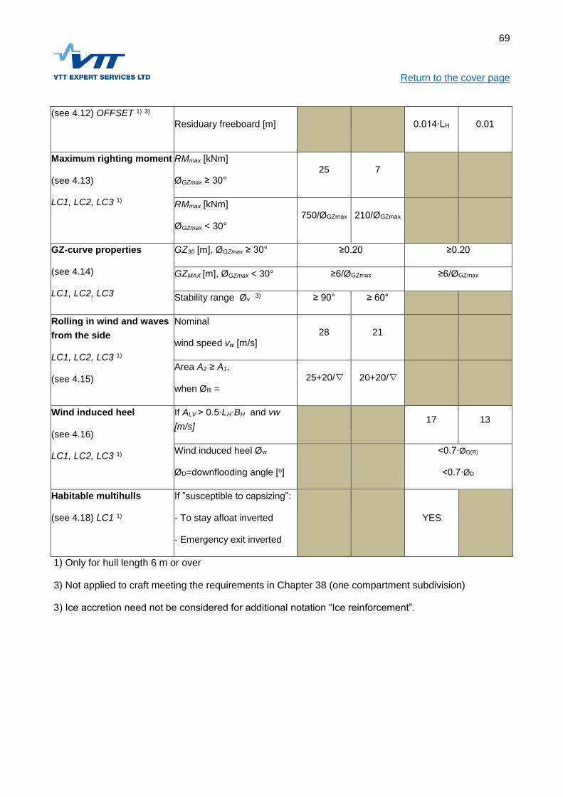
69
Return to the cover page
(see 4.12) OFFSET 1) 3)
Residuary freeboard [m]
0.014∙LH 0.01
Maximum righting moment
(see 4.13)
LC1, LC2, LC3 1)
RMmax [kNm]
ØGZmax ≥ 30° 25 7
RMmax [kNm]
ØGZmax < 30° 750/ØGZmax 210/ØGZmax
GZ-curve properties
(see 4.14)
LC1, LC2, LC3
GZ30 [m], ØGZmax ≥ 30° ≥0.20 ≥0.20
GZMAX [m], ØGZmax < 30° ≥6/ØGZmax ≥6/ØGZmax
Stability range Øv 3) ≥ 90° ≥ 60°
Rolling in wind and waves
from the side
LC1, LC2, LC3 1)
(see 4.15)
Nominal
wind speed vw [m/s] 28 21
Area A2 ≥ A1,
when ØR =
25+20/∇ 20+20/∇
Wind induced heel
(see 4.16)
LC1, LC2, LC3 1)
If ALV > 0.5∙LH∙BH and vw
[m/s]
17 13
Wind induced heel Øw
ØD=downflooding angle [o]
<0.7∙ØO(R)
<0.7∙ØD
Habitable multihulls
(see 4.18) LC1 1)
If ”susceptible to capsizing”:
- To stay afloat inverted
- Emergency exit inverted
YES
1) Only for hull length 6 m or over
3) Not applied to craft meeting the requirements in Chapter 38 (one compartment subdivision)
3) Ice accretion need not be considered for additional notation “Ice reinforcement”.

70
Return to the cover page
Table 4.2: Requirements and test procedures according to the assessment alternative for rigid bottom
inflatables (RIB) and other craft with buoyancy chambers.
Assessment alternative Nr. 3B 3C 3D
Craft concept Rigid bottom inflatable (RIB) or other craft with
buoyancy chambers
Design Category B 1) C D
Recesses
(see 4.8) LC3 1) Recess type Water tight or quick draining
Downflooding
opening height
(see 4.11) LC1, LC2 1)
hD [m] LH/17 LH/17 LH/20
Minimum [m] 0.40 0.35 0.30
Maximum [m] 1.41 0.75 0.40
Downflooding angle[o]
(see 4.12)
LC1, LC2 LC3 1)
ØO=heeling angle
with offset load ØO+15
at least 25o
Stability with offset
load
(see 4.12) OFFSET 1) 3)
Maximum heel [o]
Residuary freeboard
[m]
0.014∙LH 0.01
Maximum righting
moment
(see 4.13)
LC1, LC2, LC3 1)
RMmax [kNm]
Ø GZmax ≥ 30° 7
RMmax [kNm]
ØGZmax < 30° 210/ ØGZmax
GZ-curve properties
(see 4.14)
LC1, LC2, LC3 1)
GZ30 [m]
ØGZmax ≥ 30° ≥0.20 ≥0.20 ≥0.20
GZMAX [m]
ØGZmax < 30° ≥6/ØGZmax ≥6/ØGZmax ≥6/ØGZmax
Stability range Øv ≥ 60°
Weather criterion Nominal wind 21

71
Return to the cover page (see 4.15)
LC1, LC2, LC3 1)
speed vw [m/s]
Area A2 ≥ A1,
kun ØR =20+20/∇
Wind induced heel
(see 4.16)
LC1, LC2, LC3 1)
If ALV > 0.5∙LH∙BH and
vw [m/s]
17 13
Wind induced heel
Øw
ØD=downflooding
angle [o]
<0.7∙ØO(R)
<0.7∙ØD
Flotation
(see 4.17) LC2 1)
Flotation and stability
when waterfilled
Shall float nearly horizontal fully loaded. To stand a
load of 6∙CL on the side rail. For CL see 1.12.2
Flotation elements
(see 4.17) 3)
Arrangement
The floatation elements’ combined volume
(=pontoons+air chambers+foam floatation+solid
structure) minimum 1,33 * mLDC [l]
2) For RIB:s the pontoon volume shall be at least
0.665*mLDC [l]. The pontoon volume to be divided into
at least 5 parts. Each part to be ±20 % of the average
If no RIB, no requirements for pontoon volume.
The number of air chambers depend on their share of
the necessary total float volume and the Design
Category according to item 4.17.3
Material The pontoon material shall meet ISO 15372:2000
Foam floatation according to ISO 6185
Testing
Air chamber test pressure 5 kPa
Pressure and leak testing of pontoons according to
ISO 6185
1) Only for hull length 6 m and over
2) The craft falls under the RIB-standard ISO 6185 if the pontoons volume is more than half of the
required float volume
3) Ice accretion need not be considered for additional notation “Ice reinforcement”.

72
Return to the cover page
Table 4.3: Requirements for partially protected and open craft
Assessment alternative Nr. 5C 5D 6C 6D
Craft concept Partially protected Open
Design Category C D C D
Recesses
(see 4.8)
LC3 1)
Recess type
Small watertight or quick
draining recesses allowed
V<LH∙BH∙FM/40
To be quick draining if
entirelyforward of LH/2,
otherwise no restrictions
Bow buoyancy
(see. 4.10)
LC1, LC2, LC3 1)
Freeboard at bow
1.15∙LH/10
min 0.69 m min 0.46 m
Height of down-
flooding opening
(see 4.11) LC1, LC2
1)
hD [m] LH/12 - LH/10 -
Minimum [m] 0.50 0.4 0.6 0.4
Maximum [m] 0.75 - 0.75 -
Stability with offset
load
(see 4.12) OFFSET
1) 3)
Maximum heel [o]
Residuary freeboard [m] 0.,014∙LH 0.01 0.014∙LH 0.01
GZ-curve
properties
(see 4.14)
LC1, LC2, LC3 1)
GZ30 [m]
ØGZmax ≥ 30°
≥0.20
GZMAX [m]
ØGZmax < 30° ≥6/ØGZmax
Wind induced heel
(see 4.16)
LC1, LC2, LC3 1)
If ALV > 0.5∙LH∙BH and
vw [m/s] = 17 13 17 13
Wind induced heel Øw
ØD=downflooding
angle[o]
<0.7∙ØO(R)
<0.7∙ØD

73
Return to the cover page 1) Only for hull length 6 m and over
3) Ice accretion need not be considered for additional notation “Ice reinforcement”.
4.5 Definitions and assumptions
4.6 Lightweight
The lightweight mLC is the weight of the craft including propulsion engine, permanent systems and
equipment without crew, stores and cargo as defined in standard ISO 12217-1:2013.
4.6.1 Determination of lightweight and center of gravity
4.6.1.1 Lightweight
The craft lightweight to be determined by one of the following methods:
Measurement of flotation position in a known loading condition, determination of the
displacement corresponding to the flotation using the craft geometry information, and correcting
the result to correspond to the lightweight according to ISO 12217:2013;
Weighing the craft in a known loading condition, and correcting the result by calculation to
correspond to the lightweight according to ISO 12217:2013;
By calculation based on a sistership lightweight and known changes. With this method the
allowed lightweight change is maximum 10% compared to the sistership.
4.6.1.2 Vertical position of center of gravity
The vertical center of gravity, VCG, to be determined by one of the following methods depending on the
circumstances:
Inclining test performed according to ASTM F-1321-90 or corresponding standard;
Determining VCG by calculation based on the mass and VCG for individual components, and
raising the resulting position above the keel by 5% of the craft side height;
Determining VCG by calculation based on a sistership mass and known changes. With this
method the allowed VCG change is maximum 10% compared to the sistership.
An inclining test must not be used for craft having a transverse metacentric height GM exceeding 5 m in
light condition. Methods relying entirely on weight calculation or sistership information must not be used
for craft having a GM less than 1.5 m in light condition.
4.6.1.3 Longitudinal position of center of gravity
The longitudinal position of center of gravity, LCG, to be determined by one of the following methods:

74
Return to the cover page
Measurement of flotation position in a known loading condition, determination of the
displacement corresponding to the flotation using the craft geometry information, and correcting
the result to correspond to the lightweight according to ISO 12217:2013;
Determining LCG by calculation based on the mass and LCG for individual components;
Determining LCG by calculation based on a sistership mass and known changes.
4.6.2 Maximum load
The maximum load, ML, is the amount of load the craft is designed to carry. ML includes the following
weights:
The maximum number of persons (CL) times 85 kg;
Their personal equipment;
Stores and proviant;
Cargo;
Consumable liquids like fuel and water;
Grey and black water
Water ballast if carried
Rafts or dinghies if carried
Other weights not included in lightweight
NOTE! Icing on hull and superstructures is not included in the maximum load, but all rule requirements
must be met with icing considered, if not stated otherwise.
In the loading conditions assessed in 4.6 the space required by people, and their center of gravity to be
taken according to Chapter 1 item 12.1.
4.7 Loading conditions
4.7.1 Loading conditions to be assessed
The craft stability to be assessed in the following loading conditions:
Minimum operating condition, short notation LC1
Fully loaded, departure, LC2
Fully loaded, arrival, LC3
Offset load condition, OFFSET
Some requirements are independent of the loading condition, some are again tied to a certain loading
condition. In the Tables 4.1-4.3 information is given under each requirement pointing out the load
conditions that refer.
If it can be expected that the stability may be critical for the craft in other relevant loading conditions the
stability needs to be assessed also for them. If applicable, icing weights need to be considered
according to 4.7.4.

75
Return to the cover page
4.7.2 Minimum operating condition, loading condition LC1
In the minimum operating condition the following is included on top of the lightweight:
the mass of the crew located at the highest steering position;
85 kg, if LH ≤ 8 m;
170 kg, if LH = 8...16 m; and
255 kg, if LH = 16...24 m.
stores and equipment normally kept on board; and
fuel 10% of the maximum capacity.
4.7.3 Fully loaded, departure, loading condition LC2
In the ”Fully loaded, departure”-condition the maximum load ML is on board, according to item 4.5.3.
The load components are assumed to be in their intended places, see 4.7. If there is cargo, it has to be
located according to Chapter 33.
4.7.4 Fully loaded, arrival, loading condition LC3
The condition ”Fully loaded, arrival” is similar to the departure condition 4.6.3, except for the amount of
consumable stores which is carried 10 % of the capacity.
4.7.5 Offset load, loading condition OFFSET
The condition ”OFFSET” is similar to the arrival condition 4.6.4, except for that persons and deck cargo,
if any, are located towards the side (see item 4.12).
4.8 Assumptions when assessing stability
4.8.1 Hull model for stability calculation
In the hull model used for the stability calculations the recesses, superstructures, and underwater
appendages influencing the hydrostatics shall be included. Only items sufficiently watertight (see
Chapter 3) and strong (see Chapters 10, 14, and 18, depending on the material used) may be
considered.
The righting levers shall normally be calculated so the water surface in recesses is at the same level as
the surrounding water at all heeling angles. In Design Category C and D the righting levers may be
calculated assuming the following drain openings to be closed tight:
Drain openings with non-return flaps or similar devices
Drain openings whose combined area do not exceed three times the smallest drain area
required by ISO 11812.

76
Return to the cover page The assumption above may be used only for heeling angles smaller than the recess edge immersion
angle.
4.8.2 Location of loading components
Liquids are assumed to be contained in their tanks.
The location of persons to correspond to the normal use of the craft. The mass and centre of gravity for
persons are assumed to be taken from Chapter 1 item 12.1, unless the special mission of the craft
gives reason to use different numbers.
For the location of cargo the guidelines in Chapter 33 shall be used.
4.8.3 Free surfaces in the tanks
The free surface effects in the tanks shall be considered if their combined reduction of GM exceeds 2 %
with the tanks 10 % full.
4.8.4 Icing
When the ice that can form on hull and superstructure is considered, and always for craft having the
Additional Notation ”Ice reinforcement” according to Chapter 39, the weight and distribution of the ice
shall be as follows:
30 kg/m2 on open decks, and on structures located on these decks;
7.5 kg/ m2 on both sides of the craft projected side profile area above the water line;
Icing of other already mentioned surfaces is considered by increasing the projected side profile area 5
% on both sides.
4.9 The effect of recesses on stability
The effects of recesses on stability are assessed only for fully enclosed craft. The loading condition to
assess is LC3, fully loaded at arrival, see 4.6.4.
For Design Category A and B craft the effect of recesses on stability shall always be assessed. Design
Category C craft are assessed only if the craft does not fit any of the following alternatives:
The combined volume of all recesses is maximum LH∙BH∙FM/40 m3, where FM is the average
freeboard height at the recess, [m]
The lowest freeboard to the recess coaming is less than LH/10 or 0.75 m, whichever is smaller;
The stability range of the craft is at least 90°;
The recess coaming height is maximum 3 % of its maximum width on at least 35 % of its
circumference;
The recess coaming height is maximum 12.5 % of its maximum width, and the drain openings
located in the coaming bottom quarter have an area of at least 5 % of the coaming area.

77
Return to the cover page
The drain opening areas per side are at least k∙V, where V is recess volume in m3, and k is:
o 0.09, if the drain openings are in the bottom quarter of the coaming
o 0.16, if the drain openings are below the half height
o 0.30, if the drain openings are located over the entire height of the coaming.
If none of the alternatives fits, the effect on the stability shall be assessed according to ISO 12217:2015
with the following clarification.
The edge over which water drains from or enters into the recess is assumed to be on a height where
the effective cross section is 5 % of the recess volume, corresponding to the ISO 12217:2013 definition.
4.10 Reserve buoyancy
4.10.1 General
This requirement is intended to ensure that the craft has a sufficient weather tight volume above the
water (reserve buoyancy) in order to carry a certain amount of overload in addition to the full load
displacement. This requirement is not applied to craft having one compartment subdivision, see
Chapter 38.
For rigid-bottom inflatables (RIB) the reserve buoyancy is determined according to standard ISO 6185.
For monohulls the requirement 4.9.1 is considered fulfilled if the freeboard measured to the lowest point
of the deck, FMIN, is at least according to Table 4.1, assuming that the deck is continuous from side to
side. Alternatively, and always if the previous interpretation is unsuitable because of for example a
discontinuous deck, the assessment shall be based on determination of the actual volume.
For multihulls the reserve buoyancy shall always be based on the actual volume.
4.11 The buoyancy of the bow
The bow needs to have sufficient buoyancy. This is normally achieved with a raised deck or forecastle,
the height of which is to be at least FBOW at a point forward of the fore perpendicular. From this point the
forecastle can drop to the height Fmin on a distance LH/4 aft of the bow. For Design Category A and B
craft the forecastle needs to be weather tight up to the top. For Design Category C and D the freeboard
at the bow can alternatively be taken to the upper edge of a weather tight bulwark.
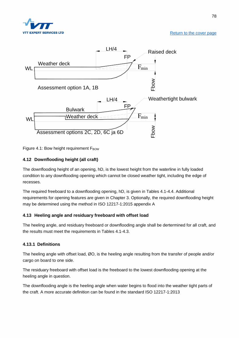
78
Return to the cover page
Weathertight bulwark
Raised deck
Weather deck
Weather deck
Assessment options 2C, 2D, 6C ja 6D
Assessment option 1A, 1B
Bulwark
F
Fbow
LH/4
Fbow
LH/4
FWL
WL
min
min
FP
FP
Figure 4.1: Bow height requirement FBOW
4.12 Downflooding height (all craft)
The downflooding height of an opening, hD, is the lowest height from the waterline in fully loaded
condition to any downflooding opening which cannot be closed weather tight, including the edge of
recesses.
The required freeboard to a downflooding opening, hD, is given in Tables 4.1-4.4. Additional
requirements for opening features are given in Chapter 3. Optionally, the required downflooding height
may be determined using the method in ISO 12217-1:2015 appendix A
4.13 Heeling angle and residuary freeboard with offset load
The heeling angle, and residuary freeboard or downflooding angle shall be dertermined for all craft, and
the results must meet the requirements in Tables 4.1-4.3.
4.13.1 Definitions
The heeling angle with offset load, ØO, is the heeling angle resulting from the transfer of people and/or
cargo on board to one side.
The residuary freeboard with offset load is the freeboard to the lowest downflooding opening at the
heeling angle in question.
The downflooding angle is the heeling angle when water begins to flood into the weather tight parts of
the craft. A more accurate definition can be found in the standard ISO 12217-1:2013

79
Return to the cover page
4.13.2 The loading condition when measuring heeling angle, and residuary freeboard or downflooding angle
Heeling angle and residuary freeboard with offset load is measured with the same amount of load as in
the loading condition ”fully loaded, arrival” (see item 4.6.4). In comparison to the mentioned condition
the difference is that persons and deck cargo are located as follows:
persons or corresponding weights (85 kg each) are located as close to the crew area limits as
possible, so that:
the centre of gravity of the persons closest to the limit is 0.20 m from it;
the centre of gravity of the persons are spaced 0.50 m;
if the craft has decks narrower than 0.4 m, the weight is put in the centre of that part of the
deck;
the centre of gravity of the persons are assumed to be 0.10 m above the deck or seat; and
the persons are placed so that the largest heel, or smallest residuary freeboard is achieved,
considering general arrangement features like upper decks; and
if deck cargo is included in the craft full load, the additional heel caused by its shift to one side
shall also be considered according to Chapter 33 item 4.5.
A more accurate description of testing offset loads can be found in the standard ISO 12217-1:2013.
4.14 Maximum righting moment
In order to prevent too small craft from obtaining Design Category A and B, a requirement is given for
the maximum righting moment. The required value, given in Table 4.1, depends on the Design
Category, and the heeling angle at which the maximum GZ occurs.
4.15 The GZ-curve properties
If the heeling angle at which the maximum GZ value, ØGZmax occurs, is 30° or larger, the required GZ-
value at 3° heel shall be at least 0.2 m.
If the heeling angle at the maximum GZ occurs, ØGZmax, is less than 30°, the requirement refers to the
largest GZ value, GZMAX.
Irrespective of the heeling angle at which the maximum GZ occurs, the craft shall meet the requirement
for stability range.
4.16 Rolling with wind and waves on the beam (weather criterion)
The purpose of the assessment is to ensure that the craft righting energy is at least equal to the heeling
energy caused by the waves on the beam, when simultaneously a steady side wind is blowing.

80
Return to the cover page
The waves are assumed to cause rolling with the amplitude:
ØR = 25+20/ VD Design Category A (4.4)
ØR = 20+20/ VD Design Category B (4.5)
Where VD is the displacement volume in cubic meters.
The righting moment curve is limited by the smallest of the angles:
Downflooding angle
Capsizing angle
50°
The wind heeling moment, MW [Nm], is assumed to be constant at all heeling angles, and has to be
determined with either of these formulas:
MW1 = 0.53∙ ALV ∙h∙ vw2 [Nm] (4.2)
MW2 = 0.30∙ ALV (ALV/ LWL+TM) ∙ vw2
Where
TM [m] is the mean draught
vw = 28 m/s for Design Category A and 21 m/s for Design Category B
ALV [m2] is the lateral wind area, minimum 0.5∙LH∙BH
h = vertical distance btw centers of windage area and underwater lateral area, [m]
The righting and heeling moments are plotted as a function of the heeling angle in the same graph as
shown in Figure 4.2. The craft meets the stability criterion provided area A2 is equal or larger than area
A1.

81
Return to the cover page
A1
A2
Wind moment, Mw
Heel angle
Rig
htin
g o
r h
ee
ling
mom
ent
Min
(F
loo
d.
an
gle
,
Roll amplitude Phi_R
Righting moment curve
symmetrical about moment-axis
va
nis
hin
g a
ng
le o
r 5
0 d
eg.)
0
Figure 4.2: Rolling with wind and waves on the beam
4.17 Wind induced heel
This criterion ensures that righting moment of the craft is sufficient in strong beam wind. If the projected
lateral windage area ALV < 0.5∙ LH∙BH in the loading condition LC3, it is not necessary to perform this
check. Otherwise the procedure is:
Determine the wind induced heeling moment MW according to 4.15, but use the wind speed vw = 17 m/s
for Design Category C and 13 m/s for design Category D.
The wind induced heeling angle ØW is determined by comparing the heeling moment curve with the
righting moment curve worked out for loading condition LC3.
The heeling angle ØW must be less than 70% of the allowed heeling angle with offset load, and less
than 70% of the downflooding angle as well.
4.18 Buoyancy when swamped
4.18.1 General
Remaining afloat when swamped means that a loaded and waterfilled craft remains afloat due to the
buoyancy provided for this purpose, and stays approximately horizontal with a certain minimum
stability. The requirements depend both on the used assessment option and on the type of flotation
elements.

82
Return to the cover page
4.18.2 Types of flotation elements and their requirements
The required buoyancy volume may be comprised of air tanks, pontoons or foam filled floats, and also
the craft structure.
Air tanks are water- and airtight compartments, contained within walls of FRP, metal, or other stiff
material. It must be possible to remove condensed- and other water from the tanks through an
inspection hatch or –opening, which can be closed tight. Air tanks shall be tested to 5 kPa pressure,
and during 30 seconds the maximum allowed pressure drop is 1 kPa.
Pontoons are air filled floats with walls of thin, typically fabric reinforced polymer film, keeping the shape
due to internal air pressure. Pontoon materials shall meet the requirements in the standard ISO 15372,
and they have to be tested according to the same standard. Prefabricated pontoons shall be tested as
follows according to standard ISO 6185:
over pressure test, (ISO 6185-4 item 7.9)
tightness test, (ISO 6185-4 item 7.9)
test of pontoon attachment, (ISO 6185-4 item 7.14)
Foam filled floats contain cellular plastic foam. It has to be mechanically protected by hull structure, or
have a protecting surface layer. The foam is to meet the requirements in:
ISO 6185-3:2014 item 5.7
4.18.3 Arrangements for buoyancy
Pontoons must be divided into at least five about equally large compartments, each volume within ±
20% of the average for all pontoon compartments.
Air tanks need to be divided into compartments based on their volume fraction of the required total
buoyancy volume according to Table 4.4.
Table 4.4: The number of permanent air tanks in the hull versus Design Category
Volume
fraction
Number of permanent air tank compartments
B C D
≤ 50 % 2 2 1
> 50 % 3 2 2
4.18.4 Assessment of buoyancy
A buoyancy test has to be performed according to standard ISO 12217-1:2015. The floating position as
well as stability in swamped condition with full load are assessed.

83
Return to the cover page The buoyancy can also be verified by calculation. The permeability of the waterfilled compartments
shall normally be 1, except for the engine space, where 0.85 may be used.
4.19 Multihulls susceptible to inversion
4.19.1 Susceptible to inversion
The requirements apply only to craft in Design Category C and D.
The craft is regarded susceptible to immersion if:
hC/BH > 0.572 while VD1/3 > 2.6
hC/BH > 0.22∙VD1/3 while VD
1/3 ≤2.6
Where
hC is the lateral wind area centre above the waterline, [m]
VD is the displacement volume in light service condition [m³]
4.19.2 Requirements
Craft vulnerable to capsizing according to item 4.18.1 shall meet the following requirements:
The craft shall, fully loaded, remain afloat swamped upside down according to ISO 12217-
2:2013 item 7.12;
There shall be an emergency exit which can be used while the craft is upside down according to
item 7.13 in the same standard.

84
Return to the cover page
5 DECK ARRANGEMENT AND RECESSES
5.1 Purpose
The purpose of this chapter is to ensure that:
The deck arrangement is laid out so green water coming on board drains back to the sea as
quickly as possible;
The recesses have proper size and location considering the craft reserve buoyancy and stability
in relation to the Design Category; and
The drain arrangements enable quick draining of the recesses; and
Flooding of the craft weather tight spaces through openings in the recesses is avoided.
NOTE! The effects of green water to stability is treated in Chapter 4!
5.2 References
In this chapter reference is made to the following documents:
ISO 12217-1:2015 Small craft – Stability and buoyancy assessment and categorisation
ISO 11812:2001 Small craft – Water tight cockpits and quick-draining cockpits
International Load Line Convention 1966 with amendments
5.3 Documentation
For assessment of the requirements given in this chapter the following documentation is required:
Deck arrangement;
Volume of recesses;
Drain opening location and size; and
Sill heights for doors in recesses leading into the weather tight hull;
Calculation of draining time, or test protocol
Most of the mentioned information can be given in the general arrangement drawing.
Handling of the green water coming on board
When applying the rules of this chapter it should be noted, that with different deck arrangements (see
Chapter 2) the required level of water- and weather tightness varies. For open or partially protected
craft it is assumed that water coming on board is led to the bilge, and drained overboard with bilge
pumps. For fully enclosed craft and those provided with buoyancy for remaining afloat, the deck,
superstructures, and recesses shall be designed so green water coming on board is efficiently drained
back to the sea. The assessment is done according to standard ISO 12217-1, as explained in Chapter
4.
85
Return to the cover page
5.4 Definitions
5.4.1 Recesses
A recess is any part of the craft where water can collect, as a consequence of green water coming on
board, heeling, heavy rain etc. For example, cockpits and deck areas surrounded by bulwarks are
recesses.
5.4.2 Basic requirements for recesses
A quick-draining recess meets the requirements in standard ISO 11812 for the Design Category in
question. A quick-draining recess shall have:
bottom height above the waterline according to 5.7.1;
draining arrangements according to 5.7.2;
coaming height according to 5.7.8; and
water tightness according to 5.7.9.
5.4.3 Watertight recess
A watertight recess shall have sill height according to 5.7.8 and water tightness according to 5.7.9. For
fully enclosed craft the total volume of all watertight recesses must not exceed LH∙BH∙FM/40.
5.5 Requirements for deck arrangements
5.5.1 Weatherdeck arrangement
The weatherdeck (see definition in Chapter 2) arrangement shall ensure that green water coming on
board does not remain on deck for a long period. Arrangements that prevent the water from draining
back to the sea are not allowed.
5.5.2 Non-weather tight superstructures in fully enclosed craft
Superstructures not meeting the requirements regarding strength, water tightness, or closing
arrangements for the location in question, are not allowed in design category A and B although the
craft’s stability would be sufficient without this superstructure. Alternatively, such superstructures could
be fitted with drain openings having a capacity meeting the requirements for a recess in the same
location, assuming that the recess coaming height is the same as the sill height for the required door.
5.6 Detailed requirement for recesses
The following requirements are based on the international standard ISO 11812. Only typical cases are
presented, and in other cases the mentioned standard has to be applied.

86
Return to the cover page
5.6.1 Height of recess bottom above waterline
For quick-draining recesses the height of the recess bottom above the waterline has to be at least
according to Table 5.1. The requirements in the table refer to recesses with straight bottoms. For
recesses with other bottom configurations the standard ISO 11812 shall be applied.
NOTE! Achievement of the draining time in 5.7.2 may require a higher located bottom than given in
Table 5.1.
NOTE! The reserve buoyancy requirement in Chapter 4 item 4.9 may also require a higher located
bottom.
Table 5.1 Recess bottom height HBmin
Design Category A B C D
hBmin [mm] 150 100 75 50
5.6.2 Maximum draining time
The recess maximum draining time is shown in Figure 5.1 as a function of the parameter kC, describing
recess volume versus craft weather tight volume. The parameter kC is determined with Formula (5.1)
Where VC [m3] is the recess volume and BMAX the craft maximum beam.
The draining time never must exceed:
2 minutes for Design Category A;
3 minutes for Design Category B;
4.5 minutes for Design Category C; and
5 minutes for Design Category D.

87
Return to the cover page
Figure 5.1: Maximum allowed draining time tmax [min] for quick draining recesses as a function of kC.
5.6.3 Area requirement for drain openings
The area for drain openings is to be such that the maximum draining time according to 5.7.2 is not
exceeded. Compliance can be shown using the simple Formula (5.2) method, examples in Figure 5.2,
performing a draining test, or the calculation method given in standard ISO 11812.
5.6.4 Example arrangement
In Figure 5.2 the area requirement is given for a maximum 1 m long drain tube above the waterline and
fitted with a non-return flap. Areas shown in the example must be used only for recesses with over 0.4
m high coamings, tube outlet above the waterline, and tube length maximum 1.0 m. The outlet opening
may have a non-return flap, but bends or other resistance increasing features are not allowed.
Maximum allowed draining time

88
Return to the cover page
Figure 5.2. The minimum area per side for drain openings in recesses with over 0.4 m high coamings,
when the drain tube length is less than 1 m, and outlet above water fitted with non-return flap.
5.6.5 Drain area per side
The required total drain area per side can be determined with the simple method in Formula (5.2)
provided:
The drains are evenly spaced along the deck edge;
The drains’ flow characteristics correspond to holes in a plate without tubes or other flow
restricting features;
89
Return to the cover page
In loaded condition the height of the drains above the waterline is at least the same as the
freeboard requirement in Chapter 4 item 4.11.
A = k ∙ VC [cm²] (5.2)
Where VC [m³] is the recess volume according to standard ISO 11812, normally the deck area times
the coaming or bulwark minimum height, and coefficient k to be
200 for Design Category A;
100 for Design Category B;
50 for Design Category C; and
20 for Design Category D.
5.6.6 Draining test
In all cases draining time compliance can be demonstrated by a physical draining test. The recess is
filled with water, and the draining time is measured. If the time does not exceed the requirement in item
5.7.2 the recess is compliant in this respect.
Alternatively, the required drain area can be determined by calculation according to standard ISO
11812.
5.6.7 Number and location of drains
Recesses shall have at least one drain opening per side. Particularly for working decks and other big
recesses the drain location must ensure efficient draining considering the recess volume distribution,
and a possible trim change for the craft due to a filled recess.
5.6.8 Sill heights
The closing appliances leading into the weather tight hull shall have sill heights meeting the
requirements for doors or hatches given in Chapter 3.
5.6.9 Water tightness
Closing appliances in the bottom or side of recesses shall at least meet the requirements in Chapter 3.

90
Return to the cover page
6 PREVENTION AND CONTROL OF LEAKS, BILGE SYSTEMS
6.1 Purpose
The purpose of this chapter is to ensure that:
The watertight spaces are arranged so that the consequences of probable damage are
minimized;
There is a draining system sufficient for the craft size and use.
6.2 References
In this chapter the following documents are referred to:
ISO 12217-1:2015 Small craft – Stability and buoyancy assessment and categorisation
ISO 15083:2003 Small craft – Bilge pumping systems
ISO 8849:2003 Small craft -- Electrically operated direct-current bilge pumps
6.3 Documentation
For assessment of the requirements given in this chapter the following documentation is required:
the watertight subdivision;
the structure of watertight bulkheads including WT doors and penetrations;
the location of openings leading to watertight compartments, their closing arrangements;
other possible flooding control arrangements
the location of drainage pumps, manufacturer/type notation and capacity;
location of high bilge level alarms;
drainage lines and their through-hulls as well as used materials
test protocol for bilge pumping capacity
6.4 Requirements
A summary of the requirements is shown in Table 6.1. The details are treated separately.
The requirements for ”One compartment subdivision” are given in Chapter 38.
6.5 Leak control
Sufficient safety level in case of a leak can be provided in one of three ways. They are:
limited unsinkability, which is the compulsory minimum level for all craft types, except those
assessed according to the alternatives 3B, 2C and 3D (craft with buoyancy for remaining afloat,
see Table 4.2);
one compartment subdivision as an alternative to limited unsinkability, in case the Additional
Notation ”One Compartment Damage Stability” is chosen.
flotation in swamped condition for craft assessed according to the alternatives 3B, 2C, and 3D.

91
Return to the cover page The details for these are explained in items 6, 7, and 8.
6.6 Limited unsinkability
6.6.1 Principle
The risk of flooding the hull as a consequence of damage shall be minimized as far as practically
possible. ”Limited unsinkability” means that the spaces particularly vulnerable to damage are protected
with local watertight subdivision or other damage tolerant arrangements. The aim is to limit the leak so
much that the craft does not sink or capsize because of the damage.
6.6.2 The means for achieving limited unsinkability
Depending on the assessment option for the undamaged craft, the watertight subdivision, the
underwater appendages, and possible buoyancy for remaining afloat, the following arrangements for
improved unsinkability are required according to Table 6.1:
Collision bulkhead to be installed between 0.05 ∙ LWL and 0.15 ∙ LWL aft of the forward
perpendicular. In the vertical direction the collision bulkhead shall extend from the bottom up to
weather deck (see definition in Chapter 1)
An alternative to the previous item could be a collision zone of hard polymer foam or equal,
extending at least 0.05 ∙ LWL aft from the forward perpendicular. The vertical extent to be the
same as for a corresponding collision bulkhead.
In craft with unprotected rudders and/or propellers, the bottom above them should be
subdivided, or have other precautions taken for limiting a possible leak, in case rudders or
propellers should damage the hull in connection with grounding.
Engine space bulkheads watertight at least to the deck above the full load waterline in fully
enclosed craft, and up to 100 mm above the full load waterline in open or partially protected
craft.
For cargo hold bulkheads the same water tightness requirements as for the engine space refer.
o Here the forward perpendicular to be taken as the intersection of the full load waterline
with the stem.
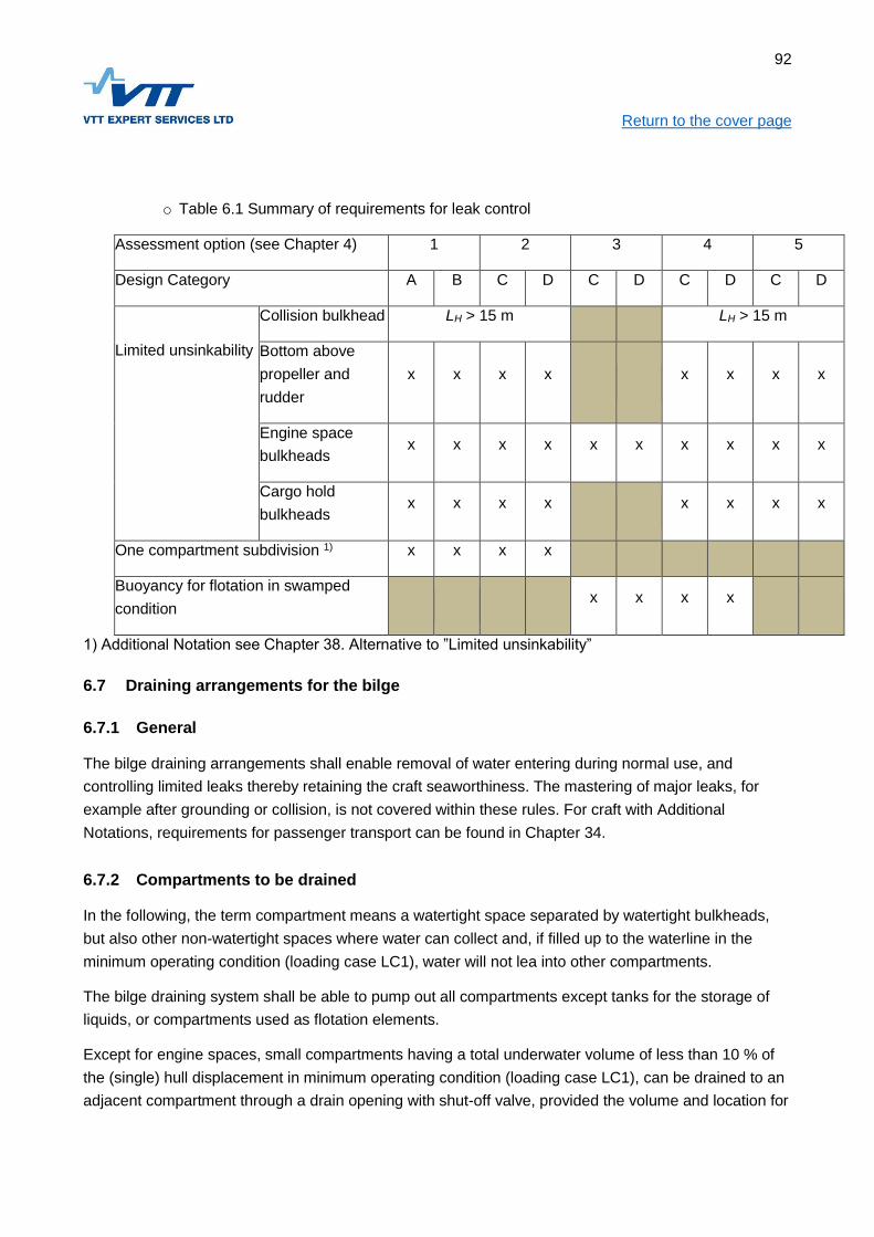
92
Return to the cover page
o Table 6.1 Summary of requirements for leak control
Assessment option (see Chapter 4) 1 2 3 4 5
Design Category A B C D C D C D C D
Limited unsinkability
Collision bulkhead LH > 15 m LH > 15 m
Bottom above
propeller and
rudder
x x x x x x x x
Engine space
bulkheads x x x x x x x x x x
Cargo hold
bulkheads x x x x x x x x
One compartment subdivision 1) x x x x
Buoyancy for flotation in swamped
condition x x x x
1) Additional Notation see Chapter 38. Alternative to ”Limited unsinkability”
6.7 Draining arrangements for the bilge
6.7.1 General
The bilge draining arrangements shall enable removal of water entering during normal use, and
controlling limited leaks thereby retaining the craft seaworthiness. The mastering of major leaks, for
example after grounding or collision, is not covered within these rules. For craft with Additional
Notations, requirements for passenger transport can be found in Chapter 34.
6.7.2 Compartments to be drained
In the following, the term compartment means a watertight space separated by watertight bulkheads,
but also other non-watertight spaces where water can collect and, if filled up to the waterline in the
minimum operating condition (loading case LC1), water will not lea into other compartments.
The bilge draining system shall be able to pump out all compartments except tanks for the storage of
liquids, or compartments used as flotation elements.
Except for engine spaces, small compartments having a total underwater volume of less than 10 % of
the (single) hull displacement in minimum operating condition (loading case LC1), can be drained to an
adjacent compartment through a drain opening with shut-off valve, provided the volume and location for

93
Return to the cover page the compartment in question does not endanger the safety of the craft. Alternatively, small
compartments may be drained with a portable bilge pump.
Except for superstructures, spaces above the waterline providing reserve displacement below the
working deck, shall have the possibility to drain to compartments connected to the bilge draining
system.
Water collecting in compartments shall drain to the bilge pump or emptying point.
All bilge pumps and bilge level indicators shall be functional at ±10° heel, the amount of remaining
water to be less than 10 % of the compartment displacement in the light service condition, and
maximally 500 liter.
In compartments where the above requirement cannot be met, additional bilge pumps are required,
located so that the compartment can be emptied also at 10° heel.
When there are several pumps in a compartment the pump capacity requirement refers for the
compartment.
6.7.3 Requirements for the bilge draining system
The requirements for the bilge draining system depend on the craft length, displacement, Design
Category, subdivision, risk of flooding, and craft concept.
Except for the small compartments mentioned in 6.7.2, it shall be possible to pump out all
compartments with the main bilge draining system.
In the engine space and in compartments with through-hull connections, a reserve bilge draining
system is required according to Table 6.2.
In craft with buoyancy for remaining afloat the main bilge draining system may, with the exception of the
engine space, be manual and operated from the working deck, having a capacity corresponding to the
secondary draining system.
In compartments with inherent risk of flooding, indication for high bilge level is required.
The bilge system discharge line must not be connected to or other systems such as
the engine cooling system discharge.

94
Return to the cover page
Table 6.2 Summary of the requirements for bilge draining systems
Design Category BCD AB CD CD
Craft Concept Flotation
buoyancy
Fully
enclosed
Fully
enclosed
Open or
partially
protected
Main bilge draining system in all
compartments (mechanical or
electrical pumps)
xM) x x x
Secondary bilge draining
system, (manual or electrical
pumps)
xB) x xC) x
Engine space backup bilge
draining system
(engine driven pump)
LH > 15 m
High bilge water level alarm in
engine space x x x x
High bilge water level alarm in
compartments with through-hull
fittings or weathertight closing
appliances below loaded
waterline.
x xC) x
xM) Manual bilge pump with the reserve pump capacity allowed for main bilge draining system, with the
exception of engine space bilge pump
xC) Only Design Category C craft
xB) Only Design Category B craft engine space
6.7.4 Main bilge draining system
The main bilge draining system shall consist of a stationary electrical or mechanical pump, enabling
pumping out all compartments through pipelines;
Craft with flotation buoyancy are exceptions, for them a manual bilge pump with reserve pumping
capacity is allowed for emptying the compartments. Their engine space, however, requires a powered
pump.

95
Return to the cover page The pipelines shall be arranged so any flooded compartment can be pumped out with the required
capacity in all loading conditions, irrespective of trim or heel changes caused by the flooding, and high
bilge level indicators always remaining fully operative.
The pipeline system shall be sized for the required pumping out capacity in Figure 6.1.
Alternatively, each compartment can have its own pump, connected to common or separate pipelines.
Bilge pumps may be used for other purposes, such as fire extinguishing, but not for pumping flammable
fluids.
All main bilge pumps shall be operable from the steering position, except for the manual pumps used in
craft with flotation buoyancy.
For fully enclosed craft in design category A or B with a hull length exceeding 15 m, there shall be two
independent main bilge pumps in the engine space.
Bilge pumps may be automatic provided there is no risk of transferring polluting substances into the
environment.
The capacity requirement for the main bilge draining system is met if the pump nominal output
according to standard ISO 8849 is at least in conformity with Figure 6.1 against a back pressure of 1 m
hydraulic water head, while considering the requirements in 6.7.6.

96
Return to the cover page
Figure 6.1: Minimum pumping capacity requirement [l/min] for main bilge pump as a function of hull
length LH
6.7.5 Secondary bilge pumping system
For the engine space, and the compartments with through-hulls below the fully loaded waterline, there
shall be a secondary bilge pumping system, completely separate from the main bilge pumping system,
according to Table 6.2.
REQUIREMENT FOR MAIN BILGE PUMP
Engine space or non-WT compartment 8*LH+25
WT-compartment not engine space 3*LH+45
Against 1 m of hydraulic water head ISO 8849

97
Return to the cover page The secondary pump shall be operable outside the compartment.
Figure 6.2: Minimum reserve pump capacity requirement [l/min] for bilge pumping as a function of hull
length LH
6.7.6 Measurement of bilge pumping capacity
The pump output shall be measured at the hull outlet or from a corresponding arrangement.
For electrical pumps the output is measured with the battery charging system connected.
The measured bilge pump output at the hull outlet shall be at least 33% of the required nominal
capacity given in this chapter (Figures 6.1 and 6.2).
The measured result must not influence the capacity requirement towards a reduction of
capacity.
6.7.7 Multihull bilge draining arrangements
For multihulls each hull should have bilge draining arrangements corresponding to those required for
monohulls.
RESERVE BILGE PUMP
4*LH+10, maximum 70 l/min
Against 1 m of hydraulic water head
Acc.to ISO 8849

98
Return to the cover page For compartments which are part of the reserve displacement above the loaded waterline, except for
the superstructure, the emptying of water shall be arranged by letting it drain to compartments lower
down which are part of the main bilge draining system. For example, an enclosed bridge between the
hulls is such reserve displacement.
For multihulls the sum of the small compartment (see 6.7.2) volumes in one hull shall be maximum 10%
of the light service displacement (LC1) for this hull, and maximum 500 liter.
6.7.8 Alarm for high bilge water level
All craft shall have alarm for high water level in the engine space.
In other compartments where there is a risk of water intrusion through damaged or accidentally open
underwater through-hulls, openable hull windows, hatches without coamings on weather deck, or other
similar arrangements which in open position may let in water, there shall be alarm for high bilge water
level according to Table 6.2.
Bilge alarm is not required in small compartments (see 6.7.2).
A visual high bilge level indication shall be visible at the steering position.
The indication can be combined with the bilge pump float actuator in compartments where there is no
risk of transferring polluting substances into the environment.
6.7.9 Material specifications for bilge draining systems
The tubing and hoses used in bilge draining systems shall have a safe working temperature of at least
80 °C.
Hoses used for bilge draining shall stand at least 50 kPa (0.5 bar) vacuum without collapsing, and be oil
resistant, except for fire pump discharge hoses.
Hoses on deck shall be UV-resistant.
Fire pump discharge hoses and tubing shall have a working pressure higher than the pump discharge
pressure.
For craft over 15 m hull length in Design Category A and B bilge system hoses and non-metallic
discharge tubing in the engine space shall meet the requirements in ISO 7840 or ISO 15540 for short
term fire resistance.
The system parts must not be connected so this creates galvanic action.
6.7.10 Strainers for suction hoses or bilge pumps
The suction hose for manual bilge pumps is to be fitted with a strainer if the compartment is vulnerable
to the collection of trash or oil.

99
Return to the cover page For powered pumps there shall always be a strainer preventing trash from entering the pump.
The suction hose intake strainer shall be easily accessible for cleaning in compartments vulnerable to
collecting trash or oil, such as:
engine spaces;
public spaces, and passages between such spaces;
open spaces, and other spaces connecting to them; and
cargo spaces
The strainers shall be accessible for cleaning in spaces where there is no risk of trash ending up in a
suction hose or bilge pump, as for example in weather tight tanks, through which there is no traffic to
other spaces.

100
Return to the cover page
7 DESIGN PRESSURES AND LOADS
7.1 Objective
This chapter gives the design pressures and loads for the dimensioning of the structural strength of
scantlings. The level of the loads is determined on the basis of craft size, design category, speed and
vertical acceleration at the upper limit. Only design loads related to normal use of the craft are included.
Design loads for craft running through ice-covered waters are provided separately in Chapter 39. At this
point, only design loads for mono-hull craft are included.
7.2 References
The load determination model presented herein is based on the international standard ISO 12215-
5:2008 Small craft – Hull construction and scantlings – Part 5: Design pressures for monohulls, design
stresses, scantlings determination.
The multihull bridge structures design pressure and global loads are based on ISO/WD 12215-7 Small
Craft – Scantlings – Part 7: Multihulls.
The fastening of RIB-pontoons to the rigid hull is assessed using ISO 6185-3:2014 ja ISO 6185-4:2011.
7.3 Principles
The loads as determined in this section are to be used with the calculation formulae in Chapters 10, 14
and 18.
7.3.1 Global loads
Global loads may be significant in multihulls, but also in monohulls in the case of small hull depth,
unfavourable weight distribution, etc. The effect of global loads shall be taken into account as required
in chapters 8, 12 and 14.
7.3.2 Local loads
The safety against loads from minor groundings, launching, etc., is in general considered satisfactory if
the requirements for keel, stem, chine, bulwark and panels are complied with.
7.3.3 Extension of loads
The bottom design pressure to be used in the scantlings formulae in chapters 10, 14 and 18 extends in
the vertical direction up to limit of the bottom and the side. The limit between bottom and side is for
displacement speed up to the waterline in fully loaded condition. In planing speed
the limit between bottom and side is at the chine provided the deadrise is at most 20 degrees. If the
deadrise exceeds 20 degrees, as it usually does in the bow, the limit between bottom and side is at the

101
Return to the cover page waterline in fully loaded condition. For craft without a pronounced chine, the limit between bottom and
side at planing speed is found at the 50-degree tangent, see Figure 7.1.
Above this limit, the side shell design pressure shall be used in the dimensioning. The top limit of the
side is the weather deck for fully enclosed craft and the rail for open craft. Any higher structural parts
(gunwale) shall be dimensioned for minimum pressure as per the formula 7.10.
If the panel is completely within one area, the design pressure is determined at the geometric centroid
of the panel, or at the mid-span of the stiffener. If the panel extends on several areas, the design
pressure is determined according to ISO 12215:2008 clause 6.2.5
Limit bottom/side, deadrise<=20 degrees
Planing, hard chine
Planing, round bilge
20°
LWL
Limit bottom/side, deadrise>20 degrees
Limit bottom/side
Displacement speed
LWLLWL
Limit bottom/side at 50 degree tangent to hull,
however need not be above LWL
Figure 7.1. Limit between bottom and side pressure.
7.4 Bottom design pressure
The bottom design pressure is to be determined for non-planning mode, and, if the speed of the craft
fully loaded exceeds 5∙√LWL [kn], also at maximum speed. The design pressure to be used for
determining bottom scantlings shall be the greater of these pressures.

102
Return to the cover page The bottom design pressure PBM, is the greatest of the pressures given by formulae 7.1-7.3:
[kPa] (7.1)
[kPa] (7.2)
[kPa] (7.3)
Where
[kPa] (7.4)
[kPa] (7.5)
[g] (7.6)
And
kDC Design category factor, see Table 7.3
kL Longitudinal pressure distribution factor, see 7.11.3
kAR Area reduction factor, see 7.11.2
Deadrise at 40% of LWL from stern, degrees
V Maximum speed at full load, kn, minimum 5∙√ LWL
BC is the distance between chines at 40% of LWL from stern, for multihulls the sum of the waterline
beams.
If the dynamic load factor, nCG, according to formula (7.6) exceeds 3,0, the value obtained by formula
(7.7) shall be used as nCG in formula (7.5).
For multihulls, the dynamic load factor shall always be determined using formula (7.7), however, nCG
shall never be taken as less than 1,5.
[g]; min 3,0; max 7,0; for multihulls min 1.5 (7.7)
7.5 Side design pressure
The side design pressure is to be determined for non-planing mode, and when speed exceeds 5∙√LWL,
also for the greatest speed in the loaded displacement condition. The design pressure to be used in the
scantling calculations shall be the greater of the pressures. Bulwarks above weather deck shall be
dimensioned using the pressure obtained from formula 7.10.

103
Return to the cover page
[kPa] (7.8)
[kPa] (7.9)
[kPa] (7.10)
PBMD BASE = Bottom base pressure as per the formula (7.4)
PDM BASE = Deck base pressure as per formula (7.12)
kZ = Vertical pressure distribution factor, see (7.11.4)
kAR, kDC and kL as defined in 7.4
7.6 Design pressure for decks
Design pressure for weather decks not used for transport of cargo shall be determined by formula 7.11.
For sheltered decks, not intended for cargo, the design pressure shall be 5 kPa. For decks intended for
cargo, the design pressure shall be the greater value from formulae 7.11 or 7.13.
[kPa] (7.11)
[kPa] (7.12)
[kPa] (7.13)
Where:
kAR, kDC and kL as defined in 7.4
Q Amount of cargo per square meter, t/m2
7.7 Design pressure for superstructures
Design pressures for superstructures are based on the design pressure for decks and shall be taken
according to formula 7.14
[kPa]; min 5 kPa (7.14)
Where:
PDMBASE is calculated using formula 7.12
kSUP 1,00 for surfaces facing forward;
0,67 for surfaces faces to the side
0,50 for surfaces aft
0,50 for horizontal surfaces ≤0,8 m above deck without cargo
0,35 for horizontal surfaces >0,8 m above deck without cargo

104
Return to the cover page Other factors as defined in 7.4
The design pressure for superstructures intended to carry cargo shall be determined as for cargo
decks.
7.8 Watertight bulkheads
The design pressure for watertight bulkheads is the hydrostatic pressure which occurs on either side of
the bulkhead when the compartment is flooded. This pressure shall be calculated by formula 7.15.
[kPa] (7.15)
Where
hB is the water head determined as follows:
For panels 2/3 of the height of the bulkhead [m]
For vertical stiffeners 2/3 of the stiffeners length, m
For horizontal stiffeners its distance from the upper edge of the bulkhead, m
7.9 Design pressure for integral tanks
The design pressure for integral tanks is determined by formula 7.16.
[kPa] always minimum 20 kPa (7.16)
Where hB is the pressure head measured as in 7.8
7.10 Design pressure for multihull wet-decks
The design pressure of multihull wet-decks PWD applies to all structure above the waterline at full load
between the demihulls, including the inside topsides of the demihulls.
(7.17)
Where
[min 0,5 < kZWD < 2,0 max]
And
zWD = vertical distance from the loaded waterline to the center of the panel or stiffener in question, [m]
7.11 Global loadcases for multihull craft
Global loads shall be taken into account for monohulls if the beam/length ratio exceeds the following
value:

105
Return to the cover page
BH/LH > -0,013 * LH + 0,55 (7.18)
Load case 1. Diagonal load in quartering seas
The load case simulates a situation, where the vessel sails on an obique course relative the waves, and
thereby momentarily is supported by two wave crests, one at the bow at one hull and one at the stern of
the other hull.
[kNm] (7.19)
Where
BCB = distance between centrelines of demihulls
Load case 2. Load corresponding to the righting moment.
A vertical load, acting at one hull, which is the smaller of the following:
The buoyancy force when the hull is immersed, acting at its center of buoyancy;
A vertical force corresponding to the greatest righting moment in the loading case LC2
If the bridge structure is shorter than 0,4·LH, also other global loadcases as defined in ISO 12215-7
might need to be checked.
7.12 Forces on transoms for high-power outboard motors
In Table 7.1 is presented design forces, based on seatrials, for transoms of planing boats in rough
seas.
Strength assessment of the transom shall be made in load cases I, II and III for boats if:
The engine power exceeds 100 kW; and
The power factor CPM exceeds 1,0
Load Case I: Simulates the situation where the air-borne craft lands at the next wave crest, when the
gravity of the outboard motor induces a backward force on the transom.
Load Case II: Simulates the situation where the air-borne craft lands at the next wave through, when
the craft retards and the propulsion simultaneously is acting forward.
Load case III: Simulates the situation after the wave impact, when the propulsion acts with full force.
For craft with schock-mitigating seats, the forces FX, FZ and the moment MY shall be multiplied by a
factor 1,2

106
Return to the cover page Table 7.1. Design forces and moments for outboard transoms
Formula Description
FX CPM * 0,42 P0,7 Forward force parallel to keel, one engine [kN]
FZ CPM * 0,10 mm Vertical force, one engine [kN]
MY CPM * 0,36 P0,7 Moment at axis of rotation due to mass and propulsion forces, one engine [kNm]
joissa
CPM 0,43(50-β)*(PTOT0,5/mMT
2/3) Power factor based on power/weight
mm Mass of outboard or sterndrive [kg]
mMT Mass of craft in sea trial condition [kg] = mLC + 150 kg
P Power of one engine [kW]
PTOT Total engine power [kW]
β Deadrise@ transom according to ISO 8666 [degrees]
Loads and moments, coordinate system described in Figure 7.2
Load case FX FZ MY
I ei 1,0 FZ 0,7 MY
II 0,5 FX 1,0 FZ 1,0 MY
III 1,0 FX ei 0,5 MY
Figure 7.2. The coordinate system for determining the transom forces and moments
7.13 Connection of RIB pontoons
The connection of RIB the pontoons to the rigid hull shall be tested asa per ISO 6185-3 for craft with a
hull length up to 8 m and ISO 6185-4 for bigger craft.

107
Return to the cover page
7.14 Design pressure correction factors
7.14.1 Design category factor
The design category coefficient factors for the design pressure differences in various design categories
shall be used as per the Table 7.1:
Table 7.1. Design category coefficient
Design category A B C D
kDC 1,0 0,8 0,6 0,4
7.14.2 Area reduction factor
The area pressure reduction factor kAR takes account of the effect of the size of the strength member
on the design pressure. It shall be determined in accordance with the following formula (7.18)
(7.18)
Where
kR = 1,0
AD = Design area, m2, to be determined by the formula 7.19 and 7.20:
; max 2,5 ∙ b2 ∙ 10-6 [m2] paneeleille (7.19)
; max 0,33 ∙ lU2 ∙ 10-6 [m2] jäykisteille (7.20)
Where
a = Shorter side of panel, mm
b = Longer side of panel, mm
lU = Stiffener unsupported span, mm
kAR must not be taken smaller than 0,25 when calculating requirements based on bending strength or
stiffness. When calculating requirements based on allowable shear stress of sandwich cores, kAR must
not be taken less than Figure 7.2. For other than bottom and side panels kAR≥0,40. The factor kAR
cannot exceed 1,0.

108
Return to the cover page
Figure 7.2. Area reduction factor minimum value for sandwich panels.
7.14.3 Design pressure correction based on longitudinal position
The longitudinal pressure distribution factor kL takes account of variations in the distribution of pressure
in the craft’s longitudinal direction. It is a function of the dynamic load factor nCG, and shall be
determined using the values in Figure 7.3 or the formulae 7.21 and 7.22.:
; 0 ≤ x ≤ 0,6 ∙ LWL perästä keulaan päin (7.21)
; x > 0,6 ∙ LWL perästä keulaan päin (7.22)
Bottom, kat. A
Bottom, kat. B, side kat A
Side, kat B
Longitudinal position

109
Return to the cover page
Figure 7.3: Correction factor kL
7.14.4 Design pressure correction based on vertical position
The vertical pressure distribution factor kZ takes account of variations in the distribution of pressure in
the vertical direction. It is a function of a strength member’s location in relation to the limit between the
bottom and the side, as depicted in Figure 7.4. The factor kZ shall be determined with formula 7.23
(7.23)
Where
Z = height of freeboard locally to the weather deck (fully enclosed craft) or to the edge of the gunwale
(open craft), m
h = Vertical distance between the center of gravity of the structural part’s design area and the limit
between bottom and side, m
Longitudinal position

110
Return to the cover page
Figure 7.4. Correction of design pressure based on vertical position.
section through centre of panel or design area of
stiffener
z
point of pressure for panel or stiffener
h

111
Return to the cover page
8 DESIGN PRINCIPLES, FIBRE-REINFORCED PLASTIC
8.1 Objective
This chapter contains requirements regarding the structural arrangement of the craft and also regarding
the design of some critical details. Further, the underlying principles for the assessment are dealt with.
The objective is that the structural arrangement and -details has been carried out correctly from a
strength of materials point of view and in accordance with the special properties of fiber-reinforced
plastic.
8.2 References
The requirements in this chapter are based on the international standard ISO 12215-6:2008 Small craft
– Hull construction and scantlings – Part 6: Structural arrangements and details.
8.3 Principles of analysis
8.3.1 Simple assessment method
The simple assessment method means, that the panels, stiffeners and other structural members
covered by the Rules are dimensioned according to the formulae in Chapter 10 using the loads of
Chapter 7 and the mechanical properties of Chapter 9.
The simple assessment method may be used provided the following conditions are met:
The structural arrangement meets the requirements in clause 8.6.;
The assumptions in clause 8.4 are valid;
The structure is not critical regarding global loads, see clause 8.5
8.3.2 Assessment using First Principles
In cases, where the assumptions listed in 8.3.1 are not valid, the structure, or parts thereof, is to be
assessed using first principles of strength of material. For FRP such methods include Laminate Stack
Analysis (see ISO 12215-5 Annex H) and Classical Laminate Theory.
8.3.3 Finite Element Method (FE)
The standard ISO 12215-5 does not presently allow FE to be used for dimensioning structures subject
to sea loads due to their dynamic nature. For other than structures subject to sea loads FE is allowed.
The allowable stresses can be found in Chapter 10 clause 10.13.

112
Return to the cover page
8.4 Assumptions
8.4.1 Local and global strength/stiffness
The scantling determination method presented in Chapter 10 is based on dimensioning against local
loads. Normally, this will result in scantlings, which are adequate also for global loads. Where this is not
the case, the dimensioning against global loads shall be assessed, see Clause 8.5
8.4.2 Hierarchy of the load carrying elements
When calculating rule requirements for panels and stiffeners according to Chapter 10, the hierarchy of
structure is assumed to adhere to the following principles:
The panel is supported by secondary stiffeners supported by primary stiffeners as indicated in
Figure 8.1;
The primary stiffeners are at least twice as stiff as the secondary stiffeners, or
(8.1)
The modulus of elasticity of the laminate in the principal directions is within the limits given in
8.9.2;
The load is uniformly distributed.;
The edges of the panel are clamped;
The ends of the stiffeners are fixed.

113
Return to the cover page
Figure 8.1. Hierachy of load carrying elements
8.4.3 Sandwich panels
When calculating scantling requirements using the formulae in Chapter 10, the following assumptions
are made:
The faces of the sandwich panel are thin (total panel thickness/face thickness > 5.77);
The stiffness (EI) ratio of a thinner face to a thicker face is in the range 0.75...1,0;
The ratio of the stiffnesses of the face laminates measured in the main directions of the panel is
within the limits given in 8.9.2;
The modulus of elasticity is much higher in the face than in the core material.
Sandwich panels with faces thicker than mentioned above, shall be analysed according to ISO 12215-5
paragraph 10.2.3
8.5 Global strength and stiffness
In the following cases also the global strength and stiffness must be investigated:
If the bottom is only transversely stiffened and the relative speed is V/√ LWL >6
If there are large openings in the deck;
Primary stiffener (for ex. Web-frame)
Load area for primary
stiffener
Load area for
secondary stiffener
Secondary stiffener Support for primary stiffener
(for ex. chine)
Support for primary stiffener
(for ex. keel)

114
Return to the cover page
If the ratio of the hull length to the hull depth LH/DMAX >12
The global strength and stiffness shall be determined according to ISO 12215-6 Annex D, but the
analysis shall be carried out using FE-analysis. At least the deck shall be checked against buckling
(compressive stress in the deck). For craft with only transverse stiffening in the bottom also the strength
of the bottom shall be checked.
For multihulls, the global strength shall be checked in the load cases given in Chapter 7
8.6 Requirements for structural arrangement
8.6.1 Displacement craft, design category D
Boats in design category D with V/√ LWL ≤6, may be stiffened by the keel, gunwale and transverse
stiffeners only. Boats in higher design categories may only be stiffened by transverse framing alone if
an assessment of the global strength and stiffness is carried out, see paragraph 8.5.
8.6.2 Planing craft
Boats with V/√ LWL >6, should in general have longitudinal stiffening in the bottom. The details of
longitudinal stiffeners shall meet the requirements of paragraph 8.7.
8.6.3 Support for longitudinal stiffeners
The bottom longitudinal stiffeners shall in general be supported by transverse stiffeners such as
bulkheads, web frames or deep floors, which are to be designed to carry the load acting on the hull
area in question, see Figure 8.1. The details of transverse stiffeners shall meet the requirements in
paragraph 8.7.
8.6.4 Keels, stem and chines
The craft shall have a reinforced keel, stem and chines according to Chapter 10 paragraph 10.11.
8.6.5 Torsion stiffness and -strength
The torsion strength and stiffness is considered adequate if the craft has one of the following items:
A full deck;
Transverse bulkheads;
A strengthened bulwark.
8.6.6 Superstructure support points
The loads induced by superstructures shall be led into bulkheads, webframes or other primary
structure.

115
Return to the cover page
8.7 Hull stiffeners
8.7.1 Continuity of stiffeners
In craft where V/√LWL>6, the bottom longitudinal stiffeners shall be continuous. Terminating of
stiffeners on a panel between stiffeners shall be avoided. With the exceptions of paragraph 8.10.2 the
ends of stiffeners shall be fastened to other stiffeners.
8.7.2 Straightness and local discontinuities of stiffeners
Hull stiffeners shall be as straight as possible. At most 30 degrees are accepted, provided buckling
support is arranged at the points where the direction change. Aprupt changes is the cross section of the
stiffeners shall be avoided. If the stiffeners have local discontinuities, the transition shall be smooth and
corners shall be rounded, radius at least 30 mm.
8.7.3 Safety against buckling
The cross section of stiffeners shall be such that they are not prone to buckling. Stiffeners with one web
must not be fastened at an angle exceeding 30 degrees relative to the normal against the panel.
8.7.4 Transverse stiffeners
The hull transverse stiffeners such as bulkheads, webframes and deep floors, shall extend from side to
side of the hull. If the section modulus of the keel meets the requirements in Chapter 10 clause
10.11.12, the stiffeners span may be taken to the keel, else the distance between the chines shall be
used.
8.7.5 Floating framing
Floating transverse frames, ie. frames not extending to the bottom or side shell, are permitted only if the
safety against buckling is checked
Using interior elements as stiffeners
Interior components alone or together with innerliners may be utilised as structurally effective provided
that they meet section 8.7.1...8.7.4 regarding arrangement and Chapter 10 clause 4 regarding scantling
requirements.
8.7.6 Other stiffeners
The stiffener arrangement of decks, superstructures and structural bulkheads must in general consist of
secondary stiffeners supported by primary stiffeners following the principles laid down in 8.4.2.

116
Return to the cover page
8.8 Laminate design
8.8.1 Fibers carry the load
The structure is to be designed such that the fibers primarily carry the loads. The fibers shall be
oriented in the anticipated directions of the load.
8.8.2 Laminate balance
When the stiffness in the main directions of the laminate are different, a sufficient balance of properties
has to be maintained. The stiffness ratio in the longer and shorter directions of the panel shall be within
the limits given in Table 8.1.
Structural member Stiffness ratio
Panels, aspect ratio = 1,0 0,80…1,0
Panels, aspect ratio ≥ 2,0 1) 0,68…1,0
Crowns of stiffeners 0,25…1,0
¹Intermediate values to be obtained by linear
Normally, laminates should contain fibers in the two main directions parallel to the edges, but also in
plus/minus 45 degree directions.
8.8.3 Laminates containing several types of fibers
When a laminate contains several types of fibers, the compatibility shall be checked by laminate stack
analysis or CLT. No layer shall be loaded more than half of the ultimate stress of that layer when
subject to the load determined according to Chapter 7.
8.9 Layer drop-off
8.9.1 Single skin laminates
The drop-off shall in any case be at least 20 times the thickness difference, and for especially stressed
areas at least 40 times the difference in thickness. The following are regarded as especially stressed
areas:
Stiffeners ending within a panel;
Engine foundations;
Crane foundations;
Fastening points for lifting lugs;
Fastening points for mooring cleats.

117
Return to the cover page
8.10 Sandwich
8.10.1 Transition from sandwich to single skin
The width of the transition from sandwich to single skin shall be at least two times the core thickness.
In addition, it has to be checked, that the panel is able to carry the bending moment and shear force in
the transition zone.
8.11 Laminate bonding
8.11.1 Bonding of stiffeners
The bond shall be capable of carrying the bending moment and shear force according to Chapter 10
clause 10.
The thickness of the bonding laminate shall in general be at least the same as the thickness of the web
laminate. For a stiffener with a single web, the sum of the laminates shall meet the requirement. The
width of the bonding laminate shall be at least 25+15·t mm, where t is the thickness of the bonding
laminate. In especially stressed areas (see 8.9.1) the width shall be increased to 25+20·t mm
The ends of stiffeners shall be bonded to other stiffeners except for the cases listed below. The ending
of siffeners within a panel is allowed in the following case:
Bottom, all design categories:
The end of the stiffener runs out against the bottom so it forms an angle of at least 15 degrees,
see Figure 8.2.
The stiffener ends at a reinforced area such as near a keel or chine.
In both cases the bending- and shear stresses must be exceed half the allowable stresses
according to Chapter 10 clause 10.13.
The distance between the end of the stiffener and surrounding stiff structure shall be in the
range 30-75 mm.
Other application, all design categories
The stiffener end shall be sniped 3:1.
The bonding laminate shall be according to 8.10.1.
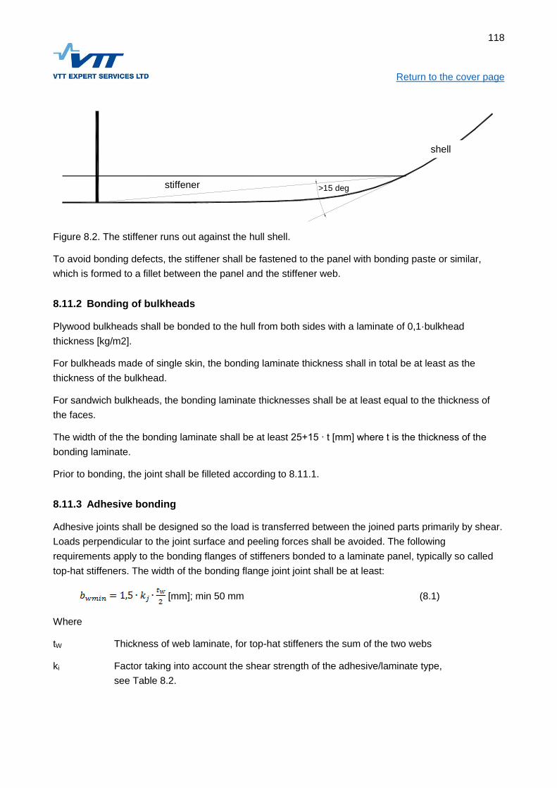
118
Return to the cover page
Figure 8.2. The stiffener runs out against the hull shell.
To avoid bonding defects, the stiffener shall be fastened to the panel with bonding paste or similar,
which is formed to a fillet between the panel and the stiffener web.
8.11.2 Bonding of bulkheads
Plywood bulkheads shall be bonded to the hull from both sides with a laminate of 0,1·bulkhead
thickness [kg/m2].
For bulkheads made of single skin, the bonding laminate thickness shall in total be at least as the
thickness of the bulkhead.
For sandwich bulkheads, the bonding laminate thicknesses shall be at least equal to the thickness of
the faces.
The width of the the bonding laminate shall be at least 25+15 ∙ t [mm] where t is the thickness of the
bonding laminate.
Prior to bonding, the joint shall be filleted according to 8.11.1.
8.11.3 Adhesive bonding
Adhesive joints shall be designed so the load is transferred between the joined parts primarily by shear.
Loads perpendicular to the joint surface and peeling forces shall be avoided. The following
requirements apply to the bonding flanges of stiffeners bonded to a laminate panel, typically so called
top-hat stiffeners. The width of the bonding flange joint joint shall be at least:
[mm]; min 50 mm (8.1)
Where
tW Thickness of web laminate, for top-hat stiffeners the sum of the two webs
ki Factor taking into account the shear strength of the adhesive/laminate type,
see Table 8.2.
>15 deg
stiffener
shell

119
Return to the cover page
Fibre reinforcement type
Fibre content by
weight [%]
Polyester or vinyl ester adhesive
Epoxy adhesive, curing in room temperature
CSM/WR /multiaxiali 35 12 7
50 14 8
Double bias 35 20 11
50 23 13
For other laminate types, the width of the bonding flange shall be determined according to
ISO 12215-6.
8.12 Other structural details
8.12.1 Openings in load-bearing structures
The effect of openings in load-carrying structures shall be taken into account.
If needed, openings shall be fitted with flanges or similar around their perimeter to avoid buckling .
With the exceptions listed below no openings are allowed in stiffeners unless a detailed calculation
shows that the stress level is below the allowable stresses according to Chapter 10 clause 10.13:
Openings in stiffener webs are not allowed in the ends within 20% of the length between support points.
No openings are allowed in the crown. In other locations openings in the webs are allowed provided the
height does not exceed 50% and the length 75% of the web height.
8.12.2 Sharp corners
Unless strengthened with unidirectional laminate, sharp corners shall be avoided.
8.12.3 Special issues for sandwich construction
In way of highly loaded fittings, the face laminates shall be reinforced and the sandwich core shall be
replaced by a material with a compressive strength of at least 2 MPa or alternatively replaced by single
skin laminate.
In way of through-hull fittings the sandwich core shall be replaced with inserts of non-organic material
with a compressive strength of at least 2 MPa or alternatively replaced by single skin laminate.
The potential danger of outer skin peeling on sandwich hulls shall be taken into account on fast craft.
8.12.4 Other structural details
Spray strips in craft in design categories A, B or C shall be reinforced with additional laminate or filled
and laminated over.

120
Return to the cover page Structures, where water can be entrapped, shall be avoided as much as possible. Where such cannot
be avoided, they shall be readily accessible (definition see Chapter 34).
Laminate inside surfaces that are exposed to water, such as bilge water, shall be painted with topcoat
or other suitable coating.

121
Return to the cover page
9 FIBRE REINFORCED PLASTICS MATERIAL
9.1 Objective
The objective with this chapter is to give requirements for the raw-materials used in structural parts of
the craft and to define the mechanical properties to be used in the scantlings determination.
9.2 References
This chapter is based on the following international standards:
ISO 12215.1:2000 - Hull construction and scantlings - Part 1: Materials: Thermosetting resins,
glass-fibre reinforcement, reference laminate.
ISO 12215-2:2002 - Hull construction and scantlings - Part 2: Materials: Core materials for
sandwich construction, embedded materials
ISO 12215-5:2008 - Hull construction and scantlings -- Part 5: Design pressures for monohulls,
design stresses, scantlings determination
9.3 Documentation
To verify the compliance with the requirements in this chapter, the following documentation is needed:
Datasheets or similar of the used raw-materials
Testreports of mechanical properties
9.4 Resins
Resins used in structural components shall meet the requirements of ISO 12215-1 as "Type A" resin.
Resin additives such as agents for adjusting tixotrophy or filling, shall be compatible with the resin.
9.5 Fiber reinforcement
Fiber reinforcements used in structural components shall meet the requirements of ISO 12215-1.
9.6 Compability of fibers with resin
There shall be documentation to show, that materials are suitable for the application in question and for
the anticipated environmental conditions. The fiber reinforcement shall have a seizing which is
compatible with the laminating resin.
Orthophtalic resin must not be used with powder bounded chopped strand mat.

122
Return to the cover page
9.7 Mechanical properties of laminates
The following requirements concern glass/polyester laminates if not stated otherwise. Requirements for
other materials shall be determined according to ISO 12215-5. Glassfibre reinforced laminates shall
fulfill the following minimum properties:
Ultimate tension stress T = 80 MPa
Tensile modulus ET = 6350 MPa
Ultimate bending stress B = 135 MPa
Flexural modulus EB = 5200 MPa
Ultimate shear stress in the plane of the laminate XY = 50 MPa
Ultimate interlaminar shear stress XZ ja YZ = 15 MPa
Mechanical properties shall be determined by testing according to paragraph 8 or by calculation using
the method in paragraph 9.
9.8 9.8. Determination of mechanical properties by testing
When the mechanical properties of laminates are determined by testing, the specimen shall be
produced using the same production processes and -parameters as when manufacturing the craft itself.
The relevant values shall be determined in the both main directions of the laminate. Unidirectional
laminates shall be tested in one direction only. The laminates shall be tested without gel- or topcoat.
The following standards shall be used for determination of mechanical properties:
Tensile stress and –modulus, ISO 527-1 ja ISO 527-4.
Compressive stress, ASTM D3410
Bending stress and modulus, ISO 178.
Shear stress, ASTM D 4255.
When measuring bending strength, the outer surface (=the outside of the hull) shall be in tension.
The average results for each tested property shall meet the requirements in 9.7. No single value shall
be less than 80% of the average value.
9.9 Determination of mechanical properties by a nominal fiber content
The mechanical properties of laminates may also be determined on the basis of a nominal fiber content
which is a function of the used reinforcement products and the manufacturing process.

123
Return to the cover page
9.9.1 Nominal fiber content
The nominal fiber content, , which is expressed in percent by weight, shall be taken as follows. The
formulae are valid for laminates reinforced by glassfibre. For other fiber types the nominal fiber content
shall be determined according to ISO 12215-5.
Chopped strand mat (CSM) laminates = 30%
CSM / woven rowing laminates = 46-18∙R, where R = proportion of CSM
Multidirectional laminate = 50%
Unidirectional laminates = 55%
9.9.2 Mechanical properties
The mechanical properties of laminates is determined from Figure 9.1...9.6 based on the nominal fiber
content. The figures apply to laminates reinforced by chopped strand mat and/or balanced woven
rowing and for unidirectional laminates. The mechanical properties for "Double Bias" (±45o fabrics) and
multiaxial fabrics shall be determined according to ISO 12215-5.
Requirements from paragraph 12 shall be met when acquiring values from figures 9.1...9.6.
When assessing the compliance according to Chapter 10, the laminate thickness requirements shall be
converted to reinforcement area mass using Figure 9.8 which is based on ISO 12215-5 Annex C.
9.10 Sandwich core materials
Sandwich core materials in structural components of the craft shall meet the requirements of
ISO 12215-2 "Grade 1."
9.10.1 Mechanical properties of sandwich core materials
Unless samples have been tested from the actual batch used for the craft in question, the mechanical
properties of sandwich core materials shall be determined on the basis of the material, the elongation to
break and the density of the material using Figures 9.8...9.11.
9.11 Values to be used for scantling determination
The values used for scantling determination depend on the level of production control.
If the mechanical properties have been determined by testing, and the tested laminates correspond to
the laminate for the structural part in question, the values to be used for scantling determination are:
For tensile-, compressive-, bending- and shear strength, the smallest of the following
90% of the average, µ, value obtained in the tests;
The average value µ minus two standard deviations;

124
Return to the cover page For the modulus, the average value obtained from the test shall be used.
If no testing has been carried out, but the fiber content is regularly monitored in the production, the
values determined according to paragraph 8 are to be used without further correction for scantling
determination.
If no testing has been carried out and no monitoring of fiber content during production is done, the
values determined according to paragraph 8 are to be multiplied by 0,8 for scantling determination.
For sandwich core materials, the values obtained from paragraph 10.1 shall be used without further
correction.
9.12 Adhesives
Adhesives to be used in structural components are to be intended for the combination of materials in
question.
For bonding sandwich faces to the core, adhesives developed for that purpose shall be used.
Alternatively, shop-made adhesives of the same resin type that is used for lamination may be used.
9.13 Other materials
Plywood shall be water resistant type and its adhesives shall meet the requirements from WBP
standard B.S. 6566 part 8.
Embedded materials such as reinforcements for fittings etc. shall meet the requirements in
ISO 12215-3.

125
Return to the cover page
50
100
150
200
250
300
350
400
450
500
550
30 35 40 45 50 55 60
Fibre content by weight, %
Ultim
ate
tensile
str
ess,
MP
a
UD
CSM&WR
Figure 9.1. Ultimate tensile stress for chopped strand mat/woven rowing laminates and unidirectional
laminates as a function of nominal fiber content.
100
150
200
250
300
350
30 35 40 45 50 55 60
Fibre content by weight, %
Ultim
ate
com
pre
ssiv
e s
tress,
MP
a
UD
CSM&WR
Figure 9.2. Ultimate compressive stress for chopped strand mat/woven rowing laminates and
unidirectional laminates as a function of nominal fiber content.

126
Return to the cover page
140
160
180
200
220
240
260
280
300
30 35 40 45 50 55 60
Fibre content by weight, %
Ultim
ate
fle
xura
l str
ess,
MP
a
CSM&WR
Figure 9.3. Ultimate flexural stress for chopped strand mat/woven rowing laminates and unidirectional
laminates as a function of nominal fiber content.
5000
10000
15000
20000
25000
30000
30 35 40 45 50 55 60
Fibre content by weight, %
Modulu
s,
MP
a
UD
CSM&WR
Figure 9.4. Modulus of elasticity for chopped strand mat/woven rowing laminates and unidirectional
laminates as a function of nominal fiber content.

127
Return to the cover page
60
65
70
75
80
85
90
30 35 40 45 50 55 60
Fibre content by weight, %
In-p
lane s
hear
str
ess,
MP
a
CSM&WR
Figure 9.5. Ultimate shear stress in the plane of the laminate for chopped strand mat/woven rowing
laminates as a function of nominal fiber content.
10
11
12
13
14
15
16
17
18
19
20
30 35 40 45 50 55 60
Lujitepitoisuus, paino-%
Inte
rlam
inar
shear
str
ess,
MP
a
CSM&WR
Figure 9.6. Ultimate interlaminar shear stress for chopped strand mat/woven rowing as a function of
nominal fiber content.

128
Return to the cover page
0,400
0,500
0,600
0,700
0,800
0,900
1,000
1,100
1,200
1,300
1,400
30 35 40 45 50 55 60 65 70
Fibre content by weight %
Fib
re a
rea w
eig
ht/
mm
lam
inate
th
ickn
ess,
kg
/m2
Figure 9.7. Reinforcement area mass as a function of fiber content.

129
Return to the cover page
0,0
0,5
1,0
1,5
2,0
2,5
3,0
40 60 80 100 120 140 160 180 200
Ultim
ate
shear
str
ess, M
Pa
Density, kg/m3
Balsa
PVC Crosslinked 1
PVC Crosslinked 2
PVC Linear
SAN
Figure 9.8. Ultimate shear stress for structural polymer foams as a function of density.

130
Return to the cover page
0
10
20
30
40
50
60
70
80
90
100
40 90 140 190 240
Sh
ea
r m
od
ulu
s, M
Pa
.
Density, kg/m3
PVC Crosslinked 1
PVC Crosslinked 2
PVC Linear
SAN
Figure 9.9. Shear modulus for structural foam materials as a function of density.

131
Return to the cover page
60
80
100
120
140
160
180
200
90 110 130 150 170 190 210 230
Sh
ea
r m
od
ulu
s, M
Pa
.
Density, balsa, kg/m3
Figure 9.10. Shear modulus of end grain balsa as a function of density

132
Return to the cover page
0,0
0,5
1,0
1,5
2,0
2,5
3,0
3,5
4,0
4,5
5,0
40 60 80 100 120 140 160 180 200
Ultim
ate
co
mp
ressiv
e s
tre
ss, M
Pa
.
Density, kg/m3
PVC Crosslinked 1
PVC Crosslinked 2
PVC Linear
SAN
Figure 9.11. Ultimate compressive stress for structural polymer foams as a function of density.

133
Return to the cover page
1300
1800
2300
2800
3300
3800
4300
80 100 120 140 160 180 200
Com
pre
ssiv
e m
od
ulu
s, M
Pa
.
Density, kg/m3
Figure 9.12 Compressive modulus of end grain balsa as a function of density

134
Return to the cover page
10 SCANTLINGS DETERMINATION, FIBRE REINFORCED PLASTICS
10.1 Objective
In this chapter is given equations and allowable stresses for the determination of scantlings for strength
members made of fiber-reinforced plastics.
Formulae in this chapter are intende to be used only used with loads defined in Chapter 7, material
values from Chapter 9 following the assumptions and principles presented in Chapter 8.
10.2 References
The scantlings equations given in this chapter are those of the international standard ISO 12215-5:2008
Small craft – Hull construction and scantlings – Part 5: Design pressures for monohulls, design
stresses, scantlings determination.
Compared with the standard, however, higher minimum reinforcement requirements based on craft
length, displacement and speed for minimum strength against local loads are given. In addition, the
allowable stresses are in some cases smaller in to reflect the more demanding use of commercial craft.
In addition, the following standards are referred to for RIB’s:
EN ISO 6185-3:2014 Inflatable boats - Part 3: Boats with a hull length less than 8 m with a
motor rating of 15 kW and greater
EN ISO 6185-4:2011 + Corr. 2014 Inflatable boats. Boats with a hull length of between 8 m and
24 m with a motor power rating of 15 kW and greater
10.3 Documentation
To verify requirements in this chapter, following documentation is required:
Structural drawings, including the following where relevant:
o Longitudinal section;
o Transverse sections;
o Laminate schedule;
o The materials used and their mechanical properties (see Chapter 9);
Scantling calculations indicating the rule requirements for different structural elements and the
attained values.;
10.4 List of symbols
Symbols used in several Chapters are given in Chapter 1. In Table 10.1 some symbols used in this
Chapter are listed. In addition, there are symbols defined in their context.

135
Return to the cover page Table 10.1: Symbols used in this Chapter
Symbo Unit Description Reference
p kPa Design pressure Chapter 7
l mm Shorter side of panel
b mm Longer side of panel
s mm Stiffener space, load width
lU mm Unsupported span of stiffener
t mm Laminate thickness
W cm3 Section modulus
I cm4 Second moment of area
E MPa Elasticy modulus
kC - Correction for curvature Clause 8.1
σd MPa Allowable tensile/compressive stress Clause 12
τd MPa Allowable shear stress Clause 12
10.5 Dimension of panels
The dimensions of panels are given for some typical cases in Figure 10.1.
a) Rectangle shaped panel. Note, that l and b are measured to the web of the stiffener.

136
Return to the cover page
b)
Some other shapes
Figure 10.1 Measures for typical panels
10.6 Scantlings requirements, single skin panels
For single-skin panels, the laminate thickness, excluding gel and topcoats, shall not be less than
obtained from formula (10.1):
[mm]; (10.1)
Where
kC = curvature correction factor, see 10.9.1
P = design pressure, see Chapter 7.
k2 = panel aspect correction factor, see. 10.9.2
D = allowable stress. see 10.13.
The laminate thickness shall never be less than tmin according to Table 10.2.
The thickness requirements obtained from formulae 10.1 Table 10.2 shall be converted to required area
mass of reinforcement as described in Chapter 9 paragraph 9.3.
Note! If the clamping of an edge of a panel is less than that of a panel continuing past its edge
stiffeners, the thickness requirement must be adjusted to conform to the actual edge clamping.

137
Return to the cover page
10.7 Scantlings requirement, sandwich panels
10.7.1 Bending strength criterion
The section modulus of a 1 cm strip of the sandwich panel, WO, calculated to the outer (loaded) surface
and WI calculated to the inner side shall be not less than given in formulae 10.2 and 10.3:
[cm3] (10.2)
[cm3] (10.3)
Where
k2 correction factor for flexural stress based on panel aspect ratio.
dto allowable tensile stress in outer face [MPa] see Clause 10.13.
or 0,5·CU whichever is less, [MPa] (10.4)
And
EC Elasticity modulus of inner face, [MPa]
ECO Elasticity modulus in compression for sandwich core, [MPa]
GC Shear modulus of the sandwich core, [MPa]
CU Ultimate compressive stress of laminate, [MPa]
Note! If the clamping of an edge of a panel is less than that of a panel continuing past its edge
stiffeners, the thickness requirement must be adjusted to conform to the actual edge clamping.
10.7.2 Stiffness criterion
The second moment of area of a 1 cm strip of the sandwich panel shall be not less than given in
formulae 10.5:
[cm4] (10.5.)
Where
k1 stiffness factor = 0,017
k3 stiffness correction based on panel aspect ratio, see Clause 10.9.2.
Note! In addition, the requirement in Chapter 8 Clause 8.10.2 shall be met.
When determining the moment of inertia, the thicknesses shall be calculated with the nominal fibre
content as described in Chapter 9 paragraph 9.9.1.

138
Return to the cover page
10.7.3 Shear criterion
The thickness of a sandwich panel measured as the distance between the mid-points of the skins must
be at least as given by formula 10.6:
[mm] (10.6)
Where
[mm] (10.7)
And
kSHC shear stress factor based on panel aspect ratio, see Clause 10.9.2.
tC core thickness, mm
ti thickness of inner sandwich skin, mm
to thickness of outer sandwich skin, mm
10.7.4 Sandwich core minimum compressive strength in hull bottom
The compressive strength of sandwich core material used in hull bottom shall be at least as given by
formula 10.8.
C=0,01∙PBMPBASE, MPa, kuitenkin vähintään 1,0 MPa (10.8)
Where
PPMPBASE bottom slamming pressure, see Chapter 7 formula 7.5.
10.8 Minimum amount of fiber reinforcement for local strength
In addition to the requirements on bending strength, -stiffness and shear load capacity, the mass of the
total laminate reinforcement per square meter, wmin, must be at least as indicated by the formula below.
[kg/m2] (10.9)
The speed used in the formula must be at least 5·√ LWL. The constant A and the factors k5, k7 and k8
are found in Table 10.2.

139
Return to the cover page Table 10.2: Constants and factors to be used in formula 10.9
Area A k5 k7 k8 Sandwich outer skin
Hull bottom 1,5 1) 0,03 0,15 k5 0,6 wMIN
Hull topside and
transom 1,5 1) 0 0,15 k5 0,6 wMIN
Decks for persons,
superstructures 1,5 + 0,2 ∙ LH 1) 0 0 k5 0,6 wMIN
Cargo decks,
load Q [t/m2] 3 + 0,5 ∙ Q + 0,15 ∙ LH 1) 0 0 k5 0,6 wMIN
1) Correction factor k5:
1,00 for E glass laminate with more than 50% chopped strand mat and the rest woven rowing and/or biaxial.
0,90 for E glass laminate with not more than 50% chopped strand mat and the rest woven
rowing and/or biaxial.
0,70 for Aramid and/or HS carbon fiber laminates consisting of woven and/or bi or multiaxial
reinforcements
10.9 Correction factors for panels
10.9.1 Correction for panel curvature
The correction factor kc takes into account the effect the panel curvature has on the flexural strength
and flexural rigidity, and on the shear stress of the sandwich panels. It is calculated according to
Table 10.3.
Figure 10.2. Measurements needed for correction for curvature.
b
b
c
c

140
Return to the cover page Table 10.3. Panel curvature factor kc.
c/b kC
0…0,03 1,0
0,03…0,18 1,1 - 3,33 ∙ c/b
>0,18 0,5
10.10 Correction based on panel aspect ratio
Correction factors based on panel aspect ratio to be used in formulae 10.1-10.6, are found Table 10.4.
Table 10.4. Correction factors on the basis of panel aspect ratio
Aspect ratio Correction factor for
bending stress
Correction factor for
bending stiffness
Correction factor for
shear stress 1)
l/b k2 k3 kSHC
>2,0 0,500 0,028 0,465
2,0 0,497 0,028 0,463
1,9 0,493 0,027 0,459
1,8 0,487 0,027 0,453
1,7 0,479 0,026 0,445
1,6 0,468 0,025 0,435
1,5 0,454 0,024 0,424
1,4 0,436 0,023 0,410
1,3 0,412 0,021 0,395
1,2 0,383 0,019 0,378
1,1 0,349 0,016 0,360
1,0 0,308 0,014 0,339
10.11 Stiffeners
10.11.1 General
The following requirements apply to stiffeners made from similar laminates. If the rigidity of the crown,
web or base laminate of a stiffener does not differ by more than 25% from each other, the flexural
strength and rigidity of the stiffener may be estimated using the section modulus or moment of inertia.
In other cases, the method for orthotropic stiffeners in ISO 12215-5 shall be used.
10.11.2 Section modulus
The section modulus calculated to the outer face (loaded side), Wo, and inner side, Wi, shall be at least
as given by equations 10.10 and 10.11.

141
Return to the cover page
[cm3] (10.10)
[cm3] (10.11)
Where
lU stiffener span, not needed to be taken greater than 330·LH [mm]
kCS correction factor for stiffener curvature, see Table 10.5.
di design stress for inner skin laminate, [MPa], see clause 10.13
do design stress for outer skin laminate, [MPa], see clause 10.13
Table 10.5: Correction factor for stiffener curvature, kCS
cU/lU kCS
0…0,03 1,0
0,03…0,18 1,1 – 3,33 ∙ cU/lU
0,18… 0,5
When calculating the section modulus of the actual stiffener, the laminate thicknesses shall be
determined for the appropriate fiber content for the laminate in question according to Chapter 9
clause 9.9.1.
If the end fixity of one or both ends of the stiffener differs from the situation, where a stiffener is
continuous over its support points, the required section modulus shall be corrected to correspond to the
real end fixity.
10.11.3 Second moment of area
The second moment of area, I, including effective flange according to Clause 9.4, shall be at least as
given by formula 10.12.
[cm4] (10.12)
Where
lU stiffener span, not needed to be taken greater than 330·LH [mm]
kCS correction factor for stiffener curvature, see Table 10.5.
ETC average value of tensile and compressive moduli, [MPa]
k1S stiffness factor=0,05
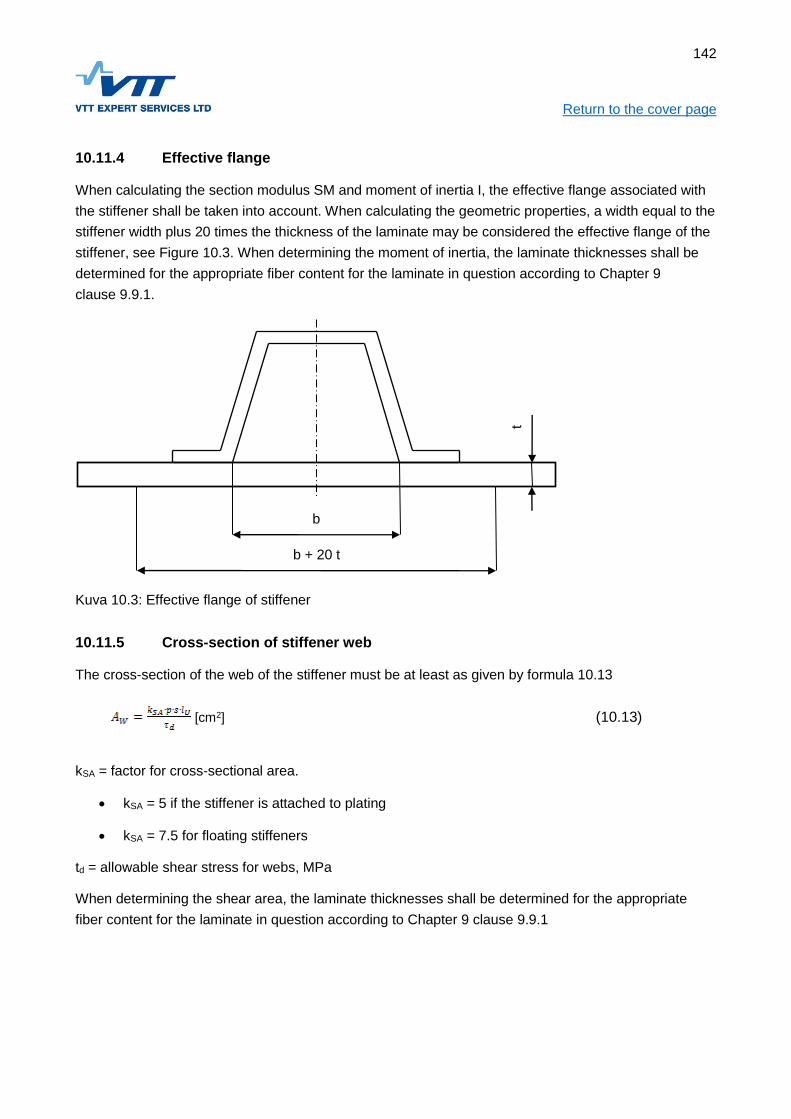
142
Return to the cover page
10.11.4 Effective flange
When calculating the section modulus SM and moment of inertia I, the effective flange associated with
the stiffener shall be taken into account. When calculating the geometric properties, a width equal to the
stiffener width plus 20 times the thickness of the laminate may be considered the effective flange of the
stiffener, see Figure 10.3. When determining the moment of inertia, the laminate thicknesses shall be
determined for the appropriate fiber content for the laminate in question according to Chapter 9
clause 9.9.1.
Kuva 10.3: Effective flange of stiffener
10.11.5 Cross-section of stiffener web
The cross-section of the web of the stiffener must be at least as given by formula 10.13
[cm2] (10.13)
kSA = factor for cross-sectional area.
kSA = 5 if the stiffener is attached to plating
kSA = 7.5 for floating stiffeners
td = allowable shear stress for webs, MPa
When determining the shear area, the laminate thicknesses shall be determined for the appropriate
fiber content for the laminate in question according to Chapter 9 clause 9.9.1
b
b + 20 t
t

143
Return to the cover page
10.11.6 Orthotropic stiffeners
Stiffeners built with laminates with moduli that differ by more than 25% from each other are to be
assessed using the procedure presented in the standard ISO 12215-5.
10.11.7 Buckling of stiffeners
Where the normal stress in the crown or flanges or the shear stress in the web exceeds 80% of
allowable stress, the potential risk of stiffener buckling must be estimated using the procedure
presented in the standard ISO 12215-5.
10.12 Reinforced shell areas
Where applicable, the strengthened areas of the hull must conform to Figure 10.3
Figure 10.4. Reinforced laminate areas
10.12.1 Reinforced keel
Keel structures shall be strengthened to sustain loads from docking and/or transporting the craft on a
trailer. This requirement is considered to be fulfilled, when the requirements for the keel laminates and
section modulus presented in Table 10.6 are met. The section modulus of the keel is also to be
assessed as a bottom stiffener.
10.12.2 Reinforced stem
The stem post shall be reinforced as given in Table 10.6
10.12.3 Reinforced chine
The corners of chines including the sharp corner of transoms, must be strengthened for their entire
length according to Figure 10.4 and Table 10.6
Chine reinforcement
Keel reinforcement
Stem reinforcement

144
Return to the cover page
10.12.4 Edge of deck and hull/deck joint
If the edge of the deck or the hull/deck joint is the widest part of the craft, they are to be strengthened to
withstand loads from collision with piers, docking and handling of the craft ashore. The deck edge or
hull/deck joint usually functions as a stiffener for hull topsides. The hull/deck joint shall be watertight for
craft in design category A, B and C.
Table 10.6: Reinforced laminate areas, minimum fibre mass.
Structural member
Width on both sides of
centreline
Single skin [kg/m2]
Sandwich outer skin
Inner skin = 0,7 ·outer skin [kg/m2]
wMIN = Eq. 10.9
Keel 80 ∙ BH 1,0 + 2,2wMIN (bottom) 1) 1,7 wMIN (bottom) 1)
Stem post 40 ∙ BH 1,0 + 2,0wMIN (bottom) 1) 1,5 wMIN (bottom) 1)
Chine 40 ∙ BH 1,0 + 1,7wMIN (bottom) 1) 1,2 wMIN (bottom) 1)
1)see 10.8
10.13 Highly loaded structures
10.13.1 Engine foundations
Engine foundations shall be strong and stiff enough to carry the weight and loads of the engine. Such
loads are:
Weight of the engine and additional dynamic forces from craft’s motion;
Propulsion force (in cases where no thrust bearing is fitted);
Torsion from the propeller;
Vibration.
Engine foundations must be securely fixed primary athwarthship stiffeners like bulkheads or similar at
both ends. Foundations shall be supported against buckling and collapsing, especially near engine
holding down bolts.
Areas where the engine is fixed to the foundation must be strengthened with metal or a corresponding
material.
10.13.2 Transoms for outboard and sterndrive engines
The transom design should ensure that the moment, mass forces and thrust from the outboard engine
or sterndrive will be transferred into the primary structure without creating excessive stresses.
For engines with big power, the transom shall be engineered using the design loads given in Chapter 7
Clause 7.10.6.

145
Return to the cover page For craft with smaller engine power, the following requirements apply, assuming sandwich construction
of the transom.
The core is to consist of plywood, high density foam or corresponding material with a ultimate
compressive stress of 4 MPa. If plywood is used, it has to be of durability class 1 or 2 according to ISO
12215-3:2002.
The thickness of the transom, measured between centers of skin laminates, shall be at least as given
by formula (10.14)
[mm] (10.14)
Where
P = total engine power installed on the transom, [kW]
The skin laminates shall be at least as given by formula (10.15)
min. 1,40 kg/m2 (10.15)
10.13.3 Attachment of mooring and other highly loaded fittings
The foundations of mooring and towing fittings, rails, pulpits, lifeline stanchions, winches and similar
items must be dimensioned to withstand loads as per ISO 15084.
10.13.4 Attachment of railings, handholds and lifeline hooking points
Attachment of railings, handholds and lifeline hooking points shall meet the requirements of ISO 15085.
10.13.5 Design of attachment points
The reinforcement of single-skin laminate at highly loaded fittings shall in general be carried out by
adding additional laminate, installing plywood or metal reinforcements, or a combination of these.
Where highly loaded fittings are fixed to sandwich laminates, the core shall either have sufficient
compressive strength or be replaced with spacers or single-skin laminate. The sandwich faces shall be
locally reinforced with additional laminate.
10.13.6 Attachment of RIB-pontoon
The attachment of the RIB-pontoon to the rigid hull shall be designed to transmit the loads without
stress peaks. Special attention shall be paid to the attachment in the bow and stern. The attachment
shall be tested according to ISO 6185-3 for craft with a hull length of less than 8 m and ISO 6185-4 for
bigger craft.

146
Return to the cover page
10.14 Design stresses
The design stresses to be used in the equations in this chapter are presented in Table 10.7. The
determination of mechanical properties for composite materials, upon which the design stresses are
based, is described in Chapter 8.
Table 10.7 Design stresses
Structural member Detail Design stress
Single skin panels σUF/3,00
Sandwich panels Outer skin, do σUC/2,00
Inner skin, di σUT/2,00
Sandwich core shear stress
Balsa τU/3,00
Foam, elongation < 20 % τU/2,73
Foam, elongation > 20 % τU/2,31
Stiffeners
Crown σUC/2,00
Attached plate σUT/2,00
Webs τXY/2,00

147
Return to the cover page
11 PRODUCTION OF FIBRE-REINFORCED PLASTIC CRAFT
11.1 Objective
The requirements in this chapter apply to the manufacturing of craft of fiber reinforced plastics. A
prerequisite for applying the rules in this chapter is that the raw-materials, the structure and scantlings
meet the requirements in Chapters 8, 9 and 10 respectively.
The rules apply to individually built craft and, as applicable, to series built boats.
11.2 References
The requirements are partly based on the international standard ISO 12215-4 - Small craft — Hull
construction and scantlings —Part 4: Workshop and manufacturing
11.3 Documentation
To verify the compliance with the requirements in this chapter, a production report for each individual
craft is to be prepared. The report shall be readily identifiable by means of the Craft Identification Code,
the yards' newbuilding number or similar and shall include the following information as relevant:
Reference to the laminate schedule, see Chapter 10;
The manufaturer, typecodes and batch numbers of the used laminating resins, fiber
reinforcements, sandwich core materials;
Lamination log (i.e. the sequence of reinforcement layers, curing, possible surface treatment
after curing);
Temperature and humidity log for the lamination area during the lamination and curing
Reports of possible problems encountered during lamination and the remedy
Thickness gauging report of the hull laminate
Reports of mechanical tests and / or determination of fiber content
11.4 Workshop conditions
The laminating shop shall be substantially free from draughts so that the temperature can be kept
constant during the laminating process. Ventilation systems shall ensure a suitable production
environment throughout the entire lamination area.
The ambient temperature (i.e. temperature in the laminating shop) shall fulfill requirements by resin
manufacturer or be at least 18° and the variation during the moulding process shall not be more than ±3
°C from the required nominal temperature. This temperature shall be reached at least 24 hours before
the moulding starts.

148
Return to the cover page A higher temperature is permitted during the curing process or in a separate curing space.
The lamination shop shall be insulated and built in such a way that the indoor temperature is not
significantly affected by the outdoor temperature or sunlight. Windows shall be painted over or
screened off if they are subject to direct sunlight.
The relative air humidity shall be as constant as possible and shall not exceed 80%. When using a
spray lay-up technique, the relative air humidity shall be at least 40%.
Temperature and humidity shall be regularly recorded during the lamination and at least 48 hours after
the lamination.
The moulding shop shall be clean and substantially free of dust. Grinding and woodworking shall be
avoided during lamination and, when necessary, the laminate shall be cleaned thoroughly before
continuing lamination.
11.5 Material storage
The purchase-, receiving- and storage processes shall assure that:
The correct type of material is used for every craft;
It can be traced which batch of raw-material is used for a particular craft.
Storage premises shall be dry and clean. In particular, packages of glassfibre reinforcement and
sandwich core material shall be kept free from dust and moisture.
Raw materials shall be stored according to the raw-material manufacturer's recommendation. Materials,
which have passed their expiry date must not be used for load-carrying structures.
Storage tanks for resin shall be equipped with an effective means of stirring which is to be carried out
regularly.
Fibre reinforcements shall be kept for at least 48 hours at a temperature at least 2 oC higher and at a
lower humidity than that of the moulding shop before they are transferred there. If the glassfibre has
been sealed in plastic, the package shall be opened and kept for at least 48 hours in the moulding shop
prior to use.
11.6 Lamination
11.6.1 Requirements for all types of laminates
All materials shall be according to the laminate schedule.
The amount and mixing of catalyst or hardener shall be according to the resin manufacturer's
recommendation.

149
Return to the cover page The reinforcement layers shall be applied in the sequence shown on the lamination drawings. The
coverage, fiber directions, overlapping, layer drop-off and other details shall be according to the
lamination drawings.
The lamination sequence shall be recorded such that it can be compared with the lamination drawings.
The fiber content of the cured laminate shall correspond to the nominal fiber content (see Chapter 9).
The amount of laminate to be laminated at one time, shall be planned such that the pot-life of the resin
is not exceeded.
When laminating thick layers, care shall be taken not to damage the laminate by exothermic heat (the
heat distortion temperature or glass transition temperature is not to be exceeded).
11.6.2 Polyester- and vinylester laminates
On all external surfaces there shall be an even gelcoat layer or an equivalent surface treatment applied
after the lamination. The gelcoat shall have a thickness of 0.4 - 6 mm and shall be applied without
significant thickness variation
As a minimum, the outermost layer of the hull laminate shall be made with isophtalic resin or vinylester
resin. If the hull is made entirely using orthophtalic resin, the area beneath the loaded waterline plus
100 mm shall be treated with a minimum of two layers of epoxy paint
Powder-bound mat max 450g/m2 shall in general be used as the first reinforcement layer after the
gelcoat in the hull.
In areas where no topcoat is applied, the final layer of the laminate shall contain paraffin or similar to
prevent styrene evaporation and ensure that the curing will be satisfactory.
11.6.3 Epoxy laminates
If gelcoat is used together with epoxy laminate, the compatibility shall be documented
A layer of peel-ply shall be applied as the final layer before every curing. The peel-ply shall not be
removed until the secondary lamination commences.
11.7 Sandwich construction
The type, thickness and density of the sandwich core shall be according to the laminating drawings.
Sandwich core materials with open cells on the surface shall be impregnated with resin or filling putty
before bonding the core to the laminate.
When using core materials which are grid-scored, it shall be ensured that all cavities are filled with resin
or putty.
When bonding sandwich cores to wet laminate without vacuum-bagging, the uncured laminate shall be
at least 450 g/m2 on straight surfaces and 900 g/m2 on curved surfaces.

150
Return to the cover page Sandwich cores without grid-scoring shall be bonded to the wet laminate with vacuum-bagging, evenly
distributed weight or similar to ensure a good bond.
All joints and cavities in the core shall be filled with resin or putty before lamination is commenced. All
unevennesses shall be removed.
Other techniques such as vacuum bagging may be used with less adhesive than required above if it
can be demonstrated, that it results in an effective bond.
11.8 Secondary lamination
11.8.1 Polyester- and vinylester laminates
The surface treatment prior to secondary lamination shall be carried out in accordance with the resin
manufacturer's recommendations. The following requirements are to be met as a minimum where no
such recommendations are given:
The cured laminate shall always be at least lightly sanded to remove irregularities from the
surface before secondary lamination.
When secondary lamination is started more than 48 hours after lamination of the previous layer,
the laminate shall be grinded to expose fibers on the surface. All dust is to be removed.
If there is paraffin on the surface, it shall be removed by washing or similar unless the previous
lamination is so fresh that the paraffin will dilute into the next laminate layer.
Gel- and topcoat shall always be removed from the bonding area before secondary bonding.
Where peel-ply has been used, no sanding is required.
11.8.2 Epoxy laminates
After removal of the peel-ply possible (small) areas where the peel-ply has not been in contact with the
laminate surface shall be sanded so to achieve a matt surface, and all dust shall be removed. After that
the surface is to be washed with acetone unless it can be demonstrated by testing that an acceptable
interlaminar shear strength (ILSS) can be achieved without acetone washing.
If the laminate has cured without peel-ply, the surface is to be washed with warm water or acetone, and
let to dry. After that the surface is to be sanded thoroughly and cleaned with acetone prior to secondary
lamination.
11.9 Adhesive bonding
Adhesive bonding shall be carried out according to the adhesive manufacturer's recommendation.
Particularly, attention shall be given to the surface treatment of the bonding surfaces, the control of the
bondline thickness and the usable working time to assemble the components to be bonded.

151
Return to the cover page
11.10 Curing
Gelcoat must not cure more than 24 hours before the first laminate layer is applied
With the exception of trimming the edges, the laminate must not be machined or be subject to loads
during the curing.
The ambient temperature during curing must not be so high that the heat distortion temperature (HDT)
for polyester and vinylester or the glass transition temperature for epoxies is reached in the laminate.
The curing shall be carried out within the temperature range recommended by the resin manufacturer.
When demoulding the cured components, they are to be properly supported to avoid distortion until all
stiffeners are fitted.
11.11 Thickness gauging
The objective of the thickness gauging is to check, that the laminate is manufactured according to the
laminating drawings. The measured thicknesses may be compared to the laminate thickness
requirements calculated using the nominal fiber content (see Chapter 9 paragraph 9.2). Alternatively,
the total fiber reinforcement area mass in the laminate can be approximatively determined on basis of
the nominal fiber content and compared to the laminate drawings. The thickness gauging may be
carried out using any of the following methods:
With an reconized NDT-method after demoulding;
By measuring directly from cut-outs in the laminate.
The thickness may be measured including gel- and topcoat, but in such case 0,6 mm shall be deducted
from the measured thickness for the gelcoat and 0,4 mm for the topcoat
The thickness requirement is deemed to pass the requirement if, for the laminate area in question, the
mean value of measurements exceeds the requirement from Chapter 10. In addition, no single
measurement must not be less than 85% of the thickness requirement
11.12 Material testing
It shall be ensured, that the used raw materials in conjunction with the manufacturing process results in
mechanical properties of the laminate which are at least as the assumed values for determination of the
scantlings. The production control is connected to the assumptions in the scantling calculations through
the mechanical properties of the laminates. There are three levels of production controls to choose
from. These depend on the extent of the mechanical testing and monitoring of fiber content (see
Chapter 9 Clause 9.11).
Mechanical testing shall be carried out according to the standards listed in Chapter 9.

152
Return to the cover page
12 STRUCTURAL DESIGN PRINCIPLES, ALUMINIUM
12.1 Objective
In this chapter is given requirements for the structural arrangement and the details of the structure. In
addition, the principles for the assessment of the structure are defined. The purpose of the
requirements presented in this chapter is to ensure that the structural arrangement and details of the
craft has been carried out correctly taking into account the special properties of aluminium and that the
procedures for assessing the structure are unambiguous.
This Chapter is to be used in conjunction with Chapter 7 (Design pressures and loads), Chapter 13
(Aluminium materials), Chapter 14 (Scantlings, aluminium craft) and Chapter 15 (Production of
aluminium craft)
12.2 References
Requirements in chis chapter are partly based on international standard ISO 12215-6:2008. Small craft
- Hull construction and scantlings -- Part 6: Structural arrangements and details.
12.3 Principles of structural analysis
12.3.1 Simplified calculation method
If the following conditions are met the scantlings may be analysed using the simplified calculation
method:
The structural arrangement is according to clause 6;
The assumptions in clause 4 are valid;
The craft does not have features, which makes it critical to global loads, see clause 12.5.
The "Simplified calculation method" means that the scantlings are determined using the formulae for
panels, stiffeners etc. given in Chapter 14 using the loads in Chapter 7 and the allowable stresses given
in Chapter 14.
12.3.2 Direct calculation of stresses and strains
For other cases than those mentioned in 12.3.1, general methods of strength of materials shall be
followed. For such analysis, the loads given in Chapter 7 and the design stresses given in Chapter 13
shall be used.

153
Return to the cover page
12.4 Assumptions
12.4.1 Assumptions regarding local vs. global strength and stiffness
The scantling determination method presented in Chapter 14 is based on dimensioning against local
loads. Normally, this will result in scantlings, which are adequate also for global loads. Where this is not
the case, the dimensioning against global loads shall be assessed, see paragraph 12.5.
12.4.2 Hierarchy of the load carrying elements
When calculating requirements for panels and stiffeners according to Chapter 14, the hierarchy of
structure is assumed to adhere to the following principles:
The panel is supported by secondary stiffeners supported by primary stiffeners as indicated in Figure 12.1
The primary stiffeners are at least twice as stiff as the secondary stiffeners, i.e:
(12.1)
The load is uniformly distributed;
The edges of the panel are clamped;
The ends of the stiffeners are fixed.

154
Return to the cover page
Figure 12.1. Hierarchy of stiffeners.
12.5 Global strength and stiffness
In the following cases also the global strength and stiffness must be investigated:
If the bottom is only transversely stiffened and its relative speed V/√LWL>6
If there are (large) openings in the deck;
If the ratio of the hull length to the hull depth LH/DMAX>12
The global strength and stiffness shall be determined according to ISO 12215-6 Annex D. At least the
deck shall be checked against buckling (compressive stress in the deck). For craft with only transverse
stiffening in the bottom also the strength of the bottom shall be checked.
For multihull craft, the strength shall be assessed in the global load cases given in Chapter 7.
12.6 Structural arrangement
12.6.1 Displacement craft, design category D
Boats in design category D with V/√LWL≤6, may be stiffened by the keel, gunwale and transverse
stiffeners alone. Boats in higher design categories may only be stiffened by transverse framing alone if
an assessment of the global strength and stiffness is carried out, see paragraph 12.5.
Support for primary stiffener
(for ex. keel)
Primary stiffener (for ex. Web-frame)
Load area for primary
stiffener
Load area for
secondary stiffener
Secondary stiffener Support for primary stiffener
(for ex. chine)

155
Return to the cover page
12.6.2 Planing craft
Boats with V/√LWL>6, should in general have longitudinal stiffening in the bottom. The details of
longitudinal stiffeners shall meet the requirements of paragraph 7.
12.6.3 Support for longitudinal stiffeners
The bottom longitudinal stiffeners shall in general be suppoerted by transverse stiffeners such as
bulkheads, web frames or deep floors, which are to be designed to carry the load acting on the hull
area in question, see Figure 12.1. Principle of load areas. The details of transverse stiffeners shall meet
the requirements in paragraph 12.7.
12.6.4 Keels, stem and chines
The craft shall have a reinforced keel, stem and chines according to Chapter 14.
12.6.5 Torsional stiffness and -strength
The torsional strength and stiffness is considered adequate if the craft has one of the following items:
A full deck;
Tranverse bulkheads;
A strengthened bulwark.
12.6.6 Superstructure support points
The loads imposed by superstructures shall be led into bulkheads, webframes or other primary
structure.
12.7 Hull stiffeners
12.7.1 Continuity and termination of stiffeners
In craft where V /√LWL>6, the bottom longitudinal stiffeners shall be continuous. Terminating of
stiffeners on a panel between stiffeners shall be avoided. With the exceptions of paragraph 12.9.2, the
ends of stiffeners shall be fastened to other stiffeners
12.7.2 Straightness and local discontinuities of stiffeners
Hull stiffeners shall be as straight as possible. At most 30 degrees are accepted, provided buckling
support is arranged at the points where the direction change. Aprupt changes is the cross section of the
stiffeners shall be avoided. If the stiffeners have local discontinuities, the transition shall be smooth and
corners shall be rounded, radius at least 30 mm.

156
Return to the cover page
12.7.3 Safety against buckling
The cross section of stiffeners shall be such that they are not prone to buckling. Stiffeners with one web
without flange are not allowed at bottom area. Stiffeners with one web must not be fastened at an angle
exceeding 30 degrees relative to the normal against the panel.
12.7.4 Transverse stiffeners
The hull transverse stiffeners such as bulkheads, webframes and deep floors, shall extend from side to
side of the hull. If the section modulus of the keel meets the requirements in chapter 14 paragraph 8,
the stiffeners span may be taken to the keel when calculating the section modulus requirement
according to chapter 14 paragraph 5, else the distance between the chines shall be used.
12.7.5 Floating stiffeners
Arrangements, where stiffeners are not fastened to the bottom (floating stiffener), assessed according
to ISO 12215-6: 6.3.4.
12.8 Other stiffeners
The stiffening arrangement of decks, superstructures and bulkheads shall comprise of secondary
stiffeners supported by primary stiffeners according to the principles in paragraph 12.4.2.
12.9 Construction details
12.9.1 Joining plates of different thickness
The thickness difference between adjacent hull plates shall not exceed 25% of the thicker plate unless
the edge of the thicker plate is bevelled.
12.9.2 Fastening and joints of stiffeners
The stiffener including its fastening shall be able to carry the bending moment and shear force in
Chapter 14 paragraph 14.8 without exceeding the design stresses given in Chapter 14.
If a stiffener is continuous through a web frame or bulkhead, a bracket is not required at the
intersection. If the stiffener is cut off for instance at a watertight bulkhead, the end(s) shall be connected
by means of brackets or similar to ensure, that the stiffness and strength of joint corresponds to that of
a continuous stiffener
The ends of stiffeners shall, with the following exceptions, be connected to other stiffeners. Termination
of stiffeners within a plate panel is allowed under the following conditions.
(a) In the bottom structure, all design categories, side structure of craft in design category A and B:
The stiffener ends at an angle of at least 15 degrees relative to a line through the last support
point and the stiffener end, or
157
Return to the cover page
The stiffener ends at a stiff area, for instance near the keel or chine;
In both case the bending and shear stress must not exceed half of the design stress as given in
Chapter 14 and
The end of the stiffener shall be sniped at least 3:1 and
The distance from the stiffener end to a stiff point is at most 35 mm.
(b) Other applications, all design categories
The end of the stiffener shall be sniped at least 3:1 and the distance from the stiffener end to a
stiff point is at most 35 mm
12.9.3 Openings in load-bearing structures
12.9.3.1 General
The effect of openings in load-bearing structures shall be taken into account. Opening shall, where
necessary, be supported at their edges by flanges or similar.
12.9.3.2 Openings in hull stiffeners
With the exceptions given below, openings in hull stiffeners are not allowed, unless it can be shown by
calculation that the stiffener meets the requirements of Chapter 14 including the opening.
In the webs, no openings are to be located within 20% of the length of the stiffeners from the support
points. In other locations of the webs openings with a height not exceeding 50% of the web height and
a length not exceeding 75% of the web height are allowed.
12.9.4 Sharp edges
Sharp edges or notches are not allowed in loaded structures.
12.9.5 Other details
Structures, which accumulate water shall be avoided as far as possible. Locations, where water may
accumulate shall be readily accessible (definition see chapter 31).
12.9.6 Corrosion
All items fitted to the underwater hull, which are not the same material as the hull, shall be isolated for
instance by sealant to avoid crevice corrosion. Sacrificial anodes are required if the craft is equipped
with an AC shore connection.

158
Return to the cover page
12.10 Welding
The weld joint geometry shall be according to Table 12.1.
Table 12.1. Geometry of welding joints
Joint type Joint dimensions Comments
MIG
s = 1.5...5 mm
b = 0...2 mm
Welding from one side
only. Back-up strip shall
be used.
s = 5...25 mm
b = 0...3 mm
c = 1.5...3 mm
= 60...100o
Largest angle
recommended for under-
up position. Gouging and
re-welding shall be carried
out.
s = 8...25 mm
b = 3...7 mm
c = 2...4 mm
= 40...60o
Smallest joint angle may
be used up to 15 mm and
with the largest root cap.
Vertical position, under-up
and side-in require a large
root cap.
s = 12...25 mm
b = 0...2 mm
c = 3...5 mm
= 50...70o
Specially allowed for
automatic welding.
Semiautomatic processes
may be used in all
positions, and gouging
shall be performed prior to
welding from the other
side.
TIG

159
Return to the cover page
s < 2 mm
s < 4 mm
b = 0...2 mm
Welding from one side.
s = 4...10 mm
b = 0...2 mm
= 60...70o
Back-up strip shall be used
in a horizontal position.
s= Material thickness, mm
b = Root gap, mm
c = Root face, mm
= Joint angle
Table 12.3. Welding shall be carried out in accordance with the following table. The notations in the
table are the minimum requirements.
Application Design category
A B C D
Hull shell plating butt welds s <5 mm CDB CDB CSB CSB
Hull shell plating butt welds s => 5mm CDB CDB CDB -
Other plating butt welds s < 5 mm CSB CSB CSB CSB
Other plating butt welds s => 5 mm CDB CDB CDB -
Hull chines fillet welds s <5 mm CDF CDF CSF CSF
Hull chines fillet welds s=>5 mm CDF CDF CDF -
Other watertight fillet welds CDF CDF CSF CSF
Engine foundations CDF CDF CSF -
Brackets, supports for highly loaded items CDF CDF CDF -
Hull transverse frame ends (also at keel, CDF CDF CDF CDF
160
Return to the cover page
chine)
Hull transverse frames at engine foundations CDF CDF CDF -
Hull transverse frames elsewhere DF DF DF DF
Hull and other stiffener ends CDF CDF CDF CDF
Hull and other stiffeners elsewhere DF DF DF DF
Notations for butt weld types:
CSB = Continuous single-sided butt weld, no back-opening required, s < 5mm
CDB = Continuous double-sided butt weld, back-opening required, s => 5mm
Notations for filled welds:
CSF = Continuous single-sided fillet weld
CDF = Continuous double-sided fillet weld
DF = Intermittent (staggered or chain) double-sided fillet weld
When hull and deck stiffeners are welded using intermittent welding, the welds shall be at least as long
as the break. Shorter welds may be considered for other types of stiffeners that are permitted to be
welded with intermittent welds. The length of the weld must never be less than 40% of the joint length.
The ends of stiffeners shall always be welded from both sides.
The a-dimension of the weld shall be at least 2.5 mm or (0,35 t+1,5) whichever is greater, where t is the
thickness of the plate [mm]. The a-dimension never need to be taken more than 7 mm for plate
thicknesses up to 30 mm.

161
Return to the cover page
13 ALUMINIUM MATERIALS
13.1 Objective
This chapter presents the aluminium materials suitable for boat building. Mechanical properties for the
different alloys and tempers are given. These values are intended for use with the scantlings formulae
given in Chapter 14. Provided herein are also guidelines for selection of welding consumables with
different base metal combinations.
This chapter is to be used with chapters 7 (design pressuseres and loads) 12 (design principles,
aluminium), 14 (scantlings, aluminium), 15 (production of aluminium boats).
13.2 References
This chapter refers to the following international standards:
ISO 12215-3. Small craft. Hull construction and scantlings. Part 3: Materials: Steel, aluminium
alloys, wood, other materials.
ISO 12215-5:2008 - Hull construction and scantlings -- Part 5: Design pressures for monohulls,
design stresses, scantlings determination
13.3 Documentation
The following documents are needed to verify the requirements of this chapter:
The material certificates of the plates and profiles
Material certificate for the welding consumables
13.4 Mechanical properties of aluminium alloys
13.4.1 Group 1. Non-heat treatable alloys
The alloys in this group are used for plates. Examples of commonly used alloys are presented in
Table 13.1.

162
Return to the cover page Table 13.1. Example of Group 1 aluminium alloys
Standard marking Mixture Condition σU σUW σY σYW
EN AW-5052 AlMg2,5 H32 210 170 160 65
EN AW-5052 AlMg2,5 H34 235 170 180 65
EN AW-5754 AlMg3 0/H111 225 190 80
EN AW-5754 AlMg3 H24 240 190 190 80
EN AW-5154A AlMg3,5 0/H111 215 215 85 85
EN AW-5154A AlMg3,5 H24 240 215 200 85
EN AW-5086 AlMg4 0/H111 240 240 100 100
EN AW-5086 AlMg4 H34 275 240 185 100
EN AW-5083 AlMg4,5Mn0,7 0/H111 275 275 125 125
EN AW-5083 AlMg4,5Mn0,7 H32 305 275 215 125
AA 5059 Alustar AlMg5-6 0/H111 330 300 160 160
AA 5059 Alustar AlMg5-6 H32 370 300 270 160
EN AW-5383 AlMg4,5Mn0,9 0/H111 290 290 145 145
EN AW-5383 AlMg4,5Mn0,9 H32 305 290 220 145
13.4.2 Group 2. Heat treatable alloys
The alloys in this group are used for profiles. Examples of commonly used alloys are presented in
Table 13.2.
Table 13.2. Example of Group 2 aluminium alloys
Standard marking Mixture Condition σU σUW σY σYW
EN AW-6060 AlMgSi T5, T6 190 95 150 65
EN AW-6061 AlMg1SiCu T5, T6 260 165 240 115
EN AW-6061 AlMg1SiCu T5, T6 245 165 205 115
EN AW-6063 AlMg0,7Si T5 150 100 110 65
EN AW-6063 AlMg0,7Si T6 205 100 170 65
EN AW-6005A AlSiMg(A) T5, T6 260 165 215 115
EN AW-6005A AlSiMg(A) T5, T6 250 165 215 115
EN AW-6082 AlSi1MgMn T5, T6 310 170 260 115
EN AW-6082 AlSi1MgMn T5, T6 290 170 240 115
EN AW-6106 AlMgSiMn T6 240 240 195 195
13.4.3 Other alloys
Alloys, which contain cupper must not be used

163
Return to the cover page
13.5 Welding consumables
The welding consumables used shall be chosen on the basis of base metals to be welded together, as
indicated in Table 13.3
Table 13.3. Applicability of welding consumables
Materials to be pieced together AlMg2,5
AlMg3
AlMg4,5Mn
AlMg5
Group 2,
all mixtures
Group 2,
all mixtures
AlMg5
AlMg4,5Mn
AlSi5
AlMg5
AlMg4,5Mn
AlSi5
AlSi5
AlMg5
AlMg4,5Mn
AlMg4,5Mn
AlMg5
AlMg5
AlMg4,5Mn
AlMg5
AlMg4,5
AlMg2,5
AlMg3
AlMg5
AlMg4,5Mn
AlMg3

164
Return to the cover page
14 SCANTLINGS DETERMINATION, ALUMINIUM
14.1 Objective
This chapter presents the formulae for scantling determination of aluminium craft.
The given formulae are to be used only in conjunction with the design loads given in Chapter 7, using
the mechanical properties given in Chapter 13 and the principles regarding the structural arrangement
given in Chapter 12.
14.2 References
The scantlings determination method in this chapter is in general that of the ISO 12215-5:2008 - Hull
construction and scantlings -- Part 5: Design pressures for monohulls, design stresses, scantlings
determination. To ensure that workboat can cope with harsh operating conditions, additions regarding
plate thickness against impact loads and corrosion have been added.
14.3 Documentation
To verify that the requirements presented in this chapter are met, the following documentation is
required:
Structural design drawings, including, if appropriate:
o Longitudinal cross-section;
o Transverse cross-sections;
o Welding methods and welding dimensions;
Material certificates for the plates and profiles used;
Scantlings calculations showing the rule requirements for different structural members and the
attained values.
14.4 List of symbols
Symbols used in several Chapters are given in Chapter 1. In Table 14.1 some symbols used in this
Chapter are listed. In addition, there are symbols defined in their context.
Table 14.1. Symbols used in Chapter 14.
Symbol Unit Meaning Reference
p kPa Design pressure Chapter 7
l mm Longer side of panel
b mm Shorter side of panel
s mm Fram spacing, width of design area
lU mm Span of stiffener

165
Return to the cover page
t mm Thickness of panel
W cm3 Section modulus
σd MPa Allowable normal stress Section 9
τd MPa Allowable shear stress Section 9
14.5 Dimension of panels
The dimensions of panels are given for some typical cases in Figure 14.1.
a) Rectangle shaped panel. Note, that l and b are measured to the web of the stiffener.
b) Some other shapes
Figure 14.1 Measures for typical panels
166
Return to the cover page
14.6 Scantlings requirements, aluminium panels
The thickness of aluminium plating shall not be less than the greater of formulae 14.1 and 14.2:
[mm] (14.1)
Where
kC = curvature correction factor, see 14.7.2
P = design pressure, see Chapter 7.
k2 = panel aspect correction factor, see. 14.7.3
D = allowable stress. see 14.11.
The plating thickness shall never be less than given by formula 14.2:
[mm] (14.2)
Where
Factors t0, k1, k3 and k4 can be found in Table 14.2 anf factor f1 from Clause 14.7.1.
Table 14.2. Factors used in formula 14.2
Component t0 k3 k4
Bottom plate 1,0 0,02 0,1
Side plating and transom 1,0 0 0,1
Cargo deck, load Q [t/m2] 2 + 0,5∙Q 0 0
If the clamping of an edge of a panel is less than that of a panel continuing past its edge stiffeners, the
thickness requirement must be adjusted to conform to the actual edge clamping.
14.7 Correction factors for panels
14.7.1 Correction for alloy strength
The correction factor f1 used in the minimum thickness formula takes the strength of the alloy into
consideration. The factor shall be determined with the following formula:
(14.3)
Where
Y = yield strength of alloy, [MPa]

167
Return to the cover page
14.7.2 Correction based on panel curvature
The correction factor takes account of the effect the curvature has on the strength of steel panels; kc
must be at least 0.8, however.
Table 14.5. Correction factor for panel on the basis of curvature
c/b kC
0…0,03 1,0
0,03…0,18 1,1 – 3,33 ∙ c/b
>0,18 0,5
Figure 14.2. Measures needed for curvature correction factor.
14.7.3 Correction based on panel aspect ratio.
Correction on the basis of panel aspect ratio. The factor k2, which takes the effect of the panel aspect
ratio on the bending stress into consideration, can be found in table 14.4
b
b
c
c

168
Return to the cover page Table 14.4. Panel aspect ratio correction factor k2.
Aspect ratio Correction factor for
bending stress
l/b k2
>2,0 0,500
2,0 0,497
1,9 0,493
1,8 0,487
1,7 0,479
1,6 0,468
1,5 0,454
1,4 0,436
1,3 0,412
1,2 0,383
1,1 0,349
1,0 0,308
14.8 Stiffeners
14.8.1 Section modulus
The section modulus of stiffeners, including the effective flange calculated according to 6.3, shall not be
less than given by formula 14.4.
[cm3] (14.4)
Where
lU stiffener span, not needed to be taken greater than 330·LH [mm]
kCS correction factor for stiffener curvature, see Table 14.5.
d design stress for aluminium alloy, [MPa], see clause 14.11
Table 14.5. Stiffener correction factor kCS
c/b kCS
0…0,03 1,0
0,03…0,18 1,1 – 3,33 – cU/lU
0,18… 0,5
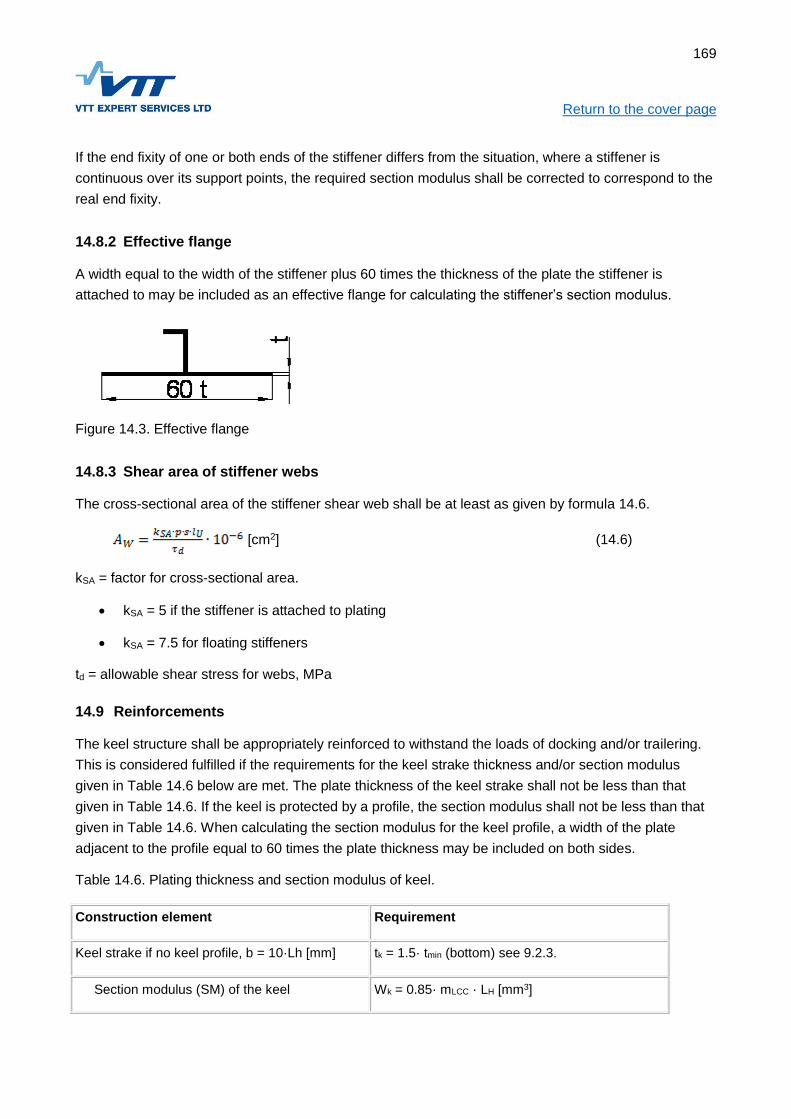
169
Return to the cover page If the end fixity of one or both ends of the stiffener differs from the situation, where a stiffener is
continuous over its support points, the required section modulus shall be corrected to correspond to the
real end fixity.
14.8.2 Effective flange
A width equal to the width of the stiffener plus 60 times the thickness of the plate the stiffener is
attached to may be included as an effective flange for calculating the stiffener’s section modulus.
Figure 14.3. Effective flange
14.8.3 Shear area of stiffener webs
The cross-sectional area of the stiffener shear web shall be at least as given by formula 14.6.
[cm2] (14.6)
kSA = factor for cross-sectional area.
kSA = 5 if the stiffener is attached to plating
kSA = 7.5 for floating stiffeners
td = allowable shear stress for webs, MPa
14.9 Reinforcements
The keel structure shall be appropriately reinforced to withstand the loads of docking and/or trailering.
This is considered fulfilled if the requirements for the keel strake thickness and/or section modulus
given in Table 14.6 below are met. The plate thickness of the keel strake shall not be less than that
given in Table 14.6. If the keel is protected by a profile, the section modulus shall not be less than that
given in Table 14.6. When calculating the section modulus for the keel profile, a width of the plate
adjacent to the profile equal to 60 times the plate thickness may be included on both sides.
Table 14.6. Plating thickness and section modulus of keel.
Construction element Requirement
Keel strake if no keel profile, b = 10·Lh [mm] tk = 1.5· tmin (bottom) see 9.2.3.
Section modulus (SM) of the keel Wk = 0.85· mLCC · LH [mm3]

170
Return to the cover page If the edge of the deck or the hull/deck joint is the widest part of the craft, they are to be strengthened to
withstand loads from collision with piers, docking and handling of the craft ashore. The deck edge or
hull/deck joint usually functions as a stiffener for hull topsides. The hull/deck joint shall be watertight for
craft in design category A, B and C.
14.10 Highly loaded structures
14.10.1 Engine foundations
Engine foundations shall be strong and stiff enough to carry the weight and loads of the engine. Such
loads are:
Weight of the engine and additional dynamic forces from craft’s motion;
Propulsion force (in cases where no thrust bearing is fitted);
Torsion from the propeller;
Vibration.
Engine foundations must be securely fixed primary athwarthship stiffeners like bulkheads or similar at
both ends. Foundations shall be supported against buckling and collapsing, especially near engine
holding down bolts.
14.10.2 Transoms for outboard and sterndrive engines
The transom design should ensure that the moment, mass forces and thrust from the outboard engine
or sterndrive will be transferred into the primary structure without creating excessive stresses.
For engines with big power, the transom shall be engineered using the design loads given in Chapter 7
Clause 7.10.6.
14.10.3 Attachment of mooring and other highly loaded fittings
The foundations of mooring and towing fittings, rails, pulpits, lifeline stanchions, winches and similar
items must be dimensioned to withstand loads as per ISO 15084.
14.10.4 Attachment of railings, handholds and lifeline hooking points
Attachment of railings, handholds and lifeline hooking points shall meet the requirements of ISO 15085.
14.10.5 Attachment of RIB-pontoon
The attachment of the RIB-pontoon to the rigid hull shall be designed to transmit the loads without
stress peaks. Special attention shall be paid to the attachment in the bow and stern. The attachment
shall be tested according to ISO 6185-3 for craft with a hull length of less than 8 m and ISO 6185-4 for
bigger craft.

171
Return to the cover page
14.11 Design stresses
The design stresses to be used in the equations in this chapter are presented in Table 14.7. Mechanical
properties for commonly used aluminium alloys can be found in Chapter 13.
Table 14.7. Design stresses
Structural member Allowed stress, MPa
Panels d = 0,6· UW tai 0,9 · YW
Stiffeners, normal stress d = 0,7· YW
Stiffeners, shear stress d = 0,7· YW
UW = Tensile strength, welded
YW = Yield strength, welded

172
Return to the cover page
15 PRODUCTION OF ALUMINIUM BOATS
15.1 Objective
The rules in this chapter deal with the production of aluminium craft. A prerequisite for applying the
rules in this chapter is that the raw-materials, the structure and scantlings meet the requirements in
Chapters 12, 13 and 14 respectively. The rules apply to individually built boats and, as applicable, to
series built boats.
15.2 References
This chapter is partially based on international standard ISO 12215-4 - Small craft — Hull construction
and scantlings —Part 4: Workshop and manufacturing.
Reference is made also to the following documents:
EN 9606-2:2002. Qualification test of welders. Fusion welding. Aluminium and aluminium alloys.
EN ISO 15614-2:2005. Specification and qualification of welding procedures for metallic
materials -- Welding procedure test -- Part 2: Arc welding of aluminium and its alloys
SFS-EN ISO 10042: Welding. Arc-welded joints in aluminium and its alloys. Quality levels for
imperfections.
SFS-EN 970: Non-destructive examination of fusion welds. Visual examination
15.3 Documentation
To verify the compliance with the requirements in this chapter, a production report for each individual
craft is to be prepared. The report shall be readily identifiable by means of the Craft Identification Code,
the yards' newbuilding number or similar and shall include the following information as relevant:
Reference to the used structural drawings, see Chapter 14.
The material certificates for plates, profiles and welding consumables;
The qualification certificates of the welders which have participated in the welding of the hull;
Reference to relevant welding procedure specifications (WPS);
Protocol of visual inspection of welds;
Reports of radiography and/or other NDT inspection carried out;
Reports of possible problems encountered during lamination and the remedy;
15.4 Workshop conditions
Aluminium plates, profiles, welding consumables and other aluminium materials shall be stored in a dry
location separated from other metals.

173
Return to the cover page The workshop shall be essentially clean and there must not be any cutting of other metals during the
welding process.
The cutting and welding of aluminium shall be carried out in a dry place under cover, protected from
wind and weather.
Welding of aluminium shall not be carried out at temperatures below -5 oC. Where the outdoor
temperature may fall below 0 oC, it shall be possible to heat the workshop.
15.5 Materials
It shall be possible to show, with the aid of material certificates, that the plating and profiles which are
used in a particular craft, are of the alloy and temper specified on the construction drawings.
The material shall be straight and undamaged, and of the dimensions and alloy specified on the
approved drawings.
15.6 Cutting and forming
Hardened aluminium alloys shall not be formed by the application of heat. Where cold forming is
required, care shall be taken to avoid local damage to the material. When bending plates and profiles,
the methods and the bend radius shall ensure that excessive local strain leading to cracks in the
material does not occur.
15.7 Welding
15.7.1 Welder’s qualification
Welding shall only be carried out by qualified persons. In craft of design category A and B an official
welder's qualification according to EN 9606-2:2002 or equivalent standard is required. For craft of
design category C or D, the qualification may be assessed by the beforementioned test or by assessing
of the welds at the workshop.
In general, MIG or TIG welding methods shall be used. Other methods may be utilised if it can be
demonstrated that the results is at least as good as for welds carried out with MIG or TIG.
15.7.2 Welding Procedure Specification
In the manufacturing of craft of design category A and B the welding shall be carried out in accordance
with welding procedure specifications (WPS) tried out prior to the construction and which are
demonstrated to result in welds with adequate quality. Welding procedure specifications shall be
prepared for all relevant joint types, welding positions and material thicknesses and with the welding
machines to be used for the construction of the craft. The welding procedure specifications shall be
carried out in accordance with the standard EN ISO 15614-2. For craft of design category C and D no
formally approved welding procedure specifications are required.

174
Return to the cover page
15.7.3 Surveys
The welds in the hull, deck and other critical structures are to be visually inpected according to EN ISO
970.
In addition, for craft of design category A and B, inspection by radiography shall be carried out. The
sampling is to be decided on basis of the visual inspection.
Required weld quality
The quality level of welds in all load-bearing structures shall be at least C according to the standard
SFS-EN ISO 10042. This applies to the following items:
For all boats the hull including the following structural members:
Plating and transom;
Keel and stem;
Bulkheads, webframes and stiffeners;
Engine foundations;
Possible other stiffeners and foundations.
For fully enclosed boats also:
Decks and their stiffeners;
Superstructures and their stiffeners;

175
Return to the cover page
16 DESIGN PRINCIPLES, STEEL
16.1 Objective
In this chapter is given requirements for the structural arrangement and the details of the structure. In
addition, the principles for the assessment of the structure are defined. The purpose of the
requirements presented in this chapter is to ensure that the structural arrangement and details of the
craft has been carried out correctly taking into account the special properties of steel and that the
procedures for assessing the structure are unambiguous.
This Chapter is to be used in conjunction with Chapter 7 (Design pressures and loads), Chapter 17
(Steel materials), Chapter 18 (Scantlings, steel craft) and Chapter 19 (Production of steel craft)
16.2 References
Requirements in chis chapter are partly based on international standard ISO 12215-6:2008. Small craft
- Hull construction and scantlings -- Part 6: Structural arrangements and details.
16.3 Principles of structural analysis
16.3.1 Simplified calculation method
If the following conditions are met the scantlings may be analysed using the simplified calculation
method:
The structural arrangement is according to clause 6;
The assumptions in clause 4 are valid;
The craft does not have features, which makes it critical to global loads, see clause 16.5.
The "Simplified calculation method" means that the scantlings are determined using the formulae for
panels, stiffeners etc. given in Chapter 18 using the loads in Chapter 7 and the allowable stresses given
in Chapter 18.
16.3.2 Direct calculation of stresses and strains
For other cases than those mentioned in 16.3.1, general methods of strength of materials shall be
followed. For such analysis, the loads given in Chapter 7 and the design stresses given in Chapter 18
shall be used.
16.4 Assumptions
16.4.1 Assumptions regarding local vs. global strength and stiffness
The scantling determination method presented in Chapter 18 is based on dimensioning against local
loads. Normally, this will result in scantlings, which are adequate also for global loads. Where this is not
the case, the dimensioning against global loads shall be assessed, see paragraph 16.5.

176
Return to the cover page
16.4.2 Hierarchy of the load carrying elements
When calculating requirements for panels and stiffeners according to Chapter 18, the hierarchy of
structure is assumed to adhere to the following principles:
The panel is supported by secondary stiffeners supported by primary stiffeners as indicated in
Figure 16.1
The primary stiffeners are at least twice as stiff as the secondary stiffeners, i.e:
(12.1)
The load is uniformly distributed;
The edges of the panel are clamped;
The ends of the stiffeners are fixed.
Figure 16.1. Hierarchy of stiffeners.
Support for primary stiffener
(for ex. keel)
Primary stiffener (for ex. Web-frame)
Load area for primary
stiffener
Load area for
secondary stiffener
Secondaryy stiffener
Support for primary stiffener
(for ex. chine)

177
Return to the cover page
16.5 Global strength and stiffness
In the following cases also the global strength and stiffness must be investigated:
If the bottom is only transversely stiffened and its relative speed V/√LWL>6
If there are (large) openings in the deck;
If the ratio of the hull length to the hull depth LH/DMAX>12
The global strength and stiffness shall be determined according to ISO 12215-6 Annex D. At least the
deck shall be checked against buckling (compressive stress in the deck). For craft with only transverse
stiffening in the bottom also the strength of the bottom shall be checked.
For multihull craft, the strength shall be assessed in the global load cases given in Chapter 7.
16.6 Structural arrangement
16.6.1 Displacement craft, design category D
Boats in design category D with V/√LWL≤6, may be stiffened by the keel, gunwale and transverse
stiffeners alone. Boats in higher design categories may only be stiffened by transverse framing alone if
an assessment of the global strength and stiffness is carried out, see paragraph 16.5.
16.6.2 Planing craft
Boats with V/√LWL>6, should in general have longitudinal stiffening in the bottom. The details of
longitudinal stiffeners shall meet the requirements of paragraph 16.7.
16.6.3 Support for longitudinal stiffeners
The bottom longitudinal stiffeners shall in general be supported by transverse stiffeners such as
bulkheads, web frames or deep floors, which are to be designed to carry the load acting on the hull
area in question, see Figure 16.1. Principle of load areas. The details of transverse stiffeners shall meet
the requirements in paragraph 16.7.
16.6.4 Keels, stem and chines
The craft shall have a reinforced keel, stem and chines according to Chapter 18.
16.6.5 Torsional stiffness and -strength
The torsional strength and stiffness is considered adequate if the craft has one of the following items:
A full deck;
Tranverse bulkheads;
A strengthened bulwark.

178
Return to the cover page
16.6.6 Superstructure support points
The loads imposed by superstructures shall be led into bulkheads, webframes or other primary
structure.
16.7 Hull stiffeners
16.7.1 Continuity and termination of stiffeners
In craft where V /√LWL>6, the bottom longitudinal stiffeners shall be continuous. Terminating of stiffeners
on a panel between stiffeners shall be avoided. With the exceptions of paragraph 16.9.2, the ends of
stiffeners shall be fastened to other stiffeners
16.7.2 Straightness and local discontinuities of stiffeners
Hull stiffeners shall be as straight as possible. At most 30 degrees are accepted, provided buckling
support is arranged at the points where the direction change. Aprupt changes is the cross section of the
stiffeners shall be avoided. If the stiffeners have local discontinuities, the transition shall be smooth and
corners shall be rounded, radius at least 30 mm.
16.7.3 Safety against buckling
The cross section of stiffeners shall be such that they are not prone to buckling. Stiffeners with one web
without flange are not allowed at bottom area. Stiffeners with one web must not be fastened at an angle
exceeding 30 degrees relative to the normal against the panel.
16.7.4 Transverse stiffeners
The hull transverse stiffeners such as bulkheads, webframes and deep floors, shall extend from side to
side of the hull. If the section modulus of the keel meets the requirements in Chapter 18 paragraph 8,
the stiffeners span may be taken to the keel when calculating the section modulus requirement
according to Chapter 18 paragraph 5, else the distance between the chines shall be used.
16.7.5 Floating stiffeners
Arrangements, where stiffeners are not fastened to the bottom (floating stiffener), assessed according
to ISO 12215-6 clause 6.3.4.
16.8 Other stiffeners
The stiffening arrangement of decks, superstructures and bulkheads shall comprise of secondary
stiffeners supported by primary stiffeners according to the principles in paragraph 16.4.2.

179
Return to the cover page
16.9 Construction details
16.9.1 Joining plates of different thickness
The thickness difference between adjacent hull plates shall not exceed 25% of the thicker plate unless
the edge of the thicker plate is bevelled.
16.9.2 Fastening and joints of stiffeners
The stiffener including its fastening shall be able to carry the bending moment and shear force in
Chapter 18 paragraph 14.8 without exceeding the design stresses given in Chapter 18.
If a stiffener is continuous through a web frame or bulkhead, a bracket is not required at the
intersection. If the stiffener is cut off for instance at a watertight bulkhead, the end(s) shall be connected
by means of brackets or similar to ensure, that the stiffness and strength of joint corresponds to that of
a continuous stiffener
The ends of stiffeners shall, with the following exceptions, be connected to other stiffeners. Termination
of stiffeners within a plate panel is allowed under the following conditions.
(a) In the bottom structure, all design categories, side structure of craft in design category A and B:
The stiffener ends at an angle of at least 15 degrees relative to a line through the last support point and the stiffener end, or
The stiffener ends at a stiff area, for instance near the keel or chine;
In both case the bending and shear stress must not exceed half of the design stress as given in Chapter 18 and
The end of the stiffener shall be sniped at least 3:1 and
The distance from the stiffener end to a stiff point is at most 35 mm.
(b) Other applications, all design categories
The end of the stiffener shall be sniped at least 3:1 and the distance from the stiffener end to a
stiff point is at most 35 mm
16.9.3 Openings in load-bearing structures
16.9.3.1 General
The effect of openings in load-bearing structures shall be taken into account. Opening shall, where
necessary, be supported at their edges by flanges or similar.
16.9.3.2 Openings in hull stiffeners
With the exceptions given below, openings in hull stiffeners are not allowed, unless it can be shown by
calculation that the stiffener meets the requirements of Chapter 18 including the opening.

180
Return to the cover page In the webs, no openings are to be located within 20% of the length of the stiffeners from the support
points. In other locations of the webs openings with a height not exceeding 50% of the web height and
a length not exceeding 75% of the web height are allowed.
16.9.4 Sharp edges
Sharp edges or notches are not allowed in loaded structures.
16.9.5 Other details
Structures, which accumaulate water shall be avoided as far as possible. Locations, where water may
accumulate shall be readily accessible (definition see chapter 31).
16.9.6 Corrosion
All items fitted to the underwater hull, which are not the same material as the hull, shall be isolated for
instance by sealant to avoid crevice corrosion. Sacrificial anodes are required if the craft is equipped
with an AC shore connection.
16.10 Welding
The weld joint geometry shall be according to Table 16.1.
Table 16.1. Geometry of welding joints
Joint type Joint dimensions Comments
MIG
s = 1.5...5 mm
b = 0...2 mm
Welding from one side only.
Back-up strip shall be used.
s = 5...25 mm
b = 0...3 mm
c = 1.5...3 mm
= 60...100o
Largest angle recommended
for under-up position.
Gouging and re-welding shall
be carried out.

181
Return to the cover page
s = 8...25 mm
b = 3...7 mm
c = 2...4 mm
= 40...60o
Smallest joint angle may be
used up to 15 mm and with
the largest root cap. Vertical
position, under-up and side-
in require a large root cap.
s = 12...25 mm
b = 0...2 mm
c = 3...5 mm
= 50...70o
Specially allowed for
automatic welding.
Semiautomatic processes
may be used in all positions,
and gouging shall be
performed prior to welding
from the other side.
TIG
s < 2 mm
s < 4 mm
b = 0...2 mm
Welding from one side.
s = 4...10 mm
b = 0...2 mm
= 60...70o
Back-up strip shall be used
in a horizontal position.
s= Material thickness, mm
b = Root gap, mm
c = Root face, mm
= Joint angle, deg

182
Return to the cover page Table 16.3. Welding shall be carried out in accordance with the following table. The notations in the
table are the minimum requirements.
Application Design category
A B C D
Hull shell plating butt welds s <5 mm CDB CDB CSB CSB
Hull shell plating butt welds s => 5mm CDB CDB CDB -
Other plating butt welds s < 5 mm CSB CSB CSB CSB
Other plating butt welds s => 5 mm CDB CDB CDB -
Hull chines fillet welds s <5 mm CDF CDF CSF CSF
Hull chines fillet welds s=>5 mm CDF CDF CDF -
Other watertight fillet welds CDF CDF CSF CSF
Engine foundations CDF CDF CSF -
Brackets, supports for highly loaded items CDF CDF CDF -
Hull transverse frame ends (also at keel, chine) CDF CDF CDF CDF
Hull transverse frames at engine foundations CDF CDF CDF -
Hull transverse frames elsewhere DF DF DF DF
Hull and other stiffener ends CDF CDF CDF CDF
Hull and other stiffeners elsewhere DF DF DF DF
Notations for butt weld types:
CSB = Continuous single-sided butt weld, no back-opening required, s < 5mm
CDB = Continuous double-sided butt weld, back-opening required, s => 5mm
Notations for filled welds:
CSF = Continuous single-sided fillet weld
CDF = Continuous double-sided fillet weld
DF = Intermittent (staggered or chain) double-sided fillet weld

183
Return to the cover page When hull and deck stiffeners are welded using intermittent welding, the welds shall be at least as long
as the break. Shorter welds may be considered for other types of stiffeners that are permitted to be
welded with intermittent welds. The length of the weld must never be less than 40% of the joint length.
The ends of stiffeners shall always be welded from both sides.
The a-dimension of the weld shall be at least 2.5 mm or (0,35 t+1,5) whichever is greater, where t is the
thickness of the plate [mm]. The a-dimension never need to be taken more than 7 mm for plate
thicknesses up to 30 mm.

184
Return to the cover page
17 STEEL MATERIALS
17.1 Normal strength steel
Unless otherwise specified, steel with a yield strength of 240 MPa is assumed as the basis for the rules.
This is referred to as “normal strength steel”. The use of steel grades with better mechanical properties
is to be considered separately according to their yield strength and ultimate strength and ultimate strain.
17.2 Steel grades for low temperatures
The use of normal strength steel with normal impact toughness is permitted for commercial craft that do
not have an additional “Ice strengthening” notation. For ice-strengthened craft, steel with enhanced
toughness in cold temperatures is to be used

185
Return to the cover page
18 SCANTLINGS DETERMINATION, STEEL
18.1 Objective
This chapter presents the formulae for scantling determination of steel craft.
The given formulae are to be used only in conjunction with the design loads given in Chapter 7, using
the principles regarding the structural arrangement given in Chapter 16.
18.2 References
The scantlings determination method in this chapter is in general that of the ISO 12215-5:2008 - Hull
construction and scantlings -- Part 5: Design pressures for monohulls, design stresses, scantlings
determination. To ensure that workboat can cope with harsh operating conditions, additions regarding
plate thickness against impact loads and corrosion have been added.
18.3 Documentation
To verify that the requirements presented in this chapter are met, the following documentation is
required:
Structural design drawings, including, if appropriate:
o Longitudinal cross-section;
o Transverse cross-sections;
o Welding methods and welding dimensions;
Material certificates for the plates and profiles used;
Scantlings calculations showing the rule requirements for different structural members and the
attained values.
18.4 List of symbols
Symbols used in several Chapters are given in Chapter 1. In Table 18.1 some symbols used in this
Chapter are listed. In addition, there are symbols defined in their context.
Table 18.1. Symbols used in Chapter 18.
Symbol Unit Meaning Reference
p kPa Design pressure Chapter 7
l mm Longer side of panel
b mm Shorter side of panel
s mm Fram spacing, width of design area
lU mm Span of stiffener
t mm Thickness of panel

186
Return to the cover page
W cm3 Section modulus
σd MPa Allowable normal stress Chapter 9
τd MPa Allowable shear stress Chapter 9
18.5 Dimension of panels
The dimensions of panels are given for some typical cases in Figure 18.1.
c) Rectangle shaped panel. Note, that l and b are measured to the web of the stiffener.
d) Some other shapes
Figure 18.1 Measures for typical panels
18.6 Scantlings requirements, steel panels
The thickness of steel plating shall not be less than the greater of formulae 14.1 and 14.2:
[mm] (18.1)

187
Return to the cover page Where
kC = curvature correction factor, see 14.7.2
P = design pressure, see Chapter 7.
k2 = panel aspect correction factor, see. 14.7.3
D = allowable stress. see 18.11.
The plating thickness shall never be less than given by formula 14.2:
[mm] (18.2)
Where
Factors t0, k1, k3 and k4 can be found in Table 18.2 anf factor f1 from Clause 18.7.1.
Table 18.2. Factors used in formula 14.2
Rakenneosa t0 k3 k4
Bottom plater 0,9 0 0,02
Side plating and transom 0,9 0 0
Cargo deck, load Q [t/m2] 1,5 + 0,5 ∙ Q 0 0
If the clamping of an edge of a panel is less than that of a panel continuing past its edge stiffeners, the
thickness requirement must be adjusted to conform to the actual edge clamping.
18.7 Correction factors for panels
18.7.1 Correction for alloy strength
The correction factor f1 used in the minimum thickness formula takes the strength of the alloy into
consideration. The factor shall be determined with the following formula:
(18.3)
Where
Y = yield strength of steel alloy, [MPa]
18.7.2 Correction based on panel curvature
The correction factor takes account of the effect the curvature has on the strength of steel panels; kc
must be at least 0.8, however.

188
Return to the cover page
Table 18.5. Correction factor for panel on the basis of curvature
c/b kC
0…0,03 1,0
0,03…0,18 1,1 – 3,33 ∙ c/b
>0,18 0,5
Figure 18.2. Measures needed for curvature correction factor.
18.7.3 Correction based on panel aspect ratio.
Correction on the basis of panel aspect ratio. The factor k2, which takes the effect of the panel aspect
ratio on the bending stress into consideration, can be found in table 18.4
b
b
c
c

189
Return to the cover page
Table 18.4. Panel aspect ratio correction factor k2.
Aspect ratio Correction factor for
bending stress
l/b k2
>2,0 0,500
2,0 0,497
1,9 0,493
1,8 0,487
1,7 0,479
1,6 0,468
1,5 0,454
1,4 0,436
1,3 0,412
1,2 0,383
1,1 0,349
1,0 0,308
18.8 Stiffeners
18.8.1 Section modulus
The section modulus of stiffeners, including the effective flange calculated according to 6.3, shall not be
less than given by formula 18.4.
[cm3] (18.4)
Where
lU stiffener span, not needed to be taken greater than 330·LH [mm]
kCS correction factor for stiffener curvature, see Table 18.5.
d design stress for steel alloy, [MPa], see clause 18.11
Table 18.5. Stiffener correction factor kCS
c/b kCS
0…0,03 1,0
0,03…0,18 1,1 – 3,33 – cU/lU
0,18… 0,5
If the end fixity of one or both ends of the stiffener differs from the situation, where a stiffener is
continuous over its support points, the required section modulus shall be corrected to correspond to the
real end fixity.

190
Return to the cover page
18.8.2 Effective flange
A width equal to the width of the stiffener plus 80 times the thickness of the plate the stiffener is
attached to may be included as an effective flange for calculating the stiffener’s section modulus.
80 t
t
Figure 18.3. Effective flange
18.8.3 Shear area of stiffener webs
The cross-sectional area of the stiffener shear web shall be at least as given by formula 18.6.
[cm2] (18.6)
kSA = factor for cross-sectional area.
kSA = 5 if the stiffener is attached to plating
kSA = 7.5 for floating stiffeners
td = allowable shear stress for webs, MPa, see 18.11
18.9 Reinforcements
The keel structure shall be appropriately reinforced to withstand the loads of docking and/or trailering.
This is considered fulfilled if the requirements for the keel strake thickness and/or section modulus
given in Table 18.6 below are met. The plate thickness of the keel strake shall not be less than that
given in Table 18.6. If the keel is protected by a profile, the section modulus shall not be less than that
given in Table 18.6. When calculating the section modulus for the keel profile, a width of the plate
adjacent to the profile equal to 80 times the plate thickness may be included on both sides.
Table 18.6. Plating thickness and section modulus of keel.
Construction element Requirement
Keel strake if no keel profile, b = 10·Lh [mm] tk = 1.5· tmin (bottom) see Eq.18.2.
Section modulus (SM) of the keel Wk = 0.85· mLCC · LH [mm3]

191
Return to the cover page If the edge of the deck or the hull/deck joint is the widest part of the craft, they are to be strengthened to
withstand loads from collision with piers, docking and handling of the craft ashore. The deck edge or
hull/deck joint usually functions as a stiffener for hull topsides. The hull/deck joint shall be watertight for
craft in design category A, B and C.
18.10 Highly loaded structures
18.10.1 Engine foundations
Engine foundations shall be strong and stiff enough to carry the weight and loads of the engine. Such
loads are:
Weight of the engine and additional dynamic forces from craft’s motion;
Propulsion force (in cases where no thrust bearing is fitted);
Torsion from the propeller;
Vibration.
Engine foundations must be securely fixed primary athwarthship stiffeners like bulkheads or similar at
both ends. Foundations shall be supported against buckling and collapsing, especially near engine
holding down bolts.
18.10.2 Transoms for outboard and sterndrive engines
The transom design should ensure that the moment, mass forces and thrust from the outboard engine
or sterndrive will be transferred into the primary structure without creating excessive stresses.
For engines with big power, the transom shall be engineered using the design loads given in Chapter 7
Clause 7.10.6.
18.10.3 Attachment of mooring and other highly loaded fittings
The foundations of mooring and towing fittings, rails, pulpits, lifeline stanchions, winches and similar
items must be dimensioned to withstand loads as per ISO 15084.
18.10.4 Attachment of railings, handholds and lifeline hooking points
Attachment of railings, handholds and lifeline hooking points shall meet the requirements of ISO 15085.
18.10.5 Attachment of RIB-pontoon
The attachment of the RIB-pontoon to the rigid hull shall be designed to transmit the loads without
stress peaks. Special attention shall be paid to the attachment in the bow and stern. The attachment
shall be tested according to ISO 6185-3 for craft with a hull length of less than 8 m and ISO 6185-4 for
bigger craft.

192
Return to the cover page
18.11 Design stresses
The design stresses to be used in the equations in this chapter are presented in Table 18.7.
Table 14.7. Design stresses
Structural member Allowed stress, MPa
Panels d = 0,6· UW tai 0,9 · YW
Stiffeners, normal stress d = 0,7· YW
Stiffeners, shear stress d = 0,7· YW
UW = Tensile strength, welded
YW = Yield strength, welded

193
Return to the cover page
19 PRODUCTION OF STEEL BOATS
19.1 Objective
The rules in this chapter deal with the production of steel craft. A prerequisite for applying the rules in
this chapter is that the raw-materials, the structure and scantlings meet the requirements in Chapters
16, 17 and 18 respectively. The rules apply to individually built boats and, as applicable, to series built
boats.
19.2 References
This chapter is partially based on international standard ISO 12215-4 - Small craft — Hull construction
and scantlings —Part 4: Workshop and manufacturing.
Reference is made also to the following documents:
EN 9606-1:2002. Qualification test of welders. Fusion welding of steel.
EN ISO 15614-1:2005. Specification and qualification of welding procedures for metallic materials - Welding procedure test - Part 1 : arc and gas welding of steels and arc welding of nickel and nickel alloys.
ISO 5817:2014. Welding -- Fusion-welded joints in steel, nickel, titanium and their alloys (beam welding excluded) -- Quality levels for imperfections
SFS-EN 970: Non-destructive examination of fusion welds. Visual examination
19.3 Documentation
To verify the compliance with the requirements in this chapter, a production report for each individual
craft is to be prepared. The report shall be readily identifiable by means of the Craft Identification Code,
the yards' newbuilding number or similar and shall include the following information as relevant:
Reference to the used structural drawings, see Chapter 18.
The material certificates for plates, profiles and welding consumables;
The qualification certificates of the welders which have participated in the welding of the hull;
Reference to relevant welding procedure specifications (WPS);
Protocol of visual inspection of welds;
Reports of radiography and/or other NDT inspection carried out;
Reports of possible problems encountered during lamination and the remedy;
19.4 Workshop conditions
Steel plates, profiles, welding consumables and other steel materials shall be stored in a dry location to
prevent corrosion.

194
Return to the cover page Welding of steel shall not be carried out at temperatures below -5 oC. Where the outdoor temperature
may fall below 0 oC, it shall be possible to heat the workshop.
Workshops where welding using shield gas is carried out shall be essentially free of draught.
19.5 Materials
It shall be possible to show, with the aid of material certificates, that the plating and profiles which are
used in a particular craft, are of the correct type according to the construction drawings.
The material shall be straight and undamaged, and of the dimensions and alloy specified on the
approved drawings.
19.6 Cutting and forming
Where cold forming is required, care shall be taken to avoid local damage to the material.
When bending plates and profiles, the methods and the bend radius shall ensure that excessive local
strain leading to cracks in the material does not occur.
19.7 Welding
19.7.1 Welder’s qualification
Welding shall only be carried out by qualified persons. In craft of design category A and B an official
welder's qualification according to EN 9606-1:2002 or equivalent standard is required. For craft of
design category C or D, the qualification may be assessed by the before mentioned test or by
assessing of the welds at the workshop.
In general, MIG or TIG welding methods shall be used. Other methods may be utilised if it can be
demonstrated that the results are at least as good as for welds carried out with MIG or TIG.
19.7.2 Welding Procedure Specification
In the manufacturing of craft of design category A and B the welding shall be carried out in accordance
with welding procedure specifications (WPS) tried out prior to the construction and which are
demonstrated to result in welds with adequate quality. Welding procedure specifications shall be
prepared for all relevant joint types, welding positions and material thicknesses and with the welding
machines to be used for the construction of the craft. The welding procedure specifications shall be
carried out in accordance with the standard EN ISO 15614-1. For craft of design category C and D no
formally approved welding procedure specifications are required.
19.7.3 Surveys
The welds in the hull, deck and other critical structures are to be visually inspected according to EN ISO
970.

195
Return to the cover page In addition, for craft of design category A and B, inspection by radiography shall be carried out. The
sampling is to be decided on basis of the visual inspection.
19.7.4 Required weld quality
The quality level of welds in all load-bearing structures shall be at least C according to the standard ISO
5817. This applies to the following items:
For all boats the hull including the following structural members:
Plating and transom;
Keel and stem;
Bulkheads, webframes and stiffeners;
Engine foundations;
Possible other stiffeners and foundations.
For fully enclosed boats also:
Decks and their stiffeners;
Superstructures and their stiffeners;

196
Return to the cover page
20 RUDDER AND STEERING SYSTEMS
20.1 Objective
The purpose of the rules in this chapter is to ensure proper and safe steering of the craft, while
considering her Design Category and maximum speed, and to make sure that the craft can proceed
into a safe harbour even when the main steering is out of order.
20.2 References
In this chapter reference is made to the following documents:
ISO 12215-8:2009 Small Craft – Hull construction and scantlings – Part 8: Rudders
ISO 8847:2004 Small Craft – Steering gear –Cable and pulley systems
ISO 9775:1994 Remote steering systems for single outboard motors of 15 kW to 40 kW
EN 28848:1993/A1:2000 Small craft – Remote steering systems
EN 29775:1993 Small craft - Remote steering systems for single outboard motors of 15 kW to 40 kW power
ISO 10592:1995/A1:2000 Small craft – Hydraulic steering systems
ISO 4413:2010 Hydraulic power – General rules and safety requirements for systems and their components
ISO 13929:2001 Small craft – Steering gear – Geared link systems
ISO 25197:2012 Small craft – Electrical/electronic control systems for steering, shift and throttle
20.3 Documentation
For assessment of the requirements given in this chapter the following documentation is required:
drawings of the rudder and its installation, showing the rudder geometry and construction;
the materials used;
measurements for the parts;
dimensioning calculations showing;
rudder stock;
tiller or quadrant connection to the stock; and
dimensioning of the bearings; and
conformity declarations for CE-marked components

197
Return to the cover page
20.4 Steering arrangements
20.4.1 Main steering system
The main steering system shall enable proper and safe steering at all speeds considering the Design
Category of the craft.
Steering shall normally be accomplished with a fixed steering system, able to produce the required
torque or force for proper steering. In craft where manual steering provides sufficient power, remote
control is not required.
For craft with the additional notation Ice Reinforcement there are additional requirements for the
steering system given in Chapter 39.
20.4.2 Emergency steering system
Except for the mentioned cases below, for all craft with remote steering a rapidly available emergency
steering system is required. This system shall have proper strength, and enable steering at minimum 4
knots speed, retaining the steering control using the input from one person at a safe force level.
A separate emergency steering system is not required provided:
the craft has two rudders, each with separate steering system, and can be steered even if either one of the systems is out of order;
the craft has at least two propulsion units, enabling the craft to be steered even if the main steering system is out of order;
the craft can be steered in some other way, for example with a bow thruster; or
the craft has outboard- or sterndrive engine, or waterjet propulsion, and belongs to Design Category C or D.
In case the steering system is electrical, emergency steering is always required.
In connection with emergency steering a dedicated lookout may be used.
The emergency steering shall be assessed in connection with the sea trials (see Chapter 30).
20.4.3 Requirements for steering systems
The steering system components shall be CE-marked according to item 20.2, or be approved by an
independent notified body using a method ensuring the corresponding safety level.
The dimensioning of the steering system shall rely entirely on the torque from the rudder or drive unit as
calculated in this chapter.
When industrial hydraulic components are used, the installation including components shall meet the
requirements in ISO 4413.

198
Return to the cover page Electrical steering systems shall be approved for marine use by a Classification Society, or shall have
CE-marking according to standard ISO 25197.
Cable steering with a single cable must not be used with engine power over 74 kW if the speed of the
craft exceeds 7∙√LH knots.
For craft with the additional notation Ice Reinforcement there are additional requirements for the
steering system given in Chapter 39.
20.5 Rudders
20.5.1 Rudder design, general
The rudder and its parts shall be designed so they can stand the applied loads in all conditions. This
includes also light grounding when the craft is stationary, and ice loads for craft intended for such
services (see Chapter 39)
Generally, the rudder area shall be sufficient for good control also at low speed in conditions when only
one engine is in use.
20.5.2 Fail-safe design
Rudders to be designed paying attention to grounding, and collision with objects in the water.
This requirement is considered fulfilled if there is a strong skeg or similar in front of the rudder.
Alternatively, this can be arranged with local watertight compartmentation, preventing a leak from
reaching spaces above the rudder in case the bottom is holed (limited unsinkability, see Chapter 6).

199
Return to the cover page Table 20.1. Rudder stock material properties [MPa]
Material Compo-
sition
σya
unwelde
d
σua
unwelde
d
σyw
welded
σuw
welded
σDa
unwelde
d
σDw
welded
E
ESTIMA
TE
Stainless steel
AISI 304 X5 Cr Ni
18.9 195 500 195 195 195 97
2.05*105
AISI 316,316L X5 Cr Ni
Mo 17.2.2 195 500 195 195 195 97
AISI 329 Not
coldworked
X3 Cr Ni
Mo N 27-
5-2
500 650 500 500 325 250
AISI 329
Coldworked
X3 Cr Ni
Mo N 27-
5-2
780 900 780 780 450 390
17-4 PH,
F 16 PH
X5 Cr Ni
Cu
Nb16.4
720 1000 - No
welding 500 -
DX45, Uranusb X2 CrNi
No N
22.5.3
450 660 450 450 330 225
Carbon steel
E24/A - 235 400 235 400 200 200
2.10*105 E32-AH 32 - 315 470 315 470 235 235
E36-AH 36 - 355 490 355 490 245 245
Copper alloys
Bronze-Mn - 245 510 - - 245 -
1.10*105 Bronze-Ni-Al - 390 740 - - 370 -
Monel 400 - 350 550 - - 275 - 1.80*105
Monel 500 - 690 960 - - 480 -
a, Properties in unwelded condition σD = min(σy;0.5σu)
b, To be welded in a shielding gas (argon)

200
Return to the cover page
20.5.3 Rudder dimensioning load
The rudder maximum hydrodynamic force F [N] shall be calculated with formula (20.2) for displacement
craft, and (20.3) for planning craft, the larger of these values to be used.
ALF WL 13001 [N] (20.2)
AVA
hF MAX
r
3,1
43,02
2 465 [N] (20.3)
Where A [m2] is the rudder area, and hr [m] the rudder blade height.
20.5.4 Spade rudder bending moment and bearing loads
Table 20.2 Centre of pressure height parameter
12 / cc 1,00 0,90 0,80 0,70 0,60 0,50 0,40 0,30 0,20
bk 0,50 0,49 0,48 0,47 0,46 0,44 0,43 0,41 0,39
Where c2 is the rudder blade upper edge chord, and c1 the lower chord
The rudder bending arm zb [m] is
bcbrbb hhhhkz [m] (20.5)
Where hb is the distance from the top of the rudder blade to the centre of the neck bearing, and kb is the
height parameter for the centre of pressure location along the rudder blade. The centre of pressure
location hc may also be determined graphically.
Rudder bearing loads for spade rudders. RU is the carrier bearing load.
u
bU
h
zFR [N] (20.6)
Where
hu [m] is the distance between the carrier and neck bearing centres.
RH is the neck bearing load
FRR UH [N] (20.7)
Spade rudder bearing stocks shall be dimensioned using the equivalent (combined torque and bending)
arm zeq at the centre of the neck bearing
2275,0 rzz beq [m] (20.8)

201
Return to the cover page Where the torsion arm r [m] is calculated with the formula
ucr 3,0 r > 0,1c [m] (20.9)
where u [m] is the distance between the rudder stock centre and the rudder leading edge taken at the
rudder centre of pressure height.
The dimensioning bending moment for a spade rudder at the centre of the neck bearing is calculated as
follows
FzM eqeq [Nm] (20.10)
20.5.5 Bending moment and bearing loads for rudders supported at their lower end
The bending moment at the neck bearing is:
bH zFM 25,0 [Nm] (20.11)
where zb is the centre of pressure height according to Formula (20.5)
The bending moment in the sole piece:
Ss LFM 4,0 [Nm] (20.12)
Where LS [m] is the the distance from the sole piece forward end to the rudder stock.
The carrier bearing load:
u
HU
h
MR [N] (20.13)
The neck bearing load:
FRS 35,0 [N] (20.14)
The pintle bearing load:
SH RFR [N] (20.15)
The equivalent moment Meq [Nm] assumed to occur in the rudder stock:
2275,0 TMM Heq [Nm] (20.16)
Where MH is the moment in (20.11) and T = F∙ r [Nm]

202
Return to the cover page
20.5.6 Rudder stock diameter
The diameter d [mm] of a round solid stock to be at least
3
1
22
D
eqMd
[mm] (20.17)
Where σD is the rudder stock design stress according to Table 20.1.
This requirement refers to the position where the equivalent moment reaches its maximum. Stocks
other than round and solid shall be assessed based on their section modulus. Rudders supported in
other ways than shown here above shall be assessed according to ISO 12215-8 except for that the
formulas for forces F1 (20.2), F2 (20.3), and rudder stock diameter d (20.17) given above shall apply.
20.5.7 Rudder bearings
The rudder bearings and their support arrangements shall be designed for the rudder stock loads at the
position in question. The bearing pressure is calculated for the projected area using the actual bearing
length.
Table 20.3: Allowed bearing pressures
Material combination Allowed pressure, σD [N/mm2]
Steel against stainless or bronze 7.0
Steel against white metal, oil lubricated 4.5
Steel against plastic, water lubricated 5.5
20.5.8 Rudder blade
The rudder blade shall stand the dynamic pressure from the water flow rate in the propeller slipstream.
The construction shall ensure that the skins do not separate from internal pressure.
The bending and torque moments shall be effectively transmitted to the rudder stock using stiffeners or
bracing.
For spade rudders the thickness of the blade at half height hr/2 shall be at least 70 % of the thickness
at the top. This requirement may be linearly interpolated from top to bottom.

203
Return to the cover page
20.5.9 Plate and profiled rudders
Plate rudders shall have a thickness te [mm] at least according to Formula (20.18), and the skin
thickness for profiled rudders td [mm] at least according to Formula (20.19).
[mm] (20.18)
[mm] (20.19)
Where
d [mm] is the required rudder stock diameter
k = 0.46 for carbon steel and aluminium, and
k = 0.33 for stainless steel (AISI 316).
Rudders with skins of FRP shall have at least the same skin thickness as carbon steel or aluminium.
20.5.10 Tillers and quadrants
The rudder torque shall be transmitted to the tiller or quadrant through a keyway connection or equal.
The intact diameter of the connection with the given torque Tr [Nm] shall be at least:
3
1
175072,1
D
rtop
Td
, > 0,6 d [mm] (20.20)
Where Tr = F ∙ r [Nm].
The diameter of the machined stock shall meet the requirement in Formula (20.20) with the diameter
taken as the smallest intact diameter to the bottom of the keyway, or as shown in Figure 20.3.
At the carrier bearing the intact diameter of the stock shall be at least 60% of the maximum diameter
requirement for the stock, and the diameter requirement increases linearly towards the largest
diameter.
Figure 20.3: Interpretation of the intact diameter for a machined stock

204
Return to the cover page
20.5.11 Upper end of rudder stock casing
For preventing entrance of water there shall be a watertight seal or an equal arrangement in the casing.
20.5.12 Rudder sole piece
For rudders supported at their lower end the section modulus SMS at the forward end of the sole piece
where it attaches to the hull shall be at least:
D
Ss
MSM
5,1 [cm3] (20.21)
Where σD [MPa] for metals is given in Table 20.1 and for FRP min(0.5σut, 0.5σuc).
The section modulus for the sole piece at the rudder stock shall be at least 60% of the value specified
by Formula (20.21)
Between the sole piece attachment forward, and the rudder stock position the sole piece section
modulus may be linearly interpolated.
20.5.13 Rudder stock flange bolted connections
For a rudder stock bolted connection the minimum allowed effective bolt circle diameter shall be
determined with this formula:
264,01
11
qn
Mqd
eq
B
[mm] (20.22)
Where Meq is the equivalent moment according to Formula (20.10) for spade rudders, or Formula
(20.16) for rudders supported at their lower end, n is the number of bolts, and q the bolt circle width
[mm] according to Figure 20.4.
The bolt circle width q shall be at least two times the rudder stock thickness.
The bolts used shall have a minimum breaking strength of 790 Mpa.
The rudder stock flange with connections and welds shall be dimensioned for an equivalent moment
Meq using the material properties given in Table 20.1.

205
Return to the cover page
Figure 20.4: Bolt circle width q [mm]
20.5.14 Steering system forces
The steering force KRD for craft with rudders shall be determined with the formula:
T
RDl
rFK 1,1 [N] (20.23)
Where r is the centre of pressure distance from the rudder stock center, and lt the tiller length [m].
Steering arrangements for steerable propulsion devices shall meet the specifications from both the
steering system and propulsion device manufacturers.
206
Return to the cover page
21 PROPULSION MACHINERY
21.1 Objective
The objective of the rules in this chapter is to ensure that the machinery installations are made so that
the risks of fire and personal injury caused by rotating or hot parts, and unintentional engine stopping
are minimized.
21.2 References
In this chapter reference is made to the following documents:
ISO 8665:2006 Small craft – Marine propulsion reciprocating internal combustion engines – Power measurements
ISO 9094-1:2002 Small craft – Fire protection: Part 1 (Craft with hull length up to and including 15 m)
ISO 9094-1:2002 Small craft – Fire protection: Part 2 (Craft with hull length over 15 m)
ISO 13591:1997 Small craft –Portable fuel systems for outboard motors
ISO 10088:2013 Small craft – Permanently installed fuel systems and fixed fuel tanks
ISO 11105:1997 Small craft – Ventilation of petrol engine and/or petrol tank compartments
ISO 7840
IEC 60092-507 Electrical installations in ships part 507 Small vessels
21.3 Documentation
For assessment of the requirements given in this chapter the following documentation is required:
propulsion engine manufacturer, type, and power rating;
propulsion devices manufacturer and type;
engine space arrangement drawing, showing
location of machinery;
doors and hatches;
ventilation duct locations and cross sections;
cooling system arrangement
exhaust system arrangement; and
pressure vessel information, if any
21.4 Application
These rules apply only for unmanned engine spaces.

207
Return to the cover page
21.5 Engines
21.5.1 Propulsion engine types
Inboard engines shall be designed and approved for marine use, and be diesel engines or electrical
motors.
For outboard engines petrol may be used as fuel.
Outboard engines are approved with the following limitations:
In Design Category C and D single or multiple outboard engines may be installed;
If outboard engines are used in Design Category A at least twin installation is required;
Electrical propulsion systems shall meet the requirements in IEC 60092-507.
Permanently installed auxiliaries, for example for generating electrical power, shall have diesel engines
designed for marine use.
21.5.2 Portable auxiliaries
Portable auxiliaries like petrol driven generators, pumps, and hydraulic power units are allowed
provided they are used solely on open decks, and are stored in compartments meeting the
requirements for petrol storage given in standard ISO 10088.
A portable petrol tank shall have a maximum of 27 liters volume, and meet the requirements in standard
ISO 13591.
For small portable petrol engines (<10 kW) where the portable tank volume (27 liters) is not exceeded,
the tank may alternatively be integrated into the power unit provided there are safety instructions for the
safe procedures to be followed when fuel is filled.
21.5.3 Power ratings
The power for combustion engines shall be declared according to standard ISO 8665.
21.5.4 Redundancy
It shall be possible to maintain the normal use of the propulsion machinery, or restore it to normal also
when one essential auxiliary system falls out. Depending on Design Category and engine installation
the following essential auxiliary systems shall have a backup:
fuel feed system (see Chapter 22);
seawater cooling system (see item 21.8); and
electrical supply (batteries or generator) (see Chapter 24).

208
Return to the cover page
21.5.5 Rolling and pitching
The main propulsion engines as well as all auxiliaries which are important for the safety of the craft
shall as installed on board work at heeling angles between 0...15 degrees each way in statical
conditions, and between 0...22.5 degrees in dynamic heeling conditions (rolling) with 7.5 degrees of
dynamic trim changes each way (pitching) at the same time.
21.5.6 Hot surfaces
Any surface with temperatures exceeding 220°C shall not be located directly below components
containing fuel. If necessary, the fuel from joints prone to leaking shall be prevented from reaching hot
surfaces by the use All surfaces with temperatures exceeding 60°C which can be touched by the crew
without the use of tools shall be insulated.
21.6 Power transmission
Engine beds, propeller shafting, flange couplings and other parts of the transmission shall meet the
requirements in Chapter 23.
21.7 Engine spaces
21.7.1 Arrangements
Engine spaces shall be separated from the interior of the craft.
All engine parts shall be accessible (definition see Chapter 32) for service and repair. This may be
arranged by providing enough space around the engine(s), enabling service and repair in situ. In order
to achieve accessibility the removal of non-structural bulkheads and equal is allowed. Alternatively, it
should be possible to lift out the engine for bigger overhauls. Accessibility is required for routine service.
There must not be any windows in the engine space. Electrical lighting is compulsory.
21.7.2 Installation of outboard engines
For outboard engines with maximum power 15 kW, attached without through bolting, there shall be a
transom protection. The protection shall have a ridge at least 5 mm high preventing the engine from
sliding off the transom in case its attachments loosen.
Outboard engines with over 15 kW power shall be through bolted to the transom.
In craft with over 15 kW outboard engine(s) there shall be a splash well forward of the engine(s). The
well shall have a drain opening. Alternatively, fully enclosed craft, or those having buoyancy for
flotation, may have arrangements where the water is immediately drained overboard. Steering cables
and fuel hoses penetrations in the well shall meet the requirements in Chapter 3.
The installation of steering systems shall meet the requirements in Chapter 20.
209
Return to the cover page
21.8 Cooling systems
21.8.1 General
The rules in this section apply to cooling systems where the cooling is achieved by circulating sea water
from a through hull connection through the engine cylinder block, or a heat exchanger, and also to
systems where the cooling water is circulated through bottom tanks cooled by the passing sea water
(skin tank cooling).
21.8.2 Cooling systems with sea water intake
In Design Category A and B two separate sea water intakes and suction pipes are required.
Alternatively, an intake connected to a sea chest having a protective grating may be accepted.
For craft with more than one propulsion engine, one sea water intake per engine is sufficient.
For Design Category C and D craft a single intake and suction pipe is sufficient.
Each intake shall have a strainer, and additionally a filter in the suction pipe. The filter shall be
serviceable without the use of tools.
Sea water filters and other cooling system components shall stand at least 100°C working temperature,
as well as short fires in the engine space.
Sea water filters and other cooling system components shall stand at least 100°C working temperature,
as well as fire of short duration in the engine space.
Sea water shall be prevented from back flowing into the engine cylinders by a siphon breaking
arrangement at the highest point of the cooling water circuit, and if required with a water lock in the
exhaust line when the exhaust bend is close to the water surface according to item 21.9.2.
Sea water cooling circuits shall be equipped with alarm for lack of water.
The through-hulls shall conform with Chapter 3.
Cooling systems without sea water intakes
When the cooling is based on heat exchanging through the bottom of the craft, the exchanger lowest
point shall not be below the keel, and the forward part have collision protection.
Skin tank cooling and external heat exchanger sizing and scantlings shall conform with the engine
manufacturer’s recommendations.
Skin tank cooling integrated into the hull, and external heat exchangers shall pass a pressure test to 40
kPa for three minutes without any pressure drop.

210
Return to the cover page
21.8.3 Cooling system details
The materials used in sea water systems shall be corrosion resistant. Parts shall not be combined so
this causes galvanic corrosion.
Cooling circuits shall normally consist of metal tubing. Where flexibility is required short hoses may be
used.
Hoses used in cooling system shall stand the expected temperatures (for example meet the
requirements in standard ISO 7840).
Hose clamps shall be of stainless steel (AISI 316) or equivalent material.
In cooling system hose connections two stainless clamps shall be used, or alternatively at least one
heavy duty super-clamp with two bolts, and over 15 mm width.
21.9 Exhaust system
21.9.1 General
Each engine shall have a separate exhaust system.
The exhaust system exits and ventilation system intakes shall be located so that exhaust gases are not
conveyed into the craft interior.
Exhaust system parts cooled by seawater shall be of corrosion resistant materials. Parts shall not be
combined so this causes galvanic corrosion.
The exhaust system back pressure shall not exceed the engine manufacturer’s limits.
For dry exhaust systems attention should be paid to high temperature, gas tightness, heat expansion,
engine vibrations, and necessary heat insulation.
21.9.2 Prevention of water intrusion
The exhaust should be laid out so water intrusion into the engine or craft through siphoning or water
pressure is avoided.
The entire exhaust outlet including its connection to the exhaust hose shall be at least 100 mm above
the fully loaded waterline, or alternatively;
If the exhaust outlet is less than 100 mm above the fully loaded waterline, the strength of the outlet pipe
shall be equal to that required for the hull in the same location, and the connection to the exhaust hose
shall be at least 100 mm above the fully loaded waterline.

211
Return to the cover page In watercooled exhaust systems without a water lock or siphon breaker, the overflow edge of the engine
exhaust bend shall be at least 350 mm above the fully loaded waterline, and the exhaust line shall be
downward-sloping all the way to the outlet located above the fully loaded waterline
If the engine exhaust bend overflow edge is less than 350 mm above the fully loaded waterline, a
siphon breaker shall be installed in the cooling water line, additionally the uppermost point of the
exhaust line shall be at least 350 mm above the fully loaded waterline, and the exhaust be downward-
sloping from this point to the outlet in all loading conditions.
The siphon breaker shall be higher up than the exhaust line, and at least 350 mm above the fully
loaded waterline.
The volume of the exhaust line between the engine exhaust bend and the uppermost overflow point of
the exhaust line shall be sufficient, and if necessary increased with a water lock, for avoiding water
intrusion into the engine.
For engines with integrated exhaust the engine manufacturer’s advice should be followed for the height
of the engine exhaust bend above the fully loaded waterline, considering all loading conditions.
21.9.3 Insulation
For dry exhaust systems all parts exceeding 60°C shall be thermally insulated for reasons of engine
space temperature and crew safety.
Exhaust lines passing through bulkheads and the hull shall be thermally insulated from these items.
21.9.4 Engine space ventilation
The air supply for combustion and engine space cooling shall be sufficient in relation to the power of the
engine(s). With the engines running the engine space temperature measured at the level of the engine
air intake shall not be more than 15°C over the ambient temperature.
This requirement is considered fulfilled if the engine space natural ventilation is arranged as follows:
in the engine space bottom third, above bilge water level, there shall be duct(s) for the outgoing
air;
in the engine space top third there shall be duct(s) for the incoming air on the opposite side of
the engine space; and
the total cross section of the ducts shall be at least 7 ∙ P [cm2] where P [kW] is the total engine
power.
Alternatively the ventilation may be based on the engine manufacturer’s recommendations, provided
the engine space temperature requirement above is fulfilled.
Engine space ventilation ducting shall also meet the requirements in standard ISO 11105, meaning that
the ventilation of the space shall work also when the engines and forced ventilation are shut off.

212
Return to the cover page For preventing water intrusion into the engine space, the location of the ventilation openings shall meet
the requirements in Chapter 3.
The ventilation openings shall be located for avoiding flying spray in waves from getting into the engine
combustion air.
In case there is a fire extinguishing system in the engine space (see Chapter 27) requiring the
ventilation to be disabled for proper functioning, the ventilation ducting shall be fitted with closing
arrangements having controls outside the engine space, enabling locking in both Closed and Open
position.
21.9.5 Material requirements for the exhaust system
Water cooled exhaust hoses shall meet the requirements in SAE J2006, or have Classification Society
approval for use in marine exhaust systems. The allowed working temperature for components should
be at least 80°C, and at least 100°C within half a meter from the engine exhaust bend.
Dry exhausts shall be of steel or equivalent material, and have insulation according to Clause 21.9.3.
21.10 Control and information systems
Propulsion machinery shall be controllable from the steering station. The following information shall be
displayed at this station if applicable:
propulsion engine rpm;
propulsion engine lubricating oil pressure;
reduction gear oil pressure (over 15 m length);
cooling water temperature; and
alarm for lack of water in wet exhaust systems.
21.11 Pressure equipment
Pressure equipment shall be assembled, located, maintained, used, and inspected so it does not
present a hazard to health, safety, or property. Conformity assessment according to the applicable Law
for pressure equipment is verified with Notified Body inspections or other procedures specified in
National Regulations and Trade and Industry Ministry decisions for pressure equipment safety.
21.11.1 Tanks
21.11.2 Strength
Fuel tanks shall meet the requirements in Chapter 22. Other tanks, such as for lubricating- or hydraulic
oil, or cooling water tanks shall be pressure tested to a level ensuring sufficient safety in relation to the
working pressure in the tank, including the static head in an overflow condition. The test pressure
PTEST is determined with Formula (21.1)

213
Return to the cover page PTEST = 15 ∙ h [kPa]; min 20 kPa (21.1)
where h [m] is the vertical distance from the bottom of the tank to the top of the filler or vent line.
21.11.3 Tank materials
Tank materials shall be suitable for the intended use. For fuel tanks the requirements in Chapter 22
shall be met.

214
Return to the cover page
22 FUEL SYSTEM
22.1 Purpose
The purpose of the rules in this chapter is to ensure a undisturbed fuel supply, to minimize risk of fire,
and to define the means for the prevention of pollution.
NOTE! In Chapters 34...39 there may be further requirements related to additional notations.
22.2 References
In this chapter reference is made to the following documents:
ISO 10088:2013 Small craft – Permanently installed fuel tanks
ISO 11105:1997 Small craft – Ventilation of petrol engine and/or petrol tank compartments
ISO 28846:1993 Small craft – Electrical devices – Protection against ignition of surrounding flammable gases
ISO 7840:2013 Small craft – Fire resistant fuel hoses
ISO 10133:2012 Small craft – Electrical systems – Extra-low voltage d.c. installation
ISO 13297:2012 Small craft - Electrical systems – Alternating current installations
ISO 21487:2012+A2:2015 Small craft – Permanently installed petrol and diesel fuel tanks
ISO 5817:2014 Welding. Fusion-welded joints in steel, nickel, titanium and their alloys (beam welding excluded). Quality levels for imperfections
ISO 10042:2006 Welding. Arc-welded joints in aluminium and its alloys. Quality levels for imperfections
22.3 Documentation
For assessment of the requirements given in this chapter the following documentation is required:
fuel system showing
o location of components
o information about components
drawings of fuel tanks showing
o shape
o construction
o scantlings
test protocols (for example leak testing, pressure testing).

215
Return to the cover page
22.4 Design of fuel systems
The fuel system shall be designed and built so a undisturbed fuel supply is ensured to the propulsion
engine(s) and other critical machinery considering the Design Category of the craft.
In Design Category C and D there may be one fuel tank with separate feed and return lines, fuel filter,
and water separator. In Design Category A and B one of the following arrangements is required:
one tank with one feed line equipped with dual filters and by-pass
one tank with two feed lines (twin engine installation); or
two tanks
The valves controlling the switching from one feed line to the other shall be easily accessible (see
Chapter 31).
Portable fuel tanks (see Chapter 21) are allowed in the following case:
Small auxiliaries
Supply for one outboard motor.
Petrol fuel tanks shall not be integrated into the hull structure.
22.5 Requirements for spaces containing fuel tanks
Spaces containing fuel tanks shall be separated from enclosed interior spaces (see detailed information
in EN ISO 11105 clause 4.4).
Spaces containing petrol tanks shall have natural ventilation. Spaces containing diesel oil tanks shall
have natural ventilation in craft over 15 m length. The ventilation ducts shall lead to the open air. The
duct for the outgoing air shall be located in the bottom third of the space. The ducts for the incoming
and outgoing air shall be located on opposite sides of the space, at least 600 mm apart when feasible.
The total cross section of the incoming air duct(s), and the total cross section of the outgoing air duct(s)
shall be according to Formula (22.1)
A≥33∙ln〖V/0,14〗 [cm2] (22.1)
where V [m3] is the net volume of the space.
In spaces containing petrol tanks only electrical components essential for bilge pumping and fuel
system shall be installed. All the installed electrical components shall be of the ignition protected type
according to standard ISO 28846.

216
Return to the cover page
22.6 Fuel tanks
22.6.1 Fuel tank arrangements
In diesel oil tanks the connections may be located on the sides provided they have shut-off valves
directly at the tank. The shut-off valves shall be protected if there is a risk of structural damage to them.
In petrol tanks all the connections shall be on the top, except for metallic feed or return pipes, which
may be attached at the top edge of tank sides or ends, provided they are welded to the tank, and
extend upwards above the tank top.
The fuel return pipe shall terminate close to the tank bottom.
If there is a drain in a diesel oil tank, it shall be fitted with a shut-off valve having a plug that can be
removed only with tools.
Each tank shall have an inspection hatch with at least 150 mm diameter. The inspection hatch shall, as
a rule, be located on top of the tank, but for diesel oil tanks it may also be on the tank side. There shall
be access to the inspection hatch when the tank is in position.
It shall be possible to determine the fuel level and the amount of fuel in each tank.
Transparent external tank level sightglasses are allowed only in diesel oil tanks. They shall be
permanently installed, protected against structural damage, and have self-closing shut-off valves which
can be opened only manually. Sight glasses connected to the top of a tank, or at the upper edge of tank
sides do not need a shut-off valve at that end.
Metal tanks shall be designed and installed so their external surfaces do not trap water.
All fittings on as well as inside the tanks shall be designed and installed so they can not cause damage
to the tanks as a result of movement or vibration.
Inside tanks there shall not be any filters.
Prefabricated fuel tanks shall be CE-marked according to standard ISO 21487:2012+A2:2015.
Electrical components in fuel systems shall be installed according to standard ISO 10088, ISO 10133
and ISO 13297.
Integral fuel tanks are allowed only for fuels with a flashpoint over 60°C (for example diesel oil).
22.6.2 Materials
The following requirements refer for tanks made of steel, stainless steel, aluminium, FRP, and
polyethylene. Tanks made of other materials are assessed based on the material compatibility with the
fuel in question, as well as the diffusion properties, corrosion resistance, strength and stiffness, and
other relevant properties. FRP tanks shall be made with Class A resins according to standard ISO EN
12215-1, or with other fuel resistant resins.

217
Return to the cover page Diesel fuel tanks located in the engine space shall be of metal.
The welds in metallic fuel tanks shall meet the requirements in standard ISO 12215-6 for the weld
details.
22.6.3 Fuel tank construction
CE-marked tanks with a volume less than 200 litres are considered to meet these requirements.
Tanks without CE-marking shall meet the requirents in Table 22.1.
Fuel tanks shall be designed to stand the highest pressure the tank will encounter, considering also
dynamic forces.
Tanks with maximum 500 liters volume and meeting the minimum thickness and number of baffles
requirements in Table 22.1, are considered to meet the strength requirements.
Tanks with over 500 liters volume shall additionally be assessed using standard ISO 12215-5.
Integral tanks shall additionally be dimensioned and built according to Chapters 7…19 to stand the hull
loads.
Table 22.1: Minimum thickness [mm] and Number of baffles, V = volume [liters]
Volume, V [l] <50 50…15
0 150…30
0 300…50
0 >500
Number of baffles 0 1 2 3 V/150
Material Material thickness [mm] Fuel
Aluminium 2,0 3,0 4,0 5,0 6,0 Diesel,
Petrol
Stainless steel (AISI 316)
1,25 1,5 2,0 3,0 3,0 Diesel,
Petrol
Steel 2,0 2,0 3,0 4,0 5,0 Diesel
Hot-dipped galvanized steel (from outside only)
1,5 1,5 2,5 3,5 4,0 Diesel
Hot-dipped galvanized steel (from both sides)
1,5 1,5 2,5 3,5 4,0 Petrol
FRP 4,0 4,5 5,0 5,5 6,0 Diesel
Polyethylene 4,0 6,0 8,0 10 15 Diesel,
Petrol
Openings in baffles shall be maximum 30% of the tank cross section at the baffle. Baffles shall not
prevent fuel flow along the bottom of the tank, nor air flow along the inside of the tank top.

218
Return to the cover page
22.6.4 Tank seatings and attachments
The tank seatings and attachments shall stand the loads that occur in the relevant Design Category
conditions. The tank attachment shall pay attention to chafe protection. The attachment shall stand the
mass forces caused by the downward accelerations used in the hull design pressure determination (see
Chapter 7). In other directions the accelerations shall be assumed to be at least 2 g.
Tanks not integrated in the structure shall be installed so there is ventilation around them. Metal tanks
shall be at least 25 mm above the bilge pump suction head, or float switch.
Tanks may be foamed in with polymer foam on the following conditions:
the foam can stand the fuel in question, and the temperature range -40…+60°C;
metal tanks shall not be foamed in;
the foam shall not extend to the hull bottom;
the supporting area is sufficient for carrying the previously mentioned loads.
22.6.5 Testing of fuel tanks
In case the tank has CE-marking, only a system tightness test according to 22.9 “Testing” is made.
The tank shall have all connections installed during the test.
22.6.5.1 Diesel oil tanks
For metal tanks the test pressure is the larger of: 20 kPa, or 1.5 times the maximum possible static
head (the vertical distance from the top of the tank to the top of the filler or vent line).
Testing time is 5 minutes. The pressure shall not increase or decrease during the testing. The tank
must not leak.
Polyethylene tanks shall use the same test pressures as for metal diesel oil tanks. The testing time is 1
hour when the material density is ≥ 935 kg/m3 and 5 hours when the density is less than 935 kg/m3.
Non-metallic tanks in engine spaces shall meet the fire testing requirements in ISO 21487.
22.6.5.2 Petrol tanks
Petrol tanks shall be pressure-impulse tested according to ISO 21487. Metallic petrol tanks may
alternatively be pressure tested. The test pressure shall be the higher of 30 kPa, or 1.5 times the
maximum possible static head + 10 kPa.
The tank shall not break or leak during the test, but permanent deformation is allowed. In addition to the
requirements in this chapter the tank scantlings shall meet the ISO 12215-5 integral tank requirements,
12215-6 structural detail requirements, and welding quality class B requirements in ISO 5817 (steel) or
ISO 10042 (aluminium).

219
Return to the cover page Non-metallic petrol tanks shall meet the fire testing requirements in ISO 21487.
22.6.6 Marking of fuel tanks
Tanks shall be marked with the net volume [liters] and the fuel to be used.
For craft having additional CE-marking according to the RCD the tanks shall be marked as follows:
Tanks to be permanently marked with at least 3 mm high letters and numbers:
Tank manufacturer, place and country
Year made (last two numbers)
Tank volume [liters]
For non-metallic tanks the maximum allowed temperature [°C]
Symbol for the appropriate fuel(s) (per ISO 11192) or the words “Petrol” or “Diesel”.
Maximum hydrostatic head above the tank [m]
Maximum allowed test pressure [kPa]
For fire-tested non-metallic tanks additionally “ISO 21487”
The markings shall be legible when the tank has been installed.
22.7 Fuel system installation
All fuel system parts shall be separately supported, except for small couplings and fittings, as well as
short hoses.
All valves and other fittings used or monitored during normal use or in an emergency shall be easily
accessible (see Chapter 32). All the other components shall be accessible.
In case there are copper alloy fittings with an aluminium tank, the fittings shall be electrically insulated
from the tank for corrosion prevention.
All metallic parts of the fuel system between the filler cap and engine shall be grounded. The grounding
cable must not be attached to a spud by jamming it under the hose clamp. If the grounding cable is
insulated, the colour shall be yellow-green.
22.8 Fuel system piping
The filler cap inside diameter to be at least 31.5 mm, and the filler hose at least 38 mm. A separate filler
line is required for each tank.
The vent line cross section shall be at least 95 mm2 and the inside diameter 16 mm. A separate vent
line is required for each tank.
The fuel filler and vent lines shall be installed so they drain downwards to the tank.

220
Return to the cover page The fuel filler cap shall be located so overflowing fuel cannot reach the craft interior.
The fuel filler cap and vent line exit shall be at least 400 mm from any ventilation opening or air intake.
The vent line exit or vent line gooseneck shall be installed sufficiently high up, so overflow is avoided
during filling, and water can nor enter during normal use. The vent line exit and gooseneck shall be
located higher up than the filler cap.
Fuel pipelines shall normally be of steel or copper. Aluminium piping is allowed for diesel oil. Rigid
pipes shall be connected to the engine with short flexible fuel hoses.
Fuel hoses shall be accessible for inspection and maintenance.
Fuel hoses in the engine space shall be fire resistant, type A1 or A2 according to standard ISO 7860.
Outside of the engine space hoses of type B1 or B2 may be used.
Fuel feed and return pipes shall have shut-off valves as close to the tank as possible. The valves shall
have remote control from an easily accessible location outside the engine space. The valves shall be
metallic or fire resistant according to ISO 7840. If feed and return lines are installed so fuel siphoning
cannot occur, the shut-off valves are not required.
The fuel feed system shall have a fuel filter, and a water separator. Water collected in the separator
shall be recognized visually, or by a sensor with alarm. In outboard installations filtering and water
separation may be combined into one unit, then it is not necessary to have visual indication for any
water.
For craft in Design Category A and B it shall be possible to clean or replace the filter with the engine
running. In the filter pipeline there shall be a vacuum sensor, with indication when cleaning of the filter
is due.
he fuel hoses shall be connected to the pipes, spuds or fittings with metallic hose clamps, or swaged
end fittings. Hoses with over 25 mm outer diameter shall use two hose clamps for the connections, and
the spuds shall be at least 35 mm long to accommodate twin clips.
22.9 Testing
22.9.1 Pressure testing of the system
After installation the fuel system shall be tested for leaks according to standard ISO 10088 Annex A.
In Design Category C and D this testing may alternatively be made in connection with sea trials.

221
Return to the cover page Using pressure testing the installed system shall be controlled as follows:
Test pressure 20 kPa
Testing time 1.5 s times tank volume in liters, min. 5 min, and max. 30 min.
During the test no leaking in the system is allowed, possible pressure drop to be monitored.
Filler cap and vent line exits may be plugged.
The fuel pump at the engine to be disconnected from the feed line, and closed. Other valves and anti-siphon valve to be open during the test.
22.9.2 Fire testing
The fuel system components located in the engine space (for example fuel filters, water separators)
shall have been fire tested according to ISO 7840. Non-metallic fuel tanks in the engine space shall
have been tested according to ISO 21487. When the fuel pipelines are of metal, their attachments and
brackets do not need fire testing.
222
Return to the cover page
23 POWER TRANSMISSION
23.1 Objective
The purpose of the rules in this chapter is to ensure correct sizing of the parts of the power
transmission in question which do not belong to assemblies for which the equipment supplier takes
responsibility, and make sure that the power transmission does not impair the watertightness of the hull.
23.2 References
In this chapter reference is made to the standard ISO 8665 Small Craft – Marine propulsion
reciprocating internal combustion engines – Power measurements
23.3 Documentation
For assessment of the requirements given in this chapter the following documentation is required:
drawing of the propeller shaft line, with the following shown
propeller shaft including bearings and shaft seal;
constant velocity joints and other components; and
material information; and
propeller shaft sizing calculation
23.4 General requirements
These rules are primarily intended for cases where the power transmission is not supplied as a
complete assembly, instead the components are manufactured and chosen one by one by the
manufacturer. This rule version deals with propellers on straight shafts as well as waterjet units.
The rules do not specify requirements for propulsion units delivered as assemblies, such as stern
drives, water jets, and surface propeller drives. For the installation and use of such units the
manufacturer’s instructions should be followed. In case such units despite this cause unexpected
danger, additional requirements can be given according to the principles presented under clause 23.1
“Objective”.
For craft with the additional notation Ice Reinforcement the power transmission shall be assessed
according to the additional requirements in Chapter 38.
23.5 Engine bearers
Engine bearers shall be designed so they can stand the forces in the relevant Design Category arising
from engine weight, accelerations, propulsion torque, and possibly thrust.
This requirement is considered fulfilled if the bearers are designed according to Chapters 10, 14 and
18, depending on the material used.

223
Return to the cover page
23.6 Gearboxes
The gearbox shall be compatible with the propulsion engine
23.7 Requirements for shafting with propeller
23.7.1 Propeller shaft
The diameter of the propeller shaft d [mm] shall meet the engine manufacturer’s recommendations, but
shall as a minimum meet Formula (23.1)
3
1
420
dr
Pd
[mm] (23.1)
where P [kW] is the engine maximum continuous output according to standard ISO 8665, r [1/min]
the propeller rpm, and τd [N/mm2] the allowed shear strength given in Table 23.2.

224
Return to the cover page Table 23.2 Propeller shaft and strut material data
Material Chemical composition σya
[MPa]
σua
[MPa]
σDa
[MPa]
τD
[MPa]
AISI 304 X5 Cr Ni 18.9 195 500 195 111
AISI 316, 316L X5 Cr Ni Mo 17.2.2 195 500 195 111
AISI 329
Not cold worked
X3 Cr Ni Mo N 27-5-2 500 650 325 185
AISI 329
Cold worked
X3 Cr Ni Mo N 27-5-2 780 900 450 256
17-4 PH,
F 16 PH
X5 Cr Ni Cu Nb 16.4 720 1000 500 285
DX45, Uranusb X2 Cr Ni No N 22.5.3 450 660 330 188
E24/A - 235 400 200 114
E32-AH 32 - 315 470 235 133
E36-AH 36 - 355 490 245 139
Bronze-Mn - 245 510 245 139
Bronze-Ni-Al - 390 740 370 210
Monel 400 - 350 550 275 156
Monel 500 - 690 960 480 273
τD = 0,57 σDa , where
σDa = min(σy ; 0,5σu)
23.7.2 Flexible shaft couplings and constant velocity joints
Flexible shaft couplings equalizing torque and bending or constant velocity joints shall be suitable for
the occurring torque and bending according to the manufacturer’s recommendations.
23.7.3 Thrust bearings including bearers
Thrust bearings shall be chosen according to the manufacturer’s recommendations. Their bearers shall
be dimensioned with consideration for maximum propeller thrust, and other loads for example in ice.
23.7.4 Propeller shaft seals
All materials used in shaft seals shall be oil resistant. The entire seal shall stand heating up without
leaking significantly.

225
Return to the cover page Propeller shaft penetrations through watertight bulkheads shall be dimensioned so the bulkhead
strength, tightness, and possible fire class are not impaired.
23.7.5 Propeller shaft struts
Single arm propeller shaft struts shall be dimensioned so that the section modulus W [cm3] at the hull is
at least:
[cm3] (23.2)
Where:
l [mm] is the strut length from the hull to the centre of the shaft
d [mm] is the shaft diameter
σu [Mpa] the material breaking strength according to Table 23.3.
Where the strut joins the shaft bearing the section modulus W [cm3] shall be at least 60 % of the above.
W at intermediate positions along the strut can be linearly interpolated between these two values.
For double arm struts the section modulus for each shall be 50 % of the requirement in (23.2), when the
distance l is measured along the perpendicular from the shaft center to the hull, and the angle between
the arms is less than 70 degrees.
23.7.6 Propeller shaft bearings
The following requirements are valid for bearings of white metal or equal materials.
The bearing outer diameter shall be at least according to Formula (23.3).
[mm] (23.3)
Where d [mm] is the actual shaft diameter.
The length of a bearing inside the stern tube shall be at least three times the shaft diameter, and at
least two times the shaft diameter in other locations.
23.7.7 Bearing spacing
The maximum distance between bearing centres S [m] shall be taken according to Formula (23.4) for
shafts of steel.
[m] (23.4)

226
Return to the cover page Where
d [mm] is the shaft diameter
r [1/min] is shaft rpm.
When a flexible coupling is used at the gearbox flange the minimum bearing spacing should be
according to Table 23.3, but not more than given by Formula (23.4).
Table 23.3: Minimum bearing distance with flexible coupling.
Shaft diameter [mm]
Minimum allowed bearing distance [mm]
25 300
30 400
35 500
40 600
45 700
50 800
55 900
60 1000
70 1100
80 1200
23.8 Requirements for waterjets
For waterjet units the shaft couplings shall meet the requirements in this chapter where applicable.

227
Return to the cover page
24 ELECTRICAL INSTALLATION
24.1 Objective
The objective of the rules in this chapter is to provide installation guidelines for electrical installations in
commercial craft, for permanently installed d.c. and a.c. systems with nominal voltages Un ≤ 50 V d.c.
respective Un ≤ 500 V a.c.
The rules aim to ensure sufficient safety against electric shocks, to minimize the risk of electrical fires,
and to enhance the component reliability for distribution of power.
The rules do not refer to internal installations within classed components.
The capacity requirements for electrical propulsion systems are not within the scope of the rules,
instead the requirements have to be evaluated case by case. Electrical propulsion system installations
are addressed in standard IEC 60092-507.
Protection against electromagnetic interference refers only to the components used onboard, which
should meet IEC 60533 and IEC 60945.
24.2 References
In this chapter reference is made to the following documents:
ISO 10133:2012 Small craft – Electrical systems – Extra-low-voltage d.c. installations
ISO 13297:2012 Small craft – Electrical systems – Alternating current installations
IEC 60092-507 Electrical installations in ships part 507 Small vessels
ISO 16325 Small craft – Electric propulsion systems
24.3 Documentation
For assessment of the requirements given in this chapter the following documentation is required:
electrical load balance calculation;
list of equipment;
battery capacity calculations;
electrical distribution main scheme;
switchboard circuit scheme;
other electrical schemes if relevant;
grounding scheme 1) ;
instructions for service and use of the equipment
signed declaration of conformity, where references to the rules used, possible exceptions 1)
signed test protocols according to item 24.12 Testing

228
Return to the cover page
1) the requirement is not applied to small installations see 24.4.4.
24.4 Definitions
24.4.1 Main electric source, secondary electric source, and emergency electric source
Main electric source means in this connection generators, producing power which enables the craft to
operate at sea. The main electric source, i.e. the generator may be powered by the propulsion engine,
or an auxiliary engine.
Secondary electric source is a battery or battery bank, whose primary task is to supply electricity to
essential consumers when the main electric source is not in use. The secondary electric source can be
located in the engine space. Typically the secondary electric source supplying the craft’s consumers is
the service battery bank, with separate batteries for big consumers (for ex. bow thruster, anchor
windlass). Starting batteries are not counted as a secondary electric source.
For craft with the additional notation Passenger transport there are additional requirements for the
secondary electric source of electricity in Chapter 34.
Emergency electric source is an independent battery bank outside the engine space, or a generator
above the fully loaded waterline, whose purpose is to supply electricity only to the radio communication
equipment, emergency lighting, and position-indicating radio equipment during at least two hours
(GMDSS). Detailed requirements are given in the TraFi regulation Radio Equipment for Ships
(TraFi/5379)
24.4.2 Essential consumers
Essential consumers are all electrical systems needed for the safe navigation of the craft. For example
the following, if applicable:
the propulsion engine systems;
the steering system;
running lights;
bilge pumps;
radio equipment;
navigation equipment;
communication equipment;
electrically powered doors and hatches
fire alarm and extinguishing systems; and
emergency lighting

229
Return to the cover page
24.4.3 Main voltage
Main voltage means the voltage supplied by the main electric source.
24.4.4 Small installations, definition
In Small d.c. installations the total power of the main electric source of electricity shall be at the most 2
kW (166 Ah 12 V, 83 Ah 24 V) and for the secondary electric source at the most 3 kW (250 Ah 12 V,
125 Ah 24 V).
In Small a.c. installations a.c. is not used as the main voltage, the installation has a single phase, and
the main fuse is at the most 1 x 16 A.
24.4.5 Easily accessible
Accessible and easily accessible are defined in Chapter 32.
24.5 Application
24.5.1 Electrical installations
The electrical installations for the craft shall be designed and installed according to
IEC 60092-507, except for Small installations.
The additional requirements and exceptions in the text of this chapter shall be followed.
Component manufacturer’s specific requirements shall be followed.
24.5.2 Small installations, alternative standards
When an d.c. or a.c. installation meets the definition for small installations, standard ISO 10133 and
ISO 13297 may be used instead, but in addition the following items from this chapter shall always be
used:
24.3 Documentation
24.9 Batteries
24.10 Generators and charging equipment
24.11 Protection classes for equipment
24.12 Testing
24.5.3 Electrical propulsion
The installations for electrical propulsion systems shall be made according to standard IEC 60092-507.

230
Return to the cover page
24.6 General
24.6.1 Selection, planning, dimensioning, and installation
All permanently installed equipment essential for the safe operation of the craft shall be selected and
installed so that it is suitable for the craft considering its Design Category and possible special
missions.
Electrical appliances and equipment shall be planned and installed so they do not pose any danger to
life or property. The risk of arc discharge shall also be considered in connection with the installation of
electrical appliances and equipment.
The equipment shall not cause unreasonable electrical or electromagnetical disturbance, and the
proper function shall not suffer easily from electrical or electromagnetical disturbance. The appliances
shall meet IEC 60533 or IEC 60945 requirements as applicable.
All appliances shall be accessible for operation and service.
The appliances shall be selected and dimensioned for functioning properly considering the
accelerations and vibrations of the craft (for example operating in ice), overcoming water, temperature
variations, sea water, chemicals, oil, UV-radiation, as well as other circumstances to be expected.
The associated cables and piping shall allow some movement for the appliances and equipment.
24.6.2 Propulsion machinery starting circuit
Only for propulsion engines with less than 100 kW output it is allowed to use the engine block as a
conductor in the starting circuit during the starting operation.
24.7 Distribution network
In craft over 15 m with metal hulls all branches of the distribution network shall be fitted with ground-
fault circuit interrupters having testing possibility.
All switchboards and consumers shall have a reliable disconnection possibility for service purposes, for
example double pole switches or circuit breakers. However, gas alarm, intrusion alarm, heater, and
automatic bilge pumps may be connected without disconnection possibility. In this case they shall have
their own short circuit propection.
24.8 Electrical generation on board.
24.8.1 The main electric source
The main electric source shall be one or several generators, which can be driven by their own auxiliary
engine, or by the main engine.
Craft in Design Category A and B shall have at least two main electric sources, i.e. two generators.

231
Return to the cover page The capacity of each main electric source shall be sufficient for all electrical requirements of the whole
craft in all operating conditions.
24.8.2 The secondary electric source
The craft shall have a battery or battery bank to ensure uninterrupted power supply to the essential
consumers when the the main electric source of electricity is not in use.
24.8.3 The emergency electric source
The emergency source of electricity supplying the radio equipment related to the GMDSS-system
(VHF), the emergency lighting, and the position finding (GPS), shall be independent from the battery
bank in the engine space.
24.9 Batteries and battery banks
24.9.1 General
In case the main- and/or auxiliary engine of the craft has electric starting, there shall be both a service
battery bank and a starting battery bank.
In normal conditions the starting batteries must not be used for any other purpose than the starting of
engines, except for paralleling with the service batteries in exceptional conditions.
For the service and starting batteries there shall be a possibility to connect them in parallel. The service
batteries shall be able to function as starting batteries and vice versa.
The service battery bank shall normally supply power to the radio equipment, but additionally there shall
be a separate emergency source of electricity for the supply of the radio equipment only.
24.9.2 Battery capacities
The secondary electric source shall have a capacity ensuring that the service batteries can supply the
essential consumers of the craft alone, without the main and emergency sources, during at least three
hours, when the craft is not in operation, and there is a leak in one compartment corresponding to the
bilge pumping capacity, also considering emergency radio traffic, in the applicable alternative situations
and circumstances.
The emergency source of electricity shall alone have a capacity able to supply the GMDSS-equipment
for at least two hours. Detailed requirements can be found in TraFi regulations for marine radio
equipment.
The capacity of starting batteries shall meet the engine manufacturer’s requirements, and additionally
be according to Formula (24.1):
[A] (24.1)
232
Return to the cover page where MCA is the battery nominal starting current in 0°C during 30 seconds, and P the nominal power
[kW] of the engine to be started.
A fully charged starting battery shall be able to provide six times 10 seconds long starting sequences in
0°C temperature without intermediate charging.
24.9.3 Battery ventilation
When the battery capacity is at most 5 kWh (416 Ah 12 V, 208 Ah 24 V), the batteries shall be installed
in a battery trough or box resistant to battery acid, with ventilation in its top part.
When the battery capacity exceeds 5 kWh (416 Ah 12 V, 208 Ah 24 V), the batteries shall be installed
in a separate gastight battery space resistant to battery acid, and ventilated to the open air from its top
part.
Batteries at most 5 kWh may be installed in crew spaces provided they are in a gastight box or locker
with ventilation to the open air from its top part.
The total cross section of the ventilation ducts, leading upwards from the top of the battery space, shall
be at least 800 mm2 for each battery kWh.
When the battery space or locker has forced ventilation, battery charging in fast-charging mode shall be
interrupted if the ventilation stops. Forced ventilation shall have ignition protected components.
24.9.4 Protection against engine room fire and flooding
In case the batteries are located in the same watertight compartment as the engine space, the batteries
shall be protected so that they do not short circuit even if the water level in this compartment rises to
the full load waterline.
24.9.5 Attachment of battery installation
The batteries shall be reliably attached, so they can stand forces of at least twice their weight in all
directions without moving more than 10 mm. Additionally the installation including cables shall stand the
relevant accelerations and vibrations.
24.10 Generators and chargers
It shall be possible to charge the batteries continuously while the craft is in operation.
24.10.1 Charging capacity
The main electric source, i.e. the generators, shall together be able to charge all battery banks within
maximum 10 hours to 80% charge level, while the nominal electrical consumption according to the
electrical load balance calculation is running simultaneously.

233
Return to the cover page An independent main electric source shall be able to increase the state of charge in the discharged
batteries while the maximum electrical consumption is running simultaneously.
The charging current shall be split between the battery banks automatically depending on the state of
charge, and loading condition in each bank.
When the batteries to be charged have a total capacity of more than 2 kWh, the craft shall be fitted with
a charger fed from an external electrical network, and the maximum charging current shall be at least
5% of the nominal capacity [Ah] for the batteries to be charged, while the charger at the same time
supplies the craft’s other electrical services.
24.11 Degree of protection for the equipment
The degree of protection shall meet the requirements in IEC 60092-507, except for small installations,
for them the standards ISO 10133 and ISO 13297 shall be used.
24.12 Testing
All electrical systems on board the craft shall be tested before delivery both visually and for proper
function according to IEC 60092-507.
Earthing connection 1)
Insulation resistance 1)
Load tests for switchboards and control gear 1)
Voltage drop for essential equipment
Proper function of devices and circuits
1) This requirement is not applicable to small d.c. installations.
Test protocols shall be made for all tests, and included in the documentation for the craft.

234
Return to the cover page
25 INTERIOR
25.1 Objective
The rules in this chapter are to ensure basic convenience and safety for persons on board with regard
to toilets, ventilation and supply of fresh water.
25.2 References
In this chapter reference is made to the standard ISO 8099
25.3 Documentation
For the verification of the requirements in this chapter a general layout with installations qualifies.
25.4 Toilets
Boats in design categories A and B, where the maximum number of persons (crew+other) exceeds 10,
shall be fitted with at least one toilet. Craft without weather tight spaces for accommodation need not
comply with this requirement.
Toilet spaces shall have a lockable door and be fitted with lighting. Each toilet space shall have a wash
basin with water and drain.
25.5 Ventilation
Accommodation spaces shall be ventilated as to ensure sufficient supply and exhaust of air when
doors, side scuttles, windows and similar apertures are closed.
The ventilation apertures for inlet and outlet of air shall be so located as to obtain sufficient ventilation to
remove moisture from the interior.
Air intakes shall be located so to minimize the intrusion of fuel fumes and exhaust gases. The exhaust
outlet from heaters and engines shall be at least 400 mm.
For natural ventilation, the channels shall be as short and straight as possible.
For natural ventilation, the cross section area for the flow of supply and exhaust channels shall be a
minimum of 7.5 cm2 per seat.
In craft fitted with devices having an open flame, or a heater which uses air from the interior for
combustion, the air ducts shall be sized on basis of the power of the device and the number of persons.
For heaters and cookers a cross sectional area of at least 22 cm2 per kW is required.
A cowl with exhaust into the open air shall be mounted above any cooking appliance. The channel shall
be fitted with a ventilation fan.
Toilet spaces shall be provided with a separate exhaust into the open air.

235
Return to the cover page
25.6 Fresh water systems
Fresh water tanks shall be readily accessible for cleaning. The tanks shall have an inspection hatch
with a diameter of at least 150 mm.
Fresh water tanks shall be capable of being drained through a valve at the lowest point of the tank or
through a suction line. The suction line shall end in a well in the bottom of the tank.

236
Return to the cover page
26 PERSONAL SAFETY
26.1 Objective
The objective of the rules in this chapter is to minimize the risk of falling overboard, to facilitate getting
back on board, to minimize the risk of injury caused by unsuitable arrangements on board, to define the
emergency routes and emergency exits, and to enable the people on board to find and use the life
saving appliances in an emergency.
Note! In Chapters 33...42 there may be additional requirements for the craft type.
26.2 References
In this chapter reference is made to the following documents:
ISO 15085:2003+A1:2009 Small craft – Man-overboard prevention and recovery
ISO 9094-1:2003 Small craft – Fire protection – Part 1: Craft with a hull length up to and including 15 m
ISO 9094-2:2002 Small craft – Fire protection – Part 2: Craft with a hull length of over 15 m
ISO 14946:2001 Small craft – Maximum load capacity
26.3 Documentation
For assessment of the requirements given in this chapter it is sufficient that the arrangements are
shown on the drawings.
26.4 Working deck
26.4.1 Definition
Working deck in this connection means outside areas where people can stand or walk during the
normal operation of the craft.
26.4.2 Accessibility
The general arrangement of the craft shall meet the requirements in Chapter 31 (Accessibility and
serviceability).
26.4.3 Minimum width of working deck
To facilitate safe moving the working deck shall be near the deck edge, both transversally and
longitudinally:
unrestricted, continuous, and angled at most 15° from the fully loaded waterline (LC2); and
at least 100 mm wide in Design Category D, 120 mm in Category C, and 150 mm in Category A and B

237
Return to the cover page
26.4.4 Working deck continuity
The working decks shall be connected to each other. This may mean passing through interior spaces.
In case the height changes, or obstacles need to be bypassed, special rules are applied (see standard
ISO 15085 4.4).
26.4.5 Prevention of falling overboard
Falling overboard from the working deck is prevented by the implementation of one of the appropriate
alternatives in Table 26.1, with possible additional requirements related to the craft type, mission, and
Design Category. Different alternatives may be applied to separate craft areas.
Table 26.1. Summary of requirements
Design category A B B
C C D
Safety arrangement
Slip resistant deck areas x x x x x x
Foot-stops x x x
Handholds on the working deck x x x x x x
Guard-rails and guard-lines x x xa
Hooking points for safety harnesses x x x
Handholds in high speed craft x x x x x x
Body support in high speed craft and emergency stop x x x x x x
Means of reboarding x x x x x x
Emergency stop xb xb xb xb xb xb
a Guard-rails or -lines are not required for working decks in case these are used only when the speed is below 4 knots in smooth water, for example when entering harbour.
In all Design Categories it is possible to use the requirements of a higher category.
A handhold according to item 4.8 can also be used as hooking point for safety harnesses.
Different alternatives may also be combined provided the Design Category minimum requirements are met. Example: Foot-stop meeting the requirements for handholds, and located less than 300 mm from the working deck outer edge.
b Only for craft with open steering position and speed > 10 · √LH or 25 knots
26.4.6 Slip resistant deck areas
Working decks shall be slip resistant. The slip resistant areas must not be continuous, but the distance
between slip resistant areas must not exceed 75 mm.

238
Return to the cover page
26.4.7 Foot-stops
Foot-stops shall be as near the working deck outer edge as practically possible. Foot-stops are not
required at the deck aft edge, nor at gates in the guard-rails.
The top edge of foot-stops shall be at least 25 mm above the adjacent working deck level.
26.4.8 Handholds on working decks
Handholds which are less than 300 mm from the working deck outer edge, shall be at least 500 mm
above the deck level, but not higher than an adjacent superstructure. Handholds located more than 300
mm inboard of the working deck outer edge can be at any height.
26.4.9 Guard-rails, bulwarks and guard-lines
The bulwarks and/or guard-rails shall be at least 750 mm high in craft with a hull length of up to and
including 15 m, and 1000 mm in craft longer than 15 m. In the bulwarks or guard-rails there must not be
vertical openings exceeding 230 mm below the lower rail. The spacing between the other rails shall be
maximum 300 mm.
The same requirements as for guard-rails refer for guard-lines. They shall also meet standard ISO
15085.
Gates or chains in guard-rail openings shall be lockable in closed position.
Guard-lines shall have tensioning possibility.
Hooking points for safety harnesses
Suitable attachment points (see standard ISO 15085) shall be located as follows:
within 1 m from main entrance hatch or door edge;
within 2 m from all outside steering positions; and
within 2 m from winch or strong point required for towing.
The hooking points must not be more than 3 m apart.
The hooking point shall fit within a circle having 15 mm diameter. Also other parts of the craft may work
as harness hooking points, although not specifically designed for this, for example handholds.
26.4.10 Seats
There shall be a seat for each person. In Design Category C and D there may alternatively be standing
places, for which the same handhold requirements as for seats are applied.
The minimum dimensions for seats shall be as specified in Chapter 1 item 1.12.1.

239
Return to the cover page The requirements for width and horizontal length do not apply for seats where the person has to sit
astride. In craft having a maximum allowed speed exceeding 10 · √LH or 25 knots, pontoons (see
Chapter 4 clause 4.17.2) are not allowed as seats.
The seats and their attachment shall be sufficiently strong for the intended conditions of use.
A seat for one person shall stand 1.8 kN force in any direction without breaking, as well as the vertical
accelerations according to Chapter 7 item 7.4.
For each seat there shall be at least one handhold.
When the dynamic loading factor according to Chapter 7 item 7.4 exceeds 4 in fully loaded condition,
there shall be arrangements enabling the crew to dampen the accelerations for example by using well
padded saddle or spring damped seats.
Damped seats shall be located so their movements do not create risks for the occupant’s heads hitting
the craft structure.
26.4.11 Handholds in high speed craft
Craft with a top speed exceeding 10 · √LH or 25 knots shall, irrespective of Design Category, have
arrangements for supporting the persons on board so the risk of being thrown overboard in tight turns,
fast accelerations, or big waves is minimized. When arranging support for the persons on the seats one
of the following alternatives shall be used:
one handhold plus body support according to item 26.4.13; or
two handholds arranged so continuous holding on with both hands is possible
Note! One handhold may serve as two handholds, provided it is long enough so the hands can be at
least 200 mm apart.
The handholds shall be located in relation to the seat so the person is able to stay in place securely.
For a sitting person this means that the handholds shall be at least 0.3 m above the seat, and for a
standing person at least 1.0 m above the deck.
A handhold intended for one hand shall stand 1.8 kN force in any direction per user, in case there are
more than one user at the same time.
26.4.12 Body support in high speed craft
Craft with a top speed exceeding 10 · √LH or 25 knots where the persons onboard are sitting, shall have
working deck seats fitted with body support at least 120 mm high above the solid seat bottom, or in
case the seats are padded, above the compressed padding.
The purpose of the body support is to prevent the person primarily from falling overboard, or over a
higher located edge.

240
Return to the cover page In case the persons on board are standing or leaning against the seat, the body support can brace only
the back of the person.
In case the persons on board are sitting astride on saddle seats the body support can be considered to
be given through the knees.
Saddle seats and leaning seats shall have strength equal to single seats.
26.4.13 Emergency stop
Craft with an open steering position and top speed exceeding 10 · √LH or 25 knots shall have an
emergency stop for the engine, shutting it off if the driver tumbles from his position.
26.4.14 Means of reboarding
All craft shall have permanently installed ladders or equal for reboarding, enabling a person in the water
to climb on board unaided. Ladders which can swing under the craft are not approved. The lowest foot
step shall be at least 560 mm below the light service condition waterline. Additionally, there shall be
suitable handholds for climbing up to the working deck.
In case a permanent system along the guidelines above is not installed, it shall be demonstrated by a
practical test that climbing on board the craft is possible unaided. The test person shall have a dry
weight of 85 kg with equipment, with suitable clothing and a life vest during the test.
26.5 Minimizing the risk of injury on board
26.5.1 Doors and passageways
Doors and passageways shall be at least 500 mm wide.
26.5.2 Sharp edges
There shall be no sharp edges or protusions which can cause personal injury. On the decks there must
not be any stumbling risk.
26.5.3 Securing of heavy objects
Heavy unattached objects shall be secured properly.
26.5.4 Hot surfaces
Hot surfaces shall be protected in case their temperature exceeds 80°C, and their location allows
accidental contact with persons on board.

241
Return to the cover page
26.5.5 Rotating machinery
Rotating machinery and components shall be protected so injury can be avoided (see also Chapter 21
Propulsion machinery)
26.5.6 Falling and loosing balance
In addition to the working deck attention shall also be paid to crew spaces, where the risk of injury shall
be kept small by providing handholds and guard-rails if applicable in passageways, stairs and sitting
areas.
26.6 Emergency routes and emergency exits
It shall be possible to evacuate people from the interior to the life saving appliances in case of a fire or
sinking emergency. The following requirements shall be met irrespectible of the living quarter
arrangements:
in case there are two emergency routes only one of them may go through the engine space;
in case the emergency route passes any surface of a cooker or open flame heater at less than 750 mm distance, there shall be alternative route;
In a closed galley this requirement is not applied if there is a dead end within less than 2 m distance; and
any emergency route must not pass straight over a cooker or open flame heater.
26.6.1 Open living quarters
In case living or sleeping quarters are not separated from the closest exit door, meaning that people
can reach the exit door without passing through any door, the following applies:
the distance to the nearest exit shall not exceed LH/3 or 5 m, the smaller applies; and
the distance shall be measured as the shortest horizontal distance to the centre of the exit from
the furthest point where a person can stand regardless of headroom; or
the centre of a berth, whichever is further
26.6.2 Closed living quarters
In case living or sleeping quarters are separated from the nearest main exit with a bulkhead and door,
the emergency routes and exits shall be arranged considering the risk of people getting trapped, and
living quarters shall have more than one emergency exit, leading to the open air, except when in question is one cabin, where maximum four people can stay, and the exit leads straight to the open air without passing through or over the engine space, or over a cooker, and there is no cooker or open flame heater in the cabin;

242
Return to the cover page
the emergency exits for separate cabins where maximum four people can stay, and having no cooker or open flame heater, shall form common emergency exits for at most 2 m length measured from the door or entrance;
shower- and toilet spaces are considered a part of the cabin or passage into which their doors open, and for them alternative emergency exits are not required; and
for living quarters on several decks the exits shall not lead to the same section.
26.6.3 Emergency exits
All emergency exits in living quarters shall have the following free areas:
rectangular shape minimum 500 x 500 mm; and
other shape: the exit to be sufficiently large so a circle with 500 mm diameter fits through.
Emergency exits shall be easily accessible. Exits opening to the weather deck or open air shall be
openable from both in- and outside when they are secured, but not locked.
In case a deck hatch is intended as emergency exit, it shall be fitted with steps, ladders, or stairs. The
vertical distance between the uppermost step and the emergency exit shall be at most 1.2 m. These
aids shall be permanently installed in the cabin, and marked if not self-evident.
Emergency routes and -doors shall, in case not self-evident, be marked with the appropriate ISO- or
national symbols.
Accessibility to life saving appliances
Life saving appliances shall be easily accessible from the weather deck (definition see Chapter 2).
In craft meeting the One compartment subdivision requirements in Chapter 6 the life saving appliances
shall be easily accessible in the flotation condition resulting after the filling of any one compartment.

243
Return to the cover page FIRE SAFETY
26.7 Objective
The purpose of the rules in this chapter is to identify the fire risks during the operation of the craft, and
provide the means of minimizing the consequences of fire. In small craft (LH ≤ 15 m) the main objective
is to detect, limit, and extinguish any fire at its outset, and ensure the immediate availability of effective
extinguishing means. In larger craft the objective is to additionally limit the use of flammable materials,
as well as materials giving off smoke and poisonous gases when burning, and to protect means of
escape and emergency routes.
26.8 References
In this chapter reference is made to the following documents:
The 2000 International Code of Safety for High-Speed Craft (2000 HSC Code)
IMO MSC/Circ.911, ”Interpretation of fire protection related provisions of the HSC Code”
International Code for Fire Safety Systems (FSS Code) 2007 edition
International Code for Application of Fire Tests Procedures (FTP Code ) 2010
ISO 9094 Small Craft – Fire Protection
ISO 14895:2003 Small craft – Liquid-fuelled galley stoves
ISO 4589-3:1996 Determination of burning behaviour by oxygen index – Part 3: Elevated-temperature test
ISO 10239:2008 Small craft – Liquefied petroleum gas (LPG) systems
ISO 9705 Fire tests – Full-scale room test for surface products
ISO 5066 Reaction-to-fire tests – Heat release, smoke production and mass loss rate
26.9 Documentation
For assessment of the requirements given in this chapter the following documentation is required:
Drawings and other documents showing, if applicable:
o fire resistant bulkheads:
o the construction and materials for the above;
o the inherent fire risk areas (engine space, storage of hazardous substances);
o the galley;
o emergency exits.
approval and test protocols for interior materials
ventilation ducting schemes;

244
Return to the cover page
information about fire extinguishing equipment
o the manufacturer of the fixed extinguishing system, type, capacity and installation
requirements
o the location of cylinders and orifices; and
o portable extinguisher type, capacity, and location
26.10 Definitions
In addition to the definitions given in this rule, terms are also defined in standard ISO 9094.
26.10.1 Fire resisting divisions
Fire resisting divisions are divisions enclosed within bulkhead- and deck materials certified according to
the Marine equipment directive 2014/90/EU and resisting the fire the prescribed time. Alternatively,
prototype bulkheads or -decks can be subject to a fire test procedure according to the FTP Code in
order to demonstrate equal fire resistance.
26.10.2 Fire resisting materials
Fire resisting materials are materials meeting the Fire Test Procedure Code (FTP code).
26.10.3 Non-combustible material
Non-combustible material is a material which when heated to 750°C does not burn or develop
flammable gases in sufficient amounts for ignition according to the Fire Test Procedures Code (HSC
Code 7.2.3 and FTP code)
Standard fire test
A standard fire test is a test where specimens of the relevant bulkheads, decks, or other constructions
are exposed in a test furnace by a specified test method in accordance with the Fire Test Procedures
Code (HSC Code 7.2.4)
26.10.4 Steel or other equivalent material
Where the words steel or other equivalent material occur, ”equivalent material” means any non-
combustible material, which by itself or due to insulation provided, has structural and integrity properties
equivalent to steel at the end of the standard fire test. Such a material is for example aluminium alloy
with appropriate insulation (HSC Code 7.2.5)
26.10.5 Low flame-spread
Low frame spread means that the surface will restrict the spread of flame in accordance with the Fire
Test Procedures Code (HSC Code 7.2.6)

245
Return to the cover page
26.10.6 Fire detection and alarm
Fire detection and alarm means a system that gives an alarm, generally at the main helm position, and
is equipped with fire detection.
26.10.7 Fire alarm
Fire alarm means separate alarm units which function locally and independently.
26.11 Firefighting
26.11.1 General arrangements
The bilges where overflowing flammable liquids may collect, shall be accessible for cleaning.
The spaces where petrol- or diesel engines or fuel tanks are located, shall be separated from enclosed
accommodation according to the requirements in standard ISO 9094.
Limitations regarding fuel tank materials and testing of the tanks is presented in Chapter 22 clause
22.6.5.
26.11.2 Escape ways and emergency exits
Escape ways and emergency exits shall be arranged according to Chapter 26.
26.11.3 Cooking and heating appliances
The general safety of the installation shall meet standard ISO 9094 and ISO 14895.
Figure 27.1: The areas with specific requirements for their surface materials

246
Return to the cover page
26.11.4 LPG gas installations
LPG gas installations shall meet the requirements in standard ISO 10239.
26.11.5 Ignition protection
Only equipment ignition protected according to standard 8846 shall be installed in spaces where there
are any of these:
a petrol engine or -tank;
a LPG gas tank;
petrol fuel system components;
LPG gas system components except for connections in accommodation near LPG appliances
portable petrol tank.
26.12 Requirements for material and arrangements
26.12.1 General
The following spaces are considered fire hazard areas:
Engine spaces, excluding spaces for small engines ≤120 kW;
Spaces containing flammable substances (flashpoint below 60°C, does not refer to diesel oil)
The surroundings of cookers and heaters are treated according to item 27.5.3.
In fire hazard areas the materials used in the structure or insulation shall be at least fire resisting, the
surface against the engine shall not absorb fuel, and the material oxygen index shall be at least 21
according to standard ISO 4589-3 when the surrounding temperature is 60°C.
26.12.2 Fire resisting divisions (for length of hull over 15 m)
Fire hazard areas shall be arranged to form fire resisting divisions, separated from accommodation,
working spaces, passages and outside spaces.
The structure shall consist of non-combustible materials (see 27.4.3) or fire resisting materials (see
27.4.2) and insulated with at least 50 mm thick non-combustible mineral wool, having a density of at
least 100 kg/m3 or having fire class A-30. Materials tested according to ISO 9075 or ISO 5660 may be
accepted here as fire resisting.
Steel surfaces against the open air need not be insulated, unless the surface in question is used in
emergency situation such as access to fire pump, escape routes, routes leading to the life raft.
Insulation is not required further down than 300 mm below the waterline.
Penetrations shall be at least approved for A-0 fire divisions (FTP Code).
247
Return to the cover page
26.12.3 Restrictions to the use of burning materials (for length of hull over 15 m)
When insulation is installed in areas where it may come in contact with a flammable fluid or its vapour,
the surface of the insulation must not allow the fluid or vapor to pass through.
For the following surfaces the minimum requirement is low flame-spread:
the exposed surfaces in closed passages and stairwells;
bulkheads (including windows) as well as wall and overhead covering in accommodation, control rooms, and helm stations.
Heat- and sound insulation shall be non-combustible or fire resisting on the above mentioned surfaces.
The insulation vapor barrier and glue, or refrigeration tubing attachment insulation need not be non-
combustible or fire resisting, but their amount shall be kept as small as practically possible, and their
exposed surfaces shall have low flame-spread.
In closed passages or stairwells the exposed surfaces, bulkheads (including windows) as well as wall
and overhead covering in accommodation, control rooms and helm stations shall consist of materials
which do not produce excessive amounts of smoke and toxic gas when burning, as prescribed by the
FTP Code.
26.12.4 Exhaust piping
The exhaust piping shall be designed and arranged to ensure that the exhaust gases are led safely to
the open air.
The exhaust pipes shall be arranged so the fire hazard is minimized. For this purpose the exhaust
system shall be insulated (this does not refer to wet exhaust systems).
All spaces and structures near the exhaust system, or which may be heated up by the exhaust gases
either in normal use or in exceptional conditions, shall be of non-combustible materials, or be protected
and insulated with non-combustible materials considering high temperatures.
26.13 Ventilation control
26.13.1 General (for length of hull over 15 m)
It shall be possible to close the inlets and outlets of all ventilation systems from a location outside the
ventilated spaces.
26.13.2 Ventilation fan controls
It shall be possible to shut off all fans for the fire hazard areas from a continuously manned control
room or helm station outside the ventilated area, and outside the space where the fans are located.
The controls for shutting off the engine space ventilation shall be located separately from the controls
for shutting off the ventilation for other spaces.

248
Return to the cover page
26.13.3 Fire damper controls (for length of hull over 8 m)
Fire dampers shall be installed in fire resisting spaces, and shall have manual controls operable from
both sides of the division where they are installed.
Fire dampers installed in ventilation ducts for basically unmanned spaces (such as engine spaces,
stores, and toilet spaces) it is sufficient that the dampers can be closed manually from outside of the
spaces.
26.13.4 Deck penetrations (for length of hull over 15 m)
Where ventilations ducts penetrate decks the arrangement shall be such that the deck effectiveness of
preventing fire from spreading is not reduced, and that the probability of smoke and hot gases
spreading from one space to another is reduced.
26.14 Fire detection- and alarm systems
26.14.1 General
The engine space shall have a fire detection system, with its alarm at the craft main helm position. In
other spaces a fire alarm is sufficient in craft below 15 m length.
26.14.2 Areas to be protected (for length of hull over 15 m)
Fire hazard areas and other enclosed non-manned areas located within crew- and public spaces, such
as toilets, stairwells, passages, and escapeways, shall be fitted with automatic smoke detectors
connected to the alarm system. In the galley heat detectors may be used.
Propulsion engine spaces shall additionally be fitted with fire detection based on other signs than
smoke.
Gas turbines shall be monitored with flame detectors.
26.14.3 Requirements for the system
The required fire detectors, their alarms, and the fire alarms shall be intended for marine use.
All the required permanently installed fire detectors, their alarm systems, and the fire alarms shall be
continuously ready for immediate use.
In connection with each fire detector there shall be a clear description of the spaces protected, and
where they are located. This is not required if the sensor is integrated into the alarm.
Necessary instructions and spare parts for testing and maintenance shall be supplied.
The sensors shall detect heat, flames, smoke or other combustion gases, or their combinations. Flame
detectors shall be used only in addition to smoke and heat detection (see item 27.8.2).
249
Return to the cover page The fire detection system must not be used for any other purpose, except for the closing of fire doors or
equal functions on control panels.
26.14.4 Installation requirements
Where permanently installed fire detection and alarm is required for the protection of spaces, at least
one sensor for each space is required, except for stairwells, passages, and escapeways.
The sensors shall be located optimally for detection of fire. They shall not be fitted close to beams or
ventilation conduits or other locations where air flow may disturb the proper function of the sensor.
Further locations shall be avoided where shock loads or mechanical damage is probable.
Fire detection system electrical cabling shall not be routed through fire hazard areas like the engine
space, except where this is necessary for the protection of the spaces in question, or for the connection
to the power supply.
26.15 Fire-extinguishing systems – general
Fire hazard areas shall be protected with a fixed fire-extinguishing system, operated from a control
station conveniently located for this fire hazard.
In case there is only one engine of 120 kW or less in the engine space, the fire protection can be a
portable extinguisher launched through a fire port in the engine casing, according to the requirements in
standard ISO 9094.
Other areas to be protected with portable extinguishers.
26.16 Fixed fire-extinguishing systems
26.16.1 Fixed fire-extinguishing system control
A fixed fire extinguishing system shall be operable from the main helm position or, in case this position
is more than 5 m away from the protected space, there shall be controls for activating the fire-
extinguishing locally.
Automatic fire-extinguishing may be accepted provided the extinguishing agent does not present any
danger to people, and the extinguishing does not need other activities, as for example closing of fire
dampers, shutting down of engine, or some other intervention necessary for the extinguishing. Solely
the release of fire extinguishing agent is not accepted.
The controls for fixed fire-extinguishing systems shall be simple and immediately ready for use. They
shall be grouped into as few locations as possible, however so that in case of fire their connection to
the protected space is not cut off. In each location there shall be clear instructions to the crew for the
use of the extinguishing system.
In case the extinguishing agent is of a suffocating type, or the protected space is large enough for
people to enter, a warning signal shall be sounded before the extinguishing agent is released.

250
Return to the cover page In case the engine is able to suck in the extinguishing agent and thereby prevent the extinguishing, it is
necessary to shut down the engine before the extinguishing agent is released into the engine space
(see ISO 9094).
26.16.2 The amount of extinguishing agent
The amount of extinguishing agent shall be sufficient for the space to be protected. In engine spaces
with CO2 –systems the amount of CO2 shall be at least 1.5 kg/m3 of engine space gross volume. The
smallest accepted amount is 2 kg. At least half of the gas shall be released into the space during 10
seconds. There shall be arrangements in the space for closing all openings through which air can enter
or gas can escape.
26.16.3 Pressure vessels and tubing
The extinguishing agent distribution tubing and the discharge nozzles shall be located for achieving an
even distribution of the extinguishing agent.
The installation for all components shall follow the requirements in standard ISO 9094, and the system
manufacturer’s instructions.
The pressure vessels and tanks for the storage of extinguishing agent may be located in the engine
space or in the space to be protected, in case accidental release of the agent does not present any
danger to people.
CO2-bottles must not be located in the engine space.
The connection between CO2-bottle valves and system pipelines shall be made with the approved
flexible high pressure hoses intended for this purpose.
26.17 Portable extinguishers
26.17.1 Location and type
Portable extinguishers shall be ready for use, and located visibly so they are immediately available in
the case of fire.
Extinguishers may be located in lockers whose door is clearly marked with the appropriate ISO symbol.
The extinguishers shall be located so their function is not restricted by weather conditions, vibration, or
other external factors.
It shall be clearly visible if a portable extinguisher has been released.
In control rooms or other spaces containing electrical equipment important for the safety of the craft, the
extinguishing agent of portable extinguishers must not conduct electricity nor cause damage to
electrical components.

251
Return to the cover page Portable CO2 –extinguishers may be installed in enclosed accommodation only where there are
flammable liquids (for example a galley) or high-voltage equipment, such as electrical motors, batteries,
or a main switchboard. A warning text shall be posted near such an extinguisher according to standard
ISO 9094.
The minimum capacity of any extinguisher shall not be smaller than 8A/68B (usually 2 kg) and at least
one extinguisher must be 34A/183BC (usually 6 kg).
All extinguishers shall meet the requirements in standard EN 3.
26.17.2 Number
The number of portable extinguishers and their location shall be as follows:
an extinguisher shall be located not more than 2 m (1 m if the craft length of hull is below 10 m) of
unobstructed distance from the main helm position;
an extinguisher shall be located not more than 2 m from a permanently installed cooker, or from any
application with an open flame;
one extinguisher for each 20 m2 of accommodation area, not more than LH/3 m from the centre of any
bed; and
outside every entrance to engine spaces there shall be an extinguisher suitable for extinguishing a fire
in the engine space.
26.18 Fire pumps, waterpipes, hydrants and hoses (for length of hull over 15 m)
Fire pumps and accessories shall be installed for all craft over 15 m length, or alternative efficient
extinguishing systems as follows:
at least one independently powered fire pump is required.
the fire pump capacity shall be at least 15 m3/h (250 l/min)
each fire pump shall produce sufficient water pressure for the continuous use of the hydrants.
the hydrants shall be located so all parts of the craft can be extinguished with water jets from the hydrants.
All fire hoses shall be of durable materials, and their maximum length approved by the authorities. Fire hoses including the required fittings and tools shall be stored ready for use in easily found locations near the hydrants. Indoors the fire hoses shall be continuously connected to the hydrants.
there shall be one fire hose for each hydrant.
all fire hoses shall be fitted with approved dual-mode (spray/jet) nozzles with shut-off valves.

252
Return to the cover page
26.19 Miscellaneous
26.19.1 Doors and hatches in fire protected spaces
All openings shall be fitted with permanently installed closing appliances, which shall be at least as fire
resistant as the spaces where they are located.
All doors shall be openable from both sides by one person.
26.19.2 Fire protection plan (for length of hull over 15 m)
For craft with a hull length over 15 m length there shall be a fire protection plan permanently posted for
captain and crew, where the following locations are clearly shown:
control stations
fire resisting spaces
fire detection and alarms
sprinkler installations
fixed and portable extinguishers
access doors to the spaces
ventilation system (including information about main fan controls, location of fire dampers as well as the ventilation fan identification numbers for the various compartments)
location of all control devices.

253
Return to the cover page
27 ANCHORING, MOORING AND TOWING
27.1 Objective
The objective of the rules in this chapter is to ensure that the craft is fitted with the proper equipment for
mooring, anchoring and temporary emergency towing, taking the intended design category into
account.
27.2 References
In this chapter reference is made to the following documents:
ISO 15084 Anchoring, mooring and towing - Strong points
27.3 Documentation
To verify that the requirements presented in this chapter are met, the following documentation is
required:
Layout of mooring points and equipment;
Number, weight and type of anchors;
Type and size of anchor warps and –chains;
Drawing to determine frontal area of craft.
27.4 Mooring equipment
All craft shall be fitted with at least one mooring cleat or bollard forward and one aft. When two cleats or
bollards are fitted forward or aft, they shall be located as near as possible to the deck edge.
At least one cleat or bollard forward and one aft shall be located to facilitate towing.
Cleats and bollards shall be strongly designed and mounted. The cleat or bollard, including its
fastening, shall be capable of withstanding a horizontal tensile load P according to formula 29.1:
4,53,4 HSP LfP < mLDC [kN] (29.1)
Appropriate reinforcements shall be provided in the way of cleats and bollards. Bolts, nuts and other
mounting details shall be made of corrosion resistant material.
The craft shall be equipped with at least three mooring ropes of a length and minimum breaking
strength as per formula 29.2.
HM LL 0,2 [m, kN] (29.2)
254
Return to the cover page
27.5 Anchoring equipment
The anchor weight for traditional anchors is obtained from formula 29.3
20000,3 LDC
xFHANC
mAkm , min 6 kg [kg] (29.3)
Where
AX = frontal area of craft including superstructures, [m2] in loaded displacement condition (LC2).
kFH = factor for design category, see Table 28.1.
If the anchor is of a type with extra-high holding capacity, e.g. anchors approved by a recognized
classification society with the designation "High Holding Power", the required anchor weight may be
reduced by 25%.
If the anchor is of a type approved by a recognized classification society with the designation "Super
High Holding Power", the required anchor weight may be reduced by 50%.
The required anchor weight shall be increased by 10% when divided between two anchors.
Each anchor shall have a warp or chain of a length of at least four times the length of hull of the craft.
The reaking strength of the anchor warp/chain shall be at least 80% of formula 29.1 but must not
exceed the actual breaking load of the bollard or mooring cleat.
At least one anchor shall be equipped with a short chain of a length according to Formula 29.4:
HCH LL 85,0 [m] (29.4)
No chain is required if the anchor warp is leaded rope or similar heavy rope.
The anchor equipment shall be suitably located to facilitate rapid and safe deployment without use of
tools.
If the weight of the anchor exceeds 20 kg, there shall be an arrangement to facilitate lifting (windlass).
Table 1. Correction factors for anchor equipment.
Design category
fSP kFH
A 1,00 1,00
B 1,00 0,90
C 0,90 0,70
D 0,75 0,50

255
Return to the cover page
27.6 Towing
The requirements in this chapter covers only temporary towing of the craft by another craft in an
emergency situation. Craft, which are intended for towing other craft or floating objects shall meet the
requirements in Chapter 34.

256
Return to the cover page
28 MAIN HELM POSITION ARRANGEMENTS AND NAVIGATION LIGHTS
28.1 Objective
The objective of the rules in this chapter is to ensure that the visibility at the main helm position is
sufficient, the control devices used for the maneuvering of the craft are properly located, and the
navigation lights meet the International Regulations.
NOTE! The requirements for special missions in connection with Additional Notations are given in
Chapters 33...41. The requirements for high-speed craft seats are given in Chapter 26.
28.2 References
In this chapter reference is made to the following documents:
Convention on the International Regulations for Preventing Collisions at Sea, 1972 (COLREGs)
ISO 11591:2011 Small craft, engine driven – Field of vision from helm
ISO 11592:2001 Small craft less than 8 m length of hull – Determination of maximum propulsion power rating
28.3 Documentation
For assessment of the requirements given in this chapter a drawing is required, enabling the visibility at
the main helm position to be assessed.
28.4 Visibility at the main helm position
28.4.1 General
The main helm position, or other control station, from which the craft is maneuvered, shall be arranged
so that the helmsman has sufficient visibility in reference to the speed of the craft. This does not mean
that the visibility may be limited in some certain loading condition. In such cases sufficient visibílity shall
be ensured by increasing the number of watchmen, and/or reducing the speed of the craft.
The field of visibility is defined horizontally (item 29.4.2) and vertically (item 29.4.3).
The field of visibility is defined in relation to the view point, which corresponds to the eye position.
The highest and lowest viewpoints represent the vertical limits.
The field of visibility is assessed with practical tests in light service condition, and fully loaded condition,
as well as other possible loading conditions if applicable.
The visibility may be restricted only at the craft planning threshold ± 2 knots, provided however, that the
visibility requirement is met, when standing or in some other way, 50 m from the view point to the
horizon.
257
Return to the cover page Helm stations which can be used both sitting and standing shall meet the requirements in one of the
cases.
In case the craft has several helm stations, at least one of them shall meet the visibility requirements.
28.4.2 Horizontal field of visibility
From the helm station there shall be 112.5° horizontal visibility on the right side of the craft, and 90° on
the left side (Figure 29.1, sector A)
When the craft top speed is at most 30 knots in light service condition (loading condition LC1) it is
assumed that the horizontal distance between the eyes is 70 mm, and both eyes are open.
When the craft top speed is over 30 knots in light service condition (loading condition LC1) the
assessment is made assuming one view point.
In front of the helmsman there shall be a central field of visibility extending from straight forward to 15°
to each side. Within this sector there shall not be blind spots simultaneously for both eyes when the
head is moved 35 mm in the horizontal direction. (Figure 29.1, sector B).
Additionally, there shall be a field of visibility extending between 90° and 112.5° on the left side, and
within this sector there shall not be blind spots if the view point is moved 0.5 m horizontally forward from
the normal position (Figure 29.1 sector C).
Aft there shall be a field of visibility 112.5...180° each side of the centreline (Figure 30.1, sector D).
In this sector it shall be possible to maintain the visibility without moving sideways more than 0.5 m to
each side if the craft is helmed sitting, and 1 m to each side if the craft is helmed in standing position.
28.4.3 Vertical field of visibility
Vertically the field of visibility shall extend from the lower border to a line, which at the speed defined in
29.4.1 in the actual load condition is parallel with the water surface and is located at the level of the
highest view point (see Figures 29.2 and 29.3).
28.4.4 Requirements
From the view point in question the water surface shall be visible from 4· LH or 50 m, whichever is
smaller, all the way to the horizon, according to the field of visibility defined in 29.4.2 and 29.4.3.
This distance to be defined from the limiting structure the in forward direction.
During normal turns the horizon shall be visible according to the horizontal field of visibility sector in
29.4.2.
The number and size of blind spots shall be minimized, so they do not cause a critical reduction of the
visibility from the helm station. In unclear cases the visibility shall be assessed according to standard
ISO 11591.

258
Return to the cover page
D 135°
C 22,5°
A
112,5°
90°
15°
15°
B
Figure 29.1: Horizontal field of visibility
1730
1480
400 Pystysuuntainen näkökenttä
Näkökenttää rajoittava rakenne
Figure 29.2: Vertical field of visibility when helmsman is standing at the helm
vertical visibility
structure restricting visibility

259
Return to the cover page
840
650
400 Pystysuuntainen näkökenttä
Näkökenttää rajoittava rakenne
Figure 29.3: Vertical field of visibility when helmsman is sitting at the helm
28.4.5 Illumination
Glare and stray reflections shall be avoided at the helm station. Materials with matte finish shall be used
in order to avoid stray reflections.
In areas where illumination is required when the craft is in operation, red lights shall be used in order to
help adaptation to night vision.
On decks and outside the helming station the illumination shall be arranged so the safe operation of the
craft is not endangered.
28.4.6 Windows
It shall be possible to maintain the visibility through the helm station windows in all weather conditions.
Craft with enclosed helm stations shall have windshield wipers and de-misting at least for the windows
in the central field of visibility (see item 29.4.2).
The windows within the field of visibility shall not be tinted or polarized. Removable sunscreens with
slight colour distortion are permitted.
28.5 Control equipment
The main controls for maneuvering and speed, as well as secondary controls such as trim tabs and
stern drive angle, shall be located within reach at the helm station.
The compass and other essential instruments shall be located at or be available or readable from the
helm station.
In craft with a top speed exceeding 25 knots, it shall be possible to operate all control devices related to
steering without taking both hands off the steering wheel at the same time.
vertical visibility
structure restricting visibility

260
Return to the cover page
28.6 Navigation lights
The craft shall have navigation lights according to COLREGs, see item 29.2. Unless the function of
each light can be monitored from the helmsman’s position, there shall be indication lights or similar
inside when the helm position is enclosed.

261
Return to the cover page
29 HANDLING CHARACTERISTICS AND DETERMINATION OF ENGINE POWER
29.1 Objective
The objective of the rules in this chapter is to ensure that the performance features are such that:
the craft can keep a straight course both at low and full speed;
the craft can avoid a collision with an obstacle in its way;
the craft can be maneuvered properly also when going astern;
the craft’s propulsion power is not too high in relation to the dynamic stability for holding a straight course and turning at high speed;
all the above mentioned properties are acceptable considering the loading conditions; and
the craft can be maneuvered at low speed even when the main steering system is out of order.
29.2 References
The rules in this chapter are based on the requirements in the international standard ISO 11592 Small
craft – Determination of maximum propulsion power rating.
29.3 Documentation
For assessment of the requirements given in this chapter a sea trial report is required, stating, if
applicable:
the weights on board during the trials;
the maximum speed achieved;
the measured turning radiuses;
an assessment about the function of the emergency steering; and
other observations referring to the safety of the craft
29.4 Requirements
In Table 30.1 a summary of the requirements is given. Item 30.5 gives a more detailed explanation of
the assessment procedure.

262
Return to the cover page Table 30.1: Summary of the requirements related to handling characteristics
Feature
Trials for the determination of engine power and handling characteristic
VMAX ≤ 7 ∙ √LWL VMAX > 7 ∙ √LWL
LC1 1) LC2 2) LC1 LC2
Keeping a straight course x x x x
Alternating turns at full speed (zig-zag-test)
x - x -
Turning, normal speed x x x x
Avoidance test
(simple method) x - - -
Avoidance test
(extended method) - - x3) -
Crash stop Alternative to avoidance test if LH ≥ 8.0 m
Going astern x x x x
Emergency steering test When emergency steering is required
1) and 2) Loading condition LC1 and LC2, see. Luku 4 item 4.6.2 and 4.6.3 3) Need not be carried out using greater speed than 3LH + 24 knots max. 70 knots. Further, reduced speed ≥0,85 * VMAX is allowed, if a warning sign showing the maximum safe avoidance speed according to standard ISO 11592 is installed.
The requirements for hovercraft are given in Chapter 41.
29.5 Assessment
29.5.1 Loading and weather conditions
The assessment shall be made with the craft in Light condition, and Fully loaded condition, according to
Table 30.1.
The avoidance line test and zig-zag- test at full speed are not made in fully loaded condition.
In fully loaded condition the weight distribution both longitudinally and vertically shall be realistic.
The floating position shall be as near the loading conditions used for the assessment of stability and
freeboard as possible.
All heavy items shall be properly secured during the testing.
The significant wave height during the testing shall not exceed 0.2 m.
29.5.2 Keeping a straight course
All craft shall be able to keep a fairly straight course at full speed in all loading conditions. For craft
where purposing or chine walking occurs, it shall be possible to eliminate the dynamic unbalance with
the trim tabs only, without active helming or speed reduction.

263
Return to the cover page
29.5.3 Alternating turns at full speed (zig-zag-test)
The dynamic stability shall be tested for all craft at full speed in light service condition by turning the
wheel to both sides in a suitable rhythm until the craft possibly begins to oscillate by itself.
If oscillation occurs, it shall stop within a reasonable time simply by putting the wheel into centre
position, without active helming or speed reduction.
The helmsman shall be particularly alert, and ready to reduce speed if the oscillations tend to increase.
29.5.4 Avoidance test at high speed
The craft shall approach the turning point at high speed, there a sharp 90 degrees turn is initiated.
During the turn all craft shall be able to keep the turning radius R between the values given in Formula
(31.1) and (31.2) in both directions. The turning radius R corresponds to the distance needed for
avoiding a fictitious obstacle;
[m]; VMAX < 30 kn (31.1)
[m]; VMAX ≥ 30 kn (31.2)
The test is performed at maximum speed, however not exceeding VTEST;
[kn] (31.2)
Further, a test speed reduced from the maximum speed to 0.85 · VMAX [kn] is allowed, provided a
warning sign showing the maximum safe avoidance speed according to standard ISO 11592 is installed
at the helm station.
The avoidance test is begun at lower speeds, which are increased until a feel for the craft behaviour as
developed.
During the turn it shall be possible to control the direction of the craft. Dangerous instability or broaching
tendencies shall not occur. The helmsman shall stay in position.
For slow craft (VMAX ≤ 7 ∙ √LWL) the compliance may be estimated by observing the wake and
comparing the turning radius with some known distance like the length of the craft. This procedure is
called the simple method.
For high-speed craft (VMAX > 7 ∙ √LWL) the compliance shall be evaluated by measuring the turning
radius for example with the aid of a track marked with buoys. At least three successful turns shall be
made to both sides. This procedure is called the extended method.

264
Return to the cover page
29.5.5 Crash stop
The purpose of the crash stop is to determine the distance the craft needs to stop from full speed. This
test is an alternative to the avoidance test in 30.5.4 for craft with a hull length of 8 m or larger. The
maximum allowed stopping distance is the same as the turning radius requirement for craft with speeds
below 30 knots according to Formula (31.1)
29.5.6 Going astern
The craft shall be able to go astern in a straight line, and turn to both sides. It is allowed to use thrusters
or equal if required.
Going astern momentarily at 4 knots must not collect water in recesses or on deck affecting stability or
water tightness in a dangerous way.
29.5.7 Emergency steering
The proper function of the emergency steering required in Chapter 20 shall be assessed by a practical
test.
Conformity is shown if the craft can be steered in a fairly straight line while the speed is at least 4 knots.

265
Return to the cover page
30 ACCESSIBILITY AND MAINTENANCE
30.1 Objective
The objective of the rules in this chapter is to ensure that:
Systems and equipment essential for the safe operation of the craft are accessible and operable
Routine maintenance can be carried out without impairing the structure of the craft.
NOTE! Additional requirements may be given for special mission related to class
30.2 References
In this chapter reference is made to the following documents:
ISO 10088 Permanently installed fuel systems
ISO 15083 Bilge pumping
30.3 Documentation
For the verification of the requirements in this chapter no specific documents are required.
30.4 Definitions
"Accessible" means
Capable of being reached for inspection, removal or maintenance without the removal of permanent
structures.
"Readily accessible" means
Capable of being reached for operation, inspection or maintenance without the use of tools or removal
of any structure or any item of portable equipment.
"Without impairing the weather tightness" means one of the following, as applicable:
In fully enclosed craft (see Chapter 2) the item in question shall be accessible by a person entering through a hatchway of limited size, classified as being "occasionally open at sea" (definition, Chapter 3) from the weather deck (definition, Chapter 2) or from inside a weather tight superstructure or deckhouse.
Alternatively, in fully enclosed craft, the item in question shall be accessible through suitable openings, which, by virtue of their small size, are regarded as "service openings" (definition, Chapter 3) from outside the space in which it is located.
Alternatively, in fully enclosed craft, the system and/or equipment in question may be remotely controlled.
In partially decked and open craft, no requirements are given in this respect.

266
Return to the cover page
30.5 Requirements for accessibility and maintenance
Systems and equipment essential for the safe operation of the craft shall be capable of being accessed.
Especially critical systems that are prone to failure at sea are required to be readily accessible.
When located inside the weather tight envelope of a fully enclosed craft, and at the same time regarded
as particularly critical, some of the systems and equipment are, in addition, required to be accessible
without impairing the weather tightness. A summary of the requirements for the accessibility and
maintenance of systems and equipment is presented in Table 1. The requirements are clarified as
needed in clause 4.2.
Table 1. Summary of requirements for accessibility and maintenance of systems and equipment.
Object
Accessibility
Viite Accessible
Readily accessible
Without impairing the
weathertightness
Doors and hatchways x 31.6.1
Anchoring equipment x 31.6.2
Mooring points and equipment
x
Lifesaving equipment (lifewests, rafts, fire extinguishers)
x
Fuel filters x x 1) 31.6.3
Fuel fill, vent and distribution lines
x
Sea water filters x x 1) 31.6.3
Sea water pump x x 1) 31.6.3
Seacocks x x 1) 31.6.4
Bilge pump strainers x2) x x 1) 31.6.4
Bilge pump lines x
Steering gear x 31.6.5
Emergency steering gear x 31.6.6
Propeller shaft seals x
Hydraulic systems x
DC main systems x x 1) 31.6.7
1) Only for craft of design category A
2) For strainers located in weather tight spaces not prone to collect litter or oil

267
Return to the cover page
30.6 Clarification of some of the requirements
30.6.1 Doorways and hatchways
Doorways and hatchways leading into the interior, including emergency exits and routes (see Chapter
28), shall be Readily accessible and operable regardless of possible deck cargo.
30.6.2 Anchoring equipment
Anchoring equipment, including chains and warps, shall be Readily accessible at all times. This also
means that the routes from the steering positions to the anchoring equipment can be used safely
regardless of possible deck cargo.
30.6.3 Engine systems
The following systems on the main engine(s) shall be Readily accessible without impairing the weather
tightness of the craft.
Fuel filters
Sea water pump impeller
Sea water filters
30.6.4 Shut-off valves for seacocks
All shut-off valves for seacocks shall be readily accessible. In addition, in design category A only,
seacocks located below a level 100 mm above the water line in maximum load condition shall be
accessible without impairing the weather tightness of the craft.
30.6.5 Steering gear
The following components of the steering gear shall be accessible for maintenance:
The hydraulic pump unit;
The piston unit;
All valves and joints.
30.6.6 Emergency steering
The arrangements for emergency steering (see Chapter 20) shall be readily accessible. In fully
enclosed craft the emergency steering system shall be capable of being operated without impairing the
weather tightness of the craft.

268
Return to the cover page
30.6.7 Electrical systems
On DC systems the following items shall be readily accessible:
The battery banks
Main switches
Switch boards
Chargers
Residual current devices
Main fuses
Fuses for consumer circuits.

269
Return to the cover page
31 PREVENTION OF POLLUTION AND NOISE
31.1 Objective
The objective of the rules in this chapter is to establish the limits to interior noise in craft and to airborne
pass-by noise emitted by craft. In addition, the requirements for handling toilet waste is given in this
chapter. Further, requirements for handling oil-contamined bilge water is included.
References
This chapter refers to the following documents:
ISO 11201:2010 Acoustics – Noise emitted by machinery and equipment - Determination of emission sound pressure levels at a work station and at other specified positions in an essentially free field over a reflecting plane with negligible environmental corrections
ISO 2923:1996 Acoustics – Measurement of noise on board vessels
ISO 14509-1: 2008 Small craft - Measurement of airborne sound emitted by powered recreational craft - Part 1: Pass-by measurement procedures
ISO 8099 Small craft – Toilet waste retention systems
IEC 61672-1: 2013 Electroacoustic – Sound level meters – Part 1: Specifications
IEC 60942: 2003 Electroacoustic – Sound calibrators
ISO 8099: 2000 Small craft – Toilet waste retention systems
31.2 Noise on board the craft
This section defines the conditions in and methods by which the ambient noise level is measured in the
cockpits of work boats, and the normally allowable level of noise. Measurements must be taken at the
position of the driver and also at the position of the assistant driver, when applicable. The same
methods may also be applied to other work positions, including monitoring rooms, pantries and
workshops. In the following, operator means the driver, navigator or other person working at his or her
position.
31.2.1 Test method
The measurement instrument system must comply with the requirements for Class 1 measurement
instruments in the standard IEC 61672-1. The measurements must be made using an integrating time-
average sound level meter that meets the requirements of the standard IEC 60651. Microphones must
be calibrated with a calibrator that meets the requirements of the standard IEC 60942. A windscreen
must be used on microphones but its effect on the A-weighted acoustic pressure level may not exceed
0.5 dB in windless conditions.
The circumstances in which the craft is used must be as follows:
acoustic pressure levels must be measured both at full load and light load;

270
Return to the cover page
the speed of the craft must be that attained at full throttle in both load configurations; propulsion machinery must be running at least 95% of the maximum continuous rating (MCR);
all auxiliary engines and equipment that may be running simultaneously in normal conditions must run for the entire duration of the measurement;
doors and windows must be closed, unless they are kept open in normal use;
weather conditions must be reported; they must be such that they do not influence the measurement; and
if further definition of the circumstances of use is needed, they must comply with standard ISO 2923.
The equivalent continuous A-weighted acoustic pressure must be measured with a microphone placed
0.20 m ± 0.02 m from the side of the operator’s head as defined in ISO 2923, Chapter XX. The
operator must be standing or sitting in his or her normal working position. Measurements must be taken
from both sides of the operator’s head and the higher A-weighted acoustic pressure figure LpA will be
recorded.
31.2.2 Test report
The following data must be reported:
identifying data of the craft and its main and auxiliary engines
the craft's loading configurations and corresponding attained speeds;
the measurement area and weather conditions during the measurements;
the measurement instruments; and
the equivalent A-weighted pressure level at the locations described in the previous chapter.
31.2.3 Allowable LpA values
Unless otherwise is determined for the craft type in question, the LpA value may not exceed 80 dB(A) in
the case of a closed space or 85 dB(A) in the case of an open space in the locations defined under item
32.3.1.
31.3 Pass-by noise
31.3.1 Objective
For a commercial craft to meet the requirements of the EU recreational craft directive, the airborne
noise pass-by emission of the craft must be determined. The noise emission shall be measured in
compliance with the standard ISO 14509 as a maximum of the AS-weighted acoustic pressure level.
The principal sections of measurement are presented in the following; for details, see the standard ISO
14509.

271
Return to the cover page Measurements are not required in the case of outboard or inboard engine installations if the engines in
question have a fixed exhaust manifold and have been type-tested to meet the requirements of the
directive. In addition, measurements are not needed if all of the following terms are met:
the engines have been installed as instructed by the engine manufacturer; and
the exhaust manifold includes a silencer or silencers that comply with the instructions of the engine manufacturer.
Froude number does not exceed the value 1.1
Power-displacement ratio P/, where P = the rated power of the engine under the standard ISO
8665 [kW] and = loaded displacement mass [ton] does not exceed the value 40 kW/ton.
In other cases, measurements must be conducted in compliance with the following section.
31.3.2 Test method
Pass-by noise is measured on both sides of the craft, normally at a distance of 25 m. The measurement
instruments must meet the Class 1 instrument requirements presented in the standard IEC 61672-1.
The measurements must be made using an integrating time-average sound level meter that meets the
requirements of the standard IEC 60651. Microphones must be calibrated with a calibrator that meets
the requirements of the standard IEC 60942. A windscreen must be used on microphones but its effect
on the A-weighted acoustic pressure level may not exceed 0.5 dB in windless conditions.
The weather conditions, circumstances of use, test track and microphone locations must comply with
the standard ISO 14509. The maximum AS-weighted acoustic pressure level during pass-by must be
measured. At least two pass-byes must be made for both sides of the craft. The result for both sides is
the average of the first two measurement results that are within 1 dB of each other. The maximum AS-
weighted acoustic pressure level LpASmax to be recorded is the value for the higher-noise side of the
craft.
31.3.3 Allowable acoustic pressure levels LpASmax values
The acoustic pressure level LpASmax may not exceed 75 dB when the craft has a single propulsion
engine installed or 78 dB when the craft has two or more propulsion engines.
31.4 Toilet waste
31.4.1 General
If the craft is required to have a toilet, it must have a holding tank equipped with both a pipe going
through the bottom and a deck fitting for suction drainage. As an alternative, a chemical toilet may be
fitted, with a tank of at least 15 litres, which can be taken ashore for discharge.
272
Return to the cover page
31.4.2 Installation of a holding tank for waste water
Waste water holding tanks must be separate and firmly fixed. The minimum capacity of a holding tank
is 30 litres. The filling ratio of the tank must be discernible at least when it is ¾ full.
The installation must comply with the standard ISO 8099. The integrity of the system must be verified
with tests. When installed, the tank and the pipes, hoses and fittings associated with the system must
withstand 20 kPa pressure for a period of 5 minutes without leakage. In addition, the tank must
withstand 20 kPa of negative pressure without sustaining permanent deformation. The system must
have a means of venting vapours to the outside of the craft.
31.4.3 Hull penetrations
Hull penetrations must have a shut-off valve that can be sealed shut.
31.4.4 Deck fittings for suction drainage
Deck fittings for suction drainage must be placed where they are easily accessible and identified with a
marking on the fitting or in its vicinity. The minimum diameter of the fitting is 38 mm.
31.5 Prevention of fuel or lubrication oil leakage
31.5.1 General
The craft must be so constructed that discharge of pollutants (oil, fuel, etc.) overboard is prevented. In
particular, there shall be a fixed arrangement to collect oil and fuel spill from the engine.
31.5.2 Alternatives for arranging bilge water removal from the engine room
The part of the bilge underneath the engine(s) is separated from the rest of the bilge in order to facilitate collection and removal of contamined water. Automatic bilge pumps must not be used from such a compartment. A manual bilge pump shall discharge in a dedicated bilge water tank.
An automatic bilge pump equipped with an oil separator or bilge water filter. Manual bilge pumps shall discharge in a dedicated bilge water tank or be equipped with oil separator or bilge water filter.
The engine room bilge is possible to drain with a pump into a fixed or portable container. Automatic bilge pumps are equipped with an oil separator or bilge water filter.
The oil separators and bilge water filters must have at least the same capacity as the connected pump.

273
Return to the cover page
32 ADDITIONAL NOTATION “TRANSPORT OF CARGO”
32.1 Objective
In this chapter requirements are given for cargo handling and carrying.
NOTE! Additional requirements on lifting gear are given in Chapter 41!
32.2 Additional notation “Transport of cargo”
The requirements in this chapter is valid for craft where the amount of cargo see Clause 4.5.3, exceeds
the value given by formula 33.1:
mCARGO=(2,5∙LWL∙BWL)1,5 kg (33.1)
If the craft meets the requirements in this chapter, it will be granted the additional notation “Transport of
Cargo”.
32.3 Documentation
To verify that the requirements presented in this chapter are met, the following documentation is
required:
Cargo deck layout;
Stability calculations taking into account the effect of shifting deck cargo.
32.4 Requirements
32.4.1 General arrangement
The arrangement of decks shall be such that the intended amount and type of cargo can be safely
handled and carried in conditions corresponding to the intended design category. It shall be possible to
carry the cargo in such a way that:
The trim of the vessel is such that water coming onboard will not accumulate on any part of the deck
The cargo will not block the drainage ports
The visibility requirements in Chapter 30 are met
The critical locations according to Chapter 32 and the functions of the vessel are accessible/operable, such as engine room, emergency steering, anchoring, mooring and towing equipment, fire-fighting equipment and life-saving appliances.
32.4.2 Load line mark
A craft with the additional notation "Transport of Cargo" shall have a load line mark on both sides
amidships. The load line mark shall be according to Figure 1. The upper edge of the mark shall
correspond to the draught in fully loaded condition in fresh water.

274
Return to the cover page
Täyskuormatilannetta vastaava syväys makeassa vedessä
25
300
Draught in fresh water corresponding to “maximum load, departure” condition
Figure 33.1.
32.4.3 Load distribution
The load distribution assumed in the calculation of freeboard and stability shall be realistic and in
accordance with the principles in paragraph 33.4.1. When the type of cargo is unknown, a specific
gravity of 1 t/m3 shall be assumed, and, further, that the cargo is evenly distributed on the cargo
deck(s). The vertical centre of gravity of the cargo shall not be taken less than 0,3 m above the deck,
unless a limitation is given.
32.4.4 Lashing of cargo
There shall be provision for lashing on decks intended for cargo.
32.4.5 Stability with shifting deck cargo
In the stability assessment according to Chapter 4 it shall be assumed that the athwart ship shift of the
total amount of cargo on deck is BCD/4, where BCD is the width of the cargo deck in question. If the deck
arrangement prevents a shift of this magnitude, a smaller shift may be permitted.
32.4.6 Stability with other types of cargo
The effect of shifting of dry cargo carried in holds, and bulk and liquid cargoes are considered on the
basis of the possible potential heeling moment.
Deck cranes, other onboard lifting gear and winches.
Craft fitted with a deck crane shall meet the requirements in Chapter 40. Other onboard lifting gear and
winches are assessed on basis on their effect on stability and possible other risks they pose.

275
Return to the cover page
33 ADDITIONAL NOTATION “PASSENGER TRANSPORT”
33.1 Objective
The objective of the rules in this chapter is to define additional requirements corresponding to the risks
encountered by commercial craft transporting more than 12 passengers.
33.2 Additional Notation ”Passenger Transport”
The Additional Notation ”Passenger Transport” can be granted for commercial craft transporting more
than 12 passengers, which are not part of the crew.
33.3 References
In this chapter reference is made to the following documents:
Passenger Ships Directive 2009/45/EC
ISO 15085:2003+A1:2009 Small craft – Man-overboard prevention and recovery
ISO 8099:2000 Small craft- Toilet waste retention systems
HSC Code – Chapter 7
33.4 Documentation
For assessment of the requirements given in this chapter the following documentation is required:
Passenger ship safety information “Safety Plan”;
Certificates for fire resistant materials as required; and
Drawings and reports showing compliance with the requirements in items 34.6…34.16
33.4.1 Scope of application
Within the scope are commercial craft built according to these rules and engaged in domestic transport
of passengers. It should be noted, that craft within the scope of the Directive 2009/45/EY are not
included.
33.5 General requirements
Craft with the Additional Notation “Passenger Transport” shall in addition to meeting the requirements in
the Chapters 1…32 in these rules also meet the requirements in this Chapter.
33.6 Stability
The craft shall meet the stability requirements for the applied assessment option in Chapter 4,
assuming that the centre of gravity for standing persons is 1 m above the deck, and for a sitting person
0.3 m above the seat level. The weight of a person shall be taken as 75 kg in all assessments.
276
Return to the cover page Passenger craft may heel maximally 12 degrees when persons of 75 kg weight are located near the
deck edge according to the offset-load test in standard ISO 12217-1, considering the person centre of
gravity given in item 34.6. The requirement shall be met with any number of persons right up to the
maximum number. The freeboard during the offset-load test shall be at least 0.014· LH and always over
200 mm measured to the lowest down flooding opening.
Open craft are allowed only in Design Category D.
The craft limit of positive stability shall normally be at least 50 degrees. In cases where the GZ-curve
area between 30 and 40 degrees is at least 0.03 meter-radians, a limit of positive stability of at least 40
degrees may be allowed.
33.7 Subdivision and water draining arrangements
The craft shall meet the requirements at least for limited unsinkability in Chapter 6 item 6.6.
In Design Categories A and B one compartment damage stability according to Chapter 38 is required.
The bilge pumping arrangement output and function shall always be tested according to Chapter 6
separately for each compartment.
In each compartment, except for the small spaces in Chapter 6 item 6.7.2, there shall be a reserve
pumping out system which can be controlled outside the pumped out space.
33.8 Fire safety
The fire hazard areas shall be separated according to Chapter 27 item 27.6.2 from enclosed
passenger- and crew areas and from their passages.
In crew- and passenger spaces and their passages the surfaces shall be of low flame-spread type
according to Chapter 27 item 27.4.6.
The craft shall have a fire detection system able to determine the compartment where the fire is.
The fire alarm shall also detect smoke.
33.9 Personal safety
Falling over board shall be prevented according to Chapter 26 with the following additions:
All craft shall be fitted with rails, except for craft with air-filled pontoons in Design Category C and D,
where the passengers shall be within the helmsman’s field of view, and be seated on saddle seats with
front-mounted handholds for both hands.
The rail and its gate, intended to prevent persons from falling over board, or over an upper edge, shall
not be removable.
The rail and its gate shall be at least 1000 mm high, and a sphere with 110 mm diameter must not fit
through it anywhere from the deck up to 700 mm height.

277
Return to the cover page The rails intended to prevent people from falling over board shall be fitted with at least 25 mm high
foot-stops except for where there are gangway gates and passages.
The craft shall be equipped with an arrangement enabling safe disembarking, for example a gangway
integrated in the rail.
The gates/gangways shall be arranged so passengers cannot open them accidentally while in the
passenger areas without the crew taking notice.
Stairs shall have uniform rise and tread, run in the craft longitudinal direction, and have handrails both
sides.
In case the dynamic load factor for the fully loaded craft exceeds calculated according to Chapter 7 item
7.4, there shall be arrangements for reducing the passenger seat vertical accelerations for example
with saddle or spring suspended seats.
33.10 Passenger spaces and escapeways
The width of seats shall be at least 0.5 m. The height above the back edge of seats shall be at least 0.9
m. Footwell depth shall be at least 0.75 m measured from the seat backrest.
In the passenger spaces there shall be the same number of seats as the maximum number of persons
for the craft. Temporary arrangements or assemblies shall not be counted as seats.
An escapeway located high up shall have permanent a ladder in case its opening is over 1 m above the
floor in the evacuated space.
It shall be easy for the passengers to move from the pier to the passenger spaces, and vice versa. The
stairs and doors shall be at least 0.75 m wide.
Escapeways, except for stairs and doors, shall be at least 0.8 m wide, including the escapeways for
transverse rows of more than four grouped seats.
The area of an escapeway opening shall be at least 0.25 m2, arranged so a sphere with 0.5 m diameter
fits through.
The headroom in passenger spaces and their passages shall be at least 1.98 m. In other crew spaces
1.80 m is required.
The smaller of the heights may be accepted in doors and escapeways, and above seats.
The escapeways shall be illuminated and marked with photoluminescent signs according to SFS-ISO
7010 so the passengers can indentify all escapeways, and find the way out.
Escapeways leading to an emergency exit not normally in use, shall be marked with a
photoluminescent sign EMERGENCY EXIT.
In crew- and passenger spaces, and deck lounges there shall be illumination and emergency lighting.

278
Return to the cover page The free deck area shall be sufficient for evacuating the craft maximum number of persons from the
interior spaces in Design Category A and B.
33.11 Accommodation
In craft with enclosed passenger spaces there shall be at least one toilet, for over 50 passengers at
least two toilets.
Spaces closed from the inside shall in an emergency be openable from the outside without breaking
anything.
33.12 Electrical system
The craft shall have a reserve source of electricity located above the waterline and outside the engine
space, able to power the following functions simultaneously for at least three hours without charging:
Emergency lighting
Navigation lights
VHF radio (50 % transmitting, 50 % receiving)
Navigation electronics
Alarm- and fire detection systems
Signalling equipment (at least 20 % use)
Bilge pumps in engine space
Additionally, the craft shall have an emergency source of electricity powering solely the GMDSS-system
radio equipment according to Chapter 24. Detailed requirements are given in TraFi regulation Radio
Equipment for Ships (TraFi/5379).
The craft shall have two main sources of electricity.
For Design Category A and B having enclosed crew- and passenger spaces, the electrical cables shall
be halogen-free.
33.13 Propulsion machinery
There shall be an emergency stop for the craft propulsion machinery at the helm station.
33.14 Fuel system
Fuel with a flashpoint below 60°C (for example petrol) is allowed only for outboard engine installations
when the helm station and passenger spaces are entirely in the open.
In tank spaces for fuels with a flashpoint below 60°C, only ignition protected components are allowed
for tank level transmitters and ventilation of the space.

279
Return to the cover page For inboard engine installations only fuel with a flashpoint over 60°C is allowed (for example diesel oil).
Fuel or flammable oils shall not be carried forward of the collision bulkhead.
33.15 Prevention of pollution and noise
The craft shall meet the requirements for pass-by noise according to Chapter 32 item 32.4.
Enclosed helming and passenger spaces shall meet the requirements for noise on board craft in
Chapter 32 item 32.3
Toilets, waste retention, and pump-out systems shall be installed according to standard ISO 8099.

280
Return to the cover page
34 ADDITIONAL NOTATION TOWING
34.1 Objective
The objective of this chapter is to define additional requirements for craft engaged in towing operations.
A tugboat is a craft designed for the towing of other craft, log rafts, or other floating objects using a
towing hawser, and for this purpose is equipped with a towing hook, winch, bollards or corresponding
equipment.
Craft with propulsion power less than 150 kW is not considered a tugboat.
34.2 Additional Notation ”Towing”
Craft meeting the requirements in this chapter will be assigned the Additional Notation ”Towing”.
34.3 Documentation
For assessment of the requirements given in this chapter the following documentation is required:
A stability calculation according to Chapter 4, where the heeling moment caused by towing is considered; and
Documentation showing that the towing hawser can be cast off at full load.
34.4 Stability requirements
The stability for tugboats is assessed by plotting the righting and heeling moment curves calculated in
the most unfavourable loading condition according to Chapter 4 into the same diagram. Then the area
formed above the heeling moment curve between the righting and heeling moment curves shall be at
least 0.01 metreradians when calculated up to 40° heeling angle.
34.5 Heeling moment
The heeling moment lever k [m] is calculated according to Formula (34.1)
[m] (34.1)
where
C = 4 · l / LWL, max 1.0*
D = mean draught, [m]
h = the towing point height above the waterline, [m]
ф = heel angle, [degrees]
l = the horizontal distance from the towing point to the aft perpendicular, [m]
T = the static bollard pull, [kN]
R = towing hook radial support radius, [m]. If the radius varies the distance to be used is taken from the
hook point of application to the centerline with the pull straight to the side.
281
Return to the cover page For tugboats towing craft which are using their own propulsion engines, or working together with other
tugboats, the stability shall be assessed in relation to the pulling power developed by the other craft.
34.6 Special requirements
34.6.1 Towing hawser
It shall be possible to cast off the towing hawser quickly under full load.
The towing hook and hawser hauling-in system shall be dimensioned using the craft maximum bollard
pull, with a safety factor of 5 in relation to the breaking load of the used materials.
34.6.2 Visibility from the helm station
From the helm station there shall be an unobstructed view of the towing hook and towing winch.

282
Return to the cover page
35 ADDITIONAL NOTATION “OIL SPILL COMBAT”
35.1 Objective
The objective of this chapter is to define additional requirements for craft engaged in oli spill combat
operations, corresponding to the risks these craft are exposed to. Particularly the toxic and flammable
components in crude oil requires a higher safety level. However, craft which operate continuously in an
environment containing high concentrations of explosive or toxic gases, are outside the scope of these
rules.
35.2 Additional Notation ”Oil Spill Combat”
Craft meeting the requirements in this chapter will be assigned the Additional Notation ”Oil Spill
Combat”.
35.3 References
In this chapter reference is made to the following documents:
Germanischer Lloyd: MSA Code of practice for vessels engaged in oil recovery operations
ISO 28846:1993 Small craft – Electrical devices – Protection against ignition of surrounding flammable gases
IEE regulations for the electrical and electronic equipment of ships with recommended practice for their implementation, 6th edition, 1990
35.4 Documentation
For assessment of the requirements given in this chapter the following documentation is required:
General arrangement drawing with unsafe and safe areas marked; and
Drawings and documents showing that the requirements in items 36.5...36.13 are met.
35.5 Scope of application
These rules are applied to craft built to handle, store, and transport oil in connection with an oil spill, i.e.
either collecting the oil floating on the water surface, or acting generally in oil recovery.
The rules in this chapter are specifically aimed at larger craft (LH > 15 m), but they may where
necessary be applied also to smaller craft.
The scope of application for these rules are limited to oil recovery operations where there are no highly
explosive gases. This is considered to be the situation when the flashpoint in the oil spill area is at least
60°C (closed cup test).

283
Return to the cover page
35.6 Unsafe and safe areas
35.6.1 Unsafe areas
Unsafe areas are such areas where highly explosive or flammable gases tend to collect. These are:
Storage tanks for recovered oil;
Cargo pump spaces;
Cofferdams and spaces adjacent to the storage tanks for recovered oil;
Open spaces on deck, where recovered oil may flow;
Spaces on deck within 3 m from an opening leading into a space on deck;
Spaces on deck within 3 m from vent openings or hatches from tanks, pump spaces and cofferdams;
Closed or half open spaces containing cargo piping
Spaces not having positive pressure ventilation, with direct access from an unsafe area, or having openings to an unsafe area; and
Any area outside the craft where there is oil pollution (i.e. oil on the water surface).
35.6.2 Safe areas
The areas not mentioned above are considered to be safe in these rules.
35.7 External surface materials
All external surfaces shall be of a non-combustible material, such as steel or aluminium.
35.8 Isolation of unsafe and safe areas
Unsafe and safe areas shall be isolated from each other as far as possible.
35.9 Storage tanks for recovered oil
35.9.1 Arrangement
In case recovered oil will be stored on board the craft, there shall be storage tanks designed for this
purpose. The storage tanks for recovered oil shall not be in machinery or accommodation spaces. The
tanks shall be isolated from the mentioned spaces by cofferdams, tanks for other purposes, or other dry
spaces than accommodation.
35.9.2 Tank openings
All openings to these tanks (fill- and vent line, sounding tube, hatches, etc.) shall be on the open deck.

284
Return to the cover page
35.9.3 Tank vents
Tank vent openings shall be located at least 5 m from openings to accommodation or engine spaces,
and from uncertified electrical equipment. The tank vent openings shall have flame arrestors.
35.9.4 Pumping systems
The recovered oil shall be handled with a pumping and piping system installed for this purpose.
35.10 Engine installation
35.10.1 Arrangements
Diesel engines including their exhausts, or other equipment which may cause ignition hazards, shall not
be installed in unsafe areas.
35.10.2 Cooling system
The propulsion engine cooling system shall be designed for working in oil contaminated water. This can
be achieved for example with skin tank cooling, or a scoop system reaching through the oil layer into
clean water. In case skin tank cooling is used, particular attention shall be paid to the reduced heat
transfer caused by the oil layer. A scoop system shall be sufficiently protected against hitting floating
objects.
35.10.3 Exhaust systems
Exits of dry exhaust systems shall be fitted with flame arrestors.
35.11 Ventilation of accommodation spaces
The unsafe and safe areas shall be separated from each other. Ventilation intakes shall be in the safe
areas.
At least one entrance to the accommodation to be in the safe area. Doors and other access openings
between safe and unsafe areas shall be kept closed during oil recovery operations.
35.12 Gas detection system
All craft denoted Oil Spill Combat according to these rules, shall have at least one portable device for
the detection of explosive gases.
35.13 Electrical equipment
35.13.1 Certified equipment
Electrical equipment located in unsafe areas shall primarily meet the requirements in IEE regulations for
the electrical and electronic equipment of ships with recommended practice for their implementation,

285
Return to the cover page 6th edition, 1990, including additions. Alternatively, CE-marked equipment may be used, meeting the
requirements in standard ISO 8846 Electrical devices – Protection against ignition of surrounding
flammable gases. Electrical bilge pumps shall meet the standard ISO 8849 Electrically operated bilge
pumps
35.13.2 Uncertified electrical equipment
It shall be possible to disconnect such electrical equipment located in the unsafe areas from controls in
the safe areas during oil recovery operations. None of these shall be:
Navigation lights;
Bilge pumps; and
Other equipment necessary for the safe operation of the craft.
35.13.3 Oil recovery equipment
The electrical supply to oil recovery equipment shall if possible be permanently installed. Both
permanently installed and removable oil recovery and pumping equipment as well as separate power
sources shall meet the requirements for machinery and electrical equipment as far as applicable.

286
Return to the cover page
36 ADDITIONAL NOTATION “SELF-RIGHTING”
36.1 Objective
In this chapter additional requirements are given for craft required to be self-righting after turning fully
upside down. The following risks are addressed:
The craft shall self-righting without any additional actions from any heeling angle.
The propulsion machinery and its systems shall be able to operate after the craft righted itself.
Heavy equipment and objects on board shall not move a dangerous amount during the turning.
36.2 Additional Notation ”Self-righting”
Craft meeting the requirements in this chapter will be assigned the Additional Notation ”Self-righting”
36.3 Documentation
For assessment of the requirements given in this chapter the following documentation is required:
Stability calculation (see Chapter 4) considering the requirements in item 37.4;
A declaration from the propulsion engine manufacturer that the engine can stand turning upside down without damage;
A declaration of the heavy objects on board, and their attachment.
36.4 Stability
The righting lever shall be positive for all heeling angles from -180...180°. This requirement shall be met
in all appropriate loading conditions, at least loading conditions LC1, LC2, and LC3 see Chapter 4.
36.5 Propulsion engine and its systems
In case the propulsion engine cannot work in upside down position, there shall be a system stopping
the engine automatically if the craft capsizes.
The ingress of water shall be prevented to the extent that it does not endanger the stability of the craft,
or the function of the equipment. In addition to the requirements in Chapter 3 the openings always open
during operation, such as engine air intake and ventilation, shall be fitted with automatic closing
appliances.
36.6 Strength of superstructures
In addition to the scantling pressures given in Chapter 7, the condition when the craft is upside down
and the superstructures under water shall be considered. The superstructures shall be dimensioned
according to Chapter 10,14, or 18, depending on the building material, for the largest hydrostatic
pressure that occurs at the point under consideration when the craft heels from -180...180°. The
pressure shall be determined for each case with the help of the stability calculations.

287
Return to the cover page
36.7 Heavy equipment and objects
When the craft heels from -180...180° all equipment and objects shall remain in place. For all objects
weighing more than 10 kgs there shall be proper attachments or equal.
36.8 Seating
The seating arrangements shall consider that the craft may turn upside down. The seats shall be fitted
with safety belts.
36.9 Operational capability after capsizing and returning to upright
The craft shall after a capsize be fully operational, except for possibly damaged antennas and other
sensitive external equipment.

288
Return to the cover page
37 ADDITIONAL NOTATION “ONE COMPARTMENT DAMAGE STABILITY”
37.1 Objective
The objective of this chapter is to ensure that the craft can endure that one watertight compartment is
flooded without capsizing and/or sinking.
37.2 Additional Notation ”One compartment damage stability”
Craft meeting the requirements in this chapter are assigned the Additional Notation ”One compartment
damage stability”.
37.3 References
In this chapter reference is made to the following document:
SOLAS Consolidated Edition 2014
37.4 Documentation
For assessment of the requirements given in this chapter the following documentation is required:
Drawings showing the following:
o The watertight subdivision;
o The structure for watertight bulkheads including WT doors and penetrations;
o The location of openings leading to watertight compartments, their closing arrangements;
o Other possible flooding control arrangements;
Damage stability calculations showing the following:
o A description of the watertight hull used in the calculations;
o The lightweight and centre of gravity position;
o Loading cases (usually the same loading cases as in the stability calculations for the
undamaged craft)
o A description of the damaged conditions;
o Stability and equilibrium flotation positions after the damage for all loading/damage
conditions;
o Comparison of calculated results with the criteria.

289
Return to the cover page
37.5 Definitions
37.6 General
The term ”One compartment damage stability” means that the watertight subdivision of the craft is such
that the craft can endure that one watertight compartment is flooded without capsizing or sinking, and
the flooding does not proceed to other compartments.
37.7 Compartment
A space limited by watertight bulkheads, its length exceeds the minimum length of damage 0.1·LWL.
37.8 Bulkhead deck
The bulkhead deck is the uppermost deck, or other watertight surface, to which the bulkheads extend.
37.9 Margin line
The margin line is a (theoretical) line along the craft topside 76 mm below the upper surface of the
bulkhead deck.
37.10 Space permeability
The permeability means how big a part of the compartment volume can be filled with water. Note that
the volume of the space is calculated as a moulded volume up to the margin line. Normally the numbers
in Table 38.2 are used, but if so desired, the permeability used in the damage stability calculations may
also be determined based on the volume of the water displacing items in the space.
37.10.1 Watertight doors and hatches
For the watertight doors and hatches there shall be documentation stating their watertightness. Doors
shall be openable and closeable from both sides. Prototypes for doors or hatches shall be tested using
a water pressure which can occur when the compartment in question, or the adjacent ones, have filled
with water. The closing device shall stand the relevant hydrostatic pressure from both sides.
37.10.2 Initial condition
The craft loading condition before the damage. The initial conditions to be assessed are mentioned in
Chapter 4. Note that for craft with the Additional Notation ”Ice reinforcement” the icing on decks and
superstructures shall be considered according to Chapter 4 item 4.7.4.
37.10.3 Damage condition
A condition where part of the craft watertight compartments are damaged.

290
Return to the cover page
37.11 Assumptions for the craft subdivision
The rules for one compartment damage stability are based on the following assumptions for the craft
subdivision:
The craft is divided into watertight compartments primarily with transverse bulkheads extending up to the bulkhead deck, thus preventing flooding from one compartment to another.
The craft has a collision bulkhead, see Chapter 6.
The watertight bulkheads are primarily straight, but if this is not the case, SOLAS Part B
Chapter II-2 Regulation 7 gives advice for the determination of the extent of flooding.
Unsymmetrical watertight compartments should better be avoided. In case heeling angle equalization is required using cross-flooding, the arrangement shall be such that no action from the crew is required. Otherwise the advice given in SOLAS Part B Chapter II-1 Regulation 8 for cross-flooding shall be applied.
The number and size of openings in the watertight bulkheads shall be kept to a minimum.
Bulkhead penetrations for electrical cables etc. shall be dimensioned for the hydrostatic pressures which can occur in the location in question. Watertight bulkhead penetrations for piping or similar, having open holes in both compartments are not allowed.
Openings in the bulkhead deck, such as access stairs and hatches, shall be protected with weathertight closing appliances (at least Tightness Level 2 according to Chapter 3 item 3.9.3). In case such openings are located inside a weather tight superstructure, the opening does not need a closing appliance, unless the same superstructure also protects an opening leading to another compartment.
37.12 Extent of damage
37.12.1 Length of damage
When assessing the craft endurance after damage both side damage and bottom damage shall be
considered.
The length of the damage shall be assumed to be 0.1·LWL. The damage is assumed to be limited to
one watertight compartment, but in case the length of a compartment is less than 0.1·LWL, the damage
shall be assumed to extend into the next compartment(s) towards the stern.
37.12.2 Bottom damage
The width of the damage for monohulls shall be the same as the beam of the craft, or a smaller width in
case this causes a more dangerous damage condition. For catamarans the damage is assumed to
affect only one hull.
The vertical extent of the damage shall be assumed to be 0.1·BH. For catamarans the width of the
bridge can be deducted from the beam when determining the vertical extent.

291
Return to the cover page Catamaran bridges are assumed to suffer damage only in case the part in question is below the fully
loaded waterline when the craft is undamaged.
37.12.3 Side damage
The transverse extent of the side damage shall be assumed to be 0.2·BH measured from the side
perpendicularly to the centreline at the fully loaded waterline. For catamarans the width of the bridge at
waterline level can be deducted from the beam when determining the transverse extent. In the vertical
direction the damage is assumed to extend upwards from the base line without limitation.
37.13 Permeability coefficients for damaged compartments
The permeability coefficients for damaged compartments shall be taken from Table 38.2, or determined
by calculation. The coefficients are applied to both volumes and waterplane areas.
Table 38.2 The space permeability coefficients
Space Permeability coefficient
Cargo space or store 60
Accomodation 95
Engine space 85
Tanks 0 tai 95 1)
Dry cargo space 70
Car transport space 90
Voids 95
1) Whichever results in the worse result
37.14 Flotation equilibrium position after damage
In the flotation equilibrium position after the damage in calm water in any damage condition specified in
item 38.7 and in all applicable loading conditions, the craft shall have sufficient reserve buoyancy and
stability, so it meets the following requirements:
The margin line shall be above water, except for the damaged compartment area, where the margin line may be submerged;
The freeboard to openings without weather tight closing appliances, through which flooding may progress to undamaged compartments, shall be at least 150 mm;
The freeboard to openings with weather tight closing appliances shall be positive in all undamaged compartments;
The craft angle of heel and/or trim shall be at most 10°;
At the life rafts the freeboard shall be positive;

292
Return to the cover page
The essential life saving appliances, emergency radio equipment, sources of electricity and audible information systems, if any, needed for the evacuation control, shall be in working order.
37.15 Heeling moment
When determining the righting moment lever curve for assessment according to item 38.11 it shall be
assumed, that the offset load moment, or wind induced moment, whichever is bigger, acts on the craft.
37.15.1 Offset load moment
This is the heeling moment arising when all people collect on one side. The heeling moment caused by
the transfer of people shall be the same as in the evaluation of offset loads (see Chapter 4 item 4.12),
but transfer of deck cargo need not be considered.
37.15.2 Wind induced moment
The wind induced moment shall be calculated in the same way as when assessing the craft stability
with wind and waves on the beam in the undamaged condition (see Chapter 4 item 15).
37.15.3 Alternative to the use of the margin line
In case the craft watertight compartments are such that it is difficult to define the bulkhead deck, or that
its use is not appropriate, the flotation equilibrium after flooding shall be assessed as follows: In the
equilibrium flotation condition after flooding, the volume of the watertight hull above the waterline shall
be at least according to Formula (38.1).
VR = 0.5· LH – 2.5 m3 (38.1)
The craft shall in other respects meet the requirements for the flotation position specified in the bulleted
list in item 38.9.
37.16 Stability after the damage
The stability in the equilibrium flotation condition after flooding and possible cross-flooding, shall meet
the following requirements:
The stability range to be at least 15°;
The maximum righting moment lever must not be smaller than 0.10 m;
The area under the righting moment lever curve shall be at least 0.015 metreradians measured from the equilibrium angle to the smaller of the following heeling angles:
o The heeling angle at which flooding to undamaged compartments occur; or
o 22° measured from the upright position.

293
Return to the cover page It shall be assumed in the assessment that the larger of the heeling moments in item 38.10.1 or 38.10.2
is affecting the craft.

294
Return to the cover page
38 ADDITIONAL NOTATION “ICE REINFORCEMENT”
38.1 Objective
The objective of the rules in this chapter is to ensure that hull and appendages have enough strength
for craft navigating in restricted ice conditions. Further, some other requirements associated with winter
navigation are considered. The rules do not address the craft performance in ice breaking tasks.
Here restricted ice conditions mean maximum 20 cm thick solid ice.
38.2 References
In this chapter reference is made to Finnish-Swedish Ice Class Rules
38.3 Symbols
h = ice thickness [mm]
α = waterline angle [degrees]
β0 = frame angle [degrees]
Pi = ice pressure [MPa]
F = the linear ice load per metre of contact area [kN/m]
F1m = the linear ice load per metre of contact area corrected for displacement [kN/m]
b = the panel shorter side [mm]
l = the panel longer side [mm]
s = frame spacing [mm]
lu = stiffener span [mm]
σD = design stress [MPa]
mLDC = displacement weight fully loaded [kg]
38.4 Documentation
For assessment of the requirements given in this chapter the following documentation is required:
Drawing showing the geometry of the hull and underwater appendages (lines drawing);
Drawings of the structure in the ice zone;
Calculations of the ice pressure and the strength of the structure;
Drawing of the propeller shaft line;
Drawing of the rudder;
Drawing of the cooling water system;
Drawing of closing appliances in the ice zone;
Drawing of the exhaust line arrangement.
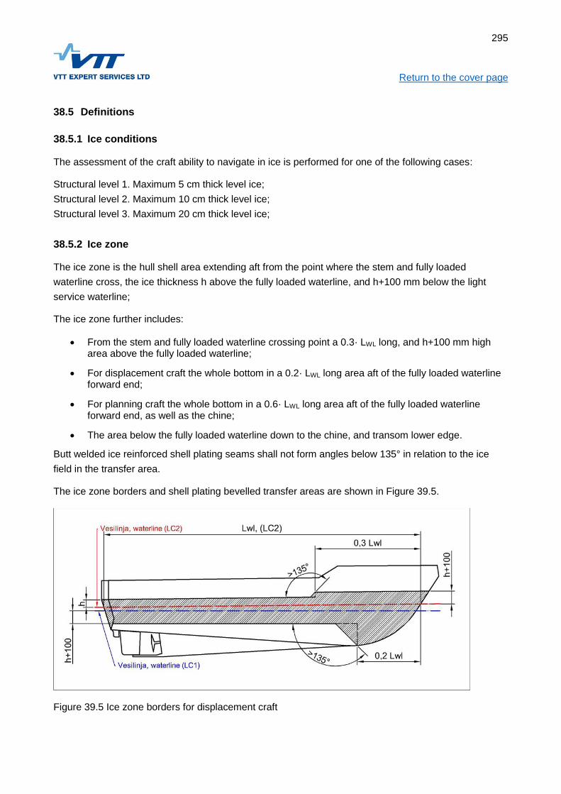
295
Return to the cover page
38.5 Definitions
38.5.1 Ice conditions
The assessment of the craft ability to navigate in ice is performed for one of the following cases:
Structural level 1. Maximum 5 cm thick level ice;
Structural level 2. Maximum 10 cm thick level ice;
Structural level 3. Maximum 20 cm thick level ice;
38.5.2 Ice zone
The ice zone is the hull shell area extending aft from the point where the stem and fully loaded
waterline cross, the ice thickness h above the fully loaded waterline, and h+100 mm below the light
service waterline;
The ice zone further includes:
From the stem and fully loaded waterline crossing point a 0.3· LWL long, and h+100 mm high area above the fully loaded waterline;
For displacement craft the whole bottom in a 0.2· LWL long area aft of the fully loaded waterline forward end;
For planning craft the whole bottom in a 0.6· LWL long area aft of the fully loaded waterline forward end, as well as the chine;
The area below the fully loaded waterline down to the chine, and transom lower edge.
Butt welded ice reinforced shell plating seams shall not form angles below 135° in relation to the ice
field in the transfer area.
The ice zone borders and shell plating bevelled transfer areas are shown in Figure 39.5.
Figure 39.5 Ice zone borders for displacement craft

296
Return to the cover page
38.5.3 Ice frame
An ice frame is a stiffener in the ice zone, transferring the ice loads to ice stringers in transversely
framed structures, or to web frames in longitudinally stiffened structures.
38.5.4 Ice stringer
An ice stringer is an approximately horizontal major stiffener at the lower and/or upper edges of the ice
zone, its purpose is to support ice frames at their upper and/or lower ends.
38.6 Scope of application
38.6.1 Hull type
The craft is assumed to be a monohull designed for the displacement- or planning speed regime. Craft
designed for maximum 5 cm ice may be of planning type.
38.6.2 Hull shape and appendages
The slope of the stem in the ice zone in relation to the horizontal plane shall be at most 60 degrees. For
ensuring that the craft is able to go astern in ice the transom or sternpost angle shall equally be at most
60 degrees.
For ensuring the maneuvering properties for Structural level 3 craft the loaded waterline shall be
narrower in its aftermost quarter length.
The underwater appendages shall stand ice blocks. Thruster tunnels and water intakes shall be
protected by grids.
38.6.3 Propulsion and cooling system
The propulsion for craft with Structural level 2 or 3 shall be an open propeller arrangement meeting the
requirements in item 39.8.7 and 39.8.9. For craft with Structural level 1 waterjet propulsion is allowed.
For Structural level 1 two through hulls with grids and their own raw water filters are approved for
cooling water intakes below the ice zone. For Structural level 2 and 3 there shall be closed circuit skin
tanks, or a raw water chest to which also the outlet water is led. Raw water filters shall be installed so
the crushed ice can be removed from one filter at a time while the engine is running.
38.6.4 Navigation speed
The craft speed in ice fields is limited to 2 m/s (4 knots). In broken ice, or in open water with ice floes
the craft may use higher speeds at the discretion of the master. Because several uncertainty factors are
involved here, in particular the size of floes, which in practice is impossible to determine from the craft
at speed, the rules do not address the maximum allowed speed or the maximum floe size. Further it is
assumed that the frame angle is large ( > 70°) in the area hitting the floes at planing speeds.

297
Return to the cover page
38.6.5 Hull material
The rules refer for steel at all Structural levels. In Structural level 1 or 2 the rules may be applied for
aluminium hulls. At Structural level 1 FRP is allowed as hull material, with the limitation, however, that
sandwich construction is not allowed in underwater areas, including the ice zone area above the full
load water line.
The mechanical properties for the materials are given in Chapter 9 (FRP), 13 (aluminium), and 16
(steel).
38.7 Ice load
38.7.1 The nature of ice load
The ice load is assumed to be a linear load working along the craft ice zone. When the craft proceeds in
an ice field, the ice is broken partly by crushing in compression, and partly by bending.
The ice edge in contact with the hull is assumed to exert full load up to 0.6 m length, after that the load
drops when the ice field breaks. The ice load is related to the thickness of the entire ice field.
The ice load is in some cases limited by the craft displacement, when the craft climbs up on the ice
edge supported by a small contact surface.
It is assumed that ice blocks are hitting the rudder and propeller, but not solid ice.
The ice loads are assumed to depend on the following factors:
Waterline angle α from the longitudinal direction
Frame angle β0 from the vertical direction
Ice thickness h
Ice bending strength σ
Craft speed v
The definition of angles α and β0 is shown in Figure 39.6. The ice bending strength is assumed to be
500 kPa. The range for both the waterline and the frame angles is 20°...40°. In case the frame angle is
less than 20° the calculations shall use 20°, and correspondingly, if the frame angle exceeds 40° the
calculations shall use 40°.

298
Return to the cover page
Figure 39.6 Waterline angle and frame angle from buttock
38.7.2 Ice load per contact surface unit length
The ice load per contact surface unit length shall be determined using the curves in Figure 39.7.
20
40
60
80
100
120
20 22 24 26 28 30 32 34 36 38 40
Ice
lo
ad
/me
tre c
on
tac
t s
urf
ac
e, F,
kN
Frame angle, degrees
Ice thickness 5 cm
waterline angle 20
waterline angle 30
waterline angle 40

299
Return to the cover page
50
70
90
110
130
150
170
190
210
230
250
20 22 24 26 28 30 32 34 36 38 40
Ice
lo
ad
/me
tre c
on
tac
t s
urf
ac
e, F,
kN
Frame angle, degrees
Ice thickness 10 cm
waterline angle 20
waterline angle 30
waterline angle 40

300
Return to the cover page
100
150
200
250
300
350
400
20 22 24 26 28 30 32 34 36 38 40
Ice
lo
ad
/me
tre
co
nta
ct
su
rfa
ce
, F
, k
N
Frame angle, degrees
Ice thickness 20 cm
waterline angle 20
waterline angle 30
waterline angle 40
Figure 39.7 Ice load per meter of contact surface, F for ice thicknesses 5 cm, 10 cm, and 20 cm.
Note! In the formulas the ice thickness is given in millimeters!
The ice load per meter under consideration is the smallest of the following:
kN (39.1)
38.7.3 Correction of the load based on contact surface length
The ice load shall be corrected based on contact surface length according to Formula (39.2)
(max 1,0 ; min 0,35) (39.2)
Where la is to be taken from Table 39.2

301
Return to the cover page Table 39.3.
Structure Framing system la [mm]
Shell transverse b
longitudinal 1.7∙ b
Ice frames transverse s
longitudinal lu
Ice stringers -
Span between bulkheads or equal
primary structures, lu
38.7.4 Ice pressure
The ice pressure used for the ice zone panel structural design is calculated based on the linear load
Flm as follows:
MPa (39.3)
38.8 Structure
38.8.1 Structural arrangements in the ice zone
The structure in the ice zone area is assumed to be an either transversely or longitudinally stiffened hull
shell. In a transversely stiffened structure the secondary stiffeners in the ice zone are ice frames placed
approximately vertically, and transferring the loads to the ice stringers located at the lower and upper
ends of the frames, or to a similar structure (for example a deck).
In a longitudinally stiffened structure the ice zone secondary stiffeners are placed longitudinally, see
Figure 39.2
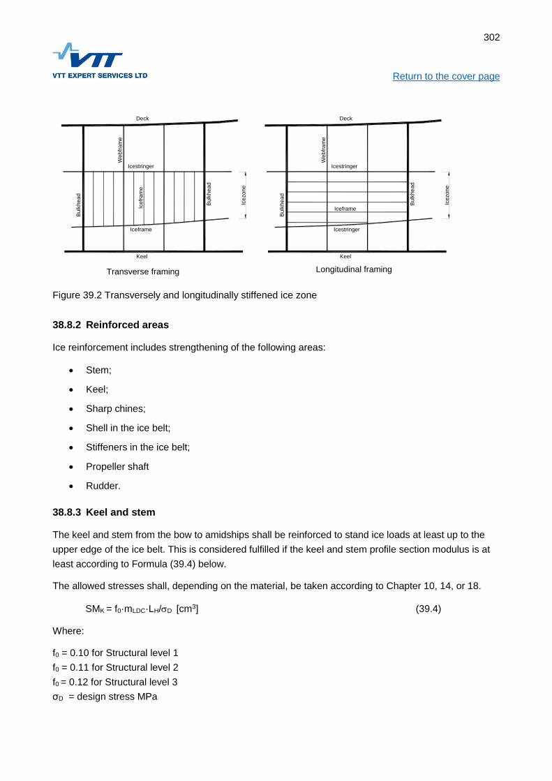
302
Return to the cover page
Icezone
Deck
Keel
Icestringer
Iceframe
Bulk
head
Bulk
head
Webfr
am
e
Icefr
am
e
Icezone
Deck
Keel
Icestringer
Icestringer
Bulk
head
Bulk
head
Webfr
am
e
Iceframe
Transverse framing Longitudinal framing
Figure 39.2 Transversely and longitudinally stiffened ice zone
38.8.2 Reinforced areas
Ice reinforcement includes strengthening of the following areas:
Stem;
Keel;
Sharp chines;
Shell in the ice belt;
Stiffeners in the ice belt;
Propeller shaft
Rudder.
38.8.3 Keel and stem
The keel and stem from the bow to amidships shall be reinforced to stand ice loads at least up to the
upper edge of the ice belt. This is considered fulfilled if the keel and stem profile section modulus is at
least according to Formula (39.4) below.
The allowed stresses shall, depending on the material, be taken according to Chapter 10, 14, or 18.
SMK = f0·mLDC·LH/D [cm3] (39.4)
Where:
f0 = 0.10 for Structural level 1
f0 = 0.11 for Structural level 2
f0 = 0.12 for Structural level 3
σD = design stress MPa

303
Return to the cover page σD = σy for metal
σD = σUF/3 for FRP
When the section modulus for the keel or stem is determined, the effective flange width shall be taken
as follows:
FRP: 20 · t1 [mm]
Aluminium: 60 · t1 [mm]
Steel: 80 · t1 [mm]
FRP craft shall have a steel reinforcement for the stem in the ice zone.
For FRP craft reinforced areas the minimum allowed fiber weight Wmin (Formula 10.9) shall be
increased by a factor of 1.2.
38.8.4 Sharp chines
The section modulus of a sharp chine in the ice belt shall meet the Formula (39.5) requirement in the
direction of the angle bisector, considering the effective flange according to item 39.8.3
[cm3] (39.5)
38.8.5 Hull shell
38.8.5.1 Transversely stiffened shell
The required thickness for a transversely stiffened shell is calculated according to Formula (39.6)
[mm] (39.6)
f1 ≤1,0 (39.7)
Where:
D = design stress:
D = y for metals;
D = UF/3 for FRP;
tC = kulumis- ja korroosiolisä:
For steel over the whole ice zone +1 mm
For FRP over the length 0.2 LWL from bow +1 mm
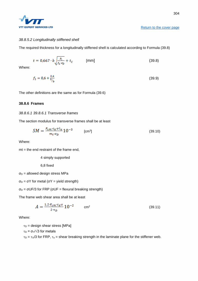
304
Return to the cover page
38.8.5.2 Longitudinally stiffened shell
The required thickness for a longitudinally stiffened shell is calculated according to Formula (39.8)
[mm] (39.8)
Where:
(39.9)
The other definitions are the same as for Formula (39.6)
38.8.6 Frames
38.8.6.1 39.8.6.1 Transverse frames
The section modulus for transverse frames shall be at least
[cm3] (39.10)
Where:
mt = the end restraint of the frame end,
4 simply supported
6,8 fixed
σD = allowed design stress MPa
σD = σY for metal (σY = yield strength)
σD = σUF/3 for FRP (σUF = flexural breaking strength)
The frame web shear area shall be at least
cm2 (39.11)
Where:
D = design shear stress [MPa]
D = σY/√3 for metals
D = U/3 for FRP, u = shear breaking strength in the laminate plane for the stiffener web.

305
Return to the cover page
38.8.6.2 Longitudinal frames
The section modulus for longitudinal frames shall be at least
cm3 (39.12)
Where:
f3 = (1 – 0.2 · h/s)
ms = 13 for continuous frame ending with brackets
ms = 11 for continuous frame without brackets
The frame web shear area shall be at least
cm2 (39.13)
Where:
D = design shear stress, [MPa]
D = σY/√3 for metals
D = u/3 for FRP, u = shear breaking strength in the laminate plane for the stiffener web.
38.8.6.3 Ice stringers
Ice stringers are dimensioned in the same way as longitudinal frames while considering the ice
pressure reduction coefficient ca see formula 38.2. Ice stringers shall be supported sideways against
lateral buckling.
38.8.7 Propeller shaft
The shaft diameter requirement in Chapter 23 shall be multiplied with the following factors
Structural level 1: 1.10
Structural level 2: 1.15
Structural level 3: 1.20
38.8.8 Consideration of side accelerations
The presence of side accelerations shall be considered for the structure and installations.
38.8.9 Reduction and reverse gear
The reduction and reverse gear shall be sized for the shaft end torque considering the following
coefficients applied to the engine power:

306
Return to the cover page Structural level 1: 1.25
Structural level 2: 1.35
Structural level 3: 1.50
Additionally, the sizing of the reduction and reverse gear shall be based on the manufacturer’s
recommendations for ice navigation.
38.8.10 Rudder and steering system
For Structural level 2 and 3 there shall be an ice knife aft of the rudder, able to crush the ice without
exceeding the knife’s yield strength.
The steering gear components shall be sized to stand the loads corresponding to the rudder stock yield
strength.
For Structural level 2 and 3 there shall be rudder stoppers at the maximum angle.
Rudder stock, rudder, and steering gear including components shall be sized according to Chapter 20
with the following additional factors applied to the force F1:
Structural level 1: 1.50
Structural level 2: 2.00
Structural level 3: 2.50
The force F2 is calculated as presented in Chapter 20, but always at minimum 18 knots speed.
38.8.11 Icing on deck and superstructures
The weight of icing on deck and superstructures shall be considered in the stability calculations, see
item 4.7.5
The structure shall stand removal of icing without suffering damage.
The dimensioning of the working deck shall be based on at least 1 t/m2 deck load.

307
Return to the cover page
39 ADDITIONAL NOTATION “DECK CRANE”
39.1 Objective
In this chapter additional requirements are given for craft equipped with a deck crane.
39.2 Additional Notation “Deck Crane”
Craft meeting the requirements in this chapter are assigned the Additional Notation ”Deck Crane”.
39.3 Scope of application
The following requirements refer for power-operated deck cranes.
39.4 Prevention of overload
39.4.1 Restrictions
The lifting gear shall be arranged so the following is avoided:
Lifting of loads exceeding the crane designed capacity;
Large heeling angles resulting from unsuitable combinations of boom length and cargo weight.
39.4.2 Stability
When a deck crane is used, the static heeling angle shall not exceed 10° for any combination of cargo
weight and boom length.
At this heel the remaining righting moment lever curve positive area shall be at least 0.01 metreradians.
In case the assessment is done experimentally, the test shall be performed with a short boom in
horizontal position. With a load corresponding to the desired maximum lifting moment the heeling angle
shall not exceed 10°.
After this the load shall be increased by 20%. With this load there shall not be any signs of insufficient
stability, and the static heeling angle must not exceed 15°.
39.4.3 Maximum allowed load
The lifting device shall have a sign in a visible location, stating the maximum allowed load. Other
markings, which may be confusing, are not allowed.

308
Return to the cover page
39.5 Documentation of the strength
39.5.1 The strength of the crane
Every lifting device shall have a certificate issued by an accredited testing facility, stating the load for
which the device is approved.
39.5.2 The strength of the lifting device attachment
Attachments built of metal shall be dimensioned so that the safety factor to yield is at least 2 and to
ultimate strength at least 4. This safety factor does not refer to bolts and other type approved elements
coming with the lifting device.

309
Return to the cover page
40 ADDITIONAL NOTATION HOVERCRAFT
40.1 Objective
The objective of the rules in this chapter is to specify additional requirements and exceptions for
covering the risks hovercraft encounter.
40.2 Additional Notation ”Hovercraft”
Craft meeting the requirements in this chapter are assigned the Additional Notation ”Hovercraft”
40.2.1 References
In this chapter reference is made to the following documents:
ISO 12215-5:2008 Small craft - Hull construction and scantlings – Part 5: Design pressures for monohulls, design stresses, scantlings determination
ISO 12215-6:2008 Small craft - Hull construction and scantlings – Part 6: Structural arrangements and details
ISO 12216:2002 Small craft – Windows, portlights, hatches, deadlights and doors. Strength and watertightness requirements
MCA – The Hovercraft Code, (8.12.2015)
40.3 Documentation
For assessment of the special requirements and exceptions given in this chapter the following
documentation is required:
Drawings, test protocols, and reports showing compliance with the requirements in items 42.6...42.15.
40.4 Scope of application
These rules are applied to craft considered to be hovercraft according to the following definition:
Hovercraft is a vehicle which during operation is supported by an air cushion, either partly (SES) or
fully.
40.5 General requirements
Craft with the Additional Notation ”Hovercraft” shall meet the requirements stated in Chapters 1...32 in
these Commercial Craft Rules, as applicable considering the exceptions and additional requirements
specified in this chapter.
40.6 Environmental conditions
The requirements stated in this chapter are suitable for Design Category C and D conditions, however,
the maximum allowed significant wave height here is 1 m.

310
Return to the cover page Hovercraft which are used in the winter shall meet the requirements in item 41.9.2 related to winter
conditions.
40.7 Stability and flotation
The stability for hovercraft may be based on the air cushion, therefore the stability shall be assessed
both with air cushion, and without it.
40.8 Structure
40.8.1 Scantlings
The structure shall be dimensioned as a displacement motor craft according to standard ISO 12215-5
for Design Category D.
The windows shall meet the strength and water tightness requirements for Design Category D
according to standard ISO 12216.
The minimal dry fibre weight (WMIN) and thickness (tMIN) can be determined with the formulas in
standard ISO 12215-5 provided the structure otherwise meets the above requirements.
Otherwise the chapters concerning structure and manufacture in this Commercial Craft Rule apply.
40.8.2 Operation on ice
40.8.2.1 On smooth ice
In case the hovercraft is designed for operation on ice, it shall be ensured that the hovercraft watertight
shell is not chafed through.
40.8.2.2 Crossing ice channels
In case the hovercraft is designed for the crossing of ice channels, it shall be ensured that the uneven
surface (ice blocks) does not cause damage to the hovercraft watertight shell.
The loads are difficult to predict, and it needs to be made sure experimentally or by calculation that
damage to the contact surfaces does not endanger the hovercraft watertight shell.
40.8.3 Operation on land
In case the hovercraft is designed for operation on land, it shall be made sure experimentally or by
calculation that the hovercraft watertight shell is not chafed through.

311
Return to the cover page
40.9 Propulsion machinery
40.9.1 General
The propulsion machinery shall meet the requirements in Chapter 21, with the exception that also
engines designed for aircraft purposes can be accepted.
Petrol fuel can be allowed provided that the engine is installed outside the enclosed hull.
40.9.2 Cooling system
The cooling system shall be approved by the engine manufacturer.
40.10 Personal safety
Hovercraft shall meet the requirements in Chapter 26, further an air propeller shall be protected so it
does not cause danger to crew or passengers.
40.10.1 Air propeller protection
An air propeller shall be protected so any part of the human body cannot come into contact with the
rotating propeller from the side or deck of the hovercraft. See Figure 41.1.
A protective net shall stand 450 N of external force at any location on an area of 100 x 100 mm without
endangering its protective function.
Protection guardrails shall stand 1.8 kN force in any direction without breaking.
Side or front protection less than 800 mm from the propeller shall not allow a round bar with 50 mm to
pass through, and from the openings in this protection there shall be at least 250 mm distance to the
propeller swept area. A tight impermeable protection can be closer to the swept area (for example a
propeller duct).
Protection located on the side of the propeller shall be less than 800 mm from the swept area.
There shall be protection in the sector forward of the propeller at least 800 mm from it preventing a
person from accidentally accessing or stumbling into the propeller. Such an arrangement may be a
steeply sloping surface where it is impossible to stand, the outer edge of the hull, or an at least 600 mm
high guardrail.
Behind the propeller there shall be an at least 800 mm wide safety area to an at least 600 mm high
outer edge of the hull, or a guardrail with the same height.
Behind the propeller there shall be a warning sign with at least 20 mm high letters:
BEWARE OF THE ROTATING PROPELLER!

312
Return to the cover page
Figure 41.1. Protection of air propeller, comprising a tight propeller duct and guardrails. Aft the
protection is the craft outer edge, or a guardrail.
40.11 Fire safety
The engine space shall be fitted with a fixed fire extinguishing system, or alternatively a fire port located
at the steering position. In addition to this the requirements in Chapter 27 shall be met.

313
Return to the cover page
40.12 Handling characteristics
40.12.1 Air cushion supported
It shall be possible to control and maneuver the hovercraft over smooth ice and over water. If required
for turning on glassy ice, it is allowed to deflate the air cushion during a turn. A sudden deflation during
a turn must not, however, upset the stability of the hovercraft.
40.12.2 Without air cushion
The hovercraft shall be able to operate in water without an air cushion.
40.13 Noise
A hovercraft must not meet the noise level requirements in Chapter 32.
In a hovercraft not meeting the Chapter 32 requirements for interior noise levels there shall be a
warning sign within the view of the pilot reminding about wearing hearing protection.
40.14 User Manual
The User Manual shall explain the hovercraft peculiar features mentioning at least the following:
Special features related to the maneuvering of the hovercraft
Turning over various surfaces
Braking over various surfaces
Limitations when operating over land
Limitations for wind speed and significant wave height
Limitations when crossing ice channels
Inspection procedures for surfaces subject to wear
Instructions for hearing protection (if required)
Service instructions
Any dangerous issues