guideline for technical regulation on hydropower civil works · 7.9 penstocks ... including samples...
TRANSCRIPT
SOCIALIST REPUBLIC OF VIETNAM Ministry of Construction (MOC)
Guideline for Technical Regulation
on Hydropower Civil Works
Design and Construction of Civil Works and Hydromechanical Equipment
Final Draft
June 2013
Japan International Cooperation Agency
Electric Power Development Co., Ltd. Shikoku Electric Power Co., Inc.
West Japan Engineering Consultants, Inc.
IL
CR(2)
13-096

Guideline for QCVN xxxx : 2013/BXD
Table of Contents 1. Scope of application .................................................................................................. 1 2. Reference documents ............................................................................................... 1 3. Nomenclatures and definitions ................................................................................. 1 4. Classification of works .............................................................................................. 1
4.1 General stipulation ................................................................................................. 1 4.2 Principles for the classification of hydropower works .............................................. 2
5. Guarantee of serving level of hydropower works .................................................... 7 6. Safety coefficient of hydropower civil works ........................................................... 7 7. Construction of hydropower civil works ................................................................ 26
7.1 General requirements .......................................................................................... 26 7.2 Reservoir ............................................................................................................. 49 7.3 Dams ................................................................................................................... 53 7.4 Spillways .............................................................................................................. 83 7.5 Waterway ............................................................................................................. 90 7.6 Intakes ................................................................................................................. 95 7.7 Settling basins ...................................................................................................... 98 7.8 Head tanks and surge tanks ............................................................................... 101 7.9 Penstocks .......................................................................................................... 103 7.10 Tailraces ............................................................................................................ 106 7.11 Outlets ............................................................................................................... 107 7.12 Hydropower plants (Powerhouse) ...................................................................... 107 7.13 Daily storage reservoir ....................................................................................... 110 7.14 Bottom discharge ............................................................................................... 110 7.15 Protective works of reservoirs, headwork area and downstream of headwork .... 112 7.16 Observation device system of the work .............................................................. 112
8. Hydromechanical equipments .............................................................................. 132 8.1 General requirements ........................................................................................ 132 8.2 Valve gates ........................................................................................................ 142 8.3 Trash rack .......................................................................................................... 149 8.4 Steel penstock ................................................................................................... 150
9. Stipulation of management ................................................................................... 154 10. Organization for implementation .......................................................................... 154 Appendix A ...................................................................................................................... 155 Appendix B ...................................................................................................................... 155 Appendix C ...................................................................................................................... 156 Appendix D ...................................................................................................................... 171
i
Guideline for QCVN xxxx : 2013/BXD
List of Tables Table 4.2-1 Criteria for Project Ranking ............................................................................................. 3 Table 4.2-2 Size Classification............................................................................................................ 3 Table 4.2-3 Hazard Potential Classification ........................................................................................ 3 Table 4.2-4 Criteria for Hazardous Level ........................................................................................... 4 Table 6.1-1 Loads imposed on dam body ........................................................................................... 8 Table 6.1-2 Loads imposed on dam bodies ......................................................................................... 8 Table 6.1-3 Basic definition of loads .................................................................................................. 9 Table 6.1-4 Design seismic coefficient ............................................................................................. 10 Table 6.1-5 Uplift under various conditions ..................................................................................... 10 Table 7.1-1 Criteria for Project Ranking ........................................................................................... 33 Table 7.1-2 Criteria of Design and Check Flood (Return Period to be Applied) .............................. 34 Table 7.1-3 Size Classification.......................................................................................................... 34 Table 7.1-4 Hazard Potential Classification ...................................................................................... 34 Table 7.1-5 Recommended Safety Standards ................................................................................... 34 Table 7.1-6 Criteria for Hazardous Level ......................................................................................... 35 Table 7.1-7 Tanaka’s rock classification method used for dam foundation ...................................... 40 Table 7.3-1 Crest elevation of non-overflow section of dam ............................................................ 55 Table 7.3-2 Wave heights by fetch and wind velocity ...................................................................... 57 Table 7.3-3 Normal freeboard and minimum freeboard ................................................................... 57 Table 7.3-4 Crest elevation of non-overflow section of dam ............................................................ 73 Table 7.3-5 Wave heights by fetch and wind velocit ........................................................................ 76 Table 7.3-6 Normal freeboard and minimum freeboard ................................................................... 76 Table 7.3-7 Lugeon values and infiltration factors according to dam height .................................... 82 Table 7.4-1 Criteria for Project Ranking ........................................................................................... 85 Table 7.4-2 Criteria of Design and Check Flood (Return Period to be Applied) .............................. 85 Table 7.4-3 Size Classification.......................................................................................................... 85 Table 7.4-4 Hazard Potential Classification ...................................................................................... 86 Table 7.4-5 Recommended Safety Standards ................................................................................... 86 Table 7.4-6 Criteria for Hazardous Level ......................................................................................... 86 Table 8.1 Classification of forces on gates .................................................................................. 140 Table 8.2 Classification of forces on penstocks ........................................................................... 141
ii

Guideline for QCVN xxxx : 2013/BXD
List of Figures Fig.6.1-1 Typical loads acting on dam body ................................................................................... 9 Fig.6.1-2 Expected function of drains ........................................................................................... 10 Fig.7.1-1 Process for decision of environmental flow rate ............................................................ 28 Fig 7.1-2 Hydraulic analyses of discharge facilities ...................................................................... 31 Fig 7.1-3 Area of grouting ............................................................................................................. 43 Fig.7.1-4 Estimation of Lugeon value ........................................................................................... 44 Fig.7.3-1 Normal and minimum freeboard .................................................................................... 55 Fig.7.3-2 Height of wave above reservoir water surface ............................................................... 56 Fig.7.3-3 Run-up wave height (inclusive of wave height) obtained by combined use of
S.M.B. Method and Saville's Method ............................................................................ 56 Fig.7.3-4 Crest of fill type dam ..................................................................................................... 57 Fig.7.3-5 Prohibited Case .............................................................................................................. 58 Fig.7.3-6 Acceptable Case ............................................................................................................. 58 Fig.7.3-7 Seepage Flow in Zoned Type Fill Dams ........................................................................ 59 Fig.7.3-8 Grain-size Range of the Borrow Material ...................................................................... 60 Fig.7.3-9 Settlement of dam crest after completion ...................................................................... 60 Fig.7.3-10 Detail of perimeter joint ................................................................................................. 65 Fig.7.3-11 Relation between water content and properties ............................................................. 66 Fig.7.3-12 Normal and minimum freeboard .................................................................................... 74 Fig.7.3-13 Height of wave above reservoir water surface ............................................................... 74 Fig.7.3-14 Run-up wave height (inclusive of wave height) obtained by combined use of
S.M.B. Method and Saville's Method ............................................................................ 75 Fig 7.3-15 Drain hole in gallery ...................................................................................................... 82 Fig 7.3-16 Installation of waterstop, joint drain, and crack initiator ............................................... 83 Fig.7.4-1 Classification of reservoir sediment management ......................................................... 88 Fig.7.5-1 Hydraulics of pipe flow ................................................................................................. 91 Fig.7.6-1 Representative type of pressure type intake ................................................................... 96 Fig.7.6-2 Submerge depth of pressure type intake ........................................................................ 98 Fig.7.7-1 Settling of soil or sand particle ...................................................................................... 99 Fig.7.7-2 Relationship between settling velocity and particle size ............................................... 99 Fig.7.7-3 Cleaning of settling basin ............................................................................................ 100 Fig.7.8-1 Hydraulic conditions of surge tank .............................................................................. 102 Fig.7.8-2 Visual description of symbols in equation for restricted orifice type surge tank ......... 102 Fig.7.9-1 Cross Section Image of Penstock and its Internal Water Pressure ............................... 104 Fig.7.9-2 Relationship of h and h0 ............................................................................................... 106 Fig.7.12-1 Development process of underground cavern .............................................................. 109 Fig.7.12-2 Construction of underground cavern ............................................................................ 110
iii

Guideline for QCVN xxxx : 2013/BXD
Fig.8.1 Hydrostatic pressure .................................................................................................... 132 Fig.8.2 Friction force................................................................................................................ 133 Fig.8.3 Operating force ............................................................................................................ 134 Fig.8.4 Air vacuum force in case of closing gate ..................................................................... 135 Fig.8.5 Forces at lifting gear in case of stuck gate ................................................................... 135 Fig.8.6 Earthquake force .......................................................................................................... 136 Fig.8.7 Longitudinal force causing by changes of pipeline diameters ..................................... 136 Fig.8.8 Longitudinal force causing by changes of pipeline direction at bend section ............. 137 Fig.8.9 Water pressure acting on pipe shell ............................................................................. 137 Fig.8.10 Own weight of pipe shell and water ............................................................................ 138 Fig.8.11 Rock pressure on intermediate abutments ................................................................... 139 Fig.8.12 Forces causing by uneven settlement of intermediate abutments ................................ 139
iv

Guideline for QCVN xxxx : 2013/BXD
Guideline for National technical regulation on hydropower civil works
This guideline describes purpose and/or interpretation of provisions in each articles of QCVN xxx: 2013/BXD (hereinafter described as “Technical Regulation”), and provides relevant information including samples or guides of technical applications as well as relevant technical regulations, standards and other reference documents.
Quotations from other Vietnamese regulations and standards are described in italics form in this Guideline.
1. Scope of application
Technical Regulation Article 1 describes scope of application and stipulates that all hydropower facilities and all related persons shall conform to the provisions prescribed in the Technical Regulation as the basic requirements.
The Technical Regulation is applied to the design and construction of hydropower civil works and not applied to the electrical equipment.
2. Reference documents
As stipulated in Technical Regulation Article 2.
3. Nomenclatures and definitions
As stipulated in Technical Regulation Article 3.
4. Classification of works
4.1 General stipulation 4.1.1. Technical Regulation Article 4.1.1 describes classification of guarantee level of hydropower works which are classified according to the following three indexes.
1) Capacity of hydropower plant (installed capacity)
2) Reservoir volume (gross storage volume but not effective storage volume)
3) Dam height
The classification is determined based on importance of hydropower works in terms of installed capacity of a hydropower plant and reservoir storage capacity as well as the combination of foundation condition and height of dam or retaining wall belonging to that hydropower plant. The major purpose of classification is to vary required safety coefficients according to importance of hydropower civil works and influence to the downstream area in case of their failure as stipulated in Article 4.2.4.
The classification method is explained in detail in the following sections.
GUIDELINE FOR QCVN xxx : 2013/BXD
1

Guideline for QCVN xxxx : 2013/BXD
4.1.2. As stipulated in Technical Regulation Article 4.1.2.
4.2 Principles for the classification of hydropower works 4.2.1. As stipulated in Technical Regulation Article 4.2.1.
4.2.2. Technical Regulation Article 4.2.2 describes the classification rule for a headwork, water conveyance and transfer systems (waterway and powerhouse).
In this Technical Regulation, the grade of headworks is determined as the class of hydropower works, and the class of water conveyance and transfer systems is subordinate to that of headworks.
Based on the above mentioned criterion, the class of hydropower works is decided as follows:
1) Choose a class of work item listed in Table 1 for hydropower works according to numerical criteria of the item;
2) Determine the class of the hydropower works by the highest class among those for each work item (items 1 to 5) in Table 1, namely installed capacity of a hydropower plant, gross storage capacity and dam height;
3) Determine the class of headwork structures as the same class of the hydropower works;
4) Determine the class of waterways structures in reference to the class of the headwork;
5) Determine the class of downstream water utilization works such as irrigation woks belonging to the hydropower plant, if any, according to the scale of water use, and
6) Determine the class of minor work and temporary work by lowering the grade of the headwork by one and two, respectively according to the rule stipulated in Article 4.2.10 of Technical Regulation.
4.2.3. Technical Regulation Article 4.2.1 and Article 4.2.2 regulate that the class of works shall be decided by selecting the highest class among those for each work item (items 1 to 5) in Table 1 basically, and Technical Regulation Article 4.2.3 describes the rule of degradation of classes for hydropower works as follows:
a) The dam height has more influence to safety of the downstream area than the reservoir volume, so the class of dam height takes precedence over that of the reservoir volume;
b) The structures which are not placed in the pressure alignment such as service roads, administration building, control building, etc. have less influence to safety of the whole hydropower works, so the class of the said works can be degraded by one in case they are Special and Class I, however, the structures consisting of a powerhouse, pressure water pipeline and water-line used to conduct water to a turbine, headtank or surgetank are not subject to this provision due to their importance;
c) A probability of the outbreak of floods, earthquake or the loads caused by natural disasters reduces for the structures which has the exploitation time less than 10 years, so the class of such short life structures, if any, can be degraded by one; and
d) Hydraulic works such as spillway gates, intake gates, draft gates, outlet gates or any other structures of which rehabilitation and renovation will not affect significantly on the normal operation of the hydropower plant have less influence to securing required role of the hydropower plant in the power system, so the class of the said works can be degraded by one.
4.2.4. Technical Regulation Article 4.2.4 describes the rule of upgrading of classes for hydropower works.
Hydropower works of which failures give significant damage for the socio-economic and environmental conditions downstream are regarded as more important than the class chosen in the process of Article 4.2.1. In this case, the class of hydropower works is upgraded by one.
Table 1 of Article 4.2.1 does not provide with classification according to the influence to the downstream area due to failure of structures., So the examples of rule employed in the other countries to assess influence to the downstream area are shown as follows for reference:
2
Guideline for QCVN xxxx : 2013/BXD
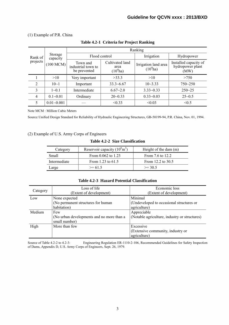
(1) Example of P.R. China
Table 4.2-1 Criteria for Project Ranking
Rank of projects
Storage capacity
(100 MCM)
Ranking Flood control Irrigation Hydropower
Town and industrial town to
be prevented
Cultivated land area
(104ha) Irrigation land area
(104ha) Installed capacity of hydropower plant
(MW) 1 >10 Very important >33.3 >10 >750 2 10~1 Important 33.3~6.67 10~3.33 750~250 3 1~0.1 Intermediate 6.67~2.0 3.33~0.33 250~25 4 0.1~0.01 Ordinary 20~0.33 0.33~0.03 25~0.5 5 0.01~0.001 — <0.33 <0.03 <0.5
Note MCM : Million Cubic Meters
Source: Unified Design Standard for Reliability of Hydraulic Engineering Structures, GB-50199-94, P.R. China, Nov. 01, 1994.
(2) Example of U.S. Army Corps of Engineers
Table 4.2-2 Size Classification
Category Reservoir capacity (106m3) Height of the dam (m) Small From 0.062 to 1.23 From 7.6 to 12.2 Intermediate From 1.23 to 61.5 From 12.2 to 30.5 Large >= 61.5 >= 30.5
Table 4.2-3 Hazard Potential Classification
Category Loss of life (Extent of development)
Economic loss (Extent of development)
Low None expected (No permanent structures for human habitation)
Minimal (Undeveloped to occasional structures or agriculture)
Medium Few (No urban developments and no more than a small number)
Appreciable (Notable agriculture, industry or structures)
High More than few Excessive (Extensive community, industry or agriculture)
Source of Table 4.2-2 to 4.2-3: Engineering Regulation ER-1110-2-106, Recommended Guidelines for Safety Inspection of Dams, Appendix D, U.S. Army Corps of Engineers, Sept. 26, 1979.
3

Guideline for QCVN xxxx : 2013/BXD
(3) Example of Canada
Table 4.2-4 Criteria for Hazardous Level
Consequence category
Potential incremental consequences of failure 1)
Inflow design flood Life safety 2)
Socio-economic Financial
Environmental 2) 3) Very high Large number
of fatalities Extreme damages Probable maximum flood
(PMF) 4) High Some fatalities Large damages Annual Exceedance probability
between 1/1,000 and the PMF 5) Low No fatalities
anticipated Moderate damages Annual Exceedance probability
between 1/100 and 1/1,000 5) 6) Very Low No fatalities Minor damages beyond owner’s property
Note 1) Incremental to the impacts which would occur under the same natural conditions (flood, earthquake or other event) but without failure of the dam. The consequence (i.e. loss of life, or economic losses) with the higher rating determines which category is assigned to the structure. In the case of tailings dams, consequence categories should be assigned for each stage in the life cycle of the dam.
2) The criteria which define the Consequence Categories should be established between the Owner and regulatory authorities, consistent with societal expectations. Where regulatory authorities do not exist, or do not provide guidance, the criteria should be set by the Owner to be consistent with societal expectations. The criteria may be based on levels of risk which are acceptable or tolerable to society.
3) The Owner may wish to establish separate corporate financial criteria which reflect their ability to absorb or otherwise manage the direct financial loss to their business and their liability for damage to others.
4) An appropriate level of conservatism shall be applied to loads from this event, to reduce the risks of dam failure to tolerable values. Thus, the probability of dam failure could be much lower than the probability of extreme event loading.
5) Within the High Consequence category, the IDF is based on the consequences of failure. For example, if one incremental fatality would result from failure, an AEP of 1/1000 could be acceptable, but for consequences approaching those of a Very High Consequence dam, design floods approaching the PMF would be required.
6) If a Low Consequence structure cannot withstand the minimum criteria, the level of upgrading may be determined by economic risk analysis, with consideration of environmental and social impacts.
Source of Table 4.2-4: Water Act, Alberta Province, Canada, January 1, 1999.
4.2.5. Technical Regulation Article 4.2.5 describes the rule of determination of flood discharge capacity in case of cascade exploitation.
In case of the cascade exploitation, if a hydropower reservoir is planned downstream the existing reservoir, the spillway capacity of the planned hydropower reservoir shall be equal to the check flood discharge of the existing work located upstream corresponding to its grade plus the check flood discharge of the incremental catchment area between the two works (existing upstream dam and planned dam) corresponding to the grade of the planned hydropower reservoir without upgrading design class of the work.
For example, assuming that the grade of the existing reservoir in the upstream area is I and that of the planned reservoir in the downstream is II, spillway capacity of the planned hydropower reservoir corresponding to the check flood is as follows under the condition that the flood discharge is in proportion to a catchment area.
Cd = F0.10 + F0.20*(Au - Ad) / Ad
Where,
Cd : Spillway capacity of planned hydropower reservoir;
F0.10 :Check flood discharge corresponding to frequency of 0.10%;
4
Guideline for QCVN xxxx : 2013/BXD
F0.20 : Check flood discharge corresponding to frequency of 0.20%;
Au : Catchment area of upstream hydropower reservoir; and
Ad : Catchment area of downstream hydropower reservoir.
In this case, it is assumed that the events of check flood for the upstream basin and the incremental basin respectively occurred at once in the whole catchment area as the maximum phenomenon.
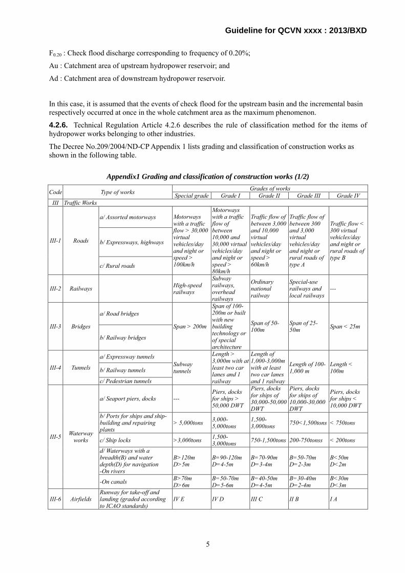
4.2.6. Technical Regulation Article 4.2.6 describes the rule of classification method for the items of hydropower works belonging to other industries.
The Decree No.209/2004/ND-CP Appendix 1 lists grading and classification of construction works as shown in the following table.
Appendix1 Grading and classification of construction works (1/2)
Code Type of works Grades of works Special grade Grade I Grade II Grade III Grade IV
III Traffic Works
III-1 Roads
a/ Assorted motorways Motorways with a traffic flow > 30,000 virtual vehicles/day and night or speed > 100km/h
Motorways with a traffic flow of between 10,000 and 30,000 virtual vehicles/day and night or speed > 80km/h
Traffic flow of between 3,000 and 10,000 virtual vehicles/day and night or speed > 60km/h
Traffic flow of between 300 and 3,000 virtual vehicles/day and night or rural roads of type A
Traffic flow < 300 virtual vehicles/day and night or rural roads of type B
b/ Expressways, highways
c/ Rural roads
III-2 Railways High-speed railways
Subway railways, overhead railways
Ordinary national railway
Special-use railways and local railways
---
III-3 Bridges
a/ Road bridges
Span > 200m
Span of 100-200m or built with new building technology or of special architecture
Span of 50-100m
Span of 25-50m Span < 25m
b/ Railway bridges
III-4 Tunnels
a/ Expressway tunnels Subway tunnels
Length > 3,000m with at least two car lanes and 1 railway
Length of 1,000-3,000m with at least two car lanes and 1 railway
Length of 100-1,000 m
Length < 100m b/ Railway tunnels
c/ Pedestrian tunnels
III-5 Waterway works
a/ Seaport piers, docks --- Piers, docks for ships > 50,000 DWT
Piers, docks for ships of 30,000-50,000 DWT
Piers, docks for ships of 10,000-30,000 DWT
Piers, docks for ships < 10,000 DWT
b/ Ports for ships and ship-building and repairing plants
> 5,000tons 3,000-5,000tons
1,500-3,000tons 750<1,500tons < 750tons
c/ Ship locks >3,000tons 1,500-3,000tons 750-1,500tons 200-750tonss < 200tons
d/ Waterways with a breadth(B) and water depth(D) for navigation -On rivers
B>120m D>5m
B=90-120m D=4-5m
B=70-90m D=3-4m
B=50-70m D=2-3m
B<50m D<2m
-On canals B>70m D>6m
B=50-70m D=5-6m
B=40-50m D=4-5m
B=30-40m D=2-4m
B<30m D<3m
III-6 Airfields Runway for take-off and landing (graded according to ICAO standards)
IV E IV D III C II B I A
5

Guideline for QCVN xxxx : 2013/BXD
Appendix1 Grading and classification of construction works (2/2)
Code Type of works Grades of works Special grade Grade I Grade II Grade III Grade IV
IV Irrigation works
IV-1 Reservoirs Capacity > 5,000x106m3
Capacity of 1,000x106-5,000x106m3
Capacity of 100x106-1,000x106m3
Capacity of 1x10⁶-100x106m3
Capacity < 1x10⁶m3
IV-2 Dams
a/ Earth, earth-rock dams Height>100m Height of 75-100m
Height of 25-75m
Height of 15-25m Height<15m
b/ Concrete dams Height>150m Height of 100-150m
Height of 50-100m
Height of 15-50m Height<15m
c/ Reservoir walls --- --- Height>50m Height of 5-50m Height<5m
IV-3 Rural
irrigation works
a/ Irrigation systems with a supplying or draining capacity over an acreage: Sx103 ha
Acreage>75 Acreage of 50-75
Acreage of 10-50
Acreage of 2-10 Acreage<2
b/ Works that supply water for daily life and production with a flow: Q(m3/s)
Q>20 Q of 10-20 Q of 2-10 Q<2 ---
IV-4 Dykes Embankments
Main dykes, girdle-shaped dykes, cofferdams (graded according the irrigation sector’s dyke grading regulations)
Special I II III IV
The class of other current structures belonging to other industries is chosen based on Appendix 1 and the grade of a hydropower works is decided considering importance of each item. 4.2.7. Technical Regulation Article 4.2.7 describes the rule of classification method of a hydropower works crossing river bank protection dike. In this case, the class of hydropower works shall be the same as that of the dam.
4.2.8. Technical Regulation Article 4.2.8 describes rules of adjustment of classification for temporary works.
The class of temporary works may be increased to that of major works when temporary works hold major place in safety of the whole hydropower works, but shall not be higher than that of major works in case that failure of the works can lead to following consequences:
a) Failure of temporary works affects safety of the permanent structures under construction. For example, collapse of a cofferdam spoils construction of a main dam;
b) Failure of temporary works gives significant damage to the downstream area and the amount of damage by its failure is larger than additional investment to improve it; and
c) A delay of the commissioning date of hydropower works and collection time of investment worsens profitability of the works.
4.2.9. As stipulated in Technical Regulation Article 4.2.9.
4.2.10. Technical Regulation Article 4.2.10 describes the process of selecting the class of hydropower works.
Basically, when the class of major works is determined, the class of minor works and temporary works is lower than the major works by one and two grades, respectively, and the lowest grade shall be IV even though the class of major works is III or IV.
6

Guideline for QCVN xxxx : 2013/BXD
Summarizing provisions in Article 4.2, the class of hydropower works is determined according to Table 1 considering in the following process.
1) Choose a class of work item listed in Table 1 for a hydropower work according to numerical value of the item;
2) Determine the class of a hydropower work by the highest class among those for each work item (items 1 to 5) in Table 1,
3) Determine the class of headwork as the same class of the hydropower works;
4) Determine the class of waterways in reference to the class of the headwork;
5) Determine the class of minor work and temporary work by lowering the grade of the headwork by one and two, respectively according to Table 2; and
6) Adjust the class of hydropower works according to conditions described in Article 4.2.2 to 4.2.8.
5. Guarantee of serving level of hydropower works 5.1. Technical Regulation Article 5.1 describes the rule regarding the application of guarantee level for service of hydropower works.
A hydropower plant shall be developed with a plan that satisfies the following requirement based on computation of ability of power generation with a series of river flow data for a period longer than the required minimum years according to the existing Vietnamese standards.
A hydropower plant assures to generate electricity at a level equal to or more than the dependable capacity or dependable peak capacity for a duration (hours) per day to be determined based on the requirement of power system for a period in percentage which is equal to or more than the specified guarantee service level.
The service level of hydropower works (flow regulation type) is defined as the firm (dependable) peak output in the minimum peak duration which can be maintained during a day for the period of days (%) shown in Table 3 of Technical Regulation in the average year.
The service level of hydropower works (run-of-river type) is defined as the firm output which can be maintained during the period of days (%) shown in Table 3 of Technical Regulation in the average year.
A guaranteed service level is defined as an output which can be generated for the days corresponding to the percentage in a year. In case of a multipurpose dam, the dam owner shall consult with other water users and the competent authorities such as MARD, MONRE, etc. to determine the guarantee level of water use other than power generation.
5.2. As stipulated in Technical Regulation Article 5.2.
5.3. As stipulated in Technical Regulation Article 5.3.
6. Safety coefficient of hydropower civil works 6.1. Technical Regulation Article 6 describes loads to be considered for design of hydropower works and their combination, and safety coefficients corresponding to each class. Hydropower works shall be safe and stable against loads assumed to act on them during the project life.
Seismic loads acting on hydropower works shall be estimated following provisions of TCXDVN 375:2006 considering regional seismic intensity. An earthquake resistant design must be referred to provisions of Article 7.3 of Technical Regulation.
For reference, examples of safety coefficients of a dam are listed as below.
7

Guideline for QCVN xxxx : 2013/BXD
(1) Example of Vietnam
According to QCVN 04 - 05 : 2011/BNNPTNT, loads imposed on a dam body are as shown in Table 6.1-1.
Table 6.1-1 Loads imposed on dam body Name of loads Load deviation coefficient
Self weight 1.05 Silt pressure 1.20 Hydrostatic pressure 1.00 Hydrodynamic pressure 1.20 Thermal load 1.10 Seismic load 1.10
(2) Example of U.S.A.
Refer to Appendix C of this Guideline.
(3) Example of Japan
According to the Government Ordinance for Structural Standard for River Administration Facilities, loads imposed on a dam body and foundation corresponding to various dam type and reservoir water level are as shown in Table 6.1-2. Typical loads are illustrated in Fig. 6.1-1.
Table 6.1-2 Loads imposed on dam bodies
Reservoir water level
Type of dam Concrete gravity dam Arch dam Fill dam
Retention water level • self-weight • hydrostatic pressure • hydrodynamic pressure • horizontal earthquake
acceleration • mud pressure • uplift
• self-weight • hydrostatic pressure • hydrodynamic pressure • horizontal earthquake
acceleration • mud pressure • uplift • thermal load
• self-weight • hydrostatic pressure • horizontal earthquake
acceleration • pore pressure
Design flood water level
• self-weight • hydrostatic pressure at
FWL • mud pressure • uplift
• self-weight • hydrostatic pressure at
FWL • mud pressure • uplift • thermal load
• self-weight • hydrostatic pressure at
FWL • pore pressure
8

Guideline for QCVN xxxx : 2013/BXD
Fig.6.1-1 Typical loads acting on dam body
The calculation methods of loads are as shown in Table 6.1-3.
Table 6.1-3 Basic definition of loads Loads Formula
Self-weight Based on unit weights of the dam body materials Hydrostatic pressure P = W0h P : Hydrostatic pressure
W0 : Unit weight of water h : Depth of water including wave height
Uplift Based on the condition of foundation treatment and location of drains Ux = W0Hx Ux : Uplift pressure at location x
Hx : Depth of water at location x Silt pressure Pe = CeW0d Pe : Horizontal silt pressure
Ce : Silt pressure coefficient d : Thickness of silt
Seismic force I = Wk I : Inertial force of the dam body during an earthquake W : Self weight of a dam body k : Design seismic coefficient
Hydrodynamic pressure
Pd = 0.875W0k(Hh)^0.5 Pd : Hydrodynamic pressure W0 : Unit weight of water k : Design seismic coefficient h : Depth of water from reservoir water surface to
foundation bed H : Depth of water from reservoir water surface to the
point of action of hydrodynamic pressure
The national land is divided into three seismic hazard zones, i.e. strong seismic zone, medium seismic zone and weak seismic zone. The minimum seismic coefficients used for dam design are stipulated by the seismic zone and dam type as shown in Table 6.1-4.
9

Guideline for QCVN xxxx : 2013/BXD
Table 6.1-4 Design seismic coefficient Earthquake intensity
zone
Dam type Strong Middle Weak
Concrete gravity 0.12 0.12 0.10 Arch 0.24 0.24 0.20
Fill dam Homogeneous type 0.15 0.15 0.12 Other type 0.15 0.12 0.10
The coefficient of uplift depends much on the construction work and deterioration in the function of drainage system during operation as shown in Table 6.1-5. The reliability of drains is relatively low, especially in a small hydropower station. Therefore, the coefficient of uplift shall not be mentioned as a standard, but rather mentioned as a reference although the Japanese standards allow deduction of uplift downstream from drains as shown in Fig. 6.1-2.
Fig.6.1-2 Expected function of drains
Table 6.1-5 Uplift under various conditions
H1: Uplift at upstream end of dam H1=H2+1/3*(Hu-H2) Hu :Hydrostatic pressure at upstream end of dam H2: Hydrostatic pressure at downstream end of dam
H1: Hydrostatic pressure at upstream end of dam H3: Hydrostatic pressure at drain hole H3=H2+1/5*(H1-H2) H2: Hydrostatic pressure at downstream end of dam
1. Without foundation drains 2. With drains
Stability conditions are as follows.
1) Concrete dam
The dam body and the contact zone between the dam body and the foundation shall be stable against
H 1
H 2
Drainage Gallery
H 3
Drains
L
Ha = H2 + aL × (H1–H2)*
* The uplift in this table is calculated with a proportional method.
H1
H2
a
L
Ha
H1
H2
H1
H2
Drainage Gallery
Drains
10
Guideline for QCVN xxxx : 2013/BXD
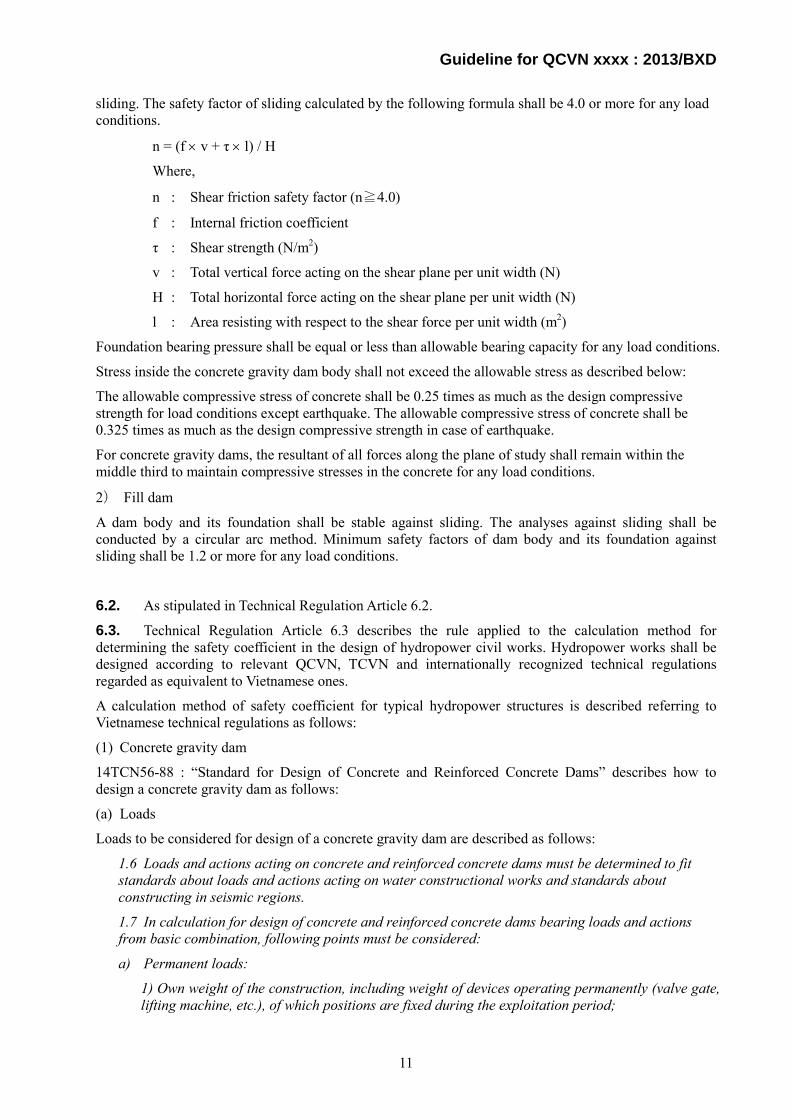
sliding. The safety factor of sliding calculated by the following formula shall be 4.0 or more for any load conditions.
n = (f × v + τ × l) / H
Where,
n : Shear friction safety factor (n≧4.0)
f : Internal friction coefficient
τ : Shear strength (N/m2)
v : Total vertical force acting on the shear plane per unit width (N)
H : Total horizontal force acting on the shear plane per unit width (N)
l : Area resisting with respect to the shear force per unit width (m2)
Foundation bearing pressure shall be equal or less than allowable bearing capacity for any load conditions.
Stress inside the concrete gravity dam body shall not exceed the allowable stress as described below:
The allowable compressive stress of concrete shall be 0.25 times as much as the design compressive strength for load conditions except earthquake. The allowable compressive stress of concrete shall be 0.325 times as much as the design compressive strength in case of earthquake.
For concrete gravity dams, the resultant of all forces along the plane of study shall remain within the middle third to maintain compressive stresses in the concrete for any load conditions.
2) Fill dam
A dam body and its foundation shall be stable against sliding. The analyses against sliding shall be conducted by a circular arc method. Minimum safety factors of dam body and its foundation against sliding shall be 1.2 or more for any load conditions.
6.2. As stipulated in Technical Regulation Article 6.2. 6.3. Technical Regulation Article 6.3 describes the rule applied to the calculation method for determining the safety coefficient in the design of hydropower civil works. Hydropower works shall be designed according to relevant QCVN, TCVN and internationally recognized technical regulations regarded as equivalent to Vietnamese ones.
A calculation method of safety coefficient for typical hydropower structures is described referring to Vietnamese technical regulations as follows:
(1) Concrete gravity dam
14TCN56-88 : “Standard for Design of Concrete and Reinforced Concrete Dams” describes how to design a concrete gravity dam as follows:
(a) Loads
Loads to be considered for design of a concrete gravity dam are described as follows:
1.6 Loads and actions acting on concrete and reinforced concrete dams must be determined to fit standards about loads and actions acting on water constructional works and standards about constructing in seismic regions.
1.7 In calculation for design of concrete and reinforced concrete dams bearing loads and actions from basic combination, following points must be considered:
a) Permanent loads:
1) Own weight of the construction, including weight of devices operating permanently (valve gate, lifting machine, etc.), of which positions are fixed during the exploitation period;
11

Guideline for QCVN xxxx : 2013/BXD
2) Hydrostatic pressure from the upstream corresponding to the normal water level (NWL);
3) Hydrostatic pressure from the downstream corresponding to:
i) Minimum downstream level (MDoL);
ii) Downstream level when maximum discharge is released through the dam in case of NWL;
4) Osmotic pressure corresponding to NWL and when waterproof and drainage devices work normally;
5) Weight of soil sliding with the dam and lateral pressure of soil at upstream and downstream sides;
Permanent temporal loads:
6) Silt pressure in front of the dam;
7) Temperature impact (for concrete dam) determined for years with average annual oscillation amplitude of average monthly temperature;
Short-term temporal loads:
8) Wave pressure corresponding to average over-years wind velocity;
9) Loads caused by lifting, support and transport devices and by other structures and machines (roller bridge, etc.);
10) Loads caused by floatage;
11) Dynamic loads when flood is released through flushing dam corresponding to NWL;
If concrete and reinforced concrete dams are calculated with special load combinations and actions, some loads in the basic load combination must be checked. If there are enough reliable facts, two of following loads must be checked:
12) Hydrostatic pressure at upstream and downstream corresponding to reinforced water level (RWL) at the upstream;
13) Osmotic pressure caused by the breakdown of any waterproof or drainage device;
14) Temperature impact determined for years with maximum annual oscillation amplitude of average monthly temperature (replacing term 7);
15) Wave pressure corresponding to maximum over-years wind pressure (replacing term 8);
16) Dynamic loads when flood is released through flushing dam corresponding to RWL at the upstream (replacing term 11);
17) Seismic impacts.
Loads and actions in the constructional and maintenance periods must be selected from basic and special combinations; and their value are determined based on specific conditions when constructing and maintaining the construction.
Loads and actions must be selected from the most unfavorable combinations that might occur during the operational and constructional periods.
Loads assumed to act on hydropower works shall be selected and combined considering probability of incidence and the most unfavorable conditions during construction and operation.
Besides the above, an estimation method of uplift is described in Article 1.75 to 1.84 of 14TCN56-88 as follows:
Infiltration of Dam
12
Guideline for QCVN xxxx : 2013/BXD
1.75 Infiltrative calculation of concrete and reinforced concrete dams must be done in order to determine:
Return pressure of seepage water action on the dam bed;
Average gradient of pressure head;
Maximum local gradient of pressure head;
Location of saturated line of the seepage flow in a bank adjacent to the dam;
Water loss in the reservoir due to infiltration, including water discharge infiltrating into drainage devices;
Parameters of drainage and waterproof devices.
1.76 Calculation of general seepage strength of the base soil must be done with average gradient of water head.
Calculation of local durability of water proof items (blanket, trench, and membrane) and of base soil must be done with highest gradient of water head.
At output of the seepage flow which is downstream or drainage devices;
Boundary between heterogeneous soil layers;
Zones having large cracks.
The check of seepage stream flowing to flanks and of flood surrounding the construction is done based on calculated location of saturated line of the seepage flow.
1.77 In seepage calculation of the dam, allow consider the seepage to flow follow the linear rule and to have a sufficient condition. If water levels of downstream and upstream change suddenly and if earthquake occurs, seepage calculation must be done with insufficient flow condition.
1.78 Features of the seepage flow (water level, pressure, gradient, discharge) in dams grade I, II, and III must be done by method of electromotive and hydrodynamic analogy on analog or arithmetic computer by solving one of these problems:
Dam parts in riverbed: at vertical cross section – solving the two dimensional problem;
Bank adjacent to the dam: on the plan or at vertical cross sections across the flow – solving the two dimensional problem or spatial problem.
For dams grade IV and for preliminary calculation of dams grade I, II, and III; allow determine features of the seepage flow by approximate analytical method (resistance factor method, etc.)
1.79 In calculation of the seepage flow features, following points must be considered:
Drainage and waterproof devices;
Empty opening, and extended joints in the base and galleries in the dam;
Permeability of concrete;
Deformation stress of the base;
Temperature of subsurface water and its mineralized ratio.
1.80 For concrete and reinforced concrete dams grade II and III on rock and non-rock bases that are re-graded into grade IV due to the breakdown or their height, allow calculate the permeability the same as dam grade IV.
1.81 Forces acting on seepage flow in the dam body and base must be considered.
a) For concrete and reinforced concrete dams grade III and IV, as well as in preliminary calculation of dams in all grades, actions of surface forces on the contact face between the dam and foundation (total return pressure) are based on term 1.83 of this standard (Figure 5);
13
Guideline for QCVN xxxx : 2013/BXD
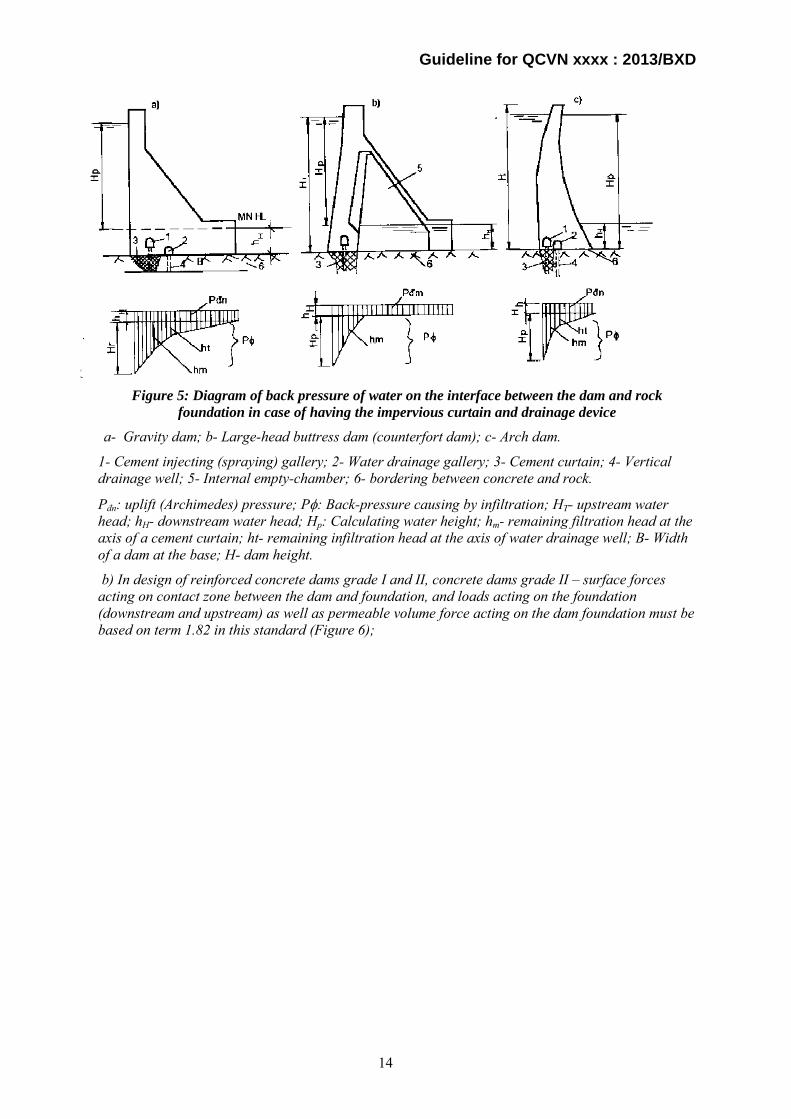
Figure 5: Diagram of back pressure of water on the interface between the dam and rock
foundation in case of having the impervious curtain and drainage device
a- Gravity dam; b- Large-head buttress dam (counterfort dam); c- Arch dam.
1- Cement injecting (spraying) gallery; 2- Water drainage gallery; 3- Cement curtain; 4- Vertical drainage well; 5- Internal empty-chamber; 6- bordering between concrete and rock.
Pđn: uplift (Archimedes) pressure; Pφ: Back-pressure causing by infiltration; HT- upstream water head; hH- downstream water head; Hp: Calculating water height; hm- remaining filtration head at the axis of a cement curtain; ht- remaining infiltration head at the axis of water drainage well; B- Width of a dam at the base; H- dam height.
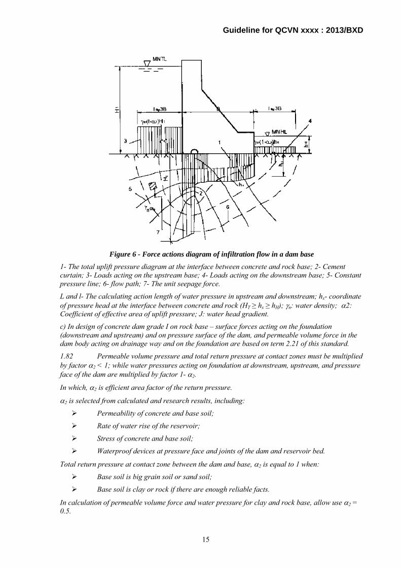
b) In design of reinforced concrete dams grade I and II, concrete dams grade II – surface forces acting on contact zone between the dam and foundation, and loads acting on the foundation (downstream and upstream) as well as permeable volume force acting on the dam foundation must be based on term 1.82 in this standard (Figure 6);
14
Guideline for QCVN xxxx : 2013/BXD
Figure 6 - Force actions diagram of infiltration flow in a dam base
1- The total uplift pressure diagram at the interface between concrete and rock base; 2- Cement curtain; 3- Loads acting on the upstream base; 4- Loads acting on the downstream base; 5- Constant pressure line; 6- flow path; 7- The unit seepage force.
L and l- The calculating action length of water pressure in upstream and downstream; hx- coordinate of pressure head at the interface between concrete and rock (HT ≥ hx ≥ hH); γn: water density; α2: Coefficient of effective area of uplift pressure; J: water head gradient.
c) In design of concrete dam grade I on rock base – surface forces acting on the foundation (downstream and upstream) and on pressure surface of the dam, and permeable volume force in the dam body acting on drainage way and on the foundation are based on term 2.21 of this standard.
1.82 Permeable volume pressure and total return pressure at contact zones must be multiplied by factor α2 < 1; while water pressures acting on foundation at downstream, upstream, and pressure face of the dam are multiplied by factor 1- α2.
In which, α2 is efficient area factor of the return pressure.
α2 is selected from calculated and research results, including:
Permeability of concrete and base soil;
Rate of water rise of the reservoir;
Stress of concrete and base soil;
Waterproof devices at pressure face and joints of the dam and reservoir bed.
Total return pressure at contact zone between the dam and base, α2 is equal to 1 when:
Base soil is big grain soil or sand soil;
Base soil is clay or rock if there are enough reliable facts.
In calculation of permeable volume force and water pressure for clay and rock base, allow use α2 = 0.5.
15
Guideline for QCVN xxxx : 2013/BXD
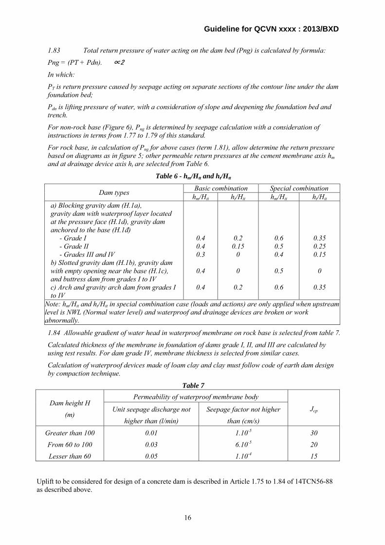
1.83 Total return pressure of water acting on the dam bed (Png) is calculated by formula:
Png = (PT + Pdn). ∝2
In which:
PT is return pressure caused by seepage acting on separate sections of the contour line under the dam foundation bed;
Pdn is lifting pressure of water, with a consideration of slope and deepening the foundation bed and trench.
For non-rock base (Figure 6), Png is determined by seepage calculation with a consideration of instructions in terms from 1.77 to 1.79 of this standard.
For rock base, in calculation of Png for above cases (term 1.81), allow determine the return pressure based on diagrams as in figure 5; other permeable return pressures at the cement membrane axis hm and at drainage device axis ht are selected from Table 6.
Table 6 - hm/Htt and ht/Htt
Dam types Basic combination Special combination hm/Htt ht/Htt hm/Htt ht/Htt
a) Blocking gravity dam (H.1a), gravity dam with waterproof layer located at the pressure face (H.1d), gravity dam anchored to the base (H.1đ) - Grade I - Grade II - Grades III and IV b) Slotted gravity dam (H.1b), gravity dam with empty opening near the base (H.1c), and buttress dam from grades I to IV c) Arch and gravity arch dam from grades I to IV
0.4 0.4 0.3
0.4
0.4
0.2 0.15
0
0
0.2
0.6 0.5 0.4
0.5
0.6
0.35 0.25 0.15
0
0.35
Note: hm/Htt and ht/Htt in special combination case (loads and actions) are only applied when upstream level is NWL (Normal water level) and waterproof and drainage devices are broken or work abnormally.
1.84 Allowable gradient of water head in waterproof membrane on rock base is selected from table 7.
Calculated thickness of the membrane in foundation of dams grade I, II, and III are calculated by using test results. For dam grade IV, membrane thickness is selected from similar cases.
Calculation of waterproof devices made of loam clay and clay must follow code of earth dam design by compaction technique.
Table 7
Dam height H (m)
Permeability of waterproof membrane body
Jcp Unit seepage discharge not higher than (l/min)
Seepage factor not higher than (cm/s)
Greater than 100 From 60 to 100 Lesser than 60
0.01 0.03 0.05
1.10-5 6.10-5 1.10-4
30 20 15
Uplift to be considered for design of a concrete dam is described in Article 1.75 to 1.84 of 14TCN56-88 as described above.
16
Guideline for QCVN xxxx : 2013/BXD
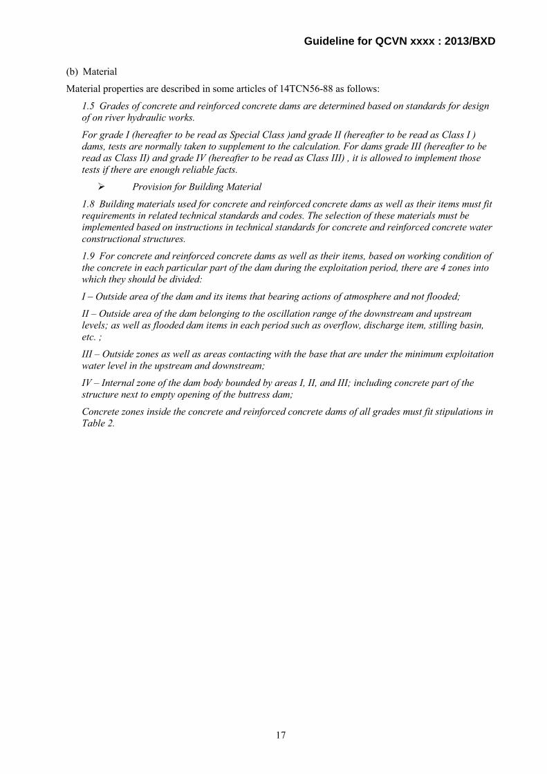
(b) Material
Material properties are described in some articles of 14TCN56-88 as follows:
1.5 Grades of concrete and reinforced concrete dams are determined based on standards for design of on river hydraulic works.
For grade I (hereafter to be read as Special Class )and grade II (hereafter to be read as Class I ) dams, tests are normally taken to supplement to the calculation. For dams grade III (hereafter to be read as Class II) and grade IV (hereafter to be read as Class III) , it is allowed to implement those tests if there are enough reliable facts.
Provision for Building Material
1.8 Building materials used for concrete and reinforced concrete dams as well as their items must fit requirements in related technical standards and codes. The selection of these materials must be implemented based on instructions in technical standards for concrete and reinforced concrete water constructional structures.
1.9 For concrete and reinforced concrete dams as well as their items, based on working condition of the concrete in each particular part of the dam during the exploitation period, there are 4 zones into which they should be divided:
I – Outside area of the dam and its items that bearing actions of atmosphere and not flooded;
II – Outside area of the dam belonging to the oscillation range of the downstream and upstream levels; as well as flooded dam items in each period such as overflow, discharge item, stilling basin, etc. ;
III – Outside zones as well as areas contacting with the base that are under the minimum exploitation water level in the upstream and downstream;
IV – Internal zone of the dam body bounded by areas I, II, and III; including concrete part of the structure next to empty opening of the buttress dam;
Concrete zones inside the concrete and reinforced concrete dams of all grades must fit stipulations in Table 2.
17

Guideline for QCVN xxxx : 2013/BXD
Table 2
Requirements for concrete in different zones of the dam Dam zone
Concrete Reinforced concrete
- Based on compressible strength - Based on tensional strength - Based on moisture proofness - Based on limit elongation - Based on water erosion strength - Based on abrasive strength toward flow with silt as well as real gas strength when throughput at the concrete surface is equal to or greater than 15m/s - Based on exothermal ratio of curing concrete
I – IV I - III II – III I – IV II – III II I – IV
I – III I – III II – III No requirement II - III II No requirement
Note: For dam grade IV, it is allowed to bypass the requirement about limit elongation and exothermal ratio of concrete.
1.10 Thickness of outside areas of the dam is determined based on type and class of the dam, value of acting water head, weather condition of the building region, and dimension of dam items; but not lesser than 2m.
1.11 There are normally no more than 4 types of concrete grade in design of dam. Only allow to increase concrete grade if there are enough reliable facts.
1.12 For cement used in dams grade I, II, and III; private productive processes should be created if necessary and must be agreed by related authorities and approved according to general provisions.
Material properties shall be selected considering environments of the woks.
(c) Durability and stability
1.62 The calculation of durability and stability of concrete and reinforced concrete dams must be based on limit state, including impacts of force, temperature, and humidity which fit related standards and codes.
1.63 The calculation of durability and stability of the dam must be based on two groups of limit state:
- The first limit state (non-usable construction): Calculation for general stability and durability of the construction, as well as local durability of its items;
- The second limit state (abnormal working construction): Calculation for local durability of the base, calculation for the creation of cracks, and calculation for deformation of the construction as well as for the expansion of construction joints in the concrete and reinforced concrete structures;
Calculations of general durability, deformational stability, and expansion of cracks as well as of constructional joints are based on the constructional process and must be implemented for the entire dam or each dam section (or each separate “column” if the concreting block is divided into vertical sections).
Calculations of local durability and the creation of cracks must be done for each separate section of the construction; for concrete structure, calculation for creation of cracks must be done for items bounded by constructional joints.
18

Guideline for QCVN xxxx : 2013/BXD
1.64 Durability and stability of the dam, dam foundation, and its items must be done for the highest probability cases in the constructional and operational periods with a consideration of constructional process and loading strength of the dam.
If the design plan includes the construction and handover of headwork which will be taken periodically, partial durability and stability of the dam in all grades must be calculated for all known loads and actions appeared during the permanent operation. In addition, conditions of durability and stability of the dam during the temporal operation are selected equal to the permanent operation.
In the design, constructional process of dam and its items must be estimated so that there is no need of reinforcing or increasing other weights of the construction to deal with forces appeared in the constructional period.
1.65 Durability and stability of the dam are determined based on calculated loads.
Calculation of standard loads must include requirements mentioned in terms from 1.82 to 1.84 of this standard as well as following instructions:
Volume weight of concrete: For dams grade I, II, and III, volume weight is based on choice result of concrete compositions; for dams grade IV and for preliminary calculation of dam in all grades, it is 2.4 t/m3, reinforced concrete is 2.5 t/m3;
Dynamic loads in flood discharge: For dams grade I and II, dynamic loads are based on calculation and research; for dams grade III and IV, they are based on calculation or on similar constructions;
Thermal actions: They are based on documents of over-year air temperature on the dam site as well as based on estimation of water temperature of the reservoir.
Note: General durability and stability of the dam; overloading factors of its own weight, of thermal action, of humidity and dynamic loads, as well as of all soil loads corresponding calculated features tgφI,II , CI,II , γI,II based on requirements of the standard for foundation design in hydraulic projects are equal to 1.
1.66 Durability of dams grade I and II constructed on rock base are calculated based on elastic theory technique; and if necessary, must include non-elastic deformation as well as cracks in the concrete or base.
Calculation for durability of dam grade I and II constructed on non-rock base must include spatial work of the foundation plate as well as other loading items of the structure.
Durability of dams grade III and IV as well as of preliminary calculation of dams grade I and II must be determined principally by simplified structural analysis methods.
1.67 For dams grade I and II that are re-graded into grade III and IV respectively due to their breakdowns or height, their durability can be calculated by simplified methods; calculated coefficients can be equal to those of dams grade I and II, while load combination factor and standard durability are equal to those of dams grade III and IV.
1.68 If stress-deformation states of the dam and contact zones of the foundation are calculated by elastic theory technique, allow consider concrete as an isotropic homogeneous material with average mechanical features. Then, following points must be considered:
Galleries (wells) in vertical empty opening, machinery room of the hydropower station, water pipe of the turbine, deep discharge works, and other holes if widths of the opening and these holes are greater than 15% of calculated width of dam cross section;
Distribution of concrete in each zone, if proportion of elastic module in that zone is greater or equal to 2;
Difference between mechanical features of dam and foundation materials;
Heterogeneity of the foundation and appearance of cracks and faults in the base;
19

Guideline for QCVN xxxx : 2013/BXD
Expansion of constructional joints and the monolithic failure of the foundation in tensional zones;
Constructional process as well as technique and time limit for the concreting of dam blocks.
1.69 In calculation of general durability, deformation, expansion of constructional joints, and expansion of cracks; calculated elastic module of concrete (E) is:
If the dam is concreted by “column concreting” technique or “seam web” technique (like brick wall arrangement):
E = Eb.t x (1 - 0.04 x nk) ;
If the dam is concreted by lifts (layer by layer):
E = 0.90 x Eb.t ;
In which:
Ebt is initial elastic module of concrete selected from table 4 in “design standard for hydraulic concrete and reinforced concrete structures”;
Nk is amount of vertical joints in concreting of dam bed.
For all cases, elastic module of concrete must be in the range:
0.65 Ebt ≤ E ≤ 250 x 103 kg/cm2
1.70 Calculation for extended depth of constructional joints at downstream must include own weight of the construction, hydrostatic pressure, and thermal actions caused by seasonal oscillation of atmosphere and reservoir water temperature, as well as by the difference between initial temperature when concreting constructional joints and average over-year temperature of the dam during its operational period.
1.71 General durability and stability of the dam as well as local durability of particular items must be calculated based on follow conditions:
cmn N Rk
≤ ; (3)
( , )c a btmn R Rk
σ φ< ; (4)
In which:
m is coefficient of working condition including working features of the dam, its items and the foundation; selected from table 5;
nc is load combination factor;
k is safety coefficient;
σ is calculated stress;
Ra and Rbt are calculated strengths of reinforcing bar and of concrete respectively, based on design standard of hydraulic concrete and reinforced concrete structure.
Φ is a function; its diagram depends on characteristics of the stress-deformation state of the dam that is determined based on terms 2, 3, 4, and 5 of this standard.
N and R are calculated values of general force and general loading strength of the construction respectively.
20

Guideline for QCVN xxxx : 2013/BXD
Table 5 - Coefficient of working condition m of the dam
Calculation cases and causes for the use of working condition factor Working condition factor m
1. Stability of concrete and reinforced concrete dams on half-rock base 1,0 2. Stability of concrete and reinforced concrete dams on half-rock base: a) For sliding face travelling through cracks of the base 1,0 b) For sliding face travelling through contact zones between concrete and rock; sliding face in the base, of which a part travels through cracks and the remaining travels through monolith 0,95 3. Stability of arch dam 0,75 4. General durability and local durability of concrete and reinforced concrete dams as well as of their items if the durability is critical to below structures: a) In concrete structure: - For basic load combinations and actions 0,9 - For special load combinations and actions, without consideration of earthquake 1,0 - As above, but with consideration of earthquake 1,1 b) In reinforced concrete structures (flank and plate types), if thickness of the plate (flank) is equal or greater than 60cm ; 1,15 c) In reinforced concrete structures (flank and plate types), if thickness of the plate (flank) is lesser than 60cm 1,0 5. Same as 4, but durability of the non-pre-stressed reinforcing bar is critical to below structures: a) Items of reinforced concrete, of which horizontal cross section has number of main bars: - Lesser than 10; 1,1 - Greater or equal to 10; 1,15 b) Combination structure of steel – reinforced concrete (open or buried underground) 0,8 Note:
1. In calculation of durability and stability of arch dams, working condition factors selected from above table are multiplied by factor mv taken from part 5 of this standard;
2. In calculation of general and local durability of all concrete and reinforced dams; if durability of prestressed reinforcing bar is critical, coefficient of working condition is selected from design standard of concrete and reinforced concrete structures (table 24);
3. For frequent loads in dam items, working condition factors are chosen from design standard of hydraulic concrete and reinforced concrete structures (tables 2 and 6).
1.72 In design of arch dam, buttress dam, arch buttress dam, and deckless buttress dam, as well as other structures, of which concrete bears spatial compressible stress; calculated compressive strength of the concrete is based on term 2.14 of Design standard of hydraulic concrete and reinforced concrete structure.
For plane stresses, if they are same in sign, there is no need of considering their impacts.
For plane and spatial stresses, if acting stresses are in different signs, compressive strength of concrete must be calculated the same as for single-axial load case.
1.73 Calculation of concrete dam in earthquake state based on parts 3, 4, and 5 of this standard must be done by spectral linear theory including earthquake factor that is determined in standard for construction of works in earthquake region. Compressive strength of concrete will be taken from test results.
21
Guideline for QCVN xxxx : 2013/BXD
1.74 For concrete dam higher than 60m and greater than 1 million m3 in volume, the design must include intermediate standard values of compressive and tension strengths which are different from strengths determined in term 2.2 of Design standard for hydraulic concrete and reinforced concrete structures.
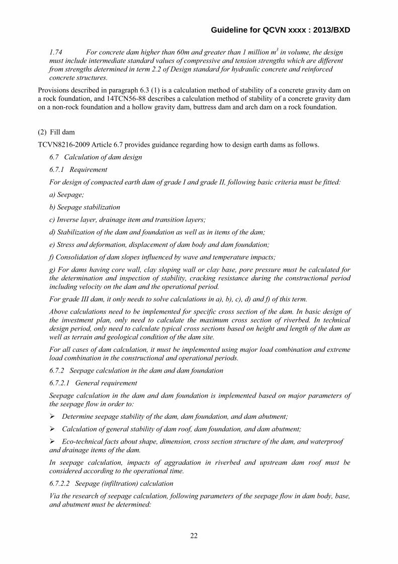
Provisions described in paragraph 6.3 (1) is a calculation method of stability of a concrete gravity dam on a rock foundation, and 14TCN56-88 describes a calculation method of stability of a concrete gravity dam on a non-rock foundation and a hollow gravity dam, buttress dam and arch dam on a rock foundation.
(2) Fill dam
TCVN8216-2009 Article 6.7 provides guidance regarding how to design earth dams as follows.
6.7 Calculation of dam design
6.7.1 Requirement
For design of compacted earth dam of grade I and grade II, following basic criteria must be fitted:
a) Seepage;
b) Seepage stabilization
c) Inverse layer, drainage item and transition layers;
d) Stabilization of the dam and foundation as well as in items of the dam;
e) Stress and deformation, displacement of dam body and dam foundation;
f) Consolidation of dam slopes influenced by wave and temperature impacts;
g) For dams having core wall, clay sloping wall or clay base, pore pressure must be calculated for the determination and inspection of stability, cracking resistance during the constructional period including velocity on the dam and the operational period.
For grade III dam, it only needs to solve calculations in a), b), c), d) and f) of this term.
Above calculations need to be implemented for specific cross section of the dam. In basic design of the investment plan, only need to calculate the maximum cross section of riverbed. In technical design period, only need to calculate typical cross sections based on height and length of the dam as well as terrain and geological condition of the dam site.
For all cases of dam calculation, it must be implemented using major load combination and extreme load combination in the constructional and operational periods.
6.7.2 Seepage calculation in the dam and dam foundation
6.7.2.1 General requirement
Seepage calculation in the dam and dam foundation is implemented based on major parameters of the seepage flow in order to:
Determine seepage stability of the dam, dam foundation, and dam abutment;
Calculation of general stability of dam roof, dam foundation, and dam abutment;
Eco-technical facts about shape, dimension, cross section structure of the dam, and waterproof and drainage items of the dam.
In seepage calculation, impacts of aggradation in riverbed and upstream dam roof must be considered according to the operational time.
6.7.2.2 Seepage (infiltration) calculation
Via the research of seepage calculation, following parameters of the seepage flow in dam body, base, and abutment must be determined:
22
Guideline for QCVN xxxx : 2013/BXD
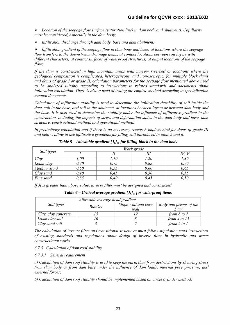
Location of the seepage flow surface (saturation line) in dam body and abutments. Capillarity must be considered, especially in the dam body;
Infiltration discharge through dam body, base and dam abutment;
Infiltration gradient of the seepage flow in dam body and base; at locations where the seepage flow transfers to the downstream drainage items; at contact locations between soil layers with different characters; at contact surfaces of waterproof structures; at output locations of the seepage flow;
If the dam is constructed in high mountain areas with narrow riverbed or locations where the geological composition is complicated, heterogeneous, and non-isotropic, for multiple block dams and dams of grade I or grade II, calculation parameters for the seepage flow mentioned above need to be analyzed suitably according to instructions in related standards and documents about infiltration calculation. There is also a need of testing the empiric method according to specialization manual documents.
Calculation of infiltration stability is used to determine the infiltration durability of soil inside the dam, soil in the base, and soil in the abutment, at locations between layers or between dam body and the base. It is also used to determine the stability under the influence of infiltrative gradient in the construction, including the impacts of stress and deformation states in the dam body and base, dam structure, constructional method, and operational method.
In preliminary calculation and if there is no necessary research implemented for dams of grade III and below, allow to use infiltrative gradients for filling-soil introduced in table 5 and 6.
Table 5 – Allowable gradient [Jk]cp for filling-block in the dam body
Soil types Work grade I II III IV~V
Clay 1,00 1,10 1,20 1,30 Loam clay 0,70 0,75 0,85 0,90 Medium sand 0,50 0,55 0,60 0,65 Clay sand 0,40 0,45 0,50 0,55 Fine sand 0,35 0,40 0,45 0,50
If Jk is greater than above value, inverse filter must be designed and constructed
Table 6 – Critical average gradient [Jk]th for waterproof items
Soil types Allowable average head gradient
Blanket Slope wall and core wall
Body and prisms of the Dam
Clay, clay concrete 15 12 from 8 to 2 Loam clay soil 10 8 from 4 to 15 Clay sand soil 3 2 from 2 to 1
The calculation of inverse filter and transitional structures must follow stipulation sand instructions of existing standards and regulations about design of inverse filter in hydraulic and water constructional works.
6.7.3 Calculation of dam roof stability
6.7.3.1 General requirement
a) Calculation of dam roof stability is used to keep the earth dam from destructions by shearing stress from dam body or from dam base under the influence of dam loads, internal pore pressure, and external forces;
b) Calculation of dam roof stability should be implemented based on circle cylinder method;
23
Guideline for QCVN xxxx : 2013/BXD
c) If there are some areas in the base or dam body that are weak soil or weak parting layers; and when calculating the stability of slope wall or protective layer, etc. , the calculation must be computed for a random sliding surface;
d) Selected calculation methods must fit equilibrium conditions of sliding triangles and limit equilibrium conditions of their components as well as stress states of the construction and its base.
6.7.3.2 Cases in calculation of dam roof stability
Earth dam bears different loads and filling-soils inside the dam body have different shearing strength in different periods, from constructing, finishing, accumulating, and discharging. Hence, the calculation must be implemented for each roof in upstream and downstream of the dam.
Constructional period (including as-built): Upstream and downstream roofs;
Stable infiltration period: Upstream and downstream roofs;
Fast draining period (of the reservoir): Upstream roofs.
The calculation must distinguish between normal working condition and abnormal working condition according to details in 3.12.
In high rainfall regions, inspection of dam roof stability in continuous raining period and selection of safety coefficient in abnormal working condition should be based on seepage coefficient of the filling-soil, drain-conveyance capacity of drainage items on the dam surface, and consideration of specific facts.
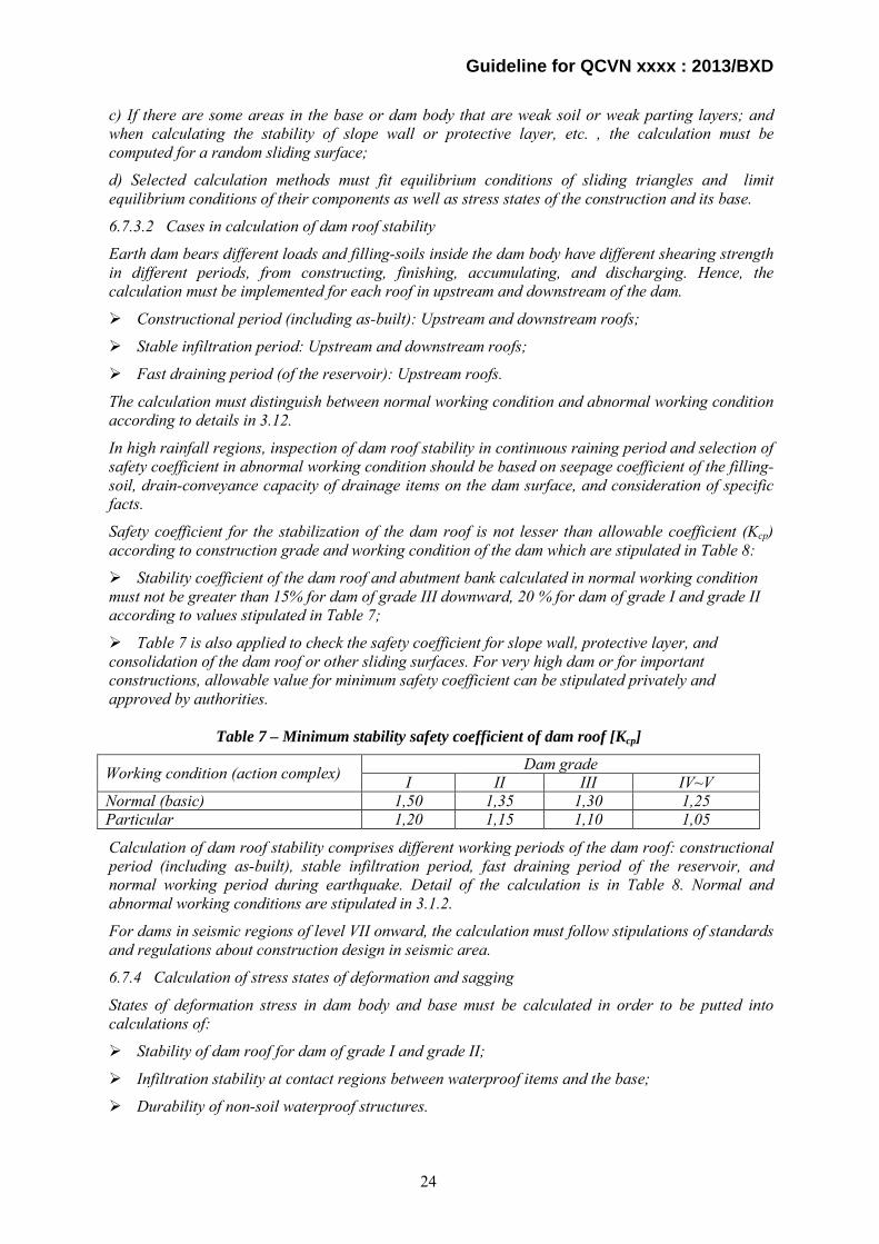
Safety coefficient for the stabilization of the dam roof is not lesser than allowable coefficient (Kcp) according to construction grade and working condition of the dam which are stipulated in Table 8:
Stability coefficient of the dam roof and abutment bank calculated in normal working condition must not be greater than 15% for dam of grade III downward, 20 % for dam of grade I and grade II according to values stipulated in Table 7;
Table 7 is also applied to check the safety coefficient for slope wall, protective layer, and consolidation of the dam roof or other sliding surfaces. For very high dam or for important constructions, allowable value for minimum safety coefficient can be stipulated privately and approved by authorities.
Table 7 – Minimum stability safety coefficient of dam roof [Kcp]
Working condition (action complex) Dam grade I II III IV~V
Normal (basic) 1,50 1,35 1,30 1,25 Particular 1,20 1,15 1,10 1,05
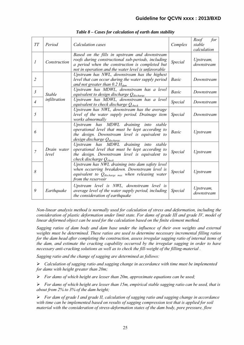
Calculation of dam roof stability comprises different working periods of the dam roof: constructional period (including as-built), stable infiltration period, fast draining period of the reservoir, and normal working period during earthquake. Detail of the calculation is in Table 8. Normal and abnormal working conditions are stipulated in 3.1.2.
For dams in seismic regions of level VII onward, the calculation must follow stipulations of standards and regulations about construction design in seismic area.
6.7.4 Calculation of stress states of deformation and sagging
States of deformation stress in dam body and base must be calculated in order to be putted into calculations of:
Stability of dam roof for dam of grade I and grade II;
Infiltration stability at contact regions between waterproof items and the base;
Durability of non-soil waterproof structures.
24
Guideline for QCVN xxxx : 2013/BXD
Table 8 – Cases for calculation of earth dam stability
TT Period Calculation cases Complex Roof for stable calculation
1 Construction Based on the fills in upstream and downstream roofs during constructional sub-periods, including a period when the construction is completed but not in operation and the water level is unfavorable
Special Upstream, downstream
2
Stable infiltration
Upstream has NWL, downstream has the highest level that can occur during the water supply period and not greater than 0.2 Hdam
Basic Downstream
3 Upstream has MDWL, downstream has a level equivalent to design discharge Qdischarge
Basic Downstream
4 Upstream has MDWL, downstream has a level equivalent to check discharge Qcheck
Special Downstream
5 Upstream has NWL, downstream has the average level of the water supply period. Drainage item works abnormally
Special Downstream
6
Drain water level
Upstream has MDWL draining into stable operational level that must be kept according to the design. Downstream level is equivalent to design discharge Qdischarge
Basic Upstream
7 Upstream has MDWL draining into stable operational level that must be kept according to the design. Downstream level is equivalent to check discharge Qcheck
Special Upstream
8 Upstream has NWL draining into dam safety level when occurring breakdown. Downstream level is equivalent to Qdischarge max when releasing water from the reservoir
Special Upstream
9 Earthquake Upstream level is NWL, downstream level is average level of the water supply period, including the consideration of earthquake
Special Upstream, downstream
Non-linear analysis method is normally used for calculation of stress and deformation, including the consideration of plastic deformation under limit state. For dams of grade III and grade IV, model of linear deformed object can be used for the calculation based on the finite element method.
Sagging ratios of dam body and dam base under the influence of their own weights and external weights must be determined. These ratios are used to determine necessary incremental filling ratios for the dam head after completing the construction, assess irregular sagging ratio of internal items of the dam, and estimate the cracking capability occurred by the irregular sagging in order to have necessary anti-cracking solutions as well as to check the fill-weight of the filling-material .
Sagging ratio and the change of sagging are determined as follows:
Calculation of sagging ratio and sagging change in accordance with time must be implemented for dams with height greater than 20m;
For dams of which height are lesser than 20m, approximate equations can be used;
For dams of which height are lesser than 15m, empirical stable sagging ratio can be used, that is about from 2% to 3% of the dam height;
For dam of grade I and grade II, calculation of sagging ratio and sagging change in accordance with time can be implemented based on results of sagging compression test that is applied for soil material with the consideration of stress-deformation states of the dam body, pore pressure, flow
25

Guideline for QCVN xxxx : 2013/BXD
property of soil, wet sagging ratio, and swelling ratio when the humidity is increased during the operational period, etc.
The calculation is based on stipulations and instructions in related standards and regulations.
7. Construction of hydropower civil works
7.1 General requirements 7.1.1. Technical Regulation Article 7.1.1 describes design and construction method to be considered for normal operation of hydropower works. Hydropower civil works shall be designed following TCVNs and/or internationally recognized technical regulations, standards and codes satisfying the requirements in the Technical Regulation.
Besides main structures, the Dam Owner shall decide specifications of construction roads by the following procedure:
1) Investigate laws and ordinances on construction roads;
2) Investigate the present topography and environment designated for the construction of construction roads ;
3) Consult with a local government, competent authorities on environment and land owners on feasibility for construction of construction roads;
4) Design construction roads based on a construction plan, work class shown in Table 2 of Technical Regulation Article 4.2.10, relevant technical regulations and the environmental impact assessment report. In case construction roads are used as permanent roads after completion of hydropower works, the works class shall follow Guideline for Technical Regulation Article 4.2.6;
5) Estimate cost for construction roads and compensation for land acquisition , and compare them;
6) Explain design and cost of construction roads and compensation plan to local government competent authorities on environment and land owners for approval, and revise them, if necessary;
7) Decide construction of construction roads; and
8) Construct construction roads as designed.
7.1.2. Technical Regulation Article 7.1.2 describes basic requirements on operation and maintenance of hydropower civil works.
In general, the Dam Owner shall establish operation and maintenance rules and prepare operation and maintenance manuals.
The Technical Regulation Vol.4 of MOIT describes provisions on operation and maintenance of hydropower civil works. 7.1.3. Technical Regulation Article 7.1.3 describes basic requirements on an obligation to discharge to the downstream area.
Generally the Dam Owner shall decide flow rate and a discharge method by the following procedure:
1) Investigate laws and ordinances regarding environment;
2) Consult with local government and relevant downstream water users about details of water demand such as time, amount, quality, etc.;
3) Work out a water utilization plan so as to discharge 0 to 30% of the average flow in the year with the frequency of 95%;
4) Design an outlet facility to satisfy the above demand; and
5) Operate the reservoir as planned.
26

Guideline for QCVN xxxx : 2013/BXD
It is required to discharge the water to the downstream area as an environmental flow at a rate to be determined within the range stipulated in Article 7.1.3 of Technical Regulation to balance environmental preservation with profitability of hydropower.
An example of estimation of an environmental flow rate to the downstream area in Japan is as follows.
An environmental flow rate shall be decided considering protection of flora and fauna, fishery, landscape, maintenance of river water quality, and water use, which is aimed at a desirable low water discharge.
An environmental flow rate shall be decided in the process as shown in Fig. 7.1-1.
27

Guideline for QCVN xxxx : 2013/BXD
Fig.7.1-1 Process for decision of environmental flow rate
Study on environmental flow rate
Study on necessary river flow rate
Investigation of river environment
・ River flow regime ・ River discharge ・ Use of river water ・ Natural environment ・ Social affairs ・ Historical drought
Classification of river
Estimation of necessary river flow rate ・ Habitat of flora and fauna ・ Fishery ・ Landscape ・ River water quality ・ Navigation ・ Prevention of salt damage ・ Prevention of river mouth clogging ・ Protection of river management facilities ・ Maintenance of groundwater level
Decision of river maintenance flow rate
Decision of river flow rate necessary for water use
Selection of standard points to monitor river flow rate and river environment
Decision of necessary flow rate for each season
Decision of environmental flow rate
28

Guideline for QCVN xxxx : 2013/BXD
7.1.4. Technical Regulation Article 7.1.4 describes basic requirements on harmony with surrounding
environment and landscape.
Generally the Dam Owner shall decide landscape design by the following procedure:
1) Investigate laws and ordinances regarding landscape;
2) Consult with local government, tourist industries and experts on landscape about exterior design of hydropower civil works;
3) Design hydropower civil structures considering harmony with surrounding environment and landscape;
4) Estimate cost for landscape design;
5) Explain landscape design to local government, tourist industries and experts on landscape for approval and revise it if necessary; and
6) Construct hydropower civil structures as designed.
7.1.5. Technical Regulation Article 7.1.5 describes basic requirements on conservation of navigation and aquatic resources. A dam blocks a river flow to store water, and obstructs navigation and migration of fish by forming the difference in elevation between upstream and downstream the dam. In case construction of a navigation lock and fishway is feasible technically and economically, it is recommended that these structures be constructed simultaneously with a dam or retrofit them after due consultation with a local government, river transport industries, fishermen and experts on aquatic life. In case construction of a navigation lock and fishway is unfeasible, the Dam Owner shall consult with interested parties about compensation for navigation and fishery.
Generally the Dam Owner shall decide necessity and specifications of a navigation lock and fishway by the following procedure:
(1) Navigation lock
1) Investigate laws and ordinances on river navigation;
2) Investigate the present state of navigation and river transport at the dam site ;
3) Consult with a local government and river transport industries on necessity of a navigation lock and compensation for abolition of navigation;
4) Design a navigation lock based on the volume of navigation;
5) Estimate cost for a navigation lock and compensation for abolition of navigation, and compare them;
6) Explain design and cost of a navigation lock and compensation plan for abolition of navigation to local government and river transport industries for approval, and revise them, if necessary;
7) Decide construction of a navigation lock or compensation for abolition of navigation; and
8) Construct a navigation lock as designed if construction of a navigation lock is selected.
(2) Fishway
1) Investigate laws and ordinances regarding fishery and river environment;
2) Investigate the present state of aquatic life;
3) Consult with a local government, fishermen and experts on aquatic life about installation of a fishway and compensation for fishery;
4) Design a fishway according to expert’s advice;
5) Estimate cost for a fishway and compare compensation for fishery, and compare them;
29
Guideline for QCVN xxxx : 2013/BXD
6) Explain design of a fishway and compensation plan to local government, fishermen and experts for approval and revise them if necessary;
7) Decide construction of a fishway or compensation for fishery ;and
8) Construct a fishway as designed if construction of a fishway is selected.
7.1.6. Technical Regulation Article 7.1.6 describes basic requirements on experiments.
Generally it is recommended, when there is no better solutions for design of complex structures than experiments and field tests, that the Dam Owner confirm type and shape of following hydropower civil works by experiments and in-situ tests:
(1) Dam foundation
Site reconnaissance, exploratory drilling, Lugeon test or any other geological investigations to investigate geological structure of foundation
Seismic prospecting or any other types of geophysical prospecting to investigate geological structure of foundation
Plate bearing test or any other in-situ tests to investigate bearing capacity of foundation
Grouting test to decide a pattern of grouting and to estimate amount of grouting
(2) Dam material
Site reconnaissance, trench excavation, exploratory drilling or any other investigations to estimate deposits of dam materials such as aggregate, core material, filter material and rock material
Mix design test of concrete using aggregate exploited from a candidate quarry site to decide mix proportion of concrete used for a dam and other concrete structures
Trial embankment using materials exploited from a candidate borrow area and quarry site to decide grading, water content and compaction method of impervious material for a fill dam
(3) Spillway
Site reconnaissance, exploratory drilling or any other geological investigations to investigate geological structure of foundation
Hydraulic model test to confirm a shape of a chute and dissipater, existence of cavitation, dissipation effect, or any other hydraulic phenomena
(4) Intake
Site reconnaissance, exploratory drilling or any other geological investigations to investigate geological structure of foundation
Hydraulic model test to confirm non-intrusion of air to a headrace tunnel
(5) Surge tank
Site reconnaissance, exploratory drilling or any other geological investigations to investigate geological structure of foundation
Hydraulic model test to confirm coefficient of loss at orifice
(6) Tailrace outlet
Site reconnaissance, exploratory drilling or any other geological investigations to investigate geological structure of foundation
Hydraulic model test to confirm condition of outflowing water
Hydraulic model tests are implemented for the hydropower projects of special grade and Grade I. Regarding the hydropower project Grade II or even below, hydraulic model tests shall be conducted in case a special or complicated structure of which hydraulic behavior is difficult to be confirmed by
30

Guideline for QCVN xxxx : 2013/BXD
common hydraulic calculations or innovative technology which does not have sufficient reliability is applied to the design of a structure of hydraulic civil works.
An example of the technical approach of hydraulic model test is described below:
< Example of technical approach for hydraulic model test >
It is desirable that an intake and outlet structures should be located in the following position:
- Sediment may not be deposited in front of it;
- Inflow may not be disturbed or biased by the surrounding topography;
- Inflow may not erode the slope or suck sediment in front of it;
- Inflow may not entrain air; and
- Outflow may not erode the river bed in front of it or slope or on its periphery.
Discharge facilities are designed in the process shown in Fig.7.1-2.
Fig 7.1-2 Hydraulic analyses of discharge facilities
Generally the dam owner shall decide a shape and dimensions of an intake and outlet structures, and discharge facilities by the following procedure:
1) Estimate necessary capacity;
2) Calculate necessary dimensions and shape;
3) Select the location;
4) Estimate flow condition by hydraulic calculation and/or simulation considering the surrounding topography;
5) Estimate flow conditions by hydraulic model test;
6) Reconsider the location, dimensions and/or shape in case the initial design gives negative effect to the surrounding area; and
7) Construct facilities as designed.
31

Guideline for QCVN xxxx : 2013/BXD
7.1.7. Technical Regulation Article 7.1.7 describes requirements or prohibited issues during the period of repair, rehabilitation, upgrading or expansion of existing hydropower works.
Suspension of operation of hydropower plants is inevitable during their repair, rehabilitation, upgrading or expansion in general and it is desirable that suspension of their operation and negative influence on power supply be minimized.
The Dam Owner shall consult with network operators, water consuming sectors and other interested parties about required time and period of repair, rehabilitation, upgrading or expansion of hydropower works, and select the suitable time to minimize negative influence due to suspension of operation.
7.1.8. Technical Regulation Article 7.1.8 describes major design criteria of the following flow rate stipulated in Article 5.2 of QCVN 04 - 05 : 2012/BNNPTNT:
(1) Maximum inflow and water level
Article 5.2.1 of QCVN 04 - 05 : 2012/BNNPTNT stipulate as follows:
5.2.1 The flow frequency and the highest water level using to calculate, design as well as examine the stability, structure, foundation and discharge ability of hydraulic works on rivers and riverain, constructions on the pressure line and constructions of the irrigation and drainage system incase of no flow-regulated works in upstream are not higher than values stipulating in the Table 4.
Table 4 - Flow frequency as well as the highest designed and examined water levels of hydraulic works
No. Type of construction Design class Special I II III IV
1 Headwork units of various types (exclude headwork in the tidal region); water conduction channel and relevant works not belonging to the agricultural irrigation and drainage system; conveyance structures cross rivers and streams of the irrigation and drainage system for agriculture
- Design frequency, % 0.10 0.50 1.00 1.50 2.00 In accordance with return period, year 1,000 200 100 67 50 - Check frequency, % 0,02 0,10 0,20 0,50 - In accordance with return period, year 5,000 1,000 500 200 -
2 Headwork in tidal region; constructions and relevant water conduction system in the irrigation and drainage system for agriculture (exclude construction transferring water to cross rivers and streams of the irrigation and drainage system for agriculture):
- Design frequency, % 0.20 0.50 1.00 1.50 2.00 In accordance with return period, year 500 200 100 67 50 - Check frequency, % 0.10 0.20 0.50 1.00 - In accordance with return period, year 1,000 500 200 100 -
NOTE: 1) The largest flow and water level in the statistic data is the rate and level of the maximum value appearing in each year. The quality of the statistic data (length, representative characteristic, statistical duration, etc.) should meet requirements stipulating in the correlative standards. The data should be processed to reach the same condition before carrying the calculation; 2) If impacts in upstream can lead to changes in the flow forming condition or there are regulated constructions, the determination of factors, stipulating in this article, should mention the re-regulated ability of these constructions; 3) If there are regulated constructions in downstream, the discharge model is not allow to destroy or exceed the
32

Guideline for QCVN xxxx : 2013/BXD
No. Type of construction Design class Special I II III IV
regulation ability of that construction; 4) The special class hydraulic construction belonging to the unit 1 of this table, the checked flood can be calculated by the frequency of 0.01% or extreme flood if there are sufficient evaluations and accepted investment decision.
This article regulates flow frequency to estimate design and check flood for design of a spillway.
Examples of regulations on flood discharge in the foreign countries are shown below for reference.
1. Example of Japan
1) Concrete dams
The estimation method which gives largest value shall be selected among the following methods:
1) A flood estimated to occur at a rate of once in 200 years
2) The maximum flood that has occurred at the dam site
3) The flood which is obtained by Creager’s formula, i.e. q = C×A×(A-0.05-1). q: specific yield(m3/s/km2), A: catchment area(km2), C: location factor
2) Fill dams
1.2 times of a concrete dam Source: Governmental Ordinance for Structural Standard for River Administration Facilities, Ministry of Land, Infrastructure, Transport and Tourism, Japan, July 20, 1976.
2. Example of P.R. China Table 7.1-1 Criteria for Project Ranking
Rank of projects
Storage capacity
(100 MCM)
Ranking Flood control Irrigation Hydropower
Town and industrial town to
be prevented
Cultivated land area
(104ha)
Irrigation land area (104ha)
Installed capacity of hydropower plant
(MW) 1 >10 Very important >33.3 >10 >750 2 10~1 Important 33.3~6.67 10~3.33 750~250 3 1~0.1 Intermediate 6.67~2.0 3.33~0.33 250~25 4 0.1~0.01 Ordinary 20~0.33 0.33~0.03 25~0.5 5 0.01~0.001 — <0.33 <0.03 <0.5
Note MCM : Million Cubic Meters
Source: Unified Design Standard for Reliability of Hydraulic Engineering Structures, GB-50199-94, P.R. China, Nov. 01, 1994.
33

Guideline for QCVN xxxx : 2013/BXD
Table 7.1-2 Criteria of Design and Check Flood (Return Period to be Applied)
Rank of projects
Normal operation (design flood)
(year)
Extreme operation (check flood) The dam failure shall not cause large damage.
Fill dam (year)
Concrete dam (year)
1 2,000~500 10,000 5,000 2 500~100 2,000 1,000 3 100~50 1,000 500 4 50~30 500 300 5 30~20 300 200
Source: Flood Control Standards, GB-50201-94, P.R. China, Jan. 01, 1995.
3. Example of U.S. Army Corps of Engineers Table 7.1-3 Size Classification
Category Reservoir capacity (106m3) Height of the dam (m) Small From 0.062 to 1.23 From 7.6 to 12.2 Intermediate From 1.23 to 61.5 From 12.2 to 30.5 Large >= 61.5 >= 30.5
Table 7.1-4 Hazard Potential Classification Category Loss of life
(Extent of development) Economic loss
(Extent of development) Low None expected
(No permanent structures for human habitation)
Minimal (Undeveloped to occasional structures or
agriculture) Medium Few
(No urban developments and no more than a small number)
Appreciable (Notable agriculture, industry or structures)
High More than few Excessive (Extensive community, industry or agriculture)
Table 7.1-5 Recommended Safety Standards Hazard Size Safety standard
Small 50-year to 100-year flood Low Intermediate 100-year to 50% of the PMF Large 50% to 100% of the PMF Small 100-year to 50% of the PMF Medium Intermediate 50% to 100% of the PMF Large PMF Small 50% to 100% of the PMF High Intermediate PMF Large PMF
Source of Table 7.1-3 to 7.1-5: Engineering Regulation ER-1110-2-106, Recommended Guidelines for Safety Inspection of Dams, Appendix D, U.S. Army Corps of Engineers, Sept. 26, 1979.
4. Example of Norway
Norway adopts a double design criterion:
The 1,000 year probable inflow flood is prescribed as design flood for normal operation of dam
34

Guideline for QCVN xxxx : 2013/BXD
spillway system, while the stability of the dam is subject to the PMF.
5. Example of Canada
Table 7.1-6 Criteria for Hazardous Level
Consequence category
Potential incremental consequences of failure 1)
Inflow design flood Life safety 2)
Socio-economic Financial
Environmental 2) 3) Very high Large number
of fatalities Extreme damages Probable maximum flood
(PMF) 4) High Some fatalities Large damages Annual Exceedance probability
between 1/1,000 and the PMF 5) Low No fatalities
anticipated Moderate damages Annual Exceedance probability
between 1/100 and 1/1,000 5) 6) Very Low No fatalities Minor damages beyond owner’s property
Note 1) Incremental to the impacts which would occur under the same natural conditions (flood, earthquake or other event) but without failure of the dam. The consequence (i.e. loss of life, or economic losses) with the higher rating determines which category is assigned to the structure. In the case of tailings dams, consequence categories should be assigned for each stage in the life cycle of the dam.
2) The criteria which define the Consequence Categories should be established between the Owner and regulatory authorities, consistent with societal expectations. Where regulatory authorities do not exist, or do not provide guidance, the criteria should be set by the Owner to be consistent with societal expectations. The criteria may be based on levels of risk which are acceptable or tolerable to society.
3) The Owner may wish to establish separate corporate financial criteria which reflect their ability to absorb or otherwise manage the direct financial loss to their business and their liability for damage to others.
4) An appropriate level of conservatism shall be applied to loads from this event, to reduce the risks of dam failure to tolerable values. Thus, the probability of dam failure could be much lower than the probability of extreme event loading.
5) Within the High Consequence category, the IDF is based on the consequences of failure. For example, if one incremental fatality would result from failure, an AEP of 1/1,000 could be acceptable, but for consequences approaching those of a Very High Consequence dam, design floods approaching the PMF would be required.
6) If a Low Consequence structure cannot withstand the minimum criteria, the level of upgrading may be determined by economic risk analysis, with consideration of environmental and social impacts.
Source of Table 7.1-6: Water Act, Alberta Province, Canada, January 1, 1999.
Article 5.2.4 of QCVN 04 - 05 : 2012/BNNPTNT stipulate as follows:
5.2.4 The highest water level using to calculate the exploitation regime of a gravity-water supply construction from a reservoir and normal weir is defined in the Table 4, exclude some circumstances such as there are stipulations, which do not allow exploiting at that water level to prevent potential risks for downstream or against dike protection regulations. In those circumstances, the design consultant authority should propose the safety exploiting water level, which is decided by the jurisdiction agencies.
This article regulates the highest water level to be considered for design of gravity type water supply structures in taking water from a reservoir or an intake weir.
(2) Lowest inflow and water level
Article 5.2.3 of QCVN 04 - 05 : 2012/BNNPTNT stipulate as follows:
5.2.3 The lowest flow and water elevation using to calculate the structural stability of the construction and foundation is stipulated in the Table 5.
35

Guideline for QCVN xxxx : 2013/BXD
Table 5 – The lowest flow and water level using to calculate the structural stability of the construction and foundation
No Type of construction Construction class
Frequency of the lowest flow and water level, % Design Examine
1 Reservoir Special, I, II, III and IV Death elevation
The lowest drainage level using to repair and dredge, etc.
Special 99 The lowest daily water level occurring at the constructional alignment
I 97 2 On-river construction II 95 III 95 IV 90
3
Drainage system and other relevant works in the hydraulic system
Special , I, II, III and IV
The lowest water level stipulating in the exploitation period
The drainage water level using to repair and dredge, etc.
NOTE: 1) The lowest flow and water level using in the statistic collection is the flow and level of the lowest value appearing in each year; 2) If the water users in downstream require to guarantee that the minimum flow is larger than the flow stipulating in the table 5, the lowest flow is chosen according to that minimum flow. The lowest calculating level is now a water level in accordance with the above minimum flow; 3) The design of constructions from class I and higher must consider the ability of this water level to become lower as the result of deep scour of downstream channel-flow or the influences from the re-regulated activities of other constructions in the chain in the future.
This article regulates the lowest flow rate and lowest water level used for stability calculation of hydropower works.
As stipulated in Technical Regulation Article 6.3, loads shall be selected from the most unfavorable combinations that might occur during operation and construction. The most unfavorable load combinations might occur at the low water level or rapid drawdown, so stability of hydropower works shall be examined for the load combinations with the water level show in Article 5.2.7 and Table 6 of QCVN 04 - 05 : 2012/BNNPTNT as follows:
(3) Lowest exploiting water level
Article 5.2.7 of QCVN 04 - 05 : 2012/BNNPTNT stipulate as follows:
5.2.7 The lowest water level at the source (reservoir or river), the exploitation state for the water supply and drainage constructions is stipulated in the Table 6.
36
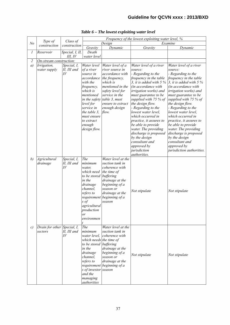
Guideline for QCVN xxxx : 2013/BXD
Table 6 – The lowest exploiting water level
No Type of construction
Class of construction
Frequency of the lowest exploiting water level, % Design Examine
Gravity Dynamic Gravity Dynamic 1 Reservoir Special, I, II,
III, IV Death
water level
2 On-stream construction: a) Irrigation,
water supply Special, I, II, III and IV
Water level of a river source in accordance with the frequency, which is mentioned in the safety level for service in the table 3, must ensure to extract enough design flow.
Water level of a river source in accordance with the frequency, which is mentioned in the safety level for service in the table 3, must ensure to extract enough design flow.
Water level of a river source: - Regarding to the frequency in the table 3, it is added with 5 % (in accordance with irrigation works) and must guarantee to be supplied with 75 % of the design flow. - Regarding to the lowest water level, which occurred in practice, it assures to be able to provide water. The providing discharge is proposed by the design consultant and approved by jurisdiction authorities.
Water level of a river source: - Regarding to the frequency in the table 3, it is added with 5 % (in accordance with irrigation works) and must guarantee to be supplied with 75 % of the design flow. - Regarding to the lowest water level, which occurred in practice, it assures to be able to provide water. The providing discharge is proposed by the design consultant and approved by jurisdiction authorities.
b) Agricultural drainage
Special, I, II, III and IV
The minimum water, which need to be stored in the drainage channel, refers to requirements of agricultural production or environment
Water level at the suction tank in coherence with the time of buffering drainage at the beginning of a season or drainage at the beginning of a season
Not stipulate Not stipulate
c) Drain for other sectors
Special, I, II, III and IV
The minimum water level, which needs to be stored in the drainage channel, refers to requirements of investor and the managing authorities
Water level at the suction tank in coherence with the time of buffering drainage at the beginning of a season or drainage at the beginning of a season
Not stipulate Not stipulate
37

Guideline for QCVN xxxx : 2013/BXD
No Type of construction
Class of construction
Frequency of the lowest exploiting water level, % Design Examine
Gravity Dynamic Gravity Dynamic d) Electricity
generation Special, I, II, III and IV
The lowest exploiting water level
Not stipulate Not stipulate Not stipulate
NOTES: 1) The lowest exploitation mentioning in the section (a) refers to the means of daily water level obtaining the smallest value, which is appeared during the exploiting period of each statistical year.; 2) The minimum exploiting water level mentioning in the section (b) refers to the lowest water level, which needs to be stored at the end of the first buffering drainage period or drained at the beginning of a season in order to increase the drainage effectiveness, which is stipulated in the exploitation procedure.
This article regulates the lowest exploiting water level for each class.
(4) Frequency of flow and maximum water level for design of temporary works
Article 5.2.8 of QCVN 04 - 05 : 2012/BNNPTNT stipulate as follows:
5.2.8 In order to design temporary works, supporting to the diversion task (coffer dam, channel, etc.),, the frequency of flow and the maximum level are not higher than the values in the Table 7.
Table 7 – Frequency of flow and maximum water level using to design temporary works, which support the diversion task
Construction class
Frequency of flow and maximum water level using to design temporary works, which support the diversion task, %
Diversion in 1 dry season Diversion from 2 dry seasons and above
Special 5 2 I 10 5
II, III, IV 10 10 NOTES:
Flow and the maximum water level in the statistic data is the maximum flow and level among the highest value appearing in each diversion season. The diversion season refers to the period of time in a year, when the works supporting for diversion task need to be well improved in order to face the design flood;
Regarding to constructions, which need to divert from 2 years and above, the safety level of temporary constructions, using to divert constructional flow in coherence with stipulated frequency in the table 7, will be proposed to increase by the design consultant authorities if there are adequate evaluations. The purposes of this are to limit negative influences (damage to the major built work-items, slow-speed progress rate and damage in downstream), which cost great higher than new investment for a new diversion work;
The gravity concrete works obtaining a good ground condition, which allow water to overflow, the design authority can propose to decrease the guarantee level of the temporary work in order to reduce the investment cost. The decrease level depends on the number of years using temporary diversion works and the decision from the investor;
The arrangement of temporary spill-way, which is used to discharge constructional flood through the body of the unfinished rock-dam, should obtain protective measures for dams and reservoir. The design frequency of temporary dam in this case equals the design frequency of a construction;
It is necessary to propose solutions to prevent the exceedance of real diversion frequency comparing to the design frequency in order to actively handle if this situation occurs in practice;
All proposals about the increase and reduction of design frequency of the temporary works, supporting the construction diversion, must have the economic and engineering evaluations and are accepted by the ratified authority.
This article regulates frequency of flow and maximum water level for temporary works such as cofferdams, diversion tunnels, or other diversion works. Capacity of diversion tunnels and the crest level of cofferdams shall be decided corresponding to discharge which occurs with the frequency as shown in Table 7.
(5) Frequency of maximum flow for impounding
Article 5.2.9 of QCVN 04 - 05 : 2012/BNNPTNT stipulate as follows:
5.2.9 The frequency of the maximum flow using to impound is not higher than values, which is regulated in the Table 8.
38

Guideline for QCVN xxxx : 2013/BXD
Table 8 – Frequency of the maximum flow using for impoundment
Class of construction Frequency of the maximum flow using for impoundment %
Special, I, II 5 III, IV 10 NOTES:
Flow in the statistic data refers to the average daily flow rate obtaining the highest value in accordance with the flow not being influenced by tide. It also refers to the average hourly flow obtaining the highest value regarding to the flow affecting by tide, which appears during the estimated diversion period of each statistical year. The estimated time for diversion is divided once every 10 days in a month of proposing diversion in correlation with the period of decreasing flow;
Basing on the real measurement values during the period prior to the assigned time of diversion (normally, the measurement will be carried out continuously from the end of the flood season until the assigned time of diversion), the constructional authority will adjust the diverted option so as to suit real condition of flow, weather and tide schedule as well as submit the investor for acceptance.
This article regulates frequency of the maximum flow rate used for impoundment of a reservoir.
(6) Use of rainfall data complementary to river discharge data
If there are not any or not sufficient river discharge measurement data for estimating inflow of a reservoir, use of rainfall data to complement river discharge data. If there are rainfall data with an observation period longer than river discharge period, rainfall data can be used to complement river discharge data in the following process.
1) Compare a trend of rainfall data and river discharge data with a double mass curve or other methods;
2) Use rainfall data to complement river discharge data in case close correlation between the both data;
3) Generate river discharge data from correlation with rainfall data; and
4) Extend the period of river discharge data or fill the blank data.
7.1.9 Technical Regulation Article 7.1.9 describes important requirement on foundation of a dam to secure stability and safety of hydropower civil works in case foundation consists of rock with more strength of rockfill material.
a) Compressive strength of foundation
b) Modulus of deformation of foundation
Generally required quality of foundation for each type of dam is summarized as follows in Japan.
1) Concrete gravity dam
A concrete gravity dam is designed to ensure stability in the section perpendicular to a dam axis considering distribution of load transferred from a dam body to foundation. So, foundation of concrete gravity dam is to be excavated to the level that bears stress transferred from a dam body.
2) Arch dam
An arch dam transfers loads acting on a dam body to foundation by mutual action of a horizontal arch element and vertical cantilever element, and shape, strength and deformability of foundation affects stress distribution in a dam body. An arch thrust load acts on the both banks, while most of a load acts on the bottom in case of a concrete gravity dam. So, bedrock of arch dam shall be sound to the upper elevation of the both banks.
3) Fill type dam
Foundation of a concrete dam requires shear strength and deformability to support a dam body, while a fill type dam transfers less stress to foundation than a concrete dam. So, the extent of foundation excavation is not subject to its strength and deformability. A foundation excavation plan of a zone type rockfill dam is as follows.
39
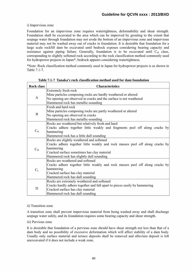
Guideline for QCVN xxxx : 2013/BXD
i) Impervious zone
Foundation for an impervious zone requires watertightness, deformability and shear strength. Foundation shall be excavated to the area which can be improved by grouting to the extent that seepage water through foundation may not erode the bottom of an impervious zone and impervious material may not be washed away out of cracks in foundation. It is desirable that foundation for a large scale rockfill dam be excavated until bedrock exposes considering bearing capacity and resistance against piping failure. Generally, foundation is to be excavated until CM class, corresponding to slightly softened rock according to the rock classification method commonly used for hydropower projects in Japan*, bedrock appears considering watertightness.
*Note: Rock classification method commonly used in Japan for hydropower projects is as shown in Table 7.1-7.
Table 7.1-7 Tanaka’s rock classification method used for dam foundation
Rock class Characteristics
A
Extremely fresh rock Mine particles composing rocks are hardly weathered or altered No opening are observed in cracks and the surface is not weathered Hammered rock has metallic-sounding
B
Fresh and hard rock Mine particles composing rocks are partly weathered or altered No opening are observed in cracks Hammered rock has metallic-sounding
CH
Rocks are weathered but relatively fresh and hard Cracks adhere together little weakly and fragments peel off along cracks by hammering Hammered rock has a little dull sounding
CM
Rocks are slightly weathered and softened Cracks adhere together little weakly and rock masses peel off along cracks by hammering Cracked surface sometimes has clay material Hammered rock has slightly dull sounding
CL
Rocks are weathered and softened Cracks adhere together little weakly and rock masses peel off along cracks by hammering Cracked surface has clay material Hammered rock has dull sounding
D
Rocks are extremely weathered and softened Cracks hardly adhere together and fall apart to pieces easily by hammering Cracked surface has clay material Hammered rock has dull sounding
ii) Transition zone
A transition zone shall prevent impervious material from being washed away and shall discharge seepage water safely, and its foundation requires some bearing capacity and shear strength.
iii) Pervious zone
It is desirable that foundation of a pervious zone should have shear strength not less than that of a dam body and no possibility of excessive deformation which will affect stability of a dam body. Usually only surface material and terrace deposits shall be removed and alluvium deposit is left unexcavated if it does not include a weak zone.
40

Guideline for QCVN xxxx : 2013/BXD
c) Foundation treatment
Technical requirements are described quoting provisions of TCVN8216-2009 as follows:.
6.7.2 Seepage calculation in the dam and dam foundation
6.7.2.1 General requirement
Seepage calculation in the dam and dam foundation is implemented based on major parameters of the seepage flow in order to:
- Determine seepage stability of the dam, dam foundation, and dam abutment;
- Calculation of general stability of dam roof, dam foundation, and dam abutment;
- Eco-technical facts about shape, dimension, cross section structure of the dam, and waterproof and drainage items of the dam.
In seepage calculation, impacts of aggradation in riverbed and upstream dam roof must be considered according to the operational time.
6.7.2.2 Seepage (infiltration) calculation
Via the research of seepage calculation, following parameters of the seepage flow in dam body, base, and abutment must be determined:
- Location of the seepage flow surface (saturation line) in dam body and abutments. Capillarity must be considered, especially in the dam body;
- Infiltration discharge through dam body, base and dam abutment;
- Infiltration gradient of the seepage flow in dam body and base; at locations where the seepage flow transfers to the downstream drainage items; at contact locations between soil layers with different characters; at contact surfaces of waterproof structures; at output locations of the seepage flow;
If the dam is constructed in high mountain areas with narrow riverbed or locations where the geological composition is complicated, heterogeneous, and non-isotropic, for multiple block dams and dams of grade I or grade II, calculation parameters for the seepage flow mentioned above need to be analyzed suitably according to instructions in related standards and documents about infiltration calculation. There is also a need of testing the empiric method according to specialization manual documents.
Calculation of infiltration stability is used to determine the infiltration durability of soil inside the dam, soil in the base, and soil in the abutment, at locations between layers or between dam body and the base. It is also used to determine the stability under the influence of infiltrative gradient in the construction, including the impacts of stress and deformation states in the dam body and base, dam structure, constructional method, and operational method.
In preliminary calculation and if there is no necessary research implemented for dams of grade III and below, allow to use infiltrative gradients for filling-soil introduced in Table 5 and 6.
Table 5 – Allowable gradient [Jk]cp for filling-block in the dam body
Soil types
Work grade I (to be read as Special)
II (to be read as I)
III to be read as II)
IV - V (to be read as III - IV)
Clay 1.00 1.10 1.20 1.30 Loam clay 0.70 0.75 0.85 0.90 Medium sand 0.50 0.55 0.60 0.65 Clay sand 0.40 0.45 0.50 0.55 Fine sand 0.35 0.40 0.45 0.50
41
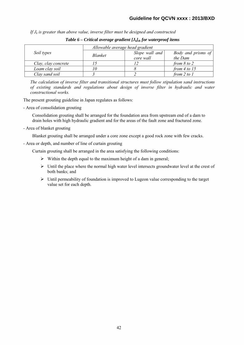
Guideline for QCVN xxxx : 2013/BXD
If Jk is greater than above value, inverse filter must be designed and constructed
Table 6 – Critical average gradient [Jk]th for waterproof items
Soil types Allowable average head gradient
Blanket Slope wall and core wall
Body and prisms of the Dam
Clay, clay concrete 15 12 from 8 to 2 Loam clay soil 10 8 from 4 to 15 Clay sand soil 3 2 from 2 to 1
The calculation of inverse filter and transitional structures must follow stipulation sand instructions of existing standards and regulations about design of inverse filter in hydraulic and water constructional works.
The present grouting guideline in Japan regulates as follows:
- Area of consolidation grouting
Consolidation grouting shall be arranged for the foundation area from upstream end of a dam to drain holes with high hydraulic gradient and for the areas of the fault zone and fractured zone.
- Area of blanket grouting
Blanket grouting shall be arranged under a core zone except a good rock zone with few cracks.
- Area or depth, and number of line of curtain grouting
Curtain grouting shall be arranged in the area satisfying the following conditions:
Within the depth equal to the maximum height of a dam in general;
Until the place where the normal high water level intersects groundwater level at the crest of both banks; and
Until permeability of foundation is improved to Lugeon value corresponding to the target value set for each depth.
42
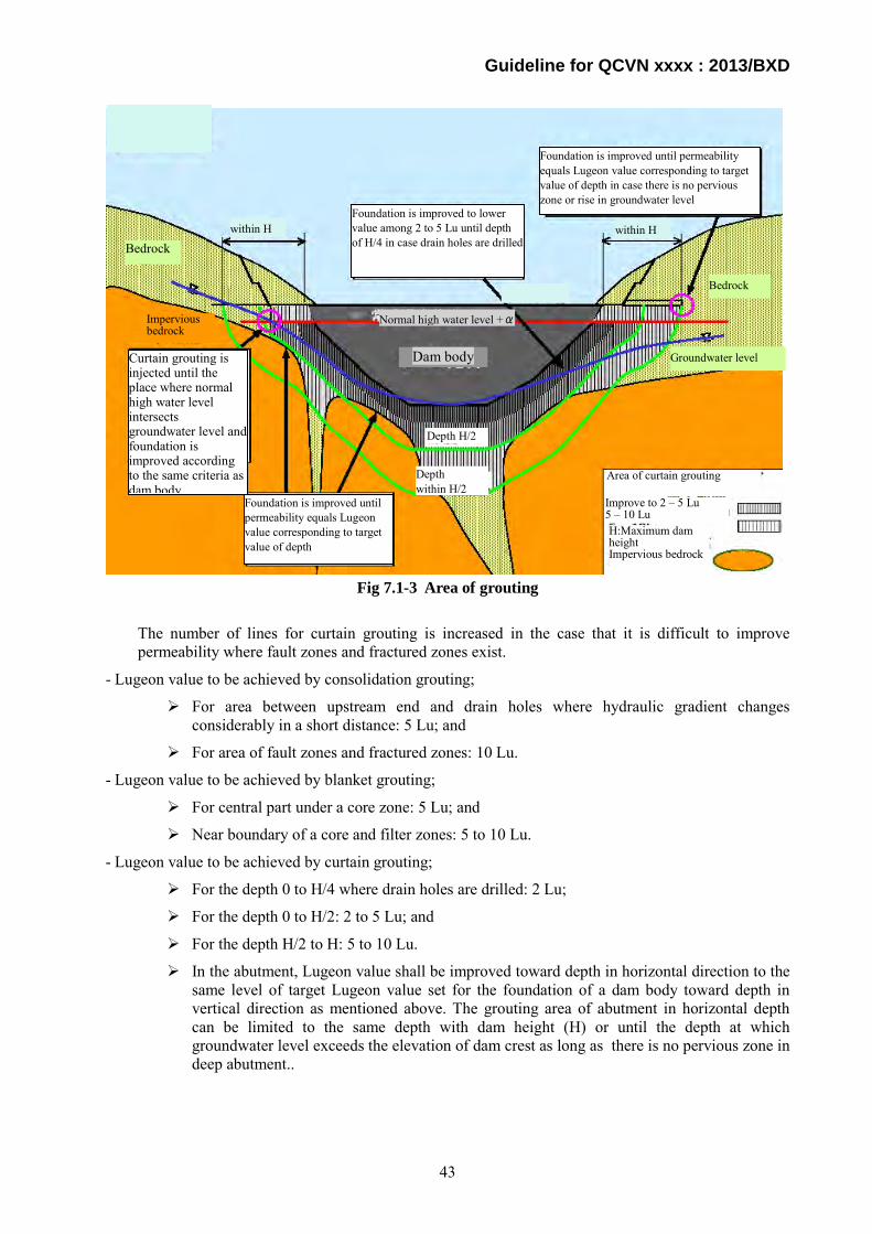
Guideline for QCVN xxxx : 2013/BXD
Fig 7.1-3 Area of grouting
The number of lines for curtain grouting is increased in the case that it is difficult to improve permeability where fault zones and fractured zones exist.
- Lugeon value to be achieved by consolidation grouting;
For area between upstream end and drain holes where hydraulic gradient changes considerably in a short distance: 5 Lu; and
For area of fault zones and fractured zones: 10 Lu.
- Lugeon value to be achieved by blanket grouting;
For central part under a core zone: 5 Lu; and
Near boundary of a core and filter zones: 5 to 10 Lu.
- Lugeon value to be achieved by curtain grouting;
For the depth 0 to H/4 where drain holes are drilled: 2 Lu;
For the depth 0 to H/2: 2 to 5 Lu; and
For the depth H/2 to H: 5 to 10 Lu.
In the abutment, Lugeon value shall be improved toward depth in horizontal direction to the same level of target Lugeon value set for the foundation of a dam body toward depth in vertical direction as mentioned above. The grouting area of abutment in horizontal depth can be limited to the same depth with dam height (H) or until the depth at which groundwater level exceeds the elevation of dam crest as long as there is no pervious zone in deep abutment..
within H
Normal high water level +α
Bedrock
Bedrock
Impervious bedrock
within H
Foundation is improved to lower value among 2 to 5 Lu until depth of H/4 in case drain holes are drilled
Groundwater level
Depth H/2
Depth within H/2
Dam body
Curtain grouting is injected until the place where normal high water level intersects groundwater level and foundation is improved according to the same criteria as dam body Foundation is improved until
permeability equals Lugeon value corresponding to target value of depth
Area of curtain grouting
H:Maximum dam height Impervious bedrock
Improve to 2 – 5 Lu 5 – 10 Lu
Foundation is improved until permeability equals Lugeon value corresponding to target value of depth in case there is no pervious zone or rise in groundwater level
43

Guideline for QCVN xxxx : 2013/BXD
where, H: Maximum height of dam
Lu: Lugeon value, defined as the loss of water in liters per minute and per meter of borehole length at a hydrostatic pressure of 10 kgf/cm2, approximately 0.98 MPa. Lugeon value is calculated by the following formula.
LPQLu
××
=10
… (1)
where, Q: Amount of infiltrated water (l/min)
L: Length of drill hole to conduct Lugeon test (m)
P: Injection pressure (kgf/cm2)
In case the relation of injection pressure and amount of infiltrated water runs off a linear relation before injection pressure reaches 10 kgf/cm2 (0.98 MPa), Legon value is estimated by extending the linear relation as shown in Fig.7.1-4.
Permeability coefficient K is calculated by the following formula when a permeability test is conducted at a drill hole with constant injection pressure.
rL
HLQK elog
2 ×××=
π … (2)
where, L: Length of drill hole to conduct permeability test (cm)
H: Head (cm)
Q: Amount of infiltrated water (cc/s)
r : Radius of drill hole (cm)
Unifying formulae (1) and (2), permeability coefficient, K, is calculated by the following formula.
rLLuK elog1066.2 6 ×××= − … (3)
where, K: Permeability coefficient (cm/s)
Lu: Lugeon value
L: Length of drill hole to conduct permeability test (cm)
Inje
ctio
n p
ress
ure
P (k
gf/c
m2)
Converted Lugeon value Lugeon value Amount of infiltrated water Q (l/min) Fig.7.1-4 Estimation of Lugeon value
44

Guideline for QCVN xxxx : 2013/BXD
r : diameter of drill hole (cm)
Substituting r for 3.3cm as a radius of a drill hole and L for 500cm as test length usually used for a permeability test to formula (3), the relation of permeability coefficient and Lugeon value is calculated as follows.
LuK ××= −51034.1 … (4)
Here it shall be noted that the purpose of a permeability test is different from that of a Lugeon test. A permeability test is a general term of some tests to investigate permeability of foundation, which aims at getting hydraulic parameters of foundation. A Lugoen test aims at getting permeability of foundation, but does not estimate the state of seepage water in foundation.
Technical Regulation Article 7.1.9 c) stipulates that permeability coefficient of foundation shall be less than 1.16 x 10⁻⁵ cm/s and it corresponds to 0.87 Lu using the equation (4), which is similar to the lower limit of a target value to be achieved by curtain grouting regulated in the previous grouting guideline in Japan, 1 to 2 Lu, while that in the present grouting guideline in Japan is 2 to 5 Lu.
In case a dam shall be constructed on foundation with high permeability, improvement by curtain grouting is not an only solution, and a floating dam, dam with blanket or other measures to prevent dam foundation from being damaged by piping failure by reducing hydraulic gradient could be practical solutions.
7.1.10. Technical Regulation Article 7.1.10 describes requirements on restoration of temporary facilities and quarry sites to preserve environment in and around construction site of hydropower civil works.
Generally the Dam Owner shall conduct restoration of temporary works and quarry sites by the following procedure:
1) Investigate laws and ordinances regarding landscape and environmental preservation;
2) Consult with local government and communities on restoration of temporary facilities and quarry sites;
3) Prepare a restoration plan;
4) Estimate cost for restoration;
5) Explain a restoration plan to local government and communities for approval and revise it if necessary; and
6) Restore temporary facilities and quarry sites as designed.
7.1.11. As stipulated in Technical Regulation Article 7.1.11.
7.1.12. Technical Regulation Article 7.1.12 describes the rule of drilling and blasting in a safe and effective way. The method of drilling and blasting shall refer to provisions of QCVN 04-04 : 2012/BNNPTNT.
7.1.13. Technical Regulation Article 7.1.13 describes the requirements for reservoir operation.
a) Safe operation
The reservoir shall be operated safely in all discharge level including deign and check flood conditions. Each flood condition is defined in Guideline for Technical Regulation Article7.1.8.
b) Harmony with water consuming sectors
The Dam Owner shall establish the reservoir operation rule after due consultation with other water consuming sectors.
c) Flood regulation
The Dam Owner shall establish the flood control rule keeping the following requirements:
45

Guideline for QCVN xxxx : 2013/BXD
The flood releasing operation for the flood events lower than the design flood does not cause significant damages for downstream area; and
In case of flood releasing operation for the flood events higher than design flood, there shall be appropriate constructional solutions in order to assure safety for reservoir work, hydropower plant and minimize damages in downstream area.
In the case of reservoir which does not have function of flood control, the basic rule of flood release from a reservoir is that discharge from a dam be balanced with inflow to a reservoir, that is, a flood flows down a river without stored in the reservoir as if a dam did not exist.
In case a flood larger than a design flood occurs, an influence to the downstream area shall not exceed the effected that could occur before a dam was constructed.
Articles of decrees and circulars relevant to flood regulation are as follows:
Decision No: 285/2006/QD-TTg
Article 2. Content of the reservoir operation procedures
1. Mission of the hydropower structures.
2. Main criteria of the hydropower structures:
a) Name and location of the structures;
b) Main criteria of the reservoirs and structures;
c) Criteria of relevant equipment (Number of units, capacity, and specifications of operation equipment).
3. Detailed provisions of the reservoir operation procedures:
a) Provisions on flood prevention mission:
- Periods of early flood, main flood and late flood;
- Water level of reservoirs in periods of early flood, main flood and late flood;
- Performance of reduction of frequent flood and big flood for downstream (implemented for structures with flood reduction mission for downstream);
- Handling procedure of valve gate insuring safety operation which shall ensure water level of reservoirs not exceeding designated level of all cases;
- Coordination principle between flood reduction and control structures (if any).
b) Provisions on power generation mission:
- Working regime of hydropower plants in the system;
- Requirement of water release volume for the downstream ensuring ecological flow (if any);
- Requirement of downstream level fluctuation caused by operation procedure regime of the plants (if any);
- Coordination principle of generation mission amongst other sub-missions (if any).
4. Responsibilities to organize the reservoir operation:
a) Responsibilities of organizations and individuals issuing orders;
b) Responsibilities of organizations and individuals carrying out those orders;
c) Responsibilities to notify the orders to affected area caused by valve operation;
d) Responsibilities relating to the safety of the structures;
46
Guideline for QCVN xxxx : 2013/BXD
e) Principles in dealing with the accidents when operating the structures;
g) Responsibilities of inspecting the structures and reservoirs before and after flood season;
h) Responsibilities in dealing with damage and faults relating to the structures, and equipment which ensure the safety of exploitation and operation of hydropower structures and reservoirs during flood season.
The Dam Owner shall establish a reservoir operation rule specifying such items as described in the above provisions.
Circular No.34/2010/TT-BCT:
Article 10. Hydropower reservoir operation procedure
1. The procedures are prepared by the dam’s owner in compliance with the provisions of Decision No. 285/2006/QD-TTg of the Prime Minister dated December 25, 2006 regarding the power for promulgation and execution of the hydropower reservoir operation procedure, and submitting to competent authority prior to reservoir impounding;
2. Competence for approving reservoir operation procedure
a. MOIT approves the procedure of reservoir having capacity of equal or greater than 1,000,000 m3 or for reservoirs located in more than two provinces, except for cases complying with the provisions in Article 12 of Decree 112/2008/ND-CP of the Government dated October 20,2008 regarding the comprehensive protection, management and exploitation of resources and environment of hydropower and hydraulic reservoir;
b. The provincial People’s Committee approved the procedures for remaining cases.
3. The regulation of water reservoirs shall follow the provisions in the approved procedures.
4. Trial test for gates of the structures
a. Procedure of dry test for gates is prepared by dam’s owner depending on the characteristics of the structures and conducts this test at least once a year before the flood season. Repair works for the gates after dry test shall be finished before the annual flood season;
b. Procedure of wet test for gates is prepared by dam’s owner. Depending on hydrological conditions and the characteristics of each structure, the gates wet test can be carried out by beginning of flood season but shall not affect to the downstream area when discharging water through the spillway.
The Dam Owner shall prepare a reservoir operation rule including the items stipulated in Article 2 of Decision No: 285/2006/QD-TTg and submit it to the competent authorities for approval.
The Dam Owner shall conduct a trial test for spillway gates before the flood season and repair trouble, if any.
Decree No: 112/2008/ND-PQD-TTg
Article 9: Regulating water of reservoir
1. Operating process of reservoir should be established and submitted to authorized office for approval before accumulating water of reservoir, satisfying fully duties of reservoir in priority order, ensuring the safety of project, safety of reservoir’s lowlands, general exploit resources and environment of reservoir, maintain minimal water current in the reservoir’s lowlands, not causing much change to current at reservoir’s lowlands and consider the factor of climate changing; go with operating process of join reservoirs in river valley (if exist) approved by authorized governmental office.
The Dam Owner shall prepare a reservoir operation rule including the items stipulated in paragraph 1 above and submit it to the competent authorities for approval before start of impoundment.
47

Guideline for QCVN xxxx : 2013/BXD
2. The owners of reservoir have duties to supervise, collect information, data of hydrometeorology by their own expense to serve the demand of protection, management, operation, exploitation of reservoir as instruction of governmental managing office for resources and environment and send annual report of implementing result to specialized managing Ministry and related provincial people’s committee.
The Dam Owner shall prepare a reservoir operation rule according to hydro-meteorological data and submit an annual report to the competent authorities.
3. Annually, owners of reservoirs are responsible for making plans of regulating water in reservoirs and inform the plan of water regulation to people’s committees of different levels where the reservoirs locate and area of reservoir’s lowlands to reduce bad effect on production, life of people and environment.
The Dam Owner shall revise the reservoir operation rule every year and inform the competent authorities of it.
4. The plan of water regulation in reservoir is established based on operating process of reservoir approved by authorized governmental office, demand of maintaining minimal water current, forecast of current changing in the year from hydro meteorological office and the water using demand by sections, local area, economic organizations.
The reservoir operation rule shall be revised according to the latest information.
5. In case, offices, related organizations and locality don’t agree with the plan of water regulation in reservoir, they can send their petition to owner of reservoir and authorized governmental offices to consider, decide the plan of water regulation in reservoir.
The competent authorities may order the Dam Owner to revise the reservoir operation rule.
d) Discharge to downstream area
In case the Dam Owner shall discharge some amount of water to the downstream area, he shall follow the procedure as shown in Guideline for Technical Regulation Article 7.1.3.
7.1.14. As stipulated in Technical Regulation Article 7.1.14.
7.1.15. As stipulated in Technical Regulation Article 7.1.15.
7.1.16. As stipulated in Technical Regulation Article 7.1.16.
7.1.17. As stipulated in Technical Regulation Article 7.1.17.
Standard Specification for Concrete Structures in Japan shows the relation between compressive strength, f’ck, and bending strength of concrete, fbck, for reference as follows:
tkbbbck fkkf ××= 10
+
+=
ch
b
lh
k5.485.0
110
)4.0(55.041 ≥=
hk b
where fbck: Bending strength of concrete (N/mm2);
k0b: Coefficient showing the relation between tensile strength and bending strength due to tensile softening characteristics of concrete;
k1b: Coefficient showing reduction of strength due to drying, hydration or any other causes;
h: Height of component (m) (> 0.2) ;
48
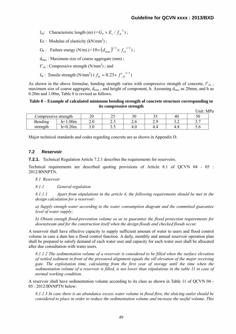
Guideline for QCVN xxxx : 2013/BXD
lch: Characteristic length (m) (= 2/ ckcF fEG × ) ;
Ec : Modulus of elasticity (kN/mm2) ;
GF : Failure energy (N/m) (= ( ) 3/13/1max10 ckfd ×× ) ;
dmax : Maximum size of coarse aggregate (mm) ;
f’ck : Compressive strength (N/mm2) ; and
ftk : Tensile strength (N/mm2) ( 3/2'23.0 cktk ff ×= )
As shown in the above formulae, bending strength varies with compressive strength of concrete, f’ck , maximum size of coarse aggregate, dmax , and height of component, h. Assuming dmax as 20mm, and h as 0.20m and 1.00m, Table 8 is revised as follows.
Table 8 – Example of calculated minimum bending strength of concrete structure corresponding to its compressive strength
Unit: MPa Compressive strength 20 25 30 35 40 50 Bending strength
h=1.00m 2.0 2.3 2.6 2.9 3.2 3.7 h=0.20m 3.0 3.5 4.0 4.4 4.8 5.6
Major technical standards and codes regarding concrete are as shown in Appendix D.
7.2 Reservoir 7.2.1. Technical Regulation Article 7.2.1 describes the requirements for reservoirs.
Technical requirements are described quoting provisions of Article 8.1 of QCVN 04 - 05 : 2012/BNNPTN.
8.1 Reservoir
8.1.1 General regulation
8.1.1.1 Apart from stipulations in the article 4, the following requirements should be met in the design calculation for a reservoir:
a) Supply enough water according to the water consumption diagram and the committed guarantee level of water supply;
b) Obtain enough flood-prevention volume so as to guarantee the flood protection requirements for downstream and for the construction itself when the design floods and checked floods occur.
A reservoir shall have effective capacity to supply sufficient amount of water to users and flood control volume in case a dam has a flood control function. A daily, monthly and annual reservoir operation plan shall be prepared to satisfy demand of each water user and capacity for each water user shall be allocated after due consultation with water users.
8.1.1.2 The sedimentation volume of a reservoir is considered to be filled when the surface elevation of settled sediment in front of the pressured alignment equals the sill elevation of the major receiving gate. The exploitation time, calculating from the first year of storage until the time when the sedimentation volume of a reservoir is filled, is not lower than stipulations in the table 11 in case of normal working condition.
A reservoir shall have sedimentation volume according to its class as shown in Table 11 of QCVN 04 - 05 : 2012/BNNPTN below:
8.1.1.3 In case there is an abundance excess water volume in flood flow, the sluicing outlet should be considered to place in order to reduce the sedimentation volume and increase the useful volume. This
49
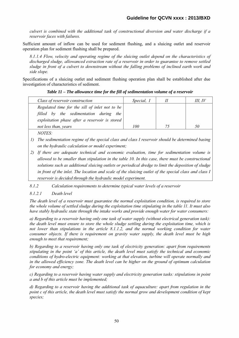
Guideline for QCVN xxxx : 2013/BXD
culvert is combined with the additional task of constructional diversion and water discharge if a reservoir faces with failures.
Sufficient amount of inflow can be used for sediment flushing, and a sluicing outlet and reservoir operation plan for sediment flushing shall be prepared.
8.1.1.4 Flow, velocity and operating regime of the sluicing outlet depend on the characteristics of discharged sludge, allowanced extraction rate of a reservoir in order to guarantee to remove settled sludge in front of a culvert to downstream without the falling problems of inclined earth work and side slope.
Specifications of a sluicing outlet and sediment flushing operation plan shall be established after due investigation of characteristics of sediment.
Table 11 – The allowance time for the fill of sedimentation volume of a reservoir
Class of reservoir construction Special, I II III, IV Regulated time for the sill of inlet not to be filled by the sedimentation during the exploitation phase after a reservoir is stored not less than, years 100 75 50 NOTES:
1) The sedimentation regime of the special class and class I reservoir should be determined basing on the hydraulic calculation or model experiment;
2) If there are adequate technical and economic evaluation, time for sedimentation volume is allowed to be smaller than stipulation in the table 10. In this case, there must be constructional solutions such as additional sluicing outlets or periodical dredge to limit the deposition of sludge in front of the inlet. The location and scale of the sluicing outlet of the special class and class I reservoir is decided through the hydraulic model experiment.
8.1.2 Calculation requirements to determine typical water levels of a reservoir
8.1.2.1 Death level
The death level of a reservoir must guarantee the normal exploitation condition, is required to store the whole volume of settled sludge during the exploitation time stipulating in the table 11. It must also have stably hydraulic state through the intake works and provide enough water for water consumers:
a) Regarding to a reservoir having only one task of water supply (without electrical generation task): the death level must ensure to store the whole sludge settling during the exploitation time, which is not lower than stipulations in the article 8.1.1.2, and the normal working condition for water consumer objects. If there is requirement on gravity water supply, the death level must be high enough to meet that requirement;
b) Regarding to a reservoir having only one task of electricity generation: apart from requirements stipulating in the point ‘a’ of this article, the death level must satisfy the technical and economic conditions of hydro-electric equipment: working at that elevation, turbine will operate normally and in the allowed efficiency zone. The death level can be higher on the ground of optimum calculation for economy and energy;
c) Regarding to a reservoir having water supply and electricity generation tasks: stipulations in point a and b of this article must be implemented;
d) Regarding to a reservoir having the additional task of aquaculture: apart from regulation in the point c of this article, the death level must satisfy the normal grow and development condition of kept species;
50
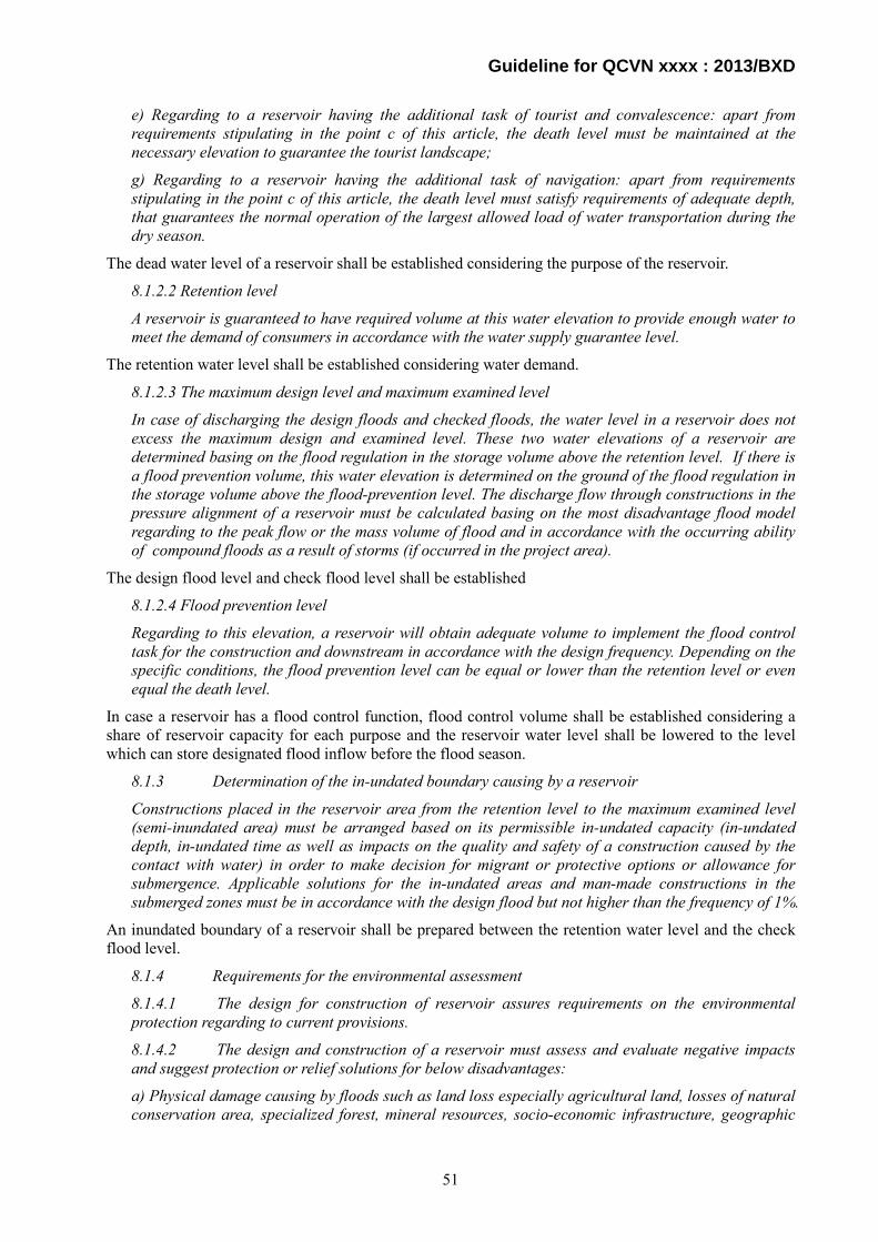
Guideline for QCVN xxxx : 2013/BXD
e) Regarding to a reservoir having the additional task of tourist and convalescence: apart from requirements stipulating in the point c of this article, the death level must be maintained at the necessary elevation to guarantee the tourist landscape;
g) Regarding to a reservoir having the additional task of navigation: apart from requirements stipulating in the point c of this article, the death level must satisfy requirements of adequate depth, that guarantees the normal operation of the largest allowed load of water transportation during the dry season.
The dead water level of a reservoir shall be established considering the purpose of the reservoir.
8.1.2.2 Retention level
A reservoir is guaranteed to have required volume at this water elevation to provide enough water to meet the demand of consumers in accordance with the water supply guarantee level.
The retention water level shall be established considering water demand.
8.1.2.3 The maximum design level and maximum examined level
In case of discharging the design floods and checked floods, the water level in a reservoir does not excess the maximum design and examined level. These two water elevations of a reservoir are determined basing on the flood regulation in the storage volume above the retention level. If there is a flood prevention volume, this water elevation is determined on the ground of the flood regulation in the storage volume above the flood-prevention level. The discharge flow through constructions in the pressure alignment of a reservoir must be calculated basing on the most disadvantage flood model regarding to the peak flow or the mass volume of flood and in accordance with the occurring ability of compound floods as a result of storms (if occurred in the project area).
The design flood level and check flood level shall be established
8.1.2.4 Flood prevention level
Regarding to this elevation, a reservoir will obtain adequate volume to implement the flood control task for the construction and downstream in accordance with the design frequency. Depending on the specific conditions, the flood prevention level can be equal or lower than the retention level or even equal the death level.
In case a reservoir has a flood control function, flood control volume shall be established considering a share of reservoir capacity for each purpose and the reservoir water level shall be lowered to the level which can store designated flood inflow before the flood season.
8.1.3 Determination of the in-undated boundary causing by a reservoir
Constructions placed in the reservoir area from the retention level to the maximum examined level (semi-inundated area) must be arranged based on its permissible in-undated capacity (in-undated depth, in-undated time as well as impacts on the quality and safety of a construction caused by the contact with water) in order to make decision for migrant or protective options or allowance for submergence. Applicable solutions for the in-undated areas and man-made constructions in the submerged zones must be in accordance with the design flood but not higher than the frequency of 1%.
An inundated boundary of a reservoir shall be prepared between the retention water level and the check flood level.
8.1.4 Requirements for the environmental assessment
8.1.4.1 The design for construction of reservoir assures requirements on the environmental protection regarding to current provisions.
8.1.4.2 The design and construction of a reservoir must assess and evaluate negative impacts and suggest protection or relief solutions for below disadvantages:
a) Physical damage causing by floods such as land loss especially agricultural land, losses of natural conservation area, specialized forest, mineral resources, socio-economic infrastructure, geographic
51

Guideline for QCVN xxxx : 2013/BXD
name, historical and cultural monuments and famous landscape as well as the extinction of exhausted fauna and flora species;
b) It can lead to the reduction or loss of residential areas, which have been settled stably for hundreds of years. There are security, society and defense disadvantages as well as hazard consequences resulting from the broken dam, which can occur in the future;
c) The reliability and feasibility of the migrant and re-settlement activities so as to guarantee the better living conditions in all aspects in a new living areas comparing to the old ones;
d) Downstream area can be influenced by the changes of flow and sedimentation regimes; Forecast the impacts of these changes to the riverbed, dikes or estuaries;
e) Assessment on the socio-economic and environmental benefits after the construction.
8.1.4.3 There are solutions such as the restriction of toxic substances encroaching into a reservoir, the development of protective forest as well as the improvement of area and quality of floristic composition in the catchment area to guarantee the water quality in a reservoir during the management and exploitation periods.
A hydropower and water use project shall follow laws and ordinances regarding environmental preservation, and an environmental impact assessment shall be conducted and a social safeguard program and compensation plan shall be established.
8.1.6 Exploitation in the semi-inundated area
Researches should be implemented to take advantages of the semi-flood area for production and in accordance with the submerged state. However, it will not reduce the design volume and water quality of a reservoir as well as not increase the volume of erosion soil above the permission level.
Semi-flooded area can be used for some purposes in the dry season, however, land use shall not reduce effective capacity, pollute reservoir water or erode soil on the slope.
7.2.2. Technical Regulation Article 7.2.2 describes the rule before start of impoundment stipulated in Article 8.1.5 of QCVN 04 - 05 : 2012/BNNPTNT:
8.1.5 Works must be done before the accumulation of a reservoir
8.1.5.1 Determine the submerged area of a reservoir, including permanent and semi inundated areas which can be exploited.
The Dam Owner shall conduct site survey and decide submerged area of a reservoir corresponding to the normal high water level and freeboard.
8.1.5.2 Slash and clean up forest and reservoir foundation, absolute excavation of mineral resources or protection of useful mineral mines (if existed), conservation of agriculture land at the highest level (if possible) as well as protection or replacement of cultural works and valuable historical and cultural monuments in the in-undated area of a reservoir foundation.
The Dam Owner shall clear trees, excavate or preserve mineral resources, conserve agricultural lands, and protect cultural heritage in the estimated reservoir area.
8.1.5.3 Having solutions to protect aquatic product resources, gene and other biological resources.
The Dam Owner shall take proper measures to protect aquatic life following the process shown in Guideline for Technical Regulation Article 7.1.5.
8.1.5.4. Creation of appropriate conditions to meet requirement of navigation (if existed).
The Dam Owner shall take proper measures to ensure navigation following the process shown in the Guideline for Technical Regulation Article 7.1.5.
8.1.5.5 Prepare solutions in dealing with peat blocks and other physical blocks being floated when a reservoir is stored.
52

Guideline for QCVN xxxx : 2013/BXD
The Dam Owner shall dispose peat blocks or any other impurities out of a reservoir to prevent water pollution.
7.2.3. Technical Regulation Article 7.2.3 describes basic requirements on measures against destructive insects. The Dam Owner shall get rid of destructive insects from the project area according to TCVN 8479-2010 and TCVN 8480-2010.
7.3 Dams
7.3.1. Earth dam
7.3.1.1.Technical Regulation Article 7.3.1.1 describes basic technical requirements for earth dams.
Basic technical requirements for an earth dam, rockfill dam or earth-rockfill dam are:
i) A dam body and its foundation shall be safe against sliding failure; and
ii) A dam body and its foundation shall be safe against seepage failure.
Technical requirements are described by quoting provisions of TCVN8216-2009.
a) Adequate safety height to prevent overtopping
6.1 Determination of crest level (elevation of dam crest)
6.1.1 Crest level is the highest elevation determined considering the normal high water level, the highest water level when design flood and check flood occur and fluctuation of the reservoir water level by other causes in order to keep reservoir water from overflowing the dam crest according to the construction grade.
6.1.2 Freeboard of dam crest is determined:
hđ = ∆h + hsl + a
In which
∆h Height of tail water due to wind, m;
hsl Height of run-up wave on the slope, m;
a Safety height, determined based on 6.1.3, m;
Calculated frequency of run-up wave is determined based on 6.1.3;
Freeboard of the dam is stipulated differently for 3 cases:
Normal high water level;
Design flood level;
Check flood level;
6.1.3 Safety height and design wind frequency:
Safety height of the dam based on grade of the dam and working condition is selected according to Table 2;
Design wind frequency is based on grade of the dam and selected according to stipulations in Table 3.
Table 2 – Safety height of the dam
Working condition of the reservoir Safety height according to grade of the dam (m) I II III IV V
Normal water level 1.5 1.2 0.7 0.5 0.5 Design flood level 1.0 1.0 0.5 0.5 0.5 Check flood level 0.5 0.3 0.2 0.2 0.0
53
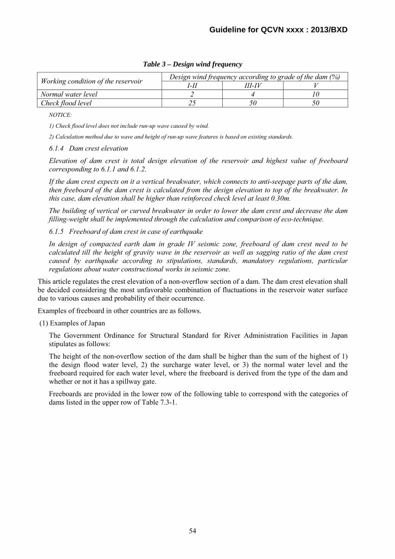
Guideline for QCVN xxxx : 2013/BXD
Table 3 – Design wind frequency
Working condition of the reservoir Design wind frequency according to grade of the dam (%) I-II III-IV V
Normal water level 2 4 10 Check flood level 25 50 50
NOTICE:
1) Check flood level does not include run-up wave caused by wind.
2) Calculation method due to wave and height of run-up wave features is based on existing standards.
6.1.4 Dam crest elevation
Elevation of dam crest is total design elevation of the reservoir and highest value of freeboard corresponding to 6.1.1 and 6.1.2.
If the dam crest expects on it a vertical breakwater, which connects to anti-seepage parts of the dam, then freeboard of the dam crest is calculated from the design elevation to top of the breakwater. In this case, dam elevation shall be higher than reinforced check level at least 0.30m.
The building of vertical or curved breakwater in order to lower the dam crest and decrease the dam filling-weight shall be implemented through the calculation and comparison of eco-technique.
6.1.5 Freeboard of dam crest in case of earthquake
In design of compacted earth dam in grade IV seismic zone, freeboard of dam crest need to be calculated till the height of gravity wave in the reservoir as well as sagging ratio of the dam crest caused by earthquake according to stipulations, standards, mandatory regulations, particular regulations about water constructional works in seismic zone.
This article regulates the crest elevation of a non-overflow section of a dam. The dam crest elevation shall be decided considering the most unfavorable combination of fluctuations in the reservoir water surface due to various causes and probability of their occurrence.
Examples of freeboard in other countries are as follows.
(1) Examples of Japan
The Government Ordinance for Structural Standard for River Administration Facilities in Japan stipulates as follows:
The height of the non-overflow section of the dam shall be higher than the sum of the highest of 1) the design flood water level, 2) the surcharge water level, or 3) the normal water level and the freeboard required for each water level, where the freeboard is derived from the type of the dam and whether or not it has a spillway gate.
Freeboards are provided in the lower row of the following table to correspond with the categories of dams listed in the upper row of Table 7.3-1.
54

Guideline for QCVN xxxx : 2013/BXD
Table 7.3-1 Crest elevation of non-overflow section of dam
Category Gravity dam, hollow gravity dam, and arch dam Fill dam
Freeboard
At the normal water level, Hf = hw + he + ha, where Hf ≥ 2. At the surcharge water level,
ae
wf h2
hhH ++=
where Hf ≥ 2. At the design flood water level, Hf = hw + ha where Hf ≥ 1.
At the normal water level, Hf = hw + he + ha + 1 where Hf ≥ 3. At the surcharge water level,
1h2hhH a
ewf +++=
where Hf ≥ 3. At the design flood water level, Hf = hw + ha + 1 where Hf ≥ 2.
[Note]
Hf is the freeboard (in units of m).
hw is the height of waves caused by wind (in units of m).
he is the height of waves caused by an earthquake (in units of m).
ha is 0.5 m for dams with a spillway gate and 0 m for dams without a spillway gate.
The freeboard provided in Paragraph above can be changed from [Hf ≥ 3] to [Hf ≥ 2] for fill dams if they do not have a spillway gate and their overflow depth of water is less than 2.5 m when the flow of water discharged from the spillway flows down at the design flood water level.
The calculation method of hw and he is as follows:
NWL
FWL
Minimum Freeboard
Normal Freeboard
Fig.7.3-1 Normal and minimum freeboard
55
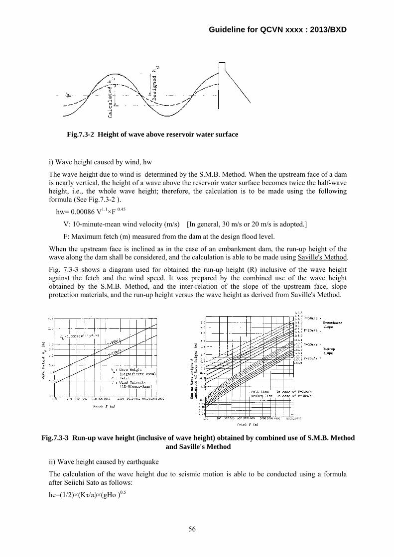
Guideline for QCVN xxxx : 2013/BXD
i) Wave height caused by wind, hw
The wave height due to wind is determined by the S.M.B. Method. When the upstream face of a dam is nearly vertical, the height of a wave above the reservoir water surface becomes twice the half-wave height, i.e., the whole wave height; therefore, the calculation is to be made using the following formula (See Fig.7.3-2 ).
hw= 0.00086 V1.1×F 0.45
V: 10-minute-mean wind velocity (m/s) [In general, 30 m/s or 20 m/s is adopted.]
F: Maximum fetch (m) measured from the dam at the design flood level.
When the upstream face is inclined as in the case of an embankment dam, the run-up height of the wave along the dam shall be considered, and the calculation is able to be made using Saville's Method.
Fig. 7.3-3 shows a diagram used for obtained the run-up height (R) inclusive of the wave height against the fetch and the wind speed. It was prepared by the combined use of the wave height obtained by the S.M.B. Method, and the inter-relation of the slope of the upstream face, slope protection materials, and the run-up height versus the wave height as derived from Saville's Method.
ii) Wave height caused by earthquake
The calculation of the wave height due to seismic motion is able to be conducted using a formula after Seiichi Sato as follows:
he=(1/2)×(Kτ/π)×(gHo )0.5
Fig.7.3-2 Height of wave above reservoir water surface
Fig.7.3-3 Run-up wave height (inclusive of wave height) obtained by combined use of S.M.B. Method and Saville's Method
56
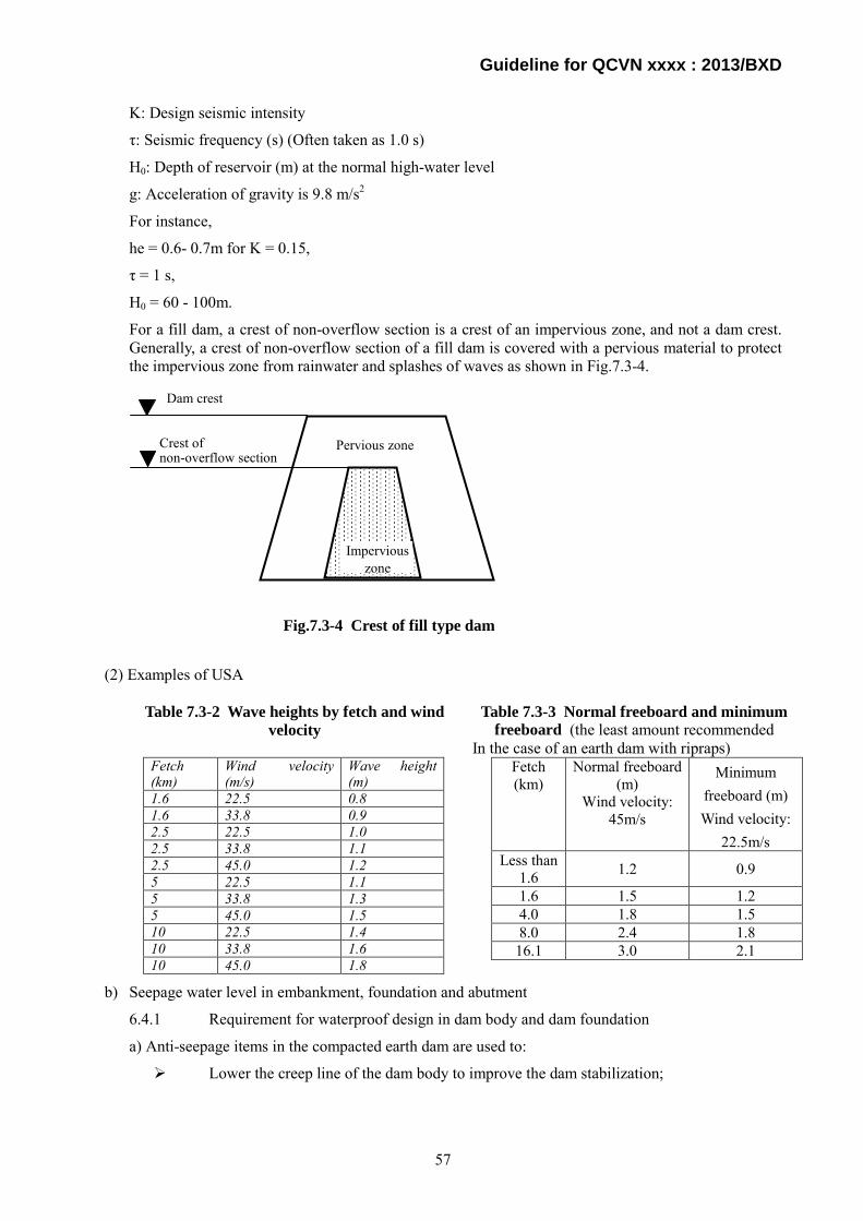
Guideline for QCVN xxxx : 2013/BXD
K: Design seismic intensity
τ: Seismic frequency (s) (Often taken as 1.0 s)
H0: Depth of reservoir (m) at the normal high-water level
g: Acceleration of gravity is 9.8 m/s2
For instance,
he = 0.6- 0.7m for K = 0.15,
τ = 1 s,
H0 = 60 - 100m.
For a fill dam, a crest of non-overflow section is a crest of an impervious zone, and not a dam crest. Generally, a crest of non-overflow section of a fill dam is covered with a pervious material to protect the impervious zone from rainwater and splashes of waves as shown in Fig.7.3-4.
(2) Examples of USA
Table 7.3-2 Wave heights by fetch and wind velocity
Table 7.3-3 Normal freeboard and minimum freeboard (the least amount recommended
In the case of an earth dam with ripraps) Fetch (km)
Wind velocity (m/s)
Wave height (m)
1.6 22.5 0.8 1.6 33.8 0.9 2.5 22.5 1.0 2.5 33.8 1.1 2.5 45.0 1.2 5 22.5 1.1 5 33.8 1.3 5 45.0 1.5 10 22.5 1.4 10 33.8 1.6 10 45.0 1.8
b) Seepage water level in embankment, foundation and abutment
6.4.1 Requirement for waterproof design in dam body and dam foundation
a) Anti-seepage items in the compacted earth dam are used to:
Lower the creep line of the dam body to improve the dam stabilization;
Dam crest
Crest of non-overflow section
Impervious zone
Pervious zone
Fetch (km)
Normal freeboard (m)
Wind velocity: 45m/s
Minimum freeboard (m) Wind velocity:
22.5m/s Less than
1.6 1.2 0.9
1.6 1.5 1.2 4.0 1.8 1.5 8.0 2.4 1.8 16.1 3.0 2.1
Fig.7.3-4 Crest of fill type dam
57

Guideline for QCVN xxxx : 2013/BXD
Decrease the seepage gradient in the dam body and output areas and prevent the deformation of soil caused by actions of seepage flow. This stream causes the appearance of concentrated seepage flow inside of dam body, dam foundation, and natural soil area next to two abutments and downstream area that might destroy the construction and the base;
Decrease the seepage discharge through the dam body, dam foundation, and dam abutments to allowable scope.
This article regulates the seepage water level in an embankment, foundation and abutment, and comes under the item ii) of the basic technical requirement at the beginning of this article. A dam body shall be safe against piping failure caused by seepage water flowing inside a dam body and foundation. Generally safety against seepage failure is evaluated by velocity of seepage water and hydraulic gradient. An impervious zone shall be designed so that soil particle will not moved by seepage water.
As an example, the Government Ordinance for Structural Standard for River Administration Facilities in Japan stipulates as follows:
A fill type dam shall be so designed as to satisfy the following technical requirements:
i) A dam body shall not cause sliding failure inside a dam body, and at and around a boundary between a dam body and its foundation;
ii) A phreatic surface shall not appear at the downstream slope or toe; and
iii) An impervious zone shall satisfy the following requirements;
An impervious zone shall consist of soil or other proper impervious materials;
The crest of an impervious zone shall be higher than the normal high water level plus freeboard; and
An impervious zone and its boundary with foundation shall not cause piping failure.
c) Location of discharge facilities
Discharge facilities shall not be installed through a dam body. Settlement of a dam body will cause cracks between the dam body and a conduit installed in the dam body, and infiltration of reservoir water through those cracks will cause piping failure in the dam body.
Fig.7.3-5 Prohibited Case
Fig.7.3-6 Acceptable Case
Discharge facility
Cracks
Discharge facility
58

Guideline for QCVN xxxx : 2013/BXD
d) Grading of neighboring zone
Grading of fill material shall be so connected that impervious material may not be flown to a transitional and rock material zone by seepage water pressure;
A transitional zone has an important role to prevent impervious zone material from flowing to a transitional and rock zone.
When the transitional zone plays the role of a filter, the relation with the material to be protected is required to meet the following criteria for a filter. Riverbed sand is one type of preferable material for the filter.
1) F15: 15% grain size of the filter material
B15: 15% grain size of the material to be protected by the filter > 5
2) F15: 15% grain size of the filter material
B85: 85% grain size of the material to be protected by the filter < 5
3) The grain-size curve of the filter material shall preferably be parallel to that of the material to be protected.
4) When the material to be protected contains coarse-grained material, items "1)" and "2)" are applied regarding the grain size of a material smaller than 25 mm.
5) The filter material shall be non-adhesive and shall not contain material smaller than 0.074 mm (over 5% of the material). For the adhesive material to be protected, however, this requirement can be loosened.
Materials meeting these requirements can be considered to have good drainage ability and high resistance to a seepage failure of the material to be protected. It is adequate that the permeability coefficient of the filter material is 10 to 100 times that of the material to be protected (in general).
Fig.7.3-7 Seepage Flow in Zoned Type Fill Dams
Seepage flow through fine grained materials
Pervious zone
Semi-pervious zone Impervious zone
59
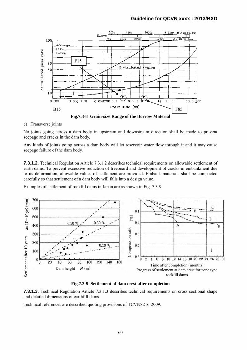
Guideline for QCVN xxxx : 2013/BXD
Fig.7.3-8 Grain-size Range of the Borrow Material
e) Transverse joints
No joints going across a dam body in upstream and downstream direction shall be made to prevent seepage and cracks in the dam body.
Any kinds of joints going across a dam body will let reservoir water flow through it and it may cause seepage failure of the dam body.
7.3.1.2. Technical Regulation Article 7.3.1.2 describes technical requirements on allowable settlement of earth dams. To prevent excessive reduction of freeboard and development of cracks in embankment due to its deformation, allowable values of settlement are provided. Embank materials shall be compacted carefully so that settlement of a dam body will falls into a design value.
Examples of settlement of rockfill dams in Japan are as shown in Fig. 7.3-9.
Fig.7.3-9 Settlement of dam crest after completion
7.3.1.3. Technical Regulation Article 7.3.1.3 describes technical requirements on cross sectional shape and detailed dimensions of earthfill dams.
Technical references are described quoting provisions of TCVN8216-2009.
F85 B15
F15
Dam height
Settl
emen
t afte
r 10
year
s
Com
pres
sion
ratio
Time after completion (months) Progress of settlement at dam crest for zone type
rockfill dams
A E
D
C B
60

Guideline for QCVN xxxx : 2013/BXD
a) Crest elevation
Technical references regarding the crest elevation are described in Guideline for Technical Regulation Article 7.3.1.1.
b) Width of dam crest
6.2 Width and composition of dam crest
6.2.1 Width of dam crest
Determination of the dam crest width depends on constructional and exploitation conditions, but it is not less than 5.0m. Besides the consideration of construction grade shown in Table 1, following conditions shall be considered:
1) If there is no other requirement, width of the dam crest shall be from 5m to 10m for grade III downwards, greater than 10m for grade I and grade II dam;
2) If there is a requirement of combining with public traffic way, it shall be designed based on traffic way standard. If the value in traffic way standard is smaller than in this standard, it shall follow stipulations of this standard.
The crest width shall be 5.0 to 10.0 m for Class II and below, greater than 10.0 m for Special and Class I, and shall follow traffic road standard in case the dam crest is used as a public road.
6.2.2 Width of dam crest at locations adjoining other structures
The dam crest width at locations adjoining other structures shall be decided suitably with the adjoining structures and commonly, a wider area shall be used.
The crest of two dam abutments needs to be flared with larger dam crest width and lower gradient of the slope, which is convenient for the stabilization and anti-seepage of the dam abutment as well as the fineness of the construction. Widening the crest of two abutments into flared slopes depends mainly on terrain conditions around the abutments.
In case the dam crest leads to another structure or another dam crest, a larger value shall be adopted.
6.2.3 Structure and location of dam crest surface
Structure and location of the dam crest surface shall be durable, safe, and convenient during the exploitation and fineness.
The dam crest surface shall slope down in one or two sides with gradient from 2% to 3%, and drainage system to dam face shall be well-constructed (there is no stagnant water on the dam crest surface).
The dam crest road shall have a camber for drainage.
6.2.4 Protective layer of dam crest
Protective layer of the dam crest is based on management requirements, use purposes, and investment possibility in order to choose one of following protective materials:
Rock with compacted aggregate sand and gravel;
Road tar (asphalt) type penetration macadam;
Asphalt concrete;
If there is a plan to heighten the dam in the future, the protective layer shall not be made of concrete;
The dam crest shall have a protective layer to prevent it from being eroded.
6.2.5 Dam crest combining with traffic road
If there is a need to use the dam crest as a public road, marker posts and barrier or road bead shall be located for the safety purpose. If there is no expectation of traffic road, marker posts shall be also located to direct business vehicles.
61

Guideline for QCVN xxxx : 2013/BXD
In headwork with electric power source, pressure burner system could be located on the dam crest to support the management and exploitation as well as improve the fineness of the construction.
In case the dam crest road is used as a public road, traffic signs or any other necessary facilities following traffic regulations.
c) Dam slope
6.3 Dam surface and protection
6.3.1 Dam surface
Dam surface:
Is illustrated by dam surface coefficient m or scale between vertical and horizontal heights, for example: m = 1 : 2.0; 1 : 2.5; 1 : 3.0; and
Its upstream surface is symbolized as mt, downstream surface is mh.
Dam surface shall be stable according to the standard for all working conditions. Gradient of the dam surface is determined based on: type of dam, dam height, properties of dam materials and dam base materials, loads acting on the surface, such as own weight, hydrostatic and hydrodynamic pressure, seepage force, capillary force, seismic force, external load on the dam crest and dam surface, etc., working and exploitation condition.
In preliminary calculation of the dam surface gradient, documents from similar dams constructed in the area or approximate method can be used and subsequently, the result shall be checked by calculation stipulated in 6.7.
If sloping wall at upstream of the dam is filled by materials with anti-slipping criteria (ϕ, c) less than corresponding criteria of filling-soil in the dam body, gradient of upstream surface can be determined based on slide possibility of the surface in general and of the sloping wall over contact surface with the dam body as well as of protective layer on sloping wall surface.
The dam slope shall be safe and stable against loads acting on it, and decided by slope stability analyses.
6.3.4 Consolidation of the dam surface
The dam surface shall be consolidated to prevent it from destructions due to wave, rain, and other disturbance factors.
Protective structure for the dam surface is selected from types stipulated in 6.3.5 and the end of 6.3.7 according to an eco-technical comparison in order to fit following requirements:
Stable and solid, able to stand all disturbance types acting on the dam surface, and well-drainage;
Take advantage of in site material and use technological material with sensible cost;
Simple construction, easy management and maintenance; and
High fineness, especially at downstream surface and permanent exposed parts above water level in upstream surface.
The dam surface shall be compacted with proper machinery to prevent it from slipping off.
6.3.5 Upstream surface
Upstream surface is often protected by using following methods:
a) Filling-rock;
b) Dry masonry;
c) Mortared stonework with flexible joints and weep hole in each cell;
d) Concrete plate or reinforced concrete plate casted in place or precast plate with flexible joints and weep hole;
62

Guideline for QCVN xxxx : 2013/BXD
e) Asphalt concrete with flexible joints and weep hole in each cell;
f) Plant applied for low dam, reservoir with small wave. An anti-termite solution shall be issued.
Dimension of the protective layer is determined according to existing regulations and calculated instructions.
6.3.6 Consolidation layer of upstream surface
Consolidation layer of upstream surface shall be divided into main consolidation part which is located in area mainly exposed to the highest wave occurring in the exploitation period, and secondary parts located in remaining areas; stone or concrete bearings shall be located across the time of the main consolidation part.
Protective area for upstream surface starts from the dam crest to the lowest water level, dead water level: 2.5m for grade III or above dams, and 1.5m for grade IV dams.
6.3.7 Consolidation type for upstream surface
When selecting type to consolidate the upstream surface, following features shall be considered:
Height of run-up wave due to wind and ship acting on the surface;
Characteristics of materials in the dam body and erosion level in the reservoir;
Amount of consolidation material in the construction area as well as their manufacture condition; and
Grade and multi-purpose feature of the construction;
Consolidation type by rock-fill can be applied to all cases when there is sufficient amount of useable rock in the construction site and it is convenient for constructing by machine.
Dry masonry or mortared stonework is used when constructing by machine is not available.
Reinforced concrete and asphalt concrete are only applied in rock-rare areas and its economy is better than of other consolidation types.
Under the surface consolidation layer, a buffer layer shall be located to connect the layer and the dam body as well as works as an inverted filter to keep the soil layer from being eroded by wave or sudden change in reservoir water level.
Aggregate and thickness of the buffer layer shall be designed based on existing stipulations and design instructions for invert layer. Normally, dry masonry or mortared stonework filter layer comprises two layers: gravel and sand with thickness of each layer about at least 15cm. For sand-rare areas, geotextitle fabric can be researched to work as filter layer.
When using concrete plates, reinforced concrete plates, casted-in-place asphalt concrete, and mortared stonework for the surface protection, weep holes shall be located to reduce internal water pressure because the reservoir water level lowers quickly or because of other causes. For concrete or asphalt concrete consolidation layers that are used to protect and control seepage of the dam body, weep holes shall not be bored on it.
The upstream surface shall be protected with proper material to prevent it from slipping off or being eroded by fluctuation in the reservoir water level.
6.3.8 Protection of downstream surface
Downstream surface is often applied following protective methods:
Planting grass on rich soil layer covered on the filling surface;
Scattering gravel or 0.2m thick gravel on the dam surface completely;
Dry masonry;
Casted-in-rock reinforced concrete mold; and
63
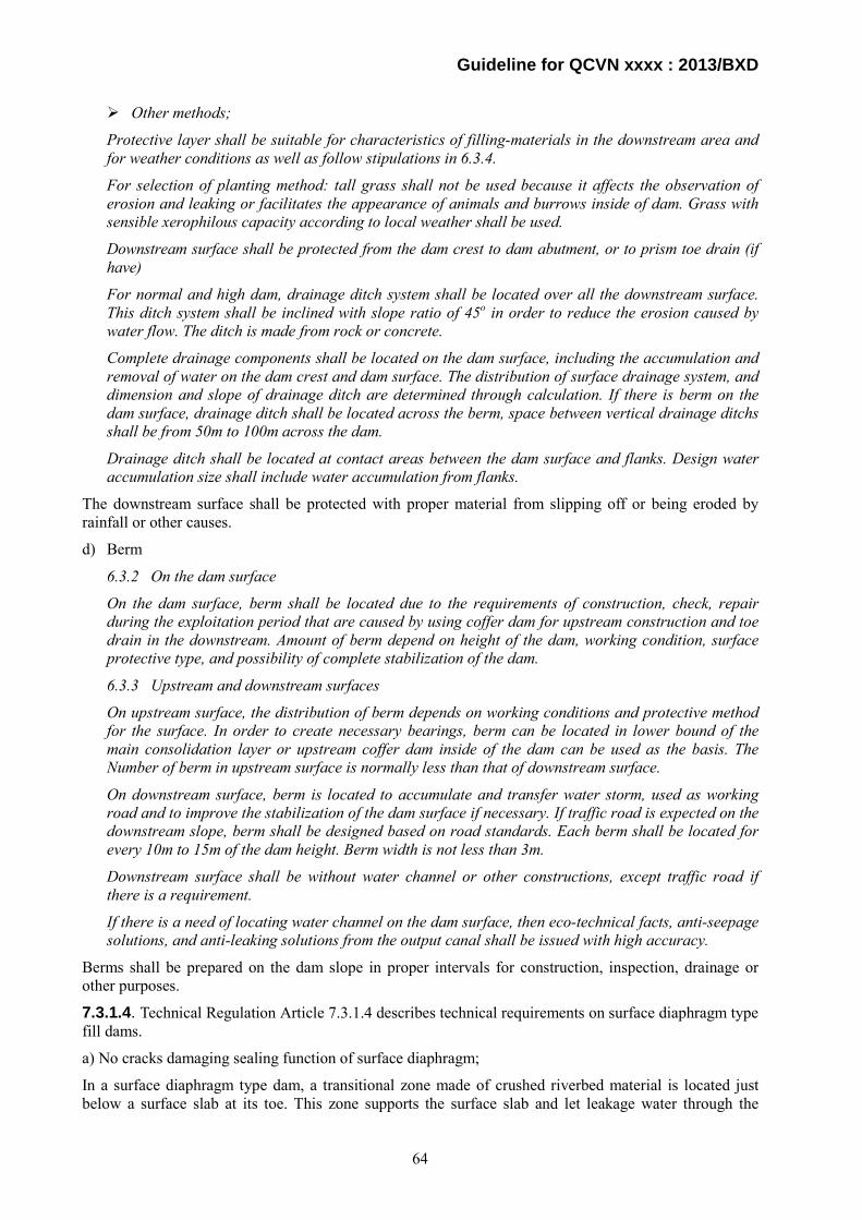
Guideline for QCVN xxxx : 2013/BXD
Other methods;
Protective layer shall be suitable for characteristics of filling-materials in the downstream area and for weather conditions as well as follow stipulations in 6.3.4.
For selection of planting method: tall grass shall not be used because it affects the observation of erosion and leaking or facilitates the appearance of animals and burrows inside of dam. Grass with sensible xerophilous capacity according to local weather shall be used.
Downstream surface shall be protected from the dam crest to dam abutment, or to prism toe drain (if have)
For normal and high dam, drainage ditch system shall be located over all the downstream surface. This ditch system shall be inclined with slope ratio of 45o in order to reduce the erosion caused by water flow. The ditch is made from rock or concrete.
Complete drainage components shall be located on the dam surface, including the accumulation and removal of water on the dam crest and dam surface. The distribution of surface drainage system, and dimension and slope of drainage ditch are determined through calculation. If there is berm on the dam surface, drainage ditch shall be located across the berm, space between vertical drainage ditchs shall be from 50m to 100m across the dam.
Drainage ditch shall be located at contact areas between the dam surface and flanks. Design water accumulation size shall include water accumulation from flanks.
The downstream surface shall be protected with proper material from slipping off or being eroded by rainfall or other causes.
d) Berm
6.3.2 On the dam surface
On the dam surface, berm shall be located due to the requirements of construction, check, repair during the exploitation period that are caused by using coffer dam for upstream construction and toe drain in the downstream. Amount of berm depend on height of the dam, working condition, surface protective type, and possibility of complete stabilization of the dam.
6.3.3 Upstream and downstream surfaces
On upstream surface, the distribution of berm depends on working conditions and protective method for the surface. In order to create necessary bearings, berm can be located in lower bound of the main consolidation layer or upstream coffer dam inside of the dam can be used as the basis. The Number of berm in upstream surface is normally less than that of downstream surface.
On downstream surface, berm is located to accumulate and transfer water storm, used as working road and to improve the stabilization of the dam surface if necessary. If traffic road is expected on the downstream slope, berm shall be designed based on road standards. Each berm shall be located for every 10m to 15m of the dam height. Berm width is not less than 3m.
Downstream surface shall be without water channel or other constructions, except traffic road if there is a requirement.
If there is a need of locating water channel on the dam surface, then eco-technical facts, anti-seepage solutions, and anti-leaking solutions from the output canal shall be issued with high accuracy.
Berms shall be prepared on the dam slope in proper intervals for construction, inspection, drainage or other purposes.
7.3.1.4. Technical Regulation Article 7.3.1.4 describes technical requirements on surface diaphragm type fill dams.
a) No cracks damaging sealing function of surface diaphragm;
In a surface diaphragm type dam, a transitional zone made of crushed riverbed material is located just below a surface slab at its toe. This zone supports the surface slab and let leakage water through the
64
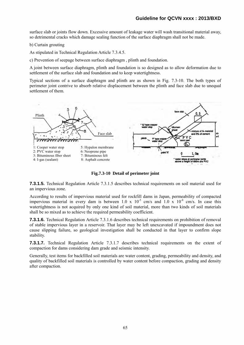
Guideline for QCVN xxxx : 2013/BXD
surface slab or joints flow down. Excessive amount of leakage water will wash transitional material away, so detrimental cracks which damage sealing function of the surface diaphragm shall not be made.
b) Curtain grouting
As stipulated in Technical Regulation Article 7.3.4.5.
c) Prevention of seepage between surface diaphragm , plinth and foundation.
A joint between surface diaphragm, plinth and foundation is so designed as to allow deformation due to settlement of the surface slab and foundation and to keep watertightness.
Typical sections of a surface diaphragm and plinth are as shown in Fig. 7.3-10. The both types of perimeter joint contrive to absorb relative displacement between the plinth and face slab due to unequal settlement of them.
Fig.7.3-10 Detail of perimeter joint
7.3.1.5. Technical Regulation Article 7.3.1.5 describes technical requirements on soil material used for an impervious zone.
According to results of impervious material used for rockfill dams in Japan, permeability of compacted impervious material in every dam is between 1.0 x 10⁻⁵ cm/s and 1.0 x 10⁻⁸ cm/s. In case this watertightness is not acquired by only one kind of soil material, more than two kinds of soil materials shall be so mixed as to achieve the required permeability coefficient.
7.3.1.6. Technical Regulation Article 7.3.1.6 describes technical requirements on prohibition of removal of stable impervious layer in a reservoir. That layer may be left unexcavated if impoundment does not cause slipping failure, so geological investigation shall be conducted in that layer to confirm slope stability. 7.3.1.7. Technical Regulation Article 7.3.1.7 describes technical requirements on the extent of compaction for dams considering dam grade and seismic intensity.
Generally, test items for backfilled soil materials are water content, grading, permeability and density, and quality of backfilled soil materials is controlled by water content before compaction, grading and density after compaction.
1: Cooper water stop 5: Hypalon membrane 2: PVC water stop 6: Neoprene pipe 3: Bituminous fiber sheet 7: Bituminous felt 4: I-gas (sealant) 8: Asphalt concrete
Plinth
Face slab
65

Guideline for QCVN xxxx : 2013/BXD
Fig.7.3-11 Relation between water content and properties
As shown in Fig. 7.3-11, an upper limit of water content before compaction is regulated by reduction of shear strength due to pore pressure and reduction of trafficability, and a lower limit is regulated by permeability after compaction and degree of saturation. If water content before compaction is lower than the optimum water content (Wopt), it is difficult to ensure required impermeability and deformation of a dam body increases after impounding, while in case water content is excessively wet of optimum water content, waving phenomena occur and cracks develop on the surface of banking. So water content is usually kept between 0 to 3% wet of optimum water content. It is desirable that water content be measured at least twice a day.
To select construction method and machinery, trial banking is usually conducted and the following items are tested and decided:
Type of compacting equipment;
Spreading thickness of impervious material;
Number of passage for compacting equipment;
Water content of impervious material during compaction; and
Driving speed of compacting equipment.
In Japan, standard value of density after compaction is expressed by percentage to the maximum dry density (D value), and quality is controlled by to what percentage soil materials are compacted compared to dry density of a specimen compacted by an laboratory test. Usually, it is provided that D value shall be more than 95% and an in-situ density test is conducted three times per layer.
7.3.2. Rock-fill dam
7.3.2.1. As stipulated in Technical Regulation Article 7.3.2.1.
7.3.2.2. Technical Regulation Article 7.3.2.2 describes technical requirements on foundation of an impervious zone and the guidance for them are already described in Guideline for Technical Regulation Article 7.1.9.
7.3.2.3. Technical Regulation Article 7.3.2.3 describes technical requirements on foundation of a rockfill dam.
In Japan, requirements on foundation of each zone of a zone type rockfill dam are as follows.
(1) Impervious zone
Foundation of an impervious zone requires water-tightness firstly and, plasticity and shear strength secondly. It is desirable that in case of a large scale rockfill foundation of an impervious zone be excavated to bedrock.
Inte
rnal
fric
tion
angl
e φ
(deg
) C
ohes
ion
c (M
Pa)
Perm
eabi
lity
coef
ficie
nt k
(cm
/s)
Allowable range
Test value
Allowable range
Test value
Test value
Dry
den
sity
ρ(t/
m3 )
Water content and density Water content and permeability Water content and shear strength
Lower limit
66

Guideline for QCVN xxxx : 2013/BXD
(2) Transitional zone
A role of a transitional zone is prevention of impervious material from flowing out and safe discharge of seepage water. Foundation of a transition zone requires bearing capacity and shear strength.
(3) Pervious zone
Foundation of a pervious zone requires shear strength with same or more than that of dam body materials and low deformability not to affect a dam body. Usually surface soil, terrace deposit, or other loosened zones are removed, and river alluvium deposit remains unexcavated as a foundation.
(4) Riprap
A role of riprap is to protect an embank material from being eroded and slipping off due to wave or fluctuation of a reservoir water level. The maximum thickness of riprap is 1.0m in general.
7.3.2.4. Technical Regulation Article 7.3.2.4 describes technical requirements on quality of rockfill materials.
(1) Prohibition on mixing impurities with rockfill material
Impurities such as organic matters reduce strength and decomposing of organic materials make gaps in a rockfill dam body .
(2) Grading
As described in Guideline of Technical Regulation Article 7.3.1.1.
7.3.2.5 As stipulated in Technical Regulation Article 7.3.2.5.
7.3.2.6. Technical Regulation Article 7.3.2.6 describes technical requirements on permission of installation of a temporary spillway on a dam body. As described in Guideline for Technical Regulation Article 7.3.1.1. c), settlement of a dam body is inevitable and permanent structures affected by settlement of a dam body shall not be installed on or inside a dam body. It is desirable that a main dam body not be overtopped during construction at the worst case, however, some measures such as a temporary spillway on a dam body or reinforcement of downstream slope shall be taken in case overtopping of a main dam is inevitable.
7.3.3. Earth and rock-fill dam
Technical Regulation Article 7.3.3 describes technical requirements on zoning of an earth and rock-fill dam and the guidance of them are already described in Guideline for Technical Regulation Article 7.3.2.3.
TCVN XX stipulates zoning of an earthfilll, rockfill and earth-rockfill dams as follows.
4.1.1 Earth dam
4.1.1.1 Common fill dams on impervious foundation (Fig. 4.1):
a) Homogenous earth dam: using single type of soil with same source and similar physico-mechanical characteristics (Fig. 4.1 a);
b) Non-homogenous earth dam: using multi types of soil with different characteristic. Each type of soil is located in separate block and in appropriate location in dam cross section (Fig 4.1 b and d);
c) Dam with sloping wall: sloping wall is impervious material (soft or solid) located outer of upstream slope (Fig. 4.1 c and e);
d) Dam with core-wall: core wall is impervious material (soft or solid) located at dam core (Fig. 4.1 f and g);
- Mixed dam: dam body part at upstream side is filled by one or many types of soil, dam body part at downstream side is rock fill block (Fig. 4.1 h). Generally, for this type of dam, soil part of the dam takes account of more than a half of whole dam volume.
67

Guideline for QCVN xxxx : 2013/BXD
Fig. 4.1 – Cross section of common earth dams constructed on impervious (low permeability)
foundation
4.1.1.2 Common earth dams on pervious foundation (Fig. 4.2):
a) Dam with cutoff wall: applied for the foundation which is not rock type or its pervious bed is not deep. Cutoff wall can be made from soil with type as same as one used for homogenous dam body (Fig. 4.2 a) or better impervious type (Fig. 4.2 b) or it can deeply locate cutoff wall and core into foundation using the same soil of cutoff wall and core (Fig 4.2 c, d). It depends on the depth of impervious bed and calculation of permeability strength that cutoff wall can be located deeply into impervious bed or just at certain depth;
b) Dam with sheet pile: applied for pervious foundation which is not rock and has quite great depth. It depends on the depth of impervious bed and calculation of permeability strength that sheet pile can be located deeply to impervious bed (Fig. 4.2 e) or just at certain depth (Fig. 4.2 g). This impervious method can be applied for non-homogenous dams;
68

Guideline for QCVN xxxx : 2013/BXD
Fig. 4.2 - Cross section of common earth dams constructed on pervious foundation
c) Dam with impervious diaphragm: impervious diaphragm is made by filling cement mortar, clay-cement… into gravel sandy bed, deeply pervious or soft-weak weathered rock bed. Impervious diaphragm can be located deeply into solid rock bed (Fig. 4.2 h) or to certain depth (Fig. 4.2 i);
d) Dam with upstream apron: upstream apron is suitable for applying great depth or extreme depth of impervious bed. Upstream apron is made from greatly impervious material and constructed adjacent to sloping wall (Fig. 4.2 k) or to homogenous dam.
4.1.1.3 Scope of application:
a) Applying only for non-overflow dam in power line;
b) Being suitable for location in which soil materials are available and easy for filling. These soils are caused from similarly homogenous alluvium, diluvium such as semi-clay soil, semi-sand, grit, completely weathered or strong weathered rock. Disposal soil, or rock is taken from excavation pit. After categorizing, most of them can be used for dam fill.
c) Not applying for foundation which will lead to settlement, washout, sudden reduce of shear resistance criteria when soil contacts water or when earthquake occurs it will lead to liquefying phenomenon. If it is required to construct on this foundation, it shall have special treatment method, appropriate method for the construction work and shall have approval from investor;
d) Homogenous is only applicable for medium, low dam and for site locations which have only considerably homogenous soil and similar physio-mechanical characteristic.
69

Guideline for QCVN xxxx : 2013/BXD
4.1.2 Rock dam
4.1.2.1 Common-use rock dam:
a) Rockfill dam (Fig. 4.3 a, b, c and Fig 4.4): major material for filling is rock. Impervious material is clay with low permeability factor used for core or diaphragm which is made from rigid material such as: concrete, reinforced concrete, asphalt concrete, plastic diaphragm… It is located outside upstream slope for sloping wall type (Fig. 4.3 a) or inside dam body for central wall type (Fig. 4.3 b and c);
b) Masonry rock dam: impervious equipment is installed outside upstream slope (Fig. 4.3 d). It is allowed to construct overflow dam when dam height is less than 5m;
c) Mixed dam of half fill and half masonry rock type: dam body at upstream side is masonry rock, dam body at downstream side is rockfill. Impervious equipment is installed outside upstream slope (Fig. 4.3 e);
d) Mixed dam: beside earth-rock dam (Fig. 4.1 h), it is applicable for using concrete (reinforced concrete)-rock: concrete block is located at upstream dam body as retain wall and for impervious purpose (Fig 4.3 f).
Remark:
1) Impervious equipment; 2) rockfill; 3) masonry rock; 4) concrete or reinforced concrete
Fig. 4.3 – Cross section of some common rock dams constructed on rock bed
Remark:
1) rockfill; 2) impervious core; 3) transitional block; 4) transitional filter; 5) rock base;6) impervious diaphragm
Fig. 4.4- Cross section of rockfill dam construction on gravel sandy foundation
70
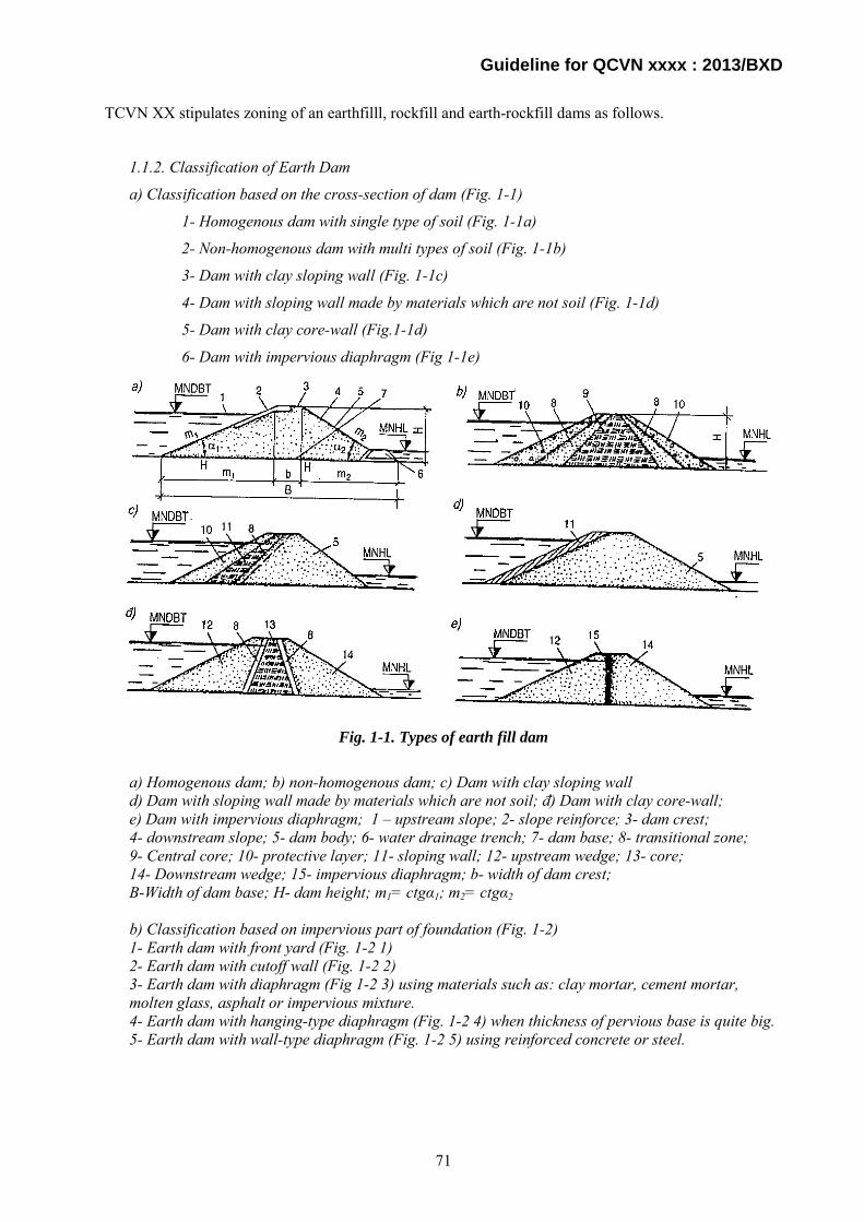
Guideline for QCVN xxxx : 2013/BXD
TCVN XX stipulates zoning of an earthfilll, rockfill and earth-rockfill dams as follows.
1.1.2. Classification of Earth Dam
a) Classification based on the cross-section of dam (Fig. 1-1)
1- Homogenous dam with single type of soil (Fig. 1-1a)
2- Non-homogenous dam with multi types of soil (Fig. 1-1b)
3- Dam with clay sloping wall (Fig. 1-1c)
4- Dam with sloping wall made by materials which are not soil (Fig. 1-1d)
5- Dam with clay core-wall (Fig.1-1d)
6- Dam with impervious diaphragm (Fig 1-1e)
Fig. 1-1. Types of earth fill dam
a) Homogenous dam; b) non-homogenous dam; c) Dam with clay sloping wall d) Dam with sloping wall made by materials which are not soil; đ) Dam with clay core-wall; e) Dam with impervious diaphragm; 1 – upstream slope; 2- slope reinforce; 3- dam crest; 4- downstream slope; 5- dam body; 6- water drainage trench; 7- dam base; 8- transitional zone; 9- Central core; 10- protective layer; 11- sloping wall; 12- upstream wedge; 13- core; 14- Downstream wedge; 15- impervious diaphragm; b- width of dam crest; B-Width of dam base; H- dam height; m1= ctgα1; m2= ctgα2 b) Classification based on impervious part of foundation (Fig. 1-2) 1- Earth dam with front yard (Fig. 1-2 1) 2- Earth dam with cutoff wall (Fig. 1-2 2) 3- Earth dam with diaphragm (Fig 1-2 3) using materials such as: clay mortar, cement mortar, molten glass, asphalt or impervious mixture. 4- Earth dam with hanging-type diaphragm (Fig. 1-2 4) when thickness of pervious base is quite big. 5- Earth dam with wall-type diaphragm (Fig. 1-2 5) using reinforced concrete or steel.
71
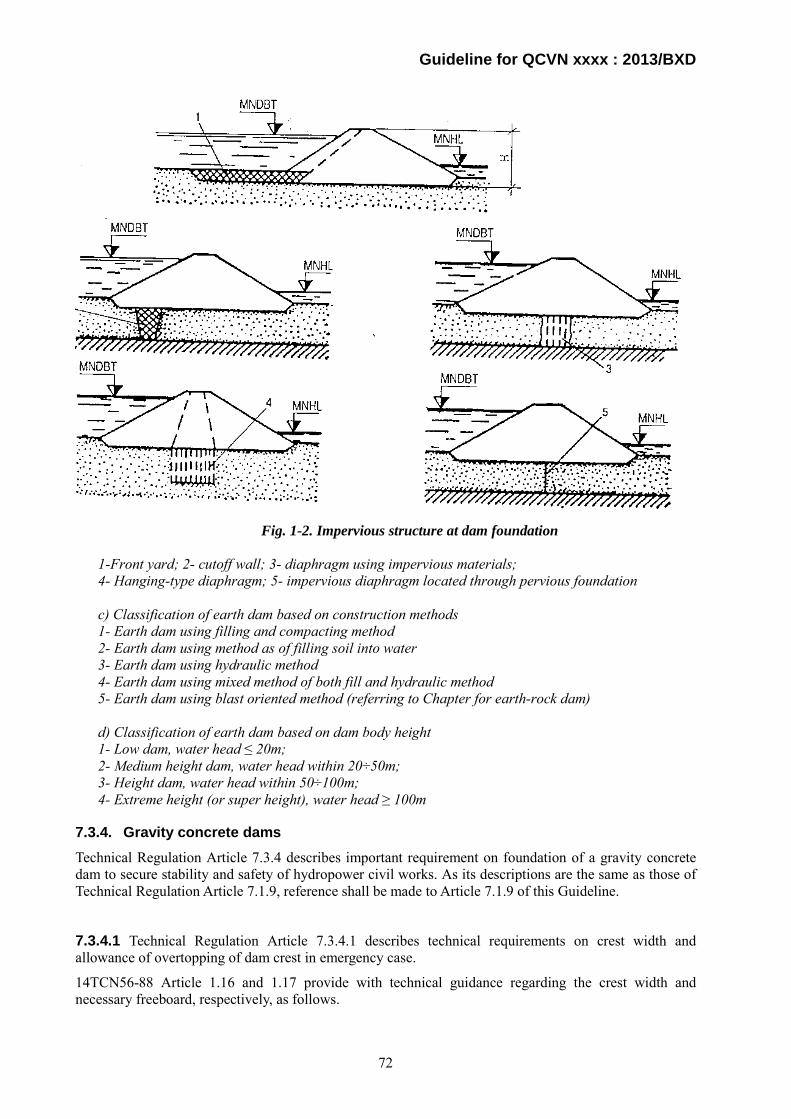
Guideline for QCVN xxxx : 2013/BXD
Fig. 1-2. Impervious structure at dam foundation
1-Front yard; 2- cutoff wall; 3- diaphragm using impervious materials; 4- Hanging-type diaphragm; 5- impervious diaphragm located through pervious foundation c) Classification of earth dam based on construction methods 1- Earth dam using filling and compacting method 2- Earth dam using method as of filling soil into water 3- Earth dam using hydraulic method 4- Earth dam using mixed method of both fill and hydraulic method 5- Earth dam using blast oriented method (referring to Chapter for earth-rock dam) d) Classification of earth dam based on dam body height 1- Low dam, water head ≤ 20m; 2- Medium height dam, water head within 20÷50m; 3- Height dam, water head within 50÷100m; 4- Extreme height (or super height), water head ≥ 100m
7.3.4. Gravity concrete dams Technical Regulation Article 7.3.4 describes important requirement on foundation of a gravity concrete dam to secure stability and safety of hydropower civil works. As its descriptions are the same as those of Technical Regulation Article 7.1.9, reference shall be made to Article 7.1.9 of this Guideline.
7.3.4.1 Technical Regulation Article 7.3.4.1 describes technical requirements on crest width and allowance of overtopping of dam crest in emergency case.
14TCN56-88 Article 1.16 and 1.17 provide with technical guidance regarding the crest width and necessary freeboard, respectively, as follows.
72
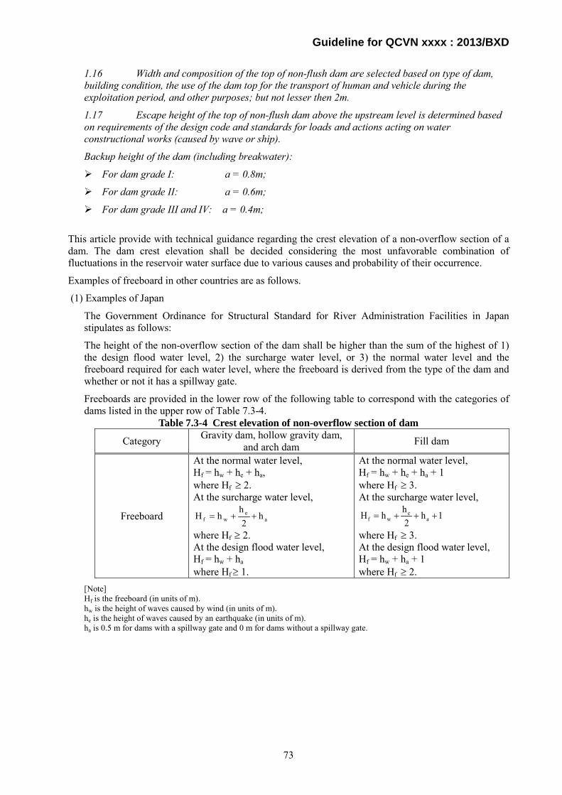
Guideline for QCVN xxxx : 2013/BXD
1.16 Width and composition of the top of non-flush dam are selected based on type of dam, building condition, the use of the dam top for the transport of human and vehicle during the exploitation period, and other purposes; but not lesser then 2m.
1.17 Escape height of the top of non-flush dam above the upstream level is determined based on requirements of the design code and standards for loads and actions acting on water constructional works (caused by wave or ship).
Backup height of the dam (including breakwater):
For dam grade I: a = 0.8m;
For dam grade II: a = 0.6m;
For dam grade III and IV: a = 0.4m;
This article provide with technical guidance regarding the crest elevation of a non-overflow section of a dam. The dam crest elevation shall be decided considering the most unfavorable combination of fluctuations in the reservoir water surface due to various causes and probability of their occurrence.
Examples of freeboard in other countries are as follows.
(1) Examples of Japan
The Government Ordinance for Structural Standard for River Administration Facilities in Japan stipulates as follows:
The height of the non-overflow section of the dam shall be higher than the sum of the highest of 1) the design flood water level, 2) the surcharge water level, or 3) the normal water level and the freeboard required for each water level, where the freeboard is derived from the type of the dam and whether or not it has a spillway gate.
Freeboards are provided in the lower row of the following table to correspond with the categories of dams listed in the upper row of Table 7.3-4.
Table 7.3-4 Crest elevation of non-overflow section of dam
Category Gravity dam, hollow gravity dam, and arch dam Fill dam
Freeboard
At the normal water level, Hf = hw + he + ha, where Hf ≥ 2. At the surcharge water level,
ae
wf h2
hhH ++=
where Hf ≥ 2. At the design flood water level, Hf = hw + ha where Hf ≥ 1.
At the normal water level, Hf = hw + he + ha + 1 where Hf ≥ 3. At the surcharge water level,
1h2hhH a
ewf +++=
where Hf ≥ 3. At the design flood water level, Hf = hw + ha + 1 where Hf ≥ 2.
[Note] Hf is the freeboard (in units of m). hw is the height of waves caused by wind (in units of m). he is the height of waves caused by an earthquake (in units of m). ha is 0.5 m for dams with a spillway gate and 0 m for dams without a spillway gate.
73

Guideline for QCVN xxxx : 2013/BXD
Fig.7.3-12 Normal and minimum freeboard
The freeboard provided in Paragraph above can be changed from [Hf ≥ 3] to [Hf ≥ 2] for fill dams if they do not have a spillway gate and their overflow depth of water is less than 2.5 m when the flow of water discharged from the spillway flows down at the design flood water level.
The calculation method of hw and he is as follows:
i) Wave height caused by wind, hw
The wave height due to wind is determined by the S.M.B. Method. When the upstream face of a dam is nearly vertical, the height of a wave above the reservoir water surface becomes twice the half-wave height, i.e., the whole wave height; therefore, the calculation is to be made using the following formula (See Fig.7.3-13 ).
Fig.7.3-13 Height of wave above reservoir water surface
hw= 0.00086 V1.1×F 0.45
V: 10-minute-mean wind velocity (m/s) [In general, 30 m/s or 20 m/s is adopted.]
F: Maximum fetch (m) measured from the dam at the design flood level.
When the upstream face is inclined as in the case of an embankment dam, the run-up height of the wave along the dam shall be considered, and the calculation is able to be made using Saville's Method.
Fig. 7.3-14 shows a diagram used for obtained the run-up height (R) inclusive of the wave height against the fetch and the wind speed. It was prepared by the combined use of the wave height obtained by the S.M.B. Method, and the inter-relation of the slope of the upstream face, slope protection materials, and the run-up height versus the wave height as derived from Saville's Method.
NWL
FWL
Minimum Freeboard
Normal Freeboard
74
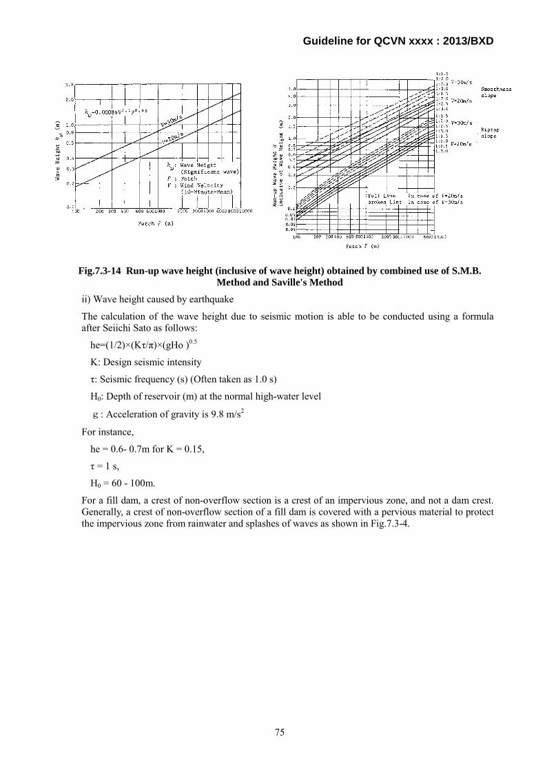
Guideline for QCVN xxxx : 2013/BXD
Fig.7.3-14 Run-up wave height (inclusive of wave height) obtained by combined use of S.M.B. Method and Saville's Method
ii) Wave height caused by earthquake
The calculation of the wave height due to seismic motion is able to be conducted using a formula after Seiichi Sato as follows:
he=(1/2)×(Kτ/π)×(gHo )0.5
K: Design seismic intensity
τ: Seismic frequency (s) (Often taken as 1.0 s)
H0: Depth of reservoir (m) at the normal high-water level
g: Acceleration of gravity is 9.8 m/s2
For instance,
he = 0.6- 0.7m for K = 0.15,
τ = 1 s,
H0 = 60 - 100m.
For a fill dam, a crest of non-overflow section is a crest of an impervious zone, and not a dam crest. Generally, a crest of non-overflow section of a fill dam is covered with a pervious material to protect the impervious zone from rainwater and splashes of waves as shown in Fig.7.3-4.
75
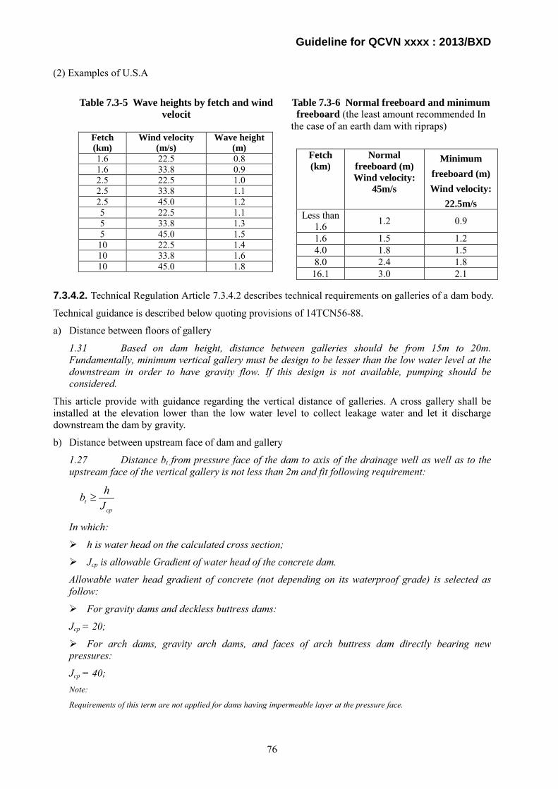
Guideline for QCVN xxxx : 2013/BXD
(2) Examples of U.S.A
Table 7.3-5 Wave heights by fetch and wind
velocit Table 7.3-6 Normal freeboard and minimum freeboard (the least amount recommended In
the case of an earth dam with ripraps) Fetch (km)
Wind velocity (m/s)
Wave height (m)
1.6 22.5 0.8 1.6 33.8 0.9 2.5 22.5 1.0 2.5 33.8 1.1 2.5 45.0 1.2 5 22.5 1.1 5 33.8 1.3 5 45.0 1.5 10 22.5 1.4 10 33.8 1.6 10 45.0 1.8
7.3.4.2. Technical Regulation Article 7.3.4.2 describes technical requirements on galleries of a dam body.
Technical guidance is described below quoting provisions of 14TCN56-88.
a) Distance between floors of gallery
1.31 Based on dam height, distance between galleries should be from 15m to 20m. Fundamentally, minimum vertical gallery must be design to be lesser than the low water level at the downstream in order to have gravity flow. If this design is not available, pumping should be considered.
This article provide with guidance regarding the vertical distance of galleries. A cross gallery shall be installed at the elevation lower than the low water level to collect leakage water and let it discharge downstream the dam by gravity.
b) Distance between upstream face of dam and gallery
1.27 Distance bt from pressure face of the dam to axis of the drainage well as well as to the upstream face of the vertical gallery is not less than 2m and fit following requirement:
tcp
hbJ
≥
In which:
h is water head on the calculated cross section;
Jcp is allowable Gradient of water head of the concrete dam.
Allowable water head gradient of concrete (not depending on its waterproof grade) is selected as follow:
For gravity dams and deckless buttress dams:
Jcp = 20;
For arch dams, gravity arch dams, and faces of arch buttress dam directly bearing new pressures:
Jcp = 40; Note:
Requirements of this term are not applied for dams having impermeable layer at the pressure face.
Fetch (km)
Normal freeboard (m) Wind velocity:
45m/s
Minimum freeboard (m) Wind velocity:
22.5m/s Less than
1.6 1.2 0.9
1.6 1.5 1.2 4.0 1.8 1.5 8.0 2.4 1.8
16.1 3.0 2.1
76

Guideline for QCVN xxxx : 2013/BXD
This article provide with guidance regarding the minimum distance between the upstream face of a dam and gallery. The thickness of a dam body for an arch dam, arch gravity dam and buttress dam is less than that of a gravity dam in general, so allowable water head gradient of concrete is larger than that of a gravity dam.
c) Drainage gallery
1.32 Dimension of gallery to inject the base cement and construction joint of the dam or to create and repair vertical drainage wells must be the minima in order to keep the transport and operation of grouting and drilling devices, etc.
Galleries used for water accumulation and drainage, for check of dam concrete state and tightening connection joints, and for installation of measure devices and pipes must have following dimensions:
Galleries, which are used for accumulating and draining water, inspecting dam concrete state and tightening connection joints, should obtain the following dimension in order to arrange measurement devices and pipes:
Width is not less than 1.2 m;
Height is not less than 2.0 m.
Floors of the accumulation and drainage galleries are designed to have a slope not greater than 1:50 toward the discharge trough.
d) Openings in dam
This article provide with guidance regarding special consideration on openings in a dam body. In general reinforcing bars are arranged in the circumference of an opening to prevent development of cracks due to tensile stress.
7.3.4.3. Technical Regulation Article 7.3.4.3 describes technical requirements on settlement joins of concrete dams.
14TCN56-88 Articles 1.35 to 1.37 provide with guidance regarding design and construction method of a settlement joint.
1.35 In design of concrete and reinforced concrete dams, long-term deformed joints (between parts) and temporal deformed joints (constructional joints) must be located.
Dimension of dam parts and concreting blocks is determined based on:
Height and type of the dam;
Dimension of each part in the hydropower station as well as location of drain holes (including water pipes to turbine) inside the dam;
Solution for constructing the dam;
Shape of riverbed, weather condition of the working site, geological composition, deformability of the dam base.
1.36 In selection of deformed joints and the distance between them, requirements of the design standard for water constructional concrete and water constructional reinforced concrete structures.
1.37 Width of long-term deformed joints must be determined based on the comparison between calculations about deformability of adjacent dam parts; including a consideration of their building solution, deformability of water tightening material, and the guarantee of independent displacement between dam parts.
In preliminary determination for structure of the long-term deformed joint, its width should be as follow:
Thermal joint with distance to upstream pressure face not greater than 5m: its width is from 0.5 cm to 1 cm; for that inside of the dam body: its width is from 0.1 cm to 0.3 cm;
77

Guideline for QCVN xxxx : 2013/BXD
Thermal subsidence joint in the range of foundation plate of the dam and in the range of stilling basin for non-rock and semi-rock bases: its width is from 1 cm to 2 cm. For that above the foundation plate in non-rock bases: its width is not lesser than 5cm.
7.3.4.4. Technical Regulation Article 7.3.4.4 describes technical requirements on watertightness of settlement and thermal settlement joints.
14TCN56-88 Article 1.38 to 1.42 provide with guidance regarding design and construction method of settlement and thermal settlement joints.
1.38 In structure of long-term deformed joints, following items must be located:
Water tightening to prevent seepage through the joint;
Drainage devices to discharge osmotic water through the water tightening;
Well and check gallery to observe the state of joints and repair the water tightening;
1.39 Classification of water tightening of the long-term deformed joint:
Based on its location in the joint: Vertical joint, horizontal joint, and contour joint;
Based on composition and material: metal membrane, rubber membrane, and plastic membrane;
Wedge and asphalt buffer layer;
Cement injection and bituminous;
Beam or concrete/reinforced concrete plate.
78

Guideline for QCVN xxxx : 2013/BXD
Figure 3- Layout of water tightening objects of the permanent deformed connection joint of a rock-
base dam (a, b) and non-rock-base dam (c, d)
1- Connection joint δ= 0.5-1 cm; 2- Connection joint δ= 0.1 – 0.3 cm;
3- Connection joint δ= 1 - 2 cm: 4- Connection joint δ≥5 cm;
5,6,7: Water tightening object towards 8- Drainage device;
vertical, horizontal and contour (border) 9- Observation hole;
directions respectively, 10 – Observation gallery
79
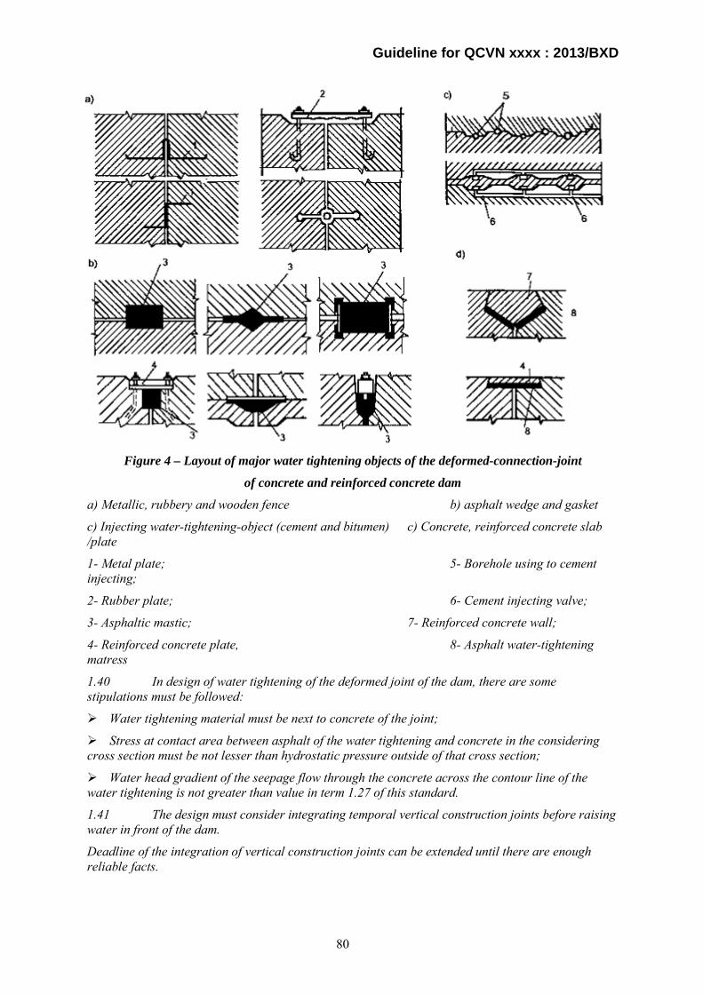
Guideline for QCVN xxxx : 2013/BXD
Figure 4 – Layout of major water tightening objects of the deformed-connection-joint
of concrete and reinforced concrete dam
a) Metallic, rubbery and wooden fence b) asphalt wedge and gasket
c) Injecting water-tightening-object (cement and bitumen) c) Concrete, reinforced concrete slab /plate
1- Metal plate; 5- Borehole using to cement injecting;
2- Rubber plate; 6- Cement injecting valve;
3- Asphaltic mastic; 7- Reinforced concrete wall;
4- Reinforced concrete plate, 8- Asphalt water-tightening matress
1.40 In design of water tightening of the deformed joint of the dam, there are some stipulations must be followed:
Water tightening material must be next to concrete of the joint;
Stress at contact area between asphalt of the water tightening and concrete in the considering cross section must be not lesser than hydrostatic pressure outside of that cross section;
Water head gradient of the seepage flow through the concrete across the contour line of the water tightening is not greater than value in term 1.27 of this standard.
1.41 The design must consider integrating temporal vertical construction joints before raising water in front of the dam.
Deadline of the integration of vertical construction joints can be extended until there are enough reliable facts.
80
Guideline for QCVN xxxx : 2013/BXD
1.42 To decrease the thermal subsidence stress in the dam as well as decrease the influence of irregular subsidence in the base, it is allowed to locate temporal widening joints, which will be covered by concrete (filling block) after balancing the temperature and subsidence.
In general, a gap of transverse and longitudinal joints are filled with mortar to make a dam body monolithic and keep watertightness.
7.3.4.5. Technical Regulation Article 7.3.4.5 describes technical requirements on curtain grouting and drain holes.
Technical guidance of them is described quoting provisions of 14TCN56-88.
2.44. The depth of impervious curtain and its penetrability should be determined basing on the water height of a dam, the penetrated and underground erosive characteristics of a foundation as well as the requirements of reducing uplift pressure acting on the dam foundation.
2.45. The width of impervious curtain bm should be determined basing on below condition:
In where:
hm- Head loss at the given curtain cross section;
Jcp – The allowance gradient of a curtain
2.46. Depending on type of soil base, the allowance water-level gradient of an impervious curtain is adopted as below:
- In fine sand soil: Jcp = 2.5;
- In gravel as well as coarse and medium grained soil : Jcp = 4;
- In gravel: Jcp = 5;
If the impervious curtain is groove-wall style, Jcp is adopted from experiment.
Typical arrangement of drain pipes is as shown in Fig.7.3-15.
81
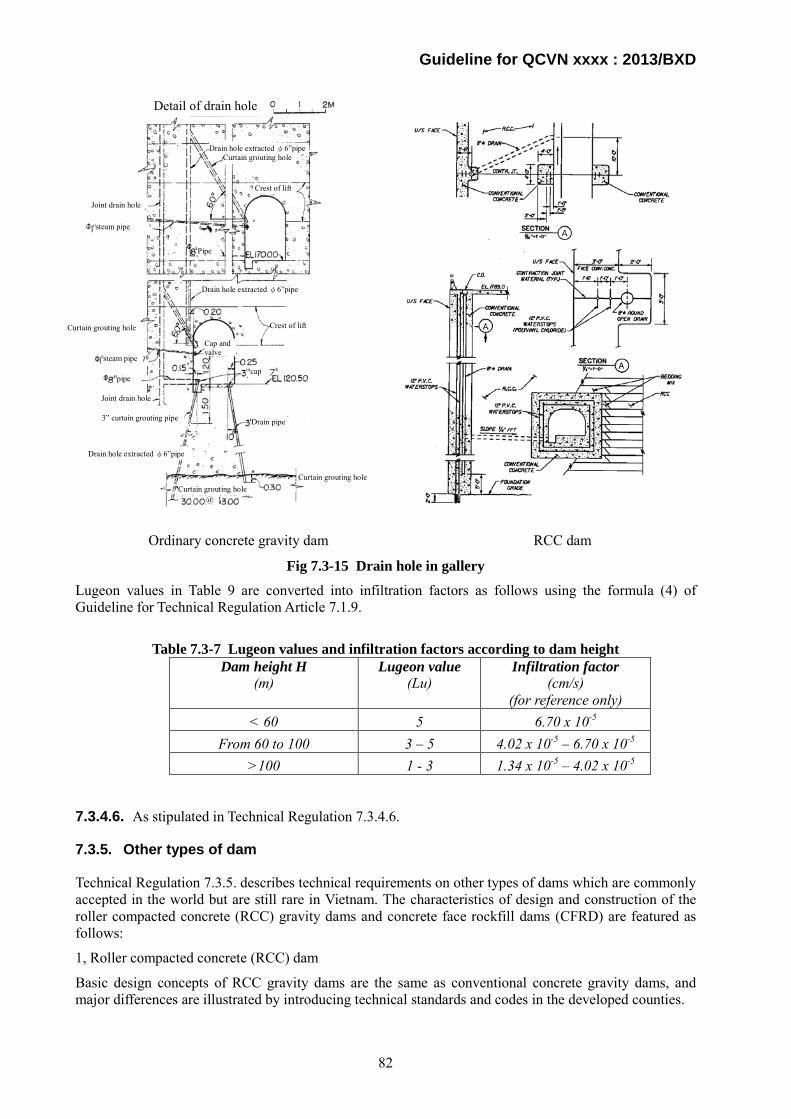
Guideline for QCVN xxxx : 2013/BXD
Ordinary concrete gravity dam RCC dam
Fig 7.3-15 Drain hole in gallery
Lugeon values in Table 9 are converted into infiltration factors as follows using the formula (4) of Guideline for Technical Regulation Article 7.1.9.
Table 7.3-7 Lugeon values and infiltration factors according to dam height
Dam height H (m)
Lugeon value (Lu)
Infiltration factor (cm/s)
(for reference only) < 60 5 6.70 x 10⁻⁵
From 60 to 100 3 – 5 4.02 x 10⁻⁵ – 6.70 x 10⁻⁵
>100 1 - 3 1.34 x 10⁻⁵ – 4.02 x 10⁻⁵
7.3.4.6. As stipulated in Technical Regulation 7.3.4.6.
7.3.5. Other types of dam
Technical Regulation 7.3.5. describes technical requirements on other types of dams which are commonly accepted in the world but are still rare in Vietnam. The characteristics of design and construction of the roller compacted concrete (RCC) gravity dams and concrete face rockfill dams (CFRD) are featured as follows:
1, Roller compacted concrete (RCC) dam
Basic design concepts of RCC gravity dams are the same as conventional concrete gravity dams, and major differences are illustrated by introducing technical standards and codes in the developed counties.
Detail of drain hole
Curtain grouting hole @
Drain pipe
Curtain grouting hole
Curtain grouting hole
pipe
Joint drain hole
3” curtain grouting pipe
Cap and valve
Pipe
Joint drain hole
steam pipe
Drain hole extracted φ6”pipe
Crest of lift
Curtain grouting hole
Drain hole extracted φ6”pipe
steam pipe
Drain hole extracted φ6”pipe
Crest of lift
cap
82

Guideline for QCVN xxxx : 2013/BXD
1) USACE Engineer Manual EM 1110-2-2200 Gravity Dam Design
This engineer manual regulates design of concrete gravity dams and describes major differences between conventional concrete dams and RCC dams.
2) USACE Engineer Manual EM 1110-2-2006 Roller Compacted Concrete
This engineer manual describes essential points on construction of RCC dams and allows space for mix design and quality control of concrete.
Fig 7.3-16 Installation of waterstop, joint drain, and crack initiator
3) USACE Pamphlet EP 1110-2-12 Seismic Design Provisions for Roller Compacted Concrete Dams
Earthquake resistant design of roller compacted concrete (RCC) dams are basically the same as conventional concrete gravity dams. This engineer pamphlet summarizes essential points for seismic design of RCC dams.
4) FERC Engineering Guidelines for the Evaluation of Hydropower Projects Chapter 3 Gravity Dams
This guideline summarizes points to note for design and construction of RCC dams.
2. Concrete face rockfill dams (CFRD)
This type of dam is composed of an embankment made by pervious rock and sand materials, impervious face diaphragm and cut-off or plinth. Pervious materials with particle size distribution suitable for compaction are used for an embankment, and they are spread out in a thin layer and compacted to minimize settlement of an embankment. A transition zone composed of crushed rock or sand is prepared on the upstream surface to transmit load from a surface diaphragm to an embankment uniformly.
A concrete diaphragm must be designed to prevent development of crack caused by nonuniform settlement of an embankment or thermal load. Empirical design adopts the minimum thickness of a concrete diaphragm of 30 cm and its thickness increases in a ratio of 2 to 3 mm of increment of water depth by 1.0 m. Empirical unit amount of reinforcing bars is 0.3 to 0.5 % of the sectional area of a concrete diaphragm.
Article 7.3.1.5 describes technical requirements of a plinth.
7.4 Spillways Technical Regulation Article 7.4 describes technical requirements on spillways. Spillways for concrete dams are regarded as a part of a dam body, so details of concrete structures shall refer to Guideline for Technical Regulation Article 7.3.4 and 8.3 of QCVN 04 - 05 : 2012/BNNPTN.
83
Guideline for QCVN xxxx : 2013/BXD
Technical requirements are described quoting provisions of Article 8.3 of QCVN 04 - 05 : 2012/BNNPTN.
8.3 Discharge works
8.3.1 Must guarantee the safety and stability working condition in the design and examined circumstances. Water should be discharged actively regarding to the managing and exploiting regulations so as to ensure that the water level in a reservoir will not excess the stipulated level.
This article stipulates that discharge facilities, form a spillway down, shall discharge design flood and check flood safely, and that the reservoir water level shall not exceed the designated level for each flood condition.
8.3.2 The general layout and structure of discharge works and continuing solutions between a construction and downstream must guarantee that the following requirements will be met in case of its operation:
a) Not influence on the safety and stability of a reservoir and its normal operating and managing condition;
b) The discharge of the design flood will not destroy natural characteristics of downstream channel, not impact on socio-economic activities and normal operating condition of permanent hydraulic works in lower steps as well as not damage constructional works in downstream discharge works. The navigation work must guarantee that flow and velocity in downstream will not affect the normal operation of ships;
c) The operation at the examined water level allows:
- Reduction in the production of hydro-power station (if it supports safety condition of the construction);
- Abnormal working conditions of water intakes. Nevertheless, it will not lead to failures situations for water consumption sectors;
- Discharging water through close conduits with variable hydraulic states (from free flow to pressure flow and reverse) but it will not bring about the destructions of conducted lines;
- Eroded channel flow and slope in downstream head-works. However, those failures will not become hazards to the destruction of major work-items of the head-works as well as the safety condition of residential, industrial areas and infrastructures in downstream.
- Failures in the standby discharge works. However, those failures will not influence on the safety condition of major construction.
8.3.3 The computed discharge flow during the exploitation period through the permanent discharge and supply works of head-works should be determined on the ground of design flood flow, which is stipulated in the article 5.2.1 and table 4. The calculation and determination will be in accordance with the variations of the design flood flow, caused by the re-regulated activities of current or design reservoirs, as well as the changes in the flow forming condition resulting from socio-economic activities in the basin.
A design and check flood discharge for each class shall refer to Table 4 of Article 5.2.1 of QCVN 04 - 05 : 2012/BNNPTN and shall be reviewed properly considering changes in surrounding circumstances.
Examples of regulations on flood discharge criteria in the foreign countries are shown below for reference.
1. Example of Japan
1) Concrete dams
The design flood is the largest value selected among the following methods:
1) A flood estimated to occur at a rate of once in 200 years
84

Guideline for QCVN xxxx : 2013/BXD
2) The maximum flood that has occurred at the dam site
3) The flood which is obtained by Creager’s formula, i.e. q = C×A×(A-0.05-1). q: specific yield (m3/s/km2), A: catchment area(km2), C: regional factor (given in the guideline)
2) Fill dams
The design flood is 1.2 times of the value estimated by the above method for a concrete dam Source: Governmental Ordinance for Structural Standard for River Administration Facilities, Ministry of Land, Infrastructure, Transport and Tourism, Japan, July 20, 1976.
2. Example of P.R. China Table 7.4-1 Criteria for Project Ranking
Rank of projects
Storage capacity
(100 MCM)
Ranking Flood control Irrigation Hydropower
Town and industrial town to
be prevented
Cultivated land area
(104ha)
Irrigation land area (104ha)
Installed capacity of hydropower plant
(MW) 1 >10 Very important >33.3 >10 >750 2 10~1 Important 33.3~6.67 10~3.33 750~250 3 1~0.1 Intermediate 6.67~2.0 3.33~0.33 250~25 4 0.1~0.01 Ordinary 20~0.33 0.33~0.03 25~0.5 5 0.01~0.001 — <0.33 <0.03 <0.5
Note MCM : Million Cubic Meters
Source: Unified Design Standard for Reliability of Hydraulic Engineering Structures, GB-50199-94, P.R. China, Nov. 01, 1994.
Table 7.4-2 Criteria of Design and Check Flood (Return Period to be Applied)
Rank of projects
Normal operation (design flood)
(year)
Extreme operation (check flood) The dam failure shall not cause large damage.
Fill dam (year)
Concrete dam (year)
1 2,000~500 10,000 5,000 2 500~100 2,000 1,000 3 100~50 1,000 500 4 50~30 500 300 5 30~20 300 200
Source: Flood Control Standards, GB-50201-94, P.R. China, Jan. 01, 1995.
3. Example of U.S. Army Corps of Engineers Table 7.4-3 Size Classification
Category Reservoir capacity (106m3) Height of the dam (m) Small From 0.062 to 1.23 From 7.6 to 12.2 Intermediate From 1.23 to 61.5 From 12.2 to 30.5 Large >= 61.5 >= 30.5
85

Guideline for QCVN xxxx : 2013/BXD
Table 7.4-4 Hazard Potential Classification
Category Loss of life (Extent of development)
Economic loss (Extent of development)
Low None expected (No permanent structures for human habitation)
Minimal (Undeveloped to occasional structures or agriculture)
Medium Few (No urban developments and no more than a small number)
Appreciable (Notable agriculture, industry or structures)
High More than few Excessive (Extensive community, industry or agriculture)
Table 7.4-5 Recommended Safety Standards
Hazard Size Safety standard Small 50-year to 100-year flood Low Intermediate 100-year to 50% of the PMF Large 50% to 100% of the PMF Small 100-year to 50% of the PMF Medium Intermediate 50% to 100% of the PMF Large PMF Small 50% to 100% of the PMF High Intermediate PMF Large PMF
Source of Table 7.4-3 to 7.4-5: Engineering Regulation ER-1110-2-106, Recommended Guidelines for Safety Inspection of Dams, Appendix D, U.S. Army Corps of Engineers, Sept. 26, 1979.
4. Example of Norway
Norway adopts a double design criterion: The 1,000 year probable inflow flood is prescribed as design flood for normal operation of dam spillway system, while the stability of the dam is subject to the PMF.
5. Example of Canada
Table 7.4-6 Criteria for Hazardous Level
Consequence category
Potential incremental consequences of failure 1)
Inflow design flood Life safety 2)
Socio-economic Financial
Environmental 2) 3) Very high Large number
of fatalities Extreme damages Probable maximum flood
(PMF) 4) High Some fatalities Large damages Annual Exceedance probability
between 1/1,000 and the PMF 5) Low No fatalities
anticipated Moderate damages Annual Exceedance probability
between 1/100 and 1/1,000 5) 6) Very Low No fatalities Minor damages beyond owner’s property
Note 1) Incremental to the impacts which would occur under the same natural conditions (flood, earthquake or other event) but without failure of the dam. The consequence (i.e. loss of life, or economic losses) with the higher rating determines which category is assigned to the structure. In the case of tailings dams, consequence categories should be assigned for each stage in the life cycle of the dam.
2) The criteria which define the Consequence Categories should be established between the Owner and regulatory authorities, consistent with societal expectations. Where regulatory authorities do not exist, or do not provide guidance, the criteria should be
86
Guideline for QCVN xxxx : 2013/BXD
set by the Owner to be consistent with societal expectations. The criteria may be based on levels of risk which are acceptable or tolerable to society. 3) The Owner may wish to establish separate corporate financial criteria which reflect their ability to absorb or otherwise manage the direct financial loss to their business and their liability for damage to others. 4) An appropriate level of conservatism shall be applied to loads from this event, to reduce the risks of dam failure to tolerable values. Thus, the probability of dam failure could be much lower than the probability of extreme event loading. 5) Within the High Consequence category, the IDF is based on the consequences of failure. For example, if one incremental fatality would result from failure, an AEP of 1/1,000 could be acceptable, but for consequences approaching those of a Very High Consequence dam, design floods approaching the PMF would be required. 6) If a Low Consequence structure cannot withstand the minimum criteria, the level of upgrading may be determined by economic risk analysis, with consideration of environmental and social impacts.
Source of Table 7.4-6: Water Act, Alberta Province, Canada, January 1, 1999.
8.3.4 The determination of maximum design and examined flow of headwork on the river, which is exploited pursue the stairs diagram, should mention the class of the construction itself, its position in the stairs as well as the discharge and supply capacity of the head-work unit in the upper stair regarding to the retention level and surcharged level (in case of releasing the design and checked floods). Other factors are operated and exploited regulation of hydraulic works and reservoir of stairs, input flow from tributaries to upstream section approaching to the design headwork.
A design and check flood discharge in a cascade exploitation shall follow Article 4.2.5.
8.3.5 Reservoirs of class I and above, apart from the major flood spillway, the standby spillway (overflow the checked floods) should be placed. Reservoirs of class II and below will be arranged with the standby spillway in case of adequate arguments and acceptance from the investor:
a) The major spillway must obtain adequate capacity in order to discharge design and checked floods;
b) The standby spillway in accordance with the major spillway must evacuate a flood that exceeds the checked flood and guarantee that water in a reservoir will not overflow through the dam crest. The frequency of a flood, that exceeds the checked flood, refers below stipulations:
- Works of special grade: flood with frequency of 0.01% (in accordance with the returned period of 1000 years) or extreme flood;
- Works of grade 1 and below: equal frequency of checked flood regarding to works of grade being increased one class (referring to the Table 4);
c) A class of a standby spillway can be lower than that of the major flood spillway;
d) If there are not adequate conditions for the arrangement of individual standby spillways, the major spillway will be studied to extend or the dam height will be increased so as to improve the regulated volume of a reservoir. The two above approaches can be applied individually or in a combination solution in order to evacuate a flood exceeding the checked flood;
e) The determination of a model for a flood exceeding the checked flood as well as a class of a standby spillway is proposed by the design consultation and accepted by the decision authority for the investment.
A standby spillway shall be surely placed in a dam of Special and Class I, and placed after due discussion with an investor of Class II and below against inflow exceeding a check flood. A design consultant shall estimate flood for a standby spillway and design structures for approval of the decision authority.
8.3.6 A reservoir, which has flood discharge work such as flood relief well or tunnel-type discharge carrier, must place the discharge construction for a flood exceeding the design flood (emergency spillway).
A dam equipped with a tunnel type spillway shall have an emergency spillway against inflow exceeding a design flood.
87

Guideline for QCVN xxxx : 2013/BXD
8.3.7 Apart from a major flood spillway, researches on the application ability of other constructions in flood discharging, constructional flow releasing and sedimentation excavating during the exploitation period are permitted to implement.
Besides a spillway, measures against sedimentation shall be taken to keep effective capacity of a reservoir. Typical measures against sedimentation are as follows:
1) Reducing sediment flowing into reservoirs;
2) Sediment routing; and
3) Sediment flushing
Fig.7.4-1 Classification of reservoir sediment management
8.3.8 The flood discharge work is permitted to arrange on the dam crest and inside the body of a concrete barrage or on the compacted rock-fill dam with concrete face. However it must guarantee the safety condition for a dam during the constructional and exploitation periods. Regarding to barrages using locally natural materials such as earth dam, rock-fill dam or earth and rock-fill dam, the flood discharge work will be placed separately from the barrage.
A spillway may be equipped with a dam body of a concrete dam but it shall not damage safety and stability of the dam body. A spillway shall not be equipped on a dam body of an earth dam, rockfill dam or earth and rockfill dam except a concrete faced rockfill dam.
8.3.9 The flood discharge for constructions from class I and above or class II in accordance with complex hydraulic states, model experiments will be implemented in order to obtain adequate evaluations about the reasonability of hydraulic arrangement and design.
A shape, arrangement and capacity of spillway shall be confirmed by a hydraulic model test for a dam of Special and Class I.
8.3.10 Structures of the flood discharge and release constructions as well as its continuing work-items should be computed regarding to the basic exploiting situations and re-examined
Classification Place
Upstream reservoirs
End of reservoirs Sediment check
dam
Sediment bypass
Sediment routing Sediment sluicing Sediment management
Density current venting
Drawdown flushing
Sediment flushing outlet
Sediment flushing Inside reservoirs
Partial flushing without drawdown Sediment scoring gate
Sediment scoring pipe
Excavating and dredging
Reduction of sediment production by hillside and valley works Regulation of reservoirs and sediment by erosion control dams and slit dams Reduction of discharged sediment and river course stabilization by channel works
Details of sediment control measures Examples in Japan
Sabo area, changing from sediment check dams to sediment control dams (slit dams)
Reducing sediment flowing into reservoirs
Regularly excavating and recycling for aggregate or sediment supply to downstream river
Miwa Dam, Koshibu Dam, Nagashima Dam, Matsukawa Dam, Yokoyama Dam
Asahi Dam, Miwa Dam, Koshibu Dam, Matsukawa Dam, Yokoyama Dam
Sabaishigawa Dam Dashidaira Dam-Unazuki Dam (Coordinated sluicing)
Masudagawa Dam Non-gate bottom outlets (natural flushing)
Bottom outlets for flood control
Non-gate conduits with curtain wall
Koshibu Dam, Futase Dam, Kigawa Dam
Katagiri Dam
Selective withdrawal works Yahagi Dam
Ikawa Dam
Recycling for concrete aggregate Miwa Dam, Koshibu Dam, Sakuma Dam, Hiraoka Dam, Yasuoka Dam
Senzu Dam, Yasuoka Dam
Soil improving material, farm land, filling, banking material Miwa Dam, Yanase Dam
Sediment replacing inside reservoir
Sediment supplying to downstream rivers Akiba Dam, Futase Dam, Miharu Dam, Nagayasuguchi Dam, Nagashima Dam
Sakuma Dam
Inside reservoirs
End of reservoirs
Dashidaira Dam-Unazuki Dam (Coordinated flushing)
88

Guideline for QCVN xxxx : 2013/BXD
regarding to the extra-ordinary circumstances to guarantee the safety condition for a construction. It also ensures that water is not allowed to excavate through the crest pressure alignment. Computing circumstances are:
a) Working with the maximum design water level in upstream of the head-work: fully opened water discharge works in case of design flood, operating turbines and normal working condition of other discharge and supply works. The operation pursue that circumstance, work-items in the head-work including the continuing parts in up and downstream must be in normal working condition and are not broken. Load and influence in coherence with this situation will be computed based on the basic loads compounds. If there are adequate arguments, there will be the considerations about the ability of blocked discharge gates;
b) Working with the maximum examined water level in upstream of the head-work: All of discharging and supplying works, which are mentioned in the item a, in accordance with standby spillways will be fully opened in case of the checked flood. The ability of blocked discharge gate will not be considered. Loads and influences in this case are in coherence with the special load compound;
c) Other gate-opening-combinations will be considered in order to meet the design targets and ensure the safety condition of a construction in case of the flood regulation or emergency situations;
d) Consideration about the occurring ability of a flood that exceeds the checked flood. NOTE: Regarding to the computed circumstance, mentioning in the item ‘a’ of the article 8.3.10, if there is a
blocked situation in a major discharge gate, it will be calculated in accordance with the special load compound.
Discharge of a design flood shall not obstruct a normal operation of a hydropower plant or damage river facilities in the downstream area. Partial blockage of discharge gates is allowed in case of design flood but not allowed in case of a check flood because discharge capacity of a spillway is designed to be able to discharge a check flood with a whole ability of spillway gates.
8.3.11 The determination of the unit discharge rate (specific discharge), downstream channel velocity, continuing state for downstream flow, structure of major constructions as well as methods for energy dissipation and consolidation in downstream area should base on the comparison among economic and engineering criteria of options.
Table 3 and 4 in Article 1.44 of 14TCN56-88 provide with guidance for allowable specific discharge of a spillway to prevent erosion in the downstream area.
Table 3 – Allowable specific discharge of different soils corresponding to different flow depth (*)
Order number Soil type
Non-erosion velocity when depth is 1m
(m/s)
Allowable specific discharge (m3/s) when flow depth is
h=5m h=10m h=20m
1 Medium sand including coarse sand 0.6 7 16 37
2 Sand including medium gravel 0.75 9 20 46
3 Normal density clay, heavy loam clay with normal density 0.85 10 23 53
4 Coarse gravel including light but high density loam clay 1.00 12 27 62
5 Sand including no less than 10% of high density clay gravel and heavy but high density loam clay
1.2 14 32 74
(*): M.Grisin, Design of hydraulic works on non-rock bases, page 114, 1966.
89
Guideline for QCVN xxxx : 2013/BXD
Table 4 – Allowable average specific discharge [q]tb corresponding to different diameters of rock and different erosion depth (**)
Rock diameter (m)
[q]tb corresponding to erosion depth is 5m 10m 15m 20m
0.10 0.30 0.50 0.75 1.00 1.50 2.00 2.50 3.00
20 22 25 29 32 35 38 42 45
30 40 50 60 70 75 80 85 90
45 55 65 75 85 90 95
105 115
60 70 80 90
100 110 120 130 140
(**) Design instruction – protection of riverbed and downstream of flush works from erosion, 1974.
8.3.12 Discharge works and bottom opening should have major valve gates and repaired gates in order to meet below requirements:
a) Repaired and emergency valve gate should place in front of the major valve gate
b) Apart from the major valve gate and repairing – emergency valve, repairing valve gate or plank should be placed in front of the inlet part of the lower outlet in case the emptying ability is not available in order to expose that inlet part.
c) If the sill of discharge works or lower outlet is lower than downstream water level, a movable repairing valve gate will be arranged behind the outlet cross-section of a culvert;
d) The establishment of operating regulation of those above gates bases on the typical exploiting diagram.
8.3.13 The selection for types of valve gates and lifting machines should be on the ground of climb speed of a flood, storage capacity in up and downstream as well as requirements for minimum flows in downstream, including circumstances such as sudden cutoff situations for the partial of the whole base-load of hydro-power station
8.3.14 The specific discharge hole, which is smaller than the gully hole, will be designed if the valve gate of lower outlet is a plane gate obtaining the area of above 60 m2 and a considerably small discharge flow requirement comparing to the discharge ability of a gully hole.
7.5 Waterway 7.5.1. Technical Regulation Article 7.5.1 describes the technical requirements in designing waterways to secure stability and safety of hydraulic works. The important notices related to the technical requirements are the following:
(1) Capacity to conduct sufficient amount of water to satisfy demand;
(2) Ability to control discharge
(3) Prevention of sand, dust, driftwood or any other substances which may damage a waterway and hydraulic turbine from entering the waterway;
(4) Bearing capacity against water hammer load due to full load rejection; and
(5) Alignment of a waterway beneath the minimum hydraulic gradient line.
a) Waterways shall not be operated out of the designated conditions established in the design stage to prevent them from being damaged;
b) Excessive deposit of sediment may decrease the sectional area of a waterway which leads to decrease in discharge capacity of the waterway and sediment flowing with water may wear the inner surface of
90
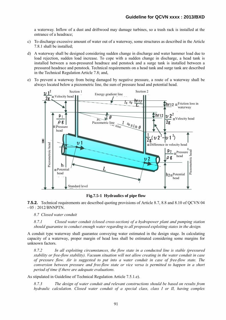
Guideline for QCVN xxxx : 2013/BXD
a waterway. Inflow of a dust and driftwood may damage turbines, so a trash rack is installed at the entrance of a headrace;
c) To discharge excessive amount of water out of a waterway, some structures as described in the Article 7.8.1 shall be installed;
d) A waterway shall be designed considering sudden change in discharge and water hammer load due to load rejection, sudden load increase. To cope with a sudden change in discharge, a head tank is installed between a non-pressured headrace and penstock and a surge tank is installed between a pressured headrace and penstock. Technical requirements on a head tank and surge tank are described in the Technical Regulation Article 7.8; and,
e) To prevent a waterway from being damaged by negative pressure, a route of a waterway shall be always located below a piezometric line, the sum of pressure head and potential head.
Fig.7.5-1 Hydraulics of pipe flow
7.5.2. Technical requirements are described quoting provisions of Article 8.7, 8.8 and 8.10 of QCVN 04 - 05 : 2012/BNNPTN.
8.7 Closed water conduit
8.7.1 Closed water conduit (closed cross-section) of a hydropower plant and pumping station should guarantee to conduct enough water regarding to all proposed exploiting states in the design.
A conduit type waterway shall guarantee conveying water estimated in the design stage. In calculating capacity of a waterway, proper margin of head loss shall be estimated considering some margins for unknown factors.
8.7.2 In all exploiting circumstances, the flow state in a conducted line is stable (pressured stability or free-flow stability). Vacuum situation will not allow creating in the water conduit in case of pressure flow. Air is suggested to put into a water conduit in case of free-flow state. The conversion between pressure and free-flow state or vice versa is permitted to happen in a short period of time if there are adequate evaluations.
As stipulated in Guideline of Technical Regulation Article 7.5.1.e).
8.7.3 The design of water conduit and relevant constructions should be based on results from hydraulic calculation. Closed water conduit of a special class, class I or II, having complex
Standard level
Potential head
Piez
omet
reic
hea
d
Pressure head
Velocity head Energy gradient line
Piez
omet
reic
hea
d
Potential head
Pressure head
Velocity head
Section 1 Section 2
Difference in velocity head
Friction loss in waterway
Piezometric line Piezometric line
91

Guideline for QCVN xxxx : 2013/BXD
configuration should be studied through hydraulic experiments in order to determine head-loss as well as the maximum and minimum water pressure towards the longitude direction of conduit in case of water hammer.
It is recommendable that dimensions and layout of a waterway for Special Class, Class I and II shall be confirmed by a hydraulic model test when there is a significant assumption or unknown factor related to performance and safety in the hydraulic calculation.
8.7.4 Regarding the receiving gate of the steel penstock, which partly or totally open in the whole supply alignment, there are repairing valve at the front and emergency valve for each separate pipe in order to guarantee the maintenance state and quick disconnection in case of broken pipe-line. Air will be provided sufficiently for the pipeline at the rear emergency valve. Protected and prevented solutions for a station should be proposed in case of damage or inundation causing by broken pipes.
A gate or valve shall be prepared upstream of a receiving gate of steel penstock for maintenance works and emergency cases.
8.7.5 The determination of the highest calculating water level in the free-flow conduit should mention positive wave resulting from emergency rapid-cut or operating concurrent cut-off for the maximum load.
Freeboard of a channel type waterway shall be designed considering fluctuation in a water level due to load rejection.
8.7.6 The calculation of water hammer at the conduit line to turbine and discharge tube should consider below circumstances:
a) Sudden cut-off all loads of a plant;
b) Switch loads regarding to the exploiting procedure until a plant reaches to the overall capacity.
As stipulated in Guideline for Technical Regulation Article 7.8.
8.7.7 The operation of repairing and emergency gates is fully automatic. There are remove control and local control in order to manage in necessary situations.
A repair gate shall be installed upstream of a main gate considering convenience of repair works without lowering the reservoir water level. An emergency closing device shall be installed in case that water flow shall be stopped quickly when an accident happens.
8.8 Other water conduit
8.8.1 The selection for type and structure of conduits should be implemented on the ground of economic and engineering comparisons among options in accordance with functions of pipes, value of water column, ground soil as well as erecting and exploiting condition. Pipe-line arranging through wet sub-siding soil, saturated soil, muddy soil and swamped area must be designed to place pipe-line on the ground and in accordance with consolidation solutions for the foundation if necessary.
Type of conduit waterway shall be selected from technical and economical point of view. It is desirable that type of conduit waterway be selected from a hydropower project of similar topographical and geological conditions.
8.8.2 The design of the open-pipes on the soil foundation should arrange compensated joints along its length, including the connected parts with constructional works, etc. in order to guarantee that the settlement and thermal deformation of sections are separation (independent). These pipes can place on the monolith reinforced concrete foundation to guarantee the uniform settlement. Steel conduit without compensated joints can be designed in case of adequate evaluations and appropriate conditions. There are corrosion-proof solutions regarding to current standards.
An open channel type waterway to be constructed on a soil foundation shall be equipped with joints to prevent development of cracking due to uneven settlement and water leakage caused by cracks.
92

Guideline for QCVN xxxx : 2013/BXD
8.8.3 Observed gates, water inject equipment (using to fill a pipe) as well as air supply or discharge equipments are arranged at two heads and along a conduit pipe-line.
Auxiliary devices shall be installed considering convenience of repair and maintenance works.
8.8.4 The design of reinforced concrete pipe should clearly define the crack-restriction standard regarding to the anti-corrosion and anti-leakage conditions.
In designing a reinforced concrete pipe, restriction of cracks shall be considered to prevent corrosion of reinforcing bars. In Japan, a crack index is used to evaluate safety against occurrence of cracks.
Crack index = Maximum tensile stress / Tensile strength of concrete
In case cracks shall be prevented : Crack index > 1.75
In case cracks shall be reduced as much as possible : Crack index > 1.45
In case cracks are allowed but crack opening shall not be excessively large : Crack index > 1,0
8.10 Water race
8.10.1 The selection of the canal route, canal design, technical parameters and head loss should base on evaluations through the comparison among options in accordance with transferring ability, navigation response capability (if existed), quantities of building work and equipments, operation mode of water dispatch, exploiting cost and environmental protection requirements.
Dimensions and layout of an open channel type waterway shall be selected considering capacity, construction cost, environmental preservation, and navigation, if any. Navigation in the open channel type waterway of a hydropower plant is only allowed for inspection and maintenance purpose in general.
8.10.2 If there is not any requirement on the restrictions of water level, the race should arrange in the excavation block or semi-embankment and semi-excavation. The determination of curve radius of the canal route should guarantee the movable ability of boats (if existed) and not result in the erosion in the channel flow.
8.10.3 The anti-flood and anti-swamped methods will be proposed for the fringle area of the canal alignment as well as aquatic plants in a channel.
8.10.4 The channel design should consider the variabilities of ground soil and back-fill soil characteristics during the future exploitation period regarding to complex conditions such as crossing the wet subsiding soil, swelling soil and soil with solube-saline components, on the collapsed slope as well as at the intersection with mudrock flow. Appropriate structural solutions and construction technique should be applied if necessary.
8.10.5 The flow velocity in a channel is defined basing on the scour-resistance or aggrade-resistance conditions in a channel flow. Solutions in preventing blocked condition in the channel flow, which causes by rubbish, alga and surfacing vegetations, should be proposed.
8.10.6 Appropriate protective structures should be proposed in order to prevent scour and physical failure problems in a channel, causing by rainfall, flow and seepage.
8.10.7 Steepness of channel slopes is determined on the stability condition of slope.
8.10.8 In order to guarantee the clearness standard of consumed water, sand trap or extension solution for the dimension of header canal should be proposed. Forms of sedimentation and deposit sludge treatment in a channel will be decided regarding to the calculation of economic and engineering evaluations.
8.10.9 The water race should be divided into many sections in order to support the periodic examination and maintenance. Length of each section is determined basing on specific condition in a correlation with natural characteristics and exploiting and maintenance requirements.
8.10.10 The channel design should consider the consumption probability from supplementary sources from intersection streams. The additional flow refers to the elementary volume of stream water after being excluded supplied flow for downstream to maintain the environmental flow.
93
Guideline for QCVN xxxx : 2013/BXD
8.10.11 The management way should be arranged along a channel in order to regularly examine states of canal. Protective fences should be constructed at the some crossing areas with channel such as: hazardous area, residential area and civilian constructions.
8.10.12 The utilization of supplementary sources from rivers and streams should obey below conditions:
a) Water quality criteria in the intake alignment should be in accordance with consumed water standard.
b) Solid flow rate and its grain content must be in accordance with the transferring capacity of channel.
8.10.13 The hydraulic calculation should consider the unstable flow state appearing in case of changes in flow and water level, impacts of backwater and wave causing by wind as well as waves being created by the operation of valve gate, machine assembly, regulation works, pump station and navigation lock.
8.10.14 If a canal route goes through sections with bad topographic and geologic conditions such as locally separated topography or erosion-prone soil or weak soil, alternative options for these sections should be considered using appropriate continuing works (canal-bridge or siphon).
8.10.15 The design of multi-function-channel should be implemented basing on the forecast about water demand and quality requirement in accordance with water households in the project area, supplying by the canal.
8.10.16 The combination with rural traffic should be taken advantages in the design of conveying canal. If it is coherence with traffic plan, the canal banks are design according to the traffic road standard. The combination with navigation should base on type of boats and structures of convoy in order to determine calculated water level and channel dimension as well as requirements of navigation lock. Navigated channel often allow the two-way traffic of boats. Wharfs are place at appropriate locations along a canal.
8.10.17 The design of underground crossing-works under the bottom of channel shall assure that the depth of upper-covering layer of this work will not sink the channel bottom.
As stipulated in Technical Regulation Article 8.10.2 to 8.10.17. These stipulations are mainly prepared for irrigation facilities, so the stipulations related to waterways for the hydropower works shall be referred.
7.5.3. Technical Regulation Article 7.5.3 describes technical requirements on hydraulic tunnels.
Technical requirements are described quoting provisions of Article 8.9 of QCVN 04 - 05 : 2012/BNNPTN.
8.9 Hydraulic tunnel
8.9.1 The design of hydraulic tunnel should meet the multi-purposes requirements such as flood release, sand excavation, reservoir emptying, constructional derivation and water supply. etc.
8.9.2 The selection of alignment, type (pressure or free flow), structure and shape of the tunnel cross-section should base on its tasks, calculation and comparison of economic and engineering criteria among options and in accordance with below factors:
a) General layout of the head-work system and inter-influences among tunnel, on-ground constructions and adjacent under-ground works;
b) The under-ground depth, water-column value and hydraulic state of a tunnel;
c) Engineering geology and hydrological geology conditions;
d) Construction condition.
Dimensions and layout of hydraulic tunnel shall be selected considering topographical, geological and hydraulic conditions and its purpose.
94
Guideline for QCVN xxxx : 2013/BXD
8.9.3 The tunnel alignment is the straight alignment obtaining the shortest length. The application of non-linear alignment is permitted but must meet below requirements:
a) At the bent, inter-section angle of a tunnel is not smaller than 60º (regarding to a flow velocity lower than 10 m/s) and curve radius is not five time smaller than water depth in the tunnel;
b) If the flow velocity in a tunnel exceeds 10 m/s, model experiments are needed to determine values of inter-section angle and curve radius.
It is desirable that a tunnel route be straight connecting an entrance and exit of the tunnel to get the shortest length, however, in case curves are inevitable due to topographic conditions, geological conditions and other requirements related to layout design, a tunnel route shall follow provisions in this article.
8.9.4 The depth of rock layer on the top of the tunnel must be three time higher than the tunnel width.
8.9.5 Remove the tunnel alignment crossing the swelling rock layers.
8.9.6 Energy of flow after the tunnel outlet must be absolutely dissipated.
8.9.7 Dimension of tunnel cross-section should meet requirements of utilization as well as constructional, repaired and maintained conditions of a construction. However, its height is not lower than 2,0 m and the width is not smaller than 1,5 m.
As stipulated in Technical Regulation Article 8.9.4 to 8.9.7.
7.5.4. As stipulated in Technical Regulation 7.5.4.
7.6 Intakes 7.6.1. Technical Regulation Article 7.6.1 describes technical requirements on intakes.
Technical requirements are described quoting provisions of Article 8.4 of QCVN 04 - 05 : 2012/BNNPTN.
8.4 Water intake works
8.4.1 The design computation of the water intake work should guarantee the following requirements:
a) Safety and stability working conditions in the design and examined situations;
b) Receiving enough flow and total volume of water regarding to requirements of water consumption sectors;
c) Having the control ability for volume of water supply and actively stop providing water in case of examination, amendment regarding to the operating regulation or emergency circumstances;
d) Trash rack, rubbish collecting measurements, inlet sill, sand trap and scour gallery should be placed to prevent and remove the encroachment of settlement, garbage and floating objects into the conduit;
e) Be convenience for the construction, management, maintenance, amendment and application of modern technology such as electrification and automation.
As stipulated in Technical Regulation 8.4.1.
8.4.2 Structural type and general layout of the selected intake work should be in coherence with the construction’s function, type of conduit (pressure, free or combination; regulation and not self-regulation); characteristic of water collector (with or without dam); natural conditions such as states of hydrology and muddy-sand current, bank morphology, the appearance of rubbish and floating objects as well as the operating and sedimentation regimes in upstream. The collection of water into a pressure line should guarantee that air will not imbibe into a pipe and the head loss is
95

Guideline for QCVN xxxx : 2013/BXD
the lowest. The intake gate should be designed with several sections so that it can be separated into individual sections, which support the amendment or dredge activities.
This article describes technical requirements on an intake. Basic technical requirements on a typical intake for hydropower plant are as follows.
(1) Type
There are two types of intake, non-pressure and pressure, according to the type of headrace or penstock to which it connects.
(2) Location
a) Non-pressure type intake
A non-pressure type intake shall be located off a main river course, and free from inflow of driftwood or inflow and accumulation of sediment.
A trash rack is installed at the entrance of an intake to prevent driftwood and dust from flowing into a settling basin and headrace.
Considering head loss and vibration due to flowing water, it is desirable that a flow velocity passing through a trash rack be 0.3 to 1.0 m/s empirically.
b) Pressure type intake
A pressure type intake is located at any place because stored water reduces flow velocity. Usually it is located adjacent to a dam, off a slope or at the bottom of a reservoir.
United with dam body Tower type Bottom type
Fig.7.6-1 Representative type of pressure type intake
8.4.3 Apart from regulations in the article 8.4.1, the water intake from a reservoir should guarantee below requirements:
a) During the exploiting period, stipulating in the table 10, the sill of water intake will not be covered by sediment and sludge. The re-generation of bank lines should not influence the conduit alignment.
b) Regarding to the sewer (culvert):
- The body of a culvert should place directly on the parent rock or the trench in the foundation (under condition of adequate load-bearing and deformation capacity of the ground base, which meet the design requirements). The culvert will not be arranged on the earth-fill base;
- The flow regime in a culvert can be pressure, free or semi-pressure flow. The semi-pressure state is not permitted to occur in case of submerged inlet and outlet of that culvert (pressure flow) and free flow in the middle of a culvert;
- The water inlet, placing under the earth dam or rock-fill dam of a reservoir, which has a storage capacity of 20 million m3 and above, will be arranged in the gallery below a dam to create the advantages for the testing and amendment activities. It will also guarantee the safety working condition for culvert and dam;
96

Guideline for QCVN xxxx : 2013/BXD
- The culvert obtaining a high inside water-pressure (for example culvert intake using to generate electricity or discharge flood) should have a round section;
- The water intake type tunnel should meet requirements in the article 8.10;
c) The horizontal water intake inside the body of concrete or reinforced concrete dam should meet requirements stipulating in the construction of concrete and reinforced concrete dam.
As stipulated in Technical Regulation Article 8.4.3.
8.4.4 Selection for the type of water intake from a river depends on types of typical water levels on a river and required levels in the major conduit in accordance with the onsite hydrological, topographic and geologic conditions. The water intake without dam is applied in case the water level in a river always guarantees to be higher than required water level in the major conduit. If water level at the construction alignment is lower than required level of the major conduit, the water intake should be in coherence with the appearance of dam. The intake in accordance with dam can be replaced by pump stations through the comparison calculation about investment effectiveness.
As stipulated in Technical Regulation Article 8.4.4. This article involves the stipulations prepared for intakes for irrigation facilities , so the stipulations related to waterways for the hydropower works shall be referred
8.4.5 The computed water level in upstream of a construction is stipulated as below:
a) Regarding to the water intake without dam: the water level regarding to the maximum calculating design and examined water levels at the construction alignment will be determined corresponding to requirements in the article 5.2.1 of this regulation;
b) Regarding to the water intake with the appearance of dam: the water level in accordance with upstream of a dam incase of discharging the maximum calculating designed and examined flow.
In selecting the base level of an intake, it is desirable that a submerge water depth, S, the difference between the retention water level and the ceiling level of a headrace, be 1.5 to 2.0 times as much as diameter of a headrace empirically.
8.4.6 In order to guarantee the operating and exploiting conditions and prevent failures for the construction itself, conduit line and technical equipments of rear works, adequate valves pursue each receiving gate will be installed. Type of valve gate, quantity and position will be determined regarding the specific task of each construction.
As stipulated in Technical Regulation Article 8.
8.4.7 The design will propose sand trap in accordance with adequate installations so as to guarantee the better quality of input water (i.e. necessary clearness). It will also bases on the economic – engineering calculations.
Technical requirements on a sand trap shall refer to Technical Regulation Article 7.7.
8.4.8 The design for water intake and collection works of domestic water supply system and other production sectors, regulations about the design of external network and relevant water supply works will be complied.
In case an intake has a purpose of not only power generation but also other water use, design criteria for other water users shall be applied.
7.6.2. Technical Regulation Article 7.6.2 describes the rule on avoidance of intake construction on foundation consisting of alternation layers consisting of rock and soil and solutions in case construction of an intake on such weak foundation is inevitable to secure stability and safety of hydropower civil works.
In general, constructing an intake on alternation layer is not recommended because differential settlement will damage its stability of the structure.
97

Guideline for QCVN xxxx : 2013/BXD
Fig.7.6-2 Submerge depth of pressure type intake
7.7 Settling basins
Guideline for Technical Regulation Article 7.7 describes basic technical requirements on a settling basin. Technical requirements are described quoting provisions of Article 8.5 of QCVN 04 - 05 : 2012/BNNPTN.
8.5 Sand trap
8.5.1 The design of sand trap and relevant installations should guarantee below requirements:
a) Silt of large grain, which exceeds the permitted value, will be remained in the sand trap in order to provide clear water in accordance with requirements about quality. Sizes of silts, which are permitted to provide into a conduit, are determined basing on taking advantages of useful alluviums. It will limit or not lead to the sedimentation or erosion situations in the channel flow; not decrease the life-span of technical installations to below regulated level;
b) Guarantee to provide enough water of adequate clearness in order to meet requirements of water consumption sectors;
c) Actively remove deposited silt in a sedimentation compartment if necessary.
This article describes requirements on a function of settling basins. In case of a run-of-river type hydropower plant, water containing suspended sand and silt particles is taken from a weir and flows into a headrace, settles on the bottom of a headrace and reduces the sectional area of the tunnel, and remaining particles wear the surface of a headrace and penstock. To avoid deposition and wearing, a settling basin is located just downstream an intake to trap sand and silt particles suspended in water.
An example of design criteria of a settling basin in Japan is as follows:
The first step to determine the capacity of a settling basin is to define the minimum size of the soil and sand to be settled down.
The acceptable size is determined by considering following condition.
(1) To prevent the surface of the waterways and penstocks from the wearing
(2) To prevent turbines from damaging and the runner from wearing.
After finding the soil or sand particle size for the design, the length of a settling basin is obtained as follows:
L ≥ H
Vg · V = Q
B · Vg
Where,
Air-entrained vortex
FSL RWL
98

Guideline for QCVN xxxx : 2013/BXD
L : necessary length (m)
H : water depth (m)
B : width of the settling basin (m)
V : mean flow velocity (m/s) = Q/B*H
Vg : settling velocity (m/s)
Q : water flow rate (m3/s)
Relationship between Vg and d (particle size, i.e. a diameter of sediment such as soil and sand)
In practice:
Vg is 0.1 m/s in accordance with diameter of sand, 0.5 or 1 mm;
V shall be less than 0.3 m/s, and;
A settling basin shall be twice longer than the length obtained abovementioned formula.
8.5.2 The design for a sand trap on the channel of an irrigated system should be on a ground of the silt contents in a year with an average turbidity level as well as the examination about operating capacity of that pond in a year of the highest turbidity level in a correlation with the working state of a channel.
As stipulated in Article 8.5.2. This article is prepared for irrigation facilities, so the stipulations in Article 8.5.1 shall be referred to for hydropower works.
8.5.3 Sand trap should be placed on the scale of the head-work unit or at the beginning of a major conduit in a relationship with below requirements:
a) Onsite topographic and geologic conditions allow the arrangement of water conduit to the sand trap with appropriate dimension and flow state in order to let harmful silt deposit in the sedimentation basin;
b) It has the ability of releasing deposited silt out of the sedimentation basin or accumulating in a basin so as to periodically dredge by a mechanical method.
Sand and silt deposited at the bottom of a settling basin shall be discharged out of the basin periodically to maintain its function.
Vg
V
H
Fig.7.7-1 Settling of soil or sand particle
Fig.7.7-2 Relationship between settling velocity and particle size
99

Guideline for QCVN xxxx : 2013/BXD
8.5.4 Choosing type of sedimentation compartment, which is continuously or periodically cleaned by the hydraulic or mechanical method, should be implemented on the ground of economic and engineering comparisons. The selection in the type of sand trap bases on below fundaments:
a) The sedimentation chamber cleaning by hydraulic method will be applied in the area of abundant water resources as well as adequate hydraulic gradient;
b) If the different in level is not high enough to clean the whole deposit layer in a basin, a compound of sedimentation and wash chamber should be used. In this compound measure, fine silt is removed by hydraulic method while coarse sediment is cleaned by mechanic measurements;
c) Sand trap type one periodic cleaning chamber will only be applied if water supply is allowed to be completely stopped, or raw water is allowed to be used during the cleaning period.
To avoid suspension of power generation during cleaning works of a settling basin, it is recommended that two sets of settling basin be prepared and maximum discharge for power generation be supplied by one side of the settling basin.
Fig. 7.7-3 shows cleaning of a settling basin.
Washing away sediment remaining at the bottom of the settling basin
Fine particles discharged through bottom gates Fig.7.7-3 Cleaning of settling basin
100

Guideline for QCVN xxxx : 2013/BXD
7.8 Head tanks and surge tanks 7.8.1. Technical Regulation Article 7.8.1 describes basic requirements on head tanks.
a) Stability and safety under every operating conditions
A head tank shall have sufficient capacity to supply water to penstock in case sudden increase in load in order to prevent penstock from air intrusion and in case of sudden stop of water supply from a headrace in order to gain time to stop operation of a power plant.
For example, a method to decide necessary capacity of a head tank used in Japan is as follows.
Head tank capacity shall be large enough to continue operation for 1 to 2 minutes at the maximum power discharge without any supply of water from a headrace.
The water surface area of a head tank shall satisfy the following against rapid changes in a water surface level or wave actions during steady operation.
A/Q ≥ 50
Where,
A : Storage area (m2)
Q : Maximum plant discharge (m3/s)
Water level fluctuations against load fluctuations shall be within the permissible upper and lower limits.
b) Prevention of air intrusion into penstock
Air entrained in penstock may damage turbines by an air hammer effect.
c) Capacity of head tank
As stipulated in the paragraph a).
d) Spillway of head tank
A head tank shall have a spillway to let excessive amount of water spill over it.
e) Discharge from spillway
Water which spills over the head tank spillway shall not damage the surrounding area. Usually, water which spills over the head tank spillway is discharged to a river through a waterway installed adjacent to penstock.
f) Sand trap of head tank
Usually a head tank has a sand trap to prevent garbage or sediment which settles at the bottom from flowing into penstock and to let them discharge out of the head tank.
g) Air supply
In dewatering and filling water in penstock, comings and goings air shall be conducted smoothly to prevent penstock from being in negative pressure while dewatering and air remaining in it or entrapped air obstructing filling while filling water.
7.8.2. Technical Regulation Article 7.8.2 describes basic requirements on surge tanks.
Necessity of a surge tank shall be examined considering construction cost;
An increase in construction cost due to installation of a surge tank and decrease in that of penstock due to reduction of thickness of penstock plate by decrease in internal hydraulic pressure due to installation of a surge tank; and
A decrease in construction cost due to omission of a surge tank and increase in that of penstock due to increase in thickness of penstock plate by increase in internal hydraulic pressure due to omission of a surge tank.
101
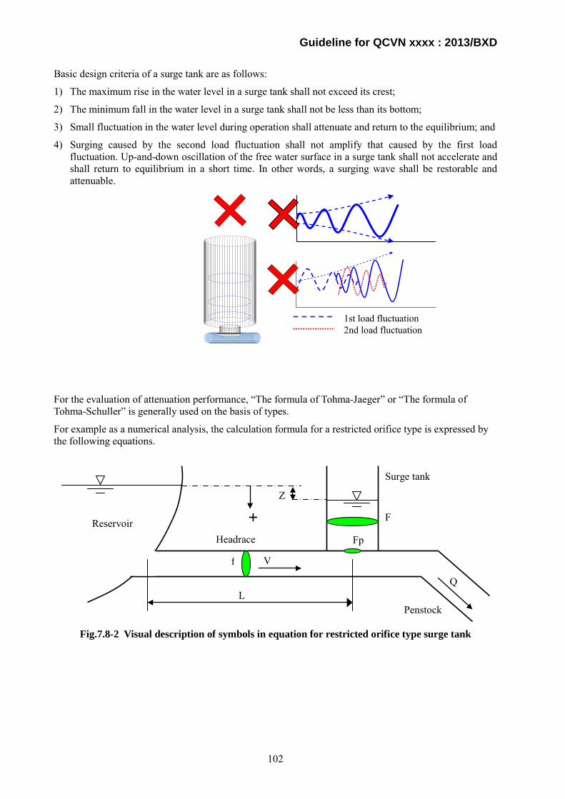
Guideline for QCVN xxxx : 2013/BXD
Basic design criteria of a surge tank are as follows:
1) The maximum rise in the water level in a surge tank shall not exceed its crest;
2) The minimum fall in the water level in a surge tank shall not be less than its bottom;
3) Small fluctuation in the water level during operation shall attenuate and return to the equilibrium; and
4) Surging caused by the second load fluctuation shall not amplify that caused by the first load fluctuation. Up-and-down oscillation of the free water surface in a surge tank shall not accelerate and shall return to equilibrium in a short time. In other words, a surging wave shall be restorable and attenuable.
For the evaluation of attenuation performance, “The formula of Tohma-Jaeger” or “The formula of Tohma-Schuller” is generally used on the basis of types.
For example as a numerical analysis, the calculation formula for a restricted orifice type is expressed by the following equations.
Fig.7.8-2 Visual description of symbols in equation for restricted orifice type surge tank
Reservoir Headrace
Surge tank
Penstock
V
L
f
F
Q
Z
+ Fp
1st load fluctuation2nd load fluctuation
(b)
102
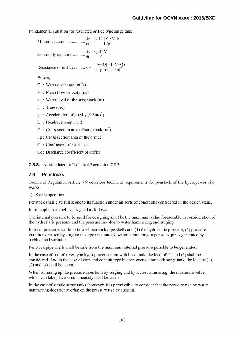
Guideline for QCVN xxxx : 2013/BXD
Fundamental equation for restricted orifice type surge tank
Motion equation ................ dvdt =
z–C · |V| · V–kL/g
Continuity equation ........... dzdt =
Q–f · VF
Resistance of orifice .......... k = |f · V–Q| · (f · V–Q)
2 · g · (Cd · Fp)2
Where,
Q : Water discharge (m3/s)
V : Mean flow velocity (m/s
z : Water level of the surge tank (m)
t : Time (sec)
g : Acceleration of gravity (9.8m/s2)
L : Headrace length (m)
F : Cross-section area of surge tank (m2)
Fp : Cross section area of the orifice
C : Coefficient of head-loss
Cd : Discharge coefficient of orifice
7.8.3. As stipulated in Technical Regulation 7.8.3.
7.9 Penstocks Technical Regulation Article 7.9 describes technical requirements for penstock of the hydropower civil works.
a) Stable operation
Penstock shall give full scope to its function under all sorts of conditions considered in the design stage.
In principle, penstock is designed as follows.
The internal pressure to be used for designing shall be the maximum value foreseeable in consideration of the hydrostatic pressure and the pressure rise due to water hammering and surging.
Internal pressures working in steel penstock pipe shells are, (1) the hydrostatic pressure, (2) pressure variations caused by surging in surge tank and (3) water hammering in penstock pipes generated by turbine load variation.
Penstock pipe shells shall be safe from the maximum internal pressure possible to be generated.
In the case of run-of-river type hydropower station with head tank, the load of (1) and (3) shall be considered. And in the case of dam and conduit type hydropower station with surge tank, the load of (1), (2) and (3) shall be taken.
When summing up the pressure rises both by surging and by water hammering, the maximum value which can take place simultaneously shall be taken.
In the case of simple surge tanks, however, it is permissible to consider that the pressure rise by water hammering does not overlap on the pressure rise by surging.
103
Guideline for QCVN xxxx : 2013/BXD
Fig.7.9-1 Cross Section Image of Penstock and its Internal Water Pressure
Water hammer is caused by velocity fluctuations in penstock pipes inducted by closing equipment operation of water turbines.
Water hammer occurs at the place of closing equipment (maximum) and, decreasing through the penstock pipes, propagates to the water surface of the head tank or surge tank (minimum=0).
The closing equipment of Francis turbines and Kaplan turbines is a guide vane and the closing equipment of Pelton turbine is a needle valve.
Formula for the propagation velocity of pressure wave is described as follows.
αi = 1
wg ·
1
k + 1E ·
Dt
Where,
αi : Propagation velocity of pressure wave of number penstock pipe i (m/s)
w : Unit weight of water (1tf/m3)
g : Acceleration of gravity (m/s2)
K : Elastic coefficient of water (=̇.2.1×105tf/m2)
E : Elastic coefficient of steel (=̇.2.1×107tf/m2)
D : Diameter of steel penstock pipe (m)
t : Thickness of steel penstock pipe (m)
Therefore, the average propagation velocity of pressure wave is described as follows.
αm = ∑Li
Σ
Li
αi
Formula for the pressure rise due to the water hammering without pressure regulators are classified into
Surge tank (3) Pressure rise by water hammering
(2) Pressure rise by surging
(1) Hydrostatic pressure
Penstock
Total of Internal water pressure
Closing equipment of water turbine
104

Guideline for QCVN xxxx : 2013/BXD
the following (A) and (B) depending upon Allievi’s pipeline constant ρ:
Notations
ρ = αm · v0
2 · g · H0 ............................... Allievi’s pipeline constant
θ = αm · T2 · L0
.................................... Closing time constant of a closing equipment
n = ρθ
Where,
h0 : pressure rise due to water hammering at a closing equipment (m)
H0 : Hydrostatic pressure after entirely shutting off a closing equipment at the turbine end (m)
L0 : Length of pipe line (m)
v0 = Σvi · li
L0 : Average velocity
li : Pipe length of section i (m)
vi : Velocity of section i (m/s)
T : Closing time of a closing equipment (s)
g : Acceleration of gravity (m/s2)
αm : Average propagation velocity of pressure wave (m/s)
1) In case of ρ>1:
When h0
H0 ≥ 50%,
h0
H0 =
n2 · (n+ n2+4)
When h0
H0 < 50%,
h0
H0 =
2 · n2–n
When h0
H0 =̇. 30%,
h0
H0 =̇. 1.10n
2) In case of ρ<1:
h0
H0 =
2 · n1+n · (θ–1)
Pressure rise “h” due to water hammering at an arbitrary point is shown in Fig.7.9-2.
105

Guideline for QCVN xxxx : 2013/BXD
Fig.7.9-2 Relationship of h and h0
b) Infiltration and water leakage
Infiltration of water into penstock may deteriorate water quality, and water leakage out of penstock may loosen surrounding bedrock, so these phenomena shall be controlled.
Detail structures are described in Technical Regulation Article 8.
c) Penstock route
As stipulated in Technical Regulation Article 7.5.1 e).
d) Expose d type penstock
As stipulated in Technical Regulation Article 8.
7.10 Tailraces
Technical Regulation Article 7.10 describes technical requirements on tailraces.
a) Safety and stability
As stipulated in Guideline for Technical Regulation Article 7.5.1 a).
b) Prevention of leakage
Leakage from a tailrace may loosen surrounding bedrock in case of a tunnel type tailrace and erode the slope in case of an open channel type tailrace. Followings are typical measures to prevent damage by leakage from a tailrace:
Sealing of construction joint, effective for tunnel lining and open channel; and
Tunnel grouting
c) Prevention of damage to downstream waterways
To prevent damage to the downstream waterways due to collapse of a tailrace, a regulation pond to absorb spilt water, installation of sensors to detect collapse of a tailrace and to stop operation of a hydropower plant.
Surge tank Pressure rise by water hammering
Pressure rise by surging
Hydrostatic pressure
Penstock
Total of Internal water pressure
Closing equipment of water turbine
L
L0
H
P
h= h0LL0
106

Guideline for QCVN xxxx : 2013/BXD
7.11 Outlets
Technical Regulation Article 7.11 describes technical requirements on outlets.
a) Stable and safe operation in all working conditions of hydropower plant
A location of an outlet shall be selected considering the following conditions:
Structure is based on firm foundation;
Structure is not damaged by flood flow;
Outlet is not blocked by sediment; and
Outflow does not collide with river flow.
b) Stable and favorable connection with downstream channel flow
In case an outlet is connected to an intake of another hydropower plant, it is desirable that structures to absorb fluctuation of outflow be prepared in front of an intake of another hydropower plant.
c) Solutions to guarantee stable and safe operation of structures located downstream of hydropower plant
Outflow from an outlet shall not affect stable and safe operation of structures located downstream of hydropower plant. Fluctuation in the river water level does not affect turbine efficiency.
7.12 Hydropower plants (Powerhouse)
7.12.1. Technical Regulation Article 7.12.1 describes technical requirements on powerhouses.
a) Safe, stable and effective operation
A hydropower plant shall give full scope to its capacity under every condition estimated in the design stage.
b) Appropriate layout
A hydropower plant shall be connected with headworks and a waterway appropriately and harmonize with surroundings. A process for harmonized design shall refer to Article 7.1.4 of this Guideline .
c) Head as calculated in design stage
Water pressure acting on structures and hydropower equipment measured at the site fits design value.
d) Appropriate geological conditions
A powerhouse shall be constructed on firm foundation with sufficient bearing capacity to support structures.
e) Prevention of inundation
A location, elevation and structures of a powerhouse shall be decided to prevent it from being inundated by flood, water leakage, or any other causes.
f) Drainage system
A powerhouse shall be equipped with a drain pit, water collecting well and adequate pumping system to prevent it from being inundated and keep it in a dry condition. The number, arrangement, type and capacity of drainage shall be decided considering groundwater level, estimated flood water level, water leakage from penstock and foundation, and any other causes.
g) Erection bay
A location and dimensions of an erection bay shall be selected considering transport from an access road, work schedule of installation and maintenance.
107
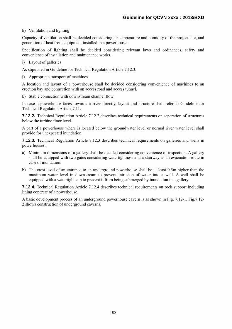
Guideline for QCVN xxxx : 2013/BXD
h) Ventilation and lighting
Capacity of ventilation shall be decided considering air temperature and humidity of the project site, and generation of heat from equipment installed in a powerhouse.
Specification of lighting shall be decided considering relevant laws and ordinances, safety and convenience of installation and maintenance works.
i) Layout of galleries
As stipulated in Guideline for Technical Regulation Article 7.12.3.
j) Appropriate transport of machines
A location and layout of a powerhouse shall be decided considering convenience of machines to an erection bay and connection with an access road and access tunnel.
k) Stable connection with downstream channel flow
In case a powerhouse faces towards a river directly, layout and structure shall refer to Guideline for Technical Regulation Article 7.11.
7.12.2. Technical Regulation Article 7.12.2 describes technical requirements on separation of structures below the turbine floor level.
A part of a powerhouse where is located below the groundwater level or normal river water level shall provide for unexpected inundation.
7.12.3. Technical Regulation Article 7.12.3 describes technical requirements on galleries and wells in powerhouses.
a) Minimum dimensions of a gallery shall be decided considering convenience of inspection. A gallery shall be equipped with two gates considering watertightness and a stairway as an evacuation route in case of inundation.
b) The crest level of an entrance to an underground powerhouse shall be at least 0.5m higher than the maximum water level in downstream to prevent intrusion of water into a well. A well shall be equipped with a watertight cap to prevent it from being submerged by inundation in a gallery.
7.12.4. Technical Regulation Article 7.12.4 describes technical requirements on rock support including lining concrete of a powerhouse.
A basic development process of an underground powerhouse cavern is as shown in Fig. 7.12-1. Fig.7.12-2 shows construction of underground caverns.
108

Guideline for QCVN xxxx : 2013/BXD
109
Fig.7.12-1 Development process of underground cavern
Site selection
Geological investigation
Rock mechanical properties(Strength and
initial rock pressure)Layout of underground cavern,sectional shape and dimensions
Excavation analysis, stability calculation and support design
Is a cavern stable ?
Excavation, rock support and concrete
Measurement(Information-oriented construction)
Is a cavern stable ?
Completion of cavern
Additional support
Planning
Design
Investigation
OperationConstruction Direct asymmetry estimation, inverse analysis method, etc.
Yes
Yes
No
No
Stability of cavern shall be confirmed periodically by measurement records
•Geological investigation•Exploratory drilling•Exploratory adits•In-situ tests•Laboratory tests, etc.
Guideline for QCVN xxxx : 2013/BXD
Fig.7.12-2 Construction of underground cavern
Concrete used for a powerhouse shall follow technical requirements of Technical Regulation Article 7.1.14 to 7.1.17.
7.13 Daily storage reservoir
In case of small scale hydropower power plant in general, when storage capacity of a reservoir located just upstream a hydropower plant is insufficient to supply necessary amount of water to be used for power generation per day, a regulation reservoir to make good the shortage of water for daily use. A daily storage reservoir shall be located on a place technically and economically feasible.
7.13.1 Technical Regulation Article 7.13.1 describes technical requirements on structure of daily storage reservoir. In case a daily regulating reservoir is made by an earthfill dam, it shall be designed following Technical Regulation Article 7.3.
7.14 Bottom discharge
7.14.1. Technical Regulation Article 7.14.1 describes technical requirements on bottom discharge works.
Typical location of a bottom outlet is as follows:
a) Bottom outlet embedded on foundation;
b) Bottom outlet embedded in concrete dam;
7.14.2. Technical Regulation Article 7.14.2 describes technical requirements on a bottom outlet.
The function of the bottom outlet may be as follows:
a) Discharge river maintenance flow to the downstream area;
Arch excavation
Mushroom type cavern
Egg-shaped cavern
110

Guideline for QCVN xxxx : 2013/BXD
b) Empty a reservoir for dredging, repair works or inspection of a dam;
c) Sediment flushing;
d) Diversion works during construction; and
e) Assistant spillway.
7.14.3. Technical Regulation Article 7.14.3 describes technical requirements on tunnel type bottom outlets.
Technical requirements are described quoting provisions of Article 8.9 of QCVN 04 - 05 : 2012/BNNPTN.
8.9 Hydraulic tunnel
8.9.1 The design of hydraulic tunnel should meet the multi-purposes requirements such as flood release, sand excavation, reservoir emptying, constructional derivation and water supply. etc..
A hydraulic tunnel shall satisfy various requirements with which it is charged.
8.9.2 The selection of alignment, type (pressure or free flow), structure and shape of the tunnel cross-section should base on its tasks, calculation and comparison of economic and engineering criteria among options and in accordance with below factors:
a) General layout of the head-work system and inter-influences among tunnel, on-ground constructions and adjacent under-ground works;
b) The under-ground depth, water-column value and hydraulic state of a tunnel;
c) Engineering geology and hydrological geology conditions;
d) Construction condition.
Several factors for design of a bottom outlet such as influence to other facilities, hydrostatic pressure, geology, construction method, etc. shall be considered.
8.9.3 The tunnel alignment is the straight alignment obtaining the shortest length. The application of non-linear alignment is permitted but must meet below requirements:
a) At the bent, inter-section angle of a tunnel is not smaller than 60º (regarding to a flow velocity lower than 10 m/s) and curve radius is not five time smaller than water depth in the tunnel;
b) If the flow velocity in a tunnel exceeds 10 m/s, model experiments are needed to determine values of inter-section angle and curve radius.
It is desirable that alignment of a tunnel be straight connecting the beginning and end in the shortest distance, and conditions a) and b) shall be satisfied in case non-linear alignment is adopted.
8.9.4 The depth of rock layer on the top of the tunnel must be three time higher than the tunnel width.
8.9.5 Remove the tunnel alignment crossing the swelling rock layers.
8.9.6 Energy of flow after the tunnel outlet must be absolutely dissipated.
8.9.7 Dimension of tunnel cross-section should meet requirements of utilization as well as constructional, repaired and maintained conditions of a construction. However, its height is not lower than 2,0 m and the width is not smaller than 1,5 m.
As stipulated in Article 8.9.3 to 8.9.7.
7.14.4. Technical Regulation Article 7.14.4 describes technical requirements on installation of bottom outlet works.
An example of installation criteria of a bottom outlet works (low level outlet works) in Japan is as follows:
111

Guideline for QCVN xxxx : 2013/BXD
- A fill type dam shall be equipped with bottom outlet works to lower the reservoir water level for inspection and repair of a dam body,
A dam is equipped with a spillway and outlet works to discharge environmental flow and irrigation water to the downstream area, however, those facilities might not be able to lower the reservoir water level in case of need for inspection and repair of a dam body, or an outbreak of an accident since they are equipped for flood discharge or water use, Abnormal leakage of water from a dam body of a fill type dam induces embankment materials to flow out with an increasing speed, which might lead to a dam breach. In that case, installation of outlet works at as low elevation as possible assures stability of a fill type dam because lowering the reservoir water level recovers stability of a dam body abruptly, decreases amount of water from a leakage spot, and mitigate damage.
7.15 Protective works of reservoirs, headwork area and downstream of headwork
7.15.1. Technical Regulation Article 7.15.1 describes technical requirements on bottom protective works of reservoirs, headwork area and downstream of headwork.
Technical requirements are described quoting provisions of Article 8.11 of QCVN 04 - 05 : 2012/BNNPTN.
8.11 Protection work in a reservoir and downstream head-work unit
8.11.1 The protection works in a reservoir and downstream head-work unit such as embankment and bank consolidation works should be proposed in order to prevent floods and bank collapsing in valuable land and national economy objects such as city, industrial zone and agriculture land as well as improve pond sanitation condition. The design of protective works is implemented according to relevant design regulations, which are decided by the investor.
8.11.2 Draining for the protective area should consider on-site regulation of partial flow so as to reduce scale of pumping station.
8.11.3 The design of bank consolidation should forecast the displacement and deep-erosion of the channel flow (if existed) as well as the bank regenerating and the general stability of the whole protective dike sections.
8.11.4 In the flood-protective region, a net-work of ground-water observation wells should be proposed.
As stipulated in Article 8.11.
7.15.2. As stipulated in Technical Regulation Article 7.15.2.
7.15.3. Technical Regulation Article 7.15.3 describes necessity of mitigation methods in case rapid change in a river water level due to discharge from a power plant is anticipated. Construction of a regulating reservoir or widening of a river channel is an effective mitigation method if a site for the regulating reservoir or widened river channel is available. In case there is no space for the said facilities, fluctuation in a river water level shall be controlled by reducing change in discharge from a spillway, a bottom outlet, or a power plant.
7.16 Observation device system of the work
7.16.1. Technical Regulation Article 7.16.1 describes the requirements regarding the installation of monitoring devices in hydropower civil structures.
Monitoring items and arrangement of instruments shall follow Guideline for Technical Regulation Vol.4 Article 50.
In addition, TCVN 8215-2009 Chapter 3 lists arrangement of observation items in the following tables. Monitoring devices shall be installed in hydropower works of Grade III and below if necessary.
112
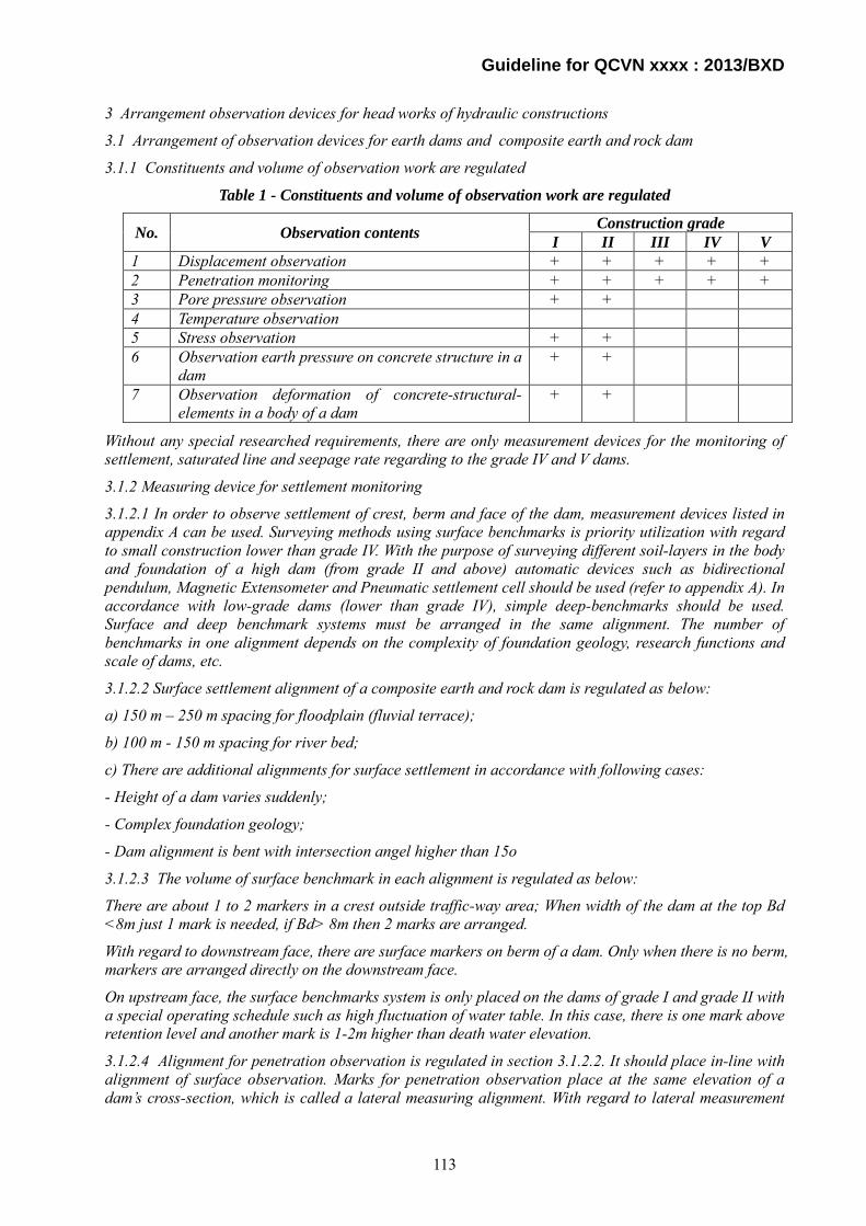
Guideline for QCVN xxxx : 2013/BXD
3 Arrangement observation devices for head works of hydraulic constructions
3.1 Arrangement of observation devices for earth dams and composite earth and rock dam
3.1.1 Constituents and volume of observation work are regulated
Table 1 - Constituents and volume of observation work are regulated
No. Observation contents Construction grade I II III IV V
1 Displacement observation + + + + + 2 Penetration monitoring + + + + + 3 Pore pressure observation + + 4 Temperature observation 5 Stress observation + + 6 Observation earth pressure on concrete structure in a
dam + +
7 Observation deformation of concrete-structural- elements in a body of a dam
+ +
Without any special researched requirements, there are only measurement devices for the monitoring of settlement, saturated line and seepage rate regarding to the grade IV and V dams.
3.1.2 Measuring device for settlement monitoring
3.1.2.1 In order to observe settlement of crest, berm and face of the dam, measurement devices listed in appendix A can be used. Surveying methods using surface benchmarks is priority utilization with regard to small construction lower than grade IV. With the purpose of surveying different soil-layers in the body and foundation of a high dam (from grade II and above) automatic devices such as bidirectional pendulum, Magnetic Extensometer and Pneumatic settlement cell should be used (refer to appendix A). In accordance with low-grade dams (lower than grade IV), simple deep-benchmarks should be used. Surface and deep benchmark systems must be arranged in the same alignment. The number of benchmarks in one alignment depends on the complexity of foundation geology, research functions and scale of dams, etc.
3.1.2.2 Surface settlement alignment of a composite earth and rock dam is regulated as below:
a) 150 m – 250 m spacing for floodplain (fluvial terrace);
b) 100 m - 150 m spacing for river bed;
c) There are additional alignments for surface settlement in accordance with following cases:
- Height of a dam varies suddenly;
- Complex foundation geology;
- Dam alignment is bent with intersection angel higher than 15o
3.1.2.3 The volume of surface benchmark in each alignment is regulated as below:
There are about 1 to 2 markers in a crest outside traffic-way area; When width of the dam at the top Bd <8m just 1 mark is needed, if Bd> 8m then 2 marks are arranged.
With regard to downstream face, there are surface markers on berm of a dam. Only when there is no berm, markers are arranged directly on the downstream face.
On upstream face, the surface benchmarks system is only placed on the dams of grade I and grade II with a special operating schedule such as high fluctuation of water table. In this case, there is one mark above retention level and another mark is 1-2m higher than death water elevation.
3.1.2.4 Alignment for penetration observation is regulated in section 3.1.2.2. It should place in-line with alignment of surface observation. Marks for penetration observation place at the same elevation of a dam’s cross-section, which is called a lateral measuring alignment. With regard to lateral measurement
113
Guideline for QCVN xxxx : 2013/BXD
alignment, there is one alignment in every 8-10 m height of a homogenous earth dam. In a non-homogenous dam, there is one deep measuring alignment for each type of soil. There are 2 to 5 deep- marks in each alignment.
3.1.3 Arrangement of horizontal displacement observation-devices
3.1.3.1 The layout of monitoring instruments for horizontal displacements are regulated as below:
a) 100 m to 150 m spacing for one observed alignment in case a dam is located on the river-bed;
b) 150 to 200 m spacing for one observed alignment in case a dam is located on the fluvial terrace;
A volume of alignments for horizontal displacement observation depends on the length of a dam, but not less than three alignments (one alignment at the deepest position, the two others place at two-sided of the fluvial terrace). The location of the alignment for horizontal displacement observation should be concurred with the alignments of settlement observation.
When width of a dam Bd is greater than 8m, there are two observed points at the borders of upstream and downstream faces. When Bd<8m, just only one observed point is located at the border of upstream face or at an intersection of accentuated- maximum-water level and upstream face.
3.1.3.2 There is one monitoring point of horizontal displacement in every 8-10m height of a homogeneous earth dam. In a non-homogenous dam, there is one observed point for each type of backfill soil.
3.1.3.3 In order to observe horizontal displacement, one of the following measurement devices should be used:
a) Field rod;
b) Longitudinal gallery;
c) Bio-directional pendulum;
d) Inclinometer, etc.;
3.1.3.4 In case there is reinforce-concrete-structure in a dam body, the observation alignment should concur with a location of reinforce-concrete-structures. If this structure is a open structure on a dam face, the arrangement of observation for horizontal displacement is the same as that of normal an earth dam.
3.1.4 Arrangement of percolation observation
3.1.4.1 The percolation observation in an earth and an earth and rock composite dam includes the following contents:
a) Monitoring water elevation at upstream and downstream of a dam;
b) Monitoring saturated line in a body, foundation and abutment of a dam;
c) Monitoring pressure of seepage water on a concrete construction and pore pressure;
d) Monitoring seepage rate;
3.1.4.2 In order to monitor a saturated line in a dam body, observation wells are arranged. Placing elevation of the observation well and the returned-water-section length of the observation well are determined through calculation but must be lower than calculating values of a saturated line for a minimum section of 1-2m.
Observation wells placing in cross sections of a dam are piezometric alignments. The piezometric alignment is regulated as below:
150 to 250m spacing for alignments on the fluvial terrace;
100 to 150m spacing for alignments on the river bed;
The arrangement of piezometric alignments should be placed at the positions without any changes of foundation geology or dam structure. The volume of piezometric alignments must not below three
114

Guideline for QCVN xxxx : 2013/BXD
alignments.
3.1.4.3 The number of observation wells in each alignment depends on height of dam, form and structure of dam but should not lower than 4. There is one piezometric pipe locates on upstream face and higher than a retention level. About 1-2 pipes are placed at dam crest (outer traffic way), 2-3 pipes at downstream face (the best position is at banquette of dam and forward drain facilities)
3.1.4.5 A dam with the anti-seepage structures like core-wall and battered wall, which are made from impervious materials, should arrange seepage monitoring devices to check the operating effectiveness of those walls. The arrangement is regulated in section 3.1.4.2 and 3.1.4.3
3.1.4.6 In order to determine seepage rate, the water-collecting ditches should be placed at a downstream toe. Water-gauging installation such as triangular flume and thin-plate weir will be arranged at required positions of discharge measurement. With the purpose of measuring seepage rate into a connected joint in a dam, water-collecting ditches are placed and convey water to the water-gauging construction.
3.1.4.7 In case a foundation is treated by a concrete-spraying screen or pile (steel, concrete, etc.) the piezometric pipe must be arranged to evaluate effectiveness of screen. Alignment for seepage observation is regulated in section 3.1.4.2. There are at least 3 rows for each alignment:
a) The first row is placed in front of a screen and at the depth of 2m under the interface between dam and its foundation;
b) The second row is placed adjacent a back of the screen and at the depth equals 0.5 – 0.7 times less than the height of the screen;
c) The following rows are placed shallower. The final row must be placed adjacently to the interface of the dam and its foundation.
d) The piezometric measurement system can be arranged at the same time with the construction phase or after the construction phase but supported-drilling methods are needed.
3.1.5 Pore pressure observation
3.1.5.1 The arrangement of pore pressure observed-devices is conducted just for dams from grade II and above, of which a dam body, a core wall or battered wall is formed by clay or heavy clay-loam. Regarding to dams of lower grade, just a special schedule of observation is implemented.
3.1.5.2 Devices for pore pressure observation are piezometers, of which structure is similar to a piezometer used to measure water or soil pressure. Pore-pressure piezometers are placed at the given positions during the construction phase. The alignment of pore-pressure observation should be arranged at the same location with that of saturated line. The layout of alignments on the cross-sections of a dam bases on the height with 15-20m spacing. The value of measuring devices in each alignment depends on the width of a dam but not less than 5 alignments
3.1.5.3 The arrangement of wiring system from piezometers to observed positions can utilize a jet-drilling corridor. If there is not any corridor, a special cell can be used at the downstream toe, where inundated situation does not occur.
3.1.6 Arrangement of stress observation for a dam
3.1.6.1 Just only dams from grade II and above need to install stress measurement devices.
3.1.6.2 Stress measuring devices in a body of an earth dam as well as an earth and rock composite dam are pressure cells. They obtain the same structure as piezometers, which are used to measure the earth pressure on the concrete construction. The arrangement of the stress-observation alignment is regulated in section 3.1.2.2. This alignment should be placed at the same position with the alignment of settlement observation. The volume of piezometers is regulated in section 3.1.5.2
3.1.7 Devices arrangement for earth pressure observation on the concrete structure, reinforce concrete structure in the dam
Piezometers are used to observe earth pressure on the concrete structure, reinforce concrete structure in
115
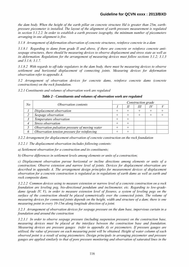
Guideline for QCVN xxxx : 2013/BXD
the dam body. When the height of the earth pillar on concrete structure Hd is greater than 25m, earth-pressure piezometer is installed. The layout of the alignment of earth pressure measurement is regulated in section 3.1.2.2. In order to establish a earth pressure isography, the minimum number of piezometers arranging in one alignment is five.
3.1.8 Arrangement of deformation observation of concrete structures, reinforce concrete in a dam
3.1.8.1 Regarding to dams from grade II and above, if there are concrete or reinforce concrete anti-seepage structures, there should be measuring devices to observe displacement and stress state as well as its deformation. Regulations for the arrangement of measuring devices must follow sections 3.1.2; 3.1.3 and 3.1.6; 3.1.7.
3.1.8.2 With regards to off-take regulators in the dam body, there must be measuring devices to observe settlement and horizontal displacement of connecting joints. Measuring devices for deformation observation refer to appendix A.
3.2 Arrangement of observation devices for concrete dams, reinforce concrete dams (concrete constructions) on the rock foundation.
3.2.1 Constituents and volumes of observation work are regulated
Table 2 - Constituents and volumes of observation work are regulated
No Observation contents Construction grade I II III IV V
1 Displacement observation + + + + + 2 Seepage observation + + + + + 3 Temperature observation + + 4 Stress observation + + 5 Observation pulsation pressure of moving water + + 6 Observation tension pressure for reinforcing + +
3.2.2 Arrangement for displacement observation of concrete construction on the rock foundation
3.2.2.1 The displacement observation includes following contents:
a) Settlement observation for a construction and its constituents;
b) Observe differences in settlement levels among elements or units of a construction;
c) Displacement observation pursue horizontal or incline directions among elements or units of a construction; Observe extension and narrow level of joints. Devices for displacement observation are described in appendix A. The arrangement design principles for measurement devices of displacement observation for a concrete construction is regulated as in regulations of earth dams as well as earth and rock composite dams.
3.2.2.2 Common devices using to measure extension or narrow level of a concrete construction on a rock foundation are leveling peg, bio-directional pendulum and inclinometer, etc. Regarding to low-grade-dams (grade IV, V), in order to measure extension level of fissures, a system of leveling pegs on the surface of the construction should be placed symmetrically over the connected joints. The volume of measuring devices for connected joints depends on the height, width and structure of a dam; there is one measuring point in every 10-15m along longitude direction of a joint.
3.2.3 Arrangement of observation devices for seepage pressure on the dam base, impervious curtain in a foundation and around the construction
3.2.3.1 In order to observe seepage pressure (including suspension pressure) on the construction base, measuring devices must be placed at the interface between the construction base and foundation. Measuring devices are pressure gauges (refer to appendix A) or piezometers. If pressure gauges are utilised, the value of pressure on each measuring point will be obtained. Height of water column of each observed point is a result of using piezometers. Design principals in arranging piezometer and pressure gauges are applied similarly to that of pore pressure monitoring and observation of saturated lines in the
116
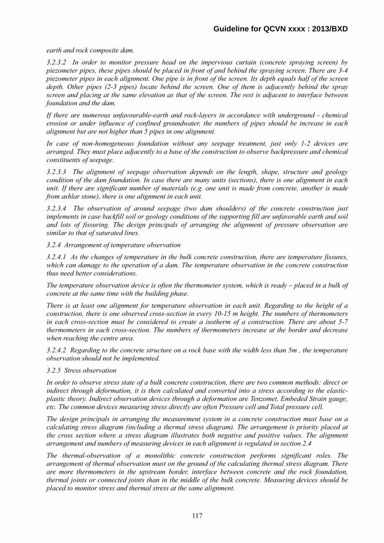
Guideline for QCVN xxxx : 2013/BXD
earth and rock composite dam.
3.2.3.2 In order to monitor pressure head on the impervious curtain (concrete spraying screen) by piezometer pipes, these pipes should be placed in front of and behind the spraying screen. There are 3-4 piezometer pipes in each alignment. One pipe is in front of the screen. Its depth equals half of the screen depth. Other pipes (2-3 pipes) locate behind the screen. One of them is adjacently behind the spray screen and placing at the same elevation as that of the screen. The rest is adjacent to interface between foundation and the dam.
If there are numerous unfavourable-earth and rock-layers in accordance with underground - chemical erosion or under influence of confined groundwater, the numbers of pipes should be increase in each alignment but are not higher than 5 pipes in one alignment.
In case of non-homogeneous foundation without any seepage treatment, just only 1-2 devices are arranged. They must place adjacently to a base of the construction to observe backpressure and chemical constituents of seepage.
3.2.3.3 The alignment of seepage observation depends on the length, shape, structure and geology condition of the dam foundation. In case there are many units (sections), there is one alignment in each unit. If there are significant number of materials (e.g. one unit is made from concrete, another is made from ashlar stone), there is one alignment in each unit.
3.2.3.4 The observation of around seepage (two dam shoulders) of the concrete construction just implements in case backfill soil or geology conditions of the supporting fill are unfavorable earth and soil and lots of fissuring. The design principals of arranging the alignment of pressure observation are similar to that of saturated lines.
3.2.4 Arrangement of temperature observation
3.2.4.1 As the changes of temperature in the bulk concrete construction, there are temperature fissures, which can damage to the operation of a dam. The temperature observation in the concrete construction thus need better considerations.
The temperature observation device is often the thermometer system, which is ready – placed in a bulk of concrete at the same time with the building phase.
There is at least one alignment for temperature observation in each unit. Regarding to the height of a construction, there is one observed cross-section in every 10-15 m height. The numbers of thermometers in each cross-section must be considered to create a isotherm of a construction. There are about 5-7 thermometers in each cross-section. The numbers of thermometers increase at the border and decrease when reaching the centre area.
3.2.4.2 Regarding to the concrete structure on a rock base with the width less than 5m , the temperature observation should not be implemented.
3.2.5 Stress observation
In order to observe stress state of a bulk concrete construction, there are two common methods: direct or indirect through deformation, it is then calculated and converted into a stress according to the elastic-plastic theory. Indirect observation devices through a deformation are Tenzomet, Embeded Strain gauge, etc. The common devices measuring stress directly are often Pressure cell and Total pressure cell.
The design principals in arranging the measurement system in a concrete construction must base on a calculating stress diagram (including a thermal stress diagram). The arrangement is priority placed at the cross section where a stress diagram illustrates both negative and positive values. The alignment arrangement and numbers of measuring devices in each alignment is regulated in section 2.4
The thermal-observation of a monolithic concrete construction performs significant roles. The arrangement of thermal observation must on the ground of the calculating thermal stress diagram. There are more thermometers in the upstream border, interface between concrete and the rock foundation, thermal joints or connected joints than in the middle of the bulk concrete. Measuring devices should be placed to monitor stress and thermal stress at the same alignment.
117
Guideline for QCVN xxxx : 2013/BXD
3.2.6 Arrangement for pulsation pressure observation of moving water
3.2.6.1 The pulsation pressure observation of moving water downstream spillway, outlet of culvert, flow-deflector of spout chute, body of chute spillway, etc. is only implemented in accordance with important constructions from grade II and above.
In order to monitor pulsation pressure of moving water, sensing measurement devices (pressure cell, hydraulic load cell) at required positions such as valve gate, flow-deflector of spillway, energy dissipater, etc.
Pulsation pressure measuring devices are arranged in parallel alignments, which are perpendicular to the axis of flow. At one measuring alignment, the number of measuring devices must not below 3.
Regarding to important constructions, before arranging observed devices of pulsation pressure, numerous experiments must be carried out to place such measurement instruments precisely.
3.2.6.2 The monitor of construction vibration causing by earthquake, operating machine or moving load is not regulated in this standard.
3.3 Arrangement of observation devices for the reinforce concrete construction on the earth foundation
3.3.1 Reinforce concrete constructions in this standard mainly include overflow spillway, open sewer, pumping station, etc. General principals of monitoring contents and formulating design project to arrange measurement devices are regulated in above parts.
3.3.2 Regarding to reinforce concrete construction on the earth foundation, the observation of displacement, seepage on a base, saturated line at two shoulders of dam are important tasks that need to place observation devices. Furthermore, with regards to the construction from grade II and above, it is necessary to place measuring devices to observe stress state in the body and base of the dam, pulsation pressure at downstream of energy dissipater and horizontal pressure of earth.
3.3.3 Settlement observation of the reinforce concrete construction on the earth foundation is the same as that of the earth dam or concrete construction using a surveying method and automatic methods such as bio-directional pendulum, magnetic extensometer, etc. Principals in arranging benchmarks for settlement observation in a concrete dam are similar to that of an earth dam.
In case there are certain sections creating by settling joints in a construction, measuring marks of each section will be used as benchmarks of settlement observation (including inclined observation) for each section. If setting joints cross abutments, elevation datum can be placed at four angels of every abutment upstream and downstream.
3.3.4 Horizontal displacement observation of a reinforce concrete construction on an earth foundation is implemented similarly to that of a concrete construction on a rock base.
3.3.5 In order to monitor seepage pressure on the foundation of a construction, pressure gauges readily placing at given positions from construction phase are utilised. Regarding to a fine-sand foundation, the protection layer must be design carefully so as to prevent clogging conditions.
3.3.6 Alignments for seepage pressure observation are arranged perpendicular to central axis of a construction. The numbers of observation alignments are fixed by the geology conditions of the base and scale of a construction, distance between alignments does not greater than 40m. The numbers of alignments in one construction cannot lower than 3: one center alignment and the two other ones at fluvial terrace or shoulders in series with the banks.
3.3.7 In each observation alignment, pressure gauges are placed as below:
a) At specific positions of the border line;
b) Just in front of or behind the anti-seepage devices.
3.3.8 Observation of by-pass seepage around two shoulders of a construction must be implemented during a backfill phase or when geological condition of a support fill is formed by poor rock and well
118

Guideline for QCVN xxxx : 2013/BXD
cracking. A measuring device is structured similarly to that of a pipe using to measure saturated line in an earth dam. The number of pipes in each alignment depends on a foundation and scale of a construction but must be higher than 3.
3.3.9 Regarding to reinforce concrete constructions from grade II and above on an earth foundation, a part from arranging measurement device to observe stress in a body of a construction, it must include instruments using to monitor stress of earth base. The stress monitoring devices are pressure gauges placing 10-15m above a concrete base. The detailed layout of stress observation devices on an earth base is regulated in section 2.4.1 and 3.2.5.1. The numbers of monitoring alignments can not lower than 3: one alignment on the river bed, the other two on the two fluvial terraces. The distance between two observed alignments should not larger than 30m. The numbers of pressure gauges in each alignment depend on cross section dimension, at least from 4 to 5 devices. These gauges must be located at two borders and with higher density in the center of a construction. In case of a complex foundation, the numbers of pressure gauges must increase.
3.3.10 Regarding to elements forming from bulk concrete block, there must be thermal-stress observation devices regulating in the section 3.2.5.
3.3.11 With regards to reinforce concrete constructions, strain of reinforcing should be monitored. Measuring devices are force gauges such as Load cell, Vibration load cell, Embeded strain gauge, etc. Force-gauges are arranged in alignments pursue force direction. There are at least 3 alignments in each construction: one alignment locates in a center of construction base, the two others locate on two border of a bed plate. The quantities of force gauges depend on shape and dimension of a construction base but do not lower than 3. Arranging into blocks/units is the best solution. The force gauges are welded permanently to the forcing reinforcements following two directions (longitudinal and lateral). Forcing gauges must be connected with the steel reinforcements with diameters higher than 20mm.
3.3.12 In case a construction includes a stay-steel into a foundation, force gauges must be arranged to observe its tension stress. The alignment arrangement and quantities of force gauges in each alignment is applied as in section 3.3.11.
3.3.13 Reinforce concrete construction on a soft-soil foundation must include devices to observe pulsation pressure of moving water on the dam face, a stilling basin and a spillway apron in series with a basin. Devices using to measure pulsation pressure often arrange pursue parallel alignments and perpendicular to flow. The measuring locations in each observed alignment should examined carefully and placed at the positions of highest impulse values of flow. With regards to grade I and grade special, locations of pulsation measuring must be results of model experiments.
3.4 Arrangement of observation devices for an arch-dam on a rock foundation
3.4.1 Arch dam is one style of concrete construction on a rock foundation. The contents of observation design follow section 3.2.
However, the arch dam belongs to a thin-shade-structure and obtains certain differences in operating conditions compare to that of a gravity concrete dam so there are additional regulations.
3.4.2 Due to a good quality rock foundation of an arch dam, the layout design of observing settlement can utilize a simple method: placing leveling pegs on the dam surface.
3.4.3 In order to monitor horizontal displacement of an arch dam, there following devices should be used: bio-directional pendulum, and Inclinometer. In case an arch dam obtains bent or weld-shape cross-sections, the sire suspensions system should not be arranged continuously from top to toe, fixed positions on a bent-surface should be placed (refer to figure 3.12). Points of application of pendulum plumping should be arranged vertically pursue top to toe direction. A pendulum and supporting racks should be placed in a chamber, which does not in inundated situation.
3.4.4 A pendulum system is used to observe horizontal displacement and deflection level of a bent surface comparing to a longitude centre line of a dam. The quantities of observation points depend on the height of a dam. There is one measuring point in average in every 10-15m. Each chamber of a dam obtains at least one observed alignment to monitor horizontal displacement and deflection level.
119

Guideline for QCVN xxxx : 2013/BXD
3.4.5 Arrangement of measuring devices to observe extension or narrow level of thermal joints and settlement joints has to be conducted immediately during the construction phase. The devices using to measure clearances must be arranged symmetrically across thermal joints (settlement joints). There is one device in every 5-10 m height of a dam. Regarding to dams of grade IV and lower, marking points or balance level should be used to monitor extension level of connected joints and settlement joints.
3.4.6 The arrangements of measuring device using to observe seepage through a foundation, shoulders and connected joints of an arch dam are regulated similarly to that of gravity concrete dam in the section 3.2.3. Devices using to observe the operation of concrete spraying screen and impervious curtain for a foundation can be simples instruments like piezometer pipes which are readily placing in a construction base right after drilling phase. Alignments using for seepage observation are arranged as below:
a) One alignment locates in front of a concrete spraying screen. Its depth equals half of the depth of a screen;
b) There are two alignments behind a screen. One alignment is adjacent to a screen and its depth equals 0.5 – 0.7 times that of a screen. The third alignment is placed adjacently to the interface of the foundation.
3.4.7 In order to observe seepage pressure on the interface between a foundation and the construction, there are certain types of devices:
a) Pressure gauges;
b) Piezometers: Total pressure, Pressure cell, Hydraulic load cells, etc.;
In case a pressure gauge is utilized, there must be long-pipelines reaching above a free surface. In case a readily- installed piezometer is used on the interface between a base and a construction, there is a wiring system that connects to a observed position.
The measuring devices can arrange pursue alignments or grids. The alignment quantities depend on the length, height and geology condition of a dam base. The maximum distance between alignments is 100-150m in case a geological condition of a base is less complex. When a dam base has a complex geology, there are more observation devices in a system.
3.4.8 The arrangement of devices to observe by-pass seepage around two borders of a construction is designed similarly to that of saturate lines in an earth dam.
3.4.9 The observation of the distribution of concrete temperature in an arch dam is considerably important and must be implement as soon as the starting period of a building phase. The quantity and location design of thermal observation must base on the height and number of dam’s chambers. There is at least one alignment in each chamber of a dam.
Regarding to the height of a dam, there is one cross section using for observation in every 10 m. There are 5-7 points in each cross section. The first and last point must be 0.4-0.6m far from the dam borders
3.4.10 In order to observe temperature of a dam base, resistance thermometers must be placed at the readily installed holes under a base at the depth of 5-6m.
Regarding to the advantages of observation procedures, the boring system is arranged in a horizontal alignment, a longitudinal alignment or a grid system. The number of measuring points placing in a base must be large enough to be able to analyze the thermal field and seepage field of a dam foundation.
3.4.11 In an arch dam, stress causing by external strain is often large so the arrangement of measuring devices to observe stress and deformation is very important. In each observed position, there is devices in both two directions: vertical and horizontal.
The number of measuring alignments depends on the dam height, a special task for research (if exist). Regarding to the height of a dam, there is one cross section in every 10m. There are 5-7 measuring points in each cross section. The specific position bases on results from calculations of stress state and deformation of a dam.
120
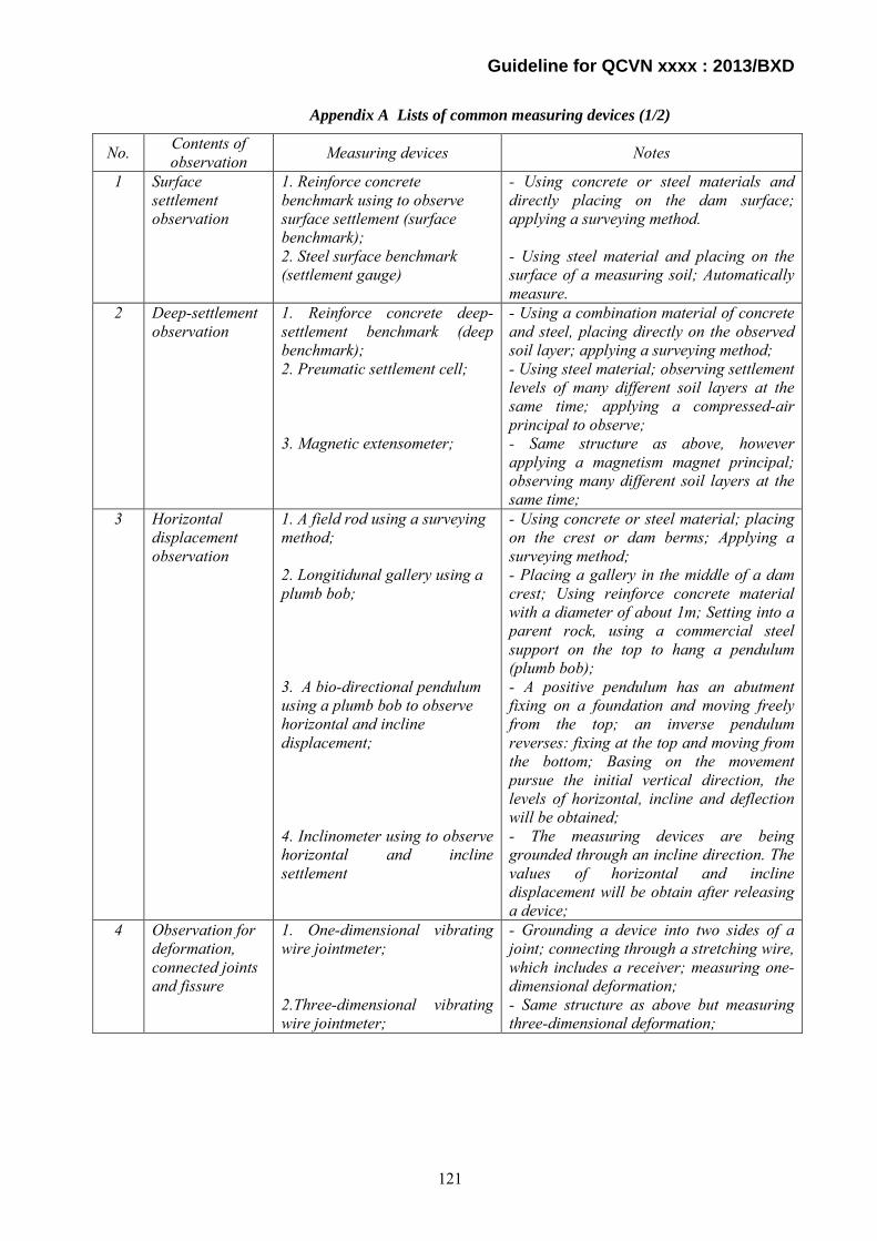
Guideline for QCVN xxxx : 2013/BXD
Appendix A Lists of common measuring devices (1/2)
No. Contents of observation Measuring devices Notes
1 Surface settlement observation
1. Reinforce concrete benchmark using to observe surface settlement (surface benchmark); 2. Steel surface benchmark (settlement gauge)
- Using concrete or steel materials and directly placing on the dam surface; applying a surveying method. - Using steel material and placing on the surface of a measuring soil; Automatically measure.
2 Deep-settlement observation
1. Reinforce concrete deep-settlement benchmark (deep benchmark); 2. Preumatic settlement cell; 3. Magnetic extensometer;
- Using a combination material of concrete and steel, placing directly on the observed soil layer; applying a surveying method; - Using steel material; observing settlement levels of many different soil layers at the same time; applying a compressed-air principal to observe; - Same structure as above, however applying a magnetism magnet principal; observing many different soil layers at the same time;
3 Horizontal displacement observation
1. A field rod using a surveying method; 2. Longitidunal gallery using a plumb bob; 3. A bio-directional pendulum using a plumb bob to observe horizontal and incline displacement; 4. Inclinometer using to observe horizontal and incline settlement
- Using concrete or steel material; placing on the crest or dam berms; Applying a surveying method; - Placing a gallery in the middle of a dam crest; Using reinforce concrete material with a diameter of about 1m; Setting into a parent rock, using a commercial steel support on the top to hang a pendulum (plumb bob); - A positive pendulum has an abutment fixing on a foundation and moving freely from the top; an inverse pendulum reverses: fixing at the top and moving from the bottom; Basing on the movement pursue the initial vertical direction, the levels of horizontal, incline and deflection will be obtained; - The measuring devices are being grounded through an incline direction. The values of horizontal and incline displacement will be obtain after releasing a device;
4 Observation for deformation, connected joints and fissure
1. One-dimensional vibrating wire jointmeter; 2.Three-dimensional vibrating wire jointmeter;
- Grounding a device into two sides of a joint; connecting through a stretching wire, which includes a receiver; measuring one-dimensional deformation; - Same structure as above but measuring three-dimensional deformation;
121

Guideline for QCVN xxxx : 2013/BXD
No. Contents of observation Measuring devices Notes
5 Saturated line observation
1. Piezometer pipe; 2.Observation well;
- Drilling a piezometer pipe into a body and foundation of a dam, attaching a protected filtration pipe; The value of water level in a pipe will be obtained when releasing a device into a pipe to create a close chain; - Same structure as above but significantly higher in a diameter; a receiver has a circle shape; when releasing a device in to a well, the value of water elevation will be recorded automatically;
Appendix A Lists of common measuring devices (2/2)
6 Pore pressure observation
1. Hydraulic piezometer; 2. Pneumatic piezometer; 3.Vibrating string piezometer; 4.Carlson pore pressure;
- A measuring device is a pipe system filling-up by a liquid; a structure of a receiver similar to that of a piezometer; - Same structure as above but using compressed air instead of a liquid; - Including a stretching metal bar, a blowpipe and an electromagnetic winding; when being stimulated, a metal bar will vibrate to create a frequency code which will transfer through a signaling cable to a receiver; - Same structure as above;
7 Observation for stress, water pressure, pulsation pressure, etc.
1.Tenzomet; 2.Strain gauge; 3.Pressure cell; 4.Preumatic/hydraulic pressure cell
- Using an indirect measurement device through a deformation observation; it then converts into stress basing on an elastic-plastic theory; - Same structure as above; - Same operating principal, attaching a measuring device which automatically converts frequency into a force unit; - Same structure as above;
8 Reinforcement tensioning observation
1.Load cell; 2.Embeded strain gauge
- Same operating principal as that of devices measuring stress; - Observe reinforce deformation and then determine tension pursue an elastic theory
9 Temperature observation
Carlson resistance thermometer Applying an energy metabolism principal from electric energy into thermal energy; Including a metal resistance and a receiver; A reading record is a temperature value;
10 Water column observation
Water gas column Using concrete, steel or timber material; placing in front of observation alignment;
122
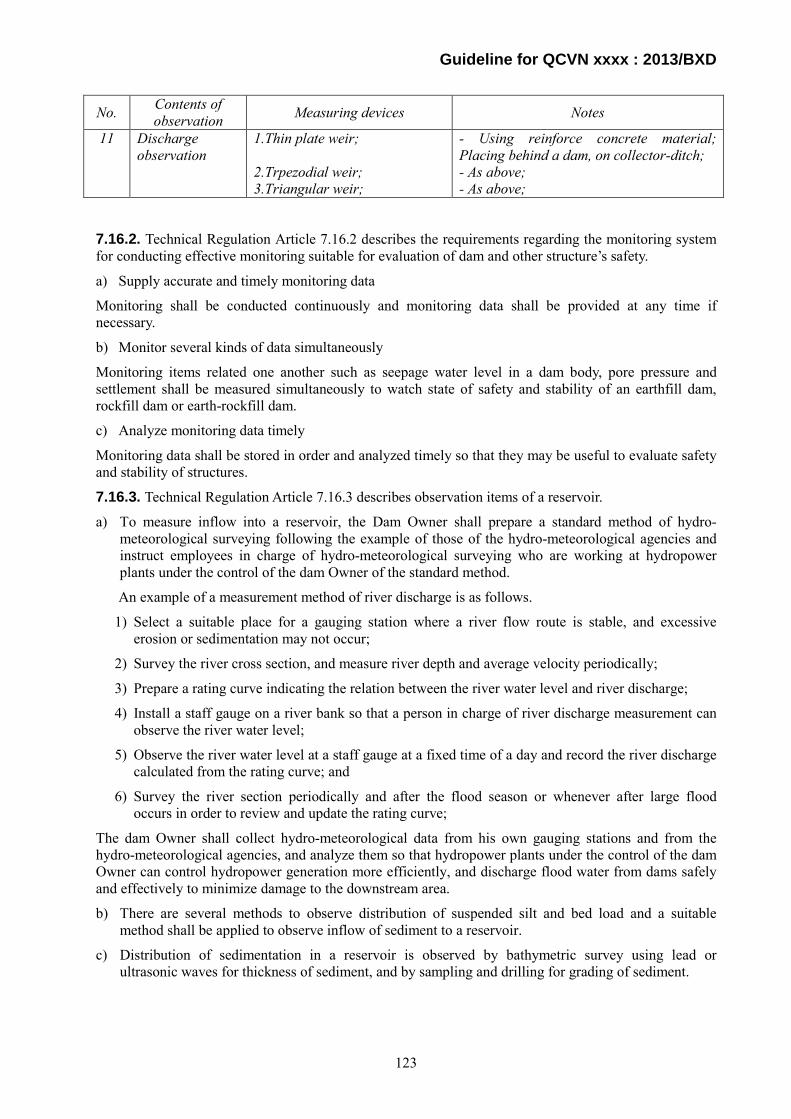
Guideline for QCVN xxxx : 2013/BXD
No. Contents of observation Measuring devices Notes
11 Discharge observation
1.Thin plate weir; 2.Trpezodial weir; 3.Triangular weir;
- Using reinforce concrete material; Placing behind a dam, on collector-ditch; - As above; - As above;
7.16.2. Technical Regulation Article 7.16.2 describes the requirements regarding the monitoring system for conducting effective monitoring suitable for evaluation of dam and other structure’s safety.
a) Supply accurate and timely monitoring data
Monitoring shall be conducted continuously and monitoring data shall be provided at any time if necessary.
b) Monitor several kinds of data simultaneously
Monitoring items related one another such as seepage water level in a dam body, pore pressure and settlement shall be measured simultaneously to watch state of safety and stability of an earthfill dam, rockfill dam or earth-rockfill dam.
c) Analyze monitoring data timely
Monitoring data shall be stored in order and analyzed timely so that they may be useful to evaluate safety and stability of structures.
7.16.3. Technical Regulation Article 7.16.3 describes observation items of a reservoir.
a) To measure inflow into a reservoir, the Dam Owner shall prepare a standard method of hydro-meteorological surveying following the example of those of the hydro-meteorological agencies and instruct employees in charge of hydro-meteorological surveying who are working at hydropower plants under the control of the dam Owner of the standard method.
An example of a measurement method of river discharge is as follows.
1) Select a suitable place for a gauging station where a river flow route is stable, and excessive erosion or sedimentation may not occur;
2) Survey the river cross section, and measure river depth and average velocity periodically;
3) Prepare a rating curve indicating the relation between the river water level and river discharge;
4) Install a staff gauge on a river bank so that a person in charge of river discharge measurement can observe the river water level;
5) Observe the river water level at a staff gauge at a fixed time of a day and record the river discharge calculated from the rating curve; and
6) Survey the river section periodically and after the flood season or whenever after large flood occurs in order to review and update the rating curve;
The dam Owner shall collect hydro-meteorological data from his own gauging stations and from the hydro-meteorological agencies, and analyze them so that hydropower plants under the control of the dam Owner can control hydropower generation more efficiently, and discharge flood water from dams safely and effectively to minimize damage to the downstream area.
b) There are several methods to observe distribution of suspended silt and bed load and a suitable method shall be applied to observe inflow of sediment to a reservoir.
c) Distribution of sedimentation in a reservoir is observed by bathymetric survey using lead or ultrasonic waves for thickness of sediment, and by sampling and drilling for grading of sediment.
123
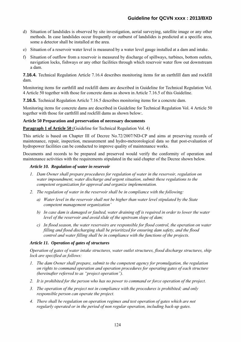
Guideline for QCVN xxxx : 2013/BXD
d) Situation of landslides is observed by site investigation, aerial surveying, satellite image or any other methods. In case landslides occur frequently or outburst of landslides is predicted at a specific area, some a detector shall be installed at the area.
e) Situation of a reservoir water level is measured by a water level gauge installed at a dam and intake.
f) Situation of outflow from a reservoir is measured by discharge of spillways, turbines, bottom outlets, navigation locks, fishways or any other facilities through which reservoir water flow out downstream a dam.
7.16.4. Technical Regulation Article 7.16.4 describes monitoring items for an earthfill dam and rockfill dam.
Monitoring items for earthfill and rockfill dams are described in Guideline for Technical Regulation Vol. 4 Article 50 together with those for concrete dams as shown in Article 7.16.5 of this Guideline.
7.16.5. Technical Regulation Article 7.16.5 describes monitoring items for a concrete dam.
Monitoring items for concrete dams are described in Guideline for Technical Regulation Vol. 4 Article 50 together with those for earthfill and rockfill dams as shown below:.
Article 50 Preparation and preservation of necessary documents
Paragraph 1 of Article 50 (Guideline for Technical Regulation Vol. 4)
This article is based on Chapter III of Decree No.72/2007/ND-CP and aims at preserving records of maintenance, repair, inspection, measurement and hydro-meteorological data so that post-evaluation of hydropower facilities can be conducted to improve quality of maintenance works.
Documents and records to be prepared and preserved would verify the conformity of operation and maintenance activities with the requirements stipulated in the said chapter of the Decree shown below.
Article 10. Regulation of water in reservoir
1. Dam Owner shall prepare procedures for regulation of water in the reservoir, regulation on water impoundment, water discharge and urgent situation, submit these regulations to the competent organization for approval and organize implementation.
2. The regulation of water in the reservoir shall be in compliance with the following:
a) Water level in the reservoir shall not be higher than water level stipulated by the State competent management organization’
b) In case dam is damaged or faulted, water draining off is required in order to lower the water level of the reservoir and avoid slide of the upstream slope of dam;
c) In flood season, the water reservoirs are responsible for flood control, the operation on water filling and flood discharging shall be prioritized for ensuring dam safety, and the flood control and water filling shall be in compliance with the functions of the projects.
Article 11. Operation of gates of structures
Operation of gates of water intake structures, water outlet structures, flood discharge structures, ship lock are specified as follows:
1. The dam Owner shall prepare, submit to the competent agency for promulgation, the regulation on rights to command operation and operation procedures for operating gates of each structure (hereinafter referred to as “project operation”).
2. It is prohibited for the person who has no power to command or force operation of the project.
3. The operation of the project not in compliance with the procedures is prohibited; and only responsible person can operate the project.
4. There shall be regulation on operation regimes and test operation of gates which are not regularly operated or in the period of non regular operation, including back-up gates.
124

Guideline for QCVN xxxx : 2013/BXD
5. The operations as well as test operation of structure gates shall be recorded in the operation record book.
Article 12. Measurement, monitoring of dam and meteorological- hydrological parameters
1. For large dams: the following shall be implemented;
a) After taking over the works of management, the dam Owner shall organize measurement, monitoring or contracting with professional agencies to carry out measurement, gathering meteorological-hydrological data of the catchments of reservoir, progress of seepage through dam body, dam bed and dam abutment, dam displacement, dam cracks, slides in dam foot, foundation and surrounding areas, and the sedimentation in the reservoir.
b) The measurement documents shall be adjusted, analyzed, evaluated and compared with the design and forecast data to find the sudden phenomenon in order to make decision on remedial measures in time and to implement documentation preservation in accordance with the regulation.
2. For small dams: the measurement of water levels and other measurements as specified by the design consulting company.
Article 13. Maintenance of dam
1. The dam Owner shall specify contents and procedures on maintenance for each structure, components of structure and equipment.
2. The maintenance of dam and equipment shall be performed periodically, regularly in compliance with the regulation in order to ensure reliable, safe operation of the structure, for easiness of inspection and finding damages for repairing in time, and for ensuring beauty of the projects.
Article 14. Inspection of dam
The dam owner shall carry out dam inspection in compliance with the specified contents and regulations as follows:
1. Regular inspection with analysis, assessment of dam measurement documents, and by measurements on dam and visual inspection.
2. Periodical inspection prior to and after annual flood season:
a) Each year, at the time prior to the flood season, it is needed to carry out general inspection, assessment on dam stability; close coordination with Steering Committees on Flood, Typhoon Prevention of ministries, sectors, localities in order to prepare or update, supplement alternatives for protection of dam against floods, typhoons and protection of downstream areas against floods and typhoons.
b) At time after termination of the flood season, it is needed to carry out inspection in order to find out damages (if any); monitoring progress of outstanding problems of dam; drawing experience on protection against flood, typhoons; proposing measures and plans for repairing, overcoming such damages and outstanding problems;
c) The time for inspection prior to the flood season and after flood season are specified as follows:
April and November for provinces in the Northern, Northern Central regions;
April and December for provinces in Highland, Eastern South;
August and January for Central Coastal areas.
3. Carry out emergency inspection right after the large floods, earthquakes or sudden damage of dam.
4. Detailed inspection, investigation of dam: when dam is heavily damaged, the dam Owner shall organize detailed investigation and survey in order to find out the reason, level and scope of damage;
125

Guideline for QCVN xxxx : 2013/BXD
carry out remedial design and carry out measures for prevention, protection and measures for ensuring safety of the dam and downstream areas
Article 15. Rehabilitation, repairing and upgrading of dams
1. Restoration, repair and upgrading of dam shall be carried out in the following cases:
a) Dam is heavily damaged and safety is not ensured.
b) Flood discharge structure has not enough flood discharge capacity as specified in the design standards.
c) Change in the design standards which makes dam not satisfactory to the stability conditions in accordance to the new design standards.
d) The regeneration of reservoir banks which affects the dam safety.
2. Restoration, repair, upgrading of dam shall be carried out in compliance with the regulation on investment construction management.
Article 16. Reports of dam safety status
1. Each year, the dam Owner shall prepare and send report to Ministry of Industry and Trade, Ministry of Agriculture and Rural Development and relating organizations on dam safety in compliance with the existing regulation. The contents of report include:
a) Highest water level in reservoir; maximal flood flow into the reservoir (time of occurrence, peak flood flow, total flood flow, flood discharge process).
b) Measurement results of dam which are adjusted, analyzed and evaluated.
c) Damages of structures and repair, remedial measures.
d) Results of inspection before flood;
e) Other necessary related contents.
2. Time for submission of report is specified as follows:
a) Prior to 15th May for provinces in Northern Region, Northern Central, Eastern South areas and Highland.
b) Prior to the 15th September for provinces in the Coastal Central areas.
3. The dam Owner shall report to the State competent organizations when the following situations happen:
a) The strange measurement results of seepage, displacement of dam.
b) The dam is heavily damaged or previous damage goes worse.
c) Fault in operation of gates of dam structures during flood season.
d) Heavy rain on the catchments of reservoir when reservoir is full of water.
e) There is doubt of sabotage plan.
Article 17. Inspection of dam safety
1. The periodical inspection of dam safety shall be performed for the reservoir with capacity equal or larger than 10,000,000 m3 (ten million cubic meters), in compliance with the following regulation:
a) Periodical inspection shall be performed in the interval not exceeding 10 years, from the initial water impoundment of the reservoir or from the latest inspection.
b) The inspection work shall be performed by the dam Owner. The dam Owner shall select inspection consultant which has enough capability in compliance with the regulation of the Ministry of Agriculture and Rural Development.
126

Guideline for QCVN xxxx : 2013/BXD
c) The contents of inspection include:
Assessment of results of dam management works in accordance to the contents specified in the Chapter III of the Decree.
Checking and analysis of documents of measurement and monitoring of dam;
Checking and assessment of quality and safety of the dam;
Checking sedimentation situation of the reservoir;
Calculation of flood, capacity of flood discharge of reservoir according to present dam design standards and updated meteorological - hydrological data;
Assessment of works of prevention and protection against flood and typhoon for the project.
d) The inspection results shall be considered and approved by the State competent organization.
2. For reservoir with capacity less than 10,000,000 m3 (ten million cubic meters), every 7 years, the dam Owner shall organize re-calculation of the flood flow into the reservoir, check the capacity of flood discharge of the reservoir in compliance with the present dam design standards and based on the updated meteorological and hydrological data and changes in topography, vegetal cover rate on the catchments area of the reservoir, prepare report and submit report to the State competent organization for consideration and approval.
3. The dam Owner shall be responsible for payment to the dam inspection consultants.
Paragraph 2 of Article 50
1. Purpose
Article 50 prescribes fundamental items on handling of documents for proper and smooth performance of plant operation. The documents listed above provide the Owner with information for maintenance, repair and remodeling of hydropower facilities.
2. Principles of administration
Important instructions and responses shall be recorded in a form of documents to keep process and results of activities. Operation, maintenance and repair record of hydropower facilities shall be recorded in a form of documents to leave those records for reference.
Documents shall be unified in a fixed form clarifying contents of each document and to provide with easy access and avoid mistakes.
Paragraph 3 of Article 50 (Guideline for Technical Regulation Vol. 4)
1. Background
Paragraph 3 of Article 50 is based on Article 12 of Decree No. 72/2007/ND-CP.
Monitoring plan shall be prepared for each dam so as to satisfy the following requirements stipulated in Article 12 of Decree No. 72/2007/ND-CP.
Article 12. Measurement, monitoring of dam and meteorological- hydrological parameters
For large dams:
a) After taking over the works of management, the dam Owner shall organize measurement, monitoring or contracting with professional agencies to carry out measurement, gathering meteorological-hydrological data of the catchments of reservoir, progress of seepage through dam body, dam bed, dam abutment, dam displacement, dam cracks, slides in dam foot, foundation and surrounding areas, the sedimentation in the reservoir.
b) The measurement documents shall be adjusted, analyzed, evaluated, compared with the design and forecast data; finding the sudden phenomenon in order to make decision on
127

Guideline for QCVN xxxx : 2013/BXD
remedial measures in time; implementation of documentation preservation in accordance to the regulation.
For small dams: the measurement of water levels and other measurements as specified by the design consulting company.
2. Example of monitoring items
Major items to be monitored for dam safety are as follows.
Water leakage
- Water leakage from drain holes provided in concrete dams
- Water leakage from joints provided in concrete dams
- Water leakage collected in gallery of concrete dams and embankment dams
Uplift or pore pressure
- Uplift measured at drain holes provided in concrete dams
- Uplift measured at bedrock
- Pore pressure measured at impervious zone provided in embankment dams
Temperature of dam body
Opening of joint provided in dam body
Stress and strain in dam body
Soil pressure in dam embankment
Deformation of dam body
- Displacement of targets embedded in dam body
- Deflection of dam body measured at plumb lines provided in concrete gravity dams
- Settlement of dam crest in embankment dams
- Settlement of each zone in embankment dams
Displacement of bedrock
3. Monitoring activities
(1) In principle, monitoring equipment shall be established in dams with the following conditions and usual monitoring shall be implemented depending on the conditions of the safety of the dam body and the progress of sedimentation of the reservoir in order to confirm the safety and proper functioning of a dam body and a reservoir. The minimum inspection items shall be as specified in Table 50-1
Table 50-1 Usual monitoring items Classification Monitoring items Dam type Height from foundation (m)
Concrete gravity Less than 50 Leakage and uplift
From 50 and up Leakage, deformation and uplift
Arch Less than 30 Leakage and deformation
From 30 and up Leakage, deformation and uplift
Fill Homogeneous type All Leakage, deformation and seepage
line Other type All Leakage and deformation
128
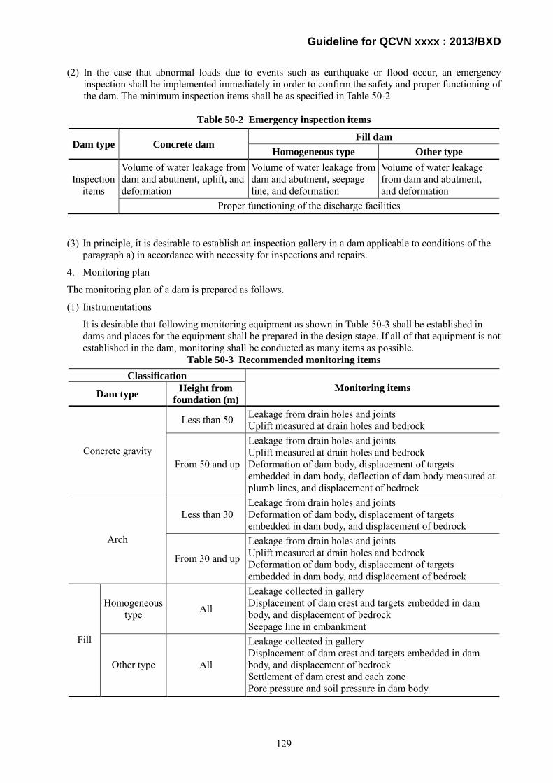
Guideline for QCVN xxxx : 2013/BXD
(2) In the case that abnormal loads due to events such as earthquake or flood occur, an emergency inspection shall be implemented immediately in order to confirm the safety and proper functioning of the dam. The minimum inspection items shall be as specified in Table 50-2
Table 50-2 Emergency inspection items
Dam type Concrete dam Fill dam
Homogeneous type Other type
Inspection items
Volume of water leakage from dam and abutment, uplift, and deformation
Volume of water leakage from dam and abutment, seepage line, and deformation
Volume of water leakage from dam and abutment, and deformation
Proper functioning of the discharge facilities
(3) In principle, it is desirable to establish an inspection gallery in a dam applicable to conditions of the paragraph a) in accordance with necessity for inspections and repairs.
4. Monitoring plan
The monitoring plan of a dam is prepared as follows.
(1) Instrumentations
It is desirable that following monitoring equipment as shown in Table 50-3 shall be established in dams and places for the equipment shall be prepared in the design stage. If all of that equipment is not established in the dam, monitoring shall be conducted as many items as possible.
Table 50-3 Recommended monitoring items Classification
Monitoring items Dam type Height from foundation (m)
Concrete gravity
Less than 50 Leakage from drain holes and joints Uplift measured at drain holes and bedrock
From 50 and up
Leakage from drain holes and joints Uplift measured at drain holes and bedrock Deformation of dam body, displacement of targets embedded in dam body, deflection of dam body measured at plumb lines, and displacement of bedrock
Arch
Less than 30 Leakage from drain holes and joints Deformation of dam body, displacement of targets embedded in dam body, and displacement of bedrock
From 30 and up
Leakage from drain holes and joints Uplift measured at drain holes and bedrock Deformation of dam body, displacement of targets embedded in dam body, and displacement of bedrock
Fill
Homogeneous type All
Leakage collected in gallery Displacement of dam crest and targets embedded in dam body, and displacement of bedrock Seepage line in embankment
Other type All
Leakage collected in gallery Displacement of dam crest and targets embedded in dam body, and displacement of bedrock Settlement of dam crest and each zone Pore pressure and soil pressure in dam body
129

Guideline for QCVN xxxx : 2013/BXD
(2) Monitoring plan by height of dams
Based on the stipulations of Article 2 and Article 12 of Decree No. 72/2007/ND-CP, monitoring plan shall be prepared for each dam so as to satisfy the following requirements.
For dams with height equal or higher than 15 m, calculated from the dam foundation surface to the dam crest or the dam of the reservoir with capacity equal or bigger than 3,000,000 m3, a monitoring plan shall be prepared as follows.
1) After taking over the works of management, the dam Owner shall organize measurement and monitoring or contracting with professional agencies to carry out measurement, gathering meteorological-hydrological data of the catchments of reservoir, progress of seepage through dam body, dam bed, dam abutment, dam displacement, dam cracks, slides in dam foot, foundation and surrounding areas, the sedimentation in the reservoir.
2) The measurement documents shall be adjusted, analyzed, evaluated, compared with the design and forecast data; finding the sudden phenomenon in order to make decision on remedial measures in time; implementation of documentation preservation in accordance to the regulation.
3) For dams with height less than 15 m, calculated from the foundation surface to the dam crest or the dam of the reservoir with capacity less than 3000000 m3, the measurement of water levels and other measurements as specified by the design consulting company shall be conducted.
(3) Monitoring plan for emergency inspection
In the case that abnormal loads due to events such as earthquake or flood occur, an emergency inspection shall be implemented immediately in order to confirm the safety and proper functioning of the dam. The minimum inspection items shall be as specified in Table 50-4.
Table 50-4 Emergency inspection items
Dam type Concrete dam Fill dam
Homogeneous type Other type
Inspection items
Volume of water leakage from dam and abutment, uplift, and deformation
Volume of water leakage from dam and abutment, seepage line, and deformation
Volume of water leakage from dam and abutment, and deformation
Proper functioning of the discharge facilities
7.16.6. Technical Regulation Article 7.16.6 describes monitoring items of a powerhouse.
a) Displacement of a powerhouse building shall be observed to monitor stability of a powerhouse. Displacement of turbines, generators and main components of hydropower plant shall be observed to monitor safety of powerhouse equipment.
b) Amount of seepage water inside and outside of a powerhouse shall be observed to monitor safety of a powerhouse building.
7.16.7. Technical Regulation Article 7.16.7 describes special monitoring items besides basic items stipulated in Technical Regulation Article 7.16.1.
a) Stress conditions
Stress condition of structure and its foundation shall be observed in order to detect changes in stress state of structure and foundation. Stress condition of important structures such as dam and its foundation, and pore pressure of a dam body and its foundation shall be observed.
b) Soil pressure
Soil pressure of an earthfill and rockfill dam on firm foundation shall be observed to monitor safety of an impervious core.
130
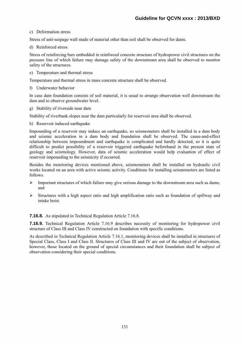
Guideline for QCVN xxxx : 2013/BXD
c) Deformation stress
Stress of anti-seepage wall made of material other than soil shall be observed for dams.
d) Reinforced stress
Stress of reinforcing bars embedded in reinforced concrete structure of hydropower civil structures on the pressure line of which failure may damage safety of the downstream area shall be observed to monitor safety of the structures.
e) Temperature and thermal stress
Temperature and thermal stress in mass concrete structure shall be observed.
f) Underwater behavior
In case dam foundation consists of soil material, it is usual to arrange observation well downstream the dam and to observe groundwater level.
g) Stability of riverside near dam
Stability of riverbank slopes near the dam particularly for reservoir area shall be observed.
h) Reservoir induced earthquake
Impounding of a reservoir may induce an earthquake, so seismometers shall be installed in a dam body and seismic acceleration in a dam body and foundation shall be observed. The cause-and-effect relationship between impoundment and earthquake is complicated and hardly detected, so it is quite difficult to predict possibility of a reservoir triggered earthquake beforehand in the present state of geology and seismology. However, data of seismic acceleration would help evaluation of effect of reservoir impounding to the seismicity if occurred.
Besides the monitoring devices mentioned above, seismometers shall be installed on hydraulic civil works located on an area with active seismic activity. Conditions for installing seismometers are listed as follows.
Important structures of which failure may give serious damage to the downstream area such as dams; and
Structures with a high aspect ratio and high amplification ratio such as foundation of spillway and intake hoist.
7.16.8. As stipulated in Technical Regulation Article 7.16.8.
7.16.9. Technical Regulation Article 7.16.9 describes necessity of monitoring for hydropower civil structure of Class III and Class IV constructed on foundation with specific conditions.
As described in Technical Regulation Article 7.16.1, monitoring devices shall be installed in structures of Special Class, Class I and Class II. Structures of Class III and IV are out of the subject of observation, however, those located on the ground of special circumstances and their foundation shall be subject of observation considering their special conditions.
131

Guideline for QCVN xxxx : 2013/BXD
8. Hydromechanical equipments
8.1 General requirements
8.1.1.
- Hydromechanical equipment is applied to mainly hydraulic gates and steel penstocks. - The following matters are required for designing hydromechanical equipment;
i) The equipment must be safe against anticipated loads. ii) The equipment must be economical. iii) The equipment must be easy for maintenance. iv) The equipment must affect minimum to the environment.
8.1.2. As the specific procedure regarding determination of loads acting on the equipment depends on stipulations in each design standard, the clarifications of major loads are as follows:
1. Valve and gate
(1) Hydrostatic pressure
- Hydrostatic pressure is a pressure which acts by static fluid. In case of designing valve and gate at a hydropower plant, the hydrostatic pressure is of subtracted by the pressure under the minimum water level of downstream side from the pressure under the maximum water level. The brief illustration of hydrostatic pressure is shown in Fig.8.1.
Fig.8.1 Hydrostatic pressure (2) Hydrodynamic pressure
- Hydrodynamic pressure acts to the valve and gate as the pressure created by the water flow in a reservoir during discharging from the gate.
(3) Own weight, inertia force
- Own weight acts to the valve and gate, and inertia force of the gate leaf acts when gate stops.
(4) Seepage pressure of water
- Seepage pressure acts from bedrock to outside of the gate guide which has box-shape structure such as bonnet type gate guide, because the gate guide blocks the water passing between outside and inside of the gate guide.
(5) Buoyancy
- When a valve or a gate locates under water, buoyancy acts to submerged part of the structure.
Water level
Hydrostatic pressure
Water level
Hydrostatic pressure
132
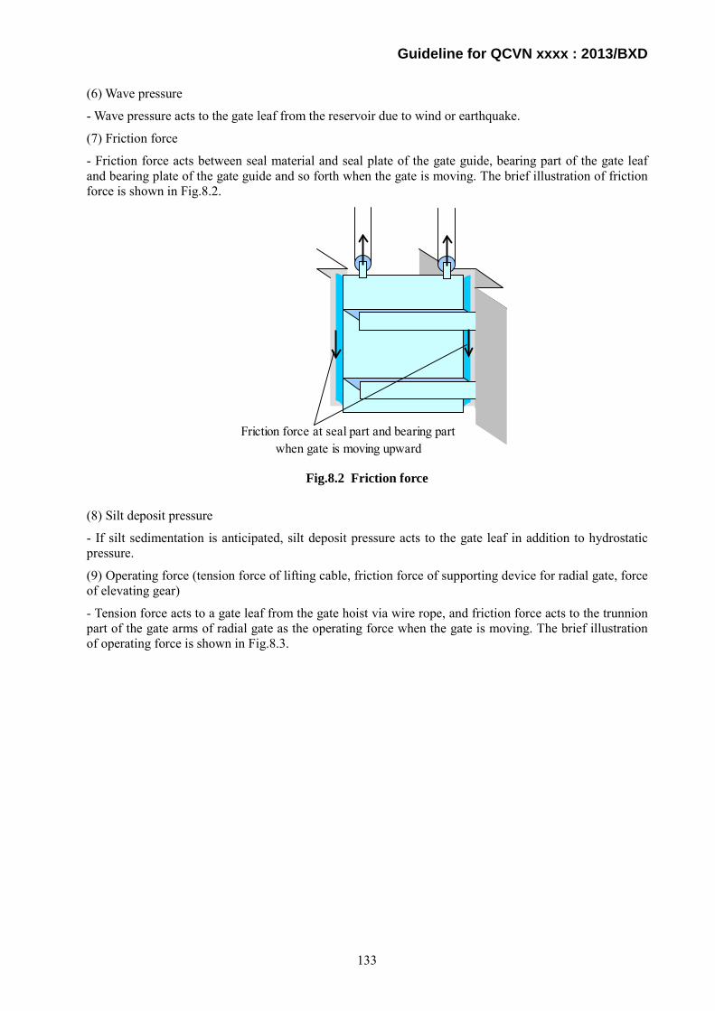
Guideline for QCVN xxxx : 2013/BXD
(6) Wave pressure
- Wave pressure acts to the gate leaf from the reservoir due to wind or earthquake.
(7) Friction force
- Friction force acts between seal material and seal plate of the gate guide, bearing part of the gate leaf and bearing plate of the gate guide and so forth when the gate is moving. The brief illustration of friction force is shown in Fig.8.2.
Fig.8.2 Friction force
(8) Silt deposit pressure
- If silt sedimentation is anticipated, silt deposit pressure acts to the gate leaf in addition to hydrostatic pressure.
(9) Operating force (tension force of lifting cable, friction force of supporting device for radial gate, force of elevating gear)
- Tension force acts to a gate leaf from the gate hoist via wire rope, and friction force acts to the trunnion part of the gate arms of radial gate as the operating force when the gate is moving. The brief illustration of operating force is shown in Fig.8.3.
Friction force at seal part and bearing partwhen gate is moving upward
133
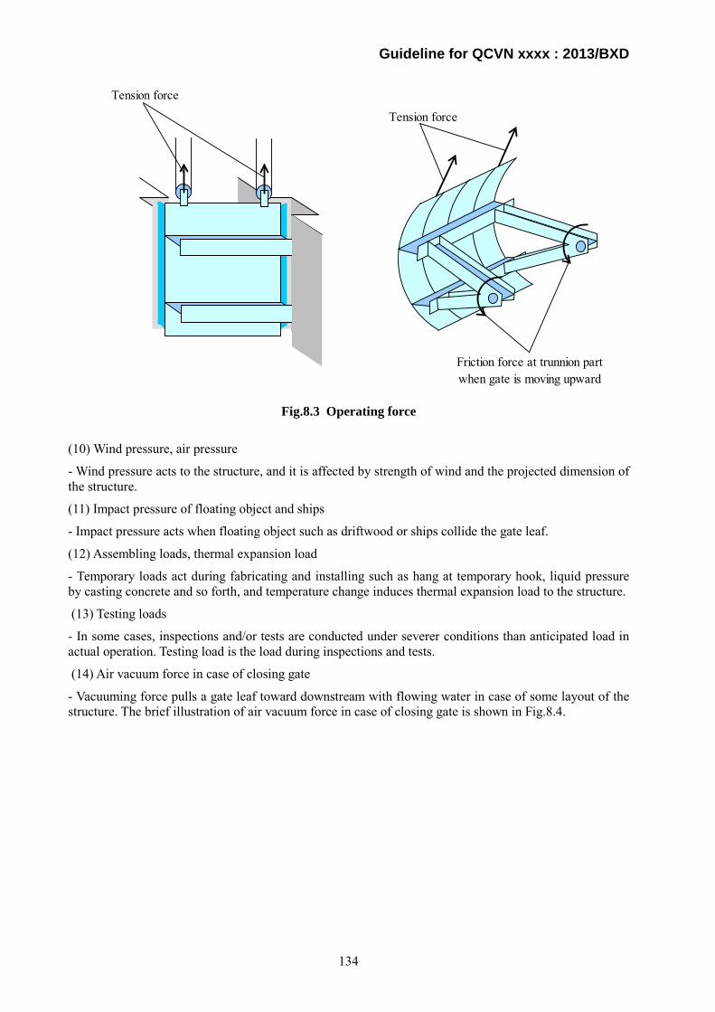
Guideline for QCVN xxxx : 2013/BXD
Fig.8.3 Operating force
(10) Wind pressure, air pressure
- Wind pressure acts to the structure, and it is affected by strength of wind and the projected dimension of the structure.
(11) Impact pressure of floating object and ships
- Impact pressure acts when floating object such as driftwood or ships collide the gate leaf.
(12) Assembling loads, thermal expansion load
- Temporary loads act during fabricating and installing such as hang at temporary hook, liquid pressure by casting concrete and so forth, and temperature change induces thermal expansion load to the structure.
(13) Testing loads
- In some cases, inspections and/or tests are conducted under severer conditions than anticipated load in actual operation. Testing load is the load during inspections and tests.
(14) Air vacuum force in case of closing gate
- Vacuuming force pulls a gate leaf toward downstream with flowing water in case of some layout of the structure. The brief illustration of air vacuum force in case of closing gate is shown in Fig.8.4.
Tension force
Friction force at trunnion partwhen gate is moving upward
Tension force
134
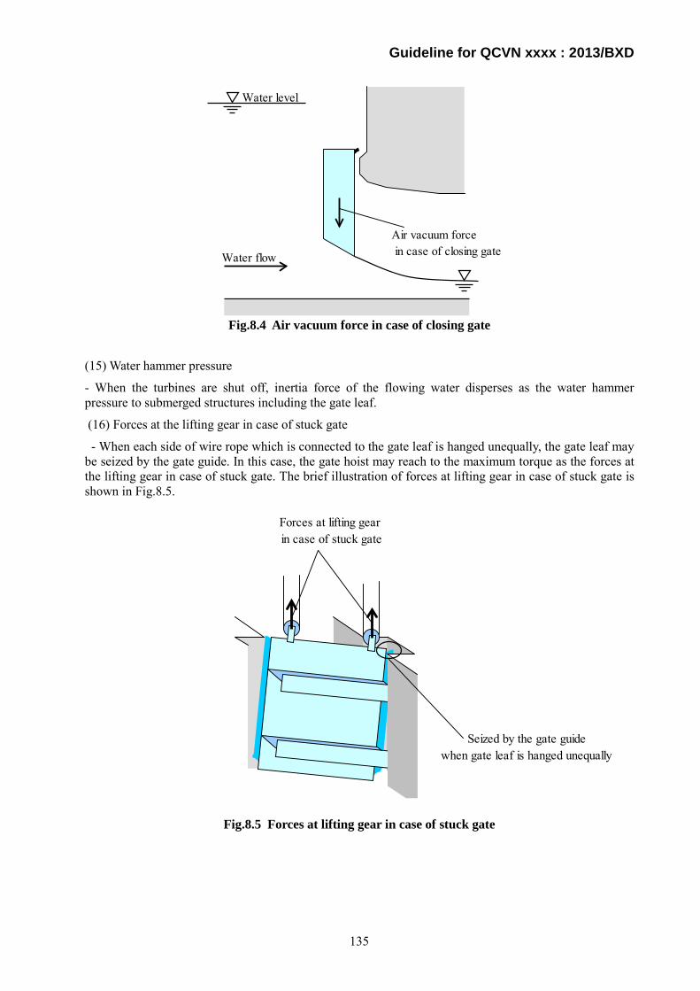
Guideline for QCVN xxxx : 2013/BXD
Fig.8.4 Air vacuum force in case of closing gate
(15) Water hammer pressure
- When the turbines are shut off, inertia force of the flowing water disperses as the water hammer pressure to submerged structures including the gate leaf.
(16) Forces at the lifting gear in case of stuck gate
- When each side of wire rope which is connected to the gate leaf is hanged unequally, the gate leaf may be seized by the gate guide. In this case, the gate hoist may reach to the maximum torque as the forces at the lifting gear in case of stuck gate. The brief illustration of forces at lifting gear in case of stuck gate is shown in Fig.8.5.
Fig.8.5 Forces at lifting gear in case of stuck gate
Seized by the gate guidewhen gate leaf is hanged unequally
Forces at lifting gear in case of stuck gate
Water level
Air vacuum force in case of closing gateWater flow
135
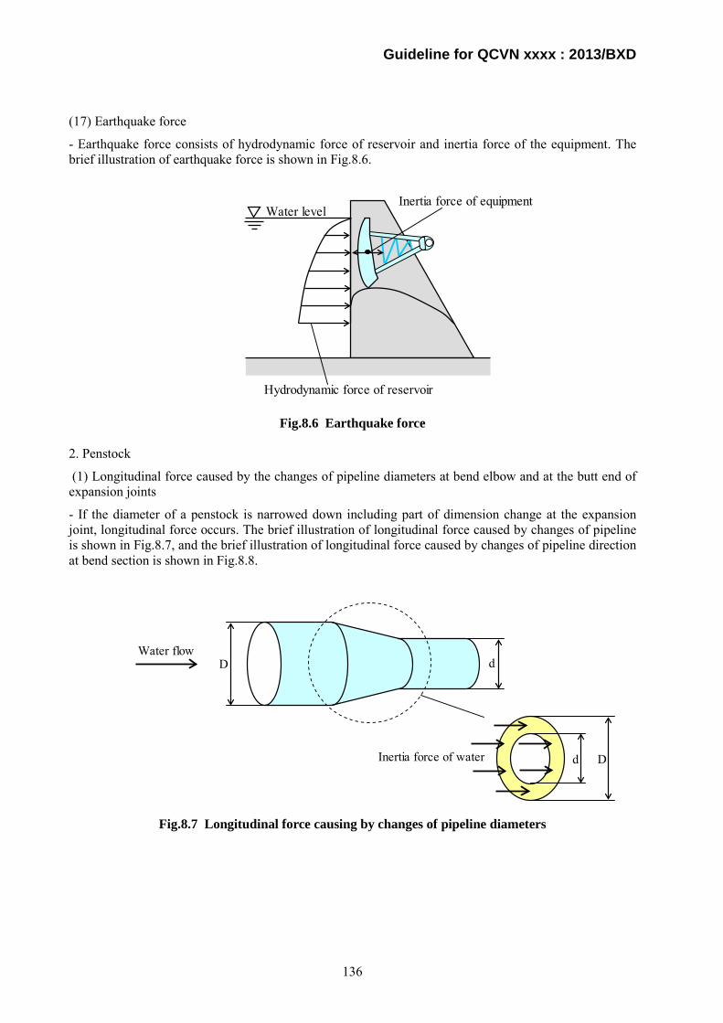
Guideline for QCVN xxxx : 2013/BXD
(17) Earthquake force
- Earthquake force consists of hydrodynamic force of reservoir and inertia force of the equipment. The brief illustration of earthquake force is shown in Fig.8.6.
Fig.8.6 Earthquake force
2. Penstock
(1) Longitudinal force caused by the changes of pipeline diameters at bend elbow and at the butt end of expansion joints
- If the diameter of a penstock is narrowed down including part of dimension change at the expansion joint, longitudinal force occurs. The brief illustration of longitudinal force caused by changes of pipeline is shown in Fig.8.7, and the brief illustration of longitudinal force caused by changes of pipeline direction at bend section is shown in Fig.8.8.
Fig.8.7 Longitudinal force causing by changes of pipeline diameters
Inertia force of equipment
Hydrodynamic force of reservoir
Water level
DWater flow
d
Inertia force of water d D
136

Guideline for QCVN xxxx : 2013/BXD
Fig.8.8 Longitudinal force causing by changes of pipeline direction at bend section
(2) Water pressure acting on the pipe shell, including water hammer
- Water pressure acting on the pipe shell consists of hydrostatic pressure, pressure rise due to water hammering and water rising due to surging. The maximum value is hydrostatic pressure plus water hammering at the lower part of the penstock. However, hydrostatic pressure plus surging is severer at the upper part of the penstock generally. The brief illustration of water pressure acting on pipe shell is shown in Fig.8.9.
Fig.8.9 Water pressure acting on pipe shell
Water flow Inertia force of water
Hydrostatic pressure
Water rising due to surging
Water hammering
137

Guideline for QCVN xxxx : 2013/BXD
(3) Water pressure acting on the guard valve in the pipe
- Water pressure acting on the guard valve consists of hydrostatic pressure, pressure rise due to water hammering and water rising due to surging. The maximum value is hydrostatic pressure plus water hammering, if the guard valve locates at the lower part of the penstock. However, hydrostatic pressure plus surging is severer at the upper part of the penstock generally.
(4) Own weight of pipe shell and water, which is fully stored in a pipe
- Own weight of pipe shell and water inside the pipe shell act to the exposed pipe of a penstock. The maximum forces occur when the pipe shell is filled with water. The brief illustration of own weight of pipe shell and water is shown in Fig.8.10.
Fig.8.10 Own weight of pipe shell and water
(5) Friction force between steel pipe and intermediate abutments, between water and pipe shell, friction force inside expansion joints
- When penstock is moving along longitudinal direction by temperature change, longitudinal friction force acts at the sliding part such as intermediate abutments and between packing and pipe shell of the expansion joint.
(6) Centrifugal force caused by the movement of water through bend elbow
- At bend section of a penstock, centrifugal force acts by inertial action of flowing water.
(7) Deformation force caused by the influences of environmental temperature and internal water pressure to the un-sectional pipe
- In case that there are not any adjustment devices such as expansion joint, the forces caused by temperature change or water pressure to the un-sectional pipe and so on act to the pipe shell directly.
(8) Rock pressure on anchors and intermediate abutments
- The underground part of anchor block and intermediate abutments may be acted by pressures due to displacements of surrounding rocks, especially when the penstock is located at inclined part. The penstock may be acted by rock pressure due to the movement of the anchor blocks and intermediate abutments. The brief illustration of rock pressure on intermediate abutments is shown in Fig.8.11
Own weight of pipe shell and water
138
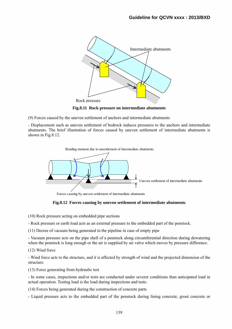
Guideline for QCVN xxxx : 2013/BXD
Fig.8.11 Rock pressure on intermediate abutments (9) Forces caused by the uneven settlement of anchors and intermediate abutments
- Displacement such as uneven settlement of bedrock induces pressures to the anchors and intermediate abutments. The brief illustration of forces caused by uneven settlement of intermediate abutments is shown in Fig.8.12.
Fig.8.12 Forces causing by uneven settlement of intermediate abutments
(10) Rock pressure acting on embedded pipe sections
- Rock pressure or earth load acts as an external pressure to the embedded part of the penstock.
(11) Decree of vacuum being generated in the pipeline in case of empty pipe
- Vacuum pressure acts on the pipe shell of a penstock along circumferential direction during dewatering when the penstock is long enough or the air is supplied by air valve which moves by pressure difference.
(12) Wind force
- Wind force acts to the structure, and it is affected by strength of wind and the projected dimension of the structure.
(13) Force generating from hydraulic test
- In some cases, inspections and/or tests are conducted under severer conditions than anticipated load in actual operation. Testing load is the load during inspections and tests.
(14) Forces being generated during the construction of concrete parts
- Liquid pressure acts to the embedded part of the penstock during lining concrete, grout concrete or
Forces causing by uneven settlement of intermediate abutments
Bending moment due to unsettlement of intermediate abutments
Uneven settlement of intermediate abutments
Rock pressure
Intermediate abutments
139

Guideline for QCVN xxxx : 2013/BXD
anchor concrete is consolidating.
(15) Forces causing by earthquake and other geologic factors
- Inertia force which is induced by earthquake acts to the anchors of a penstock.
In many technical standards regarding designing hydromechanical equipment, correcting bearing force such as correcting allowable stress according to sort of load is stipulated. If the load act temporarily during earthquake, installation and so on, or the load acts to limited part of structures for example part of pipe shell of penstocks which is seized rigidly by reinforcement members, the considerable load combination and/or the bearing force such as allowable stress is corrected. Thus, utmost attention must be paid to the sort of load to be classified properly at design.
3. Load combination
The following classifications shown in Tables 8.1 and 8.2 are only examples. Specific procedure for selecting loads must obey the technical standard which is used at the design project by project.
Table 8.1 Classification of forces on gates
Class Vietnamese standard (TCVN 8299)
Japanese standard (Technical standards
for gates and penstocks)
Main loads (which act permanently on valve and gate)
- Hydrostatic pressure - Hydrodynamic pressure - Own weight, inertial force - Seepage pressure of water - Buoyancy - Wave pressure - Frictional force - Sludge pressure - Wind pressure, air pressure - Force of lifting mechanism - Water hammer pressure
- Hydrostatic pressure - Own weight, inertial force - Buoyancy - Wave pressure - Frictional force - Sludge pressure - Wind pressure, air pressure - Force of lifting mechanism
Special loads (which act temporally or locally on valve and gate)
- Impact pressure of floating object or ship
- Earthquake force - Construction load, thermal
dilatation force - Trial load - Force of lifting mechanism in gate
stuck situation - Vacuum force when closing gate
- Earthquake force - Construction load - Trial load - Force of lifting mechanism in gate
stuck situation - Vacuum force when closing gate
140

Guideline for QCVN xxxx : 2013/BXD
Table 8.2 Classification of forces on penstocks
Class Vietnamese standard (TCVN 8636)
Japanese standard (Technical standards
for gates and penstocks)
Major loads (which act permanently on penstock)
- Water pressure acting on the pipe wall, including water hammer,
- Water pressure acting on the guard valve in the pipe,
- Longitudinal force causing by the changes of pipeline diameters at bend elbow and at the butt end of expansion joints,
- Own weight of the pipe shell and water which is fully stored in the pipe,
- Friction force between pipe shell and intermediate abutments, between water and pipe shell, friction force inside expansion joints,
- Centrifugal force causing by the movement of water through bend elbow,
- Deformation force causing by the influences of environmental temperature and internal water pressure to the un-sectional pipe,
- Rock pressure on anchors and intermediate abutments,
- Forces causing by the uneven settlement of anchors and intermediate abutments, and
- Rock pressure acting on embedded pipe sections.
- Water pressure acting on the pipe wall, including water hammer,
- Own weight of the pipe shell and water which is fully stored in the pipe,
- Friction force between pipe shell and intermediate abutments, between water and pipe shell, friction force inside expansion joints,
- Decree of vacuum being generated in the pipeline in case of empty pipe,
- Snow force. - Wind force, - Forces causing by earthquake and
other geologic factors.
Supplementary loads (which act temporally or locally on penstock)
- Decree of vacuum being generated in the pipeline in case of empty pipe,
- Wind force, - Force generating from hydraulic
test, and - Forces being generated during the
constructing concrete parts.
- Local stress at pressure lining part seized by ring girder, stiffeners and anchor blocks.
- Local stress caused by thickness change, and
- Bend stress at bending part.
Special loads (which act temporally or locally on penstock)
- Forces causing by earthquake and other geologic factors.
- Excessive local stress concentration at holes of a pressure lining part.
8.1.3. Result of calculation at design and behavior of actual equipment must be corresponded. Thus behavior of the equipment must be confirmed by visual inspections and/or measurements. Confirmation methods are measuring deflections of members, measuring stresses of members, conducting visual inspection to check deformations and so forth.
141

Guideline for QCVN xxxx : 2013/BXD
8.2 Valve gates
8.2.1. Basic functions and requirements of gates are stipulated in the Technical Regulations, and detailed issues related to the basic requirements for valves and gates are as follows:
a) Basic requirements on gate:
(1) Safety against predictable load
- Structures of gate must be designed so as to minimize secondary stress generated by the effect such as eccentricity of each member, rigidity of the panel point, sharp change of the cross section, and deflection of the member by its own weight.
(2) Sufficient water-tightness
- In order to keep hydraulic gates watertight, various types of elastic material are used. Soft rubber is generally used for low hydraulic pressure and hard rubber is for high pressure. Under high pressure condition, the rubber is fixed by seal plates. Metal is often used as a seal material also.
(3) Easy and reliable operation
- The load during gate operation consists of its own weight, friction force, uplift force, down-pull force and so on. The hoisting devices of gates must have sufficient capacity against the loads for reliable operation.
(4) High durability
- Sufficient investigations of water quality at site are needed because the service-life of hydraulic gate is long. Corrosion of the material for gate leaf, gate guide, anchorage and hoisting device must be considered properly at design.
(5) Easy maintenance
- Serious accident is anticipated when gate components are deteriorated. So the gate must be designed intending to easy operation and maintenance, and in case of trouble, the gate must stop operation automatically when the emergency signal is activated.
b) Component of gate:
The major components of hydraulic gate are listed as follows:
- Gate leaf,
- Gate guide,
- Anchorage and,
- Gate hoist,
c) Selection of gate type:
Type, shape, size and number of hydraulic gate must be determined in accordance with the location, the purpose and the condition of use.
i) Spillway gate
- Spillway gate are usually installed in the overflow portion of dam or in the submerged portion. Therefore, their inspection and repair are restricted. This matter must be considered in gate design. In general, wheel gate or radial gate is selected.
ii) Conduit gate (orifice gate) and valve
- These gates are installed inside dam or downstream of dam, and discharge water under high water pressure. Therefore, rigid structure and unfailing operation are necessary. Many of operating systems are hydraulic type.
142

Guideline for QCVN xxxx : 2013/BXD
iii) Gate for intake and head tank
- Gate for intake and head tank is used when the headrace, the head tank, or the steel penstock is inspected or repaired. Generally, fixed wheel gate or slide gate is used. However, high pressure gate, caterpillar gate, or high pressure radial gate is used when the water head is high.
iv) Valve for steel penstock
- In order to regulate the water flow at both ends of steel penstock, following types of valve are generally used:
- Butterfly valve
- Sluice valve
- Rotary valve
v) Draft gate and Tailrace gate
- Gate installed at tailrace tunnel or tailrace end is used when the turbine and the draft tube are inspected or repaired, and for the purpose of preventing backward flood, following types are generally used:
- Slide gate
- Fixed wheel gate
vi) Sediment flush gate
- This gate is in full-time use and this is installed to flush sediment at dam, silt basin, headrace, or head tank. The structure must be rigid and reliable. Following types of gate are generally used:
- Slide gate
- Fixed wheel gate
- Radial gate
- Conduit gate when the water head is high.
vii) Gate for repair/ maintenance
- Hydraulic gate used for the purpose of inspecting and repairing the spillway gate must have simple structure with easy transportation. Therefore slide gate or fixed wheel gate is used generally.
d) Key technical issues in the design of gate and gate hoist:
(1) Material
- Material of gate must have enough property and accuracy of shape. Mechanical properties (such as strength, elongation and toughness), chemical components, limitations of harmful ingredients and shape (such as thickness and dimension error) must be guaranteed.
- Material tests must be implemented to ensure necessary characteristics which are specified by Vietnamese or internationally accepted standards. If the material properties are clarified by the material manufacturer, the contractor may substitute the results of their own tests.
- If the material is not covered by Vietnamese or internationally accepted standards, the properties of material must be inspected and tested based on general rules, and the required results must be confirmed.
- When the material is thick or have some special properties, additional tests or inspections must be implemented in order to avoid problems caused by lack of the workability, the weldability and so on.
(2) Minimum thickness
- Hydraulic gate is exposed at condition where the gate is become worn by flowing water and sand, and it is necessary to keep sufficient stiffness during transporting and installing. For these reasons, minimum thickness of gate material must be considered.
143
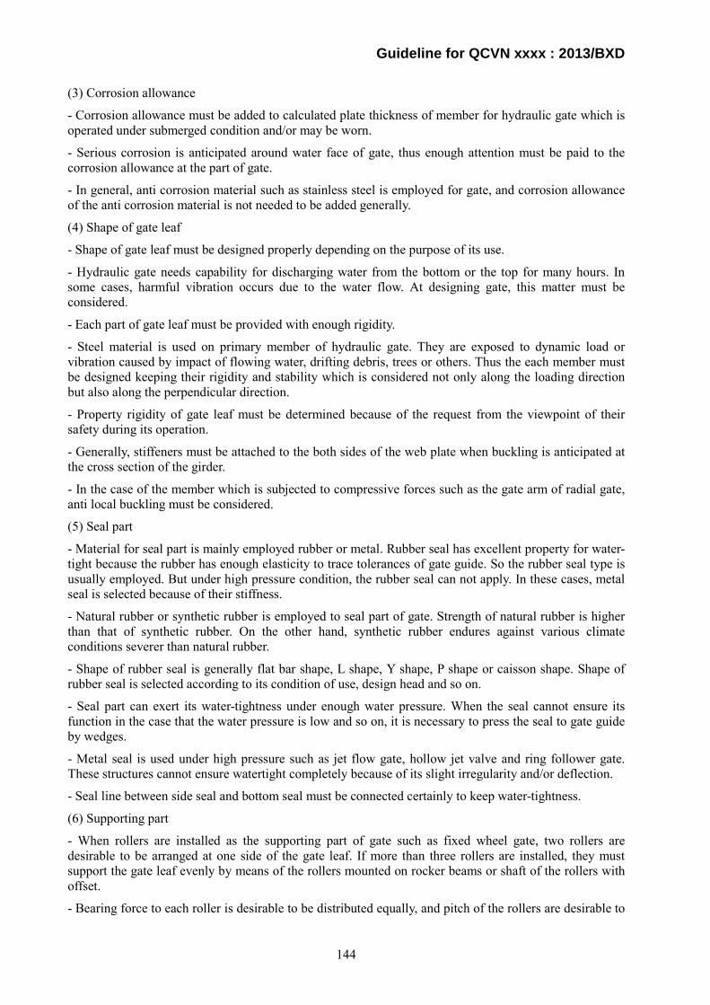
Guideline for QCVN xxxx : 2013/BXD
(3) Corrosion allowance
- Corrosion allowance must be added to calculated plate thickness of member for hydraulic gate which is operated under submerged condition and/or may be worn.
- Serious corrosion is anticipated around water face of gate, thus enough attention must be paid to the corrosion allowance at the part of gate.
- In general, anti corrosion material such as stainless steel is employed for gate, and corrosion allowance of the anti corrosion material is not needed to be added generally.
(4) Shape of gate leaf
- Shape of gate leaf must be designed properly depending on the purpose of its use.
- Hydraulic gate needs capability for discharging water from the bottom or the top for many hours. In some cases, harmful vibration occurs due to the water flow. At designing gate, this matter must be considered.
- Each part of gate leaf must be provided with enough rigidity.
- Steel material is used on primary member of hydraulic gate. They are exposed to dynamic load or vibration caused by impact of flowing water, drifting debris, trees or others. Thus the each member must be designed keeping their rigidity and stability which is considered not only along the loading direction but also along the perpendicular direction.
- Property rigidity of gate leaf must be determined because of the request from the viewpoint of their safety during its operation.
- Generally, stiffeners must be attached to the both sides of the web plate when buckling is anticipated at the cross section of the girder.
- In the case of the member which is subjected to compressive forces such as the gate arm of radial gate, anti local buckling must be considered.
(5) Seal part
- Material for seal part is mainly employed rubber or metal. Rubber seal has excellent property for water-tight because the rubber has enough elasticity to trace tolerances of gate guide. So the rubber seal type is usually employed. But under high pressure condition, the rubber seal can not apply. In these cases, metal seal is selected because of their stiffness.
- Natural rubber or synthetic rubber is employed to seal part of gate. Strength of natural rubber is higher than that of synthetic rubber. On the other hand, synthetic rubber endures against various climate conditions severer than natural rubber.
- Shape of rubber seal is generally flat bar shape, L shape, Y shape, P shape or caisson shape. Shape of rubber seal is selected according to its condition of use, design head and so on.
- Seal part can exert its water-tightness under enough water pressure. When the seal cannot ensure its function in the case that the water pressure is low and so on, it is necessary to press the seal to gate guide by wedges.
- Metal seal is used under high pressure such as jet flow gate, hollow jet valve and ring follower gate. These structures cannot ensure watertight completely because of its slight irregularity and/or deflection.
- Seal line between side seal and bottom seal must be connected certainly to keep water-tightness.
(6) Supporting part
- When rollers are installed as the supporting part of gate such as fixed wheel gate, two rollers are desirable to be arranged at one side of the gate leaf. If more than three rollers are installed, they must support the gate leaf evenly by means of the rollers mounted on rocker beams or shaft of the rollers with offset.
- Bearing force to each roller is desirable to be distributed equally, and pitch of the rollers are desirable to
144
Guideline for QCVN xxxx : 2013/BXD
be arranged as long distance as possible in order to conduct maintenance work easily.
- In general, maintenance work of gate guide is more difficult than the work of supporting parts on gate leaf, so the hardness of the contact surface of supporting part to gate guide must be lower than the hardness of the gate guide.
- In general, plain bearing is chosen for bush of roller shaft. But rolling bearing is chosen if the gate is operated under extra-high pressure or the gate cannot descend by own weight.
- Material of bearing part is often selected to be alloy, the material tend to cause bimetallic corrosion. Sufficient attention must be paid to the combination of materials at bearing part to avoid bimetallic corrosion.
(7) Bearing part
- Bearing structure of gate leaf has larger area than supporting structure to bear force. Transforming force from gate leaf via gate guide to concrete structure directly is more preferable, but the friction force at operating is much larger and more unfavorable than supporting structures such as rollers. Thus the bearing structure is selected when the gate is operated under pressure balancing between upstream and downstream of the gate leaf.
- The hardness of the contact surface at the bearing part of gate is lower than that of the contact surface at gate guide to protect the gate guide generally. For example, the material of the bearing part is cupper alloy and the material of gate guide is stainless steel.
- Material of the bearing part is often selected to be an alloy, the material tends to cause bimetallic corrosion. Sufficient attention must be paid to the combination of materials at the bearing part to avoid bimetallic corrosion.
(8) Gate guide
- The contact face of gate guide is acted by concentrated force from the gate leaf. If strength and stiffness of the gate guide is not sufficient, unfavorable phenomenon may occur such as operational force rising due to local deformation at the contact face, and cracks appear at the weir column concrete.
- Water seal part of the gate guide must have sufficient flatness in order to avoid tearing the seal rubber and occurring harmful vibration and so on.
- Lateral gate guide consists of heavy duty part and light duty part. The heavy duty part supports the loads from the gate leaf and transfers the loads to the concrete structure. On the other hand, the light duty part guides the gate leaf when the gate is operated. The light duty part may have removal portions to maintain the lateral part and the contact part of the gate leaf such as main rollers.
- If sediment in the reservoir is anticipated to flow into the gate slot during service term of the gate, shape of the gate slot may be considered to avoid sediment flowing by the method of mounting covers upside the slot and so on.
(9) Anchorage
- In general, types of anchorage are divided into three types; bearing by tension beam, pre-stressed concrete anchor and pre-stressed concrete reinforcing pier.
(10) Bearing part
- If bearing part of gate guide does not have enough strength and stiffness, friction force increases because of local deformation at the truck plate of the gate guide and/or cracks occurs at the pier concrete structure.
- In general, the part of gate guide that is under submerged condition and difficult to maintain the truck plate, corrosion-resistant material such as stainless steel must be selected for the portion.
- Maintenance work on gate guide is more difficult than the work on supporting part or bearing part of gate leaf, so hardness of the contact surface for the gate guide must be higher than hardness of the gate leaf.
145
Guideline for QCVN xxxx : 2013/BXD
- Material of bearing part is often selected to be alloy, the material tend to cause bimetallic corrosion. Sufficient attention must be paid to the combination of materials at the bearing part to avoid bimetallic corrosion.
(11) Selection of type on hoisting device
- In selecting of type on hoisting device, careful consideration must be given to type, size, purpose and frequency of use, and the place for installation of the hydraulic gate.
i) Wire rope winding type
- This type can be widely used for medium-size and large-size gate.
ii) Screw spindle type and rack gear type
- These types are suitable for small-size gate. It is better not to use this type for the hydraulic gate which has large lifting height and large size because of the space limitations.
iii) Hydraulic cylinder type
- This type is widely used for high pressure gate. It is advantageous when the opening position of the gate leaf must be strictly adjusted or when the hoisting device must be installed in a narrow space, but extra cost is required for the replacement of oil and maintenance. It must be noted that, in some cases, the reaction of operating force may not be sustained at the support of the hydraulic cylinder.
iv) Hydraulic motor wire rope type
- When multiple hydraulic gates are installed, it can be operated by one hydraulic pump. This type is convenient for changing the operating speeds linearly.
(12) Power equipment for gate operating
i) General
- Power equipment must have enough capacity of gate operation at any time without fail. For small size gate, however, manual equipment may be installed.
- The operating speed of the hydraulic gate must obey the purpose of its use.
- The operating speed of the hydraulic gate is selected taking account of upstream and downstream effects caused by discharging of water. And the operating speed is slowed by automatic control or for some other purposes.
- The lifting height of hydraulic gate must be determined so as to be safe against flowing water after the gate is lifted.
- For spillway gate, the clearance between the bottom of gate when it is lifted up and the water surface must be determined by considering shape and size of drifting debris during flood.
- In order to ensure rapid operation, the power equipment for hydraulic gate must have enough capacity to this purpose. Generally a motor is used, but internal combustion engine may be used for small dam such as intake dike. When the combustion engine is selected, the type and the capacity of the power equipment must be determined by taking into account maintainability, frequency of flood occurrence and rising speed of water level.
- For the hydraulic gate which is operated by means of buoyancy or counter weight, it is necessary to take some measures against vibration of the gate leaf caused by water flow.
- If the hydraulic gate is jammed during operation, the maximum torque of the prime mover (the motor or the internal combustion engine) may act on the gate hoist. The maximum torque may be specified as high as twice of the rated torque so that the hoist will not be broken down.
- The maximum operating force is generally required at starting time when the gate is closed. However, the maximum force for the submerging gate or the high pressure gate is required at time of partial discharge.
146
Guideline for QCVN xxxx : 2013/BXD
- Electric motor must exert its function enough time, it designed longer than the time for design height operation or required time for one operation.
- In case of frequent and short-distance operating by means of automatic control, the electric motor must be trouble-free even if repeated operation is conducted for many hours.
- Mechanical efficiencies and coefficients of friction will vary with lubricating condition, ambient temperatures and operating hours. Thus proper determination on use conditions is required.
ii) Brake
- Brake equipment must be provided for the gate hoist.
- Brake equipment is required for stopping and keeping the gate leaf in required position.
- When using manual device or internal combustion engine as reserve power for the gate hoist, braking or locking mechanism must be provided to prevent the gate leaf from lowering due to its own weight when the power source is switched to reserve power.
iii) Emergency lowering device
- Emergency lowering device must be provided for the hydraulic gate which requires emergency closure.
- For the gate hoist installed at intake, discharge pipe and head tank must be equipped with the emergency lowering device capable of stopping flowing water when emergency closure without power is required. Such requirement would apply to accidents in the headrace, the steel penstock or the turbine generator.
- When such device is used, the gate leaf is often lowered by its own weight by separating it from the power equipment with the clutch. Hand brake, electrically-driven brake, centrifugal brake, fan brake, oil hydraulic pump brake, power-generated brake and so on is used to control speed. Structural parts of the brake must have enough capacity to withstand high pressure and high revolution.
iv) Wire rope
- Wire rope must be suitable for purpose of use, taking into account tension, frequency and condition of use as well as the effect to environment.
- When wire rope is spooled onto drum or sheave, bending force acts. If small diameter drum or sheave is installed, the wire rope fatigues easily because of increasing bending force.
- It must be noted that wire rope under submerged condition may be vibrated due to discharge water with debris.
- Minimum number of wraps may be three or more, and the rope end must be properly fixed to the drum.
v) Hydraulic power unit
- Capacity of hydraulic power unit for driving pump must be sufficient for planned performance of pump.
- Following matters are considered in the design of capacity of hydraulic power unit.
- Loss inside hydraulic pipes,
- Friction loss of packings,
-Weight of movable parts, and
- Back pressure.
- Internal diameter required for oil hydraulic cylinder must be determined from gate operating force and design pressure.
- Internal diameter of oil hydraulic pipe must be decided based on velocity of flow.
147

Guideline for QCVN xxxx : 2013/BXD
- Oil hydraulic pipe must be cleaned by using flushing oil after the oil hydraulic piping work.
- Oil hydraulic pipe must be stored in good condition before piping so that they do not become rusty or contaminated with dust. After piping work, pressure test must be conducted and pipe must be checked for oil leaks or deformations. At piping work, it is necessary that the pipe is completely embedded in concrete so that corrosion can be prevented, or that external coating can easily be applied if the pipe is exposed. Careful oil leak pressure test must be conducted before embedding pipes.
- Whenever oil is supplied after repair or piping system is newly installed, scales, slugs, water, dust, and sand must be removed from the steel pipe and thorough cleaning must be conducted by using flushing oil.
- Suitable hydraulic operating fluid must be used by taking into account type of pump, working pressure, working temperature range and durability.
vi) Safety device and auxiliary facility for gate hoist
- Following safety device and auxiliary facility must be provided with, as appropriate, for the gate hoist:
- Limit switch
This switch is used to automatically stop the gate at its upper and lower traveling limit. It must be maintained in sufficient water-proof, dust-proof and so as to operate exactly as planned.
- Emergency limit switch
This switch is used for operation when the limit switch is out of order. It is generally the same type as limit switches.
- Overload protector
This protector is used to automatically shut off the power when overload acts to the hoist. When internal combustion engine is used for the gate operating power, this protector is not required. Over-current relay, torque limit detector, sliding clutch, shear pin, buckling protector and so on are commonly used for rope winding type, screw spindle type, and rack gear type.
vii) Gate resting device
- This device is used to rest a gate leaf on for a long time for repair and for checking the hoist and the gate leaf. Manual or automatic operation is required. Hooks are used for the wire rope winding type, and hooks or screws are used for the hydraulic cylinder type or the hydraulic cylinder wire rope type. A method for fixing rack gear with wedges is commonly used for the rack gear type.
viii) Gate inclination adjusting device
- Differential synchronizer is generally used to adjust gate inclination when one gate leaf is lifted up by two gate hoists.
ix) Gate position indicator
- This indicator is used to detect opening position of gate leaf. Structure of this device is either detecting from rotation of the gear shaft or from traveling of the gate directly.
- It is desirable to provide a display at side of the hoist when it is operated locally, and it is desirable to provide a remote control panel when it is remote-operated. Both analog displays and the digital displays are available.
- A/D converter, potentiometer, and syncro selsyn are generally used for transmitting signals from the position detector to the position indicator.
x) Detection device for wire rope slackening and dislocation
- Installing the wire rope slackening and dislocation device is desirable because the wire rope of the hydraulic gate may slacken or dislocation when debris intervenes between the wire rope and the
148

Guideline for QCVN xxxx : 2013/BXD
sheave.
xi) Wire rope adjusting device
- Screw type (turnbuckle type) is generally provided as the wire rope adjusting device at the end of a wire rope to adjust the wire rope length on both right and left sides.
xii) Interlock device
- Interlock device must be provided for gate hoist to prevent accidents due to false operation or overlapping operations. Various types of interlock devices are available.
- When both local and remote controls are available, the local control must be prior and the remote control must not be possible during local control.
- When the gate has multi-power sources, the buck-up operating power must not work when the primary operating power is working.
- When the gate leaf is held by the resting devices, the closing operation must not be available.
xiii) Others
- Instruments and displays necessary for gate operation must be provided on the control panel, and protective covers must be provided for the gate hoist in order to prevent accidents, as required.
e) Basic function of power supply device:
(1) Normal power supply device
- When the gate is operated by electric devices, the power supply device must supply electricity certainly, quickly, and easily.
(2) Auxiliary power supply device
- The auxiliary power supply device must be provided for important hydraulic gates such as spillway gate.
- If no serious damage can be expected downstream as well as upstream area of hydraulic gate, auxiliary power supply device is not necessary.
- The auxiliary power supply device must have enough capacity for operating the hydraulic gate, and it must provide power quickly without fail when the normal power service is interrupted.
- The generator which is powered by the internal combustion engine is generally used as the auxiliary power supply device. The standby power source is necessary to perform its function certainly.
8.2.2. (a) The contents of the guideline for this item are the same as 8.2.1 d) Key technical issues in the design of gate and gate hoist:
(b) The contents of the guideline for this item are the same as 8.2.1 d) (6) to (10).
(c) The contents of the guideline for this item are the same as 8.2.1 d) (12) Power equipment for gate operating.
(d) The contents of the guideline for this item are the same as 8.2.1 e) (1) Normal power supply device.
(e) The contents of the guideline for this item are the same as 8.2.1 e) (2) Auxiliary power supply device.
8.3 Trash rack
Basic functions and requirements of trash rack are stipulated in the Technical Regulations, and more detail explanations are as follows.
a) Basic requirements:
- Trash rack must block the debris whose size are bigger than acceptable size which is determined in
149

Guideline for QCVN xxxx : 2013/BXD
design, flowing into the waterway safely and certainly, and trash rack must work with minimum influence to flowing water.
- Trash rack bar pitch must be designed so as to avoid inflowing debris which is enough large that affects the turbine, the pump, the gate and so forth harmfully.
- Material of trash rack must be determined based on anticipated loads, water quality, sort of debris and operating conditions.
b) Key technical issues in design of trash rack:
(1) Minimum thickness
- In order to keep necessary stiffness at transporting and installing, minimum thickness must be considered in design.
(2) Material
- Material for trash rack must apply Vietnamese standard or internationally accepted standards in principle. If other material is used for the trash rack, sufficient study must be made.
- The characteristics of material must be clear, and it is necessary to confirm the material by the material test in accordance with the internationally accepted standards before fabrication. But when the material characteristics are enough clear by the material test record which is made by steel manufacturer, the record can be substituted for the material test by the fabricator.
(3) Corrosion allowance
- Corrosion allowance must be added to plate thickness of the structural part.
- The in-service period of trash rack is multi-decade scale, so the plate thickness is decreased inside and outside due to corrosion and wear. Thus, in order to maintain safe and to increase the service life, appropriate allowance must be introduced in design.
- Decreasing thickness of trash rack is affected by physical and chemical factors, the corrosion allowance must be decided taking into account of amount of incoming soil and sand, water quality, velocity of flow and so on.
(4) Trash rack bar
- Trash rack bar must have sufficient strength and stiffness against anticipated loads.
- The method of connecting trash rack bars is to tie them with distance piece or by welding generally. The distance piece connecting type is widely used because its cost is low, but sufficient attention must be paid to the vibration due to corrosion and wear.
- The welding type is used when the velocity of water flow is relatively high. The welding type has high stiffness and resistance property against wear, but it is complex to fabricate.
- Installing detachable panel is desirable when the trash rack is large so as to check both side of the panel, if needed.
(5) Supporting beam
- When height of trash rack is high, the trash rack must be fixed to intermediate supporting beam.
- Supporting beam must have sufficient strength and stiffness against anticipated loads.
- Structure of trash rack is desirable to detach easily by means of bolt connecting to the supporting beam in order to be easy to future operating and maintenance.
8.4 Steel penstock Basic functions and requirements of penstock are stipulated in the Technical Regulations, and more detail explanations are as follows.
150

Guideline for QCVN xxxx : 2013/BXD
a) Basic requirements:
(1) Safety against predictable load
- Penstock must be safe against predictable load such as internal pressure, external pressure and so forth. The load must be determined not only for during service but also for temporally load during installation and so forth.
(2) Safety against vibration and corrosion
- Vibration of penstock is classified as bending vibration and lateral vibration. When character frequency of the turbine correspond character frequency of the penstock, the penstock can vibrate intensively and the penstock may be destroyed by fatigue. Thus intensive vibration of the penstock must be avoided.
- Components of penstock reduce thickness during service because of corrosion and rust. Applicable measures must be conducted for example corrosion allowance to be set at design.
(3) Allowable water leakage
- Excessive water leakage of penstock must not be observed from the movable part such as the expansion joint as well as the pipe shell and the welding part of the penstock.
(4) Easy maintenance
- Serious accidents are anticipated when the penstock components are deteriorated. Thus the penstock must be made in considering easy operation and maintenance.
b) Key technical issues in design of penstock:
1. Pressure lining part
(1) Minimum thickness
- In order to keep necessary stiffness at transporting and installing, minimum thickness must be considered in design.
(2) Material
- Material for steel penstock must apply Vietnamese standard or internationally accepted standards in principle. If other material is used for the steel penstock, sufficient study must be made.
- The characteristics of material must be clear, and it is necessary to confirm the material by the material test in accordance with the internationally accepted standards before fabrication. But when the material characteristics are enough clear by the material test record which is made by steel manufacturer, the record can be substituted for the material test by the fabricator.
(3) Corrosion allowance
- Corrosion allowance must be added to plate thickness of the pressure lining part.
- The service life of steel penstock is multi-decade scale, so the shell thickness is decreased inside and outside due to corrosion and wear. Thus, in order to maintain safe and to increase the life, appropriate allowance must be introduced in design.
- Decreasing thickness of penstock is affected by physical and chemical factors, the corrosion allowance must be decided taking into account of amount of incoming soil and sand, water quality, velocity of flow and so on.
(4) Branch pipe
- The structure of branch pipe must be safe against internal and external pressures, and water flow into the branch must not be disturbed due to its shape.
i) Geometrical classification
- Branch can be classified several types as a geometrical viewpoint such as bifurcation and
151

Guideline for QCVN xxxx : 2013/BXD
trifurcation and so on. Symmetrical bifurcation is employed generally.
ii) Structural classification
- Internal reinforced type branch wye branch and spherical branch are typical types as a structural viewpoint. Internal reinforced type branch have the reinforcement plate which is arranged inside the pipe. Wye branch is the type which is attached with stiffening girders on their intersecting line, and the spherical branch has the spherical shell through reinforcing rings.
- In the case of wye branch, V-type girder is employed as the beam subjected to bending. The girder height increases rapidly with increasing design pressure. On the other hand, the spherical branch is normally treated as symmetrical shell, the analysis is easier compared with that of wye branch, and it is possible to decrease local bending stress of the spherical shell connected to the reinforcing ring when the cross section is properly selected.
(5) Reinforcement of hole
- Hole of pressure lining part which is prepared to connect the component or the device must be reinforced to prevent excessive local stress concentration by means of adding plate generally.
- When the hole is connected to manhole, air pipe, air vent, bypass pipe, drain pipe, measuring device, water pressure gauge, water feed pipe and so on, local stress concentration occurs around the hole.
2. Auxiliaries
(1) Expansion joint
- Expansion joint must be arranged where excessive stress or deformation is anticipated to occur by temperature change or other external force along the axial direction.
- When increment of longitudinal stress caused by temperature change is small enough and there is not necessary to add the plate thickness because the span between anchor block is short enough and so on, the installation of expansion joint can be omitted.
- Temperature of steel penstock at water-filled condition is mainly influenced by water temperature. Atmospheric temperature affects the temperature of steel penstock when the penstock is empty. The main purpose of installation of the expansion joint is to permit axial movement of pipe shell to decrease axial stress caused by temperature change and so on.
- Type of expansion joint is mainly sleeve type which can expand only toward axial direction. The joint is usually installed at just downstream of anchor block or middle of each anchor block.
- Expansion joint must have enough strength and water-tightness, and it must exert the function against anticipated conditions certainly.
- Movable range of expansion joint must be determined based on temperature change of steel penstock which is presumed by the maximum and minimum temperatures at site. The temperature of the penstock which is exposed to sunshine reaches as high as 60°C or over.
- Sliding length of the expansion joints must be provided with enough allowance to the anticipated (calculated) value.
(2) Manhole
- Steel penstock must have manholes for maintenance and inspection, and number of manholes depends upon length, diameter and gradient of the penstock. The location of manholes is principally determined so as to gain easy access and is usually installed at both end portions of the penstock.
(3) Air pipe and air valve
- The purpose of installing air pipe or air valve is to eliminate pressure difference by means of discharging air during water filling or dewatering of penstock. And the main purpose of installing them is to avoid buckling of the penstock caused by pressure reduction during dewatering.
- If the air pipe or the air valve has got stack with leaves and so on, air supply is restricted and buckling
152
Guideline for QCVN xxxx : 2013/BXD
of the penstock may occur. Thus, effective measures must be implemented.
- Air valve induces physical impact when it moves at closing or opening, thus the structure must be strong enough to resist the impact.
- In addition to above consideration, it is advisable to install two or more air valves so as to ensure safety against unexpected accident for the purpose of increasing reliability and workability of the valve.
(4) Anchor bolt, anchor band and thrust collar
- In case of steel penstock is exposed or tensile stress is generated in the anchor block with a thin concrete cover, the penstock must be fixed against the external force by means of using anchor bolts, anchor bands or other devices.
- In case of steel penstock is fixed into the anchor block or embedded in the tunnel, anchor bolts, anchor bands or other devices must be used to cope with buoyancy which acts on the penstock during concrete filling, and thrust collars must be equipped to resist the axial force.
- Thrust collar must be installed to resist the external force acting along the axial direction.
(5) Movable part of support
- Movable part of support enables the steel penstock to expand safely and smoothly.
- Types of support are mainly divided into two types; saddle support type and ring support type. The saddle support type tends to be selected on small diameter penstock, and ring support type is for relatively large diameter penstock. Types of support must be decided taking account of importance, safety, and economy on the steel penstock.
- There are two types of saddle support; concrete saddle and steel saddle. The steel saddle is used as the special support in tunnels or dams. On the other hand, there are some types of concrete saddle, one example is the support which is made of concrete and supports the penstock directly, and another is made of concrete but supports penstock via a steel plate with lubricant.
- Circumferential pipe displacement at the support portion of saddle support type is larger than the displacement of ring support type, and vibration of pipe is likely to be generated due to pressure fluctuation produced at the turbine.
- Structure of penstock support must be designed to minimize pipe's deformation at support, and to enable to move the pipe freely against its axial expansion due to temperature change and internal pressure. As for friction, a ring support type bearing is superior in axial move.
- Bearing plate is recommended for the concrete bearing saddle support.
- The maximum deformation occurs at pipes during water filling and dewatering. Extreme care must be taken to the saddle support.
- Pipe shell of the penstock at the saddle support is loaded by a circumferential bending moment in addition to the force which is caused by internal pressure.
(6) Ring girder
- Ring girder must be designed so as to be safe against internal pressure, self weight of pipe, water weight in pipe, force caused by temperature change, force caused by earthquake, wind pressure and other expected forces.
- It must be particularly emphasized that the temperature change due to sunshine when the pipe is empty must be considered in the design. Uneven temperature distribution in the pipes generates large thrust force and moment at the bearing part, and enough studies are required regarding this matter as well as regarding stability against overturning and sliding caused by earthquake and wind pressure.
153

Guideline for QCVN xxxx : 2013/BXD
9. Stipulation of management
As stipulated in Technical Regulation Article 9.
10. Organization for implementation
As stipulated in Technical Regulation Article 10.
154

Guideline for QCVN xxxx : 2013/BXD
Appendix A (Mandatory)
Major works and minor works
As stipulated in Appendix A of Technical Regulation.
Appendix B (Mandatory)
Calculation of general safety coefficient of works and work items
As stipulated in Appendix B of Technical Regulation.
155

Guideline for QCVN xxxx : 2013/BXD
Appendix C (Option)
Application of American standard for deign of dams
C.1 Engineer manuals, USACE
This appendix is based on the following documents.
US Army Corps of Engineers, Engineering and Design
EM 1110-2-2200, Gravity Dam Design;
EM 1110-2-2201, Arch Dam Design;
EM 1110-2-1902, Slope Stability
ER 1110-2-1806, Earthquake Design and Evaluation of Civil Works Projects
C.1.1 Loads
C.1.1.1 The loads acting on the dam bodies are stipulated in the table C.1.
Table C.1 - Loads imposed on dam bodies
Basic load condition Type of dam
Concrete gravity dam Arch dam Fill dam
Usual Normal operating
• self-weight • hydrostatic pressure
at NHWL • mud pressure • uplift
• self-weight • hydrostatic pressure • mud pressure • uplift • thermal load
• self-weight • hydrostatic pressure • pore pressure
Unusual
Construction • self weight • empty reservoir
• self weight • pore pressure, ,and • empty reservoir
Design Flood
• self-weight • hydrostatic pressure
at DFWL • mud pressure • uplift
• self-weight • hydrostatic pressure
at DFWL • mud pressure • uplift • thermal load
• self-weight • hydrostatic pressure
at DFWL • pore pressure
Normal operating with OBE
• self-weight • hydrostatic
pressure* • hydrodynamic
pressure* • horizontal
earthquake acceleration in downstream direction
• mud pressure • uplift*
• self-weight • hydrostatic
pressure* • hydrodynamic
pressure* • mud pressure • uplift* • thermal load • dynamic OBE load
• self-weight • hydrostatic
pressure* • horizontal
earthquake acceleration
• pore pressure
156
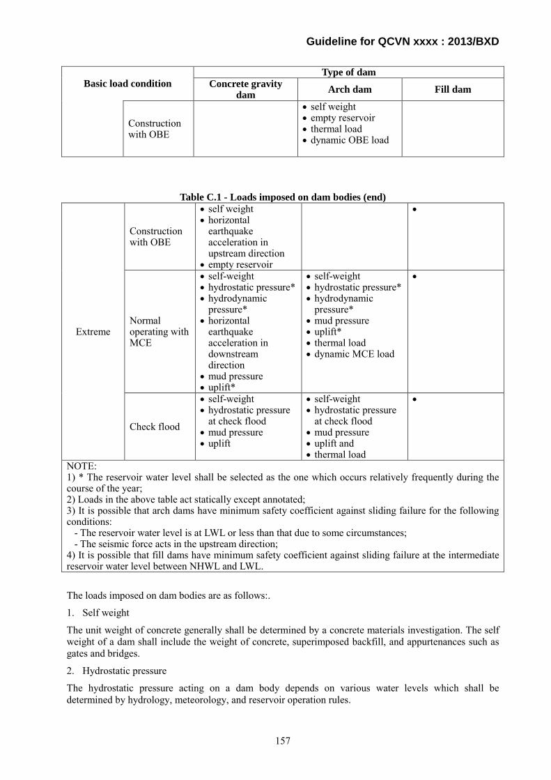
Guideline for QCVN xxxx : 2013/BXD
Basic load condition Type of dam
Concrete gravity dam Arch dam Fill dam
Construction with OBE
• self weight • empty reservoir • thermal load • dynamic OBE load
Table C.1 - Loads imposed on dam bodies (end)
Extreme
Construction with OBE
• self weight • horizontal
earthquake acceleration in upstream direction
• empty reservoir
•
Normal operating with MCE
• self-weight • hydrostatic pressure* • hydrodynamic
pressure* • horizontal
earthquake acceleration in downstream direction
• mud pressure • uplift*
• self-weight • hydrostatic pressure* • hydrodynamic
pressure* • mud pressure • uplift* • thermal load • dynamic MCE load
•
Check flood
• self-weight • hydrostatic pressure
at check flood • mud pressure • uplift
• self-weight • hydrostatic pressure
at check flood • mud pressure • uplift and • thermal load
•
NOTE: 1) * The reservoir water level shall be selected as the one which occurs relatively frequently during the course of the year; 2) Loads in the above table act statically except annotated; 3) It is possible that arch dams have minimum safety coefficient against sliding failure for the following conditions: - The reservoir water level is at LWL or less than that due to some circumstances; - The seismic force acts in the upstream direction; 4) It is possible that fill dams have minimum safety coefficient against sliding failure at the intermediate reservoir water level between NHWL and LWL.
The loads imposed on dam bodies are as follows:.
1. Self weight
The unit weight of concrete generally shall be determined by a concrete materials investigation. The self weight of a dam shall include the weight of concrete, superimposed backfill, and appurtenances such as gates and bridges.
2. Hydrostatic pressure
The hydrostatic pressure acting on a dam body depends on various water levels which shall be determined by hydrology, meteorology, and reservoir operation rules.
157
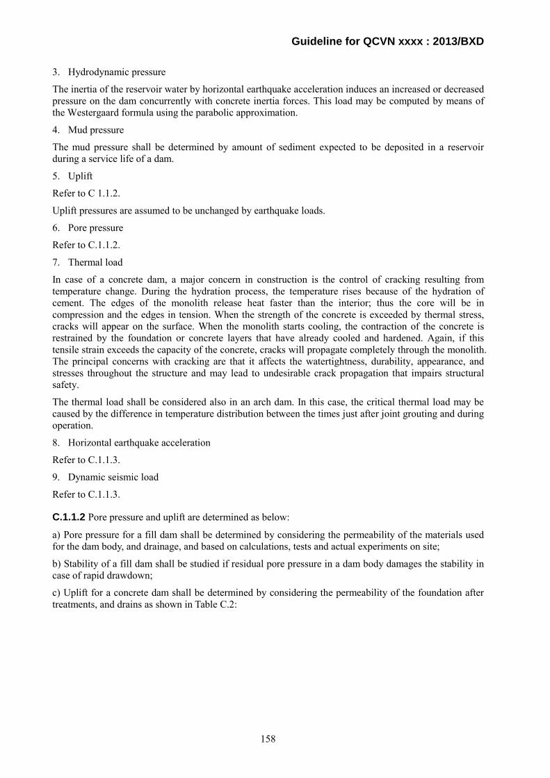
Guideline for QCVN xxxx : 2013/BXD
3. Hydrodynamic pressure
The inertia of the reservoir water by horizontal earthquake acceleration induces an increased or decreased pressure on the dam concurrently with concrete inertia forces. This load may be computed by means of the Westergaard formula using the parabolic approximation.
4. Mud pressure
The mud pressure shall be determined by amount of sediment expected to be deposited in a reservoir during a service life of a dam.
5. Uplift
Refer to C 1.1.2.
Uplift pressures are assumed to be unchanged by earthquake loads.
6. Pore pressure
Refer to C.1.1.2.
7. Thermal load
In case of a concrete dam, a major concern in construction is the control of cracking resulting from temperature change. During the hydration process, the temperature rises because of the hydration of cement. The edges of the monolith release heat faster than the interior; thus the core will be in compression and the edges in tension. When the strength of the concrete is exceeded by thermal stress, cracks will appear on the surface. When the monolith starts cooling, the contraction of the concrete is restrained by the foundation or concrete layers that have already cooled and hardened. Again, if this tensile strain exceeds the capacity of the concrete, cracks will propagate completely through the monolith. The principal concerns with cracking are that it affects the watertightness, durability, appearance, and stresses throughout the structure and may lead to undesirable crack propagation that impairs structural safety.
The thermal load shall be considered also in an arch dam. In this case, the critical thermal load may be caused by the difference in temperature distribution between the times just after joint grouting and during operation.
8. Horizontal earthquake acceleration
Refer to C.1.1.3.
9. Dynamic seismic load
Refer to C.1.1.3.
C.1.1.2 Pore pressure and uplift are determined as below:
a) Pore pressure for a fill dam shall be determined by considering the permeability of the materials used for the dam body, and drainage, and based on calculations, tests and actual experiments on site;
b) Stability of a fill dam shall be studied if residual pore pressure in a dam body damages the stability in case of rapid drawdown;
c) Uplift for a concrete dam shall be determined by considering the permeability of the foundation after treatments, and drains as shown in Table C.2:
158
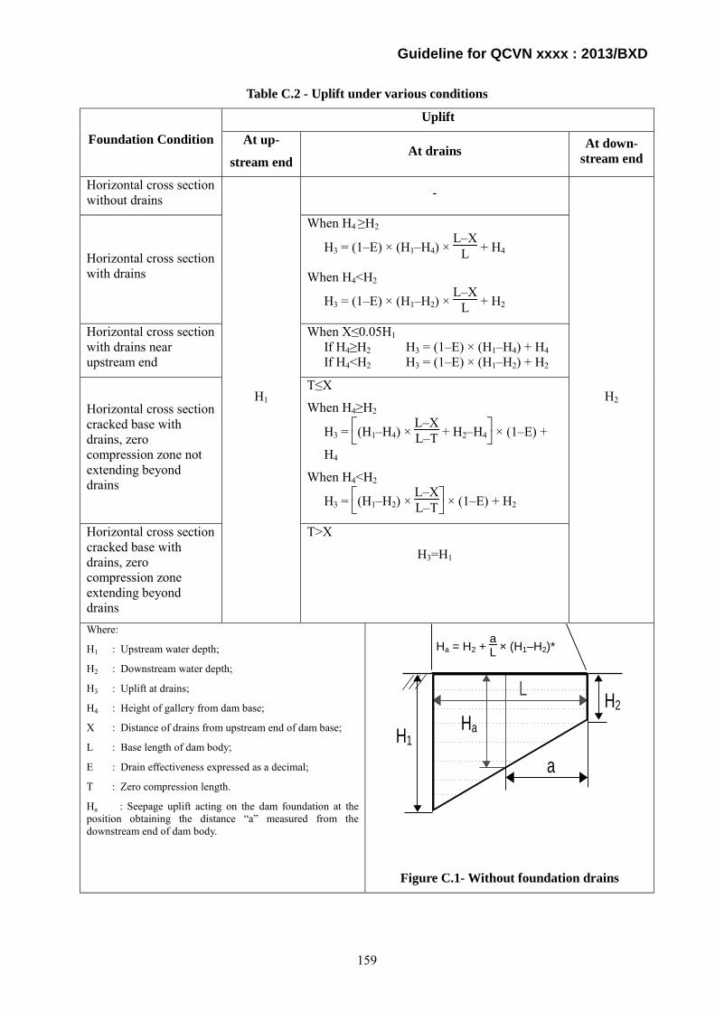
Guideline for QCVN xxxx : 2013/BXD
Table C.2 - Uplift under various conditions
Foundation Condition
Uplift
At up-
stream end At drains At down-
stream end
Horizontal cross section without drains
H1
-
H2
Horizontal cross section with drains
When H4 ≥H2
H3 = (1–E) × (H1–H4) × L–X
L + H4
When H4<H2
H3 = (1–E) × (H1–H2) × L–X
L + H2
Horizontal cross section with drains near upstream end
When X≤0.05H1 If H4≥H2 H3 = (1–E) × (H1–H4) + H4 If H4<H2 H3 = (1–E) × (H1–H2) + H2
Horizontal cross section cracked base with drains, zero compression zone not extending beyond drains
T≤X
When H4≥H2
H3 =
(H1–H4) ×
L–XL–T + H2–H4 × (1–E) +
H4
When H4<H2
H3 =
(H1–H2) ×
L–XL–T × (1–E) + H2
Horizontal cross section cracked base with drains, zero compression zone extending beyond drains
T>X
H3=H1
Where:
H1 : Upstream water depth;
H2 : Downstream water depth;
H3 : Uplift at drains;
H4 : Height of gallery from dam base;
X : Distance of drains from upstream end of dam base;
L : Base length of dam body;
E : Drain effectiveness expressed as a decimal;
T : Zero compression length.
Ha : Seepage uplift acting on the dam foundation at the position obtaining the distance “a” measured from the downstream end of dam body.
Figure C.1- Without foundation drains
Ha = H2 + aL × (H1–H2)*
H1
H2
a
L
Ha
159

Guideline for QCVN xxxx : 2013/BXD
Table C.2 - Uplift under various conditions (end)
When H4 ≥H2
H3 = (1–E) × (H1–H4) × L–X
L + H4
When H4<H2
H3 = (1–E) × (H1–H2) × L–X
L + H2
Figure C.2 - With drains
When X≤0.05H1 If H4≥H2 H3 = (1–E) × (H1–H4) + H4 If H4<H2 H3 = (1–E) × (H1–H2) + H2
Figure C.3 - With drains near upstream end
T≤X
When H4≥H2
H3 =
(H1–H4) ×
L–XL–T + H2–H4 × (1–E) + H4
When H4<H2
H3 =
(H1–H2) ×
L–XL–T × (1–E) + H2
Figure C.4- Cracked base with drains, zero compression zone not extending beyond drains
T>X
NOTE:
Drain effectiveness depends on depth, size, and spacing of the drains; the character of the foundation; and the facility with which the drains can be maintained.
Figure C.5 - Cracked base with drains, zero compression zone extending beyond drains
NOTE: H1: Upstream water depth; H2: Downstream water depth; H3: Uplift at drains; H4: Height of gallery from dam base; X: Distance of drains from upstream end of dam base; L: Base length of dam body; E: Drain effectiveness expressed as a decimal; T: Zero compression length. The uplift in this table is calculated with a proportional method. Drain effectiveness depends on depth, size, and spacing of the drains; the character of the foundation; and the facility with which the drains can be maintained.
H1
H2
Drainage Gallery
H4
XH3
Drains
LH2
Drainage GalleryH4
XH3
Drains
L
H1
H2
L
Drainage Gallery
H4
XH3
T
Drains
H1
H2
Drainage GalleryH4
X
TL
Drains
160
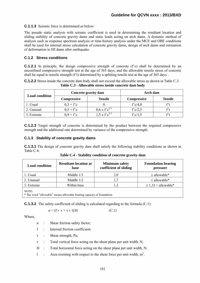
Guideline for QCVN xxxx : 2013/BXD
C.1.1.3 Seismic force is determined as below:
The pseudo static analysis with seismic coefficient is used in determining the resultant location and sliding stability of concrete gravity dams and static loads acting on arch dams. A dynamic method of analysis such as response spectrum analysis or time-history analysis under the MCE and OBE conditions shall be used for internal stress calculation of concrete gravity dams, design of arch dams and estimation of deformation in fill dams after earthquake.
C.1.2 Stress conditions
C.1.2.1 In principle, the design compressive strength of concrete (f’c) shall be determined by an unconfined compressive strength test at the age of 365 days, and the allowable tensile stress of concrete shall be equal to tensile strength (f’t) determined by a splitting tensile test at the age of 365 days .
C.1.2.2 Stress inside the concrete dam body shall not exceed the allowable stress as shown in Table C.3: Table C.3 - Allowable stress inside concrete dam body
Load condition Concrete gravity dam Arch dam
Compressive Tensile Compressive Tensile 1. Usual 0,3 × f’c 0 f’c/4,0 f’t 2. Unusual 0,5 × f’c 0,6 x f’c2/3 f’c/2,5 f’t 3. Extreme 0,9 × f’c 1,5 x f’c2/3 f’c/1,5 f’t
C.1.2.3 Target strength of concrete is determined by the product between the required compressive strength and the additional rate determined by variance of the compressive strength.
C.1.3 Stability of concrete gravity dams
C.1.3.1 The design of concrete gravity dam shall satisfy the following stability conditions as shown in Table C.4:
Table C.4 - Stability condition of concrete gravity dam
Load condition Resultant location at base
Minimum safety coefficient of sliding
Foundation bearing pressure
1. Usual Middle 1/3 2,0 ≤ allowable* 2. Unusual Middle 1/2 1,7 ≤ allowable* 3. Extreme Within base 1,3 ≤ 1,33 × allowable* NOTE: * The word ”allowable” means allowable bearing capacity of foundation.
C.1.3.2 The safety coefficient of sliding is calculated regarding to the formula (C.1):
n = (f × v + τ × l)/H (C.1)
Where,
n : Shear friction safety factor;
f : Internal friction coefficient;
τ : Shear strength, Pa;
v : Total vertical force acting on the shear plane per unit width, N;
H : Total horizontal force acting on the shear plane per unit width, N;
l : Area resisting with respect to the shear force per unit width, m2.
161

Guideline for QCVN xxxx : 2013/BXD
The basic stability requirements for a concrete gravity dam for all conditions of loading are;
1. A dam body shall be safe against overturning at any horizontal plane within the structure, at the base, or at a plane below the base;
2. A dam body shall be safe against sliding on any horizontal or near-horizontal plane within the structure at the base or on any rock seam in the foundation; and
3. All allowable unit stresses in the concrete or in the foundation material shall not be exceeded.
Characteristic locations within the dam in which a stability criteria check shall be considered include planes where there are dam section changes and high concentrated loads. Large galleries and openings within the structure and upstream and downstream slope transitions are specific areas for consideration.
C.1.4 Stability of arch dams
C.1.4.1 The design of arch dams shall satisfy the following stability conditions as shown in table C.5 Table C.5 - Stability condition of arch dam
Load condition Minimum safety coefficient of sliding 1. Usual 2.0 2. Unusual 1.3 3. Extreme 1.1
C.1.4.2 The contact zone between the dam body and the foundation and any part of the foundation shall be stable against sliding. The safety coefficient of sliding is calculated by the formula (C.2) as below:
n = (f × v + τ × l)/H (C.2)
Where:
n : Shear friction safety coefficient;
f : Internal friction coefficient;
τ : Shear strength, Pa;
v : Total vertical force acting on the shear plane per unit width, N;
H : Total horizontal force acting on the shear plane per unit width, N;
l : Area resisting with respect to the shear force per unit width, m2;
C.1.4.3 Arch dams are designed for two groups of load combinations. The first group combines all the static loads and the second group takes into account the effects of earthquake. Abutment stability is critical to the overall stability of arch dams. The analysis of the stability of the abutments of an arch dam requires very careful application of both engineering geology and rock mechanics investigative and analytical techniques. When these procedures are properly applied and their results accounted for in the design, a high degree of confidence in the stability of the dam foundation is justified.
C.1.5 Stability of fill dams
C.1.5.1 A dam body and its foundation shall be stable against sliding. The analyses against sliding shall be conducted by conventional limit equilibrium methods such as circular arc methods. In the case that sliding lines which include the foundation are expected, the calculations along the sliding lines, not only circular, shall be implemented. Minimum safety coefficients of dam body and its foundation against sliding expressed by the ratio of shear strength along the trial shear surface to equilibrium shear stress along the same trial shear surface shall be as specified in Table C.6.
162

Guideline for QCVN xxxx : 2013/BXD
C.1.5.2 In the case of assessment for strong ground motions corresponding to MCE and OBE, an appropriate dynamic method of analyses such as response spectrum analysis and time-history analysis shall be used to evaluate liquefaction potential and/or to estimate deformations for dam body and foundation materials.
Table C.6 - Minimum safety coefficients of fill dams
Analysis condition Required minimum safety
coefficient Slope
Usual Normal operating* 1,5 Upstream and Downstream
Unusual
Just after completion and before filling 1,3 Upstream and Downstream
Design flood 1,4 Downstream
Rapid drawdown 1,1 to 1,3 Upstream
NOTES: * The reservoir water level is between NHWL and LWL, and the seepage flow in the dam is in steady state.
C.2 Engineering Guidelines for the Evaluation of Hydropower Projects, FERC This appendix is based on the following documents.
Federal Energy Regulatory Commission, Engineering Guidelines for the Evaluation of Hydropower Projects.
Chapter 1 General Requirements
Chapter 2 Selecting and Accommodating for Inflow Design Floods for Dams
Chapter3 Gravity Dams
Chapter 4 Embankment Dams
Chapter 11 Arch Dams
163
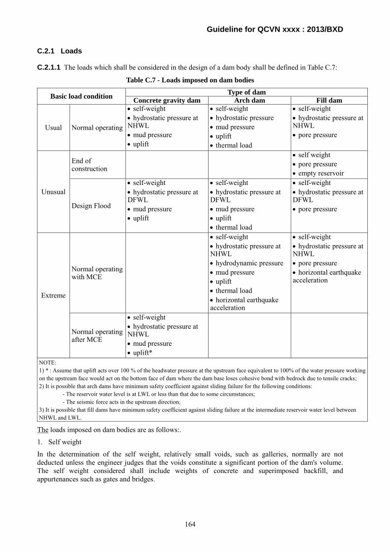
Guideline for QCVN xxxx : 2013/BXD
C.2.1 Loads
C.2.1.1 The loads which shall be considered in the design of a dam body shall be defined in Table C.7:
Table C.7 - Loads imposed on dam bodies
Basic load condition Type of dam Concrete gravity dam Arch dam Fill dam
Usual Normal operating
• self-weight • hydrostatic pressure at NHWL • mud pressure • uplift
• self-weight • hydrostatic pressure • mud pressure • uplift • thermal load
• self-weight • hydrostatic pressure at NHWL • pore pressure
Unusual
End of construction
• self weight • pore pressure • empty reservoir
Design Flood
• self-weight • hydrostatic pressure at DFWL • mud pressure • uplift
• self-weight • hydrostatic pressure at DFWL • mud pressure • uplift • thermal load
• self-weight • hydrostatic pressure at DFWL • pore pressure
Extreme
Normal operating with MCE
• self-weight • hydrostatic pressure at NHWL • hydrodynamic pressure • mud pressure • uplift • thermal load • horizontal earthquake acceleration
• self-weight • hydrostatic pressure at NHWL • pore pressure • horizontal earthquake acceleration
Normal operating after MCE
• self-weight • hydrostatic pressure at NHWL • mud pressure • uplift*
NOTE: 1) * : Assume that uplift acts over 100 % of the headwater pressure at the upstream face equivalent to 100% of the water pressure working on the upstream face would act on the bottom face of dam where the dam base loses cohesive bond with bedrock due to tensile cracks; 2) It is possible that arch dams have minimum safety coefficient against sliding failure for the following conditions:
- The reservoir water level is at LWL or less than that due to some circumstances; - The seismic force acts in the upstream direction;
3) It is possible that fill dams have minimum safety coefficient against sliding failure at the intermediate reservoir water level between NHWL and LWL.
The loads imposed on dam bodies are as follows:.
1. Self weight
In the determination of the self weight, relatively small voids, such as galleries, normally are not deducted unless the engineer judges that the voids constitute a significant portion of the dam's volume. The self weight considered shall include weights of concrete and superimposed backfill, and appurtenances such as gates and bridges.
164
Guideline for QCVN xxxx : 2013/BXD
2. Hydrostatic pressure
A linear distribution of the hydrostatic pressure acting normal to the surface of the dam shall be applied.
3. Hydrodynamic pressure
During seismic excitation the motion of the dam causes a portion of the water in the reservoir to move also. Acceleration of this added mass of water produces pressures on the dam that must be taken into account in dynamic analysis. Westergaard derived a pressure distribution assuming that the dam would move upstream and downstream as a rigid body, in other words, the base and crest accelerations of the dam are assumed to be identical.
4. Mud pressure
The mud pressure shall be determined by amount of sediment expected to be deposited in a reservoir during a service life of a dam. Silt shall be assumed to liquefy under seismic loading. Thus, for post earthquake analysis, silt internal shear strength shall be assumed to be zero unless site investigations demonstrate that liquefaction is not possible.
5. Uplift
Refer to C 2.1.2.
6. Pore pressure
Refer to C.2.1.2.
7. Thermal load
Thermal loads in arch dams result from the differences between the closure temperature when construction joints between cantilever monoliths are grouted or filled by concrete to bind them together, and the concrete temperatures during the operation of the dam. The closure or stress-free temperature is a design parameter selected such that to minimize thermally induced tensile stresses in the dam. In the case of an existing dam, the actual value(s) of closure temperature can usually be found in the construction or design records. If such records are not available, it can be assumed to be equal to either the mean annual concrete temperature or the mean annual air temperature that exists at the dam site. The concrete temperatures are determined from either computation of heat flow through the dam due to the air and water temperatures adjacent to the dam surfaces and exposure to the solar radiation, or from embedded instruments.
8. Horizontal earthquake acceleration
Refer to C.2.1.3.
9. Dynamic seismic load
Refer to C.2.1.3.
Regarding load combinations of concrete gravity dams of moderate height, the following loading conditions and requirements are suitable in general. Loads which are not indicated, such as wave action, or any unusual loadings shall be considered where applicable.
1. Usual Loading Combination - Normal Operating Condition
The reservoir water level is at the normal power operation level, as governed by the crest elevation of an overflow structure, or the top of the closed spillway gates whichever is greater;
The normal downstream water level, that is the usual downstream water level, is used; and
The horizontal silt pressure shall also be considered, if applicable.
2. Unusual Loading Combination - Flood Discharge Loading
For high and significant hazard potential projects, the flood condition that results in reservoir and downstream water level which produce the lowest factor of safety shall be used;
Flood events up to and including the Design Flood, if appropriate, shall be considered; and
165

Guideline for QCVN xxxx : 2013/BXD
For dams having a low hazard potential, the project shall be stable for floods up to and including the 100 year flood.
3. Extreme Loading Combination - Case 1+Earthquake
In a departure from the way the FERC has previously considered seismic loading, there is no longer any acceptance criteria for stability under earthquake loading. Factors of safety under earthquake loading will no longer be evaluated.
Acceptance criteria are based on the dam's stability under post earthquake static loading considering damage likely to result form the earthquake. The purpose of considering dynamic loading is to determine the damage that will be caused so that this damage can be accounted for in the subsequent post earthquake static analysis.
Factors to consider are as follows:
Loss of cohesive bond in regions of seismically induced tensile stress;
Degradation of friction angle due to earthquake induced movements or
rocking; and
Increase in silt pressure and uplift due to liquefaction of reservoir silt.
Regarding load combinations of arch dams, the following loading conditions shall be considered. Depending on their probabilities of occurrence, three basic loading combinations, Usual, Unusual, and Extreme shall be considered. The usual loading combination considers the effects of all loads which may exist during the normal operation of the dam. The unusual loading combination refers to the loads acting on the dam during the flood stage. The extreme loading combination includes any of the usual loading combinations plus the effects of MCE Rare loading conditions which have a remote probability of occurrence at any given time, have a negligible probability of simultaneous occurrence and shall not be combined. When a very low water level or empty reservoir may be expected, its effects shall be considered by a special loading combination. The loading combinations to be considered are as follows:
1. Usual loading combinations
The reservoir water level is assumed to be at NHWL.
Maximum mean concrete temperatures;
NHWL or the most probable water level occurring at the time of maximum mean temperature;
Self weight;
Mud load, if applicable; and
Downstream water level, if applicable.
2. Unusual loading combinations
Depending on the time of flooding, one or both of the following unusual loading combinations shall be considered. The maximum mean concrete temperatures shall be used with the flooding.
Flood water level;
Maximum mean concrete temperatures, or mean concrete temperature occurring at the time of flood;
Self weight;
Mud load, if applicable; and
Downstream water level, if applicable.
3. Special lading combination:
Special loading combinations correspond to LWL or a complete reservoir drawdown condition. They are
166
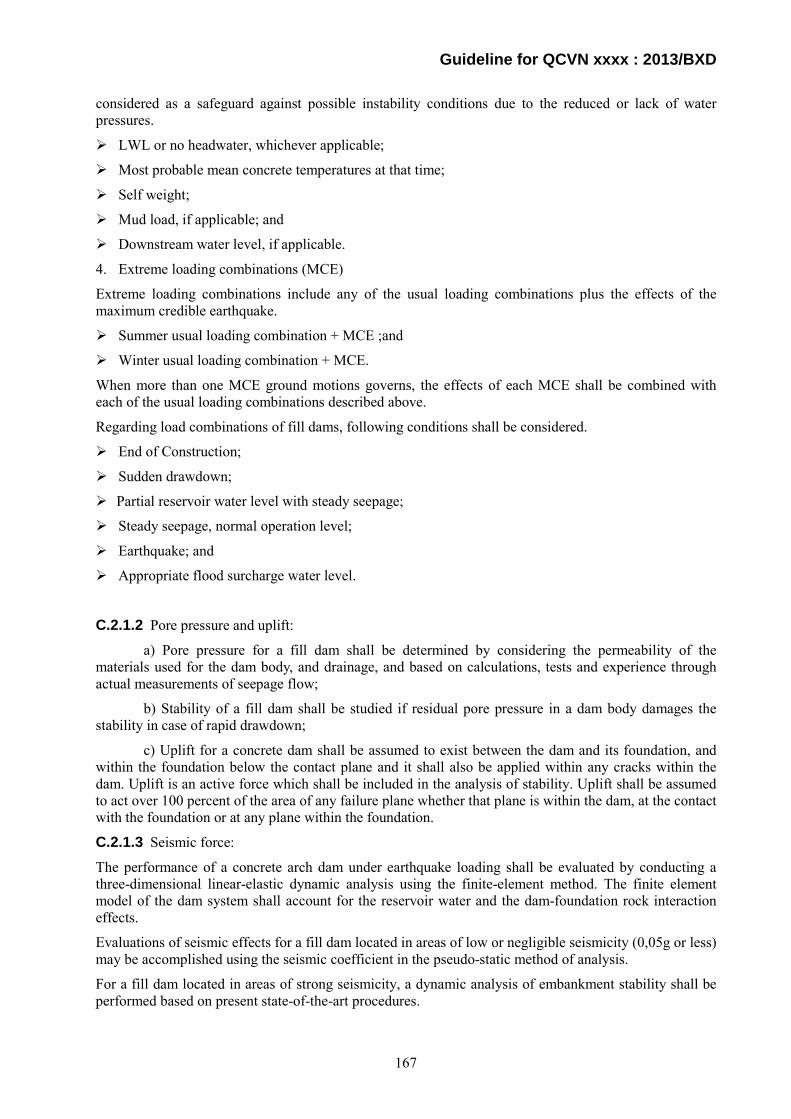
Guideline for QCVN xxxx : 2013/BXD
considered as a safeguard against possible instability conditions due to the reduced or lack of water pressures.
LWL or no headwater, whichever applicable;
Most probable mean concrete temperatures at that time;
Self weight;
Mud load, if applicable; and
Downstream water level, if applicable.
4. Extreme loading combinations (MCE)
Extreme loading combinations include any of the usual loading combinations plus the effects of the maximum credible earthquake.
Summer usual loading combination + MCE ;and
Winter usual loading combination + MCE.
When more than one MCE ground motions governs, the effects of each MCE shall be combined with each of the usual loading combinations described above.
Regarding load combinations of fill dams, following conditions shall be considered.
End of Construction;
Sudden drawdown;
Partial reservoir water level with steady seepage;
Steady seepage, normal operation level;
Earthquake; and
Appropriate flood surcharge water level.
C.2.1.2 Pore pressure and uplift:
a) Pore pressure for a fill dam shall be determined by considering the permeability of the materials used for the dam body, and drainage, and based on calculations, tests and experience through actual measurements of seepage flow;
b) Stability of a fill dam shall be studied if residual pore pressure in a dam body damages the stability in case of rapid drawdown;
c) Uplift for a concrete dam shall be assumed to exist between the dam and its foundation, and within the foundation below the contact plane and it shall also be applied within any cracks within the dam. Uplift is an active force which shall be included in the analysis of stability. Uplift shall be assumed to act over 100 percent of the area of any failure plane whether that plane is within the dam, at the contact with the foundation or at any plane within the foundation.
C.2.1.3 Seismic force:
The performance of a concrete arch dam under earthquake loading shall be evaluated by conducting a three-dimensional linear-elastic dynamic analysis using the finite-element method. The finite element model of the dam system shall account for the reservoir water and the dam-foundation rock interaction effects.
Evaluations of seismic effects for a fill dam located in areas of low or negligible seismicity (0,05g or less) may be accomplished using the seismic coefficient in the pseudo-static method of analysis.
For a fill dam located in areas of strong seismicity, a dynamic analysis of embankment stability shall be performed based on present state-of-the-art procedures.
167
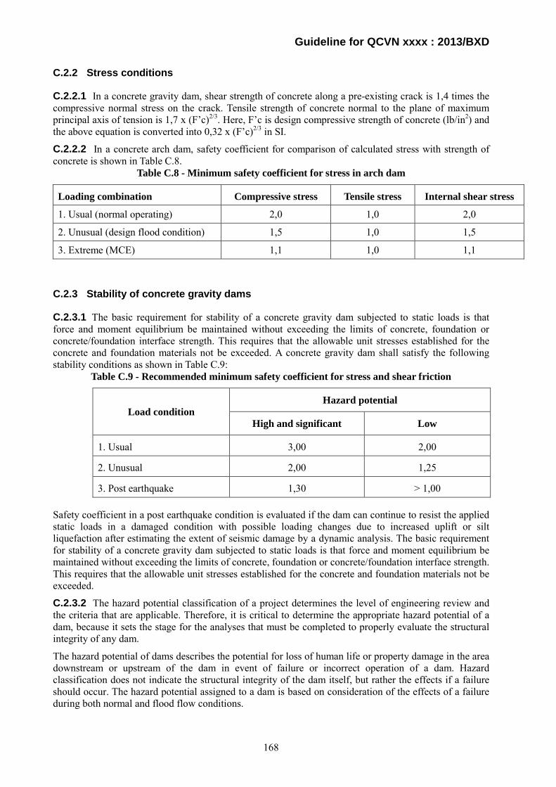
Guideline for QCVN xxxx : 2013/BXD
C.2.2 Stress conditions
C.2.2.1 In a concrete gravity dam, shear strength of concrete along a pre-existing crack is 1,4 times the compressive normal stress on the crack. Tensile strength of concrete normal to the plane of maximum principal axis of tension is 1,7 x (F’c)2/3. Here, F’c is design compressive strength of concrete (lb/in2) and the above equation is converted into 0,32 x (F’c)2/3 in SI.
C.2.2.2 In a concrete arch dam, safety coefficient for comparison of calculated stress with strength of concrete is shown in Table C.8.
Table C.8 - Minimum safety coefficient for stress in arch dam
Loading combination Compressive stress Tensile stress Internal shear stress
1. Usual (normal operating) 2,0 1,0 2,0
2. Unusual (design flood condition) 1,5 1,0 1,5
3. Extreme (MCE) 1,1 1,0 1,1
C.2.3 Stability of concrete gravity dams
C.2.3.1 The basic requirement for stability of a concrete gravity dam subjected to static loads is that force and moment equilibrium be maintained without exceeding the limits of concrete, foundation or concrete/foundation interface strength. This requires that the allowable unit stresses established for the concrete and foundation materials not be exceeded. A concrete gravity dam shall satisfy the following stability conditions as shown in Table C.9:
Table C.9 - Recommended minimum safety coefficient for stress and shear friction
Load condition Hazard potential
High and significant Low
1. Usual 3,00 2,00
2. Unusual 2,00 1,25
3. Post earthquake 1,30 > 1,00
Safety coefficient in a post earthquake condition is evaluated if the dam can continue to resist the applied static loads in a damaged condition with possible loading changes due to increased uplift or silt liquefaction after estimating the extent of seismic damage by a dynamic analysis. The basic requirement for stability of a concrete gravity dam subjected to static loads is that force and moment equilibrium be maintained without exceeding the limits of concrete, foundation or concrete/foundation interface strength. This requires that the allowable unit stresses established for the concrete and foundation materials not be exceeded.
C.2.3.2 The hazard potential classification of a project determines the level of engineering review and the criteria that are applicable. Therefore, it is critical to determine the appropriate hazard potential of a dam, because it sets the stage for the analyses that must be completed to properly evaluate the structural integrity of any dam.
The hazard potential of dams describes the potential for loss of human life or property damage in the area downstream or upstream of the dam in event of failure or incorrect operation of a dam. Hazard classification does not indicate the structural integrity of the dam itself, but rather the effects if a failure should occur. The hazard potential assigned to a dam is based on consideration of the effects of a failure during both normal and flood flow conditions.
168

Guideline for QCVN xxxx : 2013/BXD
Dams conforming to criteria for the low hazard potential category generally are located in rural or agricultural areas where failure may damage farm buildings, limited agricultural land, or township and country roads. Low hazard potential dams have a small storage capacity, the release of which would be confined to the river channel in the event of a failure and therefore would represent no danger to human life. Significant hazard potential category structures are usually located in predominately rural or agricultural areas where failure may damage isolated homes, secondary highways or minor railroads; cause interruption of use or service of relatively important public utilities; or cause some incremental flooding of structures with possible danger to human life. Dams in the high hazard potential category are those located where failure may cause serious damage to homes, agricultural, industrial and commercial facilities, important public utilities, main highways, or railroads, and there would be danger to human life. The hazard potential evaluation includes consideration of recreational development and use and socio-economic matters. Included in the high hazard potential category are dams where failure would cause serious damage to permanently established or organized recreational areas or activities. Also included in the high hazard potential category are dams where failure could result in loss of life of people gathered for an unorganized recreational activity (such as salmon fishermen and kayakers) where concentrated use of a confined area below the dam is a common annual occurrence during certain times each year.
C.2.4 Stability of arch dams
Safety is defined as adequacy of an arch dam against an uncontrolled release of reservoir water. The structural integrity is maintained and the dam is considered safe if overstressing, sliding, and other possible modes of failure will not occur. A safety evaluation, therefore, shall identify all significant failure modes and conduct appropriate analyses to assure that the structural stability of the dam is maintained. A concrete arch dam shall satisfy the stability conditions shown in Table C.10:
Table C.10 - Recommended minimum safety coefficient of arch dams
Loading combination Sliding stability*
1. Usual (normal operating) 1,5
2. Unusual (design flood condition) 1,5
3. Extreme (MCE) 1,1
NOTE: * Safety coefficient is valid for assumption of no cohesion between a dam body and bedrock.
C.2.5 Stability of fill dams
C.2.5.1 A dam body and its foundation shall be stable against sliding. The analyses against sliding shall be conducted by conventional limit equilibrium methods such as circular arc methods. In the case that sliding lines which include the foundation are expected, the calculations along the sliding lines, not only circular, shall be implemented. The safety coefficient includes a margin of safety to guard against ultimate failure, to avoid unacceptable deformations, and to cover uncertainties associated with the measurement of soil properties or the analysis used. In electing a minimum acceptable safety coefficient, an evaluation shall be made on both the degree of conservatism with which assumptions were made in choosing soil strength parameters and pore water pressures, and the influence of the method of analysis which is used. Minimum safety coefficients are listed in Table C.11.
169

Guideline for QCVN xxxx : 2013/BXD
Table C.11 - Minimum safety coefficients of fill dams
Analysis condition Required minimum safety coefficient Slope to be analyzed
Usual Normal operating at NHWL 1,5 Upstream and downstream
Unusual
Just after completion and before filling 1,3 Upstream and downstream
Design flood 1,4 Downstream
Rapid drawdown from NHWL > 1,1 Upstream
Normal operating with MCE* >1,0 Upstream and downstream
NOTE: * For steady seepage conditions with seismic loading using seismic coefficient method. This condition shall be applied only to a dam located in areas of low or negligible seismicity.
C.2.5.2 In evaluating safety of embankment using a deformation method of dynamic analyses, deformation along the potential failure plane shall be less than 60 cm.
170
Guideline for QCVN xxxx : 2013/BXD
Appendix D
Major Technical Standards and Codes of Concrete
D.1 TCVN of Vietnam
TCVN 1651-1:2008 : Steel for the reinforcement of concrete. Part 1: Plain bars
TCVN 1651-2:2008 : Steel for the reinforcement of concrete. Part 2: Ribbed bars
TCVN 1651-3:2008 : Steel for the reinforcement of concrete. Part 3: Welded fabric
TCVN 1651-85 : Hot-rolled steel for reinforcement of concrete
TCVN 3100-79 : Round steel wire for the reinforcement of prestressed concrete structures
TCVN 3105:1993 : Fresh heavy weight concrete and heavy weight concrete. Sampling, marking and curing test specimens
TCVN 3106:1993 : Fresh heavy weight concrete. Slump test method
TCVN 3107:1993 : Fresh heavy weight concrete. Vebe test method
TCVN 3108:1993 : Fresh heavy weight concrete. Determination of density
TCVN 3109:1993 : Fresh heavy weight concrete. Determination of mortar and water segregation
TCVN 3110-79 : Heavy concrete mixtures. Composition analysis
TCVN 3111:1993 : Fresh heavy weight concrete. Determination of air bubbles content
TCVN 3112:1993 : Heavy weight concrete. Determination of specific mass
TCVN 3113:1993 : Heavy weight concrete. Determination of water absorptivity
TCVN 3114:1993 : Heavy weight concrete. Determination of abrasiveness
TCVN 3115:1993 : Heavy weight concrete. Determination of density
TCVN 3116:1993 : Heavy weight concrete. Determination of watertightness
TCVN 3117:1993 : Heavy weight concrete. Determination of shrinkage
TCVN 3118:1993 : Heavy weight concrete. Determination of compressive strength
TCVN 3119:1993 : Heavy weight concrete. Determination of flexural strength
TCVN 3120:1993 : Heavy weight concrete. Determination of tensile splitting strength
TCVN 3993-85 : Protection against corrosion in construction. Concrete and reinforced concrete structures. Basic principles for design
TCVN 3994-85 : Protection against corrosion in construction. Concrete and reinforced concrete structures. Classification of erosive environments
TCVN 4058-85 : System of quality characteristic of construction products. Concrete and reinforced products and structures. Lists of characteristics
TCVN 4116-85 : Hydraulic engineering concrete and reinforced concrete structures. Design standard
TCVN 4452-87 : Precast concrete and reinforced concrete structures. Code for execution and acceptance
TCVN 4453:1995 : Monolithic concrete and reinforced concrete structures. Code for execution and acceptance
TCVN 4506-87 : Water for concrete and mortar. Specifications
TCVN 4612-88 : System of building design documents. Reinforced concrete structures. Symbols and representation on drawings
171

Guideline for QCVN xxxx : 2013/BXD
LVN 150:2004 : Concrete strength test instruments with rebound method. Methods and means of calibration
CVN 5440-91 : Concrete. Strength control and evaluation. General
TCVN 5572:1991 : System of building design documents. Concrete and reinforced concrete structures. Production drawings
TCVN 5574:1991 : Concrete and reinforced concrete structures. Design standard
TCVN 5592:1991 : Heavy concrete. Curing requirements under natural humidity conditions
TCVN 5718:1993 : Reinforced concrete roof and floor of buildings. Technical requirements for watertightness
TCVN 5724:1993 : Concrete and reinforced concrete structures. Minimum technical conditions for execution and acceptance
TCVN 5726:1993 : Heavy weight concrete. Determination of prismatic compressive strength and static modulus of elasticity in compression
TCVN 6025:1995 : Concrete. Classification by compressive strength
TCVN 6084:1995 : Building and civil engineering drawings. Symbols for concrete reinforcement
TCVN 6220:1997 : Monolithic concrete and reinforced concrete structures. Code for execution and acceptance
TCVN 6221:1997 : Light weight aggregates for concrete. Expanded clay, grawel and sand. Test method
TCVN 6284-1:1997 : Steel for the prestressing of concrete. Part 1: General requirements
TCVN 6284-2:1997 : Steel for the prestressing of concrete. Part 2: Cold-drawn wire
TCVN 6284-3:1997 : Steel for the prestressing of concrete. Part 3: Quenched and tempered wire
TCVN 6284-4:1997 : Steel for the prestressing of concrete. Part 4: Strand
TCVN 6284-5:1997 : Steel for the prostrating of concrete. Part 5: Hot-rolled steel bars with or without subsequent processing
TCVN 6285:1997 : Steel for the reinforcement of concrete. Ribbed bars
TCVN 6286:1997 : Steel for the reinforcement of concrete. Welded fabric
TCVN 6287:1997 : Steel bars for reinforcement of concrete. Bend and rebend tests
TCVN 6288:1997 : Cold-reduced steel wire for the reinforcement of concrete and the manufacture of welded fabric
TCVN 6394:1998 : Net-wire concrete units irrigational canal
TCVN 6476:1999 : Interlocking concrete bricks
TCVN 6477:1999 : Concrete block bricks
TCVN 6477:2011 : Concrete brick
QCVN 07:2011/BKHCN : National technical regulation on steel for the reinforcement of concrete
TCVN 7570:2006 : Aggregates for concrete and mortar. Specifications
TCVN 7572-1:2006 : Aggregates for concrete and mortar. Test methods. Part 1: Sampling
TCVN 7572-10:2006 : Aggregates for concrete and mortar. Test methods. Part 10: Method for determination of strength and softening coefficient of the original stone
TCVN 7572-11:2006 : Aggregates for concrete and mortar. Test methods. Part 11: Method of crushing value (ACV) and softening coefficient of coarse aggregate
172

Guideline for QCVN xxxx : 2013/BXD
TCVN 7572-12:2006 : Aggregates for concrete and mortar. Test methods. Part 12: Determination of resistance to degradation of coasre aggregate by abration and impact in the Los Angeles machine
TCVN 7572-13:2006 : Aggregates for concrete and mortar. Test methods. Part 13: Determination of elongation and flakiness index of coarse aggregate
TCVN 7572-14:2006 : Aggregates for concrete and mortar. Test methods. Part 14: Determination of alkali silica reactivity
TCVN 7572-15:2006 : Aggregates for concrete and mortar. Test methods. Part 15: Determination of chloride content
TCVN 7572-16:2006 : Aggregates for concrete and mortar. Test methods. Part 16: Determination of sulfate and sulfite content
TCVN 7572-17:2006 : Aggregates for concrete and mortar. Test methods. Part 17: Determination of feeble weathered particle content
TCVN 7572-18:2006 : Aggregates for concrete and mortar. Test methods. Part 18: Determination of crushed particle content
TCVN 7572-19:2006 : Aggregates for concrete and mortar. Test methods. Part 19: Determination of amorphous silicate content
TCVN 7572-2:2006 : Aggregates for concrete and mortar. Test methods. Part 2: Determination of partical size distribution
TCVN 7572-20:2006 : Aggregates for concrete and mortar. Test methods. Part 20: Determination of mica content in fine aggregate
TCVN 7572-3:2006 : Aggregates for concrete and mortar. Test methods. Part 3: Guide for determination of petrographic compositions
TCVN 7572-4:2006 : Aggregates for concrete and mortar. Test methods. Part 4: Determination of apparent specific gravity, bulk specific gravity and water absorption
TCVN 7572-5:2006 : Aggregates for concrete and mortar. Test methods. Part 5: Method for determination of apparent specific gravity, bulk specific gravity and water absorption of original stone and coarse aggregate particles
TCVN 7572-6:2006 : Aggregates for concrete and mortar. Test methods. Part 6: Determination of bulk density and voids
TCVN 7572-7:2006 : Aggregates for concrete and mortar. Test methods. Part 7: Determination of moisture
TCVN 7572-8:2006 : Aggregates for concrete and mortar. Test methods. Part 8: Method for determination of content of dust, mud and clay in aggregate and content of clay lumps in fine aggregate
TCVN 7572-9:2006 : Aggregates for concrete and mortar. Test methods. Part 9: Determination of organic impurities
TCVN 7690:2005 : Plastic formwork for concrete
TCVN 7934:2009 : Epoxy-coated steel for the reinforcement of concrete
TCVN 7935:2009 : Epoxy-coated strand for the prestressing of concrete
TCVN 7936:2009 : Epoxy powder and sealing material for the coating of steel for the reinforcement of concrete
TCVN 7937-1:2009 : Steel for the reinforcement and prestressing of concrete. Test methods. Part 1: Reinforcing bars, wire rod and wire
TCVN 7937-2:2009 : Steel for the reinforcement and prestressing of concrete. Test methods. Part 2: Welded fabric
173

Guideline for QCVN xxxx : 2013/BXD
TCVN 7937-3:2009 : Steel for the reinforcement and prestressing of concrete. Test methods. Part 3: Prestressing steel
TCVN 7938:2009 : Certification scheme for steel bars and wires for the reinforcement of concrete structures
TCVN 7951:2008 : Epoxy resin base bonding systems for concrete. Specifications
TCVN 7952-1:2008 : Epoxy resin base bonding systems for concrete. Test methods. Part 1: Determination of viscosity
TCVN 7952-10:2008 : Epoxy resin base bonding systems for concrete. Test methods. Part 10: Determination of tensile strength and elongation at break
TCVN 7952-11:2008 : Epoxy resin base bonding systems for concrete. Test methods. Part 11: Determination of contact strength
TCVN 7952-2:2008 : Epoxy resin base bonding systems for concrete. Test methods. Part 2: Determination of consistency
TCVN 7952-3:2008 : Epoxy resin base bonding systems for concrete. Test methods. Part 3: Determination of gel time
TCVN 7952-4:2008 : Epoxy resin base bonding systems for concrete. Test methods. Part 4: Determination of bond strength
TCVN 7952-5:2008 : Epoxy resin base bonding systems for concrete. Test methods. Part 5: Determination of water absorption
TCVN 7952-6:2008 : Epoxy resin base bonding systems for concrete. Test methods. Part 6: Determination of heat deflection temperature under flexural load
TCVN 7952-7:2008 : Epoxy resin base bonding systems for concrete. Test methods. Part 7: Determination of thermal compatibility
TCVN 7952-8:2008 : Epoxy resin base bonding systems for concrete. Test methods. Part 8: Determination of linear shrinkage
TCVN 7952-9:2008 : Epoxy resin base bonding systems for concrete. Test methods. Part 9: Determination of compressive yield strength and modulus
TCVN 7953:2008 : Epoxy resin base bonding systems for concrete. Code of practice and acceptance
TCVN 7959:2008 : Autoclaved aerated concrete blocks (AAC)
TCVN 7959:2011 : Lightweight concrete. Autoclaved aerated concrete bricks (AAC)
TCVN 7996-2-12:2009 : Hand-held motor-operated electric tools. Safety. Part 2-12: Particular requirements for concrete vibrators
TCVN 8163:2009 : Steel for the reinforcement of concrete. Threaded coupler splice
TCVN 8218:2009 : Hydraulic concrete. Technical requirements
TCVN 8219:2009 : Hydraulic concrete mixture and hydraulic concrete. Test method
TCVN 8228:2009 : Hydraulic concrete mixture. Technical requirements
TCVN 8819:2011 : Specification for Construction of Hot Mix Asphalt Concrete Pavement and Acceptance
TCVN 8820:2011 : Standard Practice for Asphalt Concrete Mix Design Using Marshall Method
TCVN 8825:2011 : Mineral admixtures for roller-compacted concrete
TCVN 8826:2011 : Chemical admixtures for concrete
174
Guideline for QCVN xxxx : 2013/BXD
TCVN 8827:2011 : Highly Activity Pozzolanic Admixtures for concrete and mortar. Silicafume and Rice Husk Ash
TCVN 8828:2011 : Concrete. Requirements for natural moist curing
TCVN 8860-1:2011 : Asphalt Concrete. Test methods. Part 1: Determination of Marshall Stability and Plastic Flow
TCVN 8860-2:2011 : Asphalt Concrete. Test methods. Part 2: Determination of bitumen content using extraction Centrifuge
TCVN 9034:2011 : Acid resistant mortars and concretes
TCVN 9113:2012 : Reinforced concrete pipes for water draining
TCVN 9114:2012 : Precast prestressed concrete product. Technical requirements and acceptance test
TCVN 9115:2012 : Assembled concrete and reinforced concrete structures. Practice for erection and acceptance
TCVN 9116:2012 : Reinforced concrete box culverts.
D.2 ASTM of the U.S.A.
List of cement standards and concrete standards developed by ASTM:
C418 - 12 Standard Test Method for Abrasion Resistance of Concrete by Sandblasting
C779 / C779M - 12 Standard Test Method for Abrasion Resistance of Horizontal Concrete Surfaces
C944 / C944M - 12 Standard Test Method for Abrasion Resistance of Concrete or Mortar Surfaces by the Rotating-Cutter Method
C1138M - 12 Standard Test Method for Abrasion Resistance of Concrete (Underwater Method)
C226 - 12 Standard Specification for Air-Entraining Additions for Use in the Manufacture of Air-Entraining Hydraulic Cement
C465 - 10 Standard Specification for Processing Additions for Use in the Manufacture of Hydraulic Cements
C688 - 08 Standard Specification for Functional Additions for Use in Hydraulic Cements
C1565 - 09 Standard Test Method for Determination of Pack-Set Index of Portland Cement
C185 - 08 Standard Test Method for Air Content of Hydraulic Cement Mortar
C1397 - 09 Standard Practice for Application of Class PB Exterior Insulation and Finish Systems (EIFS) and EIFS with Drainage
C1516 - 05(2011) Standard Practice for Application of Direct-Applied Exterior Finish Systems
C1535 - 05(2011) Standard Practice for Application of Exterior Insulation and Finish Systems Class PI
C233 / C233M - 11 Standard Test Method for Air-Entraining Admixtures for Concrete
C260 / C260M - 10a Standard Specification for Air-Entraining Admixtures for Concrete
C403 / C403M - 08 Standard Test Method for Time of Setting of Concrete Mixtures by Penetration Resistance
C494 / C494M - 12 Standard Specification for Chemical Admixtures for Concrete
C796 / C796M - 12 Standard Test Method for Foaming Agents for Use in Producing Cellular Concrete Using Preformed Foam
175

Guideline for QCVN xxxx : 2013/BXD
C869 / C869M - 11 Standard Specification for Foaming Agents Used in Making Preformed Foam for Cellular Concrete
C979 / C979M - 10 Standard Specification for Pigments for Integrally Colored Concrete
C1017 / C1017M - 07 Standard Specification for Chemical Admixtures for Use in Producing Flowing Concrete
C1582 / C1582M - 11 Standard Specification for Admixtures to Inhibit Chloride-Induced Corrosion of C1622 / C1622M - 10 Standard Specification for Cold-Weather Admixture Systems
C227 - 10 Standard Test Method for Potential Alkali Reactivity of Cement-Aggregate Combinations (Mortar-Bar Method)
C289 - 07 Standard Test Method for Potential Alkali-Silica Reactivity of Aggregates (Chemical Method)
C441 / C441M - 11 Standard Test Method for Effectiveness of Pozzolans or Ground Blast-Furnace Slag in Preventing Excessive Expansion of Concrete Due to the Alkali-Silica Reaction
C586 - 11 Standard Test Method for Potential Alkali Reactivity of Carbonate Rocks as Concrete Aggregates (Rock-Cylinder Method)
C1105 - 08a Standard Test Method for Length Change of Concrete Due to Alkali-Carbonate Rock Reaction
C1260 - 07 Standard Test Method for Potential Alkali Reactivity of Aggregates (Mortar-Bar Method)
C1293 - 08b Standard Test Method for Determination of Length Change of Concrete Due to Alkali-Silica Reaction
C1567 - 13 Standard Test Method for Determining the Potential Alkali-Silica Reactivity of Combinations of Cementitious Materials and Aggregate (Accelerated Mortar-Bar Method)
C25 - 11 Standard Test Methods for Chemical Analysis of Limestone, Quicklime, and Hydrated Lime
C400 - 98(2006) Standard Test Methods for Quicklime and Hydrated Lime for Neutralization of Waste Acid
C1164 - 92(2009) Standard Practice for Evaluation of Limestone or Lime Uniformity From a Single Source
C1271 - 99(2012) Standard Test Method for X-ray Spectrometric Analysis of Lime and Limestone
C1301 - 95(2009)e1 Standard Test Method for Major and Trace Elements in Limestone and Lime by Inductively Coupled Plasma-Atomic Emission Spectroscopy (ICP) and Atomic Absorption (AA)
C1318 - 95(2009)e1 Standard Test Method for Determination of Total Neutralizing Capability and Dissolved Calcium and Magnesium Oxide in Lime for Flue Gas Desulfurization (FGD)
C114 - 11b Standard Test Methods for Chemical Analysis of Hydraulic Cement
C1356 - 07(2012) Standard Test Method for Quantitative Determination of Phases in Portland Cement Clinker by Microscopical Point-Count Procedure
C1365 - 06(2011) Standard Test Method for Determination of the Proportion of Phases in Portland Cement and Portland-Cement Clinker Using X-Ray Powder Diffraction Analysis
C642 - 13 Standard Test Method for Density, Absorption, and Voids in Hardened Concrete
C1202 - 12 Standard Test Method for Electrical Indication of Concrete's Ability to Resist Chloride Ion Penetration
C1543 - 10a Standard Test Method for Determining the Penetration of Chloride Ion into Concrete by Ponding
C1556 - 11a Standard Test Method for Determining the Apparent Chloride Diffusion Coefficient of Cementitious Mixtures by Bulk Diffusion
176

Guideline for QCVN xxxx : 2013/BXD
C1585 - 13 Standard Test Method for Measurement of Rate of Absorption of Water by Hydraulic-Cement Concretes
C1760 - 12 Standard Test Method for Bulk Electrical Conductivity of Hardened Concrete
C183 - 08 Standard Practice for Sampling and the Amount of Testing of Hydraulic Cement
C490 / C490M - 11 Standard Practice for Use of Apparatus for the Determination of Length Change of Hardened Cement Paste, Mortar, and Concrete
C511 - 09 Standard Specification for Mixing Rooms, Moist Cabinets, Moist Rooms, and Water Storage Tanks Used in the Testing of Hydraulic Cements and Concretes
C778 - 12 Standard Specification for Standard Sand
C1005 - 10 Standard Specification for Reference Masses and Devices for Determining Mass and Volume for Use in the Physical Testing of Hydraulic Cements
C1222 - 09 Standard Practice for Evaluation of Laboratories Testing Hydraulic Cement
C51 - 11 Standard Terminology Relating to Lime and Limestone (as used by the Industry)
C670 - 10 Standard Practice for Preparing Precision and Bias Statements for Test Methods for Construction Materials
C802 - 09a Standard Practice for Conducting an Interlaboratory Test Program to Determine the Precision of Test Methods for Construction Materials
C1067 - 12 Standard Practice for Conducting a Ruggedness Evaluation or Screening Program for Test Methods for Construction Materials
C1451 - 11 Standard Practice for Determining Uniformity of Ingredients of Concrete From a Single Source
C1077 - 13 Standard Practice for Agencies Testing Concrete and Concrete Aggregates for Use in Construction and Criteria for Testing Agency Evaluation
C1116 / C1116M - 10a Standard Specification for Fiber-Reinforced Concrete
C1399 / C1399M - 10 Standard Test Method for Obtaining Average Residual-Strength of Fiber-Reinforced Concrete
C1550 - 12a Standard Test Method for Flexural Toughness of Fiber Reinforced Concrete (Using Centrally Loaded Round Panel)
C1579 - 06(2012) Standard Test Method for Evaluating Plastic Shrinkage Cracking of Restrained Fiber Reinforced Concrete (Using a Steel Form Insert)
C1609 / C1609M - 12 Standard Test Method for Flexural Performance of Fiber-Reinforced Concrete (Using Beam With Third-Point Loading)
C115 - 10 Standard Test Method for Fineness of Portland Cement by the Turbidimeter
C188 - 09 Standard Test Method for Density of Hydraulic Cement
C204 - 11 Standard Test Methods for Fineness of Hydraulic Cement by Air-Permeability Apparatus
C430 - 08 Standard Test Method for Fineness of Hydraulic Cement by the 45-μm (No. 325) Sieve
C786 / C786M - 10 Standard Test Method for Fineness of Hydraulic Cement and Raw Materials by the 300-μm (No. 50), 150-μm (No. 100), and 75-μm (No. 200) Sieves by Wet Methods
C989 / C989M - 12a Standard Specification for Slag Cement for Use in Concrete and Mortars
C1073 - 12 Standard Test Method for Hydraulic Activity of Slag Cement by Reaction with Alkali
C186 - 05 Standard Test Method for Heat of Hydration of Hydraulic Cement
177

Guideline for QCVN xxxx : 2013/BXD
C1702 - 09a Standard Test Method for Measurement of Heat of Hydration of Hydraulic Cementitious Materials Using Isothermal Conduction Calorimetry
C637 - 09 Standard Specification for Aggregates for Radiation-Shielding Concrete
C638 - 09 Standard Descriptive Nonmenclature of Constituents of Aggregates for Radiation-Shielding Concrete
C937 - 10 Standard Specification for Grout Fluidifier for Preplaced-Aggregate Concrete
C938 - 10 Standard Practice for Proportioning Grout Mixtures for Preplaced-Aggregate Concrete
C939 - 10 Standard Test Method for Flow of Grout for Preplaced-Aggregate Concrete (Flow Cone Method)
C940 - 10a Standard Test Method for Expansion and Bleeding of Freshly Mixed Grouts for Preplaced-Aggregate Concrete in the Laboratory
C941 - 10 Standard Test Method for Water Retentivity of Grout Mixtures for Preplaced-Aggregate Concrete in the Laboratory
C942 - 10 Standard Test Method for Compressive Strength of Grouts for Preplaced-Aggregate Concrete in the Laboratory
C943 - 10 Standard Practice for Making Test Cylinders and Prisms for Determining Strength and Density of Preplaced-Aggregate Concrete in the Laboratory
C953 - 10 Standard Test Method for Time of Setting of Grouts for Preplaced-Aggregate Concrete in the Laboratory
C1741 - 12 Standard Test Method for Bleed Stability of Cementitious Post-Tensioning Tendon Grout
C10 / C10M - 10 Standard Specification for Natural Cement
C150 / C150M - 12 Standard Specification for Portland Cement
C595 / C595M - 12e1 Standard Specification for Blended Hydraulic Cements
C1157 / C1157M - 11 Standard Performance Specification for Hydraulic Cement
C330 / C330M - 09 Standard Specification for Lightweight Aggregates for Structural Concrete
C331 / C331M - 10 Standard Specification for Lightweight Aggregates for Concrete Masonry Units
C332 - 09 Standard Specification for Lightweight Aggregates for Insulating Concrete
C495 / C495M - 12 Standard Test Method for Compressive Strength of Lightweight Insulating Concrete
C513 - 11 Standard Test Method for Obtaining and Testing Specimens of Hardened Lightweight Insulating Concrete for Compressive Strength
C567 / C567M - 11 Standard Test Method for Determining Density of Structural Lightweight Concrete
C641 - 09 Standard Test Method for Iron Staining Materials in Lightweight Concrete Aggregates
C1761 / C1761M - 12 Standard Specification for Lightweight Aggregate for Internal Curing of Concrete
C91 / C91M - 12 Standard Specification for Masonry Cement
C1328 / C1328M - 12 Standard Specification for Plastic (Stucco) Cement
C1329 / C1329M - 12 Standard Specification for Mortar Cement
C156 - 11 Standard Test Method for Water Loss [from a Mortar Specimen] Through Liquid Membrane-Forming Curing Compounds for Concrete
C171 - 07 Standard Specification for Sheet Materials for Curing Concrete
C309 - 11 Standard Specification for Liquid Membrane-Forming Compounds for Curing Concrete
178

Guideline for QCVN xxxx : 2013/BXD
C1315 - 11 Standard Specification for Liquid Membrane-Forming Compounds Having Special Properties for Curing and Sealing Concrete
C174 / C174M - 12 Standard Test Method for Measuring Thickness of Concrete Elements Using Drilled Concrete Cores
C1084 - 10 Standard Test Method for Portland-Cement Content of Hardened Hydraulic-Cement Concrete
C1152 / C1152M - 04(2012)e1 Standard Test Method for Acid-Soluble Chloride in Mortar and Concrete
C1218 / C1218M - 99(2008) Standard Test Method for Water-Soluble Chloride in Mortar and Concrete
C1524 - 02a(2010) Standard Test Method for Water-Extractable Chloride in Aggregate (Soxhlet Method)
C1542 / C1542M - 02(2010) Standard Test Method for Measuring Length of Concrete Cores
C1580 - 09e1 Standard Test Method for Water-Soluble Sulfate in Soil
C215 - 08 Standard Test Method for Fundamental Transverse, Longitudinal, and Torsional Frequencies of Concrete Specimens
C597 - 09 Standard Test Method for Pulse Velocity Through Concrete
C803 / C803M - 03(2010) Standard Test Method for Penetration Resistance of Hardened Concrete
C805 / C805M - 13 Standard Test Method for Rebound Number of Hardened Concrete
C900 - 13 Standard Test Method for Pullout Strength of Hardened Concrete
C1074 - 11 Standard Practice for Estimating Concrete Strength by the Maturity Method
C1383 - 04(2010) Standard Test Method for Measuring the P-Wave Speed and the Thickness of Concrete Plates Using the Impact-Echo Method
C1740 - 10 Standard Practice for Evaluating the Condition of Concrete Plates Using the Impulse-Response Method
C29 / C29M - 09 Standard Test Method for Bulk Density ("Unit Weight") and Voids in Aggregate
C33 / C33M - 13 Standard Specification for Concrete Aggregates
C40 / C40M - 11 Standard Test Method for Organic Impurities in Fine Aggregates for Concrete
C70 - 13 Standard Test Method for Surface Moisture in Fine Aggregate
C87 / C87M - 10 Standard Test Method for Effect of Organic Impurities in Fine Aggregate on Strength of Mortar
C88 - 05 Standard Test Method for Soundness of Aggregates by Use of Sodium Sulfate or Magnesium Sulfate
C117 - 13 Standard Test Method for Materials Finer than 75-μm (No. 200) Sieve in Mineral Aggregates by Washing
C123 / C123M - 12 Standard Test Method for Lightweight Particles in Aggregate
C127 - 12 Standard Test Method for Density, Relative Density (Specific Gravity), and Absorption of Coarse Aggregate
C128 - 12 Standard Test Method for Density, Relative Density (Specific Gravity), and Absorption of Fine Aggregate
C131 - 06 Standard Test Method for Resistance to Degradation of Small-Size Coarse Aggregate by Abrasion and Impact in the Los Angeles Machine
C136 - 06 Standard Test Method for Sieve Analysis of Fine and Coarse Aggregates
C142 / C142M - 10 Standard Test Method for Clay Lumps and Friable Particles in Aggregates
179

Guideline for QCVN xxxx : 2013/BXD
C535 - 12 Standard Test Method for Resistance to Degradation of Large-Size Coarse Aggregate by Abrasion and Impact in the Los Angeles Machine
C566 - 13 Standard Test Method for Total Evaporable Moisture Content of Aggregate by Drying
C702 / C702M - 11 Standard Practice for Reducing Samples of Aggregate to Testing Size
C1252 - 06 Standard Test Methods for Uncompacted Void Content of Fine Aggregate (as Influenced by Particle Shape, Surface Texture, and Grading)
C881 / C881M - 10 Standard Specification for Epoxy-Resin-Base Bonding Systems for Concrete
C882 / C882M - 12 Standard Test Method for Bond Strength of Epoxy-Resin Systems Used With Concrete By Slant Shear
C884 / C884M - 98(2010) Standard Test Method for Thermal Compatibility Between Concrete and an Epoxy-Resin Overlay
C1059 / C1059M - 99(2008) Standard Specification for Latex Agents for Bonding Fresh To Hardened Concrete
C387 / C387M - 11b Standard Specification for Packaged, Dry, Combined Materials for Concrete and High Strength Mortar
C928 / C928M - 09 Standard Specification for Packaged, Dry, Rapid-Hardening Cementitious Materials for Concrete Repairs
C1107 / C1107M - 11 Standard Specification for Packaged Dry, Hydraulic-Cement Grout (Nonshrink)
C1708 - 12 Standard Test Methods for Self-leveling Mortars Containing Hydraulic Cements
C1679 - 09 Standard Practice for Measuring Hydration Kinetics of Hydraulic Cementitious Mixtures Using Isothermal Calorimetry
C1688 / C1688M - 12 Standard Test Method for Density and Void Content of Freshly Mixed Pervious Concrete
C1701 / C1701M - 09 Standard Test Method for Infiltration Rate of In Place Pervious Concrete
C1747 / C1747M - 11 Standard Test Method for Determining Potential Resistance to Degradation of Pervious Concrete by Impact and Abrasion
C1754 / C1754M - 12 Standard Test Method for Density and Void Content of Hardened Pervious Concrete
C294 - 12 Standard Descriptive Nomenclature for Constituents of Concrete Aggregates
C295 / C295M - 12 Standard Guide for Petrographic Examination of Aggregates for Concrete
C457 / C457M - 12 Standard Test Method for Microscopical Determination of Parameters of the Air-Void System in Hardened Concrete
C823 / C823M - 12 Standard Practice for Examination and Sampling of Hardened Concrete in Constructions
C856 - 11 Standard Practice for Petrographic Examination of Hardened Concrete
C1723 - 10 Standard Guide for Examination of Hardened Concrete Using Scanning Electron Microscopy
C50 / C50M - 12 Standard Practice for Sampling, Sample Preparation, Packaging, and Marking of Lime and Limestone Products
C110 - 11 Standard Test Methods for Physical Testing of Quicklime, Hydrated Lime, and Limestone
C1438 - 11a Standard Specification for Latex and Powder Polymer Modifiers in Hydraulic Cement Concrete and Mortar
C1439 - 08a Standard Test Methods for Evaluating Polymer Modifiers in Mortar and Concrete
180
Guideline for QCVN xxxx : 2013/BXD
C94 / C94M - 12a Standard Specification for Ready-Mixed Concrete
C685 / C685M - 11 Standard Specification for Concrete Made by Volumetric Batching and Continuous Mixing
C1602 / C1602M - 12 Standard Specification for Mixing Water Used in the Production of Hydraulic Cement Concrete
C1603 - 10 Standard Test Method for Measurement of Solids in Water
C666 / C666M - 03(2008) Standard Test Method for Resistance of Concrete to Rapid Freezing and Thawing
C672 / C672M - 12 Standard Test Method for Scaling Resistance of Concrete Surfaces Exposed to Deicing Chemicals
C1646 / C1646M - 08a Standard Practice for Making and Curing Test Specimens for Evaluating Resistance of Coarse Aggregate to Freezing and Thawing in Air-Entrained Concrete
C1040 / C1040M - 08 Standard Test Methods for In-Place Density of Unhardened and Hardened Concrete, Including Roller Compacted Concrete, By Nuclear Methods
C1170 / C1170M - 08 Standard Test Method for Determining Consistency and Density of Roller-Compacted Concrete Using a Vibrating Table
C1176 / C1176M - 08 Standard Practice for Making Roller-Compacted Concrete in Cylinder Molds Using a Vibrating Table
C1245 / C1245M - 12 Standard Test Method for Determining Relative Bond Strength Between Hardened Roller Compacted Concrete Lifts (Point Load Test)
C1435 / C1435M - 08 Standard Practice for Molding Roller-Compacted Concrete in Cylinder Molds Using a Vibrating Hammer
C1610 / C1610M - 10 Standard Test Method for Static Segregation of Self-Consolidating Concrete Using Column Technique
C1611 / C1611M - 09be1 Standard Test Method for Slump Flow of Self-Consolidating Concrete
C1621 / C1621M - 09b Standard Test Method for Passing Ability of Self-Consolidating Concrete by J-Ring
C1712 - 09 Standard Test Method for Rapid Assessment of Static Segregation Resistance of Self-Consolidating Concrete Using Penetration Test
C1758 / C1758M - 11 Standard Practice for Fabricating Test Specimens with Self-Consolidating Concrete
C1140 / C1140M - 11 Standard Practice for Preparing and Testing Specimens from Shotcrete Test Panels
C1141 / C1141M - 08 Standard Specification for Admixtures for Shotcrete
C1385 / C1385M - 10 Standard Practice for Sampling Materials for Shotcrete
C1436 - 08 Standard Specification for Materials for Shotcrete
C1480 / C1480M - 07(2012) Standard Specification for Packaged, Pre-Blended, Dry, Combined Materials for Use in Wet or Dry Shotcrete Application
C1604 / C1604M - 05(2012) Standard Test Method for Obtaining and Testing Drilled Cores of Shotcrete
C806 - 12 Standard Test Method for Restrained Expansion of Expansive Cement Mortar
C845 / C845M - 12 Standard Specification for Expansive Hydraulic Cement
C1600 / C1600M - 11 Standard Specification for Rapid Hardening Hydraulic Cement
C5 - 10 Standard Specification for Quicklime for Structural Purposes
181
Guideline for QCVN xxxx : 2013/BXD
C141 / C141M - 09 Standard Specification for Hydrated Hydraulic Lime for Structural Purposes
C206 - 03(2009) Standard Specification for Finishing Hydrated Lime
C207 - 06(2011) Standard Specification for Hydrated Lime for Masonry Purposes
C593 - 06(2011) Standard Specification for Fly Ash and Other Pozzolans for Use With Lime for Soil Stabilization
C602 - 12 Standard Specification for Agricultural Liming Materials
C706 - 02(2008)e1 Standard Specification for Limestone for Animal Feed Use
C737 - 08 Standard Specification for Limestone for Dusting of Coal Mines
C821 - 09 Standard Specification for Lime for Use with Pozzolans
C911 - 06(2011) Standard Specification for Quicklime, Hydrated Lime, and Limestone for Selected Chemical and Industrial Uses
C977 - 10 Standard Specification for Quicklime and Hydrated Lime for Soil Stabilization
C1097 - 07(2012) Standard Specification for Hydrated Lime for Use in Asphalt Cement or Bituminous Pavements
C1489 - 01(2008)e1 Standard Specification for Lime Putty for Structural Purposes
C1529 - 06a(2011) Standard Specification for Quicklime, Hydrated Lime, and Limestone for Environmental Uses
C1707 - 11 Standard Specification for Pozzolanic Hydraulic Lime for Structural Purposes
D6249 - 06(2011) Standard Guide for Alkaline Stabilization of Wastewater Treatment Plant Residuals
C35 - 01(2009) Standard Specification for Inorganic Aggregates for Use in Gypsum Plaster
C474 - 12 Standard Test Methods for Joint Treatment Materials for Gypsum Board Construction
C475 / C475M - 12 Standard Specification for Joint Compound and Joint Tape for Finishing Gypsum Board
C514 - 04(2009)e1 Standard Specification for Nails for the Application of Gypsum Board
C631 - 09 Standard Specification for Bonding Compounds for Interior Gypsum Plastering
C645 - 11a Standard Specification for Nonstructural Steel Framing Members
C847 - 12 Standard Specification for Metal Lath
C897 - 05(2009) Standard Specification for Aggregate for Job-Mixed Portland Cement-Based Plasters
C932 - 06 Standard Specification for Surface-Applied Bonding Compounds for Exterior Plastering
C933 - 11 Standard Specification for Welded Wire Lath
C954 - 11 Standard Specification for Steel Drill Screws for the Application of Gypsum Panel Products or Metal Plaster Bases to Steel Studs from 0.033 in. (0.84 mm) to 0.112 in. (2.84 mm) in Thickness
C955 - 11c Standard Specification for Load-Bearing (Transverse and Axial) Steel Studs, Runners (Tracks), and Bracing or Bridging for Screw Application of Gypsum Panel Products and Metal Plaster Bases
C1002 - 07 Standard Specification for Steel Self-Piercing Tapping Screws for the Application of Gypsum Panel Products or Metal Plaster Bases to Wood Studs or Steel Studs
C1032 - 06(2011) Standard Specification for Woven Wire Plaster Base
C1047 - 10a Standard Specification for Accessories for Gypsum Wallboard and Gypsum Veneer Base
182

Guideline for QCVN xxxx : 2013/BXD
C1513 - 12a Standard Specification for Steel Tapping Screws for Cold-Formed Steel Framing Connections
C109 / C109M - 12 Standard Test Method for Compressive Strength of Hydraulic Cement Mortars (Using 2-in. or [50-mm] Cube Specimens)
C348 - 08 Standard Test Method for Flexural Strength of Hydraulic-Cement Mortars
C349 - 08 Standard Test Method for Compressive Strength of Hydraulic-Cement Mortars (Using Portions of Prisms Broken in Flexure)
C917 - 05(2011) Standard Test Method for Evaluation of Cement Strength Uniformity From a Single Source
C265 - 08 Standard Test Method for Water-Extractable Sulfate in Hydrated Hydraulic Cement Mortar
C563 - 13 Standard Test Method for Approximation of Optimum SO3 in Hydraulic Cement Using Compressive Strength
C1038 / C1038M - 10 Standard Test Method for Expansion of Hydraulic Cement Mortar Bars Stored in Water
C452 / C452M - 10 Standard Test Method for Potential Expansion of Portland-Cement Mortars Exposed to Sulfate
C1012 / C1012M - 13 Standard Test Method for Length Change of Hydraulic-Cement Mortars Exposed to a Sulfate Solution
C311 - 11b Standard Test Methods for Sampling and Testing Fly Ash or Natural Pozzolans for Use in Portland-Cement Concrete
C618 - 12a Standard Specification for Coal Fly Ash and Raw or Calcined Natural Pozzolan for Use in Concrete
C1240 - 12 Standard Specification for Silica Fume Used in Cementitious Mixtures
C1697 - 10 Standard Specification for Blended Supplementary Cementitious Materials
C1709 - 11 Standard Guide for Evaluation of Alternative Supplementary Cementitious Materials (ASCM) for Use in Concrete
C219 - 07a Standard Terminology Relating to Hydraulic Cement
C125 - 12a Standard Terminology Relating to Concrete and Concrete Aggregates
C11 - 10a Standard Terminology Relating to Gypsum and Related Building Materials and Systems
C31 / C31M - 12 Standard Practice for Making and Curing Concrete Test Specimens in the Field
C39 / C39M - 12a Standard Test Method for Compressive Strength of Cylindrical Concrete Specimens
C42 / C42M - 13 Standard Test Method for Obtaining and Testing Drilled Cores and Sawed Beams of Concrete
C78 / C78M - 10e1 Standard Test Method for Flexural Strength of Concrete (Using Simple Beam with Third-Point Loading)
C192 / C192M - 12a Standard Practice for Making and Curing Concrete Test Specimens in the Laboratory
C293 / C293M - 10 Standard Test Method for Flexural Strength of Concrete (Using Simple Beam With Center-Point Loading)
C469 / C469M - 10 Standard Test Method for Static Modulus of Elasticity and Poisson's Ratio of Concrete in Compression
C470 / C470M - 09 Standard Specification for Molds for Forming Concrete Test Cylinders Vertically
183
Guideline for QCVN xxxx : 2013/BXD
C496 / C496M - 11 Standard Test Method for Splitting Tensile Strength of Cylindrical Concrete Specimens
C512 / C512M - 10 Standard Test Method for Creep of Concrete in Compression
C617 / C617M - 12 Standard Practice for Capping Cylindrical Concrete Specimens
C873 / C873M - 10a Standard Test Method for Compressive Strength of Concrete Cylinders Cast in Place in Cylindrical Molds
C918 / C918M - 07 Standard Test Method for Measuring Early-Age Compressive Strength and Projecting Later-Age Strength
C1231 / C1231M - 12 Standard Practice for Use of Unbonded Caps in Determination of Compressive Strength of Hardened Concrete Cylinders
C1768 / C1768M - 12 Standard Practice for Accelerated Curing of Concrete Cylinders
C138 / C138M - 12a Standard Test Method for Density (Unit Weight), Yield, and Air Content (Gravimetric) of Concrete
C143 / C143M - 12 Standard Test Method for Slump of Hydraulic-Cement Concrete
C172 / C172M - 10 Standard Practice for Sampling Freshly Mixed Concrete
C173 / C173M - 12 Standard Test Method for Air Content of Freshly Mixed Concrete by the Volumetric Method
C231 / C231M - 10 Standard Test Method for Air Content of Freshly Mixed Concrete by the Pressure Method
C232 / C232M - 12 Standard Test Methods for Bleeding of Concrete
C1064 / C1064M - 12 Standard Test Method for Temperature of Freshly Mixed Hydraulic-Cement Concrete
C1362 - 09 Standard Test Method for Flow of Freshly Mixed Hydraulic Cement Concrete
C191 - 08 Standard Test Methods for Time of Setting of Hydraulic Cement by Vicat Needle
C266 - 08e1 Standard Test Method for Time of Setting of Hydraulic-Cement Paste by Gillmore Needles
C359 - 08 Standard Test Method for Early Stiffening of Hydraulic Cement (Mortar Method)
C451 - 08 Standard Test Method for Early Stiffening of Hydraulic Cement (Paste Method)
C807 - 08 Standard Test Method for Time of Setting of Hydraulic Cement Mortar by Modified Vicat Needle
C151 / C151M - 09 Standard Test Method for Autoclave Expansion of Hydraulic Cement
C596 - 09 Standard Test Method for Drying Shrinkage of Mortar Containing Hydraulic Cement
C1608 - 12 Standard Test Method for Chemical Shrinkage of Hydraulic Cement Paste
C157 / C157M - 08 Standard Test Method for Length Change of Hardened Hydraulic-Cement Mortar and Concrete
C341 / C341M - 06 Standard Practice for Length Change of Cast, Drilled, or Sawed Specimens of Hydraulic-Cement Mortar and Concrete
C827 / C827M - 10 Standard Test Method for Change in Height at Early Ages of Cylindrical Specimens of Cementitious Mixtures
C878 / C878M - 09 Standard Test Method for Restrained Expansion of Shrinkage-Compensating Concrete
C1090 - 10 Standard Test Method for Measuring Changes in Height of Cylindrical Specimens of Hydraulic-Cement Grout
184

Guideline for QCVN xxxx : 2013/BXD
C1581 / C1581M - 09a Standard Test Method for Determining Age at Cracking and Induced Tensile Stress Characteristics of Mortar and Concrete under Restrained Shrinkage
C1698 - 09 Standard Test Method for Autogenous Strain of Cement Paste and Mortar
C187 - 11e1 Standard Test Method for Amount of Water Required for Normal Consistency of Hydraulic Cement Paste
C230 / C230M - 08 Standard Specification for Flow Table for Use in Tests of Hydraulic Cement
C305 - 12 Standard Practice for Mechanical Mixing of Hydraulic Cement Pastes and Mortars of Plastic Consistency
C1437 - 07 Standard Test Method for Flow of Hydraulic Cement Mortar
C1506 - 09 Standard Test Method for Water Retention of Hydraulic Cement-Based Mortars and Plasters
C1738 - 11a Standard Practice for High-Shear Mixing of Hydraulic Cement Paste
C1749 - 12 Standard Guide for Measurement of the Rheological Properties of Hydraulic Cementious Paste Using a Rotational Rheometer
D.3 ACI of the U.S.A.
ACI 117 EN-Specification for Tolerances for Concrete Construction and Materials (ACI 117-10) and Commentary
ACI 117M EN-Specification for Tolerances for Concrete Construction and Materials (ACI 117M-10) and Commentary
ACI 121R EN-Guide for Concrete Construction Quality Systems in Conformance with ISO 9001
ACI 122R EN-Guide to Thermal Properties of Concrete and Masonry Systems
ACI 124.2R EN-The Mercer Mile Buildings
ACI 126.3R EN-Guide to Recommended Format for Concrete in Materials Property Database
ACI 201.1R EN-Guide for Conducting a Visual Inspection of Concrete in Service
ACI 201.2R EN-Guide to Durable Concrete
ACI 207.1R EN-Guide to Mass Concrete
ACI 207.2R EN-Report on Thermal and Volume Change Effects on Cracking of Mass Concrete
ACI 207.3R EN-Practices for Evaluation of Concrete in Existing Massive Structures for Service Conditions
ACI 207.4R EN-Cooling and Insulating Systems for Mass Concrete
ACI 207.4R ERTA EN-Cooling and Insulating Systems for Mass Concrete
ACI 207.5R EN-Roller-Compacted Mass Concrete
ACI 209.1R EN-Report on Factors Affecting Shrinkage and Creep of Hardened Concrete
ACI 209.2R EN-Guide for Modeling and Calculating Shrinkage and Creep in Hardened Concrete
ACI 209.2R ERTA EN-Guide for Modeling and Calculating Shrinkage and Creep in Hardened Concrete
ACI 209R EN-Prediction of Creep Shrinkage and Temperature Effects in Concrete Structures
ACI 210R EN-Erosion of Concrete in Hydraulic Structures
ACI 211.1 EN-Standard Practice for Selecting Proportions for Normal Heavyweight and Mass Concrete
ACI 211.2 EN-Standard Practice for Selecting Proportions for Structural Lightweight Concrete
ACI 211.3R EN-Guide for Selecting Proportions for No-Slump Concrete
185

Guideline for QCVN xxxx : 2013/BXD
ACI 211.4R EN-Guide for Selecting Proportions for High-Strength Concrete Using Portland Cement and Other
ACI 211.5R EN-Guide for Submittal of Concrete Proportions
ACI 212.3R EN-Chemical Admixtures for Concrete
ACI 212.4R EN-Guide for the Use of High-Range Water-Reducing Admixtures (Superplasticizers) in Concrete
ACI 213R EN-Guide for Structural Lightweight-Aggregate Concrete
ACI 214.4R EN-Guide for Obtaining Cores and Interpreting Compressive Strength Results
ACI 214R EN-Evaluation of Strength Test Results of Concrete
ACI 214R ERTA EN-Evaluation of Strength Test Results of Concrete
ACI 215R EN-Considerations for Design of Concrete Structures Subjected to Fatigue Loading
ACI 216.1 EN-Code Requirements for Determining Fire Resistance of Concrete and Masonry Construction Assemblies
ACI 216.1M EN-Code Requirements for Determining Fire Resistance of Concrete and Masonry Construction Assemblies
ACI 221.1R EN-Report on Alkali-Aggregate Reactivity
ACI 221R EN-Guide for Use of Normal Weight and Heavyweight Aggregates in Concrete
ACI 222.2R EN-Corrosion of Prestressing Steels
ACI 222R EN-Protection of Metals in Concrete Against Corrosion
ACI 223 EN-Standard Practice for the Use of Shrinkage-Compensating Concrete
ACI 224.1R EN-Causes Evaluation and Repair of Cracks in Concrete Structures
ACI 224.2R EN-Cracking of Concrete Members in Direct Tension
ACI 224.3R EN-Joints in Concrete Construction
ACI 224R EN-Control of Cracking in Concrete Structures
ACI 224R ERTA EN-Control of Cracking in Concrete Structures
ACI 225R EN-Guide to the Selection and Use of Hydraulic Cements
ACI 228.1R EN-In-Place Methods to Estimate Concrete Strength
ACI 228.2R EN-Nondestructive Test Methods for Evaluation of Concrete in Structures
ACI 229R EN-Controlled Low-Strength Materials
ACI 230.1R EN-Report on Soil Cement
ACI 231R EN-Report on Early-Age Cracking: Causes Measurement and Mitigation
ACI 232.1R EN-Use of Raw or Processed Natural Pozzolans in Concrete
ACI 232.2R EN-Use of Fly Ash in Concrete
ACI 233R EN-Slag Cement in Concrete and Mortar
ACI 234R EN-Guide for the Use of Silica Fume in Concrete
ACI 237R EN-Self-Consolidating Concrete
ACI 238.1R EN-Report on Measurements of Workability and Rheology of Fresh Concrete
ACI 301 EN-Specifications for Structural Concrete
ACI 301 ERTA EN-Specifications for Structural Concrete
186
Guideline for QCVN xxxx : 2013/BXD
ACI 301 SPANISH SP-Especificaciones para Concreto Estructural
ACI 301M EN-Specifications for Structural Concrete
ACI 302.1R EN-Guide for Concrete Floor and Slab Construction-Incorporates Errata: 3/18/2006 and Errata:
ACI 302.2R EN-Guide for Concrete Slabs that Receive Moisture-Sensitive Flooring Materials
ACI 303.1 EN-Standard Specification for Cast-In-Place Architectural Concrete
ACI 303R EN-Guide to Cast-in-Place Architectural Concrete Practice
ACI 304.1R EN-Guide for the Use of Preplaced Aggregate Concrete for Structural and Mass Concrete Applications
ACI 304.2R EN-Placing Concrete by Pumping Methods
ACI 304.3R EN-Heavyweight Concrete: Measuring Mixing Transporting and Placing
ACI 304.4R EN-Placing Concrete with Belt Conveyors
ACI 304.6R EN-Guide for Use of Volumetric-Measuring and Continuous-Mixing Concrete Equipment
ACI 304R EN-Guide for Measuring Mixing Transporting and Placing Concrete
ACI 305.1 EN-Specification for Hot Weather Concreting
ACI 305R EN-Hot Weather Concreting-Incorporates Errata: 6/15/2006
ACI 306.1 EN-Standard Specification for Cold Weather Concreting
ACI 306R EN-Cold Weather Concreting
ACI 307 EN-Code Requirements for Reinforced Concrete Chimneys (ACI 307-08) and Commentary
ACI 307 ERTA EN-Code Requirements for Reinforced Concrete Chimneys and Commentary
ACI 308.1 EN-Standard Specification for Curing Concrete
ACI 308R EN-Guide to Curing Concrete
ACI 309.1R EN-Report on Behavior of Fresh Concrete During Vibration
ACI 309.2R EN-Identification and Control of Visible Effects of Consolidation on Formed Concrete Surfaces
ACI 309R EN-Guide for Consolidation of Concrete
ACI 311.4R EN-Guide for Concrete Inspection
ACI 311.5 EN-Guide for Concrete Plant Inspection and Testing of Ready-Mixed Concrete
ACI 311.6 EN-Specification for Ready Mixed Concrete Testing Services
ACI 311.6M EN-Specification for Ready Mixed Concrete Testing Services
ACI 313 EN-Standard Practice for Design and Construction of Concrete Silos and Stacking Tubes for Storing
ACI 318 EN-Building Code Requirements for Structural Concrete (ACI 318-08) and Commentary-Third Printing;
ACI 318 CD EN-318-08 and PCA Notes on CD-ROM-CD Rom - To Purchase Call 1-800-854-7179 USA/Canada or 303-397-7956
ACI 318 CEN CD EN-ACI Building Code Requirements of the 20th Century-CD Rom - To Purchase Call 1-800-854-7179
ACI 346 EN-Specification for Cast-in-Place Concrete Pipe
ACI 346M EN-Specification for Cast-in-Place Concrete Pipe
187

Guideline for QCVN xxxx : 2013/BXD
ACI 347 EN-Guide to Formwork for Concrete
ACI 349.2R EN-Guide to the Concrete Capacity Design (CCD) Method- Embedment Design Examples
ACI 349.2R ERTA EN-Concrete Capacity Design (CCD) Method-Embedment Design Examples
ACI 350 EN-CODE REQUIREMENTS FOR ENVIRONMENTAL ENGINEERING CONCRETE STRUCTURES AND COMMENTARY
ACI 350 ERTA EN-CODE REQUIREMENTS FOR ENVIRONMENTAL ENGINEERING CONCRETE STRUCTURES AND COMMENTARY
ACI 350.1/350.1R EN-Tightness Testing of Environmental Engineering Concrete Structures (ACI 350.1-01) and Commentary (ACI 350.1R-01)
ACI 350.2R EN-Concrete Structures for Containment of Hazardous Materials
ACI 350.2R ERTA EN-Concrete Structures for Containment of Hazardous Materials
ACI 350.3 EN-Seismic Design of Liquid-Containing Concrete Structures and Commentary
ACI 350.3 ERTA EN-Seismic Design of Liquid-Containing Concrete Structures and Commentary
ACI 350.4R EN-Design Considerations for Environmental Engineering Concrete Structures
ACI 350M EN-CODE REQUIREMENTS FOR ENVIRONMENTAL ENGINEERING CONCRETE STRUCTURES (ACI 350M-06) AND COMMENTARY
ACI 351.1R EN-Grouting Between Foundations and Bases for Support of Equipment and Machinery
ACI 351.2R EN-Report on Foundations for Static Equipment
ACI 351.3R EN-Foundations for Dynamic Equipment
ACI 352.1R EN-Recommendations for Design of Slab-Column Connections in Monolithic Reinforced Concrete Structures
ACI 352R EN-Recommendations for Design of Beam-Column Connections in Monolithic Reinforced Concrete Structures
ACI 355.2 EN-Qualification of Post-Installed Mechanical Anchors in Concrete and Commentary
ACI 357.2R EN-Report on Barge-Like Concrete Structures
ACI 357R EN-Guide for the Design and Construction of Fixed Offshore Concrete Structures
ACI 358.1R EN-Analysis and Design of Reinforced and Prestressed-Concrete Guideway Structures
ACI 360R EN-Guide to Design of Slabs-on-Ground
ACI 363.2R EN-Guide to Quality Control and Testing of High-Strength Concrete
ACI 363R EN-Report on High-Strength Concrete
ACI 364.1R EN-Guide for Evaluation of Concrete Structures Prior to Rehabilitation
ACI 364.2T EN-Increasing Shear Capacity Within Existing Reinforced Concrete Structures
ACI 364.3R EN-Guide for Cementitious Repair Material Data Sheet
ACI 364.3T EN-Treatment of Exposed Epoxy-Coated Reinforcement in Repair
ACI 364.4T EN-Determining the Load Capacity of a Structure When As-Built Drawings are Unavailable
ACI 365.1R EN-Service-Life Prediction - State-of-the-Art Report
ACI 372R EN-Design and Construction of Circular Wire- and Strand- Wrapped Prestressed Concrete Structures
ACI 373R EN-Design and Construction of Circular Prestressed Concrete Structures with Circumferential Tendons
188

Guideline for QCVN xxxx : 2013/BXD
ACI 374.1 EN-Acceptance Criteria for Moment Frames Based on Structural Testing and Commentary
ACI 408.2R EN-BOND UNDER CYCLIC LOADS
ACI 408.3R EN-Guide for Lap Splice and Development Length of High Relative Rib Area Reinforcing Bars in Tension and Commentary
ACI 408R EN-Bond and Development of Straight Reinforcing Bars in Tension
ACI 421.1R EN-Guide to Shear Reinforcement for Slabs
ACI 421.2R EN-Guide to Seismic Design of Punching Shear Reinforcement in Flat Plates
ACI 423.3R EN-Recommendations for Concrete Members Prestressed with Unbonded Tendons
ACI 423.4R EN-Corrosion and Repair of Unbonded Single Strand Tendons
ACI 423.6/423.6R EN-Specification for Unbonded Single-Strand Tendons and Commentary
ACI 423.7 EN-Specification for Unbonded Single-Strand Tendon Materials and Commentary
ACI 423.9M EN-Test Method for Bleed Stability of Cementitious Post-Tensioning Tendon Grout
ACI 435.8R EN-Observed Deflections of Reinforced Concrete Slab Systems and Causes of Large Deflections
ACI 435R EN-Control of Deflection in Concrete Structures-incorporates Appendix B: 2003
ACI 437.1R EN-Load Tests of Concrete Structures: Methods Magnitude Protocols and Acceptance Criteria
ACI 437R EN-Strength Evaluation of Existing Concrete Buildings
ACI 439.3R EN-Types of Mechanical Splices for Reinforcing Bars
ACI 439.4R EN-Report on Steel Reinforcement-Material Properties and U.S. Availability
ACI 440.1R EN-Guide for the Design and Construction of Structural Concrete Reinforced with FRP Bars
ACI 440.2R EN-Guide for the Design and Construction of Externally Bonded FRP Systems for Strengthening Concrete Structures
ACI 440.2R ERTA EN-Guide for the Design and Construction of Externally Bonded FRP Systems for Strengthening Concrete Structures
ACI 440.3R EN-Guide Test Methods for Fiber-Reinforced Polymers (FRPs) for Reinforcing or Strengthening Concrete Structures
ACI 440.4R EN-Prestressing Concrete Structures with FRP Tendons
ACI 440.5 EN-Specification for Construction with Fiber-Reinforced Polymer Reinforcing Bars
ACI 440.5M EN-Specification for Construction with Fiber-Reinforced Polymer Reinforcing Bars
ACI 440.6 EN-Specification for Carbon and Glass Fiber-Reinforced Polymer Bar Materials for Concrete Reinforcement
ACI 440.6M EN-Specification for Carbon and Glass Fiber-Reinforced Polymer Bar Materials for Concrete Reinforcement
ACI 440.7R EN-Guide for the Design and Construction of Externally Bonded Fiber-Reinforced Polymer Systems for Strengthening Unreinforced Masonry Structures
ACI 440R EN-Report on Fiber-Reinforced Polymer (FRP) Reinforcement for Concrete Structures
ACI 441R EN-High-Strength Concrete Columns: State of the Art
ACI 445R EN-Recent Approaches to Shear Design of Structural Concrete
189
Guideline for QCVN xxxx : 2013/BXD
ACI 446.1R EN-Fracture Mechanics of Concrete: Concepts Models and Determination of Material Properties
ACI 446.3R EN-Finite Element Analysis of Fracture in Concrete Structures: State-of-the-Art
ACI 446.4R EN-Report on Dynamic Fracture of Concrete
ACI 503.1-503.4 EN-Four Epoxy Standards
ACI 503.5R EN-Guide for the Selection of Polymer Adhesives with Concrete
ACI 503.6R EN-Guide for the Application of Epoxy and Latex Adhesives for Bonding Freshly Mixed and Hardened Concretes
ACI 503.7 EN-Specification for Crack Repair by Epoxy Injection
ACI 503R EN-USE OF EPOXY COMPOUNDS WITH CONCRETE
ACI 506.1R EN-Guide to Fiber-Reinforced Shotcrete
ACI 506.2 EN-Specification for Shotcrete
ACI 506.4R EN-Guide for the Evaluation of Shotcrete
ACI 506.5R EN-Guide for Specifying Underground Shotcrete
ACI 506R EN-Guide to Shotcrete
ACI 522.1 EN-Specification for Pervious Concrete Pavement
ACI 522R EN-Report on Pervious Concrete
ACI 523.1R EN-Guide for Cast-in-Place Low-Density Cellular Concrete
ACI 523.2R EN-Guide for Precast Cellular Concrete Floor Roof and Wall Units
ACI 523.3R EN-Guide for Cellular Concretes Above 50 pcf and for Aggregate Concretes Above 50 pcf with Compressive Strengths Less Than 2500 psi
ACI 523.4R EN-Guide for Design and Construction with Autoclaved Aerated Concrete Panels
ACI 524R EN-Guide to Portland Cement-Based Plaster
ACI 530/530.1 EN-Building Code Requirements and Specification for Masonry Structures
ACI 530/530.1 ERTA EN-Building Code Requirements and Specification for Masonry Structures-1st printing
ACI 533.1R EN-Design Responsibility for Architectural Precast-Concrete Projects
ACI 533R EN-Guide for Precast Concrete Wall Panels
ACI 543R EN-Design Manufacture and Installation of Concrete Piles
ACI 544.1R EN-Report on Fiber Reinforced Concrete
ACI 544.2R EN-Measurement of Properties of Fiber Reinforced Concrete
ACI 544.3R EN-Guide for Specifying Proportioning and Production of Fiber-Reinforced Concrete
ACI 544.4R EN-Design Considerations for Steel Fiber Reinforced Concrete
ACI 544.5R EN-Report on the Physical Properties and Durability of Fiber-Reinforced Concrete
ACI 546.2R EN-Guide to Underwater Repair of Concrete
ACI 546.3R EN-Guide for the Selection of Materials for the Repair of Concrete
ACI 546R EN-Concrete Repair Guide
ACI 548.1R EN-Guide for the Use of Polymers in Concrete
ACI 548.3R EN-Report on Polymer-Modified Concrete
190

Guideline for QCVN xxxx : 2013/BXD
ACI 548.4 EN-Standard Specification for Latex-Modified Concrete (LMC) Overlays
ACI 548.5R EN-Guide for Polymer Concrete Overlays
ACI 548.6R EN-Polymer Concrete - Structural Applications State-of-the-Art Report
ACI 548.7 EN-Test Method for Load Capacity of Polymer Concrete Underground Utility Structures
ACI 548.8 EN-Specification for Type EM (Epoxy Multi-Layer) Polymer Overlay for Bridge and Parking Garage Decks
ACI 548.9 EN-Specification for Type ES (Epoxy Slurry) Polymer Overlay for Bridge and Parking Garage Decks
ACI 548.9M EN-Specification for Type ES (Epoxy Slurry) Polymer Overlay for Bridge and Parking Garage Decks
ACI 549.1R EN-Guide for the Design Construction and Repair of Ferrocement
ACI 549.2R EN-Report on Thin Reinforced Cementitious Products
ACI 549.3R EN-Report on Glass Fiber-Reinforced Concrete Premix
ACI 549R EN-Report on Ferrocement
ACI 551.1R EN-Tilt-Up Concrete Construction Guide
ACI 551.2R EN-Design Guide for Tilt-Up Concrete Panels
ACI 555R EN-Removal and Reuse of Hardened Concrete
ACI ASCC-1 EN-The Contractor's Guide to Quality Concrete Construction
ACI C-10 EN-Repair and Rehabilitation of Concrete Structures-To Purchase Call 1-800-854-7179 USA/Canada or 303-397-7956 Worldwide
ACI C-16 EN-Quality Assurance in Concrete Construction
ACI C-20 EN-Repair & Rehabilitation II
ACI C-21 EN-Elevated Slabs
ACI C-22 EN-Mineral Admixtures
ACI C-23 EN-Chemical Admixtures
ACI C-24 EN-Durable Concrete
ACI C-25 EN-Concrete Durability: Corrosion Protection
ACI C-26 EN-Formwork
ACI C-27 EN-Steel Fiber Reinforced Concrete
ACI C-28 EN-Synthetic and Other Non-Metallic Fiber Reinforcement of Concrete
ACI C-30 EN-Concrete Pavements
ACI C-31 EN-Seismic Design and Construction
ACI C-32 EN-High-Performance Concrete
ACI C-34 EN-Bridge Durability and Performance-To Purchase Call 1-800-854-7179 USA/Canada or 303-397-7956
ACI C-37 EN-Precast and Prestressed Concrete-To Purchase Call 1-800-854-7179 USA/Canada or 303-397-7956
ACI C-38 EN-Quality in Concrete Construction-To Purchase Call 1-800-854-7179 USA/Canada or 303-397-7956
ACI CCS-0 EN-Concrete Fundamentals
191
Guideline for QCVN xxxx : 2013/BXD
ACI CCS-1 EN-Slabs-on-Ground-Third Edition; To Purchase Call 1-800-854-7179 USA/Canada or 303-397-7956
ACI CCS-200 EN-Cast-in-Place Walls-To Purchase Call 1-800-854-7179 USA/Canada or 303-397-7956 Worldwide
ACI CCS-3 EN-Supported Beams and Slabs
ACI CCS-4 EN-Shocrete for the Craftsman-To Purchase Call 1-800-854-7179 USA/Canada or 303-397-7956 Worldwide
ACI CFPR EN-Concrete Folded Plate Roofs-To Purchase Call 1-800-854-7179 USA/Canada or 303-397-7956 Worldwide
ACI CR MANUAL EN-Concrete Repair Manual 2008 CD/Book Pack-2 volume set and CD Rom - To Purchase Call 1-800-854-7179 USA/Canada or 303-397-7956 Worldwide
ACI CRC1 EN-Evaluation of F-Number Systems and Waviness Index for Measuring Floor Flatness and Levelness-To Purchase Call 1-800-854-7179 USA/Canada or 303-397-7956 Worldwide
ACI CRMI EN-Concrete Repair and Maintenance Illustrated-To Purchase Call 1-800-854-7179 USA/Canada or 303-397-7956 Worldwide
ACI CT01 CD EN-Concrete Tools Vol. 1 - Slabs-CD Rom - To Purchase Call 1-800-854-7179 USA/Canada or 303-397-7956 Worldwide
ACI CT02 CD EN-Concrete Tools Vol. 2 - Proportioning and Handling Concrete-CD Rom - To Purchase Call 1-800-854-7179 USA/Canada or 303-397-7956 Worldwide
ACI CT03 CD EN-Concrete Tools Vol. 3 - Durability-CD Rom - To Purchase Call 1-800-854-7179 USA/Canada or 303-397-7956 Worldwide
ACI CT04 CD EN-Concrete Tools Vol. 4 - Shotcrete-CD Rom - To Purchase Call 1-800-854-7179 USA/Canada or 303-397-7956 Worldwide
ACI E1 EN-Aggregates for Concrete-To Purchase Call 1-800-854-7179 USA/Canada or 303-397-7956 Worldwide
ACI E2 EN-Reinforcement for Concrete-To Purchase Call 1-800-854-7179 USA/Canada or 303-397-7956 Worldwide
ACI E3 EN-Cementious Materials for Concrete-To Purchase Call 1-800-854-7179 USA/Canada or 303-397-7956 Worldwide
ACI E4 EN-Chemical Admixtures for Concrete-To Purchase Call 1-800-854-7179 USA/Canada or 303-397-7956 Worldwide
ACI EB071 EN-Solidification and Stabalization of Waste Using Portland Cement-To Purchase Call 1-800-854-7179 USA/Canada or 303-397-7956 Worldwide
ACI ICFC EN-Insulating concrete forms construction-To Purchase Call 1-800-854-7179 USA/Canada or 303-397-7956 Worldwide
ACI IPS-1 EN-Essential Requirements for Reinforced Concrete Buildings-To Purchase Call 1-800-854-7179 USA/Canada or 303-397-7956 Worldwide
ACI IPS-2 EN-Seismic Rehabilitation of Concrete Structures-To Purchase Call 1-800-854-7179 USA/Canada or 303-397-7956 Worldwide
ACI ITG-3 EN-Report on Bridge Decks Free of Steel Reinforcement
ACI ITG-4.1 EN-Specification for High-Strength Concrete in Moderate to High Seismic Applications
ACI ITG-4.3R EN-Report on Structural Design and Detailing for High-Strength Concrete in Moderate to High Seismic Applications
192

Guideline for QCVN xxxx : 2013/BXD
ACI ITG-5.1 EN-Acceptance Criteria for Special Unbonded Post-Tensioned Precast Structural Walls Based on Validation Testing and Commentary
ACI ITG-5.2 EN-Requirements for Design of a Special Unbonded Post-Tensioned Precast Shear Wall Satisfying ACI ITG-5.1 (ACI ITG-5.2-09) and Commentary
ACI ITG-7 EN-Specification for Tolerances for Precast Concrete
ACI ITG-7M EN-Specification for Tolerances for Precast Concrete
ACI LICC EN-Legal Issues In Concrete Construction-To Purchase Call 1-800-854-7179 USA/Canada or 303-397-7956 Worldwide
ACI MCP SET EN-MANUAL OF CONCRETE PRACTICE Practice - 6 volume set-To Purchase Call 1-800-854-7179 USA/Canada or 303-397-7956 Worldwide
ACI MCP SET CD EN-MANUAL OF CONCRETE PRACTICE CD-CD-ROM-To Purchase Call 1-800-854-7179 USA/Canada or 303-397-956 Worldwide
ACI MCP-1 EN-Manual of Concrete Practice Part 1-CD-ROM-To Purchase Call 1-800-854-7179 USA/Canada or 303-397-7956 Worldwide
ACI MCP-2 EN-Manual of Concrete Practice Part 2-CD-ROM-To Purchase Call 1-800-854-7179 USA/Canada or 303-397-7956 Worldwide
ACI MCP-3 EN-Manual of Concrete Practice Part 3-CD-ROM-To Purchase Call 1-800-854-7179 USA/Canada or 303-397-7956 Worldwide
ACI MCP-4 EN-Manual of Concrete Practice Part 4-CD-ROM-To Purchase Call 1-800-854-7179 USA/Canada or 303-397-7956 Worldwide
ACI MCP-5 EN-Manual of Concrete Practice Part 5-CD-ROM-To Purchase Call 1-800-854-7179 USA/Canada or 303-397-7956 Worldwide
ACI MCP-6 EN-Manual of Concrete Practice Part 6-CD-ROM-To Purchase Call 1-800-854-7179 USA/Canada or 303-397-7956 Worldwide
ACI MDG EN-Masonry Designers Guide-Fifth Edition - To Purchase Call 1-800-854-7179 USA/Canada or 303-397-7956 Worldwide
ACI NGBSPACK EN-National Green Building Standard Pack-To Purchase Call 1-800-854-7179 USA/Canada or 303-397-7956 Worldwide
ACI PCIDH EN-PCI Design Handbook-7th Edition; To Purchase Call 1-800-854-7179 USA/Canada or 303-397-7956 Worldwide
ACI SCG1 EN-The Sustainable Concrete Guide - Strategies and Examples-To Purchase Call 1-800-854-7179 USA/Canada or 303-397-7956 Worldwide
ACI SCM-17 EN-Troubleshooting Concrete Construction-To Purchase Call 1-800-854-7179 USA/Canada or 303-397-7956 Worldwide
ACI SP-1 EN-Concrete Primer-Fifth Edition; To Purchase Call 1-800-854-7179 USA/Canada or 303-397-7956 Worldwide
ACI SP-104 EN-Lewis H. Tuthill International Symposium on Concrete and Concrete Construction
ACI SP-106 EN-Computer Applications in Concrete Technology
ACI SP-107 EN-Forming Economical Concrete Buildings Proceedings of the Third International Conference
ACI SP-114 EN-Fly Ash Silica Fume Slag and Natural Pozzolans in Concrete
ACI SP-115 EN-Specifications for Masonry Structures ACI 530.1-92/ASCE 6-92/TMS 602-92 with ASTM References
193

Guideline for QCVN xxxx : 2013/BXD
ACI SP-116 EN-Polymers in Concrete: Advances and Applications
ACI SP-117 EN-Long-Term Serviceability of Concrete Structures
ACI SP-118 EN-Fracture Mechanics: Application to Concrete
ACI SP-119 EN-Superplasticizers and Other Chemical Admixtures in Concrete
ACI SP-122 EN-Paul Klieger Symposium on Performance of Concrete
ACI SP-124 EN-Thin-Section Fiber Reinforced Concrete and Ferrocement
ACI SP-125 EN-Lunar Concrete
ACI SP-126 EN-Durability of Concrete
ACI SP-132 EN-Fly Ash Silica Fume Slag and Natural Pozzolans in Concrete
ACI SP-133 EN-Designing Concrete Structures for Serviceability and Safety
ACI SP-136 EN-Structural Lightweight Aggregate Concrete Performance
ACI SP-137 EN-Polymer Concrete
ACI SP-138 EN-Fiber-Reinforced-Plastic Reinforcement for Concrete Structures - International Symposium -
ACI SP-140 EN-High Performance Concrete in Severe Environments
ACI SP-141 EN-New Concrete Technology
ACI SP-143 EN-New Experimental Techniques for Evaluating Concrete Material and Structural Performance
ACI SP-145 EN-Durability of Concrete
ACI SP-146 EN-Thin Reinforced Concrete Products and Systems
ACI SP-147 EN-Masonry in the Americas
ACI SP-148 EN-Fourth CANMET/ACI International Conference on Superplasticizers and Other Chemical Admixtures in Concrete
ACI SP-149 EN-High-Performance Concrete
ACI SP-15 EN-Field Reference Manual: Standard Specifications for Structural Concrete ACI 301-05 with Selected
ACI References-To Purchase Call 1-800-854-7179 USA/Canada or 303-397-7956 Worldwide
ACI SP-150 EN-Controlled Low-Strength Materials
ACI SP-151 EN-Concrete Bridges in Aggressive Environments
ACI SP-153 EN-Fly Ash Silica Fume Slag and Natural Pozzolans in Concrete
ACI SP-154 EN-Advances in Concrete Technology
ACI SP-155 EN-Testing of Fiber Reinforced Concrete
ACI SP-156 EN-Interface Fracture and Bond
ACI SP-157 EN-Recent Developments in Lateral Force Transfer in Buildings
ACI SP-158 EN-Concrete and Grout in Nuclear and Hazardous Waste Disposal
ACI SP-159 EN-International Workshop on High Performance Concrete
ACI SP-161 EN-Recent Developments in Deflection Evaluation of Concrete
ACI SP-162 EN-Mete A. Sozen Symposium: A Tribute from His Students
ACI SP-163 EN-Performance of Concrete in Marine Environment
194

Guideline for QCVN xxxx : 2013/BXD
ACI SP-164 VOL 1 EN-Fourth World Congress on Joint Sealants and Bearing Systems for Concrete Structures - Volume 1
ACI SP-164 VOL 2 EN-The Fourth World Congress on Joint Sealing and Bearing Systems in Concrete Structures - Volume 2-To Purchase Call 1-800-854-7179 USA/Canada or 303-397-7956 Worldwide
ACI SP-166 EN-Properties and Uses of Polymers in Concrete
ACI SP-167 EN-High-Strength Concrete: An International Perspective
ACI SP-168 EN-Innovations in Nondestructive Testing of Concrete
ACI SP-169 EN-In-Place Performance of Polymer Concrete Overlays
ACI SP-17 EN-ACI Design Handbook-To Purchase Call 1-800-854-7179 USA/Canada or 303-397-7956 Worldwide
ACI SP-170 EN-Durability of Concrete
ACI SP-171 EN-Advances in Concrete Technology
ACI SP-172 EN-High-Performance Concrete: Design and Materials and Recent Advances in Concrete Technology
ACI SP-174 EN-Hybrid and Composite Structures
ACI SP-175 EN-Concrete and Blast Effects
ACI SP-176 EN-High-Strength Concrete (HSC) in Seismic Regions
ACI SP-177 EN-Ettringite - The Sometimes Host of Destruction
ACI SP-178 EN-Fly Ash Silica Fume Slag and Natural Pozzolans in Concrete
ACI SP-178 VOL I EN-Fly Ash Silica Fume Slag and Natural Pozzolans in Concrete Proceedings Sixth CANMET/ACI International Conference Bangkok Thailand 1998 Volume 1
ACI SP-178 VOL II EN-Fly Ash Silica Fume Slag and Natural Pozzolans in Concrete Proceedings CANMET/ACI International Conference Bangkok Thailand 1998 - Volume II
ACI SP-179 EN-Advances in Concrete Technology
ACI SP-180 EN-Bond and Development of Reinforcement
ACI SP-181 EN-Recent Developments in the Design and Specification of Concrete Pavement Systems
ACI SP-182 EN-Structural Applications of Fiber Reinforced Concrete
ACI SP-183 EN-The Design of Two-Way Slabs
ACI SP-184 EN-Development of Seismic Steel Reinforcement Products and Systems
ACI SP-186 EN-High-Performance Concrete Performance and Quality of Concrete Structures
ACI SP-187 EN-Seismic Response of Concrete Bridges
ACI SP-188 EN-Fourth International Symposium Fiber Reinforced Polymer Reinforcement for Reinforced Concrete Structures
ACI SP-189 EN-High-Performance Concrete Research to Practice
ACI SP-191 EN-Water-Cement Ratio and Other Durability Parameters
ACI SP-193 EN-Repair Rehabilitation and Maintenance of Concrete Structures and Innovations in Design and Construction
ACI SP-194 EN-The Adam Neville Symposium: Creep and Shrinkage - Structural Design Effects
ACI SP-196 EN-Composite and Hybrid Systems
195

Guideline for QCVN xxxx : 2013/BXD
ACI SP-197 EN-S. M. Uzumeri Symposium Behavior and Design of Concrete Structures for Seismic Performance
ACI SP-198 EN-Structural Concrete: Behavior to Implementation
ACI SP-199 VOL I EN-Fly Ash Silica Fume Slag and Natural Pozzolans in Concrete - Volume I-Seventh CANMET/ACI International Conference
ACI SP-199 VOL II EN-Fly Ash Silica Fume Slag and Natural Pozzolans in Concrete - VOLUME II-Seventh CANMET/ACI International Conference
ACI SP-2 EN-ACI Manual of Concrete Inspection-To Purchase Call 1-800-854-7179 USA/Canada or 303-397-7956 Worldwide
ACI SP-200 EN-Recent Advances in Concrete Technology
ACI SP-201 EN-Fracture Mechanics for Concrete Materials: Testing and Applications
ACI SP-202 EN-Sustainable Development of Cement and Concrete
ACI SP-203 EN-Code Provisions for Deflection Control in Concrete Structures
ACI SP-204 EN-Design and Construction Practices to Mitigate Cracking
ACI SP-205 EN-Finite Element Analysis of Reinforced Concrete Structures
ACI SP-206 EN-Concrete: Material Science to Application
ACI SP-207 EN-High-Performance Concrete Performance and Quality of Concrete Structures
ACI SP-208 EN-Examples for the Design of Structural Concrete with Strut-and-Tie Models
ACI SP-209 EN-Innovations in Design with Emphasis on Seismic Wind and Environmental Loading; Quality Control and Innovations in Materials/Hot-Weather Concreting
ACI SP-211 EN-Large-Scale Structural Testing
ACI SP-212 EN-Sixth Canmet/ACI: Durability of Concrete-To Purchase Call 1-800-854-7179 USA/Canada or 303-397-7956 Worldwide
ACI SP-213 EN-The Art and Science of Structural Concrete Design
ACI SP-214 EN-Polymers in Concrete: The First Thirty Years-To Purchase Call 1-800-854-7179 USA/Canada or 303-397-7956 Worldwide
ACI SP-215 EN-Field Applications of FRP Reinforcement: Case Studies
ACI SP-216 EN-Innovations in Fiber-Reinforced Concrete for Value-To Purchase Call 1-800-854-7179 USA/Canada or 303-397-7956 Worldwide
ACI SP-219 EN-Recycling Concrete and Other Materials for Sustainable Development
ACI SP-220 EN-Autogenous Deformation of Concrete
ACI SP-221 EN-Fly Ash Silica Fume Slag and Natural Pozzolans in Concrete
196