guideline dimensioning of linear motors - beckhoff · used to detect failures of a watercooling...
TRANSCRIPT
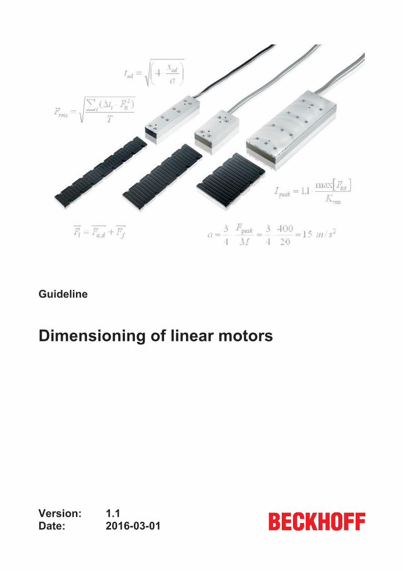
Guideline
Dimensioning of linear motors
1.12016-03-01
Version:Date:

Table of content
Table of content1 Foreword .................................................................................................................................................... 4
1.1 Notes on the documentation............................................................................................................. 41.2 Documentation issue status ............................................................................................................. 5
2 Introduction................................................................................................................................................ 6
3 System considerations ............................................................................................................................. 73.1 Power supply .................................................................................................................................... 73.2 Protective Earth (PE) ........................................................................................................................ 73.3 Heat dissipation ................................................................................................................................ 73.4 Mounting frame................................................................................................................................. 83.5 Positioning ........................................................................................................................................ 83.6 Measurement unit ............................................................................................................................. 83.7 Servo-controller ................................................................................................................................ 93.8 Accuracy ........................................................................................................................................... 93.9 Braking............................................................................................................................................ 103.10 Cables............................................................................................................................................. 103.11 Bearings.......................................................................................................................................... 113.12 Vertical applications........................................................................................................................ 113.13 Coupling of Coil Units ..................................................................................................................... 12
4 Linear motor dimensioning .................................................................................................................... 134.1 Introduction ..................................................................................................................................... 134.2 Physical background....................................................................................................................... 144.3 Used symbols ................................................................................................................................. 154.4 Used formulas................................................................................................................................. 164.5 The case ......................................................................................................................................... 18
4.5.1 Step 1: Worst case cycle .................................................................................................... 184.5.2 Step 2: Kinematic analysis.................................................................................................. 204.5.3 Step 3: Force analysis ........................................................................................................ 214.5.4 Step 4: Motor sizing ............................................................................................................ 224.5.5 Step 5: Amplifier sizing ....................................................................................................... 23
5 Appendix .................................................................................................................................................. 245.1 Heat transfer and temperature........................................................................................................ 245.2 Influences on accuracy ................................................................................................................... 265.3 DC link diagram .............................................................................................................................. 27
6 Technical data.......................................................................................................................................... 28
7 Support and Service................................................................................................................................ 29
Dimensioning of linear motors 3Version: 1.1

Foreword
1 Foreword
1.1 Notes on the documentationThis description is only intended for the use of trained specialists in control and automation engineering whoare familiar with the applicable national standards.It is essential that the following notes and explanations are followed when installing and commissioningthese components.
The responsible staff must ensure that the application or use of the products described satisfy all therequirements for safety, including all the relevant laws, regulations, guidelines and standards.
Disclaimer
The documentation has been prepared with care. The products described are, however, constantly underdevelopment.For that reason the documentation is not in every case checked for consistency with performance data,standards or other characteristics.In the event that it contains technical or editorial errors, we retain the right to make alterations at any timeand without warning.No claims for the modification of products that have already been supplied may be made on the basis of thedata, diagrams and descriptions in this documentation.
Trademarks
Beckhoff®, TwinCAT®, EtherCAT®, Safety over EtherCAT®, TwinSAFE®, XFC®and XTS® are registeredtrademarks of and licensed by Beckhoff Automation GmbH.Other designations used in this publication may be trademarks whose use by third parties for their ownpurposes could violate the rights of the owners.
Patent Pending
The EtherCAT Technology is covered, including but not limited to the following patent applications andpatents:EP1590927, EP1789857, DE102004044764, DE102007017835with corresponding applications or registrations in various other countries.
The TwinCAT Technology is covered, including but not limited to the following patent applications andpatents:EP0851348, US6167425 with corresponding applications or registrations in various other countries.
EtherCAT® is registered trademark and patented technology, licensed by Beckhoff Automation GmbH,Germany
Copyright
© Beckhoff Automation GmbH & Co. KG, Germany.The reproduction, distribution and utilization of this document as well as the communication of its contents toothers without express authorization are prohibited.Offenders will be held liable for the payment of damages. All rights reserved in the event of the grant of apatent, utility model or design.
Dimensioning of linear motors4 Version: 1.1

Foreword
1.2 Documentation issue statusVersion Comment1.1 Complete update1.0 First edition from October 2001
Dimensioning of linear motors 5Version: 1.1
Introduction
2 IntroductionWith the series AL2000 Beckhoff Automation GmbH & Co. KG introduced a wide, standard range of highquality linear motors. Due to a far-reaching standardization it is possible for designers to select the linearmotors themselves. However specialized knowledge is required for making the right design decisions. Thisknowledge is provided here step by step departing form a practical case.
A linear motor of Beckhoff Automation GmbH & Co. KG is not a system in itself. Usually a linear motor isbuild within a total machine concept or a working unit. Depending on the application choices have to bemade concerning the specifications and the sizing of the motor system. To assure a faultless operation allthe components of the motor system must comply to strict requirements. In this document the relevantchoices and requirements are discussed step by step. Several stages can be distinguished in a motorsystem analysis and design process.
In this leaflet you will be guided through these stages. First of all some system considerations have to bemade. These considerations will provide you with relevant practical information, for instance about the powersupply, heat dissipation, stability, accuracy and braking. As a designer of linear motor systems one shouldbe familiar with some theoretical physical laws and formulas. This information will be provided together withthe step by step analysis and design process. Special attention is given to mechanics.
Dimensioning of linear motors6 Version: 1.1

System considerations
3 System considerations
3.1 Power supplyThe performance of a linear motor is depending on the powersupply. Therefore a linear motor is specified foran appropriate voltage. The motor’s servo-amplifier can be connected to different voltage power supplies:230 to 480V, one- or three phase. By means of capacitors and a rectifier bridge the power is transformed ina DC voltage link. For high forces and velocities a DC link is required of at least 560 V. For limited forces andvelocities a 310 V DC link will do. For more information about the DC voltage link and the powersupply -motorforce relatio, please see the appendix - ’Peak force - velocity diagrams’ and - ’DC Link diagram’.
3.2 Protective Earth (PE)To prevent hazardous situations in case of an electrical failure, all metal components must be earthed. Thecoilunit housing and ironcore are earthened by the PE of the motor’s power cable. The cable shield isconnected to the housing but is not appropriate as PE. Earthen the cable shield on the servo-amplifier toprevent EMC problems. Follow instructions of the servo-amplifier. The magnet plates which are bolted to theframe, have to be electrically connected to the frame through the bolts. The stainless cover of themagnetplate is earthened through the magnetplates. The earthing has to be checked according to demandswith respect to electrical machine safety.
3.3 Heat dissipationHeat dissipation is a very important but difficult item. Every linear motor produces heat. The heat will mainlybe dissipated in the coil unit. There are two aspects to consider:
• This heat must flow away to ambient. If possible, the route of the heat conduction should be traced.• Heat generation causes temperature differences. That can be unacceptable for accuracy or other
reasons.
For your system, especially for the coil unit, the allowed temperature increase should be determined. Thecoil unit is fitted with a temperature sensor. In some designs the coil unit is not capable enough oftransferring the heat to the surrounding air. This counts especially for heavy loaded motors with a high ratiobetween motorforce and coil unit size. Also when the motor is thermally isolated or when ventilation isprevented by a hood. In these cases active cooling, like water cooling, is needed.
Without cooling an unacceptable heat up of the coil unit could occur. This could result in lower performance,thermic safety stops and even damage to your motor system. Water-cooling of the motor is very effective toreduce the heatflow and to obtain a constant temperature of the body. Water-cooling requires a waterconditioning unit containing at least a pump and a cooler. Beware of leaking. The temperature sensor can beused to detect failures of a watercooling system. An additional flow-sensor for controlling the cooling isstrictly not necessary, but yields extra safety and system information. If heat up of particular parts of thesystem is critical, a thermal insulation between the coil unit and the critical parts of the slide can beconsidered. This can reduce, but not nullify, the temperature rise. Sometimes small heat up also takes placein the magnet plates.
Dimensioning of linear motors 7Version: 1.1

System considerations
3.4 Mounting frameThe propelling forces of a linear motor are relatively high. Therefore the frame needs sufficient dynamicstiffness. Because of the required accuracy the frame should be insensible to shocks and vibrations.
A linear motor system gaines its accuracy by means of a high bandwidth feedback control loop. In this loopall mechanical parts such as load, frame and mountings are involved as well as the characteristics of theservocontroller and the linear encoder. The loop can be compromised by the characteristics of theconstruction. A bad construction can even cause total loss of control of the linear motor system.
Attention should be paid to the machine’s natural frequencies. Especially vibrations between 50 - 500 Hz indriving direction can be harmful for accuracy. To meet main problems a rule of thumb is: the motorsystemshould be rigidly connected to a massive and rigid body of at least 3 times the mass of the accelerated load.
3.5 PositioningLM applications require a sophisticated position and velocity feedback. A linear encoder and aservocontroller are taken up in the positioning system. The position of the slide is detected by ameasurement unit, a rulerprobe combination. The unit’s linear encoder returns the information to theservocontroller. The accuracy of the motor system depends strongly on this positioning system. Mostmeasurement units return incremental position information. So the linear motor has to do without theabsolute position of the slide. Especially when starting a motor operation this could be problematical.Herefore the slide is activated to some minimal test movement. This ‘magnetic alignment’ supplies thepositioning system with the required information.
3.6 Measurement unitThe series AL2000 motors use a wireless linear encoder for communication, speed and position control. Theperformance of the linear motor depends on the characteristics of the applied linear encoder. The use of anencoder system with a wire is not possible due to the bad dynamic characteristics. The unit is to beconnected and shielded with care. Any disturbance of the positioning signal could lead to positioning failuresand system oscillations.
Several types of measurement units can be applied, such as encoder kits by Heidenhain, Renishaw, Sikoand Numerik Jena. Mostly the resolution should lie between 0.1 and 5 μm. The accuracy of themeasurement unit must at least be better than the required accuracy of the motor system. Depending on thedynamics of the application it can be a factor 2 to 10.
The position of a moving body is measured with respect to the frame. Depending on its stiffness the frameacts more or less as a reaction force body. In the measurement appearing rotations or vibrations should bedisgarded. Therefore the mounting of the measurement unit is critical. The probe should be mounted asclose as possible to the mass centre of the complete moving unit (slide + load), whereas the ruler needs tobe placed near the centroid of the frame. The presence of rotations or vibrations is surmountable but theirmeasurement and feed back should be avoided.
In exceptional cases stick or slip effects are present. If so the measurement can be placed best between thebodies between that cause these effects.
Dimensioning of linear motors8 Version: 1.1

System considerations
3.7 Servo-controllerThe position information as well as the current in the coils is fed back to a servocontroller. Here theinformation is processed and translated into a proper inputsignal for the linear motor. Because the linearmotor needs a powerful input the signal is provided by a servo-amplifier.
The slide’s movement is directed by a three phase voltage pulse to the coil unit. The phase depends on theactual and the desired position of the slide. Hereby the motion’s directing quantity is the pulse width. In factthe servo-amplifier is a pulse width modulation amplifier with a fixed voltage and a fixed switching frequency.
AL2000 linear motors can ideally be combined with our servo-controller series AX2000. With preparedmotor-, feedback- and thermal protection cables we offer a complete and flexible linear motor system.
3.8 AccuracyGenerally the accuracy of the motor system is influenced by
• the accuracy of the error detection and positioning system,• the static stiffness of the system,• the dynamic stiffnes of the system
The main restriction for the accuracy arises from the lack of stability of the mounting frame, as discussedbefore. Here we discuss the restrictions of the linear motor system.
The linear motor itsself is an electromagnetic device. It deals with resistance and selfinductance. This impliesthat the current in the coils always lags behind the provided voltage signal. Since the magnetic force isdirectly linked to the current this means that the motorforce also lags behind.
With a static load (constant velocity) the positioning error will be small. Static disturbance arises fromcogging at stand-still or friction. Only a constant force has to be compensated. The system must react withan appropriate contant force to the disturbance. Generally this is done by an integrator action of the positioncontroller. This action takes some settling time. The more accurate the positioning, the higher the settlingtime. An accurate positioning typically requires a settling time of 5 to 25 ms.
With a dynamic load (accelerating or decelerating) the system shouldn’t just react appropriately but alsorapidly. Now the disturbance is dynamic. It arises from cogging during move, acceleration forces, vabrationsand contact forces (for instance when milling). Depending on the stiffness of the whole system the accurcycan deteriorate because of this. As a motor system can be considered as a kind of mass-spring system, it isobvious that the accuracy is worsened most by disturbances at the system’s natural frequency.
By the servo controller the returned information of the position, the velocity and the current is processed andtranslated into an appropriate voltage signal to the linear motor. The controller has to deal with some delaybecause of processor and update times. For a schematic overview, see the appendix ’Influences onaccuracy’.
The voltage signal to the linear motor is provided as pulses with a fixed switching frequency. Here the pulsewidth is the parameter to be regulated. Accuracy is limited by the fixed pulse frequency and the fixed pulsevoltage.
Needless to say that the accuracy of the positioning system also depends on the accuracy of the linearencoder and the thermal stability of the system’s components.
Dimensioning of linear motors 9Version: 1.1

System considerations
3.9 BrakingA controlled stop by the servocontroller is recommended, especially with short runouts. The Servocontrollerstops the motor as quick as possible using the maximum force of the motor. This action has to be activatedby a signal from the position controlling system. Herefore power up is required. In addition there should beno error status in the servocontroller. Usually a linear motor’s braking depends on the power supply andposition information. Without additive measurements this could result in an uncontrolled rollout to the end ofthe track in case of power loss or measurement and controlling errors. This means that a normal, free motionof the slide is only made possible by one or more unlocked or unbolted braking systems. Suitable is the useof relais. All active solutions need to be activated by the loss of power or control.
Risky situations by uncontrolled roll out can be prevented in several ways, such as:• The use of pneumatic rail guide brakes. This establishes a short runout. Some rail guide suppliers offer
brakes that are released by air pressure. These can be very useful for vertical applications and forsome safety situations.
• Short-circuiting of the motor coils. This results in a moderate runout. A braking force is generated whenthe coils are short circuited. There are standard relais for this action. The braking energy is dissipatedin the coil unit. Requirements for relay: current similar to Ipeak, contact resistance below 0.5 Ohms,switching time according to application requirements.
• The use of mechanical end stops. Mechanical end stops check the slide at the end of the track. Sothere is a maximum run out. Non-flexible end stops are not suitable. Hydraulic or pneumatic dampersabsorb the energy of the movement and stop the slide. Springs cause the slide to be returned, but canbe combined with damping by short circuiting. Requirements: no damage/danger by uncontrolledmovement possible
• A combination of the mentioned measurements.
Which methods are useful depends on the application. For design, consider at least the followingworst case situations:
• Safety violation detected by sensors (linear motor must stop immediatly).• Programming error, (uncontrolled movement at maximum speed).• Overtemperature in motor, (linear notor must stop within seconds).• Fatal error in the Servocontroller (uncontrolled movement).• Main Power loss (loss of motor control and force).• DC control Power loss (loss of motor control and force).• Failure of end of track detector, (hitting end of track).• Air pressure loss.
3.10 CablesLinear motors have moving cables. In case of watercooling the coolant lines move as well. Take care ofmechanical support of the cables and lines. Make moving parts replacable.
Dimensioning of linear motors10 Version: 1.1

System considerations
3.11 BearingsTo assure a free movement the slide should be provided with robust bearings that run smoothly on two rails.The rails are mounted aside the magnet plate. This construction ensures the right airgap between the coilunit and the magnet plate. For the sideward positioning of the coil unit to the magnet plates a small toleranceis acceptable. The coil unit contains iron parts which are strongly attracted by the permanent magnets of themagnet plate whether or not the motor is electrically propelled. This attraction force should continuously bebeared by the linear bearings. Therefore it is important to take the attraction force into account whendimensioning the bearings.
3.12 Vertical applicationsLinear motors in vertical applications often require a counterbalance mechanism to prevent dropping the loadin the event of power interuption. The counterbalance neutralizes the gravitational force, making anadditional continous force of the linear motor superfluous. The inertia of the motor system though couldincrease. For counterbalance mechanisms can be thought of springs, pneumatic cylinders orcounterweights. When the moving mass is small, especially when the gravitational force is significantlysmaller then the continuous attraction force, the application could do without a counterbalance mechanism.
Dimensioning of linear motors 11Version: 1.1

System considerations
3.13 Coupling of Coil Units
A magnet track can be shared by more than one slide. A servo controller can be shared as well. Thefollowing combinations can be distinguished (see figure).
• 1. Two (or more) coil units share a magnet track, each of them directed by it’s own amplifier.• 2. Two coil units are coupled (rigidly connected), sharing one amplifier and one magnet track.• 3. Two coil units are coupled, sharing one amplifier. They are running on different parallel tracks.
When two linear motors share one amplifier, they are connected in parallel. For motor sizing objectives thecurrents of both motors should be added up. It is not possible to mount motors in series. Use one of thetemperature sensors. Use the sensor of the coil unit which is expected to have the worst cooling and also toreach the highest temperature.
Dimensioning of linear motors12 Version: 1.1

Linear motor dimensioning
4 Linear motor dimensioning
4.1 IntroductionThe choice for the right linear motor size depends on the requirements of your positioning application,especially the worst case requirements. These requirements can be modelled and translated in somecharacteristic parameters, such as time, maximum speed, mass of load, inertia and friction. By means of akinematic and force analysis these parameters can be linked to typical motor parameters, like peak force andcontinuous force. On base of the calculated values an appropriate motor size is to be selected. In additionthe appropriate servo-amplifier can be chosen. Below a case is worked out as a kind of finger exercise.Understanding this case requires basic knowledge of some physical laws and principles, especiallykinematics and dynamics.
Dimensioning of linear motors 13Version: 1.1

Linear motor dimensioning
4.2 Physical backgroundUsually a linear motor’s motion can be distinguished in 3 stages:
1. acceleration 2. constant (or maximum) velocity 3. deceleration
Velocity-time diagram for a combined or ' long motion'
During ta the accelaration takes place and during tc the velocity is constant at its maximum. The decelarationto stand still takes place in td. The total distance covered by the motion equals the area under the graphicaldrawing. During acceleration and decelaration the largest forces are displayed while the movement atconstant speed only requires the force needed to overcome friction. A linear motor that is constantly movingto and fro without reaching its maximum velocity is thus loaded upmost.
Velocity-time diagram for a combined or ' short motion'
v(m/s)
vmax
t(s)ta
td
0
Dimensioning of linear motors14 Version: 1.1

Linear motor dimensioning
4.3 Used symbolssymbol unit descriptiont s timeta td tad time needed for acceleration, deceleration or bothtc time needed to cover a distance at constant speedDt small time differenceT total timev m/s velocityva velocity after acceleration from stand stillvmax maximum velocitya m/s² accelerationx m distancexa1 xd1 xc distance covered by acceleration, deceleration or constant speedX total distance of a combined movement (ta+tc+td)F N forceFa1 Fd1 Fad force needed for acceleration and/or decelerationF1 force applied by the load (like processing contact forces)Fpeak motor´s peak forceFcont motor´s continuous forceF1 friction forceFms mean force over a longer period (root mean square)M kg mass of the loadQ W dissipated powerS25 N²/W motor constant (slope) at 25°CSTW motor constant at working temperatureK N/A motor force constantKms mean motor force constant (depending on the current)I A currentIpeak motor´s peak currentIcont motor´s continuous currentRth °C/W thermal resistanceTw °C working temperature
Dimensioning of linear motors 15Version: 1.1
Linear motor dimensioning
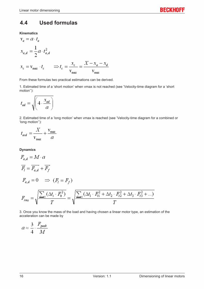
4.4 Used formulas
Kinematics
From these formulas two practical estimations can be derived.
1. Estimated time of a ‘short motion’ when vmax is not reached (see ’Velocity-time diagram for a ‘shortmotion’’):
2. Estimated time of a ‘long motion’ when vmax is reached (see ’Velocity-time diagram for a combined or‘long motion’’):
Dynamics
3. Once you know the mass of the load and having chosen a linear motor type, an estimation of theacceleration can be made by
Dimensioning of linear motors16 Version: 1.1

Linear motor dimensioning
Other formulas
The dissipated power by the linear motor:
The mean motor force constant:
Estimated maximum needed current:
Dimensioning of linear motors 17Version: 1.1

Linear motor dimensioning
4.5 The caseA gripper places components and moves to and fro continuously: X = 0.8 m. The duration of a singlemovement of 0.8 m can ultimately be 0.4 s. On both sides of the movement 0.5 s is needed for settling andgripper action.
Other parameters are:• The mass of the load: M = 20 kg.• Friction: Ff = 30 N.• Slide air cooled, large cooling surface.• Accuracy approximately 0.02 mm.• Maximum speed: vmax = 3 m/s
4.5.1 Step 1: Worst case cycleLook for the severest job-cycle your application meets. Worst cases happen generally in two situations. Firstwhen the motor produces a high holding force and second where the motor is accelerating and decelerationcontinuously (short moves) with little standstill time. Now determine the quantities during the severest job-cycle. In the case there is only one job-cycle. First let’s choose the type AL2006 motor.
Calculate the acceleration of this motor:
Note: The value of Fpeak is can be found on the AL2000 series specification sheet.
The formula to calculate the required time to cover the distance depends on whether the linear motorreaches its maximum velocity vmax during the movement.
In the case of a short move (vmax not reached):
In this case the velocity after ta is:
This calculated velocity va exceeds the maximum velocity required for this application (vmax = 3 m/s). It isobvious that the chosen linear motor reaches the maximum velocity somewhere during the motion. In thiscase we will have to calculate the required time using the formula for long moves.
Notice that this calculated time exceeds the required travelling time for this application (0,4 s). Therefore amore heavy type motor like the AL2012 needs to be selected.
So let’s choose the type AL2012 and repeat the calculations.
Dimensioning of linear motors18 Version: 1.1

Linear motor dimensioning
Acceleration:
Required time using the formula for short moves (vmax not reached):
Maximum velocity during acceleration:
Once again this velocity exceeds vmax therefore the actual velocity is to be calculated using theformula for long moves (vmax reached):
This time is in accordance with the requirements. So the AL2012 seems to be the right choice
Dimensioning of linear motors 19Version: 1.1
Linear motor dimensioning
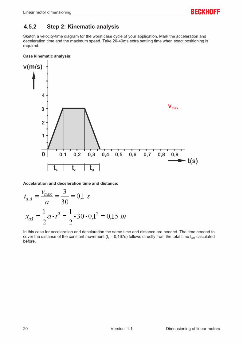
4.5.2 Step 2: Kinematic analysisSketch a velocity-time diagram for the worst case cycle of your application. Mark the acceleration anddeceleration time and the maximum speed. Take 20-40ms extra settling time when exact positioning isrequired.
Case kinematic analysis:
Accelaration and deceleration time and distance:
In this case for acceleration and decelaration the same time and distance are needed. The time needed tocover the distance of the constant movement (tc = 0,167s) follows directly from the total time tacd calculatedbefore.
Dimensioning of linear motors20 Version: 1.1

Linear motor dimensioning
4.5.3 Step 3: Force analysisSketch a motorforce-time diagram. The motorforce depends on:
• Required accelation and deceleration forces.• Friction forces.• Processing contact forces (for instance when using bits or cutters).• For vertical applications: the gravitational forces
The maximum force Fmax is the overall maximum force, driving or braking. The motor’s peak force shouldmeet this. Consider the square time average force Frms. This force should remain below the motor’scontinuous force.
Case force analysis: motorforce versus time diagram:
In the case we get the following results.
Parameter Acceleration ohase(ta)
Maximum velocityphase (tc)
Deceleration phase(td)
Settling and grip-per action phase
Dt(s) 0.1 0.167 0.1 0.5a(m/s²) 30 0 -30 0Fa,c,d (N) 600 0 -600 0Ff (N) 30 30 30 0Flot (N) 630 30 -570 0
The mean force during the cycle:
Dimensioning of linear motors 21Version: 1.1

Linear motor dimensioning
4.5.4 Step 4: Motor sizingTwo main criteria for the motor’s thrust force should be kept in mind:
1. A linear motor’s peak force is depending on the velocity of the coil unit. This can be seen in the linearmotor Specification Diagrams.
Peak force versus velocity (velocity and force in the same direction)
As shown in the diagram this effect depends on the power supply. The speed at F=0 is the limit. For morediagrams see the appendix - ’Peak force - velocity diagrams’.
2. Frms must remain below the motor’s specified continous force Fcont. The continuous force is a measure forthe thermal load of the linear motor. Amongst others it depends on the cooling conditions. For watercooling,Fcont is specified. Without cooling, Fcont is to be estimated. For more information, see the appendix ’Heattransfer and Temperature’.
Choose a linear motor which meets both criteria.
From the calculated mean force and the specified motor constant the dissipated power is obtained.
This power equals the heat production in the coil unit. It has to be conducted to ambient.
Dimensioning of linear motors22 Version: 1.1

Linear motor dimensioning
4.5.5 Step 5: Amplifier sizingFor most servo controllers the duration of the peak current is limited from 0.25 to several seconds. If thecurrent exceeds the continous current during a period, longer than this specified time, the required continouscurrent must be raised to this higher level. So check whether in long periods the required current is over thecontinuous current. Choose a servo controller which can deliver the required Icont and Ipeak.
Here, from the specified Krms and the calculated Frms we obtain
The maximum force during the cycle is 630N, so the servo-amplifier has to generate a maximum current
Since the periods of I>Icont are no longer than 5 seconds the AX2006 is full filling the requirements.
For braking heavy loads from high speeds (for example 100 kg at 4 m/s) the motor feeds back the electricalpower into the servo-amplifier. Most of it is dissipated in a braking resistor. Of course this resistor should beof sufficient power, especially when such situations occur frequently (for instance in short repeated moves).
Dimensioning of linear motors 23Version: 1.1

Appendix
5 Appendix
5.1 Heat transfer and temperatureThe dissipated power in the coil unit causes a heatflow to the ambient. The resulting temperature rise of thecoils is determined by the thermal resistance of the heat conducting route. The coil unit is fitted with atemperature sensor of the PTC 1kOhm type. This sensor detects overtemperature of the coil unit. Theservocontroller should check overtemperature at a level of 1000 Ohms
The water-cooling unit can be connected serial as well as parallel. Parallel connection demands a good flowthrough the T-connection pieces. The watercooling lines are linked to the coil unit by means of standard M5connections. Haake or Julabo cooling system are compliant with Beckhoff Automation GmbH & Co. KGlinear motors.
As noticed before the linear motor’s continuous force is a measure for the thermal load. Fcont depends on themotor constant STW and is limited by the allowed working temperature. For watercooling, Fcont is specified.In that case the thermal resistance of both motor and water can be determined. The heat flow results in alimited rise of the temperature. Tcoils can be kept controlled beneath the allowed working temperature.
Heatflow and watercooling
The motor constant depends on the temperature.
This means that the motor’s continuous force decreases at high temperatures. When no water cooling isapplied, the heat flow usually results in a significant rise of the temperature. The amount depends on thesituation. Sometimes it is not so easy to keep Tcoils controlled beneath the allowed working temperature.
Dimensioning of linear motors24 Version: 1.1
Appendix
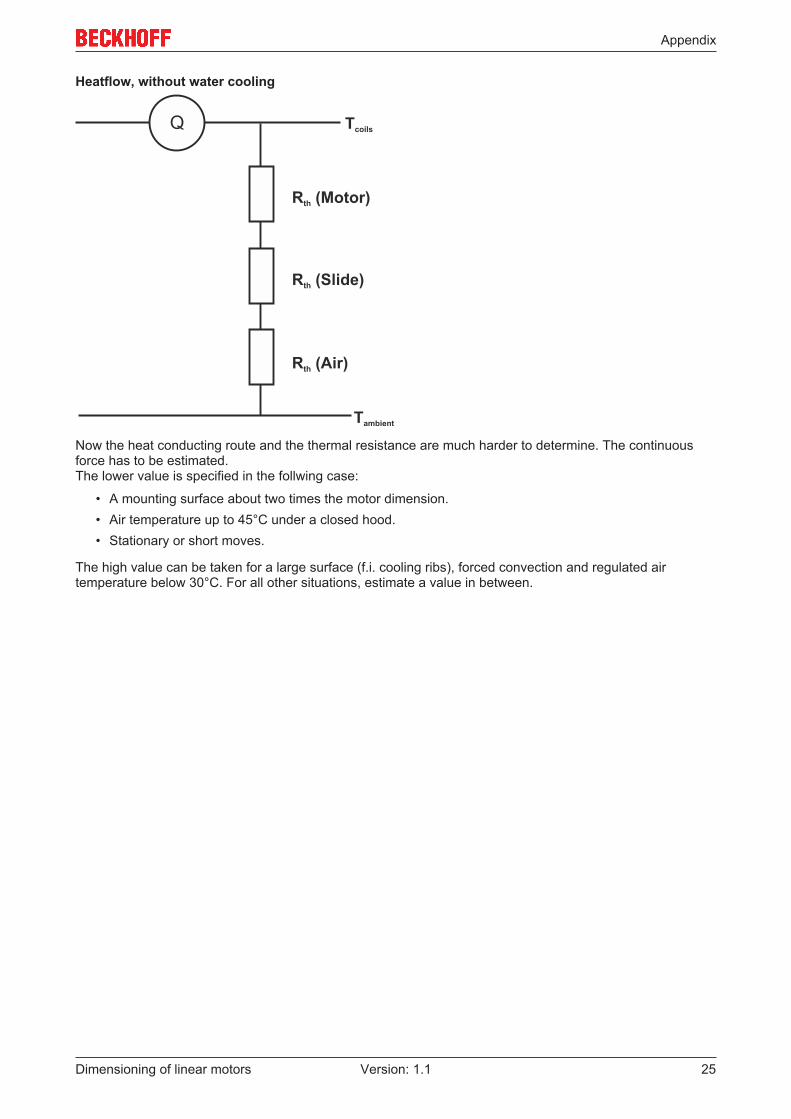
Heatflow, without water cooling
Now the heat conducting route and the thermal resistance are much harder to determine. The continuousforce has to be estimated. The lower value is specified in the follwing case:
• A mounting surface about two times the motor dimension.• Air temperature up to 45°C under a closed hood.• Stationary or short moves.
The high value can be taken for a large surface (f.i. cooling ribs), forced convection and regulated airtemperature below 30°C. For all other situations, estimate a value in between.
Dimensioning of linear motors 25Version: 1.1
Appendix
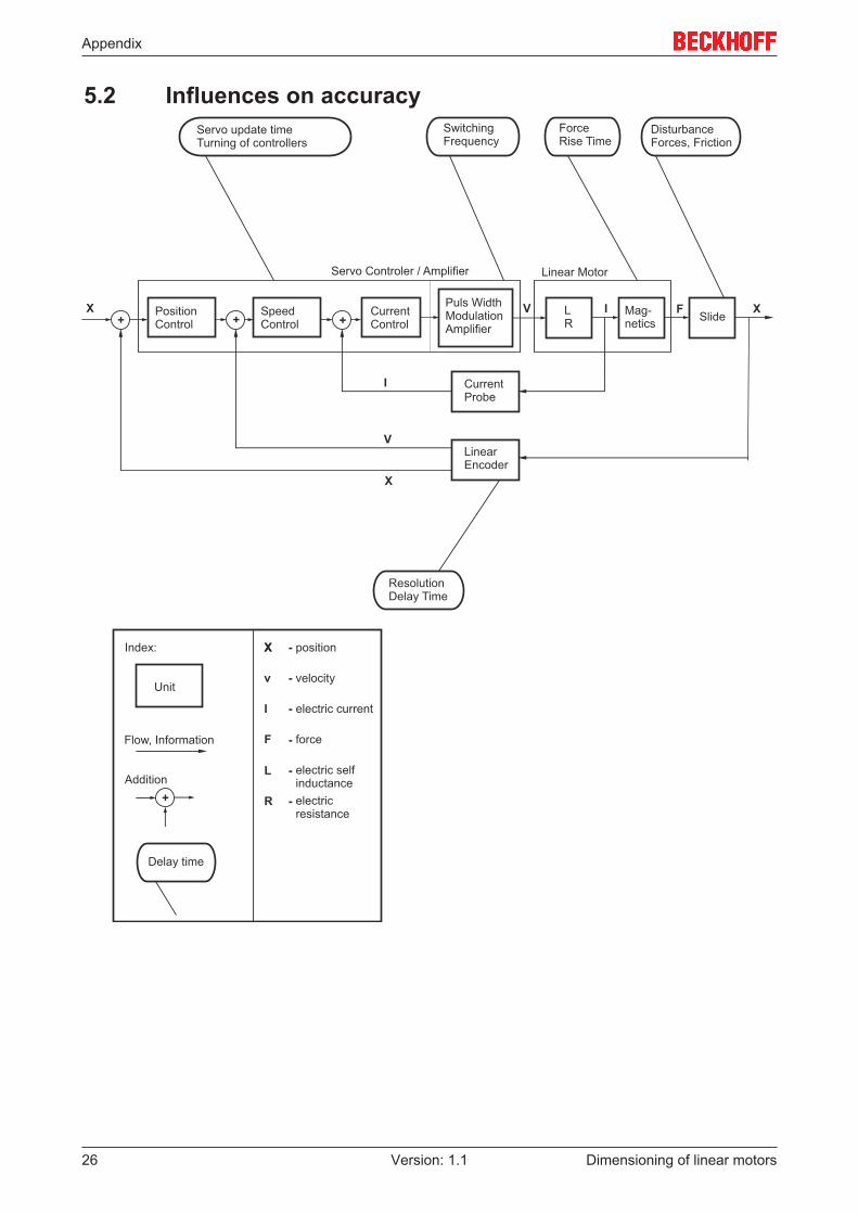
5.2 Influences on accuracy
Dimensioning of linear motors26 Version: 1.1

Appendix
5.3 DC link diagram
L1
L3
L2
D3
D2
D1
C
D6
D5
D4
U
W
V
T3
T2
T1
T6
T5
T4
L1, L2 and L3: the three phases of the AC power supply.
D1 ... D6: these diodes are part of the 3 phase diode bridge.
C: the DC link capacitor.
Tb: the activating transistor of the braking resistor.
Rb: the braking resistor.
T1 ... T6: transistors of the PWM amplifier stage.
U, V and W: The coils of the motor.
Dimensioning of linear motors 27Version: 1.1
Technical data
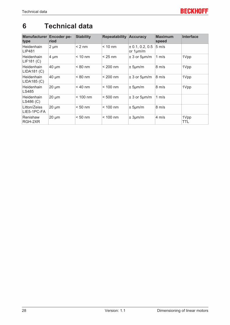
6 Technical dataManufacturertype
Encoder pe-riod
Stability Repeatability Accuracy Maximumspeed
Interface
HeidenhainLIP481
2 µm < 2 nm < 10 nm ± 0.1, 0.2, 0.5or 1µm/m
5 m/s
HeidenhainLIF181 (C)
4 µm < 10 nm < 25 nm ± 3 or 5µm/m 1 m/s 1Vpp
HeidenhainLIDA181 (C)
40 µm < 80 nm < 200 nm ± 5µm/m 8 m/s 1Vpp
HeidenhainLIDA185 (C)
40 µm < 80 nm < 200 nm ± 3 or 5µm/m 8 m/s 1Vpp
HeidenhainLS485
20 µm < 40 nm < 100 nm ± 5µm/m 8 m/s 1Vpp
HeidenhainLS486 (C)
20 µm < 100 nm < 500 nm ± 3 or 5µm/m 1 m/s
Litton/ZeissLIE5-1PC-FA
20 µm < 50 nm < 100 nm ± 5µm/m 8 m/s
RenishawRGH-2XR
20 µm < 50 nm < 100 nm ± 3µm/m 4 m/s 1VppTTL
Dimensioning of linear motors28 Version: 1.1

Support and Service
7 Support and ServiceBeckhoff and their partners around the world offer comprehensive support and service, making available fastand competent assistance with all questions related to Beckhoff products and system solutions.
Beckhoff's branch offices and representatives
Please contact your Beckhoff branch office or representative for local support and service on Beckhoffproducts!
The addresses of Beckhoff's branch offices and representatives round the world can be found on her internetpages:http://www.beckhoff.com
You will also find further documentation for Beckhoff components there.
Beckhoff Headquarters
Beckhoff Automation GmbH & Co. KG
Huelshorstweg 2033415 VerlGermany
Phone: +49(0)5246/963-0Fax: +49(0)5246/963-198e-mail: [email protected]
Beckhoff Support
Support offers you comprehensive technical assistance, helping you not only with the application ofindividual Beckhoff products, but also with other, wide-ranging services:
• support• design, programming and commissioning of complex automation systems• and extensive training program for Beckhoff system components
Hotline: +49(0)5246/963-157Fax: +49(0)5246/963-9157e-mail: [email protected]
Beckhoff Service
The Beckhoff Service Center supports you in all matters of after-sales service:
• on-site service• repair service• spare parts service• hotline service
Hotline: +49(0)5246/963-460Fax: +49(0)5246/963-479e-mail: [email protected]
Dimensioning of linear motors 29Version: 1.1