guidebook for cost-effective strategies for...
TRANSCRIPT

0-4449-P1 Guidebook for Selecting Cost-Effective Wireless Communication Technologies for Intelligent Transportation Systems Authors:
Yi-Chang Chiu, Haitham Logman, Mo-Ning Chiu, and Analsoni Sunkara Department of Civil Engineering, The University of Texas at El Paso
Carl Haas Center for Transportation Research, The University of Texas at Austin Project 0-4449: Cost-Effective Strategies for Communicating with Remote Surveillance Stations October 2003 Revised March 2005 Performing Organization: Center for Transportation Research The University of Texas at Austin 3208 Red River, Suite 200 Austin, Texas 78705-2650
Sponsoring Organization: Texas Department of Transportation Research and Technology Implementation Office P.O. Box 5080 Austin, Texas 78763-5080
Project conducted in cooperation with the U. S. Department of Transportation, Federal Highway Administration, and the Texas Department of Transportation. Abstract: The advances of modern communication technologies have changed the way the roadway information is collected. Innovative surveillance systems powered by various communication technologies have been installed to support various transportation operations. The abundance of available communication technologies and multiple available communication system configurations presents overwhelming challenges for traffic engineers in selecting proper communication technologies for users of various traffic operation and ITS applications. The objective of this research is to propose an effective approach to characterize available communication technology choices, and analyze how they can be applied to various traffic operations. Of particular interest is the development of a guidebook to facilitate the decision-making in choosing appropriate communication technology given the operational requirements and decision objectives. Because of the fast-paced developments in communication technologies, a web-based Knowledge Management System that enables on-line learning of applications vs. communication technology choices, as well as continual updates of the technology choice set, has been developed to ensure the continual usability of this research product.
Keywords: telecommunication, wireless communication, intelligent transportation systems, cost-effective strategies, life-cycle cost analysis, life-cycle risk analysis, decision-making, decision tree, knowledge management system
No. of Pages: 108


Table of Contents
1. About this Guidebook .................................................................................................................................. 1 2. Overview of Emerging Communication Technologies .............................................................................. 3
2.1. Wireline and Wireless Technologies....................................................................................................... 3 2.2. Emerging Wireless Technologies............................................................................................................ 7
2.2.1. 802.11 (Wi-Fi).................................................................................................................................. 7 2.2.1.1. Technology Overview.................................................................................................................................7 2.2.1.2. Applications/Vendors..................................................................................................................................8 2.2.1.3. Latest Product/Technology Developments..................................................................................................8 2.2.1.4. Case Study and Analysis .............................................................................................................................9
2.2.2. Mesh Networking........................................................................................................................... 10 2.2.2.1. Technology Overview...............................................................................................................................10 2.2.2.2. Latest Product/Technology Developments................................................................................................12 2.2.2.3. Case Study and Analysis ...........................................................................................................................12
2.2.3. 802.16 (WiMAX) ........................................................................................................................... 13 2.2.3.1. Technology Overview...............................................................................................................................13 2.2.3.2. Case Study and Analysis ...........................................................................................................................14 2.2.3.3. Latest Deployments...................................................................................................................................14
2.2.4. General Packet Radio Service (GPRS)........................................................................................... 15 2.2.4.1. Technology Overview...............................................................................................................................15
2.2.5. Multi-Code Direct Sequence Spread Spectrum Technology (M-CDSSS) ..................................... 16 2.2.5.1. Technology Overview...............................................................................................................................16 2.2.5.2. Applications/Vendors................................................................................................................................16 2.2.5.3. Latest Product/Technology Developments................................................................................................16 2.2.5.4. Case Study and Analysis ...........................................................................................................................16
2.2.6. Wide-Band Orthogonal Frequency Division Multiplexing ............................................................ 17 2.2.6.1. Technology Overview...............................................................................................................................17 2.2.6.2. Applications/Vendors................................................................................................................................17 2.2.6.3. Latest Product/Technology Developments................................................................................................17 2.2.6.4. Case Study and Analysis ...........................................................................................................................18
2.2.7. 3G Cellular Wireless ...................................................................................................................... 18 2.2.8. Summary ........................................................................................................................................ 20
2.3. Wireless Communication Service Providers ......................................................................................... 23 2.4. Wireless Communication System Vendors/Contractors........................................................................ 26
3. Strategies for Wireless Communication Configuration and Technology Selection .............................. 27 3.1. Budget and Risk Consideration in Wireless Technology Acquisition................................................... 29 3.2. Life-Cycle Cost and Risk Analysis ....................................................................................................... 32
3.2.1. Life-Cycle Cost Analysis ............................................................................................................... 32 3.2.2. Life-Cycle Risk Analysis ............................................................................................................... 39
3.3. Life-Cycle Cost and Risk Analysis Guideline....................................................................................... 41 4. Wireless Technology Acquisition Knowledge Management System ...................................................... 51
4.1. Knowledge Management Concept ........................................................................................................ 51 4.2. Knowledge Management System Structure and Features ..................................................................... 54
5. Additional Resources.................................................................................................................................. 69 6. References ................................................................................................................................................... 71 Appendix A—Data Rate Requirement for Traffic Management Applications......................................... 73 Appendix B—Worksheets for Life-Cycle Cost and Risk Analysis Example............................................. 77 Appendix C—Wireless Equipment and Wireless Data Service Vendors
Registered in the Knowledge Management System Website ............................................................... 85


List of Figures Figure 2-1. Transmission of video and data among trailers, relay site, TMCs, and UCI during the mobile surveillance
and wireless communication systems field operational test (Klein, 1999) ...............................................3 Figure 2-2. Maximum distance between base stations for fixed wireless technology (Rysavy, 2002).........................5 Figure 2-3. Service range of three types of wireless communication technologies (Rysavy, 2002).............................5 Figure 2-4. Mesh network in Intelligent Transportation Systems Application
(source: MeshNetworks, 2003) ...............................................................................................................10 Figure 2-5. 802.16 functional architecture. Source: (Stallings, 2001) .........................................................................14 Figure 3-1. Wireless technology acquisition project process.......................................................................................28 Figure 3-2. Total cost concept (Blanchard, 1998) .......................................................................................................32 Figure 3-3. Example of lifetime of a wireless technology alternative. ........................................................................34 Figure 3-4. Expenditure diagram with activity, costs, and timing. ..............................................................................37 Figure 3-5. Decision tree framework...........................................................................................................................40 Figure 3-6. Decision framework for lease or own decision. ........................................................................................41 Figure 3-7. Example system configuration (1). ...........................................................................................................43 Figure 3-8. Example of system configuration (2). .......................................................................................................43 Figure 3-9. Example system configuration (3). ...........................................................................................................44 Figure 3-10. Decision diagram for the example application........................................................................................45 Figure 3-11. Expenditure diagram for scenario 1-1.....................................................................................................46 Figure 3-12. Life-cycle cost and risk analysis results for the Example. ......................................................................49 Figure 4-1. Cycle of knowledge (Burk, 1999). ............................................................................................................52 Figure 4-2. Main page of knowledge management system for wireless technology acquisition.................................55 Figure 4-3. Personalized homepage for registered members showing personalized information................................56 Figure 4-4. Main page of discussion forum. ................................................................................................................57 Figure 4-5. Threaded discussion lists and topics. ........................................................................................................58 Figure 4-6. Example of project information, posted by TxDOT engineer in project center. .......................................59 Figure 4-7. Main page of decision support module. ....................................................................................................60 Figure 4-8. Decision support module—looking for general technical information. ....................................................61 Figure 4-9. Decision support module—have made a lease or own decision ...............................................................62 Figure 4-10. Main page of knowledge base.................................................................................................................63 Figure 4-11. Sub-sections of wireless technology knowledge base.............................................................................64 Figure 4-12. Sub-sections of wireless technology management knowledge base. ......................................................64 Figure 4-13. Sub-sections of TxDOT experience knowledge base..............................................................................64 Figure 4-14. TxDOT experience–interview summaries. .............................................................................................65 Figure 4-15. Book section in technology project management in knowledge base. ....................................................66 Figure 4-16. Tutorial section in wireless technology in knowledge base. ...................................................................67 Figure 4-17. Web-based knowledge management system structure for wireless
technology acquisition. ..........................................................................................................................68


List of Tables
Table 2-1. Wireline technology characteristics .............................................................................................................4 Table 2-2. Wireless technology characteristics .............................................................................................................6 Table 2-3. Typical data rates from different cellular standards ...................................................................................19 Table 2-4. Bandwidth, cost, and reliability comparison between communication technologies .................................21 Table 2-5. Nationwide or regional wireless communication service providers in Texas ............................................24 Table 3-1. A brief timeline in wireless technologies evaluation (Dubendorf, 2003)...................................................31 Table 3-2. Expected Future Life Span of Various Cellular Wireless Technologies ....................................................36 Table 3-3. Worksheet for calculating life-cycle cost for scenario 1-1. ........................................................................47 Table 3-4. Decision Tree Analysis Final Results.........................................................................................................48 Table 4-1. Commonly adopted KM disciplines...........................................................................................................53 Table A-1. Lane-by-lane, station, and segment data transmission characteristics.......................................................73 Table A-2. Transmission rate for various data and video requirements (Klein, 2001)................................................74 Table A-3. Data types and transmission rates for selected traffic management applications ......................................75 Table B-1. Decision tree worksheet for example of problem ......................................................................................77 Table B-2. LCCs worksheet for scenario 1-1. .............................................................................................................78 Table B-3. LCCs worksheet for scenario 1-2. .............................................................................................................78 Table B-4. LCCs worksheet for scenario 1-3. .............................................................................................................78 Table B-5. LCCs worksheet for scenario 2-1. .............................................................................................................79 Table B-6. LCCs worksheet for scenario 2-2. .............................................................................................................79 Table B-7. LCCs worksheet for scenario 2-3. .............................................................................................................80 Table B-8. LCCs worksheet for scenario 3-1. .............................................................................................................81 Table B-9. LCCs worksheet for scenario 3-2. .............................................................................................................81 Table B-10. LCCs worksheet for scenario 3-3 ............................................................................................................82 Table B-11. LCCs worksheet for scenario 3-4 ............................................................................................................82 Table B-12. LCCs worksheet for scenario 3-5. ...........................................................................................................83 Table B-13. LCCs worksheet for scenario 3-6. ...........................................................................................................83 Table B-14. LCCs worksheet for scenario 3-7. ...........................................................................................................84

1
1. About this Guidebook While major installations to support advanced traffic management applications are
being deployed along Texas’ major urban freeways, the need for surveillance and/or detector capabilities also exists in numerous remote locations with no established telecommunications capability for the transmission of roadway-related data. The abundance of available communication technology choices, ranging from the decade-old but robust technologies (e.g., analogue radio, spread spectrum radio, microwave, etc.) to the state-of-the-art and soon-to-be-available technologies (e.g., 3G cellular wireless), presents difficult challenges for traffic engineers in deciding upon a cost-effective means of data transmission from a remote location to a freeway traffic management center.
In reality, not all technology options are suitable for the desired application. In conjunction with the application, the availability of site characteristics such as power, line of sight, transmission distance to adjacent relay/receiving site, transmission data rate requirements, frequency, and bandwidth will determine the range of options available and generally point to a specific technology choice. Furthermore, for a particular application, multiple communication system configurations that satisfy the application’s functional and physical requirements are likely to exist. Different configurations involve distinct wireless or wireline technologies. Under such a circumstance, choosing the most suitable configuration/technology becomes a challenging task for Texas Department of Transportation (TxDOT) engineers.
What is required to assist TxDOT engineers in their planning is an application guide for the Intelligent Transportation Systems (ITS) communications. Covering wireline and wireless technologies, the guide should start with the traffic application as the basis for selection of a communication technology. The guide should include an examination of both the benefits and limitations of the various technologies and should address issues such as current and future availability, reliability of service, and cost expectations. Recognizing this need, the Federal Highway Administration (FHWA) has in the past prepared a special chapter on communication technologies in the Traffic Control Systems Handbook (Federal Highway Administration, 1996). However, the technology is evolving at a fast pace, especially in the wireless arena, and documents soon become obsolete by the time they are published. In addition to the need to update the information in the Traffic Control Systems Handbook, it is desirable to develop a mechanism for continual update of this information in order to keep it current for the use of traffic engineers. Furthermore, it is not sufficient simply to provide descriptive information on the various available technologies. What is needed is a specific set of procedures or decision aids that can be followed to identify the most appropriate configuration/technology for a particular application.
This guidebook is aimed to provide organized and structural information to TxDOT engineers in order to assist the decision making of wireless communication technology acquisition. This guidebook starts with a brief survey of emerging communication technologies, with a particular emphasis on wireless technologies. Next, the guidebook describes the strategies and procedures for selecting cost-effective and minimal-risk communication configurations and wireless technologies. A web-based knowledge management system (WBKMS) that compiled all the information and decision-aid models was created as a part of the deliverables for this project. This guidebook discusses the features of the WBKMS, and provides guidance to using these features. Appendix A provides an overview of the common data transmission rate requirements for traffic

2
operations and ITS applications. Appendix B includes the life-cycle cost and risk analysis worksheets for the ITS application example. Appendix C contains a partial list of the wireless equipment and data service vendors/contractors who registered in the WBKMS.

3
2. Overview of Emerging Communication Technologies
Wireline and wireless communication technologies continue to be innovated at an explosive rate. Old technologies, although slow, low-bandwidth, and medium-dependent, tend to be robust and resilient to various environmental conditions. Newer technologies generally offer much higher data throughput, break the barriers of communication media, and provide flexible configurations and a wide range of services.
2.1. Wireline and Wireless Technologies
Wireline communication technologies, developed much earlier than wireless technologies, offer services that allow for various data, voice, and video applications. New communication protocols and materials continue to increase the throughput of data that run through traditional media like copper wires or coaxial cables. As shown in Table 2-1, various technologies offer transmission rates ranging from 10 bps (twisted pair copper) to 10 Gbps (fiber optics). Technologies that hybridize various media (e.g., Asymmetric Digital Subscriber Line (ADSL) using copper wire and satellite) could improve the service, data rate, and configuration flexibility. The upcoming new technology in wireline communication is the use of power lines not only to transmit electricity but also to deliver data, voice, and videos.
Wireless communication technologies have been advancing at an exponential rate over the past decade. Using air as the primary transmission medium, wireless communications can take place under almost any conditions by using appropriate technologies. As such, wireless technologies have been increasingly used in various ITS and transportation operation applications. Figure 2-1 shows the communication architecture and techniques used during the Mobile Surveillance and Wireless Communication Systems Field Operational Test (Klein, 1999). In the field operational test, the spread spectrum radio was used to provide direct links between the surveillance trailers and relay sites, and among the relay site, the district office, the TMC, and the research laboratory.
Figure 2-1. Transmission of video and data among trailers, relay site, TMCs, and UCI during the mobile surveillance and wireless communication systems field operational test (Klein, 1999)

4
Table 2-1. Wireline technology characteristics
Existing Technologies Twisted-pair Medium – copper wire
Operates at 300 to 3,00 Hz Offers 56 bps with range 9 to 15 miles Support data, voice, slow scan TV
ISDN Offers 64 kbps ADSL (copper wire)
Offers 1.5 Mbps to 6.3 Mbps downstream, depending on wire gauge, protocol, and distance Support data, voice and video
ADSL (copper wire + satellite)
Offers 1.5 Mbps downstream, 128 kbps upstream Support data, voice and video
Cable Medium – coaxial cable Operates at 5 to 350 MHz Offers 10 Mbps downstream, 1.5 Mbps to 10 Mbps upstream Support data, voice and video
Fiber-optics Medium – fiber glass Operates using laser waves Offers from 10 Mbps to 10s Gbps Support data, voice and video, usually used in backbone network, now increasing used at access network
Upcoming Technologies Power Line Medium – electricity power line
Offers up to 15 Mbps data transfer rate Latest standard released in 2002z Field test in 2002 (Homeplug, 2002)
Source: (FHWA, 1996, Alliance, 2003); Regis, 2000; Homeplug Network Alliance, 2002) A partial list of commonly available wireless technologies is provided in Table 2-2.
Detailed discussions of specific wireless technologies are given in section 2.2. Circuit-switched technology has already been available across existing analog and
digital cellular networks worldwide for a decade. Packet-switched data services are also available in several countries over dedicated frequency bands through BellSouth Wireless Data (formerly known as RAM Mobile Data before BellSouth acquired it) and ARDIS in several countries. Over Cellular Digital Packet Data (CDPD) networks standards (e.g., pACT and iDEN) have propagated into various wireless data markets in many geographical areas. A number of telecommunications companies have deployed circuit-switched CDPD for a decade, allowing cellular operators to cost-effectively offer data service where voice services already exist. Most U.S. carriers have already adopted CDPD, and some carriers, such as Ameritech and Bell Atlantic NYNEX, have linked their CDPD networks to offer seamless roaming coverage throughout their service areas. Canada, Mexico, and New Zealand, along with several other countries, are also rolling out CDPD systems. CDPD is expected to phase out of marketing by 2005 (for further discussion see sections 2.2, 3.1, and 3.2).
Fixed wireless technology (including radio spectrum, spread spectrum, microwave, local multipoint distribution service, and multi-channel multipoint distribution service), as Figure 2-2 shows, can have a maximum wide area range of up to 50 kilometers between radio transceivers, but that drops to 1,200 feet or less in in-building systems, such as wireless local area networks (WLANs) accessed through laptop computers equipped with WLAN cards.

5
Figure 2-2. Maximum distance between base stations for fixed wireless technology
(Rysavy, 2002).
Microwave communications, including analog and digital point-to-point communications, can replace leased lines in dedicated networks with wide area coverage up to 50 miles.
Paging is now available with one- or two-way service and 100% coverage in the United States and most other countries. Service is available from a variety of carriers, including certain FM broadcasters and mobile communications satellite services.
Integrated Digital Enhanced Network, better known as iDEN, essentially boosts the performance of cellular networks to combine voice, dispatch, and short messaging with data. Developed by Motorola, iDEN covers most U.S. metropolitan areas.
Satellites, whether in geostationary earth orbit (GEO) or medium- or low-earth orbit (MEO and LEO), offer global data coverage with data rates ranging from 56 Kbps to 155 Mbps. Figure 2-3 provides a quick overview of the various wireless technologies that operate at three distinct altitudes.
Figure 2-3. Service range of three types of wireless communication technologies
(Rysavy, 2002).

6
Table 2-2. Wireless technology characteristics
Existing Technology Cellular Data transfer speeds of 9.6 kbps at 2G, can go up to 50 – 70 Kbps with
144 kbps peak rate at 3G Digital airtime rate cheaper than analog charges Does not reach beyond suburban areas Cellular digital packet data (CDPD) supports data transfer rate as high as 19.2 kbps. The data rate will be improved significantly by the 3G technology Personal communication service (PCS) user greatly reduced transmitter power so phones are smaller, lighter and able to operate loner on a single charge – operate mostly along major travel corridors
Radiopaging Primarily an urban service Traditionally just a one-way service Simple technology Competition among providers is creating a wide selection of options for users Tone and voice message models are available
Land Mobile Radio
Less high-tech than other wireless services for voice communication Has existed for almost 40 years Rugged, dependable, proven Low airtime costs, with set-aside frequencies Only by switching to a digital data transmission could call scanning be eliminated
Radio Data Network (RDN)
RDN cannot carry voice communications Provides mobile data networking at fairly slow data transmission speeds Very limited coverage into rural locations Airtime rates difficult to calculate and modems are expensive
Micro-Cellular Another version of RDN Uses spread-spectrum transmission (unlicensed frequencies between 902-928 MHz) Faster data transfer rate (up to 77 kbps) than standard RDN May be susceptible to interference problems because of sharing frequencies Lower equipment and airtime rates than standard RDN
Microwave Ideal for transmission of large quantities of voice, data or video Less microwave congestion outside metropolitan areas Microwave requires clear link-of-sight between sending and receiving antennas Most operate at 25-mile distances between transmission towers Transmission is very reliable and secured because their use licensed Service can be leased from many common carriers
Spread Spectrum
Alternative to Microwave Offer rates of 1, 2, 3, 4 and 10 or 11 Mbps Distance up to 10 or 25 miles
7
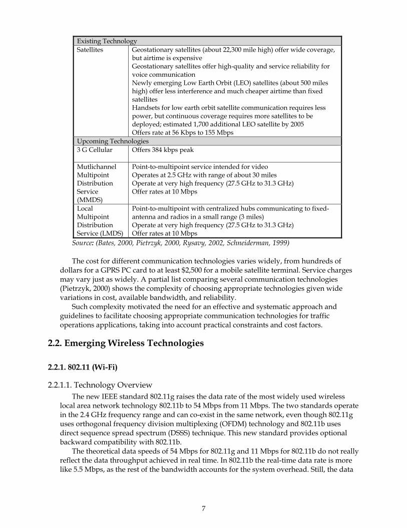
Existing Technology Satellites Geostationary satellites (about 22,300 mile high) offer wide coverage,
but airtime is expensive Geostationary satellites offer high-quality and service reliability for voice communication Newly emerging Low Earth Orbit (LEO) satellites (about 500 miles high) offer less interference and much cheaper airtime than fixed satellites Handsets for low earth orbit satellite communication requires less power, but continuous coverage requires more satellites to be deployed; estimated 1,700 additional LEO satellite by 2005 Offers rate at 56 Kbps to 155 Mbps
Upcoming Technologies 3 G Cellular Offers 384 kbps peak
Mutlichannel Multipoint Distribution Service (MMDS)
Point-to-multipoint service intended for video Operates at 2.5 GHz with range of about 30 miles Operate at very high frequency (27.5 GHz to 31.3 GHz) Offer rates at 10 Mbps
Local Multipoint Distribution Service (LMDS)
Point-to-multipoint with centralized hubs communicating to fixed-antenna and radios in a small range (3 miles) Operate at very high frequency (27.5 GHz to 31.3 GHz) Offer rates at 10 Mbps
Source: (Bates, 2000, Pietrzyk, 2000, Rysavy, 2002, Schneiderman, 1999) The cost for different communication technologies varies widely, from hundreds of
dollars for a GPRS PC card to at least $2,500 for a mobile satellite terminal. Service charges may vary just as widely. A partial list comparing several communication technologies (Pietrzyk, 2000) shows the complexity of choosing appropriate technologies given wide variations in cost, available bandwidth, and reliability.
Such complexity motivated the need for an effective and systematic approach and guidelines to facilitate choosing appropriate communication technologies for traffic operations applications, taking into account practical constraints and cost factors.
2.2. Emerging Wireless Technologies
2.2.1. 802.11 (Wi-Fi)
2.2.1.1. Technology Overview The new IEEE standard 802.11g raises the data rate of the most widely used wireless
local area network technology 802.11b to 54 Mbps from 11 Mbps. The two standards operate in the 2.4 GHz frequency range and can co-exist in the same network, even though 802.11g uses orthogonal frequency division multiplexing (OFDM) technology and 802.11b uses direct sequence spread spectrum (DSSS) technique. This new standard provides optional backward compatibility with 802.11b.
The theoretical data speeds of 54 Mbps for 802.11g and 11 Mbps for 802.11b do not really reflect the data throughput achieved in real time. In 802.11b the real-time data rate is more like 5.5 Mbps, as the rest of the bandwidth accounts for the system overhead. Still, the data

8
rates for 802.11g are around three to five times higher and appear very fast compared with 802.11b. The added transmission speed gives wireless networks based on IEEE 802.11b (often called Wi-Fi) the ability to serve as many as four to five times more users than they do now. It also opens the possibility for using IEEE 802.11 networks in more demanding applications, such as wireless multimedia video transmission and broadcast MPEG.
The data speed of 802.11g access points falls back to a speed 802.11b if there are any 802.11b components present in its LAN. For optimum performance in data speed, it requires the usage of 802.11g in the single mode instead of the dual-mode 802.11b/g.1,2
The 802.11 LANs are built around cells called basic service sets. The base station in each cell is called an access point. Laptop computers, field sensors, and other devices communicate via the access point using small wireless LAN cards.
2.2.1.2. Applications/Vendors The applications of 802.11g in intelligent transportation systems include: California Department of Transportation (Caltrans) is currently testing Wi-Fi for public
access on its Capitol Corridor Intercity train route in California for a three-month period.3 This can be extended to automobiles to provide data services such as traveler information and traffic congestion to the motorists.
In January 2000, WiLAN, Inc. in partnership with California Department of Transportation (Caltrans) demonstrated support of 20 Mbps data services to a vehicle moving at 70 mph over a 1.3-mile stretch of US Highway 101 in Goleta, California.
Some of the applications of this technology are adaptive traffic signals, variable message boards, surveillance video cameras, etc.
This technology is ideal for short-range wireless communication where high bandwidth is required, like establishing a wireless data link among unattended ground sensors and between remote video cameras and roadside control units.
802.11g are widely used in building-to-building data communication using wireless LAN bridges. Wireless LAN bridges provide an alternative to more expensive leased lines and underground cabling projects.
2.2.1.3. Latest Product/Technology Developments Airgo Networks, a developer of innovative wireless technology and products, is
currently testing an AGN100 chipset, which it claims extends the existing Wi-Fi data rates to 108 Mbps per channel and is compatible with all common Wi-Fi standards. The AGN100 chipset greatly increases the throughput, range, and reliability of Wi-Fi devices by utilizing Airgo’s breakthrough multi-antenna transmission and reception technology. It incorporates the multiple-input-multiple-output (MIMO) technology that is the most sophisticated and highest-performance class of smart antenna signal processing.4
D-Link Systems, Inc. and Texas Instruments (TI) will be launching a new family of 802.11g+ products by late third quarter of 2003. The new D-Link AirPlus Extreme G+ product family based on the TI TNETW1130 chipset will deliver high-speed throughput, an improvement of up to 8 times the 802.11b average throughputs. TI’s 802.11g+ solution is
1 http://standards.ieee.org/announcements/80211gfinal.html 2 http://www.nwfusion.com/reviews/2003/0512rev11gside2.html 3 http://www.nwfusion.com/news/2003/0815transport.html 4 http://www.airgonetworks.com/AirgoLaunchRelease.doc
9
optimized to deliver the highest performance and interoperability in any 802.11g or 802.11b network.5
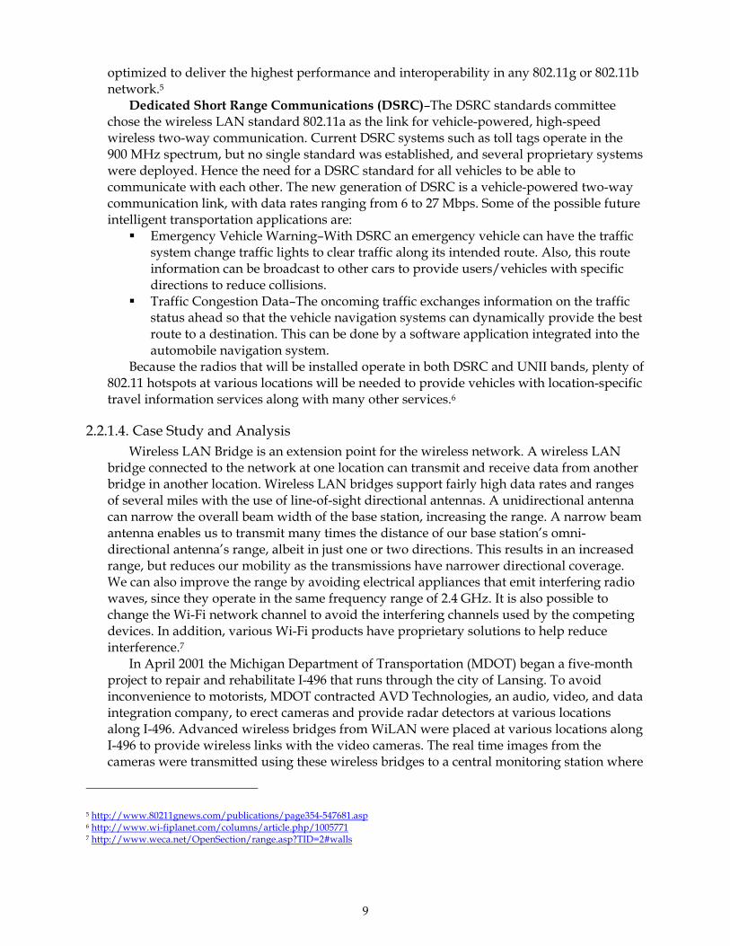
Dedicated Short Range Communications (DSRC)–The DSRC standards committee chose the wireless LAN standard 802.11a as the link for vehicle-powered, high-speed wireless two-way communication. Current DSRC systems such as toll tags operate in the 900 MHz spectrum, but no single standard was established, and several proprietary systems were deployed. Hence the need for a DSRC standard for all vehicles to be able to communicate with each other. The new generation of DSRC is a vehicle-powered two-way communication link, with data rates ranging from 6 to 27 Mbps. Some of the possible future intelligent transportation applications are:
Emergency Vehicle Warning–With DSRC an emergency vehicle can have the traffic system change traffic lights to clear traffic along its intended route. Also, this route information can be broadcast to other cars to provide users/vehicles with specific directions to reduce collisions.
Traffic Congestion Data–The oncoming traffic exchanges information on the traffic status ahead so that the vehicle navigation systems can dynamically provide the best route to a destination. This can be done by a software application integrated into the automobile navigation system.
Because the radios that will be installed operate in both DSRC and UNII bands, plenty of 802.11 hotspots at various locations will be needed to provide vehicles with location-specific travel information services along with many other services.6
2.2.1.4. Case Study and Analysis Wireless LAN Bridge is an extension point for the wireless network. A wireless LAN
bridge connected to the network at one location can transmit and receive data from another bridge in another location. Wireless LAN bridges support fairly high data rates and ranges of several miles with the use of line-of-sight directional antennas. A unidirectional antenna can narrow the overall beam width of the base station, increasing the range. A narrow beam antenna enables us to transmit many times the distance of our base station’s omni-directional antenna’s range, albeit in just one or two directions. This results in an increased range, but reduces our mobility as the transmissions have narrower directional coverage. We can also improve the range by avoiding electrical appliances that emit interfering radio waves, since they operate in the same frequency range of 2.4 GHz. It is also possible to change the Wi-Fi network channel to avoid the interfering channels used by the competing devices. In addition, various Wi-Fi products have proprietary solutions to help reduce interference.7
In April 2001 the Michigan Department of Transportation (MDOT) began a five-month project to repair and rehabilitate I-496 that runs through the city of Lansing. To avoid inconvenience to motorists, MDOT contracted AVD Technologies, an audio, video, and data integration company, to erect cameras and provide radar detectors at various locations along I-496. Advanced wireless bridges from WiLAN were placed at various locations along I-496 to provide wireless links with the video cameras. The real time images from the cameras were transmitted using these wireless bridges to a central monitoring station where
5 http://www.80211gnews.com/publications/page354-547681.asp 6 http://www.wi-fiplanet.com/columns/article.php/1005771 7 http://www.weca.net/OpenSection/range.asp?TID=2#walls

10
AVD observed the congestion on I-496 and reported it to MDOT. MDOT then used this information on brief message signs that instantly update the motorists on upcoming congestion and alternate routes they can take to avoid it.8
2.2.2. Mesh Networking
2.2.2.1. Technology Overview Mesh Networks created MeshLAN using its patented multi hopping technology to
extend the coverage, capacity, and throughput of traditional 802.11 networks while reducing the deployment costs. MeshLAN is a complete standards-based 802.11b solution, which significantly increases the value and utility of wireless local area networks (WLAN).
The multi hopping routing technology turns every client device into a router/repeater, so every user improves network coverage and increases network throughput. MeshLAN users can hop through other users or wireless routers in either infrastructure or peer-to-peer mode, greatly enhancing the utility of wireless networking. This enables the users to hop long distances and around obstacles to reach an access point. Hence, this technology overcomes the problem of line of sight in certain situations where it is difficult to have a clear line of sight, a serious limitation in 802.11 systems.
MeshLAN networks are self-forming; that is, they automatically discover neighboring devices and form a robust multi hopping network (see Figure 2-4). MeshLAN networks are also self-healing, adjusting the routing configuration, when necessary, to compensate for network congestion and node failures.
The products using this technology greatly increase the coverage of the networks. The data rates range from 1.5 to 6 Mbps. This technology used with QDMA radios of mesh networks, has been successfully applied to industry standard 802.11b to develop MeshLAN multi hopping 802.11b products. This technology can also be applied to other modulation schemes and radios, including 802.11a and g, ultra wideband, WCDMA, and OFDM, to increase the product capabilities.
MeshLAN utilizes 802.11b (Wi-Fi) standard-based radios and personal client cards, which can be configured to operate in either MeshLAN enhanced or conventional 802.11b networks.9
Figure 2-4. Mesh network in Intelligent Transportation Systems Application
(source: MeshNetworks, 2003)
8 http://www.wilan.com/success/index.html 9 http://www.meshnetworks.com/

11
Because of Mesh Networking’s potential in the Intelligent Transportation Systems applications, more extensive information is provided for the Mesh Networking technology herein (Rotondo, 2003).
In 1997, The Defense Advanced Research Projects Agency (DARPA), the organization that created the Internet, began developing a robust, tactical, mobile communications system for use by the U.S. Military. The military needed to provide soldiers with broadband access to IP-based voice, video and data services that could be used on the battlefield with little or no fixed infrastructure. Additional requirements included geo-location beyond the limitations of GPS, high security, and connectivity at speeds in excess of 250 miles per hour. The result was ad hoc peer-to-peer (p2p) wireless networking – more commonly known as mesh networking. An ad hoc wireless mesh network is a collection of wireless terminals (e.g. handheld devices, mobile phones, automotive telematics systems, etc.) that communicate directly with each other without the aid of established infrastructure such as cell sites and towers. Through Multi-Hop routing techniques, the terminals act as routers/relays for each other and extend the range and coverage of communications links between users. After an investment in excess of $170 million and six years of R&D, MeshNetworks, Inc. was founded to commercialize this technology and holds an exclusive commercial license to the technology and patents created by ITT industries.
Traditional cellular solutions attempt to create a mobile broadband data network by overlaying data onto a circuit-switched, voice-centric system. MeshNetworks takes a different approach by offering an end-to-end IP-based, packet switched; mesh architecture that closely mimics the wired Internet's architecture and its resulting advantages. In addition to this, precision geo-location is inherent to the technology and does not require GPS to operate.
MeshNetworks' peer-to-peer routing technology is significant because as each user joins the network they also act as mobile routers and repeaters for every other device in the network. In short they are the network. Because users carry much of the network with them, network capacity and coverage is dynamically shifted to accommodate changing user patterns. As users congregate and create pockets of high demand, they also create additional routes for each other to hop through, thus enabling network capacity from surrounding access points to be utilized. Intelligent routing technology allows users to automatically hop away from congested routes and access points to less congested routes and network access points. This permits the network to dynamically and automatically self-balance capacity, and increase network utilization. This self-balancing aspect of a MeshNetworks solution is one of its fundamental advantages over star and cellular wireless topologies
The features and benefits of the technology include (Rotondo, 2003): Up to 6 mbps burst data rates Sustained data rates equal to or better than DSL or Cable modems Better spectral efficiency than 2.5G or 3G cellular technologies Patented QDMATM air-interface optimized for high speed mobile networking No cell towers are required End-to-end IP-based networking that works transparently with standard Internet
applications and devices Voice, video, and data streams individually managed for QoS Complete mobility at highway speeds and above Cost-effective for PAN, LAN, and WAN deployments
12
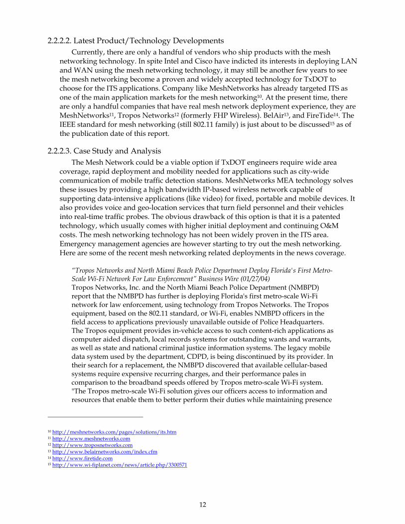
2.2.2.2. Latest Product/Technology Developments Currently, there are only a handful of vendors who ship products with the mesh
networking technology. In spite Intel and Cisco have indicted its interests in deploying LAN and WAN using the mesh networking technology, it may still be another few years to see the mesh networking become a proven and widely accepted technology for TxDOT to choose for the ITS applications. Company like MeshNetworks has already targeted ITS as one of the main application markets for the mesh networking10. At the present time, there are only a handful companies that have real mesh network deployment experience, they are MeshNetworks11, Tropos Networks12 (formerly FHP Wireless). BelAir13, and FireTide14. The IEEE standard for mesh networking (still 802.11 family) is just about to be discussed15 as of the publication date of this report.
2.2.2.3. Case Study and Analysis The Mesh Network could be a viable option if TxDOT engineers require wide area
coverage, rapid deployment and mobility needed for applications such as city-wide communication of mobile traffic detection stations. MeshNetworks MEA technology solves these issues by providing a high bandwidth IP-based wireless network capable of supporting data-intensive applications (like video) for fixed, portable and mobile devices. It also provides voice and geo-location services that turn field personnel and their vehicles into real-time traffic probes. The obvious drawback of this option is that it is a patented technology, which usually comes with higher initial deployment and continuing O&M costs. The mesh networking technology has not been widely proven in the ITS area. Emergency management agencies are however starting to try out the mesh networking. Here are some of the recent mesh networking related deployments in the news coverage.
“Tropos Networks and North Miami Beach Police Department Deploy Florida's First Metro-Scale Wi-Fi Network For Law Enforcement” Business Wire (01/27/04) Tropos Networks, Inc. and the North Miami Beach Police Department (NMBPD) report that the NMBPD has further is deploying Florida's first metro-scale Wi-Fi network for law enforcement, using technology from Tropos Networks. The Tropos equipment, based on the 802.11 standard, or Wi-Fi, enables NMBPD officers in the field access to applications previously unavailable outside of Police Headquarters. The Tropos equipment provides in-vehicle access to such content-rich applications as computer aided dispatch, local records systems for outstanding wants and warrants, as well as state and national criminal justice information systems. The legacy mobile data system used by the department, CDPD, is being discontinued by its provider. In their search for a replacement, the NMBPD discovered that available cellular-based systems require expensive recurring charges, and their performance pales in comparison to the broadband speeds offered by Tropos metro-scale Wi-Fi system. "The Tropos metro-scale Wi-Fi solution gives our officers access to information and resources that enable them to better perform their duties while maintaining presence
10 http://meshnetworks.com/pages/solutions/its.htm 11 http://www.meshnetworks.com 12 http://www.troposnetworks.com 13 http://www.belairnetworks.com/index.cfm 14 http://www.firetide.com 15 http://www.wi-fiplanet.com/news/article.php/3300571
13
in the community, instead of accessing this information back at the central office," said NMBPD Chief of Police William Berger. "In addition, we anticipate that the transition from CDPD to metro-scale Wi-Fi will result in significant savings for the taxpayers of North Miami Beach by eliminating recurring service provider fees. It's an absolute win-win situation." The NMBPD is currently using the Tropos Wi-Fi network in a several square block area centered around the central police headquarters. Plans to expand the coverage area are under way, pending approval from the North Miami Beach City Council. The expanded network will eventually cover the entire city core of North Miami Beach, an area of over five square miles. “City of Garland, Texas to upgrade first responder network with mesh architecture” (IWCE/MRT, Jan 22 2004) The city of Garland, Texas, in the Dallas-Fort Worth metroplex, will upgrade its first responder mobile data communications network by replacing the current cellular-based infrastructure with a mobile mesh network developed by Richardson, Texas-based NexGen City that will have a coverage range of 57 square miles. The project, which is being managed by Lockheed Martin, will be the first use of a mobile mesh network by a public-safety organization, according to the NextGen City, which is the system integrator on the project. The network, dubbed NexNet, embeds a wireless router in every device to extend the network, determine optimum paths for data transmission and provide additional paths for connectivity, according to NextGen City. All NexNet components use ASIC chip sets developed by Maitland, Fla.-based MeshNetworks. In field tests that covered a five-square-mile area, units deployed in two vehicles traveling more than 60 mph in opposite directions were able to provide real-time streaming video, voice-over-IP calls and data throughput rates up to 1.5 Mb/s, according to NextGen City.
2.2.3. 802.16 (WiMAX)
2.2.3.1. Technology Overview Another future option for wide-area deployment applications such as city-wide
communication of mobile traffic detection stations is the WiMAX based on the 802.16 standard. To date, there have not been cost effective, standards-based solutions for implementing wireless networks within metropolitan-sized areas. As mentioned in the previous section and MeshNetwork can be a high performance option for providing connectivity over a wide area, however, such kind of technologies tend to be more expensive and risky in terms of long-term support. They also lack interoperability, something that engineers demand.
The use of 802.11-based hardware for metropolitan-sized networks decreases costs, but 802.11 has performance limitations when supporting larger numbers of users needing guaranteed bandwidth. In addition, RF interference is often a significant problem with 802.11 when covering large areas due to license free operation. Any party could install an 802.11 network which interferes with TxDOT’s network, and cause potential sporadic, poor performance. Such a situation is not anticipated to be resolved soon because there are no legal grounds to remedy the situation.

14
The primary differences of 802.16-based WiMAX and 802.11-based WiFi are in speed, range, and as a consequence of these two, power consumption. WiMAX is designed for wireless broadband access, can reach 50 km and 70 Mbit/s (Keeping, 2003). The WiFi family (802.11a, b and g), designed for wireless Ethernet applications, can reach 10’s of meters in range, and data rates from 5.5 Mbit/s to 11 Mbit/s for “a” and “b”, through to 54 Mbit/s for “g”. And Bluetooth, a subset of the 802.15 “wireless personal area network” (WPAN) standard, has a range up to 10 m or so (this can be extended at the expense of increased power consumption), and a data exchange rate of around 1 Mbit/s.
An example of the 802.16 functional architecture is illustrated in Figure 2-5.
Figure 2-5. 802.16 functional architecture. Source: (Stallings, 2001)
2.2.3.2. Case Study and Analysis Several companies, such as Airspan Networks, Alvarion, Intel, Nokia, Proxim and Wi-
LAN—all members of WiMax, an industry group backing 802.16—are in the process of developing 802.16 products, but they won't be available until mid-2004. Based on past experience, product release dates tend to slip, especially for products using new standards and technologies. However, it is reasonable to anticipate that the 802.16 technology becomes mature for ITS applications in 2005.
With wireless base station equipment targeted at under $20,000, 802.16 can serve up to 60 customers with T-1 speed connections. That's attractive to the typical WISP that's short on cash. In addition, 802.16 can provide a feasible backhaul for connecting wireless LAN hotspots together. For TxDOT, it may be considered for not only the wide-area traffic detector or mobile surveillance station deployment, but, if within the transmission range, also be a cost–effective option for building center-to-center redundancy communication capability16.
2.2.3.3. Latest Deployments Mesh Networks is currently testing off-the-shelf 802.11 radios and a variant radio it has
developed that utilizes real-time equalization and a multitap rake receiver, which can handle multipath and fading to enable multihopping networks at vehicle speeds as fast as
16 http://www.itsa.org/mn.nsf/0/2f4f1ecd1bc8961885256d4700696f42?OpenDocument

15
70 mph. In conjunction with relay devices posted on light poles (two per square mile), the system can provide a QoS (Quality of Service) sufficient to stream video and to support Voice over IP (VoIP) calls. The system has been installed on Orlando, Florida city buses.17
Delphi, a leading automotive electronics vendor, is testing Mesh Networks, peer-to-peer technology for in-vehicle telematics applications, including streaming environment, web access, safety, and location based services.18
Mesh Networks and Viasys reached an agreement to bring this new technology to the Intelligent Transportation systems and Public safety. Viasys, a leading provider of infrastructure development and maintenance services for the transportation industry, will begin offering this Mesh Networks proprietary peer-to-peer technology to its customers.19
The ITS Laboratory at the University of Minnesota has developed several generations of data acquisition systems to meet the needs of researchers working on freeway traffic flow issues. The most recent of these is the Beholder system, a fully independent network of video detectors providing space- and time-continuous coverage of the I-35W/I-94 Commons freeway area in Minneapolis. Beholder expands on the pioneering Auto scope system, originally developed at the University of Minnesota and now in commercial use. Beholder’s portable monitoring stations are currently deployed on the roofs of several high-rise buildings overlooking the freeway, and transmit data back to the lab via a high-speed IEEE 802.16 wireless network.
2.2.4. General Packet Radio Service (GPRS)
2.2.4.1. Technology Overview General packet radio service (GPRS) is a wireless technology standard, generally dubbed
as 2.5G, that supports fast point-to-point communication through devices that enable an “always on” Internet connection. GPRS facilitates instant connections whereby information can be sent or received immediately as the need arises, subject to radio coverage.20
GPRS technology converts wireless data into standard Internet packets, enabling interoperability between the Internet and the GSM network. The data to be transmitted are split into separate but related packets before being transmitted and reassembled at the receiving end.
The theoretical data speeds are as high as 171.2 Kbps. The data rates from 9 to 100 Kbps can be achieved by assigning multiple time slots per frame to the same user. The use of packet switching in GPRS technology optimizes the data network capacity by using the bandwidth only when necessary. Rather than dedicating a radio channel to a data user for a fixed period of time, the available radio resource can be concurrently shared between several users. This efficient use of radio resources means that large numbers of GPRS users can potentially share the same bandwidth and be served from a single cell.
General packet radio service supports both global system for mobile communications (GSM) and the IS-136 time division multiple access (TDMA) standard networks.21
17 http://biz.yahoo.com/bw/030812/125122_1.html 18 http://www.itsa.org/itsnews.nsf/0/24BF8A1A8F40877185256C7D004F2352?OpenDocument 19 http://www.meshnetworks.com/pages/newsroom/press_releases/release_03_26_03.htm 20 http://www.itsa.org/ITSNEWS.NSF/0/118b6014e357788a85256c440006600a?OpenDocument 21 http://www.gsmworld.com/technology/gprs/intro.shtml#1

16
2.2.5. Multi-Code Direct Sequence Spread Spectrum Technology (M-CDSSS)
2.2.5.1. Technology Overview Spread spectrum techniques were originally developed for military applications to
provide secure communication channels impervious to enemy jamming. Frequency bands 902-928 MHz, 2.4-2.484 GHz, and 5.725-5.85 GHz are available for unlicensed spread spectrum transmission. As its name implies, the spread spectrum signal is spread across a larger bandwidth than the minimum required transmitting the data successfully.
The two most popular spread spectrum techniques used are: direct sequence spread spectrum (DSSS) frequency hopping spread spectrum (FHSS)
WiLAN patented multi-code direct sequence spread spectrum (M-CDSSS) technology using direct sequence spread spectrum (DSSS) techniques that increases the carrying capacity of traditional spread spectrum systems by up to a factor of ten.
MC-DSSS is a spectrally efficient spread spectrum modulation technique. This technique enables multiple CDMA codes to be assigned to a single user in a CDMA network, thus increasing the throughput. MC-DSSS is used in WiLAN’s advanced Ethernet bridges, which operate in the 2.4-2.4835 GHz frequency range supporting up to 7 channels. The data transmission rate varies from 3.4 Mbps to 9 Mbps as the number of remotes per base station varies from 255 to 1000. Point-to-multipoint network topology has a transmission distance of up to 10 km and up to 40 km for a point-to-point transmission.22
2.2.5.2. Applications/Vendors The applications of M-CDSSS products in intelligent transportation systems include: the
following AVD Technologies used the WiLAN’s advanced Ethernet bridges to establish a wireless network for streaming real-time video from the cameras on the highway to monitor traffic congestion and provide the motorists with up-to-the-minute updates on problem spots and alternative routes off of the freeway.23
2.2.5.3. Latest Product/Technology Developments WiLAN filed an intellectual property (IP) statement in 1999 with the International
Telecommunication Union (ITU) offering to make MC-DSSS available for licensing on fair, reasonable, and non-discriminatory terms. This statement is based on the company’s belief that the IMT-2000 proposals under consideration for 3G standards use MC-DSSS technology. The ITU received ten proposals for 3G systems, with most of them based on CDMA.24
2.2.5.4. Case Study and Analysis In April 2001, the Michigan Department of Transportation (MDOT) began a five-month
project to repair and rehabilitate I-496 that runs through the city of Lansing. To avoid inconvenience to motorists, MDOT contracted AVD Technologies, an audio, video, and data integration company to erect cameras and provide radar detectors at various locations along I-496. Advanced wireless bridges from WiLAN were placed at various locations along I-496
22 http://www.wilan.com/ 23 http://www.wilan.com/ 24 http://www.wilan.com/

17
to provide wireless links with the video cameras. The real-time images from the cameras were transmitted using these wireless bridges to a central monitoring station where AVD observed the congestion on I-496 and reported it to MDOT. The MDOT then used this information on short message signs that instantly update the motorists on upcoming congestion and alternate routes that they can take to avoid it.
2.2.6. Wide-Band Orthogonal Frequency Division Multiplexing
2.2.6.1. Technology Overview Wide-band orthogonal frequency division multiplexing (W-OFDM) uses the IEEE
wireless standards 802.11a and 802.11g as its basis. It is also the foundation for the proposed IEEE standard 802.16. WiLAN patented this technology in the United States and Canada. This transmission scheme enables data to be encoded on multiple high-speed radio frequencies concurrently, which results in greater security, increased amounts of data being sent, and the efficient use of the bandwidth. W-OFDM is a non-line-of-sight technology with multilayered security.
W-OFDM enables the implementation of low power multipoint RF networks that minimize interference with adjacent networks. This reduced interference enables independent channels to operate within the same band allowing multipoint networks and point-to-point backbone systems to be overlaid in the same frequency band.25
The W-OFDM channels are 6 MHz wide and can support raw data rates up to 19 Mbps. The W-OFDM system uses Reed Solomon encoding. The modulation scheme is 16-ary quadrature amplitude modulation. Another feature of WiLAN’s W-OFDM system is the use of signal whitening that enables security implementation into the system.26
The latest wireless access product LIBRA 5800 from WiLAN operating in the 5.8 GHz frequency range provides a data rate of 32 Mbps in narrow 10 MHz channels and a range of up to 41 miles in a point-to-point configuration, or an aggregated data rate of up to 192 Mbps per six sector cell and a radius of up to 22 miles in a point-to-multipoint configuration. According to the President and COO of WiLAN LIBRA is the only product that uses 256-carrier W-OFDM specifically designed for outdoor wireless metropolitan area network (WMAN) applications.27
2.2.6.2. Applications/Vendors The applications of W-OFDM technology in intelligent transportation systems include:
some of the applications are controlling traffic signals remotely, vehicular traffic monitoring, and providing public transportation information and other data services to motorists.
2.2.6.3. Latest Product/Technology Developments There has been speculation that OFDM will be the ideal technology for a fourth-
generation cellular network. AT&T has entered into a contract with Nortel Networks to develop a 4G standard based on its existing Angel product. The downlink in such a system would be OFDM, which is capable of transmitting data to the phones at speeds of 10 Mbps;
25 http://www.wilan.com/technology/index.html 26 http://www.commsdesign.com/design_corner/OEG20010227S0025 27 http://www.80211gnews.com/publications/page354-525711.asp
18
the uplink back to the base stations would be a higher-speed time-division multiple-access link.
Wellink a leading provider of high-speed telecommunications systems, and WiLAN, a global provider of broadband wireless communication products and technologies, have reached an agreement to develop mobile wireless products based on WiLAN’s W-OFDM technology. These mobile wireless systems are initially intended Intelligent Transportation Systems (ITS). ITS applications may include real-time video security, advertising, and Internet.28
2.2.6.4. Case Study and Analysis W-OFDM is a variant of the Orthogonal Frequency Division Technology (OFDT) that
improves its characteristics. OFDM technology has been around since the 1960s. WiLAN developed W-OFDM technology in the early 1990s. The reason that the OFDT and W-OFDM technologies are becoming popular now is because economical integrated circuits that can perform a high-speed FFT in real time were not available till 1998.29
Caltrans, the California Department of Transportation has hosted a demonstration of WiLAN’s first mobile application of W-OFDM technology in the year 1999. It was held on Highway 101 in Santa Barbara. The high-speed demonstration proved successful as video streaming and file transfers were exchanged between two IWILL 300-24 access points at a data rate of 30 Mbps. One access point was located in a traffic cabinet on Highway 101, transmitting to another access point in a moving vehicle, while traveling at speeds of up to 70 miles per hour.30
2.2.7. 3G Cellular Wireless
There are currently two main standards in the 3rd generation (3G) cellular network, the European-company-backed WCDMA and the U.S. company-backed CDMA2000. Apparently, the WCDMA standard will provide natural migration for those operators who are currently using the global systems for mobile communications (GSM), and the U. S. market will likely be dominated by the CDMA2000 standard.
Global system for mobile communications (GSM) is a 2nd generation digital cellular telecommunication standard widely implemented in many countries. This standard is based on the time-division multiple access (TDMA) protocol, where several different calls may share the same carrier, with each call assigned a separate time slot. The frequency range specified for GSM networks is 1.850 MHz to 1.990 MHz, with a bandwidth specification of 270 Kbps. Circuit switched data are possible at either 9.6 or 14.4 Kbps.31 The enhanced data rate for GSM evolution (EDGE) is an extension of the current 2.5G digital technologies, such as GSM-based GPRS, and CDMA-based 1xRTT, that provide higher data rates with existing systems. EDGE uses 8-PSK (phase shift keying) modulation to provide up to three times the data rate in a GPRS system. EDGE enables a maximum theoretical data speed of up to 513 Kbps, but the actual data rate is 60 to 120 Kbps. This enables voice, data, and video
28 http://www.wi-lan.com/news/press290.html 29 http://www.wilan.com/technology/index.html 30 http://www.wi-lan.com/news/press78.html 31 http://www.iec.org/online/tutorials/gsm/

19
streaming.32 Existing GSM operators in the United States include Cingular Wireless and AT&T Wireless.
Code division multiple access (CDMA) is a form of spread spectrum developed for commercial use by Qualcomm. CDMA2000 is a third generation technology that evolved from CDMA, and it has two phases, 1x and 3x. 1xRTT stands for 1 channel (1.25 MHz) radio transmission technology. The maximum theoretical data speed in the forward direction from the base station to the mobile is 307.2 Kbps and 144 Kbps in the reverse direction. The telecommunication industries association (TIA) is working on a second release of this protocol to support downlink speeds of 614 Kbps. But the actual data rates are lower, depending on the user channel quality and some other factors. The current implementation involves voice and data services. A sustainable data rate of around 40 Kbps in the reverse direction will support video at frames rates between 5 and 20 frames per second. The forerunner of the CDMA2000-based network is Verizon Network. Typical data rates are listed in Table 2-3.
Table 2-3. Typical data rates from different cellular standards
Cellular Family
Generation Standard Peak Data Rate(kbps)
Typical real life data rate(kbps)
Connection type
Modulation
GSM-CSD (normal) 9.6 / 14.4 9.6 Circuit GMSK
HSCSD 28.8 / 43.2 28.8 Circuit GMSK GPRS 115 / 171 50 Packet GMSK
GSM 2-2.5
EDGE 384 / 513 115 Packet 8-PSK FDD 384 / 2000 144 Packet QPSK
UMTS 3 TDD 384 / 2000 144 Packet QPSK IS-95A 14.4 14.4 Circuit QPSK
CDMAone 2 IS-95B 64 / 115 56 Packet QPSK 1X 144 / 307 130 Packet QPSK 1X-EV 2000 tba Packet QPSK CDMA 2000 3 1X-EVDO 2400 tba Packet QPSK
TDMA 2 CSD 9.6 9.6 Circuit DQpi/4PSK 3xRTT is the future implementation of the 3x phase of CDMA2000, where three 1xRTT
channels are multiplexed in a 5 MHz channel. It supports all channels sizes, which are multiples of 5 MHz, and is envisioned to enable data rates of up to 2 Mbps.
CDMA2000 1xEV-DO stands for 1-channel (1.25 MHz) evolutionary data-only service. This is considered a true 3G service, with peak data rates of up to 2.4 Mbps in the forward direction and 153.5 kbps in the reverse direction. The high data rates also use smaller spreading factors and multilevel modulations. This incorporates burst mode on the forward link with burst rates of 600-1200 Kbps per subscriber.33 Verizon Network has recently announced its 1xEV-DO service in San Diego and Washington, D.C., in late 2003. The
32 http://press.nokia.com/PR/200212/883986_5.html 33 http://www.mitretek.org/publications/its/MP2003V2_05.doc
20
coverage is expected to continue to increase. It is also anticipated that by 2005, 80% of the U.S. network shall be covered by 3G networks. It is anticipated that existing operators who use different standards (GSM versus CDMA) will migrate to respective 3G standards.
2.2.8. Summary
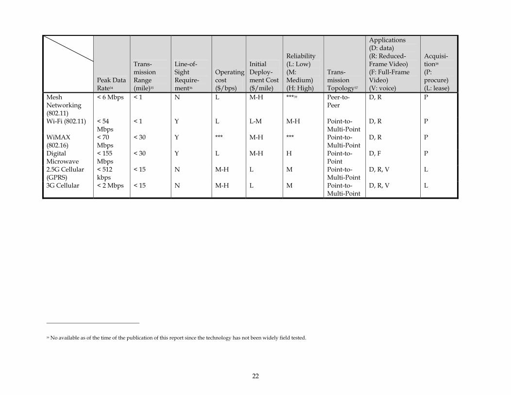
Most of the surveyed emerging wireline and wireless communication technologies are summarized in Table 2-4 for quick reference. Each technology is identified based on several key attributes, such as data rate, transmission range, line-of-sight requirement, cost, application, and acquisition method. As a high-level reference of technology, this table gives engineers a brief idea of various technologies’ characteristics. To select a cost-effective and minimal risk technology for the intended application, one should consider several other aspects in a systematic manner. Chapter 4 discusses such a methodology in detail.

21
Table 2-4. Bandwidth, cost, and reliability comparison between communication technologies
Peak Data Rate34
Trans-mission Range (mile)35
Line-of-Sight Require-ment36
Operatingcost ($/bps)
Initial Deploy-ment Cost ($/mile)
Reliability (L: Low) (M: Medium) (H: High)
Trans-mission Topology37
Applications (D: data) (R: Reduced-Frame Video) (F: Full-Frame Video) (V: voice)
Acquisi-tion38 (P: procure) (L: lease)
Wireline Twisted-pair < 1.5
Mbps 15 + NA H H H NA D, R L
Coaxial cable < 100 Mbps
15 + NA H, L H M NA D, F L, P
Multi-mode fiber
< 500 Mbps
< 15 NA L H M-H NA D, F P
Single-mode fiber
< 40 Gbps 15 + NA L H M-H NA D, F P
Wireless 900 MHz Spread Spectrum Radio
< 120 kbps
< 15 Y L L H Point-to-Point
D P
2.4 GHz Spread Spectrum Radio
< 200 kbps
< 15 Y L L-M H Point-to-Point
D P
5 GHz Spread Spectrum Radio
< 100 Mbps
< 15 Y L L-M H Point-to-Point
D P
34 Typical real-life data rate is less than half of the peak data rate. 35 The range of many spread spectrum radio can be extended by using repeaters. 36 Most of the technologies can still function without line-of-sight, but the transmission range will be significantly reduced. 37 Mostly common seen configuration. Some exception may exist in some products. 38 Most common way of acquiring the technology. Some exception may exist.
22
Peak Data Rate34
Trans-mission Range (mile)35
Line-of-Sight Require-ment36
Operatingcost ($/bps)
Initial Deploy-ment Cost ($/mile)
Reliability (L: Low) (M: Medium) (H: High)
Trans-mission Topology37
Applications (D: data) (R: Reduced-Frame Video) (F: Full-Frame Video) (V: voice)
Acquisi-tion38 (P: procure) (L: lease)
Mesh Networking (802.11)
< 6 Mbps < 1 N L M-H ***39 Peer-to-Peer
D, R P
Wi-Fi (802.11) < 54 Mbps
< 1 Y L L-M M-H Point-to-Multi-Point
D, R P
WiMAX (802.16)
< 70 Mbps
< 30 Y *** M-H *** Point-to-Multi-Point
D, R P
Digital Microwave
< 155 Mbps
< 30 Y L M-H H Point-to-Point
D, F P
2.5G Cellular (GPRS)
< 512 kbps
< 15 N M-H L M Point-to-Multi-Point
D, R, V L
3G Cellular < 2 Mbps < 15 N M-H L M Point-to-Multi-Point
D, R, V L
39 No available as of the time of the publication of this report since the technology has not been widely field tested.
23
2.3. Wireless Communication Service Providers
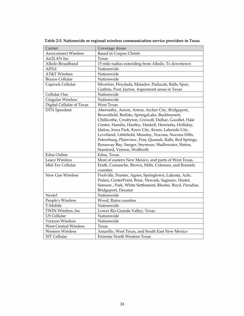
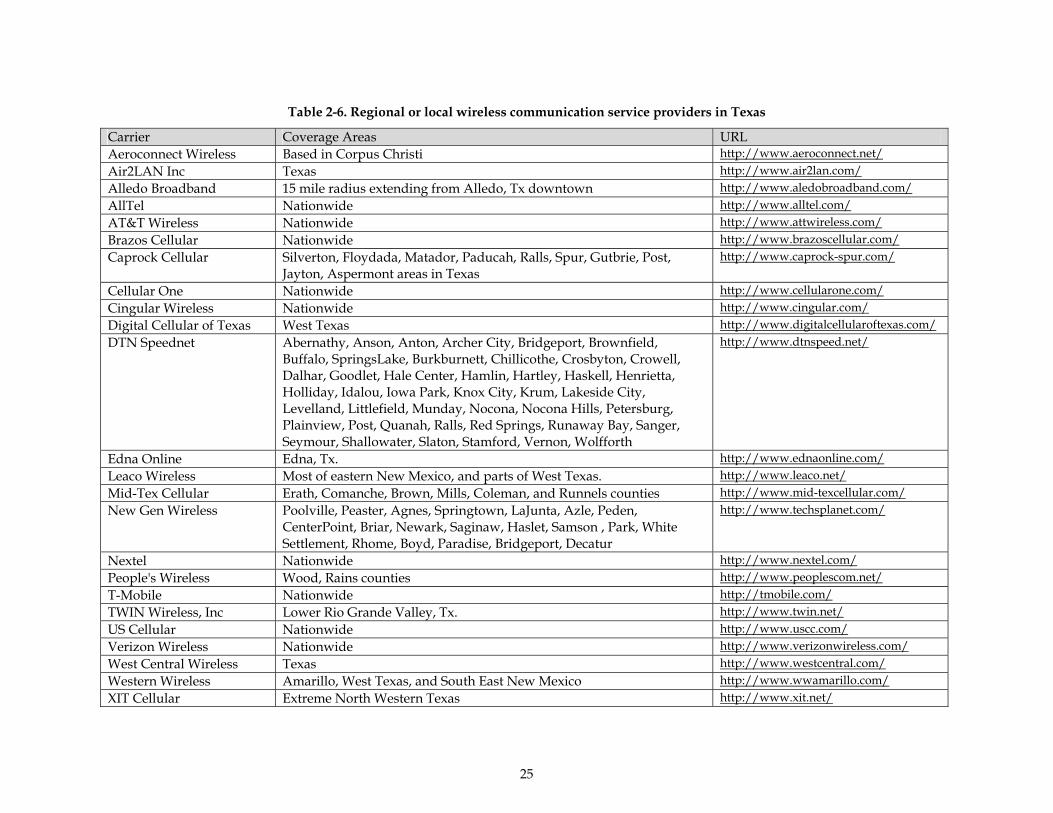
Most of the ILEC (incumbent local exchange carrier, such as Southwestern Bell Company [SBC], or any other bell company), or CLEC (competitive local exchange carrier) which were established after telecommunication deregulation in 1996 provide wireless communication services. There are also an increasing number of such carriers primarily focused on providing wireless services in cities in Texas. As shown in Table 2-5 and Table 2-6, there are more than 50 nationwide, regional, or local service providers for wireless communication services in Texas. Most of the nationwide carriers offer both wireless voice and data services using GSM or CDMA technologies. Most of the regional or local providers offer voice services only; several of them offer wireless broadband services, via MMDS or LMDS, or even cellular technology (see Table 2-5). The cost structure for such type of communication service also includes communication devices (e.g., modems) installed at premise and a monthly service charge. The monthly service charge varies, depending on the data rate and the number of connections required. Some service bundles also include voice and data service. Similar to the wireline communication alternative, the ILEC and CLEC could also provide wireless communication services.
24
Table 2-5. Nationwide or regional wireless communication service providers in Texas
Carrier Coverage Areas Aeroconnect Wireless Based in Corpus Christi Air2LAN Inc Texas Alledo Broadband 15 mile radius extending from Alledo, Tx downtown AllTel Nationwide AT&T Wireless Nationwide Brazos Cellular Nationwide Caprock Cellular Silverton, Floydada, Matador, Paducah, Ralls, Spur,
Gutbrie, Post, Jayton, Aspermont areas in Texas Cellular One Nationwide Cingular Wireless Nationwide Digital Cellular of Texas West Texas DTN Speednet Abernathy, Anson, Anton, Archer City, Bridgeport,
Brownfield, Buffalo, SpringsLake, Burkburnett, Chillicothe, Crosbyton, Crowell, Dalhar, Goodlet, Hale Center, Hamlin, Hartley, Haskell, Henrietta, Holliday, Idalou, Iowa Park, Knox City, Krum, Lakeside City, Levelland, Littlefield, Munday, Nocona, Nocona Hills, Petersburg, Plainview, Post, Quanah, Ralls, Red Springs, Runaway Bay, Sanger, Seymour, Shallowater, Slaton, Stamford, Vernon, Wolfforth
Edna Online Edna, Texas. Leaco Wireless Most of eastern New Mexico, and parts of West Texas. Mid-Tex Cellular Erath, Comanche, Brown, Mills, Coleman, and Runnels
counties New Gen Wireless Poolville, Peaster, Agnes, Springtown, LaJunta, Azle,
Peden, CenterPoint, Briar, Newark, Saginaw, Haslet, Samson , Park, White Settlement, Rhome, Boyd, Paradise, Bridgeport, Decatur
Nextel Nationwide People's Wireless Wood, Rains counties T-Mobile Nationwide TWIN Wireless, Inc Lower Rio Grande Valley, Texas. US Cellular Nationwide Verizon Wireless Nationwide West Central Wireless Texas Western Wireless Amarillo, West Texas, and South East New Mexico XIT Cellular Extreme North Western Texas
25
Table 2-6. Regional or local wireless communication service providers in Texas
Carrier Coverage Areas URL Aeroconnect Wireless Based in Corpus Christi http://www.aeroconnect.net/ Air2LAN Inc Texas http://www.air2lan.com/ Alledo Broadband 15 mile radius extending from Alledo, Tx downtown http://www.aledobroadband.com/ AllTel Nationwide http://www.alltel.com/ AT&T Wireless Nationwide http://www.attwireless.com/ Brazos Cellular Nationwide http://www.brazoscellular.com/ Caprock Cellular Silverton, Floydada, Matador, Paducah, Ralls, Spur, Gutbrie, Post,
Jayton, Aspermont areas in Texas http://www.caprock-spur.com/
Cellular One Nationwide http://www.cellularone.com/ Cingular Wireless Nationwide http://www.cingular.com/ Digital Cellular of Texas West Texas http://www.digitalcellularoftexas.com/ DTN Speednet Abernathy, Anson, Anton, Archer City, Bridgeport, Brownfield,
Buffalo, SpringsLake, Burkburnett, Chillicothe, Crosbyton, Crowell, Dalhar, Goodlet, Hale Center, Hamlin, Hartley, Haskell, Henrietta, Holliday, Idalou, Iowa Park, Knox City, Krum, Lakeside City, Levelland, Littlefield, Munday, Nocona, Nocona Hills, Petersburg, Plainview, Post, Quanah, Ralls, Red Springs, Runaway Bay, Sanger, Seymour, Shallowater, Slaton, Stamford, Vernon, Wolfforth
http://www.dtnspeed.net/
Edna Online Edna, Tx. http://www.ednaonline.com/ Leaco Wireless Most of eastern New Mexico, and parts of West Texas. http://www.leaco.net/ Mid-Tex Cellular Erath, Comanche, Brown, Mills, Coleman, and Runnels counties http://www.mid-texcellular.com/ New Gen Wireless Poolville, Peaster, Agnes, Springtown, LaJunta, Azle, Peden,
CenterPoint, Briar, Newark, Saginaw, Haslet, Samson , Park, White Settlement, Rhome, Boyd, Paradise, Bridgeport, Decatur
http://www.techsplanet.com/
Nextel Nationwide http://www.nextel.com/ People's Wireless Wood, Rains counties http://www.peoplescom.net/ T-Mobile Nationwide http://tmobile.com/ TWIN Wireless, Inc Lower Rio Grande Valley, Tx. http://www.twin.net/ US Cellular Nationwide http://www.uscc.com/ Verizon Wireless Nationwide http://www.verizonwireless.com/ West Central Wireless Texas http://www.westcentral.com/ Western Wireless Amarillo, West Texas, and South East New Mexico http://www.wwamarillo.com/ XIT Cellular Extreme North Western Texas http://www.xit.net/

26
2.4. Wireless Communication System Vendors/Contractors
Representative wireless communication system vendors and contractors are listed in Appendix C.
27
3. Strategies for Wireless Communication Configuration and Technology Selection
Acquiring communication technology could be an ill-structured and complicated problem, primarily because communication technology is typically only a part of the IT system to enable traffic operation applications. Multiple feasible IT system configurations may exist, and the use of communication technology may vary widely. For example, in the application to send video data back to TMC, engineers could choose to utilize a configuration in which short-range wireless communication technology is used to send video data from cameras down to the roadside cabinet (so that no wire is needed between the camera and cabinet) and use wireline technology (ISDN, T1, T3, or fiber optics) to feed the video back to the center. Alternative configurations may allow the camera to send the video data directly back to TMC without involving any wireline technology. In response to such a wide range of possible network and system configurations, the best practice begins with thorough and careful system architecture and configuration design. After this process, several distinct configurations that involve wireline or wireless technologies at varying degrees may be derived. Further cost-and risk-analysis will then be applied to these candidate configurations in order to select the most cost-effective and minimal-risk configuration.
Due to the scope of this project, the discussion is limited to situations in which wireless technology is assumed to be involved in the configuration, regardless of the degree of involvement. Thus the configuration exclusively concerned with wireline technology will not be included in the discussion. The lease and own options that are extensively discussed in subsequent sections of this report stand for the consideration of whether to lease (from a service provider) or own (procure the equipment) the wireless portion of the system configuration. The methodology discussed in this report is significantly applicable to configurations that primarily employ wireless technology.
This chapter first discusses the budget and risk considerations associated with selecting wireless technologies, and then it explains the research approach—life-cycle cost and risk analysis. The guidelines for applying this method are illustrated through an example in section 3.3.
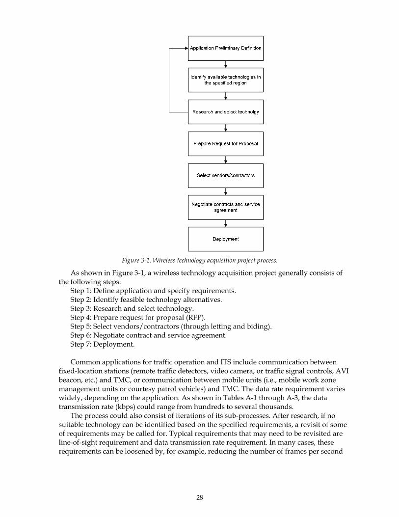
28
Figure 3-1. Wireless technology acquisition project process.
As shown in Figure 3-1, a wireless technology acquisition project generally consists of the following steps:
Step 1: Define application and specify requirements. Step 2: Identify feasible technology alternatives. Step 3: Research and select technology. Step 4: Prepare request for proposal (RFP). Step 5: Select vendors/contractors (through letting and biding). Step 6: Negotiate contract and service agreement. Step 7: Deployment. Common applications for traffic operation and ITS include communication between
fixed-location stations (remote traffic detectors, video camera, or traffic signal controls, AVI beacon, etc.) and TMC, or communication between mobile units (i.e., mobile work zone management units or courtesy patrol vehicles) and TMC. The data rate requirement varies widely, depending on the application. As shown in Tables A-1 through A-3, the data transmission rate (kbps) could range from hundreds to several thousands.
The process could also consist of iterations of its sub-processes. After research, if no suitable technology can be identified based on the specified requirements, a revisit of some of requirements may be called for. Typical requirements that may need to be revisited are line-of-sight requirement and data transmission rate requirement. In many cases, these requirements can be loosened by, for example, reducing the number of frames per second

29
for video applications. Therefore, iterations between step 3 and step 1 are quite common in many cases.
3.1. Budget and Risk Consideration in Wireless Technology Acquisition
There are risks associated with any decision. Making wireless technology acquisition decisions comes with unique risks. These risks can be generally termed reliability risk and obsolete risk. Reliability risk exists because no technology is perfect. It is impossible to guarantee that any system will function as intended 100% of the time throughout its lifecycle. There are numerous possible factors to cause failure or significantly degrade the performance of a wireless communication system, including regular maintenance, component failure, natural causes (lightening) or man-made causes (sabotage or radio frequency saturation in the region). If an own decision is to be made, then the TxDOT will be exposed to all of the above types of reliability risk. Even though the system malfunction may be covered by the manufacturer’s warranty or service agreement by the contractor, the down time is still inevitable, and its duration depends upon how soon the failed part is repaired. The degree of impact of such a risk could vary from one district to another, depending on the level of ITS technical staffing and degree of expertise in wireless technology. If a district has proficient in-house expertise, repairs could be immediately initiated with minimal cost. If a vendor/contractor needs to be called up, the repair is contingent upon the vendor’s/contractor’s responsiveness. Extra repair costs may be unavoidable.
If a lease decision is to be made, then TxDOT will be exposed to different types of reliability risk. The service provider could bring down the service for regular maintenance or upgrade. System malfunction can be caused by any of a number of unknown factors. In such an event, TxDOT will have very limited control over how soon service can be resumed. It depends primarily on the service provider’s responsiveness to the problem. Bringing the service back online will not incur any extra cost for TxDOT, since it is the service provider’s responsibility.
Based on interviews with TxDOT engineers conducted by the researchers (for interview summaries, see appendix A of Project 0-4449-1), it is clear that these risks could be perceived very differently from district to district. A wireless technology-savvy district may be more willing to live with own risk than others, since engineers are capable of making judgments as to the course of action, and of predicting the time it will take to bring back online capability. These engineers also may be more willing to trade such predictability with potential higher cost. Other districts, which may not be as comfortable in handling the technology in-house, may consider the lease option better meets their needs, since it generally requires less in-house expertise.
Furthermore, when comparing the lease and own options, budget structure is another significant consideration for TxDOT engineers. The own option requires budgeting the expenditure in the current or upcoming fiscal year (from the long-term capital improvement budget or the yearly Operating and Maintenance (O&M) budget). Once the equipment (system) is acquired, the O&M and future upgrade costs (due to technology turnover) is allocated to future budgets. The lease option incurs less start-up capital investment, but will require significantly more O&M funds in future years. Deferring the expenditure to later years has its theoretical advantages because future dollar has less worth from the standpoint of current time because of inflation. Furthermore the funds saved in the current fiscal year can be invested in other traffic management actions, which may generate additional benefits

30
(contribute to higher return of investment (ROI)). However, some TxDOT engineers express concerns about accruing higher O&M cost in future fiscal years, since it may impact future funding for traffic operation/management works. In several cases, getting the system in place using the funds in the current year is considered less risky than depending on future funds. Such concerns indicate that deferring the expenditure to the later year is not always preferable. As discussed earlier, the wireless technology funds saved in the current fiscal year, if used in traffic operation tasks (such as purchasing other traffic control devices for other purposes), may generate additional return on investment. However, unless such a collateral benefit is considered in the decision process, then deferring the expenditure is likely to be viewed in terms of future financial burden and uncertain impact on future traffic operations.
Another type of risk associated with wireless technology is obsolete risk, which is realized when the technology becomes outdated and is no longer supported by manufacturers or service providers. As a result, the system or service based on such outdated technology becomes difficult and costly to maintain/upgrade, or support is entirely unavailable.
Such a risk exists because of two reasons. First, wireless technology has been advancing at an accelerated pace in the last decade. As shown in Table 3-1, wireless technologies have experienced several major milestones in every decade from the early 1900s. In the 1990s major technology advancements and milestones were announced in almost every year. A recent incident causing TxDOT district offices to scramble was the “sunsetting” of the cellular digital packet data (CDPD) technology. CDPD was initially developed by the U.S Cellular operators in early 1990s. After one decade of deployment, it has become one of the most widely deployed cellular wireless data communication technologies in the U.S. However, its available transmission data rate fell behind the increasing requirements of many audio/video oriented ITS applications. Furthermore, with the accelerated development of 2.5G or 3G cellular technology in late 1990s, more advanced data communication systems are ready to replace CDPD, and wireless carriers have decided to upgrade to newer technology and phase out CDPD. AT&T Wireless and Verizon Wireless, two of the major CDPD service providers, have recently announced that they are "sunsetting" CDPD wireless technology in June 2004 and December 2005, respectively. Districts like Dallas have had to modify their ongoing contract with Verizon for its traffic surveillance application in order to opt in Verizon’s newly deployed technology (e.g., 1xRTT (nationwide) or 3G CDMA 1xEV-DO in San Diego and Washington, D.C. as of late 2003).
The second obsolete risk contributing factor stems from system design practice that tends to suggest existing and proven technology. Generally speaking, government agencies are about 2 years behind the curve. Obsolete risk arises with this principle. If the selected technology reaches the end of its life span during the life cycle of the application (say 7 to 10 years), district offices face the need to undertake a major upgrade of the system. The cost associated with this upgrade could be high. To avoid such a pitfall, thoroughly examining the future life span of alternative wireless technologies becomes crucial to in the decision process. Undertaking this task is not difficult, but will require careful review of the latest technology reports/news, or consultation of other sources.
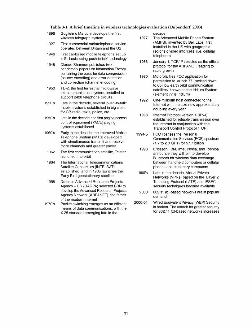
31
Table 3-1. A brief timeline in wireless technologies evaluation (Dubendorf, 2003)
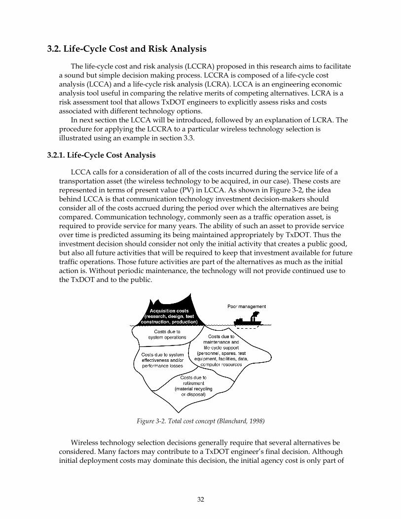
32
3.2. Life-Cycle Cost and Risk Analysis
The life-cycle cost and risk analysis (LCCRA) proposed in this research aims to facilitate a sound but simple decision making process. LCCRA is composed of a life-cycle cost analysis (LCCA) and a life-cycle risk analysis (LCRA). LCCA is an engineering economic analysis tool useful in comparing the relative merits of competing alternatives. LCRA is a risk assessment tool that allows TxDOT engineers to explicitly assess risks and costs associated with different technology options.
In next section the LCCA will be introduced, followed by an explanation of LCRA. The procedure for applying the LCCRA to a particular wireless technology selection is illustrated using an example in section 3.3.
3.2.1. Life-Cycle Cost Analysis
LCCA calls for a consideration of all of the costs incurred during the service life of a transportation asset (the wireless technology to be acquired, in our case). These costs are represented in terms of present value (PV) in LCCA. As shown in Figure 3-2, the idea behind LCCA is that communication technology investment decision-makers should consider all of the costs accrued during the period over which the alternatives are being compared. Communication technology, commonly seen as a traffic operation asset, is required to provide service for many years. The ability of such an asset to provide service over time is predicted assuming its being maintained appropriately by TxDOT. Thus the investment decision should consider not only the initial activity that creates a public good, but also all future activities that will be required to keep that investment available for future traffic operations. Those future activities are part of the alternatives as much as the initial action is. Without periodic maintenance, the technology will not provide continued use to the TxDOT and to the public.
Figure 3-2. Total cost concept (Blanchard, 1998)
Wireless technology selection decisions generally require that several alternatives be
considered. Many factors may contribute to a TxDOT engineer’s final decision. Although initial deployment costs may dominate this decision, the initial agency cost is only part of

33
the story. The technology alternative selected will commit TxDOT to future expenditures for maintenance over the life cycle of the technology product or service. Furthermore, the selected alternative will accrue costs to facility users through project activities that directly impact the traveling public. LCCA provides the means to include total cost to both agency and the user in the acquisition decision. Additionally, the structure and documentation of the LCCA process provide TxDOT with the ability to enhance the stewardship of the public’s investment. Documentation is also a resource that TxDOT can use to educate newer employees and to maintain institutional knowledge.
Life-cycle cost analysis (LCCA) has been promoted by the Federal Highway Administration (FHWA) to be used in major transportation investment decision making for many years. As the inline table shows, FHWA has continued establishing guidelines in the last decade to assist federal and state agencies apply LCCA to major transportation investment decisions. In the area of making ITS technology investment decisions, however, there has been relatively limited guidance provided by FHWA or other national ITS organizations.
Figure 3-3 depicts the timeline of a typical communication system. After the system is initially deployed, engineer satisfaction regarding this system steadily declines because of increasing transmission rate requirement (due to expanded and sophisticated applications) or the aging of system that requires more frequent maintenance. If an engineer decides to upgrade the system, the performance of the system is elevated, among with his satisfaction. The performance satisfaction continues to decline following the upgrade for the same reasons. Thus, the second upgrade takes place after certain further aging of the system. Eventually the system reaches the end of its life cycle and needs to be retired.

34
Figure 3-3. Example of lifetime of a wireless technology alternative.
The LCCA process consists of the following steps. The sequence of these steps is
designed so that the analysis builds upon information gathered in prior steps. Step 1: Determine technology alternative.
Step 2: Determine activity timing.
Step 3: Estimate costs.
Step 4: Compute life-cycle costs.
Step 5: Analyze results.
The following articulate the 4-step LCCA process. STEP 1: Determine communication alternatives. The LCCA process is called for when communication needs are identified for a
particular traffic operation application. Available communication alternatives may encompass a wide spectrum of alternatives. Alternatives that could be considered include:
Wireline communication alternative—lease Most of the ILEC (incumbent local exchange carrier, such as SBC or any other Bell company) or CLEC (competitive local exchange carriers, which were established after telecommunication deregulation in 1996) offer various types of wireline communication services, ranging from ISDN, DSL, T1, T3, etc. Users typically need to pay a monthly service fee for the service. The cost structure for this type of communication service includes purchase of communication devices (e.g., modems and cables) to be installed at the premises, and monthly service charges. The monthly service charge may vary depending on the data rate. Some service bundles also include voice and data services. There is no remaining service life value at the end of the service period.
Wireless communication alternative—lease Similar to the wireline communication alternative, the ILEC and CLEC could also provide wireless communication services. There are an increasing number of such carriers that primarily focus on providing wireless services in cities of Texas. As

35
shown in Table 2-5 and Table 2-6, there are almost 50 nationwide, regional, or local wireless service providers in Texas. Most of the nationwide carriers offer both wireless voice and data services using varying technologies, such as PCS, GPRS, CDPD, EDGE, 1xRTT, 1xEV-DO, etc. Many regional or local providers offer voice services only; several of them offer wireless broadband services via MMDS, LMDS, or above cellular technologies. The cost structure for such types of communication service includes purchases of communication devices (e.g., modems and wires) to be installed at the premise and monthly service charges. The monthly service charge varies depending on data rate and number of connections required. Some service bundles also include voice and data services. There is no remaining service life value at the end of the service period.
Wireless communication alternative—own Owning wireless communication equipment or system is considered when a small-scale deployment is needed and line-of-sight is not an issue. The transmission range may or may not be an issue. If extended transmission range is required, a transceiver and an amplifier may be installed to extend the transmission range for spread spectrum radio. For microwave, the transmission range naturally goes up to several tens of miles. The cost structure for such alternative includes purchasing equipment and labor for the initial deployment, regular O&M cost, and future upgrade costs. There are certain remaining service life values at the end of the service period.
STEP 2: Determine activity timing. Activity timing is the duration over which the life-cycle cost is calculated, and is the time
period over which the current decision may impact. It can be longer or shorter than the technology lifecycle; however, it is recommended that the activity timing includes at least one or two major system upgrades or even entire system retirement. It is suggested that the activity timing to be defined between 5–10 years because of the following considerations:
Moore’s Law40—the fundamental governing rules of modern digital computation power—indicates 18 months as the life cycle for new generations of micro-chip.
Prevalent operating system such as Microsoft Windows ® underwent five major upgrades from 1992 to 2002 (Windows 3.X to Windows XP), averaging 2 years a version. On the average, major compatibility issues arise every four years (from 16-bit version to 32-bit version, and the 64-bit version has just been announced in late 2003).
The evaluation of cellular wireless technologies suggests that the 2G and 2.5G cellular networks have a good possibility of facing “sunsetting” in the foreseeable future, because it is predicted that 80% of the U.S. market will be covered with 3G network by 2005. Several years later, when the 3G becomes mature and cost effective, the 2G and 2.5G may become today’s CDPD, facing the discontinued support from major national operators. It is speculated that the 2G and 2.5G services are still provided in regional areas. Therefore, the “sunsetting” of these technologies is speculated to be between 2010 and 1015, but could widely vary geographically. On other hand, other wireless technologies such as spread
40 The observation made in 1965 by Gordon Moore, co-founder of Intel, that the number of transistors per square inch on integrated circuits had doubled every year since the integrated circuit was invented. Moore predicted that this trend would continue for the foreseeable future. In subsequent years, the pace slowed down a bit, but data density has doubled approximately every 18 months, and this is the current definition of Moore's Law, which Moore himself has blessed. Most experts, including Moore himself, expect Moore's Law to hold for at least another two decades.

36
spectrum radio, microwave, radio paging, land mobile, and satellites, etc. are more likely to extend longer life span because of less fluctuation in this area (see Table 3-2).
Table 3-2. Expected Future Life Span of Various Cellular Wireless Technologies
Commercialization (Year)
Phase out (possible year)
Cellular (2 – 3G) 1st Generation Wireless AMPS 1980s 2004 - CDPD 1993 2004 – 2005 2nd Generation Wireless GSM 1990s 2010-2015? PCS (IS-136) 1990s 2010-2015? PCS (IS-95) 1990s 2010-2015? 2.5 Generation Wireless GPRS 1990s 2010-2015? 1xRTT 1990s 2010-2015? EDGE 1990s 2010-2015? 3rd Generation Wireless UTMS (WCDMA) 2003 ? 1xEV-DO (CDMA 2000) 2003 ? Others (Spread Spectrum, microwave) Spread Spectrum Radio 1970s ? Microwave 1970s ? Radio paging 1970s ? Land Mobile 1970s ? Satellite 1970s ?
STEP 3: Estimate costs. The cost structure for lease and own alternatives could include the following items.
Depending on the service provision and equipment characteristics, not all the cost items need to be considered.
Lease Labor cost – initial installation of device at site Equipment cost – initial installation of device at site Initial training cost – engineer’s time to learn how to operate the equipment/service Service cost – monthly service charge for the service Operator manpower – engineer’s time required to operate the equipment Upgrade cost – cost to upgrade to new services
Own Labor cost – initial installation of device at site Equipment cost – initial installation of device at site Initial training cost – engineer’s time to learn how to operate the equipment Operation and maintenance cost – cost to operate and maintain (due to system
component failure) the equipment Operator manpower – engineer’s time required to operate the equipment Upgrade cost – cost to upgrade and software and/or hardware Salvage value – the remaining value of the equipment at the end of analysis period
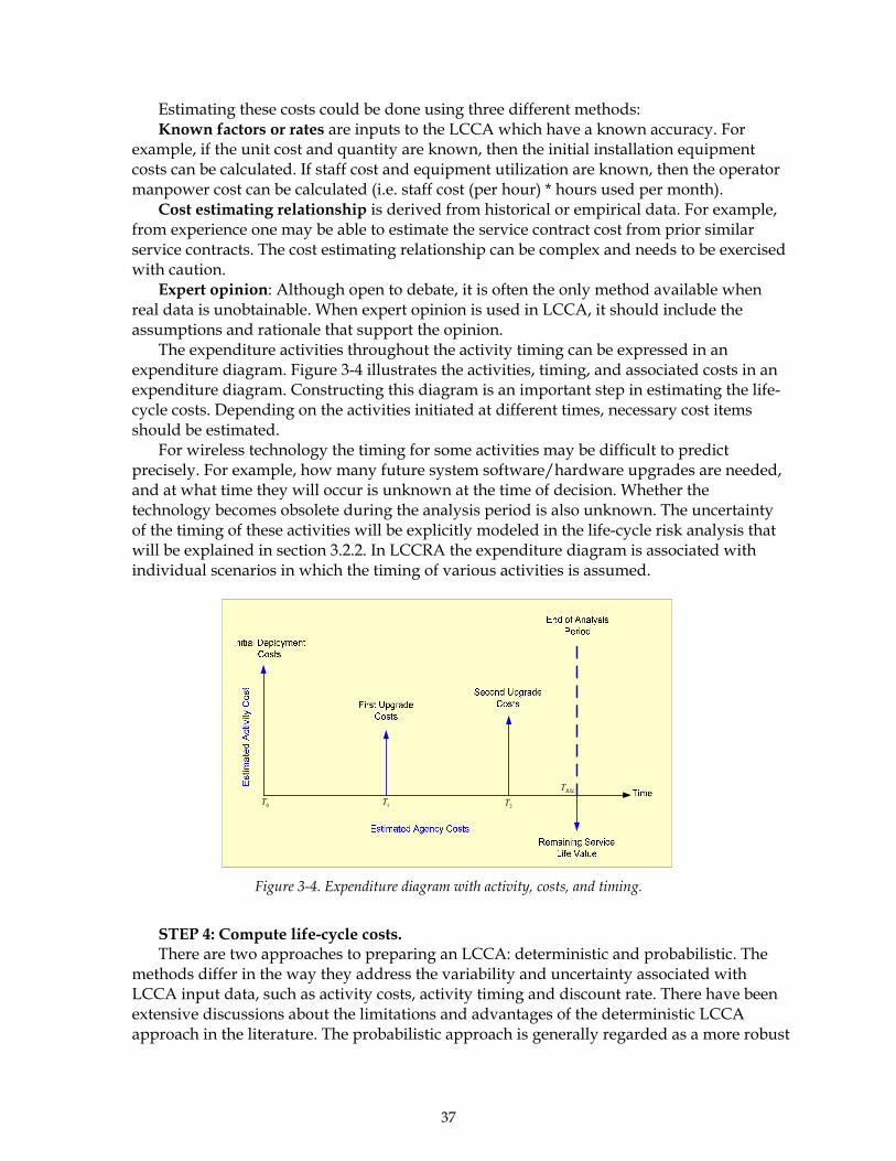
37
Estimating these costs could be done using three different methods: Known factors or rates are inputs to the LCCA which have a known accuracy. For
example, if the unit cost and quantity are known, then the initial installation equipment costs can be calculated. If staff cost and equipment utilization are known, then the operator manpower cost can be calculated (i.e. staff cost (per hour) * hours used per month).
Cost estimating relationship is derived from historical or empirical data. For example, from experience one may be able to estimate the service contract cost from prior similar service contracts. The cost estimating relationship can be complex and needs to be exercised with caution.
Expert opinion: Although open to debate, it is often the only method available when real data is unobtainable. When expert opinion is used in LCCA, it should include the assumptions and rationale that support the opinion.
The expenditure activities throughout the activity timing can be expressed in an expenditure diagram. Figure 3-4 illustrates the activities, timing, and associated costs in an expenditure diagram. Constructing this diagram is an important step in estimating the life-cycle costs. Depending on the activities initiated at different times, necessary cost items should be estimated.
For wireless technology the timing for some activities may be difficult to predict precisely. For example, how many future system software/hardware upgrades are needed, and at what time they will occur is unknown at the time of decision. Whether the technology becomes obsolete during the analysis period is also unknown. The uncertainty of the timing of these activities will be explicitly modeled in the life-cycle risk analysis that will be explained in section 3.2.2. In LCCRA the expenditure diagram is associated with individual scenarios in which the timing of various activities is assumed.
0T 1T 2TRSLT
Figure 3-4. Expenditure diagram with activity, costs, and timing.
STEP 4: Compute life-cycle costs. There are two approaches to preparing an LCCA: deterministic and probabilistic. The
methods differ in the way they address the variability and uncertainty associated with LCCA input data, such as activity costs, activity timing and discount rate. There have been extensive discussions about the limitations and advantages of the deterministic LCCA approach in the literature. The probabilistic approach is generally regarded as a more robust

38
method. However, this approach requires significantly more input data and takes more time to complete. Thus it may be less applicable in wireless technology selection because of the budget size and time constraints for this task. Thus, the deterministic approach has been selected for this study. The uncertainty and variability aspects of the problem will be addressed in section 3.2.2.
The deterministic approach assigns each LCCA input variable (cost, timing, etc.) a fixed, discrete value. The engineer determines the value most likely to occur for each input variable. This determination can be based on historical evidence, professional judgment, consultation with other engineers, or study of various sources including the Internet. Deterministic LCC computation is straightforward and can be conducted manually using a calculator or automatically with a computer spreadsheet program (i.e., MS Excel). In this research, the calculation of LCC has been implemented in a web-based knowledge management system (WBKMS) and in a MS Excel worksheet, which will be later discussed in this chapter.
The results of deterministic analysis can be enhanced through the use of a technique called sensitivity analysis. This procedure involves changing a single input variable of interest, such as the discount rate or activity costs, over the range of its possible values while holding others constant, and estimating a series of present values (PVs). Each PV result reflects the effect of input change. In this way input variables may be ranked according to their impacts on the bottom-line conclusions. This information could be important to engineers who want to understand the variability associated with alternative options. It also allows the engineer to identify those input factors or economic conditions that warrant special attention.
The method for converting the future value to current value is called discounting. The reason for discounting is that cost of benefits occurring at different points in time—past, present, and future—cannot be compared without considering the opportunity value of time. The opportunity value of time as it applies to current versus future funds can be understood in terms of the economic return that could be earned on funds in their next best alternative use (e.g., the fund could be earning interest or could be invested in other traffic operation strategies to introduce other benefits) or the compensation that must be paid to induce an engineer to defer an additional amount of current year consumption for one year. In other words, reducing the value of future cost makes deferring the expenditure relatively attractive. A lower discounting rate discounts less of future value, or discourages deferring the expenditure to future years. A discounting rate of 7% is suggested by the Federal Government.41 According to the discussions in preceding sections, TxDOT engineers may not necessarily prefer deferring the expenditure to future years. In this case, he/she may choose to take a lower discounting rate. Furthermore, applying the discounting also implies that inflation for all costs is approximately equal, and thus inflation is usually considered embedded in the discounting and is not calculated separately.
41 OMB Circular No. A-94

39
The formula for discounting can be expressed as:
Present value = future value nr)1(1
+×
Where r = discounting rate, 7% based on OMB Circular No. A-9442; however, a lower rate (2-
5%) is used in this research n = number of years in the future when the cost will be incurred STEP 5: Analysis the results. This step involves analyzing and interpreting the LCCA results. With the deterministic
LCCs computed, the PVs of the differential costs may be compared across competing alternatives. In this research, the LCCs are treated as inputs of the life-cycle risk analysis (LCRA) and will be not used as the final outcome for comparison. It is generally recommended that both agency and use costs be included in the LCC. In wireless technology selection application, it is extremely difficult to estimate the user costs resulting from various activities during the analysis duration; thus only agency costs are considered.
3.2.2. Life-Cycle Risk Analysis
As discussed in the preceding section, emerging wireless technologies always come with several competing standards which may not be compatible with each other. While the technology becomes standardized, mature, and proven (which is generally preferred by government agency), a newer generation of the similar technology or even entirely different technology may emerge. Cellular wireless technologies, particular the 2G or 2.5G technology (GPRS, EDGE, 1xRTT, etc.) have become mature but may be phased out in a foreseeable future. Their future life span depends on the path of technology advancement, competition, and market adaptation of 3G technology. Other wireless technologies (e.g., spread spectrum radio, microwave, etc.) may exhibit longer life span that interim cellular technologies. The short and unpredictable life cycle of wireless technology, as defined obsolete risk, makes technology selection decision risky.
Engineers may also have different perceptions and tolerances toward risk, depending on personal preferences, applications, and budget constraints. A more risky but less costly alternative may be preferred because of budget constraints. A less risky but costly option may be chosen because it provides a higher data rate that may soon to be needed. Recognizing the obsolete risk and varying perceptions of risk, this research develops life-cycle risk analysis (LCRA) risk assessment guidelines in conjunction with LCCA to consider the risk-based life-cycle costs. The LCRA is a decision tree based approach, in which the entire decision problem is represented through a set of possible decision scenarios. Each scenario is a combination of actions and subsequent outcomes of actions. A typical decision tree is rooted in a decision node (represented as a square-shaped node as in Figure 3-5), which represents the selection of several feasible alternatives. The alternatives represented by the branches from a decision node must be such that the decision makers can choose only one alternative. For example, the engineer can choose only configuration 1 or 2, but not both. In some cases, a combination of strategies is possible. In this case, the three alternatives should
42 http://www.whitehouse.gov/omb/circulars/a094/a094.html
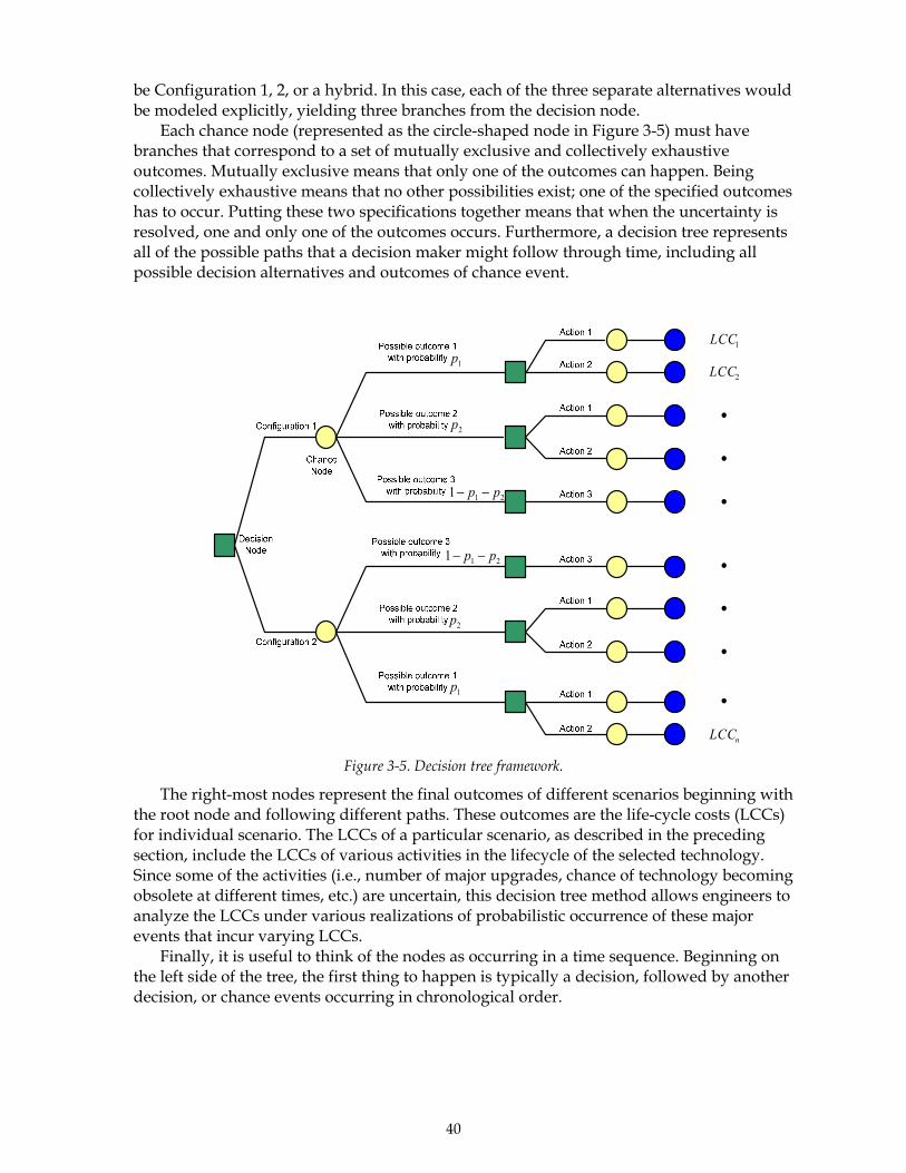
40
be Configuration 1, 2, or a hybrid. In this case, each of the three separate alternatives would be modeled explicitly, yielding three branches from the decision node.
Each chance node (represented as the circle-shaped node in Figure 3-5) must have branches that correspond to a set of mutually exclusive and collectively exhaustive outcomes. Mutually exclusive means that only one of the outcomes can happen. Being collectively exhaustive means that no other possibilities exist; one of the specified outcomes has to occur. Putting these two specifications together means that when the uncertainty is resolved, one and only one of the outcomes occurs. Furthermore, a decision tree represents all of the possible paths that a decision maker might follow through time, including all possible decision alternatives and outcomes of chance event.
1p
2p
211 pp −−
1p
2p
211 pp −−
1LCC
2LCC
•
•
•
•
•
•
•
nLCC Figure 3-5. Decision tree framework.
The right-most nodes represent the final outcomes of different scenarios beginning with the root node and following different paths. These outcomes are the life-cycle costs (LCCs) for individual scenario. The LCCs of a particular scenario, as described in the preceding section, include the LCCs of various activities in the lifecycle of the selected technology. Since some of the activities (i.e., number of major upgrades, chance of technology becoming obsolete at different times, etc.) are uncertain, this decision tree method allows engineers to analyze the LCCs under various realizations of probabilistic occurrence of these major events that incur varying LCCs.
Finally, it is useful to think of the nodes as occurring in a time sequence. Beginning on the left side of the tree, the first thing to happen is typically a decision, followed by another decision, or chance events occurring in chronological order.

41
3.3. Life-Cycle Cost and Risk Analysis Guideline
The procedure for the LCCRA is briefly described as follows. It is best understood through an example, which will be given in this section. The methods for LCCRA have been implemented in a Web-based knowledge management system to cope with general decision situations (see http://atrl.utep.edu/telecom/DSM/dsm_home.php?type=4). The Microsoft Excel spreadsheet for the example is also included in the CD that accompanies this project, 0-4449-P2. Leasing or owning wireless technology/service is often called for in applications such as having remote traffic detectors or video cameras communicate with TMC. In urban areas where existing TxDOT-owned ITS infrastructure is typically in place (i.e., fiber networks), the decision is relatively easy since utilizing existing infrastructure is the best choice. If the application is located in a rural area where no ITS infrastructure exists, and budget is a concern, then leasing or owning the technology deserves careful consideration.
It is suggested that given such a decision context, engineers follow the steps depicted in Figure 3-6.
Figure 3-6. Decision framework for lease or own decision.

42
In this framework, the decision process is organized into several steps. These steps are explained using a hypothetical example, as follows:
A TxDOT district needs to monitor traffic on a rural freeway corridor using several video imaging vehicle detection systems, which include cameras and vehicle detection processors. The distances from the cameras to the TMC range from 2,000 ft. to 10 miles. The video data will need to be sent back to the TMC located at the district office.
Stage 1: Application definition and requirement specification. Important information that should be identified in this step includes: Local Cellular Wireless or Wireline Service Providers, Service Plans
SBC is the ILEC for the wireless service; there are a few national and regional wireless voice and data service carriers. The available cellular wireless service available in the region is CDPD and GRPS. The CDPD and GPRS service costs $40-80/month/unit.
Data Rate Requirements In this example, the data need to be transmitted are the vehicle detection data and the video feeds. The transmission rate requirement is flexible because the video resolution (number of frames per second) can be adjusted based on the available transmission rate.
Line-of-Sight Line-of-sight is available for most of the sites.
Transmission Range The transmission range varies from 2,000 ft. to 10 miles.
Life-Cycle Budget Uncertain, most likely less than $400k.
Frequency Range Unlicensed (own option) or unrestricted (lease option).
Terrain Flat terrain, slightly hilly.
Existing TxDOT-Owned ITS Infrastructure No TxDOT-owned ITS infrastructure (such as fiber optics) exists.
Stage 2: Identify feasible technology alternatives Prior to identifying feasible technology alternatives, system configurations need to be
designed. Let us assume that there are three possible candidate configurations. As shown in Figure 3-7 to Figure 3-9, in configuration 1, the data are transmitted directly to the center wirelessly43. In configuration 2, the data are transmitted from cameras to the cabinet, and then wireline is used to send data to the TMC. In configuration 3, the data are sent to the center using cellular technology. In other words the data are sent to the wireless carrier’s base station and relayed to the TMC. Wireless technology is employed in different ways in these configurations. In the first configuration, line-of-sight is required, and the transmissions range from thousands of feet to miles. The available data transmission rate depends on the wireless technology employed. Prevalent technologies available for this
43 For remote sites that are 10 miles away, signals can be relayed by transceivers and amplifiers.

43
configuration are spread spectrum radio and microwave. These technologies are typically acquired through procurement, or they could be included as a part of the camera systems.
Figure 3-7. Example system configuration (1).
In the second configuration, only short-range communication is needed (hundreds of feet). The available data transmission depends on a minimum of wireless and wireline technology. Prevalent technology for this configuration is 802.11x-based technology. The wireline service could be regular phone line, ISDN, T1, T3, frame relay, or OC-X. The wireless technology used is typically acquired through procurement, or it could be included as a part of the wireless camera systems.
Figure 3-8. Example of system configuration (2).
In the third configuration, the cameras transmit data back to the center through a wireless service provider’s base station. The available data transmission rate depends on the technology that the service provider uses, and it also may depend on the service plan. The technologies in this area are currently experiencing rapid migration. The recently phased out CDPD technology belongs to this area. Prevalent techniques include GPRS (GSM-based), EDGE (GSM-based), and 1xRTT (CDMA-based). These are 2.5G technologies. The 3G technologies, including 1xEV-DO (CDMA2000 based), and UMTS (WCDMA) will rapidly deployed in the near future. It is anticipated that the dominating 3G technology in the United States is CDMA2000-based technology. The only way to acquire this technology is through subscribing to the service; the modems may need to be purchased.

44
Figure 3-9. Example system configuration (3).
Feasible technologies or services that come with the lease option can be identified
through calling national or regional wireless service providers. Different service providers use different technologies that may require purchasing different type of communication devices installed at premises.
Feasible technologies or services that come with the own option can be identified in several ways, including: (1) Logging onto the Web-based knowledge management system (http://atrl.utep.edu/telecom) developed by the researchers for this project (this site is expected to operate continuously from 2003 to 2006) to (a) search the latest technology news, tutorials, glossary, etc.; (b) post project information onto the Project Center to solicit information for interested parties; (c) to post related questions on to the Discussion Forum (these questions will automatically forwarded to a Technical support panel, which is composed of other TxDOT engineers, vendors/contractors, and other professional engineers. (2) Consult with other TxDOT engineers or other engineers/consultants via various channels. (3) Survey the Internet for related information. It is obvious that for any new projects, it is effective and efficient to start from the WBKMS, because all the features provided on this website are primarily designed to support TxDOT engineers’ wireless technology acquisition needs. Detailed descriptions of this WBKMS are provided in (http://atrl.utep.edu/telecom).
Stage 3: Research and select configuration. As discussed earlier, wireless technology is employed differently in individual
configurations. Simply analyzing the wireless portion does not provide the whole picture. In the following, the LCCRA is discussed based on the configurations with many assumptions made for wireline technologies. The use of the LCCRA for this example is described in following actions:
Step 1: Define the analysis period. As discussed earlier, choose an analysis duration between 5 and 10 years. Step 2: Construct decision tree diagram. The decision tree diagram captures major uncertain events (which will incur significant
costs) throughout the life cycle of a particular configuration. The tree starts from the root
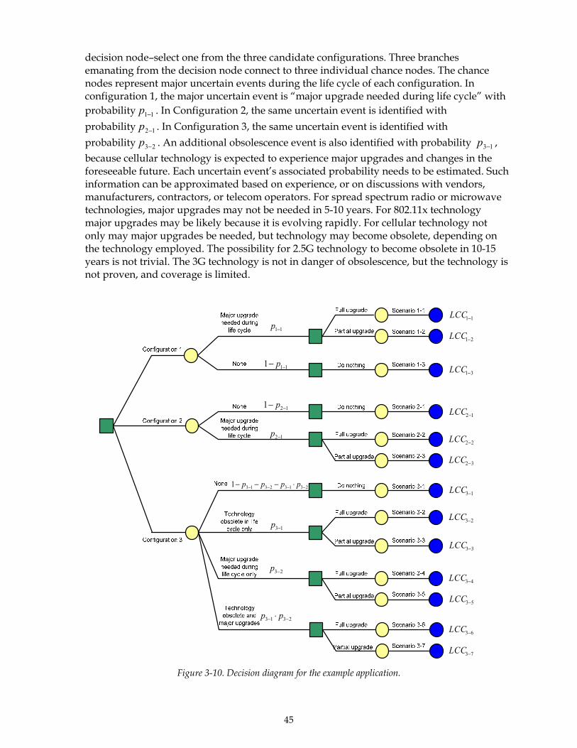
45
decision node–select one from the three candidate configurations. Three branches emanating from the decision node connect to three individual chance nodes. The chance nodes represent major uncertain events during the life cycle of each configuration. In configuration 1, the major uncertain event is “major upgrade needed during life cycle” with probability 11−p . In Configuration 2, the same uncertain event is identified with probability 12−p . In Configuration 3, the same uncertain event is identified with probability 23−p . An additional obsolescence event is also identified with probability 13−p , because cellular technology is expected to experience major upgrades and changes in the foreseeable future. Each uncertain event’s associated probability needs to be estimated. Such information can be approximated based on experience, or on discussions with vendors, manufacturers, contractors, or telecom operators. For spread spectrum radio or microwave technologies, major upgrades may not be needed in 5-10 years. For 802.11x technology major upgrades may be likely because it is evolving rapidly. For cellular technology not only may major upgrades be needed, but technology may become obsolete, depending on the technology employed. The possibility for 2.5G technology to become obsolete in 10-15 years is not trivial. The 3G technology is not in danger of obsolescence, but the technology is not proven, and coverage is limited.
11−p
111 −− p
12−p
121 −− p
11−LCC
23−p
13−p
231323131 −−−− ⋅−−− pppp
2313 −− ⋅ pp
21−LCC
31−LCC
12−LCC
22−LCC
32−LCC
13−LCC
23−LCC
33−LCC
43−LCC
53−LCC
63−LCC
73−LCC
Figure 3-10. Decision diagram for the example application.
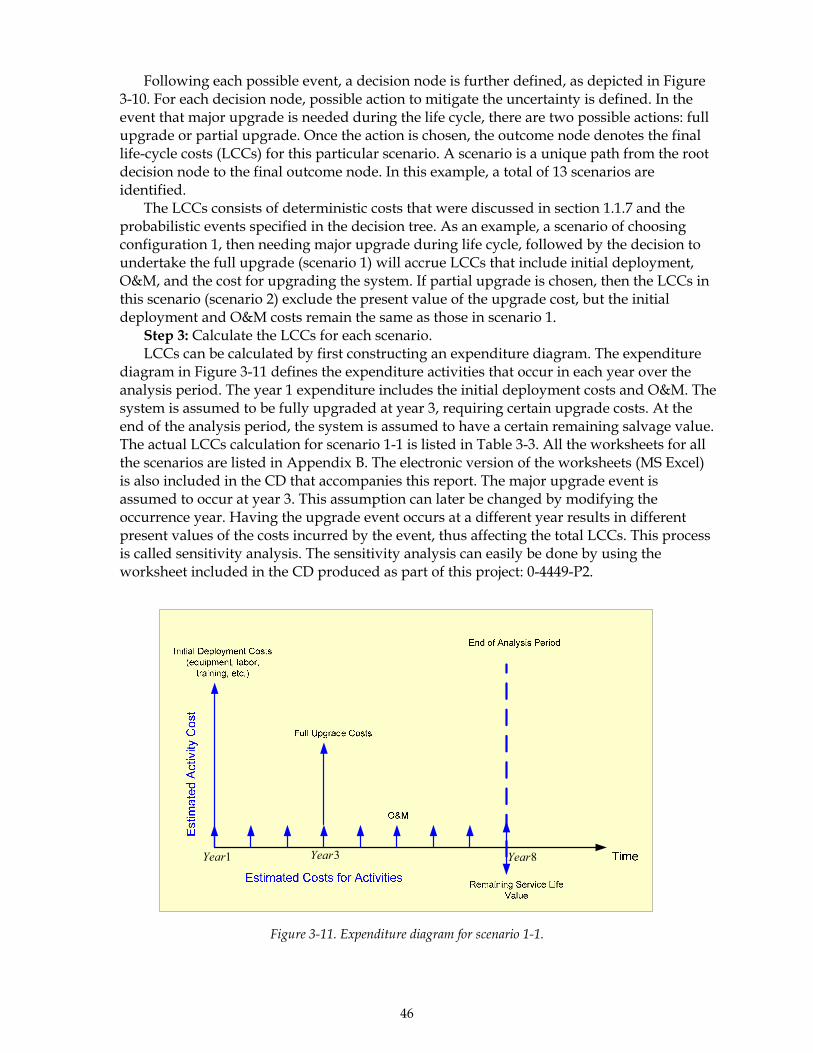
46
Following each possible event, a decision node is further defined, as depicted in Figure 3-10. For each decision node, possible action to mitigate the uncertainty is defined. In the event that major upgrade is needed during the life cycle, there are two possible actions: full upgrade or partial upgrade. Once the action is chosen, the outcome node denotes the final life-cycle costs (LCCs) for this particular scenario. A scenario is a unique path from the root decision node to the final outcome node. In this example, a total of 13 scenarios are identified.
The LCCs consists of deterministic costs that were discussed in section 1.1.7 and the probabilistic events specified in the decision tree. As an example, a scenario of choosing configuration 1, then needing major upgrade during life cycle, followed by the decision to undertake the full upgrade (scenario 1) will accrue LCCs that include initial deployment, O&M, and the cost for upgrading the system. If partial upgrade is chosen, then the LCCs in this scenario (scenario 2) exclude the present value of the upgrade cost, but the initial deployment and O&M costs remain the same as those in scenario 1.
Step 3: Calculate the LCCs for each scenario. LCCs can be calculated by first constructing an expenditure diagram. The expenditure
diagram in Figure 3-11 defines the expenditure activities that occur in each year over the analysis period. The year 1 expenditure includes the initial deployment costs and O&M. The system is assumed to be fully upgraded at year 3, requiring certain upgrade costs. At the end of the analysis period, the system is assumed to have a certain remaining salvage value. The actual LCCs calculation for scenario 1-1 is listed in Table 3-3. All the worksheets for all the scenarios are listed in Appendix B. The electronic version of the worksheets (MS Excel) is also included in the CD that accompanies this report. The major upgrade event is assumed to occur at year 3. This assumption can later be changed by modifying the occurrence year. Having the upgrade event occurs at a different year results in different present values of the costs incurred by the event, thus affecting the total LCCs. This process is called sensitivity analysis. The sensitivity analysis can easily be done by using the worksheet included in the CD produced as part of this project: 0-4449-P2.
1Year 3Year 8Year
Figure 3-11. Expenditure diagram for scenario 1-1.

47
It should be noted that the discounting rate is set to be zero for year 1. Throughout the
life cycle, it is set within a range of 0.2–0.5. Generally, the discounting rate decreases over time.
Table 3-3. Worksheet for calculating life-cycle cost for scenario 1-1 Unit cost ($1000)
Unit Subtotal (k)
Discounting Rate
($1000) (r%)1 Equipment (Camera, spread spectrum radio or
Microwave)12.50 20 250.00 0.00 250.00
1 Labor 10.00 1 10.00 0.00 10.001 O&M 0.50 1 0.50 0.00 0.501 Training (engineer time) 0.05 100 5.00 0.00 5.002 O&M 0.50 1 0.50 2.00 0.483 O&M 0.50 1 0.50 2.00 0.473 Full Upgrade 30.00 1 30.00 3.20 27.294 O&M 1.00 1 1.00 2.00 0.925 O&M 1.00 1 1.00 2.00 0.916 O&M 1.00 1 1.00 2.00 0.897 O&M 2.00 1 2.00 2.00 1.748 O&M 2.00 1 2.00 2.00 1.718 Salvage Value -20.00 1 -20.00 2.00 -17.07
LCCs $282.84
Year (n) Expenditure Item Present Value of Expenditure ($100) =
⎥⎦⎤
⎢⎣⎡ +⋅ nrk )
1001(1
Step 4: Select the alternative with minimal expected LCCs. This step is done by moving from the outcome node backward to the root decision node.
The calculation is discussed as follows: List all the LCCs at each outcome node. At the decision node that is “upstream” of the outcome node, write down the lower of
the LCCs that emanate from this decision node. As an example, for the decision node that leads to two scenarios 1-1 and 1-2, the LCCs at the decision node are the lower LCCs of scenarios 1-1 and 1-2, which is the lower of (282.8, 277.2). Doing so indicates that the best decision at the decision node is to conduct a partial upgrade because of lower LCCs.
Repeat the procedure for all the decision nodes. Next, move one level higher. At each chance node above the decision nodes, calculate
the weighted average LCCs using the following formula:
{ }∑ ⋅= kLCCpLCC ki |min
Where iLCC is the average LCCs for Chance Node i,
kp is the probability of event k, { }kLCC |min is the minimal LCC given that event k occurs, which is the LCC calculated
at 2. Once calculation of all the iLCC has been completed, the most cost-effective alternative
based on the average LCCs is the alternative with the minimal iLCC . Calculate the variation of iLCC by checking the largest and smallest LCCs associated
with different events. For example, as shown in Table 3-4, LCC variation for configuration 1 is [265.6, 277.2]. That for configuration 2 is [279.8, 287.6], and that for configuration 3 is [298.3, 332.5].

48
Table 3-4. Decision Tree Analysis Final Results
CONFIGURATION PROB LLCS OF BEST ACTIONConfiguration 1Major upgrade needed during life cycle 0.40 277.17None 0.60 255.55Average LLCs ($1000) 264.20Configuration 2Major upgrade needed during life cycle 0.10 287.64None 0.90 279.81Average LLCs ($1000) 280.60Configuration 3None 0.68 298.26Technology obsolete 0.10 332.07Major upgrade needed during life cycle 0.20 298.85Technology obsolete and major upgrade 0.02 332.53Average LLCs ($1000) 302.44
Decision Tree Worksheet
Step 5: Reach preliminary conclusions by checking average and variation of LCCs. From Figure 3-12 it is clear that configuration 1 is the best choice, with the minimal
average LCCs at $264. Configuration 2 requires $280.6K, while configuration 3 requires the most at LCCs $302.4K. Comparing the range of LCC variation, configuration 1 is $11.6K ($277.1 minus $265.6), while configuration 2 has $7.8 [$287.6 minus $279.8]. Configuration 3 has the highest variation at $34.2K. These LCCs variation measures provide engineers with an idea of at what range the actual LCCs may be realized. Further checking confirms that the lowest possible LCC for configuration 2 ($279.8) is still higher than the highest LCC for configuration 1 ($277.2), which suggests that configuration 1 is not only the most cost-effective alternative but also the minimal-risk alternative.
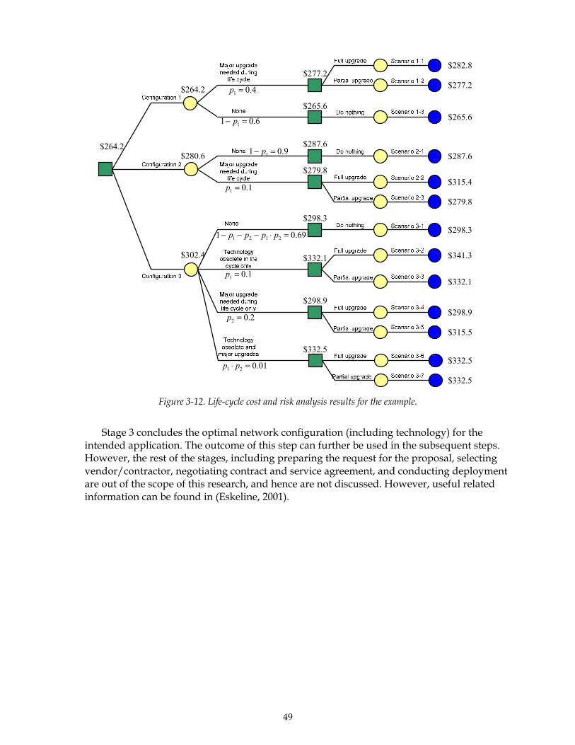
49
4.01 =p
6.01 1 =− p
1.01 =p
9.01 1 =− p
8.282$
2.02 =p
1.01 =p
69.01 2121 =⋅−−− pppp
01.021 =⋅ pp
2.277$
6.265$
6.287$
4.315$
8.279$
3.298$
3.341$
1.332$
9.298$
$315.5
$332.5
5.332$
5.332$
9.298$
1.332$
3.298$
8.279$
6.287$
6.265$
2.277$
2.264$
6.280$
4.302$
2.264$
Figure 3-12. Life-cycle cost and risk analysis results for the example.
Stage 3 concludes the optimal network configuration (including technology) for the
intended application. The outcome of this step can further be used in the subsequent steps. However, the rest of the stages, including preparing the request for the proposal, selecting vendor/contractor, negotiating contract and service agreement, and conducting deployment are out of the scope of this research, and hence are not discussed. However, useful related information can be found in (Eskeline, 2001).


51
4. Wireless Technology Acquisition Knowledge Management System
The creation of a Web-based knowledge management system (WBKMS) was motivated by interviews with TxDOT engineers. In these interviews, engineers expressed concerns about having to make their ITS wireless technology acquisition decisions based on very limited information. This situation was partly attributed to decision time constraints and partly to the lack of a mechanism to facilitate the formation of institutional knowledge and experience accessible by all TxDOT engineers. To remedy this situation, the researchers employed the concept and framework of knowledge management (KM), which has recently been increasingly emphasized in the public sector, and created a Web-based knowledge management system (WBKMS) that is specifically designed for assisting TxDOT engineers in coping with various aspects of decisions in ITS wireless technology acquisition.
This chapter discusses the concept of WBKMS and the development of a WBKMS for TxDOT engineers to assist in their decision process.
4.1. Knowledge Management Concept
Unfortunately, there is no universal definition of KM, just as there is no agreement as to what constitutes knowledge in the first place. Any attempt to define knowledge is complex, controversial, and capable of being interpreted in many different ways. Therefore, it is best to think of KM in the broadest context. KM could be viewed as the process through which organizations generate value and improve overall performance by identifying, developing, managing, and sharing their intellectual and knowledge-based assets. These intangible assets consist of human capital (employees’ competence), structural capital (the internal structure of the organization), and customer capital (relationships with customers, suppliers, partners, or other external bodies.)
These assets can also be classified into two categories: explicit or tacit. As a general rule of thumb, explicit knowledge consists of anything that can be documented, archived, and codified, often with the help of information technology (IT). Much harder to grasp is the concept of tacit knowledge, or the know-how that is contained in people’s heads. In other words, most of the challenges in KM are how to recognize, generate, share, and manage tacit knowledge.
Burk (1999) characterizes the notion of a “cycle of knowledge,” in which four major knowledge processes take place repeatedly in a circular manner (Figure 4-1). Once one individual has formed certain knowledge through research, lesson, or production performance evaluation, he/she documents such knowledge via means of publications, conferences, etc. Such knowledge needs further organization so that it is easily shared and reused by other employees in the same organization and for those who are either new to the position or at a different position but in need of similar knowledge.
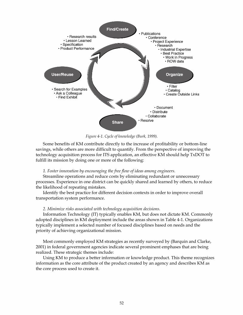
52
Figure 4-1. Cycle of knowledge (Burk, 1999).
Some benefits of KM contribute directly to the increase of profitability or bottom-line savings, while others are more difficult to quantify. From the perspective of improving the technology acquisition process for ITS application, an effective KM should help TxDOT to fulfill its mission by doing one or more of the following:
1. Foster innovation by encouraging the free flow of ideas among engineers. Streamline operations and reduce costs by eliminating redundant or unnecessary
processes. Experience in one district can be quickly shared and learned by others, to reduce the likelihood of repeating mistakes.
Identify the best practice for different decision contexts in order to improve overall transportation system performance.
2. Minimize risks associated with technology acquisition decisions. Information Technology (IT) typically enables KM, but does not dictate KM. Commonly
adopted disciplines in KM deployment include the areas shown in Table 4-1. Organizations typically implement a selected number of focused disciplines based on needs and the priority of achieving organizational mission.
Most commonly employed KM strategies as recently surveyed by (Barquin and Clarke,
2001) in federal government agencies indicate several prominent emphases that are being realized. These strategic themes include:
Using KM to produce a better information or knowledge product. This theme recognizes information as the core attribute of the product created by an agency and describes KM as the core process used to create it.
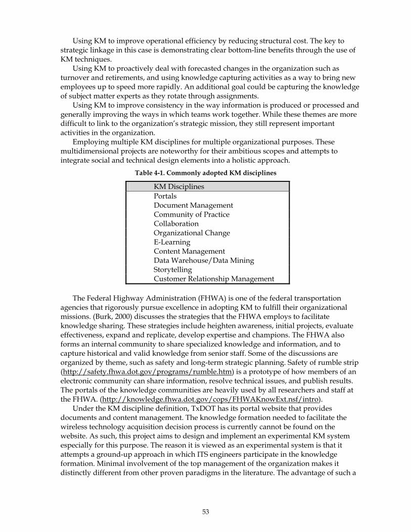
53
Using KM to improve operational efficiency by reducing structural cost. The key to strategic linkage in this case is demonstrating clear bottom-line benefits through the use of KM techniques.
Using KM to proactively deal with forecasted changes in the organization such as turnover and retirements, and using knowledge capturing activities as a way to bring new employees up to speed more rapidly. An additional goal could be capturing the knowledge of subject matter experts as they rotate through assignments.
Using KM to improve consistency in the way information is produced or processed and generally improving the ways in which teams work together. While these themes are more difficult to link to the organization’s strategic mission, they still represent important activities in the organization.
Employing multiple KM disciplines for multiple organizational purposes. These multidimensional projects are noteworthy for their ambitious scopes and attempts to integrate social and technical design elements into a holistic approach.
Table 4-1. Commonly adopted KM disciplines
KM Disciplines Portals Document Management Community of Practice Collaboration Organizational Change E-Learning Content Management Data Warehouse/Data Mining Storytelling Customer Relationship Management
The Federal Highway Administration (FHWA) is one of the federal transportation
agencies that rigorously pursue excellence in adopting KM to fulfill their organizational missions. (Burk, 2000) discusses the strategies that the FHWA employs to facilitate knowledge sharing. These strategies include heighten awareness, initial projects, evaluate effectiveness, expand and replicate, develop expertise and champions. The FHWA also forms an internal community to share specialized knowledge and information, and to capture historical and valid knowledge from senior staff. Some of the discussions are organized by theme, such as safety and long-term strategic planning. Safety of rumble strip (http://safety.fhwa.dot.gov/programs/rumble.htm) is a prototype of how members of an electronic community can share information, resolve technical issues, and publish results. The portals of the knowledge communities are heavily used by all researchers and staff at the FHWA. (http://knowledge.fhwa.dot.gov/cops/FHWAKnowExt.nsf/intro).
Under the KM discipline definition, TxDOT has its portal website that provides documents and content management. The knowledge formation needed to facilitate the wireless technology acquisition decision process is currently cannot be found on the website. As such, this project aims to design and implement an experimental KM system especially for this purpose. The reason it is viewed as an experimental system is that it attempts a ground-up approach in which ITS engineers participate in the knowledge formation. Minimal involvement of the top management of the organization makes it distinctly different from other proven paradigms in the literature. The advantage of such a

54
grass-roots activity is that it agilely responds to the needs of engineers without having to wait for leadership from the top. The challenges are the potential lack of motivation to contribute and the absence of rewards for best practice.
4.2. Knowledge Management System Structure and Features
The knowledge management system developed from this research is designed to facilitate knowledge building and information/experience exchanges among TxDOT engineers in acquiring wireless communication technologies. Wireless communication technologies have currently been widely applied in ITS related traffic operations in TxDOT jurisdictions. Although there are many districts with high levels of expertise and experience in dealing with the acquisition of wireless technologies for ITS applications, many of the smaller districts encounter difficulties when facing similar technology acquisition decision situations. Developments in wireless technology protocols, standards, or products are evolving rapidly. Unless one keeps track of the technology evolution constantly, one will often be in the dark when coming across a new jargon. The WBKMS is implemented as a Web-based clearinghouse, which entails the following objectives:
To compile basic technical information regarding wireless communication technologies and technology acquisition project management in a single repository in order to serve TxDOT engineers' various needs.
To provide a platform to facilitate information sharing and communications among TxDOT engineers, vendors, and other wireless technology professionals.
To provide basic decision support analysis for decisions such as procurement vs. leasing, or varying product configurations.
This Web-based clearinghouse is for members only, and registering on this site is free of charge. All the information that members provide is kept strictly confidential; none of the information is shared with anyone else. The reason for asking users to register is to ensure that all communications and information going on this Web site is of relevance to Web site users, and to continue proving the service of this clearinghouse. Once an engineer, vendor, contractor, or other professional registers, the Web site provides the member with personalized information-answers to posted information, responses to projects, etc. If a member volunteers to be a technical support panel (TSP) member, he/she will receive a weekly newsletter about the updates of activities on this Web site.
The main features of this WBKMS are introduced in next few sections.
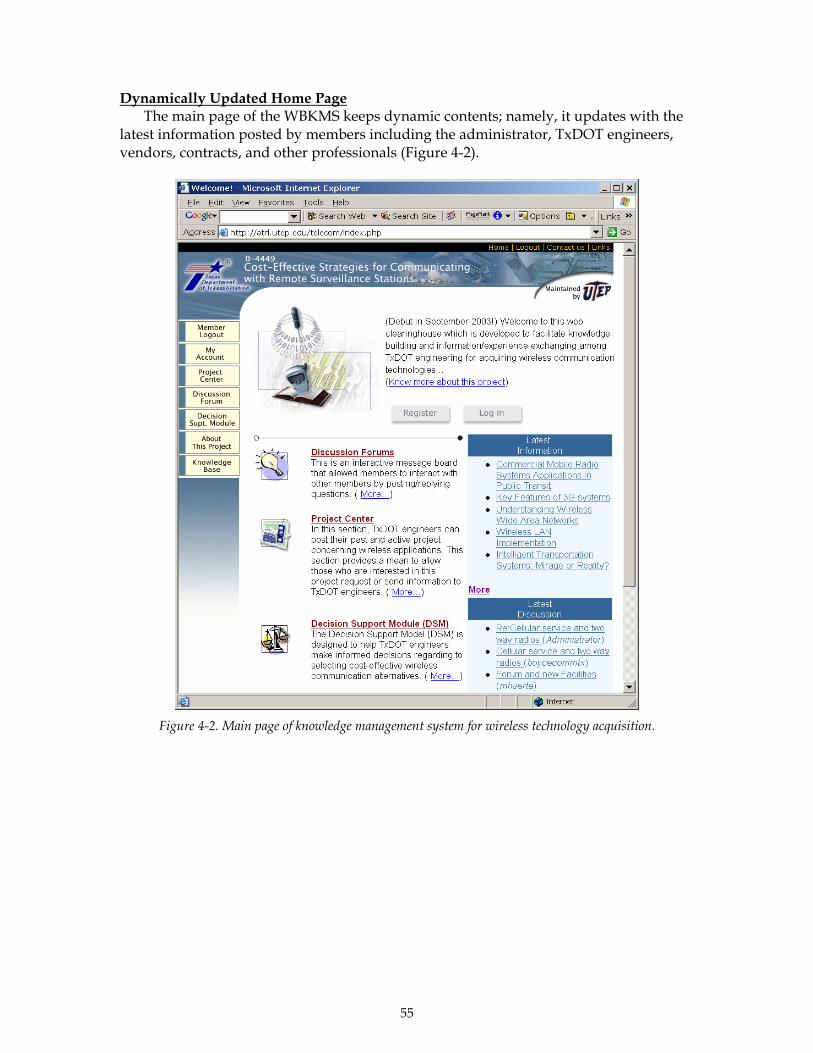
55
Dynamically Updated Home Page
The main page of the WBKMS keeps dynamic contents; namely, it updates with the latest information posted by members including the administrator, TxDOT engineers, vendors, contracts, and other professionals (Figure 4-2).
Figure 4-2. Main page of knowledge management system for wireless technology acquisition.

56
Personalized Homepage for Registered Members The Web site requires a personal login to access features. Once logged in, each member
will immediately see a personal main page, which lists the latest activities related to this member, discussion topics or projects posted (Figure 4-3).
Figure 4-3. Personalized homepage for registered members showing personalized information.

57
Discussion Forums This is an interactive message board that allows all members to interact with others by
posting and replying to questions (Figures 4-4 and 4-5). This discussion forum has several unique features.
First, it sends out a relay alarm that notifies the person who posts a question whenever someone else has replied to the questions. This way one does not need to constantly return to the Web site to check whether one’s questions have been answered.
Second, the forum sends weekly newsletters to notify the technical support panel (TSP) about newly posted but unanswered questions in the forum. TSP members can easily return to the forum by clicking on the links in the newsletter. It is believed that TSP members are willing to help and can be even more helpful if we provide some reminders to their desktop on a regular basis.
Figure 4-4. Main page of discussion forum.
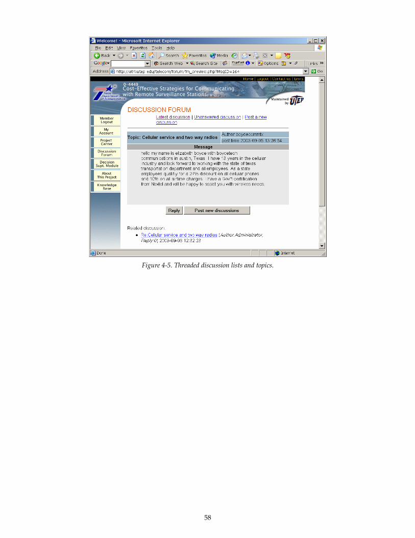
58
Figure 4-5. Threaded discussion lists and topics.
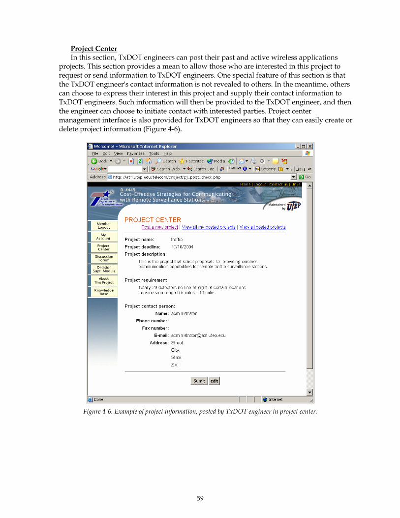
59
Project Center In this section, TxDOT engineers can post their past and active wireless applications
projects. This section provides a mean to allow those who are interested in this project to request or send information to TxDOT engineers. One special feature of this section is that the TxDOT engineer's contact information is not revealed to others. In the meantime, others can choose to express their interest in this project and supply their contact information to TxDOT engineers. Such information will then be provided to the TxDOT engineer, and then the engineer can choose to initiate contact with interested parties. Project center management interface is also provided for TxDOT engineers so that they can easily create or delete project information (Figure 4-6).
Figure 4-6. Example of project information, posted by TxDOT engineer in project center.
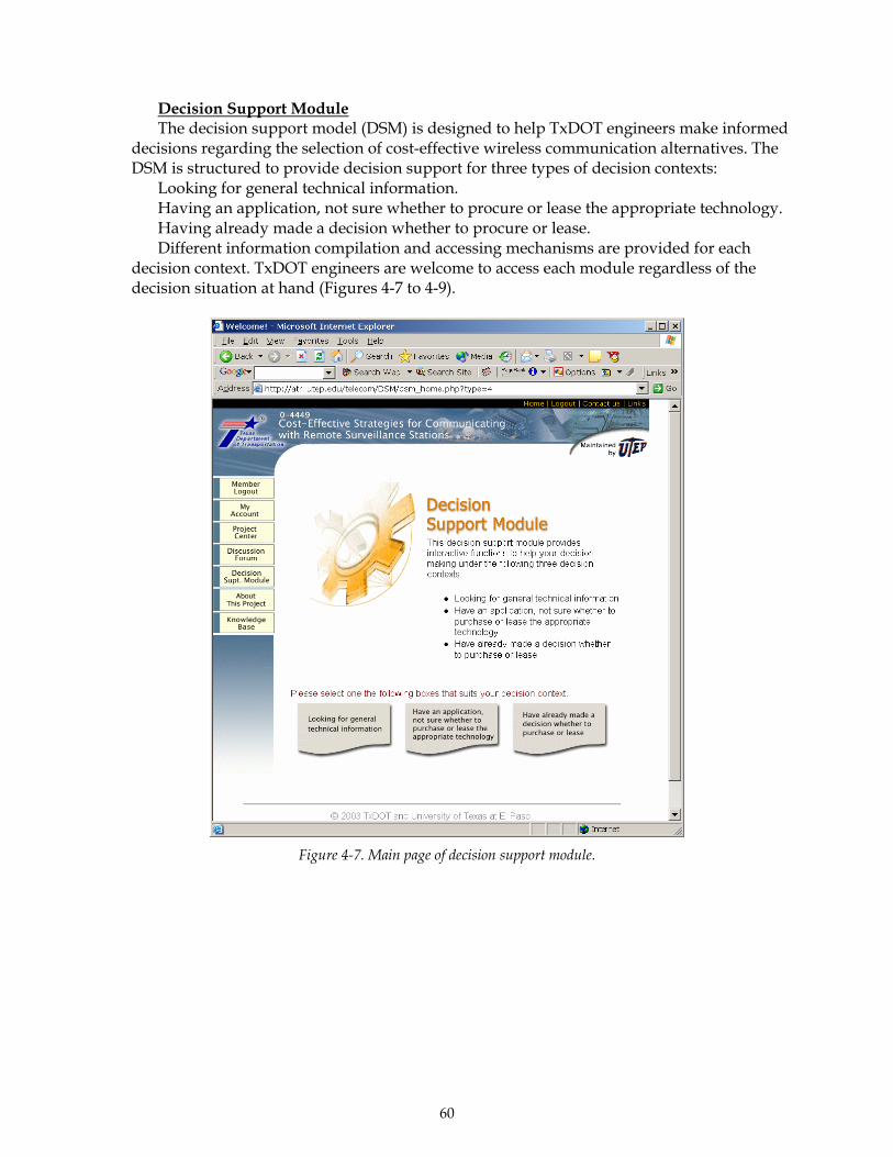
60
Decision Support Module The decision support model (DSM) is designed to help TxDOT engineers make informed
decisions regarding the selection of cost-effective wireless communication alternatives. The DSM is structured to provide decision support for three types of decision contexts:
Looking for general technical information. Having an application, not sure whether to procure or lease the appropriate technology. Having already made a decision whether to procure or lease. Different information compilation and accessing mechanisms are provided for each
decision context. TxDOT engineers are welcome to access each module regardless of the decision situation at hand (Figures 4-7 to 4-9).
Figure 4-7. Main page of decision support module.

61
Figure 4-8. Decision support module—looking for general technical information.
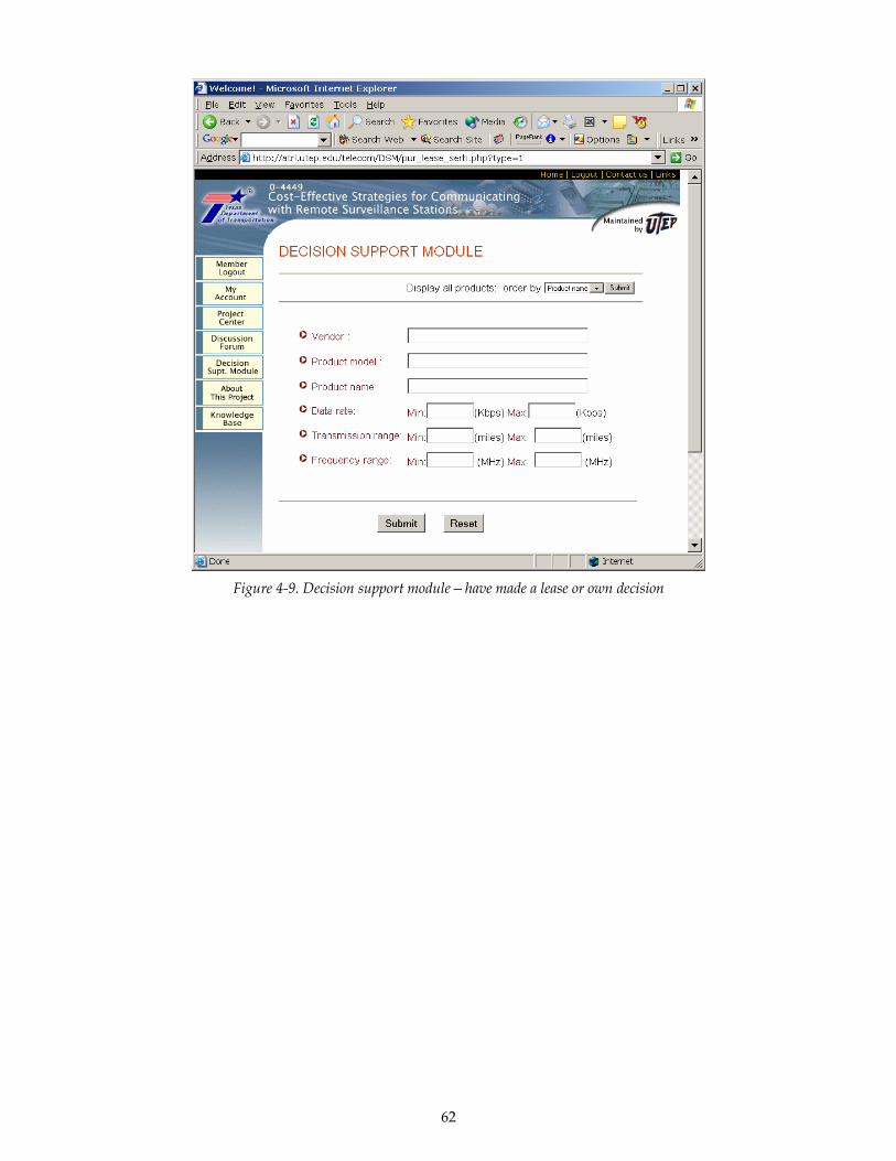
62
Figure 4-9. Decision support module—have made a lease or own decision
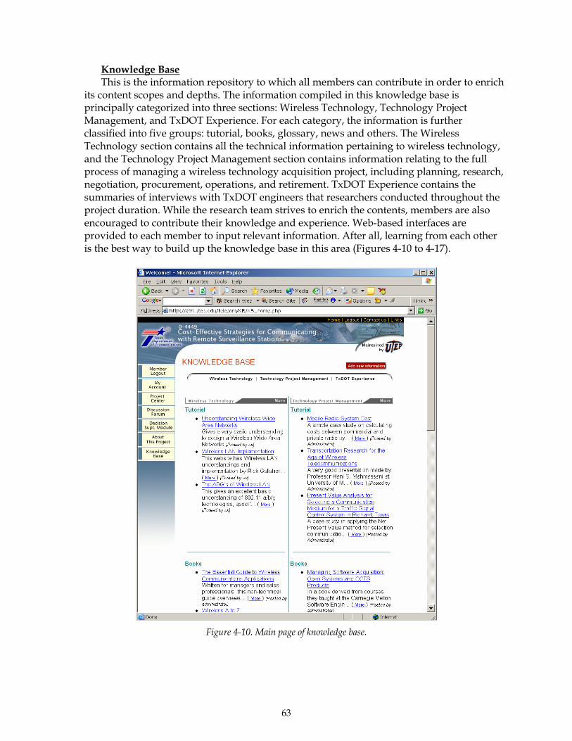
63
Knowledge Base This is the information repository to which all members can contribute in order to enrich
its content scopes and depths. The information compiled in this knowledge base is principally categorized into three sections: Wireless Technology, Technology Project Management, and TxDOT Experience. For each category, the information is further classified into five groups: tutorial, books, glossary, news and others. The Wireless Technology section contains all the technical information pertaining to wireless technology, and the Technology Project Management section contains information relating to the full process of managing a wireless technology acquisition project, including planning, research, negotiation, procurement, operations, and retirement. TxDOT Experience contains the summaries of interviews with TxDOT engineers that researchers conducted throughout the project duration. While the research team strives to enrich the contents, members are also encouraged to contribute their knowledge and experience. Web-based interfaces are provided to each member to input relevant information. After all, learning from each other is the best way to build up the knowledge base in this area (Figures 4-10 to 4-17).
Figure 4-10. Main page of knowledge base.

64
Figure 4-11. Sub-sections of wireless technology knowledge base.
Figure 4-12. Sub-sections of wireless technology management knowledge base.
Figure 4-13. Sub-sections of TxDOT experience knowledge base.
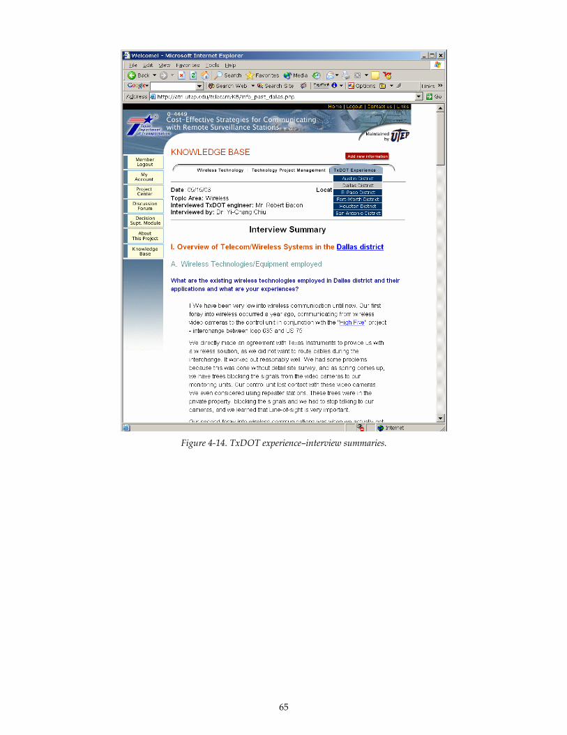
65
Figure 4-14. TxDOT experience–interview summaries.
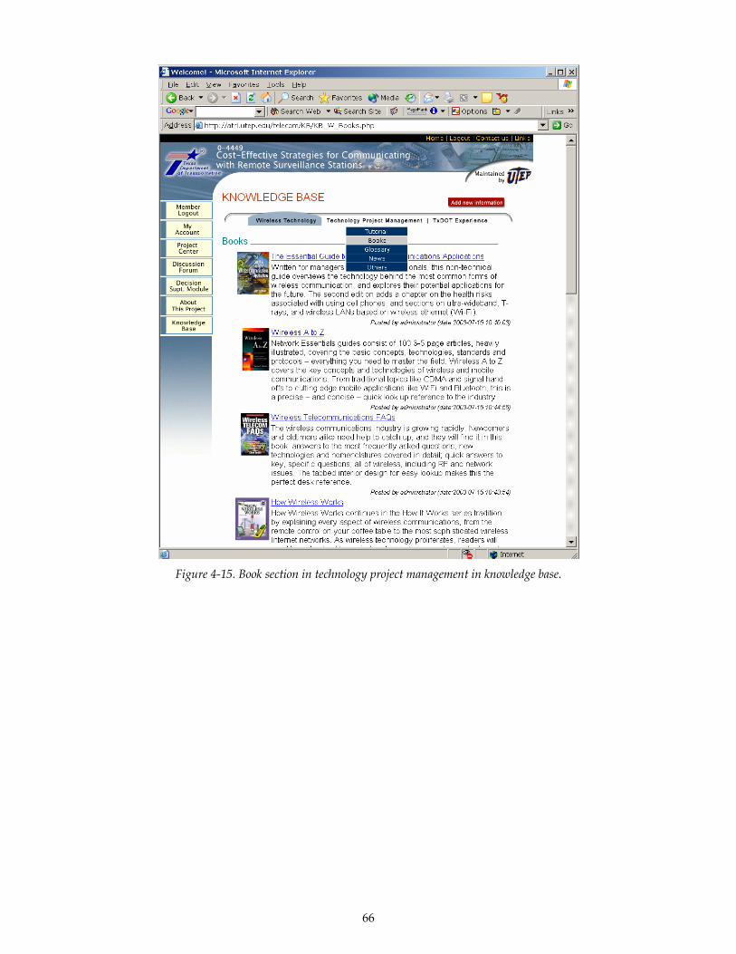
66
Figure 4-15. Book section in technology project management in knowledge base.
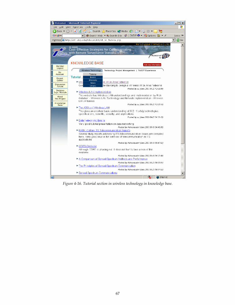
67
Figure 4-16. Tutorial section in wireless technology in knowledge base.

68
Figure 4-17. Web-based knowledge management system structure for wireless technology acquisition.

69
5. Additional Resources Most of the additional resources are being compiled on the Wireless Communication
Technology Knowledge Management System website (http://atrl.utep.edu/telecom). Please visit the website regularly for constantly updated information.

71
6. References 1 Alliance, H. N. (2003) http://www.homeplug.org. 2 Barquin, R. and Clarke, D. S. (2001) Knowledge Management in the Public Sector: A Survey. Proceedings of the 2nd Annual E-Gov Knowledge Management Conference, Washington, D.C., 3 Bates, R. J. (2000) Broadband Telecommunications Handbook. McGraw-Hill, New York. 4 Blanchard, B. S. (1998) System Engineering Management. Willey-Interscience. 5 Burk, M. (2000) Knowledge Management: Everyone Benefits by Sharing Information. Public Roads, 63(3). 6 Dubendorf, V. A. (2003) Wireless Data Technology Reference. John Wiley & Sons. 7 Eskeline, A. (2001) Technology Acquisition: Buying the Future of Your Business. Addison-Wesley. 8 FHWA (1996) Traffic Control Systems Handbook. Federal Highway Administration. 9 Klein, L. A. (1999) Final Report: Mobile Surveillance and Wireless Communication Systems Field Operational Test; Volume 2: FOT Objectives, Organization, System Design, Results, Conclusions, and Recommendations. PATH, 10 Klein, L. A. (2001) Sensor Technology and Data Requirements for ITS. Artech House Publication. 11 Pietrzyk, M. C. (2000) Raising Location Government I.Q. on Fiber-Optic Communication Systems. Proceedings of Annual Meeting of Intelligent Transportation Society of America, Boston, 12 Rysavy, P. (2002) Wireless Broadband and Other Fixed-Wireless Systems. Network Computing. 13 Schneiderman, R. (1999) Manager's Guide to Wireless Telecommunications. AMACOM Books, New York.


73
Appendix A—Data Rate Requirement for Traffic Management Applications
Table A-1. Lane-by-lane, station, and segment data transmission characteristics
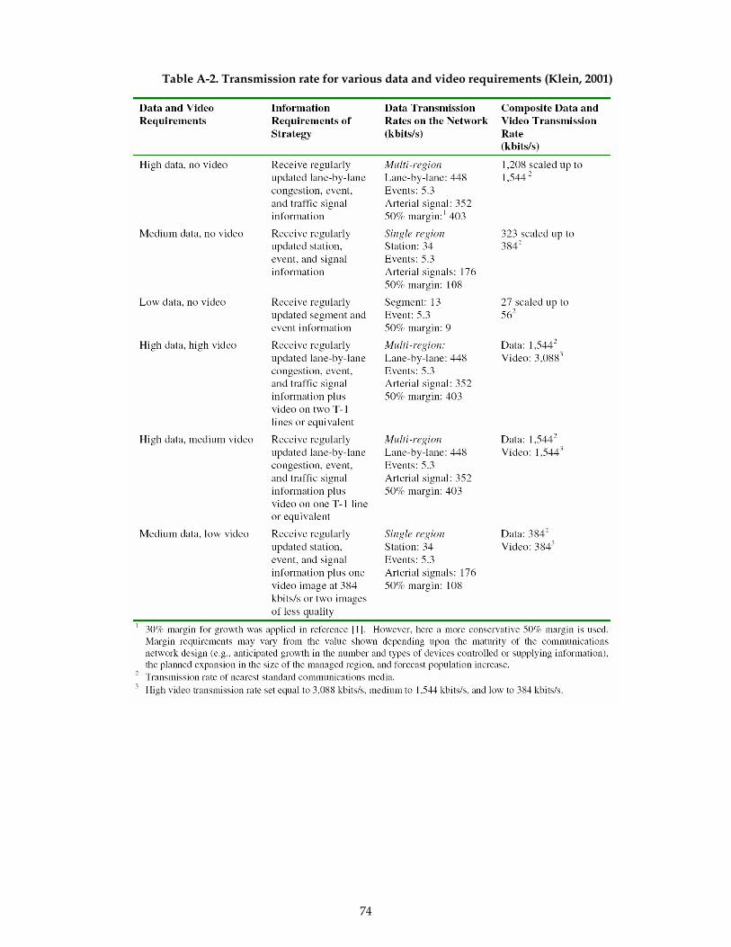
74
Table A-2. Transmission rate for various data and video requirements (Klein, 2001)
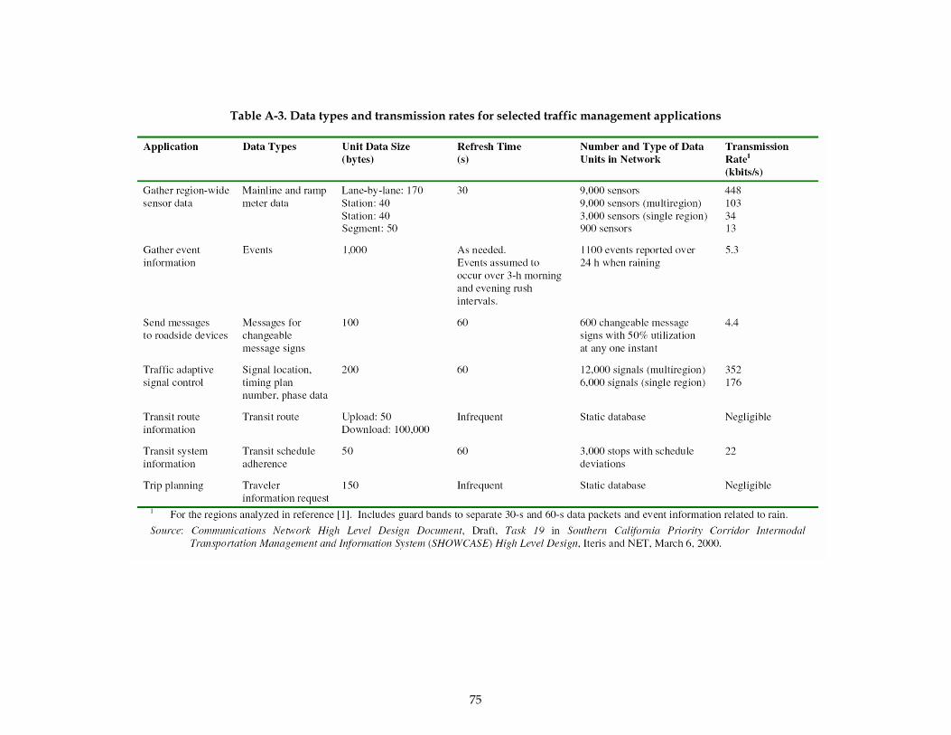
75
Table A-3. Data types and transmission rates for selected traffic management applications

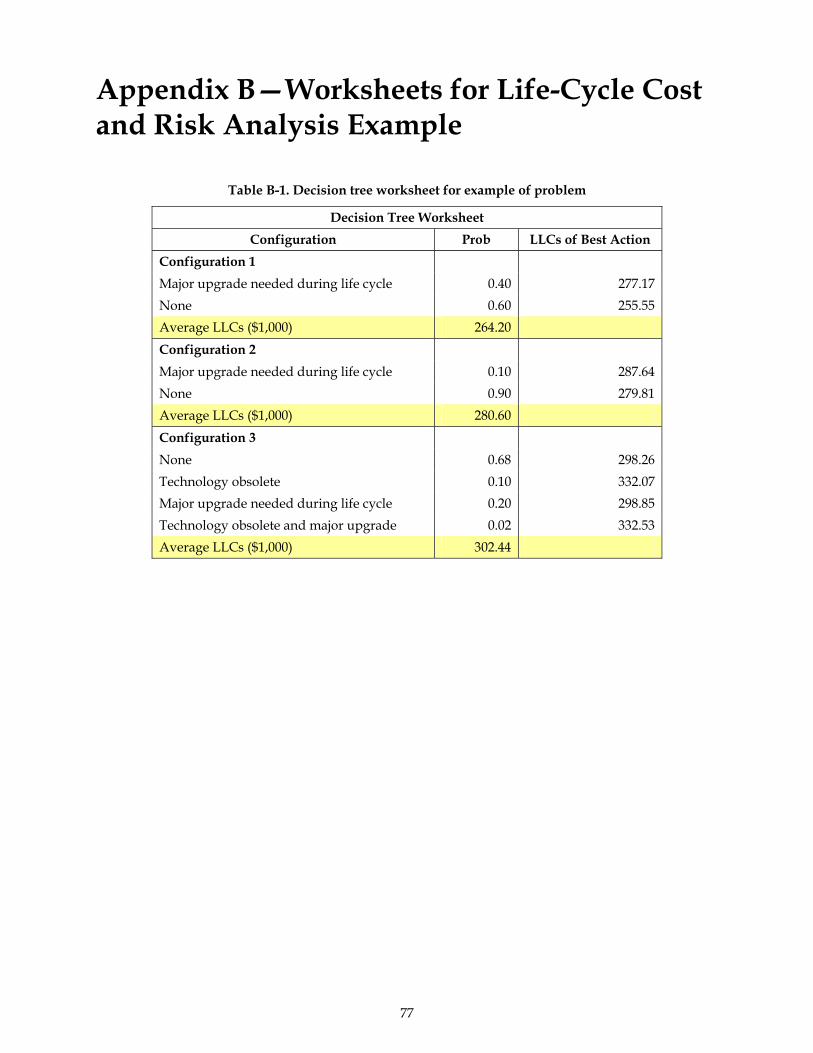
77
Appendix B—Worksheets for Life-Cycle Cost and Risk Analysis Example
Table B-1. Decision tree worksheet for example of problem
Decision Tree Worksheet Configuration Prob LLCs of Best Action
Configuration 1 Major upgrade needed during life cycle 0.40 277.17None 0.60 255.55Average LLCs ($1,000) 264.20Configuration 2 Major upgrade needed during life cycle 0.10 287.64None 0.90 279.81Average LLCs ($1,000) 280.60Configuration 3 None 0.68 298.26Technology obsolete 0.10 332.07Major upgrade needed during life cycle 0.20 298.85Technology obsolete and major upgrade 0.02 332.53Average LLCs ($1,000) 302.44
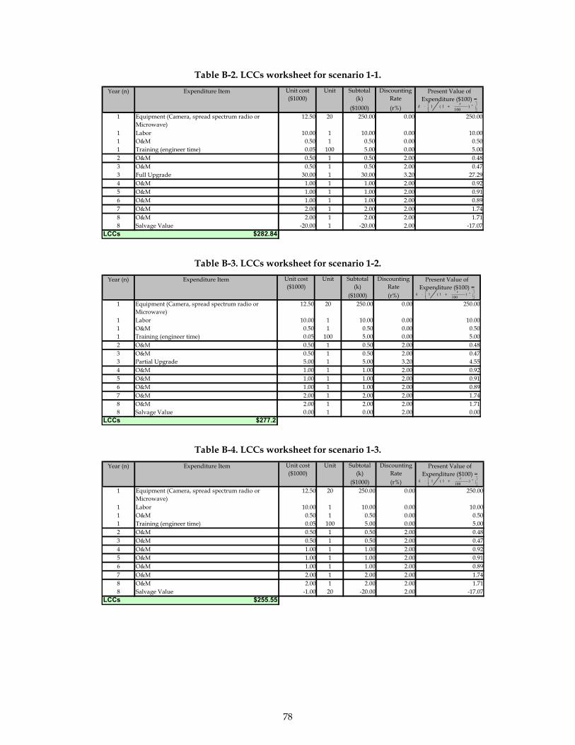
78
Table B-2. LCCs worksheet for scenario 1-1.
Unit cost ($1000)
Unit Subtotal (k)
Discounting Rate
($1000) (r%)1 Equipment (Camera, spread spectrum radio or
Microwave)12.50 20 250.00 0.00 250.00
1 Labor 10.00 1 10.00 0.00 10.001 O&M 0.50 1 0.50 0.00 0.501 Training (engineer time) 0.05 100 5.00 0.00 5.002 O&M 0.50 1 0.50 2.00 0.483 O&M 0.50 1 0.50 2.00 0.473 Full Upgrade 30.00 1 30.00 3.20 27.294 O&M 1.00 1 1.00 2.00 0.925 O&M 1.00 1 1.00 2.00 0.916 O&M 1.00 1 1.00 2.00 0.897 O&M 2.00 1 2.00 2.00 1.748 O&M 2.00 1 2.00 2.00 1.718 Salvage Value -20.00 1 -20.00 2.00 -17.07
LCCs $282.84
Year (n) Expenditure Item Present Value of Expenditure ($100) =
⎥⎦⎤
⎢⎣⎡ +⋅ nrk )
1001(1
Table B-3. LCCs worksheet for scenario 1-2. Unit cost ($1000)
Unit Subtotal (k)
Discounting Rate
($1000) (r%)1 Equipment (Camera, spread spectrum radio or
Microwave)12.50 20 250.00 0.00 250.00
1 Labor 10.00 1 10.00 0.00 10.001 O&M 0.50 1 0.50 0.00 0.501 Training (engineer time) 0.05 100 5.00 0.00 5.002 O&M 0.50 1 0.50 2.00 0.483 O&M 0.50 1 0.50 2.00 0.473 Partial Upgrade 5.00 1 5.00 3.20 4.554 O&M 1.00 1 1.00 2.00 0.925 O&M 1.00 1 1.00 2.00 0.916 O&M 1.00 1 1.00 2.00 0.897 O&M 2.00 1 2.00 2.00 1.748 O&M 2.00 1 2.00 2.00 1.718 Salvage Value 0.00 1 0.00 2.00 0.00
LCCs $277.2
Year (n) Expenditure Item Present Value of Expenditure ($100) =
⎥⎦⎤
⎢⎣⎡ +⋅ nrk )
1001(1
Table B-4. LCCs worksheet for scenario 1-3. Unit cost ($1000)
Unit Subtotal (k)
Discounting Rate
($1000) (r%)1 Equipment (Camera, spread spectrum radio or
Microwave)12.50 20 250.00 0.00 250.00
1 Labor 10.00 1 10.00 0.00 10.001 O&M 0.50 1 0.50 0.00 0.501 Training (engineer time) 0.05 100 5.00 0.00 5.002 O&M 0.50 1 0.50 2.00 0.483 O&M 0.50 1 0.50 2.00 0.474 O&M 1.00 1 1.00 2.00 0.925 O&M 1.00 1 1.00 2.00 0.916 O&M 1.00 1 1.00 2.00 0.897 O&M 2.00 1 2.00 2.00 1.748 O&M 2.00 1 2.00 2.00 1.718 Salvage Value -1.00 20 -20.00 2.00 -17.07
LCCs $255.55
Year (n) Expenditure Item Present Value of Expenditure ($100) =
⎥⎦⎤
⎢⎣⎡ +⋅ nrk )
1001(1
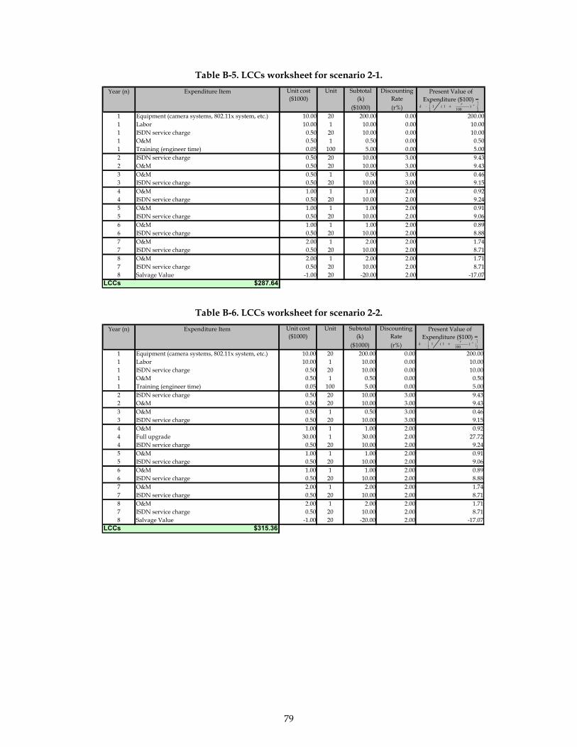
79
Table B-5. LCCs worksheet for scenario 2-1.
Unit cost ($1000)
Unit Subtotal (k)
Discounting Rate
($1000) (r%)1 Equipment (camera systems, 802.11x system, etc.) 10.00 20 200.00 0.00 200.001 Labor 10.00 1 10.00 0.00 10.001 ISDN service charge 0.50 20 10.00 0.00 10.001 O&M 0.50 1 0.50 0.00 0.501 Training (engineer time) 0.05 100 5.00 0.00 5.002 ISDN service charge 0.50 20 10.00 3.00 9.432 O&M 0.50 20 10.00 3.00 9.433 O&M 0.50 1 0.50 3.00 0.463 ISDN service charge 0.50 20 10.00 3.00 9.154 O&M 1.00 1 1.00 2.00 0.924 ISDN service charge 0.50 20 10.00 2.00 9.245 O&M 1.00 1 1.00 2.00 0.915 ISDN service charge 0.50 20 10.00 2.00 9.066 O&M 1.00 1 1.00 2.00 0.896 ISDN service charge 0.50 20 10.00 2.00 8.887 O&M 2.00 1 2.00 2.00 1.747 ISDN service charge 0.50 20 10.00 2.00 8.718 O&M 2.00 1 2.00 2.00 1.717 ISDN service charge 0.50 20 10.00 2.00 8.718 Salvage Value -1.00 20 -20.00 2.00 -17.07
LCCs $287.64
Year (n) Expenditure Item Present Value of Expenditure ($100) =
⎥⎦⎤
⎢⎣⎡ +⋅ nrk )
1001(1
Table B-6. LCCs worksheet for scenario 2-2. Unit cost ($1000)
Unit Subtotal (k)
Discounting Rate
($1000) (r%)1 Equipment (camera systems, 802.11x system, etc.) 10.00 20 200.00 0.00 200.001 Labor 10.00 1 10.00 0.00 10.001 ISDN service charge 0.50 20 10.00 0.00 10.001 O&M 0.50 1 0.50 0.00 0.501 Training (engineer time) 0.05 100 5.00 0.00 5.002 ISDN service charge 0.50 20 10.00 3.00 9.432 O&M 0.50 20 10.00 3.00 9.433 O&M 0.50 1 0.50 3.00 0.463 ISDN service charge 0.50 20 10.00 3.00 9.154 O&M 1.00 1 1.00 2.00 0.924 Full upgrade 30.00 1 30.00 2.00 27.724 ISDN service charge 0.50 20 10.00 2.00 9.245 O&M 1.00 1 1.00 2.00 0.915 ISDN service charge 0.50 20 10.00 2.00 9.066 O&M 1.00 1 1.00 2.00 0.896 ISDN service charge 0.50 20 10.00 2.00 8.887 O&M 2.00 1 2.00 2.00 1.747 ISDN service charge 0.50 20 10.00 2.00 8.718 O&M 2.00 1 2.00 2.00 1.717 ISDN service charge 0.50 20 10.00 2.00 8.718 Salvage Value -1.00 20 -20.00 2.00 -17.07
LCCs $315.36
Year (n) Expenditure Item Present Value of Expenditure ($100) =
⎥⎦⎤
⎢⎣⎡ +⋅ nrk )
1001(1

80
Table B-7. LCCs worksheet for scenario 2-3.
Unit cost ($1000)
Unit Subtotal (k)
Discounting Rate
($1000) (r%)1 Equipment (camera systems, 802.11x system, etc.) 10.00 20 200.00 0.00 200.001 Labor 10.00 1 10.00 0.00 10.001 ISDN service charge 0.50 20 10.00 0.00 10.001 O&M 0.50 1 0.50 0.00 0.501 Training (engineer time) 0.05 100 5.00 0.00 5.002 ISDN service charge 0.50 20 10.00 3.00 9.432 O&M 0.50 20 10.00 3.00 9.433 O&M 0.50 1 0.50 3.00 0.463 ISDN service charge 0.50 20 10.00 3.00 9.154 O&M 1.00 1 1.00 2.00 0.924 Partial upgrade 10.00 1 10.00 2.00 9.244 ISDN service charge 0.50 20 10.00 2.00 9.245 O&M 1.00 1 1.00 2.00 0.915 ISDN service charge 0.50 20 10.00 2.00 9.066 O&M 1.00 1 1.00 2.00 0.896 ISDN service charge 0.50 20 10.00 2.00 8.887 O&M 2.00 1 2.00 2.00 1.747 ISDN service charge 0.50 20 10.00 2.00 8.718 O&M 2.00 1 2.00 2.00 1.717 ISDN service charge 0.50 20 10.00 2.00 8.718 Salvage Value -2.00 20 -40.00 2.00 -34.14
LCCs $279.81
Year (n) Expenditure Item Present Value of Expenditure ($100) =
⎥⎦⎤
⎢⎣⎡ +⋅ nrk )
1001(1
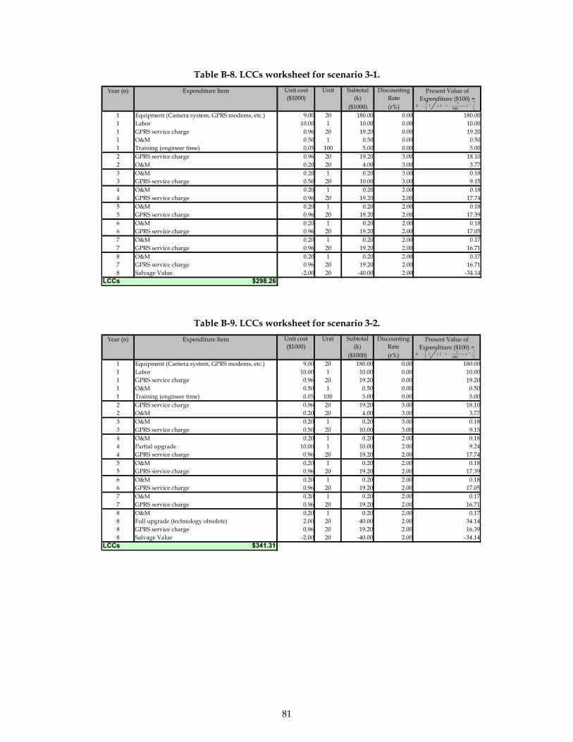
81
Table B-8. LCCs worksheet for scenario 3-1.
Unit cost ($1000)
Unit Subtotal (k)
Discounting Rate
($1000) (r%)1 Equipment (Camera system, GPRS modems, etc.) 9.00 20 180.00 0.00 180.001 Labor 10.00 1 10.00 0.00 10.001 GPRS service charge 0.96 20 19.20 0.00 19.201 O&M 0.50 1 0.50 0.00 0.501 Training (engineer time) 0.05 100 5.00 0.00 5.002 GPRS service charge 0.96 20 19.20 3.00 18.102 O&M 0.20 20 4.00 3.00 3.773 O&M 0.20 1 0.20 3.00 0.183 GPRS service charge 0.50 20 10.00 3.00 9.154 O&M 0.20 1 0.20 2.00 0.184 GPRS service charge 0.96 20 19.20 2.00 17.745 O&M 0.20 1 0.20 2.00 0.185 GPRS service charge 0.96 20 19.20 2.00 17.396 O&M 0.20 1 0.20 2.00 0.186 GPRS service charge 0.96 20 19.20 2.00 17.057 O&M 0.20 1 0.20 2.00 0.177 GPRS service charge 0.96 20 19.20 2.00 16.718 O&M 0.20 1 0.20 2.00 0.177 GPRS service charge 0.96 20 19.20 2.00 16.718 Salvage Value -2.00 20 -40.00 2.00 -34.14
LCCs $298.26
Year (n) Expenditure Item Present Value of Expenditure ($100) =
⎥⎦⎤
⎢⎣⎡ +⋅ nrk )
1001(1
Table B-9. LCCs worksheet for scenario 3-2. Unit cost ($1000)
Unit Subtotal (k)
Discounting Rate
($1000) (r%)1 Equipment (Camera system, GPRS modems, etc.) 9.00 20 180.00 0.00 180.001 Labor 10.00 1 10.00 0.00 10.001 GPRS service charge 0.96 20 19.20 0.00 19.201 O&M 0.50 1 0.50 0.00 0.501 Training (engineer time) 0.05 100 5.00 0.00 5.002 GPRS service charge 0.96 20 19.20 3.00 18.102 O&M 0.20 20 4.00 3.00 3.773 O&M 0.20 1 0.20 3.00 0.183 GPRS service charge 0.50 20 10.00 3.00 9.154 O&M 0.20 1 0.20 2.00 0.184 Partial upgrade 10.00 1 10.00 2.00 9.244 GPRS service charge 0.96 20 19.20 2.00 17.745 O&M 0.20 1 0.20 2.00 0.185 GPRS service charge 0.96 20 19.20 2.00 17.396 O&M 0.20 1 0.20 2.00 0.186 GPRS service charge 0.96 20 19.20 2.00 17.057 O&M 0.20 1 0.20 2.00 0.177 GPRS service charge 0.96 20 19.20 2.00 16.718 O&M 0.20 1 0.20 2.00 0.178 Full upgrade (technology obsolete) 2.00 20 40.00 2.00 34.148 GPRS service charge 0.96 20 19.20 2.00 16.398 Salvage Value -2.00 20 -40.00 2.00 -34.14
LCCs $341.31
Year (n) Expenditure Item Present Value of Expenditure ($100) =
⎥⎦⎤
⎢⎣⎡ +⋅ nrk )
1001(1
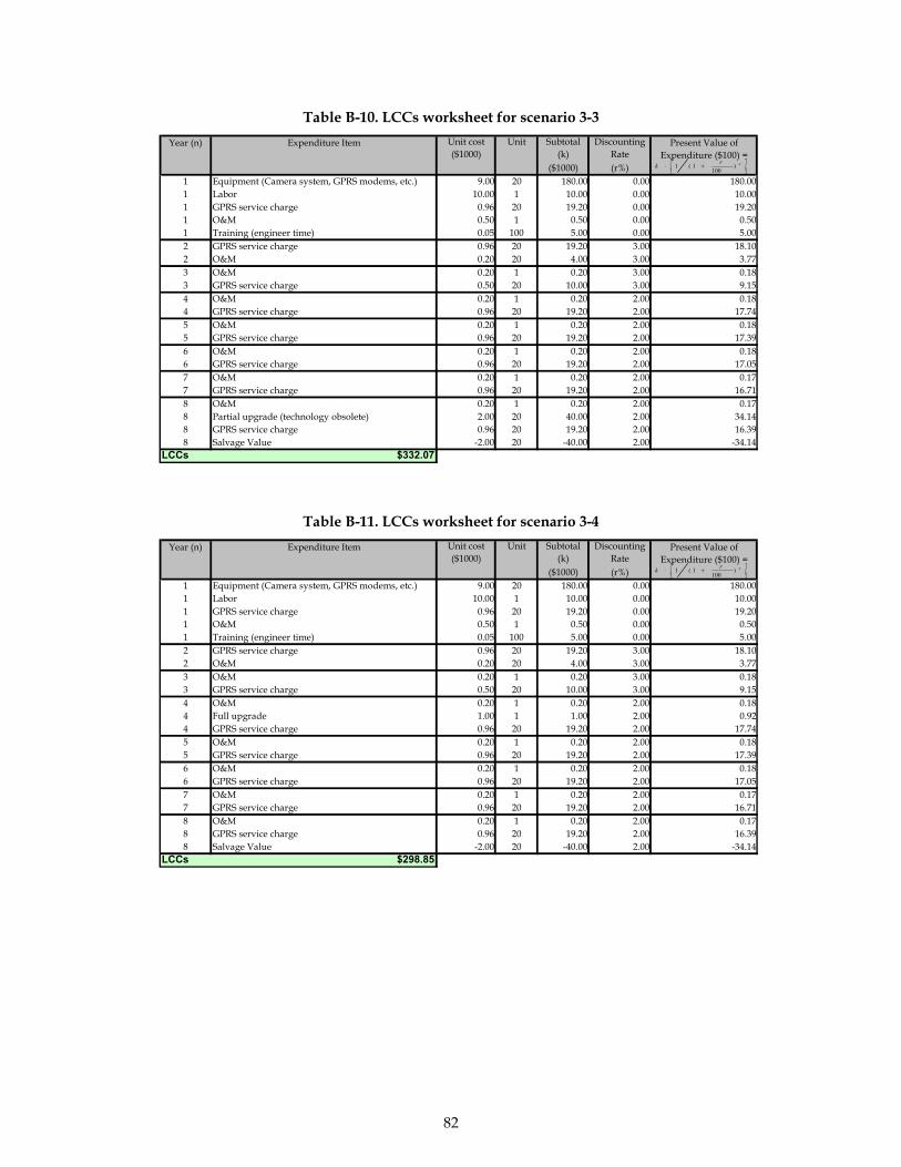
82
Table B-10. LCCs worksheet for scenario 3-3
Unit cost ($1000)
Unit Subtotal (k)
Discounting Rate
($1000) (r%)1 Equipment (Camera system, GPRS modems, etc.) 9.00 20 180.00 0.00 180.001 Labor 10.00 1 10.00 0.00 10.001 GPRS service charge 0.96 20 19.20 0.00 19.201 O&M 0.50 1 0.50 0.00 0.501 Training (engineer time) 0.05 100 5.00 0.00 5.002 GPRS service charge 0.96 20 19.20 3.00 18.102 O&M 0.20 20 4.00 3.00 3.773 O&M 0.20 1 0.20 3.00 0.183 GPRS service charge 0.50 20 10.00 3.00 9.154 O&M 0.20 1 0.20 2.00 0.184 GPRS service charge 0.96 20 19.20 2.00 17.745 O&M 0.20 1 0.20 2.00 0.185 GPRS service charge 0.96 20 19.20 2.00 17.396 O&M 0.20 1 0.20 2.00 0.186 GPRS service charge 0.96 20 19.20 2.00 17.057 O&M 0.20 1 0.20 2.00 0.177 GPRS service charge 0.96 20 19.20 2.00 16.718 O&M 0.20 1 0.20 2.00 0.178 Partial upgrade (technology obsolete) 2.00 20 40.00 2.00 34.148 GPRS service charge 0.96 20 19.20 2.00 16.398 Salvage Value -2.00 20 -40.00 2.00 -34.14
LCCs $332.07
Year (n) Expenditure Item Present Value of Expenditure ($100) =
⎥⎦⎤
⎢⎣⎡ +⋅ nrk )
1001(1
Table B-11. LCCs worksheet for scenario 3-4 Unit cost ($1000)
Unit Subtotal (k)
Discounting Rate
($1000) (r%)1 Equipment (Camera system, GPRS modems, etc.) 9.00 20 180.00 0.00 180.001 Labor 10.00 1 10.00 0.00 10.001 GPRS service charge 0.96 20 19.20 0.00 19.201 O&M 0.50 1 0.50 0.00 0.501 Training (engineer time) 0.05 100 5.00 0.00 5.002 GPRS service charge 0.96 20 19.20 3.00 18.102 O&M 0.20 20 4.00 3.00 3.773 O&M 0.20 1 0.20 3.00 0.183 GPRS service charge 0.50 20 10.00 3.00 9.154 O&M 0.20 1 0.20 2.00 0.184 Full upgrade 1.00 1 1.00 2.00 0.924 GPRS service charge 0.96 20 19.20 2.00 17.745 O&M 0.20 1 0.20 2.00 0.185 GPRS service charge 0.96 20 19.20 2.00 17.396 O&M 0.20 1 0.20 2.00 0.186 GPRS service charge 0.96 20 19.20 2.00 17.057 O&M 0.20 1 0.20 2.00 0.177 GPRS service charge 0.96 20 19.20 2.00 16.718 O&M 0.20 1 0.20 2.00 0.178 GPRS service charge 0.96 20 19.20 2.00 16.398 Salvage Value -2.00 20 -40.00 2.00 -34.14
LCCs $298.85
Year (n) Expenditure Item Present Value of Expenditure ($100) =
⎥⎦⎤
⎢⎣⎡ +⋅ nrk )
1001(1

83
Table B-12. LCCs worksheet for scenario 3-5. Unit cost ($1000)
Unit Subtotal (k)
Discounting Rate
($1000) (r%)1 Equipment (Camera system, GPRS modems, etc.) 9.00 20 180.00 0.00 180.001 Labor 10.00 1 10.00 0.00 10.001 GPRS service charge 0.96 20 19.20 0.00 19.201 O&M 0.50 1 0.50 0.00 0.501 Training (engineer time) 0.05 100 5.00 0.00 5.002 GPRS service charge 0.96 20 19.20 3.00 18.102 O&M 0.20 20 4.00 3.00 3.773 O&M 0.20 1 0.20 3.00 0.183 GPRS service charge 0.50 20 10.00 3.00 9.154 O&M 0.20 1 0.20 2.00 0.184 Partial upgrade 0.50 1 0.50 2.00 0.464 GPRS service charge 0.96 20 19.20 2.00 17.745 O&M 0.20 1 0.20 2.00 0.185 GPRS service charge 0.96 20 19.20 2.00 17.396 O&M 0.20 1 0.20 2.00 0.186 GPRS service charge 0.96 20 19.20 2.00 17.057 O&M 0.20 1 0.20 2.00 0.177 GPRS service charge 0.96 20 19.20 2.00 16.718 O&M 0.20 1 0.20 2.00 0.178 GPRS service charge 0.96 20 19.20 2.00 16.398 Salvage Value -1.00 20 -20.00 2.00 -17.07
LCCs $315.46
Year (n) Expenditure Item Present Value of Expenditure ($100) =
⎥⎦⎤
⎢⎣⎡ +⋅ nrk )
1001(1
Table B-13. LCCs worksheet for scenario 3-6. Unit cost ($1000)
Unit Subtotal (k)
Discounting Rate
($1000) (r%)1 Equipment (Camera system, GPRS modems, etc.) 9.00 20 180.00 0.00 180.001 Labor 10.00 1 10.00 0.00 10.001 GPRS service charge 0.96 20 19.20 0.00 19.201 O&M 0.50 1 0.50 0.00 0.501 Training (engineer time) 0.05 100 5.00 0.00 5.002 GPRS service charge 0.96 20 19.20 3.00 18.102 O&M 0.20 20 4.00 3.00 3.773 O&M 0.20 1 0.20 3.00 0.183 GPRS service charge 0.50 20 10.00 3.00 9.154 O&M 0.20 1 0.20 2.00 0.184 Partial upgrade 0.50 1 0.50 2.00 0.464 GPRS service charge 0.96 20 19.20 2.00 17.745 O&M 0.20 1 0.20 2.00 0.185 GPRS service charge 0.96 20 19.20 2.00 17.396 O&M 0.20 1 0.20 2.00 0.186 GPRS service charge 0.96 20 19.20 2.00 17.057 O&M 0.20 1 0.20 2.00 0.177 GPRS service charge 0.96 20 19.20 2.00 16.718 O&M 0.20 1 0.20 2.00 0.178 Full upgrade (technology obsolete) 2.00 20 40.00 2.00 34.148 GPRS service charge 0.96 20 19.20 2.00 16.398 Salvage Value -2.00 20 -40.00 2.00 -34.14
LCCs $332.53
Year (n) Expenditure Item Present Value of Expenditure ($100) =
⎥⎦⎤
⎢⎣⎡ +⋅ nrk )
1001(1
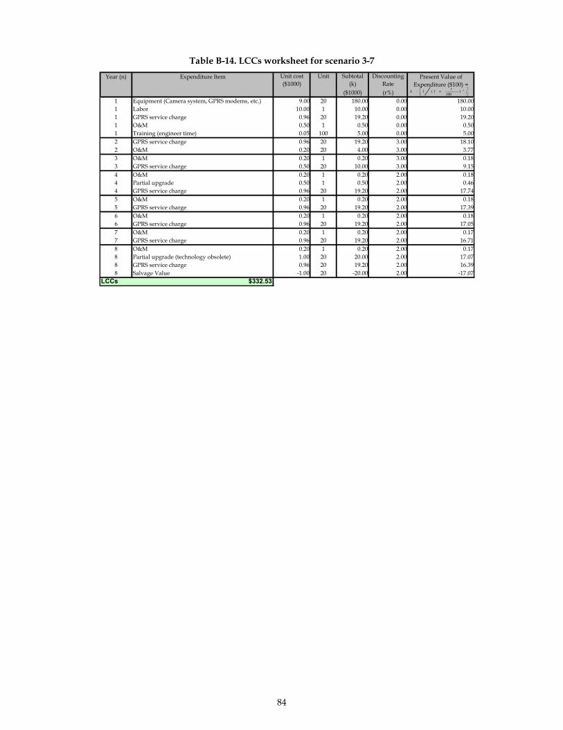
84
Table B-14. LCCs worksheet for scenario 3-7 Unit cost ($1000)
Unit Subtotal (k)
Discounting Rate
($1000) (r%)1 Equipment (Camera system, GPRS modems, etc.) 9.00 20 180.00 0.00 180.001 Labor 10.00 1 10.00 0.00 10.001 GPRS service charge 0.96 20 19.20 0.00 19.201 O&M 0.50 1 0.50 0.00 0.501 Training (engineer time) 0.05 100 5.00 0.00 5.002 GPRS service charge 0.96 20 19.20 3.00 18.102 O&M 0.20 20 4.00 3.00 3.773 O&M 0.20 1 0.20 3.00 0.183 GPRS service charge 0.50 20 10.00 3.00 9.154 O&M 0.20 1 0.20 2.00 0.184 Partial upgrade 0.50 1 0.50 2.00 0.464 GPRS service charge 0.96 20 19.20 2.00 17.745 O&M 0.20 1 0.20 2.00 0.185 GPRS service charge 0.96 20 19.20 2.00 17.396 O&M 0.20 1 0.20 2.00 0.186 GPRS service charge 0.96 20 19.20 2.00 17.057 O&M 0.20 1 0.20 2.00 0.177 GPRS service charge 0.96 20 19.20 2.00 16.718 O&M 0.20 1 0.20 2.00 0.178 Partial upgrade (technology obsolete) 1.00 20 20.00 2.00 17.078 GPRS service charge 0.96 20 19.20 2.00 16.398 Salvage Value -1.00 20 -20.00 2.00 -17.07
LCCs $332.53
Year (n) Expenditure Item Present Value of Expenditure ($100) =
⎥⎦⎤
⎢⎣⎡ +⋅ nrk )
1001(1

85
Appendix C—Wireless Equipment and Wireless Data Service Vendors Registered in the Knowledge Management System Website
This section compiles a partial list of wireless communication vendors/contractors registered in the Knowledge Management System/web clearinghouse for this project http://atrl.utep.edu/telecom
Company Name Company’s Self Introduction Company Service URL
ACEx Technologies, Inc.
Since 1979 ACEx has provided engineering design and implementation expertise to public agencies and private corporations. Our clients include transit and railroad agencies throughout the United States, federal and regional electrical power utilities, and major domestic system integrators. We have built our reputation and our company on the quality and responsiveness of our work, and the ability of our staff to work well with our clients.
We design and help implement communications networks and control systems for voice, video and data communications applications. Communications technologies include wide area and local area optical fiber networks, voice and data radio, and specialized technologies such as power-line communications.
www.acex.com
Advance Network Systems Inc.
www.anstyler.com
Advanced Wireless Solutions
AWS Inc. was founded in May of 2002 and began providing high-speed wireless Internet access to South Austin Business and South Rural Texas in September 11, 2002 they are headquartered in Austin, Texas, and have grown into a complete Internet Access Provider including Inter office wireless networking performing quality installations and services.
Our engineers and installation technicians are highly trained and take responsibility of your network project from the Design phase to Premise Wiring, Hardware Installation, Testing, Network Monitoring, Tuning and Management. We install, terminate, and test: Voice and Data cable; Category 5/5e Cable; Coaxial Cable; Cable Runway / Routing Systems. We install: Wireless Networking Equipment, Cabinets, Equipment Racks Install Telecom Equipment
www.awsolutions.net
AeroComm Inc. AeroComm is the worldwide leader in providing Instant Wireless data communications to original equipment manufacturers. Our company
AeroComm designs, manufactures and markets spread spectrum data radios for OEM integration or commercial plug-and-play.
www.aerocomm.com/index.htm

86
Company Name Company’s Self Introduction Company Service URL
commands the industry with consistent breakthroughs, such as superior RF price and performance for both industrial and commercial applications.
AirWaves Communications, Inc.
Established 1980-Two way radio sales, service, paging, towers. A Motorola Two-Way, Radius, Professional Conventional & Trunking dealer. Kenwood, Relm, E F Johnson, Maxon dealer.
Two-way radio installation & repair, paging service statewide & beyond, Logic Trunked Radio systems, Tower space rental, Community repeater service.
Alamon Telco, Inc. Alamon Telco is a Women owned business that is certified by the Women’s Business National Council as well as the North Central Texas Regional Certification Agency. Alamon has over 28 years experience in telecommunications services. We are a tier one vendor for many of the nation’s largest manufacturers and operating companies.
Alamon Telco, Inc. Provides voice and data cabling services for cat5e, cat6 as well as fiber and coax. We provide wireless installations as well.
www.alamon.com
Andrew Corporation
Andrew Corporation is a global supplier of communications products and systems to worldwide commercial, industrial and governmental customers.
Andrew's principal products include coaxial cables, connectors, cable assemblies and accessories, power amplifiers, microwave antennas and products for point-to-point communication systems, television broadcasting antennas, special-purpose antennas for commercial and government use, antennas and earth stations for satellite communication systems, cellular antenna products, global positioning system (GPS) antennas and products, radar system components and related ancillary items and services. Sales, installation, turn-key, operation and maintenance.
www.andrew.com
Andrew Corporation
Andrew Corporation is a global supplier of communications products and systems to worldwide commercial, industrial and governmental customers.
Andrew's principal products include coaxial cables, connectors, cable assemblies and accessories, power amplifiers, microwave antennas and products for point-to-point communication systems, television broadcasting antennas, special-purpose antennas for commercial and government use, antennas and earth stations for satellite communication systems,
www.andrew.com

87
Company Name Company’s Self Introduction Company Service URL
cellular antenna products, global positioning system (GPS) antennas and products, radar system components and related ancillary items and services.
AnyWARE, Inc. AnyWARE, Inc. is a networking company offering data and voice products from AT&T, Cisco, and other major vendors. We are an AT&T Alliance Partner, authorized to sell AT&T business communications services.
AnyWARE, Inc. offers a combination of professional services, including project management, engineering, installation, and account management. We provide products to businesses as well as state and local governments.
www.anywareinc.com
ATE Telecom Solutions
Small business dedicated to integrate solutions in networks, including copper, fiber optic and wireless networks.
Installs copper, fiber, networking equipment. Satellite internet connection.
www.ate-tele.com
ATS-Plus, Inc. ATS+ is a premier distributor for Ascom® Wireless Solutions, a market leading developer of workplace wireless communication solutions.
Using Ascom’s products and solutions, ATS+ provides in-building wireless communication systems that are unique, durable and innovative.
www.atsplus.com
Avaya Avaya Inc. designs, builds and manages communications networks for more than one million businesses worldwide, including more than 90 percent of the FORTUNE 500®. Focused on businesses large to small, Avaya is a world leader in secure and reliable Internet Protocol (IP) Telephony software applications, systems and services and driving the convergence of voice and data communications with business applications
Wireless: Voice Wireless 900 MHz Wireless Telephone Solution TransTalk™ 9000 Digital Wireless System DEFINITY® Wireless DECT System DEFINITY® Wireless Business System EC500 IP Wireless Telephone Solution Wireless LAN AP-3 Access Point AP-4 Access Point AP-5 Access Point AP-6 Access Point Wireless Outdoor Router System
www.avaya.com
Axonn AXONN, LCC, is the worldwide leader in wireless packet data solutions. With over 6 million units in operation, AXONN’s proven technology provides secure wireless data links for industrial, commercial, residential and remote monitoring applications.
AXONN offers four families of radio products: Satellite Products End-user products which can be easily connected by standard interfaces Radio modules which can be integrated into existing or custom systems Custom engineered radios
www.axonn.net

88
Company Name Company’s Self Introduction Company Service URL
BearCom BearCom is North America's largest provider of wireless communications equipment and tailored solutions.
BearCom offers sales and service of two-way radios from Motorola, ICOM and others.
www.bearcom.com
Boycetech Communications
We provide wireless voice services, data applications (java enabled), cellular phones, and two way radios. We specialize in Nextel Direct Connect, Cellular services and all data applications.
www.boycetech.com
CenturyTel ILEC Telephone Company serving Sab Marcos, Lake Dallas and Port Aransas TX
Provide voice and data solutions Nortel and Cisco distributor
www.centurytel.com
CES Network Services, Inc.
Established in 1988, CES has combined technical and organizational consulting expertise to offer a comprehensive, timely and high quality service to the public and private sector. Since 1988, we have been responsible for Wireless System Design & Analysis for Switching, Telephone Systems and RF and Audio Networks, FCC / FAA Licensing, RF Interfere Analysis, Tower Co-locations. We perform Installation, Test, Service, Support and Maintenance both nationwide and internationally.
Network Strategy, Design and Engineering Network Planning and Management of both wired and wireless (LAN, WAN & MAN) RF Engineering and Propagation Studies Design of Satellite networks (C, Ku and L bands) Development of video (TVRO) and voice / data (VSAT) networks Microwave Radio Cellular / CT2 / 450, 800 Trunking & 900 Mhz / iDEM PCS System Engineering Radio Traffic Control Network Equipment for Voice / Data and Video applications
www.cesnetser.com
Christian Telecommun-ication Services
As a previous contractor for TXDOT, I am looking forward to doing business with you in the future. We have maintained and installed voice and data cabling, and data network systems at most of your sites in Houston and the surrounding areas.
We specialize in the installation and maintenance of voice and data cabling, data network systems, and phone systems.
Cingular Wireless Established over 16 years ago, under the name of Southwestern Bell Wireless locally, we are a merger between SBC and Bell South Mobility with a mature network. Currently offering TDMA and GSM digital technologies which provide significant benefits like strong voice quality & clarity, privacy &
wireless voice and data services www.cingular.com

89
Company Name Company’s Self Introduction Company Service URL
SECURITY, increased system capacity, extended battery life, text messaging capability.
CMS Communications
Avaya, Nortel and NEC Telephone Equipment www.cmsc.com
Communications Supply Corporation
CSC has over 600 employees, 27 warehouses, more than $60 million in local inventory, and 30 sales offices throughout the United States.
Copper Cabling Solutions (Cat 6, 5e) Fiber Optic Systems & Solutions Cable Management Solutions Test Equipment Tools & Installation Products Power Protection Low Voltage Specialty Cabling Wireless Solutions Outside Plant Products & Solutions Networking Solutions Hardware Voice Products
www.gocsc.com/houston
Connection Technologies
Connection Technologies is a systems integration and technology consulting company located in Shreveport, Louisiana, close by the East Texas area.
Wireless communications engineering, installation & support services Video monitoring & surveillance systems Local & wide area network systems Consulting
Cross Telecom Corporation
Cross Telecom is a Platinum Reseller for Avaya, and the fastest growing Avaya Reseller in the USA. Cross Telecom has (8) offices in Texas and Nationwide coverage.
Data Networking equipment, VOIP equipment, Call Centers, Avaya Wireless equipment, Video Conferencing equipment.
www.crosstelecom.com
Daniels Electronics Ltd.
Daniels Electronics Ltd. was incorporated under the Company Act of the Province of British Columbia December 12, 1950 and was organized to research, develop and manufacture radio communications equipment.
Daniels Electronics Ltd. specializes in the design and manufacture of modular AM / FM and Digital radio systems operating from 29 MHz to 960 MHz. Modular, high reliability, high performance Low Band VHF / VHF FM / VHF AM / UHF/ 800MHz and 900MHz continuous duty base stations and radio repeaters systems. Solar cell powered mountain top Low Band VHF / VHF FM / VHF AM / UHF / 800MHz and 900MHz radio multi-linking systems.
www.danelec.com

90
Company Name Company’s Self Introduction Company Service URL
Transportable VHF / UHF fire and law enforcement repeaters.
Datron World Communications
Datron World Communications is a division of the Titan Corporation. Datron is an equipment manufacturer that supplies voice and data radios.
Manufacturer of Guardian series of land mobile radios that are APCO Project 25 compliant
www.dtwc.com
ELPRO Technologies
ELPRO, based in Brisbane Australia, is a world specialist in radio telemetry technology - sending data and information by radio. The company utilizes the very latest design techniques to manufacture high quality data radios and microprocessor controllers, combined with industry proven, dedicated software.
www.elprotech.com
ENCOM Wireless Data Solutions Inc.
ENCOM Wireless Data Solutions manufactures a complete line of industrial-strength, spread spectrum wireless products for many applications, including Traffic Monitoring and Control (Intelligent Transportation Systems).
All ENCOM products include ControlPAKTM, the most comprehensive radio programming and diagnostic software in the traffic industry.
www.encomwireless.com
Enterprise Systems Enterprise Systems a Nortel Networks Premium Partner is a National Distributor and is Head quartered in Houston Texas.
Enterprise Systems sells services and Maintains Meridian PBX Succession and Norstar Key systems. As well as a full line of Nortel Data products.
www.enter-sys.com
FastLinks LCC FastLinks is an authorized QISV for the state of Texas. We specialize in the design, installation and support of wireless WANs.
We offer a full suite services aimed at meeting every customer’s needs for wireless building to building LAN, voice and video connectivity. These services includes feasibility studies, system & path engineering, site surveys, FCC licensing, project management, turn-key system installation, and a host of comprehensive post-installation support services.
www.wirelesswans.com
harGIS LCC harGIS LCC delivers mobile GIS solutions that dramatically improve field force productivity. By combining wireless communications, office systems connectivity, and location based services, the har*GIS TruckMap*™ product line gives mobile field crews and dispatchers the information
Our professional services team provides all levels of implementation, development, integration and project management. We have special expertise with geo-spatial systems and GIS. We feature a low-cost, quick-implementation Benchmark service to provide a field trial system using your map data
www.har-gis.com

91
Company Name Company’s Self Introduction Company Service URL
and support that they need — when they need it. and forms. Business Partners include Trimble Navigation, ESRI, NexTel and Navigation Technologies.
Harris Corporation Microwave Communications Equipment and Services
Point-to-point microwave radio communications equipment. Engineering Design Transmission Engineering Installation Project Management Training
www.harris.com
Infiniti Communications Technologies, Inc.
ICT is an organization with deep roots of experience in the communications industry…maintaining a staff with over 100 years of combined experience. Our customers’ communications systems are designed, installed, and maintained to meet the demands of today and the challenges of tomorrow.
Providing consistent superior service and quality products stems from the ability to utilize personnel that are experienced and certified in many of the diverse backgrounds of our industry. Network Cabling Infrastructures, Fiber Optic Specialties, Video Systems, Computer Systems, Wireless Networks, Security & Surveillance Systems, and Outside Plant Capabilities are some of the interwoven aspects of communications ICT supports.
www.infiniticorp.com
Infinity Connections, Inc
Infinity Connections, Inc. is a full service network integration firm. From wireless networks to WAN or LAN projects, we can connect your company to the latest Technology.
Wireless Networks, Wide Area Networks, Local Area Networks, data drops, fiber and CAT5E cabling.
www.infinityconnections.com
InHouse Systems, Inc.
InHouse is a systems integration contractor specializing in CCTV and remote video surveillance, access control and wireless security and fire alarm monitoring since 1988. Authorized dealer for American Dynamics and Sensormatic.
Remote Video Surveillance, CCTV, Networking, Access Control, Security, Fire Alarm, Environmental Supervision, Wireless System Monitoring from U.L. facility.
www.safeandsound.net
Inter-Tel Technologies
A profitable 34-year-old telecommunications solutions company with 63 direct offices nationwide.
Wireless solutions via partnership with Spectralink.Digital voice and data systems. Audio and video systems. Local and long distance service.
www.inter-tel.com
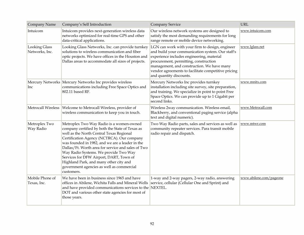
92
Company Name Company’s Self Introduction Company Service URL
Intuicom Intuicom provides next-generation wireless data networks optimized for real-time GPS and other data-critical applications.
Our wireless network systems are designed to satisfy the most demanding requirements for long range remote or mobile device networking.
www.intuicom.com
Looking Glass Networks, Inc.
Looking Glass Networks, Inc. can provide turnkey solutions to wireless communication and fiber optic projects. We have offices in the Houston and Dallas areas to accommodate all sizes of projects.
LGN can work with your firm to design, engineer and build your communication system. Our staff's experience includes engineering, material procurement, permitting, construction management, and construction. We have many vendor agreements to facilitate competitive pricing and quantity discounts.
www.lglass.net
Mercury Networks Inc
Mercury Networks Inc provides wireless communications including Free Space Optics and 802.11 based RF.
Mercury Networks Inc provides turnkey installation including site survey, site preparation, and training. We specialize in point to point Free Space Optics. We can provide up to 1 Gigabit per second links.
www.mnitx.com
Metrocall Wireless Welcome to Metrocall Wireless, provider of wireless communication to keep you in touch.
Wireless 2way communication. Wireless email, Blackberry, and conventional paging service (alpha text and digital numeric).
www.Metrocall.com
Metroplex Two Way Radio
Metroplex Two Way Radio is a women-owned company certified by both the State of Texas as well as the North Central Texas Regional Certification Agency (NCTRCA). Our company was founded in 1982, and we are a leader in the Dallas/Ft. Worth area for service and sales of Two Way Radio Systems. We provide Two Way Services for DFW Airport, DART, Town of Highland Park, and many other city and government agencies as well as commercial customers.
Two Way Radio parts, sales and services as well as community repeater services. Para transit mobile radio repair and dispatch.
www.mtwr.com
Mobile Phone of Texas, Inc.
We have been in business since 1965 and have offices in Abilene, Wichita Falls and Mineral Wells and have provided communications services to the DOT and various other state agencies for most of those years.
1-way and 2-way pagers, 2-way radio, answering service, cellular (Cellular One and Sprint) and NEXTEL.
www.abilene.com/pageone
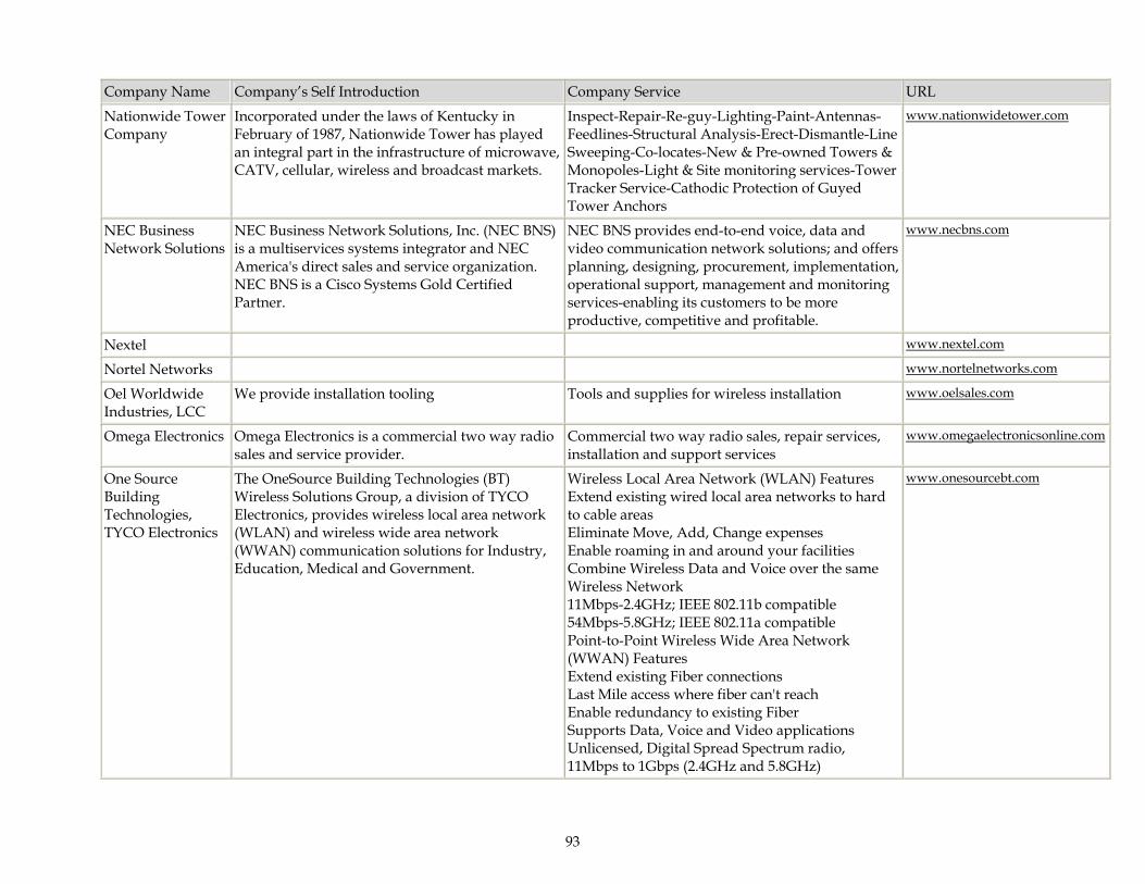
93
Company Name Company’s Self Introduction Company Service URL
Nationwide Tower Company
Incorporated under the laws of Kentucky in February of 1987, Nationwide Tower has played an integral part in the infrastructure of microwave, CATV, cellular, wireless and broadcast markets.
Inspect-Repair-Re-guy-Lighting-Paint-Antennas-Feedlines-Structural Analysis-Erect-Dismantle-Line Sweeping-Co-locates-New & Pre-owned Towers & Monopoles-Light & Site monitoring services-Tower Tracker Service-Cathodic Protection of Guyed Tower Anchors
www.nationwidetower.com
NEC Business Network Solutions
NEC Business Network Solutions, Inc. (NEC BNS) is a multiservices systems integrator and NEC America's direct sales and service organization. NEC BNS is a Cisco Systems Gold Certified Partner.
NEC BNS provides end-to-end voice, data and video communication network solutions; and offers planning, designing, procurement, implementation, operational support, management and monitoring services-enabling its customers to be more productive, competitive and profitable.
www.necbns.com
Nextel www.nextel.com
Nortel Networks www.nortelnetworks.com
Oel Worldwide Industries, LCC
We provide installation tooling Tools and supplies for wireless installation www.oelsales.com
Omega Electronics Omega Electronics is a commercial two way radio sales and service provider.
Commercial two way radio sales, repair services, installation and support services
www.omegaelectronicsonline.com
One Source Building Technologies, TYCO Electronics
The OneSource Building Technologies (BT) Wireless Solutions Group, a division of TYCO Electronics, provides wireless local area network (WLAN) and wireless wide area network (WWAN) communication solutions for Industry, Education, Medical and Government.
Wireless Local Area Network (WLAN) Features Extend existing wired local area networks to hard to cable areas Eliminate Move, Add, Change expenses Enable roaming in and around your facilities Combine Wireless Data and Voice over the same Wireless Network 11Mbps-2.4GHz; IEEE 802.11b compatible 54Mbps-5.8GHz; IEEE 802.11a compatible Point-to-Point Wireless Wide Area Network (WWAN) Features Extend existing Fiber connections Last Mile access where fiber can't reach Enable redundancy to existing Fiber Supports Data, Voice and Video applications Unlicensed, Digital Spread Spectrum radio, 11Mbps to 1Gbps (2.4GHz and 5.8GHz)
www.onesourcebt.com
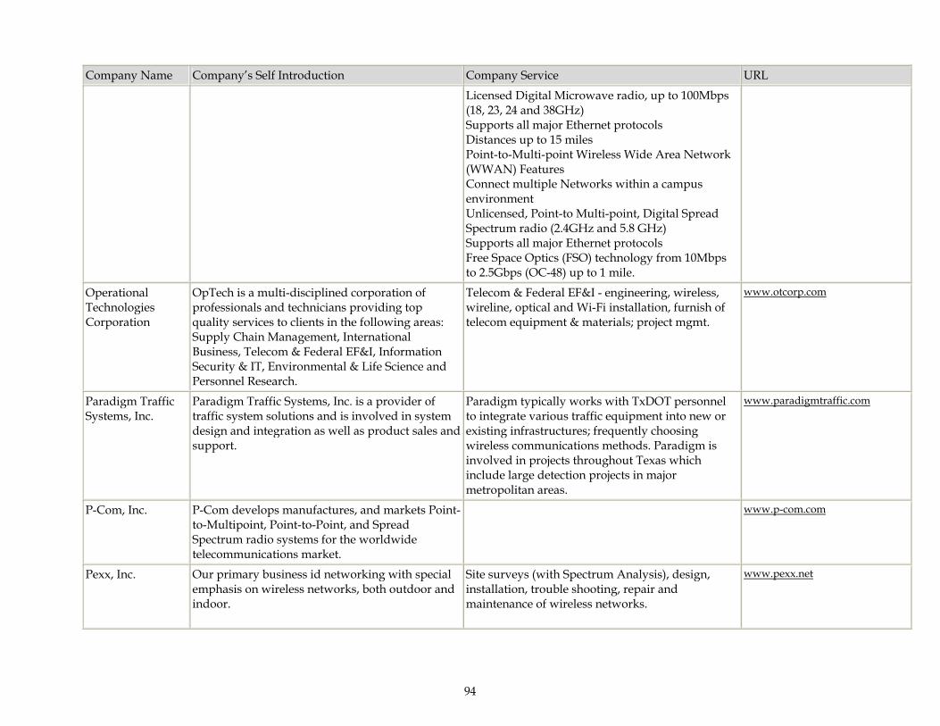
94
Company Name Company’s Self Introduction Company Service URL
Licensed Digital Microwave radio, up to 100Mbps (18, 23, 24 and 38GHz) Supports all major Ethernet protocols Distances up to 15 miles Point-to-Multi-point Wireless Wide Area Network (WWAN) Features Connect multiple Networks within a campus environment Unlicensed, Point-to Multi-point, Digital Spread Spectrum radio (2.4GHz and 5.8 GHz) Supports all major Ethernet protocols Free Space Optics (FSO) technology from 10Mbps to 2.5Gbps (OC-48) up to 1 mile.
Operational Technologies Corporation
OpTech is a multi-disciplined corporation of professionals and technicians providing top quality services to clients in the following areas: Supply Chain Management, International Business, Telecom & Federal EF&I, Information Security & IT, Environmental & Life Science and Personnel Research.
Telecom & Federal EF&I - engineering, wireless, wireline, optical and Wi-Fi installation, furnish of telecom equipment & materials; project mgmt.
www.otcorp.com
Paradigm Traffic Systems, Inc.
Paradigm Traffic Systems, Inc. is a provider of traffic system solutions and is involved in system design and integration as well as product sales and support.
Paradigm typically works with TxDOT personnel to integrate various traffic equipment into new or existing infrastructures; frequently choosing wireless communications methods. Paradigm is involved in projects throughout Texas which include large detection projects in major metropolitan areas.
www.paradigmtraffic.com
P-Com, Inc. P-Com develops manufactures, and markets Point-to-Multipoint, Point-to-Point, and Spread Spectrum radio systems for the worldwide telecommunications market.
www.p-com.com
Pexx, Inc. Our primary business id networking with special emphasis on wireless networks, both outdoor and indoor.
Site surveys (with Spectrum Analysis), design, installation, trouble shooting, repair and maintenance of wireless networks.
www.pexx.net

95
Company Name Company’s Self Introduction Company Service URL
Psion Teklogix Corporation
Psion Teklogix develops, implements and supports mobile computing solutions for warehousing, distribution, transportation and logistics and mobile data collection.
Manufacturers, repairs, support wireless data devices.
www.psionteklogix.com
Quality Network Service Inc
Quality Network Services, Inc (QNSI) was founded in May 1999 as a full service EF&I organization, headquartered in Austin, Texas.
QNSI provides comprehensive wireless services to include: Site evaluation and construction Zoning and permitting Installation Skidding Commissioning Project planning and management Tower and Antenna installation Warehouse services Quality Network Services provides tower erection and maintenance services, along with antenna change outs, repairs and maintenance and provides turnkey installation on Microwave Systems.
www.qnsi.net
R.T.C., inc. RTC is an authorized Motorola service center as well as a dealer, agent and manufacturer's representative for providing two-way radio equipment.
Provider of 2-way radio equipment and hardware. Provider of installation of said equipment. Provider of repairs and services to include microwave, tower work and 2-way radio services.
RedMoon Broadband
The dawn of RedMoon high-speed Internet is here. Pioneers in wireless broadband technology, RedMoon specializes in Wireless High-Speed Internet Networks and Public Hot Spots.
We provide discounted T1s, Wireless High-Speed Internet Networks, cable modem networks, Hot Spots, as well as other emerging technologies.
www.redmoonbroadband.com
R-Tel Communications, Inc
R-Tel is a premium provider of Avaya, Nortel and Siemens/Rolm products in the Texas market. We have support staff in the DFW, Houston/Beaumont, Austin/San Antonio, and Sub-contractors in the remainder of the state.
R-Tel provides communication equipment from Avaya, Nortel, Siemens/Rolm, and ESI. We install and service on T&M as well as full service maintenance contracts. We also provide cabling infrastructure, inside and outside plant including fiber optic.
www.rtelcom.com
Rx Technology Rx Technology is the largest provider of commercial high speed wireless broadband internet access, VPN and point to point services in
Cisco Premier Partner - Wireless Certified. Surveillance cameras, Construction Site Hot Spots. Networking, Fiber Optic Cabling Certified.
www.rx-tech.com
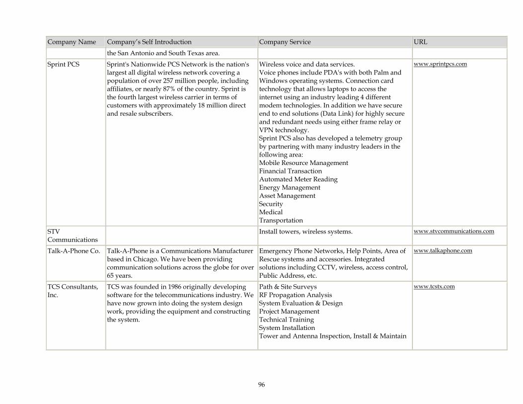
96
Company Name Company’s Self Introduction Company Service URL
the San Antonio and South Texas area.
Sprint PCS Sprint's Nationwide PCS Network is the nation's largest all digital wireless network covering a population of over 257 million people, including affiliates, or nearly 87% of the country. Sprint is the fourth largest wireless carrier in terms of customers with approximately 18 million direct and resale subscribers.
Wireless voice and data services. Voice phones include PDA's with both Palm and Windows operating systems. Connection card technology that allows laptops to access the internet using an industry leading 4 different modem technologies. In addition we have secure end to end solutions (Data Link) for highly secure and redundant needs using either frame relay or VPN technology. Sprint PCS also has developed a telemetry group by partnering with many industry leaders in the following area: Mobile Resource Management Financial Transaction Automated Meter Reading Energy Management Asset Management Security Medical Transportation
www.sprintpcs.com
STV Communications
Install towers, wireless systems. www.stvcommunications.com
Talk-A-Phone Co. Talk-A-Phone is a Communications Manufacturer based in Chicago. We have been providing communication solutions across the globe for over 65 years.
Emergency Phone Networks, Help Points, Area of Rescue systems and accessories. Integrated solutions including CCTV, wireless, access control, Public Address, etc.
www.talkaphone.com
TCS Consultants, Inc.
TCS was founded in 1986 originally developing software for the telecommunications industry. We have now grown into doing the system design work, providing the equipment and constructing the system.
Path & Site Surveys RF Propagation Analysis System Evaluation & Design Project Management Technical Training System Installation Tower and Antenna Inspection, Install & Maintain
www.tcstx.com
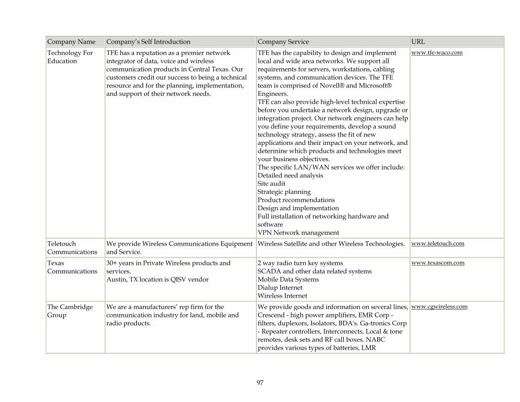
97
Company Name Company’s Self Introduction Company Service URL
Technology For Education
TFE has a reputation as a premier network integrator of data, voice and wireless communication products in Central Texas. Our customers credit our success to being a technical resource and for the planning, implementation, and support of their network needs.
TFE has the capability to design and implement local and wide area networks. We support all requirements for servers, workstations, cabling systems, and communication devices. The TFE team is comprised of Novell® and Microsoft® Engineers. TFE can also provide high-level technical expertise before you undertake a network design, upgrade or integration project. Our network engineers can help you define your requirements, develop a sound technology strategy, assess the fit of new applications and their impact on your network, and determine which products and technologies meet your business objectives. The specific LAN/WAN services we offer include: Detailed need analysis Site audit Strategic planning Product recommendations Design and implementation Full installation of networking hardware and software VPN Network management
www.tfe-waco.com
Teletouch Communications
We provide Wireless Communications Equipment and Service.
Wireless Satellite and other Wireless Technologies. www.teletouch.com
Texas Communications
30+ years in Private Wireless products and services. Austin, TX location is QISV vendor
2 way radio turn key systems SCADA and other data related systems Mobile Data Systems Dialup Internet Wireless Internet
www.texascom.com
The Cambridge Group
We are a manufacturers’ rep firm for the communication industry for land, mobile and radio products.
We provide goods and information on several lines, Crescend - high power amplifiers, EMR Corp - filters, duplexors, Isolators, BDA's. Ga-tronics Corp - Repeater controllers, Interconnects, Local & tone remotes, desk sets and RF call boxes. NABC provides various types of batteries, LMR
www.cgwireless.com

98
Company Name Company’s Self Introduction Company Service URL
rechargeable and alkaline. Kenwood Communications - various two-way and mobile radios along with repeaters, GPS and AVL systems. Manning Navcomp - AVL, GPS mapping systems. Otto Communications - profesional quality headsets, speaker mics, lapel and palm mics. Pyramid Communications - UHF/VHF Synthesized Vehicular repeaters, GPS/AVL systems, Inband SVR options. Radiall/Larsen - Portable, mobile and ase station antennas, PCS, cellular, data, LMR, SMR and GPS antennas. Trident Micro Systems - Logic controller products. Watson Dispatch - communications console furniture.
T-Mobile Wireless GSM Wireless Voice Communications and GPRS Wireless Data Connection
Provider of voice and data communications including Blackberry Data Devices, Pocket PC Devices, and Unlimited Mobile to mobile rate plans and unlimited Data plans.
www.t-mobile.com
Trillion Partners, Inc.
Trillion is a leading provider of ""last mile"" broadband connectivity and high-speed Internet access for K-12 schools, government and municipalities, healthcare systems, libraries and colleges and universities.
Wireless wide area (WWAN) networks, WWAN engineering, WLANs & Engineering, network management services, and converged services over WWANs (voice, video & data).
www.trillionpartners.com
TVi Dish Satellite TV and high speed two way satellite internets.
www.tvidish.com
TVi Dish Local Satellite internet dealer in the Greater Austin/Georgetown area including rural.
We sell service and install StarBand satellite internet service. Business class service with over 1Mbs downloads and up to 150Kbs uploads. Static IP and VPN.
www.tvidish.com
Vibes Technologies
Remanufacturer of Nortel, Avaya, Cisco & Executone telecommunications parts and systems. Also provide Repair services and complete systems. We are a Nortel Premier Partner for Upgrades & New product.
Remanufactured & new Nortel (Meridian & Norstar), Avaya, Cisco, & Executone products. Repair facility for all listed products. - Provider of peripheral products such as headsets, audio conferencing, CSU & DSU, & Etc.
www.vibestech.com

99
Company Name Company’s Self Introduction Company Service URL
Victoria Communication Services, Inc.
VCS is a full sale and service center for two-way radios and cellular phones
Complete sales and service
www.viccomm.com
W.T. Services, Inc. W.T. Services, Inc. has been in business since 1982. We have four locations in the Texas Panhandle, Hereford, Amarillo, Borger and Plainview. Our business consist of Two-way radio communications, telephone companies (Friona & Bovina) Area wide paging(Panhandle of TX), Cablevision (Friona & Bovina) and Internet, Wireless Internet
Sales, Service, Communications System Design and Installation of Communications Equipment, Wireless services, telephone systems.
www.wtservicesinc.com
Wave Wireless Networking
Wave Wireless Networking is a nine year old manufacturing company specializing in delivering "last mile" connectivity for high-speed Internet and intranet access using outdoor fixed wireless solutions. Our highly secure broadband routers with AES (Advanced Encryption Standard) were touted at the TOPPOFF2 exercises earlier last month and have been deployed in various FAA and government projects throughout the country.
2.4GHz wireless routers 18GHz licensed microwave 23GHz licensed microwave Our routers provide secure transmissions as required by government and private enterprises.
www.wavewireless.com
Wear Radio Service Inc
Authorized Motorola, Zetron dealer. Specialists in two-way radio design, sales & service. Installation of equipment including police packages tower construction and service. Support 911 systems. Qualified mobile Vision (video camera) service.
Repairs of two-way equipment. 24 hour technicians.
www.wearradio.com
Western Communications
Western Communications was established in 1936 in San Angelo, Texas. The company takes pride in providing local customer support in the markets we serve and has a loyal customer base.
The company provides paging service, dialup Internet service and high-speed wireless DSL Internet service.
www.wcsonline.net
Wireless Dynamics A premier Fixed Wireless Broadband company serving Texas. Small to large fixed wireless deployments using both TCP/IP and ATM protocols. QISV qualified.
Consulting, Engineering, and Turn-key project implementation.
www.wdynamics.net
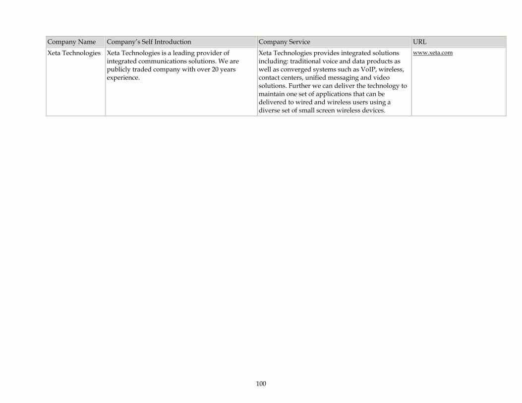
100
Company Name Company’s Self Introduction Company Service URL
Xeta Technologies Xeta Technologies is a leading provider of integrated communications solutions. We are publicly traded company with over 20 years experience.
Xeta Technologies provides integrated solutions including: traditional voice and data products as well as converged systems such as VoIP, wireless, contact centers, unified messaging and video solutions. Further we can deliver the technology to maintain one set of applications that can be delivered to wired and wireless users using a diverse set of small screen wireless devices.
www.xeta.com