guide to sectioning on the reichert jung ultracut ultramicrotome
DESCRIPTION
UltramicrotomíaTRANSCRIPT

Guide to Sectioning on the
Reichert-Jung Ultracut E Ultramicrotome
Shannon Modla
BioImaging Center
Delaware Biotechnology Institute

2
Table of Contents
I. Checking Knives..................................................................................................3 II. Making Boats from Glass Knives.........................................................................4
III. Knobs, Buttons, and Levers .................................................................................6 IV. Trimming Trapezoids......................................................................................... 11
V. Facing the Block................................................................................................ 14 VI. Trimming with a Glass Knife............................................................................. 16
VII. Thin Sectioning ............................................................................................... 17
A. Filling the Boat....................................................................................... 17 B. Aligning the Block to the Knife and Thin Sectioning .............................. 17 C. Section Thickness................................................................................... 20
VIII. Thick Sectioning ............................................................................................ 22 IX. Grids and Section Manipulation......................................................................... 23
A. What are Grids?...................................................................................... 23 B. Preparing Grids ...................................................................................... 23 C. Flattening your Sections ......................................................................... 24 D. Collecting Sections onto Formvar-Coated Mesh Grids ........................... 25
X. Staining Sections
XI. Troubleshooting................................................................................................ 28 XII. References........................................................................................................ 30

3
Both diamond and glass knives can be used to obtain ultra-thin sections for viewing with the TEM. However, due to the expense and added care one must use when sectioning with a diamond knife, beginners should first learn to section with glass knives. Instructions for creating glass knives can be found in the �Leica EM KMR2 � Guide to Making Glass Knives� document.
I. Checking Knives
1. View the glass knife with a dissecting microscope. 2. Examine the knife edge for any edge imperfections, whiskers, knicks, or
contamination (Fig. 1A). 3. The sharpest edge is usually on the left side of the knife edge (Fig. 1A). This area
is highlighted by a stress line that starts in the corner and arcs down toward the heel. The useable knife edge (Fig 1A) extends from the left side to where imperfections occur on the right side of the knife edge. The area where the stress line contacts the knife edge (far left corner) should be avoided.
4. Of the two knives created by bisecting the glass square, one knife is generally of
higher quality than the counter piece. When the two knives are viewed as a pair, the knife with the larger heel is sharper than its counter piece. Leica recommends using glass knives with a 1 mm heel for thin sectioning of resin blocks.
5. Store good knives and boats in a knife holder box to prevent dust and dirt from
contaminating the knife edge.
6. Discard unwanted knives into a sharps container.
Figure 1A-B. A. Diagram showing knife imperfections and cutting areas of a glass
knife. B. Features of a glass knife.

4
II. Making Boats from Glass Knives
When cutting a sample on the ultramicrotome, sections are floated onto water. In order for this to occur, a boat that will hold water must be attached behind the knife edge.
Supplies needed: Glass knives Shiny silver tape Scissors Nail polish Razor blades
1. Remove the outermost layer of silver tape to expose a clean portion of tape that is
free of fingerprints or oil on the adhesive surface. 2. Using scissors, cut a 3-4 inch strip of tape. This is more tape than is needed to
make the boat, but extra is cut so that the tape can be gripped by the two ends without getting body oils on the middle of the cut strip. Never touch that portion of the tape which will be against the side of the knife or on the inside of the boat.
3. Without touching the knife edge, carefully stick the middle portion of the tape to
the knife side adjacent to the knife edge (Fig. 2A). The tape should be perfectly aligned with the knife edge � tape should not extend above or below the knife edge. Otherwise, the boat may not hold water properly. Make sure the strip of tape is parallel to the bottom of the knife and press firmly to stick the tape to the side of the knife.
4. Holding the opposite end of the tape, wrap the strip of tape around the knife front
and stick it to the opposite side of the knife as described in step 3 (Fig. 2B, C). The tape should not be too tight or too loose � it should form a U-shape behind the knife edge.
5. With a razor blade, remove excess tape from the back of the knife by applying a
single smooth stroke from the bottom of the knife toward the knife edge (Fig. 2D). Be careful not to damage the knife edge.
6. Seal the bottom of the boat to the knife front using nail polish (Fig. 2D, 3).
7. Boats should dry for at least 30 min before using. 8. Boats and knives can be stored for several days to weeks in a knife holder box.
The knife edge should never be touched. Although knives can be store for a limited period of time, best results will be obtained by using newly made knives.

5
Figure 2A-D. Diagram illustrating how to make a boat from silver tape.
Figure 3. Illustration of a glass knife with boat.

6
III. Buttons, Knobs, and Levers
Figure 4. Labeled parts of the Reichert-Jung Ultramicrotome.
1. Binoculars 2. Magnification knob 3. Focus knob 4. Moves binoculars forward and
backward 5. Light switch 6. Stage with guides
7. Stage course advance knob 8. Cantilever arm course advance
knobs -Inner knob: Sets the advance increment -Outer knob: Advances cantilever arm

7
Figure 5. Labeled parts of the Reichert-Jung Ultramicrotome.
9. Cutting wheel 10. Control lever for motor drive 11. Cantilever arm reset knob (Moves cantilever arm backwards)

8
Figure 6A, B. Labeled parts of chuck and chuck holder. 12. Cantilever arm 13. Cantilever arm clamping screw
(Secures chuck holder into cantilever arm)
14. Chuck 15. Specimen block clamping screw (Secures block into chuck with key) 16. Chuck holder rotational control
Knob
17. Chuck holder/segment arc 18. Trimming block 19. Locking lever (Secures chuck holder
into trimming block) 20. Locking lever (Secures trimming block
and knife carrier between guides of stage)
21. Locks chuck into chuck holder with key 22. Chuck holder tilt control knob

9
Figure 7. Labeled parts of the knife holder.
23. Knife holder 24. Knife clamping screw (secures knife into knife holder) 25. Clearance angle locking screw 26. Clearance angle adjustment knob 27. Upper part of knife carrier 28. Lower part of knife carrier 29. Knife carrier pivot/tilt control knob

10
Figure 8. Labeled speed and thickness control unit.
30. Cutting speed knob 31. Thickness control for ultrathin sections 32. Thickness control for semithin sections 33. Toggle switch-toggles between ultrathin and semithin controls 34. Power button Warning Lights and Sounds
a. Sounds when stage course advance has reached its limit. Retract stage by turning stage course advance knob counterclockwise
b. Sounds when cantilever arm is left in the bypass postion. Rotate cutting wheel until cantilever arm is in the cutting position
c. Sounds when cantilever arm has reached its limit. Retract cantilever arm by rotating cantilever arm reset knob clockwise until it stops and then rotate it counterclockwise one quarter of a turn.

11
IV. Trimming Trapezoids Tissue samples that are embedded in a resin must be trimmed into a shape that is conducive to sectioning. The shape most often used is that of a trapezoid block face with sloping sides (a flat pyramid). This shape has several advantages: makes orienting the block to the knife easier, minimizes compressive forces on the sample as it is sectioned, and facilitates serial sectioning (Since the trapezoid has sloping sides, the sections become larger as one sections deeper into the sample. Therefore the size of the sections can be used to determine whether they were cut from the top or bottom of the specimen block). The exact method for trimming can vary depending on the sample and goal of the project, but the below pointers give a general guide. 1. Obtain a box of razor blades. Both the duller single-edge razorblades (Fig. 9 A)
and the sharp, double-edge razorblades (Fig. 9B) may be used. The double-edge razor blades dull quickly and need to be replaced often during trimming. NOTE: Both types of razorblades are sharp and care should be taken so as not to cut yourself.
Figure 9. A. Single-edge razorblade. B. Double-edge razorblade.
2. Tighten the sample into the chuck and place the chuck holder into the trimming block on the ultramicrotome stage. The type of chuck used depends on whether the sample was embedded in flat molds or in round beem capsules (Fig. 10).
3. If the sample is not at the top of the block, remove excess surface resin (Fig. 11A,
B). Grip the razor blade by the sides or back so that the sharp edge is facing toward the front of the ultramicrotome. Make thin slices parallel to the ultramicrotome stage and stop just before the desired area in the specimen is reached. If the sample was treated with osmium tetroxide, it will usually appear black and be easy to see. Try to make the surface of the block as flat as

12
possible�rotating the specimen block while looking through the binoculars will help to determine if the surface of the block is flat.
4. Now a trapezoid is ready to be trimmed. The top and bottom sides of a trapezoid
are parallel with the bottom side being longer than the top. The two sides of the trapezoid are slanted, and the two bottom corners should preferably make equal angles with the long bottom side (Fig. 12).
a. Using a razor blade, make a series of thin cuts along one side of the block to a depth of 2-3 mm and at a 45-60° angle relative to the table top along one side of the block (Fig. 11C). This will form one of the parallel sides of the trapezoid. These cuts should be made with the edge of the razor blade angled toward you (this allows more control when trimming).
b. Rotate the specimen block 180° and repeat step 4a to form the opposite parallel side (Fig. 11D). Make sure the two sides are parallel as this will allow a straight ribbon of sections to be formed once sectioning begins.
c. Rotate the specimen block 90° and make a series of cuts at about a 60° angle to generate one of the slanted sides of the trapezoid (Fig. 11E).
d. Rotate the specimen block 180° and repeat step 5C to make the opposite slanted side (Fig. 11F).
The final trapezoid should contain the important areas of your specimen. The dimensions of the final trapezoid should be about one half to one third the width of the milled edge of the razor blade.
5. If needed, trim off any excess resin surrounding the trapezoid to reduce the surface area of the block. In the end, the trapezoid should have sloping sides of a 45-60° angle on a relatively flat surface (Fig. 12 and 13).
Figure 10. A. Chuck for samples embedded in flat molds B. Chuck for samples embedded in round beem capsules.

13
Figure 11A-G. Steps to trimming a trapezoid from your specimen block.
Figure 12. Illustration of a trapezoid as seen from above.
Figure 13. Illustration of a trapezoid as seen from the side.

14
V. Facing the Block Facing the surface of the trapezoid will form a smooth, reflective surface that will make it easier to align the trapezoid with the knife. Facing should always be done with a glass knife. 1. Adjust the tilt angle of the chuck holder to 0°. 2. Insert the chuck holder into the cantilever arm and tighten. 3. Rest the knife carrier between the guides of the ultramicrotome stage and secure it
into place with the locking lever. The knife carrier should be set back away from the sample so as not to ram the block into the knife.
4. Place a glass knife into the knife holder and tighten. A boat does not need to be
attached to the knife and may interfere. 5. Set the clearance angle of the knife to 4°. Loosen the clearance angle locking screw.
To decrease the clearance angle, press down on the wedge-shaped base supporting the knife until the desired angle is reached. To increase the clearance angle, rotate the clearance angle knob counterclockwise. Retighten the clearance angle locking screw once the clearance angle is set. Note: The value of the clearance angle is that number read from the clearance angle knob only when the knob is fully turned counterclockwise to its stopped position.
6. The knife tilt angle on the knife carrier should be set to 0°. 7. Unlock the knife carrier and manually approach the bock until the knife is 3-4 mm
from the block face. Relock the knife carrier. Extreme care should be taken so as not to ram the knife into the specimen block.
8. Using the course advance knob cautiously approach closer to the block. Once again,
do NOT ram the knife into the block. A shadow of the knife edge on the block face can be used to gage the distance between the knife and the block. The thinner the shadow, the closer the knife edge is to the block.
9. Rotate the specimen block until the long, bottom side of the trapezoid is parallel with
the knife edge. 10. Move the knife laterally so that the left or middle of the knife edge is in front of the
specimen block. 11. Advance the cantilever arm by 0.5-1.0 µm increments by turning the cantilever arm
course advance clockwise while rotating the cutting wheel clockwise through a cutting stroke.

15
12. Continue until a complete trapezoid-shaped section is cut from the surface of the block. The number of cutting strokes required to obtain a full section will depend on how flatly the surface of the trapezoid was trimmed.
13. The surface of the trapezoid should now be completely flat with a mirror-like quality.
The trapezoid may need to be placed back into the trimming block and retrimmed using a fresh razorblade. Make sure the top and bottom sides are parallel.

16
VI. Trimming with a Glass Knife
In some instances, it is necessary to make the top and bottom sides of the trapezoid perfectly parallel and not ragged. Since this is difficult to do by hand, the top and bottom sides can be more precisely trimmed with a glass knife.
1. Secure the specimen block into the chuck and place into the chuck holder. Rotate
the chuck such that the top side of the trapezoid is perpendicular to the 90° tick mark on the chuck holder. Secure the chuck into the chuck holder.
2. Insert the chuck holder into the cantilever arm and the knife into the knife holder.
3. Rotate the block exactly 90° using the tick marks on the chuck and chuck holder
as a guide.
4. Tilt the knife carrier so that the right edge of the upper part of the knife carrier is aligned with the 10° mark on the left side of the lower part of the knife carrier.
5. Slowly approach the side of the trapezoid by moving the stage forward with the
course advance.
6. Shave thin sections off the side of the trapezoid by rotating the cutting wheel and approaching the block in very small increments (fraction of a tick mark) using the stage course advance.
7. When one side is complete, back away the knife. Rotate the block exactly 180°
and repeat steps 5-6.
8. If the glass knife has a good, straight edge, the top and bottom sides of the trapezoid should be crisply cut and perfectly parallel.

17
VII. Thin Sectioning
Before beginning to thin section, the specimen block should be securely mounted into the chuck and the chuck holder should be inserted into the cantilever arm. The knife holder should be set back away from the sample so as not to ram the block into the knife. A. Filling the Boat
1. Insert a fresh glass knife with a boat into the knife holder and tighten. 2. Using a syringe, fill the boat with filtered de-ionized water until a positive
meniscus forms above the level of the boat. A single drop of filtered Tween-20 solution (1 drop Tween 20 in 60cc de-ionized water) may be added to the boat to reduce the surface tension (This helps to keep the edge of the knife wet). The boat should always be filled from the back to avoid damaging the knife edge.
3. Using a 1 cc syringe with a needle, withdraw water from the back of the boat
until the water level is slightly below the level of the boat while still leaving the knife edge wet. Be careful not to poke a hole in the boat! The correct water level is achieved when the water near the knife edge has a uniformly silvery surface. If the water level becomes low, a gray crescent adjacent to the knife edge will be visible.
**Water level should be checked frequently as it will naturally become lower due to evaporation.
**The correct water level is essential to seeing the interference colors of your sections.
**Improper water levels can cause sectioning problems
B. Aligning the Block to the Knife and Thin Sectioning
If the block face is properly aligned with the knife edge, a full section can be rapidly obtained with minimal cutting strokes. Four alignments must be made: specimen rotational alignment, knife lateral alignment, knife tilt alignment, and specimen tilt alignment. When using glass knives, these alignments can me made by observing a shadow that is cast onto the block face by the knife. When using diamond knives, a line of reflected light is cast onto the block face. Important Note: The knife should always be moved back, away from the block, during any change in alignment to avoid damaging the knife edge.

18
1. Unlock the knife carrier and manually approach the block until the knife edge is 3-4 mm from the block face. Relock the knife carrier. Extreme care should be taken so as not to ram the knife into the specimen block.
2. Using the course advance knob cautiously move the knife closer to the block.
Once again, do NOT ram the knife into the block. As the knife approaches the block, a shadow of the knife edge will be projected onto the block face when viewed through the binoculars. The thickness of this shadow can be used to estimate the distance between the block face and the knife edge: the larger the shadow, the greater the distance between the knife edge and block face; the smaller the shadow, the closer knife edge is to the block face.
3. Specimen rotational alignment (Fig. 14):
a. Rotate the specimen block until the long, bottom edge of the trapezoid
is parallel with the knife edge
Figure 14. Specimen rotational alignment.
4. Knife lateral alignment: a. Move the knife laterally so that the sharpest edge of the knife (usually
left) is in front of the specimen block. Avoid areas with knicks and whiskers if present.
5. Knife tilt alignment:
a. If the shadow cast onto the block face by the knife edge is thinner on the right side of the block face than the left, then the knife is closer on the right than the left (Fig. 15A). To correct, tilt the knife to the left. If the shadow is thinner on the left side of the block than the right, then the knife is closer on the left than the right (Fig. 15B). To correct, tilt the knife to the right. Adjust the knife tilt until a straight shadow is seen across the block face.

19
Figure 15A, B. Diagram illustration knife tilt alignment.
6. Specimen tilt alignment
a. While slowly moving the specimen through a cutting stroke, carefully study the shadow line. If the shadow line grows and becomes thicker, the top of the block face is tilted further from the knife than the bottom of the block (Fig. 16A). Therefore, the block must be tilted forward. If the shadow line shrinks and becomes thinner, the top of the block face is tilted closer to the knife than the bottom of the block (Fig. 16B), and the block needs to be tilted back. Adjust the specimen tilt until the width of the shadow line remains constant across the entire block face during a cutting stroke. Be sure to back the knife away from the specimen after every change in alignment to avoid damaging the knife!
Figure 16A, B. Illustration showing specimen tilt alignment. A. If the block is tilted too far back, the shadow line grows as the block face passes in front of the knife edge. To correct, tilt the block forward. B. If the block is tilted too far forward. The shadow line shrinks as the block face passes in front of the knife edge. To correct, tilt the block back.

20
7. Set the cutting range. The cutting range is the vertical distance located above
and below the knife edge whereby the specimen block passes over the knife edge during the downward cutting stroke of the cantilever arm and a section is cut. On automated ultramicrotomes, such as this one, setting the cutting range will allow the movement of the cantilever arm to be slowed to an appropriate speed as it passes over the knife edge. To set the cutting range:
a. Turn the cutting wheel clockwise until the specimen block is above the knife edge.
b. Lift the control lever located to the right of the ultramicrotome stage c. Continue to turn the cutting wheel until it stops and becomes harder to
move. d. Move the cutting wheel either up or down so that the top of your
trapezoid is completely below the knife edge. e. Lower control lever to its original position
8. Set the sectioning speed to 1.0 mm/sec. The speed may need to be varied
depending on the sample.
9. Approach the block face using the thickness of the shadow line as a guide. Be careful not to ram the knife into the block face.
10. Toggle the section thickness control to �semi-thin� and set to 250 nm.
11. Go through a series of cutting strokes by rotating the cutting wheel until the
entire block face is cut and whole sections can be seen floating on the water.
12. Toggle the section thickness control to �ultrathin� and set to 60 nm to obtain sections with a silver-gray interference color. Depress the control lever and the ultramicrotome will automatically start to section. A ribbon of sections should form in the boat, floating off the knife edge. Do not bump the table during sectioning to minimize vibrations.
13. To stop sectioning, lift the control lever to its original position
C. Section Thickness
Although the ultramicrotome has a section thickness control, the true thickness of the sections should be determined from their interference colors. When white light is reflected from the bottom and top of the section, the light will be differentially slowed down depending on the thickness of the section. Consequently the phase of the light will change. These emerging wavelengths will interfere with those reflected from the water�s surface, which gives the sections a particular color. The thickness of the sections can be determined by using an interference card (Fig. 17) that gives a color spectrum with the corresponding section thickness.

21
Figure 17. Interference card for determination of section thickness.

22
VIII. Thick Sectioning
Taking thick (1 µm) sections of the block can prove useful in a number of instances. A few examples include determining tissue orientation, finding a particular region within the tissue, or assessing the quality of tissue preservation. Thick sectioning should only be done with a glass knife, as it will dull the knife edge quickly.
1. Secure and mount the specimen block and glass knife. Fill the boat as described in section VII A. Approach block face with the knife, and align the knife to the block face as in thin sectioning.
2. Toggle the section thickness control to �semi-thin� and set to 250 nm. Go through
a series of cutting strokes by rotating the cutting wheel until the entire block face is cut and whole sections appear on the water. Toggle the section thickness control to �ultra-thin� and set to 60 nm.
3. Using the cantilever arm course advance, move the cantilever arm forward by 1
µm increments as you turn the cutting wheel. Thick 1 µm sections will appear in the boat.
4. Use an eyelash brush to move the sections away from the knife edge and corral
them together.
5. Flatten the sections with the heat pen as described in section IX C.
6. On a pre-cleaned microscope slide, place a drop of distilled water.
7. Using a wooden applicator stick with the end sharpened into the shape of a paddle, scoop up the thick sections from your boat and transfer them to the drop of water on the slide.
8. Place the slide on a warm hot plate (dial set between 2 and 3) and allow the water
to evaporate. Heating will allow the sections to adhere to the slide.
9. Cover the sections with epoxide stain and place back onto the warm hot plate.
9. When a greenish-yellow rim forms around the perimeter of the stain, remove the slide from the hot plate and rinse with distilled water into a waste container.
10. Slides can now be mounted with a drop of water and a coverslip for viewing with
a light microscope. To keep slides long-term, mount the coverslip with 9:1 Tris glycerol and seal the edges with nail polish.

23
IX. Grids and Section Manipulation A. What are Grids?
Grids are equivalent to the glass slides used in light microscopy. They are used to support the sections for viewing with the transmission electron microscope. Grids come in many different varieties�the type of grid used depends upon the aim of the research project. The standard grid types are 200-mesh copper grids. Grids can also be made from gold, nickel, platinum, steel, and other metals. The mesh size of the grids may also vary. Grids with small mesh sizes have more space between grid bars and offer less support for sections. Some grids have an open slot, which provides a more unobstructed view of the specimen.
Grids will often be coated with a thin support film. A common plastic film is Formvar. Grids can be coated with Formvar in the lab or they can be ordered already coated. Make a note of when the grids were coated or purchased as Formvar will degrade with time. Upon close examination, the two sides of a grid can be differentiated (Fig. 18). The dull side appears bright. The shiny side is reflective and appears dark. The Formvar on coated grids is applied to the brighter, dull side, which is rougher in texture than the opposite side. Therefore, sections are usually collected onto the dull side of the grid. When buying pre-coated grids one should contact the manufacturer and inquire about the proper side to collect sections.
Figure 18. Note the shiny (darker) side and dull (brighter) side of grids.
B. Preparing Grids
When using grids that have not been pre-coated with a support film, they should be cleaned to remove contamination. 1. Sonicate grids in acetone for 5 min
2. In the fume hood, dump the cleaned grids and acetone onto a piece of clean
filter paper in a clean Petri dish.

24
3. Allow the acetone to evaporate.
4. Once the grids have dried, cover the Petri dish and label it with the date, your initials, the grid mesh size, and grid metal. The grids are now ready to be used or coated with a support film. See the �Making Formvar Grids� document for instructions.
C. Flattening Sections
Before sections can be collected onto grids, they must be flattened. There are at least two methods for expanding sections: chloroform flattening and heat pen flattening.
1. Chloroform Flattening
a. Place a drop of chloroform on the tip of a wand (Fig. 19B). To make the wand, glue a wedge of filter paper to a wooden applicator stick.
b. Wave the wand over the sections. Be careful not to dip the wand in
the water. Do not touch the sections or knife edge. c. Watch as the sections flatten with the binoculars.
Figure 19. A. Eyelash brush. B. Flattening wand.
2. Heat Pen Flattening
a. Just before sections are ready to be collected, turn on the heat pen (Fig. 20A) and turn knob clockwise (Fig. 20B) to increase the temperature. The tip of the pen will start to glow red.
b. Lower the pen above the sections, being careful not to dip it into the
water. Do not touch the sections or the knife edge. Sections should

25
not be attached to the knife edge when flattening them with the heat pen since the heat can melt the sections to the knife edge.
c. When finished flattening the sections, return the heat pen to its holder,
turn the temperature down, and turn off the heat pen. Do not keep heat pen on while sectioning.
Figure 20. Heat pen D. Collecting Sections onto Formvar-Coated Mesh Grids
There are at several different ways to collect sections onto grids. The first method involves plucking the sections from the surface of the water with a grid. Although this method gets the job done, it will often introduce folds on the sections. Therefore, the second method, which utilizes a Perfect Loop, is recommended.
1. Plucking
a. Use an eyelash brush (Fig. 19A) to gently move the sections to the center of the boat. If the sections are not in a ribbon, corral them together. Do

26
not poke the sections with the eyelash brush. Simply dip the brush in the water alongside the sections and push them gently.
b. Grids should be placed onto filter paper inside a Petri dish. When not
using grids, place the cover on the dish to avoid contamination. c. With the shiny (darker) side of the grid up, grip the rim of the grid with
forceps and bend upward 30-40° (Fig. 21)
d. Hold the grid above the sections while looking through the binoculars.
e. Lower the grid dull-side down over the sections and briefly make contact without breaking the surface tension of the water. Do not dip the grid below the water level or drop the grid into the boat. A single grid can hold 4-5 sections depending on the size of the trapezoid.
f. Wick off excess water from the grid by gently touching the rim with a
wedge of filter paper. Wick away water from between the forceps.
g. Place the grid, section side up, onto a clean piece of filter paper inside a Petri dish and cover.
Figure 21. Picture showing how grids should be picked up by the rim.
2. Perfect Loop
a. Use an eyelash brush (Fig. 19A) to gently move the sections to the center of the boat. If the sections are not in a ribbon, corral them together. Do not poke the sections with the eyelash brush. Simply dip the brush in the water alongside your sections and push the sections gently.
b. Grids should be placed onto filter paper inside a Petri dish with the
dull side facing up. When not using grids, place the cover on the dish to avoid contamination.
27
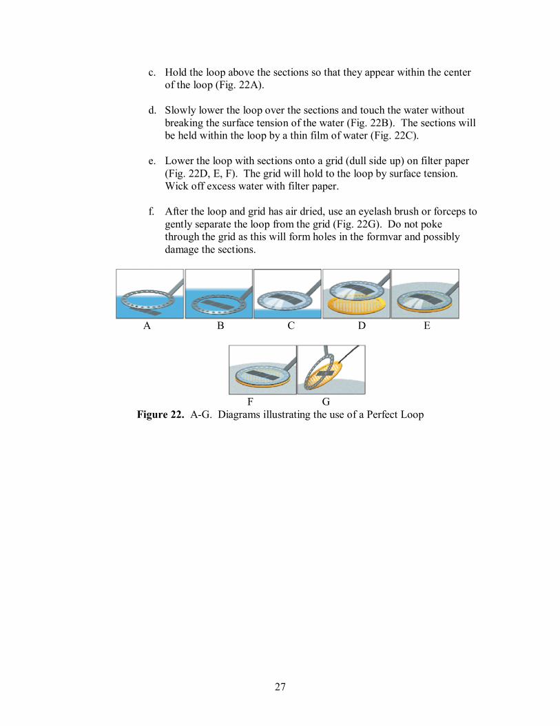
c. Hold the loop above the sections so that they appear within the center of the loop (Fig. 22A).
d. Slowly lower the loop over the sections and touch the water without
breaking the surface tension of the water (Fig. 22B). The sections will be held within the loop by a thin film of water (Fig. 22C).
e. Lower the loop with sections onto a grid (dull side up) on filter paper
(Fig. 22D, E, F). The grid will hold to the loop by surface tension. Wick off excess water with filter paper.
f. After the loop and grid has air dried, use an eyelash brush or forceps to
gently separate the loop from the grid (Fig. 22G). Do not poke through the grid as this will form holes in the formvar and possibly damage the sections.
A B C D E
F G
Figure 22. A-G. Diagrams illustrating the use of a Perfect Loop

28
XI. Troubleshooting (Taken from Bozzolla & Russel, 1999; Wagner)
Knife cuts every other section a. The advance has been set
below the capabilities of the cutting edge--Increase the advance until serial sections are cut or use a sharper knife
Failure to cut any sections
a. Cantilever arm at end of fine advance
b. Dull knife c. Block too soft d. Knife or block not secure e. Negative clearance angle f. Wet block face g. Vibrations h. Temp fluctuations
Thickness variation from one entire section to the next
a. Dull knife b. Bumping of microtome c. Drafts or temperature
variations d. Knife or block not secure e. Block face too large or soft f. Wrong cutting speed
Wrinkled Sections a. Block face too large or too
soft b. Dirty or dull knife c. Clearance angle too great d. Water level too low e. Cutting speed too fast f. Knife not secure
Compressed Sections a. Block too soft b. Cutting speed too fast c. Inadequate expansion-try
using chloroform vapors to flatten sections
Chatter
a. High-frequency vibrations during sectioning- try a different cutting speed or clearance angle
b. Block too tall with small base c. Dull knife or soft block d. Block or knife not secure
Specimen block lifts sections on return stroke
a. Water level too high b. Block face dirty, wet, or
hydrophilic�If block face is wet, wick dry with clean wedge of filter paper without touching knife edge
c. Clearance angle too small d. Dirty knife or back of knife is
wet e. Static electricity on block
face
Block face gets wet a. See a-e above b. Block face too large c. Cutting speed too slow
Sections dragged over knife edge a. Cutting speed too slow b. Water level too high c. Clearance angle too low d. Block too soft or a ragged
edge of trapezoid prevents clean detachment
Sections have holes
a. Bubbles in resin b. Incomplete infiltration with
resin c. Hard objects in specimen

29
Specimen falls out of block a. Poor infiltration b. Block too soft
Sections have striations perpendicular to the knife
a. Nick in knife edge-Move to a different region of knife edge or change knife
b. Dirt on knife edge c. Knife damaged by hard
region in specimen-Trim block to avoid hard region
Sections do not form ribbons
a. Top and bottom of trapezoid not parallel-try re-trimming block
b. Water level wrong c. Cutting speed too slow d. Static electricity on block
face
Ribbon of sections curved a. Top and bottom of trapezoid
not parallel-try re-trimming block
b. Compression on one side of section
Sections stick to eyelash probe
a. Dirty eyelash probe b. Bearing down on sections too
much with eyelash probe
Sections hard to see a. Water level wrong b. Illumination wrong
Sections hard to move in boat a. Contamination in boat water-
change water
Sections move away from grid a. Dirty grid
Perpendicular regions with varied interference colors in sections
a. Cutting edge not equally sharp across knife edge-use different part of knife edge or change knife
Irregular variations in interference colors throughout sections
a. Uneven consistency between specimen and embedding material or within different regions of the specimen-Try to re-trim to include only areas with an even consistency
Color variations occur in bands parallel to knife edge
a. Low frequency vibrations b. Knife or specimen not secure c. Cutting speed too fast d. Trapezoid needs to be re-
trimmed
30
XII. References Bozzola JJ and Russel LD. Electron Microscopy, 2nd ed. Boston: Jones and Bartlett
Publishers, Inc., 1999. Dillaman R and Gay DM. Electron microscopy lab manual. University of North
Carolina Wilmington. Fall 2004. Ultramicrotomy. Accessed Sept. 2006.
http://www.chm.bris.ac.uk/emuweb/Microsoft%20Word%20-%20ULTRAMICROTOMY.pdf. Oct. 2001. The electron microscopy unit, School of chemistry, Bristol University.
Wagner, R. Ultramicrotomy and staining of thin sections. Accessed Sept. 2006.
http://www.udel.edu/Biology/Wags/b617/micro/micro.htm. University of Delaware.