guide to pasing the hvac exam rev 5 - john whitejohnrwhite.net/guide to pasing the hvac exam rev...
TRANSCRIPT

1
IMPORTANT STUFF
This manual has been designed as a supplemental aid for students preparing to take thestate heating and/or air conditioning license exam. It is not intended to replace any manualsor material required for study. Furthermore, it is not an approved reference to carry intothe exam room.
The student must obtain the following reference material in order to use this manual.These references may to be taken into the exam room.
International (or your state) Mechanical CodeInternational (or your state) Fuel Gas CodeACCA- Manual J (seventh or eighth edition)ACCA Manual NACCA- Manual D
Optional references
International (or your state) Energy CodeInternational (or your state) Residential Building Code
Questions or comments may be emailed to: [email protected] ©
2006
Revised 2011
This manual is the sole property of Energy Marketing Services. No part of thismanual may be reproduced in any form or by any means without express written
permission by the owner.
ENERGY MARKETING SERVICE
374 Cattlelot Lane, Belhaven, NC 27810

2
A GUIDE TO MANUAL J 7th or 8th Edition
THE FOLLOWING DISCUSSION IS FOR MANUAL J8 USERS
Manual J8 was developed to provide two methods of calculating residential loads; theaverage load procedure and the peak load procedure.
The average load procedure is used to size the equipment used for homes with AdequateExposure Diversity*. If the home will utilize zoning, then the zone loads must becalculated using the peak load procedure.
*Adequate Exposure Diversity (AED) A home has AED if it is typical withabout the same amount of fenestration (glass) facing all directions.
If the home does not have adequate exposure diversity then the peak load procedure mustbe used. It may be necessary to perform a number of calculations, based on time of day ortime of year, then select the load that covers the worst case scenario.
A home does not have AED if it has a disproportional amount of glass facing any onedirection.
An example of a home without AED, would be one with an unusually largeamount of glass facing south. Because the average load procedure is based on midsummer data, the equipment might be undersized in October when the sun getslower and begins radiating through the large amount of south facing glass.
The following is a discussion of the Average Load Procedure which is also the basis ofManual J7. A discussion of the Peak Load Procedure will follow afterward.
Why a guide to manual J?
For over 40 years Manual J has been the industry’s leading reference tool for performingresidential load calculations. With over 30 years of experience teaching Manual J, wehave observed that most students only need an orderly explanation of the loadcalculation process. This guide puts it all together in a smooth flowing, easy to understandbooklet. This guide does not replace Manual J, as you will need the reference material inManual J to accurately perform a load calculation. This manual is designed to be shorton words and simple on math, so lets get started.
What is a load calculation?
All structures either lose heat in the winter time or gain heat in the summer time. Thisheat loss or heat gain is caused by the fact that the transfer of heat cannot be completelystopped. For example, if you put 180-degree coffee in a thermos bottle, even if it is superinsulated, sooner or later it will reach room temperature (lose heat). If you wanted tomaintain the temperature of the coffee at 180 degrees then you would have to put heat toit. The problem is. “How much heat (BTUH) do you put to it to maintain the 180 degreetemperature?” Too many BTU’s will overheat it and too little will not keep it warmenough. To know the precise amount of heat we need, we would have to know exactlyhow much heat the thermos bottle is losing per hour through it’s walls and cap. Then. wewould apply exactly that amount of heat per hour.
A house, like a thermal insulated bottle, also losses or gains heat, depending on

3
whether it’s winter or summer. If we know how much heat is being transferred throughit’s walls, ceilings, floors, windows and doors, ducts and through infiltration (airleakage) on an hourly basis then we could calculate the precise size heater or airconditioner the house would need to maintain a comfortable temperature. Thiscalculation is called a load calculation.
Why do a load calculation?
The oblivious reason is to prevent installing a system that is too small to do the job. Ifthis were true then why wouldn’t we just put a 5-ton air conditioner and a 140,000 btuhfurnace in a 1200 sq. ft. house and never worry about it again. The real reason for a loadcalculation is to size the equipment, right, in order to assure comfort, economy and goodindoor air quality.
When heating, it is important to size the system as close to the heat losscalculation as possible to prevent (1) drafts, (2) hot and cold spots, and (3) short cyclingof equipment. When a furnace is grossly oversized, the unit will constantly cut off andon. It may satisfy the thermostat but leave other parts of the home either over or underheated, thus the occupants are uncomfortable. A correctly sized unit runs longer, resultingin a better distribution of air and reduced short cycling. Short cycling also leads to higherenergy costs. Each time a furnace fires up it has to heat up the heat exchange before theindoor fan comes on. This heat is wasted up the chimney. Short cycling (short on-offperiods) increases the amount of heat wasted up the chimney. In addition, if theoccupant is cold in the area he is sitting in (cold spot), he will turn up the thermostat,wasting fuel as other areas are over heated
Sizing rules for heating (ACCA)
Fossil fuel furnaces- do not exceed 100% load calculation (may be twice the sizerequired).
Electric resistance heat- do not exceed 10% of load calculation. Heat pumps (used for heating and cooling)- do not exceed 25% of cooling load. Heat pumps (used for heating only)- do not exceed 15% of heating load. Auxiliary heat (electric resistance)– install only enough KW to make up for the
heat pump’s deficit. If more heat is desired, the additional heat must be controlledto remain off during normal heat pump operation.
Sizing an air conditioner correctly is even more important than sizing heat. Aside fromcausing hot and cold spots, over sizing an air conditioner can result in causing highhumidity and the problems associated with it. When an air conditioner runs it is not onlycooling, it is dehumidifying. An oversized air conditioner will cool the house but willnot run long enough to dehumidify. High relative humidity can have two detrimentaleffects, (1) higher energy bills, because higher humidity requires lower thermostatsettings to remain comfortable and (2) mold, mildew moisture and possibly health relatedproblems. NOTE: Even a correctly sized air conditioner is oversized most of the time.For example, a load calculation may call for a three-ton unit at 95-degree outdoortemperature, however, 97% of the time it is less than 95 degrees outdoors. A practicalsolution is to slightly undersize the unit, but talk this over with the owner
4
Sizing rules for air conditioners (ACCA)
Air conditioner- may be sized up to 115% of calculation.
Heat pump- may be sized up to 125% of calculation if needed to supply extraheating capacity.
.
A few basics before getting started
We’re almost ready to do a load calculation but before we get started there are a fewthermodynamic terms we need to discuss.
1st law of thermodynamics
Energy can neither be created nor destroyed, but can be converted from one form toanother with some amount of heat given off during the conversion. For example, whenwe burn gasoline in our car we convert chemical energy (gasoline) to mechanical energy andheat energy. With a gasoline engine being about 35% efficient, 65 % of the energy in a gallonof gas is wasted as heat. A furnace converts fuel to heat with amazing efficiency, 99% heat,1% light. We cannot make a furnace more than 100% efficient; otherwise we’d becreating energy. When we talk about a furnace being 80% efficient when heating ahome, we are referring to the percentage of heat (80%) that goes into the home versus thepercentage of heat that goes up the chimney (20%).
2nd law of thermodynamics
Heat goes from a warm place to a cold place. Heat does not rise, hot air rises. Thereason for stating this law is because many people are under the impression that heatrises; therefore we only need to insulate ceilings. If that were true we’d only insulate thetop of a refrigerator or water heater. Heat travels in all directions, through walls, floorsand ceilings at the same rate.
BTU
The amount of heat required to raise the temperature of one pound of water one degreeF.
BTUH
The amount of heat required to raise the temperature of one pound of water one degree Fin one hours time.
SPECIFIC HEAT
The amount of heat required to raise the temperature of one pound any substance compared tothat of water. Water has a specific heat of 1.00 while the specific heat of rock is .20 andthe specific heat of ice is .50. Therefore it takes five times more heat to raise thetemperature of water compared to rock and two times compared to ice. A Specific HeatTable of common substances can be found in ASHRAE's Handbook of Fundamentals(See Sensible Heat.)

5
SENSIBLE HEAT
Heat we can measure with a thermometer. When we heat water from 70 degrees to90 degrees we can see the thermometer rise. To determine the amount of sensible heat(BTU’s) required to raise the temperature of a substance use the following formula.
BTU (sensible) = lbs. X temp diff. X specific heat
Raise temp of 10 lbs. water 15 degrees
10 lbs X 15 degrees TD X 1.00 = 150 btu
Raise temp of 10 lbs. rock 15 degrees
10 lbs X 15 degrees TD X .20 = 30 btu
Note: compared to rock, it takes five times more heat (btu) to raise the temperature ot thewater.
Design temperature and design temperature difference (TD)
When you design a heating or air conditioning system you need to know how coldor hot it is likely to get in your area (this is the outdoor design temperature) and whattemperature you’d like to maintain inside (this is the indoor design temperature). Table1 in manual J will provide you with the outdoor conditions for major cities in the UnitedStates. Find the city that closest represents your area and use Table 1 figures. Use 97-1/2%(99% J8) design column for winter and the 2-1/2 % (1% J8) column for summer.
NOTE 1: If you feel the temperatures in manual J are not true representations then useother data or experience but do not go overboard. (On test use Manual J figures)
NOTE 2: If you are heating or cooling an area that is adjacent to or surrounded byanother area that is at a different temperature than outside then use the surroundingtemperature as your outside design temperature. An example would be an office in thecenter of a 50 degree warehouse. Use 50 degrees for the outdoor temperature.
The inside design temperature should always be:
70 degrees F for winter*
75 degrees for summer*
*unless otherwise specified
The design temperature difference (DTD) is simply the difference between the indoorand outdoor design temperatures.
Example: What is the winter design temperature difference for Raleigh
70F- 20F (OD temp found in table 1)=50 DTD
6
LATENT HEAT
Latent heat is heat required to change the state of a substance. It cannot be measured with athermometer. For example, if we heat one pound of water ten degrees it would take 10BTUS according to our definition of sensible heat. But when we change the state of thewater from liquid to vapor (steam) we are not changing the temperature, only the state(water can exist as liquid or steam at 212 degrees F), but it takes energy or BTU’s todo the job. This is called latent heat or latent heat of vaporization to be specific. Ittakes 970 BTUS to change the state of one pound of water from liquid to vapor orvapor to liquid. When an air conditioner removes moisture from the air, it isconverting (changing the state) water vapor to liquid, which flows down the drain lineand out of the house. If you were to catch this water in a bucket and determined that 1.5gals per hour were being produce by the air conditioner then it would take 12,120 BTUH ofcapacity to produce the latent heat necessary to remove the moisture.
Water weighs 8.33 lbs./ gal.8.33 lbs/gal. X 1.5 gals = 12.5 lbs.
12.5 lbs. X 970 btus/lb.= 12,120 BTU’s (latent heat)
NOTE: When calculating heat gain (air conditioning) two loads are figured. One issensible heat and the other is latent heat. Example: if the total calculated load comes to28,344 BTUH you might be tempted to install a 2 1/2 ton unit (30,000 BTUH). Howeveryou must first check the manufactures specs to see that both the sensible and latent loadswill be covered. If the calculation came out like this - 20,290 BTUH sensible/ 8054latent, and the manufactures specs says the units capacity is 23,000 BTUH sensible!7000 BTUH latent, then you would have to find another unit, capable of supplying the8054 BTU’s of latent heat even if you must use a larger unit.
R-Value
This is a number indicating the ability of a substance to resist the flow of heat. Thehigher the R value the better it acts as an insulator.
U value (learn and understand this, it is the foundation of a load calculation)
The U value is the number of BTU’s that pass though one square foot of substance inone hour’s time when there is one degree temperature difference. The U value is thereciprocal* of the R value
U=1/R
*A reciprocal of a number is 1 divided by itself. The reciprocal of 20 is 1!20 or .05
Suppose you had a six-inch thick, R- 19 fiberglass insulation batt and you wanted toknow how much heat will pass through it. First, determine the U value.
U= 1/R
U= 1/19
U=.0526
Therefore .0526 BTU’s pass through 1 square foot of the batt each hour when there isone degree temperature difference.

7
If the batt measured 2’ X 8’ we would have a total area of 16 Sq. Ft. We could then saythat .8414 BTU’s (16 Sq. Ft. X .0526 BTU’s). pass through the entire batt in one hourwhen there is one degree temperature difference.

8
Carrying our example just one step further, if the temperature on one side of the batt is20 degrees and on the other side it is 70 degrees, then we would have a 50 degreetemperature difference (70 – 20). Therefore, 42.08 BTU’s (.8414 BTU’s X 50 degrees)would pass through the batt in one hour.
Simply stated, to determine the amount of heat gained or lost through any substanceBTUH=U X AREA X TD
=.0526 X 16’ X 50 TD
= 42.08
Ok, now you’ve learned if you know the U value, the square footage and the temperaturedifference, you can calculate the BTU heat loss or gain per hour through a substance. Awall floor or ceiling is not made up of just insulation however. A wall may be made upof brick, sheathing, insulation and sheetrock, each of which has it’s own R value. The Rvalue of each component must be added together to obtain the total R value. Then wesimply take the reciprocal (1/R) and get the total U value of the wall. Manual J7section VII paragraph 7-8 (This illustration is not in J8, but you need to know this)attempts to show you one such wall with its composite R values (R-values of commonmaterial are listed in Table 10 for J7 or Table A51 for J8). Using Manual J’sillustration, it shows a total R value (resistance) of 12.89. This illustration is misleading.You must also add the R value of air films, both inside and outside of the wall (readparagraph 7-10). The illustration should look like this.
ACCA Manual J, 7th edition
Moving air surfaceR = .17
Still air surfaceR= .68
Illustration does not showair surfaces
Should be as follows:
Moving air film .17Brick .44Insulation 12.00Dry wall .45Still air film .17Total resistance R 13.23
Air films must be includedto get total R-value
x
4” x .11
NOTE: on the test DO NOT FORGET TO ADD AIR FILMS to get total R value.
Now that you have the total R value, you can calculate the U-value of the wall.
U=1 /R

9
U= 1/13.23U=. 076
AND once you know (1) the U value, (2) the square footage of the wall and (3) thedesign temperature difference, you can calculate the heat loss or heat gain through thewall.
As an example. Lets say we’re figuring the heat loss through the above wall. The wallis 40 ft. long and 9 ft. high. The wall is located in Durham, NC. What is the heat loss(BTUH)?
The formula BTUH = U X AREA X TDWe know the U value = .076
The area =40 ft. x 9 ft.= 360 sq. ft.To get the TD we need to go to Table 1, look up Durham, NC and find the outdoorwinter design temperature, which is 20 degrees. You were also told that unless otherwisestated to use 70 degrees as the indoor winter design temperature. Therefore the TD is70F-20F = 50F.
Now complete the simple calculation below.BTUH=U X AREA X TD
=.076 X 360X 50= 1368
Now that you’ve calculated the heat loss through a wall you should be able to calculatethe loss through the ceilings, floors, doors and windows exactly the same way.
Here’s the good news(J7 only) Tables 2 and 4 do lot of work for you. Lets say youhave a 1678 sq. ft. ceiling with R 30 insulation under a ventilated attic and you want toknow the heat loss through it at 55 degree design temperature difference (DTD). First goto Table 2 (winter) NOT Table 4 (cooling). Thumb through the table until you find aceiling that matches the one your working with. In this case it would be constructionnumber 16-G. Slide your finger across the top to 55 degrees, then down to the bincorresponding to line G and you see 1.8. Manual J refers to the number as the HTM (heattransfer multiplier). The HTM is simply the U value times the design temperaturedifference (DTD).
HTM=U X DTD
Therefore, if you know the construction characteristics of the walls, floors, ceilings,doors and windows, all you have to do is look up the HTM and multiply it by the area. Ourceiling described above would have a heat loss of:
BTUH = HTM X AREABTUH= 1.8 X 1678
BTUH=3020NOTE: Suppose the temperature difference is 53 degrees. You will notice the TD’s areonly given in 5 degree increments; therefore, the HTM for 53 degrees is not listed. What

10
do you do? If you slide your finger to the last column on the right you will see thecolumn is labeled U. Go down to construction number 16-G and you will see a U factor of.033.
HTM=U X DTDHTM=.033 X 53
HTM= 1.75
Now for the bad news (J8 only). Manual J8 does not have the tables mentioned abovewhich give you the HTM, but it does have Table 4A which give the U value of variousconstruction components You must create your own HTM using the above formula.Go to Table 4A, construction number 16C-30. This is approximately the same ceiling as
used for the J7 illustration above. Under the column labeled U-value, you will find a
ceiling with R-30 insulation has a U value of .032. To get the HTM for a 55 degree TD
simply perform the following:
HTM=U X DTD=.032 X 55
= 1.76
To determine the heat loss through the ceiling:
BTUH = HTM X AREA= 1.76 X 1678
= 2953
INFILTRATION AND VENTILATATIONSo far we have talked about heat loss/gain through conduction. Conduction is theprocess of heat transferring it’s energy from one surface of a substance to the other. Ifyou place a spoon in a hot cup of coffee sooner or later the heat will work it’s way up tothe handle by conduction. When calculating a heat loss/gain on a house we have tofigure in all ways heat can be either lost or gained by the structure.
Another way heat is transferred either in or out of a structure is through infiltration andventilation. Infiltration occurs when outside air enters the building through cracksaround windows, doors, receptacles, sole plates, etc. Ventilation occurs when wepurposely force outside air in, either mechanically, such as using fans, or passively, suchas opening a window. When outside air comes in by infiltration or ventilation it must beconsidered part of the load calculation because this air has to be heated or cooled.
The following infiltration and ventilation discussion will address the heat loss (winter)calculation only. Below is one of the most important formulas you will ever need in theHVAC business. We are going to spend some time on it not only because many testquestions are based on it: It will make you a better HVAC professional.
BTU=CFM X 1.1 X TD

11
CFM – cubic feet per minute
1.1– constant (amount of BTU’S required to heat 1 cu. Ft. of air 1 degree)
TD- temperature difference or design temperature difference
Let’s start by calculating the heat loss due to infiltration. Unless we use highly accuratescientific instruments the amount of infiltrated air entering a house is only an educatedguess.
Turning to Manual J7, Section III, Table 5 (J8, Table 5A) you will see the top sectionlabeled winter air changes per hour. Let’s say our house is of BEST tightness and is1500 sq. ft., 9 ft. ceilings with one fireplace. The design temperature difference is 55degrees. Locate where 1500 sq. ft. and BEST intersect and you will see .3. Add afireplace (.1) and you have a total of .4 (.3 +. 1 = .4). This means the house willexperience .4 air changes per hour. Our job is to determine how many BTUH weneed to make up for this infiltration loss.
To determine the heat loss due to infiltration we must use the formula,
BTU = CFM X 1.1 X TD
1.1 is a constant and 55 Is our TD. If we only knew the CFM we could plug it into theformula and get the BTU’s needed to offset the infiltration. How do we get the CFM?Answer: we must change air changes per hour to cubic feet per minute (CFM).
How to change air changes per hour to CFM
CFM = (VOLUME OF STRUCTURE X AIR CHANGES PER HOUR)/60 MINUTES
OR
CFM = VOLUME OF STRUCTURE X AIR CHANGES PER HOUR X .0167
Volume = length X width X height,
Or
Volume = area X height
.0167 is the decimal equivalent of 1/60
Using our volume formula, the volume is 13,500 cu. ft. (1500 sq, ft, X 9 ft. high)
CFM = (13,500 x .4)/60 MINUTES
CFM= 5400/60
CFM=90
Now that we have the mystery CFM figure, we can plug it into the infiltration formula to
12
determine the house heat loss due to infiltration.
BTU=CFM X 1.1 X TDBTU= 90 X 1.1 X 55
BTU = 5445
Looking at the bottom of Table 5 (J7 only) you will see (in their example) an HTM of70.6. If you were to perform a whole house heat loss calculation (sometimes calleda block load) you would not need to calculate the INFILTRATION HTM(Simply insert 5445 BTUH in cell 7C below) . However when performing a room-by-room calculation you must determine an HTM in order to determine the infiltrationloss for each room. To get an infiltration HTM divide the whole house infiltration by thetotal square footage of the windows and doors. For example, in our above house lets say ithad 240 sq. ft of windows and doors. The HTM would be:
INFILTRATION HTM = WHOLE HOUSE INFILTRATION BTU/TOTAL WINDOW AND DOOR AREA
HTM = 5445/240
HTM = 22.7
So, what do you do with this infiltration HTM?You multiply the window and door area of each room by the HTM in order to determinethe infiltration loss of each room. Suppose we have two identical sized rooms. Room A has20 sq. ft. of windows and room B has 80 sq. ft. of windows and doors. Which room wouldlikely have more heat loss due to infiltration? Room A is losing 454 BTUH (22.7 X 20)vs. room B with a 1816 BTUH loss (22.7 X 80).
Ventilation calculations are a whole lot easier than infiltration. When we ventilate weare bringing in a specific amount of air (CFM). For example, if the outdoor airtemperature is 20 degrees and the indoor temperature is 70 degrees and we bring in 300CFM of outdoor air, what is the heat loss due to ventilation?
Use the same formula as for infiltration:
A n s w e r : B T U H = C F M X 1 . 1 X T D
B T U H = 300 X 1.1 X 50
BTUH = 16,500
Duct loss and duct gain
Another way a house loses or gains heat is through loses in the duct system.
Using the following description, we will calculate the duct loss using both J7 and J8methods. Notice the difference in the results:

13
The ductwork is in the attic, it’s an unsealed, trunk and branch configuration and locatedin an area where the outdoor temperature does not get below 16 F. The return is near theequipment and the supply outlets are in the center of the room. Assume the airtemperature in the supply is 110 F and the ducts are insulated with R-2 and the outdoordesign temperature is 20 F.
J7 users only
Manual J7 has two tables; 7A for duct loss (winter) multipliers and 7B for duct gain(cooling) multipliers. Be sure to use the correct table. Simply put, once you calculate thetotal heat loss or gain multiply the total BTUH by the duct loss multiplier and add it toyour calculation.
Using Table 7B, we will use Case 1 (SA temp below 120F), then go to the far rightcolumn (winter design temp above 15F). Our ducts are in the attic with R-2 insulation,therefore, the multiplier is .15
Example: Total heat loss of structure 43,678 BTUH
Duct loss .15
Solution .15 X 43,678 = 6552 BTUH duct loss
Add duct loss to heat gain 6552 + 43,678
Total heat loss with duct loss 50,230 BTUH (J7)
Manual J8 users only
Manual J8 has 23 pages of Table 7’s. Let’s use Table 7A-T for our illustration. Notice at
the top of the page it describes the ductwork and location. In the BASE CASE HEAT
LOSS FACTOR chart locate 20 degrees below the OAT heading. slide to the right under
the 1500 sq. ft. heading and you will see of factor of .170. This means the duct loss is
17% before any corrections for insulation values or leakage. Next, go to the R-VALUE
CORRECTION chart (below), you will see a correction factor of 1.84 beneath R2. Next
go to the LEAKAGE CORRECTION chart and select a factor under R2. Since our
ductwork is unsealed select 1.52. ( see section 1-8, J8 for explanation of leakage options)

14
To determine the duct loss factor, multiply;
BASE FACTOR X R-VALUE CORRECTION FACTOR X LEAKAGE CORRECTION FACTOR.
.170 X 1.84 X 1.52 = .475
Our duct loss therefore is 47.5% of the total heat loss of the home.
Before you get too excited, we have one more adjustment to make. Take a look at the
DEFAULT DUCT WALL SURFACE AREA chart. Under the 1500 sq. ft. column it
says the surface area of the supply should be 177 sq. ft. and the surface area of the return
should be 43 sq. ft. If our duct system is anything other than these dimensions than we
must apply another correction factor to the above calculated duct loss. Obviously, it is
most unlikely the surface areas will be the same as the default areas, so here's how to
make the adjustment:
Assume the actual surface area of the supply ducts is 140 sq. ft. and the return ducts is 54
sq. ft. Find the chart labeled SURFACE AREA FACTORS. Under the Ks column
(supply) find a Ks factor of .613 and under the Kr column (return) find a Kr factor of
.387. Now apply the following formula:
SAA = (Ks X (actual area/default area)) + ( Kr X (actual area/ default area))
= (.613 X (140/177)) + (.387 X (54/43))
= (.613 X .791) + (.387 X 1.256)
= .485 + .486
= .971
The duct loss before applying the surface area factor is .475. To get the adjusted duct
loss, multiply the duct loss by the SAA.
Final or adjusted duct loss = .475 X .971
= .461
Total heat loss of structure (before duct loss)= 43,678 BTUH

15
Duct loss factor = .461
.461 X 43,678 = 20,135 BTUH duct loss
Add duct loss to heat gain 20,135 + 43,678
Total heat loss with duct loss 63,813 BTUH (J8)
Let’s do a heat loss calculationThe calculation we’re about to do will be a whole house calculation. Manual J’s exampleis a room by room calculation. It uses up a lot of paper and ink and makes the calculationlook a lot harder than it really is. A heat loss calculation is made up of only three things;conduction losses, infiltration losses and duct losses. We are not going to try to teach youhow to figure square footage or volume at this time. If you’re having trouble withgeometry you’ll find help at the back of this book. For simplicity, our sample house is verysmall and simple. The principles would be the same, however, even if it were the Vanderbiltmansion.
Sample House

16
LOCATION- RALIEGH
DUCTS LOCATED IN VENTED CRAWLSPACE, R-2 INS, UNSEALED,110FSUPPLY AIR, TRUNK AND BRANCH
TIGHTNESS OF CONSTRUCTION- AVERAGE
8 FT. CIELINGS
COMPONENT J7 HTM J8 HTM
WINDOWS – DOUBLECLEAR GLASS WOODFRAME
27.6 (TABLE 2 NO.1A)
.57 X 50 DTD = 28.5
(TABLE 2A NO. 1 D)
DOORS- METALPOLYSTYRENE COREWITH STORM
15.9 (TABLE 2 NO.11 D)
.21 X 50 DTD = 10.5
(TABLE 4A NO. 11O)
WALLS- WOOD FRAME,R-1 1 INS, WOODSHEATHING
4.5 (TABLE 2 NO.12C)
.097 X 50 DTD = 4.85(TABLE 4A NO.12B 0Sw/m)
CEILING- VENTILATEDATTIC,R-19 INS
2.6 (TABLE 2 NO.16D)
.049 X 50 DTD = 2.45
(TABLE 4A NO. 16B-19)
FLOORS- ENCLOSEDCRAWLSPACE, CARPET,NO INS
5.4 (TABLE 2 NO.19F)
.295 X 18.8 = 5.55 useTD in Table 4A, const #19A. do not use DTD(TABLE 4A NO.19A ocp)Figure A

17
1. The first thing to do is determine the design temperature difference (DTD). Wewill need the DTD in order to lookup or calculate the HTM for each buildingcomponent. Since the house is located in Raleigh, NC, we will have to go totable 1 to look up the outdoor design temperature. The correct temperature is 20degrees. Therefore the DTD is 50 (70 degree indoor temperature –20 degreeoutdoor temperature)
2. In column A (figure B below) enter the square footage of each buildingcomponent. On line 7 enter the house volume instead of sq. ft.
3. In column B enter the HTM. Go to Table 2 (J7) or Tables 2 and 4A (J8), find thecomponent that most closely matches our description and enter the HTM listedunder 50 degree TD. (The chart above (figure A) shows the calculated HTM.sand gives reference to their origin.)
4. Column C is the product of columns of A and B (AX B). This gives you the totalheat loss of each component.
5. In cell 7C use the infiltration calculation at bottom of chart to get the infiltration lossand enter it in the cell. Use Table 5, J7 (Table 5A, J8) to obtain air changes.NOTE: the Table in J7 indicates 1 A/C per hour, While J8 indicates .75 A/Cper hour. Our example is based on the J7 data.
6. Add columns 2C thru 7C and enter answer in 8C. This would be the total heat lossof the house if it did not have a duct system or the duct system is in theconditioned space. (ducts in conditioned space have zero heat loss/gain.)
7. Duct loss: when ducts are located in unconditioned areaUsing J7:From the description of the duct system go to table 7a and determinethe duct loss. Enter the figure in the quotation marks next to DUCT LOSS andmultiply the sub total (8C) by the duct loss (.10). Enter the answer in cell 9C.

18
8. Add the sub total (8C) and duct loss (9C) and enter answer in cell 10C.
HEAT LOSS CALCULATION
A B C
AREAOR
VOLUME.
X HTM = BTUH
1 GROSS WALL 1056 XXXXXXXX XXXXXXXXX2 WINDOWS 80 27.6 22023 DOORS 42 15.9 6684 NET WALL 934 4.0 37365 CEILING 1008 2.6 26216 FLOORS 1008 5.4 54437 VOLUME (INF) 8064 SEE BELOW 73928 SUBTOTAL XXXXXXXX XXXXXXXX 22,0629 DUCT LOSS ( .10 ) XXXXXXXX XXXXXXXX 2206
10 TOTAL HEAT LOSS XXXXXXXX XXXXXXXX 24268
Figure B (Calculation based on J7 HTM.s and duct loss, J8 data may be substituted)
INFILTRATION = (AC/HR X VOL ./60) X 1.1 X TD
= (1 X 8064/60) X 1.1 X 50
= 134.4 X 1.1 X 50
= 7392 BTUH
ROOM BY ROOM CALCULATION
A room-by-room load calculation must be performed in order to size the airdistribution system. Each room will have a different load; therefore, a correspondingamount of air has to be delivered to each room to assure an even temperature throughoutthe house. Duct sizing and air distribution is discussed in our Guide to Duct Sizing.
Performing a load calculation for an individual room is done in the same manner as awhole house calculation. You must, however, keep in mind to enter in column A, onlyareas exposed to the outdoor temperature. For example, although the kitchen has 52linear feet of wall area, only 26 linear feet is exposed to the outdoors. If the house weretwo stories, where the room above is heated, you would enter 0 area for the kitchenceiling, as the ceiling is not exposed to the outside, but exposed to the heated secondfloor.
Infiltration is calculated differently when performing a room-by-room calculationRather than room volume, enter in cell A7, the total area of all windows and doors in theroom. In column B enter the HTM as calculated below the heat loss form.

19
ROOM-BY-ROOM HEAT LOSS
(Kitchen) A B C
AREAOR
VOLUME.
XHTM =BTUH
1 GROSS WALL 208 XXXXXXXX XXXXXXXX2 WINDOWS 24 27.6 6623 DOORS 0 15.9 04 NET WALL 184 4.0 7365 CEILING 168 2.6 4376 FLOORS 168 5.4 9077 INFILTRATION (window and door area)
DOORS DOORS24 61 1464
8 SUBTOTAL XXXXXXXX XXXXXXXX 42069 DUCT LOSS (.10 %) XXXXXXXX XXXXXXXX 421
10 TOTAL HEAT LOSS XXXXXXXX XXXXXXXX 4627
Inf. HTM = whole house infiltration / total area of windows and doors
HTM = 7392/122
= 61
The Heat Gain Calculation
A heat gain (cooling) calculation is much like a heat loss calculation except the heat isentering rather than leaving the house. We must also add in internal loads fromappliances and people and solar gain through glass. In addition, a separate calculationmust be done to determine the latent heat load (a heat loss calculation only determinesthe sensible heat load). We’re going to try to make this as painless as possible.

20
Manual J7 users only (next five paragraphs)As with heating, the first things we need to know are the design conditions. Todetermine the outdoor design temperature for cooling go back to Table 1. Look upRaleigh NC. Use the column labeled summer, 2 1/2% Design db. You will see 92degrees as the outdoor summer design temperature We always use 75 degrees as theindoor design temperature for cooling (70 for heating). Therefore, the designtemperature difference (DTD) is 17 degrees (92-75).
Turn to Table 4, construction No. 12 D. To the left you will see the HTM’s listed underthe various TD’s and L M H. To the far left is the U factor (.080). When figuring aheat loss we could arrive at the correct HTM by simply multiplying the TD by the Ufactor (HTM=U X TD). In the summertime, however, the TD is not exactly what itappears to be.
As calculated above, our TD is 17 degrees, however, because of the effect of the sun’sradiation beating against the wall and the wall’s ability to store heat, the effectivetemperature difference (ETD) can be higher or lower than the actual outdoortemperature. In addition, the daily temperature range affects the rate of heat transferthrough a construction component. Where you have a high (H) range such as LasVegas, the daytime temperature may reach 90 but at nighttime it might fall to 60; thenighttime temperature helps take the load off the wall. In Miami the temperature range islow (L), 90 during the day 78 at night, resulting in not much help in reducing the load.
Because of all the parameters involved to determine an ETD, it is best to just use theHTM listed in Table 4. Use the next higher TD
Since our TD is 17, we must use 20 (Table 4 does not list HTM’s for 17 degree TD). Thedaily range (L M H) can be found in the last column of Table 1; for Raleigh it ismedium (M). Therefore, the HTM for the wall is 1.9. HTM’s for doors, ceilings andfloors are found in the same manner.
Manual J8 users only (next 5 pargraphs)
As with heating, the first things we need to know are the design conditions. To determine

21
the outdoor design temperature for cooling go back to Table 1. Look up Raleigh NC.Use the column labeled summer, Cooling 1% dry bulb. You will see 90 degrees as theoutdoor summer design temperature We always use 75 degrees as the indoor designtemperature for cooling (70 for heating). Therefore, the design temperature difference(DTD) is 15 degrees (90-75).
Turn to Table 4A, construction no. 12B-0s w/m. To the right, under U-value with woodstuds, you will see .097 listed as the U-value. When figuring a heat loss we could arriveat the correct HTM by simply multiplying the TD by the U factor (HTM=U X TD). In thesummertime, however, the TD is not exactly what it appears to be. Because of the effectof the sun’s radiation beating against the wall and the wall’s ability to store heat, theeffective temperature difference (ETD) can be higher or lower than the actual outdoortemperature. In addition, the daily temperature range affects the rate of heat transferthrough a construction component. Where you have a high (H) range such as LasVegas, the daytime temperature may reach 90 but at nighttime it might fall to 60; thenighttime temperature helps take the load off the wall. In Miami the temperature range islow (L), 90 during the day 78 at night, resulting in not much help in reducing the load.
The effective temperature difference, also called the cooling temperature difference(CLTD), can be found in Table 4B.
Let’s go back to Table 4A, construction no. 12B-0s w/m. The far right hand columnindicates the wall is in Group B. Now go to Table 4B. The cell at the intersection of15/M and B/wall indicates a CLTD of 24.1
To get the cooling HTM, use the following formula:
COOLING HTM = U X CLTD
=.097 X 24.1
= 2.34
Note: our sample heat gain calculation will be calculated using Manual J7 data. J8 datawill be in parenthesis.
Solar gain through windows or glass
Heat is gained through glass by conduction (glass has a U factor) and by solarradiation. There is a calculation about a mile long used to determine the HTM for glass.We are not going to discuss it here. Just use Table’s 3 in either J7 or J8 to obtain anHTM.
In order to use the tables, you will need to know (1) the TD, (2) the type of glass, (3) thedirection the glass is facing and (4) the area of glass that is shaded and unshaded.
Determine shaded/unshaded glass area
The area of glass that is shaded and unshaded is the toughest thing to calculate (we’retalking about outside shading due to the roof overhang). section V, paragraph 5-2 of

22
Manual J7 gives one explanation for calculating shaded area. Table 8 gives you a formfor the calculation. Manual J8 uses the same form, which is found in table 3E. Below,we will give another way (hopefully easier) to calculate the shaded/unshaded area.
Our sample window is 5 ft. high and 3 foot wide, facing south. The overhangsticks out 18" and the top of the window begins 6" below the overhang. (youmay want to draw this out). The home is located 40 degrees north latitude
To determine where the shade line hits the window do the following:
Multiply the distance the overhang sticks out by the Shade Line Multiplier inTable 8 (J7) or Table 3E (J8).
1.5 ft. X 2.60 = 3.9 ft.
This means the shade line falls 3.9 ft (aprox. 3' 10") below the overhang
Since the first 6" below the overhang is wall, then it leaves 3' 4" (aprox 3.3ft.)shading the window.
3'10" - 6" = 3'4"
The window is 3 feet wide, therefore;
3.3' X 3' = 9.9 sq. ft. is shaded or considered facing north
Since the total area of the window is 15 sq. ft. (3' X 5'), it would leave 5.1 sq.ft. (15'-9.9') unshaded or facing south.
In our solar gain calculation below, all glass facing south will be totally shaded by theoverhang. There is no overhang on the east side so these windows are totally exposed to thesun and because the west facing windows are under a carport they will be totally shaded.The north facing windows are always shadedLet’s do the solar gain calculation for the window area: calculation is from J7 data,HTM’s in ( ) are from J8 data @15 DTD
Use Table 3A, Tinted (heat absorbing) Glass. The windows are double pain.
Solar Gain calculation
Direction window is facing AREA HTM BTUH (solar gain)
East 12 46(49) 552West 0 46 (49) 0South 0 25 (26) 0
North or shaded* 68 16(17) 1088Total solar gain (BTUH) 1640

23
*The HTM for north and shaded will always be the same.
HEAT GAIN CALCULATION
The calculation below is performed using J7 data, numbers in ( ) are J8HTM’s. The following explanation for obtaining the HTM for the doors isrepresentative of obtaining all J8 HTM’s. Remember, J8 recommends a 15DTD, While J7 is based on a 20 DTD
DOORS- METALPOLYSTYRENECOREWITH STORM
J8
TABLE 4A NO. 11-O
.21 X 26 CLTD = 5.46
WALLS- WOOD FRAME,R-11 INS, WOODSHEATHING
J8TABLE 4A NO.12B 0S
w/m
.097 X 24.1 CLTD = 2.34(TABLE 4A NO.12B 0Sw/m)
AREAOR
VOLUME
X HTM = BTUH
1 SOLAR GAIN XXXXXXXX XXXXXXXX 16402 GROSS WALLS 1056 XXXXXXXX3 WINDOWS 80 XXXXXXXX4 DOORS 42 7.5 (5.46) 3155 NET WALLS 934 1.9 (2.34) 17756 CEILING 1008 2.3 (2.45) 23187 FLOORS 1008 0 08 VOLUME (INF) 8064 SEE BELOW 14788 NO. PEOPLE 4 300 120010 APPLIANCES XXXXXXXX XXXXXXXX 120011 SUB TOTAL XXXXXXXX XXXXXXXX 892612 DUCT GAIN (.10 (.29)) XXXXXXXX XXXXXXXX 89313 TOTALHEATGAIN
(SEN.)XXXXXXXX XXXXXXXX 9819
INFILTRATION=(AC/HOURXVOL./60)X 1.1 XTD =(.5X8064/60)X 1. 1X 20
=67.2X 1.1 X20= 1478
The total heat gain of 9819 BTUH per hour is just the sensible heat gain. Now we haveto calculate the latent heat gain.
Latent heat as you will remember is the heat required to remove the moisture from the air.Infiltration of humid outdoor air and people are the main sources of moisture in aresidence. People contribute about 250 BTUH of latent heat per person. The amount oflatent heat brought in from outside air is dependent upon the CMF and it’s amount ofmoisture (measured in grains! Cu. Ft. of air).

24
The formula for determining the latent heat due to infiltration is:
BTUH = CFM X GRAINS DIFFERENCE X .68
CFM = (AIR CHANGES PER HOUR X VOLUME)/60 min.
GRAINSDIFFERENCE is the average amount of moisture (measured in grains) found inoutside air at design conditions minus the amount of moisture required to achieve asatisfactory relative humidity inside. It takes 7005 grains to make a pound.Looking at Table 1, Raleigh NC, you will see under grains difference a choicebetween 50% (45% for J8) and 55% relative humidity. We will use the columnunder 50% (meaning we want to achieve 50% RH in the house) and find 40 (45 inJ8) will be the grains difference (the amount of moisture we need to remove fromthe inside air). Manual J is leaving it up to you to decide which RH to strive for.55% should be the upper limit as mold and mildew will begin to become a problemabove 60% RH.
.68 is a constant.
With the above information we can now calculate the latent heat gain of our samplehouse.Manual J7 specifies an occupant load of 300 btuh sensible and 230 btuh latent
ManualJ8specifiesanoccupantloadof230btuhsensibleand200btuhlatent
LATENT HEAT
BTUH
LATENT HEAT (PEOPLE) 4 people X 230 BTU’S 920
LATENT HEAT(INFILTRATION)
CFM X GRAINS DIFF X .6867.2 X 40 X .68
1828
TOTAL LATENT HEAT BTUH 2758
THE TOTAL HEAT GAI N= 9819 BTUH (SENSIBLE) + 2758 BTUH (LATENT)12,577 Total BTUH
NOTE: Remember this is only a sample house. The window area is far less than thatof a typical house. A typical house would likely have more window area, hence, alarger heat gain.

25
Peak Load Procedure (Manual J8 only)
When to use the peak load procedure
Use the peak load procedure to perform a room-by-room calculation when zoning. Theroom load is used only to size ducts. Use the average load procedure (the procedure wehave been discussing) to size the equipment.
If the home has an unusually large amount of glass facing a particular direction(especially south) then a peak load, based on time of year, would be necessitated. Youwould then compare the peak load calculation to the average load calculation and install aunit capable of covering the largest of the two loads.
A peak load is only calculated for the cooling load, and only two things change whenperforming a peak load.
1. The HTM of glass. Use Table 3F for the peak CLTD.
2. The temperature difference (CLTD) used for calculating the HTM of walls. UseTable 4C the get the peak CLTD.

26
IMPORTANT NOTES(J7 only) For mobile homes do not use table 2 and 4 for HTM’s, use appendix A-1.
(J7 only) For multi family structures (apartments and condos) use appendix A-3 toobtain air changes when calculating infiltration. Do not use Table 5
(J7 only) Footnotes to Table 2 include 1 5 footnotes that should not be overlooked. Wesuggest you read and become familiar with all of them.
Wall, is it above or below grade?
Construction #15 in both manuals deal with below grade walls (basement walls)Rule #1 The wall must be at least two feet below grade to be considered abelow grade wall.(ie. A wall 1 .5 feet below grade is considered an above gradewall)
Rule #2 When measuring a below grade wall, measure from the actual gradelevel to the basement floor, then select 2'-5' below grade or more than 5'below grade
Concrete slabs on grade
If the concrete slab is less than 2 ft. below grade then it is considered on grade. Abasement floor less than 2 ft. below grade is also treated as a slab on grade. Unlike aregular floor, you must multiply the linear feet (do not use sq. ft.) of the exposed edgeby the HTM to get the heat loss. For example, a 10’ X 20’ slab on grade with R-5 insulation(construction No. 22-B using J7) would have an HTM of 22.5 at 55 degree TD. Theperimeter of the slab is 60 linear ft. (10+20+10+20= 60). The heat loss is 22.5 x 60 = 1350BTUH.
Using J8, the construction number would be 22B-5pm. The HTM would be 24.7 (449 X55 = 24.7)
Basement floors
A basement floor is any slab greater than 2 ft. below grade. To get the heat loss,multiply the HTM by the sq. ft., just like a regular floor.
27
THE NEXT FIVE PAGES COVERING OPERATING COST AND HEAT PUMPBALANCE POINTS ONLY APPLY TO MANUAL J7 USERS. However, it
wouldn’t hurt for everyone to read on.
OPERATING COSTHEATING
Comfort and operating costs are the most important considerations of your customerswhen choosing an HVAC system. As a contractor you should be able to correctly sizeequipment, design the air distribution system and perform a quality installation job.As an expert you should be able to advise customers of their options for saving money,whether, it’s adding insulation, increasing equipment efficiency or even changing fuels.
DEGREE DAY METHOD
Appendix A-4, Manual J offers a number of methods to calculate operating costs. Thedegree day method is the oldest and easiest method to use. It can be used to calculateoperating cost for fossil fuel equipment (gas or oil), and electric furnaces. It should not beused for heat pumps. Paragraph A-4-3 gives the formula for the degree day method. Itreads like this:
Annual fuel consumption = House heat loss X degree days X 24
Efficiency of furnace X btu content of fuel X DTD
Lets figure the operating cost for heating our sample house using and 80% AFUE naturalgas furnace. Gas price is $1.50 per hundred cubic feet (therm). Since the house islocated in Raleigh NC, look up the degree days in Table 1.
Fuel = 24,268 btus X 24 X 3440 degree days
.80 efficiency X 1025 btus/cu. ft. X 50 degrees DTD
= 2,003,356,60841,000
= 48.867cu. ft. gas / year
Since gas is sold per hundred cubic feet (therm), we must divide 48,867 by 100 in orderto get therms.
Therms = 48,867btu/100 cubic ft. gas
= 488.67

Annual operating costs = 488.67 therms X $1.20$586.40 per year
Before going any further, it is appropriate to understand a few terms used to determineoperating costs
Efficiency-
AFUE (Annual fuel utilization efficiency)- This is the overall efficiency of afossil fuel furnace including its’ start up stack losses. Expressed as a percentage.SEER (Seasonal energy efficiency ratio) – This is the average number ofBTU’s an air conditioner will produce for each watt of energy consumed. Anair conditioner with a SEER of 12 will produce 12 BTU’s per watt inputHSPF (Heating seasonal performance factor) – This is the average number ofBTU’s a heat pump will produce for each watt of energy consumed. A heatpump with an HSPF of 7 will produce 7 BTU’s per watt input. Althoughit’s popular to sell heat pumps by their SEER rating, it is equally important topromote it’s HSPF as this is the wintertime heating efficiency. Inaddition, just because a heat pump might have a higher SEER rating than acompeting one, it may not necessarily have a higher HSPF rating. In fact itcould be lower. It pays to check both ratings.
Comparing efficiencies
To determine the operating cost of one system vs. the other use the following formula:
Operating cost of new system(B) = Efficiency of system A X Operating cost of system A
Efficiency of system B
EXAMPLE:
If the annual cooling cost of a 10 SEER A/C were $500, what would it be with a 12 SEERA/C?
Solution: Assume the 10 SEER system as A and the 12 SEER system as B.
New operating cost = 10 SEER X $500
12 SEER
= 500012
= $416
To compare operating cost of furnaces use AFUE instead of SEER and for heat pumpsuse HSPF.
Degree day
Suppose Monday night it got dotemperature rose to 63 degrees.degrees (63+25=88, 88/2 = 44)outdoor temperature gets belo
28
wn to 25 degrees outdoors and later in the afternoon theThen the average temperature for the day would be 44
. Typically we do not need to heat our house unless thew 65. Therefore we use 65 degrees as a base
29
temperature. When we subtract the average temperature from 65 the result in thiscase is 21 degrees. These 21 degrees are called 21 degree days. If we took Tuesday’saverage temperature and subtracted it from 65 we will come up with another number,say 41 degrees, or 41 degree days. If we add all the degree days for each day in the yearthe total would represent how cold an area is. Raleigh, NC has 3440 degree days whileDuluth, MN has 9890. Oil and LP gas companies use degree days to determine when todeliver their product. We use degree days to determine operating costs.
Heat pump balance point
At 70 degree outdoor temperature our sample house will have 0 heat loss. At 20 degreeoutdoor temperature our house will have a 24,268 BTUH heat loss. Let’s say weinstalled a 2-ton heat pump, 24,000 BTUH (All right, the heat gain was only 10,979, sowe’re grossly over sizing the unit. If the house were notjust a sample, the load would becloser to 2 tons). The heat pump manufacturer’s specs indicate at 47 degrees the heatpump capacity is 25,000 BTUH and at 17 degrees its capacity is reduced to 12,000BTUH. At some outdoor temperature the heat loss of the house and the capacity of theheat pump are going to be equal. This is called the balance point. If it gets any colderthen the heat pump will need some help and auxiliary heat will be needed.
Below is a balance point chart. You can make one out of graph paper.
1. Place a dot at the intersection of the house heat loss BTUH and the designoutdoor temperature (24,268 @ 20 degrees)
2. Place a dot at the intersection of 0 BTUH and 65 degree
3. Draw a line between them. This is the house heat loss line.4. Place a dot at the intersection of the heat pump capacity (25,000 BTUH) @ 47
degrees and another dot at the intersection of the heat pump capacity (12,000BTUH) @ 17.
5. Draw a line between them. This is the heat pump line.6. Where the house heat loss line and heat pump line intersect is the balance
point (31.5 degrees)7. To determine the amount of auxiliary heat we need to know (1) what is the
heat loss at the outdoor design temperature and (2) what is the heat pumpcapacity at that temperature. The difference must be made up withauxiliary heat. We know the heat loss is 24,368 BTUH. Looking at theheat pump line where it intersects 20 degrees appears to be about 12,500BTUH; therefore the auxiliary heat should be 11,768 BTUH (24,268-12,500). If electric resistance heat were used as the auxiliary heat then wewould divide the BTUHby 3413 to determine the KW (3413 BTU’s = 1 KW).
11,768/3413 = 3.45 KW (auxiliary heat)

Balance Point Chart
Operating Cost
BIN METHOD (J7 only)
The most accurate method of calculating operating cost is the bin method. Thismethod can be used for fossil fuels and heat pumps. The drawback is it is timeconsuming. The jist of the idea is to break up the heat loss into temperature bins of 5 or10 degree increments. For example, turn to Table A4-1, find Raleigh, NC. Under thetemperature bin 40-45 degree you will see 589 hours. If we knew the heat loss at this bintemperature we could use the formula:
FUEL BTU’s = HEAT LOSS X HOURS
To get the heat loss we must determine the average temperature of the bin (40 + 45 = 85,85/2 = 42.5 degrees). Now that we know the average bin temperature to be 42.5 we candetermine the heat loss of our house at this temperature using the following method:
1. Determine the heat loss per degree temperature difference.
Heat loss per degree = house heat loss / design temperature difference
= 24,268/50
= 485.36 btus /degree temp. diff.
2. Determine the temperature difference between the bin temperature and indoordesign temperature.
Indoor design temp. = 70Bin average temp. = -42.5Temp. diff. =
30
27.5

31
3. Determine house heat loss at bin temperature (42.5)
Heat loss = TD X BTU’s / degree temp. diff.
= 27.5 X 485.36
= 13,374 BTUH
Now that we know the heat loss at the bin temperature we can apply the basic formula:
FUEL BTU’s=HEAT LOSS X HOURS
= 13,474 BTUH X 589 HOURS
= 7,936,186 BTU’s
So far we have figured the fuel requirements for only one temperature bin. In order toget the total fuel requirements for the entire season we must go through steps 1-3 foreach temperature bin between 20 degrees and 70 degrees (10 bins total), and then totalup the BTU’s for all bins.
To obtain the amount of fuel used:
FUEL=TOTAL OF BIN BTU’s/(EFFICIENCY X BTU CONTENT OF FUEL)
The above example is for fossil fuels and electric furnaces only. Using the bin methodfor a heat pump requires knowing the coeffient of performance (COP), capacity andcharacteristics of the auxiliary heat for each bin. The calculation becomes quiteencumbering. Appendix A-4 offers an explanation of the procedure as well as anywhere

32
USEFUL FORMULAS
HEAT LOSSBTUH= U X TD X AREA
or
BTUH=HTM X AREA
SQUARE FEET = LENGTH X WIDTH
or
= LENGTH X HEIGHT
CUBIC FEET (VOLUME)= LENGTH X WIDTH X HEIGHT
or
= SQUARE FEET X CEILING HEIGHT
INFILTRATION BTUH (SENSIBLE) = CFM X 1.1 X TEMPERATURE DIFF.
To calculate CFM for infiltration
CFM = (Air changes per hour X Volume of house) / 60
INFILTRATION BTUH (LATENT) = CFM X .68 X GRAINS DIFF.
U-VALUE= 1/R
R-VALUE= 1/U
Important; U-values cannot be added to arrive at a new U value. U values must beconverted to R values. Add the R values together, and then convert back to new U value.
Example:
An un-insulated wall has a U-value of .20. What is the new U-value if R-11 insulation isadded?
1. Convert the U-value to R value: 1/.20 = R-52. Add: R-5+R-11=R-163. Convert new R value to new U value: 1/16 = .0625
HTM = U X TEMPERATURE DIFFERENCE
HTM (INFILTRATION) = Sensible infiltration load / Total window and door area

33
Guide to Manual N
The principles of Manual N are basically the same as those of Manual J. However, theinternal loads, number of people and time of day have a significantly greater effect oncommercial buildings than residences. To size equipment for commercial buildingswe must know the peak load. While three o’clock in the afternoon might be the hottestpart of the day, a business may experience a peak load at some other time of day.A restaurant, for example, will experience its peak between 12:00 PM and 1:30 PM,when the place is full of customers and all the cooking equipment is going full blast.Therefore it may be necessary to perform two load calculations, one at 3:00 PM and one atnoon, to determine the true peak load.
As discussed in Manual J, BTUH = U x TD x Area or BTUH = HTM x Area (in caseyou’ve forgotten, HTM = U x TD). To make things a little easier Manual J has Tables 2,3 & 4, listing all the HTM’s at various temperature differences. Manual N does not offerthis luxury. There are no HTM tables; therefore you must calculate the loads using thefollowing formulas.
To determine the winter (heat loss) use the formula:
BTUH=U x TD x Area
To determine the summer (heat gain) use the formula:
BTUH = U x ETD x Area (for walls and ceilings)
BTUH = U x TD x Area (for doors, floors and partitions)The ETD (equivalent temperature difference) takes into consideration the mass, color,direction it is facing, and, time of day. Before you jump out the window let’s see howeasy it is to calculate the heat gain through a wall.
A 10 ft. x 200 ft. south facing wall is constructed of hollow core, lightweight, 8” blockwith brick facing tight on block and no inside insulation or finish. What is the heat gainat 3:00 PM if we wish to design for a 20-degree temperature difference?
The formula is: BTUH = U x ETD x AREA
Step 1. Determine the U value.
Thumb through Tables 7 until you find a wall meeting the above description. Table 7H isthe correct Table. The U value is .253
Step 2. Determine the ETD
The last column to the right in Table 7H indicates that this wall is an ETD group
A. Go to Table 8; under Group A, 3PM, South. You will see the ETD is 17.
Step 3. Determine the Area
A r e a = L e n g t h xh e i g h t =10’x200’
= 2000 sq. ft.

34
Step 4. Determine the heat gain
BTUH=UxETDxArea
=.253X 17X2000
=8620BTUH
Note: Be sure to read notes at bottom of Table 8.
Calculating the load for ceilings is done just like walls. Use Table 9 for ETD.
For floors, doors and partitions use the temperature difference x U to calculateHTM, not ETD (equivalent temperature difference).
WINDOW LOADS
For winter load (heat loss) calculations use Table 5 to determine U value.
Example:
300 sq. ft. of double pane (Cl,T,Abs,R @1/4” gap), bare glass @ 45 degreetemperature difference, located in Raleigh NC
Solution:
BTUH=UxTDxAreaa. Go to table 5 to find the U value for the described glass. The correct U-value
is .62.b. BTUH=.62x45x300
= 8370
For summer load calculations on the same window, we must know the degree latitude,time of day, direction window is facing, amount of outside shading and type of insideshading.
Question?
If the above windows are facing east with inside horizontal blinds(medium color), 30% solar transmittance, and no outside shading, what is the solargain at 12:00 PM?
Solution:
Solar gain = Adjusted solar heat gain factor (SHGF) x AreaWe know the area equals 300 sq. ft.
To get the adjusted solar heat gain factor turn to tables 2A and 2B. At the top of Table2A, it says, (Do not use for internally shaded glass). Our window is internally shaded byblinds, therefore, we must use table 2B.
The first thing we need to know is the latitude of Raleigh, NC. Find Raleigh, NC inTable 1 and look up the latitude (35 degrees). You will also see, in the last column, thedaily range is M (medium). If the glass had no internal shading you would need to knowthe daily range.

35
Back to Table 2B, we will use the 40 degree column, as it lists larger SHGF’s than the32 degree column. Under 12 (12:00 PM) slide your finger down to E (east); you will seethe SHGF is 58. Since the window has inside shading (blinds) we must apply ashading factor. Go to Table 3. Under the column labeled BLINDS (M), slide yourfinger down until you find a window matching our description. .34 is the shadingfactor.
Adjusted solar heat gain factor = SHGF x Shading Factor=58 x.34
= 19.72
Therefore;
Solar heat gain = Adjusted solar heat gain factor x Area= 19.72x300
=5916BTUH
Suppose the above glass has external shade screens. What would the SHGF be?
In Table 3 find SHADING FACTORS (SF) FOR EXTERNAL SHADESCREENS. If the SF for the screen is .35, then the new SHGF would be:.
35x 19.72= 6.9
Hence the new solar gain would be: 6.9 x 300= 1170 BTUH
Note: glass area shaded by overhangs and porches is considered to be facingnorth. When obtaining the SHGF for shaded areas from Tables 2A or 2B use theN row. A good reference or calculating shaded and unshaded glass area is givenbelow Table 4.
INFILTRATION AND VENTILATION
Loads presented by infiltration and ventilation are calculated the same as discussed inGuide to Manual J. Air changes per hour and door infiltration estimates are found inTables 13A and 13B. Table 14 lists ventilation requirements (CFM per person) forvarious occupancies. Table 15 tells how many people per square foot should occupy aparticular type building.
Question?
How many CFM of outside air is required for a 2500 square foot dining room? Answer:
Table 15 says, “Expect 14 people per sq. ft.”.
Therefore: 2500 /14 = 179 people
Table 14 says “You need 10 CFM per person”.
Therefore: 179 people x 10 CFM = 1790 CFM
To calculate the ventilation loads use the following formulas. If you need a furtherexplanation of ventilation and infiltration, refer to pages 8 and 17 in Guide to Manual J.

36
BTUH (sensible) = CFM x 1.1 x TD
BTUH (latent) = CFM x .68 x Grains DifferenceINTERNAL LOADS
Internal loads generally are not included in heat loss (winter) calculations, because mostbusinesses are not operating in the middle of the night when the heating load is greatest.However, internal loads can have a significant effect on cooling equipment and must beaccounted for.
A Manual J calculation calls for an appliance load of 1200 BTUH and a people load of300 BTUH (sensible) and 230 BTUH (latent) per person. Obviously a commercialbuilding could have any number of appliances, motors, people and lighting fixtures.Manual N offers Tables 10, 11, 11 A and 12 as a reference for calculating these loads.
In our dining room above, we determined 179 people would be having dinner.
Looking at Table 10, under Dining room we see that each person emits 255 BTUH(sensible) and 325 BTUH (latent). Therefore the heat gain would be:
Sensible 179 x 255 = 45,645 BTUH
Latent 179 x 325 = 58,179 BTUHThis is 8.5 tons just to satisfy the people load
If florescent lighting is installed at the rate of 3 watts per square foot, then 7500 watts (3watts x 2500 sq, ft.) must be added to the load. See Table 11A for lighting gains.
7500 watts x 4.4 BTUH/watt = 30,750 BTUH
The kitchen may have a hooded gas griddle and a 15# gas deep fat fryer, a 1.5 hp mixer,and a refrigerator; for a total load of:
Item Sensible latent Ref. TableGas griddle 3,600 0 12Deep fat fryer 3,000 0 12Mixer 3,390 0 11Refrigerator 625 0 12
Total load 10,616 0
HUMIDIFICATION LOADS (HEATING)
In the wintertime, especially in colder climates, we may wish to introduce moisture intothe air in order to maintain a comfortable relative humidity (RE). Low RE causes dryskin and membranes and at 20% or below causes static electricity and drying out offurniture and building materials.
Generally, humidifiers add water to the air stream where it is evaporated and dumpedinto the occupied area. This evaporation process requires additional heat (BTUH).Tables 19A, 19B and 19C gives you the additional heating loads required to humidify abuilding per 100 CFM of outside flowing into the building.
For example:

37
Our dining room above requires 1790 CFM of outside air for ventilation. Using Table19B, if the outdoor temperature is 20 degrees @ 80% RE and we wish to maintain indoorconditions at 72 degrees @ 35% RE, we would need to add 1975 BTUH to the heating plantfor every 100 CFM of outdoor air.
1790/100 = 17.917.9 x 1975 = 35,355 BTUE
The daily water requirement would be:
17.9 x 5.3 = 95 gallons

38
DUCT SIZING IN THREE EASY STEPS A guide to Manual D
This section is based on the 1995 second edition of Manual D. However theprinciples, friction charts and fitting equivalent lengths are the same for all editions.
To size residential ductwork you only need to calculate three things.
1. What is the available static pressure?
2. What is the adjusted static pressure or friction rate3. How many CFM per room is needed?
First let’s discuss pressure. Air moving down a duct exerts two types of pressure; staticpressure and velocity pressure. Static pressure is the pressure of the air pushing against thesides of the duct (this is the pressure that causes a balloon to increase in size). Velocitypressure is the impact pressure of the air caused by its movement (like a baseball, thefaster its thrown the harder it hurts when you get hit). When we add both pressures togetherwe get the total pressure. Luckily, for residential applications we only have to concernourselves with static pressure.
The manufacturers of furnaces and air handlers print charts in their specificationsindicating the amount of CFM to expect when connected to a duct system designed at variousstatic pressures. For example, in figure 8-1 page 8-2 of Manual D (Blower PerformanceChart) the manufacturer is saying “IF you want 1250 CFM then you must set the fan atmedium speed and design an air distribution system that exerts exactly .49 inches of watercolumn pressure (static pressure) against the fan. If the system is not designed to this staticpressure and you end up with .14 in.wc then you will get 1400 CFM”. Therefore, sizing asystem using the specified static pressure is important in order to assure correct CFM.
Why is the correct CFM important? It affects the temperature of the air coming out of thefurnace or air handler, which in turn, affects comfort and the life of the system. With airconditioners, CFM also effects humidity control (latent heat capacity). The following formulashould be memorized:
CFM= BTUH / (1.1 X Temp Rise)
Suppose you have an 80,000 BTUH output furnace and you want 120 degree air coming out.The air entering will be room temperature (70 degrees), the air coming out will be 120degrees; therefore, the temperature rise will be 50 degrees (120 – 70 = 50). The CFMrequired will be as follows:
CFM = 80,000 / (1.1 X 50)
= 80,000/55
= 1455
Let’s get back to static pressure. If you will refer back to the blower performancechart on page 8-2, you’ll see a footnote at the bottom saying the listed static pressures allowfor a wet coil and air filter but not electric strips*. Electric strips, along with othercomponents you might find in a duct system, such as dampers, registers and grills,electronic air cleaners, etc., add resistance to the airflow. This resistance is measured ininches of water column (“ w.c.). The resistance for each component may be found in themanufacturer’s specification sheets. Once we’ve identified all the components, and theirresistance, to be included in the duct system, we will deduct the total resistance from theblower manufacture’s static pressure requirement. The pressure that is left will be the

39
available static pressure for the duct system.
Example:
Manufactures specified SP for 1250 CFM .49*with coil and filter
Other components: Electric strips - .08Registers - .03Grills - .03Dampers -. 05
Available static pressure for duct system .30” w.c.
Always read footnotes to determine what components if any are included inblower performance charts. If, for example, the filter is not included in themanufacturer’s specs, the you would have to deduct it’s resistance along with theother components.
Now that we’ve figured the available static pressure, there’s one other adjustment tomake. If you look at the bottom of the friction chart you will see a note saying, frictionloss in inches of water per 100 feet. If our duct system were exactly 100 feet in length,no further adjustment would be necessary. However, more likely than not, the ductsystem will be something other than 100 feet in length. Therefore, the available staticpressure must be adjusted in order to deliver the required CFM.
If you were to connect a 1/2”, 50 ft. garden hose to a spigot, you might fill a 5-gallon bucket in 30 seconds (delivering 10 gallons per minute, GPM). If the 1/2” hosewere 300 ft. long however, it might take 60 seconds to fill the bucket (delivering only 5gallons per minute). The water pressure at the spigot is the same in both instances, butthe longer hose is restricting the water flow due to greater friction loss. To get 10GPM out of the longer hose we would have to either increase the pressure or increasethe diameter of the hose. Air, like water, is a fluid, thus reacts the same way when forceddown a conduit. When the pressure (fan speed) is constant our only option for controllingCFM is adjusting duct size
To determine the adjusted static pressure we use the formula:
ADJUSTED STATIC PRESSURE = AVAILABLESTATIC PRESSURE X 100
TOTAL EFFECTIVE LENGTH
In our example above, the availablestatic pressure is .30” w. c. To determine the total effective length we must addtogether, the longest measured length and the total equivalent lengths.
TOTAL EFFECTIVE LENGTH = LONGEST MEASURED LENGTH + EQUIVALENT LENGTHS

40
Longest measured length
The longest measured length is the measured distance from the farthest return to thefarthest supply outlet.
20' 35'10'
12'
R
S
AHU
The above illustration shows the distances from the return to outlet F to be the longestmeasured length, 77 ft. (20+35+10+12 = 77).
Equivalent length
Each fitting, transition or turn in ductwork produces a resistance to air flow. This resistanceis expressed in equivalent feet. Turn to page A3-12; look at figure 4-G. This is a typicalboot used for a floor register. Beneath the figure is EL = 80. This means that the bootis equivalent to 80 ft. of straight duct. We must add the equivalent length of eachcomponent (in the longest measured run only, run F) together to determine the totalequivalent length.
Example:
From the return to supply outlet F, are the following components:
Equivalent lengthsReturn air boot 6-F, page A3-1 8 25Return transition at unit 5-C, page A3-13 40Supply transition at unit 1 -D, page A3 -3 10Supply reducer 12-H, page A3-26 20Takeoff 2-A, page A3 -7 45*Elbow group 8, page A3-20, 4 or 5 piece R/D = 1.0 20Floor boot 4-G, page A3-12 80
Total equivalent length 240 ft.
*As air is dropped off at each branch, the remaining air in the trunk slows. Slower air iseasier to turn, thus, the last run on a trunk will have a lower EL than the first.

41
Total Effective length
TOTAL EFFECTIVE LENGTH = MEASURED LENGTH + EQUIVALENT LENGTHS
= 77ft. + 240 ft.
= 317 ft.
Now we can determine the adjusted static pressure;
ADJUSTED STATIC PRESSURE = AVAILABLE STATIC PRESSURE X 100
TOTAL EFFECTIVE LENGTH
= (.30 X 100)/ 317
= 30/317
= .095
.095 is the static pressure we will use to size the entire duct system whether using afriction chart or duct calculator.
Next, we need to know how many CFM to place in each room in order to achieve an eventemperature. For illustration purposes, let’s say the air handler in the example above(1250 CFM), is serving an 80,000 BTU}]I furnace. Supply outlets E and F are serving theliving room how many CFM is needed in the living room and how many CFM must eachoutlet deliver?
There are two methods to calculate ROOM CFM either method will give the sameresults.
Method 1First, we must perform a room-by room heat loss calculation to determine both, theliving room and whole house load. If the whole house load is 58,000 BTU}]I and theliving room load is 7900 BTU}]I then the percent of load represented by the living roomis:
PERCENT OF LOAD PER ROOM = ROOM BTUH
WHOLE HOUSE BTUH
= 7900
58,000
= .136or13.6%
If the living room needs 13.6 % of the heat, then it makes sense it will need 13.6 % ofthe air coming out of the furnace. Therefore, 13.6% times 1250 CFM is 170 CFM.
ROOM CFM = ROOM LOAD PERCENT X FURNACE CFM
= .136 X 1250 CFM
= 170 CFM

42
Method 2Manual D uses the following method. Either method produces the same answer.Calculate a cooling factor (CF) or heating factor (HF) then multiply the factor by eachroom load.
To get heating factor (HF)
HEATING FACTOR(HF) = BLOWER CFM
WHOLE HOUSE LOAD
= 1250 /58,000
=.0215
To get the room CFM
ROOM CFM = HF X ROOM HEAT LOAD
= .0215 X 7900 BTUH= 170CFM
Since there are two outlets in the room, each will have to deliver 85CFM (170/2).
Now that we know the adjusted static pressure (.095) and the room or outlet CFM (85)we can go to the duct calculator or friction chart and get the correct duct size. At point A,on the friction chart below, is the intersection of .095” w. c. and 85 CFM. One set ofdiagonal lines indicates the round duct size and the diagonal lines in the oppositedirection indicate the velocity in feet per minute. These lines are circled. Looking atpoint A you will see the duct size falls between 5” and 6” and the velocity is about 500FPM. Turn to manual D, page A1-2, Table 3-1. Since we are using round metal pipe,this is a rigid branch supply duct, the recommended velocity is 600 FPM - Max. - 900FPM. Our velocity is only 500 FPM, therefore, if a 6” duct is chosen (do not fall back tothe smaller duct), we will have a very quite duct run.
The duct runs for each of the other rooms are sized just like you sized the living room. Continueto use the same adjusted static pressure of .095. Calculate the ROOM CFM using eitherof the above methods, then go to the friction chart or duct calculator. REMEMBER TOCHECK VELOCITY
Sizing the supply and return ductsYou will notice on our duct drawing, there is a reduction about halfway down thesupply. Once you determine the CFM required for each room you can calculate theamount of air each section must carry. Obviously the first section must carry all the air(1250 CFM) the second section (after the reducing transition), must carry enough CFMto feed the last 7 runs; let’s say 715 CFM. Size the first section of duct at point B (1250CFM @ .095” w.c.). Check the duct size (16”), check the velocity (about 980 FPM);Table 3-1 says maximum velocity is 900 FPM. What do you do? Slide the point to theleft along the 1250 CFM line until you fall below 900 FPM, then, select the duct sizeindicated (18”). The last section carries 715 CFM. Locate 715 CFM @ .095 on thefriction chart and check duct size and velocity (14”duct @ about 850 FPM. According toTable 3-1, a 14’ duct is allowable. The return trunk is sized just like the supply;

43
.095”SP
BIntersection of .095 @
1250 CFM
New trunk duct size to getvelocity below 900 FPM
AIntersection of.095” @ 85
85CFM

44
A few notes on manual D
1. Be sure to use the correct friction chart. There is a different chart for each type ofduct material; metal, lined, flex, etc.
2. When converting round duct sizes to rectangular duct sizes use Chart 9. Do notattempt to use pie-r-square. Although the area may be the same, the pressure dropis greater in rectangular duct because the air is exposed to more wall area per linearft.
3. Flexible duct bends. Use group 11, page A3-25, to determine the equivalent length ofbends in flex duct. Study example in bottom left box.
4. When sizing ductwork for zoning, a room-by-room load calculation must beperformed using the peak load method as prescribed in Manual J eighth edition.Trunk lines and runs serving each zone must be sized according to each zone’s peakload. The main trunk, between the air handler and the first zone damper may besized using the houses average load. Generally, the greatest differences betweenpeak and average loads occur with the heat gain calculation, therefore, in most cases,you would use heat gain loads for sizing the duct system.
As a quick example, let’s suppose we install a 31/2-ton, 1400 CFM air conditioner in ahouse having a total sensible heat gain of 33,000 BTU}]I using Manual J seventh edition(seventh edition uses average method). The load for a room facing east is 5500 BTU}]Iand a room facing west is 4200 BTU}]I. In reality, at 3:00 in the afternoon the roomfacing east may only require 2300 BTU}]I because the sun is on the west side of thehouse at that time. Meanwhile the sunbathed west facing room may require 7200BTU}]I. A zoned system must be designed to deliver this peak load (7200 BTU}]I) tothe room. The room CFM, therefore would be:
COOLING FACTOR (CF) = BLOWER CFMWHOLE HOUSE LOAD
= 140033,000
= .042
ROOM CFM = CF X ROOM COOLING LOAD
=. 042X 7200=302CFM
Once the room CFM is calculated, use the same methods described above to determinethe adjusted static pressure then size the duct accordingly.
Bypass ductA duct system with two or more zones should have a bypass duct located between thesupply and return trunks, thus enabling a passageway for excess air to be returned to theblower when one or more zones are closed. The duct should be located on the supply justbefore the first zone damper. The bypass duct will also include a damper, which iscontrolled to open as the static pressure increases.
Suppose the above example house has three zones. A peak load calculation results inthe following CFM requirements: Zone A-450 CFM, Zone B-575 CFM and Zone C-660CFM (total-1685 CFM). To size the bypass duct, subtract the smallest zone CFM from

45
the blower CFM and size the duct using the resulting CFM and system adjusted staticpressure.
Blower CFM 1400Smallest zone (Zone A) -450
Bypass duct CFM 950
5. Air flow formulas
BTU=CFM X 1.1 X TD
CFM= BTU/(TD X 1.1)
TD= BTU/(CFM X 1.1)
If you wanted to know the temperature rise through a furnace which formula abovewould you use?
Answer: TD = BTU
CFMX 1.1
If the furnace is rated at 80,000 BTUH output @ 1400 CFM, what is the temperaturerise?
Answer: TD = BTU
CFMX 1.1
= 80,000 / (1400x 1.1)
= 52 degrees
If you have a 15 KW electric furnace with a 42-degree temperature rise, what is theCFM?
Answer: CFM = BTU/ (TD x 1.1)
First convert KW to BTU - 15KW X 3413 BTU per KW = 51,195 BTU’s
= 51,159
42 x 1.1
= 1107 CFM
Velocity (feet per minute)
FPM= CFM/AREA note: area is in square feet, 1 Sq. Ft. = 144 Sq. Ft.
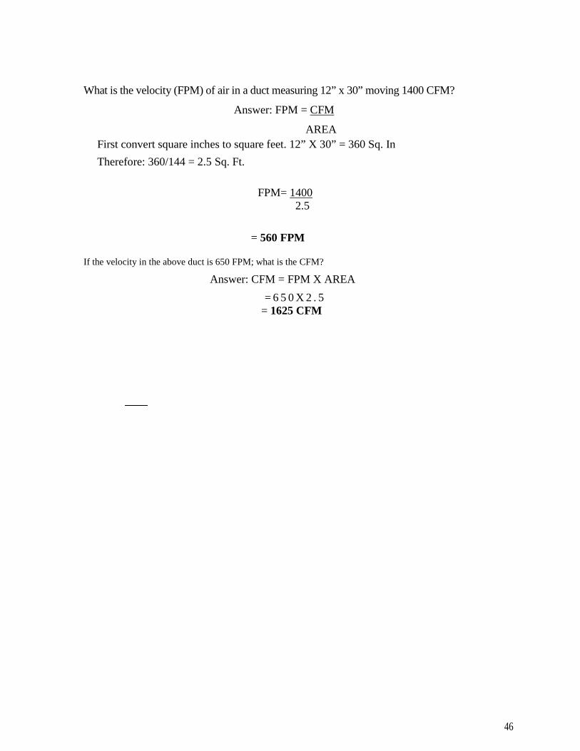
46
What is the velocity (FPM) of air in a duct measuring 12” x 30” moving 1400 CFM?
Answer: FPM = CFM
AREA
First convert square inches to square feet. 12” X 30” = 360 Sq. In
Therefore: 360/144 = 2.5 Sq. Ft.
FPM= 14002.5
= 560 FPM
If the velocity in the above duct is 650 FPM; what is the CFM?
Answer: CFM = FPM X AREA
= 6 5 0 X 2 . 5= 1625 CFM

47
Copyright ©2006This manual is the sole property of Energy Marketing Services. No part of thismanual may be reproduced in any form or by any means without express writtenpermission by the owner.
ENERGY MARKETING SERVICES
374 CATTLELOT LANEBELHAVEN, NC 27810
252-341-5028
www.johnrwhite.net
Accounting and Business Math Made Easy
One of the most dreaded and toughest courses in school is accounting. Accounting ranksup there with chemistry and physics. Fact is, if you can get your thought process startedoff right, then, accounting becomes not only easy, it becomes completely logical. Onceyou see the light you’ll wonder why anyone would find accounting difficult. This little e-book is going to start you from the very beginning. So let’s get started
CASH
Cash is where accounting begins and ends. You debit cash when you receive it and youcredit cash when you spend it. All other accounting entries depend on their relationshipto CASH. Allow me give you an example; Joey has just started a yo-yo company with$2000 dollars. His accounting entry will be $2000 in the debit column (left side) of hiscash account. One rule of accounting says, for every debit there must be a credit (right

48
column) and vice versa, therefore, if he borrowed the money to get started he will have tocredit accounts payable. If he had the money, perhaps from savings he would creditowner’s equity. Nevertheless, he must credit something. For the purpose of ourdiscussion we will say he borrowed the money, therefore he will credit accounts payable.
At this point if Joey were to prepare a balance sheet (a statement listing assets, liabilitiesand owner’s equity) he would show zero equity, his total assets are $2000 cash and histotal liabilities are $2000 accounts payable. Assets minus liabilities equal owner’sequity. The only way his equity will change is if he does some business. If he doesthings right he will make a profit, if not, he will suffer a loss. Owner’s equity can beeither a plus or minus figure.
Assets are items you own. Liabilities are items you owe.
Remember, when you receive cash you debit the cash account and always credit the itemyou received cash for. When you spend cash you credit the cash account and debit the itemyou paid for.
How does Joey keep up with his daily sales and expenses? In a journal. Joey has twojournals; a cash receipts journal and a cash disbursement journal. A journal is a bookwith a bunch of columns for listing accounts. For example, when he pays the light bill heuses the cash disbursement journal. He will enter the amount paid in the credit side underthe cash column and the debit side under the utility column.
Joey rents a building, purchases fire insurance, installs a telephone, buys an ad in a trademagazine, gets the lights turned on and hires a secretary/bookkeeper. All these expensesare necessary to run his business. Because these expenses are necessary whether ornot he does any business they are called overhead expenses.
Expenses are all costs associated with doing business. If the expense increases ordecreases directly with sales then it is a direct or variable expense. If the expenseremains constant regardless of sales volume then it is a fixed or overhead expense.
How does Joey make his accounting entries for these initial expenses? Up until now hehas only two accounts, cash and accounts payable. Now he has incurred newexpenses, each of which will require a separate account. Let’s see how they will be setup.
Rent- The rent is $150 per month with a $150 security deposit. This transactionrequires two accounts; (1) rent expense and (2) security deposit. When Joey pay’s thetotal $300 he will credit cash (he’s taking money out of the cash account) and debitrent expense for $150 and security deposit for $150. Why two separate accounts?Because the rent is an expense but the security deposit is an asset; it is yourmoney; it’s just been moved into the landlords account
Insurance- Joey’s insurance cost is $360 per year and he must pay for it up front. Hewill again credit his cash account for $360 because he had to write the check. Again hemust set up two insurance accounts to debit. One account is called insuranceexpense the other is called prepaid insurance. What’s the difference? When Joeyfirst buys the insurance he does not use it all at one time, he uses it at the rate of $30per month. Therefore his initial entry would be a $360 debt to prepaid insurance,which is an asset account. Insurance expense will remain at $0 At the end of themonth he will credit prepaid insurance for $30 and debit insurance expense for $30.
49
After four months his total insurance expense will be $120 and his prepaid insurance(asset) will be reduced to a balance of $240.
Items such as stamps and stationary, although technically can be prepaid assets areconsidered expenses and do not require prepaid accounts.
Lights and telephone- If, Joey has to pay a deposit to have these items turned on thenthe deposit will be a credit to cash and a debit to security deposit. Remember securitydeposit is an asset not an expense. At the end of the month when the first bills comein, the transaction will be a credit to cash and a debit to lights and telephone expenserespectively.
Advertising- The ad Joey bought costs $480 and the ad agency is offering 30 day’scredit. Since no cash has been exchanged yet, the entry will not affect the cash account,however the advertising expense has been incurred. Therefore, advertising expense must bedebited and as stated earlier, for every debit there must be a credit. So what will we credit?Accounts payable (a liability) is the answer. At the end of the month Joey will pay thead bill, cash will be credited and accounts payable will be debited, leaving a zero balance.Advertising expense will be left untouched with a $480 debit balance
Secretary/bookkeeper- this person is an administrative expense, also part of thecompany overhead. If the secretary is paid $400, cash is credited for $400 and officesalaries are debited for $400.
As you may see by now, anytime cash is spent it is credited and, whatever the cash ispaying for, is debited. The debited account can be either an expense or an asset.
Let’s see what happens when Joey starts doing some business.Joey receives his first order from Acme Toys for $200 worth of yo-yos. Did hereceive cash? No, it’s just an order. The only thing he can do with an order is make anote that it needs to be filled but there is no accounting entry. Joey does, however, needto buy some wood, strings, clue and a lathe to produce the yo-yos. The bank finances alathe for $10,000 at $300 per month he charges $75 worth of wood and clue and pays$10 cash for string. What do his entries look like?
The day the lathe is delivered he creates an asset account called lathe and debits it for$10,000. Since he has not yet made any payments to the bank he will credit notespayable account (this is an account payable, but over time) for $10,000. At the end of themonth he will make a payment, which must be split between interest and principal. Letssay the first payment of $300 contained $75 interest. Therefore his entry will be $300credit to cash, $75 debit to interest expense and $225 debit to notes payable.
The lathe is an asset. Because it is a relatively expensive item with a relatively longservice life it is capitalized, which means it may be depreciated over its useful life.Smaller, less expensive tools may be treated as expenses.
The $75 he charged for wood and glue will be entered as a debit to materials accountand a credit to accounts payable and the $10 for string will be a debit to materialsaccount and a credit to cash.
A few days later Joey has produced the order and shipped them out to Acme Toys.The secretary makes out an invoice (bill) and sends it to Acme. The bookkeeper enters a

50
$200 debit in the accounts receivable account and credits sales (revenue). When Acmepays the bill, Joey’s bookkeeper will debit cash and credit accounts receivables. Thesales account will remain untouched as a sale is a sale, and a sale is made whether it ispaid for or not. Below are sample journal entries of Joey’s business.
GENERAL JOURNAL
date description debit credit
2/5/2007cashaccounts payable (loan from Uncle
Bob)2/7/2007cash
rent expense2/10/2007cash
2000
150
2000150
360
prepaid insurance 3602/10/2007 cash 50
utility deposit 502/10/2007 cash 100
telephone deposit 10012/12/2007 account payable 480
advertising expense 48012/12/2007 cash 400
salaries 40012/20/2007 cash 10,000
notes payable (loan from ABC bank) 10,00012/20/2007 cash 10,000
equipment (lathe) 10,0002/24/2007 accounts receivable (Acme Toys) 200
sales 200
3/1/2007 cash 100account payable (Uncle Bob) 90interest expense 10
3/1/2007 cash 300notes payable (ABC Bank) 225interest expense 75
3/10/2007 cash 200
accounts receivable (Acme Toys) 200
After a few months in business Joey is beginning to realize that he can’t keep up withwho owes him and whom he owes. The bookkeeper suggests he start keeping ledgers.Ledgers are books that contain a page (ledger sheet) for each individual creditor(accounts payable ledger) and each individual customer (accounts receivable ledger).At the end of each day, or with some businesses, each week or month, the bookkeeperwill transfer the information in the journal to a ledger. Accounts receivable is an
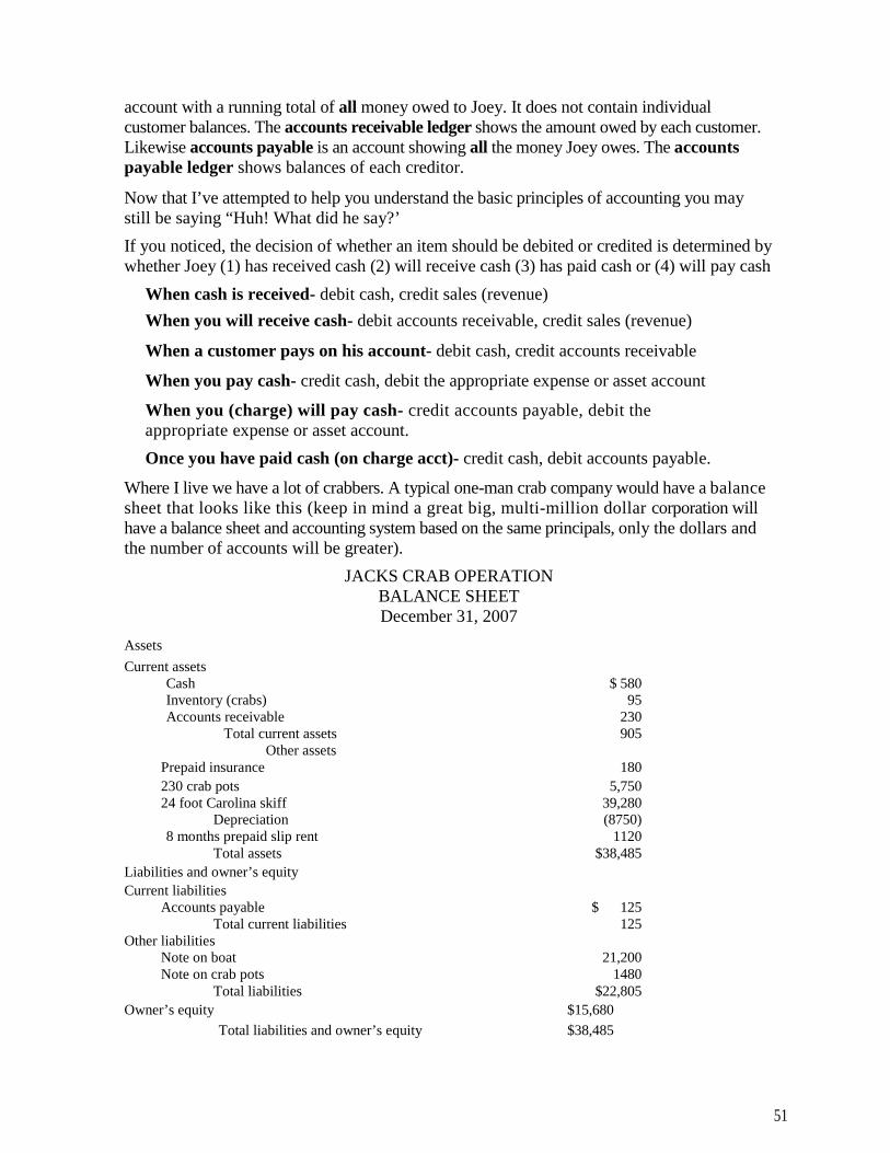
51
account with a running total of all money owed to Joey. It does not contain individualcustomer balances. The accounts receivable ledger shows the amount owed by each customer.Likewise accounts payable is an account showing all the money Joey owes. The accountspayable ledger shows balances of each creditor.
Now that I’ve attempted to help you understand the basic principles of accounting you maystill be saying “Huh! What did he say?’
If you noticed, the decision of whether an item should be debited or credited is determined bywhether Joey (1) has received cash (2) will receive cash (3) has paid cash or (4) will pay cash
When cash is received- debit cash, credit sales (revenue)
When you will receive cash- debit accounts receivable, credit sales (revenue)
When a customer pays on his account- debit cash, credit accounts receivable
When you pay cash- credit cash, debit the appropriate expense or asset account
When you (charge) will pay cash- credit accounts payable, debit theappropriate expense or asset account.
Once you have paid cash (on charge acct)- credit cash, debit accounts payable.
Where I live we have a lot of crabbers. A typical one-man crab company would have a balancesheet that looks like this (keep in mind a great big, multi-million dollar corporation willhave a balance sheet and accounting system based on the same principals, only the dollars andthe number of accounts will be greater).
JACKS CRAB OPERATIONBALANCE SHEETDecember 31, 2007
Assets
Current assetsCash $ 580Inventory (crabs) 95Accounts receivable 230
Total current assets 905Other assets
Prepaid insurance 180
230 crab pots 5,75024 foot Carolina skiff 39,280
Depreciation (8750)8 months prepaid slip rent 1120
Total assets $38,485
Liabilities and owner’s equity
Current liabilitiesAccounts payable $ 125
Total current liabilities 125Other liabilities
Note on boat 21,200Note on crab pots 1480
Total liabilities $22,805
Owner’s equity $15,680
Total liabilities and owner’s equity $38,485

52
A balance sheet tells how much you own (assets), how much you owe (liabilities) andhow much your worth (owners equity). When borrowing money, the lender is mostinterested in your current asset to current liability ratio. According to Jack’s balancesheet, his ratio is 7.24:1, which is very good ($905/$ 125). If this ratio ever becomes lessthan 1:1 it might be time to bail out, as Jack will not be able to meet his currentobligations.
The income statement would look like this.
JACKS CRAB OPERATIONINCOME STATEMENT
Dec. 31, 2007
$2250900480
$32,300
SalesDirect costs
Fuel and oilBait
Misc. suppliesCost of goods sold
3630
100%
11.2%
700890032012516701920
OverheadSlip rentDepreciationInsuranceLicensesRepairsInterest
Total overheadTotal costs and overhead
Income from operationsOther income
Gain on sale of boatIncome before taxes
Income taxes
13,63517,26514,035
17,4354360
3400
42.2%53.5%43.5%
54%
Net income
13,075 40.5%
Notice the percentages to the right. Each represents a percentage of total sales (revenue).For example, overhead equals 42.2% of sales ($13635/$32,300). When we talk aboutpercentages in business they are generally expressed as percent of sales. When abusinessperson says his gross profit is 28%, he means 28% of total sales. Therefore, if histotal sales were $150,000, then his gross profit would be $42,000 ($150,000 x .28).
Using data taken from the balance sheet and income statement, a number of otherfinancial ratios can be determined. Two important ratios are:

53
Debt-to-Equity
= Total liabilities/owner’s equity
= $22,805/$ 15,680= 1.45 (this means Jack owes 1.45 times more than he is worth)
Return-on-Investment
= Net income/assets=$13,075/$3 8,485= .40 or 40% (this tells Jack he is making the equivalent to 40% interest on hisinvestment)
How to price ajob and stay in business
This is perhaps the most important section of this book. If you do not make a profit youdo not stay in business. Before we talk about profit, let’s talk about pricing. The price of aproduct is dictated, in a capitalistic world, by supply and demand. When supply is high anddemand is low the price is low and when the supply is low and demand is high the priceis high. If you’re fortunate enough to offer a product with low supply and high demandthen you may charge whatever the market will bare. If, however, your product falls intothe mature product category where demand is high or good and supply is high or goodthen your price may very well be dictated not by you but by the going market price.Unfortunately, in a mature market there are competitors whom will offer their goodsat prices below their costs in order to increase sales. Eventually their business fails, butnot before establishing a new low benchmark for your products price.Industries dominated by small businesses are the most susceptible failure due to softprices because most small business owners do not understand or will not accept the factthat there is a break even point in pricing and when that point is reached it’s time toreevaluate your business strategy. Large companies, Proctor and Gamble for example,are vying for market share just like the little guy’s, the difference is, they have an army ofcost accountants that are constantly keeping an eye on the break even point. If they gettoo close to the break-even point with price they will use another marketing gimmick togain share such as change packaging or make it new and improved, but they will notlower the price below break even. P&G’s competitors are just as business savvy; theyalso know that products cannot be sold below cost and still stay in business. Thereforethe large companies rarely are put out of business because of price wars.
So, how do you price ajob or product in a competitive market?
Know your product cost
In Joey’s yo-yo business let’s say he has $1.00 in labor and material per yo-yo.
Know your overhead %
Joey’s income statement from last year showed 15% overhead
Know what % profit will make you happy
For our example, Joey feels like 12% is the minimum profit hewill accept
The calculationWhat does the sales price have to be to cover Joey’s overhead and profit? Solution:
1. He knows the material and labor cost per yo-yo is $1.00
2. Joey’s overhead + profit = 27%

54
3. Therefore, he must mark-up his yo-yo 27% in order to cover cost andoverhead.
Most readers (99%) would say, “Well, this is simple, just multiply $1.00 x .27then add the answer to $1.00 or simply multiply $1.00 x 127%, either way the salesprice will be $1.27”. WRONG! Don’t believe me? Ok, then give me a 25% discount,after all your still making 2%. Try it; see what happens. If your math is correct youwill be selling the yo-yo for about $.95 which means you’re going to lose about anickel instead of making 2 cents. Why? Because the sale price was figured as apercentage of cost ($1.00) not sales
Remember all financial percentages used in business are percentages of salesnot cost.
The correct method
The following is the correct method for figuring a sales price. We are not going to gointo the where and why, just remember this for the exam.
Always start off with 100%Deduct the percent you need to cover overhead and profit (27%)This leaves 73% (100% - 27% = 73%)Divide the cost ($1.00) by 73%1.00/.73 = $1.37 sales price
Joey will sell his yo-yos for $1.37 each. If the market will not bear this price then heneeds to find something else to do for a living, unless he swallows his pride and takes asmaller percentage of profit.
The above formula should be used to figure all jobs. For example if you pay $1750 for aheat pump, $850 for ductwork, $1200 labor, and $50 for a permit. Your overhead is20% and you wish to make 25% profit what price would you sell the job for.
1 .00- .20- .25=.55
Total cost of job = $3850
Sales price = $3850/.55
Sales price = $7000
Let’s have some more fun with numbers and percentages now that you’regetting the hang of it.
What would your annual sales have to be if you are selling a product with a 15% profitand you need to make $75,000?
Solution: $75,000
.15= $500,000

55
Suppose you raise your price 5% and make 20% profit?
Solution $75,000
.20
= $375,000
Moral of the story: Raise your price a little bit and do a whole lot less work. Loweryour price a little bit and do a whole lot more work.
Payroll
Below are some examples and explanations of payroll calculations. For this discussion Iwill use Willie as my payroll guinea pig.
Willie earns $12.00 per hour, is married, claims 3 withholding allowances and is paidweekly. I will use a 2003 Circular E (federal income tax tables). Other years work thesame way; only the numbers have changed.
Before doing the math, we must understand the federal government’s Fair LaborStandards Act. This act mandates a minimum wage and dictates when overtime must bepaid.
Basically, overtime must be paid at a rate of 1 1/2 times the regular hourly wage if theemployee works over 40 hours in any one week. Willy’s overtime rate will be$18.00/hour. (12.00 X 1.5 = 18.00)
If Willie works 40 hours, his pay will be $480 ($12 x 40= $480)
If Willie works 48 hours, his pay will be $624 ($12 x 40 plus $18 x 8 = $624)
If Willie puts in 40 hours during Thanksgiving week and works on Thanksgiving Day, apaid holiday, he will be paid for 48 hours, but only straight time; $576 ($12 x 48= $576)
An employee must physically work over 40 hours per week to get overtime pay. If Willieworks a 12-hour day he will only be paid straight time. The law has no restriction on thenumber of hours worked per day, just per week. A week is 168 consecutive hours.
If Willie takes a day off this week to go fishing (works 32 hours) and makes his time upnext week (works 48 hours) then he must be paid 8 hours overtime. The law says anemployee cannot work more than 40 per week, period, without paying overtime.

56
Circular E
Three federal deductions are taken out of Willie’s check; income tax, social security, andMedicare. Income tax is computed using the above schedule in Circular E. Socialsecurity is calculated as 6.2% of income. Once Willie earns $94,200 for the year, he willno longer have to pay social security (2006 figures). Medicare is calculated as 1.45% ofhis income with no limit. In addition to federal taxes, state income taxes are alsodeducted (check with your state for tax rate).
Example:
Willie works 42 hours for the week. The state income tax rate is 7%. What is his takehome pay?
40 hours regular time X $12.00 = $480
2 hours overtime X $18.00 = $ 36
Total pay =$516

57
Federal income tax – Using the circular E schedule above, locate the column at the toplabeled 3 allowances, go down the column until you reach the row 5 10-520 and you willsee $22 as the tax amount of tax to withhold.
Social security – Obviously, Willie has not made $94,200 this year, therefore his socialsecurity will be 6.2% of $516.
(Social security) .062 X $516 = $31.99
(Medicare) .0145X$516= 7.48(Federal tax) see circular E 22.00(Statetax) .07x$516= 36.12
All four withholdings add up to $97.59, which is deducted from his check.
Weeklypay $516.00Total withholdings - 97.59Take home pay $418.41
There are certain taxes related to the employee’s income that the employer must pay.These include:
Social security – The social security rate is actually 12.4%. The employee pays half andthe employer pays half (6.2% each)
Medicare – The Medicare rate is actually 2.9%. The employee pays half and theemployer pays half (1.45% each).
Federal unemployment tax (FUTA) - .8% of the first $7000 of employee’s salary. Thisis paid once a year by the employer and may not be deducted from the employee’s pay.If FUTA is not paid on time then the rate is 6.2%
State unemployment tax – This varies state-by-state and must be paid by the employerand may not be deducted from the employee’s salary.
Where and when does the employer deposit the funds withheld from employees?
FICA funds (social security and Medicare) and federal income taxes withheld must bedeposited in a federal depository bank or Electronic Federal Tax Payment system(EFTPS). Most major banks are federal depository banks. The frequency at witch thefunds must be deposited is based on the total amounts withheld from all employees.Circular E gives instructions on when deposits must be made.
Unemployment taxes are sent to their respective agency.
Untimely payments are subject to penalties; some may be substantial. These penaltiesare outlined in Circular E.
A payroll journal should be maintained to account for the total withholding moneys anda payroll ledger should be maintained to keep a record of each employee’s wages andwithholdings.

58
Administration and Laws
This manual does not attempt to discuss or explain administrative rules, state or federallaws, as the reference material is pretty much cut and dry. You should be able to look upthe answers during the test.
One caution; take note of the current names of the insurance commissioner, council andcommittee members found at the beginning of the Administrative Code.
Questions regarding state laws will be from the Boards Laws and Rules book, theadministrative code and the first chapter of all other codebooks. Question regarding federallaws and state laws will be found in the Business Project Management for Contractorsbook.
International Residential Building Code
Almost all test questions pertaining to this code will come from Section N1 103,paragraphs N1 1 03. 1, N1 1 03.2 and N1 1 03.3 and Table N1 1 03. 1. The sections stateResidential heat pump control requirements, duct insulation requirements and a table ofminimum efficiency requirements. Do not use insulation and control requirements statedin the Energy Code for residential applications. The Energy Code is for commercialapplications.
What is the minimum SEER rating for a packaged air conditioner?
The answer is not 13 or 10, look it up in Table N1 103.1, Residential Building Code.
INTERNATIONAL ENERGY CODE
Almost all questions pertaining to this code will come from Section 503. Therequirements of this code are for commercial applications. Residential controls, ductand pipe insulation requirements are in the NC residential building code.
Things to look out for:
1. Read paragraph 503.3.2.2. These requirements are for commercial installationsonly
2. There are two tables labeled Minimum Pipe Insulation. Use table 503.3.3.3 todetermine R-value requirements for ductwork. The TD is >40.

59
INTERNATIONAL MECHANICAL CODE
Attempting to memorize the code at this time could test your sanity, however you mustread and highlight it. When reading the code, you may not remember the minimum sizescreen needed to protect outdoor intake openings or how far off the ground a duct shouldbe, but you will know there is a code requirement. Only time and experience will makeyou an authority. You will be supplied plenty of time
Most items in the Mechanical Code are self-explanatory. Below we will discuss a fewthings that may give you trouble.
Outdoor ventilation
All buildings, including residences require a certain amount of outdoor ventilation,measured in CFM. Turn to Table 403.3. Locate conference rooms in the Officecategory. To the right you will see the estimated maximum occupancy of 50 people per1000 square feet, and the required CFM of outdoor air per person to be 20.
A question might be: How many outdoor CFM are required to ventilate a 1500 sq. ft.office conference room?
Solution: The code says figure 50 people per 1000 sq. ft., we have 1500 sq. ft. Therefore,the room will hold 1 1/2 times 50, or 75 people total.
1500/1000= 1.5
1.5 X 50 people=7520 CFM is required for each person.
20 X 75=1500CFM
Domestic clothes dryers (504.6)According to the requirements of the code is a 30 ft. rigid dry vent will two 90-degreebends allowed?
Answer: No. The section states, the maximum length cannot exceed 45 ft., less 10 ft. foreach 90 degree bend (+45-10-10 = 25ft.). 25 ft. is the longest the vent is allowed.
Medium-duty cooking appliance exhaust hood (507.13.3)
How many CFM is required for a 4’ X 6’ island hood? Hood is 6’ long.
Answer: 3000 CFM
A single island canopy requires 500 CFM per linear foot. The hood is 6 linear feet,thus 6’ X 500 CFM = 3000CFM

60
Return air intakes (918.10)
1. May a 16” x 20” return air grille with 75% free area be used on an 800CFM system?
Answer: No, the velocity is too high, see belowA 16” x 20” grille has 320 sq. inches: only 240 sq, in is free area (320 x .75 = 240)
240 sq. in. / 144 sq. in. = 1.67 sq. ft.
Velocity = CFMAREA (area in sq. ft.)
800 cfm1.67 Sq. Ft. = 479 feet per minute (FPM)
Code says face velocity cannot be greater than 450 FPM
2.How many 10”, 16’ on center joists must be panned to handle 1200 CFM ofreturn air.
Answer: 3
Each joist can handle up to 525 CFM 1200/525 = 2.28 joists
INTERNATIONAL FUEL GAS CODE
Confined and unconfined spaces (Definitions)In the Definition chapter, look up confined and unconfined space.
According to the definition, is a room measuring 10’ x 10’ x 8’high with two 60,000BTUH furnaces confined or unconfined?
Answer: confined, less than 50 cu. ft. per 1000 BTUH
1. divide the total btuh by 50, this give the cubic ft. limit.120,000 = 2400
50I f t h e r o o m i s l e s s t h a n 2 4 0 0 c u . f t t h e n i t i s a
conf ined space . More than 2400 cu. f t , an unconf inedspace
T h e r o o m i s 1 0 x 1 0 x 8 = 8 0 0 c u . f t . , t h e r e f o r e i t i sconfined
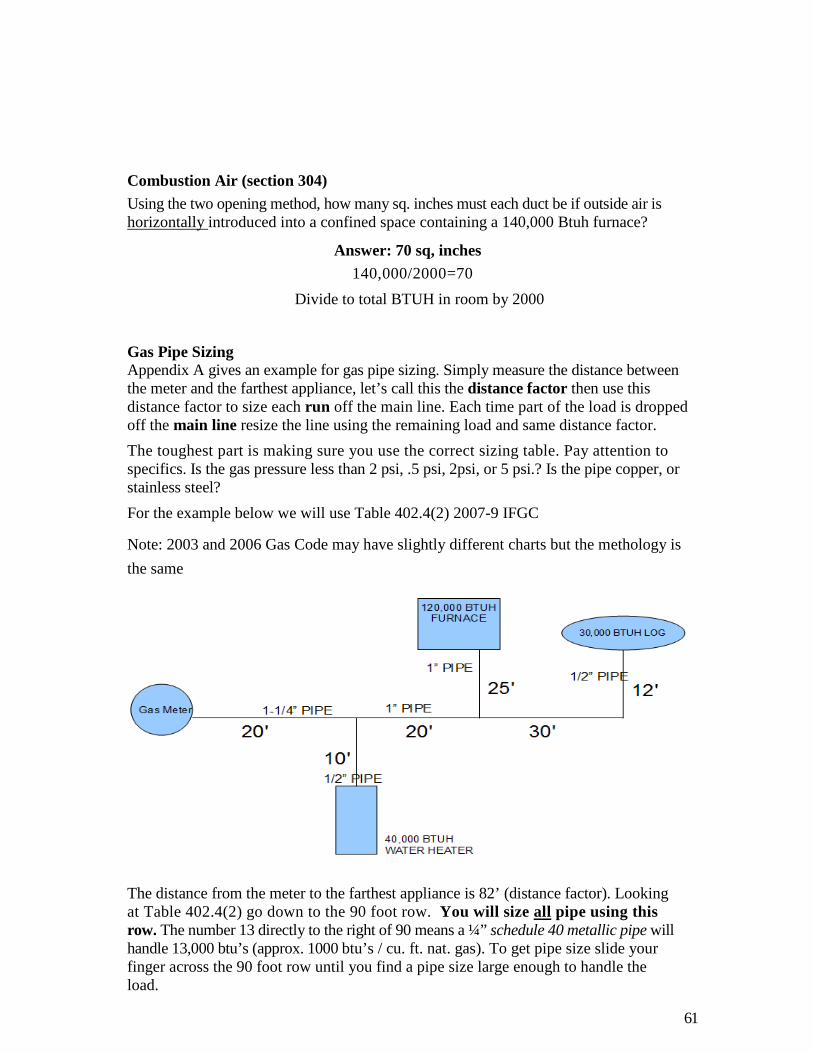
61
Combustion Air (section 304)
Using the two opening method, how many sq. inches must each duct be if outside air ishorizontally introduced into a confined space containing a 140,000 Btuh furnace?
Answer: 70 sq, inches
140,000/2000=70
Divide to total BTUH in room by 2000
Gas Pipe SizingAppendix A gives an example for gas pipe sizing. Simply measure the distance betweenthe meter and the farthest appliance, let’s call this the distance factor then use thisdistance factor to size each run off the main line. Each time part of the load is droppedoff the main line resize the line using the remaining load and same distance factor.
The toughest part is making sure you use the correct sizing table. Pay attention tospecifics. Is the gas pressure less than 2 psi, .5 psi, 2psi, or 5 psi.? Is the pipe copper, orstainless steel?
For the example below we will use Table 402.4(2) 2007-9 IFGC
Note: 2003 and 2006 Gas Code may have slightly different charts but the methology is
the same
The distance from the meter to the farthest appliance is 82’ (distance factor). Lookingat Table 402.4(2) go down to the 90 foot row. You will size all pipe using thisrow. The number 13 directly to the right of 90 means a ¼” schedule 40 metallic pipe willhandle 13,000 btu’s (approx. 1000 btu’s / cu. ft. nat. gas). To get pipe size slide yourfinger across the 90 foot row until you find a pipe size large enough to handle theload.

62
To size the main
Beginning at the meter the first 20’ must handle the entire system load, 210,000 btuh
Thus the pipe must be 1-1/4” ( good for 430,000btuh)
After dropping off the water heater load the next 20’ must handle 150,000 btuh.
Thus the pipe must be 1” (good for 205,000 btuh)
After dropping of the furnace the remaining 42’ must only handle the gas log, 30,000btuh.
Thus, the pipe must be 1/2” (good for 53,000 btuh)
To size the runs off the main
The 10’ pipe between the main and water heater must handle 40,000 btuh.
Thus, the pipe must be ½” (good for 53,000 bthu). Remember to stay on the 90 footrow
The 25’ pipe between the main and the furnace must handle 120,000 btuh.
Thus, the pipe must be 1” (good for 205,000 btuh)
Size L-P gas piping the same way once you’ve passed the second stage regulator.To size between the first stage regulator (at the tank) and the secondstage regulator (at the house), use the distance between regulators as the distancefactor and size according to total connected load. Be sure to read and use the correctsizing Tables.
Venting (section 503)
Look at paragraph 503.5.4 and figure 503.5.4. This requirement is for chimneysand single wall vents.
Look at figure 503.6.6. This requirement is for UL listed B and BW vents
Single appliance -Table 504.2(1) Sizing vents
What size vent is needed for a 160,000 BTU} I naturally ventilated appliance if thetotal vent height is 18’ and the lateral 2’?
Under the height column you have to choose either 15’ or 20’. Remember this, thetaller the vent the more capacity it has, therefore, if the 20’ row is used the vent maybe under sized. Always use the shorter height. In this case use 15’. Now use the2’ lateral and select a vent size under NAT. A 5” vent will handle only 129,000BTUH, while a 6” vent will handle 225,000 BTU} I, therefore select a 6” vent.
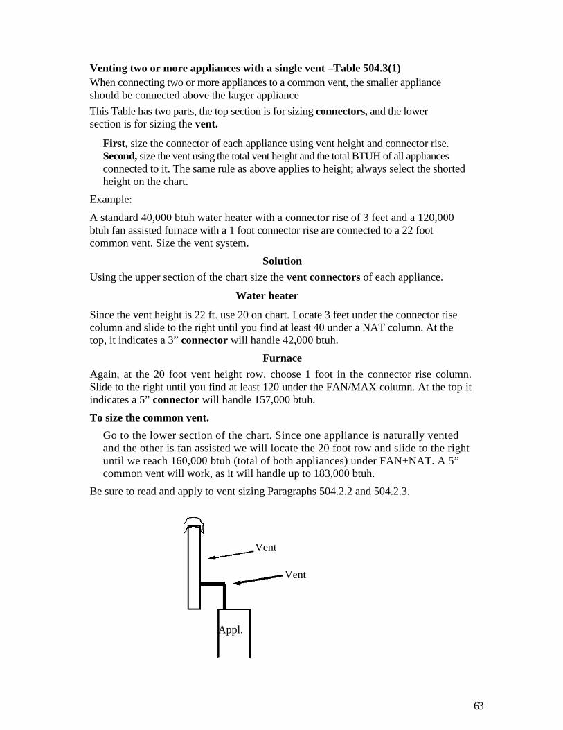
63
Venting two or more appliances with a single vent –Table 504.3(1)
When connecting two or more appliances to a common vent, the smaller applianceshould be connected above the larger appliance
This Table has two parts, the top section is for sizing connectors, and the lowersection is for sizing the vent.
First, size the connector of each appliance using vent height and connector rise.Second, size the vent using the total vent height and the total BTUH of all appliancesconnected to it. The same rule as above applies to height; always select the shortedheight on the chart.
Example:
A standard 40,000 btuh water heater with a connector rise of 3 feet and a 120,000btuh fan assisted furnace with a 1 foot connector rise are connected to a 22 footcommon vent. Size the vent system.
Solution
Using the upper section of the chart size the vent connectors of each appliance.
Water heater
Since the vent height is 22 ft. use 20 on chart. Locate 3 feet under the connector risecolumn and slide to the right until you find at least 40 under a NAT column. At thetop, it indicates a 3” connector will handle 42,000 btuh.
Furnace
Again, at the 20 foot vent height row, choose 1 foot in the connector rise column.Slide to the right until you find at least 120 under the FAN/MAX column. At the top itindicates a 5” connector will handle 157,000 btuh.
To size the common vent.
Go to the lower section of the chart. Since one appliance is naturally ventedand the other is fan assisted we will locate the 20 foot row and slide to the rightuntil we reach 160,000 btuh (total of both appliances) under FAN+NAT. A 5”common vent will work, as it will handle up to 183,000 btuh.
Be sure to read and apply to vent sizing Paragraphs 504.2.2 and 504.2.3.
Vent
Ventconnector
Appl.

64
EXAMPRACTICE QUESTIONS
1. A LICENSEE MAY HAVE HIS LICENCE REVOKED FOR WHICH OF THEFOLLOWING
A. MISCONDUCTB. GROSS NEGLIGENCEC. INCOMPETENCYD. ANYOFTHEABOVE
2. IF A CONTRACTOR WORKS ON 15% NET PROFIT, WHAT WILL HISSALES HAVE TO BE TO MAKE $75,000?
A. $500,000B. $112,500C. $862.500D. $600,000
3. A CONTRATORS PAYS $750.00 FOR A FURNACE PLUS 7% SALES TAX.WHAT WILL HIS SALES PRICE BE IF HE WISHES TO MAKE 30% GROSSPROFIT
A. $1028B. $1043C. $975D. $1146
4. THE MINIMUM THICKNESS OF REFRIGERATNT LINE INSULATIONFORA RESIDENCE IS
A. 1/4”B. 3/8”C. 1/2”D. 5/8’
5. THE DISTANCE FROM A METER TO A NATURAL GAS WATER HEATER(40,000 BTUH) IS30 FEET, 20 FEET FURTHER DOWN THE LINE ISAFURNACE (120,000BTUH). WHAT IS THE MINIMUM PIPE SIZE THATMUST BE USED BETWEEN THE WATER HEATER AND FURNACE?(PRESSURE DROP =.05)
A. 3/8”B. 1/2”C. 3/4”D. 1”

6. A HOUSE HAS A HEAT LOSS OF 48,000 BTUH AT 20 DEGREEOUTDOOR TEMPERATURE. WHAT IS THE HEAT LOSS AT 40 DEGREEOUTDOOR TEMPERATURE?
A. 24.000 BTUHB. 28,800 BTUHC. 19,200 BTUHD. 18,000 BTUH
7. A CEILING HAS A TOTAL U VALUE OF .O7. WHAT IS THE NEW RVALUE IF R 19IS ADDED?
A. 30B. 31C. 32D. 33
8. A 30’ X 8’ PARTITION (2 X 4 STUDS, GYPSUM ON BOTH SIDES. NOINSULATION)SEPARATESTWOROOMSHAVINGATEMPERATUREDIFFERENCE OF 20 DEGREES. WHAT IS THE WINTER HEAT LOSSTHROUGH THE PARTITION?
A. 15,360 BTUHB. 3,535 BTUHC. 1,500 BTUHD. 2,609 BTUH
9. A 75,000 BTUH (INPUT RATING) 80% EFFICIENT FURNACE HAS ATEMPERATUR RISE OF 45 DEGREES. WHAT IS THE CFM?
A. 1212B. 1667C. 1515D. 1175
10. A CUSTOMER MOVES UP FROM A 8 SEER TO A 14 SEER AIRCONDITIONER WHAT WOULD HIS YEARLY SAVINGS BE IF HE WASPAYING $650 PER YEAR FOR AIR CONDITIONING?
A. $325B. $260C. $197D. $279
11. A HEAT PUMP IN A RESIDENCE MUST BE CONTROLLED BY WHICHOF THE FOLLOWING
A. PROGRAMABLE THERMOSTATB. A DEVICE TO PREVENT ELECTRIC SUPPLEMENTARY
HEAT FROM COMING ON IF HEATPUMP CAN HANDLE THE LOAD ALONE
C. A DEVICE THAT ALLOWS SUPPLEMENTARY HEATOPERATION DURING DEFROST CYCLESEXCEEEDING 15 MINUTES
D. AFOSSILFUELKIT12. IN A ROOM THAT IS LARGE IN COMPARISION WITH THE SIZE OF
EQUIPMENT, AN APPLIANCE THAT REQUIRES 18” CLEARANCEON ITS SIDES MAY HAVE IT’S CLEARANCE REDUCED TO ___ “IF .024SHEETMETAL WITH A VENTILATED AIR SPACE IS USED TO PROTECT

THE COMBUSTIBLE SURFACE.A. 9”B. 6”C. 12”D. MAY NOT HAVE CLEARANCE REDUCED
13.WHATISTHEVELOCITYOFAIR1400CFMAIRINADUCTMEASURING 12” X 30”
A. 360FPMB. 467FPMC. 3.8FPMD. 560FPM
14.CATEGORYIEQUIPMENTMAYBEVENTEDWITHWHICHOFTHEFOLLOWING TYPE VENTS
A. SINGLE WALL METALB. TYPE BC. CHIMNEY WITH CLAY LINERD. ALL THE ABOVE
15. TWO NATURALLY VENTILATING APPLIANCES WITH A COMBINEDCAPACITY OF 128,000 BTUH ARE CONNECTED TO A COMMON B-VENT
18’ HIGH WITH TWO 90 DEGREE ELBOWS. WHAT SIZE COMMONVENT SHOULD BE USED?
A. 4”B. 5”C. 6”D. 7”
16. THE MAXIMUM ALLOWABLE HOIZONTAL LENGTH OF A CATEGORYI APPLIANCE VENT CONNECTOR IS_______FEET FOR EACH INCH OFIT’S DIAMETER.
A. 1/2
B. 1C. 1.5D. 2
17.THEMAXIMUMHORIZONTALLENGTHOFASINGLEWALLMETALCONNECTOR IS %OF THE HIEGHT OF THE CHIMNEY OR VENT.
A . 50B . 75C .100D .150
18. IN ORDER TO SUPPLY OUTDOOR COMBUSTION AIR USING THE TWOOPENING METHOD WITH HORIZONTAL DUCTS, WHAT SIZE WOULDEACH DUCT BE TO HANDLE A 140,000 BTUH FURNACE?A 7”X1 0”B .3.5”X1 0”C 14”X10”D .8.5”X10”
19. IF A GALLON OF OIL CONTAINING 140,000 BTUS SELLS FOR $1.25, HOWMUCH WILL 1,000,000 BTUS COST WHEN USED IN AN 80% AFUE OIL

D .15
FURNACE?A .$8.93B .$14.00
C .$12.78D .$11.16
20. IN WHICH OF THE FOLLOWING AREAS MAY A SINGLE WALLMOUNTED 4,000 BTUH UNVENTED GAS HEATER EQUIPED WITH ANOXYGEN DEPLETION SENSOR BE ALLOWED?
A. SLEEPING ROOMSB. BATHROOMC. STORAGE CLOSETD. SURGICAL ROOM
21. GAS APPLIANCE CONNECTORS SHALL NOT PASS THROUGH ANY OFTHE FOLLOWING EXCEPT:
A. WALLSB. APPLIANCE HOUSINGSC. FACTORY BUILT FIREPLACE INSERTSD. FLOORS
22. RECLAIMED REFRIGERANTS SHALL NOT BE REUSED IN ADIFFERENT OWNER’S EQUIPMENT UNLESS TESTED AND FOUND TOMEET THE PUITY REQUIREMENTS OF;
A. ASHRAE34B. NFPA54C. ASTMA53D. ARI700
23. AN AIR CONDITIONER HAS HIGH SUCTION AND LOWHEAD PRESSURES. WHAT WOULD BE A LIKELY CAUSE?
A. DIRTY FILTERSB. BAD OR WEAK COMPRESSOR VALVESC. CLOGED METERING DEVICED. DIRTY CONDENSER COIL
24. A HOUSE HAS A HEATING LOAD OF 46,800 BTUH. HOW MANYCFM ARE REQUIRED IN A ROOM WITH A LOAD OF 5200 BTUH,USING A FURNACE WITH A 1200 CFM BLOWER.
A 1112B 112
C 133D 468
25. WHAT IS THE DESIGN FRICTION RATE WHEN THE AVAILABLESTATIC
PRESSURE FOR THE DUCT SYSTEM IS .36 AND THE RUN WITH THELONGEST EFFECTIVE LENGTH IS 375 FT.
A .10B .08
C .05D .15
26. A BLOWER WITH AN EXTERNAL STATIC PRESSURE OF .55” WC ISCONNECTED TO A 70 FT. LONG DUCT. THE SYSTEM INCLUDESREGISTERS AND GRILLS (.03 “WC EACH), A COOLING COIL (.15” WC),
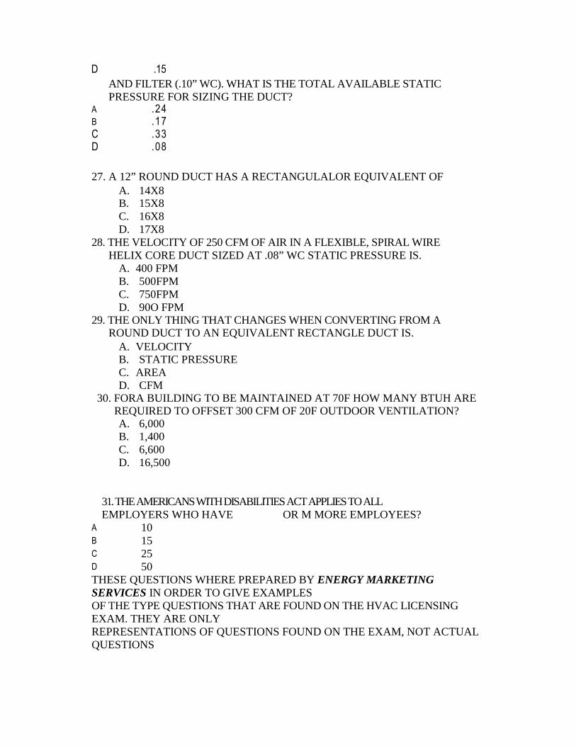
D .15
AND FILTER (.10” WC). WHAT IS THE TOTAL AVAILABLE STATICPRESSURE FOR SIZING THE DUCT?
A .24B .17C .33D .08
27. A 12” ROUND DUCT HAS A RECTANGULALOR EQUIVALENT OFA. 14X8B. 15X8C. 16X8D. 17X8
28. THE VELOCITY OF 250 CFM OF AIR IN A FLEXIBLE, SPIRAL WIREHELIX CORE DUCT SIZED AT .08” WC STATIC PRESSURE IS.
A. 400 FPMB. 500FPMC. 750FPMD. 90O FPM
29. THE ONLY THING THAT CHANGES WHEN CONVERTING FROM AROUND DUCT TO AN EQUIVALENT RECTANGLE DUCT IS.
A. VELOCITYB. STATIC PRESSUREC. AREAD. CFM
30. FORA BUILDING TO BE MAINTAINED AT 70F HOW MANY BTUH AREREQUIRED TO OFFSET 300 CFM OF 20F OUTDOOR VENTILATION?A. 6,000B. 1,400C. 6,600D. 16,500
31.THEAMERICANSWITHDISABILITIESACTAPPLIESTOALLEMPLOYERS WHO HAVE OR M MORE EMPLOYEES?
A . 10B . 15C . 25D . 50THESE QUESTIONS WHERE PREPARED BY ENERGY MARKETINGSERVICES IN ORDER TO GIVE EXAMPLESOF THE TYPE QUESTIONS THAT ARE FOUND ON THE HVAC LICENSINGEXAM. THEY ARE ONLYREPRESENTATIONS OF QUESTIONS FOUND ON THE EXAM, NOT ACTUALQUESTIONS

D .15
Answers to HVAC questions
1.D
2. A- $75,000 = $500,000.15
3. D- $750.00 cost
52.50 tax(.07x$750)$802.50 total cost1.00-.30= .70 802.50/.70=$1146.42
4. C- Residential building code Section N1 103.5, Table N1 102.5
5. C- Fuel Gas Code. Table 402.3 (2). The farthest appliance from the meter is 50Ft. (30 Ft. +20 Ft.= 50 Ft.). Use column labeled 50. The section between waterheater and furnace has to carry 120,000 BTUH (The water heater load has beendropped off). Go down the column until you find 120 (120,000) or greater. Youshould see 138 (138,000). To the right is 3/4”
6. B- At 20 degrees outdoor temperature the degree temperature difference (DTD)is 50 (70 indoor- 20 outdoor =50 DTD). Divide 48,000 BTUH by 50 DTD toget the heat loss per DTD (48,000/50 = 960 BTUH per DTD).At 40 degree outdoor temperature the DTD is 30(70 indoor –40 outdoor =30 DTD).Since the heat loss per DTD is 960 BTU, multiply 960 BTU x 30. 28,800 BTU isthe answer.
960 BTU per DTD x 30 DTD = 28,000 BTU
7. D- All U values must be converted to R values before adding or subtracting. Inthis case the U value (.07) must be converted to an R value.
R= 1= 1/.07= 14.2
14.28 (the old R value) + 19 (the added R value) = 33.28 (the new R value)
8. A partition is an inside wall separating rooms, therefore the surface air films on
each side of the wall are still. Go to Table 10, Manual J- No. 1c indicates the R
value for a non-reflective surface is .68 (there are two surfaces, one on each side of
partion). Between the gypsum is a 3.5" air space (no insulation), No. 2 (d) with an R
value of .94. The 1/2”gypsum, No. 4(d) has an R value of .45 (there are 2 pieces of
gypsum< one on ead side of the wall) . Therefore the total R value is 3.20
Heat Loss or BTUH = U x Area x TD
U = 1/R Area = length x height TD =20
= 1/3.20 = 30’x8’= .3125 =240 sq. ft.
.3125 x 240 x 20 = 1500 BTUH

9. A- The furnace is 80% efficient, therefore its output is 75,000 x .80 = 60,000 BTU= CFM X 1.1 X TD TD (Temp Diff.) is also TR (Temp Rise)
CFM= BTU /1.1 xTD
TD= BTU / 1.1 x CFM
Since we are asking for CFM, use the CFM formula.
CFM = 60,000 / (1.1 X 45)
= 60,00/49.5= 1212 CFM
10. D- old seer 8/ new seer 14 = .57.57 X $650 = $370.50
$650- $371 (rounded) = $279
11. B- Residential building code, Section N1 103.212. B- Mechanical Code Table 308.613. D- Velocity = CFM
AREA (Area must be in Sq. Ft.)
The area is 360 sq. inches (12” x 30” = 360 sq. inches)You must convert sq. inches to sq. feet, therefore:
360 sq. inches/144 sq. inched per sq. ft. = 2.5 sq. ft.
1400 CFM/ 2.5 sq.ft. = 560 FPM
14. D- See Table 503.4, Fuel Gas Code
15. C- In appendix B, look at figure B-12. It shows twoappliances connected to a common vent with one offset (two 90 degree bends).Now turn to section 504.3.5, Common vertical vent offset. This paragraphsays to reduce the capacities listed in the tables by 20 %. The lower section ofTable 504.3 (1), common vent capacity, is the table we’ll use to size thecommon vent. First, we have to determine which height to use, 15 ft. or 20ft. As stated earlier, if the height of a vent falls between two choices, use thelower choice (15 ft.). To the right of 15 ft., look under each NAT + NATcolumn until you see 128 (128,000) or greater. The chart indicates a 5” ventwill handle 144,000 btus, however, because of the offset, we must reducethis figure to 115, therefore a 6” vent must be chosen.
Note: Be sure to consult all paragraphs under Section 504, SIZING OFCATEGORY 1 APPLIANCE VENTING SYSTEMS before making afinal determination of vent sizes.
16 .C- Fuel Gas Code, 503.10.9
17. B-Fuel Gas Code, 504.3.2

18. A- Fuel Gas Code, 304.11.1
Calls for 1 sq. inch per 2000 BTUH for each duct
140,000btuh/2000 btu =70 sq. inches
2000
A 10” x 7” duct = 70 sq. inches
19.D1,000,000 = 7.14 gals.
140,000The oil furnace is 80% efficient, therefore:
7.14 gals. = 8.925 Gals..80
If oil sells for $1.25, therefore:$1.25 x 8.925 gals. = $11.16
20. B- Fuel Gas Code, 303.3, exception 3.21. C-Fuel Gas Code, 411.1.222. D- Mechanical Code, 1102.2.2.323.B
2 4 . C Room CFM = heating factor (HF) x roomheat loss
HF = FURNACE CFM / HOUSE HEAT LOSS
=1200 / 46,8000
= .0256Room CFM= .0256 x 5200 btuh= 133 CFM
2 5 . A Design static pressure = available static pressure x 100 Total effectivelength
= .36x100375
= 3 6375
= .096 (.10,roundedup)26. A-Available static pressure = external static pressure – total resistance of all added
components
External static pressure = .55 (from manufacturer's blower specs)
DEDUCT- registers- grilles-cooling coil- air filter
.03
.03
.15
.10
Available static pressure ( pressure left to design duct system = .24' wc

27. C-
Manual D, Chart 9 (You must use chart. Do not attempt to convert fromsquare to round mathematically).
Locate 8” (one side of duct) across the top; slide your finger down until you find16” (round duct size). Use 16.2”, the closest duct size in the chart, 15.8
is too small. Slide finger to left hand column and you will see 16” (the other sideof duct).
28. B-Be sure to use correct friction chart in Manual D. In this case it will be Chart 7(Flexible, Spiral Wire Helix Core Ducts). Locate .08 (static pressure) at bottom ofchart. Slide finger up to 250 CFM. Diagonal line indicates 500 FPM.
29. C- This is a tricky question. If a conversion chart is used then the area ofthe square or rectangular duct will be larger than the round duct, thuscompensating for the increased friction loss of square duct. If the areas are thesame for both round and square duct then the friction loss will be higher for thesquare duct, therefore the velocity, static pressure and cfm will be different.
30. D-BTUH=CFMx 1.1 xTD
= 300x1.1x(70-20)= 300x1.1x50
= 16,500 BTUH
31. B- Business Project Management for Contractors, page 7-4
