guide to implementing foundation h1 field devices 2014 fieldbus foundation oundation 3.2 foundation...
TRANSCRIPT

GUIDE TO IMPLEMENTING
FOUNDATION™ H1 FIELD DEVICES
1
Copyright 2014 Fieldbus Foundation
GUIDE TO
IMPLEMENTING FOUNDATION™ H1 FIELD DEVICES
EXECUTIVE SUMMARY FOUNDATION™ fieldbus is a digital fieldbus technology widely used in process automation applications. It provides advantages over legacy analog communication and is supported in an increasing number of field devices. Its functionality is defined by the FOUNDATION fieldbus specifications.
In this whitepaper, Softing discusses the individual hardware and software aspects of implementing a FOUNDATION H1 field device. While the traditional development approach is applicable to a wide range of target platforms, it results in a substantial effort and long implementation time if performed by the manufacturer. It also requires in-depth fieldbus expertise. As a consequence, field device manufacturers are typically interested in reducing the associated expenses and shortening their time-to-market. This goal can be reached by the following implementation approaches based on using pre-engineered hardware and software components.
SOLUTIONS FOR
FIELD DEVICE
MANUFACTURERS
FOUNDATION fieldbus technology has experienced significant growth worldwide. However, developing the fieldbus interface requires key expertise. Field device manufacturers need solutions for implementing FOUNDATION H1 technology in their products with manageable resources and impact.
Please share your comments and feedback with us. Just email us at [email protected]
2
Copyright 2014 Fieldbus Foundation
1 Introduction In the past, process automation devices were based on proprietary or analog communication technology. For instance, the communication made use of 4-20mA or HART technology. During recent years, however, an increasing number of installations have been implemented based on digital bus technologies such as FOUNDATION fieldbus.
The use of a digital fieldbus protocol provides a set of functional benefits, including the high-resolution measurement of values, accuracy and reliable data transmission. It is based on standardized object models and access methods. Diagnostic and maintenance capabilities, as well as asset monitoring and management functionality, also contribute to the advantages of digital fieldbus.
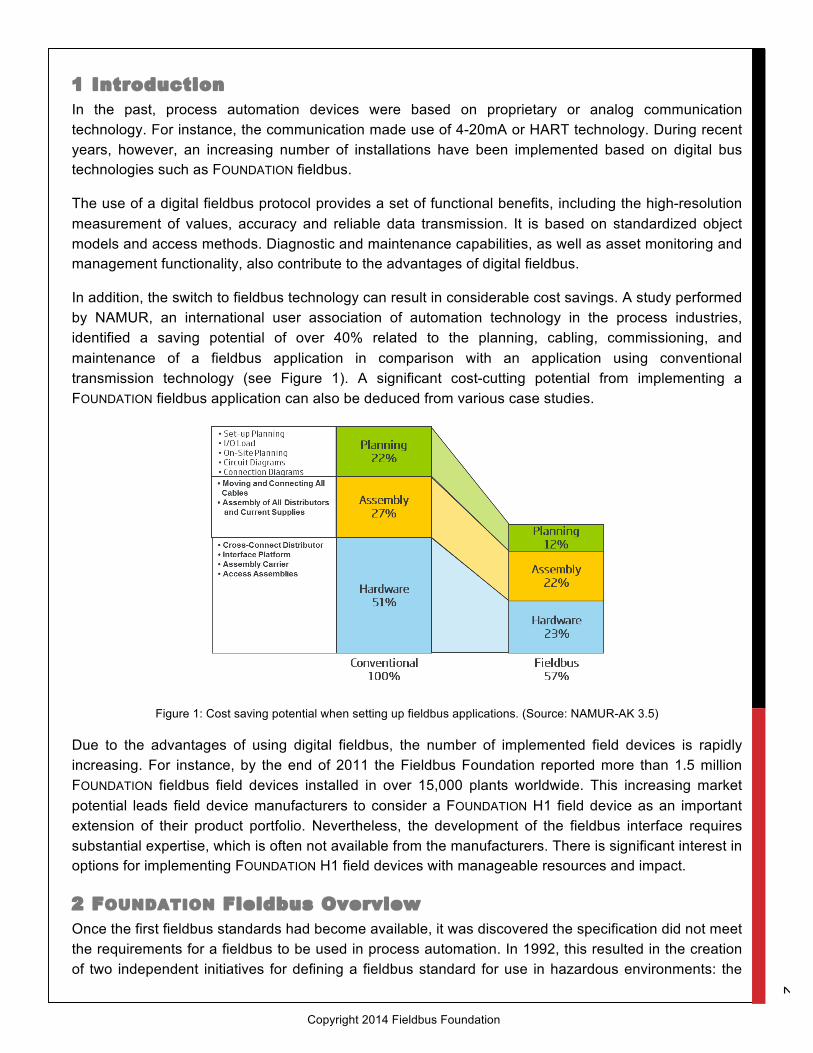
In addition, the switch to fieldbus technology can result in considerable cost savings. A study performed by NAMUR, an international user association of automation technology in the process industries, identified a saving potential of over 40% related to the planning, cabling, commissioning, and maintenance of a fieldbus application in comparison with an application using conventional transmission technology (see Figure 1). A significant cost-cutting potential from implementing a FOUNDATION fieldbus application can also be deduced from various case studies.
Figure 1: Cost saving potential when setting up fieldbus applications. (Source: NAMUR-AK 3.5)
Due to the advantages of using digital fieldbus, the number of implemented field devices is rapidly increasing. For instance, by the end of 2011 the Fieldbus Foundation reported more than 1.5 million FOUNDATION fieldbus field devices installed in over 15,000 plants worldwide. This increasing market potential leads field device manufacturers to consider a FOUNDATION H1 field device as an important extension of their product portfolio. Nevertheless, the development of the fieldbus interface requires substantial expertise, which is often not available from the manufacturers. There is significant interest in options for implementing FOUNDATION H1 field devices with manageable resources and impact.
2 FOUNDATION Fieldbus Overview Once the first fieldbus standards had become available, it was discovered the specification did not meet the requirements for a fieldbus to be used in process automation. In 1992, this resulted in the creation of two independent initiatives for defining a fieldbus standard for use in hazardous environments: the

3
Copyright 2014 Fieldbus Foundation
Interoperable System Project (ISP), and WorldFIP, an outcome of the French and North American Flux Information Processus (FIP, previously known as Factory Instrumentation Protocol). When major end-users like Chevron or Exxon demanded just one solution, the organizations merged in 1994 to form the Fieldbus Foundation, which developed the FOUNDATION fieldbus protocol and began implementation the following year.
FOUNDATION fieldbus provides an all-digital, serial, two-way communications system between hosts and remote I/O field devices (sensors and actuators). It implements the OSI layers 1 (Physical), 2 (Data Link) and 7 (Application) (see Figure 2).
Figure 2: FOUNDATION H1 is made up of the Physical and Data Link Layers, the Fieldbus Access Sublayer, and Fieldbus Message Specification, where the last three items are implemented in the communication stack. The various H1 layers refer to
the Physical, Data Link and Application Layers of the OSI Model. (Source: Fieldbus Foundation)
FOUNDATION technology addresses different needs within the process automation environment. Today, FOUNDATION H1 is used for connection to field devices. It works at a data transfer rate of 31.25 Kbit/s and performs the transfer based on Manchester Coded Bus Powered (MBP), which is capable of supplying power to the individual field devices via the twisted-pair bus wire. As a consequence, the wiring overhead can be reduced significantly. MBP communication requires only 8-bits for encoding a character. FOUNDATION H1 is suitable for use in hazardous and potentially explosive areas (Ex zones 0 and 1). Each FOUNDATION H1 segment supports a length of 1,900 m and connects up to 32 field devices, depending on the individual environment. These limits can be extended using bridges.
In addition, the FOUNDATION High Speed Ethernet (HSE) implementation is standardized. It employs a transfer rate of 100 Mbit/s and can be used for connecting host systems like Distributed Control Systems (DCSs) and linking devices via standard Ethernet cabling. Two FOUNDATION topologies are shown in Figure 3.

4
Copyright 2014 Fieldbus Foundation
Figure 3: The supported FOUNDATION topologies include the connection of a host system to H1 field devices either via FOUNDATION HSE and a Linking Device or H1 segments.
The capabilities of FOUNDATION field devices are contained in the Device Description (DD) files. They provide information needed by a host system to understand the field devices’ data together with the human interface for functions such as calibration and diagnostics, ensuring the interoperability of devices by various manufacturers. Optional Enhanced Device Description (EDD) files may extend the description of the features supported by FOUNDATION field devices.
FOUNDATION fieldbus defines functions and parameters for process control devices, such as transmitters, actuators, valves, and analyzers. These functions and parameters are used to adapt the devices to the respective application and process conditions. The functions are based on Function Blocks, and the associated parameters are classified as input, output, and internal parameters. FOUNDATION fieldbus also determines how the various services of the communication protocol are used. For example, process data that is exchanged cyclically is based on a standard format for all devices. In addition to the measured value and/or manipulated set point value, this format also features a status supplying information about the quality of the value and possible limit violations. It provides the foundation for harmonized applications, simplified engineering, device exchangeability and increased reliability by means of standardized diagnostic information.
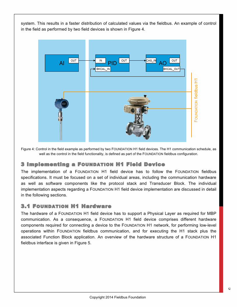
There are two features optimizing FOUNDATION fieldbus communication: First, the complete communication is based on a detailed communication schedule, including the calculation of all individual values within Function Blocks as well as the distribution of these values within the fieldbus. The Link Master performs the overall schedule timing within the fieldbus. This role can be performed not only by the host system, but also by any device offering Link Active Scheduler (LAS) functionality. A deterministic communication is reached when using FOUNDATION fieldbus. The second FOUNDATION fieldbus advantage is the support of control in the field. Here, closed loop calculations can be performed in a decentralized manner without requiring a controller, based on the distributed execution of Function Blocks available within the individual field devices rather than centralized in the host
5
Copyright 2014 Fieldbus Foundation
system. This results in a faster distribution of calculated values via the fieldbus. An example of control in the field as performed by two field devices is shown in Figure 4.
Figure 4: Control in the field example as performed by two FOUNDATION H1 field devices. The H1 communication schedule, as well as the control in the field functionality, is defined as part of the FOUNDATION fieldbus configuration.
3 Implementing a FOUNDATION H1 Field Device The implementation of a FOUNDATION H1 field device has to follow the FOUNDATION fieldbus specifications. It must be focused on a set of individual areas, including the communication hardware as well as software components like the protocol stack and Transducer Block. The individual implementation aspects regarding a FOUNDATION H1 field device implementation are discussed in detail in the following sections.
3.1 FOUNDATION H1 Hardware The hardware of a FOUNDATION H1 field device has to support a Physical Layer as required for MBP communication. As a consequence, a FOUNDATION H1 field device comprises different hardware components required for connecting a device to the FOUNDATION H1 network, for performing low-level operations within FOUNDATION fieldbus communication, and for executing the H1 stack plus the associated Function Block application. An overview of the hardware structure of a FOUNDATION H1 fieldbus interface is given in Figure 5.

6
Copyright 2014 Fieldbus Foundation
Figure 5: Hardware block diagram of a FOUNDATION H1 field device fieldbus interface.
3.1.1 Medium Attachment Unit The Medium Attachment Unit (MAU) is the hardware component of a FOUNDATION H1 field device that provides the direct connection of the device to the fieldbus. It has to support the MBP transmission technology used for FOUNDATION H1 communication.
The MBP implementation is based on the IEC61158-2 Type 3 31.25Kbit/s Voltage-Mode standard. The direct current (DC) voltage of 9V to 32V provided by the bus power supply is overlaid by an information signal of 0.75V to 1V. The transmitting field device generates this voltage modulation by modifying the current drawn from the network. To obtain this information, the voltage level is evaluated within the field device (i.e., the information signal is decoupled from the power supply). As long as no transmission is performed, the individual field devices are only allowed to draw a constant current, which is described by the device properties. Ideally, this current is 10mA.
This signal adaptation on the sender as well as the receiver side is performed by the MAU. In addition, this hardware component is responsible for the bus power extraction required for performing the device functionality as well as the fieldbus access of the field device.
There are different ways to implement the analog MAU within a FOUNDATION H1 field device. While it is possible to design this functionality based on discrete hardware components, this option is often not used due to the limited space available in field devices. An integrated MAU is chosen instead to implement the core fieldbus access functionality within a FOUNDATION H1 field device. Integrated MAUs are available from various suppliers (e.g., Siemens SIM 1-2, ON Semiconductor AMIS-492x0).

7
Copyright 2014 Fieldbus Foundation
3.1.2 Fieldbus Controller The Fieldbus Controller acts as an interface between the digitized serial data stream provided by the MAU and the processor that executes the software in the FOUNDATION H1 protocol. Typically, the Fieldbus Controller implements the FOUNDATION H1 Physical Layer as well as the time-critical part of the FOUNDATION H1 Data Link Layer. In addition to decoding and encoding the MBP frame, it is responsible for the creation and verification of the cyclic redundancy check (CRC) polynomial used for ensuring the required data transmission reliability. The provided functionality may also include address recognition, filtering of received frames, timer management, and the DLL state machine.
Figure 6: The Aniotek Fieldbus Controller UFC100-L1 supports the implementation of FOUNDATION H1 field devices.
There are two types of Fieldbus Controllers available for implementing a FOUNDATION H1 field device: a general type of Fieldbus Controller for field device implementation, and a controller particularly targeted for use in a PROFIBUS PA field device.
Manufacturers currently offering fieldbus chip sets include:
Microcyber (FBC0409)
Siemens (SPC4-2)
SMAR SW4050 (Coming Q4 2014)
Softing (UFC100-L1)
3.1.3 Processor The Processor is used for executing the software of the FOUNDATION H1 protocol stack (i.e., the less time-critical part not covered by the Fieldbus Controller). Here, Processors for embedded usage are required, which combine minimum current consumption with the appropriate computing power for implementing FOUNDATION H1 field devices.

8
Copyright 2014 Fieldbus Foundation
As FOUNDATION H1 is a relatively complex protocol, its implementation requires an address space of greater than 64KB. While an 8-bit processor can also support this requirement, the usage of this platform results in a higher clock rate, which, in turn, implies a higher current consumption and is not adequate for embedded applications. Therefore, 16-bit or even 32-bit processors are typically chosen for the implementation of H1 field devices.
As a FOUNDATION H1 field device implementation requires not only computing power, but also additional hardware capacities like RAM and Flash memory, timers, ports and serial interfaces, the hardware implementation often is based on a microcontroller, a typical example being the M16C family from Renesas.
Besides the FOUNDATION H1 protocol stack, a FOUNDATION H1 field device also includes additional software for the device application. Depending on the selected hardware platform, it is possible to either execute all software components on a single processor, which results in a higher processor load, or to distribute the execution of the complete device software to more than one processor (e.g., dual-processor solution). In the second case, more effort has to be spent on implementing the necessary data exchange between the individual processors.
3.1.4 Additional Hardware Components Besides the hardware components described above, additional hardware components are required for implementing a FOUNDATION H1 field device. They may include additional memory extending the processor’s internal RAM or (serial) EEPROM or FRAM, which is used for storing non-volatile communication and Function Block parameters.
Hardware jumpers are often used in addition. They provide functionality like address selection or write protection. FOUNDATION H1 field devices require the implementation of a Simulate Jumper for certification purposes.
3.2 FOUNDATION H1 Protocol Stack and Function Block
Application As described above, the FOUNDATION H1 protocol makes use of the OSI layers 1 (Physical), 2 (Data Link), and 7 (Application). While the Physical Layer, as well as parts of the Data Link Layer, is implemented in hardware (see Sections 3.1.1 and 3.1.2), the rest of the FOUNDATION H1 protocol stack is implemented in software. To ensure optimum performance, the protocol stack needs to be available in a format executable on the individual target processor. This format is the result of the porting process, during which the protocol stack is compiled and linked for the target hardware platform and real-time operating system by using a specific development tool chain.
In addition to the protocol stack, which is responsible for the pure data exchange via the fieldbus, the FOUNDATION H1 field device implementation also requires a Function Block application. This component acts as an interface between the FOUNDATION H1 protocol stack on one side and the specific device functionality on the other side, and ensures that all device functions and parameters as well as access to this data are standardized throughout the network. To achieve this, the Function Block application follows an object-oriented approach and allows implementing all the different types of

9
Copyright 2014 Fieldbus Foundation
FOUNDATION H1 field devices. The block diagram of a Function Block application for implementing a simple FOUNDATION H1 transmitter is shown in Figure 7.
Figure 7: Block diagram of Function Block application for a simple transmitter interfacing the FOUNDATION H1 protocol stack.
The standard forming the basis for Function Block applications refers to the supported parameters and blocks. The device parameters are defined according to the FOUNDATION H1 device profiles. In general, they can be divided into three groups, as shown in Table 1.
Parameter Description
Dynamic Process Values
All measuring, signal, and status values required for controlling the system.
Typically dynamic process values are accessed cyclically.
Operating and Standard Parameters
Data describing the capabilities as well as configuration and parameterization objects of the individual device.
Typically operating and standard parameters are accessed acyclically1.
Operating and standard parameters can be split into objects whose implementation is mandatory or optional.
Manufacturer-Specific Parameters
Additional data supported by the device.
Table 1: Parameters of FOUNDATION H1 field devices.
1 While access to operating and standard parameters is performed acyclically from the point of view of the FOUNDATION fieldbus H1 protocol services, this communication may take place on a periodic basis from the end user's point of view. This applies, for example, to the reading of view objects by a SCADA system.

10
Copyright 2014 Fieldbus Foundation
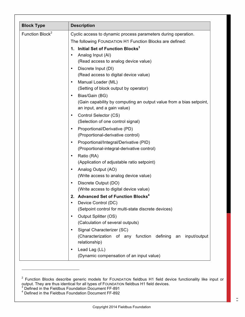
Uniform and systematic access to the different field device parameters within the FOUNDATION H1 network is standardized using a block model. The different block types in Table 2 are supported.
11
Copyright 2014 Fieldbus Foundation
Block Type Description
Function Block2 Cyclic access to dynamic process parameters during operation.
The following FOUNDATION H1 Function Blocks are defined:
1. Initial Set of Function Blocks3 • Analog Input (AI)
(Read access to analog device value)
• Discrete Input (DI) (Read access to digital device value)
• Manual Loader (ML) (Setting of block output by operator)
• Bias/Gain (BG) (Gain capability by computing an output value from a bias setpoint, an input, and a gain value)
• Control Selector (CS) (Selection of one control signal)
• Proportional/Derivative (PD) (Proportional-derivative control)
• Proportional/Integral/Derivative (PID) (Proportional-integral-derivative control)
• Ratio (RA) (Application of adjustable ratio setpoint)
• Analog Output (AO) (Write access to analog device value)
• Discrete Output (DO) (Write access to digital device value)
2. Advanced Set of Function Blocks4 • Device Control (DC)
(Setpoint control for multi-state discrete devices)
• Output Splitter (OS) (Calculation of several outputs)
• Signal Characterizer (SC) (Characterization of any function defining an input/output relationship)
• Lead Lag (LL) (Dynamic compensation of an input value)
2 Function Blocks describe generic models for FOUNDATION fieldbus H1 field device functionality like input or output. They are thus identical for all types of FOUNDATION fieldbus H1 field devices. 3 Defined in the Fieldbus Foundation Document FF-891 4 Defined in the Fieldbus Foundation Document FF-892

12
Copyright 2014 Fieldbus Foundation
• Dead Time (DT) (Delay of continuous signal by amount of time)
• Integrator (IT) (Accumulation of measured value to a total value as a function of time)
• Setpoint Ramp Generator (SPG) (Setpoint generation following a profile as a function of time)
• Input Selector (IS) (Selection of one input)
• Arithmetic (AR) (Performance of popular measurement mathematical functions)
• Timer (TMR) (Performance of various timing functions)
• Analog Alarm (AAL) (Alarm reporting based on analog value)
• Totalizer (TOT) (Accumulation of measured value to a total value based on operator interaction)
3. Function Blocks for Manufacturing Automation I/O Applications5
• Multiple Discrete Input (MDI) (Separation of input to discrete output channels)
• Multiple Discrete Output (MDI) (Combination of discrete input channels to output)
• Multiple Analog Input (MAI) (Separation of input to analog output channels)
• Multiple Analog Output (MAI) (Combination of analog input channels to output)
Transducer Block6 Converter mapping between process data and function blocks.
The Transducer Block is used to perform pre-processing and calibration of device data according to specific device settings.
At least one Transducer Block has to be available for a FOUNDATION H1 field device.
Resource Block Access to device-specific data identifying the individual physical device properties.
5 Defined in the Fieldbus Foundation Document FF-893 6 Transducer Blocks map generic Function Blocks to the individual properties of a specific field device. Standardized Transducer Blocks are available for various device classes such as pressure transmitters or temperature transmitters.

13
Copyright 2014 Fieldbus Foundation
Table 2: Types of FOUNDATION H1 blocks. The Function Block Shell performs the coupling of various blocks to FOUNDATION H1 communication within the Function Block application, and their execution control. This component can be seen as a kind of run-time environment for FOUNDATION H1 blocks.
3.3 Transducer Block Implementation A FOUNDATION H1 Function Block application typically results in a large number of parameters to be handled. For example, depending on the respective device profile, a simple FOUNDATION H1 transmitter has to support at least 80 (fixed and variable) parameters, which are accessed by the fieldbus via blocks. During the implementation of a FOUNDATION H1 field device, these blocks have to be designed in an individual and device-specific way. The pre-processing performed within the Transducer Blocks is an important task here. It handles individual FOUNDATION H1 read and write requests by mapping the individual device parameters to Function Blocks.
One approach to internally implement an individual Transducer Block is based on a data structure representing all supported parameters. This data structure is used as an internal cache memory, storing the latest available parameter values to support a faster execution of individual FOUNDATION H1 read and write requests. While write requests are usually forwarded directly to the device, the individual device parameters are read cyclically in the background and the appropriate values are copied to the Transducer Block’s cache memory. When a FOUNDATION H1 read request must be executed, the data from the internal cache memory is read. This handling is shown in Figure 8.
Figure 8: Handling of read and write requests within a Transducer Block.

14
Copyright 2014 Fieldbus Foundation
This type of data handling within the Transducer Block is implemented by a device-specific software program (for example, using the C programming language). Depending on the number of parameters handled by a single Transducer Block, this implementation may result in a large program for handling the high number of parameters, which requires extensive development and testing. A sample Transducer Block code for writing data to the device based on the situation from Figure 8 is presented in Figure 9.
Figure 9: Transducer block code sample for sending data to the device.
Due to the specific supported device capabilities, the individual Transducer Block implementation varies from device to device. However, it is possible to standardize this implementation with respect to the logical data exchange between the Transducer Block and the device. These standardized solutions are discussed in the following sections.
3.3.1 Transducer Block Implementation Based on Serial
HART Protocol One option for exchanging data between the Transducer Block and the device is to use the serial HART protocol, which is often available in devices for internal data exchange. This implementation approach can be used in particular when migrating an existing HART device to support FOUNDATION H1.
To be able to use the serial HART protocol for data exchange between the Transducer Block and the device, a HART master has to be available to manage the data transfer.

15
Copyright 2014 Fieldbus Foundation
The execution of individual HART commands is triggered by individual FOUNDATION H1 read and write requests. For write requests, the Transducer Block program creates the corresponding HART commands, which then are executed via the HART master, whereas for read requests the current value kept in the internal cache memory is returned. The necessary cyclic update of the parameter values in the internal cache memory in the background is also part of the Transducer Block program and performed using HART commands.
One or more HART commands can be associated with an individual FOUNDATION H1 read or write request
3.3.2 Transducer Block Implementation Based on Modbus
RTU Protocol and Other Serial Protocols Another typical approach for implementing a FOUNDATION H1 field device is usage of the serial Modbus RTU protocol for data exchange between the Transducer Block and the device. This approach is similar to the data exchange via a serial HART protocol as discussed in Section 3.3.1, except the data exchange is managed by a Modbus RTU master.
This procedure can also be easily adapted to allow the use of other serial protocols for data exchange between the Transducer Block and the device, including proprietary ones. The implementation of data exchange via non-serial protocols is more complicated, however, as these require their own hardware.
3.3.3 Transducer Block Implementation for 4-20mA Devices For migrating 4-20mA devices to FOUNDATION H1, no standard approach is available due to the current required by these devices. A 20mA current consumption at a voltage of 8V would result in a current consumption of about 60 to 70mA from the FOUNDATION H1 network. This would mean only one to two FOUNDATION H1 field devices could be used within an intrinsically safe trunk, which typically disqualifies the device for practical use.
In addition, a special MAU would be required in order to support the increased current consumption, resulting in higher hardware costs.
3.4 Add-on Files for FOUNDATION H1 Field Devices For using a FOUNDATION H1 field device, DD files are available in order to describe its capabilities. An overview of these files can be found in Chapter 2.
The DD file of a FOUNDATION H1 field device is required for its registration. Other means can be provided for accessing the device capabilities, such as a Device Type Manager (DTM) file according to the Field Device Tool (FDT) standard.
3.5 Certification and Registration of FOUNDATION H1 Field
Devices The FOUNDATION certification process consists of three individual tests. The FOUNDATION Physical Layer Conformance Test, during which the device is checked against the appropriate Physical Layer requirements of the Fieldbus Foundation. The Physical Layer Test is performed by an accredited testing laboratory as part of the certification test, or through self-certification.

16
Copyright 2014 Fieldbus Foundation
Another test is the FOUNDATION Conformance Test according the Conformance Test Kit (CTK). This test addresses the implementation of the FOUNDATION protocol stack (OSI Data Link and Application Layers). This test has to be performed by an accredited testing laboratory.
And the last test required for certification is the FOUNDATION Interoperability Test according the Interoperability Test Kit (ITK). This test focuses on the implemented Function Block application. The FOUNDATION Interoperability Test is performed by the Fieldbus Foundation and requires the Physical Layer Conformance Test as well as the Conformance Test to be passed successfully.
As a result the FOUNDATION certification process ensures the individual field device implementation, its full functionality as well as the interoperability, easy installation, and supported performance of the field device.
4 Reducing the Implementation Effort of FOUNDATION H1 Field
Devices As can be seen from the description in Chapter 3, the complete implementation of a full-featured FOUNDATION H1 field device with all its individual capabilities is quite an extensive task and addresses various hardware and software aspects. Many device manufacturers are interested in identifying the best ways to reduce the implementation effort of FOUNDATION H1 field devices without compromising on the requested flexibility. Implementation kits based on pre-engineered hardware and software components can help significantly reduce the associated development costs as well as the time-to-market.
4.1 FOUNDATION H1 Fieldbus Device Communication Kit The FOUNDATION H1 Fieldbus Device Communication Kit makes use of pre-engineered, standardized hardware and software components and provides a universal approach for implementing all types of FOUNDATION H1 field devices. It consists of a ready-to-use hardware board, the FOUNDATION H1 protocol stack plus most of the standardized Function Blocks as described in Section 3.2.
The hardware board included in the FOUNDATION H1 Fieldbus Device Communication Kit meets the various requirements discussed in Section 3.1 and eliminates the need for customer-specific hardware development. This board is integrated into a device as an add-on piggyback board and provides all the means for executing the FOUNDATION H1 protocol stack and the appropriate Function Block application. It is also capable of supplying power from the fieldbus to the field device hardware.
The device implementation, on the other hand, runs on the device’s main board. As a result, a dual-processor solution is implemented, separating the FOUNDATION H1 implementation from the pure device functionality. The Softing embedded communication module FBK-2, as part of a FOUNDATION H1 field device implementation, is shown in Figure 10. As can be seen, this board is small enough to fit into most devices.

17
Copyright 2014 Fieldbus Foundation
Figure 10: FOUNDATION H1 field device making use of Softing’s embedded communication module FBK-2.
The software component of the FOUNDATION H1 Fieldbus Device Communication Kit is pre-compiled and executable on the hardware board. No porting of the FOUNDATION H1 protocol stack is required when using the FOUNDATION H1 Fieldbus Device Implementation Kit.
As a consequence, the Transducer Block implementation (see Section 3.3) is the only major task to be performed when using the FOUNDATION H1 Fieldbus Device Communication Kit. This implementation task is further simplified by providing the aforementioned serial HART or Modbus RTU protocol as the default means of data exchange between the Transducer Block and the device. A different serial protocol (proprietary) can be implemented as well when using the FOUNDATION H1 Fieldbus Device Communication Kit, providing added flexibility.
The FOUNDATION H1 Fieldbus Device Communication Kit reduces the implementation effort compared to a full-featured FOUNDATION H1 field device implementation. The manufacturer can focus on the specific device implementation without needing in-depth FOUNDATION technology know-how.
The FOUNDATION H1 Fieldbus Device Communication Kit has already successfully passed the Physical Layer Conformance Test as well as the Conformance Test as described in Section 3.5. The certification process of a field device implemented based on the FOUNDATION H1 Fieldbus Device Communication Kit is reduced to the Interoperability Test.
4.2 FOUNDATION H1 Fieldbus Device Configuration Kit FFeasy In comparison to the FOUNDATION H1 Fieldbus Device Communication Kit, the FOUNDATION H1 Fieldbus Device Configuration Kit FFeasy simplifies the implementation of a FOUNDATION H1 field device even more. To achieve this, a standardized Function Block application, including a pre-defined Transducer Block implementation, is added to the FOUNDATION H1 Fieldbus Device Communication Kit. This Function Block application can be adapted to the needs of the individual field device.

18
Copyright 2014 Fieldbus Foundation
For supporting this type of standardization, some assumptions regarding the field device have to be made. For instance, these standardizations restrict the available Function Blocks and the supported number of flexible parameters.
These standardizations have the advantage that the complete development process of a FOUNDATION H1 field device requires no programming, but can be performed simply by configuring the Function Block application. This task requires no specific FOUNDATION H1 know-how and can be done by any device manufacturer. As a result, the development time is shortened significantly.
The scope of delivery of the FOUNDATION H1 Fieldbus Device Configuration Kit FFeasy also includes the appropriate DD file required for certification.
The FOUNDATION H1 Fieldbus Device Configuration Kit FFeasy has already successfully passed the Physical Layer Conformance Test, the Conformance Test as well as the Interoperability Test described in Section 3.5. The certification process of a field device based on the FOUNDATION H1 Fieldbus Device Configuration Kit is simplified to a pure re-certification.
5 Summary The implementation of a FOUNDATION H1 field device must meet a variety of hardware and software requirements defined by the FOUNDATION fieldbus standard. Depending on the required functionality and the available fieldbus know-how, this implementation may involve a great deal of development time and effort when performed without pre-engineered fieldbus communication components.
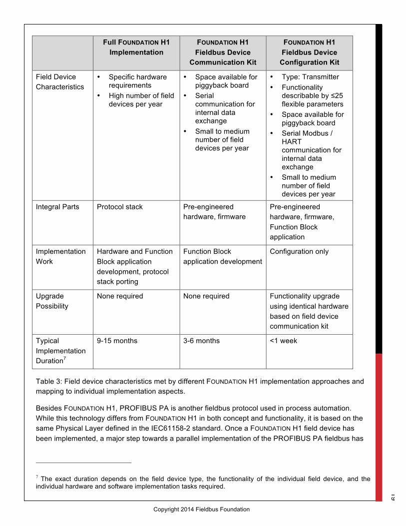
A field device implementation based on the FOUNDATION H1 Fieldbus Device Communication Kit or the FOUNDATION H1 Fieldbus Device Configuration Kit FFeasy significantly reduces the involved time and effort. These approaches, however, are associated with some drawbacks (e.g., hardware used and supported functionality). A summary of the provided field device characteristics and individual aspects of the different implementation approaches discussed in this white paper can be found in Table 3.
19
Copyright 2014 Fieldbus Foundation
Full FOUNDATION H1 Implementation
FOUNDATION H1 Fieldbus Device
Communication Kit
FOUNDATION H1 Fieldbus Device
Configuration Kit
Field Device Characteristics
• Specific hardware requirements
• High number of field devices per year
• Space available for piggyback board
• Serial communication for internal data exchange
• Small to medium number of field devices per year
• Type: Transmitter • Functionality
describable by ≤25 flexible parameters
• Space available for piggyback board
• Serial Modbus / HART communication for internal data exchange
• Small to medium number of field devices per year
Integral Parts Protocol stack Pre-engineered hardware, firmware
Pre-engineered hardware, firmware, Function Block application
Implementation Work
Hardware and Function Block application development, protocol stack porting
Function Block application development
Configuration only
Upgrade Possibility
None required None required
Functionality upgrade using identical hardware based on field device communication kit
Typical Implementation Duration7
9-15 months 3-6 months <1 week
Table 3: Field device characteristics met by different FOUNDATION H1 implementation approaches and mapping to individual implementation aspects.
Besides FOUNDATION H1, PROFIBUS PA is another fieldbus protocol used in process automation. While this technology differs from FOUNDATION H1 in both concept and functionality, it is based on the same Physical Layer defined in the IEC61158-2 standard. Once a FOUNDATION H1 field device has been implemented, a major step towards a parallel implementation of the PROFIBUS PA fieldbus has
7 The exact duration depends on the field device type, the functionality of the individual field device, and the individual hardware and software implementation tasks required.

20
Copyright 2014 Fieldbus Foundation
already been made. A key aspect here is that the implementation of a PROFIBUS PA field device does not require different hardware.
In addition, the software development effort can be reduced as well if both implementations are based on the Softing Field Device stack. For instance, this solution provides an identical interface and allows the re-use of parts of the Transducer Block structures and the source code. The implemented data exchange between the Transducer Block and the device can also be re-used. The exact percentage of savings that can be achieved in a subsequent FOUNDATION H1 implementation cannot be given as a general figure, however, as it depends on the complexity of the FOUNDATION H1 field device implemented in the first place.

21
Copyright 2014 Fieldbus Foundation
6 Author Georg Süss Product Marketing Softing Industrial Automation GmbH Haar (near Munich)
7 References FOUNDATION fieldbus Technical Overview FD-043 Revision 3.0 Fieldbus Foundation, 2003
Presentation "FOUNDATION Fieldbus Technology Engineering Advantages" Fieldbus Foundation, 2009 Available at: www.fieldbus.org/images/stories/international/asiapacific/India/presentations/Dec 09_03_ffieuc_mumbai_engineering_adavntages_-_harendra_mistry.pdf (as of August 22, 2013)
Application Note "DeltaV System, FOUNDATION Fieldbus Technology Delivers Results for TotalFinaElf in North Sea Offshore Platform" Emerson Process Management, 2011 Available at: www2.emersonprocess.com/siteadmincenter/PM DeltaV Documents/ProvenResults/OilGasRefining/RES_OG_TotalFinaElf_final_5-11.pdf (as of August 22, 2013)
Application Note "Alcan realizes significant benefits using Emerson’s PlantWeb Architecture with FOUNDATION fieldbus technology" Emerson Process Management, 2007 Available at: www2.emersonprocess.com/siteadmincenter/PM Central Web Documents/QBRAlcanGove13dec.pdf (as of August 22, 2013)
Presentation "FOUNDATION Fieldbus Lifecycle Management" Fieldbus Foundation, 2012 Available at: www.fieldbus.org/images/stories/international/emea/middle-east/presentations/al_khobar_june_13_ff_lifecycle_management_final_utpal.pdf (as of August 22, 2013)

22
Copyright 2014 Fieldbus Foundation
9 List of Figures Figure 1: Cost saving potential when setting up fieldbus applications 1
Figure 2: FOUNDATION H1 is made up of the Physical and Data Link Layers, the Fieldbus Access Sublayer, and Fieldbus Message Specification, where the last three items are implemented in the communication stack. The various H1 layers refer to the Physical, Data Link and Application Layers of the OSI Model. 3
Figure 3: The supported FOUNDATION topologies include the connection of a host system to FOUNDATION H1 field devices, either via FOUNDATION HSE and a Linking Device or FOUNDATION H1 segments. 4
Figure 4: Control in the field example as performed by two FOUNDATION H1 field devices. The FOUNDATION H1 communication schedule, as well as the control in the field functionality, is defined as part of the FOUNDATION fieldbus configuration. 6
Figure 5: Hardware block diagram of a FOUNDATION H1 field device fieldbus interface. 7
Figure 6: The Aniotek Fieldbus Controller UFC100-L1 supports the implementation of FOUNDATION H1 PA field devices. 8
Figure 7: Block diagram of Function Block application for Simple Transmitter interfacing the FOUNDATION H1 protocol stack. 11
Figure 8: Handling of read and write requests within a transducer block. 16
Figure 9: Transducer block code sample for sending data to the device. 17
Figure 10: FOUNDATION H1 Field Device Making Use of Softing’s Embedded Communication Module FBK-2. 20
10 List of Tables Table 1: Parameters of FOUNDATION H1 field devices. 12
Table 2: Types of FOUNDATION H1 blocks. 15
Table 3: Field device characteristics met by different FOUNDATION H1 implementation approaches and mapping to individual implementation aspects. 23