guide specifications
TRANSCRIPT

GENERALUnits shall be performance certified to ISO standard 13256-1 for Water Loop Heat Pump, Ground Water Heat Pump and Ground Loop Heat Pump applications. Units shall be Underwriter Laboratories (UL and ULc) listed for safety on all models. Each unit shall be run tested at the factory. Each unit shall be pallet mounted and stretch wrapped. The units shall be manufactured in an ISO9001:2000 certified facility.
The units shall be warranted by the manufacturer against defects in materials and workmanship for a period of i) in the case of residentially sold units having the last digit of the serial number as a 'T'; five years on all parts and 10 years on the refrigerant circuit components ii) on all other units; five years on the compressor and one year on all other parts.
The units shall be designed to operate with entering fluid temperatures between 50˚F (10˚C) and 110˚F (43.3˚C) in cooling and temperatures between 20˚F (-6.6˚C) and 80˚F (27˚C) in heating as manufactured by Bosch in Fort Lauderdale, Florida.
CASING & CABINETThe cabinet shall be fabricated from heavy-gauge steel finished with a vinyl coated black cabinet and a silver brushed aluminum front panel. The interior shall be insulated with ½” (12.7mm) thick foil faced glass fiber. All units shall allow sufficient service access to replace the compressor without unit removal. One blower and two compressor compartment access panels shall be removable with supply and return ductwork in place. A duct collar shall be provided on the supply air opening. A filter rack with 2" (50.8 mm) thick disposable filters and a 1" (25.4mm) return air duct collar shall be provided with each unit. Air filters shall be MERV 11 rated. The units shall have an insulated divider panel between the air handling section and the compressor section to minimize the transmission of compressor noise, and to permit service testing without air bypass. Units shall have a stainless steel condensate drain pan. The compressor shall have a floating base pan to minimize noise transmissions.
REFRIGERATION CIRCUITSAll units shall contain a sealed refrigerant circuit including a two stage scroll compressor, bi-directional thermal expansion valve metering device, finned tube air-to-refrigerant heat exchanger, refrigerant reversing valve and service ports. Compressor shall be high efficiency two stage scroll type, designed for heat pump duty, quiet operation and mounted on rubber vibration isolators. Compressor motors shall be equipped with overload protection. Refrigerant reversing valves shall be pilot operated sliding piston type with replaceable encapsulated magnetic coils energized only during the cooling cycle. The finned tube coil shall be constructed of lanced aluminum fins not exceeding fourteen fins per inch bonded to rifled copper tubes in a staggered pattern not less than three rows deep and have a 600 PSIG (4140 Kpa) working pressure. Coils shall have a baked polyester enamel coating for protection against most airborne chemicals. Coil end plates shall be aluminum. The coaxial water-to-refrigerant heat exchanger shall be constructed of a convoluted copper (optional cupronickel) inner tube and steel outer tube with a designed refrigerant working pressure of 600 PSIG (4140 Kpa) and a designed water side working pressure of no less than 400 PSIG (2750 kPa). The water-to-refrigerant heat exchanger shall be insulated to prevent condensation at low fluid temperatures.
FAN MOTOR & ASSEMBLYThe fan shall be direct drive centrifugal forward curved type with a dynamically balanced wheel. The housing and wheel shall be designed for quiet low velocity operation. The fan housing shall be removable from the unit without disconnecting the supply air ductwork for servicing of the
fan motor.The fan motor shall be an ECM-2 microprocessor controlled DC type motor with internal programming factory set for the specific unit and featuring soft start/stop and a delay off feature for maximum efficiency and quiet operation. Air flow rates shall be varied according to the staging of the unit. There will further be provisions for adjusting the air delivery of the motor and blower by +/- 15% from rated air flow.
ELECTRICALControls and safety devices will be factory wired and mounted within the unit. Controls shall include comfort alert module, compressor contactor, 24V transformer, reversing valve coil and solid state lock-out controller (UPM). The UPM controller shall include the following features: diagnostic LED's, low pressure bypass time delay (to prevent nuisance low pressure lock-outs during operation with low fluid temperatures), anti short cycle time delay, random start time delay and one time intelligent reset. When the safety controls are activated the lock-out circuit shall reset itself the first time. If the safety controls are subsequently activated within one hour, then the lock-out circuit shall disable the compressor until it is reset at the thermostat or main circuit breaker to prevent compressor operation during fault conditions. A lock-out indicating terminal shall be provided in the low voltage circuit. Safety devices include a low pressure cutout set a 40 PSIG (280 kPa) for loss of charge protection (freezestat and/or high discharge gas temperature sensor is not acceptable) and a high pressure cutout control set at 600 PSIG (4140 Kpa).The ECM motor interface board shall provide a screw type terminal block for thermostat connection, LED's to indicate thermostat status and air delivery. It shall also provide a means of changing the motor program to any of up to four pre-programmed options. Direct wiring of the motor control harness to the thermostat is not acceptable.
A terminal block with screw terminals shall be provided for control wiring. An optional condensate overflow device shall be factory installed to stop compressor operation if drain pan overflow is imminent. An optional energy management relay to allow unit control by an external source shall be factory installed.
PIPINGSupply, return water and condensate drain connections shall be brass female pipe thread fittings and mounted flush to cabinet exterior.
INTERNAL ELECTRIC HEAT208/230-1-60 volt units shall be equipped with optional internal electric resistance heat for auxiliary and emergency heat. Electric heater must be Underwriter's Laboratories (UL and ULc) approved for safety when installed in the unit. External heater packages or heater packages not specifically listed for use with the unit are unacceptable. Electric heater packages shall include a heater collar mounted to the blower outlet, individual thermal overload protected heater elements no greater than 5kW each and magnetic contactors. Heater packages shall have a separate power supply connection from the compressor and this power supply shall also power the unit blower motor and control transformer for safe operation.
HEAT RECOVERY PACKAGE208/230 volt units shall be equipped with an optional factory installed internal heat recovery kit for domestic hot water production. This kit shall include an internally protected pump, double walled coaxial water-to-refrigerant heat exchanger, 140˚F (60˚C) hot water temperature limit switch and an on/off switch/circuit breaker.
GUIDE SPECIFICATIONSTA Series Two Stage R-410A
TASPECS.INDD REV: 05-11 Catalog (TA Technical Data Sheet)

Right HandReturn(FRT)
NOTES: All dimensions within +/- 0.125". All condensate drain connections are 3/4" FPT. All Heat Recovery Kit connections are 1/2" FPT. Internal electric heat available on 208-230/1/60 top discharge units only Internal Heat Recovery Kit available on 208-230 volt units only. Specifications subject to change without notice.
FHP Manufacturing Co.601 N.W. 65th CourtFort Lauderdale, FL 33309Phone: (954) 776-5471Fax: (800) 776-5529http://www.bosch-climate.us
TA Two Stage Series Vertical Dimensions
A B C D E F G H J K M N P Q Condenser Recommended MODEL R/A Duct R/A Duct Filter Rack Water Replacement Width Depth Height Flg Width Flg Height Height Connections Nominal Filter Size
TA025 21.50 26.00 47.25 13.75 15.75 7.00 4.80 2.47 8.00 14.47 24.00 22.00 24.00 4.00 3/4" F.P.T. 24 X 24 X 2 TA035 24.00 33.25 47.25 15.75 15.75 8.25 6.37 2.47 8.00 14.47 30.00 22.00 24.00 4.00 1" F.P.T. 24 X 30 X 2 TA049 26.00 33.25 58.00 17.75 17.75 8.50 7.25 2.47 8.00 16.47 30.00 30.00 32.00 4.00 1" F.P.T. 16 X 30 X 2 (2) TA061 26.00 33.25 66.25 17.75 17.75 8.38 6.38 4.25 10.00 16.50 30.00 38.00 40.00 4.00 1" F.P.T. 20 X 30 X 2 (2) TA071 26.00 33.25 66.25 17.75 17.75 8.38 6.38 4.25 10.00 18.50 30.00 38.00 40.00 4.00 1" F.P.T. 20 X 30 X 2 (2)
Left HandReturn(FLT)
TAVTDGIP INT II.INDD REV: 05-11
C
AccessPanel
ElectricalKnock-outs
CondensateDrain
HeaterKnock-out
CondenserWater Out
CondenserWater In
HRP
GF E
D
KJ
H
B A BA
DE
FQ
P
M
NC

TAHZDGIP.INDD REV: 0 05-11
Left Hand ReturnEnd Blow (FLE)
Left Hand ReturnStraight Through (FLS)
Right Hand ReturnEnd Blow (FRE)
Right Hand ReturnStraight Through (FRS)
A B C D E F G H J K M N P Q R T Condenser Recommended
MODEL R/A Duct Filter Rack R/A Duct Water Replacement Width Depth Height Flg Width Height Flg Height Connections Nom. Filter Size
TA025* 26.00 54.50 22.00 2.00 30.00 22.50 3.25 15.25 5.25 13.75 4.00 15.75 5.00 3.00 20.00 18.00 3/4" F.P.T. 16 X 20 X 2 (2) TA035* 30.00 68.00 22.00 2.50 34.00 32.00 2.25 14.38 5.25 15.75 4.00 15.75 5.81 3.00 20.00 18.00 1" F.P.T. 18 X 20 X 2 (2) TA049 30.00 68.00 22.00 2.50 34.00 32.00 2.75 16.75 4.75 17.75 2.00 17.75 7.66 2.00 20.00 18.00 1" F.P.T. 18 X 20 X 2 (2) TA061 30.00 89.00 22.00 2.50 54.00 31.50 5.75 16.75 4.50 17.75 3.75 17.75 4.5 2.00 20.00 18.00 1" F.P.T. 20x28x2 (2) TA071 30.00 89.00 22.00 2.50 54.00 31.50 5.75 16.75 4.50 17.75 3.75 17.75 7.66 2.00 20.00 18.00 1" F.P.T. 20x28x2 (2) * Add 0.500" height on TA025 and TA035 for base rails.
NOTES: All dimensions within +/- 0.125". All condensate drain connections are 3/4" FPT. All Heat Recovery connections are 1/2" FPT. Internal electric heat available on 208-230 volt units only Internal Heat Recovery Kit available on 208-230 volt units only. Units can be field converted between end blow and straight through supply air configurations. Specifications subject to change without notice.
FHP Manufacturing Co.601 N.W. 65th CourtFort Lauderdale, FL 33309Phone: (954) 776-5471Fax: (800) 776-5529http://www.bosch-climate.us
Left Hand Return
Right Hand Return
TA Two Stage Series Horizontal Dimensions
D
E
F
HG
C
B
AccessPanel
ElectricalKnock-outs
HeaterKnock-out
Return AirOpening
CondensateDrain
A
JK
M
N
C
B
Return AirOpening
A
QK
PNCondensate
Drain
AB
CondensateDrain
Return AirOpening
M
KP
C
N
AB
NCondensate
Drain
HeaterKnock-out
JK
Q
Return AirOpening
C
AccessPanel
CondenserWater Out
CondenserWater In
D
E
FHRP

A B C D E F G H J K M N P Condenser RecommendedMODEL Blower Blower R/A Duct R/A Duct Filter Rack Water Replacement
Width Depth Height Opening Opening Flg Width Flg Height Height Connections Nominal Filter Size
TA025 21.50 26.00 47.25 9.25 10.25 8.38 5.00 8.13 20.13 9.75 24.00 22.00 24.00 3/4" F.P.T. 24 X 24 X 2 TA035* 24.00 33.25 47.25 9.25 10.25 11.13 6.88 8.13 20.13 10.00 30.00 22.00 24.00 1" F.P.T. 24 X 30 X 2 TA049 26.00 33.25 58.00 10.50 11.50 11.25 8.25 9.13 23.13 10.50 30.00 30.00 32.00 1" F.P.T. 16 X 30 X 2 (2) TA061 26.00 33.25 66.25 12.25 12.50 9.75 6.25 6.84 21.34 11.00 30.00 38.00 40.00 1" F.P.T. 20 X 30 X 2 (2) TA071 26.00 33.25 66.25 12.25 13.50 9.75 6.25 7.84 20.84 11.00 30.00 38.00 40.00 1" F.P.T. 20 X 30 X 2 (2)
Right Hand Return(FRB)
FHP Manufacturing Co.601 N.W. 65th CourtFort Lauderdale, FL 33309Phone: (954) 776-5471Fax: (800) 776-5529http://www.bosch-climate.us
TA Two Stage Series Counterflow Dimensions
NOTES: All dimensions within +/- 0.125". All condensate drain connections are 3/4" FPT. All Heat Recovery Kit connections are 1/2" FPT. Internal electric heat available on 208-230/1/60 bottom discharge units only Internal Heat Recovery Kit available on 208-230 volt units only. Specifications subject to change without notice.TACFDGIP INT II.INDD REV: 05 -11
Left Hand Return(FLB)
C
CompressorAccess Panel
ElectricalKnock-outs
CondensateDrain
HeaterKnock-out
CondenserWater Out
CondenserWater In
HRP
GF E D
K
J
H
B A
P
M
NBlower & Heater
Access Panel
C
BA
FED

Entering Entering Heat Fluid Air Total Power of Temp. Temp. Capacity Input Abs. COP (oF) (oF) (MBtuH) (kW) (MBtuH)
50o 60o
60o
70o
80o
50o
60o 70o
70o
80o
50o
60o 80o
70o
80o
20.98 1.12 17.16 5.522.83 1.12 19.00 6.024.69 1.13 20.83 6.426.55 1.14 22.67 6.819.84 1.14 15.96 5.121.59 1.14 17.69 5.523.35 1.15 19.43 6.025.10 1.16 21.16 6.418.50 1.16 14.54 4.720.14 1.17 16.15 5.121.77 1.17 17.77 5.423.41 1.18 19.38 5.8
Fluid Pressure Flow Drop (GPM) (FOH) (PSIG) 5.0 2.0 0.9 7.0 3.6 1.6 9.0 5.7 2.5 11.0 8.2 3.5 13.0 11.0 4.8
Compressor Blower Loop Pump Min. Max. Circuit Fuse/ RLA LRA FLA HP FLA HP Amps Breaker
208/230-1-60 -1 10.3 52.0 2.8 1/3 - - 15.7 25
Electrical Elect. Characteristics Symbol
0.10 0.20 0.30 0.40 0.50 0.60 0.70 0.80 0.90 1.00 1.10 1.20
CAPACITY DATA - PART LOAD
ELECTRICAL SPECIFICATIONS
BLOWER PERFORMANCE
COOLING All performance at 750 CFM and 8.0 GPM HEATING
Available External Static Pressure (Inches of Water, Gauge. Wet Coil and Filter Included)
BlowerSpeed
+ 860 Norm 750
- 640
TA025
Water Loop Ground Water Ground Loop Cooling Heating Cooling Heating Cooling Heating Capacity EER Capacity COP Capacity EER Capacity COP Capacity EER Capacity COP 20,000 19.3 23,000 6.5 22,500 32.5 19,500 5.5 22,000 27.8 16,600 4.7
ISO 13256-1 CERTIFIED PERFORMANCE DATA Rated at 750 CFM and 8.0 GPM
Refrigerant: R-410AAir Coil
Square Rows Tube Fins/ Feet Deep O.D. Inch 3.5 3 3/8 14 Water Coil Type Work Press Coaxial 450 psig Blower Size Compr Type 9 x 7 DD Scroll Net Weight Ship Weight 330 lbs 355 lbs
MECHANICAL SPECIFICATIONS
Entering Entering Sensible Heat Fluid Air Total Sensible to Power of Temp. Temp. Capacity Capacity Total Input Reject EER (oF) (oF) (MBtuH) (MBtuH) Ratio (kW) (MBtuH) 50o
60o 70odb 70o 61owb 85o
100o
50o
60o 75odb 70o 63owb 85o
100o
50o
60o 80odb 70o 67owb 85o
100o
50o
60o 85odb 70o 71owb 85o
100o
Units are complete packages containing compressor, reversing valve, expansion valve metering device, ECM fan motor and heat exchangers. Also included are safety controls: Overload protection for motors, high and low refrigerant pressure switches and solid state lock-out circuit. Optional UL approved internal electric heater, factory installed with primary thermal overload protection and magnetic contactors (208/230-1-60 only) optional UL approved internal Heat Recovery Package and/or Ground Loop Pump with purge connections available.
Performance based on ARI/ISO rated air flow, fluid flow and voltage. For conditions other than rated, consult the Bosch EAD selection software. Due to variations in installation actual performance may vary marginally from tabulated values.
As a result of continuing research and development, specifications are subject to change without notice.
TA025.1IP60 Rev: 05-11
FLUID PRESSURE DROP
19.80 12.73 0.64 0.65 22.03 30.419.09 12.37 0.65 0.77 21.70 24.918.37 12.05 0.66 0.88 21.38 20.917.30 11.65 0.67 1.05 20.89 16.4
16.22 11.31 0.70 1.22 20.40 13.3 21.22 15.24 0.72 0.66 23.46 32.4 20.46 14.81 0.72 0.77 23.09 26.6 19.69 14.43 0.73 0.89 22.71 22.2 18.54 13.95 0.75 1.06 22.15 17.5 17.39 13.55 0.78 1.23 21.59 14.1 23.30 16.83 0.72 0.66 25.56 35.3 22.46 16.36 0.73 0.78 25.11 28.9 21.62 15.95 0.74 0.89 24.67 24.2 20.36 15.41 0.76 1.07 24.00 19.1 19.10 14.97 0.78 1.24 23.33 15.4 25.38 18.44 0.73 0.66 27.65 38.2 24.47 17.93 0.73 0.78 27.14 31.3 23.56 17.47 0.74 0.90 26.62 26.2 22.19 16.89 0.76 1.07 25.85 20.7 20.82 16.41 0.79 1.25 25.08 16.7
EFT Range (Standard) 25oF to 80oF
EFT Range (Standard) 50oF to 100oF
25o 30o 60o
40o
25o
30o 70o
40o
25o
30o 80o
40o
LOW TEMP HEATING16.01 1.10 12.25 4.316.92 1.11 13.15 4.518.74 1.11 14.95 4.915.15 1.12 11.32 4.016.01 1.12 12.17 4.217.73 1.13 13.87 4.614.13 1.15 10.22 3.614.93 1.15 11.02 3.816.54 1.15 12.60 4.2
Antifreeze Required
PACKAGED UNITS
SPECIFICATION DATA SHEET
FHP Manufacturing Company601 N.W. 65th Court - Fort Lauderdale, FL 33309Phone: (954) 776-5471 - Fax: (800) 776-5529http://www.bosch-climate.us

Entering Entering Heat Fluid Air Total Power of Temp. Temp. Capacity Input Abs. COP (oF) (oF) (MBtuH) (kW) (MBtuH)
50o 60o
60o
70o
80o
50o
60o 70o
70o
80o
50o
60o 80o
70o
80o
28.16 1.71 22.32 4.831.67 1.81 25.49 5.135.18 1.91 28.66 5.438.70 2.01 31.83 5.626.63 1.74 20.69 4.529.95 1.84 23.66 4.833.27 1.95 26.63 5.036.59 2.05 29.60 5.224.83 1.78 18.76 4.127.92 1.88 21.50 4.331.02 1.99 24.23 4.634.11 2.09 26.97 4.8
Fluid Pressure Flow Drop (GPM) (FOH) (PSIG) 5.0 2.0 0.9 7.0 3.6 1.6 9.0 5.7 2.5 11.0 8.2 3.5 13.0 11.0 4.8
0.10 0.20 0.30 0.40 0.50 0.60 0.70 0.80 0.90 1.00 1.10 1.20
CAPACITY DATA - FULL LOAD
ELECTRICAL SPECIFICATIONS
BLOWER PERFORMANCE
COOLING All performance at 950 CFM and 8.0 GPM HEATING
Available External Static Pressure (Inches of Water, Gauge. Wet Coil and Filter Included)
BlowerSpeed
+ 1100 Norm 950
- 800
TA025
Water Loop Ground Water Ground Loop Cooling Heating Cooling Heating Cooling Heating Capacity EER Capacity COP Capacity EER Capacity COP Capacity EER Capacity COP 27,000 16.2 32,500 5.3 31,000 25.1 26,500 4.8 28,500 19.2 20,400 4.1
ISO 13256-1 CERTIFIED PERFORMANCE DATA Rated at 950 CFM and 8.0 GPM
Refrigerant: R-410AAir Coil
Square Rows Tube Fins/ Feet Deep O.D. Inch 3.5 3 3/8 14 Water Coil Type Work Press Coaxial 450 psig Blower Size Compr Type 9 x 7 DD Scroll Net Weight Ship Weight 330 lbs 355 lbs
MECHANICAL SPECIFICATIONS
Entering Entering Sensible Heat Fluid Air Total Sensible to Power of Temp. Temp. Capacity Capacity Total Input Reject EER (oF) (oF) (MBtuH) (MBtuH) Ratio (kW) (MBtuH)
50o
60o 70odb 70o 61owb 85o
100o
50o
60o 75odb 70o 63owb 85o
100o
50o
60o 80odb 70o 67owb 85o
100o
50o
60o 85odb 70o 71owb 85o
100o
Units are complete packages containing compressor, reversing valve, expansion valve metering device, ECM fan motor and heat exchangers. Also included are safety controls: Overload protection for motors, high and low refrigerant pressure switches and solid state lock-out circuit. Optional UL approved internal electric heater, factory installed with primary thermal overload protection and magnetic contactors (208/230-1-60 only) optional UL approved internal Heat Recovery Package and/or Ground Loop Pump with purge connections available.
Performance based on ARI/ISO rated air flow, fluid flow and voltage. For conditions other than rated, consult the Bosch EAD selection software. Due to variations in installation actual performance may vary marginally from tabulated values.
As a result of continuing research and development, specifications are subject to change without notice.
TA025.2IP60 Rev: 05-11
FLUID PRESSURE DROP
27.31 18.01 0.66 1.19 31.36 23.026.05 17.32 0.67 1.34 30.62 19.524.78 16.69 0.67 1.49 29.87 16.622.89 15.82 0.69 1.72 28.76 13.321.00 15.02 0.72 1.95 27.65 10.829.26 21.55 0.74 1.19 33.34 24.527.91 20.73 0.74 1.35 32.51 20.726.56 19.97 0.75 1.50 31.68 17.724.54 18.94 0.77 1.73 30.44 14.222.51 17.98 0.80 1.96 29.20 11.5
32.13 23.80 0.74 1.20 36.23 26.7 30.65 22.89 0.75 1.36 35.28 22.6 29.17 22.06 0.76 1.51 34.32 19.3 26.95 20.92 0.78 1.74 32.90 15.5 24.73 19.87 0.80 1.97 31.47 12.5 34.99 26.07 0.75 1.21 39.12 28.9 33.38 25.08 0.75 1.37 38.04 24.4 31.77 24.17 0.76 1.52 36.97 20.9 29.36 22.92 0.78 1.76 35.35 16.7 26.94 21.77 0.81 1.99 33.73 13.5
EFT Range (Standard) 25oF to 80oF
EFT Range (Standard) 50oF to 100oF
25o 30o 60o
40o
25o
30o 70o
40o
25o
30o 80o
40o
LOW TEMP HEATING18.99 1.46 14.01 3.8
20.72 1.51 15.56 4.0 24.16 1.61 18.66 4.4 17.97 1.48 12.90 3.5 19.60 1.54 14.35 3.7 22.85 1.64 17.26 4.1 16.77 1.52 11.59 3.2 18.28 1.57 12.93 3.4 21.31 1.67 15.60 3.7
Antifreeze Required
PACKAGED UNITS
SPECIFICATION DATA SHEET
FHP Manufacturing Company601 N.W. 65th Court - Fort Lauderdale, FL 33309Phone: (954) 776-5471 - Fax: (800) 776-5529http://www.bosch-climate.us
Compressor Blower Loop Pump Min. Max. Circuit Fuse/ RLA LRA FLA HP FLA HP Amps Breaker
208/230-1-60 -1 10.3 52.0 2.8 1/3 - - 15.7 25
Electrical Elect. Characteristics Symbol

Entering Entering Heat Fluid Air Total Power of Temp. Temp. Capacity Input Abs. COP (oF) (oF) (MBtuH) (kW) (MBtuH) 50o 60o
60o
70o
80o
50o
60o 70o
70o
80o
50o
60o 80o
70o
80o
26.93 1.44 22.01 5.5 29.10 1.46 24.13 5.9 31.28 1.47 26.26 6.2 33.46 1.49 28.38 6.6 25.47 1.47 20.46 5.1 27.52 1.48 22.47 5.4 29.58 1.50 24.47 5.8 31.64 1.51 26.48 6.1 23.75 1.50 18.64 4.6 25.67 1.51 20.51 5.0 27.59 1.53 22.37 5.3 29.50 1.54 24.23 5.6
Fluid Pressure Flow Drop (GPM) (FOH) (PSIG) 5 2.0 0.9 7 3.6 1.6 9 5.7 2.5 11 8.2 3.5 13 11.1 4.8
Compressor Blower Loop Pump Min. Max. Circuit Fuse/ RLA LRA FLA HP FLA HP Amps Breaker
208/230-1-60 -1 16.7 82.0 4.3 1/2 - - 25.2 40
Electrical Elect. Characteristics Symbol
0.10 0.20 0.30 0.40 0.50 0.60 0.70 0.80 0.90 1.00 1.10 1.20
CAPACITY DATA - PART LOAD
ELECTRICAL SPECIFICATIONS
BLOWER PERFORMANCE
COOLING All performance at 1000 CFM and 9.0 GPM HEATING
Available External Static Pressure (Inches of Water, Gauge. Wet Coil and Filter Included)
BlowerSpeed
+ 1000 Norm 900 - 800
TA035
Water Loop Ground Water Ground Loop Cooling Heating Cooling Heating Cooling Heating Capacity EER Capacity COP Capacity EER Capacity COP Capacity EER Capacity COP 25,700 19.8 29,500 6.3 29,500 34.0 24,300 5.3 28,200 28.5 22,000 4.8
ISO 13256-1 CERTIFIED PERFORMANCE DATA Rated at 1000 CFM and 9.0 GPM
Refrigerant: R-410AAir Coil
Square Rows Tube Fins/ Feet Deep O.D. Inch 4.5 3 3/8 14 Water Coil Type Work Press Coaxial 450 psig Blower Size Compr Type 9 x 7 DD Scroll Net Weight Ship Weight 365 lbs 400 lbs
MECHANICAL SPECIFICATIONS
Entering Entering Sensible Heat Fluid Air Total Sensible to Power of Temp. Temp. Capacity Capacity Total Input Reject EER (oF) (oF) (MBtuH) (MBtuH) Ratio (kW) (MBtuH)
50o
60o 70odb 70o 61owb 85o
100o
50o
60o 75odb 70o 63owb 85o
100o
50o
60o 80odb 70o 67owb 85o
100o
50o
60o 85odb 70o 71owb 85o
100o
Units are complete packages containing compressor, reversing valve, expansion valve metering device, ECM fan motor and heat exchangers. Also included are safety controls: Overload protection for motors, high and low refrigerant pressure switches and solid state lock-out circuit. Optional UL approved internal electric heater, factory installed with primary thermal overload protection and magnetic contactors (208/230-1-60 only) optional UL approved internal Heat Recovery Package and/or Ground Loop Pump with purge connections available.
Performance based on ARI/ISO rated air flow, fluid flow and voltage. For conditions other than rated, consult the Bosch EAD selection software. Due to variations in installation actual performance may vary marginally from tabulated values.
As a result of continuing research and development, specifications are subject to change without notice.
TA035.1IP60 Rev: 05-11
FLUID PRESSURE DROP
26.07 16.75 0.64 0.81 28.82 32.324.94 16.16 0.65 0.95 28.18 26.323.82 15.62 0.66 1.09 27.55 21.822.13 14.90 0.67 1.31 26.59 16.920.44 14.24 0.70 1.52 25.64 13.427.94 20.05 0.72 0.81 30.71 34.426.74 19.35 0.72 0.95 29.99 28.025.53 18.71 0.73 1.10 29.28 23.223.73 17.85 0.75 1.31 28.21 18.121.92 17.07 0.78 1.53 27.14 14.330.68 22.15 0.72 0.82 33.46 37.629.36 21.38 0.73 0.96 32.64 30.528.04 20.67 0.74 1.11 31.81 25.326.06 19.72 0.76 1.32 30.58 19.724.08 18.86 0.78 1.54 29.34 15.633.42 24.28 0.73 0.82 36.22 40.631.98 23.43 0.73 0.97 35.29 33.030.55 22.65 0.74 1.11 34.35 27.428.39 21.61 0.76 1.33 32.94 21.326.24 20.67 0.79 1.55 31.54 16.9
EFT Range (Standard) 25oF to 80oF
EFT Range (Standard) 50oF to 100oF
25o 30o 60o
40o
25o
30o 70o
40o
25o
30o 80o
40o
LOW TEMP HEATING21.06 1.40 16.27 4.4
22.13 1.41 17.31 4.6 24.26 1.43 19.39 5.0 19.93 1.43 15.05 4.1 20.93 1.44 16.03 4.3 22.95 1.45 18.00 4.6 18.59 1.46 13.62 3.7 19.53 1.47 14.53 3.9 21.41 1.48 16.35 4.2
Antifreeze Required
PACKAGED UNITS
SPECIFICATION DATA SHEET
FHP Manufacturing Company601 N.W. 65th Court - Fort Lauderdale, FL 33309Phone: (954) 776-5471 - Fax: (800) 776-5529http://www.bosch-climate.us

Entering Entering Heat Fluid Air Total Power of Temp. Temp. Capacity Input Abs. COP (oF) (oF) (MBtuH) (kW) (MBtuH) 50o 60o
60o
70o
80o
50o
60o 70o
70o
80o
50o
60o 80o
70o
80o
38.04 2.33 30.08 4.842.34 2.47 33.92 5.046.64 2.60 37.75 5.250.93 2.74 41.59 5.535.97 2.37 27.87 4.440.03 2.51 31.46 4.744.09 2.65 35.05 4.948.16 2.79 38.64 5.133.55 2.42 25.27 4.137.33 2.57 28.57 4.341.11 2.71 31.87 4.444.89 2.85 35.17 4.6
Fluid Pressure Flow Drop (GPM) (FOH) (PSIG) 5 2.0 0.9 7 3.6 1.6 9 5.7 2.5 11 8.2 3.5 13 11.1 4.8
0.10 0.20 0.30 0.40 0.50 0.60 0.70 0.80 0.90 1.00 1.10 1.20
CAPACITY DATA - FULL LOAD
ELECTRICAL SPECIFICATIONS
BLOWER PERFORMANCE
COOLING All performance at 1200 CFM and 9.0 GPM HEATING
Available External Static Pressure (Inches of Water, Gauge. Wet Coil and Filter Included)
BlowerSpeed
+ 1380 Norm 1200 - 1020
Water Loop Ground Water Ground Loop Cooling Heating Cooling Heating Cooling Heating Capacity EER Capacity COP Capacity EER Capacity COP Capacity EER Capacity COP 36,600 16.0 43,000 5.1 41,200 23.5 36,200 4.7 38,200 18.4 28,200 4.1
ISO 13256-1 CERTIFIED PERFORMANCE DATA Rated at 1200 CFM and 9.0 GPM
Refrigerant: R-410AAir Coil
Square Rows Tube Fins/ Feet Deep O.D. Inch 4.5 3 3/8 14 Water Coil Type Work Press Coaxial 450 psig Blower Size Compr Type 9 x 7 DD Scroll Net Weight Ship Weight 365 lbs 400 lbs
MECHANICAL SPECIFICATIONS
Entering Entering Sensible Heat Fluid Air Total Sensible to Power of Temp. Temp. Capacity Capacity Total Input Reject EER (oF) (oF) (MBtuH) (MBtuH) Ratio (kW) (MBtuH) 50o
60o 70odb 70o 61owb 85o
100o
50o
60o 75odb 70o 63owb 85o
100o
50o
60o 80odb 70o 67owb 85o
100o
50o
60o 85odb 70o 71owb 85o
100o
Units are complete packages containing compressor, reversing valve, expansion valve metering device, ECM fan motor and heat exchangers. Also included are safety controls: Overload protection for motors, high and low refrigerant pressure switches and solid state lock-out circuit. Optional UL approved internal electric heater, factory installed with primary thermal overload protection and magnetic contactors (208/230-1-60 only) optional UL approved internal Heat Recovery Package and/or Ground Loop Pump with purge connections available.
Performance based on ARI/ISO rated air flow, fluid flow and voltage. For conditions other than rated, consult the Bosch EAD selection software. Due to variations in installation actual performance may vary marginally from tabulated values.
As a result of continuing research and development, specifications are subject to change without notice.
TA035.2IP60 Rev: 05-11
FLUID PRESSURE DROP
36.10 23.53 0.65 1.67 41.81 21.634.64 22.76 0.66 1.86 41.00 18.633.18 22.08 0.67 2.05 40.19 16.230.99 21.16 0.68 2.34 38.97 13.328.80 20.36 0.71 2.62 37.75 11.0
38.68 28.14 0.73 1.68 44.43 23.037.12 27.23 0.73 1.87 43.52 19.835.56 26.41 0.74 2.06 42.61 17.233.22 25.33 0.76 2.35 41.24 14.130.87 24.37 0.79 2.64 39.87 11.7
42.47 31.08 0.73 1.70 48.26 25.040.75 30.08 0.74 1.89 47.20 21.639.04 29.17 0.75 2.08 46.14 18.836.47 27.98 0.77 2.37 44.56 15.433.91 26.92 0.79 2.66 42.97 12.846.25 34.05 0.74 1.71 52.08 27.144.39 32.95 0.74 1.90 50.88 23.342.52 31.96 0.75 2.10 49.68 20.339.73 30.65 0.77 2.39 47.88 16.636.94 29.49 0.80 2.68 46.08 13.8
EFT Range (Standard) 25oF to 80oF
EFT Range (Standard) 50oF to 100oF
25o 30o 60o
40o
25o
30o 70o
40o
25o
30o 80o
40o
LOW TEMP HEATING26.76 1.99 19.96 3.928.87 2.06 21.83 4.133.08 2.20 25.58 4.425.32 2.03 18.39 3.727.31 2.10 20.15 3.831.29 2.24 23.66 4.123.62 2.07 16.55 3.325.47 2.14 18.16 3.529.18 2.28 21.39 3.7
Antifreeze Required
TA035PACKAGED UNITS
SPECIFICATION DATA SHEET
FHP Manufacturing Company601 N.W. 65th Court - Fort Lauderdale, FL 33309Phone: (954) 776-5471 - Fax: (800) 776-5529http://www.bosch-climate.us
Compressor Blower Loop Pump Min. Max. Circuit Fuse/ RLA LRA FLA HP FLA HP Amps Breaker
208/230-1-60 -1 16.7 82.0 4.3 1/2 - - 25.2 40
Electrical Elect. Characteristics Symbol

Entering Entering Heat Fluid Air Total Power of Temp. Temp. Capacity Input Abs. COP (oF) (oF) (MBtuH) (kW) (MBtuH)
50o 60o
60o
70o
80o
50o
60o 70o
70o
80o
50o
60o 80o
70o
80o
36.30 1.93 29.72 5.539.48 1.97 32.75 5.942.66 2.02 35.78 6.245.84 2.06 38.82 6.534.33 1.96 27.64 5.137.34 2.01 30.49 5.540.34 2.05 33.35 5.843.35 2.10 36.20 6.132.02 2.00 25.19 4.734.82 2.05 27.83 5.037.62 2.09 30.47 5.340.42 2.14 33.11 5.5
Fluid Pressure Flow Drop (GPM) (FOH) (PSIG) 6.0 2.3 1.0 7.0 3.0 1.3 9.5 5.3 2.3 12.0 8.0 3.5 16.0 13.4 5.8
Compressor Blower Loop Pump Min. Max. Circuit Fuse/ RLA LRA FLA HP FLA HP Amps Breaker
208/230-1-60 -1 21.2 96.0 6.8 3/4 - - 33.3 50
Electrical Elect. Characteristics Symbol
0.10 0.20 0.30 0.40 0.50 0.60 0.70 0.80 0.90 1.00 1.10 1.20
CAPACITY DATA - PART LOAD
ELECTRICAL SPECIFICATIONS
BLOWER PERFORMANCE
COOLING All performance at 1300 CFM and 12.0 GPM HEATING
Available External Static Pressure (Inches of Water, Gauge. Wet Coil and Filter Included)
BlowerSpeed
+ 1490 Norm 1300 - 1100
Water Loop Ground Water Ground Loop Cooling Heating Cooling Heating Cooling Heating Capacity EER Capacity COP Capacity EER Capacity COP Capacity EER Capacity COP 37,000 20 38,500 5.9 41,200 32.5 31,500 5.0 40,200 28.0 28,000 4.6
ISO 13256-1 CERTIFIED PERFORMANCE DATA Rated at 1300 CFM and 12.0 GPM
Refrigerant: R-410AAir Coil
Square Rows Tube Fins/ Feet Deep O.D. Inch 6 3 3/8 14 Water Coil Type Work Press Coaxial 450 psig Blower Size Compr Type 10x 8 DD Scroll Net Weight Ship Weight 445 lbs 475 lbs
MECHANICAL SPECIFICATIONS
Entering Entering Sensible Heat Fluid Air Total Sensible to Power of Temp. Temp. Capacity Capacity Total Input Reject EER (oF) (oF) (MBtuH) (MBtuH) Ratio (kW) (MBtuH) 50o
60o 70odb 70o 61owb 85o
100o
50o
60o 75odb 70o 63owb 85o
100o
50o
60o 80odb 70o 67owb 85o
100o
50o
60o 85odb 70o 71owb 85o
100o
Units are complete packages containing compressor, reversing valve, expansion valve metering device, ECM fan motor and heat exchangers. Also included are safety controls: Overload protection for motors, high and low refrigerant pressure switches and solid state lock-out circuit. Optional UL approved internal electric heater, factory installed with primary thermal overload protection and magnetic contactors (208/230-1-60 only) optional UL approved internal Heat Recovery Package and/or Ground Loop Pump with purge connections available.
Performance based on ARI/ISO rated air flow, fluid flow and voltage. For conditions other than rated, consult the Bosch EAD selection software. Due to variations in installation actual performance may vary marginally from tabulated values.
As a result of continuing research and development, specifications are subject to change without notice.
TA049.1IP60 Rev: 05-11
FLUID PRESSURE DROP
37.65 28.42 0.75 1.17 41.65 32.136.39 27.70 0.76 1.37 41.06 26.635.12 27.08 0.77 1.57 40.47 22.433.23 26.30 0.79 1.86 39.58 17.931.34 25.67 0.82 2.15 38.69 14.640.35 33.98 0.84 1.18 44.37 34.239.00 33.12 0.85 1.38 43.69 28.337.65 32.38 0.86 1.57 43.02 23.935.62 31.45 0.88 1.87 42.00 19.133.59 30.71 0.91 2.16 40.98 15.544.30 37.52 0.85 1.19 48.35 37.342.81 36.57 0.85 1.39 47.55 30.941.33 35.76 0.87 1.59 46.74 26.139.11 34.73 0.89 1.88 45.54 20.836.89 33.91 0.92 2.18 44.33 16.948.24 41.10 0.85 1.20 52.32 40.346.63 40.06 0.86 1.40 51.40 33.445.02 39.16 0.87 1.60 50.47 28.242.60 38.05 0.89 1.90 49.08 22.540.19 37.15 0.92 2.20 47.69 18.3
EFT Range (Standard) 25oF to 80oF
EFT Range (Standard) 50oF to 100oF
25o 30o 60o
40o
25o
30o 70o
40o
25o
30o 80o
40o
LOW TEMP HEATING27.79 1.82 21.59 4.5
29.35 1.84 23.08 4.7 32.47 1.88 26.04 5.1 26.29 1.85 19.99 4.2 27.77 1.87 21.38 4.4 30.71 1.92 24.18 4.7 24.53 1.89 18.09 3.8 25.90 1.91 19.39 4.0 28.65 1.96 21.97 4.3
Antifreeze Required
TA049PACKAGED UNITS
SPECIFICATION DATA SHEET
FHP Manufacturing Company601 N.W. 65th Court - Fort Lauderdale, FL 33309Phone: (954) 776-5471 - Fax: (800) 776-5529http://www.bosch-climate.us

Entering Entering Heat Fluid Air Total Power of Temp. Temp. Capacity Input Abs. COP (oF) (oF) (MBtuH) (kW) (MBtuH) 50o 60o
60o
70o
80o
50o
60o 70o
70o
80o
50o
60o 80o
70o
80o
48.44 2.96 38.32 4.8 52.79 3.05 42.38 5.1 57.15 3.14 46.43 5.3 61.50 3.23 50.48 5.6 45.81 3.02 35.52 4.5 49.92 3.11 39.32 4.7 54.04 3.20 43.13 5.0 58.15 3.29 46.94 5.2 42.72 3.08 32.21 4.1 46.55 3.17 35.73 4.3 50.39 3.26 39.25 4.5 54.22 3.36 42.76 4.7
Fluid Pressure Flow Drop (GPM) (FOH) (PSIG) 6.0 2.3 1.0 7.0 3.0 1.3 9.5 5.3 2.3 12.0 8.0 3.5 16.0 13.4 5.8
0.10 0.20 0.30 0.40 0.50 0.60 0.70 0.80 0.90 1.00 1.10 1.20
CAPACITY DATA - FULL LOAD
ELECTRICAL SPECIFICATIONS
BLOWER PERFORMANCE
COOLING All performance at 1700 CFM and 12.0 GPM HEATING
Available External Static Pressure (Inches of Water, Gauge. Wet Coil and Filter Included)
BlowerSpeed
+ 1950 Norm 1700 - 1450
Water Loop Ground Water Ground Loop Cooling Heating Cooling Heating Cooling Heating Capacity EER Capacity COP Capacity EER Capacity COP Capacity EER Capacity COP 50,000 16.9 53,000 5.2 56,000 24.0 45,500 4.8 52,000 19.0 38,000 4.1
ISO 13256-1 CERTIFIED PERFORMANCE DATA Rated at 1700 CFM and 12.0 GPM
Refrigerant: R-410AAir Coil
Square Rows Tube Fins/ Feet Deep O.D. Inch 6.0 3 3/8 14 Water Coil Type Work Press Coaxial 450 psig Blower Size Compr Type 10x 8 DD Scroll Net Weight Ship Weight 445 lbs 475 lbs
MECHANICAL SPECIFICATIONS
Entering Entering Sensible Heat Fluid Air Total Sensible to Power of Temp. Temp. Capacity Capacity Total Input Reject EER (oF) (oF) (MBtuH) (MBtuH) Ratio (kW) (MBtuH)
50o
60o 70odb 70o 61owb 85o
100o
50o
60o 75odb 70o 63owb 85o
100o
50o
60o 80odb 70o 67owb 85o
100o
50o
60o 85odb 70o 71owb 85o
100o
Units are complete packages containing compressor, reversing valve, expansion valve metering device, ECM fan motor and heat exchangers. Also included are safety controls: Overload protection for motors, high and low refrigerant pressure switches and solid state lock-out circuit. Optional UL approved internal electric heater, factory installed with primary thermal overload protection and magnetic contactors (208/230-1-60 only) optional UL approved internal Heat Recovery Package and/or Ground Loop Pump with purge connections available.
Performance based on ARI/ISO rated air flow, fluid flow and voltage. For conditions other than rated, consult the Bosch EAD selection software. Due to variations in installation actual performance may vary marginally from tabulated values.
As a result of continuing research and development, specifications are subject to change without notice.
TA049.2IP60 Rev: 05-11
FLUID PRESSURE DROP
48.95 31.89 0.65 2.28 56.74 21.447.04 30.90 0.66 2.51 55.59 18.845.13 30.01 0.67 2.73 54.45 16.542.27 28.85 0.68 3.06 52.72 13.839.40 27.84 0.71 3.40 51.00 11.6
52.46 38.15 0.73 2.30 60.29 22.950.41 36.97 0.73 2.52 59.01 20.048.37 35.92 0.74 2.74 57.74 17.645.31 34.54 0.76 3.08 55.82 14.742.24 33.33 0.79 3.42 53.90 12.457.59 42.14 0.73 2.31 65.48 24.955.35 40.84 0.74 2.54 64.01 21.853.11 39.68 0.75 2.76 62.55 19.249.75 38.15 0.77 3.10 60.35 16.046.39 36.82 0.79 3.44 58.14 13.562.72 46.16 0.74 2.33 70.67 26.960.29 44.74 0.74 2.56 69.01 23.657.85 43.47 0.75 2.79 67.36 20.854.20 41.80 0.77 3.13 64.87 17.350.54 40.35 0.80 3.47 62.38 14.6
EFT Range (Standard) 25oF to 80oF
EFT Range (Standard) 50oF to 100oF
25o 30o 60o
40o
25o
30o 70o
40o
25o
30o 80o
40o
LOW TEMP HEATING36.81 2.74 27.45 3.938.95 2.79 29.44 4.143.22 2.87 33.41 4.434.83 2.79 25.31 3.736.84 2.83 27.17 3.840.88 2.93 30.89 4.132.49 2.85 22.77 3.334.37 2.89 24.49 3.538.13 2.99 27.93 3.7
Antifreeze Required
TA049PACKAGED UNITS
SPECIFICATION DATA SHEET
FHP Manufacturing Company601 N.W. 65th Court - Fort Lauderdale, FL 33309Phone: (954) 776-5471 - Fax: (800) 776-5529http://www.bosch-climate.us
Compressor Blower Loop Pump Min. Max. Circuit Fuse/ RLA LRA FLA HP FLA HP Amps Breaker
208/230-1-60 -1 21.2 96.0 6.8 3/4 - - 33.3 50
Electrical Elect. Characteristics Symbol

Entering Entering Heat Fluid Air Total Power of Temp. Temp. Capacity Input Abs. COP (oF) (oF) (MBtuH) (kW) (MBtuH)
50o 60o
60o
70o
80o
50o
60o 70o
70o
80o
50o
60o 80o
70o
80o
49.27 2.53 40.63 5.754.35 2.59 45.50 6.159.43 2.66 50.36 6.664.51 2.72 55.22 6.946.56 2.58 37.77 5.351.36 2.64 42.35 5.756.16 2.71 46.92 6.160.97 2.77 51.50 6.443.39 2.63 34.39 4.847.86 2.70 38.64 5.252.33 2.77 42.88 5.556.80 2.83 47.12 5.9
Fluid Pressure Flow Drop (GPM) (FOH) (PSIG) 8 3.5 1.5 12 7.2 3.1 16 12.1 5.3 18 15.0 6.5 22 21.5 9.3
Compressor Blower Loop Pump Min. Max. Circuit Fuse/ RLA LRA FLA HP FLA HP Amps Breaker
208/230-1-60 -1 25.6 118.0 6.8 3/4 - - 38.8 60
Electrical Elect. Characteristics Symbol
0.10 0.20 0.30 0.40 0.50 0.60 0.70 0.80 0.90 1.00 1.10 1.20
CAPACITY DATA - PART LOAD
ELECTRICAL SPECIFICATIONS
BLOWER PERFORMANCE
COOLING All performance at 1500 CFM and 14.0 GPM HEATING
Available External Static Pressure (Inches of Water, Gauge. Wet Coil and Filter Included)
BlowerSpeed
+ 1725 Norm 1500 - 1275
Water Loop Ground Water Ground Loop Cooling Heating Cooling Heating Cooling Heating Capacity EER Capacity COP Capacity EER Capacity COP Capacity EER Capacity COP 47,000 19.0 56,500 6.2 53,000 33.0 45,000 5.2 51,000 27.7 39,000 4.6
ISO 13256-1 CERTIFIED PERFORMANCE DATA Rated at 1500 CFM and 14.0 GPM
Refrigerant: R-410AAir Coil
Square Rows Tube Fins/ Feet Deep O.D. Inch 7.5 3 3/8 14 Water Coil Type Work Press Coaxial 450 psig Blower Size Compr Type 11x 9 DD Scroll Net Weight Ship Weight 555 lbs 580 lbs
MECHANICAL SPECIFICATIONS
Entering Entering Sensible Heat Fluid Air Total Sensible to Power of Temp. Temp. Capacity Capacity Total Input Reject EER (oF) (oF) (MBtuH) (MBtuH) Ratio (kW) (MBtuH)
50o
60o 70odb 70o 61owb 85o
100o
50o
60o 75odb 70o 63owb 85o
100o
50o
60o 80odb 70o 67owb 85o
100o
50o
60o 85odb 70o 71owb 85o
100o
Units are complete packages containing compressor, reversing valve, expansion valve metering device, ECM fan motor and heat exchangers. Also included are safety controls: Overload protection for motors, high and low refrigerant pressure switches and solid state lock-out circuit. Optional UL approved internal electric heater, factory installed with primary thermal overload protection and magnetic contactors (208/230-1-60 only) optional UL approved internal Heat Recovery Package and/or Ground Loop Pump with purge connections available.
Performance based on ARI/ISO rated air flow, fluid flow and voltage. For conditions other than rated, consult the Bosch EAD selection software. Due to variations in installation actual performance may vary marginally from tabulated values.
As a result of continuing research and development, specifications are subject to change without notice.
TA061.1IP60 Rev: 05-11
FLUID PRESSURE DROP
47.18 30.54 0.65 1.27 51.51 37.345.41 29.64 0.65 1.55 50.71 29.243.64 28.84 0.66 1.84 49.92 23.740.98 27.79 0.68 2.27 48.73 18.038.32 26.89 0.70 2.70 47.55 14.250.53 36.44 0.72 1.27 54.87 39.748.63 35.37 0.73 1.56 53.96 31.146.73 34.41 0.74 1.85 53.05 25.243.89 33.17 0.76 2.28 51.69 19.241.04 32.10 0.78 2.72 50.32 15.155.42 40.19 0.73 1.28 59.80 43.253.34 39.01 0.73 1.57 58.72 33.951.26 37.96 0.74 1.87 57.63 27.548.14 36.59 0.76 2.30 56.00 20.945.02 35.40 0.79 2.74 54.38 16.460.31 43.98 0.73 1.29 64.73 46.658.05 42.69 0.74 1.59 63.47 36.655.79 41.54 0.74 1.88 62.21 29.752.40 40.04 0.76 2.32 60.32 22.649.00 38.75 0.79 2.76 58.43 17.7
EFT Range (Standard) 25oF to 80oF
EFT Range (Standard) 50oF to 100oF
25o 30o 60o
40o
25o
30o 70o
40o
25o
30o 80o
40o
LOW TEMP HEATING35.85 2.37 27.76 4.4
38.34 2.40 30.14 4.7 43.32 2.47 34.91 5.1 33.88 2.41 25.65 4.1 36.24 2.45 27.89 4.3 40.94 2.51 32.37 4.8 31.58 2.47 23.16 3.8 33.77 2.50 25.23 4.0 38.15 2.57 29.39 4.4
Antifreeze Required
TA061PACKAGED UNITS
SPECIFICATION DATA SHEET
FHP Manufacturing Company601 N.W. 65th Court - Fort Lauderdale, FL 33309Phone: (954) 776-5471 - Fax: (800) 776-5529http://www.bosch-climate.us

Entering Entering Heat Fluid Air Total Power of Temp. Temp. Capacity Input Abs. COP (oF) (oF) (MBtuH) (kW) (MBtuH) 50o 60o
60o
70o
80o
50o
60o 70o
70o
80o
50o
60o 80o
70o
80o
67.49 3.83 54.43 5.2 76.05 4.05 62.22 5.5 84.62 4.28 70.01 5.8 93.19 4.51 77.81 6.1 63.78 3.90 50.48 4.8 71.88 4.13 57.78 5.1 79.97 4.36 65.09 5.4 88.06 4.59 72.40 5.6 59.43 3.99 45.82 4.4 66.97 4.22 52.56 4.6 74.50 4.46 59.29 4.9 82.04 4.69 66.02 5.1
Fluid Pressure Flow Drop (GPM) (FOH) (PSIG) 8 3.5 1.5 12 7.2 3.1 16 12.1 5.3 18 15.0 6.5 22 21.5 9.3
0.10 0.20 0.30 0.40 0.50 0.60 0.70 0.80 0.90 1.00 1.10 1.20
CAPACITY DATA - FULL LOAD
ELECTRICAL SPECIFICATIONS
BLOWER PERFORMANCE
COOLING All performance at 2000 CFM and 14.0 GPM HEATING
Available External Static Pressure (Inches of Water, Gauge. Wet Coil and Filter Included)
Blower Speed + 2200 Norm 2000 - 1700
Water Loop Ground Water Ground Loop Cooling Heating Cooling Heating Cooling Heating Capacity EER Capacity COP Capacity EER Capacity COP Capacity EER Capacity COP 64,000 16.2 78,500 5.4 71,000 23.8 65,000 5.0 67,000 18.5 49,000 4.1
ISO 13256-1 CERTIFIED PERFORMANCE DATA Rated at 2000 CFM and 14.0 GPM
Refrigerant: R-410A Air Coil Square Rows Tube Fins/ Feet Deep O.D. Inch 7.5 3 3/8 14 Water Coil Type Work Press Coaxial 450 psig Blower Size Compr Type 11x 9 DD Scroll Net Weight Ship Weight 555 lbs 580 lbs
MECHANICAL SPECIFICATIONS
Entering Entering Sensible Heat Fluid Air Total Sensible to Power of Temp. Temp. Capacity Capacity Total Input Reject EER (oF) (oF) (MBtuH) (MBtuH) Ratio (kW) (MBtuH) 50o
60o 70odb 70o 61owb 85o
100o
50o
60o 75odb 70o 63owb 85o
100o
50o
60o 80odb 70o 67owb 85o
100o
50o
60o 85odb 70o 71owb 85o
100o
Units are complete packages containing compressor, reversing valve, expansion valve metering device, ECM fan motor and heat exchangers. Also included are safety controls: Overload protection for motors, high and low refrigerant pressure switches and solid state lock-out circuit. Optional UL approved internal electric heater, factory installed with primary thermal overload protection and magnetic contactors (208/230-1-60 only) optional UL approved internal Heat Recovery Package and/or Ground Loop Pump with purge connections available.
Performance based on ARI/ISO rated air flow, fluid flow and voltage. For conditions other than rated, consult the Bosch EAD selection software. Due to variations in installation actual performance may vary marginally from tabulated values.
As a result of continuing research and development, specifications are subject to change without notice.
TA061.2IP60 Rev: 05-11
FLUID PRESSURE DROP
62.67 40.56 0.65 2.66 71.76 23.5 60.48 39.48 0.65 3.01 70.76 20.1 58.30 38.53 0.66 3.36 69.77 17.4 55.03 37.33 0.68 3.88 68.27 14.2 51.76 36.33 0.70 4.40 66.78 11.8 67.11 48.40 0.72 2.68 76.25 25.0 64.77 47.11 0.73 3.03 75.11 21.4 62.44 45.98 0.74 3.38 73.97 18.5 58.94 44.54 0.76 3.90 72.25 15.1 55.43 43.35 0.78 4.43 70.54 12.5 73.61 53.38 0.73 2.70 82.82 27.3 71.05 51.96 0.73 3.05 81.47 23.3 68.49 50.71 0.74 3.41 80.11 20.1 64.65 49.13 0.76 3.93 78.08 16.4 60.81 47.82 0.79 4.46 76.04 13.6 80.11 58.42 0.73 2.72 89.40 29.4 77.32 56.86 0.74 3.08 87.82 25.1 74.54 55.50 0.74 3.43 86.25 21.7 70.36 53.77 0.76 3.97 83.90 17.7 66.19 52.33 0.79 4.50 81.54 14.7
EFT Range (Standard) 25oF to 80oF
EFT Range (Standard) 50oF to 100oF
25o 30o 60o
40o
25o
30o 70o
40o
25o
30o 80o
40o
LOW TEMP HEATING 45.17 3.26 34.04 4.1 49.37 3.38 37.85 4.3 57.77 3.60 45.48 4.7 42.70 3.32 31.36 3.8 46.66 3.44 34.93 4.0 54.60 3.67 42.08 4.4 39.79 3.40 28.20 3.4 43.49 3.52 31.49 3.6 50.88 3.75 38.07 4.0
Antifreeze Required
TA061PACKAGED UNITS
SPECIFICATION DATA SHEET
FHP Manufacturing Company601 N.W. 65th Court - Fort Lauderdale, FL 33309Phone: (954) 776-5471 - Fax: (800) 776-5529http://www.bosch-climate.us
Compressor Blower Loop Pump Min. Max. Circuit Fuse/ RLA LRA FLA HP FLA HP Amps Breaker
208/230-1-60 -1 25.6 118.0 6.8 3/4 - - 38.8 60
Electrical Elect. Characteristics Symbol

Entering Entering Heat Fluid Air Total Power of Temp. Temp. Capacity Input Abs. COP (oF) (oF) (MBtuH) (kW) (MBtuH) 50o 60o
60o
70o
80o
50o
60o 70o
70o
80o
50o
60o 80o
70o
80o
58.79 3.48 46.91 4.9 64.25 3.59 51.98 5.2 69.71 3.71 57.05 5.5 75.17 3.82 62.13 5.8 55.58 3.54 43.49 4.6 60.74 3.66 48.25 4.9 65.90 3.77 53.02 5.1 71.06 3.89 57.78 5.4 51.82 3.62 39.46 4.2 56.62 3.74 43.86 4.4 61.43 3.86 48.26 4.7 66.23 3.98 52.66 4.9
Fluid Pressure Flow Drop (GPM) (FOH) (PSIG) 8 2.5 1.1 12 3.6 1.6 16 4.3 1.9 18 6.9 3.0 22 8.2 3.6
Compressor Blower Loop Pump Min. Max. Circuit Fuse/ RLA LRA FLA HP FLA HP Amps Breaker
208/230-1-60 -1 27.2 150.0 6.8 1.0 - - 40.8 60
Electrical Elect.Characteristics Symbol
0.10 0.20 0.30 0.40 0.50 0.60 0.70 0.80 0.90 1.00 1.10 1.20
CAPACITY DATA - PART LOAD
ELECTRICAL SPECIFICATIONS
BLOWER PERFORMANCE
COOLING All performance at 1500 CFM and 18.0 GPM HEATING
Available External Static Pressure (Inches of Water, Gauge. Wet Coil and Filter Included)
BlowerSpeed
+ 1600 Norm 1500 - 1200
Water Loop Ground Water Ground Loop Cooling Heating Cooling Heating Cooling Heating Capacity EER Capacity COP Capacity EER Capacity COP Capacity EER Capacity COP 53,000 18.2 65,800 5.2 59,000 28.8 53,700 4.6 57,500 25.2 47,000 4.1
ISO 13256-1 CERTIFIED PERFORMANCE DATA Rated at 1500 CFM and 18.0 GPM
Refrigerant: R-410A Air Coil Square Rows Tube Fins/ Feet Deep O.D. Inch 7.5 3 3/8 14 Water Coil Type Work Press Coaxial 450 psig Blower Size Compr Type 12 x 9 DD Scroll Net Weight Ship Weight 645 lbs 690 lbs
MECHANICAL SPECIFICATIONS
Entering Entering Sensible Heat Fluid Air Total Sensible to Power of Temp. Temp. Capacity Capacity Total Input Reject EER (oF) (oF) (MBtuH) (MBtuH) Ratio (kW) (MBtuH) 50o
60o 70odb 70o 61owb 85o
100o
50o
60o 75odb 70o 63owb 85o
100o
50o
60o 80odb 70o 67owb 85o
100o
50o
60o 85odb 70o 71owb 85o
100o
Units are complete packages containing compressor, reversing valve, expansion valve metering device, ECM fan motor and heat exchangers. Also included are safety controls: Overload protection for motors, high and low refrigerant pressure switches and solid state lock-out circuit. Optional UL approved internal electric heater, factory installed with primary thermal overload protection and magnetic contactors (208/230-1-60 only) optional UL approved internal Heat Recovery Package and/or Ground Loop Pump with purge connections available.
Performance based on ARI/ISO rated air flow, fluid flow and voltage. For conditions other than rated, consult the Bosch EAD selection software. Due to variations in installation actual performance may vary marginally from tabulated values.
As a result of continuing research and development, specifications are subject to change without notice.
TA071.1IP60 Rev: 05-11
FLUID PRESSURE DROP
51.94 33.47 0.64 1.74 57.88 29.850.20 32.62 0.65 2.03 57.11 24.848.46 31.88 0.66 2.31 56.35 21.045.85 30.96 0.68 2.74 55.20 16.743.25 30.23 0.70 3.17 54.05 13.755.65 40.01 0.72 1.75 61.62 31.853.79 39.00 0.73 2.04 60.74 26.451.93 38.13 0.73 2.32 59.86 22.449.14 37.03 0.75 2.75 58.54 17.846.35 36.15 0.78 3.18 57.21 14.661.08 44.18 0.72 1.76 67.09 34.759.04 43.06 0.73 2.05 66.04 28.857.00 42.10 0.74 2.34 64.99 24.453.94 40.89 0.76 2.77 63.41 19.450.88 39.92 0.78 3.21 61.83 15.966.51 48.39 0.73 1.78 72.57 37.564.29 47.16 0.73 2.07 71.35 31.162.07 46.11 0.74 2.36 70.12 26.358.75 44.79 0.76 2.80 68.29 21.055.42 43.73 0.79 3.23 66.45 17.1
EFT Range (Standard) 25oF to 80oF
EFT Range (Standard) 50oF to 100oF
25o 30o 60o
40o
25o
30o 70o
40o
25o
30o 80o
40o
LOW TEMP HEATING44.26 3.20 33.35 4.1
46.93 3.25 35.83 4.2 52.28 3.37 40.79 4.5 41.85 3.25 30.75 3.8 44.38 3.31 33.08 3.9 49.44 3.43 37.74 4.2 39.03 3.32 27.68 3.4 41.39 3.38 29.84 3.6 46.09 3.50 34.14 3.9
Antifreeze Required
TA071PACKAGED UNITS
SPECIFICATION DATA SHEET
FHP Manufacturing Company601 N.W. 65th Court - Fort Lauderdale, FL 33309Phone: (954) 776-5471 - Fax: (800) 776-5529http://www.bosch-climate.us
Entering Entering Heat Fluid Air Total Power of Temp. Temp. Capacity Input Abs. COP (oF) (oF) (MBtuH) (kW) (MBtuH) 50o 60o
60o
70o
80o
50o
60o 70o
70o
80o
50o
60o 80o
70o
80o
77.31 4.74 61.12 4.8 86.25 5.00 69.17 5.0 95.20 5.27 77.22 5.3 104.14 5.53 85.28 5.5 73.10 4.83 56.62 4.4 81.55 5.09 64.16 4.7 90.00 5.36 71.70 4.9 98.45 5.63 79.25 5.1 68.15 4.93 51.32 4.0 76.02 5.21 58.26 4.3 83.89 5.48 65.20 4.5 91.76 5.75 72.14 4.7
Fluid Pressure Flow Drop (GPM) (FOH) (PSIG) 8 2.5 1.1 12 3.6 1.6 16 4.3 1.9 18 6.9 3.0 22 8.2 3.6
0.10 0.20 0.30 0.40 0.50 0.60 0.70 0.80 0.90 1.00 1.10 1.20
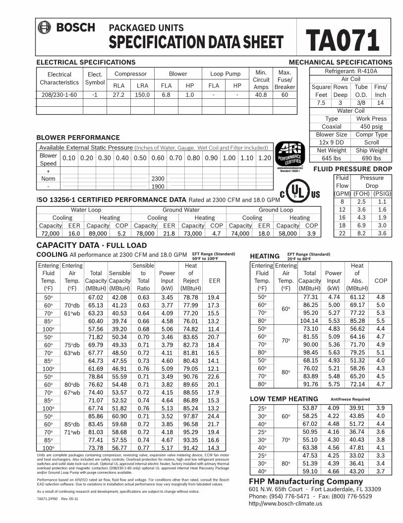
CAPACITY DATA - FULL LOAD
ELECTRICAL SPECIFICATIONS
BLOWER PERFORMANCE
COOLING All performance at 2300 CFM and 18.0 GPM HEATING
Available External Static Pressure (Inches of Water, Gauge. Wet Coil and Filter Included)
Blower Speed + Norm 2300 - 1900
Water Loop Ground Water Ground Loop Cooling Heating Cooling Heating Cooling Heating Capacity EER Capacity COP Capacity EER Capacity COP Capacity EER Capacity COP 72,000 16.0 89,000 5.2 78,000 21.8 73,000 4.7 74,000 18.0 58,000 3.9
ISO 13256-1 CERTIFIED PERFORMANCE DATA Rated at 2300 CFM and 18.0 GPM
Refrigerant: R-410A Air Coil Square Rows Tube Fins/ Feet Deep O.D. Inch 7.5 3 3/8 14 Water Coil Type Work Press Coaxial 450 psig Blower Size Compr Type 12x 9 DD Scroll Net Weight Ship Weight 645 lbs 690 lbs
MECHANICAL SPECIFICATIONS
Entering Entering Sensible Heat Fluid Air Total Sensible to Power of Temp. Temp. Capacity Capacity Total Input Reject EER (oF) (oF) (MBtuH) (MBtuH) Ratio (kW) (MBtuH)
50o
60o 70odb 70o 61owb 85o
100o
50o
60o 75odb 70o 63owb 85o
100o
50o
60o 80odb 70o 67owb 85o
100o
50o
60o 85odb 70o 71owb 85o
100o
Units are complete packages containing compressor, reversing valve, expansion valve metering device, ECM fan motor and heat exchangers. Also included are safety controls: Overload protection for motors, high and low refrigerant pressure switches and solid state lock-out circuit. Optional UL approved internal electric heater, factory installed with primary thermal overload protection and magnetic contactors (208/230-1-60 only) optional UL approved internal Heat Recovery Package and/or Ground Loop Pump with purge connections available.
Performance based on ARI/ISO rated air flow, fluid flow and voltage. For conditions other than rated, consult the Bosch EAD selection software. Due to variations in installation actual performance may vary marginally from tabulated values.
As a result of continuing research and development, specifications are subject to change without notice.
TA071.2IP60 Rev: 05-11
FLUID PRESSURE DROP
67.02 42.08 0.63 3.45 78.78 19.465.13 41.23 0.63 3.77 77.99 17.363.23 40.53 0.64 4.09 77.20 15.560.40 39.74 0.66 4.58 76.01 13.257.56 39.20 0.68 5.06 74.82 11.4
71.82 50.34 0.70 3.46 83.65 20.769.79 49.33 0.71 3.79 82.73 18.467.77 48.50 0.72 4.11 81.81 16.564.73 47.55 0.73 4.60 80.43 14.161.69 46.91 0.76 5.09 79.05 12.178.84 55.59 0.71 3.49 90.76 22.676.62 54.48 0.71 3.82 89.65 20.174.40 53.57 0.72 4.15 88.55 17.971.07 52.52 0.74 4.64 86.89 15.367.74 51.82 0.76 5.13 85.24 13.285.86 60.90 0.71 3.52 97.87 24.483.45 59.68 0.72 3.85 96.58 21.781.03 58.68 0.72 4.18 95.29 19.477.41 57.55 0.74 4.67 93.35 16.673.78 56.77 0.77 5.17 91.42 14.3
EFT Range (Standard) 25oF to 80oF
EFT Range (Standard) 50oF to 100oF
25o 30o 60o
40o
25o
30o 70o
40o
25o
30o 80o
40o
LOW TEMP HEATING 53.87 4.09 39.91 3.9 58.25 4.22 43.85 4.0 67.02 4.48 51.72 4.4 50.95 4.16 36.74 3.6 55.10 4.30 40.43 3.8 63.38 4.56 47.81 4.1 47.53 4.25 33.02 3.3 51.39 4.39 36.41 3.4 59.10 4.66 43.20 3.7
Antifreeze Required
TA071PACKAGED UNITS
SPECIFICATION DATA SHEET
FHP Manufacturing Company601 N.W. 65th Court - Fort Lauderdale, FL 33309Phone: (954) 776-5471 - Fax: (800) 776-5529http://www.bosch-climate.us
Compressor Blower Loop Pump Min. Max. Circuit Fuse/ RLA LRA FLA HP FLA HP Amps Breaker
208/230-1-60 -1 27.2 150.0 6.8 1.0 - - 40.8 60
Electrical Elect. Characteristics Symbol


601 N.W. 65th Court, Ft. Lauderdale, FL 33309Phone: 954-776-5471 | Fax: 954-776-5529www.boschtaxcredit.com | www.bosch-climate.us