guide specifications for seismic design of steel … · guide specifications for seismic design of...
TRANSCRIPT

GUIDE SPECIFICATIONS FOR SEISMIC DESIGNOF STEEL BRIDGES
First Edition
State of CaliforniaDepartment of Transportation
December 2001


GUIDE SPECIFICATIONS FOR SEISMIC DESIGN OF STEEL BRIDGES – FIRST EDITION
December 2001 ii
TABLE OF CONTENTS
PREFACE iDEFINITIONS ivNOTATION vii
1. INTRODUCTION 11.1. Scope 11.2. Referenced Specifications and Standards 11.3. Bridge Categories 21.4. Seismic Performance Criteria 2
2. GENERAL PROVISIONS 32.1. Loads and Load Combination 32.2. Seismic Design Acceptance Criteria 3
2.2.1. Structural Component Classification 32.2.2. Damage Levels, Strain and Ductility in Structural Steel 62.2.3. Displacements 82.2.4. Forces 8
3. STRUCTURAL ANALYSIS 93.1. Analysis Methods 9
3.1.1. General 93.1.2. Moment-Curvature Analysis 11
3.2. Structural Modeling 123.2.1. General 123.2.2. Materials 133.2.3. Geometry 133.2.4. Effective Section Properties 15
4. DESIGN REQUIREMENTS 164.1. Proportions 164.2. Materials 174.3. Effective Net Sections 184.4. Effective Length of Compression Members 184.5. Limiting Width-Thickness Ratios 194.6. Limiting Slenderness Parameters 194.7. Built-up Members 234.8. Shear Connectors 244.9. Restraining Components 264.10. Welding 28

GUIDE SPECIFICATIONS FOR SEISMIC DESIGN OF STEEL BRIDGES – FIRST EDITION
December 2001 iii
5. DUCTILE SEISMIC RESISTING SYSTEMS 295.1. Ductile Substructure Systems 29
5.1.1. Moment Resisting Frames 295.1.2. Concentrically Braced Frames 325.1.3. Eccentrically Braced Frames 34
5.2. Ductile End Cross Frames and Diaphragms 375.2.1. General 375.2.2. Effective Column Area 385.2.3. Boundary Conditions of Effective Columns 38
5.3. Integral Connection Systems 395.3.1. General 395.3.2. Steel Girder Superstructures 395.3.3. Concrete Columns 405.3.4. Concrete Bent Cap Beams 405.3.5. Concrete End Diaphragms at Abutments 41
6. DUCTILE COMPONENTS 426.1. General 426.2. Tension Members 426.3. Compression Members 426.4. Flexural Members 436.5. Members Subjected to Combined Flexure and Axial Force 43
7. CAPACITY-PROTECTED COMPONENTS 447.1. General 447.2. Tension Members 447.3. Compression Members 447.4. Flexural Members 457.5. Members Subjected to Combined Flexure and Axial Force 457.6. Connections and Splices 45
7.6.1. General 457.6.2. Bracing Connections 467.6.3. Beam-to-Column Connections 477.6.4. Gusset Plate Connections 48
7.7. Fasteners and Holes 547.8. Anchor Rods and Anchorage Assemblies 54
APPENDICESA. STRESS-STRAIN RELATIONSHIPS FOR STRUCTURAL STEEL 56B. EFFECTIVE SECTION PROPERTIES 58C. YIELD SURFACE EQUATIONS FOR DOUBLY SYMMETRICAL
STEEL SECTIONS 63D. DESIGN FORMULAS (U.S. UNITS) 65E. LATERAL STIFFNESS OF GIRDER BRIDGES IN TRANSVERSE DIRECTION 67F. REFERENCES 71

GUIDE SPECIFICATIONS FOR SEISMIC DESIGN OF STEEL BRIDGES – FIRST EDITION
December 2001 iv
DEFINITIONS
The following definitions are supplemental to the definitions given in the Caltrans Seismic
Design Criteria Version 1.2 (Caltrans 2001) and the Caltrans Bridge Design Specifications (Caltrans
2000).
Block Shear Rupture – A failure phenomenon or limit state for a bolted web connection of coped
beams or any tension connection by the tearing out of a portion of a plate along the centerlines of
the bolt holes. The block shear rupture strength combines tensile strength on one plane and shear
strength on a perpendicular plane.
Bracing Member - A member intended to brace a main member or part thereof against lateral
movement.
Capacity-Protected Component - A component expected to experience minimum damage and to
behave essentially elastic during the design earthquakes.
Connections - A combination of joints used to transmit forces between two or more members.
Concentrically Braced Frame (CBF) - A diagonally braced frame in which all members of the bracing
system are subjected primarily to axial forces.
Design Earthquake – Earthquake loads represented by Acceleration Response Spectrum (ARS) curves
specified in Caltrans SDC or site-specific ARS curves.
Design Strength - Resistance (axial/shear force, moment, as appropriate) provided by structural
components, the product of the nominal strength and the resistance factor.
Displacement Ductility - Ratio of ultimate-to-yield displacement.
Ductile Component – A component expected to experience repairable damage during the FEE and
significant damage but without failure during the SEE.
Ductility - Ratio of ultimate-to-yield deformation.
Eccentrically Braced Frame (EBF) - A diagonally braced frame that has at least one end of each
bracing member connected to a link.
Expected Nominal Strength - Nominal strength of a component based on its expected yield strength.
Functional Evaluation Earthquake (FEE) - A lower level design earthquake that has relatively small
magnitude but may occur several times during the life of the bridge. It may be assessed either
deterministically or probabilistically. The determination of this event is to be reviewed by a
Caltrans-approved consensus group.

GUIDE SPECIFICATIONS FOR SEISMIC DESIGN OF STEEL BRIDGES – FIRST EDITION
December 2001 v
Joint – An area where member ends, surfaces, or edges are attached by plates, fasteners and welds.
Link - In EBF, the segment of a beam that is located between the ends of two diagonal braces or
between the end of a diagonal brace and a column. Under lateral loading, the link deforms
plastically in shear thereby absorbing energy. The length of the link is defined as the clear
distance between the ends of two diagonal braces or between the diagonal brace and the column
face.
Maximum Credible Earthquake (MCE) - The largest earthquake that is capable of occurring along an
earthquake fault, based on current geologic information as defined by the 1996 Caltrans Seismic
Hazard Map.
Moment Resisting Frame (MRF) - A frame system in which seismic forces are resisted by shear and
flexure in members, and connections in the frame.
Nominal Strength – The capacity of a component to resist the effects of loads, as determined by
computations using specified material strength, dimensions and formulas derived form acceptable
principles of structural mechanics or by field tests or laboratory test of scaled models, allowing
for modeling effects, and differences between laboratory and field conditions.
Overstrength Capacity - The maximum possible strength capacity of a ductile component considering
actual strength variation between the component and adjacent components. It is estimated by an
overstrength factor of 1.2 times expected nominal strength.
Panel Zone - The web area of the beam-to-column connection delineated by the extension of column
and beam flanges.
Rotation Ductility - Ratio of ultimate-to-yield rotation.
Safety Evaluation Earthquake (SEE) - An upper level design earthquake that has only a small
probability of occurring during the life of the bridge. It may be assessed either deterministically
or probabilistically. The deterministic assessment corresponds to the Maximum Credible
Earthquake (MCE). The probabilistically assessed earthquake typically has a long return period
(approximately 1000-2000 years).
Splice – The connection between two structural elements jointed at their end to form a single, longer
element.

GUIDE SPECIFICATIONS FOR SEISMIC DESIGN OF STEEL BRIDGES – FIRST EDITION
December 2001 vi
Ultimate Displacement - The lateral displacement of a component or a frame corresponding to the
expected damage level, not to exceed the displacement when the lateral resistance degrades to a
minimum of 80 percent of the peak resistance.
Ultimate Rotation - The rotation corresponding to the expected damage level at which strain in the
extreme fiber reaches its strain limit, not to exceed the rotation when the moment resistance
degrades to a minimum of 80 percent of the peak moment resistance.
Upper Bound Solution – A solution calculated on the basis of an assumed mechanism which is always
at best equal to or greater than the true ultimate load.
Yield Rotation - The rotation at the onset of yielding in the extreme tension fiber.
Yield Displacement - The lateral displacement of a component or a frame at the onset of forming the
first plastic hinge.

GUIDE SPECIFICATIONS FOR SEISMIC DESIGN OF STEEL BRIDGES – FIRST EDITION
December 2001 vii
NOTATION
Numbers in parentheses after the definition of a symbol refer to the Article where the symbol
first appears or is used.
a = distance between two battens along the member axis (mm) (Appendix B)
a = length of the beam outside of a link (mm) (Appendix E)
Ab = cross-sectional area of a batten plate (mm2) (Appendix B)
Ab = cross-sectional area of each brace (mm2) (Appendix E)
Aclose = area enclosed within the mean dimension for a box-shaped section (mm2) (Appendix B)
Ad = cross-sectional area of all diagonal lacings in one panel (mm2) (Appendix B)
Ae = effective net section area (mm2) (Article 4.3)
Aequiv = cross-sectional area of a thin-walled plate equivalent to lacing bars considering shear
transferring capacity (mm2) (Appendix B)
Aequiv* = cross-sectional area of a thin-walled plate equivalent to lacing bars or battens assuming full
section integrity (mm2) (Appendix B)
Af = flange area to which battens or laces are attached (mm2) (Appendix B)
Ag = web gross area of a rectangular tube or cross-sectional area of a pipe (mm2) (Article 4.9)
Ag = gross cross-sectional area (mm2) (Article 7.6.4.3)
Ag = area of a stiffened girder (mm2) (Appendix E)
Ai = cross-sectional area of an individual main component i (mm2) (Appendix B)
Al = cross-sectional area of shear links (mm2) (Appendix E)
An = net section area (mm2) (Article 4.3)
Ar = cross-sectional area of a fastener (mm2) (Appendix B)
As,l = shear area of a shear link (mm2) (Appendix E)
Atg = gross area resisting tension (mm2) (Article 7.6.4.3)
Atn = net area resisting tension (mm2) (Article 7.6.4.3)
Avg = gross area resisting shear (mm2) (Article 7.6.4.3)
Avn = net area resisting shear (mm2) (Article 7.6.4.3)
Ai* = cross-sectional area above or below the plastic neutral axis (mm2) (Appendix B)

GUIDE SPECIFICATIONS FOR SEISMIC DESIGN OF STEEL BRIDGES – FIRST EDITION
December 2001 viii
A1 = bearing area of a steel pipe in concrete (mm2) (C4.9)
A2 = confinement concrete area equal to the embedment length of a steel pipe times the concrete
edge width bound by two 45o lines drawn from the outside diameter of the pipe to the edge
of concrete element (mm2) (C4.9)
b = width of a gusset plate perpendicular to the edge (mm) (Article 7.6.4.2)
bf = beam flange width (mm) (Article 5.1.2)
bi = length of the particular segment of a section (mm) (Appendix B)
Cs = seismic coefficient from the design response spectrum curve (C3.2.3)
dg = overall girder depth (mm) (Article 7.6.3)
dz = panel zone depth between continuity plates (mm) (Article 7.6.3)
D = outside diameter of a steel pipe (mm) (Table 4.5)
e = link length (mm) (C5.1.3)
E = modulus of elasticity of steel (200,000 MPa) (Table 4.6)
Es = modulus of elasticity of steel (MPa) (Appendix A)
fs = stress in steel (MPa) (Appendix A)
fy = yield stress of steel (MPa) (Appendix A)
fsb = rupture stress of steel (MPa) (Appendix A)
fsu = maximum stress of steel (MPa) (Appendix A)
cf � = specified compressive strength of concrete at 28 days (MPa) (C4.9)
Fu = specified minimum tensile strength of steel (MPa) (Article 7.6.4.3)
Fy = specified minimum yield strength of steel (MPa) (Article 4.2)
Fye = expected yield strength of steel (MPa) (Article 4.2)
Fyf = specified minimum yield strength of a flange component (MPa) (Appendix B)
Fyw = specified minimum yield strength of a web component (battens or lacing bars) (MPa)
(Appendix B)
FC = nominal strength (axial/shear force, moment, as appropriate) of a capacity-protected
component determined in accordance with Article 7 (Article 2.2.4)

GUIDE SPECIFICATIONS FOR SEISMIC DESIGN OF STEEL BRIDGES – FIRST EDITION
December 2001 ix
FD = force demand (axial/shear force, moment, as appropriate) on a capacity-protected
component determined by the joint equilibrium of overstrength capacities of adjacent
ductile components or elastic seismic forces if there is no yielding in ductile members
(Article 2.2.4)
h = frame height (mm) (C5.1.3)
h = depth of a member in the lacing plane (mm) (Appendix B)
h = height of a girder bridge = hsup + hsup + hsub (mm) (Appendix E)
hbear = height of a bearing (mm) (Appendix E)
hsg = height of a steel girder (mm) (Appendix E)
hsub = height of the substructure (mm) (Appendix E)
hsup = height of the girder superstructure measured from the bottom of the girder flange to central
gravity of the concrete deck (mm) (Appendix E)
H = height of the pier from the point of fixity for the foundation (mm) (C3.2.3)
H = height of a stiffened girder (mm) (Appendix E)
Ib = moment of inertia of a batten plate (mm4) (Appendix B)
Ii = moment of inertia of a main individual component i (mm4) (Appendix B)
Il = moment of inertia of shear links (mm4) (Appendix E)
Iy-y = moment of inertia of a section about y-y axis considering shear transferring
capacity (mm4) (Appendix B)
Is = moment of inertia of a stiffener about its strong axis (mm4) (Article 7.6.4.2)
Isg = moment of inertia of a stiffened girder in the bearing location (mainly due to bearing
stiffeners) in the lateral direction (mm4) (Appendix E)
K = effective length factor of a member (Article 4.4)
Kbear = lateral stiffness of bearings at bent (kN/mm) (Appendix E)
Kendf = lateral stiffness of an end cross frame/diaphragm (kN/mm) (Appendix E)
Ktrans = lateral stiffness of a girder bridge bent in the transverse direction (kN/mm) (Appendix E)
Ksg = lateral stiffness of a steel girder (kN/mm) (Appendix E)
Ksub = lateral stiffness of the substructure at a bent (N/mm) (Appendix E)
Ksup = lateral stiffness of the superstructure at a bent (kN/mm) (Appendix E)

GUIDE SPECIFICATIONS FOR SEISMIC DESIGN OF STEEL BRIDGES – FIRST EDITION
December 2001 x
ld = embedment length of a steel pipe (mm) (C4.9)
lb = length of each brace (mm) (Appendix E)
L = unsupported length of a member (mm) (Article 4.4)
Lg = unsupported length of a gusset plate (mm) (Article 7.6.4.2)
Ls = girder spacing (mm) (Appendix E)
L1 = distance from the centerline of the Whitmore section to the interior corner of a gusset (mm)
(C7.6.4.4)
L2, L3 = distance from the outside corner of the Whitmore section to the edge of a member; negative
value shall be used when the part of Whitmore section enters into the member (mm)
(C7.6.4.4)
m = number of panels between the point of maximum calculated moment to the point of zero
moment to either side (as an approximation, the number of panels in half of the main
member length (L/2) may be used) (Appendix B)
m = sum of the superstructure mass and a half of substructure mass in the tributary area (kg)
(Appendix E)
mb = number of batten planes (Appendix B)
ml = number of lacing planes (Appendix B)
M = flexural moment due to seismic and permanent loads (N-mm) (Article 7.6.4.7)
Mn = nominal flexural moment strength (N-mm) (Article 7.6.4.5)
Moc = overstrength moment of a ductile column = 1.2Mpc (N-mm) (Article 5.1.1)*ocM = overstrength flexural moment in the column at the beam centerlines = [Moc+Mv] (N-mm)
(Article 5.1.1)coloM = overstrength plastic moment of a concrete column (N-mm) (Article 5.3.2)
Mp-b = plastic moment of a batten plate about the strong axis (N-mm) (Appendix B)colpM = idealized plastic moment capacity of a column calculated by moment-curvature analysis
(N-mm) (C3.2.3)*pbM = expected design flexural strengths of the beam at the intersection of the beam and the
column centerline (N-mm) (Article 5.1.1)

GUIDE SPECIFICATIONS FOR SEISMIC DESIGN OF STEEL BRIDGES – FIRST EDITION
December 2001 xi
Mpc = expected plastic moment capacity (N-mm) estimated by yield surface equations in
Appendix C based on the expected yield strength Fye, or approximated as Zc(Fye�P/Ag)
(Article 5.1.1)
Mv = additional moment due to the shear amplification from the actual location of the column
plastic hinge to the beam centerline (N-mm) (Article 5.1.1)
�*pbM = sum of the nominal flexural strength of the beam(s) at the intersection of the beam and the
column centerlines (N-mm) (Article 5.1.1)
�*ocM = sum of overstrength flexural moments in the column(s) above and below the joint at the
intersection of the beam and column centerlines (N-mm) (Article 5.1.1)
nr = number of fasteners of the connecting lacing bar or battens to the main component at one
connection (Appendix B)
P = axial force due to seismic and permanent loads (N) (Article 5.1.1)
Pdl = axial dead load (N) (C3.2.3)
Pn = nominal axial strength of a member (N) (Article 5.1.2)
Py = yield axial strength (AgFy) (N) (Article 5.1.2)
Pncomp = nominal compressive strength of a lacing bar, can be determined by AISC-LRFD (1999)
column curve (N) (Appendix B)
Pnten = nominal tensile strength of a lacing bar, can be determined by AISC-LRFD (1999) (N)
(Appendix B)
R = ratio between the elastic force and the lateral strength of the pier or bent (C3.2.3)
Rn = nominal shear strength of a HSS shear key (MN) (Article 4.9)
Ry = overstrengh factor for steel (Article 4.2)
r = radius of gyration (mm) (Article 4.4)
ry = radius of gyration about the minor axis (mm) (Table 4.6)
t = plate thickness (mm) (Table 4.5)
tequiv = thickness of equivalent thin-walled plate (mm) (Appendix B)
tf = beam flange thickness (mm) (Article 5.1.2)
ti = average thickness of a segment bi (mm) (Appendix B)

GUIDE SPECIFICATIONS FOR SEISMIC DESIGN OF STEEL BRIDGES – FIRST EDITION
December 2001 xii
tp = total thickness of the panel zone including doubler plates (mm) (Article 7.6.3)
tw = thickness of a web plate (mm) (Table 4.5)
T = period of vibration (second) (C3.2.3)
T* = 1.25Ts and Ts is period at the end of constant design spectral acceleration (second) (C3.2.3)
V = shear force due to seismic and permanent loads (N) (Article 7.6.4.7)
Vn = nominal shear strength (N) (Article 7.6.3)
wz = panel zone width between girder flanges (mm) (Article 7.6.3)
xi = distance between y-y axis and the centroid of the main individual component i (mm)
(Appendix B)
xi* = distance between the center of gravity of a section Ai
* and plastic neutral y-y axis (mm)
(Appendix B)
yi* = distance between center of gravity of a section Ai
* and the plastic neutral x-x axis (mm)
(Appendix B)
Z = plastic section modulus about the strong axis of the cross section of a gusset plate (mm3)
(Article 7.6.4.5)
Zc = plastic section modulus of a column (mm3) (Article 5.1.1)
Zx-x = plastic section modulus of a section about the plastic x-x neutral axis (mm3) (Appendix B)
Zy-y = plastic section modulus of a section about the plastic y-y neutral axis (mm3) (Appendix B)
� = brace’s angle with the horizontal direction (Appendix E)
�fix = fixity factor, equal to 12 if full fixity is provided at both flanges of a steel girder; 3 if one
end is fully fixed and other one pinned; and 0 if both ends are pinned (Appendix E)
�m = reduction factor for the moment of inertia (Appendix B)
�t = reduction factor for the torsion constant (Appendix B)
� = resistance factor (Article 7.1)
� = angle between a diagonal lacing bar and the axis perpendicular to the member axis
(Appendix B)
�bs = resistance factor for block shear rupture (Article 7.1)
�f = resistance factor for fracture in the net section (Article 7.1)

GUIDE SPECIFICATIONS FOR SEISMIC DESIGN OF STEEL BRIDGES – FIRST EDITION
December 2001 xiii
�s = strain in steel (Appendix A)
�sh = strain at the onset of strain hardening of steel (Article 2.2.2)
�su = strain corresponding to the maximum stress of steel (Appendix A)
�sb = rupture strain of steel (Appendix A)
�y = yield strain of steel (Article 2.2.2)
�b = slenderness parameter for flexural members (Article 4.6)
�bp = limiting slenderness parameter for flexural members (Article 4.6)
�c = slenderness parameter for compression members (Article 4.6)
�cp = limiting slenderness parameter for compression members (Article 4.6)
�p = limiting width-thickness ratio of a compression element for ductile components (Article
4.5)
�r = limiting width-thickness ratio of a compression element for capacity-protected components
(Article 4.5)
�� = displacement ductility, ratio of ultimate-to-yield displacement (�u/�y) (Article 2.2.2)
�� = rotation ductility, ratio of ultimate-to-yield rotation (�u/�y) (Article 2.2.2)
�y = yield rotation which is the rotation at the onset of yielding in the extreme tension fiber
(Article 2.2.2)
�p = plastic rotation angle (C5.1.3)
�u = ultimate rotation capacity which is the rotation corresponding to the expected damage level
at which strain in the extreme fiber reaches its strain limit as specified in Table 2.2.2, not to
exceed the rotation when the moment resistance degrades to a minimum of 80 percent of
the peak moment resistance (Article 2.2.2)
�p = link plastic rotation angle (C5.1.3)
�e = displacement demand from the seismic analysis (mm) (C3.2.3)
�p = plastic frame displacement (mm) (C5.1.3)
�r = relative lateral offset between the point of contra-flexure and the base of the plastic hinge
(mm) (C3.2.3)

GUIDE SPECIFICATIONS FOR SEISMIC DESIGN OF STEEL BRIDGES – FIRST EDITION
December 2001 xiv
�u = ultimate lateral displacement capacity which is the lateral displacement of a component or a
frame corresponding to the expected damage level limit as specified in Table 2.2.2, not to
exceed the displacement when the lateral resistance degrades to a minimum of 80 percent of
the peak resistance (mm) (Article 2.2.2)
�y = yield displacement which is the lateral displacement of a component or a frame at the onset
of forming the first plastic hinge (mm) (Article 2.2.2)
�C = displacement capacity determined by using a static push over analysis in which both
material and geometric non-linearities are considered (mm) (Article 2.2.3)
�D = displacement demand determined by one of the analysis methods specified in Article 3.1
(mm) (Article 2.2.3)

GUIDE SPECIFICATIONS FOR SEISMIC DESIGN OF STEEL BRIDGES – FIRST EDITION
SPECIFICATIONS COMMENTARY
___________________________________________________________________________________________________December 2001 1
1. INTRODUCTION
1.1 Scope
The Guide Specifications for Seismic
Design of Steel Bridges (Guide) is intended for
the seismic design of steel bridges. The Guide is
supplemental to the Caltrans Seismic Design
Criteria Version 1.2 (Caltrans 2001), hereafter
referred to as the SDC. These provisions shall
be applied in conjunction with the Caltrans
Bridge Design Specifications (Caltrans 2000a),
hereafter referred to as the BDS.
1.2 Referenced Specifications and Standards
The following documents are referenced in
the Guide:
AASHTO (1998). LRFD Bridge DesignSpecifications, 2nd Edition with 1999, 2000 and2001 Interims.
ACI (1999). Building Code Requirements forStructural Concrete (ACI 318-99) andCommentary (ACI 318R-99).
AISC (1999a). Load and Resistance FactorDesign for Structural Steel Buildings, 3rdEdition.
AISC (1997). Seismic Provisions for StructuralSteel Buildings with Supplements No. 1 (1999b)and No. 2 (2000).
Caltrans (2000a). Bridge Design Specifications.
Caltrans (2001). Seismic Design Criteria,Version 1.2.

GUIDE SPECIFICATIONS FOR SEISMIC DESIGN OF STEEL BRIDGES – FIRST EDITION
SPECIFICATIONS COMMENTARY
___________________________________________________________________________________________________December 2001 2
Caltrans (1995a). Bridge Memo to DesignersManual.
Caltrans (1995b). Bridge Design Aids Manual.
1.3 Bridge Categories
All steel bridges shall be categorized as
either Important or Ordinary in accordance with
the Bridge Memo to Designer (MTD) 20-1
(Caltrans 1999).
1.4 Seismic Performance Criteria
All steel bridges shall be designed to meet
the Seismic Performance Criteria specified in
the MTD 20-1.

GUIDE SPECIFICATIONS FOR SEISMIC DESIGN OF STEEL BRIDGES – FIRST EDITION
SPECIFICATIONS COMMENTARY
___________________________________________________________________________________________________December 2001 3
2. GENERAL PROVISIONS
2.1 Loads and Load Combination
Earthquake loads shall be in accordance
with Article 2.1 of the SDC.
2.2 Seismic Design Acceptance Criteria
2.2.1 Structural Component Classification
Structural components of a steel bridge
are classified into two categories: Ductile and
Capacity-protected as shown in Table 2.2.1.
C2.2.1
Ductile components are those expected to
experience repairable damage during the
Functional Evaluation Earthquake (FEE) and
significant damage but without failure during
the Safety Evaluation Earthquake (SEE). The
components shall be pre-identified and well-
detailed to behave inelastically without
significant degradation of strength or stiffness.
Capacity-protected components are those
expected to experience minimum damage, and
to behave essentially elastic during both the
FEE and the SEE.
Earthquake resisting systems shall be
designed to meet the seismic performance
criteria. A dual level design may be needed for
nonstandard ordinary bridges and important
bridges. For example, in both the longitudinal
and transverse directions, isolation bearings
could be used to dissipate energy for a moderate
to large earthquake while column hinging could
be used as a second mechanism for the
Maximum Credible Earthquake (MCE) once

GUIDE SPECIFICATIONS FOR SEISMIC DESIGN OF STEEL BRIDGES – FIRST EDITION
SPECIFICATIONS COMMENTARY
___________________________________________________________________________________________________December 2001 4
displacement limits are reached in the bearings.
Similarly in the transverse direction ductile end
cross frames or diaphragms could be used for a
moderate to large earthquake while ductile
columns will be activated in an extremely large
event when the displacement limits are reached
in the end cross frames or diaphragms.

GUIDE SPECIFICATIONS FOR SEISMIC DESIGN OF STEEL BRIDGES – FIRST EDITION
SPECIFICATIONS COMMENTARY
___________________________________________________________________________________________________December 2001 5
Table 2.2.1 Structural Component Classification
Structural Component ClassificationDirection System Ductile Capacity-protected
Longitudinal Integral/Non-integral
ColumnsPiers
Bent capsSuperstructuresFoundations
Bent Connections Isolation Bearings Bent CapsSuperstructuresSubstructures
Non-integral BentConnections
Isolation Bearings Bent CapsSuperstructuresSubstructures
DuctileEnd-Diaphragm
ConcentricallyBracedFrames
Bracingmembers
Bracing connectionsGirdersSubstructures
System EccentricallyBracedFrames
Links Diagonal bracesBeam outside of LinksGirders, ConnectionsSubstructures
Transverse MomentResistingFrames
Columns Bent CapsSuperstructuresConnectionsFoundations
Ductile Substructure
Systems
EccentricallyBracedFrames
Links SuperstructuresDiagonal bracesBeam outside of LinksConnections, ColumnsFoundations
ConcentricallyBraced Frames
Bracingmembers
SuperstructuresBracing connectionsBeams, ColumnsFoundations

GUIDE SPECIFICATIONS FOR SEISMIC DESIGN OF STEEL BRIDGES – FIRST EDITION
SPECIFICATIONS COMMENTARY
___________________________________________________________________________________________________December 2001 6
2.2.2 Damage Levels, Strain and Ductility in
Structural Steel
The following limiting strains, ductility
and corresponding damage levels may be used.
C2.2.2
Table 2.2.2 Damage Levels, Strain and Ductility in Structural SteelDamage Strain Ductility
Level � �� ��
Significant �sh 8 4 Repairable Larger of
���
3/2008.0
sh�
6 3
Minimum Larger of
���
y�5.1003.0
2 1.5
Table 2.2.2 provides quantitative strain
and ductility limits corresponding to the three
damage levels specified in the Caltrans Seismic
Performance Criteria in the MTD 20-1
(Caltrans 1999).
where�sh = strain at the onset of strain hardening
of steel
�y = yield strain of steel
�� = displacement ductility, ratio of
ultimate-to-yield displacement (�u/�y)
�� = rotation ductility, ratio of ultimate-to-
yield rotation (�u/�y)
�y = yield displacement which is the lateral
displacement of a component or a
frame at the onset of forming the first
plastic hinge (mm)
�y = yield rotation which is the rotation at
the onset of yielding in the extreme
tension fiber

GUIDE SPECIFICATIONS FOR SEISMIC DESIGN OF STEEL BRIDGES – FIRST EDITION
SPECIFICATIONS COMMENTARY
___________________________________________________________________________________________________December 2001 7
�u = ultimate displacement capacity which
is the lateral displacement of a
component or a frame corresponding
to the expected damage level limit as
specified in Table 2.2.2, not to exceed
the displacement when the lateral
resistance degrades to a minimum of
80 percent of the peak resistance
(Figure C2.2.2a) (mm)
�u = ultimate rotation capacity
corresponding to the expected damage
level at which strain in the extreme
fiber reaches its strain limit as
specified in Table 2.2.2, not to exceed
the rotation when the moment
resistance degrades to a minimum of
80 percent of the peak moment
resistance (Fig. C.2.2b)
Figure C2.2.2 shows typical load-deformation
curves.
(a)
(b)
Figure C2.2.2 Load-Deformation Curves

GUIDE SPECIFICATIONS FOR SEISMIC DESIGN OF STEEL BRIDGES – FIRST EDITION
SPECIFICATIONS COMMENTARY
___________________________________________________________________________________________________December 2001 8
2.2.3 Displacements
The displacements in a global and local
ductile system shall satisfy the following
requirement:
CD �� � (2.2.3-1)
where�D = displacement demand determined by
one of the analysis methods specified
in Article 3.1 (mm)
�C = displacement capacity determined by
using a static push over analysis in
which both material and geometric
non-linearities are considered (mm)
2.2.4 Forces
The forces in a capacity-protected
component shall satisfy the following
requirement:
CD FF � (2.2.4-1)where
FD = force demand (axial/shear force,
moment, as appropriate) on a capacity-
protected component determined by
the joint equilibrium of overstrength
capacities of adjacent ductile
components or elastic seismic forces if
there is no yielding in ductile members
FC = nominal strength (axial/shear force,
moment, as appropriate) of a capacity-
protected component determined in
accordance with Article 7

GUIDE SPECIFICATIONS FOR SEISMIC DESIGN OF STEEL BRIDGES – FIRST EDITION
SPECIFICATIONS COMMENTARY
___________________________________________________________________________________________________December 2001 9
3. STRUCTURAL ANALYSIS
3.1 Analysis Methods
3.1.1 General
Analysis methods such as Equivalent
Static Analysis (ESA), Elastic Dynamic
Analysis (EDA), Inelastic Static Analysis (ISA)
presented in Article 5.2 of the SDC shall apply.
C3.1
Inelastic Static Analysis (ISA), commonly
referred to as the “push over analysis”, shall be
used to determine the displacement capacity of
a steel bridge. ISA can be categorized into three
types of analysis: (1) elastic-plastic hinge, (2)
refined plastic hinge, and (3) distributed
plasticity.
The simplest method, elastic-plastic hinge
analysis, may be used to obtain an upper bound
solution. The most accurate method, distributed
plasticity analysis, can be used to obtain a
better solution. Refined plastic hinge analysis is
an alternative that can reasonably achieve both
computational efficiency and accuracy.
In an elastic-plastic hinge (lumped
plasticity) analysis, material inelasticity is taken
into account using concentrated "zero-length"
plastic hinges which maintain plastic moment
capacities and rotate freely. When the section
reaches its plastic moment capacity, a plastic
hinge is formed and element stiffness is adjusted
(King et al. 1992; Levy et al. 1997). For regions
in a framed member away from the plastic
hinge, elastic behavior is assumed. It does not,
however, accurately represent the distributed
plasticity and associated P-� effects. This
analysis provides an upper bound solution.

GUIDE SPECIFICATIONS FOR SEISMIC DESIGN OF STEEL BRIDGES – FIRST EDITION
SPECIFICATIONS COMMENTARY
___________________________________________________________________________________________________December 2001 10
In the refined plastic hinge analysis (Chen
and Toma 1994), a two-surface yield model
considers the reduction of plastic moment
capacity at the plastic hinge due to the presence
of axial force, and an effective tangent modulus
accounts for the stiffness degradation due to
distributed plasticity along a frame member.
This analysis is similar to the elastic-plastic
hinge analysis in efficiency and simplicity and
also accounts for distributed plasticity.
Distributed plasticity analysis models the
spread of inelasticity through the cross sections
and along the length of the members. This is
also referred to as plastic zone analysis, spread-
of-plasticity analysis, or elasto-plastic analysis
by various researchers. In this analysis, a
member needs to be subdivided into several
elements along its length to model the inelastic
behavior more accurately. Two main
approaches have been successfully used to
model plastification of members in a second-
order distributed plasticity analysis:
(1) Cross sectional behavior is described as an
input for the analysis by means of moment-
thrust-curvature (M-P-�) and moment-
thrust-axial strain (M-P-�) relations, which
may be obtained separately from a moment-
curvature analysis or approximated by
closed-form expressions (Chen and Atsuta
1977).

GUIDE SPECIFICATIONS FOR SEISMIC DESIGN OF STEEL BRIDGES – FIRST EDITION
SPECIFICATIONS COMMENTARY
___________________________________________________________________________________________________December 2001 11
(2) Cross sections are subdivided into
elementary areas and the state of stresses
and strains are traced explicitly using the
proper stress-strain relations for all
elements during the analysis.
3.1.2 Moment-Curvature Analysis
In a moment-curvature analysis for a
ductile structural steel component, the following
assumptions are usually made:
� Section that are plane before bending,
remain plane after bending
� Shear and torsional deformation is
negligible
� Stress-strain relationships for steel
C3.1.2
The steel section shall be divided into
layers or filaments and a typical steel stress-
strain relationship assumed. The yield moment
My is the section moment at the onset of yielding
of an extreme fiber. The ultimate moment Mu is
the moment at the peak moment capacity.
A set of typical moment-curvature curves
for a steel I-section is shown in Figure C3.1.2.
Figure C3.1.2 Moment-Curvature Curves

GUIDE SPECIFICATIONS FOR SEISMIC DESIGN OF STEEL BRIDGES – FIRST EDITION
SPECIFICATIONS COMMENTARY
___________________________________________________________________________________________________December 2001 12
3.2 Structural Modeling
3.2.1 General
The principles presented in Articles 5.3,
5.4 and 5.5 of the SDC shall generally apply.
The straight steel girder superstructure should
be modeled as a series of three-dimensional
frame elements. Bent caps and columns shall be
modeled as three-dimensional frame elements.
C3.2.1
In general, dynamic behavior of a bridge
structure can be predicted by the finite element
method. The elements can be frame (beam),
shell, solid elements or other types of elements
idealizing the real structures. Two types of finite
element models, simplified and detailed, are
typically used for dynamic analysis of a steel
bridge structure. A simplified model uses two-
dimensional or three-dimensional frame
elements, as so-called “stick” models to
represent superstructures and columns. A
detailed model uses solid elements for
superstructure deck, shell elements for steel
girders, and frame elements for columns.
A recent report (Itani and Sedarat 2000)
indicated that the dynamic characteristics of
straight steel girder bridges can be captured by
the simplified modeling procedure. The five
elements per span are sufficient for a good
representation of the first three vibration modes
of a span (ATC, 1996). When the periods of the
higher modes of a span are within the
acceleration-control region of the earthquake
response spectrum, it is necessary to include
more elements to capture high modes. In
general, if the contribution of the ith mode
needs to be included in the analysis, the span

GUIDE SPECIFICATIONS FOR SEISMIC DESIGN OF STEEL BRIDGES – FIRST EDITION
SPECIFICATIONS COMMENTARY
___________________________________________________________________________________________________December 2001 13
should be modeled by 2i-1 elements over the
span length (Itani and Sedarat 2000).
3.2.2 Materials
Structural steel shall be modeled to closely
represent actual testing behavior. In
the absence of material data and test results, the
stress-strain relationships represented in
Appendix A may be used in the analysis.
3.2.3 Geometry C3.2.3
The member forces, moment and
displacements induced by P-� effects, shall be
considered in evaluating the overall structural
frame stability.
The P-� effects can be ignored when the
requirement specified in Article 4.4 of the SDC
is satisfied.
The P-� effects can be evaluated by a
large deflection analysis, usually referred to as
second-order analysis or geometrically
nonlinear analysis where equilibrium equations
are established with respect to the deformed
geometry of the structure. In lieu of a second-
order elastic analysis, the moment
magnification method specified in Article
4.5.3.2.2 of the AASHTO-LRFD (1998) may be
used.
A small deflection analysis is usually
referred to as first-order analysis or
geometrically linear analysis where equilibrium
equations are established with respect to
undeformed (or original) geometry of the
structure. It is recognized that a first-order
analysis always underestimates the force and
deformation effects.
GUIDE SPECIFICATIONS FOR SEISMIC DESIGN OF STEEL BRIDGES – FIRST EDITION
SPECIFICATIONS COMMENTARY
___________________________________________________________________________________________________December 2001 14
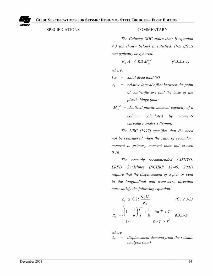
The Caltrans SDC states that: If equation
4.3 (as shown below) is satisfied, P-� effects
can typically be ignored.colprdl M.P 20�� (C3.2.3-1)
where:
Pdl = axial dead load (N)
�r = relative lateral offset between the point
of contra-flexure and the base of the
plastic hinge (mm)colpM = idealized plastic moment capacity of a
column calculated by moment-
curvature analysis (N-mm)
The UBC (1997) specifies that P� need
not be considered when the ratio of secondary
moment to primary moment does not exceed
0.10.
The recently recommended AASHTO-
LRFD Guidelines (NCHRP 12-49, 2001)
require that the displacement of a pier or bent
in the longitudinal and transverse direction
must satisfy the following equation:
d
se R
HC.250�� (C3.2.3-2)
��
��
�
�
���
��
�
�*
**
d
TT.
TTRT
TRR
for 01
for 111(C3.2.3-3)
where�e = displacement demand from the seismic
analysis (mm)

GUIDE SPECIFICATIONS FOR SEISMIC DESIGN OF STEEL BRIDGES – FIRST EDITION
SPECIFICATIONS COMMENTARY
___________________________________________________________________________________________________December 2001 15
Cs = seismic coefficient from the designresponse spectrum curve
H = height of the pier form the point of
fixity for the foundation (mm)
R = ratio between the elastic force and the
lateral strength of the pier or bent
T = period of vibration (second)
T* = 1.25Ts and Ts is period at the end of
constant design spectral acceleration
(second)
3.2.4 Effective Section Properties
Effective section properties presented in
Appendix B may be used for built-up members
in a seismic analysis in lieu of more refined
properties.

GUIDE SPECIFICATIONS FOR SEISMIC DESIGN OF STEEL BRIDGES – FIRST EDITION
SPECIFICATIONS COMMENTARY
___________________________________________________________________________________________________December 2001 16
4. DESIGN REQUIREMENTS
4.1 Proportions C4.1
Structural systems for bridges shall be
proportioned and designed to provide effective
load paths and continuity, and to reduce the
seismic demands and effects on the structural
system to the greatest possible extent. Steel
components within the structural system shall be
designed to achieve their desired performance.
For steel bridges, structural components
shall be generally designed to ensure that
inelastic deformation only occurs in the
specially detailed ductile substructure elements.
Inelastic behavior in the form of controlled
damage may be permitted in some of the
superstructure components such as the end
cross-frames, end diaphragms, and bearings.
The inertial forces generated by the deck shall
be transferred to the substructure through
girders, trusses, cross frames, lateral bracings,
end diaphragms and bearings.
At transition and splice locations of a
ductile member, changes in the stiffness and the
strength of the member shall not exceed 50
percent.

GUIDE SPECIFICATIONS FOR SEISMIC DESIGN OF STEEL BRIDGES – FIRST EDITION
SPECIFICATIONS COMMENTARY
___________________________________________________________________________________________________December 2001 17
4.2 Materials
Structural steel used in ductile components
that protect other structural elements by the
capacity design principle shall meet one of the
following
� AASHTO M270 (ASTM A709M)
Grade 345 and Grade 345W
� ASTM A992 Steel
� A500 Grade B or A501 Steels
Other steels may be used provided that
they are compatible to the approved Grade 345
steels. The specified minimum yield strength of
steel used for ductile components shall not
exceed 345 MPa unless the suitability of the
material is determined by testing.
C4.2
The materials specified herein are
recommended in the recently recommended
AASHTO-LRFD Guidelines (NCHRP 12-49
2001).
The AISC Seismic Provisions (AISC 1997)
specify that structural steel permitted for use in
seismic design shall meet the following
characteristics: (1) a ratio of yield strength to
tensile strength not greater than 0.85; (2) a
pronounced stress-strain plateau at the yield
strength; (3) a large inleastic strain capacity
(for example, tensile elongation of 20 percent or
greater in a 127-mm gage length); and (4) good
weldability. M270 Grade 250 (ASTM 709 Grade
36 Steel) is not recommended for use in the
ductile components because it has a wide range
between its expected yield and ultimate strength,
as well as a large overstrength factor.
Expected yield strength Fye of steel is
defined as:
yyye FRF � (4.2-1)
where
Fye = expected yield strength of steel (MPa)
Ry = overstrengh factor for steel
Fy = specified minimum yield strength of
steel (MPa)
The AISC Seismic Provisions Supplement
No. 2 (AISC 2000) provides the following
overstrength factor Ry values:
Table C4.2 Ry Values
Application RyPlate and all other productsHot-rolled structural shapes and bars ASTM A36 A572 Grade 42 All other gradesHollow Structural Section ASTM A500, A501, A618 and A84Steel Pipe - ASTM A53
1.1
1.51.31.1
1.31.4

GUIDE SPECIFICATIONS FOR SEISMIC DESIGN OF STEEL BRIDGES – FIRST EDITION
SPECIFICATIONS COMMENTARY
___________________________________________________________________________________________________December 2001 18
4.3 Effective Net Sections
The net section, An, of a tension member
shall be determined in accordance with Article
10.9 and 10.16.14 of the BDS.
The effective net section, Ae, of a tension
member shall be determined in accordance with
Article 10.9 of the BDS.
4.4 Effective Length of Compression
Members
In the absence of more accurate analysis,
the effective length factor K for compression
members may be determined in accordance with
Appendix C of the BDS.
For built-up members, if the buckling
mode involves relative deformations that
produce shear forces in the connectors between
individual shapes, KL/r shall be modified in
accordance with Article E4 of the AISC-LRFD
(1999a).

GUIDE SPECIFICATIONS FOR SEISMIC DESIGN OF STEEL BRIDGES – FIRST EDITION
SPECIFICATIONS COMMENTARY
___________________________________________________________________________________________________December 2001 19
4.5 Limiting Width-Thickness Ratios
For capacity-protected components, the
width-thickness ratios of compression elements
shall not exceed the limiting values, �r, as
specified in Table 4.5. For ductile components,
width-thickness ratios of compression elements
shall not exceed the limiting values, �p, as
specified in Table 4.5.
4.6 Limiting Slenderness Parameters
The slenderness parameter �c for
compression members, and �b for
flexural members shall not exceed the limiting
values, �cp and �bp, as specified in Table 4.6,
respectively.

GUIDE SPECIFICATIONS FOR SEISMIC DESIGN OF STEEL BRIDGES – FIRST EDITION
SPECIFICATIONS COMMENTARY
___________________________________________________________________________________________________December 2001 20
Table 4.5 Limiting Width-Thickness Ratios
No Description of Elements ExamplesWidth-
ThicknessRatios
�r �p
UNSTIFFENED ELEMENTS
1Flanges of I-shaped rolled beams andchannels in flexure
Figure 4.5(a)Figure 4.5(c)
b/t69
370�yF yF
137
2
Outstanding legs of pairs of angles incontinuous contact; flanges of channels inaxial compression; angles and platesprojecting from beams or compressionmembers
Figure 4.5(d)Figure 4.5(e)
b/tyF
250
yF137
STIFFENED ELEMENTS
3
Flanges of square and rectangular boxand hollow structural section of uniformthickness subject to bending orcompression; flange cover plates anddiaphragm plates between lines offasteners or welds.
Figure 4.5(b)b/t
yF625
yF290/ (tubes)
yF400/ (others)
4Unsupported width of cover platesperforated with a succession of accessholes
Figure 4.5(d) b/tyF
830
yF400
5All other uniformly compressed stiffenedelements, i.e., supported along two edges.
Figures 4.5(a)
(c),(d),(f)
b/th/tw yF
665yF290/ (w/lacing)
yF400/ (others)
6 Webs in flexural compressionFigures 4.5(a)
(c),(d),(f)
h/tw
yF2550
yF1365
7 Webs in combined flexural and axialcompression
Figures 4.5(a)
(c),(d),(f) h/tw ���
����
�
��
y
0.741
2550
PP
F
b
y
For
���
����
�
��
�
yby
ybu
PP
F
PP
1.5411365
0.125
For
y
yby
ybu
F
PP
F
PP
665
2.33500
0.125
�
���
����
�
�
�
8 Longitudinally stiffened plates incompression
Figure 4.5(e) b/tyFk297
yFk197
9 Round HSS in axial compression orflexure
D/tyF
17930
yF8950
Notes:1. Width-Thickness Ratios shown in Bold are from AISC-LRFD (1999a) and AISC-Seismic Provisions (1997). Fy is MPa2. k = buckling coefficient specified by Article 6.11.2.1.3a of AASHTO-LRFD (AASHTO,1998)
for n = 1, 048 313 .)/( /�� btIk s for n = 2,3, 4 and 5, 04314 3143 .)/.( /
�� nbtIk s n = number of equally spaced longitudinal compression flange stiffeners Is = moment of inertia of a longitudinal stiffener about an axis parallel to the bottom flange and taken at the base of the stiffener


GUIDE SPECIFICATIONS FOR SEISMIC DESIGN OF STEEL BRIDGES – FIRST EDITION
SPECIFICATIONS
___________________________________________________________________________________________________December 2001 22
Table 4.6 Limiting Slenderness Parameters
Member Classification Limiting Slenderness Parameters
Compression Member
�cp 0.75
DuctileFlexural Member �bp 17240/ yF
Compression Member �cp 1.5
Capacity-Protected Flexural Member �bp yF/1970
��
cyKL
rFE
����
��� (slenderness parameter for compression members)
� by
Lr
� (slenderness parameter for flexural members)
�cp = limiting slenderness parameter for compression members
�bp = limiting slenderness parameter for flexural members
K = effective length factor of a member
L = unsupported length of a member (mm)
r = radius of gyration (mm)
ry = radius of gyration about the minor axis (mm)
Fy = specified minimum yield strength of steel (MPa)
E = modulus of elasticity of steel (200,000 MPa)

GUIDE SPECIFICATIONS FOR SEISMIC DESIGN OF STEEL BRIDGES – FIRST EDITION
SPECIFICATIONS COMMENTARY
___________________________________________________________________________________________________December 2001 23
4.7 Built-up Members
For built-up members, lacing including
flat bars, angles, channels, or other shapes
employed as lacing, or batten plates, or
connectors shall be so spaced that l/r of the
flange included between their connections shall
not exceed three-fourths times the governing
slenderness ratio for the laced member as a
whole.
C4.7
Two types of built-up members are
commonly used for steel construction. The first
type includes the laced or battened members
with widely spaced flange components and the
second type consists of closely spaced shapes
interconnected by welds or connectors. It is
known that compressive strength of both types
of built-up members is affected by the shearing
effect. For the first type, the shearing effects
results from the deformation of flange
components and laces, while for the second
type, the shearing effect is caused by the
shearing of intermediate connectors. The
current practice (AISC-LRFD 1999a) considers
the shear effects of the second type, but not the
first type. A recent study (Duan, et al. 2002)
has shown that the compressive strength of
built-up members may also affected by the
compound buckling due to the interaction
between the global buckling mode of the
member and the localized flange component
buckling mode between lacing points or
intermediate connectors. The ¾(KL/r) rule for
latticed members is recommended to avoid
significant effect of the compound buckling.

GUIDE SPECIFICATIONS FOR SEISMIC DESIGN OF STEEL BRIDGES – FIRST EDITION
SPECIFICATIONS COMMENTARY
___________________________________________________________________________________________________December 2001 24
4.8 Shear ConnectorsShear connectors shall be provided on the
flanges of girders, end cross frames or
diaphragms to transfer seismic loads from the
concrete deck to the abutments or pier supports.
C 4.8
The cross frames or diaphragms at the end
of each span are the main components to
transfer the lateral seismic loads from the deck
down to the bearing locations. Recent tests on a
0.4 scale experimental steel girder bridge (18.3
m long) conducted by University of Nevada,
Reno (Carden, et al. 2001) indicated that too
few shear connectors between the girders and
deck at the bridge end did not allow the end
cross frame to reach its ultimate capacity.
Supporting numerical analysis on a continuous
multi-span bridge showed that for non-
composite negative moment regions, the
absence of shear connectors at the end of a
bridge span caused large weak axis bending
stresses in the girders likely to cause buckling
or yielding of the girders before the capacity of
the ductile component was reached.
Furthermore there were large forces in the
intermediate cross frames, therefore, the end
cross frames were no longer the only main
components transferring lateral seismic loads
form the deck to the bearings. It is, therefore,
recommended that adequate shear connectors
be provided above supports to transfer seismic
lateral loads. These shear connectors can be
placed on the girders or the top struts of the end
cross frame or diaphragms.
GUIDE SPECIFICATIONS FOR SEISMIC DESIGN OF STEEL BRIDGES – FIRST EDITION
SPECIFICATIONS COMMENTARY
___________________________________________________________________________________________________December 2001 25
For the transverse seismic load, the
effective shear connectors should be taken as
those located on the flanges of girders, end cross
frames or diaphragms that are no further than
9tw on each side of the outer projecting elements
of the bearing stiffener group.
For the longitudinal seismic load, the
effective shear connectors should be taken as all
those located on the girder flange within the
tributary span length of the support.
The lateral stiffness for a girder bridge
bent in the transverse direction as presented in
Appendix E may be used to estimate the period
of fundamental mode of vibration in the
transverse direction.
The seismic load at columns/piers should
be the smaller of the following:
� The overstrength shear of the
columns/piers
� 1.3 times the capacity of the bracing
systems if they are considered as
ductile seismic resisting systems
The seismic load at abutments should be
the smaller of the following:
� The overstrength shear of the shear
keys
� 1.3 times the capacity of the bracing
systems if they are considered as
ductile seismic resisting systems
Nominal strength of the shear connectors
shall be in accordance with Article 10.38.5.1.2
of the BDS.

GUIDE SPECIFICATIONS FOR SEISMIC DESIGN OF STEEL BRIDGES – FIRST EDITION
SPECIFICATIONS COMMENTARY
___________________________________________________________________________________________________December 2001 26
4.9 Restraining Components C 4.9
Hinge restrainers and/or shear keys shall
be provided to prevent excessive lateral
movement of the superstructure relative to the
substructure.
Hinge restrainers shall be designed as a
secondary line of defense against unseating of
girders in accordance with Article 7.2.6 of the
SDC.
When supports have ample width to
tolerate seismic displacements, shear keys may
be designed as fuse elements in accordance
with Article 7.8.4 of the SDC. When excessive
seismic displacements must be prevented, shear
keys shall be provided and designed as
capacity-protected elements.
Concrete shear keys shall be designed in
accordance with applicable provisions in the
SDC and the BDS.
Figure C4.9 shows typical shear keys for
a girder bridge.
Figure C4.9 Shear Keys
The extra strong pipe is the preferred
system for interior shear keys (Figure C4.9) as
it requires less space and provides more access
for future inspection and maintenance.
Concrete shear keys that are impacted by
relatively thin steel elements such as girder
flanges shall be armored with sufficiently thick
steel plates or angles to distribute the line load
over an area of concrete to reduce the bearing
stress to an acceptable value (Figure C4.9).

GUIDE SPECIFICATIONS FOR SEISMIC DESIGN OF STEEL BRIDGES – FIRST EDITION
SPECIFICATIONS COMMENTARY
___________________________________________________________________________________________________December 2001 27
For steel tubing and pipe shear keys, the
outside diameter-wall thickness ratio of a round
hollow structural sections (HSS), and the
outside width-thickness ratio of a rectangular
HSS shall not exceed �p as specified in Table
4.5 unless its wall is stiffened or it is concrete
filled. The nominal shear strength of a HSS
shear key, Rn, shall be calculated by:
gyn AF.R 580� (4.9.1)
where
Ag = web gross area of a rectangular tube
or cross-sectional area of a pipe
(mm2)
Fy = specified minimum yield strength of
steel (MPa)
The steel shear key shall be adequately
embedded in the base concrete or positively
connected to the base steel.
Steel pipe shear key tests reported by
Frosch (1999) have shown that proper
embedment was required to produce shear
yielding of the pipe. The pipe embedment
lengths may be determined by considering the
bearing of the pipe on the concrete and an
overstrength factor of 1.2 for pipe as follows:
1
2
1.2
AADf
Rl
c
nd
�
� (C4.9-1)
where
ld = embedment length of a steel pipe
(mm)
cf � = specified compressive strength of
concrete at 28 days (MPa)
D = outside diameter of a steel pipe (mm)
Rn = nominal shear strength of a steel pipe
(MN)
A1 = bearing area of a steel pipe in
concrete (mm2)
A2 = confinement concrete area equal to
the embedment length of a steel pipe
times the concrete edge width bound
by two 45o lines drawn from the
outside diameter of the pipe to the
edge of concrete element (mm2)
12 AA = confinement factor not more than 2.
In deriving Equation (C4.9-1), design
bearing strength of concrete is based on
� � � �cc ff ��� 85.07.085.0�

GUIDE SPECIFICATIONS FOR SEISMIC DESIGN OF STEEL BRIDGES – FIRST EDITION
SPECIFICATIONS COMMENTARY
___________________________________________________________________________________________________December 2001 28
4.10 Welding
Welds located in the expected inelastic
region of ductile components are preferably
complete penetration welds. Partial penetration
groove welds are not recommended in these
regions. If the fillet welds are only practical
solution for an inelastic region, Quality Control
(QC) and Quality Assurance (QA) inspection
procedures for the Fracture Critical Members
specified in the Caltrans Standard Specifications
(Caltrans 2000b) shall be followed.
C4.10
Recent tests on the Richmond-San Rafael
Bridge tower shear links with fillet welds
showed that the fillet welds in the inelastic
regions performed well (Itani, 1997).


GUIDE SPECIFICATIONS FOR SEISMIC DESIGN OF STEEL BRIDGES – FIRST EDITION
SPECIFICATIONS COMMENTARY
___________________________________________________________________________________________________December 2001 31
Moc = overstrength moment of a ductile
column = 1.2Mpc (N-mm)
Overstrength factor, 1.2, is used to
primarily account for strain hardening and the
potential overstrength of idealized plastic
moment capacity of a column estimated by yield
surface equations. An overstrength factor of 1.2
is used for concrete columns in Article 4.3 of the
SDC.
Mpc = expected plastic moment capacity (N-
mm) estimated by yield surface
equations in Appendix C based on the
expected yield strength Fye, or
approximated as Zc(Fye�P/Ag)
Mv = additional moment due to the shear
amplification from the actual location
of the column plastic hinge to the
beam centerline (Fig. C5.1.1) (N-mm)
Ag = gross cross-sectional area of a column
(mm2)
P = axial force due to seismic and
permanent loads (N)
Zc = plastic section modulus of a column
(mm3)
The beam-to-column connection and panel
zone shall be designed in accordance with
Article 7.6.3.

GUIDE SPECIFICATIONS FOR SEISMIC DESIGN OF STEEL BRIDGES – FIRST EDITION
SPECIFICATIONS COMMENTARY
___________________________________________________________________________________________________December 2001 32
5.1.2 Concentrically Braced Frames
Inelastic deformation under lateral loads
shall be limited to bracing members only. All
other components shall be designed to remain
essentially elastic.
Bracing member design shall be in
accordance with Article 6.2 for tension braces
and Article 6.3 for compression braces.
Bracing connections shall be in
accordance with Article 7.6.2.
For built-up bracing members, the
slenderness ratio of the individual elements
between the stitches shall not be greater than 0.4
times the governing slenderness ratio of the
built-up members as a whole. When it can be
shown that braces will buckle without causing
shear in the stitches, the spacing of the stitches
shall be such that the slenderness ratio of the
individual element between the stitches does not
exceed three-fourths times the governing
slenderness ratio of the built-up member.
C5.1.2
Concentrically braced frames (CBFs)
exhibit the best seismic performance and
contribute significantly to the total hysteretic
energy dissipation when the diagonal members
undergo both yielding in tension and inelastic
buckling in compression. The energy absorption
capability of a brace in compression depends on
its slenderness ratio (KL/r) and its resistance to
local buckling. Since CBFs are subjected to
more stringent detailing requirements, they are
expected to withstand significant inelastic
deformations during the SEE.
V-type and inverted-V-type bracing shall
meet the following requirements:
This requirement (AISC 1997) ensures that
the beam will not fail due to the large
unbalanced force after buckling and yielding of
the braces.

GUIDE SPECIFICATIONS FOR SEISMIC DESIGN OF STEEL BRIDGES – FIRST EDITION
SPECIFICATIONS COMMENTARY
___________________________________________________________________________________________________December 2001 33
(1) A beam that is intersected by braces shall be
continuous between columns and designed
to support the effects of all the prescribed
tributary gravity loads including an
unbalanced vertical seismic force and
assuming that the bracing is not present.
This unbalanced lateral load shall be the
maximum unbalanced vertical force applied
to the beam by the braces. It shall be
calculated using a minimum of Py for the
brace in tension and a maximum of 0.3Pn for
the brace in compression.
(2) The top and bottom flanges of the beam at
the point of intersection of the braces shall
be adequately braced laterally; the lateral
bracing shall be designed for two percent of
the expected nominal beam flange strength
(Fyebftf).

GUIDE SPECIFICATIONS FOR SEISMIC DESIGN OF STEEL BRIDGES – FIRST EDITION
SPECIFICATIONS COMMENTARY
___________________________________________________________________________________________________December 2001 34
5.1.3 Eccentrically Braced Frames
Inelastic deformation under lateral loads
shall be limited to the links between two braces.
All other components shall be designed to
remain essentially elastic. Link-to-column
connections shall be avoided. Links at the deck
level shall be avoided. Columns and braces shall
be designed to resist the forces generated by
overstrength shear capacity of the link.
C5.1.3
Research results have shown that a well
designed EBF system possesses high stiffness in
the elastic range and excellent ductility capacity
in the inelastic range (Popov et al. 1989). The
high elastic stiffness is provided by the braces.
The high ductility capacity is achieved by
transmitting one brace force to another brace or
column, through shear and bending in a short
beam segment designated as a “link”. When
properly detailed, these links provide a reliable
source of energy dissipation. By following the
capacity design concept, buckling of braces and
beams outside of the link can be prevented
because these members have been designed to
remain essentially elastic while resisting forces
associated with the fully yielded and strain
hardened links. The AISC Seismic Provisions
(1997) for the EBF design are intended to
achieve this objective.
The width-thickness ratio of links shall not
exceed �p as specified in Table 4.5. The web of
a link shall be single thickness without double-
plate reinforcement and without web
penetrations. Openings shall also be avoided.

GUIDE SPECIFICATIONS FOR SEISMIC DESIGN OF STEEL BRIDGES – FIRST EDITION
SPECIFICATIONS COMMENTARY
___________________________________________________________________________________________________December 2001 35
The design strength of the link shall be in
accordance with Articles 15.2d to 15.2g of the
AISC Seismic Provisions (AISC 1997).
Links yielding in shear possesses a
greater rotational capacity than links yielding in
bending. The link rotation angle, �p, is the
plastic rotation angle between the link and the
beam outside of the link, and can be
conservatively determined assuming that the
braced bay will deform in a rigid-plastic
mechanism. Plastic mechanisms for two EBF
configurations are illustrated in Fig. C5.1.3. It
should be pointed out that links located at bent-
cap level (deck level) as shown in Fig. C5.1.3a
are not desirable as these can produce
undesirable deck damage. The plastic rotation
is determined using a frame drift angle, � p =
�p/h, where �p is the plastic frame displacement
and h is the frame height. Alternatively, the
plastic rotation angle can be determined more
accurately by inelastic nonlinear analyses.
The link stiffeners shall be designed in
accordance with Article 15.3 of the AISC
Seismic Provisions (AISC 1997).
Lateral supports shall be designed in
accordance with Article 15.5 of the AISC
Seismic Provisions (AISC 1997).
The diagonal brace and the beam outside
of the link shall be designed in accordance with
Article 15.6 of the AISC Seismic Provisions
(AISC 1997).

GUIDE SPECIFICATIONS FOR SEISMIC DESIGN OF STEEL BRIDGES – FIRST EDITION
SPECIFICATIONS COMMENTARY
___________________________________________________________________________________________________December 2001 36
Both the beams and diagonal braces
should be designed as beam-columns in
accordance with Article 6.9.2.2 of the
AASHTO-LRFD (AASHTO 1998). The beam
design should be based on the expected material
properties and diagonal braces strength should
be based on nominal material properties. Each
lateral bracing member shall have a required
strength of two percent of the expected nominal
beam flange strength (Fyebftf.).
The diagonal brace-to-beam connection at
the link end of the brace shall be designed to
resist at least the expected nominal strength of
the brace. The width-thickness ratio of the brace
elements should not exceed �p as specified in
Table 4.5.
Beam-to-column connections away from
the links can be designed as simple shear
connections. The connection must have a
strength adequate to resist a rotation about the
longitudinal axis of the beam resulting from two
equal and opposite forces of at least two percent
of the expected nominal beam flange strength
(Fyebftf ).
Columns shall be designed to resist the
forces generated by overstrength shear of the
link.
(a)
(b)
Figure C5.1.3 Plastic Mechanisms of EBF

GUIDE SPECIFICATIONS FOR SEISMIC DESIGN OF STEEL BRIDGES – FIRST EDITION
SPECIFICATIONS COMMENTARY
___________________________________________________________________________________________________December 2001 37
5.2 Ductile End Cross Frames and
Diaphragms
5.2.1 General C5.2.1
A ductile end cross frame or diaphragm
can be a concentrically braced frame (CBF) or
an eccentrically braced frame (EBF), or a
specially designed system (Fehling et al, 1992;
Nakashima 1995; Tsai et al. 1993, Zahrai and
Bruneau 1999). The ductile end cross frames or
diaphragms shall not be used in curved bridges.
Displacement of an end cross frame or
diaphragm is the relative lateral displacement
between the deck (or the top strut) and the
bottom of the girder. The displacement ductility
of a ductile end cross frame or diaphragm shall
not be less than limiting values specified in
Table 2.2.2. Design provisions in Articles 5.1.2
and 5.1.3 shall apply. The bridge girders with
transverse stiffeners act as columns in the CBF
and EBF. The effective area of these equivalent
columns is defined in Article 5.2.2. A top and
bottom struts in CBF shall be provided to allow
for unbalanced forces when one member
buckles.
End cross frames or diaphragms in slab-
on-girder steel bridges may be designed as
ductile systems for better inelastic performance
and energy dissipation capacity to limit the
seismic forces transferred to the substructure in
transverse direction. Ductile end diaphragm
systems are usually effective in longer span
bridges and may not be effective for short span
bridges when the superstructure is significantly
stiffer than the substructure. More detailed
guidelines are under development based on the
new research conducted by the University of
Nevada at Reno.

GUIDE SPECIFICATIONS FOR SEISMIC DESIGN OF STEEL BRIDGES – FIRST EDITION
SPECIFICATIONS COMMENTARY
___________________________________________________________________________________________________December 2001 38
5.2.2 Effective Column Area
For bearing stiffeners bolted to the web,
the effective column section shall be taken as
the stiffener elements only. For stiffeners
welded to the web, the effective column section
shall be taken as all stiffener elements, plus a
centrally located strip of web extending not
more than 9tw on each side of the outer
projecting elements of the stiffener group.
C5.2.2
For a ductile end cross frame or
diaphragm, bearing stiffener column specified
in Article 10.34.6.1 of the BDS is assumed as an
equivalent column.
5.2.3 Boundary Conditions of Effective
Columns
The bottom of effective columns should be
assumed as pinned while the top of the columns
may be assumed as fixed.
C5.2.3
Boundary conditions of effective columns
depend on bearing details and the bending
stiffness of some tributary length of deck about
the longitudinal bridge axis. It may be
conservative to consider the top fixed to allow
the maximum contribution as an upper bound to
the stiffness of effective columns. A finite
element analysis indicates that the contribution
of the effective columns is around 5 percent in
the elastic range; while relative contribution
will be significant when the cross frames yield
(Zahrai and Bruneau 1998).
GUIDE SPECIFICATIONS FOR SEISMIC DESIGN OF STEEL BRIDGES – FIRST EDITION
SPECIFICATIONS COMMENTARY
___________________________________________________________________________________________________December 2001 39
5.3 Integral Connection Systems
5.3.1 General
Integral connections between steel girder
superstructures and concrete substructures shall
be appropriately detailed and designed to
maintain its full integrity to resist seismic
effects.
5.3.2 Steel Girder Superstructures
Steel girder superstructures shall be
designed to resist the forces generated by the
overstrength plastic moment capacity coloM of
the concrete columns. Effective superstructure
width resisting longitudinal seismic moments
generated by a concrete column shall be the sum
of the column cross-sectional dimension in the
transverse direction and the depth of the
superstructure in accordance with Article 7.2.1.1
of the SDC. A wider effective width may be
used if the bent cap is designed in accordance
with Article 5.3.3. Steel-concrete composite
action of the superstructure can be considered
only if adequate shear studs are provided in
accordance with Article 10.52 of the BDS.
C5.3.1
Integral connections for steel girder
bridges make the entire structure act as one
system to resist loads and result in more
economical foundations. The integral
connection systems may be effective for short
span bridges. Practice of this detail also
increases vertical clearance, and provides
improved aesthetics. More detailed guidelines
are under development based on the new
research conducted by UCSD and NCHRP.

GUIDE SPECIFICATIONS FOR SEISMIC DESIGN OF STEEL BRIDGES – FIRST EDITION
SPECIFICATIONS COMMENTARY
___________________________________________________________________________________________________December 2001 40
5.3.3 Concrete Columns
Design provisions for concrete columns in
the SDC shall apply.
5.3.4 Concrete Bent Cap Beams
When an effective superstructure width
wider than that specified in Article 5.3.2 is used,
concrete cap beams shall be designed to resist
torsional moments generated by overstrength
plastic moment capacity coloM of the concrete
column. Torsion capacity of concrete cap beam
shall be designed in accordance with Article
5.8.3.6 of the AASHTO-LRFD (1998).
C5.3.4
Recent component test results found out
that (Patty et al. 2001):
� Stiffeners on the girder web in the cap beam
region increased maximum capacity of the
connection by providing a confining effect to
the concrete cap.
� Post-tensioning the cap beam increased the
initial capacity and decreased the damage
level during the initial loading stage, but did
not increase ultimate moment and rotation
capacities. The detail is much less congested
than conventional reinforced concrete cap
beams.

GUIDE SPECIFICATIONS FOR SEISMIC DESIGN OF STEEL BRIDGES – FIRST EDITION
SPECIFICATIONS COMMENTARY
___________________________________________________________________________________________________December 2001 41
5.3.5 Concrete End Diaphragms at
Abutments
C5.3.5
Concrete end diaphragms may be used at
the abutments of steel I-girder bridges and shall
be continuous with the deck and extended as
close as possible to the bottom flange of the
girder. The end diaphragm should be designed
to resist the permanent, live, as well as
transverse and longitudinal wind and seismic
lateral loads. The connection of the diaphragm
to the steel girder should be able to resist the
longitudinal seismic soil pressures without the
girder punching through it. The connection
should include continuous reinforcement that is
placed both behind the girder and placed
through drilled holes in the girder web near the
front face of the diaphragm for flexural
moments. Headed anchors shall be welded to
the girder web to resist longitudinal shear and
punching forces.
Concrete end diaphragms are preferred
over steel cross frames due to their ability to
better mobilize the soil behind the abutment thus
reducing seismic loads to the columns. Even if
the soil-abutment interaction is not accounted
for in the design for the MCE, the soil-abutment
interaction will reduce the movement and
damage during the FEE events.

GUIDE SPECIFICATIONS FOR SEISMIC DESIGN OF STEEL BRIDGES – FIRST EDITION
SPECIFICATIONS COMMENTARY
___________________________________________________________________________________________________December 2001 42
6. DUCTILE COMPONENTS
6.1 General
Ductile components shall be designed and
detailed to provide ductile inelastic behavior
without significant strength and stiffness
degradation, and to prevent failure from non-
ductile failure modes, such as elastic buckling
(shear, compression, flexural-torsion, torsion)
and fracture. Ductile components shall not be
spliced in the inelastic region.
6.2 Tension Members C6.2
Yielding in the gross section shall be the
governing failure mode. Fracture in the net
section and block shear rupture failure shall be
prevented.
Tension bracing members in a CBF
system shall be designed to resist at least 30
percent but not more than 70 percent of the total
lateral force applied to the CBF system.
This requirement is to provide redundancy
and balance to the tensile and compressive
strengths in a CBF system.
6.3 Compression Members
Inelastic flexural buckling shall be the
governing failure mode.
C6.3
The design strength of a bracing member
in axial compression shall be taken as 0.8� cPn,
where � c is taken as 0.85 and Pn is the nominal
axial compression strength of the brace.
The reduction factor of 0.8 has been
prescribed for CBF systems in the previous
seismic building provisions (AISC 1992) to
account for the degradation of compressive

GUIDE SPECIFICATIONS FOR SEISMIC DESIGN OF STEEL BRIDGES – FIRST EDITION
SPECIFICATIONS COMMENTARY
___________________________________________________________________________________________________December 2001 43
strength in the post-buckling region. The 1997
AISC Seismic Provisions have removed this
reduction factor for CBFs. It is suggested to
apply this strength reduction factor for the steel
bridges (Uang et al. 1999). In determining the
design forces generated by a bracing member
on adjacent capacity-protected components, this
reduction factor should not be used, if the
application of this reduction factor will lead to a
less conservative design.
6.4 Flexural Members
Moment and curvature capacities shall be
determined by a moment-curvature analysis
based on the specified minimum yield strength
of material. The potential plastic hinge locations
shall be laterally braced. Shear strength shall be
based on specified minimum shear yield
strength in web sections in accordance with
Article 10.48.8 of the BDS. When the axial
compression force due to seismic and permanent
loads exceeds 0.15AgFy, the members shall be
considered as members subjected to combined
flexure and axial force.
6.5 Members Subjected to CombinedFlexure and Axial ForceLoad-carrying and displacement capacities
shall be determined by a moment-curvatureanalysis based on the expected materialproperties with consideration of residual stressesand out-of-straightness.

GUIDE SPECIFICATIONS FOR SEISMIC DESIGN OF STEEL BRIDGES – FIRST EDITION
SPECIFICATIONS COMMENTARY
___________________________________________________________________________________________________December 2001 44
7. CAPACITY-PROTECTED
COMPONENTS
7.1 General C7.1
Design strength shall be based on the
nominal strength of structural components
multiplied by a resistance factor � as follows:
� For fracture in the net section �f = 0.8
� For block shear �bs = 0.8
� For bolts and welds � = 0.8
� For all other cases � = 1.0
To account for unavoidable inaccuracies
in the theory, variation in the material
properties, workmanship and dimensions,
nominal strength of structural components
should be modified by a resistance factor � to
obtain the design strength or resistance.
7.2 Tension Members
The nominal strength of a tension member
shall be determined in accordance with Articles
10.12.3 and 10.19.4.3 of the BDS. It is the
smallest value obtained according to (a) yielding
in gross section; (b) fracture in net section; (c)
block shear rupture.
7.3 Compression Members
The nominal strength of a compression
member shall be determined in accordance with
Article 6.9 of the AASHTO-LRFD (AASHTO
1998).

GUIDE SPECIFICATIONS FOR SEISMIC DESIGN OF STEEL BRIDGES – FIRST EDITION
SPECIFICATIONS COMMENTARY
___________________________________________________________________________________________________December 2001 45
7.4 Flexural Members
The nominal flexural strength and shear
strength of a flexural member shall be
determined in accordance to Articles 10.48 of
the BDS.
7.5 Members Subjected to Combined
Flexure and Axial Force
Members subjected to combined flexure
and axial force shall satisfy the provisions
specified in Article 6.9 of the AASHTO-LRFD
(AASHTO 1998).
7.6 Connections and Splices
7.6.1 GeneralThe nominal strength of connections and
splices for ductile members shall not be less
than overstrength capacities of members being
connected and spliced, respectively.
The design strength of connections and
splices for the capacity-protected members shall
not be less than design strengths of members
being connected and spliced, respectively.
Yielding in the gross section shall be the
governing failure mode; fracture in the net
section and block shear failure shall be
prevented.
Splices shall be designed for the strength
of the smaller member spliced.

GUIDE SPECIFICATIONS FOR SEISMIC DESIGN OF STEEL BRIDGES – FIRST EDITION
SPECIFICATIONS COMMENTARY
___________________________________________________________________________________________________December 2001 46
7.6.2 Bracing Connections
The nominal strength of bracing
connections shall not be less than the
overstrength axial tensile capacity of the brace.
The brace shall be terminated on the
gusset a minimum of two times the gusset
thickness from a line perpendicular to the brace
axis about which the gusset plate may bend
unrestrained by the beam, columns, or other
brace joints (AISC 1997).
C7.6.2
Testing (Astaneh et al., 1986) has shown
that where a single gusset plate connection is
used, the rotation at the end of a brace can be
accommodated as long as the brace end is
separated by at least two times the gusset
thickness from a line perpendicular to the brace
centerline, drawn from the point on the gusset
plate nearest to the brace end that is
constrained from out-of-plane rotation (see
Figure C7.6.2). The effect of end fixity should be
considered in determining the critical buckling
axis if rigid end conditions are used for in-plane
buckling, and pinned connections are used for
out-of-plane buckling. More information on
seismic design of gusset plates can be obtained
from Astaneh (1998).
The nominal strength of bracing
connections shall not be less than the
overstrength flexural moment capacity of the
brace about the critical buckling axis. An
exception to this requirement is permitted when
the braced connections meet the requirements in
the above paragraph, can accommodate the
inelastic rotations associated with brace post-
buckling deformations, and have a design
strength at least equal to the expected nominal
axial compressive strength of the brace. Figure C7.6.2 Brace-to-Gusset Plate
Requirement for Buckling Out-of-
plane Bracing System

GUIDE SPECIFICATIONS FOR SEISMIC DESIGN OF STEEL BRIDGES – FIRST EDITION
SPECIFICATIONS COMMENTARY
___________________________________________________________________________________________________December 2001 47
7.6.3 Beam-to-Column Connections C7.6.3
The nominal strength of beam-to-column
connections and the panel zone (Fig. C7.6.3) in
the Moment-Resisting Frames shall not be less
than forces generated by overstrength moment,
Moc, of the column. The nominal shear strength
of the panel zone, Vn, shall be determined by:
pgyn tdF.V 580� (7.6.3-1)
where
dg = overall girder depth (mm)
tp = total thickness of the panel zone
including doubler plates (mm)
The panel zone thickness, tp, shall satisfy
the following requirement:
90zz
pwdt �
� (7.6.3-2)
where
dz = panel zone depth between continuity
plates (mm)
Figure C7.6.3 A Typical Panel Zone
wz = panel zone width between girder
flanges (mm)

GUIDE SPECIFICATIONS FOR SEISMIC DESIGN OF STEEL BRIDGES – FIRST EDITION
SPECIFICATIONS COMMENTARY
___________________________________________________________________________________________________December 2001 48
7.6.4 Gusset Plate Connections
7.6.4.1 General
Nominal strengths of a gusset plate shall
not be less than forces generated by the
overstrength capacities of connected ductile
members and the nominal strengths of
connected capacity-protected members. The
nominal strength shall be based on the effective
width as shown in Fig. C7.6.4.1.
C7.6.4.1
A comprehensive discussion on seismic
design of gusset plates can be found in the
Report by Astaneh (1998).
Figure C7.6.4.1 shows the effective width
for a gusset plate in accordance with
Whitmore's method (Whitmore 1952).
(a) Bolted
(b) Welded
Figure 7.6.4.1 Effective Width of Gusset Plate

GUIDE SPECIFICATIONS FOR SEISMIC DESIGN OF STEEL BRIDGES – FIRST EDITION
SPECIFICATIONS COMMENTARY
___________________________________________________________________________________________________December 2001 49
7.6.4.2 Limiting Unsupported Edge
Length to Thickness Ratio
The unsupported edge length to thickness
ratio of a gusset plate shall satisfy:
Lt
EF
g
y
� 2 06. (7.6.4.2-1)
C7.6.4.2
Equation 7.6.4.2-1 is an AASHTO-LRFD
(AASHTO 1998) requirement.
where
Lg = unsupported edge length of a gusset
plate (mm)
t = thickness of a gusset plate (mm)
When Lg/t is larger than yFE /6.1 , the
compression stress of a gusset plate shall be less
than 0.8Fy. Otherwise, the plate shall be
stiffened.
The limit of yFE /6.1 is set forth in
Caltrans SFOBB West Span Seismic Retrofit
Design Criteria (Caltrans 1997) and validated
by UNR Test (Itani, Vesco and Dietrich 1998).
For stiffened edge, the following
requirements shall be satisfied:
� For welded stiffeners, slenderness ratio of
the stiffener plus a width of gusset plate
equal to ten times its thickness shall be l/r �
40.
� For bolted stiffeners, slenderness ratio of the
stiffener between fasteners shall be l/r � 40.
� The moment of inertia of the stiffener shall
be
� �It b t
ts �
����
��
183 144
9 2
4 2
4
. /
. (7.6.4.2-2)
where
The moment of inertia of the stiffener that
is required to develop the post buckling strength
of a long plate has been experimentally
determined by Eq. (7.6.4.2-2) (AISI 1962).
Is = moment of inertia of a stiffener about
its strong axis (mm4)

GUIDE SPECIFICATIONS FOR SEISMIC DESIGN OF STEEL BRIDGES – FIRST EDITION
SPECIFICATIONS COMMENTARY
___________________________________________________________________________________________________December 2001 50
b = width of a gusset plate perpendicular
to the edge (mm)
t = thickness of a gusset plate (mm)
7.6.4.3 Tensile Strength
The design tensile strength of a gusset
plate shall be:
C7.6.4.3
This requirement is to ensure that the
tensile strength is governed by yielding in the
gross section, and fracture in the net section
and block shear rupture are prevented.
���
��bsbs
unfygn P
FAFAP
�
��� (7.6.4.3-1)
where
��
���
��
���
vntntgyvnu
vntntnuvgybs AAAFAF
AAAFAFP
58.0for58.0
58.0for58.0
(7.6.4.3-2)
An = net cross-sectional area (mm2)
Ag = gross cross-sectional area (mm2)
Avg = gross area resisting shear (mm2)
Avn = net area resisting shear (mm2)
Atg = gross area resisting tension (mm2)
Atn = net area resisting tension (mm2)
Fy = specified minimum yield strength of
steel (MPa)
Fu = specified minimum tensile strength of
steel (MPa)

GUIDE SPECIFICATIONS FOR SEISMIC DESIGN OF STEEL BRIDGES – FIRST EDITION
SPECIFICATIONS COMMENTARY
___________________________________________________________________________________________________December 2001 51
7.6.4.4 Compressive Strength
The nominal compressive strength of a
gusset plate, Pn, shall be calculated according to
Article 6.9.4.1 of the AASHTO-LRFD
(AASHTO 1998).
C7.6.4.4
AASHTO-LRFD (AASHTO 1998) provides
a more rational design formula for columns
than the BDS.
Symbol K in AASHTO-LRFD Eqs.
(6.9.4.1-1) and (6.9.4.1-2) is the effective length
factor, which is equal to 0.6 for the gusset
supported by both edges, and 1.2 for the gusset
supported by one edge only (AISC 2001); As is
the average effective cross section area defined
by Whitmore’s method; l is the perpendicular
distance from the Whitmore section to the
interior corner of the gusset. For members that
are not perpendicular to each other as shown in
Figure C7.6.4.4 (AISC 2001), l can be
alternatively determined as the average value of
3321 LLL
l��
� (C7.6.4.4)
Figure C7.6.4.4 Gusset Plate Connection

GUIDE SPECIFICATIONS FOR SEISMIC DESIGN OF STEEL BRIDGES – FIRST EDITION
SPECIFICATIONS COMMENTARY
___________________________________________________________________________________________________December 2001 52
where
L1 = distance from the centerline of the
Whitmore section to the interior corner
of a gusset plate (mm)
L2, L3 = distance from the outside corner of the
Whitmore section to the edge of a
member; negative value shall be used
when the part of Whitmore section
enters into the member (mm)
7.6.4.5 In-Plane Moment Strength (Strong
Axis)
The nominal moment strength of a gusset
plate, Mn, shall be determined by:
yn ZFM � (7.6.4.5)
where
Z = plastic section modulus about the
strong axis of the cross section of a
gusset plate (mm3)
7.6.4.6 In-Plane Shear Strength
The nominal shear strength of a gusset
plate, Vn, shall be determined by:
gyn AF.V 580� (7.6.4.6)
where
Ag = gross area of a gusset plate (mm2)

GUIDE SPECIFICATIONS FOR SEISMIC DESIGN OF STEEL BRIDGES – FIRST EDITION
SPECIFICATIONS COMMENTARY
___________________________________________________________________________________________________December 2001 53
7.6.4.7 Combined Moment, Shear and Axial
Force
The full yield strength of a gusset plate
subjected to a combination of in-plane moment,
shear and axial force shall be determined by the
following equations (ASCE 1971):
1
12
4
2
�
��
�
�
��
�
�
��
��
�
�
��
���
���
��
�
�
y
n
yn
PP
VV
PP
MM (7.6.4.7-1)
where V = shear force due to seismic and
permanent loads (N)
M = moment due to seismic and permanent
loads (N-mm)
P = axial force due to seismic and
permanent loads (N)
Mn = nominal moment strength determined
by Eq. (7.6.4.5) (N-mm)
Vn = nominal shear strength determined by
Eq. (7.6.4.6) (N)
Py = yield axial strength (AgFy) (N)
7.6.4.8 Out-of-Plane Forces Consideration
For double gusset plate connections, out-
of-plane moment shall be resolved into a couple
of tension and compression forces acting on the
near and far side plates. Separate shear
connections shall be provided to resist out-of-
plane shear.

GUIDE SPECIFICATIONS FOR SEISMIC DESIGN OF STEEL BRIDGES – FIRST EDITION
SPECIFICATIONS COMMENTARY
___________________________________________________________________________________________________December 2001 54
For single gusset plate connections, out-
of-plane moment and shear are about the weak
axis.
7.7 Fasteners and Holes
The nominal strength of a fastener for
shear, tension, combined shear and tension,
shall be calculated in accordance with Article
10.56.1.3 of the BDS.
The bearing capacity on fastener holes
shall be calculated in accordance with Article
10.56.1.3.4 of the BDS.
C7.7
A325 high strength bolts shall be used.
A490 bolts are not recommended. If considered,
however, the designer shall consult with the
Steel Committee.
Additional tension forces resulting from
prying action must be accounted for in
determining applied loads on fasteners. The
connected elements (primarily angles) must also
be checked for adequate flexural strength.
Prying action forces may be determined
from the equations presented in AISC-LRFD
Manual (AISC, 2001).
7.8 Anchor Rods and Anchorage
Assemblies
Steel superstructures and columns shall be
anchored with sufficient capacity to transfer the
lateral force demands to substructures or
foundations. Shear and tension (uplift) resisting
elements preferably shall be separated.
C7.8
Anchor bolts may be used to resist small
shear forces, but shear keys are the preferred
method of resisting lateral seismic loads. Shear
keys shall be designed in accordance with
Article 4.9.

GUIDE SPECIFICATIONS FOR SEISMIC DESIGN OF STEEL BRIDGES – FIRST EDITION
SPECIFICATIONS COMMENTARY
___________________________________________________________________________________________________December 2001 55
Yielding of the anchor rods shall be the
governing failure mode. A brittle concrete
tensile failure shall be prevented.
Edge distance and embedment length of anchor
rods shall be such that a ductile failure occurs.
Concrete failure surfaces shall be based on a
shear stress of cf 166.0 ( cf in MPa) or cf �2
( cf in psi ) and account for edge distances and
overlapping shear zones.
The AISC-LRFD Manual (AISC 2001)
Table 8.26 provides the minimum edge distance
and embedment length for typical anchor rods.
The PCI Design Handbook (PCI 1999) provides
method of calculating strength of embebbed
bolts and rods.
Capacity of anchorage assemblies in
concrete shall be based on reinforced concrete
behavior with bonded or unbonded anchor rods
under combined axial load and bending
moment. All anchor rods outside of the
compressive region may be taken to full
minimum tensile strength and anchor rods
within the compression regions may be ignored.
The nominal strength of anchor rods for
shear, tension and combined shear and tension,
shall be calculated according to Article
10.56.1.3 of the BDS.
When anchor rods are required to resist a
calculated tensile force Tu, headed anchor rods
shall be used to form a more positive anchorage.
Hooked anchor rods shall not be used for
superstructure anchorage. High strength steels
are not recommended for use in hooked rods.
Quenched and tempered anchor rods shall not
be welded.
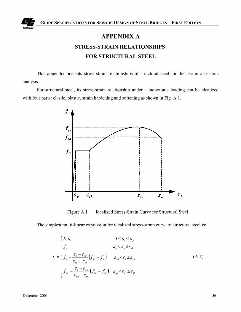
GUIDE SPECIFICATIONS FOR SEISMIC DESIGN OF STEEL BRIDGES – FIRST EDITION
December 2001 56
APPENDIX ASTRESS-STRAIN RELATIONSHIPS
FOR STRUCTURAL STEEL
This appendix presents stress-strain relationships of structural steel for the use in a seismic
analysis.
For structural steel, its stress-strain relationship under a monotonic loading can be idealized
with four parts: elastic, plastic, strain hardening and softening as shown in Fig. A.1.
Figure A.1 Idealized Stress-Strain Curve for Structural Steel
The simplest multi-linear expression for idealized stress-strain curve of structural steel is:
� �
� �����
�
����
�
�
����
��
����
��
��
��
sbssusbsususb
sussu
susshysushsu
shsy
shsyy
ysss
s
fff
fff
f
E
f
���
��
��
���
��
��
���
��� 0
(A-1)

GUIDE SPECIFICATIONS FOR SEISMIC DESIGN OF STEEL BRIDGES – FIRST EDITION
December 2001 57
where
fs = stress in steel (MPa)
�s = strain in steel
Es = modulus of elasticity of steel (MPa)
fy = yield stress of steel (MPa)
�y = yield strain of steel
�sh = strain at the onset of strain hardening of steel
fsu = maximum stress of steel (MPa)
�su = strain corresponding to the maximum stress of steel
fsb = rupture stress of steel (MPa)
�sb = rupture strain of steel
For both strain-hardening and softening portions, the following expression proposed by Holzer
et al. (1975) may be used.
sbsshshsu
shs
y
su
shsu
shsys f
fff ���
��
��
��
��
�����
�
���
�
���
�
�
��
�
��
��
�
��� for 1exp11 (A-2)
The nominal limiting values for stress and strain proposed by Holzer et al. (1975) is shown in
Table A-1.
Table A-1 Nominal Limiting Values for Steel Stress-Strain Curves
fy
(MPa) (ksi)
fu
(MPa) (ksi)
�y �sh �su �sb
280 (40) 550 (80) 0.00138 0.0230 0.140 0.200
420 (60) 730 (106) 0.00207 0.0060 0.087 0.136
520 (75) 900 (130) 0.00259 0.0027 0.073 0.115

GUIDE SPECIFICATIONS FOR SEISMIC DESIGN OF STEEL BRIDGES – FIRST EDITION
December 2001 58
APPENDIX BEFFECTIVE SECTION PROPERTIES
This appendix presents formulas of effective section properties for latticed members as shown in
Fig. B.1 for possible use in a seismic analysis (Duan, Reno and Lynch 2000).
B.1. Cross-sectional Area - A
The contribution of lacing bars for carrying vertical load is assumed negligible. The cross-
sectional area of latticed member is only based on individual main components.
A Ai� � (B-1)
where
Ai = cross-sectional area of an individual main component i (mm2)
Figure B.1 Typical Latticed Members

GUIDE SPECIFICATIONS FOR SEISMIC DESIGN OF STEEL BRIDGES – FIRST EDITION
December 2001 59
B.2. Moment of Inertia - I
B2.1. Lacing Bars or Battens in Plane of Web (bending about y-y axis in Fig. B.1)
I I A xy y y y i m i i� �
� � �� ( ) � 2 (B-2)
where
Iy-y = moment of inertia of a section about y-y axis considering shear transferring capacity
(mm4)
Ii = moment of inertia of a main individual component i (mm4)
xi = distance between y-y axis and the centroid of the main individual component i (mm)
�m = reduction factor for the moment of inertia
For laced member (Fig. B.1a)
�
�
m
l ncomp
nten
l r r u
yf f
m smaller ofm P Pm n A F
F A�
���
��
�� �
sin( )
( . ).
0 61 0 (B-3a)
For battened member (Fig. B.1b)
� m
b b yw
b p b
b r r u
yf f
m smaller ofm A Fm M hm n A F
F A�
�
�
��
��
�
�
( . )( / )
( . ).
0 62
0 61 0 (B-3b)
where
� = angle between a diagonal lacing bar and the axis perpendicular to the member axis
(see Fig. B.2)
Ab = cross-sectional area of batten plate (mm2)
Af = flange area to which battens or laces are attached (mm2)
Fyf = specified minimum yield strength of a flange component (MPa)
Fyw = specified minimum yield strength of a web component (battens or lacing bars) (MPa)
F u = specified minimum tensile strength of fasteners (MPa)

GUIDE SPECIFICATIONS FOR SEISMIC DESIGN OF STEEL BRIDGES – FIRST EDITION
December 2001 60
Ar = cross-sectional area of a fastener (mm2)
nr = number of fasteners of connecting lacing bar or battens to the main component at one
connection
m = number of panels between point of maximum calculated moment to point of zero
moment to either side (as an approximation, the number of panels in half of the main
member length (L/2) may be used)
mb = number of batten planes
ml = number of lacing planes
Mp-b = plastic moment of a batten plate about strong axis (N-mm)
Pncomp = nominal compressive strength of lacing bar, can be determined by AISC-LRFD
(1999) column curve (N)
Pnten = nominal tensile strength of lacing bar, can be determined by AISC-LRFD (1999) (N)
B.2.2. Lacing Bars or Battens in Plane of Flange (bending about x-x axis in Fig. B.1)
I I A yx x x x i i i� �
� � �� ( )2 (B-4)
B.3. Plastic Section Modulus - Z
B.3.1. Lacing Bars or Battens in Plane of Web (bending about y-y axis in Fig. B.1)
Z x Ay y m i i�
� �� * * (B-5)
where
Zy-y = plastic section modulus of a section about the plastic y-y neutral axis (mm3)
xi* = distance between the center of the gravity of a section Ai
* and the plastic neutral y-y
axis (mm)
yi* = distance between the center of the gravity of a section Ai
* and the plastic neutral x-x
axis (mm)
Ai* = cross-sectional area above or below the plastic neutral axis (mm2)

GUIDE SPECIFICATIONS FOR SEISMIC DESIGN OF STEEL BRIDGES – FIRST EDITION
December 2001 61
B.3.2. Lacing Bars or Battens in Plane of Flange (bending about x-x axis in Fig. B.1)
Z y Ax x i i�
� �* * (B-6)
where
Zx-x = plastic section modulus of a section about the plastic x-x neutral axis (mm3)
B.4. Torsional Constant - J
JA
bt
close
i
i
�
�
4 2( ) (B-7)
where
Aclose = area enclosed within the mean dimension for a box-shaped section (mm2)
bi = length of the particular segment of a section (mm)
ti = average thickness of a segment bi (mm)
For determination of torsional constant of a latticed member, the lacing bars or batten plates can
be replaced by reduced equivalent thin-walled plates defined as:
A Aequiv t equiv� � * (B-8)
For laced member (Fig. B.1a)
A Aequiv d* . sin cos� 312 2� � (B-9a)
For battened member (Fig. B.1b)
Aa hI
aI
equiv
b f
* .�
�
74 88 12 2 (B-9b)
tA
hequivequiv
� (B-10)
where
a = distance between two battens along the member axis (mm)
Aequiv = cross-sectional area of a thin-walled plate equivalent to lacing bars considering shear
transferring capacity (mm2)

GUIDE SPECIFICATIONS FOR SEISMIC DESIGN OF STEEL BRIDGES – FIRST EDITION
December 2001 62
Aequiv* = cross-sectional area of a thin-walled plate equivalent to lacing bars or battens
assuming full section integrity (mm2)
tequiv = thickness of equivalent thin-walled plate (mm)
h = depth of a member in the lacing plane (mm)
Ad = cross-sectional area of all diagonal lacings in one panel (mm2)
Ib = moment of inertia of a batten plate (mm4)
�t = reduction factor for the torsion constant
For laced member (Fig. B.1a)
�
�
t
ncomp
nten
r r u
yw equiv
smaller ofP Pn A F
F A�
���
�� �
cos( . )
..*
0 60 6
10 (B-11a)
For battened member (Fig. B.1b)
� t
b yw
p b
r r u
yw equiv
smaller ofA F h a
M an A F h a
F A�
�
��
��
�
�
( . ) //
( . ) /.
.*
0 62
0 60 6
10 (B-11b)

GUIDE SPECIFICATIONS FOR SEISMIC DESIGN OF STEEL BRIDGES – FIRST EDITION
December 2001 63
APPENDIX C
YIELD SURFACE EQUATIONS FOR
DOUBLY SYMMETRICAL STEEL SECTIONS
This appendix presents the yield surface expressions for typical steel sections suitable for use in
an inelastic static analysis
The general shape of yield surface for a doubly symmetrical steel section as shown in Fig. C.1
can be described approximately by the following general equation (Duan and Chen 1990).
Figure C.1 Typical Yield Surface for Structural Steel Sections
MM
MM
x
pcx
y
pcy
x y�
���
�
��� �
�
���
�
��� �
� �
10. (C-1)
where Mpcx and Mpcy are the moment capacities about respective axes, reduced for the presence of
axial load; and can be obtained by the following formulas:
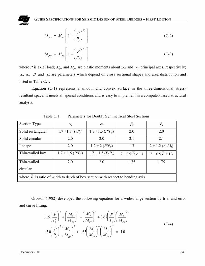
GUIDE SPECIFICATIONS FOR SEISMIC DESIGN OF STEEL BRIDGES – FIRST EDITION
December 2001 64
M M PPpcx px
y
x
� ��
���
�
���
��
�
��
1�
(C-2)
M M PPpcy py
y
y
� ��
���
�
���
��
�
��
1�
(C-3)
where P is axial load; Mpx and Mpy are plastic moments about x-x and y-y principal axes, respectively;
�x, �y, �x and �y are parameters which depend on cross sectional shapes and area distribution and
listed in Table C.1.
Equation (C-1) represents a smooth and convex surface in the three-dimensional stress-
resultant space. It meets all special conditions and is easy to implement in a computer-based structural
analysis.
Table C.1 Parameters for Doubly Symmetrical Steel Sections
Section Types �x �y �x �y
Solid rectangular 1.7 +1.3 (P/Py) 1.7 +1.3 (P/Py) 2.0 2.0
Solid circular 2.0 2.0 2.1 2.1
I-shape 2.0 1.2 + 2 (P/Py) 1.3 2 + 1.2 (Aw/Af)
Thin-walled box 1.7 + 1.5 (P/Py) 1.7 + 1.5 (P/Py) 2 0 5 13� �. .B 2 0 5 13� �. .B
Thin-walled
circular
2.0 2.0 1.75 1.75
where B is ratio of width to depth of box section with respect to bending axis
Orbison (1982) developed the following equation for a wide-flange section by trial and error
and curve fitting:
115 3 67
3 0 4 65 1 0
2 2 4 2
2 2 4 2
. .
. . .
PP
MM
MM
PP
MM
PP
MM
MM
MM
y
x
px
y
py y
x
px
y
y
py
x
px
y
py
�
��
�
�� �
�
��
�
�� �
�
��
�
�� �
�
��
�
���
��
�
��
��
��
�
��
�
��
�
�� �
�
��
�
��
�
��
�
�� �
(C-4)
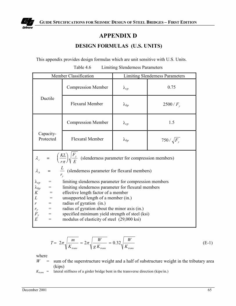
GUIDE SPECIFICATIONS FOR SEISMIC DESIGN OF STEEL BRIDGES – FIRST EDITION
December 2001 65
APPENDIX D DESIGN FORMULAS (U.S. UNITS)
This appendix provides design formulas which are unit sensitive with U.S. Units.
Table 4.6 Limiting Slenderness Parameters
Member Classification Limiting Slenderness Parameters
Compression Member
�cp 0.75
DuctileFlexural Member �bp yF/2500
Compression Member �cp 1.5
Capacity-Protected Flexural Member �bp yF/750
��
cyKL
rFE
����
��� (slenderness parameter for compression members)
� by
Lr
� (slenderness parameter for flexural members)
�cp = limiting slenderness parameter for compression members �bp = limiting slenderness parameter for flexural membersK = effective length factor of a memberL = unsupported length of a member (in.)r = radius of gyration (in.)ry = radius of gyration about the minor axis (in.)Fy = specified minimum yield strength of steel (ksi)E = modulus of elasticity of steel (29,000 ksi)
transtranstrans KW.
KgW
KmT 32022 ��� �� (E-1)
whereW = sum of the superstructure weight and a half of substructure weight in the tributary area
(kips)Ktrans = lateral stiffness of a girder bridge bent in the transverse direction (kips/in.)

GUIDE SPECIFICATIONS FOR SEISMIC DESIGN OF STEEL BRIDGES – FIRST EDITION
SPECIFICATIONS COMMENTARY
___________________________________________________________________________________________________December 2001 66
Table 4.5 Limiting Width-Thickness Ratios
No Description of Elements ExamplesWidth-
ThicknessRatios
�r �p
UNSTIFFENED ELEMENTS
1Flanges of I-shaped rolled beams andchannels in flexure
Figure 4.5(a)Figure 4.5(c)
b/t69
370�yF yF
137
2
Outstanding legs of pairs of angles incontinuous contact; flanges of channels inaxial compression; angles and platesprojecting from beams or compressionmembers
Figure 4.5(d)Figure 4.5(e)
b/tyF
250
yF137
STIFFENED ELEMENTS
3
Flanges of square and rectangular boxand hollow structural section of uniformthickness subject to bending orcompression; flange cover plates anddiaphragm plates between lines offasteners or welds.
Figure 4.5(b)b/t
yF625
yF290/ (tubes)
yF400/ (others)
4Unsupported width of cover platesperforated with a succession of accessholes
Figure 4.5(d) b/tyF
830
yF400
5All other uniformly compressed stiffenedelements, i.e., supported along two edges.
Figures 4.5(a)
(c),(d),(f)
b/th/tw yF
665yF290/ (w/lacing)
yF400/ (others)
6 Webs in flexural compressionFigures 4.5(a)
(c),(d),(f)
h/tw
yF2550
yF1365
7 Webs in combined flexural and axialcompression
Figures 4.5(a)
(c),(d),(f) h/tw ���
����
�
��
y
0.741
2550
PP
F
b
y
For
���
����
�
��
�
yby
ybu
PP
F
PP
1.5411365
0.125
For
y
yby
ybu
F
PP
F
PP
665
2.33500
0.125
�
���
����
�
�
�
8 Longitudinally stiffened plates incompression
Figure 4.5(e) b/tyFk297
yFk197
9 Round HSS in axial compression orflexure
D/tyF
17930
yF8950
Notes:1. Width-Thickness Ratios shown in Bold are from AISC-LRFD (1999a) and AISC-Seismic Provisions (1997). Fy is MPa2. k = buckling coefficient specified by Article 6.11.2.1.3a of AASHTO-LRFD (AASHTO,1998)
for n = 1, 048 313 .)/( /�� btIk s for n = 2,3, 4 and 5, 04314 3143 .)/.( /
�� nbtIk s n = number of equally spaced longitudinal compression flange stiffeners Is = moment of inertia of a longitudinal stiffener about an axis parallel to the bottom flange and taken at the base of the stiffener

GUIDE SPECIFICATIONS FOR SEISMIC DESIGN OF STEEL BRIDGES – FIRST EDITION
December 2001 67
APPENDIX ELATERAL STIFFNESS OF GIRDER BRIDGES
IN TRANSVERSE DIRECTION
This appendix presents the lateral stiffness calculation for a steel girder bridge bent in the
transverse direction as shown in Figure E.1. The lateral stiffness may used to estimate the period of
fundamental mode of vibration in the transverse direction.
Figure E.1. A Typical Steel Girder Bridge Bent
The fundamental period in the transverse direction is given by:
transKmT �2� (E-1)
where
m = sum of the superstructure mass and a half of substructure mass in the tributary area
(kg)
Ktrans = lateral stiffness of a girder bridge bent in the transverse direction (kN/mm)

GUIDE SPECIFICATIONS FOR SEISMIC DESIGN OF STEEL BRIDGES – FIRST EDITION
December 2001 68
Lateral Stiffness
sub
sub
bear
bear
sup
trans
KKK
K��
��
�
11 (E-2)
2
331 ���
����
����
�
����
���
bear
sup
bear
supbear h
hhh
� (E-3)
2
331 ���
����
����
�
����
��
subsubsub h
hhh
� (E-4)
where
hsup = height of the girder superstructure measured from the bottom of the girder flange to
central gravity of the concrete deck (mm)
hbear = height of a bearing (mm)
hsub = height of the substructure (mm)
h = height of a girder bridge = hsup + hsup + hsub (mm)
Ksup = lateral stiffness of the superstructure at a bent (kN/mm) (kN/mm)
Ksub = lateral stiffness of the substructure at a bent (N/mm)
Kbear = lateral stiffness of bearings at a bent (kN/mm)
Stiffness of End Cross Frames
���� sgendfsup KKK (E-5)
3sg
sgfixsg h
IEK
�
� (E-6)
where
Kendf = lateral stiffness of an end cross frame/diaphragm (kN/mm)
Ksg = lateral stiffness of a steel girder (kN/mm)
Isg = moment of inertia of a stiffened girder in the bearing location (mainly due to bearing
stiffeners) in the lateral direction (mm4)

GUIDE SPECIFICATIONS FOR SEISMIC DESIGN OF STEEL BRIDGES – FIRST EDITION
December 2001 69
hsg = height of a steel girder (mm)
E = modulus of elasticity of steel (kPa)
�fix = fixity factor, equal to 12 if full fixity is provided at both flanges of a steel girder; 3 if
one end is fully fixed and other one pinned; and 0 if both ends are pinned.
It is the engineer’s judgement to determine the level of fixity provided at the ends of girders. It
should be noted that the most conservative solution is not obtained when zero fixity is assumed
because fixity also adds strength to the diaphragms. The role of the ductile diaphragms is to limit the
magnitude of the maximum forces that can be developed in the substructure.
For EBF Cross Frames as shown in Figure E.2 (Zahrai and Bruneau, 1998)
Figure E.2. A Typical EBF Ductile Cross Frame
gl,sslslb
bendf
AtanH
AaLeH.
ILHe
Aa
cosAl
EK
231
1222
2222
2
�
�
����
� (E-7)
where
lb = length of each brace (mm)
Ab = cross-sectional area of each brace (mm2)
Ls = girder spacing (mm)
a = length of the beam outside of a link (mm)

GUIDE SPECIFICATIONS FOR SEISMIC DESIGN OF STEEL BRIDGES – FIRST EDITION
December 2001 70
e = length of a shear link (mm)
Il = moment of inertia of a shear link (mm4)
Al = cross-sectional area of a shear link (mm2)
As,l = shear area of a shear link (mm2)
H = height of a stiffened girder (mm)
Ag = area of a stiffened girder (mm2)
� = brace’s angle with the horizontal direction
For X or V-Type Cross Frames
b
bendf l
cosEAK
�22
� (E-8)

GUIDE SPECIFICATIONS FOR SEISMIC DESIGN OF STEEL BRIDGES – FIRST EDITION
December 2001 71
APPENDIX F REFERENCES
1. AASHTO. (1998). LRFD Bridge Design Specifications, 2nd Ed., and 1999, 2000 and 2001 Interims,
American Association of State Highway and Transportation Officials, Washington, DC.
2. ACI. (1999). Building Requirements for Structural Concrete (ACI 318-99) and Commentary (ACI
318R-99), American Concrete Institute, Farmington Hills, MI.
3. AISC. (1992). Seismic Provisions for Structural Steel Buildings, American Institute of Steel
Construction, Chicago, IL.
4. AISC. (1999a). Load and Resistance Factor Design Specification for Structural Steel Buildings,
3rd Ed., American Institute of Steel Construction, Chicago, IL.
5. AISC. (2001). Manual of Steel Construction, Load and Resistance Factor Design, 3rd Ed.,
American Institute of Steel Construction, Chicago, IL.
6. AISC. (1997). Seismic Provisions for Structural Steel Buildings, American Institute of Steel
Construction, Chicago, IL.
7. AISC. (1999b). Seismic Provisions for Structural Steel Buildings (1997) Supplement No. 1
American Institute of Steel Construction, Chicago, IL.
8. AISC. (2000). Seismic Provisions for Structural Steel Buildings, (1997) Supplement No. 2
American Institute of Steel Construction, Chicago, IL.
9. AISI. (1962). Light Gage Cold-Formed Steel Design Manual, American Iron and Steel Institute,
Washington, DC.
10. ASCE. (1971). Plastic Design in Steel, A Guide and Commentary, American Society of Civil
Engineers, New York, NY.
11. ATC (1996). Improved Seismic Design Criteria for California Bridges: Provisional
Recommendations, (ATC-32), Applied Technology Council, Redwood City, CA.
12. Astaneh, A. A., Goel, S. C., and Hanson, R. D. (1986). "Earthquake-resistant Design of Double
Angle Bracings," Engineering Journal, AISC, 23(4).
13. Astaneh, A. A. (1998). "Seismic Behavior and Design of Gusset Plate," Steel Tips, Structural Steel
Education Council, Moraga, CA.

GUIDE SPECIFICATIONS FOR SEISMIC DESIGN OF STEEL BRIDGES – FIRST EDITION
December 2001 72
14. Caltrans. (1995a). Bridge Memo to Designers Manual, California Department of Transportation,
Sacramento, CA.
15. Caltrans. (1995b). Bridge Design Aids Manual, California Department of Transportation,
Sacramento, CA.
16. Caltrans. (1997). San Francisco-Oakland Bay Bridge West Spans Seismic Retrofit Design Criteria,
Final Draft, California Department of Transportation, Sacramento, CA.
17. Caltrans. (1999). Memo to Designers 20-1 Seismic Design Methodology, California Department of
Transportation, Sacramento, CA.
18. Caltrans. (2000a). Bridge Design Specifications, California Department of Transportation,
Sacramento, CA.
19. Caltrans. (2000b). Standard Specifications, California Department of Transportation, Sacramento,
CA.
20. Caltrans. (2001). Seismic Design Criteria Version 1.2. California Department of Transportation,
Sacramento, CA, December.
21. Carden, L., Garcia-Alvarez, S., Itani, A, and Buckle, I. (2001). “Cyclic Response of Steel Plate
Girder Bridges in the Transverse Direction,” The Sixth Caltrans Seismic Research Workshop,
Divisions of Engineering Services, California Department of Transportation, Sacramento, CA, June
12-13.
22. Chen, W. F., and Atsuta, T. (1977). Theory of Beam-Columns, Vol.1 and 2, McGraw-Hill Inc.,
New York, NY.
23. Chen, W. F., and Toma, S. (1994). Advanced Analysis of Steel Frames, CRC Press, Boca Raton,
FL.
24. Duan, L. and Chen, W. F. (1990). "A Yield Surface Equation for Doubly Symmetrical Section,"
Structural Engineering, 12(2), pp. 114-119.
25. Duan, L., Reno, M. and Lynch J. (2000). "Section Properties for Latticed Members of San
Francisco-Oakland Bay Bridge," J. Bridge Engrg., ASCE, 5(2), pp. 156-164.
26. Duan, L., Reno, M. and Uang, C.M. (2002). "Effect of Compound Buckling on Compression
Strength of Built-up Member,” Engrg. J., AISC, 39(1), (in Press).
27. Fehling, E., Pauli, W. and Bouwkamp, J. G. (1992). "Use of Vertical Shear-Links in Eccentrically
Braced Frames," Proc., 10th World Conf. on Earthquake Engrg., Madrid, Vol. 9, pp. 4475-4479.

GUIDE SPECIFICATIONS FOR SEISMIC DESIGN OF STEEL BRIDGES – FIRST EDITION
December 2001 73
28. Frosch, R. J. (1999). "Shear Transfer between Concrete Elements Using Steel Pipe Connection,"
ACI Structural Journal, 96(6), pp. 1003-1008.
29. Holzer, S.M., et al. (1975). SINDER. "A Computer Code for General Analysis of Two-
Dimensional Reinforced Concrete Structures," Report AFWL-TR-74-228 Vol.1. Air Force
Weapons Laboratory, Kirtland, AFB, NM.
30. ICBO, (1997). Uniform Building Code, International Conference of Building Officials, Whitter,
CA.
31. Itani, A. M. (1997). "Cyclic Behavior of Richmond-San Rafael Tower Links," Report No. CCEER
99-4, Center for Civil Engineering Earthquake Research, University of Nevada, Reno, NV
32. Itani, A. M. and Sedarat, H. (2000). “Seismic Analysis and Design of the AISI LRFD Design
Examples of Steel Highway Bridges,” Report No. CEER 00-8, Center for Civil Engineering
Earthquake Research, University of Nevada, Reno, NV.
33. Itani, A. M., Vesco, T. D. and Dietrich, A M. (1998). "Cyclic Behavior of As-Built Laced
Members with End Gusset Plates on the San Francisco-Oakland Bay Bridge," Report No. CCEER
98-01, Center for Civil Engineering Earthquake Research, University of Nevada, Reno, NV.
34. King, W. S., White, D. W. and Chen, W. F. (1992). "Second-Order Inelastic Analysis Methods for
Steel-Frame Design," J. Struct. Engrg., ASCE, 118(2), pp. 408-428.
35. Levy, R., Joseph, F., Spillers, W. R. (1997). "Member Stiffness with Offset Hinges," J. Struct.
Engrg., ASCE, 123(4), pp. 527-529.
36. Nakashima, M. (1995). "Strain-Hardening Behavior of Shear Panels Made of Low-Yield Steel. I:
Test," J. Struct. Engrg., ASCE, 121(12), pp. 1742-1749.
37. NCHRP 12-49 (2001). Recommended LRFD Guidelines for the Seismic Design of Highway
Bridges, Part I: Specifications and Part II: Commentary and Appendixes, NCHRP 12-49 Project
Team, MCEER, State University of New York at Buffalo, Buffalo, NY.
38. Orbison, J. G. (1982). Nonlinear Static Analysis of Three-dimensional Steel Frames, Dept. of
Structural Engineering, Cornell University, NY.
39. Patty, J. Seible F. and Uang, C .M. (2001). “Longitudinal Seismic Response of Concrete
Substructure Steel Superstructure Integral Bridge Connections”, The Sixth Caltrans Seismic
Research Workshop, Divisions of Engineering Services, California Department of Transportation,
Sacramento, CA, June 12-13.
GUIDE SPECIFICATIONS FOR SEISMIC DESIGN OF STEEL BRIDGES – FIRST EDITION
December 2001 74
40. PCI. (1999). PCI Design Handbook – Precast and Prestressed Concrete, Fifth Edition,
Precast/Prestressed Concrete Institute, Chicago, IL.
41. Popov, E. P. and Tsai, K. C. (1989). "Performance of Large Seismic Steel Moment Connections
under Cyclic Loads," Engrg. J., AISC, 26(2), pp. 51-60.
42. Tsai, K. C., Yang, Y. F. and Lin, J. L. (1993). "Seismic Eccentrically Braced Frames," Int’l J. of
Struct. Design of Tall Buildings, 2(1), pp. 53-74.
43. Uang, C. M., Tsai, K. C. and Bruneau M. (1999). "Chapter 39: Seismic Design of Steel Bridges,"
Bridge Engineering Handbook, Ed., Chen, W. F. and Duan, L., CRC Press, Boca Raton, FL.
44. Whitmore, R. E. (1952). "Experimental Investigation of Stresses in Gusset Plates," Bulletin 16,
University of Tennessee, Knoxville, TN.
45. Zahrai, S. M. and Bruneau, M. (1998). "Impact of Diaphragms on Seismic Responses of Straight
Slab-on-Girder Steel Bridges," J. Struct. Engrg. 124(8), pp. 938-947.
46. Zahrai, S. M. and Bruneau, M. (1999). "Ductile End-Diaphragms for Seismic Retrofit of Slab-on-
Girder Steel Bridges," J. Struct. Engrg. 125(1), pp. 71-80.