guidance for research reactors and critical assemblies
TRANSCRIPT
National Nuclear Security Administration ENERGYU.S. DEPARTMENT OF
NIS Office of NuclearSafeguards and Security
Safeguards-By-Design Facility Guidance Series (NGSI-SBD-003)
September 2012
Guidance for Research Reactors and Critical Assemblies
1
LA-UR-12-26349
Safeguards by Design (SBD): Safeguards Guidance for
Research Reactors and Critical Assemblies
September 2012
Paul Pan Brian Boyer
Chantell Murphy
Los Alamos National Laboratory
Sponsored by the
NNSA-NA-241 Office of Nuclear Safeguards & Security: Safeguards Policy
2
ACKNOWLEDGMENTS
The United States Department of Energy, National Nuclear Security Agency Office of Nuclear Safeguards and Security: Safeguards Policy (NA-241), under the Safeguards-by-Design Project, provided the funding from the Next Generation Safeguards Initiative to sponsor this endeavor. The authors wish to thank NA-241 for its input, support, and guidance in preparing this final report.
3
Contents Acknowledgments........................................................................................................................... 2 1 Introduction ............................................................................................................................. 5 2 Key Definitions ....................................................................................................................... 7 3 IAEA Safeguards .................................................................................................................... 8
3.1 Safeguards Objectives ........................................................................................................9 3.2 Traditional and Integrated Safeguards .............................................................................10 3.3 Safeguards Responsibilities ..............................................................................................10
4 Elements of Facility Design That Are Relevant for Safeguards ........................................... 12 4.1 Design Features Relevant for Safeguards ........................................................................12 4.2 Misuse and Diversion Scenarios ......................................................................................15
4.2.1 Diversion or Theft of 235U......................................................................................... 16 4.2.2 Diversion of Plutonium and 233U .............................................................................. 16 4.2.3 Diversion of Depleted, Natural, and Low-Enriched Uranium (DNLEU) ................. 17 4.2.4 Undeclared Production of Plutonium or 233U ........................................................... 17
5 Key Elements of Safeguards Approach for RRCA ............................................................... 18 5.1 Design Information Verification ......................................................................................18 5.2 Physical Inventory Verification and Interim Inventory Verification ...............................19 5.3 Verification of the Decommissioned Status of an RRCA ................................................19 5.4 Summary of RRCA IAEA Safeguards Challenges ..........................................................19
6 SBD Best Practices ............................................................................................................... 21 6.1 Best Practices ...................................................................................................................21 6.2 General Requirements ......................................................................................................21 6.3 Layout Requirements and Guidelines ..............................................................................21
6.3.1 Fresh Fuel Receiving and Storage Area.................................................................... 22 6.3.2 Fuel Handling Area ................................................................................................... 23 6.3.3 Reactor Core and Bay Area ...................................................................................... 23 6.3.4 Spent Fuel Storage and Shipping Areas.................................................................... 25
6.4 Space Allocation Requirements and Guidelines ..............................................................26 6.4.1 Safeguards Equipment .............................................................................................. 26 6.4.2 Inspector Office Space and Computer ...................................................................... 26
6.5 Design Impacts of Facilitating Inspections ......................................................................27 6.5.1 Design Features to Facilitate DIE/DIV at a Facility ................................................. 27 6.5.2 Design Features to Facilitate Inspections ................................................................. 27
6.6 Design Team Discipline-Specific Impacts .......................................................................29 6.6.1 Electrical ................................................................................................................... 29 6.6.2 Chemistry .................................................................................................................. 29
References ..................................................................................................................................... 30

4
Figures
Figure 1. TRIGA reactor operated by TU Vienna in Vienna, Austria. ...................................... 24 Figure 2. Maria reactor in Swierk, Poland—the reactor core shows the flexibility of the core for
irradiation. ................................................................................................................... 24 Figure 3. HEU fresh fuel storage in Vinca, Serbia (l), and in Swierk, Poland, at the Maria
reactor (r). ................................................................................................................... 28
Tables
Table 1. Timeliness of Diversion of Nuclear Materials .............................................................. 9 Table 2. Summary of Safeguards-Related Key Design Features .............................................. 12 Table 3. Nuclear Material Diversion and Diversion Methods .................................................. 17 Table 4. Safeguards Implications of RRCA Fuels .................................................................... 18
5
1 INTRODUCTION
This document is part of a series of guidance documents developed by the National Nuclear Security Administration’s (NNSA’s) Next Generation Safeguards Initiative to assist facility designers and operators in implementing international safeguards by design (SBD). SBD has two main objectives: (1) avoid costly and time-consuming redesign work or retrofits of new nuclear fuel cycle facilities and (2) make the implementation of international safeguards more effective and efficient at such facilities. In the long term, the attainment of these goals would save both industry and the International Atomic Energy Agency (IAEA, or the Agency) time, money, and resources—a mutually beneficial, win-win endeavor. The purpose of the IAEA safeguards system is to provide credible assurance to the international community that nuclear material and other specified items are not diverted from peaceful nuclear uses.1 The safeguards system consists of the IAEA’s statutory authority to establish safeguards, the safeguards rights and obligations in safeguards agreements and additional protocols, and technical measures implemented pursuant to those agreements. Of foremost importance as a basis for IAEA safeguards is the international safeguards agreement between a country and the IAEA, concluded pursuant to the Treaty on the Non-Proliferation of Nuclear Weapons (NPT). According to a 1992 IAEA Board of Governors decision, countries must (1) notify the IAEA of a decision to construct a new nuclear facility as soon as such a decision is made, (2) provide design information on such facilities as the designers develop, and (3) provide detailed design information (called a “Design Information Questionnaire” in IAEA parlance) based on construction plans at least 180 days before the start of construction and on “as-built” designs at least 180 days before the first receipt of nuclear material.2 Because the main interlocutor with the IAEA in each country is a state regulatory authority (SRA) or regional regulatory authority (e.g., the European Atomic Energy Community, or Euratom), the responsibility for transferring this design information falls to the SRA. For the nuclear industry to reap the benefits of SBD (i.e., avoided costs and averted schedule slippages), designers/operators should work closely with the SRA as soon as a decision is made to build a new nuclear facility. Ideally, this interaction should begin during the conceptual design phase and continue throughout construction and start-up of a nuclear facility. Such early coordination and planning could influence decisions on, for example, the chemical processing flowsheet and design, the material storage and handling arrangements, and the facility layout. Communication among the designer, operator, SRA, and IAEA should be frequent and iterative throughout the design/construction/start-up. This dialog will help to more effectively and efficiently incorporate IAEA safeguards into the design of nuclear facilities and to minimize misunderstandings that could arise from any misinterpretation of the safeguards input and guidance. The facilities under scrutiny in this document are research reactors and critical assemblies (RRCAs). Major design features and operations of RRCAs that have significant impacts on current safeguards regimes and scope are the flexible capability of a research reactor to produce fissile material during operation, the use of significant quantities (SQs) of fresh highly enriched uranium (HEU), the possible use of plutonium in experimental reactors, and the small size of such facilities making the existence of a clandestine facility more probable. In many older

6
facilities, SQs of spent fuel with both plutonium and HEU in them would be attractive for diversion.

7
2 KEY DEFINITIONS
Argonaut Argonne Nuclear Assembly for University Training C/S1 Containment and Surveillance CoK2 Continuity of Knowledge CSA3 Comprehensive Safeguards Agreement CZT Cadmium Zinc Telluride DIE4 Design Information Examination DIQ5 Design Information Questionnaire DIV6 Design Information Verification DNLEU Depleted, Natural, and Low Enriched Uranium Euratom European Atomic Energy Community GMRR Graphite Moderated Research Reactor HEU7 High Enriched Uranium (≥20% 235U) HWMRR Heavy Water Moderated Research Reactor IAEA International Atomic Energy Agency ICVD Improved Cerenkov Viewing Device LEU8 Low Enriched Uranium (<20% 235U) LHRR Liquid Homogeneous Research Reactor LTMSR Liquid Thorium Molten Salt Reactor MOX Mixed Oxide MTR Materials Testing Reactor NDA Nondestructive Assay NNSA National Nuclear Security Administration NPT9 Treaty on the Non-Proliferation of Nuclear Weapons NU10 Natural Uranium ORNL Oak Ridge National Laboratory PBMR Pebble Bed Modular Reactor RERTR Reduced Enrichment for Research and Test Reactor RRCA Research Reactor and Critical Assembly SBD Safeguards by Design SQ11 Significant Quantity SRA State Regulatory Authority SSAC12 State System of Accounting for the Control of Nuclear Material TRIGA Training Research Isotope Production General Atomic (Reactor)
Footnote denotes reference in IAEA Safeguards Glossary, 2001 Edition, International Nuclear Verification Series No. 3, International Atomic Energy Agency (June 2002)
.1IAEA Safeguards Glossary references 8.1, 8.2. 2IAEA Safeguards Glossary references 8.1, 8.5, 8.6. 3IAEA Safeguards Glossary references 1.17, 1.18, 1.19. 4IAEA Safeguards Glossary references 3.3, 3.28, 3.29, 3.31, 13.1. 5IAEA Safeguards Glossary reference 3.28. 6IAEA Safeguards Glossary references 3.28, 3.30, 3.31, 5.29, 13.1. 7IAEA Safeguards Glossary references 4.5, 4.13, 4.25. 8IAEA Safeguards Glossary references 4.5, 4.12, 4.26. 9IAEA Safeguards Glossary reference 1.2. 10IAEA Safeguards Glossary reference 4.9. 11IAEA Safeguards Glossary references 3.4, Table II. 12IAEA Safeguards Glossary references 3.33, 6.1.
8
3 IAEA SAFEGUARDS
The SBD process requires an understanding of IAEA safeguards goals and approaches by designers and operators, as well as of the underlying principles of IAEA safeguards, with an aim of improving the procedures of interactions between the State System of Accounting for the Control of Nuclear Material (SSAC) and the IAEA.
As a signatory to the IAEA’s Comprehensive Safeguards Agreement (CSA), a State is bound by INFCIRC/1533 to establish and maintain an SSAC if it possesses nuclear material. In addition to the CSA, a State may have an additional safeguards agreement with the IAEA based on INFCIRC/540,4 “Additional Protocol,” as part of the IAEA’s “Strengthened Safeguards.” National safeguards as implemented by the SSAC typically refer to “domestic” safeguards, and the related requirements attempt to prevent the subnational theft of nuclear material. In contrast to domestic safeguards, international safeguards under the IAEA focus on detecting the national (i.e., State) diversion of nuclear material. As such, domestic requirements provide the foundation for nuclear material accountancy and control, and international requirements provide the verification that the facility operates as declared and that no material is diverted. This verification is dependent on the domestic safeguards design, with independent international verification. IAEA requirements dictate safeguards goals such as those used for material accountancy. The latest version of Code 3.1 of the Subsidiary Arrangements of the Safeguards Agreement requires notification to the IAEA by the SSAC as soon as the decision is made to construct a new nuclear facility and requires the provision of preliminary design information regarding a new nuclear facility. The State must progressively provide the IAEA with further design information because the design is developed early in the project definition, preliminary design, construction, and commissioning phases. Following the Design Information Questionnaire, the State and IAEA make “subsidiary arrangements” that specify in detail how the IAEA will implement its safeguards at the facility under the CSA in the form of a “Facility Attachment.” The IAEA defines RRCAs as research facilities that use using more than 1 effective kilogram of nuclear material. The IAEA and nuclear facility operators have emerging technologies in nuclear material accountancy and verification available for implementation to improve the detection capabilities of the IAEA. Evolving philosophies of what proliferation threats exist in research facilities and the push to build IAEA capabilities to uncover clandestine nuclear activities drive how much effort needs to be put into research reactor safeguards activities. To ensure the success of the SBD process, active dialog and interactions must occur among the designers, operators, SSAC, and IAEA as early as practical to allow safeguards features to be effectively integrated into the design of RRCAs.
9
3.1 Safeguards Objectives
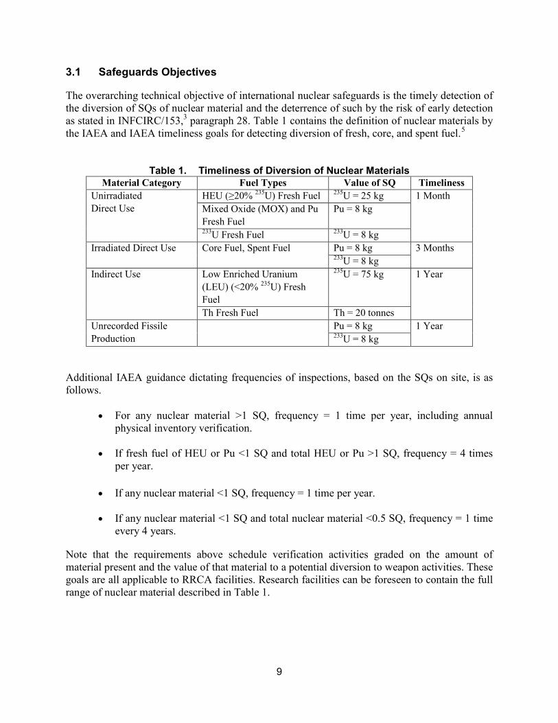
The overarching technical objective of international nuclear safeguards is the timely detection of the diversion of SQs of nuclear material and the deterrence of such by the risk of early detection as stated in INFCIRC/153,3 paragraph 28. Table 1 contains the definition of nuclear materials by the IAEA and IAEA timeliness goals for detecting diversion of fresh, core, and spent fuel.5
Table 1. Timeliness of Diversion of Nuclear Materials
Material Category Fuel Types Value of SQ Timeliness Unirradiated Direct Use
HEU (≥20% 235U) Fresh Fuel 235U = 25 kg 1 Month Mixed Oxide (MOX) and Pu Fresh Fuel
Pu = 8 kg
233U Fresh Fuel 233U = 8 kg Irradiated Direct Use Core Fuel, Spent Fuel Pu = 8 kg 3 Months
233U = 8 kg Indirect Use Low Enriched Uranium
(LEU) (<20% 235U) Fresh Fuel
235U = 75 kg 1 Year
Th Fresh Fuel Th = 20 tonnes Unrecorded Fissile Production
Pu = 8 kg 1 Year 233U = 8 kg
Additional IAEA guidance dictating frequencies of inspections, based on the SQs on site, is as follows.
• For any nuclear material >1 SQ, frequency = 1 time per year, including annual physical inventory verification.
• If fresh fuel of HEU or Pu <1 SQ and total HEU or Pu >1 SQ, frequency = 4 times per year.
• If any nuclear material <1 SQ, frequency = 1 time per year.
• If any nuclear material <1 SQ and total nuclear material <0.5 SQ, frequency = 1 time every 4 years.
Note that the requirements above schedule verification activities graded on the amount of material present and the value of that material to a potential diversion to weapon activities. These goals are all applicable to RRCA facilities. Research facilities can be foreseen to contain the full range of nuclear material described in Table 1.
10
3.2 Traditional and Integrated Safeguards
The overarching goals of traditional (facility-level) nuclear safeguards and integrated safeguards are as noted above. The IAEA defines integrated safeguards as the “optimum combination of all safeguards measures available to the IAEA under comprehensive safeguards agreements and additional protocols to achieve maximum effectiveness and efficiency in meeting the IAEA’s safeguards obligations within available resources.” The following sections will discuss the typical safeguards strategy for RRCAs in more detail. A key distinction regarding integrated safeguards is that it is applied to the country as a whole. Traditional IAEA safeguards were applied at the level of the facility. The goal of detecting the diversion of significant quantities of nuclear material or misuse of the facility remains relevant even with the recently strengthened safeguards emphasis on detecting undeclared nuclear activities. If an RRCA fell under integrated safeguards, additional measures, such as the use of remotely monitored safeguards equipment, satellite imagery, and/or short-notice random inspections, could enable a reduction in the frequency and number of on-site inspections. This concept is an example of achieving maximum effectiveness as well as efficiency because of increased transparency from the SSAC. In terms of design, the facility must accommodate IAEA safeguards equipment (e.g., seals, surveillance, and/or radiation detection systems), regardless of whether the RRCA is under traditional (facility-level) or integrated safeguards. The key difference for inspection activities between traditional (facility-level) and integrated safeguards is the timing and intensity of inspection activities, but not whether inspection will take place. As the RRCA is being designed and constructed, the facility operator, State Regulatory Authority, and IAEA should also discuss whether the RRCA will need to accommodate other measures, such as the remote monitoring of safeguards equipment.
3.3 Safeguards Responsibilities
Engagement and dialog between the facility operator, the facility designer, the State Regulatory Authority, and the IAEA should begin early in the design process to ensure that IAEA safeguards goals can be efficiently and effectively met. The responsibilities for implementing safeguards are as follows.
• Facility Designer: Design the facility, per the requirements of the facility owner and operator, (customer) to meet the specified operational objectives and to be compliant with relevant national and international regulations, requirements, and guidelines. These regulations, requirements, and guidelines include, but are not limited to nuclear safety, and security and safeguards regulations, requirements, and guidelines. The facility designer should design the facility in a manner that accommodates IAEA safeguards equipment and systems, facilitates design verification for safeguards purposes, and facilitates implementation of IAEA inspector activities during construction, operation, and decommissioning of the facility. Inclusion by the owner/operator of a relevant specification in its contract with the designer can ensure
11
that SBD for international safeguards is part of the design requirements that the facility designer must meet.
• Facility Operator: Operate the nuclear facility, as declared to the State Regulator Authority/SSAC in accordance with relevant national and international regulations, requirements, and guidelines. The facility operator prepares the construction specifications for the facility, which include specifications for implementing effective nuclear safeguards and providing space and utilities for nuclear safeguards equipment and measures. The facility operator hosts IAEA inspections and must operate the facility in the manner declared to the IAEA.
• State Regulatory Authority/SSAC: Oversee the implementation of national (domestic) nuclear regulations within the country, particularly those pertaining to nuclear safety, security, and safeguards. Ensure the effective accounting, control, and regulated use of nuclear material within the country. The State Regulatory Authority/SSAC regulates and controls nuclear activities in the State for the purpose of assuring that nuclear materials is used only for peaceful purposes, provides correct and complete information to IAEA on nuclear material and facilities, and facilitates IAEA safeguard activities to verify the information provided, as per the safeguards agreement between the country and the IAEA. The State Regulatory Authority/SSAC coordinates operator and designer dialog and engagement with the IAEA.
• IAEA: Verify that the country is upholding its international safeguards agreement with the IAEA. The IAEA Department of Safeguards uses the safeguards measures available to achieve its objectives of verifying that no nuclear material has been diverted to weapons programs, there has been no misuse of a safeguarded facility to produce nuclear material outside of safeguards, and (in countries with an Additional Protocol) that there are no undeclared nuclear fuel cycle activities.
12
4 ELEMENTS OF FACILITY DESIGN THAT ARE RELEVANT FOR SAFEGUARDS
4.1 Design Features Relevant for Safeguards
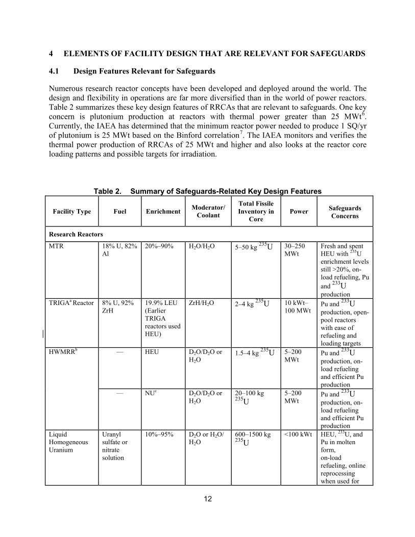
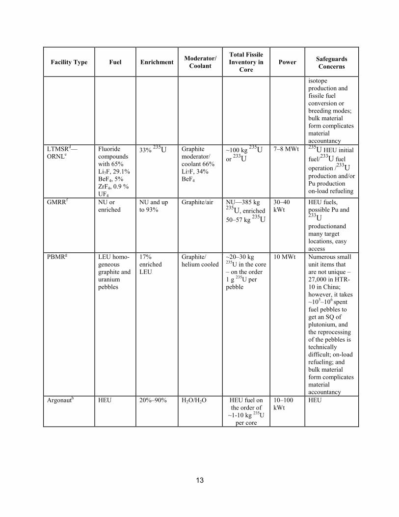
Numerous research reactor concepts have been developed and deployed around the world. The design and flexibility in operations are far more diversified than in the world of power reactors. Table 2 summarizes these key design features of RRCAs that are relevant to safeguards. One key concern is plutonium production at reactors with thermal power greater than 25 MWt6. Currently, the IAEA has determined that the minimum reactor power needed to produce 1 SQ/yr of plutonium is 25 MWt based on the Binford correlation7. The IAEA monitors and verifies the thermal power production of RRCAs of 25 MWt and higher and also looks at the reactor core loading patterns and possible targets for irradiation.
Table 2. Summary of Safeguards-Related Key Design Features
Facility Type Fuel Enrichment Moderator/ Coolant
Total Fissile Inventory in
Core Power
Safeguards Concerns
Research Reactors
MTR 18% U, 82% Al
20%–90% H2O/H2O 5–50 kg 235U 30–250 MWt
Fresh and spent HEU with 235U enrichment levels still >20%, on-load refueling, Pu and 233U production
TRIGAa Reactor 8% U, 92% ZrH
19.9% LEU (Earlier TRIGA reactors used HEU)
ZrH/H2O 2–4 kg 235U 10 kWt–100 MWt
Pu and 233U production, open-pool reactors with ease of refueling and loading targets
HWMRRb — HEU D2O/D2O or H2O
1.5–4 kg 235U 5–200 MWt
Pu and 233U production, on-load refueling and efficient Pu production
— NUc D2O/D2O or H2O
20–100 kg 235U
5–200 MWt
Pu and 233U production, on-load refueling and efficient Pu production
Liquid Homogeneous Uranium
Uranyl sulfate or nitrate solution
10%–95% D2O or H2O/ H2O
600–1500 kg 235U
<100 kWt HEU, 233U, and Pu in molten form, on-load refueling, online reprocessing when used for
13
Facility Type Fuel Enrichment Moderator/ Coolant
Total Fissile Inventory in
Core Power
Safeguards Concerns
isotope production and fissile fuel conversion or breeding modes; bulk material form complicates material accountancy
LTMSRd—ORNLe
Fluoride compounds with 65% Li7F, 29.1% BeF4, 5% ZrF4, 0.9 % UF4
33% 235U Graphite moderator/ coolant 66% Li7F, 34% BeF4
~100 kg 235U or 233U
7–8 MWt 235U HEU initial fuel/233U fuel operation /233U production and/or Pu production on-load refueling
GMRRf NU or enriched
NU and up to 93%
Graphite/air NU—385 kg 235U, enriched 50–57 kg 235U
30–40 kWt
HEU fuels, possible Pu and 233U productionand many target locations, easy access
PBMRg LEU homo-geneous graphite and uranium pebbles
17% enriched LEU
Graphite/ helium cooled
~20–30 kg 235U in the core – on the order 1 g 235U per pebble
10 MWt Numerous small unit items that are not unique –27,000 in HTR-10 in China; however, it takes ~105–106 spent fuel pebbles to get an SQ of plutonium, and the reprocessing of the pebbles is technically difficult; on-load refueling; and bulk material form complicates material accountancy
Argonauth HEU 20%–90% H2O/H2O HEU fuel on the order of
~1-10 kg 235U per core
10–100 kWt
HEU

14
Facility Type Fuel Enrichment Moderator/ Coolant
Total Fissile Inventory in
Core Power
Safeguards Concerns
Critical Assemblies
Vertical Integral Assemblies—Fast
Oxide or Metal: U and Pu
93% or 37.5%
— 350 kg 93% 235U, 150 kg 37.5% 235U, & 100 kg Pu
W–kWt HEU, reconfigured fuel
Vertical Integral Assemblies—Thermal
Oxide, MOX
<20% Graphite or D2O/H2O
20–150 kg 235U or 60 kg Pu
W–kWt Pu and 233U production, HEU, reconfigured fuel
Horizontal Split—Bed Fast Assemblies
Oxide or Metal
— — 40–550 kg 235U and 40–250 kg Pu, up to 3000 kg Pu
Up to MWt
Pu and 233U production, HEU, reconfigured fuel
aTRIGA = Training Research Isotope Production General Atomic (reactor). bHWMRR = heavy water moderated research reactor. cNU = natural uranium. dLTMSR = liquid thorium molten salt reactor. eORNL = Oak Ridge National Laboratory. fGMRR = graphite moderated research reactor. gPBMR = pebble bed modular reactor. hArgonaut = Argonne Nuclear Assembly for University Training. Specific RRCA types have particular proliferation concerns (listed in the above Table 2) that safeguards must address. Note that the possibility of irradiation of thorium targets has been included here for the production of 233U. Although this possibility has not been a concern of the IAEA’s to date, 233U production at least must be mentioned to be thorough in describing the proliferation pathways in a flexible research reactor with the capability to irradiate material. Specifically, ORNL had programs in the post-war era up to the 1970s developing thorium and 233U concepts for reactors and ran molten thorium/233U research reactors. This concept is under study now for Generation IV reactors. The IAEA will need to give considerable thought to how it might safeguard any future RRCA facilities that could test future liquid thorium molten salt reactor designs that can produce 233U. While critical assemblies can use LEU as a fuel, it should be noted that the possibility of the use of high fissile (HEU, 233Uand 239Pu) content fuels can make critical assemblies very sensitive facilities. This fissile material is in a form easily converted to a weapons form and, as documented by Los Alamos National Laboratory in 19818, can be used to provide valuable weapons test data. The Godiva bare critical HEU critical assemblies provided key data for the critical mass of early American weapons. Such high content fissile material critical assembly fuel are unirradiated direct-use material, even after irradiation, because the radiation times for most crucial assemblies are so short that the radiation levels drop quickly from the fuels. Inventories of unirradiated direct use material may be greater than an SQ. Any RRCA with these capabilities would need stringent safeguards and attention to possible diversions or gathering of data desirable for designing and producing a weapon.
15
Major design features and operations of RRCAs that have significant impacts on current safeguards regimes and scope are the
1. possibility of stores of large quantities of fresh HEU, 233U, and plutonium, which are readily used for weaponization and that require special safeguards protection procedures to prevent materials diversion;
2. targets of fertile materials of 238U or thorium, which can be converted to fissile material (plutonium or 233U) in reactors having a power of ≥25 MWt in the core region or blanket or via irradiation ports. A research reactor having fertile targets could require advanced thermal hydraulic power monitoring to track core power and special surveillance, containment, and radiation detectors to identify unreported plutonium and 233U production because knowledge of the thermal power operation of a reactor gives insights and bounds for possible fissile material production; and
3. fresh, core, and spent MOX fuels that could be part of advanced pilot plants for certain new Generation IV designs require additional safeguards procedures.
Conversion of previously HEU-fueled research reactors to LEU fuels and creating future designs to be fueled with LEU, through such programs as the U.S. Reduced Enrichment Research and Test Reactor Program, would significantly reduce the proliferation risks associated with production and use of HEU fuels and with reprocessing of spent HEU fuels having high residual enrichments in U235. It should be noted, however, that the spent LEU fuels will still need to be safeguarded.
4.2 Misuse and Diversion Scenarios
The IAEA treats the vast majority of RRCA facilities similarly to a light-water reactor or on-load reactor—i.e., as an item facility. An exception might be the novel RRCAs, such as a PBMR9 or an LTMSR, where the fuel is not readily available in item form. The entire RRCA constitutes one material balance area. However, RRCAs have significantly smaller quantities of nuclear materials than power reactors, and a smaller number of fuel assemblies/rods. Diversion of the fresh HEU fuels used in RRCAs is the major concern in HEU-fueled reactors and a reason for a push, for nonproliferation reasons, to redesign existing RRCAs using HEU to run with LEU and discourage new HEU-powered RRCAs. Diversion of the LEU fresh fuel is still a safeguards concern (albeit a lesser one than HEU fresh fuel diversion) because it can be further enriched to HEU or irradiated in a clandestine reactor for plutonium production. Plutonium in the spent LEU fuel can be separated using well-known processes. A determined State can be assumed to be capable of building a clandestine reprocessing plant for this purpose. Some RRCA facilities also have stores of loose items containing plutonium and uranium for research activities, which complicates the material accountancy and safeguarding of the RRCA. Careful attention needs to be given to safeguards on these items in the context of the overall safeguards approach to these facilities. Critical assemblies with fissile material in them would also be a serious concern especially in countries of concern.

16
4.2.1 Diversion of 235U HEU may exist at RRCAs in the following forms:
• fresh fuel for a reactor or critical assembly that has not been converted via RERTR or
similar program to use LEU fuel, or fresh HEU fuel that has yet to be repatriated following core conversion or facility shutdown/decommissioning;
• HEU used in booster rods for NU-fueled reactors;
• HEU used in targets for production of medical isotopes (e.g., 99Mo);
• residual HEU in spent fuel, which may be burned down from 93% enriched, for example, to a lower but still highly enriched—e.g., 35%. It may have cooled for a substantial period, allowing the radiation hazards to be significantly reduced;
• HEU as part of materials for research stored at the facility.
4.2.2 Diversion of Plutonium and 233U Any reactor using plutonium fuel presents the possibilities that the state may divert plutonium from declared inventories or flows. Plutonium in fresh fuel could be used more readily as converting the plutonium from a MOX fuel to pure plutonium is easier than separating plutonium out of irradiated fuel by reprocessing. Such MOX fuel is thus given the same safeguards concern as fresh HEU fuel. Plutonium production in a research reactor can be optimized if the core is loaded with a driver fuel to maintain reactor criticality and a target fuel to generate plutonium. The driver fuel can be HEU or LEU, whereas the target fuel may be either natural or depleted uranium. For a typical materials testing reactor (MTR), the consumption rate of 235U is 1.0–1.2 g/MWd, whereas the net production rate of plutonium is 0.4–0.6 g (Pu)/MWd. If these values are used when they are scaled to a generic 30-MWt reactor operating 300 days per year, the maximum net production rate of plutonium is ~3.6–5.4 kg/yr. This number is consistent with a total net plutonium production of 3.9 kg/yr for a high-flux-type reactor when scaled to 30 MWt. Approximately 3–5 kg of plutonium can be produced annually in a generic 30-MWt MTR. Support for the veracity of this plutonium production calculation is found in historic deliberate plutonium production campaigns at graphite reactors, such as those at Brookhaven. Irradiating thorium produces 233U, the fission properties of which are superior to 235U. However, it comes along with 232U and the 232U daughter products. Although one daughter, 208Tl, emits a 2.6-MeV gamma ray, 233U still is considered to be a nuclear material of high attractiveness.10 Furthermore, the capability to separate protactinium chemically from the uranium allows 233Pa to be separated as a pure elemental compound. With its 27-day half-life compared with the 2.3-day half-life of 239Np, which is the precursor of 239Pu, 233Pa can more easily be isolated than 239Np before decaying to 239Pu. Thus, a pure block of 233Pa could be set aside to decay away within a year to a pure block of fissile 233U. Liquid homogeneous research reactors (LHRRs) such as the LTMSR can operate with on-load refueling and a linkage to reprocessing of the removed material. A safeguards approach more akin to a reprocessing plant would have to be created for

17
such an LHRR with on-load refueling and reprocessing to track the loading and unloading of material and fissile material separations activities.
4.2.3 Diversion of Depleted, Natural, and Low-Enriched Uranium (DNLEU) Declared inventories of DNLEU are also a concern as indirect use material (see below), depending on the scale of activities and the availability of more attractive materials.
• NU or LEU might fuel a clandestine production reactor or be reinserted into the declared reactor after it had been removed from the records.
• NU or depleted uranium might be slightly enriched. LEU might be further enriched to HEU levels in declared or clandestine enrichment plants.
• DNLEU might be diverted or stolen for use as target material for plutonium production in the State or elsewhere.
Diversion and concealment activities for fresh and irradiated fuels are summarized in Table 3.
Table 3. Nuclear Material Diversion and Diversion Methods Fuel Diversion Methods
Fresh Fuel Removal from fresh fuel storage Substitution by dummies or by fuel with lower enrichment Misstatement of records/reports
Irradiated Fuel Removal from core or from pool/tank Substitution by dummies Falsification of records
4.2.4 Undeclared Production of Plutonium or 233U Plutonium produced with low burnup (<1 GWd/T) is more desirable for weapons stockpiles than plutonium irradiated at higher burnups, considering plutonium isotopic compositions.11 Introducing fertile material in large amounts as needed to sustain a clandestine production scheme requires that the irradiation positions be accessible and that the reactor operate safely with the fertile material targets installed. In general, large-scale irradiation of fertile material around the core region will perturb the neutron spatial and energy distributions and may adversely affect reactor control and heat transfer. The reactor fuel consumption rate will increase, requiring additional, more frequent reloads. The IAEA specifies that the minimum power required to produce 8 kg of plutonium per year is 25 MWt. A study by Tomanin et al.12 showed that safeguards measures should be strengthened by the IAEA for all reactors with >10 MWt. In terms of the total plutonium produced, another study by Los Alamos National Laboratory showed that 80 research reactors operating at >1 MWt could produce ~250 kg of plutonium based on their reported power output.13 However, in CSA safeguards, the IAEA has set the level for extra concern for monitoring thermal power in an RRCA at 25 MWt. Therefore, we could foresee a situation where the IAEA would, under a State

18
level approach with a State with a lack of transparency and cooperation, attempt to do more monitoring of the power at an RRCA with <25 MWt. In summary, the RRCA uses various forms and types of fuels, the safeguards implications of which are listed in Table 4.
Table 4. Safeguards Implications of RRCA Fuels Fuel/Target Safeguards Implications
HEU Fresh, core Direct use Spent Recovery of HEU, or for further enrichment
DNLEU Fresh, core Further enrichment Spent Recovery of Pu Target Production of Pu
233U, Pu, MOX Fresh, core Direct use Spent Recovery of 233U and Pu
Th Target Recovery of 233U
5 KEY ELEMENTS OF SAFEGUARDS APPROACH FOR RRCA
The previous section described the proliferation pathways of concern for an RRCA. This section will describe the safeguards approaches that the IAEA implements to verify diversion at an RRCA has not taken place. These include design information verification, physical inventory verification, interim inventory verification at the facility, and verification of the decommissioning of an RRCA.
5.1 Design Information Verification
The IAEA must verify the design features of a facility according to the declaration of the operator. This is an iterative process that takes place over the life-cycle of the facility. For research reactors, the functionality and uses of the design are particularly important, since such facilities are intended to support a range of uses and operations in support of R&D. Thus, the IAEA will verify how the facility will operate, where material will be stored and used, and how the facilities will be collocated (such as hot cells to a research reactor). The operator provides information to the IAEA through the State in the form of a Design Information Questionnaire (DIQ). The IAEA takes the DIQ and will perform Design Information Examination (DIE) activities to check the information from the State. The DIE takes the form of Design Information Verification (DIV), which includes visits to the facility to verify the completeness and correctness of the DIQ. With this information and the creation of the facility attachment for the RRCA by the IAEA, the IAEA can plan its safeguards implementation at a facility. In the operational period, DIV continues during inspections to ensure that declared facility changes are verified and that no undeclared changes have been made. DIV continues even into the decommissioning phases to allow the IAEA to continue to verify that the design and operation of the facility are as declared, even after nuclear material is removed.

19
5.2 Physical Inventory Verification and Interim Inventory Verification
During material accountancy verification, the IAEA must have procedures and equipment to verify the parameters and materials of concern. The first concern at an RRCA is to verify the unirradiated materials stored at the reactor. This fuel is almost exclusively fresh but may include other nuclear materials at the RRCA used for research. The IAEA has used item counting, serial number checks, and nondestructive assay (NDA) with random sampling plans to verify this material, including LEU fuel at gross defect levels and HEU and plutonium fuel or test items at gross and partial defect levels. Inspectors use sodium iodide, high-purity germanium, and cadmium zinc telluride (CZT) detectors to verify the uranium and plutonium contents of fresh fuel and other items in the facility, at least at the gross defect level. Other equipment could be needed to verify the partial defect level, including scales or load cells to weigh items and the active well coincidence counter for uranium and the high-level neutron coincidence counter for plutonium. Such items can be stored in containers that can be sealed or observed by cameras to maintain continuity of knowledge (CoK) under containment and surveillance (C/S). Once items move to the reactor and get irradiated, the verification becomes more complicated. Here the IAEA can rely on sharing operator instrumentation to do criticality checks by observing operator instrumentation and observing operations such as a reactor pulse in reactors (such as at a TRIGA reactor) to verify that the reactor operated as declared. The inspector can observe the Cerenkov glow from an irradiated core with the Improved Cerenkov Viewing Device (ICVD). The inspector further uses the ICVD to verify the spent fuel being stored in a storage pond in or near the reactor and can use spent fuel attribute testers that use gross gamma or CZT detectors to see if an assembly has been irradiated. In the case of high-power research reactors operating at >25 MWt, the IAEA can install reactor power monitors to detect either the neutron and gamma levels or the thermal power by the use of thermocouples showing operational data that verify the operator’s thermal power declarations. Recent technical advances have touted the use of anti-neutrino detectors to verify the power operation and fissile content of the core. Whether such a tool is cost effective in an RRCA is debatable.
5.3 Verification of the Decommissioned Status of an RRCA
The IAEA maintains safeguards coverage of an RRCA until it is decommissioned. Design information verification (DIV) privileges exist for the IAEA until it declares the facility decommissioned for safeguards purposes. The IAEA is leaning toward keeping these privileges until the RRCA is in a “green fields” status to avoid misuse of the facility by the construction of a clandestine facility on and in the facility.14
5.4 Summary of RRCA IAEA Safeguards Challenges
The key challenge to safeguarding an RRCA is the flexibility and a possible lack of transparency of operations at an RRCA. The small scale of fuel cycle activities and low power level of a research reactor can give the perception that a research reactor is not an important fuel cycle facility; therefore, the IAEA gave less emphasis to safeguards at RRCAs. The evidence from key challenges to the nonproliferation regime in the past two decades has heightened IAEA attention to safeguards challenges at RRCAs:
20
• Democratic People’s Republic of Korea—used a research reactor to produce plutonium for its weapons program,
• Iraq—used RRCA facilities to cloak clandestine operations,
• Syria—built alleged clandestine RRCA, and
• Iran—constructed an RRCA based on NU and heavy water and a reactor using 19.75% enriched uranium that Iran used as a basis for enriching uranium to the 20% enrichment level.
21
6 SBD BEST PRACTICES
SBD guidance presented here focuses on important IAEA safeguards objectives, such as DIV, the use of inspections to verify material inventory, shipments and receipts, and declared operations. The SBD process also uses input from reactor designers, operators, and safeguards equipment suppliers. In addition, the guidance incorporates lessons learned from former IAEA inspectors with inspection and analysis experience on current operating RRCAs.
6.1 Best Practices
The following general guidance is relevant for designers. We have laid out how best to incorporate SBD for RRCAs such that inspections and design information verification can be accomplished with less effort and more assurance that the facilities are operating as declared.
6.2 General Requirements
The general requirements for an RRCA are to provide for the IAEA to perform inspections and verify design information.
• Provide inspector access for verification of fresh fuel by item counting and the use of appropriate NDA equipment.
• Provide inspector access to the reactor and spent fuel ponds to allow the ICVD to verify the core and spent fuel. The inspectors must have an unobstructed and overhead view of irradiated core and spent fuels. Access to the spent fuel pond will allow NDA equipment to be inserted to verify spent fuel qualitatively (verifying that the fuel rods were irradiated) and in the future possibly quantitatively to measure plutonium content.
• Provide access for inspectors to perform a relevant design verification to ensure that the plant declaration of the scale of activities and use of nuclear material are consistent with the reality of the constructed and operated facility.
6.3 Layout Requirements and Guidelines
The layout requirements for an RRCA should address the following considerations related to IAEA ability to perform inspections and verify design information.
• Configure the physical plant to make safeguards activities more accessible and less complex. Minimize the number of access points in the reactor containment, nuclear material storage areas, and other shielding structures through which any fresh or spent fuel movement could occur. Make the operations of the facility transparent and capable of observation and verification. With research facilities, this process may take some extra design effort to reduce the potential pathways through which nuclear material might be diverted; however, with the push to make nuclear research facilities more secure from theft or sabotage, such efforts could also help with safeguards

22
measures. With fewer access points, containment and surveillance measures can become simpler and less complex to employ and provide less complicated and unambiguous results if the scale of fuel cycle activities at an RRCA does call for C/S measures.
• Design for adequate and reliable illumination at the containment access, the fuel storage areas (dry and wet), reactor bay, and fueling mechanism areas to aid inspection.
• Plan the fuel transport routes so that if a surveillance system is deemed necessary, it can obtain images that provide information to draw safeguards conclusions—in particular, the ability to distinguish clearly between routine and nonroutine fuel transfers and other fuel pond activities such as licit targets for isotope production and clandestine fissile material production. Radiation detectors can also be used as surveillance to alert the IAEA to any movement of material. Containment systems (e.g., seals on containers or on cranes and refueling machines) provide further indication that no nuclear material has been diverted during fuel receipts, shipments, transfers within the facility, and refueling. The scale of the reactor power and capabilities to produce fissile material and the amount and type of materials present throughout the facility determine the need for surveillance and containment on fuel movements.
• Minimize the effect of safeguards on plant operation by selecting locations for safeguards equipment that are accessible for inspection, monitoring, and maintenance and that do not obstruct or impede plant operations.
Nuclear materials at an RRCA are present in four areas: the fresh fuel receiving and storage area, the fuel handling area for loading and unloading fuel, the reactor core, and the spent fuel storage and shipping area. Designers need to consider certain features specific to each area.
6.3.1 Fresh Fuel Receiving and Storage Area The following design features for the fresh fuel receiving and storage area would assist in implementing safeguards:
• a dry-air room equipped with fission detectors and a surveillance camera with an intrusion sensor—such measures would be necessary with multiple SQs of unirradiated direct-use materials, such as HEU, MOX, or plutonium fuels;
• a minimum number of openings in the building structure to access the fresh fuel storage area (through which removal of fuel could take place), with suitable arrangements, if required by the safeguards approach, to allow for sealing and/or surveillance of these openings;
• layout of the fresh fuel storage area that allows inspectors to verify and progressively seal groups of fuel assemblies as they are put into storage without affecting the CoK of the fuel already in inventory; and
23
• provisions for adequate space and illumination between assemblies that allow inspectors to read the identifiers on fuel assemblies and conduct NDA; specifically:
o provision for the use of the IAEA inspector’s portable NDA equipment and possible secure storage on site and
o arrangement of fuel within the storage area so that it minimizes the need to move fuel to identify specific assemblies.
6.3.2 Fuel Handling Area The following design features for the fuel loading and unloading area would assist in implementing safeguards:
• a mounting for surveillance equipment suitable for inspectors to view the tops of the fuel assemblies,
• an indexing mechanism on the refueling machine with a device that can identify the location of each assembly, and
• a provision for sealing the canal gate (when applicable) to indicate to the inspectors when it is open and an indexing system (where possible) to monitor material shipments between the core and spent fuel pool.
6.3.3 Reactor Core and Bay Area The following design features for the reactor core would assist in implementing safeguards in all sizes of research reactors. The TRIGA reactor in Vienna, Austria [operated by the Vienna University of Technology (TU Vienna)] is an example of a smaller reactor which operates at the 250-kWt-power scale. It is less capable of producing fissile material, than an example of one of the larger reactors, the 20–30-MWt Maria reactor in Swierk, Poland (see Figures 1 and 2, respectively). The design features in the core and reactor bay area should exist to make nuclear material accountancy verification simpler and to make verifying fissile material production more transparent for all sizes of reactors but especially for those with higher thermal power output.

24
Figure 1. TRIGA reactor operated by TU Vienna in Vienna, Austria.
Figure 2. Maria reactor in Swierk, Poland—the reactor core shows the flexibility of the core for
irradiation.

25
The reactor design should:
• have a sealing system to provide a tamper indication for the nuclear material contained in the reactor core if physically possible (such a system should be accessible for inspection, easy to install, and protected against damage);
• incorporate underwater illumination in the reactor pool/tank and sufficient water clarity so that the inspector can count the fuel assemblies and read their identifiers;
• incorporate tracking of the crane and fuel handling equipment to verify the movements and positions of fuel elements in the core (this feature becomes more necessary with larger and more flexible reactors, however, if a reactor core itself can be moved around easily by crane the cost benefits of having such data must be analyzed in light of specific RRCA designs and the need for the reactor operator to make frequent fuel movements);
• incorporate tamper-resistant surveillance cameras, radiation detectors to monitor operational activities in the core, and peripheral pipings;
• incorporate the installation of tamper-resistant surveillance cameras monitoring target movements in all irradiation channels, including ducts and beam tubes;
• incorporate power monitors at reactor and experimental areas; and
• allow operator power level information and temperatures of the inlet and outlet of the reactor coolants of the reactor instrumentation to be shared with the inspectors.
6.3.4 Spent Fuel Storage and Shipping Areas The following design features for the spent fuel storage and shipping area would assist in the implementation of safeguards:
• high-purity water to preserve the integrity of the spent fuel items and improve water clarity for visual verification techniques (which will described in detail later);
• an arrangement that is suitable for the installation of surveillance equipment;
• light sources in the room, selected so that their spectrum does not overlap the characteristics of the ICVD imager, which is sensitive to the ultraviolet range (otherwise, the signal/background advantage could be lost or switching off the illumination in the spent fuel storage area may be needed, which might oppose plant safety rules);
• storage racks, preferably configured in a single layer, that permit viewing, directly from above, on the top of each fuel assembly with its identifier showing (e.g., no overhang over fuel storage locations should exist);

26
• provisions (i.e., adequate pitch) for verifying and sealing the fuel in a lower layer(s) if fuel storage is in more than one layer;
• an indexing system such that the inspectors can identify specific fuel assembly locations from the fuel handling control point;
• provisions that facilitate the annual physical inventory verification, which consists of counting the total number of spent fuel items and verifying spent fuel attributes by NDA;
• an adequate fuel storage space designed to minimize the contact of aluminum cladding with different metals to avoid galvanic corrosion when in an aqueous medium. Use aluminum-compatible cages or baskets to avoid galvanic corrosion that leads to degradation of the fuel and ensuing poor water quality that would hamper the use of the ICVD and even preclude simple spent fuel item counting;
• a storage capacity adequate to provide unblocked viewing and inspection of nuclear materials and transparency in operations so that inspectors can understand and verify if irradiation of fertile targets such as 238U and thorium occurred; and
• difficult-to-access locations identified where nonintrusive and remote measurement equipment (e.g., clamp-on ultrasonic flowmeters) is required for power level calculations.
6.4 Space Allocation Requirements and Guidelines
6.4.1 Safeguards Equipment The design should accommodate IAEA safeguards equipment, and:
• provide a single dedicated space for the IAEA safeguards equipment. This space should accommodate incorporating anticipated developing technologies in data processing and transmission equipment;
• support an IAEA tamper-resistant local area network connection at each safeguards measurement point and make allowances for analysis and digital data storage equipment at the measurement sites; and
• consider working with the IAEA to employ joint-use equipment (e.g., used by both the operator and IAEA) with adequate authentication of IAEA data feeds that measure critical parameters, including temperature, flow, radiation level and fluxes, and core inventories, to allow verification of operations (including fuel loadings and thermal power levels).
6.4.2 Inspector Office Space and Computer The designer should address the following needs:
27
• provide office space or equipment space for IAEA inspectors. The scale of the space needed will depend on the facility’s activities and the safeguards effort at the facility;
• make a centralized site available for IAEA data recording, analysis, and processing of computer data; and
• consider the viability of allowing off-site transmission of safeguards-relevant data to the IAEA to facilitate remote inspections using remote NDA and C/S as desired by the IAEA for future safeguards implementation.
6.5 Design Impacts of Facilitating Inspections
This section describes design impacts for the RRCA based on safeguards needs.
6.5.1 Design Features to Facilitate DIE/DIV at a Facility DIE/DIV is an important means for the IAEA to verify that a facility operates as declared. The designers can make the IAEA’s efforts more efficient, effective and less intrusive by ensuring that the facility is designed to have specific accessible areas for the storage of fresh fuels and that the control room and instrumentation are visible and understandable to the inspectors when examining the facility, as part of DIV, for purposes of understanding its use and operations. 6.5.2 Design Features to Facilitate Inspections For the IAEA to be able to perform inspections, it must be able to access material and to apply C/S if needed. The designers can make inspector access to material less complex by designing parts of the facility specifically for the safe and secure storage of fresh fuel in a manner amenable to verification activities during inspection. The core and the spent fuel pond should be accessible by a bridge or other means, have transparent water, and offer a clear view to allow for visual verification of the fuel by inspectors using both visual identification and detection of the Cerenkov glow by ICVD. Differentiation of fuel items and target items should be apparent to the inspector so that a proper inventory can be made. If a target is a nonnuclear material, it should be apparent to the observer and verifiable by NDA techniques. Design features should allow spent fuel NDA instrumentation to be lowered into the pond to easily verify the spent fuel. C/S is the primary method for the IAEA to ensure Continuity of Knowledge. If an RRCA is handling SQs of unirradiated direct use material or is a large reactor producing plutonium or 233U or having onload refueling options, the IAEA may deem C/S measures such as seals and surveillance to be desirable to make safeguarding the RRCA more efficient and effective. To demonstrate that no tampering or removal of material in a facility can occur, inspectors can seal the following with a tamper-indicating seal: a container holding material, a door to the room containing the material if possible, the spent fuel racks and containers, and equipment (such as a crane essential to move material). This general approach, when applied at strategic points in fuel movement pathways or on doors to rooms or other structures, constitutes a means of indication of tampering with material in a facility. These barriers and containers are unique to the particular design situation and are the designer’s responsibility. Sealing systems could cover spent fuel inventories stored in pools, spent fuel casks, reactor core, and transfer canal gates. In general, most fresh fuel can be stored in secure cask containers that can be sealed (see Figure 3). Sealing the fuel storage room provides a backup to the cask seal. Such arrangements that provide backup
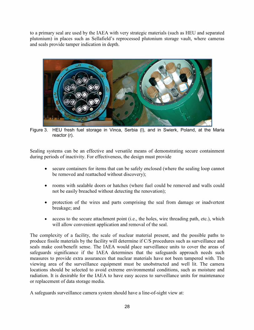
28
to a primary seal are used by the IAEA with very strategic materials (such as HEU and separated plutonium) in places such as Sellafield’s reprocessed plutonium storage vault, where cameras and seals provide tamper indication in depth.
Figure 3. HEU fresh fuel storage in Vinca, Serbia (l), and in Swierk, Poland, at the Maria
reactor (r).
Sealing systems can be an effective and versatile means of demonstrating secure containment during periods of inactivity. For effectiveness, the design must provide
• secure containers for items that can be safely enclosed (where the sealing loop cannot be removed and reattached without discovery);
• rooms with sealable doors or hatches (where fuel could be removed and walls could not be easily breached without detecting the renovation);
• protection of the wires and parts comprising the seal from damage or inadvertent breakage; and
• access to the secure attachment point (i.e., the holes, wire threading path, etc.), which will allow convenient application and removal of the seal.
The complexity of a facility, the scale of nuclear material present, and the possible paths to produce fissile materials by the facility will determine if C/S procedures such as surveillance and seals make cost/benefit sense. The IAEA would place surveillance units to cover the areas of safeguards significance if the IAEA determines that the safeguards approach needs such measures to provide extra assurances that nuclear materials have not been tampered with. The viewing area of the surveillance equipment must be unobstructed and well lit. The camera locations should be selected to avoid extreme environmental conditions, such as moisture and radiation. It is desirable for the IAEA to have easy access to surveillance units for maintenance or replacement of data storage media. A safeguards surveillance camera system should have a line-of-sight view at:

29
• fresh fuel storage areas (if plutonium or HEU fuels are used); • the spent fuel pool; • the reactor bay, experiment ports, and enclosure; and • exit doors and hatches for the transfer of fresh and spent fuel.
6.6 Design Team Discipline-Specific Impacts
6.6.1 Electrical To facilitate surveillance and unattended NDA systems, designers need to provide electrical service that has
• light sources in the room, selected so that their spectrum does not overlap the characteristics of the ICVD imager, which is sensitive to the ultraviolet range (otherwise, the signal/background advantage could be lost or switching off the illumination in the spent fuel storage area may be needed, which might oppose plant safety rules);
• suitable measures to ensure adequate continuity of surveillance for known, expected interruptions when it may be desirable to extinguish all lights within the reactor containment;
• appropriate backups for reasonably expected power supply or equipment failures; and
• independent electrical circuits and switchgear to avoid the possibility of inadvertent interruptions of electric power to safeguards equipment.
6.6.2 Chemistry To facilitate surveillance and unattended NDA systems, designers need to
• design a water chemical balance system to maintain optimum water chemistry, avoiding fuel cladding deterioration from corrosion, and design a water-cooling system to keep pool water at a low temperature to reduce the corrosion rate.15
Excellent water quality is a key factor in allowing visual identification of fuel rods and the use of the ICVD. The Cerenkov glow requires water clarity in the ultraviolet, as well as in the visible spectrum.
• use high-purity water with an optimal chemistry of pH (5.5–6.5), an optimal electroconductivity (<4), an optimal chemical ionization (<50 mcg/kg), and an optimal aluminum (<50 mcg/kg) ion concentration, which will minimize aluminum-cladding corrosion.16
This issue of water quality is highlighted because of experience by one of the authors in inspecting both power reactors and research reactors with inadequate water clarity and purity for visual or Cerenkov glow detection.
30
REFERENCES
1. The Safeguards System of the International Atomic Energy Agency, http://www.iaea.org/OurWork/SV/Safeguards/documents/safeg_system.pdf.
2. International Atomic Energy Agency Board of Governors Document GOV/2554/
Attachment 2/Rev. 2 (April 1992). 3. “The Structure and Content of Agreements between the Agency and States Required in
Connection with the Treaty on the Non-proliferation of Nuclear Weapons,” INFCIRC/153 [Corrected] (June 1972).
4. International Atomic Energy Agency, “Model Protocol Additional to the Agreement(s) Between State(s) and the International Atomic Energy Agency for the Application of Safeguards,” International Atomic Energy Agency report INFCIRC/540 [Corrected] (September 1997).
5. IAEA Safeguards Glossary, 2001 Edition, International Nuclear Verification Series No. 3, International Atomic Energy Agency, (June 2002), pp. 22–25.
6. Safeguards Manual, “Safeguards Criteria, Research Reactors and Critical Assemblies
(RRCAs),” SMC 4, International Atomic Energy Agency, Department of Safeguards, (October 2003), p. 6.
7. F. Binford, “Diversion Assumptions for High-Power Research Reactors,” Oak Ridge
National Laboratory report ORNL-6022 (January 1984). 8. R. Malenfant, “Los Alamos Critical Assemblies Facility,” Los Alamos National Laboratory
report LA-8762-MS (1981). 9. Brian D. Boyer, David Beddingfield, Philip Durst, and Robert Bean, “Pebble Bed Modular
Reactor Safeguards: Developing New Approaches and Implementing Safeguards by Design,” Proceedings of the Pacific Northwest International Conference on Global Nuclear Security—the Decade Ahead, Portland, Oregon, April 2010.
10. Charles G. Bathke et al., “Attractiveness of Materials in Advanced Nuclear Fuel Cycles for
Various Proliferation and Theft Scenarios,” Nuclear Technology 179:1 (July 2012), pp. 5–30.
11. B. W. Smith and T. E. Shea, “Safeguards Considerations for Research Reactor and Critical
Assemblies,” Pacific Northwest National Laboratory report PNNL-16449 (April 15, 2007). 12. A. Tomanin, P. Peerani, and G. Janssens-Maenhout, “Non-Proliferation Issues Related to
Misuse of Research Reactors,” Proceedings of the 51st Annual INMM Meeting, Baltimore, Maryland, 2010.
31
13. J. S. Dreicer and D. A. Rutherford, “Global Estimation of Potential Unreported Plutonium
Production in Thermal Research Reactors,” Los Alamos National Laboratory report LAUR-96-2617 (1996).
14. B. D. Boyer, J. Valente, C. Gazze, and J. Gilbert, “A Field Exercise Course to Train IAEA
Safeguards Inspectors in Implementing the Additional Protocol and Performing Complementary Access Activities,” Symposium on International Safeguards: Addressing Verification Challenges, Vienna, Austria, October 2006.
15. International Atomic Energy Agency report IAEA-TECDOC-1508, “Spent Fuel
Management Options for Research Reactors in Latin America,” International Atomic Energy Agency report IAEA-TECDOC-1508, International Atomic Energy Agency, (June 2006).
16. B. S. Yuldashev et al., “Account and Control of Nuclear Materials at the WWR-SM Reactor
in the Institute of Nuclear Physics, Tashkent, Uzbekistan,” in Safety Related Issues of Spent Nuclear Fuel Storage, NATO Science for Peace and Security Series C: Environmental Security, Part 2, J. D. B. Lambert and K. K. Kadyrzhanov (eds.), (Springer Publishing, New York City, New York, 2007), pp. 143–146.
United States Department of EnergyNational Nuclear Security Administration
Defense Nuclear Nonproliferation
1000 Independence Avenue, S.W.Washington, D.C. 20585
National Nuclear Security AdministrationDefense Nuclear Nonproliferation
www.nnsa.energy.gov/nonproliferation/nis
National Nuclear Security Administration ENERGYU.S. DEPARTMENT OF
President Barack Obama, Prague, April 2009. DOE Secretary Steven Chu, IAEA General Conference, 2010.
NNSA Administrator Thomas D’Agostino, Third International Meeting on Next
Generation Safeguards, 2010.