guidance and control for flat-circular parachutesfaculty.nps.edu/oayakime/adsc/agas - dellicker -...
TRANSCRIPT

JOURNAL OF AIRCRAFT
Vol. 38, No. 5, September–October 2001
Guidance and Control for Flat-Circular Parachutes
Scott Dellicker¤
U.S. Army Yuma Proving Grounds, Yuma, Arizona 85365-9110Richard Benney†
U.S. Army Soldier and Biological Chemical Command, Natick, Massachusetts 01760-5017and
Glen Brown‡
Vertigo, Inc., Lake Elsinore, California 92531-0117
The Affordable Guided Airdrop System (AGAS) is being evaluated as a low-cost alternative for meeting themilitary’s requirements for precision airdrop. Designed to bridge the gap between relatively expensive high-glideratio parafoil systems and uncontrolled ballistic parachutes, the AGAS concept offers the bene� ts of high-altitudeparachute releases as well as the potential for highly accurate point-of-use delivery of material. The design goalof the AGAS development is to provide a guidance, navigation, and control system that can be placed in line withcargo parachute systems, for example the G-12 � at-circular parachute, and standard delivery containers (A-22)without modifying these � elded systems. The AGAS is required to provide an accuracy of 328 ft (100 m), circularerror probable (CEP), with a desired goal of 164 ft (50 m) CEP. The feasibility of this concept was investigatedthrough modeling and simulation. A three-degree-of-freedom (3DOF) point mass � ight dynamics model, sensormodels of a commercial global positioning system (GPS) receiver and magnetic compass, and a model of thecontrol and actuator system were incorporated into a Monte Carlo simulation tool. A bang-bang controller wasimplemented with trajectory tracking algorithms using position and heading information. Flight testing, using aradio-controlled scaled prototype, provided parachute dynamic and control response data to support the modelingefforts. The study demonstrated that this concept has the potential to provide control of previously unguided roundparachutes to accuracies of approximately 210 ft (64 m) CEP. The program is now continuing into the next phaseto include the development of a full-scale prototype system for payloads up to 2200 lb (1000 kg).
Nomenclature§
A = apparent mass matrixA.CPD / = position of point D, measured in fCg and
expressed in fAg where
A¡
CPD
¢D A
C R¡
CPD
¢6D CPD
B = body axisfBg = name of the coordinate systemCD S = drag areaCF = forces in fCgCN = moments in fCgCPD = position of point D, measured in fCg and
expressed in fCgCAR = rotation matrix from coordinate system fAg
to coordinate system fCgCVD = velocity of point D, measured in fCg and
expressed in fCgC ÄD = angular velocity of point D, measured in fCg
and expressed in fC gD = dragd = distanced=dt = time derivatives in the body-axis fBgIii = moment of inertiaL , M , N = moments in the x , y, z axis, respectively
Received 20February2000;revisionreceived 1September 2000;acceptedfor publication 6 September 2000. This material is declared a work of theU.S. Government and is not subject to copyright protection in the UnitedStates.
¤Chief, Aviation and AirdropSystems Division,CSTE-DTC-YP-MT-EA.†Airdrop Technology Team Leader, Natick Soldier Center.‡President, P.O. Box 117.§Capital letters/symbolsdenotevectors ormatrices. Small letters/symbols
denote scalars. If coordinate axis symbol is omitted, fU g is assumed.
L i , Mi , NI = change in moment with respect to ili i = lengthM = mass matrixm = massPe = position errorp = roll rateq = pitch rateNq = dynamic pressurer = yaw rateS. / = skew-symmetric matrixS0 = reference areau = inertial axisW = wind axisWI = weight of iX , Y , Z = forces in the x , y, z axis, respectivelyX i , Yi , Z I = change in force with respect to i®ii = apparent mass coef� cient° = glide ratio± = control de� ectionµ = pitch½ = atmospheric densityÁ = rollà = yaw.¢/ = time derivatives in the inertial-axis fU g
Subscripts
AERO = aerodynamicAM = apparent massa = actuatorc = canopyc.g. = center of gravitye = errorGRAV = gravityp = payloadxx or 1 = x axis
809
810 DELLICKER, BENNEY, AND BROWN
yy or 2 = y axiszz or 3 = z axis1 = suspension lines
Introduction
T HE U.S. Air Force Science Advisory board report titled “NewWorld Vistas, Air and Space Power for the 21st Century”1
identi� ed a critical need to improve the accuracy of airdrop of ma-terial. As a result of this study, a U.S. Army and U.S. Air Forceteam was formed to study precision airdrop. This team formulatedthe New World Vista, Precision Air Delivery program that seeks todemonstrate improved high-altitude cargo air delivery with a goalof achieving accuracies less than 164 ft (50 m) circular error prob-able (CEP). The program is investing in three areas: 1) improvedwind estimation integrating mesoscale modeling with � eld windmeasurements,2) automatedcomputed aerial release point (CARP)calculations using enhanced modeling of unguided parachutes, and3) advanced decelerators.
To date, signi� cant emphasis in the developmentof advancedde-celerators has been placed on large-scale parafoil systems. Thesesystems provide the accuracy required with delivery from high alti-tude and large offset distances.The drawback is relatively high costfor each pound of payload delivered. Alternate approaches wererequired to reduce system cost. The low-cost concept of the Afford-able Guided Airdrop System2 (AGAS) is considered in this paper.This study encompassed modeling and simulation efforts to assessdynamic response of a � at circular parachute, to design guidanceand control techniques, and to evaluate the feasibility of the AGASconcept.
Agas ConceptThe design goal of the AGAS development is to provide a guid-
ance, navigation, and control (GNC) system that can be placed inline with existing � elded cargo parachute systems (G-12) and stan-dard delivery containers (A-22). The system is required to provideanaccuracyof 328ft (100 m)CEP, with a designgoalof 164ft (50m)CEP. The system should not require any changes to the parachuteor cargo system.
The current design concept includes implementation of a com-mercial global positioning system (GPS) receiver and a magneticcompass as the navigation sensors, a guidance computer to deter-mine and activate the desired control input, and the application ofpneumaticmuscle actuators(PMAs)3 to affect thecontrol.The GNCsystem will be rigged with the payload, and the PMAs will go inline with each of four risers. Figure 1 illustrates this concept.
Fig. 1 AGAS concept illustration.
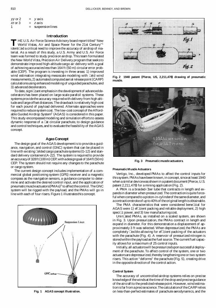
Fig. 2 1940 patent (Pierce, US, 2,211,478) drawing of pneumaticmuscle.
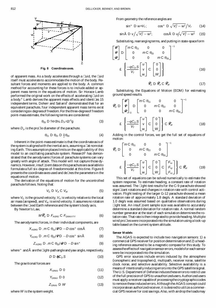
Fig. 3 Pneumatic muscle actuators.
Pneumatic Muscle Actuators
Vertigo, Inc., developed PMAs to affect the control inputs forthis system. PMAs have been known, in concept, since at least 1940when a similar devicewas shown in a patentdocument (Pierce, U.S.patent 2,211,478) for a mining application (Fig. 2).
A PMA is a braided-�ber tube that contracts in length and ex-pands in diameter when pressurized.The contraction is quite force-ful when comparedto a piston-in-cylinderof the same diameter, anda contractionstrokeof up to 40% of the original length is obtainable.
The PMA characteristics that were considered bene� cial forAGAS were 1) ef� cient packing and reliable deployment, 2) highspeci� c power, and 3) low manufacturing cost.
Unin� ated PMAs, as installed on a scaled system, are shownin Fig. 3. Upon pressurization, the PMAs contract in length andexpand in diameter. For this demonstration a displacement of ap-proximately 3 ft was selected. When depressurized, the PMAs arecompletely � exible allowing for ef� cient packing of the actuatorswith the parachute (Fig. 4). A reservoir of pressurized nitrogen isstored within the payload as the fuel source. The current fuel capac-ity allows for a maximum of 25 control inputs.
Initially, all actuatorswill be pressurizedupon successfuldeploy-ment of the parachute. To affect control of the system, one or twoactuators are depressurized,thereby lengtheningone or two systemrisers. This action “deforms” the parachute (Fig. 5), creating drivein the opposite direction of the control action.
Control System
The accuracy of uncontrolled airdrop systems relies on preciseknowledgeof the winds at the time of the drop and precise guidanceof the aircraft to the predicted release point. However, wind estima-tion is far from a precise science.The calculationof the CARP relieson less-than-perfect estimates of parachute aerodynamics, and the

DELLICKER, BENNEY, AND BROWN 811
Fig. 4 Packing the parachute and actuators.
Fig. 5 Parachute with control activation.
aircraft crews cannot � y exactly to the predicted release point foreach airdrop mission. Therefore, the AGAS control system designmust help overcome these potential errors.
The parachutes to be used for this effort were not designed forglideor to be controlled.Therefore,limited controlauthoritywas ex-pected. The G-12 parachutesystem is a � at-circularparachute (one,when lying � at on the ground, forms a circle) without any glide orcontrol capabilities. A smaller � at-circular parachute, the C-9, wasused for initial � ight tests.This parachutewas selected for this studyas it has similar constructionto the G-12 but is less than one-half thesize, thereby simplifying test operations.Considering the relativelylow glide ratio and a descent rate of approximately25 ft/s (7.6 m/s),it is estimated the AGAS can overcome only a 12 ft/s (3.7 m/s)(approximately 7 kn) horizontal wind. It is therefore imperative toimplement the system to overcome poor estimates in the wind andnot try to steer the system against the entire wind. In other words,the drive of the system is insuf� cient to attempt to � y straight to thetargetbut is likely suf� cient to overcomeerrors in the wind estimate.For this reason, trajectory tracking techniqueswere selected.A pre-planned trajectory, based on the best wind estimate available, mustbe determined and provided to the guidance computer. The GPSnavigation system will provide continuous position of the system.The guidancecomputer will compare the actual horizontalposition,at the system’s current altitude, to the planned trajectory. This rep-resents the position error Pe at the current time. A tolerance coneis establishedabout the planned trajectory (Fig. 6) starting at 600 ft(183 m) at the beginning of the trajectory and gradually decreasingto 60 ft (18.3 m) at ground level. Should the position error be out-side this tolerance, a control is activated to steer the system back
Fig. 6 Control concept.
Fig. 7 Control activation.
to the planned trajectory. When the system is within 30 ft (9.1 m)of the planned trajectory, the control is disabled, and the parachutedrifts with the wind. Thirty feet was selected to encompass approx-imately 1-¾ of the GPS errors (each axis, no selective availabilityGPS errors).
As justoutlined,the controlsystemrelieson thecurrenthorizontalpositionerror to determine if control input is required.This positionerror Pe is determined in inertial space and is then rotated to thebody axis using an Euler angle rotation with heading only [Eq. (1)].
Pb D bu R ¢ Pe (1)
where bu R is the Euler rotation matrix.
The resultant body-axis error Pb is then used to identify whichcontrol input must be activated as shown in Eq. (2).
input D sign.Pb=kPbk/ (2)
Two components are returned, a C or for the x axis and a C orfor the y axis. It was assumed for this simulation that Cx would
activate control A, x activates control C , Cy activates controlB, while y activates control D (Fig. 7). The actual rigging of theoperationalsystem must align thesecontrolactuatorsto the compassreference line to ensure proper control. Control A is assumed to bealigned with the compass zero reference line.
The magnitude of the individual x and y components of the nor-malized body-axis position error vector is used to determine if theselected control will be activated. If the magnitude is greater than0.3, then that control is activated. This concept will allow the acti-vation of a single control input or two simultaneous control inputs.
System ModelingThree major components are included in the overall system
model: 1) dynamics model, 2) sensor model, and 3) control systemmodel. In addition, the reference trajectory generator was imple-mented using the same equations of motion used in the dynamicsmodel.
Dynamics Model
In theabsenceofsuf� cientwind-tunneldata for theC-9 parachute,a point-mass system was assumed with the only forces on the sys-tem being drag and weight. Included in the weight are the effects
812 DELLICKER, BENNEY, AND BROWN
Fig. 8 Coordinate axes.
of apparent mass. As a body accelerates through a � uid, the � uiditself must accelerate to accommodate the motion of the body. Re-sultant forces and moments are applied to the body. A commonmethod for accounting for these forces is to include added or ap-parent mass terms in the equations of motion. Sir Horace Lambperformed the original work on the effects of accelerating � uid ona body.4 Lamb derives the apparent mass effects and identi� es 15independent terms. Doherr and Saliaris5 demonstrated that for anequivalent parachute, four independent apparent mass terms existconsideringsix degreesof freedom.For the three-degreeof freedompoint-mass estimate, the following terms are considered:
®33 D f4=3¼.DP=2/3g (3)
where Dp is the pro� le diameter of the parachute.
®11 D ®22 D 12 ®33 (4)
Inherent in the point-mass estimate is that the coordinate axis ofthe system is alignedwith the inertial axis, assuming a � at nonrotat-ing Earth. This assumption places limits on the applicability of thismodel to an oscillating parachute system. Research5 has demon-strated that the aerodynamic forces of parachute systems can varygreatly with angle of attack. This model will not capture those dy-namics. However, insuf� cient data on this parachuteare availabletoformulate a full six-degree-of-freedommodel at this time. Figure 8presents the coordinate axes used and de� nes the parameters in theequations of motion.
The derivation of the equations of motion for the uncontrolledparachute follows. Noting that:
VG D VA C VW (5)
where VG is the ground velocity, VA is velocity relative to the localair mass (airspeed), and VW is wind velocity. It assumes no rotationbetween the � xed Earth reference and the system’s body axis.
By Newton’s Law,
M PVG D FAERO C FGRAVITY (6)
The aerodynamic forces, in their individual components, are
XAERO D .m C ®11/ Pu D D cos ° cos à (7)
YAERO D .m C ®22/ Pv D D cos ° sinà (8)
ZAERO D .m C ®33/ Pw D D sin° (9)
where ° and à are the � ight-pathangle and yaw angle, respectively.
D D NqCD S (10)
The gravitional forces are
XGRAV D 0 (11)
YGRAV D 0 (12)
ZGRAV D W (13)
where W is the system weight.
From geometry the reference angles are
sin° D w=VT ; cos ° Dp
V 2T w2
¯VT (14)
sin à D v¯p
V 2T w2; cos à D u
p̄V 2
T w2 (15)
Substituting, rearranging terms, and putting in state-space form2
4PuPvPw
3
5 D
2
4m C ®11 0 0
0 m C ®22 0
0 0 m C ®33
3
51
£
8<
:qCD S
VT
2
4u
v
w
3
5 C
2
40
0
W
3
5
9=
; (16)
PVG D PVA C PVW (17)
Substituting, the Equations of Motion (EOM) for estimatingground speed results.
PVG D
2
4PuPvPw
3
5
G
D
2
4m C ®11 0 0
0 m C ®22 0
0 0 m C ®33
3
51
£
8<
:qCD S
VT
2
4u
v
w
3
5 C
2
40
0
W
3
5
9=
; C PVW (18)
Adding in the control forces, we get the full set of equations ofmotion:
PVG D
2
4m C ®11 0 0
0 m C ®22 0
0 0 m C ®33
3
51
£
8<
:qCD S
VT
2
4u
v
w
3
5 C
2
40
0
W
3
5 C
2
4F±x
F±y
F±z
3
5
9=
; C PVW (19)
This set of equations can be solved numerically to estimate thesystem response. To estimate heading, a constant rate of rotationwas assumed. The � ight-test results for the C-9 parachute showedsigni� cant rotations and changes in rotation rate with control acti-vation. Flight testing of the larger G-12 parachute showed a meanrotation rate of approximately 1.8 deg/s. A standard deviation of1.0 deg/s was assumed based on qualitative observations during� ight test. An insuf� cient sample size was available to accuratelydetermine a standard deviation for rotation rate. A normal randomnumber generator at the start of each simulation determines the ro-tation rate. That rate is then integrated to provide heading. Multiplewind pro� les were incorporatedinto the simulation using a look-uptable based on the current system altitude.
Sensor Models
The AGAS is expected to include two navigation sensors: 1) acommercial GPS receiver for position determinationand 2) a head-ing reference assumed to be a magnetic compass for this study. Toassess the effectsof navigationsensorerrors,models for each sensorwere be incorporated into the simulation.
GPS error sources include errors induced by the atmosphere(ionospheric and tropospheric), multipath, receiver noise, satelliteclock noise, and selective availability. Selective availability is ameans of intentionally inducing errors into the GPS satellite signal.The U.S. Department of Defense induces these errors to restrict useof the full precisionof GPS to unauthorizedusers. Authorized usersmust apply a receiver capableof processingthe cryptographiccodesto remove these induced errors. Although the AGAS concept couldincorporatean authorizedreceiver, it is desired to utilize a commer-cial GPS receiver for cost savings. Also, with airdrop the loads may

DELLICKER, BENNEY, AND BROWN 813
Fig. 9 Measured unauthorized GPS errors.
not be fully recoverable,and loss of the authorized receivers wouldnot be desirable. Modeling techniques for GPS range errors result-ing from these sourceshave beendevelopedand validated6 to modelrange errors and not errors in a Cartesian reference as desired here.Cartesian (x, y, z) errors would therefore have to be formed fromthe range errors for implementation in this simulation. This neces-sitates applicationof a numerical solution like maximum likelihoodtechniques.7 Although this implementation is relatively trivial, thecomputation resources required severely limit the simulation speedon a PC. Therefore, a variation of this approach was implemented.
The errors resulting from selective availability are not stochasticin nature. Therefore system identi� cation methods were employedto obtain a reasonableerror model. Data were collectedat the YumaProving Ground Satellite Reference Station. An unauthorizedGPSreceiverwas placedona knownsurveypoint.GPS positiondatawerecollected for over two hours.The positiondata in the threeCartesianaxes were differencedwith the surveyedcoordinatesresulting in theCartesian errors. These errors represent all GPS error sources justidenti� ed. Figure 9 illustrates the apparent random nature of thesedata.
To obtain a model of these data, the MATLAB® system identi� -cation toolbox was utilized.An ARMAX8 model was used with theinput being white noise and the output being the positionerrors justshown. The ARMAX model incorporatesa predictionerror methodwith a model represented by a set of difference equations of theform:
A.q/y.t/ D B.q/u.t nk/ C C.q/e.t/
where y and u are the outputs and inputs of the system, respectively.The coef� cients A, B, and C are polynomials that describe the
model’s difference equations. The prediction error is minimizedusing an iterativeGauss–Newton algorithm.The ARMAX functionreturns a matrix of the polynomialcoef� cients.This matrix, referredto as THETA format,can then be transformedintoa transferfunctionusing the MATLAB® command TH2TF. This technique resulted inthe following transfer function that was used in the overall systemmodel to obtain GPS errors:
z4 1:5302z3 C 0:2608z2 C 0:2566z C 0:0192
z4 2:6500z3 C 1:9582z2 C 0:0337z 0:3420
Figure 10 presents the output of the GPS error model includingselective availability errors.
The transfer function input is white noise initiated with a randomseed ensuringvariable errors are introducedfrom simulation to sim-ulation. To assess the adequacy of this model, the mean, standarddeviation, and rms were calculated for the measured and modeledGPS errors.The sample ofmeasurederrors justpresentedhasa mean
Table 1 GPS position error model
Draper P-code C/A-codeParameter model model
Accuracy standard deviation, ft 30 45Accuracy correlation time constant, s 0.1 0.1Jitter standard deviation, ft 5 8Jitter correlation time constant, s 0.05 0.05Uniform uncorrelated noise
standard deviation q=[2*sqrt(3)] q=[2*sqrt(3)]
q is the quantization interval.
Fig. 10 Modeled GPS (unauthorized) errors.
value of approximately0 ft in each axis and a standard deviation of56, 94, and 69 ft (17, 29, and 21 m) in the x , y, and z axes, respec-tively. The modeled results demonstratedmean errors of 10 to 20 ft(3 to 6 m) with standard deviations ranging from 82 to 115 ft (25 to35 m). The rms errors for the model were found to range from 85to 122 ft (26 to 37 m) for three independentsimulations.The modelproduces a reasonable representationof the measured GPS data.
With selective availability turned off, that is, no induced errors, acommercialGPS receiveris capableof navigatingwith greateraccu-racy. A GPS error model was derived considering a noise structureproposed by Draper Laboratory.9 This report models a P-code GPSreceiver incorporated into the Honeywell Embedded GPS/InertialNavigationSystem. The noisemodel incorporatestwo components:accuracyand jitter.The accuracynoise componentis consideredex-ponentially correlated noise. The jitter component consists of twoelements:an exponentiallycorrelatednoise componentwith a fastertime constant than the accuracy component and a uniform uncorre-latednoisecomponent.The GPS positionnoisemodel, suggestedforGPS-only operations (no inertial aiding), was adapted for a com-mercial grade (C/A-code) receiver by adjusting the accuracy andjitter standard deviation speci� cation. Table 1 presents the originaland adapted models.
This model was incorporated into the Simulink® simulation.Figure 11 illustrates the results obtained from this model for a 50-ssimulation. The standard deviation of the three-axis error for thissimulation was 56.3 ft (17.2 m), which is close to the speci� cationsfor an commercial receiver with selective availability off.
The heading sensor is assumed to be a magnetic compass for thisstudy. Two components of errors are considered here: a static erroror bias and a dynamic (noise) component.System speci� cations forthe attitude heading reference system (AHRS) provide a static errorof §2 deg (§1 deg with velocity aiding) and a dynamic componentof §2%. The AHRS incorporates rate gyros to obtain three-axisattitude rates and attitude data. Speci� cation sheets of a low-costdigital magnetic compass produced by KVH Industries presentedsimilar accuracy statements. The static error is incorporated as abias element in the Simulink® model and is set as a uniformrandomvariable at the start of each simulation. The dynamic component

814 DELLICKER, BENNEY, AND BROWN
Fig. 11 GPS error model—selective availabilityoff (50-s simulation).
Fig. 12 Modeled heading error.
is found by adding 2% of the current heading reading. Figure 12presents a 400-s simulation of the heading error.
Flight-Test OverviewThe � ight-test effort focused on the collection of � ight dynamic
data to support modeling of the AGAS concept and was conductedwith four actuators in line with a C-9 parachute (a 28-ft (8.5 m),� at-circular parachute) and a one-half scale container delivery sys-tem [300-lb (137 kg) payload].The actuatorswere activatedusing amanual radio control system. Six-degree-of-freedomlight dynamicdata were obtained including the position,velocity, acceleration,at-titude, and attitude rates of the system. It was necessary to correlatethese data with control inputs. Therefore, the state of control activa-tion was also monitored. In addition, preliminary drop tests of theG-12 parachute (a 64-ft (17 m), � at-circular parachute) were con-ducted to assess qualitatively the differences in performance fromthat of the C-9 system and estimate effective PMA lengths, whichare sized to maximize glide ratio.
Instrumentation
Ideally, both the parachute and payload would have been instru-mented to collect all necessary data. However, the state of the artin instrumentation is not yet suf� cient to instrument the parachuteitself. As a result, only the payload could be instrumented. An in-strumentation system (Fig. 13) was developed and included a dif-ferential GPS system for precise position and velocity, three-axisaccelerometers for acceleration, and an AHRS for three-axis atti-tudes and attitude rates. Pressure transducers were put in line withthe pneumatic actuators to monitor their action.
The accuracies of the measured data are presented in Table 2.These data are the compilation of the measurement sensors,A/D conversion, and resultant resolution of the data storage andprocessing.
Table 2 Flight-test data accuracies/resolutions
Parameter Accuracy Resolution Sensor range
GPS position §3 ma §0.1 m Dynamics up to 4 gGPS velocity §0.1 m/sa §0.01 m/s Dynamics up to 4 gThree-axis attitude §0.5 dega §0.1 deg §90 deg
0–360 deg headingThree-axis attitude rates §0.1 deg/sb §0.01 deg/s §100 deg/sThree-axis acceleration §0.1 gb §0.01 g 0–10 gActuator pressure §1 psib §0.1 psi 0–250 psiaMeasured against other comparable range instrumentation systems.bObtained from manufacturer speci� cations.
Fig. 13 Instrumentation block diagram.
Fig. 14 System response.
Flight-Test Results
The control system is intended to affect a change in horizontalvelocity.This is best demonstratedby assessing the glide ratio of thesystem with the winds removed. Figure 14 presents the glide ratiowith the measured control inputs. The results show that a nominalglide ratio of 0.4 to 0.5 exists for the C-9 parachute with no controlinputs. Potential causes of this induced glide are motion inducedby the oscillations, imperfections in length of the pressurized ac-tuators, the mathematics of creating a horizontal glide ratio, whicheliminates direction of motion or errors in the wind estimate. Thisnominal glide ratio does not limit the assessment of the responsecaused by control input, as we are interested in the change of glideratio at the time of control activation. At time zero all PMAs werepressurized. The system was then allowed to stabilize to a “trim”condition.A change in glide ratio is apparent at approximately20 swith no change in the state of the controls. The � rst incident ofchange in glide ratio can be attributed to the parachute in� ation andstabilizationprocess.The remainingdata clearly show a correlationof glide ratio changes to the activation of the controls.
Figure 15 isolates the response of a single control input. An in-crease in glide ratio from approximately 0.5 to approximately 1.0with a time constant of about 4 to 5 s is observed. The system

DELLICKER, BENNEY, AND BROWN 815
Fig. 15 Single control response.
Fig. 16 Two control responses.
returns to its oscillatory trim state after about 5 s following removalof the control input. The reducedmagnitudeof oscillationor coningangle contributes to a reduced rate of descent and increased glideratio. Recall that the two control inputs can be activated simultane-ously. The intent is to provide additional resolution (every 45 deg)in controlling the system. Figure 16 presents the response with twosimultaneous inputs.
As exempli� ed by this � gure, there is no increase in performancewith two control inputs over that achievedwith one. In fact, the dataindicate reduced response results from the simultaneous activationof two PMAs. This reducedperformanceis likelycausedby leading-edge collapse (as observed in � ight test) of the parachute with twocontrol inputs. The magnitude of the oscillations is not reduced asdramatically as with a single control input.
Model Veri� cationFigure 17 presents the measured velocity data from � ight test as
compared to the modeled velocity data for an uncontrolled drop.The “noise” in the measured data results from the velocity beingmeasured at the payload, which is experiencing signi� cant oscil-lations. Because the point-mass model does not incorporate theseoscillations,no noise is apparent in the modeled data. As is demon-strated in the graph, the velocitydata agree very well for this uncon-trolled condition. For this run atmospheric density measurementswere not available. Therefore, the modeled descent rate does notmatch precisely with the measured descent rate, but the differencesappear negligible. Initializing the model at the start position of the
Fig. 17 Measured vs modeled velocity.
Fig. 18 Measured vs modeled position.
� ight test, the model’s ability to estimate positionof the system wasevaluated.
Figure 18 shows the accurate prediction of the � ight path underthe given wind conditions.
SimulationThe individualmodelingeffortshavebeenpresented.These mod-
els were integrated into a full system simulation using Simulink.®
Figure 19 provides a block diagram of the overall simulation con-cept. To obtain the statisticalbase desired, Monte Carlo capabilitieswere added to the simulation. The parameters randomly selectedduring the simulation include 1) planned wind � le (used to obtainpredicted trajectory), 2) GPS selective availability errors included(or not) in the simulation, 3) offset from predicted release point,4) parachute system turn rate, 5) release altitude, and 6) compassbias.
ResultsSix-hundredsimulationswere conducted.10 These results include
the achieved accuracy improvement of the controlled system overthat of an uncontrolled system. The simulations produced excel-lent results with an accuracy of 210 ft (64 m) CEP. The total av-erage horizontal error was 309 ft (94 m) with an average of 15control inputs being required. The maximum number of controlinputs for all 600 simulations was 33. Figure 20 presents a three-dimensional plot of several of the simulation results. This � gure il-lustrates the initial release points and � ight paths to impact with the
816 DELLICKER, BENNEY, AND BROWN
Fig. 19 Simulation overview.
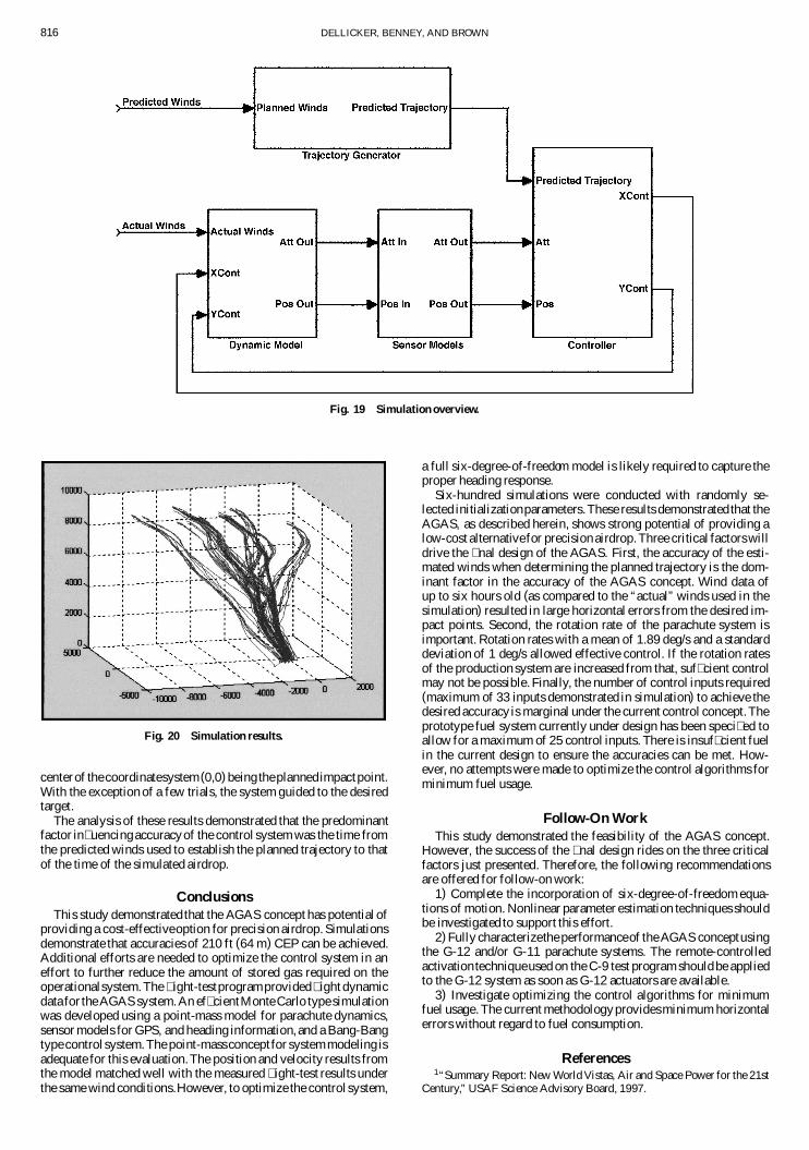
Fig. 20 Simulation results.
centerof thecoordinatesystem(0,0) being theplannedimpactpoint.With the exception of a few trials, the system guided to the desiredtarget.
The analysis of these results demonstrated that the predominantfactor in� uencingaccuracyof the control system was the time fromthe predicted winds used to establish the planned trajectory to thatof the time of the simulated airdrop.
ConclusionsThis study demonstrated that the AGAS concept has potential of
providing a cost-effectiveoption for precision airdrop. Simulationsdemonstrate that accuracies of 210 ft (64 m) CEP can be achieved.Additional efforts are needed to optimize the control system in aneffort to further reduce the amount of stored gas required on theoperationalsystem.The � ight-testprogramprovided� ight dynamicdata for the AGAS system.An ef� cientMonte Carlo type simulationwas developed using a point-mass model for parachute dynamics,sensor models for GPS, and heading information, and a Bang-Bangtype control system.The point-massconceptfor system modeling isadequate for this evaluation.The position and velocity results fromthe model matched well with the measured � ight-test results underthe same wind conditions.However, to optimize the control system,
a full six-degree-of-freedom model is likely required to capture theproper heading response.
Six-hundred simulations were conducted with randomly se-lected initializationparameters.These results demonstrated that theAGAS, as described herein, shows strong potential of providing alow-cost alternativefor precision airdrop.Three critical factors willdrive the � nal design of the AGAS. First, the accuracy of the esti-mated winds when determining the planned trajectory is the dom-inant factor in the accuracy of the AGAS concept. Wind data ofup to six hours old (as compared to the “actual” winds used in thesimulation) resulted in large horizontal errors from the desired im-pact points. Second, the rotation rate of the parachute system isimportant. Rotation rates with a mean of 1.89 deg/s and a standarddeviation of 1 deg/s allowed effective control. If the rotation ratesof the production system are increased from that, suf� cient controlmay not be possible. Finally, the number of control inputs required(maximum of 33 inputs demonstrated in simulation) to achieve thedesired accuracy is marginal under the current control concept.Theprototype fuel system currently under design has been speci� ed toallow for a maximum of 25 control inputs. There is insuf� cient fuelin the current design to ensure the accuracies can be met. How-ever, no attempts were made to optimize the control algorithms forminimum fuel usage.
Follow-On WorkThis study demonstrated the feasibility of the AGAS concept.
However, the success of the � nal design rides on the three criticalfactors just presented. Therefore, the following recommendationsare offered for follow-on work:
1) Complete the incorporation of six-degree-of-freedom equa-tions of motion. Nonlinear parameter estimation techniques shouldbe investigated to support this effort.
2) Fully characterizethe performanceof the AGAS conceptusingthe G-12 and/or G-11 parachute systems. The remote-controlledactivation techniqueused on the C-9 test program should be appliedto the G-12 system as soon as G-12 actuators are available.
3) Investigate optimizing the control algorithms for minimumfuel usage. The current methodologyprovidesminimum horizontalerrors without regard to fuel consumption.
References1“Summary Report: New World Vistas, Air and Space Power for the 21st
Century,” USAF Science Advisory Board, 1997.

DELLICKER, BENNEY, AND BROWN 817
2Brown, G., Haggard, R., Almassy, R., Benney, R., and Dellicker, S.,“The Affordable Guided Airdrop System,” AIAA Paper 99-1742, June1999.
3Brown, G., Haggard, R., Benney, R., and Rosato, N., “A New Pneu-matic Actuator: Its Use in AirdropApplications,”AIAA Paper 99-1719,June1999.
4Lamb, S. H., Hydrodynamics, 6th ed., Dover, New York, 1945.5Doherr, K. F., and Saliaris, C., “On the In� uence of Stochastic and
Acceleration Dependent Aerodynamic Forces on the Dynamic Stability ofParachutes,” AIAA Paper 81-1941, May 1981.
6Braasch, M. S., “A Signal Model for GPS,” Journal of the Institute of
Navigation, Vol. 37, No. 4, 1990–1991.7Kaminer, I., “Lecture Notes, AA3276 Introduction to Avionics,” Naval
Postgraduate School, Sept. 1997.8System Identi� cation User’s Manual, The Mathworks, Inc., Natick, MA,
1997.9“Final Report: Development and Demonstration of a Ram-Air Parafoil
Precision Guided Airdrop System, Vol. 3,” Draper Lab., Army ContractDAAK60-94-C-0041, National Soldier Center, Oct. 1996.
10Dellicker, S., “LowCostParachute Guidance, Navigation,and Control,”M.S. Thesis, Aeronautical and Astronautical Engineering, Naval Postgrad-uate School, Monterey, CA, Sept. 1999.