guarded hot box (astm c-1363-97) energy …guarded hot box (astm c-1363-97) energy efficiency roof...
TRANSCRIPT

ITS_011506_MS 1 Last rev: 01-15-06
Guarded Hot Box (ASTM C-1363-97) Energy Efficiency Roof Testing, 2003
2001 Co. P.O. Box 2557 Waterbury, CT 1-800-537-7663
2001 Company Slow-rise Adhesive Foam Roof Application Technique Increases Insulation Energy Efficiency 35% to 65% over Conventional
Mechanically Attached Insulation and Waterproofing Membrane Systems
Tom Kelly cuts 22-gauge used and painted steel deck, to be installed in an 8 ft x 8 ft Guarded Hot Box test frame. Used steel deck (worst case scenario) was chosen for testing. For reroofing applications, rust, extra weld and screw holes would normally exist in the metal deck. Three-inch ISO insulation boards were installed in the test frame with four fasteners per 4 ft x4 ft board. Boards were aged for 60 or more days.
Jim Spencer of ICS controls the insu-lation joint line gap with 1/8-inch shims for the field of the test assem-bly, and 1/16-inch shims at the test frame perimeter edge
Intertek Testing Services, Mississauga, Canada

ITS_011506_MS 2 Last rev: 01-15-06
Guarded Hot Box (ASTM C-1363-97) Energy Efficiency Roof Testing, 2003
2001 Co. P.O. Box 2557 Waterbury, CT 1-800-537-7663
The R-18.5 three-inch ISO insulation boards were meticulously cut for the test sample, with no greater than 1/16 of an inch gap at test frame edge and no greater than 1/8-inch gap between interior joints.
Four screws and three-inch washers were used to fasten the 4 ft x 4 ft of three-inch ISO insulation boards to the 22-gauge steel deck
An eight-penny nail cannot fit into the insulation joint. Plastic shims were used to confirm joint line tolerances.
ITS_011506_MS 3 Last rev: 01-15-06
Guarded Hot Box (ASTM C-1363-97) Energy Efficiency Roof Testing, 2003
2001 Co. P.O. Box 2557 Waterbury, CT 1-800-537-7663
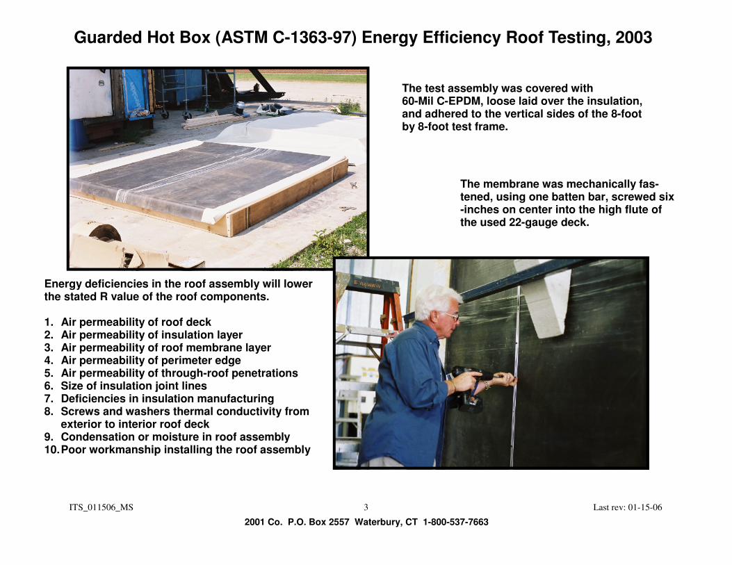
The test assembly was covered with 60-Mil C-EPDM, loose laid over the insulation, and adhered to the vertical sides of the 8-foot by 8-foot test frame.
Energy deficiencies in the roof assembly will lower the stated R value of the roof components. 1. Air permeability of roof deck 2. Air permeability of insulation layer 3. Air permeability of roof membrane layer 4. Air permeability of perimeter edge 5. Air permeability of through-roof penetrations 6. Size of insulation joint lines 7. Deficiencies in insulation manufacturing 8. Screws and washers thermal conductivity from
exterior to interior roof deck 9. Condensation or moisture in roof assembly 10. Poor workmanship installing the roof assembly
The membrane was mechanically fas-tened, using one batten bar, screwed six-inches on center into the high flute of the used 22-gauge deck.

ITS_011506_MS 4 Last rev: 01-15-06
Guarded Hot Box (ASTM C-1363-97) Energy Efficiency Roof Testing, 2003
2001 Co. P.O. Box 2557 Waterbury, CT 1-800-537-7663
A two-inch gap was fabricated around the perimeter of the test frame, to be filled with slow-rise spray foam to create the 2001 Company patented air seals on perimeters and roof penetrations, to stop lateral air infiltration in a roof assembly.
Note the ISO gap at the nailer. The spray foam will fill the metal deck low flute to the top of the nailer, making a complete air sealed perimeter edge.
ITS_011506_MS 5 Last rev: 01-15-06
Guarded Hot Box (ASTM C-1363-97) Energy Efficiency Roof Testing, 2003
2001 Co. P.O. Box 2557 Waterbury, CT 1-800-537-7663
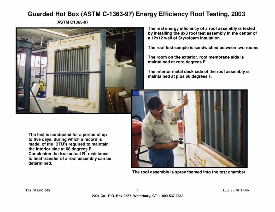
The real energy efficiency of a roof assembly is tested by installing the 8x8 roof test assembly in the center of a 12x12 wall of Styrofoam insulation. The roof test sample is sandwiched between two rooms. The room on the exterior, roof membrane side is maintained at zero degrees F. The interior metal deck side of the roof assembly is maintained at plus 68 degrees F.
The test is conducted for a period of up to five days, during which a record is made of the BTU’s required to maintain the interior side at 68 degrees F. Conclusion the true actual RT resistance to heat transfer of a roof assembly can be determined.
ASTM C1363-97
The roof assembly is spray foamed into the test chamber

ITS_011506_MS 6 Last rev: 01-15-06
Guarded Hot Box (ASTM C-1363-97) Energy Efficiency Roof Testing, 2003
2001 Co. P.O. Box 2557 Waterbury, CT 1-800-537-7663
The left-side picture shows a freezer with 500 air tubes blowing zero degree F cold air at the top membrane surface of a roof assembly. The picture below shows a heated box that is installed on the in-terior metal deck side of the roof sample, to maintain a tempera-ture of plus 68 degree F. This test is conducted for up to five days, to determine the BTU’s required to maintain the plus 68 degree F internal building atmosphere. The BTU consumption will give us the energy efficiency of the total roof assembly, and what the real R value or µ value is.
Roof assembly installed in test chamber center wall, sandwiched between two building; one a zero degree F freezer on the exterior, and the other a room temperature plus 68 degree interior.

ITS_011506_MS 7 Last rev: 01-15-06
Guarded Hot Box (ASTM C-1363-97) Energy Efficiency Roof Testing, 2003
2001 Co. P.O. Box 2557 Waterbury, CT 1-800-537-7663
Summary of Results from ITS Testing
Test #
Specimen Description Estimated
R-Value Test Results
R-Value
Test 1
3’’ ISO, One Layer, Mechanically attached
20.57 2.43
Test 2
3’’ ISO, One Layer, Slow-Rise Adhesive Foam
20.57 13.89
Test 3
2 Layers of 1.5’’ ISO, Off-set, Mechanically Attached
20.57 12.23
Test 4
Same assembly as Test 3 with 6 mil Poly Air Barrier
21.33 12.60
ITS_011506_MS 8 Last rev: 01-15-06
Guarded Hot Box (ASTM C-1363-97) Energy Efficiency Roof Testing, 2003
2001 Co. P.O. Box 2557 Waterbury, CT 1-800-537-7663
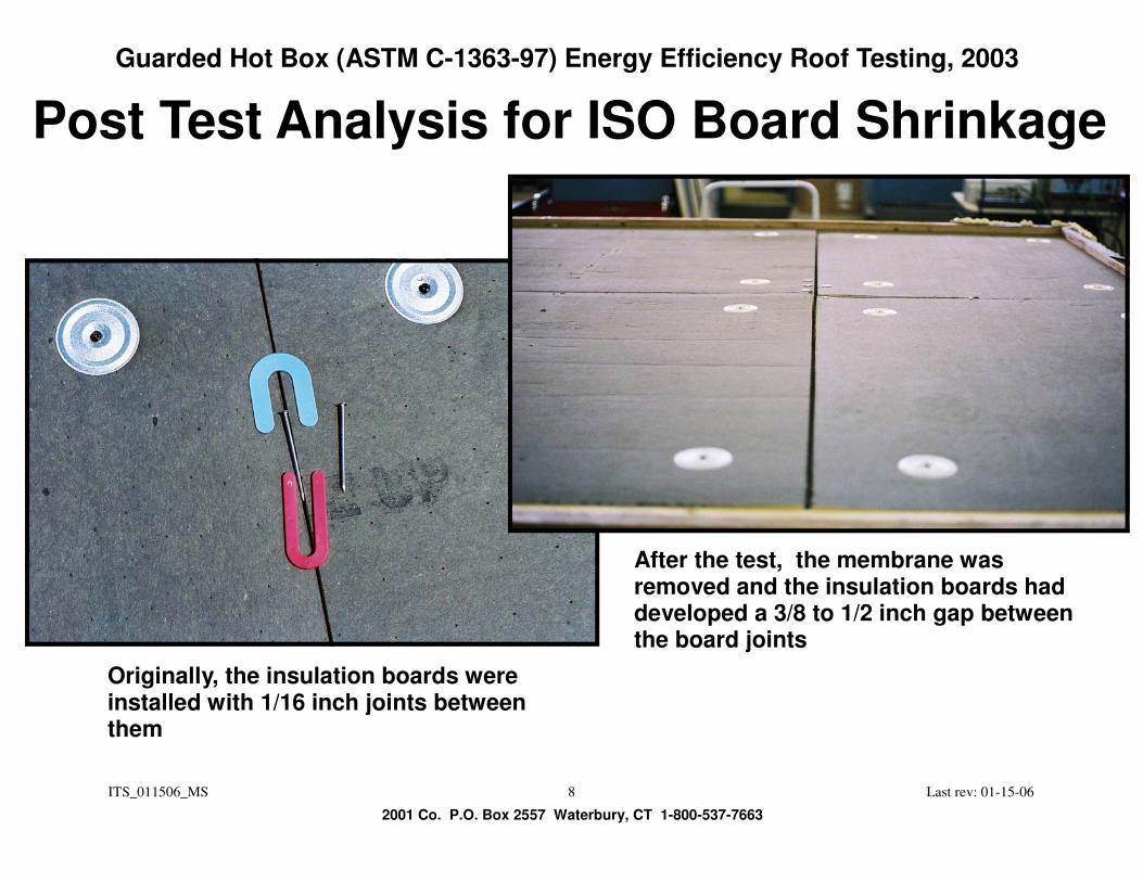
Post Test Analysis for ISO Board Shrinkage
After the test, the membrane was removed and the insulation boards had developed a 3/8 to 1/2 inch gap between the board joints
Originally, the insulation boards were installed with 1/16 inch joints between them

ITS_011506_MS 9 Last rev: 01-15-06
Guarded Hot Box (ASTM C-1363-97) Energy Efficiency Roof Testing, 2003
2001 Co. P.O. Box 2557 Waterbury, CT 1-800-537-7663
Picture for description of 1/2” joint gap

ITS_011506_MS 10 Last rev: 01-15-06
Guarded Hot Box (ASTM C-1363-97) Energy Efficiency Roof Testing, 2003
2001 Co. P.O. Box 2557 Waterbury, CT 1-800-537-7663
After removal of the fasteners, the ISO Insulation Boards warped

ITS_011506_MS 11 Last rev: 01-15-06
Guarded Hot Box (ASTM C-1363-97) Energy Efficiency Roof Testing, 2003
2001 Co. P.O. Box 2557 Waterbury, CT 1-800-537-7663
(Six US quarters and one dime) or (8 Canadian quarters) fit under the angle as shown below

ITS_011506_MS 12 Last rev: 01-15-06
Guarded Hot Box (ASTM C-1363-97) Energy Efficiency Roof Testing, 2003
2001 Co. P.O. Box 2557 Waterbury, CT 1-800-537-7663
The ISO Board ASTM 2% shrinkage standard allows for far too much shrinkage. For Example: 1) 2% in 96” (8’ board) = 2” of shrinkage 2) 2% in 48” (4’ board) = 1” of shrinkage
Notes: 2% shrinkage is too high to be acceptable in roofing Insulation shrinkage gaps under a waterproofing membrane can cause fail-ure of the membrane. Shrinkage of rigid roof insulation boards is a major factor for the energy de-ficiency of a roof assembly. It allows for convection air currents to be circu-lated within a roof assembly.