gtx 335 setup wizard guide - aeroelectric.com setup wizard guide.pdf · gtx 335 setup wizard guide...
TRANSCRIPT
190-01499-40 February, 2018 Revision E
GTX 335 Setup Wizard Guide

GTX 335 Setup Wizard Guide Page 2
190-01499-40 Revision E
© 2018 Garmin International, Inc. or its subsidiaries All Rights Reserved
Except as expressly provided herein, no part of this manual may be reproduced, copied, transmitted, disseminated, downloaded or stored in any storage medium, for any purpose without the express prior written consent of Garmin. Garmin hereby grants permission to download a single copy of this manual and of any revision to this manual onto a hard drive or other electronic storage medium to be viewed and to print one copy of this manual or of any revision hereto, provided that such electronic or printed copy of this manual or revision must contain the complete text of this copyright notice and provided further that any unauthorized commercial distribution of this manual or any revision hereto is strictly prohibited. Garmin® is a registered trademark of Garmin International or its subsidiaries. Connext™, GDU™, and GTN™ are trademarks of Garmin International or its subsidiaries. These trademarks may not be used without the express permission of Garmin. Windows® is a registered trademark of Microsoft Corporation in the United States and other countries. All other product or company names that may be mentioned in this publication are trade names, trademarks, or registered trademarks of their respective owners. At Garmin, we value your opinion. For comments about this guide, please e-mail [email protected]. For comments about Garmin aviation products, email [email protected]. For aviation product support, visit: https://fly.garmin.com/fly-garmin/support.
Garmin International Inc. 1200 E. 151st Street Olathe, Kansas 66062 USA Telephone: (913) 397-8200 Aviation Dealer Technical Support Line (Toll Free): (888) 606-5482 Website Address: www.garmin.com Garmin AT, Inc. 2345 Turner Rd. SE Salem, OR 97302 USA Telephone: (503) 581-8101 Fax: (503) 364-2138 Email: [email protected] Garmin (Europe) Ltd. Liberty House, Hounsdown Business Park Southampton, Hampshire SO40 9LR U.K. Phone: +44 (0) 23 8052 4000 Fax: +44 (0) 23 8052 4004 Aviation Support +44 (0) 370 850 1243
GTX 335 Setup Wizard Guide Page 3
190-01499-40 Revision E
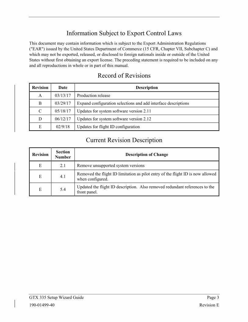
Information Subject to Export Control Laws This document may contain information which is subject to the Export Administration Regulations ("EAR") issued by the United States Department of Commerce (15 CFR, Chapter VII, Subchapter C) and which may not be exported, released, or disclosed to foreign nationals inside or outside of the United States without first obtaining an export license. The preceding statement is required to be included on any and all reproductions in whole or in part of this manual.
Record of Revisions
Revision Date Description
A 03/13/17 Production release
B 03/29/17 Expand configuration selections and add interface descriptions
C 05/18/17 Updates for system software version 2.11
D 06/12/17 Updates for system software version 2.12
E 02/9/18 Updates for flight ID configuration
Current Revision Description
Revision Section Number Description of Change
E 2.1 Remove unsupported system versions
E 4.1 Removed the flight ID limitation as pilot entry of the flight ID is now allowed when configured.
E 5.4 Updated the flight ID description. Also removed redundant references to the front panel.
GTX 335 Setup Wizard Guide Page 4
190-01499-40 Revision E
Table of Contents Table of Contents .......................................................................................................................................... 4
Table of Figures ............................................................................................................................................ 6
Table of Tables ............................................................................................................................................. 7
1 First Time Setup: Quick Start Guide ..................................................................................................... 8
2 GTX 335 Setup Wizard......................................................................................................................... 9
2.1 Product Components ..................................................................................................................... 9
2.2 Reference Documents ................................................................................................................... 9
2.3 Installation Procedure ................................................................................................................. 10
2.3.1 Troubleshooting Installation Problems ............................................................................... 10
2.4 Connecting to the Transponder ................................................................................................... 11
2.4.1 Connection Status ............................................................................................................... 12
2.4.2 Troubleshooting Connection Problems ............................................................................... 13
2.5 Transponder Version Information ............................................................................................... 14
2.6 Tool Version Information ........................................................................................................... 15
3 Uploading Software ............................................................................................................................ 16
3.1 Post Software Upload Actions .................................................................................................... 17
4 Transponder Setup .............................................................................................................................. 18
4.1 Limitations .................................................................................................................................. 18
4.2 Welcome ..................................................................................................................................... 18
4.3 Configuration .............................................................................................................................. 19
4.4 Audio Test ................................................................................................................................... 21
4.5 Altitude Encoder Calibration ...................................................................................................... 22
4.6 Backlight Calibration .................................................................................................................. 24
4.7 Review ........................................................................................................................................ 26
4.8 Transponder Setup Without a Unit Connected ........................................................................... 27
5 Transponder Diagnostics..................................................................................................................... 28
5.1 Saving a Diagnostic Report ......................................................................................................... 28
5.2 Resetting Configuration .............................................................................................................. 28
5.3 Discrete Configuration ................................................................................................................ 29
5.4 Status Information ....................................................................................................................... 30
5.5 GPS Diagnostics ......................................................................................................................... 32
6 Transponder Interfaces ........................................................................................................................ 33
6.1 Discretes ...................................................................................................................................... 33

GTX 335 Setup Wizard Guide Page 5
190-01499-40 Revision E
6.2 ARINC 429 Input ........................................................................................................................ 33
6.3 ARINC 429 Output ..................................................................................................................... 34
7 Equipment Interfaces and Configuration ............................................................................................ 36
7.1 GNS 400W/500W Series (Including Non-WAAS Units) ........................................................... 36
7.2 GTN 6XX/7XX ........................................................................................................................... 38
GTX 335 Setup Wizard Guide Page 6
190-01499-40 Revision E
Table of Figures Figure 1: Main Menu .................................................................................................................................. 11
Figure 2: Transponder Setup Connection Status ......................................................................................... 12
Figure 3: Software Load Connection Status ............................................................................................... 12
Figure 4: Garmin Aviation Device.............................................................................................................. 13
Figure 5: Garmin Aviation Device Driver .................................................................................................. 13
Figure 6: Transponder Version Information ............................................................................................... 14
Figure 7: Tool Version Information ............................................................................................................ 15
Figure 8: Software Upload .......................................................................................................................... 16
Figure 9: Discrete Configuration Menu ...................................................................................................... 17
Figure 10: Transponder Setup Welcome .................................................................................................... 18
Figure 11: Transponder Setup Configuration ............................................................................................. 19
Figure 12: Transponder Setup Apply Configuration .................................................................................. 20
Figure 13: Audio Test ................................................................................................................................. 21
Figure 14: Altitude Encoder Correction ...................................................................................................... 22
Figure 15: Altitude Encoder Calibration ..................................................................................................... 23
Figure 16: Display Calibration .................................................................................................................... 24
Figure 17: Transponder Setup Review........................................................................................................ 26
Figure 18: Connection Options ................................................................................................................... 27
Figure 19: GTX Menu ................................................................................................................................ 28
Figure 20: Discrete Configuration .............................................................................................................. 29
Figure 21: Transponder Status Information ................................................................................................ 30
Figure 22: GPS Diagnostics ........................................................................................................................ 32
Figure 23: GNS 400W/500W Interconnect Drawing.................................................................................. 36
Figure 24: GNS A429 Configuration .......................................................................................................... 37
Figure 25: GTN 6XX/7XX Interconnect Drawing ..................................................................................... 38
Figure 26: GTN Configuration Mode ......................................................................................................... 39
Figure 27: GTN Setup ................................................................................................................................. 39
Figure 28: GTN RS-232 Configuration ...................................................................................................... 40
Figure 29: GTN Discrete Configuration ..................................................................................................... 40
GTX 335 Setup Wizard Guide Page 7
190-01499-40 Revision E
Table of Tables Table 1: Supported System Software ............................................................................................................ 9
Table 2: Reference Documents ..................................................................................................................... 9
Table 3: Discrete Interface Pin Assignments .............................................................................................. 33
Table 4: Air Data Computer (ADC) Input Labels ...................................................................................... 33
Table 5: EFIS Air Data Input Labels .......................................................................................................... 33
Table 6: Garmin Concentrator Output Labels ............................................................................................. 34
Table 7: Garmin TIS Output Labels ........................................................................................................... 34
Table 8: Garmin TAS Output Labels .......................................................................................................... 35
Table 9: GPS Data Output Labels ............................................................................................................... 35
GTX 335 Setup Wizard Guide Page 8
190-01499-40 Revision E
1 First Time Setup: Quick Start Guide This section is intended to give you a step by step guide to setting up the GTX 335 for the first time. More detailed descriptions of each item described exist in other sections of the document.
1. Install the GTX 335 Setup Wizard
2. Connect the transponder to your PC using a USB cable and apply power
3. Launch the GTX 335 Setup Wizard
4. Press “Set up Transponder” and wait for the unit to become connected
5. Follow the on-screen instructions to configure your transponder
6. Once you reach the apply configuration step, review and apply your configuration selections
7. Continue by pressing next, and perform any necessary calibration processes
8. Once you reach the final review step, review your transponders configuration summary and then save configuration to a file
9. Push to configuration module, if installed
10. Power cycle your transponder and verify it is operating normally
GTX 335 Setup Wizard Guide Page 9
190-01499-40 Revision E
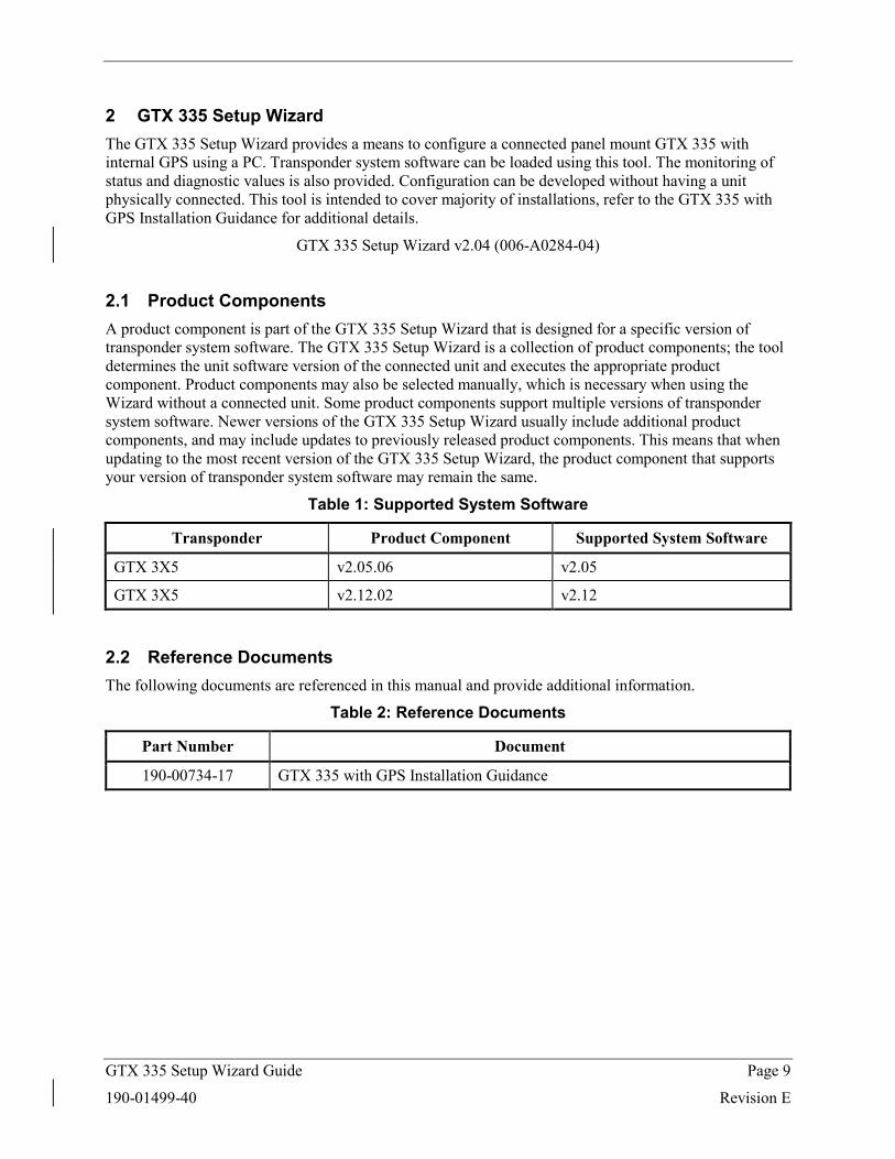
2 GTX 335 Setup Wizard The GTX 335 Setup Wizard provides a means to configure a connected panel mount GTX 335 with internal GPS using a PC. Transponder system software can be loaded using this tool. The monitoring of status and diagnostic values is also provided. Configuration can be developed without having a unit physically connected. This tool is intended to cover majority of installations, refer to the GTX 335 with GPS Installation Guidance for additional details.
GTX 335 Setup Wizard v2.04 (006-A0284-04)
2.1 Product Components A product component is part of the GTX 335 Setup Wizard that is designed for a specific version of transponder system software. The GTX 335 Setup Wizard is a collection of product components; the tool determines the unit software version of the connected unit and executes the appropriate product component. Product components may also be selected manually, which is necessary when using the Wizard without a connected unit. Some product components support multiple versions of transponder system software. Newer versions of the GTX 335 Setup Wizard usually include additional product components, and may include updates to previously released product components. This means that when updating to the most recent version of the GTX 335 Setup Wizard, the product component that supports your version of transponder system software may remain the same.
Table 1: Supported System Software
Transponder Product Component Supported System Software
GTX 3X5 v2.05.06 v2.05
GTX 3X5 v2.12.02 v2.12
2.2 Reference Documents The following documents are referenced in this manual and provide additional information.
Table 2: Reference Documents
Part Number Document
190-00734-17 GTX 335 with GPS Installation Guidance
GTX 335 Setup Wizard Guide Page 10
190-01499-40 Revision E
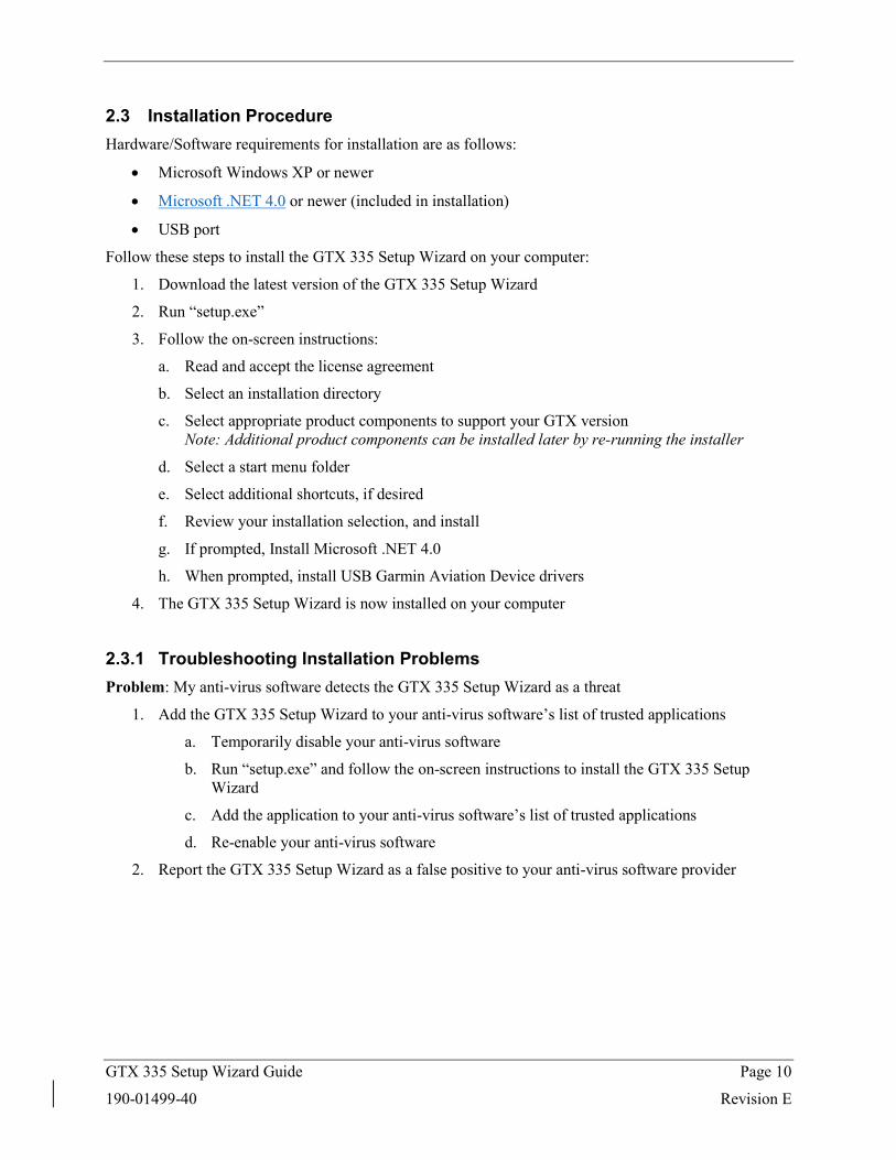
2.3 Installation Procedure Hardware/Software requirements for installation are as follows:
• Microsoft Windows XP or newer
• Microsoft .NET 4.0 or newer (included in installation)
• USB port
Follow these steps to install the GTX 335 Setup Wizard on your computer:
1. Download the latest version of the GTX 335 Setup Wizard
2. Run “setup.exe”
3. Follow the on-screen instructions:
a. Read and accept the license agreement
b. Select an installation directory
c. Select appropriate product components to support your GTX version Note: Additional product components can be installed later by re-running the installer
d. Select a start menu folder
e. Select additional shortcuts, if desired
f. Review your installation selection, and install
g. If prompted, Install Microsoft .NET 4.0
h. When prompted, install USB Garmin Aviation Device drivers
4. The GTX 335 Setup Wizard is now installed on your computer
2.3.1 Troubleshooting Installation Problems Problem: My anti-virus software detects the GTX 335 Setup Wizard as a threat
1. Add the GTX 335 Setup Wizard to your anti-virus software’s list of trusted applications
a. Temporarily disable your anti-virus software
b. Run “setup.exe” and follow the on-screen instructions to install the GTX 335 Setup Wizard
c. Add the application to your anti-virus software’s list of trusted applications
d. Re-enable your anti-virus software
2. Report the GTX 335 Setup Wizard as a false positive to your anti-virus software provider
GTX 335 Setup Wizard Guide Page 11
190-01499-40 Revision E
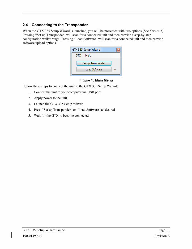
2.4 Connecting to the Transponder When the GTX 335 Setup Wizard is launched, you will be presented with two options (See Figure 1). Pressing “Set up Transponder” will scan for a connected unit and then provide a step-by-step configuration walkthrough. Pressing “Load Software” will scan for a connected unit and then provide software upload options.
Figure 1: Main Menu
Follow these steps to connect the unit to the GTX 335 Setup Wizard:
1. Connect the unit to your computer via USB port
2. Apply power to the unit
3. Launch the GTX 335 Setup Wizard
4. Press “Set up Transponder” or “Load Software” as desired
5. Wait for the GTX to become connected
GTX 335 Setup Wizard Guide Page 12
190-01499-40 Revision E
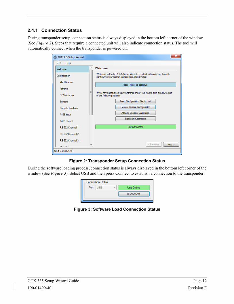
2.4.1 Connection Status During transponder setup, connection status is always displayed in the bottom left corner of the window (See Figure 2). Steps that require a connected unit will also indicate connection status. The tool will automatically connect when the transponder is powered on.
Figure 2: Transponder Setup Connection Status During the software loading process, connection status is always displayed in the bottom left corner of the window (See Figure 3). Select USB and then press Connect to establish a connection to the transponder.
Figure 3: Software Load Connection Status
GTX 335 Setup Wizard Guide Page 13
190-01499-40 Revision E
2.4.2 Troubleshooting Connection Problems Problem: I can’t connect using USB
1. Make sure there are no loose wires
2. Make sure the unit is powered on
3. Make sure another instance of the GTX 335 Setup Wizard is not open and connected
4. Power cycle the transponder
5. Make sure the unit appears in device manager:
a. Connect the unit to your computer using USB
b. Apply power to the unit
c. Open Device Manager from the windows start menu
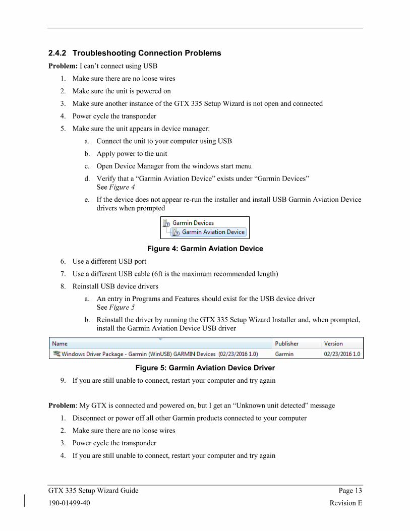
d. Verify that a “Garmin Aviation Device” exists under “Garmin Devices” See Figure 4
e. If the device does not appear re-run the installer and install USB Garmin Aviation Device drivers when prompted
Figure 4: Garmin Aviation Device
6. Use a different USB port
7. Use a different USB cable (6ft is the maximum recommended length)
8. Reinstall USB device drivers
a. An entry in Programs and Features should exist for the USB device driver See Figure 5
b. Reinstall the driver by running the GTX 335 Setup Wizard Installer and, when prompted, install the Garmin Aviation Device USB driver
Figure 5: Garmin Aviation Device Driver
9. If you are still unable to connect, restart your computer and try again
Problem: My GTX is connected and powered on, but I get an “Unknown unit detected” message
1. Disconnect or power off all other Garmin products connected to your computer
2. Make sure there are no loose wires
3. Power cycle the transponder
4. If you are still unable to connect, restart your computer and try again
GTX 335 Setup Wizard Guide Page 14
190-01499-40 Revision E
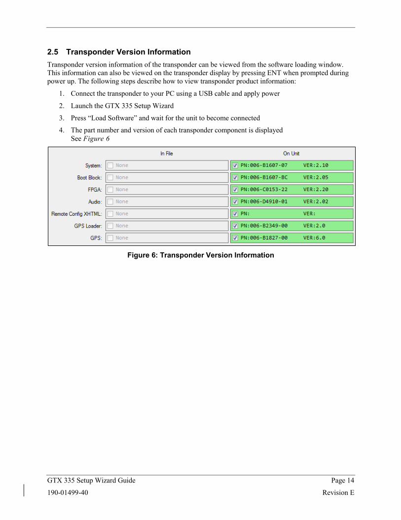
2.5 Transponder Version Information Transponder version information of the transponder can be viewed from the software loading window. This information can also be viewed on the transponder display by pressing ENT when prompted during power up. The following steps describe how to view transponder product information:
1. Connect the transponder to your PC using a USB cable and apply power
2. Launch the GTX 335 Setup Wizard
3. Press “Load Software” and wait for the unit to become connected
4. The part number and version of each transponder component is displayed See Figure 6
Figure 6: Transponder Version Information
GTX 335 Setup Wizard Guide Page 15
190-01499-40 Revision E
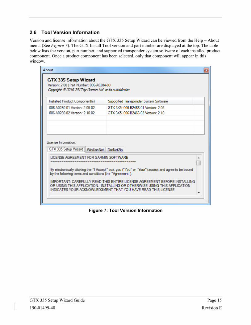
2.6 Tool Version Information Version and license information about the GTX 335 Setup Wizard can be viewed from the Help – About menu. (See Figure 7). The GTX Install Tool version and part number are displayed at the top. The table below lists the version, part number, and supported transponder system software of each installed product component. Once a product component has been selected, only that component will appear in this window.
Figure 7: Tool Version Information
GTX 335 Setup Wizard Guide Page 16
190-01499-40 Revision E
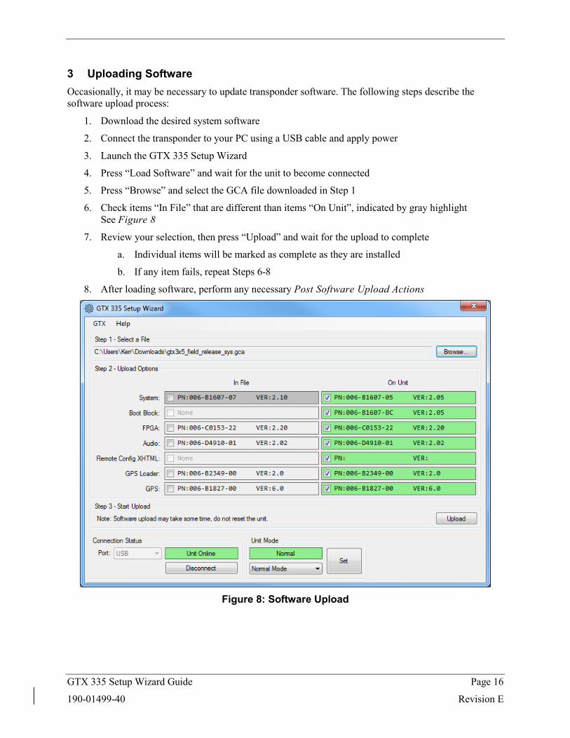
3 Uploading Software Occasionally, it may be necessary to update transponder software. The following steps describe the software upload process:
1. Download the desired system software
2. Connect the transponder to your PC using a USB cable and apply power
3. Launch the GTX 335 Setup Wizard
4. Press “Load Software” and wait for the unit to become connected
5. Press “Browse” and select the GCA file downloaded in Step 1
6. Check items “In File” that are different than items “On Unit”, indicated by gray highlight See Figure 8
7. Review your selection, then press “Upload” and wait for the upload to complete
a. Individual items will be marked as complete as they are installed
b. If any item fails, repeat Steps 6-8
8. After loading software, perform any necessary Post Software Upload Actions
Figure 8: Software Upload
GTX 335 Setup Wizard Guide Page 17
190-01499-40 Revision E
3.1 Post Software Upload Actions Review New Configuration Items A system software update may add new configuration items. Values for new items should be determined and assigned.
Resolve Service Soon Alert After loading software, further action is needed under the following conditions:
1. System software was updated from version 2.02, 2.03, 2.05, or 2.10 to version 2.11 or later
2. The transponder is failed and reports a service soon message
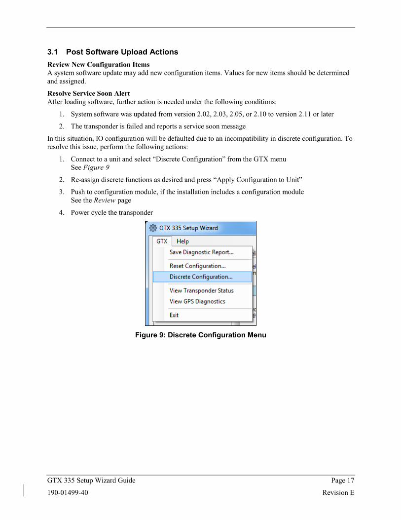
In this situation, IO configuration will be defaulted due to an incompatibility in discrete configuration. To resolve this issue, perform the following actions:
1. Connect to a unit and select “Discrete Configuration” from the GTX menu See Figure 9
2. Re-assign discrete functions as desired and press “Apply Configuration to Unit”
3. Push to configuration module, if the installation includes a configuration module See the Review page
4. Power cycle the transponder
Figure 9: Discrete Configuration Menu
GTX 335 Setup Wizard Guide Page 18
190-01499-40 Revision E
4 Transponder Setup 4.1 Limitations When using the GTX 335 Setup Wizard, the following assumptions are made regarding transponder configuration:
1. Only internal GPS data will be used as a GPS source.
2. The unit will broadcast UAT In receive capability. This will allow portable ADS-B receivers, such as GDL-39, to receive ADS-B In data.
3. Discrete pin assignments are configured as described in Table 3. All other configurable discrete functions are unassigned.
4. Altitude source selection is performed automatically by the transponder.
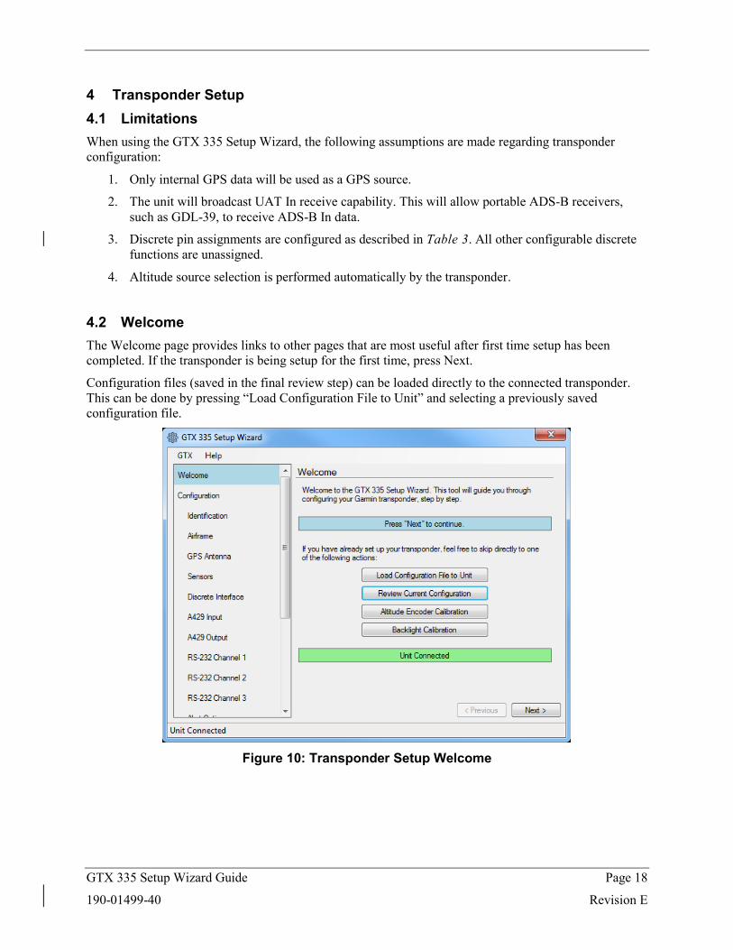
4.2 Welcome The Welcome page provides links to other pages that are most useful after first time setup has been completed. If the transponder is being setup for the first time, press Next.
Configuration files (saved in the final review step) can be loaded directly to the connected transponder. This can be done by pressing “Load Configuration File to Unit” and selecting a previously saved configuration file.
Figure 10: Transponder Setup Welcome
GTX 335 Setup Wizard Guide Page 19
190-01499-40 Revision E
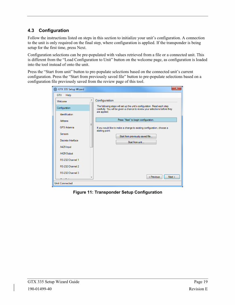
4.3 Configuration Follow the instructions listed on steps in this section to initialize your unit’s configuration. A connection to the unit is only required on the final step, where configuration is applied. If the transponder is being setup for the first time, press Next.
Configuration selections can be pre-populated with values retrieved from a file or a connected unit. This is different from the “Load Configuration to Unit” button on the welcome page, as configuration is loaded into the tool instead of onto the unit.
Press the “Start from unit” button to pre-populate selections based on the connected unit’s current configuration. Press the “Start from previously saved file” button to pre-populate selections based on a configuration file previously saved from the review page of this tool.
Figure 11: Transponder Setup Configuration
GTX 335 Setup Wizard Guide Page 20
190-01499-40 Revision E
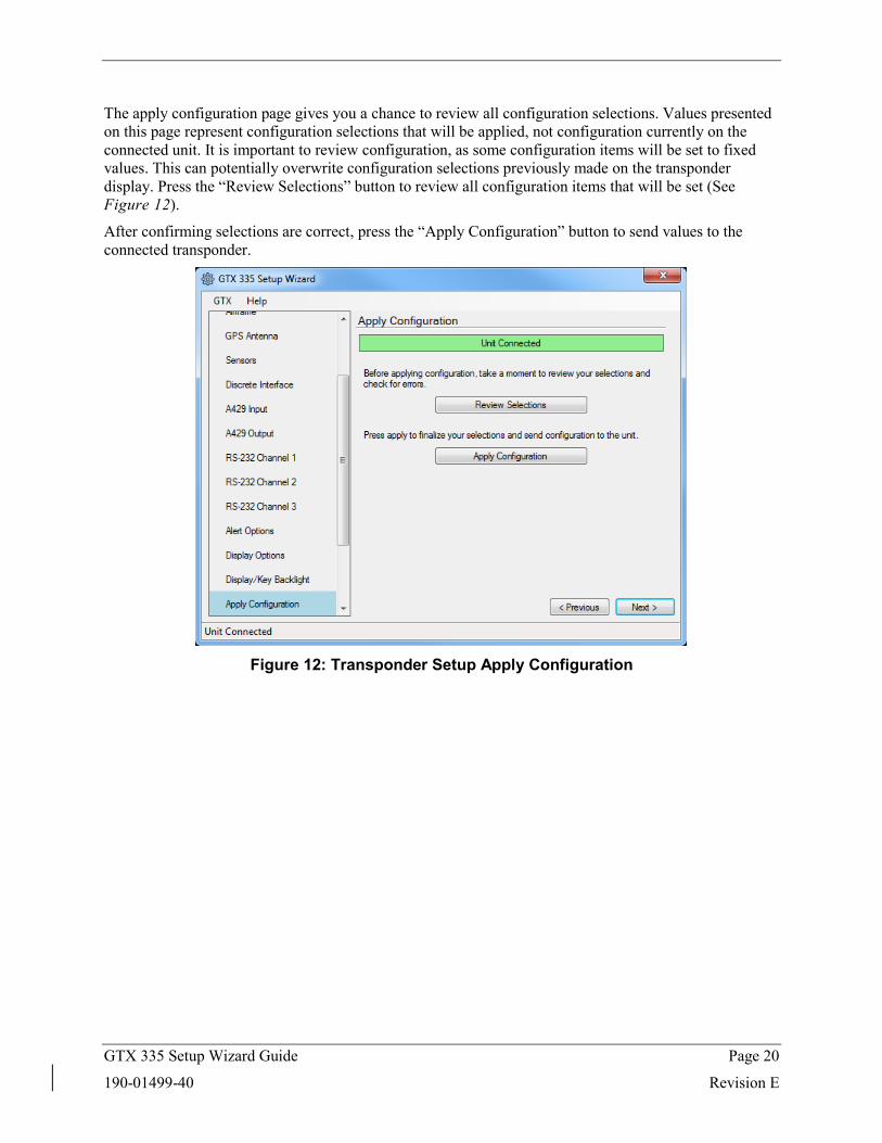
The apply configuration page gives you a chance to review all configuration selections. Values presented on this page represent configuration selections that will be applied, not configuration currently on the connected unit. It is important to review configuration, as some configuration items will be set to fixed values. This can potentially overwrite configuration selections previously made on the transponder display. Press the “Review Selections” button to review all configuration items that will be set (See Figure 12).
After confirming selections are correct, press the “Apply Configuration” button to send values to the connected transponder.
Figure 12: Transponder Setup Apply Configuration
GTX 335 Setup Wizard Guide Page 21
190-01499-40 Revision E
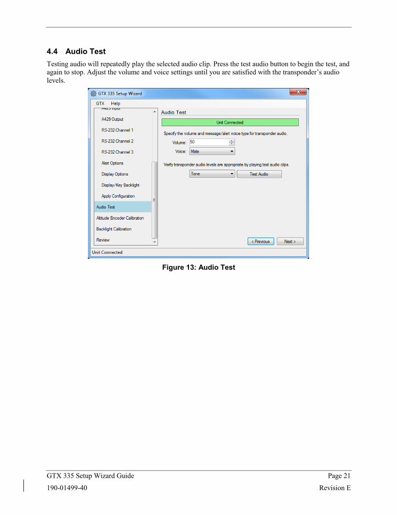
4.4 Audio Test Testing audio will repeatedly play the selected audio clip. Press the test audio button to begin the test, and again to stop. Adjust the volume and voice settings until you are satisfied with the transponder’s audio levels.
Figure 13: Audio Test
GTX 335 Setup Wizard Guide Page 22
190-01499-40 Revision E
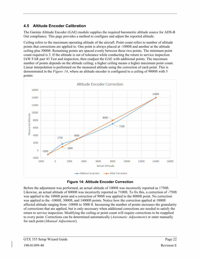
4.5 Altitude Encoder Calibration The Garmin Altitude Encoder (GAE) module supplies the required barometric altitude source for ADS-B Out compliance. This page provides a method to configure and adjust the reported altitude.
Ceiling refers to the maximum operating altitude of the aircraft. Point count refers to number of altitude points that corrections are applied to. One point is always placed at -1000ft and another at the altitude ceiling plus 5000ft. Remaining points are spaced evenly between these two points. The minimum point count required is 3. If the altitude is out of tolerance while conducting the return to service inspection IAW FAR part 43 Test and inspection, then readjust the GAE with additional points. The maximum number of points depends on the altitude ceiling; a higher ceiling means a higher maximum point count. Linear interpolation is performed on the measured altitude using the correction of each point. This is demonstrated in the Figure 14, where an altitude encoder is configured to a ceiling of 9000ft with 5 points:
Figure 14: Altitude Encoder Correction
Before the adjustment was performed, an actual altitude of 1000ft was incorrectly reported as 1750ft. Likewise, an actual altitude of 8000ft was incorrectly reported as 7100ft. To fix this, a correction of -750ft was applied to the 1000ft point and a correction of 900ft was applied to the 8000ft point. No correction was applied to the -1000ft, 3000ft, and 14000ft points. Notice how the correction applied at 1000ft affected altitude ranging from -1000ft to 3000 ft. Increasing the number of points increases the granularity of corrections that are applied, but is only necessary when additional corrections are needed to satisfy the return to service inspection. Modifying the ceiling or point count will require corrections to be reapplied to every point. Corrections can be determined automatically (Automatic Adjustment) or enter manually for each point (Manual Adjustment).
GTX 335 Setup Wizard Guide Page 23
190-01499-40 Revision E
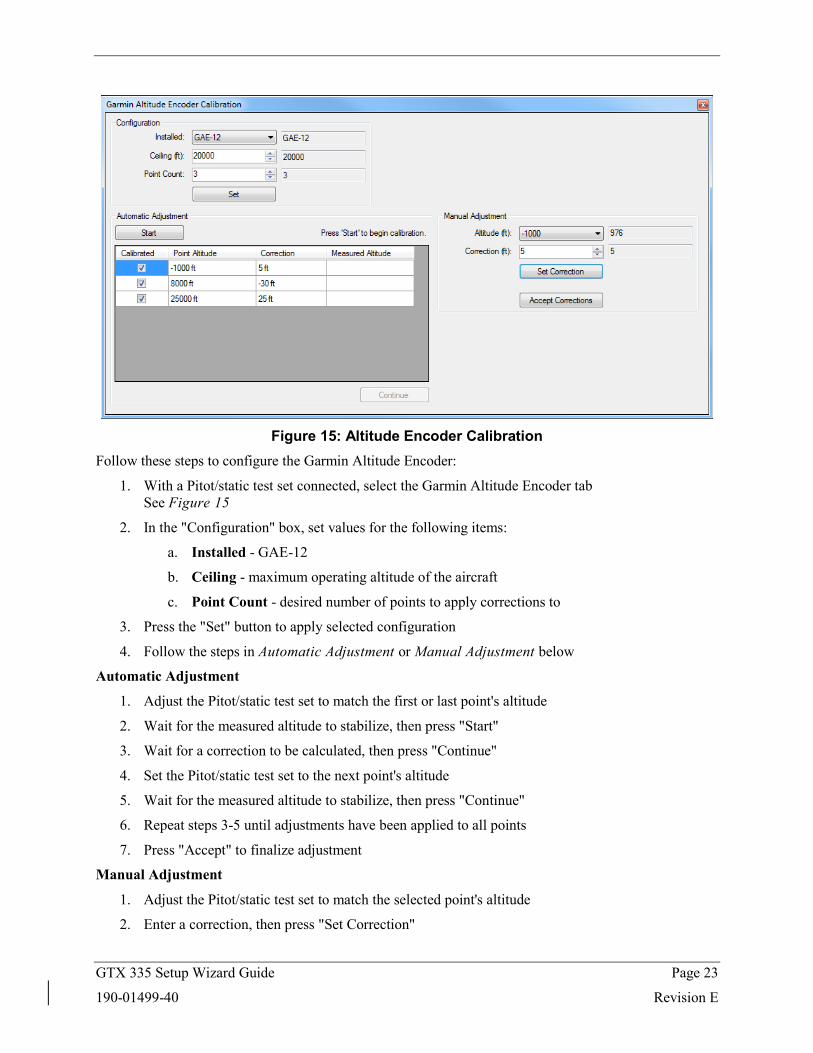
Figure 15: Altitude Encoder Calibration
Follow these steps to configure the Garmin Altitude Encoder:
1. With a Pitot/static test set connected, select the Garmin Altitude Encoder tab See Figure 15
2. In the "Configuration" box, set values for the following items:
a. Installed - GAE-12
b. Ceiling - maximum operating altitude of the aircraft
c. Point Count - desired number of points to apply corrections to
3. Press the "Set" button to apply selected configuration
4. Follow the steps in Automatic Adjustment or Manual Adjustment below
Automatic Adjustment
1. Adjust the Pitot/static test set to match the first or last point's altitude
2. Wait for the measured altitude to stabilize, then press "Start"
3. Wait for a correction to be calculated, then press "Continue"
4. Set the Pitot/static test set to the next point's altitude
5. Wait for the measured altitude to stabilize, then press "Continue"
6. Repeat steps 3-5 until adjustments have been applied to all points
7. Press "Accept" to finalize adjustment
Manual Adjustment
1. Adjust the Pitot/static test set to match the selected point's altitude
2. Enter a correction, then press "Set Correction"
GTX 335 Setup Wizard Guide Page 24
190-01499-40 Revision E
a. If the measured altitude is too high, enter a negative correction
b. If the measured altitude is too low, enter a positive correction
3. Make additional correction adjustments until the measured altitude is as close to the point's altitude as possible
4. Repeat, until adjustments have been applied to all desired points
5. Press "Accept Corrections" to finalize adjustments
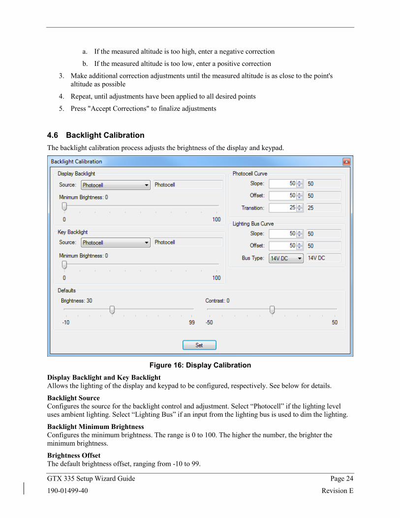
4.6 Backlight Calibration The backlight calibration process adjusts the brightness of the display and keypad.
Figure 16: Display Calibration
Display Backlight and Key Backlight Allows the lighting of the display and keypad to be configured, respectively. See below for details.
Backlight Source Configures the source for the backlight control and adjustment. Select “Photocell” if the lighting level uses ambient lighting. Select “Lighting Bus” if an input from the lighting bus is used to dim the lighting.
Backlight Minimum Brightness Configures the minimum brightness. The range is 0 to 100. The higher the number, the brighter the minimum brightness.
Brightness Offset The default brightness offset, ranging from -10 to 99.
GTX 335 Setup Wizard Guide Page 25
190-01499-40 Revision E
Contrast Offset The default contrast offset, ranging from -50 to 50.
Photocell and Lighting Bus Slope Configures the sensitivity of the input level. The field has a range of 0 to 100. Set the slope higher for a brighter display for a given increase in the input level.
Photocell and Lighting Bus Offset Configures the lighting level up or down for any given input level. This field has a range of 0 to 100. Use the offset setting to match lighting curves with other equipment in the panel.
Photocell Transition Configures a point on the lighting bus. When the lighting bus is below this point, the GTX uses the photocell to adjust the display brightness. The range is 5 to 50.
Lighting Bus Type Configures the voltage of the lighting bus input.
GTX 335 Setup Wizard Guide Page 26
190-01499-40 Revision E
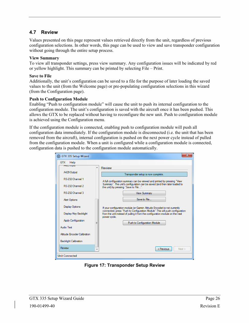
4.7 Review Values presented on this page represent values retrieved directly from the unit, regardless of previous configuration selections. In other words, this page can be used to view and save transponder configuration without going through the entire setup process.
View Summary To view all transponder settings, press view summary. Any configuration issues will be indicated by red or yellow highlight. This summary can be printed by selecting File – Print.
Save to File Additionally, the unit’s configuration can be saved to a file for the purpose of later loading the saved values to the unit (from the Welcome page) or pre-populating configuration selections in this wizard (from the Configuration page).
Push to Configuration Module Enabling “Push to configuration module” will cause the unit to push its internal configuration to the configuration module. The unit’s configuration is saved with the aircraft once it has been pushed. This allows the GTX to be replaced without having to reconfigure the new unit. Push to configuration module is achieved using the Configuration menu.
If the configuration module is connected, enabling push to configuration module will push all configuration data immediately. If the configuration module is disconnected (i.e. the unit that has been removed from the aircraft), internal configuration is pushed on the next power cycle instead of pulled from the configuration module. When a unit is configured while a configuration module is connected, configuration data is pushed to the configuration module automatically.
Figure 17: Transponder Setup Review
GTX 335 Setup Wizard Guide Page 27
190-01499-40 Revision E
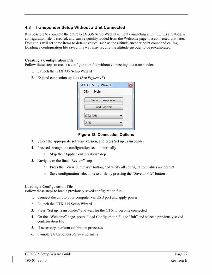
4.8 Transponder Setup Without a Unit Connected It is possible to complete the entire GTX 335 Setup Wizard without connecting a unit. In this situation, a configuration file is created, and can be quickly loaded from the Welcome page to a connected unit later. Doing this will set some items to default values, such as the altitude encoder point count and ceiling. Loading a configuration file saved this way may require the altitude encoder to be re-calibrated.
Creating a Configuration File Follow these steps to create a configuration file without connecting to a transponder:
1. Launch the GTX 335 Setup Wizard
2. Expand connection options (See Figure 18)
Figure 18: Connection Options
3. Select the appropriate software version, and press Set up Transponder
4. Proceed through the configuration section normally
a. Skip the “Apply Configuration” step
5. Navigate to the final “Review” step
a. Press the “View Summary” button, and verify all configuration values are correct
b. Save configuration selections to a file by pressing the “Save to File” button
Loading a Configuration File Follow these steps to load a previously saved configuration file:
1. Connect the unit to your computer via USB port and apply power
2. Launch the GTX 335 Setup Wizard
3. Press “Set up Transponder” and wait for the GTX to become connected
4. On the “Welcome” page, press “Load Configuration File to Unit” and select a previously saved configuration file
5. If necessary, perform calibration processes
6. Complete transponder Review normally
GTX 335 Setup Wizard Guide Page 28
190-01499-40 Revision E
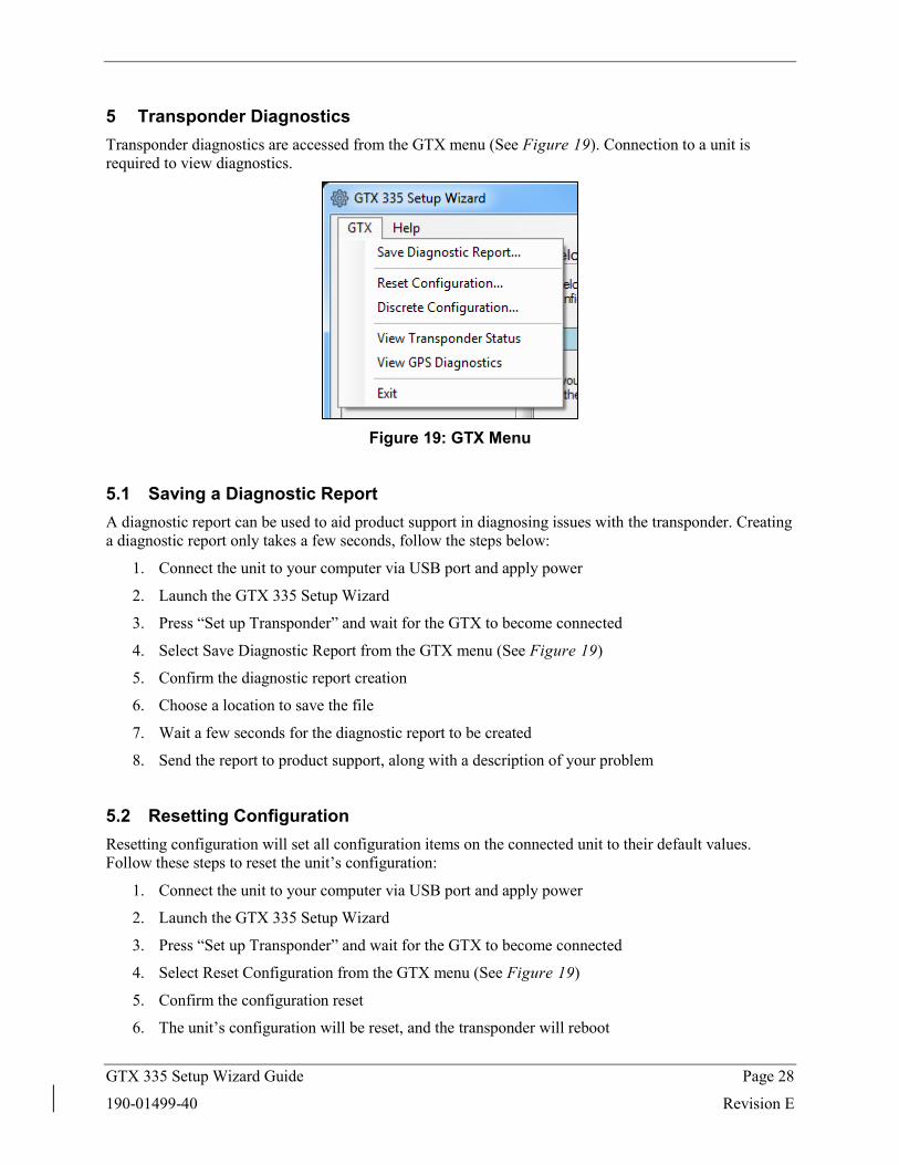
5 Transponder Diagnostics Transponder diagnostics are accessed from the GTX menu (See Figure 19). Connection to a unit is required to view diagnostics.
Figure 19: GTX Menu
5.1 Saving a Diagnostic Report A diagnostic report can be used to aid product support in diagnosing issues with the transponder. Creating a diagnostic report only takes a few seconds, follow the steps below:
1. Connect the unit to your computer via USB port and apply power
2. Launch the GTX 335 Setup Wizard
3. Press “Set up Transponder” and wait for the GTX to become connected
4. Select Save Diagnostic Report from the GTX menu (See Figure 19)
5. Confirm the diagnostic report creation
6. Choose a location to save the file
7. Wait a few seconds for the diagnostic report to be created
8. Send the report to product support, along with a description of your problem
5.2 Resetting Configuration Resetting configuration will set all configuration items on the connected unit to their default values. Follow these steps to reset the unit’s configuration:
1. Connect the unit to your computer via USB port and apply power
2. Launch the GTX 335 Setup Wizard
3. Press “Set up Transponder” and wait for the GTX to become connected
4. Select Reset Configuration from the GTX menu (See Figure 19)
5. Confirm the configuration reset
6. The unit’s configuration will be reset, and the transponder will reboot
GTX 335 Setup Wizard Guide Page 29
190-01499-40 Revision E
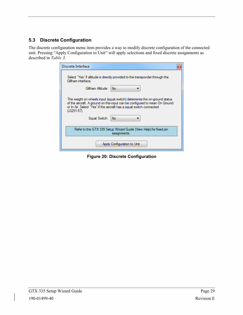
5.3 Discrete Configuration The discrete configuration menu item provides a way to modify discrete configuration of the connected unit. Pressing “Apply Configuration to Unit” will apply selections and fixed discrete assignments as described in Table 3.
Figure 20: Discrete Configuration
GTX 335 Setup Wizard Guide Page 30
190-01499-40 Revision E
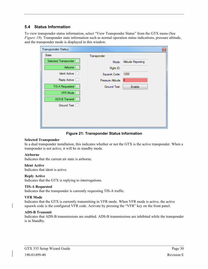
5.4 Status Information To view transponder status information, select “View Transponder Status” from the GTX menu (See Figure 19). Transponder state information such as normal operation status indications, pressure altitude, and the transponder mode is displayed in this window.
Figure 21: Transponder Status Information
Selected Transponder In a dual transponder installation, this indicates whether or not the GTX is the active transponder. When a transponder is not active, it will be in standby mode.
Airborne Indicates that the current air state is airborne.
Ident Active Indicates that ident is active.
Reply Active Indicates that the GTX is replying to interrogations.
TIS-A Requested Indicates that the transponder is currently requesting TIS-A traffic.
VFR Mode Indicates that the GTX is currently transmitting in VFR mode. When VFR mode is active, the active squawk code is the configured VFR code. Activate by pressing the “VFR” key on the front panel.
ADS-B Transmit Indicates that ADS-B transmissions are enabled. ADS-B transmissions are inhibited while the transponder is in Standby.
GTX 335 Setup Wizard Guide Page 31
190-01499-40 Revision E
Ground Test Indicates that the unit is operating in ground test mode. When ground test mode is active the unit will behave as if it was airborne, and thus reply to interrogations. This is intended to be used when testing transponder functionality while on the ground. Enable by pressing “Ground Test: Enable” and again to disable. This mode can be entered by holding the CRSR key on the front panel during a power cycle.
Transponder Mode The current mode of the transponder. These modes can be entered on panel mount display units by pressing the “SBY”, “ON”, and “ALT” keys. The three transponder modes are described below:
• Standby: All transmissions are disabled • On: Transmissions do not include pressure altitude information • Altitude Reporting: Transmissions include pressure altitude information
Flight ID The current flight ID, can be entered on the front panel when pilot entry is allowed per configuration. Otherwise, it is fixed to the aircraft’s tail number.
Squawk Code The current squawk code, can be entered using the front panel.
Pressure Altitude The current pressure altitude reported by the transponder. Green indicates a valid pressure altitude, red indicates an invalid pressure altitude.
GTX 335 Setup Wizard Guide Page 32
190-01499-40 Revision E
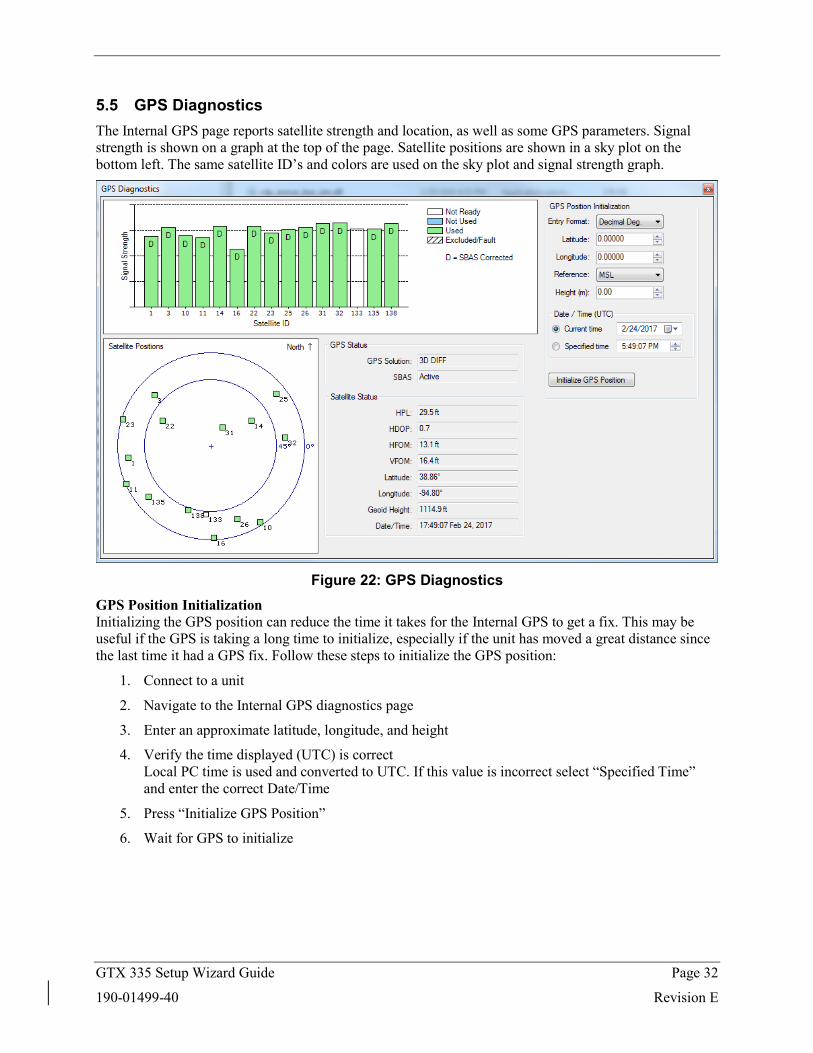
5.5 GPS Diagnostics The Internal GPS page reports satellite strength and location, as well as some GPS parameters. Signal strength is shown on a graph at the top of the page. Satellite positions are shown in a sky plot on the bottom left. The same satellite ID’s and colors are used on the sky plot and signal strength graph.
Figure 22: GPS Diagnostics
GPS Position Initialization Initializing the GPS position can reduce the time it takes for the Internal GPS to get a fix. This may be useful if the GPS is taking a long time to initialize, especially if the unit has moved a great distance since the last time it had a GPS fix. Follow these steps to initialize the GPS position:
1. Connect to a unit
2. Navigate to the Internal GPS diagnostics page
3. Enter an approximate latitude, longitude, and height
4. Verify the time displayed (UTC) is correct Local PC time is used and converted to UTC. If this value is incorrect select “Specified Time” and enter the correct Date/Time
5. Press “Initialize GPS Position”
6. Wait for GPS to initialize
GTX 335 Setup Wizard Guide Page 33
190-01499-40 Revision E
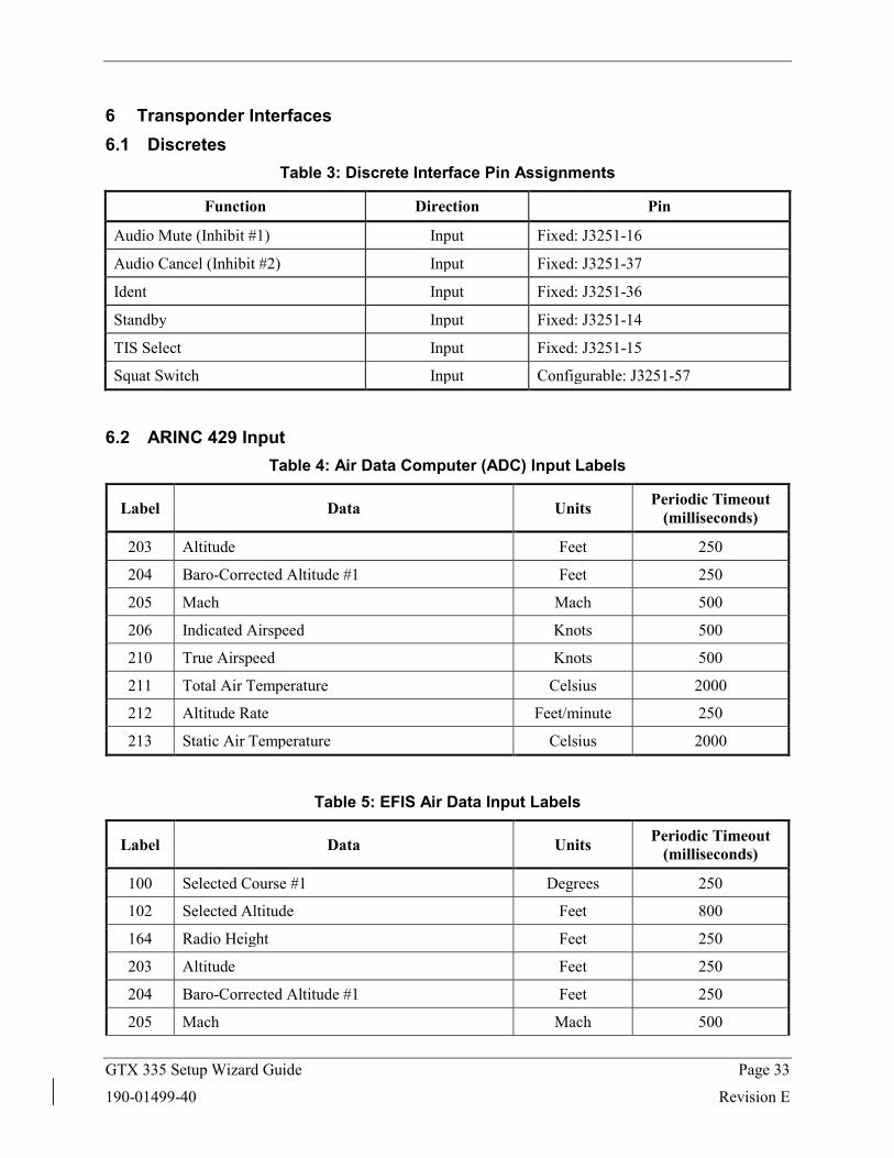
6 Transponder Interfaces 6.1 Discretes
Table 3: Discrete Interface Pin Assignments
Function Direction Pin
Audio Mute (Inhibit #1) Input Fixed: J3251-16
Audio Cancel (Inhibit #2) Input Fixed: J3251-37
Ident Input Fixed: J3251-36
Standby Input Fixed: J3251-14
TIS Select Input Fixed: J3251-15
Squat Switch Input Configurable: J3251-57
6.2 ARINC 429 Input Table 4: Air Data Computer (ADC) Input Labels
Label Data Units Periodic Timeout (milliseconds)
203 Altitude Feet 250
204 Baro-Corrected Altitude #1 Feet 250
205 Mach Mach 500
206 Indicated Airspeed Knots 500
210 True Airspeed Knots 500
211 Total Air Temperature Celsius 2000
212 Altitude Rate Feet/minute 250
213 Static Air Temperature Celsius 2000
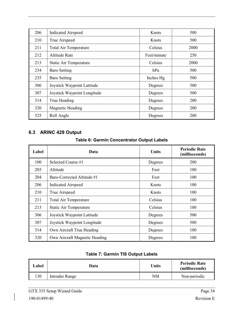
Table 5: EFIS Air Data Input Labels
Label Data Units Periodic Timeout (milliseconds)
100 Selected Course #1 Degrees 250
102 Selected Altitude Feet 800
164 Radio Height Feet 250
203 Altitude Feet 250
204 Baro-Corrected Altitude #1 Feet 250
205 Mach Mach 500
GTX 335 Setup Wizard Guide Page 34
190-01499-40 Revision E
206 Indicated Airspeed Knots 500
210 True Airspeed Knots 500
211 Total Air Temperature Celsius 2000
212 Altitude Rate Feet/minute 250
213 Static Air Temperature Celsius 2000
234 Baro Setting hPa 500
235 Baro Setting Inches Hg 500
306 Joystick Waypoint Latitude Degrees 500
307 Joystick Waypoint Longitude Degrees 500
314 True Heading Degrees 200
320 Magnetic Heading Degrees 200
325 Roll Angle Degrees 200
6.3 ARINC 429 Output Table 6: Garmin Concentrator Output Labels
Label Data Units Periodic Rate (milliseconds)
100 Selected Course #1 Degrees 200
203 Altitude Feet 100
204 Baro-Corrected Altitude #1 Feet 100
206 Indicated Airspeed Knots 100
210 True Airspeed Knots 100
211 Total Air Temperature Celsius 100
213 Static Air Temperature Celsius 100
306 Joystick Waypoint Latitude Degrees 500
307 Joystick Waypoint Longitude Degrees 500
314 Own Aircraft True Heading Degrees 100
320 Own Aircraft Magnetic Heading Degrees 100
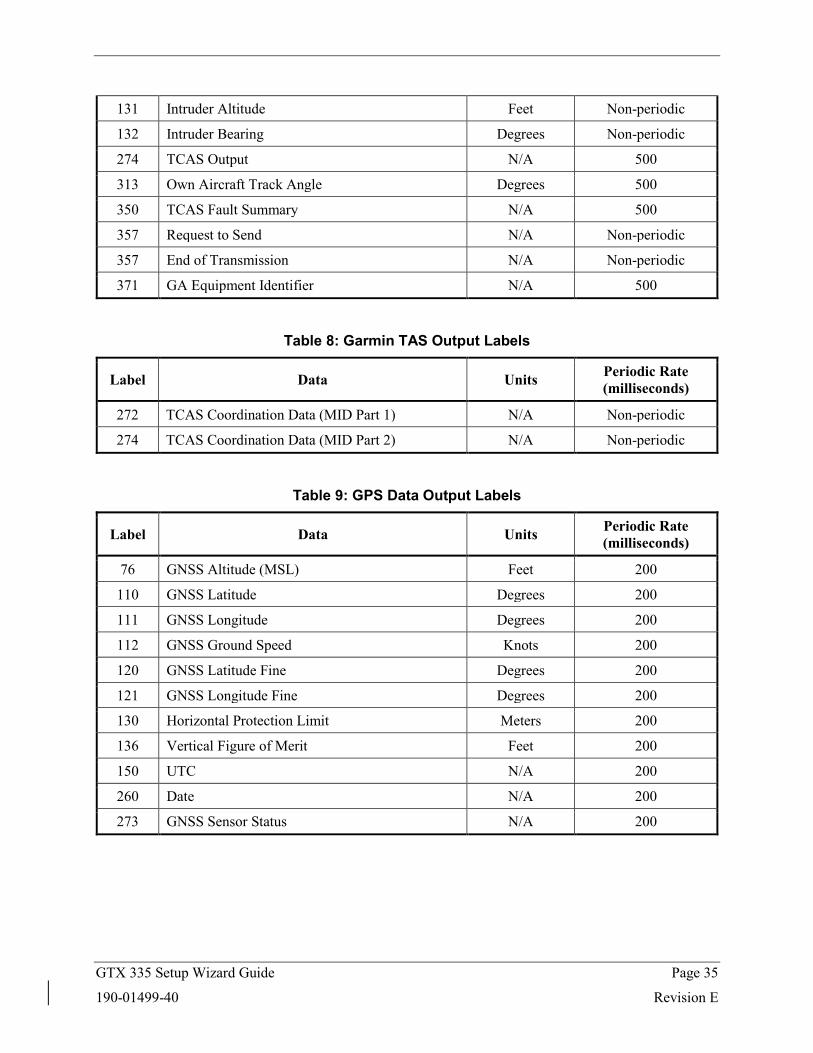
Table 7: Garmin TIS Output Labels
Label Data Units Periodic Rate (milliseconds)
130 Intruder Range NM Non-periodic
GTX 335 Setup Wizard Guide Page 35
190-01499-40 Revision E
131 Intruder Altitude Feet Non-periodic
132 Intruder Bearing Degrees Non-periodic
274 TCAS Output N/A 500
313 Own Aircraft Track Angle Degrees 500
350 TCAS Fault Summary N/A 500
357 Request to Send N/A Non-periodic
357 End of Transmission N/A Non-periodic
371 GA Equipment Identifier N/A 500
Table 8: Garmin TAS Output Labels
Label Data Units Periodic Rate (milliseconds)
272 TCAS Coordination Data (MID Part 1) N/A Non-periodic
274 TCAS Coordination Data (MID Part 2) N/A Non-periodic
Table 9: GPS Data Output Labels
Label Data Units Periodic Rate (milliseconds)
76 GNSS Altitude (MSL) Feet 200
110 GNSS Latitude Degrees 200
111 GNSS Longitude Degrees 200
112 GNSS Ground Speed Knots 200
120 GNSS Latitude Fine Degrees 200
121 GNSS Longitude Fine Degrees 200
130 Horizontal Protection Limit Meters 200
136 Vertical Figure of Merit Feet 200
150 UTC N/A 200
260 Date N/A 200
273 GNSS Sensor Status N/A 200
GTX 335 Setup Wizard Guide Page 36
190-01499-40 Revision E
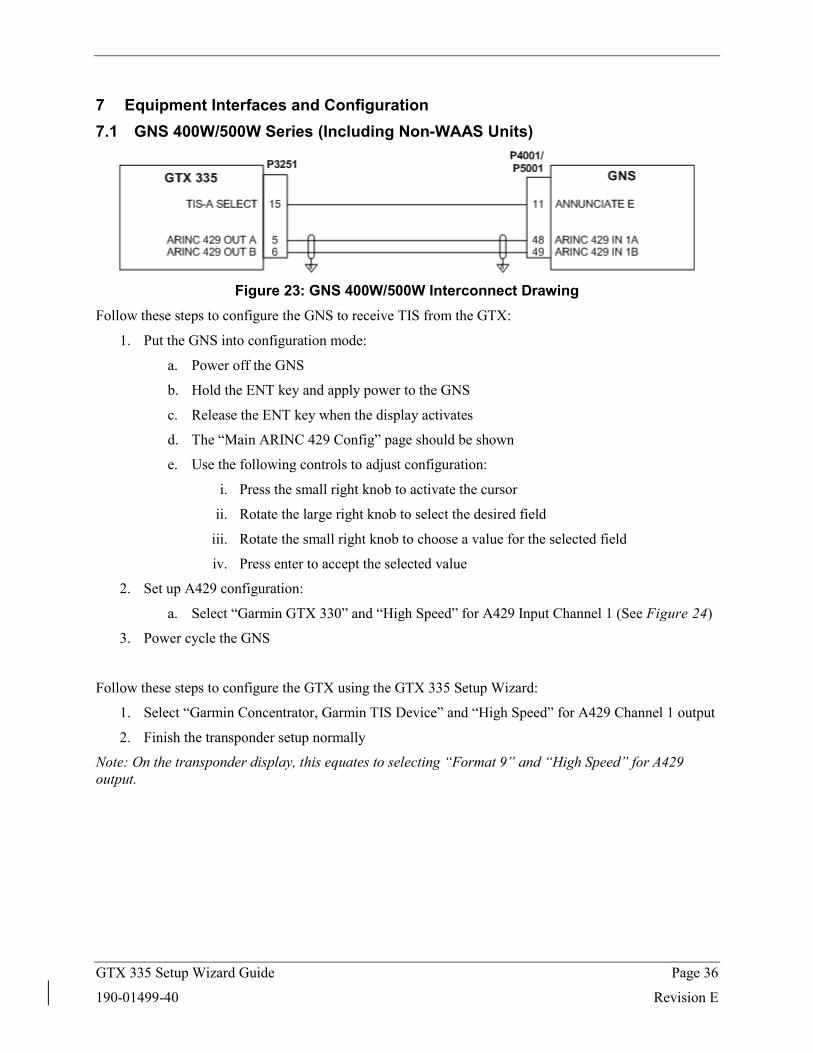
7 Equipment Interfaces and Configuration 7.1 GNS 400W/500W Series (Including Non-WAAS Units)
Figure 23: GNS 400W/500W Interconnect Drawing
Follow these steps to configure the GNS to receive TIS from the GTX:
1. Put the GNS into configuration mode:
a. Power off the GNS
b. Hold the ENT key and apply power to the GNS
c. Release the ENT key when the display activates
d. The “Main ARINC 429 Config” page should be shown
e. Use the following controls to adjust configuration:
i. Press the small right knob to activate the cursor
ii. Rotate the large right knob to select the desired field
iii. Rotate the small right knob to choose a value for the selected field
iv. Press enter to accept the selected value
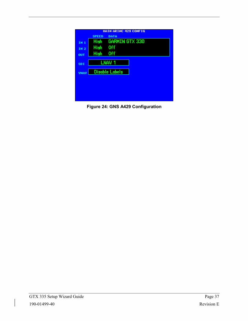
2. Set up A429 configuration:
a. Select “Garmin GTX 330” and “High Speed” for A429 Input Channel 1 (See Figure 24)
3. Power cycle the GNS
Follow these steps to configure the GTX using the GTX 335 Setup Wizard:
1. Select “Garmin Concentrator, Garmin TIS Device” and “High Speed” for A429 Channel 1 output
2. Finish the transponder setup normally
Note: On the transponder display, this equates to selecting “Format 9” and “High Speed” for A429 output.
GTX 335 Setup Wizard Guide Page 37
190-01499-40 Revision E
Figure 24: GNS A429 Configuration
GTX 335 Setup Wizard Guide Page 38
190-01499-40 Revision E
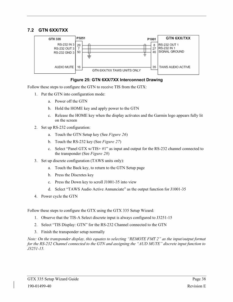
7.2 GTN 6XX/7XX
Figure 25: GTN 6XX/7XX Interconnect Drawing
Follow these steps to configure the GTN to receive TIS from the GTX:
1. Put the GTN into configuration mode:
a. Power off the GTN
b. Hold the HOME key and apply power to the GTN
c. Release the HOME key when the display activates and the Garmin logo appears fully lit on the screen
2. Set up RS-232 configuration:
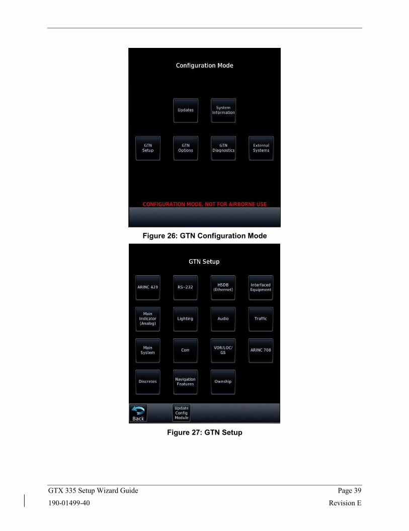
a. Touch the GTN Setup key (See Figure 26)
b. Touch the RS-232 key (See Figure 27)
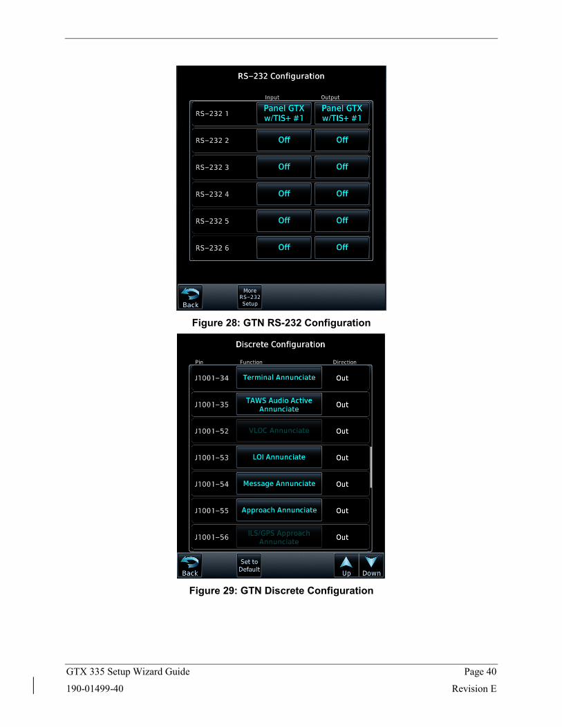
c. Select “Panel GTX w/TIS+ #1” as input and output for the RS-232 channel connected to the transponder (See Figure 28)
3. Set up discrete configuration (TAWS units only):
a. Touch the Back key, to return to the GTN Setup page
b. Press the Discretes key
c. Press the Down key to scroll J1001-35 into view
d. Select “TAWS Audio Active Annunciate” as the output function for J1001-35
4. Power cycle the GTN
Follow these steps to configure the GTX using the GTX 335 Setup Wizard:
1. Observe that the TIS-A Select discrete input is always configured to J3251-15
2. Select “TIS Display: GTN” for the RS-232 Channel connected to the GTN
3. Finish the transponder setup normally
Note: On the transponder display, this equates to selecting “REMOTE FMT 2” as the input/output format for the RS-232 Channel connected to the GTN and assigning the “AUD MUTE” discrete input function to J3251-15.
GTX 335 Setup Wizard Guide Page 39
190-01499-40 Revision E
Figure 26: GTN Configuration Mode
Figure 27: GTN Setup
GTX 335 Setup Wizard Guide Page 40
190-01499-40 Revision E
Figure 28: GTN RS-232 Configuration
Figure 29: GTN Discrete Configuration
Part Information
Spec Item Attribution Report 1 of 1 Item: 190-01499-40 Rev:E ECO#169297 Creation Date: 14-Feb-2018 08:47 AM CST
GPN: 190-01499-40
Description: GTX 335 Setup Wizard GuidePart Type: Manuals / Printed Literature
Lifecycle Phase: ProductionRev: E ECO#169297
Item Attribution:
Document Review Required:Item Notes:
ESD Sensitive:Moisture Sensitive:Limited Shelf Life:
Magnetic Sensitive: