gst301 extinguishing control panel installation and operation manual
DESCRIPTION
GST ManualTRANSCRIPT

GST301
Extinguishing Control Panel
Installation and Operation Manual (Issue 1.0, July 2004)
Global System Technology PLC
GST301 Extinguishing Control Panel Global System Technology PLC Installation and Operation Manual The Intelligent Solution
Global System Technology PLC London EC1R 3AU England
www.gstplc.com Email [email protected]
CONTENTS
I General............................................................................................................ 1 II Features........................................................................................................... 1 III Technical Specifications................................................................................... 1 IV Structure and Operation Principle..................................................................... 1 V Mounting and Commission............................................................................... 7 VI Operation....................................................................................................... 12 VII Troubleshooting ............................................................................................. 15 VIII Cautions......................................................................................................... 15
GST301 Extinguishing Control Panel Global System Technology PLC Installation and Operation Manual The Intelligent Solution
Global System Technology PLC London EC1R 3AU England
www.gstplc.com Email [email protected] Page 1
I General
GST301 Extinguishing Control Panel (hereinafter called the panel) is a stand-alone
panel intended for use with gas extinguishing systems. The function of the panel is to
monitor zones or areas for fire conditions and give an appropriate audible/visible indication. The panel also provides a facility for initiating the gas release to achieve
automatic protection, both manually and automatically.
II Features
GST301 Extinguishing Control Panel has 2 detection zones to achieve double-knock function, and a normal detection zone for extra usage. With C-9317 Emergency Gas
Override Control (emergency start/abort button), gas release can be controlled in field.
III Technical Specifications
1 Operating voltage: 220 VAC 15%
2 Power consumption 20W (Monitoring Mode)
3 Battery Requirement: 2X12VDC, 7Ah
4 Battery Operating Time:
a) 24 hours monitoring and half an hour alarm if the current of AUX power
output is 0mA. b) 8 hours monitoring and half an hour alarm if the current of AUX power
output is 100mA. 5 AUX Power Supply:100mA/24VDC
6 Sounder Output: 0.5A/24VDC
7 Release Output: 2A/24VDC, pulse 8 Battery Charge Current: 300mA
9 Maximum Detectors in Each Zone:15
10 Maximum Number of C-9317 Emergency Gas Override Control: 4
11 Operating Environment:
Temperature: -10°C 55°C Relative Humidity: 95%, no condensation
12 Dimension: 300mmX350mmX104mm
13 Mounting Hole Distance: 260mm
14 According to Standard: EN 54-2
IV Structure and Operation Principle
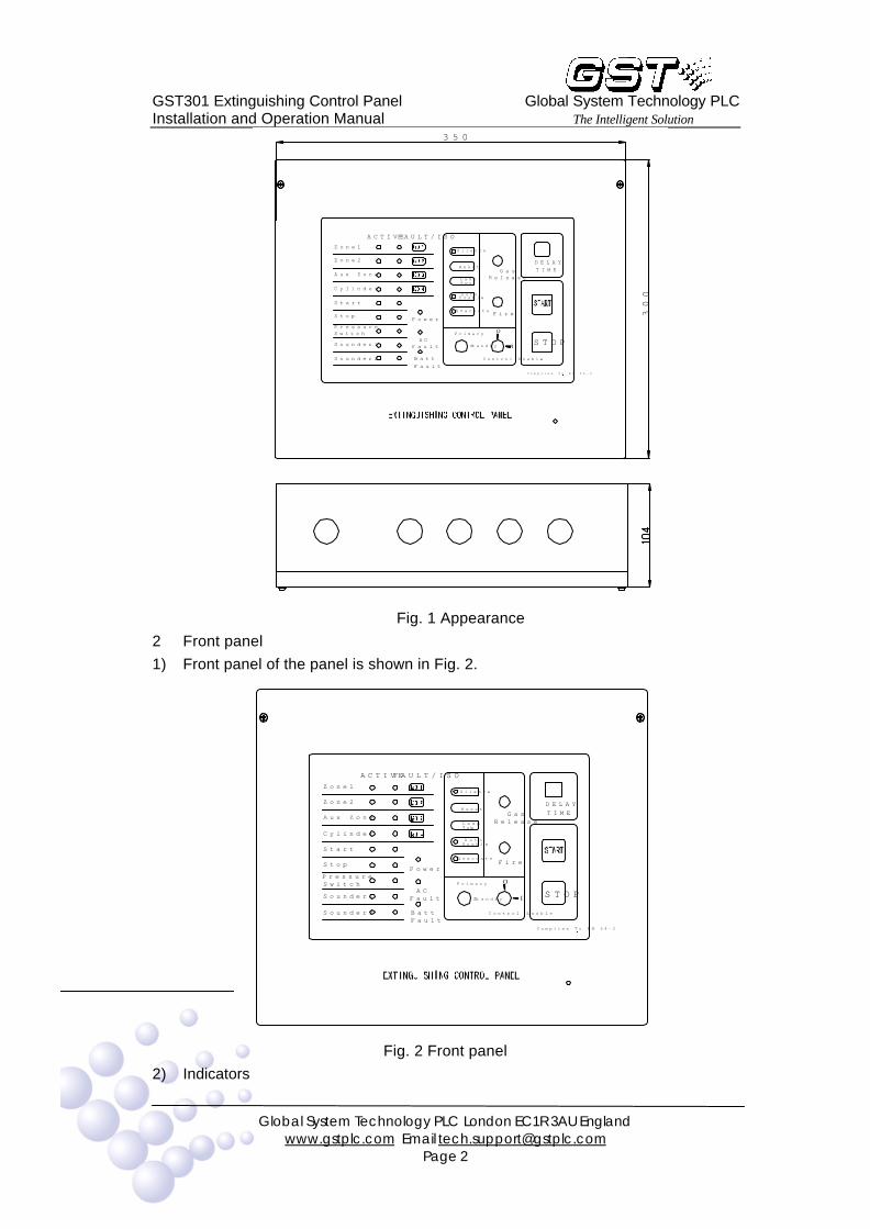
1 The panel is wall-mounted. It mainly consists of a cabinet, a main board, a display
board, and a transformer. Its structure is shown in Fig. 1.
GST301 Extinguishing Control Panel Global System Technology PLC Installation and Operation Manual The Intelligent Solution
Global System Technology PLC London EC1R 3AU England
www.gstplc.com Email [email protected] Page 2
Zone1
300
standby
Sounder2 Batt
Fault
EnableStart
PressureSwitch
Sounder1 ACFault
Primary
StopEvacuate
Power
Aux Zone
CylinderAuto
TestLamp
Zone2Reset
Silence
Complies To EN 54-2
Control Enable
STOPI
O
Fire
GasRelease
DELAY
TIME
350
ACTIVE FAULT/ISO
Fig. 1 Appearance
2 Front panel
1) Front panel of the panel is shown in Fig. 2.
FireStop
Istandby ACFaultSounder1
BattFault
Sounder2 Control Enable
PowerPressureSwitch OPrimary
STOP
Complies To EN 54-2
Zone1
Lamp
Start
Cylinder
Enable
Evacuate
Auto
Tes t
Aux Zone
Zone2Reset
GasRelease
Silence
TIME
DELAY
FAULT/ISOACTIVE
Fig. 2 Front panel
2) Indicators

GST301 Extinguishing Control Panel Global System Technology PLC Installation and Operation Manual The Intelligent Solution
Global System Technology PLC London EC1R 3AU England
www.gstplc.com Email [email protected] Page 3
l Power Green. Lighted when power supplied.
l AC Fault Amber. Lighted when there is AC Fault.
l Batt Fault Amber. Lighted when battery voltage is below 5V.
l Gas Release Red. Flashes during delay time. Lighted after gas
released. Extinguished by reset. l Fire Red. General fire indication. Lighted by any fire signal.
Extinguished by reset.
l Silence Green. Lighted if the panel is silenced. Extinguished when
it re-sounds.
l Auto Enable Green. Lighted if the panel is in automatic mode. Off for manual only mode.
l Evacuate Green. Flashes when “Evacuate” key is pressed.
Extinguished by reset.
l DELAY TIME Red. Indicating the time (in second) before gas releasing.
l Zone1 ACTIVE Red. Flashes when Zone1 is in alarm. Lighted steadily after it’s silenced. Extinguished by reset.
l Zone1 Fault/ISO Amber. Flashes when Zone1 has any fault. Off when the
fault is removed. Steadily lighted when Zone1 is isolated.
l Zone2 ACTIVE Red. Flashes when Zone2 is in alarm. Lighted steadily
after it’s silenced. Extinguished by reset. l Zone2 Fault/ISO Amber. Flashes when Zone2 has any fault. Off when the
fault is removed. Steadily lighted when Zone2 isolated.
l Aux Zone ACTIVE Red. Flashes when the AUX Zone is in alarm. Lighted
steadily after it’s silenced. Extinguished by reset.
l Aux Zone Fault/ISO Amber. Flashes when the AUX zone has any fault. Steadily lighted when the AUX zone is isolated. OFF
when the fault is removed.
l Cylinder ACTIVE Green. Flashes when the release output is active.
Extinguished after output finished.
l Cylinder FAULT/ISO Amber. Flashes when the gas release output circuit has any fault. Lighted steadily in isolated mode.
l Start ACTIVE Green. Flashes when the “START” key on the panel or the
Emergency Start Button in field is pressed.
l Start FAULT Amber. Lighted by fault with Emergency Start Button
Circuit. Extinguished when fault removed. l Stop ACTIVE Green. Flashes when the “STOP” key on panel or the
field Emergency Abort Button is pressed.
l Stop FAULT Amber. Lighted by fault with Emergency Abort Button
Circuit. Extinguished when fault removed.
l Pressure Switch ACTIVE Green. Lighted if the pressure switch is active (gas released) or after gas release output started (no pressure
switch). Extinguished by reset.
GST301 Extinguishing Control Panel Global System Technology PLC Installation and Operation Manual The Intelligent Solution
Global System Technology PLC London EC1R 3AU England
www.gstplc.com Email [email protected] Page 4
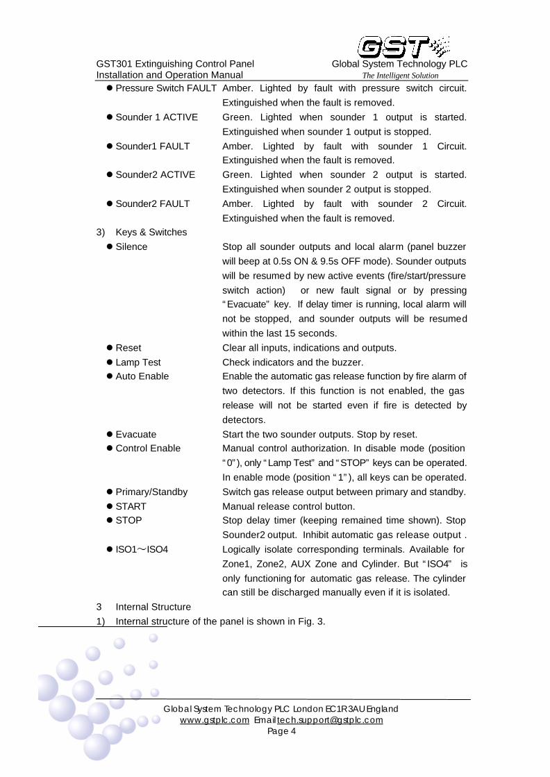
l Pressure Switch FAULT Amber. Lighted by fault with pressure switch circuit.
Extinguished when the fault is removed.
l Sounder 1 ACTIVE Green. Lighted when sounder 1 output is started.
Extinguished when sounder 1 output is stopped.
l Sounder1 FAULT Amber. Lighted by fault with sounder 1 Circuit. Extinguished when the fault is removed.
l Sounder2 ACTIVE Green. Lighted when sounder 2 output is started.
Extinguished when sounder 2 output is stopped.
l Sounder2 FAULT Amber. Lighted by fault with sounder 2 Circuit.
Extinguished when the fault is removed. 3) Keys & Switches
l Silence Stop all sounder outputs and local alarm (panel buzzer
will beep at 0.5s ON & 9.5s OFF mode). Sounder outputs
will be resumed by new active events (fire/start/pressure
switch action) or new fault signal or by pressing “Evacuate” key. If delay timer is running, local alarm will
not be stopped, and sounder outputs will be resumed
within the last 15 seconds.
l Reset Clear all inputs, indications and outputs.
l Lamp Test Check indicators and the buzzer. l Auto Enable Enable the automatic gas release function by fire alarm of
two detectors. If this function is not enabled, the gas
release will not be started even if fire is detected by
detectors.
l Evacuate Start the two sounder outputs. Stop by reset. l Control Enable Manual control authorization. In disable mode (position
“0”), only “Lamp Test” and “STOP” keys can be operated.
In enable mode (position “1”), all keys can be operated.
l Primary/Standby Switch gas release output between primary and standby.
l START Manual release control button. l STOP Stop delay timer (keeping remained time shown). Stop
Sounder2 output. Inhibit automatic gas release output .
l ISO1 ISO4 Logically isolate corresponding terminals. Available for
Zone1, Zone2, AUX Zone and Cylinder. But “ISO4” is
only functioning for automatic gas release. The cylinder can still be discharged manually even if it is isolated.
3 Internal Structure
1) Internal structure of the panel is shown in Fig. 3.

GST301 Extinguishing Control Panel Global System Technology PLC Installation and Operation Manual The Intelligent Solution
Global System Technology PLC London EC1R 3AU England
www.gstplc.com Email [email protected] Page 5
Fig. 3 Internal structure
AC transformer: 220VAC input, 27VAC output.
Input current fuse of the AC transformer: 1A
AC Input: 220VAC input
Main board
Battery: 12VDC 7Ah each Display board
The cylinder output selection switch and manual control enable switch
Buzzer 2) Main Board

GST301 Extinguishing Control Panel Global System Technology PLC Installation and Operation Manual The Intelligent Solution
Global System Technology PLC London EC1R 3AU England
www.gstplc.com Email [email protected] Page 6
Fig. 4 Main board structure
X5: Discharge remote output mode setting (NO/NC) X4: Fire remote output mode setting (NO/NC)
X6: Fault remote output mode setting (NO/NC)
X1: Sounder1 output mode setting (Active/NO/NC)
X2: Sounder2 output mode setting (Active/NO/NC)
X3: Cylinder output mode setting (Active/NO/NC) F5: Fuse of cylinder output (active mode)
F4: Fuse of Sounder2 output (active mode)
F3: fuse of Sounder1 output (active mode)
XT1, XT2: AC terminal and battery terminal
D1: MCU 3) Display Board
GST301 Extinguishing Control Panel Global System Technology PLC Installation and Operation Manual The Intelligent Solution
Global System Technology PLC London EC1R 3AU England
www.gstplc.com Email [email protected] Page 7
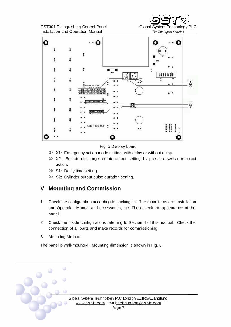
Fig. 5 Display board
X1: Emergency action mode setting, with delay or without delay. X2: Remote discharge remote output setting, by pressure switch or output
action.
S1: Delay time setting.
S2: Cylinder output pulse duration setting.
V Mounting and Commission
1 Check the configuration according to packing list. The main items are: Installation
and Operation Manual and accessories, etc. Then check the appearance of the
panel.
2 Check the inside configurations referring to Section 4 of this manual. Check the connection of all parts and make records for commissioning.
3 Mounting Method
The panel is wall-mounted. Mounting dimension is shown in Fig. 6.
GST301 Extinguishing Control Panel Global System Technology PLC Installation and Operation Manual The Intelligent Solution
Global System Technology PLC London EC1R 3AU England
www.gstplc.com Email [email protected] Page 8
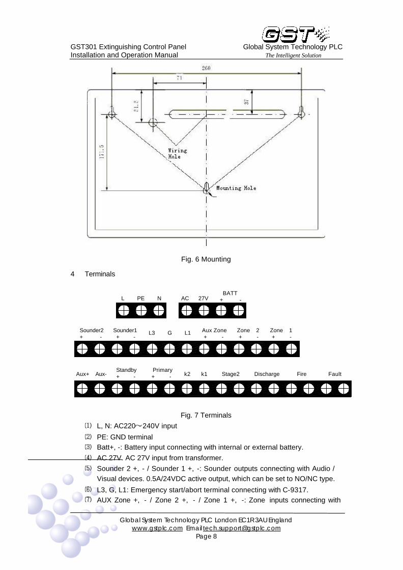
Fig. 6 Mounting
4 Terminals
Sounder1 + -
Standby + -
L PE N
Sounder2 + -
Aux Zone + -
Stage2 Primary + - k2 k1
L3 G L1
Discharge Fire
Zone 1 + -
Zone 2 + -
Fault
BATT + - AC 27V
Aux+ Aux-
Fig. 7 Terminals
L, N: AC220 240V input
PE: GND terminal Batt+, -: Battery input connecting with internal or external battery.
AC 27V. AC 27V input from transformer.
Sounder 2 +, - / Sounder 1 +, -: Sounder outputs connecting with Audio / Visual devices. 0.5A/24VDC active output, which can be set to NO/NC type.
L3, G, L1: Emergency start/abort terminal connecting with C-9317. AUX Zone +, - / Zone 2 +, - / Zone 1 +, -: Zone inputs connecting with

GST301 Extinguishing Control Panel Global System Technology PLC Installation and Operation Manual The Intelligent Solution
Global System Technology PLC London EC1R 3AU England
www.gstplc.com Email [email protected] Page 9
conventional detectors and manual call points.
AUX +, AUX -: AUX power supply (100mA/24VDC).
Standby +, - / Primary +, - : Gas release output connecting with primary and standby cylinder. 2A/24VDC active output. Can be set to NO/NC type. 2 to 45
seconds adjustable pulse output.
K2, K1: Pressure switch input connecting with cylinder pressure switch. Dry contact input.
Stage 2: Pre-release remote output. NO dry contact.
Discharge: Gas discharge remote indication output. NO/NC dry contact.
Fire: Fire remote indication output. NO/NC dry contact. Fault: Fault remote indication output. NO/NC dry contact.
5 Wiring
1) Wire requirements:
227 IEC 02 fire cable with cross section not less than 1.5mm2 for Zone,
Sounder, Remote Output, Emergency Start/Abort button and AUX Power. 227 IEC 02 fire cable with cross section not less than 1.5mm2 for Cylinder
Output (Primary & Standby) and Battery connection. If the cable length is more
than 50 meters, 227 IEC 02 fire cable with cross section not less than 2.5mm2
should be used.
2) Wiring Method
Wiring diagram when using Active End of Line unit is shown in Fig .8.
ZoneInputTerminals
Panel
470(normal)
A.E.O.L
MCP
Fig. 8. Wiring diagram when using Active End of Line unit
Wiring diagram when using End of Line resistor is shown in Fig. 9.
ZoneInputTerminals
Panel
470(normal)
MCP
470(normal)
MCP
4.7kResistor
No Diode
Fig. 9 Wiring diagram when using End of Line resistor
Wiring method of gas override control is shown in Fig. 10.

GST301 Extinguishing Control Panel Global System Technology PLC Installation and Operation Manual The Intelligent Solution
Global System Technology PLC London EC1R 3AU England
www.gstplc.com Email [email protected] Page 10
Panel
L1
G
L3
L1+
G
L3+
K1 K2
L2+
G
L4+
L1+
G
L3+
K1 K2
L2+
G
L4+
L1+
G
L3+
K1 K2
L2+
G
L4+
3k
3k
Contact Output
Emergency
Start/Abort Button
Emergency
Start/Abort Button
Emergency
Start/Abort Button
Fig. 10 Wiring method of Emergency Start/Abort Button
Wiring method when driving cylinder is of active output mode is shown in Fig. 11.
4.7k 0.25W
1N5408
1N5408
Add components
Cylinder24VDC >12
Primary/Standby
Panel
Fig. 11 Wiring method when driving cylinder is of active output mode
Wiring method when driving sounder is of active output mode is shown in Fig. 12.
4.7k 0.25W
1N5408
1N5408
Add components
Sounder24VDC 48
Sounder1/
Sounder2
Panel
Fig. 12 Wiring method when driving sounder is of active output mode
All remote output are dry contact output, simple for connection with other systems.
3) Typical system connection is shown in Fig. 13.
GST301 Extinguishing Control Panel Global System Technology PLC Installation and Operation Manual The Intelligent Solution
Global System Technology PLC London EC1R 3AU England
www.gstplc.com Email [email protected] Page 11
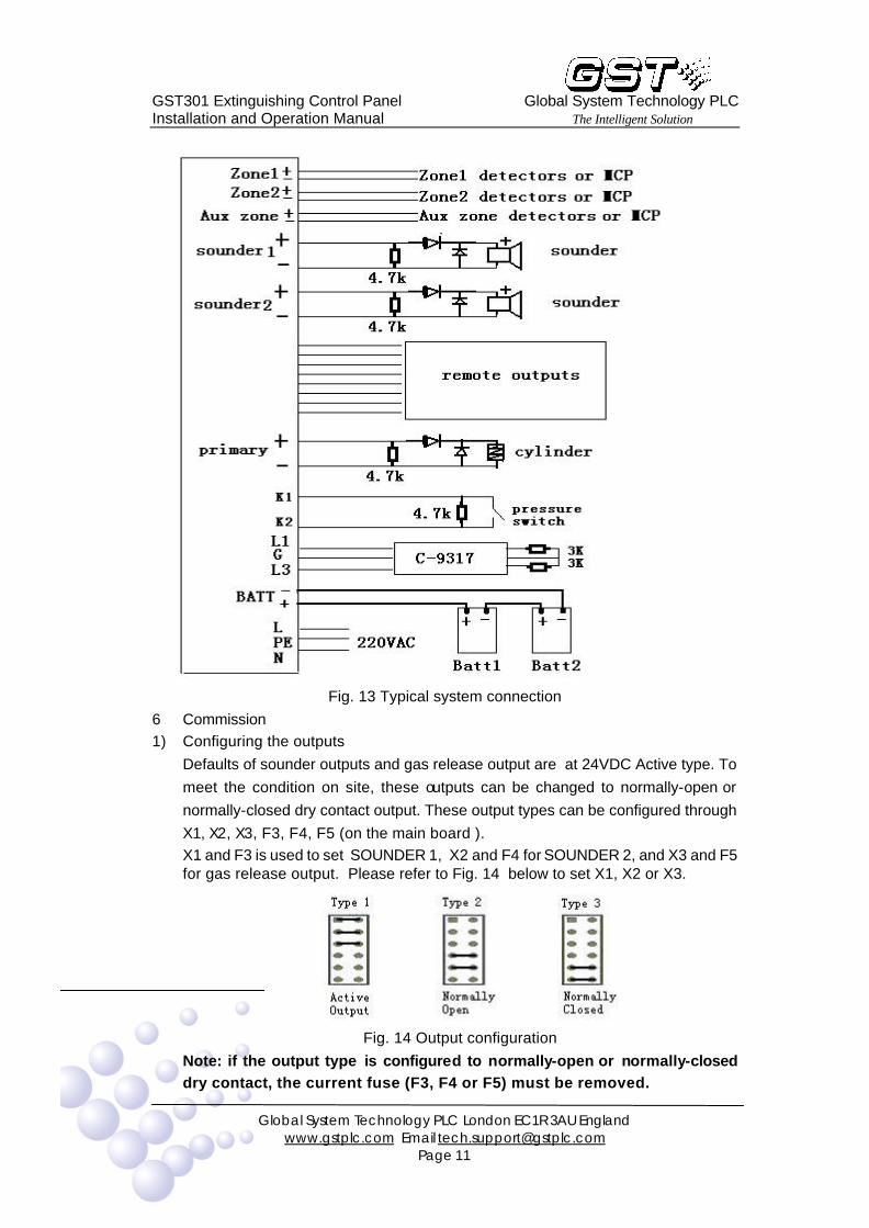
Fig. 13 Typical system connection
6 Commission 1) Configuring the outputs
Defaults of sounder outputs and gas release output are at 24VDC Active type. To
meet the condition on site, these outputs can be changed to normally-open or
normally-closed dry contact output. These output types can be configured through
X1, X2, X3, F3, F4, F5 (on the main board ). X1 and F3 is used to set SOUNDER 1, X2 and F4 for SOUNDER 2, and X3 and F5 for gas release output. Please refer to Fig. 14 below to set X1, X2 or X3.
Fig. 14 Output configuration
Note: if the output type is configured to normally-open or normally-closed dry contact, the current fuse (F3, F4 or F5) must be removed.
GST301 Extinguishing Control Panel Global System Technology PLC Installation and Operation Manual The Intelligent Solution
Global System Technology PLC London EC1R 3AU England
www.gstplc.com Email [email protected] Page 12
2) Configuring the Emergency Start Button
Press the emergency start button in field can start the gas release with or without
delay. Short X1 (on the display board) to set with delay and remove the jumper to
set without delay. Default setting is with delay.
3) Configuring the discharge output The discharge output can be started by pressure switch or directly by gas release output. Short X2 (on the display board) to set as using pressure switch, remove the
jumper to set as not using pressure switch (active after gas release output). Default
setting is using pressure switch.
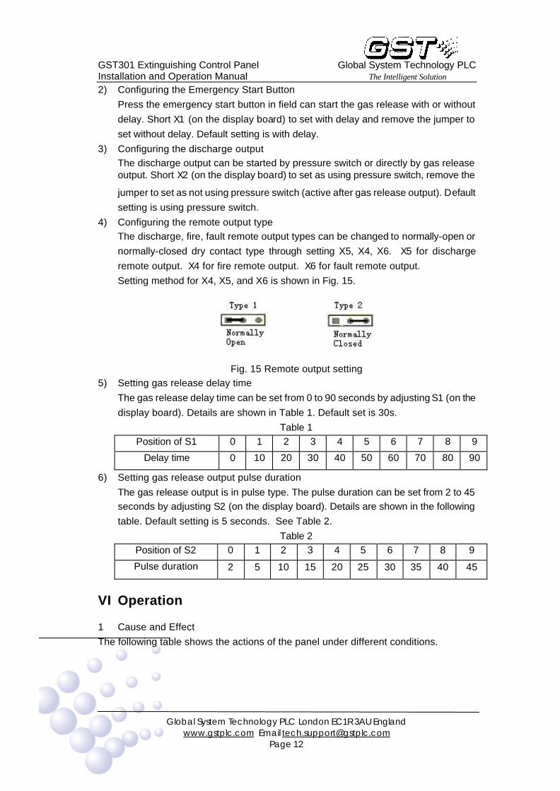
4) Configuring the remote output type The discharge, fire, fault remote output types can be changed to normally-open or
normally-closed dry contact type through setting X5, X4, X6. X5 for discharge
remote output. X4 for fire remote output. X6 for fault remote output.
Setting method for X4, X5, and X6 is shown in Fig. 15.
Fig. 15 Remote output setting
5) Setting gas release delay time
The gas release delay time can be set from 0 to 90 seconds by adjusting S1 (on the
display board). Details are shown in Table 1. Default set is 30s.
Table 1 Position of S1 0 1 2 3 4 5 6 7 8 9
Delay time 0 10 20 30 40 50 60 70 80 90
6) Setting gas release output pulse duration
The gas release output is in pulse type. The pulse duration can be set from 2 to 45 seconds by adjusting S2 (on the display board). Details are shown in the following
table. Default setting is 5 seconds. See Table 2.
Table 2 Position of S2 0 1 2 3 4 5 6 7 8 9
Pulse duration 2 5 10 15 20 25 30 35 40 45
VI Operation
1 Cause and Effect
The following table shows the actions of the panel under different conditions.

GST301 Extinguishing Control Panel Global System Technology PLC Installation and Operation Manual The Intelligent Solution
Global System Technology PLC London EC1R 3AU England
www.gstplc.com Email [email protected] Page 13
No. Cause Effect
1 Zone1 alarm ♦ Sounder1 start immediately ♦ Fire remote output active immediately
2 Zone2 alarm ♦ Sounder1 start immediately ♦ Fire remote output active immediately
3 AUX Zone alarm ♦ Sounder1 start immediately ♦ Fire remote output active immediately
4 Zone1 & Zone2 alarm
♦ Sounder1 start immediately ♦ Sounder2 start immediately ♦ Fire remote output active immediately ♦ Stage 2 remote output active immediately ♦ Delay timer start immediately ♦ Gas release output start after timing finished ♦ If pressure switch is not used, start the discharge
output after the release output started.
5 Emergency start button pressed
♦ Sounder1 start immediately ♦ Sounder2 start immediately ♦ Fire remote output active immediately ♦ Stage 2 remote output active immediately ♦ Start the release delay timer or start the gas release
output immediately (select the option by jumper when commissioning)
♦ If pressure switch is not used, start the discharge output after the release output started.
6 Start key on panel pressed
♦ Sounder1 start immediately ♦ Sounder2 start immediately ♦ Fire remote output active immediately ♦ Gas start immediately without delay ♦ If pressure switch is not used, start the discharge
output after the release output started.
7 Emergency Abort Switch pressed
During gas delay timing ♦ Stop Sounder2 output. ♦ Stop Timer. Show remaining time. No gas delay timer ♦ No action
8 Stop Key on panel pressed
During gas delay timing ♦ Stop Sounder2 output. ♦ Stop Timer. Show remaining time. No gas delay timer ♦ No action
9 Pressure Switch active
♦ Start discharge remote output if pressure switch is used, otherwise it will not be cared.
10 Any Fault ♦ Start Fault Remote output ♦ Light corresponding LED (internal fault is indicated by
delay time indicator). Note: If the gas release action has finished, the panel will not repeat automatic start or delay start. But it can be started by pressing the “START” key on the
panel, the action will be kept until the pressed key released.
2 Preparation before installation and operation
GST301 Extinguishing Control Panel Global System Technology PLC Installation and Operation Manual The Intelligent Solution
Global System Technology PLC London EC1R 3AU England
www.gstplc.com Email [email protected] Page 14
1 Remove the two screws on the panel surface and open the front cover.
2 Do Wiring( referring to Clause 5 of Section 5). Check the cables before connecting them to the panel. Ensure that there is no
problem of short circuit, open circuit, earth fault and cross connection, etc.
Note: If any zone, alarm circuit, or cylinder circuit is not used, an end of line resistor must be connected to the corresponding terminal.
3 Configuration (refer to Clause 6 of Section 5) Set the discharge/fire/fault/stage 2 remote output mode, NO or NC.
Set the sounder1/sounder2/cylinder output mode, ACTIVE, NO or NC.
Set emergency start with delay or without delay. Set remote discharge output by pressure switch or by gas release output
action.
Set delay time and output pulse duration.
4 Power Up Connect the A.C mains to the panel and turn on the break. Do not switch on the mains supply before connecting well.
5 Battery Connection. If the panel reacts well after mains on, you can disconnect the mains and connect the batteries with correct polarity.
3 Manual Operations 1) Starting gas release from the panel
Press the “START” key on the panel will start the gas release output without
any delay. This operation is controlled under “Control Enable” switch (by key).
2) Starting gas release in field
Press the Emergency Start button on field will start the gas release output with
or without delay (configurable). This function is not inhibited by “Auto Enable” setting.
3) Stopping gas release from the panel
During the gas release delay timing, press the “STOP” key will stop the timer.
The output terminal will be electronically isolated. This function is not inhibited
by “Auto Enable” and “CONTROL ENABLE” setting. Note, if the timer is finished and the panel is starting the gas release action, the stop
operation will not function.
4) Stopping gas release in field
During the gas release delay time, press the emergency abort switch will stop
the timer. The output terminal will be electronically isolated. This function is not inhibited by “Auto Enable” and “Control Enable” setting. Note, if the timer is
finished and the panel is starting the gas release action, the stop
operation will not function.
5) Silencing the sounders & alarming panel
Press “Silence” key to stop sounder outputs and the buzzer of the panel. This operation is controlled under “Control Enable” switch. Note: if the “Evacuate”
key is active, the “Silence” key will not act. (If it’s within gas release delay
GST301 Extinguishing Control Panel Global System Technology PLC Installation and Operation Manual The Intelligent Solution
Global System Technology PLC London EC1R 3AU England
www.gstplc.com Email [email protected] Page 15
time, pressing “Silence” will not stop the panel alarming. The sounder outputs
will be resumed in the lasts 15 seconds.)
6) Starting the sounders
Press “Evacuate” key to start the sounder outputs. This operation is controlled
by “Control Enable” switch. 7) Isolation/De-isolation operation
In case of false-alarm and fault, if the problem cannot be removed immediately,
the faulty zone can be logically isolated in order to avoid false-release and
noises. After the problem is solved, De-isolate to resume the functions. The
Isolation/De-isolation operation is available for Zone1, Zone2, AUX Zone and the Cylinder. Pressing the corresponding “ISO1 ISO4” key to change the
isolation condition. This operation is controlled by “Control Enable” switch.
8) Standby cylinder output
To ensure fire protection, there should be 2 sets of gas cylinders in field. In
case of fault with the primary (discharge, low pressure or other problems), switch the output to standby terminal. Note: Only the circuit in use is
monitored.
VII Troubleshooting
The panel itself is able to check and judge fault. If there is any short or broken circuit with wiring of a certain zone, the panel will light corresponding fault indicator, and output
fault remote signal. If it still cannot work normally or still alarm fault, please contact GST
technical support personnel.
VIII Cautions
l If the cylinder’s output or the sounder’s output is set as a normally-open or
normally-closed type, the corresponding current fuse must be removed!
l ‘ISO4’ operation is only valid for gas release actions caused by emergency
start button and detection zones. The “START” key on the panel is not under
control. That means even if the output is isolated, gas release can still be active by the “START” key. So, only when “ISO4” is active and “Control
Enable” is Off, will gas release output be completely inhibited.
l If there is any serious internal error during self-test, the panel will show
flashing ‘E0’ on its front panel and start the fault remote output. In this case,
repair must be done. l The panel must be properly grounded to ensure safety.
l The panel must be maintained or repaired by authorised and skilled person.