gsmp-40 technical presentation - gem systems advanced
TRANSCRIPT


DEVELOPMENT OF A NEW OPTICALLYPUMPED POTASIUM MAGNETOMETER
Dr. Ivan Hrvoic, Ph.D., P.Eng.President, GEM Advanced Magnetometers
Greg M. Hollyer, M.Sc.(Eng.), P.Eng.Manager, Communication
Mike WilsonElectronics Technologist
Anthony Szeto, Ph.D., P. Geo.Associate Professor, York University
SAGEEP 2003

INTRODUCTION
• Near Surface Requirements
• Recent Developments
• Optically Pumped Potassium Theory
• GSMP-40 Potassium Design Considerations
• Short Case History with Target Comparisons

NEAR SURFACE REQUIREMENTS
• Migrating from “bump” location
• Fast, “highly detailed” mapping and characterization
• Parallel requirement for manufacturers to develop instrumentation to meet needs:
• More detail for analysis & modeling
• Higher productivity

RECENT DEVELOPMENTS
• Overhauser for walking surveys (v6.0 2000):
• High sensitivity, low weight, minimal power, high absolute accuracy & minimal orientation error
• Ongoing R&D led to Optically Pumped Potassium for walking & vehicular surveys (2001 & 2002):
• Very high sensitivity, high absolute accuracy, minimal orientation error and 20x sampling

OVERHAUSER MAGNETOMETER

POTASSIUM MAGNETOMETER
• Multi-sensor, “Sweep Initiated” system that locks on to the first peak in Potassium spectrum
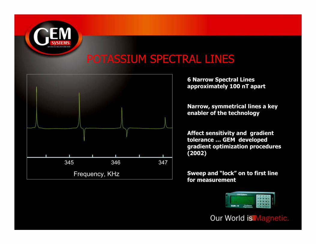
POTASSIUM SPECTRAL LINES
6 Narrow Spectral Linesapproximately 100 nT apart
Narrow, symmetrical lines a keyenabler of the technology
Affect sensitivity and gradienttolerance … GEM developedgradient optimization procedures(2002)
Sweep and “lock” on to first linefor measurement
345 346 347
Frequency, KHz
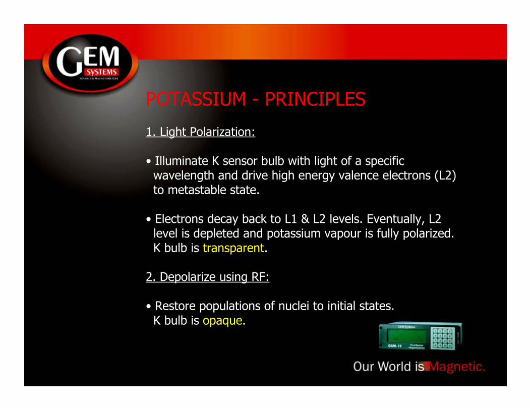
POTASSIUM - PRINCIPLES
1. Light Polarization:
• Illuminate K sensor bulb with light of a specific wavelength and drive high energy valence electrons (L2) to metastable state.
• Electrons decay back to L1 & L2 levels. Eventually, L2 level is depleted and potassium vapour is fully polarized. K bulb is transparent.
2. Depolarize using RF:
• Restore populations of nuclei to initial states. K bulb is opaque.
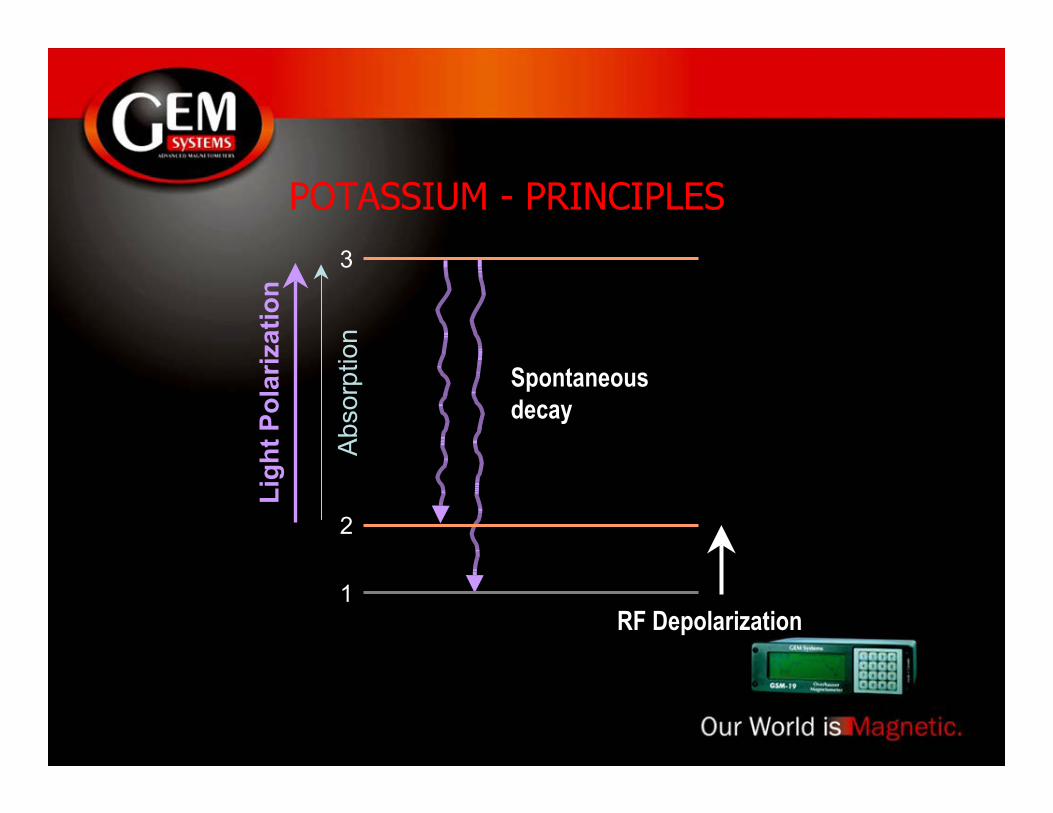
POTASSIUM - PRINCIPLES
1
2
Spontaneousdecay
RF Depolarization
3
Abso
rptio
n
Ligh
t Pol
ariz
atio
n

POTASSIUM - PRINCIPLES
3. Detect light modulation and “lock”:
• Chamber oscillates from transparent to opaque. Use this light modulation to detect a potassium resonance signal.
• “Lock” to this frequency using a designated “VCO” circuit.
4. Measure the frequency of light modulation:
• Convert to magnetic units.
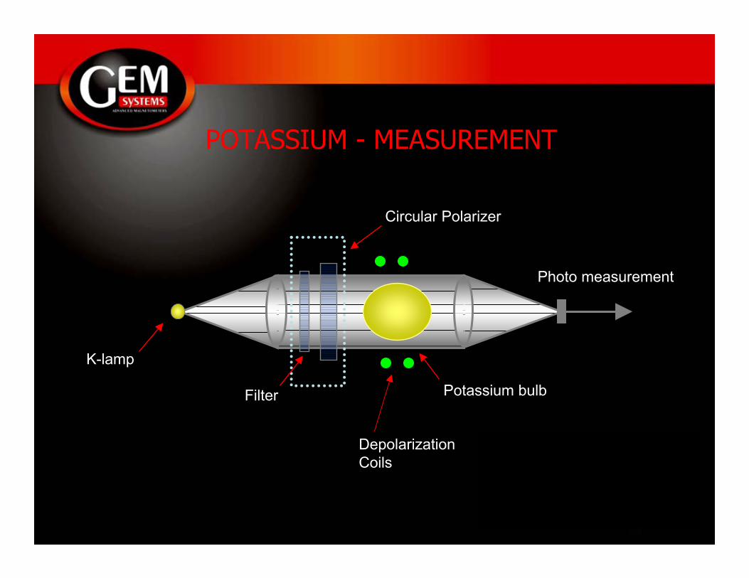
POTASSIUM - MEASUREMENT
K-lamp
Filter
Circular Polarizer
Photo measurement
Potassium bulb
DepolarizationCoils

POTASSIUM - SENSOR
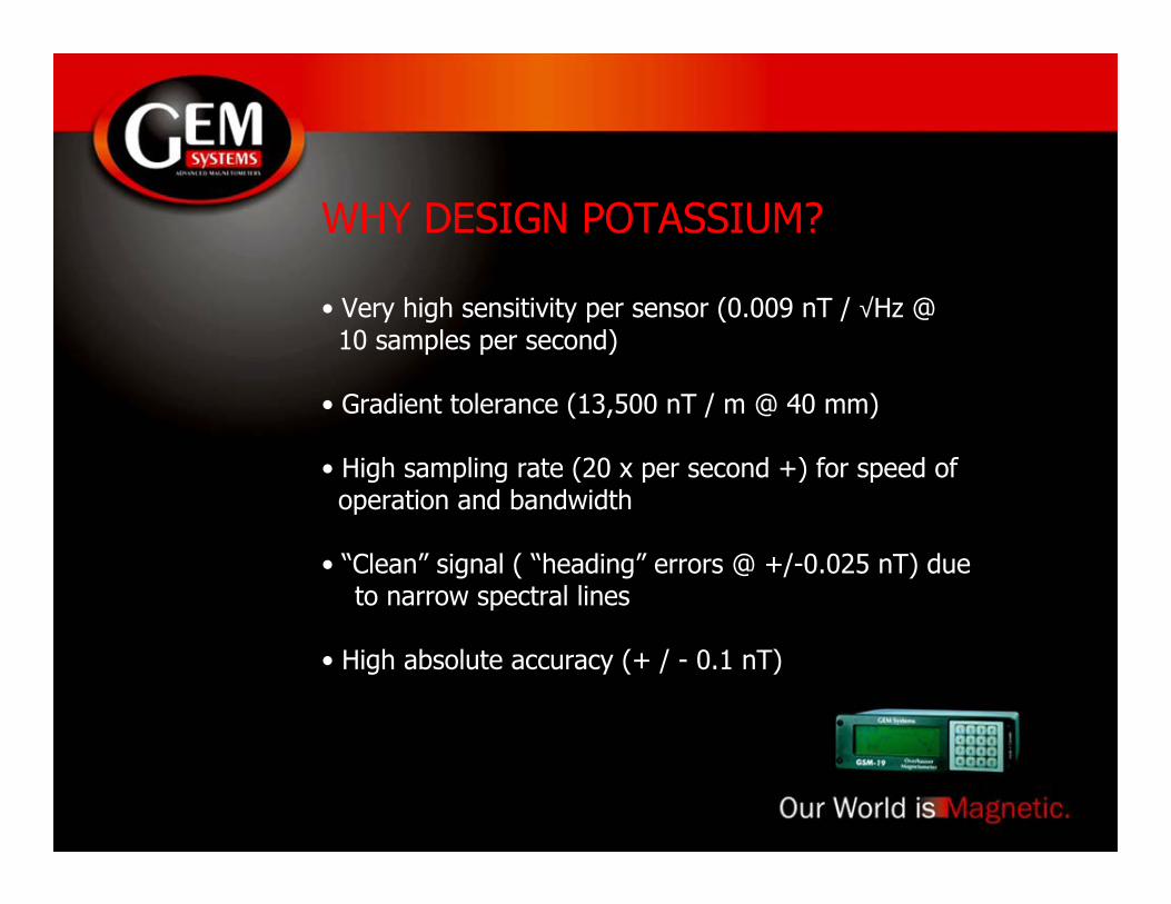
WHY DESIGN POTASSIUM?
• Very high sensitivity per sensor (0.009 nT / √Hz @ 10 samples per second)
• Gradient tolerance (13,500 nT / m @ 40 mm)
• High sampling rate (20 x per second +) for speed of operation and bandwidth
• “Clean” signal ( “heading” errors @ +/-0.025 nT) due to narrow spectral lines
• High absolute accuracy (+ / - 0.1 nT)
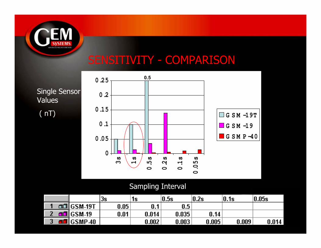
SENSITIVITY - COMPARISON
0
0.05
0.1
0.15
0.2
0.25
3s
1s
0.5s
0.2s
0.1s
0.05s
G S M -19T
G S M -19
G S M P -40
Sampling Interval
Single SensorValues
( nT)
0.5
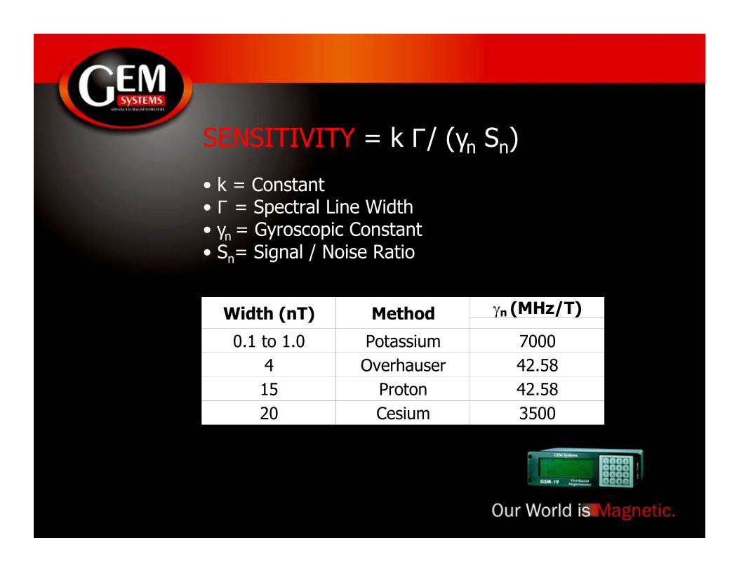
SENSITIVITY = k Γ/ (γn Sn)
• k = Constant• Γ = Spectral Line Width• γn = Gyroscopic Constant• Sn= Signal / Noise Ratio
Width (nT) Method γn (MHz/T)
0.1 to 1.0 Potassium 70004 Overhauser 42.5815 Proton 42.5820 Cesium 3500
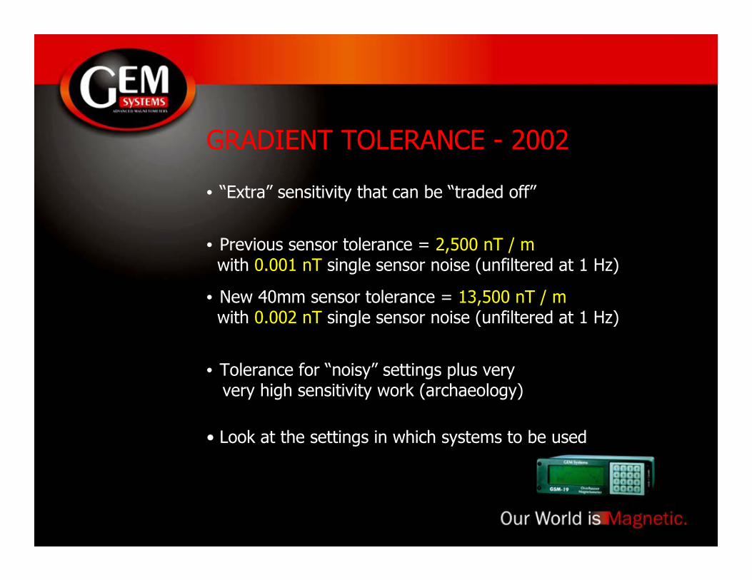
GRADIENT TOLERANCE - 2002
• “Extra” sensitivity that can be “traded off”
• Previous sensor tolerance = 2,500 nT / m with 0.001 nT single sensor noise (unfiltered at 1 Hz)
• New 40mm sensor tolerance = 13,500 nT / m with 0.002 nT single sensor noise (unfiltered at 1 Hz)
• Tolerance for “noisy” settings plus very very high sensitivity work (archaeology)
• Look at the settings in which systems to be used
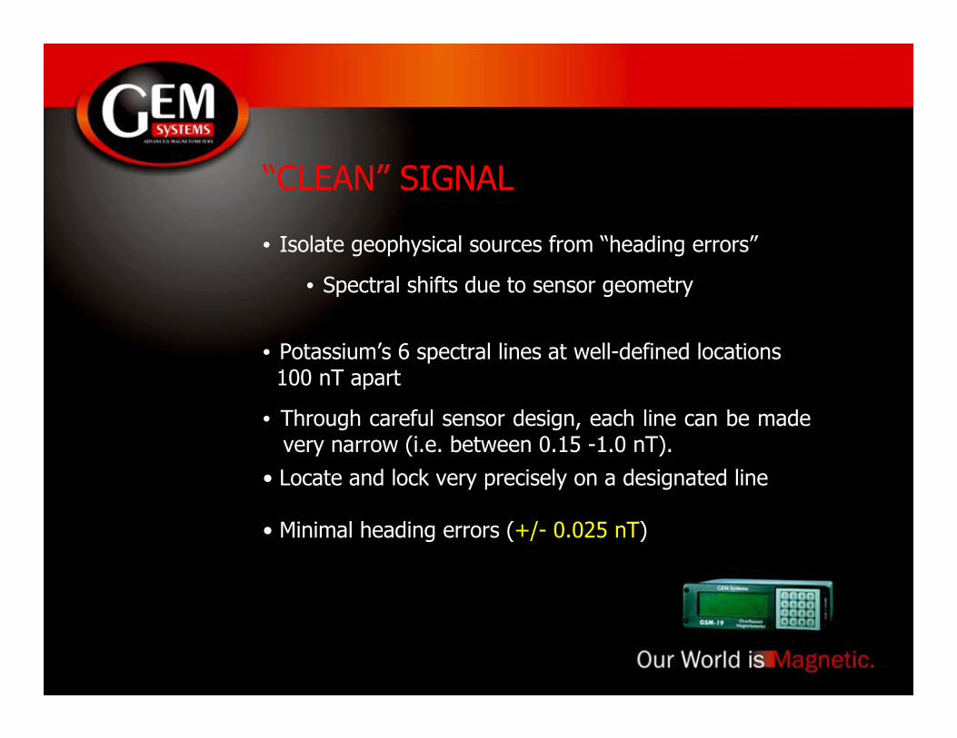
“CLEAN” SIGNAL
• Isolate geophysical sources from “heading errors”
• Spectral shifts due to sensor geometry
• Potassium’s 6 spectral lines at well-defined locations 100 nT apart
• Through careful sensor design, each line can be made very narrow (i.e. between 0.15 -1.0 nT).• Locate and lock very precisely on a designated line
• Minimal heading errors (+/- 0.025 nT)
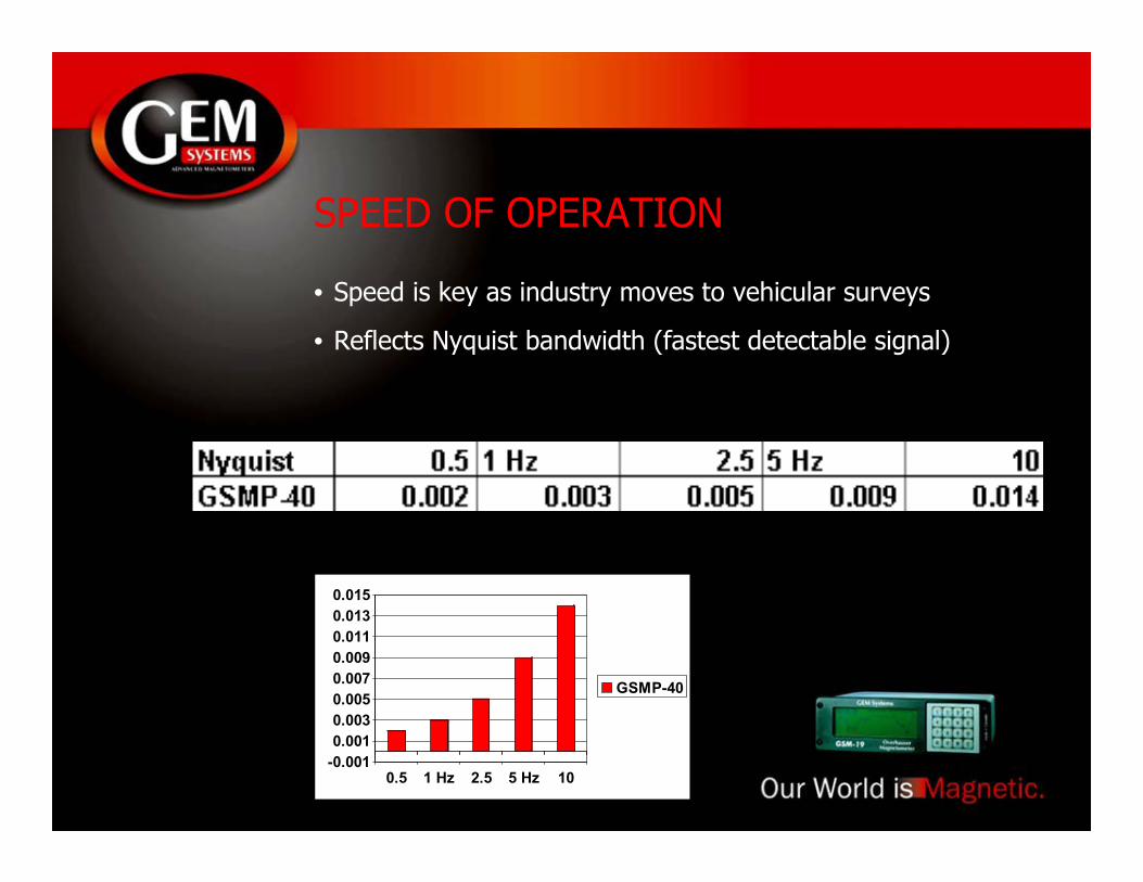
SPEED OF OPERATION
• Speed is key as industry moves to vehicular surveys
• Reflects Nyquist bandwidth (fastest detectable signal)
-0.0010.0010.0030.0050.0070.0090.0110.0130.015
0.5 1 Hz 2.5 5 Hz 10
GSMP-40

ABSOLUTE ACCURACY
Key for consistent surveys and for multiple sensor arrays
• All components operating within the same tolerances
• Consider factors that affect field values and accuracy
• Gyromagnetic constant uncertainties
• Zero crossing algorithms and heading errors
• +/- 0.1 nT. Field results show that GSMP-40 does not introduce substantial biases related to time, sensor orientation or sensor changes.

CASE HISTORY
• York Environmental Site (YES), York University
• Opened in Fall, 1985 - 110m x 95m
• 42 - 15m x 15m cells containing “targets”
• First complete survey by a magnetic instrument manufacturer in December 2002
• Vertical gradiometer survey over parts of 2 days (no base station)
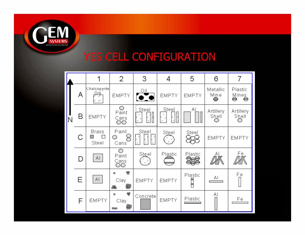
YES CELL CONFIGURATION
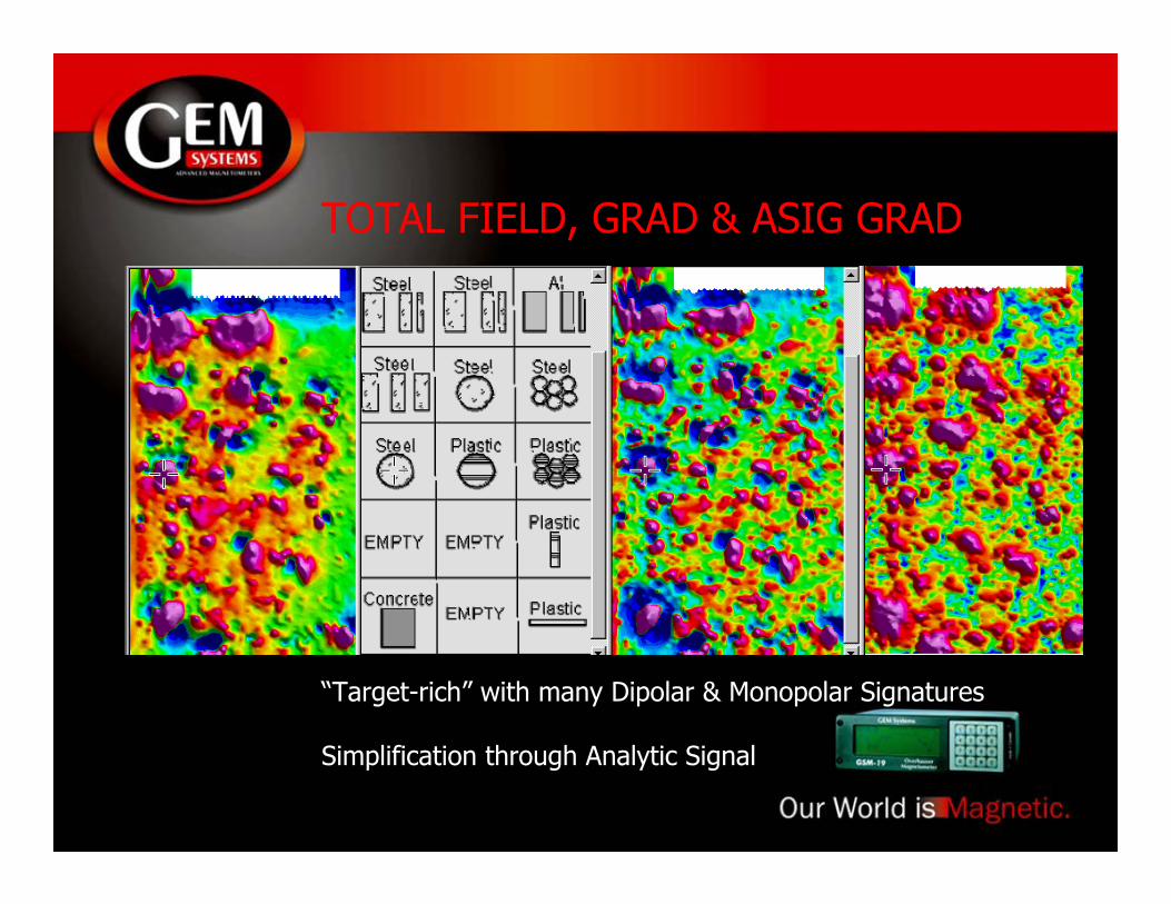
TOTAL FIELD, GRAD & ASIG GRAD
“Target-rich” with many Dipolar & Monopolar Signatures
Simplification through Analytic Signal
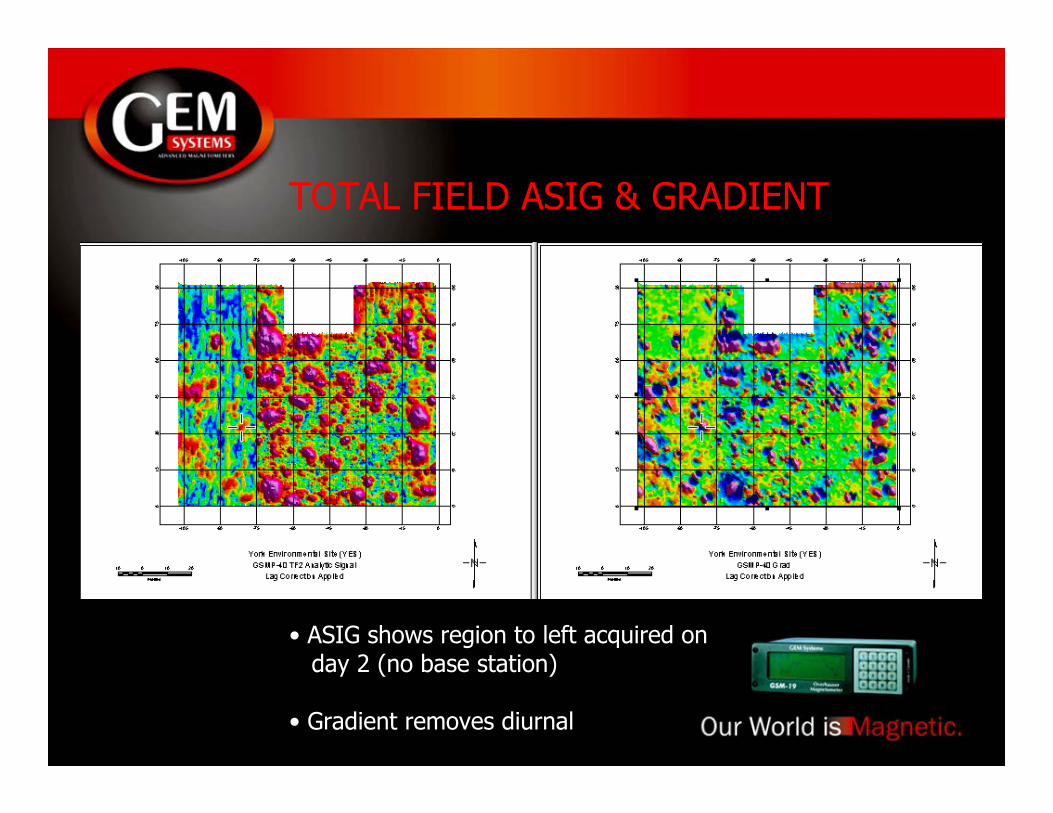
TOTAL FIELD ASIG & GRADIENT
• ASIG shows region to left acquired on day 2 (no base station)
• Gradient removes diurnal
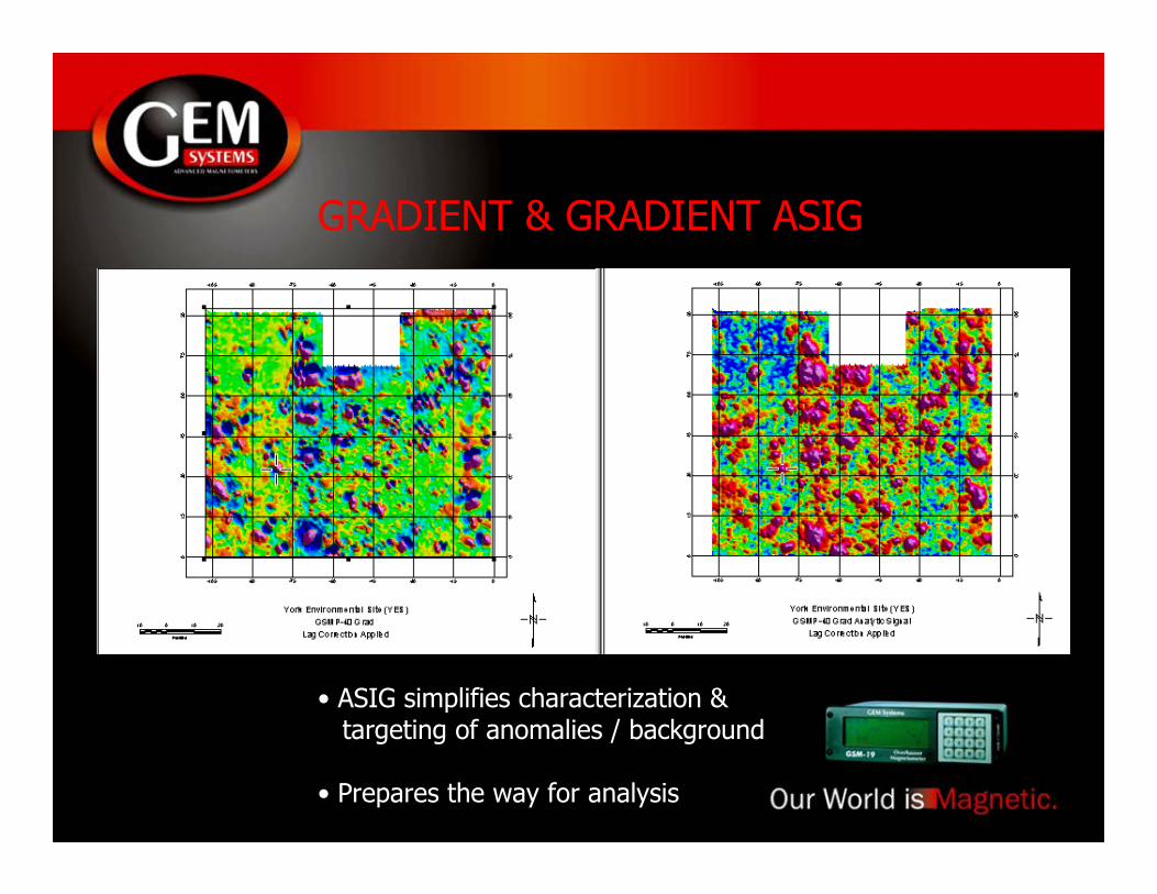
GRADIENT & GRADIENT ASIG
• ASIG simplifies characterization & targeting of anomalies / background
• Prepares the way for analysis
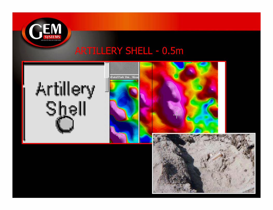
ARTILLERY SHELL - 0.5m
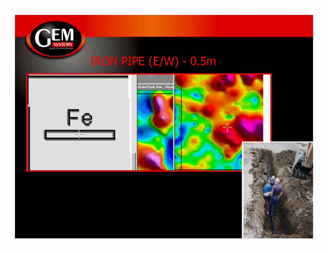
IRON PIPE (E/W) - 0.5m
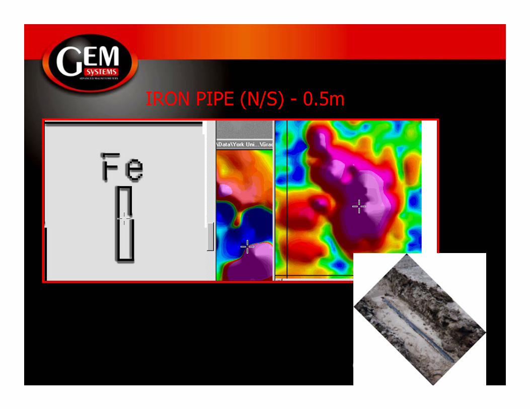
IRON PIPE (N/S) - 0.5m
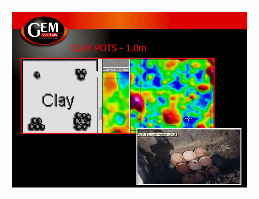
CLAY POTS - 1.0m
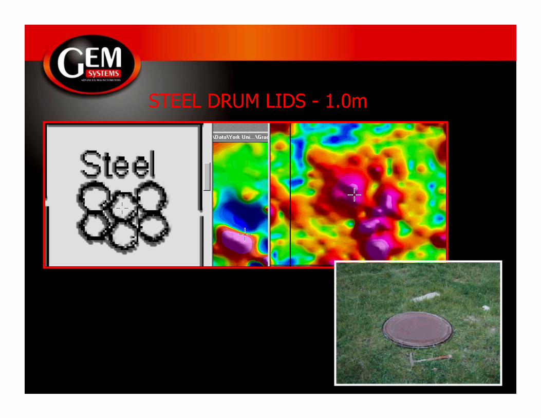
STEEL DRUM LIDS - 1.0m
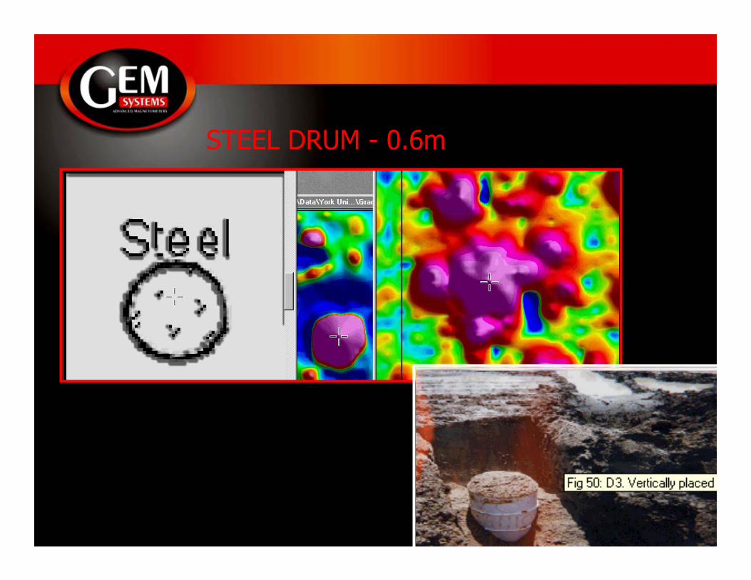
STEEL DRUM - 0.6m

STEEL PLATES - 2.0m

CONCRETE BUNKER - 1.0m
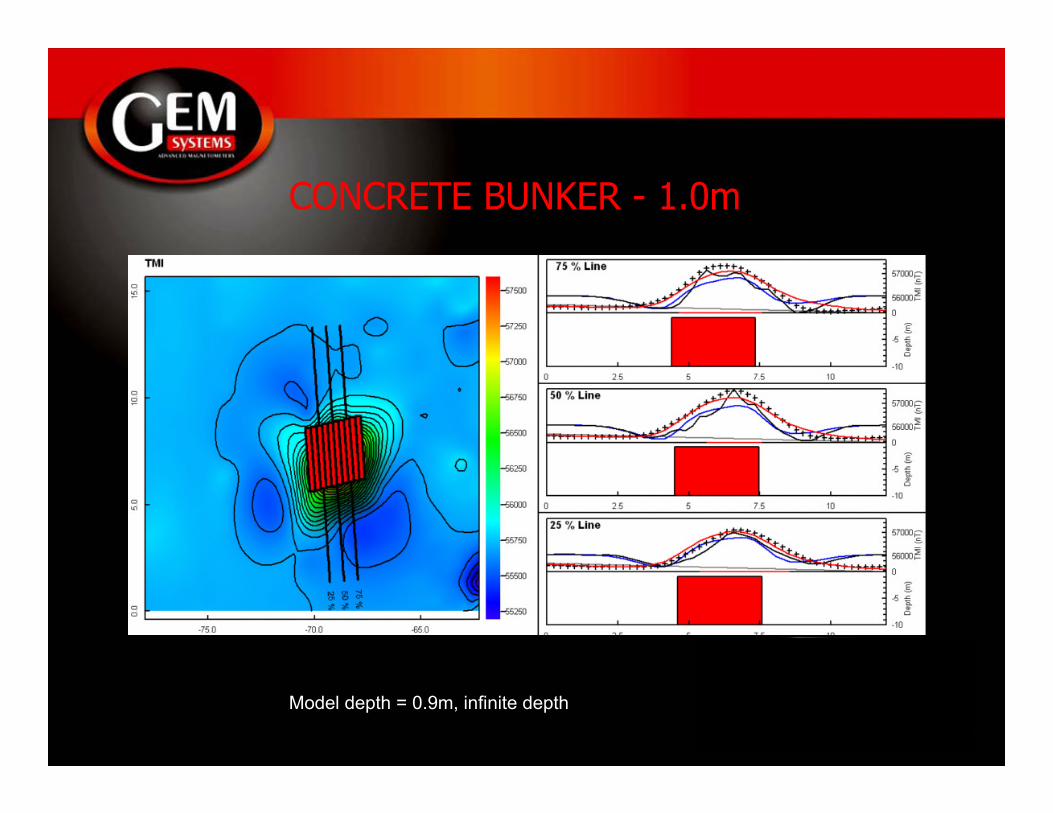
CONCRETE BUNKER - 1.0m
Model depth = 0.9m, infinite depth
SUMMARY
+ R&D ongoing in magnetometer / gradiometer systems
+ Potassium instrumentation takes advantage of narrow line, “Sweep Initiated” sensor physics and electronics
+ Design considerations reflect needs for “high detail” mapping and rapid sampling
+ Potassium, Overhauser and Proton technologies offer a range of sensitivities, gradient tolerances, etc. that should be understood in selecting appropriate tool for problem
+ Potassium test results demonstrate effectiveness of tool for detailing and characterization

Thank you for your attention ...