gsm rne fundamentals - cosconor.frcosconor.fr/gsm/divers/equipment/alcatel/gsm fundamentals.pdf ·...
TRANSCRIPT
Mobile Radio Network Planning 13FL 11820 ABAA WAZZA ed01
GSM Radio Network Engineering Fundamentals
Prerequisite: Introduction to the Alcatel GSM Network

Mobile Radio Network Planning 2
GSM RNE Fundamentals
3FL 11820 ABAA WAZZA ed01
Contents Introduction RNP Process Overview Coverage Planning Traffic Planning and Frequency
Planning Radio Interface / Quality of Service Abbreviations
P. 3 P. 39 P. 54 P.306 P.382 P.416
Mobile Radio Network Planning 33FL 11820 ABAA WAZZA ed01
GSM Radio Network Engineering Fundamentals
Introduction
Mobile Radio Network Planning 4
GSM RNE Fundamentals
3FL 11820 ABAA WAZZA ed01
Contents Standardization Documentation Radio Network Architecture Mobile Phone Systems

Mobile Radio Network Planning 53FL 11820 ABAA WAZZA ed01
Introduction
StandardizationDocumentation

Mobile Radio Network Planning 6
GSM RNE Fundamentals
3FL 11820 ABAA WAZZA ed01
www.3GPP.org organizational partners Project supported by
ARIB Association of Radio Industries and Businesses (Japan)
CWTS China Wireless Telecommunication Standard group
ETSI European Telecommunications Standards Institut
T1 Standards Committee T1 Telecommunication (US)
TTA Telecommunications Technology Association (Korea)
TTC Telecommunication Technology Committee (Japan)
The Organizational Partners shall determine the general policy and strategy of 3GPP and perform the following tasks:
Approval and maintenance of the 3GPP scope
Maintenance the Partnership Project Description
Taking decisions on the creation or cessation of Technical Specification Groups, and approving their scope and terms of reference
Approval of Organizational Partner funding requirements
Allocation of human and financial resources provided by the Organizational Partners to the Project Co-ordination Group

Mobile Radio Network Planning 7
GSM RNE Fundamentals
3FL 11820 ABAA WAZZA ed01
Technical Specification Group TSG
Mobile Radio Network Planning 8
GSM RNE Fundamentals
3FL 11820 ABAA WAZZA ed01
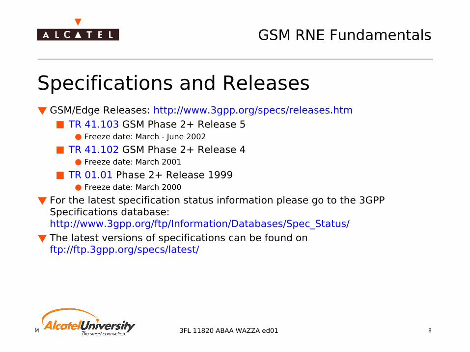
Specifications and Releases GSM/Edge Releases: http://www.3gpp.org/specs/releases.htm
TR 41.103 GSM Phase 2+ Release 5 Freeze date: March - June 2002
TR 41.102 GSM Phase 2+ Release 4 Freeze date: March 2001
TR 01.01 Phase 2+ Release 1999 Freeze date: March 2000
For the latest specification status information please go to the 3GPP Specifications database: http://www.3gpp.org/ftp/Information/Databases/Spec_Status/
The latest versions of specifications can be found on ftp://ftp.3gpp.org/specs/latest/

Mobile Radio Network Planning 9
GSM RNE Fundamentals
3FL 11820 ABAA WAZZA ed01
Specifications out of Release 1999 TR 01.04 Abbreviations and acronyms TS 03.22 Functions related to Mobile Station (MS) in idle mode
and group receive mode TR 03.30 Radio Network Planning Aspects TS 04.04 Layer 1 - General Requirements TS 04.06 Mobile Station - Base Stations System (MS - BSS)
Interface Data Link (DL) Layer Specification TS 04.08 Mobile radio interface layer 3 specification TS 05.05 Radio Transmission and Reception TS 05.08 Radio Subsystem Link Control TS 08.06 Signalling Transport Mechanism Specification for the
Base Station System - Mobile Services Switching Centre (BSS-MSC) Interface
TS 08.08 Mobile-services Switching Centre - Base Station system (MSC-BSS) Interface Layer 3 Specification

Mobile Radio Network Planning 103FL 11820 ABAA WAZZA ed01
Introduction
Radio Network ArchitectureMobile Phone Systems

Mobile Radio Network Planning 11
GSM RNE Fundamentals
3FL 11820 ABAA WAZZA ed01
GSM Network Architecture
HLR GCR AuC
E
B C
D
F
G H
I
Abis
B C D E F G H I
PSTN ISDN
BTS - BSC
MSC-VLR (SM-G)MSC-HLR
HLR-VLR (SM-G)MSC-MSC (SS7 basic) +
MAP MSC-EIR VLR-VLR
HLR-AuC MSC-GCR
MSC-PSTN (SS7 basic) + TUP or ISUP MSC-ISDN
LapD (ISDN type)
GSM Circuit-switching:
(BSSAP = BSSMAP + DTAP)
A BSC - MSC (SS7 basic) + BSSAP
BTS LapDm
(GSM specific) Um
(Radio) MS - BTS
BSC BSC
MSC MSC
BTS
PSTN / ISDN
MS
VLR VLR EIR
AuC

Mobile Radio Network Planning 12
GSM RNE Fundamentals
3FL 11820 ABAA WAZZA ed01
Gc GGSN-HLR IP/SS7
LAPDm(GSM specific)
Gs
Gb
Um (Radio)
Gi GGSN-Data Network IP
MS
BSS - SGSN
Gr SS7SGSN-HLR
Gf SS7SGSN-EIRSGSN-MSC/VLR
GnSGSN-GGSN IP
IPSGSN-SGSN
MS - BTS
Gs
GfGr
Gn
Gn
Gc SS7
GSM Packet-switching (GPRS/EDGE):
BSSGP
BSS withPCU
BSS withPCU
HLR EIR
Data Network
SGSN
GGSN
SGSN
MSC

Mobile Radio Network Planning 13
GSM RNE Fundamentals
3FL 11820 ABAA WAZZA ed01
OMC-RBSS
BTS
BTS
Alcatel9135 MFS SSP
+ RCPBSC
SGSN
OMC-R
MS
A bis A ter
TC
Gb
A
GGSNGn
OMC-G
NSS
GPRS CN

Mobile Radio Network Planning 14
GSM RNE Fundamentals
3FL 11820 ABAA WAZZA ed01
GSM Network Elements Base Station System BSS
Base Transceiver Station BTS
Base Station Controller BSC
Terminal Equipment Mobile Station MS
Operation and Maintenance Center-Radio OMC-R
Network Subsystem NSS Mobile Services Switching
Center MSC Visitor Location Register VLR Home Location Register HLR Authentication Center AuC Equipment Identity Register
EIR Operation and Maintenance Center
OMC Multi-BSS Fast Packet Server
(GPRS) MFS Serving GPRS Support Node SGSN Gateway GPRS Support Node
GGSN

Mobile Radio Network Planning 15
GSM RNE Fundamentals
3FL 11820 ABAA WAZZA ed01
RF SpectrumSystem Total
BandwidthUplink frequency band /MHz
Downlink frequency band /MHz
Carrier Spacing
GSM 450 2x7.5MHz 450.4-457.6 460.4-467.6 200 kHz
GSM 480 2x7.2MHz 478.8-486 488.8-496 200 kHz
GSM 850 2x25MHz 824-849 869-894 200 kHz
GSM 900 2x25MHz 890-915 935-960 200 kHz
E-GSM 2x35MHz 880-915 925-960 200 kHz
DCS 1800 (GSM)
2x75MHz 1710-1785 1805-1880 200 kHz
PCS 1900 (GSM)
2x60MHz 1850-1910 1930-1990 200 kHz

Mobile Radio Network Planning 16
GSM RNE Fundamentals
3FL 11820 ABAA WAZZA ed01
Access Methods FDMA (Frequency Division Multiple Access)
TDMA (Time Division Multiple Access)
CDMA (Code Division Multiple Access)
Mobile Radio Network Planning 17
GSM RNE Fundamentals
3FL 11820 ABAA WAZZA ed01
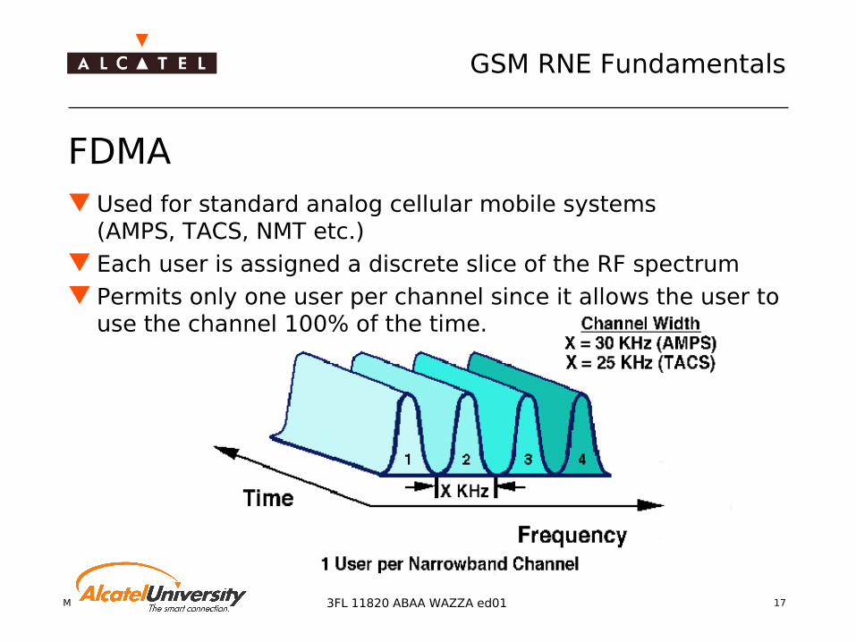
FDMA Used for standard analog cellular mobile systems
(AMPS, TACS, NMT etc.) Each user is assigned a discrete slice of the RF spectrum Permits only one user per channel since it allows the user to
use the channel 100% of the time.

Mobile Radio Network Planning 18
GSM RNE Fundamentals
3FL 11820 ABAA WAZZA ed01
TDMA Multiple users share RF carrier on a time slot basis Carriers are sub-divided into timeslots Information flow is not continuous for an user, it is sent and
received in "bursts"

Mobile Radio Network Planning 19
GSM RNE Fundamentals
3FL 11820 ABAA WAZZA ed01
CDMA (Code Division Multiple Access) Multiple access spread spectrum technique Each user is assigned a sequence code during a call No time division; all users use the entire carrier

Mobile Radio Network Planning 20
GSM RNE Fundamentals
3FL 11820 ABAA WAZZA ed01
Analogue Cellular Mobile Systems Analogue transmission of speech One TCH/Channel Only FDMA (Frequency Division Multiple Access) Different Systems
AMPS (Countries: USA) TACS (UK, I, A, E, ...) NMT (SF, S, DK, N, ...) ...

Mobile Radio Network Planning 21
GSM RNE Fundamentals
3FL 11820 ABAA WAZZA ed01
AMPS (Advanced Mobile Phone System) Analogue cellular mobile telephone system Predominant cellular system operating in the US Original system: 666 channels (624 voice and 42 control
channels) EAMPS - Extended AMPS
Current system: 832 channels (790 voice, 42 control); has replaced AMPS as the US standard
NAMPS - Narrowband AMPS New system that has three times more voice channels than EAMPS with no loss of signal quality
Backward compatible: if the infrastructure is designed properly, older phones work on the newer systems

Mobile Radio Network Planning 22
GSM RNE Fundamentals
3FL 11820 ABAA WAZZA ed01
AMPS - Technical objectives
Technology FDMARF frequency band 825 - 890 MHzChannel Spacing 30 kHzCarriers 666 (832)Timeslots 1Mobile Power 0.6 - 4 WTransmission Voice, (data)HO possibleRoaming possible
Mobile Radio Network Planning 23
GSM RNE Fundamentals
3FL 11820 ABAA WAZZA ed01
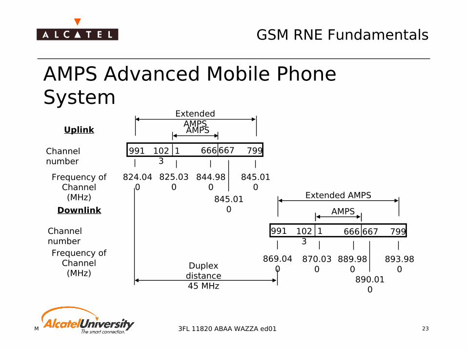
AMPS Advanced Mobile Phone System
991 1023
1 666 667 799
Extended AMPSAMPSUplink
Channel number
Frequency of Channel(MHz)
824.040
825.030
844.980
845.010
845.010
Duplex distance45 MHz
Downlink
Channel numberFrequency of
Channel(MHz)
991 1023
1 666 667 799
Extended AMPS
AMPS
869.040
870.030
889.980
893.980
890.010
Mobile Radio Network Planning 24
GSM RNE Fundamentals
3FL 11820 ABAA WAZZA ed01
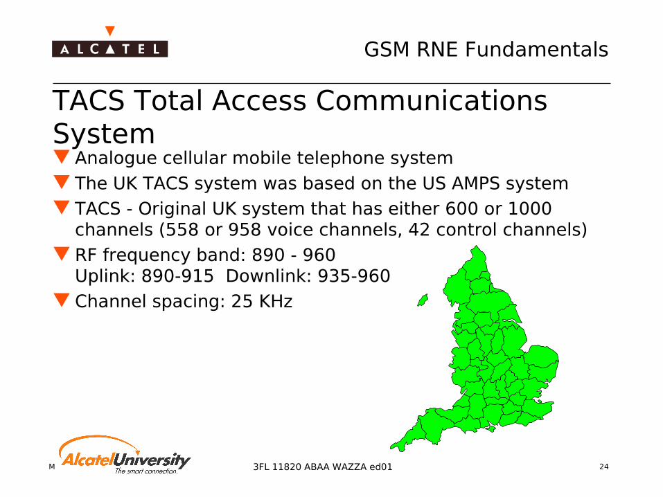
TACS Total Access Communications System Analogue cellular mobile telephone system The UK TACS system was based on the US AMPS system TACS - Original UK system that has either 600 or 1000
channels (558 or 958 voice channels, 42 control channels) RF frequency band: 890 - 960
Uplink: 890-915 Downlink: 935-960 Channel spacing: 25 KHz

Mobile Radio Network Planning 25
GSM RNE Fundamentals
3FL 11820 ABAA WAZZA ed01
TACS - Technical objectives
Technology FDMARF frequency band 890 - 960 MHzChannel Spacing 25 kHzCarriers 1000Timeslots 1Mobile Power 0.6 - 10 WTransmission Voice , (data)HO possibleRoaming possible

Mobile Radio Network Planning 26
GSM RNE Fundamentals
3FL 11820 ABAA WAZZA ed01
Different TACS-Systems
ETACS - Extended TACS Current UK system that has 1320 channels (1278 voice, 42
control)and has replaced TACS as the UK standard
ITACS and IETACS - International (E)TACS Minor variation of TACS to allow operation outside of the UK by
allowing flexibility in assigning the control channels
JTACS - Japanese TACS A version of TACS designed for operation in Japan
NTACS - Narrowband TACS New system that has three times as many voice channels as
ETACS with no loss of signal quality

Mobile Radio Network Planning 27
GSM RNE Fundamentals
3FL 11820 ABAA WAZZA ed01
TACS (Total Access Communications System)
1329 2047 0 23 44 323
344
600
1000
11
890.0125(935.012
5)
905(950)
915(960)
1st Assignment in the UK (600 channels)
Organisation B
Organisation A
Original concept (1000 channels)
890935
889.9875(934.987
5)
889.9625(934.962
5)
872.0125
(917.0125)
872917
Frequency of
channel [Mhz]
Number of
Channel
E-TACS - 1320 Channels
Borders of
channels [Mhz]
Mobile Station TX
(Base Station TX)
Mobile Radio Network Planning 28
GSM RNE Fundamentals
3FL 11820 ABAA WAZZA ed01
Why digital mobile communication ? Easy adaptation to digital networks
Digital signaling serves for flexible adaptation to operational needs
Possibility to realize a wide spectrum of non-voice services
Digital transmission allows for high cellular implementation flexibility
Digital signal processing gain results in high interference immunity
Privacy of radio transmission ensured by digital voice coding and encryption
Cost and performance trends of modern microelectronics arein favour of a digital solution

Mobile Radio Network Planning 29
GSM RNE Fundamentals
3FL 11820 ABAA WAZZA ed01
GSM - Technical objectivesTechnology TDMA/FDMARF frequency band 890 - 960 MHzChannel Spacing 200 kHzCarriers 124Timeslots 8Mobile Power (average/max) 2 W/ 8 WBTS Power class 10 ... 40 WMS sensitivity - 102 dBmBTS sensitivity - 104 dBmTransmission Voice, dataHO possibleRoaming possible

Mobile Radio Network Planning 30
GSM RNE Fundamentals
3FL 11820 ABAA WAZZA ed01
DECT (Digital European Cordless Telephone) European Standard for Cordless Communication Using TDMA-System Traditional Applications
Domestic use ("Cordless telephone") Cordless office applications
Combination possible with ISDN GSM
High flexibility for different applications

Mobile Radio Network Planning 31
GSM RNE Fundamentals
3FL 11820 ABAA WAZZA ed01
DECT - Technical objectives
Technology TDMA/FDMARF frequency band 1880 - 1900 MHzChannel Spacing 1.728 MHzCarriers 10Timeslots 12 (duplex)Mobile Power (average/max) 10 mW/250 mWBTS Power class 250 mWMS sensitivity -83 dBmBTS sensitivity -83 dBmTransmission Voice, dataHO possible

Mobile Radio Network Planning 32
GSM RNE Fundamentals
3FL 11820 ABAA WAZZA ed01
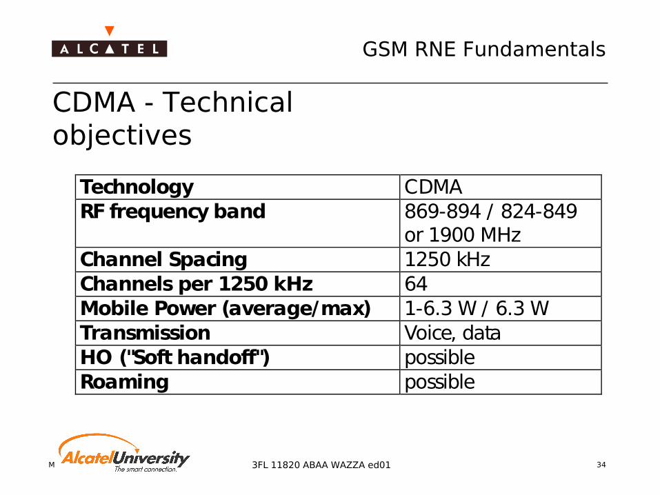
CDMA - Technical objectives
Spread spectrum technology(Code Division Multiple Access)
Several users occupy continuously one CDMA channel(bandwidth: 1.25 MHz) The CDMA channel can be re-used in every cell
Each user is addressed by
A specific code and
Selected by correlation processing
Orthogonal codes provides optimumisolation between users

Mobile Radio Network Planning 33
GSM RNE Fundamentals
3FL 11820 ABAA WAZZA ed01
CDMA - Special Features
Vocoder allows variable data rates
Soft handover
Open and closed loop power control
Multiple forms of diversity
Data, fax and short message services possible
Mobile Radio Network Planning 34
GSM RNE Fundamentals
3FL 11820 ABAA WAZZA ed01
CDMA - Technical objectives
Technology CDMARF frequency band 869-894 / 824-849
or 1900 MHzChannel Spacing 1250 kHzChannels per 1250 kHz 64Mobile Power (average/max) 1-6.3 W / 6.3 WTransmission Voice, dataHO ("Soft handoff") possibleRoaming possible

Mobile Radio Network Planning 35
GSM RNE Fundamentals
3FL 11820 ABAA WAZZA ed01
TETRA - Features Standard for a frequency efficient european digital trunked radio
communication system (defined in 1990) Possibility of connections with simultaneous transmission of voice and
data Encryption at two levels:
Basic level which uses the air interface encryption End-to-end encryption (specifically intended for public safety users)
Open channel operation "Direct Mode" possible
Communication between two MS without connecting via a BTS MS can be used as a repeater
Mobile Radio Network Planning 36
GSM RNE Fundamentals
3FL 11820 ABAA WAZZA ed01
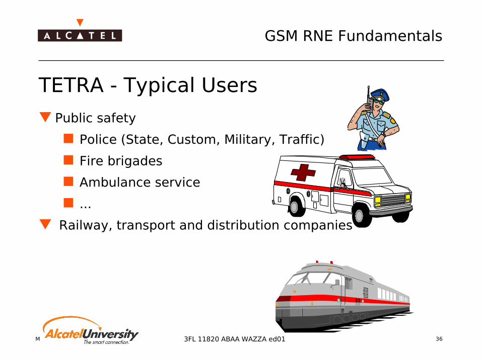
TETRA - Typical Users
Public safety
Police (State, Custom, Military, Traffic)
Fire brigades
Ambulance service
...
Railway, transport and distribution companies

Mobile Radio Network Planning 37
GSM RNE Fundamentals
3FL 11820 ABAA WAZZA ed01
TETRA - Technical objectivesTechnology TDMA/FDMARF frequency band 380 - 400 MHzChannel Spacing 25 or 12.5 KHzCarriers not yet specifiedTimeslots 4Mobile Power (3 Classes) 1, 3, 10 WBTS Power class 0.6 - 25 WMS sensitivity -103 dBmBTS sensitivity -106 dBmTransmission Voice, data, images,
short messageHO possibleRoaming possible
Mobile Radio Network Planning 38
GSM RNE Fundamentals
3FL 11820 ABAA WAZZA ed01
UMTS (Universal Mobile Telecommunication System) Third generation mobile communication system
Combining existing mobile services (GSM, CDMA etc.) and fixed telecommunications services
More capacity and bandwidth
More services (Speech, Video, Audio, Multimedia etc.)
Worldwide roaming
"High" subscriber capacity

Mobile Radio Network Planning 393FL 11820 ABAA WAZZA ed01
GSM Radio Network Engineering Fundamentals
RNP Process Overview

Mobile Radio Network Planning 40
GSM RNE Fundamentals
3FL 11820 ABAA WAZZA ed01
Definition of RN Requirements The Request for Quotation (RfQ) from the customer prescribes the
requirements mainly Coverage
Definition of coverage probability Percentage of measurements above level threshold
Definition of covered area Traffic
Definition of Erlang per square kilometer Definition of number of TRX in a cell Mixture of circuit switched and packed switched traffic
QoS Call success rate RxQual, voice quality, throughput rates, ping time
Mobile Radio Network Planning 41
GSM RNE Fundamentals
3FL 11820 ABAA WAZZA ed01
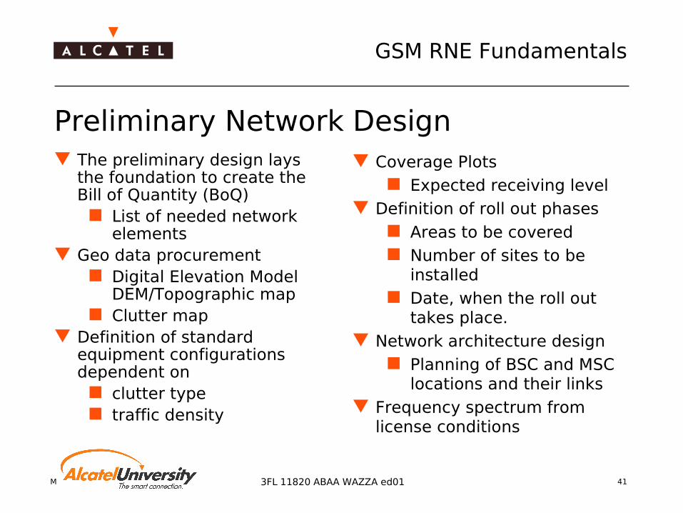
Preliminary Network Design The preliminary design lays
the foundation to create the Bill of Quantity (BoQ)
List of needed network elements
Geo data procurement Digital Elevation Model
DEM/Topographic map Clutter map
Definition of standard equipment configurations dependent on
clutter type traffic density
Coverage Plots Expected receiving level
Definition of roll out phases Areas to be covered Number of sites to be
installed Date, when the roll out
takes place. Network architecture design
Planning of BSC and MSC locations and their links
Frequency spectrum from license conditions

Mobile Radio Network Planning 42
GSM RNE Fundamentals
3FL 11820 ABAA WAZZA ed01
Project Setup and Management This phase includes all tasks to be performed before the on
site part of the RNP process takes place. This ramp up phase includes:
Geo data procurement if required Setting up ‘general rules’ of the project Define and agree on reporting scheme to be used
Coordination of information exchange between the different teams which are involved in the project
Each department/team has to prepare its part of the project
Definition of required manpower and budget Selection of project database (MatrixX)

Mobile Radio Network Planning 43
GSM RNE Fundamentals
3FL 11820 ABAA WAZZA ed01
Initial Radio Network Design Area surveys
As well check of correctness of geo data Frequency spectrum partitioning design RNP tool calibration
For the different morpho classes: Performing of drive measurements Calibration of correction factor and standard deviation by comparison of
measurements to predicted received power values of the tool
Definition of search areas (SAM – Search Area Map) A team searches for site locations in the defined areas The search team should be able to speak the national language
Selection of number of sectors/TRX per site together with project management and customer
Get ‘real’ design acceptance from customer based on coverage prediction and predefined design level thresholds

Mobile Radio Network Planning 44
GSM RNE Fundamentals
3FL 11820 ABAA WAZZA ed01
Site Acquisition Procedure Delivery of site candidates
Several site candidates shall be the result out of the site location search
Find alternative sites If no site candidate or no
satisfactory candidate can be found in the search area
Definition of new SAM Possibly adaptation of radio
network design Check and correct SAR (Site
Acquisition Report) Location information Land usage Object (roof top, pylon,
grassland) information Site plan
Site candidate acceptance and ranking
If the reported site is accepted as candidate, then it is ranked according to its quality in terms of
Radio transmissionHigh visibility on covered areaNo obstacles in the near field of the antennasNo interference from other systems/antennas
Installation costsInstallation possibilitiesPower supplyWind and heat
Maintenance costsAccessibilityRental rates for objectDurability of object
Mobile Radio Network Planning 45
GSM RNE Fundamentals
3FL 11820 ABAA WAZZA ed01
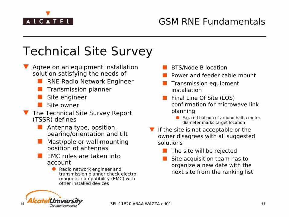
Technical Site Survey Agree on an equipment installation
solution satisfying the needs of RNE Radio Network Engineer Transmission planner Site engineer Site owner
The Technical Site Survey Report (TSSR) defines
Antenna type, position, bearing/orientation and tilt
Mast/pole or wall mounting position of antennas
EMC rules are taken into account
Radio network engineer and transmission planner check electro magnetic compatibility (EMC) with other installed devices
BTS/Node B location Power and feeder cable mount Transmission equipment
installation Final Line Of Site (LOS)
confirmation for microwave link planning
E.g. red balloon of around half a meter diameter marks target location
If the site is not acceptable or the owner disagrees with all suggested solutions
The site will be rejected Site acquisition team has to
organize a new date with the next site from the ranking list

Mobile Radio Network Planning 46
GSM RNE Fundamentals
3FL 11820 ABAA WAZZA ed01
Basic Parameter Definition After installation of equipment
the basic parameter settings are used for
Commissioning Functional test of BTS and
VSWR check
Call tests RNEs define cell design data Operations field service
generates the basic software using the cell design CAE data
Cell design CAE data to be defined for all cells are for example:
CI/LAC/BSIC Frequencies Neighborhood/cell
handover relationship Transmit power Cell type (macro, micro,
umbrella, …)

Mobile Radio Network Planning 47
GSM RNE Fundamentals
3FL 11820 ABAA WAZZA ed01
Cell Design CAE Data Exchange over COF
A9156 RNO
OMC 1
COF
ACIE
ACIE
POLOBSS Software offline production
3rd Party RNP or
Database
A955 V5 /A9155 V6
RNP
A9155PRC
Generator Module
Conversion OMC 2
ACIE = PRC file

Mobile Radio Network Planning 48
GSM RNE Fundamentals
3FL 11820 ABAA WAZZA ed01
Turn On Cycle The network is launched step by step during the TOC A single step takes typically two or three weeks
Not to mix up with rollout phases, which take months or even years
For each step the RNE has to define ‘TOC Parameter’ Cells to go on air Determination of frequency plan Cell design CAE parameter
Each step is finished with the ‘Turn On Cycle Activation’ Upload PRC/ACIE files into OMC-R Unlock sites

Mobile Radio Network Planning 49
GSM RNE Fundamentals
3FL 11820 ABAA WAZZA ed01
Site Verification and Drive Test RNE performs drive measurement to compare the real
coverage with the predicted coverage of the cells. If coverage holes or areas of high interference are detected
Adjust the antenna tilt and orientation Verification of cell design CAE data To fulfill heavy acceptance test requirements, it is
absolutely essential to perform such a drive measurement. Basic site and area optimization reduces the probability to
have unforeseen mysterious network behavior afterwards.

Mobile Radio Network Planning 50
GSM RNE Fundamentals
3FL 11820 ABAA WAZZA ed01
HW / SW Problem Detection Problems can be detected due to drive tests or equipment monitoring
Defective equipment will trigger replacement by operation field service
Software bugs Incorrect parameter settings
are corrected by using the OMC or in the next TOC
Faulty antenna installation Wrong coverage footprints of the site will trigger antenna re-alignments
If the problem is serious Lock BTS Detailed error detection Get rid of the fault Eventually adjusting antenna tilt and orientation

Mobile Radio Network Planning 51
GSM RNE Fundamentals
3FL 11820 ABAA WAZZA ed01
Basic Network Optimization Network wide drive measurements
It is highly recommended to perform network wide drive tests before doing the commercial opening of the network
Key performance indicators (KPI) are determined The results out of the drive tests are used for basic optimization
of the network Basic optimization
All optimization tasks are still site related Alignment of antenna system Adding new sites in case of too large coverage holes Parameter optimization
No traffic yet -> not all parameters can be optimized
Basic optimization during commercial service If only a small number of new sites are going on air the basic
optimization will be included in the site verification procedure

Mobile Radio Network Planning 52
GSM RNE Fundamentals
3FL 11820 ABAA WAZZA ed01
Network Acceptance Acceptance drive test
Calculation of KPI according to acceptance requirements in contract
Presentation of KPI to the customer
Comparison of key performance indicators with the acceptance targets in the contract
The customer accepts the whole network only parts of it step by step
Now the network is ready for commercial launch

Mobile Radio Network Planning 53
GSM RNE Fundamentals
3FL 11820 ABAA WAZZA ed01
Further Optimization Network is in commercial operation Network optimization can be performed Significant traffic allows to use OMC based statistics by
using A9156 RNO and A9185 NPA End of optimization depends on contract and mutual
agreement between Alcatel and customer Usually, Alcatel is only involved during the first
optimization activities directly after opening the network commercially

Mobile Radio Network Planning 543FL 11820 ABAA WAZZA ed01
GSM Radio Network Engineering Fundamentals
Coverage Planning
Mobile Radio Network Planning 55
GSM RNE Fundamentals
3FL 11820 ABAA WAZZA ed01
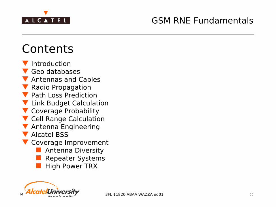
Contents Introduction Geo databases Antennas and Cables Radio Propagation Path Loss Prediction Link Budget Calculation Coverage Probability Cell Range Calculation Antenna Engineering Alcatel BSS Coverage Improvement
Antenna Diversity Repeater Systems High Power TRX

Mobile Radio Network Planning 563FL 11820 ABAA WAZZA ed01
Coverage Planning
Geo Databases

Mobile Radio Network Planning 57
GSM RNE Fundamentals
3FL 11820 ABAA WAZZA ed01
Why are geographical data needed for Radio Network Planning ?
Propagation models depend on geographical data
Geographical information for site acquisition Latitude (East/West) / Longitude (North/South) Rectangular coordinates
(e.g. UTM coordinates)

Mobile Radio Network Planning 58
GSM RNE Fundamentals
3FL 11820 ABAA WAZZA ed01
Contents Map Projection
Different Map Projections: conical, cylindrical, planar/ azimuthal
Geodetic Datum: e.g. WGS 84 Transverse Mercator Projection: e.g. UTM
Types of Geospatial Data Creation of geospatial databases Raster data: DEM /Topography, Morphostructure/ Clutter,
Buildings Vector data: airport, coastline, border line, buildings, etc.
Geocoordinate Transformation Practical Applications
Converting one single point Compare to different geodetic datums Converting a list of points

Mobile Radio Network Planning 593FL 11820 ABAA WAZZA ed01
Geo Databases
Map Projection

Mobile Radio Network Planning 60
GSM RNE Fundamentals
3FL 11820 ABAA WAZZA ed01
Maps are flat
Longitude
Latitude
x, y
Problem: Earth is 3D, the maps are 2D

Mobile Radio Network Planning 61
GSM RNE Fundamentals
3FL 11820 ABAA WAZZA ed01
Mapping the earth
The Earth is a very complex shape To map the geography of the earth,
a reference model (-> Geodetic Datum) is needed The model needs to be simple so that it is easy to use It needs to include a Coordinate system which allows
the positions of objects to be uniquely identified It needs to be readily associated with the physical world
so that its use is intuitive

Mobile Radio Network Planning 62
GSM RNE Fundamentals
3FL 11820 ABAA WAZZA ed01
Map Projection
Geodetic Datume.g. WGS84, ED50
Ellipsoide.g. WGS84,
International 1924
GeocoordinateSystem
e.g. UTM
Map Projectione.g. Transverse Mercator (UTM),
Lambert Conformal Conic

Mobile Radio Network Planning 63
GSM RNE Fundamentals
3FL 11820 ABAA WAZZA ed01
Geodetic EllipsoidDefinition: A mathematical surface (an ellipse rotated around the earth's polar axis) which provides a convenient model of the size and shape of the earth. The ellipsoid is chosen to best meet the needs of a particular map datum system design.
Reference ellipsoids are usually defined by semi-major (equatorial radius) and flattening (the relationship between equatorial and polar radii).
Mobile Radio Network Planning 64
GSM RNE Fundamentals
3FL 11820 ABAA WAZZA ed01
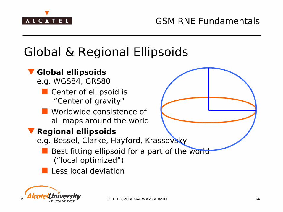
Global & Regional Ellipsoids
Global ellipsoidse.g. WGS84, GRS80
Center of ellipsoid is “Center of gravity”
Worldwide consistence ofall maps around the world
Regional ellipsoidse.g. Bessel, Clarke, Hayford, Krassovsky
Best fitting ellipsoid for a part of the world (“local optimized”)
Less local deviation

Mobile Radio Network Planning 65
GSM RNE Fundamentals
3FL 11820 ABAA WAZZA ed01
Geodetic Datum
A Geodetic Datum is a Reference System which includes:
A local or global Ellipsoid One “Fixpoint”
Attention: Referencing geodetic coordinates to the wrong map datum can result in positionerrors ofhundreds of meters
Info:In most cases the shift, rotation and scale factor of a Map Datum is relative to the “satellite map datum” WGS84.

Mobile Radio Network Planning 66
GSM RNE Fundamentals
3FL 11820 ABAA WAZZA ed01
Map Projection Cylindrical
e.g. UTM, Gauss-Krueger
Conical e.g.Lambert
Conformal Conic Planar/Azimuthal
Info: In 90% of the cases we will have a cylindrical projection in 10% of the cases a conical projection

Mobile Radio Network Planning 67
GSM RNE Fundamentals
3FL 11820 ABAA WAZZA ed01
Geo-Coordinate System
To simplify the use of maps aCartesian Coordinates is used
To avoid negative values a False Easting value and
a False Northing value
is added Also a scaling factor is used
to minimize the “projection error” over the whole area
X = EastingY = Northing

Mobile Radio Network Planning 68
GSM RNE Fundamentals
3FL 11820 ABAA WAZZA ed01
WGS 84 (World Geodetic System 1984) Most needed Geodetic Datum
in the world today (“Satellite Datum”) It is the reference frame used
by the U.S. Department of Defenseis defined by the National Imageryand Mapping Agency (NIMA)
The Global Positioning System (GPS)system is based on the World GeodeticSystem 1984 (WGS-84).
Optimal adaption to the surface of the earth
Mobile Radio Network Planning 69
GSM RNE Fundamentals
3FL 11820 ABAA WAZZA ed01
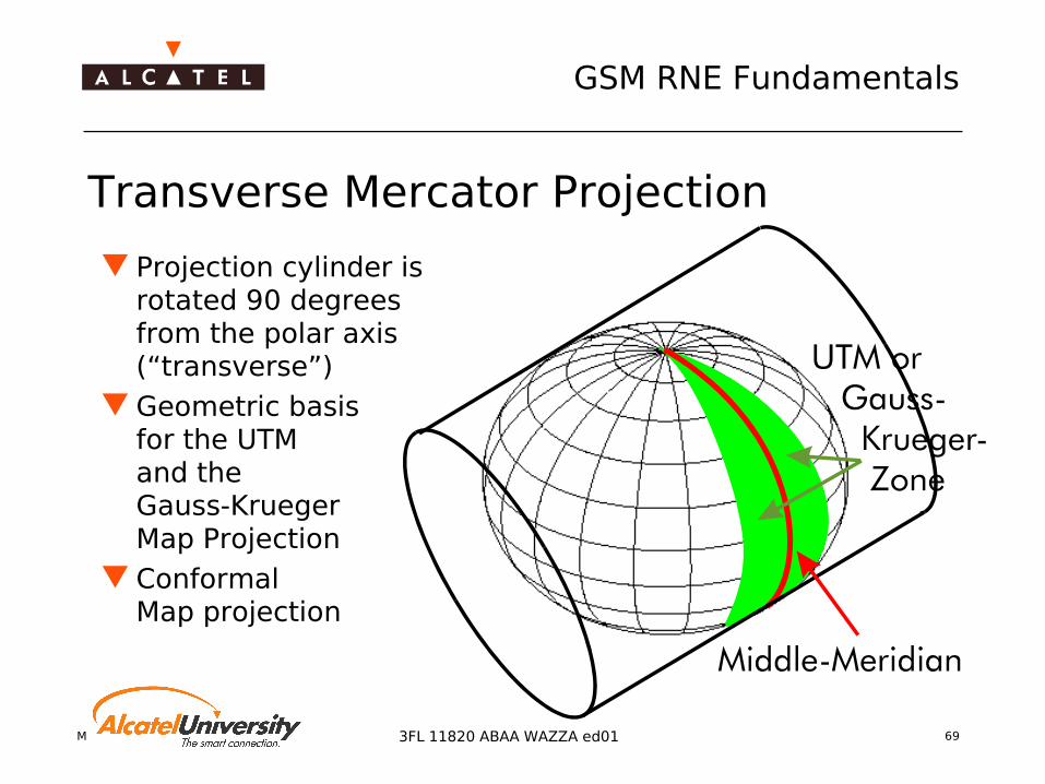
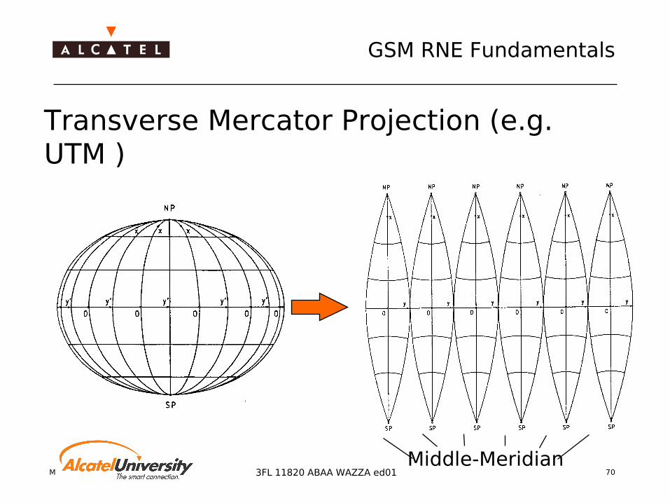
Transverse Mercator Projection
Projection cylinder is rotated 90 degrees from the polar axis (“transverse”)
Geometric basisfor the UTMand theGauss-KruegerMap Projection
ConformalMap projection
Mobile Radio Network Planning 70
GSM RNE Fundamentals
3FL 11820 ABAA WAZZA ed01
Transverse Mercator Projection (e.g. UTM )
Middle-Meridian
Mobile Radio Network Planning 71
GSM RNE Fundamentals
3FL 11820 ABAA WAZZA ed01
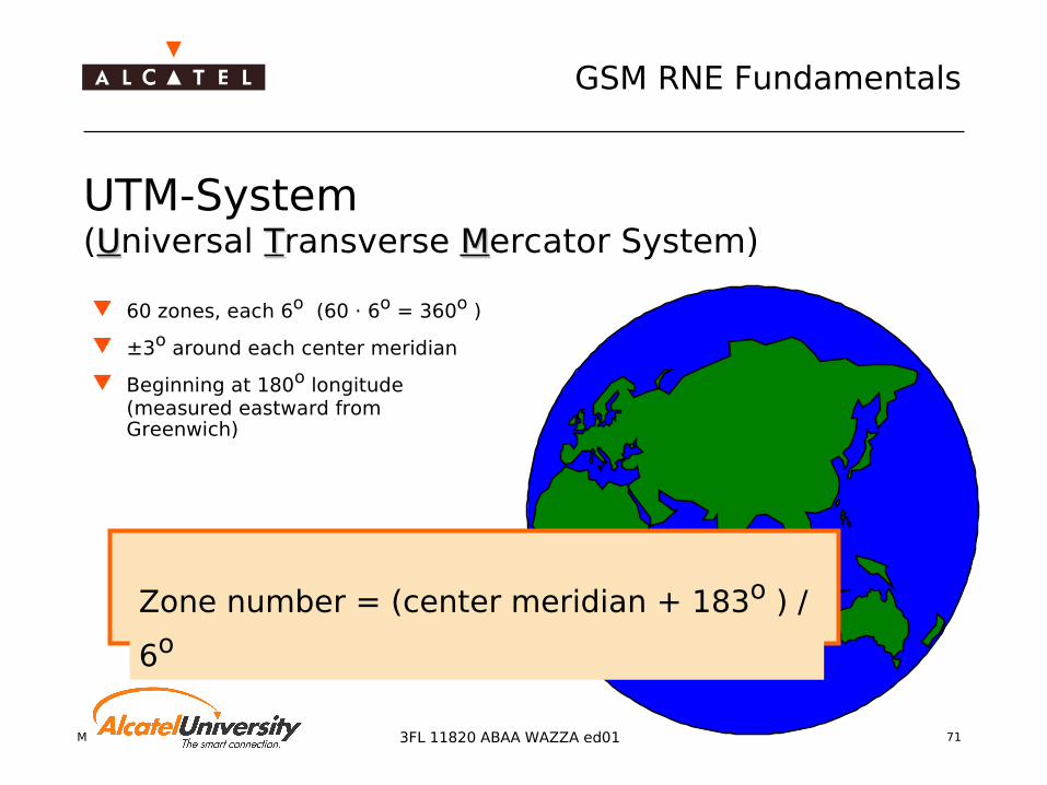
UTM-System(UUniversal TTransverse MMercator System)
60 zones, each 6o (60 · 6o = 360o )
±3o around each center meridian
Beginning at 180o longitude (measured eastward from Greenwich)
Zone number = (center meridian + 183o ) /
6o

Mobile Radio Network Planning 72
GSM RNE Fundamentals
3FL 11820 ABAA WAZZA ed01
UTM - Definitions
False Easting: 500 000 m(Middle-meridian x = 500 000 m)
False Northing: Northern Hemisphere: 0 m Southern Hemisphere: 10 000 000 m
Scaling Factor: 0,9996(used to minimize the“projection error” over the whole area)

Mobile Radio Network Planning 73
GSM RNE Fundamentals
3FL 11820 ABAA WAZZA ed01
UTM Zones (e.g. Europe)UTM-Zones
9° 15° 21° 27° 33° 39°3°-3°-6° Middle-Meridian
Mobile Radio Network Planning 74
GSM RNE Fundamentals
3FL 11820 ABAA WAZZA ed01
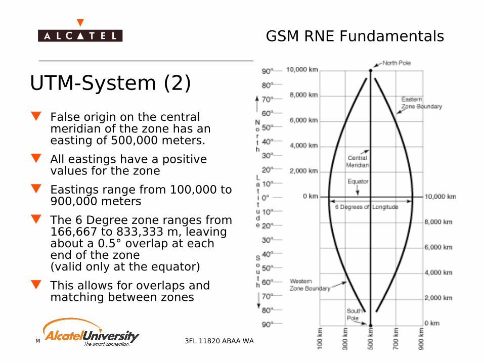
UTM-System (2)
False origin on the central meridian of the zone has an easting of 500,000 meters.
All eastings have a positive values for the zone
Eastings range from 100,000 to 900,000 meters
The 6 Degree zone ranges from 166,667 to 833,333 m, leaving about a 0.5° overlap at each end of the zone(valid only at the equator)
This allows for overlaps and matching between zones

Mobile Radio Network Planning 75
GSM RNE Fundamentals
3FL 11820 ABAA WAZZA ed01
Mobile Radio Network Planning 76
GSM RNE Fundamentals
3FL 11820 ABAA WAZZA ed01
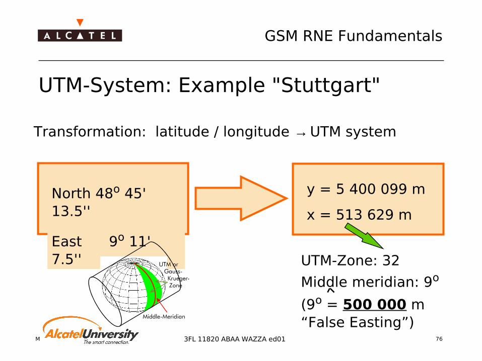
UTM-Zone: 32
Middle meridian: 9o
(9o = 500 000 m“False Easting”)
UTM-System: Example "Stuttgart"
Transformation: latitude / longitude → UTM system
North 48o 45' 13.5''
East 9o 11' 7.5''
y = 5 400 099 m
x = 513 629 m

Mobile Radio Network Planning 77
GSM RNE Fundamentals
3FL 11820 ABAA WAZZA ed01
Lambert Conformal Conic Projection Maps an ellipsoid onto a cone whose central axis coincides
with the polar axis
Cone touches the ellipsoid=> One standard parallel (1SP)(e.g. NTF-System in France)
Cutting edges of cone and ellipsoid=> Two standard parallels (2SP)(e.g. Lambert-Projection in Austria)

Mobile Radio Network Planning 783FL 11820 ABAA WAZZA ed01
Geo Databases
Types of Geospatial Data

Mobile Radio Network Planning 79
GSM RNE Fundamentals
3FL 11820 ABAA WAZZA ed01
Geospatial data for Network Planning
DEM (Digital Elevation Model)/ Topography Morphostructure / Land usage / Clutter Satellite Photos /
Orthoimages Scanned Maps Background data
(streets, borders, coastlines, etc. )
Buildings Traffic data

Mobile Radio Network Planning 80
GSM RNE Fundamentals
3FL 11820 ABAA WAZZA ed01
Creation of geospatial databases
Satellite imagery
Digitizing maps Aerial photography
Geospatial data
Mobile Radio Network Planning 81
GSM RNE Fundamentals
3FL 11820 ABAA WAZZA ed01
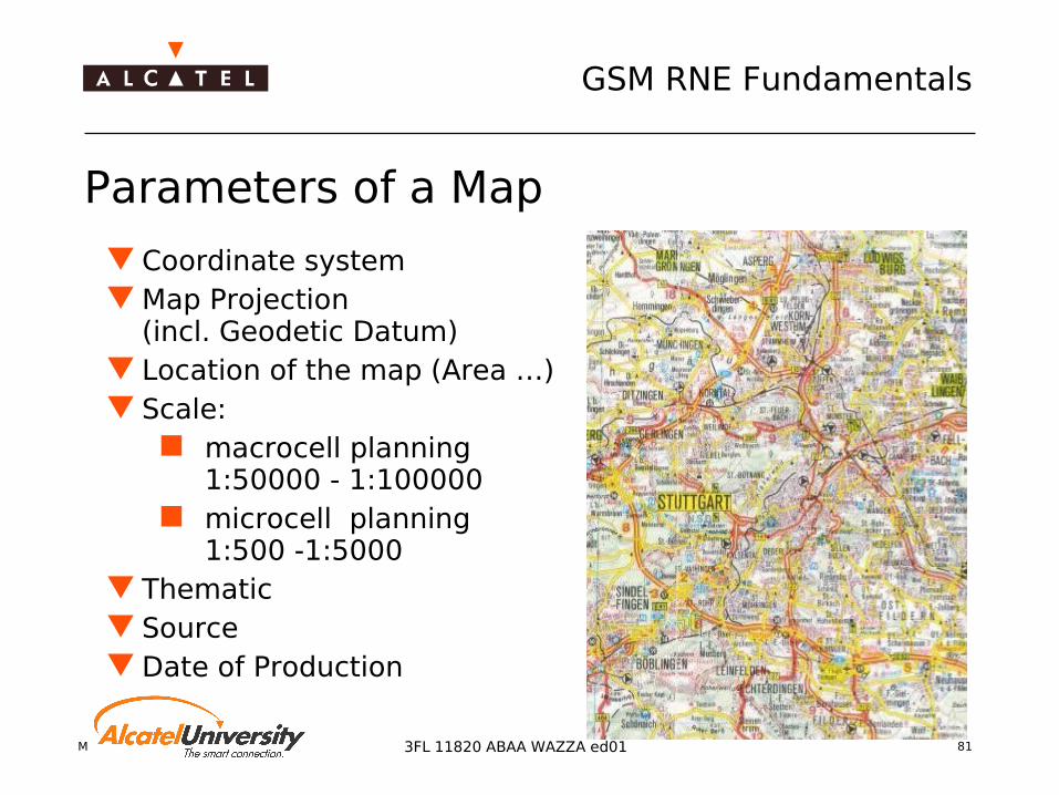
Parameters of a Map
Coordinate system Map Projection
(incl. Geodetic Datum) Location of the map (Area …) Scale:
macrocell planning 1:50000 - 1:100000
microcell planning 1:500 -1:5000
Thematic Source Date of Production

Mobile Radio Network Planning 82
GSM RNE Fundamentals
3FL 11820 ABAA WAZZA ed01
Raster data DEM /Topography Morphostructure /
Land usage / Clutter Traffic density
Vector data Background data
(streets, borders, coastlines, etc. ) Buildings
Raster- and Vectordata
x
y
(x1,y1)
(xn,yn
)
Mobile Radio Network Planning 83
GSM RNE Fundamentals
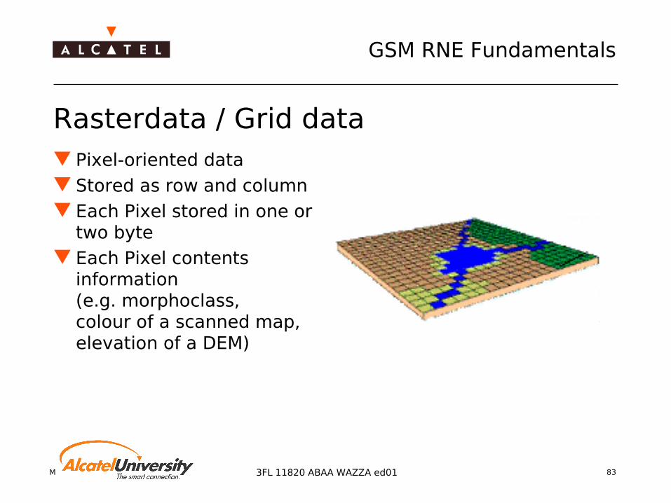
3FL 11820 ABAA WAZZA ed01
Rasterdata / Grid data Pixel-oriented data Stored as row and column Each Pixel stored in one or
two byte Each Pixel contents
information(e.g. morphoclass,colour of a scanned map, elevation of a DEM)
Mobile Radio Network Planning 84
GSM RNE Fundamentals
3FL 11820 ABAA WAZZA ed01
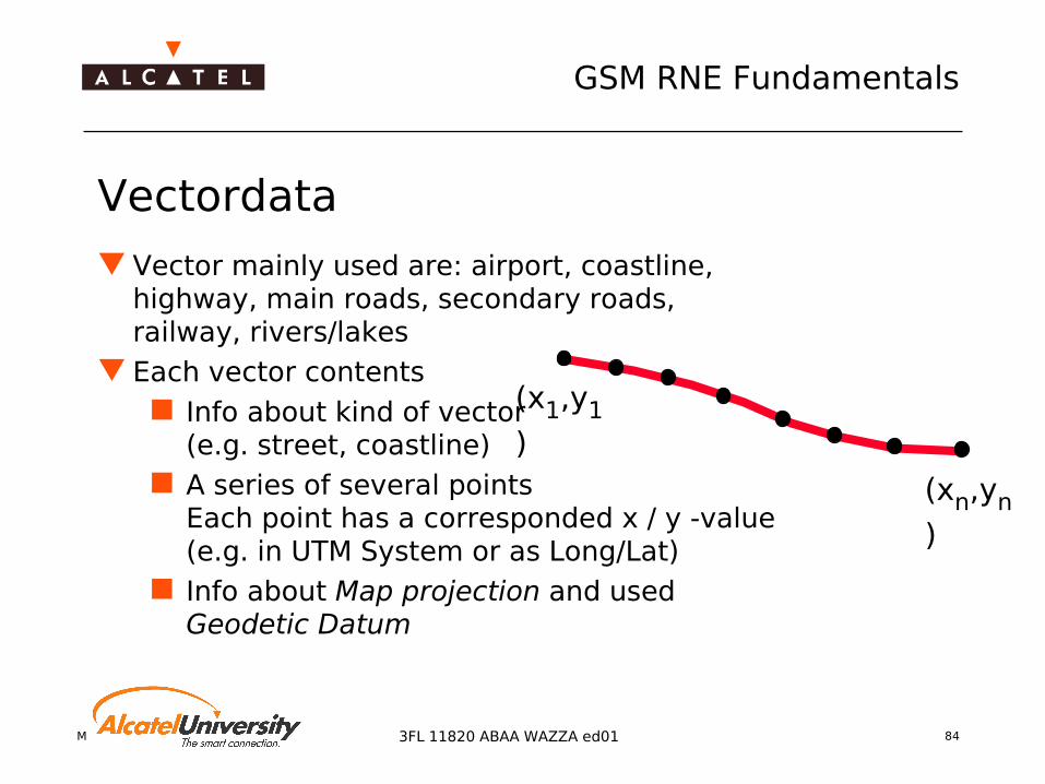
Vectordata
Vector mainly used are: airport, coastline, highway, main roads, secondary roads, railway, rivers/lakes
Each vector contents Info about kind of vector
(e.g. street, coastline) A series of several points
Each point has a corresponded x / y -value(e.g. in UTM System or as Long/Lat)
Info about Map projection and used Geodetic Datum
(x1,y1
)
(xn,yn
)

Mobile Radio Network Planning 85
GSM RNE Fundamentals
3FL 11820 ABAA WAZZA ed01
Digital Elevation Model (DEM) Raster dataset that shows
terrain features such as hillsand valleys
Each element (or pixel) inthe DEM image represents the terrain elevation at that location
Resolution in most cases: 20 m for urban areas50-100 m for other areas
DEM are typically generatedfrom topographic maps,stereo satellite images,or stereo aerial photographs

Mobile Radio Network Planning 86
GSM RNE Fundamentals
3FL 11820 ABAA WAZZA ed01
Morphostructure / Land usage / Clutter (1) Land usage classification
according to the impact on wave propagation
In most cases:7...14 morpho classes
Resolution in most cases:20 m for cities50…100m other areasfor radio networkplanning

Mobile Radio Network Planning 87
GSM RNE Fundamentals
3FL 11820 ABAA WAZZA ed01
Morphostructure (2) Besides the topo database the basic input
for radio network planning Each propagation area has different
obstacles like buildings, forest etc.Obstacles which have similar effects on propagation conditions are classified in morphoclasses
Each morphoclass has a corresponding value for the correction gain
The resolution of the morphodatabases should be adaptedto the propagation model
Morpho correction factor for predictions:0 dB (”skyscapers") … 30 dB (”water")

Mobile Radio Network Planning 88
GSM RNE Fundamentals
3FL 11820 ABAA WAZZA ed01
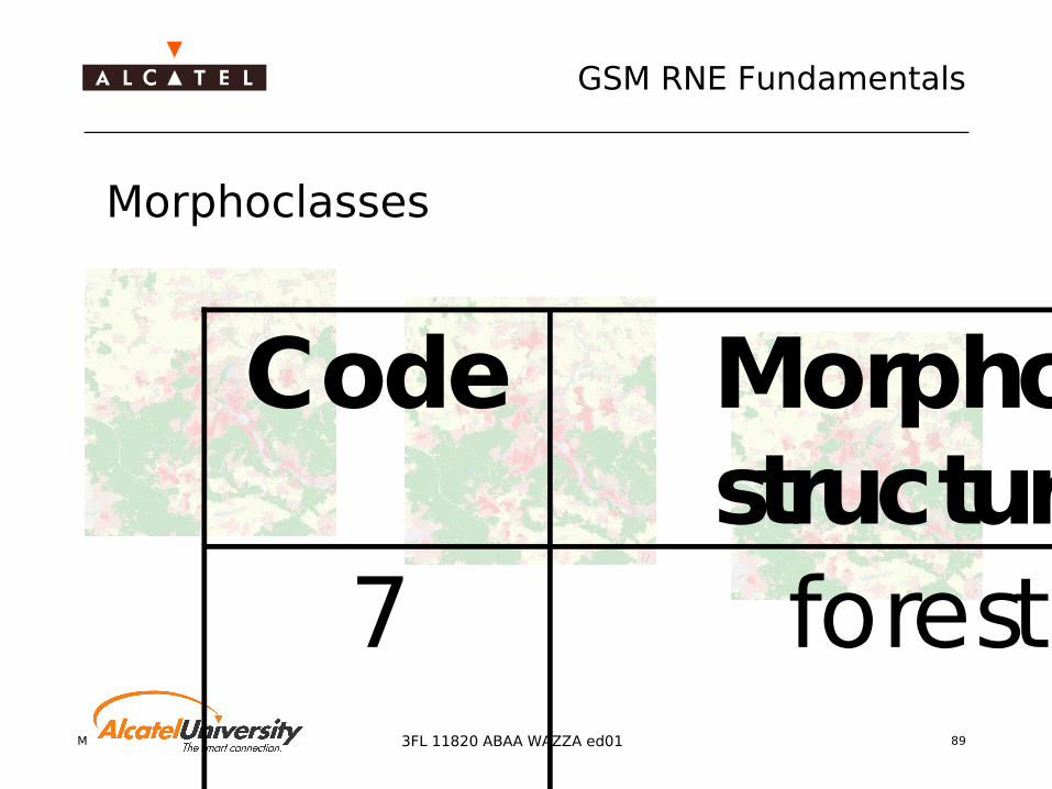
Morphoclasses
Code Morpho-structure
Description
0 not classified e.g. edge of a database
1 skyscrapers / buildings
very high buildings ( >40m), very high density of buildings, no vegetation on ground level e.g. cities like NewYork, Tokio etc.
2 dense urban 4 or more storeys, areas within urban perimeters, inner city, very little vegetation, high density of buildings, most buildings are standing close together, small pedestrian zones and streets incl.
3 medium urban / mean
urban
3 or 4 storeys, areas within urban perimeters, most buildings are standing close together, less vegetation, middle density of buildings, small pedestrian zones and streets included
4 lower urban / suburban
2 or 3 storeys, middle density of buildings, some vegetation, terraced houses with gardens
5 residential 1-2 storeys, low density of buildings with gardens e.g. farmhouses, detached houses
6 industrial zone / industrial
factory, warehouse, garage, shipyards
Mobile Radio Network Planning 89
GSM RNE Fundamentals
3FL 11820 ABAA WAZZA ed01
Morphoclasses
Code Morpho-structure
Description
7 forest all kinds of forest, parks, with high tree density
8 agriculture / rural
high vegetation, plants: 1... 3 m, high density of plants, e.g. crop fields, fruit plantation
9 low tree density / parks
low vegetation, low height of plants, low density of plants, some kinds of parks, botanical garden
10 water sea, rivers, all kind of fresh- and saltwater
11 open area no buildings, no vegetation e.g. desert, beach, part of an airport, big streets etc. huge parking areas, large
12 (optional)
defined by networkplanner if necessary
13 (optional)
defined by networkplanner if necessary

Mobile Radio Network Planning 90
GSM RNE Fundamentals
3FL 11820 ABAA WAZZA ed01
Background data (streets, borders etc.)
All kinds of information data like streets, borders, coastlines etc.
Necessary for orientationin plots of calculation results
The background data arenot needed for the calculationof the fieldstrength, power etc.

Mobile Radio Network Planning 91
GSM RNE Fundamentals
3FL 11820 ABAA WAZZA ed01
Orthophoto
Georeferenced Satellite Image Resolution:
most 10 or 20 m Satellite: e.g. SPOT, Landsat

Mobile Radio Network Planning 92
GSM RNE Fundamentals
3FL 11820 ABAA WAZZA ed01
Scanned Maps Mainly used as
background data Not used for calculation
but for localisation Has to be geocoded
to put it into a GIS (Geographic Information System) e.g. a Radio Network Planning Tool
Mobile Radio Network Planning 93
GSM RNE Fundamentals
3FL 11820 ABAA WAZZA ed01
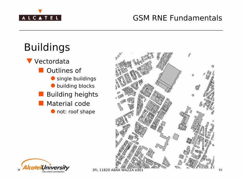
Buildings Vectordata
Outlines of single buildings building blocks
Building heights Material code
not: roof shape

Mobile Radio Network Planning 94
GSM RNE Fundamentals
3FL 11820 ABAA WAZZA ed01
Buildings (2) Microcell radio network planning
is mainly used in urban environment The prediction of mircowave
propagation is calculated witha ray-tracing/launching model
A lot of calculationsteps are needed
Optimum building databaserequired (data reduction) tominimize the pre-calculation time
Mobile Radio Network Planning 95
GSM RNE Fundamentals
3FL 11820 ABAA WAZZA ed01
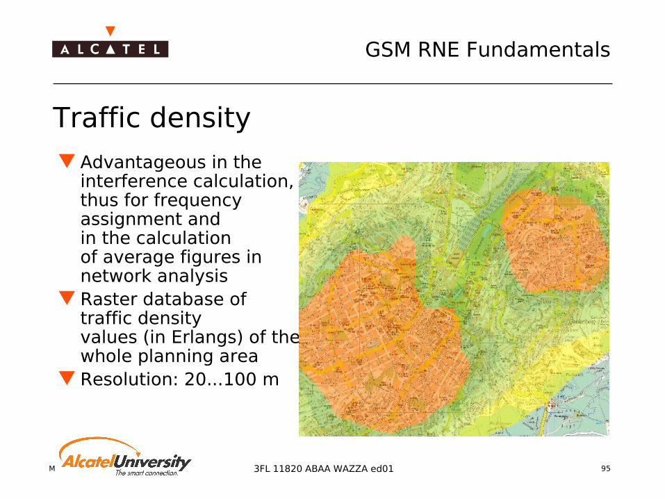
Traffic density
Advantageous in theinterference calculation,thus for frequencyassignment andin the calculationof average figures innetwork analysis
Raster database of traffic densityvalues (in Erlangs) of thewhole planning area
Resolution: 20...100 m

Mobile Radio Network Planning 963FL 11820 ABAA WAZZA ed01
Geo Databases
Geocoordinate transformation
Mobile Radio Network Planning 97
GSM RNE Fundamentals
3FL 11820 ABAA WAZZA ed01
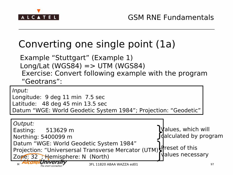
Converting one single point (1a)Example “Stuttgart” (Example 1)Long/Lat (WGS84) => UTM (WGS84)
Input: Longitude: 9 deg 11 min 7.5 secLatitude: 48 deg 45 min 13.5 secDatum “WGE: World Geodetic System 1984”; Projection: “Geodetic”
Exercise: Convert following example with the program “Geotrans”:
Output: Easting: 513629 mNorthing: 5400099 mDatum “WGE: World Geodetic System 1984”Projection: “Universersal Transverse Mercator (UTM)”Zone: 32 ; Hemisphere: N (North)
Preset of thisvalues necessary
Values, which willcalculated by program

Mobile Radio Network Planning 98
GSM RNE Fundamentals
3FL 11820 ABAA WAZZA ed01
Converting one single point (1b)
GEOTRANS(Geographic Translator)is an application program which allows you to convert geographic coordinates easily among a wide variety of coordinate systems, map projections, and datums.
Example “Stuttgart” (Example 1)Long/Lat (WGS84) => UTM (WGS84)
Source: http://164.214.2.59/GandG/geotrans/geotrans.html

Mobile Radio Network Planning 99
GSM RNE Fundamentals
3FL 11820 ABAA WAZZA ed01
Converting one single point (2a)
Input: Longitude: 9 deg 11 min 7.5 secLatitude: 48 deg 45 min 13.5 secDatum “WGE: World Geodetic System 1984”; Projection: “Geodetic”
Exercise: Convert following example with the program “Geotrans”:
Output: Easting: 513549 mNorthing: 5403685 mDatum “EUR-A: EUROPEAN 1950, Western Europe”Projection: “Universersal Transverse Mercator (UTM)”Zone: 32 ; Hemisphere: N (North)
Example “Stuttgart” (Example 2)Long/Lat (WGS84) => UTM (ED50) (ED50 = EUR-A = European Datum 1950)
Preset of thisvalues necessary
Values, which willcalculated by program

Mobile Radio Network Planning 100
GSM RNE Fundamentals
3FL 11820 ABAA WAZZA ed01
Converting one single point (2b)Example “Stuttgart” (Example 2)Long/Lat (WGS84) => UTM (ED50)(ED50 = EUR-A = European Datum 1950)
Attention: For flat coordinates (e.g. UTM) as well as for geographic coordinates (Long/Lat) a reference called “Geodetic Datum” is necessary.
Diff. X (Ex.2 - Ex.1): 69 mDiff. Y (Ex.2 - Ex.1): 200 mDifference because of different Geodetic Datums

Mobile Radio Network Planning 101
GSM RNE Fundamentals
3FL 11820 ABAA WAZZA ed01
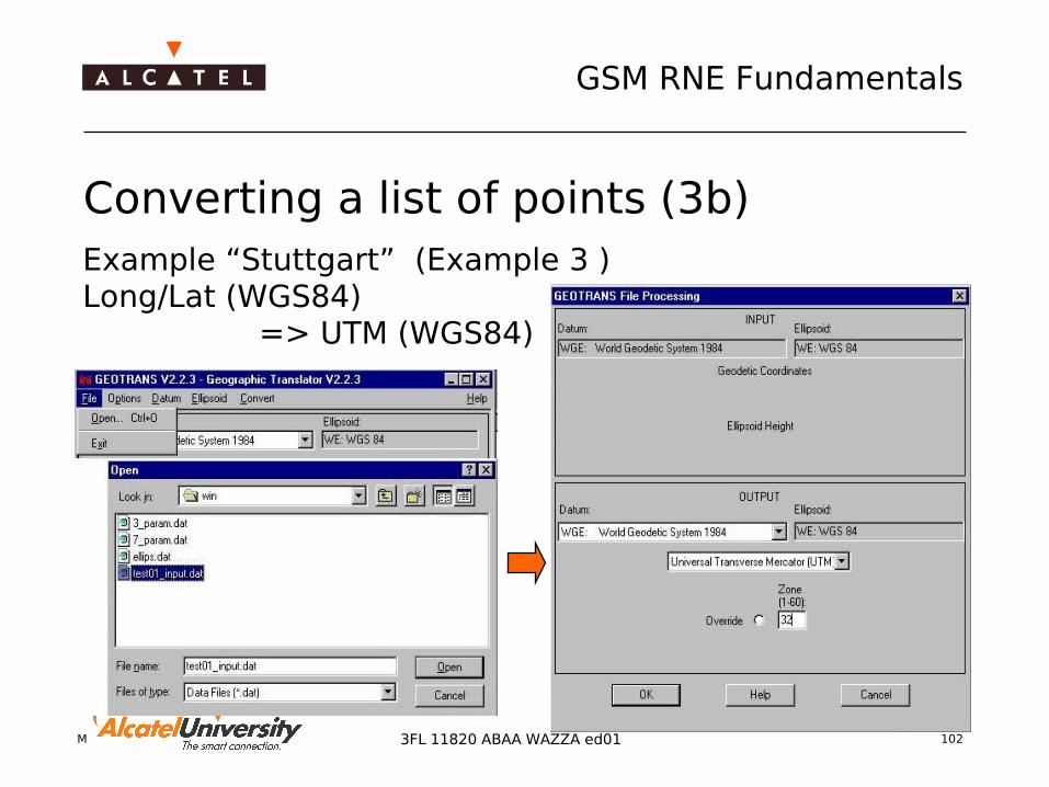
Converting a list of points (3a)
Example “Stuttgart” (Example 3 )Long/Lat (WGS84) => UTM (WGS84)
Input:text-file with the values (list) of the longitudeand latitude of different points(How to create the inputfile see on page 3c)
Output:Datum: “WGE: World Geodetic System 1984”Projection: “Universal Transverse Mercator (UTM)”Zone: 32
Preset of thisvalues necessary
Mobile Radio Network Planning 102
GSM RNE Fundamentals
3FL 11820 ABAA WAZZA ed01
Converting a list of points (3b)Example “Stuttgart” (Example 3 )Long/Lat (WGS84) => UTM (WGS84)

Mobile Radio Network Planning 103
GSM RNE Fundamentals
3FL 11820 ABAA WAZZA ed01
Converting a list of points (3c) Example “Stuttgart” (Example 3)
Long/Lat (WGS84)=> UTM (WGS84)
LatitudeLongitude UTM-Zone
Hemisphere
Easting (x)
Northing (y)
Optional: different error-infos,depending on the input-datadefault: “Unk”=“unknown”
Geotrans V2.2.3 Geotrans V2.2.3
deg min sec deg min sec

Mobile Radio Network Planning 104
GSM RNE Fundamentals
3FL 11820 ABAA WAZZA ed01
Provider for Geospatial data
Geodatasupplier InternetBKS www.bks.co.ukComputaMaps www.computamaps.comGeoimage www.geoimage.frInfoterra www.infoterra-global.comIstar www.istar.frRMSI www.rmsi.com

Mobile Radio Network Planning 105
GSM RNE Fundamentals
3FL 11820 ABAA WAZZA ed01
Links for more detailed infos
Maps Projection Overviewhttp://www.colorado.edu/geography/gcraft/notes/mapproj/mapproj.htmlhttp://www.ecu.edu/geog/faculty/mulcahy/mp/http://www.wikipedia.org/wiki/Map_projection
Coordinate Transformation (online)http://jeeep.com/details/coord/http://www.cellspark.com/UTM.html
Map Collectionhttp://www.lib.utexas.edu/maps/index.html
Finding out Latitude/Longitude of cities etc. http://www.maporama.com
Mobile Radio Network Planning 1063FL 11820 ABAA WAZZA ed01
Coverage Planning
Antennas and Cables
Mobile Radio Network Planning 107
GSM RNE Fundamentals
3FL 11820 ABAA WAZZA ed01
Antenna Systems Antennas Power divider Cables (jumper) Feeder cables Connectors Clamps Lightning protection Wall glands Planning
Rxdiv
Tx
Rx
Feedercable
Earthingkit
Wallgland
Jumper cables
Feederinstallationclamps
Plugs7/16“
Sockets7/16“
Mountingclamp
Grounding
Lightningrod Antennas
Earthing kit
Jumpercable Jumper
cable
Mechanicalantennasupportstructure

Mobile Radio Network Planning 108
GSM RNE Fundamentals
3FL 11820 ABAA WAZZA ed01
Antenna Theory 50Ω is the impedance of the cable 377Ω is the impedance of the air Antennas adapt the different impedances They convert guided waves, into free-space waves (Hertzian
waves) and/or vice versa
Z =377ΩZ =50Ω
Mobile Radio Network Planning 109
GSM RNE Fundamentals
3FL 11820 ABAA WAZZA ed01
Antenna Data Polarization
Specification due to certain wave polarization (linear/elliptic, cross-polarization)
Half power beam width (HPBW) Related to polarization of electrical field Vertical and Horizontal HPBW
Antenna pattern Yields the spatial radiation characteristics of the
antenna Front-to-back ratio
Important for interference considerations

Mobile Radio Network Planning 110
GSM RNE Fundamentals
3FL 11820 ABAA WAZZA ed01
Antenna Pattern and HPBW
0 dB
-3 dB
-10 dB
0 dB
-3 dB
-10 dB
verticalhorizontal
sidelobe
null direction
main beam
HP
BW
Mobile Radio Network Planning 111
GSM RNE Fundamentals
3FL 11820 ABAA WAZZA ed01
EIRP
Pt = 45 dBm
Gain = 11dBi
Isotropic radiated Power Pt
Effective isotropicradiated power:EIRP = Pt+Gain = 56 dBm
V1
V2 = V1
radiatedpower

Mobile Radio Network Planning 112
GSM RNE Fundamentals
3FL 11820 ABAA WAZZA ed01
Linear Antennas: Monopole and Dipole For the link between base station and mobile station, mostly
linear antennas are used:
Monopole antennas MS antennas, car roof antennas
Dipole antennas Used for array antennas at base stations for increasing the
directivity of RX and TX antennas

Mobile Radio Network Planning 113
GSM RNE Fundamentals
3FL 11820 ABAA WAZZA ed01
Monopole Antenna Pattern Influence of antenna length on the antenna pattern
Mobile Radio Network Planning 114
GSM RNE Fundamentals
3FL 11820 ABAA WAZZA ed01
Panel Antenna with Dipole Array Many dipoles are arranged in a grid layout Nearly arbitrary antenna patterns may be designed
Feeding of the dipoles with weighted and phase-shifted signals
Coupling of all dipole elements

Mobile Radio Network Planning 115
GSM RNE Fundamentals
3FL 11820 ABAA WAZZA ed01
Dipole Arrangement
Dipole arrangement
Typical flat panel antenna
Dipole element
Weightedandphaseshiftedsignals

Mobile Radio Network Planning 116
GSM RNE Fundamentals
3FL 11820 ABAA WAZZA ed01
Omni Antenna Antenna with vertical HPBW for omni sites
Large area coverage Advantages
Continuous coverage around the site Simple antenna mounting Ideal for homogeneous terrain
Drawbacks No mechanical tilt possible Clearance of antenna required

Mobile Radio Network Planning 117
GSM RNE Fundamentals
3FL 11820 ABAA WAZZA ed01
X 65° T6 900MHz 2.5m Rural road coverage with mechanical uptilt
Antenna RFS Panel Dual Polarized Antenna 872-
960 MHz APX906516-T6 Series
Electrical specification Gain in dBi: 17.1 Polarization: +/-45° HBW: 65° VBW: 6.5° Electrical downtilt: 6°
Mechanical specification Dimensions HxWxD in mm: 2475 x 306
x 120 Weight in kg: 16.6
Horizontal Pattern

Mobile Radio Network Planning 118
GSM RNE Fundamentals
3FL 11820 ABAA WAZZA ed01
X 65° T6 900MHz 1.9m Dense urban area Antenna
RFS Panel Dual Polarized Antenna 872-960 MHz
APX906515-T6 Series Electrical specification
Gain in dBi: 16.5 Polarization: +/-45° HBW: 65° VBW: 9° Electrical downtilt: 6°
Mechanical specification Dimensions HxWxD in mm: 1890 x 306
x 120 Weight in kg: 16.6
Vertical Pattern

Mobile Radio Network Planning 119
GSM RNE Fundamentals
3FL 11820 ABAA WAZZA ed01
X 90° T2 900MHz 2.5m Rural area with mechanical uptilt
Antenna RFS Panel Dual Polarized Antenna
872-960 MHz APX909014-T6 Series
Electrical specification Gain in dBi: 15.9 Polarization: +/-45° HPBW: 90° VBW: 7° Electrical downtilt: 6°
Mechanical specification Dimensions HxWxD in mm: 2475 x
306 x 120 Weight in kg: 15.5
Vertical Pattern

Mobile Radio Network Planning 120
GSM RNE Fundamentals
3FL 11820 ABAA WAZZA ed01
V 65° T0 900MHz 2.0m Highway
Antenna RFS CELLite® Panel Vertical Polarized
Antenna 872-960 MHz AP906516-T0 Series
Electrical specification Gain in dBi: 17.5 Polarization: Vertical HBW: 65° VBW: 8.5° Electrical downtilt: 0°
Mechanical specification Dimensions HxWxD in mm: 1977 x 265
x 130 Weight in kg: 10.9
Vertical Pattern

Mobile Radio Network Planning 121
GSM RNE Fundamentals
3FL 11820 ABAA WAZZA ed01
V 90° T0 900MHz 2.0m Rural Area
Antenna RFS CELLite® Panel Vertical Polarized
Antenna 872-960 MHz AP909014-T0 Series
Electrical specification Gain in dBi: 16.0 Polarization: Vertical HBW: 65° VBW: 8.5° Electrical downtilt: 0°
Mechanical specification Dimensions HxWxD in mm: 1977 x 265
x 130 Weight in kg: 9.5
Vertical Pattern

Mobile Radio Network Planning 122
GSM RNE Fundamentals
3FL 11820 ABAA WAZZA ed01
X 65° T6 1800MHz 1.3m Dense urban area
Antenna RFS Panel Dual Polarized Antenna
1710-1880 MHz APX186515-T6 Series
Electrical specification Gain in dBi: 17.5 Polarization: +/-45° HBW: 65° VBW: 7° Electrical downtilt: 6°
Mechanical specification Dimensions HxWxD in mm: 1310 x
198 x 50 Weight in kg: 5.6
Vertical Pattern

Mobile Radio Network Planning 123
GSM RNE Fundamentals
3FL 11820 ABAA WAZZA ed01
X 65° T2 1800MHz 1.3m Dense urban area
Antenna RFS Panel Dual Polarized Antenna
1710-1880 MHz APX186515-T2 Series
Electrical specification Gain in dBi: 17.5 Polarization: +/-45° HBW: 65° VBW: 7° Electrical downtilt: 2°
Mechanical specification Dimensions HxWxD in mm: 1310 x
198 x 50 Weight in kg: 5.6
Vertical Pattern
Mobile Radio Network Planning 124
GSM RNE Fundamentals
3FL 11820 ABAA WAZZA ed01
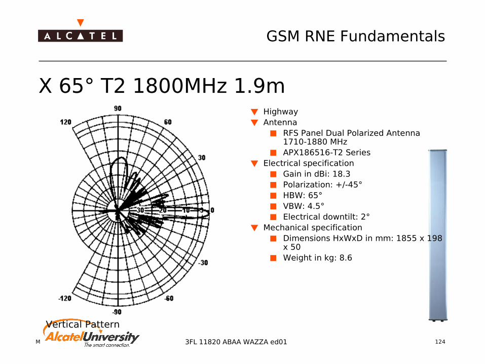
X 65° T2 1800MHz 1.9m Highway Antenna
RFS Panel Dual Polarized Antenna 1710-1880 MHz
APX186516-T2 Series Electrical specification
Gain in dBi: 18.3 Polarization: +/-45° HBW: 65° VBW: 4.5° Electrical downtilt: 2°
Mechanical specification Dimensions HxWxD in mm: 1855 x 198
x 50 Weight in kg: 8.6
Vertical Pattern
Mobile Radio Network Planning 125
GSM RNE Fundamentals
3FL 11820 ABAA WAZZA ed01
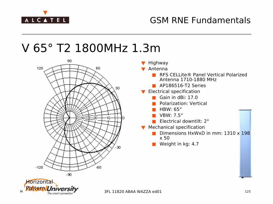
V 65° T2 1800MHz 1.3m Highway
Antenna RFS CELLite® Panel Vertical Polarized
Antenna 1710-1880 MHz AP186516-T2 Series
Electrical specification Gain in dBi: 17.0 Polarization: Vertical HBW: 65° VBW: 7.5° Electrical downtilt: 2°
Mechanical specification Dimensions HxWxD in mm: 1310 x 198
x 50 Weight in kg: 4.7
Horizontal Pattern

Mobile Radio Network Planning 126
GSM RNE Fundamentals
3FL 11820 ABAA WAZZA ed01
V 90° T2 1800MHz 1.9m Highway Antenna
RFS CELLite® Panel Vertical Polarized Antenna 1710-1880 MHz
AP189016-T2 Series Electrical specification
Gain in dBi: 17.0 Polarization: Vertical HBW: 90° VBW: 5.5° Electrical downtilt: 2°
Mechanical specification Dimensions HxWxD in mm: 1855 x 198
x 50 Weight in kg: 6.0
Vertical Pattern
Mobile Radio Network Planning 127
GSM RNE Fundamentals
3FL 11820 ABAA WAZZA ed01
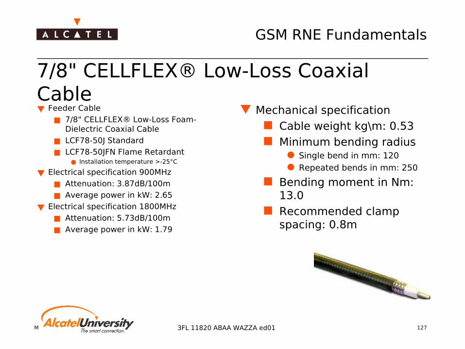
7/8" CELLFLEX® Low-Loss Coaxial Cable Feeder Cable
7/8" CELLFLEX® Low-Loss Foam-Dielectric Coaxial Cable
LCF78-50J Standard
LCF78-50JFN Flame Retardant Installation temperature >-25°C
Electrical specification 900MHz
Attenuation: 3.87dB/100m
Average power in kW: 2.65
Electrical specification 1800MHz
Attenuation: 5.73dB/100m
Average power in kW: 1.79
Mechanical specification Cable weight kg\m: 0.53 Minimum bending radius
Single bend in mm: 120 Repeated bends in mm: 250
Bending moment in Nm: 13.0
Recommended clamp spacing: 0.8m

Mobile Radio Network Planning 128
GSM RNE Fundamentals
3FL 11820 ABAA WAZZA ed01
1-1/4" CELLFLEX® Coaxial Cable Feeder Cable
1-1/4" CELLFLEX® Low-Loss Foam-Dielectric Coaxial Cable
LCF114-50J Standard
LCF114-50JFN Flame Retardant Installation temperature >-25°C
Electrical specification 900MHz
Attenuation: 3.06dB/100m
Average power in kW: 3.56
Electrical specification 1800MHz
Attenuation: 4.61dB/100m
Average power in kW: 2.36
Mechanical specification Cable weight kg\m: 0.86 Minimum bending radius
Single bend in mm: 200 Repeated bends in mm: 380
Bending moment in Nm: 38.0
Recommended clamp spacing: 1.0m

Mobile Radio Network Planning 129
GSM RNE Fundamentals
3FL 11820 ABAA WAZZA ed01
1-5/8" CELLFLEX® Coaxial Cable Feeder Cable
1-5/8" CELLFLEX® Low-Loss Foam-Dielectric Coaxial Cable
LCF158-50J Standard
LCF158-50JFN Flame Retardant Installation temperature >-25°C
Electrical specification 900MHz
Attenuation: 2.34dB/100m
Average power in kW: 4.97
Electrical specification 1800MHz
Attenuation: 3.57dB/100m
Average power in kW: 3.26
Mechanical specification Cable weight kg\m: 1.26 Minimum bending radius
Single bend in mm: 200 Repeated bends in mm: 508
Bending moment in Nm: 46.0
Recommended clamp spacing: 1.2m
Mobile Radio Network Planning 130
GSM RNE Fundamentals
3FL 11820 ABAA WAZZA ed01
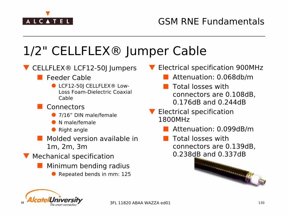
1/2" CELLFLEX® Jumper Cable CELLFLEX® LCF12-50J Jumpers
Feeder Cable LCF12-50J CELLFLEX® Low-
Loss Foam-Dielectric Coaxial Cable
Connectors 7/16” DIN male/female N male/female Right angle
Molded version available in 1m, 2m, 3m
Mechanical specification Minimum bending radius
Repeated bends in mm: 125
Electrical specification 900MHz Attenuation: 0.068db/m Total losses with
connectors are 0.108dB, 0.176dB and 0.244dB
Electrical specification 1800MHz
Attenuation: 0.099dB/m Total losses with
connectors are 0.139dB, 0.238dB and 0.337dB

Mobile Radio Network Planning 1313FL 11820 ABAA WAZZA ed01
Coverage Planning
Radio Propagation and Path Loss Prediction

Mobile Radio Network Planning 132
GSM RNE Fundamentals
3FL 11820 ABAA WAZZA ed01
Propagation effects Free space loss Fresnel ellipsoid Reflection, Refraction, Scattering
in the atmosphere at a boundary to another material
Diffraction at small obstacles over round earth
Attenuation Rain attenuation Gas absorption
Fading
Mobile Radio Network Planning 133
GSM RNE Fundamentals
3FL 11820 ABAA WAZZA ed01
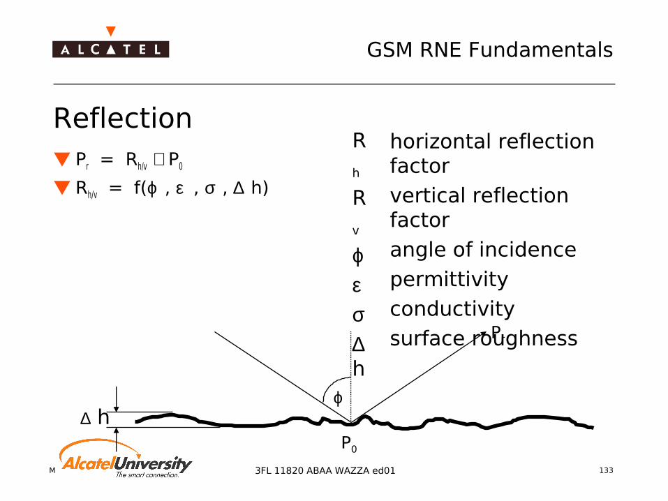
ϕ
P0
∆ h
Reflection Pr = Rh/v ⋅ P0
Rh/v = f(ϕ , ε , σ , ∆ h)
horizontal reflection factorvertical reflection factorangle of incidencepermittivityconductivitysurface roughness
Rh
Rv
ϕεσ∆h
Pr
Mobile Radio Network Planning 134
GSM RNE Fundamentals
3FL 11820 ABAA WAZZA ed01
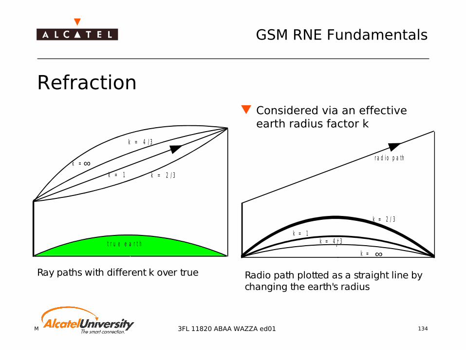
Refraction
k = 4 / 3
k = 1 k = 2 / 3
k =
t r u e e a r t h
Ray paths with different k over true earth
∞
Considered via an effective earth radius factor k
Radio path plotted as a straight line by changing the earth's radius
k = 4 / 3k = 1
k = 2 / 3
k =
r a d i o p a t h
∞

Mobile Radio Network Planning 135
GSM RNE Fundamentals
3FL 11820 ABAA WAZZA ed01
Diffraction Occurs at objects which sizes are in the order of the wavelength λ Radio waves are ‘bent’ or ‘curved’ around objects
Bending angle increases if object thickness is smaller compared to λ
Influence of the object causes an attenuation: diffraction loss
diffracted radio beams
shadow zone
obstacle
radio beam
Mobile Radio Network Planning 136
GSM RNE Fundamentals
3FL 11820 ABAA WAZZA ed01
Fading Caused by delay spread of original signal
Multi path propagation Time-dependent variations in heterogeneity of environment Movement of receiver
Short-term fading, fast fading This fading is characterised by phase summation and
cancellation of signal components, which travel on multiple paths. The variation is in the order of the considered wavelength.
Their statistical behaviour is described by the Rayleigh distribution (for non-LOS signals) and the Rice distribution (for LOS signals), respectively.
In GSM, it is already considered by the sensitivity values, which take the error correction capability into account.
Mobile Radio Network Planning 137
GSM RNE Fundamentals
3FL 11820 ABAA WAZZA ed01
Fading types Mid-term fading, lognormal fading
Mid-term field strength variations caused by objects in the size of 10...100m (cars, trees, buildings). These variations are lognormal distributed.
Long-term fading, slow fading Long-term variations caused by large objects like large
buildings, forests, hills, earth curvature (> 100m). Like the mid-term field strength variations, these variations are lognormal distributed.

Mobile Radio Network Planning 138
GSM RNE Fundamentals
3FL 11820 ABAA WAZZA ed01
Signal Variation due to Fading
-70
-60
-50
-40
-30
-20
-10
0
0.1
2.8
5.4
8.0
10.6
13.2
15.9
18.5
21.1
23.7
26.3
29.0
31.6
34.2
36.8
39.4
42.1
44.7
47.3
49.9
Distance [m]
Rec
eive
d P
ow
er [
dB
m]
Lognormal fading
Raleygh fading
Fading hole
Mobile Radio Network Planning 139
GSM RNE Fundamentals
3FL 11820 ABAA WAZZA ed01
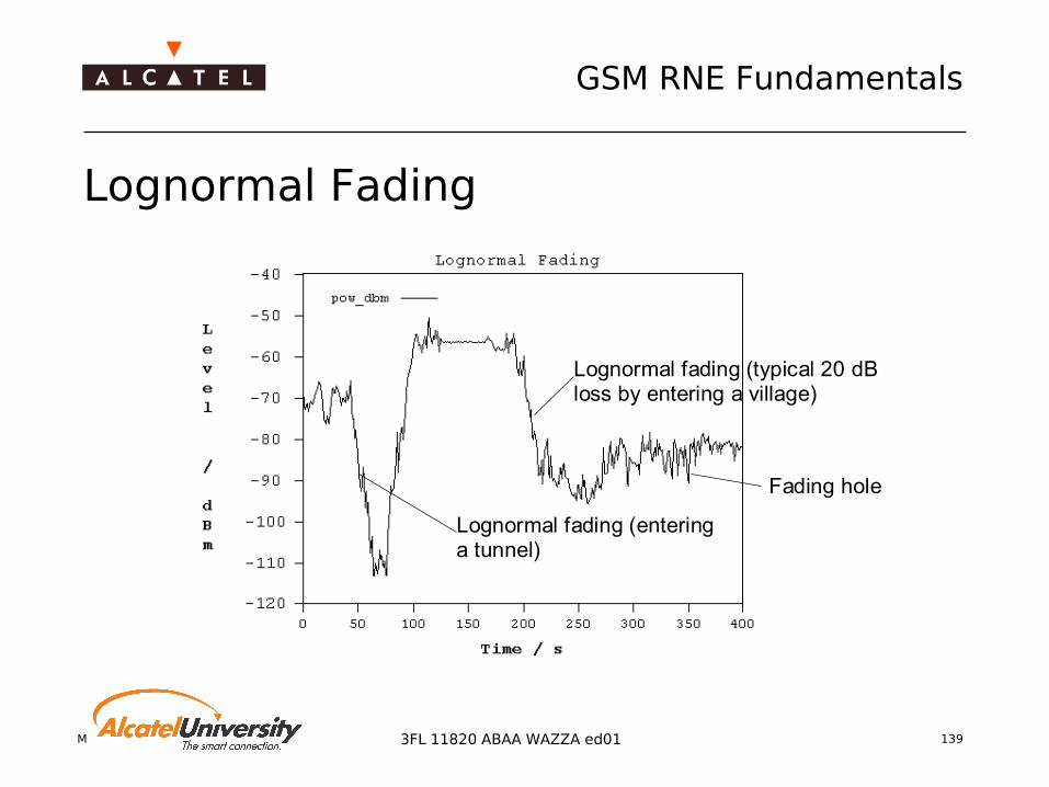
Lognormal Fading
Lognormal fading (typical 20 dB loss by entering a village)
Fading hole Lognormal fading (entering a tunnel)

Mobile Radio Network Planning 140
GSM RNE Fundamentals
3FL 11820 ABAA WAZZA ed01
Free Space Loss The simplest form of wave propagation is the free-space propagation
The according path loss can be calculated with the following formula
Path Loss in Free Space Propagation
L free space loss
d distance between transmitter and receiver antenna
f operating frequency
Ld
km
f
MHzfreespace = + ⋅ + ⋅32 4 20 20. log log

Mobile Radio Network Planning 141
GSM RNE Fundamentals
3FL 11820 ABAA WAZZA ed01
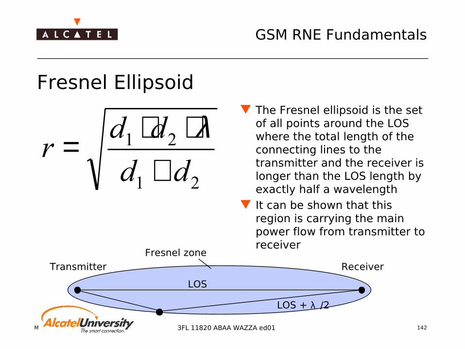
Fresnel Ellipsoid The free space loss formula can only be applied if the direct line-of-
sight (LOS) between transmitter and receiver is not obstructed This is the case, if a specific region around the LOS is cleared from
any obstacles The region is called Fresnel ellipsoid
Transmitter
Receiver
LOS
Mobile Radio Network Planning 142
GSM RNE Fundamentals
3FL 11820 ABAA WAZZA ed01
Fresnel Ellipsoid
21
21
dd
ddr
+⋅⋅= λ
The Fresnel ellipsoid is the set of all points around the LOS where the total length of the connecting lines to the transmitter and the receiver is longer than the LOS length by exactly half a wavelength
It can be shown that this region is carrying the main power flow from transmitter to receiver
Transmitter Receiver
LOS
LOS + λ /2
Fresnel zone

Mobile Radio Network Planning 143
GSM RNE Fundamentals
3FL 11820 ABAA WAZZA ed01
Knife Edge Diffraction
1st Fresnel zone
r
BTS
MS
d1 d2
h0
line of sight
path of diffracted wave
d1 d2
h0
replaced obstacle (knife edge)
h0 = height of obstacle over line of sight
d1, d2 = distance of obstacle from BTS and MS

Mobile Radio Network Planning 144
GSM RNE Fundamentals
3FL 11820 ABAA WAZZA ed01
Knife Edge Diffraction Function
Knife-edge diffraction function
-5
0
5
10
15
20
25
30
35
-9 -8 -7 -6 -5 -4 -3 -2 -1 0 1 2 3
Clearance of Fresnel ellipsoid (v)
F(v
) [d
B]
Additional diffraction loss F(v)v: clearance parameter, v=-h0/rNote: h0 = 0 ⇒ v =0 ⇒ L = 6 dB

Mobile Radio Network Planning 145
GSM RNE Fundamentals
3FL 11820 ABAA WAZZA ed01
Computers: the "Final Solution" for Wave Propagation Calculations?
Exact field solution requires too much computer resources! Too much details required for input Exact calculation too time-consuming Field strength prediction rather than calculation
Requirements for field strength prediction models Reasonable amount of input data Fast (it is very important to see the impact of changes in the
network layout immediately) Accurate (results influence the hardware cost directly) Tradeoff required (accurate results within a suitable time) Parameter tuning according to real measurements should be
possible

Mobile Radio Network Planning 146
GSM RNE Fundamentals
3FL 11820 ABAA WAZZA ed01
CCIR Recommendation
The CCIR Recommendations provide various propagation curves
Based on Okumura (1968) Example (CCIR Report 567-3):
Median field strength in urban areaFrequency = 900 MHzhMS = 1.5 mDashed line: free space
How to use this experience in field strength prediction models?
Model which fits the curves in certain ranges → Hata's model
was modified later by the European Cooperation in Science and Technology (COST): COST 231 Hata/Okumura

Mobile Radio Network Planning 147
GSM RNE Fundamentals
3FL 11820 ABAA WAZZA ed01
Mobile Radio Propagation
Free-space propagation (Fresnel zone not obstructed) → L ~ d2
Fresnel zone heavily obstructed near the mobile station→ L ~ d3.7
d
Mobile Radio Network Planning 148
GSM RNE Fundamentals
3FL 11820 ABAA WAZZA ed01
Terrain Modeling Topography
Effective antenna height Knife edge diffraction
single obstacles multiple obstacles
Surface shape/Morpho-structure
Correction factors for Hata-Okumura formula

Mobile Radio Network Planning 149
GSM RNE Fundamentals
3FL 11820 ABAA WAZZA ed01
Effect of Morphostructure on Propagation Loss
Open area Open areaUrban area
Distance
Field
stre
ngth
urban area
open area

Mobile Radio Network Planning 150
GSM RNE Fundamentals
3FL 11820 ABAA WAZZA ed01
Path loss (Lu) is calculated (in dB) as follows:
Lu= A1 + A2 log(f) + A3 log(hBTS) + (B1 + B2log(hBTS)) log d
The parameters A1, A2, A3, B1 and B2 can be user-defined. Default values are proposed in the table below:
Hata-Okumura for GSM 900
Parameters Okumura-Hataf< 1500 MHz
Cost-HataF>1500 MHz
A1 69.55 46.30
A2 26.16 33.90
A3 -13.82 -13.82
B1 44.90 44.90
B2 -6.55 -6.55

Mobile Radio Network Planning 151
GSM RNE Fundamentals
3FL 11820 ABAA WAZZA ed01
CORRECTIONS TO THE HATA FORMULA As described above, the Hata formula is valid for urban environment and a
receiver antenna height of 1.5m. For other environments and mobile antenna heights, corrective formulas must be applied.
Lmodel1=Lu-a(hMS) for large city and urban environments
Lmodel1=Lu-a(hMS) -2log² (f/28) -5.4 for suburban area
Lmodel1=Lu -a(hMS) - 4.78log² (f)+ 18.33 log(f) – 40.94 for rural area
a(hMS) is a correction factor to take into account a receiver antenna height different from 1.5m. Environments A(hMS)
Rural/Small city (1.1log(f) – 0.7)hMS – (1.56log(f) -0.8)
Large city 3.2log² (11.75hMS) – 4.97
Note: When receiver antenna height equals 1.5m, a(hMS) is close to 0 dB regardless of frequency.

Mobile Radio Network Planning 152
GSM RNE Fundamentals
3FL 11820 ABAA WAZZA ed01
COST 231 Hata-Okumura for GSM 900
Formula valid for frequency range: 150…1000 MHz
Lmorpho [dB] Morpho/surface shape-Correction factor 0 dB: ‘Skyscrapers’->27 dB: ‘open area’
f [MHz] Frequency (150 - 1000 MHz)hBTS [m] Height of BTS (30 - 200 m)hMS [m] Height of Mobile (1 - 10m)d [km] Distance between BTS and MS (1 - 20 km)
Power law exponent shown colored
LossHata = 69.55 + 26.16 log (f) - 13.82 log (hBTS)- a(hMS) +(44.9 - 6.55 log (hBTS)) log (d) - Lmorpho
a (hMS) = (1.1 log (f) - 0.7) hMS - (1.56 log (f) - 0.8)

Mobile Radio Network Planning 153
GSM RNE Fundamentals
3FL 11820 ABAA WAZZA ed01
COST 231 Hata-Okumura GSM 1800
Formula is valid for frequency range: 1500...2000 MHz Hata’s model is extended for GSM 1800
Modification of original formula to the new frequency range For cells with small ranges the COST 231 Walfish-Ikegami model is
more precisely
LossHata = 46.3 + 33.9 log (f) - 13.82 log (hBTS) - a(hMS) +(44.9 - 6.55 log (hBTS)) log (d) - Lmorpho
a (hMS) = (1.1 log (f) - 0.7) hMS - (1.56 log (f) -0.8)
Mobile Radio Network Planning 154
GSM RNE Fundamentals
3FL 11820 ABAA WAZZA ed01
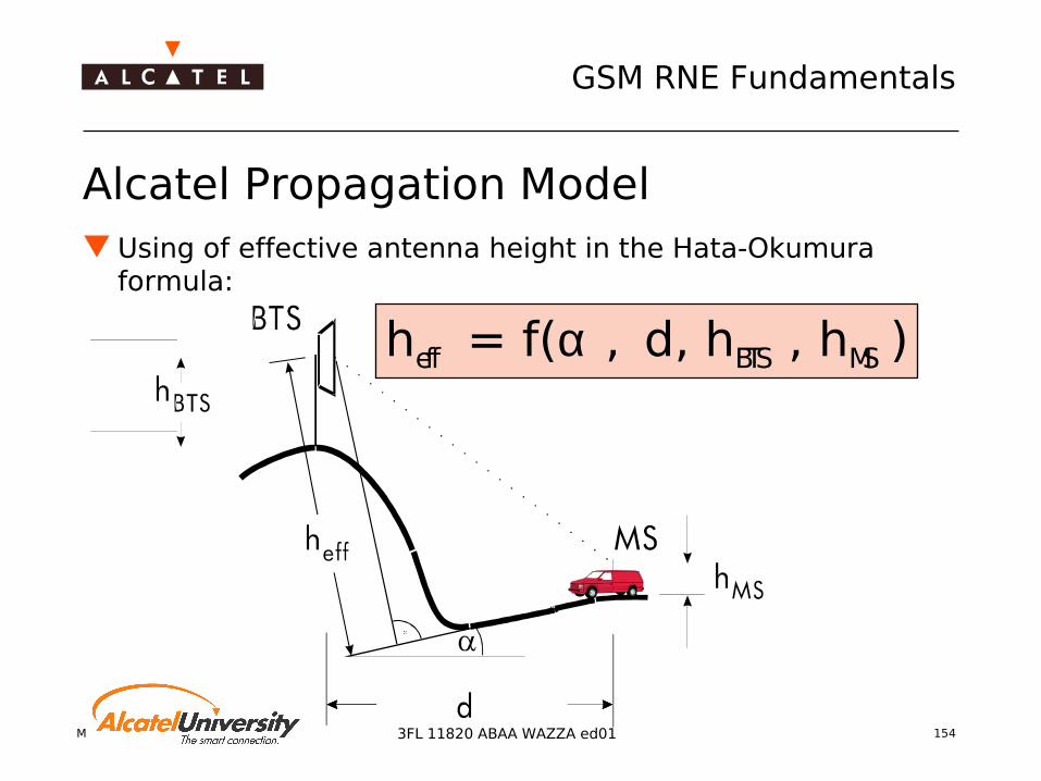
Alcatel Propagation Model Using of effective antenna height in the Hata-Okumura
formula:
Τheff = f(α , d, hBTS , hMS )

Mobile Radio Network Planning 155
GSM RNE Fundamentals
3FL 11820 ABAA WAZZA ed01
Exercise ‘Path Loss’ Scenario
Height BTS = 40m Height MS = 1.5m D (BTS to MS) = 2000m
1. Calculate free space loss for A.) f=900MHz B.) f=1800MHz
2. Calculate the path loss for f = 900MHz A.) Morpho class ‘skyscraper’ B.) Morpho class ‘open area’
3. Calculate the path loss for f = 1800MHz A.) Morpho class ‘skyscraper’ B.) Morpho class ‘open area’

Mobile Radio Network Planning 1563FL 11820 ABAA WAZZA ed01
Coverage Planning
Link Budget CalculationCoverage Probability
Cell Range
Mobile Radio Network Planning 157
GSM RNE Fundamentals
3FL 11820 ABAA WAZZA ed01
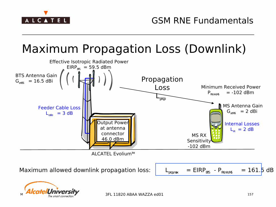
Maximum Propagation Loss (Downlink)
Feeder Cable LossLcable = 3 dB
BTS Antenna GainGantBS = 16.5 dBi
Effective Isotropic Radiated PowerEIRPBTS = 59.5 dBm
MS Antenna GainGantMS = 2 dBi
Internal LossesLint = 2 dB
ALCATEL EvoliumTM
Propagation LossLprop
Minimum Received PowerPRX,min,MS = -102 dBm
Maximum allowed downlink propagation loss: Lprop,max = EIRPBTS - PRX,min,MS = 161.5 dB
MS RXSensitivity-102 dBm
Output Power at antenna connector 46.0 dBm

Mobile Radio Network Planning 158
GSM RNE Fundamentals
3FL 11820 ABAA WAZZA ed01
Max. allowed uplink propagation loss: Lprop,max = EIRPMS - PRX,min,BTS = 157.5 dB
With antenna diversity gain of 3dB: Lprop,max,AD = EIRPMS - PRX,min,BTS + GAD = 160.5 dB
With TMA compensating cable loss: Lprop,max,AD,TMA = EIRPMS - PRX,min,BTS + GAD + GTMA = 163.5 dB
Maximum Propagation Loss (Uplink)
Feeder Cable LossLcable = 3 dB
BTS Antenna GainGantBS = 16.5 dBi
Minimum Received Power
PRX,min,BTS = -124.5 dBm
MS Antenna GainGantMS = 2 dBi
Internal LossesLint = 2 dB
ALCATEL EvoliumTM
Propagation LossLprop
EIRPMS = 33 dBm
MS TX Power33 dBm
Receiving sensitivity at ant. conn. -111 dBm
Mobile Radio Network Planning 159
GSM RNE Fundamentals
3FL 11820 ABAA WAZZA ed01
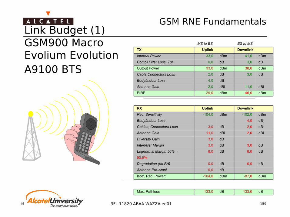
Link Budget (1)GSM900 MacroEvolium Evolution A9100 BTS
dB133,0dB133,0Max. Pathloss
dBm-87,0dBm-104,0Isotr. Rec. Power:
dB0,0Antenna Pre-Ampl.
dB0,0dB0,0Degradation (no FH)
90,9%
dB8,0dB8,0Lognormal Margin 50%→
dB3,0dB3,0Interferer Margin
dB3,0Diversity Gain
dBi2,0dBi11,0Antenna Gain
dB2,0dB3,0Cables, Connectors Loss
dB4,0 Body/Indoor Loss
dBm-102,0dBm-104,0Rec. Sensitivity
Downlink UplinkRX
dBm46,0dBm29,0EIRP
dBi11,0dBi2,0Antenna Gain
dB4,0Body/Indoor Loss
dB3,0dB2,0Cable,Connectors Loss
dBm38,0dBm33,0Output Power
dB3,0dB0,0Comb+Filter Loss, Tol.
dBm41,0dBm33,0Internal Power
Downlink UplinkTX
BS to MSMS to BS

Mobile Radio Network Planning 160
GSM RNE Fundamentals
3FL 11820 ABAA WAZZA ed01
GSM1800 Link Budget

Mobile Radio Network Planning 161
GSM RNE Fundamentals
3FL 11820 ABAA WAZZA ed01
Additional Losses Overview
Loss type Reason Value
Indoor loss Electrical properties of wall material 20dB (3...30dB)
Incar loss Brass influencing radio waves 7dB (4...10dB)
Body loss Absorption of radio waves by thehuman body
3dB (0...8dB)
Interferer margin Both signal-to-noise ratio and C/I low 3 dB
Lognormal margin Receiving the minimum field strengthwith a higher probability
According toprobability
Mobile Radio Network Planning 162
GSM RNE Fundamentals
3FL 11820 ABAA WAZZA ed01
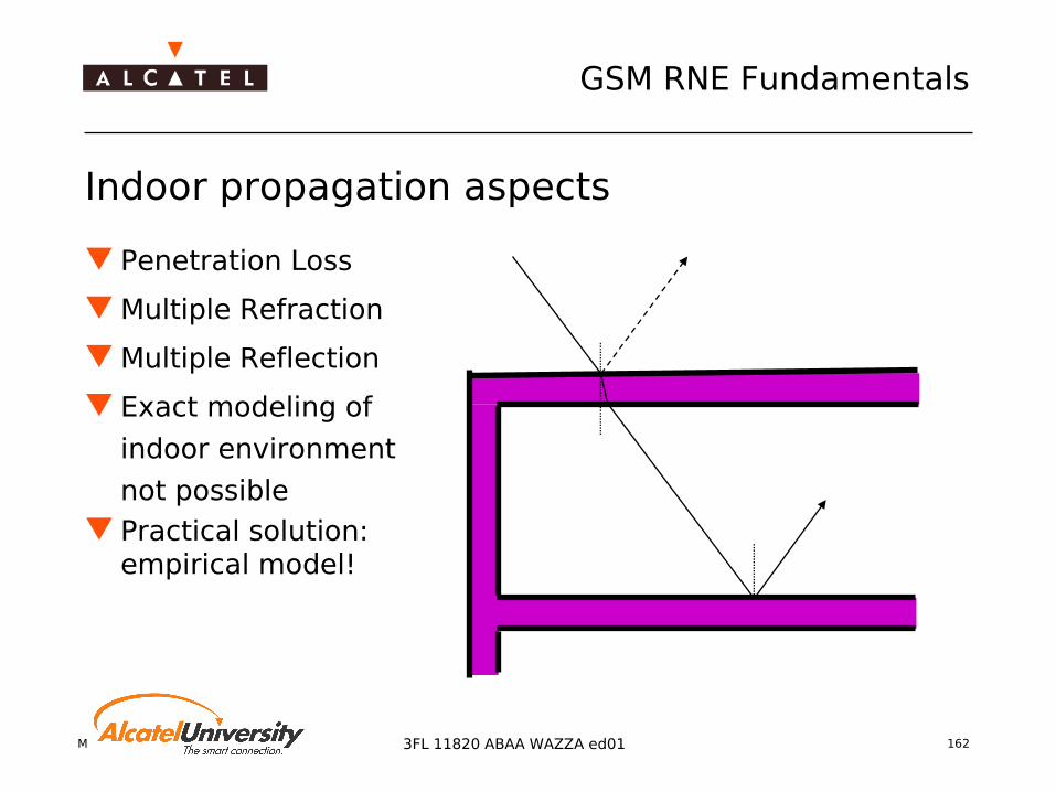
Indoor propagation aspects
Penetration Loss
Multiple Refraction
Multiple Reflection
Exact modeling of
indoor environment
not possible Practical solution:
empirical model!

Mobile Radio Network Planning 163
GSM RNE Fundamentals
3FL 11820 ABAA WAZZA ed01
Indoor propagation: empirical model
d
Additional Loss in [dB] relative to loss at vertical incidence
Power relative to power at d=0
ϕ
d
0
5
10
15
20
25
30
35
0 6
12
18
24
30
36
42
48
54
60
66
72
78
84
90
Angle of incidence in degree
Ad
dit
ion
al att
en
uati
on
in
dB
Mobile Radio Network Planning 164
GSM RNE Fundamentals
3FL 11820 ABAA WAZZA ed01
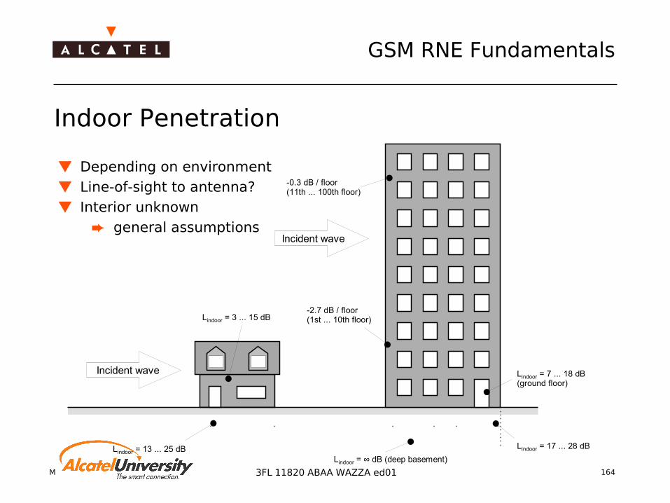
Indoor Penetration
Incident wave
Incident wave
Lindoor = 3 ... 15 dB
Lindoor = 13 ... 25 dBLindoor = ∞ dB (deep basement)
Lindoor = 17 ... 28 dB
-2.7 dB / floor(1st ... 10th floor)
-0.3 dB / floor(11th ... 100th floor)
Lindoor = 7 ... 18 dB(ground floor)
Depending on environment
Line-of-sight to antenna?
Interior unknown general assumptions

Mobile Radio Network Planning 165
GSM RNE Fundamentals
3FL 11820 ABAA WAZZA ed01
Body Loss (1)
Measured attenuation
versus time for a test person
walkingaround in an
anechoic chamber

Mobile Radio Network Planning 166
GSM RNE Fundamentals
3FL 11820 ABAA WAZZA ed01
Body Loss (2)
Head modeled as sphere
Calculation model
Near field of MS antenna•without head•with head

Mobile Radio Network Planning 167
GSM RNE Fundamentals
3FL 11820 ABAA WAZZA ed01
Body Loss (3)
Indirect measured field strength penetrated into the head (horizontal cut)
Test equipment for indirectfield strength measurements

Mobile Radio Network Planning 168
GSM RNE Fundamentals
3FL 11820 ABAA WAZZA ed01
Interference Margin In GSM, the defined minimum carrier-to-interferer ration
(C/I) threshold of 9 dB is only valid if the received server signal is not too weak.
In the case that e.g. the defined system threshold for the BTS of -111dBm is approached, a higher value of C/I is required in order to maintain the speech quality.
According to GSM, this is done by taking into account a correction of 3 dB.

Mobile Radio Network Planning 169
GSM RNE Fundamentals
3FL 11820 ABAA WAZZA ed01
Degradation (no FH) GSM uses a frame correction system, which works with
checksum coding and convolutional codes. Under defined conditions, this frame correction works
successfully and copes even with fast fading types as Rayleigh or Rician fading.
For lower mobile speed or stationary use, the fading has a bigger influence on the bit error rate and hence the speech quality is reduced.
In such a case, a degradation margin must be applied. The margin depends on the mobile speed and the usage of slow frequency hopping, which can improve the situation for slow mobiles again.

Mobile Radio Network Planning 170
GSM RNE Fundamentals
3FL 11820 ABAA WAZZA ed01
Diversity Gain This designates the optional usage of a second receiver
antenna. The second antenna is placed in a way, which provides
some decorrelation of the received signals. In a suitable combiner, the signals are processed in order to
achieve a sum signal with a smaller fading variation range. Depending on the receiver type, the signal correlation, and
the antenna orientation, a diversity gain from 2…6 dB is possible.

Mobile Radio Network Planning 171
GSM RNE Fundamentals
3FL 11820 ABAA WAZZA ed01
Lognormal margin Lognormal margin is also called fading margin
Due to fading effects, the minimum isotropic power is only received with a certain probability
Signal statistics, lognormal distribution with median power value Fmed and standard deviation σ (sigma)
Without any margin, the probability is 50%, which is not a sufficient value in order to provide a good call success rate.
A typical design goal should be a coverage probability of 90...95%. The following normalised table can be applied to find fading margins for different values of σ . The fading margin is calculated by multiplying the value of k (in the table) with the standard deviation:
Lognormal/Fading Margin = kσ .
k -∞ -0.5 0 1 1.3 1.65 2 2.33 +∞
Coverage Probability
0% 30% 50% 84% 90% 95% 97.7%
99% 100%
k -∞ -0.5 0 1 1.3 1.65 2 2.33 +∞
Coverage Probability
0% 30% 50% 84% 90% 95% 97.7%
99% 100%
kk -∞-∞ -0.5-0.5 00 11 1.31.3 1.651.65 22 2.332.33 +∞+∞
Coverage Probability Coverage
Probability 0%0% 30%30% 50%50% 84%84% 90%90% 95%95% 97.7
%97.7%
99%99% 100%
100%
Mobile Radio Network Planning 172
GSM RNE Fundamentals
3FL 11820 ABAA WAZZA ed01
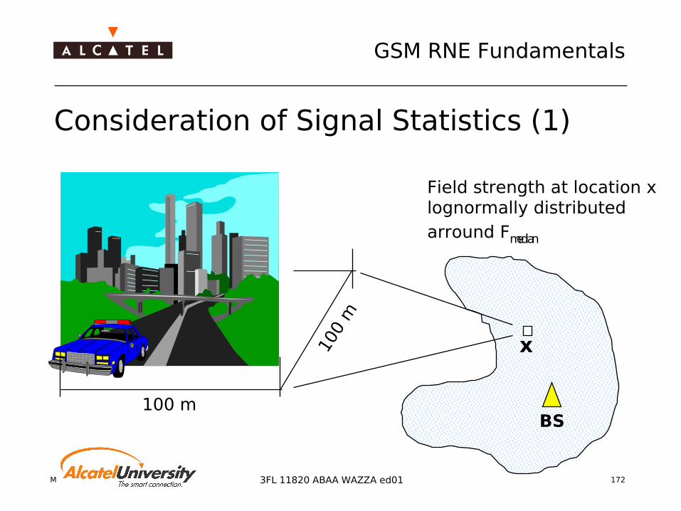
Consideration of Signal Statistics (1)
100 m
100
m
BS
x
Field strength at location xlognormally distributedarround Fmedian

Mobile Radio Network Planning 173
GSM RNE Fundamentals
3FL 11820 ABAA WAZZA ed01
Consideration of Signal Statistics (2)
0
0,05
0,1
0,15
0,2
0,25
0,3
received signal level F [dBm]
Local coverage probability: Pcov = P [ F > Fthreshold ]
σ
FmedianFthreshold
Area representing thecoverage probability

Mobile Radio Network Planning 174
GSM RNE Fundamentals
3FL 11820 ABAA WAZZA ed01
For what Radius R is the average coverage probability in the cell area 95% ?
Calculation of Coverage Radius R
r = distance between BTS and MS Frec = received power
σ = Standard deviation
F rec, thr
F rec
Frec,med (r)
0 r
σ
R
R
<Pcov (R)> = = 0.95∫20
π
π R²
Pcov (r) dr!
Frec,med (r) = EIRP - LossHata (r)
Loss Hata = f(hBS , hMS , f, r) + Kmor
Pcov (r)= P(Frec (r) > Frec,thr )
R = f (hBS , hMS , f, Kmor , EIRP, Frec,thr )
Mobile Radio Network Planning 175
GSM RNE Fundamentals
3FL 11820 ABAA WAZZA ed01
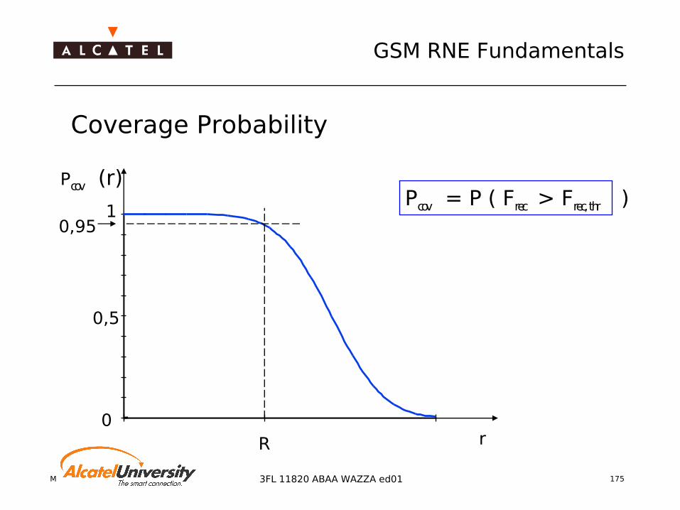
Coverage Probability
0
0,5
0,951
Pcov (r)
R r
Pcov = P ( Frec > Frec, thr )

Mobile Radio Network Planning 176
GSM RNE Fundamentals
3FL 11820 ABAA WAZZA ed01
Coverage Ranges and Hata Correction Factors
Area Coverage Probability
70%
75%
80%
85%
90%
95%
100%
0,0 1,5 3,0 4,5 6,0 7,5 9,0 10,5
d [km]
Pc
ov
155
150
145
140
135
130
125
120
115
110
ReferencePathloss [dB]
Calculation conditions:
Correction = 3; Sigma = 7hBS = 30 m; hMS = 1.7m; f = 900 Mhz
Clutter type Cor [dB] σ [dB]
Skyscrapers 0 6Dense urban 2 6Medium urban 4 7Lower urban 6 7Residential 8 6Industrial zone 10 10Forest 8 8Agricultural 20 6Low tree density 15 8Water 27 5Open area 27 6

Mobile Radio Network Planning 177
GSM RNE Fundamentals
3FL 11820 ABAA WAZZA ed01
Conventional BTS Configuration
ALCATEL EvoliumTM
TX → 45.4 dBmRX → -109dBm
TX
TX
and
RX
1 BTS Omnidirectional antenna for both TX and RX
Coverage Range R0
Coverage Area A0
R0
A0

Mobile Radio Network Planning 178
GSM RNE Fundamentals
3FL 11820 ABAA WAZZA ed01
Coverage Improvement by Antenna Diversity
ALCATEL EvoliumTM
TX → 45.4 dBmRX → -109dBm
TX RX
DIV
RX
an
d T
X 1 BTS Omnidirectional antennas
one for both RX and TX one for RXDIV
Antenna diversity gain (2...6 dB) Example: 3 dB
Coverage rangeRDiv = 1.23 · R0
Coverage areaADiv = 1.5 · A0
R0
RDiv
A0
ADiv
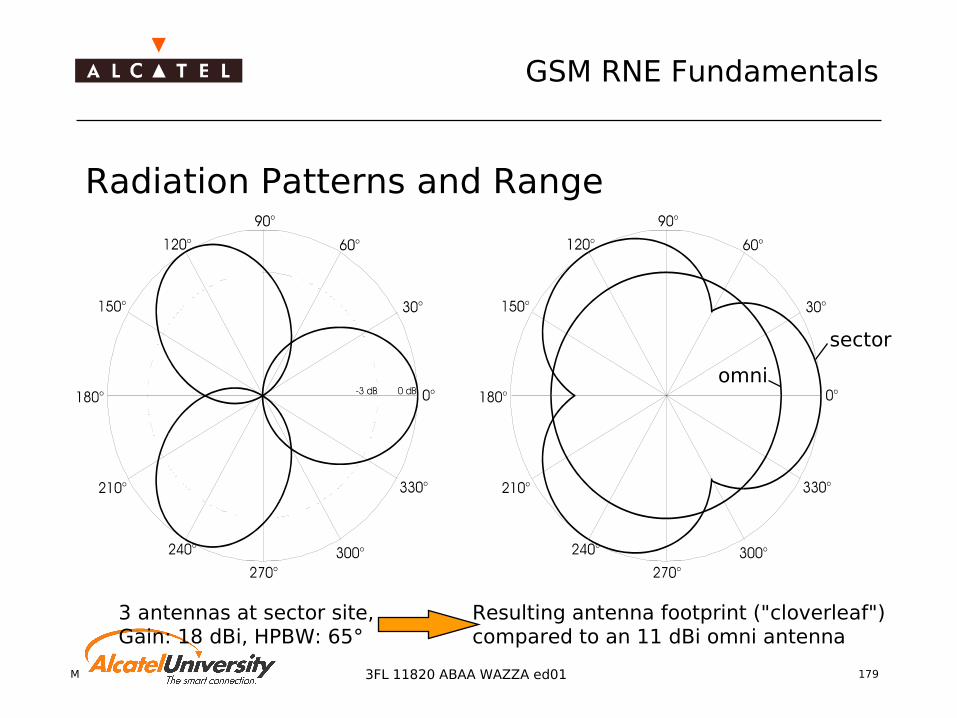
Mobile Radio Network Planning 179
GSM RNE Fundamentals
3FL 11820 ABAA WAZZA ed01
Radiation Patterns and Range
3 antennas at sector site,Gain: 18 dBi, HPBW: 65°
Resulting antenna footprint ("cloverleaf")compared to an 11 dBi omni antenna
omni
sector

Mobile Radio Network Planning 180
GSM RNE Fundamentals
3FL 11820 ABAA WAZZA ed01
Improvement by Antenna Diversity and Sectorization
TX
RX
DIV
3 BTS Directional antennas (18 dBi) Antenna diversity (3 dB) Max. coverage range
Rsec,div = 1.95 · R0
Coverage areaAsec,div = 3 · A0
ALCATEL EvoliumTM
ALCATEL EvoliumTM
ALCATEL EvoliumTM
R0
Rsec,div
Asec,div
Mobile Radio Network Planning 181
GSM RNE Fundamentals
3FL 11820 ABAA WAZZA ed01
Improvement by Antenna Preamplifier TX
RX
DIV
3 BTS Directional antennas (18 dBi) Antenna diversity (3 dB) Antenna preamplifier (3dB) Max. coverage range
Rsec,div,pre = 2.22 · R0
Coverage areaAsec,div,pre = 3.9 · A0
General:Asec = g · A0
g: Area gain factorR0
Rsec,div,pre
Asec,div,pre
ALCATEL EvoliumTM
ALCATEL EvoliumTM
ALCATEL EvoliumTM

Mobile Radio Network Planning 1823FL 11820 ABAA WAZZA ed01
Coverage Planning
Antenna Engineering
Mobile Radio Network Planning 183
GSM RNE Fundamentals
3FL 11820 ABAA WAZZA ed01
Omni Antennas Application
Large area coverage Umbrella cell for micro cell layer
Advantages Continuous coverage around the site Simple antenna mounting Ideal for homogeneous terrain
Drawbacks No mechanical tilt possible Clearance of antenna required Densification of network difficult

Mobile Radio Network Planning 184
GSM RNE Fundamentals
3FL 11820 ABAA WAZZA ed01
Sector Antenna Antenna with horizontal HPBW of e.g. 90° or 65° Advantages
Coverage can be focussed on special areas Low coverage of areas of no interest (e.g. forest) Allows high traffic load Additional mechanical downtilt possible Wall mounting possible
Drawbacks More frequencies needed per site compared to omni
sites More hardware needed Lower coverage area per sector

Mobile Radio Network Planning 185
GSM RNE Fundamentals
3FL 11820 ABAA WAZZA ed01
Typical Applications
Wide horizontal beam width (e.g. 90°) For areas with few reflecting and scattering objects (rural
area) Area coverage for 3-sector sites Sufficient cell overlap to allow successful handovers
Small horizontal beam width (e.g. 65°) For areas with high scattering (city areas) Coverage between sectors by scattering and by adjacent
sites (mostly site densification in urban areas)
Mobile Radio Network Planning 186
GSM RNE Fundamentals
3FL 11820 ABAA WAZZA ed01
Antenna Tilt Downtilting of the Antenna main beam related to the
horizontal line Goals:
Reduction of overshoot Removal of insular coverage Lowering the interference Coverage improvement of the near area (indoor
coverage) Adjustment of cell borders (handover zones)
Mechanical / Electrical or Combined downtilt

Mobile Radio Network Planning 187
GSM RNE Fundamentals
3FL 11820 ABAA WAZZA ed01
Mechanical Downtilt Advantages
Later adjustment of vertical tilt possible Antenna diagram is not changed, i.e. nulls and side
lobes remain in their position relative to the main beam
Cost effective (single antenna type may be used) Fast adjustments possible
Drawbacks Side lobes are less tilted Accurate adjustment is difficult Problems for sites with difficult access
Mobile Radio Network Planning 188
GSM RNE Fundamentals
3FL 11820 ABAA WAZZA ed01
Electrical Downtilt Advantages
Same tilt for both main and side lobes Antenna mounting is more simple
→ no adjustment errors
Drawbacks Introduction of additional antenna types necessary New antenna installation at the site if downtilting is
introduced Long antenna optimization phase Adjustment of electrical tilt mostly not possible
τ = 0
τ = t
τ = 2 t
τ = 3 t
τ = delay time
downtilt angle
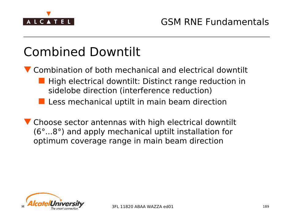
Mobile Radio Network Planning 189
GSM RNE Fundamentals
3FL 11820 ABAA WAZZA ed01
Combined Downtilt Combination of both mechanical and electrical downtilt
High electrical downtilt: Distinct range reduction in sidelobe direction (interference reduction)
Less mechanical uptilt in main beam direction
Choose sector antennas with high electrical downtilt (6°...8°) and apply mechanical uptilt installation for optimum coverage range in main beam direction

Mobile Radio Network Planning 190
GSM RNE Fundamentals
3FL 11820 ABAA WAZZA ed01
Assessment of Required Tilts
Required tilt is estimated using Geometrical Optics
Consideration of Vertical HPBW of the antenna Antenna height above ground Height difference antenna/location to be covered Morpho-structure in the vicinity of the antenna Topography between transmitter and receiver location
Tilt must be applied for both TX and RX antennas!

Mobile Radio Network Planning 191
GSM RNE Fundamentals
3FL 11820 ABAA WAZZA ed01
Inter Site Distance in Urban Area Using sectorized sites with
antennas of 65° horizontal half power beam width
The sidelobe is approximately reduced by 10dB.
This is a reduction of cell range to 50%.
The inter site distance calculation factor depends on
Type of antenna Type of morpho class
Multi path propagation Scattering Sigma (fading variations)
X XA B
0.5* R2R2

Mobile Radio Network Planning 192
GSM RNE Fundamentals
3FL 11820 ABAA WAZZA ed01
Downtilt in Urban Area
Cell range R2
Main beam
0.5* R2
Side lobe
Tilt 2 Tilt 2Site A Site B
Inter Site Distance A-B = 1.5* R2

Mobile Radio Network Planning 193
GSM RNE Fundamentals
3FL 11820 ABAA WAZZA ed01
Downtilt in Urban Area The upper limit of the vertical half power beam width
is directed towards the ground at maximum cell range Upper –3dB point of the vertical antenna pattern
To be used in areas with Multi path propagation condition Good scattering of the beam
Aim Reduction of interference
Optimization Coverage Optimization in isolated cases using less downtilt Interference Reduction in isolated cases using more downtilt

Mobile Radio Network Planning 194
GSM RNE Fundamentals
3FL 11820 ABAA WAZZA ed01
Downtilt in Suburban and Rural Area Downtilt planning for
Suburban Rural Highway Coverage
The main beam is directed towards the ground at maximum cell range
Main beamMain beam
Cell range R1 Cell range R1
Tilt 1 Tilt 1
Inter Site Distance C-D = 2* R1
Site C Site D

Mobile Radio Network Planning 195
GSM RNE Fundamentals
3FL 11820 ABAA WAZZA ed01
Antenna configurations
Application of Duplexer Consists of a TX/RX Filter and a combiner one antenna can be saved
Tower Mounted Amplifier (TMA) Increase Uplink Sensitivity TMA needs to have TX bypass
=> in case of duplexer usage Diversity
Space diversity Polarization diversity
Rx/Tx
RxTx
DuplexFilter
To BTS

Mobile Radio Network Planning 196
GSM RNE Fundamentals
3FL 11820 ABAA WAZZA ed01
Antenna Configurations for Omni and Sector Sites
Rx
Tx
Rxdiv
Tower mounting for omni antennas Tower mounting for directional antennas
Pole mounting for roof-top mounting
Pole mounting for wallor parapet mounting
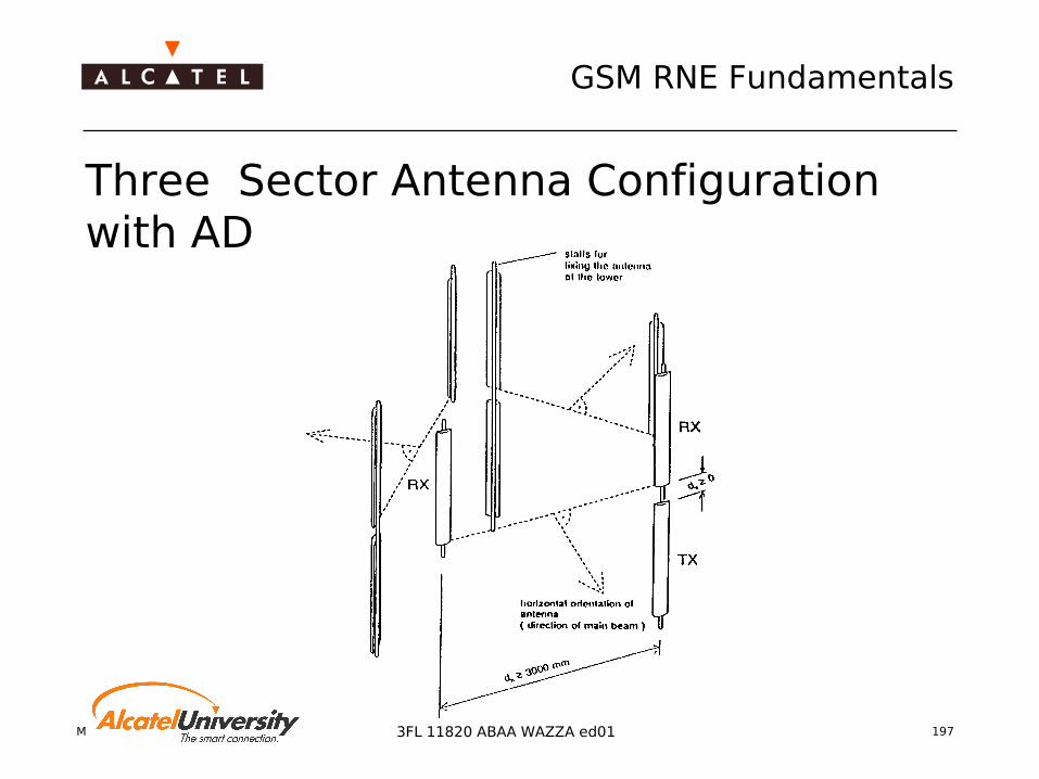
Mobile Radio Network Planning 197
GSM RNE Fundamentals
3FL 11820 ABAA WAZZA ed01
Three Sector Antenna Configuration with AD

Mobile Radio Network Planning 198
GSM RNE Fundamentals
3FL 11820 ABAA WAZZA ed01
Antenna Engineering Rules
Distortion of antenna pattern: No obstacles within Antenna near field range HPBW Rule plus security margin of 20° First fresnel ellipsoid range (additional losses!)
TX-RX Decoupling to avoid blocking and intermodulation Required minimum separation of TX - RX antennas
dependent on antenna configuration (e.g. duplexer or not)
Diversity gain Required antenna separation for space diversity

Mobile Radio Network Planning 199
GSM RNE Fundamentals
3FL 11820 ABAA WAZZA ed01
Distortion of antenna pattern Antenna Near Field Range: Rmin = 2D²/λ
D = Aperture of antenna (e.g. 3m)
=> Rmin = 60 / 120m for GSM / DCS
HPBW Rule with securtiy margin of 20° and tilt α
Roof Top = Obstacle
ϕϕ = HPBW/2 + 20° + α
D
H
D[m] 1 5 10H[m] 0.5 2.5 5
HPBW = 8°, α = 2°

Mobile Radio Network Planning 200
GSM RNE Fundamentals
3FL 11820 ABAA WAZZA ed01
Tx-Rx Decoupling (1)
TX
RX
fuse
fint
f[MHz]
P [dBm]
fuse fint
-101
-13
n*200kHz
Pout
Pin
ReceiverCharacteristic
Pblock
P1dB
Out of Band Blocking Requirement (GSM Rec. 11.21) GSM 900 = +8 dBm GSM 1800 = 0 dBm
Required Decoupling (n = number of transmitters)
TX-TX = 20 dB TX-RX GSM = 30 + 10 log (n) dB TX-RX DCS = 40 + 10 log (n) dB

Mobile Radio Network Planning 201
GSM RNE Fundamentals
3FL 11820 ABAA WAZZA ed01
TX-RX Decoupling (2) Horizontal separation (Approximation)
IH=22+20log(d
H/λ )-(G
T+G
R) [dB]
dH
Isolation for Horizontal Separation - omni 11dBi
15
20
25
30
35
40
45
1.7
2.7
3.7
4.7
5.7
6.7
7.7
8.7
9.7
10.4
10.8
11.2
11.6 12 12
.412
.813
.213
.6 14 14.4
14.8
15.2
Separation [m]
Iso
lati
on
[d
B] GSM1800
GSM900

Mobile Radio Network Planning 202
GSM RNE Fundamentals
3FL 11820 ABAA WAZZA ed01
TX-RX Decoupling (3) Vertical separation (Approximation)
IV=28+40log(d
V/λ) [dB]
dv
dm
Mast
Iso la tion for V e rtica l S e pa ra tion
0
10
20
30
40
50
60
70
0.2 0.3 0.4 0.5 0.6 0.7 0.8 0.9 1
Se par ation [m ]
Isol
atio
n [d
B]
GSM1800
GSM900
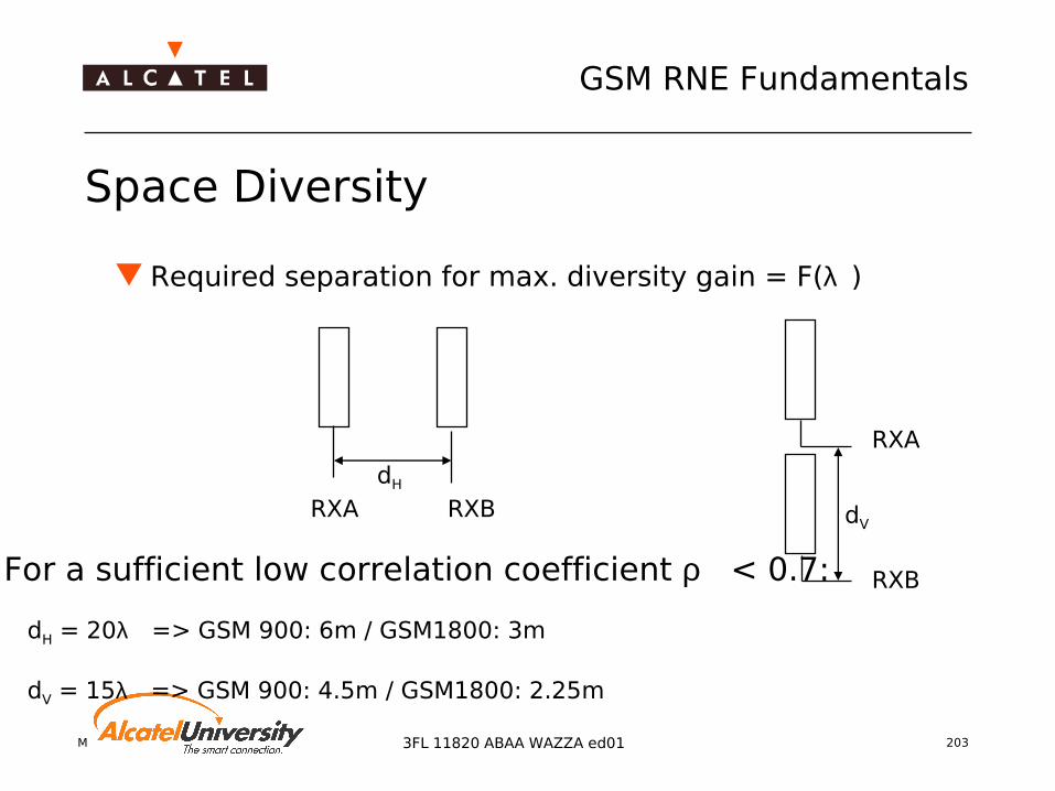
Mobile Radio Network Planning 203
GSM RNE Fundamentals
3FL 11820 ABAA WAZZA ed01
Required separation for max. diversity gain = F(λ )
Space Diversity
dH
RXA RXB dV
RXA
RXBFor a sufficient low correlation coefficient ρ < 0.7: dH = 20λ => GSM 900: 6m / GSM1800: 3m
dV = 15λ => GSM 900: 4.5m / GSM1800: 2.25m
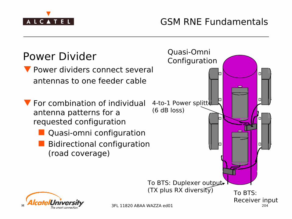
Mobile Radio Network Planning 204
GSM RNE Fundamentals
3FL 11820 ABAA WAZZA ed01
Power Divider Power dividers connect several antennas to one feeder cable
For combination of individualantenna patterns for a requested configuration
Quasi-omni configuration Bidirectional configuration
(road coverage)
4-to-1 Power splitter(6 dB loss)
To BTS: Receiver input
To BTS: Duplexer output(TX plus RX diversity)
Quasi-OmniConfiguration

Mobile Radio Network Planning 205
GSM RNE Fundamentals
3FL 11820 ABAA WAZZA ed01
Power divider Also called "power splitter" or "junction box" Passive device (works in both (transmit and
receive) direction)
3 dB
Pin
Pin
2
Pin
2
Pin
3
4.5 dB
Pin
Pin
3
Pin
3
6 dB
Pin
Pin
4
Pin
4
Pin
4
Pin
4
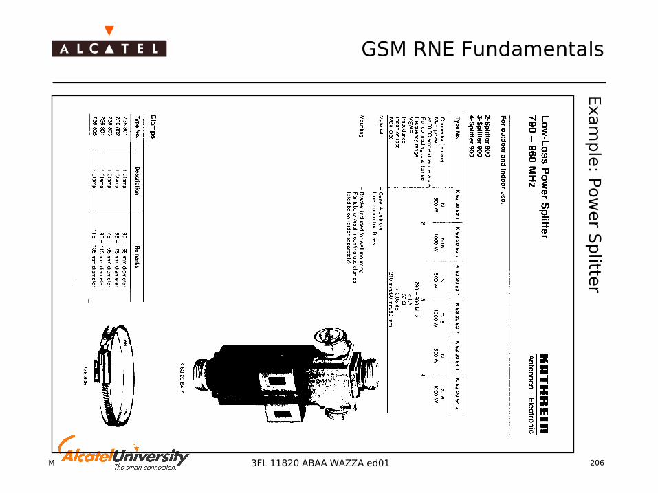
Mobile Radio Network Planning 206
GSM RNE Fundamentals
3FL 11820 ABAA WAZZA ed01
Exam
ple
: Pow
er S
plitte
r

Mobile Radio Network Planning 207
GSM RNE Fundamentals
3FL 11820 ABAA WAZZA ed01
Panel Configurations (1) Radial Arrangement
of 6 Panel Antennas with horizontal beamwidth = 105 °gain = 16.5 dBi, mast radius = 0.425 m, mounting radius = 0.575 m
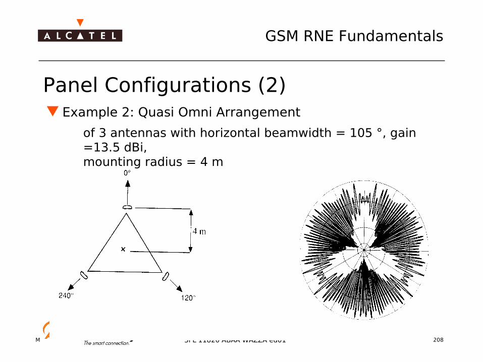
Mobile Radio Network Planning 208
GSM RNE Fundamentals
3FL 11820 ABAA WAZZA ed01
Panel Configurations (2) Example 2: Quasi Omni Arrangement
of 3 antennas with horizontal beamwidth = 105 °, gain =13.5 dBi,mounting radius = 4 m
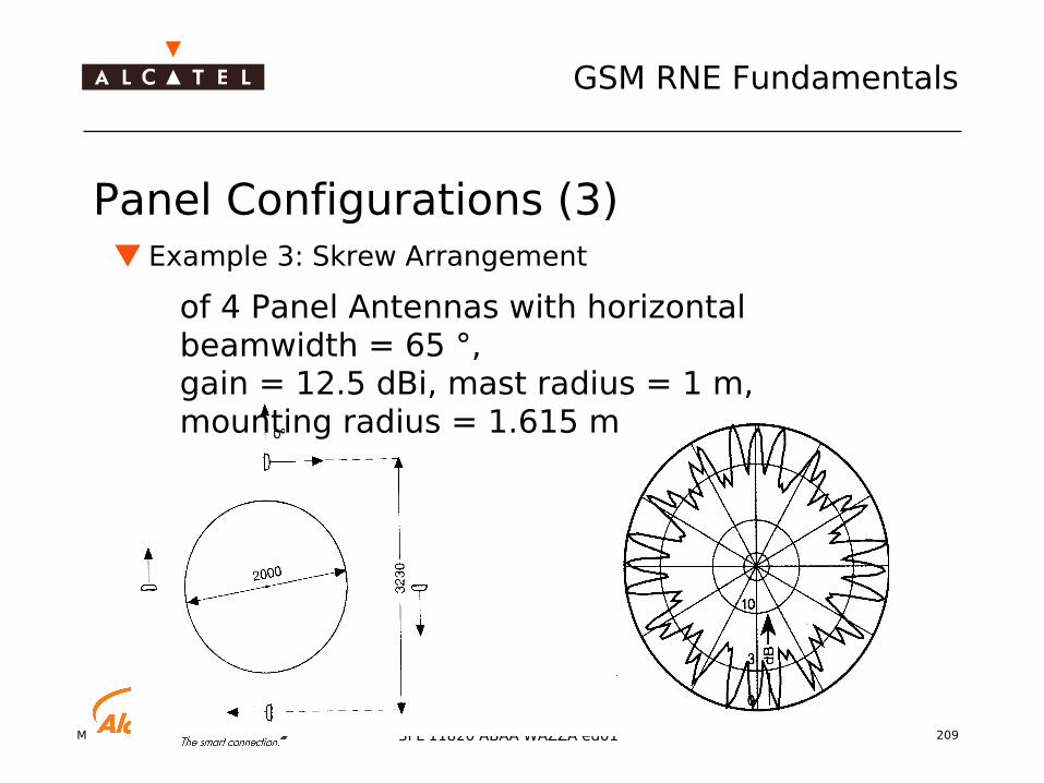
Mobile Radio Network Planning 209
GSM RNE Fundamentals
3FL 11820 ABAA WAZZA ed01
Panel Configurations (3) Example 3: Skrew Arrangement
of 4 Panel Antennas with horizontal beamwidth = 65 °,gain = 12.5 dBi, mast radius = 1 m,mounting radius = 1.615 m

Mobile Radio Network Planning 210
GSM RNE Fundamentals
3FL 11820 ABAA WAZZA ed01
Feeders
Technical summary
Inner conductor: Copper wire
Dielectric: Low density foam PE
Outer conductor: Corrugated copper tube
Jacket: Polyethylene (PE) black
Inner conductorOuter conductor
Dielectric Jacket

Mobile Radio Network Planning 211
GSM RNE Fundamentals
3FL 11820 ABAA WAZZA ed01
Feeder Installation Set and Connectors
1 Cable Clamps2 Antenna Cable3 Double Bearing4 Counterpart5 Anchor tape
7/16 Connector:Coaxial ConnectorRobustGood RF-Performance

Mobile Radio Network Planning 212
GSM RNE Fundamentals
3FL 11820 ABAA WAZZA ed01
Type Minimum bending radius Jacket(outer diameter)
Weight (m) Recommendedclamp spacing
Single bending Repeated bending
LCF 1/2’’ 70 mm 210 mm 16 mm 0.35 kg 0.6 m
LCF 7/8’’ 120 mm 360 mm 28 mm 0.62 kg 0.8 m
LCF 1 5/8’’ 300 mm 900 mm 49.7 mm 1.5 kg 1.2 m
These values are based on feeder types with an impedance of 50 ohms
GSM 900 GSM 1800 GSM 1900
Type Attenuation /100 m [dB]
Recommendedmax length [m]
Attenuation /100 m [dB]
Recommendedmax length [m]
Attenuation /100 m [dB]
Recommendedmax length [m]
LCF 1/2“ 6.6 45 10.3 30 10.6 28LCF 7/8“ 4.0 75 6.0 50 6.3 47LCF 1_5/8“ 2.6 115 4.0 75 4.2 71
Feeder Parameters

Mobile Radio Network Planning 213
GSM RNE Fundamentals
3FL 11820 ABAA WAZZA ed01
Feeder attenuation (1)
Main contribution is given by feeder loss Feeder Cable 4dB/100m => length 50m Loss =2.0dB Jumper Cable 0.066dB/1m => 5m Loss =0.33dB Insertion Loss of connector and power splitter < 0.1dB Total Loss 2.0dB+2x0.33dB+5x0.1dB+0.1dB=3.26dB
Cable type is trade off between Handling flexibility Cost Attenuation

Mobile Radio Network Planning 214
GSM RNE Fundamentals
3FL 11820 ABAA WAZZA ed01
Radiating Cables
Provide coverage in Tunnels, buildings, along side tracks or
lines
Principle: Radiate a weak but constant electromagnetic wave
Suitable for coverage over longer distances (Repeater)
Fieldstrength distribution more constant as with antennas
F
FThr
Repeater
F
FThr
Terminat-ing Load
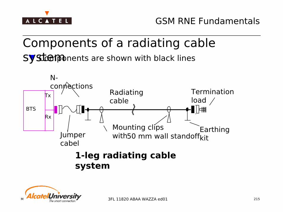
Mobile Radio Network Planning 215
GSM RNE Fundamentals
3FL 11820 ABAA WAZZA ed01
Components are shown with black lines
BTS
Tx
Rx
Radiating cable
Termination load
Earthing kit
Mounting clips with50 mm wall standoff
N-connections
Jumper cabel
1-leg radiating cable system
Components of a radiating cable system

Mobile Radio Network Planning 216
GSM RNE Fundamentals
3FL 11820 ABAA WAZZA ed01
-40
-50
-60
-70
-80
-90
-100
-110
[dBm]
Cable attenuationbetween the antennas
Radiating cable field strength
Antenna field strength
Distance
Comparison of field strength: Radiating cable and standard antenna

Mobile Radio Network Planning 217
GSM RNE Fundamentals
3FL 11820 ABAA WAZZA ed01
Example of a radiating cable in a tunnel

Mobile Radio Network Planning 218
GSM RNE Fundamentals
3FL 11820 ABAA WAZZA ed01
Microwave antennas, feeders and accessories Microwave point to point systems use highly directional antennas
Gain
with G = gain over isotropic, in dBiA = area of antenna aperturee = antenna efficiency
Used antenna types parabolic antenna high performance antenna horn lens antenna horn antenna
GA e= 10
42
lgπλ

Mobile Radio Network Planning 219
GSM RNE Fundamentals
3FL 11820 ABAA WAZZA ed01
Parabolic antenna Parabolic dish, illuminated by a feed horn
at its focus Available sizes: 1’ (0.3 m) up to 16’ (4.8
m) Sizes over 4’ seldom used due to
installation restrictions Single plane polarized feed vertical (V) or
horizontal (H) Also: dual polarized feeder (DP), with
separate V and H connections (lower gain)
Front-to-back ratios of 45 dB not high enough for back-to-back configuration on the same frequency
Antenna patterns are absolutely necessary for interference calculations

Mobile Radio Network Planning 220
GSM RNE Fundamentals
3FL 11820 ABAA WAZZA ed01
High performance antenna
Similar to common parabolic antenna, except for attached cylindrical shield
Improvement of front-to-back ratio and wide angle radiation discrimination
Available in same sizes as parabolic, single or dual polarized
Substantially bigger, heavier, and more expensive than parabolic antennas
Allow back-to-back transmission at the same frequency in both directions (refer to interference calculation)

Mobile Radio Network Planning 221
GSM RNE Fundamentals
3FL 11820 ABAA WAZZA ed01
Horn antennas Horn lens antenna For very high frequencies > 25 GHz Replacement for small parabolic
antennas (1’) Same electrical data, but easier to
install due to size and weight
Horn reflector antenna Large parabola, energy from the feed
horn is reflected at right angle (90°) Gain like 10’ parabolic antenna (60
dBi), but higher front-to-back ratios > 70 dB
Big and heavy, requires a complex installation procedureOnly used on high capacity microwave backbones (e.g. MSC-MSC interconnections)
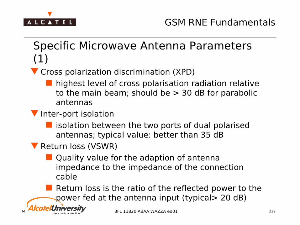
Mobile Radio Network Planning 222
GSM RNE Fundamentals
3FL 11820 ABAA WAZZA ed01
Specific Microwave Antenna Parameters (1)
Cross polarization discrimination (XPD) highest level of cross polarisation radiation relative
to the main beam; should be > 30 dB for parabolic antennas
Inter-port isolation isolation between the two ports of dual polarised
antennas; typical value: better than 35 dB Return loss (VSWR)
Quality value for the adaption of antenna impedance to the impedance of the connection cable
Return loss is the ratio of the reflected power to the power fed at the antenna input (typical> 20 dB)

Mobile Radio Network Planning 223
GSM RNE Fundamentals
3FL 11820 ABAA WAZZA ed01
Radiation pattern envelope (RPE) Tolerance specification for antenna pattern (specification of
antenna pattern itself not suitable due to manufacturing problems)
Usually available from manufacturer in vertical and horizontal polarisation (worst values of several measurements)
Weight
Wind load
Specific Microwave Antenna Parameters (2)

Mobile Radio Network Planning 224
GSM RNE Fundamentals
3FL 11820 ABAA WAZZA ed01
Data sheet 15 GHz
Parabolic antenna 15 GHz High performance antenna 15 GHz
B an d w id th (G H z ) 1 4 .4 - 1 5 .3 51 4 .4 - 1 5 .3 51 4 .4 - 1 5 .3 5 M o d e l n u m b e r P A 2 - 1 4 4 P A 4 - 1 4 4 P A 6 - 1 4 4 N o m in a l d iam e te r (m ) 0 .6 1 .2 1 .8
(f t) 2 4 6
H a lf-p o w e r b ea m w id th (d e g ) 2 .3 1 .2 0 .8 G a in lo w b a n d (d B i) 3 6 .2 4 2 .3 4 5 .8 G a in m id b a n d (d B i) 3 6 .5 4 2 .5 4 6 .0 G a in h ig h b an d (d B i) 3 6 .7 4 2 .8 4 6 .3 F ro n t- to -b a ck ra tio (d B ) 4 2 4 8 5 2 C ro ss p o la r d isc r im in a tio n(d B ) 2 8 3 0 3 0 R e tu rn lo ss (d B ) 2 6 2 6 2 8
W e ig h t (k g ) 1 9 4 3 7 3 W in d lo ad E le v a tio n a d ju s tm e n t (d e g ) + /- 5 + /- 5 + /- 5
B a n d w id th (G H z ) 1 4 .4 - 1 5 .3 51 4 .4 - 1 5 .3 51 4 .4 - 1 5 .3 5M o d e l n u m b e r D A 2 - 1 4 4D A 4 - 1 4 4D A 6 - 1 4 4N o m in a l d ia m e te r (m ) 0 .6 1 .2 1 .8
( f t ) 2 4 6
H a lf -p o w e r b e a m w id th (d e g ) 2 .3 1 .2 0 .8G a in lo w b a n d (d B i) 3 6 .2 4 2 .3 4 5 .8G a in m id b a n d (d B i) 3 6 .5 4 2 .5 4 6 .0G a in h ig h b a n d (d B i) 3 6 .7 4 2 .8 4 6 .3F ro n t- to -b a c k r a t io (d B ) 6 5 6 8 6 8C ro ss p o la r d isc r im in a t io n(d B ) 2 8 3 0 3 0R e tu r n lo s s (d B ) 2 6 2 6 2 6
W e ig h t (k g ) 2 8 5 5 1 3 0W in d lo a dE le v a tio n a d ju s tm e n t (d e g ) + /- 1 2 + /- 1 2 + /- 1 2

Mobile Radio Network Planning 225
GSM RNE Fundamentals
3FL 11820 ABAA WAZZA ed01
Radiation pattern envelope
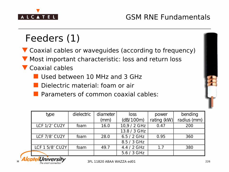
Mobile Radio Network Planning 226
GSM RNE Fundamentals
3FL 11820 ABAA WAZZA ed01
Feeders (1) Coaxial cables or waveguides (according to frequency) Most important characteristic: loss and return loss Coaxial cables
Used between 10 MHz and 3 GHz Dielectric material: foam or air Parameters of common coaxial cables:
type dielectric diameter(mm)
loss(dB/100m)
powerrating (kW)
bendingradius (mm)
LCF 1/2’ CU2Y foam 16.0 10,9 / 2 GHz 0.47 20013.8 / 3 GHz
LCF 7/8’ CU2Y foam 28.0 6.5 / 2 GHz 0.95 3608.5 / 3 GHz
LCF 1 5/8’ CU2Y foam 49.7 4.4 / 2 GHz 1.7 3805.6 / 3 GHz

Mobile Radio Network Planning 227
GSM RNE Fundamentals
3FL 11820 ABAA WAZZA ed01
Feeders (2)
Waveguides Used for frequency bands above 2.7 GHz Three basic types available: circular, elliptical and
rectangular Rigid circular waveguide
Very low loss Supports two orthogonal polarisations Capable to carry more than one frequency band Usually, short components of this type are used Disadvantages: cost, handling and moding problems

Mobile Radio Network Planning 228
GSM RNE Fundamentals
3FL 11820 ABAA WAZZA ed01
Feeders (3)
Elliptical semiflexible waveguides Acceptable loss, good VSWR performance Low cost and easy to install Various types optimised for many frequency bands up to 23
GHz Used for longer distances (easy and flexible installation) Can be installed as a "single run" (no intermediate flanges)
type loss /100 m FrequencyEW 34 2.0 4 GHzEW 52 4.0 6GHzEW 77 5.8 8GHzEW 90 10.0 11 GHzEW 220 28.0 23 GHz
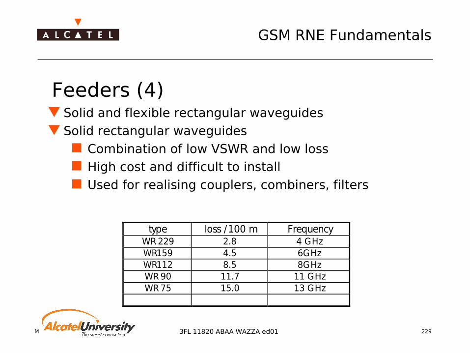
Mobile Radio Network Planning 229
GSM RNE Fundamentals
3FL 11820 ABAA WAZZA ed01
Feeders (4) Solid and flexible rectangular waveguides Solid rectangular waveguides
Combination of low VSWR and low loss High cost and difficult to install Used for realising couplers, combiners, filters
type loss /100 m FrequencyWR 229 2.8 4 GHzWR159 4.5 6GHzWR112 8.5 8GHzWR 90 11.7 11 GHzWR 75 15.0 13 GHz

Mobile Radio Network Planning 230
GSM RNE Fundamentals
3FL 11820 ABAA WAZZA ed01
Feeders (5)
Flexible rectangular waveguides Worse VSWR and losses than for solid waveguides Often used in short lengths (<1 m), where position
between connection points depends on actual installation place
Common applications: connection of microwave system to antenna (close together on rooftops or towers) for frequencies >13 Ghz
type loss / m FrequencyPDR140 0.5 15GHzPDR180 1 18 GHzPDR220 2 23 GHz

Mobile Radio Network Planning 231
GSM RNE Fundamentals
3FL 11820 ABAA WAZZA ed01
Antenna feeder systems (1) Direct radiating system
Most commonly used for frequencies up to 13 Ghz
Depending on accepted feeder loss/length, higher frequencies may be possible
Excessive attenuation and costs in long runs of wave guide
Occurence of echo distortion due to mismatch in long runs of waveguide possible
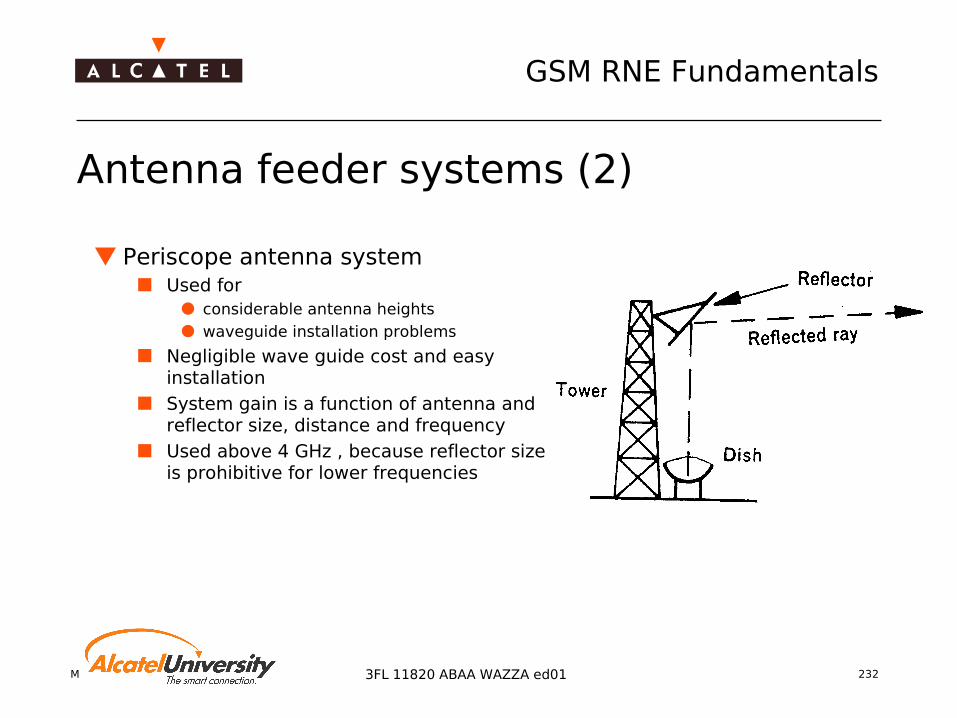
Mobile Radio Network Planning 232
GSM RNE Fundamentals
3FL 11820 ABAA WAZZA ed01
Antenna feeder systems (2)
Periscope antenna system Used for
considerable antenna heights waveguide installation problems
Negligible wave guide cost and easy installation
System gain is a function of antenna and reflector size, distance and frequency
Used above 4 GHz , because reflector size is prohibitive for lower frequencies

Mobile Radio Network Planning 233
GSM RNE Fundamentals
3FL 11820 ABAA WAZZA ed01
Antenna feeder systems (3) Combined antenna with transceiver
Antenna and transceiver are combined as a single unit to cut out wave guide loss (higher frequencies)
Units are mounted on top of a mast and connected to multiplex equipment via cable
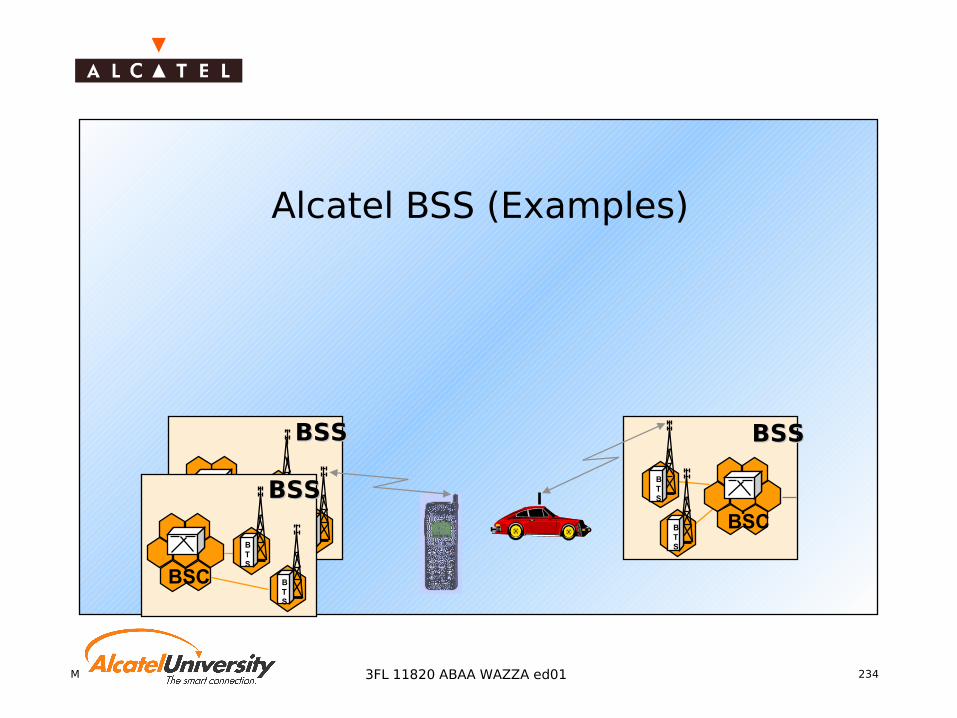
Mobile Radio Network Planning 2343FL 11820 ABAA WAZZA ed01
Alcatel BSS (Examples)
BSSBSS
BTS
BSCBTS
BSSBSS
BTS
BSC BTS
BSSBSS
BTS
BSC BTS
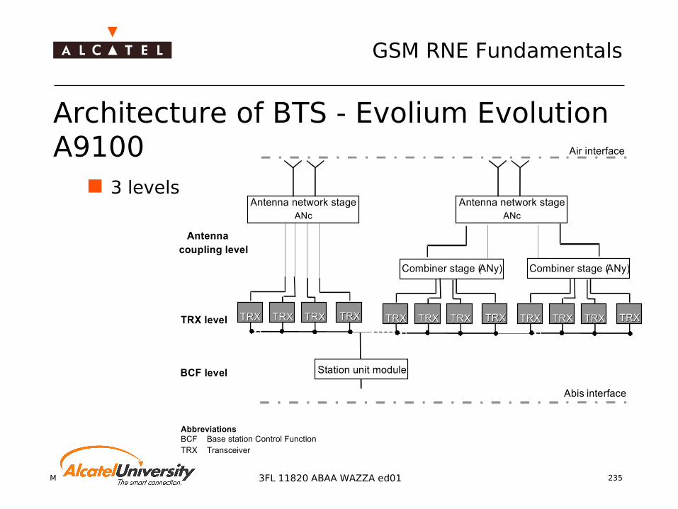
Mobile Radio Network Planning 235
GSM RNE Fundamentals
3FL 11820 ABAA WAZZA ed01
Architecture of BTS - Evolium Evolution A9100
3 levels
Antennacoupling level
TRX level
BCF level Station unit module
Abis interface
AbbreviationsBCF Base station Control FunctionTRX Transceiver
Antenna network stage ANc
Air interface
Combiner stage (ANy)Combiner stage (ANy)
TRXTRX TRXTRX TRXTRX TRXTRXTRXTRX TRXTRX TRXTRX TRXTRX TRXTRX TRXTRX TRXTRX TRXTRX
Antenna network stage ANc

Mobile Radio Network Planning 236
GSM RNE Fundamentals
3FL 11820 ABAA WAZZA ed01
EVOLIUMTM A9100 Base Station (1) The Antenna network Combiner (ANc)- combining mode
DuplexerFilter Filter
LNA
Splitter
Splitter SplitterWBC
DuplexerFilter Filter
LNA
Splitter
SplitterSplitter WBC
Antenna ATXA, RX A, RXBdiv
Antenna BTXB, RX B, RXAdiv
TX RX RXdiv
TRX 1
TX RX RXdiv
TRX 2
Rxdiv RX TX
TRX 4
Rxdiv RX TX
TRX 3
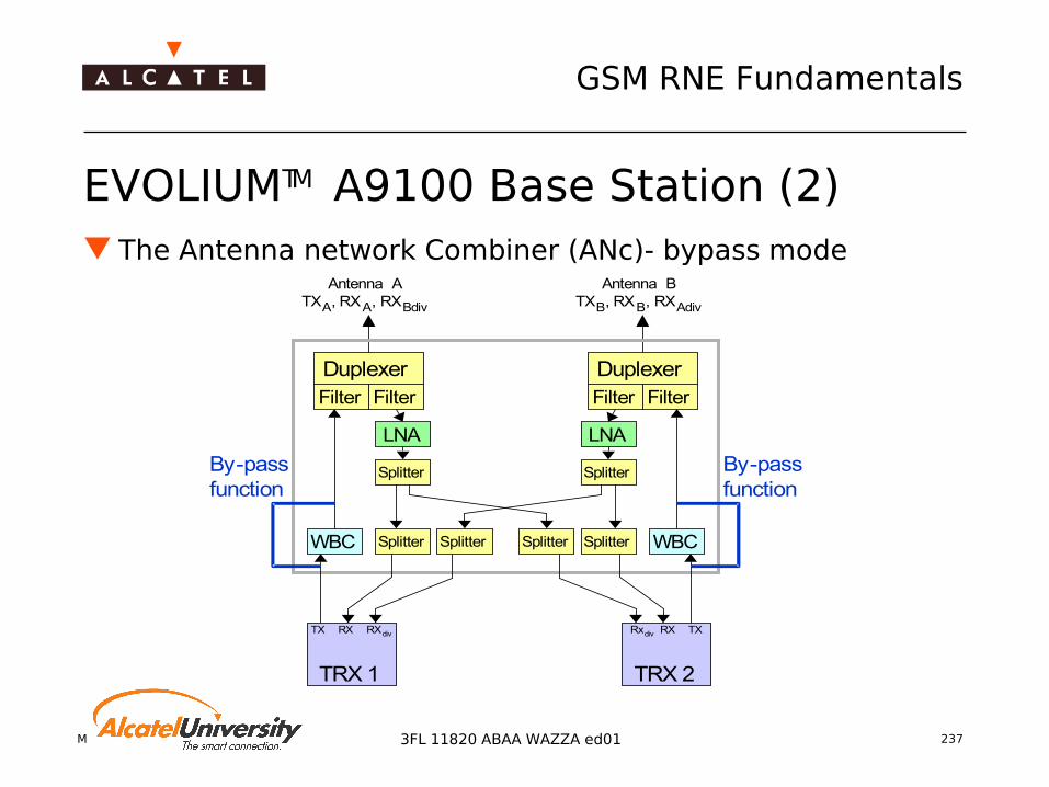
Mobile Radio Network Planning 237
GSM RNE Fundamentals
3FL 11820 ABAA WAZZA ed01
EVOLIUMTM A9100 Base Station (2) The Antenna network Combiner (ANc)- bypass mode
DuplexerFilter Filter
LNA
Splitter
Splitter SplitterWBC
DuplexerFilter Filter
LNA
Splitter
SplitterSplitter WBC
Antenna ATXA, RXA, RXBdiv
Antenna BTXB, RXB, RXAdiv
TX RX RXdiv
TRX 1
Rxdiv RX TX
TRX 2
By-passfunction
By-passfunction
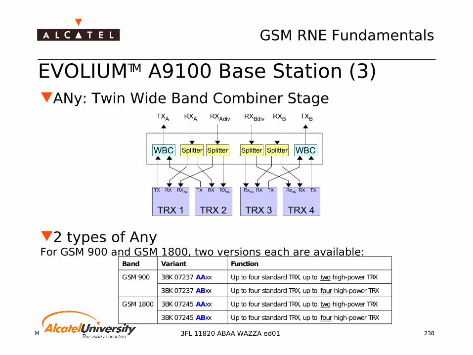
Mobile Radio Network Planning 238
GSM RNE Fundamentals
3FL 11820 ABAA WAZZA ed01
EVOLIUMTM A9100 Base Station (3)ANy: Twin Wide Band Combiner Stage
2 types of AnyFor GSM 900 and GSM 1800, two versions each are available:
Splitter SplitterWBC SplitterSplitter WBC
TXA RXA RXAdiv
TX RX RXdiv
TRX 1
TX RX RXdiv
TRX 2
Rxdiv RX TX
TRX 4
Rxdiv RX TX
TRX 3
RXBdiv RXB TXB
Band Variant Function
3BK 07237 AAxx Up to four standard TRX, up to two high-power TRXGSM 900
3BK 07237 ABxx Up to four standard TRX, up to four high-power TRX
3BK 07245 AAxx Up to four standard TRX, up to two high-power TRXGSM 1800
3BK 07245 ABxx Up to four standard TRX, up to four high-power TRX
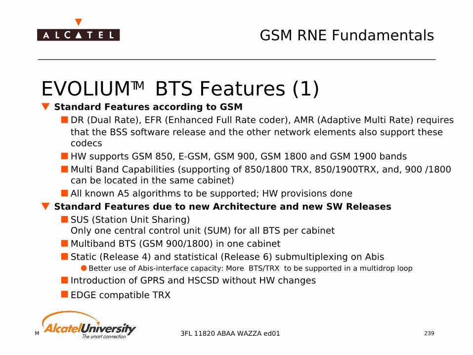
Mobile Radio Network Planning 239
GSM RNE Fundamentals
3FL 11820 ABAA WAZZA ed01
EVOLIUMTM BTS Features (1) Standard Features according to GSM
DR (Dual Rate), EFR (Enhanced Full Rate coder), AMR (Adaptive Multi Rate) requires that the BSS software release and the other network elements also support these codecs
HW supports GSM 850, E-GSM, GSM 900, GSM 1800 and GSM 1900 bands Multi Band Capabilities (supporting of 850/1800 TRX, 850/1900TRX, and, 900 /1800
can be located in the same cabinet) All known A5 algorithms to be supported; HW provisions done
Standard Features due to new Architecture and new SW Releases SUS (Station Unit Sharing)
Only one central control unit (SUM) for all BTS per cabinet Multiband BTS (GSM 900/1800) in one cabinet Static (Release 4) and statistical (Release 6) submultiplexing on Abis
Better use of Abis-interface capacity: More BTS/TRX to be supported in a multidrop loop
Introduction of GPRS and HSCSD without HW changes
EDGE compatible TRX

Mobile Radio Network Planning 240
GSM RNE Fundamentals
3FL 11820 ABAA WAZZA ed01
EVOLIUMTM BTS Features (2) Features specific to Radio Performance
TX Output Power
RX Sensitivity: -111 dBm certified (GSM request: -104 dBm)
Synthesized Frequency Hopping as general solution Standard RF hopping mode
Pseudo baseband RF hopping mode
Antenna Diversity in general Two antennas per sector
One cross-polarized antenna
Duplexer (TX and RX on one antenna) as general solution

Mobile Radio Network Planning 241
GSM RNE Fundamentals
3FL 11820 ABAA WAZZA ed01
Generic Configurations for A9100 G4 BTS The configurations for indoor (MBI) and outdoor (MBO) cabinet
are presented in the next slides
larger configurations with more than one cabinet can be derived from the tables
configurations are valid for EDGE capable TRX (Evolution step 2)
availability of multiband configurations other than GSM 900 / GSM 1800 must be checked with product management (authorization required)
Notation: BBU - Battery Backup Unit BATS - Small Battery Backup LBBU - Large Battery Backup Unit
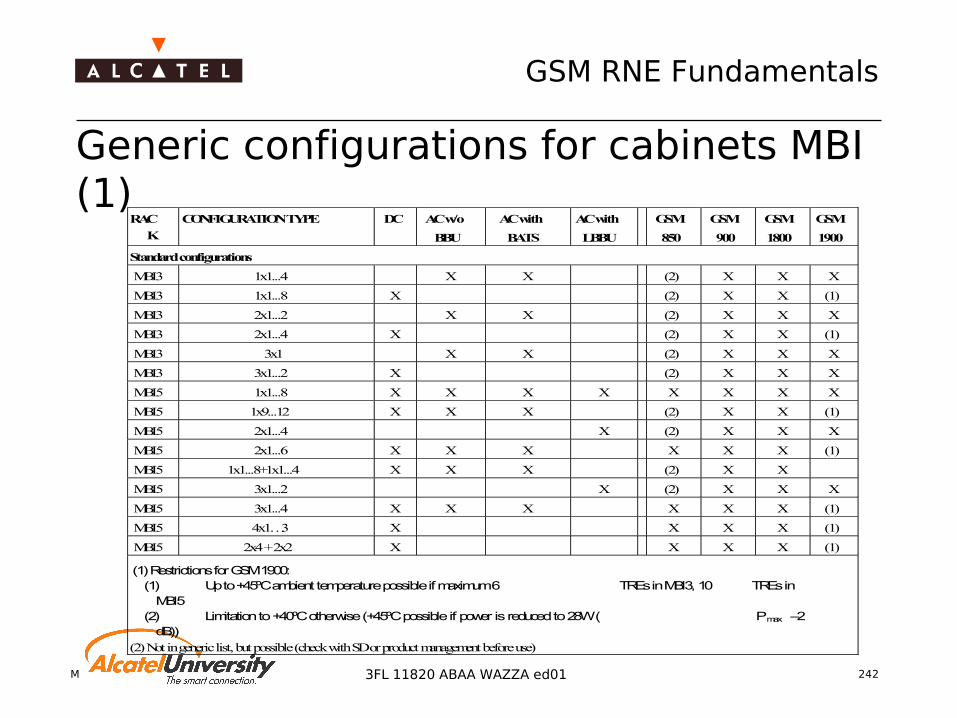
Mobile Radio Network Planning 242
GSM RNE Fundamentals
3FL 11820 ABAA WAZZA ed01
Generic configurations for cabinets MBI (1)
RAC
K
CONFIGURATION TYPE DC AC w/o
BBU
AC with
BATS
AC with
LBBU
GSM
850
GSM
900
GSM
1800
GSM
1900
Standard configurations
MBI3 1x1...4 X X (2) X X X
MBI3 1x1...8 X (2) X X (1)
MBI3 2x1...2 X X (2) X X X
MBI3 2x1...4 X (2) X X (1)
MBI3 3x1 X X (2) X X X
MBI3 3x1...2 X (2) X X X
MBI5 1x1...8 X X X X X X X X
MBI5 1x9...12 X X X (2) X X (1)
MBI5 2x1...4 X (2) X X X
MBI5 2x1...6 X X X X X X (1)
MBI5 1x1...8+1x1...4 X X X (2) X X
MBI5 3x1...2 X (2) X X X
MBI5 3x1...4 X X X X X X (1)
MBI5 4x1…3 X X X X (1)
MBI5 2x4 + 2x2 X X X X (1)
(1) Restrictions for GSM 1900:(1) Up to +45ºC ambient temperature possible if maximum 6 TREs in MBI3, 10 TREs in
MBI5(2) Limitation to +40ºC otherwise (+45ºC possible if power is reduced to 28W ( Pmax –2
dB))(2) Not in generic list, but possible (check with SD or product management before use)
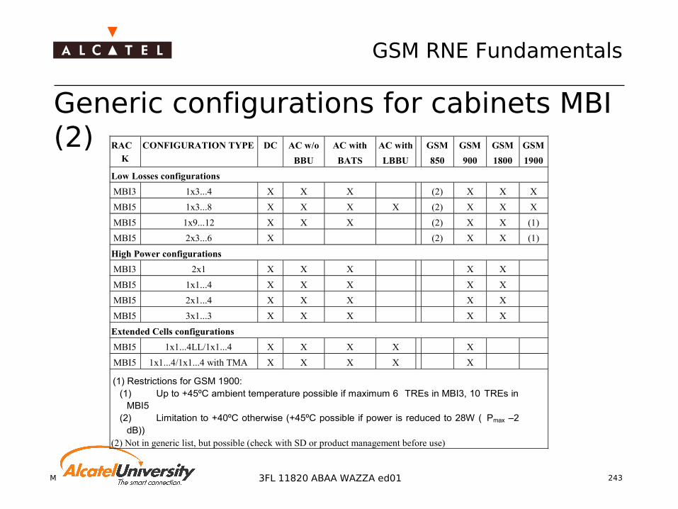
Mobile Radio Network Planning 243
GSM RNE Fundamentals
3FL 11820 ABAA WAZZA ed01
Generic configurations for cabinets MBI (2) RAC
K
CONFIGURATION TYPE DC AC w/o
BBU
AC with
BATS
AC with
LBBU
GSM
850
GSM
900
GSM
1800
GSM
1900
Low Losses configurations
MBI3 1x3...4 X X X (2) X X X
MBI5 1x3...8 X X X X (2) X X X
MBI5 1x9...12 X X X (2) X X (1)
MBI5 2x3...6 X (2) X X (1)
High Power configurations
MBI3 2x1 X X X X X
MBI5 1x1...4 X X X X X
MBI5 2x1...4 X X X X X
MBI5 3x1...3 X X X X X
Extended Cells configurations
MBI5 1x1...4LL/1x1...4 X X X X X
MBI5 1x1...4/1x1...4 with TMA X X X X X
(1) Restrictions for GSM 1900:(1) Up to +45ºC ambient temperature possible if maximum 6 TREs in MBI3, 10 TREs in
MBI5(2) Limitation to +40ºC otherwise (+45ºC possible if power is reduced to 28W ( Pmax –2
dB))(2) Not in generic list, but possible (check with SD or product management before use)

Mobile Radio Network Planning 244
GSM RNE Fundamentals
3FL 11820 ABAA WAZZA ed01
Generic configurations for cabinets MBO (1)
RAC
K
CONFIGURATION TYPE DC AC w/o
BBU
AC with
BBU
GSM
850
GSM
900
GSM
1800
GSM
1900
Standard configurations
CBO 1x1…2 X (1) X (2) (1)
CBO 2x1 X (1) X (2) (1)
MBO1 1x1...6 X X
MBO1 1x1...8 X X X X
MBO1 2x1...3 X X
MBO1 2x1...4 X X X X
MBO1 3x1...2 X X X X X
MBO2 1x9...12 X X X X X
MBO2 2x1...6 X X X X X
MBO2 1x1...8+1x1...4 X X X X X
MBO2 3x1...4 X X X X X
MBO2 4x1…3 X X X X X
MBO2 2x4 + 2x2 X X X X X
(1) CBO for GSM 850 and GSM 1900 are planned for 2004. For availability, check with SD or theproduct management (authorization required).
(2) CBO for GSM 1800 planned for Q4 2003 (check with SD)

Mobile Radio Network Planning 245
GSM RNE Fundamentals
3FL 11820 ABAA WAZZA ed01
Generic configurations for cabinets MBO (2)
RAC
K
CONFIGURATION TYPE DC AC w/o
BBU
AC with
BBU
GSM
850
GSM
900
GSM
1800
GSM
1900
Low Losses configurations
MBO1 1x5...6 X X
MBO1 1x5...8 X X X X
MBO2 2x3...6 X X X X X
MBO2 3x3...4 X X X X X
High Power configurations
CBO 1x1…2 X X (2)
CBO 2x1 X X (2)
MBO1 1x1...4 X X X
MBO1 2x1...2 X X X
MBO1 3x1...2 X X X
MBO2 2x1…4 X X X
MBO2 3x1…4 X X X
(1) CBO for GSM 850 and GSM 1900 are planned for 2004. For availability, check with SD or theproduct management (authorization required).
(2) CBO for GSM 1800 planned for Q4 2003 (check with SD)

Mobile Radio Network Planning 246
GSM RNE Fundamentals
3FL 11820 ABAA WAZZA ed01
TRX Types
This slide is referring only to Evolium macro BTS A9100 Overview on TRX types of A9100 Evolium Evolution BTS
(G4)Module Output powername GMSK 8PSK
Evolution Step 1TRGM GSM 900 35 Watts 45.44 dBmTRDM GSM 1800 35 Watts 45.44 dBmTRDH GSM 1800 60 Watts 47.78 dBm
Evolution Step 2TRAL GSM 850 45 Watts 46.53 dBm 15 Watts 41.76 dBmTRAG GSM 900 45 Watts 46.53 dBm 15 Watts 41.76 dBmTAGH GSM 900 60 Watts 47.78 dBm 25 Watts 43.98 dBmTRAD GSM 1800 35 Watts 45.44 dBm 12 Watts 40.79 dBmTADH GSM 1800 60 Watts 47.78 dBm 25 Watts 43.98 dBmTRAP GSM 1900 45 Watts 46.53 dBm 25 Watts 43.98 dBm

Mobile Radio Network Planning 247
GSM RNE Fundamentals
3FL 11820 ABAA WAZZA ed01
BTS Output Power What is monitored during validation is the BTS output power
at antenna connector The individual losses for duplexer, combiner and internal
cabling are not systematically measured for detailed info consult the BTS product description

Mobile Radio Network Planning 248
GSM RNE Fundamentals
3FL 11820 ABAA WAZZA ed01
Feature Power Balancing G4 BTS it is allowed to use TRXs of different power within
the same sector, or to use of different combining path for TRX belonging to the same sector.
Reason: the G4 BTS is able to detect unbalanced losses/powers within a sector and automatically compensate it for GMSK modulation.
Consequence: All TRX connected to one ANc are automatically adjusted to the GMSK output power of the weakest TRX (required for BCCH recovery)

Mobile Radio Network Planning 249
GSM RNE Fundamentals
3FL 11820 ABAA WAZZA ed01
Cell Split Feature Principle
Cell Split allows to provide one logical cell with one common BCCH over several BTS cabinets. The cabinets must be synchronized
Benefits Same number of TRX in fewer racks No need to touch/modify the configuration of existing BTS
(cabling) Take full benefit of 12 TRX per cabinet
Drawback: more complex antenna system Applications
Multi-band cells Configuration extension of sites by adding TRX Large configurations
Condition: BTS must be synchronized

Mobile Radio Network Planning 250
GSM RNE Fundamentals
3FL 11820 ABAA WAZZA ed01
Influence of Cell Split feature on BTS configurations One slave cabinet can only have one master One master can control three slave cabinets
Cabinet 1
4 TRXGSM 900
Master
4 TRXGSM 900
Master
Cabinet 2
4 TRXGSM 900
Master
4 TRXGSM 1800
Slave
4 TRXGSM 1800
Slave
4 TRXGSM 1800
Slave
Cabinet 3
4 TRXGSM 1800
Slave
4 TRXGSM 1800
Slave
4 TRXGSM 1800
Slave
Cabinet 1
6 TRXGSM 900Master
6 TRXGSM 1800
Master
Cabinet 2
6 TRXGSM 900Master
6 TRXGSM 1800
Master
Cabinet 4
2 TRXGSM 1800
Slave
2 TRXGSM 1800
Slave
Possible cell split configuration Not allowed cell split configuration

Mobile Radio Network Planning 251
GSM RNE Fundamentals
3FL 11820 ABAA WAZZA ed01
Cell Split Example: Deployment of multi-band cells
BTS 1 BTS 1 BTS 2
4TRX
4TRX
4TRX
4TRX
4TRX
4TRX
GSM 900 GSM 9002TRX
2TRX
2TRX
GSM1800
cell1
cell3
cell2
cell3
cell2
cell1
4TRX
4TRX
4TRX
GSM 900
4 TRX 9002TRX 1800
4 TRX 9002TRX 1800
4 TRX 9002TRX 1800
BTS 1 BTS1 BTS 2
cell1
cell3
cell2
cell2
cell1
cell3
With cell split:- No antenna re-cabling- No TRX moving- Connection to the first BTS while the BTS is working- Short service interruption during radio conf. change
With cell split:- No antenna re-cabling- No TRX moving- Connection to the first BTS while the BTS is working- Short service interruption during radio conf. change
Without cell split:- Complete re-configuration
Without cell split:- Complete re-configuration

Mobile Radio Network Planning 252
GSM RNE Fundamentals
3FL 11820 ABAA WAZZA ed01
Cell Split Example: Migration to multiband cells
Example: Migration from multiband BSS (single BCCH) to multiband cells (dual BCCH)
No more limitation to have the 900 and the 1800 TRX‘s installed inside the same cabinet
4TRX
4TRX
4TRX
GSM 900
4TRX
4TRX
4TRX
GSM1800
BTS 1 BTS 2
Cell 3
Cell 2
Cell 1
4TRX
4TRX
4TRX
GSM 900
BTS 1
Cell 1
Cell 3
Cell 2
4TRX
4TRX
4TRX
GSM 1800
BTS 2
Cell 4
Cell 6
Cell 5

Mobile Radio Network Planning 253
GSM RNE Fundamentals
3FL 11820 ABAA WAZZA ed01
Cell Split Example: High Power Configuration

Mobile Radio Network Planning 254
GSM RNE Fundamentals
3FL 11820 ABAA WAZZA ed01
BTS 1 (with900 or 1800TRX)
4TRX
4TRX
4TRX
BTS 1 (with 12 TRX900 or 1800)BTS 2 (with 6 TRX900 or 1800)
4TRX
4TRX
4TRX
LinkedBTS
2 TRX
4TRX
cell1
cell2
cell3 cell3
cell2
cell1
Two shared sectors
Cell Split Example: Configuration extension 3x4 sector cells extended to cell 1(6 TRX), cell 2 (4 TRX),
cell 3 (8 TRX)

Mobile Radio Network Planning 255
GSM RNE Fundamentals
3FL 11820 ABAA WAZZA ed01
4TRX
4TRX
4TRX 4TRX
4TRX
4TRX
BCCH
BTS 1 BTS 2
Without cell split: -3 racks with 8 TRX/sector, empty space
With cell split: -2 racks with 12 TRX, 8 TRX per sector
Without cell split: -3 racks with 8 TRX/sector, empty space
With cell split: -2 racks with 12 TRX, 8 TRX per sector
Cell Split Example: Large configurations
3x8 TRX with 2 racks:
16 TRX’s per cell

Mobile Radio Network Planning 256
GSM RNE Fundamentals
3FL 11820 ABAA WAZZA ed01
Indoor BTS Rack Layout

Mobile Radio Network Planning 257
GSM RNE Fundamentals
3FL 11820 ABAA WAZZA ed01
Outdoor BTS Rack Layout

Mobile Radio Network Planning 258
GSM RNE Fundamentals
3FL 11820 ABAA WAZZA ed01
3 Level Architecture
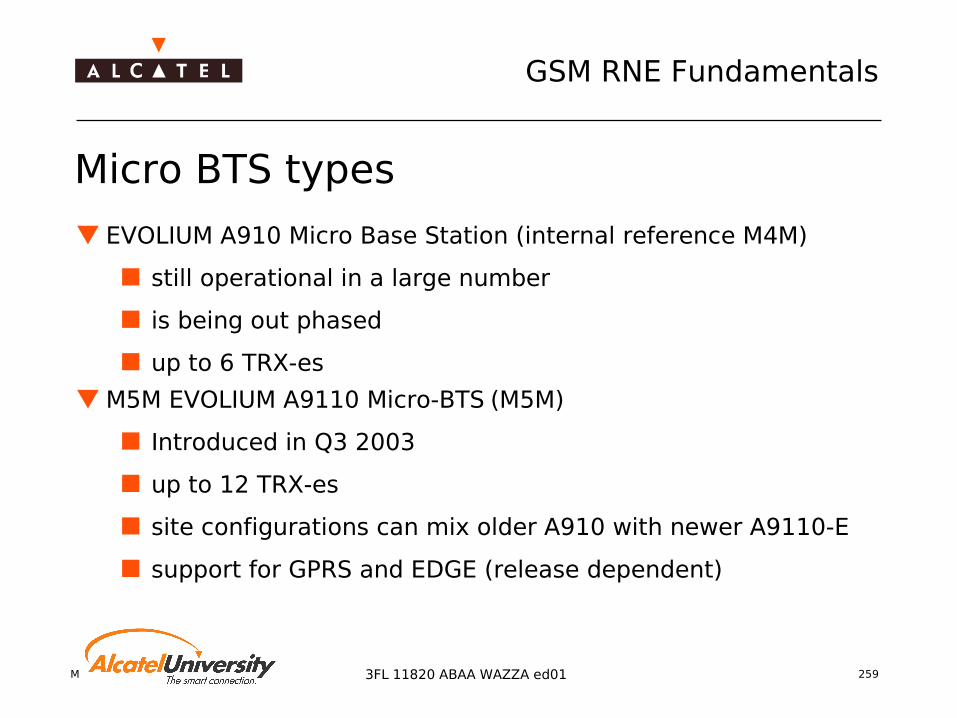
Mobile Radio Network Planning 259
GSM RNE Fundamentals
3FL 11820 ABAA WAZZA ed01
Micro BTS types
EVOLIUM A910 Micro Base Station (internal reference M4M)
still operational in a large number
is being out phased
up to 6 TRX-es
M5M EVOLIUM A9110 Micro-BTS (M5M)
Introduced in Q3 2003
up to 12 TRX-es
site configurations can mix older A910 with newer A9110-E
support for GPRS and EDGE (release dependent)
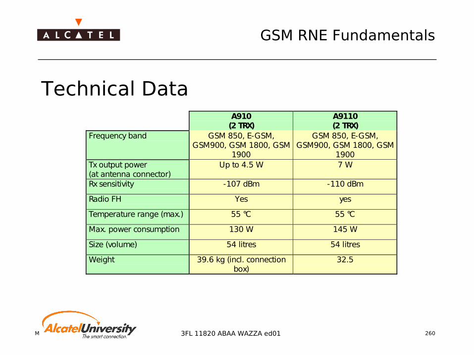
Mobile Radio Network Planning 260
GSM RNE Fundamentals
3FL 11820 ABAA WAZZA ed01
Technical DataA910(2 TRX)
A9110(2 TRX)
Frequency band GSM 850, E-GSM,GSM900, GSM 1800, GSM
1900
GSM 850, E-GSM,GSM900, GSM 1800, GSM
1900Tx output power(at antenna connector)
Up to 4.5 W 7 W
Rx sensitivity -107 dBm -110 dBm
Radio FH Yes yes
Temperature range (max.) 55 °C 55 °C
Max. power consumption 130 W 145 W
Size (volume) 54 litres 54 litres
Weight 39.6 kg (incl. connectionbox)
32.5
Mobile Radio Network Planning 261
GSM RNE Fundamentals
3FL 11820 ABAA WAZZA ed01
Evolium™ BSC Characteristics Capacity
Maximum physical capacity: 352 FR TRX or 176 DR TRX in 255 BTS Traffic and signalling capacity: up to 1500 erlang->∅13,5 erl/BTS traffic
capacity
Flexibility 6 Abis interfaces per SM module with integrated cross connect function Integrated in BSC subracks (no cabling), 100% Alcatel No BSC internal recabling for network extensions/modifications
Compactness Maximum BSC configuration in three standard Alcatel 1000 S12 cabinets
(90 cm width, 52 cm depth)
Technology Two stage Alcatel 1000 S12 switching technology Distributed processing in trunk control units and processing resources Same application SW running on both BSC generations
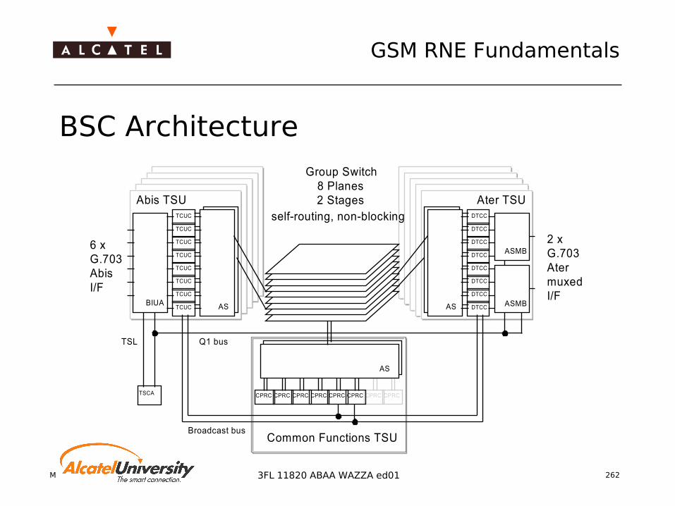
Mobile Radio Network Planning 262
GSM RNE Fundamentals
3FL 11820 ABAA WAZZA ed01
BSC Architecture
BIUA
TCUC
TCUC
TCUC
TCUC
TCUC
TCUC
TCUC
TCUC
AS
DTCC
DTCC
DTCC
DTCC
DTCC
DTCC
DTCC
AS
DTCC
CPRC CPRC CPRC CPRC CPRC CPRC CPRC CPRC
AS
6 xG.703AbisI/F
2 xG.703AtermuxedI/F
Abis TSU Ater TSU
Common Functions TSU
Group Switch8 Planes2 Stages
TSCA
TSL
ASMB
ASMB
Q1 bus
Broadcast bus
self-routing, non-blocking

Mobile Radio Network Planning 263
GSM RNE Fundamentals
3FL 11820 ABAA WAZZA ed01
BSC Rack Layouts
A-BIS TSU
AIRBAFFLE
A-BIS TSUGS
GSCOMMON TSUTSCA
ClockStage 1
Stage 2Stage 2 Stage 2
A-BIS TSU
Group Switch GS GS
A-TER TSU
A-TER TSU A-TER TSU
A-BIS TSU
Stage 2
A-BIS TSU
AIRBAFFLE
A-BIS TSUGS
GSA-BIS TSUTSCA
ClockStage 1
Stage 2Stage 2 Stage 2
A-BIS TSU
Group Switch GS GS
A-TER TSU
A-TER TSU A-TER TSU
A-BIS TSU
Stage 2
A-BIS TSU
AIRBAFFLE
A-BIS TSUGS
A-BIS TSUTSCA
ClockStage 1
A-BIS TSU
A-TER TSU
A-TER TSU A-TER TSU
A-BIS TSU
6 Configurations possible
Cabinet #1 Cabinet #2 Cabinet #3
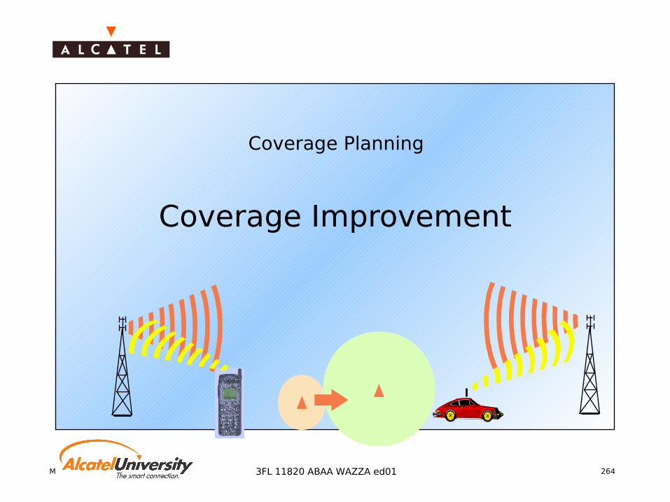
Mobile Radio Network Planning 2643FL 11820 ABAA WAZZA ed01
Coverage Planning
Coverage Improvement
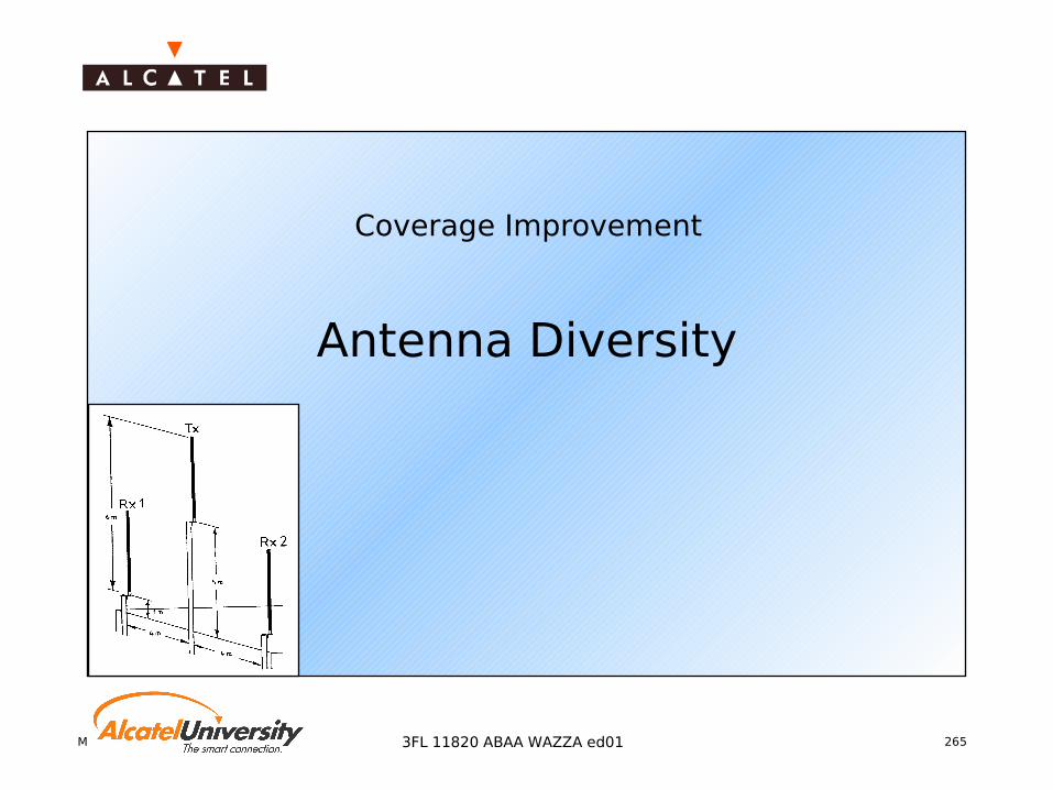
Mobile Radio Network Planning 2653FL 11820 ABAA WAZZA ed01
Coverage Improvement
Antenna Diversity

Mobile Radio Network Planning 266
GSM RNE Fundamentals
3FL 11820 ABAA WAZZA ed01
Diversity Purpose
Improvement in fading probability statistics
leads to a better total signal level or better total S/N ratio
Principle Combining signals with
same information from different signal branches
Demands correlation between
different signal branches should be low
Combining methods Selection Diversity Maximum Ratio
Combining Equal Gain Combining

Mobile Radio Network Planning 267
GSM RNE Fundamentals
3FL 11820 ABAA WAZZA ed01
Time [sec]
Fie
ldstr
en
gth
[d
Bm
]
0.1 0.2 0.3 0.4
-80
-90
-100
Antenna 1 Antenna 2
Selection Diversity (1) Principle
selection of the highest baseband signal-to-noise ratio (S/N) or of the strongest signal (S+N)
Correlation of signal levels a lower correlation
between signal levels of different branches improves the total signal level
Correlation of signal levels should be low

Mobile Radio Network Planning 268
GSM RNE Fundamentals
3FL 11820 ABAA WAZZA ed01
Time [sec]
Fie
ldstr
en
gth
[d
Bm
]
0.1 0.2 0.3 0.4
-80
-90
-100
Antenna 1
Antenna 2
Selection Diversity (2) Difference in signal level
a high difference in signal levels of two branches doesn’t improve the total signal level
Difference in signal levels should be low
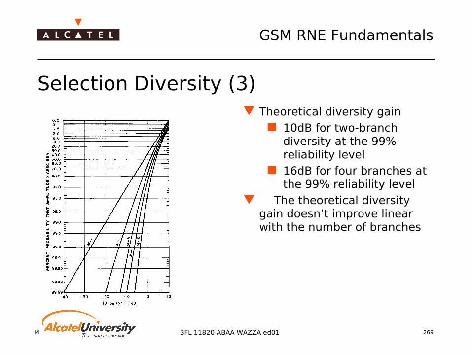
Mobile Radio Network Planning 269
GSM RNE Fundamentals
3FL 11820 ABAA WAZZA ed01
Selection Diversity (3) Theoretical diversity gain
10dB for two-branch diversity at the 99% reliability level
16dB for four branches at the 99% reliability level
The theoretical diversity gain doesn’t improve linear with the number of branches

Mobile Radio Network Planning 270
GSM RNE Fundamentals
3FL 11820 ABAA WAZZA ed01
Equal Gain Combining (1) Principle
cophase signal branches sum up signals
Coherent addition of signals and incoherent addition of noises
Theoretical diversity gain 11dB for two-branch
diversity at the 99% reliability level

Mobile Radio Network Planning 271
GSM RNE Fundamentals
3FL 11820 ABAA WAZZA ed01
Equal Gain Combining (2) Difference in signal level
Assuming equal noise in the branches, the higher the difference in signal levels is, the higher is the loss of S/N ratio of the better signal branch after summation
Difference in signal levels should be low
Correlation of signal levels a lower correlation
between signal levels of different branches improves the total S/N ratio
Correlation of signal levels should be low

Mobile Radio Network Planning 272
GSM RNE Fundamentals
3FL 11820 ABAA WAZZA ed01
Maximum Ratio Combining (1) Principle
weight signals proportionally to their S/N ratios
cophase signal branches sum up the weighted
signals Coherent addition of signals
and incoherent addition of noises
Improved S/N

Mobile Radio Network Planning 273
GSM RNE Fundamentals
3FL 11820 ABAA WAZZA ed01
Correlation of signal levels a lower correlation
between signal levels of different branches improves the total S/N ratio
Correlation of signal levels should be low
Maximum Ratio Combining (2) Difference in signal level
Assuming equal noise in the branches, the higher the difference in signal levels is, the higher is the loss of S/N ratio of the better signal branch after summation
comparing to equal ratio combining, this combining reduces influence of worse signal branches
Difference in signal levels should be low
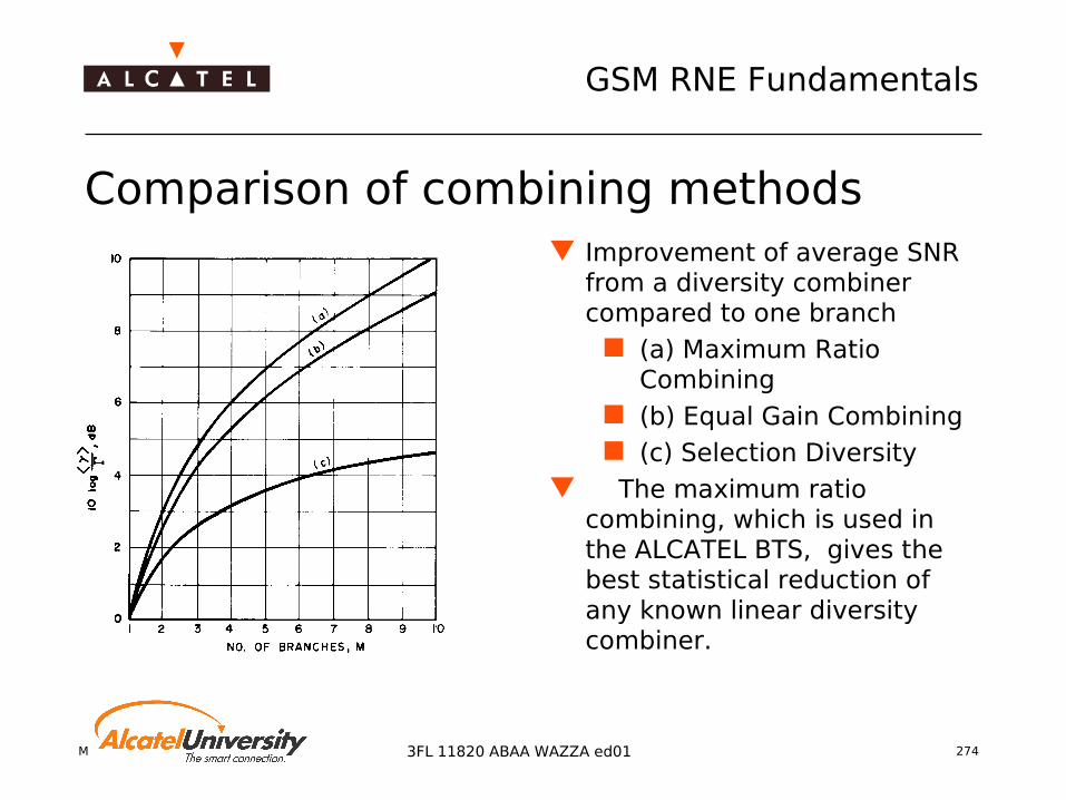
Mobile Radio Network Planning 274
GSM RNE Fundamentals
3FL 11820 ABAA WAZZA ed01
Comparison of combining methods Improvement of average SNR
from a diversity combiner compared to one branch
(a) Maximum Ratio Combining
(b) Equal Gain Combining (c) Selection Diversity
The maximum ratio combining, which is used in the ALCATEL BTS, gives the best statistical reduction of any known linear diversity combiner.

Mobile Radio Network Planning 275
GSM RNE Fundamentals
3FL 11820 ABAA WAZZA ed01
Enhanced Diversity Combining (1) Principle:
2 algorithms Beam forming algorithm (available also for MRC) Interference reduction algorithm (new)
best efficiency when the useful signal and the interfering signals come from different directions.
Requirements to benefit from this feature: Hardware: G4 TRE (Edge capable TRX) installed in Evolium
Evolution BTS step1 resp. step 2 (internal name: G3 resp. G4)
Software release: from B6.2 onwards For a maximum gain: antenna engineering rules respected
Correct antenna choice for the considered environment Correct antenna spacings and orientations (in case of space diversity)

Mobile Radio Network Planning 276
GSM RNE Fundamentals
3FL 11820 ABAA WAZZA ed01
Enhanced Diversity Combining (2)
The values in the right column are due to the feature Enhanced Diversity Combining, Selective Beam-forming Combining
Antenna diversity gain recommendation for link budgetEnvironment Evolution
step 1,Evolutionstep 2 up
to B5
Evolutionstep2sinceB6.2
Urban, dense urban 5 dB 6 dBResidential, suburban 3.5 dB 5 dBRural (horizontal space diversity) 3 dB 3.5 dB

Mobile Radio Network Planning 277
GSM RNE Fundamentals
3FL 11820 ABAA WAZZA ed01
Diversity systems in Mobile Radio Networks
Two diversity systems are used in Mobile Radio Networks :
Space DiversitySpace Diversity horizontal vertical
Polarization DiversityPolarization Diversity
dH
RXA RXB
+45° -45°
RXA RXB
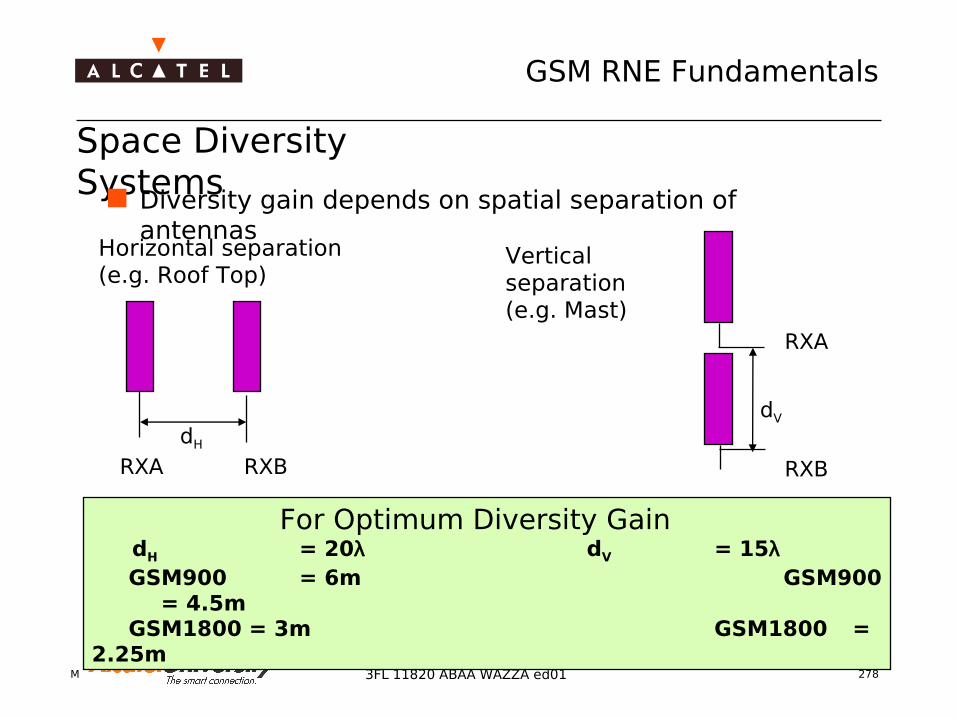
Mobile Radio Network Planning 278
GSM RNE Fundamentals
3FL 11820 ABAA WAZZA ed01
Space Diversity Systems
Diversity gain depends on spatial separation of antennas
dH
RXA RXB
dV
RXA
RXB
Horizontal separation(e.g. Roof Top)
Vertical separation(e.g. Mast)
For Optimum Diversity Gain dH = 20λ dV = 15λ GSM900 = 6m GSM900
= 4.5m GSM1800 = 3m GSM1800 = 2.25m

Mobile Radio Network Planning 279
GSM RNE Fundamentals
3FL 11820 ABAA WAZZA ed01
The larger the separation the higher the diversity gain Prefer horizontal separation (more effective) The higher the antenna the higher the required separation, rule: d > h/10 Highest diversity gain from the "broadside” Select orientation of diversity setup according to
orientation of cell / traffic
h
d
Optimum diversity Gain
Space Diversity - General Rules
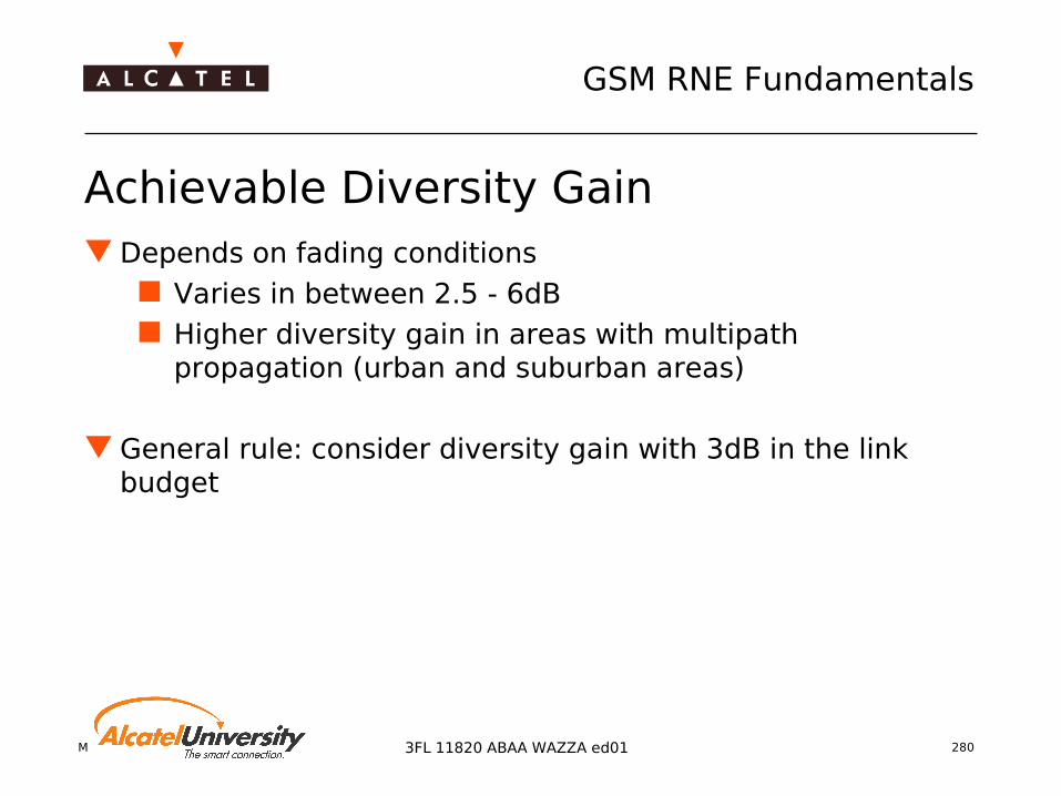
Mobile Radio Network Planning 280
GSM RNE Fundamentals
3FL 11820 ABAA WAZZA ed01
Achievable Diversity Gain Depends on fading conditions
Varies in between 2.5 - 6dB Higher diversity gain in areas with multipath
propagation (urban and suburban areas)
General rule: consider diversity gain with 3dB in the link budget
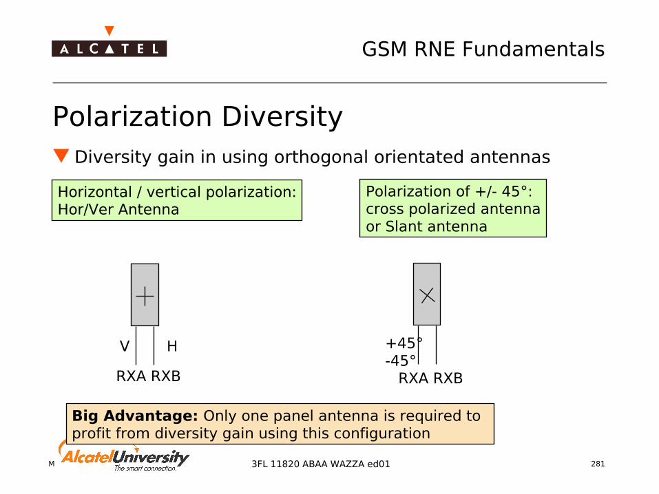
Mobile Radio Network Planning 281
GSM RNE Fundamentals
3FL 11820 ABAA WAZZA ed01
Horizontal / vertical polarization:Hor/Ver Antenna
Polarization of +/- 45°:cross polarized antennaor Slant antenna
Big Advantage: Only one panel antenna is required to profit from diversity gain using this configuration
V H +45° -45°
RXA RXB RXA RXB
Polarization Diversity Diversity gain in using orthogonal orientated antennas

Mobile Radio Network Planning 282
GSM RNE Fundamentals
3FL 11820 ABAA WAZZA ed01
DiversityGain
multipath-propagation
reflection,diffraction
reception with
reception with
a hor / verpolarisedantenna
a X-polarisedantenna
EV
EH
EX2
EX1
G = f( ρ ,∆ )
Time [sec]
Ex1 or Ev
Ex2 or Eh
Principle of Polarization Diversity
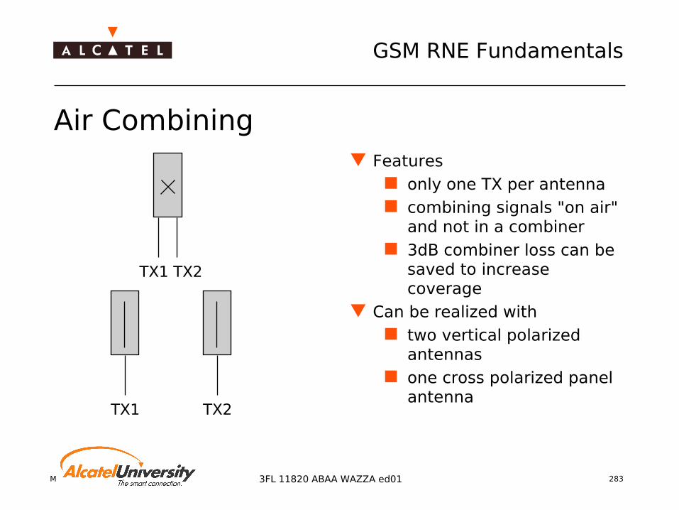
Mobile Radio Network Planning 283
GSM RNE Fundamentals
3FL 11820 ABAA WAZZA ed01
Air Combining Features
only one TX per antenna combining signals "on air"
and not in a combiner 3dB combiner loss can be
saved to increase coverage
Can be realized with two vertical polarized
antennas one cross polarized panel
antenna
TX1 TX2
TX1 TX2

Mobile Radio Network Planning 284
GSM RNE Fundamentals
3FL 11820 ABAA WAZZA ed01
Air Combining with Polarization Diversity
One antenna system cross polarized antennas
recommended for urban/suburban area (less space req.)
No Air combiningBandfilter if De-coupling too low
Air combiningRecommended forEvolium BTS
V H
DUPL BF
TX RXA RXB
DUPL
TX1 RX1 TX2 RX2 RX2D RX1D
DUPL
or
1 TRX 2 TRX
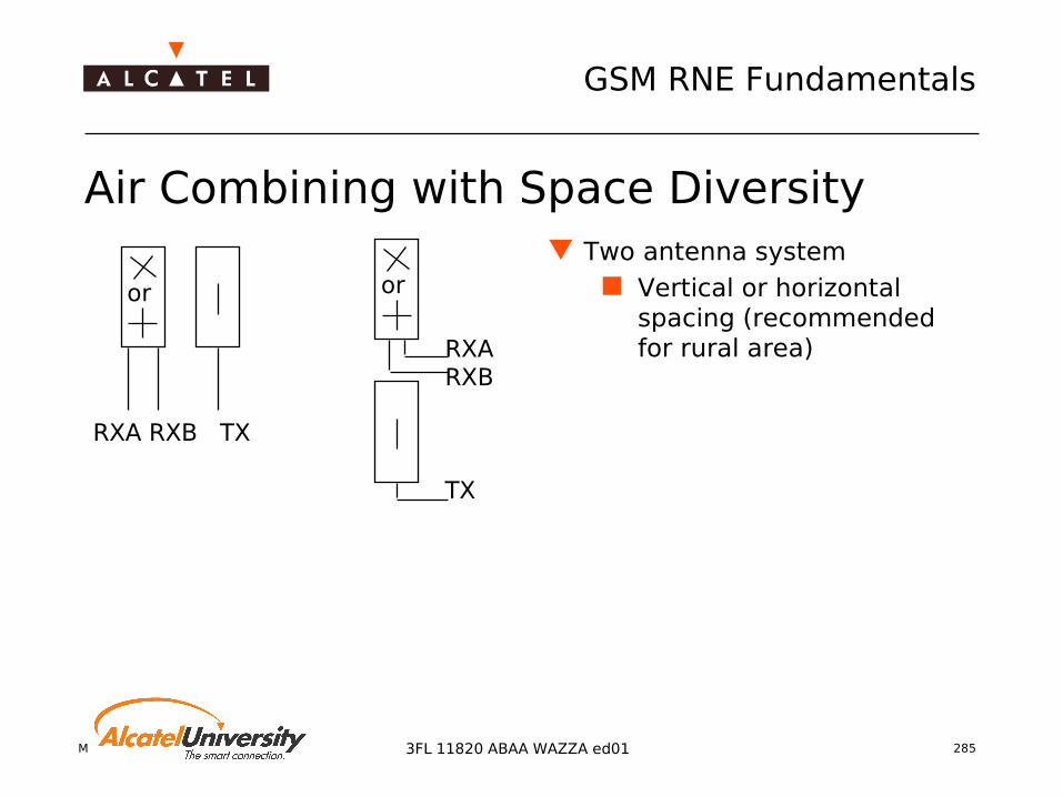
Mobile Radio Network Planning 285
GSM RNE Fundamentals
3FL 11820 ABAA WAZZA ed01
Air Combining with Space Diversity Two antenna system
Vertical or horizontal spacing (recommended for rural area)
RXA RXB TX
or or
RXARXB
TX

Mobile Radio Network Planning 286
GSM RNE Fundamentals
3FL 11820 ABAA WAZZA ed01
Decoupling of Signal Branches
One antenna system: TX / RX decoupling cannot be achieved by spatial separation
Decoupling between both polarization branches needs to be sufficiently high to avoid
blocking problems intermodulation problems
Required decoupling values G2 BTS: 30 dB Evolium A9100 BTS: 25dB (Integrated duplexer Anx)
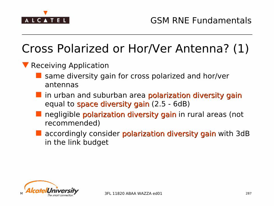
Mobile Radio Network Planning 287
GSM RNE Fundamentals
3FL 11820 ABAA WAZZA ed01
Cross Polarized or Hor/Ver Antenna? (1) Receiving Application
same diversity gain for cross polarized and hor/ver antennas
in urban and suburban area polarization diversity gainpolarization diversity gain equal to space diversity gainspace diversity gain (2.5 - 6dB)
negligible polarization diversity gain polarization diversity gain in rural areas (not recommended)
accordingly consider polarization diversity gainpolarization diversity gain with 3dB in the link budget

Mobile Radio Network Planning 288
GSM RNE Fundamentals
3FL 11820 ABAA WAZZA ed01
Cross Polarized or Hor/Ver Antenna? (2) Transmission Application: Air
combining 3dB loss when
transmitting horizontal/vertical polarized (use of combiner)
1-2dB losses when transmitting at 45° (optimum antenna is straighten vertically)
Air combining only recommended with cross polarized antenna
3dB2dB
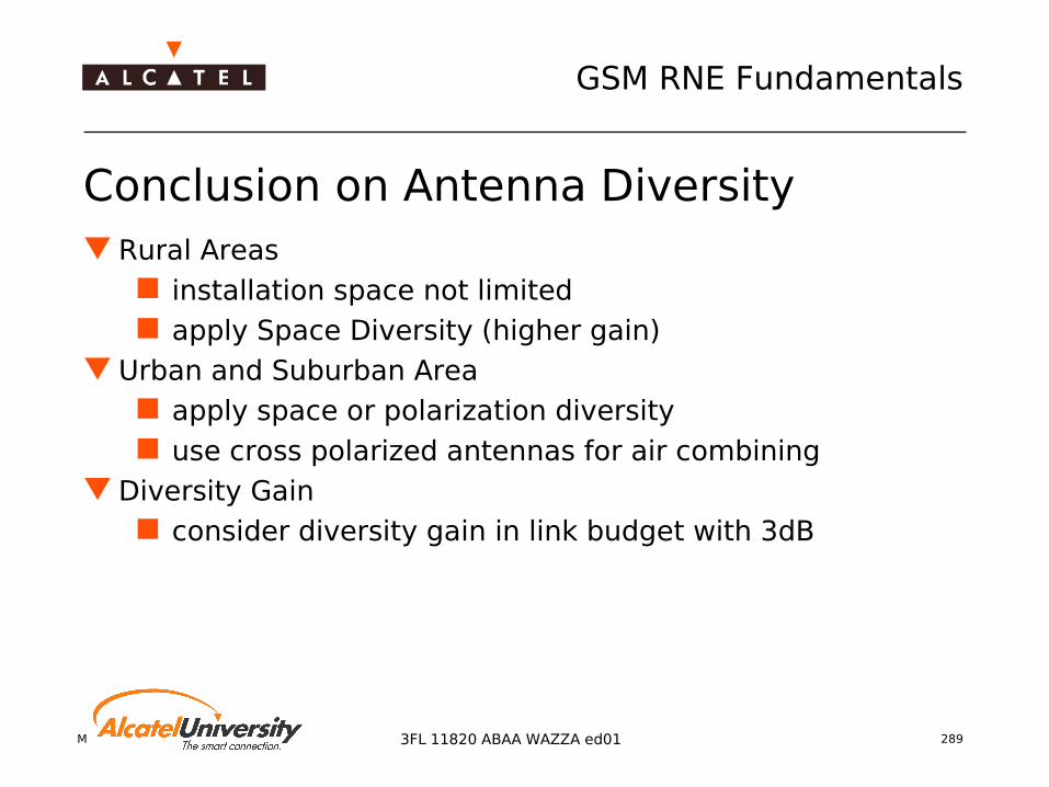
Mobile Radio Network Planning 289
GSM RNE Fundamentals
3FL 11820 ABAA WAZZA ed01
Conclusion on Antenna Diversity Rural Areas
installation space not limited apply Space Diversity (higher gain)
Urban and Suburban Area apply space or polarization diversity use cross polarized antennas for air combining
Diversity Gain consider diversity gain in link budget with 3dB

Mobile Radio Network Planning 2903FL 11820 ABAA WAZZA ed01
Coverage Improvement
Repeater Systems
BTS (donor cell)repeater
original service areaarea covered by repeater

Mobile Radio Network Planning 291
GSM RNE Fundamentals
3FL 11820 ABAA WAZZA ed01
Repeater Application
BTS (donor cell)repeater
original service areaarea covered by repeater

Mobile Radio Network Planning 292
GSM RNE Fundamentals
3FL 11820 ABAA WAZZA ed01
Repeater Block Diagram
Required Isolation > 70…90 dB

Mobile Radio Network Planning 293
GSM RNE Fundamentals
3FL 11820 ABAA WAZZA ed01
Repeater Applications
Coverage Improvement of Cells (‘Cell Enhancer’) removal of coverage holes caused by
topography (hills, ravines, ...) man made obstacles
Provision of tunnel coverage street, railway tunnels underground stations
Provision of indoor coverage at places of low additional traffic

Mobile Radio Network Planning 294
GSM RNE Fundamentals
3FL 11820 ABAA WAZZA ed01
Repeater Types Channel selective repeaters
high selectivity of certain channels
high traffic areas, small cell sizes
Band selective repeaters adjustment to operator’s
frequency band no (accidental) usage by
competitors
Broad band repeaters low cost solution for low
traffic areas (rural environment)
medium to high repeater gain
Personal repeaters low gain broad band indoor coverage
improvement for certain rooms

Mobile Radio Network Planning 295
GSM RNE Fundamentals
3FL 11820 ABAA WAZZA ed01
Antennato donor cell
Repeater
Radiatingcable
Tunnel
Repeater for Tunnel Coverage Choice of repeater type due to
tunnel dimensions wall materials
feeding by directional antennas leaky feeder cables
long tunnels chains of several
repeaters fiber optic backbone for
repeater feeding
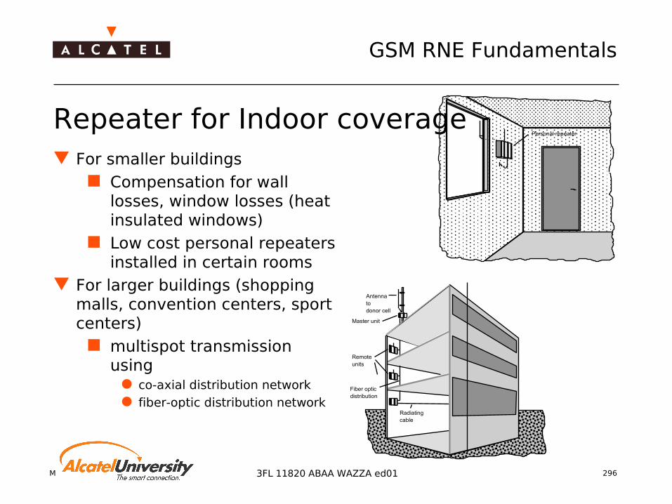
Mobile Radio Network Planning 296
GSM RNE Fundamentals
3FL 11820 ABAA WAZZA ed01
Personal repeater
Antennatodonor cell
Fiber opticdistribution
Remoteunits
Master unit
Radiatingcable
Repeater for Indoor coverage For smaller buildings
Compensation for wall losses, window losses (heat insulated windows)
Low cost personal repeaters installed in certain rooms
For larger buildings (shopping malls, convention centers, sport centers)
multispot transmission using
co-axial distribution network fiber-optic distribution network

Mobile Radio Network Planning 297
GSM RNE Fundamentals
3FL 11820 ABAA WAZZA ed01
Planning Aspects Repeater does not provide additional traffic capacity
risk of blocking if additional coverage area catches more traffic
possible carrier upgrading required Repeater causes additional signal delay
delay: 4..8µ s → max. cell range of 35 km reduced by 1 to 2km
special care needed for total delay of repeater chain! delayed signal and original signal could cause outage in
urban environment if total delay exceeds 16 ... 22µ s
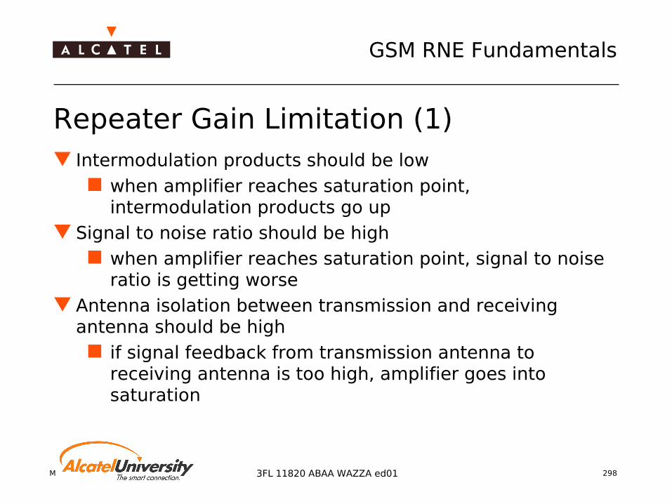
Mobile Radio Network Planning 298
GSM RNE Fundamentals
3FL 11820 ABAA WAZZA ed01
Repeater Gain Limitation (1) Intermodulation products should be low
when amplifier reaches saturation point, intermodulation products go up
Signal to noise ratio should be high when amplifier reaches saturation point, signal to noise
ratio is getting worse Antenna isolation between transmission and receiving
antenna should be high if signal feedback from transmission antenna to
receiving antenna is too high, amplifier goes into saturation
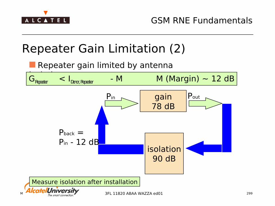
Mobile Radio Network Planning 299
GSM RNE Fundamentals
3FL 11820 ABAA WAZZA ed01
Repeater Gain Limitation (2)
Pin Poutgain78 dB
isolation90 dB
Pback =Pin - 12 dB
Repeater gain limited by antenna isolation:GRepeater < IDonor, Repeater - M M (Margin) ~ 12 dB
Measure isolation after installation

Mobile Radio Network Planning 300
GSM RNE Fundamentals
3FL 11820 ABAA WAZZA ed01
Intermodulation Products A Non-linear system
produces higher-order intermodulation products as soon as output power reaches the saturation point
Parameter 1 dB compression point 3rd order intercept point (ICP3) Intermodulation reduction (IMR) Amplifier back-off
GSM900/GSM1800 requirements IM products ≤ -36 dBm or IM distance > 70 dBc whichever is higher

Mobile Radio Network Planning 301
GSM RNE Fundamentals
3FL 11820 ABAA WAZZA ed01
Uplink Loss = Downlink Loss ⇒ Uplink Gain = Downlink Gain!
Repeater Link Budget
Different gains may be needed in Up- and Downlink if the sensitivity of the repeater is worse than the sensitivity of the BTS
!
Downlink Path Unit ValueReceived power at repeater dBm -65Link antenna gain dBi +19Cable loss dB -2Repeater input power dBm -48Repeater gain dB +78Repeater output power dBm 30Cable loss dB -2Repeater antenna gain dBi +18EIRP dBm 46

Mobile Radio Network Planning 302
GSM RNE Fundamentals
3FL 11820 ABAA WAZZA ed01
Exam
ple
: Rep
eate
r MR
40
2

Mobile Radio Network Planning 303
GSM RNE Fundamentals
3FL 11820 ABAA WAZZA ed01
High Power TRXs High Power TRXs: solution for coverage improvement HP must be used together with TMA: due to unbalanced Link
Budget A9100 BTS supports
High Power TRX Medium Power TRX type is chosen by:
environment conditions required data throughput (GPRS/EDGE)
TX power of EVOLIUM™ Evolution step 2 TRX :
Frequency band TX output power, GMSK TX output power, 8-PSK (EDGE)
GSM 900 HP 60 W = 47.8 dBm 25 W = 44.0 dBm
GSM 1800 HP 60 W = 47.8 dBm 25 W = 44.0 dBm
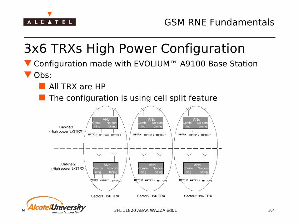
Mobile Radio Network Planning 304
GSM RNE Fundamentals
3FL 11820 ABAA WAZZA ed01
3x6 TRXs High Power Configuration Configuration made with EVOLIUM™ A9100 Base Station Obs:
All TRX are HP The configuration is using cell split feature
Cabinet1(High power 3x3TRX)
Sector3: 1x6 TRXSector2: 1x6 TRXSector1: 1x6 TRX
Cabinet2(High power 3x3TRX)
No-com-bining
ANc
HPTRX1 HPTRX 2
Combi-ning
MPTRX 3
No-com-bining
ANc
HPTRX1 HPTRX 2
Combi-ning
MPTRX 3
No-com-bining
ANc
HPTRX1 HPTRX 2
Combi-ning
MPTRX 3
No-com-bining
ANc
HPTRX1 HPTRX 2
Combi-ning
MPTRX 3
No-com-bining
ANc
HPTRX1 HPTRX 2
Combi-ning
MPTRX 3
No-com-bining
ANc
HPTRX1 HPTRX 2
Combi-ning
MPTRX 3
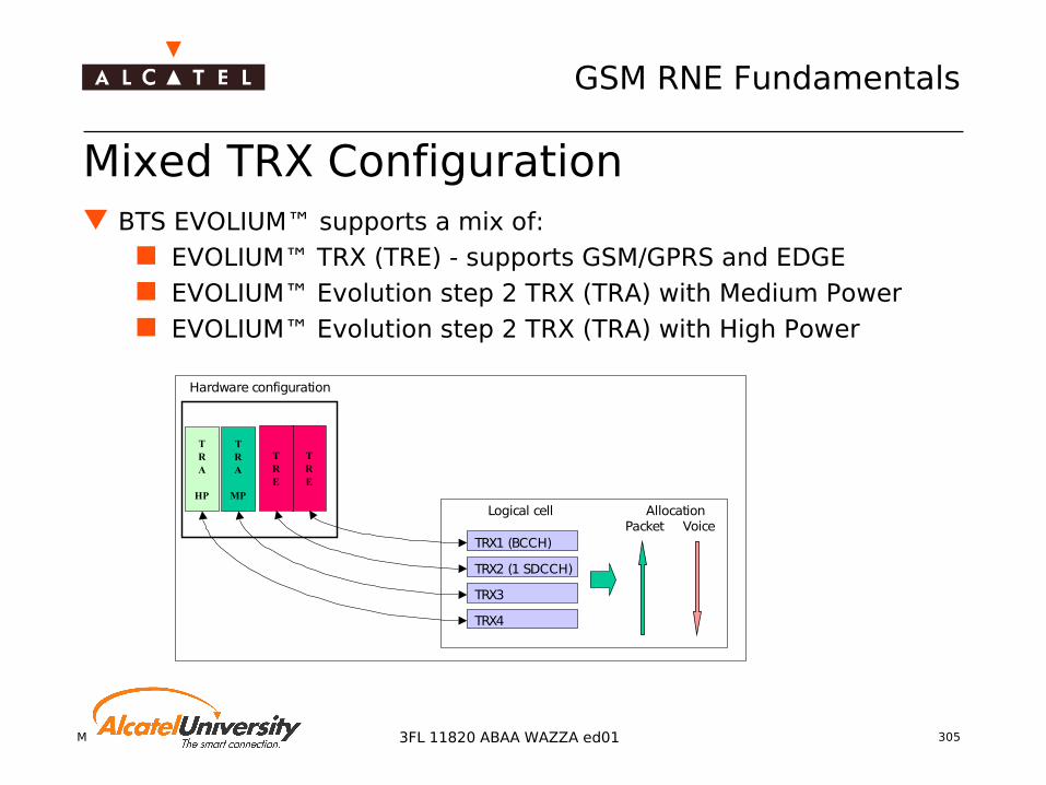
Mobile Radio Network Planning 305
GSM RNE Fundamentals
3FL 11820 ABAA WAZZA ed01
Mixed TRX Configuration BTS EVOLIUM™ supports a mix of:
EVOLIUM™ TRX (TRE) - supports GSM/GPRS and EDGE EVOLIUM™ Evolution step 2 TRX (TRA) with Medium Power EVOLIUM™ Evolution step 2 TRX (TRA) with High Power
TRE
TRE
TRA
MP
TRA
HP
Hardware configuration
Logical cell
TRX1 (BCCH)
TRX2 (1 SDCCH)
TRX3
TRX4
Packet VoiceAllocation

Mobile Radio Network Planning 3063FL 11820 ABAA WAZZA ed01
GSM Radio Network Engineering Fundamentals
Traffic Planning & Frequency Planning
Mobile Radio Network Planning 307
GSM RNE Fundamentals
3FL 11820 ABAA WAZZA ed01
Contents Traffic Capacity Network evolution Cell structures Frequency Reuse Cell Planning - Frequency Planning Interference Probability Carrier types Multiple Reuse Pattern MRP Intermodulation Manual Frequency Planning BSIC Planning Capacity Enhancement Techniques
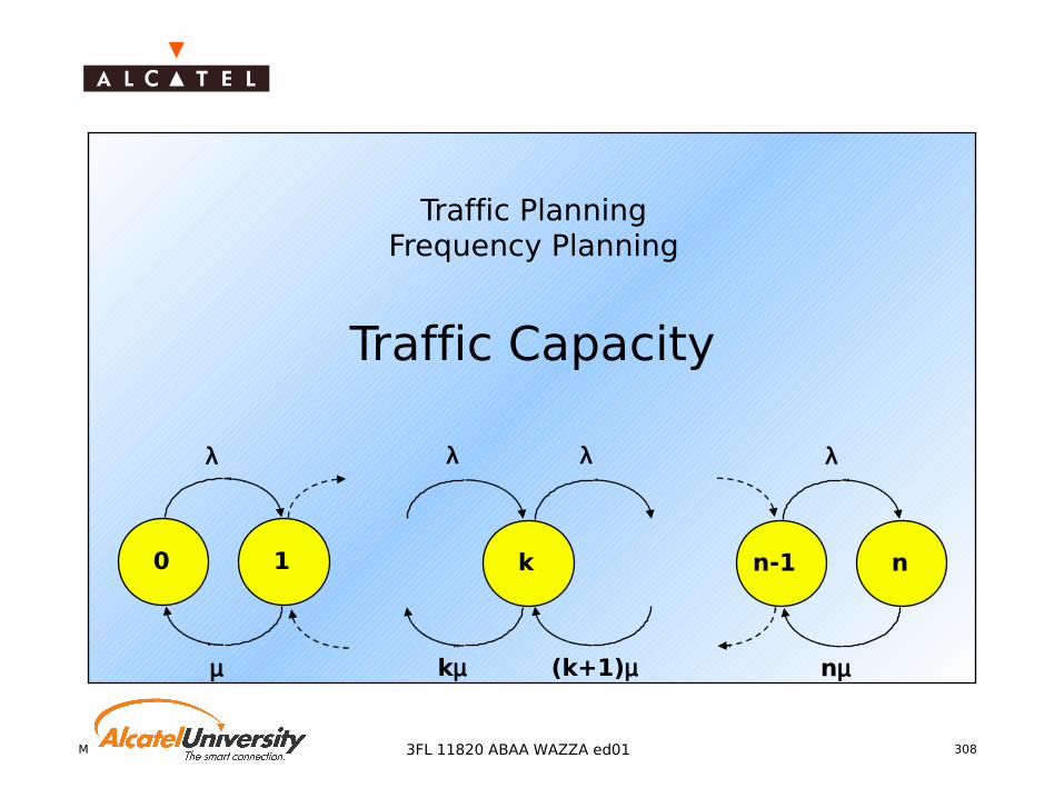
Mobile Radio Network Planning 3083FL 11820 ABAA WAZZA ed01
Traffic PlanningFrequency Planning
Traffic Capacity
k
(k+1)µ
λ
kµ
λ
0 1
µ
λ
n-1 n
λ
nµ
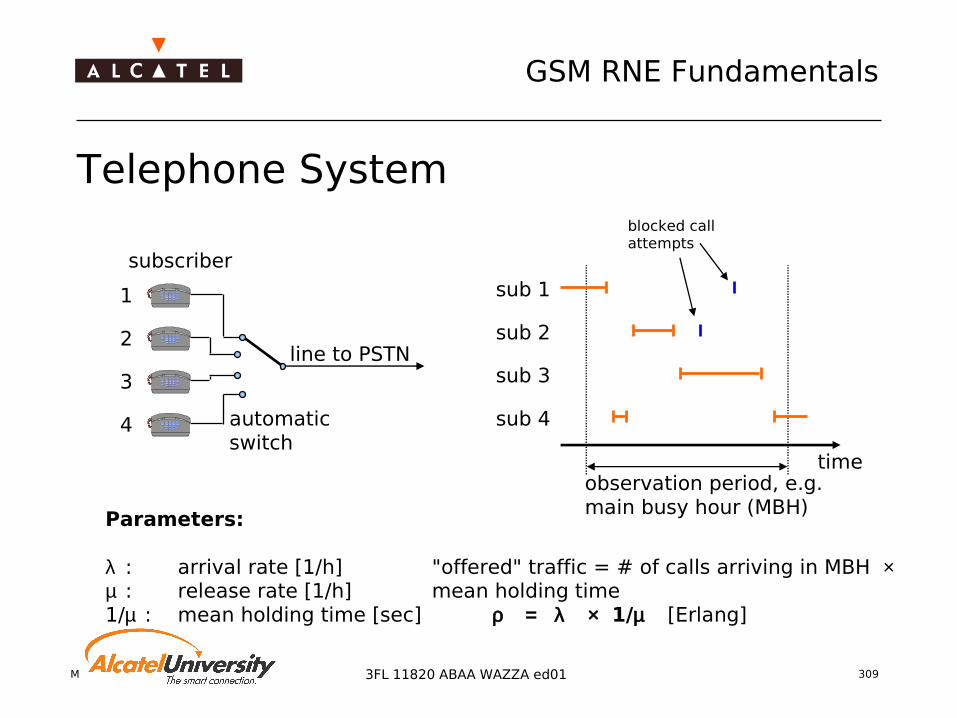
Mobile Radio Network Planning 309
GSM RNE Fundamentals
3FL 11820 ABAA WAZZA ed01
Telephone System
subscriber
1
2
3
4
line to PSTN
sub 1
sub 2
sub 3
sub 4
timeobservation period, e.g.main busy hour (MBH)
blocked callattempts
Parameters:
λ : arrival rate [1/h]µ : release rate [1/h]1/µ : mean holding time [sec]
"offered" traffic = # of calls arriving in MBH × mean holding time ρ = λ × 1/µ [Erlang]
automaticswitch

Mobile Radio Network Planning 310
GSM RNE Fundamentals
3FL 11820 ABAA WAZZA ed01
Offered Traffic and Traffic Capacity
Handled Traffic, Traffic Capacity: T
Blocking Probability, Grade of Service (GoS): pblock = R / ρ
System load: τ = T / n, i.e. T < n
Loss System(n slots)
HandledTraffic (T)
OfferedTraffic (ρ )
Rejected Traffic (R)
T = ρ - R

Mobile Radio Network Planning 311
GSM RNE Fundamentals
3FL 11820 ABAA WAZZA ed01
Definition of Erlang
ERLANG : Unit used to quantify traffic
T = (resource usage duration)/(total observation duration) [ERLANG]

Mobile Radio Network Planning 312
GSM RNE Fundamentals
3FL 11820 ABAA WAZZA ed01
Call Mix and Erlang Calculation
CALL MIX EXAMPLE 350 call/hour 3 LU/call TCH duration : 85 sec SDCCH duration : 4,5 sec
ERLANG COMPUTATION TCH = (350 * 85)/3600 = 8,26 ERLANG SDCCH = [ (350 + 350*3) * 4,5 ] / 3600 = 1.75 ERLANG

Mobile Radio Network Planning 313
GSM RNE Fundamentals
3FL 11820 ABAA WAZZA ed01
Definition of Erlang B ERLANG B LAW
Relationship between
Offered traffic Number of resources Blocking rate
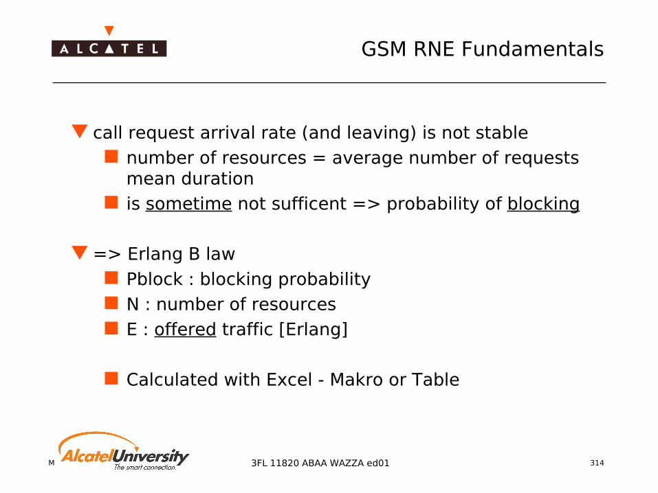
Mobile Radio Network Planning 314
GSM RNE Fundamentals
3FL 11820 ABAA WAZZA ed01
call request arrival rate (and leaving) is not stable
number of resources = average number of requests mean duration
is sometime not sufficent => probability of blocking
=> Erlang B law Pblock : blocking probability N : number of resources E : offered traffic [Erlang]
Calculated with Excel - Makro or Table
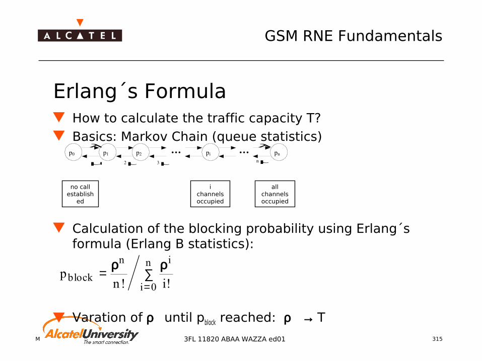
Mobile Radio Network Planning 315
GSM RNE Fundamentals
3FL 11820 ABAA WAZZA ed01
Erlang´s Formula How to calculate the traffic capacity T? Basics: Markov Chain (queue statistics)
Calculation of the blocking probability using Erlang´s formula (Erlang B statistics):
Varation of ρ until pblock reached: ρ → T
pn iblock
n i
i
n= ∑
=
ρ ρ! !0
p0 p1
2µµ
λpi
λpn
nµ
p2
3µ
no callestablish
ed
i channels occupied
all channels occupied

Mobile Radio Network Planning 316
GSM RNE Fundamentals
3FL 11820 ABAA WAZZA ed01
Blocking Probability (Erlang B)Nr. of Blocking Probability Erlang Bchannels 0.1% 0.2% 0.5% 1% 2% 3% 4% 5% 10% 15% 20% 50%
1 0.001 0.002 0.005 0.010 0.020 0.031 0.042 0.053 0.111 0.176 0.250 1.000
2 0.046 0.065 0.105 0.153 0.223 0.282 0.333 0.381 0.595 0.796 1.000 2.732
3 0.194 0.249 0.349 0.455 0.602 0.715 0.812 0.899 1.271 1.602 1.930 4.591
4 0.439 0.535 0.701 0.869 1.092 1.259 1.399 1.525 2.045 2.501 2.945 6.501
5 0.762 0.900 1.132 1.361 1.657 1.875 2.057 2.218 2.881 3.454 4.010 8.437
6 1.146 1.325 1.622 1.909 2.276 2.543 2.765 2.960 3.758 4.445 5.109 10.389
7 1.579 1.798 2.157 2.501 2.935 3.250 3.509 3.738 4.666 5.461 6.230 12.351
8 2.051 2.311 2.730 3.128 3.627 3.987 4.283 4.543 5.597 6.498 7.369 14.320
9 2.557 2.855 3.333 3.783 4.345 4.748 5.080 5.370 6.546 7.551 8.522 16.294
10 3.092 3.427 3.961 4.461 5.084 5.529 5.895 6.216 7.511 8.616 9.685 18.273
11 3.651 4.022 4.610 5.160 5.842 6.328 6.727 7.076 8.487 9.691 10.857 20.254
12 4.231 4.637 5.279 5.876 6.615 7.141 7.573 7.950 9.474 10.776 12.036 22.238
13 4.831 5.270 5.964 6.607 7.402 7.967 8.430 8.835 10.470 11.867 13.222 24.224
14 5.446 5.919 6.663 7.352 8.200 8.803 9.298 9.730 11.473 12.965 14.413 26.212
15 6.077 6.582 7.376 8.108 9.010 9.650 10.174 10.633 12.484 14.068 15.608 28.201
16 6.721 7.258 8.099 8.875 9.828 10.505 11.059 11.544 13.500 15.176 16.807 30.191
17 7.378 7.946 8.834 9.652 10.656 11.368 11.952 12.461 14.522 16.289 18.010 32.182
18 8.046 8.644 9.578 10.437 11.491 12.238 12.850 13.385 15.548 17.405 19.216 34.173
19 8.724 9.351 10.331 11.230 12.333 13.115 13.755 14.315 16.579 18.525 20.424 36.166
20 9.411 10.068 11.092 12.031 13.182 13.997 14.665 15.249 17.613 19.647 21.635 38.159
21 10.108 10.793 11.860 12.838 14.036 14.885 15.581 16.189 18.651 20.773 22.848 40.153
22 10.812 11.525 12.635 13.651 14.896 15.778 16.500 17.132 19.692 21.901 24.064 42.147
23 11.524 12.265 13.416 14.470 15.761 16.675 17.425 18.080 20.737 23.031 25.281 44.142
24 12.243 13.011 14.204 15.295 16.631 17.577 18.353 19.031 21.784 24.164 26.499 46.137
25 12.969 13.763 14.997 16.125 17.505 18.483 19.284 19.985 22.833 25.298 27.720 48.132
30 16.684 17.606 19.034 20.337 21.932 23.062 23.990 24.802 28.113 30.995 33.840 58.113
35 20.517 21.559 23.169 24.638 26.435 27.711 28.758 29.677 33.434 36.723 39.985 68.099
40 24.444 25.599 27.382 29.007 30.997 32.412 33.575 34.596 38.787 42.475 46.147 78.088
45 28.447 29.708 31.656 33.432 35.607 37.155 38.430 39.550 44.165 48.245 52.322 88.07950 32.512 33.876 35.982 37.901 40.255 41.933 43.316 44.533 49.562 54.029 58.508 98.072

Mobile Radio Network Planning 317
GSM RNE Fundamentals
3FL 11820 ABAA WAZZA ed01
BTS Traffic Capacity (Full Rate)
Number of Speech Traffic (Erlang B) Signalling Traffic (Erlang B)TRX SDCCH TCH 1% 2% 5% 0.1% 0.2% 0.5%1 4 7 2.501 2.935 3.738 0.439 0.535 0.7012 8 14 7.352 8.2 9.73 2.051 2.311 2.733 8 22 13.651 14.896 17.132 2.051 2.311 2.734 16 29 19.487 21.039 23.833 6.721 7.258 8.0995 16 37 26.379 28.254 31.64 6.721 7.258 8.0996 24 44 32.543 34.682 38.557 12.243 13.011 14.2047 24 52 39.7 42.124 46.533 12.243 13.011 14.2048 32 59 46.039 48.7 53.559 18.205 19.176 20.678
Mobile Radio Network Planning 3183FL 11820 ABAA WAZZA ed01
Traffic PlanningFrequency Planning
Network Evolution
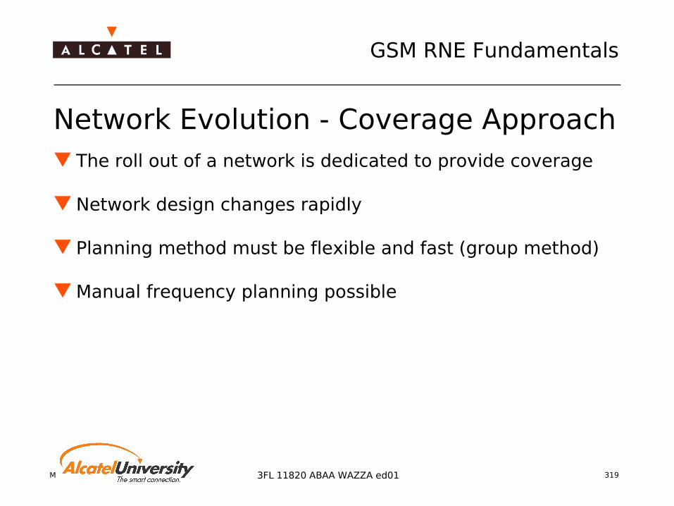
Mobile Radio Network Planning 319
GSM RNE Fundamentals
3FL 11820 ABAA WAZZA ed01
Network Evolution - Coverage Approach The roll out of a network is dedicated to provide coverage
Network design changes rapidly
Planning method must be flexible and fast (group method)
Manual frequency planning possible

Mobile Radio Network Planning 320
GSM RNE Fundamentals
3FL 11820 ABAA WAZZA ed01
Network Evolution - Capacity Approach (1) With the growing amount of subscribers, the need for more
installed capacity is rising
Possible Solutions:
Installing more TRXs on the existing BTS
Implementing additional sites
Discussion!

Mobile Radio Network Planning 321
GSM RNE Fundamentals
3FL 11820 ABAA WAZZA ed01
Network Evolution - Capacity Approach (2) Installing more TRXs - Advantages
No site search/acquisition process No additional sites to rent (saves cost) Trunking efficiency Higher capacity per cell
Installing more TRXs - Disadvantages More antennas on roof top (Air combining) Additional losses if WBC has to be used
Less (indoor) coverage
More frequencies per site needed Tighter reuse necessary decreasing quality

Mobile Radio Network Planning 322
GSM RNE Fundamentals
3FL 11820 ABAA WAZZA ed01
Network Evolution - Capacity Approach (3) Implementing additional sites - Advantages
Reuse can remain the same (smaller cell sizes) Needs less frequency spectrum
higher spectrum efficiency
Implementing additional sites - Disadvantages Additional site cost (rent) Re-design of old cells necessary (often not done)

Mobile Radio Network Planning 3233FL 11820 ABAA WAZZA ed01
Traffic PlanningFrequency Planning
Cell Structures

Mobile Radio Network Planning 324
GSM RNE Fundamentals
3FL 11820 ABAA WAZZA ed01
Cell Structures and Quality Frequency re-use in cellular radio networks
allow efficient usage of the frequency spectrum but causes interference
Interdependence of Cell size Cluster size Re-use distance Interference level Network Quality
interfererregion
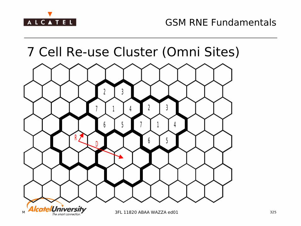
Mobile Radio Network Planning 325
GSM RNE Fundamentals
3FL 11820 ABAA WAZZA ed01
7 Cell Re-use Cluster (Omni Sites)
1
2 3
47
6 5 1
2 3
47
6 5RD

Mobile Radio Network Planning 326
GSM RNE Fundamentals
3FL 11820 ABAA WAZZA ed01
12 Cell Re-use Cluster (Omni Sites)
5 64
1 2 3
7 8 9
1 0 1 1 1 2
D

Mobile Radio Network Planning 327
GSM RNE Fundamentals
3FL 11820 ABAA WAZZA ed01
3x3 Cell Re-use Cluster (Sector Site)

Mobile Radio Network Planning 328
GSM RNE Fundamentals
3FL 11820 ABAA WAZZA ed01
4x3 Cell Re-use Cluster (Sector Site)
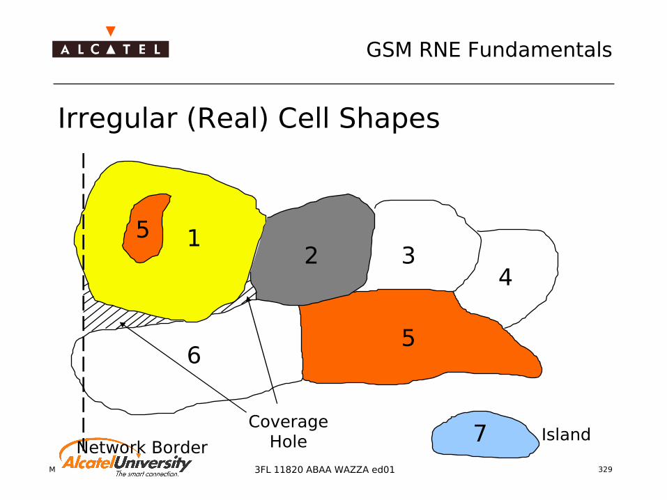
Mobile Radio Network Planning 329
GSM RNE Fundamentals
3FL 11820 ABAA WAZZA ed01
Irregular (Real) Cell Shapes
12 3
4
56
5
7Network Border
CoverageHole Island

Mobile Radio Network Planning 3303FL 11820 ABAA WAZZA ed01
Traffic PlanningFrequency Planning
Frequency Reuse
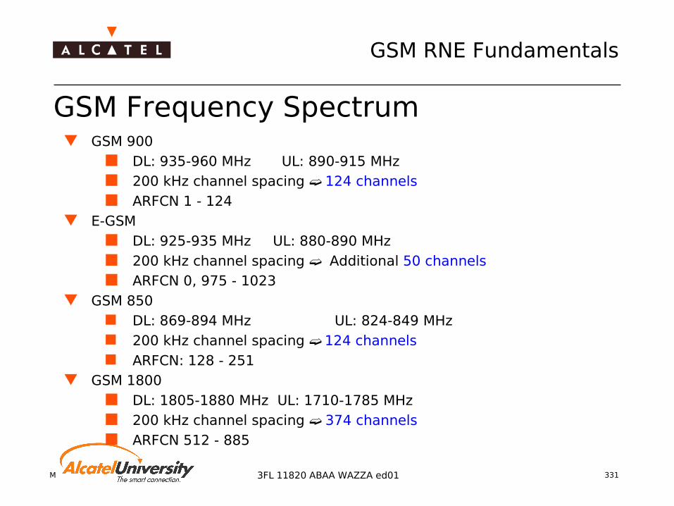
Mobile Radio Network Planning 331
GSM RNE Fundamentals
3FL 11820 ABAA WAZZA ed01
GSM Frequency Spectrum GSM 900
DL: 935-960 MHz UL: 890-915 MHz 200 kHz channel spacing 124 channels ARFCN 1 - 124
E-GSM DL: 925-935 MHz UL: 880-890 MHz 200 kHz channel spacing Additional 50 channels ARFCN 0, 975 - 1023
GSM 850 DL: 869-894 MHz UL: 824-849 MHz 200 kHz channel spacing 124 channels ARFCN: 128 - 251
GSM 1800 DL: 1805-1880 MHz UL: 1710-1785 MHz 200 kHz channel spacing 374 channels ARFCN 512 - 885

Mobile Radio Network Planning 332
GSM RNE Fundamentals
3FL 11820 ABAA WAZZA ed01
Impact of limited Frequency Spectrum
Bandwidth is an expensive resource
Best usage necessary
Efficient planning necessary to contain good QoS when the
traffic in the network is increasing smaller reuse MRP usage implementation of concentric cells / microcells/dual
band implementation of Frequency Hopping
Baseband Synthezised
Mobile Radio Network Planning 333
GSM RNE Fundamentals
3FL 11820 ABAA WAZZA ed01
What is frequency reuse? As the GSM spectrum is limited, frequencies have to be
reused to provide enough capacity
The more often a frequency is reused within a certain amount of cells, the smaller the frequency reuse
Aim:Minimizing the frequency reuse for providing more capacity
REUSE CLUSTER:Area including cells which do not reuse the same frequency (or frequency group)

Mobile Radio Network Planning 334
GSM RNE Fundamentals
3FL 11820 ABAA WAZZA ed01
RCS and ARCS (1) Reuse Cluster Size - RCS
If all cells within the reuse cluster have the same amount of TRXs, the reuse per TRX layer can be calculated:
cellTRXB
RCS/#
=
cellTRXB
ARCS/#
=
Average Reuse Cluster Size - ARCS If the cells are different equiped, the average number of
TRXs has to be used for calculating the average reuse cluster size:

Mobile Radio Network Planning 335
GSM RNE Fundamentals
3FL 11820 ABAA WAZZA ed01
RCS and ARCS (2) The ARCS is giving the average reuse of the network when
using the whole bandwidth and all TRXs per cell E.g: if we want to have the reuse of all non hopping TCH
TRXs, we have to use the dedicated bandwidth and the average number of non hopping TCH TRXs per cell to get the ARCS of this layer type.
Each cell has only one BCCH. Therefore the BCCH reuse is an RCS and not an ARCS!
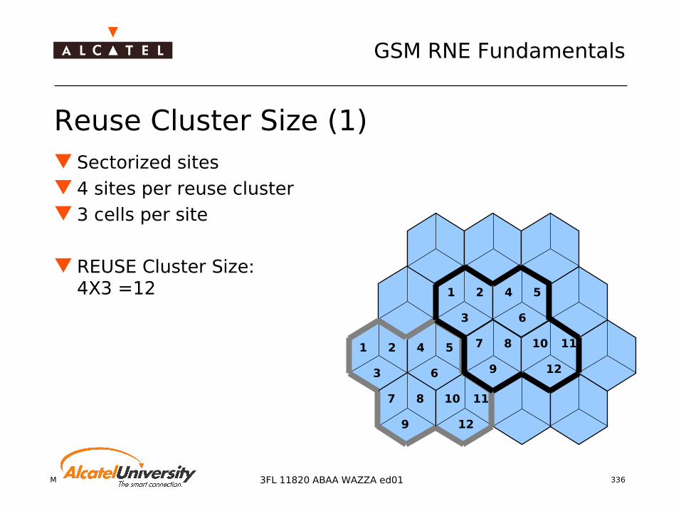
Mobile Radio Network Planning 336
GSM RNE Fundamentals
3FL 11820 ABAA WAZZA ed01
Reuse Cluster Size (1) Sectorized sites 4 sites per reuse cluster 3 cells per site
REUSE Cluster Size:4X3 =12 1 2
3
4 5
6
7 8
9
10 11
12
1 2
3
4 5
6
7 8
9
10 11
12

Mobile Radio Network Planning 337
GSM RNE Fundamentals
3FL 11820 ABAA WAZZA ed01
Reuse Cluster Size (2) Sectorized sites 3 sites per reuse cluster 3 cells per site
REUSE Cluster Size3X3 = 9
1 2
3
4 5
6
7 8
9
1 2
3
4 5
6
7 8
9

Mobile Radio Network Planning 338
GSM RNE Fundamentals
3FL 11820 ABAA WAZZA ed01
Reuse Distance
RCSRfD ⋅⋅⋅= 3
= cells sectorized-three3
2cells ionalomnidirect1
f
re-use distancecell A
cell B
interfererregion

Mobile Radio Network Planning 339
GSM RNE Fundamentals
3FL 11820 ABAA WAZZA ed01
Frequency Reuse Distance
site A site B
distance DR
D = distance between cell sites with the same frequenciesR = service radius of a cellB = number of frequencies in total bandwidthRCS = reuse cluster size, i.e. one cell uses B/RCS frequencies
In hexagonal cell geometry: D/R = f · 3 RCS
omni cells: f=1; sector cells: f=2/3
Examples (omni):RCS = 7: D/R = 4.6RCS = 9: D/R = 5.2RCS =12:D/R = 6.0
Received PowerFrec
σC/I
Frec, A Frec, B
0

Mobile Radio Network Planning 340
GSM RNE Fundamentals
3FL 11820 ABAA WAZZA ed01
Frequency Reuse: Example No sectorization 7 cells per cluster
BCCH RCS = 7 TCH Reuse: Depending on BW
and Number of installed TRXs per cell
Example: B= 26 4TRXs per cell
interfererregion
63
1726 =−−= GuardBCCHRCSTCH
RCSTCH
RCSBCCH

Mobile Radio Network Planning 3413FL 11820 ABAA WAZZA ed01
Traffic PlanningFrequency Planning
Cell Planning - Frequency Planning
Mobile Radio Network Planning 342
GSM RNE Fundamentals
3FL 11820 ABAA WAZZA ed01
Cell Planning - Frequency Planning (1) Can frequency planning be seen independently from cell
planning?
Discussion

Mobile Radio Network Planning 343
GSM RNE Fundamentals
3FL 11820 ABAA WAZZA ed01
Cell Planning - Frequency Planning (2) Bad cell planning
Island coverage disturbing the reuse pattern Big overlap areas bigger reuse necessary
Good cell planning Sharp cell borders good containment of
frequency Small overlap areas tighter reuse possible

Mobile Radio Network Planning 344
GSM RNE Fundamentals
3FL 11820 ABAA WAZZA ed01
Influencing Factors on Frequency Reuse Distance Topography
Hilly terrain Usage of natural obstacles to define sharp cell borders tighter frequency reuse possible
Flat terrain Achieveable reuse much more dependent on the accurate cell design
Morphology
Water low attenuation high reuse distance
City high attenuation low reuse distance

Mobile Radio Network Planning 345
GSM RNE Fundamentals
3FL 11820 ABAA WAZZA ed01
Conclusion In cellular mobile networks, the frequency reuse pattern has a
direct influence on the interference and hence the network quality Regular hexagonal patterns allow the deduction of engineering
formulas In real networks, cell sizes and shapes are irregular due to
Variation in traffic density Topography Land usage
Engineering formulas allow the assessment of the network quality and worst-case considerations, but the real situation must be proved!
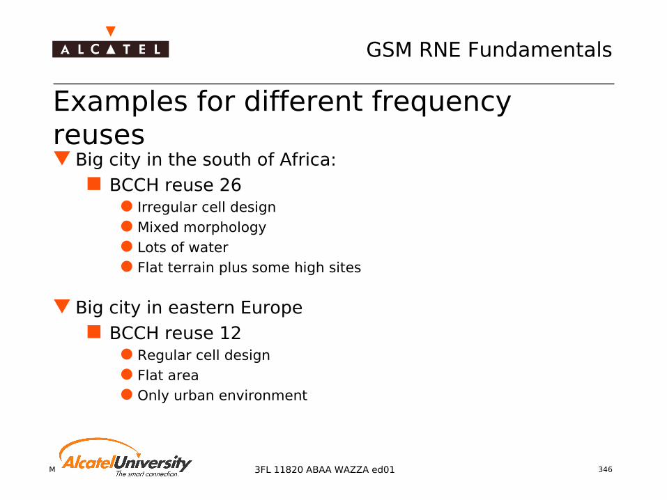
Mobile Radio Network Planning 346
GSM RNE Fundamentals
3FL 11820 ABAA WAZZA ed01
Examples for different frequency reuses Big city in the south of Africa:
BCCH reuse 26 Irregular cell design Mixed morphology Lots of water Flat terrain plus some high sites
Big city in eastern Europe BCCH reuse 12
Regular cell design Flat area Only urban environment
Mobile Radio Network Planning 3473FL 11820 ABAA WAZZA ed01
Traffic PlanningFrequency Planning
Interference Probability

Mobile Radio Network Planning 348
GSM RNE Fundamentals
3FL 11820 ABAA WAZZA ed01
Interference Theory (1) C/I restrictions
9dB for co-channel interference -9 dB for adjacent channel interference
dista nce DR
Received PowerP rec
σC/ I
Prec, A Prec, B
0

Mobile Radio Network Planning 349
GSM RNE Fundamentals
3FL 11820 ABAA WAZZA ed01
Interference Theory (2)
Probability density function [%]
0,0%
1,0%
2,0%
3,0%
4,0%
5,0%
C/I [dB] →C/ImedC/Ithr
Margin
Interferer probability [%]
0%
20%
40%
60%
80%
100%
-20 -15 -10 -5 0 5 10 15 20
C/I - C/I thr[dB]
Interference probability
C/Imed is the calculated carrier tointerference ratio at a certain location (pixel)
ARCS Pint[%]6.5..9.0 107.0..9.5 7.58.5..11.0 5.012.0..16.0 2.5

Mobile Radio Network Planning 350
GSM RNE Fundamentals
3FL 11820 ABAA WAZZA ed01
Interference Probability
Pint = P ( C/I < C/I thr )
00,10,20,30,40,50,60,70,80,91
P int
Distance from serving cell
DR
CPDF - Cumulative Probability Density Function
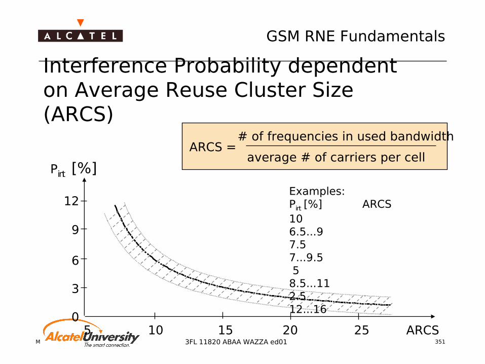
Mobile Radio Network Planning 351
GSM RNE Fundamentals
3FL 11820 ABAA WAZZA ed01
Interference Probability dependent on Average Reuse Cluster Size (ARCS)
ARCS =# of frequencies in used bandwidth
average # of carriers per cellPint [%]
ARCS0
3
6
9
12
5 10 15 20 25
Examples:Pint [%] ARCS106.5...97.57...9.5 5 8.5...112.512...16

Mobile Radio Network Planning 3523FL 11820 ABAA WAZZA ed01
Traffic PlanningFrequency Planning
Carrier TypesMultiple Reuse Pattern
Intermodulation
Mobile Radio Network Planning 353
GSM RNE Fundamentals
3FL 11820 ABAA WAZZA ed01
Carrier Types - BCCH carrier BCCH frequency is on air all the time
If there is no traffic/signaling on TS 1 to 7 dummy bursts are transmitted
PC (Power Control) and DTX (Discontinuous Transmission) are not allowed
Important for measurements of the mobile
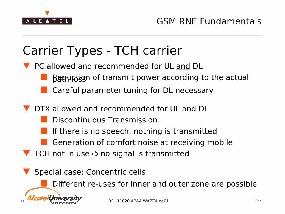
Mobile Radio Network Planning 354
GSM RNE Fundamentals
3FL 11820 ABAA WAZZA ed01
Carrier Types - TCH carrier PC allowed and recommended for UL and DL
Reduction of transmit power according to the actual path loss
Careful parameter tuning for DL necessary
DTX allowed and recommended for UL and DL
Discontinuous Transmission
If there is no speech, nothing is transmitted
Generation of comfort noise at receiving mobile
TCH not in use no signal is transmitted
Special case: Concentric cells
Different re-uses for inner and outer zone are possible
Mobile Radio Network Planning 355
GSM RNE Fundamentals
3FL 11820 ABAA WAZZA ed01
Multiple reuse pattern (1) For different types of carriers, different interference
potential is expected
As the BCCH carrier has the highest interferer potential because of being on air all the time and the BCCH channel itself is accepting only low interference, the REUSE on the BCCH layer is higher then on other layers
TCH layers can be planned with a smaller REUSE
Inner zones of concentric cells are able to deal with the smallest reuse in non hopping networks

Mobile Radio Network Planning 356
GSM RNE Fundamentals
3FL 11820 ABAA WAZZA ed01
Multiple reuse pattern (2)
REUSE clusters for
INNER ZONE layer
TCH layer
BCCH layer

Mobile Radio Network Planning 357
GSM RNE Fundamentals
3FL 11820 ABAA WAZZA ed01
GSM restrictions Intra site minimum channel spacing 2 Intra cell minimum channel spacing 2 (ETSI recommends
3, but with Alcatel EVOLIUM capabilities this value can be set to 2)
constrains: Uplink power control enabled Intra cell interference handover enabled
f A1,f
A2,f
A3,.
..
fB1 ,f
B2 ,fB3 ,...
f C1,f C2
,f C3,...
Frequencies fAx,fBx,fCx,… must have at least 2 channels spacing
Frequencies fx1,fx2,fx3,… must have at least 3 channels spacing

Mobile Radio Network Planning 358
GSM RNE Fundamentals
3FL 11820 ABAA WAZZA ed01
Intermodulation problems (1) IM Products GSM900
In a GSM 900 system intermodulation products of 3rd and 5th order can cause interference
2 * f1,t – f2,t = f2,r / 2 * f2,t – f1,t = f1,r
3 * f1,t – 2 * f2,t = f2,r / 3 * f2,t – 2 * f1,t = f1,r
Frequency planning must avoid fulfilling these equations
Both frequencies must be on the same duplexer
To avoid intra band IM inside GSM900 the following frequency separations shall be avoided:
75/112/113 channels
IM5 IM3

Mobile Radio Network Planning 359
GSM RNE Fundamentals
3FL 11820 ABAA WAZZA ed01
Intermodulation problems (2) IM Products GSM1800
In a GSM 1800 system, only intermodulation products of 3rd order can cause measurable interference
2 * f1,t – f2,t = f2,r / 2 * f2,t – f1,t = f1,r
Frequency separations to be avoided 237/238 channels
IM Products Dual Band (GSM900/GSM1800)
f1800,t – f900,t = f900,r
Decoupling between the GSM 1800 TX path and the GSM 900 RX path is less than 30 dB (e.g. same antenna used!)

Mobile Radio Network Planning 360
GSM RNE Fundamentals
3FL 11820 ABAA WAZZA ed01
Intermodulation problems (3) - Summary
carrier/antenna restriction
G3 900 1 no
G3 900 2 ore more 112/113 (IM3) and 75 (IM5)
G3 1800 1 no
G3 1800 2 or more 237/238 (IM3) no IM5 quality degradation measurable
carrier/antenna
G2 900 w/o dupl 1 no
2 or more no
G2 900 with dupl 1 no
2 or more 112/113 (IM3) and 75 (IM5)
G2 1800 w/o dupl 1 no
2 or more no
G2 1800 with dupl 1 no
2
2
G3 900 G2/G3 1800 f(1800,t) - f(900,t) = f(900,r)
G2 900 w/o dupl G2/G3 1800 no
G2 900 with dupl G2/G3 1800 f(1800,t) - f(900,t) = f(900,r)
Colocated BTSs
dud2(high Power) -> no
dupd -> 237/238
OUTSIDE Problem: Dual Band
INSIDE Problem: IM3 / IM5
Problem only for non hopping and BCCH carriers
Problem can be solved by hopping over more than 10 frequencies
Mobile Radio Network Planning 361
GSM RNE Fundamentals
3FL 11820 ABAA WAZZA ed01
Treating “neighbor” cells Cells, which are not declared as neighbor cells but are
located in the neighborhood may use adjacent frequencies if it is not avoidable, but no co channel frequencies
Cells which are declared as neighbors, thus have HO relationships, must not use co or adjacent frequencies
If an adjacent frequency is used, the HO will be risky and at least audible by the user

Mobile Radio Network Planning 362
GSM RNE Fundamentals
3FL 11820 ABAA WAZZA ed01
Where can I find neighbor cells? At the OMC-R for each cell a list of neighbor cells is defined
Maximum number of neighbors: 32
The list of neighbors and their frequencies is transmitted to the mobile to be able to perform measurements on these frequencies
In case of a HO cause, the HO will be performed towards the best neighbor

Mobile Radio Network Planning 3633FL 11820 ABAA WAZZA ed01
Traffic PlanningFrequency Planning
Manual Frequency Planning
Mobile Radio Network Planning 364
GSM RNE Fundamentals
3FL 11820 ABAA WAZZA ed01
Manual frequency planning (1) No fixed method
Free frequency assignment possible, but very time consuming for larger networks
For easy and fast frequency planning: use group assignment
Example:18 channels, 2TRX per cell ARCS 9
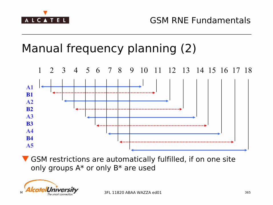
Mobile Radio Network Planning 365
GSM RNE Fundamentals
3FL 11820 ABAA WAZZA ed01
Manual frequency planning (2)
GSM restrictions are automatically fulfilled, if on one site only groups A* or only B* are used
1 2 3 4 5 6 7 8 9 10 11 12 13 14 15 16 17 18
A1B1A2B2A3B3A4B4A5

Mobile Radio Network Planning 366
GSM RNE Fundamentals
3FL 11820 ABAA WAZZA ed01
Exercise: Manual frequency planning (3)

Mobile Radio Network Planning 367
GSM RNE Fundamentals
3FL 11820 ABAA WAZZA ed01
Exercise: Manual frequency planning (4)
A1
A2A3
A2
A4 A5
B4
B1
B2 B3
B1
B2
A1
A2A3A2A4
A5
B2
B4B1
A3
A2A1

Mobile Radio Network Planning 368
GSM RNE Fundamentals
3FL 11820 ABAA WAZZA ed01
Discussion: Subdivide Frequency Band? Any subdivision of the frequency band is reducing the
spectrum efficiency!
Separations should be avoided if possible!
As the BCCH has to be very clean, it is nevertheless recommended to use a separated band and select a bigger reuse

Mobile Radio Network Planning 369
GSM RNE Fundamentals
3FL 11820 ABAA WAZZA ed01
Hint for creating a future proofed frequency plan
If a frequency plan is implemented, using all available frequencies in the most efficient way, it is very difficult to implement new sites in the future!
New sites would make a complete re-planning of the surrounding area or the whole frequency plan necessary
To avoid replanning every time when introducing new sites, it is recommended to keep some Joker frequencies free
These Joker frequencies can be used for new sites (especially BCCH TRXs) unless it is impossible to implement new sites without changing a big part of the frequency plan
New frequency plan necessary!

Mobile Radio Network Planning 370
GSM RNE Fundamentals
3FL 11820 ABAA WAZZA ed01
Implementing a frequency plan If only a few frequencies have to be changed, the changes can
be done at the OMC-R Disadvantage: Every cell has to be modified separately Downtime of the cell approx. 5 minutes
If lots of changes have to be done, it is of advantage to use external tools
Since B6.2 the complete frequency plan can be uploaded from the OMC
the uploaded file can be modified by the tool (A9155 PRC Generator)
the the new plan is downloaded into the network and activated at once

Mobile Radio Network Planning 3713FL 11820 ABAA WAZZA ed01
Traffic PlanningFrequency Planning
BSIC Planning

Mobile Radio Network Planning 372
GSM RNE Fundamentals
3FL 11820 ABAA WAZZA ed01
BSIC allocation Together with the frequencies the Base Transceiver Station
Identity Code (BSIC) has to be planned
The BSIC is to distinguish between cells using the same BCCH frequency
BSIC = NCC (3bits) + BCC (3bits) NCC Network (PLMN) Colour Code BCC - Base Transceiver Station (BTS) Colour Code
BSIC planning is supported by the A9155 (Alcatel Radio Network Planning Tool)

Mobile Radio Network Planning 373
GSM RNE Fundamentals
3FL 11820 ABAA WAZZA ed01
BSIC Planning Rules The same combination BCCH/BSIC must not be used on cell
influencing on each other (having a mutual interference <>0) BSIC allocation rules:
Avoid using same BCCH/BSIC combination of: neighbours cells second order neighbour cells (the neighbours of neighbour cell (OMC
limitation))
Neighbour Cell
BCCH:24
BSIC:36
Neighbour Cell
BCCH:24
BSIC: must NOT be 36
Serving Cell
BCCH:10
BSIC: any
A
B C

Mobile Radio Network Planning 374
GSM RNE Fundamentals
3FL 11820 ABAA WAZZA ed01
Spurious RACH Bad BSIC planning can cause SDCCH congestion cause by
the spurious RACH problem, also known as “Ghost RACH”
This problem occurs, when a mobile sends an HO access burst to a TRX of cell A using the same frequency as a nearby cell B uses on the BCCH
Both cells using the same BSIC and Training Sequence Code TSQC, the HO access burst is understood by the cell B as a RACH for call setup
Therefore on cell B SDCCHs are allocated everytime a HO access burst is sent from the mobile to the cell A

Mobile Radio Network Planning 375
GSM RNE Fundamentals
3FL 11820 ABAA WAZZA ed01
Summary For optimal usage of your frequency spectrum a good cell
design is essential Use larger reuse for BCCH frequencies Use spectrum splitting only when necessary

Mobile Radio Network Planning 3763FL 11820 ABAA WAZZA ed01
Traffic PlanningFrequency Planning
Capacity Enhancement Techniques

Mobile Radio Network Planning 377
GSM RNE Fundamentals
3FL 11820 ABAA WAZZA ed01
Capacity enhancement by planning Interference reduction of cells
Check of antenna type, direction and down tilt This is a check of cell size, border and orientation
Check of proper cabling Is TX and RX path on the same sector antenna?
Check of the frequency plan Introduction of a better frequency plan

Mobile Radio Network Planning 378
GSM RNE Fundamentals
3FL 11820 ABAA WAZZA ed01
Capacity enhancement by adding feature Frequency hopping
Base band hopping Synthesized frequency hopping
Concentric cells Half rate

Mobile Radio Network Planning 379
GSM RNE Fundamentals
3FL 11820 ABAA WAZZA ed01
Capacity enhancement by adding TRX Adding TRX to existing cells Multi band cells Concentric cells

Mobile Radio Network Planning 380
GSM RNE Fundamentals
3FL 11820 ABAA WAZZA ed01
Capacity enhancement by adding cells Adding of cells at existing site locations Adding new cell = adding new BCCH Dual band
Adding cells using another frequency band Cell splitting
Reduction of cell size Change of one omni cell into several cells/sector cells

Mobile Radio Network Planning 381
GSM RNE Fundamentals
3FL 11820 ABAA WAZZA ed01
Capacity enhancement by adding sites Dual band/multi band network
Adding of new sites in new frequency band Multi layer network
Adding of new sites in another layer E.g. adding micro cells for outdoor coverage
Indoor coverage Adding micro cells indoor coverage Adding macro cells indoor coverage
Mobile Radio Network Planning 3823FL 11820 ABAA WAZZA ed01
GSM Radio Network Engineering Fundamentals
Radio Interface

Mobile Radio Network Planning 383
GSM RNE Fundamentals
3FL 11820 ABAA WAZZA ed01
Contents GSM Air Interface Channel Coding Performance Figures

Mobile Radio Network Planning 3843FL 11820 ABAA WAZZA ed01
Quality of Service
GSM Air Interface

Mobile Radio Network Planning 385
GSM RNE Fundamentals
3FL 11820 ABAA WAZZA ed01
Radio Resources
Radio Spectrum Allocation
Frequency(FDMA)
Time(TDMA)
Timeslot0<TN<7
TDMA Frames0<FN<FN_MAX
Carrier Frequencies (ARFCN)
Cell Allocation(CA)
Mobile Allocation(MA)
FDMA Frequency division multiple accessTDMA Time division multiple accessARFCN Absolute radio frequency channel numberTN Timeslot numberFN Frame number

Mobile Radio Network Planning 386
GSM RNE Fundamentals
3FL 11820 ABAA WAZZA ed01
FDMA and TDMA with 8 time slots per carrier RF frequency band
(E)GSM: (880) 890 ... 915 MHz Uplink (MS → BS)(925) 935 ... 960 MHz Downlink (BS → MS)
GSM1800: 1710 ... 1785 MHz Uplink1805 ... 1880 MHz Downlink
200 kHz bandwidth Number of carriers: 124 (GSM); 374 (DCS); 49 (E-GSM)
GSM Transmission Principles (1)
GSM: Flower (n) = 890 + 0.2 · n MHz with 1 ≤ n ≤ 124
E-GSM: Flower (n) = 890 + 0.2 · n MHz with 0 ≤ n ≤ 124
Flower (n) = 890 + 0.2 · (n -1024) MHz with 975 ≤ n ≤ 1023
DCS : Flower (n) = 1710.2 + 0.2 · (n - 512) MHz with 512 ≤ n
≤ 885
(E)GSM: Fupper (n) = Flower (n) + 45 MHzDCS: Fupper (n) = Flower (n) + 95 MHz

Mobile Radio Network Planning 387
GSM RNE Fundamentals
3FL 11820 ABAA WAZZA ed01
GSM Transmission Principles (2)
Channel types Traffic Channels (TCH)
Full rate Half rate
Control Channels (CCH) Broadcast Control Channel (BCCH) Common Control Channel (CCCH) Dedicated Control Channel (DCCH)
TDMA frame cycles 26 cycle for traffic channels 51 cycle for control channels

Mobile Radio Network Planning 388
GSM RNE Fundamentals
3FL 11820 ABAA WAZZA ed01
Advantages of Signal Processing
Spectrum limitationsBad propagation
conditions
P
t
Good spectrum efficiency Good transmission quality
Operator

Mobile Radio Network Planning 389
GSM RNE Fundamentals
3FL 11820 ABAA WAZZA ed01
Signal Processing Chain
stealing bit and FACCH
speechcoding
errorprotection
interleaving encryption modulation
radiochannel
stealing bit and FACCH
speechinput
speechdecoding
errorcorrection
de-interleaving decryption demodulation
speechoutput
LossNoise
InterferenceFading

Mobile Radio Network Planning 390
GSM RNE Fundamentals
3FL 11820 ABAA WAZZA ed01
Speech Coding
260 bits speech block
182 class 1 bits
20 ms of coded speech
78 class 2 bits
sensitive to bit errorsmust be protected
robust to bit errors
Coding algorithm: RPE-LTP Pre-computation RPE = Regular Pulse Excitation
Model of human voice generation
LTP = Long Term Prediction Reduction of bit rate
Bit rate: 13 kBit/s
Coding at fixed network: PCM A-lawBit rate: 64 kBit/s
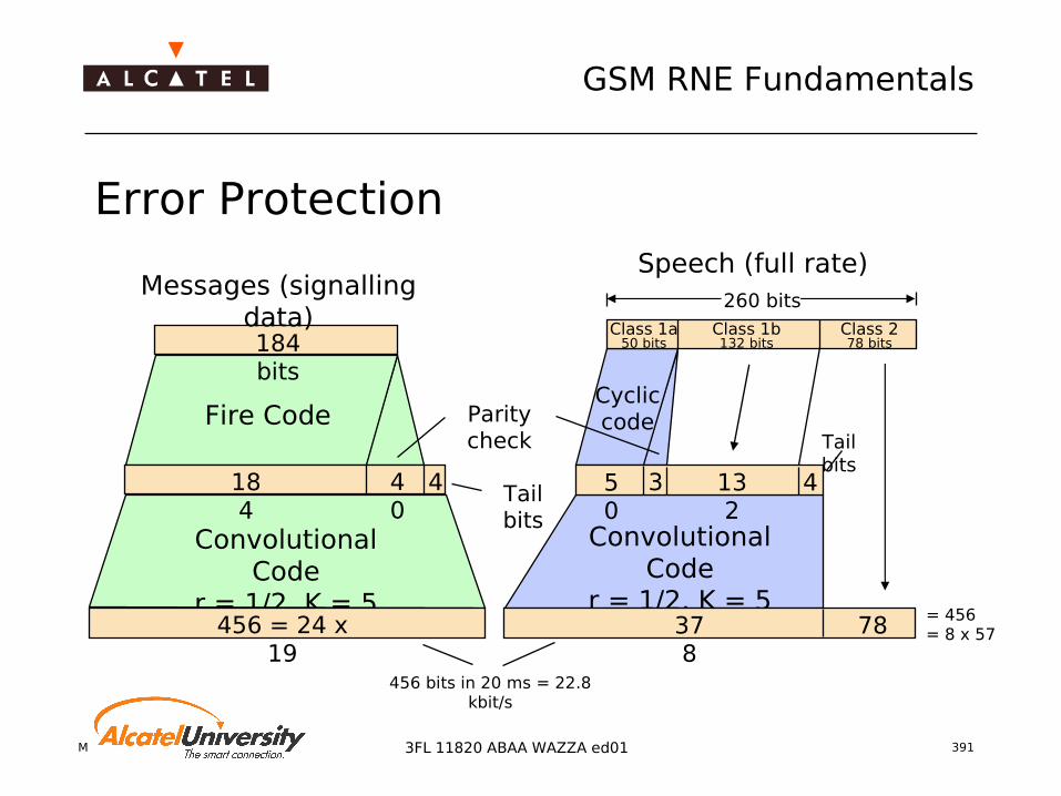
Mobile Radio Network Planning 391
GSM RNE Fundamentals
3FL 11820 ABAA WAZZA ed01
Error Protection
Messages (signalling data)
Fire Code
184 bits
184
40
4
Convolutional Code
r = 1/2, K = 5456 = 24 x
19456 bits in 20 ms = 22.8
kbit/s
Convolutional Code
r = 1/2, K = 5
Tail bits
Parity check
Cycliccode
Speech (full rate)
Tail bits
Class 1a50 bits
Class 1b132 bits
Class 278 bits
= 456= 8 x 5737
878
50
3 132
4
260 bits
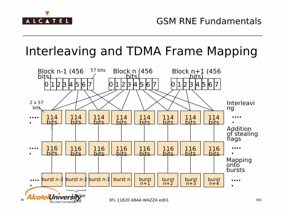
Mobile Radio Network Planning 392
GSM RNE Fundamentals
3FL 11820 ABAA WAZZA ed01
Interleaving and TDMA Frame Mapping
1 2 3 4 5 6 70 1 2 3 4 5 6 70
Mappingonto bursts
....
.
....
.
Addition of stealing flags
....
.
Interleaving
....
.
....
.
....
.
2 x 57 bits
Block n-1 (456 bits)
57 bits Block n (456 bits)
Block n+1 (456 bits)
1 2 3 4 5 6 70
1 time slot
114 bits
114 bits
114 bits
114 bits
114 bits
114 bits
114 bits
114 bits
116 bits
116 bits
116 bits
116 bits
116 bits
116 bits
116 bits
116 bits
burst n-3 burst n-2 burst n-1 burst n burst n+1
burst n+2
burst n+3
burst n+4

Mobile Radio Network Planning 393
GSM RNE Fundamentals
3FL 11820 ABAA WAZZA ed01
Encryption
AlgorithmA3
Randomnumber
generator
AlgorithmA8
IMSIKi
Ki RAND (128 bit)
+
Authentication
yes/noAlgorithm
A3
AlgorithmA8
RAND
SRES (32 bit)
SIMCard
Ki
AlgorithmA5
AlgorithmA5
+
Kc (64 bit)
+
RAND
Kc
originaldata
originaldata
encrypted
data
encrypted
data
Network Mobile station
AuC

Mobile Radio Network Planning 394
GSM RNE Fundamentals
3FL 11820 ABAA WAZZA ed01
Burst Structure
0 1 2 3 4 5 6 7
TDMA frame = 4.615 ms
Data TrainingSequence Data
57 bits3 26 bits1 31 57 bits
tail bits tail bitsstealing flags
156.25 bit periods = 0.577 ms
GP GP
A burst contains one data "portion" of one timeslot
TDMA frame: time between two bursts with same timeslot number
The burst also consists of: Guard period (GP): allows for
transition and settling times Tail bits: allow for small
shifts in time delay (synchronisation)
Stealing flags: to indicate FACCH (control channel) data
Training sequence: for equalization purposes
Normal Burst
0

Mobile Radio Network Planning 395
GSM RNE Fundamentals
3FL 11820 ABAA WAZZA ed01
Synchronisation
received at MS(downlink)
transmitted from MS(uplink)
transmitted from BTS(downlink)
received at BTS(uplink)
Transmitted bursts need a travelling time (TT) to the receiver For network access, the MS sends a (non-synchronized) shortened RACH burst The BSS measures the TT and generates a timing advance value TA which is
transmitted to the MS
0 1 2 3
1 2
0 1 2
1 2
TT TT
non-synchronized
3 TSdelay
0 1 2 3 4 5 6 7 0 1
0 1 2 3 4 5 6 7 0 1
0 1 2 3 4 5 6 7 0 1
0 1 2 3 4 5 6 7 0 1
TT
TT
synchronized
RACH
MS delay line setting
1
4
2
3

Mobile Radio Network Planning 396
GSM RNE Fundamentals
3FL 11820 ABAA WAZZA ed01
Modulation Gaussian minimum shift keying
Based on phase shift keying Reduction of required bandwidth
Maximum phase change during one bit duration Baseband filtering to achieve continuous phase changes
∫
cos
sin
+
x
x
≈90°
to RF modulatorDataϕ

Mobile Radio Network Planning 397
GSM RNE Fundamentals
3FL 11820 ABAA WAZZA ed01
Propagation Environment
Radio propagation is characterised by dispersive multi-path caused by reflection and scattering
Moving MS causes Doppler spectrum→ Definition of propagation models in the time domain to allow channel simulations
TUxx (Typical Urban) RAxx (Rural Area) HTxx (Hilly Terrain) xx = speed in km/h
see also GSM 05.05, 11.20, 11.21

Mobile Radio Network Planning 398
GSM RNE Fundamentals
3FL 11820 ABAA WAZZA ed01
Equalizing
Purpose: equalize distortions in transmission spectrum
Adaptive filtering required Filter parameters
determined out of the training sequence
Filter parameters change from burst to burst
Equalizer takes advantage from multipath propagation (path diversity)
0.001
0.01
0.1
0 1 2 3 4 5 6 7 8
Delay of second path [chips]
BE
R
none
Alcatel
MLSE
Equalizer
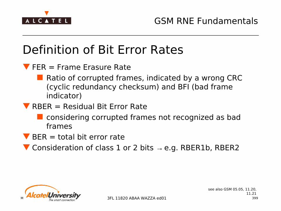
Mobile Radio Network Planning 399
GSM RNE Fundamentals
3FL 11820 ABAA WAZZA ed01
Definition of Bit Error Rates FER = Frame Erasure Rate
Ratio of corrupted frames, indicated by a wrong CRC (cyclic redundancy checksum) and BFI (bad frame indicator)
RBER = Residual Bit Error Rate considering corrupted frames not recognized as bad
frames BER = total bit error rate Consideration of class 1 or 2 bits → e.g. RBER1b, RBER2
see also GSM 05.05, 11.20, 11.21
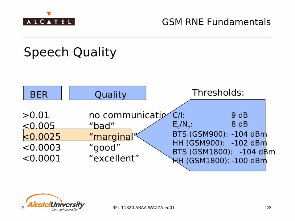
Mobile Radio Network Planning 400
GSM RNE Fundamentals
3FL 11820 ABAA WAZZA ed01
BER Quality
>0.01 no communication<0.005 “bad”<0.0025 “marginal”<0.0003 “good”<0.0001 “excellent”
Thresholds:
C/I: 9 dBEc/No: 8 dBBTS (GSM900): -104 dBmHH (GSM900): -102 dBmBTS (GSM1800): -104 dBmHH (GSM1800): -100 dBm
Speech Quality

Mobile Radio Network Planning 401
GSM RNE Fundamentals
3FL 11820 ABAA WAZZA ed01
Dependence of BER on Noise and Interference (1) Variation of BER1 over C/I
Parameter: Ec/N0
How to find a quality figure? BER1 for marginal speech
quality: 0.25% required C/I ≈ 9 dB for TU50
environment but: signal must not be
close to noise floor!
C/I [dB] →
TU50BER
1 →

Mobile Radio Network Planning 402
GSM RNE Fundamentals
3FL 11820 ABAA WAZZA ed01
Frequency Hopping (1)
-70
-60
-50
-40
-30
-20
-10
0
0.1
2.8
5.4
8.0
10.6
13.2
15.9
18.5
21.1
23.7
26.3
29.0
31.6
34.2
36.8
39.4
42.1
44.7
47.3
49.9
Distance [m ]
Rec
eive
d P
ower
[dB
m]
Lognorm al fading
Raleygh fading
Problem: specific fading pattern for each used frequency
Fast MS cope with the situation (due to signal processing)
Slow MS suffer from fading holes
Solution: change the fading pattern by frequency hopping
Fading holes

Mobile Radio Network Planning 403
GSM RNE Fundamentals
3FL 11820 ABAA WAZZA ed01
Frequency Hopping (2) Variation of BER1 over Ec/N0
TU environment, flat fading, v = 0 km/h (worst case)
Parameter: number of hopping frequencies
Compensation with 4 hopping frequencies possible
Ec/N0 [dB] →
BER
→
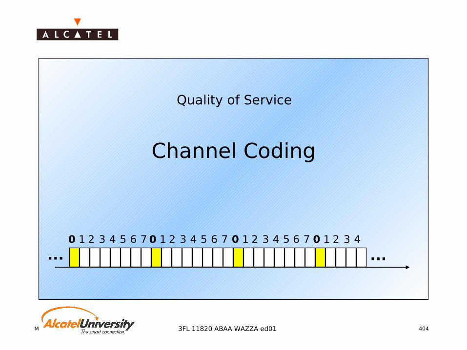
Mobile Radio Network Planning 4043FL 11820 ABAA WAZZA ed01
Quality of Service
Channel Coding
0 0 0 01 1 112 2 223 3 334 4 445 556 6 67 7 7
... ...

Mobile Radio Network Planning 405
GSM RNE Fundamentals
3FL 11820 ABAA WAZZA ed01
The OSI Reference Model
Definition in GSM recommendations: layers 1 to 3 Notion of "Physical" channels and "Logical" channels
7
6
5
4
3
2
1
Application layer
Presentation layer
Session layer
Transport layer
Network layer
Data link layer
Physical layer
End system End systemTransportation system
04.0408.54
04.05/0608.56
04.07/0808.58/4.0
8

Mobile Radio Network Planning 406
GSM RNE Fundamentals
3FL 11820 ABAA WAZZA ed01
GSM Burst Types (1)
Normal Burst For regular transmission
Frequency Correction Burst Contains 142 zeros (0) → pure sine wave Allows synchronisation of the mobile's local oscillator
Synchronisation Burst Consists of an enlarged unique training sequence code (TSC) Contains the actual FN → time synchronisation
Access Burst Shortened burst (unique TSC and enlarged guard period) Timeslot overlapping avoided at BTS when MS accesses network
Dummy Burst "Filler" for unused BCCH timeslots → BCCH permanently on air Similar to normal burst (defined mixed bits for data, no stealing
flag)

Mobile Radio Network Planning 407
GSM RNE Fundamentals
3FL 11820 ABAA WAZZA ed01
GSM Burst Types (2)
TB3
57 data bits 126 bit training
sequence1 57 data bits
TB3
Normal burstGP
8.25
TB3
142 fixed bits (pure sine wave)TB3
Frequency correction burstGP
8.25
TB3
39 data bits64 bit training
sequence39 data bits
TB3
Synchronisation burstGP
8.25
TB8
36 data bits41 bit synchronisation
sequence
Access burstenlarged GP
68.25 bitTB3

Mobile Radio Network Planning 408
GSM RNE Fundamentals
3FL 11820 ABAA WAZZA ed01
Logical Channels
Trafficchannel
Controlchannel
Speech Data
TCH/FS
TCH/HS
TCH/F9.6
TCH/F4.8
TCH/F2.4
TCH/H4.8
TCH/H2.4
CCCHBroadcastchannel
Associatedchannel
Dedicatedchannel
FCCH
SCH
BCCH
RACH
PCH
AGCH
FACCH
SACCH
SDCCH
CBCH
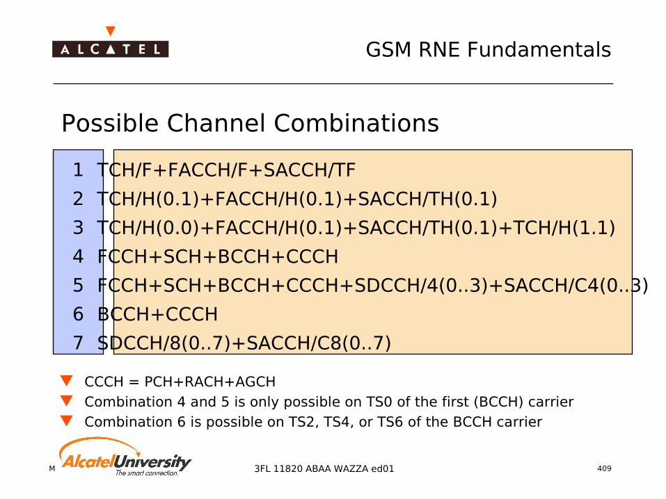
Mobile Radio Network Planning 409
GSM RNE Fundamentals
3FL 11820 ABAA WAZZA ed01
Possible Channel Combinations
1
2
3
4
5
6
7
TCH/F+FACCH/F+SACCH/TF
TCH/H(0.1)+FACCH/H(0.1)+SACCH/TH(0.1)
TCH/H(0.0)+FACCH/H(0.1)+SACCH/TH(0.1)+TCH/H(1.1)
FCCH+SCH+BCCH+CCCH
FCCH+SCH+BCCH+CCCH+SDCCH/4(0..3)+SACCH/C4(0..3)
BCCH+CCCH
SDCCH/8(0..7)+SACCH/C8(0..7)
CCCH = PCH+RACH+AGCH Combination 4 and 5 is only possible on TS0 of the first (BCCH) carrier Combination 6 is possible on TS2, TS4, or TS6 of the BCCH carrier

Mobile Radio Network Planning 410
GSM RNE Fundamentals
3FL 11820 ABAA WAZZA ed01
Channel Mapping (1)
time
.......
....
...
....
...
0 0 0 01 1 112 2 223 3 334 4 445 556 6 67 7 7
one TDMA frame = 4.616 ms
Information packages are always related to the same timeslot number!
Bursts are transmitted and received every TDMA frame duration (4.616 ms)Presentation of
consecutive TDMA frames on the vertical axis
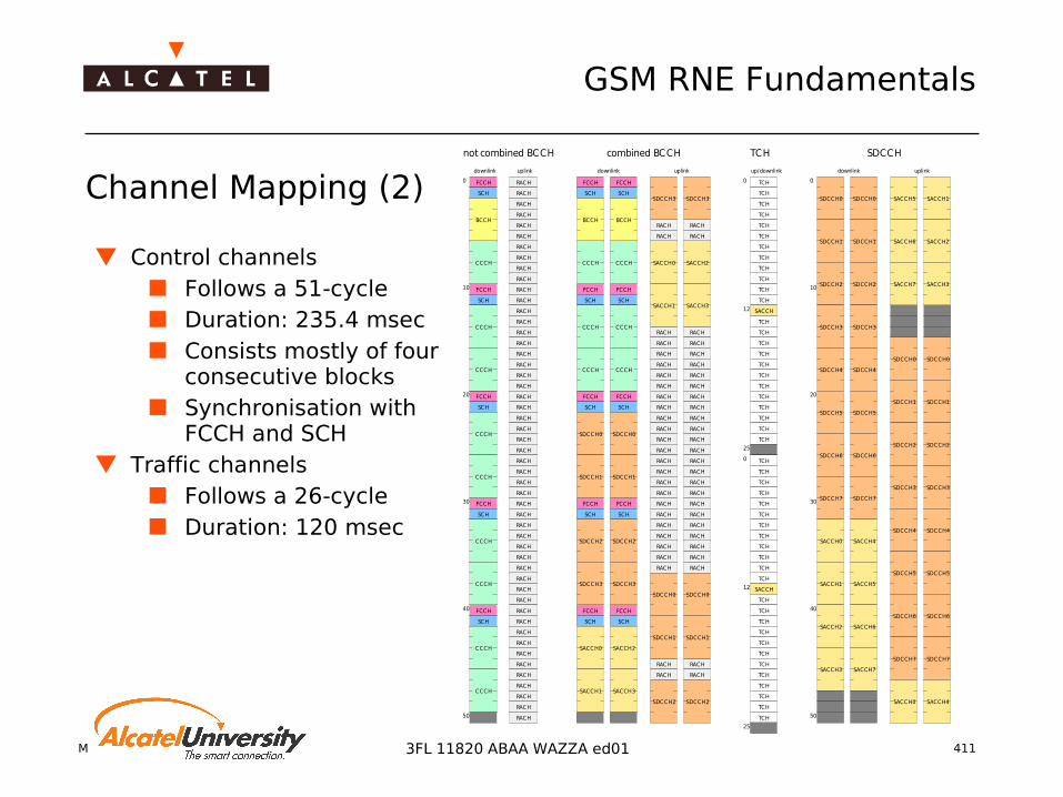
Mobile Radio Network Planning 411
GSM RNE Fundamentals
3FL 11820 ABAA WAZZA ed01
Channel Mapping (2) SCH
FCCH RACH
SCH
FCCH
SCH
FCCH
SCH
FCCH
SCH
FCCH
RACH
RACH
RACH
RACH
RACH
RACH
RACH
RACH
RACH
RACH
RACH
RACH
RACH
RACH
RACH
RACH
RACH
RACH
RACH
RACH
RACH
RACH
RACH
RACH
RACH
RACH
RACH
RACH
RACH
RACH
RACH
RACH
RACH
RACH
RACH
RACH
RACH
RACH
RACH
RACH
RACH
RACH
RACH
RACH
RACH
RACH
RACH
RACH
RACH
RACH
SCH
FCCH
SCH
FCCH
SCH
FCCH
SCH
FCCH
SCH
FCCH
SCH
FCCH
SCH
FCCH
SCH
FCCH
SCH
FCCH
SCH
FCCH
RACH
RACH
RACH
RACH
RACH
RACH
RACH
RACH
RACH
RACH
RACH
RACH
RACH
RACH
RACH
RACH
RACH
RACH
RACH
RACH
RACH
RACH
RACH
RACH
RACH
RACH
RACH
RACH
RACH
RACH
RACH
RACH
RACH
RACH
RACH
RACH
RACH
RACH
RACH
RACH
RACH
RACH
RACH
RACH
RACH
RACH
RACH
RACH
RACH
RACH
RACH
RACH
RACH
RACH
BCCH
CCCH
CCCH
CCCH
CCCH
CCCH
CCCH
CCCH
CCCH
CCCH
BCCH BCCH
CCCH
CCCH
CCCH
CCCH
CCCH
CCCH
SDCCH0
SDCCH1
SDCCH2
SDCCH3
SDCCH0
SDCCH1
SDCCH2
SDCCH3
SDCCH0
SDCCH1
SDCCH0
SDCCH1
SDCCH2
SDCCH3
SDCCH2
SDCCH3
SACCH0
SACCH1
SACCH2
SACCH3
TCH
TCH
TCH
TCH
TCH
TCH
TCH
TCH
TCH
TCH
TCH
TCH
SACCH
TCH
TCH
TCH
TCH
TCH
TCH
TCH
TCH
TCH
TCH
TCH
TCH
TCH
TCH
TCH
TCH
TCH
TCH
TCH
TCH
TCH
TCH
TCH
TCH
SACCH
TCH
TCH
TCH
TCH
TCH
TCH
TCH
TCH
TCH
TCH
TCH
TCH
SDCCH0
SDCCH1
SDCCH2
SDCCH3
SDCCH4
SDCCH5
SDCCH6
SDCCH7
SACCH0
SACCH1
SACCH2
SACCH3
SACCH0
SACCH1
SACCH2
SACCH3
SDCCH0
SDCCH1
SDCCH2
SDCCH3
SDCCH4
SDCCH5
SDCCH6
SDCCH7
SACCH4
SACCH5
SACCH6
SACCH7
SDCCH0
SDCCH1
SDCCH2
SDCCH3
SDCCH4
SDCCH5
SDCCH6
SDCCH7
SACCH0
SDCCH0
SDCCH1
SDCCH2
SDCCH3
SDCCH4
SDCCH5
SDCCH6
SDCCH7
SACCH1
SACCH2
SACCH3
SACCH4
SACCH5
SACCH6
SACCH7
0
10
20
30
40
50
0
10
20
30
40
50
0
12
25
0
12
25
not combined BCCH
downlink uplink downlink uplink downlink uplink
combined BCCH TCH SDCCH
up/downlink
Control channels Follows a 51-cycle Duration: 235.4 msec Consists mostly of four
consecutive blocks Synchronisation with
FCCH and SCH Traffic channels
Follows a 26-cycle Duration: 120 msec

Mobile Radio Network Planning 412
GSM RNE Fundamentals
3FL 11820 ABAA WAZZA ed01
TDMA Frame Structure for TCHs
TB3
57 data bits 126 bit training
sequence1 57 data bits
TB3
GP8.25
0 1 2 3 4 5 6 7
0 1 2 3 4 5 6 7 8 9 10 11 12 13 14 15 16 17 18 19 20 21 22 23 24 25
Time slot
Frame
Multiframe
Superframe
Hyperframe
51 multiframes of 120 ms duration
2048 superframes of 6.12 s duration
0.577 ms
4.615 ms
120 ms
6.12 s
3 h 28 m 53 s

Mobile Radio Network Planning 4133FL 11820 ABAA WAZZA ed01
Quality of Service
Performance Figures

Mobile Radio Network Planning 414
GSM RNE Fundamentals
3FL 11820 ABAA WAZZA ed01
Performance Figures (1)
Interference Probability Pint
measure for co/adjacent channel interference
Coverage Probability Pcov
measure for sufficient received power Call Success Rate (CSR)
CSR = "Coverage" AND (NOT "Interference“)
CSR = Pcov · (1 - Pint)
Outage Probability Pout
complementary to CSR
Pout = 1 - CSR
Mobile Radio Network Planning 4153FL 11820 ABAA WAZZA ed01
Abbreviations

Mobile Radio Network Planning 416
GSM RNE Fundamentals
3FL 11820 ABAA WAZZA ed01
AMR Advanced Multi Rate (TC)AMSS Aeronautical Mobile Satellite ServicesAN Antenna Network (BTS)ARCS Average Reuse Cluster SizeARFCN Absolute Radio Frequency ChannelAS Access Switch (BSC)AS Alarm Surveillance (O&M)ASMA A-ter Submultiplexer AASMB A-ter Submultiplexer BAuC Authentication CenterBC BroadcastBCU Broadcast UnitBCLA BSC Clock ABCR Broadcast RegisterBCU Broadcast UnitBCCH Broadcast Common Control Channel
(GSM TS)BCF Base station Control Function (BTS)BG Border Gate (GPRS)
BIE Base Station Interface EquipmentBIEC Base Station Interface Equipment (BSC)BIUA Base Station Interface Unit ABPA Back Panel AssemblyBSC Base Station ControllerBSIC Base Transceiver Station Identity CodeBSS Base Station (sub)SystemBSSGP Base Station System GPRS Protocol
(GPRS)BTS Base Transceiver StationCAE Customer Application EngineeringCAL Current Alarm List (O&M)CBC Cell Broadcast CenterCBCH Cell Broadcast Channel (GSM TS)CBE Cell Broadcast EntityCCCH Common Control Channel (GSM TS)CCU Channel Coding Unit

Mobile Radio Network Planning 417
GSM RNE Fundamentals
3FL 11820 ABAA WAZZA ed01
CDMA Code Division Multiple AccessCE Control Element (BSC)CEK Control Element KernelC/I Carrier to Interferer ratioCLK ClockCLSI Custom Large Scale Integrated circuitCMA Configuration Management Application (O&M)CMDA Common Memory Disk ACMFA Common Memory Flash ACPR Common Processor (Type: CPRA, CPRC)CRC Cyclic Redundancy CheckCS Circuit Switching (Telecom)CS Coding Scheme (GPRS):
CS-1, CS-2, CS-3, CS-4CU Carrier Unit (BTS)DCE Data Circuit Terminating EquipmentDCN Data Communication NetworkDL DownLink
DLS Data Load SegmentDMA Direct Memory AccessDRFU Dual Rate Frame UnitDRX Discontinuous Reception (GSM TS)DSE Digital Switching ElementDSN Digital Switching NetworkDTX Discontinuous Transmission (GSM TS)DTC Digital Trunk Controller
(Type: DTCA, DTCC)DTE Data Terminal EquipmentEDGE Enhanced Data rates for GSM EvolutionEI Extension interfaceEML Element Management LevelEPROM Erasable Programmable Read Only
MemoryETSI European Telecom Standard InstituteFPE Functional and Protective EarthFR Full Rate (GSM TS)
Mobile Radio Network Planning 418
GSM RNE Fundamentals
3FL 11820 ABAA WAZZA ed01
FR Frame Relay (Telecom)FRDN Frame Relay Data Network (Telecom)FU Frame Unit (BTS)FW FirmwareGCR Group Call RegisterGGSN Gateway GPRS Support Node (GPRS)GMLC Gateway Mobile Location CenterGMM GPRS Mobility Management (GPRS)GMSC Gateway Mobile Switching CenterGPRS General Packet Radio ServiceGPU GPRS Packet UnitGS-1 Group Switch of stage 1 (BSC)GS-2 Group Switch of stage 2 (BSC)GSL GPRS Signalling LinkGSM Global System for Mobile CommunicationsGSM TS GSM Technical SpecificationHAL Historical Alarm List (O&M)HDSL High rate Digital Subscriber LineHDLC High Level Datalink Control
HLR Home Location RegisterHMI Human Machine InterfaceHO HandOverHR Half RateHW HardwareIDR Internal Directed RetryILCS ISDN Link ControllerIMT Installation and Maintenance Terminal
(MFS)IND Indoor (BTS)IP Internet ProtocolISDN Integrated Services Data NetworkIT Intelligent TerminalLA Location Area (GSM TS)LAC Location Area Code (GSM TS)LAN Local Area NetworkLED Light Emitting DiodeLEO Low Earth Orbit (Satellite)LCS Location Services

Mobile Radio Network Planning 419
GSM RNE Fundamentals
3FL 11820 ABAA WAZZA ed01
LLC Logical Link Control (GPRS)LMU Location measurement unitMA Mobile Allocation (GSM TS)MAC Medium Access Control (GPRS)MAN Metropolitan Area NetworkMAN MicroBTS Antenna Network (BTS)MCB Multiplex Channel BlockMFS Multi-BSS Fast Packet Server (GPRS)MLU Massive Logical UpdateMMI Man Machine InterfaceMO Managed Object (O&M)MRP Multiple Reuse PatternMS Mobile StationMSC Mobile Switching CenterMSUM MicroBTS Station Unit Module (BTS)NMI Non Maskable InterruptNPA Network Performance AnalyserNSS Network SubSystemNTL Network Termination LineNW Network
OBC On Board ControllerOBCI On Board Controller InterfaceOC Originating CallODMC On Demand Measurement Campaign
(O&M)O&M Operation and MaintenanceOMC Operation and Maintenance CenterOMC-R Operation and Maintenance Center -
RadioOML Operation and Maintenance LinkOMU Operation and Maintenance Unit (BTS)OS Operating SystemOUT Outdoor (BTS)PBA Printed Board AssemblyPBCCH Packet Broadcast Common Control
CHannel (GPRS)PC Personal ComputerPCCCH Packet Common Control Channel
(GPRS)

Mobile Radio Network Planning 420
GSM RNE Fundamentals
3FL 11820 ABAA WAZZA ed01
PCH Paging CHannel (GSM TS)PCM Pulse Coded ModulationPCU Packet Control Unit (GPRS)PDCH Packet Data CHannelPDN Packet Data Network (Telecom)PDU Protocol Data Unit (generic terminology)PLL Phase Locked LoopPLMN Public Land Mobile NetworkPMA Prompt Maintenance Alarm (O&M)PMC Permanent Measurement Campaign
(O&M)PPCH Packet Paging CHannel (GPRS)PRACH Packet Random Access CHannel (GPRS)Prec Received PowerPRC Provisioning Radio Configuration (O&M)PSDN Packet Switching Data Network
(Telecom)
PSTN Public Switching Telephone Network(Telecom)
PTP-CNLS Point To Point CoNnectionLeSs datatransfer (GPRS)
QoS Quality of ServiceRA Radio AccessRACH Random Access CHannel (GSM TS)RAM Random Access MemoryRCP Radio Control PointRLC Radio Link Control (GPRS)RLP Radio Link Protocol (GSM TS)RML Radio Management LevelRNO Radio Network OptimisationRNP Radio Network PlanningRSL Radio Signalling Link

Mobile Radio Network Planning 421
GSM RNE Fundamentals
3FL 11820 ABAA WAZZA ed01
RTS Radio Time SlotRxLev Received LevelRxQual Received QualitySACCH Slow Associated Control Channel
(GSM TS)SAU Subrack assembly unit (BSC)SC Supervised Configuration (O&M)SCC Serial Communication ControllerSCP Service Control PointSCCP Signalling Connection Control PartSCSI Small Computer Systems InterfaceSDCCH Standalone Dedicated Control Channel
(GSM TS)SDU Service Data Unit (generic terminology)SGSN Serving GPRS Support Node (GPRS)SIEA SCSI Interface Extension A
SM SubmultiplexerSMLC Serving Mobile Location CenterSMP Service Management PointSMS Short Message ServiceSMS-CB Short Message Service - Cell BroadcastSM-GMSC Short Message Gateway Mobile Switching
CenterSRAM Static RAMSRS SubRate SwitchSS7 Signalling System ITU-T N°7 (ex CCITT)SSD Solid State DiskSSP Service Switching PointSW SoftwareSWEL Switch ElementTBF Temporary Block Flow (GPRS)TAF Terminal Adaptor Function

Mobile Radio Network Planning 422
GSM RNE Fundamentals
3FL 11820 ABAA WAZZA ed01
TC TranscoderTC Terminating CallTCC Trunk Controller ChipTCH Traffic CHannel (GSM TS)TCIL TransCoder Internal LinkTCSM TransCoder / SubMultiplexer equipmentTCU TRX Control Unit (Type: TCUA, TCUC)TDMA Time Division Multiple AccessTFO Tandem Free Operation (TC)TFTS Terrestrial Flight Telecom SystemsTLD Top Level DesignTMN Telecommunication Management
NetworkTRAC Trunk Access CircuitTRAU Transcoder and Rate Adapter UnitTRCU Transcoder UnitTRE Transceiver EquipmentTRS Technical Requirement SpecificationTRU Top Rack Unit
TRX TransceiverTS Time SlotTS Technical Specification (GSM TS)TSS Time Space Switch TSCA Transmission Sub-System Controller A
(BSC) TSU Terminal Sub Unit (BSC)TU Terminal Unit (BSC)UL UpLinkUMTS Universal Mobile Transmission SystemUSSD Unstructured Supplementary Services DataVBS Voice Broadcast ServiceVGCS Voice Group Code ServiceVLR Visitor Location RegisterVPLMN Visited PLMNVSWR Voltage Standing Wave Ratio (BTS)WAN Wide Area NetworkWAP Wireless Application ProtocolWBC Wide Band Combiner