gs-co-1000 indoor carbon monoxide sensors · please see note in section 7 on previous page...
TRANSCRIPT

Page 1 of 5
GS-CO-1000 Date of Issue: 17/03/2015
Issue Number: 5.5
Tel: +44 (0)1732 861200. - E-mail: [email protected]. - Web: www.sontay.com.
© 2012 Sontay Limited. All rights reserved
Features: Benefits:
The GS-CO-1000 series of Carbon Monoxide sensors are based on tried and tested SnO2 sensor technology, the new design provides a highly cost-effective answer for monitoring CO, typically for alarm purposes. NB The sensor is not designed, manufactured or intended for use or re-sale as control or monitoring equipment in environments requiring life safety performance, in which the failure of the sensor could lead directly to death, personal injury, or severe physical or environmental damage. Sontay and its suppliers specifically disclaim any express or implied warranty of fitness for life safety. Please note that the sensor will need approximately 10 minutes warm-up time before the sensor becomes active.
GS-CO-1000
Indoor Carbon Monoxide Sensors
• Multi-function sensor • Direct thermistor temperature options
available
• High stability & reliability • Long term stability • 4-20mA, 0-5Vdc and 0-10Vdc outputs
for compatibility with a wide range of controllers
• Blends into the fabric of any building
Technical Overview

Page 2 of 5
GS-CO-1000 Date of Issue: 17/03/2015
Issue Number: 5.5
Tel: +44 (0)1732 861200. - E-mail: [email protected]. - Web: www.sontay.com.
© 2012 Sontay Limited. All rights reserved
Outputs: Voltage 0-10Vdc, 0-5Vdc Current 4-20mA (3-wire) Optional Passive Outputs: Thermistor
Set point 0-10kΩ or 11-1kΩlinear Momentary switch VFC Fan Speed Resistive
Measurement range: 0 to 160ppm Power Supply: 12-26Vac or 16-26Vdc @60mA
Ambient: Temperature 0 to 50°C (32 to 122°F) RH 0 to 95% RH, non-condensing Housing: Material ABS (flame retardant) Colour polished white finish Dimensions 115 x 85 x 28mm (4.53 x 3.35 x 1.1”) Ambient range -10 to 60°C (14 to 140°F) Protection IP30 Country of origin UK
The products referred to in this data sheet meet the requirements of EU Directive 2004/108/EC
GS-CO-1000 Space CO sensor Suffixes (add to part code) -T Direct resistive temperature output Thermistor types: A (10K3A1) B (10K4A1) C (20K6A1) H (SAT1) K (STA1) L (TAC1) M (2.2K3A1) N (3K3A1) P (30K6A1) Q (50K6A1) S (SAT2) T (SAT3) W (SIE1) Y (STA2) Z(10K NTC) Platinum types: D (PT100a) E (PT1000a) Nickel types: F (NI1000a) G (NI1000a/TCR (LAN1)) Interface Options (add to part code)*
-SP Resistive set point 0-10kΩ or 11-1kΩ -FS3 Resistive 3-speed fan switch -FS4 Resistive 3-speed fan switch -FS5 Resistive 5-speed fan switch -MS Momentary switch
Accessory DECOR Decorators trim plate GASKET Insulating gasket (pack of 10) * Interface Restrictions • SP only • MS only • SP-MS only • SP-FSx only
Notes: Current versions are NOT loop powered and will require a common 0V connection. When using the –T option, they are not compensated for internal heating.
Specification: Part Codes:

Page 3 of 5
GS-CO-1000 Date of Issue: 17/03/2015
Issue Number: 5.5
Tel: +44 (0)1732 861200. - E-mail: [email protected]. - Web: www.sontay.com.
© 2012 Sontay Limited. All rights reserved

Page 4 of 5
GS-CO-1000 Date of Issue: 17/03/2015
Issue Number: 5.5
Tel: +44 (0)1732 861200. - E-mail: [email protected]. - Web: www.sontay.com.
© 2012 Sontay Limited. All rights reserved
The sensor has a heated element with a nominal resistance in clean air. This resistance decreases in the presence of detectable CO. This is a nominal resistance, is different for each sensor element and will change during the life of the sensor. To allow for this, on powering the sensor a period of time is required before the sensor achieves thermal equilibrium (about ten minutes). During this process the system determines the resistance for the sensor element fitted, with this value being used for air quality calculations. While in operation this reference value is constantly monitored and adjusted as necessary. During the ten minute warm-up after power is applied, the sensor should not be exposed to CO. During this period the output will register zero CO. During warm-up period the unit calibrates itself, it is important that the environment around it is clean uncontaminated air and free from odours, cigarette smoke and CO. If exposed to CO during this time the calibration will be wrong, though it will correct itself after a couple of hours in clean air. The purpose of the GS-CO-1000 is to monitor for CO levels up to 170ppm.
Antistatic precautions must be observed when handling these sensors. The PCB contains circuitry that can be damaged by static discharge.
1. Select a location on a wall of the controlled space which will give a representative sample of the prevailing room
condition. Avoid sitting the sensor in direct sunlight, on an outside wall or near heat sources. An idea mounting height is 1.5m from the floor.
2. Undo the tamperproof screw at the bottom of the housing.
3. To remove the front panel from the base, twist a screwdriver as below and pull gently the front panel from the base.
Operation:
Installation:

Page 5 of 5
GS-CO-1000 Date of Issue: 17/03/2015
Issue Number: 5.5
Tel: +44 (0)1732 861200. - E-mail: [email protected]. - Web: www.sontay.com.
© 2012 Sontay Limited. All rights reserved

Page 6 of 5
GS-CO-1000 Date of Issue: 17/03/2015
Issue Number: 5.5
Tel: +44 (0)1732 861200. - E-mail: [email protected]. - Web: www.sontay.com.
© 2012 Sontay Limited. All rights reserved
Installation:
4. Using the base as a template mark the hole centres and fix to the wall with suitable screws. Alternatively the base plate can be mounted on to a conduit box or standard recessed back box. The base plate is suitable for EU & North America fixings.
5. Feed cable through the hole in the base plate of the housing and terminate the cores at the terminal block as required. Leaving some slack inside the unit.
6. Set the yellow dip-switches according to output type required (see page 5 for dip-switch details).
7. Replace the housing to the base plate and fit the tamperproof screw (if required) through the lug at the bottom of
the base plate.
8. Before powering the sensor, ensure that the supply voltage is within the specified tolerances. Note: When using the sensor with a 4-20mA output, it is important to make all electrical connections before applying the supply voltage. If the sensor is not connected sequence, then you may see a higher reading than expected (can be as much as 55mA).
9. Allow 10 minutes before checking functionality, and at least 30 minutes before carrying out pre-commissioning
checks. This will allow the electronics time to stabilise. Left Hand terminal Block: Right Hand Terminal Block (if -T option is selected); 24V Supply + 24Vac or Vdc (see note below) T2 Direct thermistor output only GND Supply 0V (other half of OP1 if J11 is set to T) OP1 Direct thermistor output only (see J11 settings) MS1 Momentary switch VFC output OP2 Not used MS2 Momentary switch output GND Common 0V P5* Set point OP3 CO Output P6* Set point wiper GND Common 0V P7* Set point OVRD Not used FS2 Fan speed switch output, resistive FS1 Fan speed switch output, resistive
Notes:
Voltage output Nominal voltage 24Vac/dc. Current output Nominal voltage 24Vac/dc.3-Wire
Please see note in section 7 on previous page regarding connections.
Set point* 2-wire 11-1kΩ output is required use terminals P6 and P7 2-wire 0-10kΩ output is required, use terminals P5 and P6 Direct thermistor output (if fitted) is between terminals OP1 and T2, polarity is independent. When using the -T option, they are not compensated for internal heating.
Connections:
Page 7 of 5
GS-CO-1000 Date of Issue: 17/03/2015
Issue Number: 5.5
Tel: +44 (0)1732 861200. - E-mail: [email protected]. - Web: www.sontay.com.
© 2012 Sontay Limited. All rights reserved
Whilst every effort has been made to ensure the accuracy of this specification, Sontay cannot accept responsibility for damage, injury, loss or expense from errors or omissions. In the interest of technical improvement, this specification may be altered without notice.
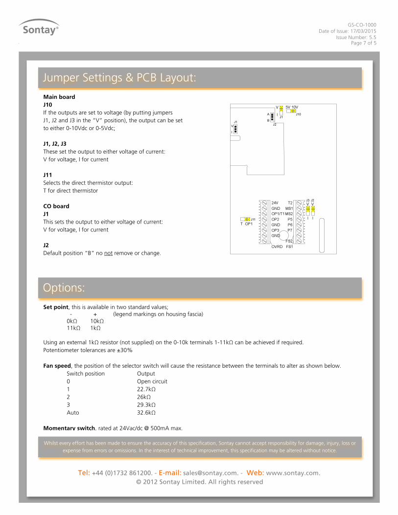
Jumper Settings & PCB Layout:
Main board J10 If the outputs are set to voltage (by putting jumpers J1, J2 and J3 in the “V” position), the output can be set to either 0-10Vdc or 0-5Vdc; J1, J2, J3 These set the output to either voltage of current: V for voltage, I for current J11 Selects the direct thermistor output: T for direct thermistor CO board J1 This sets the output to either voltage of current: V for voltage, I for current J2 Default position “B” no not remove or change. Set point, this is available in two standard values; - + (legend markings on housing fascia) 0kΩ 10kΩ 11kΩ 1kΩ
Using an external 1kΩ resistor (not supplied) on the 0-10k terminals 1-11kΩ can be achieved if required. Potentiometer tolerances are ±30% Fan speed, the position of the selector switch will cause the resistance between the terminals to alter as shown below. Switch position Output 0 Open circuit 1 22.7kΩ 2 26kΩ 3 29.3kΩ Auto 32.6kΩ Momentary switch, rated at 24Vac/dc @ 500mA max.
Options: