grs 77/gmu 44 - garmin · page vi grs 77/gmu 44 installation manual revision l 190-00303-10 grs...
TRANSCRIPT

190-00303-10 March, 2010 Revision L
GRS 77/GMU 44Installation Manual

Page A GRS 77/GMU 44 Installation Manual Revision L 190-00303-10
© Copyright 2010 Garmin Ltd. or its subsidiaries
All Rights Reserved
Except as expressly provided herein, no part of this manual may be reproduced, copied, transmitted, disseminated, downloaded or stored in any storage medium, for any purpose without the express prior written consent of Garmin. Garmin hereby grants permission to download a single copy of this manual and of any revision to this manual onto a hard drive or other electronic storage medium to be viewed and to print one copy of this manual or of any revision hereto, provided that such electronic or printed copy of this manual or revision must contain the complete text of this copyright notice and provided further that any unauthorized commercial distribution of this manual or any revision hereto is strictly prohibited.
Garmin International, Inc. 1200 E. 151st Street Olathe, Kansas 66062 U.S.A.
Telephone: 913-397-8200 Aviation Dealer Technical Support Line (Toll Free): (888) 606-5482
www.garmin.com
Garmin (Europe) Ltd Liberty House
Bulls Copse Road Hounsdown Business Park
Southampton, SO40 9RB, UK Telephone: 44 (0) 8708501241
RECORD OF REVISIONS
Revision Revision Date Description
A 04/29/04 Production Release B 08/24/04 Engineering Changes C 04/26/05 Added –10 GRS 77 and removed EQF
D 7/26/05 Changed GRS 77 unit weight, added torque specs, and added GMU 44 note
E 2/16/06 Revised calibration procedure and updated document F 6/8/06 Added baud rates and wing tip lights to interference test G 4/24/08 Added -10 GMU 44 and new TSO deviations H 4/13/09 Added -10 GMU 44 installation rack and mod status J 08/31/09 Update to reflect Level A SW for GRS 77 K 01/26/10 Added 011-00868-20 GRS 77H unit L 03/02/10 Added wording for multiple AHRS installations

GRS 77/GMU 44 Installation Manual Page i 190-00303-10 Revision L
CURRENT REVISION DESCRIPTION
Revision Page Number(s)
Section Number Description of Change
L 2-5 2.5.1 Added paragraph concerning installation of multiple AHRS
DOCUMENT PAGINATION
Section Page Range Table of Contents i – viii
Section 1 1-1 – 1-8 Section 2 2-1 – 2-8 Section 3 3-1 – 3-6 Section 4 4-1 – 4-6 Section 5 5-1 – 5-18
Appendix A A-1 – A-12 Appendix B B-1 – B-4

Page ii GRS 77/GMU 44 Installation Manual Revision L 190-00303-10
This manual reflects the operation of system and boot block software versions listed in the following table. Some differences in operation may be observed when comparing the information in this manual to earlier or later software versions.
LRU Part Number System SW Version Boot Block SW Version GRS 77, 011-00868-00 3.00 3.00 GRS 77, 011-00868-10 3.00 3.00
GRS 77H, 011-00868-20 3.50 3.00 GMU 44, 011-00870-00 2.05 2.05 GMU 44, 011-00870-10 2.05 2.05
INFORMATION SUBJECT TO EXPORT CONTROL LAWS This document may contain information which is subject to the Export Administration Regulations (“EAR”) issued by the United States Department of Commerce (15 CFR, Chapter VII Subchapter C) and which may not be exported, released or disclosed to foreign nationals inside or outside the United States without first obtaining an export license. The preceding statement is required to be included on any and all reproductions in whole or in part of this manual.
WARNING This product, its packaging, and its components contain chemicals known to the State of California to cause cancer, birth defects, or reproductive harm. This Notice is being provided in accordance with California's Proposition 65. If you have any questions or would like additional information, please refer to our web site at www.garmin.com/prop65.
NOTE Throughout this document references made to GRS 77 shall equally apply to the GRS 77 and GRS 77H (011-00868-20) except where specifically noted.
GRS 77/GMU 44 Installation Manual Page iii 190-00303-10 Revision L
TABLE OF CONTENTS PARAGRAPH PAGE 1 GENERAL DESCRIPTION..............................................................................................................1-1 1.1 Introduction........................................................................................................................................1-1 1.2 Equipment Description ......................................................................................................................1-1 1.3 Interface Summary.............................................................................................................................1-2 1.4 Technical Specifications ....................................................................................................................1-2 1.5 Certification .......................................................................................................................................1-4 1.6 Reference Publications ......................................................................................................................1-6 1.7 Aviation Limited Warranty................................................................................................................1-7 2 INSTALLATION OVERVIEW ........................................................................................................2-1 2.1 Introduction........................................................................................................................................2-1 2.2 Installation Approval Considerations for Pressurized Aircraft..........................................................2-3 2.3 Wiring ................................................................................................................................................2-4 2.4 Cooling Air ........................................................................................................................................2-4 2.5 Aircraft Mounting Requirements for GRS 77/GMU 44 ....................................................................2-4 3 INSTALLATION PROCEDURE......................................................................................................3-1 3.1 Unpacking Unit..................................................................................................................................3-1 3.2 Electrical Connections .......................................................................................................................3-1 3.3 Backshell Assembly...........................................................................................................................3-2 3.4 GRS 77/GMU 44 Interconnect Harness Fabrication Instructions .....................................................3-3 3.5 GRS 77 and GMU 44 Mounting Instructions....................................................................................3-4 3.6 GRS 77 Rack to Unit Flatness Check ................................................................................................3-4 3.7 Post Installation Inspection................................................................................................................3-5 4 SYSTEM INTERCONNECTS..........................................................................................................4-1 4.1 Pin Function List................................................................................................................................4-1 4.2 Power Function..................................................................................................................................4-3 4.3 Serial Data Electrical Characteristics.................................................................................................4-4

Page iv GRS 77/GMU 44 Installation Manual Revision L 190-00303-10
PARAGRAPH PAGE 5 POST INSTALLATION CONFIGURATION AND CHECKOUT PROCEDURE .........................5-1 5.1 Function Selector Switches and Display ...........................................................................................5-1 5.2 Post-Installation Calibration Procedures............................................................................................5-1 5.3 Calibration Procedure A-1: Pitch/Roll Offset Compensation by Aircraft Leveling ..........................5-4 5.4 Calibration Procedure A-2: Zero Pitch/Roll Offsets by Manual Entry..............................................5-5 5.5 Calibration Procedure B: Magnetometer Calibration ........................................................................5-7 5.6 Calibration Procedure C: Heading Offset Compensation ................................................................5-10 5.7 Calibration Procedure D: Engine Run-Up Vibration Test ...............................................................5-11 5.8 Calibration Procedure E: Magnetometer Interference Test .............................................................5-13 5.9 Site Evaluation of Magnetic Disturbances for Magnetometer Calibration Procedure.....................5-17 APPENDIX A OUTLINE AND INSTALLATION DRAWINGS APPENDIX B INTERCONNECT DRAWINGS
GRS 77/GMU 44 Installation Manual Page v 190-00303-10 Revision L
LIST OF ILLUSTRATIONS FIGURE PAGE 2-1 GRS 77 and Mounting Rack..............................................................................................................2-5 3-1 Measuring GRS 77 to Mounting Rack with Feeler Gauge ................................................................3-5 4-1 Rear Connector J771..........................................................................................................................4-1 4-2 Pigtail Connector J441.......................................................................................................................4-3 5-1 Fixed-wing and Helicopter position examples ..................................................................................5-7 A-1 GRS 77 Outline Drawing With Mounting Rack...............................................................................A-1 A-2 GMU 44 Mounting Rack (Sheet 1 of 2) ...........................................................................................A-3 A-2 GMU 44 Mounting Rack (Sheet 2 of 2) ...........................................................................................A-5 A-3 GMU 44 Top Mounted Installation ..................................................................................................A-7 A-4 GMU 44 Bottom Mounted Installation.............................................................................................A-9 A-5 GMU 44 Wiring Detail ...................................................................................................................A-11 B-1 Typical GRS 77/GMU 44 Interconnect Wiring Diagram................................................................. B-1 B-2 Simplified GRS 77/GMU 44 Installation, Interconnect Wiring Diagram ........................................ B-3
LIST OF TABLES TABLE PAGE 2-1 Required Distance from Magnetic Disturbances ...............................................................................2-6 3-1 Pin Contact Part Numbers..................................................................................................................3-1 3-2 Recommended Crimp Tools ..............................................................................................................3-1 3-3 Parts Needed for GMU 44 Installation ..............................................................................................3-3 3-4 GMU 44 Connector Kit 011-00871-00 Contents ..............................................................................3-3 4-1 P771 Pin Assignments .......................................................................................................................4-1 4-2 P441 Pin Assignments .......................................................................................................................4-3 4-3. Aircraft Power Pin Assignments, P771 and P441 .............................................................................4-3 4-4 RS-232 Pin Assignments, P771 and P441 .........................................................................................4-4 4-5 RS-485 Pin Assignments, P771 and P441 .........................................................................................4-4 4-6 ARINC 429 Pin Assignments, P771..................................................................................................4-5 4-7 Configuration Module Connections, P771 ........................................................................................4-5 4-8 AHRS System ID Program Pins, P771 ..............................................................................................4-6 4-9 P771 Strapping to Achieve Desired System ID.................................................................................4-6 5-1 Post-Installation Calibration Procedure Summary.............................................................................5-2 5-2 Fixed-wing Magnetometer Interference Test Sequence Example ...................................................5-14 5-3 Helicopter Magnetometer Interference Test Sequence Example.....................................................5-15

Page vi GRS 77/GMU 44 Installation Manual Revision L 190-00303-10
GRS 77/GMU 44 HARDWARE MOD LEVEL HISTORY The following table identifies hardware modification (Mod) Levels for the GRS 77 AHRS and GMU 44 Magnetometer. Mod Levels are listed with the associated service bulletin number, service bulletin date, and the purpose of the modification. The table is current at the time of publication of this manual (see date on front cover) and is subject to change without notice. Authorized Garmin Sales and Service Centers are encouraged to access the most up-to-date bulletin and advisory information on the Garmin Dealer Resource web site at www.garmin.com using their Garmin-provided user name and password.
GRS 77 P/N 011-00868-00 HARDWARE MOD LEVEL HISTORY
MOD LEVEL
SERVICE BULLETIN NUMBER
SERVICE BULLETIN
DATE PURPOSE OF MODIFICATION
1 N/A N/A This modification improves the reliability of certain GRS 77 LRUs.
2 N/A N/A Improves circuit reliability and robustness with the use of improved circuit components.
3 N/A N/A Improves vibration immunity.
GRS 77 P/N 011-00868-10 HARDWARE MOD LEVEL HISTORY
MOD LEVEL
SERVICE BULLETIN NUMBER
SERVICE BULLETIN
DATE PURPOSE OF MODIFICATION
1 0735 9/7/07 This modification improves the reliability of certain GRS 77 LRUs.
2 N/A N/A Improves circuit reliability and robustness with the use of improved circuit components.
3 N/A N/A Improves vibration immunity.
GRS 77H P/N 011-00868-20 HARDWARE MOD LEVEL HISTORY
MOD LEVEL
SERVICE BULLETIN NUMBER
SERVICE BULLETIN
DATE PURPOSE OF MODIFICATION

GRS 77/GMU 44 Installation Manual Page vii 190-00303-10 Revision L
GMU 44 P/N 011-00870-00 HARDWARE MOD LEVEL HISTORY
MOD LEVEL
SERVICE BULLETIN NUMBER
SERVICE BULLETIN
DATE PURPOSE OF MODIFICATION
1 N/A N/A This modification improves the reliability of certain GMU 44 LRUs.
GMU 44 P/N 011-00870-10 HARDWARE MOD LEVEL HISTORY
MOD LEVEL
SERVICE BULLETIN NUMBER
SERVICE BULLETIN
DATE PURPOSE OF MODIFICATION

Page viii GRS 77/GMU 44 Installation Manual Revision L 190-00303-10
This page intentionally left blank

GRS 77/GMU 44 Installation Manual Page 1-1 190-00303-10 Revision L
1 GENERAL DESCRIPTION
1.1 Introduction
This manual presents mechanical and electrical installation requirements for installing the Garmin GRS 77 AHRS and GMU 44 Magnetometer as part of a Garmin Integrated Flight Deck. The GRS 77/GMU 44 can be incorporated into a variety of airframes under appropriate TC or STC. Each airframe installation may vary. Interconnect drawings and procedures that are aircraft-manufacturer approved must be used during actual installation. 1.2 Equipment Description
The Garmin GRS 77 AHRS (Attitude and Heading Reference System) and GMU 44 Magnetometer are remote mounted devices that provide flight attitude and heading data for flight instrumentation. With information available and valid from all sensors, or without the GPS, the GRS 77 AHRS provides valid attitude, angular rate and acceleration information to the GIA 63(W) Integrated Avionics and the GDU 104X Primary Flight Display. Approved installations must include a compatible GPS (which is included in the GIA 63(W)). An Attitude and Heading Reference System combines the functions of a Vertical Gyro and a Directional Gyro to provide measurement of Roll, Pitch and Heading angles. The Garmin AHRS and magnetometer replace traditional rotating mass instruments. Using long-life solid-state sensing technology, the GRS 77 AHRS and GMU 44 Magnetometer combine 3-axis angular rate, linear acceleration and magnetic field measurements to create an electronically stabilized AHRS. The GRS 77 provides the following information in ARINC 429 format:
• Aircraft heading, pitch and roll • Aircraft yaw, pitch and roll rates • Aircraft body-axis accelerations • Rates of change of heading, pitch and roll • Aircraft accelerations expressed in a local level frame of reference
The GRS 77H has the same functions/capabilities of the GRS 77, but has higher vibration capabilities and compatibility with rotorcraft flight. The GMU 44 magnetometer provides magnetic information to support the function of the GRS 77. Operating voltage range of the GRS 77 AHRS is from 10 to 33 volts DC. The GRS 77 provides operating voltage to the GMU 44 Magnetometer. The GRS 77/GMU 44 is capable of maneuvers through a range of 360° in bank and pitch. The rotation rate capability is ±200° per second. However, ARINC 429 angular rate output messages are limited to ±128° per second. Bank error and pitch error are within ±1.25° over the range of 30° bank, left and right, and 15° pitch nose up and nose down. Heading is accurate to within 2° in straight and level flight.
Page 1-2 GRS 77/GMU 44 Installation Manual Revision L 190-00303-10
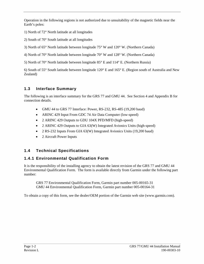
Operation in the following regions is not authorized due to unsuitability of the magnetic fields near the Earth’s poles:
1) North of 72° North latitude at all longitudes
2) South of 70° South latitude at all longitudes
3) North of 65° North latitude between longitude 75° W and 120° W. (Northern Canada)
4) North of 70° North latitude between longitude 70° W and 128° W. (Northern Canada)
5) North of 70° North latitude between longitude 85° E and 114° E. (Northern Russia)
6) South of 55° South latitude between longitude 120° E and 165° E. (Region south of Australia and New Zealand) 1.3 Interface Summary
The following is an interface summary for the GRS 77 and GMU 44. See Section 4 and Appendix B for connection details.
• GMU 44 to GRS 77 Interface: Power, RS-232, RS-485 (19,200 baud) • ARINC 429 Input From GDC 74 Air Data Computer (low-speed) • 2 ARINC 429 Outputs to GDU 104X PFD/MFD (high-speed) • 2 ARINC 429 Outputs to GIA 63(W) Integrated Avionics Units (high-speed) • 2 RS-232 Inputs From GIA 63(W) Integrated Avionics Units (19,200 baud) • 2 Aircraft Power Inputs
1.4 Technical Specifications
1.4.1 Environmental Qualification Form
It is the responsibility of the installing agency to obtain the latest revision of the GRS 77 and GMU 44 Environmental Qualification Form. The form is available directly from Garmin under the following part number: GRS 77 Environmental Qualification Form, Garmin part number 005-00165-31 GMU 44 Environmental Qualification Form, Garmin part number 005-00164-31 To obtain a copy of this form, see the dealer/OEM portion of the Garmin web site (www.garmin.com).
GRS 77/GMU 44 Installation Manual Page 1-3 190-00303-10 Revision L
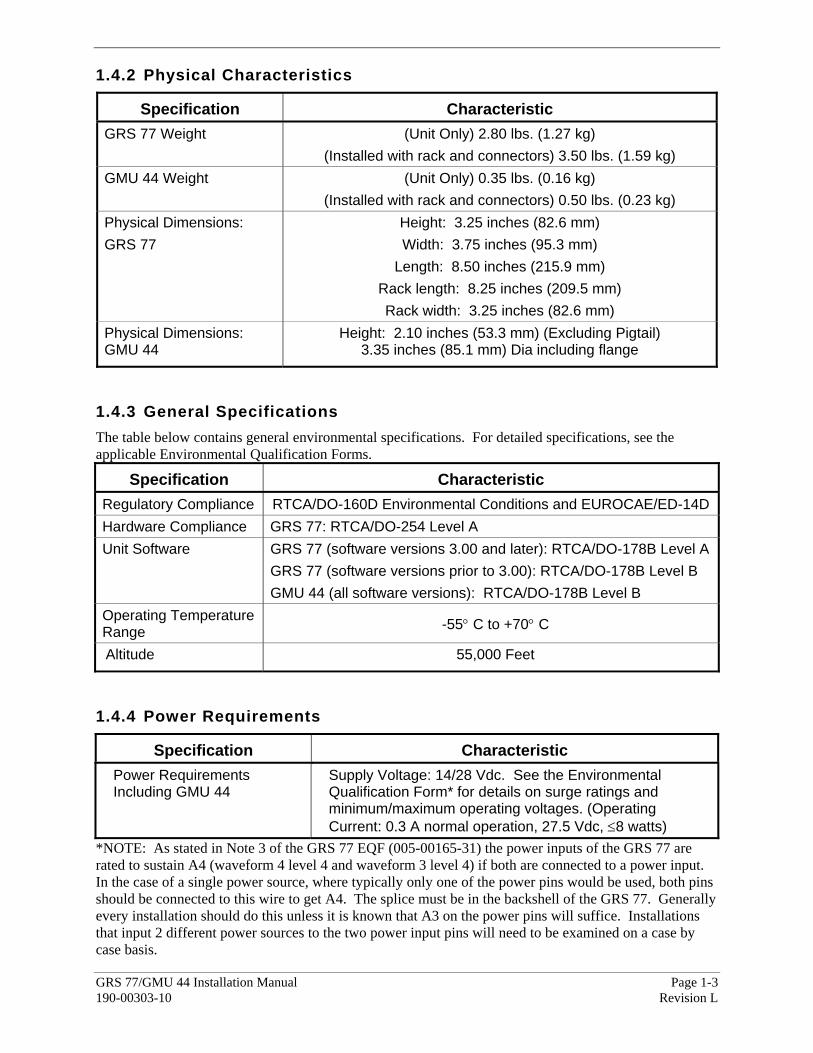
1.4.2 Physical Characteristics
Specification Characteristic GRS 77 Weight (Unit Only) 2.80 lbs. (1.27 kg)
(Installed with rack and connectors) 3.50 lbs. (1.59 kg) GMU 44 Weight (Unit Only) 0.35 lbs. (0.16 kg)
(Installed with rack and connectors) 0.50 lbs. (0.23 kg) Physical Dimensions: GRS 77
Height: 3.25 inches (82.6 mm) Width: 3.75 inches (95.3 mm)
Length: 8.50 inches (215.9 mm) Rack length: 8.25 inches (209.5 mm) Rack width: 3.25 inches (82.6 mm)
Physical Dimensions: GMU 44
Height: 2.10 inches (53.3 mm) (Excluding Pigtail) 3.35 inches (85.1 mm) Dia including flange
1.4.3 General Specifications The table below contains general environmental specifications. For detailed specifications, see the applicable Environmental Qualification Forms.
Specification Characteristic Regulatory Compliance RTCA/DO-160D Environmental Conditions and EUROCAE/ED-14D Hardware Compliance GRS 77: RTCA/DO-254 Level A Unit Software GRS 77 (software versions 3.00 and later): RTCA/DO-178B Level A
GRS 77 (software versions prior to 3.00): RTCA/DO-178B Level B GMU 44 (all software versions): RTCA/DO-178B Level B
Operating Temperature Range -55° C to +70° C
Altitude 55,000 Feet
1.4.4 Power Requirements
Specification Characteristic Power Requirements Including GMU 44
Supply Voltage: 14/28 Vdc. See the Environmental Qualification Form* for details on surge ratings and minimum/maximum operating voltages. (Operating Current: 0.3 A normal operation, 27.5 Vdc, ≤8 watts)
*NOTE: As stated in Note 3 of the GRS 77 EQF (005-00165-31) the power inputs of the GRS 77 are rated to sustain A4 (waveform 4 level 4 and waveform 3 level 4) if both are connected to a power input. In the case of a single power source, where typically only one of the power pins would be used, both pins should be connected to this wire to get A4. The splice must be in the backshell of the GRS 77. Generally every installation should do this unless it is known that A3 on the power pins will suffice. Installations that input 2 different power sources to the two power input pins will need to be examined on a case by case basis.

Page 1-4 GRS 77/GMU 44 Installation Manual Revision L 190-00303-10
1.5 Certification
The conditions and tests required for TSO approval of this article are minimum performance standards. It is the responsibility of those installing this article either on or within a specific type or class of aircraft to determine that the aircraft installation conditions are within the TSO standards. TSO articles must have separate approval for installation in an aircraft. The article may be installed only if performed under 14 CFR part 43 or the applicable airworthiness requirements. At the time of publication, installation of this TSO approved article is only approved when installed in an aircraft as part of a Garmin Integrated Flight Deck. 1.5.1 GMU 44 TSO/ETSO Compliance
Function TSO/ETSO/SAE/ RTCA/EUROCAE Category
Applicable LRU SW Part Numbers
Applicable Custom Logic
Device Part Numbers
Direction Instrument, Magnetic (Gyroscopically Stabilized)
TSO-C6d ETSO-C6d AS8013A
All 006-B0224-(__)
except 006-B0224-Z(_)
All
006-C0048-0(_)
1.5.2 GRS 77 and GRS 77H TSO/ETSO Compliance
The following table applies to both the GRS 77 and the GRS 77H units.
Function TSO/ETSO/SAE/ RTCA/EUROCAE Category
Applicable LRU SW Part Numbers
Applicable Custom Logic
Device Part Numbers
Turn and Slip Instrument TSO-C3d ETSO-C3d
AS8004
Instrument Type II
All 006-B0223-(__)
except 006-B0223-Z(_)
All 006-C0049-0(_)
Bank and Pitch Instruments TSO-C4c ETSO-C4c
AS8001
Turn Error,Category A
All 006-B0223-(__)
except 006-B0223-Z(_)
All 006-C0049-0(_)
Direction Instrument, Magnetic (Gyroscopically Stabilized)
TSO-C6d ETSO-C6d AS8013A
All 006-B0223-(__)
except 006-B0223-Z(_)
All 006-C0049-0(_)

GRS 77/GMU 44 Installation Manual Page 1-5 190-00303-10 Revision L
1.5.3 TSO/ETSO Deviations
The following table provides a list of applicable TSO and SAE deviations for the GRS 77, GRS 77H, and the GMU 44.
TSO Deviation 1. Garmin was granted a deviation from TSO-C3d to use RTCA DO-160D instead of RTCA DO-160B as the standard for Environmental Conditions and Test Procedures for Airborne Equipment. 2. Garmin was granted a deviation from TSO-C3d to use RTCA DO-178B instead of RTCA DO-178A to demonstrate compliance for the verification and validation of the computer software. 3. Garmin was granted a deviation from TSO-C3d to list this secondary TSO in the Installation Manual rather then on the article itself.
TSO-C3d (GRS 77)
4. Garmin was granted a deviation from TSO-C3d to list the DO-178B software level in the Installation Manual rather than on the article itself. 1. Garmin was granted a deviation from TSO-C4c to use SAE AS 8001 instead of SAE AS 396B for Minimum Performance Standards and Environmental Standards. 2. Garmin was granted a deviation from SAE Aerospace Standard AS 8001 to use RTCA DO-160D instead of RTCA DO-138 as the standard for Environmental Conditions and Test Procedures for Airborne Equipment.
TSO-C4c (GRS 77)
Neither TSO-C4c nor SAE Aerospace Standard AS 8001 specifies use of a standard for software development; Garmin used RTCA DO-178B as the standard for Software Considerations in Airborne Systems and Equipment Certification. 1. Garmin was granted a deviation from ETSO-C4c to use SAE AS 8001 instead of SAE AS 396B for Minimum Performance Standards and Environmental Standards. 2. Garmin was granted a deviation from SAE Aerospace Standard AS 8001 to use RTCA DO-160D instead of RTCA DO-138 as the standard for Environmental Conditions and Test Procedures for Airborne Equipment.
ETSO-C4c (GRS 77)
3. Neither ETSO-C4c nor SAE Aerospace Standard AS 8001 specifies use of a standard for software development; Garmin used RTCA DO-178B as the standard for Software Considerations in Airborne Systems and Equipment Certification.
1. Garmin was granted a deviation from TSO-C6d to use RTCA DO-160D instead of RTCA DO-160B as the standard for Environmental Conditions and Test Procedures for Airborne Equipment. 2. Garmin was granted a deviation from TSO-C6d to use RTCA DO-178B instead of RTCA DO-178A to demonstrate compliance for the verification and validation of the computer software. 3. Garmin was granted a deviation from TSO-C6d to use SAE AS 8013A instead of SAE AS 8013 as the Minimum Performance Standard. 4. Garmin was granted a deviation from TSO-C6d to list this secondary TSO in the Installation Manual rather than on the article itself.
TSO-C6d (GRS 77 and GMU 44)
5. Garmin was granted a deviation from TSO-C6d to list the DO-178B software level in the Installation Manual rather than on the article itself. 1. Garmin was granted a deviation from ETSO-C6d to use RTCA DO-160D instead of SAE AS 8013 as the standard for Environmental Conditions and Test Procedures for Airborne Equipment.
ETSO-C6d (GRS 77 and GMU 44)
2. Garmin was granted a deviation from ETSO-C6d to use SAE AS 8013A instead of SAE AS 8013 as the Minimum Performance Standard.

Page 1-6 GRS 77/GMU 44 Installation Manual Revision L 190-00303-10
1.6 Reference Publications
The following publications are sources of additional information for installing the GRS 77 and GMU 44. Before installing the unit, the technician should read all referenced materials along with this manual.
Part Number Document 190-00303-00 G1000 System Installation Manual 190-00303-04 G1000 Line Maintenance and Configuration Manual 190-00313-03 SPIDER Installation Instructions 190-00313-09 Shield Block Installation Instructions
GRS 77/GMU 44 Installation Manual Page 1-7 190-00303-10 Revision L
1.7 Aviation Limited Warranty All Garmin avionics products are warranted to be free from defects in materials or workmanship for: two years from the date of purchase for new Remote-Mount and Panel-Mount products; one year from the date of purchase for new portable products and any purchased newly-overhauled products; six months for newly-overhauled products exchanged through a Garmin Authorized Service Center; and 90 days for factory repaired or newly-overhauled products exchanged at Garmin in lieu of repair. Within the applicable period, Garmin will, at its sole option, repair or replace any components that fail in normal use. Such repairs or replacement will be made at no charge to the customer for parts or labor, provided that the customer shall be responsible for any transportation cost. This warranty does not apply to: (i) cosmetic damage, such as scratches, nicks and dents; (ii) consumable parts, such as batteries, unless product damage has occurred due to a defect in materials or workmanship; (iii) damage caused by accident, abuse, misuse, water, flood, fire, or other acts of nature or external causes; (iv) damage caused by service performed by anyone who is not an authorized service provider of Garmin; or (v) damage to a product that has been modified or altered without the written permission of Garmin. In addition, Garmin reserves the right to refuse warranty claims against products or services that are obtained and/or used in contravention of the laws of any country.
THE WARRANTIES AND REMEDIES CONTAINED HEREIN ARE EXCLUSIVE AND IN LIEU OF ALL OTHER WARRANTIES, WHETHER EXPRESS, IMPLIED OR STATUTORY, INCLUDING ANY LIABILITY ARISING UNDER ANY WARRANTY OF MERCHANTABILITY OR FITNESS FOR A PARTICULAR PURPOSE, STATUTORY OR OTHERWISE. THIS WARRANTY GIVES YOU SPECIFIC LEGAL RIGHTS, WHICH MAY VARY FROM STATE TO STATE.
IN NO EVENT SHALL GARMIN BE LIABLE FOR ANY INCIDENTAL, SPECIAL, INDIRECT OR CONSEQUENTIAL DAMAGES, WHETHER RESULTING FROM THE USE, MISUSE OR INABILITY TO USE THE PRODUCT OR FROM DEFECTS IN THE PRODUCT. SOME STATES DO NOT ALLOW THE EXCLUSION OF INCIDENTAL OR CONSEQUENTIAL DAMAGES, SO THE ABOVE LIMITATIONS MAY NOT APPLY TO YOU.
Garmin retains the exclusive right to repair or replace (with a new or newly-overhauled replacement product) the product or software or offer a full refund of the purchase price at its sole discretion. SUCH REMEDY SHALL BE YOUR SOLE AND EXCLUSIVE REMEDY FOR ANY BREACH OF WARRANTY.
Online Auction Purchases: Products purchased through online auctions are not eligible for warranty coverage. Online auction confirmations are not accepted for warranty verification. To obtain warranty service, an original or copy of the sales receipt from the original retailer is required. Garmin will not replace missing components from any package purchased through an online auction.
International Purchases: A separate warranty may be provided by international distributors for devices purchased outside the United States depending on the country. If applicable, this warranty is provided by the local in-country distributor and this distributor provides local service for your device. Distributor warranties are only valid in the area of intended distribution. Devices purchased in the United States or Canada must be returned to the Garmin service center in the United Kingdom, the United States, Canada, or Taiwan for service.
Garmin International, Inc. Garmin (Europe) Ltd. 1200 East 151st Street Liberty House, Bulls Copse Road Olathe, Kansas 66062, U.S.A. Hounsdown Business Park Phone: 913/397.8200 Romsey, SO40 9RB, U.K.
FAX: 913/397.0836 Phone: 44/ (0) 870.8501241 FAX: 44/ (0) 870.850125

Page 1-8 GRS 77/GMU 44 Installation Manual Revision L 190-00303-10
This page intentionally left blank
GRS 77/GMU 44 Installation Manual Page 2-1 190-00303-10 Revision L
2 INSTALLATION OVERVIEW
2.1 Introduction
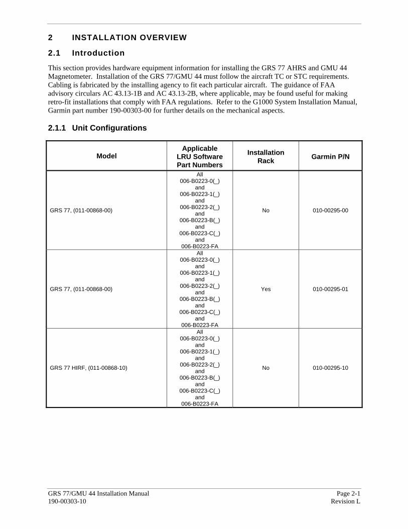
This section provides hardware equipment information for installing the GRS 77 AHRS and GMU 44 Magnetometer. Installation of the GRS 77/GMU 44 must follow the aircraft TC or STC requirements. Cabling is fabricated by the installing agency to fit each particular aircraft. The guidance of FAA advisory circulars AC 43.13-1B and AC 43.13-2B, where applicable, may be found useful for making retro-fit installations that comply with FAA regulations. Refer to the G1000 System Installation Manual, Garmin part number 190-00303-00 for further details on the mechanical aspects. 2.1.1 Unit Configurations
Model Applicable
LRU Software Part Numbers
Installation Rack Garmin P/N
GRS 77, (011-00868-00)
All 006-B0223-0(_)
and 006-B0223-1(_)
and 006-B0223-2(_)
and 006-B0223-B(_)
and 006-B0223-C(_)
and 006-B0223-FA
No 010-00295-00
GRS 77, (011-00868-00)
All 006-B0223-0(_)
and 006-B0223-1(_)
and 006-B0223-2(_)
and 006-B0223-B(_)
and 006-B0223-C(_)
and 006-B0223-FA
Yes 010-00295-01
GRS 77 HIRF, (011-00868-10)
All 006-B0223-0(_)
and 006-B0223-1(_)
and 006-B0223-2(_)
and 006-B0223-B(_)
and 006-B0223-C(_)
and 006-B0223-FA
No 010-00295-10
Page 2-2 GRS 77/GMU 44 Installation Manual Revision L 190-00303-10
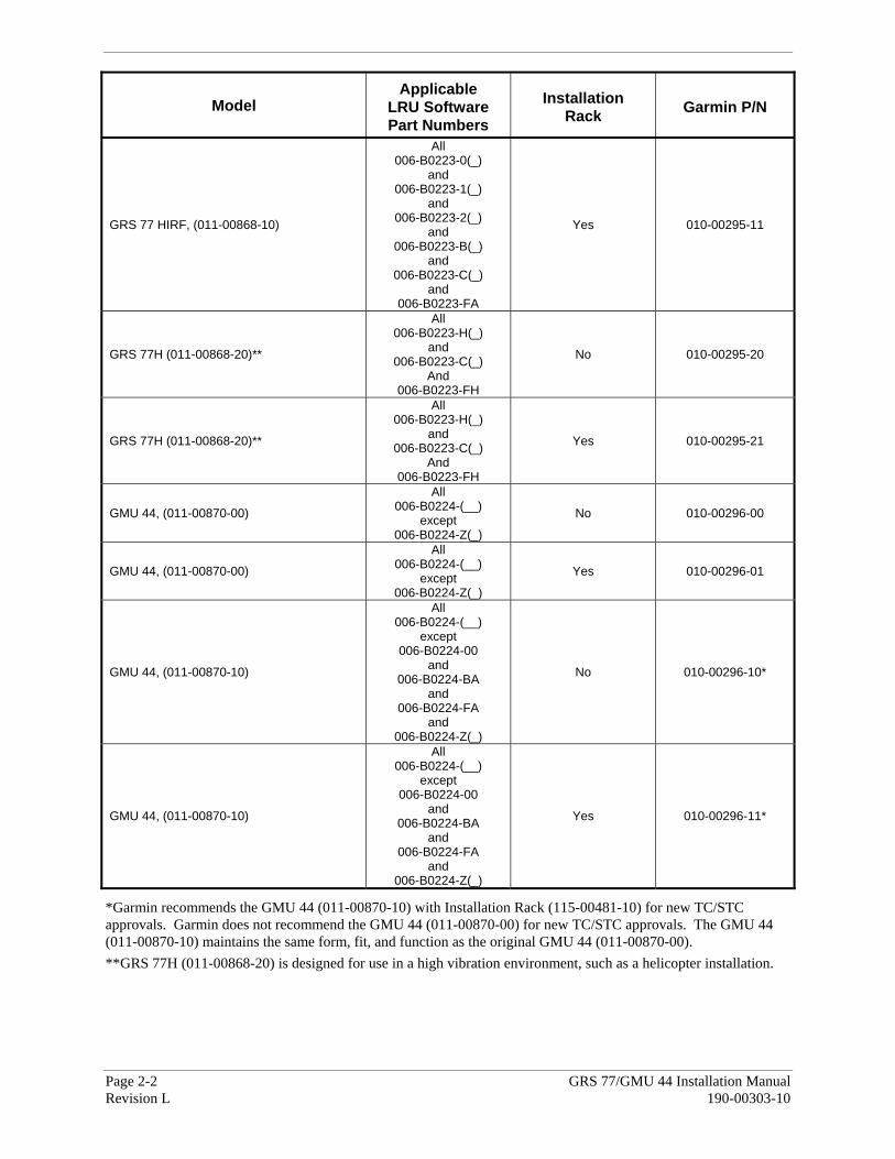
Model Applicable
LRU Software Part Numbers
Installation Rack Garmin P/N
GRS 77 HIRF, (011-00868-10)
All 006-B0223-0(_)
and 006-B0223-1(_)
and 006-B0223-2(_)
and 006-B0223-B(_)
and 006-B0223-C(_)
and 006-B0223-FA
Yes 010-00295-11
GRS 77H (011-00868-20)**
All 006-B0223-H(_)
and 006-B0223-C(_)
And 006-B0223-FH
No 010-00295-20
GRS 77H (011-00868-20)**
All 006-B0223-H(_)
and 006-B0223-C(_)
And 006-B0223-FH
Yes 010-00295-21
GMU 44, (011-00870-00)
All 006-B0224-(__)
except 006-B0224-Z(_)
No 010-00296-00
GMU 44, (011-00870-00)
All 006-B0224-(__)
except 006-B0224-Z(_)
Yes 010-00296-01
GMU 44, (011-00870-10)
All 006-B0224-(__)
except 006-B0224-00
and 006-B0224-BA
and 006-B0224-FA
and 006-B0224-Z(_)
No 010-00296-10*
GMU 44, (011-00870-10)
All 006-B0224-(__)
except 006-B0224-00
and 006-B0224-BA
and 006-B0224-FA
and 006-B0224-Z(_)
Yes 010-00296-11*
*Garmin recommends the GMU 44 (011-00870-10) with Installation Rack (115-00481-10) for new TC/STC approvals. Garmin does not recommend the GMU 44 (011-00870-00) for new TC/STC approvals. The GMU 44 (011-00870-10) maintains the same form, fit, and function as the original GMU 44 (011-00870-00). **GRS 77H (011-00868-20) is designed for use in a high vibration environment, such as a helicopter installation.
GRS 77/GMU 44 Installation Manual Page 2-3 190-00303-10 Revision L
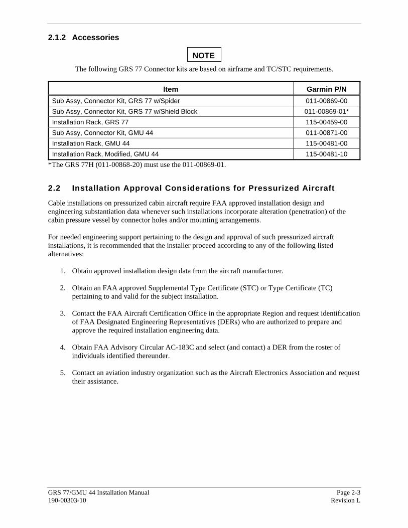
2.1.2 Accessories
The following GRS 77 Connector kits are based on airframe and TC/STC requirements.
Item Garmin P/N
Sub Assy, Connector Kit, GRS 77 w/Spider 011-00869-00 Sub Assy, Connector Kit, GRS 77 w/Shield Block 011-00869-01* Installation Rack, GRS 77 115-00459-00 Sub Assy, Connector Kit, GMU 44 011-00871-00 Installation Rack, GMU 44 115-00481-00 Installation Rack, Modified, GMU 44 115-00481-10
*The GRS 77H (011-00868-20) must use the 011-00869-01.
2.2 Installation Approval Considerations for Pressurized Aircraft Cable installations on pressurized cabin aircraft require FAA approved installation design and engineering substantiation data whenever such installations incorporate alteration (penetration) of the cabin pressure vessel by connector holes and/or mounting arrangements. For needed engineering support pertaining to the design and approval of such pressurized aircraft installations, it is recommended that the installer proceed according to any of the following listed alternatives:
1. Obtain approved installation design data from the aircraft manufacturer. 2. Obtain an FAA approved Supplemental Type Certificate (STC) or Type Certificate (TC)
pertaining to and valid for the subject installation. 3. Contact the FAA Aircraft Certification Office in the appropriate Region and request identification
of FAA Designated Engineering Representatives (DERs) who are authorized to prepare and approve the required installation engineering data.
4. Obtain FAA Advisory Circular AC-183C and select (and contact) a DER from the roster of
individuals identified thereunder. 5. Contact an aviation industry organization such as the Aircraft Electronics Association and request
their assistance.
NOTE
Page 2-4 GRS 77/GMU 44 Installation Manual Revision L 190-00303-10
2.3 Wiring Use AWG #24 or larger wire for all connections unless otherwise specified by the aircraft manufacturer or Garmin. The standard pin contacts supplied in the connector kit are compatible with up to AWG #22 wire. In cases where some installations have more than one unit sharing a common circuit breaker, sizing and wire gauge is based on aircraft circuit breaker layout, length of wiring, current draw of units, and internal unit protection characteristics. Do not attempt to combine more than one unit on the same circuit breaker unless it is specified on aircraft manufacturer approved drawings. In some cases, a larger gauge wire such as AWG #18 or #20 may be needed for power connections. The provided connector kit supplies extended barrel contacts for AWG #18 and #20 wire, if required. Special thin-wall heat shrink tubing is also provided to insulate the extended barrels inside the backshell. If using extended barrel contacts, ensure that no two extended barrel contacts are mounted directly adjacent to each other. This minimizes the risk of contacts touching and shorting to adjacent pins and to ground. Ensure that routing of the wiring does not come in contact with sources of heat, RF or EMI interference. Check that there is ample space for the cabling and mating connectors. Avoid sharp bends in cabling and routing near aircraft control cables. 2.4 Cooling Air No cooling air is needed for either the GRS 77 or the GMU 44. Refer to the G1000 System Installation Manual, Garmin part number 190-00303-00, for information on G1000 system cooling requirements. 2.5 Aircraft Mounting Requirements for GRS 77/GMU 44
The following guidelines describe proper mechanical installation of the Garmin GRS 77 AHRS and GMU 44 Magnetometer. The guidelines include requirements for proper location selection in the aircraft, requirements for supporting structure and mechanical alignment and restriction on nearby equipment. The post-installation calibration procedures required prior to flight are described in Section 5.
The GRS 77H 011-00868-20 and the GMU 44 011-00870-10 units are required for helicopter installations.
NOTE

GRS 77/GMU 44 Installation Manual Page 2-5 190-00303-10 Revision L
2.5.1 GRS 77 AHRS Mounting
Only part number 011-00868-20 GRS 77H units can be installed in helicopters.
The GRS 77 includes an extremely sensitive strap-down inertial measurement unit. It must be mounted rigidly to the aircraft primary structure. Do not use shock mounting. Shock mounts used for other types of inertial systems are not acceptable for the GRS 77 AHRS. The mounting system must have no resonance with the unit installed that would cause DO–160D vibration levels to be exceeded. (See the GRS 77 Environmental Qualification Form). Vibration outside of these limits may result in degraded accuracy. The supporting plate must be rigidly connected to the aircraft primary structure through strong structural members capable of supporting substantial loads. Avoid areas that are prone to severe vibration (e.g., areas close to engine mounts and landing gear). The GRS 77 should be mounted within 13 feet (4.0 meters) longitudinally and 6.5 feet (2.0 meters) laterally of the aircraft center of gravity. The mounting location for the GRS 77 should be protected from rapid thermal transients, in particular, large heat loads from nearby high-power equipment. The GRS 77 mounting rack should be leveled to within 3.0° of the aircraft level reference, and an aircraft leveling and offset setting procedure carried out prior to flight. (This procedure is described in Section 5.) Alternatively, if the mounting rack can be guaranteed level to within 0.25° of the aircraft level reference, the aircraft leveling and offset setting procedure is not required. The GRS 77 mounting rack’s forward direction must be aligned in heading to within 1.0° of the aircraft forward direction. (The arrow symbol on the rack points forward.) Some metal structures of the GRS 77 may become magnetized if closely exposed to permanent magnets. While this will not affect the GRS 77 itself, it may slightly affect nearby magnetic instruments in the aircraft (whiskey compass). Ordinary use of magnetic screwdrivers to tighten the GRS 77 fasteners will not cause problems, but non-magnetic screwdrivers are preferred. Avoid placing the GRS 77 within 1 inch of magnetically mounted antennas, speaker magnets, or other strongly magnetic items. For installations with multiple GRS 77 AHRS units, note that the slip/skid indications associated with the AHRS units may differ slightly depending upon the heading misalignments between the AHRS units. For example, a 2-degree difference in heading alignment between two AHRS units will result in a one-eight trapezoid difference in the slip/skid indications when in a steady 15-degree nose-up climb. Reducing the heading misalignment between AHRS units will reduce this effect approximately proportional to the misalignment angle.
Figure 2-1. GRS 77 and Mounting Rack
NOTE

Page 2-6 GRS 77/GMU 44 Installation Manual Revision L 190-00303-10
2.5.2 GMU 44 Magnetometer Mounting
Only part number 011-00870-10 GMU 44 units can be installed in helicopters (see Section 2.5.2.1).
The GMU 44 is an extremely sensitive three-axis magnetic sensor. It is more sensitive to nearby magnetic disturbances than a flux gate magnetometer. For this reason, when choosing a mounting location for the GMU 44, observe the following distances from objects or devices that can disturb the magnetic field. Table 2-1 specifies required distances from magnetic disturbances for GMU 44 location.
Table 2-1. Required Distance from Magnetic Disturbances
Disturbance Source Minimum Distance from GMU 44 Electric motors and relays, including servo motors 10 feet (3.0 meters) Ferromagnetic structure greater than 1 kg total (iron, steel, or cobalt materials, especially landing gear structure)
8.2 feet (2.5 meters)
Ferromagnetic materials less than 1 kg total, such as control cables 3 feet (1.0 meter)
Any electrical device drawing more than 100 mA current 3 feet (1.0 meter)
Electrical conductors passing more than 100 mA current [(must be twisted shielded pair if within 10 feet (3.0 meters)]
3 feet (1.0 meter)
Electrical devices drawing less than 100 mA current 2 feet (0.6 meter) Magnetic measuring device (e.g. installed flux gates, even if not powered) 2 feet (0.6 meter)
Electrical conductors passing less than 100 mA current [(must be twisted shielded pair if within 10 feet (3.0 meters)]
1.3 feet (0.4 meter)
Ensure that any electrical conductor that comes within 10 feet (3.0 meters) of the GMU 44 is installed as a twisted shielded pair, not a single-wire conductor. (If possible, the shield should be grounded at both ends.) Use nonmagnetic materials to mount the GMU 44, and replace any magnetic fasteners within 0.5 meter with nonmagnetic equivalents (e.g. replace zinc-plated steel screws used to mount wing covers or wingtips with nonmagnetic stainless steel screws.) In general, wing mounting of the GMU 44 magnetometer is strongly preferred. Fuselage mounting is strongly discouraged because of numerous potential disturbances that interfere with accurate operation. Mechanical mounting fixtures for the GMU 44 must be rigidly connected to the aircraft structure. Use of typical aircraft-grade materials and methods for rigid mounting of components is acceptable, so long as adequate measures are taken to ensure a stiffened mounting structure. Align the GMU 44 mounting rack to within 3.0° of the aircraft level reference in pitch and roll.
NOTE

GRS 77/GMU 44 Installation Manual Page 2-7 190-00303-10 Revision L
Align the GMU 44 mounting rack’s forward direction to within 0.5° in heading of the aircraft forward direction (longitudinal axis). If it is not possible to guarantee this accuracy, installation alignment to within 2.5° in heading is acceptable, in combination with a post-installation heading alignment of the aircraft to a precise heading to determine and set a heading offset. The heading offset procedure is described in Section 5. It is strongly preferred that the GMU 44 alignment is within 0.5° of the aircraft longitudinal axis, rather than using the heading offset procedure. 2.5.2.1 Requirements for Helicopter Installations
Only the part number 011-00870-10 GMU 44 may be used in helicopter installations. In addition to the mounting instructions in Section 2.5 and 2.5.2, helicopter installations of the GMU 44 must use the 115-00481-10 installation rack, using Hole Set B for high vibration installations. The Hole Set B instruction drawing is Figure A-2 Sheet 2, on page A-5. 2.5.2.2 Consideration for Wing Grounded Lighting Fixtures
The following installation practices are recommended when installing the GMU 44 in a wing.
1. The wing tip lights should not have a power ground referenced to the chassis of the light assembly that would then be referenced back to the airframe ground via the light assembly mounting.
2. A dedicated power ground should be used and returned as a twisted pair with the power source back into the fuselage for a wing mounted GMU 44.
These installation practices will prevent magnetically interfering currents from flowing in the wing skin that encloses the GMU 44. Electrically isolating the light assembly should not be used as an alternative to item 1 above, unless the isolated light assembly has been analyzed for adequate protection against direct attachment of lightning.

Page 2-8 GRS 77/GMU 44 Installation Manual Revision L 190-00303-10
This page intentionally left blank

GRS 77/GMU 44 Installation Manual Page 3-1 190-00303-10 Revision L
3 INSTALLATION PROCEDURE 3.1 Unpacking Unit
Carefully unpack the equipment and make a visual inspection of the unit for evidence of damage incurred during shipment. If the unit is damaged, notify the carrier and file a claim. To justify a claim, save the original shipping container and all packing materials. Do not return the unit to Garmin until the carrier has authorized the claim. Retain the original shipping containers for storage. If the original containers are not available, a separate cardboard container should be prepared that is large enough to accommodate sufficient packing material to prevent movement. 3.2 Electrical Connections
All electrical connections to the GRS 77 AHRS are made through one 44-pin D-subminiature connector (see Figure 4-1). Connections to the GMU 44 Magnetometer are made through a 9-pin connector (see Figure 4-2). Connector detail is shown in Figure A-5. Tables in Section 4 define the electrical characteristics of all input and output signals. Required connector and associated hardware are supplied in the GRS 77 connector kit (P/N 011-00869-00,-01) and GMU 44 connector kit (P/N 011-00871-00). See Figures B-1 and B-2 for interconnect wiring diagrams.
CAUTIONCheck wiring connections for errors before inserting connectors into the GRS 77 or GMU 44 pigtail. Incorrect wiring could cause internal component damage.
Table 3-1. Pin Contact Part Numbers 44 pin D-Subminiature connector (P771) Manufacturer 16 AWG
(Power Only) 18-20 AWG
(Power Only) 22-28 AWG
Garmin P/N 336-00044-01 336-00044-00 336-00021-00 Military P/N N/A N/A M39029/58-360 AMP N/A N/A 204370-2 Positronic N/A N/A MC8522D ITT Cannon N/A N/A 030-2042-000
Table 3-2. Recommended Crimp Tools
18-20 AWG 22-28 AWG Manufacturer Hand Crimping Tool Positioner Insertion/
Extraction Tool (Note 2)
Positioner Insertion/ Extraction Tool
Military P/N M22520/2-01 N/A M81969/1-04 M22520/2-09 M81969/1-04 Positronic 9507 9502-11 M81969/1-04 9502-4 M81969/1-04 ITT Cannon 995-0001-584 N/A N/A M22520/2-09 274-7048-000AMP 601966-1 N/A 91067-1 601966-6 91067-1 Daniels AFM8 K774 M81969/1-04 K42 M81969/1-04 Astro 615717 N/A M81969/1-04 615725 M81969/1-04
Page 3-2 GRS 77/GMU 44 Installation Manual Revision L 190-00303-10
NOTES 1. Non-Garmin part numbers shown are not maintained by Garmin and consequently are subject
to change without notice. 2. Extracting the #18 and #20 contact requires that the expanded wire barrel be cut off from the
contact. It may also be necessary to push the pin out from the face of the connector when using an extractor due to the absence of the wire. A new contact must be used when reassembling the connector.
3. For applications using 16 AWG wire, contact Garmin for information regarding connector crimp positioner tooling.
3.3 Backshell Assembly
The GRS 77 connector kit includes a Garmin backshell assembly. The backshell assembly houses the configuration module. Garmin’s backshell connectors give the installer the ability to quickly and easily terminate shield grounds at the backshell housing using one of two methods available. To assemble the backshell and grounding system, refer to instructions provided in the SPIDER Installation Instructions (190-00313-03) or Shield Block Installation Instructions (190-00313-09).
The SPIDER grounding method is permitted for previous installations, however Garmin recommends the use of the Shield Block grounding method for all new installations.
NOTE
GRS 77/GMU 44 Installation Manual Page 3-3 190-00303-10 Revision L
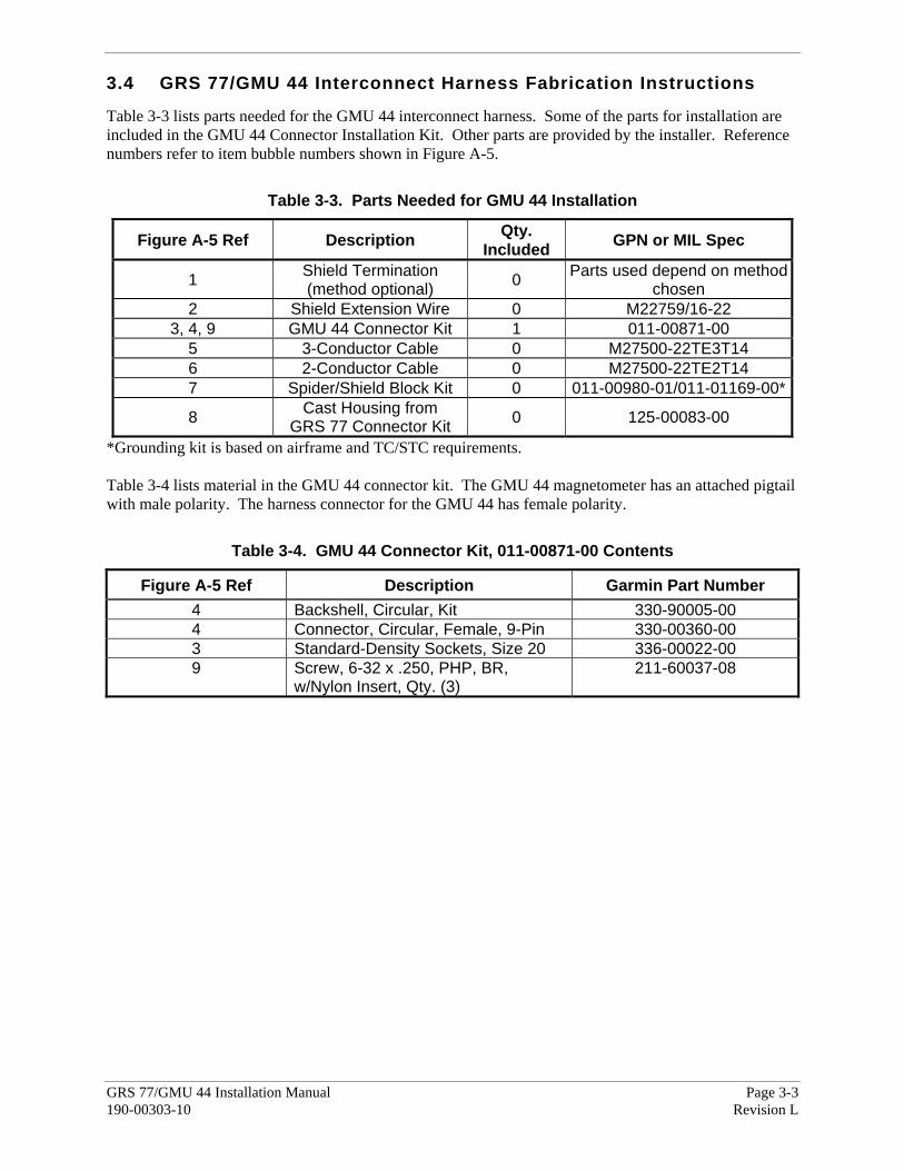
3.4 GRS 77/GMU 44 Interconnect Harness Fabrication Instructions
Table 3-3 lists parts needed for the GMU 44 interconnect harness. Some of the parts for installation are included in the GMU 44 Connector Installation Kit. Other parts are provided by the installer. Reference numbers refer to item bubble numbers shown in Figure A-5.
Table 3-3. Parts Needed for GMU 44 Installation
Figure A-5 Ref Description Qty. Included GPN or MIL Spec
1 Shield Termination (method optional) 0 Parts used depend on method
chosen 2 Shield Extension Wire 0 M22759/16-22
3, 4, 9 GMU 44 Connector Kit 1 011-00871-00 5 3-Conductor Cable 0 M27500-22TE3T14 6 2-Conductor Cable 0 M27500-22TE2T14 7 Spider/Shield Block Kit 0 011-00980-01/011-01169-00*
8 Cast Housing from GRS 77 Connector Kit 0 125-00083-00
*Grounding kit is based on airframe and TC/STC requirements. Table 3-4 lists material in the GMU 44 connector kit. The GMU 44 magnetometer has an attached pigtail with male polarity. The harness connector for the GMU 44 has female polarity.
Table 3-4. GMU 44 Connector Kit, 011-00871-00 Contents
Figure A-5 Ref Description Garmin Part Number 4 Backshell, Circular, Kit 330-90005-00 4 Connector, Circular, Female, 9-Pin 330-00360-00 3 Standard-Density Sockets, Size 20 336-00022-00 9 Screw, 6-32 x .250, PHP, BR,
w/Nylon Insert, Qty. (3) 211-60037-08

Page 3-4 GRS 77/GMU 44 Installation Manual Revision L 190-00303-10
3.5 GRS 77 and GMU 44 Mounting Instructions
NOTE When mounting the GRS 77 rack to the airframe, and the unit to the rack, it is important to ensure that fastening hardware is tight for proper unit operation. Use a #2 Phillips screwdriver to tighten the GRS 77 to the rack, rather than hand tightening the knurled screws. The recommended torque is 22-25 inch pounds.
After ensuring that requirements are met, assemble the GRS 77 and GMU 44 mounting plate kits according to the dimensions given in Appendix B. Install the unit assemblies. While installing the GRS 77 on its rack, perform the flatness check described in Section 3.6. After completion, tighten the four mounting screws securing the GRS 77 unit to the rack. Mount the GMU 44 to its mounting plate, taking care to tighten the mounting screws firmly. The metal components in the GMU 44's connector may slightly affect the magnetic field sensed by the GMU 44. Place the connector at least 2 inches from the body of the GMU 44 to minimize this effect. After attaching the GMU 44's connector to its mate in the aircraft wiring, secure the connector in place using good installation practices. This will ensure that any remaining magnetic effect can be compensated for using Calibration Procedure B: Magnetometer Calibration. If the GMU 44 is ever removed, the anti-rotation properties of the mounting screws must be restored. This may be done by replacing the screws with new Garmin PN 211-60037-08. If original screws must be re-used, coat screw threads with Loctite 242 (blue) thread-locking compound, Garmin PN 291-00023-02, or equivalent. Important: Mounting screws must be brass. 3.6 GRS 77 Rack to Unit Flatness Check
While installing the GRS 77 unit on its rack, a flatness check is required to ensure that the unit’s base is properly preloaded after installation. Place the unit on its rack, and tighten the screw fasteners on one end of the unit to the rack (recommended torque is 22-25 inch pounds), but leave the screw fasteners on the other end of the unit unfastened. At the unfastened end of the unit, there should now be a gap between the unit baseplate and the rails of the mounting rack. Measure the gap to determine if it is within tolerances. See Figure 3-1. Using feeler gauges, check to ensure that the gap between the unit and each rack rail is at least 0.010 inch, but less than 0.070 inch. If the gaps between the unit and each rack rail are within tolerance (0.010 inch, but less than 0.070 inch) tighten the remaining two screw fasteners to hold the GRS 77 unit firmly to its rack (recommended torque is 22-25 inch pounds). If the gap is less than 0.010 inch, or greater than 0.070 inch, then the proper amount of preload will not be exerted on the unit baseplate when the unit is fastened down, and the installation is not acceptable.

GRS 77/GMU 44 Installation Manual Page 3-5 190-00303-10 Revision L
Possible causes for a failure of this check include the following:
a) The rack is fastened down to a surface that is not sufficiently flat b) The rack is warped or damaged c) The GRS 77 has a center baseplate external shim that is damaged or has been removed d) The GRS 77 baseplate has been warped or damaged
In the event of a failed test (gap on unfastened end of unit not within the range of 0.010 inch to 0.070 inch), these possibilities must be examined, and any deficiencies corrected to pass this check before the installation is acceptable.
MEASURE GAPMEASURE GAPAT UNFASTENED ENDAT UNFASTENED END
Figure 3-1. Measuring GRS 77 to Mounting Rack with Feeler Gauge 3.7 Post Installation Inspection
After the installation is complete, refer to Section 5 for system configuration, calibration and checkout.
NOTE
The GRS 77 AHRS will not provide valid outputs until the post installation calibration procedures are completed.

Page 3-6 GRS 77/GMU 44 Installation Manual Revision L 190-00303-10
This page intentionally left blank

GRS 77/GMU 44 Installation Manual Page 4-1 190-00303-10 Revision L
4 SYSTEM INTERCONNECTS
4.1 Pin Function List
Following the pin assignment tables, additional tables group pin connections by function. 4.1.1. Connector J771
123456789101112131415
161718192021222324252627282930
3132333435363738394041424344
Figure 4-1. Rear Connector J771
Table 4-1. P771 Pin Assignments
Pin Pin Name I/O 1 CONFIG MODULE GROUND -- 2 AHRS SYSTEM ID PROGRAM* 1 In 3 AHRS SYSTEM ID PROGRAM* 2 In 4 RESERVED -- 5 SPARE -- 6 GPS 2 RS-232 IN In 7 RESERVED -- 8 SPARE RS-232 IN 1 In 9 MAGNETOMETER POWER OUT Out
10 MAGNETOMETER RS-232 OUT Out 11 GPS 1 RS-232 IN In 12 ARINC 429 OUT 3 A (CDU 1, high-speed) Out 13 ARINC 429 OUT 2 A (GIA 2, high-speed) Out 14 ARINC 429 OUT 1 A (GIA 1, high-speed) Out 15 ARINC 429 IN 1 A (AIR DATA, low speed) In 16 CONFIG MODULE DATA I/O 17 CONFIG MODULE POWER OUT Out 18 AIRCRAFT POWER 1 In 19 ARINC 429 OUT 3 B (CDU 2, high-speed) Out 20 AIRCRAFT POWER 2 In 21 GPS 2 RS-232 OUT Out 22 POWER GROUND --
An asterisk (*) following a signal name denotes that the signal is an Active Low, requiring a ground to activate.
Page 4-2 GRS 77/GMU 44 Installation Manual Revision L 190-00303-10
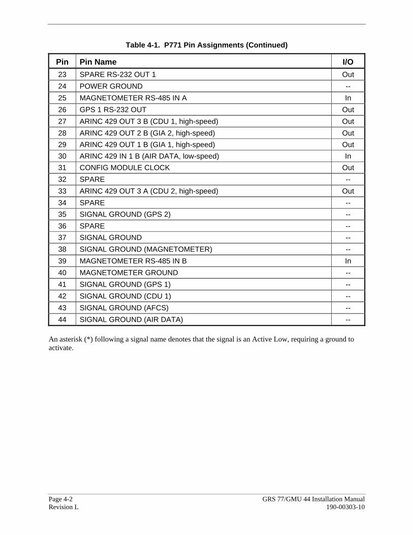
Table 4-1. P771 Pin Assignments (Continued)
Pin Pin Name I/O 23 SPARE RS-232 OUT 1 Out 24 POWER GROUND -- 25 MAGNETOMETER RS-485 IN A In 26 GPS 1 RS-232 OUT Out 27 ARINC 429 OUT 3 B (CDU 1, high-speed) Out 28 ARINC 429 OUT 2 B (GIA 2, high-speed) Out 29 ARINC 429 OUT 1 B (GIA 1, high-speed) Out 30 ARINC 429 IN 1 B (AIR DATA, low-speed) In 31 CONFIG MODULE CLOCK Out 32 SPARE -- 33 ARINC 429 OUT 3 A (CDU 2, high-speed) Out 34 SPARE -- 35 SIGNAL GROUND (GPS 2) -- 36 SPARE -- 37 SIGNAL GROUND -- 38 SIGNAL GROUND (MAGNETOMETER) -- 39 MAGNETOMETER RS-485 IN B In 40 MAGNETOMETER GROUND -- 41 SIGNAL GROUND (GPS 1) -- 42 SIGNAL GROUND (CDU 1) -- 43 SIGNAL GROUND (AFCS) -- 44 SIGNAL GROUND (AIR DATA) --
An asterisk (*) following a signal name denotes that the signal is an Active Low, requiring a ground to activate.

GRS 77/GMU 44 Installation Manual Page 4-3 190-00303-10 Revision L
4.1.2 Connector J441
Figure 4-2. Pigtail Connector J441
Table 4-2. P441 Pin Assignments
Pin Pin Name I/O 1 SIGNAL GROUND -- 2 RS-485 OUT B Out 3 SIGNAL GROUND -- 4 RS-485 OUT A Out 5 SPARE -- 6 POWER GROUND -- 7 SPARE -- 8 RS-232 IN In 9 +12 VDC POWER In
4.2 Power Function
Power Input requirements are listed in Table 4-3. Power Input requirements and Lighting Bus inputs are listed in the following tables. The power-input pins accept 11-33 Vdc. AIRCRAFT POWER 2 is for connecting to an alternate power source, such as on aircraft with two electrical buses. Refer to Figures B-1 and B-2 in Appendix B for power connections and Section 1.4.4 for lightning level note.
Table 4-3. Aircraft Power Pin Assignments, P771 and P441
Pin Pin Name Description I/O P771-18 AIRCRAFT POWER 1, GRS 77 Unit Power In P771-20 AIRCRAFT POWER 2, GRS 77 Unit Power In P771-9 MAGNETOMETER POWER OUT Provides Power to Magnetometer Out
P771-40 MAGNETOMETER GROUND Ground Reference to Magnetometer -- P771-22 POWER GROUND, GRS 77 Aircraft Ground -- P771-24 POWER GROUND, GRS 77 Aircraft Ground --
P441-9 +12 VDC POWER, GMU 44 Unit Power from GRS 77 In P441-6 POWER GROUND, GMU 44 Ground Reference from GRS 77 --

Page 4-4 GRS 77/GMU 44 Installation Manual Revision L 190-00303-10
4.3 Serial Data Electrical Characteristics
4.3.1 RS-232 Input/Output
Table 4-4. RS-232 Pin Assignments, P771 and P441
Pin Pin Name Description I/O P771-11 GPS 1 RS-232 IN Data In In P771-6 GPS 2 RS-232 IN Data In In P771-8 SPARE RS-232 IN 1 Data In In P771-26 GPS 1 RS-232 OUT Data Out Out P771-21 GPS 2 RS-232 OUT Data Out Out P771-23 SPARE RS-232 OUT 1 Data Out Out P771-10 MAGNETOMETER RS-232 OUT Data Out Out
P441-8 RS-232 IN Data In In The RS-232 outputs conform to EIA/TIA-232C with an output voltage swing of at least ±5 V when driving a standard RS-232 load. Refer to Figures B-1 and B-2 in Appendix B for the RS-232 serial data interconnections. 4.3.2 RS-485 Input/Output
Table 4-5. RS-485 Pin Assignments, P771 and P441
Pin Pin Name Description I/O P771-39 MAGNETOMETER RS-485 IN B Data In In P771-25 MAGNETOMETER RS-485 IN A Data In In P771-40 MAGNETOMETER GROUND Ground --
P441-4 RS-485 OUT A Data Out Out P441-2 RS-485 OUT B Data Out Out

GRS 77/GMU 44 Installation Manual Page 4-5 190-00303-10 Revision L
4.3.3 ARINC 429 Input/Output
Table 4-6. ARINC 429 Pin Assignments, P771
Pin Pin Name Description I/O 12 ARINC 429 OUT 3 A (CDU 1, high-speed) Data Out Out 33 ARINC 429 OUT 3 A (CDU 2, high-speed) Data Out Out 27 ARINC 429 OUT 3 B (CDU 1, high-speed) Data Out Out 19 ARINC 429 OUT 3 B (CDU 2, high-speed) Data Out Out 42 SIGNAL GROUND (CDU 1) Ground -- 14 ARINC 429 OUT 1 A (GIA 1, high-speed) Data Out Out 13 ARINC 429 OUT 2 A (GIA 2, high-speed) Data Out Out 29 ARINC 429 OUT 1 B (GIA 1, high-speed) Data Out Out 28 ARINC 429 OUT 2 B (GIA 2, high-speed) Data Out Out 43 SIGNAL GROUND (AFCS) Ground -- 15 ARINC 429 IN 1 A (AIR DATA, low-speed) Data In In 30 ARINC 429 IN 1 B (AIR DATA, low-speed) Data In In 44 SIGNAL GROUND (AIR DATA) Ground -- 41 SIGNAL GROUND (GPS 1) Ground -- 35 SIGNAL GROUND (GPS 2) Ground -- 37 SIGNAL GROUND Ground --
4.3.4 Configuration Module Connections
The configuration module, mounted in the unit connector backshell, contains an EEPROM.
Table 4-7. Configuration Module Connections, P771
Pin Pin Name Description I/O 1 CONFIG MODULE GROUND Ground --
16 CONFIG MODULE DATA Data In /Out I/O 17 CONFIG MODULE POWER OUT Power Out 31 CONFIG MODULE CLOCK Clock Output Out

Page 4-6 GRS 77/GMU 44 Installation Manual Revision L 190-00303-10
4.3.5 AHRS ARINC 429 System ID Connections
Table 4-8. AHRS System ID Program Pins, P771
Pin Pin Name Description I/O 2 AHRS SYSTEM ID PROGRAM* 1 Data In In 3 AHRS SYSTEM ID PROGRAM* 2 Data In In
4.3.6 AHRS System ID Strapping
By hard strapping the program pins listed in Table 4-8 to ground, the GRS 77 is assigned a System ID identified within the transmitted ARINC 429 words. ID’s identify a GRS 77 as an All Call, #1, #2, or #3. For a single system, the pins are left open (All Call). The GRS 77 has an associated Source/Destination Identifier (SDI or System ID) that is coded into its ARINC 429 output messages/labels. The System ID may be used to uniquely distinguish the source of the GDC 74A ARINC 429 labels in a system with more than one GRS 77. The GRS 77 System ID can be set to All Call, #1, #2, or #3 for such purposes. Table 4-8 identifies which pins on connector P741 are used to select the desired System ID. 4.3.7 GRS 77 System ID Strapping
By hard strapping the program pins listed in Table 4-8 to ground or open, the GRS 77 is assigned a System ID. The System ID is included in each transmitted ARINC 429 word. The System ID indicates that there is only a single AHRS installed (All Call) or, if multiple units are installed, which AHRS the data originates from (#1, #2 or #3). When a single GRS 77 is installed in the system, then the pins are left open (All Call). Table 4-9 shows strapping connections to achieve the desired system ID.
Table 4-9. P771 Strapping to Achieve Desired System ID
System ID Number ARINC System ID 1 Pin 2
ARINC System ID 2 Pin 3
All Call Open Open #1 Ground Open #2 Open Ground #3 Ground Ground

GRS 77/GMU 44 Installation Manual Page 5-1 190-00303-10 Revision L
5 POST INSTALLATION CONFIGURATION AND CHECKOUT PROCEDURE
CAUTION
Be sure to check all aircraft control movements before flight is attempted to insure that the wiring harness does not touch any moving part.
NOTE
The following procedures reflect a Garmin G1000 installation. 5.1 Function Selector Switches and Display
There are no operating controls or displays on the GRS 77/GMU 44. 5.2 Post-Installation Calibration Procedures
After mechanical and electrical installation of the GRS 77 AHRS and GMU 44 magnetometer have been completed, prior to operation, a set of post-installation calibration procedures must be carried out. Table 5-1 describes the necessary calibration procedures:
Page 5-2 GRS 77/GMU 44 Installation Manual Revision L 190-00303-10
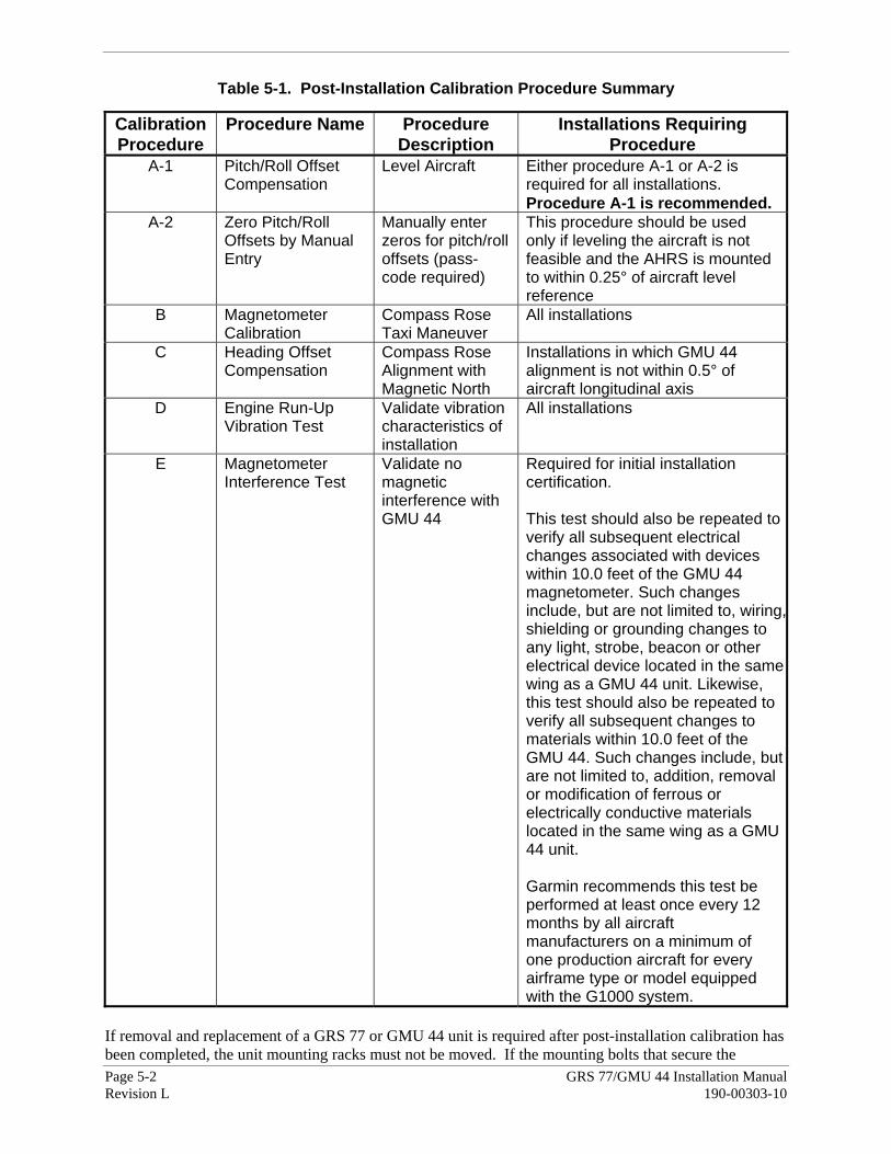
Table 5-1. Post-Installation Calibration Procedure Summary
Calibration Procedure
Procedure Name Procedure Description
Installations Requiring Procedure
A-1 Pitch/Roll Offset Compensation
Level Aircraft Either procedure A-1 or A-2 is required for all installations. Procedure A-1 is recommended.
A-2 Zero Pitch/Roll Offsets by Manual Entry
Manually enter zeros for pitch/roll offsets (pass-code required)
This procedure should be used only if leveling the aircraft is not feasible and the AHRS is mounted to within 0.25° of aircraft level reference
B Magnetometer Calibration
Compass Rose Taxi Maneuver
All installations
C Heading Offset Compensation
Compass Rose Alignment with Magnetic North
Installations in which GMU 44 alignment is not within 0.5° of aircraft longitudinal axis
D Engine Run-Up Vibration Test
Validate vibration characteristics of installation
All installations
E Magnetometer Interference Test
Validate no magnetic interference with GMU 44
Required for initial installation certification. This test should also be repeated to verify all subsequent electrical changes associated with devices within 10.0 feet of the GMU 44 magnetometer. Such changes include, but are not limited to, wiring,shielding or grounding changes to any light, strobe, beacon or other electrical device located in the same wing as a GMU 44 unit. Likewise, this test should also be repeated to verify all subsequent changes to materials within 10.0 feet of the GMU 44. Such changes include, but are not limited to, addition, removal or modification of ferrous or electrically conductive materials located in the same wing as a GMU 44 unit. Garmin recommends this test be performed at least once every 12 months by all aircraft manufacturers on a minimum of one production aircraft for every airframe type or model equipped with the G1000 system.
If removal and replacement of a GRS 77 or GMU 44 unit is required after post-installation calibration has been completed, the unit mounting racks must not be moved. If the mounting bolts that secure the

GRS 77/GMU 44 Installation Manual Page 5-3 190-00303-10 Revision L
GRS 77 mounting racks are loosened for any reason, a new post-installation calibration procedure, A-1, B and D (plus C if required initially) must be carried out before the aircraft can be returned to service. Any GMU 44 removal and replacement requires repeating the magnetometer calibration, and if applicable, the heading offset compensation. The addition, removal or modification of components that are ferrous, or otherwise magnetic, within 10.0 feet of the GMU 44 magnetometer location after the magnetometer interference test or magnetometer calibration procedure were completed requires a repeat of both procedures. Furthermore, electrical changes to the installation that affect components within 10.0 feet of the GMU 44 magnetometer after the magnetometer calibration and magnetometer interference procedures were completed will require a repeat of the magnetometer interference test. If new magnetic interference is detected, it must be resolved and then the magnetometer calibration procedure must be repeated. Wiring or grounding changes associated with a device located in the same wing as the GMU 44 is a good example of such a change.

Page 5-4 GRS 77/GMU 44 Installation Manual Revision L 190-00303-10
5.3 Calibration Procedure A-1: Pitch/Roll Offset Compensation by Aircraft Leveling
NOTEEither procedure A-1 or procedure A-2 is required for all installations. Procedure A-1 is preferred.
1. Level the aircraft to within ±0.25° of zero pitch and zero roll.
2. Initiate the AHRS Ground Pitch/Roll Aircraft Level compensation mode by performing the following steps:
a) Enter the configuration mode by holding the ENTER key on both displays while applying power. Release the ENTER key when the words INITIALIZING SYSTEM are displayed on the PFD and MFD.
3. On the PFD, turn the FMS large knob clockwise until the GRS Page Group is selected.
4. At the GRS Page Group, turn the small FMS to display the GRS/GMU Calibration page.
5. The GRS/GMU Calibration page is protected and requires a keystroke password to perform the calibration. Press the following softkeys in sequence:
i. softkey 9
ii. softkey 10
iii. softkey 11
iv. softkey 12
6. Press in the FMS small knob to highlight GRS 77 #1. The FMS small knob can now be turned to select either GRS 77 #1 or GRS 77 #2 for calibration. Press the ENTER key after selecting which GRS 77 unit to calibrate. The Select Procedure field is now blinking.
7. The FMS small knob can now be used to select which calibration/validation procedure to run. Select PITCH/ROLL OFFSET, then press the ENTER key. If the PITCH/ROLL OFFSET selection is still blinking, press the ENTER key again.
8. Follow the checklist items displayed on the PFD and press the ENTER key as each one is completed or confirmed. When the CALIBRATE field is blinking, press the ENTER key to begin the procedure.
9. After several seconds, a new checklist appears in the lower half of the PFD. Press the ENTER key as each item is confirmed. When the CONFIRM AIRCRAFT IS LEVEL field is blinking, press the ENTER key to continue.
10. The result of the pitch/roll offset compensation is displayed on the PFD. If successful, the AHRS records the required pitch and roll offsets, informs the operator of a successful conclusion and returns to normal operation.
11. Press the ENTER key on the PFD to conclude this procedure.

GRS 77/GMU 44 Installation Manual Page 5-5 190-00303-10 Revision L
5.4 Calibration Procedure A-2: Zero Pitch/Roll Offsets by Manual Entry
NOTEProcedure A-2 requires a unique pass-code that is not listed here. Contact Garmin for the pass-code.
1. Initiate the AHRS Ground Pitch/Roll Aircraft Level compensation mode by performing the following steps:
a) Enter the configuration mode by holding the ENTER key on both displays while applying power. Release the ENTER key when the words INITIALIZING SYSTEM are displayed on the PFD and MFD.
b) On the PFD, turn the FMS large knob clockwise until the GRS Page Group is selected.
c) At the GRS Page Group, turn the small FMS to display the GRS/GMU Calibration page.
2. The GRS/GMU Calibration page is protected and requires a keystroke password to perform the calibration. Press the following softkeys in sequence:
i. softkey 9
ii. softkey 10
iii. softkey 11
iv. softkey 12
3. Press the FMS small knob to highlight GRS 77 #1. The FMS small knob can now be turned to select either GRS 77 #1 or GRS 77 #2 for calibration. Press the ENTER key after selecting which GRS 77 unit to calibrate. The Select Procedure field is now blinking.
4. The FMS small knob can now be used to select which calibration/validation procedure to run. Select PITCH/ROLL OFFSET, then press the ENTER key. If the PITCH/ROLL OFFSET selection is still blinking, press the ENTER key again.
5. Contact Garmin for password.
6. Follow the checklist items displayed on the PFD and press the ENTER key as each one is completed or confirmed.
7. When the PASSCODE field is blinking, enter the appropriate pass-code by using the FMS small knob to change the value of the first digit and the FMS large knob to move to the next digit of the pass-code. Press the ENTER key when finished entering the pass-code.
8. When the CALIBRATE field is blinking, press the ENTER key to begin the procedure.
9. After several seconds, additional instructions appear in the lower half of the PFD and the PITCH OFFSET FIELD will be blinking.
Page 5-6 GRS 77/GMU 44 Installation Manual Revision L 190-00303-10
10. Enter a pitch offset value of exactly 0.00 using the FMS small and large knobs as described above. Press the ENTER key when finished with the pitch offset. The ROLL OFFSET field is now blinking.
11. Enter a roll offset value of exactly 0.00 using the FMS small and large knobs as described above. Press the ENTER key when finished with the roll offset.
12. When the RECORD OFFSETS field is blinking, press the ENTER key to complete data entry.
13. The result of the pitch/roll offset compensation is displayed on the PFD. If successful, the AHRS records the required pitch and roll offsets, informs the operator of a successful conclusion and then returns to normal operation.
14. Press the ENTER key on the PFD to conclude this procedure.

GRS 77/GMU 44 Installation Manual Page 5-7 190-00303-10 Revision L
5.5 Calibration Procedure B: Magnetometer Calibration
NOTES
Calibration Procedure A-1 or A-2 must be successfully completed prior to Calibration Procedure B.
Calibration Procedure B must be carried out at a location that is determined to be free of magnetic disturbances, such as a compass rose. Attempting to carry out this maneuver on a typical ramp area will not yield a successful calibration. The accuracy of the AHRS cannot be guaranteed if this calibration is not performed at a magnetically clean location. A method for evaluating the magnetic disturbances at a candidate site is described in Section 5.9.
Taxi the aircraft to a site that has been determined to be free of magnetic disturbances. Ensure that there are no nearby magnetic materials on or near the perimeter of the site. If unavoidable, maneuver the aircraft to keep the magnetometer from passing within twenty feet (6.1 meters) of such objects. Additionally ensure that vehicles or other aircraft are an adequate distance [forty feet (12.2 meters)] away from the aircraft under test. At the site, align the aircraft to a heading of magnetic north (±5°). The aircraft should be positioned to enable clockwise turning around the compass rose. For fixed-wing aircraft, it is best to offset the aircraft position to the left (west) of the North/South axis. For helicopters, it is best to position the aircraft in the center of the compass rose. These positions are depicted in Figure 5-1.
Figure 5-1. Fixed-wing and Helicopter position examples
With the aircraft stationary, initiate the GRS 77 AHRS magnetometer calibration procedure as follows:
1. If the MFD and PFD(s) are not both in configuration mode, proceed with Steps 2 through 4. If the MFD and PFD(s) are already in configuration mode, skip ahead to Step 5.
2. Enter the configuration mode by holding the ENTER key on each display while applying power. Release the ENTER key when the words INITIALIZING SYSTEM are displayed on each display.

Page 5-8 GRS 77/GMU 44 Installation Manual Revision L 190-00303-10
3. On the PFD, turn the FMS large knob clockwise until the GRS Page Group is selected.
4. At the GRS Page Group, turn the small FMS to display the GRS/GMU Calibration page.
5. The GRS/GMU Calibration page is protected and requires a keystroke password to perform the calibration. Press the following softkeys in sequence:
i. softkey 9
ii. softkey 10
iii. softkey 11
iv. softkey 12
6. Press the FMS small knob to highlight GRS 77 #1. The FMS small knob can now be turned to select either GRS 77 #1 or GRS 77 #2 for calibration. Press the ENTER key after selecting the desired GRS 77 unit to calibrate. The SELECT PROCEDURE field is now blinking.
7. Using the FMS small knob, select MAGNETOMETER and press the ENTER key. If the MAGNETOMETER selection continues to blinking, press the ENTER key again.
8. Follow the checklist items displayed on the PFD and press the ENTER key as each one is completed or confirmed. When the CALIBRATE field is blinking, press the ENTER key to begin the procedure.
9. The PFD advises the operator when to turn the aircraft, when to stop, and when to turn again.
10. FOR FIXED-WING AIRCRAFT - Upon instruction to turn, taxi the aircraft in a right turn. After approximately 30° of turn from the last heading the PFD instructs the operator to stop the aircraft.
FOR HELICOPTER - Upon instruction to turn, lift the aircraft off the ground and maintain a level orientation. While the aircraft is hovering, make a heading change of approximately 30° to the right (i.e., clockwise). After turning by approximately 30°, the aircraft should be set back down on the ground.
NOTE
Due to the difficulties in executing smooth, accurate turns the PFD may incorrectly interpret a station and instruct to “HOLD POSITION” prior to full completion of a 30° turn. If this scenario is encountered, it is best for the operator to ignore the “HOLD POSITION” command and instead use outside references to complete the approximate 30° of turn. Instead of using the PFD instruction to turn as a real-time indication of when to turn, simply judge the 30° (±5°) turn increments of the aircraft by using the compass rose radials. Dwelling at these 30° increments for the time recommended by the PFD should result in successful calibration.

GRS 77/GMU 44 Installation Manual Page 5-9 190-00303-10 Revision L
11. The PFD guides the operator to dwell at multiple headings around a complete circle.
NOTE
Due to high winds or excessive airframe vibration, the operator may encounter a condition where the PFD restarts the 18-second countdown without full completion of the previous countdown. If this is encountered more than once for a given station, the operator should begin turning to the next station (approximately 30°). A minimum of 2 successful stations per quadrant is required, where a successful station is a full 18-second countdown followed by instruction to move. Ensure that if stations are skipped, at least a minimum of 2 stations per quadrant are completed. Thus, it may sometimes be required to dwell at a station after a countdown restart. A maximum of 30 stations is allowed for the entire calibration procedure. If too many countdown restarts are encountered, the calibration will fail with the message, “TOO MANY STATIONS.”
12. Repeat the turn-and-stop process until the PFD instructs the operator that a successful calibration is complete.
13. Press the ENTER key on the PFD to conclude this procedure.

Page 5-10 GRS 77/GMU 44 Installation Manual Revision L 190-00303-10
5.6 Calibration Procedure C: Heading Offset Compensation
NOTECalibration Procedures A and B must have been successfully completed before Calibration Procedure C can be carried out. This procedure is required only if the GMU 44 is not installed facing forward, aligned to within 0.5° of the aircraft longitudinal axis.
This procedure is required only when the GMU 44 Magnetometer has not been installed facing forward and parallel to within 0.5° of the aircraft longitudinal axis. For calibration accuracy, maneuver the aircraft with assistance from outside the cockpit to precisely align the aircraft to cardinal compass heading reference lines on the compass rose. In order to accomplish the necessary degree of accuracy in heading alignment, it is generally required that the aircraft be physically towed by hand. Towing tugs should not be used as they distort the magnetic field in their vicinity.
1. Initiate the AHRS heading offset calibration mode by performing the following steps:
a) If the PFD is not displaying the GRS/GMU CALIBRATION configuration page, follow steps from calibration procedure A-1 listed previously.
b) The FMS small knob can now be used to select which calibration/validation procedure to run. Select HEADING OFFSET, then press the ENTER key. If the HEADING OFFSET selection is still blinking, press the ENTER key again.
c) Follow the checklist items displayed on the PFD and press the ENTER key as each one is completed or confirmed. When the CALIBRATE field is blinking press the ENTER key to begin the procedure.
2. The PFD display advises the operator when to turn the aircraft to a cardinal heading, when to stop, and when to turn to another heading. During the procedure, the operator turns to magnetic headings of 360, 090, 180, and 270 degrees, within a tolerance of ±0.25°.
NOTEA tolerance of ±0.5° can be used if ±0.25° is not achievable.
Maneuver the aircraft with the longitudinal axis aligned with the desired heading line of the compass rose.
3. The operator must confirm each aircraft heading. Press the ENTER key to confirm. The CONFIRM HEADING field stops blinking.
4. The PFD informs the operator of the calibration results. Press the ENTER key on the PFD to conclude this procedure.

GRS 77/GMU 44 Installation Manual Page 5-11 190-00303-10 Revision L
5.7 Calibration Procedure D: Engine Run-Up Vibration Test
NOTE
Calibration Procedure D is required for all installations to validate the vibration characteristics of the installation. Calibration Procedures A-1 through C are not required prior to this procedure.
1. Initiate the AHRS engine run-up vibration test procedure by performing the following steps:
a) If the PFD is not displaying the GRS/GMU CALIBRATION configuration page, follow steps from calibration procedure A-1 listed previously.
b) The FMS small knob can now be used to select which calibration/validation procedure to run. Select ENGINE RUN-UP TEST and press the ENTER key. If the ENGINE RUN-UP TEST selection is still blinking, press the ENTER key again.
c) Follow the checklist items displayed on the PFD, and press the ENTER key as each one is completed or confirmed. When the CALIBRATE field is blinking, press the ENTER key to begin the procedure.
2. The PFD display instructs the operator to gradually increase power from idle to full throttle and back to idle over the course of a couple of minutes.
3. When the operator has completed the engine run-up and the engine is back to an idle setting, press the ENTER key to indicate that the process is complete. When this is done, the TEST COMPLETE field stops blinking.
4. The PFD informs the operator if the installation has passed or failed the vibration test. If the test fails, the specific measurements causing the failure are identified and numeric values are displayed on the PFD. Use the FMS small knob to scroll through and view the entire list of failed measurements.
If failures are indicated, the engine run-up test may be repeated up to three times. If the test does not pass after three attempts, then the installation should be considered unreliable until the source of the vibration problem is identified and remedied. When the engine run-up test fails repeatedly, record the values that are reported to be out of range for future reference. The following are potential causes for failure of the engine run-up test:
a) Excessive flexibility of GRS 77 and/or GMU 44 mechanical mounting with respect to
airframe (See Section 2.6 entitled “Aircraft Mounting Requirements for GRS 77/GMU 44”).
b) Vibrational motion of GRS 77 and/or GMU 44 caused by neighboring equipment and/or supports.
c) Mounting of GRS 77 at a location that is subject to severe vibrations (example; close to an
engine mount.)

Page 5-12 GRS 77/GMU 44 Installation Manual Revision L 190-00303-10
d) Mounting screws and other hardware for GRS 77 and/or GMU 44 not firmly attached.
e) Absence of mounting supports recommended by the aircraft manufacturer.
f) GRS 77 connector not firmly attached to unit.
g) Cabling leading to GRS 77 or GMU 44 not firmly secured to supporting structure.
h) An engine/propeller combination that is significantly out of balance. In some aircraft, attempting the engine runup test on a day with very strong and/or gusty winds may cause the test to occasionally fail. However, windy conditions should not be taken as evidence that the test would pass in calm conditions; an actual pass is required before the installation can be considered adequate.
5. Press the ENTER key on the PFD to conclude this procedure.

GRS 77/GMU 44 Installation Manual Page 5-13 190-00303-10 Revision L
5.8 Calibration Procedure E: Magnetometer Interference Test
NOTE
Calibration Procedure E is required for initial installation certification. This test should also be repeated to verify all subsequent electrical changes associated with devices within 10.0 feet of the GMU 44 magnetometer. Such changes include, but are not limited to, wiring, shielding or grounding changes to any light, strobe, beacon or other electrical device located in the same wing as a GMU 44 unit. Likewise, this test should also be repeated to verify all subsequent changes to materials within 10.0 feet of the GMU 44. Such changes include, but are not limited to, addition, removal or modification of ferrous or electrically conductive materials located in the same wing as a GMU 44 unit. This procedure validates that no electronic device is interfering with the operation of the GMU 44 magnetometer which directly impacts the determination of attitude and heading by the GRS 77 AHRS. Calibration Procedures A-1 through D are not required prior to this execution of this procedure. Garmin recommends this test be performed at least once every 12 months by all aircraft manufacturers on a minimum of one production aircraft for every airframe type or model equipped with the G1000 system.
1. Initiate the AHRS magnetometer interference test procedure by performing the following steps:
a) If the PFD is not displaying the GRS/GMU CALIBRATION configuration page, follow steps from calibration procedure A-1.
b) The FMS small knob can now be used to select which calibration/validation procedure to run. Select MAG INTERFERENCE TEST and press the ENTER key. If the MAG INTERFERENCE TEST selection is still blinking, press the ENTER key again.
c) Follow the checklist items displayed on the PFD, and press the ENTER key as each one is completed or confirmed.
NOTE
The third item on the checklist instructs the operator to prepare a detailed test sequence list with precise start and stop times for exercising all electronic devices. Only the electronic devices that are likely to affect the operation of the GMU 44 magnetometer need be included in the test sequence. The list of relevant electronic devices varies from aircraft to aircraft. An example of an appropriate test sequence for both a fixed-wing aircraft and a helicopter is given in Tables 5-2 and 5-3.
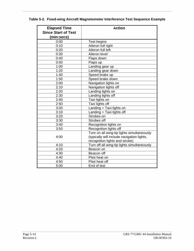
Page 5-14 GRS 77/GMU 44 Installation Manual Revision L 190-00303-10
Table 5-2. Fixed-wing Aircraft Magnetometer Interference Test Sequence Example
Elapsed Time Since Start of Test
(min:secs)
Action
0:00 Test begins 0:10 Aileron full right 0:20 Aileron full left 0:30 Aileron level 0:40 Flaps down 0:50 Flaps up 1:00 Landing gear up 1:20 Landing gear down 1:40 Speed brake up 1:50 Speed brake down 2:00 Navigation lights on 2:10 Navigation lights off 2:20 Landing lights on 2:30 Landing lights off 2:40 Taxi lights on 2:50 Taxi lights off 3:00 Landing + Taxi lights on 3:10 Landing + Taxi lights off 3:20 Strobes on 3:30 Strobes off 3:40 Recognition lights on 3:50 Recognition lights off
4:00 Turn on all wing-tip lights simultaneously (typically will include navigation lights, recognition lights and strobe)
4:10 Turn off all wing-tip lights simultaneously 4:20 Beacon on 4:30 Beacon off 4:40 Pitot heat on 4:50 Pitot heat off 5:00 End of test

GRS 77/GMU 44 Installation Manual Page 5-15 190-00303-10 Revision L
Table 5-3. Helicopter Magnetometer Interference Test Sequence Example
Elapsed Time Since Start of Test
(min:secs)
Action
0:00 Test begins 0:20 Cyclic full right 0:30 Cyclic full left 0:40 Cyclic full forward 0:50 Cyclic full back 1:00 Cyclic centered 1:10 Collective full negative 1:20 Collective full positive 1:30 Anti Torque full left 1:40 Anti Torque full right 1:50 Navigation lights on 2:00 Navigation lights off 2:10 Landing lights on (FWD Only) 2:20 Landing lights off (FWD Only) 2:30 Landing lights on (REAR Only) 2:40 Landing lights off (REAR Only) 2:50 Landing lights on (FWD+REAR) 3:00 Landing lights off (FWD+REAR) 3:10 Strobes on 3:20 Strobes off 3:30
Turn on all lights simultaneously (typically will include navigation lights, recognition lights and strobe)
3:40 Turn off all lights simultaneously 3:50 Pitot heat on 4:00 Pitot heat off 4:10 Air conditioning system on 4:20 Air conditioning system off 4:30 End of test
d) When the CALIBRATE field is blinking, press the ENTER key to begin the procedure, and have a stopwatch ready to begin recording the elapsed time.
NOTE
It is important that the “time equals zero” moment corresponds with the moment the PFD first displays the blinking TEST COMPLETE message.
2. The operator should carry out the actions called for in the prepared test sequence.

Page 5-16 GRS 77/GMU 44 Installation Manual Revision L 190-00303-10
NOTEIt is important that all actions are carried out in the order and at the precise elapsed time as specified in the prepared test sequence.
3. When the operator has completed the actions specified in the test sequence, press the ENTER key to indicate that the process is complete. When this is done, the TEST COMPLETE field stops blinking.
4. The PFD informs the operator if the installation has passed or failed the magnetometer interference test. If the test passes, no further action is required for this test.
If the test fails, the installation should be considered unreliable until the source of magnetic interference is identified and remedied. The magnetometer interference test must be repeated until passed. When the magnetometer interference test fails, record the three magnetometer maximum deviation values and their corresponding timestamps. A maximum deviation value greater than 5.0 milliGauss in either the X or Y axes, or greater than 8.0 milligauss in the Z axis indicates a problem that must be resolved. Compare the corresponding timestamps with the prepared test sequence to identify which action produced the problem. Contact Garmin for assistance in resolving the problem.
NOTE
Two common reasons for a failed magnetometer interference test are: 1) new equipment is installed in close proximity to the GMU 44 magnetometer 2) an existing or new electronic device has become grounded through the aircraft structure instead of via the proper ground wire in a twisted shielded pair.
5. Press the ENTER key on the PFD to conclude this procedure.
GRS 77/GMU 44 Installation Manual Page 5-17 190-00303-10 Revision L
5.9 Site Evaluation of Magnetic Disturbances for Magnetometer Calibration Procedure
As mentioned in Section 5.5, the Magnetometer Calibration Procedure (Calibration Procedure B) must be carried out at a site that is determined to be free of magnetic disturbances.
NOTETypically, a compass rose is an acceptable location to perform the magnetometer calibration procedure. However, because not all compass roses are well maintained, even an existing compass rose should be regularly evaluated using the method described here to determine if it is free of magnetic disturbances. If evaluation of an existing compass rose indicates that magnetic disturbances are present, then an alternative location must be found to perform the Magnetometer Calibration Procedure.
A G1000-equipped airplane can be used to evaluate a candidate site for magnetic disturbances and determine whether it is a suitable location to perform the magnetometer calibration procedure. The magnetometer calibration procedure itself contains the logic to simultaneously survey the location for magnetic cleanliness while it is computing the magnetometer calibration parameters. The G1000-equipped airplane installation used to evaluate the site must have already completed the pitch/roll offset compensation procedure (Procedure A-1). However, prior completion of the Magnetometer Calibration Procedure (Procedure B) is not required. In order to evaluate a candidate site, the Magnetometer Calibration Procedure must be performed twice: once turning clockwise around the site, and once turning counter-clockwise. Both times, the procedure should be conducted as described in Section 5.5 of this document, with the exception of the direction of turns around the site.
NOTEAlthough Section 5.5 indicates that the Magnetometer Calibration Procedure should be performed by making a series of clockwise turns around the site, the procedure can also be performed by making counter-clockwise turns for the purpose of evaluating the site for magnetic disturbances.
If, upon completion of the Magnetometer Calibration Procedure in both the clockwise and counter-clockwise directions, the PFD displays the “CALIBRATION SUCCESSFUL / SITE IS CLEAN” message, then the candidate site is sufficiently free of magnetic disturbances and is acceptable for performing the Magnetometer Calibration Procedure. It is important to perform the procedure in both the clockwise and counter-clockwise directions to ensure that the magnetometer sweeps over a large enough area at the candidate site. If, upon completion of the Magnetometer Calibration Procedure in either of the two directions, the PFD displays either the “MAG FIELD AT SITE NOT UNIFORM”, or “MAG FIELD AT SITE DIFFERS FROM IGRF MODEL” message, then the site contains magnetic disturbances that are too large.

Page 5-18 GRS 77/GMU 44 Installation Manual Revision L 190-00303-10
NOTEThe Magnetometer Calibration Procedure must consistently report “CALIBRATION SUCCESSFUL / SITE IS CLEAN” in both the clockwise and counter-clockwise directions for the site to be considered acceptable. More than one failure out of ten attempts in a given direction would be sufficient reason to conclude the site is not acceptable.
A site that is used repeatedly to perform the Magnetometer Calibration Procedure should be re-evaluated every 12 months, and after any significant construction or placement of magnetic objects (above or below ground) within 50 meters of the location.
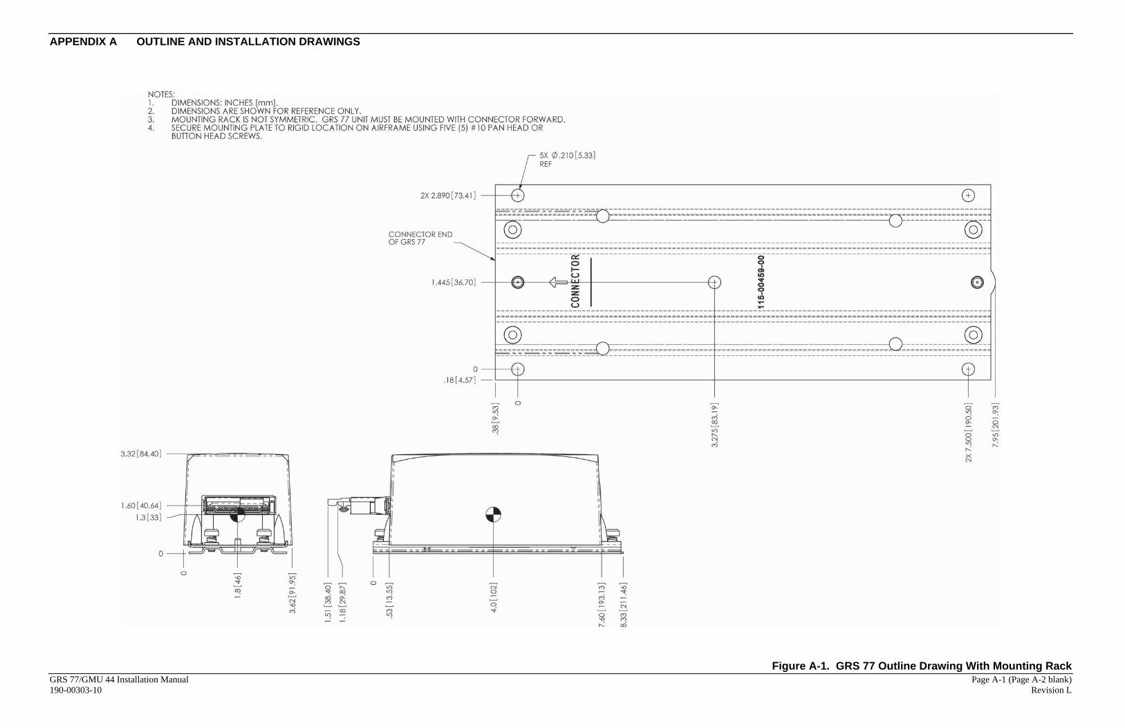
APPENDIX A OUTLINE AND INSTALLATION DRAWINGS
GRS 77/GMU 44 Installation Manual Page A-1 (Page A-2 blank) 190-00303-10 Revision L
Figure A-1. GRS 77 Outline Drawing With Mounting Rack

APPENDIX A OUTLINE AND INSTALLATION DRAWINGS
GRS 77/GMU 44 Installation Manual Page A-3 (Page A-4 blank) 190-00303-10 Revision L
Figure A-2. GMU 44 Mounting Rack (Sheet 1 of 2)

APPENDIX A OUTLINE AND INSTALLATION DRAWINGS
GRS 77/GMU 44 Installation Manual Page A-5 (Page A-6 blank) 190-00303-10 Revision L
Figure A-2. GMU 44 Mounting Rack (Sheet 2 of 2)

APPENDIX A OUTLINE AND INSTALLATION DRAWINGS
GRS 77/GMU 44 Installation Manual Page A-7 (Page A-8 blank) 190-00303-10 Revision L
Figure A-3. GMU 44 Top Mounted Installation

APPENDIX A OUTLINE AND INSTALLATION DRAWINGS
GRS 77/GMU 44 Installation Manual Page A-9 (Page A-10 blank) 190-00303-10 Revision L
Figure A-4. GMU 44 Bottom Mounted Installation

APPENDIX A OUTLINE AND INSTALLATION DRAWINGS
GRS 77/GMU 44 Installation Manual Page A-11 (Page A-12 blank) 190-00303-10 Revision L
Figure A-5. GMU 44 Wiring Detail

APPENDIX B INTERCONNECT DRAWINGS
GRS 77/GMU 44 Installation Manual Page B-1 (Page B-2 blank) 190-00303-10 Revision L
Figure B-1. Typical GRS 77/GMU 44 Interconnect Wiring Diagram
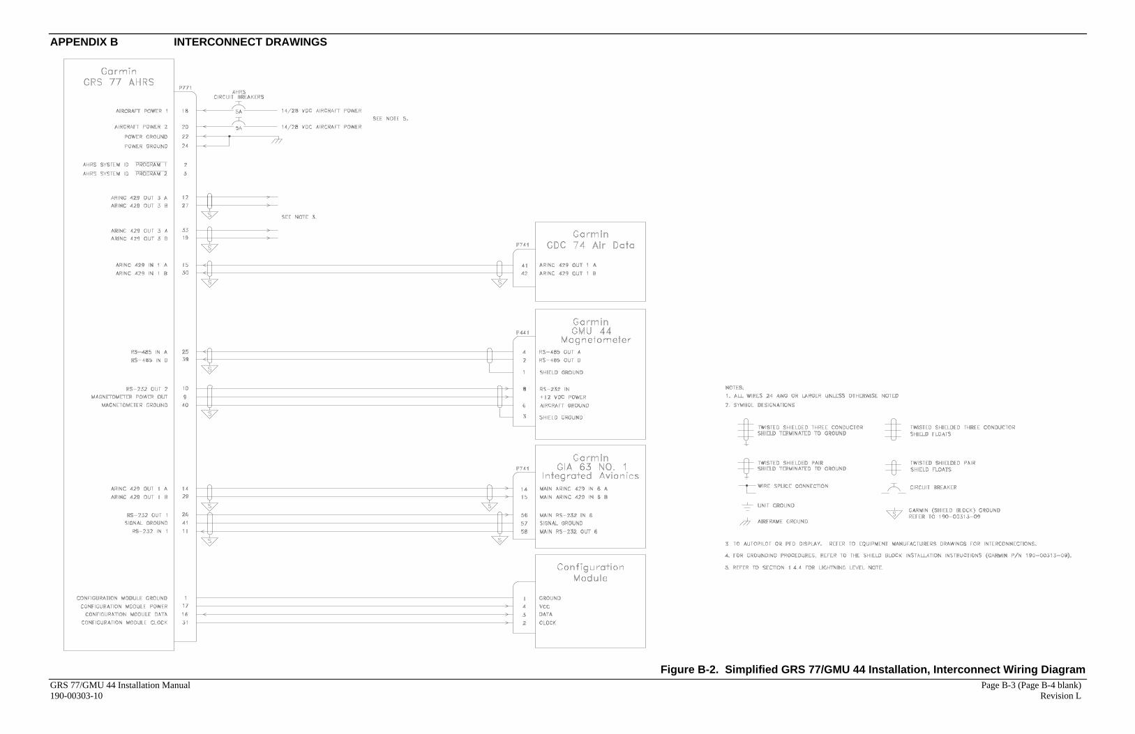
APPENDIX B INTERCONNECT DRAWINGS
GRS 77/GMU 44 Installation Manual Page B-3 (Page B-4 blank) 190-00303-10 Revision L
Figure B-2. Simplified GRS 77/GMU 44 Installation, Interconnect Wiring Diagram