growing fish in a recirculating system: advanced teacher’s workshop
DESCRIPTION
Growing Fish in a Recirculating System: Advanced Teacher’s Workshop. An Inexpensive Recirculating System Blan Page & PJ Waters. System Components. Three (3) 100 gallon stock watering troughs Two (2) 55 gallon barrels Pipe, valves, fittings 1.5” 1.25” 0.75” Special fittings - PowerPoint PPT PresentationTRANSCRIPT

Growing Fish in a Recirculating System:
Advanced Teacher’s Workshop
An Inexpensive Recirculating System
Blan Page & PJ Waters

System Components• Three (3) 100 gallon stock watering troughs• Two (2) 55 gallon barrels • Pipe, valves, fittings
– 1.5”– 1.25”– 0.75”– Special fittings
• 90- 0.75” x 5/8” hose barb• 0.75” threaded Tee
• Submersible Pump• Cable Ties• Garden Hose 5/8”• “Light grate”

Where To Get it??
• Troughs– Purchased at local Feed & Seed store for under $80.00 each.
• Can find for less, just have to look in your area
• 55 gallon barrels– Donated by Coca Cola
• Pipe, valves, fittings, Light grate– Local plumbing supply and hardware stores
• Pump, Bulk Head Fittings, Bio Media, Mechanical Sock, etc.– Aquatic Ecosystem
• Other places/ideas exist

The Tanks
• Come with threaded fitting (1.25”)• Make sure the BHF in the tank is tight– Many times they will leak b/c they are not secured
at the factory– DO NOT over tighten

The Barrels
• Have a 0.75” threaded fitting in the tops• Not used in this instance, but could be to put
an external pump in place• Make sure that you ‘chock’ the mechanical
filter when you get it installed– Use a 2x6 on each side– Build a box frame– Etc.

Simple instructions
• You can start where ever you want• We started with the mechanical filter and a
tank to get good measurements

The Mechanical Filter
• Two 90s (1.25”) nested• One tail piece to go into
barrel• Pipe height will
determine water level– WHY?

The Mechanical Filter/Pump
• Opposite end of the barrel
• Cut out for pump

The Mechanical Filter/Pump
• Insert Pump• How to attach– Catalog indicates a 0.75”
outlet– Doesn’t fit?– Improvise


The Supply Side
• Use a threaded 0.75” tee, a 5/8” X 0.75” threaded 90, and 2- 0.75” valves
• Why 2 valves?

The Supply Side
• Here you can see the Mechanical filter (lower left corner), one of the 2 valves you just installed and the pipe leading to the biofilter

Supplying the Biofilter
• Measure carefully• Use the model

Supplying the BiofilterTrace out the inner circle of the BHF gasket
Carefully cut out line with jig saw. No need to look fora hole saw.

Supplying the Biofilter
• On the inside of the supply side
• BHF to nested 90 turned up

Supplying the Biofilter
• On the inside of the supply side cont’d
• Up to Nested 90s • Down to bottom of tank

Flood Prevention Step
• No guarantees, but drilling a small hole in the center of the nested 90s will allow for a siphon break in the event of a power failure.
• Keeps the water in the barrels and off the floor
Supplying the Biofilter
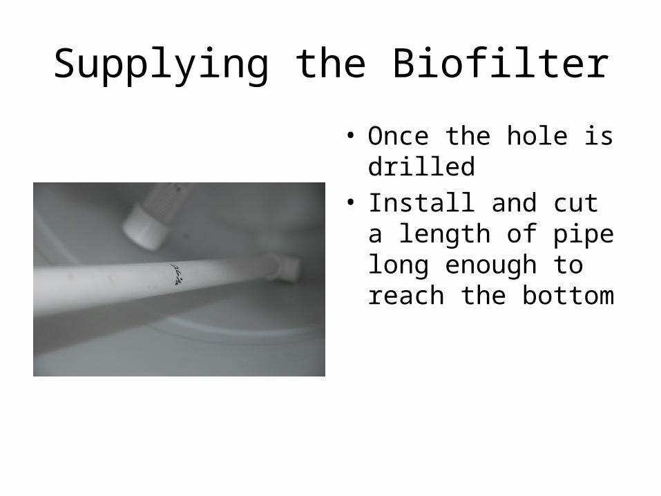
• Once the hole is drilled• Install and cut a length
of pipe long enough to reach the bottom

• Use a BHF (1.5”)• MPT X SLP• Tee• 2 Caps• Measure carefully– Try to center tee– Cap the ends– Use slotted pipe to
screen biofilter material
Draining the Biofilter (inside the unit)

• BHF to MPT X SLP• Nested Valve• This valve is screened
inside so biomedia will not leave
• Can be plumbed further to drain where needed
Draining the Biofilter (outside the unit)

Supplying the Tanks
• The Biomedia we are using floats
• Screen the supply line so it doesn’t escape
• Just like the drain• Measure carefully to
center• Allow arms to be long
enough to just fit inside the barrel
• MPT X SLP to BHF

Supplying the Tanks Cont’d
• Further contain the biomedia by adding a piece of lighting screen
• Sometimes easier to cut 2 halves and then connect with cable ties
• Makes it more difficult for unoccupied hands to access and subsequently spread media across your hatchery

Supplying the Tanks• This shows the system with 1
tank (capped end for expansion)
• MPT X SLP• Nested 90 down turned• Into 45 to sloped pipe• To Tee, down turned (could use
sweep)• Valve at every tank for flexibility• Then continue to next tank• MEASURE CAREFULLY
– Your are relying on gravity here and need to not have uphill

Draining the Tank
• This is the end tank in the line
• Cap on down stream end allows for easy expansion– Leave enough room to
cut then glue new piece
• MPT X SLP• Nested Valve• Nested Tee

Draining the Tank
• Tanks flow into central drain line
• Into stand pipe• Design differs from
photo here– External stand pipe is
lower for more reasonable water level

Design Changes from Model
• Supply Side to tanks• Recommend moving
supply side to a position over the mechanical filter– Provides better access– Centralizes plumbing
• Pump Selection– Pump provided will run 3
tanks at ~ 1 turnover per hour
– If you desire more flow or are going to add tanks consider adding a stronger pump