group t asme design challenge project
TRANSCRIPT

Washington University in St. Louis Washington University in St. Louis
Washington University Open Scholarship Washington University Open Scholarship
Mechanical Engineering Design Project Class Mechanical Engineering & Materials Science
Fall 2018
Group T ASME DESIGN CHALLENGE PROJECT Group T ASME DESIGN CHALLENGE PROJECT
Thomas Orgielewicz Washington University in St. Louis
Hayden von Hoffmann Washington University in St. Louis
Michael Chirumbole Washington University in St. Louis
Follow this and additional works at: https://openscholarship.wustl.edu/mems411
Part of the Mechanical Engineering Commons
Recommended Citation Recommended Citation Orgielewicz, Thomas; von Hoffmann, Hayden; and Chirumbole, Michael, "Group T ASME DESIGN CHALLENGE PROJECT" (2018). Mechanical Engineering Design Project Class. 96. https://openscholarship.wustl.edu/mems411/96
This Final Report is brought to you for free and open access by the Mechanical Engineering & Materials Science at Washington University Open Scholarship. It has been accepted for inclusion in Mechanical Engineering Design Project Class by an authorized administrator of Washington University Open Scholarship. For more information, please contact [email protected].

Executive Summary
The project that we made this semester was a remoted controlled vehicle that is eligible to compete in the ASME 2019
Design Competition. The function of our robot is to navigate the playing field of the competition while attempting to pick
up as many balls as possible within the allotted time. The balls are situated on top of 20 cm pegs that are each spaced 1
meter apart. To pick up these balls, we mounted a box that had been cut in half and was able to pivot to an open or closed
position. To move our robot around, we mounted 2 motors at the back that each powered a wheel. To steer, we created a
simple mechanism that could control both of the front wheels. All of these components were powered by a rechargeable
battery. To control the motors, ball grabbing mechanism, and front wheel steering, we used a three channel remote paired
with a receiver. At the beginning of the project we created a set of goals that we felt would translate to a good performance
in the competition. Now that we have completed our project, we are proud to say that we were successful in reaching or
exceeding our goals.
MEMS 411: MECHANICAL ENGINEERING DESIGN PROJECT
FALL 2018
Project Name
Michael Chirumbole
Thomas Orgielewicz
Hayden von Hoffmann

1
TABLE OF CONTENTS
List of Figures ..................................................................................................................................................................... 3
List of Tables ...................................................................................................................................................................... 4
1 Introduction ..................................................................................................................................................................... 5
2 Problem Understanding ................................................................................................................................................... 5
2.1 Background Information Study ............................................................................................................................... 5
2.2 User Needs ............................................................................................................................................................ 10
2.3 Design Metrics ...................................................................................................................................................... 11
2.4 Project Management ............................................................................................................................................. 11
3 Concept Generation....................................................................................................................................................... 12
3.1 Mockup Prototype ................................................................................................................................................. 12
3.2 Functional Decomposition ...................................................................................................................................... 1
3.3 Alternative Design Concepts .................................................................................................................................. 2
4 Concept Selection ........................................................................................................................................................... 8
4.1 Selection Criteria..................................................................................................................................................... 8
4.2 Concept Evaluation ................................................................................................................................................. 8
4.3 Evaluation Results................................................................................................................................................... 9
4.4 Engineering Models/Relationships ....................................................................................................................... 10
5 Concept Embodiment .................................................................................................................................................... 12
5.1 Initial Embodiment ............................................................................................................................................... 12
5.2 Proof-of-Concept .................................................................................................................................................. 15
6 Working Prototype ........................................................................................................................................................ 17
6.1 Overview ............................................................................................................................................................... 17
6.2 Demonstration Documentation ............................................................................................................................. 18
6.3 Experimental Results ............................................................................................................................................ 18
7 Design Refinement ........................................................................................................................................................ 19
7.1 FEM STRESS/ Deflection analysis ...................................................................................................................... 19
7.2 Design for Safety .................................................................................................................................................. 20
7.3 Design for manufacturing ..................................................................................................................................... 22
7.4 Design for usability ............................................................................................................................................... 23
8 Discussion ..................................................................................................................................................................... 24
8.1 Project Development and Evolution ..................................................................................................................... 24
8.2 Design Resources .................................................................................................................................................. 24
8.3 Team Organiztion ................................................................................................................................................. 25
Appendix A – Cost Accounting Worksheet .......................................................................................................................... 26
Appendix B – Final Design Documentation ......................................................................................................................... 27

2
Bibliography ......................................................................................................................................................................... 30
3
LIST OF FIGURES
Figure 1: Images of the Traxxas TRX-4 Tactical Crawler ..................................................................................................... 6 Figure 2: Images of the HuiNa Toys 1550 RC Excavator ...................................................................................................... 7 Figure 3: Images of the Fisca RC Tank .................................................................................................................................. 8 Figure 4: Patent page for a controller with multiple signals and devices ............................................................................... 9 Figure 5: Patent page for the body steered rover .................................................................................................................... 9 Figure 6: Patent page for the body steered rover .................................................................................................................. 12 Figure 7: Mockup front view with closed ball collector ....................................................................................................... 12 Figure 8: Mockup front view with open ball collector ......................................................................................................... 12 Figure 9: Mockup front view with raised ball collector Figure 10: Mockup side view with lowered collector
0 Figure 11: Mockup side view with lowered collector ............................................................................................................. 0 Figure 12: Function tree diagram ............................................................................................................................................ 1 Figure 13: Morphological chart .............................................................................................................................................. 2 Figure 14: Thomas’ first design for the ASME “Pick-and-Place-Race” ................................................................................ 3 Figure 15: Preliminary sketches for the robot ......................................................................................................................... 3 Figure 16: Final sketches of Patrick ........................................................................................................................................ 4 Figure 17: Preliminary sketches of Perry ................................................................................................................................ 5 Figure 18: Final sketches of Perry .......................................................................................................................................... 6 Figure 19: Preliminary sketches of Tread Design ................................................................................................................... 7 Figure 20: Preliminary sketches of Tread Design ................................................................................................................... 7 Figure 21: Formula for battery discharge rate based on motor(s) used and battery used. .................................................... 10 Figure 22: Relationship between turn raidus, wheelbase, and front wheel turn angle. ........................................................ 11 Figure 23: Sum of the moments and diagram about the front wheels of the robot ............................................................... 12 Figure 24: Isometric view of CAD embodiment with bill of materials. ............................................................................... 13 Figure 25: Exploded view of CAD embodiment .................................................................................................................. 13 Figure 26: Exploded view of Front Wheel Assembly with bill of materials ........................................................................ 14 Figure 27: How to calculate turn radius for any 4 wheeled vehicle. ..................................................................................... 15 Figure 28: Calculating the turn radius for the CAD embodiment. ........................................................................................ 16 Figure 29: Overall view of PoC prototype ............................................................................................................................ 16 Figure 30: View of Front Wheel Assembly .......................................................................................................................... 17 Figure 31: View of ball collector .......................................................................................................................................... 17 Figure 32: Back view of final project Figure 33: Side view of final project ......................................................... 18 Figure 34: Top view of final project .................................................................................................................................... 18 Figure 35: Loaded front beam of the turning apparatus ........................................................................................................ 19 Figure 36: Loaded plastic (A) and aluminum beams (B) ...................................................................................................... 20 Figure 37: Risk assessment heat map for the proof of concept prototype ............................................................................ 21 Figure 38: Before and after images of sample part using Solidworks “Draft Analysis” ...................................................... 22 Figure 39: DFM analysis for a Mill/Drill Only process on the selected part ....................................................................... 22 Figure 40: DFM analysis for a Turn with Mill/Drill process on the selected part ................................................................ 23
4
LIST OF TABLES
Table 1: Customer Needs Interview ...................................................................................................................................... 10
Table 3: Interpreted Customer Needs ................................................................................................................................... 11
Table 3: Analytical hierarchy weighing the relative importance of robot design criteria ....................................................... 8
Table 4: Analytical hierarchy weighing the relative importance of robot design criteria ....................................................... 9
Table 5: Analytical hierarchy weighing the relative importance of robot design criteria ..................................................... 14

5
1 INTRODUCTION
For this project we will be building a robot that meets the qualifications to compete in the 2019 ASME Student
Design Competition. This upcoming year the contest is the “The Pick-and-Place Race.” The objective is to make a
small remote controlled robot that collects balls of various sizes off of small pegs. Balls range from ping-pong ball
size to basketball size. However, after interviewing Dr. Potter, it was decided that the four balls used would be a
tennis ball, ping pong ball, golf ball, and plastic bowling ball. The robot will pick the balls up off the peg, then drop
it in a designated area.
Our robot will be powered by a rechargeable lithium polymer and will use DC brushed motors attached to wheels
in order to move. The base of the vehicle is an aluminum sheet. It’s imperative that the robot is able to perform
basic functions such as move in all directions, and pick a ball off of a tee without knocking the ball to the ground.
To accomplish this, we used a front steering assembly made of aluminum beams, and is powered by a servo. The
ball collection device uses a servo to rotate half of a box made of poster board to grab the ball. More materialistic
aspects of the design, such as robot size, weight, and looks, are not as much of a concern in regards to our project.
However, we were able to keep the robot within the regulation size, and it was also very lightweight. The
competition calls for use of a wireless remote controller which we were also able to accomplish.
2 PROBLEM UNDERSTANDING
2.1 BACKGROUND INFORMATION STUDY
In order to get a good idea of where to begin with the design, a background study of existing similar products was
conducted. Patents also needed to be researched in order to aid the building of the robot.
2.1.1 Product 1: Traxxas TRX-4 Tactical Crawler
Since the competition requires a remote controlled car, it made sense to find a product that is a remote controlled
(RC) vehicle. The Traxxas RC [1] car is a standard RC car that has strong maneuverability with its four tires—an
important aspect when considering the play area of the ASME challenge. Figures 1A-1C give some views of the
RC car for detail.

6
Figure 1: Images of the Traxxas TRX-4 Tactical Crawler
This product is a remote controlled all terrain SUV. It is about 58 cm long, 25 cm wide, and 21 cm tall. It uses a
rechargeable lithium polymer (LiPo) battery and a 2.4 GHz-4 Channel Transmitter. This car can drive forwards and
backwards and can turn using the two front wheels that are mounted to a servo motor. The SUV exceeds the sizing
limits of the competition by 8 cm (as it needs to fit in a 50x50x50 cm3 box), but is close to the size that our group is
looking for. A rechargeable battery is also need for the competition, and a LiPo battery could be a good choice to go
with. Front wheel steering is also one possible consideration for the making of our RC car.
(A) (B)
(C)
https://www.rcplanet.com/traxxas-trx-4-tactical-crawler-tra82066-4/
7
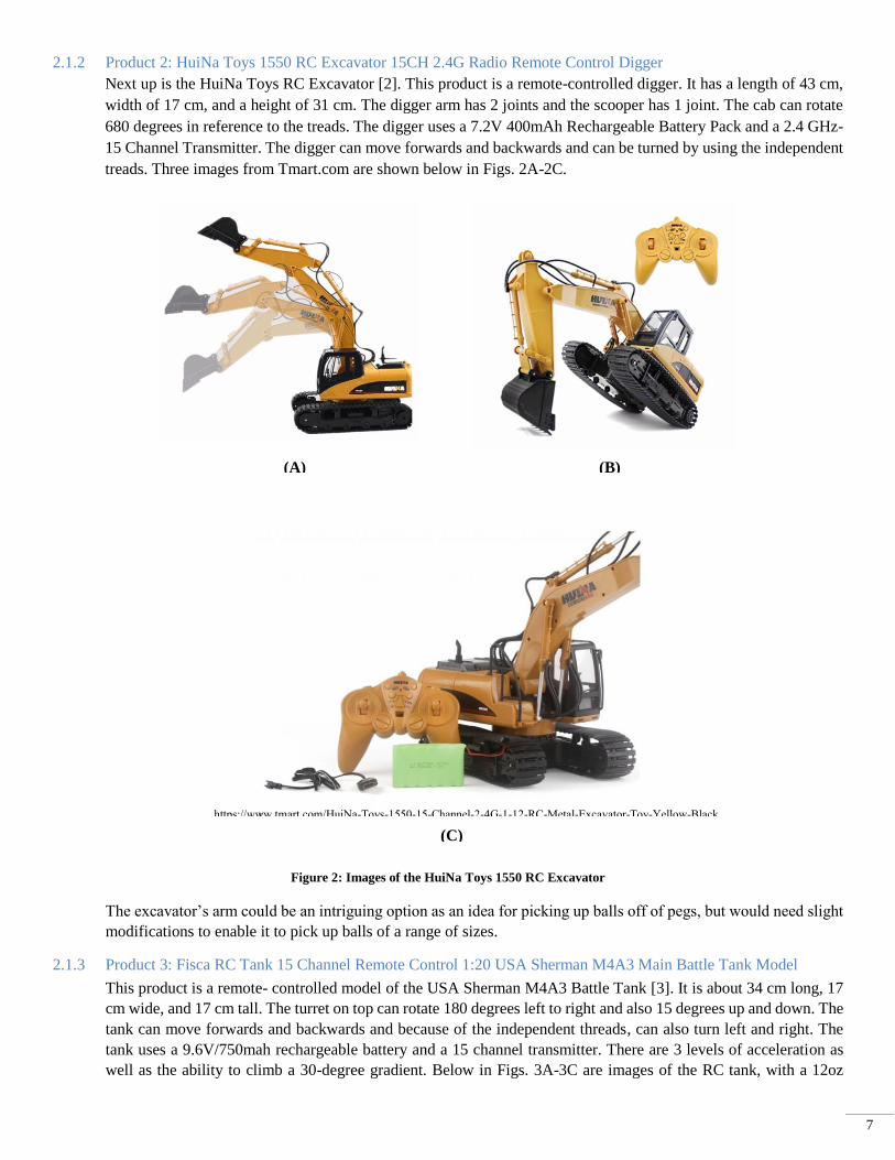
2.1.2 Product 2: HuiNa Toys 1550 RC Excavator 15CH 2.4G Radio Remote Control Digger
Next up is the HuiNa Toys RC Excavator [2]. This product is a remote-controlled digger. It has a length of 43 cm,
width of 17 cm, and a height of 31 cm. The digger arm has 2 joints and the scooper has 1 joint. The cab can rotate
680 degrees in reference to the treads. The digger uses a 7.2V 400mAh Rechargeable Battery Pack and a 2.4 GHz-
15 Channel Transmitter. The digger can move forwards and backwards and can be turned by using the independent
treads. Three images from Tmart.com are shown below in Figs. 2A-2C.
Figure 2: Images of the HuiNa Toys 1550 RC Excavator
The excavator’s arm could be an intriguing option as an idea for picking up balls off of pegs, but would need slight
modifications to enable it to pick up balls of a range of sizes.
2.1.3 Product 3: Fisca RC Tank 15 Channel Remote Control 1:20 USA Sherman M4A3 Main Battle Tank Model
This product is a remote- controlled model of the USA Sherman M4A3 Battle Tank [3]. It is about 34 cm long, 17
cm wide, and 17 cm tall. The turret on top can rotate 180 degrees left to right and also 15 degrees up and down. The
tank can move forwards and backwards and because of the independent threads, can also turn left and right. The
tank uses a 9.6V/750mah rechargeable battery and a 15 channel transmitter. There are 3 levels of acceleration as
well as the ability to climb a 30-degree gradient. Below in Figs. 3A-3C are images of the RC tank, with a 12oz
(A) (B)
(C)
https://www.tmart.com/HuiNa-Toys-1550-15-Channel-2-4G-1-12-RC-Metal-Excavator-Toy-Yellow-Black

8
Pepsi can in image 3C for size.
Figure 3: Images of the Fisca RC Tank
2.1.4 Patent 1: Multi-Vehicle, Multi-Controller Radio Remote Control System
Patent #: US4334221A
(A)
(C)
(B)

9
This is a patent for an RC controller with multiple controllers and multiple devices. They function without
interrupting each other’s signals. They allow for both speed and direction control. The controllers send out
command bursts to the devices to tell them what to do. If the device receives a burst that has noise or is incomplete,
it will not execute that command. Below in Fig. 4 is an image of the patent.
Figure 4: Patent page for a controller with multiple signals and devices
2.1.5 Patent 2: Body Steered Rover
Patent #: US4932491A
This patent is for a rover to traverse over rough
terrain. It has a set of front and back primary
wheels as well as a set of “auxiliary wheels”
which are deployed to drive over the rough
terrain. The rover has arms powered by a motor
that are attached to the wheels. They have 180-
degree motion so that they can deploy on either
the front or back of the rover to climb the terrain.
Fig. 5 shows a picture from the patent. If we were
to put our product on the market, this could apply
to our robot if we wanted to market it as an all-
terrain vehicle.
Figure 5: Patent page for the body steered rover

10
2.2 USER NEEDS
The design of the RC robot being built is heavily influenced upon the rules of the ASME Challenge, but an interview
with Dr. Potter was conducted to further discuss the design needs of the robot. After the interview, a table was put
together of the customer needs, as shown below in Table 1. The importance was rated on a scale of 1-5, with 5 being
the most important.
Table 1: Customer Needs Interview
After completing the interview, it was necessary to interpret some of what Dr. Potter said into more concrete
statements that were applicable to the building of the robot. Below in Table 2 is the interpreted customer needs.

11
Table 2: Interpreted Customer Needs
Again, the importance was ranked from 1-5, with 5 being the most important.
2.3 DESIGN METRICS
Next a table was made for target specifications of our robot based upon the interpreted customer needs. For most
need numbers, at least one metric was assigned and a target specifying the acceptable as well as ideal values for the
metrics of the robot. It is shown below in Table 3.
Table 2: Interpreted Customer Needs
2.4 PROJECT MANAGEMENT
A Gant chart was made after the interview process was completed to help manage the time of our project. It is shown
below in Fig. 6.

12
Figure 6: Patent page for the body steered rover
3 CONCEPT GENERATION
3.1 MOCKUP PROTOTYPE
A non-functioning mockup prototype was the first building stage of the project. A mockup was made in order to
better understand how the project was to be approached, what limitations might be faced, and also how big the robot
would be. Figs. 7-11 show pictures taken of the mockup.
Figure 7: Mockup front view with closed ball collector
Figure 8: Mockup front view with open ball collector

Figure 9: Mockup front view with raised ball collector Figure 10: Mockup side view with lowered collector
Figure 11: Mockup side view with lowered collector

1
The biggest takeaway from the mockup was realizing how limited we are in the size of the robot. Keeping the size
within the contest rules and being able to pick up the larger balls will be difficult. It must also be designed so that the
weight of the ball won’t tip the entire robot over once the arms have raised up. It also became clear that because of
the size constraint that collecting multiple balls in one trip might not be the best approach. Any motors, actuators, or
other electronic attachments that we plan on using must all be able to fit on the robot while still allowing the ball
collector rotation. The use of an open-faced box works well in theory and for the mockup when there’s manual
movement, but it isn’t the most viable method for mechanical movement. The final product will probably involve
arms with some sort of attachment at the end instead.
3.2 FUNCTIONAL DECOMPOSITION
There were several customer needs whose goals could be fulfilled with many different designs. A functional
decomposition was thus done to show all of the different ways critical parts of the robot could be incorporated into a
design. First a function tree was created, as shown below in Fig. 12.
Figure 12: Function tree diagram
The function tree had 3 main design considerations, namely the power, movement, and ball handling. These design
considerations were broken down further until they could no longer get more specific. A morphological chart was
drawn up to show how the specific designs would be represented by parts. The morphological chart is shown below
in Fig. 13.

2
Figure 13: Morphological chart
Some components of the robot will be limited by the rules. For example, the robot must use rechargeable batteries
and must be touching the ground. Therefore, disposable batteries in the power section would not work, and the
hovercraft in the movement section would not be allowed.
3.3 ALTERNATIVE DESIGN CONCEPTS
Each of the three group members used the morphological chart components to come up with a design concept. Each
alternative design concept is shown below, starting with Thomas’. Shown in Fig. 14 is Thomas’ original design idea,
but it had some short comings. Namely, the vacuum tube used to suction the ball off the peg did not have any way to
adjust to different sized balls or different heights of the pegs the balls will be sitting on.

3
Figure 14: Thomas’ first design for the ASME “Pick-and-Place-Race”
There were other issues regarding the plausibility of design, such as governing the movement of the legs; they would
overcomplicate the movement of the robot, and could easily be replaced by wheels with motors. Next, in Fig. 15, the
original drawings and ideas for what later became the alternative design named Patrick are shown.
Figure 15: Preliminary sketches for the robot

4
Above in Fig. 15 are rough sketches and ideas that led to the more refined idea that becomes Patrick. Figure 16
below shows multiple views of the alternative design idea Patrick.
Figure 16: Final sketches of Patrick
Description: Patrick has a square base and a smaller square top, with 4 trapezoids as the sides of the body. It has
four wheels, with the front wheels on one axle, and the back two on a different axle. It plugs into an outlet for power
via a cord in the back, and uses a wireless signal and remote controller to govern the wheel movement, vacuum tube
movement, and the vacuum itself. Patrick is made to drive up to a peg holding a ball, pick the ball up using the
adjustable and extendable vacuum tube, and then hold onto the ball and drive it over to a designated zone where the
ball will then be dropped.

5
Solutions:
1. Body powered by wire into outlet
2. Controller powered by reusable batteries
3. Four wheels with a total of two axles
4. Electric motor used to power wheels
5. Vacuum used to pick balls up off of peg
6. Balls dropped by turning off the vacuum
Next is Hayden’s design, nicknamed Perry. The preliminary and final sketches are shown below in Figs. 17-18.
Figure 17: Preliminary sketches of Perry
6
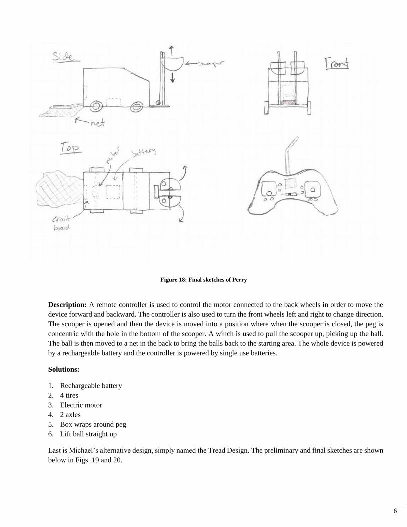
Figure 18: Final sketches of Perry
Description: A remote controller is used to control the motor connected to the back wheels in order to move the
device forward and backward. The controller is also used to turn the front wheels left and right to change direction.
The scooper is opened and then the device is moved into a position where when the scooper is closed, the peg is
concentric with the hole in the bottom of the scooper. A winch is used to pull the scooper up, picking up the ball.
The ball is then moved to a net in the back to bring the balls back to the starting area. The whole device is powered
by a rechargeable battery and the controller is powered by single use batteries.
Solutions:
1. Rechargeable battery
2. 4 tires
3. Electric motor
4. 2 axles
5. Box wraps around peg
6. Lift ball straight up
Last is Michael’s alternative design, simply named the Tread Design. The preliminary and final sketches are shown
below in Figs. 19 and 20.
7
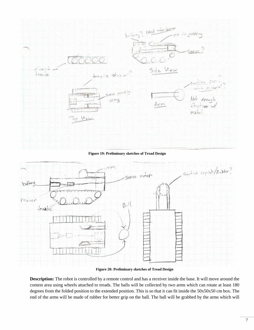
Figure 19: Preliminary sketches of Tread Design
Figure 20: Preliminary sketches of Tread Design
Description: The robot is controlled by a remote control and has a receiver inside the base. It will move around the
contest area using wheels attached to treads. The balls will be collected by two arms which can rotate at least 180
degrees from the folded position to the extended position. This is so that it can fit inside the 50x50x50 cm box. The
end of the arms will be made of rubber for better grip on the ball. The ball will be grabbed by the arms which will
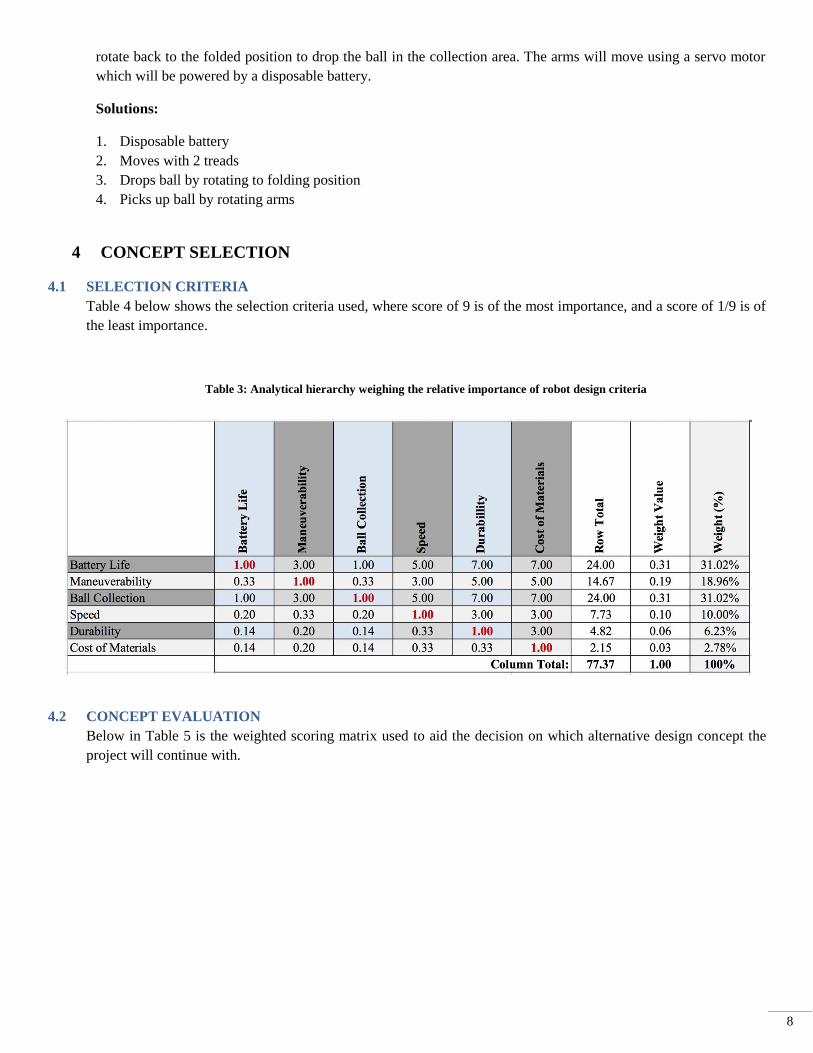
8
rotate back to the folded position to drop the ball in the collection area. The arms will move using a servo motor
which will be powered by a disposable battery.
Solutions:
1. Disposable battery
2. Moves with 2 treads
3. Drops ball by rotating to folding position
4. Picks up ball by rotating arms
4 CONCEPT SELECTION
4.1 SELECTION CRITERIA
Table 4 below shows the selection criteria used, where score of 9 is of the most importance, and a score of 1/9 is of
the least importance.
Table 3: Analytical hierarchy weighing the relative importance of robot design criteria
4.2 CONCEPT EVALUATION
Below in Table 5 is the weighted scoring matrix used to aid the decision on which alternative design concept the
project will continue with.

9
Table 4: Analytical hierarchy weighing the relative importance of robot design criteria
4.3 EVALUATION RESULTS
Design Concept 2 received the highest possible score for battery life because rechargeable batteries can be used with
it and can very easily last the 5 minute rounds. This design only received a 4 in maneuverability because it doesn’t
have the best possible turn radius. It will be able to navigate the course well enough, but it is not as good as having
treads which allow for maximum maneuverability. The trailing net could also cause maneuverability issues. It
received a 5 in ball collection because it allows for a very wide range of ball size collection. The bucket design will
work just as well for a ping pong ball as it will for a volleyball. It can also pick the ball up from any height and place
it in the area by lowering. This will lead to minimal bouncing in the placing area. It received the highest score in
speed because it is on wheels instead of the slower treads. It also doesn’t have as much weight as the vacuum design
allowing for faster movement. It has the highest score in durability as well because the design is simpler and has
fewer moving parts, so there is a smaller chance of failure or it breaking. The cost has the highest score along with
the tread design. This is because the parts involved are relatively cheap and can be found at most hardware and hobby
stores while the vacuum and any modifications involved would be much more expensive.
10
4.4 ENGINEERING MODELS/RELATIONSHIPS
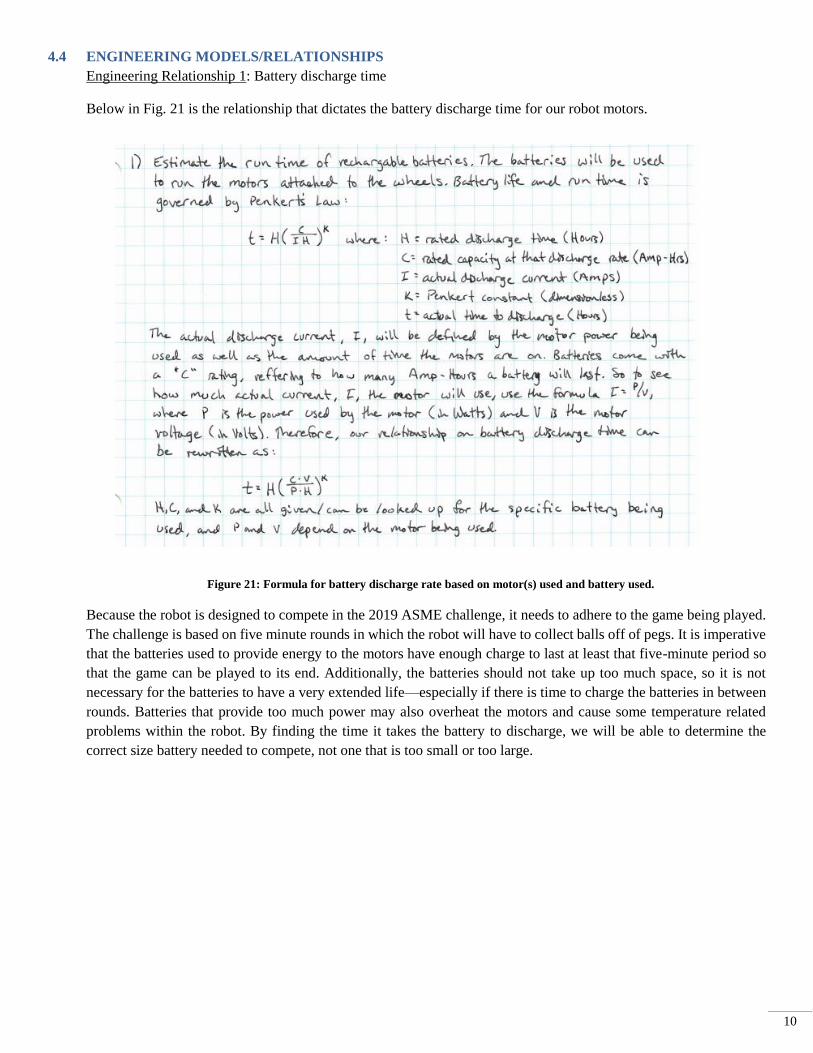
Engineering Relationship 1: Battery discharge time
Below in Fig. 21 is the relationship that dictates the battery discharge time for our robot motors.
Figure 21: Formula for battery discharge rate based on motor(s) used and battery used.
Because the robot is designed to compete in the 2019 ASME challenge, it needs to adhere to the game being played.
The challenge is based on five minute rounds in which the robot will have to collect balls off of pegs. It is imperative
that the batteries used to provide energy to the motors have enough charge to last at least that five-minute period so
that the game can be played to its end. Additionally, the batteries should not take up too much space, so it is not
necessary for the batteries to have a very extended life—especially if there is time to charge the batteries in between
rounds. Batteries that provide too much power may also overheat the motors and cause some temperature related
problems within the robot. By finding the time it takes the battery to discharge, we will be able to determine the
correct size battery needed to compete, not one that is too small or too large.
11
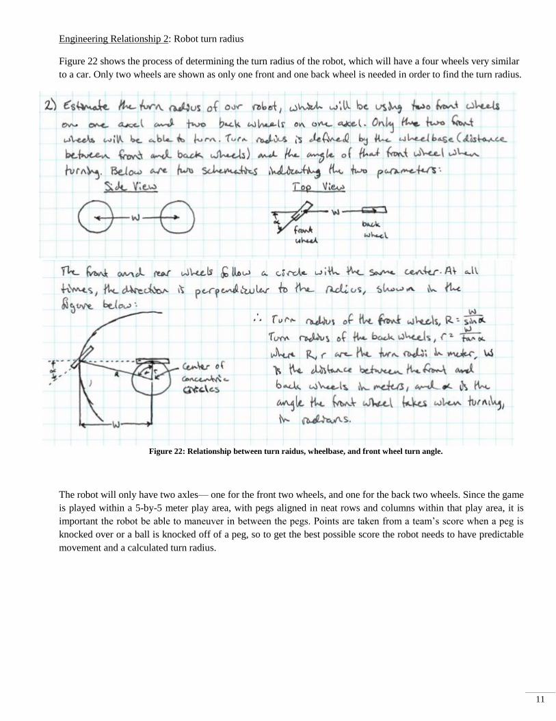
Engineering Relationship 2: Robot turn radius
Figure 22 shows the process of determining the turn radius of the robot, which will have a four wheels very similar
to a car. Only two wheels are shown as only one front and one back wheel is needed in order to find the turn radius.
Figure 22: Relationship between turn raidus, wheelbase, and front wheel turn angle.
The robot will only have two axles— one for the front two wheels, and one for the back two wheels. Since the game
is played within a 5-by-5 meter play area, with pegs aligned in neat rows and columns within that play area, it is
important the robot be able to maneuver in between the pegs. Points are taken from a team’s score when a peg is
knocked over or a ball is knocked off of a peg, so to get the best possible score the robot needs to have predictable
movement and a calculated turn radius.

12
Engineering Relationship 3: Tipping moment of robot
Shown in Fig. 23 is the relationship defined by the tipping moment of the robot.
Figure 23: Sum of the moments and diagram about the front wheels of the robot
This model is important in making an informed decision because it will determine if our Pick ‘N Place robot will
remain upright after picking up a ball. If, after plugging in all the terms, the moment equation is positive, it will not
tip over. We could also assume the normal force at the back wheel is zero and solve for the mass of the ball, and
that would tell us the largest mass we could pick up.
5 CONCEPT EMBODIMENT
5.1 INITIAL EMBODIMENT
To get an idea of the best way to design the robot, we put together an initial embodiment. The purpose of the initial
embodiment is to test our understanding of the mechanics behind the robot and to try and prove that the concepts
applied to the robot will indeed work to fulfill its function—mainly picking up and placing balls for the ASME
challenge. The robot may take new forms as the design progresses and new challenges are discovered, and prototypes
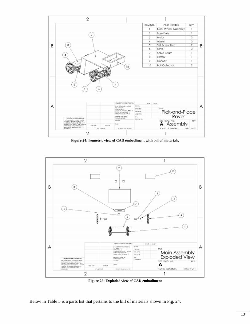
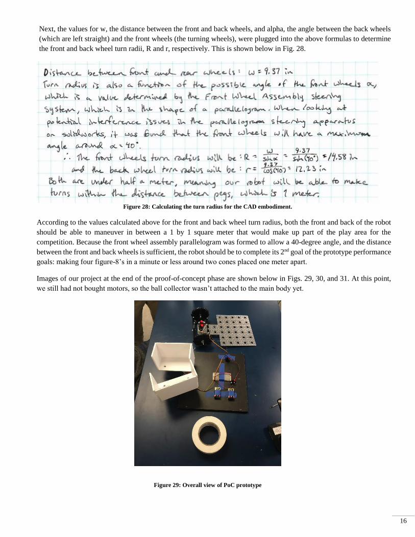
tested. Below in Figs. 24 and 25 are an isometric view of the initial concept embodiment with a bill of materials and
then an exploded view of the initial concept, respectively.
13
Figure 24: Isometric view of CAD embodiment with bill of materials.
Figure 25: Exploded view of CAD embodiment
Below in Table 5 is a parts list that pertains to the bill of materials shown in Fig. 24.

14
Table 5: Initial parts of prototypes components (does not include front wheel assembly breakdown.)
The front wheel assembly is a steering system that uses the front two wheels and a servo. Provided in Fig. 26 is a
breakdown of the front wheel assembly’s part composition in a bill of materials, as well as an isometric exploded
view of the assembly.
Figure 26: Exploded view of Front Wheel Assembly with bill of materials

15
Table 6 contains the parts relevant to only the wheel assembly, which ARE NOT listed in the bill of materials in
Fig. 24, or in the initial parts list in Table 5.
Table 6: Front Wheel Assembly parts list.
5.2 PROOF-OF-CONCEPT
In order to evaluate the prototyping process of our robot, we decided upon three measurable goals. These goals are
used to provide proof that the concepts we have chosen to base our design on will indeed work. The three Prototype
Performance Goals are: (1) Pick up and place 3 of 4 balls within 1 minute, (2) Perform four figure-8s in one minute
around two cones that are placed one meter apart, and (3) Test battery life to see if it will last all five minutes by picking
up and placing 16 balls off of the same four pegs. To try and complete the three goals, it was important to that the robot
be accurately designed based upon specific engineering models and relationships. Because we have yet to choose our
exact battery or the material for the canopy, the only model we used that could apply was the turn radius model. Recall
from Section 4.4 the equations for turn radius, as explained again in Fig. 27 below:
Figure 27: How to calculate turn radius for any 4 wheeled vehicle.
16
Next, the values for w, the distance between the front and back wheels, and alpha, the angle between the back wheels
(which are left straight) and the front wheels (the turning wheels), were plugged into the above formulas to determine
the front and back wheel turn radii, R and r, respectively. This is shown below in Fig. 28.
Figure 28: Calculating the turn radius for the CAD embodiment.
According to the values calculated above for the front and back wheel turn radius, both the front and back of the robot
should be able to maneuver in between a 1 by 1 square meter that would make up part of the play area for the
competition. Because the front wheel assembly parallelogram was formed to allow a 40-degree angle, and the distance
between the front and back wheels is sufficient, the robot should be to complete its 2nd goal of the prototype performance
goals: making four figure-8’s in a minute or less around two cones placed one meter apart.
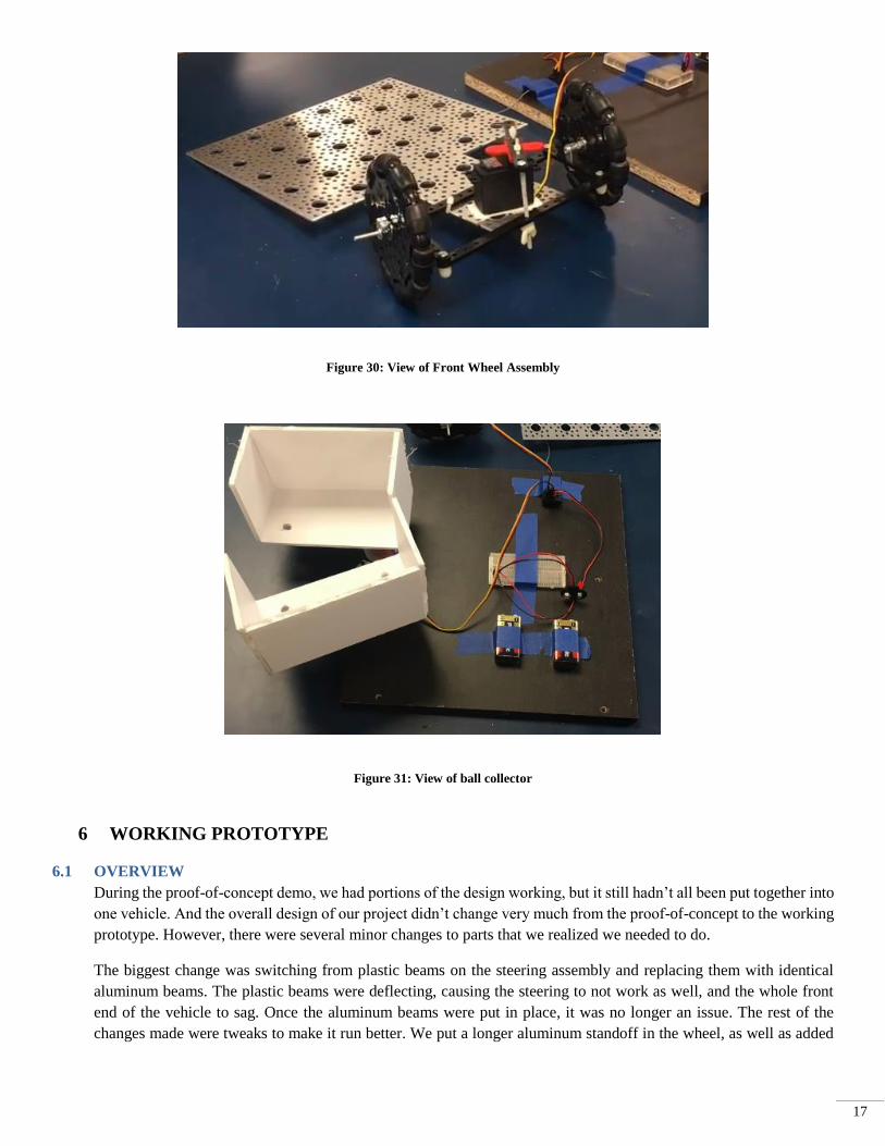
Images of our project at the end of the proof-of-concept phase are shown below in Figs. 29, 30, and 31. At this point,
we still had not bought motors, so the ball collector wasn’t attached to the main body yet.
Figure 29: Overall view of PoC prototype
17
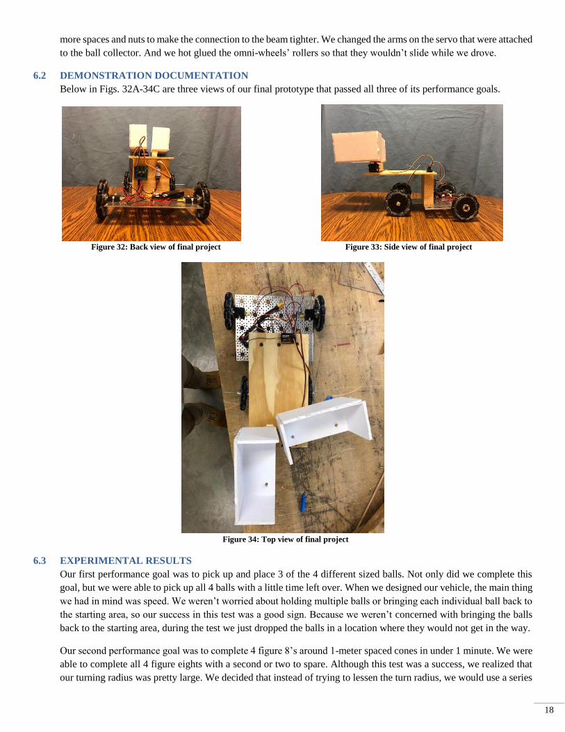
Figure 30: View of Front Wheel Assembly
Figure 31: View of ball collector
6 WORKING PROTOTYPE
6.1 OVERVIEW
During the proof-of-concept demo, we had portions of the design working, but it still hadn’t all been put together into
one vehicle. And the overall design of our project didn’t change very much from the proof-of-concept to the working
prototype. However, there were several minor changes to parts that we realized we needed to do.
The biggest change was switching from plastic beams on the steering assembly and replacing them with identical
aluminum beams. The plastic beams were deflecting, causing the steering to not work as well, and the whole front
end of the vehicle to sag. Once the aluminum beams were put in place, it was no longer an issue. The rest of the
changes made were tweaks to make it run better. We put a longer aluminum standoff in the wheel, as well as added
18
more spaces and nuts to make the connection to the beam tighter. We changed the arms on the servo that were attached
to the ball collector. And we hot glued the omni-wheels’ rollers so that they wouldn’t slide while we drove.
6.2 DEMONSTRATION DOCUMENTATION
Below in Figs. 32A-34C are three views of our final prototype that passed all three of its performance goals.
Figure 32: Back view of final project Figure 33: Side view of final project
Figure 34: Top view of final project
6.3 EXPERIMENTAL RESULTS
Our first performance goal was to pick up and place 3 of the 4 different sized balls. Not only did we complete this
goal, but we were able to pick up all 4 balls with a little time left over. When we designed our vehicle, the main thing
we had in mind was speed. We weren’t worried about holding multiple balls or bringing each individual ball back to
the starting area, so our success in this test was a good sign. Because we weren’t concerned with bringing the balls
back to the starting area, during the test we just dropped the balls in a location where they would not get in the way.
Our second performance goal was to complete 4 figure 8’s around 1-meter spaced cones in under 1 minute. We were
able to complete all 4 figure eights with a second or two to spare. Although this test was a success, we realized that
our turning radius was pretty large. We decided that instead of trying to lessen the turn radius, we would use a series
19
of smaller K-turns to maneuver in tight areas. This method worked very well as long as the person controlling the
vehicle had some experience.
Our third performance goal was to have our rechargeable Li-Po battery last the duration of one round of the
competition, which is 5 minutes. After our first two performance goals our vehicle had been running for two minutes,
so we continued to drive it around for another three minutes to prove that it could run the full five minutes. Since the
working prototype demo, we have also run it for the expo as well as for some video recordings and we have not had
to charge it yet. This means that our battery would easily last the 5 minutes that it would take compete in one round
of the competition.
7 DESIGN REFINEMENT
7.1 FEM STRESS/ DEFLECTION ANALYSIS
We ran a FEM analysis on one of the beams that is part of the front wheel steering system of our vehicle. Of the 4
beams that make up the main components of the steering system, this is the only one that is connected directly to the
body of the vehicle. For that reason, the weight of the vehicle is mostly on this beam, so we decided to do a deflection
test on it. The beam is attached to the body at one point, so to model this we created a point force on the beam in the
location where it is connected, which is the middle of the bar. The magnitude of this force is roughly equal to the
weight of the vehicle. We fixed both ends of the bar because they are connected to the wheels and therefore can’t
move. The mesh we used was a fine mesh. Based on the simplicity of the analysis and the results, we believe that the
model we made is fairly accurate in how well it mimics our vehicles condition. We have not decided whether to use
plastic or aluminum beams yet, so we ran the analysis for both materials.
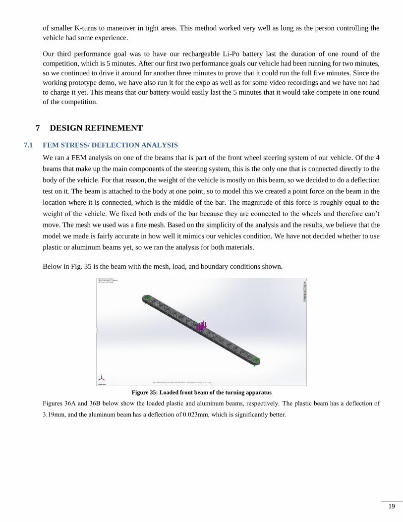
Below in Fig. 35 is the beam with the mesh, load, and boundary conditions shown.
Figure 35: Loaded front beam of the turning apparatus
Figures 36A and 36B below show the loaded plastic and aluminum beams, respectively. The plastic beam has a deflection of
3.19mm, and the aluminum beam has a deflection of 0.023mm, which is significantly better.

20
Figure 36: Loaded plastic (A) and aluminum beams (B)
The maximum deflection possible without causing significant problems for the function of the vehicle is about 2 mm.
At around 2 mm, we estimate that the stress in the screws connecting the beams would be significant and also that it
would cause the wheels to tilt. This would mean that the deflection in the aluminum beam is acceptable, but the
deflection in the plastic beam would not be.
7.2 DESIGN FOR SAFETY
Risk Name: Sharp Edges
Description: Our design has multiple metal pieces, some of which had to be machined to fit our needs. Since there
is a lot of metal, there is a possibility the user could cut themselves on a sharp edge. This could be mitigated by filing
and smoothing over any exposed metal edge.
Impact: 2
Likelihood: 3
Risk Name: Exposed Wires
Description: There several wires used in our design. Exposed wires pose the risk of the user shocking themselves or
potentially short circuiting the motors by moving the wires around. The more likely impact would be that the user
could move the wires and cause the vehicle to no longer function.
Impact: 2
Likelihood: 2
Risk Name: Hot Metal Parts
Description: There are two motors that are mounted directly to the aluminum base plate. It is possible that the motors
get overheated and become hot to the touch. They could also heat up the aluminum plate itself, making it hot as well.
Impact: 2
Likelihood: 1
Risk Name: Battery Failure
Description: We use a Lithium Polymer battery to power our cart which can potentially cause a huge risk. If one of
the tanks in the battery get punctured and exposed to air, they can instantly explode. In the competition there isn’t
much that could cause this to happen, but if used outside as a recreational vehicle this risk greatly increases.
Impact: 3
Likelihood: 1
Risk Name: Choking Hazard
(A)
(B)

21
Description: There are several small screws, spacers, nuts, etc. used in our design that pose a choking hazard for
small children. Most of the pieces are screwed in and secure, but if one were to come loose, it could be fatal. That is
why our product is design for older children and adults only.
Impact: 4
Likelihood: 1
Below in Fig. 37 is a heat map depicting the safety risks of the proof of concept prototype.
Figure 37: Risk assessment heat map for the proof of concept prototype
The likelihood of any serious safety hazard concerning the robot ranges from low to moderate, with the most likely
issue being sharp edges. Currently, the edges of all exposed metal parts are deburred and all corners have been filed
to a dull point. That said, the sharp edges aren’t likely to cause a significant safety issue to the user, whereas something
like choking on one of the half inch length screws could pose a near catastrophic issue such as hospitalization or
death. The small parts of the robot are very well connected and extremely unlikely to come apart from the robot, but
due to the possibility of a serious safety hazard, it is the second priority of the group when looking at safety concerns.
Next would be both battery failure, which is also unlikely to happen but could cause a serious issue, and exposed
wires. They both share a risk score of 4, which is calculated by adding up the Impact and Likelihood scores from the
x and y axis respectively. Then lastly, the final safety priority of the group is hot metal parts, as we believe it is very
unlikely to happen, and even if it did occur, there would be such an insignificant change in temperature of the metal

22
that the user would not be harmed, more so irritated and would refrain from touching it if that is even necessary.
7.3 DESIGN FOR MANUFACTURING
Draft analysis was performed on the front beam of the parallelogram used to steer the chassis of the robot using
SolidWorks. Figure 38 shows the before and after images of the sample part below.
Figure 38: Before and after images of sample part using Solidworks “Draft Analysis”
The only change that was made to the beam was along the face that is perpendicular to the holes. A 3-degree draft
was added on this face when the drafting face was the thin edge of the beam.
Next a DFM (Design for Manufacturing) analysis was done on a bore hub used to screw the back wheel to the motors.
Below in Figs. 39 and 40 are pictures of the analysis run on the same part, but in Fig. 39 a Mill/Drill was only used,
whereas in 40 a Mill/Drill with a Turn was used.
Figure 39: DFM analysis for a Mill/Drill Only process on the selected part

23
Figure 40: DFM analysis for a Turn with Mill/Drill process on the selected part
7.4 DESIGN FOR USABILITY
We want our RC vehicle to be usable by a wide group of people. For this reason we have taken into account the
following potential barriers of use.
7.4.1 Vision
The operation of the robot using the remote controller does not require any type of color distinctions. Additionally,
the robot should be within close range of the user, no more than 10 meters away from them due to the boundaries
of the ASME challenge playing area, so far sightedness should not be an issue.
7.4.2 Hearing
Hearing has no impact on the use of the robot, and is not necessary to play the ASME challenge. All controls for
the robot can be demonstrated visually and are simple. Those who are hard of hearing do to age or condition should
have no problem learning how to control the robot and rules for the game can be read by the player.
7.4.3 Physical
The controller of the robot will need to use two hands and be able to press different buttons—one located on the
handle part of the controller, and one located on the top of the controller, while also turning a small vertical wheel
on the side of the controller. Additionally, the controller will need to be able to move a trigger underneath the head
of the controller forwards and backwards. Technically only one hand for holding the controller would be necessary,
as long as the handler of the controller had a way to spin the wheel to turn the robot. For someone with arthritis,
pushing down on the two buttons could pose a challenge, but could easily be fixed by use of a different controller
(with softer buttons or trigger like buttons) and a quick rewiring of the new receiver to adapt to the new controller.
7.4.4 Language
There are no language barriers to using the robot. All controls can be demonstrated visually without talking. Simply
press a button, hit the trigger, and spin the wheel to show how the robot reacts, and the new user would be able to
understand. Game rules could also be translated to the language of their choice for the new user to read if necessary.

24
7.4.5 Control
The robot should only be turned on in a 5x5 meter playing area that is used for the ASME competition. Distraction
could lead to the robot running astray and striking the user or any nearby person. Considering the parts sticking out
of the front end of the robot will be made of Styrofoam, and the robot will not be traveling at high speeds relative
to a walking human, being hit by the robot would cause minimal to no harm. Even then, the play area can be boxed
off to stop the robot from moving around in potentially hazardous places.
8 DISCUSSION
8.1 PROJECT DEVELOPMENT AND EVOLUTION
8.1.1 Does the final project result align with its initial project description?
Our initial product description was to design an RC vehicle that is eligible to compete in the 2019 ASME “Pick and
Place Competition.” Our final project accomplishes this goal. Our RC car is small enough to fit in the 50 cm x 50
cm x 50 cm box, uses a rechargeable battery, doesn’t involve any manually powered parts, is user controlled, and
most importantly, it’s able to collect balls from the pegs.
8.1.2 Was the project more or less difficult than expected?
The overall scope of the project was about as difficult as expected. No one in our group had much experience with
RC cars or motors and servos. Because of this, we made a somewhat simple design, but was still able to do
everything it needed to do. What ended up being the most difficult part of the project was getting the steering to
work. The kinematics and construction of the front wheel assembly was much harder than anything involving servos
or motors.
8.1.3 On which part(s) of the design process should your group have spent more time? Which parts required less time?
Our group could have spent more time on the ball placing portion of the project. We were able to drop the balls in
the area inconsistently, although our group wanted to focus on the collection aspect. Given more time, we could
have found a way to modify our design to include this aspect of the competition. We also could have found a sturdier
material to use. Something we could have spent less time on is figuring out which servos and motors to buy and
how to set them up. Towards the end of the semester we went to a hobby store where the employees were very
helpful. After speaking with them, the motor portion of our design was fairly easy.
8.1.4 Was there a component of the prototype that was significantly easier or harder to make/assemble than expected?
The most problematic part of the prototyping process for our group was trying to get our motors and servos to work
together. Initially, we just had the motors and servos running through a breadboard and the receiver, but that didn’t
give us the ability to control the motors speed. We then got an electronic speed controller, but that didn’t regulate
the voltage to the servos so it didn’t allow the servos to work at the same time as the motors. So, we finally solved
the problem by also getting a battery eliminator circuit which would control the voltage output to the servos.
8.1.5 In hindsight, was there another design concept that might have been more successful than the chosen concept?
The design concept we used was very successful overall. The other concepts may have worked better, but they
would have been extremely difficult or impossible to implement. The vacuum concept would require way too much
power and is somewhat unreasonable. The treads concept was good in theory, but getting the arms to grip the ball
would have been very difficult and probably would not have worked.
8.2 DESIGN RESOURCES
8.2.1 How did your group decide which codes and standards were most relevant? Did they influence your design
concepts?
We looked at codes and standards for similar sized RC vehicles. We also looked into general codes and standards
for children’s toys because that is who would most likely be using our product. However, we didn’t let these affect
our design too much. Our goal was to build something eligible for the ASME competition which had its own set of
rules which we had to follow. For example, we had a lot of exposed wires in our final design which is fine for the
25
contest. But if we were designing a product to go to market, we would have fixed that with a covering for the RC
car.
8.2.2 Was your group missing any critical information when it generated and evaluated concepts?
The most important thing our group was missing when generating concepts was general knowledge of what we
could do with motors and servos. As stated before, we all had little experience with motors, so we didn’t know what
we could and couldn’t do with them. Luckily, we knew the other two design concepts were out of our scope and
chose to go with the simpler concept.
8.2.3 Were there additional engineering analyses that could have helped guide your design?
It would have been helpful if we had done an engineering analysis of the power of our motors. If we had done this,
we could have calculated how fast our vehicle would be able to go. If we had done an analysis of the motors, we
could have also calculated the torque that they would output. With that information we could figure out the max
weight that our vehicle could be and still be able to be driven by our motors.
8.2.4 If you were able to redo the course, what would you have done differently the second time around?
If we were to redo the course, we would have ordered our parts and the things we need to build our project earlier.
This way we could start building the project earlier and see what was going to work and what wasn’t going to work.
This would have been helpful because we had to reorder different parts 2 or 3 times, which really set us back in
terms of time.
8.2.5 Given more time and money, what upgrades could be made to the working prototype?
If we had had more time and money, the first thing we would have done is find a way to drop the balls and have
them stay in place. This would have required a more robust ball grabbing mechanism, which would have been our
first upgrade. The next thing we would have done is create a housing for all of the exposed wires and internal
workings of the vehicle. This would both protect the electrical components as well as make the vehicle safe if it
were to be marketed.
8.3 TEAM ORGANIZTION
8.3.1 Were team members’ skills complementary? Are there additional skills that would have benefitted this project?
For the most part, the skills that we all had were very similar. None of us have much experience with wiring so that
part of our project is what gave us the most issues. If we had someone who really understood wiring as well as the
best way to get motors and servos to work together, that would have been a big help.
8.3.2 Does this design experience inspire your group to attempt other design projects? If so, what type of projects?
This project has inspired us to attempt other design projects. All three of us really enjoyed the challenge of building
a remote-controlled vehicle and how it involved solving both mechanical and electrical problems. We think that
maybe trying to design and build our own racing drone would be a cool step up from a remote-controlled car. We
also think that having a drone we built would provide endless hours of entertainment.

26
APPENDIX A – COST ACCOUNTING WORKSHEET
27
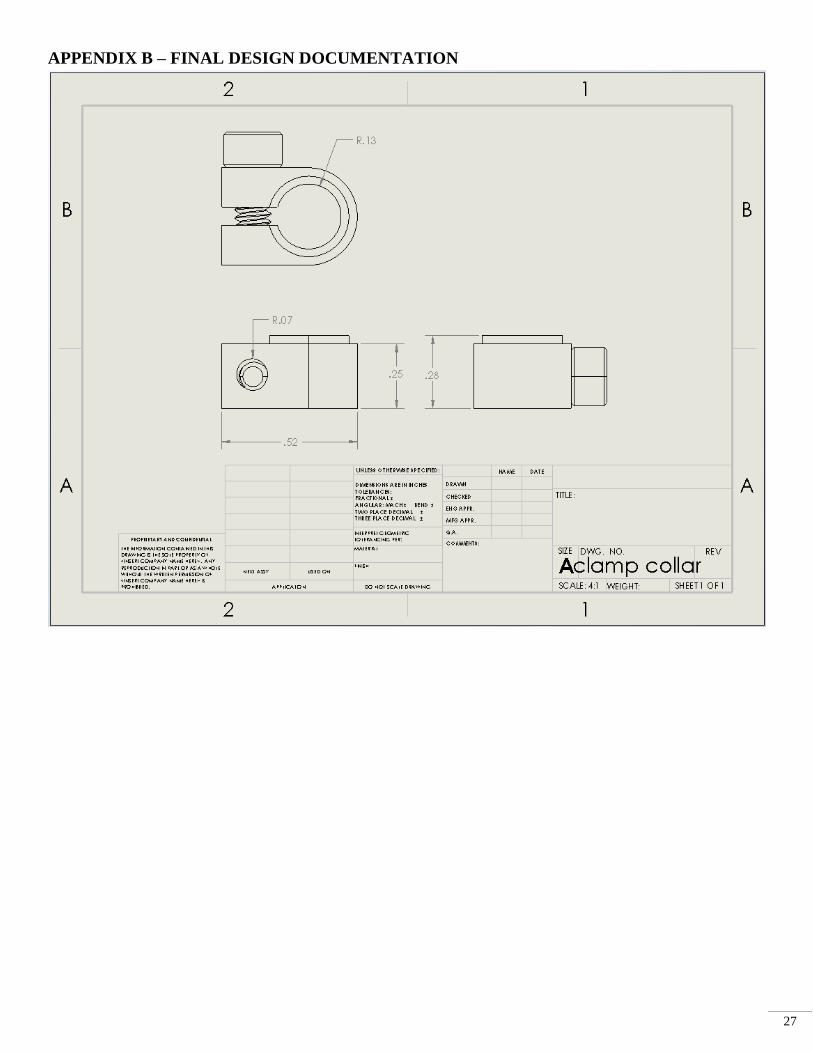
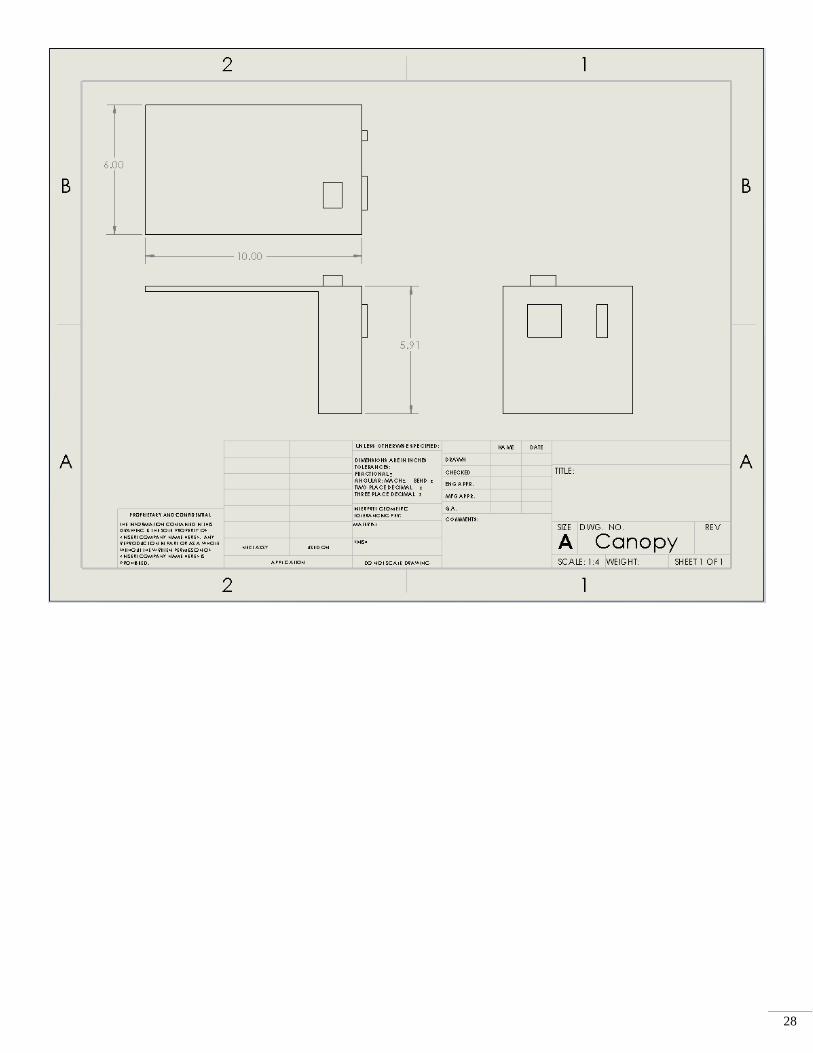
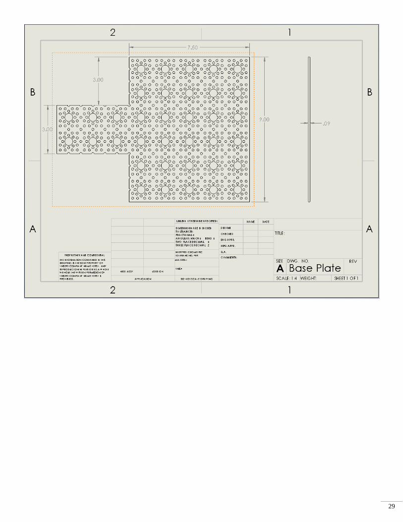
APPENDIX B – FINAL DESIGN DOCUMENTATION
28
29

30
BIBLIOGRAPHY
[1] https://www.rcplanet.com/traxxas-trx-4-tactical-crawler-tra82066-4/

31
[2] https://www.tmart.com/HuiNa-Toys-1550-15-Channel-2-4G-1-12-RC-Metal-Excavator-Toy-Yellow-Black
[3] https://www.amazon.com/Fisca-Tank-Channel-Remote-
Control/dp/B01MQKFRP4/ref=zg_bs_6925851011_6?_encoding=UTF8&psc=1&refRID=1F0GKGAZES06G35DPV8F