group 26 cool roommate - ucf department of eecs · group 26 cool roommate ... atmega328 pin mapping...
TRANSCRIPT
Friday, May 1, 2015
Group 26
Cool Roommate Senior Design 2 Project Documentation
Authors: Dennis Moy Shawn Mahon Junhao Liang Sponsored by: Leidos Engineering
Table of Contents 1 Executive Summary ............................................................................................ 1
2 Product Description ............................................................................................. 2
2.1 Purpose and scope of specification .............................................................. 3
2.2 Division of labor ............................................................................................ 3
3 Product/Service Description ................................................................................ 4
3.1 Relevant Technologies ................................................................................. 4
3.1.1 Home Automation Solutions ................................................................... 4
3.1.1.1 Conventional Thermostat Topology ................................................. 4
3.1.1.2 SmartThings .................................................................................... 5
3.1.1.3 Control4 ........................................................................................... 5
3.1.2 Components ........................................................................................... 6
3.1.2.1 Wireless Interconnect ...................................................................... 6
3.1.2.1.1 nRF24L01+ .................................................................................. 6
3.1.2.1.2 AIR BoosterPack CC110L ........................................................... 7
3.1.2.1.3 Part Decision ............................................................................... 9
3.1.2.2 Thermal Sensor ............................................................................... 9
3.1.2.2.1 LM35 .......................................................................................... 10
3.1.2.2.2 Thermistors ................................................................................ 10
3.1.2.2.3 Infrared Thermal Sensor ............................................................ 11
3.1.2.2.4 Part Decision ............................................................................. 12
3.1.2.3 Motor ............................................................................................. 12
3.1.2.3.1 Brushed DC Motors ................................................................... 12
3.1.2.3.2 Stepper Motors .......................................................................... 13
3.1.2.3.3 Servo Motors ............................................................................. 14
3.1.2.3.4 Part Decision ............................................................................. 15
3.1.2.4 Motor Controller ............................................................................. 15
3.1.2.4.1 Texas Instruments L293D .......................................................... 16
3.1.2.4.2 Texas Instruments LMD18200 ................................................... 17
3.1.2.4.3 Stepper Motor Driver ................................................................. 18
3.1.2.4.4 Part Decision ............................................................................. 19
3.1.2.5 Microcontroller for child unit ........................................................... 19
3.1.2.5.1 Atmel AVR UC3 L ...................................................................... 20
i
3.1.2.5.2 Atmel ATmega328P................................................................... 21
3.1.2.5.3 Texas Instruments MSP430 ...................................................... 22
3.1.2.5.4 Part Decision ............................................................................. 23
3.1.2.6 Microcontroller for Master Unit ....................................................... 25
3.1.2.6.1 Texas Instruments Tiva-C .......................................................... 25
3.1.2.6.2 Raspberry Pi .............................................................................. 27
3.1.2.6.3 BeagleBone Black ..................................................................... 28
3.1.2.6.4 Arduino ...................................................................................... 29
3.1.2.6.5 Part Decision ............................................................................. 30
3.1.2.7 LCD module ................................................................................... 31
3.1.2.7.1 Kentec LCD Boosterpack EB-LM4F120-L35 ............................. 31
3.1.2.8 Power Source ................................................................................ 32
3.1.2.8.1 Linear Regulator ........................................................................ 32
3.1.2.8.2 LDO Linear Regulator ................................................................ 33
3.1.2.8.3 Switching Regulator ................................................................... 33
3.1.3 Electronic Switching Techniques .......................................................... 34
3.1.3.1 Relay ............................................................................................. 35
3.1.3.2 Optoisolator ................................................................................... 36
3.1.4 HVAC Control ....................................................................................... 36
3.1.5 Battery Topologies ............................................................................... 38
3.1.5.1 Sealed Lead Acid ........................................................................... 38
3.1.5.2 Lithium-ion Polymer ....................................................................... 38
3.1.5.3 Lithium phosphate (LiFePO4) ......................................................... 39
3.1.6 Prototype Production ............................................................................ 39
3.1.6.1 PCB production .............................................................................. 40
3.1.6.2 Hand Soldered Components ......................................................... 40
3.1.6.3 Prepopulated Components ............................................................ 40
3.1.7 Software ............................................................................................... 41
3.1.7.1 Schematic layout ........................................................................... 41
3.1.7.1.1 EAGLE ....................................................................................... 41
3.1.7.1.2 KiCAD ........................................................................................ 42
3.1.7.2 Programming Language ................................................................ 42
3.1.7.2.1 Assembly Language .................................................................. 42
ii
3.1.7.2.2 Ada ............................................................................................ 43
3.1.7.2.3 Java Platform, Micro Edition ...................................................... 44
3.1.7.2.4 Embedded C++ ......................................................................... 45
3.1.7.2.5 Programming Language Decision ............................................. 45
3.1.7.3 Integrated Development Environment ........................................... 46
3.1.7.3.1 Texas Instruments Code Composer Studio ............................... 46
3.1.7.3.2 Arduino ...................................................................................... 48
3.1.7.3.3 Energia ...................................................................................... 50
3.1.7.3.4 Atmel Studio .............................................................................. 52
3.1.7.3.5 IDE Decision .............................................................................. 53
3.2 Assumptions ............................................................................................... 53
3.2.1 Communication .................................................................................... 53
3.2.2 Automation ........................................................................................... 54
3.2.3 Battery Life ........................................................................................... 54
3.3 Constraints .................................................................................................. 54
3.3.1 Hardware Performance ........................................................................ 54
3.3.2 Power ................................................................................................... 54
3.3.3 Time ..................................................................................................... 54
3.4 Dependencies ............................................................................................. 54
3.4.1 Connectivity .......................................................................................... 54
3.4.2 Battery Life ........................................................................................... 55
4 Impact of Realistic Design Contraints ................................................................ 55
4.1 Economic .................................................................................................... 55
4.2 Environmental ............................................................................................. 55
4.3 Social .......................................................................................................... 55
5 Indentification of Related Standards and Laws ................................................. 56
5.1 Home Energy Rating System ...................................................................... 56
5.2 ISM Band Regulations ................................................................................ 56
6 Requirements .................................................................................................... 57
6.1 Functional requirements ............................................................................. 57
6.2 Sensors....................................................................................................... 57
6.3 Communication ........................................................................................... 58
6.4 Usability ...................................................................................................... 58
6.5 Performance ............................................................................................... 58
iii
6.5.1 Capacity ............................................................................................... 58
6.5.2 Availability ............................................................................................ 58
6.5.3 Latency ................................................................................................. 59
7 Project Hardware and Software Design Details ................................................. 59
7.1 Initial Design Architecture and Related Diagrams ....................................... 59
7.2 Logic Controller ........................................................................................... 62
7.2.1 Master Controller .................................................................................. 62
7.2.2 Slave Controller .................................................................................... 62
7.3 Energy ........................................................................................................ 62
7.4 Memory Allocation ...................................................................................... 62
7.5 Direct memory access ................................................................................ 62
7.5.1 Multiple low-power modes .................................................................... 63
7.5.2 Real-time clock ..................................................................................... 63
7.5.3 Low Level Network Communication ..................................................... 63
7.5.3.1 RF System Air modules CC110L ................................................... 63
7.5.4 Power ................................................................................................... 65
7.5.5 Sensors and control ............................................................................. 65
7.5.5.1 HVAC control ................................................................................. 65
7.5.5.2 Temperature .................................................................................. 65
7.5.5.3 Fan Control .................................................................................... 65
7.5.5.4 Window Control ............................................................................. 66
7.5.5.5 Vent Control ................................................................................... 66
7.5.5.6 Appliance Expansion ..................................................................... 66
7.5.6 High Level Network Management ........................................................ 66
7.5.6.1 Master to slave link ........................................................................ 66
7.5.6.2 Outside of the grid ......................................................................... 67
8 Design and Summary of Hardware Specification .............................................. 67
8.1 MCU ........................................................................................................... 67
8.1.1 TM4C1294NCPDT ............................................................................... 67
8.1.2 MSP430G2553 ..................................................................................... 69
8.2 RF module .................................................................................................. 70
8.2.1 A110LR09A .......................................................................................... 70
8.3 Temperature Sensor ................................................................................... 70
8.3.1 LM35 .................................................................................................... 70
iv
8.4 Motor Controller .......................................................................................... 71
8.4.1 LMD18200 ............................................................................................ 71
8.5 LCD Touch Screen ..................................................................................... 71
8.5.1 EB-LM4F120-L35 ................................................................................. 71
9 Design Summary of Software Code .................................................................. 72
9.1 UI ................................................................................................................ 72
9.2 Libraries ...................................................................................................... 72
9.3 Language .................................................................................................... 72
10 Project Prototype Construction and Coding....................................................... 72
10.1 Hardware Prototype Testing Memo ......................................................... 72
10.1.1 RF Transceiver Testing ..................................................................... 72
10.1.2 RF Transceiver and Wi-Fi Testing .................................................... 73
10.1.3 Wi-Fi Module and SensorHub Testing .............................................. 75
10.1.4 LCD Touch Screen Testing ............................................................... 76
10.1.5 PCB Design ...................................................................................... 77
10.2 Parts Acquisition and Bill of Materials ...................................................... 78
10.3 Printed Circuit Board ............................................................................... 79
10.4 Final Coding ............................................................................................ 81
11 Project Prototype and Testing ........................................................................... 84
11.1 Hardware Testing .................................................................................... 84
11.1.1 Relay Test ......................................................................................... 85
11.1.2 Temperature Sensor ......................................................................... 85
11.1.3 LCD Module ...................................................................................... 85
11.1.4 Wireless Module ............................................................................... 85
11.1.5 Motor Control .................................................................................... 85
11.1.6 Comprehensive Testing .................................................................... 86
11.2 Software Testing ...................................................................................... 86
11.2.1 Display .............................................................................................. 86
11.2.2 RF Module ........................................................................................ 86
11.2.3 Servo Motor ...................................................................................... 86
12 Administrative Content ...................................................................................... 87
12.1 Milestone Discussion ............................................................................... 87
12.1.1 Senior Design I ................................................................................. 87
12.1.2 Senior Design II ................................................................................ 88
v
12.2 Budget and Finance Discussion .............................................................. 89
12.2.1 Sponsors ........................................................................................... 89
12.3 Final Thoughts and Lasting Impressions ................................................. 90
Copyright Permissions ........................................................................ A
References .......................................................................................... B
Figures Figure 1 : Cool Roommate Logo ................................................................................ 2 Figure 2 : Division of Labor ........................................................................................ 3 Figure 3 : nRF24L01+ Radio with Pin Labelled .......................................................... 6 Figure 4 : nRF24L01+ block diagram ......................................................................... 7 Figure 5 : CC110L Air BoosterPack ........................................................................... 8 Figure 6 : Basic Centigrade Temperature Sensor .................................................... 10 Figure 7 : Brushed DC Motor Diagram ..................................................................... 13 Figure 8 : NEMA 17 Stepper Motor .......................................................................... 14 Figure 9 : Servo Motor Block Diagram ..................................................................... 14 Figure 10 : Motor Controller Block Diagram ............................................................. 16 Figure 11 : Bidirectional DC Motor Control using L293D ......................................... 17 Figure 12 : LMD18200 Typical Application .............................................................. 18 Figure 13 : AT32UC3L032 Pinout ............................................................................ 20 Figure 14 : ATmega328 Pin Mapping ...................................................................... 21 Figure 15 : MSP430 Pinout ...................................................................................... 22 Figure 16 : Functional Diagram of MSP430G2553 .................................................. 23 Figure 17 : TM4C1294NCPDT Functional Diagram ................................................. 26 Figure 18 : Raspberry Pi Software Architecture ....................................................... 27 Figure 19 : AM335x processor block diagram .......................................................... 28 Figure 20 : SAM3X ARM Cortex-M3 Architecture .................................................... 29 Figure 21 : Simple 5V Voltage Regulator using LM2825 ......................................... 34 Figure 22 : Circuit Symbols of Relays ...................................................................... 35 Figure 23 : Optoisolator Diagram ............................................................................. 36 Figure 24 : HVAC Wiring Diagram ........................................................................... 37 Figure 25 : Comparison between Classic CCS UI and CCS Simple UI ................... 47 Figure 26 : Screenshot of Arduino IDE with Sample Code ...................................... 49 Figure 27 : Screenshot of Energia with Sample Code ............................................. 51 Figure 28 : Screenshot of Atmel Studio with Example Code .................................... 53 Figure 29 : CC110L RF BoosterPack Layout ........................................................... 64 Figure 30 : RF Transceiver Testing Flowchart for Hub and Sensor ......................... 73 Figure 31 : RF Transceiver Testing with Wi-Fi Function Test .................................. 74 Figure 32 : SensorHub Testing with Wi-Fi Module ................................................... 76 Figure 33 : LCD Touch Screen Test with Sample UI ............................................... 77 Figure 34 :Slave PCB ............................................................................................. 78 Figure 35 : Bill of Materials ...................................................................................... 79 Figure 35 : Power Source Schematic Example ........................................................ 80
vi
Figure 36 : MSP430G2553 Schematic Example ...................................................... 80 Figure 37 : Relay Schematic Layout Example ......................................................... 81 Figure 38 : Master Controller Flowchart ................................................................... 82 Figure 39 : Slave Controller Flowchart ..................................................................... 83 Figure 40 : Child Controller Flowchart ...................................................................... 84 Figure 41 : Milestone of Senior Design I .................................................................. 87 Figure 42 : Milestone of Senior Design II ................................................................. 88
Tables Table 1: Low Level Wireless Communication Comparison ........................................ 9 Table 2: Thermal Sensor Comparison ..................................................................... 12 Table 3: Motor Comparison ..................................................................................... 15 Table 4: Motor Controller Comparison ..................................................................... 19 Table 5 : Child Controller MCU Comparison ............................................................ 24 Table 6 : Master/Slave Platform Comparison .......................................................... 31 Table 7 : Conventional HVAC Wiring ....................................................................... 37 Table 8: TM4C1294NCPDT Specification ................................................................ 69 Table 9: MSP430G2553 Specification ..................................................................... 70 Table 10: A110LR09A Specification ........................................................................ 70 Table 11: LM35 Specification ................................................................................... 71 Table 12: LMD18200 Specification .......................................................................... 71 Table 13: EB-LM4F120-L35 ..................................................................................... 72 Table 14: Pin Mapping ............................................................................................. 75 Table 15: Budget...................................................................................................... 89
Equations Equation 1 : Power Loss for Linear Voltage Regulators ........................................... 32
vii
1 Executive Summary The “Cool Roommate” system will be a third party, A.I. system, capable of controlling temperature environments using household infrastructure such as Air Conditioning units, ceiling fans, window shades, and air vents. The system will operate on user input and restrictions to satisfy the individual need. The “Cool Roommate” system has the ability to maximize the energy efficiency from the current costly model of cooling your home. The “Cool Roommate” will be able to provide the following key features:
• Evaluate current temperature conditions: The system will actively monitor temperature conditions and response will be based off of user input.
• Controlling the thermostat: A user will be able to specify what temperature they would like their home to be cooled to.
• Specifying “target” zones: A user can be able to use the application to
designate which rooms the cooling system should focus on. Several risks must be addressed in development of the “Cool Roommate”, they are the following:
• Usability: The “Cool Roommate” user interface must be easy to use, otherwise primary clients may have trouble accessing and understanding the resources available provide by the system.
• Rapid development: The schedule designed should be considered
aggressive and fast-paced. The quality of the system should not be sacrificed for the complexity as a result of rapid development.
• Maintaining Consistency: The system must be able to compute and
exercise tasks without running into errors. There are several parameters within the system that must be thought of in order to have a functioning design.
1
2 Product Description In the recent years, cooling and energy efficiency has become a hot topic. In the United States, Americans spend billions a year to power air conditioners alone. With the new innovative cooling technology, you can rest at ease knowing that you will be actively reducing your energy bill every month.The logo designed for the Cool Roommate is shown in Figure 1.
Figure 1 : Cool Roommate Logo
The concept of Cool Roommate is to automate your home cooling system in the most efficient and effective way. With multiple temperature sensors throughout the environment, cooling vents can be controlled to open and close for maximum efficiency of airflow and distribution. Each room in the house will contain a configurable climate control. For example, if you have a server room and know that you will be away on vacation, you can program the system through an intuitive user interface to selectively cool a single or multiple rooms if necessary. To maximize efficiency, the system will also have the ability to distribute airflow by controlling ceiling fans. Ceiling fans cost significantly less to operate than a central air conditioning unit. Ceiling fans are also an easy way to circulate air to reduce temperature imbalances within a room.
2
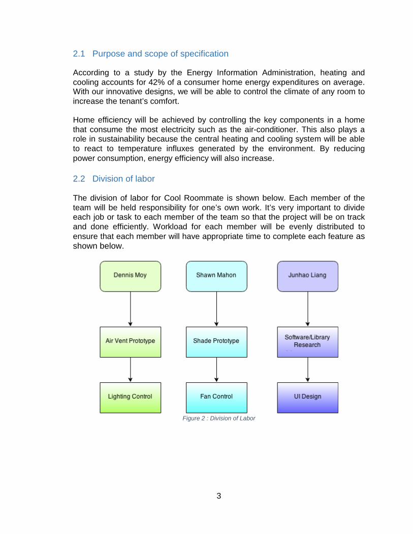
2.1 Purpose and scope of specification According to a study by the Energy Information Administration, heating and cooling accounts for 42% of a consumer home energy expenditures on average. With our innovative designs, we will be able to control the climate of any room to increase the tenant’s comfort. Home efficiency will be achieved by controlling the key components in a home that consume the most electricity such as the air-conditioner. This also plays a role in sustainability because the central heating and cooling system will be able to react to temperature influxes generated by the environment. By reducing power consumption, energy efficiency will also increase. 2.2 Division of labor The division of labor for Cool Roommate is shown below. Each member of the team will be held responsibility for one’s own work. It’s very important to divide each job or task to each member of the team so that the project will be on track and done efficiently. Workload for each member will be evenly distributed to ensure that each member will have appropriate time to complete each feature as shown below.
Figure 2 : Division of Labor
3
3 Product/Service Description 3.1 Relevant Technologies There are currently relevant technologies that exist on a larger scale that aim to improve overall efficiency of homes through wireless communication between a home owner and their devices. The Cool Roommate will aim to improve efficiency of a households HVAC system, and will have capabilities for future growth and integration of additional household activities. An HVAC system is critical to the development for any system’s goal for a Smart Home, where devices that exist in the home are able to communicate. The Senior Design team feels that the current technologies do not do enough for a home HVAC system when dealing with the efficiency of the overall system. The Cool Roommate is being designed to target the inadequacy of the HVAC system.
3.1.1 Home Automation Solutions 3.1.1.1 Conventional Thermostat Topology In the 21st century, a digital thermostat is most commonly used in an indoor environment. One of the greatest features of a digital thermostat is programmability. With more advanced digital thermostats; a weekly schedule can be made with different temperatures set throughout any day of the week. Digital thermostats typically contain a thermistor to measure temperature. A thermistor is a resistor that can change resistance depending on temperature. This component can then be applied to a thermostat by measuring its resistance and converting it to a temperature. Then activate the cooling or heating function to adjust accordingly. Advantages
• No moving parts • Higher accuracy than mechanical thermostats • More programmable features
Disadvantages
• May become costly depending on feature set • Advanced features may not be user friendly
The Cool Roommate plans to add to the capabilities of a traditional thermostat. Current digital thermostats are only capable of measuring temperature, and are not responsible for air flow. The Cool Roommate will be able to optimize the temperature of the household, while contributing to overall efficiency.
4
3.1.1.2 SmartThings SmartThings is a building automation platform that allows and enables consumers to connect, manage, and monitor their home. The whole concept incorporates modularity. A few examples of some of the features are locks, light switches, outlets, and thermostats. The SmartThings platform is compatible with Z-Wave, ZigBee, and Wi-Fi connected devices. Advantages
• Modular design • Compatibility • Future expansion platform
Disadvantages
• Software not fully developed • Cannot control temperature of individual rooms
Due to the fact that the software is not fully developed it may cause issues with connectivity between user and interface, the Cool Roommate aims to provide the ultimate user experience by controlling temperatures and air flow of the household. The design system in Cool Roommate is optimized for future growth and development. 3.1.1.3 Control4 Control4 offers a complete home automation solution by integrated existing devices within a home to work seamlessly together. The system can also be personalized to provide the best experience towards comfort, savings, and convenience. Control4 can offer flexible solutions starting from a single room to a whole complete solution. Advantages
• Flexibility • Complete integration solution available • Wireless
Disadvantages
• Cost A complete automation solution can be very costly as seen in the Control4 solutions. The Cool Roommate has a design made to replicate the flexibility and complete integration between a user and a household air conditioning unit while keeping the cost low and within the scope of the Senior Design course. The design system in Cool Roommate is optimized for future growth and development.
5
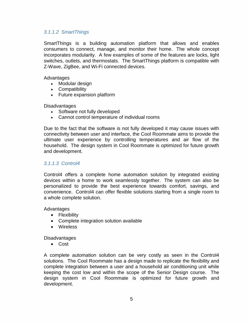
3.1.2 Components In order to design and implement the Cool Roommate within the appropriate budget and time, extensive research when into the advantages and disadvantages of the individual components for the system. The decision to integrate a component was made on several factors overall on what would be most efficient. 3.1.2.1 Wireless Interconnect In some newer homes, wires may become a costly clutter while wireless solutions can offer higher flexibility without the need of running wires through walls. Performance of wireless solutions has increased in the recent years offering high throughput using the least amount of power. The best solution for the low level wireless interconnects should contain good documentation, high throughput, energy efficiency, and low cost. 3.1.2.1.1 nRF24L01+ Integrated ultra-low powered wireless transceiver module. The module is capable of transmitting up to 2 megabits per second through the 2.4 GHz ISM band. The module is highly versatile and can be powered by 1.9-3.6 Volts. According to its specifications, the module can run off of coin cells or AA/AAA batteries for months to years. Libraries are readily available and can be used for immediate software development of projects through the use of the Arduino IDE using ATMEL ATMEGA328P integrated circuits.
Figure 3 : nRF24L01+ Radio with Pin Labelled
Advantages
• Community support when using Arduino • Libraries readily available
6
• Only approximately $8 shipped from amazon Disadvantages
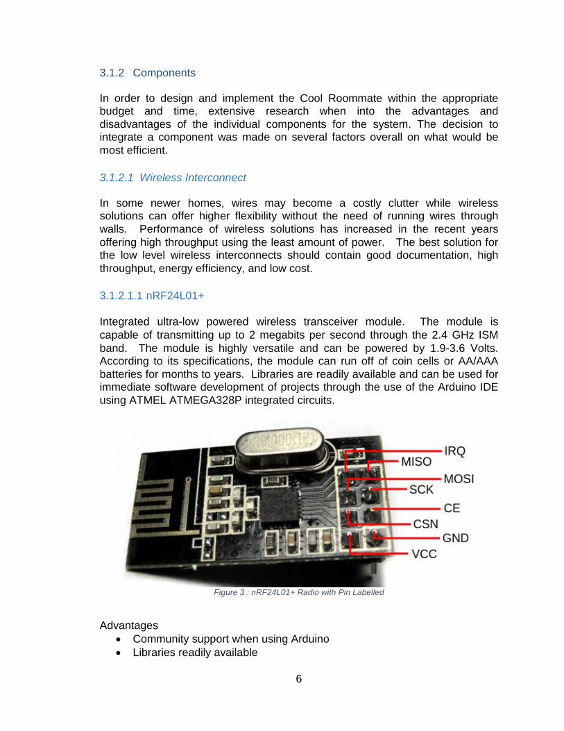
• Backup plan The block diagram for the nRF24L01+ diagram is shown below .
Figure 4 : nRF24L01+ block diagram
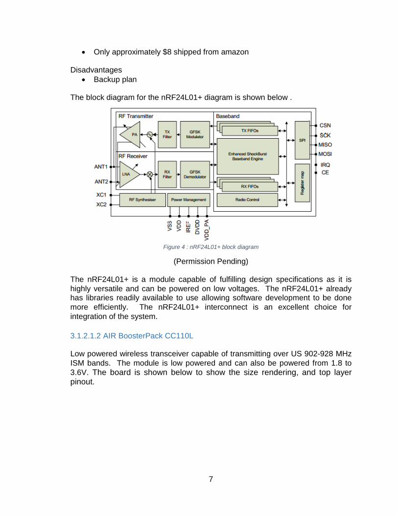
(Permission Pending) The nRF24L01+ is a module capable of fulfilling design specifications as it is highly versatile and can be powered on low voltages. The nRF24L01+ already has libraries readily available to use allowing software development to be done more efficiently. The nRF24L01+ interconnect is an excellent choice for integration of the system. 3.1.2.1.2 AIR BoosterPack CC110L Low powered wireless transceiver capable of transmitting over US 902-928 MHz ISM bands. The module is low powered and can also be powered from 1.8 to 3.6V. The board is shown below to show the size rendering, and top layer pinout.
7
Figure 5 : CC110L Air BoosterPack
(Courtesy of Texas Instruments) Advantages
• Free courtesy of Texas Instruments • Compatible with Texas Instruments MSP430 microcontroller • Operates at low powers
Disadvantages
• Texas Instruments Code Composer is not user friendly • Programming development may not be feasible with given timeframe
The AIR BoosterPack CC110L is an ideal transmitter as it provides wireless transceiver capabilities at low power. The software development may prove to be problematic since its primary development environment is does not provide the software developers with an accessible library. The AIR BoosterPack CC110L is free and is an excellent candidate for system integration.
8
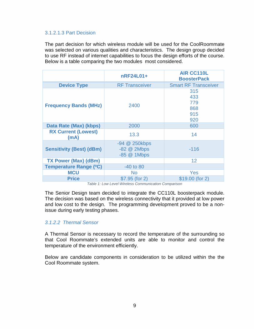
3.1.2.1.3 Part Decision The part decision for which wireless module will be used for the CoolRoommate was selected on various qualities and characteristics. The design group decided to use RF instead of internet capabilities to focus the design efforts of the course. Below is a table comparing the two modules most considered.
nRF24L01+ AIR CC110L BoosterPack
Device Type RF Transceiver Smart RF Transceiver
Frequency Bands (MHz) 2400
315 433 779 868 915 920
Data Rate (Max) (kbps) 2000 600 RX Current (Lowest)
(mA) 13.3 14
Sensitivity (Best) (dBm) -94 @ 250kbps -82 @ 2Mbps -85 @ 1Mbps
-116
TX Power (Max) (dBm) 12 Temperature Range (oC) -40 to 80
MCU No Yes Price $7.95 (for 2) $19.00 (for 2)
Table 1: Low Level Wireless Communication Comparison
The Senior Design team decided to integrate the CC110L boosterpack module. The decision was based on the wireless connectivity that it provided at low power and low cost to the design. The programming development proved to be a non-issue during early testing phases. 3.1.2.2 Thermal Sensor A Thermal Sensor is necessary to record the temperature of the surrounding so that Cool Roommate’s extended units are able to monitor and control the temperature of the environment efficiently. Below are candidate components in consideration to be utilized within the the Cool Roommate system.
9
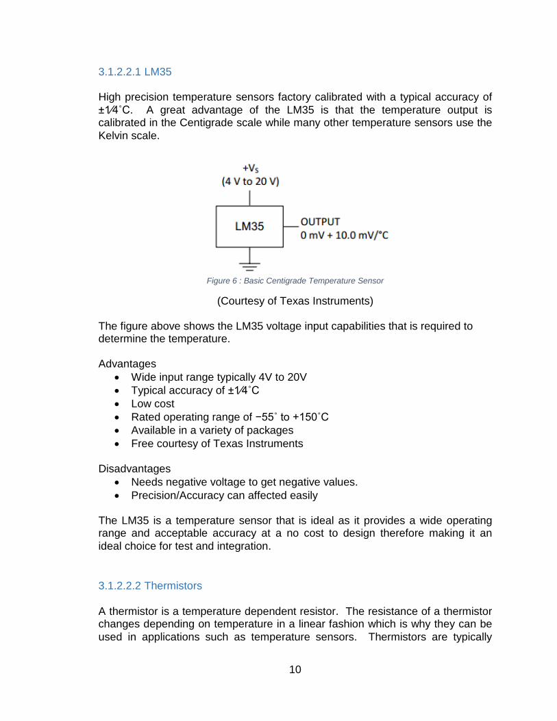
3.1.2.2.1 LM35 High precision temperature sensors factory calibrated with a typical accuracy of ±1⁄4˚C. A great advantage of the LM35 is that the temperature output is calibrated in the Centigrade scale while many other temperature sensors use the Kelvin scale.
Figure 6 : Basic Centigrade Temperature Sensor
(Courtesy of Texas Instruments)
The figure above shows the LM35 voltage input capabilities that is required to determine the temperature. Advantages
• Wide input range typically 4V to 20V • Typical accuracy of ±1⁄4˚C • Low cost • Rated operating range of −55˚ to +150˚C • Available in a variety of packages • Free courtesy of Texas Instruments
Disadvantages
• Needs negative voltage to get negative values. • Precision/Accuracy can affected easily
The LM35 is a temperature sensor that is ideal as it provides a wide operating range and acceptable accuracy at a no cost to design therefore making it an ideal choice for test and integration. 3.1.2.2.2 Thermistors A thermistor is a temperature dependent resistor. The resistance of a thermistor changes depending on temperature in a linear fashion which is why they can be used in applications such as temperature sensors. Thermistors are typically
10
made using a ceramic material which contains properties that contribute to how they can change resistance due to temperature differences. A typical thermistor can measure temperatures of -40 to 150°C with an accuracy of ±0.02 °C and are available in different shapes such as a bead, rod, and more. Typical resistance of a thermistor can vary from ohms to mega ohms. An example of a thermistor currently mass produced and readily available by Texas Instruments is INA330. Advantages
• High accuracy ±0.02 °C • Low Cost
Disadvantages
• Unsuitable at higher temperature ranges. Thermistors are a good candidate for use as they have high stability and repeatability. The high accuracy is necessary for optimal design and efficiency of machine. The disadvantage is not to be considered as the higher bounds of the temperature range is not relevant to our system. 3.1.2.2.3 Infrared Thermal Sensor Infrared thermometer sensors are designed to sense temperature without contacting the perspective object to be measured. Infrared sensors utilize high precision and low latency in every thermal reading. The use of infrared sensors can allow measurement of hazardous or inaccessible objects because it does not require contact to sense the temperature. Another great benefit of using infrared temperature sensors is that they can provide accurate measurements for objects at high temperatures. TMP006 is an example of an infrared thermopile sensor manufactured by Texas Instruments. Advantages
• Measurements can be taken from a distance • No contact necessary for measurements
Disadvantages
• Cannot be used to sense gas or liquids • May become costly
Using an infrared thermometer sensor allows for measurements to be taken from a distance and should be able to help maintain accuracy of the system design. The expense of the sensor must be taken into consideration for the scope and size of the budget for the Senior Design course.
11
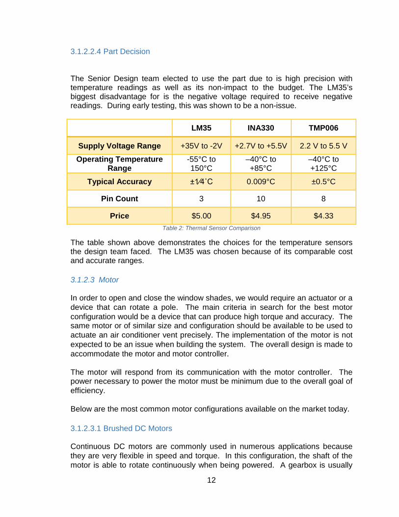
3.1.2.2.4 Part Decision The Senior Design team elected to use the part due to is high precision with temperature readings as well as its non-impact to the budget. The LM35’s biggest disadvantage for is the negative voltage required to receive negative readings. During early testing, this was shown to be a non-issue.
LM35 INA330 TMP006
Supply Voltage Range +35V to -2V +2.7V to +5.5V 2.2 V to 5.5 V Operating Temperature
Range -55°C to 150°C
–40°C to +85°C
–40°C to +125°C
Typical Accuracy ±1⁄4˚C 0.009°C ±0.5°C
Pin Count 3 10 8
Price $5.00 $4.95 $4.33 Table 2: Thermal Sensor Comparison
The table shown above demonstrates the choices for the temperature sensors the design team faced. The LM35 was chosen because of its comparable cost and accurate ranges. 3.1.2.3 Motor In order to open and close the window shades, we would require an actuator or a device that can rotate a pole. The main criteria in search for the best motor configuration would be a device that can produce high torque and accuracy. The same motor or of similar size and configuration should be available to be used to actuate an air conditioner vent precisely. The implementation of the motor is not expected to be an issue when building the system. The overall design is made to accommodate the motor and motor controller. The motor will respond from its communication with the motor controller. The power necessary to power the motor must be minimum due to the overall goal of efficiency. Below are the most common motor configurations available on the market today. 3.1.2.3.1 Brushed DC Motors Continuous DC motors are commonly used in numerous applications because they are very flexible in speed and torque. In this configuration, the shaft of the motor is able to rotate continuously when being powered. A gearbox is usually
12
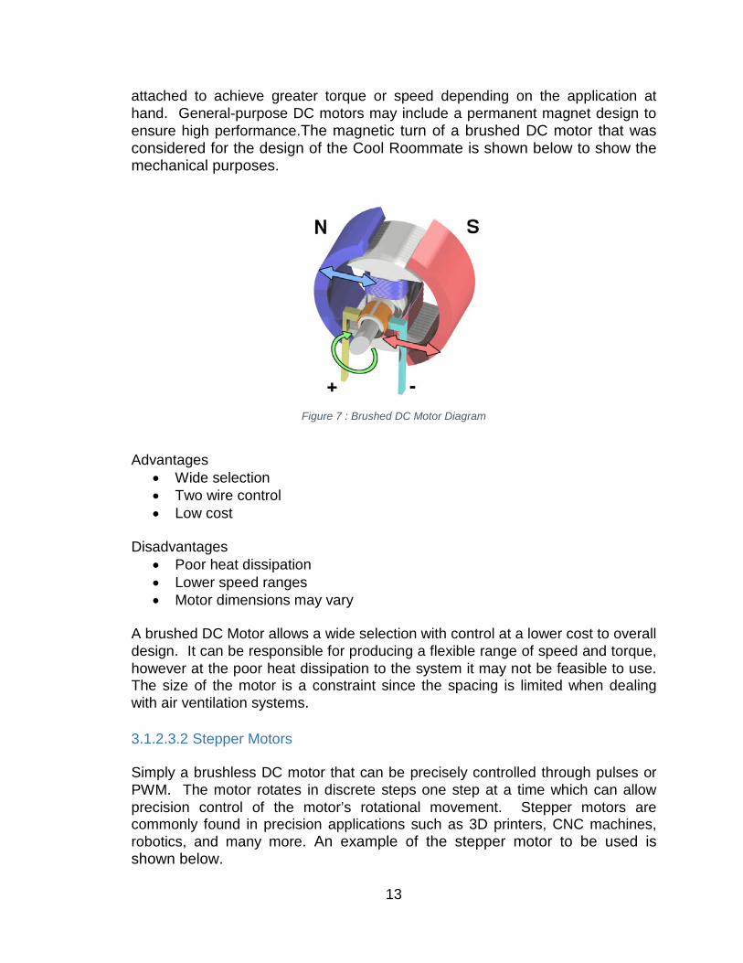
attached to achieve greater torque or speed depending on the application at hand. General-purpose DC motors may include a permanent magnet design to ensure high performance.The magnetic turn of a brushed DC motor that was considered for the design of the Cool Roommate is shown below to show the mechanical purposes.
Figure 7 : Brushed DC Motor Diagram
Advantages
• Wide selection • Two wire control • Low cost
Disadvantages
• Poor heat dissipation • Lower speed ranges • Motor dimensions may vary
A brushed DC Motor allows a wide selection with control at a lower cost to overall design. It can be responsible for producing a flexible range of speed and torque, however at the poor heat dissipation to the system it may not be feasible to use. The size of the motor is a constraint since the spacing is limited when dealing with air ventilation systems. 3.1.2.3.2 Stepper Motors Simply a brushless DC motor that can be precisely controlled through pulses or PWM. The motor rotates in discrete steps one step at a time which can allow precision control of the motor’s rotational movement. Stepper motors are commonly found in precision applications such as 3D printers, CNC machines, robotics, and many more. An example of the stepper motor to be used is shown below.
13
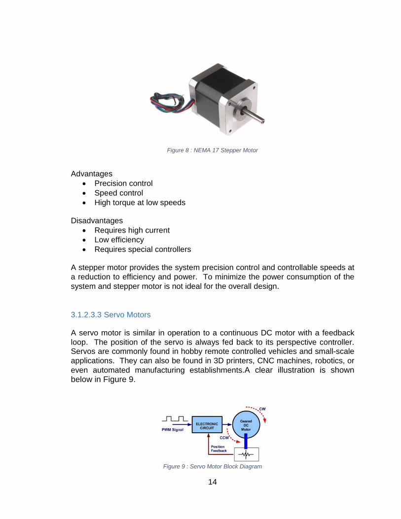
Figure 8 : NEMA 17 Stepper Motor
Advantages
• Precision control • Speed control • High torque at low speeds
Disadvantages
• Requires high current • Low efficiency • Requires special controllers
A stepper motor provides the system precision control and controllable speeds at a reduction to efficiency and power. To minimize the power consumption of the system and stepper motor is not ideal for the overall design. 3.1.2.3.3 Servo Motors A servo motor is similar in operation to a continuous DC motor with a feedback loop. The position of the servo is always fed back to its perspective controller. Servos are commonly found in hobby remote controlled vehicles and small-scale applications. They can also be found in 3D printers, CNC machines, robotics, or even automated manufacturing establishments.A clear illustration is shown below in Figure 9.
Figure 9 : Servo Motor Block Diagram
14
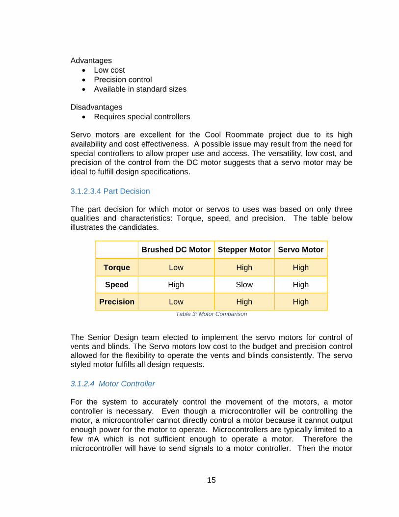
Advantages
• Low cost • Precision control • Available in standard sizes
Disadvantages
• Requires special controllers Servo motors are excellent for the Cool Roommate project due to its high availability and cost effectiveness. A possible issue may result from the need for special controllers to allow proper use and access. The versatility, low cost, and precision of the control from the DC motor suggests that a servo motor may be ideal to fulfill design specifications. 3.1.2.3.4 Part Decision The part decision for which motor or servos to uses was based on only three qualities and characteristics: Torque, speed, and precision. The table below illustrates the candidates.
Brushed DC Motor Stepper Motor Servo Motor
Torque Low High High
Speed High Slow High
Precision Low High High Table 3: Motor Comparison
The Senior Design team elected to implement the servo motors for control of vents and blinds. The Servo motors low cost to the budget and precision control allowed for the flexibility to operate the vents and blinds consistently. The servo styled motor fulfills all design requests. 3.1.2.4 Motor Controller For the system to accurately control the movement of the motors, a motor controller is necessary. Even though a microcontroller will be controlling the motor, a microcontroller cannot directly control a motor because it cannot output enough power for the motor to operate. Microcontrollers are typically limited to a few mA which is not sufficient enough to operate a motor. Therefore the microcontroller will have to send signals to a motor controller. Then the motor
15
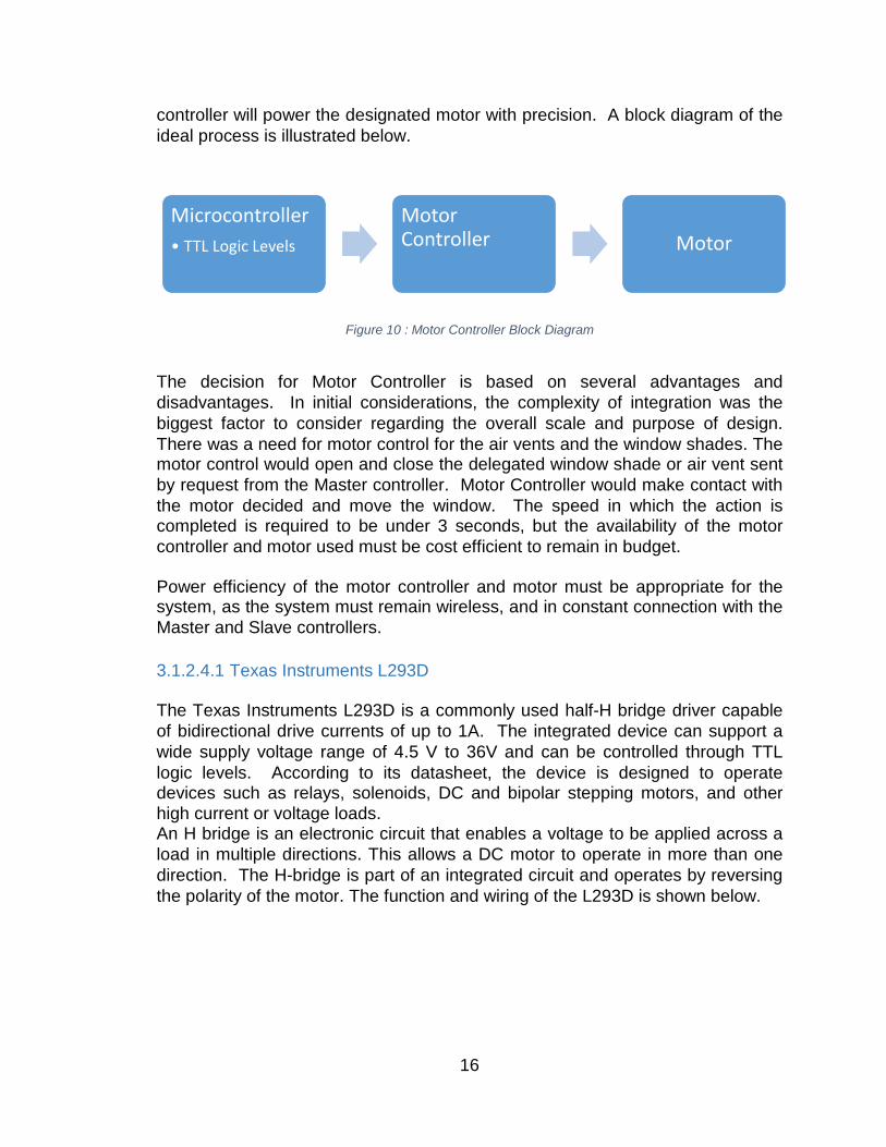
controller will power the designated motor with precision. A block diagram of the ideal process is illustrated below.
Figure 10 : Motor Controller Block Diagram
The decision for Motor Controller is based on several advantages and disadvantages. In initial considerations, the complexity of integration was the biggest factor to consider regarding the overall scale and purpose of design. There was a need for motor control for the air vents and the window shades. The motor control would open and close the delegated window shade or air vent sent by request from the Master controller. Motor Controller would make contact with the motor decided and move the window. The speed in which the action is completed is required to be under 3 seconds, but the availability of the motor controller and motor used must be cost efficient to remain in budget. Power efficiency of the motor controller and motor must be appropriate for the system, as the system must remain wireless, and in constant connection with the Master and Slave controllers. 3.1.2.4.1 Texas Instruments L293D The Texas Instruments L293D is a commonly used half-H bridge driver capable of bidirectional drive currents of up to 1A. The integrated device can support a wide supply voltage range of 4.5 V to 36V and can be controlled through TTL logic levels. According to its datasheet, the device is designed to operate devices such as relays, solenoids, DC and bipolar stepping motors, and other high current or voltage loads. An H bridge is an electronic circuit that enables a voltage to be applied across a load in multiple directions. This allows a DC motor to operate in more than one direction. The H-bridge is part of an integrated circuit and operates by reversing the polarity of the motor. The function and wiring of the L293D is shown below.
Microcontroller• TTL Logic Levels
Motor Controller Motor
16
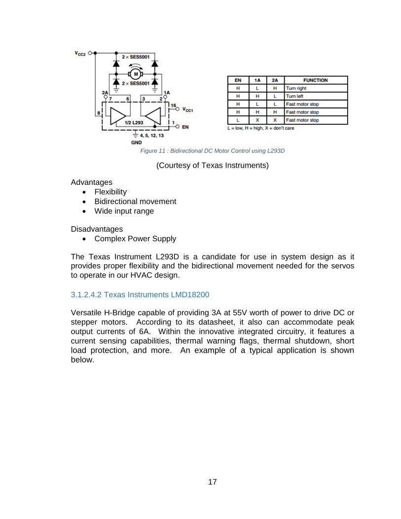
Figure 11 : Bidirectional DC Motor Control using L293D
(Courtesy of Texas Instruments) Advantages
• Flexibility • Bidirectional movement • Wide input range
Disadvantages
• Complex Power Supply The Texas Instrument L293D is a candidate for use in system design as it provides proper flexibility and the bidirectional movement needed for the servos to operate in our HVAC design. 3.1.2.4.2 Texas Instruments LMD18200 Versatile H-Bridge capable of providing 3A at 55V worth of power to drive DC or stepper motors. According to its datasheet, it also can accommodate peak output currents of 6A. Within the innovative integrated circuitry, it features a current sensing capabilities, thermal warning flags, thermal shutdown, short load protection, and more. An example of a typical application is shown below.
17
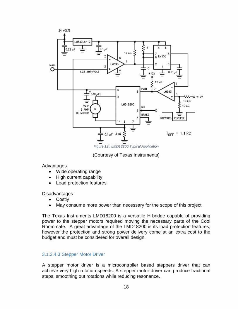
Figure 12 : LMD18200 Typical Application
(Courtesy of Texas Instruments) Advantages
• Wide operating range • High current capability • Load protection features
Disadvantages
• Costly • May consume more power than necessary for the scope of this project
The Texas Instruments LMD18200 is a versatile H-bridge capable of providing power to the stepper motors required moving the necessary parts of the Cool Roommate. A great advantage of the LMD18200 is its load protection features; however the protection and strong power delivery come at an extra cost to the budget and must be considered for overall design. 3.1.2.4.3 Stepper Motor Driver A stepper motor driver is a microcontroller based steppers driver that can achieve very high rotation speeds. A stepper motor driver can produce fractional steps, smoothing out rotations while reducing resonance.
18
Advantages
• High Rotation Speeds • Precision Control • Fractional Stepping
Disadvantages
• Complex Power Supply • Limited Usage
A stepper motor driver is necessary to power a stepper motor. The extreme control allowed by the stepper motor driver is excellent and can make motor usage efficient and quiet. However the stepper motor driver will require additional power, and is only compatible for certain boards. 3.1.2.4.4 Part Decision The part decision for power supply was selected on qualities of efficiency and impact to overall budget. Below is a table that illustrates the two main choices for the Power supply.
L293D LMD18200
Supply Voltage 4.5 V to 36 V 60 V
Peak Output Current 1.2 A 6 A
Continuous Output Current 3 A 600 mA
Max Junction Temperature 150oC 150oC
Storage Temperature range (oC) -65 to 150 -40 to 150
Price $2.50 $17.01 Table 4: Motor Controller Comparison
The senior design team elected to use a Servo motor, as a result there is no longer a need to use a motor controller. This effectively reduces impact to budget, while maintaining usability of the system. Below is the pin out for the 3.1.2.5 Microcontroller for child unit A microcontroller is a crucial component within our home automation solution. This will be the logic of the design to interpret and control devices at times when it deems it to be necessary for operation. The microcontroller will be responsible
19
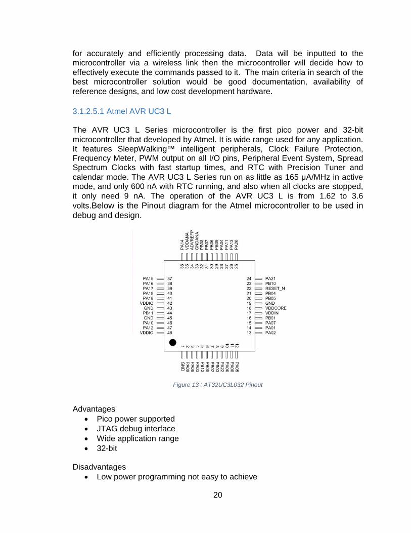
for accurately and efficiently processing data. Data will be inputted to the microcontroller via a wireless link then the microcontroller will decide how to effectively execute the commands passed to it. The main criteria in search of the best microcontroller solution would be good documentation, availability of reference designs, and low cost development hardware. 3.1.2.5.1 Atmel AVR UC3 L The AVR UC3 L Series microcontroller is the first pico power and 32-bit microcontroller that developed by Atmel. It is wide range used for any application. It features SleepWalking™ intelligent peripherals, Clock Failure Protection, Frequency Meter, PWM output on all I/O pins, Peripheral Event System, Spread Spectrum Clocks with fast startup times, and RTC with Precision Tuner and calendar mode. The AVR UC3 L Series run on as little as 165 μA/MHz in active mode, and only 600 nA with RTC running, and also when all clocks are stopped, it only need 9 nA. The operation of the AVR UC3 L is from 1.62 to 3.6 volts.Below is the Pinout diagram for the Atmel microcontroller to be used in debug and design.
Figure 13 : AT32UC3L032 Pinout
Advantages
• Pico power supported • JTAG debug interface • Wide application range • 32-bit
Disadvantages
• Low power programming not easy to achieve
20
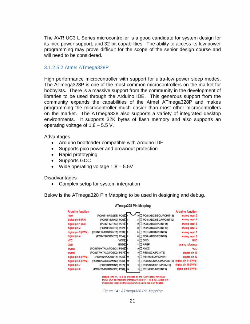
The AVR UC3 L Series microcontroller is a good candidate for system design for its pico power support, and 32-bit capabilities. The ability to access its low power programming may prove difficult for the scope of the senior design course and will need to be considered. 3.1.2.5.2 Atmel ATmega328P High performance microcontroller with support for ultra-low power sleep modes. The ATmega328P is one of the most common microcontrollers on the market for hobbyists. There is a massive support from the community in the development of libraries to be used through the Arduino IDE. This generous support from the community expands the capabilities of the Atmel ATmega328P and makes programming the microcontroller much easier than most other microcontrollers on the market. The ATmega328 also supports a variety of integrated desktop environments. It supports 32K bytes of flash memory and also supports an operating voltage of 1.8 – 5.5 V. Advantages
• Arduino bootloader compatible with Arduino IDE • Supports pico power and brownout protection • Rapid prototyping • Supports GCC • Wide operating voltage 1.8 – 5.5V
Disadvantages
• Complex setup for system integration Below is the ATmega328 Pin Mapping to be used in designing and debug.
Figure 14 : ATmega328 Pin Mapping
21
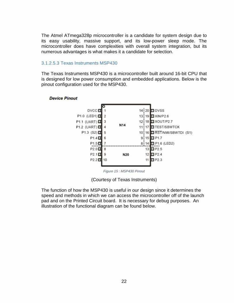
The Atmel ATmega328p microcontroller is a candidate for system design due to its easy usability, massive support, and its low-power sleep mode. The microcontroller does have complexities with overall system integration, but its numerous advantages is what makes it a candidate for selection. 3.1.2.5.3 Texas Instruments MSP430 The Texas Instruments MSP430 is a microcontroller built around 16-bit CPU that is designed for low power consumption and embedded applications. Below is the pinout configuration used for the MSP430.
Figure 15 : MSP430 Pinout
(Courtesy of Texas Instruments)
The function of how the MSP430 is useful in our design since it determines the speed and methods in which we can access the microcontroller off of the launch pad and on the Printed Circuit board. It is necessary for debug purposes. An illustration of the functional diagram can be found below.
22
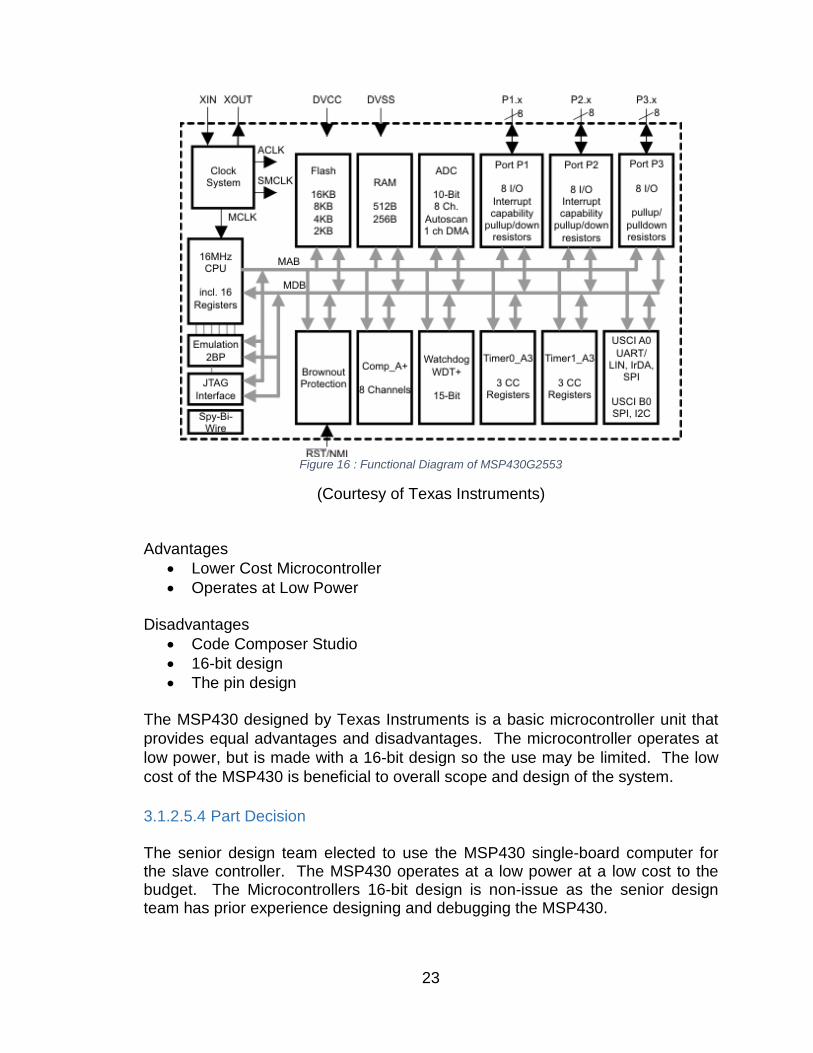
Figure 16 : Functional Diagram of MSP430G2553
(Courtesy of Texas Instruments)
Advantages
• Lower Cost Microcontroller • Operates at Low Power
Disadvantages
• Code Composer Studio • 16-bit design • The pin design
The MSP430 designed by Texas Instruments is a basic microcontroller unit that provides equal advantages and disadvantages. The microcontroller operates at low power, but is made with a 16-bit design so the use may be limited. The low cost of the MSP430 is beneficial to overall scope and design of the system. 3.1.2.5.4 Part Decision The senior design team elected to use the MSP430 single-board computer for the slave controller. The MSP430 operates at a low power at a low cost to the budget. The Microcontrollers 16-bit design is non-issue as the senior design team has prior experience designing and debugging the MSP430.
23
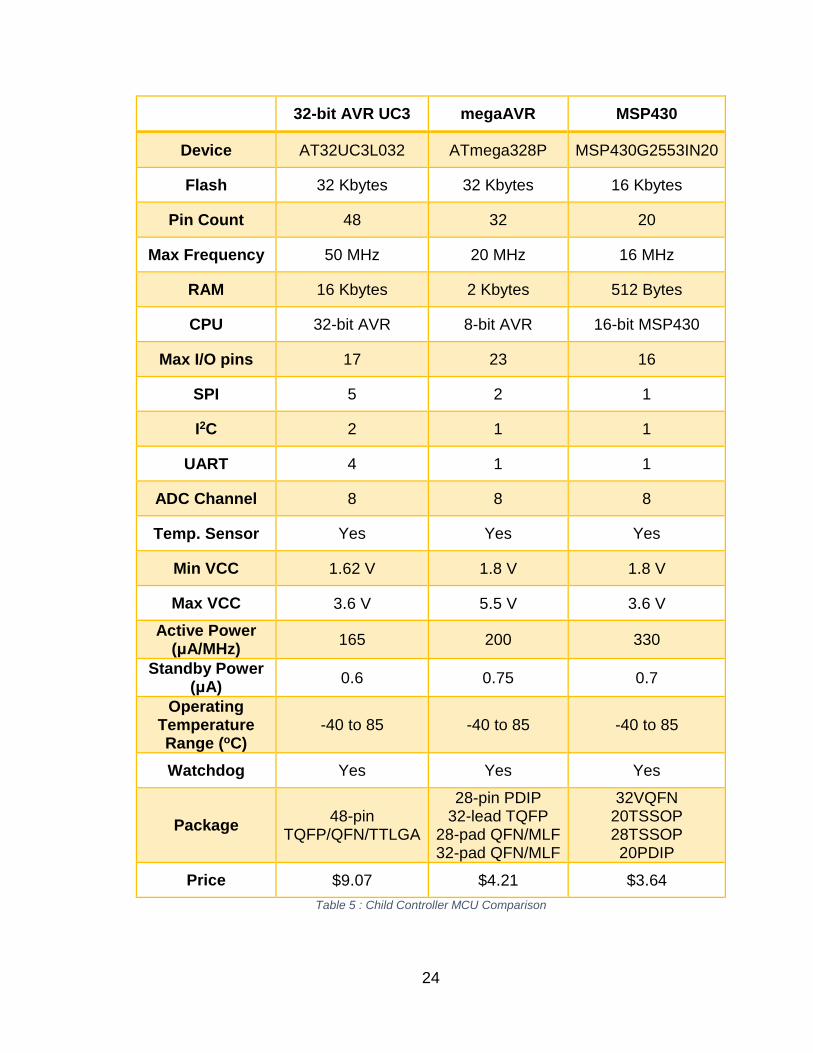
32-bit AVR UC3 megaAVR MSP430
Device AT32UC3L032 ATmega328P MSP430G2553IN20
Flash 32 Kbytes 32 Kbytes 16 Kbytes
Pin Count 48 32 20
Max Frequency 50 MHz 20 MHz 16 MHz
RAM 16 Kbytes 2 Kbytes 512 Bytes
CPU 32-bit AVR 8-bit AVR 16-bit MSP430
Max I/O pins 17 23 16
SPI 5 2 1
I2C 2 1 1
UART 4 1 1
ADC Channel 8 8 8
Temp. Sensor Yes Yes Yes
Min VCC 1.62 V 1.8 V 1.8 V
Max VCC 3.6 V 5.5 V 3.6 V Active Power
(μA/MHz) 165 200 330
Standby Power (μA) 0.6 0.75 0.7
Operating Temperature Range (oC)
-40 to 85 -40 to 85 -40 to 85
Watchdog Yes Yes Yes
Package 48-pin TQFP/QFN/TTLGA
28-pin PDIP 32-lead TQFP
28-pad QFN/MLF 32-pad QFN/MLF
32VQFN 20TSSOP 28TSSOP 20PDIP
Price $9.07 $4.21 $3.64 Table 5 : Child Controller MCU Comparison
24
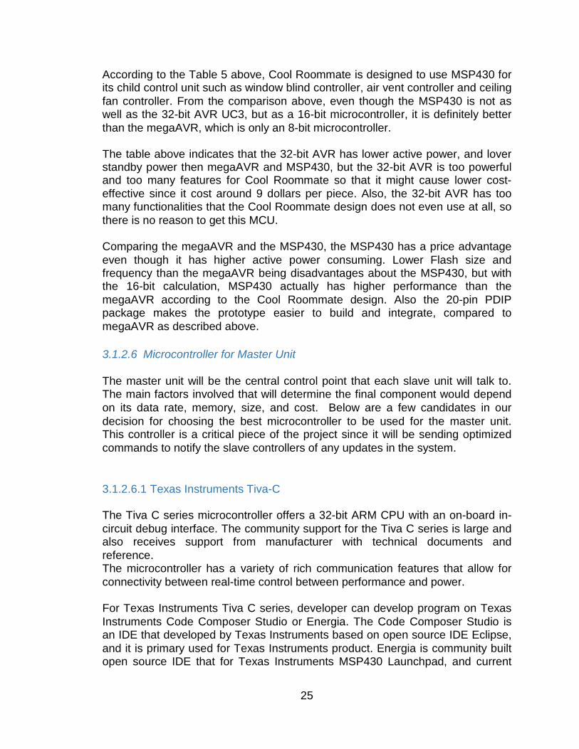
According to the Table 5 above, Cool Roommate is designed to use MSP430 for its child control unit such as window blind controller, air vent controller and ceiling fan controller. From the comparison above, even though the MSP430 is not as well as the 32-bit AVR UC3, but as a 16-bit microcontroller, it is definitely better than the megaAVR, which is only an 8-bit microcontroller. The table above indicates that the 32-bit AVR has lower active power, and lover standby power then megaAVR and MSP430, but the 32-bit AVR is too powerful and too many features for Cool Roommate so that it might cause lower cost-effective since it cost around 9 dollars per piece. Also, the 32-bit AVR has too many functionalities that the Cool Roommate design does not even use at all, so there is no reason to get this MCU. Comparing the megaAVR and the MSP430, the MSP430 has a price advantage even though it has higher active power consuming. Lower Flash size and frequency than the megaAVR being disadvantages about the MSP430, but with the 16-bit calculation, MSP430 actually has higher performance than the megaAVR according to the Cool Roommate design. Also the 20-pin PDIP package makes the prototype easier to build and integrate, compared to megaAVR as described above. 3.1.2.6 Microcontroller for Master Unit The master unit will be the central control point that each slave unit will talk to. The main factors involved that will determine the final component would depend on its data rate, memory, size, and cost. Below are a few candidates in our decision for choosing the best microcontroller to be used for the master unit. This controller is a critical piece of the project since it will be sending optimized commands to notify the slave controllers of any updates in the system. 3.1.2.6.1 Texas Instruments Tiva-C The Tiva C series microcontroller offers a 32-bit ARM CPU with an on-board in-circuit debug interface. The community support for the Tiva C series is large and also receives support from manufacturer with technical documents and reference. The microcontroller has a variety of rich communication features that allow for connectivity between real-time control between performance and power. For Texas Instruments Tiva C series, developer can develop program on Texas Instruments Code Composer Studio or Energia. The Code Composer Studio is an IDE that developed by Texas Instruments based on open source IDE Eclipse, and it is primary used for Texas Instruments product. Energia is community built open source IDE that for Texas Instruments MSP430 Launchpad, and current
25
version also supports Tiva C series Launchpad and CC3200. For more details about Code Composer Studio and Energia, please refer to section 3.1.7.3.1 and section 3.1.7.3.3. Advantages
• 32-bit CPU • ARM development tools • Plenty of GPIO and peripherals • Good documentation
Disadvantages
• Registers and microcontroller knowledge are require • Limited community support other than from TI
The figure below is a functional diagram of the processor operations.
Figure 17 : TM4C1294NCPDT Functional Diagram
(Courtesy of Texas Instruments) The Tiva C series microcontroller is a candidate for its 32-bit CPU makes it easier to program more efficiently, but the limited community support does not make it easily accessible to code and debug.
26
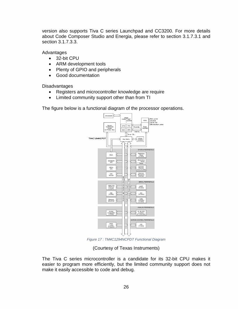
3.1.2.6.2 Raspberry Pi The Raspberry Pi Launchpad and microcontroller was considered for the purposes of our Master unit in our system architecture. An appealing characteristics were the software architecture it provides. For an illustrated figure, see below.
Figure 18 : Raspberry Pi Software Architecture
(Courtesy of Raspberry Pi Foundation) The Raspberry Pi is a single board computer based on the Broadcom BCM 2835 system on a chip, which includes an ARM 1176JZF-S 700MHz processor. The foundation provides for Linux ARM. The Raspberry Pi has extensive support and is easy to conform for design and purpose. Advantages
• Ability to operate a full Linux distribution • Low power consumption • Large Community Support
Disadvantage
• CPU may not be able to handle high straining tasks
27
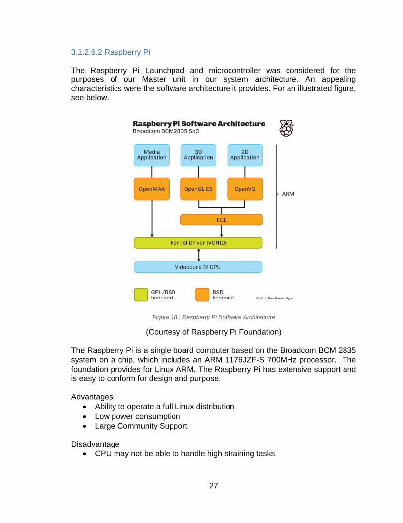
The Raspberry Pi is a single board computer is an attractive candidate due to its low power consumption, the large community support, and its ability to operate at a full Linux distribution. The biggest disadvantage is that the CPU may not be able to handle high straining tasks. 3.1.2.6.3 BeagleBone Black Beagle Boards are an open-source single-board computer developed by Texas Instruments with other partners. The Beaglebone black has a RAM of 512MB, the processor clock of 1 GHz, and has 2GB of eMMC flash support with HDMI capability. The BeagleBone has a large community support due to its open source nature, and uses the AM 335x ARM Cortex-A8 processor. Advantages
• Ability to operate a full Linux distribution • High Community Support • Low power • Powerful Processor
Disadvantages
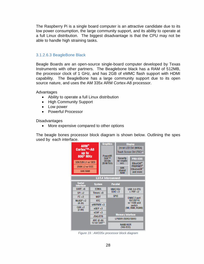
• More expensive compared to other options The beagle bones processor block diagram is shown below. Outlining the spes used by each interface.
Figure 19 : AM335x processor block diagram
28
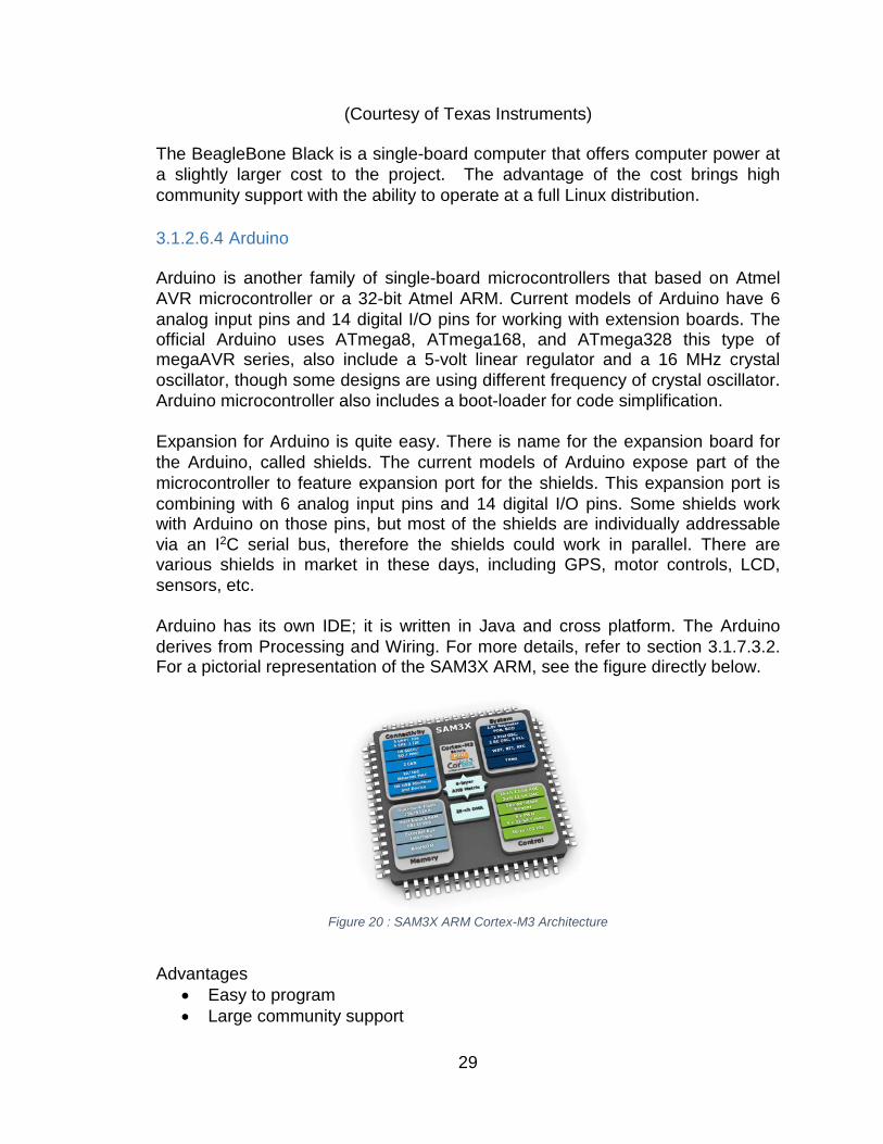
(Courtesy of Texas Instruments) The BeagleBone Black is a single-board computer that offers computer power at a slightly larger cost to the project. The advantage of the cost brings high community support with the ability to operate at a full Linux distribution. 3.1.2.6.4 Arduino Arduino is another family of single-board microcontrollers that based on Atmel AVR microcontroller or a 32-bit Atmel ARM. Current models of Arduino have 6 analog input pins and 14 digital I/O pins for working with extension boards. The official Arduino uses ATmega8, ATmega168, and ATmega328 this type of megaAVR series, also include a 5-volt linear regulator and a 16 MHz crystal oscillator, though some designs are using different frequency of crystal oscillator. Arduino microcontroller also includes a boot-loader for code simplification. Expansion for Arduino is quite easy. There is name for the expansion board for the Arduino, called shields. The current models of Arduino expose part of the microcontroller to feature expansion port for the shields. This expansion port is combining with 6 analog input pins and 14 digital I/O pins. Some shields work with Arduino on those pins, but most of the shields are individually addressable via an I2C serial bus, therefore the shields could work in parallel. There are various shields in market in these days, including GPS, motor controls, LCD, sensors, etc. Arduino has its own IDE; it is written in Java and cross platform. The Arduino derives from Processing and Wiring. For more details, refer to section 3.1.7.3.2. For a pictorial representation of the SAM3X ARM, see the figure directly below.
Figure 20 : SAM3X ARM Cortex-M3 Architecture
Advantages
• Easy to program • Large community support
29
• Function encapsulation makes code much simpler Disadvantages
• Few memory, GPIO and peripherals • Lower clock speed compared to TI Launchpad
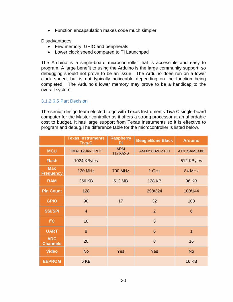
The Arduino is a single-board microcontroller that is accessible and easy to program. A large benefit to using the Arduino is the large community support, so debugging should not prove to be an issue. The Arduino does run on a lower clock speed, but is not typically noticeable depending on the function being completed. The Arduino’s lower memory may prove to be a handicap to the overall system. 3.1.2.6.5 Part Decision The senior design team elected to go with Texas Instruments Tiva C single-board computer for the Master controller as it offers a strong processor at an affordable cost to budget. It has large support from Texas Instruments so it is effective to program and debug.The difference table for the microcontroller is listed below. Texas Instruments
Tiva-C Raspberry
Pi BeagleBone Black Arduino
MCU TM4C1294NCPDT ARM 1176JZ-S AM3358BZCZ100 AT91SAM3X8E
Flash 1024 KBytes 512 KBytes
Max Frequency 120 MHz 700 MHz 1 GHz 84 MHz
RAM 256 KB 512 MB 128 KB 96 KB
Pin Count 128 298/324 100/144
GPIO 90 17 32 103
SSI/SPI 4 2 6
I2C 10 3
UART 8 6 1
ADC Channels 20 8 16
Video No Yes Yes No
EEPROM 6 KB 16 KB
30
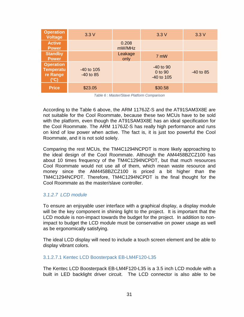
Operation Voltage 3.3 V 3.3 V 3.3 V
Active Power 0.208
mW/MHz
Standby Power Leakage
only 7 mW
Operation Temperature Range
(oC)
-40 to 105 -40 to 85
-40 to 90 0 to 90
-40 to 105 -40 to 85
Price $23.05 $30.58 Table 6 : Master/Slave Platform Comparison
According to the Table 6 above, the ARM 1176JZ-S and the AT91SAM3X8E are not suitable for the Cool Roommate, because these two MCUs have to be sold with the platform, even though the AT91SAM3X8E has an ideal specification for the Cool Roommate. The ARM 1176JZ-S has really high performance and runs on kind of low power when active. The fact is, it is just too powerful the Cool Roommate, and it is not sold solely. Comparing the rest MCUs, the TM4C1294NCPDT is more likely approaching to the ideal design of the Cool Roommate. Although the AM4458BZCZ100 has about 10 times frequency of the TM4C1294NCPDT, but that much resources Cool Roommate would not use all of them, which mean waste resource and money since the AM4458BZCZ100 is priced a bit higher than the TM4C1294NCPDT. Therefore, TM4C1294NCPDT is the final thought for the Cool Roommate as the master/slave controller. 3.1.2.7 LCD module To ensure an enjoyable user interface with a graphical display, a display module will be the key component in shining light to the project. It is important that the LCD module is non-impact towards the budget for the project. In addition to non-impact to budget the LCD module must be conservative on power usage as well as be ergonomically satisfying. The ideal LCD display will need to include a touch screen element and be able to display vibrant colors. 3.1.2.7.1 Kentec LCD Boosterpack EB-LM4F120-L35 The Kentec LCD Boosterpack EB-LM4F120-L35 is a 3.5 inch LCD module with a built in LED backlight driver circuit. The LCD connector is also able to be
31
interfaced with a larger size LCD module. The resolution is 320x240 and has an 8-bit parallel interface. Advantages
• Plug-n-play • Ability to Scale to larger size
Disadvantages
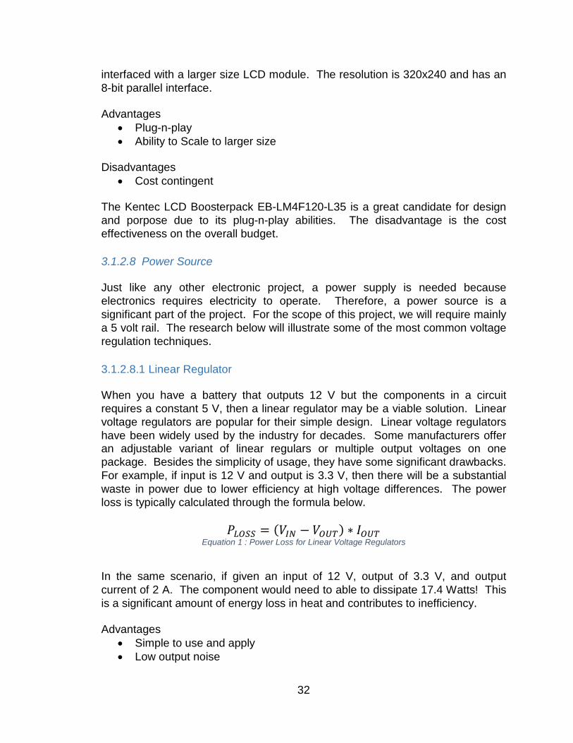
• Cost contingent The Kentec LCD Boosterpack EB-LM4F120-L35 is a great candidate for design and porpose due to its plug-n-play abilities. The disadvantage is the cost effectiveness on the overall budget. 3.1.2.8 Power Source Just like any other electronic project, a power supply is needed because electronics requires electricity to operate. Therefore, a power source is a significant part of the project. For the scope of this project, we will require mainly a 5 volt rail. The research below will illustrate some of the most common voltage regulation techniques. 3.1.2.8.1 Linear Regulator When you have a battery that outputs 12 V but the components in a circuit requires a constant 5 V, then a linear regulator may be a viable solution. Linear voltage regulators are popular for their simple design. Linear voltage regulators have been widely used by the industry for decades. Some manufacturers offer an adjustable variant of linear regulars or multiple output voltages on one package. Besides the simplicity of usage, they have some significant drawbacks. For example, if input is 12 V and output is 3.3 V, then there will be a substantial waste in power due to lower efficiency at high voltage differences. The power loss is typically calculated through the formula below.
𝑃𝑃𝐿𝐿𝐿𝐿𝐿𝐿𝐿𝐿 = (𝑉𝑉𝐼𝐼𝐼𝐼 − 𝑉𝑉𝐿𝐿𝑂𝑂𝑂𝑂) ∗ 𝐼𝐼𝐿𝐿𝑂𝑂𝑂𝑂 Equation 1 : Power Loss for Linear Voltage Regulators
In the same scenario, if given an input of 12 V, output of 3.3 V, and output current of 2 A. The component would need to able to dissipate 17.4 Watts! This is a significant amount of energy loss in heat and contributes to inefficiency. Advantages
• Simple to use and apply • Low output noise
32
• Low ripple • Fast response to input fluctuations
Disadvantages
• Not efficient • May require heat sink to dissipate excessive power • May require large external components • Can only output voltage lower than input
3.1.2.8.2 LDO Linear Regulator LDO linear regulators are very similar to the common linear regulators. The benefit of using Low Dropout (LDO) linear regulators is that they can provide a regulated output voltage at a lower minimum operating input voltage to ensure longevity. Advantages
• Simple to use an apply • Lower minimum operating voltage • Same benefits as linear regulator
Disadvantages
• Not efficient • May require heat sink to dissipate excessive power • May require large external components • Can only output voltage lower than input
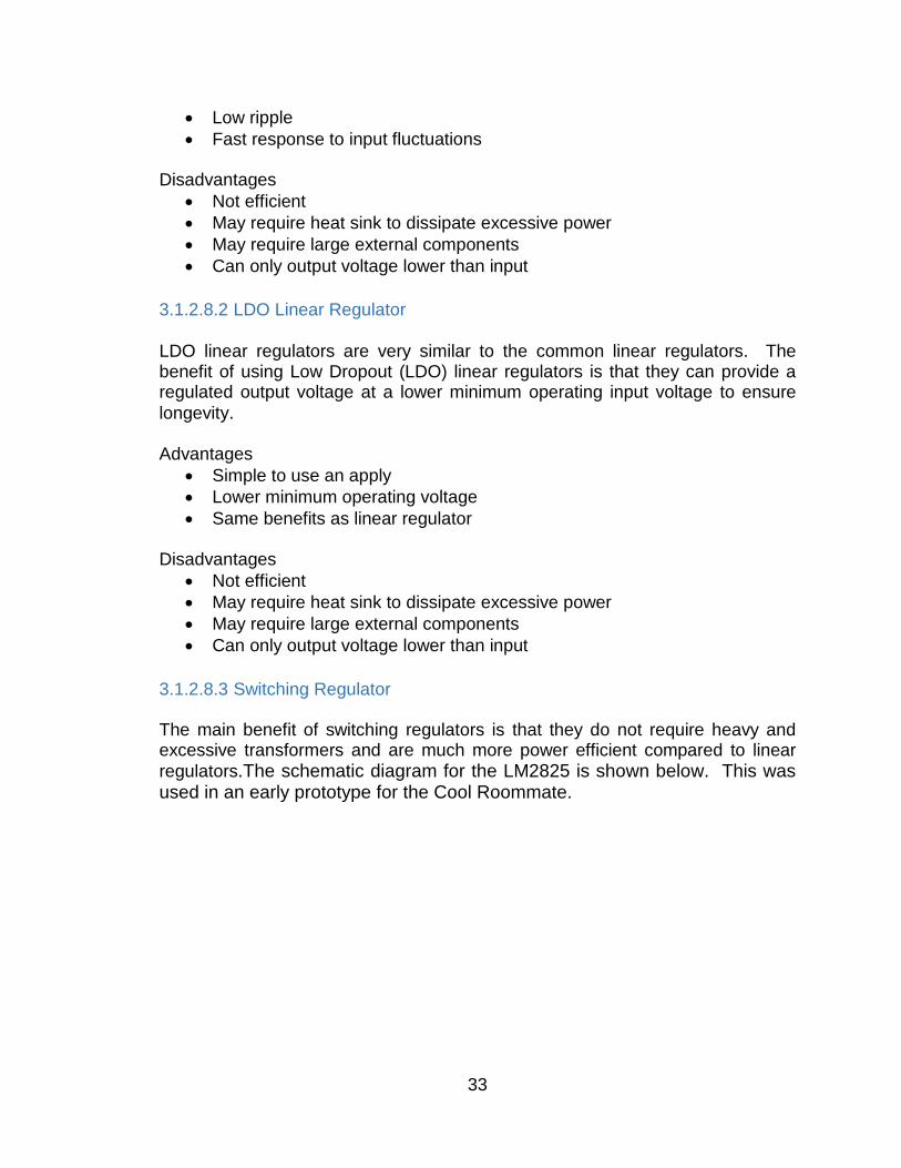
3.1.2.8.3 Switching Regulator The main benefit of switching regulators is that they do not require heavy and excessive transformers and are much more power efficient compared to linear regulators.The schematic diagram for the LM2825 is shown below. This was used in an early prototype for the Cool Roommate.
33
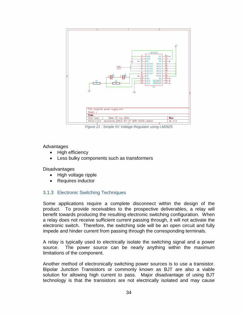
Figure 21 : Simple 5V Voltage Regulator using LM2825
Advantages
• High efficiency • Less bulky components such as transformers
Disadvantages
• High voltage ripple • Requires inductor
3.1.3 Electronic Switching Techniques Some applications require a complete disconnect within the design of the product. To provide receivables to the prospective deliverables, a relay will benefit towards producing the resulting electronic switching configuration. When a relay does not receive sufficient current passing through, it will not activate the electronic switch. Therefore, the switching side will be an open circuit and fully impede and hinder current from passing through the corresponding terminals. A relay is typically used to electrically isolate the switching signal and a power source. The power source can be nearly anything within the maximum limitations of the component. Another method of electronically switching power sources is to use a transistor. Bipolar Junction Transistors or commonly known as BJT are also a viable solution for allowing high current to pass. Major disadvantage of using BJT technology is that the transistors are not electrically isolated and may cause
34
abnormal interference that may affect the overall performance of allowing sufficient current to pass. 3.1.3.1 Relay Relays are simply a switch that can be electronically controlled through an electromagnet. When power is applied to the coils of the relay, the electromagnet activates and switches the state of the switch. This type of relay is called an electro-mechanical relay because it incorporates an electromagnet. For a single pole single throw relay, there are typically five terminals. A single pole single throw relay contains two for the coil, common ground (COM), normally closed (NC), and normally open (NO). To understand which relay to use, there was an investigate of which relay would be most successful in our operations goal. Below are the different types of relays considered.
Figure 22 : Circuit Symbols of Relays
35
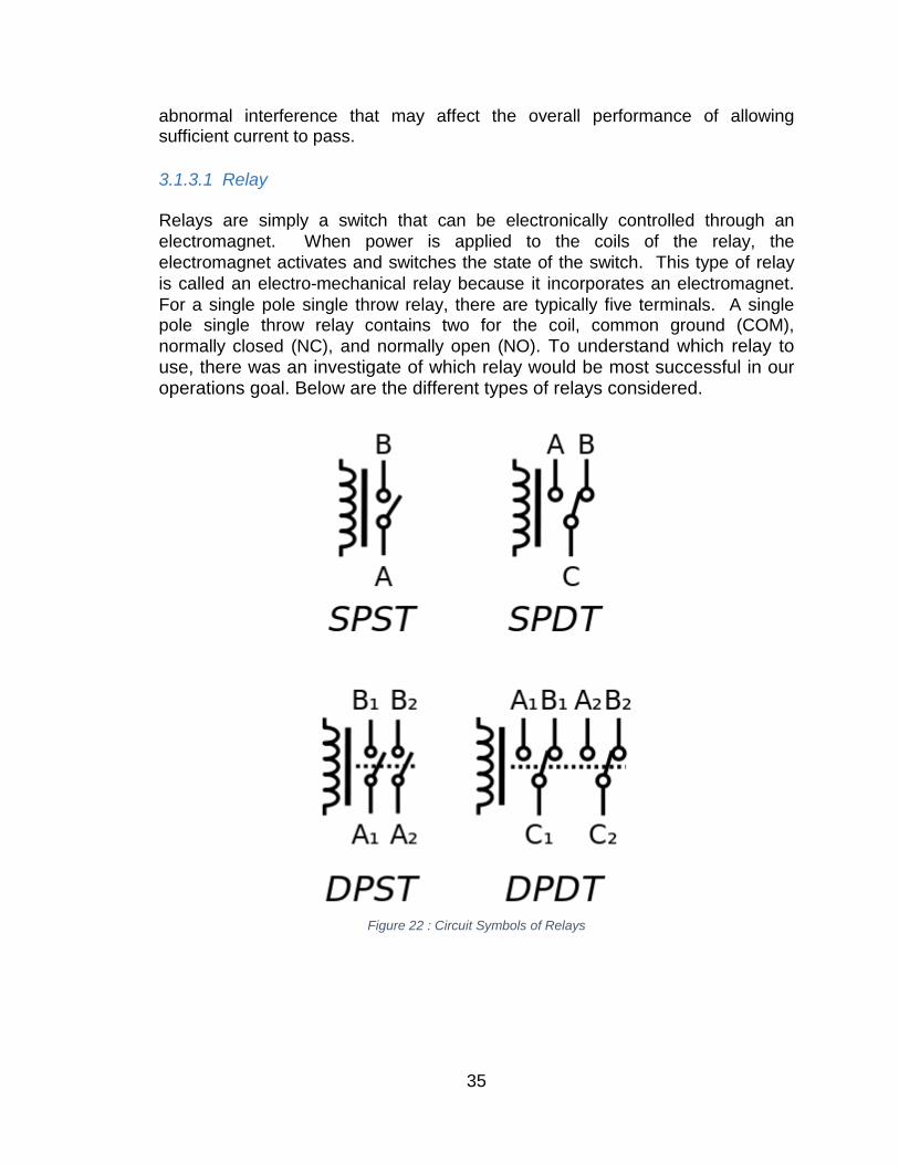
3.1.3.2 Optoisolator Optoisolators are similar to relays but incorporate isolation to reduce noise that may be present when controlling multiple systems. Optoisolators are also known as optical coupler and optocoupler. These integrated semiconductor devices operate by using a light source and a photo sensor. When activating the optoisolator, the light source will turn on and shine a light to the photo sensor. The photo sensor will detect the light and allow current to pass through. A typical optoisolator uses a light emitting diode or an infrared light emitting diode as the light source.Below is an optoisolator diagram.
Figure 23 : Optoisolator Diagram
Advantages
• Nosie isolation • High speed capacity • Compact footprint compared to relays
Disadvantages
• Low current capacity • Susceptible to high humidity, pressure, and air pollution • Ideal for climate controlled environments
3.1.4 HVAC Control Controlling an electric central heating, ventilation, and air conditioning unit is as simple as shorting two wires. Most central air conditioning units use a common writing convention. Four or more wires coming from the wall may be present for the thermostat. The wires needed for basic functions are R, W, Y, and G. R contains the 24 VAC power that will be used to power the relays that will activate the appropriate heating or cooling function. For example, connecting R and G together will activate the blower fan. To manually activate the air conditioning unit’s cooling feature, it would be as simple as connecting R, G, and Y together. To start the heating function, connect R, G, and W together. Digital thermostats are able to control central heating and cooling units in a similar fashion. For the
36
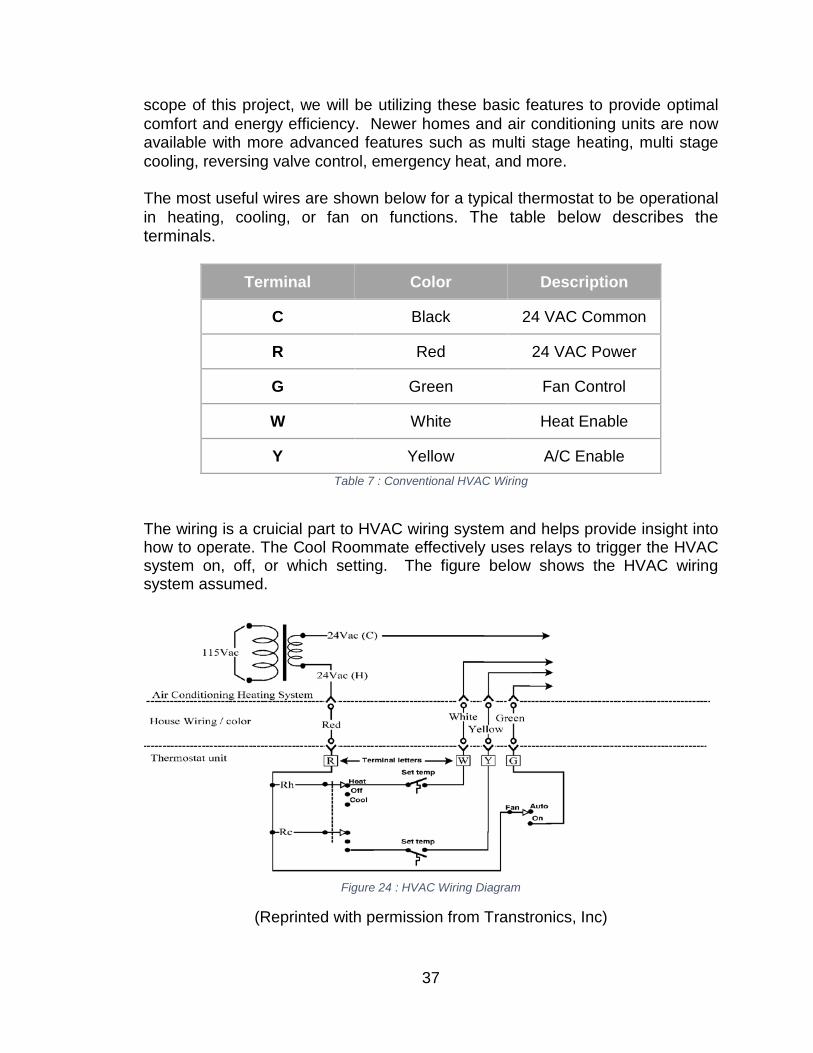
scope of this project, we will be utilizing these basic features to provide optimal comfort and energy efficiency. Newer homes and air conditioning units are now available with more advanced features such as multi stage heating, multi stage cooling, reversing valve control, emergency heat, and more. The most useful wires are shown below for a typical thermostat to be operational in heating, cooling, or fan on functions. The table below describes the terminals.
Terminal Color Description
C Black 24 VAC Common
R Red 24 VAC Power
G Green Fan Control
W White Heat Enable
Y Yellow A/C Enable Table 7 : Conventional HVAC Wiring
The wiring is a cruicial part to HVAC wiring system and helps provide insight into how to operate. The Cool Roommate effectively uses relays to trigger the HVAC system on, off, or which setting. The figure below shows the HVAC wiring system assumed.
Figure 24 : HVAC Wiring Diagram
(Reprinted with permission from Transtronics, Inc)
37
To control the air conditioning unit, we are forecasting the use of multiple relays or optoisolator to connect the corresponding wires that are necessary for a functioning air conditioning unit. 3.1.5 Battery Topologies The ideal battery must be light weight, reusable, efficient, environmentally friendly, and have a large capacity. The battery topology must be effective for holding a charge over a long period of time, and remotely. Battery should not affect the usability of the system. 3.1.5.1 Sealed Lead Acid Generally for powering heavy loads without a concern of weight or cost, sealed lead acid batteries would be a great candidate. Some major advantages are its inexpensive cost per watt and reliability. Researchers have been developing and refining lead acid batteries since they were invented in 1859. They are popular within the automotive industry and various other vehicles. Uninterrupted power supplies also typically contain sealed lead acid batteries because of its reliability. Advantages
• Cheap • Simple charging characteristics • No memory effect
Disadvantages
• Heavy and bulky • Not as efficient as other topologies • Voltage sag • Low charge density • Short life cycle • Environmentally damaging
3.1.5.2 Lithium-ion Polymer Lithium-ion polymer batteries differ from lithium ion batteries in the fabrication process. They are typically fabricated using a dry electrolyte which increases its capabilities in ruggedness, performance, and safety. The flexibility within the fabrication process allows each cell to be as thin as one millimeter thick. This allows engineers to expand their creativity in adapting the technology to suit their requirements and preferences. The technology is still advancing and can currently be seen in use within portable electronics such as portable computers, tablets, cellular phones, and more.
38
Advantages • Flexibility of cell form factor • High energy density • Long lifecycle of over 1000 charge cycles
Disadvantages
• Requires protection circuitry for increased safety • Expensive compared to Sealed Lead Acid batteries • Susceptible to heat and aging
3.1.5.3 Lithium phosphate (LiFePO4) Lithium Iron Phosphate, or LiFePO4 or LFP, is a type of Li-Ion rechargeable battery that for high power application, such as power tool, laptop, solar application, home EV conversions, and transportation. LFP battery is high discharging current, non-explosive, and long cycle life battery, but the energy density of it is lower than a normal Li-Ion dell. For the LiFePO4, it has a very constant discharge voltage. Voltage will stay close to 3.2V while discharging until it is empty, which is great that allows the battery delivery full power during the discharge. Because of the stability of the delivering, 4 of the LiFePO4 could be placed in series for 12.8V, which comes close to the voltage of a six-cell lead-acid battery. Also, because of the high safety of LiFePO4 itself, it is always used to replace lead-acid battery in many applications. Advantages
• Light weight • High charge density • Long life cycle and charge cycles • Environmentally friendly • Safe • Low self-discharge
Disadvantages
• Expensive • Complex charging and maintenance
3.1.6 Prototype Production Within nearly all product lifecycles, a prototype is a critical part of the development process. With the complexity of components, DIY prototyping may not be a viable option due to the difficulty involved. The prototype shall be used as a visual demonstration and proof of concept of the design. This phase will allow proper visualization and realization of size, mass, and structural integrity to be comparable to the final production model. Aside from appearances, key
39

requirements and functionality will be tested to ensure all features meet or exceed the requirements. 3.1.6.1 PCB production Due to the initial investment of purchasing materials and chemicals to perform in house fabrication of the printed circuit board prototype, sending design specifications to a board house is a viable and compelling option. Typically printed circuit board production facilities offer an abundance of capabilities and features. 3.1.6.2 Hand Soldered Components Hand soldering will increase soldering skills throughout the team and reduce overall prototype costs due to reduced external labor costs. To reduce costs and resource waste, we can order the PCB with only complex components such as ball grid array packages and other packages that contain a high count of pins pre-solder. Then hand soldering capacitors and resistors according to the design. Manually soldering each component will also require tools Advantages
• Cost effective • Increases team skillset
Disadvantages
• Susceptible to human error 3.1.6.3 Prepopulated Components Ordering PCB prepopulated with all the components onboard would be the simplest solution and will reduce human error that may result in faulty connections or component damage. Turnkey PCB production will simplify the prototyping process so that we can jump straight into the testing and tweaking phase. This will save time and ensure that the prototype is well made and constructed to our specifications. Advantages
• Reduced fabrication error Disadvantages
• Expensive • Turnaround times may vary depending on complexity
40
3.1.7 Software A complete version of an embedded system is not only about the hardware that required, but also the correct software will totally affect the progress and efficiency of the development. Choosing the right software for different stages of the development is not easy. The hardware is chosen, the environment of development, the budget that the team has, and a lot of other fact will take as consideration while choosing the software. If this step is skipped, and the wrong software is used, the progress might be stuck, or more seriously, the team has to redo the project. Therefore, researching the software is definitely needed no matter what. 3.1.7.1 Schematic layout After designing a schematic on paper, generating an electronic copy can be immensely beneficial to the user and the longevity of the product in mind. Modifications can be as simple as a click of a button or pressing a key on the keyboard. Some software have the additional feature such as simulating schematics and autorouter. Autorouter is a tool that automates the routing process of drawing traces within the schematic layout software. Schematic layout tools are typically included within EDA software suites. EDA stands for Electronic Design Automation, these sets of software are used to increase development efficiency for designing printed circuit boards and assimilating integrated circuits. Some tools include a simulation feature. EDA tools are widely used within the majority of information technology companies that develop hardware. 3.1.7.1.1 EAGLE EAGLE is an acronym created by CadSoft Computer that stands for “Easily Applicable Graphical Layout Editor.” Eagle has generous support from the electronics community for user generated components. Element14 offers CAD libraries for a vast selection of components. Advantages
• Simple user interface • Community support • Multi-platform support
Disadvantages
• Limitations of 100 x 80mm in Light Edition • Custom component creation is time consuming
41

3.1.7.1.2 KiCAD KiCAD is an EDA suite featuring schematic and printed circuit board design. The EDA suite has been in development since 1992 and have recently received a contribution from the European Organization for Nuclear Research also known as CERN. The KiCAD suite includes a schematic capture tool that is capable of creating professional boards up to 32 layers and counting. KiCAD is a work of art and is an excellent contender in the EDA market capable of producing high quality schematic designs and layouts. Advantages
• Organized user interface • Community support • Multi-platform support • Open source
Disadvantages
• Learning curve We will use KiCAD in the development of the project due to its increase in popularity and further development. 3.1.7.2 Programming Language For an embedded system, there is always embedded software to support it to have the system working. For different type of embedded system, depends on the compiler, different type of embedded programming languages is needed. There are some popular programming languages are using in the industrial, some of them are objected-oriented to make the program much easier to approach. 3.1.7.2.1 Assembly Language An assembly language is a low-level programming language that used for computer, or some other devices that could be programmable. It has a very strong parallelism between the computer architecture’s machine code instruction sets and the language itself. Different assembly language is corresponding to a specific computer architecture, or assembler. Assembly language is the closest language to the hardware for programming. It has ability to direct access the hardware, and has much quicker performance on calculation than high-level programming language. Nowadays, some software and embedded devices are still utilizing assembly language for lower layer software design, which could increase the performance of the product itself by cutting down compiling and interpreting time.
42
Advantages
• Direct hardware access • Short for each line of the code • It is symbolic and easy to understand
Disadvantages
• Machine dependent • Tremendous code for a normal program
Assembly language is a low-level programming that allows direct access to the hardware. The direct access to the hardware allows the designer to program to more specific needs of the system; however the code is longer and is hardware dependent so it may not be feasible for a flexible system or future integration. 3.1.7.2.2 Ada Ada is a statically typed, imperative, structured, wide-spectrum, and cross-platform high-level programming language. It is also objected-oriented. Ada was extended from Pascal, and influenced by other languages, such as Java, C++, Eiffel, and more. Ada has built-in language support for explicit concurrency, protected objects, synchronous message passing, and offering tasks. Ada was originally targeted at embedded and real-time systems, and by the time goes by, Ada now not only focuses on those fields, but it is also used for very large software systems. Additionally, Ada packages can be compiled separately without the implementation to check for consistency, which makes Ada possible to discover the problems and bugs during the design phase. Ada has a large number of compile-time checks that helps to find the bugs that only appear during run-time. Ada also supports run-time checks to protect against access to certain common bugs, such as buffer overflow errors, range violations, and so on. The dynamic memory management of Ada is high-level and type-safe. It is possible to have several different access types that all designate the same type but use different storage pools. Because of Ada’s safety-critical support features, it is not only used for military purpose, but also in avionics and air traffic control, commercial rockets, and satellites. Advantages
• Syntax is easy to learn • Strong typing • Program is easy to follow • Good error handling • Existed references are not required to make code runs
Disadvantages
43
• Not a lot good compilers out there • A lot of reserved words • Tremendous code
Ada is a extended form of Pascal and has built-in language support. The high level language is simple to learn and runs smoothly, but does not have much support as compilers are limited. Design code can be lengthy from its reserved words. 3.1.7.2.3 Java Platform, Micro Edition Java Platform, Micro Edition, or Java ME, is a Java platform that designed for embedded systems. It targets device range is wide, from industrial controls to mobile phone devices. Java ME was designed by Sun Microsystems, and it replaced a similar technology, PersonalJava. Same as J2EE and J2SE, Java ME originally developed under the JCP (Java Community Process) as JSR 68. Java ME devices implement a profile. The most common one is the Mobile Information Device Profile that targeted at the mobile devices. Also the Personal Profile targeted at the consumer products and other embedded devices like PDAs and set-top box. For Java ME, Sun provides a reference implementation of these configurations and profiles for CDC and MIDP. Nowadays, there more billions and billions embedded devices using Java ME. It was also implemented on most of the mobile operating system, such as Symbian (as a native software), Windows CE, Windows Mobile, MeeGo, Maemo, and Android. Advantages
• Syntax is easy to learn • Large class library • Good portability • Comprehensive documentation • Automatic Memory Management implemented by Garbage Collection
Disadvantages
• Lack of garbage collection on resources other than memory • Primitive don’t inherit from Object • Large memory footprint
The Java Platform is designed for embedded systems and supplies a large class library readily accessible for software design. The large memory footprint brings itself to an issue depending on memory allocation determined. Java is a more simple higher level language to learn, but may still provide issues when debugging and designing.
44
3.1.7.2.4 Embedded C++ Embedded C++, also known as EC++, was a dialect of the C++ programming language for embedded systems, and it is objected-oriented. Embedded C++ was defined by a group of major Japanese CPU (central processor unit) manufacturers, including NEC, Fujitsu, and Toshiba, to address the shortcoming of C++ for embedded applications. The goal of that is to preserve the most useful object-oriented features of the C++ and minimize the code size while maximizing the efficiency. The official website states the goal as “to provide embedded systems programmers with a subset of C++ that is easy for the average C programmer to understand and use.” There are differences between C++ and embedded C++, some of the C++ features have been removed such as multiple inheritance, virtual base classes, run-time type information, new style casts, the mutable storage class specifier, namespaces, exceptions, and templates, but some compliers allows developer to re-enable them if desired, and that called “extended embedded C++.” For compilation, any C++ compilers could be able to compile embedded C++ code, but a compiler specific to embedded C++ would have an easier time doing optimization. Somehow, the fact is, embedded C++ has a poor reception with many C++ programmers, and there is not a lot of market other than Japan. Advantages
• True subset of C++ • Object-oriented • Template support
Disadvantages
• Limited population, small community Embedded C++ allows the software developer to object-oriented tools and template support not found in traditional upper level languages. However the limited community support provides a larger learning curve making it difficult for use for scope and design of the course. 3.1.7.2.5 Programming Language Decision According to the MCU and platform, the team chose for developing Cool Roommate, (Embedded) C and C++ are decided to use as main programming language. Based on these, the IDE that used for development should support C and C++, or either one, so that the development process should not have any problem.
45
3.1.7.3 Integrated Development Environment For developing embedded systems, there are many choices of IDE (Integrated Development Environment) are currently used in the market. Some IDEs are specific to a certain products or hardware, but there are still some IDEs are cross-platform. Picking a good IDE for the project is a good starting point for development, because if chose a wrong IDE, the whole project might just stuck because of that. A good IDE gives the developer an unexpected success, increases the development speed, the product efficiency, and reliability of the project. According to different hardware architectures, different IDEs will have different features. Even though the same hardware architecture, IDEs will also have different functions or usages depends on the manufactures or the IDE’s developers. A group of community will also have a large impact on the IDEs for developing different libraries. IDE for software development, but not limit to embedded system, will have the following basic features, editor, compiler, linker and debugger, and most IDEs will also come with version control. Sometime, an IDE is specific to a programming language or hardware (CPU, GPU, etc.) according to the compiler or vendor, but more often the IDEs will support multiple programming languages instead of one. That usually comes with multiple compilers or cross-compiler. The purpose of that is to provide various choices to the developer, and unify various projects in one IDE makes everything organized. Also the major reason of that is allow developer to develop polyglot, which is a program or script written in a valid form of multiple programming languages. Some commonly used IDEs for embedded systems are gcc (GNU compiler collection), Eclipse, DevC++, IntelliJ, Microsoft Visual Studio, etc. In addition, Eclipse is an open source IDE that has powerful extendable features. Most of the vendors will choose Eclipse to build their own IDEs, for example, Texas Instruments Code Composer Studio, also known as CCS, is the one of the IDEs build on Eclipse. 3.1.7.3.1 Texas Instruments Code Composer Studio Code Composer Studio, or CCS, is an IDE (Integrated Development Environment) that developed by Texas Instruments based on Eclipse open source IDE to develop applications for Texas Instruments embedded microprocessor. The product line of Texas Instruments embedded processors include TMS320 DSPs, OMAP and DaVinci SoC (system-on-a-chip), Sitara application processors, Hercules and Tiva/Stellaris microprocessors, MSP430 and Ducati SIP block. The Code Composer Studio include a real-time kernel that is primarily designed for embedded project and JTAG (Joint Test Action Group) based debugger. However, because of it is built on unmodified version of Eclipse, it is easy to extend to include support for OS level application debug and other
46
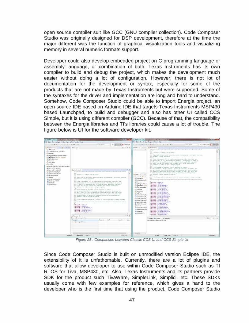
open source compiler suit like GCC (GNU complier collection). Code Composer Studio was originally designed for DSP development, therefore at the time the major different was the function of graphical visualization tools and visualizing memory in several numeric formats support. Developer could also develop embedded project on C programming language or assembly language, or combination of both. Texas Instruments has its own compiler to build and debug the project, which makes the development much easier without doing a lot of configuration. However, there is not lot of documentation for the development or syntax, especially for some of the products that are not made by Texas Instruments but were supported. Some of the syntaxes for the driver and implementation are long and hard to understand. Somehow, Code Composer Studio could be able to import Energia project, an open source IDE based on Arduino IDE that targets Texas Instruments MSP430 based Launchpad, to build and debugger and also has other UI called CCS Simple, but it is using different compiler (GCC). Because of that, the compatibility between the Energia libraries and TI’s libraries could cause a lot of trouble. The figure below is UI for the software developer kit.
Figure 25 : Comparison between Classic CCS UI and CCS Simple UI
Since Code Composer Studio is built on unmodified version Eclipse IDE, the extensibility of it is unfathomable. Currently, there are a lot of plugins and software that allow developer to use within Code Composer Studio such as TI RTOS for Tiva, MSP430, etc. Also, Texas Instruments and its partners provide SDK for the product such TivaWare, SimpleLink, Simplici, etc. These SDKs usually come with few examples for reference, which gives a hand to the developer who is the first time that using the product. Code Composer Studio
47
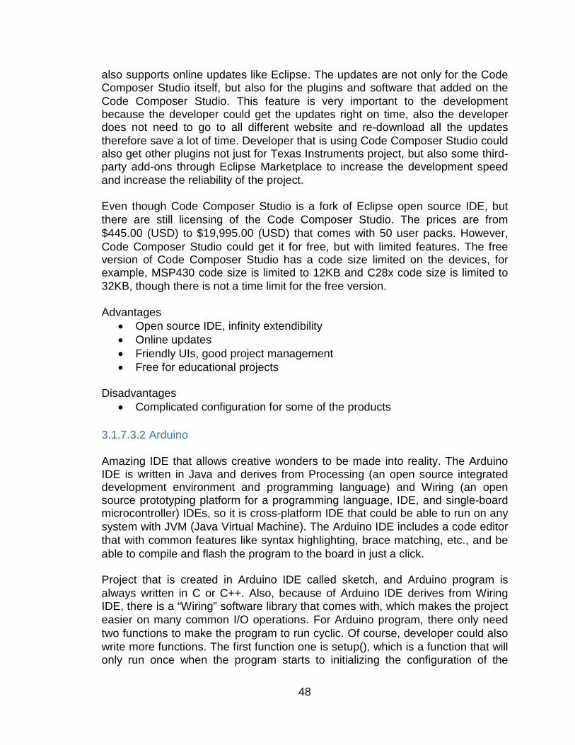
also supports online updates like Eclipse. The updates are not only for the Code Composer Studio itself, but also for the plugins and software that added on the Code Composer Studio. This feature is very important to the development because the developer could get the updates right on time, also the developer does not need to go to all different website and re-download all the updates therefore save a lot of time. Developer that is using Code Composer Studio could also get other plugins not just for Texas Instruments project, but also some third-party add-ons through Eclipse Marketplace to increase the development speed and increase the reliability of the project. Even though Code Composer Studio is a fork of Eclipse open source IDE, but there are still licensing of the Code Composer Studio. The prices are from $445.00 (USD) to $19,995.00 (USD) that comes with 50 user packs. However, Code Composer Studio could get it for free, but with limited features. The free version of Code Composer Studio has a code size limited on the devices, for example, MSP430 code size is limited to 12KB and C28x code size is limited to 32KB, though there is not a time limit for the free version. Advantages
• Open source IDE, infinity extendibility • Online updates • Friendly UIs, good project management • Free for educational projects
Disadvantages
• Complicated configuration for some of the products 3.1.7.3.2 Arduino Amazing IDE that allows creative wonders to be made into reality. The Arduino IDE is written in Java and derives from Processing (an open source integrated development environment and programming language) and Wiring (an open source prototyping platform for a programming language, IDE, and single-board microcontroller) IDEs, so it is cross-platform IDE that could be able to run on any system with JVM (Java Virtual Machine). The Arduino IDE includes a code editor that with common features like syntax highlighting, brace matching, etc., and be able to compile and flash the program to the board in just a click. Project that is created in Arduino IDE called sketch, and Arduino program is always written in C or C++. Also, because of Arduino IDE derives from Wiring IDE, there is a “Wiring” software library that comes with, which makes the project easier on many common I/O operations. For Arduino program, there only need two functions to make the program to run cyclic. Of course, developer could also write more functions. The first function one is setup(), which is a function that will only run once when the program starts to initializing the configuration of the
48
hardware. The second one is loop(), where the cyclic codes will go here to run repeatedly until power goes out. Sample code with these two function shows in the figure below. It is clear and simple, and the developer could have the program written efficiently. Compare to the Texas Instruments Code Composer Studio, the UI for the Arduino IDE is much simpler. Instead of fancy and detailed UI, Arduino IDE chooses a simple way to approach powerful features. A common menu bar, few buttons, code editor, and a console terminal construct this UI, and these features are enough for most of the development. Therefore, developer could save a lot of time for not navigating a complex menu. Multiple tabs also help with multiple files project. The figure below is UI for the software developer kit.
Figure 26 : Screenshot of Arduino IDE with Sample Code
49
Advantages
• Easy and simple UI • Cross-platform • Large community support • Tons of examples
Disadvantages
• Feature is limited • Not really focusing on production
3.1.7.3.3 Energia Energia is an open source IDE for electronic prototyping that brings the Wiring and Arduino framework to the Texas Instruments MSP430 based Launchpad, and it is also cross platform like Arduino IDE. Energia uses mspgcc compiler because it focuses on Texas Instruments MSP430 series Launchpads, different from Arduino that focus on Atmel based Arduino products. The newest version of Energia supports not only the MSP430 and C2000, but also the Tiva series and CC3200 Launchpads. Energia also supports some Boosterpacks that for those Launchpads. The functionalities of Energia, there are really similar to the Arduino IDE. Projects in Energia also called sketch, codes also written in C or C++. Energia program could also run cyclically with the two basic functions, setup() and loop(). Energia also comes with many example codes for different hardware. Libraries are also various. But since Energia is quite new, there is not bunch of libraries for some of the Texas Instruments’ products. The community also small, limited support is one of the disadvantages of it. However, coding in Energia is much easier than coding in Code Composer Studio. Shorter code and function makes development much easier. Energia provides detailed documentation that explains the description and usage for the libraries on its website. When compile the Energia program, Energia will initialize the hardware according to the device that the developer picked, therefore no extra configuration is needed. Energia contains a Serial Monitor for serial communication between the device and computer, so that other hyper terminal is optional. Energia has same UI as Arduino IDE, but with different color. As the figure below shows, this simple UI that inherited from Arduino IDE, or Processing, gives the developer a clean environment, therefore decreases the time on just working around the user interface. However, because of its age, the user interface sometimes not responding, that counts a disadvantage of it, too. The figure below is UI for the software developer kit.
50
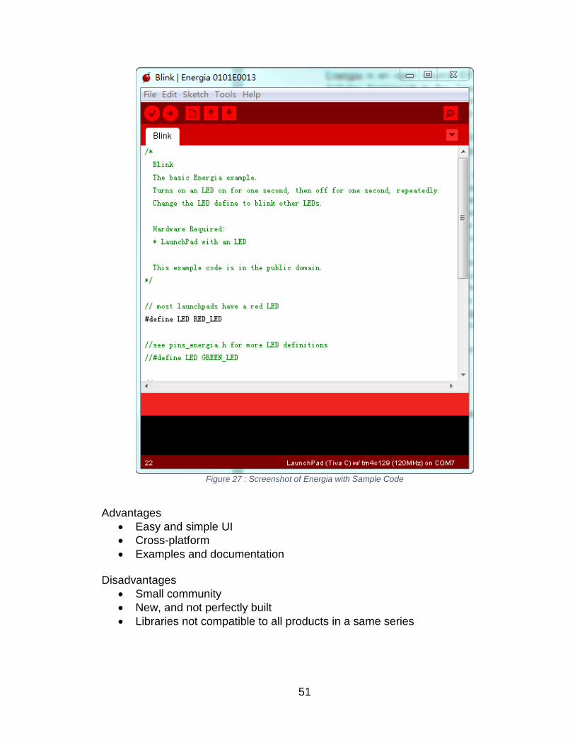
Figure 27 : Screenshot of Energia with Sample Code
Advantages
• Easy and simple UI • Cross-platform • Examples and documentation
Disadvantages
• Small community • New, and not perfectly built • Libraries not compatible to all products in a same series
51
3.1.7.3.4 Atmel Studio Atmel Studio is an IDP (integrated development platform) that focusing on development of Atmel ARM Cortex-M and Atmel AVR microcontroller based application. Atmel Studio allows developer using C or C++, or even assembly, to build and debug application. Atmel Studio contains a large library call ASF (Atmel Software Framework) and thousands of example codes for ARM and AVR projects. Atmel Studio includes the GCC C and C++ compiler, simulator and an assembler. The in-system debuggers and programmers make the development much easier. Project set up in Atmel Studio is very easy; all the linker and compiler configuration will be set up correctly when the project is created. Therefore, there is no need extra work on the configuration and developer could start writing code right the way. Word suggestion in Atmel Studio editor also increases the efficiency of development. Developer could just hover on the code, and more information about the code could just pop up. To organize the projects, the Solution Explorer in Atmel Studio also makes that easy. The in-system debugging in Atmel Studio is one of the biggest advantages of embedded system debugging for modern Flash microcontroller. With this feature, programs of the device could be updated easily. In addition, with the debugger connected, every single detail about the processor, memories could be viewed in Atmel Studio, which allows developer knows what is going on within the code and device, therefore increases the debug speed. The simulator inside of Atmel Studio can accurately simulate the AVR devices. It simulates all the instructions, interrupts and most of I/O so that the developer could have more confidence on the code.The figure below is UI for the software developer kit.
52
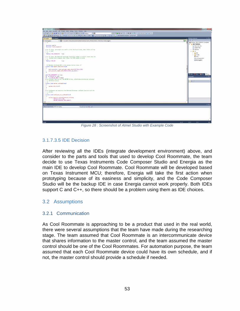
Figure 28 : Screenshot of Atmel Studio with Example Code
3.1.7.3.5 IDE Decision After reviewing all the IDEs (integrate development environment) above, and consider to the parts and tools that used to develop Cool Roommate, the team decide to use Texas Instruments Code Composer Studio and Energia as the main IDE to develop Cool Roommate. Cool Roommate will be developed based on Texas Instrument MCU; therefore, Energia will take the first action when prototyping because of its easiness and simplicity, and the Code Composer Studio will be the backup IDE in case Energia cannot work properly. Both IDEs support C and C++, so there should be a problem using them as IDE choices. 3.2 Assumptions 3.2.1 Communication As Cool Roommate is approaching to be a product that used in the real world, there were several assumptions that the team have made during the researching stage. The team assumed that Cool Roommate is an intercommunicate device that shares information to the master control, and the team assumed the master control should be one of the Cool Roommates. For automation purpose, the team assumed that each Cool Roommate device could have its own schedule, and if not, the master control should provide a schedule if needed.
53
3.2.2 Automation The Cool Roommate will be able to take commands from user input and automate responses and preferences without complications. Without any commands from user, the Cool Roommate should be able to operate and control the environment using standard pre-determined settings. 3.2.3 Battery Life The Cool Roommate will have a battery capability that will power the Master and Slave Components. 3.3 Constraints 3.3.1 Hardware Performance Some constraints that the team came up with while researching the product are related to hardware and its performance. Such as the a http server that runs on the master control would takes a lot of resources from the device, therefore yields insufficient resource for the major part of program. 3.3.2 Power Powering the minor control module, such as window shade control, air vent control, etc. must be efficient and be able to fulfill system design requirements. The Cool Roommate is designs to optimize efficiency of current HVAC systems at a low power cost. 3.3.3 Time Time is a constraint for the project as design and implementation must be completed and effective within two school semesters. The minimal time affects cost, the scope of the system, and may affect the readiness of the project to perform completely. 3.4 Dependencies 3.4.1 Connectivity The system’s reliability will depend heavily on the communication between deliverables sent and received between Master and Slave controller. Without proper connectivity between devices, the system cannot communicate properly and will provide issues executing commands.
54
3.4.2 Battery Life The system’s battery life will need to be efficient enough to maintain a strong relationship between Master and Slave controller. The battery must be effective enough to last a minimum of 6 months before changing.
4 Impact of Realistic Design Contraints 4.1 Economic The economic cost paid by consumers is estimated to be as much as $25 Billion that is lost due to inefficient energy practices. The Cool Roommate will be capable of reducing the energy deficiency found in common home practices by regulating household infrastructure such as the air conditioning unit, ceiling fans, air vents, window shades. Heating and cooling together comprise about 42% of consumer home energy expenditures, on average, although much of this energy expenditure seems to be used for space conditioning during times that the home is unoccupied or occupants are sleeping. Therefore, these “unoccupied” periods represent an often-untapped opportunity for the Cool Roommate to reduce home energy consumption. The question remains as to why such a large proportion of households do not appear to be adjusting their thermostats according to occupancy. 4.2 Environmental The environmental costs of energy are high and getting higher, with 65% of global warming pollution estimated to come from energy generation and use there is a call to be more responsible with our energy use. The United States Environmental Protection Agency, or EPA, has found that among households using thermostats for heating, it is estimated that about half of all households (49%) usually do not have someone home during the day. However, during the winter, less than half (42%) of households report turning the heat down and only 2% completely turn the heat off. A slightly higher percentage of households reported turning the heat down (46%) or off (6%) during sleep hours. 4.3 Social The social constraing the Cool Roommate plans to address is the misuse of energy in current home cooling models. The environmental costs are heavy, and on a grand scale, the misuse and inefficient energy practices lead to climate change. Human activities are primarily responsible for Earth’s warming temperature and further climate change is inevitable without actions to reduce GHG emissions. Power Plants and Ulitiy companies produce greenhouse gas emissions that in the 21st century alone can set in motion large-scale, high-
55

impact, non-linear, and potentially abrupt changes in physical and biological systems over the coming decades to millennia.
5 Indentification of Related Standards and Laws Home Automation is a recent and rapidly growing industry. There is currently no market leader and standards across automation, however there are standards and regulations identifying efficient homes and commucation. 5.1 Home Energy Rating System
The Home Energy Rating System (HERS) Index is the industry standard by which a home's energy efficiency is measured. It’s also the nationally recognized system for inspecting and calculating a home's energy performance. The U.S. Department of Energy has determined that a typical resale home scores 130 on the HERS Index while a standard new home is awarded a rating of 100.
• A home with a HERS Index Score of 70 is 30% more energy efficient than a standard new home
• A home with a HERS Index Score of 130 is 30% less energy efficient than a standard new home
The HERS Index is designed to rate home energy efficiency to:
Overall improve health and comfort and reduce temperature fluctuations.
Provide cost effective solutions that produce energy not only shields its owner from fluctuations in energy prices, but can eliminate energy bills altogether.
Establish environmental sustainability that protects the environment by reducing greenhouse gases, cutting carbon emissions and saving energy.
5.2 ISM Band Regulations The US 902-928 MHz ISM bands is a Federal Communications Commission (FCC) regulation on low-power, non-licensed transmitters within U.S. The rules for this regulation are documented in Part 15 of Title 47 of the Code of Federal Regulations (“FCC Part 15”), which is subject to two conditions. The first condition is that the device itself may not cause any harmful interference, and the second one is that the device must accept any interference received, including those interference that might cause unexpected operation.
56
6 Requirements 6.1 Functional requirements The Functional Requirements are derived from different models discovered in relevant technologies. In effort to make the project more efficient and optimize its features the scope of the project and time deadline is considered for the Senior Design course.
• The smart cooling system should be able to operate on all Microsoft Windows computers since Windows is the most popular and widespread platform. Other platforms do not have to be supported
• The system will be controlled through a central micro-processing device • The Senior Design Group 26 has not confirmed the programing language
and is TBD • The window shades shall be no heavier than 2.72 kg • The vents controllable will open and close based on response from
microcontroller • The vents will be no larger in area .09 m2 • The ceiling fans will be shut off after 75 minutes of use • The user can specify a personal setting for the use of airflow • The Master Controller shall monitor the temperature of the house and
respond based on predetermined settings. 6.2 Sensors Sensor requirements are derived from capabilities achievable within the scope and design of the senior design course. Relevant technologies were examined and considered when creating the sensor requirements. To determine what is most feasible for the system design these requirements have been decided to be what is most effective for the overall purpose of the system. • The system’s temperature sensors will provide a minimum effective range
of -10°F - 110°F. • The window shades will automatically close above 80°F. • The user can specify a personal setting for the control over the window
shades. • The main temperature sensor will be located by the Master controller. • The sensors need to be within 5% accuracy of true value. • The system must be made available for future enhancement.
57
6.3 Communication The Communication requirements are derived from capabilities achievable within the scope and design of the senior design course. Relevant technologies were examined and considered when creating the communication requirements. In order to have the proper communication between wireless components these requirements have been decided. • Short range wireless communication less than 50ft. • Master Controller will be able to communicate with a minimum of 2 slave
controllers at once. • Slave Controller should be able to communicate data and receive commands
from master controller simultaneously. • Wireless communication should be capable of passing through walls
consisting of ply wood and/or dry wall. • Wireless communication should be capable of passing through an aggregate
wall width of .3 meters.
6.4 Usability The usability requirements are derived from capabilities achievable within the scope and design of the senior design course. Relevant technologies were examined and considered when creating the usability requirements. • The user will be able to operate Cool Roommate through a touch screen • The GUI should allow the user to control the temperature, airflow, and
direction of blinds and vents • The GUI will provide an updated status to the user every 2 minutes of the
current temperature, airflow, and position of blinds and vents 6.5 Performance 6.5.1 Capacity For the scope of the class there will only be one system in production. There will be one Master controller and three slave controllers. It is the Master controller’s responsibility to receive data and transmit commands to slave controllers. Slave controllers will be responsible for receiving commands and transmitting data wirelessly to other controllers. 6.5.2 Availability Once the Cool Roommate is powered on, it should be available all the time until power out. Plug-and-Play (PnP) concept would be implemented in wireless way,
58
so for extra children (minor controllers) to be easily added onto the device without re-programming. 6.5.3 Latency Cool Roommate is depending on a wireless communication between the master and the slaves, and between the slaves to the minor controls; therefore, latency should need to be as minimum as possible to be able to synchronize every single piece of information. The expecting delays between the communications should be between two to three milliseconds, and of course, the lower the better.
7 Project Hardware and Software Design Details 7.1 Initial Design Architecture and Related Diagrams The figure below shows a simple demo usage for Cool Roommate in a single house. For example, a house has two bedrooms and a living room and each room will have its own Cool Roommate device. Also each bedroom will have a ceiling fan, window, and an air vent, and the living room will have at least one of the items that mentioned above. Assume that the Cool Roommate device in the living room is the master controller; first of all, the master will communicate to the two controllers that in each bedroom, but those two could not communicate to each other. Each controller will have its right to control every item in its area, for example, Room 1 Controller could only manage the fan, window, and vent in Room 1, and Room 2 Controller could only manage the items in Room 2, and so on. The master controllers could also send signal to each room to override to control those items.
59
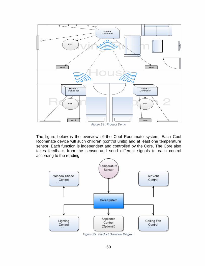
Figure 24 : Product Demo
The figure below is the overview of the Cool Roommate system. Each Cool Roommate device will such children (control units) and at least one temperature sensor. Each function is independent and controlled by the Core. The Core also takes feedback from the sensor and send different signals to each control according to the reading.
Figure 25 : Product Overview Diagram
60
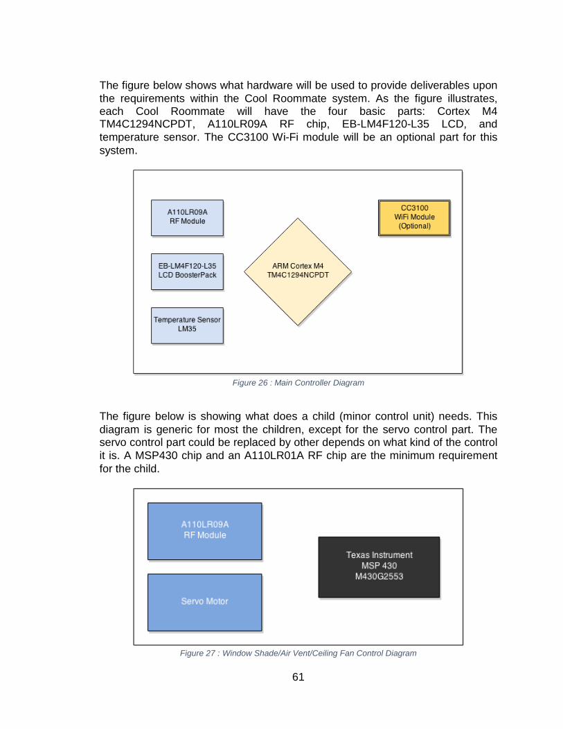
The figure below shows what hardware will be used to provide deliverables upon the requirements within the Cool Roommate system. As the figure illustrates, each Cool Roommate will have the four basic parts: Cortex M4 TM4C1294NCPDT, A110LR09A RF chip, EB-LM4F120-L35 LCD, and temperature sensor. The CC3100 Wi-Fi module will be an optional part for this system.
Figure 26 : Main Controller Diagram
The figure below is showing what does a child (minor control unit) needs. This diagram is generic for most the children, except for the servo control part. The servo control part could be replaced by other depends on what kind of the control it is. A MSP430 chip and an A110LR01A RF chip are the minimum requirement for the child.
Figure 27 : Window Shade/Air Vent/Ceiling Fan Control Diagram
61
7.2 Logic Controller 7.2.1 Master Controller Texas Instruments Tiva C is a microcontroller that provides communication real-time communication control between Master and Slave components. The integrated communication will provide its foundation for targeted rooms and functions. The microcontroller will provide sufficient computational power to execute the necessary commands to the slave controllers. 7.2.2 Slave Controller Texas Instruments MSP430 is an ultra-low power microcontroller selected for various applications. The architecture, combined with low power modes, optimizes its remote applications considered for battery life. The digitally controlled oscillator allows wake-up from low-power modes to active mode in less than 1 microsecond. 7.3 Energy Tiva C Series devices provide sleep, deep-sleep and hibernate (HIB) modes to save power when minimal functionality is required. In the hibernate mode, power to the entire chip is cut off except to the HIB block, leaving the MCU in a state where it can be brought back to life when the need arises. 7.4 Memory Allocation Tiva C Series MCUs have extended memory durability by an order of magnitude beyond the competition. The minimum number of times the Flash memory on these MCUs can be erased and reprogrammed is as high as 100,000 cycles. For most applications, this breakthrough eliminates any concern of wearing out the memory from re-flashing for data collection, configuration parameters or program modifications 7.5 Direct memory access MSP430 MCUs also feature a direct memory access controller, enabling memory transfer with no CPU intervention. This means higher throughput of peripheral data and lower system power.
62
7.5.1 Multiple low-power modes The MSP430 MCU clock system has the ability to enable and disable various clocks and oscillators which allow the device to enter several low-power modes. The flexible clocking system optimizes overall current consumption by only enabling the required clocks when appropriate. This means that MSP430 MCUs can operate for decades on a single coin cell battery. 7.5.2 Real-time clock
• The low-power real-time clock (RTC), available on select MSP430 MCUs, precisely keeps real time and enables wakeup at specified intervals. Some variants also include a switchable battery backup system that maintains operations when the primary power supply fails.
• The digitally controlled oscillator provides a startup time as fast as 1 microsecond, allowing the MSP430 to remain in low-power modes for the longest possible interval-extending battery life.
7.5.3 Low Level Network Communication 7.5.3.1 RF System Air modules CC110L The CC110L RF BoosterPack is a low-power wireless transceiver extension kit for the Texas Instruments MSP430. The BoosterPack comes with an on-board Anaren Integrated Radio module with integrated antenna. Advantages
• Low power consumption • Low Cost
Disadvantages
• Limited Compatibility
The pinout for the RF module used in the Cool Roommate is illustrated below. The pinout is required for debug and design purposes.
63
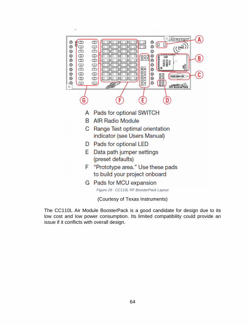
Figure 29 : CC110L RF BoosterPack Layout
(Courtesy of Texas Instruments) The CC110L Air Module BoosterPack is a good candidate for design due to its low cost and low power consumption. Its limited compatibility could provide an issue if it conflicts with overall design.
64
7.5.4 Power Switching regulators offer high efficiency especially at low loads and would be the best choice for powering the electronics. Switching DC regulators also incorporate low waste heat in correlation with its high efficiency. It is necessary that overall power consumption is minimum to provide longevity to the overall effectiveness of the design. 7.5.5 Sensors and control 7.5.5.1 HVAC control A series of relays will allow control of a central air conditioning unit. This will be the safest option in controlling a large high powered appliance such as an air conditioner. The relay setup will allow control of the fan and also the compressor to ensure maximum thermal and energy efficiency. The HVAC control is responsible for the temperature and the strength of the air flow. The senior design team will not be responsible for building an HVAC system, but will have access to its control to accomplish the goals of the Cool Roommate. 7.5.5.2 Temperature Each slave controller will have an onboard temperature sensor. The temperature sensor will measure the relative ambient temperature of its location and relay it back to the room’s main controller to be processed. Precision temperature sensors with an accuracy of less than 1 degree Celsius. The temperature will be able to change based on action from the HVAC control and system based on recordings from the temperature setting. When the temperature is too high/low the HVAC system will turn on and begin cooling/heating the environment. With the assistance and directed control from the Master controller, the ceiling fans and windows may be accessible to change the temperature. The temperature sensors are important as they act as one of the primary triggers for the Cool Roommate to monitor. 7.5.5.3 Fan Control Components such as relays and fuses will make up the fan control module. Relays will allow the ceiling device be electrically isolated and encapsulates an immense amount of functionality. The fan will help circulate the temperature of the environment, The use of ceiling fans helps circulate cool air through warm spots of the room.
65
To ensure fail safe operation, fuses will be incorporated within the design to maximize safety. 7.5.5.4 Window Control LMD18200 H-Bridge will allow bidirectional movement for the motor that will be opening and closing the window shades. The H-Bridge is rated at 3A 55V which is more than enough to power the stepper motor that will be used. The integrated circuit is also compatible with TTL inputs which are perfect for the application. 7.5.5.5 Vent Control A metal gear servo will control the air conditioner vent. The metal gear servo will be able to provide sufficient torque required to open and close the ceiling vents. Air conditioner vents are typically made of metal which therefore may not be the easiest to operate. Hence why a metal gear servo would be suitable for this operation. A servo controller will bridge the gap between the servo and slave logic controller. 7.5.5.6 Appliance Expansion Expansion ports on the slave logic controller will be included to allow future compatibility. The expansion ports on the slave logic controller to allow innovative ideas to take precedence in an effort to change the world. 7.5.6 High Level Network Management 7.5.6.1 Master to slave link In the communication network of Cool Roommate, there are two different type of communications. The first one is the communication between the slave controller and its children controllers, which are the window shade control, air vent control, and etc. The second type of communication is the communication between the master controller and slave controllers. Each slave can talk to the master, and of course, the master can talk back to the slaves. However, for security reason, each slave will be isolated. Therefore, a slave is solely a slave cannot talk to other slaves within the network.
66
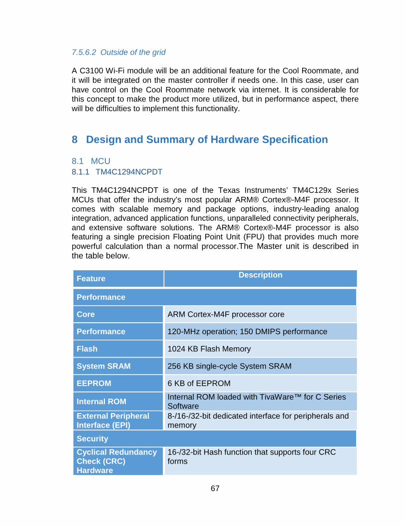
7.5.6.2 Outside of the grid A C3100 Wi-Fi module will be an additional feature for the Cool Roommate, and it will be integrated on the master controller if needs one. In this case, user can have control on the Cool Roommate network via internet. It is considerable for this concept to make the product more utilized, but in performance aspect, there will be difficulties to implement this functionality.
8 Design and Summary of Hardware Specification 8.1 MCU 8.1.1 TM4C1294NCPDT This TM4C1294NCPDT is one of the Texas Instruments’ TM4C129x Series MCUs that offer the industry’s most popular ARM® Cortex®-M4F processor. It comes with scalable memory and package options, industry-leading analog integration, advanced application functions, unparalleled connectivity peripherals, and extensive software solutions. The ARM® Cortex®-M4F processor is also featuring a single precision Floating Point Unit (FPU) that provides much more powerful calculation than a normal processor.The Master unit is described in the table below.
Feature Description
Performance
Core ARM Cortex-M4F processor core
Performance 120-MHz operation; 150 DMIPS performance
Flash 1024 KB Flash Memory
System SRAM 256 KB single-cycle System SRAM
EEPROM 6 KB of EEPROM
Internal ROM Internal ROM loaded with TivaWare™ for C Series Software
External Peripheral Interface (EPI)
8-/16-/32-bit dedicated interface for peripherals and memory
Security Cyclical Redundancy Check (CRC) Hardware
16-/32-bit Hash function that supports four CRC forms
67
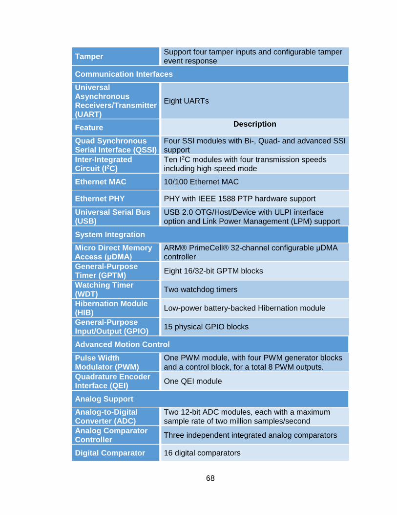
Tamper Support four tamper inputs and configurable tamper event response
Communication Interfaces Universal Asynchronous Receivers/Transmitter (UART)
Eight UARTs
Feature Description
Quad Synchronous Serial Interface (QSSI)
Four SSI modules with Bi-, Quad- and advanced SSI support
Inter-Integrated Circuit (I2C)
Ten I2C modules with four transmission speeds including high-speed mode
Ethernet MAC 10/100 Ethernet MAC
Ethernet PHY PHY with IEEE 1588 PTP hardware support
Universal Serial Bus (USB)
USB 2.0 OTG/Host/Device with ULPI interface option and Link Power Management (LPM) support
System Integration Micro Direct Memory Access (μDMA)
ARM® PrimeCell® 32-channel configurable μDMA controller
General-Purpose Timer (GPTM) Eight 16/32-bit GPTM blocks
Watching Timer (WDT) Two watchdog timers
Hibernation Module (HIB) Low-power battery-backed Hibernation module
General-Purpose Input/Output (GPIO) 15 physical GPIO blocks
Advanced Motion Control Pulse Width Modulator (PWM)
One PWM module, with four PWM generator blocks and a control block, for a total 8 PWM outputs.
Quadrature Encoder Interface (QEI) One QEI module
Analog Support Analog-to-Digital Converter (ADC)
Two 12-bit ADC modules, each with a maximum sample rate of two million samples/second
Analog Comparator Controller Three independent integrated analog comparators
Digital Comparator 16 digital comparators
68
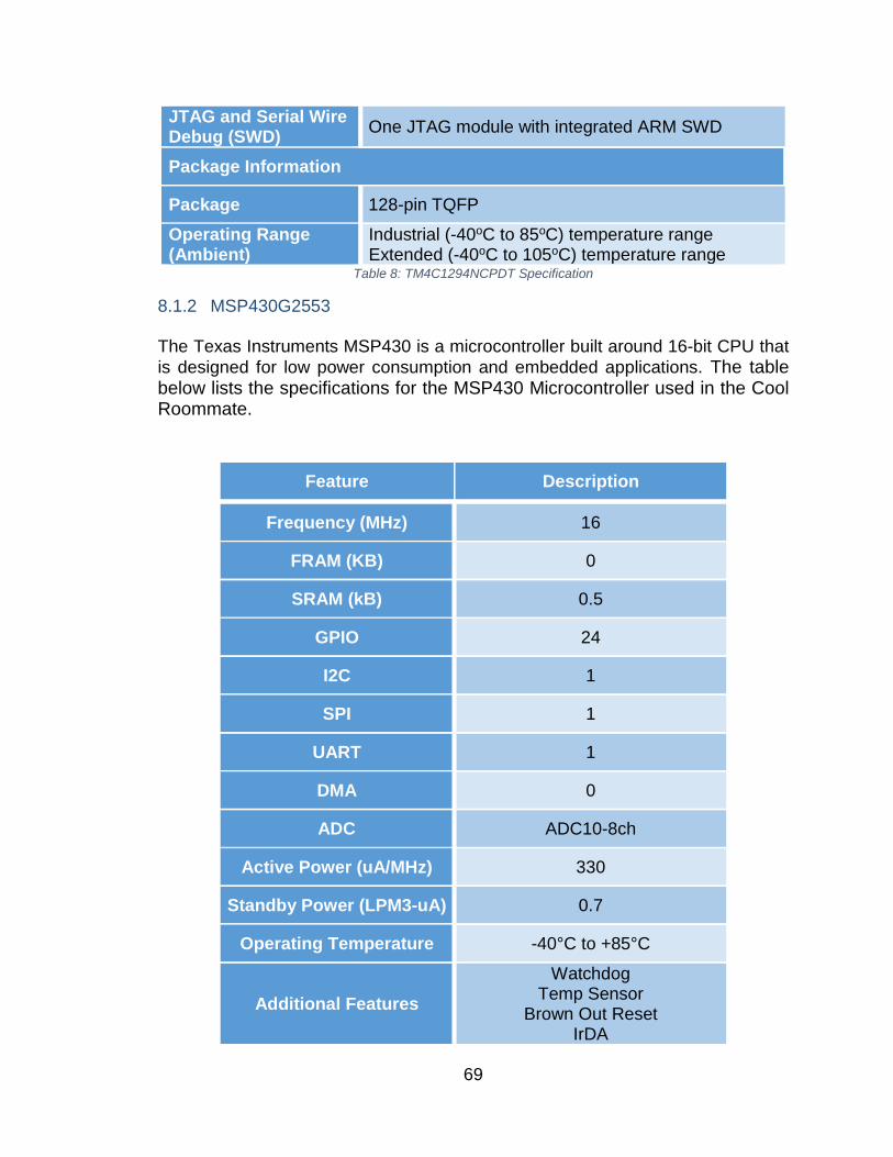
JTAG and Serial Wire Debug (SWD) One JTAG module with integrated ARM SWD
Package Information
Package 128-pin TQFP Operating Range (Ambient)
Industrial (-40oC to 85oC) temperature range Extended (-40oC to 105oC) temperature range
Table 8: TM4C1294NCPDT Specification
8.1.2 MSP430G2553 The Texas Instruments MSP430 is a microcontroller built around 16-bit CPU that is designed for low power consumption and embedded applications. The table below lists the specifications for the MSP430 Microcontroller used in the Cool Roommate.
Feature Description
Frequency (MHz) 16
FRAM (KB) 0
SRAM (kB) 0.5
GPIO 24
I2C 1
SPI 1
UART 1
DMA 0
ADC ADC10-8ch
Active Power (uA/MHz) 330
Standby Power (LPM3-uA) 0.7
Operating Temperature -40°C to +85°C
Additional Features Watchdog
Temp Sensor Brown Out Reset
IrDA
69
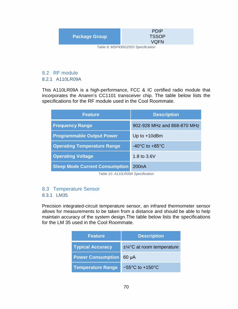
Package Group PDIP
TSSOP VQFN
Table 9: MSP430G2553 Specification
8.2 RF module 8.2.1 A110LR09A This A110LR09A is a high-performance, FCC & IC certified radio module that incorporates the Anaren’s CC1101 transceiver chip. The table below lists the specifications for the RF module used in the Cool Roommate.
Feature Description
Frequency Range 902-928 MHz and 868-870 MHz
Programmable Output Power Up to +10dBm
Operating Temperature Range -40°C to +85°C
Operating Voltage 1.8 to 3.6V
Sleep Mode Current Consumption 200nA Table 10: A110LR09A Specification
8.3 Temperature Sensor 8.3.1 LM35 Precision integrated-circuit temperature sensor, an infrared thermometer sensor allows for measurements to be taken from a distance and should be able to help maintain accuracy of the system design.The table below lists the specifications for the LM 35 used in the Cool Roommate.
Feature Description
Typical Accuracy ±¼°C at room temperature
Power Consumption 60 μA
Temperature Range −55°C to +150°C
70
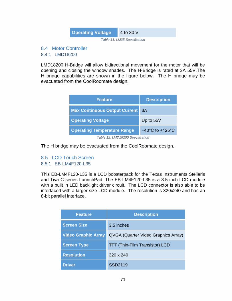
Operating Voltage 4 to 30 V Table 11: LM35 Specification
8.4 Motor Controller 8.4.1 LMD18200 LMD18200 H-Bridge will allow bidirectional movement for the motor that will be opening and closing the window shades. The H-Bridge is rated at 3A 55V.The H bridge capabilities are shown in the figure below. The H bridge may be evacuated from the CoolRoomate design.
Feature Description
Max Continuous Output Current 3A
Operating Voltage Up to 55V
Operating Temperature Range −40°C to +125°C Table 12: LMD18200 Specification
The H bridge may be evacuated from the CoolRoomate design. 8.5 LCD Touch Screen 8.5.1 EB-LM4F120-L35 This EB-LM4F120-L35 is a LCD boosterpack for the Texas Instruments Stellaris and Tiva C series LaunchPad. The EB-LM4F120-L35 is a 3.5 inch LCD module with a built in LED backlight driver circuit. The LCD connector is also able to be interfaced with a larger size LCD module. The resolution is 320x240 and has an 8-bit parallel interface.
Feature Description
Screen Size 3.5 inches
Video Graphic Array QVGA (Quarter Video Graphics Array)
Screen Type TFT (Thin-Film Transistor) LCD
Resolution 320 x 240
Driver SSD2119
71
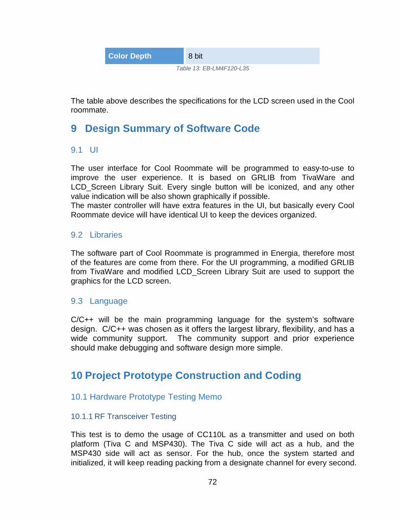
Color Depth 8 bit Table 13: EB-LM4F120-L35
The table above describes the specifications for the LCD screen used in the Cool roommate.
9 Design Summary of Software Code 9.1 UI The user interface for Cool Roommate will be programmed to easy-to-use to improve the user experience. It is based on GRLIB from TivaWare and LCD_Screen Library Suit. Every single button will be iconized, and any other value indication will be also shown graphically if possible. The master controller will have extra features in the UI, but basically every Cool Roommate device will have identical UI to keep the devices organized. 9.2 Libraries The software part of Cool Roommate is programmed in Energia, therefore most of the features are come from there. For the UI programming, a modified GRLIB from TivaWare and modified LCD_Screen Library Suit are used to support the graphics for the LCD screen. 9.3 Language C/C++ will be the main programming language for the system’s software design. C/C++ was chosen as it offers the largest library, flexibility, and has a wide community support. The community support and prior experience should make debugging and software design more simple.
10 Project Prototype Construction and Coding 10.1 Hardware Prototype Testing Memo 10.1.1 RF Transceiver Testing This test is to demo the usage of CC110L as a transmitter and used on both platform (Tiva C and MSP430). The Tiva C side will act as a hub, and the MSP430 side will act as sensor. For the hub, once the system started and initialized, it will keep reading packing from a designate channel for every second.
72
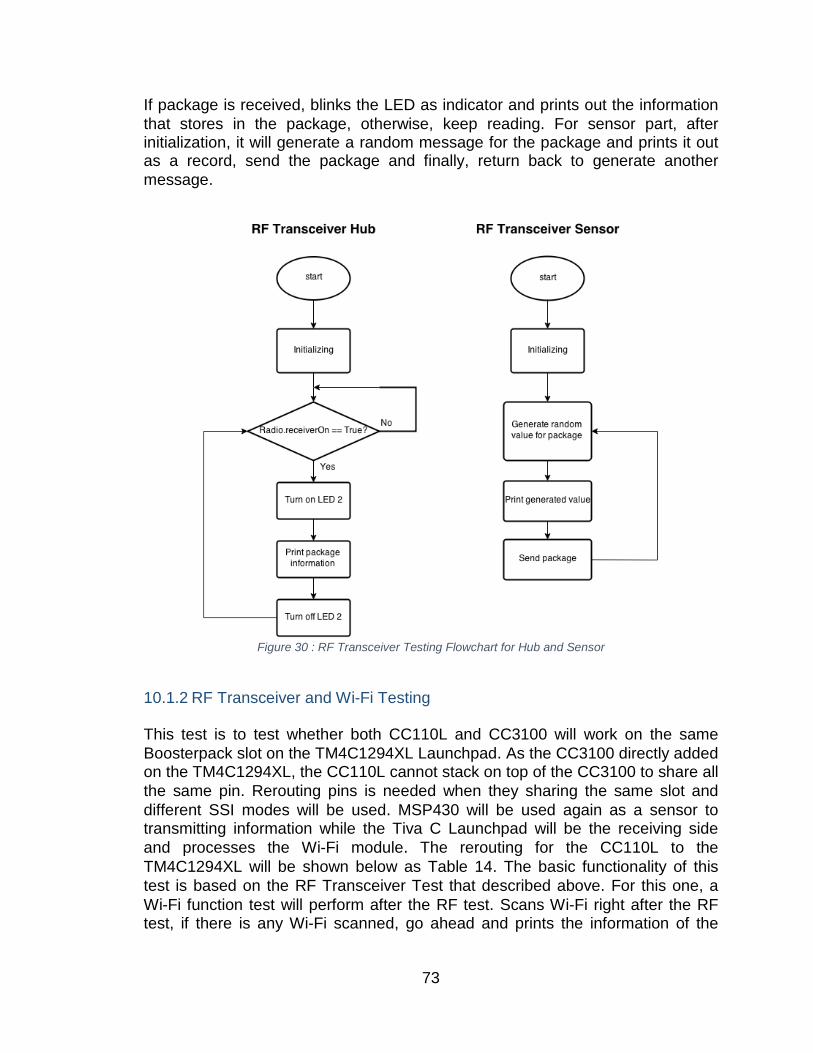
If package is received, blinks the LED as indicator and prints out the information that stores in the package, otherwise, keep reading. For sensor part, after initialization, it will generate a random message for the package and prints it out as a record, send the package and finally, return back to generate another message.
Figure 30 : RF Transceiver Testing Flowchart for Hub and Sensor
10.1.2 RF Transceiver and Wi-Fi Testing This test is to test whether both CC110L and CC3100 will work on the same Boosterpack slot on the TM4C1294XL Launchpad. As the CC3100 directly added on the TM4C1294XL, the CC110L cannot stack on top of the CC3100 to share all the same pin. Rerouting pins is needed when they sharing the same slot and different SSI modes will be used. MSP430 will be used again as a sensor to transmitting information while the Tiva C Launchpad will be the receiving side and processes the Wi-Fi module. The rerouting for the CC110L to the TM4C1294XL will be shown below as Table 14. The basic functionality of this test is based on the RF Transceiver Test that described above. For this one, a Wi-Fi function test will perform after the RF test. Scans Wi-Fi right after the RF test, if there is any Wi-Fi scanned, go ahead and prints the information of the
73
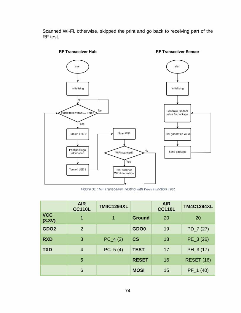
Scanned Wi-Fi, otherwise, skipped the print and go back to receiving part of the RF test.
Figure 31 : RF Transceiver Testing with Wi-Fi Function Test
AIR
CC110L TM4C1294XL AIR
CC110L TM4C1294XL
VCC (3.3V) 1 1 Ground 20 20
GDO2 2 GDO0 19 PD_7 (27)
RXD 3 PC_4 (3) CS 18 PE_3 (26)
TXD 4 PC_5 (4) TEST 17 PH_3 (17)
5 RESET 16 RESET (16)
6 MOSI 15 PF_1 (40)
74
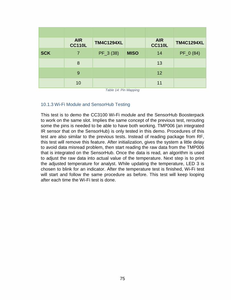
AIR CC110L TM4C1294XL AIR
CC110L TM4C1294XL
SCK 7 PF_3 (38) MISO 14 PF_0 (84)
8 13
9 12
10 11 Table 14: Pin Mapping
10.1.3 Wi-Fi Module and SensorHub Testing This test is to demo the CC3100 Wi-Fi module and the SensorHub Boosterpack to work on the same slot. Implies the same concept of the previous test, rerouting some the pins is needed to be able to have both working. TMP006 (an integrated IR sensor that on the SensorHub) is only tested in this demo. Procedures of this test are also similar to the previous tests. Instead of reading package from RF, this test will remove this feature. After initialization, gives the system a little delay to avoid data misread problem, then start reading the raw data from the TMP006 that is integrated on the SensorHub. Once the data is read, an algorithm is used to adjust the raw data into actual value of the temperature. Next step is to print the adjusted temperature for analyst. While updating the temperature, LED 3 is chosen to blink for an indicator. After the temperature test is finished, Wi-Fi test will start and follow the same procedure as before. This test will keep looping after each time the Wi-Fi test is done.
75
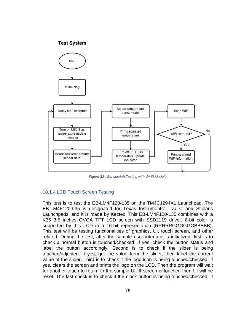
Figure 32 : SensorHub Testing with Wi-Fi Module
10.1.4 LCD Touch Screen Testing
This test is to test the EB-LM4F120-L35 on the TM4C1294XL Launchpad. The EB-LM4F120-L35 is designated for Texas Instruments’ Tiva C and Stellaris Launchpads, and it is made by Kectec. This EB-LM4F120-L35 combines with a K35 3.5 inches QVGA TFT LCD screen with SSD2119 driver. 8-bit color is supported by this LCD in a 16-bit representation (RRRRRGGGGGGBBBBB). This test will be testing functionalities of graphics, UI, touch screen, and other related. During the test, after the sample user interface is initialized, first is to check a normal button is touched/checked. If yes, check the button status and label the button accordingly. Second is to check if the slider is being touched/adjusted. If yes, get the value from the slider, then label the current value of the slider. Third is to check if the logo icon is being touched/checked. If yes, clears the screen and prints the logo on the LCD. Then the program will wait for another touch to return to the sample UI. If screen is touched then UI will be reset. The last check is to check if the clock button is being touched/checked. If
76
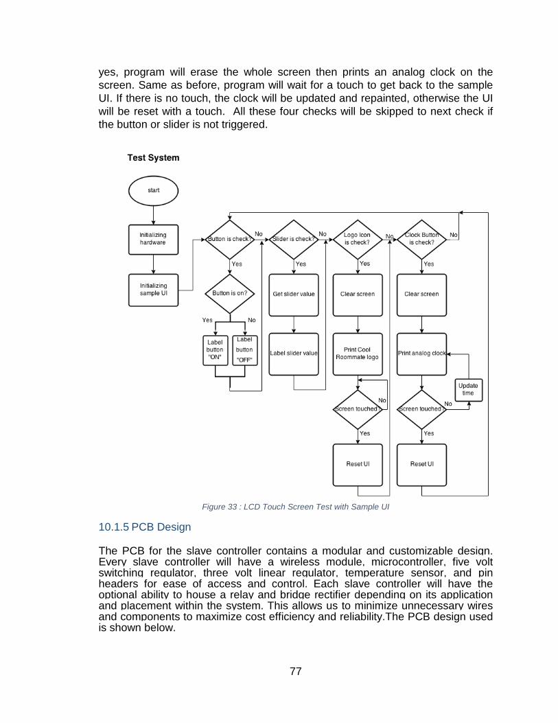
yes, program will erase the whole screen then prints an analog clock on the screen. Same as before, program will wait for a touch to get back to the sample UI. If there is no touch, the clock will be updated and repainted, otherwise the UI will be reset with a touch. All these four checks will be skipped to next check if the button or slider is not triggered.
Figure 33 : LCD Touch Screen Test with Sample UI
10.1.5 PCB Design The PCB for the slave controller contains a modular and customizable design. Every slave controller will have a wireless module, microcontroller, five volt switching regulator, three volt linear regulator, temperature sensor, and pin headers for ease of access and control. Each slave controller will have the optional ability to house a relay and bridge rectifier depending on its application and placement within the system. This allows us to minimize unnecessary wires and components to maximize cost efficiency and reliability.The PCB design used is shown below.
77
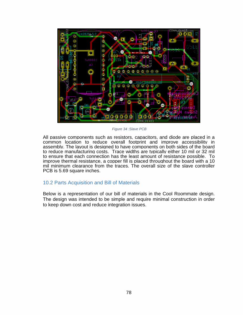
Figure 34 :Slave PCB
All passive components such as resistors, capacitors, and diode are placed in a common location to reduce overall footprint and improve accessibility in assembly. The layout is designed to have components on both sides of the board to reduce manufacturing costs. Trace widths are typically either 10 mil or 32 mil to ensure that each connection has the least amount of resistance possible. To improve thermal resistance, a copper fill is placed throughout the board with a 10 mil minimum clearance from the traces. The overall size of the slave controller PCB is 5.69 square inches. 10.2 Parts Acquisition and Bill of Materials Below is a representation of our bill of materials in the Cool Roommate design. The design was intended to be simple and require minimal construction in order to keep down cost and reduce integration issues.
78
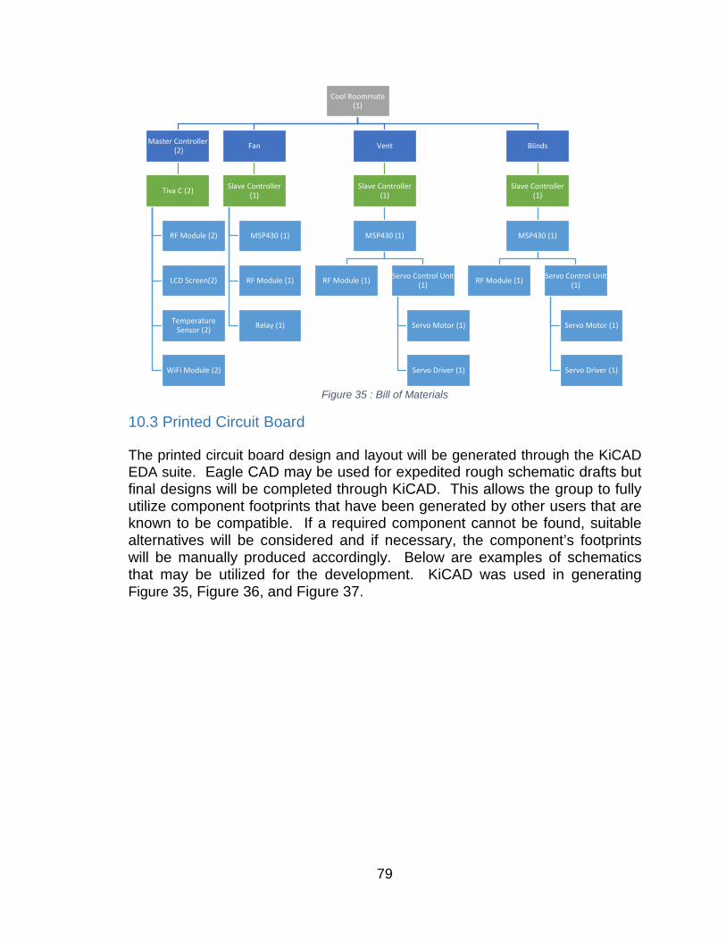
Figure 35 : Bill of Materials
10.3 Printed Circuit Board The printed circuit board design and layout will be generated through the KiCAD EDA suite. Eagle CAD may be used for expedited rough schematic drafts but final designs will be completed through KiCAD. This allows the group to fully utilize component footprints that have been generated by other users that are known to be compatible. If a required component cannot be found, suitable alternatives will be considered and if necessary, the component’s footprints will be manually produced accordingly. Below are examples of schematics that may be utilized for the development. KiCAD was used in generating Figure 35, Figure 36, and Figure 37.
Cool Roommate (1)
Master Controller(2)
Tiva C (2)
RF Module (2)
LCD Screen(2)
Temperature Sensor (2)
WiFi Module (2)
Fan
Slave Controller (1)
MSP430 (1)
RF Module (1)
Relay (1)
Vent
Slave Controller (1)
MSP430 (1)
RF Module (1) Servo Control Unit (1)
Servo Motor (1)
Servo Driver (1)
Blinds
Slave Controller (1)
MSP430 (1)
RF Module (1) Servo Control Unit (1)
Servo Motor (1)
Servo Driver (1)
79
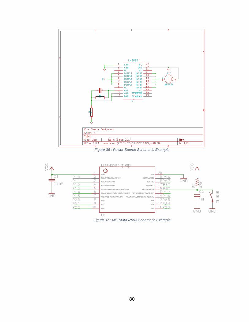
Figure 36 : Power Source Schematic Example
Figure 37 : MSP430G2553 Schematic Example
80
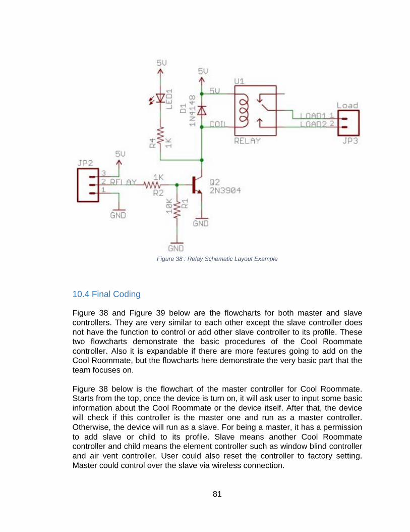
Figure 38 : Relay Schematic Layout Example
10.4 Final Coding Figure 38 and Figure 39 below are the flowcharts for both master and slave controllers. They are very similar to each other except the slave controller does not have the function to control or add other slave controller to its profile. These two flowcharts demonstrate the basic procedures of the Cool Roommate controller. Also it is expandable if there are more features going to add on the Cool Roommate, but the flowcharts here demonstrate the very basic part that the team focuses on. Figure 38 below is the flowchart of the master controller for Cool Roommate. Starts from the top, once the device is turn on, it will ask user to input some basic information about the Cool Roommate or the device itself. After that, the device will check if this controller is the master one and run as a master controller. Otherwise, the device will run as a slave. For being a master, it has a permission to add slave or child to its profile. Slave means another Cool Roommate controller and child means the element controller such as window blind controller and air vent controller. User could also reset the controller to factory setting. Master could control over the slave via wireless connection.
81
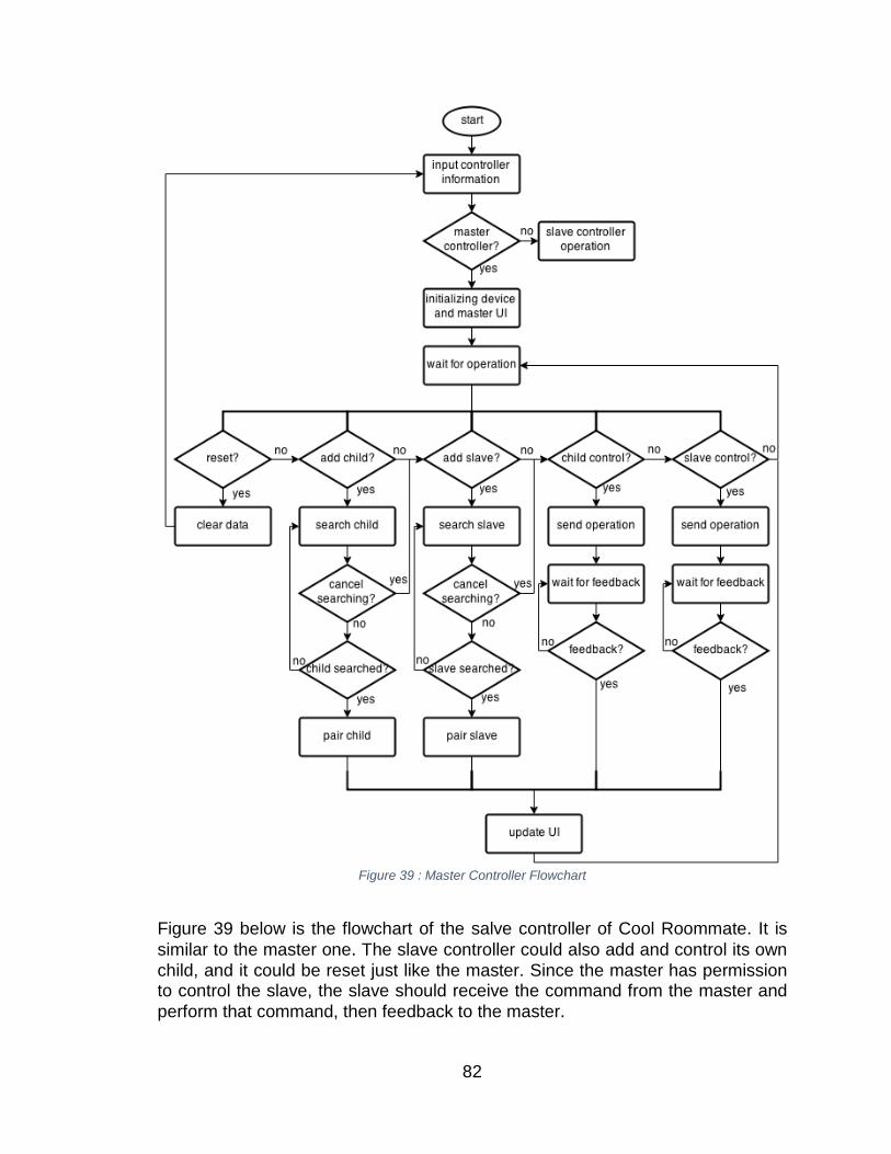
Figure 39 : Master Controller Flowchart
Figure 39 below is the flowchart of the salve controller of Cool Roommate. It is similar to the master one. The slave controller could also add and control its own child, and it could be reset just like the master. Since the master has permission to control the slave, the slave should receive the command from the master and perform that command, then feedback to the master.
82
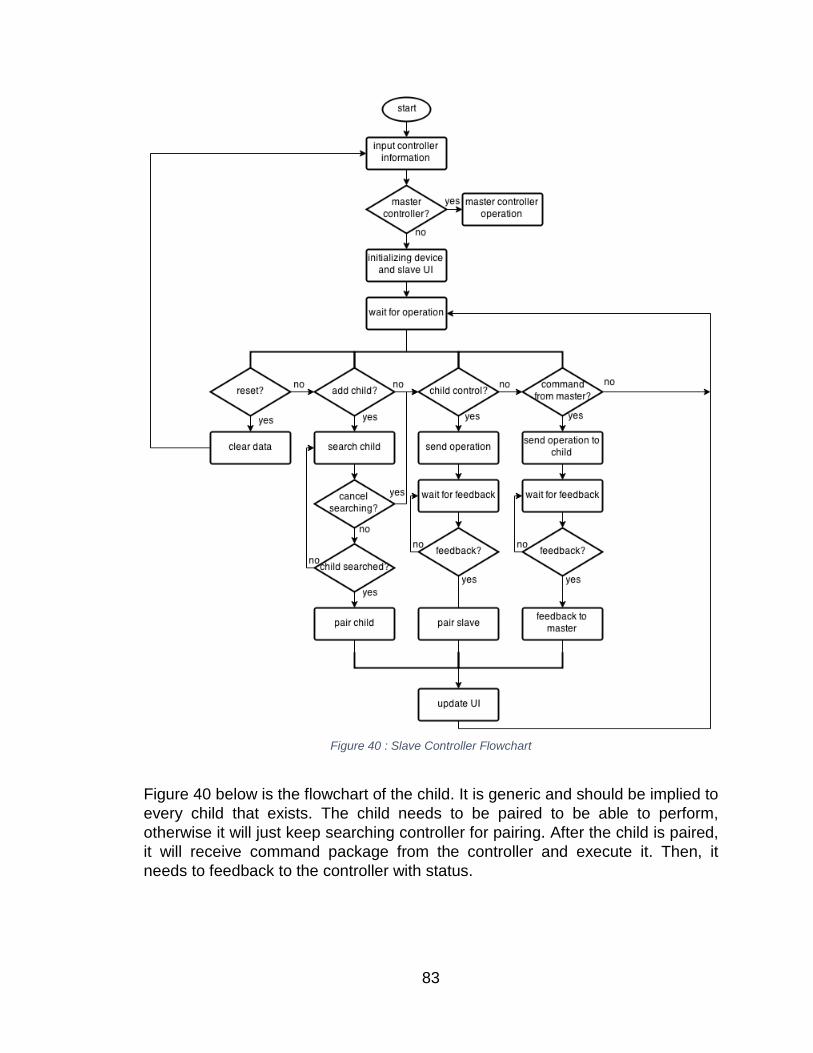
Figure 40 : Slave Controller Flowchart
Figure 40 below is the flowchart of the child. It is generic and should be implied to every child that exists. The child needs to be paired to be able to perform, otherwise it will just keep searching controller for pairing. After the child is paired, it will receive command package from the controller and execute it. Then, it needs to feedback to the controller with status.
83
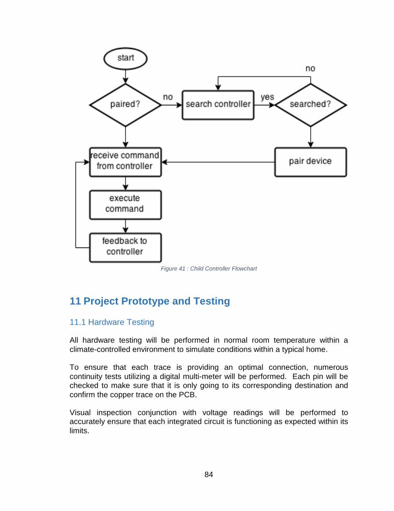
Figure 41 : Child Controller Flowchart
11 Project Prototype and Testing 11.1 Hardware Testing All hardware testing will be performed in normal room temperature within a climate-controlled environment to simulate conditions within a typical home. To ensure that each trace is providing an optimal connection, numerous continuity tests utilizing a digital multi-meter will be performed. Each pin will be checked to make sure that it is only going to its corresponding destination and confirm the copper trace on the PCB. Visual inspection conjunction with voltage readings will be performed to accurately ensure that each integrated circuit is functioning as expected within its limits.
84
11.1.1 Relay Test The relay circuitry will be manually triggered via the slave microcontroller. When given a signal to trigger the relay, the relay will complete the corresponding circuit and allow current to pass through. The test will verify against unintentional relay switching and adequately ensure a solid connection is made when triggered. 11.1.2 Temperature Sensor Ambient air temperature measured with a temperature sensor will be checked to ensure accuracy by cross-referencing with multiple other thermal sensors. Some examples are an infrared temperature gun and thermostat. 11.1.3 LCD Module To ensure accurate color representation and touch screen accuracy, a calibration will be performed then a short testing program. The test program will allow the test operator to verify touch location the module registers to safeguard against manufacture defects. The program will also include multiple reference images to verify black level, white level, sharpness, color saturation, and also color tint. 11.1.4 Wireless Module Wireless communication will be verified by manually sending data from the master controller to each slave. The test will verify that each controller is able to send and receive the correct data accurately with minimal losses. A short script will be used to send and receive data to each unit one at a time at varying intervals. Then transmit and receive multiple packets simultaneously to simulate the system at max capacity. 11.1.5 Motor Control The window blinds will be manually operated to preserve its structural integrity and calibrate speed and movement accuracy. Accurate timing and precision will be measured to confirm that the motor is moving as expected and reduce unexpected complications. Air conditioner ventilation control will be accurately assessed and calibrated. The movement should allow airflow at 100%, 50%, and 0%. Signals will be given to the motor control manually one at a time then movement between each position in every combination will be assessed.
85
11.1.6 Comprehensive Testing After each component is assessed against defects, a comprehensive test program and procedure will run. The program will improve debugging any problems that may occur within any feature. 11.2 Software Testing All software testing will be performed in normal room temperature within a climate-controlled environment to simulate conditions within a typical home. To ensure connectivity, basic deliverables will be sent between Master and Slave controller. Battery power will be measured to ensure devices are turned on. Visual inspection conjunction will be performed on circuit boards and motors to ensure no blockage, or shortage of devices prior to software testing. 11.2.1 Display The LCD display will be tested and debugged by attempting all combinations of touch communication between display and user to ensure functionality. Additionally, the display will produce deliverables receivable to the Master controller. The user should be able to see the LCD display clearly and testing will be done to reduce the lag produced by the display. 11.2.2 RF Module The RF module will be tested and debugged by manually sending known deliverables to the Master controller. If the Master controller accepts the proper deliverables without injunction or error the RF module will be sending/receiving correctly. 11.2.3 Servo Motor The Servo Motor is going to be tested by commands given from the Slave controller provided by the Master controller. This test will ensure connectivity between devices while testing motor function for system design.
86
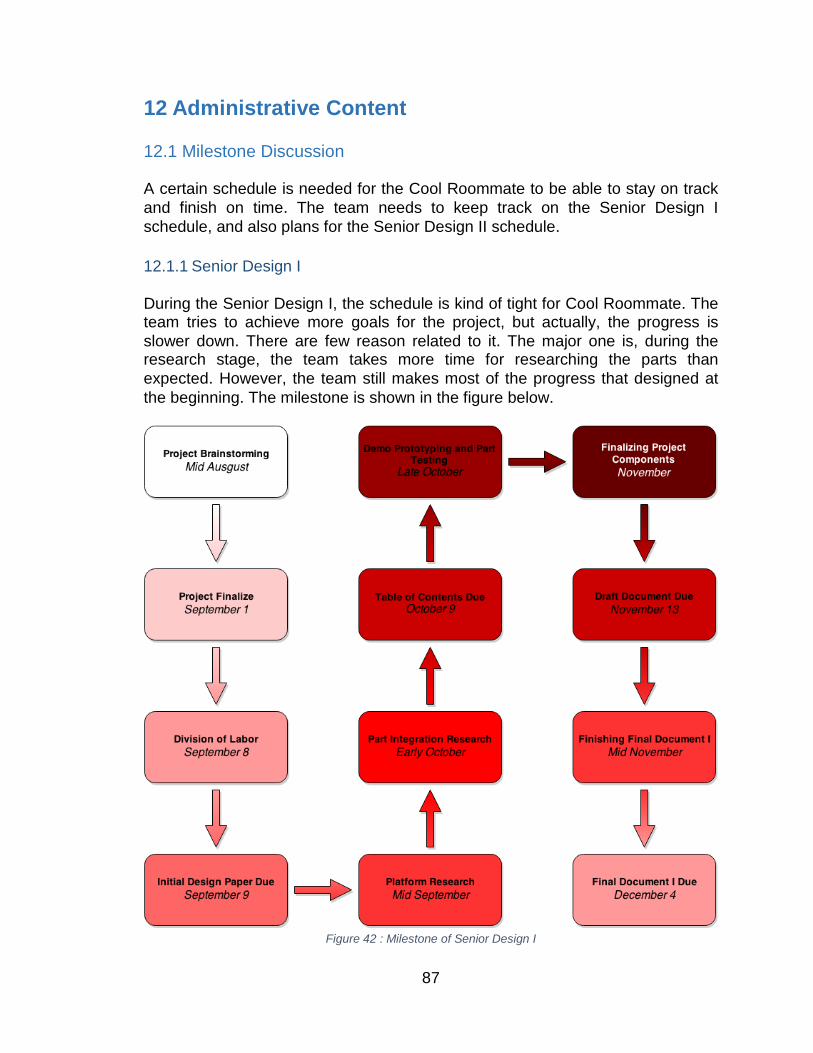
12 Administrative Content 12.1 Milestone Discussion A certain schedule is needed for the Cool Roommate to be able to stay on track and finish on time. The team needs to keep track on the Senior Design I schedule, and also plans for the Senior Design II schedule. 12.1.1 Senior Design I During the Senior Design I, the schedule is kind of tight for Cool Roommate. The team tries to achieve more goals for the project, but actually, the progress is slower down. There are few reason related to it. The major one is, during the research stage, the team takes more time for researching the parts than expected. However, the team still makes most of the progress that designed at the beginning. The milestone is shown in the figure below.
Figure 42 : Milestone of Senior Design I
87
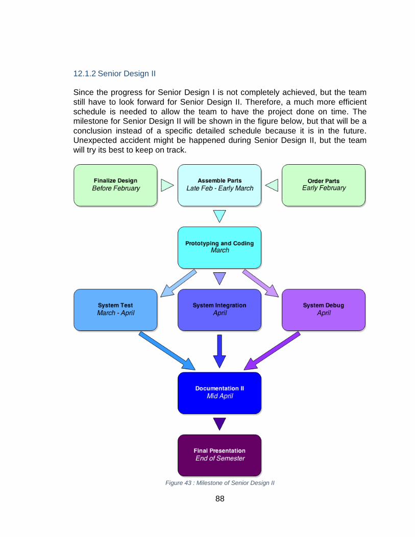
12.1.2 Senior Design II Since the progress for Senior Design I is not completely achieved, but the team still have to look forward for Senior Design II. Therefore, a much more efficient schedule is needed to allow the team to have the project done on time. The milestone for Senior Design II will be shown in the figure below, but that will be a conclusion instead of a specific detailed schedule because it is in the future. Unexpected accident might be happened during Senior Design II, but the team will try its best to keep on track.
Figure 43 : Milestone of Senior Design II
88
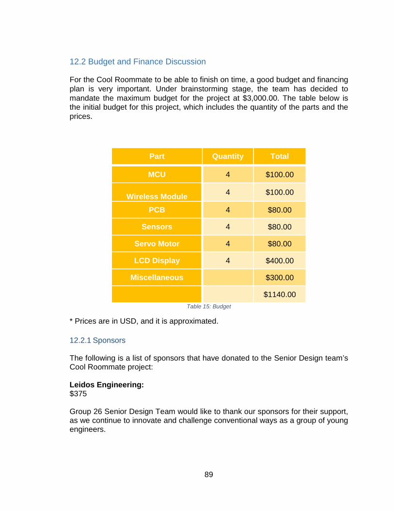
12.2 Budget and Finance Discussion For the Cool Roommate to be able to finish on time, a good budget and financing plan is very important. Under brainstorming stage, the team has decided to mandate the maximum budget for the project at $3,000.00. The table below is the initial budget for this project, which includes the quantity of the parts and the prices.
Part Quantity Total
MCU 4 $100.00
Wireless Module 4 $100.00
PCB 4 $80.00
Sensors 4 $80.00
Servo Motor 4 $80.00
LCD Display 4 $400.00
Miscellaneous $300.00
$1140.00 Table 15: Budget
* Prices are in USD, and it is approximated. 12.2.1 Sponsors The following is a list of sponsors that have donated to the Senior Design team’s Cool Roommate project: Leidos Engineering: $375 Group 26 Senior Design Team would like to thank our sponsors for their support, as we continue to innovate and challenge conventional ways as a group of young engineers.
89

12.3 Final Thoughts and Lasting Impressions As the current Senior Design team comes to the end of EEL 4914 the team has final thoughts and lasting impressions for future development of the Cool Roommate. The Cool Roommate has been designed to allow future integration and further updates to the hardware and software of the system. Currently the Cool Roommate is designed to be low cost and efficient to the overall household HVAC system. If the budget had been larger, then faster processors could be used, in addition to more parts being acquired to grant more access to other household pieces or technology that can be controlled and added to the efficiency of one’s home. Possible add-ons include:
• Access to control television, speakers, or radio within a household. • Mobile communication with the Master Controller. • House Alarm • Door lock mechanism • Blind are light sensitive and are able to respond by opening/closing blinds. • Able to modify specific room temperatures
The Senior Design team will revisit some of the design choices as the integration phase of the project begins. Should requirements need to be changes, added, or removed the Senior Design team will be able to change and promote parts to more powerful piece of hardware.
90

Copyright Permissions Use Restrictions and Termination of Access to TI Services TI Services on this site are protected by copyright laws, international copyright treaties, and other intellectual property laws and treaties. Except as stated herein, no TI Service, nor any part of any TI Service, may be reproduced, duplicated, mirrored, modified, displayed, distributed, copied, sold, resold, visited, or otherwise exploited for any purpose without express prior written consent of TI.
You agree not to use TI Services in a manner that violates any applicable law or regulation; to stalk, harass, or harm another individual; to impersonate any person or entity or otherwise misrepresent your affiliation with a person or entity; to interfere with or disrupt TI Services or servers or networks connected to TI Services; use any data mining, robots, or similar data gathering or extraction methods in connection with TI Services; frame or utilize framing techniques to enclose any trademark, logo, proprietary, or other information (including datasheets, images, text, page layout, or form); and attempt to gain unauthorized access to any portion of TI Services or any other accounts, computer systems, or networks connected to TI Services, whether through hacking, password mining, or any other means.
Subject to any Service Terms that may apply, TI grants you permission to download, reproduce, display, and distribute TI Services on this site solely for non-commercial or personal use, provided that you do not modify such TI Services, and provided further that you retain all copyright and proprietary notices as they appear in such TI Services.
TI further grants to K-12 educational institutions, universities, and community colleges permission to download, reproduce, display, and distribute TI Services on this site solely for use in the classroom, provided that such institutions identify TI as the source of TI Services and include the following credit line: “Courtesy of Texas Instruments.” Unauthorized use of any TI Service is expressly prohibited by law, and may result in civil and criminal penalties. This grant of permission terminates if you breach any provision in these Terms of Use or Service Terms. Upon termination, you agree to destroy any materials relating to TI Services obtained from this site.
TI reserves the right, in its sole discretion, to terminate, suspend, or modify your registration with, or access to, all or any part of TI Services, without notice, at any time and for any reason.
On 12/03/2014 05:00 AM, Dennis.Moy wrote: > Hello, > > My name is Dennis Moy, I am an electrical engineering student at the University of Central Florida. > I am writing a paper for my senior design project and was wondering if > I could use your diagram of a typical thermostat wiring configuration for the paper. The source will be specified in the paper. > > Here is a link of the diagram. > > http://wiki.xtronics.com/index.php/File:Thermostat.gif >
A
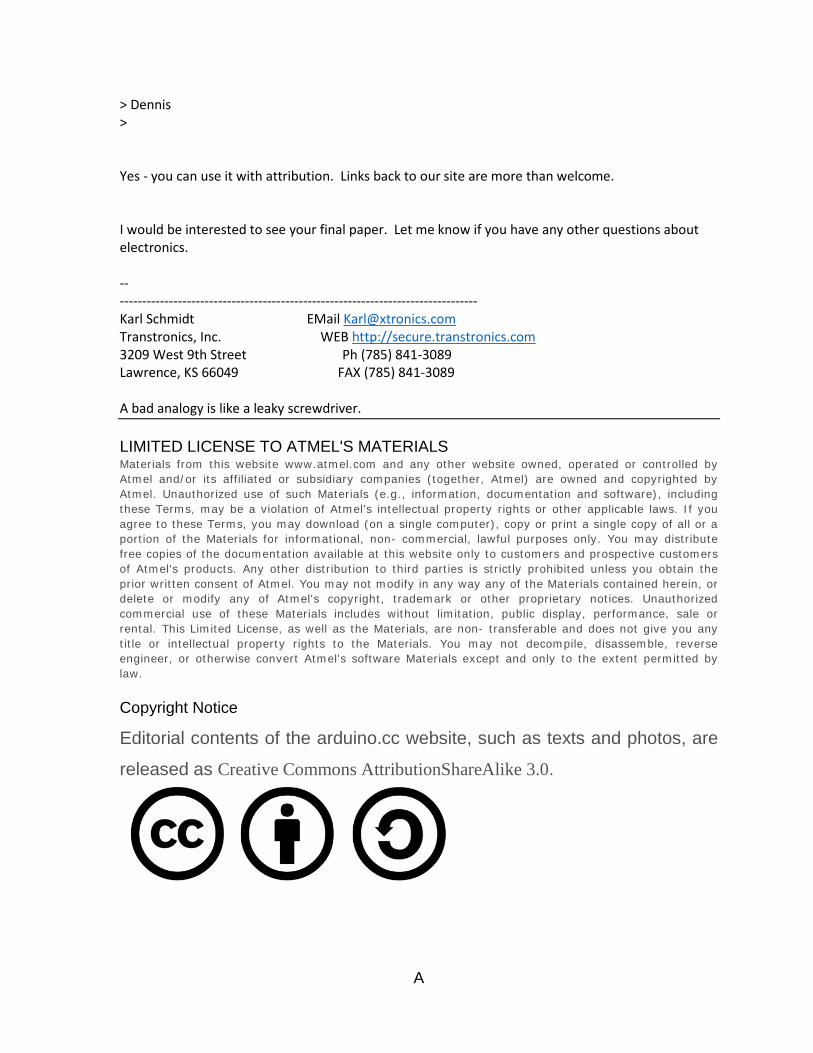
> Dennis > Yes - you can use it with attribution. Links back to our site are more than welcome. I would be interested to see your final paper. Let me know if you have any other questions about electronics. -- -------------------------------------------------------------------------------- Karl Schmidt EMail [email protected] Transtronics, Inc. WEB http://secure.transtronics.com 3209 West 9th Street Ph (785) 841-3089 Lawrence, KS 66049 FAX (785) 841-3089 A bad analogy is like a leaky screwdriver. LIMITED LICENSE TO ATMEL'S MATERIALS Materials from this website www.atmel.com and any other website owned, operated or controlled by Atmel and/or its affiliated or subsidiary companies (together, Atmel) are owned and copyrighted by Atmel. Unauthorized use of such Materials (e.g., information, documentation and software), including these Terms, may be a violation of Atmel's intellectual property rights or other applicable laws. If you agree to these Terms, you may download (on a single computer), copy or print a single copy of all or a portion of the Materials for informational, non- commercial, lawful purposes only. You may distribute free copies of the documentation available at this website only to customers and prospective customers of Atmel's products. Any other distribution to third parties is strictly prohibited unless you obtain the prior written consent of Atmel. You may not modify in any way any of the Materials contained herein, or delete or modify any of Atmel's copyright, trademark or other proprietary notices. Unauthorized commercial use of these Materials includes without limitation, public display, performance, sale or rental. This Limited License, as well as the Materials, are non- transferable and does not give you any title or intellectual property rights to the Materials. You may not decompile, disassemble, reverse engineer, or otherwise convert Atmel's software Materials except and only to the extent permitted by law. Copyright Notice Editorial contents of the arduino.cc website, such as texts and photos, are
released as Creative Commons AttributionShareAlike 3.0.
A
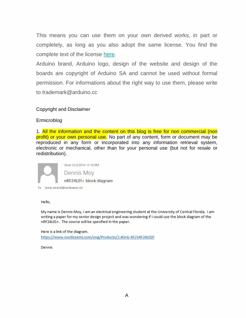
This means you can use them on your own derived works, in part or
completely, as long as you also adopt the same license. You find the
complete text of the license here.
Arduino brand, Arduino logo, design of the website and design of the
boards are copyright of Arduino SA and cannot be used without formal
permission. For informations about the right way to use them, please write
to [email protected] Copyright and Disclaimer
Ermicroblog 1. All the information and the content on this blog is free for non commercial (non profit) or your own personal use. No part of any content, form or document may be reproduced in any form or incorporated into any information retrieval system, electronic or mechanical, other than for your personal use (but not for resale or redistribution).
A
References How Home Thermostats Work http://home.howstuffworks.com/home-thermostat.htm SmartThings http://www.smartthings.com/benefits/ Control4 http://www.control4.com/spaces/whole-home nRF24L01+ http://www.nordicsemi.com/eng/Products/2.4GHz-RF/nRF24L01 http://playground.arduino.cc/InterfacingWithHardware/Nrf24L01 http://arduino-info.wikispaces.com/Nrf24L01-2.4GHz-HowTo http://web.uvic.ca/~andpol/project5.html Air CC110L https://www.anaren.com/air/cc110l-air-module-boosterpack-embedded-antenna-module-anaren http://www.ti.com/tool/430BOOST-CC110L LM35 http://www.ti.com/product/lm35 http://playground.arduino.cc/Main/LM35HigherResolution https://learn.adafruit.com/tmp36-temperature-sensor Thermistor – iNA330 http://www.ti.com/product/ina330 http://www.mouser.com/ProductDetail/Texas-Instruments/INA330AIDGST/?qs=sGAEpiMZZMsFOcXqMdeHCfeAbZt%252be81D8atNTwECA98%3d http://www.efunda.com/designstandards/sensors/thermistors/thermistors_intro.cfm Infrared Thermopile Sensor – TMP006 http://www.ti.com/product/tmp006 https://www.sparkfun.com/products/11859 http://www.adafruit.com/product/1296 Brushed DC motor http://www.robotshop.com/en/dc-motors.html http://electronicdesign.com/electromechanical/what-s-difference-between-brush-dc-and-brushless-dc-motors http://www.pololu.com/
B
http://hades.mech.northwestern.edu/index.php/Brushed_DC_Motor_Theory http://commons.wikimedia.org/wiki/File:Electric_motor_cycle_2.png Stepper Motor http://electrical-engineering-portal.com/few-words-about-stepper-motor-advantages-disadvantages-and-classification http://components.about.com/od/Components/a/Stepper-Motors-Vs-Servo-Motors-Selecting-A-Motor.htm http://www.autom.cn/News_view_38.html https://www.flickr.com/photos/snazzyguy/6963535992/ Servo Motor http://www.ermicro.com/blog/?p=771 http://www.elprocus.com/servo-motor/ http://plc-scada-dcs.blogspot.com/2011/12/servo-motor-advantages-disadvantages.html https://www.modmypi.com/blog/whats-the-difference-between-dc-servo-stepper-motors L293D dual H-Bridge Driver http://www.adafruit.com/product/807 http://www.ti.com/lit/ds/symlink/l293d.pdf http://www.instructables.com/id/Control-your-motors-with-L293D-and-Arduino/ http://www.me.umn.edu/courses/me2011/arduino/technotes/dcmotors/L293/L293.html LMD18200 http://www.ti.com/product/lmd18200 http://www.digikey.com/product-detail/en/LMD18200T/LMD18200T-ND/3701191 http://www.spickles.org/projects/lmd18200/ Stepper Motor Driver http://www.pololu.com/category/120/stepper-motor-drivers http://reprap.org/wiki/Stepper_motor_driver https://www.sparkfun.com/products/retired/10267 32-bit AVR UC3 http://www.atmel.com/products/microcontrollers/avr/32-bitavruc3.aspx ATmega328P http://www.atmel.com/devices/ATMEGA328P.aspx https://www.sparkfun.com/products/9061 http://www.adafruit.com/product/123 MSP430
B
http://www.ti.com/ww/en/launchpad/launchpads-msp430.html?DCMP=mcu-launchpad&HQS=msp430launchpad http://processors.wiki.ti.com/index.php/MSP430_LaunchPad_Tutorials http://43oh.com/ Tiva C http://www.ti.com/tool/ek-tm4c123gxl http://www.ti.com/lsds/ti/microcontrollers_16-bit_32-bit/c2000_performance/control_automation/tm4c12x/overview.page?DCMP=tivac-series&HQS=tiva-c http://www.mikroe.com/tiva/ http://www.ti.com/lit/ds/symlink/tm4c1294ncpdt.pdf Raspberry Pi http://www.raspberrypi.org/ http://www.raspberrypi.org/help/faqs/ http://www.adafruit.com/product/998 http://elinux.org/RPi_Hub http://www.element14.com/community/community/raspberry-pi http://www.arm.com/products/processors/classic/arm11/arm1176.php http://infocenter.arm.com/help/topic/com.arm.doc.ddi0333h/DDI0333H_arm1176jzs_r0p7_trm.pdf http://www.raspberrypi.org/open-source-arm-userspace/ BeagleBone http://beagleboard.org/BLACK http://www.adafruit.com/products/513 http://www.adafruit.com/datasheets/BBB_SRM.pdf http://www.ti.com/tool/linuxezsdk-sitara Arduino http://arduino.cc/en/Main/ArduinoBoardDue http://www.atmel.com/Images/doc11057.pdf http://arduino.cc/en/Guide/ArduinoDue http://www.atmel.com/products/microcontrollers/arm/sam3x.aspx Kentec LCD Boosterpack http://www.newark.com/kentec-electronics/eb-lm4f120-l35/exp-board-lcd-boosterpack-stellaris/dp/48W2063 http://www.farnell.com/datasheets/1653560.pdf http://embeddedcomputing.weebly.com/kentec-35-lcd-with-touch-boosterpack-for-stellaris.html Linear Voltage Regulator http://www.onsemi.com/PowerSolutions/parametrics.do?id=366
B
http://www.tedpavlic.com/teaching/osu/ece327/lab3_vreg/lab3_vreg_lm317_example.pdf http://www.ti.com/lsds/ti/power-management/linear-regulators-ldo-products.page Linear LDO Voltage Regulator http://www.linear.com/products/ldo_linear_regulators http://cds.linear.com/docs/en/application-note/AN140fa.pdf Switching Regulator http://www.analog.com/en/power-management/switching-regulators-integrated-fet-switches/products/index.html https://www.dimensionengineering.com/info/switching-regulators http://www.digikey.com/en/articles/techzone/2012/may/understanding-the-advantages-and-disadvantages-of-linear-regulators http://www.micrel.com/index.php/zh/products/power-management-ics/dc-dc-switching-regulators-.html Relay http://www.instructables.com/id/How-Electronic-Switches-Work-For-Noobs-Relays-and/?ALLSTEPS http://www.allaboutcircuits.com/vol_4/chpt_5/1.html Optoisolator http://searchnetworking.techtarget.com/definition/optoisolator http://www.ti.com/lit/an/slva229/slva229.pdf http://www.johnloomis.org/ece445/topics/egginc/pt_app.html HVAC Control http://wiki.xtronics.com/index.php/Thermostat_signals_and_wiring http://www.how-to-wire-it.com/wire-a-thermostat.html http://wiki.xtronics.com/index.php/File:Thermostat.gif Battery Topologies http://www.batteryspace.com/12vsealedleadacidbatteries.aspx http://batteryuniversity.com/learn/article/lead_based_batteries http://batteryuniversity.com/learn/article/whats_the_best_battery http://www.powerstream.com/BatteryFAQ.html http://www.nature.com/news/the-rechargeable-revolution-a-better-battery-1.14815 Prototype Production http://leardon.com/what-is-a-production-prototype http://www.screamingcircuits.com/Home/TurnKey http://industrialmodern.com/benefits-of-prototyping/ https://hwstartup.wordpress.com/2012/09/14/how-to-go-from-arduino-prototype-to-selling-product/ http://www.innovate-design.com/invention-prototype-manufacturing-stage/
B
EDA software http://www.cadsoftusa.com/ http://www.adafruit.com/blog/2011/09/15/comparative-review-of-pcb-cad-software-for-hobbyists/ http://www.kicad-pcb.org/display/KICAD/KiCad+EDA+Software+Suite http://www.avrfreaks.net/forum/schematic-and-pcb-design-programs Programming language http://msdn.microsoft.com/en-us/library/6h38y9z9%28v=vs.110%29.aspx http://electronics.stackexchange.com/questions/3027/is-c-suitable-for-embedded-systems http://www.embedded.com/design/programming-languages-and-tools/4424383/A-guide-to-C--for-C-programmers http://www.adacore.com/adaanswers/about/ada https://www.java.com/en/download/faq/whatis_j2me.xml http://www.oracle.com/technetwork/java/embedded/javame/embed-me/downloads/java-embedded-java-me-download-2162242.html http://www.oracle.com/technetwork/java/embedded/documentation/me-e-otn-faq-1852008.pdf Integrated Development Environment http://www.ti.com/tool/CCSTUDIO http://energia.nu/ http://www.atmel.com/ http://www.atmel.com/tools/atmelstudio.aspx http://www.arduino.cc/ MSP430 example schematic http://www.hackeda.com/circuits/msp430g2553/ Relay example schematic http://www.edn.com/electrical-engineer-community/industry-blog/4402579/2/Controlling-big--mean-devices
B