group 16 engine electrical - lilevo.com 8 260 service manual/evo8260/wm...group 16 engine electrical...
TRANSCRIPT

16-1
GROUP 16
ENGINE ELECTRICAL
CONTENTS
CHARGING SYSTEM . . . . . . . . . 16-2
GENERAL INFORMATION . . . . . . . 16-2
SERVICE SPECIFICATIONS . . . . . 16-3
SPECIAL TOOL . . . . . . . . . . . . . . . . . 16-4
ON-VEHICLE SERVICE . . . . . . . . . . 16-5ALTERNATOR OUTPUT LINE VOLTAGE DROP TEST . . . . . . . . . . . . . . . . . . . . . 16-5OUTPUT CURRENT TEST . . . . . . . . . . 16-6REGULATED VOLTAGE TEST. . . . . . . 16-8WAVEFORM CHECK USING AN OSCILLOSCOPE. . . . . . . . . . . . . . . . . . 16-9
ALTERNATOR ASSEMBLY . . . . . . 16-12REMOVAL AND INSTALLATION . . . . . 16-12DISASSEMBLY AND REASSEMBLY . . 16-15INSPECTION . . . . . . . . . . . . . . . . . . . . . 16-17
STARTING SYSTEM . . . . . . . . . . 16-19
GENERAL INFORMATION . . . . . . . 16-19
SERVICE SPECIFICATIONS . . . . . 16-20
STARTER MOTOR ASSEMBLY . . 16-20REMOVAL AND INSTALLATION . . . . . 16-20INSPECTION . . . . . . . . . . . . . . . . . . . . . 16-21DISASSEMBLY AND REASSEMBLY . . 16-23INSPECTION . . . . . . . . . . . . . . . . . . . . . 16-24
IGNITION SYSTEM . . . . . . . . . . . . 16-27
GENERAL INFORMATION . . . . . . . 16-27
SERVICE SPECIFICATIONS . . . . . 16-28
SPECIAL TOOL. . . . . . . . . . . . . . . . . . 16-28
ON-VEHICLE SERVICE . . . . . . . . . . 16-28IGNITION COIL (WITH BUILT-IN POWER TRANSISTOR) CHECK . . . . . . . . . . . . . 16-28IGNITION COIL RELAY CHECK <RH DRIVE VEHICLES> . . . . . . . . . . . . 16-29SPARK PLUG CABLE CHECK . . . . . . . 16-29SPARK PLUG CHECK AND CLEANING 16-29CAMSHAFT POSITION SENSOR CHECK 16-30CRANK ANGLE SENSOR CHECK . . . . 16-30DETONATION SENSOR CHECK . . . . . 16-30IGNITION SECONDARY VOLTAGE WAVEFORM CHECK USING AN OSCILLOSCOPE . . . . . . . . . . . . . . . . . . 16-30
IGNITION COIL . . . . . . . . . . . . . . . . . . 16-34REMOVAL AND INSTALLATION. . . . . . 16-34
CAMSHAFT POSITION SENSOR . 16-35REMOVAL AND INSTALLATION. . . . . . 16-35
CRANK ANGLE SENSOR . . . . . . . . 16-36REMOVAL AND INSTALLATION. . . . . . 16-36
DETONATION SENSOR. . . . . . . . . . 16-37REMOVAL AND INSTALLATION. . . . . . 16-37

CHARGING SYSTEMENGINE ELECTRICAL16-2
CHARGING SYSTEMGENERAL INFORMATION
M1161000100414
The charging system uses the alternator output to keep the battery charged at a constant level under various electrical loads.
OPERATION
Rotation of the excited field coil generates AC voltage in the stator.This alternating current is rectified through diodes to DC voltage having a waveform shown in the illustration.
The average output voltage fluctuates slightly with the alternator load condition.When the ignition switch is turned on, current flows in the field coil and initial excitation of the field coil occurs. When the stator coil begins to generate power after the engine is started, the field coil is excited by the output current of the stator coil. The alternator output voltage rises as the field current increases and it falls as the field current decreases. When the battery voltage (alternator "S" terminal voltage) reaches a regulated voltage of approximately 14.4 V, the field current is cut off. When the battery voltage drops below the regulated voltage, the voltage regulator regulates the output voltage to a constant level by controlling the field current. In addition, when the field current is constant, the alternator output voltage rises as the engine speed increases.
SYSTEM DIAGRAM
AKX00183
Voltage
Time
Approximately14.4 V
AC
AK304222
Alternator
B
Stator coil
Engine-ECU
G
SL
FRVoltage regulator
Chargewarning lamp
Ignition switchBattery
Field coil
+
–
AB

CHARGING SYSTEMENGINE ELECTRICAL 16-3
ALTERNATOR SPECIFICATIONS
SERVICE SPECIFICATIONSM1161000300407
Item Specifications
Type Battery voltage sensing
Rated output V/A 12/90
Voltage regulator Electronic built-in type
Item Standard value Limit
Alternator output line voltage drop (at 30 A) V − maximum 0.3
Regulated voltage ambient temperature at voltage regulator V
−20°C 14.2 − 15.4 −20°C 13.9 − 14.9 −60°C 13.4 − 14.6 −80°C 13.1 − 14.5 −
Output current − 70 % of normal output current

CHARGING SYSTEMENGINE ELECTRICAL16-4
SPECIAL TOOLM1161000600356
Tool Number Name Use
MB991502 MUT-II sub assembly • Checking the idle speed
MB991955A: MB991824B: MB991827C: MB991910D: MB991911E: MB991825F: MB991826
MUT-III sub assembly• A: Vehicle
communication interface (V.C.I.)
• B: MUT-III USB cable• C: MUT-III main
harness A (Vehicles with CAN communication system)
• D: MUT-III main harness B (Vehicles without CAN communication system)
• E: MUT-III measurement adapter
• F: MUT-III trigger harness
• Checking the idle speed
! CAUTIONMUT-III main harness B (MB991911) should be used. MUT-III main harness A should not be used for this vehicle.
MB991519 Alternator test harness Checking the alternator("S" terminal voltage)
B991502
MB991910
MB991826
MB991955
MB991911
MB991824
MB991827
MB991825
A
B
C
D
E
F
DO NOT USE

CHARGING SYSTEMENGINE ELECTRICAL 16-5
ON-VEHICLE SERVICE
ALTERNATOR OUTPUT LINE VOLTAGE DROP TESTM1161000900443
This test determines whether the wiring from the alternator "B" terminal to the battery (+) terminal (including the fusible line) is in a good condition or not.1. Always be sure to check the following before the
test.• Alternator installation• Drive belt tension
(Refer to GROUP 11A − On-vehicle Service P.11A-7.)
• Fusible link• Abnormal noise from the alternator while the
engine is running2. Turn the ignition switch to the "LOCK" (OFF)
position.3. Disconnect the negative battery cable.4. Connect a clamp-type DC test ammeter with a
range of 0 − 100 A to the alternator "B" terminal output wire.
NOTE: The way of disconnecting the alternator output wire and of connecting the ammeter is possibly not found the problem that the output current is dropping due to the insufficient connection between terminal "B" and the output wire.
5. Connect a digital-type voltmeter between the alternator "B" terminal and the battery (+) terminal. [Connect the (+) lead of the voltmeter to the "B" terminal and the connect the (-) lead of the voltmeter to the battery (+) cable].
6. Reconnect the negative battery cable.7. Connect the MUT-II/III.8. Leave the hood open.9. Start the engine.10.With the engine running at 2,500 r/min, turn the
headlamps and other lamps on and off to adjust the alternator load so that the value displayed on the ammeter is slightly above 30 A.
Adjust the engine speed by gradually decreasing it until the value displayed on the ammeter is 30 A. Take a reading of the value displayed on the voltmeter at this time.
Limit: maximum 0.3 VNOTE: When the alternator output is high and the value displayed on the ammeter does not decrease until 30 A, set the value to 40 A. Read the value displayed on the voltmeter at this time. When the value range is 40 A, the limit is maximum 0.4 V.
11.If the value displayed on the voltmeter is above the limit value, there is probably a malfunction in the alternator output wire, so check the wiring between the alternator "B" terminal and the battery (+) terminal (including fusible link).
If a terminal is not sufficiently tight or if the harness has become discoloured due to overheating, repair and then test again.
12.After the test, run the engine at idle.13.Turn off all lamps and the ignition switch.
AK203361AE
Alternator
Ammeter (clamp-type)
Voltmeter (digital-type)
"B" terminalBattery

CHARGING SYSTEMENGINE ELECTRICAL16-6
14.Remove the MUT-II/III.15.Disconnect the negative battery cable.
16.Disconnect the ammeter and voltmeter.17.Connect the negative battery cable.
OUTPUT CURRENT TESTM1161001000476
This test determines whether the alternator output current is normal.1. Before the test, always be sure to check the
following.• Alternator installation• Battery (Refer to GROUP 54A − Battery −
On-vehicle Service P.54A-4).
NOTE: The battery should be slightly discharged. The load needed by a fully-charged battery is insufficient for an accurate test.
• Drive belt tension(Refer to GROUP 11A − On-vehicle Service
P.11A-7.)• Fusible link• Abnormal noise from the alternator while the
engine is running.2. Turn the ignition switch to the "LOCK" (OFF)
position.3. Disconnect the negative battery cable.
! CAUTIONNever use clips but tighten bolts and nuts to connect the line. Otherwise loose connections (e.g. using clips) will lead to a serious accident because of high current.4. Connect a clamp-type DC test ammeter with a
range of 0 − 100 A to the alternator "B" terminal output wire.
NOTE: The way of disconnecting the alternator output wire and of connecting the ammeter is possibly not found the problem that the output current is dropping due to the insufficient connection between terminal "B" and the output wire.
5. Connect a voltmeter with a range of 0 − 20 V between the alternator "B" terminal and the earth [Connect the (+) lead of the voltmeter to the "B" terminal, and then connect the (-) lead of the voltmeter to the earth].
6. Connect the negative battery cable.
AK304240
Alternator
Ammeter(clamp-type)Voltmeter
Battery
Ignition switch
Engine-ECU
Load
BFR
L
S
G
+
AC
–
Charge warninglamp

CHARGING SYSTEMENGINE ELECTRICAL 16-7
7. Connect the MUT-II/III.8. Leave the hood open.9. Check that the reading on the voltmeter is equal
to the battery voltage.
NOTE: If the voltage is 0 V, the cause is probably an open circuit in the wire or fusible link between the alternator "B" terminal and the battery (+) terminal.
10.Turn the lamp switch on to turn on headlamps and then start the engine.
11.Immediately after setting the headlamps to high beam and turning the heater blower switch to the high revolution position, increase the engine speed to 2,500 r/min and read the maximum current output value displayed on the ammeter.
Limit: 70 % of normal current output
NOTE: .• For the nominal current output, refer to the
Alternator Specifications.• Because the current from the battery will soon
drop after the engine is started, the above step should be carried out as quickly as possible in order to obtain the maximum current output value.
• The current output value will depend on the electrical load and the temperature of the alternator body.
• If the electrical load is small while testing, the specified level of current may not be output even though the alternator is normal. In such cases, increase the electrical load by leaving the headlamps turned on for some time to discharge the battery or by using the lighting system in another vehicle, and then test again.
• The specified level of current also may not be output if the temperature of the alternator body or the ambient temperature is too high. In such cases, cool the alternator and then test again.
12.The reading on the ammeter should be above the limit value. If the reading is below the limit value and the alternator output wire is normal, remove the alternator from the engine and check the alternator.
13.Run the engine at idle after the test.14.Turn the ignition switch to the "LOCK" (OFF)
position.15.Remove the MUT-II/III.16.Disconnect the negative battery cable.17.Disconnect the ammeter and voltmeter.18.Connect the negative battery cable.

CHARGING SYSTEMENGINE ELECTRICAL16-8
REGULATED VOLTAGE TESTM1161001100462
This test determines whether the voltage regulator correctly controlling the alternator output voltage.1. Always be sure to check the following before the
test.• Alternator installation• Check that the battery installed in the vehicle is
fully charged.(Refer to GROUP 54A − Battery − On-vehicle
Service − Charging P.54A-3).• Drive belt tension
(Refer to GROUP 11A − On-vehicle Service P.11A-7.)
• Fusible link• Abnormal noise from the alternator while the
engine is running2. Turn the ignition switch to the "LOCK" (OFF)
position.3. Disconnect the negative battery cable.4. Use the special tool Alternator test harness
(MB991519) to connect a digital voltmeter between the alternator "S" terminal and earth [Connect the (+) lead of the voltmeter to the "S" terminal, and then connect the (-) lead of the voltmeter to a secure earth or to the battery (-) terminal].
5. Connect a clamp-type DC test ammeter with a range of 0 − 100 A to the alternator "B" terminal output wire.
NOTE: The way of disconnecting the alternator output wire and of connecting the ammeter is possibly not found the problem that the output current is dropping due to the insufficient connection between terminal "B" and the output wire.
6. Reconnect the negative battery cable.7. Connect the MUT-II/III.8. Turn the ignition switch to the "ON" position and
check that the reading on the voltmeter is equal to the battery voltage.
NOTE: If the voltage is 0 V, the cause is probably an open circuit in the wire or fusible link between the alternator "S" terminal and the battery (+) terminal.
9. Turn all lamps and accessories off.10.Start the engine.11.Increase the engine speed to 2,500 r/min.12.Read the value displayed on the voltmeter when
the alternator output current alternator becomes 10 A or less.
AK304241AC
Battery
Ignition switch
Engine-ECU
Ammeter (clamp-type)
Load
BlackMB991519
Voltmeter (digital-type)
Red Yellow
Blue
Alternator
BFR
L
S
G
Charge warning lamp

CHARGING SYSTEMENGINE ELECTRICAL 16-9
13.If the voltage reading conforms to the value in the voltage regulation, then the voltage regulator is operating normally.
If the voltage is not within the standard value, there is a malfunction of the voltage regulator or of the alternator.
14.After the test, lower the engine speed to the idle speed.
15.Turn the ignition switch to the "LOCK" (OFF) position.
16.Remove the MUT-II/III.17.Disconnect the negative battery cable.18.Disconnect the ammeter and voltmeter.19.Connect the alternator output wire to the
alternator "B" terminal.20.Remove the special tool, and return the connector
to the original condition.21.Connect the negative battery cable.
Voltage Regulation Table
Standard value:
WAVEFORM CHECK USING AN OSCILLOSCOPEM1161001200209
MEASUREMENT METHOD Connect the oscilloscope special patterns pick-up to the alternator "B" terminal.
STANDARD WAVEFORM
Observation Conditions
Inspection terminal Voltage regulator ambient temperature °C
Voltage V
Terminal "S" −20 14.2 − 15.4
20 13.9 − 14.9
60 13.4 − 14.6
80 13.1 − 14.5
AK100002
Alternator
"B" terminal
CH1
AC
Function Special pattern
Pattern height Variable
Variable knob Adjust while viewing the waveform.
Pattern selector Raster
Engine speed Curb idle speed

CHARGING SYSTEMENGINE ELECTRICAL16-10
NOTE:
The voltage waveform of the alternator "B" terminal can undulate as shown in the illustration. This waveform is produced when the regulator operates according to fluctuations in the alternator load (current), and is normal for the alternator. In addition,
when the voltage waveform reaches an excessively high value (approximately 2 V or higher at idle), it often indicates an open circuit due to a brown fuse between alternator "B" terminal and battery, but not a defective alternator.
AKX00189
0.4
(V)
0.2
0
–0.2
–0.4
Voltage atalternator"B" terminal
Time
AG
AKX00190

CHARGING SYSTEMENGINE ELECTRICAL 16-11
EXAMPLE OF ABNORMAL WAVEFORMSNOTE: .
1. The size of the waveform patterns differs largely, depending on the adjustment of the variable knob on the oscilloscope.
2. Identification of abnormal waveforms is easier when there is a large output current (regulator is not operating). (Waveforms can be observed when the headlamps are illuminated.)
3. Check the conditions of the charging warning lamp (illuminated/not illuminated). Also, check the charging system totally.
Abnormal waveform Problem cause
Example 1 Open diode
Example 2 Short in diode
Example 3 Broken wire in stator coil
Example 4 Short in stator coil
AKX00191
AKX00192
AKX00193
AKX00194

CHARGING SYSTEMENGINE ELECTRICAL16-12
ALTERNATOR ASSEMBLY
REMOVAL AND INSTALLATIONM1161001400720
! CAUTIONIf the vehicle is equipped with the Brembo disc brake, during maintenance, take care not to contact the caliper with tool or parts, because the caliper paint will be scratched.
Pre-removal Operation• Under Cover Removal (Refer to GROUP 51, Front
Bumper P.51-3).• Strut Tower Bar Removal (Refer to GROUP 42, Strut
Tower Bar P.42-9).• Crossmember Bar Removal (Refer to GROUP 32, Engine
Roll Stopper and Centremember P.32-8).• Front Exhaust Pipe Assembly Removal (Refer to GROUP
15, Exhaust Pipe and Main Muffler P.15-19).
Post-installation Operation• Front Exhaust Pipe Assembly Installation (Refer to
GROUP 15, Exhaust Pipe and Main Muffler P.15-19).• Crossmember Bar Installation (Refer to GROUP 32,
Engine Roll Stopper and Centremember P.32-8).• Strut Tower Bar Installation (Refer to GROUP 42, Strut
Tower Bar P.42-9).• Drive Belt Tension Check (Refer to GROUP 11A,
On-vehicle Service − Drive Belt Tension Check P.11A-7).• Under Cover Installation (Refer to GROUP 51, Front
Bumper P.51-3).

CHARGING SYSTEMENGINE ELECTRICAL 16-13
AC310806
13
2
13 ± 1 N·m
8.8 ± 1.0 N·m
22 ± 4 N·m
23 ± 3 N·m
36 ± 6 N·m
20 ± 2 N·m
1
3
4
5
6
7
9.0 ± 1.0 N·m
8
11 ± 1 N·m
10
95.0 ± 1.0 N·m
11
12N
14
14 ± 3 N·m
15
44 ± 10 N·m
16
17
18
N
AB
(Engine oil)
19
Removal steps1. Oil level gauge and guide assembly2. O-ring3. Fuel pressure solenoid valve
connector4. Fuel pressure solenoid valve5. Detonation sensor connector6. Purge control solenoid valve
connector7. Purge control solenoid valve8. Earth cable connection9. Fuel injector connectors
<<A>> 10. Fuel injector, delivery pipe, fuel return pipe and fuel pressure regulator assembly
11. Insulators12. Insulators
<<B>> 13. Drive belt14. Alternator connector and terminal• Engine front mounting bracket
(Refer to GROUP 32, Engine Mounting P.32-4).
<<C>> 15. Alternator16. Water pump pulley17. Alternator brace18. Crank angle sensor connector19. Alternator brace stay
Removal steps (Continued)

CHARGING SYSTEMENGINE ELECTRICAL16-14
REMOVAL SERVICE POINTS<<A>> FUEL INJECTOR, DELIVERY PIPE, FUEL RETURN PIPE AND FUEL PRESSURE REGULATOR ASSEMBLY REMOVALAfter loosening the delivery pipe mounting bolts, move the fuel injector, delivery pipe, fuel return pipe and the fuel pressure regulator as an assembly aside in order to make room for the alternator removal.
<<B>> DRIVE BELT REMOVALThe following operations will be needed due to the introduction of the serpentine drive system with the drive belt auto-tensioner.
1. Securely insert the spindle handle or ratchet handle with a 12.7 mm insertion angle into the jig hole of the auto-tensioner.
2. Rotate the auto-tensioner anti-clockwise and align hole A with hole B.
! CAUTIONTo reuse the drive belt, draw an arrow indicating the rotating direction (clockwise) on the back of the belt using chalk, etc.
3. Insert an L-shaped hexagon wrench, etc. into the hole to fix and then remove the drive belt.
<<C>> ALTERNATOR REMOVALRaise the engine with a floor jack and remove the alternator upward from the engine room.
AC210996 AB
Auto-tensioner
Hole A
Hole B
AC210998AB
L-shapedhexagonwrench
Auto-tensioner

CHARGING SYSTEMENGINE ELECTRICAL 16-15
DISASSEMBLY AND REASSEMBLYM1161001600199
AK202845
1
2
3 4
5
67
8
9
10
11
12
13
14
AB
Disassembly steps<<A>> 1. Front bracket assembly<<B>> 2. Alternator pulley
>>B<< 3. Rotor4. Rear bearing5. Bearing retainer6. Front bearing7. Front bracket
<<C>> 8. Stator9. Plate
<<C>> >>A<< 10. Regulator assembly11. Brush12. Rubber packing13. Rectifier14. Rear bracket
Disassembly steps (Continued)

CHARGING SYSTEMENGINE ELECTRICAL16-16
DISASSEMBLY SERVICE POINTS<<A>> FRONT BRACKET ASSEMBLY REMOVAL
! CAUTIONDo not insert the screwdriver blades too deep. Doing so could damage the stator coil.Insert the blades of screwdrivers between the front bracket assembly and stator core, and pry and separate them with the screwdrivers.
<<B>> ALTERNATOR PULLEY REMOVAL
! CAUTIONPerform operation carefully not to damage the rotor.Clamp the rotor in a vise with the pulley facing up to remove the pulley.
<<C>> STATOR / REGULATOR ASSEMBLY REMOVAL
! CAUTION• Use a 180 − 250 W soldering iron, and finish
unsoldering within four seconds. Diodes will be damaged by heat if unsoldering time is too long.
• Avoid applying undue force to the diode leads.
1. Unsolder the stator leads from the main diode of the rectifier assembly when the stator is removed.
2. When removing the rectifier assembly from the regulator assembly, undo the soldered points on the rectifier assembly.
REASSEMBLY SERVICE POINTS>>A<< REGULATOR ASSEMBLY INSTALLATION
After installing the regulator assembly, insert a piece of wire through the hole in the rear bracket while pressing the brush to keep the brush against movement.
NOTE: Holding the brush with the wire facilities installation of the rotor.
AK202718
AK202714
AK202778
Solder
Solder
Rectifier assembly
AB
AK202779
Wire
AB
AK202830
Rear bracket
Brush
Wire
AB
CHARGING SYSTEMENGINE ELECTRICAL 16-17
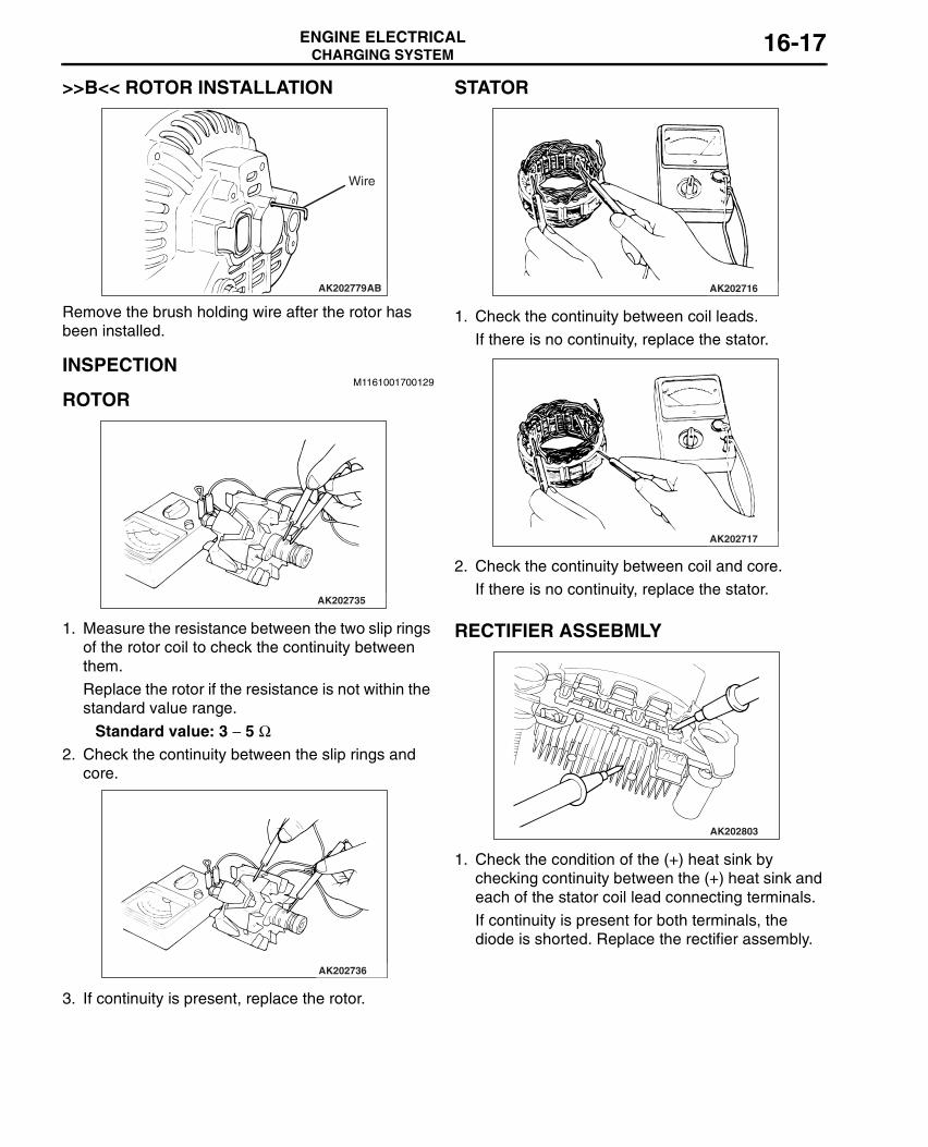
>>B<< ROTOR INSTALLATION
Remove the brush holding wire after the rotor has been installed.
INSPECTION M1161001700129
ROTOR
1. Measure the resistance between the two slip rings of the rotor coil to check the continuity between them.
Replace the rotor if the resistance is not within the standard value range.
Standard value: 3 − 5 Ω2. Check the continuity between the slip rings and
core.
3. If continuity is present, replace the rotor.
STATOR
1. Check the continuity between coil leads.
If there is no continuity, replace the stator.
2. Check the continuity between coil and core.
If there is no continuity, replace the stator.
RECTIFIER ASSEBMLY
1. Check the condition of the (+) heat sink by checking continuity between the (+) heat sink and each of the stator coil lead connecting terminals.
If continuity is present for both terminals, the diode is shorted. Replace the rectifier assembly.
AK202779
Wire
AB
AK202735
AK202736
AK202716
AK202717
AK202803

CHARGING SYSTEMENGINE ELECTRICAL16-18
2. Check the condition of the (−) heat sink by checking continuity between the (−) heat sink and each of the stator coil lead connecting terminals.
If continuity is present in both directions, the diode is shorted. Replace the rectifier assembly.
3. Check the condition of the diode trio by testing continuity of each of the three diodes using a circuit tester connected to both sides of the diode. Connect in a polarity and then reverse the polarity for each test.
If continuity exists or no continuity exists for both polarities, the diode is defective. Replace the rectifier assembly if any of the diodes is defective.
BRUSH
1. Measure the length of the protrusion of the brush. Replace the brush if the protrusion length is shorter than the limit.
Limit: 2 mm minimum2. Unsolder the lead of the brush. The brush will
come out, becoming ready for removal.
3. Install a new brush by pushing it into the holder as shown in the drawing and soldering the lead.
AK202802
AK202804
AK202808
Protrusionlength
AB
AK202834
Solder
AB

STARTING SYSTEMENGINE ELECTRICAL 16-19
STARTING SYSTEMGENERAL INFORMATION
M1162000100309
If the ignition switch is turned to the "START" position, current flows in the pull-in and holding coils provided inside magnetic switch, attracting the plunger, When the plunger is attracted, the lever connected to the plunger is actuated to engage the starter clutch.On the other hand, attracting the plunger will turn on the magnetic switch, allowing the "B" terminal and "M" terminal to conduct. Thus, current flows to engage the starter motor.
When the ignition switch is returned to the "ON" position after starting the engine, the starter clutch is disengaged from the ring gear.An overrunning clutch is provided between the pinion and the armature shaft, to prevent damage to the starter.
SYSTEM DIAGRAM
STARTER MOTOR SPECIFICATIONS
AK202970
Pull-in coil
Holding coil Plunger
Lever
Pinion gear
Overrunning clutch
Yoke
Brush
Armature
Ignition switch
Battery
+
–
AB
B
MS
Item Specifications
Type Reduction drive with planetary gear
Rated output kW/V 1.2/12
No. of pinion teeth 8

STARTING SYSTEMENGINE ELECTRICAL16-20
SERVICE SPECIFICATIONSM1162000300080
STARTER MOTOR ASSEMBLY
REMOVAL AND INSTALLATIONM1162001000781
Item Standard value Limit
Pinion gap mm 0.5 − 2.0 −Commutator run-out mm 0.05 0.1
Commutator diameter mm 29.4 28.8
Undercut depth mm 0.5 0.2
Pre-removal and Post-installation Operation• Under Cover Removal and Installation (Refer to GROUP 51, Front Bumper P.51-3).• Crossmember Bar Removal and Installation (Refer to GROUP 32, Engine Roll Stopper and Centremember P.32-8).• Front Exhaust Pipe Assembly Removal and Installation (Refer to GROUP 15, Exhaust Pipe and Main Muffler P.15-19).
AC210296
3
2
1
AB
4.9 ± 1.0 N·m
30 ± 3 N·m
30 ± 3 N·m
13 ± 2 N·m
4.9 ± 1.0 N·m
Removal steps1. Starter cover 2. Starter connector and terminal
3. Starter assembly
Removal steps (Continued)

STARTING SYSTEMENGINE ELECTRICAL 16-21
STARTER MOTOR ASSEMBLY INSPECTIONM1162001100249
PINION GAP ADJUSTMENT
1. Disconnect the field coil wire from the M-terminal of the magnetic switch.
2. Connect a 12-volt battery between the S-terminal and M-terminal.
! CAUTIONThis test must be performed quickly (in less than 10 seconds) to prevent the coil from burning.3. Set the switch to "ON", and the pinion will move
out.
4. Check the pinion-to-stopper clearance (pinion gap) with a feeler gauge.
Standard value: 0.5 − 2.0 mm
5. If the pinion gap is out of specification, adjust by adding or removing gasket(s) between the magnetic switch and front bracket.
MAGNETIC SWITCH PULL-IN TEST
1. Disconnect the field coil wire from the M-terminal of the magnetic switch.
! CAUTIONThis test must be performed quickly (in less than 10 seconds) to prevent the coil from burning.2. Connect a 12-volt battery between the S-terminal
and M-terminal.3. If the pinion moves out, the pull-in coil is good. If it
doesn’t, replace the magnetic switch.
MAGNETIC SWITCH HOLD-IN TEST
1. Disconnect the field coil wire from the M-terminal of the magnetic switch.
! CAUTIONThis test must be performed quickly (in less than 10 seconds) to prevent the coil from burning.2. Connect a 12-volt battery between the S-terminal
and body.3. Manually pull out the pinion as far as the pinion
stopper position.4. If the pinion remains out, everything is in order. If
the pinion moves in, the hold-in circuit is open. Replace the magnetic switch.
AKX01239
B
MS Battery
Switch
Startermotor
Wire
AF
AKX00198
Stopper
Pinion gap
Pinion
AC
AKX00199
AKX01243
B
MS Battery
Starter motor
Wire
AF
AKX01245
B
MS Battery
Starter motor
Wire
AF

STARTING SYSTEMENGINE ELECTRICAL16-22
FREE RUNNING TEST
1. Place the starter motor in a vise equipped with soft jaws and connect a fully-charged 12-volt battery to the starter motor as follows:
2. Connect a test ammeter (100-ampere scale) and carbon pile rheostat in series between the positive battery terminal and starter motor terminal.
3. Connect a voltmeter (15-volt scale) across the starter motor.
4. Rotate the rheostat to full-resistance position.5. Connect the battery cable from the negative
battery terminal to the starter motor body.6. Adjust the rheostat until the battery positive
voltage shown on the voltmeter is 11 V.7. Confirm that the maximum amperage is within the
specifications and that the starter motor turns smoothly and freely.
Current: maximum 95 Amps
MAGNETIC SWITCH RETURN TEST
1. Disconnect the field coil wire from the M-terminal of the magnetic switch.
! CAUTIONThis test must be performed quickly (in less than 10 seconds) to prevent the coil from burning.2. Connect a 12-volt battery between the M-terminal
and body.
! WARNINGBe careful not to get your fingers caught when pulling out the pinion.3. Pull the pinion out and release. If the pinion
quickly returns to its original position, everything is operating properly. If it doesn’t, replace the magnetic switch.
AKX01247
S M
BAmmeter
Carbon-pilerheostat
BatteryStartermotor Voltmeter
AF
A
V
AKX01249
B
MS Battery
Starter motor
Wire
AF
STARTING SYSTEMENGINE ELECTRICAL 16-23
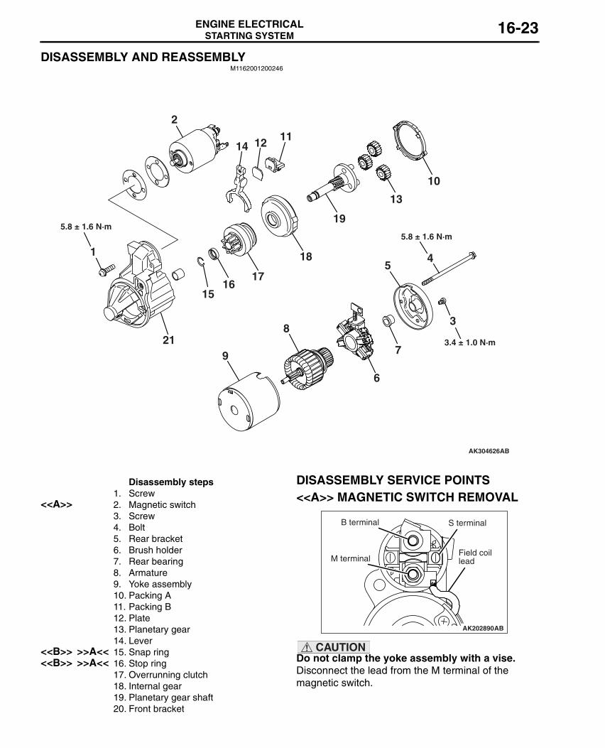
DISASSEMBLY AND REASSEMBLYM1162001200246
DISASSEMBLY SERVICE POINTS<<A>> MAGNETIC SWITCH REMOVAL
! CAUTIONDo not clamp the yoke assembly with a vise.Disconnect the lead from the M terminal of the magnetic switch.
AK304626AB
2
1617
18
19
15
13
12
21
4
1411
15
6
8
79
10
3
5.8 ± 1.6 N·m5.8 ± 1.6 N·m
3.4 ± 1.0 N·m
Disassembly steps1. Screw
<<A>> 2. Magnetic switch3. Screw4. Bolt5. Rear bracket6. Brush holder7. Rear bearing8. Armature9. Yoke assembly10. Packing A11. Packing B12. Plate13. Planetary gear14. Lever
<<B>> >>A<< 15. Snap ring<<B>> >>A<< 16. Stop ring
17. Overrunning clutch18. Internal gear19. Planetary gear shaft20. Front bracket
AK202890
B terminal
M terminal
S terminal
Field coillead
AB

STARTING SYSTEMENGINE ELECTRICAL16-24
<<B>> SNAP RING/STOP RING REMOVAL
1. Apply a long socket wrench of an appropriate size to the stop ring and strike the wrench to drive out the stop ring toward the pinion gear side.
2. Remove the snap ring with snap ring pliers, then remove the stop ring and overrunning clutch.
STARTER MOTOR PARTS CLEANINGNever clean in a solvent such starter motor parts as
the magnetic switch, brush holder, and armature. If they are soaked in a solvent, their insulation could be impaired. When these parts require cleaning, wipe off contamination with cloth.
1. Never soak the drive unit in a solvent. If it is washed in a solvent, the grease having been packed in the overrunning clutch at the factory will be washed out. Wipe the drive unit with cloth if it requires cleaning.
REASSEMBLY SERVICE POINTS>>A<< STOP RING/SNAP RING INSTALLATION
Use a suitable puller to pull the stop ring until it gets over the snap ring.
INSPECTION M1162001300180
COMMUTATOR
1. Support the armature with a pair of V block and turn it to measure the runout of the surface not rubbed by the brushes using a dial gauge.
Standard value: 0.05 mm or lessLimit: 0.1 mm
2. Measure the diameter of the commutator.
Standard value: 29.4 mmLimit: 28.8 mm
AK202790
Socket wrench
Stop ring Pinion Gear
Overrunning clutch
AB
AK202791
Snap ring pliers
Snap ring
Pinion gear
Overrunning clutch
AB
AK202911
Overrunning clutch
Stop ring
Snap ring
Stop ring
AB
AK202712
AK202715
STARTING SYSTEMENGINE ELECTRICAL 16-25
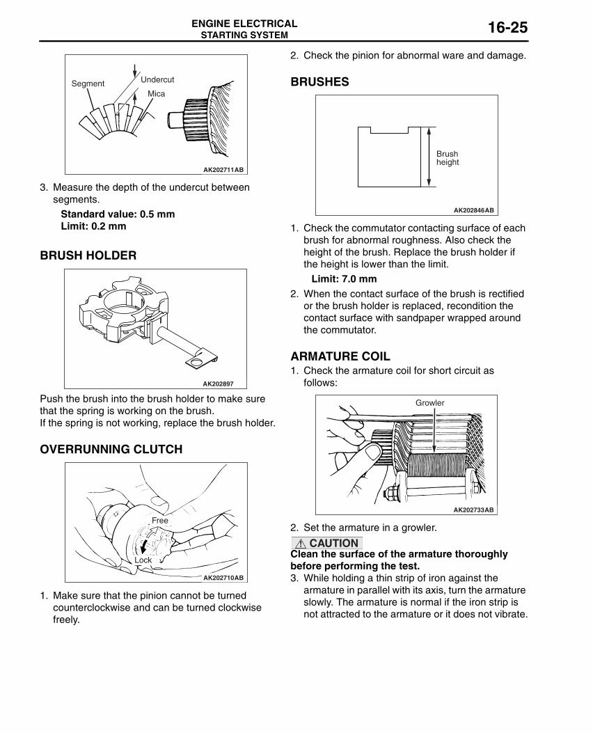
3. Measure the depth of the undercut between segments.
Standard value: 0.5 mmLimit: 0.2 mm
BRUSH HOLDER
Push the brush into the brush holder to make sure that the spring is working on the brush.If the spring is not working, replace the brush holder.
OVERRUNNING CLUTCH
1. Make sure that the pinion cannot be turned counterclockwise and can be turned clockwise freely.
2. Check the pinion for abnormal ware and damage.
BRUSHES
1. Check the commutator contacting surface of each brush for abnormal roughness. Also check the height of the brush. Replace the brush holder if the height is lower than the limit.
Limit: 7.0 mm2. When the contact surface of the brush is rectified
or the brush holder is replaced, recondition the contact surface with sandpaper wrapped around the commutator.
ARMATURE COIL1. Check the armature coil for short circuit as
follows:
2. Set the armature in a growler.
! CAUTIONClean the surface of the armature thoroughly before performing the test.3. While holding a thin strip of iron against the
armature in parallel with its axis, turn the armature slowly. The armature is normal if the iron strip is not attracted to the armature or it does not vibrate.
AK202711
Segment Undercut
Mica
AB
AK202897
AK202710
Free
Lock
AB
AK202846
Brush height
AB
AK202733
Growler
AB

STARTING SYSTEMENGINE ELECTRICAL16-26
4. Check the insulation between commutator segments and armature coils. The armature coils are properly insulated if no continuity is present.
5. Check continuity between a segment and another. There is no open circuit in the tested coil if there is continuity.
MAGNETIC SWITCH
1. Coil open circuit test• Check that there is continuity between the M
terminal and body A.• If there is no continuity, replace the magnetic
switch.
2. Contact fusion check• Check that there is no continuity between the B
terminal and M terminal.• If there is continuity, replace the magnetic switch.
3. Switch contact check• Push the indicated end of the magnetic switch
with a strong force to close the internal contacts. Without releasing the switch end, check that there is continuity between the B terminal and M terminal.
• If there is no continuity, replace the magnetic switch.
AK202734
AK202713
AK202891
A
M terminal
AB
AK202892
M terminal
B terminal
AB
AK202893
M terminal
B terminal
AB
IGNITION SYSTEMENGINE ELECTRICAL 16-27
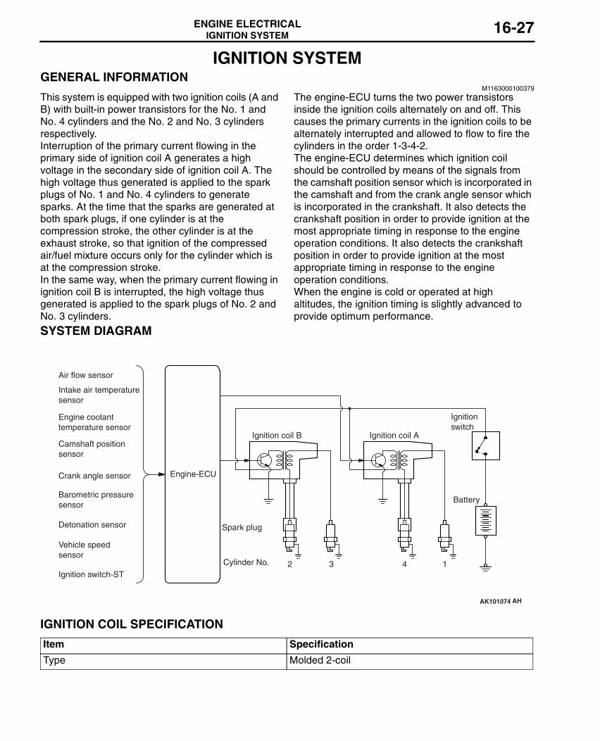
IGNITION SYSTEMGENERAL INFORMATION
M1163000100379
This system is equipped with two ignition coils (A and B) with built-in power transistors for the No. 1 and No. 4 cylinders and the No. 2 and No. 3 cylinders respectively.Interruption of the primary current flowing in the primary side of ignition coil A generates a high voltage in the secondary side of ignition coil A. The high voltage thus generated is applied to the spark plugs of No. 1 and No. 4 cylinders to generate sparks. At the time that the sparks are generated at both spark plugs, if one cylinder is at the compression stroke, the other cylinder is at the exhaust stroke, so that ignition of the compressed air/fuel mixture occurs only for the cylinder which is at the compression stroke.In the same way, when the primary current flowing in ignition coil B is interrupted, the high voltage thus generated is applied to the spark plugs of No. 2 and No. 3 cylinders.
The engine-ECU turns the two power transistors inside the ignition coils alternately on and off. This causes the primary currents in the ignition coils to be alternately interrupted and allowed to flow to fire the cylinders in the order 1-3-4-2.The engine-ECU determines which ignition coil should be controlled by means of the signals from the camshaft position sensor which is incorporated in the camshaft and from the crank angle sensor which is incorporated in the crankshaft. It also detects the crankshaft position in order to provide ignition at the most appropriate timing in response to the engine operation conditions. It also detects the crankshaft position in order to provide ignition at the most appropriate timing in response to the engine operation conditions.When the engine is cold or operated at high altitudes, the ignition timing is slightly advanced to provide optimum performance.
SYSTEM DIAGRAM
IGNITION COIL SPECIFICATION
AK101074
Air flow sensor
Intake air temperaturesensor
Engine coolanttemperature sensor
Camshaft positionsensor
Crank angle sensor
Barometric pressuresensor
Detonation sensor
Vehicle speed sensor
Ignition switch-ST
Engine-ECU
Ignition coil B
Cylinder No. 2 3 4
AH
1
Spark plug
Ignition coil A
Ignitionswitch
Battery
Item Specification
Type Molded 2-coil

IGNITION SYSTEMENGINE ELECTRICAL16-28
SPARK PLUG SPECIFICATIONS
SERVICE SPECIFICATIONSM1163000300221
IGNITION COIL
SPARK PLUG
SPARK PLUG CABLE
SPECIAL TOOLM1163000600288
ON-VEHICLE SERVICE
IGNITION COIL (WITH BUILT-IN POWER TRANSISTOR) CHECKM1163001200421
Check by the following procedure, and replace if there is a malfunction.
SECONDARY COIL RESISTANCE CHECK
Measure the resistance between the high-voltage terminals of the ignition coil.
Standard value: 8.5 − 11.5 kΩ
PRIMARY COIL AND POWER TRANSISTOR CONTINUITY CHECKNOTE: .
•
An analogue-type circuit tester should be used.• Connect the negative (-) prove of the circuit tester
to terminal No. 1.
Item Specifications
NGK IGR7A-G
Item Standard value
Secondary coil resistance kΩ 8.5 − 11.5
Item Standard value Limit
Spark plug gap mm 0.6 − 0.7 0.85
Item Standard value Limit
Resistance kΩ − Maximum 19
Tool Number Name Use
MD998773 Detonation sensor wrench
Detonation sensor removal and installation
AKX01264AKX01265AD
1.5 V
1 2 3+–

IGNITION SYSTEMENGINE ELECTRICAL 16-29
! CAUTIONThis test must be performed quickly (in less than 10 seconds) to prevent coil from burning and power transistor from breakage.
IGNITION COIL RELAY CHECK <RH DRIVE VEHICLES>
M1163006500029
! CAUTIONThe top and bottom of the ignition coil relay are difficult to identify. The triangle mark on the relay surface should be uppermost.
1. Removal the ignition coil relay.
2. Use the jumper leads to connect ignition coil relay terminal 3 to the negative battery terminal and terminal 2 to the positive battery terminal.
3. Check the continuity between ignition coil relay connector terminals 1 and 4 while alternately connecting and disconnecting the jumper leads from the battery terminals.
4. If there is a malfunction, replace the ignition coil relay.
SPARK PLUG CABLE CHECKM1163001400157
Measure the resistance of the all spark plug cables.1. Check cap and coating for cracks.2. Measure resistance.
Limit: Maximum 19 kΩ
SPARK PLUG CHECK AND CLEANINGM1163004300438
! CAUTIONWhen pulling off the spark plug cable from the plug always hold the cable cap, not the cable.1. Remove the spark plug cables and ignition coils.2. Remove the spark plugs.
! CAUTION• Do not attempt to adjust the gap of the iridium
plug.• Always use a plug cleaner and finish cleaning
within 20 seconds. Do not use wire brushes. Otherwise, the iridium and platinum tip may be damaged.
3. Check the plug gap and replace if the limit is exceeded.
Standard value: 0.6 − 0.7mmLimit: 0.85 mm
! CAUTIONBe careful not to allow foreign matter in cylinders.4. Clean the engine plug holes.
1.5 V power supply between 2 − 3
Continuity between 1 − 2
When current is flowing Continuity
When current is not flowing No continuity
Jumper leads Continuity between terminals 1 and 4
Connected Less than 2 ΩDisconnected Open circuit
AC311402AB
AC311403 AB
Relayside
AKX00382
AKX01327AD
Iridium tip
Platinum tip

IGNITION SYSTEMENGINE ELECTRICAL16-30
5. Install the spark plugs.6. Install the spark plug cables and ignition coils.
CAMSHAFT POSITION SENSOR CHECKM1163004400305
Check the camshaft position sensor system if self-diagnosis code, No. P0340 is shown.(Refer to GROUP 13A − Troubleshooting − Inspection procedure for diagnosis code P.13A-164.)
CRANK ANGLE SENSOR CHECKM1163004500368
Check the crank angle sensor system if self-diagnosis code, No. P0335 is shown.(Refer to GROUP 13A − Troubleshooting − Inspection procedure for diagnosis code P.13A-153.)
DETONATION SENSOR CHECKM1163002900070
Check the detonation sensor system if self-diagnosis code, No. P0325 is shown. (Refer to GROUP 13A − Troubleshooting − Inspection procedure for diagnosis code P.13A-149.)
IGNITION SECONDARY VOLTAGE WAVEFORM CHECK USING AN OSCILLOSCOPE
M1163001700244
MEASUREMENT METHOD1. Clamp the secondary pickup around the spark
plug cable.
NOTE: .• The peak ignition voltage will be reversed
when the spark plug cables No. 2 and No. 4, or No. 1 and No. 3 cylinders are clamped.
• Because of the two-cylinder simultaneous ignition system, the waveforms for two cylinders in each group appear during waveform observation (No. 1 cylinder - No. 4 cylinder, No. 2 cylinder - No. 3 cylinder). However, waveform observation is only applicable for the cylinder with the spark plug cable clamped by the secondary pickup.
• Identifying which cylinder waveform is displayed can be difficult. For reference, remember that the waveform of the cylinder attached to the secondary pickup will be displayed as stable.
2. Clamp the spark plug cable with the trigger pickup.
NOTE: Clamp the trigger pickup to the same spark plug cable clamped by the secondary pickup.

IGNITION SYSTEMENGINE ELECTRICAL 16-31
STANDARD WAVEFORM
Observation Conditions
Observation Conditions (The only change from above condition is the pattern selector.)
Function Secondary
Pattern height High (or Low)
Pattern selector Raster
Engine revolutions Curb idle speed
Pattern selector Display
AKX00278
kV
0
Secondaryignition voltagewave pattern
Ignition voltage(point D)
Spark line (point A)
Dwell section
Wave damping reduction section (point B)
Point C
Time
AC
AKX01275
kV
Secondary ignitionvoltage wave pattern
0
2
NO. 1 cylinder NO. 3 cylinderignition noise
Neutral section
NO. 4 cylinderNO. 2 cylinderignition noise
Time
AD

IGNITION SYSTEMENGINE ELECTRICAL16-32
WAVEFORM OBSERVATION POINTS
Point A: The height, length and slope of the spark line show the following trends (Refer to abnormal waveform examples, 1, 2, 3 and 4).
Point B: Number of vibration in reduction vibration section (Refer to abnormal waveform example 5)
Point C: Number of vibrations at beginning of dwell section (Refer to abnormal waveform example 5)
Point D: Ignition voltage height (distribution per each cylinder) shows the following trends.
EXAMPLES OF ABNORMAL WAVEFORMS
Example 1• Wave characteristics
Spark line is high and short.• Cause of problem
Spark plug gap is too large.
Example 2• Wave characteristics
Spark line is low and long, and is sloping.Also, the second half of the spark line is distorted.
This could be a result of misfiring.• Cause of problem
Spark plug gap is too small.
Spark line Plug gap Condition of electrode
Compression force
Concentration of air mixture
Ignition timing
Spark plug cable
Length Long Small Normal Low Rich Advanced Leak
Short Large Large wear High Lean Retarded High resistance
Height High Large Large wear High Lean Retarded High resistance
Low Small Normal Low Rich Advanced Leak
Slope Large Plug is fouled − − − −
Number of vibrations Coil and condenser
3 or more Normal
Except above Abnormal
Number of vibrations Coil
5 − 6 or higher Normal
Except above Abnormal
Ignition voltage
Plug gap Condition of electrode
Compression force
Concentration of air mixture
Ignition timing
Spark plug cable
High Large Large wear High Lean Retarded High resistance
Low Small Normal Low Rich Advanced Leak
AKX00280
AKX00281

IGNITION SYSTEMENGINE ELECTRICAL 16-33
Example 3• Wave characteristics
Spark line is low and long, and is sloping. However, there is almost no spark line distortion.
• Cause of problemSpark plug gap is fouled.
Example 4• Wave characteristics
Spark line is high and short.Difficult to distinguish between this and abnormal
waveform example 1.• Cause of problem
Spark plug cable is nearly falling off (Causing a dual ignition).
Example 5• Wave characteristics
No waves in wave damping section.• Cause of problem
Layer short in ignition coil.
AKX00282 AKX00283
AKX00284

IGNITION SYSTEMENGINE ELECTRICAL16-34
IGNITION COIL
REMOVAL AND INSTALLATIONM1163004000534
Pre-removal and Post-installation Operation• Rocker Cover Centre Cover Removal and Installation (Refer to GROUP 11A, Camshaft and Valve Stem Seal
P.11A-16).
AC210297
1
1
42
34
10 ± 2 N·m
25 ± 4 N·m
AB
5
Removal steps1. Ignition coil connectors2. Spark plug cable No. 13. Spark plug cable No. 3
4. Ignition coils.5. Spark plugs.
Removal steps (Continued)

IGNITION SYSTEMENGINE ELECTRICAL 16-35
CAMSHAFT POSITION SENSOR
REMOVAL AND INSTALLATIONM1163003400540
AC210298
12
3
10.5 ± 0.5 N·m
AB
N
Removal steps1. Camshaft position sensor
connector2. Camshaft position sensor3. O-ring
Removal steps (Continued)

IGNITION SYSTEMENGINE ELECTRICAL16-36
CRANK ANGLE SENSOR
REMOVAL AND INSTALLATIONM1163004800143
! CAUTIONIf the vehicle is equipped with the Brembo disc brake, during maintenance, take care not to contact the caliper with tool or parts, because the caliper paint will be scratched.
REMOVAL SERVICE POINT<<A>> POWER STEERING OIL PUMP, BRACKET AND OIL RESERVOIR ASSEMBLY REMOVALNOTE: Tie the removed power steering oil pump, bracket and oil reservoir assembly with a rope and set aside where they cannot hinder the removal of the power steering oil pump bracket.Remove the power steering oil pump, bracket and oil reservoir assembly with the hoses attached from the power steering oil pump bracket.
Pre-removal and Post-installation Operation• Timing Belt Removal and Installation (Refer to GROUP 11A,Timing Belt P.11A-34).• Radiator Reserve Tank Assembly Removal and Installation (Refer to GROUP 14, Radiator P.14-26).
AC210409
1
5
6
AB
2
22 ± 4 N·m
22 ± 4 N·m
3440 ± 5 N·m
22 ± 4 N·m
12 ± 2 N·m
12 ± 2 N·m
49 ± 9 N·m
49 ± 9 N·m
8.8 ± 1.0 N·m
Removal steps1. Power steering pressure switch
connector2. Power steering oil pump heat
protector<<A>> 3. Power steering oil pump, bracket
and oil reservoir assembly4. Power steering oil pump bracket5. Crank angle sensor connector6. Crank angle sensor

IGNITION SYSTEMENGINE ELECTRICAL 16-37
DETONATION SENSOR
REMOVAL AND INSTALLATIONM1163002800664
REMOVAL SERVICE POINT<<A>> DETONATION SENSOR REMOVAL
Use special tool detonation sensor wrench (MD998773) to remove the detonation sensor.
INSTALLATION SERVICE POINT>>A<< DETONATION SENSOR INSTALLATION
Use special tool detonation sensor wrench (MD998773) to install the detonation sensor.
Pre-removal and Post-installation Operation• Inlet Manifold Stay Removal and Installation (Refer to GROUP 15, Inlet Manifold P.15-13).
AC210411AB
23 ± 2 N·m
12
Inlet manifold stay
Removal steps1. Detonation sensor connector
<<A>> >>A<< 2. Detonation sensor
AC100807
MD998773
Detonation sensor
AB
AC100807
MD998773
Detonation sensor
AB
