group 13 - fluid control as and documents/groups/group13... · 3 tema quick release coupling safety...
TRANSCRIPT

Group 13Quick Release Couplings
Low-pressure

13 - 2
13
Flexible Solutions
INDEX
Page Contents2 Index3 Tema Quick Release Coupling Safety Nipple for Compressed Air4 Technical Information about Tema Quick Release Coupling Compressed Air Series5 Tema Quick Release Coupling Series 1100 and 1100N for Air6 Tema Quick Release Coupling Series 1300 for Air7 Tema Quick Release Coupling Series 1300N for Air8 Tema Quick Release Coupling Series 1800 for Air9 Tema Quick Release Coupling Series 1800 for Air
10 Tema Quick Release Coupling Series 1800N for Air11 Tema Quick Release Coupling Series 1400 for Air12 Tema Quick Release Coupling Series 1600 for Air13 Tema Quick Release Coupling Series 1800H and 1800D for Air14 Hansen Series 3000 and 5000 Quick Release Couplings
15-17 Cam and Groove Adaptors Brass, Aluminium, Stainless Steel and Polypropylene Quick Release Couplings18 Laux Quick Release Coupling Series Model C (German Series) and 42 (Swedish Series)19 Nor Quick Release Couplings20 Storz Quick Release Couplings21 TW (Tanker) Quick Release Couplings22 Claw Couplings European Standard Galvanized23 Claw Couplings American (“Chicago”) Standard Galvanized, Brass and Stainless Steel24 “Boss Ground Joint Seal” Steam Couplings25 Gas Hose / Tanker Hose Couplings
26-29 Dry Break Couplings (Interchangeable with Avery Hardoll, Fulcrum).

13 - 3
13
www.fluidcontrol.no
TEMA SAFETY NIPPLE FOR COMPRESSED AIR
TEMA Safety Nipple is designed to take away disconnection recoils in compressed air systems. A dangerous and often criticized factor in the workplace disappears. The nipple also makes disconnecting quieter. TEMA Safety Nipple is available for series 1300, 1400, 1600, 1700 and 1800.
Standard nipple
TEMA Safety nipple
Product Features• Reduces the risk of injury• Does not reduce the airflow• Can be connected to other brands. For example Bosch 823, Cejn 310, Cejn 320, Luna 25, Obac 25, Rectus 25 and others• Reduces recoil and noise to a minimum• Meets ISO 4414-9.4 requirements.• Service free construction• Low cost security increase
QUICK RELEASE COUPLINGSTEMA

13 - 4
13
Flexible Solutions
TECHNICAL INFORMATIONQUICK RELEASE COUPLINGS FOR COMPRESSED AIR
Series 1100Throughput:11 liters/sec.1)
Connection power:5.6 kg 2)
Minimum Throughput Diameter:5.5 mmConnections:ISO-G 1/8ISO-G 1/4 maleLength:55 mm
Ø: 18 mmMax Working Pressure:30 BarOther Applications:Water, gas
Series 1400Throughput:15 liters/secConnection power:6.5 kg 2)
Minimum Throughput Diameter:6.0 mmConnections:ISO-G 1/4, 3/8” femaleISO-R 1/4, 3/8 3)
Hose Connection: 1/4”-1/2”Length: 37 mm
Ø: 22 mm
Can be connected to: Hansen 3000, Cejn 310, Atlas, Qic8 and others.
Series 1300/1300 EThroughput:28 liters/sec 1)
Connection power:Series 1300: 9.5 kg 2)
Series 1300 E 7.3 kg 2)
Minimum Throughput Diameter:Series 1300: 6.8 mmSeries 1300 E: 7.4 mmConnections:ISO-G 1/4, 3/8 female,ISO-R 1/4 3/8 3)
ISO-G 3/8 maleHose Connection: 1300 E: 1/4” - 1/2”Length:Series 1300: 49 mmSeries 1300E: 55 mmØ: 22 mm 4)
Max Working Pressure: 30 BarOther Applications:Water, gas
Series 1600Throughput:37 liters/sec 1)
Connection power:7.6 kg 2)
Minimum Throughput Diameter:7.5 mmConnections:ISO-G1/4, 3/8, 1/2 femaleISO-R 1/4, 3/8 1/2 3)
Hose Connection:1/4” - 1/2”Length: 57 mmØ: 23 mmMax Working Pressure: 30 BarCan be connected to: JWL-5200, Cejn 320, Luna 25, Obac 25, Rectus 25 and others.
Series 1800/1800 EThroughput:65 liters/sec 1)
Connection power:Series 1800: 12.7 kg 2)
Series 1800 E: 10.8 kg 2)
Minimum Throughput Diameter:Series 1800: 10.4Series 1800 E: 10.2 mmConnections:ISO-G 3/8, 1/2, 3/4 femaleISO-G 1/2 maleISO-R 1/2 3)
Length:Series 1800: 54 mmSeries 1800E: 60 mmØ: 27 mm 4)
Max Working Pressure: 30 barOther Applications: Water, gas
Series 1100 - 1300 - 1600 - 1800 - have a valve in the coupling part.
Series 1100N - 1300N - 1800N - have a valve in both the coupling and nipple
Note! These series are not interchangeable!
1) Measured at 6 bar air pressure and 0.5 bar pressure loss2) Measured at 6 bar air pressure3) ISO-R = conical outside4) #4 is missing
QUICK RELEASE COUPLINGSTEMA

13 - 5
13
www.fluidcontrol.no
TEMA AIR COUPLINGSeries 1100
TEMA AIR COUPLINGSeries 1100 N
TypePart No.
DimensionISO-BSP
Min.Through-
putmm
RubberQuality
Dmm
Lmm
WSmm
MaxWork.Pres.bar
Hose InsideDiameter
Weightgr.Male Female mm inches
Coupling
1100 1/8 5.5 nitrile 18 37 15 30 401100 A 1/4 5.5 nitrile 18 38 15 30 351100 V 1/8 5.5 viton 18 37 15 30 40
1100 AV 1/4 5.5 viton 18 38 15 30 35
Nipple I1105 1/8 27 12 30 5 3/16” 71106 1/8 27 12 30 6 1/4” 8
Plug-in NippleMale Thread II 11110 1/8 9.5 27 12 30 9Plug-in NippleFemale Thread III 11410 1/8 9.5 27 12 30 10Plug-in Nipple w/Hose Conn. IV
11005 1/8 9.5 33 30 5 3/16” 611006 9.5 33 30 5 3/16” 7
Plastic ProtectionBody Nipple
2316 PVC 32326 PVC 3
O-ring11310 N nitrile11310 V viton
Fiber Gasket 11320
TypePart No.
DimensionISO-BSP
Min.Through-
putmm
RubberQuality
Dmm
Lmm
WSmm
MaxWork.Pres.bar
Hose Inside
Diameter
Weightgr.Male Female mm inches
Coupling
1100 N 1/8 4,8 nitrile 18 37 15 50 401100 NA 1/4 4,8 nitrile 18 38 15 50 351100 NV 1/8 4,8 viton 18 37 15 50 40
1100 NAV 1/4 4,8 viton 18 38 15 50 35
Nipple I1105 1/8 27 12 30 5 3/16” 71106 1/8 27 12 30 6 1/4” 8
Plug-in NippleFemale Thread II
11410 MN 1/8 nitrile 9,5 36 15 20 2011410 MV 1/8 viton 9,5 36 15 20 20
Plastic ProtectionBodyNipple
2316 PVC 32326 PVC 3
O-ring11310 N nitrile11310 V viton
Fiber Gasket 11320
1) All coupling bodies in the 1100 series are available without valve. Add ”UV” after Part No.Series 1100 is not interchangeable with series 1100N.
Coupling Female Thread
Coupling Male Thread
Hose Nipple
Plug-in NippleFemale Thread
Coupling Female Thread
Coupling Male Thread
Hose Nipple
Plug-in NippleFemale Thread
II
I
I
II
III
IV
Fiber Gasket
Plug-in NippleMale Thread
Plug-in Nipplew/ Hose Connection
Series 1100N is not interchangeable with series 1100.
Note! Valve in coupling and nipple
QUICK RELEASE COUPLINGSTEMA 1100 SERIES
13 - 6
13
Flexible Solutions
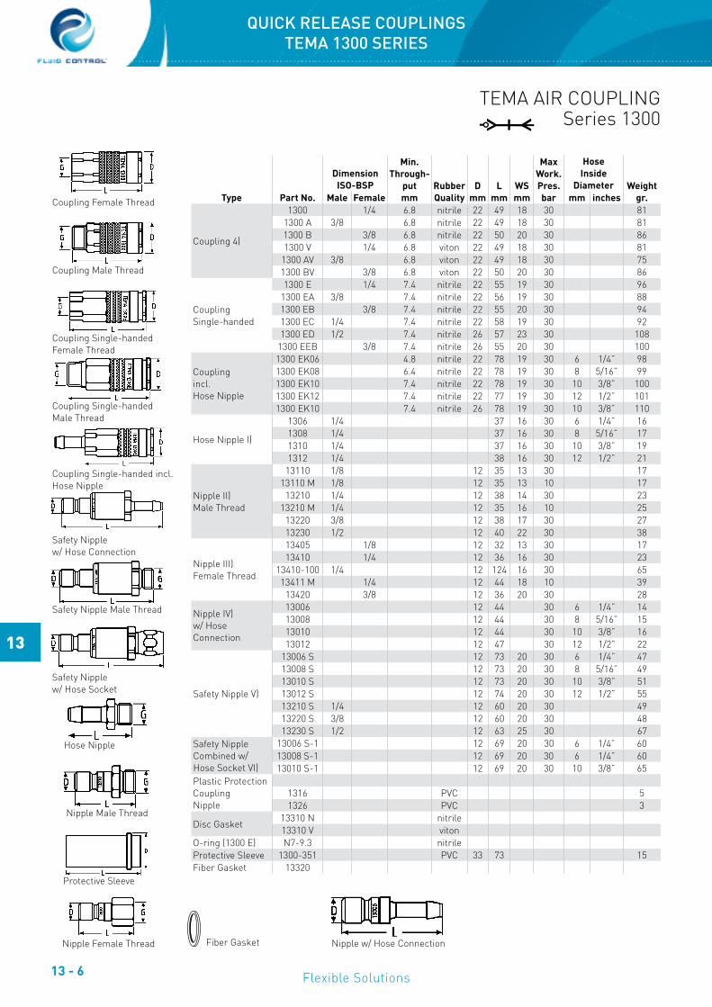
TEMA AIR COUPLINGSeries 1300
Type Part No.
DimensionISO-BSP
Min.Through-
putmm
RubberQuality
Dmm
Lmm
WSmm
MaxWork.Pres.bar
HoseInside
Diameter Weightgr.Male Female mm inches
Coupling 4)
1300 1/4 6.8 nitrile 22 49 18 30 811300 A 3/8 6.8 nitrile 22 49 18 30 811300 B 3/8 6.8 nitrile 22 50 20 30 861300 V 1/4 6.8 viton 22 49 18 30 81
1300 AV 3/8 6.8 viton 22 49 18 30 751300 BV 3/8 6.8 viton 22 50 20 30 86
CouplingSingle-handed
1300 E 1/4 7.4 nitrile 22 55 19 30 961300 EA 3/8 7.4 nitrile 22 56 19 30 881300 EB 3/8 7.4 nitrile 22 55 20 30 941300 EC 1/4 7.4 nitrile 22 58 19 30 921300 ED 1/2 7.4 nitrile 26 57 23 30 108
1300 EEB 3/8 7.4 nitrile 26 55 20 30 100
Couplingincl. Hose Nipple
1300 EK06 4.8 nitrile 22 78 19 30 6 1/4” 981300 EK08 6.4 nitrile 22 78 19 30 8 5/16” 991300 EK10 7.4 nitrile 22 78 19 30 10 3/8” 1001300 EK12 7.4 nitrile 22 77 19 30 12 1/2” 1011300 EK10 7.4 nitrile 26 78 19 30 10 3/8” 110
Hose Nipple I)
1306 1/4 37 16 30 6 1/4” 161308 1/4 37 16 30 8 5/16” 171310 1/4 37 16 30 10 3/8” 191312 1/4 38 16 30 12 1/2” 21
Nipple II)Male Thread
13110 1/8 12 35 13 30 1713110 M 1/8 12 35 13 10 17
13210 1/4 12 38 14 30 2313210 M 1/4 12 35 16 10 25
13220 3/8 12 38 17 30 2713230 1/2 12 40 22 30 38
Nipple III)Female Thread
13405 1/8 12 32 13 30 1713410 1/4 12 36 16 30 23
13410-100 1/4 12 124 16 30 6513411 M 1/4 12 44 18 10 39
13420 3/8 12 36 20 30 28
Nipple IV)w/ HoseConnection
13006 12 44 30 6 1/4” 1413008 12 44 30 8 5/16” 1513010 12 44 30 10 3/8” 1613012 12 47 30 12 1/2” 22
Safety Nipple V)
13006 S 12 73 20 30 6 1/4” 4713008 S 12 73 20 30 8 5/16” 4913010 S 12 73 20 30 10 3/8” 5113012 S 12 74 20 30 12 1/2” 5513210 S 1/4 12 60 20 30 4913220 S 3/8 12 60 20 30 4813230 S 1/2 12 63 25 30 67
Safety NippleCombined w/Hose Socket VI)
13006 S-1 12 69 20 30 6 1/4” 6013008 S-1 12 69 20 30 6 1/4” 6013010 S-1 12 69 20 30 10 3/8” 65
Plastic ProtectionCouplingNipple
1316 PVC 51326 PVC 3
Disc Gasket13310 N nitrile13310 V viton
O-ring (1300 E) N7-9.3 nitrileProtective Sleeve 1300-351 PVC 33 73 15Fiber Gasket 13320
Coupling Female Thread
Coupling Male Thread
Coupling Single-handed Female Thread
Coupling Single-handed Male Thread
Coupling Single-handed incl. Hose Nipple
Safety Nipple w/ Hose Connection
Safety Nipple Male Thread
Safety Nipple w/ Hose Socket
Hose Nipple
Nipple Male Thread
Protective Sleeve
Nipple Female Thread Nipple w/ Hose ConnectionFiber Gasket
QUICK RELEASE COUPLINGSTEMA 1300 SERIES

13 - 7
13
www.fluidcontrol.no
0,1
0,08
0,06
0,04
0,03
0,02
0,015
1 1,5 2 3 4 6 8 10 L/min
Trykkfallsdiagram: 1300N+13410MNP MPa
Kv-
verd
i (va
nn) 0
,81
Tem
pera
tur:
20°C
TEMA AIR COUPLINGSeries 1300 N
Type Part No.
DimensionISO-BSP
Min.Through-
putmm
RubberQuality
Dmm
Lmm
WSmm
Max Work. Pres.bar
HoseInside
Diameter Weightgr.Male Female mm inches
Coupling
1300 N 1/4 5.8 nitrile 22 49 18 501) 811300 NA 3/8 5.8 nitrile 22 49 18 501) 751300 NB 3/8 5.8 nitrile 22 50 20 501) 861300 NV 1/4 5.8 viton 22 49 18 501) 81
1300 NAV 3/8 5.8 viton 22 49 18 501) 751300 NBV 3/8 5.8 viton 22 50 20 501) 86
Nipple 1)
1306 1/4 37 16 30 6 1/4” 161308 1/4 37 16 30 8 5/16” 171310 1/4 37 16 30 10 3/8” 191312 1/4 37 16 30 12 1/2” 21
Nipple Female Thread II)
13410 MN 2) 1/4 nitrile 12 44 18 201) 4213410 STN 3) 1/4 nitrile 12 44 18 501) 4013410 MNV 2) 1/4 viton 12 44 18 201) 4213410 STNV 3) 1/4 viton 12 44 18 501) 40
Plastic Protection Coupling Nipple
1316 PVC 51326 PVC 3
O-ring13310 N nitrile13310 V viton
ProtectiveSleeveFiber Gasket
1300-351 PVC 33 73 1513320
Coupling Female Thread
Coupling Male Thread
Hose Nipple
Nipple Female Thread
Protective Sleeve
Fiber Gasket
Long valve that opens the valve in the N-nipple Standard coupling (series 1300, 1800) with short valve
Coupling N-series Coupling Standard
1) Max working pressure for steam 10 bar.2) Material quality brass.3) Material quality steel.
QUICK RELEASE COUPLINGSTEMA 1300N SERIES

13 - 8
13
Flexible Solutions
TEMA AIR COUPLINGSeries 1800
Type Part No.
DimensionISO-BSP
Min.Through-
putmm
RubberQuality
Dmm
Lmm
WSmm
MaxWork.Pres.bar
HoseInside
Diameter Weightgr.Male Female mm inches
Coupling 11)
1800 3/8 10.4 nitrile 27 54 22 30 1251800 A 1/2 10.4 nitrile 27 54 22 30 1151800 B 1/2 10.4 nitrile 27 55 24 30 1301800 C 3/4 10.4 nitrile 27 57 30 30 1601800 L2) 3/8 10.4 nitrile 27 54 22 30 125
1800 SV2) 3/8 10.4 nitrile 27 54 22 30 1251800 RV4) 3/8 10.0 viton 27 54 22 307) 115
1800 V 3/8 10.4 viton 27 54 22 30 1251800 AV 1/2 10.4 viton 27 54 22 30 1151800 BV 1/2 10.4 viton 27 55 24 30 1301800 CV 3/4 10.4 viton 27 57 30 30 1601800 ST9) 3/8 10.4 nitrile 27 54 22 30 122
1800 AST9) 1/2 10.4 nitrile 27 54 22 30 1121800 BST9) 1/2 10.4 nitrile 27 55 24 30 127
CouplingSingle-handed
1800 E 3/8 10.2 nitrile 27 60 23 30 1461800 EA 1/2 10.2 nitrile 27 64 23 30 1401800 EB 1/2 10.2 nitrile 27 61 24 30 146
1800 EE10) 3/8 10.2 nitrile 31 60 23 30 157
Nipple 1)
1806 3/8 38 19 30 6 1/4” 211808 3/8 38 19 30 8 5/16” 231810 3/8 38 19 30 10 3/8” 25
1810 R4) 3/8 38 19 30 10 3/8” 221812 3/8 39 19 30 12 1/2” 29
1812 R5) 3/8 39 19 30 12 1/2” 271816 3/8 39 19 30 16 5/8” 291819 3/8 39 19 30 19 3/4” 3419125) 3/8 43 21 30 12 1/2” 36
NippleMale Thread
18105 1/8 16 36 16 30 2618110 1/4 16 39 16 30 29
18110 MS6) 1/4 16 36 16 10 29182010 3/8 16 38 17 30 30
18210 R4) 3/8 16 36 19 30 3118210 SV3) 3/8 16 36 19 30 35
18220 1/2 16 40 22 30 4118220 M1) 1/2 16 40 22 10 44
18230 3/4 16 43 27 30 66
Coupling Female Thread
Coupling Male Thread
Coupling Single-handed Female Thread
Coupling Single-handed Male Thread
Hose Nipple
Plug-in Nipple Male Thread
1) Quality: brass, applicable to water.2) Coupling 1800L comes with safety mechanism to prevent disconnection under pressure.3) Coupling 1800SV fits nipple 18210SV.4) Quality: stainless steel SS2382.5) Quality: steel.6) Nipple 18110MS has built-in filter for accumulation of dirt.7) Max working pressure for liquids is 50 bar.8) Fits all nipples in the 1800 series except 18210SV.9) Quality socket: steel.10) Comes with turbo socket.11) All couplings in the 1800 series are available without valve - add “UV” after Part No.
QUICK RELEASE COUPLINGSTEMA 1800 SERIES

13 - 9
13
www.fluidcontrol.no
TEMA AIR COUPLINGSeries 1800
Type Part No.
DimensionISO-BSP
Min.Through-
putmm
RubberQuality
Dmm
Lmm
WSmm
MaxWork.Pres.bar
HoseInside
Diameter Weightgr.Male Female mm inches
NippleFemale Thread
18405 1/4 16 36 16 30 3018410 3/8 16 36 20 30 33
18410 R4) 3/8 16 36 22 30 4118411 M1) 3/8 16 49 22 30 60
18420 1/2 16 39 25 30 53
Plug-in Nipplew/ HoseConnection
18006 16 44 30 6 1/4” 2018008 16 44 30 8 5/16” 2218010 16 44 30 10 3/8” 24
18010 M1) 16 44 10 10 3/8” 2418012 16 45 30 12 1/2” 27
18012 M1) 16 45 10 12 1/2 2718016 16 46 30 16 5/8” 2618019 16 46 30 19 3/4” 32
Safety Nipple
18006 S 16 70 21 30 6 1/4” 6018008 S 16 70 21 30 8 5/16” 6118010 S 16 70 2 30 10 3/8” 6318012 S 16 71 21 30 12 1/2” 6818016 S 16 71 21 30 16 5/8” 6618019 S 16 71 21 30 19 3/4” 7018110 S 1/4 16 58 21 30 6218210 S 3/8 16 58 21 30 6218220 S 1/2 16 60 21 30 80
Safety Nipplecombined withHose Socket
18008 S-1 16 67 21 30 8 5/16” 7918010 S-1 16 67 21 30 10 3/8” 8318012 S-1 16 67 21 30 12 1/2” 88
Plastic ProtectionCouplingNippleProtectiveSleeve
5026 PVC2526 PVC
1800-35 PVC 37 41 101800-351 PVC 37 78 20
Metal Protection 184158) 23 78 45
Disc Gasket
(1800 E)
18310 N Nitrile18310 V viton
18310 NE nitrileFiber Gasket 18320
Continued from previous page
Plug-in Nipple Female Thread
Plug-in Nipple w/ Hose Connection
Safety Nipple Male Thread
Safety Nipple w/ Hose Connection
Safety Nipple w/ Hose Socket
Protective Sleeve
Metal Protection
Fiber Gasket
3000
100
2400 2600
90807060
50
40
30
25
20
15
103300 3600 4100 4400 4700 dm
3/min.
P kPa SERIES: 1800
Air volume dm3/min, 3500dm3/min at 50 kPa (0,5 bar) pressure drop
Pres
ure
drop
for
TEM
A 18
00 B
- 1
8420
at 6
00kP
a (6
bar
) ent
ranc
e pr
essu
re.
QUICK RELEASE COUPLINGSTEMA 1800 SERIES
13 - 10
13
Flexible Solutions
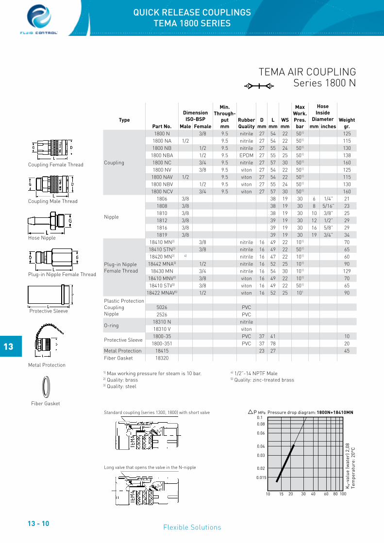
TEMA AIR COUPLINGSeries 1800 N
TypePart No.
DimensionISO-BSP
Min.Through-
putmm
RubberQuality
Dmm
Lmm
WSmm
MaxWork.Pres.bar
HoseInside
Diameter Weightgr.Male Female mm inches
Coupling
1800 N 3/8 9.5 nitrile 27 54 22 501) 1251800 NA 1/2 9.5 nitrile 27 54 22 501) 1151800 NB 1/2 9.5 nitrile 27 55 24 501) 130
1800 NBA 1/2 9.5 EPDM 27 55 25 501) 1381800 NC 3/4 9.5 nitrile 27 57 30 501) 1601800 NV 3/8 9.5 viton 27 54 22 501) 125
1800 NAV 1/2 9.5 viton 27 54 22 501) 1151800 NBV 1/2 9.5 viton 27 55 24 501) 1301800 NCV 3/4 9.5 viton 27 57 30 501) 160
Nipple
1806 3/8 38 19 30 6 1/4” 211808 3/8 38 19 30 8 5/16” 231810 3/8 38 19 30 10 3/8” 251812 3/8 39 19 30 12 1/2” 291816 3/8 39 19 30 16 5/8” 291819 3/8 39 19 30 19 3/4” 34
Plug-in NippleFemale Thread
18410 MN2) 3/8 nitrile 16 49 22 101) 7018410 STN3) 3/8 nitrile 16 49 22 501) 6518420 MN2) 4) nitrile 16 47 22 101) 60
18442 MNA5) 1/2 nitrile 16 52 25 101) 9018430 MN 3/4 nitrile 16 54 30 101) 129
18410 MNV2) 3/8 viton 16 49 22 101) 7018410 STV3) 3/8 viton 16 49 22 501) 65
18422 MNAV5) 1/2 viton 16 52 25 101 90Plastic ProtectionCouplingNipple
5026 PVC2526 PVC
O-ring18310 N nitrile18310 V viton
Protective Sleeve1800-35 PVC 37 41 10
1800-351 PVC 37 78 20Metal Protection 18415 23 27 45Fiber Gasket 18320
Coupling Female Thread
Coupling Male Thread
Hose Nipple
Plug-in Nipple Female Thread
Protective Sleeve
Metal Protection
Fiber Gasket
0.10.08
0.06
0.04
0.03
0.02
0.015
10 15 20 30 40 60 80 100
P MPa Pressure drop diagram: 1800N+18410MN
Kv-
valu
e (w
ater
) 2,0
8Te
mpe
ratu
re: 2
0°C
Standard coupling (series 1300, 1800) with short valve
Long valve that opens the valve in the N-nipple
1) Max working pressure for steam is 10 bar.2) Quality: brass3) Quality: steel
4) 1/2”-14 NPTF Male5) Quality: zinc-treated brass
QUICK RELEASE COUPLINGSTEMA 1800 SERIES

13 - 11
13
www.fluidcontrol.no
TEMA AIR COUPLINGSeries 1400
Type Part No.
DimensionISO-BSP
Min.Through-
putmm
RubberQuality
Dmm
Lmm
WSmm
MaxWork.Pres.bar
HoseInside
Diameter Weightgr.Male Female mm inches
Coupling
1400 1/4 7.4 nitrile 22 55 19 30 1001400 A 3/8 7.4 nitrile 22 55 20 30 961400 C 1/4 7.4 nitrile 22 58 19 30 931400 D 3/8 7.4 nitrile 22 56 19 30 90
Couplingincl. Hose Nipple
1400 K06 4.8 nitrile 22 78 20 30 6 1/4” 1031400 K08 6.4 nitrile 22 78 20 30 8 5/16” 1051400 K10 7.4 nitrile 22 78 20 30 10 3/8” 1051400 K12 7.4 nitrile 22 77 20 30 12 1/2” 107
Hose Nipple I
13062) 1/4 37 16 30 6 1/4” 1613082) 1/4 37 16 30 8 5/16” 1713102) 1/4 37 16 30 10 3/8” 1913122) 1/4 38 16 30 12 1/2” 21
Plug-in NippleMale Thread II
14110 1/8 8 36 12 30 1614210 1/4 8 36 12 30 1614220 3/8 8 41 17 30 23
Plug-in Nipple IIIFemale Thread
14405 1/8 8 33 12 30 1114410 1/4 8 40 17 30 2414420 3/8 8 42 20 30 31
Plug-in Nipple IVw/ HoseConnection
14006 8 47 30 6 1/4” 1414008 8 47 30 8 5/16” 1514010 8 47 30 10 3/8” 15
14010 M1) 8 47 10 10 3/8” 1514012 8 49 30 12 1/2” 17
Safety Nipple V
14006 S 8 76 20 30 6 1/4” 4914008 S 8 76 20 30 8 5/16” 5014010 S 8 76 20 30 10 3/8” 5114012 S 8 77 20 30 12 1/2” 5514210 S 1/4 8 63 20 30 49
Plastic ProtectionCouplingNipple
3826 PVC 171326 PVC 3
Fiber Gasket 13320
Coupling Female Thread
Coupling Male Thread
Coupling incl. Hose Connection
Safety Nipple, w/ Hose Connection
Safety Nipple Male Thread
Hose Nipple
Plug-in Nipple Male Thread
Plug-in Nipple Female Thread
Plug-in Nipple w/ Hose Connection
Fiber Gasket
1) Quality: Brass2) Coupling 1400A is interchangeable with series 1800Note! Interchangeable with Cejn 310, Hansen 3000, Luna 23, OBAC 23, Atlas Qic8
V
V
I
II
III
IV
QUICK RELEASE COUPLINGSTEMA 1400 SERIES

13 - 12
13
Flexible Solutions
TEMA AIR COUPLINGSeries 1600
Type Part No.
DimensionISO-BSP
Min.Through-
putmm
RubberQuality
Dmm
Lmm
WSmm
MaxWork.Pres.bar
HoseInside
Diameter Weight gr.Male Female mm inches
Coupling
1600 1/4 7.5 nitrile 23 58 19 30 1081600 A 3/8 7.5 nitrile 23 59 19 30 981600 B 3/8 7.5 nitrile 23 57 20 30 1061600 C 1/2 7.5 nitrile 23 61 23 30 1251600 D 1/4 7.5 nitrile 23 61 19 30 1001600 F 1/2 7.5 nitrile 23 57 25 30 127
Couplingincl. Hose Nipple
1600 K06 4.8 nitrile 23 80 19 30 6 1/4” 1131600 K08 6.4 nitrile 23 80 19 30 8 5/16” 1141600 K10 7.5 nitrile 23 80 19 30 10 3/8” 1151600 K12 7.5 nitrile 23 79 19 30 12 1/2” 115
Hose Nipple1) I
1306 1/4 37 16 30 6 1/4” 161308 1/4 37 16 30 8 5/16” 171310 1/4 37 16 30 10 3/8” 191312 1/4 38 16 30 12 1/2” 211806 3/8 38 19 30 6 1/4” 211808 3/8 38 19 30 8 5/16” 231810 3/8 38 19 30 10 3/8” 251812 3/8 39 19 30 12 1/2” 29
Plug-in Nipple IIMale Thread
16110 1/8 10 32 13 30 1416210 1/4 10 38 14 30 2016220 3/8 10 36 19 30 2416230 1/2 10 40 22 30 34
Plug-in Nipple IIIFemale Thread
16405 1/8 10 30 13 30 1316410 1/4 10 36 16 30 2116420 3/8 10 36 20 30 2816430 1/2 10 40 25 30 48
Plug-in Nipple IVw/ HoseConnection
16006 10 43 30 6 1/4” 1216008 10 43 30 8 5/16” 1316010 10 43 30 10 3/8” 1516012 10 46 30 12 1/2” 22
Safety Nipple V
16006 S 10 73 20 30 6 1/4” 4616008 S 10 73 20 30 8 5/16” 4816010 S 10 73 20 30 10 3/8” 4916012 S 10 74 20 30 12 1/2” 5316210 S 1/4 10 60 20 30 49
Safety Nipplecombined withHose Socket VI
16006 S-1 10 69 20 30 6 1/4” 6216008 S-1 10 69 20 30 8 5/16” 6416010 S-1 10 69 20 30 10 3/8” 68
Plastic ProtectionCouplingNipple
1316 PVC 51326 PVC 3
O-ring N7-9,3 nitrileFiber Gasket 13320
Coupling Female Thread
Coupling Male Thread
Coupling incl. Hose Nipple
Hose Nipple
Plug-in Nipple Male Thread
Plug-in Nipple Female Thread
Plug-in Nipple w/ Hose Connection
Safety Nipple w/ Hose Connection
Safety Nipple Male Thread
Safety Nipple w/ Hose Socket1500
100
900 1200
90807060
50
40
30
25
20
15
101800 2100 2400 2700 3000 dm3/min.
P kPa SERIES: 1600
Pres
sure
loss
for
TEM
A 16
00 B
- 1
6420
at 6
00kP
a (6
bar
) ent
ranc
e pr
essu
re.
Air Volume dm3/min, 2040dm3/min at 50 kPa (0,5 bar) pressure loss.Fiber Gasket
I
II
III
IV
V
V
VI
1) 1306-1312 fits 1600 1806-1812 fits 1600 B2) Interchangeable with Cejn 320, Luna 25, OBAC 25, Rectus 25, Bosch 825
QUICK RELEASE COUPLINGSTEMA 1600 SERIES

13 - 13
13
www.fluidcontrol.no
TEMA AIR COUPLINGSeries 1800 H
Type Part No.
DimensionISO-BSP
Min.Through-
putmm
RubberQuality
Dmm
Lmm
WSmm
MaxWork.Pres.bar
HoseInside
Diameter Weightgr.Male Female mm inches
Coupling 1800 H 3/8 10.5 nitrile 27 43 22 100 1001800 HV 3/8 10.5 viton 27 43 22 100 100
Plug-in Nipple I 18105 1/8 16 36 16 100 26Male Thread 18110 1/4 16 36 16 100 29
18110 A 1/4 16 36 16 100 3118210 3/8 16 38 17 100 30
18210R 2) 3/8 16 36 19 100 3118220 1/2 16 40 22 100 41
18220 M 1) 1/2 16 40 22 10 4418230 3/4 16 43 27 100 66
Plug-in Nipple II 18405 1/4 16 35 16 100 30Female Thread 18410 3/8 16 36 20 100 33
18410 R 2) 3/8 16 36 22 100 4118411 M 1) 3/8 16 48 22 10 60
18420 1/2 16 39 25 100 53Disc Gasket 18310 N nitrile
18310 V viton
TEMA AIR COUPLINGSeries 1800 D
Type Part No.
DimensionISO-BSP
Min.Through-
putmm
RubberQuality
Dmm
Lmm
WSmm
MaxWork.Pres.bar
HoseFemale
Diameter Weightgr.Male Female mm inches
Coupling
1800 D 3/8 10.0 nitrile 27 54 22 30 1271800 AD 1/2 10.0 nitrile 27 54 22 30 117
1800 AD2 1/2 10.0 nitrile 27 54 22 30 1171800 BD 1/2 10.0 nitrile 27 55 22 30 117
Hose Nipple I
1806 3/8 38 19 30 6 1/4” 211808 3/8 38 19 30 8 5/16” 231810 3/8 38 19 30 10 3/8” 251812 3/8 39 19 30 12 1/2” 291816 3/8 39 19 30 16 5/8” 291819 3/8 39 19 30 19 3/4” 34
Plug-in Nipple IIFemale Thread
18410 D 3/8 16 36 20 30 3218410 DS 3/8 16 52 22 30 70
Adapter18401) 1/2 1/2 53 13818412) 24 618432) 21 5
Disc GasketProtective Sleeve
18310 N nitrile1800-35 PVC 37 41 10
1800-351 PVC 37 78 20Fiber Gasket 18320
Coupling Female Thread
Plug-in Nipple Male Thread
Plug-in Nipple Female Thread
Coupling Female Thread
Coupling Male Thread
Hose Nipple
Plug-in Nipple Female Thread
Adapter 1840
Adapter 1841
Adapter 1843 Protective Sleeve Fiber Gasket1200
100
600 900
90807060
50
40
30
25
20
15
102400 2700 dm3/min.18001500 2100
P kPa
Pres
sure
dro
p fo
r TE
MA
1800
D -
184
10 D
at 6
00kP
a (6
bar
) ent
ranc
e pr
essu
re
SERIES: 1800 D
Air volume dm3/min, 1800dm3/min at 50 kPa (0,5 bar) pressure drop
0.1
0.08
0.06
0.04
0.03
0.02
0.015
40 60 80 100 150 200 300 400 L/min
Pressure drop diagram: 1800H+18220P MPa
Kv-
valu
e (W
ater
) 5.2
Tem
pera
turr
: 20°
C
I
II
1) Quality: brass, max pressure 10 bar.2) Quality: stainless steel SS2382.3) Working pressure applies to liquids.
Note! For high-pressure water!
NB! For high-pressure lubrication systems (SPL - Single Point Lubrication)!
I
II
1) Adapter 1840 fits coupling 1800 D
2) Adaptors 1841 and 1843 fit coupling 1800 AD2
QUICK RELEASE COUPLINGSTEMA 1800 H and 1800 D SERIES

13 - 14
13
Flexible Solutions
QUICK RELEASE COUPLINGSHANSEN SERIES 3000 and 5000
Part No.HANSEN Connection Coupling Nipple
Part No.HANSEN Connection
-2900
-3100
-3300
1/8” Male NPT
1/4” Male NPT
3/8” Male NPT
-012
-010
-014
1/8” Male NPT
1/4” Male NPT
3/8” Male NPT
-2800
-3000
-3200
1/8” Female NPT
1/4” Female NPT
3/8” Female NPT
-013
-011
-015
1/8” Female NPT
1/4” Female NPT
3/8” Female NPT
-3600
-3800
-3700
1/4” Hose I.D.
5/16” Hose I.D.
3/8” Hose I.D.
-016
-018
-017
1/4” Hose I.D.
5/16” Hose I.D.
3/8” Hose I.D.
Construction: This series has valves only in the coupling part. The nipple can freely swivel when connected to the coupling. Coupling is produced in solid brass, the nipple in stainless steel.
Applications: Compressed air, grease, gases, oils, paint, vacuum, etc.
Working pressure connected: 138 bar
HANSEN Series 3000
Part No.HANSEN Connection Coupling Nipple
Part No.HANSEN Connection
-5100
-5300
-5500
3/8” Male NPT
1/2” Male NPT
3/4” Male NPT
-052
-054
-056
3/8” Male NPT
1/2” Male NPT
3/4” Male NPT
-5000
-5200
-5400
3/8” Female NPT
1/2” Female NPT
3/4” Female NPT
-053
-055
-057
3/8” Female NPT
1/2” Female NPT
3/4” Female NPT
-5700
-5800
-5900
3/8” Hose I.D.
1/2” Hose I.D.
3/4” Hose I.D.
-059
-060
-061
3/8” Hose I.D.
1/2” Hose I.D.
3/4” Hose I.D.
Construction: This series has valves only in the coupling part. The nipple can freely swivel when connected to the coupling. Coupling is produced in solid brass, the nipple in stainless steel.
Applications: Compressed air, grease, gases, oils, paint, vacuum, etc.
Working pressure connected: 35 bar
HANSEN Series 5000

13 - 15
13
www.fluidcontrol.no
Construction: Built in accordance to MIL C-27487 specifications. Completely air- and watertight under pressure and vacuum. Available with both BSP and NPT threads. BUNA N gasket as standard. All 8 main parts are available in aluminum (AL), brass (BR), stainless steel AISI 316 L (SS) and polypropylene (PP). Other material qualities, for example UNS 31254 (6MO) available on request. Interchangeable with Ever-Tite, Seal, Fast, PT, OPW, Camlok, Snaplock, Andrews etc.
Temperature range: Aluminium, brass and stainless steel couplings stainless steel: Depending on gasket material. BUNA N -40OC to + 120OC, Viton -40OC to +200OC . Polypropylene couplings max +70OC. At this temperature, the working pressure is reduced by 40%
Applications: For transporting water, oil, fuel, liquid gases, chemicals, abrasive products, etc.
QUICK RELEASE COUPLINGSCam and Groove Adaptors
DIM.
AluminiumPart No.
BSP: 632ANPT: 633A
BrassPart No.
BSP: 632ANPT: 633A
AISI 316 LPart No.
BSP:632ANPT: 633A
Polyprop.Part No.
BSP: 632ANPT: 633A
AluminiumPart No.
BSP: 632BNPT: 633B
BrassPart No.
BSP: 632BNPT: 633B
AISI 316 LPart No.
BSP:632BNPT: 633B
Polyprop.Part No.
BSP:632BNPT:633B
1/2” 013AL 013BR 013SS 013PP 013AL 013BR 013SS 013PP3/4” 019AL 019BR 019SS 019PP 019AL 019BR 019SS 019PP1” 025AL 025BR 025SS 025PP 025AL 025BR 025SS 025PP
1.1/4” 032AL 032BR 032SS 032PP 032AL 032BR 032SS 032PP1.1/2” 038AL 038BR 038SS 038PP 038AL 038BR 038SS 038PP
2” 050AL 050BR 050SS 050PP 050AL 050BR 050SS 050PP2.1/2” 063AL 063BR 063SS 063AL 063BR 063SS
3” 075AL 075BR 075SS 075PP 075AL 075BR 075SS 075PP4” 100AL 100BR 100SS 100AL 100BR 100SS5” 125AL 125BR 125SS 125AL 125BR 125SS6” 150AL 150BR 150SS 150AL 150BR 150SS
DIM.
AluminiumPart No.
633C
BrassPart No.
633C
AISI 316 LPart No.
633C
Polyprop.Part No.
633C
AluminiumPart No.
BSP: 632DNPT: 633D
BrassPart No.
BSP: 632DNPT: 633D
AISI 316 LPart No.
BSP:632DNPT: 633D
Polyprop.Part No.
BSP:632DNPT:633D
1/2” 013AL 013BR 013SS 013PP 013AL 013BR 013SS 013PP3/4” 019AL 019BR 019SS 019PP 019AL 019BR 019SS 019PP1” 025AL 025BR 025SS 025PP 025AL 025BR 025SS 025PP
1.1/4” 032AL 032BR 032SS 032PP 032AL 032BR 032SS 032PP1.1/2” 038AL 038BR 038SS 038PP 038AL 038BR 038SS 038PP
2” 050AL 050BR 050SS 050PP 050AL 050BR 050SS 050PP2.1/2” 063AL 063BR 063SS 063AL 063BR 063SS
3” 075AL 075BR 075SS 075PP 075AL 075BR 075SS 075PP4” 100AL 100BR 100SS 100AL 100BR 100SS5” 125AL 125BR 125SS 125AL 125BR 125SS6” 150AL 150BR 150SS 150AL 150BR 150SS
A B
C D
QUICK RELEASE COUPLINGSCAM AND GROOVE ADAPTORS

13 - 16
13
Flexible Solutions
QUICK RELEASE COUPLINGSCam and Groove Adaptors
DIM.
AluminiumPart No.
633E
BrassPart No.
633E
AISI 316 LPart No.
633E
Polyprop.Part No.
633E
AluminiumPart No.
BSP: 632FNPT: 633F
BrassPart No.
BSP: 632FNPT: 633F
AISI 316 LPart No.
BSP:632FNPT: 633F
Polyprop.Part No.
BSP:632FNPT:633F
1/2” 013AL 013BR 013SS 013PP 013AL 013BR 013SS 013PP3/4” 019AL 019BR 019SS 019PP 019AL 019BR 019SS 019PP1” 025AL 025BR 025SS 025PP 025AL 025BR 025SS 025PP
1.1/4” 032AL 032BR 032SS 032PP 032AL 032BR 032SS 032PP1.1/2” 038AL 038BR 038SS 038PP 038AL 038BR 038SS 038PP
2” 050AL 050BR 050SS 050PP 050AL 050BR 050SS 050PP2.1/2” 063AL 063BR 063SS 063AL 063BR 063SS
3” 075AL 075BR 075SS 075PP 075AL 075BR 075SS 075PP4” 100AL 100BR 100SS 100AL 100BR 100SS5” 125AL 125BR 125SS 125AL 125BR 125SS6” 150AL 150BR 150SS 150AL 150BR 150SS
DIM.
AluminiumPart No.
634A
BrassPart No.
634A
AISI 316 LPart No.
634A
Polyprop.Part No.
634A
AluminiumPart No.
634B
BrassPart No.
634B
AISI 316 LPart No.
634B
Polyprop.Part No.
634B
1/2” 013AL 013BR 013SS 013AL 013BR 013SS3/4” 019AL 019BR 019SS 019PP 019AL 019BR 019SS 019PP1” 025AL 025BR 025SS 025PP 025AL 025BR 025SS 025PP
1.1/4” 032AL 032BR 032SS 032AL 032BR 032SS1.1/2” 038AL 038BR 038SS 038PP 038AL 038BR 038SS 038PP
2” 050AL 050BR 050SS 050PP 050AL 050BR 050SS 050PP2.1/2” 063AL 063BR 063SS 063AL 063BR 063SS
3” 075AL 075BR 075SS 075PP 075AL 075BR 075SS 075PP4” 100AL 100BR 100SS 100AL 100BR 100SS5” 125AL 125BR 125SS 125AL 125BR 125SS6” 150AL 150BR 150SS 150AL 150BR 150SS
E F
DUST PLUG DUST CAP
Material/Dim. 1/2’’ 3/4’’- 2’’ 2.1/2’’ 3’’ 4’’ 5’’- 6’’ 6’’ w/ 4 armsBrass 11 18 11 9 7 5 10Aluminium 11 18 11 9 7 5 10Stainless steel 316 L 11 18 16 14 7 7 14Polypropylene 5 7 4
WORKING PReSSURe FOR cOUPlINGS IN DIFFeReNt MAteRIAl QUAlItIeS (BAR)
Working pressure for polypropylene couplings must be reduced by 40% at +70°C.
QUICK RELEASE COUPLINGSCAM AND GROOVE ADAPTORS

13 - 17
13
www.fluidcontrol.no
QUICK RELEASE COUPLINGS SPECIALITIESCam and Groove Adaptors
Leverlock - coupling series with locking mechanism to prevent accidental disconnection. Interchangeable with standard cam and groove adaptor nipples. Available in AISI 316L stainless steel in dimensions. 1’’, 1.1/4’’, 1.1/2’’, 2’’and 3’’.
Flotite - coupling series with built-in ball valve to prevent leakage and contamination. Available in AISI 316L stainless steel in dimensions. 1’’, 1.1/2’’, 2’’.
Lockable dust caps - dust caps with locking handle to prevent unwanted access to tanks. Available in all material qualities in dimensions 1.1/4’ ’to 4’’.
The gaskets are available with tefl on coating
HANDle W / RING AND lOcKING PIN
Length BrassPart No.
WeightKg
Stainless SteelPart No.
WeightKgInches mm
8 200 638-KJ-200 0.01312 300 638-KJ-300 0.019 639-KJ-300 0.027
cHAIN WItH HOOK
GASKetS: BUNA N teMP. -40ºc tO +120ºc tO 200ºc.
Dim.BUNA NPart No.
VITONPart No. Dim.
BUNA NPart No.
VITONPart No.
1/2’’ 650N13 652A013 2.1/2’’ 650N063 652A0633/4’’ 650N19 652A019 3’’ 650N075 652A0751’’ 650N25 652A025 4’’ 650N100 652A100
1.1/4’’ 650N32 652A032 5’’ 650N125 652A1251.1/2’’ 650N38 652A038 6’’ 650N150 652A150
2’’ 650N50 652A050
QUICK RELEASE COUPLINGSCAM AND GROOVE ADAPTORS
Coupling Dimension Brass: Part No. Stainless Steel: Part No.1/2’’-3/4’’ 636HT019 637HT019
1’’ 636HT025 637HT0251.1/4’’ - 2.1/2’’ 636HT063 637HT063
3’’-4’’ 636HT100 637HT1005’’’ 636HT125 637HT1256’’ 636HT150 637HT150

13 - 18
13
Flexible Solutions
Construction: Galvanized steel. Couplings and nipples with welding ends, black unprocessed steel. Male Thread BSP.
Applications: For transportation of water, oil, air, steam, grain, fl our, cement, concrete, asphalt, etc.
Swedish series Mod. 42 comes with a locking mechanism. Mod. C and Mod. 42 are not interchangeable.
COUPLING WITH MALE THREAD:
Dim. Mod. C
Part No.Mod. 42Part No.
1.1/2” SMG-0382” KMG-050 SMG-050
2.1/2” KMG-070 SMG-0633” KMG-089 SMG-0754” KMG-108 SMG-100
COUPLING WITH WELDING END:
Dim. Mod. C
Part No.Mod. 42Part No.
1.1/2” SMM-0382” KKM-050 SMM-050
2.1/2” KKM-070 SMM-0633” KKM-089 SMM-0754” KKM-108 SMM-1005” KKM-133 SMM-1256” KKM-159 SMM-150
NIPPLE WITH HOSE TAIL:
Dim. Mod. C
Part No.Mod. 42Part No.
1.1/2” SVS-0382” KVS-050 SVS-050
2.1/2” KVS-070 SVS-0633” KVS-089 SVS-0754” KVS-108 SVS-1005” KVS-133 SVS-1256” KVS-159 SVS-150
NIPPLE WITH MALE THREAD:
Dim. Mod. C
Part No.Mod. 42Part No.
1.1/2” SVG-0382” KVG-050 SVG-050
2.1/2” KVG-070 SVG-0633” KVG-089 SVG-0754” KVG-108 SVG-1005” KVG-133 SVG-1256” KVG-159 SVG-150
NIPPLE WITH WELDING END:
Dim. Mod. C
Part No.Mod. 42Part No.
1.1/2” SKV-0382” KKV-050 SKV-050
2.1/2” KKV-070 SKV-0633” KKV-089 SKV-0754” KKV-108 SKV-1005” KKV-133 SKV-1256” KKV-159 SKV-150
GASKetS
Type/Dim. Part No. 1.1/2’’ 2’’ 2.1/2’’ 3’’ 4’’ 5’’ 6’’Mod. C. Standard KKG -050 -070 -089 -108 -133 -159Mod. C. Heat Part No. KKGV -050 -070 -089 -108 -133 -159
Mod. 42 Standard EPDM -50°C to +120°C SKG -038 -050 -063 -075 -100 -125 -150Mod. 42 Oil Part No. Nitrile -40°C to +100°C SKGO -038 -050 -063 -075 -100 -125 -150
Mod. 42 Chemicals Part No. VITON -30°C to +250°C SKGX -038 -050 -063 -075 -100 -125 -125
LAUX MOD. C / 42
COUPLING WITH HOSE TAIL:
Dim. Mod. C
Part No.Mod. 42Part No.
1.1/2” SMS-0382” KMS-050 SMS-050
2.1/2” KMS-070 SMS-0633” KMS-089 SMS-0754” KMS-108 SMS-1005” KMS-133 SMS-1256” KMS-159 SMS-150
”LAUX” QUICK RELEASE COUPLINGSMod. C - German series
Mod. 42 - Swedish series

13 - 19
13
www.fluidcontrol.no
1.1/2”, 2.1/2’’ and 3’’ 1.1/4”, 1.1/2’’ and 2’’ 1’’, 1.1/4” and 1.1/2’’
QUICK RELEASE COUPLINGSNOR
Construction: Brass and aluminum Nor couplings are available in 3 sizes, Lock 1, Lock 2 and Lock 3. The table below applies to Lock 1, which has the largest diameter. BSP Thread. Coupling and coupling ring: Brass - hot-pressed. Screws: Stainless steel. Aluminium - anodized. Gasket: Nitrile rubber.Applications: Special coupling for fi re hoses and fi re equipment. Gasket Part No. 2829-1
NOR COUPLINGS
HOSE TAIL:
Dim. Part No.
BrassPart No.
Aluminium1.1/2” 2820-038 2920-038
2” 2820-050 2920-0502.1/2” 2820-063 2920-063
3” 2820-075 2920-075
MALE BSP THREAD:
Dim. Part No.
BrassPart No.
Aluminium1.1/2” 2830-038 2930-038
2” 2830-050 2930-0502.1/2” 2830-063 2930-063
3” 2830-075 2930-075
FEMALE BSP THREAD:
Dim. Part No.
BrassPart No.
Aluminium1.1/2” 2840-038 2940-038
2” 2840-050 2940-0502.1/2” 2840-063 2940-063
3” 2840-075 2940-075
Locking KeyPart No.2810 for locks 1-2-3
Blind cover Lock 1Brass Part No. 2850-1Aluminium Part No. 2950-1
Lock 3Lock 2Only available in brass
Lock 1
83 mm 50 mmI.D.
65 mmI.D.
83 mmI.D.

13 - 20
13
Flexible Solutions
QUICK RELEASE COUPLINGSSTORZ
Construction: Storz brass and aluminum quick release couplings are available in 4 sizes, locks A, B, C and D. Part numbers below apply to Lock C, which is the most commonly used lock size. BSP Thread.Applications: Special coupling for fire hoses and fire equipment.
BLIND COVER:
Dim. Part No.
BrassPart No.
aluminium1’’ - 2” 3850 3950
Locking Key: Part No. 3960
HOSE TAIL:
Dim. Part No.
BrassPart No.
Aluminium1” 3820-025 3920-025
1.1/4” 3820-032 3920-0321.1/2” 3820-038 3920-038
2” 3820-050 3920-050
Inner distance between the lugs:Lock A: 133 mmLock B: 89 mmLock C: 66 mmLock D: 31 mm
Hose tail:
Lock A: 4’’, 110 mmLock B: 1.1/2’’, 2’’, 2.1/2’’, 3’’Lock C: 1’’, 1.1/4’’, 1.1/2’’, 2’’Lock D: 1’’
MALE BSP THREAD:
Dim. Part No.
BrassPart No.
aluminium1” 3830-025 3930-025
1.1/2” 3830-038 3930-0382” 3830-050 3930-050
Inner distance between the lugs:Lock A: 133 mmLock B: 89 mmLock C: 66 mmLock D: 31 mm
Male thread:
Lock A: 4’’Lock B: 1.1/2’’, 2’’, 2.1/2’’, 3’’Lock C: 1’’, 1.1/2’’, 2’’Lock D: 1’’
FEMALE BSP THREAD:
Dim. Part No.
BrassPart No.
aluminium1.1/2” 3840-038 3940-038
2” 3840-050 3940-050
Inner distance between the lugs:Lock A: 133 mmLock B: 89 mmLock C: 66 mmLock D: 31 mm
Female thread:
Lock A: 4’’Lock B: 2’’, 2.1/2’’, 3’’Lock C: 1.1/2’’, 2’’Lock D: 1’’
Inner distance between the lugs:Lock A: 133 mmLock B: 89 mmLock C: 66 mmLock D: 31 mm
STORZ
13 - 21
13
www.fluidcontrol.no
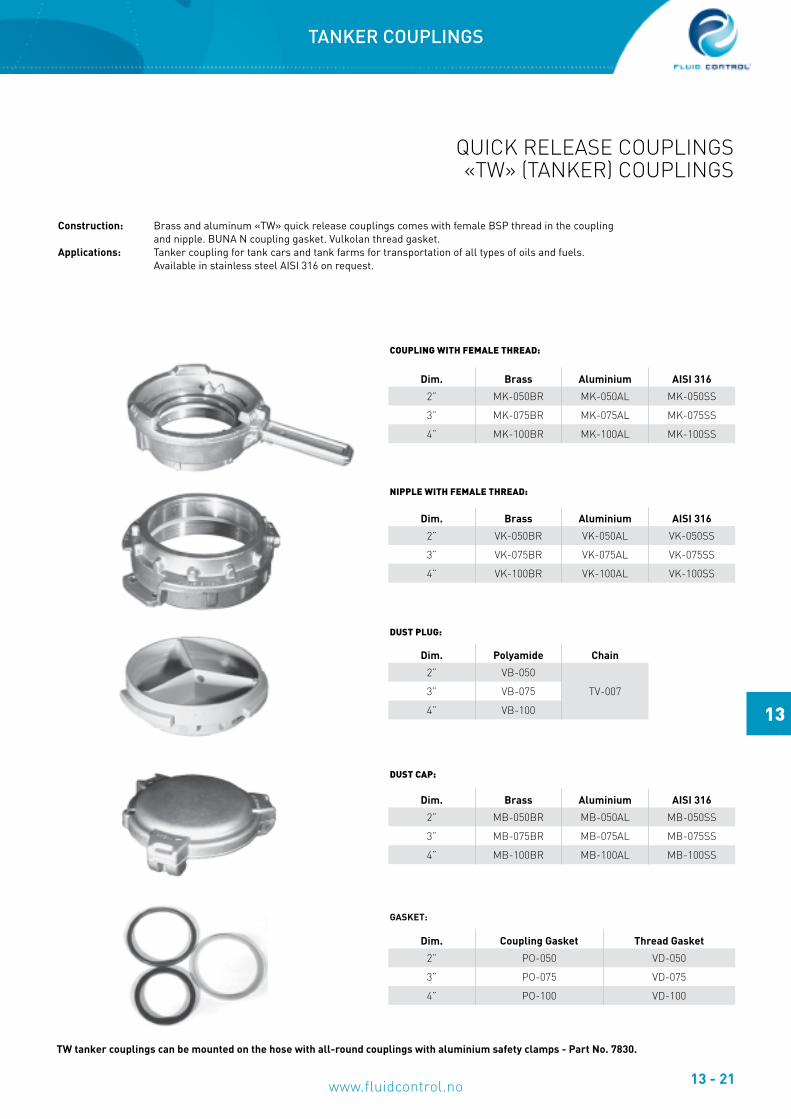
QUICK RELEASE COUPLINGS«TW» (TANKER) COUPLINGS
Construction: Brass and aluminum «TW» quick release couplings comes with female BSP thread in the coupling and nipple. BUNA N coupling gasket. Vulkolan thread gasket.Applications: Tanker coupling for tank cars and tank farms for transportation of all types of oils and fuels. Available in stainless steel AISI 316 on request.
cOUPlING WItH FeMAle tHReAD:
NIPPle WItH FeMAle tHReAD:
DUSt PlUG:
DUSt cAP:
GASKET:
TW tanker couplings can be mounted on the hose with all-round couplings with aluminium safety clamps - Part No. 7830.
TANKER COUPLINGS
Dim. Brass Aluminium AISI 316
2” MK-050BR MK-050AL MK-050SS
3” MK-075BR MK-075AL MK-075SS
4” MK-100BR MK-100AL MK-100SS
Dim. Brass Aluminium AISI 316
2” VK-050BR VK-050AL VK-050SS
3” VK-075BR VK-075AL VK-075SS
4” VK-100BR VK-100AL VK-100SS
Dim. Polyamide Chain
2” VB-050
TV-0073” VB-075
4” VB-100
Dim. Brass Aluminium AISI 316
2” MB-050BR MB-050AL MB-050SS
3” MB-075BR MB-075AL MB-075SS
4” MB-100BR MB-100AL MB-100SS
Dim. Coupling Gasket Thread Gasket
2” PO-050 VD-050
3” PO-075 VD-075
4” PO-100 VD-100

13 - 22
13
Flexible Solutions
CLAW COUPLINGSEuropean Standard
Material quality: Galvanized Malleable IronWorking pressure: Max 10 bar at 20oC
42 mm Standard Gasket 42 mm Heat Resistant Gasket 61 mm Standard GasketPart No. Part No. Part No.
GOOR DGOR SGOR
Dim.42 mm Standard Gasket 42 mm Heat Resistant Gasket 61 mm Standard Gasket
Part No. Connection Part No. Connection Part No. Connection1/4’’ KAG-06 1/4’’ Male BSP KIG-06 1/4’’ Female BSP SKG-06 1/4’’ Hose I.D.3/8’’ KAG-10 3/8’’ Male BSP KIG-10 3/8’’ Female BSP SKG-10 3/8’’ Hose I.D.1/2’’ KAG-13 1/2’’ Male BSP KIG-13 1/2’’ Female BSP SKG-13 1/2’’ Hose I.D.3/4’’ KAG-19 3/4’’ Male BSP KIG-19 3/4’’ Female BSP SKG-19 3/4’’ Hose I.D.1’’ KAG-25 1’’ Male BSP KIG-25 1’’ Female BSP SKG-25 1’’ Hose I.D.
KAG-32 1.1/4’’ Male BSP KIG-32 1.1/4’’ Female BSP SKG-32 1.1/4’’ Hose I.D.
Dim.Large (62 mm Claw Distance) Large (62 mm Claw Distance) Large (62 mm Claw Distance)
Part No. Connection Part No. Connection Part No. Connection1.1/4’’ SKAG-32 1.1/4’’ Male BSP SKIG-32 1.1/4’’ Female BSP SSKG-32 1.1/4’’ Hose I.D.1.1/2’’ SKAG-38 1.1/2’’ Male BSP SKIG-38 1.1/2’’ Female BSP SSKG-38 1.1/2’’ Hose I.D.
CLAW COUPLINGS EUROPEAN STANDARD

13 - 23
13
www.fluidcontrol.no
TYPE Dim.
Malleable Cast Iron
Part No.
Brass
Part No.
Stainless SteelAISI316LPart No.
Female NPT
2 Claws
1/4’’ UF-025 UF-025BR3/8’’ UF-037 UF-037BR1/2’’ UF-050 UF-050BR UF-050SS3/4’’ UF-075 UF-075BR UF-075SS1’’ UF-100 UF-100BR UF-100SS
4 Claws1.1/4’’ UF-125 UF-125BR1.1/2’’ UF-150 UF-150BR
2’’ UF-200 UF-200BR
Hose Tail
2 Claws
1/4’’ UH-025 UH-025BR3/8’’ UH-037 UH-037BR1/2’’ UH-050 UH-050BR UH-050SS5/8’’ UH-062 UH-062BR3/4’’ UH-075 UH-075BR UH-075SS1’’ UH -100 UH-100BR UH-100SS
4 Claws1.1/4’’ UH-125 UH-125BR1.1/2’’ UH-150 UH-150BR
2’’ UH-200 UH-200BR
Male NPT / 2 Claws
1/4’’ UM-025 UM-025BR3/8’’ UM-037 UM-037BR1/2’’ UM-050 UM-050BR UM-050SS3/4’’ UM-075 UM-075BR UM-075SS1’’ UM-100 UM-100BR UM-100SS
Blind Cap / 2 Claws 1/4’’ - 1’’ UD - 301 UD - 301BR UD - 301SS
Three-way Claw / 2 Claws 1/4’’ - 1’’ UW - 300 UW - 300BR
Safety Clip SteelSafety Clip SPF-175
w/ 150 mm Brass Chain and Ring
Small Gasket Large Gasket
Part No.: SPF - 175
Part No.: SPF-175-150
SBR Rubber: Part No.: UGNeoprene Rubber: Part No.: UGS Part No.: UG - 201
CLAW COUPLINGS «AIR KING»American Standard
«Chicago Dixon»Working Pressure: Max 10 Bar at 20oC
Use of the safety clip is necessary to ensure that the “Air King” claw coupling is not disconnected by accident. Use of the safety clip guarantees that the couplings are connected correctly, as the safety clips are otherwise unable to be put in. The use of “Whip-Check” safety wire over the couplings to avoid damage to personnel and equipment as a result of inappropriate use is recommended.
CLAW COUPLINGS AMERICAN STANDARD
Part No.:
13 - 24
13
Flexible Solutions
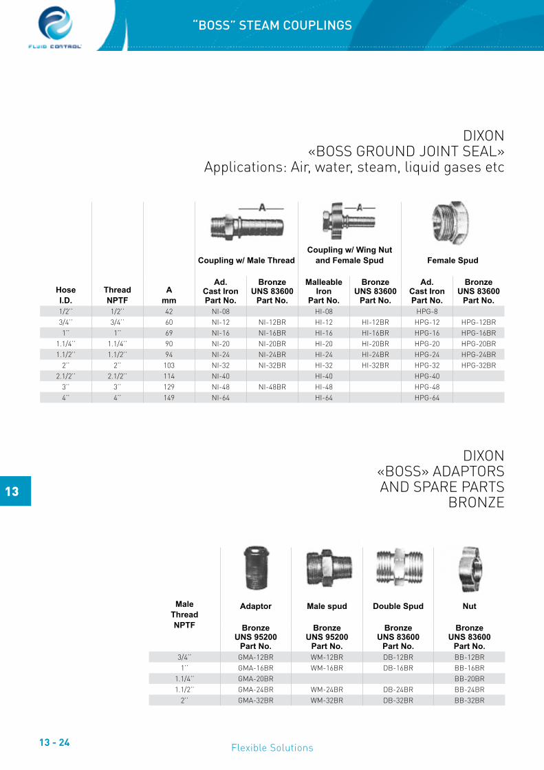
DIXON«BOSS GROUND JOINT SEAL»
Applications: Air, water, steam, liquid gases etc
HoseI.D.
ThreadNPTF
Amm
Coupling w/ Male ThreadCoupling w/ Wing Nut
and Female Spud Female Spud
Ad.Cast IronPart No.
BronzeUNS 83600
Part No.
Malleable Iron
Part No.
BronzeUNS 83600
Part No.
Ad.Cast IronPart No.
BronzeUNS 83600
Part No.1/2’’ 1/2’’ 42 NI-08 HI-08 HPG-83/4’’ 3/4’’ 60 NI-12 NI-12BR HI-12 HI-12BR HPG-12 HPG-12BR1’’ 1’’ 69 NI-16 NI-16BR HI-16 HI-16BR HPG-16 HPG-16BR
1.1/4’’ 1.1/4’’ 90 NI-20 NI-20BR HI-20 HI-20BR HPG-20 HPG-20BR1.1/2’’ 1.1/2’’ 94 NI-24 NI-24BR HI-24 HI-24BR HPG-24 HPG-24BR
2’’ 2’’ 103 NI-32 NI-32BR HI-32 HI-32BR HPG-32 HPG-32BR2.1/2’’ 2.1/2’’ 114 NI-40 HI-40 HPG-40
3’’ 3’’ 129 NI-48 NI-48BR HI-48 HPG-484’’ 4’’ 149 NI-64 HI-64 HPG-64
DIXON«BOSS» ADAPTORSAND SPARE PARTS
BRONZE
MaleThreadNPTF
Adaptor Male spud Double Spud Nut
BronzeUNS 95200
Part No.
BronzeUNS 95200
Part No.
BronzeUNS 83600
Part No.
BronzeUNS 83600
Part No.3/4’’ GMA-12BR WM-12BR DB-12BR BB-12BR1’’ GMA-16BR WM-16BR DB-16BR BB-16BR
1.1/4’’ GMA-20BR BB-20BR1.1/2’’ GMA-24BR WM-24BR DB-24BR BB-24BR
2’’ GMA-32BR WM-32BR DB-32BR BB-32BR
“BOSS” STEAM COUPLINGS

13 - 25
13
www.fluidcontrol.no
COUPLINGS FOR TANKER HOSES, GAS HOSES ETC.
All-roundCouplings
w/ AluminiumSafety Clamps
InterchangeableCouplings for
Tanker and FuelHoses
HoseI.D.
ThreadBSP
Female BSPPart No. 7820
Male BSPPart No. 7830
HoseI.D.
ThreadBSP
Female BSPPart No. 7801
Female MalePart No. 7802
1.1/4’’ 1.1/4’’ -20-20 -20-20 5/8’’ 3/4’’ -10-121.1/2’’ 1.1/2’’ -24-24 -24-24 3/4’’ 3/4’’ -12-12 -12-121.1/2’’ 2’’ -24-32 -24-32 3/4’’ 1’’ -12-16 -12-16
2’’ 2’’ -32-32 -32-32 1’’ 1’’ -16-16 -16-162.1/2’’ 2.1/2’’ -40-40 -40-40 1’’ 1.1/4’’ -16-20
3’’ 3’’ -48-48 -48-48 1.1/4’’ 1.1/4’’ -20-20 -20-204’’ 4’’ -64-64 -64-64 1.1/2’’ 1.1/2’’ -24-24 -24-24
Other dimensions on request.
COUPLINGS FOR TANKER HOSES

13 - 26
13
Flexible Solutions
FOR SAFe FlUID HANDlINGIn sizes from 1” to 6” and a wide range of material options, Dry-Break® couplings offer advanced fl uid handling solutions for a diverse range of industries.
Major offshore exploration, chemical, pharmaceutical and petro chemical companies rely on Dry break couplings to safely transfer their most aggressive or valuable products.
Designed for safe and easy use with minimum operator intervention. Dry break couplings offer an unbeatable combination of technical, safety and performance features.
HOW It WORKSTurning the hose unit 15° clockwise locks the units together. The valves are still closed and are not opened until a further rotation of 90° has been performed and then the product fl ow is guaranteed. To close the valve and to unlock the units, reverse the procedure.
ceRtIFIcAteS / APPROVAlS• • Vd-TÜV type approval, mark TÜ.AGG.162-93 towards
ADR, RID, IMDG and VDI-rules 2440, part 3.3.1.3.• • CE-marked, European directives 97/23/EC (PED) and
94/9/EC (ATEX) compliant.• • TDT approval, mark TDT-UW-30/09 towards ADR/RID in
Poland.• • Manufactured under EN ISO 9001:2000.• • Certifi ed towards ISO 14001:2004 and OHSAS
18001:2007.• • Manufactured towards EN 13480 and EN 13445.
DRy BReAK cOUPlINGS ARe AVAIlABle WItH cOlOR AND
MecHANIcAl cODING
FeAtUReS• Valves open and close automatically on connection and
disconnection. • Simple single action operation, no levers or switches to operate.• Valves are guaranteed closed prior to disconnection.• Minimal residual loss on disconnection (e.g. maximum 0.35cc for
2” DN50).• Will connect and disconnect under pressure and fl ow where
necessary.• Extremely reliable, very few moving parts.• Robust construction, no external operational components.• Available with selectivity system to prevent cross contamination.• Reduces spillages to virtually zero.• Dramatically improves both operational and fugitive emission
performance.• Reduces the possibility of human error in transfer operations.• Improves effi ciency.
DRY BREAK COUPLINGS For safe fl uid handling
DRY BREAK COUPLINGS

13 - 27
13
www.fluidcontrol.no
Hose Unit Tank Unit, Thread Tank Unit, Flange Dust Plug Dust Cap
Connection70 mm socket 70 mm socket
ThreadBSP
Part No.
ThreadNPSF
Part No.
ThreadBSP
Part No.
ThreadNPSF
Part No.
150 lbs.ANSI B 16.5
Part No.
DIN 2632PN 10/16Part No. Part No. Part No.
1.1/2” (DN 40) 5005-2307 5803-2307 5001-2207 5801-2207 5025-2207 5113-2207 6075-2007 6070-24072” (DN 50) 5006-2307 5804-2307 5002-2207 5802-2207 5109-2207 5114-2207 6075-2007 6070-2407
DRY BREAK COUPLING 1.1/2”(70 mm)
Materials: Aluminium, gunmetal and stainless steel 316L, other on request.Seals: FKM (Viton®), NBR (Nitrile), EPDM, Chemraz®, Kalrez®. Other materials on request.Working pressure: PN 10 - PN 25.Test pressure: Working pressure +50%.Safety factor: 5:1.End connections: BSP- and NPT-threads. DIN-, ASA-, TW- and TTMA-flanges (available for both tank and hose units). Other threads and flanges on request.Compatibility: NATO STANAG 3756.Description: Dry-Break couplings in 1” size are designed for smaller bore applications where compact dimensions are required. One handed operation, high flow rate and minimal release on disconnection make dry break couplings perfect for transferring high value or sensitive medias with confidence.
Materials: Aluminium, gunmetal and stainless steel 316L, other on request.Seals: FKM (Viton®), NBR (Nitrile), EPDM, Chemraz®, Kalrez®. Other materials on request.Working pressure: PN 10 - PN 25.Test pressure: Working pressure +50%.Safety factor: 5:1.End connections: BSP- and NPT-threads. DIN-, ASA-, TW- and TTMA-flanges (available for both tank and hose units). Other threads and flanges on request.Compatibility: NATO STANAG 3756.Description: The 2½” TODO-MATIC® coupling is generally used in road tanker and aviation applications transferring a variety of liquids and vapours.
SelectIVIty:To avoid incorrect installation or product mix-up, selectivity is available on request.
DRY BREAK COUPLING 2.1/2”(105 mm)
Connection
Hose Unit Tank Unit, Thread Tank Unit, Flange Dust Plug Dust Cap
105 mm socket 105 mm socketThread
BSPPart No.
ThreadNPSF
Part No.
ThreadBSP
Part No.
ThreadNPSF
Part No.
150 Ibs.ANSI B 16.5
Part No.
DIN 2632PN 10/16Part No. Part No. Part No.
2.1/2” (DN 65) 5332C2307 5808C2307 5331C2207 5807C2207 5306C2207 5329C2207 5436-2207 5435C24073” (DN 80) 5432C2307 5810C2307 5431C2207 5809C2207 5405C1107 5340C2207 5436-2207 5435C2407
DRY BREAK COUPLINGS

13 - 28
13
Flexible Solutions
Materials: Aluminium, gunmetal and stainless steel 316L, other on request.Seals: FKM (Viton®), NBR (Nitrile), EPDM, Chemraz®, Kalrez®. Other materials on request.Working pressure: PN 10 - PN 25.Test pressure: Working pressure +50%.Safety factor: 5:1.End connections: BSP- and NPT-threads. DIN-, ASA-, TW- and TTMA-flanges (available for both tank and hose units). Other threads and flanges on request.Compatibility: NATO STANAG 3756.Description: A true 3” coupling, similar in size to the 2½” but with greater flow. Typically used for road and rail tank loading / discharge, in plant chemical transfers etc. Tough construction, ease of handling, no spillage and high flow made this coupling form the natural choice for N.A.T.O refuelling standardisation.
DRY BREAK COUPLING 3”(119 mm)
Connection
Hose Unit Tank Unit, Thread Tank Unit, Flange Dust Plug Dust Cap
119 mm socket 119 mm socket
ThreadBSP
Part No.
ThreadNPSF
Part No.
ThreadBSP
Part No.
ThreadNPSF
Part No.
150 Ibs.ANSI B 16.5
Part No.
DIN 2632PN 10/16Part No. Part No. Part No.
3” (DN 80) 5532C2307 5812C2307 5531C2207 5811C2207 5505C1107 5544C2207 5536-2207 5535C2407
DRY BREAK COUPLINGS
SelectIVIty:To avoid incorrect installation or product mix-up, selectivity is available on request.

13 - 29
13
www.fluidcontrol.no
Materials: Aluminium, gunmetal and stainless steel 316L, other on request.Seals: FKM (Viton®), NBR (Nitrile), EPDM, Chemraz®, Kalrez®. Other materials on request.Working pressure: PN 10 - PN 25.Test pressure: Working pressure +50%.Safety factor: 5:1.End connections: BSP- and NPT-threads. DIN-, ASA-, TW- and TTMA-flanges (available for both tank and hose units). Other threads and flanges on request.Compatibility: NATO STANAG 3756.Description: Without exception, the most compact, light weight, high flow 4” self sealing coupling system available. Used extensively for offshore ship to rig transfers of fuels and drinking water, aviation fuel bunkering, rail tank loading / discharge, chemicals etc. Rapid, positive connection and disconnection make dry break couplings the standard for barge to ferry re-fuelling and multiple rail tank discharge.
DRY BREAK COUPLING 4”(164 mm)
Selective position 1 2 3 4 5 6 7 8Peg and slot position A & B A & C A & D A & E A & F A & G B & C B & D
9 10 11 12 13 14 15 16 17 18 19 20 21B & E B & F B & G C & D C & E C & F C & G D & E D & F D & G E & F E & G F & G
Hose UnitTank Unit
Connection
Hose Unitw/ VITON Gasket
Hose Unitw/ Nitrile Gasket
Tank UnitThread
Tank UnitFlange
DustPlug
DustCap
164 mm socket 164 mm socket
ThreadBSP
Part No.
ThreadNPSF
Part No.
ThreadBSP
Part No.
ThreadNPSF
Part No.
ThreadBSP
Part No.
ThreadNPSF
Part No.
150 Ibs.ANSI B 16,5
Part No.
DIN 2632PN 10/16Part No. Part No. Part No.
4” (DN 100) 5632D1307 5832D1307 5632D1306 5832D1306 5631-1107 5831-1107 5600-1107 5995-1107 5636-100 5635-1307
Selective pin and slot position
DRY BREAK COUPLINGS
SelectIVIty:To avoid incorrect installation or product mix-up, selectivity is available on request.

13 - 30
13
Flexible Solutions
NOTES