groundwater seep collection systems proposed …
TRANSCRIPT

ESC SDMS DocID 2108643
O^/Q INAL
ENVIRONMENTAL STRATEGIES CORPORATION
Four Penn Center West • Suite 3 1 5 - Pittsburgh. Pennsylvania 15276 • (412) 787-5100 • Fax (4 12) 787-8065
December 14, 2000
Mr Christian Matta Remedial Project Manager U.S. Environmental Protection Agency General Remedial Section (3HS23) 1650 Arch Street Philadelphia, PA 19103-2029
Re: Proposed Design of the Groundwater Seep Collection Systems Big John Salvage Superfund Site, Fairmont, WV ESC Project No. 457303
Dear Chris:
^' r-i U J ' • - :
(j:r!C[ OF r-;v;^0-;'/£N"ALHLMEDIATiON
On behalf of Reilly Industries Inc. (Reilly), Environmental Strategies Corporation (ESC) is pleased to submit a design discussion and sketches that detail the groundwater and oil seep collection systems that are being installed in the Middle and East Tributaries at the Big John site. The attached document is a design memorandum, prepared by ESC, that details all of the system elements that we discussed during meetings between ESC, Remediation Services Inc. (RSI), you, Suddha Graves, and Tom Bass on December 7 at the site.
ESC's memo provides both the steps we will take in the construction, as well as the design objectives of the system elements. As we have discussed on several occasions, the rapid nature of the Removal Action places a premium on field decisions and approvals. The design we outlined and you verbally approved last week is ready to be installed. We have ordered materials and are in the process of finishing the grading and installing the initial geotextile liners. Ryan McNeill and John Oilman of RSI have been discussing the initial work we are doing daily with Suddha Graves.
We ask that if you have any questions or concerns about the details you see in the memo, please let me or Cheyne know right away, so that we can avoid delays in making significant progress on construction before the holiday break. We will be proceeding with the construction through the weekend, and will work every day up through and including Tuesday, December 19.
The attached drawings arc sketches, and most arc not to scale. However, they accurately rcllccl ihc techniques and rclalive dimensions ol'the system. Wc have not yd completed the design of ihc licalmcm system that will handle water and oil collected in this system. Wc will Jorward a scixiiaic design memorandum to you in the near lulurc.
Reston, VA • San Jose, "CA • Boxborough, MA • Minneapolis, MN • Houston, TX • Cazenovia. NY • Burbank, CA • Durham. NC • Tulsa, OK • Somerset, NJ • Denver CO
AR102947
Mr. Chris Matta December 14, 2000 Page 2
If you have any questions about our plans, please call me.
Sincerely,
(y Douglas Taylor, P.E. Senior Project Director
DBT:dbt
enclosure
docs/Reily/457303/Collection System Cover Letter
cc: Mr. Tom Bass, WVDEP Dr. Paul Rivers, Reilly Industries Ms. Tamra Kress, Reilly Industires Dr. Art Chin, ExxonMobil Mr. Suddha Graves, Ecology and Environment Mr. Rick Smith, CBS Viacom
AR102948
DESIGN SUMMARY MEMORANDUM
TO:
FROM:
DATE:
Doug Taylor
Cheyne Gross
December 13, 2000
RE: Design of the Seep Collection System for the East Tributary at the Big John Salvage Superfund Site in Fairmont, West Virginia ESC Project No. 457303
The following memorandum describes the proposed design of the seep collection system to be installed in the East and Middle Tributaries at the Big John Salvage Superfund Site in Fairmont, West Virginia. The attached sketches show typical cross sections and approximate profiles of the seep collection system to be constructed in each tributary. Both systems will be fundamentally the same, but due to the different slopes and lengths, there are some differences needed to allow construction.
I believe this memorandum will provide all of the design information that was requested by Chris Matta of USEPA and Tom Bass of WVDEP during your meeting with them on Thursday, December 7, 2000 at the site.
PURPOSE
The purpose of the seep collection system is to collect groundwater and free phase oils that previously discharged to the ground surface and drained into the East and Middle Tributaries. This collection will partially accomplish the requirement of Section 8.3d and 8.3e of the Removal Order (RO) that specifies that Reilly Industries stop the discharge of hazardous substances to Unnamed Tributary No. 1. Based on sampling to date, we do not believe that collection will be necessary in the West Tributary or along Unnamed Tributary No. 2. The proposed system will collect the potentially contaminated groundwater and seeping oil, but will allow surface water runoff to bypass the collection system and enter Tributary No. 1. The system described in this memo is fundamentally the same system that we outlined as the conceptual system mentioned in the November 17, 2000 Removal Action Work Plan, submitted to USEPA and WVDEP.
TREATMENT
The collected water and oil will be pumped to an onsite treatment system that will remove any free phase oil and treat the water prior to being discharged to the local POTW or surface water body. The design ofthe treatment system is not complete, and the final destination of the treated water has not been determined. These designs will be forwarded when completed. However, the treatment system details do not affect the design or construction of the collection system.
COMPONENTS
AR102949

The primary components of the seep collection system are the following: Perforated HDPE collection pipe (east only) Washed No. 1 gravel Geonet composite drainage layer (also on bottom in Middle) Low permeability clean fill Non-woven geotextile, top and bottom of gravel (bottom in East only) Precast concrete manhole Soil-bentonite cutoff wall Submersible effluent pump with float switches
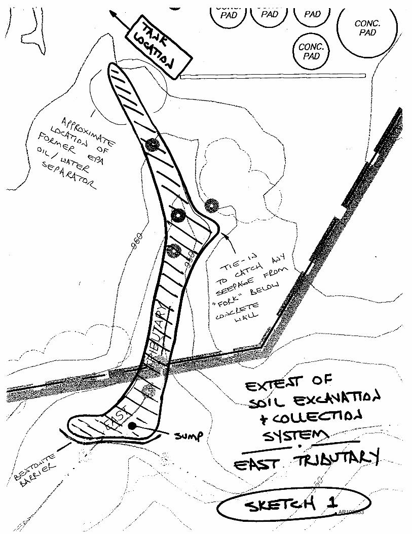
EXTENT OF SYSTEM
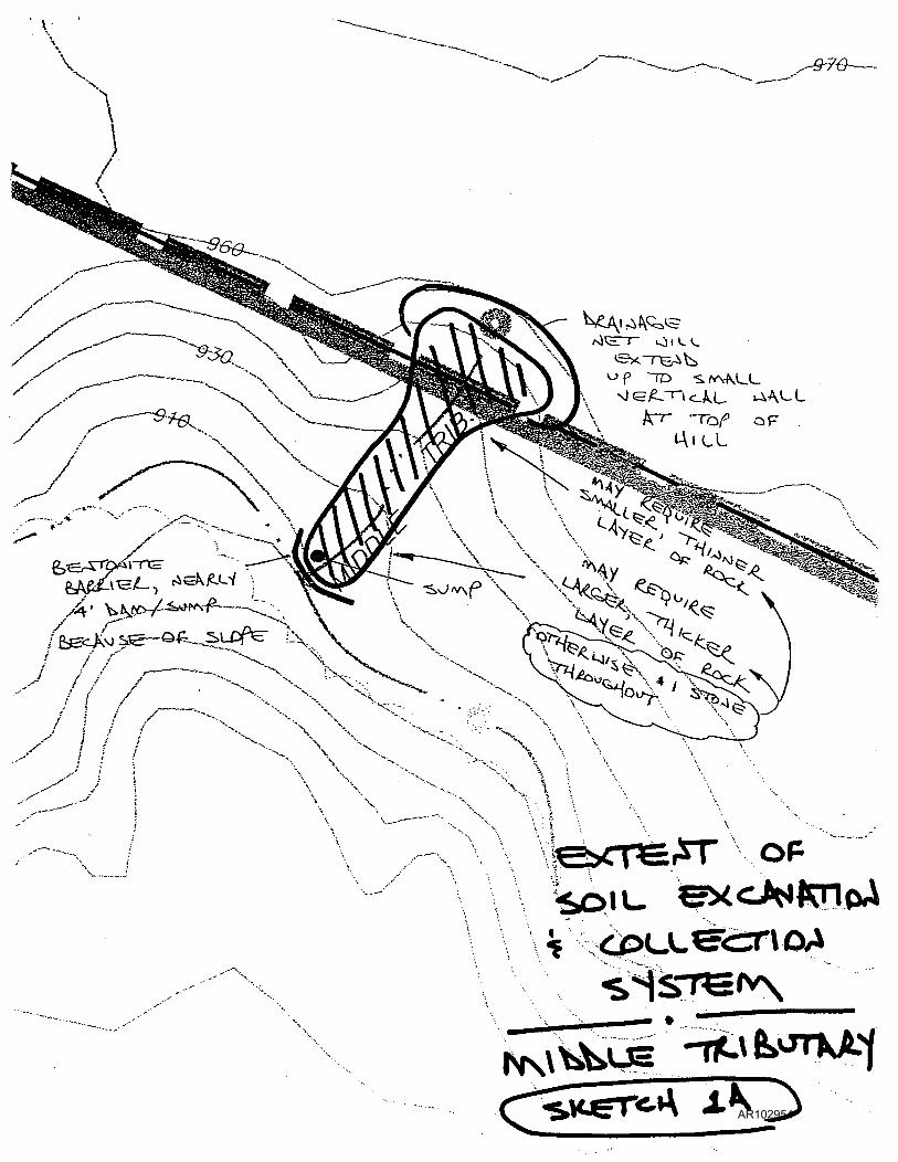
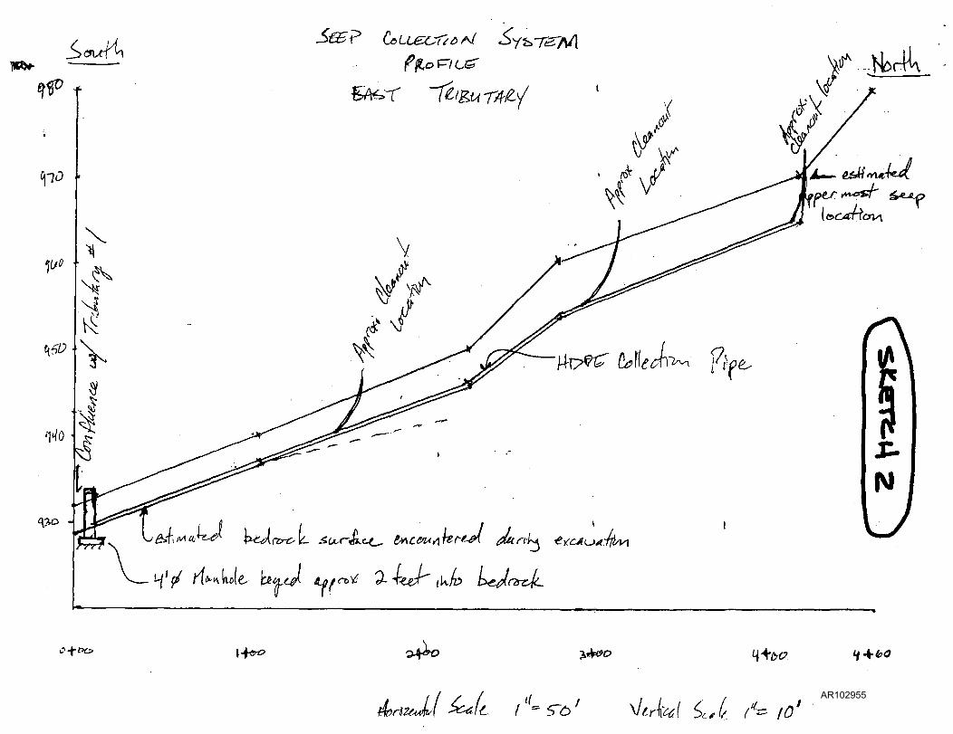
The seep collection system will extend from the upstream limits of the seepage in the East Tributary (as determined during the soil excavation phase) to the confluence with Tributary No. 1 (see Sketch 1). In the Middle Tributary, the collection system will run from the top of the hill to the bottom. This system is on a much steeper slope and is much shorter than the one in the East Tributary (see Sketch lA). During construction of the seep collection systems, water entering the work area shall be collected and contained onsite.
GRADING AND BED PREPARATION
The procedure for installing each seep collection system begins with grading the sides and bottom of the area already excavated (as part of the soil removal). This will provide a suitable subgrade to install the composite drainage layer and eliminate low lying areas that could impede water and oil (see Sketch 2). An excavator equipped with a grading bucket will be used to complete this task. A minimum slope of one percent shall be maintained in the bottom (from top to bottom). The original excavation (in the East Tributary) was done in a way that resulted in sidewalls that were more or less vertical. The drainage layer we propose to use, above the gravel on the sidewalls (to allow any seepage to drain into the gravel instead of run on the top of the new surface water runoff layer) can not be properly installed on vertical surfaces. Based on manufacturer's specifications, the drainage layer material is to be laid, not hung, and could tear under its own weight on vertical walls. As a result, we will need to cut back and fill in portions of the walls to create some sloping (still relatively severe compared to manufacturers recommendations) to lay the material. In some situations, where either the height of the wall is small, or where there is no other option, we may need to attempt to hang the drainage material; however, we do not know if that will work. Where we do create slopes, we will come back in and recut the bottom down to original excavation level (creating a notch in narrow areas), and install the gravel and pipe in the notch (see Sketch 3). In all cases, the material used to create the slope will be cut from the top of the bank and filled at the bottom. It will not stop or impede the flow of groundwater or oil into the collection system. This step will not apply to the Middle Tributary.
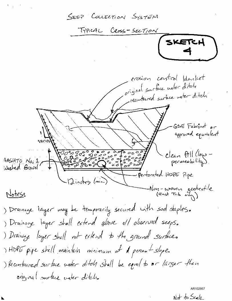
Once the subgrade is prepared, the composite drainage layer will be temporarily secured to the trench walls using either sod staples or an anchor trench as shown on Sketch 4. The composite drainage layer will provide a pathway for seepage from the excavation sidewalls to drain into the
AR102950

gravel and ultimately to the manhole. The drainage layer material will be placed high enough up the excavated sidewalls to allow all known seeps to be captured. In areas where seeps were observed higher up on the banks than the excavation, the drainage layer will be placed above the wall (and then covered). In some areas, seeps were seen on the sidewalls of the original excavation but needed to be partially covered with soil to create the slope needed to install the drainage layer. These seep location have been surveyed and the drainage layer or gravel will be installed high enough to assure that these seeps are fully captured.
LAYER CONSTRUCTION
A non-woven geotextile will be placed in the bottom of the East Tributary excavation (in the Middle, the drainage layer will be used along the bottom to help fight sliding). The purpose of the geotextile is to eliminate mixing of the native soils with washed gravel. By isolating the gravel and the native soils with a geotextile, the potential for clogging the collection system with fines is greatly reduced.
After the composite drainage layer and geotextile are installed, the perforated HDPE collection pipe will then be installed along the center of the East Tributary excavation (the slope of the Middle Tributary is so severe that the pipe would not serve any purpose and will not be used). The HDPE pipe shall have welded joints. A minimum of three cleanouts will be located at equal spacing along the collection system. The cleanouts shall have threaded end caps and be marked with a warning sign to prohibit damage and allow for easy access in the future. The collection pipe shall also maintain a minimum slope of one percent towards the manhole. After the collection pipe is installed, approximately 12 inches of washed No. 1 gravel shall be placed over the pipe. The finished thickness of gravel shall be at least 12 inches, but at the bottom of the Middle Tributary the depth may need to be increased significantly. The gravel will then be covered with a non-woven geotextile to reduce infiltration of fines into the top of the collection system gravel.
The composite drainage layer, gravel, geotextiles, and collection pipe are necessary components for the seep collection system. The low-permeability clean fill that is used to reconstruct the surface water ditch will provide a barrier to keep clean surface water runoff and potentially contaminated groundwater separate. With this layer in place, surface water will runoff and not enter the seep collection system and can it be discharged directly to Tributary No. 1. The clean fill will be imported from an offsite borrow source. The soil will be sampled and analyzed for the Target Analyte List (TAL) and Target Compound List (TCL) compounds. The soil will be backfilled with an excavator and dozer.
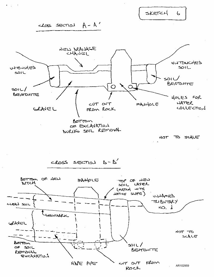
A soil-bentonite cutoff wall will be constructed at the bottom of the collection ditch, along the wall that will separate it from the unnamed Tributary (see Sketch 5 and 6). It will be constructed by mixing bentonite powder No. 1 with existing material on the down-gradient wall of the excavation. The cutoff wall will be a subsurface structure that will assure that flow will be from the gravel to the manhole and act as a hydraulic barrier to prevent subsurface flow towards Tributary No.l. The finished surface water ditch will flow unimpeded over the soil-bentonite cutoff wall, and into Unnamed Tributary No. 1.
AR102951
The reconstructed surface water ditch shall be equal to or larger than the previous drainage channel. The surface water ditch will be seeded and covered with an erosion control blanket. Check dams shall also be installed at intervals along the surface water ditch to reduce the velocity of runoff and therefore reduce effects of erosion.
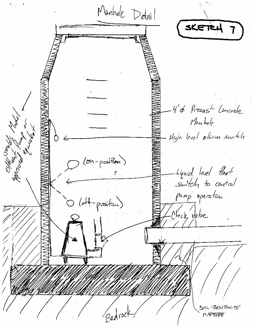
MANHOLE, PUMP, AND PIPING
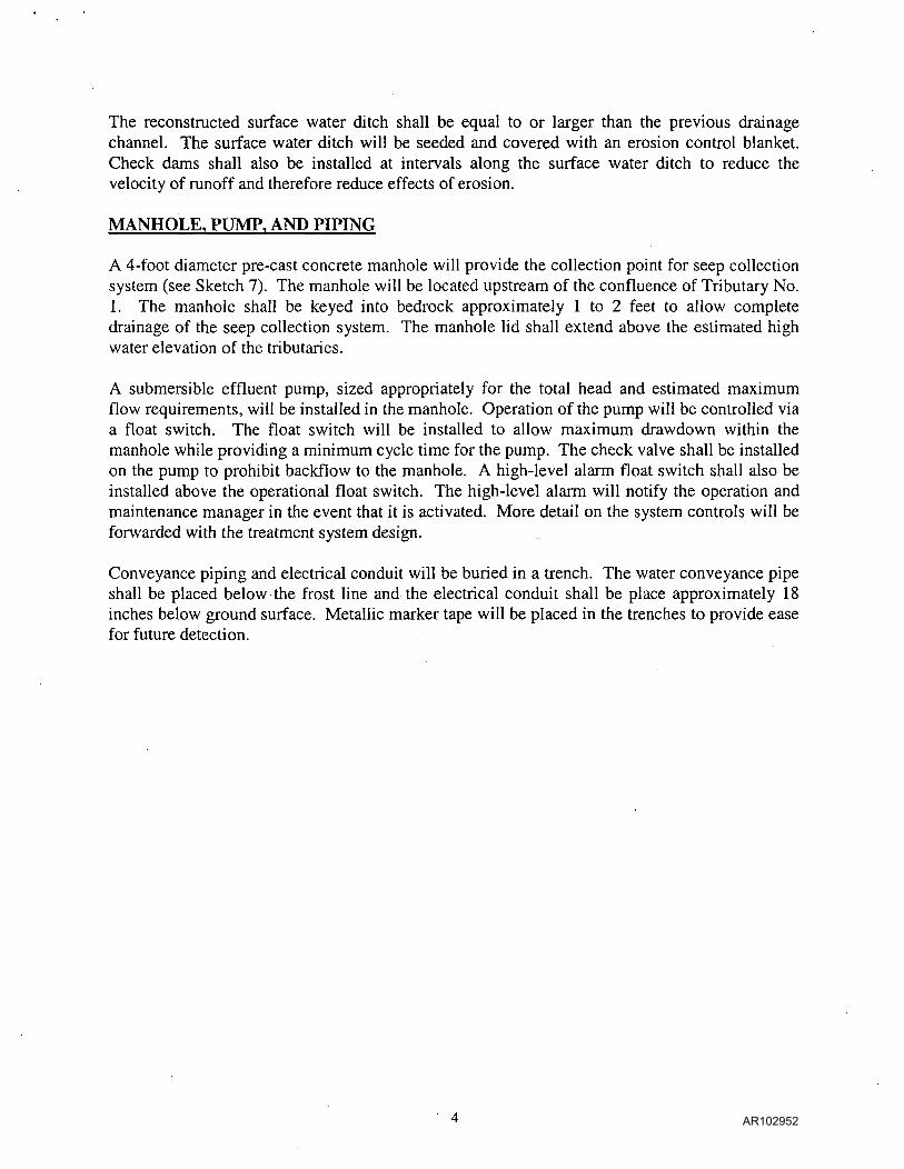
A 4-foot diameter pre-cast concrete manhole will provide the collection point for seep collection system (see Sketch 7). The manhole will be located upstream of the confluence of Tributary No. 1. The manhole shall be keyed into bedrock approximately 1 to 2 feet to allow complete drainage of the seep collection system. The manhole lid shall extend above the estimated high water elevation of the tributaries.
A submersible effluent pump, sized appropriately for the total head and estimated maximum flow requirements, will be installed in the manhole. Operation ofthe pump will be controlled via a float switch. The float switch will be installed to allow maximum drawdown within the manhole while providing a minimum cycle time for the pump. The check valve shall be installed on the pump to prohibit backflow to the manhole. A high-level alarm float switch shall also be installed above the operational float switch. The high-level alarm will notify the operation and maintenance manager in the event that it is activated. More detail on the system controls will be forwarded with the treatment system design.
Conveyance piping and electrical conduit will be buried in a trench. The water conveyance pipe shall be placed below the frost line and the electrical conduit shall be place approximately 18 inches below ground surface. Metallic marker tape will be placed in the trenches to provide ease for future detection.
AR102952
AR102953
\ -^76>
l A i L L
AR102954
T*ft#-iW^
V o
f :H^(4^
> + t ^ l+w> 3 4 ^ j «»^0 M-^c^ </4^<?
rtzJ l L I'^'S-O' \l6A^i ^c.l'. (" ^ fO* AR102955

- r v / p I ^ L o ^ S S ~ .SecTTi o J i
>\jeA< O P <LO A - S T C O C - H D ^
O
..>h"-. ? ^ ^ v
COT t ^ t r o
to*.5
vt=mA OF-
(£> OF SARj fx i i hV^iQ,ATS, W\OSrLV
© F o ^ QURXM^L * f i f e
^D^v
.. -ss '-
&^crr7orv\
p r o l-L cOt^^sr^u-cTTfO-^
. ^ seePs « 0 0'
f i p e -
AR102956
' " i ^ ( C A U ( j t o ^ ' ^ - £ > € ^ T / o r s f
tWWs^
^rZP^cno CJ^\4^rb[ IpU.v^k^'t '
d g p c e ^ J ^ €J«u,fJik.il<y{V
-\QL\•'^A^> '
^
Ufir ^ ^ / c (2_
AR102957

"se-eP o3UL.e<mD^ 'S^ST'^r^\
-T-if^<<-AC PL_K^ ^ \ec j
S>lCeT-ci-^ ^
uv \ i - r O F
®t
v > t ^ ' ^ ^ < = V -fP.£>uTlKf-~/
AR102958
^Kj^r<:i^i - ^
<JLDS^ S^<:r^o^ (\ - K "
5»DIL.
- S O I L . / fejt£,srDAi-r£
Q ^ U ^ ^ ^
.(eo<^ -s^cirrioa fe>- ^
{AM>AOLE
t^crr ~Tb s c ^ L ^
tv\lv>*V?>>-e
<^ue ^ soi
-roe O^ '^^^'^ S O I L . < - W e A -
O F SOIl_
A \ ^ PiP?=- AR102959
f^^t 1> ,
I * .
ni>TuiZ-£r AR102960