groundwater lowering in construction by cashman and preene
TRANSCRIPT
Groundwater Lowering inConstruction
A practical guide
P. M. Cashman and M. Preene
London and New York

First published 2001 by Spon Press11 New Fetter Lane, London EC4P 4EE
Simultaneously published in the USA and Canadaby Spon Press29 West 35th Street, New York, NY 10001
Spon Press is an imprint of the Taylor & Francis Group
© 2001 Spon Press
The right of Spon Press to be identified as the Author of this Work has beenasserted by them in accordance with the Copyright, Designs and Patents Act1988
All rights reserved. No part of this book may be reprinted or reproduced orutilised in any form or by any electronic, mechanical, or other means, nowknown or hereafter invented, including photocopying and recording, or inany information storage or retrieval system, without permission in writingfrom the publishers.
The publisher makes no representation, express or implied, with regard tothe accuracy of the information contained in this book and cannot accept anylegal responsibility or liability for any errors or omissions that may be made.
British Library Cataloguing in Publication DataA catalogue record for this book is available from the British Library
Library of Congress Cataloging in Publication Data
Cashman, P.M. (Pat M.)Groundwater lowering in construction: a practical guide/P.M.Cashman and M. Preenep. cm.
Includes bibliographical references and index.ISBN 0-419-21110-1 (alk. paper)1. Earthwork. 2. Drainage. 3. Building sites. 4. Groundwater flow.I. Preene, M. (Martin) II.Title.
TA715.C35 2001624.1’5–dc21 2001032252
ISBN 0-419-21110-1
This edition published in the Taylor & Francis e-Library, 2002.
(Print edition)ISBN 0-203-47632-8 Master e-book ISBN
ISBN 0-203-78456-1 (Adobe eReader Format)
Copyright © 2001 Spon Press

This book is dedicated to the memory of Pat Cashman and MickFalkingham, men who put groundwater lowering into practice
Copyright © 2001 Spon Press
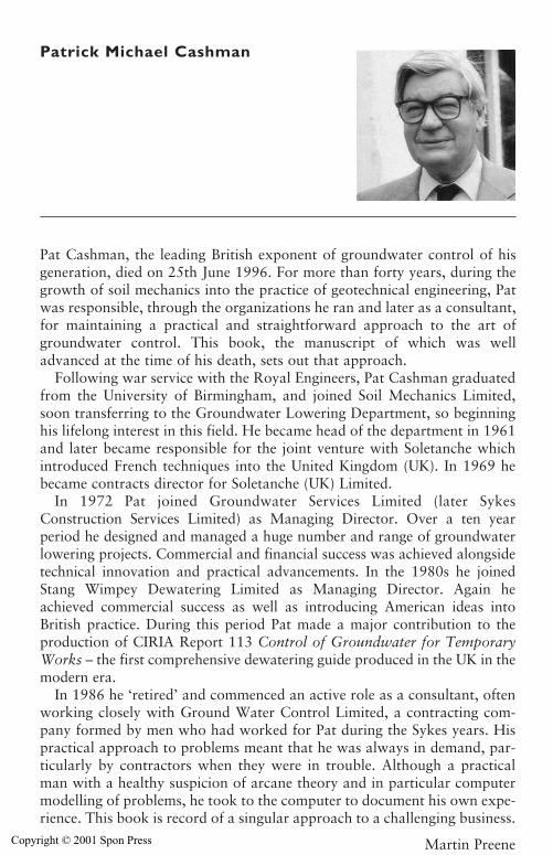
Patrick Michael Cashman
Pat Cashman, the leading British exponent of groundwater control of hisgeneration, died on 25th June 1996. For more than forty years, during thegrowth of soil mechanics into the practice of geotechnical engineering, Patwas responsible, through the organizations he ran and later as a consultant,for maintaining a practical and straightforward approach to the art ofgroundwater control. This book, the manuscript of which was welladvanced at the time of his death, sets out that approach.
Following war service with the Royal Engineers, Pat Cashman graduatedfrom the University of Birmingham, and joined Soil Mechanics Limited,soon transferring to the Groundwater Lowering Department, so beginninghis lifelong interest in this field. He became head of the department in 1961and later became responsible for the joint venture with Soletanche whichintroduced French techniques into the United Kingdom (UK). In 1969 hebecame contracts director for Soletanche (UK) Limited.
In 1972 Pat joined Groundwater Services Limited (later SykesConstruction Services Limited) as Managing Director. Over a ten yearperiod he designed and managed a huge number and range of groundwaterlowering projects. Commercial and financial success was achieved alongsidetechnical innovation and practical advancements. In the 1980s he joinedStang Wimpey Dewatering Limited as Managing Director. Again heachieved commercial success as well as introducing American ideas intoBritish practice. During this period Pat made a major contribution to theproduction of CIRIA Report 113 Control of Groundwater for TemporaryWorks – the first comprehensive dewatering guide produced in the UK in themodern era.
In 1986 he ‘retired’ and commenced an active role as a consultant, oftenworking closely with Ground Water Control Limited, a contracting com-pany formed by men who had worked for Pat during the Sykes years. Hispractical approach to problems meant that he was always in demand, par-ticularly by contractors when they were in trouble. Although a practicalman with a healthy suspicion of arcane theory and in particular computermodelling of problems, he took to the computer to document his own expe-rience. This book is record of a singular approach to a challenging business.
Martin PreeneCopyright © 2001 Spon Press
Contents
List of figuresList of tablesAcknowledgements
1 Groundwater lowering: A personal view andintroduction by P. M. Cashman
2 The history of groundwater theory and practice
2.0 Introduction2.1 The earliest times to the sixteenth century2.2 The renaissance period to the nineteenth century2.3 Progress from a qualitative to a quantitative
science2.4 Later theoretical developments2.5 Groundwater modelling2.6 Early dewatering tec nology in Britain2.7 Practical publicationReferences
3 Groundwater and permeability
3.0 Introduction3.1 Hydrology and hydrogeology3.2 Permeability and groundwater flo3.3 Aquifers, aquitards and aquicludes3.4 Flow to wells3.5 Aquifers and geological structure3.6 Aquifer boundaries3.7 Using geological structure to advantage3.8 Groundwater chemistryReferences
Copyright © 2001 Spon Press
4 Groundwater effects on the stability of excavations
4.0 Introduction4.1 Groundwater control – the objectives4.2 Groundwater, effective stress and instability4.3 Large-scale instability caused by groundwater4.4 Localized groundwater problems4.5 Excavations in rock4.6 Surface water problems4.7 Effect of climate and weatherReferences
5 Methods for control of surface waterand groundwater
5.0 Introduction5.1 Control of surface water5.2 Methods of groundwater control5.3 Exclusion methods5.4 Dewatering methods5.5 Groundwater control for tunnels and shaftsReferencesFurther reading – exclusion methods
6 Site investigation for groundwater lowering
6.0 Introduction6.1 The purpose of site investigation6.2 Planning of site investigations6.3 Stages of site investigation6.4 Determination of ground profile6.5 Determination of groundwater conditions6.6 Determination of permeabilityAppendix 6AAppendix 6BAppendix 6CReferences
7 Design of groundwater lowering systems
7.0 Introduction7.1 Design approach7.2 Development of conceptual model
viii Contents
Copyright © 2001 Spon Press
Contents ix
7.3 Selection of method and geo7.4 Estimation of steady-state dische flow rate7.5 Specification of well yield and spacing7.6 Other considerations7.7 Numerical modelling7.8 Design examplesAppendix 7AReferences
8 Sump pumping
8.0 Introduction8.1 Applications of sump pumping8.2 Surface water run-off8.3 Pumping sumps8.4 Drainage of side slopes of an excavation8.5 Sump pumping of small excavations8.6 Sump pumping problems8.7 Case history: sump pumping of large excavationReferences
9 Wellpoint systems
9.0 Introduction9.1 Which system: wellpoints or deep wells?9.2 What is a wellpoint system?9.3 Wellpoint installation techniques9.4 Spacing of wellpoints and drawdown times9.5 Sealed vacuum wellpoint system9.6 Wellpoint pumping equipment9.7 Wellpoint installations for trench excavations9.8 Wellpointing for wide excavations9.9 Wellpointing for deeper excavations9.10 Case history: Derwent outlet channel,
NorthumberlandReferences
10 Deep well systems
10.0 Introduction10.1 Deep well installations10.2 Design of wells for groundwater lowering10.3 Constructing deep wells
Copyright © 2001 Spon Press
10.4 Drilling of well borehole10.5 Installation of well materials10.6 Well development10.7 Installation and operation of deep
well pumps10.8 Vacuum deep well installations10.9 Shallow well installations10.10 Case history: Tees Barrage,
Stockton-on-TeesReferences
11 Other dewatering systems11.0 Introduction11.1 Ejectors11.2 Horizontal wellpoints11.3 Pressure relief wells11.4 Collector wells11.5 Electro-osmosis11.6 Use of dewatering and exclusion
in combinationReferences
12 Pumps for groundwater lowering duties
12.0 Introduction12.1 Units for wellpoint pumping12.2 Jetting pumps12.3 Units for sump pumping12.4 Pumps for deep wells12.5 Sizing of pumps and pipeworkReferences
13 Side effects of groundwater lowering
13.0 Introduction13.1 Settlement due to groundwater lowering13.2 Effect on groundwater supplies13.3 Effect on groundwater quality13.4 The impact of discharge flows on the surface
water environment13.5 Other effects
x Contents
Copyright © 2001 Spon Press
13.6 Artificial recharge systemsReferences
14 Monitoring and maintenance of groundwaterlowering systems
14.0 Introduction14.1 The need for monitoring14.2 Monitoring of water levels14.3 Monitoring of discharge flow rate14.4 Other parameters that may be monitored14.5 Datalogging systems14.6 Mechanical factors and automation14.7 Backfilling and sealing of wells on completion14.8 Encrustation, biofouling and corrosion14.9 Fault finding and problem solvingAppendix 14AReferences
15 Safety, contracts and the environment
15.0 Introduction15.1 Health and safety15.2 Contracts for groundwater control works15.3 Environmental regulation of groundwater controlReferences
16 The future by T. O. L. Roberts
16.0 Introduction16.1 Techniques16.2 Impact of information technology systems16.3 Regulation16.4 ConclusionReferences
NotationGlossaryConversion factors
Contents xi
Copyright © 2001 Spon Press
Figures
2.1 Rag and chain pump, manually operated2.2 Pumps for draining the Kilsby tunnel 2.3 Sewer diversion under gas main using wellpoints
and chemical injections 2.4 Early application of deep wells in Britain3.1 The hydrological cycle 3.2 Darcy’s experiment3.3 Definition of hydraulic head3.4 Soil structure and permeability 3.5 Particle size distribution3.6 Unconfined aquifer 3.7 Groundwater conditions above the water table3.8 Confined aquifer 3.9 Flowing artesian conditions3.10 Leaky aquifer system3.11 Principal components of a groundwater
lowering well3.12 Zone of influence3.13 Well losses3.14 Superposition of drawdown3.15 Chalk aquifer beneath London 3.16 Groundwater control in multiple aquifers3.17 Use of simple relief wells to maintain base stability3.18 Interaction between rivers and aquifers 3.19 Interaction between aquifers 3.20 Potential aquifer recharge boundaries3.21 Potential aquifer barrier boundaries3.22 Potential aquifer discharge boundaries4.1 Instability due to seepage into an excavation in an
unconfined aquifer
Copyright © 2001 Spon Press
4.2 Fluidization of excavation base due to upward seepagein unconfined aquifer
4.3 Excavation in very low permeability soil overlyinga confined aquifer – stable condition
4.4 Excavation in very low permeability soil overlyinga confined aquifer – unstable condition
4.5 Pore water pressures not controlled beneath thinvery low permeability layer – unstable condition
4.6 Effect of seepage on excavation 4.7 Stable excavated slopes resulting from flat
gradient and provision of drainage trench4.8 Perched water table 4.9 Perched water table 4.10 Effect of close source of recharge on effectiveness
of groundwater lowering for shaft excavation 4.11 Spring sapping 4.12 Relief wells used in rock excavations to intercept
flow in discrete fissures4.13 Control of surface water in excavations 4.14 Effect of extreme rainfall events on
groundwater levels 5.1 Drains for collection of surface water run-off 5.2 Groundwater control by exclusion using
physical cut-offs 5.3 Groundwater control by pumping5.4 Tentative ranges for groundwater lowering
methods 5.5 Tentative economic ranges for exclusion methods
in soils 5.6 Range of application of pumped well groundwater
control techniques5.7 Pressure balancing techniques used to exclude
groundwater from tunnels 5.8 Typical pattern of dewatering wells drilled out
from tunnel for localized depressurization toallow cross-passage construction
6.1 Light cable percussion boring rig 6.2 Trial pitting using a mechanical excavator6.3 Typical standpipe installation6.4 Typical standpipe piezometer installations
Figures xiii
Copyright © 2001 Spon Press
6.5 Specialist piezometers6.6 Application of Hazen’s rule6.7 Prugh method of estimating permeability of soils 6.8 Variable head tests in boreholes 6.9 Analysis of variable head tests6.10 Shape factors for permeability tests in boreholes6.11 Constant head inflow test in boreholes 6.12 Packer test 6.13 Variable head tests in observation wells6.14 Analysis of pore water pressure data from
piezocone dissipation test6.15 Components of a pumping test 6.16 Analysis of pumping test data: Cooper–Jacob
method for time-drawdown data6.17 Analysis of pumping test data: Cooper–Jacob
method for distance–drawdown data6.18 Wellpoint dewatering trial 6B-1 General arrangement of variable head tests in
boreholes6B-2 Estimation of basic time lag (original water level
known)6B-3 Estimation of basic time lag (original water level
unknown)6C-1 Components of a pumping test6C-2 Cooper–Jacob straight line method of plotting
data7.1 Example of simple conceptual model for
groundwater lowering system7.2 Plan layouts of groundwater control systems:
linear and ring arrays7.3 Zone of influence7.4 Equivalent radius of arrays of wells7.5 Equivalent slots7.6 Wells in aquifers extending to great depth7.7 Wells in aquifers of limited thickness7.8 Pumping from a layered aquifer system using the
underdrainage principle7.9 Partial penetration factors for wells and slots 7.10 Shape factor for confined flow to rectangular
equivalent wells
xiv Figures
Copyright © 2001 Spon Press
7.11 Superposition of drawdown from multiple wells 7.12 Cumulative drawdown analysis: graphical method7.13 Case history of cumulative drawdown calculation 7.14 Wetted screen length of wells7.15 Maximum yield per unit wetted length of wells7.16 Maximum yield of wellpoints7.17 Dimensionless drawdown curve for horizontal
plane flow to an equivalent slot7.18 Dimensionless drawdown curve for horizontal
plane flow to an equivalent well 7A-1 Conceptual model for design example 17A-2 Conceptual model for design example 27A-3 Conceptual model for design example 37A-4 Schematic plan of sixteen well system8.1 Typical sump within main excavation area 8.2 Typical forms of sump construction 8.3 A jetted sump 8.4 Sump pumping from within trench8.5 Significant ground movement caused by
inappropriate sump pumping 8.6 Outwash fans due to sump pumping 8.7 Dee Reservoir, central pumping sump 8.8 Dee Reservoir, plan showing positions of sump
and temporary drainage trenches 9.1 Single-sided wellpoint system9.2 Wellpoint system components 9.3 Flexible connection from wellpoint riser to suction
manifold via trim valve 9.4 Wellpoint header main installed in shallow trench9.5 Two stage lowering using wellpoints9.6 Disposable and reusable self-jetting wellpoints 9.7 Installation of self-jetting wellpoint 9.8 Installation of wellpoints using placing tube9.9 Holepuncher for installation 9.10 Rotary jet drilling rig 9.11 Hydraulic auger attachment for pre-boring
through cohesive strata9.12 Exposed sanding-in columns9.13 Double-sided wellpoint installation 9.14 Single-sided wellpoint installation with sand
drains to aid control of perched water table
Figures xv
Copyright © 2001 Spon Press
9.15 Progressive wellpoint system for trench works9.16 Typical cross section of Derwent outlet channel 9.17 Envelope of gradings of glacial lake soils,
the Derwent outlet channel 9.18 Initial excavation (showing unstable conditions)
for Derwent outlet channel 9.19 Workable conditions, following wellpoint
pumping, under which the channel was actually formed
10.1 Deep well system components 10.2 Schematic section through a deep well10.3 Aquifer and filter grading envelopes10.4 Light cable percussion boring rig10.5 Holepuncher used for installation of deep wells 10.6 Truck mounted rotary drilling rig 10.7 Well development methods 10.8 Vacuum deep well10.9 Shallow well system10.10 Schematic plan of construction basin for
Tees Barrage 10.11 Section through construction basin for Tees
Barrage showing ground conditions 11.1 Ejector system components 11.2 Single-pipe ejectors 11.3 Twin-pipe ejectors – schematic view11.4 Example ejector performance curves11.5 Ejector supply pumps11.6 Ejector pipework11.7 Examples of ejector nozzle wear11.8 Horizontal wellpoint installation using a land
drain trenching machine11.9 Specialist trenching machine for installation of
horizontal drains11.10 Trencher equipped for addition of filter media to
drain trench11.11 Installation of horizontal drains for
pipeline trench11.12 Relief well system11.13 Collector well11.14 Electro-osmosis system
xvi Figures
Copyright © 2001 Spon Press
Figures xvii
11.15 Typical electrode details 12.1 Reciprocating piston pumpset used for
wellpointing12.2 Vacuum assisted self-priming centrifugal pumpset
used for wellpointing12.3 Vacuum tank unit for wellpointing12.4 Contractor’s electric submersible pump12.5 Borehole electro-submersible turbine pump12.6 Lowering borehole electro-submersible pump and
riser into well 12.7 Methods to prevent overheating of borehole
electro-submersible pump motors 12.8 Vertical lineshaft turbine pump 12.9 Discharge heads for pump sizing12.10 Friction losses in pipework 13.1 Pore water pressure reductions in response to
groundwater lowering 13.2 Groundwater flow to fully penetrating wells13.3 Average degree of consolidation of a soil
layer vs time13.4 Correction factor for effective stress13.5 Deformation of structure due to settlement
profile in uniform conditions13.6 Deformation of structure due to settlement
profile in non-uniform conditions13.7 Settlement risk zones13.8 Silt plume in a watercourse resulting from the
discharge of water from poorly controlled sump pumping
13.9 Treatment of discharges by settlement13.10 Artificial recharge to control drawdowns around
a groundwater lowering system13.11 Recharge trench13.12 Recharge well13.13 Bank Misr, Cairo: section through dewatering
and recharge system13.14 Bank Misr, Cairo: plan layout of dewatering and
recharge system14.1 Dipmeter for measuring depth to water in a well
or piezometer
Copyright © 2001 Spon Press
14.2 V-notch weir for measurement of dischargeflow rate
14.3 Schematic view of water level datalogger14.4 Biofouling of submersible pump due to
iron-related bacteria14.5 Extreme corrosion of submersible pumps in
highly saline groundwater14A-1 V-notch weir for measurement of discharge
flow rate14A-2 Calibration chart for 90 degree V-notch14A-3 Calibration chart for half-90 degree V-notch14A-4 Calibration chart for quarter-90 degree V-notch14A-5 Calibration chart for 60 degree V-notch14A-6 Calibration chart for 45 degree V-notch14A-7 Calibration chart for 30 degree V-notch
xviii Figures
Copyright © 2001 Spon Press
Tables
3.1 Typical values of soil permeability3.2 Typical values of specific yield3.3 Effect of well diameter on yield3.4 Major anions and cations in groundwater3.5 Classification of groundwater based on total
dissolved solids (TDS)5.1 Principal methods for groundwater control
by exclusion5.2 Principal methods for groundwater control
by pumping6.1 Advantages and disadvantages of methods of
boring, drilling, probing and trial pitting6.2 Advantages and disadvantages of methods of
determining groundwater levels6.3 Tentative guide to the reliability of
permeability estimates6A-1 Specific surface of spheres lying between given
sieve sizes6A-2 In situ porosity and void ratio of typical soils in
natural state7.1 Simple formulae for estimation of
steady-state flow rate9.1 Typical wellpoint spacings and drawdown times10.1 Recommended well screen and casing diameters11.1 Maximum theoretical capacity of sand or
gravel-filled relief wells13.1 Tentative limits of building settlement and tilt for
damage risk assessment 13.2 Suggested actions for settlement risk categories
Copyright © 2001 Spon Press

13.3 Measures to mitigate or avoid groundwaterlowering induced settlement damage
14.1 Observable parameters for dewatering systems14.2 Tentative trigger levels for susceptibility to
Gallionella biofouling 15.1 Abstraction Licences, Consents and Permits
xx Tables
Copyright © 2001 Spon Press
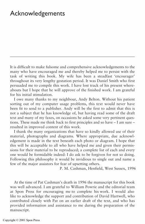
Acknowledgements
It is difficult to make fulsome and comprehensive acknowledgements to themany who have encouraged me and thereby helped me to persist with thetask of writing this book. My wife has been a steadfast ‘encourager’throughout its very lengthy gestation period. It was Daniel Smith who firstpersuaded me to compile this work. I have lost track of his present where-abouts but I hope that he will approve of the finished work. I am gratefulfor his initial stimulation.
I owe many thanks to my neighbour, Andy Belton. Without his patientsorting out of my computer usage problems, this text would never havebeen fit to send to a publisher. Andy will be the first to admit that this isnot a subject that he has knowledge of, but having read some of the drafttext and many of my faxes, on occasions he asked some very pertinent ques-tions. These made me think back to first principles and so have – I am sure –resulted in improved content of this work.
I thank the many organizations that have so kindly allowed use of theirmaterial, photographs and diagrams. Where appropriate, due acknowl-edgement is made in the text beneath each photo or diagram. I hope thatthis will be acceptable to all who have helped me and given their permis-sions for their material to be reproduced; a complete list of each and everyone would be formidable indeed: I do ask to be forgiven for not so doing.Following this philosophy it would be invidious to single out and name afew of the major assistors for fear of upsetting others.
P. M. Cashman, Henfield, West Sussex, 1996
At the time of Pat Cashman’s death in 1996 the manuscript for this bookwas well advanced. I am grateful to William Powrie and the editorial teamat Spon Press for encouraging me to complete his work. I would alsolike to acknowledge the support and contribution of David Hartwell, whocontributed closely with Pat on an earlier draft of the text, and who hasprovided information and assistance to me during the preparation of themanuscript.
Copyright © 2001 Spon Press

Valuable comments on parts of the text were provided by Lesley Benton,Rick Brassington, Steve Macklin, Duncan Nicholson, Jim Usherwood andGordon Williams. I am also grateful to Toby Roberts for kindly writing theafterword.
Illustrations and photographs provided by others, or from publishedworks, are acknowledged in the captions, and I would like to thank allthose who provided such material and permissions. The libraries of theInstitution of Civil Engineers and Ove Arup & Partners have also been ofgreat assistance in the gathering together many of the references quotedherein.
Finally, I would like to thank my wife, Pam, for her invaluable andunstinting support throughout this project.
M. Preene, Wakefield, 2001
xxii Acknowledgements
Copyright © 2001 Spon Press
Chapter 1
Groundwater loweringA personal view and introductionby P. M. Cashman
Many engineering projects, especially major ones, entail excavations intowater-bearing soils. For all such excavations, appropriate system(s) for themanagement and control of the groundwater and surface water run-off,should be planned before the start of each project. In practice this can onlybe done with knowledge of the ground and groundwater conditions likelyto be encountered by reference to site investigation data. The control ofgroundwater (and also surface water run-off) is invariably categorized as‘temporary works’ and so almost always is regarded by the client and hisengineer or architect as the sole responsibility of the contractor and oflittle or no concern of theirs. In many instances this philosophy has beendemonstrated to be shortsighted and ultimately costly to the client.
Sometimes as work proceeds, the actual soil and groundwater conditionsencountered may differ from what was expected. Should this happen, allconcerned should be willing to consider whether to modify operations andconstruction methods as the work progresses and as more detailed infor-mation is revealed. Based upon this philosophy, I advocate, particularly forlarge projects, frequent ‘engineering oriented’ reappraisal meetings betweenclient/owner and contractor or both (as distinct from ‘cost oriented’ meet-ings). This will afford the best assurance that his project will be completedsafely, economically, and within a realistic programme time and cost.
On a few occasions I have been privileged to be involved in the resolutionof some difficult excavation and construction projects when the engineersucceeded in persuading the client to share the below ground risks with thecontractor. During the progress of the contract there were frequent engi-neering oriented meetings with the contractor, to discuss and mutually agreehow to proceed. I believe that the engineers concerned with these complexprojects realized that it would not be in the best interests of their client toadhere rigidly to the traditional view that the contractor must take all of therisk. They were enlightened, had a wealth of practical experience and so hada realistic awareness that the soil and groundwater conditions likely to beencountered were complex. Also they realized that the measures for effect-ing stable soil conditions during construction may not be straightforward.
Copyright © 2001 Spon Press
The few occasions when I have experienced this joint risk sharing approachhave, without exception in my view, resulted in sound engineering solutionsto problems that needed to be addressed: they were resolved sensibly andthe projects were completed within realistic cost to the client. Furthermore,claims for additional payments for dealing with unforeseen conditions werenot pressed by the contractor.
I found these experiences most interesting and enlightening and I learnedmuch by having direct access to different points of view of the overall projectas distinct from my own view as a specialist contractor. I find it encouragingthat in recent years the target form of contract – the client and the contractorsharing the risks of unforeseen conditions – is being implemented morefrequently. Thereby the contractor is confident of a modest but reasonableprofit and the client is not eventually confronted with a multitude of claimsfor additional payments, some of which may be spurious, but all requiringcostly time consuming analysis and investigation.
There are three groups of methods available for temporary works controlof groundwater:
(a) Lowering of groundwater levels in the area of construction by means ofwater abstraction, in other words – groundwater lowering or dewatering.
(b) Exclusion of groundwater inflow to the area of construction by someform of very low permeability cut-off wall or barrier (e.g. sheet-piling,diaphragm walls, artificial ground freezing).
(c) Application of a fluid pressure in confined chambers such as tunnels,shafts and caissons to counter balance groundwater pressures (e.g.compressed air, earth pressure balance tunnel boring machines).
This book deals in detail only with group (a) methods, the groundwaterlowering and dewatering methods. The various methods of all three groups,their uses, advantages and disadvantages are only presented in summary formin Chapter 5.
Rudolf Glossop (1950) stated
The term drainage embraces all methods whereby water is removed fromsoil. It has two functions in engineering practice: permanent drainageis used to stabilize slopes and shallow excavations; whilst temporarydrainage is necessary in excavating in water bearing ground.
This book addresses the subject of temporary drainage only, though manyof the principles are common to both temporary and permanent requirements.
The book is intended for use by the practical engineer (either contractoror consultant or client); but it is intended particularly for the guidance of thespecialist ‘dewatering practitioner’ or advisor. In addition it is commendedto the final year graduate or masters student reading civil engineering orengineering geology as well as to the civil engineering oriented hydrogeologist.
2 Groundwater lowering: introduction by Cashman
Copyright © 2001 Spon Press
It is deliberately addressed to the practitioner involved in the many day-to-daysmall to medium scale dewatering projects for which a simplistic empiricalapproach is usually adequate. It is anticipated that the typical reader of thiswork will be one quite comfortable with this philosophy but one who is awareof the existence of – though perhaps wishing to avoid – the purist hydro-geologist philosophy and the seemingly unavoidable high level mathematicsthat come with it.
We, the writers and the readers, are pragmatic temporary works engi-neers – or, in the case of some readers, aspiring to be so – seeking the successful and economic completion of construction projects. For the smalland medium size projects (which are our ‘bread and butter’) there seems littlepractical justification for the use of sophisticated and time consuming tech-niques, when simpler methods can give serviceable results. The analyticalmethods described in this book are based on much field experience by manypractitioners from diverse countries and have thereby been proven to bepracticable and adequate for most temporary works assessment requirements.I consider that Powers (1992) stated a great dewatering truism ‘The success-ful practitioner in dewatering will be the man who understands the theoryand respects it, but who refuses to let the theory overrule his judgement’.
Extensively, use is made of the Dupuit–Forcheimer analytical approaches. Iam conscious that purists will question this simplistic approach. My riposte –based on some thirty or more years of dealing with groundwater loweringproblems – is that in my experience and that of many others, this empiricalphilosophy has resulted in acceptably adequate pumping installations. Alwaysprovided, of course, that due allowance is made for the often limited relia-bility of ground and groundwater information available. It requires acquiredpractical field experience to assess the quality of the site investigation data.Whenever possible, reference should be made to other excavations in adja-cent areas or in similar soil conditions to verify one’s proposals. In the textthere are some brief descriptions of a number of relevant case histories thatI have dealt with in the past.
I readily acknowledge that for a groundwater lowering system designpertinent to large-scale and/or long-term projects – for example constructionof a dry dock; a nuclear power station or an open cast mining project – moresophisticated methods of analysis will be appropriate. These can providereassurance that the pragmatic solution is about right, but do we ever knowthe ‘permeability value’ to a similar degree of accuracy?
The underlying philosophy of this publication is to address the pragmaticapproach. It follows that three questions arise:
� How does water get into the ground and how does it behave whilstgetting there and subsequently behave whilst there?
� What is the inter-relationship between the soil particles and the ground-water in the voids between them?
Groundwater lowering: introduction by Cashman 3
Copyright © 2001 Spon Press
� How to control groundwater and surface water run-off and so prevent itor them or both causing problems during excavation and construction?
A thorough site investigation should go a long way to providing theanswers to these questions. Unfortunately, experience indicates that manyengineers responsible for specifying the requirements for project site inves-tigations consider only the designer’s requirements and do not address theother important considerations, namely – how can this be built? Often thesite investigation is not tailored to the obtaining of data pertinent to tem-porary works design requirements, nor of problems that may occur duringconstruction.
The contractor should not expect always to encounter conditions exactlyas revealed by the site investigation. Soils, due to the very nature of theirdeposition and formation are variable and rarely, if ever, isotropic andhomogeneous, as is assumed in many of the analytical methods. The con-tractor should carry out the works using his professional skills and abilitiesand should be prepared to adjust, if changed circumstances are revealed asthe work proceeds.
Throughout the planning, excavation and construction phases of eachproject, safety considerations must be of paramount importance. Regret-tably, the construction industry historically has a poor safety performancerecord.
Let us consider another professional discipline! Hopefully no surgeonwould contemplate commencing an operation on a patient without carry-ing out a thorough physical examination and having the information fromX-ray; ECG; urine; blood and other test results and any pertinent scans,available to him beforehand. The surgeon will realize that these may notindicate everything and that during the operation complications may occurbut the possibilities of such ‘surprise’ occurrences will have been minimizedby having reliable site investigation data concerning his patient. Likewise,if the client’s engineer/designer provides comprehensive ground and ground-water information at tender stage, the ‘surprise’ occurrences duringconstruction should be minimized. An experienced contractor, with the co-operation of an experienced client/engineer should be able to agree how toadjust working techniques to deal adequately with the changed circum-stances as or if they are revealed, and this at realistic final cost.
Structure of the rest of the book
At the commencement of each chapter the introduction acts as a summary ofthe subject matter to be covered therein. I hope that this approach will enablethe reader to decide speedily which chapters he wishes to read forthwith whenseeking guidance on how to deal with his individual requirements, and whichchapters may be deferred till later.
4 Groundwater lowering: introduction by Cashman
Copyright © 2001 Spon Press
Chapter 2 contains a brief historical review of the principal theoriesconcerning seepage towards wells and of the technologies used to applythem. Many readers will probably consider this as superfluous and omit itfrom their initial reading. As their interest in this subject becomes furtherstimulated, I hope that they will turn back to it. I derived great pleasurewhen researching this aspect some years ago.
Chapter 3 contains a very brief summary of the hydrological cycle (i.e. howdoes water get into the ground?), together with a similarly brief summary con-cerning soils, their properties and permeability. The theoretical concepts ofDarcy’s law and the nature of flow to wells are introduced, which is muchused in a practical sense later. Groundwater chemistry is also briefly discussed.
Chapter 4 discusses the mechanisms of instability problems in excavations.An understanding of these issues can be vital when selecting a groundwatercontrol method.
Chapter 5 presents in summary form the principal features of the methodsavailable for control of groundwater by exclusion and by pumping.
Chapter 6 addresses site investigation requirements, but only that specificto groundwater lowering, and does not detail the intricacies of the availablemethods of site investigation. This chapter also covers permeability deter-mination in the field and laboratory. Guidance is also given on therelative reliability of permeability estimated by the various methods.
Chapter 7 describes various empirical and simple design methods forassessing the discharge flow rates required for groundwater lowering instal-lations, and for determining the number of wells, etc. Several simple designexamples are included in an appendix.
Chapters 8–11 address the various groundwater lowering methods: sumppumping; wellpointing; deepwells; and less commonly used methods.
Chapter 12 describes the types of pumps suitable for the various systems.Chapter 13 deals with some associated side effects of groundwater low-
ering, including ground settlements and describes the method of artificialrecharge which can be used to mitigate some of these side effects.
Chapter 14 presents appropriate methods of monitoring and maintenanceto ensure that groundwater lowering systems operate effectively when theyare first installed, and after extended periods of operation.
Chapter 15 covers safety, contractual and environmental issues (usingBritish convention, but based on principles of good practice that are applic-able in other countries).
Chapter 16 is a short afterword, looking at the future of groundwaterlowering.
The book ends with a Glossary of Terms pertinent to the subject matterand also a summary of the Symbols and Notations used. Various appendicesare included, providing detailed background information on various subjects.
Finally I reiterate my earlier statement: this book is intended for the guid-ance of practical engineers and those – many I hope! – desirous of joining us.
Groundwater lowering: introduction by Cashman 5
Copyright © 2001 Spon Press

I trust that there are several new aspirants who will realize after readingthis book that it is a challenging scientific field, and to some extent anapplied art form as well, wherein the requirement for practical experienceis paramount. No two sites have the same requirements – this is one of itsfascinations!
References
Glossop, R. (1950). Classification of geotechnical processes. Géotechnique, 2(1),3–12.
Powers, J. P. (1992). Construction Dewatering: New Methods and Applications,2nd edition. Wiley, New York, p. 11.
6 Groundwater lowering: introduction by Cashman
Copyright © 2001 Spon Press
Chapter 2
The history of groundwatertheory and practice
2.0 Introduction
Man has been aware of groundwater since prehistory, long before Biblicaltimes. Over the centuries the mysteries of groundwater have been solved, andman has developed an increasing capability to manipulate it to his will. Thischapter describes some of the key stages in the development of the under-standing and control of groundwater. The history of some of the technolo-gies now used for groundwater lowering is also discussed, especially inrelation to early applications in the United Kingdom. Detailed knowledgeof the history of groundwater control might not be considered essential fora practical engineer working today. Nevertheless, study of the past can beilluminating, not least by showing that even when theories are incomplete, andtechnology untried, the application of scientific principles and engineeringjudgement can still allow groundwater to be controlled.
2.1 The earliest times to the sixteenth century
The digging of wells for the exploitation of water and primitive implementa-tion of water management dates back to Babylonian times and even earlier.
The source of the water flowing from springs and in streams was a puz-zling problem, and the subject of much controversy and speculation. It wasgenerally held that the water discharged from springs could not be derivedfrom rain. Ingenious hypotheses were formulated to account for the occur-rence of springs. Some early writers suggested large inexhaustible reservoirswhile others recognized that there must be some form of replenishment ofthe supplying reservoirs. The Greek hypotheses, with many incredibleembellishments, were generally accepted until near the end of the seventeenthcentury. The theory of rainfall infiltration was propounded by only a veryfew writers.
Though the Romans and other early cultures indulged in quite sophisti-cated water management projects by building imposing aqueducts to chan-nel water from spring and other sources to centres of population, they had
Copyright © 2001 Spon Press
no understanding of the sources of replenishment of groundwater. Theaqueducts of the Romans were remarkable, and showed great appreciation ofthe value of water, but their methods of measuring or estimating water quan-tities were crude. Generally they appear to have lacked any semblance ofknowledge of either surface or groundwater hydrology.
According to Tolman (1937)
Centuries have been required to free scientists from superstitions andwild theories handed down from the dawn of history regarding theunseen sub-surface water, … even in this century there is still much popular superstition concerning underground water.
An elemental principle, that gravity controls the motion of water under-ground as well as at the surface, is not appreciated by all. A popular beliefexists that ‘rivers’ of underground water pass through solid rock devoid ofinterconnected interstices and flow under intervening mountain ranges.
Marcus Vitruvius, a Roman architect who lived about the time of Christ,produced a book describing the methods of finding water. He wrote of rainand snow falling on mountains and then percolating through the rock strataand reappearing as springs at the foot of the mountains. He gave a list ofplants and of other conditions indicative of groundwater such as colour anddampness of the soil and mists rising from the ground early in the morning.Vitruvius and two contemporaries of his, Cassiodorus and Plinz, were thefirst to make serious efforts to list practical methods for locating water, andthis when geology was yet unknown!
2.2 The renaissance period to the nineteenth century
At the beginning of the sixteenth century Leonardo da Vinci directed hisattention to the occurrence and behaviour of water. He correctly describedthe infiltration of rain and the occurrence of springs, and concluded thatwater goes from rivers to the sea and from the sea to the rivers and thus isconstantly circulating and returning. About the same time Pallissy, a FrenchHuguenot, presented a clear and reasoned argument that all water fromsprings is derived from rain.
The latter part of the seventeenth century was a watershed in the begin-ning of an understanding of the replenishment of groundwater. Graduallythere arose the concept of an ‘hydrological cycle’. This presumed that waterwas returned from the oceans by way of underground channels below themountains. The removal of salt was thought to be either by distillation orby percolation and there were some highly ingenious theories of how waterwas raised up to the springs.
8 The history of groundwater theory and practice
Copyright © 2001 Spon Press
2.3 Progress from a qualitative to aquantitative science
It was in the seventeenth century that the quantitative science of hydrologywas founded by Palissy, Pérrault and Mariotté in France, Ramazzini in Italyand the astronomer Halley in Britain.
Palissy, a sixteenth century potter and palaeontologist, stated that rainand melt snow were the only source of spring and river waters; and thatrain water percolates into the earth, following ‘a downward course untilthey reach some solid and impervious rock surface over which they flowuntil they make some opening to the surface of the earth.’
Pérrault made rainfall run-off measurements and demonstrated the fallacyof the long held view that the rainfall was not sufficient to account forthe discharge from springs. He also measured and investigated evaporationand capillarity. Mariotté verified Pérrault’s results and showed that theflow from springs increased in rainy weather and decreased in times ofdrought. Halley made observations of the rate of evaporation from theMediterranean ocean and showed that this was adequate to supply thequantity returned to that sea by its rivers. His measurements of evaporationwere conducted with considerable care but his estimates of stream flow werevery crude.
Towards the end of the eighteenth century La Metherie extended theresearches of Mariotté and brought them to the attention of meteorologists.He also investigated permeability and explained that some rain flows offdirectly (surface water run-off), some infiltrates into the top soil layers onlyand evaporates or feeds plants, whilst some rain penetrates undergroundwhence it can issue as springs (i.e. infiltration or groundwater recharge).This is the first recorded mention of ‘permeability’ and so is the first linkbetween hydrology and seepage to wells.
2.3.1 Seepage towards wells
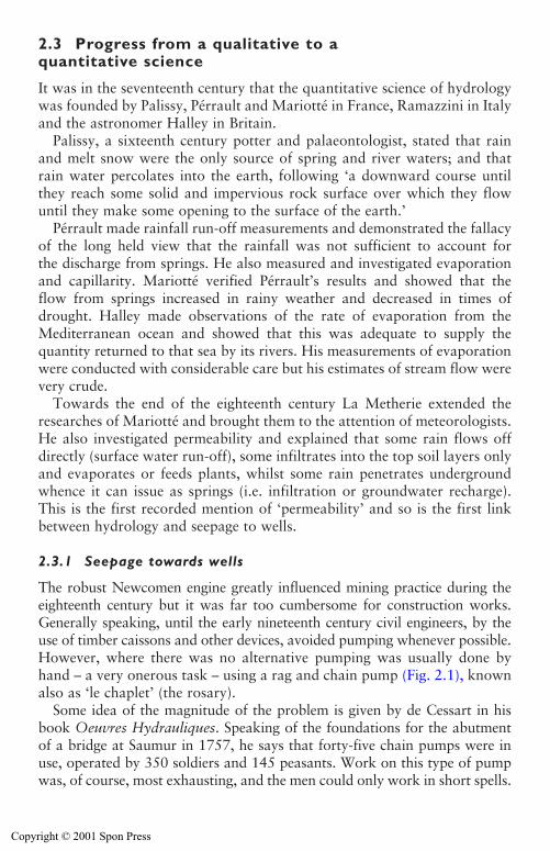
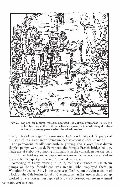
The robust Newcomen engine greatly influenced mining practice during theeighteenth century but it was far too cumbersome for construction works.Generally speaking, until the early nineteenth century civil engineers, by theuse of timber caissons and other devices, avoided pumping whenever possible.However, where there was no alternative pumping was usually done byhand – a very onerous task – using a rag and chain pump (Fig. 2.1), knownalso as ‘le chaplet’ (the rosary).
Some idea of the magnitude of the problem is given by de Cessart in hisbook Oeuvres Hydrauliques. Speaking of the foundations for the abutmentof a bridge at Saumur in 1757, he says that forty-five chain pumps were inuse, operated by 350 soldiers and 145 peasants. Work on this type of pumpwas, of course, most exhausting, and the men could only work in short spells.
The history of groundwater theory and practice 9
Copyright © 2001 Spon Press
Pryce, in his Mineralogea Cornubiensis in 1778, said that work on pumps ofthis sort led to a great many premature deaths amongst Cornish miners.
For permanent installations such as graving docks large horse-drivenchaplet pumps were used. Perronnet, the famous French bridge builder,made use of elaborate pumping installations in the cofferdams for the piersof his larger bridges; for example, under-shot water wheels were used tooperate both chaplet pumps and Archimedean screws.
According to Crèsy, writing in 1847, the first engineer to use steampumps on bridge foundations was Rennie, who employed them onWaterloo Bridge in 1811. In the same year, Telford, on the construction ofa lock on the Caledonian Canal at Clachnacarry, at first used a chain pumpworked by six horses, but replaced it by a 9 horsepower steam engined
10 The history of groundwater theory and practice
Figure 2.1 Rag and chain pump, manually operated. 1556 (from Bromehead 1956). Theballs, which are stuffed with horsehair, are spaced at intervals along the chainand act as one-way pistons when the wheel revolves.
Copyright © 2001 Spon Press
pump. From then on steam pumps were used during the construction of allthe principal locks on that canal. In 1825 Marc Brunel used a 14 horse-power steam engine when sinking the shafts for the Thames Tunnel. By thisdate steam pumping seems to have been the common practice for dealingwith groundwater and so below ground excavations for construction wereless problematical.
2.3.2 Kilsby tunnel, London to Birmingham railway
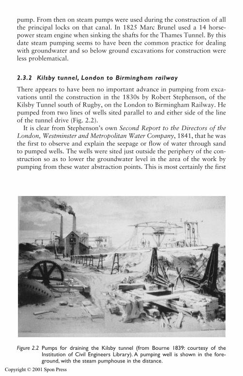
There appears to have been no important advance in pumping from exca-vations until the construction in the 1830s by Robert Stephenson, of theKilsby Tunnel south of Rugby, on the London to Birmingham Railway. Hepumped from two lines of wells sited parallel to and either side of the lineof the tunnel drive (Fig. 2.2).
It is clear from Stephenson’s own Second Report to the Directors of theLondon, Westminster and Metropolitan Water Company, 1841, that he wasthe first to observe and explain the seepage or flow of water through sandto pumped wells. The wells were sited just outside the periphery of the con-struction so as to lower the groundwater level in the area of the work bypumping from these water abstraction points. This is most certainly the first
The history of groundwater theory and practice 11
Figure 2.2 Pumps for draining the Kilsby tunnel (from Bourne 1839: courtesy of theInstitution of Civil Engineers Library). A pumping well is shown in the fore-ground, with the steam pumphouse in the distance.
Copyright © 2001 Spon Press
temporary works installation of a deep well groundwater lowering system inBritain, if not in the world. The following extract (from Boyd-Dawkins 1898,courtesy of the Institution of Civil Engineers Library) quotes from the reportand shows that Stephenson had understood the mechanism of groundwaterflow towards a pumping installation.
The Kilsby Tunnel, near Rugby, completed in the year 1838, presentedextreme difficulties because it had to be carried through the water-loggedsands of the Inferior Oolites, so highly charged with water as to be a ver-itable quicksand. The difficulty was overcome in the following manner.Shafts were sunk and steam driven pumps erected in the line of the tun-nel. As the pumping progressed the most careful measurements weretaken of the level at which the water stood in the various shafts and bore-holes; and I was soon much surprised to find how slightly the depressionof the water-level in the one shaft, influenced that of the other, not with-standing a free communication existed between them through the mediumof the sand, which was very coarse and open. It then occurred to me thatthe resistance which the water encountered in its passage through thesands to the pumps would be accurately measured by the angle or incli-nation which the surface of the water assumed towards the pumps, andthat it would be unnecessary to draw the whole of the water off from thequicksands, but to persevere in pumping only in the precise level of thetunnel, allowing the surface of the water flowing through the sand toassume that inclination which was due to its resistance.
The simple result of all the pumping was to establish and maintain achannel of comparatively dry sand in the immediate line of the intendedtunnel, leaving the water heaped up on each side by the resistancewhich the sand offered to its descent to that line on which the pumpsand shafts were situated.
As Boyd-Dawkins then comments:
The result of observations, carried on for two years, led to the conclusionthat no extent of pumping would completely drain the sands. Borings,put down within 200 yards [185 m] of the line of the tunnel on eitherside, showed further, that the water-level had scarcely been reduced aftertwelve months continuous pumping and, for the latter six months,pumping was at the rate of 1,800 gallons per minute [490 m3/h]. In otherwords, the cone of depression did not extend much beyond 200 yards[185 m] away from the line of pumps.
In this account, … it is difficult to decide which is the moreadmirable, the scientific method by which Stephenson arrived at theconclusion that the cone of depression was small in range, or the prac-tical application of the results in making a dry [the authors would have
12 The history of groundwater theory and practice
Copyright © 2001 Spon Press
used the word ‘workable’ rather than ‘dry’] pathway for the railwaybetween the waters heaped up [in the soil] … on either side.
It is astonishing that neither Robert Stephenson, nor any of his contem-poraries, realized the significance of this newly discovered principle. Thatby sinking water abstraction points, and more importantly placing them clearof the excavation so that the flow of water in the ground will be away fromthe excavation rather than towards it – stable ground conditions werecreated. For many decades this most important principle was ignored.
2.3.3 Early theory – Darcy and Dupuit
In the 1850s and early 1860s Henri Darcy made an extensive study of theproblems of obtaining an adequate supply of potable water for the town ofDijon. He is famous for his Darcy’s law (Darcy 1856) postulating how todetermine the permeability of a column of sand of selected grading, know-ing the rate of water flow through it but this formed only a small part ofhis treatise. He compiled a very comprehensive report (two thick volumes)in which he analysed the available sources of water from both river andwells – some of them artesian – and how economically to harness all thesefor optimum usage.
Darcy investigated the then current volume of supply of water per day perinhabitant for about ten municipalities in Britain – Glasgow, Nottingham andChelsea amongst others – as well as Marseille and Paris, and many otherFrench towns. He concluded that the average water provision in Britain was80–85 l/inhabitant/day and more than 60 l/inhabitant/day for Paris. Darcydesigned the water supply system for Dijon on the basis of 150 l/inhabitant/-day – no doubt his Victorian contemporaries this side of ‘la manche’ wouldhave applauded this philosophy.
In the mid-1860s Dupuit (1863), using Darcy’s law to express soil perme-ability, propounded his equations for determining flow to a single wellpositioned in the middle of an island. Dupuit made certain simplifyingassumptions and having stated them (i.e. truly horizontal flow) then dis-counted their implications! For this Dupuit has been much castigated by somelater purists but most accept that the Dupuit concept, latter slightly modifiedby Forcheimer, is acceptable and adequate in many practical situations.
Exchange of information was not as simple in Darcy’s and Dupuit’s timeas it is now. Much of the fundamental work of these two French engineerswas duplicated by independent developments shortly afterwards in Germanyand Austria and a little later, in the United States.
About 1883 Reynolds demonstrated that for linear flow – that is, flow inorderly layers – commonly known as laminar flow, there is a proportional-ity existing between the hydraulic gradient and the velocity of flow. This isin keeping with Darcy’s Law but as velocity increased the pattern of flow
The history of groundwater theory and practice 13
Copyright © 2001 Spon Press
becomes irregular (i.e. turbulent) and the hydraulic gradient approached thesquare of the velocity. Reynolds endorsed the conclusion that Darcy’s Lawgives an acceptable representation of the flow within porous media – thatis the flow through the pore spaces of soils will remain laminar, save forvery rare and exceptional circumstances. However, this may not always betrue of flow through jointed rocks (e.g. karstic limestone formations).
2.4 Later theoretical developments
In his Rankine Lecture Glossop (1968) suggested that ‘classical soil mechan-ics’ was founded on the work of Terzaghi which dates from his first bookpublished in 1925 and that it is strongly influenced by geological thinking.In 1913 Terzaghi published a paper dealing with the hydrology of the Karstregion after studying the geology for a hydro-electric scheme in Croatia. Hesoon realized that geology would be of far more use to engineers if the phys-ical constants of rocks and soils were available for design (Terzaghi 1960).This was the first positive marrying of civil engineering and geology.
2.4.1 Verifications and modification of Darcy
In 1870, a civil engineer in Dresden, Adolph Theim reviewed Darcy’s experi-ments and went on to derive the same equations as Dupuit for gravity andartesian wells. Theim was the first to collect extensive field data in supportof his and Dupuit’s equations. Thus, he was the first researcher to applypractical field experience to test the validity of the analytical pronounce-ments. This fundamentally practical philosophy was to be typical of Terzaghiand other later pioneers of soil mechanics, where reliable field measurementswere essential to verify assumptions.
The next contributor to the advance of groundwater flow theory was anAustrian engineer, Forcheimer. In the late nineteenth century he publishedhis first paper on flow towards wells (Forcheimer 1886). Over a period ofhalf a century he published many contributions to this field of technology.Based on an analogy with heat flow he developed the use of flow nets in trac-ing the flow of water through sands. His results were published in 1917 andcertainly influenced Terzaghi. Also, Forcheimer undertook the analysis ofgravity flow towards a group of wells and introduced the concept of a hypo-thetical equivalent single well. This concept, later endorsed by Weber, is ofgreat practical importance to this day in analysing well systems in connec-tion with civil engineering projects for construction temporary works.
In the 1950s an Australian research worker, Chapman (1959), investi-gated the problem of analysing long lines of closely-spaced wells or well-points. Building on earlier theoretical work by Muskat (1935) who studiedplane seepage through dams, Chapman’s modelling and analytical workproduced solutions for single and double lines of wells or wellpoints. These
14 The history of groundwater theory and practice
Copyright © 2001 Spon Press
solutions are still widely used today for the analysis of wellpoint systems fortrench excavations.
2.4.2 Non-steady state flow
An important aspect of the theory of flow towards wells upon which thevarious investigators in Europe were relatively silent, was the non-steadystate. The first European investigator to produce anything of importancewas Weber (1928). His work is still one of the most complete treatments of the subject. Weber, like Forcheimer before him, was very thorough ingathering field performance data and correlating it with his theoreticalanalyses.
In 1942 Meinzer, Chief of the Ground Water Division of the United StatesGeological Survey edited a comprehensive outline on the development of field-work and theoretical analysis in groundwater hydrology up to that time(Meinzer 1942). His contributions had extended already over more thana decade. It was he who took on engineers, physicists and mathematicians aswell as geologists to undertake the challenging responsibilities delegated tohis division. Meinzer is regarded by many as the first hydrogeologist, and inthis specialist field is considered as its ‘father’ in like manner that Terzaghiis considered as the ‘father’ of soil mechanics. Theis is probably the bestknown of many of Meinzer’s protégés. Theis approached the treatment ofnon-steady state flow from a different angle to that of Weber. His concep-tual approach (Theis 1935) is now almost universally used as the basis fornon-steady state flow analysis.
During the early 1930s Muskat, chief physicist for the Gulf Research andDevelopment Company, was the leader of a team who compiled a compre-hensive and scholarly volume treating all phases of flow of fluids throughhomogeneous porous media (Muskat 1937). The work was concerned pri-marily with the problems involved in flow of oil and oil–gas mixtures throughrocks and sands. Muskat’s approach was consistently that of a theoreticalphysicist rather than that of a field engineer. His appraisals of analytical meth-ods of test procedures tended to be more of the scientific purist than ofone concerned with the practical pragmatic needs in the field. However, theaccomplishments of Muskat and his colleagues have been of immeasurablevalue to an understanding of seepage flow.
Muskat made much use of electric analogue models and of sand tank mod-els. He investigated the effects of stratification and anisotropy and developedthe transformed section. He made extensive studies of multiple confinedwells. He seems to have given much serious thought to the limited validity ofthe Dupuit equations and pronounced ‘Their accuracy, when valid, is a luckyaccident’. No one before or since has been so intolerant of Dupuit. Boulton(1951) and many other investigators do not subscribe to Muskat’s dismis-siveness of the practical usefulness of the Dupuit–Forcheimer approach.
The history of groundwater theory and practice 15
Copyright © 2001 Spon Press
2.5 Groundwater modelling
In a pedantic context, groundwater modelling involves the use of models oranalogues to investigate or simulate the nature of groundwater flow. Inmodern parlance, groundwater modelling invariably refers to numericalmodels run on computers. In fact these are not true models but iterativemathematical solutions to a model or mesh is defined by the operator; asolution is considered to be acceptable when the errors reach a user-definedlevel. These models have been developed by many organizations from orig-inal esoteric research tools into the current generation of easier to use mod-els with excellent presentation of results which, when used appropriately,can clearly demonstrate what is happening to the groundwater flow. The useof numerical modelling is described in Section 7.7.
The origins of groundwater models and analogues are to be found, not ingroundwater theory, but in other scientific fields such as electricity and heatflow. In the mid-nineteenth century Kirkoff studied the flow of electrical cur-rent in a thin disk of copper. Just who recognized that the mathematicalexpressions or laws governing the flow of electricity were analogous to thosegoverning the flow of thermal energy and groundwater is not clear.
This dawning of the electrical analogy to groundwater flow was given amajor impetus in North America where the growing interest in the theoret-ical aspects of oil reservoir development led to major developments. Asnoted earlier, the significant contributions of Muskat during the 1930sincluded electrical analogues and sand tank models, Wyckoff, who hadworked with Muskat, published in 1935 the first conductive paper modelstudy of groundwater flow through a dam. The use of conductive paper wasa direct development from Kirchoff’s original work, nearly a century ear-lier, and became the practical basis for much of the two-dimensionalisotropic analogue modelling for the next fifty years before numerical mod-els finally superseded it. The conductive paper technique was given a furtherboost with the development of teledeltos paper in 1948. This aluminiumcoated carbon based paper enabled rapid two-dimensional studies to beundertaken.
Karplus (1958) presents an extensive discussion on the use and limitationsof conductive paper models, as well as introducing resistance networks wherethe uniform conducting layer is replaced by a grid of resistors. The advantageof this system was that it could be developed into three dimensions and so theproblems of making measurements within a solid were overcome. Herbertand Rushton (1966) developed resistance networks to introduce switchingtechniques to determine a free water surface, transistors to simulate storageand also evolved time variant solutions. Case histories of the practical appli-cation of resistance networks have been published for pressure relief wellsunder Mangla dam in Pakistan (Starr et al. 1969) and for a deep wellsystem at Sizewell B Power Station in England (Knight et al. 1996).
16 The history of groundwater theory and practice
Copyright © 2001 Spon Press
Other analogues include: electrolytic tanks where a thin layer of con-ducting fluid is used instead of the conducting paper; or a stretched rubbermembrane which, when distorted at right angles to the surface, forms ashape analogous to the cone of depression formed by a well. Neither ofthese techniques or others appear to have been used extensively for the solutionof practical groundwater problems.
A different class of models are the sand tank type (see Cedergren 1989).These physical models consist of two parallel plates of clear material such asglass, closely spaced and filled with sand to represent the aquifer. Physicalimpediments to flow, such as dams or wells can be inserted and the modelsaturated. By injecting a tracer or dye on the upstream side the flow path(s)can be observed. The viscous flow or Hele-Shaw technique – so named afterthe man who first used this technique in England – is a variation to the sandtank. These techniques have been used regularly to demonstrate the form ofgroundwater flow, particularly beneath dams but have limited application togroundwater lowering in construction.
2.6 Early dewatering technology in Britain
Much of the technology which forms the basis of modern dewatering meth-ods was developed in the United States or Germany and was introduced toBritain in the early part of the twentieth century. Up to that time any ground-water lowering required was achieved by the crude (but often effective)methods of pumping from timbered shafts or from open-jointed subdrainslaid ahead and below trench or tunnel works.
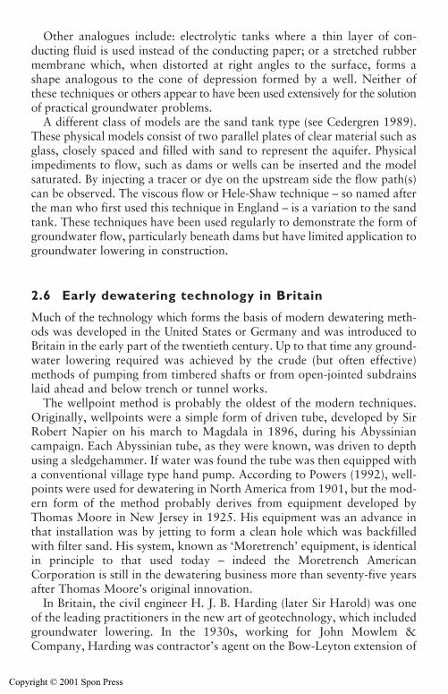
The wellpoint method is probably the oldest of the modern techniques.Originally, wellpoints were a simple form of driven tube, developed by SirRobert Napier on his march to Magdala in 1896, during his Abyssiniancampaign. Each Abyssinian tube, as they were known, was driven to depthusing a sledgehammer. If water was found the tube was then equipped witha conventional village type hand pump. According to Powers (1992), well-points were used for dewatering in North America from 1901, but the mod-ern form of the method probably derives from equipment developed byThomas Moore in New Jersey in 1925. His equipment was an advance inthat installation was by jetting to form a clean hole which was backfilledwith filter sand. His system, known as ‘Moretrench’ equipment, is identicalin principle to that used today – indeed the Moretrench AmericanCorporation is still in the dewatering business more than seventy-five yearsafter Thomas Moore’s original innovation.
In Britain, the civil engineer H. J. B. Harding (later Sir Harold) was oneof the leading practitioners in the new art of geotechnology, which includedgroundwater lowering. In the 1930s, working for John Mowlem &Company, Harding was contractor’s agent on the Bow-Leyton extension of
The history of groundwater theory and practice 17
Copyright © 2001 Spon Press
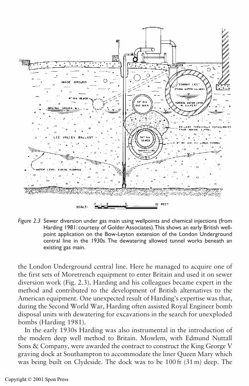
the London Underground central line. Here he managed to acquire one ofthe first sets of Moretrench equipment to enter Britain and used it on sewerdiversion work (Fig. 2.3). Harding and his colleagues became expert in themethod and contributed to the development of British alternatives to theAmerican equipment. One unexpected result of Harding’s expertise was that,during the Second World War, Harding often assisted Royal Engineer bombdisposal units with dewatering for excavations in the search for unexplodedbombs (Harding 1981).
In the early 1930s Harding was also instrumental in the introduction ofthe modern deep well method to Britain. Mowlem, with Edmund NuttallSons & Company, were awarded the contract to construct the King George Vgraving dock at Southampton to accommodate the liner Queen Mary whichwas being built on Clydeside. The dock was to be 100 ft (31 m) deep. The
18 The history of groundwater theory and practice
Figure 2.3 Sewer diversion under gas main using wellpoints and chemical injections (fromHarding 1981: courtesy of Golder Associates).This shows an early British well-point application on the Bow-Leyton extension of the London Undergroundcentral line in the 1930s. The dewatering allowed tunnel works beneath anexisting gas main.
Copyright © 2001 Spon Press
Docks Engineer at Southampton was, according to Harding (1981), ‘a wiseand experienced man, he carried out his site investigation to unusual depths’.This revealed beds of Bracklesham sands containing water under artesianhead which would reach above ground level.
At the time large deep wells using the recently developed submersiblepump had been used for groundwater lowering in Germany from 1896onwards, initially for the construction of the Berlin U-Bahn undergroundrailway, but were not a method recognized in Britain. In 1932 Mowlem hadobtained licencing agreements with Siemens Bau-Union to use their patentsfor, among other methods, groundwater lowering by deep wells, with Hardingas the nominated British expert. This method was used at Southampton and
The history of groundwater theory and practice 19
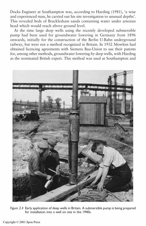
Figure 2.4 Early application of deep wells in Britain. A submersible pump is being preparedfor installation into a well on site in the 1940s.
Copyright © 2001 Spon Press
groundwater levels in the deep artesian aquifer were successfully lowered byten deep wells, each equipped with a Siemens submersible pump, run from acentral control (McHaffie 1938; Harding 1938). This was probably the firstrational application of the deep well method in Britain since that by RobertStephenson for the construction of the Kilsby tunnel a century earlier.
Further applications of deep well method with submersible pumps followedin the 1940s (Fig. 2.4), now unencumbered by licence agreements, and themethod became an established technique for the control of groundwater(Harding 1946; Glossop and Collingridge 1948). The pioneering practicaldewatering work on the Mowlem contracts was continued by Mowlem’ssubsidiary company, Soil Mechanics Limited, whose groundwater loweringdepartment carried out numerous large-scale projects on power stationsand docks in the 1950s and 1960s.
One of the most recent techniques to be introduced into the UnitedKingdom is the ejector dewatering method. Jet pumps, which are the basisof the ejector method, were first proposed in the 1850s by Thomson (1852)for the removal of water from water wheel sumps. Dewatering systems usingejectors were developed in the United States almost a century later basedon jet pumps used in water supply wells (Prugh 1960; Werblin 1960). Theejector method does not seem to have been much employed in the UnitedKingdom until a few decades after its introduction in North America,although a small-scale ejector system was used in England in 1962 to dewa-ter the Elm Park Colliery drift (Greenwood 1988). During the 1980s Britishengineers and contractors used ejectors on projects in Asia such as the HSBCheadquarters in Hong Kong (Humpheson et al. 1986) and at the Benutandam in Brunei (Cole et al. 1994). However, it was not until the late 1980sthat a large-scale ejector system was used in the United Kingdom, for thecasting basin and cut and cover sections of the river Conwy crossing projectin North Wales (Powrie and Roberts 1990).
2.7 Practical publications
As described in Chapter 1, the control of groundwater is a practical problem,where theory is only part of the picture – how the theory is put into practiceis vital. Historically, the best practical guidance came from in-house dewa-tering manuals produced by companies such as Geho Pumpen in Holland orthe Moretrench American Corporation in North America. One of the firstwidely published more practical dewatering texts was Mansur and Kaufman(1962) which formed a chapter of the book Foundation Engineering editedby G. A. Leonards. This is a detailed statement-of-the-art of the time, with astrong bias towards the analytical but with some reference to practical con-siderations. Although it may seem a little dated, this book is essential read-ing for all who aspire to be specialist dewatering practitioners, and wish tounderstand some of the more accessible theory.
20 The history of groundwater theory and practice
Copyright © 2001 Spon Press
In the 1980s some useful publications became available. First, in 1981 J. P. Powers, then of the Moretrench American Corporation, produced hisbook Construction Dewatering: A Guide to Theory and Practice which isunderstandably oriented toward American practice. Updated as Powers(1992), this remains a thorough and readable book. In 1986 the ConstructionIndustry Research and Information Association (CIRIA) produced Report 113Control of Groundwater for Temporary Works (Somerville 1986), whichwas based on British practice. It was aimed at the non-specialist engineeringdesigner and site staff, and drew on the expertise of experienced dewater-ing engineers. In the late 1990s CIRIA produced another report, coveringthe subject in more detail: Report C515 Groundwater Control – Designand Practice (Preene et al. 2000). Useful information and case histories cansometimes be found in groundwater conference proceedings. In the 1980sand 1990s relevant conferences were held on Groundwater in EngineeringGeology (Cripps et al. 1986), Groundwater Effects in GeotechnicalEngineering (Hanrahan et al. 1987), and Groundwater Problems in UrbanAreas (Wilkinson 1994).
This book is intended to compliment and augment these texts, and willconcentrate, in the main, on the practical requirements for groundwaterlowering for temporary works.
References
Bourne, J. C. (1839). Drawings of the London and Birmingham Railway. Collectionof the Institution of Civil Engineers library, London.
Boulton, N. S. (1951). The flow pattern near a gravity well in a uniform waterbearing medium. Journal of the Institution of Civil Engineers, 36, 534–550.
Boyd-Dawkins, W. (1898). On the relation of geology to engineering, James Forrestlecture. Minutes of the Proceedings of the Institution of Civil Engineers, 134,Part 4, 2–26.
Bromehead, C. N. (1956). Mining and quarrying in the seventeenth century. A Historyof Technology (Singer, C., Holmyard, E. J., Hall, A. R. and Williams, T. L., eds),Volume 2. Oxford University Press, Oxford, pp 1–40.
Cedergren, H. R. (1989). Seepage, Drainage and Flow Nets, 3rd edition. Wiley,New York.
Chapman, T. G. (1959). Groundwater flow to trenches and wellpoints. Journal ofthe Institution of Engineers, Australia, 275–280.
Cole, R. G., Carter, I. C. and Schofield, R. J. (1994). Staged construction at BenutanDam assisted by vacuum eductor wells. Proceedings of the 18th InternationalConference on Large Dams, Durban, South Africa, pp 625–640.
Cripps, J. C., Bell, F. G. and Culshaw, M. G. (eds) (1986). Groundwater inEngineering Geology. Geological Society Engineering Geology Special PublicationNo. 3, London.
Darcy, H. (1856). Les Fontaines Publique de la Ville de Dijon. Dalmont, Paris.Dupuit, J. (1863). Etudes Théoretiques et Practiques sur les Mouvement des
Eaux dans les Canaux Decouverts et a Travers les Terrains Permeable. Dunod,Paris.
The history of groundwater theory and practice 21
Copyright © 2001 Spon Press
Forcheimer, P. (1886). Uber die ergibigkeit von brunnen-anlagen und sickerschitzen.Der Architekten-und Ingenieur-Verein, 32, No. 7.
Glossop, R. (1968). The rise of geotechnology and its influence on engineeringpractice. Géotechnique, 18(2), 105–150.
Glossop, R. and Collingridge, V. H. (1948). Notes on groundwater lowering bymeans of filter wells. Proceedings of the 2nd International Conference on SoilMechanics and Foundation Engineering, Rotterdam, 2, pp 320–322.
Greenwood, D. A. (1988). Sub-structure techniques for excavation support. EconomicConstruction Techniques. Thomas Telford, London, pp 17–40.
Hanrahan, E. T., Orr, T. L. L. and Widdis, T. F. (eds) (1987). Groundwater Effects inGeotechnical Engineering. Balkema, Rotterdam.
Harding, H. J. B. (1938). Correspondence on Southampton docks extension.Journal of the Institution of Civil Engineers, 9, 562–564.
Harding. H. J. B. (1946). The principles and practice of groundwater lowering.Institution of Civil Engineers, Southern Association.
Harding, H. J. B. (1981). Tunnelling History and my Own Involvement. GolderAssociates, Toronto.
Herbert, R. and Rushton, K. R. (1966). Groundwater flow studies by resistance net-works. Géotechnique, 16(1), 53–75.
Humpheson, C., Fitzpatrick, A. J. and Anderson, J. M. D. (1986). The basementsand substructure for the new headquarters of the Hongkong and ShanghaiBanking Corporation, Hong Kong. Proceedings of the Institution of CivilEngineers, 80, Part 1, 851–883.
Karplus, W. J. (1958). Analog simulation. McGraw-Hill. London.Knight, D. J., Smith, G. L. and Sutton, J. S. (1996). Sizewell B foundation dewater-
ing – system design, construction and performance monitoring. Géotechnique,46(3), 473–490.
Mansur, C. I. and Kaufman, R. I. (1962). Dewatering. Foundation Engineering(G. A. Leonards, ed.), McGraw-Hill, New York, pp 241–350.
McHaffie, M. G. J. (1938). Southampton docks extension. Journal of the Institutionof Civil Engineers, 9, 184–219.
Meinzer, O. E. (ed.) (1942). Hydrology. McGraw-Hill, New York.Muskat, M. (1935). The seepage of water through dams with vertical faces. Physics,
6, p 402.Muskat, M. (1937). The Flow of Homogeneous Fluids Through Porous Media.
McGraw-Hill, New York.Powers, J. P. (1992). Construction Dewatering: New Methods and Applications,
2nd edition. Wiley, New York.Powrie, W. and Roberts, T. O. L. (1990). Field trial of an ejector well dewatering
system at Conwy, North Wales. Quarterly Journal of Engineering Geology, 23,169–185.
Prugh, B. J. (1960). New tools and techniques for dewatering. Journal of theConstruction Division, Proceedings of the American Society of Civil Engineers,86, CO1, 11–25.
Preene, M., Roberts, T. O. L., Powrie, W. and Dyer, M. R. (2000). GroundwaterControl – Design and Practice. Construction Industry Research and InformationAssociation, CIRIA Report C515, London.
22 The history of groundwater theory and practice
Copyright © 2001 Spon Press
Somerville, S. H. (1986). Control of Groundwater for Temporary Works.Construction Industry Research and Information Association, CIRIA Report 113,London.
Starr, M. R., Skipp, B. O. and Clarke, D. A. (1969). Three-dimensional analogue usedfor relief well design in the Mangla Dam project. Géotechnique, 19(1), 87–100.
Terzaghi, K. (1960). Land forms and subsurface drainage in the Gacka region inYugoslavia. From Theory to Practice in Soil Mechanics: Selections from theWritings of Karl Terzaghi. Wiley, New York.
Theis, C. V. (1935). The relation between the lowering of the piezometric surfaceand the rate and duration of discharge of a well using groundwater storage.Transactions of the American Geophysical Union, 16, 519–524.
Thomson, J. (1852). On a jet pump or apparatus for drawing water up by the powerof a jet. Report of the British Association, 130–131.
Tolman, C. F. (1937). Ground Water. McGraw-Hill, New York.Weber, H. (1928). Die Reichweite von Grundwasserabsenkungen Mittels
Rohrbunnen. Springer, Berlin.Werblin, D. A. (1960). Installation and operation of dewatering systems. Journal of
the Soil Mechanics and Foundations Division, Proceedings of the AmericanSociety of Civil Engineers, 86, SM1, 47–66.
Wilkinson, W. B. (ed.) (1994). Groundwater Problems in Urban Areas. ThomasTelford, London.
The history of groundwater theory and practice 23
Copyright © 2001 Spon Press
Chapter 3
Groundwater and permeability
3.0 Introduction
To allow even a basic approach to the control of groundwater, the practitionershould be familiar with some of the principles governing groundwater flow.Similarly, the specialist terms and language used must be understood. Thischapter describes briefly the background to the flow of water through theground. Chapter 4 will describe how groundwater flow affects the stability ofconstruction excavations.
This chapter outlines the hydrological cycle and introduces the concepts ofaquifers and permeability (a measure of how easily water can flow through aporous mass). Darcy’s law – which is used to describe most groundwater flowregimes – is described, and typical values of permeability are presented (theproblems of obtaining meaningful permeability values will be covered inChapter 6). Since this is a practical text, our main interest is in abstractingwater from the ground by means of wells or sumps of one kind or another.Accordingly, the principles of groundwater flow to wells are presented.
The importance of aquifer types and geological structure, both in the largeand small scale, on groundwater flow is discussed. Two geological case histo-ries are presented. Finally, this chapter discusses basic groundwater chemistry,and its relation to groundwater lowering problems.
3.1 Hydrology and hydrogeology
The study of water, and its occurrence in all its natural forms, is called‘hydrology’. This branch of science deals with water, its properties and allof its behavioural phases. It embraces geology, soil mechanics, meteorologyand climatology, as well as hydraulics and the chemistry and bacteriologyof water.
Terminology may vary from country to country, but in general those pro-fessionals who specialize in the hydrology of groundwater are known as‘hydrogeologists’. The study and practice of hydrogeology is of increasingimportance both in developed and developing countries where groundwater
Copyright © 2001 Spon Press
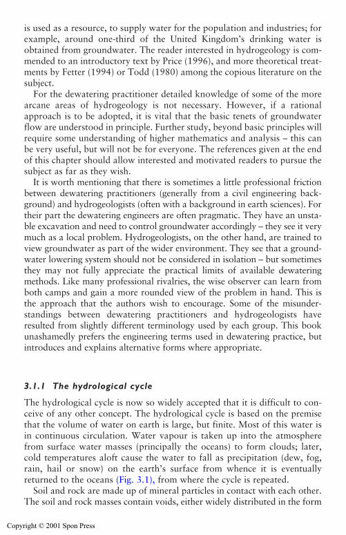
is used as a resource, to supply water for the population and industries; forexample, around one-third of the United Kingdom’s drinking water isobtained from groundwater. The reader interested in hydrogeology is com-mended to an introductory text by Price (1996), and more theoretical treat-ments by Fetter (1994) or Todd (1980) among the copious literature on thesubject.
For the dewatering practitioner detailed knowledge of some of the morearcane areas of hydrogeology is not necessary. However, if a rationalapproach is to be adopted, it is vital that the basic tenets of groundwaterflow are understood in principle. Further study, beyond basic principles willrequire some understanding of higher mathematics and analysis – this canbe very useful, but will not be for everyone. The references given at the endof this chapter should allow interested and motivated readers to pursue thesubject as far as they wish.
It is worth mentioning that there is sometimes a little professional frictionbetween dewatering practitioners (generally from a civil engineering back-ground) and hydrogeologists (often with a background in earth sciences). Fortheir part the dewatering engineers are often pragmatic. They have an unsta-ble excavation and need to control groundwater accordingly – they see it verymuch as a local problem. Hydrogeologists, on the other hand, are trained toview groundwater as part of the wider environment. They see that a ground-water lowering system should not be considered in isolation – but sometimesthey may not fully appreciate the practical limits of available dewateringmethods. Like many professional rivalries, the wise observer can learn fromboth camps and gain a more rounded view of the problem in hand. This isthe approach that the authors wish to encourage. Some of the misunder-standings between dewatering practitioners and hydrogeologists haveresulted from slightly different terminology used by each group. This bookunashamedly prefers the engineering terms used in dewatering practice, butintroduces and explains alternative forms where appropriate.
3.1.1 The hydrological cycle
The hydrological cycle is now so widely accepted that it is difficult to con-ceive of any other concept. The hydrological cycle is based on the premisethat the volume of water on earth is large, but finite. Most of this water isin continuous circulation. Water vapour is taken up into the atmospherefrom surface water masses (principally the oceans) to form clouds; later,cold temperatures aloft cause the water to fall as precipitation (dew, fog,rain, hail or snow) on the earth’s surface from whence it is eventuallyreturned to the oceans (Fig. 3.1), from where the cycle is repeated.
Soil and rock are made up of mineral particles in contact with each other.The soil and rock masses contain voids, either widely distributed in the form
Groundwater and permeability 25
Copyright © 2001 Spon Press
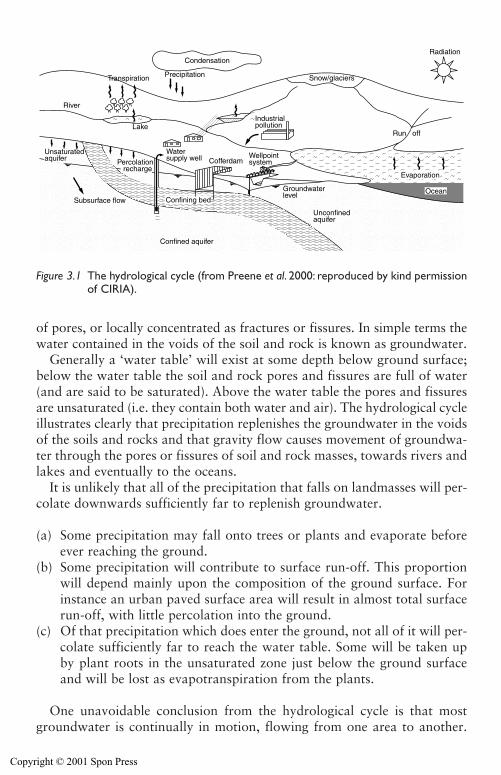
of pores, or locally concentrated as fractures or fissures. In simple terms thewater contained in the voids of the soil and rock is known as groundwater.
Generally a ‘water table’ will exist at some depth below ground surface;below the water table the soil and rock pores and fissures are full of water(and are said to be saturated). Above the water table the pores and fissuresare unsaturated (i.e. they contain both water and air). The hydrological cycleillustrates clearly that precipitation replenishes the groundwater in the voidsof the soils and rocks and that gravity flow causes movement of groundwa-ter through the pores or fissures of soil and rock masses, towards rivers andlakes and eventually to the oceans.
It is unlikely that all of the precipitation that falls on landmasses will per-colate downwards sufficiently far to replenish groundwater.
(a) Some precipitation may fall onto trees or plants and evaporate beforeever reaching the ground.
(b) Some precipitation will contribute to surface run-off. This proportionwill depend mainly upon the composition of the ground surface. Forinstance an urban paved surface area will result in almost total surfacerun-off, with little percolation into the ground.
(c) Of that precipitation which does enter the ground, not all of it will per-colate sufficiently far to reach the water table. Some will be taken upby plant roots in the unsaturated zone just below the ground surfaceand will be lost as evapotranspiration from the plants.
One unavoidable conclusion from the hydrological cycle is that mostgroundwater is continually in motion, flowing from one area to another.
26 Groundwater and permeability
Confined aquifer
Water supply well
Lake
River
CofferdamWellpointsystem
Industrialpollution
Run off
Radiation
Snow/glaciers
Condensation
PrecipitationTranspiration
Subsurface flow
Unsaturatedaquifer Percolation
recharge
Groundwaterlevel
Unconfinedaquifer
Evaporation
OceanConfining bed
Figure 3.1 The hydrological cycle (from Preene et al. 2000: reproduced by kind permissionof CIRIA).
Copyright © 2001 Spon Press
Under natural conditions (i.e. without interference by man in the form ofpumping from wells), groundwater flow is generally relatively slow, with typ-ical velocities being in the range of a few metres per day in high permeabilitysoils and rocks down to a few millimetres per year in very low permeabilitydeposits. Larger groundwater velocities generally only exist in the vicinity ofpumped wells or sumps.
The stability of the hydrological cycle can be illustrated by consideringgroundwater temperature. Price (1996) states that in temperate climates thetemperature of groundwater below a few metres depth tends not to vary withthe seasons and remains remarkably constant at around the mean annual airtemperature. In the United Kingdom this is around 10–12�C. This is obvi-ous on site if you have to take a water sample from the pumped discharge.On a frosty winter morning the pumped groundwater will seem pleasantlywarm on your hands, but take a similar sample on a warm summer day andthe discharge water will seem icy cold. At greater depths in bedrock the tem-perature stays constant with time, but increases with depth. This is knownas a geothermal temperature gradient, mainly the result of heat generated bythe decay of radioactive materials in the rock.
3.1.2 Geology and soil mechanics
The successful design and application of groundwater lowering methodsdepends not just on the nature of the groundwater environment (such aswhere the site is within the hydrological cycle), but is also critically influencedby the geology or structure of the soils and rocks through which water flows.This is especially true when trying to assess the effect of groundwater condi-tions on the stability of engineering excavations (as will be discussed inChapter 4). The eminent soil mechanics engineer, Karl Terzaghi wrote in 1945‘It is more than mere coincidence that most failures have been due to the unan-ticipated action of water, because the behaviour of water depends, more thananything else, on minor geological details that are unknown’ (Peck 1969).This is still true today, but perhaps the last sentence should to be changed to‘minor geological details that are often overlooked during site investigation’ –good practice for site investigation will be discussed in Chapter 6.
The reader wishing to apply groundwater lowering methods will need tobe familiar with some of the aspects of hydrogeology, soil mechanics (includ-ing its applied form, geotechnical engineering) and engineering geology;texts by Powrie (1997) and Blyth and De Frietas (1984) respectively, arerecommended as introductions to the latter two subjects. However, as hasbeen stated before, study of theory is only part of the learning process.Many soils and rocks may not match the idealized homogeneous isotropicconditions assumed for some analytical methods. Judgement will be neededto determine how credible are the results of analyses based on such models.
Groundwater and permeability 27
Copyright © 2001 Spon Press
An important geological distinction is made between uncemented ‘drift’deposits (termed ‘soil’ by engineers) and cemented ‘rock’.
Drift deposits are present near the ground surface and consist of sands,gravels, clays and silts, which may have resulted from weathering or fromglacial or alluvial processes. Groundwater flow through drift deposits is pre-dominantly intergranular – that is through the pores in the mass of the soil.
Rock may be exposed at the ground surface or may be covered by layersof drift and can consist of any of the many rock types that exist, such assandstone, mudstone, limestone, basalt, gneiss, and so on. Groundwaterflow through rock is often not through pores (which may be too small toallow significant passage of water) but along fissures, fractures and jointswithin the rock mass. This means that groundwater flow through rock maybe concentrated locally where the deposition and subsequent solution or tec-tonic action has created fissure networks.
Because of their uncemented nature, drift deposits can cause severe stabilityproblems for excavations below the groundwater level. Most groundwaterlowering operations are carried out in drift, and this book will concentrateon those situations. Groundwater lowering is occasionally carried out inrock (see Section 4.5).
3.2 Permeability and groundwater flow
Permeability is a critical parameter for the assessment of how water flowsthrough soil and rocks.
The precise meaning of the term ‘permeability’ is sometimes a cause ofconfusion between engineers and hydrogeologists. Civil and geotechnicalengineers are interested almost exclusively in the flow of water through soilsand rocks and use the term ‘coefficient of permeability’, given the symbol k.For convenience k is generally referred to simply as ‘permeability’, andthroughout this book this terminology will be used. Therefore, for ground-water lowering purposes permeability, k, will be defined as ‘a measure of theease or otherwise with which groundwater can flow through the pores of agiven soil mass’.
A slight complication is that the permeability of a porous mass is depen-dent not only on the nature of the porous media, but also on the propertiesof the permeating fluid. In other words, the permeability of a soil to wateris different from the permeability of the soil to another fluid, such as air oroil. Hydrogeology references highlight this by calling the engineer’s perme-ability ‘hydraulic conductivity’ to show that it is specific to water. Often, ifthe term ‘permeability’ appears in hydrogeology references it actuallymeans the permeability of the porous media independent of the permeatingfluid, sometimes also known as intrinsic permeability (see Price 1996: 52).
28 Groundwater and permeability
Copyright © 2001 Spon Press
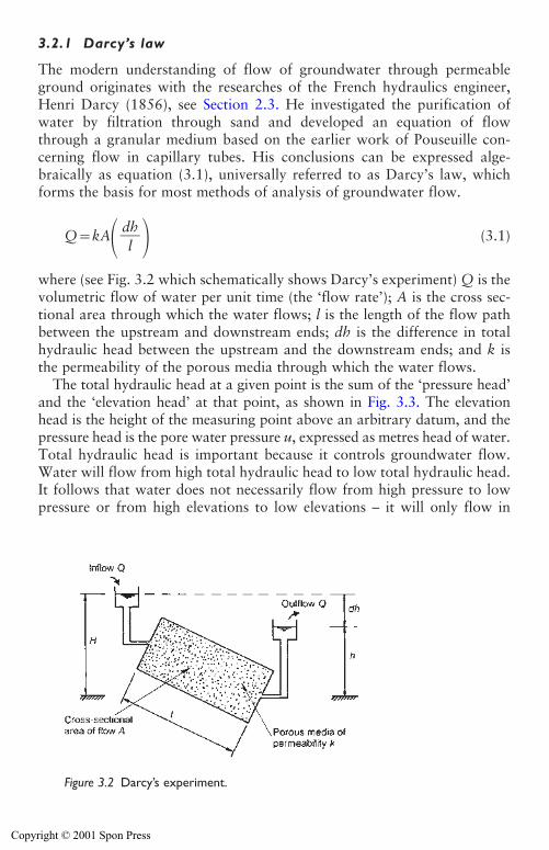
3.2.1 Darcy’s law
The modern understanding of flow of groundwater through permeableground originates with the researches of the French hydraulics engineer,Henri Darcy (1856), see Section 2.3. He investigated the purification ofwater by filtration through sand and developed an equation of flowthrough a granular medium based on the earlier work of Pouseuille con-cerning flow in capillary tubes. His conclusions can be expressed alge-braically as equation (3.1), universally referred to as Darcy’s law, whichforms the basis for most methods of analysis of groundwater flow.
Q�kA� � (3.1)
where (see Fig. 3.2 which schematically shows Darcy’s experiment) Q is thevolumetric flow of water per unit time (the ‘flow rate’); A is the cross sec-tional area through which the water flows; l is the length of the flow pathbetween the upstream and downstream ends; dh is the difference in totalhydraulic head between the upstream and the downstream ends; and k isthe permeability of the porous media through which the water flows.
The total hydraulic head at a given point is the sum of the ‘pressure head’and the ‘elevation head’ at that point, as shown in Fig. 3.3. The elevationhead is the height of the measuring point above an arbitrary datum, and thepressure head is the pore water pressure u, expressed as metres head of water.Total hydraulic head is important because it controls groundwater flow.Water will flow from high total hydraulic head to low total hydraulic head.It follows that water does not necessarily flow from high pressure to lowpressure or from high elevations to low elevations – it will only flow in
dh�l
Groundwater and permeability 29
Figure 3.2 Darcy’s experiment.
Copyright © 2001 Spon Press
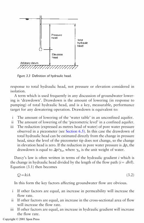
response to total hydraulic head, not pressure or elevation considered inisolation.
A term which is used frequently in any discussion of groundwater lower-ing is ‘drawdown’. Drawdown is the amount of lowering (in response topumping) of total hydraulic head, and is a key, measurable, performancetarget for any dewatering operation. Drawdown is equivalent to:
i The amount of lowering of the ‘water table’ in an unconfined aquifer.ii The amount of lowering of the ‘piezometric level’ in a confined aquifer.iii The reduction (expressed as metres head of water) of pore water pressure
observed in a piezometer (see Section 6.5). In this case the drawdown oftotal hydraulic head can be estimated directly from the change in pressurehead, since the level of the piezometer tip does not change, so the changein elevation head is zero. If the reduction in pore water pressure is �p, thedrawdown is equal to �p/�w, where �w is the unit weight of water.
Darcy’s law is often written in terms of the hydraulic gradient i which isthe change in hydraulic head divided by the length of the flow path (i� dh/l).Equation (3.1) then becomes
Q�kiA (3.2)
In this form the key factors affecting groundwater flow are obvious.
i If other factors are equal, an increase in permeability will increase theflow rate.
ii If other factors are equal, an increase in the cross-sectional area of flowwill increase the flow rate.
iii If other factors are equal, an increase in hydraulic gradient will increasethe flow rate.
30 Groundwater and permeability
Figure 3.3 Definition of hydraulic head.
Copyright © 2001 Spon Press
These points are vital in beginning to understand how groundwater canbe manipulated by groundwater lowering systems.
In the presentation of his equation Darcy left no doubt of its origin beingempirical. His important contributions to scientific knowledge were based oncareful observation in the field and in the laboratory, and on the conclusionsthat he drew from these. Permeability is in fact only a theoretical concept, butone vital to realistic assessments of groundwater pumping requirements andso an understanding of it is most desirable. In theory, permeability is thenotional (or ‘Darcy’) velocity of flow of pore water through unit cross sec-tional area. In fact, the majority of the cross sectional area of a soil mass actu-ally consists of soil particles, through which pore water cannot flow. Theactual pore water flow velocity is greater than the ‘Darcy velocity’, and isrelated to it by the soil porosity n (porosity is the ratio of voids, or pore space,to total volume).
The main condition for Darcy’s law to be valid is that groundwater flowshould be ‘laminar’, a technical term meaning the flow is smooth. Flow willbe laminar at low velocities but will become turbulent above some velocity,dependent on the porous media and the permeating fluid. Darcy’s law is notvalid for turbulent flow. In most groundwater lowering applications flowcan safely be assumed to be laminar. The only locations where turbulentflow is likely to be generated is close to high flow rate wells pumping fromcoarse gravel aquifers. The implications of this flow to wells are discussed inSection 3.4.
For idealized, homogeneous, soils permeability depends primarily on theproperties of the soil including the size and arrangement of the soil particles,and the resulting pore spaces formed when the particles are in contact. Forexample, consider an assemblage of billiard balls of similar size (Fig. 3.4(a)).This is analogous to the structure of a high permeability soil (such as a coarsegravel) where the voids (or pore water passages) are large, and the pore watercan flow freely. Next, consider an assemblage of billiard balls with marblesplaced in the spaces between the billiard balls (Fig. 3.4(b)); this is analogousto a soil of moderate permeability because the effective size of the pore waterpassages are reduced. Finally, consider a structure with lead shot particlesplaced in the voids between the billiard balls and the marbles – the passagesfor the flow of pore water are further reduced; this simulates a low perme-ability soil (Fig. 3.4(c)). It is logical to infer from this analogy that the ‘finer’portion of a sample dominates permeability. The coarser particles are just theskeleton of the soil and may have little bearing on the permeability of a sam-ple or of a soil mass in situ.
The proportion of different particle sizes in a sample of soil (as might berecovered from a borehole) can be determined by carrying out a particle sizedistribution (PSD) test, see Head (1982). The results of the test are normallypresented as PSD curves like in Fig. 3.5, which shows typical PSD curves fora range of soils. PSD curves are sometimes known as grading curves or sieveanalyses, after the sieving methods used to categorize the coarser particle
Groundwater and permeability 31
Copyright © 2001 Spon Press
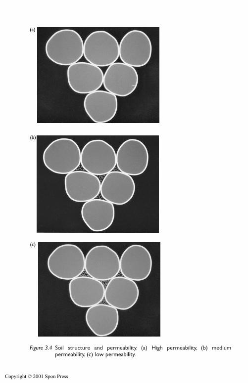
32 Groundwater and permeability
(a)
(b)
(c)
Figure 3.4 Soil structure and permeability. (a) High permeability, (b) medium permeability, (c) low permeability.
Copyright © 2001 Spon Press
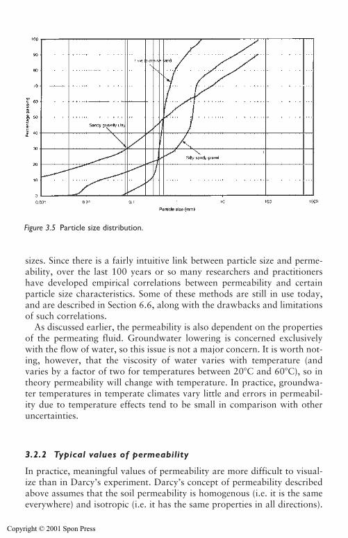
Groundwater and permeability 33
Figure 3.5 Particle size distribution.
sizes. Since there is a fairly intuitive link between particle size and perme-ability, over the last 100 years or so many researchers and practitionershave developed empirical correlations between permeability and certainparticle size characteristics. Some of these methods are still in use today,and are described in Section 6.6, along with the drawbacks and limitationsof such correlations.
As discussed earlier, the permeability is also dependent on the propertiesof the permeating fluid. Groundwater lowering is concerned exclusivelywith the flow of water, so this issue is not a major concern. It is worth not-ing, however, that the viscosity of water varies with temperature (andvaries by a factor of two for temperatures between 20�C and 60�C), so intheory permeability will change with temperature. In practice, groundwa-ter temperatures in temperate climates vary little and errors in permeabil-ity due to temperature effects tend to be small in comparison with otheruncertainties.
3.2.2 Typical values of permeability
In practice, meaningful values of permeability are more difficult to visual-ize than in Darcy’s experiment. Darcy’s concept of permeability describedabove assumes that the soil permeability is homogenous (i.e. it is the sameeverywhere) and isotropic (i.e. it has the same properties in all directions).
Copyright © 2001 Spon Press
Even a basic study of geology will show that many soils and rocks exhibitproperties far removed from these assumptions. Many strata are more orless heterogeneous in character, so that even in an apparently consistentstratum the permeability may vary greatly between one part and another.This may result from inhomogeneities such as fissures, erosion features orsand and clay lenses. Also, the nature of deposition of soils can introduceanisotropy, where the soil permeability is not the same in all directions.Soils laid down in water may have a layered or laminated structure or‘fabric’ – as a result the permeability in a horizontal direction is usually sig-nificantly greater than that in the vertical direction. The influence of soilfabric on permeability is discussed in detail by Rowe (1972).
Despite these complications, any rational attempt at groundwater lower-ing will require permeability to be investigated and assessed. Some of thedesign methods discussed in Chapter 7 assume, for simplicity, isotropic andhomogeneous permeability conditions – on a theoretical basis this is clearlyunrealistic. Yet these methods are established and field-proven methodsand, if applied appropriately, can give useful results. This highlights theprinciple that in ground engineering it is often necessary to tolerate somesimplification to make a problem more amenable to analysis. The key is toapply critical judgement to the parameters used in analysis, and not toblindly accept the results of the analysis until they are corroborated or validated by other data or experience.
As will be described in the section on site investigation (Chapter 6), teststo estimate realistic values of permeability can be problematic. As an engi-neering parameter permeability is unusual because of the tremendous rangeof possible values for natural soils and rocks; there can be a factor of per-haps 1010 between the most permeable gravels and almost impermeableintact clays. It is not unknown for the results of permeability tests to be inerror by a factor of 10, 100, 1,000 or even more. This often stems purelyfrom the limitations of the test and interpretation methods themselves, andcan occur even if the tests are carried out in an exemplary fashion by expe-rienced personnel.
Table 3.1 provides some general guidance on the permeability of typicalsoil types. This table is intended to be used for comparison purposes withpermeability test results, to look for inconsistencies between soil descrip-tions (from borehole logs) and reported test results. Nevertheless, this tableshould be used with caution, especially in mixed soil types where the soilfabric (which is sometimes not adequately indicated in the soil description)may play a dominant role.
The permeability values used throughout this book will be reported inm/s (metres per second), which is the convention in engineering and soilmechanics. This is in contrast to hydrogeological references, which gener-ally report permeability (or hydraulic conductivity) in m/d (metres per day).Conversion factors between various units are given at the end of this book.
34 Groundwater and permeability
Copyright © 2001 Spon Press
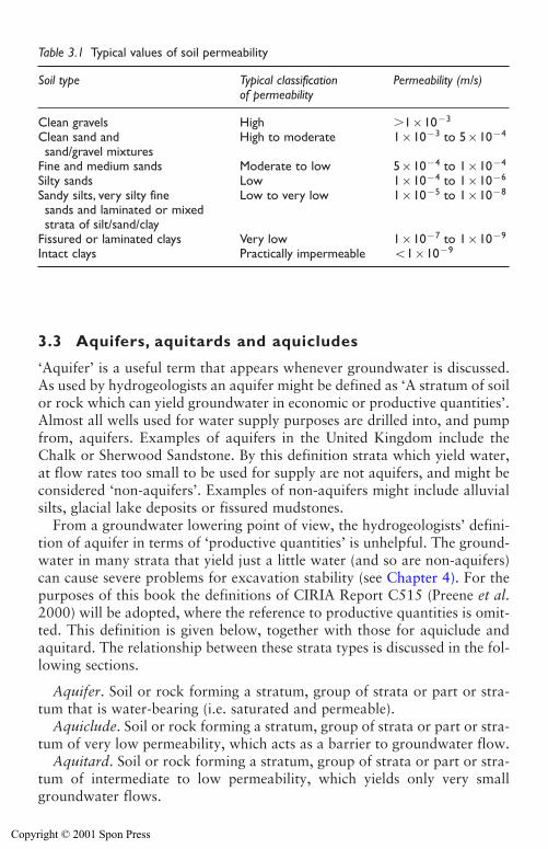
3.3 Aquifers, aquitards and aquicludes
‘Aquifer’ is a useful term that appears whenever groundwater is discussed.As used by hydrogeologists an aquifer might be defined as ‘A stratum of soilor rock which can yield groundwater in economic or productive quantities’.Almost all wells used for water supply purposes are drilled into, and pumpfrom, aquifers. Examples of aquifers in the United Kingdom include theChalk or Sherwood Sandstone. By this definition strata which yield water,at flow rates too small to be used for supply are not aquifers, and might beconsidered ‘non-aquifers’. Examples of non-aquifers might include alluvialsilts, glacial lake deposits or fissured mudstones.
From a groundwater lowering point of view, the hydrogeologists’ defini-tion of aquifer in terms of ‘productive quantities’ is unhelpful. The ground-water in many strata that yield just a little water (and so are non-aquifers)can cause severe problems for excavation stability (see Chapter 4). For thepurposes of this book the definitions of CIRIA Report C515 (Preene et al.2000) will be adopted, where the reference to productive quantities is omit-ted. This definition is given below, together with those for aquiclude andaquitard. The relationship between these strata types is discussed in the fol-lowing sections.
Aquifer. Soil or rock forming a stratum, group of strata or part or stra-tum that is water-bearing (i.e. saturated and permeable).
Aquiclude. Soil or rock forming a stratum, group of strata or part or stra-tum of very low permeability, which acts as a barrier to groundwater flow.
Aquitard. Soil or rock forming a stratum, group of strata or part or stra-tum of intermediate to low permeability, which yields only very smallgroundwater flows.
Groundwater and permeability 35
Table 3.1 Typical values of soil permeability
Soil type Typical classification Permeability (m/s)of permeability
Clean gravels High �1�10�3
Clean sand and High to moderate 1�10�3 to 5�10�4
sand/gravel mixturesFine and medium sands Moderate to low 5�10�4 to 1�10�4
Silty sands Low 1�10�4 to 1�10�6
Sandy silts, very silty fine Low to very low 1�10�5 to 1�10�8
sands and laminated or mixedstrata of silt/sand/clay
Fissured or laminated clays Very low 1�10�7 to 1�10�9
Intact clays Practically impermeable �1�10�9
Copyright © 2001 Spon Press
3.3.1 Unconfined aquifers
An unconfined aquifer is probably the simplest for most people to visualizeand understand. The soil or rock of the aquifer contains voids, pores or fis-sures. These voids are saturated (i.e. full of groundwater) up to a certainlevel known colloquially as the ‘water table’ (Fig. 3.6(a)), which is open tothe atmosphere. An observation well (see Section 6.5) installed into the sat-urated part of the aquifer will show a water level equivalent to the watertable. The analogy that can easily be drawn is that of digging a hole in thesand on a beach. Water does not enter the hole until the water table isreached, at which point water will enter the hole and stay at that levelunless water was pumped out.
The water table can be defined as level in the aquifer at which the porewater pressure is zero (i.e. equal to atmospheric). Below the water table thesoil voids are at positive pore water pressures and are saturated. Above thewater table the pressure in the voids will be negative (i.e. less than atmos-pheric), and, depending on the nature of the soil or rock, may be unsaturatedand contain both water and air. In most unconfined aquifers, the greatmajority of groundwater flow occurs below the water table. When the watertable is lowered by pumping the saturated aquifer thickness will reduce.
If groundwater is pumped (or abstracted) from an unconfined aquifer, itis intuitively apparent that the water table will be lowered locally aroundthe well and a ‘drawdown curve’ will be created (Fig. 3.6(b)). In simpleterms the drawdown curve is the new, curved shape of the water table. Porewater will drain out of the soil above the new lowered water table, and willbe replaced by air – this soil will become unsaturated. The amount of watercontained in a soil will depend on the porosity of the soil, but it is impor-tant to note that not all of the water in an unconfined aquifer will drain outwhen the water table is lowered. Some water will be retained in the smallersoil pores by capillary forces. The proportion of water which can drainfrom an unconfined aquifer is described by the specific yield Sy, which isgenerally less than the soil porosity.
The zone above the water table (sometimes known as the vadose zone) isworthy of further consideration. Generally, the soil in this zone above stand-ing water table will be moist, due to the presence of capillary water in theinterconnected pores between soil particles. This capillary water differs fromgroundwater below the water table in that it is hardly noticeable in a boreholeor excavation since it is at below atmospheric pressure and cannot flow intothe excavation. It is held in place by capillary tension, at negative pore waterpressures (Fig. 3.7).
The soil is saturated with capillary water for a height above the water table(this is the capillary saturated zone). The height of the capillary saturated zoneabove the water table is dependent on the effective size of the pores – thesmaller the pores the greater the height. At the upper surface of the capillary
36 Groundwater and permeability
Copyright © 2001 Spon Press
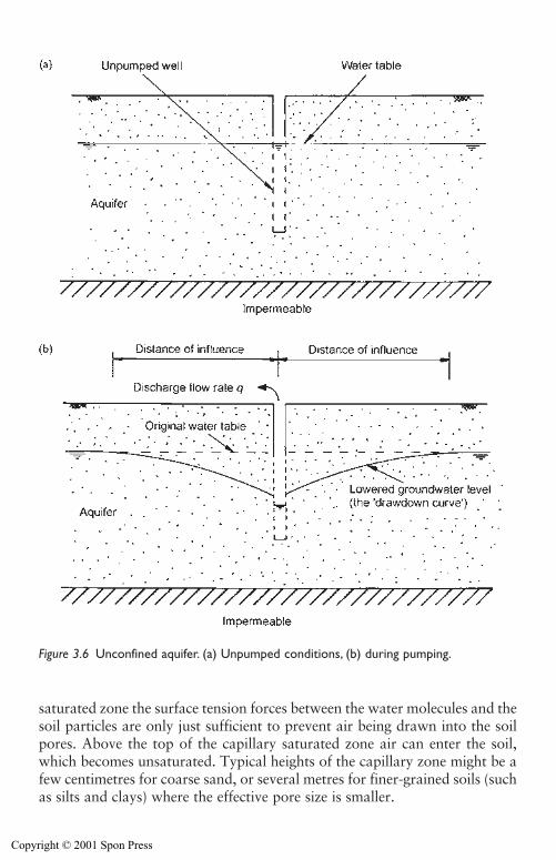
saturated zone the surface tension forces between the water molecules and thesoil particles are only just sufficient to prevent air being drawn into the soilpores. Above the top of the capillary saturated zone air can enter the soil,which becomes unsaturated. Typical heights of the capillary zone might be afew centimetres for coarse sand, or several metres for finer-grained soils (suchas silts and clays) where the effective pore size is smaller.
Groundwater and permeability 37
Figure 3.6 Unconfined aquifer. (a) Unpumped conditions, (b) during pumping.
Copyright © 2001 Spon Press
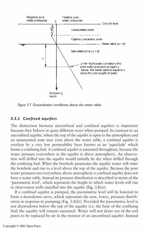
3.3.2 Confined aquifers
The distinction between unconfined and confined aquifers is importantbecause they behave in quite different ways when pumped. In contrast to anunconfined aquifer, where the top of the aquifer is open to the atmosphere andan unsaturated zone may exist above the water table, a confined aquifer isoverlain by a very low permeability layer known as an ‘aquiclude’ whichforms a confining bed. A confined aquifer is saturated throughout, because thewater pressure everywhere in the aquifer is above atmospheric. An observa-tion well drilled into the aquifer would initially be dry when drilled throughthe confining bed. When the borehole penetrates the aquifer water will enterthe borehole and rise to a level above the top of the aquifer. Because the porewater pressures are everywhere above atmospheric a confined aquifer does nothave a water table. Instead its pressure distribution is described in terms of the‘piezometric level’, which represents the height to which water levels will risein observation wells installed into the aquifer (Fig. 3.8(a)).
If a confined aquifer is pumped, the piezometric level will be lowered toform a drawdown curve, which represents the new, lower, pressure distrib-ution in response to pumping (Fig. 3.8(b)). Provided the piezometric level isnot drawndown below the top of the aquifer (i.e. the base of the confiningbed) the aquifer will remain saturated. Water will not drain out of the soilpores to be replaced by air in the manner of an unconfined aquifer. Instead
38 Groundwater and permeability
Figure 3.7 Groundwater conditions above the water table.
Copyright © 2001 Spon Press
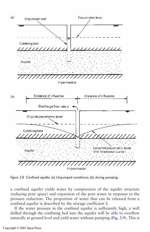
a confined aquifer yields water by compression of the aquifer structure(reducing pore space) and expansion of the pore water in response to thepressure reduction. The proportion of water that can be released from aconfined aquifer is described by the storage coefficient S.
If the water pressure in the confined aquifer is sufficiently high, a welldrilled through the confining bed into the aquifer will be able to overflownaturally at ground level and yield water without pumping (Fig. 3.9). This is
Groundwater and permeability 39
Figure 3.8 Confined aquifer. (a) Unpumped conditions, (b) during pumping.
Copyright © 2001 Spon Press
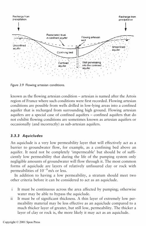
known as the flowing artesian condition – artesian is named after the Artoisregion of France where such conditions were first recorded. Flowing artesianconditions are possible from wells drilled in low-lying areas into a confinedaquifer that is recharged from surrounding high ground. Flowing artesianaquifers are a special case of confined aquifers – confined aquifers that donot exhibit flowing conditions are sometimes known as artesian aquifers oroccasionally (and incorrectly) as sub-artesian aquifers.
3.3.3 Aquicludes
An aquiclude is a very low permeability layer that will effectively act as abarrier to groundwater flow, for example, as a confining bed above anaquifer. It need not be completely ‘impermeable’ but should be of suffi-ciently low permeability that during the life of the pumping system onlynegligible amounts of groundwater will flow through it. The most commonforms of aquiclude are layers of relatively unfissured clay or rock with permeabilities of 10�9 m/s or less.
In addition to having a low permeability, a stratum should meet twoother criteria before it can be considered to act as an aquiclude.
i It must be continuous across the area affected by pumping; otherwisewater may be able to bypass the aquiclude.
ii It must be of significant thickness. A thin layer of extremely low per-meability material may be less effective as an aquiclude compared to amuch thicker layer of greater, but still low, permeability. The thicker alayer of clay or rock is, the more likely it may act as an aquiclude.
40 Groundwater and permeability
Figure 3.9 Flowing artesian conditions.
Copyright © 2001 Spon Press
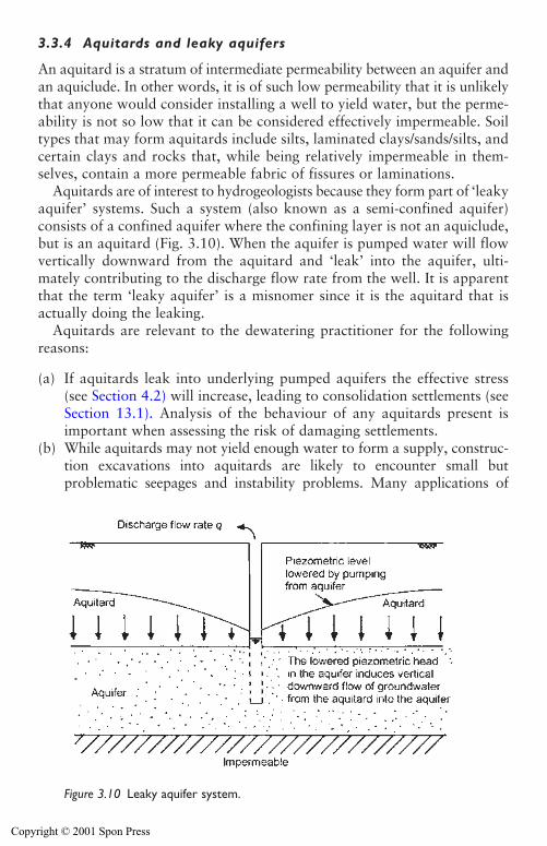
3.3.4 Aquitards and leaky aquifers
An aquitard is a stratum of intermediate permeability between an aquifer andan aquiclude. In other words, it is of such low permeability that it is unlikelythat anyone would consider installing a well to yield water, but the perme-ability is not so low that it can be considered effectively impermeable. Soiltypes that may form aquitards include silts, laminated clays/sands/silts, andcertain clays and rocks that, while being relatively impermeable in them-selves, contain a more permeable fabric of fissures or laminations.
Aquitards are of interest to hydrogeologists because they form part of ‘leakyaquifer’ systems. Such a system (also known as a semi-confined aquifer)consists of a confined aquifer where the confining layer is not an aquiclude,but is an aquitard (Fig. 3.10). When the aquifer is pumped water will flowvertically downward from the aquitard and ‘leak’ into the aquifer, ulti-mately contributing to the discharge flow rate from the well. It is apparentthat the term ‘leaky aquifer’ is a misnomer since it is the aquitard that isactually doing the leaking.
Aquitards are relevant to the dewatering practitioner for the followingreasons:
(a) If aquitards leak into underlying pumped aquifers the effective stress(see Section 4.2) will increase, leading to consolidation settlements (seeSection 13.1). Analysis of the behaviour of any aquitards present isimportant when assessing the risk of damaging settlements.
(b) While aquitards may not yield enough water to form a supply, construc-tion excavations into aquitards are likely to encounter small butproblematic seepages and instability problems. Many applications of
Groundwater and permeability 41
Figure 3.10 Leaky aquifer system.
Copyright © 2001 Spon Press
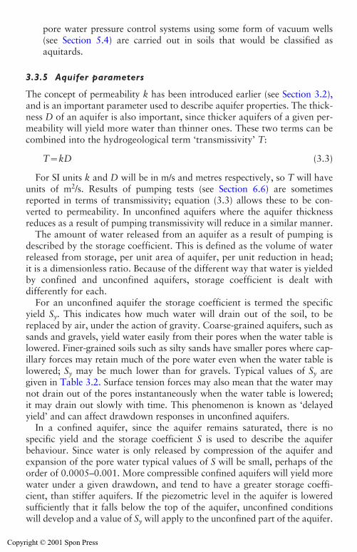
pore water pressure control systems using some form of vacuum wells(see Section 5.4) are carried out in soils that would be classified asaquitards.
3.3.5 Aquifer parameters
The concept of permeability k has been introduced earlier (see Section 3.2),and is an important parameter used to describe aquifer properties. The thick-ness D of an aquifer is also important, since thicker aquifers of a given per-meability will yield more water than thinner ones. These two terms can becombined into the hydrogeological term ‘transmissivity’ T:
T�kD (3.3)
For SI units k and D will be in m/s and metres respectively, so T will haveunits of m2/s. Results of pumping tests (see Section 6.6) are sometimesreported in terms of transmissivity; equation (3.3) allows these to be con-verted to permeability. In unconfined aquifers where the aquifer thicknessreduces as a result of pumping transmissivity will reduce in a similar manner.
The amount of water released from an aquifer as a result of pumping isdescribed by the storage coefficient. This is defined as the volume of waterreleased from storage, per unit area of aquifer, per unit reduction in head;it is a dimensionless ratio. Because of the different way that water is yieldedby confined and unconfined aquifers, storage coefficient is dealt withdifferently for each.
For an unconfined aquifer the storage coefficient is termed the specificyield Sy. This indicates how much water will drain out of the soil, to bereplaced by air, under the action of gravity. Coarse-grained aquifers, such assands and gravels, yield water easily from their pores when the water table islowered. Finer-grained soils such as silty sands have smaller pores where cap-illary forces may retain much of the pore water even when the water table islowered; Sy may be much lower than for gravels. Typical values of Sy aregiven in Table 3.2. Surface tension forces may also mean that the water maynot drain out of the pores instantaneously when the water table is lowered;it may drain out slowly with time. This phenomenon is known as ‘delayedyield’ and can affect drawdown responses in unconfined aquifers.
In a confined aquifer, since the aquifer remains saturated, there is nospecific yield and the storage coefficient S is used to describe the aquiferbehaviour. Since water is only released by compression of the aquifer andexpansion of the pore water typical values of S will be small, perhaps of theorder of 0.0005–0.001. More compressible confined aquifers will yield morewater under a given drawdown, and tend to have a greater storage coeffi-cient, than stiffer aquifers. If the piezometric level in the aquifer is loweredsufficiently that it falls below the top of the aquifer, unconfined conditionswill develop and a value of Sy will apply to the unconfined part of the aquifer.
42 Groundwater and permeability
Copyright © 2001 Spon Press
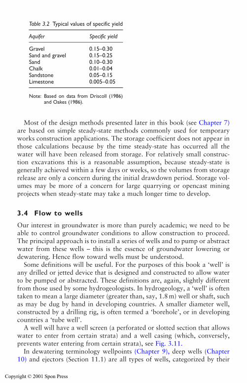
Most of the design methods presented later in this book (see Chapter 7)are based on simple steady-state methods commonly used for temporaryworks construction applications. The storage coefficient does not appear inthose calculations because by the time steady-state has occurred all thewater will have been released from storage. For relatively small construc-tion excavations this is a reasonable assumption, because steady-state isgenerally achieved within a few days or weeks, so the volumes from storagerelease are only a concern during the initial drawdown period. Storage vol-umes may be more of a concern for large quarrying or opencast miningprojects when steady-state may take a much longer time to develop.
3.4 Flow to wells
Our interest in groundwater is more than purely academic; we need to beable to control groundwater conditions to allow construction to proceed.The principal approach is to install a series of wells and to pump or abstractwater from these wells – this is the essence of groundwater lowering ordewatering. Hence flow toward wells must be understood.
Some definitions will be useful. For the purposes of this book a ‘well’ isany drilled or jetted device that is designed and constructed to allow waterto be pumped or abstracted. These definitions are, again, slightly differentfrom those used by some hydrogeologists. In hydrogeology, a ‘well’ is oftentaken to mean a large diameter (greater than, say, 1.8 m) well or shaft, suchas may be dug by hand in developing countries. A smaller diameter well,constructed by a drilling rig, is often termed a ‘borehole’, or in developingcountries a ‘tube well’.
A well will have a well screen (a perforated or slotted section that allowswater to enter from certain strata) and a well casing (which, conversely,prevents water entering from certain strata), see Fig. 3.11.
In dewatering terminology wellpoints (Chapter 9), deep wells (Chapter10) and ejectors (Section 11.1) are all types of wells, categorized by their
Groundwater and permeability 43
Table 3.2 Typical values of specific yield
Aquifer Specific yield
Gravel 0.15–0.30Sand and gravel 0.15–0.25Sand 0.10–0.30Chalk 0.01–0.04Sandstone 0.05–0.15Limestone 0.005–0.05
Note: Based on data from Driscoll (1986)and Oakes (1986).
Copyright © 2001 Spon Press
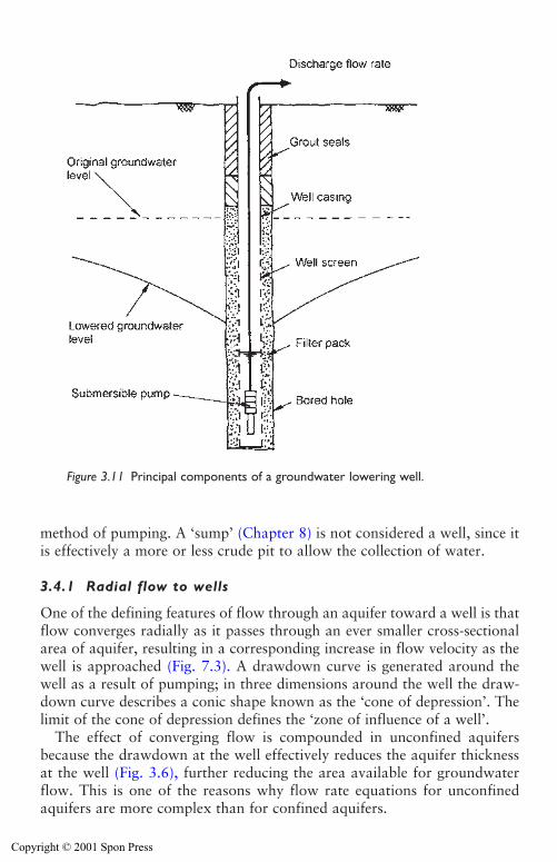
method of pumping. A ‘sump’ (Chapter 8) is not considered a well, since itis effectively a more or less crude pit to allow the collection of water.
3.4.1 Radial flow to wells
One of the defining features of flow through an aquifer toward a well is thatflow converges radially as it passes through an ever smaller cross-sectionalarea of aquifer, resulting in a corresponding increase in flow velocity as thewell is approached (Fig. 7.3). A drawdown curve is generated around thewell as a result of pumping; in three dimensions around the well the draw-down curve describes a conic shape known as the ‘cone of depression’. Thelimit of the cone of depression defines the ‘zone of influence of a well’.
The effect of converging flow is compounded in unconfined aquifersbecause the drawdown at the well effectively reduces the aquifer thicknessat the well (Fig. 3.6), further reducing the area available for groundwaterflow. This is one of the reasons why flow rate equations for unconfinedaquifers are more complex than for confined aquifers.
44 Groundwater and permeability
Figure 3.11 Principal components of a groundwater lowering well.
Copyright © 2001 Spon Press
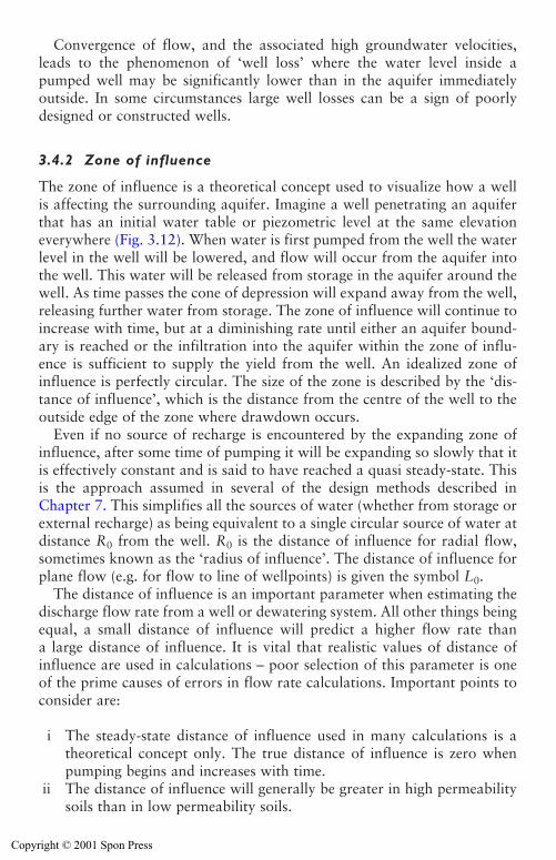
Convergence of flow, and the associated high groundwater velocities,leads to the phenomenon of ‘well loss’ where the water level inside apumped well may be significantly lower than in the aquifer immediatelyoutside. In some circumstances large well losses can be a sign of poorlydesigned or constructed wells.
3.4.2 Zone of influence
The zone of influence is a theoretical concept used to visualize how a wellis affecting the surrounding aquifer. Imagine a well penetrating an aquiferthat has an initial water table or piezometric level at the same elevationeverywhere (Fig. 3.12). When water is first pumped from the well the waterlevel in the well will be lowered, and flow will occur from the aquifer intothe well. This water will be released from storage in the aquifer around thewell. As time passes the cone of depression will expand away from the well,releasing further water from storage. The zone of influence will continue toincrease with time, but at a diminishing rate until either an aquifer bound-ary is reached or the infiltration into the aquifer within the zone of influ-ence is sufficient to supply the yield from the well. An idealized zone ofinfluence is perfectly circular. The size of the zone is described by the ‘dis-tance of influence’, which is the distance from the centre of the well to theoutside edge of the zone where drawdown occurs.
Even if no source of recharge is encountered by the expanding zone ofinfluence, after some time of pumping it will be expanding so slowly that itis effectively constant and is said to have reached a quasi steady-state. Thisis the approach assumed in several of the design methods described inChapter 7. This simplifies all the sources of water (whether from storage orexternal recharge) as being equivalent to a single circular source of water atdistance R0 from the well. R0 is the distance of influence for radial flow,sometimes known as the ‘radius of influence’. The distance of influence forplane flow (e.g. for flow to line of wellpoints) is given the symbol L0.
The distance of influence is an important parameter when estimating thedischarge flow rate from a well or dewatering system. All other things beingequal, a small distance of influence will predict a higher flow rate than a large distance of influence. It is vital that realistic values of distance ofinfluence are used in calculations – poor selection of this parameter is oneof the prime causes of errors in flow rate calculations. Important points toconsider are:
i The steady-state distance of influence used in many calculations is atheoretical concept only. The true distance of influence is zero whenpumping begins and increases with time.
ii The distance of influence will generally be greater in high permeabilitysoils than in low permeability soils.
Groundwater and permeability 45
Copyright © 2001 Spon Press
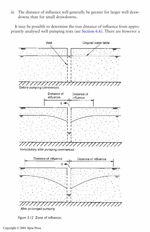
iii The distance of influence will generally be greater for larger well draw-downs than for small drawdowns.
It may be possible to determine the true distance of influence from appro-priately analysed well pumping tests (see Section 6.6). There are however a
46 Groundwater and permeability
Figure 3.12 Zone of influence.
Copyright © 2001 Spon Press
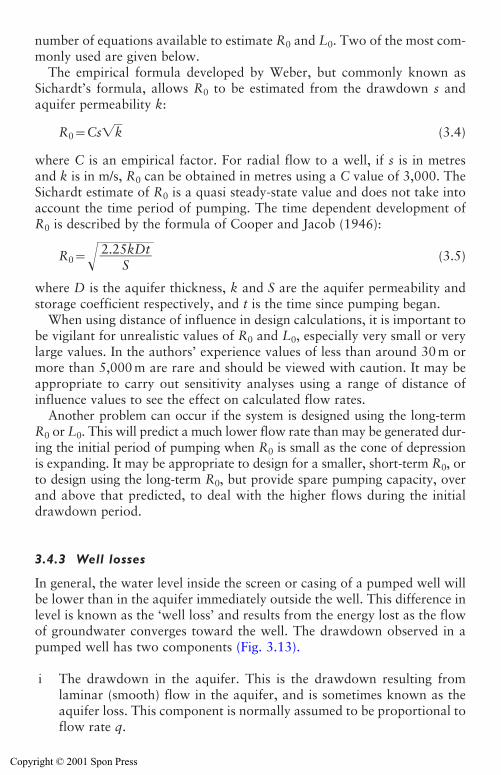
number of equations available to estimate R0 and L0. Two of the most com-monly used are given below.
The empirical formula developed by Weber, but commonly known asSichardt’s formula, allows R0 to be estimated from the drawdown s andaquifer permeability k:
R0�Cs�k� (3.4)
where C is an empirical factor. For radial flow to a well, if s is in metresand k is in m/s, R0 can be obtained in metres using a C value of 3,000. TheSichardt estimate of R0 is a quasi steady-state value and does not take intoaccount the time period of pumping. The time dependent development ofR0 is described by the formula of Cooper and Jacob (1946):
R0��� (3.5)
where D is the aquifer thickness, k and S are the aquifer permeability andstorage coefficient respectively, and t is the time since pumping began.
When using distance of influence in design calculations, it is important tobe vigilant for unrealistic values of R0 and L0, especially very small or verylarge values. In the authors’ experience values of less than around 30 m ormore than 5,000 m are rare and should be viewed with caution. It may beappropriate to carry out sensitivity analyses using a range of distance ofinfluence values to see the effect on calculated flow rates.
Another problem can occur if the system is designed using the long-termR0 or L0. This will predict a much lower flow rate than may be generated dur-ing the initial period of pumping when R0 is small as the cone of depressionis expanding. It may be appropriate to design for a smaller, short-term R0, orto design using the long-term R0, but provide spare pumping capacity, overand above that predicted, to deal with the higher flows during the initialdrawdown period.
3.4.3 Well losses
In general, the water level inside the screen or casing of a pumped well willbe lower than in the aquifer immediately outside the well. This difference inlevel is known as the ‘well loss’ and results from the energy lost as the flowof groundwater converges toward the well. The drawdown observed in apumped well has two components (Fig. 3.13).
i The drawdown in the aquifer. This is the drawdown resulting fromlaminar (smooth) flow in the aquifer, and is sometimes known as theaquifer loss. This component is normally assumed to be proportional toflow rate q.
2.25kDt�
S
Groundwater and permeability 47
Copyright © 2001 Spon Press
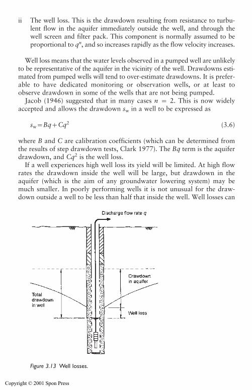
ii The well loss. This is the drawdown resulting from resistance to turbu-lent flow in the aquifer immediately outside the well, and through thewell screen and filter pack. This component is normally assumed to beproportional to qn, and so increases rapidly as the flow velocity increases.
Well loss means that the water levels observed in a pumped well are unlikelyto be representative of the aquifer in the vicinity of the well. Drawdowns esti-mated from pumped wells will tend to over-estimate drawdowns. It is prefer-able to have dedicated monitoring or observation wells, or at least toobserve drawdown in some of the wells that are not being pumped.
Jacob (1946) suggested that in many cases n � 2. This is now widelyaccepted and allows the drawdown sw in a well to be expressed as
sw�Bq�Cq2 (3.6)
where B and C are calibration coefficients (which can be determined fromthe results of step drawdown tests, Clark 1977). The Bq term is the aquiferdrawdown, and Cq2 is the well loss.
If a well experiences high well loss its yield will be limited. At high flowrates the drawdown inside the well will be large, but drawdown in theaquifer (which is the aim of any groundwater lowering system) may bemuch smaller. In poorly performing wells it is not unusual for the draw-down outside a well to be less than half that inside the well. Well losses can
48 Groundwater and permeability
Figure 3.13 Well losses.
Copyright © 2001 Spon Press
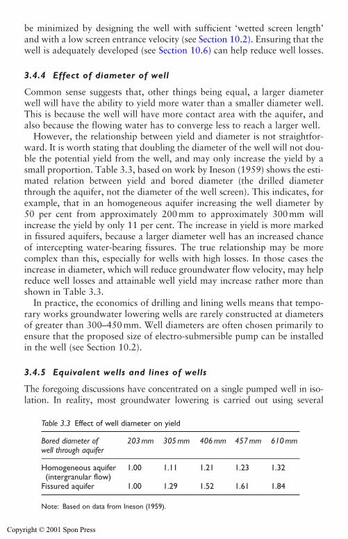
be minimized by designing the well with sufficient ‘wetted screen length’and with a low screen entrance velocity (see Section 10.2). Ensuring that thewell is adequately developed (see Section 10.6) can help reduce well losses.
3.4.4 Effect of diameter of well
Common sense suggests that, other things being equal, a larger diameterwell will have the ability to yield more water than a smaller diameter well.This is because the well will have more contact area with the aquifer, andalso because the flowing water has to converge less to reach a larger well.
However, the relationship between yield and diameter is not straightfor-ward. It is worth stating that doubling the diameter of the well will not dou-ble the potential yield from the well, and may only increase the yield by asmall proportion. Table 3.3, based on work by Ineson (1959) shows the esti-mated relation between yield and bored diameter (the drilled diameterthrough the aquifer, not the diameter of the well screen). This indicates, forexample, that in an homogeneous aquifer increasing the well diameter by 50 per cent from approximately 200 mm to approximately 300 mm willincrease the yield by only 11 per cent. The increase in yield is more markedin fissured aquifers, because a larger diameter well has an increased chanceof intercepting water-bearing fissures. The true relationship may be morecomplex than this, especially for wells with high losses. In those cases theincrease in diameter, which will reduce groundwater flow velocity, may helpreduce well losses and attainable well yield may increase rather more thanshown in Table 3.3.
In practice, the economics of drilling and lining wells means that tempo-rary works groundwater lowering wells are rarely constructed at diametersof greater than 300–450 mm. Well diameters are often chosen primarily toensure that the proposed size of electro-submersible pump can be installedin the well (see Section 10.2).
3.4.5 Equivalent wells and lines of wells
The foregoing discussions have concentrated on a single pumped well in iso-lation. In reality, most groundwater lowering is carried out using several
Groundwater and permeability 49
Table 3.3 Effect of well diameter on yield
Bored diameter of 203 mm 305 mm 406 mm 457 mm 610 mmwell through aquifer
Homogeneous aquifer 1.00 1.11 1.21 1.23 1.32(intergranular flow)
Fissured aquifer 1.00 1.29 1.52 1.61 1.84
Note: Based on data from Ineson (1959).
Copyright © 2001 Spon Press
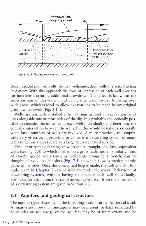
closely spaced pumped wells (be they wellpoints, deep wells or ejectors) actingin concert. With this approach the cone of depression of each well overlaps(or interferes), creating additional drawdown. This effect is known as thesuperposition of drawdown and can create groundwater lowering overwide areas, which is ideal to allow excavations to be made below originalgroundwater levels (Fig. 3.14).
Wells are normally installed either as rings around an excavation or aslines alongside one or more sides of the dig. It is probably theoretically pos-sible to consider the influence of each well individually and determine thecomplex interaction between the wells, but this would be tedious, especiallywhen large numbers of wells are involved. A more practical, and empiri-cally very effective, approach is to consider a dewatering system of manywells to act on a gross scale as a large equivalent well or slot.
Circular or rectangular rings of wells can be thought of as large equivalentwells (see Fig. 7.4) to which flow is, on a gross scale, radial. Similarly, linesof closely spaced wells (such as wellpoints alongside a trench) can bethought of as equivalent slots (Fig. 7.5) to which flow is predominantlyplane to the sides. Once this conceptual leap is made, the well and slot for-mula given in Chapter 7 can be used to model the overall behaviour ofdewatering systems, without having to consider each well individually.Formulae for estimating the size of an equivalent well from the dimensionsof a dewatering system are given in Section 7.3.
3.5 Aquifers and geological structure
The aquifer types described in the foregoing sections are a theoretical ideal.At many sites more than one aquifer may be present (perhaps separated byaquicludes or aquitards), or the aquifers may be of finite extent and be
50 Groundwater and permeability
Figure 3.14 Superposition of drawdown.
Copyright © 2001 Spon Press
influenced by their boundaries. The particular construction problemsresulting from the presence of aquifers at a site will be strongly influencedby the soil stratification and geological structure.
This section will illustrate the importance of an appreciation of geologi-cal structure to the execution of groundwater lowering works. Two casehistories will be presented: the London basin shows how large-scale geo-logical structure can allow multiple aquifer systems to exist; and a problemof base heave in a small trench excavation illustrates the importance ofsmaller-scale geological details.
3.5.1 Multiple aquifers beneath London
The city of London is founded on river gravels and alluvial deposits associ-ated with the River Thames, which are underlain by the very low permeabil-ity London Clay. These gravels form a shallow (generally less than 10 mthick) aquifer. Construction of utility pipelines, basements and other shallowstructures often requires groundwater lowering to be employed; wellpointingand deep wells have proved to be effective expedients in these conditions.However, the geology beneath London allows another, deeper, aquifer toexist below the city, largely isolated from the shallow aquifer.
Beneath the London Clay lie a series of sands and clays comprising theLambeth Group stratum (formerly known as the Woolwich and ReadingBeds) and the Thanet Sand stratum. These are underlain by the Chalk, afissured white or grey limestone, which rests on the very low permeabilityGault Clay. The overall geological structure is a syncline forming what isoften called the ‘London Basin’. The Chalk, Thanet Sand and parts of theLambeth Group together form an aquifer. The upper 60–100 m of the Chalkare probably the dominant part of the aquifer, where significant fissure net-works readily yield water to wells. The sands are of moderate permeabilityand generally do not yield as much water as the Chalk. The overlyingLondon Clay acts as an aquiclude or confining bed, effectively separatingthe deep aquifer from the shallow gravel aquifer.
The Chalk has a wide exposure on the North Downs to the South ofLondon and on the Chilterns to the North and occurs as a continuous layerbeneath the Thames Valley (Fig. 3.15). Rain falling on central London mayultimately reach the gravel aquifer, but the London Clay prevents it from per-colating down to the Chalk. The Chalk obtains its recharge from rain fallingon the North Downs and the Chilterns many miles from the city. Ultimatelythis water forms part of the reservoir of water in the chalk aquifer. If therecharge exceeds the discharge from the aquifer (either from wells, or naturaldischarge to springs and the River Thames) the water pressure in the aquiferwill rise slowly. If discharges exceed recharge the water pressure will fall.
Before London developed as a city, the natural rates of recharge and dis-charge meant that the deep aquifer had sufficient water pressure for it to act
Groundwater and permeability 51
Copyright © 2001 Spon Press
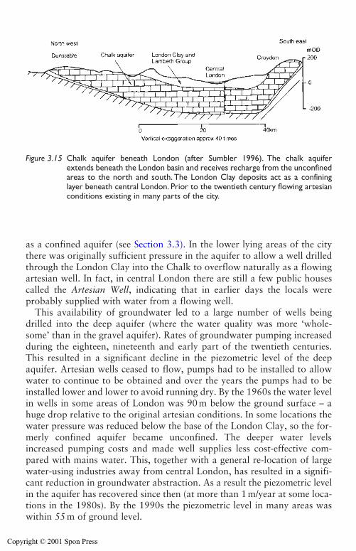
as a confined aquifer (see Section 3.3). In the lower lying areas of the citythere was originally sufficient pressure in the aquifer to allow a well drilledthrough the London Clay into the Chalk to overflow naturally as a flowingartesian well. In fact, in central London there are still a few public housescalled the Artesian Well, indicating that in earlier days the locals wereprobably supplied with water from a flowing well.
This availability of groundwater led to a large number of wells beingdrilled into the deep aquifer (where the water quality was more ‘whole-some’ than in the gravel aquifer). Rates of groundwater pumping increasedduring the eighteen, nineteenth and early part of the twentieth centuries.This resulted in a significant decline in the piezometric level of the deepaquifer. Artesian wells ceased to flow, pumps had to be installed to allowwater to continue to be obtained and over the years the pumps had to beinstalled lower and lower to avoid running dry. By the 1960s the water levelin wells in some areas of London was 90 m below the ground surface – ahuge drop relative to the original artesian conditions. In some locations thewater pressure was reduced below the base of the London Clay, so the for-merly confined aquifer became unconfined. The deeper water levelsincreased pumping costs and made well supplies less cost-effective com-pared with mains water. This, together with a general re-location of largewater-using industries away from central London, has resulted in a signifi-cant reduction in groundwater abstraction. As a result the piezometric levelin the aquifer has recovered since then (at more than 1 m/year at some loca-tions in the 1980s). By the 1990s the piezometric level in many areas waswithin 55 m of ground level.
52 Groundwater and permeability
Figure 3.15 Chalk aquifer beneath London (after Sumbler 1996). The chalk aquiferextends beneath the London basin and receives recharge from the unconfinedareas to the north and south. The London Clay deposits act as a confininglayer beneath central London. Prior to the twentieth century flowing artesianconditions existing in many parts of the city.
Copyright © 2001 Spon Press
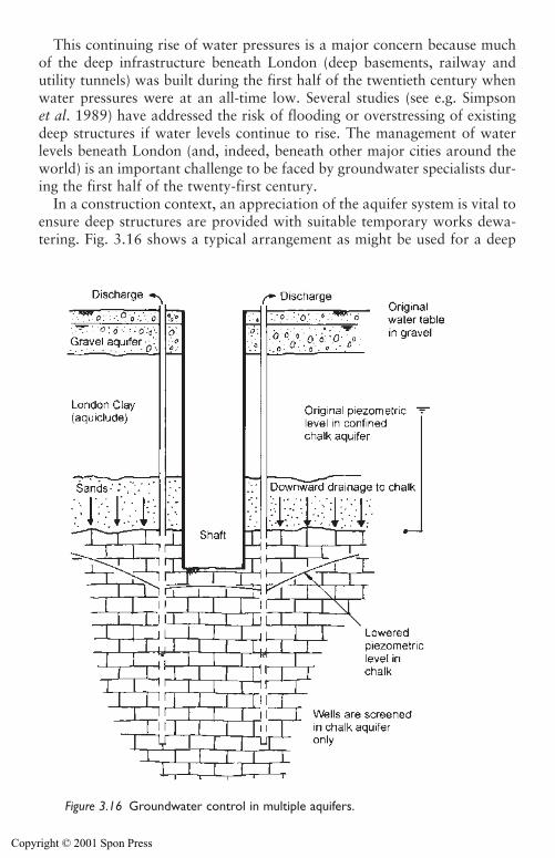
This continuing rise of water pressures is a major concern because muchof the deep infrastructure beneath London (deep basements, railway andutility tunnels) was built during the first half of the twentieth century whenwater pressures were at an all-time low. Several studies (see e.g. Simpsonet al. 1989) have addressed the risk of flooding or overstressing of existingdeep structures if water levels continue to rise. The management of waterlevels beneath London (and, indeed, beneath other major cities around theworld) is an important challenge to be faced by groundwater specialists dur-ing the first half of the twenty-first century.
In a construction context, an appreciation of the aquifer system is vital toensure deep structures are provided with suitable temporary works dewa-tering. Fig. 3.16 shows a typical arrangement as might be used for a deep
Groundwater and permeability 53
Figure 3.16 Groundwater control in multiple aquifers.
Copyright © 2001 Spon Press
shaft structure in central London. Important points to note are:
i The structure penetrates two aquifers, separated by an aquiclude.Groundwater will need to be dealt with separately in each aquifer.
ii In London it is common to deal with the upper aquifer by constructinga cut-off wall, penetrating to the London Clay, to exclude the shallowgroundwater. This is possible because the London Clay is at relativelyshallow depth. If clay was present only at greater depth any cut-offwould need to be deeper and it may be more economic to dewater theupper aquifer.
iii Wells are used to pump from the deep aquifer to lower the piezometriclevel to a suitable distance below the excavation. Because the wellsmust be relatively deep (perhaps up to 100 m), and therefore costly, itis important to design the wells and pumps to have the maximum yieldpossible, so that the number of wells can be minimized.
iv Although the lower aquifer consists of both the Chalk and the varioussand layers between the top of the Chalk and the base of the LondonClay, wells are often designed to be screened in the Chalk only, and aresealed from the sands using casing. This is because it can be difficult toconstruct effective well filters in the sands (which are fine-grained andvariable), yet wells screened in the Chalk are simpler to construct and canbe very efficient, especially if developed by acidization (see Section 10.6).This is the approach successfully adopted for some structures on theLondon Underground Jubilee Line Extension project described byLinney and Withers (1998). Excavations in the Thanet Sand weredewatered without pumping directly from the sand, but by pumpingpurely from the underlying Chalk. This might seem a rather contradic-tory approach, but is an example of the ‘underdrainage’ method. Thisis a way of using the geological structure to advantage by pumpingfrom a more permeable layer beneath the layer that needs to be dewa-tered; the upper poorly draining layer will drain down into the morepermeable layer (see Section 7.3).
3.5.2 Water pressures trapped beneath a trench excavation
Dr W. H. Ward (1957) reported some construction difficulties encounteredby a contractor excavating a pipeline trench near Southampton. The trenchexcavation was made through an unconfined aquifer of sandy gravel over-lying the clays of the Bracklesham Beds. The contractor dealt with the waterin the sandy gravel by using steel sheet-piling to form a cut-off on either sideof the trench and exclude the groundwater. The clay in the base of the exca-vation was not yielding water, so dewatering measures were not adopted.
The trench was approximately 6.1 m deep, to allow placement of a760 mm diameter pipe which was laid on a 150 mm thick concrete slab in the
54 Groundwater and permeability
Copyright © 2001 Spon Press
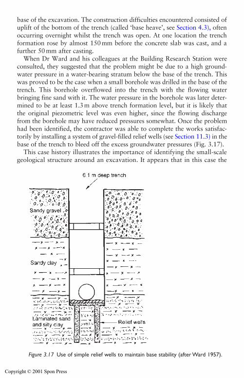
base of the excavation. The construction difficulties encountered consisted ofuplift of the bottom of the trench (called ‘base heave’, see Section 4.3), oftenoccurring overnight whilst the trench was open. At one location the trenchformation rose by almost 150 mm before the concrete slab was cast, and afurther 50 mm after casting.
When Dr Ward and his colleagues at the Building Research Station wereconsulted, they suggested that the problem might be due to a high ground-water pressure in a water-bearing stratum below the base of the trench. Thiswas proved to be the case when a small borehole was drilled in the base of thetrench. This borehole overflowed into the trench with the flowing waterbringing fine sand with it. The water pressure in the borehole was later deter-mined to be at least 1.3m above trench formation level, but it is likely thatthe original piezometric level was even higher, since the flowing dischargefrom the borehole may have reduced pressures somewhat. Once the problemhad been identified, the contractor was able to complete the works satisfac-torily by installing a system of gravel-filled relief wells (see Section 11.3) in thebase of the trench to bleed off the excess groundwater pressures (Fig. 3.17).
This case history illustrates the importance of identifying the small-scalegeological structure around an excavation. It appears that in this case the
Groundwater and permeability 55
Figure 3.17 Use of simple relief wells to maintain base stability (after Ward 1957).
Copyright © 2001 Spon Press
trench was excavated through the upper aquifer (the sandy gravel), whichwas dealt with using a sheet-pile cut-off, and the base of the trench was duginto low permeability clay, which is effectively an aquiclude. Problemsoccurred because there was a separate confined aquifer beneath theaquiclude, which contained sufficient water pressure to lift the trench for-mation. Once identified and understood, the problem was solved easilyusing relief wells. However, because the problem was not identified in thesite investigation before work started, time and money was wasted inchanging the temporary works, as well as making good the damagedpipelines. A classic failing of site investigations for groundwater loweringprojects is that the boreholes are not taken deep enough to identify any con-fined aquifers which may exist beneath the proposed excavations.Guidelines on suitable depths for boreholes are given in Section 6.4.
3.6 Aquifer boundaries
Civil and geotechnical engineers can readily appreciate the importance ofpermeability in the design of groundwater lowering systems – permeabilityis a traditional numerical engineering value. However, engineers are some-times less proficient in recognizing the less quantifiable effects that aquiferboundary conditions have on groundwater flow to excavations. The fol-lowing sections will outline some important aquifer boundary conditions.
3.6.1 Interaction between aquifers and surface water
It is obvious from the hydrological cycle (see Section 3.1) that groundwateris inextricably linked with surface waters such as rivers, streams and lakes.The significance of the link between groundwater and surface water at agiven site depends on the geological and hydrological setting.
Where surface water flows across or sits on top of an aquifer, water willflow from one to the other – the direction of flow will depend on the relativehydraulic head. The magnitude of the flow will be controlled by Darcy’s law,and will be affected by the permeability and thickness of any bed sediment,and the head difference between the aquifer and the surface water. Bodies ofsurface water that are quiet or slow flowing may have low permeability bedsediments, which may dramatically reduce flow between surface and ground-water. Similarly, if the surface water is sitting on an aquitard or aquiclude itmay be effectively isolated from groundwater in underlying aquifers.
Where watercourses (such as rivers and streams) are connected toaquifers they commonly receive water from the aquifer (the water enteringthe river from groundwater is termed ‘baseflow’). Such a river is said to bea ‘gaining’ river (Fig. 3.18(a)). This is perhaps contrary to many people’sexpectations, that rivers should feed groundwater, rather than vice versa.‘Losing’ rivers do sometimes exist, especially in unconfined aquifers with
56 Groundwater and permeability
Copyright © 2001 Spon Press
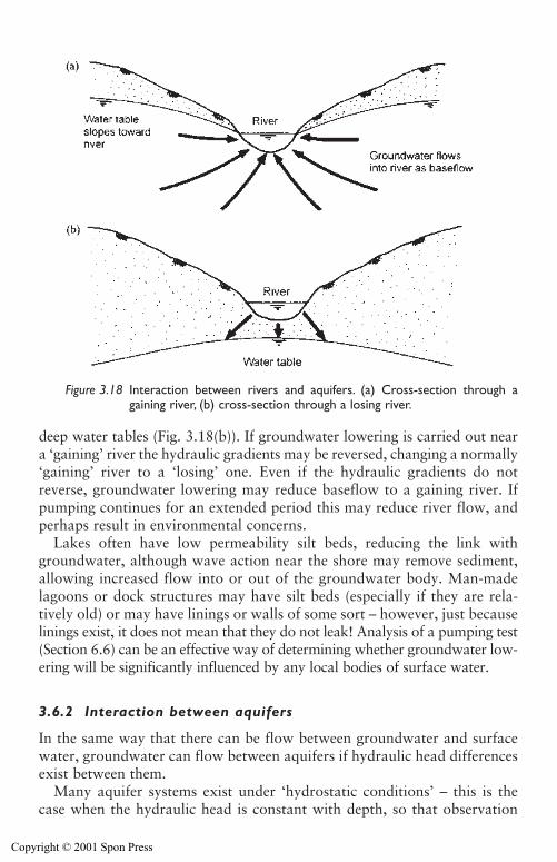
deep water tables (Fig. 3.18(b)). If groundwater lowering is carried out neara ‘gaining’ river the hydraulic gradients may be reversed, changing a normally‘gaining’ river to a ‘losing’ one. Even if the hydraulic gradients do notreverse, groundwater lowering may reduce baseflow to a gaining river. Ifpumping continues for an extended period this may reduce river flow, andperhaps result in environmental concerns.
Lakes often have low permeability silt beds, reducing the link withgroundwater, although wave action near the shore may remove sediment,allowing increased flow into or out of the groundwater body. Man-madelagoons or dock structures may have silt beds (especially if they are rela-tively old) or may have linings or walls of some sort – however, just becauselinings exist, it does not mean that they do not leak! Analysis of a pumping test(Section 6.6) can be an effective way of determining whether groundwater low-ering will be significantly influenced by any local bodies of surface water.
3.6.2 Interaction between aquifers
In the same way that there can be flow between groundwater and surfacewater, groundwater can flow between aquifers if hydraulic head differencesexist between them.
Many aquifer systems exist under ‘hydrostatic conditions’ – this is thecase when the hydraulic head is constant with depth, so that observation
Groundwater and permeability 57
Figure 3.18 Interaction between rivers and aquifers. (a) Cross-section through againing river, (b) cross-section through a losing river.
Copyright © 2001 Spon Press
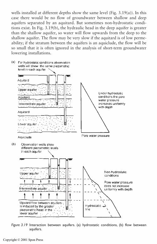
wells installed at different depths show the same level (Fig. 3.19(a)). In thiscase there would be no flow of groundwater between shallow and deepaquifers separated by an aquitard. But sometimes non-hydrostatic condi-tions exist. In Fig. 3.19(b), the hydraulic head in the deep aquifer is greaterthan the shallow aquifer, so water will flow upwards from the deep to theshallow aquifer. The flow may be very slow if the aquitard is of low perme-ability; if the stratum between the aquifers is an aquiclude, the flow will beso small that it is often ignored in the analysis of short-term groundwaterlowering installations.
58 Groundwater and permeability
Figure 3.19 Interaction between aquifers. (a) hydrostatic conditions, (b) flow betweenaquifers.
Copyright © 2001 Spon Press
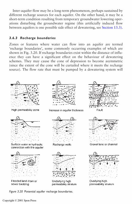
Inter-aquifer flow may be a long-term phenomenon, perhaps sustained bydifferent recharge sources for each aquifer. On the other hand, it may be ashort-term condition resulting from temporary groundwater lowering oper-ations disturbing the groundwater regime (this artificially induced flowbetween aquifers is one possible side effect of dewatering, see Section 13.3).
3.6.3 Recharge boundaries
Zones or features where water can flow into an aquifer are termed‘recharge boundaries’, some commonly occurring examples of which areshown in Fig. 3.20. If recharge boundaries exist within the distance of influ-ence they can have a significant effect on the behaviour of dewateringschemes. They may cause the cone of depression to become asymmetric(since the extent of the cone will be curtailed where it meets the rechargesource). The flow rate that must be pumped by a dewatering system will
Groundwater and permeability 59
Figure 3.20 Potential aquifer recharge boundaries.
Copyright © 2001 Spon Press
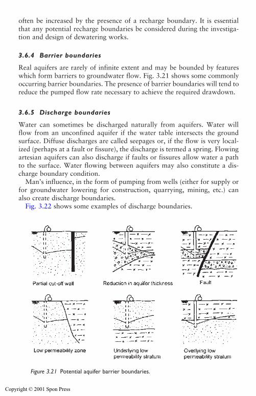
often be increased by the presence of a recharge boundary. It is essentialthat any potential recharge boundaries be considered during the investiga-tion and design of dewatering works.
3.6.4 Barrier boundaries
Real aquifers are rarely of infinite extent and may be bounded by featureswhich form barriers to groundwater flow. Fig. 3.21 shows some commonlyoccurring barrier boundaries. The presence of barrier boundaries will tend toreduce the pumped flow rate necessary to achieve the required drawdown.
3.6.5 Discharge boundaries
Water can sometimes be discharged naturally from aquifers. Water willflow from an unconfined aquifer if the water table intersects the groundsurface. Diffuse discharges are called seepages or, if the flow is very local-ized (perhaps at a fault or fissure), the discharge is termed a spring. Flowingartesian aquifers can also discharge if faults or fissures allow water a pathto the surface. Water flowing between aquifers may also constitute a dis-charge boundary condition.
Man’s influence, in the form of pumping from wells (either for supply orfor groundwater lowering for construction, quarrying, mining, etc.) canalso create discharge boundaries.
Fig. 3.22 shows some examples of discharge boundaries.
60 Groundwater and permeability
Figure 3.21 Potential aquifer barrier boundaries.
Copyright © 2001 Spon Press
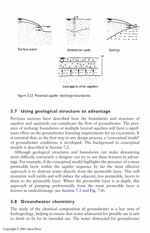
3.7 Using geological structure to advantage
Previous sections have described how the boundaries and structure ofaquifers and aquitards can complicate the flow of groundwater. The pres-ence of recharge boundaries or multiple layered aquifers will have a signif-icant effect on the groundwater lowering requirements for an excavation. Itis essential that, as the first step in any design process, a ‘conceptual model’of groundwater conditions is developed. The background to conceptualmodels is described in Section 7.2.
Although geological structures and boundaries can make dewateringmore difficult, conversely a designer can try to use these features to advan-tage. For example, if the conceptual model highlights the presence of a morepermeable layer within the aquifer sequence by far the most effectiveapproach is to abstract water directly from the permeable layer. This willmaximize well yields and will induce the adjacent, less permeable, layers todrain to the permeable layer. Where the permeable layer is at depth, thisapproach of pumping preferentially from the most permeable layer isknown as underdrainage (see Section 7.3 and Fig. 7.8).
3.8 Groundwater chemistry
The study of the chemical composition of groundwater is a key area ofhydrogeology, helping to ensure that water abstracted for potable use is safeto drink or fit for its intended use. The water abstracted for groundwater
Groundwater and permeability 61
Figure 3.22 Potential aquifer discharge boundaries.
Copyright © 2001 Spon Press
lowering purposes is rarely put to any use, and, subject to the necessary per-missions (see Chapter 15), is typically discharged to waste. Accordingly,water chemistry has often been thought of as an irrelevance to the dewa-tering practitioner.
However, a basic knowledge of groundwater chemistry can be useful forthe following reasons:
i Discharge consents and permissions. In many locations permission to dis-pose of the discharge water to a sewer or surface watercourse will only begranted if it can be demonstrated that the water is of adequate quality.
ii Corrosion and encrustation. Water chemistry will influence well clog-ging, encrustation, corrosion and biofouling (see Section 14.8) that mayaffect systems in long-term operation. Clogging and encrustation can bea particular problem for artificial recharge systems (see Section 13.6).
iii The effect of groundwater lowering on water quality. Abstracting waterfrom an aquifer may affect existing groundwater quality. Monitoringmay be necessary to determine if these effects are occurring, and tocontrol any mitigation measures (see Section 13.3).
If a project is likely to require detailed study of water chemistry, special-ist advice should be obtained. This section is intended only to highlightsome of the important practical issues of water chemistry relevant togroundwater lowering. Readers interested in the field are commended toLloyd and Heathcote (1985) as an introductory text.
3.8.1 Chemical composition of groundwater
Water is a powerful solvent, and a wide range of substances will dissolve init to some degree. Almost all water in the hydrological cycle will containsome dissolved minerals or other substances. Even rainwater contains dis-solved carbon dioxide and some sodium chloride lifted into the atmospherefrom the oceans.
Substances dissolved in water exist as electrically charged atoms ormolecules known as ions. Positively charged ions are known as anions andnegatively charged ions are known as cations. For example, when sodiumchloride (common salt, NaCl, which is highly soluble) dissolves in water itexists as sodium anions (Na�) and chloride cations (Cl�).
There are certain substances which commonly exist at substantial concen-trations (several milligrams per litre, mg/l) in natural groundwater. These areknown as the major anions and cations (Table 3.4), which are routinelytested for, in groundwater analyses. A variety of trace metals are also pre-sent (called trace because they are generally present in much smaller con-centrations, perhaps only a fraction of a mg/l). For groundwater loweringpurposes the most important trace metals are iron and manganese becausethey influence the severity of encrustation and biofouling (see Section 14.8).
62 Groundwater and permeability
Copyright © 2001 Spon Press
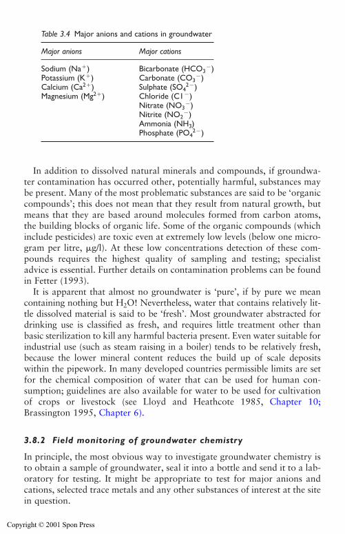
In addition to dissolved natural minerals and compounds, if groundwa-ter contamination has occurred other, potentially harmful, substances maybe present. Many of the most problematic substances are said to be ‘organiccompounds’; this does not mean that they result from natural growth, butmeans that they are based around molecules formed from carbon atoms,the building blocks of organic life. Some of the organic compounds (whichinclude pesticides) are toxic even at extremely low levels (below one micro-gram per litre, �g/l). At these low concentrations detection of these com-pounds requires the highest quality of sampling and testing; specialistadvice is essential. Further details on contamination problems can be foundin Fetter (1993).
It is apparent that almost no groundwater is ‘pure’, if by pure we meancontaining nothing but H2O! Nevertheless, water that contains relatively lit-tle dissolved material is said to be ‘fresh’. Most groundwater abstracted fordrinking use is classified as fresh, and requires little treatment other thanbasic sterilization to kill any harmful bacteria present. Even water suitable forindustrial use (such as steam raising in a boiler) tends to be relatively fresh,because the lower mineral content reduces the build up of scale depositswithin the pipework. In many developed countries permissible limits are setfor the chemical composition of water that can be used for human con-sumption; guidelines are also available for water to be used for cultivationof crops or livestock (see Lloyd and Heathcote 1985, Chapter 10;Brassington 1995, Chapter 6).
3.8.2 Field monitoring of groundwater chemistry
In principle, the most obvious way to investigate groundwater chemistry isto obtain a sample of groundwater, seal it into a bottle and send it to a lab-oratory for testing. It might be appropriate to test for major anions andcations, selected trace metals and any other substances of interest at the sitein question.
Groundwater and permeability 63
Table 3.4 Major anions and cations in groundwater
Major anions Major cations
Sodium (Na�) Bicarbonate (HCO3�)
Potassium (K�) Carbonate (CO3�)
Calcium (Ca2�) Sulphate (SO42�)
Magnesium (Mg2�) Chloride (C1�)Nitrate (NO3
�)Nitrite (NO2
�)Ammonia (NH3)Phosphate (PO4
2�)
Copyright © 2001 Spon Press
For groundwater lowering systems, obtaining a sample is relativelystraightforward. It may be possible to fill a sample bottle directly at the dis-charge tank. However, when taking groundwater samples from the dis-charge flow the following factors should be considered.
i Try to minimize the exposure of the sample to the atmosphere. Try andobtain it directly from the discharge of the pump or dewatering system.Totally fill the bottle and try and avoid leaving any air inside when itis sealed. If the pump discharge is ‘cascading’ before the sampling pointthe water will become aerated and oxidation may occur. The dischargearrangements should be altered so as the sample can be obtained beforeaeration occurs.
ii Samples may degrade between sampling and testing. The samples shouldbe tested as soon as possible after they are taken and, ideally, should berefrigerated in the meantime. The bottles used for sampling shouldbe clean with a good seal. However, the sample may degrade while inthe bottle (e.g. by trace metals oxidizing and precipitating out of solu-tion). Specialists may be able to advise on the addition of suitablepreservatives to prevent this occurring. The choice of sample bottle(glass or plastic) should also be discussed with the laboratory sincesome test results can be influenced by the material of the sample bottle.
iii Use an accredited, experienced laboratory.
Sometimes groundwater samples may be required from a site when there isno dewatering pumping taking place – perhaps for pre or post constructionbackground monitoring. In that case a sampling pump will have to be used toobtain a sample from an observation well. The water in the well has beenexposed to the atmosphere and is unlikely to represent the true aquifer waterchemistry. Therefore, it is vital to fully ‘purge’ the well before taking a sam-ple. Purging involves pumping the observation well at a steady rate until atleast three ‘well volumes’ of water have been removed (a ‘well volume’ is thevolume of water originally contained inside the well liner). Specialist samplingpumps should be used in preference to airlifting, since the latter methodmay aerate the sample, increasing the risk of oxidation of trace metals andother substances.
If samples are taken to an off-site laboratory, it may be several days beforethe results are ready. Even if the tests are rushed through as priority work,some of the actual procedures may take a week or more. Comprehensivetesting of samples is not cheap, either; a reasonably complete suite of testingmay cost several hundred pounds per sample at 2001 prices. A good way ofreducing costs, and obtaining rapid results, is to take and test water sam-ples on a periodic basis (perhaps monthly), but carry out daily (or, using adatalogger, continuously) monitoring of the ‘wellhead chemistry’.
Wellhead chemistry is a hydrogeological term used to describe certainparameters, which are best measured as soon as the water is pumped from
64 Groundwater and permeability
Copyright © 2001 Spon Press
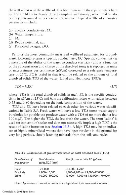
the well – that is at the wellhead. It is best to measure these parameters hereas they are likely to change during sampling and storage, which makes lab-oratory determined values less representative. Typical wellhead chemistryparameters include:
(a) Specific conductivity, EC.(b) Water temperature.(c) pH.(d) Redox potential, EH.(e) Dissolved oxygen, DO.
Perhaps the most commonly measured wellhead parameter for ground-water lowering systems is specific conductivity, EC. Specific conductivity isa measure of the ability of the water to conduct electricity and is a functionof the concentration and charge of the dissolved ions; it is reported in unitsof microseimens per centimetre (�S/cm) corrected to a reference tempera-ture of 25�C. EC is useful in that it can be related to the amount of totaldissolved solids TDS of the water (Lloyd and Heathcote 1985):
TDS�keEC (3.7)
where: TDS is the total dissolved solids in mg/l; EC is the specific conduc-tivity in �S/cm at 25�C; and ke is the calibration factor with values between0.55 and 0.80 depending on the ionic composition of the water.
TDS and EC have been related to each other for various water classifi-cations in Table 3.5. Fresh water will have a low TDS (most water supplyboreholes for potable use produce water with a TDS of no more than a few100 mg/l). The higher the TDS, the less fresh the water. The term ‘saline’ isused for convention’s sake and does not necessarily imply a high TDS is theresult of saline intrusion (see Section 13.3). A high TDS may be an indica-tor of highly mineralized waters that have been resident in the ground forvery long periods, slowly leaching minerals from the soils and rocks.
Groundwater and permeability 65
Table 3.5 Classification of groundwater based on total dissolved solids (TDS)
Classification of Total dissolved Specific conductivity, EC (�S/cm)groundwater solids,TDS (mg/l)
Fresh �1,000 �1,300–1,700a
Brackish 1,000–10,000 1,300–1,700 to 13,000–17,000a
Saline 10,000–100,000 13,000–17,000 to 130,000–170,000a
Note: a Approximate correlation; precise value depends on ionic composition of water.
Copyright © 2001 Spon Press
Daily monitoring of EC using a conductivity probe has proved useful onsites where there was concern that water of poorer quality (e.g. from salineintrusion or from deeper parts of the aquifer) might be drawn towards thepumping wells. Readings of conductivity were taken every day, andreviewed for any sudden or gradual changes in EC, which would have indi-cated that poor quality water was reaching the wells. In effect, the EC mon-itoring was used as an early warning or trigger to determine when moredetailed water testing was required.
References
Blyth, F. G. H. and De Freitas, M. H. (1984). A Geology for Engineers, 7th edition.Edward Arnold, London.
Brassington, R. (1995). Finding Water: A Guide to the Construction andMaintenance of Private Water Supplies. Wiley, Chichester.
Clark, L. (1977). The analysis and planning of step drawdown tests. QuarterlyJournal of Engineering Geology, 10, 125–143.
Cooper, H. H. and Jacob, C. E. (1946). A generalised graphical method for evalu-ating formation constants and summarising well field history. Transactions of theAmerican Geophysical Union, 27, 526–534.
Darcy, H. (1856). Les Fontaines Publiques de le Ville de Dijon. Dalmont, Paris.Driscoll, F. G. (1986). Groundwater and Wells. Johnson Division. Saint Paul,
Minnesota.Fetter, C. W. (1993). Contaminant Hydrogeology. Macmillan, New York.Fetter, C. W. (1994). Applied Hydrogeology, 3rd edition. MacMillan, New York.Head, K. H. (1982). Manual of Soil Laboratory Testing. Pentech Press, London
(3 volumes).Ineson, J. (1959). The relation between the yield of a discharging well at equilibrium
and its diameter, with particular reference to a chalk well. Proceedings of theInstitution of Civil Engineers, 13, 299–316.
Jacob, C. E. (1946). Drawdown test to determine effective radius of artesian well.Proceedings of the American Society of Civil Engineers, 72, 629–46.
Linney, L. F. and Withers, A. D. (1998). Dewatering the Thanet beds in SE London:three case histories. Quarterly Journal of Engineering Geology, 31, 115–122.
Lloyd, J. W. and Heathcote, J. A. (1985). Natural Inorganic Hydrochemistry inRelation to Groundwater: An Introduction. Clarendon Press, Oxford.
Oakes, D. B. (1986). Theory of groundwater flow. Groundwater, Occurrence,Development and Protection (Brandon, T. W., ed.). Institution of WaterEngineers and Scientists, Water Practice Manual No. 5, London, 109–134.
Peck, R. B. (1969). Advantages and limitations of the observational method inapplied soil mechanics. Géotechnique, 19(2), 171–187.
Powrie, W. (1997). Soil Mechanics: Concepts and Applications. Spon, London.Preene, M. Roberts, T. O. L., Powrie, W. and Dyer, M. R. (2000). Groundwater
Control – Design and Practice. Construction Industry Research and InformationAssociation, CIRIA Report C515, London.
Price, M. (1996). Introducing Groundwater, 2nd edition. Chapman & Hall,London.
66 Groundwater and permeability
Copyright © 2001 Spon Press

Rowe, P. W. (1972). The relevance of soil fabric to site investigation practice.Géotechnique, 22(2), 195–300.
Simpson, B., Blower, T., Craig, R. N. and Wilkinson, W. B. (1989). TheEngineering Implications of Rising Groundwater in the Deep Aquifer BelowLondon. Construction Industry Research and Information Association, CIRIASpecial Publication 69, London.
Sumbler, M. G. (1996). British Regional Geology: London and the Thames Valley,4th edition. HMSO, London.
Todd, D. K. (1980). Groundwater Hydrology, 2nd edition. Wiley, New York.Ward, W. H. (1957). The use of simple relief wells in reducing water pressure
beneath a trench excavation. Géotechnique, 7(3), 134–139.
Groundwater and permeability 67
Copyright © 2001 Spon Press
Chapter 4
Groundwater effects on thestability of excavations
4.0 Introduction
To avoid troublesome conditions during excavation and construction, mea-sures must be taken to control groundwater flows and pore water pressures inwater-bearing soils. Surface water run-off must also be effectively managed.An understanding of how an excavation may be affected will assist in assess-ing which groundwater control measures are necessary to ensure stability.
This chapter discusses the various circumstances by which inadequatelycontrolled groundwater can allow unstable ground conditions to develop.The interaction between pore water pressures, effective stress and stabilityis introduced. Various large-scale and small-scale stability problems are pre-sented and suitable approaches to prevent or control such occurrences aredescribed. The particular groundwater problems associated with the pres-ence of surface water and with excavations in rock are also discussed. Thevarious methods of groundwater control available to stabilize excavationswill be outlined in Chapter 5.
4.1 Groundwater control – the objectives
The fundamental requirement of groundwater control measures is that theyshould ensure stable and workable conditions throughout, so that excava-tion and construction can take place economically and under safe condi-tions at all times.
Groundwater may be controlled by: exclusion methods (see Section 5.3); oneor more types of pumping systems (see Section 5.4) commonly termed ‘dewa-tering’; or a combination of pumping plus exclusion techniques. This book isprimarily concerned with groundwater control by pumping or dewatering.
A correctly designed, installed and operated dewatering system ensuresthat construction work can be executed safely and economically by:
i Local lowering of the water table or groundwater level and interceptionof any seepages due to perched water tables which might otherwiseemerge on the exposed slopes or at the base of the excavation(s).
Copyright © 2001 Spon Press
ii Improving the stability of the excavation slopes and preventing mater-ial being removed from them by erosion due to seepage. Effective con-trol of groundwater may allow slopes to be steepened and the area ofexcavation reduced.
iii Preventing heave, blow-outs or quick conditions from developing in thefloor of the excavation with associated detrimental effects on the bear-ing capacity at formation level.
iv Draining the soil to improve excavation, haulage, trafficking and othercharacteristics of the soils involved.
v Reducing the lateral loads on temporary support systems such assheet-piling.
The practical upshot of objective (i) is that, by lowering the groundwaterlevel and controlling any local seepages the excavation will not be floodedby groundwater, and might be said to be ‘dewatered’. This is perhaps themost obvious aim of groundwater control – prevention of flooding – butobjectives (ii)–(v) can be equally important in improving the stability ofexcavations. This is discussed further in the following sections.
The reader may note that the word ‘dry’ does not appear anywhere in theobjectives of groundwater control outlined above. The authors are not infavour of any specifications or contracts which state that the aim of dewa-tering is to provide ‘dry’ conditions. After all, a heavy rain shower maycause ‘wet’ conditions, irrespective of how well groundwater is controlled!A much more useful target is for the dewatering measures to provide‘workable conditions’.
4.2 Groundwater, effective stress and instability
The concept of effective stress is fundamental to understanding the interrela-tion between groundwater and soil strength and stability. The principle ofeffective stress was proposed by Karl Terzaghi in 1920s, and is described indetail in soil mechanics texts such as Powrie (1997). As was described inSection 3.2 soil has a skeletal structure of solid material with an interconnect-ing system of pores. The pores may be saturated (wholly filled with water) –in confined aquifers or below the water table in unconfined aquifers – orunsaturated (filled with a mixture of water and air) – above the water table.
As a saturated soil mass is loaded, the total stress is carried by both the soilskeleton and the pore water. The pore water pressure acts with equal inten-sity in all directions. The stress carried by the soil skeleton alone (by inter-particle friction) is thus the difference between the total applied stress andthe water pressure set up in the pores u. This is termed the effective stress and is expressed by Terzaghi’s equation
��u (4.1)
Groundwater effects on excavations 69
Copyright © 2001 Spon Press
Because water has no significant shear strength, the soil skeleton maydeform while the pore water is displaced (a process known as pore waterpressure dissipation). This action continues until the resistance of the soilstructure is in equilibrium with the external forces. The rate of dissipationof the pore water will be dependent on the permeability of the soil mass andthe physical drainage conditions.
The shear strength � of soil is primarily from interparticle friction, and sois dependent on the effective stress. The shear strength at failure �f can beexpressed by the Mohr–Coulomb failure criterion:
�f�tan � (4.2)
where � is the angle of shearing resistance of the soil.These two simple equations show that reducing pore water pressures (as
a result of drawing down the groundwater level) will increase the effectivestress within the soil in the area affected. This produces a correspondingincrease in the shear strength of the soil, which will improve the stability ofthe soils around and beneath an excavation.
The increase in effective stresses that results from groundwater loweringis also an important factor in the potential for ground settlements arounddewatering systems. This is discussed in Section 13.1.
4.3 Large-scale instability caused by groundwater
Inadequately controlled groundwater can cause large-scale stability prob-lems in a variety of ways, the mechanisms likely to be prevalent at a givensite largely being controlled by ground conditions. These large-scale mecha-nisms can be explained in terms of effective stress and pore water pressures.
It is worth considering two classic cases of ground conditions. First, anexcavation with battered side slopes made into a sandy soil forming anunconfined aquifer. Second, an excavation made through a low permeabil-ity stratum overlying a confined aquifer. The mechanisms of potential insta-bility will be quite different in each case.
4.3.1 Unconfined aquifers
Consider a hole with sloping sides dug in a bed of silty fine sand belowthe standing groundwater level. If the inflow water is pumped from a sumpwithin the excavation, the sides will slump in when a depth of about0.5–1.0 m below original standing water level is reached. As digging proceedsthe situation will get progressively worse, and the edges of the excavation willrecede. The bottom will soon fill with a sand slurry in an almost liquid con-dition which will be constantly renewed by material slumping from the sideslopes. The collapse of the side slopes results from the presence of positive
70 Groundwater effects on excavations
Copyright © 2001 Spon Press
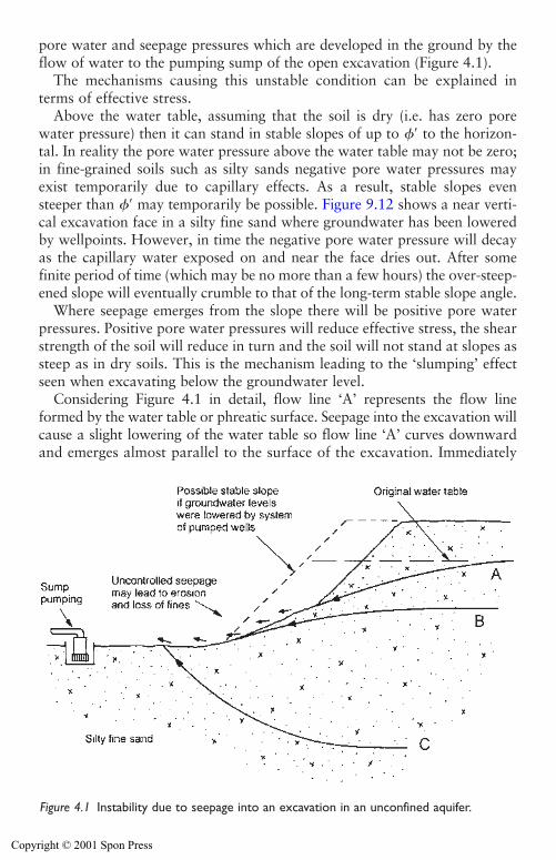
pore water and seepage pressures which are developed in the ground by theflow of water to the pumping sump of the open excavation (Figure 4.1).
The mechanisms causing this unstable condition can be explained interms of effective stress.
Above the water table, assuming that the soil is dry (i.e. has zero porewater pressure) then it can stand in stable slopes of up to � to the horizon-tal. In reality the pore water pressure above the water table may not be zero;in fine-grained soils such as silty sands negative pore water pressures mayexist temporarily due to capillary effects. As a result, stable slopes evensteeper than � may temporarily be possible. Figure 9.12 shows a near verti-cal excavation face in a silty fine sand where groundwater has been loweredby wellpoints. However, in time the negative pore water pressure will decayas the capillary water exposed on and near the face dries out. After somefinite period of time (which may be no more than a few hours) the over-steep-ened slope will eventually crumble to that of the long-term stable slope angle.
Where seepage emerges from the slope there will be positive pore waterpressures. Positive pore water pressures will reduce effective stress, the shearstrength of the soil will reduce in turn and the soil will not stand at slopes assteep as in dry soils. This is the mechanism leading to the ‘slumping’ effectseen when excavating below the groundwater level.
Considering Figure 4.1 in detail, flow line ‘A’ represents the flow lineformed by the water table or phreatic surface. Seepage into the excavation willcause a slight lowering of the water table so flow line ‘A’ curves downwardand emerges almost parallel to the surface of the excavation. Immediately
Groundwater effects on excavations 71
Figure 4.1 Instability due to seepage into an excavation in an unconfined aquifer.
Copyright © 2001 Spon Press

below its point of emergence the positive pore water pressures generated bythe seepage mean that the soil can no longer support a slope of �. Belowthe emergence of the seepage line the soil slope will slump to form shallowerangles. At the point of emergence of the almost horizontal flow line ‘B’ thesand will stand at � or less. Where there is upward seepage into the exca-vation base (flow line ‘C’) the effective stress may approach zero and thesoil cannot sustain any slope at all. In these circumstances the soil may ‘boil’or ‘fluidize’ and lose its ability to support anything placed on it – this is theso-called ‘quicksand’ case.
‘Running sand’ is another term used to describe conditions when a gran-ular soil becomes so weak that it cannot support any slope or cut face, andbecomes an almost liquid slurry. The term is often used as if it were a prop-erty of the sand itself. Actually, it is the flow of groundwater through thesoil, and the resultant low values of effective stress which cause this con-dition. Effective groundwater lowering can change ‘running sand’ into astable and workable material.
In addition to the loss of strength, seepage of groundwater through slopesmay cause erosion and undermining of the excavation slopes. This is espe-cially a problem in fine-grained sandy soils, and is discussed in Section 4.4.
Any solution to stability problems in unconfined aquifers will need to sta-bilize both the sides and base of the excavation. The most commonly usedexpedient is to install a system of dewatering wells (see Section 5.4) aroundthe excavation to lower the groundwater level to below the base of theexcavation, and to ensure that seepage does not emerge from the sideslopes. A typical target is to lower the groundwater level a short distance(say 0.5 m) below the deepest excavation formation level.
If the excavation is only penetrating a short distance (say less than 1.5 m)below the original groundwater level, a sump pumping system (Chapter 8)used in combination with slope drainage (see Section 4.4) might also beeffective. Extreme care must be taken when using sump pumping in thisway, to avoid destabilizing seepages into the excavation; the risk of thisincreases for excavations further below original groundwater level.
If the sides of the excavation are supported by physical cut-off walls (seeSection 5.3) then it is possible to sump pump from within the excavation,without the risk of instability of side slopes. The risk of fluidization of thebase due to upward seepage remains (Figure 4.2). Fluidization will theoreti-cally occur when the upward hydraulic gradient exceeds a critical value icrit
icrit� (4.3)
where �s is the unit weight of soil, and �w is the unit weight of water. In gen-eral the density of soil is about twice the density of water (peat being anotable exception), so generally icrit�1. This is the hydraulic gradient atwhich fluidization will occur, so it is important that this value is not
(�s��w)�
�w
1�2
72 Groundwater effects on excavations
Copyright © 2001 Spon Press
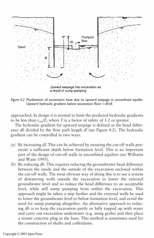
approached. In design it is normal to limit the predicted hydraulic gradientsto be less than icrit/F, where F is a factor of safety of 1.2 or greater.
The hydraulic gradient for upward seepage is defined as the head differ-ence dh divided by the flow path length dl (see Figure 4.2). The hydraulicgradient can be controlled in two ways.
(a) By increasing dl. This can be achieved by ensuring the cut-off walls pen-etrate a sufficient depth below formation level. This is an importantpart of the design of cut-off walls in unconfined aquifers (see Williamsand Waite 1995).
(b) By reducing dh. This requires reducing the groundwater head differencebetween the inside and the outside of the excavation enclosed withinthe cut-off walls. The most obvious way of doing this is to use a systemof dewatering wells outside the excavation to lower the externalgroundwater level and so reduce the head difference to an acceptablelevel, while still sump pumping from within the excavation. Thisapproach might be taken a step further and the external wells be usedto lower the groundwater level to below formation level, and avoid theneed for sump pumping altogether. An alternative approach to reduc-ing dh is to keep the excavation partly or fully topped up with waterand carry out excavation underwater (e.g. using grabs) and then placea tremie concrete plug in the base. This method is sometimes used forthe construction of shafts and cofferdams.
Groundwater effects on excavations 73
Figure 4.2 Fluidization of excavation base due to upward seepage in unconfined aquifer.Upward hydraulic gradient below excavation floor�dh/dl.
Copyright © 2001 Spon Press
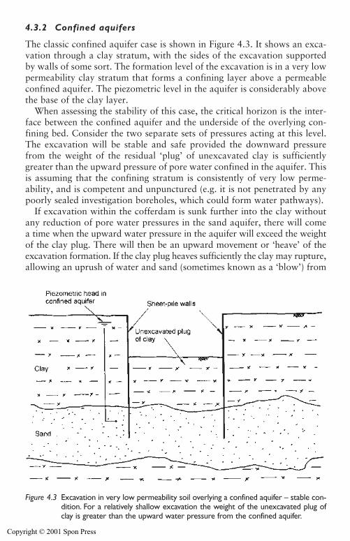
4.3.2 Confined aquifers
The classic confined aquifer case is shown in Figure 4.3. It shows an exca-vation through a clay stratum, with the sides of the excavation supportedby walls of some sort. The formation level of the excavation is in a very lowpermeability clay stratum that forms a confining layer above a permeableconfined aquifer. The piezometric level in the aquifer is considerably abovethe base of the clay layer.
When assessing the stability of this case, the critical horizon is the inter-face between the confined aquifer and the underside of the overlying con-fining bed. Consider the two separate sets of pressures acting at this level.The excavation will be stable and safe provided the downward pressurefrom the weight of the residual ‘plug’ of unexcavated clay is sufficientlygreater than the upward pressure of pore water confined in the aquifer. Thisis assuming that the confining stratum is consistently of very low perme-ability, and is competent and unpunctured (e.g. it is not penetrated by anypoorly sealed investigation boreholes, which could form water pathways).
If excavation within the cofferdam is sunk further into the clay withoutany reduction of pore water pressures in the sand aquifer, there will comea time when the upward water pressure in the aquifer will exceed the weightof the clay plug. There will then be an upward movement or ‘heave’ of theexcavation formation. If the clay plug heaves sufficiently the clay may rupture,allowing an uprush of water and sand (sometimes known as a ‘blow’) from
74 Groundwater effects on excavations
Figure 4.3 Excavation in very low permeability soil overlying a confined aquifer – stable con-dition. For a relatively shallow excavation the weight of the unexcavated plug ofclay is greater than the upward water pressure from the confined aquifer.
Copyright © 2001 Spon Press
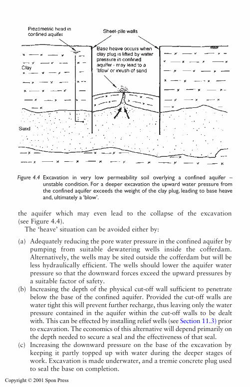
Groundwater effects on excavations 75
Figure 4.4 Excavation in very low permeability soil overlying a confined aquifer – unstable condition. For a deeper excavation the upward water pressure fromthe confined aquifer exceeds the weight of the clay plug, leading to base heaveand, ultimately a ‘blow’.
the aquifer which may even lead to the collapse of the excavation (see Figure 4.4).
The ‘heave’ situation can be avoided either by:
(a) Adequately reducing the pore water pressure in the confined aquifer bypumping from suitable dewatering wells inside the cofferdam.Alternatively, the wells may be sited outside the cofferdam but will beless hydraulically efficient. The wells should lower the aquifer waterpressure so that the downward forces exceed the upward pressures bya suitable factor of safety.
(b) Increasing the depth of the physical cut-off wall sufficient to penetratebelow the base of the confined aquifer. Provided the cut-off walls arewater tight this will prevent further recharge, thus leaving only the waterpressure contained in the aquifer within the cut-off walls to be dealtwith. This can be effected by installing relief wells (see Section 11.3) priorto excavation. The economics of this alternative will depend primarily onthe depth needed to secure a seal and the effectiveness of that seal.
(c) Increasing the downward pressure on the base of the excavation bykeeping it partly topped up with water during the deeper stages ofwork. Excavation is made underwater, and a tremie concrete plug usedto seal the base on completion.
Copyright © 2001 Spon Press
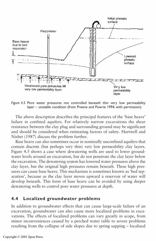
The above description describes the principal features of the ‘base heave’failure in confined aquifers. For relatively narrow excavations the shearresistance between the clay plug and surrounding ground may be significantand should be considered when estimating factors of safety. Hartwell andNisbet (1987) discuss the problem further.
Base heave can also sometimes occur in nominally unconfined aquifers thatcontain discrete (but perhaps very thin) very low permeability clay layers.Figure 4.5 shows a case where dewatering wells are used to lower ground-water levels around an excavation, but do not penetrate the clay layer belowthe excavation. The dewatering system has lowered water pressures above theclay layer, but the original high pressures remain beneath. These high pres-sures can cause base heave. This mechanism is sometimes known as ‘bed sep-aration’, because as the clay layer moves upward a reservoir of water willdevelop beneath. This form of base heave can be avoided by using deeperdewatering wells to control pore water pressures at depth.
4.4 Localized groundwater problems
In addition to groundwater effects that can cause large-scale failure of anexcavation, groundwater can also cause more localized problems in exca-vations. The effects of localized problems can vary greatly in scope, fromminor inconveniences caused by a perched water table to severe problemsresulting from the collapse of side slopes due to spring sapping – localized
76 Groundwater effects on excavations
Figure 4.5 Pore water pressures not controlled beneath thin very low permeability layer – unstable condition (from Preene and Powrie 1994, with permission).
Copyright © 2001 Spon Press
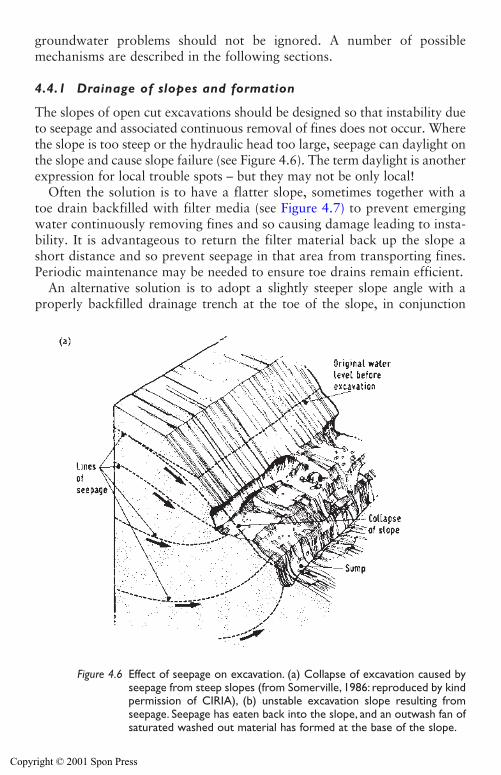
groundwater problems should not be ignored. A number of possiblemechanisms are described in the following sections.
4.4.1 Drainage of slopes and formation
The slopes of open cut excavations should be designed so that instability dueto seepage and associated continuous removal of fines does not occur. Wherethe slope is too steep or the hydraulic head too large, seepage can daylight onthe slope and cause slope failure (see Figure 4.6). The term daylight is anotherexpression for local trouble spots – but they may not be only local!
Often the solution is to have a flatter slope, sometimes together with atoe drain backfilled with filter media (see Figure 4.7) to prevent emergingwater continuously removing fines and so causing damage leading to insta-bility. It is advantageous to return the filter material back up the slope ashort distance and so prevent seepage in that area from transporting fines.Periodic maintenance may be needed to ensure toe drains remain efficient.
An alternative solution is to adopt a slightly steeper slope angle with aproperly backfilled drainage trench at the toe of the slope, in conjunction
Groundwater effects on excavations 77
Figure 4.6 Effect of seepage on excavation. (a) Collapse of excavation caused byseepage from steep slopes (from Somerville, 1986: reproduced by kindpermission of CIRIA), (b) unstable excavation slope resulting fromseepage. Seepage has eaten back into the slope, and an outwash fan ofsaturated washed out material has formed at the base of the slope.
Copyright © 2001 Spon Press

with sand-bagging of the toe of the slope or weighting with graded filtermaterial. Alternatively, the fill can be weighted with loose-laid timbers andsacking, with straw or hay padded behind them. Modern practice also allowsthe use of one of the various proprietary geotextile fabrics. Sand-bagging ora geotextile membrane may be needed where local perched water tables arerevealed. The materials to be used will depend on local availability in thecountry concerned.
The gradients within the excavated floor areas should be formed so thatthe run-off water is directed to the collector drains and the risk of pondingis assiduously avoided. Run-off from slopes should be collected by the sur-face water drainage system, suitably sited at each berm and/or toe of slope,and thence be directed to pumping sumps for ultimate disposal off site.
Sumps are usually sited at the corners of excavations, below the generalexcavation level, and made big enough to hold sufficient water for pumping
78 Groundwater effects on excavations
(b)
Figure 4.6 Continued.
Copyright © 2001 Spon Press
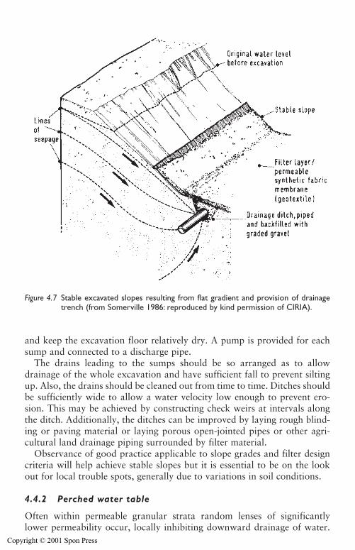
and keep the excavation floor relatively dry. A pump is provided for eachsump and connected to a discharge pipe.
The drains leading to the sumps should be so arranged as to allowdrainage of the whole excavation and have sufficient fall to prevent siltingup. Also, the drains should be cleaned out from time to time. Ditches shouldbe sufficiently wide to allow a water velocity low enough to prevent ero-sion. This may be achieved by constructing check weirs at intervals alongthe ditch. Additionally, the ditches can be improved by laying rough blind-ing or paving material or laying porous open-jointed pipes or other agri-cultural land drainage piping surrounded by filter material.
Observance of good practice applicable to slope grades and filter designcriteria will help achieve stable slopes but it is essential to be on the lookout for local trouble spots, generally due to variations in soil conditions.
4.4.2 Perched water table
Often within permeable granular strata random lenses of significantly lower permeability occur, locally inhibiting downward drainage of water.
Groundwater effects on excavations 79
Figure 4.7 Stable excavated slopes resulting from flat gradient and provision of drainagetrench (from Somerville 1986: reproduced by kind permission of CIRIA).
Copyright © 2001 Spon Press
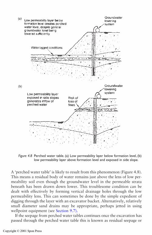
A ‘perched water table’ is likely to result from this phenomenon (Figure 4.8).This means a residual body of water remains just above the lens of low per-meability soil even though the groundwater level in the permeable stratabeneath has been drawn down lower. This troublesome condition can bedealt with effectively by forming vertical drainage holes through the lowpermeability lens. This can sometimes be done by the simple expedient ofdigging through the layer with an excavator bucket. Alternatively, relativelysmall diameter sand drains may be appropriate, perhaps jetted in usingwellpoint equipment (see Section 9.7).
If the seepage from perched water tables continues once the excavation haspassed through the perched water table this is known as residual seepage or
80 Groundwater effects on excavations
Figure 4.8 Perched water table. (a) Low permeability layer below formation level, (b)low permeability layer above formation level and exposed in side slope.
Copyright © 2001 Spon Press
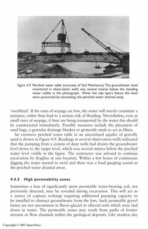
‘overbleed’. If the rates of seepage are low, the water will merely constitute anuisance, rather than lead to a serious risk of flooding. Nevertheless, even atsmall rates of seepage, if fines are being transported by the water this shouldbe counteracted immediately. Possible measures include the placement ofsand bags, a granular drainage blanket or geotextile mesh to act as filters.
An extensive perched water table in an unconfined aquifer of gravellysand is shown in Figure 4.9. Readings in several observation wells indicatedthat the pumping from a system of deep wells had drawn the groundwaterlevel down to the target level, which was several metres below the perchedwater level visible in the figure. The contractor was advised to continueexcavation by dragline at one location. Within a few hours of continuousdigging the water started to swirl and there was a loud gurgling sound asthe perched water drained away.
4.4.3 High permeability zones
Sometimes a lens of significantly more permeable water-bearing soil, notpreviously detected, may be revealed during excavation. This will act asa source of copious recharge requiring additional pumping capacity tobe installed to abstract groundwater from the lens. Such permeable gravellenses are not uncommon in fluvio-glacial or alluvial soils which were laiddown in water. The permeable zones may result from paths of formerstreams or flow channels within the geological deposits. Like modern day
Groundwater effects on excavations 81
Figure 4.9 Perched water table (courtesy of Soil Mechanics).The groundwater levelmonitored in observation wells was several metres below the standingwater visible in the photograph. When the clay layers below this levelwere punctured by excavating, the perched water drained away.
Copyright © 2001 Spon Press
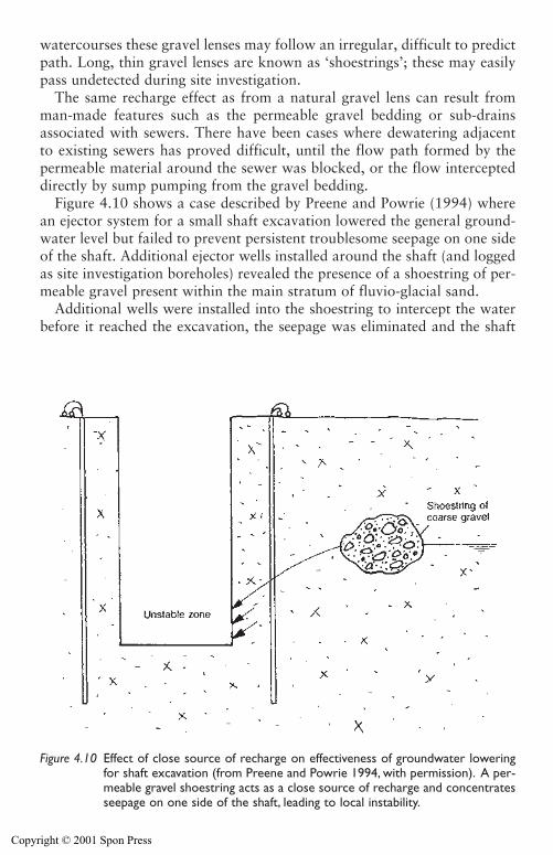
watercourses these gravel lenses may follow an irregular, difficult to predictpath. Long, thin gravel lenses are known as ‘shoestrings’; these may easilypass undetected during site investigation.
The same recharge effect as from a natural gravel lens can result fromman-made features such as the permeable gravel bedding or sub-drainsassociated with sewers. There have been cases where dewatering adjacentto existing sewers has proved difficult, until the flow path formed by thepermeable material around the sewer was blocked, or the flow intercepteddirectly by sump pumping from the gravel bedding.
Figure 4.10 shows a case described by Preene and Powrie (1994) wherean ejector system for a small shaft excavation lowered the general ground-water level but failed to prevent persistent troublesome seepage on one sideof the shaft. Additional ejector wells installed around the shaft (and loggedas site investigation boreholes) revealed the presence of a shoestring of per-meable gravel present within the main stratum of fluvio-glacial sand.
Additional wells were installed into the shoestring to intercept the waterbefore it reached the excavation, the seepage was eliminated and the shaft
82 Groundwater effects on excavations
Figure 4.10 Effect of close source of recharge on effectiveness of groundwater loweringfor shaft excavation (from Preene and Powrie 1994, with permission). A per-meable gravel shoestring acts as a close source of recharge and concentratesseepage on one side of the shaft, leading to local instability.
Copyright © 2001 Spon Press
successfully completed. This sounds very straightforward, but this was farfrom the true story. Because the location of the shoestring was not knownprecisely, the dewatering contractor had to keep drilling wells until a few ofthem directly intercepted the permeable zone. Up until that time, even whenmany additional wells had been installed and pumped, the seepage persisted.The total number of wells increased from five to twenty-two! In reality, onlythe handful pumping directly from the shoestring were truly effective.
The principle to be remembered is that whenever a local source of morecopious recharge is encountered, additional wells or sumps should ideallydraw groundwater direct from the recharge source (i.e. the permeablezone). It is preferable to intercept the flow upstream of the exposed exca-vation but sometimes this may not be practicable. In such circumstances theadditional wells or sumps must be installed as close as possible to the areaof water emergence into the work.
4.4.4 Spring sapping and internal erosion
This mechanism, which can occur in sands and silty fine sands, is notuncommon, but is not well understood. The sides of an excavation in siltyfine sand may show gully structures from which sand slurry can be seen toflow into the bottom of the excavation. This is due to internal erosion. Thewater flowing along the upper surface of the lowered phreatic line carriessand slurry with it and thus tunnels backwards beneath the overlying sand,which has some strength owing to capillary tension. Before this tunnellingeffect has gone far, the top collapses and the collapsed material is also car-ried away. This tunnelling phenomenon has often been observed in finesands and especially in silty fine sands. It tends to occur immediately abovea thin and less permeable layer of finer material which has caused a perchedwater table, though this condition may only be temporary. This phenome-non is quite well known in geology under the name of spring sapping orseepage erosion.
In the 1960s, an interesting experiment into this phenomenon was car-ried out at Imperial College, London. A slope of fine sand was formed in aglass-sided tank and a small source of water was allowed to flow in throughthe base of the tank. The base of the tank was at a flat angle. A very smallflow of water was introduced beneath the sand and erosion rapidly startedat the point of exit. One would intuitively expect a cone of eroded materialto build up, and for the process of erosion to come to an end, but in factthe flow of sand was continuous – as it was in a case described by Ward(1948). It seems that this flow can only happen if excess pore pressures existin eroded material, but their cause is still unexplained and it is hard to seewhy they are not quickly dissipated.
The site studied by Ward (1948) was near Newhaven in Sussex, at apoint where Woolwich and Reading Beds (now known more correctly as
Groundwater effects on excavations 83
Copyright © 2001 Spon Press
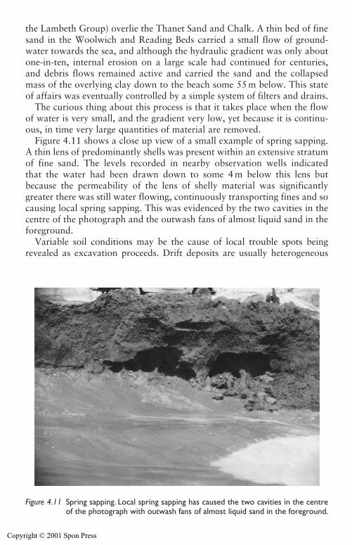
the Lambeth Group) overlie the Thanet Sand and Chalk. A thin bed of finesand in the Woolwich and Reading Beds carried a small flow of ground-water towards the sea, and although the hydraulic gradient was only aboutone-in-ten, internal erosion on a large scale had continued for centuries,and debris flows remained active and carried the sand and the collapsedmass of the overlying clay down to the beach some 55 m below. This stateof affairs was eventually controlled by a simple system of filters and drains.
The curious thing about this process is that it takes place when the flowof water is very small, and the gradient very low, yet because it is continu-ous, in time very large quantities of material are removed.
Figure 4.11 shows a close up view of a small example of spring sapping.A thin lens of predominantly shells was present within an extensive stratumof fine sand. The levels recorded in nearby observation wells indicated that the water had been drawn down to some 4 m below this lens butbecause the permeability of the lens of shelly material was significantlygreater there was still water flowing, continuously transporting fines and socausing local spring sapping. This was evidenced by the two cavities in thecentre of the photograph and the outwash fans of almost liquid sand in theforeground.
Variable soil conditions may be the cause of local trouble spots beingrevealed as excavation proceeds. Drift deposits are usually heterogeneous
84 Groundwater effects on excavations
Figure 4.11 Spring sapping. Local spring sapping has caused the two cavities in the centreof the photograph with outwash fans of almost liquid sand in the foreground.
Copyright © 2001 Spon Press
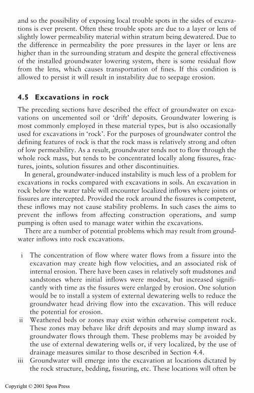
and so the possibility of exposing local trouble spots in the sides of excava-tions is ever present. Often these trouble spots are due to a layer or lens ofslightly lower permeability material within stratum being dewatered. Due tothe difference in permeability the pore pressures in the layer or lens arehigher than in the surrounding stratum and despite the general effectivenessof the installed groundwater lowering system, there is some residual flowfrom the lens, which causes transportation of fines. If this condition isallowed to persist it will result in instability due to seepage erosion.
4.5 Excavations in rock
The preceding sections have described the effect of groundwater on exca-vations on uncemented soil or ‘drift’ deposits. Groundwater lowering ismost commonly employed in these material types, but is also occasionallyused for excavations in ‘rock’. For the purposes of groundwater control thedefining features of rock is that the rock mass is relatively strong and oftenof low permeability. As a result, groundwater tends not to flow through thewhole rock mass, but tends to be concentrated locally along fissures, frac-tures, joints, solution fissures and other discontinuities.
In general, groundwater-induced instability is much less of a problem forexcavations in rocks compared with excavations in soils. An excavation inrock below the water table will encounter localized inflows where joints orfissures are intercepted. Provided the rock around the fissures is competent,these inflows may not cause stability problems. In such cases the aims toprevent the inflows from affecting construction operations, and sumppumping is often used to manage water within the excavations.
There are a number of potential problems which may result from ground-water inflows into rock excavations.
i The concentration of flow where water flows from a fissure into theexcavation may create high flow velocities, and an associated risk ofinternal erosion. There have been cases in relatively soft mudstones andsandstones where initial inflows were modest, but increased signifi-cantly with time as the fissures were enlarged by erosion. One solutionwould be to install a system of external dewatering wells to reduce thegroundwater head driving flow into the excavation. This will reducethe potential for erosion.
ii Weathered beds or zones may exist within otherwise competent rock.These zones may behave like drift deposits and may slump inward asgroundwater flows through them. These problems may be avoided bythe use of external dewatering wells or, if very localized, by the use ofdrainage measures similar to those described in Section 4.4.
iii Groundwater will emerge into the excavation at locations dictated bythe rock structure, bedding, fissuring, etc. These locations will often be
Groundwater effects on excavations 85
Copyright © 2001 Spon Press
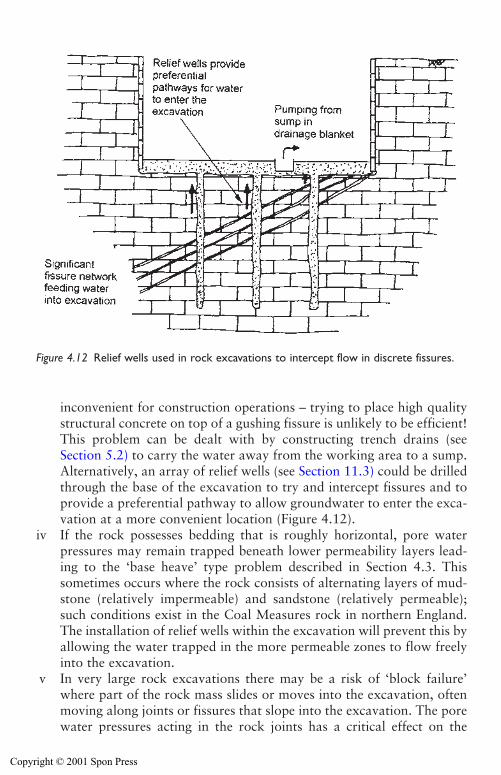
inconvenient for construction operations – trying to place high qualitystructural concrete on top of a gushing fissure is unlikely to be efficient!This problem can be dealt with by constructing trench drains (seeSection 5.2) to carry the water away from the working area to a sump.Alternatively, an array of relief wells (see Section 11.3) could be drilledthrough the base of the excavation to try and intercept fissures and toprovide a preferential pathway to allow groundwater to enter the exca-vation at a more convenient location (Figure 4.12).
iv If the rock possesses bedding that is roughly horizontal, pore waterpressures may remain trapped beneath lower permeability layers lead-ing to the ‘base heave’ type problem described in Section 4.3. Thissometimes occurs where the rock consists of alternating layers of mud-stone (relatively impermeable) and sandstone (relatively permeable);such conditions exist in the Coal Measures rock in northern England.The installation of relief wells within the excavation will prevent this byallowing the water trapped in the more permeable zones to flow freelyinto the excavation.
v In very large rock excavations there may be a risk of ‘block failure’where part of the rock mass slides or moves into the excavation, oftenmoving along joints or fissures that slope into the excavation. The porewater pressures acting in the rock joints has a critical effect on the
86 Groundwater effects on excavations
Figure 4.12 Relief wells used in rock excavations to intercept flow in discrete fissures.
Copyright © 2001 Spon Press
stability of such rock masses. Dewatering wells have occasionally beenused to control pore water pressures as part of stabilization measures.This is a very specialized case, and it is essential that rock mechanicsspecialists are involved if this approach is being contemplated.
4.6 Surface water problems
This book is primarily concerned with the control of groundwater but,since the aim is to provide workable conditions for construction, the impor-tance of surface water control must not be forgotten. Surface water mayarise in many ways: as direct precipitation into the excavation; as precipi-tation run-off from surrounding areas; as waste water from constructionoperations such as concreting or even from washing down of plant andequipment. Since the excavation is obviously going to form a low point inthe site, surface water, if given free rein, is likely to collect in the bottom ofthe excavation.
Whatever the source, if surface water is allowed to pond in the excava-tion it will impede efficient excavation and construction. Figure 4.13 showsan example of an excavation before and after surface water was suitablydealt with. Neglecting the management of surface water will undoubtedlycost the project time and money. Methods for control of surface water aredescribed in Sections 5.1 and 8.2.
4.7 Effect of climate and weather
Depending upon climatic conditions it may be prudent to make major orminor contingency plans. For instance, in some parts of the world it isknown that monsoons, typhoons and hurricanes will occur and the conse-quential high volume surface run-off may be very significant. Hence, plan-ning for such areas would dictate that appropriate measures to deal withsudden influxes of surface water, prevent slope erosion and deal with short-term rises in groundwater level must be incorporated into the excavationplan at design stage. Particularly when working in shallow unconfinedaquifers, intense rainfall events can have a major effect on lowered waterlevels. Figure 4.14 shows groundwater level and rainfall data taken duringthe rainy season at a site in South-East Asia. A wellpoint system was usedto lower water levels in a very silty sand and had achieved a drawdown ofseveral metres. Whenever there was heavy rain the water levels rose rapidlyand only fell back to their original levels slowly under the influence ofpumping.
Exposed excavated slopes may be protected from monsoon type erosionby laying an appropriate geotextile membrane. A judgement should to bemade at design stage whether to cater for the once in ten-year occurrence,or the fifty-year occurrence or more onerous conditions.
Groundwater effects on excavations 87
Copyright © 2001 Spon Press
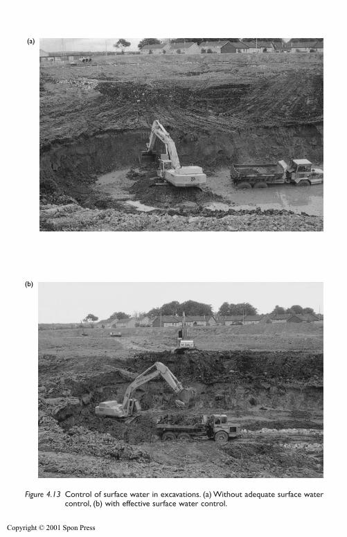
88 Groundwater effects on excavations
(a)
(b)
Figure 4.13 Control of surface water in excavations. (a) Without adequate surface watercontrol, (b) with effective surface water control.
Copyright © 2001 Spon Press
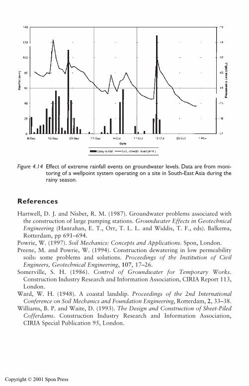
References
Hartwell, D. J. and Nisbet, R. M. (1987). Groundwater problems associated withthe construction of large pumping stations. Groundwater Effects in GeotechnicalEngineering (Hanrahan, E. T., Orr, T. L. L. and Widdis, T. F., eds). Balkema,Rotterdam, pp 691–694.
Powrie, W. (1997). Soil Mechanics: Concepts and Applications. Spon, London.Preene, M. and Powrie, W. (1994). Construction dewatering in low permeability
soils: some problems and solutions. Proceedings of the Institution of CivilEngineers, Geotechnical Engineering, 107, 17–26.
Somerville, S. H. (1986). Control of Groundwater for Temporary Works.Construction Industry Research and Information Association, CIRIA Report 113,London.
Ward, W. H. (1948). A coastal landslip. Proceedings of the 2nd InternationalConference on Soil Mechanics and Foundation Engineering, Rotterdam, 2, 33–38.
Williams, B. P. and Waite, D. (1993). The Design and Construction of Sheet-PiledCofferdams. Construction Industry Research and Information Association,CIRIA Special Publication 95, London.
Groundwater effects on excavations 89
Figure 4.14 Effect of extreme rainfall events on groundwater levels. Data are from moni-toring of a wellpoint system operating on a site in South-East Asia during therainy season.
Copyright © 2001 Spon Press
Chapter 5
Methods for control of surfacewater and groundwater
5.0 Introduction
As has been discussed in Chapter 4, the presence of groundwater can leadto troublesome conditions when construction operations are to take placebelow the original groundwater level. Surface water run-off must also beeffectively controlled to prevent interference with excavation and construc-tion works. This chapter briefly outlines some available methods for con-trol of surface water and groundwater.
Techniques for the control of groundwater can be divided into two principal types:
(a) Those that exclude water from the excavation (known as exclusiontechniques).
(b) Those that deal with groundwater by pumping (known as dewateringtechniques).
This chapter includes brief discussions and tabular summaries of the variousavailable techniques of both groups, including their advantages and disadvan-tages. Apart from this summary, this book addresses only the dewatering tech-niques. The practicalities of the more commonly used pumping or dewateringmethods are described in detail in subsequent chapters.
5.1 Control of surface water
In order to optimize efficiency (and profitability) it is essential that condi-tions within the area of excavation and construction be workable; mechani-cal plant should be able to operate efficiently without getting bogged down.To achieve this, in addition to lowering of groundwater levels, surface watermust be controlled. Thus both surface water run-off and groundwatershould be disposed of expeditiously.
On many construction sites the measures enacted to control surface waterrun-off are inadequate, and unnecessary waste of time and money results.
Copyright © 2001 Spon Press
5.1.1 Surface water run-off
The basic rule of good practice is to collect and control the surface waterrun-off as soon as, or better still even before, it enters the area of work.
The drainage system should incorporate appropriate measures to collectrun-off from land areas surrounding and adjacent to an excavation to preventsurface water run-off encroaching into the construction area. Adoption of thisphilosophy requires the installation of adequate interceptor drains sited uphillor upstream of the excavation at original ground level.
Rain water or discharges from other construction activities (such as con-creting or washing down of plant) should be prevented from entering an exca-vation, particularly on a sloping site, by the simple expedient of diggingcollector ditches or drains on the high ground. The drain should lead the wateraway to discharge points (which could be pumped by sump pumps, seeChapter 8) lower down the slope. Collector drains should be lined with animpermeable membrane to avoid potential upstream recharge that might causea rotational slip of the excavation slope. The open ditch method (see Fig. 5.1(a)should be used only where the presence of open ditches does not inhibit con-struction work. As an alternative, agricultural type drains can be used (see Fig. 5.1(b), but the surface must be regularly scarified to reduce the effect ofclogging by suspended particles in the surface water. This cleaning dictumshould be applied to both the open ditch and the agricultural type drains.
5.2 Methods of groundwater control
The techniques available for control of groundwater fall into two principalgroups:
(a) Those that exclude water from the excavation (known as exclusiontechniques).
(b) Those that deal with groundwater by pumping (known as dewateringtechniques).
This book is primarily concerned with the second group, the dewateringmethods. However, the essential features of groundwater control by exclu-sion are outlined in the following section.
5.3 Exclusion methods
The aim of groundwater control by exclusion is to prevent groundwaterfrom entering the working area. The methods used can be grouped intothree broad categories:
1 Methods where a very low permeability discrete wall or barrier is phys-ically inserted or constructed in the ground (e.g. sheet-piling, diaphragmwalls).
Control of surface water and groundwater 91
Copyright © 2001 Spon Press
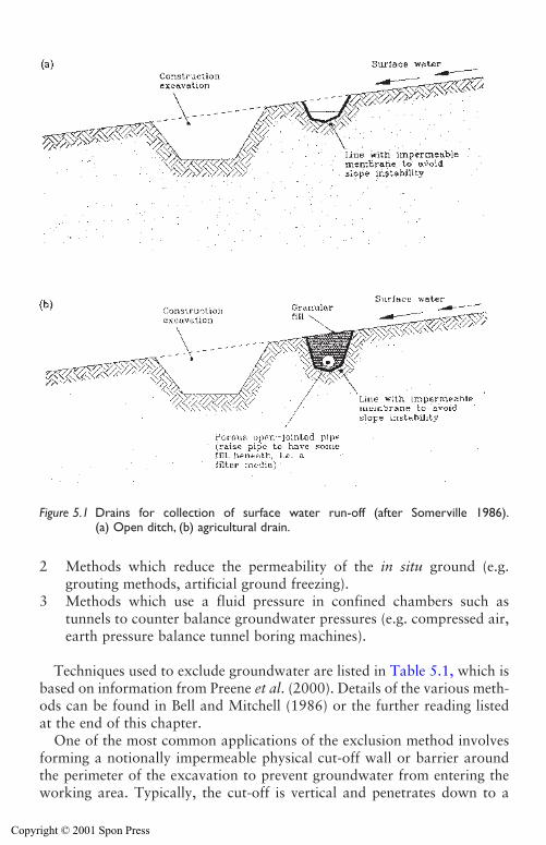
2 Methods which reduce the permeability of the in situ ground (e.g.grouting methods, artificial ground freezing).
3 Methods which use a fluid pressure in confined chambers such astunnels to counter balance groundwater pressures (e.g. compressed air,earth pressure balance tunnel boring machines).
Techniques used to exclude groundwater are listed in Table 5.1, which isbased on information from Preene et al. (2000). Details of the various meth-ods can be found in Bell and Mitchell (1986) or the further reading listedat the end of this chapter.
One of the most common applications of the exclusion method involvesforming a notionally impermeable physical cut-off wall or barrier aroundthe perimeter of the excavation to prevent groundwater from entering theworking area. Typically, the cut-off is vertical and penetrates down to a
92 Control of surface water and groundwater
Figure 5.1 Drains for collection of surface water run-off (after Somerville 1986).(a) Open ditch, (b) agricultural drain.
Copyright © 2001 Spon Press
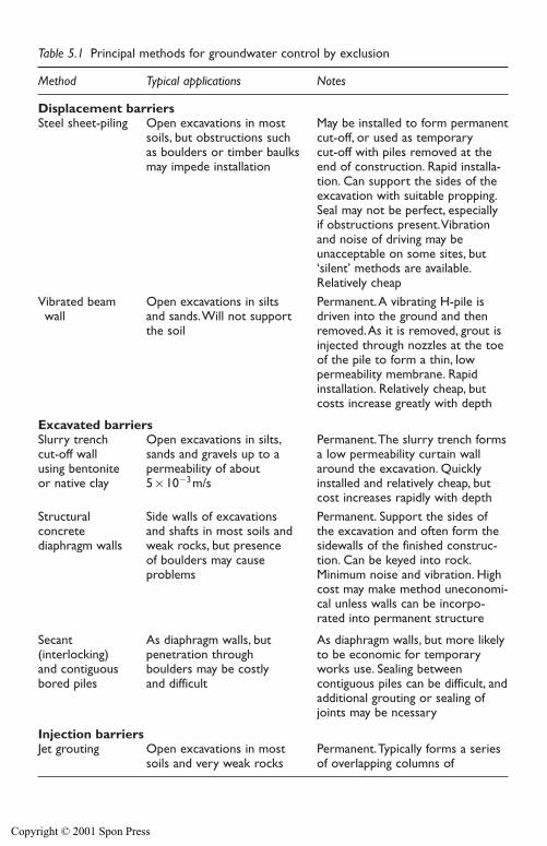
Control of surface water and groundwater 93
Table 5.1 Principal methods for groundwater control by exclusion
Method Typical applications Notes
Displacement barriersSteel sheet-piling Open excavations in most May be installed to form permanent
soils, but obstructions such cut-off, or used as temporary as boulders or timber baulks cut-off with piles removed at the may impede installation end of construction. Rapid installa-
tion. Can support the sides of theexcavation with suitable propping.Seal may not be perfect, especially if obstructions present.Vibrationand noise of driving may be unacceptable on some sites, but‘silent’ methods are available.Relatively cheap
Vibrated beam Open excavations in silts Permanent.A vibrating H-pile iswall and sands.Will not support driven into the ground and then
the soil removed.As it is removed, grout isinjected through nozzles at the toeof the pile to form a thin, low permeability membrane. Rapidinstallation. Relatively cheap, butcosts increase greatly with depth
Excavated barriersSlurry trench Open excavations in silts, Permanent.The slurry trench formscut-off wall sands and gravels up to a a low permeability curtain wallusing bentonite permeability of about around the excavation. Quicklyor native clay 5�10�3m/s installed and relatively cheap, but
cost increases rapidly with depthStructural Side walls of excavations Permanent. Support the sides of concrete and shafts in most soils and the excavation and often form thediaphragm walls weak rocks, but presence sidewalls of the finished construc-
of boulders may cause tion. Can be keyed into rock.problems Minimum noise and vibration. High
cost may make method uneconomi-cal unless walls can be incorpo-rated into permanent structure
Secant As diaphragm walls, but As diaphragm walls, but more likely(interlocking) penetration through to be economic for temporary and contiguous boulders may be costly works use. Sealing betweenbored piles and difficult contiguous piles can be difficult, and
additional grouting or sealing ofjoints may be ncessary
Injection barriersJet grouting Open excavations in most Permanent.Typically forms a series
soils and very weak rocks of overlapping columns of
Copyright © 2001 Spon Press
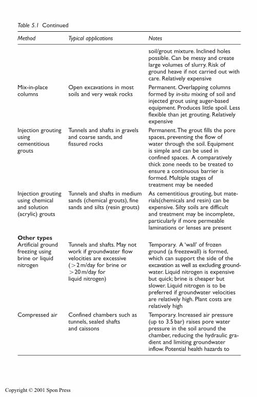
94 Control of surface water and groundwater
Table 5.1 Continued
Method Typical applications Notes
soil/grout mixture. Inclined holespossible. Can be messy and createlarge volumes of slurry. Risk ofground heave if not carried out withcare. Relatively expensive
Mix-in-place Open excavations in most Permanent. Overlapping columns columns soils and very weak rocks formed by in-situ mixing of soil and
injected grout using auger-basedequipment. Produces little spoil. Lessflexible than jet grouting. Relativelyexpensive
Injection grouting Tunnels and shafts in gravels Permanent.The grout fills the poreusing and coarse sands, and spaces, preventing the flow of cementitious fissured rocks water through the soil. Equipmentgrouts is simple and can be used in
confined spaces. A comparativelythick zone needs to be treated toensure a continuous barrier isformed. Multiple stages of treatment may be needed
Injection grouting Tunnels and shafts in medium As cementitious grouting, but mate-using chemical sands (chemical grouts), fine rials(chemicals and resin) can be and solution sands and silts (resin grouts) expensive. Silty soils are difficult (acrylic) grouts and treatment may be incomplete,
particularly if more permeable laminations or lenses are present
Other typesArtificial ground Tunnels and shafts. May not Temporary. A ‘wall’ of frozen freezing using work if groundwater flow ground (a freezewall) is formed,brine or liquid velocities are excessive which can support the side of thenitrogen (�2 m/day for brine or excavation as well as excluding ground-
�20 m/day for water. Liquid nitrogen is expensiveliquid nitrogen) but quick; brine is cheaper but
slower. Liquid nitrogen is to be preferred if groundwater velocitiesare relatively high. Plant costs arerelatively high
Compressed air Confined chambers such as Temporary. Increased air pressure tunnels, sealed shafts (up to 3.5 bar) raises pore waterand caissons pressure in the soil around the
chamber, reducing the hydraulic gra-dient and limiting groundwater inflow. Potential health hazards to
Copyright © 2001 Spon Press

very low permeability stratum that forms a basal seal for the excavation(Fig. 5.2(a)).
The costs and practicalities of constructing a physical cut-off wall are highlydependent on the depth and nature of any underlying permeable stratum. If asuitable very low permeability stratum does not exist, or is at great depth, thenupward seepage may occur beneath the bottom of the cut-off wall, leading toa risk of base instability (see Section 4.3). In such circumstances dewatering
Control of surface water and groundwater 95
Table 5.1 Continued
Method Typical applications Notes
workers.Air losses may be signifi-cant in high permeability soils. Highrunning and set-up costs
Earth pressure Tunnels in most soils Temporary.The TBM excavates for balance tunnel and weak rocks the tunnel, and supports the soil boring machine and excludes groundwater by(TBM) maintaining as balancing fluid
pressure in the plenum chamberimmediately behind the cutting head.The fluid is a mixture of soilcuttings, groundwater andconditioning agents (such as polymeror bentonite muds).TBMs need tobe carefully selected to deal withgiven ground conditions; set-up andrunning costs may be high
Figure 5.2 Groundwater control by exclusion using physical cut-offs. (a) Cut-offwalls penetrate into very low permeability stratum, (b) cut-off walls usedin combination with dewatering methods, (c) cut-off walls used with hor-izontal barrier to seal base.
Copyright © 2001 Spon Press
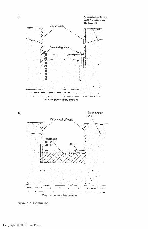
96 Control of surface water and groundwater
Figure 5.2 Continued.
Copyright © 2001 Spon Press
methods may be used in combination with exclusion methods (Fig. 5.2(b)).Alternatively, it may be possible to form a horizontal barrier or ‘floor’ to thecut-off structure to prevent vertical seepage (Fig. 5.2(c)). The construction ofhorizontal barriers is relatively rare, but has been carried out using jet grout-ing, mix-in-place, grouting and artificial ground freezing techniques.
If a complete physical cut-off is achieved, some groundwater will betrapped inside the working area. This will need to be removed to allowwork to proceed, either by sump pumping during excavation, or by pump-ing from wells or wellpoints prior to excavation.
One of the attractive characteristics of the exclusion technique is that itallows work to be carried out below groundwater level with minimal effectson groundwater levels outside the site. This means that any potential sideeffects of dewatering (see Chapter 13) are avoided. In particular, in urbanareas exclusion methods are often used in preference to dewatering meth-ods to reduce the risk of settlement damage resulting from lowering ofgroundwater levels. However, when considering using the exclusion tech-nique to avoid groundwater lowering in areas outside the site, it is essentialto remember that almost all walls will leak to some extent. Leakage mayparticularly occur through any joints (between columns, panels, piles, etc.)resulting from the method of formation.
Leakage of groundwater through cut-offs into the excavation or workingarea can cause a number of problems:
i During construction the seepages may interfere with site operations,necessitating the use of sump pump or surface water control methodsto keep the working area free of water.
ii The leakage into the excavation may be significant enough to locallylower groundwater levels outside the site, creating the risk of settlementor other side effects.
iii If the cut-offs form part of a permanent structure (such as the walls ofa deep basement) even very small seepages will be unsightly in the longterm and may cause problems with any architectural finishes applied tothe walls.
In many cases, the significant seepages that give rise to problems (i) and(ii) can be dealt with by grouting or other treatment. On the other hand, itcan be very difficult to prevent or to seal the small seepages of (iii). DavidGreenwood (1994) has said:
Water penetration is very difficult to oppose. It is comparatively easy toreduce torrents to trickles, but to eliminate trickles is difficult. If it is essen-tial to have a completely dry or leakproof structure, costs rise steeply.
This is an important point to consider if cut-off walls are to be incorporatedin the permanent works.
Control of surface water and groundwater 97
Copyright © 2001 Spon Press
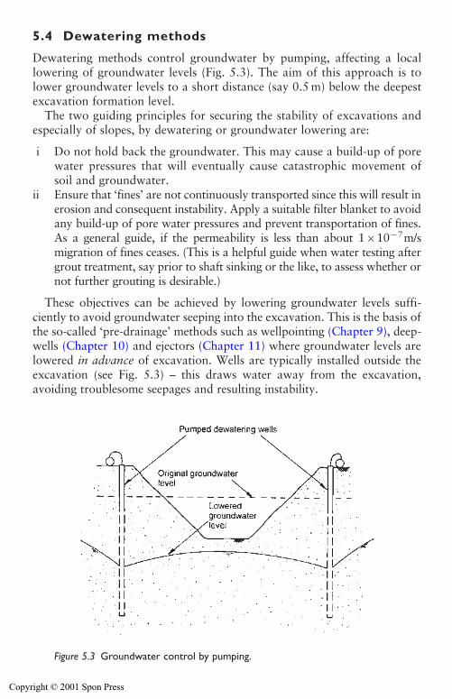
5.4 Dewatering methods
Dewatering methods control groundwater by pumping, affecting a locallowering of groundwater levels (Fig. 5.3). The aim of this approach is tolower groundwater levels to a short distance (say 0.5 m) below the deepestexcavation formation level.
The two guiding principles for securing the stability of excavations andespecially of slopes, by dewatering or groundwater lowering are:
i Do not hold back the groundwater. This may cause a build-up of porewater pressures that will eventually cause catastrophic movement ofsoil and groundwater.
ii Ensure that ‘fines’ are not continuously transported since this will result inerosion and consequent instability. Apply a suitable filter blanket to avoidany build-up of pore water pressures and prevent transportation of fines.As a general guide, if the permeability is less than about 1�10�7m/smigration of fines ceases. (This is a helpful guide when water testing aftergrout treatment, say prior to shaft sinking or the like, to assess whether ornot further grouting is desirable.)
These objectives can be achieved by lowering groundwater levels suffi-ciently to avoid groundwater seeping into the excavation. This is the basis ofthe so-called ‘pre-drainage’ methods such as wellpointing (Chapter 9), deep-wells (Chapter 10) and ejectors (Chapter 11) where groundwater levels arelowered in advance of excavation. Wells are typically installed outside theexcavation (see Fig. 5.3) – this draws water away from the excavation,avoiding troublesome seepages and resulting instability.
98 Control of surface water and groundwater
Figure 5.3 Groundwater control by pumping.
Copyright © 2001 Spon Press
The alternative approach is to allow groundwater to enter the excavationand then deal with it by sump pumping (Chapter 8); this is less than ideal,since it draws water toward the excavation and may promote instability.Nevertheless, this can be acceptable, provided that fines are not removedfrom the slopes and base of the excavation. This philosophy requires pump-ing and disposal of the seepage water collected and the creation of a filterblanket and collector drainage system. The filter blanket may be a sand orgravel layer of adequate thickness (say 0.5 m) and appropriate grading, ora suitable geotextile membrane held in place by some weighting materials(say cobbles and boulders). Measures necessary to avoid the instability ofexcavations under these conditions are described in Section 4.3.
There are several techniques or methods available for controlling ground-water flow for a construction project. The selection of a technique or tech-niques appropriate to a particular project at a particular site or country willdepend on many factors. However, the lithology and permeability(ies) ofthe soils will always be of paramount importance. Other factors to be con-sidered are:
� Extent of the area of construction requiring dewatering.� Depth of deepest formation level below existing ground level and the
amount of lowering required.� Proximity of existing structures, the nature of their foundations and the
soil strata beneath them.
The various dewatering techniques are tabulated in Table 5.2, which isbased on information from Preene et al. (2000).
There are projects where a single method is insufficient and a combinationof methods is appropriate. Where the excavation is to penetrate a successionof soils of widely varying lithology this problem is more likely to arise.
It will be seen from study of the column of Table 5.2 headed ‘Typicalapplications’, that only a few methods are suitable for use in all types of soils.The ranges of soils that are suitable for treatment by the various dewateringmethods are shown in Figure 5.4 in the traditional form of particle size dis-tribution curves. These curves are taken from CIRIA Report 113 (Somerville1986) and are based on the earlier work of Glossop and Skempton (1945)and others. Similarly the ranges of soils suitable for treatment by the variousexclusion methods are shown in Figure 5.5. These are tentative economic andphysical limits. The emphasis is on the word tentative.
An interesting and useful variation of Figure 5.4 was presented by Robertsand Preene (1994). Figure 5.6 is taken from CIRIA Report C515 (Preene et al. 2000) and is based on the Roberts and Preene (1994) original Range ofapplication of construction dewatering systems paper but has been modifiedin the light of the joint experiences of the authors (Cashman 1994) and oth-ers. The practical achievements at the lower end of the permeability range areconstrained by the physical limitations of applied vacuum. At the upper end
Control of surface water and groundwater 99
Copyright © 2001 Spon Press
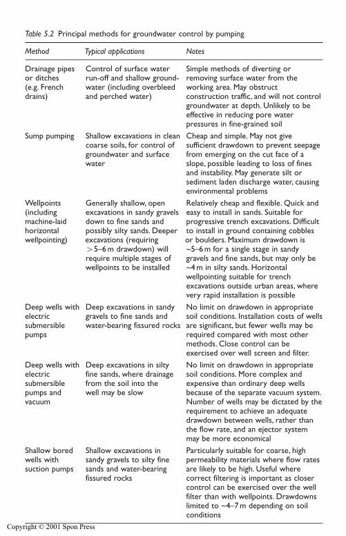
100 Control of surface water and groundwater
Table 5.2 Principal methods for groundwater control by pumping
Method Typical applications Notes
Drainage pipes Control of surface water Simple methods of diverting or or ditches run-off and shallow ground- removing surface water from the (e.g. French water (including overbleed working area. May obstructdrains) and perched water) construction traffic, and will not control
groundwater at depth. Unlikely to beeffective in reducing pore water pressures in fine-grained soil
Sump pumping Shallow excavations in clean Cheap and simple. May not give coarse soils, for control of sufficient drawdown to prevent seepage groundwater and surface from emerging on the cut face of a water slope, possible leading to loss of fines
and instability. May generate silt orsediment laden discharge water, causingenvironmental problems
Wellpoints Generally shallow, open Relatively cheap and flexible. Quick and (including excavations in sandy gravels easy to install in sands. Suitable formachine-laid down to fine sands and progressive trench excavations. Difficult horizontal possibly silty sands. Deeper to install in ground containing cobbles wellpointing) excavations (requiring or boulders. Maximum drawdown is
�5–6 m drawdown) will ~5–6 m for a single stage in sandyrequire multiple stages of gravels and fine sands, but may only be wellpoints to be installed ~4 m in silty sands. Horizontal
wellpointing suitable for trenchexcavations outside urban areas, wherevery rapid installation is possible
Deep wells with Deep excavations in sandy No limit on drawdown in appropriate electric gravels to fine sands and soil conditions. Installation costs of wells submersible water-bearing fissured rocks are significant, but fewer wells may be pumps required compared with most other
methods. Close control can beexercised over well screen and filter.
Deep wells with Deep excavations in silty No limit on drawdown in appropriate electric fine sands, where drainage soil conditions. More complex andsubmersible from the soil into the expensive than ordinary deep wells pumps and well may be slow because of the separate vacuum system.vacuum Number of wells may be dictated by the
requirement to achieve an adequatedrawdown between wells, rather thanthe flow rate, and an ejector systemmay be more economical
Shallow bored Shallow excavations in Particularly suitable for coarse, high wells with sandy gravels to silty fine permeability materials where flow rates suction pumps sands and water-bearing are likely to be high. Useful where
fissured rocks correct filtering is important as closercontrol can be exercised over the wellfilter than with wellpoints. Drawdowns limited to ~4–7 m depending on soilconditions
Copyright © 2001 Spon Press
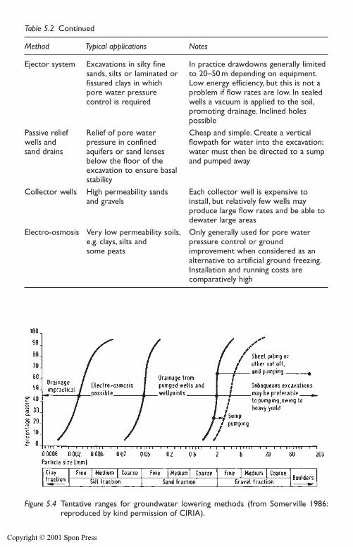
Control of surface water and groundwater 101
Table 5.2 Continued
Method Typical applications Notes
Ejector system Excavations in silty fine In practice drawdowns generally limitedsands, silts or laminated or to 20–50 m depending on equipment.fissured clays in which Low energy efficiency, but this is not a pore water pressure problem if flow rates are low. In sealed control is required wells a vacuum is applied to the soil,
promoting drainage. Inclined holes possible
Passive relief Relief of pore water Cheap and simple. Create a vertical wells and pressure in confined flowpath for water into the excavation;sand drains aquifers or sand lenses water must then be directed to a sump
below the floor of the and pumped awayexcavation to ensure basalstability
Collector wells High permeability sands Each collector well is expensive to and gravels install, but relatively few wells may
produce large flow rates and be able todewater large areas
Electro-osmosis Very low permeability soils, Only generally used for pore water e.g. clays, silts and pressure control or ground some peats improvement when considered as an
alternative to artificial ground freezing.Installation and running costs arecomparatively high
Figure 5.4 Tentative ranges for groundwater lowering methods (from Somerville 1986:reproduced by kind permission of CIRIA).
Copyright © 2001 Spon Press
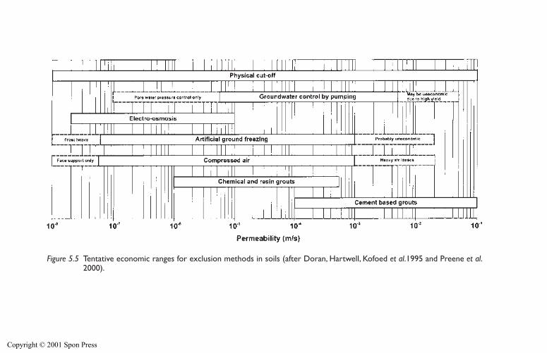
Figure 5.5 Tentative economic ranges for exclusion methods in soils (after Doran, Hartwell, Kofoed et al.1995 and Preene et al.2000).
Copyright © 2001 Spon Press
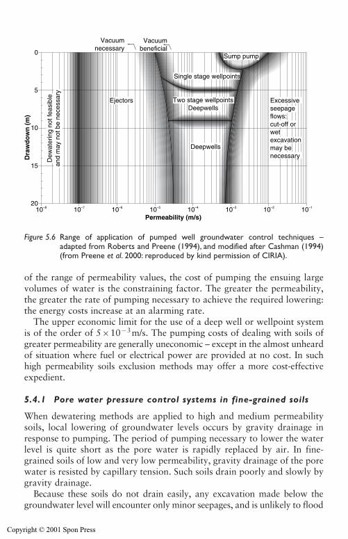
of the range of permeability values, the cost of pumping the ensuing largevolumes of water is the constraining factor. The greater the permeability,the greater the rate of pumping necessary to achieve the required lowering:the energy costs increase at an alarming rate.
The upper economic limit for the use of a deep well or wellpoint systemis of the order of 5�10�3m/s. The pumping costs of dealing with soils ofgreater permeability are generally uneconomic – except in the almost unheardof situation where fuel or electrical power are provided at no cost. In suchhigh permeability soils exclusion methods may offer a more cost-effectiveexpedient.
5.4.1 Pore water pressure control systems in fine-grained soils
When dewatering methods are applied to high and medium permeabilitysoils, local lowering of groundwater levels occurs by gravity drainage inresponse to pumping. The period of pumping necessary to lower the waterlevel is quite short as the pore water is rapidly replaced by air. In fine-grained soils of low and very low permeability, gravity drainage of the porewater is resisted by capillary tension. Such soils drain poorly and slowly bygravity drainage.
Because these soils do not drain easily, any excavation made below thegroundwater level will encounter only minor seepages, and is unlikely to flood
Control of surface water and groundwater 103
10–820
15
10
Ejectors
Deepwells
5
Dra
wd
ow
n (
m)
Permeability (m/s)
Dew
ater
ing
not f
easi
ble
and
may
not
be
nece
ssar
y0
10–7 10–6 10–5 10–4 10–3 10–2 10–1
Two stage wellpointsDeepwells
Single stage wellpoints
Vacuumnecessary
Vacuumbeneficial
Excessive seepageflows:cut-off or wetexcavation may benecessary
Sump pump
Figure 5.6 Range of application of pumped well groundwater control techniques –adapted from Roberts and Preene (1994), and modified after Cashman (1994)(from Preene et al. 2000: reproduced by kind permission of CIRIA).
Copyright © 2001 Spon Press
rapidly. Yet, even the small seepages encountered (perhaps less than 1 l/s evenfor a large excavation) can have a dramatic destabilizing effect. Side slopesmay collapse or slump inwards and the base may become unstable or ‘quick’.On site, people are often surprised that such small flow rates can be a prob-lem. The theory of effective stress explains the mechanism of instability (seeChapter 4). The seepages imply the presence of high positive pore water pres-sures around and beneath the excavation. This implies low levels of effectivestress, and hence low soil strength – instability is the natural result.
The solution to this problem is to abstract groundwater and so lower thepore water pressures around and beneath the excavation. This will main-tain effective stresses at acceptable levels and prevent instability. The aim isnot to totally drain the pore water from the soils – in any event this wouldbe very difficult as capillary forces mean that fine-grained soils can remainsaturated even at negative pore water pressures (see Fig. 3.7). Because thesoil is not being literally ‘dewatered’, pumped well systems in fine-grainedsoils are more correctly referred to as pore water pressure control systems,rather than dewatering systems. The application of pumped well systems inlow permeability soils is discussed further by Preene and Powrie (1994).
Glossop and Skempton (1945) and Terzaghi et al. (1996) indicated thatgravity drainage will prevail in soils of permeability greater than about5�10�5m/s. Where wells are installed as part of pore water pressure con-trol systems in soils of lesser permeability the well yields will be very low.This can make the continued operation of conventional wellpoint or deepwell systems difficult, as the pumps are prone to overheating at low flowrates. However, if the top of the wells are sealed a partial vacuum can beapplied to assist drainage. The increase in yield of a well due to the appli-cation of vacuum is likely to be of the order of 10 per cent, sometimes upto 15 per cent.
A sealed wellpoint system (see Section 9.5) operated by vacuum tankpump (see Section 12.1) may be effective in soils of permeability down toabout 1�10�6m/s. If a vacuum is applied to sealed deep wells (see Section10.8) the lower limit of effectiveness of deep wells may be extended toabout 1�10�5m/s. Ejectors (see Section 11.1) installed in sealed wells willautomatically generate a vacuum in the well when yields are low. Ejectorsystems can be effective in soils of permeability as low as 1�10�7m/s.
Again, the permeability ranges quoted above are tentative. In fine-grainedsoils, structure and fabric has a great influence on the performance of vac-uum well systems. If the soil structure consists of thin alternating layers orlaminations of coarser and finer soils, the drainage will be more rapid. Thisis because the layers of coarse material will more rapidly drain the adjacentlayers of finer-grained soil. There have also been cases where pore waterpressure control systems have been effective in clays of very low perme-ability – the success of the method was attributed to the presence of a per-meable fissure network in the clay.
104 Control of surface water and groundwater
Copyright © 2001 Spon Press
5.4.2 Some deep well and ejector projects deeper than 20 m
The 20 m depth limit in Fig. 5.6 is not restrictive, but is merely a conve-nience for presentation of the diagram. However, there are insufficientreported case histories to have confidence in extending Fig. 5.6 data below20 m depth but four known case histories are reported below to substanti-ate the view that, with care it is economically feasible to use wells andejectors to depths of the order of 40 m or more.
At Dungeness A nuclear power station sited on the south coast ofEngland, sixty deep wells were pumped for more than two years. The soilconditions at the site were:
(a) Gravel with cobbles, �5.5 mOD to �1.5 mOD, average permeability3�10�3m/s
(b) Original groundwater level from �2.4 mOD to 0.9 mOD(c) Gravelly sand, �1.5 mOD to �9.1 mOD, average permeability 8�
10�4m/s(d) Sand, �9.1 mOD to �33.5 mOD, permeability 1.5�10�4m/s decreas-
ing with depth to 5�10�5m/s.
The construction excavations were encircled by a continuous girdle ofinterlocking sheet piles driven to �9.1 mOD level so as to exclude rechargefrom the overlying high permeability soils. The lowering for the excavationsfor the Turbine Hall and the Reactors was achieved by pumping twenty-nine wells 20 m deep. The lowering for the Cooling Water Pumphouse andthe Syphon Recovery Chamber was achieved by pumping nineteen andtwelve wells respectively, each 41 m deep.
Prior to the construction of the East Twin Dry dock in Northern Ireland,site investigation borings had revealed a confined aquifer of Triassicsandstone beneath alluvial and glacial deposits (both mainly clays).The depth to the upper surface of Triassic sandstone varied between 34 mbelow ground level and 21 m (which was 1 m below the formation level ofthe entrance structure). There was a high piezometric level confined in thesandstone – to about 3 m above original ground level. Twenty deep wellswere installed to depths between 33.5 m and 43 m below ground level usingreverse circulation rotary drilling methods. The wells were operated forover two years.
At the Mufulira mine No. 3 dump, in northern Zambia, about 200 twinpipe ejectors were installed to reduce the moisture content and thereby stabilize slimes lagoon deposits, which were of porridge like consistencyand had broken through the roof of the main adit causing disastrous loss oflife. The Ministry of Mines, Zambia required that the slimes deposits overthe cave-in be stabilized before the mine could be permitted to reopen. Afternine months of pumping of the ejector installation the phreatic surface wasdrawn down about 10 m. Eventually the phreatic surface was drawn down
Control of surface water and groundwater 105
Copyright © 2001 Spon Press
some 30 m and resulted in an acceptable increase in the shear strength ofthe slimes deposits over the cave-in. The pumping lift was in the range from20 m to over 40 m.
At the Benutan dam site in Brunei single pipe ejectors were installed to sta-bilize alluvium comprising heterogeneous loose silty fine sands, very softclays, thin layers of peat and buried timbers (see Cole et al. 1994). Brunei isin an earthquake zone of moderate seismic activity so it was judged that therewas risk of liquefaction of these loose alluvial foundation soils beneath theproposed dam unless they were stabilized or replaced with other more stablematerials. As at Mufulira, an ejector system was installed and operated toreduce the pore water pressures of the loose soft soils and thereby increasetheir stability. The depths to which the ejectors were installed ranged fromabout 10 m to 38.5 m. The ejector pumping was continuous on the deepestline for about two years. The dam height was 20 m above valley floor level.
5.5 Groundwater control for tunnels and shafts
There is some merit in considering groundwater control for tunnels andshafts separately from methods used for surface excavations (although cut-and-cover tunnels are effectively surface excavations and can be dewateredaccordingly). Even though the great majority of tunnels are constructedbelow groundwater level, traditionally most tunnels through water-bearingground are constructed without dewatering by pumping from wells.
Dewatering is sometimes used for shaft construction, although manyshafts are constructed as flooded or ‘wet’ caissons. This method involvesthe shaft lining being constructed at ground level and sunk (by jacking orkentledge) into the ground, while material is excavated by grab from withinthe flooded caisson. This avoids the need to lower groundwater levels, butcarries its own set of risks. It can be difficult to control excavation levelswhen grabbing through considerable depths of water, and problems haveoccurred when due to over-excavation, or when boulders are present.
Ground treatment is often used to exclude groundwater from tunnels.Methods used include jet or injection grouting and artificial ground freez-ing, carried out from within the tunnel or from the surface. Any residualseepage into the tunnel is dealt with by maintaining some sump pumpingcapacity at the tunnel face.
Because many tunnelling methods construct a relatively watertight liningimmediately behind the working face, only a small area of tunnel face isexposed to water-bearing ground. This confined environment has allowedmethods to be developed whereby groundwater is excluded by maintainingthe tunnel face at a fluid pressure more or less equal to the groundwaterpressure.
The traditional way of balancing groundwater pressure is by compressedair working (Fig. 5.7(a)). This method, in use since the nineteenth century,
106 Control of surface water and groundwater
Copyright © 2001 Spon Press
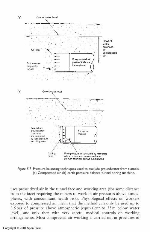
Control of surface water and groundwater 107
uses pressurized air in the tunnel face and working area (for some distancefrom the face) requiring the miners to work in air pressures above atmos-pheric, with concomitant health risks. Physiological effects on workersexposed to compressed air mean that the method can only be used up to3.5 bar of pressure above atmospheric (equivalent to 35 m below waterlevel), and only then with very careful medical controls on workingarrangements. Most compressed air working is carried out at pressures of
Figure 5.7 Pressure balancing techniques used to exclude groundwater from tunnels.(a) Compressed air, (b) earth pressure balance tunnel boring machine.
Copyright © 2001 Spon Press
less than 0.75 bar above atmospheric (known as low pressure compressedair); costs rise considerably above 0.75 bar (high pressure compressed air)due to the additional medical constraints. Compressed air working can alsobe used for shaft construction, when an air deck and airlocks are used toseal the top of the shaft.
An alternative method of balancing ground and groundwater pressures atthe tunnel face was developed in the late twentieth century – the earth pres-sure balance (EPB) tunnel boring machine (TBM). EPB machines are a formof full face TBM that cuts the soil from the tunnel face, and forms a fluidor ‘earth paste’ (consisting of soil cuttings, groundwater and conditioningagents such as polymer or bentonite muds) in a plenum chamber behind theface (Fig. 5.7(b)). By controlling the rate at which the fluid or paste isextruded from the plenum chamber as the TBM excavates and moves for-ward, the face can be supported by a balanced pressure. The TBM driverand miners work in a ‘free air’ (i.e. atmospheric) environment behind theplenum chamber, avoiding the health risks of compressed air working.
Cases do sometimes arise when groundwater control by pumping is usedin tunnel construction. Hartwell (2001) describes several case histories.Applications of groundwater lowering for tunnelling include:
i For construction of shafts to launch or receive TBMs, and for con-struction of ‘soft eyes’ in shaft linings.
ii The entry or exit of TBMs into or out of shafts, portals, outfalls andother structures.
iii For construction of tunnel enlargements, step plate junctions, cross pas-sages, adits or other connections where the tunnel lining has to bebreached temporarily.
iv To lower groundwater levels to allow compressed air working atreduced pressures (ideally less than 1 bar), for example to allow access tothe working head of a TBM for maintenance purposes. The dewateringwells should be located with care to avoid compressed air escapingthrough the ground to the wells.
v To reduce pore water pressures in fine-grained soils such as silts or verysilty sands, to reduce the risk of the soils liquefying as a result of vibra-tion from the machinery in the TBM.
vi To lower groundwater levels to below invert (to effectively ‘dewater’the tunnel) to allow open face tunnelling methods to be used in other-wise unstable ground. This is sometimes necessary when a TBMdesigned for relatively stable soils present over most of the tunnellength has to traverse a short section of alluvial or glacial soils whichmay be present in a buried channel or other geological feature.
vii For recovery of damaged or inundated TBMs.viii To control groundwater velocities to allow use of ground treatment
methods (such as artificial ground freezing or grouting) in problematicconditions.
108 Control of surface water and groundwater
Copyright © 2001 Spon Press
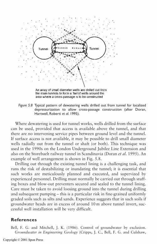
Where dewatering is used for tunnel works, wells drilled from the surfacecan be used, provided that access is available above the tunnel, and thatthere are no intervening service pipes between ground level and the tunnel.If surface access is not available, it may be possible to drill small diameterwells radially out from the tunnel or shaft (or both). This technique wasused in the 1990s on the London Underground Jubilee Line Extension andalso on the Storebaelt railway tunnel in Scandinavia (Doran et al. 1995). Anexample of well arrangement is shown in Fig. 5.8.
Drilling out through the existing tunnel lining is a challenging task, andruns the risk of destabilizing or inundating the tunnel; it is essential thatsuch works are meticulously planned and executed, and supervized byexperienced personnel. Drilling must normally be carried out through stuff-ing boxes and blow-out preventers secured and sealed to the tunnel lining.Care must be taken to avoid loosing ground into the tunnel during drillingand subsequent pumping – this is a particular risk in fine-grained uniformlygraded soils such as silts and sands. Experience suggests that in such soils ifgroundwater heads are in excess of around 10 m above tunnel invert, suc-cessful well installation will be very difficult.
References
Bell, F. G. and Mitchell, J. K. (1986). Control of groundwater by exclusion.Groundwater in Engineering Geology (Cripps, J. C., Bell, F. G. and Culshaw,
Control of surface water and groundwater 109
Figure 5.8 Typical pattern of dewatering wells drilled out from tunnel for localizeddepressurization to allow cross-passage construction (after Doran,Hartwell, Roberti et al. 1995).
Copyright © 2001 Spon Press
M. G., eds). Geological Society Engineering Geology Special Publication No. 3,London, pp 429–443.
Cashman, P. M. (1994). Discussion of Roberts and Preene (1994). GroundwaterProblems in Urban Areas (Wilkinson, W. B., ed.). Thomas Telford, London,pp 446–450.
Cole, R. G., Carter, I. C. and Schofield, R. J. (1994). Staged construction at BenutanDam assisted by vacuum eductor wells. Proceedings of the 18th InternationalConference on Large Dams, Durban, South Africa, 625–640.
Doran, S. R., Hartwell, D. J., Kofoed, N. and Warren, S. (1995). Storebælt Railwaytunnel – Denmark: design of cross passage ground treatment. Proceedings of the11th European Conference on Soil Mechanics and Foundation Engineering,Copenhagen, Denmark.
Doran, S. R., Hartwell, D. J., Roberti, P., Kofoed, N. and Warren, S. (1995).Storebælt Railway tunnel – Denmark: implementation of cross passage groundtreatment. Proceedings of the 11th European Conference on Soil Mechanics andFoundation Engineering, Copenhagen, Denmark.
Glossop, R. and Skempton, A. W. (1945). Particle-size in silts and sands. Journal ofthe Institution of Civil Engineers, 25, 81–105.
Greenwood, D. A. (1994). Engineering solutions to groundwater problems in urbanareas. Groundwater Problems in Urban Areas (Wilkinson, W. B., ed.). ThomasTelford, London, pp 369–387.
Hartwell, D. J. (2001). Getting rid of the water. Tunnels & TunnellingInternational, January, 40–42.
Preene, M. and Powrie, W. (1994). Construction dewatering in low permeabilitysoils: some problems and solutions. Proceedings of the Institution of CivilEngineers, Geotechnical Engineering, 107, 17–26.
Preene, M., Roberts, T. O. L., Powrie, W. and Dyer, M. R. (2000). GroundwaterControl – Design and Practice. Construction Industry Research and InformationAssociation, CIRIA Report C515, London.
Roberts, T. O. L., and Preene, M. (1994). Range of application of constructiondewatering systems. Groundwater Problems in Urban Areas (Wilkinson, W. B.,ed.). Thomas Telford, London, pp 415–423.
Somerville, S. H. (1986). Control of Groundwater for Temporary Works. ConstructionIndustry Research and Information Association, CIRIA Report 113, London.
Terzaghi, K., Peck, R. B. and Mesri, G. (1996). Soil Mechanics in EngineeringPractice, 3rd edition. Wiley, New York, p 305.
Further reading – exclusion methods
Steel sheet-piling
Williams, B. P. and Waite, D. (1993). The Design and Construction of Sheet-PiledCofferdams. Construction Industry Research and Information Association,CIRIA Special Publication 95, London.
Vibrated beam walls
Privett, K. D., Matthews, S. C. and Hodges, R. A. (1996). Barriers, Liners andCover Systems for Containment and Control of Land Contamination.
110 Control of surface water and groundwater
Copyright © 2001 Spon Press
Construction Industry Research and Information Association, CIRIA SpecialPublication 124, London, pp 59–60.
Slurry trench walls
Jefferis, S. A. (1993). In-ground barriers. Contaminated Land – Problems andSolutions (Cairney, T., ed.), Blackie, London, pp 111–140.
Structural concrete diaphragm walls and secant pile walls
Puller, M. (1996). Deep Excavations: A Practical Manual. Thomas Telford,London, pp 97–116.
Jet grouting
Essler, R. D. (1995). Applications of jet grouting in civil engineering. EngineeringGeology of Construction (Eddleston, M., Walthall, S., Cripps, J. C. and Culshaw,M. G., eds). Geological Society Engineering Geology Special Publication No. 10,London, pp 85–93.
Lunardi, P. (1997). Ground improvement by means of jet grouting. GroundImprovement, 1, 65–85.
Mix-in-place columns
Blackwell, J. (1994). A case history of soil stabilisation using the mix-in-place tech-nique for the construction of deep manhole shafts at Rochdale. Grouting in theGround (Bell, A. L., ed.). Thomas Telford, London, pp 497–509.
Greenwood, D. A. (1989). Sub-structure techniques for excavation support.Economic Construction Techniques. Thomas Telford, London, pp 17–40.
Injection grouting
Bell, A. L., (ed.). (1994). Grouting in the Ground. Thomas Telford, London.Little, A. L. (1975). Groundwater control by exclusion. Methods of Treatment of
Unstable Ground (Bell, F. G., ed.). Butterworths, London, pp 37–68.
Artificial ground freezing
Harris, J. S. (1995). Ground Freezing in Practice. Thomas Telford, London.
Compressed air
Megaw, T. M. and Bartlett, J. V. (1981). Tunnels: Planning, Design, Construction,Volume 1. Ellis Horwood, Chicester, pp 125–156.
Control of surface water and groundwater 111
Copyright © 2001 Spon Press
Chapter 6
Site investigation for groundwater lowering
6.0 Introduction
Site investigation was defined by Clayton et al. (1995) as:
The process by which geological, geotechnical and other relevant infor-mation which might affect the construction or performance of a civilengineering or building project is acquired.
This chapter describes the information which needs to be gathered toallow the design of groundwater lowering systems. Good practice in theplanning and execution of site investigations is outlined, together with briefdetails of methods used for boring, probing, testing, etc. The analysis of thedata gathered during site investigation is described with the design methodsin Chapter 7.
This chapter deals specifically with the site investigation requirements fordewatering projects. The successful design of such projects is highly depen-dent on obtaining realistic estimates of the permeability of the various soiland rock strata present beneath the site. Methods of permeability testing,their range of applicability and their relative merits and limitations are dis-cussed in detail.
6.1 The purpose of site investigation
Site investigation is the essential starting point, without which the design ofany construction or geotechnical process cannot progress. Groundwaterlowering is no exception to this rule. To quote the fictional detectiveSherlock Holmes:
It is a capital mistake to theorize before one has data(Sir Arthur Conan Doyle, A Scandal in Bohemia)
The best site investigations are deliberately planned and executed processesof discovery, carefully matched to the characteristics of the site, and to the
Copyright © 2001 Spon Press
work to be carried out. Sadly, many investigations in the past have not metthis challenging standard. The problems of poor or inadequate investiga-tions were highlighted in two reports by the Institution of Civil Engineers:Inadequate Site Investigation (Institution of Civil Engineers 1991) andWithout Investigation Ground is a Hazard (Site Investigation SteeringGroup 1993).
A particular problem for the designer of groundwater lowering works isthat, in many cases, investigations are designed primarily to provide infor-mation for the design of the permanent works. The information needed fordesign of temporary works (including groundwater lowering) is oftenneglected. This problem can arise when the persons designing the site inves-tigation do not have appropriate expertise or experience. Alternatively, poorcommunication may result in them not being informed of the likely need fordewatering, so they will not plan to gather the relevant information.
There is a wide and useful literature on site investigation, includingClayton et al. (1995), the British Standard Code of Practice for Site Inves-tigation (BS5930: 1999) and the Institution of Civil Engineers’ reports citedpreviously, and the reader should consult these for background on the sub-ject. The remainder of this chapter will concentrate on the particular siteinvestigation needs for projects where temporary works groundwater lower-ing schemes are to be employed.
6.2 Planning of site investigations
All site investigations need to be planned and designed in order that theyprovide the information needed by the various designers, estimators andconstruction managers. There is no such thing as a ‘standard’ site investi-gation, purely because ‘standard’ ground conditions have yet to be discov-ered, no matter how much we might wish for them!
According to the Institution of Civil Engineers (1991), the designers and planners of site investigations should attempt to answer the followingquestions:
(a) What is known about the site?(b) What is not known about the site?(c) What needs to be known?
On all but the smallest investigations, these questions cannot be answeredby one person, and may require input from specialists in soil and rockmechanics, engineering geology, geophysics, archaeology and hydrogeology.For groundwater lowering projects, advice from a dewatering specialist canalso aid the planning of investigations.
The planning, design, and ultimately procurement, of site investigationsis highly specialized. It is essential that this work is guided by a suitably
Site investigation for groundwater lowering 113
Copyright © 2001 Spon Press
qualified and experienced person, who should be associated with the siteinvestigation from conception to completion. Recommendations for thequalifications and experience required to act as geotechnical specialists andgeotechnical advisors are given in Site Investigation Steering Group (1993).
Effective communication between all parties involved in the constructionprocess is vital. This includes the site investigation as well, because withoutaccurate and up-to-date information how can an investigation be designed toanswer the questions listed earlier? The Construction (Design and Man-agement) Regulations 1994 (known as the CDM Regulations, see Chapter15) formalize this ethos, and require clients and designers to work with allparties from an early stage so that safe methods of work can be planned andadopted. This means that clients and designers must provide the designer andmanager of the site investigation with details of the proposed works (e.g.location, depth and size of excavation, support methods). Without thesedetails it is difficult to plan an investigation on a rational basis.
6.3 Stages of site investigation
A site investigation includes all the activities required to gather the neces-sary data about the site and should consist of a number of stages, listedbelow:
i Desk study,ii Site reconnaissance,iii Ground investigation,iv Reporting.
To many non-geotechnical specialists the ground investigation is per-ceived to be the ‘essence’ of a site investigation. In fact the ground investi-gation (which can involve trial pits, borings, in situ testing and laboratorytesting) aims only to determine ground and groundwater conditions at thesite. If other stages (especially the desk study) are neglected, inadequateinvestigations may result.
6.3.1 Desk study and site reconnaissance
The desk study and site reconnaissance (sometimes called a walk-over survey) are essential in any investigation – their importance cannot be over-estimated. Unfortunately, they are sometimes overlooked or consideredirrelevant.
The desk study is a review of all available information relevant to theproposed project including: geological and hydrogeological maps; aerialphotographs (if available); records of construction on nearby sites or thosewhere similar soil and groundwater conditions were encountered; records
114 Site investigation for groundwater lowering
Copyright © 2001 Spon Press
of nearby wells, boreholes and springs; and records of mining or previoususe of the site. Sources of information for desk studies are given byDumbleton and West (1976) and in Chapter 3 of Clayton et al. (1995).
The site reconnaissance is usually carried out after the desk study hasbeen largely completed. It comprises a walk-over survey of the site to gatherfurther information on the site surface conditions and access for the groundinvestigation, any exposed geological, groundwater or surface water fea-tures, and the nature of the areas surrounding the site.
Clayton et al. (1995) point out that both the desk study and site recon-naissance can provide large amounts of useful information at low cost – theyare by far the most cost effective stages of site investigation. They are essen-tial to allow efficient design of the ground investigation; failure to anticipateany predictable groundwater problems can result in poor or inadequateinvestigations, leading to potential problems during construction.
The desk study and site reconnaissance can also be used to gather infor-mation about the surroundings to the site, perhaps in areas where access forground investigation cannot be obtained. For groundwater lowering projectsthis is particularly useful to help determine whether there will be any adverseside effects of dewatering (such as ground settlement or derogation of watersupplies, see Chapter 13) outside the site. Brassington (1986) recommendsthat a survey of nearby groundwater supplies be carried out to aid theassessment of the risk of derogation to water users.
The problems which may result if the desk study and site reconnaissanceare neglected can be illustrated by two case histories.
(a) On a project through variable glacial soils in northern England, a newsewer was laid in an open-cut trench to replace an existing sewer, con-structed a few decades earlier. The new sewer was generally laid paral-lel to the old one, apart from one section where the old sewer took acircuitous ‘dog-leg’ route between manholes. The new sewer was totake the obvious straight-line route between the manholes. During con-struction of this section severe groundwater problems were encoun-tered, including a flowing artesian aquifer (see Section 3.3) immediatelybeneath the base of the excavation. Work was further hampered whenold abandoned sections of steel sheet-pile trench supports (probablydating from construction of the old sewer) were encountered. Withhindsight, it is fairly obvious that the old sewer was originally intendedto take the direct route between the manholes, but that groundwaterproblems forced them to abandon work and re-route the sewer. Thenew sewer was eventually completed, but a desk study of old construc-tion records may have allowed different methods to be adopted fromthe start, thus avoiding cost and time delays.
(b) A small sewerage project involved a wellpoint system to allow con-struction of a manhole. The manhole itself was excavated in sand and
Site investigation for groundwater lowering 115
Copyright © 2001 Spon Press
gravels, and was successfully dewatered. However, significant damageoccurred to several neighbouring structures as a result of ground set-tlements. Subsequent investigations showed that the damaged buildingswere founded on an extensive deposit of compressible peat. Althoughground investigation at the manhole site did not encounter any peat, adesk study review of geological maps would have revealed the presenceof peat beneath surrounding areas. This highlights the risk of damag-ing settlements, and would have allowed appropriate mitigation mea-sures, to reduce the impact of dewatering on nearby properties (seeSection 13.1), to be included in the project.
6.3.2 Ground investigation
There are numerous techniques available to physically investigate a site. It israrely obvious at the start of an investigation which methods will be suitableto gather the information needed by the project designers. It is preferable,therefore, that all but the smallest ground investigations be carried out inphases. The first phase may consist of an initial pattern of boreholes andtesting across the whole site. Preliminary results from the first phase willallow second and subsequent stages to be designed; such stages may includemore closely spaced boreholes in areas where ground conditions areunclear, or perhaps specialist testing such as a pumping test.
Ground investigation usually involves the use of some combination of thefollowing methods: boring, drilling, probing and trial pitting; in situ testing;geophysics; and laboratory testing. These ground investigation methods arebriefly outlined below, mainly in relation to British practice as outlined inBS5930 (1999) and BS1377 (1990). Factors particularly relevant to investi-gations for dewatering projects are highlighted.
In Britain the most common form of boring is light cable percussiondrilling, colloquially known as ‘shell and auger’ drilling (Fig. 6.1). Soil sam-ples may be recovered from the borehole (for description of soil type), or cer-tain types of in situ test may be performed within the borehole. A key pointto note is that at various stages during drilling water may be added to theborehole by the driller, or may be removed by the action of the boring tools.This can lead to natural groundwater levels and inflows being masked dur-ing boring operations.
Rotary drilling (using a water or air-based flush medium with polymer orfoam additives) is also widely used (Binns 1998), particularly in relativelyintact rock strata, but also in uncemented drift deposits. Core samples canbe recovered from the boreholes (for soil and rock description), and certaintypes of in situ tests carried out. Because the borehole is generally kept fullof the flush medium, groundwater levels and inflows can be difficult todetermine during drilling.
The older technique of wash boring is rarely used in Europe but is stillemployed in countries where labour is cheap. The basic rig is a winch tripod.
116 Site investigation for groundwater lowering
Copyright © 2001 Spon Press
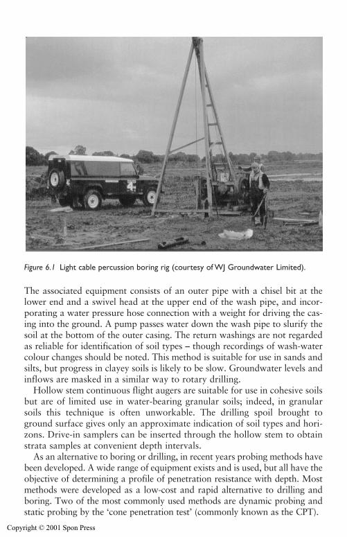
The associated equipment consists of an outer pipe with a chisel bit at thelower end and a swivel head at the upper end of the wash pipe, and incor-porating a water pressure hose connection with a weight for driving the cas-ing into the ground. A pump passes water down the wash pipe to slurify thesoil at the bottom of the outer casing. The return washings are not regardedas reliable for identification of soil types – though recordings of wash-watercolour changes should be noted. This method is suitable for use in sands andsilts, but progress in clayey soils is likely to be slow. Groundwater levels andinflows are masked in a similar way to rotary drilling.
Hollow stem continuous flight augers are suitable for use in cohesive soilsbut are of limited use in water-bearing granular soils; indeed, in granularsoils this technique is often unworkable. The drilling spoil brought toground surface gives only an approximate indication of soil types and hori-zons. Drive-in samplers can be inserted through the hollow stem to obtainstrata samples at convenient depth intervals.
As an alternative to boring or drilling, in recent years probing methods havebeen developed. A wide range of equipment exists and is used, but all have theobjective of determining a profile of penetration resistance with depth. Mostmethods were developed as a low-cost and rapid alternative to drilling andboring. Two of the most commonly used methods are dynamic probing andstatic probing by the ‘cone penetration test’ (commonly known as the CPT).
Site investigation for groundwater lowering 117
Figure 6.1 Light cable percussion boring rig (courtesy of WJ Groundwater Limited).
Copyright © 2001 Spon Press
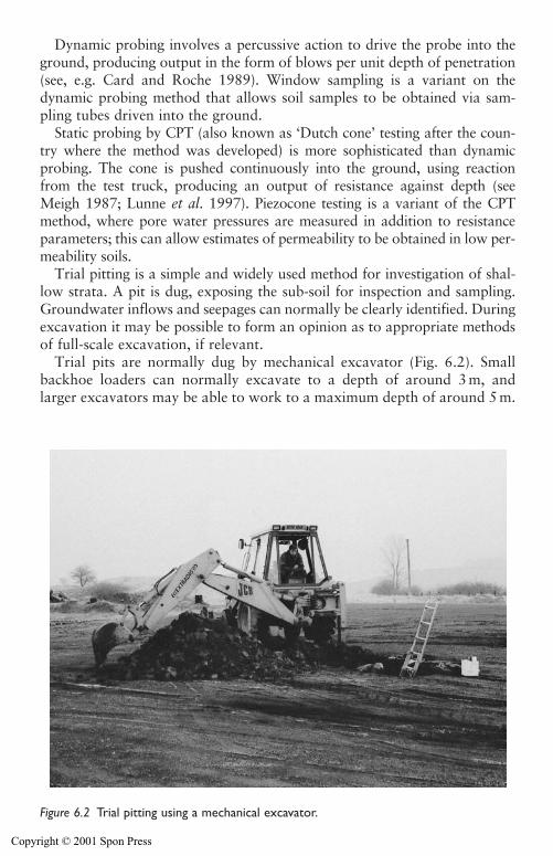
Dynamic probing involves a percussive action to drive the probe into theground, producing output in the form of blows per unit depth of penetration(see, e.g. Card and Roche 1989). Window sampling is a variant on thedynamic probing method that allows soil samples to be obtained via sam-pling tubes driven into the ground.
Static probing by CPT (also known as ‘Dutch cone’ testing after the coun-try where the method was developed) is more sophisticated than dynamicprobing. The cone is pushed continuously into the ground, using reactionfrom the test truck, producing an output of resistance against depth (seeMeigh 1987; Lunne et al. 1997). Piezocone testing is a variant of the CPTmethod, where pore water pressures are measured in addition to resistanceparameters; this can allow estimates of permeability to be obtained in low per-meability soils.
Trial pitting is a simple and widely used method for investigation of shal-low strata. A pit is dug, exposing the sub-soil for inspection and sampling.Groundwater inflows and seepages can normally be clearly identified. Duringexcavation it may be possible to form an opinion as to appropriate methodsof full-scale excavation, if relevant.
Trial pits are normally dug by mechanical excavator (Fig. 6.2). Smallbackhoe loaders can normally excavate to a depth of around 3 m, andlarger excavators may be able to work to a maximum depth of around 5 m.
118 Site investigation for groundwater lowering
Figure 6.2 Trial pitting using a mechanical excavator.
Copyright © 2001 Spon Press
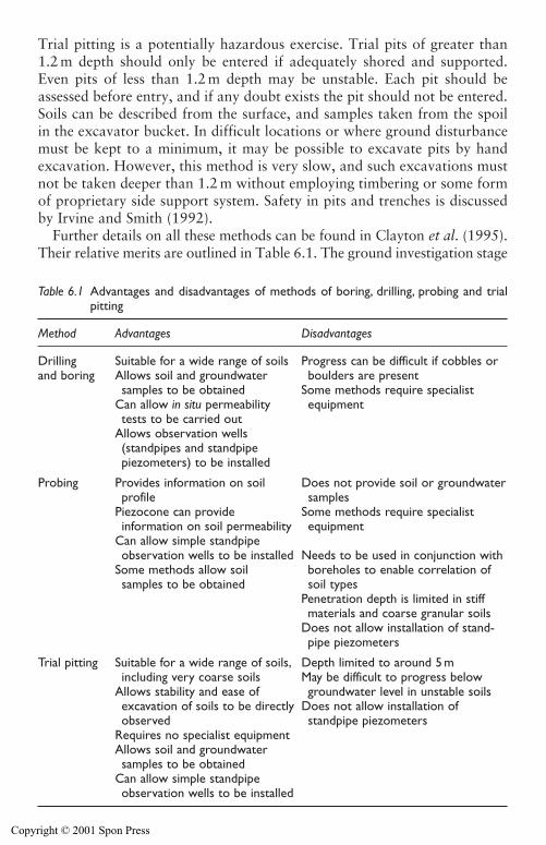
Trial pitting is a potentially hazardous exercise. Trial pits of greater than1.2 m depth should only be entered if adequately shored and supported.Even pits of less than 1.2 m depth may be unstable. Each pit should beassessed before entry, and if any doubt exists the pit should not be entered.Soils can be described from the surface, and samples taken from the spoilin the excavator bucket. In difficult locations or where ground disturbancemust be kept to a minimum, it may be possible to excavate pits by handexcavation. However, this method is very slow, and such excavations mustnot be taken deeper than 1.2 m without employing timbering or some formof proprietary side support system. Safety in pits and trenches is discussedby Irvine and Smith (1992).
Further details on all these methods can be found in Clayton et al. (1995).Their relative merits are outlined in Table 6.1. The ground investigation stage
Site investigation for groundwater lowering 119
Table 6.1 Advantages and disadvantages of methods of boring, drilling, probing and trialpitting
Method Advantages Disadvantages
Drilling Suitable for a wide range of soils Progress can be difficult if cobbles or and boring Allows soil and groundwater boulders are present
samples to be obtained Some methods require specialist Can allow in situ permeability equipmenttests to be carried out
Allows observation wells (standpipes and standpipe piezometers) to be installed
Probing Provides information on soil Does not provide soil or groundwaterprofile samples
Piezocone can provide Some methods require specialist information on soil permeability equipment
Can allow simple standpipeobservation wells to be installed Needs to be used in conjunction with
Some methods allow soil boreholes to enable correlation of samples to be obtained soil types
Penetration depth is limited in stiffmaterials and coarse granular soils
Does not allow installation of stand-pipe piezometers
Trial pitting Suitable for a wide range of soils, Depth limited to around 5 mincluding very coarse soils May be difficult to progress below
Allows stability and ease of groundwater level in unstable soilsexcavation of soils to be directly Does not allow installation of observed standpipe piezometers
Requires no specialist equipmentAllows soil and groundwater samples to be obtained
Can allow simple standpipe observation wells to be installed
Copyright © 2001 Spon Press
also includes the installation and monitoring of groundwater observationwells; this is discussed further in Section 6.5.
Various methods of in situ testing can be carried out as part of boring,drilling, probing and trial pitting. The most relevant of these to groundwa-ter lowering works are permeability tests; these are described in Section 6.6.
Geophysical methods are sometimes used in investigations for civil engineering works, but these methods are much more widely used in the oil,mineral extraction and water resource fields. In general, geophysical methodsare used to provide information on changes in particular properties of stratabeneath a site, and can be used to provide information between widelyspaced boreholes. The use of boreholes in combination with geophysics isimportant, because the borehole data can be used to ‘correlate’ or ‘calibrate’the geophysical results for the site in question. Geophysical methods usedfor civil engineering investigations are described in Clayton et al. (1995),Chapter 4 and McCann et al. (1997). Geophysical methods used in hydro-geological and water resource investigations are described by Barker (1986)and Beesley (1986). On a number of occasions when geophysics has beenused in investigations the results have been perceived to be disappointing orinconclusive. This is probably a reflection on an inappropriate choice andspecification of method, rather than a systematic drawback with the use ofgeophysics. To get the most out of geophysical surveying, it is essential thatengineering geophysicists are involved at an early stage of planning andthereafter; otherwise the method will not achieve its potential.
Samples of soil or rock obtained from boreholes or trial pits may be testedin the laboratory. The purpose of testing can be as an aid to soil descriptionand classification, or can be to determine soil properties for engineeringdesign. Properties routinely tested for include strength, compressibility, per-meability (see Section 6.6) and chemical characteristics. Samples of ground-water recovered during investigation may also be chemically tested in thelaboratory.
6.3.3 Reporting
To be useful to the designers and managers of the project, the site investiga-tion must be reported in an organized, concise and intelligible manner.Ideally, reporting should be carried out by geotechnical specialists who havebeen involved with the investigation since its inception. The minimumreporting requirement is for a ‘factual report’ which presents the data gath-ered during the desk study and site reconnaissance, and the borehole logs,trial pits logs, test results and groundwater monitoring data from the groundinvestigation. Such reports do not usually comment on the implications ofthe data gathered.
In many cases, particularly on large or complex projects, an ‘interpreta-tive report’ is produced in addition to the factual report. Again, written by
120 Site investigation for groundwater lowering
Copyright © 2001 Spon Press
geotechnical specialists, this should review the ground and groundwaterconditions at a site. It should include discussion of the effect of the antici-pated conditions on the proposed design and construction methods. At thetime the interpretative report is produced the project design may not befinalized, but the report should discuss the geotechnical aspects of the fullrange of design options current at that stage. If particular potential prob-lems in design and construction are highlighted, one of the report’s conclu-sions may be to recommend further or specialist investigations.
6.4 Determination of ground profile
Any investigation will need to identify the nature, depth, extent and orien-tation of the strata beneath the site. Collectively these parameters describethe ‘ground profile’, normally based on the results of trial pits, boreholes,geophysics and probing. Determination of the ground profile is an essentialpart of developing the groundwater conceptual model (see Section 7.2)needed to allow dewatering design.
It is essential that boreholes penetrate to adequate depth. The presence ofconfined aquifers or of localized zones of high permeability beneath exca-vations is a significant risk for many excavations. Boreholes in the area ofthe excavation should penetrate to a depth of 1.5–2 times the depth of theexcavation. There have been several cases where excavations failed due tobase heave (see Section 4.3) when investigation boreholes were not taken toadequate depths, but were terminated a few metres below proposed forma-tion level. The failure was caused by confined aquifers below formation,undetected during investigation. Such problems are frustrating because ifthe boreholes had been deeper and had detected the aquifer, groundwatercontrol (using relief wells) would have been simple and cost effective. As itwas, major cost and time delays resulted. The only case when boreholesshallower than the recommendation can be tolerated is if the desk studyclearly indicates that impermeable soils are present to considerable depthbelow formation level.
In addition to soil descriptions, groundwater level information and per-meability test results should help identify which strata are water-bearing(and may act as aquifers) and which strata are of low permeability (andmay act as aquitards and aquicludes). Compressibility test results may helpidentify any strata that may give rise to significant groundwater loweringinduced settlements.
6.5 Determination of groundwater conditions
In many investigations the observations of groundwater conditions aretotally inadequate, providing little concrete information on groundwaterlevels. Accurate knowledge of the likely range of groundwater levels and
Site investigation for groundwater lowering 121
Copyright © 2001 Spon Press
pore water pressures in the various strata is essential for the design of dewa-tering systems. This section will describe the types of groundwater observa-tions that may be taken during investigation, and will discuss their variousmerits and limitations.
6.5.1 Water level observations in trial pits and borings
The easiest and most common form of groundwater level observations arethose taken in trial pits and borings. Unfortunately, there are two importantlimitations to the accuracy of readings obtained in this way:
i The natural groundwater inflows and levels may be masked or hiddenby the excavation or boring method, particularly if water is added orremoved from the pit or borehole, or if drilling casing seals off inflowsof water.
ii For a pit or borehole to show a representative groundwater level, suf-ficient water must flow into the pit or borehole to fill it up to the nat-ural groundwater level. In soils of moderate or low permeability it cantake a long time for the water level in the pit or borehole to come intoequilibrium with the natural groundwater level. Most observations donot allow sufficient time for equilibrium, and so may report unrepre-sentative water levels.
Trial pits offer a simple way to observe shallow groundwater conditions.The size of the pit allows direct visual observation of inflows and seepages(it may be possible to categorize these as ‘slow’, ‘medium’ or ‘fast’ seepageson a subjective basis). The location of the seepages in relation to the soilfabric and layering can provide information on the relative permeability ofvarious strata – this can be a useful way of identifying perched water tables.The disadvantage of trial pits is that, because of their relatively large vol-ume, a significant volume of water has to enter the pit to fill it up to thenatural groundwater level. This process of equalization may take severaldays in soils of moderate permeability. The pit could be left open and mon-itored daily but, for safety reasons, trial pits are rarely left open for longperiods of time. In general, groundwater levels in trial pits may not berepresentative of natural groundwater levels.
In British site investigation practice, the most common form of ground-water observations are those recorded by the drilling foreman during lightcable percussion drilling. Each time groundwater is encountered theserecords should comprise:
(a) The depth at which water is first encountered (known as a ‘water strike’).(b) A description of the speed of inflow (e.g. slow, medium, fast). Boring is
normally suspended following a water strike and groundwater levels
122 Site investigation for groundwater lowering
Copyright © 2001 Spon Press
observed to record the rise (if any) in groundwater levels. Ideally, mon-itoring should continue until the water level in the borehole stabilizes,but often the rise in water level is recorded for a fixed period (often20 min) only, before boring recommences.
(c) The depth at which the groundwater inflow is sealed off by the tempo-rary drilling casings.
Additionally the drilling foreman should record whether water wasadded to the borehole during drilling and should record the water level inthe borehole at the start and end of the drilling shift (together with thecorresponding depth of borehole and casing at that time). All groundwaterdetails are recorded on the driller’s daily record sheet, and should appearon the final borehole log.
When reviewing water levels recorded during boring the following pointsmust be noted:
(a) In all but the most permeable soils, observing the water level rise for ashort period following a water strike, may not allow sufficient time forthe natural groundwater level to be apparent. In many cases the waterlevel recorded following a water strike will be lower than the actualgroundwater level in that stratum.
(b) A significant rise in borehole water level following a water strike mayindicate the presence of a confined aquifer, particularly if the waterstrike occurs just after the borehole has passed from a low perme-ability stratum into a high permeability one. However, smaller rises inwater levels may be observed, even in unconfined aquifers. This occurswhen the driller has drilled a short distance below the water tablebefore noticing the inflow. The drilling action will have removed somewater from the borehole and when drilling stops the water level willrise up to the natural level.
(c) Because of the speed of boring, when drilling through soils of perme-ability from very low to moderate (such as clays, silts and silty sands)a water strike may not be noticed at all by the driller. The spoil fromthe borehole will be damp or moist, but there will not be time for freewater to enter the borehole. There have been cases when groundwaterinflow was not recorded in investigation borings through strata of siltysand, yet excavation works encountered groundwater and needed sig-nificant dewatering. This error could have been avoided by installingand monitoring observation wells, which allow time for equalization ofwater levels.
(d) The boring process will inevitably alter the water level in the boreholeso it is not representative of that in the surrounding soil. The action ofthe drilling tool will remove water, and the driller may be deliberatelyadding water as part of the drilling process. The water level in the bore-hole at the end of the shift is likely to be very unreliable, being highly
Site investigation for groundwater lowering 123
Copyright © 2001 Spon Press
influenced by the recent drilling activities. If drilling work is done on aday shift basis, the water level at the start of shift (next morning) maybe more reliable as the borehole water level will have begun to equal-ize overnight. Even so, the start of shift level may still be unrepresenta-tive, especially in low permeability soils, where longer periods may benecessary for full equalization.
Observations during rotary drilling are generally unsatisfactory, becauseduring drilling the borehole is either kept topped up with water (if water-based flush fluids are used) or water is continually blown out of the borehole(if air-based flush fluids are used). It can be difficult to detect discrete ground-water inflows during drilling. As with boring methods, the water levels at thestart of a shift tend to be more reliable than those observed at the end ofthe shift.
The principal drawback which affects all groundwater observations dur-ing trial pitting or boring is that, at best, they only give ‘spot’ readings ofconditions at the time of investigation. As was discussed in Chapter 3, ingeneral groundwater levels are not constant, but will vary with the seasons,with long terms trends (such as drought) or in response to external influ-ences. Observations in trial pits and boreholes cannot give information onpotential variations, and (depending on the time of year when they weredrilled) may not indicate the highest groundwater level that can occur at asite. This type of information can only be obtained by the installation andmonitoring of observation wells of some sort.
6.5.2 Observation wells
An observation well is an instrument installed in the ground at a specific loca-tion to allow measurement of the groundwater level or pore water pressure.When determining groundwater levels observation wells have a number ofadvantages over observations during boring:
1 Because they are long-term installations, appropriately designed obser-vation wells can allow observation of equilibrium groundwater levels,even in very low permeability soils.
2 Observation wells can be installed as piezometers to record water lev-els or pore water pressures in a specific stratum.
3 Observation wells can be monitored for long periods of time, toobserve the variations in groundwater level at a site.
The two most commonly used devices for monitoring groundwater levelsin permeable soils are standpipes and standpipe piezometers.
The simplest from of observation well is the standpipe (see Fig. 6.3). Thisconsists of a small diameter pipe, of which the bottom section (usually atleast 1 m in length) is perforated or slotted, with the base plugged. The pipe
124 Site investigation for groundwater lowering
Copyright © 2001 Spon Press
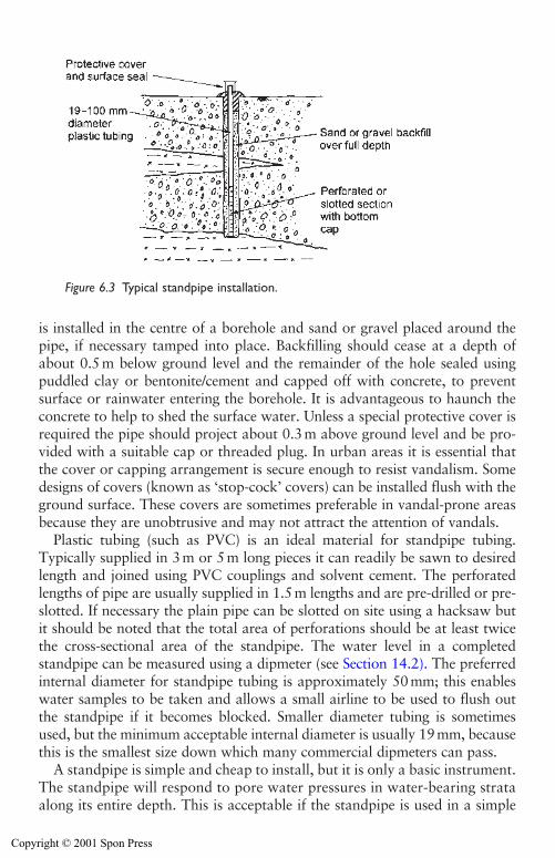
is installed in the centre of a borehole and sand or gravel placed around thepipe, if necessary tamped into place. Backfilling should cease at a depth ofabout 0.5m below ground level and the remainder of the hole sealed usingpuddled clay or bentonite/cement and capped off with concrete, to preventsurface or rainwater entering the borehole. It is advantageous to haunch theconcrete to help to shed the surface water. Unless a special protective cover isrequired the pipe should project about 0.3m above ground level and be pro-vided with a suitable cap or threaded plug. In urban areas it is essential thatthe cover or capping arrangement is secure enough to resist vandalism. Somedesigns of covers (known as ‘stop-cock’ covers) can be installed flush with theground surface. These covers are sometimes preferable in vandal-prone areasbecause they are unobtrusive and may not attract the attention of vandals.
Plastic tubing (such as PVC) is an ideal material for standpipe tubing.Typically supplied in 3m or 5m long pieces it can readily be sawn to desiredlength and joined using PVC couplings and solvent cement. The perforatedlengths of pipe are usually supplied in 1.5m lengths and are pre-drilled or pre-slotted. If necessary the plain pipe can be slotted on site using a hacksaw butit should be noted that the total area of perforations should be at least twicethe cross-sectional area of the standpipe. The water level in a completedstandpipe can be measured using a dipmeter (see Section 14.2). The preferredinternal diameter for standpipe tubing is approximately 50mm; this enableswater samples to be taken and allows a small airline to be used to flush outthe standpipe if it becomes blocked. Smaller diameter tubing is sometimesused, but the minimum acceptable internal diameter is usually 19mm, becausethis is the smallest size down which many commercial dipmeters can pass.
A standpipe is simple and cheap to install, but it is only a basic instrument.The standpipe will respond to pore water pressures in water-bearing strataalong its entire depth. This is acceptable if the standpipe is used in a simple
Site investigation for groundwater lowering 125
Figure 6.3 Typical standpipe installation.
Copyright © 2001 Spon Press
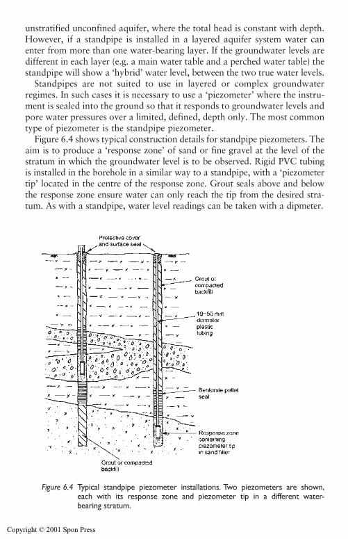
unstratified unconfined aquifer, where the total head is constant with depth.However, if a standpipe is installed in a layered aquifer system water canenter from more than one water-bearing layer. If the groundwater levels aredifferent in each layer (e.g. a main water table and a perched water table) thestandpipe will show a ‘hybrid’ water level, between the two true water levels.
Standpipes are not suited to use in layered or complex groundwaterregimes. In such cases it is necessary to use a ‘piezometer’ where the instru-ment is sealed into the ground so that it responds to groundwater levels andpore water pressures over a limited, defined, depth only. The most commontype of piezometer is the standpipe piezometer.
Figure 6.4 shows typical construction details for standpipe piezometers. Theaim is to produce a ‘response zone’ of sand or fine gravel at the level of thestratum in which the groundwater level is to be observed. Rigid PVC tubingis installed in the borehole in a similar way to a standpipe, with a ‘piezometertip’ located in the centre of the response zone. Grout seals above and belowthe response zone ensure water can only reach the tip from the desired stra-tum. As with a standpipe, water level readings can be taken with a dipmeter.
126 Site investigation for groundwater lowering
Figure 6.4 Typical standpipe piezometer installations. Two piezometers are shown,each with its response zone and piezometer tip in a different water-bearing stratum.
Copyright © 2001 Spon Press
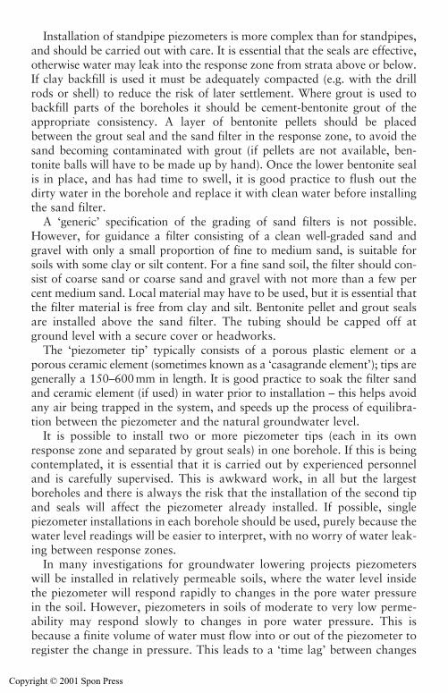
Installation of standpipe piezometers is more complex than for standpipes,and should be carried out with care. It is essential that the seals are effective,otherwise water may leak into the response zone from strata above or below.If clay backfill is used it must be adequately compacted (e.g. with the drillrods or shell) to reduce the risk of later settlement. Where grout is used tobackfill parts of the boreholes it should be cement-bentonite grout of theappropriate consistency. A layer of bentonite pellets should be placedbetween the grout seal and the sand filter in the response zone, to avoid thesand becoming contaminated with grout (if pellets are not available, ben-tonite balls will have to be made up by hand). Once the lower bentonite sealis in place, and has had time to swell, it is good practice to flush out thedirty water in the borehole and replace it with clean water before installingthe sand filter.
A ‘generic’ specification of the grading of sand filters is not possible.However, for guidance a filter consisting of a clean well-graded sand andgravel with only a small proportion of fine to medium sand, is suitable forsoils with some clay or silt content. For a fine sand soil, the filter should con-sist of coarse sand or coarse sand and gravel with not more than a few percent medium sand. Local material may have to be used, but it is essential thatthe filter material is free from clay and silt. Bentonite pellet and grout sealsare installed above the sand filter. The tubing should be capped off atground level with a secure cover or headworks.
The ‘piezometer tip’ typically consists of a porous plastic element or aporous ceramic element (sometimes known as a ‘casagrande element’); tips aregenerally a 150–600mm in length. It is good practice to soak the filter sandand ceramic element (if used) in water prior to installation – this helps avoidany air being trapped in the system, and speeds up the process of equilibra-tion between the piezometer and the natural groundwater level.
It is possible to install two or more piezometer tips (each in its ownresponse zone and separated by grout seals) in one borehole. If this is beingcontemplated, it is essential that it is carried out by experienced personneland is carefully supervised. This is awkward work, in all but the largestboreholes and there is always the risk that the installation of the second tipand seals will affect the piezometer already installed. If possible, singlepiezometer installations in each borehole should be used, purely because thewater level readings will be easier to interpret, with no worry of water leak-ing between response zones.
In many investigations for groundwater lowering projects piezometerswill be installed in relatively permeable soils, where the water level insidethe piezometer will respond rapidly to changes in the pore water pressurein the soil. However, piezometers in soils of moderate to very low perme-ability may respond slowly to changes in pore water pressure. This isbecause a finite volume of water must flow into or out of the piezometer toregister the change in pressure. This leads to a ‘time lag’ between changes
Site investigation for groundwater lowering 127
Copyright © 2001 Spon Press
in pore water pressure in the soil and the registering of that change in thepiezometer. The time lag is greater in soils of lower permeability, and isgreater for piezometers where larger volume flows are needed to registerpressure changes.
In a standpipe piezometer the prime factor controlling the equilibrationrate is the internal diameter of the tubing; the smaller the diameter theshorter the time lag and the quicker the piezometer will respond to pressurechanges. In soils of low to moderate permeability, it is normal to specify theinternal diameter of the tubing as small as possible (19 mm is the lowerpracticable limit to allow monitoring by dipmeter). However, in permeablesoils such as sand and gravels, the equilibration rate will tend to be rapid,and 50 mm diameter tubing could be used, allowing greater flexibility forsampling or flushing out of the piezometer.
A defining feature of observation wells is that (provided they are ade-quately protected from damage or vandalism) they can be used to observegroundwater levels long after the main ground investigation is complete.This can allow natural changes in groundwater levels to be determined.However, this requires the instruments to be monitored for extended peri-ods, and the practicalities of this are sometimes overlooked. If readings areto be taken manually this will have to be included in the site investigationplan and associated costings. In remote or inaccessible sites it may beappropriate to use datalogging systems (see Section 14.5) to record ground-water levels, to reduce the cost associated with regular visits by personnel.
6.5.3 Other methods for determination of groundwater levelsand pore water pressures
There may be occasions, especially in soils of low or very low permeabilitywhen the time lag is so great that the equilibration rate of a standpipepiezometer is too slow to give useful readings. In such cases, specialistinstruments such as pneumatic piezometers or electronic vibrating wirepressure transducers could be used. These instruments are characterized bythe very small volume of water which must flow into or out of the sensorin order to record a change in pressure; they have been used successfully toobserve pore water pressure changes in silts, clays and laminated soils.
Such specialist instruments must be specified, installed and calibrated withcare; instrument manufacturers can often provide useful advice. The instru-ments are installed in a discrete response zone in a similar way to a stand-pipe piezometer, but instead of an open pipe these instruments are connectedto ground level by a cable or small bore tubing (Fig. 6.5). At ground level thecables can be terminated (to be read later using a portable read-out unit) orare connected to a datalogger system (see Section 14.5) to allow regular read-ings at pre-programmed intervals. The datalogger unit can be located somedistance from the piezometer itself, being connected by cable or tubing. This
128 Site investigation for groundwater lowering
Copyright © 2001 Spon Press
allows these instruments to be used where there is no permanent surfaceaccess for reading; with suitable grout seals, they have been used in boreholesbeneath rivers and lagoons, with the datalogger located on the shore.
These instruments do not record total head, but record pore water pressure(above the level of the instrument). To interpret readings from the instru-ments correctly, the precise level at which the instrument was placed must berecorded during installation. Determination of total head or piezometric levelfrom pore water pressure readings is described in Section 3.2.
Table 6.2 summarizes the advantages and disadvantages of methods ofdetermining groundwater levels.
6.5.4 Groundwater sampling and testing
Knowledge of groundwater chemistry may be required for a variety of reasons(see Section 3.8). In particular groundwater chemistry can influence how dis-charge water can be disposed of, or may affect any potential side effects ofdewatering. Groundwater samples should be obtained and tested as part ofthe site investigation.
Where groundwater is encountered during drilling and boring, obtaininga sample is relatively straightforward. The water sample should be takenusing a clean sampling bailer as soon as possible after the seepage hasbegun. If water has been added during boring this should be bailed outprior to taking the sample.
Groundwater samples can also be taken from observation wells by use ofa sampling pump. The water in the observation well has been exposed to theatmosphere and is unlikely to represent the true aquifer water chemistry.
Site investigation for groundwater lowering 129
Figure 6.5 Specialist piezometers.
Copyright © 2001 Spon Press
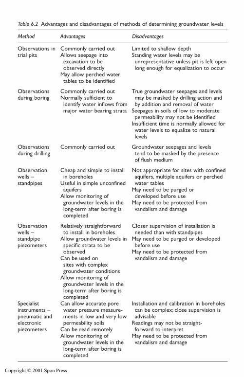
130 Site investigation for groundwater lowering
Table 6.2 Advantages and disadvantages of methods of determining groundwater levels
Method Advantages Disadvantages
Observations in Commonly carried out Limited to shallow depthtrial pits Allows seepage into Standing water levels may be
excavation to be unrepresentative unless pit is left open observed directly long enough for equalization to occur
May allow perched watertables to be identified
Observations Commonly carried out True groundwater seepages and levels during boring Normally sufficient to may be masked by drilling action and
identify water inflows from by addition and removal of watermajor water bearing strata Seepages in soils of low to moderate
permeability may not be identifiedInsufficient time is normally allowed forwater levels to equalize to naturallevels
Observations Commonly carried out Groundwater seepages and levels during drilling tend to be masked by the presence
of flush medium
Observation Cheap and simple to install Not appropriate for sites with confined wells – in boreholes aquifers, multiple aquifers or perched standpipes Useful in simple unconfined water tables
aquifers May need to be purged or Allow monitoring of developed before usegroundwater levels in the May need to be protected fromlong-term after boring is vandalism and damagecompleted
Observation Relatively straightforward Closer supervision of installation is wells – to install in boreholes needed than with standpipesstandpipe Allow groundwater levels in May need to be purged or developed piezometers specific strata to be before use
observed May need to be protected fromCan be used on vandalism and damagesites with complex groundwater conditions
Allow monitoring of groundwater levels in the long-term after boring is completed
Specialist Can allow accurate pore Installation and calibration in boreholesinstruments – water pressure measure- can be complex; close supervision is pneumatic and ments in low and very low advisableelectronic permeability soils Readings may not be straight-piezometers Can be read remotely forward to interpret
Allow monitoring of May need to be protected fromgroundwater levels in the vandalism and damagelong-term after boring is completed
Copyright © 2001 Spon Press
Therefore, it is vital to fully ‘purge’ the well before taking a sample. Purginginvolves pumping the observation well at a fairly steady rate until at leastthree ‘well volumes’ of water have been removed (a ‘well volume’ is the vol-ume of water originally contained inside the well liner). Specialist samplingpumps should be used in preference to airlifting, since the latter methodmay aerate the sample, increasing the risk of oxidation of trace metals andother substances. Obtaining a water sample during a pumping test isdescribed in Appendix 6C.
In general, water samples should be of a least 1 litre volume. The bottlesused for sampling should be clean with a good seal, and should be filled tothe brim with water to avoid air bubbles in the sample. The sample bottleshould be washed out three times (with the water being sampled) beforetaking the final sample.
Samples may degrade following sampling and should be tested as soon aspossible after they are taken. Ideally, they should be refrigerated in themeantime. However, even then the sample may degrade in the bottle (e.g. bytrace metals oxidizing and precipitating out of solution). Specialists may beable to advise on the addition of suitable preservatives to prevent this occur-ring. The choice of sample bottle (glass or plastic) should also be discussedwith the laboratory since some test results can be influenced by the materialof the sample bottle. Above all, it is vital to use an accredited, experiencedlaboratory for the chemical testing of water samples.
6.6 Determination of permeability
Permeability is an essential parameter to be determined for the design ofgroundwater lowering systems. There is a wide range of methods for deter-mining permeability, some of which have been in use since the nineteenthcentury. The available methods can be classified into four main types.
(a) Laboratory testing (including particle size analysis and permeametertesting)
(b) Small-scale in situ tests (including borehole, piezometer and specialisttests)
(c) Large-scale in situ tests (including pumping tests and groundwater con-trol trials)
(d) Other methods (including geophysics, visual assessment, and inversenumerical modelling).
While many test methods are available, obtaining realistic values of per-meability is far from straightforward. The key problem is that, as was des-cribed in Section 3.2, soils and rocks are not homogenous isotropic masses.Permeability is likely to vary from place to place and to be different for dif-ferent directions of measurement. As was stated by Preene et al. (1997) ‘Even
Site investigation for groundwater lowering 131
Copyright © 2001 Spon Press
if it could be obtained, there is no single value of permeability in the groundwaiting to be measured’.
If it is accepted that it can be difficult to determine meaningful values ofpermeability, that should still not deter those involved in site investigationand dewatering design from putting their best efforts into obtaining the mostuseful values practicable. The following sections outline the characteristicsand limitations of the most commonly used methods of determining perme-ability. The final section in this chapter discusses the relative reliability of thevarious techniques. Selection of permeability for the design of groundwaterlowering systems is dealt with in Chapter 7.
6.6.1 Visual assessment
Visual assessment of the permeability of a soil sample is the process ofassessing the soil type or grading and, based on experience or published val-ues (such as Table 3.1), estimating a very approximate range of permeabil-ity. This method is essential to allow corroboration of permeability testresults. On every project the soil descriptions from borehole or trial pit logsshould be reviewed to give a crude permeability range, against which latertest results can be judged. Information gathered by the desk study, such asexperience from nearby projects, can be useful in this regard.
For example a soil described as a medium sand might typically be expectedto have a permeability of the order of 10�4 m/s; certainly such a soil wouldbe unlikely to have a permeability greater than 10�3 m/s or less than 10�5 m/s.If permeability tests give results of 10�8 m/s there is clearly some discrepancy.Either the soil description is misleading or the test results are in error orunrepresentative. If this is recognized while testing is still going on there maybe a chance to modify test types or procedures to get better results.Discrepancies of this magnitude are not rare, and visual assessment of per-meability can often be a more useful guide to permeability than test results,especially if the latter are limited in scope and questionable in quality.
6.6.2 Inverse numerical modelling
This approach can only be used if extensive groundwater monitoring data(e.g. data from a number of observation wells over a long time period) areavailable. It also requires a thorough understanding of the geological structure and extent of the aquifers in the area. The method involves settingup a numerical model of the aquifer system in the vicinity of the site andrunning the model with a variety of permeability and other parameters,until an acceptable match is obtained between the model output and thegroundwater monitoring data.
This approach is not straightforward and is carried out only rarely. Sincea number of parameters, in addition to permeability, will be varied during
132 Site investigation for groundwater lowering
Copyright © 2001 Spon Press
the modelling, a ‘non-unique’ solution may result. In other words, a num-ber of permeability values may give an acceptable fit with the data, depend-ing on what other parameter values are used.
6.6.3 Geophysics
Geophysical methods have traditionally been used extensively in hydrogeo-logical studies for the development of groundwater resources, but are usedonly rarely in investigations for construction projects. The methods avail-able can be divided into two main types:
i Surface geophysical methods,ii Downhole (or borehole) geophysical methods.
These methods do not generally give direct estimates of permeability val-ues, but can allow: indirect estimation of permeability; identification ofzones of relatively high or low permeability; or correlation of permeabilityvalues between different parts of a site (Macdonald et al. 1999).
Surface geophysical methods include seismic refraction methods, gravitysurveying, electromagnetic surveying and the most widely used method,resistivity soundings (Barker 1986). These methods measure the variationin specific physical properties of the sub-surface environment, and applytheoretical and empirical correlations to infer the structure of the groundand groundwater regime. Typical applications include mapping the extentof gravel deposits within extensive clay strata, or locating buried channelfeatures within drift deposits overlying bedrock.
Downhole geophysical methods involve surveying previously constructedboreholes. This is normally achieved by lowering various sensing devices(known as ‘sondes’) into the borehole. Some types of sonde investigate theproperties of the aquifer material (this is known as formation logging) whileothers measure the properties of the water in the borehole (fluid logging). Thevarious methods available are described in Beesley (1986) and BS7022(1988). These methods are generally applicable in boreholes drilled into rock,when more permeable fissured or fractured zones can sometimes be identified.
Geophysical methods are specialized techniques. Their application andinterpretation requires care. In all but the simplest of cases, specialist adviceshould be obtained from experienced geophysicists.
6.6.4 Laboratory testing: particle size analysis
There are a number of empirical methods available to allow the permeabilityof granular soils to be estimated from analyses of particle size distributions(PSDs) of samples. An American water works and sanitary engineer from NewEngland, Allen Hazen (1892; 1900) was the first to propose an empiricalcorrelation for the permeability of a sand from its PSD curve. Probably due
Site investigation for groundwater lowering 133
Copyright © 2001 Spon Press
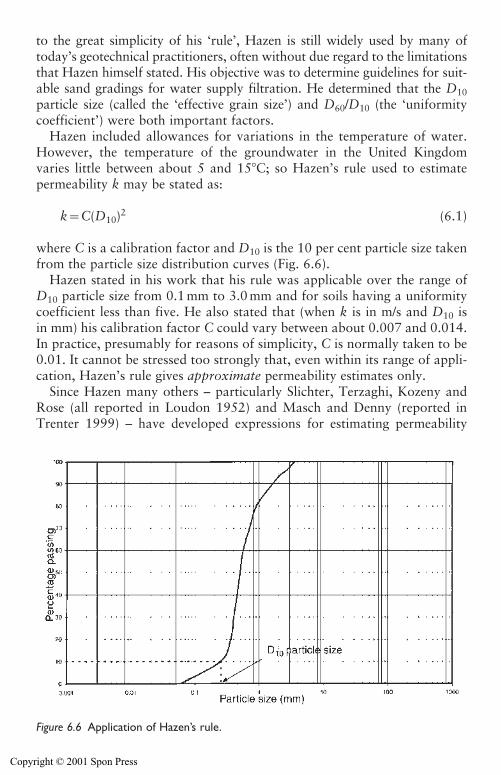
to the great simplicity of his ‘rule’, Hazen is still widely used by many oftoday’s geotechnical practitioners, often without due regard to the limitationsthat Hazen himself stated. His objective was to determine guidelines for suit-able sand gradings for water supply filtration. He determined that the D10particle size (called the ‘effective grain size’) and D60/D10 (the ‘uniformitycoefficient’) were both important factors.
Hazen included allowances for variations in the temperature of water.However, the temperature of the groundwater in the United Kingdomvaries little between about 5 and 15�C; so Hazen’s rule used to estimate permeability k may be stated as:
k�C(D10)2 (6.1)
where C is a calibration factor and D10 is the 10 per cent particle size takenfrom the particle size distribution curves (Fig. 6.6).
Hazen stated in his work that his rule was applicable over the range ofD10 particle size from 0.1 mm to 3.0 mm and for soils having a uniformitycoefficient less than five. He also stated that (when k is in m/s and D10 isin mm) his calibration factor C could vary between about 0.007 and 0.014.In practice, presumably for reasons of simplicity, C is normally taken to be0.01. It cannot be stressed too strongly that, even within its range of appli-cation, Hazen’s rule gives approximate permeability estimates only.
Since Hazen many others – particularly Slichter, Terzaghi, Kozeny andRose (all reported in Loudon 1952) and Masch and Denny (reported inTrenter 1999) – have developed expressions for estimating permeability
134 Site investigation for groundwater lowering
Figure 6.6 Application of Hazen’s rule.
Copyright © 2001 Spon Press
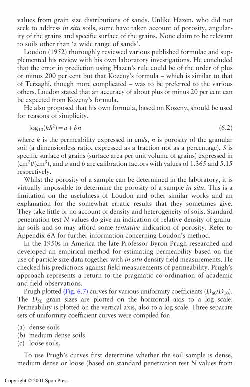
Site investigation for groundwater lowering 135
values from grain size distributions of sands. Unlike Hazen, who did notseek to address in situ soils, some have taken account of porosity, angular-ity of the grains and specific surface of the grains. None claim to be relevantto soils other than ‘a wide range of sands’.
Loudon (1952) thoroughly reviewed various published formulae and sup-plemented his review with his own laboratory investigations. He concludedthat the error in prediction using Hazen’s rule could be of the order of plus or minus 200 per cent but that Kozeny’s formula – which is similar to thatof Terzaghi, though more complicated – was to be preferred to the various others. Loudon stated that an accuracy of about plus or minus 20 per cent canbe expected from Kozeny’s formula.
He also proposed that his own formula, based on Kozeny, should be usedfor reasons of simplicity.
log10(kS2)�a�bn (6.2)
where k is the permeability expressed in cm/s, n is porosity of the granularsoil (a dimensionless ratio, expressed as a fraction not as a percentage), S isspecific surface of grains (surface area per unit volume of grains) expressed in(cm2)/(cm3), and a and b are calibration factors with values of 1.365 and 5.15respectively.
Whilst the porosity of a sample can be determined in the laboratory, it isvirtually impossible to determine the porosity of a sample in situ. This is alimitation on the usefulness of Loudon and other similar works and anexplanation for the somewhat erratic results that they sometimes give.They take little or no account of density and heterogeneity of soils. Standardpenetration test N values do give an indication of relative density of granu-lar soils and so may afford some tentative indication of porosity. Refer toAppendix 6A for further information concerning Loudon’s method.
In the 1950s in America the late Professor Byron Prugh researched anddeveloped an empirical method for estimating permeability based on theuse of particle size data together with in situ density field measurements. Hechecked his predictions against field measurements of permeability. Prugh’sapproach represents a return to the pragmatic co-ordination of academicand field observations.
Prugh plotted (Fig. 6.7) curves for various uniformity coefficients (D60/D10).The D50 grain sizes are plotted on the horizontal axis to a log scale.Permeability is plotted on the vertical axis, also to a log scale. Three separatesets of uniformity coefficient curves were compiled for:
(a) dense soils(b) medium dense soils(c) loose soils.
To use Prugh’s curves first determine whether the soil sample is dense,medium dense or loose (based on standard penetration test N values from
Copyright © 2001 Spon Press
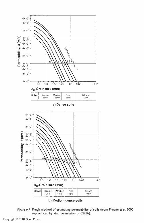
Figure 6.7 Prugh method of estimating permeability of soils (from Preene et al. 2000;reproduced by kind permission of CIRIA).
Copyright © 2001 Spon Press
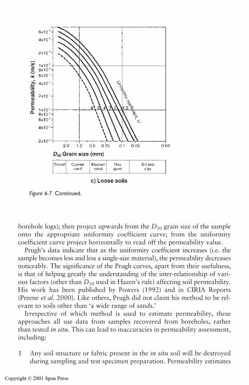
Site investigation for groundwater lowering 137
borehole logs); then project upwards from the D50 grain size of the sampleonto the appropriate uniformity coefficient curve; from the uniformitycoefficient curve project horizontally to read off the permeability value.
Prugh’s data indicate that as the uniformity coefficient increases (i.e. thesample becomes less and less a single-size material), the permeability decreasesnoticeably. The significance of the Prugh curves, apart from their usefulness,is that of helping greatly the understanding of the inter-relationship of vari-ous factors (other than D10 used in Hazen’s rule) affecting soil permeability.His work has been published by Powers (1992) and in CIRIA Reports(Preene et al. 2000). Like others, Prugh did not claim his method to be rel-evant to soils other than ‘a wide range of sands.’
Irrespective of which method is used to estimate permeability, theseapproaches all use data from samples recovered from boreholes, ratherthan tested in situ. This can lead to inaccuracies in permeability assessment,including:
1 Any soil structure or fabric present in the in situ soil will be destroyedduring sampling and test specimen preparation. Permeability estimates
Figure 6.7 Continued.
Copyright © 2001 Spon Press
based on the PSD curve of the resulting homogenized sample are likelyto be unrepresentative of the in situ permeability. If a clean sanddeposit contains laminations of silt or clay, these will become mixedinto the mass of the sample during preparation and the PSD curve willindicate a clayey or silty sand. Under-estimates of permeability willresult if the Hazen or Prugh methods are applied to these samples.
2 The samples used for particle size testing may be unrepresentative.When bulk or disturbed samples are recovered from below the waterlevel in a borehole there is a risk that finer particles will be washed fromthe sample. This is known as ‘loss of fines’. Samples affected in this waywill give over-estimates of permeability if the Hazen or Prugh methodsare used. Loss of fines is particularly prevalent in samples taken from thedrilling tools during light cable percussion boring. This can be minimizedby placing the whole contents (water and soil) into a tank or tray andallowing the fines to settle before decanting clean water. Unfortunately,in practice this is rarely done. Loss of fines is usually less severe for tubesamples such as SPT or U100 samples; these methods may give morerepresentative samples in fine sands.
6.6.5 Laboratory testing: permeameter testing
There are a number of techniques for the direct determination of the perme-ability in the laboratory by inducing a flow of water through a soil sample –this approach is known as ‘permeameter’ testing. According to Head (1982)there are two main types of permeameter testing.
1 Constant head test. A flow is induced through the sample at a constanthead. By measuring the flow rate, cross-sectional area of flow andinduced head, the permeability can be calculated using Darcy’s law. Thismethod is only suitable for relatively permeable soils such as sands orgravels (k�1�10�4 m/s); at lower permeabilities the flow rate is difficultto measure accurately.
2 Falling head test. An excess head of water is applied to the sample andthe rate at which the head dissipates into the sample is monitored.Permeability is determined from the test results in a similar way to afalling head test in a borehole or observation well. These tests are suit-able for soils of lower permeability (k�1�10�4 m/s) when the rate offall in head is easily measurable.
Tests may be carried out in: special permeameters; oedometer consolida-tion cells; Rowe consolidation cells; and triaxial cells. Methods of testingare described in BS1377 (1990) and in Head (1982).
While these tests are theoretically valid, in practice they are rarely usedbecause of the difficulty of obtaining representative ‘undisturbed’ samples ofthe granular soils (silt, sand or gravel) of interest in dewatering design. Even if
138 Site investigation for groundwater lowering
Copyright © 2001 Spon Press
the sample is representative of the particle size distribution of the soil, the insitu density and hence void ratio of the soil is likely to be known onlysketchily. This means that the in situ condition of the soil cannot be repro-duced. Similarly, any soil fabric or layering in the sample will have a profoundeffect on the in situ permeability, but cannot be replicated in the laboratory.
The only time such tests should be considered is when the permeabilityof very low permeability soils needs to be determined during investigationsof potential consolidation settlements. Even then results must be interpretedwith care, as in clays with permeable fabric the size of the test sample mayresult in scale affects distorting the measured permeability (see Rowe 1972).Large (250 mm diameter) samples may give more representative results thanthe 76 mm diameter samples routinely tested, but such large samples arerarely available.
6.6.6 In situ tests in boreholes: rising, falling and constant head tests
This group of tests includes:
i Rising and falling head tests (collectively known as variable head tests),ii Constant head tests.
These tests are carried out in the field on the soil in situ. They, therefore,avoid the problems of obtaining representative undisturbed samples thatlimit the usefulness of laboratory testing. Tests in boreholes are those car-ried out during interruptions in the drilling or boring process. When the testis complete drilling recommences – this allows several tests at differentdepths to be carried out in one borehole. These tests are distinct from testscarried out in observation wells following completion of the borehole,where tests can be carried out only at the fixed level of the response zone.
Execution of variable head tests is straightforward and requires onlybasic equipment. The borehole is advanced to the proposed depth of test,and the original groundwater level noted. The upper portion of the bore-hole is supported by temporary casing (which should exclude groundwaterfrom those levels). The ‘test section’ of exposed soil is between the bottomof the casing and the base of the borehole.
For a falling head (or inflow) test (Fig. 6.8(a)) water is added to raise thewater level in the borehole. Once the water has been added the water level inthe borehole is recorded regularly to see how the level falls with time as waterflows out of the borehole into the soil. The necessary equipment is a dipme-ter, bucket, stopwatch and a supply of clean water (perhaps from a tank orbowser). It is essential that any water added is absolutely clean, otherwise anysuspended solids in the water will clog the base of the borehole test section andsignificantly affect results. Particular attention should be given to the cleanli-ness of tanks, buckets, etc, so that the water does not become contaminated
Site investigation for groundwater lowering 139
Copyright © 2001 Spon Press
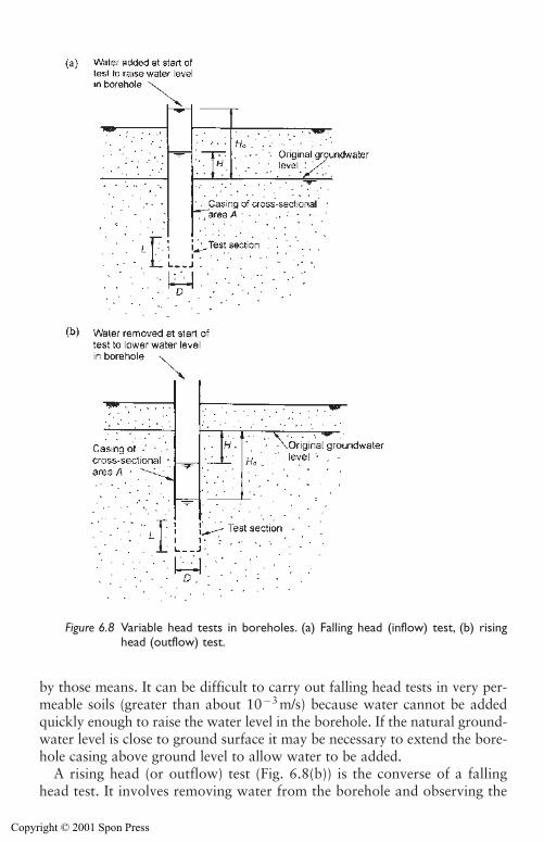
by those means. It can be difficult to carry out falling head tests in very per-meable soils (greater than about 10�3 m/s) because water cannot be addedquickly enough to raise the water level in the borehole. If the natural ground-water level is close to ground surface it may be necessary to extend the bore-hole casing above ground level to allow water to be added.
A rising head (or outflow) test (Fig. 6.8(b)) is the converse of a fallinghead test. It involves removing water from the borehole and observing the
140 Site investigation for groundwater lowering
Figure 6.8 Variable head tests in boreholes. (a) Falling head (inflow) test, (b) risinghead (outflow) test.
Copyright © 2001 Spon Press
rate at which water rises in the borehole. The test does not need a watersupply (which can be an advantage in remote locations), but does require ameans of removing water rapidly from the borehole. The most obvious wayto do this is using a bailer, which is adequate in soils of moderate perme-ability but it can be surprisingly difficult to significantly lower water levelsif soils are highly permeable. Alternatives are to use airlift equipment orsuction or submersible pumps.
For the relatively permeable soils of interest in groundwater loweringproblems, variable head tests are analysed using the work of Hvorslev(1951) which is the basis of the methods given in BS5930 (1999). Hvorslevassumed that the effect of soil compressibility on the permeability of the soilwas negligible during the test, and this is a tolerable assumption for mostwater-bearing soils. If in situ permeability tests are carried out in relativelycompressible silts and clays different test procedures and analysis may berequired (see Brand and Premchitt 1982).
For the Hvorslev analysis, permeability k is calculated using
k��FAT� (6.3)
where A is the cross-sectional area of the borehole casing (at the water levels during the test), T is the basic time lag and F is a shape factor dependenton the geometry of the test section. T is determined graphically from a semi-logarithmic plot of H/H0 versus elapsed time as shown on Fig. 6.9. H0 is theexcess head in the borehole at time t�0 and H is the head at time t (both Hand H0 are measured relative to the original groundwater level). Additionalnotes on the analysis of variable head tests are given in Appendix 6B.
Values of shape factor F for commonly occurring borehole test sectiongeometries were prepared by Hvorslev (1951) and are shown in Fig. 6.10.Shape factors for other geometries are given in BS5930 (1999). The simplesttest section is when the temporary casing is flush with the base of the bore-hole, allowing water to enter or leave the borehole through the base only.If soil will stand unsupported it may be possible to extend the borehole aheadof the casing to provide a longer test section. If the soil is not stable the bore-hole could be advanced to the test depth, and the test section be backfilledwith filter sand or gravel as the casing is withdrawn to the top of the testsection.
Constant head tests (Fig. 6.11) involve adding or removing water from aborehole at a known rate in order to maintain a constant head, which isrecorded. Constant head tests are most often carried out as inflow tests, butoutflow tests can also be carried out. The equipment required is rather morecomplex than for variable head tests, as some form of flow measurement(typically by the timed volumetric method) is required. In the simplest formof the test, appropriate to relatively permeable soils, the flow rate is adjusteduntil a suitable constant head is achieved, and the test allowed to continue
Site investigation for groundwater lowering 141
Copyright © 2001 Spon Press
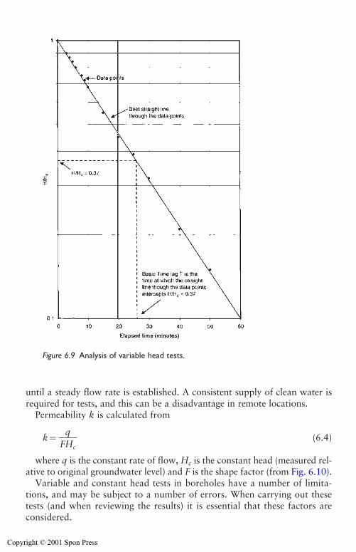
until a steady flow rate is established. A consistent supply of clean water isrequired for tests, and this can be a disadvantage in remote locations.
Permeability k is calculated from
k� (6.4)
where q is the constant rate of flow, Hc is the constant head (measured rel-ative to original groundwater level) and F is the shape factor (from Fig. 6.10).
Variable and constant head tests in boreholes have a number of limita-tions, and may be subject to a number of errors. When carrying out thesetests (and when reviewing the results) it is essential that these factors areconsidered.
q�FHc
142 Site investigation for groundwater lowering
Figure 6.9 Analysis of variable head tests.
Copyright © 2001 Spon Press
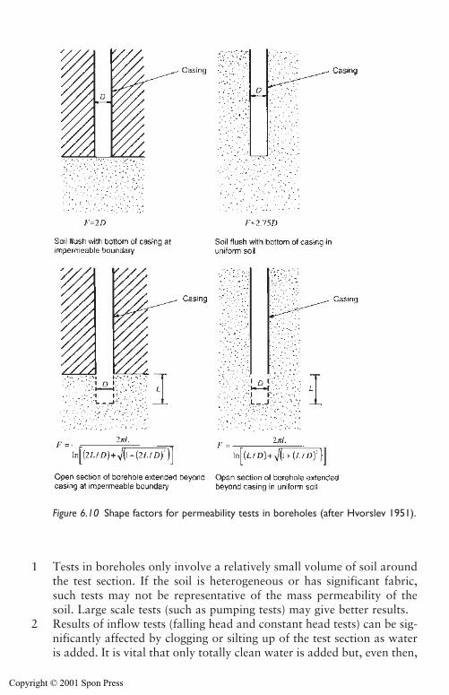
1 Tests in boreholes only involve a relatively small volume of soil aroundthe test section. If the soil is heterogeneous or has significant fabric,such tests may not be representative of the mass permeability of thesoil. Large scale tests (such as pumping tests) may give better results.
2 Results of inflow tests (falling head and constant head tests) can be sig-nificantly affected by clogging or silting up of the test section as wateris added. It is vital that only totally clean water is added but, even then,
Site investigation for groundwater lowering 143
Figure 6.10 Shape factors for permeability tests in boreholes (after Hvorslev 1951).
Copyright © 2001 Spon Press
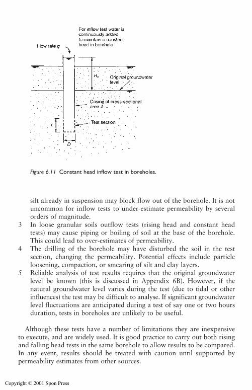
silt already in suspension may block flow out of the borehole. It is notuncommon for inflow tests to under-estimate permeability by severalorders of magnitude.
3 In loose granular soils outflow tests (rising head and constant headtests) may cause piping or boiling of soil at the base of the borehole.This could lead to over-estimates of permeability.
4 The drilling of the borehole may have disturbed the soil in the testsection, changing the permeability. Potential effects include particleloosening, compaction, or smearing of silt and clay layers.
5 Reliable analysis of test results requires that the original groundwaterlevel be known (this is discussed in Appendix 6B). However, if the natural groundwater level varies during the test (due to tidal or otherinfluences) the test may be difficult to analyse. If significant groundwaterlevel fluctuations are anticipated during a test of say one or two hoursduration, tests in boreholes are unlikely to be useful.
Although these tests have a number of limitations they are inexpensiveto execute, and are widely used. It is good practice to carry out both risingand falling head tests in the same borehole to allow results to be compared.In any event, results should be treated with caution until supported bypermeability estimates from other sources.
144 Site investigation for groundwater lowering
Figure 6.11 Constant head inflow test in boreholes.
Copyright © 2001 Spon Press
6.6.7 In situ tests in boreholes in rock
The borehole testing techniques used in soil can also be applied to boreholesin rock. However, in practice, a different approach is often taken to the insitu testing of boreholes drilled through rock strata. This is because the flowof groundwater will be mostly along joints, fissures or other discontinuities.A borehole drilled through a stratum of rock may pass through relativelyunfissured zones (which will be of low permeability) and through more fis-sured zones (of higher permeability). It is important that the level and extentof these zones are identified. Two of the most useful approaches are geo-physical logging of boreholes and packer permeability testing.
Geophysical formation logging of unlined boreholes in rock can help iden-tify the presence of more or less fissured zones. Fluid logging methods (includ-ing flowmeter and fluid conductivity and temperature logging) can be used todetermine specific levels at which groundwater is entering the well (see Beesley1986; BS7022 1988). The results from geophysical surveys can be used tospecify the levels at which permeability testing should be carried out.
The packer test is one of the most common types of permeability test usedin boreholes drilled in rock, provided the borehole is stable without casing.The method is a form of constant head test, carried out within a discretetest section isolated from the rest of the borehole by inflatable ‘packers’(Fig. 6.12). Water is pumped into or out of the test section and the changein water pressure or level noted. Because discrete sections of borehole atvarious depths can be tested, the method can help identify any fissured per-meable zones. The packer test was originally developed in the 1930s toassess the permeability of grouted rock beneath dam foundations, and issometimes known as a Lugeon test after the French engineer who pioneeredthe method. Strictly speaking, a true Lugeon test is one particular form ofpacker test, carried out using specific equipment and injection pressures,and the term should not be used for packer tests in general.
The test method is described in Walthall (1990) and BS5930 (1999). Inthe double packer test inflatable packers are used to isolate a test sectionbetween two packers (Fig. 6.12). For a single packer test, the test section isbetween a packer and the base of the borehole. The most common type ofpacker test is an inflow test, where water is injected into the test section andthe flow rate and head recorded. Outflow tests can also be carried out,although the test equipment is more complicated (Price and Williams 1993);nevertheless a number of studies (including Brassington and Walthall 1985)have concluded that outflow tests are preferable to inflow tests.
Packer tests are most suited to rocks of moderate to low permeability. Ifpermeability is greater than 10�7 m/s friction losses in the pipework becomesignificant and need to be included in calculations. When packer tests arecarried out in highly permeable zones (greater than about 10�5 m/s) it is difficult to inject sufficient water to maintain the test pressure, and the
Site investigation for groundwater lowering 145
Copyright © 2001 Spon Press
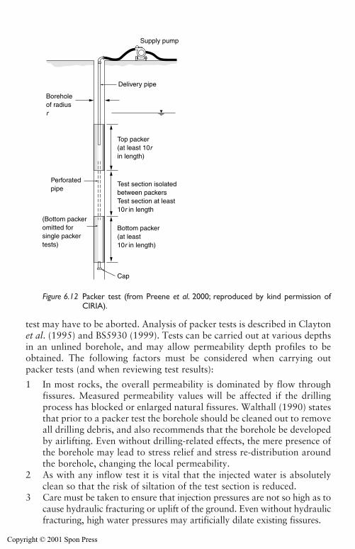
test may have to be aborted. Analysis of packer tests is described in Claytonet al. (1995) and BS5930 (1999). Tests can be carried out at various depthsin an unlined borehole, and may allow permeability depth profiles to beobtained. The following factors must be considered when carrying outpacker tests (and when reviewing test results):
1 In most rocks, the overall permeability is dominated by flow throughfissures. Measured permeability values will be affected if the drillingprocess has blocked or enlarged natural fissures. Walthall (1990) statesthat prior to a packer test the borehole should be cleaned out to removeall drilling debris, and also recommends that the borehole be developedby airlifting. Even without drilling-related effects, the mere presence ofthe borehole may lead to stress relief and stress re-distribution aroundthe borehole, changing the local permeability.
2 As with any inflow test it is vital that the injected water is absolutelyclean so that the risk of siltation of the test section is reduced.
3 Care must be taken to ensure that injection pressures are not so high as tocause hydraulic fracturing or uplift of the ground. Even without hydraulicfracturing, high water pressures may artificially dilate existing fissures.
146 Site investigation for groundwater lowering
Delivery pipe
Supply pump
Boreholeof radiusr
Perforatedpipe
Top packer(at least 10rin length)
Test section isolatedbetween packersTest section at least10r in length
Bottom packer(at least10r in length)
(Bottom packeromitted forsingle packertests)
Cap
Figure 6.12 Packer test (from Preene et al. 2000; reproduced by kind permission ofCIRIA).
Copyright © 2001 Spon Press
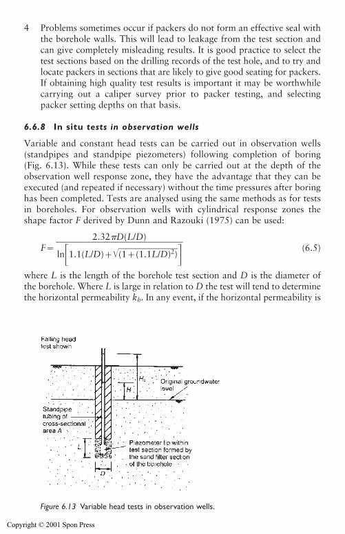
4 Problems sometimes occur if packers do not form an effective seal withthe borehole walls. This will lead to leakage from the test section andcan give completely misleading results. It is good practice to select thetest sections based on the drilling records of the test hole, and to try andlocate packers in sections that are likely to give good seating for packers.If obtaining high quality test results is important it may be worthwhilecarrying out a caliper survey prior to packer testing, and selectingpacker setting depths on that basis.
6.6.8 In situ tests in observation wells
Variable and constant head tests can be carried out in observation wells(standpipes and standpipe piezometers) following completion of boring(Fig. 6.13). While these tests can only be carried out at the depth of theobservation well response zone, they have the advantage that they can beexecuted (and repeated if necessary) without the time pressures after boringhas been completed. Tests are analysed using the same methods as for testsin boreholes. For observation wells with cylindrical response zones theshape factor F derived by Dunn and Razouki (1975) can be used:
F� (6.5)
where L is the length of the borehole test section and D is the diameter ofthe borehole. Where L is large in relation to D the test will tend to determinethe horizontal permeability kh. In any event, if the horizontal permeability is
2.32 D(L/D)����
ln�1.1(L/D)��(1���(1�.1�L�/D�)2�)��
Site investigation for groundwater lowering 147
Figure 6.13 Variable head tests in observation wells.
Copyright © 2001 Spon Press
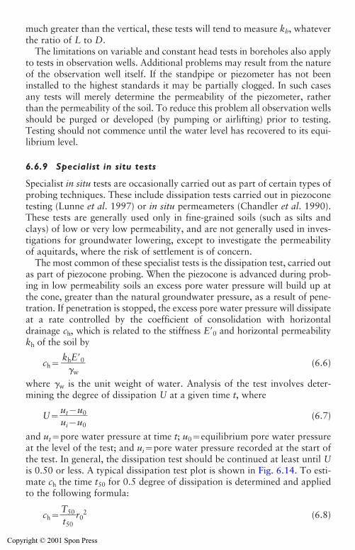
much greater than the vertical, these tests will tend to measure kh, whateverthe ratio of L to D.
The limitations on variable and constant head tests in boreholes also applyto tests in observation wells. Additional problems may result from the natureof the observation well itself. If the standpipe or piezometer has not beeninstalled to the highest standards it may be partially clogged. In such casesany tests will merely determine the permeability of the piezometer, ratherthan the permeability of the soil. To reduce this problem all observation wellsshould be purged or developed (by pumping or airlifting) prior to testing.Testing should not commence until the water level has recovered to its equi-librium level.
6.6.9 Specialist in situ tests
Specialist in situ tests are occasionally carried out as part of certain types ofprobing techniques. These include dissipation tests carried out in piezoconetesting (Lunne et al. 1997) or in situ permeameters (Chandler et al. 1990).These tests are generally used only in fine-grained soils (such as silts andclays) of low or very low permeability, and are not generally used in inves-tigations for groundwater lowering, except to investigate the permeabilityof aquitards, where the risk of settlement is of concern.
The most common of these specialist tests is the dissipation test, carried outas part of piezocone probing. When the piezocone is advanced during prob-ing in low permeability soils an excess pore water pressure will build up atthe cone, greater than the natural groundwater pressure, as a result of pene-tration. If penetration is stopped, the excess pore water pressure will dissipateat a rate controlled by the coefficient of consolidation with horizontaldrainage ch, which is related to the stiffness E0 and horizontal permeabilitykh of the soil by
ch� (6.6)
where �w is the unit weight of water. Analysis of the test involves deter-mining the degree of dissipation U at a given time t, where
U��uu
t
i�
�
uu
0
0� (6.7)
and ut�pore water pressure at time t; u0�equilibrium pore water pressureat the level of the test; and ui�pore water pressure recorded at the start ofthe test. In general, the dissipation test should be continued at least until Uis 0.50 or less. A typical dissipation test plot is shown in Fig. 6.14. To esti-mate ch the time t50 for 0.5 degree of dissipation is determined and appliedto the following formula:
ch��Tt5
5
0
0�r02 (6.8)
khE0��w
148 Site investigation for groundwater lowering
Copyright © 2001 Spon Press
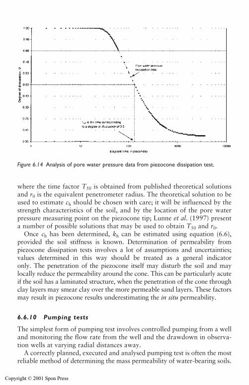
where the time factor T50 is obtained from published theoretical solutionsand r0 is the equivalent penetrometer radius. The theoretical solution to beused to estimate ch should be chosen with care; it will be influenced by thestrength characteristics of the soil, and by the location of the pore waterpressure measuring point on the piezocone tip; Lunne et al. (1997) presenta number of possible solutions that may be used to obtain T50 and r0.
Once ch has been determined, kh can be estimated using equation (6.6),provided the soil stiffness is known. Determination of permeability frompiezocone dissipation tests involves a lot of assumptions and uncertainties;values determined in this way should be treated as a general indicator only. The penetration of the piezocone itself may disturb the soil and maylocally reduce the permeability around the cone. This can be particularly acuteif the soil has a laminated structure, when the penetration of the cone throughclay layers may smear clay over the more permeable sand layers. These factorsmay result in piezocone results underestimating the in situ permeability.
6.6.10 Pumping tests
The simplest form of pumping test involves controlled pumping from a welland monitoring the flow rate from the well and the drawdown in observa-tion wells at varying radial distances away.
A correctly planned, executed and analysed pumping test is often the mostreliable method of determining the mass permeability of water-bearing soils.
Site investigation for groundwater lowering 149
Figure 6.14 Analysis of pore water pressure data from piezocone dissipation test.
Copyright © 2001 Spon Press
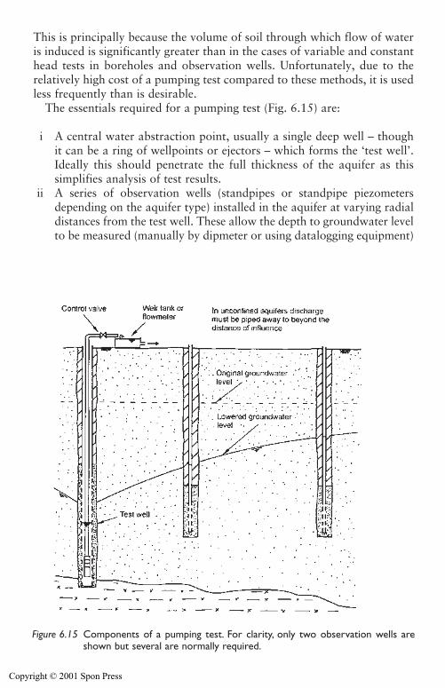
150 Site investigation for groundwater lowering
This is principally because the volume of soil through which flow of wateris induced is significantly greater than in the cases of variable and constanthead tests in boreholes and observation wells. Unfortunately, due to therelatively high cost of a pumping test compared to these methods, it is usedless frequently than is desirable.
The essentials required for a pumping test (Fig. 6.15) are:
i A central water abstraction point, usually a single deep well – thoughit can be a ring of wellpoints or ejectors – which forms the ‘test well’.Ideally this should penetrate the full thickness of the aquifer as thissimplifies analysis of test results.
ii A series of observation wells (standpipes or standpipe piezometersdepending on the aquifer type) installed in the aquifer at varying radialdistances from the test well. These allow the depth to groundwater levelto be measured (manually by dipmeter or using datalogging equipment)
Figure 6.15 Components of a pumping test. For clarity, only two observation wells areshown but several are normally required.
Copyright © 2001 Spon Press
to determine the drawdown at varying times after commencement ofpumping and during recovery after cessation of pumping.
iii A means to determine the rate of pumping, such as a weir tank orflowmeter (see Section 14.3).
A pumping test typically consists of the following phases:
1 Pre-pumping monitoring,2 Equipment test,3 Step-drawdown test,4 Constant rate pumping phase,5 Recovery phase.
In addition to monitoring of groundwater levels and the discharge flowrate, a test is also a useful opportunity to obtain groundwater samples fromchemical testing. Further details on the execution of pumping tests is givenin Appendix 6C. Test methods are defined in BS5930 (1999) and BS6316(1992). The test well itself may also provide additional information aboutground conditions. Geophysical logging of the well may provide usefulinformation (see Beesley 1986; BS7022 (1988)). In fissured rock aquifersgeophysical logging can allow identification of fissured zones wheregroundwater is entering the well.
A pumping test is a relatively expensive way of determining permeability.The cost of a pumping test is seldom justified for a small project or for routine shallow excavations. However, for any large project or deep excava-tion, or where groundwater lowering is likely to have a major impact on theconstruction cost, one or more pumping tests should be carried out. It isessential that the pumping test is planned to provide suitable data for dewa-tering design. Issues to be considered include: the drawdown during the test(which in nearby observation wells should be at least 10 per cent of that inthe proposed dewatering system); the number and position of observationwells (which should allow the drawdown pattern around the test well to befully identified); and the design of the test well (which, ideally, should be ofsimilar design to, and be installed by the same methods as, the proposeddewatering wells). To meet these aims a pumping test is generally carried outin the second or subsequent phases of ground investigation, when groundconditions have been determined to some degree. This allows the depth of thetest well screen and observation well response zones to be selected on thebasis of the data already gathered.
Analysis of the test results can provide information that is useful in anumber of ways:
(a) Data from the step-drawdown test can be used to analyse the hydraulicperformance of the well, to determine well losses and efficiency. Thisapproach is widely used in the testing of water supply wells (see Clark
Site investigation for groundwater lowering 151
Copyright © 2001 Spon Press
1977, for methods of analysis), but is less widely relevant to temporaryworks wells for groundwater lowering purposes. It can still be usefulwhen trying to optimize the performance of deep well systems, and mayallow comparison of the performance of wells drilled and developed bydifferent methods.
(b) Data from the constant rate pumping phase can be used to estimate thepermeability and storage coefficient of the volume of aquifer influencedby the test. The permeability estimated from the test results is used asan input parameter in the design methods described in Chapter 7.Permeability is estimated by conventional hydrogeological analyses(described below), which can also provide some information about theaquifer boundary conditions.
(c) Observations of the way drawdown reduces with distance from the testwell can be used to construct a distance-drawdown plot, which canthen be used to design groundwater lowering systems by the cumula-tive drawdown method (see Section 7.4). This method is interestingbecause the design does not need a permeability value, since that isimplicit in the distance-drawdown plot.
Most pumping tests are analysed by ‘non-steady state’ techniques which arerelatively flexible methods and can be applied to data even as the test is con-tinuing. This allows data to be analysed almost in ‘real time’. ‘Steady-state’methods of analysis can be used, but may require much longer periods ofpumping than is necessary with non-steady state methods. In general, analysisby non-steady state techniques is to be preferred.
There are a wide variety of methods of analysis which can be used toanalyse the results of the constant rate pumping phase, many of which areusefully summarized in Kruseman and De Ridder (1990). Each of the meth-ods is based on a particular set of assumptions about the aquifer system(unconfined, confined, leaky), the well (fully penetrating, partially penetrat-ing) and the discharge flow rate (generally assumed to be constant). Methodssuitable for analysis of data from the recovery phase are also available.
These methods should be viewed as a ‘tool kit’ providing a range of pos-sible analysis methods. Provided the basic details of the aquifer and well areknown, it is normally straightforward to select one (or more than one, ifuncertainty exists over aquifer conditions) method appropriate to the casein hand. Commonly used methods of analysis fall into two main types:
i Curve fitting methods: These typically involve plotting on a log–loggraph, for each observation well, drawdown against elapsed time. Thedata will generally form a characteristic shape. The data curve is thenoverlain with a theoretical ‘type curve’ and the relative positions of thetwo curves adjusted until the best match of the shape of the two curves isobtained. Once a match is achieved, permeability and storage coefficientcan be determined by comparing values from each curve. These methods
152 Site investigation for groundwater lowering
Copyright © 2001 Spon Press
were developed from the work of Theis on simple confined aquifers, butvariations are available for various other cases (see Kruseman and DeRidder 1990). The curve fitting process can be tedious, but in recent yearscomputer programs for pumping test analysis have speeded up theprocess.
ii Straight line methods: This approach involves plotting sets of data sothat characteristic straight lines are produced, allowing permeabilityand storage coefficient to be determined from the slope and position ofthe line. These methods are a special case of the Theis solution, and arebased on the work of Cooper and Jacob (1946) and are often called theCooper–Jacob methods. Two approaches are possible, and can be usedon the same test. Time–drawdown diagrams involve plotting the draw-down data from one observation well against elapsed time since pump-ing began (Fig. 6.16); this process is repeated for all observation wellsbeing analysed. Distance–drawdown diagrams plot the drawdownrecorded (at a specific elapsed time) in all observation wells against thedistance of each observation well from the test well (Fig. 6.17).
The Cooper–Jacob straight line method is the most commonly usedmethod of analysis, mainly due to its relative simplicity. The originalCooper–Jacob method was based on horizontal flow to fully penetratingwells in confined aquifers, but can also be used in unconfined aquiferswhere the drawdown is a small proportion (less than 20 per cent) of theoriginal aquifer saturated thickness.
For the time–drawdown data from a single observation well, aquiferpermeability k and storage coefficient S are determined as follows. Fromthe semi-log graph (Fig. 6.16) draw a straight line through the main portionof the data (the data will deviate from straight line at small times, andpossibly at later times). From the graph obtain the slope of the straight line,expressed as �s, which is the change in drawdown s per log cycle of time.Also determine t0 the time at which the straight line intercepts the zerodrawdown line – k and S are then obtained from:
k��4
2.�
3sqD
� (6.9)
S� (6.10)
where q is the constant flow rate from the test well, D is the aquifer thick-ness, and r is the distance from the centre of the test well to the observationwell. This process can be repeated for each observation well.
For the distance–drawdown approach data from all observation wells, atelapsed time t after pumping started, is plotted on the semi-log graph (Fig. 6.17). A straight line is drawn through the observation well data. If thetest well has a very much larger drawdown than the observation wells this
2.25kDt0��r2
Site investigation for groundwater lowering 153
Copyright © 2001 Spon Press
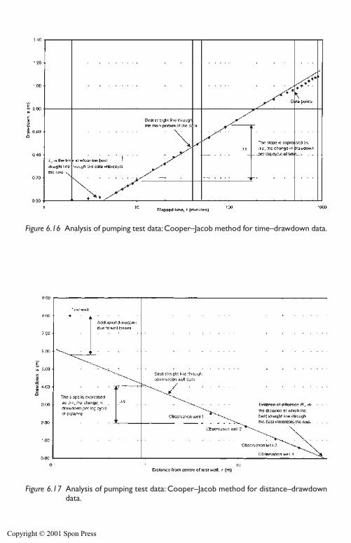
Figure 6.16 Analysis of pumping test data:Cooper–Jacob method for time–drawdown data.
Figure 6.17 Analysis of pumping test data: Cooper–Jacob method for distance–drawdowndata.
Copyright © 2001 Spon Press
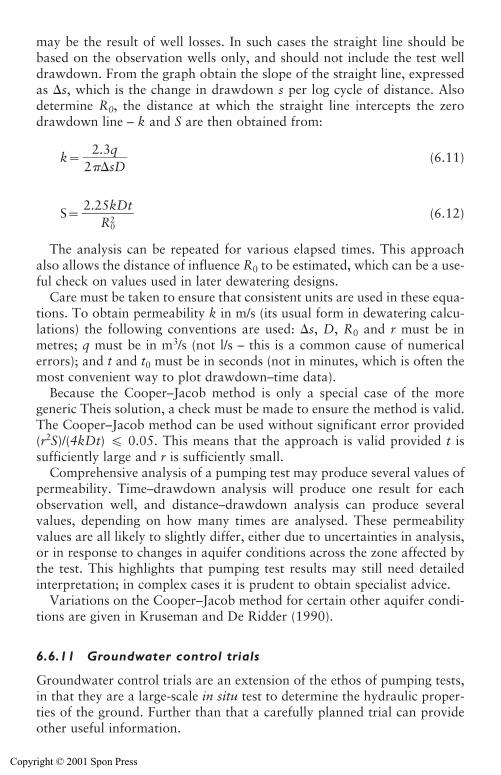
Site investigation for groundwater lowering 155
may be the result of well losses. In such cases the straight line should bebased on the observation wells only, and should not include the test welldrawdown. From the graph obtain the slope of the straight line, expressedas �s, which is the change in drawdown s per log cycle of distance. Alsodetermine R0, the distance at which the straight line intercepts the zerodrawdown line – k and S are then obtained from:
k� (6.11)
S� (6.12)
The analysis can be repeated for various elapsed times. This approachalso allows the distance of influence R0 to be estimated, which can be a use-ful check on values used in later dewatering designs.
Care must be taken to ensure that consistent units are used in these equa-tions. To obtain permeability k in m/s (its usual form in dewatering calcu-lations) the following conventions are used: �s, D, R0 and r must be inmetres; q must be in m3/s (not l/s – this is a common cause of numericalerrors); and t and t0 must be in seconds (not in minutes, which is often themost convenient way to plot drawdown–time data).
Because the Cooper–Jacob method is only a special case of the moregeneric Theis solution, a check must be made to ensure the method is valid.The Cooper–Jacob method can be used without significant error provided(r2S)/(4kDt) � 0.05. This means that the approach is valid provided t is sufficiently large and r is sufficiently small.
Comprehensive analysis of a pumping test may produce several values ofpermeability. Time–drawdown analysis will produce one result for eachobservation well, and distance–drawdown analysis can produce several values, depending on how many times are analysed. These permeability values are all likely to slightly differ, either due to uncertainties in analysis,or in response to changes in aquifer conditions across the zone affected bythe test. This highlights that pumping test results may still need detailedinterpretation; in complex cases it is prudent to obtain specialist advice.
Variations on the Cooper–Jacob method for certain other aquifer condi-tions are given in Kruseman and De Ridder (1990).
6.6.11 Groundwater control trials
Groundwater control trials are an extension of the ethos of pumping tests,in that they are a large-scale in situ test to determine the hydraulic proper-ties of the ground. Further than that a carefully planned trial can provideother useful information.
2.25kDt�
R02
2.3q�2 �sD
Copyright © 2001 Spon Press
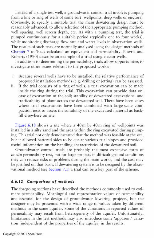
Instead of a single test well, a groundwater control trial involves pumpingfrom a line or ring of wells of some sort (wellpoints, deep wells or ejectors).Obviously, to specify a suitable trial the main dewatering design must bereasonably advanced, to allow selection of the appropriate pumping method,well spacing, well screen depth, etc. As with a pumping test, the trial ispumped continuously for a suitable period (typically one to four weeks),while monitoring discharge flow rate and water levels in observation wells.The results of such tests are normally analysed using the design methods ofChapter 7 to ‘back-calculate’ an equivalent soil permeability. Powrie andRoberts (1990) describe an example of a trial using ejector wells.
In addition to determining the permeability, trials allow opportunities toinvestigate other issues relevant to the proposed works:
i Because several wells have to be installed, the relative performance ofproposed installation methods (e.g. drilling or jetting) can be assessed.
ii If the trial consists of a ring of wells, a trial excavation can be madeinside the ring during the trial. This excavation can provide data on:ease of excavation of the soil; stability of dewatered excavations; andtrafficability of plant across the dewatered soil. There have been caseswhere trial excavations have been combined with large-scale com-paction tests to assess the suitability of the excavated material as back-fill elsewhere on site.
Figure 6.18 shows a site where a 40 m by 40 m ring of wellpoints wasinstalled in a silty sand and the area within the ring excavated during pump-ing. This trial not only demonstrated that the method was feasible at the site,but it allowed battered sides to be cut at various trial slopes and provideduseful information on the handling characteristics of the dewatered soil.
Groundwater control trials are probably the most expensive form ofin situ permeability test, but for large projects in difficult ground conditionsthey can reduce risks of problems during the main works, and the cost maybe justified on that basis. If dewatering system is to be designed by the obser-vational method (see Section 7.1) a trial can be a key part of the scheme.
6.6.12 Comparison of methods
The foregoing sections have described the methods commonly used to esti-mate permeability. Meaningful and representative values of permeabilityare essential for the design of groundwater lowering projects, but thedesigner may be presented with a wide range of values taken by differentmethods in the same aquifer. Some of the variations in reported values ofpermeability may result from heterogeneity of the aquifer. Unfortunately,limitations in the test methods may also introduce some ‘apparent’ varia-tion (independent of the properties of the aquifer) in the results.
156 Site investigation for groundwater lowering
Copyright © 2001 Spon Press
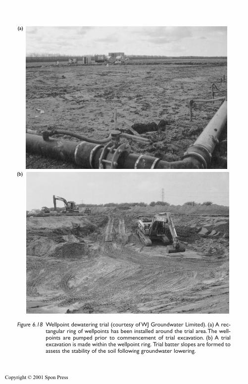
(a)
(b)
Figure 6.18 Wellpoint dewatering trial (courtesy of WJ Groundwater Limited). (a) A rec-tangular ring of wellpoints has been installed around the trial area.The well-points are pumped prior to commencement of trial excavation. (b) A trialexcavation is made within the wellpoint ring. Trial batter slopes are formed toassess the stability of the soil following groundwater lowering.
Copyright © 2001 Spon Press

Table 6.3 Tentative guide to the reliability of permeability estimates
Method Notes Relative cost Reliability1
Visual assessment For a soil or drift aquifer, can allow the order of magnitude of permeability to be Very low Goodestimated. Less applicable to fissured rock aquifers.
Inverse numerical Only applicable if the hydrogeology of the aquifers being pumped is defined Low to Goodmodelling reasonably clearly, and if adequate monitoring data are available. moderate
Geophysical Can give indirect estimates of permeability and allow identification of zones of Moderate to Poor to goodmethods higher and lower permeability. Borehole geophysical methods are more applicable high
in rock aquifers to identify fissured horizons.Laboratory Can give reasonable results for samples of fairly uniform sand with low silt and clay Very low Very poor totesting: particle content, provided loss of fines has not occurred. Loss of fines tends to be greater goodsize analysis from bulk samples compared with tube samples; permeability estimated from bulk
samples should be treated with caution. Gives very poor estimates in laminated orstructured soils or where silt and clay content is significant.
Laboratory Of little use in granular sand or gravels, as representative samples cannot be Low to Goodtesting: obtained without unacceptable disturbance. Can produce good results in clay and moderatepermeameter some silts where minimally disturbed samples can obtained. In soils with fabric andtesting structure permeability estimates are affected by sample size; smaller samples
may under-estimate permeability.In situ tests in Can test only a small volume of soil at the base of the borehole. May be influenced Very low Very poorboreholes: by soil disturbance due to boring. Prone to clogging of test section.falling head
In situ tests in Can test only a small volume of soil at the base of the borehole. May be influenced Very low Poor toboreholes: rising by soil disturbance due to boring. Prone to clogging or loosening of test section. moderatehead Better results are often obtained in coarse soils with little silt content.
In situ tests in Can test only a small volume of soil at the base of the borehole. May be influenced Low Very poorboreholes: by soil disturbance due to boring. Inflow tests prone to clogging of test section. to moderateconstant head Better results are often obtained in coarse soils with little silt content.
Copyright © 2001 Spon Press
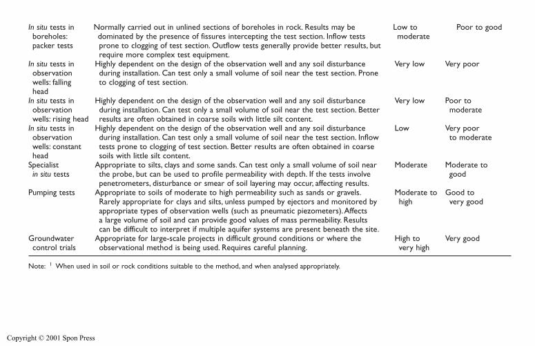
In situ tests in Normally carried out in unlined sections of boreholes in rock. Results may be Low to Poor to goodboreholes: dominated by the presence of fissures intercepting the test section. Inflow tests moderatepacker tests prone to clogging of test section. Outflow tests generally provide better results, but
require more complex test equipment.In situ tests in Highly dependent on the design of the observation well and any soil disturbance Very low Very poorobservation during installation. Can test only a small volume of soil near the test section. Pronewells: falling to clogging of test section.head
In situ tests in Highly dependent on the design of the observation well and any soil disturbance Very low Poor toobservation during installation. Can test only a small volume of soil near the test section. Better moderatewells: rising head results are often obtained in coarse soils with little silt content.
In situ tests in Highly dependent on the design of the observation well and any soil disturbance Low Very poorobservation during installation. Can test only a small volume of soil near the test section. Inflow to moderatewells: constant tests prone to clogging of test section. Better results are often obtained in coarsehead soils with little silt content.
Specialist Appropriate to silts, clays and some sands. Can test only a small volume of soil near Moderate Moderate to in situ tests the probe, but can be used to profile permeability with depth. If the tests involve good
penetrometers, disturbance or smear of soil layering may occur, affecting results.Pumping tests Appropriate to soils of moderate to high permeability such as sands or gravels. Moderate to Good to
Rarely appropriate for clays and silts, unless pumped by ejectors and monitored by high very goodappropriate types of observation wells (such as pneumatic piezometers).Affectsa large volume of soil and can provide good values of mass permeability. Results can be difficult to interpret if multiple aquifer systems are present beneath the site.
Groundwater Appropriate for large-scale projects in difficult ground conditions or where the High to Very goodcontrol trials observational method is being used. Requires careful planning. very high
Note: 1 When used in soil or rock conditions suitable to the method, and when analysed appropriately.
Copyright © 2001 Spon Press
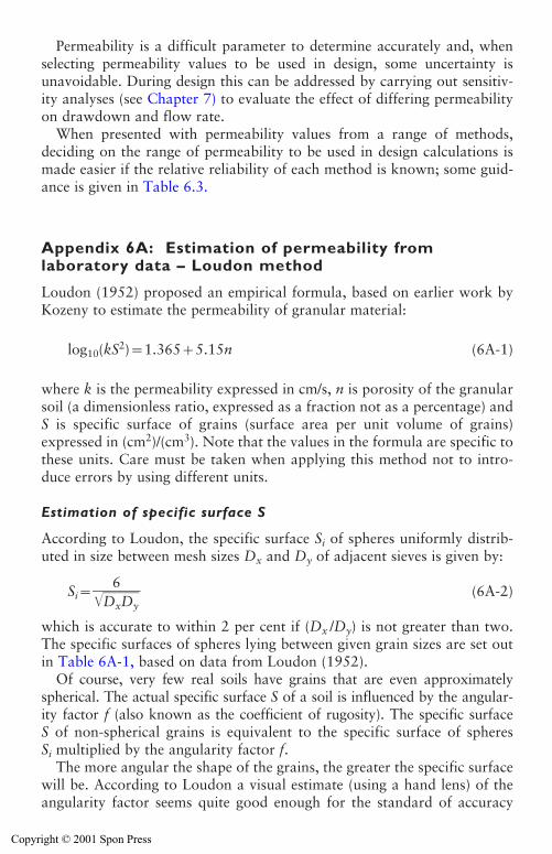
160 Site investigation for groundwater lowering
Permeability is a difficult parameter to determine accurately and, whenselecting permeability values to be used in design, some uncertainty isunavoidable. During design this can be addressed by carrying out sensitiv-ity analyses (see Chapter 7) to evaluate the effect of differing permeabilityon drawdown and flow rate.
When presented with permeability values from a range of methods,deciding on the range of permeability to be used in design calculations ismade easier if the relative reliability of each method is known; some guid-ance is given in Table 6.3.
Appendix 6A: Estimation of permeability fromlaboratory data – Loudon method
Loudon (1952) proposed an empirical formula, based on earlier work byKozeny to estimate the permeability of granular material:
log10(kS2)�1.365�5.15n (6A-1)
where k is the permeability expressed in cm/s, n is porosity of the granularsoil (a dimensionless ratio, expressed as a fraction not as a percentage) andS is specific surface of grains (surface area per unit volume of grains)expressed in (cm2)/(cm3). Note that the values in the formula are specific tothese units. Care must be taken when applying this method not to intro-duce errors by using different units.
Estimation of specific surface S
According to Loudon, the specific surface Si of spheres uniformly distrib-uted in size between mesh sizes Dx and Dy of adjacent sieves is given by:
Si���D�
6
xD�y�� (6A-2)
which is accurate to within 2 per cent if (Dx /Dy) is not greater than two.The specific surfaces of spheres lying between given grain sizes are set outin Table 6A-1, based on data from Loudon (1952).
Of course, very few real soils have grains that are even approximatelyspherical. The actual specific surface S of a soil is influenced by the angular-ity factor f (also known as the coefficient of rugosity). The specific surfaceS of non-spherical grains is equivalent to the specific surface of spheresSi multiplied by the angularity factor f.
The more angular the shape of the grains, the greater the specific surfacewill be. According to Loudon a visual estimate (using a hand lens) of theangularity factor seems quite good enough for the standard of accuracy
Copyright © 2001 Spon Press
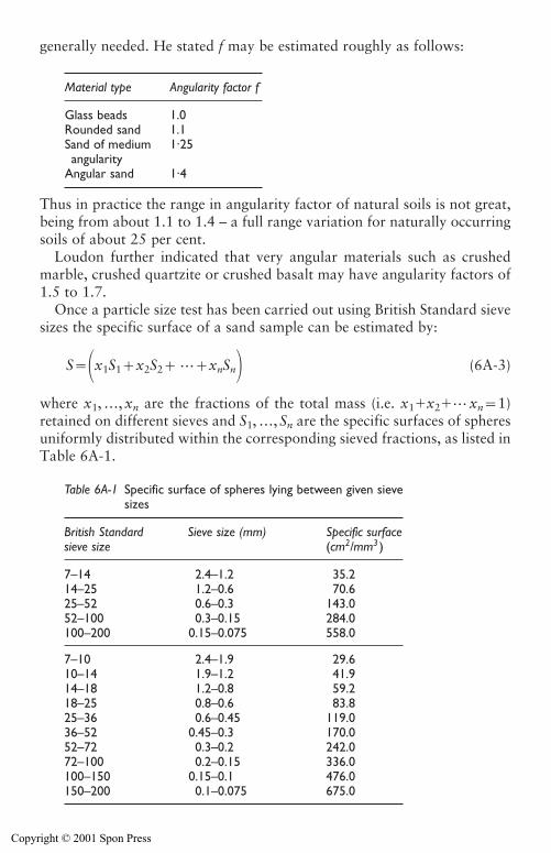
Site investigation for groundwater lowering 161
generally needed. He stated f may be estimated roughly as follows:
Thus in practice the range in angularity factor of natural soils is not great,being from about 1.1 to 1.4 – a full range variation for naturally occurringsoils of about 25 per cent.
Loudon further indicated that very angular materials such as crushedmarble, crushed quartzite or crushed basalt may have angularity factors of1.5 to 1.7.
Once a particle size test has been carried out using British Standard sievesizes the specific surface of a sand sample can be estimated by:
S��x1S1�x2S2� …�xnSn� (6A-3)
where x1, …, xn are the fractions of the total mass (i.e. x1�x2�… xn�1)retained on different sieves and S1, …, Sn are the specific surfaces of spheresuniformly distributed within the corresponding sieved fractions, as listed inTable 6A-1.
Material type Angularity factor f
Glass beads 1.0Rounded sand 1.1Sand of medium 1·25angularity
Angular sand 1·4
Table 6A-1 Specific surface of spheres lying between given sievesizes
British Standard Sieve size (mm) Specific surfacesieve size (cm2/mm3 )
7–14 2.4–1.2 35.214–25 1.2–0.6 70.625–52 0.6–0.3 143.052–100 0.3–0.15 284.0100–200 0.15–0.075 558.0
7–10 2.4–1.9 29.610–14 1.9–1.2 41.914–18 1.2–0.8 59.218–25 0.8–0.6 83.825–36 0.6–0.45 119.036–52 0.45–0.3 170.052–72 0.3–0.2 242.072–100 0.2–0.15 336.0100–150 0.15–0.1 476.0150–200 0.1–0.075 675.0
Copyright © 2001 Spon Press
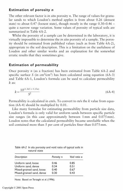
Estimation of porosity n
The other relevant factor is in situ porosity n. The range of values for granu-lar sands to which Loudon’s method applies is from about 0.26 (denseststate) to about 0.47 (loosest state), though mostly in the range 0.30–0.46 –quite a narrow range variation. Some values of porosity of typical soils aresummarized in Table 6A-2.
Whilst the porosity of a sample can be determined in the laboratory, it isvirtually impossible to determine the in situ porosity of a sample. The poros-ity should be estimated from published values (such as from Table 6A-2),appropriate to the soil description. This is a limitation on the usefulness ofLoudon and other similar works and an explanation for the somewhaterratic results that they sometimes give.
Estimation of permeability
Once porosity n (as a fraction) has been estimated from Table 6A-2 andspecific surface S (in cm2/cm3) has been calculated using equation (6A-3)and Table 6A-1, Loudon’s formula can be used to calculate permeability k as:
k��10(1.36
S
5
2
�5.15n)� (6A-4)
Permeability is calculated in cm/s. To convert to m/s the k value from equa-tion (6A-4) should be multiplied by 0.01.
Like many formulae for estimating permeability from particle size data,Loudon’s formula is only valid for uniform sands between specific particlesize ranges (in this case approximately between 1 mm and 0.075 mm).Loudon notes that the calculated permeability became unreliable when thesoil contained more than 5 per cent of particles finer than 0.075 mm.
162 Site investigation for groundwater lowering
Table 6A-2 In situ porosity and void ratio of typical soils innatural state
Description Porosity n Void ratio e
Uniform sand, loose 0.46 0.85Uniform sand, dense 0.34 0.51Mixed-grained sand, loose 0.40 0.67Mixed-grained sand, dense 0.30 0.43
Note: Based on Terzaghi et al. (1996).
Copyright © 2001 Spon Press
Site investigation for groundwater lowering 163
Appendix 6B: Execution and analysis of variable head permeability tests in boreholes
General comments on performing permeability tests
Many factors may influence the results obtained from in situ permeabilitytests. Great care must be exercised to ensure that tests are made under controlled conditions; some tests are reliable only when performed accord-ing to specific conditions and these should be strictly adhered to. Some gen-eral guidance is given below:
(a) When making tests in boreholes, prior to the test the borehole shouldbe carefully cleaned out to remove loose or disturbed material, the pres-ence of which can introduce significant errors in the results obtained.Any sediment-laden water in the borehole should be flushed out andreplaced with clean water.
(b) When carrying out inflow tests, the water used should be clean and atten-tion should be given to cleanliness of tanks, buckets, pumps, etc., so thatthe water does not become contaminated by dirt in the equipment, sincevery small amounts of silt may cause serious errors in the results.
(c) The water level should be measured with a dipmeter relative to a stabledatum such as the top of the borehole casing or a firmly positioned rodacross the top of the borehole.
(d) In the early stages of rising and falling head tests, it is desirable to takereadings of the water level at frequent intervals of about 30 seconds. To obtain reasonable accuracy in these circumstances, it is necessary tohave two persons taking the readings: one to adjust the dipmeter tokeep pace with the change in water level and to take the depth readings,and the other to call out the time intervals from a stop watch andrecord the water levels.
(e) The equations for calculating permeability are all based on the assump-tion that flow through the tested material is laminar. To be sure of lam-inar flow, velocity should not exceed 0.03 m/s. Therefore, the tests areonly applicable when the flow rate (into or out of the borehole) dividedby the area of test section is less than 0.03 m/s. The open area is takenas the peripheral area of the filter section around a well, or the intakearea of the sides and base, in the case of an unsupported hole.
(f) Tests should, if possible, be made during dry weather. If a test has tobe made while it is raining, measures must be taken to prevent surfacerun-off from entering the test borehole. If the borehole casing is closeto ground level this may involve using sand bags to build a small damaround the top of the borehole.
Where the test is carried out in an unconfined aquifer and surface condi-tions are relatively pervious, rainfall during the test may produce a change
Copyright © 2001 Spon Press
164 Site investigation for groundwater lowering
in the groundwater level, which could affect the results obtained. In thesecircumstances, a careful note should be made of any showers immediatelypreceding or during a test. The groundwater level should be measuredbefore and after the test.
Variable head inflow (falling head) test – procedure
Each test is carried out at a specific depth interval known as the ‘test section’(Fig. 6B-1). The whole test section must be below the groundwater level. Ifpossible, the groundwater level should be measured before making the test.
Prior to the test itself the borehole is advanced to the base of the test section. Where casing is not necessary to support the borehole, it must nevertheless be inserted to the top of the test section so that only the test section is exposed to the strata. The casing must be tight against theside of the borehole, otherwise the test water will leak around the casing.This test is suitable for testing at various depths during progress of boring,where the test section will stand unsupported.
If casing is required to support the sides of the hole, it must be takendown initially to the base of the test section. Fine gravel backfill is thenplaced in the borehole, whilst withdrawing the casing to expose therequired length of unlined hole for the test; subsequently the gravel fillshould be brought up with and always kept just above the bottom of thecasing as this is withdrawn. It is good practice, prior to placing the gravel,to replace any water standing in the borehole with clean water; this helpsavoid suspended silt becoming trapped in the test section, which wouldreduce permeability. This type of test can also be used at various depthsduring boring, but the gravel backfill will need to be drilled out followingeach test – this will slow down drilling progress.
It is best if these tests are carried out at the start of the day’s work, as theoriginal groundwater level will be less affected by drilling activities. If car-ried out during the day’s drilling, the original water level recorded may notbe the ‘true’ natural water level.
To start the test clean water is rapidly added to the borehole to raise thewater level as high as possible in the casing; no more water is added duringthe test.
Once the water has ceased to be added, readings of the water level insidethe borehole are taken at frequent time intervals, making a note of the timecorresponding to each reading. Time t�0 is taken as the time of the firstreading. No fixed time intervals can be specified, as the frequency of read-ings will depend on the rate of fall of water level. As a guide, an attemptshould be made to take the readings so that each level differs from the pre-vious reading by about equal increments. Since the water level will fall mostrapidly at the start of the test, and then at a decreasing rate, readings willbecome less frequent as the test progresses. If the initial head of water in the
Copyright © 2001 Spon Press

borehole above original groundwater level is say 2 m, take readings so thatthe difference in successive readings is about 100 mm; if the head is smaller,the difference in level readings should be smaller, say 25–50 mm for initialhead of 0.5–1 m. Ideally, readings should be continued until the head ofwater in the borehole above groundwater level is less than one fifth of theinitial head above original groundwater level.
The following information should be recorded:
i Diameter of unlined borehole being tested and diameter of casingii Depth to the base of the borehole (bottom of test section)iii Depth to bottom of casing (top of test section)iv Depth to top of gravel backfill, if usedv Date and time that water level readings are startedvi Water level readings and time of each readingvii Depth to the original groundwater level.
All depths and water level readings should be measured relative to a clearlydefined datum, ideally ground level. If ground level is uneven or flooded thetop of the casing can be used as a datum, provided the casing is secured soit will not slip or sink during the test.
Variable head outflow (rising head) test – procedure
This test should be used only in lined boreholes or in observation wells,provided baling or pumping-out is practicable. Each test is carried out at a
Site investigation for groundwater lowering 165
Figure 6B-1 General arrangement of variable head tests in boreholes.
Copyright © 2001 Spon Press
166 Site investigation for groundwater lowering
specific depth interval known as the ‘test section’. The whole test sectionmust be below the groundwater level; ideally the borehole should penetratebelow groundwater level by at least 10 times its diameter. If possible, thegroundwater level should be measured before making the test.
Preparation of the borehole and test section is similar to that for aninflow test. At the start of the test water is rapidly bailed or pumped out ofthe borehole to just above the bottom of the casing. No more water isremoved during the test.
Once the water has ceased to be removed, readings of the water level insidethe borehole are taken at frequent time intervals, making a note of the timecorresponding to each reading. Time t�0 is taken as the time of the firstreading. Readings should be taken at the same general intervals as an inflowtest and the same data recorded. Readings should be continued until the dif-ference between the water level in the borehole and original groundwaterlevel is less than one fifth of the initial difference in these levels.
It is best if these tests are carried out at the start of the day’s work, as theoriginal groundwater level will be less affected by drilling activities. If car-ried out during the day’s drilling, the original water level recorded may notbe the ‘true’ natural water level.
Variable head (falling and rising head) tests – calculation of results
The permeability k may be determined for a variable head test using the fol-lowing formula:
k��FAT� (6B-1)
where A is the cross-sectional area of the borehole casing (at the water levels during the test), T is the basic time lag and F is a shape factor depen-dent on the geometry of the test section.
Determination of shape factor F
The geometry of the test should be compared with the analytical solutions ofHvorslev given in Fig. 6.10 and the appropriate shape factor calculated.
Determination of basic time lag T
(1) Where the original groundwater level is reliably known, plot values ofH/H0 on a logarithmic scale against corresponding values of elapsed time ton an arithmetic scale (Fig. 6B-2). H0 is defined as the excess head of water(measured relative to the original water level) at the start of the test (the ini-tial reading at t�0). H is the excess head of water at time t during the test.Draw the best fitting straight line through the experimental points. In somecases, the experimental points for values of H/H0 near 1.0 may follow a
Copyright © 2001 Spon Press
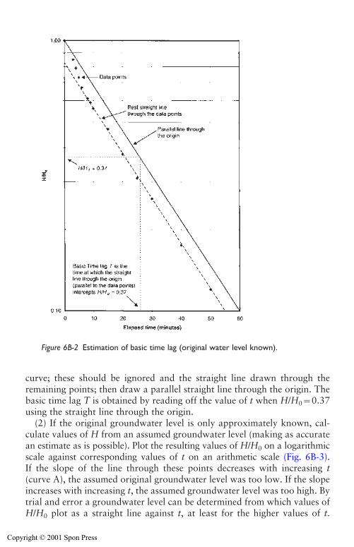
Site investigation for groundwater lowering 167
curve; these should be ignored and the straight line drawn through theremaining points; then draw a parallel straight line through the origin. Thebasic time lag T is obtained by reading off the value of t when H/H0�0.37using the straight line through the origin.
(2) If the original groundwater level is only approximately known, cal-culate values of H from an assumed groundwater level (making as accuratean estimate as is possible). Plot the resulting values of H/H0 on a logarithmicscale against corresponding values of t on an arithmetic scale (Fig. 6B-3).If the slope of the line through these points decreases with increasing t(curve A), the assumed original groundwater level was too low. If the slopeincreases with increasing t, the assumed groundwater level was too high. Bytrial and error a groundwater level can be determined from which values ofH/H0 plot as a straight line against t, at least for the higher values of t.
Figure 6B-2 Estimation of basic time lag (original water level known).
Copyright © 2001 Spon Press
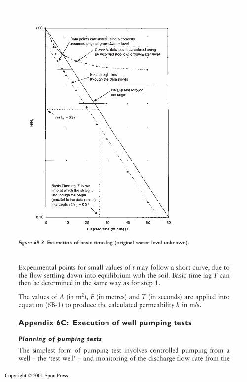
168 Site investigation for groundwater lowering
Experimental points for small values of t may follow a short curve, due tothe flow settling down into equilibrium with the soil. Basic time lag T canthen be determined in the same way as for step 1.
The values of A (in m2), F (in metres) and T (in seconds) are applied intoequation (6B-1) to produce the calculated permeability k in m/s.
Appendix 6C: Execution of well pumping tests
Planning of pumping tests
The simplest form of pumping test involves controlled pumping from awell – the ‘test well’ – and monitoring of the discharge flow rate from the
Figure 6B-3 Estimation of basic time lag (original water level unknown).
Copyright © 2001 Spon Press
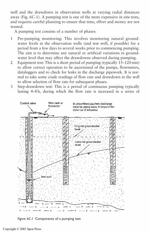
Site investigation for groundwater lowering 169
well and the drawdown in observation wells at varying radial distancesaway (Fig. 6C-1). A pumping test is one of the more expensive in situ tests,and requires careful planning to ensure that time, effort and money are notwasted.
A pumping test consists of a number of phases:
1 Pre-pumping monitoring: This involves monitoring natural ground-water levels in the observation wells (and test well, if possible) for aperiod from a few days to several weeks prior to commencing pumping.The aim is to determine any natural or artificial variations in ground-water level that may affect the drawdowns observed during pumping.
2 Equipment test: This is a short period of pumping (typically 15–120 min)to allow correct operation to be ascertained of the pumps, flowmeters,dataloggers and to check for leaks in the discharge pipework. It is nor-mal to take some crude readings of flow rate and drawdown in the wellto allow selection of flow rate for subsequent phases.
3 Step-drawdown test: This is a period of continuous pumping typicallylasting 4–8 h, during which the flow rate is increased in a series of
Figure 6C-1 Components of a pumping test.
Copyright © 2001 Spon Press
170 Site investigation for groundwater lowering
steps. Each step is of equal duration (normally 60 or 100 min) and anappropriately designed test should have four or five steps at roughly equalintervals of flow rate. Water levels are normally allowed to recover for atleast twelve hours before the constant rate pumping phase can be started.
4 Constant rate pumping phase: This is often considered to be the mainpart of the test and involves pumping the well at a constant flow rate(chosen following the step-drawdown test). The constant rate test nor-mally lasts between one and seven days, although test durations of upto twenty eight days are not unknown.
5 Recovery phase: Water levels in the observation wells and test well aremonitored as they recover following cessation of pumping. This phaseoften lasts between one and three days.
Guidance on the execution of pumping tests is given in BS6316 (1992) andKruseman and De Ridder (1990).
Pumping tests as part of groundwater lowering investigations need to bedesigned to meet certain criteria consistent with providing high quality datato the dewatering designer.
(a) The aim should be to achieve drawdowns (measured in piezometerswithin 10–20 m of the test well) of at least 10 per cent of the requireddrawdown in the proposed groundwater lowering scheme.
(b) If the site is subject to natural groundwater level variations (such astidal effects) the test should aim to achieve drawdowns significantlygreater than the background variations.
(c) It is essential that pumping is absolutely continuous during the initialhours of pumping. If pumping is interrupted due to whatever cause, suchas a pump or power failure, it is essential that the test is suspended untilgroundwater levels to return to equilibrium, or those levels recorded priorto commencement of any pumping. Only then should pumping recom-mence. Once the test pumping has been going on for 24h or more, occa-sional short interruptions (for example for daily checks of generator oillevels) are permissible. These interruptions should be as short as possible(ideally no longer than a few minutes); any longer interruptions mayrequire the test to be suspended and re-started later. Ideally, pumpingshould continue until steady-state drawdown conditions are established inobservation wells near the test well.
(d) Most of the simpler methods used to analyse pumping test data assumethe well fully penetrates the aquifer. Ideally, the test well should be fullypenetrating. However, provided the screened length is of the order of 70per cent to 80 per cent of the aquifer thickness the accuracy of theassessment of permeability is generally acceptable. Where the amount ofpenetration is less the flow will not be predominantly horizontal, andmore special corrections may need to be applied to the drawdown data.
Copyright © 2001 Spon Press
Site investigation for groundwater lowering 171
(e) Sufficient observation wells should be installed, in suitable locations,to allow groundwater flow patterns to be identified. Ideally, there should beat least three lines of observation wells radiating out from the test well, witheach line spaced 120 degrees apart. These need not penetrate the full depthof the aquifer but must be deeper than the expected drawdown (an obser-vation well that becomes dry is not acceptable!). Each line should consist ofthree or more observation wells. Depending upon the permeability of theaquifer, the distance from the test well to the nearest observation well shouldbe in the range of 2–3m (in a low to moderate permeability aquifer) or to5–10m (in a high permeability aquifer) from the test well. More distantobservation wells should located within the anticipated distance of influenceof the test well.
General comments on performing pumping tests
The test well should be designed, installed and developed according to theguidelines of Chapter 10 and observation wells should ideally be consistentwith the good practice outlined in Section 6.5. The most common form oftest well is a deep well pumped by a borehole electro-submersible pump.Suction pumps can be used, but only in highly permeable soils with a highwater table, otherwise, as drawdown occurs, the pump may become starvedof water, giving a varying flow rate. Whatever the method of pumping it isdesirable to measure the water inside the test well during pumping. Thiswill require the installation of a dip tube in the well so that the dipmetertape does not become entwined around the pump riser pipe due to the swirlof water near the pump intake.
The principal parameters to be measured during a test are water levels inthe test well and observation wells, and the discharge flow rate from thewell. All readings need to be referenced to the time elapsed since the startof pumping (or recovery) for that test phase. The frequency of monitoringmust be matched to the rate of change of the measured parameter. Duringa test the flow rate should remain approximately constant, but the waterlevels will fall rapidly immediately following the start of pumping, and willfall slower as pumping continues. Measurements of water levels must betaken very frequently at the start of the test, and become less frequent astime passes. A commonly used schedule of timings for readings is given inBS6316 (1992). This is summarized below:
� Readings to be taken immediately before the discharge flow rate isstarted, changed or stopped;
� Readings to be taken every minute for the first 10 min of the test phase;� Readings to be taken every 5 min thereafter up to an elapsed time of
60 min;
Copyright © 2001 Spon Press
172 Site investigation for groundwater lowering
� Readings to be taken every 15 min thereafter up to an elapsed time of 4 h;� Readings to be taken every 30 min thereafter up to an elapsed time of 8 h;� Readings to be taken every 60 min thereafter up to an elapsed time of
18 h;� Readings to be taken every 2 h thereafter up to an elapsed time of 48 h;� Readings to be taken every 4 h thereafter up to an elapsed time of 96 h;� Readings to be taken every 8 h thereafter up to an elapsed time of
188 hours;� Readings to be taken every 12 h thereafter, unless other influences war-
rant more frequent measurement.
These timings are for guidance only, and should be applied with judgement.The key point is to ensure that sufficient readings are taken to allow the rate of change of water levels to be clearly identified. If water levels are only changing slowly, it may be possible to increase the intervals betweenreadings without reducing the quality of the data. This would avoid generating unnecessary readings and can reduce the work involved in data analysis.
Water levels can be measured by manual dipping with a dipmeter (seeSection 14.2). However, at the start of the test readings need to be takenvery frequently. If more than a few observation wells are to be monitoredmanually, several people may be needed to take the frequent readings at thestart of the test, creating potential problems of co-ordination between per-sonnel. There is also the problem of actually gathering enough capable peo-ple together in the first place. This can lead to poor recording of the precisetiming of measurements taken during the first few minutes of pumping,leading to difficulties in subsequent analysis. If taking manual water levelreadings with limited numbers of observers, it is best to concentrate initialmonitoring on points nearest the test well. As time passes, and the timeperiod between readings increases, more observation wells can be includedin the monitoring.
The use of electronic datalogging equipment, linked to pressure trans-ducers in the observation wells (see Section 14.5), may help to overcomesuch staffing problems. Once programmed to take readings at the appro-priate intervals such equipment not only reduces the personnel require-ments, but will also produce the test measurements in electronic form,allowing rapid analysis using spreadsheet programs.
If a test is carried out in an aquifer with significant tidal response, themonitoring intervals later in the test (after several days pumping) must beselected with care. Standard tables of monitoring intervals (such as inBS6316 (1992)) allow monitoring frequencies of one reading every fewhours. If such large time gaps between readings are permitted, data will bevery difficult to interpret because the tidal responses will not be accuratelyrecorded. For tidal pumping tests the monitoring intervals for the first few
Copyright © 2001 Spon Press
Site investigation for groundwater lowering 173
hours of the test should be as per published guidelines, but the remainderof the test should be monitored at 15–30 minute intervals to ensure the tidalfluctuations are fully resolved. This requirement means that a dataloggingsystem is almost essential for pumping tests on tidal sites.
The pump discharge can be measured by means of a tank or gauge boxfitted with a V-notch or rectangular weir (see Section 14.3) or by installingan integrating flowmeter into the discharge pipeline. Even if flowmeters areused in preference to weir tanks, it is good practice to include a settlementtank in the discharge line so that it can be visually checked for suspendedsolids in the discharge water. In general, once adjusted at the start of thetest phase, the flow rate should not vary significantly. Immediately follow-ing commencement of pumping, flow rate does not need to be monitored asfrequently as water levels for the first hour or so of pumping. The outlet ofthe discharge should be well away from the test area to avoid the returnseepage affecting the drawdown levels.
It is normal to take water samples from the pumped discharge during thetest. Obtaining a sample is relatively straightforward if it is possible to filla sample bottle directly at the discharge tank. However, when takinggroundwater samples from the discharge flow the following factors shouldbe considered.
(a) Try to minimize the exposure of the sample to the atmosphere. Try andobtain it directly at the point where the pump discharges into the tank.Totally fill the bottle and try and avoid leaving any air inside when it issealed. If the pump discharge is ‘cascading’ before the sampling point thewater will become aerated and oxidation may occur. The dischargearrangements should be arranged so the sample can be obtained beforeaeration occurs.
(b) Samples may degrade between sampling and testing. The samples shouldbe tested as soon as possible after they are taken and, ideally, should berefrigerated in the meantime. The bottles used for sampling should beclean with a good seal. However, the sample may degrade while in thebottle (for example by trace metals oxidizing and precipitating out ofsolution). Specialists may be able to advise on the addition of suitablepreservatives to prevent this occurring. The choice of sample bottle(glass or plastic) should also be discussed with the laboratory since sometest results can be influenced by the material of the sample bottle.
The wellhead chemistry (see Section 3.8) can be determined using probes orsensors immersed in the flowing discharge water. These can be portablemeters, recorded manually, or may be linked to datalogging systems.
Execution of pumping tests
Before any pumping is carried out, water levels in observation wells mustbe recorded regularly over a period of days. This is to try and determine
Copyright © 2001 Spon Press
174 Site investigation for groundwater lowering
whether any natural (or artificially induced) variations in water level areoccurring. There are no generic guidelines on the duration and frequency ofbackground monitoring. On sites where it is anticipated that variations willbe small (e.g. remote inland sites) monitoring three times daily for three tofive days is the minimum acceptable. On coastal sites with a significant tidalresponse it has been necessary to use dataloggers to record water levelsevery 15 min, 24 h per day for up to thirty days. If in doubt, it is best to domore than the minimum monitoring. The time to find out about back-ground variations is prior to test pumping, not during the test itself.
The equipment test should be used to determine the most suitable pumpdischarge rate for subsequent phases of the test, so that at the end of pump-ing the water in the borehole is not drawn down to the pump intake. Itshould also be used to ensure that flow measuring devices function and thatdischarge pipework is not blocked and does not leak – to check in generalwhether the test is ready to proceed. Ideally, these preparations should betried out at least a day before test pumping is commenced so that the testwell and observation wells can be left to ensure that the groundwater levelis realistically re-established.
The following general information should be recorded prior to testing:
i Elevation of ground surface at the test well and at each observationwell.
ii Elevation of reference datum for water levels at each well (the top ofthe well casing is often used as a datum).
iii Depth of the well screen in the test well and the depth of response zonesin all observation wells.
iv Distances from the centre of the test well to all observation wells.
A step-drawdown test (if carried out) has the aim of investigating the per-formance of the well at increasing flow rates (see Clark 1977). The well ispumped in a number of steps (ideally four, or an absolute minimum ofthree); the flow rate in each step is constant, with the rate for each stepgreater than the last. Increments for flow rate should be roughly equal. Forexample a four step test might be designed as:
Step 1: one quarter of maximum well yieldStep 2: one half of maximum well yieldStep 3: three quarters of maximum well yieldStep 4: maximum well yield (estimated from the equipment test).
Step-drawdown pumping test results can be analysed to provide infor-mation about well efficiency. This is a function of friction head lossesthrough the filter pack and the well screen. It can also be affected by thetechniques used to bore and develop the test well.
Copyright © 2001 Spon Press
Site investigation for groundwater lowering 175
When starting any pumping (step-drawdown or constant rate) or recov-ery phase it is important that the monitoring team has been adequatelybriefed and is ready. Checks like ensuring all the dipmeters work and thatall observers have a pen or pencil and paper to record readings are obvious,but can be very embarrassing if overlooked! If datalogging equipment isbeing used it should be checked in advance for battery function and foraccuracy of clock setting. Above all, one person should be responsible fordeciding when to start pumping, and he or she should resist being pres-surised to start before everyone is ready. It is not necessary to start a test onthe hour of local time, but it makes recording and analysis easier if the teststarts on, say, a multiple of 10 min past the hour.
The time when the pump is started should be recorded. The control valveof the test pump should be adjusted to achieve the desired flow rate asquickly as possible after the start of pumping (or the step in a step-draw-down test). Once the flow rate has been set the valve should not be furtheradjusted as this will affect the drawdown and complicate analysis of results.At the start of the test phase, when readings are being taken frequently, itis important that readings in the test well and observation wells are takenat as nearly the same instant as possible. If all the wells are close togetherone of the observers may be able to make a visible or audible signal to theothers that it is time for a reading. Otherwise each observer will need tohave a clock of some sort, and the clocks will all need to be synchronized.If there are few observers and many wells it is best to abandon a rigidschedule of monitoring and just take readings as rapidly as possible, butrecord the precise time each reading was taken.
Monitoring during the test phases normally comprises:
i Water levels in the test well and observation well, with the time of eachreading recorded. Readings are normally taken at specified intervals(very frequently at the start of the test, less frequently as pumping pro-ceeds). Guidance is given in BS6316 (1992).
ii Pump discharge flow rate, recorded at the same time as the water lev-els (during the first hour or so of pumping, it is acceptable to record theflow rate less frequently than water levels, especially if the number ofobservers is limited).
iii Clarity of discharge water (as a check on any sand or silt in the dis-charge water).
iv Discharge water temperature and chemistry (by taking samples for test-ing or using portable meters). It is normal to take a water sample dur-ing the constant rate phase immediately after pumping commences,again after a few hours, and just before pumping ceases.
Upon cessation of pumping, monitoring of water levels in piezometersshould be continued until full recovery of water level is approached. Duringthe initial recovery period, readings should be at frequent intervals, at
Copyright © 2001 Spon Press
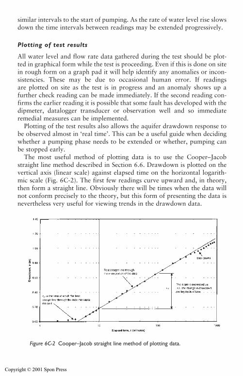
176 Site investigation for groundwater lowering
similar intervals to the start of pumping. As the rate of water level rise slowsdown the time intervals between readings may be extended progressively.
Plotting of test results
All water level and flow rate data gathered during the test should be plot-ted in graphical form while the test is proceeding. Even if this is done on sitein rough form on a graph pad it will help identify any anomalies or incon-sistencies. These may be due to occasional human error. If readings are plotted on site as the test is in progress and an anomaly shows up a further check reading can be made immediately. If the second reading con-firms the earlier reading it is possible that some fault has developed with the dipmeter, datalogger transducer or observation well and so immediateremedial measures can be implemented.
Plotting of the test results also allows the aquifer drawdown response tobe observed almost in ‘real time’. This can be a useful guide when decidingwhether a pumping phase needs to be extended or whether, pumping canbe stopped early.
The most useful method of plotting data is to use the Cooper–Jacobstraight line method described in Section 6.6. Drawdown is plotted on thevertical axis (linear scale) against elapsed time on the horizontal logarith-mic scale (Fig. 6C-2). The first few readings curve upward and, in theory,then form a straight line. Obviously there will be times when the data willnot conform precisely to the theory, but this form of presenting the data isnevertheless very useful for viewing trends in the drawdown data.
Figure 6C-2 Cooper–Jacob straight line method of plotting data.
Copyright © 2001 Spon Press
References
Barker, R. D. (1986). Surface geophysical techniques. Groundwater, Occurrence,Development and Protection (Brandon, T. W., ed.). Institution of WaterEngineers and Scientists, Water Practice Manual No. 5, London, pp 271–314.
Beesley, K. (1986). Downhole geophysics. Groundwater, Occurrence, Developmentand Protection (Brandon, T. W., ed.). Institution of Water Engineers andScientists, Water Practice Manual No. 5, London, pp 315–352.
Binns, A. (1998). Rotary coring in soils and soft rocks for geotechnical engineering.Proceedings of the Institution of Civil Engineers, Geotechnical Engineering, 131,63–74.
Brand, E. W. and Premchitt, J. (1982). Response characteristics of cylindricalpiezometers. Géotechnique, 32(3), 203–216.
Brassington, F. C. (1986). The inter-relationship between changes in groundwaterconditions and civil engineering construction. Groundwater in EngineeringGeology (Cripps, J. C., Bell, F. G. and Culshaw, M. G., eds). Geological SocietyEngineering Geology Special Publication No. 3, London, pp 47–50.
Brassington, F. C. and Walthall, S. (1985). Field techniques using borehole packersin hydrogeological investigations. Quarterly Journal of Engineering Geology, 18,181–193.
BS1377. (1990). Methods of Testing of Soils for Civil Engineering Purposes. BritishStandards Institution, London.
BS5930. (1999). Code of Practice for Site Investigation. British Standards Institution,London.
BS6316 (1992). Code of Practice for Test Pumping of Water Wells. BritishStandards Institution, London.
BS7022. (1988). Geophysical Logging of Boreholes for Hydrogeological Purposes.British Standards Institution, London.
Card, G. B. and Roche, D. P. (1989). The use of continuous dynamic probing in ground investigation. Penetration Testing in the UK. Thomas Telford, London.
Chandler, R. J., Leroueil, S. and Trenter, N. A. (1990). Measurements of the per-meability of London Clay using a self-boring permeameter. Géotechnique, 40,(1), 113–124.
Clark, L. (1977). The analysis and planning of step drawdown tests. QuarterlyJournal of Engineering Geology, 10, 125–143.
Clayton, C. R. I., Matthews, M. C. and Simons, N. E. (1995). Site Investigation,2nd edition. Blackwell, London.
Cooper, H. H. and Jacob, C. E. (1946). A generalised graphical method for evalu-ating formation constants and summarising well field history. Transactions of theAmerican Geophysical Union, 27, 526–534.
Dumbleton, M. G. and West, G. (1976). Preliminary Sources of Information for SiteInvestigations in Britain. Transport and Road Research Laboratory, LR403,Crowthorne.
Dunn, C. S. and Razouki, S. S. (1975). Interpretation of in situ permeability resultson anisotropic deposits. US Transportation Board, Transportation ResearchRecord, 532, 43–48.
Site investigation for groundwater lowering 177
Copyright © 2001 Spon Press
Hazen, A. (1892). Some physical properties of sands and gravels with special refer-ence to their use in filtration. 24th Annual Report. Massachusetts State Board ofHealth, p 539.
Hazen, A. (1900). The Filtration of Public Water Supplies. Wiley, New York.Head, K. H. (1982). Manual of Soil Laboratory Testing, Volume 2: Permeability,
Shear Strength and Compressibility Tests. Pentech Press, London.Hvorslev, M. J. (1951). Time Lag and Soil Permeability in Groundwater
Observations. Waterways Experimental Station, Corps of Engineers, Bulletin No. 36, Vicksburg, Mississippi.
Institution of Civil Engineers. (1991). Inadequate Site Investigation. ThomasTelford, London.
Irvine, D. J. and Smith, R. J. H. (1992). Trenching Practice. Construction IndustryResearch and Information Association, CIRIA Report 97, London.
Kruseman, G. P., and De Ridder, N. A. (1990). Analysis and Evaluation of PumpingTest Data. International Institute for Land Reclamation and Improvement,Publication 47, 2nd edition, Wageningen, The Netherlands.
Loudon, A. G. (1952). The computation of permeability from simple soil tests.Géotechnique, 3, 165–183.
Lunne, T., Robertson, P. K. and Powell, J. J. M. (1997). Cone Penetration Testingin Geotechnical Practice. Blackie, London.
MacDonald, A. M., Burleigh, J., and Burgess, W. G. (1999). Estimating transmis-sivity from surface resistivity soundings: an example from the Thames Gravels.Quarterly Journal of Engineering Geology, 32, 199–205.
McCann, D. M., Eddleston, M., Fenning, P. J. and Reeves, G. M., (eds) (1997).Modern Geophysics in Engineering Geology. Geological Society EngineeringGeology Special Publication No. 12, London.
Meigh, A. C. (1987). Cone Penetration Testing: Methods and Interpretation. CIRIAGround Engineering Report, Butterworths, London.
Powers, J. P. (1992). Construction Dewatering: New Methods and Applications,2nd edition. Wiley, New York.
Powrie, W. and Roberts, T. O. L. (1990). Field trial of an ejector well dewateringsystem at Conwy, North Wales. Quarterly Journal of Engineering Geology, 23,169–185.
Preene, M., Roberts, T. O. L., Powrie, W. and Dyer, M. R. (2000). GroundwaterControl – Design and Practice. Construction Industry Research and InformationAssociation, CIRIA Report C515, London.
Price, M. and Williams, A. T. (1993). A pumped double-packer system for use inaquifer evaluation and groundwater sampling. Proceedings of the Institution ofCivil Engineers, Water, Maritime and Energy, 101, April, 85–92.
Rowe, P. W. (1972). The relevance of soil fabric to site investigation practice.Géotechnique, 22(2), 195–300.
Site Investigation Steering Group. (1993). Site Investigation in Construction,Volume 1: Without Investigation Ground is a Hazard. Thomas Telford, London.
Terzaghi, K., Peck, R. B. and Mesri, G. (1996). Soil Mechanics in EngineeringPractice, 3rd edition. Wiley, New York.
178 Site investigation for groundwater lowering
Copyright © 2001 Spon Press

Trenter, N A. (1999). A note on the estimation of permeability of granular soils.Quarterly Journal of Engineering Geology, 32, 383–388.
Walthall, S. (1990). Packer testing in geotechnical engineering. Field Testing inEngineering Geology (Bell, F. G., Culshaw, M. G., Cripps, J. C. and Coffey, J. R.,eds). Geological Society Engineering Geology Special Publication No. 6, London,pp 345–350.
Site investigation for groundwater lowering 179
Copyright © 2001 Spon Press
Chapter 7
Design of groundwaterlowering systems
7.0 Introduction
The philosophy and basic methods for the design of groundwater loweringsystems are outlined in this chapter. The main emphasis of this chapter, andindeed of most of this whole book, is to deal with field proven, simplisticbut practical, methods applicable to many common situations, while pro-viding advice on the approach to more complex problems.
The uncertainty inherent in any ground engineering process, requires a‘questioning’ or ‘testing’ approach be adopted in design, where nothing istaken for granted. Sensitivity or parametric analyses can be used to assesshow the design could cope with differing conditions. Alternatively, theobservational method might be used to vary the design based on recordstaken during construction. Both these approaches are outlined, and the vitalimportance of developing a realistic conceptual model is stressed. Theimportant effect that geometry and geological structure has on design isalso described.
The basic designer’s ‘tool kit’ – the formulae and concepts used in routinedesigns – are presented and their application discussed. Methods for esti-mation of steady-state discharge flow rate, and for selection of well yieldand spacing are described in detail. Other design issues (such as time toachieve drawdown) are also outlined. The basic tenets of groundwatermodelling are discussed in relation to more complex problems. Several sim-ple design examples are presented in an appendix.
7.1 Design approach
There are two main philosophical views of the design of groundwater low-ering or dewatering systems:
1 That the design process is essentially a seepage calculation problem, whichcan be assessed using application of groundwater and hydrogeologicaltheory. This approach implies that the major problem is estimating the
Copyright © 2001 Spon Press
Design of groundwater lowering systems 181
discharge flow rate, and that selection and design of equipment is a sec-ondary matter, carried out once the flow rate has been determined. Wecould call this the ‘theoretical’ approach. Alternatively;
2 That the design process must concentrate on selecting the appropriatetype of well, well spacing and pump size for the ground conditions.Direct estimation of the flow rate is a less important issue (and indeedmay never actually be calculated precisely). This can be thought of asthe ‘empirical’ approach using case history experience.
The authors consider both the theoretical and empirical, have theiradvantages and disadvantages depending on ground conditions and thenature of the project.
For example, there are a number of cases which are sufficiently commonthat, once site investigation has confirmed there are no unusual complica-tions, they can be designed purely empirically – almost by rule of thumb,based on the established capabilities of standard dewatering equipment. Forexample, shallow trench excavations in homogenous sand deposits of mod-erate permeability can almost always be dewatered by wellpoint systems witha spacing of 1–2 m between wellpoints. This has been practically proven overmany decades. The empirical method is not applicable in more complex (orless clearly identified) geometries and ground conditions. If applied in suchcircumstances it can lead to considerable difficulties.
The theoretical approach can be used in cases whether or not there isempirical experience of the case in hand. The approach may involve fairlysimple calculations or analyses, or may require more complex numericalmodelling. The results of the calculations or modelling are used to specifythe number and type of wells, pumps, etc, that will be required. Problemsoften arise when the theoretical approach does not take into account the lim-itations and advantages of the various dewatering techniques. If these issuesare not considered, impractical or uneconomic system designs may result.
The best design approaches incorporate elements of both the theoreticaland empirical methods. The theoretical method requires a ‘conceptualmodel’ of the ground and groundwater regime to be developed, followingwhich calculations are carried out. Simple and fairly basic calculations areperfectly acceptable, and may be preferred in many cases, provided they arecompared with an empirical approach. The empirical method should beused as a ‘sanity check’ to ensure that the proposed groundwater loweringsystem is realistic and practicable. For example, if the output of a theoreti-cal design recommends a single stage of wellpoints to achieve a drawdownof 8 m this is clearly not going to work. More subtly, if a wellpoint spacingof, say, 15 m was recommended, this should be looked into more closely,since this is outside the normal range of wellpoint spacings – there may beproblems with the conceptual model, methods of analysis, or selection ofdewatering method.
Copyright © 2001 Spon Press
This chapter presents the methods that can be used in combined theoret-ical and empirical approaches. The main emphasis is to deal with fieldproven practical means pertinent to the majority of groundwater loweringprojects. The various methods presented form a ‘tool kit’ of techniqueswhich, if selected with care, can deal with a wide range of real problems.
One defining feature of the design of any geotechnical process (includinggroundwater lowering) is that there will be some uncertainties in theground. These uncertainties may result from the site investigation being oflimited or inappropriate scope. Alternatively, even following a comprehen-sive site investigation, the sheer variability and complexity of the revealedground conditions may give rise to uncertainty in design.
Uncertainty will affect the way the design is progressed. In principle thereare two basic approaches to design:
i Pre-defined designs. This might be thought of as the ‘traditional’ designprocess, whereby one geological profile and set of parameters isselected and used to produce a single set of design predictions. Thedesign is implemented with fairly basic monitoring, limited to checkingthat the design is ‘effective’ in the gross sense. Design and constructionmethods are not reviewed unless the original design is ‘ineffective’ (e.g.not achieving the target drawdown in a dewatering design). In suchcases corrective action (alternative design and construction methods)would be taken.
ii The observational method. This contrasting design process begins withmore than one geological profile and set of parameters and more thanone option for the required dewatering system. These might range from‘most probable’ to ‘most unfavourable’, perhaps with a number ofintervening conditions as well. More than one set of design predictionsare produced, together with measurable ‘trigger values’ to allow thedetailed effectiveness of the design to be observed during construction.The data taken during construction are continually reviewed, to allowdesign and construction methods to be altered incrementally to matchthe behaviour of the ground and groundwater.
7.1.1 Pre-defined designs for groundwater lowering
The pre-defined approach to dewatering design is to select a geological pro-file and important parameters (primarily permeability), and then applythese to an appropriate method of seepage analysis (such as one of thosepresented in Section 7.4). The result of this calculation is the ‘estimated’ or‘design’ discharge flow rate and drawdown distribution. Such an approachsometimes has an air of certainty or finality, especially if carried out by civilengineers more used to relatively consistent and reliable materials like steeland concrete.
182 Design of groundwater lowering systems
Copyright © 2001 Spon Press
In reality, few successful groundwater lowering systems are designed insuch a regimented way. As was discussed in Chapter 3, permeability andaquifer boundaries can have a dramatic effect on dewatering systems; the dif-ficulty of accurately determining permeability was described in Section 6.6.These factors mean that it is unrealistic to carry out a single seepage analysisand to then expect the dewatering system to have a high likelihood of per-forming adequately.
The best groundwater lowering systems are flexible and robust in nature,able to cope with ground conditions slightly different from those antici-pated with few, if any, minor modifications. Such systems are also easy tomodify or upgrade if ground conditions are substantially different fromthose expected.
The pre-defined approach can still be used, but normally more than one setof calculations is carried out as part of ‘sensitivity’ or ‘parametric’ analyses.
A sensitivity analysis is a set of repeated calculations, using varying valuesof a single parameter in each calculation. Typically for dewatering designspermeability is a key parameter, so seepage calculations are carried out fora range of possible values. The question being addressed is ‘can the ground-water lowering system, as designed, cope with the range of discharge flowrates corresponding to the possible range of permeability?’ If the answer isyes, all is well. If the answer is no, but the system could be easily (andquickly) modified to handle flow rates at either extreme end of the range,then the system may still be acceptably robust. If the answer is no, and thesystem cannot be readily modified, there is a risk that the system will notbe able to handle all the possible flow rates. In such cases it may be prudentto try and develop an alternative, more flexible, design and test that againstthe results of the sensitivity analysis.
Parametric analyses are a rather broader version of sensitivity calculations.The question addressed is ‘what parameters are influential to the design?’ Anumber of parameters or conditions are systematically varied in calculationsto investigate which have the greatest effect on the design. This may allow the design to be varied, or may prompt additional site investigation work torefine estimates of certain parameters or clarify key issues. In addition to per-meability, aquifer boundary conditions can have an important effect ondewatering designs. A parametric study might look at the effect of a closesource of recharge affecting the distance of influence, or the depth of theaquifer being deeper than expected. Again, the design process should includean assessment of the ability of the proposed dewatering system to cope withsuch possible conditions.
7.1.2 The observational method for groundwater lowering
The observational method allows a rational approach to constructionwhere there is uncertainty over ground conditions or over the most suitable
Design of groundwater lowering systems 183
Copyright © 2001 Spon Press
and economic dewatering or ground treatment options. The method usesconstruction observations to gather information about the behaviour of theground and groundwater, and then modifies methods in response. Themethod is much more than carrying out parametric or sensitivity analyses. Itshould be a continuous and deliberately planned and managed process ofdesign, construction control, monitoring and review that allows previouslydefined modifications to be incorporated into the construction process whennecessary. The object is to achieve a robust process which provides for eco-nomic construction without compromising safety. The background, methodsand case histories of the observational method are described in CIRIA ReportC185 (Nicholson et al. 1999). Two main variants are normally identified:
(a) Ab initio: applied from inception of the project.(b) Best way out: applied during construction to allow progress when unex-
pected problems occur on site. It is often applied when a ‘pre-defined’design has proved unsatisfactory, and modifications are required.
The observational method can be applied to many groundwater loweringsystems. This is because they can be easily modified (by the addition of extrawells or by using pumps of different capacity) and because easily observableparameters (such as drawdown and discharge flow rate) can be used to inter-pret how the system is performing. Examples of the observational methodapplied to groundwater lowering systems are given in Roberts and Preene(1994), Nicholson et al. (1999) and Preene et al. (2000).
The best way out application of the observational method is when a pre-defined method does not work and an alternative must be developed. It hasbeen used when dewatering systems have had to be uprated or modifiedwhen the pre-defined design fails to achieve the design aims. Effectively theinitial system (which was not installed with the observational method inmind) is monitored and used as a large-scale pumping test or trial to allowremedial measures to be selected.
The ab initio approach has been widely applied to larger projects, whereground conditions are known to be complex, or where the project design isnot going to be finalized until construction is well advanced. The numberof wells and pumping capacity can be optimized, based on the data gath-ered during the groundwater lowering works themselves. Optimization ofthe systems should be carefully considered, to avoid the temptation to usethe bare minimum number of wells. A truly optimized system will haveadequate standby plant, alarm systems, plus some additional wells (overand above the minimum) as an allowance against loss of wells or perfor-mance due to construction damage, clogging or biofouling and so on.
One possible reason why the ab initio application of the observationalmethod has mainly been applied to larger projects is the need for clear management of the design and construction process. This is necessary toallow construction feedback to be obtained and linked into the ongoing
184 Design of groundwater lowering systems
Copyright © 2001 Spon Press
design process in a timely manner. If smaller contracts are managed on thisbasis there is no reason why the benefits of the observational method couldnot be applied to a wider range of projects.
The methods presented in the remainder of this chapter are based largelyon pre-defined methods of design, but applied to give robust and flexiblesystems. The observational method will not be considered further, but it isan approach that the dewatering designer should be familiar with, since itis another part of the ‘tool kit’ to be applied when appropriate.
7.2 Development of conceptual model
The essential first step in the design process is the development of a concep-tual model of the ground and groundwater conditions. Until the conceptualmodel is developed, it is not possible to make rational decisions about whichof the methods in the designer’s ‘tool kit’ is suitable for the case in hand. Inorder to develop a conceptual model the designer needs to be familiar withthe concepts of groundwater flow, aquifers, boundary conditions and so on(see Chapter 3).
If a conceptual model is a poor match for actual conditions, then much ofthe subsequent design work may be of dubious value. Even if the design workis diligently and carefully carried out, if it is based on an inappropriate con-ceptual model the design may be going in totally the wrong direction – andthis is likely to lead to poorly performing dewatering systems. Developing theconceptual model at an early stage also forces the designer to review the avail-able data. If the designer has insufficient reliable data to formulate a modelthis could be a sign that further site investigation is needed.
The conceptual groundwater model depends on a number of factors thatare dictated by ground conditions, and are beyond the designer’s control:
i Aquifer type(s) and properties. Aquifers (the water bearing strata inwhich groundwater levels are to be lowered) may be classified as con-fined or unconfined. These types behave in quite different ways; theaquifer type(s) must be identified. It is essential that the likely perme-ability range of each aquifer be identified. If transient analyses are to becarried out the storage coefficient must also be estimated.
ii Aquifer depth and thickness. These dimensions must be estimated, anda judgement taken as to whether they are effectively constant across thearea affected by the dewatering, or whether the aquifer thickness variessignificantly.
iii Presence of aquitards and aquicludes. Very low permeability silt or claylayers may act as barriers to vertical groundwater flow. The presenceof such strata may necessitate well screens above and below theaquiclude or aquitard.
iv Distance of influence and aquifer boundaries. Is all the pumped waterlikely to be derived purely from storage in the aquifer? If not are there
Design of groundwater lowering systems 185
Copyright © 2001 Spon Press
any nearby sources of recharge water? The presence of any barrierboundaries can also influence groundwater flow.
v Initial groundwater level and pore water pressure profile. The initialgroundwater level determines the amount of drawdown required.Complications may arise if the groundwater level slopes across the site,or if groundwater levels vary with tidal or seasonal influences.
vi Presence of compressible strata. If present in significant thickness thisindicates that potentially damaging consolidation settlements may occur.
There are also some factors that are not directly related to ground condi-tions. Some of these can be controlled by the designer.
vii Geometry of the works. The depth and size of the excavation will havea direct influence on the groundwater lowering requirements. The tar-get lowered groundwater level is normally set a short distance (say 0.5to 1 m) below excavation formation level. The drawdown needed istaken as the vertical distance from the original groundwater level to thetarget lowered groundwater level.
viii Groundwater lowering technique. Different dewatering methods mayinteract with the groundwater regime in quite different ways.
ix Period for which groundwater lowering is required. The time for whichpumping is to continue may influence the choice of technique.
x Depth of wells. In very deep aquifers it may be more economic to installwells which do not penetrate to the base of the aquifer. Instead shal-lower, partially penetrating, wells may be more suitable.
xi Environmental constraints. The location or nature of the site and itssurroundings may give rise to limits on discharge rates or drawdownbeing imposed by the client or environmental regulator. These limitsare normally imposed to reduce the risk of detrimental side effects fromgroundwater lowering (see Chapter 13). Occasionally these constraintscan severely limit the options available to the dewatering designer.
If all, or at least most, of these questions can be answered a conceptualmodel can normally be developed. The conceptual model need not be par-ticularly complex, and may simply be a list of the expected conditions. Figure 7.1 shows an example of a simple pro-forma to record key data.Conceptual models are outlined in each of the design examples given inSection 7.8.
Any consideration of groundwater flow in general, or of the equations pre-sented later in this chapter highlights that aquifer permeability is a criticallyimportant parameter. Chapter 6 has described the plethora of techniquesavailable to estimate permeability, from the simple to the very complex. Whenassessing permeability values to be used in calculation, the designer should notvisualize a single permeability value to be used in the conceptual model, butrather a range of realistic values to be used in sensitivity analyses. The range
186 Design of groundwater lowering systems
Copyright © 2001 Spon Press
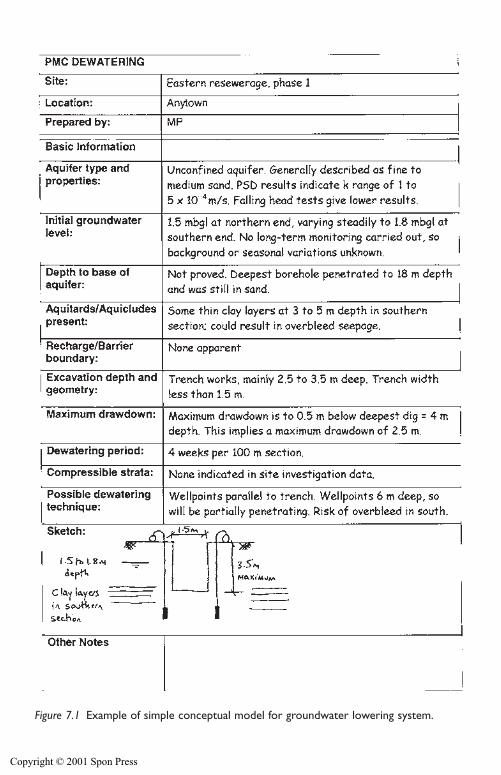
Design of groundwater lowering systems 187
Figure 7.1 Example of simple conceptual model for groundwater lowering system.
Copyright © 2001 Spon Press
of permeability values may represent uncertainty due to natural variations inpermeability, or limitations in the permeability test methods or results.
It is difficult to give simple, useful guidelines on selection of realistic per-meability ranges. There will always be some reliance on judgement andexperience, but the following advice is relevant:
� Be aware that different methods of assessing permeability produceresults of greater or lesser reliability. Table 6.3 provides some guidance.Consider the relative merits of each method when assessing permeabil-ity from the available results.
� Always compare the permeability results with ‘typical’ values of per-meability from published correlations with soil types (such as Table3.1) or, even better, from experience at nearby sites. This approach isvital in excluding unrealistically high or low permeability results. Forexample, few experienced engineers would expect a slightly silty sandygravel to have a permeability of 1�10�8 m/s, yet falling head tests insuch soils often produce results of that order.
� If permeability estimates from various differing techniques producebroadly similar results, in agreement with typical values for those soiltypes, then the design range of permeability could be assessed from the fullrange of data. If there are large discrepancies in the data from variousmethods, some of the data may have to be excluded from the assessmentprocess. Again Table 6.3 may be of help in assessing the reliability of data.
� Always consider the important aspects of the design when selecting thepermeability range to be used in calculations. Mistakes have been madewhen designers have focussed too much on estimating the highest likelypermeability, to ensure a pumping capacity sufficient for the maximumpossible flow rate. This is not always the most appropriate approach.It is true that in high permeability aquifers, the total flow rate may becritical, and assessing permeability at the upper end of the possiblerange may be a robust approach. But alternatively, in soils of low tomoderate permeability, a critical case in design may be if the perme-ability is at the lower end of the possible range when yields may be verylow, necessitating unfeasibly large numbers of wells.
Once the conceptual model exists, an initial view must be taken of thedewatering method to be used, and the likely geometry of the system.
7.3 Selection of method and geometry
There are a number of groundwater lowering methods available (seeSection 5.4), and part of the design process is to select an appropriate tech-nique which will satisfy the various constraints on the project in hand.
A useful starting point when selecting a technique is shown in Fig. 5.6.Knowing the required drawdown and estimated soil permeability from the
188 Design of groundwater lowering systems
Copyright © 2001 Spon Press
conceptual model the appropriate method can be chosen. Where more thanone method is feasible, the choice between them may be made on costgrounds, local availability of equipment, or expertise of those carrying outthe works.
7.3.1 Equivalent wells and slots
In practice, seldom can the required drawdown for an excavation be achievedby a single well; most dewatering systems rely on several wells acting in con-cert. The rare exceptions being, in a high permeability stratum, the use of alarge central sump pumping installation with radial drains (see Section 8.4 fora case history). The collector well system (see Section 11.4) is a variation onthis concept, but is more generally used for agricultural or land drainage purposes than for civil engineering construction.
For dewatering purposes the established principle is to install an array ofwater abstraction points, generally sited immediately adjacent to the area ofthe proposed excavation. This preferred location of wells (at the perimeterof the excavation) is based on practical experience. If wells are sited withinthe area to be excavated they are greatly at risk since maintaining wellheads,riser pipes, power cables and discharge mains is rarely compatible with theactivities of heavy excavation plant. Where possible wells are best locatedimmediately outside the excavation area or within the batter of excavations.Wells located in slope batters, whilst presenting an initial excavation andaccess impediment, are inherently more secure (in comparison with wells inthe main excavation area) as work progresses deeper.
Very large or wide excavations often cannot be dealt with adequately oreconomically by wells sited only around the perimeter. As highlighted abovethe practicalities of maintaining and/or reinstalling damaged wells in themiddle of a ‘live’ area of excavation are far from trivial. In many such casesunpumped relief wells (see Section 11.3) could be used inside the excavationarea. These act as vertical drainage paths and their usefulness is not affectedby progressive shortening as the excavation is deepened. The disadvantageof relief wells is their continuous water discharge; it must be disposed of byan effective drain and sump system. The disposal problem is readily con-trolled where the rates of flow are small (i.e. the underlying stratum is oflow permeability, say less than 10�5 m/s).
In general, the multiple well systems used for groundwater lowering canbe classified as either ‘linear’ systems (for installation alongside trench exca-vations) or ‘ring’ systems (for installation around circular or rectangularexcavations). Figure 7.2 shows definitions of these geometries.
This leads to the practical question of ‘how can we model the flow to suchsystems?’ It would be very tedious to consider the flow to each individual well,and the complex interaction between them. A useful approach is to consider
Design of groundwater lowering systems 189
Copyright © 2001 Spon Press
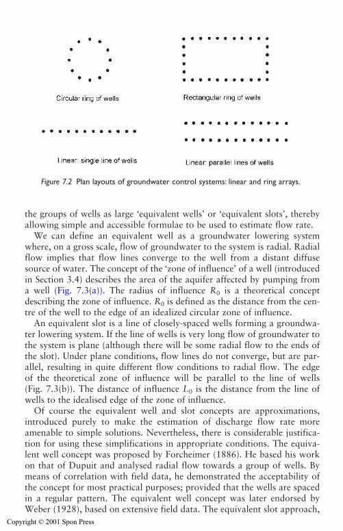
the groups of wells as large ‘equivalent wells’ or ‘equivalent slots’, therebyallowing simple and accessible formulae to be used to estimate flow rate.
We can define an equivalent well as a groundwater lowering systemwhere, on a gross scale, flow of groundwater to the system is radial. Radialflow implies that flow lines converge to the well from a distant diffusesource of water. The concept of the ‘zone of influence’ of a well (introducedin Section 3.4) describes the area of the aquifer affected by pumping froma well (Fig. 7.3(a)). The radius of influence R0 is a theoretical conceptdescribing the zone of influence. R0 is defined as the distance from the cen-tre of the well to the edge of an idealized circular zone of influence.
An equivalent slot is a line of closely-spaced wells forming a groundwa-ter lowering system. If the line of wells is very long flow of groundwater tothe system is plane (although there will be some radial flow to the ends ofthe slot). Under plane conditions, flow lines do not converge, but are par-allel, resulting in quite different flow conditions to radial flow. The edge of the theoretical zone of influence will be parallel to the line of wells (Fig. 7.3(b)). The distance of influence L0 is the distance from the line ofwells to the idealised edge of the zone of influence.
Of course the equivalent well and slot concepts are approximations,introduced purely to make the estimation of discharge flow rate moreamenable to simple solutions. Nevertheless, there is considerable justifica-tion for using these simplifications in appropriate conditions. The equiva-lent well concept was proposed by Forcheimer (1886). He based his workon that of Dupuit and analysed radial flow towards a group of wells. Bymeans of correlation with field data, he demonstrated the acceptability ofthe concept for most practical purposes; provided that the wells are spacedin a regular pattern. The equivalent well concept was later endorsed byWeber (1928), based on extensive field data. The equivalent slot approach,
190 Design of groundwater lowering systems
Figure 7.2 Plan layouts of groundwater control systems: linear and ring arrays.
Copyright © 2001 Spon Press
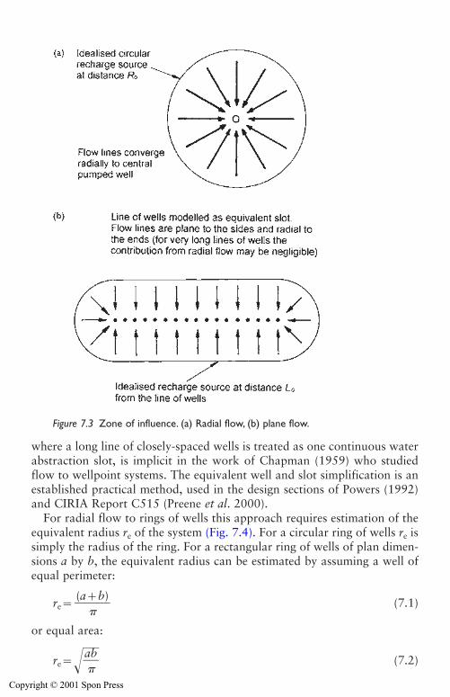
where a long line of closely-spaced wells is treated as one continuous waterabstraction slot, is implicit in the work of Chapman (1959) who studiedflow to wellpoint systems. The equivalent well and slot simplification is anestablished practical method, used in the design sections of Powers (1992)and CIRIA Report C515 (Preene et al. 2000).
For radial flow to rings of wells this approach requires estimation of theequivalent radius re of the system (Fig. 7.4). For a circular ring of wells re issimply the radius of the ring. For a rectangular ring of wells of plan dimen-sions a by b, the equivalent radius can be estimated by assuming a well ofequal perimeter:
re� (7.1)
or equal area:
re���a �b
�� (7.2)
(a�b)�
Design of groundwater lowering systems 191
Figure 7.3 Zone of influence. (a) Radial flow, (b) plane flow.
Copyright © 2001 Spon Press
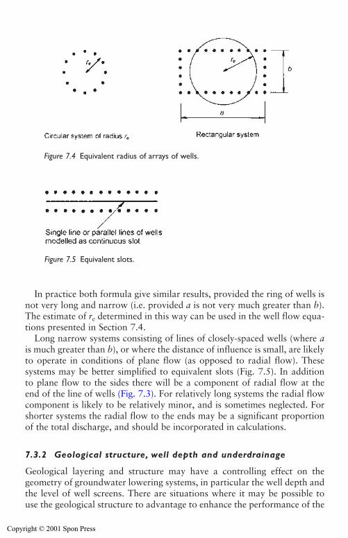
In practice both formula give similar results, provided the ring of wells isnot very long and narrow (i.e. provided a is not very much greater than b).The estimate of re determined in this way can be used in the well flow equa-tions presented in Section 7.4.
Long narrow systems consisting of lines of closely-spaced wells (where ais much greater than b), or where the distance of influence is small, are likelyto operate in conditions of plane flow (as opposed to radial flow). Thesesystems may be better simplified to equivalent slots (Fig. 7.5). In additionto plane flow to the sides there will be a component of radial flow at theend of the line of wells (Fig. 7.3). For relatively long systems the radial flowcomponent is likely to be relatively minor, and is sometimes neglected. Forshorter systems the radial flow to the ends may be a significant proportionof the total discharge, and should be incorporated in calculations.
7.3.2 Geological structure, well depth and underdrainage
Geological layering and structure may have a controlling effect on thegeometry of groundwater lowering systems, in particular the well depth andthe level of well screens. There are situations where it may be possible touse the geological structure to advantage to enhance the performance of the
192 Design of groundwater lowering systems
Figure 7.4 Equivalent radius of arrays of wells.
Figure 7.5 Equivalent slots.
Copyright © 2001 Spon Press
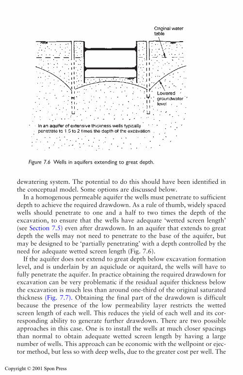
dewatering system. The potential to do this should have been identified inthe conceptual model. Some options are discussed below.
In a homogenous permeable aquifer the wells must penetrate to sufficientdepth to achieve the required drawdown. As a rule of thumb, widely spacedwells should penetrate to one and a half to two times the depth of the excavation, to ensure that the wells have adequate ‘wetted screen length’(see Section 7.5) even after drawdown. In an aquifer that extends to greatdepth the wells may not need to penetrate to the base of the aquifer, butmay be designed to be ‘partially penetrating’ with a depth controlled by theneed for adequate wetted screen length (Fig. 7.6).
If the aquifer does not extend to great depth below excavation formationlevel, and is underlain by an aquiclude or aquitard, the wells will have tofully penetrate the aquifer. In practice obtaining the required drawdown forexcavation can be very problematic if the residual aquifer thickness belowthe excavation is much less than around one-third of the original saturatedthickness (Fig. 7.7). Obtaining the final part of the drawdown is difficultbecause the presence of the low permeability layer restricts the wettedscreen length of each well. This reduces the yield of each well and its cor-responding ability to generate further drawdown. There are two possibleapproaches in this case. One is to install the wells at much closer spacingsthan normal to obtain adequate wetted screen length by having a largenumber of wells. This approach can be economic with the wellpoint or ejec-tor method, but less so with deep wells, due to the greater cost per well. The
Design of groundwater lowering systems 193
Figure 7.6 Wells in aquifers extending to great depth.
Copyright © 2001 Spon Press
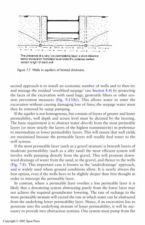
second approach is to install an economic number of wells and to then tryand manage the residual ‘overbleed seepage’ (see Section 4.4) by protectingthe faces of the excavation with sand bags, geotextile filters or other ero-sion prevention measures (Fig. 9.13(b)). This allows water to enter theexcavation without causing damaging loss of fines; the seepage water mustthen be removed by sump pumping.
If the aquifer is not homogenous, but consists of layers of greater and lesserpermeability, well depth and screen level must be dictated by the layering.The basic requirement is to abstract water directly from the most permeablelayers (or more strictly the layers of the highest transmissivity) in preferenceto intermediate or lower permeability layers. This will ensure that well yieldsare maximized because the permeable layers will readily feed water to thewell screens.
If the most permeable layer (such as a gravel stratum) is beneath layers ofmoderate permeability (such as a silty sand) the most efficient system willinvolve wells pumping directly from the gravel. This will promote down-ward drainage of water from the sand, to the gravel, and thence to the wells(Fig. 7.8). This important case is known as the ‘underdrainage’ approach,and is widely used where ground conditions allow. It is nearly always thebest option, even if the wells have to be slightly deeper than first thought inorder to intercept the permeable layer.
In contrast, where a permeable layer overlies a less permeable layer it islikely that a dewatering system abstracting purely from the lower layer maynot achieve the required groundwater lowering. The rate of recharge to themore permeable stratum will exceed the rate at which water can be abstractedfrom the underlying lower permeability layer. Hence, if an excavation has topenetrate into the underlying stratum of lesser permeability, it will be nec-essary to provide two abstraction systems. One system must pump from the
194 Design of groundwater lowering systems
Figure 7.7 Wells in aquifers of limited thickness.
Copyright © 2001 Spon Press
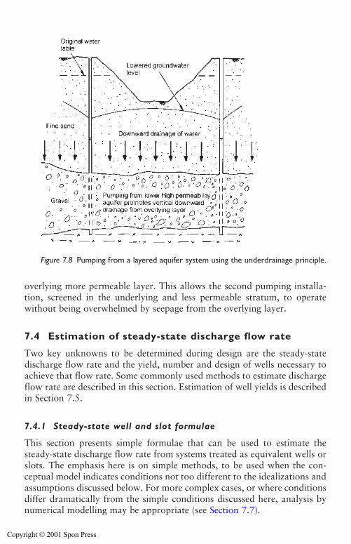
overlying more permeable layer. This allows the second pumping installa-tion, screened in the underlying and less permeable stratum, to operatewithout being overwhelmed by seepage from the overlying layer.
7.4 Estimation of steady-state discharge flow rate
Two key unknowns to be determined during design are the steady-statedischarge flow rate and the yield, number and design of wells necessary toachieve that flow rate. Some commonly used methods to estimate dischargeflow rate are described in this section. Estimation of well yields is describedin Section 7.5.
7.4.1 Steady-state well and slot formulae
This section presents simple formulae that can be used to estimate thesteady-state discharge flow rate from systems treated as equivalent wells orslots. The emphasis here is on simple methods, to be used when the con-ceptual model indicates conditions not too different to the idealizations andassumptions discussed below. For more complex cases, or where conditionsdiffer dramatically from the simple conditions discussed here, analysis bynumerical modelling may be appropriate (see Section 7.7).
Design of groundwater lowering systems 195
Figure 7.8 Pumping from a layered aquifer system using the underdrainage principle.
Copyright © 2001 Spon Press
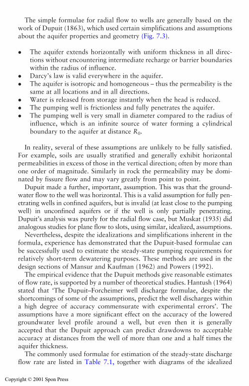
The simple formulae for radial flow to wells are generally based on thework of Dupuit (1863), which used certain simplifications and assumptionsabout the aquifer properties and geometry (Fig. 7.3).
� The aquifer extends horizontally with uniform thickness in all direc-tions without encountering intermediate recharge or barrier boundarieswithin the radius of influence.
� Darcy’s law is valid everywhere in the aquifer.� The aquifer is isotropic and homogeneous – thus the permeability is the
same at all locations and in all directions.� Water is released from storage instantly when the head is reduced.� The pumping well is frictionless and fully penetrates the aquifer.� The pumping well is very small in diameter compared to the radius of
influence, which is an infinite source of water forming a cylindricalboundary to the aquifer at distance R0.
In reality, several of these assumptions are unlikely to be fully satisfied.For example, soils are usually stratified and generally exhibit horizontalpermeabilities in excess of those in the vertical direction; often by more thanone order of magnitude. Similarly in rock the permeability may be domi-nated by fissure flow and may vary greatly from point to point.
Dupuit made a further, important, assumption. This was that the ground-water flow to the well was horizontal. This is a valid assumption for fully pen-etrating wells in confined aquifers, but is invalid (at least close to the pumpingwell) in unconfined aquifers or if the well is only partially penetrating.Dupuit’s analysis was purely for the radial flow case, but Muskat (1935) didanalogous studies for plane flow to slots, using similar, idealized, assumptions.
Nevertheless, despite the idealizations and simplifications inherent in theformula, experience has demonstrated that the Dupuit-based formulae canbe successfully used to estimate the steady-state pumping requirements forrelatively short-term dewatering purposes. These methods are used in thedesign sections of Mansur and Kaufman (1962) and Powers (1992).
The empirical evidence that the Dupuit methods give reasonable estimatesof flow rate, is supported by a number of theoretical studies. Hantush (1964)stated that ‘The Dupuit–Forcheimer well discharge formulae, despite theshortcomings of some of the assumptions, predict the well discharges withina high degree of accuracy commensurate with experimental errors’. Theassumptions have a more significant effect on the accuracy of the loweredgroundwater level profile around a well, but even then it is generallyaccepted that the Dupuit approach can predict drawdowns to acceptableaccuracy at distances from the well of more than one and a half times theaquifer thickness.
The commonly used formulae for estimation of the steady-state dischargeflow rate are listed in Table 7.1, together with diagrams of the idealized
196 Design of groundwater lowering systems
Copyright © 2001 Spon Press
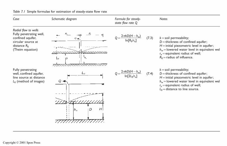
Table 7.1 Simple formulae for estimation of steady-state flow rate
Case Schematic diagram Formula for steady- Notesstate flow rate Q
Radial flow to wellsFully penetrating well,confined aquifer, Q��
2 kInD[R(H
0/�
re]hw)
� (7.3) k�soil permeability;circular source at D�thickness of confined aquifer;distance R0 H�initial piezometric level in aquifer;(Theim equation) hw�lowered water level in equivalent well;
re�equivalent radius of well;R0�radius of influence.
Fully penetrating k�soil permeability;well, confined aquifer, Q��
2
IknD[2(LH
0
�
/re]hw)
� (7.4) D�thickness of confined aquifer;line source at distance H�initial piezometric level in aquifer;L0 (method of images) hw�lowered water level in equivalent well;
re�equivalent radius of well;L0�distance to line source.
Copyright © 2001 Spon Press
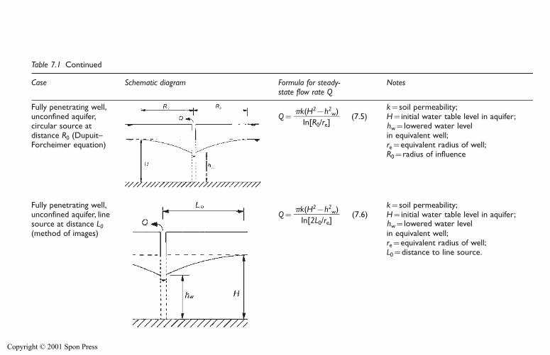
Table 7.1 Continued
Case Schematic diagram Formula for steady- Notesstate flow rate Q
Fully penetrating well, k�soil permeability;unconfined aquifer, Q� (7.5) H�initial water table level in aquifer;circular source at distance R0 (Dupuit– in equivalent well;Forcheimer equation) re�equivalent radius of well;
R0�radius of influence
Fully penetrating well, k�soil permeability;unconfined aquifer, line Q� (7.6) H�initial water table level in aquifer;source at distance L0(method of images) in equivalent well;
re�equivalent radius of well;L0�distance to line source.
k(H2�h2w)
��In[2L0/re]
k(H2�h2w)
��In[R0/re] hw�lowered water level
hw�lowered water level
Copyright © 2001 Spon Press
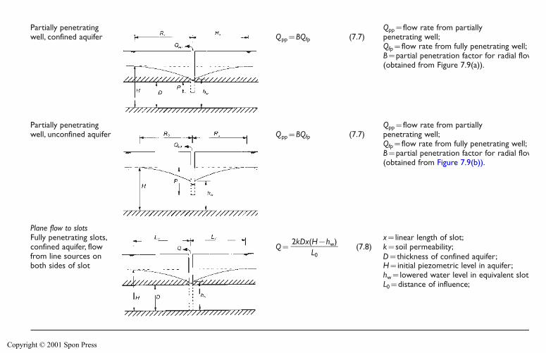
Partially penetrating Qpp�flow rate from partiallywell, confined aquifer Qpp�BQfp (7.7) penetrating well;
Qfp�flow rate from fully penetrating well;B�partial penetration factor for radial flow (obtained from Figure 7.9(a)).
Partially penetrating Qpp�flow rate from partiallywell, unconfined aquifer Qpp�BQfp (7.7) penetrating well;
Qfp�flow rate from fully penetrating well;B�partial penetration factor for radial flow (obtained from Figure 7.9(b)).
Plane flow to slotsFully penetrating slots, x�linear length of slot;confined aquifer, flow Q� (7.8) k�soil permeability;from line sources onboth sides of slot H�initial piezometric level in aquifer;
hw�lowered water level in equivalent slot;L0�distance of influence;
2kDx(H�hw)��
L0 D�thickness of confined aquifer;
Copyright © 2001 Spon Press
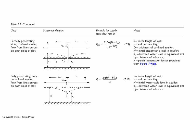
Table 7.1 Continued
Case Schematic diagram Formula for steady- Notesstate flow rate Q
Partially penetrating x�linear length of slot;slots, confined aquifer, Qpp� (7.9) k�soil permeability;flow from line sources on both sides of slot H�initial piezometric level in aquifer;
hw�lowered water level in equivalent slot;L0�distance of influence;��partial penetration factor (obtained from Figure 7.9(c)).
Fully penetrating slots, x�linear length of slot;unconfined aquifer, Q� (7.10) k�soil permeability;flow from line sourceson both sides of slot hw�lowered water level in equivalent slot;
L0�distance of influence.
kx(H2�h2w)
��L0
2kDx(H�hw)��
(L0��D)
H�initial water table level in aquifer;
D�thickness of confined aquifer;
Copyright © 2001 Spon Press
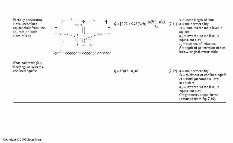
Partially penetrating x�linear length of slot;slots, unconfined Q�[0.73�0.23(P/H)] (7.11) k�soil permeability;aquifer, flow from linesources on both aquifer;sides of slot hw�lowered water level in
equivalent slot;L0�distance of influence;P�depth of penetration of slot below original water table.
Plane and radial flowRectangular systems,confined aquifer Q�kD(H�hw)G (7.12) k�soil permeability;
D�thickness of confined aquifer;H�initial piezometric level in aquifer;hw�lowered water level in equivalent slot;G�geometry shape factor(obtained from Fig. 7.10).
kx(H2�h2w)
��L0 H�initial water table level in
Copyright © 2001 Spon Press
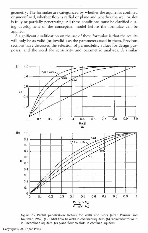
geometry. The formulae are categorized by whether the aquifer is confinedor unconfined, whether flow is radial or plane and whether the well or slotis fully or partially penetrating. All these conditions must be clarified dur-ing development of the conceptual model before the formulae can beapplied.
A significant qualification on the use of these formulae is that the resultswill only be as valid (or invalid!) as the parameters used in them. Previoussections have discussed the selection of permeability values for design pur-poses, and the need for sensitivity and parametric analyses. A similar
Figure 7.9 Partial penetration factors for wells and slots (after Mansur andKaufman 1962). (a) Radial flow to wells in confined aquifers, (b) radial flow to wellsin unconfined aquifers, (c) plane flow to slots in confined aquifers.
Design of groundwater lowering systems 202
Copyright © 2001 Spon Press
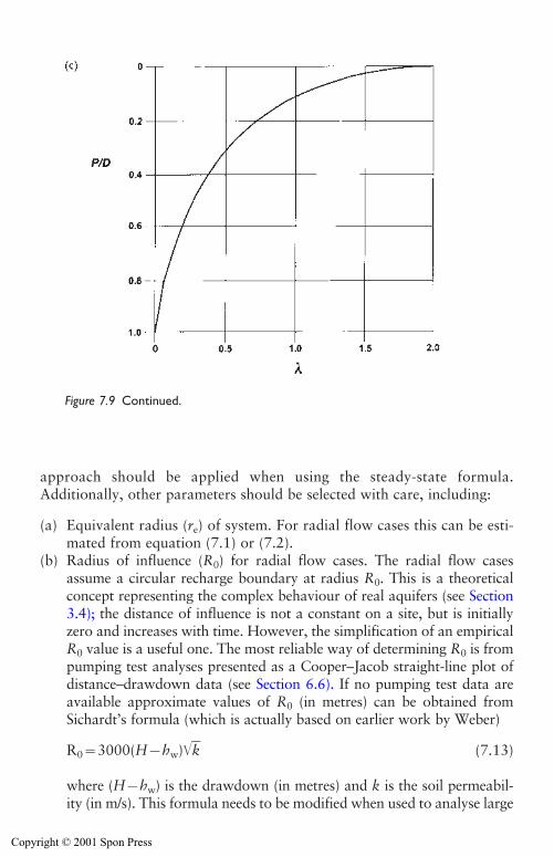
Design of groundwater lowering systems 203
Figure 7.9 Continued.
approach should be applied when using the steady-state formula.Additionally, other parameters should be selected with care, including:
(a) Equivalent radius (re) of system. For radial flow cases this can be esti-mated from equation (7.1) or (7.2).
(b) Radius of influence (R0) for radial flow cases. The radial flow casesassume a circular recharge boundary at radius R0. This is a theoreticalconcept representing the complex behaviour of real aquifers (see Section3.4); the distance of influence is not a constant on a site, but is initiallyzero and increases with time. However, the simplification of an empiricalR0 value is a useful one. The most reliable way of determining R0 is frompumping test analyses presented as a Cooper–Jacob straight-line plot ofdistance–drawdown data (see Section 6.6). If no pumping test data areavailable approximate values of R0 (in metres) can be obtained fromSichardt’s formula (which is actually based on earlier work by Weber)
R0�3000(H�hw)�k� (7.13)
where (H�hw) is the drawdown (in metres) and k is the soil permeabil-ity (in m/s). This formula needs to be modified when used to analyse large
Copyright © 2001 Spon Press
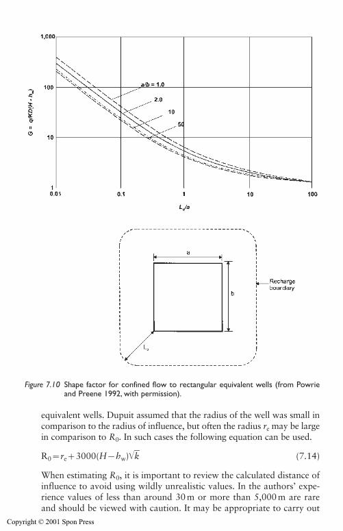
204 Design of groundwater lowering systems
equivalent wells. Dupuit assumed that the radius of the well was small incomparison to the radius of influence, but often the radius re may be largein comparison to R0. In such cases the following equation can be used.
R0�re�3000(H�hw)�k� (7.14)
When estimating R0, it is important to review the calculated distance ofinfluence to avoid using wildly unrealistic values. In the authors’ expe-rience values of less than around 30 m or more than 5,000 m are rareand should be viewed with caution. It may be appropriate to carry out
Figure 7.10 Shape factor for confined flow to rectangular equivalent wells (from Powrieand Preene 1992, with permission).
Copyright © 2001 Spon Press
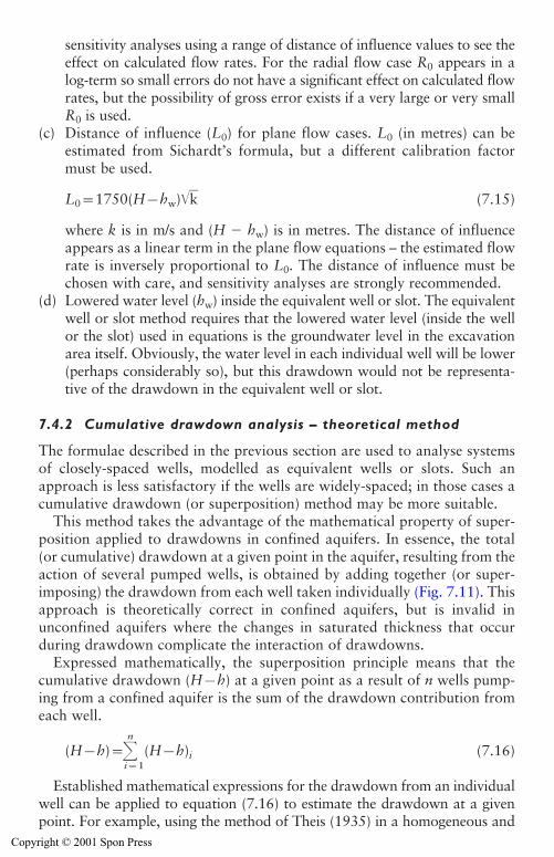
sensitivity analyses using a range of distance of influence values to see theeffect on calculated flow rates. For the radial flow case R0 appears in alog-term so small errors do not have a significant effect on calculated flowrates, but the possibility of gross error exists if a very large or very smallR0 is used.
(c) Distance of influence (L0) for plane flow cases. L0 (in metres) can beestimated from Sichardt’s formula, but a different calibration factormust be used.
L0�1750(H�hw)�k� (7.15)
where k is in m/s and (H � hw) is in metres. The distance of influenceappears as a linear term in the plane flow equations – the estimated flowrate is inversely proportional to L0. The distance of influence must bechosen with care, and sensitivity analyses are strongly recommended.
(d) Lowered water level (hw) inside the equivalent well or slot. The equivalentwell or slot method requires that the lowered water level (inside the wellor the slot) used in equations is the groundwater level in the excavationarea itself. Obviously, the water level in each individual well will be lower(perhaps considerably so), but this drawdown would not be representa-tive of the drawdown in the equivalent well or slot.
7.4.2 Cumulative drawdown analysis – theoretical method
The formulae described in the previous section are used to analyse systemsof closely-spaced wells, modelled as equivalent wells or slots. Such anapproach is less satisfactory if the wells are widely-spaced; in those cases acumulative drawdown (or superposition) method may be more suitable.
This method takes the advantage of the mathematical property of super-position applied to drawdowns in confined aquifers. In essence, the total (or cumulative) drawdown at a given point in the aquifer, resulting from theaction of several pumped wells, is obtained by adding together (or super-imposing) the drawdown from each well taken individually (Fig. 7.11). Thisapproach is theoretically correct in confined aquifers, but is invalid inunconfined aquifers where the changes in saturated thickness that occurduring drawdown complicate the interaction of drawdowns.
Expressed mathematically, the superposition principle means that thecumulative drawdown (H�h) at a given point as a result of n wells pump-ing from a confined aquifer is the sum of the drawdown contribution fromeach well.
(H�h)�n
i�1(H�h)i (7.16)
Established mathematical expressions for the drawdown from an individualwell can be applied to equation (7.16) to estimate the drawdown at a givenpoint. For example, using the method of Theis (1935) in a homogeneous and
Design of groundwater lowering systems 205
Copyright © 2001 Spon Press
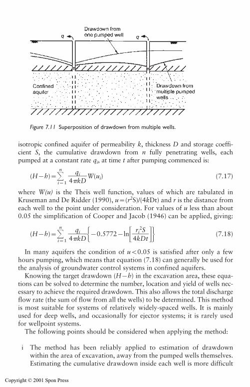
isotropic confined aquifer of permeability k, thickness D and storage coeffi-cient S, the cumulative drawdown from n fully penetrating wells, eachpumped at a constant rate qi, at time t after pumping commenced is:
(H�h)�n
i�1�4
qki
D�W(ui) (7.17)
where W(u) is the Theis well function, values of which are tabulated inKruseman and De Ridder (1990), u�(r2S)/(4kDt) and r is the distance fromeach well to the point under consideration. For values of u less than about0.05 the simplification of Cooper and Jacob (1946) can be applied, giving:
(H�h)�n
i�1�4
qki
D��0.5772�ln��4
rki2
DS
t��� (7.18)
In many aquifers the condition of u�0.05 is satisfied after only a fewhours pumping, which means that equation (7.18) can generally be used forthe analysis of groundwater control systems in confined aquifers.
Knowing the target drawdown (H�h) in the excavation area, these equa-tions can be solved to determine the number, location and yield of wells nec-essary to achieve the required drawdown. This also allows the total dischargeflow rate (the sum of flow from all the wells) to be determined. This methodis most suitable for systems of relatively widely-spaced wells. It is mainlyused for deep wells, and occasionally for ejector systems; it is rarely usedfor wellpoint systems.
The following points should be considered when applying the method:
i The method has been reliably applied to estimation of drawdownwithin the area of excavation, away from the pumped wells themselves.Estimating the cumulative drawdown inside each well is more difficult
206 Design of groundwater lowering systems
Figure 7.11 Superposition of drawdown from multiple wells.
Copyright © 2001 Spon Press
because well losses may not be accurately known. If large well lossesoccur, the method is less reliable because the drawdown contributionbecomes uncertain.
ii Application of the method requires that the aquifer parameters andwell yields be estimated. In practice, the most reliable way to obtainsuitable estimates is from analysis of a pumping test. If pumping testdata are not available the estimated cumulative drawdowns should betreated with caution, unless there is a high degree of confidence in theparameter values used in calculations. If a pumping test has been car-ried out the graphical cumulative drawdown method (described in thesubsequent section) may be a more appropriate method of analysis.
iii It may be possible to obtain the required drawdowns in the proposedexcavation using a few wells pumped at high flow rates, or a larger num-ber of wells of lower yield. Similarly, varying the well locations around(or within) the excavation may produce significantly different drawdownsin the area of interest. In years gone by investigating the effect of the var-ious options was a tedious process. However, since the advent of widely-available personal computers it is possible to write routines or macros for spreadsheet programmes to evaluate equation (7.18), allowing manyoptions to be rapidly considered. When evaluating the various options, itis vital that realistic well yields are used (see Section 7.5), otherwise toomany or too few wells will be specified.
iv Equations (7.17) and (7.18) include a term for the time since pumpingbegan, so each cumulative drawdown calculation is for a discrete timet. The time used in calculation will depend on the construction pro-gramme. If the programme shows that a two week period is availablefor drawdown (between installation of the dewatering system and com-mencement of excavation below original groundwater level) then thatcase should be analysed. However, in reality there may be problemswith installation of a few of the wells and pumps so all n wells will notbe pumping for the full two week period. It may be prudent to designon the basis of obtaining the target drawdown in a rather shorter time.
v The assumptions inherent in equations (7.17) and (7.18) (isotropic con-fined aquifer, fully penetrating wells, constant flow rate from each well)obviously will not apply in all cases. Provided that the basic aquifer con-ditions are confined or leaky it may be possible to use equation (7.17)for other conditions by substituting an alternative expression in place ofthe Theis well function W(u). Kruseman and De Ridder (1990) give wellfunctions for a number of cases, including leaky aquifers, anisotropicpermeability, partially penetrating wells and variable pumping rates.
The cumulative drawdown method assumes that individual wells do notinterfere significantly with each other’s yield. For wells at wide spacings(greater than around 20 m) in confined aquifers (where the aquifer thickness
Design of groundwater lowering systems 207
Copyright © 2001 Spon Press
does not change with drawdown), interference is usually low. In such casesthe observed drawdowns are likely to be close to those predicted directlyfrom the cumulative drawdown method. However, in general observeddrawdowns will be slightly less than predicted. It is not unusual forobserved drawdowns to be between 80 and 95 per cent of the calculatedvalues, when applied using reliable parameters derived from pumping tests.To allow for this, the total well yield (or the number of wells to be installed)should be increased (by dividing by an empirical superposition factor J of0.8–0.95). For example the total system flow rate Q is determined from thesum of the individual flow rates qi from n wells.
Q��1J�
n
i�1qi (7.19)
The cumulative drawdown method is invalid in unconfined aquifers (orconfined aquifers where the drawdown is so large that local unconfined conditions develop). This is because the saturated thickness decreases atdrawdown increases, making each additional well less effective comparedwith the initial wells. Although the method is theoretically invalid in uncon-fined conditions, where drawdowns are small (less than 20 per cent of the initial saturated aquifer thickness) the method has been successfully appliedusing an empirical superposition factor J of 0.8–0.95. For greater drawdownsin unconfined aquifers the cumulative drawdown method has been appliedusing empirical superposition factors of 0.6–0.8.
7.4.3 Cumulative drawdown analysis – graphical method
If distance–drawdown data are available describing the aquifer response tothe pumping of a single well, a graphical cumulative drawdown method canbe used. This approach is based on the Cooper–Jacob straight line methodof pumping test analysis (see Section 6.6) which uses equation (7.18)expressed as:
(H�h)�n
i�1�2
qki
D�ln��
Rri
0�� (7.20)
where all terms are as described previously, apart from R0 which is the radiusof influence at time t. The equation is evaluated graphically, and is used toobtain the total drawdown (H�h) at the selected location, resulting from agiven array of wells, without the need to evaluate the aquifer parameters.
The method is described in detail by Preene and Roberts (1994), andinvolves the following steps:
1 Determine the target drawdown level in critical points of the excava-tion. Typically, critical points where drawdown is checked include thecentre and corners of the excavation. Normally the target drawdown isa short distance (0.5–1 m) below excavation formation level.
208 Design of groundwater lowering systems
Copyright © 2001 Spon Press
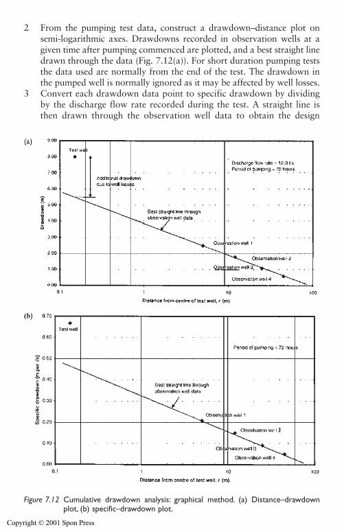
2 From the pumping test data, construct a drawdown–distance plot onsemi-logarithmic axes. Drawdowns recorded in observation wells at agiven time after pumping commenced are plotted, and a best straight linedrawn through the data (Fig. 7.12(a)). For short duration pumping teststhe data used are normally from the end of the test. The drawdown inthe pumped well is normally ignored as it may be affected by well losses.
3 Convert each drawdown data point to specific drawdown by dividingby the discharge flow rate recorded during the test. A straight line isthen drawn through the observation well data to obtain the design
Design of groundwater lowering systems 209
Figure 7.12 Cumulative drawdown analysis: graphical method. (a) Distance–drawdownplot, (b) specific–drawdown plot.
Copyright © 2001 Spon Press
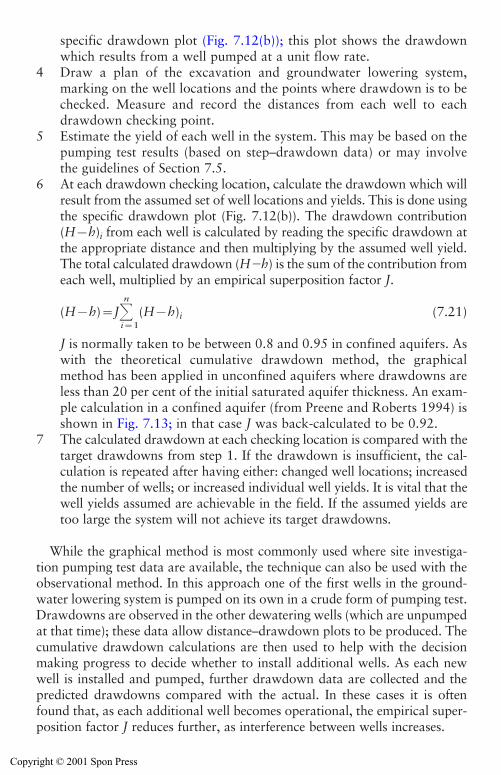
specific drawdown plot (Fig. 7.12(b)); this plot shows the drawdownwhich results from a well pumped at a unit flow rate.
4 Draw a plan of the excavation and groundwater lowering system,marking on the well locations and the points where drawdown is to bechecked. Measure and record the distances from each well to eachdrawdown checking point.
5 Estimate the yield of each well in the system. This may be based on thepumping test results (based on step–drawdown data) or may involvethe guidelines of Section 7.5.
6 At each drawdown checking location, calculate the drawdown which willresult from the assumed set of well locations and yields. This is done usingthe specific drawdown plot (Fig. 7.12(b)). The drawdown contribution(H�h)i from each well is calculated by reading the specific drawdown atthe appropriate distance and then multiplying by the assumed well yield.The total calculated drawdown (H�h) is the sum of the contribution fromeach well, multiplied by an empirical superposition factor J.
(H�h)�Jn
i�1(H�h)i (7.21)
J is normally taken to be between 0.8 and 0.95 in confined aquifers. Aswith the theoretical cumulative drawdown method, the graphicalmethod has been applied in unconfined aquifers where drawdowns areless than 20 per cent of the initial saturated aquifer thickness. An exam-ple calculation in a confined aquifer (from Preene and Roberts 1994) isshown in Fig. 7.13; in that case J was back-calculated to be 0.92.
7 The calculated drawdown at each checking location is compared with thetarget drawdowns from step 1. If the drawdown is insufficient, the cal-culation is repeated after having either: changed well locations; increasedthe number of wells; or increased individual well yields. It is vital that thewell yields assumed are achievable in the field. If the assumed yields aretoo large the system will not achieve its target drawdowns.
While the graphical method is most commonly used where site investiga-tion pumping test data are available, the technique can also be used with theobservational method. In this approach one of the first wells in the ground-water lowering system is pumped on its own in a crude form of pumping test.Drawdowns are observed in the other dewatering wells (which are unpumpedat that time); these data allow distance–drawdown plots to be produced. Thecumulative drawdown calculations are then used to help with the decisionmaking progress to decide whether to install additional wells. As each newwell is installed and pumped, further drawdown data are collected and thepredicted drawdowns compared with the actual. In these cases it is oftenfound that, as each additional well becomes operational, the empirical super-position factor J reduces further, as interference between wells increases.
210 Design of groundwater lowering systems
Copyright © 2001 Spon Press
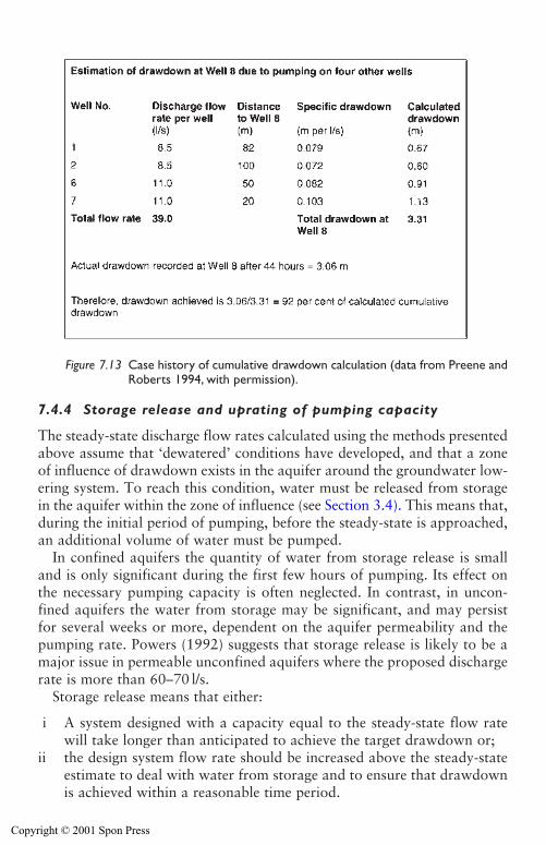
7.4.4 Storage release and uprating of pumping capacity
The steady-state discharge flow rates calculated using the methods presentedabove assume that ‘dewatered’ conditions have developed, and that a zoneof influence of drawdown exists in the aquifer around the groundwater low-ering system. To reach this condition, water must be released from storagein the aquifer within the zone of influence (see Section 3.4). This means that,during the initial period of pumping, before the steady-state is approached,an additional volume of water must be pumped.
In confined aquifers the quantity of water from storage release is smalland is only significant during the first few hours of pumping. Its effect onthe necessary pumping capacity is often neglected. In contrast, in uncon-fined aquifers the water from storage may be significant, and may persistfor several weeks or more, dependent on the aquifer permeability and thepumping rate. Powers (1992) suggests that storage release is likely to be amajor issue in permeable unconfined aquifers where the proposed dischargerate is more than 60–70 l/s.
Storage release means that either:
i A system designed with a capacity equal to the steady-state flow ratewill take longer than anticipated to achieve the target drawdown or;
ii the design system flow rate should be increased above the steady-stateestimate to deal with water from storage and to ensure that drawdownis achieved within a reasonable time period.
Design of groundwater lowering systems 211
Figure 7.13 Case history of cumulative drawdown calculation (data from Preene andRoberts 1994, with permission).
Copyright © 2001 Spon Press
The release of water from storage has the same effect as reducing the dis-tance of influence used in calculation. If the ‘long-term’ distance of influenceis used in design, drawdown may only be achieved slowly. Alternatively, if thedesigner uses a ‘short-term’ distance of influence in design, drawdown maybe achieved rapidly, but the system may be over-designed in the long term.This is only likely to be an issue in high permeability unconfined aquifers.
If the distance of influence used in design is taken from analysis of short-term pumping test data (see Section 6.6) this will include storage release, andcalculated flow rates are likely to achieve drawdowns fairly rapidly. This alsoapplies to systems designed by the graphical cumulative drawdown method,where pumping test data are used directly.
If no pumping test data are available and the distance of influence is estimated from empirical formulae such as equations (7.13)–(7.15), thenjudgement must be used where distances of influence of several hundredmetres are predicted in high permeability soils. Systems with pumpingcapacities designed on that basis will be able to cope with steady-stateinflows, once the zone of influence has developed. However, they may beoverwhelmed by storage release during the early stages of pumping, anddrawdown may take a long time to be achieved, leading to delays in theconstruction programme. Designers sometimes overcome this problem byusing rather smaller distances of influence which predict higher flow rates;this helps ensure that drawdown is achieved in reasonable time.
If the distance of influence used in the design has been estimated fromequations (7.13)–(7.15), the following equations can be used to crudely esti-mate the time t, which would be required for this distance of influence todevelop. The equations are for radial flow (from Cooper and Jacob 1946)
R0���2�.2�5
S�k�D�t�� (7.22)
and for plane flow (from Powrie and Preene 1994)
L0���1�2�k
S�D�t�� (7.23)
where D is the aquifer thickness, k is the permeability and S is the storagecoefficient. Strictly, equations (7.22) and (7.23) are only valid in confinedaquifers, but can be used in unconfined aquifers where the drawdown is nota large proportion of the original saturated thickness. Typical values of spe-cific yield (approximately equal to S in an unconfined aquifer) are given inTable 3.2.
If the design distance of influence will take a long time (more than a fewdays) to develop, it is possible that the system should be designed assuming asmaller R0 or L0 – (values typically used in high permeability soils are in therange 200–500m). Changing the design in this way would increase therequired pumping capacity of the system. This would allow the water released
212 Design of groundwater lowering systems
Copyright © 2001 Spon Press
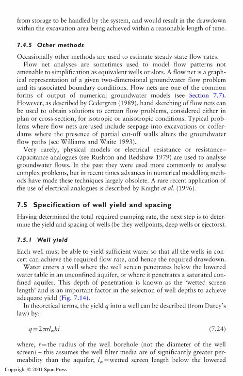
from storage to be handled by the system, and would result in the drawdownwithin the excavation area being achieved within a reasonable length of time.
7.4.5 Other methods
Occasionally other methods are used to estimate steady-state flow rates.Flow net analyses are sometimes used to model flow patterns not
amenable to simplification as equivalent wells or slots. A flow net is a graph-ical representation of a given two-dimensional groundwater flow problemand its associated boundary conditions. Flow nets are one of the commonforms of output of numerical groundwater models (see Section 7.7).However, as described by Cedergren (1989), hand sketching of flow nets canbe used to obtain solutions to certain flow problems, considered either inplan or cross-section, for isotropic or anisotropic conditions. Typical prob-lems where flow nets are used include seepage into excavations or coffer-dams where the presence of partial cut-off walls alters the groundwaterflow paths (see Williams and Waite 1993).
Very rarely, physical models or electrical resistance or resistance–capacitance analogues (see Rushton and Redshaw 1979) are used to analysegroundwater flows. In the past they were used more commonly to analysecomplex problems, but in recent times advances in numerical modelling meth-ods have made these techniques largely obsolete. A rare recent application ofthe use of electrical analogues is described by Knight et al. (1996).
7.5 Specification of well yield and spacing
Having determined the total required pumping rate, the next step is to deter-mine the yield and spacing of wells (be they wellpoints, deep wells or ejectors).
7.5.1 Well yield
Each well must be able to yield sufficient water so that all the wells in con-cert can achieve the required flow rate, and hence the required drawdown.
Water enters a well where the well screen penetrates below the loweredwater table in an unconfined aquifer, or where it penetrates a saturated con-fined aquifer. This depth of penetration is known as the ‘wetted screenlength’ and is an important factor in the selection of well depths to achieveadequate yield (Fig. 7.14).
In theoretical terms, the yield q into a well can be described (from Darcy’slaw) by:
q�2 rlwki (7.24)
where, r�the radius of the well borehole (not the diameter of the wellscreen) – this assumes the well filter media are of significantly greater per-meability than the aquifer; lw�wetted screen length below the lowered
Design of groundwater lowering systems 213
Copyright © 2001 Spon Press
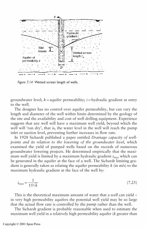
groundwater level; k�aquifer permeability; i�hydraulic gradient at entryto the well.
The designer has no control over aquifer permeability, but can vary thelength and diameter of the well within limits determined by the geology ofthe site and the availability and cost of well drilling equipment. Experiencesuggests that any well will have a maximum well yield, beyond which thewell will ‘run dry’, that is, the water level in the well will reach the pumpinlet or suction level, preventing further increases in flow rate.
In 1928 Sichardt published a paper entitled Drainage capacity of well-points and its relation to the lowering of the groundwater level, whichexamined the yield of pumped wells based on the records of numerousgroundwater lowering projects. He determined empirically that the maxi-mum well yield is limited by a maximum hydraulic gradient imax which canbe generated in the aquifer at the face of a well. The Sichardt limiting gra-dient is generally taken as relating the aquifer permeability k (in m/s) to themaximum hydraulic gradient at the face of the well by:
imax� (7.25)
This is the theoretical maximum amount of water that a well can yield –in very high permeability aquifers the potential well yield may be so largethat the actual flow rate is controlled by the pump rather than the well.
The Sichardt gradient is probably reasonable when used to estimate themaximum well yield in a relatively high permeability aquifer (k greater than
1�15�k�
214 Design of groundwater lowering systems
Figure 7.14 Wetted screen length of wells.
Copyright © 2001 Spon Press
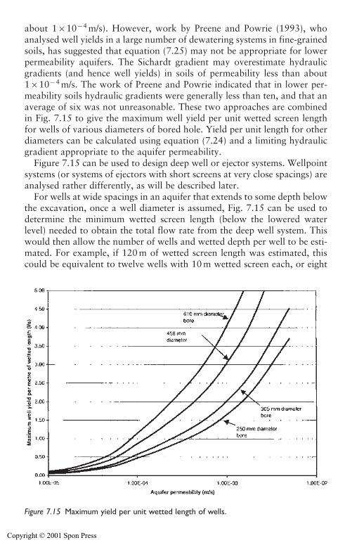
about 1�10�4 m/s). However, work by Preene and Powrie (1993), whoanalysed well yields in a large number of dewatering systems in fine-grainedsoils, has suggested that equation (7.25) may not be appropriate for lowerpermeability aquifers. The Sichardt gradient may overestimate hydraulicgradients (and hence well yields) in soils of permeability less than about1�10�4 m/s. The work of Preene and Powrie indicated that in lower per-meability soils hydraulic gradients were generally less than ten, and that anaverage of six was not unreasonable. These two approaches are combinedin Fig. 7.15 to give the maximum well yield per unit wetted screen lengthfor wells of various diameters of bored hole. Yield per unit length for otherdiameters can be calculated using equation (7.24) and a limiting hydraulicgradient appropriate to the aquifer permeability.
Figure 7.15 can be used to design deep well or ejector systems. Wellpointsystems (or systems of ejectors with short screens at very close spacings) areanalysed rather differently, as will be described later.
For wells at wide spacings in an aquifer that extends to some depth belowthe excavation, once a well diameter is assumed, Fig. 7.15 can be used todetermine the minimum wetted screen length (below the lowered waterlevel) needed to obtain the total flow rate from the deep well system. Thiswould then allow the number of wells and wetted depth per well to be esti-mated. For example, if 120 m of wetted screen length was estimated, thiscould be equivalent to twelve wells with 10 m wetted screen each, or eight
Design of groundwater lowering systems 215
Figure 7.15 Maximum yield per unit wetted length of wells.
Copyright © 2001 Spon Press
wells with 15 m wetted screen each, and so forth. Obviously, a check thenneeds to be made that the originally assumed well diameter is large enoughto accommodate well screens and pumping capacity to produce the designyield. If necessary the well diameter must be increased. Guidance on the sizeof deep wells and ejector wells required to produce given discharge rates perwell are given in Chapters 10 and 11 respectively.
Estimation of well yield is a point in design where judgement and expe-rience can be vital, so the designer should consider the following:
1 The wetted screen length lw will be rather less than the penetration ofthe well below the ‘general’ lowered water level. This is because of theadditional drawdown around each well due to each individual cone ofdepression (Fig. 7.14). The difference between the wetted depth and theexcavation drawdown level can be estimated from pumping test results.If no pumping test data are available, lw must be estimated based onengineering judgement.
2 The yields calculated by the methods described above are theoreticalmaximums and may not be achieved in practice. Well yields may bereduced by use of inappropriate filter material or poor development.The method of drilling will also influence yield, with jetted boreholesgenerally being more efficient than rotary or cable tool percussiondrilled holes. Experience also suggests that two competent drillers usingthe same methods and equipment on holes a few metres apart can pro-duce wells with wildly differing yields. There is no conclusive explana-tion for this phenomenon, but it is likely to be related to the precise wayeach driller uses the bits, casing and drilling fluids and how that affectsa thin layer of aquifer just outside the well.
3 There are certain rules of thumb about well depth, built up over manyyears of practice, and results of calculations should be compared withthese to check for gross errors. If the aquifer extends for some depthbelow the base of the excavation being dewatered, the wells should bebetween 1.5 and 2 times the depth of the excavation. Wells significantlyshallower than this are unlikely to be effective unless they are at veryclose spacing (analogous to a wellpoint system).
4 If the geology does not consist of one aquifer that extends to greatdepth, this may affect well depth and will restrict the flexibility of thedesigner in specifying lw. If the aquifer is relatively thin screen lengthswill be limited and a greater number of wells will be required. If thereis a deeper permeable stratum that, if pumped, could act to underdrainthe soils above, it may be worth deepening the wells (beyond the mini-mum required) in order to intercept the deep layer (see Section 7.3).
5 It is always prudent to allow for a few extra wells in the system over andabove the theoretically calculated number. Typically for small systemsat least one extra well is provided, or for larger systems the number of
216 Design of groundwater lowering systems
Copyright © 2001 Spon Press
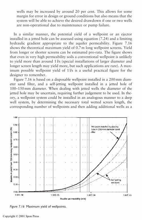
wells may be increased by around 20 per cent. This allows for somemargin for error in design or ground conditions but also means that thesystem will be able to achieve the desired drawdown if one or two wellsare non-operational due to maintenance or pump failure.
In a similar manner, the potential yield of a wellpoint or an ejectorinstalled in a jetted hole can be assessed using equation (7.24) and a limitinghydraulic gradient appropriate to the aquifer permeability. Figure 7.16shows the theoretical maximum yield of 0.7 m long wellpoint screens. Yieldfrom longer or shorter screens can be estimated pro-rata. The figure showsthat even in very high permeability soils a conventional wellpoint is unlikelyto yield more than around 1 l/s (special installations of larger diameter andlonger screen length may yield more, but such applications are rare). A max-imum possible wellpoint yield of 1 l/s is a useful practical figure for thedesigner to remember.
Figure 7.16 is based on a disposable wellpoint installed in a 200mm diam-eter sand filter, and a self-jetting wellpoint installed in a jetted hole of100–150mm diameter. When dealing with jetted wells the diameter of thejetted hole may be uncertain, requiring further judgement to be used. In the-ory, a wellpoint system could be installed in an analogous manner to a deepwell system, by determining the necessary total wetted screen length, thecorresponding number of wellpoints and then adding additional wells as a
Design of groundwater lowering systems 217
Figure 7.16 Maximum yield of wellpoints.
Copyright © 2001 Spon Press
contingency. In practice, this process is rarely carried out. Wellpoint equip-ment is almost always used in one of a limited number of standard spac-ings. Methods of selecting wellpoint spacings are described below.
The estimated well yield can be used to select the capacity of the pumpingequipment. For deep wells and ejectors the pumping equipment is located ineach well, and is sized directly from the well yield. For wellpoint systems onepump acts on many wellpoints in concert. The designer has the choice of afew larger pumps, or a greater number of smaller units (see Section 9.6).When estimating the required pump capacity from calculated steady-stateflow rate, an additional allowance must be made for the greater flow ratefrom storage release during the initial period of pumping (see Section 7.4).
7.5.2 Number of wells and well spacing
As described above, for deep well and ejector systems the number of wellsrequired can be determined from the total discharge flow rate, divided bythe predicted well yield, with some additional wells added as a contingency.This will then allow the average well spacing (the distance between adjacentwells) to be determined. Because well spacings of most groundwater lower-ing systems fall within relatively narrow ranges, comparison of the ‘design’spacing with typical values can be a useful way of verifying a design.
For all systems the well spacing chosen will influence the time required tolower groundwater levels to the target drawdown. In general the closer thewell spacing the quicker drawdown will be achieved. Because time is oftenas important a factor as cost in construction, groundwater lowering systemsare often installed with wells at rather closer spacing than is theoreticallynecessary, to ensure drawdown is achieved within a few days or weeks.
Typical spacing of deep wells are in the range 5–100 m, although thegreat majority of systems use spacings in the range 10–60 m between wells.
In aquifers of moderate to high permeability (where maximum well yieldsare relatively high), the designer has the flexibility of choosing a larger num-ber of closely-spaced low yield wells, or a smaller number of widely-spacedhigh yield wells. When potential well yields are large, high capacity pumpsmay not be available, and the output from each well may be controlled by thepump performance; this should be considered when estimating well numbersand spacings. If the aquifer extends to great depth it may be possible to userelatively few, very high capacity wells of very great depth at spacings of sev-eral hundred metres. This approach would require extensive pump testdata, backed up by numerical modelling.
In low permeability soils the well yield will be relatively low, and theoption of a small number of widely-spaced high yield wells is not availableto the designer. To achieve the total discharge flow rate the wells will be atclose spacings. If a well spacing of less than around 5–10 m is suggested by
218 Design of groundwater lowering systems
Copyright © 2001 Spon Press
the design, or if the well yield is less than around 0.7 l/s, an ejector systemcould be considered as an alternative to deep wells.
Ejector systems can be used in two ways.
i They can be used in soils of moderate permeability as an alternative tolow yield deep wells, or as ‘deep wellpoints’ to achieve drawdowns inexcess of 5–6 m. When used in this way, well spacings are similar tothose used for deep wells (5–10 m) or wellpoints (1.5–3 m).
ii In soils of low permeability they can be used as a vacuum-assisted porewater pressure control method. Because of the limited area influencedby each well, ejectors tend to be installed at close spacings (1.5–5 m)and operate at only a fraction of their pumping capacity.
In contrast to deep well and ejector systems, wellpoint spacings are rarelyselected on a yield per well basis. The number of wellpoints is determined byfirst selecting the wellpoint spacing from a fairly narrow range; the numberof wellpoints is then determined from the length of the line or ring of well-points. Typical wellpoint spacings are in the range 0.5–3.0 m (see Table 9.1for spacings categorized by soil type). Closer spacings tend to reduce thetime to achieve drawdown compared to wider spacings. Wellpoint spacingis controlled by different factors in soils of high and low permeability.
(a) In high permeability soils (such as coarse gravels) the total discharge flowrate will be large. Each wellpoint may be operating at high yields. A ruleof thumb is that a conventional wellpoint cannot yield more than about1 l/s, and the spacing is sometimes based on reducing the average well-point yield below 1 l/s. Wellpoints tend to be installed at close spacingsin high permeability soils. If a spacing in the range 0.5–1.0 m is suggestedby design calculations, wellpoint dewatering may not be the most appro-priate method. High capacity deep wells at close spacings might be con-sidered as an alternative.
(b) In low permeability soils (such as silty sands) the total flow rate will below. Consideration of the maximum wellpoint yield may suggest thatfairly wide (5–10 m) spacings may be possible. In reality, because of thelimited area influenced by each wellpoint, such a system is likely to per-form poorly and a very long time may be required to achieve drawdown.The solution is to install wellpoints at closer spacings of 1.5–3.0 m.
7.6 Other considerations
Although the prime concern of most groundwater lowering designs is toestimate the steady-state flow rate and the corresponding number and yieldof wells that will be required, other issues sometimes need to be addressedduring design.
Design of groundwater lowering systems 219
Copyright © 2001 Spon Press
7.6.1 Estimation of time-dependent drawdown distributionaround well
As pumping continues, the zone of influence around a dewatering systemwill increase with time. This means that the area affected by drawdown willexpand, initially rapidly, and then progressively more slowly as time passes.This is clearly a complex problem, and complete solution probably requiresa suitably calibrated numerical model. However, there are some simplermethods that can be used to estimate the drawdown pattern around anexcavation at a given time. These methods are outlined in this section.
In dewatering design, the time-dependent drawdown distribution may berequired for the following reasons:
(a) To determine how far the zone of significant settlements will extendduring the period of pumping. This is useful if the impact of potentialside effects (see Chapter 13) is being assessed. This normally involvesproducing a plot of the drawdown versus distance at time t after pump-ing began. Successive plots at greater values of t can show the develop-ment of the zone of influence. Each plot of drawdown versus distanceat a given time is known as an isochrone.
(b) To determine the time required to achieve the target drawdown in aparticular part of the excavation. This is normally only an issue in lowpermeability soils where it may influence the construction programme.In moderate to high permeability soils experience has shown that mostappropriately designed systems should achieve the target drawdownwithin 1–10 days pumping.
In many cases these calculations are unnecessary because the time toachieve drawdown and the risk of side effects is not a major concern. Inother cases, the methods presented here can be used to approximately deter-mine the time-dependent drawdown distribution. All these analyses assumethat the aquifer is homogenous and that no recharge or barrier boundariesare present within the zone of influence (i.e. all pumped water is derivedpurely from storage release). Numerical modelling should be consideredwhere aquifer boundaries are likely to be present.
If the groundwater lowering system consists of relatively widely spacedwells, then cumulative drawdown methods can be used. The theoreticalapproach (equation (7.16)) can allow the predicted drawdown at a selectedpoint to be plotted against time. Alternatively, the distance–drawdown pro-file (or isochrone) can be determined at a given time after pumping com-mences. By repeating the calculation for different times a series of isochrones,showing the drawdown pattern at each time interval can be produced.
If the system consists of closely spaced wells in a regular pattern, the sys-tem can be analysed as an equivalent well or slot. Analyses which assume
220 Design of groundwater lowering systems
Copyright © 2001 Spon Press
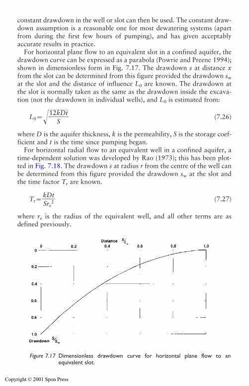
Design of groundwater lowering systems 221
constant drawdown in the well or slot can then be used. The constant draw-down assumption is a reasonable one for most dewatering systems (apartfrom during the first few hours of pumping), and has given acceptablyaccurate results in practice.
For horizontal plane flow to an equivalent slot in a confined aquifer, thedrawdown curve can be expressed as a parabola (Powrie and Preene 1994);shown in dimensionless form in Fig. 7.17. The drawdown s at distance xfrom the slot can be determined from this figure provided the drawdown swat the slot and the distance of influence L0 are known. The drawdown atthe slot is normally taken as the same as the drawdown inside the excava-tion (not the drawdown in individual wells), and L0 is estimated from:
L0���1�2�k
S�D�t�� (7.26)
where D is the aquifer thickness, k is the permeability, S is the storage coef-ficient and t is the time since pumping began.
For horizontal radial flow to an equivalent well in a confined aquifer, atime-dependent solution was developed by Rao (1973); this has been plot-ted in Fig. 7.18. The drawdown s at radius r from the centre of the well canbe determined from this figure provided the drawdown sw at the slot andthe time factor Tr are known.
Tr��kSDre
2t
� (7.27)
where re is the radius of the equivalent well, and all other terms are asdefined previously.
Figure 7.17 Dimensionless drawdown curve for horizontal plane flow to anequivalent slot.
Copyright © 2001 Spon Press
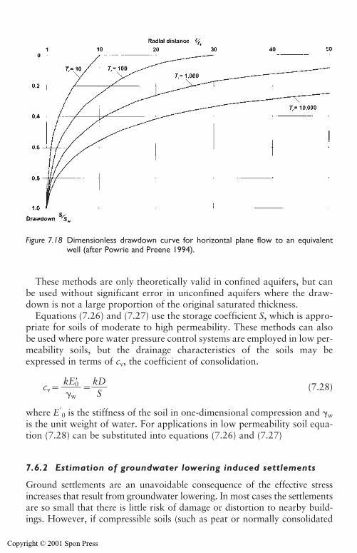
These methods are only theoretically valid in confined aquifers, but canbe used without significant error in unconfined aquifers where the draw-down is not a large proportion of the original saturated thickness.
Equations (7.26) and (7.27) use the storage coefficient S, which is appro-priate for soils of moderate to high permeability. These methods can alsobe used where pore water pressure control systems are employed in low per-meability soils, but the drainage characteristics of the soils may beexpressed in terms of cv, the coefficient of consolidation.
cv� ��kSD� (7.28)
where E0 is the stiffness of the soil in one-dimensional compression and �w
is the unit weight of water. For applications in low permeability soil equa-tion (7.28) can be substituted into equations (7.26) and (7.27)
7.6.2 Estimation of groundwater lowering induced settlements
Ground settlements are an unavoidable consequence of the effective stressincreases that result from groundwater lowering. In most cases the settlementsare so small that there is little risk of damage or distortion to nearby build-ings. However, if compressible soils (such as peat or normally consolidated
kE0��w
222 Design of groundwater lowering systems
Figure 7.18 Dimensionless drawdown curve for horizontal plane flow to an equivalentwell (after Powrie and Preene 1994).
Copyright © 2001 Spon Press
alluvial clays and silt) are present, it is possible that damaging settlementsmay occur.
If the conceptual model has identified the presence of significant thicknessesof compressible strata within the zone of influence, it will be necessary to con-sider the magnitude of ground settlements which may result. Methods for esti-mating the settlements that will result from a given drawdown are outlined inSection 13.1. The drawdown which may be expected beneath individualstructures can be estimated from the drawdown distributions given earlier inthis section.
It is important to remember the aim of settlement assessments – to assessthe risk of damage to structures and services, rather than to try and predictsettlements to the nearest millimetre. This latter aim would be difficult toachieve since the stiffness and consolidation parameters of compressiblesoils are rarely known with sufficient accuracy. Predicted degrees of dam-age, corresponding to various levels of settlement, are given in Section 13.1.That section also discusses methods used to mitigate or avoid settlementdamage resulting from groundwater lowering.
7.7 Numerical modelling
Numerical modelling of groundwater flow problems has been carried outfor several decades, but it is only since the 1980s and 1990s that advancesin personal computer (PC) technology has made this approach viable for awide range of groundwater lowering problems.
PCs can be used in design in two ways:
i By use of spreadsheet programs to evaluate design equations that mightpreviously have been carried out by hand. It is fairly easy to writeroutines for a spreadsheet to allow repeated sets of calculations to beperformed as part of sensitivity or parametric analyses. Use of the PCdramatically speeds up this process compared with hand calculation.
ii By use of a groundwater numerical modelling package to solve complexgroundwater flow problems that would not normally be amenable tosolution by other means.
This section will concentrate on the use of groundwater numerical mod-els applied to dewatering problems. It will describe the general approachthat should be adopted, and will not go into detail of the modelling process,which is described by Anderson and Woessner (1992). While numericalmodelling packages are becoming easier to apply, it is vital that anyone con-templating their use understands the theoretical basis and limitations of theprogram in question. In complex or unusual situations help should beobtained from an experienced groundwater modeller.
Design of groundwater lowering systems 223
Copyright © 2001 Spon Press
Essentially, a numerical model breaks down the overall problem, itsgeometry and boundary conditions, into a number of discrete smaller prob-lems that can be solved individually. An iterative process is often carriedout, whereby the solution to each smaller problem is adjusted until there isacceptable agreement at the boundaries between the smaller problems. It issometimes stated that numerical models produce ‘approximate’ solutions.This is true in the mathematical sense, because there will be a small differ-ence between an analytical solution and the numerical results, but in anengineering sense the numerical output is a pretty accurate reflection of theinput data and the groundwater model that has been formulated.
The key point is that the numerical package is only following instructionsgiven to it by the user. If there are errors in the input data or, more impor-tantly, if the conceptual model (on which the groundwater model is based)is unrealistic, gross errors may result. It is a cliché but the phrase ‘garbagein, garbage out’ – meaning that the results can only be as good as the inputand instructions – is very true for groundwater modelling. The conceptualmodel (see Section 7.2) is the critical starting point for any modelling exer-cise. If the conceptual model is not a good match for actual conditions thenany output may be of questionable value.
It is important to select a numerical modelling package appropriate to theproblem in hand. Some packages were originally developed for use in waterresources modelling of large areas of aquifers for regional-scale studies.These packages can be useful for large dewatering works in highly perme-able aquifers with large distances of influence, but may be less applicable forsmaller-scale seepage problems. Another group of packages were developedfor geotechnical problems such as seepage beneath cofferdams or throughearth embankments; these may be appropriate for small-scale problems.
The modelling package used must be capable of solving the type of prob-lem. Most packages can solve steady-state problems, but not all are designedfor transient time-dependent seepage; this must be considered when select-ing a modelling package. Most groundwater flow problems are three-dimensional to some degree, but for some cases the conceptual model may beable to simplify conditions to two-dimensional flow without significant error;some packages can model three-dimensional flow, but many are limited totwo dimensions only.
The numerical modelling process can be divided into a number of stages:
(a) Development of the conceptual model. Even though it does not involvetouching a computer, this is probably the most important stage of thenumerical modelling exercise. The conceptual model must quantify thegeometry, aquifer parameters and boundary conditions which will beused to define the numerical model. If the conceptual model does notreflect actual conditions, the modelling results are unlikely to be realisticor useful.
224 Design of groundwater lowering systems
Copyright © 2001 Spon Press
(b) Selection of software and setting up of numerical model. Once the conceptual model is defined, software capable of modelling those con-ditions can be selected. The software is then used to create the ground-water model (the set of instructions defining the relevant geometry,properties and boundary conditions) for the problem. Any errors oromissions in the input data and instructions will have an effect on theresults produced by the model.
(c) Verification and calibration. These activities are essential to allow anyerrors in the input data or model formulation to be identified, and forthe user to develop some degree of confidence in the validity of the out-put. The aim of verification is to answer the question ‘has the modeldone what we intended it to do?’ To answer this question the inputdata must be scrutinized for errors, and the output of the model mustbe compared with known analytical solutions. It is unlikely that an analytical solution will be available for the whole model, but it may bepossible to simplify all or part of the model and compare it with resultscalculated by, say, flow net or equivalent well methods. If errors aredetected, these are corrected and verification repeated until acceptableagreement is obtained. Following verification, the model should be cal-ibrated against field data such as observation well readings in variousparts of the modelled area. Calibration is a trial and error procedurewhereby the model parameters and boundary conditions are varied(within realistic ranges chosen from the conceptual model) until thereis acceptable agreement between the field data and the model output.
(d) Prediction and refinement. A verified and calibrated model can be usedto predict the results of interest (flow rates, drawdowns, settlements,etc). Parametric and sensitivity analyses can be carried out to assess the effect on results of different well arrays or aquifer conditions. Forlarger or longer-term projects it may be possible to refine predictions byfurther calibration against results from monitoring of the dewatering system – this can be used as part of the observational method.
There are a number of ways that numerical models can be used in the designof groundwater lowering systems. Perhaps the most obvious is to use themodel, following a comprehensive site investigation, as a direct design tool tofinalize the dewatering system. The conceptual model is developed from thesite investigation results, and the model is run repeatedly, adding, removing orrelocating wells and pumping capacity until the target drawdown is obtainedat specified points, or other design requirements are satisfied.
There is another way that numerical modelling can be used, as an aidboth to design and site investigation. If a groundwater model is created atan early stage of the project (perhaps using a conceptual model based on thesite investigation desk study) it can be used to crudely model the effect ofpossible ground conditions and construction options. Output from the
Design of groundwater lowering systems 225
Copyright © 2001 Spon Press
model may highlight particular issues to be addressed by the ground investigation. Similarly, the effect of changing the size of excavation, depthof cut-off walls and so on can be investigated; this may be useful informa-tion for designers. Any potential side effects of groundwater lowering canalso be quantified. The model is then developed, recalibrated and refined asadditional data is gathered, and continues to provide information to design-ers on the effect of various options. This approach has been successfullyadopted on a number of larger projects, including those where the obser-vational method was used.
7.8 Design examples
Some design examples are presented in Appendix 7A to illustrate the appli-cation of the methods presented in this chapter. For ease of reference therelevant equation and figure numbers are noted. The examples do notmerely cover the numerical aspects of design, but also discuss some of theissues over which ‘engineering judgement’ must be exercised.
Design example 1: Ring of relatively closely-spaced deep wells in a con-fined aquifer. This case is modelled as an equivalent well using radial flowequations.
Design example 1a: This analyses the case of example 1 using the alter-native method of using shape factors for flow to equivalent wells in con-fined aquifers.
Design example 2: A line of partially-penetrating wellpoints alongside atrench excavation in an unconfined aquifer. This case is analysed using asan equivalent slot under plane flow conditions. The effects of assuming dif-ferent aquifer depths and of including the contribution from radial flow tothe end of the slot are assessed.
Design example 3: Ring of widely-spaced deep wells around a large exca-vation in a confined aquifer. The cumulative drawdown method is used todesign the system.
Appendix 7A: Design examples
Four design examples, based on the methods of Chapter 7 are presentedhere. For ease of reference the relevant equation and figure numbers fromthe main text are also given.
Design example 1
This example is an application of the equivalent well method, to analyse asystem of fully penetrating deep wells used to lower the piezometric level in
226 Design of groundwater lowering systems
Copyright © 2001 Spon Press
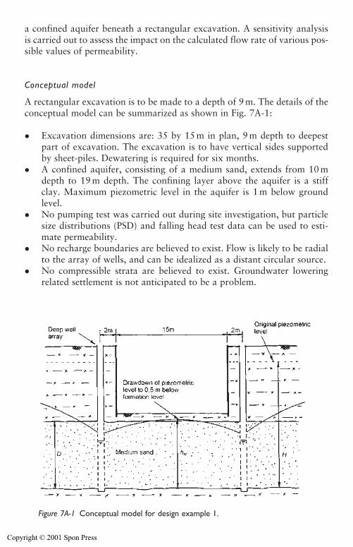
a confined aquifer beneath a rectangular excavation. A sensitivity analysisis carried out to assess the impact on the calculated flow rate of various pos-sible values of permeability.
Conceptual model
A rectangular excavation is to be made to a depth of 9 m. The details of theconceptual model can be summarized as shown in Fig. 7A-1:
� Excavation dimensions are: 35 by 15 m in plan, 9 m depth to deepestpart of excavation. The excavation is to have vertical sides supportedby sheet-piles. Dewatering is required for six months.
� A confined aquifer, consisting of a medium sand, extends from 10 mdepth to 19 m depth. The confining layer above the aquifer is a stiffclay. Maximum piezometric level in the aquifer is 1 m below groundlevel.
� No pumping test was carried out during site investigation, but particlesize distributions (PSD) and falling head test data can be used to esti-mate permeability.
� No recharge boundaries are believed to exist. Flow is likely to be radialto the array of wells, and can be idealized as a distant circular source.
� No compressible strata are believed to exist. Groundwater loweringrelated settlement is not anticipated to be a problem.
Design of groundwater lowering systems 227
Figure 7A-1 Conceptual model for design example 1.
Copyright © 2001 Spon Press
Selection of method
The presence of a confined aquifer at shallow depth beneath the excavationwould result in a risk of base heave if the piezometric level is not lowered.The conservative case is to lower the piezometric level to 9.5 m belowground level (i.e. 0.5 m below formation level). This requires a drawdownof 8.5 m below original groundwater level.
Without assessing the available permeability data in detail, typical valuesof permeability given in Table 3.1 suggest the permeability k of a mediumsand would be in the range 1�10�4–5�10�4 m/s.
Inspection of Fig. 5.6 suggests that either deep wells or two-stage wellpoints would be suitable for this combination of drawdown and per-meability. In this case the deep well method will be used, because the con-tractor wishes to excavate to full depth in one operation, and two-stagewellpointing requires a pause in excavation while the second stage isinstalled.
A system of relief wells (see Chapter 11) might have been considered.However, the anticipated permeability suggests the flow rate from the reliefwells would have been too great to be handled by sump pumping withoutinterfering with construction operations.
Estimation of steady-state discharge flow rate
The wells are to be installed in a regular pattern around the excavation.This geometry is amenable to solution as an equivalent well. If it is assumedthat the wells will be fully penetrating, the total flow rate Q can be esti-mated from equation (7.3).
Q� (7.3)
where
� k is the aquifer permeability. As described earlier, Table 3.1 suggests alikely permeability in the range 1�10�4–5�10�4 m/s. The site investi-gation data include PSD data showing a 10 per cent particle size (D10)of 0.1–0.3 mm. The sand is relatively uniform and Hazen’s rule (equa-tion (6.1)) can be used to estimate permeability as 1�10�4 to9�10�4 m/s. These permeability estimates are broadly consistent withTable 3.1. The larger end of the range is rather greater than might beexpected in a medium sand; the sample may have been affected by ‘lossof fines’ or may represent a coarser layer within the aquifer. Fallinghead tests in boreholes gave permeabilities in the range 1�10�8 to
2 kD(H�hw)��
ln�R0�re�
228 Design of groundwater lowering systems
Copyright © 2001 Spon Press
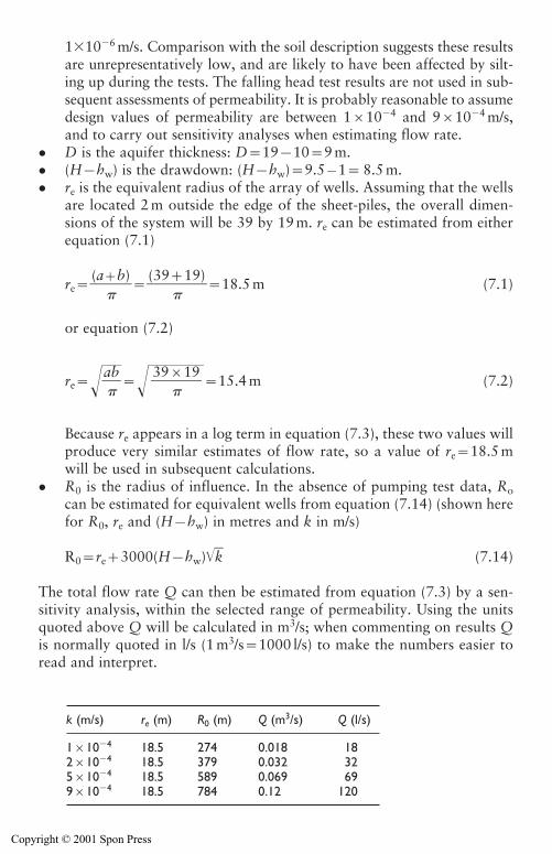
1�10�6 m/s. Comparison with the soil description suggests these resultsare unrepresentatively low, and are likely to have been affected by silt-ing up during the tests. The falling head test results are not used in sub-sequent assessments of permeability. It is probably reasonable to assumedesign values of permeability are between 1�10�4 and 9�10�4 m/s,and to carry out sensitivity analyses when estimating flow rate.
� D is the aquifer thickness: D�19�10�9 m.� (H�hw) is the drawdown: (H�hw)�9.5�1� 8.5 m.� re is the equivalent radius of the array of wells. Assuming that the wells
are located 2 m outside the edge of the sheet-piles, the overall dimen-sions of the system will be 39 by 19 m. re can be estimated from eitherequation (7.1)
re��(a�
b)���
(39�
19)��18.5 m (7.1)
or equation (7.2)
re���a �b
������15.4 m (7.2)
Because re appears in a log term in equation (7.3), these two values willproduce very similar estimates of flow rate, so a value of re�18.5 mwill be used in subsequent calculations.
� R0 is the radius of influence. In the absence of pumping test data, Rocan be estimated for equivalent wells from equation (7.14) (shown herefor R0, re and (H�hw) in metres and k in m/s)
R0�re�3000(H�hw)�k� (7.14)
The total flow rate Q can then be estimated from equation (7.3) by a sen-sitivity analysis, within the selected range of permeability. Using the unitsquoted above Q will be calculated in m3/s; when commenting on results Qis normally quoted in l/s (1 m3/s�1000 l/s) to make the numbers easier toread and interpret.
39�19�
Design of groundwater lowering systems 229
k (m/s) re (m) R0 (m) Q (m3/s) Q (l/s)
1�10�4 18.5 274 0.018 182�10�4 18.5 379 0.032 325�10�4 18.5 589 0.069 699�10�4 18.5 784 0.12 120
Copyright © 2001 Spon Press
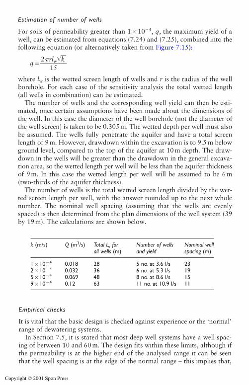
Estimation of number of wells
For soils of permeability greater than 1�10�4, q, the maximum yield of awell, can be estimated from equations (7.24) and (7.25), combined into thefollowing equation (or alternatively taken from Figure 7.15):
q��2 r
1l5w�k��
where lw is the wetted screen length of wells and r is the radius of the wellborehole. For each case of the sensitivity analysis the total wetted length (all wells in combination) can be estimated.
The number of wells and the corresponding well yield can then be esti-mated, once certain assumptions have been made about the dimensions ofthe well. In this case the diameter of the well borehole (not the diameter ofthe well screen) is taken to be 0.305 m. The wetted depth per well must alsobe assumed. The wells fully penetrate the aquifer and have a total screenlength of 9 m. However, drawdown within the excavation is to 9.5 m belowground level, compared to the top of the aquifer at 10 m depth. The draw-down in the wells will be greater than the drawdown in the general excava-tion area, so the wetted length per well will be less than the aquifer thicknessof 9 m. In this case the wetted length per well will be assumed to be 6 m(two-thirds of the aquifer thickness).
The number of wells is the total wetted screen length divided by the wet-ted screen length per well, with the answer rounded up to the next wholenumber. The nominal well spacing (assuming that the wells are evenlyspaced) is then determined from the plan dimensions of the well system (39by 19 m). The calculations are shown below.
230 Design of groundwater lowering systems
k (m/s) Q (m3/s) Total lw for Number of wells Nominal wellall wells (m) and yield spacing (m)
1�10�4 0.018 28 5 no. at 3.6 l/s 232�10�4 0.032 36 6 no. at 5.3 l/s 195�10�4 0.069 48 8 no. at 8.6 l/s 159�10�4 0.12 63 11 no. at 10.9 l/s 11
Empirical checks
It is vital that the basic design is checked against experience or the ‘normal’range of dewatering systems.
In Section 7.5, it is stated that most deep well systems have a well spac-ing of between 10 and 60 m. The design fits within these limits, although ifthe permeability is at the higher end of the analysed range it can be seenthat the well spacing is at the edge of the normal range – this implies that,
Copyright © 2001 Spon Press
if permeability is actually rather greater than the analysed range, then deepwells may not be the most appropriate method.
Another rule of thumb is that, where the aquifer depth allows, dewater-ing wells should generally penetrate to at least one and a half to two timesthe depth of the excavation. In this case the wells are 19 m deep, comparedto an excavation depth of 9 m, so this condition is satisfied.
In Table 10.1, the minimum diameters of well bore for a given yield arelisted. This table indicates that wells drilled at 305 mm diameter can accom-modate pumps of capacity up to 15–20 l/s, within the range of the antici-pated yield.
These empirical checks confirm, in the gross sense, the validity of the concept of the design.
Final design
Design calculations have produced a range of flow rates and well yields andspacings. Ultimately, a decision has to be made based on engineering judge-ment. Any records of local experience may help in forming an opinion. Inthis case the nominal system of six or eight wells would seem to be the mostappropriate option. If the construction programme is tight, and cannotcope with delays, the larger system would be prudent. However, in this caseit is assumed that there is time in the programme to install a few additionalwells (if crude testing of the first wells shows that flow rates are higher thanthe design value). Accordingly, the nominal six well system is appropriate.
If the aquifer was unconfined, the calculated steady-state flow rateswould need increasing to allow for the additional water from storagerelease in the early stages of pumping. However, the aquifer is initially con-fined, and after drawdown will only become unconfined local to the wells.Confined aquifers have very small storage coefficients, so the water releasedfrom storage will not be significant, and is not normally allowed for indesign.
It is normally prudent to increase the number of wells by around 20 percent, to provide some allowance for individual wells being temporarily outof service. In this case this increases the number of wells from six to eight.At the design yield of 5.3 l/s this give a total design capacity of around 42 l/s.In practice the system capacity will be slightly larger because submersiblepumps are manufactured with discrete capacities. The pump chosen willnormally have a slightly greater capacity than the design yield. These fac-tors should all help provide a robust design, capable of coping with modestchanges in the predicted flow rate.
Because the excavation is fairly narrow, it is likely that a well system ofadequate capacity will achieve drawdown everywhere within the excava-tion area. In many cases no formal calculation is made of the drawdowndistribution within the excavation. If necessary, the methods given in
Design of groundwater lowering systems 231
Copyright © 2001 Spon Press
Section 7.6 can be used to obtain approximate estimates of drawdownwithin the excavation.
Design example 1a
This example shows an alternative method for the estimation of steady-state flow rate from a system of deep wells in a confined aquifer. The wellarray is still modelled as an equivalent well, but the flow rate is determinedusing published ‘shape factors’. The case analysed is exactly the same as indesign example 1.
Conceptual model
As design example 1.
Selection of method
As design example 1.
Estimation of steady-state discharge flow rate
Flow to rectangular arrays of wells in confined aquifers can be determinedby the shape factor method of equation (7.12).
Q�kD(H�hw)G (7.12)
where:
� k is the aquifer permeability. See design example 1 for discussion ofselected values of permeability between 1�10�4 and 9�10�4 m/s.
� D is the aquifer thickness: D�19�10�9 m.� (H � hw) is the drawdown: (H�hw)�9.5�1�8.5 m.� G is a geometry shape factor, obtained from Fig. 7.10. To determine
the appropriate value of G for a given case, it is necessary to evaluatethe following parameters:Array aspect ratio a/b: if the array of wells is of plan dimensions a byb, the aspect ratio a/b will have an effect on the flow rate. In this casea/b�39/19�2.1.L0/a: The ratio of distance of influence L0 to the long dimension of thewell array a. In the absence of pumping test data, L0 can be estimatedfrom either equation (7.13) or (7.15). In this case, the excavation is notvery long and narrow and radial flow is likely to be the dominant flowregime. Therefore equation (7.13) is most appropriate.
L0�3000(H�hw)�k� (7.13)
232 Design of groundwater lowering systems
Copyright © 2001 Spon Press
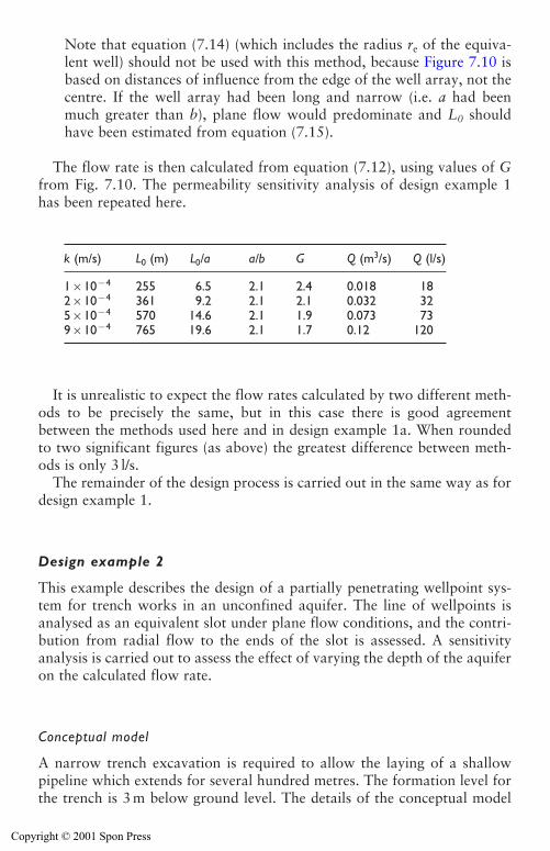
Note that equation (7.14) (which includes the radius re of the equiva-lent well) should not be used with this method, because Figure 7.10 isbased on distances of influence from the edge of the well array, not thecentre. If the well array had been long and narrow (i.e. a had beenmuch greater than b), plane flow would predominate and L0 shouldhave been estimated from equation (7.15).
The flow rate is then calculated from equation (7.12), using values of Gfrom Fig. 7.10. The permeability sensitivity analysis of design example 1has been repeated here.
It is unrealistic to expect the flow rates calculated by two different meth-ods to be precisely the same, but in this case there is good agreementbetween the methods used here and in design example 1a. When roundedto two significant figures (as above) the greatest difference between meth-ods is only 3 l/s.
The remainder of the design process is carried out in the same way as fordesign example 1.
Design example 2
This example describes the design of a partially penetrating wellpoint sys-tem for trench works in an unconfined aquifer. The line of wellpoints isanalysed as an equivalent slot under plane flow conditions, and the contri-bution from radial flow to the ends of the slot is assessed. A sensitivityanalysis is carried out to assess the effect of varying the depth of the aquiferon the calculated flow rate.
Conceptual model
A narrow trench excavation is required to allow the laying of a shallowpipeline which extends for several hundred metres. The formation level forthe trench is 3 m below ground level. The details of the conceptual model
Design of groundwater lowering systems 233
k (m/s) L0 (m) L0/a a/b G Q (m3/s) Q (l/s)
1�10�4 255 6.5 2.1 2.4 0.018 182�10�4 361 9.2 2.1 2.1 0.032 325�10�4 570 14.6 2.1 1.9 0.073 739�10�4 765 19.6 2.1 1.7 0.12 120
Copyright © 2001 Spon Press
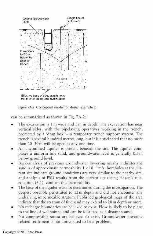
can be summarized as shown in Fig. 7A-2:
� The excavation is 1 m wide and 3 m in depth. The excavation has nearvertical sides, with the pipelaying operatives working in the trench, protected by a ‘drag box’ – a temporary trench support system. Thetrench is several hundred metres long, but it is anticipated that no morethan 20–30 m will be open at any one time.
� An unconfined aquifer is present beneath the site. The aquifer com-prises a uniform fine sand, and groundwater level is generally 0.5 mbelow ground level.
� Back-analysis of previous groundwater lowering nearby indicates thesand is of approximate permeability 1�10�4 m/s. Boreholes at the cur-rent site indicate ground conditions are very similar to the nearby site,and analysis of PSD results from the current site (using Hazen’s rule,equation (6.1)) confirm this permeability.
� The base of the aquifer was not determined during the investigation. Thedeepest borehole penetrated to 12 m depth and did not encounter anyunderlying impermeable stratum. Published geological maps of the areaindicate that the stratum of fine sand may extend to 20 m depth or more.
� No recharge boundaries are believed to exist. Flow is likely to be planeto the line of wellpoints, and can be idealized as a distant source.
� No compressible strata are believed to exist. Groundwater loweringrelated settlement is not anticipated to be a problem.
234 Design of groundwater lowering systems
Figure 7A-2 Conceptual model for design example 2.
Copyright © 2001 Spon Press
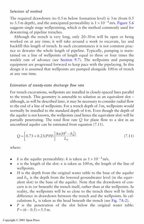
Selection of method
The required drawdown (to 0.5 m below formation level) is 3 m (from 0.5to 3.5 m depth), and the anticipated permeability is 1�10�4 m/s. Figure 5.6suggests single stage wellpointing, which is the method commonly used fordewatering of pipeline trenches.
Although the trench is very long, only 20–30 m will be open or beingworked on at any time; it will take around a week to excavate, lay andbackfill this length of trench. In such circumstances it is not common prac-tice to dewater the whole length of pipeline. Typically, pumping is main-tained on a line of wellpoints of length equal to three or four times theweekly rate of advance (see Section 9.7). The wellpoints and pumpingequipment are progressed forward to keep pace with the pipelaying. In thisdesign it is assumed that wellpoints are pumped alongside 100 m of trenchat any one time.
Estimation of steady-state discharge flow rate
For trench excavations, wellpoints are installed in closely-spaced lines parallelto the trench. This geometry is amenable to solution as an equivalent slot –although, as will be described later, it may be necessary to consider radial flowto the end of a line of wellpoints. For a trench depth of 3m, wellpoints wouldnormally be installed to the standard depth of 6m. Even though the depth ofthe aquifer is not known, the wellpoints (and hence the equivalent slot) will bepartially penetrating. The total flow rate Q for plane flow to a slot in anunconfined aquifer can be estimated from equation (7.11).
Q��0.73�0.23(P/H)� (7.11)
where:
� k is the aquifer permeability: k is taken as 1�10�4 m/s.� x is the length of the slot: x is taken as 100 m, the length of the line of
wellpoints.� H is the depth from the original water table to the base of the aquifer
and hw is the depth from the lowered groundwater level (in the equiv-alent slot) to the base of the aquifer. Note that the drawdown of con-cern is in (or beneath) the trench itself, rather than at the wellpoints. Inreality, the wellpoints will be so close to the trench there will be littledifference in drawdown between the trench and the wellpoints. In cal-culations hw is taken as the head beneath the trench (see Fig. 7A-2).
� P is the penetration of the slot below the original water table:P�(6�0.5)�5.5 m.
kx(H2�hw2)
��L0
Design of groundwater lowering systems 235
Copyright © 2001 Spon Press
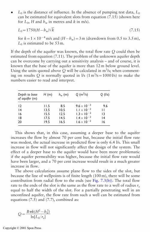
� L0 is the distance of influence. In the absence of pumping test data, L0can be estimated for equivalent slots from equation (7.15) (shown herefor L0, H and hw in metres and k in m/s).
L0�1750(H�hw)�k� (7.15)
for k�1�10�4 m/s and (H�hw)�3 m (drawdown from 0.5 to 3.5 m),L0 is estimated to be 53 m.
If the depth of the aquifer was known, the total flow rate Q could then beestimated from equation (7.11). The problem of the unknown aquifer depthcan be overcome by carrying out a sensitivity analysis – and of course, it isknown that the base of the aquifer is more than 12 m below ground level.Using the units quoted above Q will be calculated in m3/s; when comment-ing on results Q is normally quoted in l/s (1 m3/s�1000 l/s) to make thenumbers easier to read and interpret.
This shows that, in this case, assuming a deeper base to the aquiferincreases the flow by almost 70 per cent but, because the initial flow ratewas modest, the actual increase in predicted flow is only 6.4 l/s. This smallincrease in flow will not significantly affect the design of the system. Theeffect of a deeper base to the aquifer would have been more problematicif the aquifer permeability was higher, because the initial flow rate wouldhave been larger, and a 70 per cent increase would result in a much greaterincrease in flow.
The above calculations assume plane flow to the sides of the slot, butbecause the line of wellpoints is of finite length (100 m), there will be somecontribution from radial flow to the ends (see Fig. 7.3(b)). The total flowrate to the ends of the slot is the same as the flow rate to a well of radius reequal to half the width of the slot. For a partially penetrating well in anunconfined aquifer, the flow rate from such a well can be estimated fromequations (7.5) and (7.7), combined as:
Q�B k(H2�hw
2)��
ln[L0�re]
236 Design of groundwater lowering systems
Depth to base H (m) hw (m) Q (m3/s) Q (l/s)of aquifer (m)
12 11.5 8.5 9.6�10�3 9.614 13.5 10.5 1.1�10�2 1116 15.5 12.5 1.3�10�2 1318 17.5 14.5 1.4�10�2 1420 19.5 16.5 1.6�10�2 16
Copyright © 2001 Spon Press
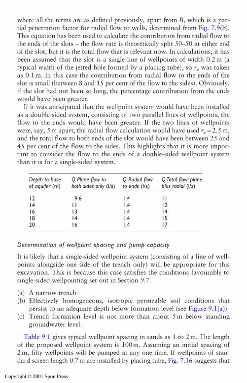
where all the terms are as defined previously, apart from B, which is a par-tial penetration factor for radial flow to wells, determined from Fig. 7.9(b).This equation has been used to calculate the contribution from radial flow tothe ends of the slots – the flow rate is theoretically split 50–50 at either endof the slot, but it is the total flow that is relevant now. In calculations, it hasbeen assumed that the slot is a single line of wellpoints of width 0.2 m (atypical width of the jetted hole formed by a placing tube), so re was takenas 0.1 m. In this case the contribution from radial flow to the ends of theslot is small (between 8 and 15 per cent of the flow to the sides). Obviously,if the slot had not been so long, the percentage contribution from the endswould have been greater.
If it was anticipated that the wellpoint system would have been installedas a double-sided system, consisting of two parallel lines of wellpoints, theflow to the ends would have been greater. If the two lines of wellpointswere, say, 5 m apart, the radial flow calculation would have used re�2.5 m,and the total flow to both ends of the slot would have been between 25 and45 per cent of the flow to the sides. This highlights that it is more impor-tant to consider the flow to the ends of a double-sided wellpoint systemthan it is for a single-sided system.
Determination of wellpoint spacing and pump capacity
It is likely that a single-sided wellpoint system (consisting of a line of well-points alongside one side of the trench only) will be appropriate for thisexcavation. This is because this case satisfies the conditions favourable tosingle-sided wellpointing set out in Section 9.7.
(a) A narrow trench(b) Effectively homogeneous, isotropic permeable soil conditions that
persist to an adequate depth below formation level (see Figure 9.1(a))(c) Trench formation level is not more than about 5 m below standing
groundwater level.
Table 9.1 gives typical wellpoint spacing in sands as 1 to 2 m. The lengthof the proposed wellpoint system is 100 m. Assuming an initial spacing of2 m, fifty wellpoints will be pumped at any one time. If wellpoints of stan-dard screen length 0.7 m are installed by placing tube, Fig. 7.16 suggests that
Design of groundwater lowering systems 237
Depth to base Q Plane flow to Q Radial flow Q Total flow: planeof aquifer (m) both sides only (l/s) to ends (l/s) plus radial (l/s)
12 9.6 1.4 1114 11 1.4 1216 13 1.4 1418 14 1.4 1520 16 1.4 17
Copyright © 2001 Spon Press
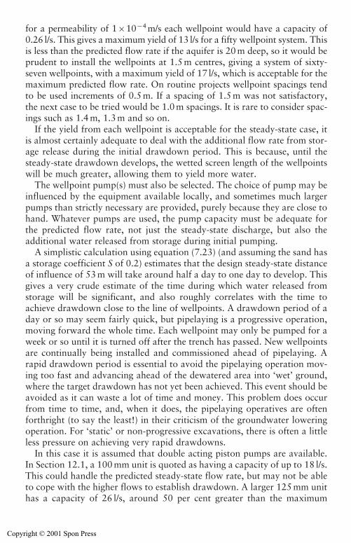
for a permeability of 1�10�4 m/s each wellpoint would have a capacity of0.26 l/s. This gives a maximum yield of 13 l/s for a fifty wellpoint system. Thisis less than the predicted flow rate if the aquifer is 20 m deep, so it would beprudent to install the wellpoints at 1.5 m centres, giving a system of sixty-seven wellpoints, with a maximum yield of 17 l/s, which is acceptable for themaximum predicted flow rate. On routine projects wellpoint spacings tendto be used increments of 0.5 m. If a spacing of 1.5 m was not satisfactory,the next case to be tried would be 1.0 m spacings. It is rare to consider spac-ings such as 1.4 m, 1.3 m and so on.
If the yield from each wellpoint is acceptable for the steady-state case, itis almost certainly adequate to deal with the additional flow rate from stor-age release during the initial drawdown period. This is because, until thesteady-state drawdown develops, the wetted screen length of the wellpointswill be much greater, allowing them to yield more water.
The wellpoint pump(s) must also be selected. The choice of pump may beinfluenced by the equipment available locally, and sometimes much largerpumps than strictly necessary are provided, purely because they are close tohand. Whatever pumps are used, the pump capacity must be adequate forthe predicted flow rate, not just the steady-state discharge, but also theadditional water released from storage during initial pumping.
A simplistic calculation using equation (7.23) (and assuming the sand hasa storage coefficient S of 0.2) estimates that the design steady-state distanceof influence of 53 m will take around half a day to one day to develop. Thisgives a very crude estimate of the time during which water released fromstorage will be significant, and also roughly correlates with the time toachieve drawdown close to the line of wellpoints. A drawdown period of aday or so may seem fairly quick, but pipelaying is a progressive operation,moving forward the whole time. Each wellpoint may only be pumped for aweek or so until it is turned off after the trench has passed. New wellpointsare continually being installed and commissioned ahead of pipelaying. Arapid drawdown period is essential to avoid the pipelaying operation mov-ing too fast and advancing ahead of the dewatered area into ‘wet’ ground,where the target drawdown has not yet been achieved. This event should beavoided as it can waste a lot of time and money. This problem does occurfrom time to time, and, when it does, the pipelaying operatives are oftenforthright (to say the least!) in their criticism of the groundwater loweringoperation. For ‘static’ or non-progressive excavations, there is often a littleless pressure on achieving very rapid drawdowns.
In this case it is assumed that double acting piston pumps are available.In Section 12.1, a 100 mm unit is quoted as having a capacity of up to 18 l/s.This could handle the predicted steady-state flow rate, but may not be ableto cope with the higher flows to establish drawdown. A larger 125 mm unithas a capacity of 26 l/s, around 50 per cent greater than the maximum
238 Design of groundwater lowering systems
Copyright © 2001 Spon Press
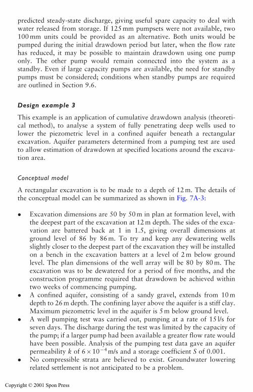
predicted steady-state discharge, giving useful spare capacity to deal withwater released from storage. If 125 mm pumpsets were not available, two100 mm units could be provided as an alternative. Both units would bepumped during the initial drawdown period but later, when the flow ratehas reduced, it may be possible to maintain drawdown using one pumponly. The other pump would remain connected into the system as astandby. Even if large capacity pumps are available, the need for standbypumps must be considered; conditions when standby pumps are requiredare outlined in Section 9.6.
Design example 3
This example is an application of cumulative drawdown analysis (theoreti-cal method), to analyse a system of fully penetrating deep wells used tolower the piezometric level in a confined aquifer beneath a rectangularexcavation. Aquifer parameters determined from a pumping test are used to allow estimation of drawdown at specified locations around the excava-tion area.
Conceptual model
A rectangular excavation is to be made to a depth of 12 m. The details ofthe conceptual model can be summarized as shown in Fig. 7A-3:
� Excavation dimensions are 50 by 50 m in plan at formation level, withthe deepest part of the excavation at 12 m depth. The sides of the exca-vation are battered back at 1 in 1.5, giving overall dimensions atground level of 86 by 86 m. To try and keep any dewatering wellsslightly closer to the deepest part of the excavation they will be installedon a bench in the excavation batters at a level of 2 m below groundlevel. The plan dimensions of the well array will be 80 by 80 m. Theexcavation was to be dewatered for a period of five months, and theconstruction programme required that drawdown be achieved withintwo weeks of commencing pumping.
� A confined aquifer, consisting of a sandy gravel, extends from 10 mdepth to 26 m depth. The confining layer above the aquifer is a stiff clay.Maximum piezometric level in the aquifer is 5 m below ground level.
� A well pumping test was carried out, pumping at a rate of 15 l/s forseven days. The discharge during the test was limited by the capacity ofthe pump; if a larger pump had been available a greater flow rate wouldhave been possible. Analysis of the pumping test data gave an aquiferpermeability k of 6�10�4 m/s and a storage coefficient S of 0.001.
� No compressible strata are believed to exist. Groundwater loweringrelated settlement is not anticipated to be a problem.
Design of groundwater lowering systems 239
Copyright © 2001 Spon Press
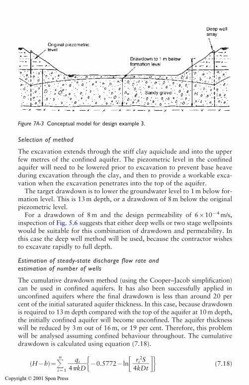
Selection of method
The excavation extends through the stiff clay aquiclude and into the upperfew metres of the confined aquifer. The piezometric level in the confinedaquifer will need to be lowered prior to excavation to prevent base heaveduring excavation through the clay, and then to provide a workable exca-vation when the excavation penetrates into the top of the aquifer.
The target drawdown is to lower the groundwater level to 1 m below for-mation level. This is 13 m depth, or a drawdown of 8 m below the originalpiezometric level.
For a drawdown of 8 m and the design permeability of 6�10�4 m/s,inspection of Fig. 5.6 suggests that either deep wells or two stage wellpointswould be suitable for this combination of drawdown and permeability. Inthis case the deep well method will be used, because the contractor wishesto excavate rapidly to full depth.
Estimation of steady-state discharge flow rate and estimation of number of wells
The cumulative drawdown method (using the Cooper–Jacob simplification)can be used in confined aquifers. It has also been successfully applied inunconfined aquifers where the final drawdown is less than around 20 percent of the initial saturated aquifer thickness. In this case, because drawdownis required to 13 m depth compared with the top of the aquifer at 10 m depth,the initially confined aquifer will become unconfined. The aquifer thicknesswill be reduced by 3 m out of 16 m, or 19 per cent. Therefore, this problemwill be analysed assuming confined behaviour throughout. The cumulativedrawdown is calculated using equation (7.18).
(H�h)�n
i�1�4
qki
D��0.5772�ln� �� (7.18)
ri2S
�4kDt
240 Design of groundwater lowering systems
Figure 7A-3 Conceptual model for design example 3.
Copyright © 2001 Spon Press
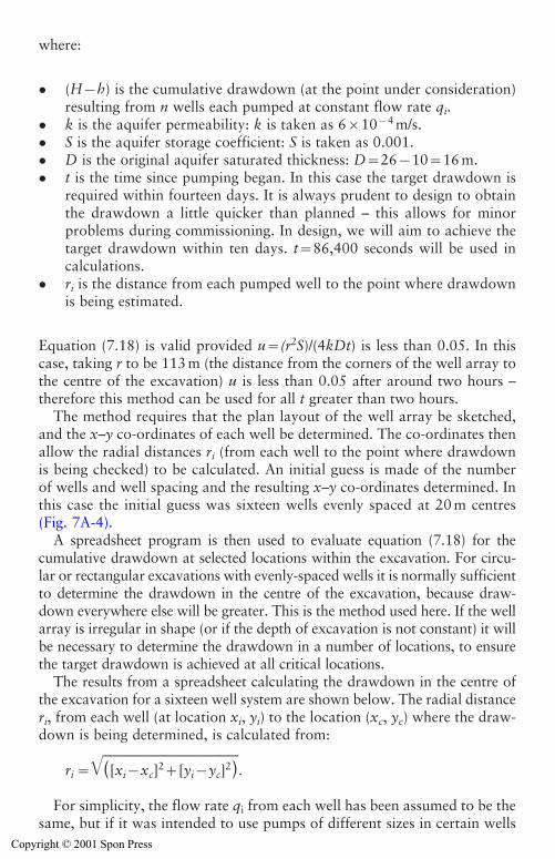
where:
� (H�h) is the cumulative drawdown (at the point under consideration)resulting from n wells each pumped at constant flow rate qi.
� k is the aquifer permeability: k is taken as 6�10�4 m/s.� S is the aquifer storage coefficient: S is taken as 0.001.� D is the original aquifer saturated thickness: D�26�10�16 m.� t is the time since pumping began. In this case the target drawdown is
required within fourteen days. It is always prudent to design to obtainthe drawdown a little quicker than planned – this allows for minorproblems during commissioning. In design, we will aim to achieve thetarget drawdown within ten days. t�86,400 seconds will be used incalculations.
� ri is the distance from each pumped well to the point where drawdownis being estimated.
Equation (7.18) is valid provided u�(r2S)/(4kDt) is less than 0.05. In thiscase, taking r to be 113 m (the distance from the corners of the well array tothe centre of the excavation) u is less than 0.05 after around two hours –therefore this method can be used for all t greater than two hours.
The method requires that the plan layout of the well array be sketched,and the x–y co-ordinates of each well be determined. The co-ordinates thenallow the radial distances ri (from each well to the point where drawdownis being checked) to be calculated. An initial guess is made of the numberof wells and well spacing and the resulting x–y co-ordinates determined. Inthis case the initial guess was sixteen wells evenly spaced at 20 m centres(Fig. 7A-4).
A spreadsheet program is then used to evaluate equation (7.18) for thecumulative drawdown at selected locations within the excavation. For circu-lar or rectangular excavations with evenly-spaced wells it is normally sufficientto determine the drawdown in the centre of the excavation, because draw-down everywhere else will be greater. This is the method used here. If the wellarray is irregular in shape (or if the depth of excavation is not constant) it willbe necessary to determine the drawdown in a number of locations, to ensurethe target drawdown is achieved at all critical locations.
The results from a spreadsheet calculating the drawdown in the centre ofthe excavation for a sixteen well system are shown below. The radial distanceri, from each well (at location xi, yi) to the location (xc, yc) where the draw-down is being determined, is calculated from:
ri ��([�xi���xc�]2���[y�i��yc�]2�)�.
For simplicity, the flow rate qi from each well has been assumed to be thesame, but if it was intended to use pumps of different sizes in certain wells
Design of groundwater lowering systems 241
Copyright © 2001 Spon Press
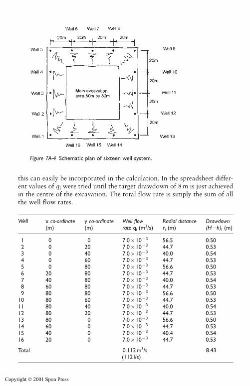
this can easily be incorporated in the calculation. In the spreadsheet differ-ent values of qi were tried until the target drawdown of 8 m is just achievedin the centre of the excavation. The total flow rate is simply the sum of allthe well flow rates.
242 Design of groundwater lowering systems
Figure 7A-4 Schematic plan of sixteen well system.
Well x co-ordinate y co-ordinate Well flow Radial distance Drawdown(m) (m) rate qi (m3/s) ri (m) (H�h)I (m)
1 0 0 7.0�10�3 56.5 0.502 0 20 7.0�10�3 44.7 0.533 0 40 7.0�10�3 40.0 0.544 0 60 7.0�10�3 44.7 0.535 0 80 7.0�10�3 56.6 0.506 20 80 7.0�10�3 44.7 0.537 40 80 7.0�10�3 40.0 0.548 60 80 7.0�10�3 44.7 0.539 80 80 7.0�10�3 56.6 0.50
10 80 60 7.0�10�3 44.7 0.5311 80 40 7.0�10�3 40.0 0.5412 80 20 7.0�10�3 44.7 0.5313 80 0 7.0�10�3 56.6 0.5014 60 0 7.0�10�3 44.7 0.5315 40 0 7.0�10�3 40.4 0.5416 20 0 7.0�10�3 44.7 0.53
Total 0.112 m3/s 8.43(112 l/s)
Copyright © 2001 Spon Press
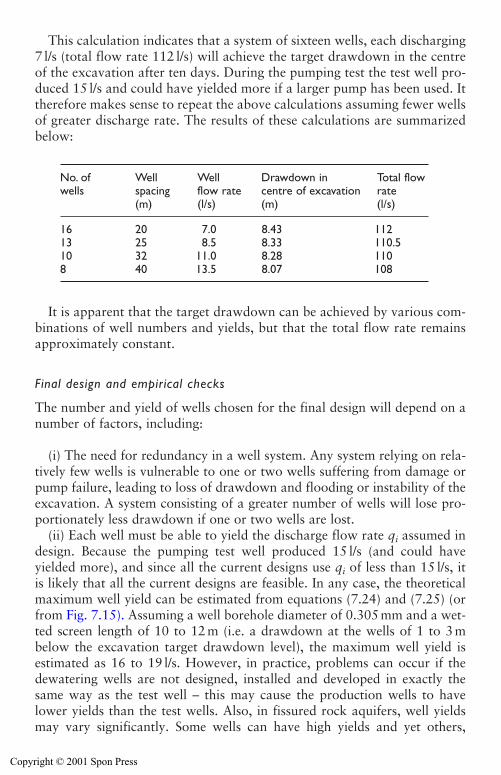
This calculation indicates that a system of sixteen wells, each discharging7 l/s (total flow rate 112 l/s) will achieve the target drawdown in the centreof the excavation after ten days. During the pumping test the test well pro-duced 15 l/s and could have yielded more if a larger pump has been used. Ittherefore makes sense to repeat the above calculations assuming fewer wellsof greater discharge rate. The results of these calculations are summarizedbelow:
It is apparent that the target drawdown can be achieved by various com-binations of well numbers and yields, but that the total flow rate remainsapproximately constant.
Final design and empirical checks
The number and yield of wells chosen for the final design will depend on anumber of factors, including:
(i) The need for redundancy in a well system. Any system relying on rela-tively few wells is vulnerable to one or two wells suffering from damage orpump failure, leading to loss of drawdown and flooding or instability of theexcavation. A system consisting of a greater number of wells will lose pro-portionately less drawdown if one or two wells are lost.
(ii) Each well must be able to yield the discharge flow rate qi assumed indesign. Because the pumping test well produced 15 l/s (and could haveyielded more), and since all the current designs use qi of less than 15 l/s, itis likely that all the current designs are feasible. In any case, the theoreticalmaximum well yield can be estimated from equations (7.24) and (7.25) (orfrom Fig. 7.15). Assuming a well borehole diameter of 0.305 mm and a wet-ted screen length of 10 to 12 m (i.e. a drawdown at the wells of 1 to 3 mbelow the excavation target drawdown level), the maximum well yield isestimated as 16 to 19 l/s. However, in practice, problems can occur if thedewatering wells are not designed, installed and developed in exactly thesame way as the test well – this may cause the production wells to havelower yields than the test wells. Also, in fissured rock aquifers, well yieldsmay vary significantly. Some wells can have high yields and yet others,
Design of groundwater lowering systems 243
No. of Well Well Drawdown in Total flow wells spacing flow rate centre of excavation rate
(m) (l/s) (m) (l/s)
16 20 7.0 8.43 11213 25 8.5 8.33 110.510 32 11.0 8.28 1108 40 13.5 8.07 108
Copyright © 2001 Spon Press
poorly connected into fissures, may be almost ‘dry’. In fissured aquifers thecumulative drawdown method needs to be applied with care.
In this case it is assumed that, due to the availability of pumps of suitablecapacity, the nominal system of ten wells, each discharging 11 l/s each will beadopted. It is normal practice to apply an empirical superposition factor J; thesystem capacity is increased by a factor of 1/J (see equation (7.19)). Thisempirical factor allows for interference between wells, and also providessome allowance for additional drawdown around the wells and waterreleased from storage when the aquifer becomes unconfined. Where aquifersbecome unconfined, and drawdowns are small (less than 20 per cent of theinitial saturated aquifer thickness), the empirical superposition factor J isnormally taken as 0.8 to 0.95. In this case, because the drawdown willreduce the thickness of the aquifer by almost 20 per cent, the maximumsuperposition factor of 0.8 will be applied, so the system capacity (and hencethe number of wells) will need to be increased by 1/0.8�1.25.
The final system design is, therefore for thirteen wells, of 11 l/s capacityeach. Total system capacity is 143 l/s. Table 10.1 indicates that, to accom-modate a pump of suitable capacity, a minimum well bore diameter of300 mm is required. The corresponding well screen and liner diameter is165 mm.
The design is then verified with some simple empirical checks. The wellspacing for a thirteen well system is approximately 25 m; this is within the‘normal’ 10 to 60 m range quoted in Section 7.5. The wells are intended tofully penetrate the aquifer, and so are 26 m deep, just over twice the depthof the excavation. Again this is consistent with guidelines given in Section7.5. These empirical checks confirm, in a gross sense, the validity of theconcept of the design.
References
Anderson, M. P. and Woessner, W. W. (1992). Applied Groundwater Modelling.Academic Press, New York.
Cedergren, H. R. (1989). Seepage, Drainage and Flow Nets, 3rd edition. Wiley,New York.
Chapman, T. G. (1959). Groundwater flow to trenches and wellpoints. Journal ofthe Institution of Engineers, Australia, October-November, 275–280.
Cooper, H. H. and Jacob, C. E. (1946). A generalised graphical method for evalu-ating formation constants and summarising well field history. Transactions of theAmerican Geophysical Union, 27, 526–534.
Dupuit, J. (1863). Etudes Théoretiques et Practiques sur les Mouvement des Eauxdans les Canaux Decouverts et a Travers les Terrains Permeable. Dunod, Paris.
Forcheimer, P. (1886). Uber die ergibigkeit von brunnen-anlagen und sicker-schitzen. Der Architekten-und Ingenieur-Verein, 32(7).
Hantush, M. S. (1964). Hydraulics of wells. Advanced Hydroscience I, 281–431.
244 Design of groundwater lowering systems
Copyright © 2001 Spon Press
Knight, D. J., Smith, G. L. and Sutton, J. S. (1996). Sizewell B foundation dewatering –system design, construction and performance monitoring. Géotechnique, 46(3),473–490.
Kruseman, G. P., and De Ridder, N. A. (1990). Analysis and Evaluation of PumpingTest Data. International Institute for Land Reclamation and Improvement,Publication 47, 2nd edition, Wageningen, The Netherlands.
Mansur, C. I. and Kaufman, R. I. (1962). Dewatering. Foundation Engineering(G. A. Leonards, ed.). McGraw-Hill, New York, pp 241–350.
Muskat, M. (1935). The seepage of water through dams with vertical faces. Physics,6, 402.
Nicholson, D. P., Tse, C.-M. and Penny, C. (1999). The Observational Method inGround Engineering. Construction Industry Research and InformationAssociation, CIRIA Report C185, London.
Powers, J. P. (1992). Construction Dewatering: New Methods and Applications,2nd edition. Wiley, New York.
Powrie, W. and Preene, M. (1992). Equivalent well analysis of construction dewatering systems. Géotechnique, 42(4), 635–639.
Powrie, W. and Preene, M. (1994). Time-drawdown behaviour of constructiondewatering systems in fine soils. Géotechnique, 44(1), 83–100.
Preene, M. and Powrie, W. (1993). Steady-state performance of construction dewa-tering systems in fine soils. Géotechnique, 43(1), 191–205.
Preene, M. and Roberts, T. O. L. (1994). The application of pumping tests to thedesign of construction dewatering systems. Groundwater Problems in UrbanAreas (Wilkinson, W. B. ed.). Thomas Telford, London, pp 121–133.
Preene, M. Roberts, T. O. L. Powrie, W. and Dyer, M. R. (2000). GroundwaterControl – Design and Practice. Construction Industry Research and InformationAssociation, CIRIA Report C515, London.
Rao, D. B. (1973). Construction dewatering by vacuum wells. Indian GeotechnicalJournal, 3(3), 217–224.
Roberts, T. O. L. and Preene, M. (1994). The design of groundwater control sys-tems using the observational method. Géotechnique, 44(4), 727–734.
Rushton, K. R. and Redshaw, S. C. (1979). Seepage and Groundwater Flow:Numerical Analysis by Analog and Digital Methods. Wiley, Chichester.
Theis, C. V. (1935). The relation between the lowering of the piezometric surfaceand the rate and duration of discharge of a well using groundwater storage.Transactions of the American Geophysical Union, 16, 519–524.
Weber, H. (1928). Die Reichweite von Grundwasserabsenkungen MittelsRohrbunnen. Springer, Berlin.
Williams, B. P. and Waite, D. (1993). The Design and Construction of Sheet-PiledCofferdams. Construction Industry Research and Information Association,CIRIA Special Publication 95, London.
Design of groundwater lowering systems 245
Copyright © 2001 Spon Press
Chapter 8
Sump pumping
8.0 Introduction
A sump might be defined as (Scott 1980):
A pit in which water collects before being bailed or pumped out. Thepump suction dips into a sump
By definition a sump is at a low level in relation to surrounding groundsurfaces so that any water will flow to it due to gravity. For constructionprojects water is removed from sumps using suction or submersible pumps,not by bailing.
This chapter addresses the formation of pumping sumps and associatedgravity drainage channels for the control of surface water and groundwater.Case histories are used to describe situations where sump pumping has beenused appropriately, and where problems were created. The pumps suitablefor sump pumping uses are dealt with in Chapter 12.
8.1 Applications of sump pumping
Sump pumping is the most basic of the dewatering methods. In essence itinvolves allowing groundwater to seep into the excavation, collecting it insumps and then pumping it away for disposal. Sumps are provided for twoseparate purposes, though the form of a sump may be similar for eitherrequirement:
(a) To collect surface water run-off channelled to it by means of collectorditches or channels for discharge to a disposal point or area (seeSection 5.1).
(b) To collect and discharge pumped water due to lowering of the ground-water for a shallow excavation; also sump pumping may be requiredfor gravity drainage to toe drains of battered slopes (see Section 4.4).
The preferred method of disposal of water collected by the sumps is bymeans of pumping. Typically, each sump is equipped with a robust, simple,pump – a ‘sump pump’ (see Section 12.3).
Copyright © 2001 Spon Press

Sump pumping can be a very effective and economic method to achievemodest drawdowns in well-graded coarse soils (such as gravelly sands,sandy gravels and coarse gravels) or in hard fissured rock.
Unfortunately, under some conditions the use of sump pumping can leadto major problems. These problems arise primarily because the flow ofwater into the excavation can have a destabilizing effect on fine-grainedsoils. This can lead to fine soil particles being washed from the soil with thewater – this is known as ‘loss of fines’. Loss of fines can lead to groundmovements and settlements because material is being removed from thesoil, giving the potential for the formation and collapse of sub-surface voids(see Section 13.1). Disposal of the water can also create problems, becauseif loss of fines occurs the discharge water will have a high sediment load,which can cause environmental problems at the disposal point (see Section13.4). These issues are discussed further in Section 8.6.
Powers (1985) lists soil types where the use of sump pumping has a sig-nificant risk of causing loss of fines. These include:
i Uniform fine sands,ii soft non-cohesive silts and soft clays,
iii soft rocks where fissures can erode and enlarge due to high watervelocities,
iv rocks where fissures are filled with silt, sand or soft clay, which may beeroded,
v sandstone with uncemented layers that may be washed out.
In these soil types, even the best engineered sump pumping systems mayencounter problems. Potential problems can be avoided by employinggroundwater lowering using an array of wells (wellpoints, deep wells orejectors) with correctly designed and installed filters. Provided the wells arelocated outside the main excavation area, these methods have the advan-tage that they draw water away from the excavation, improving stability –avoiding the destabilizing flows into the excavation that are associated withsump pumping.
8.2 Surface water run-off
When an excavation exposes low permeability soils, all surface water,whether derived from rainfall or from any other source, should be controlledso that any occurrence of ponding is prevented. Movement of constructionplant through surface water ponding will lead to deterioration of the surface,especially on clayey soils. This will inhibit efficient use of plant. It is goodpractice to form the surfaces of the construction areas so that they are notlevel; they should be gently sloped so that all surface water is shed to suit-ably sited and constructed collector channels or drains (see Section 5.1).
Sump pumping 247
Copyright © 2001 Spon Press
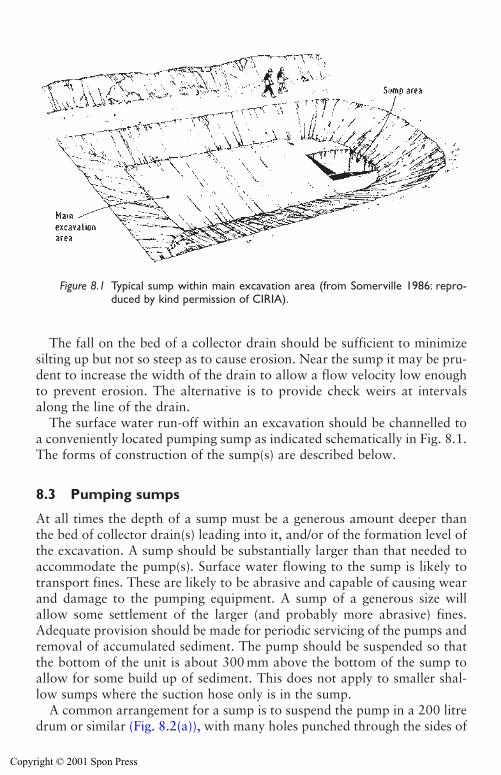
248 Sump pumping
The fall on the bed of a collector drain should be sufficient to minimizesilting up but not so steep as to cause erosion. Near the sump it may be pru-dent to increase the width of the drain to allow a flow velocity low enoughto prevent erosion. The alternative is to provide check weirs at intervalsalong the line of the drain.
The surface water run-off within an excavation should be channelled toa conveniently located pumping sump as indicated schematically in Fig. 8.1.The forms of construction of the sump(s) are described below.
8.3 Pumping sumps
At all times the depth of a sump must be a generous amount deeper thanthe bed of collector drain(s) leading into it, and/or of the formation level ofthe excavation. A sump should be substantially larger than that needed toaccommodate the pump(s). Surface water flowing to the sump is likely totransport fines. These are likely to be abrasive and capable of causing wearand damage to the pumping equipment. A sump of a generous size willallow some settlement of the larger (and probably more abrasive) fines.Adequate provision should be made for periodic servicing of the pumps andremoval of accumulated sediment. The pump should be suspended so thatthe bottom of the unit is about 300 mm above the bottom of the sump toallow for some build up of sediment. This does not apply to smaller shal-low sumps where the suction hose only is in the sump.
A common arrangement for a sump is to suspend the pump in a 200 litredrum or similar (Fig. 8.2(a)), with many holes punched through the sides of
Figure 8.1 Typical sump within main excavation area (from Somerville 1986: repro-duced by kind permission of CIRIA).
Copyright © 2001 Spon Press
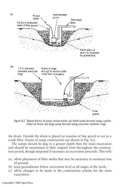
the drum. Outside the drum is placed an annulus of fine gravel to act as acrude filter. Forms of sump construction are shown in Fig. 8.2.
The sumps should be dug to a greater depth than the main excavationand should be maintained in their original form throughout the construc-tion period, though deepened if necessary as excavation proceeds. This will:
(a) allow placement of filter media that may be necessary to minimize lossof ground,
(b) keep groundwater below excavation level at all stages of the work,(c) allow changes to be made in the construction scheme for the main
excavation.
Sump pumping 249
Figure 8.2 Typical forms of sump construction. (a) Small sump formed using a perfo-rated oil drum, (b) large sump formed using concrete manhole rings.
Copyright © 2001 Spon Press
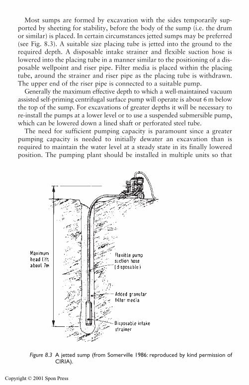
250 Sump pumping
Most sumps are formed by excavation with the sides temporarily sup-ported by sheeting for stability, before the body of the sump (i.e. the drumor similar) is placed. In certain circumstances jetted sumps may be preferred(see Fig. 8.3). A suitable size placing tube is jetted into the ground to therequired depth. A disposable intake strainer and flexible suction hose islowered into the placing tube in a manner similar to the positioning of a dis-posable wellpoint and riser pipe. Filter media is placed within the placingtube, around the strainer and riser pipe as the placing tube is withdrawn.The upper end of the riser pipe is connected to a suitable pump.
Generally the maximum effective depth to which a well-maintained vacuumassisted self-priming centrifugal surface pump will operate is about 6 m belowthe top of the sump. For excavations of greater depths it will be necessary tore-install the pumps at a lower level or to use a suspended submersible pump,which can be lowered down a lined shaft or perforated steel tube.
The need for sufficient pumping capacity is paramount since a greaterpumping capacity is needed to initially dewater an excavation than isrequired to maintain the water level at a steady state in its finally loweredposition. The pumping plant should be installed in multiple units so that
Figure 8.3 A jetted sump (from Somerville 1986: reproduced by kind permission ofCIRIA).
Copyright © 2001 Spon Press
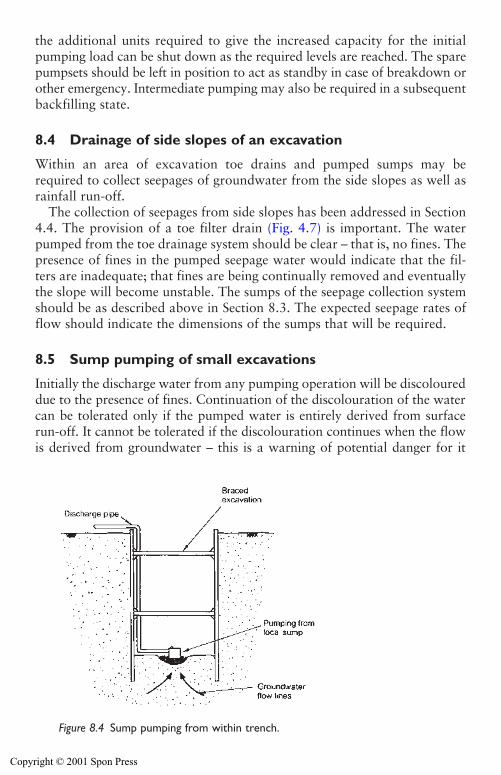
Sump pumping 251
the additional units required to give the increased capacity for the initialpumping load can be shut down as the required levels are reached. The sparepumpsets should be left in position to act as standby in case of breakdown orother emergency. Intermediate pumping may also be required in a subsequentbackfilling state.
8.4 Drainage of side slopes of an excavation
Within an area of excavation toe drains and pumped sumps may berequired to collect seepages of groundwater from the side slopes as well asrainfall run-off.
The collection of seepages from side slopes has been addressed in Section4.4. The provision of a toe filter drain (Fig. 4.7) is important. The waterpumped from the toe drainage system should be clear – that is, no fines. Thepresence of fines in the pumped seepage water would indicate that the fil-ters are inadequate; that fines are being continually removed and eventuallythe slope will become unstable. The sumps of the seepage collection systemshould be as described above in Section 8.3. The expected seepage rates offlow should indicate the dimensions of the sumps that will be required.
8.5 Sump pumping of small excavations
Initially the discharge water from any pumping operation will be discoloureddue to the presence of fines. Continuation of the discolouration of the watercan be tolerated only if the pumped water is entirely derived from surfacerun-off. It cannot be tolerated if the discolouration continues when the flowis derived from groundwater – this is a warning of potential danger for it
Figure 8.4 Sump pumping from within trench.
Copyright © 2001 Spon Press
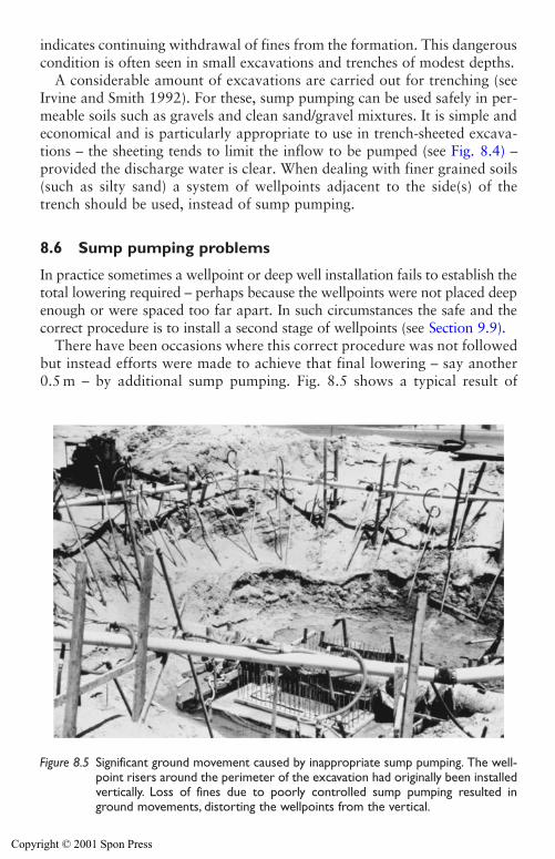
252 Sump pumping
indicates continuing withdrawal of fines from the formation. This dangerouscondition is often seen in small excavations and trenches of modest depths.
A considerable amount of excavations are carried out for trenching (seeIrvine and Smith 1992). For these, sump pumping can be used safely in per-meable soils such as gravels and clean sand/gravel mixtures. It is simple andeconomical and is particularly appropriate to use in trench-sheeted excava-tions – the sheeting tends to limit the inflow to be pumped (see Fig. 8.4) –provided the discharge water is clear. When dealing with finer grained soils(such as silty sand) a system of wellpoints adjacent to the side(s) of thetrench should be used, instead of sump pumping.
8.6 Sump pumping problems
In practice sometimes a wellpoint or deep well installation fails to establish thetotal lowering required – perhaps because the wellpoints were not placed deepenough or were spaced too far apart. In such circumstances the safe and thecorrect procedure is to install a second stage of wellpoints (see Section 9.9).
There have been occasions where this correct procedure was not followedbut instead efforts were made to achieve that final lowering – say another0.5 m – by additional sump pumping. Fig. 8.5 shows a typical result of
Figure 8.5 Significant ground movement caused by inappropriate sump pumping. The well-point risers around the perimeter of the excavation had originally been installedvertically. Loss of fines due to poorly controlled sump pumping resulted inground movements, distorting the wellpoints from the vertical.
Copyright © 2001 Spon Press
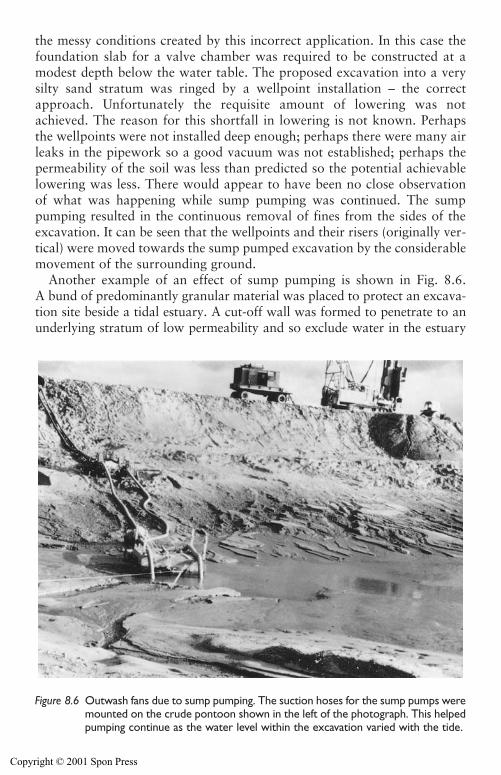
Sump pumping 253
the messy conditions created by this incorrect application. In this case thefoundation slab for a valve chamber was required to be constructed at amodest depth below the water table. The proposed excavation into a verysilty sand stratum was ringed by a wellpoint installation – the correctapproach. Unfortunately the requisite amount of lowering was notachieved. The reason for this shortfall in lowering is not known. Perhapsthe wellpoints were not installed deep enough; perhaps there were many airleaks in the pipework so a good vacuum was not established; perhaps thepermeability of the soil was less than predicted so the potential achievablelowering was less. There would appear to have been no close observationof what was happening while sump pumping was continued. The sumppumping resulted in the continuous removal of fines from the sides of theexcavation. It can be seen that the wellpoints and their risers (originally ver-tical) were moved towards the sump pumped excavation by the considerablemovement of the surrounding ground.
Another example of an effect of sump pumping is shown in Fig. 8.6.A bund of predominantly granular material was placed to protect an excava-tion site beside a tidal estuary. A cut-off wall was formed to penetrate to anunderlying stratum of low permeability and so exclude water in the estuary
Figure 8.6 Outwash fans due to sump pumping. The suction hoses for the sump pumps weremounted on the crude pontoon shown in the left of the photograph. This helpedpumping continue as the water level within the excavation varied with the tide.
Copyright © 2001 Spon Press
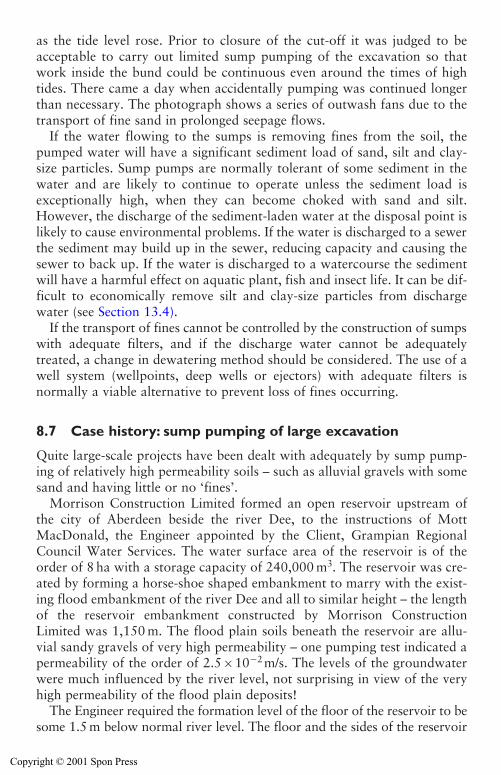
as the tide level rose. Prior to closure of the cut-off it was judged to beacceptable to carry out limited sump pumping of the excavation so thatwork inside the bund could be continuous even around the times of hightides. There came a day when accidentally pumping was continued longerthan necessary. The photograph shows a series of outwash fans due to thetransport of fine sand in prolonged seepage flows.
If the water flowing to the sumps is removing fines from the soil, thepumped water will have a significant sediment load of sand, silt and clay-size particles. Sump pumps are normally tolerant of some sediment in thewater and are likely to continue to operate unless the sediment load isexceptionally high, when they can become choked with sand and silt.However, the discharge of the sediment-laden water at the disposal point islikely to cause environmental problems. If the water is discharged to a sewerthe sediment may build up in the sewer, reducing capacity and causing thesewer to back up. If the water is discharged to a watercourse the sedimentwill have a harmful effect on aquatic plant, fish and insect life. It can be dif-ficult to economically remove silt and clay-size particles from dischargewater (see Section 13.4).
If the transport of fines cannot be controlled by the construction of sumpswith adequate filters, and if the discharge water cannot be adequatelytreated, a change in dewatering method should be considered. The use of awell system (wellpoints, deep wells or ejectors) with adequate filters isnormally a viable alternative to prevent loss of fines occurring.
8.7 Case history: sump pumping of large excavation
Quite large-scale projects have been dealt with adequately by sump pump-ing of relatively high permeability soils – such as alluvial gravels with somesand and having little or no ‘fines’.
Morrison Construction Limited formed an open reservoir upstream ofthe city of Aberdeen beside the river Dee, to the instructions of MottMacDonald, the Engineer appointed by the Client, Grampian RegionalCouncil Water Services. The water surface area of the reservoir is of theorder of 8 ha with a storage capacity of 240,000 m3. The reservoir was cre-ated by forming a horse-shoe shaped embankment to marry with the exist-ing flood embankment of the river Dee and all to similar height – the lengthof the reservoir embankment constructed by Morrison ConstructionLimited was 1,150 m. The flood plain soils beneath the reservoir are allu-vial sandy gravels of very high permeability – one pumping test indicated apermeability of the order of 2.5�10�2m/s. The levels of the groundwaterwere much influenced by the river level, not surprising in view of the veryhigh permeability of the flood plain deposits!
The Engineer required the formation level of the floor of the reservoir to besome 1.5 m below normal river level. The floor and the sides of the reservoir
254 Sump pumping
Copyright © 2001 Spon Press
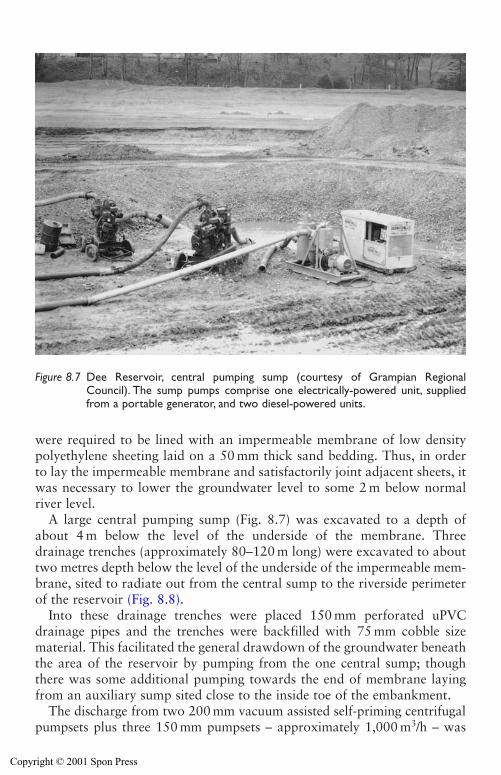
Sump pumping 255
were required to be lined with an impermeable membrane of low densitypolyethylene sheeting laid on a 50 mm thick sand bedding. Thus, in orderto lay the impermeable membrane and satisfactorily joint adjacent sheets, itwas necessary to lower the groundwater level to some 2 m below normalriver level.
A large central pumping sump (Fig. 8.7) was excavated to a depth ofabout 4 m below the level of the underside of the membrane. Threedrainage trenches (approximately 80–120 m long) were excavated to abouttwo metres depth below the level of the underside of the impermeable mem-brane, sited to radiate out from the central sump to the riverside perimeterof the reservoir (Fig. 8.8).
Into these drainage trenches were placed 150 mm perforated uPVCdrainage pipes and the trenches were backfilled with 75 mm cobble sizematerial. This facilitated the general drawdown of the groundwater beneaththe area of the reservoir by pumping from the one central sump; thoughthere was some additional pumping towards the end of membrane layingfrom an auxiliary sump sited close to the inside toe of the embankment.
The discharge from two 200 mm vacuum assisted self-priming centrifugalpumpsets plus three 150 mm pumpsets – approximately 1,000 m3/h – was
Figure 8.7 Dee Reservoir, central pumping sump (courtesy of Grampian RegionalCouncil). The sump pumps comprise one electrically-powered unit, suppliedfrom a portable generator, and two diesel-powered units.
Copyright © 2001 Spon Press
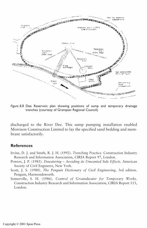
discharged to the River Dee. This sump pumping installation enabledMorrison Construction Limited to lay the specified sand bedding and mem-brane satisfactorily.
References
Irvine, D. J. and Smith, R. J. H. (1992). Trenching Practice. Construction IndustryResearch and Information Association, CIRIA Report 97, London.
Powers, J. P. (1985). Dewatering – Avoiding its Unwanted Side Effects. AmericanSociety of Civil Engineers, New York.
Scott, J. S. (1980). The Penguin Dictionary of Civil Engineering, 3rd edition.Penguin, Harmondsworth.
Somerville, S. H. (1986). Control of Groundwater for Temporary Works.Construction Industry Research and Information Association, CIRIA Report 113,London.
256 Sump pumping
Figure 8.8 Dee Reservoir, plan showing positions of sump and temporary drainagetrenches (courtesy of Grampian Regional Council).
Copyright © 2001 Spon Press
Chapter 9
Wellpoint systems
9.0 Introduction
For small and medium sized construction projects of limited depth well-pointing is the most frequently used pumping method of control of ground-water. It is much used for shallow pipe trenching and the like. The deepwell system is usually more appropriate for deep excavations and isaddressed in Chapter 10.
This chapter describes the wellpoint pumping method. Current goodpractices, installation procedures and practical uses and limitations are dis-cussed. Variations to the wellpoint system to cope with differing soil con-ditions are considered.
A variation on the conventional wellpoint system applicable to pipelinetrenching in open country, often referred to as horizontal wellpointing isaddressed in Chapter 11 together with other less commonly used ground-water lowering techniques including ejectors.
A wellpointing case history is described at the end of the chapter. It illustrates the success that can be achieved in dealing with difficult soil con-ditions by using adequate ‘sanding-in’ procedures to provide satisfactoryvertical downward drainage and so achieve acceptable pore water pressurereductions.
9.1 Which system: wellpoints or deep wells?
There is a certain amount of confusion, probably due to some looseness ofterminology, concerning the precise differences between wellpoint and deepwell systems. Essentially, a wellpoint pumping system sucks groundwater upfrom a group of wellpoints to the intake of a pump unit and then pumps itto a disposal area. Its application is constrained by the physical limits of suc-tion lift. In contrast, a deep well system consists of a group of wells, each hav-ing a submersible pump near the bottom of the well, which likewise pump toa disposal area; the method is not constrained by suction lift limitations. Thisis the key practical distinction between the two systems.
Copyright © 2001 Spon Press
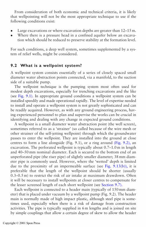
From consideration of both economic and technical criteria, it is likelythat wellpointing will not be the most appropriate technique to use if thefollowing conditions exist:
� Large excavations or where excavation depths are greater than 12–15 m.� Where there is a pressure head in a confined aquifer below an excava-
tion which should be reduced to preserve stability at the formation level.
For such conditions, a deep well system, sometimes supplemented by a sys-tem of relief wells, might be considered.
9.2 What is a wellpoint system?
A wellpoint system consists essentially of a series of closely spaced smalldiameter water abstraction points connected, via a manifold, to the suctionside of a suitable pump.
The wellpoint technique is the pumping system most often used formodest depth excavations, especially for trenching excavations and the like(see Fig. 9.1). In appropriate ground conditions a wellpoint system can beinstalled speedily and made operational rapidly. The level of expertise neededto install and operate a wellpoint system is not greatly sophisticated and canbe readily acquired. However, as with any ground engineering process, hav-ing experienced personnel to plan and supervise the works can be crucial inidentifying and dealing with any change in expected ground conditions.
A wellpoint is a small diameter water abstraction point (the well screen),sometimes referred to as a ‘strainer’ (so called because of the wire mesh orother strainer of the self-jetting wellpoint) through which the groundwaterpasses to enter the wellpoint. They are installed into the ground at closecentres to form a line alongside (Fig. 9.1), or a ring around (Fig. 9.2), anexcavation. The perforated wellpoint is typically about 0.7–1.0 m in lengthand 40–50 mm nominal diameter. Each is secured to the bottom end of anunperforated pipe (the riser pipe) of slightly smaller diameter; 38 mm diam-eter pipe is commonly used. However, where the ‘wetted’ depth is limiteddue to the proximity of an impermeable surface (see Fig. 9.13(b)), it ispreferable that the length of the wellpoint should be shorter (usually0.3–0.5 m) to restrict the risk of air intake at maximum drawdown. Oftenit will be necessary to install wellpoints at closer centres to compensate forthe lesser screened length of each short wellpoint (see Section 9.7).
Each wellpoint is connected to a header main (typically of 150 mm diam-eter) that is placed under vacuum by a wellpoint pump (Fig. 9.2). The headermain is normally made of high impact plastic, although steel pipe is some-times used, especially when there is a risk of damage from constructionactivities. The pipe is typically supplied in 6 m lengths and is joined on siteby simple couplings that allow a certain degree of skew to allow the header
258 Wellpoint systems
Copyright © 2001 Spon Press
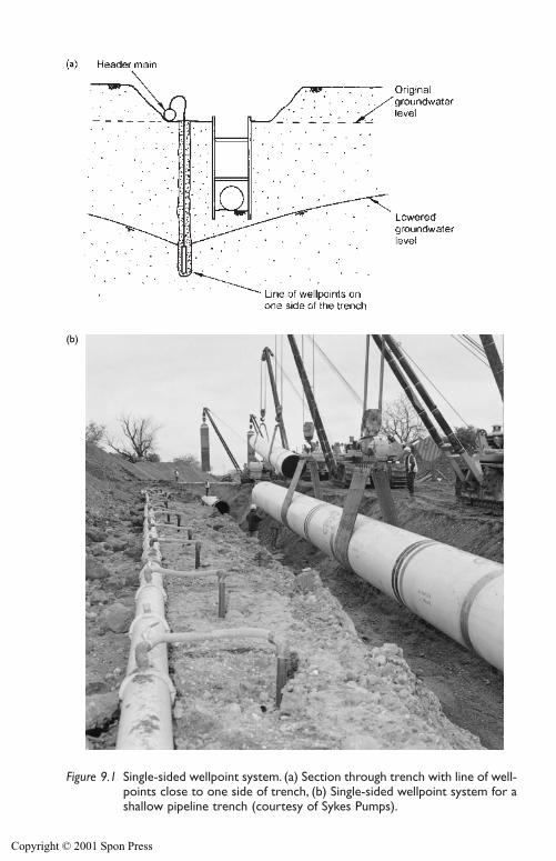
(b)
Figure 9.1 Single-sided wellpoint system. (a) Section through trench with line of well-points close to one side of trench, (b) Single-sided wellpoint system for ashallow pipeline trench (courtesy of Sykes Pumps).
Copyright © 2001 Spon Press
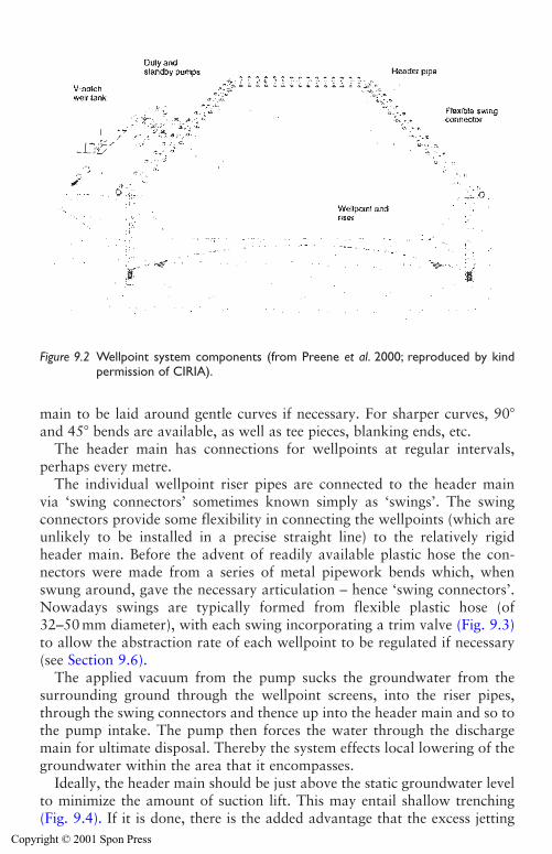
main to be laid around gentle curves if necessary. For sharper curves, 90�and 45� bends are available, as well as tee pieces, blanking ends, etc.
The header main has connections for wellpoints at regular intervals, perhaps every metre.
The individual wellpoint riser pipes are connected to the header main via ‘swing connectors’ sometimes known simply as ‘swings’. The swing connectors provide some flexibility in connecting the wellpoints (which areunlikely to be installed in a precise straight line) to the relatively rigidheader main. Before the advent of readily available plastic hose the con-nectors were made from a series of metal pipework bends which, whenswung around, gave the necessary articulation – hence ‘swing connectors’.Nowadays swings are typically formed from flexible plastic hose (of32–50 mm diameter), with each swing incorporating a trim valve (Fig. 9.3)to allow the abstraction rate of each wellpoint to be regulated if necessary(see Section 9.6).
The applied vacuum from the pump sucks the groundwater from the surrounding ground through the wellpoint screens, into the riser pipes,through the swing connectors and thence up into the header main and so tothe pump intake. The pump then forces the water through the dischargemain for ultimate disposal. Thereby the system effects local lowering of thegroundwater within the area that it encompasses.
Ideally, the header main should be just above the static groundwater levelto minimize the amount of suction lift. This may entail shallow trenching(Fig. 9.4). If it is done, there is the added advantage that the excess jetting
260 Wellpoint systems
Figure 9.2 Wellpoint system components (from Preene et al. 2000; reproduced by kindpermission of CIRIA).
Copyright © 2001 Spon Press
Wellpoint systems 261
water from installation of the wellpoints tends to be contained within theheader trench rather than cause general flooding of the site.
Ideally, the suction intake of a wellpoint pump should be at the samelevel as the header main. Often this will require that a small pit be dug tolower the pump body to the requisite level.
The amount of lowering that can be achieved by a wellpoint (or shallowwell) system is limited by the physical constraints of suction lift. It is gen-erally in the range of 4.5–6 m though 7 m drawdown is not unknown. Itdepends very much on the efficiency of the water/air separation device onthe pump and the vacuum efficiency of the total installation (i.e. the air-tightness of the system pipework). In addition it depends on the structureand permeability of the soil mass. The width of the excavation is also per-tinent to achieving the required amount of lowering at its centre. Where theland area available for construction is not constrained, the wellpoint sys-tem can be used for deeper excavations by means of a multistage wellpointinstallation (Fig. 9.5).
9.2.1 Types of wellpoint
The wellpoints are vital components of every installation. There are twotypes of wellpoints:
(i) The self-jetting wellpoint (Fig. 9.6(a))These are known as self-jetting since they can be installed without the useof a placing tube. The wellpoint and riser are metal and therefore are rigid,
Figure 9.3 Flexible connection from wellpoint riser to suction manifold via trim value(from Somerville 1986; reproduced by kind permission of CIRIA).
Copyright © 2001 Spon Press
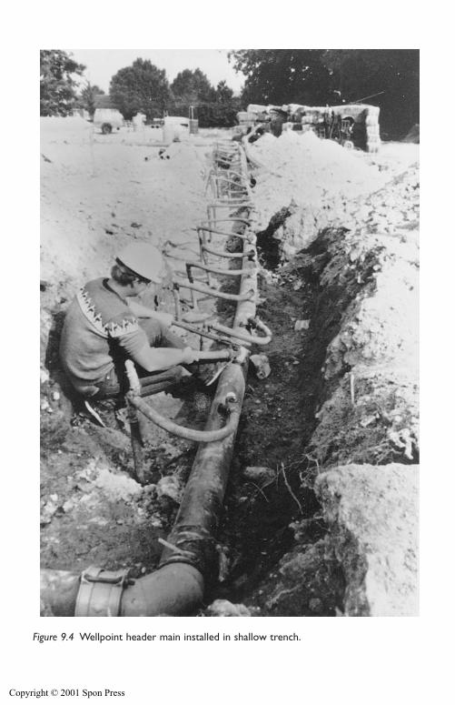
Figure 9.4 Wellpoint header main installed in shallow trench.
Copyright © 2001 Spon Press
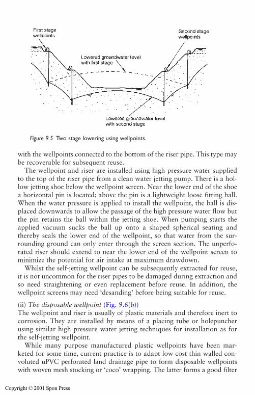
with the wellpoints connected to the bottom of the riser pipe. This type maybe recoverable for subsequent reuse.
The wellpoint and riser are installed using high pressure water suppliedto the top of the riser pipe from a clean water jetting pump. There is a hol-low jetting shoe below the wellpoint screen. Near the lower end of the shoea horizontal pin is located; above the pin is a lightweight loose fitting ball.When the water pressure is applied to install the wellpoint, the ball is dis-placed downwards to allow the passage of the high pressure water flow butthe pin retains the ball within the jetting shoe. When pumping starts theapplied vacuum sucks the ball up onto a shaped spherical seating andthereby seals the lower end of the wellpoint, so that water from the sur-rounding ground can only enter through the screen section. The unperfo-rated riser should extend to near the lower end of the wellpoint screen tominimize the potential for air intake at maximum drawdown.
Whilst the self-jetting wellpoint can be subsequently extracted for reuse,it is not uncommon for the riser pipes to be damaged during extraction andso need straightening or even replacement before reuse. In addition, thewellpoint screens may need ‘desanding’ before being suitable for reuse.
(ii) The disposable wellpoint (Fig. 9.6(b))The wellpoint and riser is usually of plastic materials and therefore inert tocorrosion. They are installed by means of a placing tube or holepuncherusing similar high pressure water jetting techniques for installation as forthe self-jetting wellpoint.
While many purpose manufactured plastic wellpoints have been mar-keted for some time, current practice is to adapt low cost thin walled con-voluted uPVC perforated land drainage pipe to form disposable wellpointswith woven mesh stocking or ‘coco’ wrapping. The latter forms a good filter
Wellpoint systems 263
Figure 9.5 Two stage lowering using wellpoints.
Copyright © 2001 Spon Press
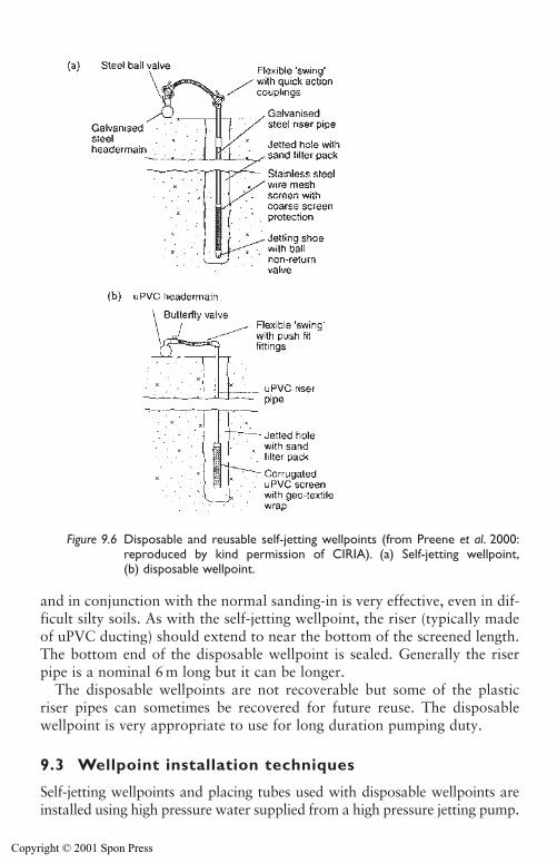
and in conjunction with the normal sanding-in is very effective, even in dif-ficult silty soils. As with the self-jetting wellpoint, the riser (typically madeof uPVC ducting) should extend to near the bottom of the screened length.The bottom end of the disposable wellpoint is sealed. Generally the riserpipe is a nominal 6 m long but it can be longer.
The disposable wellpoints are not recoverable but some of the plasticriser pipes can sometimes be recovered for future reuse. The disposablewellpoint is very appropriate to use for long duration pumping duty.
9.3 Wellpoint installation techniques
Self-jetting wellpoints and placing tubes used with disposable wellpoints areinstalled using high pressure water supplied from a high pressure jetting pump.
264 Wellpoint systems
Figure 9.6 Disposable and reusable self-jetting wellpoints (from Preene et al. 2000:reproduced by kind permission of CIRIA). (a) Self-jetting wellpoint,(b) disposable wellpoint.
Copyright © 2001 Spon Press
The jetting pump (see Section 12.2) most commonly used supplies watervia the jetting hoses at a rate of about 20 l/s and at a pressure of 6–8 bar. Theflexible jetting hoses are usually standard 63 mm fire hoses with instanta-neous male and female connections. There are other more powerful jettingpumps and hoses that are often used for the holepuncher, pile jetting, andother similar heavy duty uses.
The procurement of an adequate supply of jetting water for installationmust be resolved for each site. A continuous supply of clean water for jet-ting is essential for efficient placing of all types of wellpoints, whicheverinstallation technique is used. If the source of jetting water is restricted, con-sideration must be given to obtaining water by pumping from the first fewwellpoints as each is installed.
Generally the volume of jetting water required for installation per well-point with 6 m long riser will be of the order of 1–1.5 m3 but will dependgreatly on soil conditions. However, it can be in the range 0.5–35 m3, thelater figure being applicable to jetting in a very permeable river gravel.
Jetting in compact sands and gravels, and especially in an open gravel,may be difficult and slow, mainly because the displaced or slurrified soilparticles tend not to be washed from the jetted hole to ground surface dueto rapid dissipation of pressurized water into the open permeable forma-tion. However, there is some compensation because in such permeable soilssanding-in is unlikely to be required.
The wellpoint system is very flexible. For instance subsequent to the initialinstallation, extra wellpoints can be placed speedily to deal with localizedtrouble spots. It is especially useful for shallow depth trench excavationswhere very often the pumping period is expected to be of short duration.
9.3.1 Installation of self-jetting wellpoints
The wellpoint and its riser pipe are assembled to the required length and aflexible jetting hose is attached to the top of the riser pipe via a jettingadapter. The other end of the flexible jetting hose is connected to the sup-ply outlet from the high pressure jetting pump.
It is prudent to form a small starter hole into which to position the well-point; or, for a line of closely spaced wellpoints to form a trench and sorestrict general flooding of the site area. Prior to turning on the supply of jet-ting water, at the required wellpoint position the jetting crew must upend thewellpoint and riser with jetting adapter and jetting hose all connected (Fig. 9.7). There is considerable weight in the riser and hoses – this is a stren-uous and tricky task.
The jetting pump forces high pressure water down the metal riser pipe,past the ball at the lower end of the wellpoint. A strong jet of water emergesfrom the base of the wellpoint. The high pressure water slurrifies the granu-lar soil immediately below the bottom of the wellpoint enabling downward
Wellpoint systems 265
Copyright © 2001 Spon Press
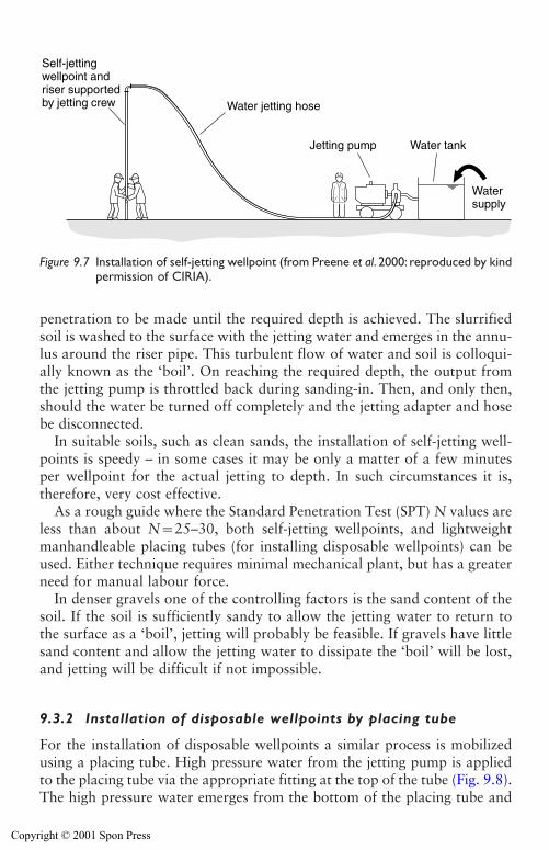
penetration to be made until the required depth is achieved. The slurrifiedsoil is washed to the surface with the jetting water and emerges in the annu-lus around the riser pipe. This turbulent flow of water and soil is colloqui-ally known as the ‘boil’. On reaching the required depth, the output fromthe jetting pump is throttled back during sanding-in. Then, and only then,should the water be turned off completely and the jetting adapter and hosebe disconnected.
In suitable soils, such as clean sands, the installation of self-jetting well-points is speedy – in some cases it may be only a matter of a few minutesper wellpoint for the actual jetting to depth. In such circumstances it is,therefore, very cost effective.
As a rough guide where the Standard Penetration Test (SPT) N values areless than about N�25–30, both self-jetting wellpoints, and lightweightmanhandleable placing tubes (for installing disposable wellpoints) can beused. Either technique requires minimal mechanical plant, but has a greaterneed for manual labour force.
In denser gravels one of the controlling factors is the sand content of thesoil. If the soil is sufficiently sandy to allow the jetting water to return tothe surface as a ‘boil’, jetting will probably be feasible. If gravels have littlesand content and allow the jetting water to dissipate the ‘boil’ will be lost,and jetting will be difficult if not impossible.
9.3.2 Installation of disposable wellpoints by placing tube
For the installation of disposable wellpoints a similar process is mobilizedusing a placing tube. High pressure water from the jetting pump is appliedto the placing tube via the appropriate fitting at the top of the tube (Fig. 9.8).The high pressure water emerges from the bottom of the placing tube and
266 Wellpoint systems
Water jetting hose
Jetting pump Water tank
Water supply
Self-jettingwellpoint andriser supportedby jetting crew
Figure 9.7 Installation of self-jetting wellpoint (from Preene et al. 2000: reproduced by kindpermission of CIRIA).
Copyright © 2001 Spon Press
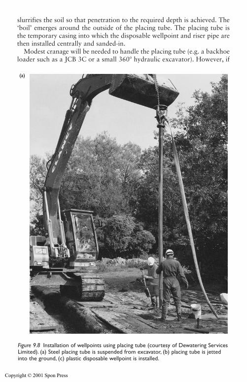
slurrifies the soil so that penetration to the required depth is achieved. The‘boil’ emerges around the outside of the placing tube. The placing tube isthe temporary casing into which the disposable wellpoint and riser pipe arethen installed centrally and sanded-in.
Modest cranage will be needed to handle the placing tube (e.g. a backhoeloader such as a JCB 3C or a small 360� hydraulic excavator). However, if
Wellpoint systems 267
(a)
Figure 9.8 Installation of wellpoints using placing tube (courtesy of Dewatering ServicesLimited). (a) Steel placing tube is suspended from excavator, (b) placing tube is jettedinto the ground, (c) plastic disposable wellpoint is installed.
Copyright © 2001 Spon Press
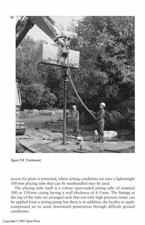
268 Wellpoint systems
(b)
access for plant is restricted, where jetting conditions are easy a lightweight100 mm placing tube that can be manhandled may be used.
The placing tube itself is a robust open-ended jetting tube of nominal100 or 150 mm casing having a wall thickness of 4–5 mm. The fittings atthe top of the tube are arranged such that not only high pressure water canbe applied from a jetting pump but there is in addition, the facility to applycompressed air to assist downward penetration through difficult groundconditions.
Figure 9.8 Continued.
Copyright © 2001 Spon Press
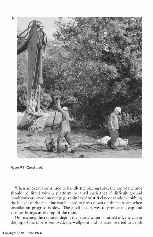
When an excavator is used to handle the placing tube, the top of the tubeshould be fitted with a platform or anvil such that if difficult ground conditions are encountered (e.g. a thin layer of stiff clay or random cobbles)the bucket of the machine can be used to press down on the platform wheninstallation progress is slow. The anvil also serves to protect the cap andvarious fittings at the top of the tube.
On reaching the required depth, the jetting water is turned off, the cap atthe top of the tube is removed, the wellpoint and its riser inserted to depth
Wellpoint systems 269
(c)
Figure 9.8 Continued.
Copyright © 2001 Spon Press
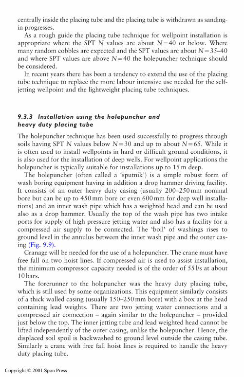
centrally inside the placing tube and the placing tube is withdrawn as sanding-in progresses.
As a rough guide the placing tube technique for wellpoint installation isappropriate where the SPT N values are about N�40 or below. Wheremany random cobbles are expected and the SPT values are about N�35–40and where SPT values are above N�40 the holepuncher technique shouldbe considered.
In recent years there has been a tendency to extend the use of the placingtube technique to replace the more labour intensive use needed for the self-jetting wellpoint and the lightweight placing tube techniques.
9.3.3 Installation using the holepuncher andheavy duty placing tube
The holepuncher technique has been used successfully to progress throughsoils having SPT N values below N�30 and up to about N�65. While itis often used to install wellpoints in hard or difficult ground conditions, itis also used for the installation of deep wells. For wellpoint applications theholepuncher is typically suitable for installations up to 15 m deep.
The holepuncher (often called a ‘sputnik’) is a simple robust form ofwash boring equipment having in addition a drop hammer driving facility.It consists of an outer heavy duty casing (usually 200–250 mm nominalbore but can be up to 450 mm bore or even 600 mm for deep well installa-tions) and an inner wash pipe which has a weighted head and can be usedalso as a drop hammer. Usually the top of the wash pipe has two intakeports for supply of high pressure jetting water and also has a facility for acompressed air supply to be connected. The ‘boil’ of washings rises toground level in the annulus between the inner wash pipe and the outer cas-ing (Fig. 9.9).
Cranage will be needed for the use of a holepuncher. The crane must havefree fall on two hoist lines. If compressed air is used to assist installation,the minimum compressor capacity needed is of the order of 55 l/s at about10 bars.
The forerunner to the holepuncher was the heavy duty placing tube,which is still used by some organizations. This equipment similarly consistsof a thick walled casing (usually 150–250 mm bore) with a box at the headcontaining lead weights. There are two jetting water connections and acompressed air connection – again similar to the holepuncher – providedjust below the top. The inner jetting tube and lead weighted head cannot belifted independently of the outer casing, unlike the holepuncher. Hence, thedisplaced soil spoil is backwashed to ground level outside the casing tube.Similarly a crane with free fall hoist lines is required to handle the heavyduty placing tube.
270 Wellpoint systems
Copyright © 2001 Spon Press
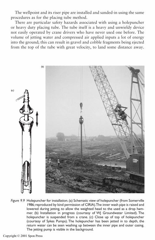
The wellpoint and its riser pipe are installed and sanded-in using the sameprocedures as for the placing tube method.
There are particular safety hazards associated with using a holepuncheror heavy duty placing tube. The tube itself is a heavy and unwieldy devicenot easily operated by crane drivers who have never used one before. Thevolume of jetting water and compressed air applied inputs a lot of energyinto the ground; this can result in gravel and cobble fragments being ejectedfrom the top of the tube with great velocity, to land some distance away.
Wellpoint systems 271
(b)
Figure 9.9 Holepuncher for installation. (a) Schematic view of holepuncher (from Somerville1986; reproduced by kind permission of CIRIA).The inner wash pipe is raised andlowered during jetting, to allow the weighted head to the used as a drop ham-mer. (b) Installation in progress (courtesy of WJ Groundwater Limited). Theholepuncher is suspended from a crane. (c) Close up of top of holepuncher(courtesy of Sykes Pumps). The holepuncher has been jetted in to depth, thereturn water can be seen washing up between the inner pipe and outer casing.The jetting pump is visible in the background.
Copyright © 2001 Spon Press
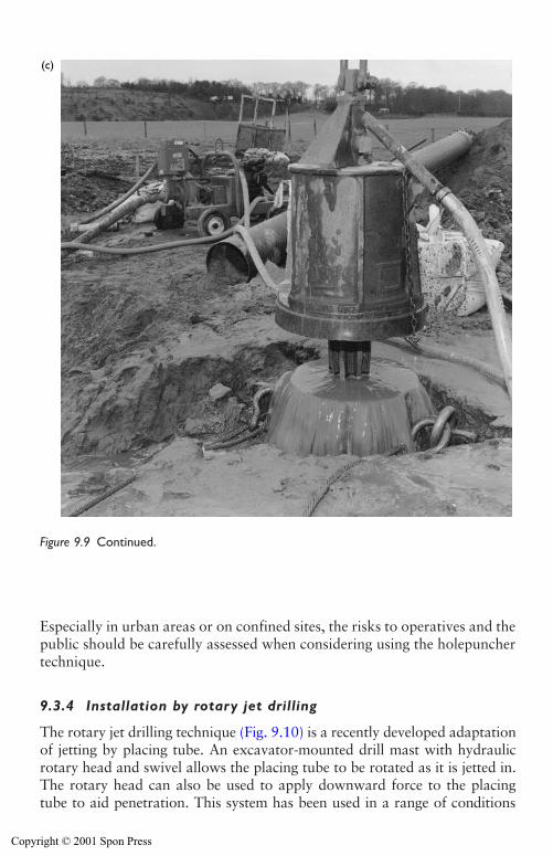
Especially in urban areas or on confined sites, the risks to operatives and thepublic should be carefully assessed when considering using the holepunchertechnique.
9.3.4 Installation by rotary jet drilling
The rotary jet drilling technique (Fig. 9.10) is a recently developed adaptationof jetting by placing tube. An excavator-mounted drill mast with hydraulicrotary head and swivel allows the placing tube to be rotated as it is jetted in.The rotary head can also be used to apply downward force to the placingtube to aid penetration. This system has been used in a range of conditions
272 Wellpoint systems
(c)
Figure 9.9 Continued.
Copyright © 2001 Spon Press
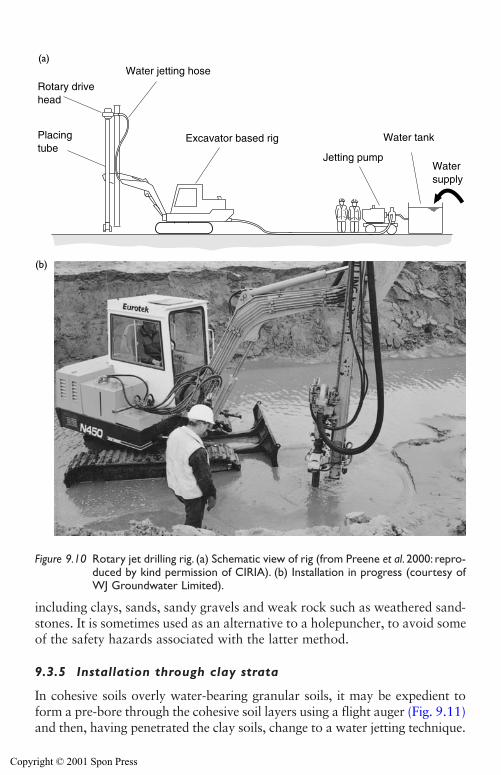
including clays, sands, sandy gravels and weak rock such as weathered sand-stones. It is sometimes used as an alternative to a holepuncher, to avoid someof the safety hazards associated with the latter method.
9.3.5 Installation through clay strata
In cohesive soils overly water-bearing granular soils, it may be expedient toform a pre-bore through the cohesive soil layers using a flight auger (Fig. 9.11)and then, having penetrated the clay soils, change to a water jetting technique.
Wellpoint systems 273
Watersupply
Water tankExcavator based rig
Jetting pump
Water jetting hose
Rotary drivehead
Placing tube
(a)
(b)
Figure 9.10 Rotary jet drilling rig. (a) Schematic view of rig (from Preene et al. 2000: repro-duced by kind permission of CIRIA). (b) Installation in progress (courtesy ofWJ Groundwater Limited).
Copyright © 2001 Spon Press
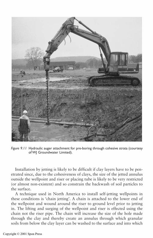
Installation by jetting is likely to be difficult if clay layers have to be pen-etrated since, due to the cohesiveness of clays, the size of the jetted annulusoutside the wellpoint and riser or placing tube is likely to be very restricted(or almost non-existent) and so constrain the backwash of soil particles tothe surface.
A technique used in North America to install self-jetting wellpoints inthese conditions is ‘chain jetting’. A chain is attached to the lower end ofthe wellpoint and wound around the riser to ground level prior to jettingin. The lifting and surging of the wellpoint and riser is effected using thechain not the riser pipe. The chain will increase the size of the hole madethrough the clay and thereby create an annulus through which granularsoils from below the clay layer can be washed to the surface and into which
274 Wellpoint systems
Figure 9.11 Hydraulic auger attachment for pre-boring through cohesive strata (courtesyof WJ Groundwater Limited).
Copyright © 2001 Spon Press
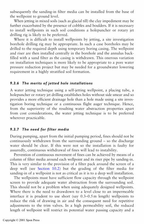
subsequently the sanding-in filter media can be installed from the base ofthe wellpoint to ground level.
When jetting in mixed soils (such as glacial till) the clay impediment may befurther exacerbated by the presence of cobbles and boulders. If it is necessaryto install wellpoints in such soil conditions a holepuncher or rotary jetdrilling rig is likely to be preferred.
Where it is difficult to install wellpoints by jetting, a site investigationborehole drilling rig may be appropriate. In such a case boreholes may bedrilled to the required depth using temporary boring casing. The wellpointand riser are then installed centrally in the borehole and the annulus back-filled with a sand filter as the casing is withdrawn. This onerous variationon installation techniques is more likely to be appropriate to a pore waterpressure reduction project but may be needed for a groundwater loweringrequirement in a highly stratified soil formation.
9.3.6 The merits of jetted hole installations
A water jetting technique using a self-jetting wellpoint, a placing tube, aholepuncher or rotary jet drilling establishes holes without side smear and soprovides a more efficient drainage hole than a hole made using a site inves-tigation boring technique or a continuous flight auger technique. Hence,from the superiority of the resulting water abstraction properties apartfrom cost considerations, the water jetting technique is to be preferredwherever practicable.
9.3.7 The need for filter media
During pumping, apart from the initial pumping period, fines should not becontinuously withdrawn from the surrounding ground – so the dischargewater should be clear. If this were not so the installation is faulty forassuredly, continuous withdrawal of fines will lead to instability.
Prevention of continuous movement of fines can be achieved by means of acolumn of filter media around each wellpoint and its riser pipe by sanding-in.This is very similar to the provision of a filter pack around the screen of adeep well (see Section 10.2) but the grading of the filter media forsanding-in of a wellpoint is not as critical as it is to a deep well installation.
The wellpoints must have sufficient flow capacity through the wellpointscreen to provide adequate water abstraction from the surrounding soil.This should not be a problem when using adequately designed wellpoints.Where there is the need to drawdown to a level close to an impermeableinterface it is prudent to use short (say 0.3–0.5 m length) wellpoints toreduce the risk of drawing in air and the consequent need for repetitiveadjustments to the trim valves. In a high permeability soil, the reducedlength of wellpoint will restrict its potential water passing capacity and a
Wellpoint systems 275
Copyright © 2001 Spon Press
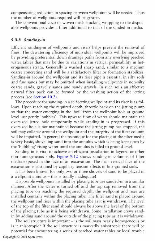
compensating reduction in spacing between wellpoints will be needed. Thusthe number of wellpoints required will be greater.
The conventional coco or woven mesh stocking wrapping to the dispos-able wellpoints provides a filter additional to that of the sanded-in media.
9.3.8 Sanding-in
Efficient sanding-in of wellpoints and risers helps prevent the removal offines. The dewatering efficiency of individual wellpoints will be improvedby providing preferential down drainage paths from any overlying perchedwater tables that may be due to variations in vertical permeability in het-erogeneous strata. Generally a washed sharp sand, similar to a mediumcoarse concreting sand will be a satisfactory filter or formation stabilizer.Sanding-in around the wellpoint and its riser pipe is essential in silty soilsand fine sands but may be omitted when installing wellpoints in non-siltycoarse sands, gravelly sands and sandy gravels. In such soils an effectivenatural filter pack can be formed by the washing action of the jettingprocess (see Section 10.2).
The procedure for sanding-in a self-jetting wellpoint and its riser is as fol-lows. Upon reaching the required depth, throttle back on the jetting pumpso that the water emerging in the ‘boil’ from the wellpoint hole at groundlevel just gently ‘bubbles’. This upward flow of water should maintain theoversized jetted hole temporarily while sanding-in is progressed. If thisoversized hole is not maintained because the jetting pump has stopped, thesoil may collapse around the wellpoint and the integrity of the filter columnwill be impaired. In general the technique for the placing of the filter mediais very basic, shovelling sand into the annulus which is being kept open bythe ‘bubbling’ rising water until the annulus is filled to ground level.
Sanding-in is vital to achieve an efficient installation in layered or othernon-homogeneous soils. Figure 9.12 shows sanding-in columns of filtermedia exposed in the face of an excavation. The near vertical face of theexcavation is sustained by capillary tension effects in fine-grained soils.
It has been known for only two or three shovels of sand to be placed ina wellpoint annulus – this is totally inadequate!
Disposable wellpoints installed by placing tube are sanded-in in a similarmanner. After the water is turned off and the top cap removed from theplacing tube on reaching the required depth, the wellpoint and riser areinstalled centrally within the placing tube. The filter sand is placed aroundthe wellpoint and riser within the placing tube as it is withdrawn. The levelof the top of the filter sand should always be above the level of the bottomof the placing tube as it is being withdrawn. Some installation crews sand-in by adding sand around the outside of the placing tube as it is withdrawn.
The soil structure is important – is the soil mass nearly homogeneous oris it anisotropic? If the soil structure is markedly anisotropic there will bepotential for encountering a series of perched water tables or local trouble
276 Wellpoint systems
Copyright © 2001 Spon Press
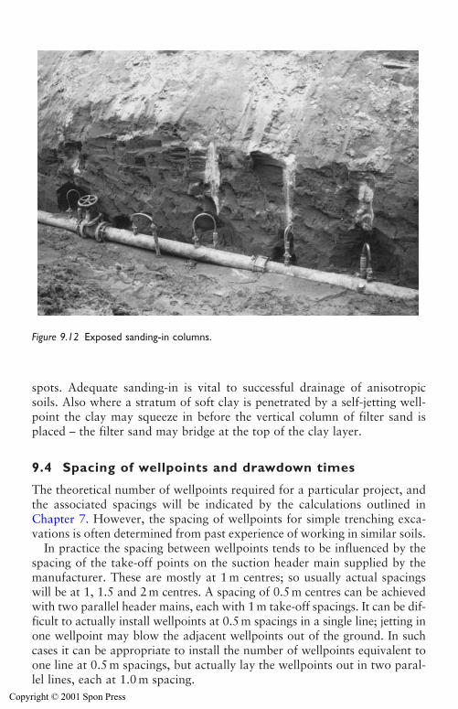
spots. Adequate sanding-in is vital to successful drainage of anisotropicsoils. Also where a stratum of soft clay is penetrated by a self-jetting well-point the clay may squeeze in before the vertical column of filter sand isplaced – the filter sand may bridge at the top of the clay layer.
9.4 Spacing of wellpoints and drawdown times
The theoretical number of wellpoints required for a particular project, andthe associated spacings will be indicated by the calculations outlined inChapter 7. However, the spacing of wellpoints for simple trenching exca-vations is often determined from past experience of working in similar soils.
In practice the spacing between wellpoints tends to be influenced by thespacing of the take-off points on the suction header main supplied by themanufacturer. These are mostly at 1 m centres; so usually actual spacingswill be at 1, 1.5 and 2m centres. A spacing of 0.5 m centres can be achievedwith two parallel header mains, each with 1 m take-off spacings. It can be dif-ficult to actually install wellpoints at 0.5 m spacings in a single line; jetting inone wellpoint may blow the adjacent wellpoints out of the ground. In suchcases it can be appropriate to install the number of wellpoints equivalent toone line at 0.5 m spacings, but actually lay the wellpoints out in two paral-lel lines, each at 1.0 m spacing.
Wellpoint systems 277
Figure 9.12 Exposed sanding-in columns.
Copyright © 2001 Spon Press
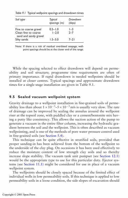
While the spacing selected to effect drawdown will depend on perme-ability and soil structure; programme time requirements are often ofprimary importance. If rapid drawdown is needed wellpoints should beinstalled at closer centres. Typical spacings and approximate drawdowntimes for a single stage installation are given in Table 9.1.
9.5 Sealed vacuum wellpoint system
Gravity drainage to a wellpoint installation in fine-grained soils of perme-ability less than about 1�10�5–5�10�5 m/s is usually very slow. The rateof drainage can be improved by sealing the annulus around the wellpointriser at the topsoil zone, with puddled clay or a cement/bentonite mix hav-ing a putty like consistency. This allows the suction action of the pump togenerate a vacuum in the entire filter column, increasing the hydraulic gra-dient between the soil and the wellpoint. This is often described as vacuumwellpointing, and is one of the methods of pore water pressure control usedin fine-grained soils (see Section 5.4).
This technique can be quite effective in stratified soils, provided thatproper sanding-in has been achieved from the bottom of the wellpoint tothe underside of the clay plug. On occasions it has been used effectively toreduce the moisture content of low strength clay soils and so therebyincrease slope stability. The vacuum tank unit pumpset (see Section 12.1)would be the appropriate type to use for this particular duty. Ejector sys-tems (see Section 11.1) might be considered for use in place of a vacuumwellpoint system.
The wellpoints should be closely spaced because of the limited effect ofindividual wells in low permeability soils. If this technique is applied to lowpermeability soils in a loose condition, the side slopes of excavation should
278 Wellpoint systems
Table 9.1 Typical wellpoint spacings and drawdown times
Soil type Typical Drawdownspacings (m) (days)
Fine to coarse gravel 0.5–1.0 1–3Clean fine to coarse 1–2.0 2–7sand and sandy gravel
Silty sands 1.5–3.0 7–21
Note: If there is a risk of residual overbleed seepage, well-point spacings should be at the closer end of the range.
Copyright © 2001 Spon Press
be protected from sudden disturbances – such as use of any vibration tech-niques – as these might cause liquefaction.
9.6 Wellpoint pumping equipment
Wellpoint equipment sets are available from many specialist manufacturers.The two important aspects to be considered before ordering equipment are:
(a) Long-term reliability.(b) Overall cost, including maintenance costs.
Unfortunately some suppliers do not conform to these simple and sensi-ble guidelines. Some supply cumbersome equipment that requires cranagefor handling. Other suppliers go to the other extreme, supplying flimsyequipment that is readily susceptible to damage and so has only a shortuseful life.
A typical medium sized wellpoint installation will incorporate a 150 mmduty pump plus a standby pump connected to 150 mm sized header main(which acts as a suction manifold) connected to the trim valves of each indi-vidual wellpoint via its riser. The individual component parts have beendescribed earlier.
9.6.1 Duty or running pumps
The total connected pump capacity must be sufficient to deal with thegreater rate of abstraction required during initial drawdown. In unconfinedaquifers of moderate to high permeability the calculated steady-state pump-ing rate is unlikely to be adequate to achieve acceptably rapid drawdown.In such circumstances the initial rate of pumping may be up to twice the cal-culated equilibrium rate of pumping required to maintain drawdown. It iscommon practice on start up to operate both the running and the standbypumpsets to achieve a fast drawdown.
When dealing with high flow rates or a large installation it is prudent toprovide multiple pumpsets in the system rather than a single large output run-ning pump since this affords greater flexibility. This often results in better fueleconomy and is economical on the provision of standby pumps. Chapter 12describes the types of pumps suitable for use with wellpoint systems.
For systems running with a single duty pump, the ideal position for thepump is at the middle of the suction header main so that water is beingabstracted from an equal number of wellpoints to either side of the pumpstation. Where two duty pumps are used they may be positioned adjacentto each other – thus at the end of each set’s header line – and a standbypump may be positioned and connected so as to pump from either set. This
Wellpoint systems 279
Copyright © 2001 Spon Press
is acceptable only if the pumping load required of either running pump issignificantly below its rated capacity.
Generally wellpoint installations are operated using diesel driven units.However, if the running pump is to be electrically powered (perhaps inorder to reduce noise levels), it is often acceptable and economical that thestandby pump be diesel powered. Since groundwater lowering pumpsetsoperate 24 h per day fuel is a significant cost factor. Fuel consumption shouldbe highlighted in the build up of cost estimates. The costs of alternativesources of power (such as mains electric power) should be compared if theirprovision is practicable.
The fuel consumption of the double acting piston pump is more modestthan that of the centrifugal pump; also the wear and tear is less because ofthe slower rate of movement. However, the maximum amount of loweringthat can be achieved using a piston pump is generally limited to about 4.5 m.An efficient system operated with a vacuum assisted self-priming centrifu-gal pumpset should achieve an additional 1 m or more of drawdown in similar soil conditions.
These are general indications for guidance only. Actual achievements willdepend upon the permeability of the soils, the mechanical efficiency of theindividual pumpsets and of all the pipework connections of the installedsystem. Air leaks must be minimized because they can have a very signifi-cant effect on the amount of suction available at the wellpoints and so affectthe lowering that is achievable.
9.6.2 Standby pumps
In general, groundwater lowering systems should operate continuously 24hper day, seven days per week. Hence it is imperative that the installed systemincorporates facilities to ensure that pumping is indeed continuous. Generally,this can be provided by connecting an additional (standby) wellpoint pump tothe suction header and discharge mains with suitably placed valves for a swiftchange over of operation from the running pump to the standby unit as andwhen required. This might be necessary in the event of an individual runningpump failure or maintenance stoppage to check oil levels, etc.
A judgement should be made before commencing site work, of the likelyeffects of a cessation of pumping. The decision should be based on theanswers to the following two questions:
i Will a cessation of pumping cause instability of the works? If the answerto this question is ‘yes’ the provision of standby pumping and/or powerfacilities is essential.
ii Will a cessation of pumping create only a relatively minor mess that canbe cleaned up afterwards at an acceptable cost both in terms of incon-venience and delay? If the answer to this question is ‘yes’ and there is
280 Wellpoint systems
Copyright © 2001 Spon Press
no safety risk, a judgement has to be made whether or not to accept thecost savings by not providing standby pumps whilst recognizing that arisk is being taken.
9.6.3 Operation of a wellpoint system and ‘trimming’
The amount of lowering of the water level that can be achieved by a wellpointsystem is governed by:
1 First and foremost – the physical bounds of suction lift. Elevation abovesea level and to a lesser extent ambient temperatures, have some inputinto this limitation. As ground elevation above sea level increases,available suction decreases. Also, ambient temperatures and groundelevation are of significant relevance to the rating of the engine requiredto drive the pump to achieve the necessary rate of pumping.
2 The hydraulic efficiency of the total wellpoint installation – thisincludes the pipework sizing above and below ground as well as theadequacy of the wellpoint sanding-in procedures and the air/water sep-aration unit on the pumpset
3 Air leaks. These can drastically reduce the amount of vacuum that isavailable to withdraw water from the soil via the abstraction points.
As suction is applied to self-jetting wellpoints, their ball valves are seatedand the groundwater is sucked through the wellpoint screen only. The bot-tom of the riser pipe terminates near the bottom of the wellpoint screen soas to minimize or delay the intake of air when maximum drawdown isbeing achieved.
The bottom end of a disposable wellpoint is sealed and so similarly thegroundwater is sucked through the screen to the bottom of the riser pipeand thence to the suction header main.
As the water level at each wellpoint is drawndown to near the level of thetop of the screen there will be a risk of entraining air with water andthereby reducing the amount of available vacuum. The trim valves (Fig. 9.3)at each individual wellpoint connection to the header main enable the experienced operator to adjust the amount of suction such that the intakeis predominantly water and the amount of air intake is minimized. This isnecessary to ensure that the wellpoint system operates at the maximumachievable drawdown.
The adjustment of the valves on each wellpoint is known as ‘trimming’or ‘tuning’ and is an important part of operating any wellpoint system. A poorly trimmed system may achieve significantly less drawdown thansystem that has been trimmed correctly. Trimming is probably more of anart than a science, but can normally be mastered with experience.
As the system is trimmed (i.e. the wellpoint valves are closed or throttled)the vacuum shown on gauges on the pump and header main should
Wellpoint systems 281
Copyright © 2001 Spon Press
increase. This is because the amount of air entering the system via the well-point screens is reducing, allowing the pump to generate more vacuum.When trimming a system it can be very satisfying to see the vacuum increaseas a result of your efforts. However, it must be remembered that the aim is notto maximize vacuum but to maximize drawdown and flow rate. It is impor-tant not to become obsessed with obtaining greater and greater vacuums.An overzealously trimmed system (where all the wellpoint valves are almostclosed) will have a very impressive vacuum but will pump little water andgenerate little drawdown – this is a classic mistake made by novices whenfirst attempting trimming!
A wellpoint that is pumping problematical volumes of air will probablybe producing ‘slugs’ or ‘gulps’ of air and water. The momentum of eachslug of water will make the wellpoint swing connector jump up and down,perhaps quite violently – this is known as ‘bumping’. A ‘bumper’ is trimmedby slowly closing the valve until the flow is smooth, and then re-openedslightly – the last action is vital to avoid over-trimming. A small steady flowof air along the swing connector is acceptable (provided the rest of the system is functioning well); it is probably counter productive to attempt totrim a system so that no air at all enters the wellpoints.
Wellpoint equipment sets supplied by British, North American andAustralian suppliers usually include trim valves to regulate the rate ofwater/air flow to each wellpoint. However, suppliers based on the continentof Europe generally do not supply trim valves, unless specifically asked todo so. The reason for this is not clear. South East Asian suppliers also tendto omit trim valves and to follow continental European philosophy. Theinclusion of trim valves is added cost but the authors consider that thepotential for increased lowering by adjustment of trim valves, especially fora multi-stage wellpoint installation, is cost-effective.
9.7 Wellpoint installations for trench excavations
A considerable amount of shallow depth trenching for pipelaying is carriedout worldwide. Irvine and Smith (1992) give overall guidance to good trench-ing practices and include many specific recommendations concerning supportof the excavations and other safety guidelines, both with and without the needfor groundwater control. This book does not address the many methods oftrench support. However, it is important that for each and every trench pump-ing installation, the basic concepts described should be observed; thoughdepending upon local conditions, some adjustments may be appropriate.
9.7.1 Single-sided wellpoint installations
The pipelaying contractor will much prefer having the header main andassociated wellpoints only on one side of the trench, because this will allow
282 Wellpoint systems
Copyright © 2001 Spon Press
uninterrupted access for his plant and equipment on the other side of thespread (Fig. 9.1). The basic question is, how to assess whether a single-sidedinstallation will be adequate. Water levels must be reduced below forma-tion level. The critical point is the bottom of the trench on the side remotefrom the line of wellpoints of Fig. 9.1. If the drawndown phreatic surfaceis below that point, a single-sided installation is adequate.
A single-sided system will be suitable only if a sufficient depth of perme-able soil exists beneath formation level and if there are no significant layersor lenses of impermeable material in the water-bearing soils, especiallyabove the level of the base of the wellpoints.
The slope and shape of the drawdown surface is very relevant, and primarily depends upon the soil permeability. The lower the permeability,the steeper the slope of the drawdown cones that individual wellpoints willestablish. The spacing between wellpoints must be close enough to ensurethat their individual cones of depression interact and so produce a generaland fairly uniform lowering.
The dewatering contractor has no control over soil conditions on site butdoes have control over the spacing between wellpoints. If the proposedexcavation depth is modest and the depth of the unconfined water-bearingstratum is considerable, the wellpoints can be installed at wide spacings onlong riser pipes. The use of long riser pipes has the merit of minimizing thepossibility of a wellpoint sucking air and so reducing the available vacuum.This may be offset by increased difficulty in the handling of long risers dur-ing installation. Generally this variation is more suitable for an installationthat is to be pumped for a significant period of time than to a progressivetype installation, when the pumping period will be of short duration.
Experienced engineering judgement is needed when deciding on wellpointspacings and whether a single-sided installation will be adequate. The con-ditions favourable to the use of a single-sided wellpoint installation fortrench excavation are:
(a) A narrow trench.(b) Effectively homogeneous, isotropic permeable soil conditions that per-
sist to an adequate depth below formation level (see Fig. 9.1a).(c) Trench formation level is not more than about 5 m below standing
groundwater level. The actual depth achievable depends upon the per-meability of the water bearing soil beneath formation and the overallpumping efficiency of the installation.
For trenching in excess of about 5 m deep, it is possible to use a lowerstage of wellpointing as described in Section 9.8, provided that there is suf-ficient depth of permeable soil beneath final formation level and the widthof the wayleave is sufficient. The sides of the trench excavation must besafely supported throughout.
Wellpoint systems 283
Copyright © 2001 Spon Press
Single-sided systems work well in isotropic soil conditions. In practicesoils are often heterogeneous and anisotropic. In such conditions double-sided systems, where wellpoints are installed on both sides of an excava-tion, may be more effective.
9.7.2 Double-sided wellpoint installations
The conditions likely to require the use of a double-sided wellpointing (Fig. 9.13(a)) for trench excavation are:
(a) A relatively wide trench.(b) Trench formation level 4.5–6m or more below standing groundwater
level.(c) Impermeable stratum close to formation level, or low permeability layers
or lenses present above formation level.
If there is an impermeable stratum (such as a clay layer) at or close to formation level (Fig. 9.13(b)), even if a double-sided wellpoint system isemployed, there may be some residual seepage or overbleed near the interfacebetween the overlying permeable stratum and the underlying impermeablesoil. In this situation particular thought must be given to the wellpoint depthand spacing. The wellpoints must be ‘toed into’ the impermeable stratum – ineffect they are installed to penetrate a few hundred millimetres into the clay,to form a sump of sorts around each wellpoint to maximize drawdown.This requires careful installation – overzealous ‘toeing in’ will result in thewellpoint screen being installed too deep into the clay, thereby becomingclogged and ineffective. The wellpoints should be installed at rather closerspacings than normal to try and intercept as much of the overbleed seepageas possible.
Even if these measures are adopted, some overbleed seepage is likely topass between the wellpoints and enter the trench. It is essential to controlthe overbleed so that pore water pressures do not build up and that thewater flow does not continuously transport fines and risk instability of thesides of the trench. Some form of sand-filled permeable bags, granulardrainage blanket or geotextile mesh should be placed as indicated in Fig. 9.13(b). This will allow the water to flow into the excavation withoutthe build up of pore water pressures and movement of fines. Thus stabilityof the trench will be preserved. The water flowing to the trench must becontinuously removed by conventional sump pumping to prevent standingwater building up in the working area.
There is a hybrid of single and double-sided systems that can be usedwhen trenching in extensive permeable strata where an impermeable layerexists above formation level (see Fig. 9.14). These conditions could be dealtwith by means of a double-sided wellpoint installation but this could be an
284 Wellpoint systems
Copyright © 2001 Spon Press
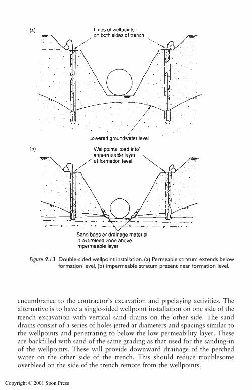
encumbrance to the contractor’s excavation and pipelaying activities. Thealternative is to have a single-sided wellpoint installation on one side of thetrench excavation with vertical sand drains on the other side. The sanddrains consist of a series of holes jetted at diameters and spacings similar tothe wellpoints and penetrating to below the low permeability layer. Theseare backfilled with sand of the same grading as that used for the sanding-inof the wellpoints. These will provide downward drainage of the perchedwater on the other side of the trench. This should reduce troublesomeoverbleed on the side of the trench remote from the wellpoints.
Wellpoint systems 285
Figure 9.13 Double-sided wellpoint installation. (a) Permeable stratum extends belowformation level, (b) impermeable stratum present near formation level.
Copyright © 2001 Spon Press
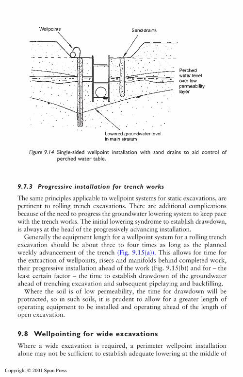
9.7.3 Progressive installation for trench works
The same principles applicable to wellpoint systems for static excavations, arepertinent to rolling trench excavations. There are additional complicationsbecause of the need to progress the groundwater lowering system to keep pacewith the trench works. The initial lowering syndrome to establish drawdown,is always at the head of the progressively advancing installation.
Generally the equipment length for a wellpoint system for a rolling trenchexcavation should be about three to four times as long as the plannedweekly advancement of the trench (Fig. 9.15(a)). This allows for time forthe extraction of wellpoints, risers and manifolds behind completed work,their progressive installation ahead of the work (Fig. 9.15(b)) and for – theleast certain factor – the time to establish drawdown of the groundwaterahead of trenching excavation and subsequent pipelaying and backfilling.
Where the soil is of low permeability, the time for drawdown will be protracted, so in such soils, it is prudent to allow for a greater length ofoperating equipment to be installed and operating ahead of the length ofopen excavation.
9.8 Wellpointing for wide excavations
Where a wide excavation is required, a perimeter wellpoint installationalone may not be sufficient to establish adequate lowering at the middle of
286 Wellpoint systems
Figure 9.14 Single-sided wellpoint installation with sand drains to aid control ofperched water table.
Copyright © 2001 Spon Press
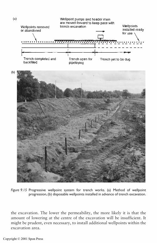
the excavation. The lower the permeability, the more likely it is that theamount of lowering at the centre of the excavation will be insufficient. Itmight be prudent, even necessary, to install additional wellpoints within theexcavation area.
Wellpoint systems 287
(b)
Figure 9.15 Progressive wellpoint system for trench works. (a) Method of wellpointprogression, (b) disposable wellpoints installed in advance of trench excavation.
Copyright © 2001 Spon Press
9.9 Wellpointing for deeper excavations
9.9.1 Long risers and lowered header mains
If the excavation width is modest, but the required drawdown is greaterthan achievable by a single stage, and the thickness of permeable soilsbeneath formation level is significant, drawdown can be increased byinstalling wellpoints on longer than normal 6 m risers to an adequate depthbelow formation level.
The additional drawdown is achieved by initially pumping the wellpointsfrom pumps and header mains laid at about standing groundwater level.Pumping of this initial installation will establish some lowering of the waterlevel. Excavation is then made down to the lowered water level and a secondsuction header main is installed at the lower level. This lower main ispumped while the upper suction main is still active. Progressively each indi-vidual wellpoint (having shortened its length of riser) is disconnected fromthe upper header main and connected to the lower header main. Pumpingshould be continued from the original upper main until all wellpoint risershave been shortened and connected into the lower main. Using the standbypump from the upper header main to begin pumping on the lower headermain can reduce the number of pumps required for this method. When allthe wellpoints have been connected to the lower main the upper pump canbe moved down to act as a standby unit for the lower main. The upperheader main is then dismantled and removed.
This process could be described as a two-stage installation having onlyone stage of installation of the wellpoints and risers (see Section 9.10 fordescription of a case history where this procedure was used).
9.9.2 Multi-stage wellpointing
Multi-stage wellpoint installations (Fig. 9.5) can be used for deep excavationsas an alternative to deepwells (see Chapter 10) or ejectors (see Section 11.1).If a multi-stage wellpoint system is used it is necessary to make sufficientallowance for side slopes or batters to excavate safely to formation depth andberms to support header mains of lower stages.
The recommended site procedure for the installation of multi-stage sets isas follows:
(a) Excavate to about the standing water level; it may be possible to exca-vate to around 0.5 m below the water level.
(b) Install and connect first stage wellpoint system around the perimeter,making due allowance for subsequent slope batters and berms.
(c) Pump continuously on the first stage system.(d) Excavate to about 0.5 m above the lowered water level.
288 Wellpoint systems
Copyright © 2001 Spon Press
(e) Install and connect the second stage wellpoint system around theperimeter that likewise allows for excavation batters and berms forsubsequent stages.
(f) Pump continuously on the second stage system as well as continuing topump on the first stage.
(g) Again excavate to about 0.5 m above the level to which water has beenlowered by pumping on both first and second stages.
(h) Continue the sequence of excavation, wellpoint installation and pump-ing until formation level is reached.
This sequence of operations will entail short halts in excavation as eachfurther intermediate stage level for wellpoints and header main, etc. isinstalled for the further lowering of the groundwater.
At each stage, in addition to installation of the wellpoint system, a num-ber of observation wells should be installed to monitor the lowering beingachieved and to indicate the depth to which the next stage excavation canbe taken.
Often, when pumping on multi-stage systems of more than two stages,the first stage pumping output declines rapidly as the third stage is broughtinto operation. When this happens the top stage pumps can be stopped andtransferred down to the fourth stage if there is one: or can be connected tothe third stage as standby units. The wellpoints and risers of the top stageshould not be extracted since it may be necessary to reactivate the upperstage(s) as the structure is being built up and backfill placed. The recoveryof the groundwater level must be controlled so that at every stage of thebuilding of the works, there is no risk of flotation of the partially completedstructure due to an uncontrolled rise of the groundwater.
Three and four stage wellpoint installations have been operated satisfac-torily for deep excavations. There have been, and will be in the future,many projects where a multi-stage wellpoint system is an economic solutionto a particular groundwater lowering problem. Consideration should alsobe given to the fact that the degree of expertise required for installation andoperation of a wellpoint system is less sophisticated than that appropriatefor a deep well or ejector system. Hence, there may be occasions or geo-graphical locations where the use of a wellpoint system will be the moreappropriate choice for a deep construction project.
9.10 Case history: Derwent outlet channel,Northumberland
In the early 1960s, the Sunderland & South Shields Water Co. awarded toJohn Mowlem & Co. Ltd. a contract for the construction of an earth damabout 15 miles to the south west of Newcastle on Tyne, in the valley of theriver Derwent (see Rowe 1968; Buchanan 1970; Cashman 1971). Thisrequired the formation of a spillway outlet channel about 240 m long and
Wellpoint systems 289
Copyright © 2001 Spon Press
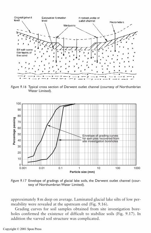
approximately 8 m deep on average. Laminated glacial lake silts of low per-meability were revealed at the upstream end (Fig. 9.16).
Grading curves for soil samples obtained from site investigation bore-holes confirmed the existence of difficult to stabilize soils (Fig. 9.17). Inaddition the varved soil structure was complicated.
290 Wellpoint systems
Figure 9.16 Typical cross section of Derwent outlet channel (courtesy of NorthumbrianWater Limited).
0
10
20
30
40
50
60
70
80
90
100
0.001 0.01 0.1 1 10 100 1000Particle size (mm)
Per
cen
tag
e p
assi
ng
Envelope of grading curvesfor sam ples recovered fromsite investigation boreholes
Figure 9.17 Envelope of gradings of glacial lake soils, the Derwent outlet channel (cour-tesy of Northumbrian Water Limited).
Copyright © 2001 Spon Press
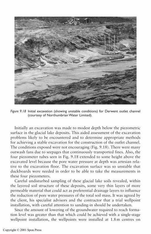
Initially an excavation was made to modest depth below the piezometricsurface in the glacial lake deposits. This aided assessment of the excavationproblems likely to be encountered and to determine appropriate methodsfor achieving a stable excavation for the construction of the outlet channel.The conditions exposed were not encouraging (Fig. 9.18). There were manyoutwash fans due to seepages that continuously transported fines. Also, thefour piezometer tubes seen in Fig. 9.18 extended to some height above theexcavated level because the pore water pressure at depth was artesian rela-tive to the excavation floor. The excavation surface was so unstable thatduckboards were needed in order to be able to take the measurements inthese four piezometers.
Careful undisturbed sampling of these glacial lake soils revealed, withinthe layered soil structure of these deposits, some very thin layers of more permeable material that could act as preferential drainage layers to influencethe reduction of pore water pressures of the total soil mass. It was agreed bythe client, his specialist advisors and the contractor that a trial wellpointinstallation, with careful attention to sanding-in should be undertaken.
Since the amount of lowering of the groundwater required to reach forma-tion level was greater than that which could be achieved with a single-stagewellpoint installation, the wellpoints were installed at 1.8 m centres on
Wellpoint systems 291
Figure 9.18 Initial excavation (showing unstable conditions) for Derwent outlet channel(courtesy of Northumbrian Water Limited).
Copyright © 2001 Spon Press
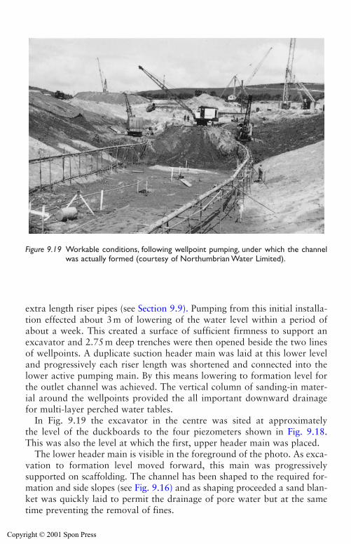
extra length riser pipes (see Section 9.9). Pumping from this initial installa-tion effected about 3 m of lowering of the water level within a period ofabout a week. This created a surface of sufficient firmness to support anexcavator and 2.75 m deep trenches were then opened beside the two linesof wellpoints. A duplicate suction header main was laid at this lower leveland progressively each riser length was shortened and connected into thelower active pumping main. By this means lowering to formation level forthe outlet channel was achieved. The vertical column of sanding-in mater-ial around the wellpoints provided the all important downward drainagefor multi-layer perched water tables.
In Fig. 9.19 the excavator in the centre was sited at approximatelythe level of the duckboards to the four piezometers shown in Fig. 9.18.This was also the level at which the first, upper header main was placed.
The lower header main is visible in the foreground of the photo. As exca-vation to formation level moved forward, this main was progressivelysupported on scaffolding. The channel has been shaped to the required for-mation and side slopes (see Fig. 9.16) and as shaping proceeded a sand blan-ket was quickly laid to permit the drainage of pore water but at the sametime preventing the removal of fines.
292 Wellpoint systems
Figure 9.19 Workable conditions, following wellpoint pumping, under which the channelwas actually formed (courtesy of Northumbrian Water Limited).
Copyright © 2001 Spon Press
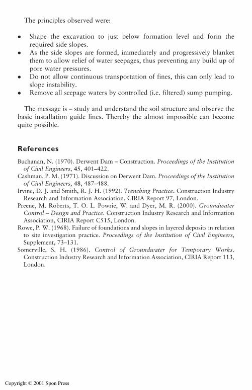
The principles observed were:
� Shape the excavation to just below formation level and form therequired side slopes.
� As the side slopes are formed, immediately and progressively blanketthem to allow relief of water seepages, thus preventing any build up ofpore water pressures.
� Do not allow continuous transportation of fines, this can only lead toslope instability.
� Remove all seepage waters by controlled (i.e. filtered) sump pumping.
The message is – study and understand the soil structure and observe thebasic installation guide lines. Thereby the almost impossible can becomequite possible.
References
Buchanan, N. (1970). Derwent Dam – Construction. Proceedings of the Institutionof Civil Engineers, 45, 401–422.
Cashman, P. M. (1971). Discussion on Derwent Dam. Proceedings of the Institutionof Civil Engineers, 48, 487–488.
Irvine, D. J. and Smith, R. J. H. (1992). Trenching Practice. Construction IndustryResearch and Information Association, CIRIA Report 97, London.
Preene, M. Roberts, T. O. L. Powrie, W. and Dyer, M. R. (2000). GroundwaterControl – Design and Practice. Construction Industry Research and InformationAssociation, CIRIA Report C515, London.
Rowe, P. W. (1968). Failure of foundations and slopes in layered deposits in relationto site investigation practice. Proceedings of the Institution of Civil Engineers,Supplement, 73–131.
Somerville, S. H. (1986). Control of Groundwater for Temporary Works.Construction Industry Research and Information Association, CIRIA Report 113,London.
Wellpoint systems 293
Copyright © 2001 Spon Press
Chapter 10
Deep well systems
10.0 Introduction
A deep well system consists of an array of bored wells pumped by sub-mersible pumps. The wells act in concert – the interaction between the coneof drawdown created by each well results in groundwater lowering over awide area. Because the technique does not operate on a suction principle,greater drawdowns can be achieved than with a single stage wellpoint sys-tem. This chapter addresses the temporary works deep well groundwaterlowering system and describes good practices to be used during installationand operation.
The principles of the method, and the stages in well design are discussed.The methods used for well drilling, installation, development and operationare outlined and some practical problems with the operation of deep well sys-tems are presented. The vacuum deep well and bored shallow well systems,which are variants on the deep well method are described briefly. The chapterends with a case history of a large-scale temporary works deep well system.
10.1 Deep well installations
A deep well system consists of a number of wells pumped by submersiblepumps. Each well consists of a bored hole (typically formed by a drillingrig) into which a special well liner is inserted. The liner consists of plasticor steel pipe of which a section is slotted or perforated to form a well screento allow water to enter; other sections consist of unperforated pipe (the wellcasing). Generally, deep well systems are installed in drift deposits and theannulus between the borehole and the well screen/casing is backfilled withfilter media or formation stabilizer to form what is known as the filter pack.
The wells are generally sited just outside the area of proposed excavation(although for very large excavations wells may be required within the mainexcavation area as well as around the perimeter). A deep well system hasindividual pumps positioned near the bottom of each well; usually thepumps are borehole electro-submersibles (see Section 12.4). The well screen
Copyright © 2001 Spon Press
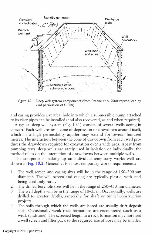
Deep well systems 295
and casing provides a vertical hole into which a submersible pump attachedto its riser pipes can be installed (and also recovered, as and when required).
A typical deep well system (Fig. 10.1) consists of several wells acting inconcert. Each well creates a cone of depression or drawdown around itself,which in a high permeability aquifer may extend for several hundredmetres. The interaction between the cone of drawdown from each well pro-duces the drawdown required for excavation over a wide area. Apart frompumping tests, deep wells are rarely used in isolation or individually; themethod relies on the interaction of drawdowns between multiple wells.
The components making up an individual temporary works well areshown in Fig. 10.2. Generally, for most temporary works requirements:
1 The well screen and casing sizes will be in the range of 150–300 mmdiameter. The well screen and casing are typically plastic, with steelbeing used only rarely.
2 The drilled borehole sizes will be in the range of 250–450 mm diameter.3 The well depths will be in the range of 10–35 m. Occasionally, wells are
drilled to greater depths, especially for shaft or tunnel constructionprojects.
4 The soils through which the wells are bored are usually drift depositsoils. Occasionally weak rock formations are encountered (such as aweak sandstone). The screened length in a rock formation may not needa well screen and filter pack so the required size of bore may be smaller.
Figure 10.1 Deep well system components (from Preene et al. 2000; reproduced bykind permission of CIRIA).
Copyright © 2001 Spon Press
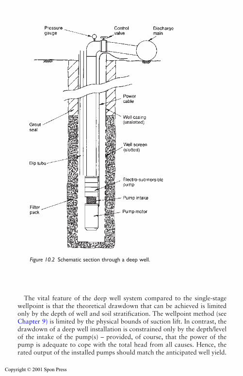
296 Deep well systems
The vital feature of the deep well system compared to the single-stagewellpoint is that the theoretical drawdown that can be achieved is limitedonly by the depth of well and soil stratification. The wellpoint method (seeChapter 9) is limited by the physical bounds of suction lift. In contrast, thedrawdown of a deep well installation is constrained only by the depth/levelof the intake of the pump(s) – provided, of course, that the power of thepump is adequate to cope with the total head from all causes. Hence, therated output of the installed pumps should match the anticipated well yield.
Figure 10.2 Schematic section through a deep well.
Copyright © 2001 Spon Press
The energy costs of operating a deep well installation are likely to becompetitive due to the greater efficiency of borehole pumps compared withthe total system efficiency of a multi-staged wellpoint installation.
The well screens, pumps and other materials are similar to those used forwater supply wells. However, since the working life of a temporary workswell will almost always be significantly less than the life of a water supplywell, temporary works wells can be constructed by rather cheaper and sim-pler methods. Also, the onerous health regulations to control the risk ofwater contamination during construction of water supply well installationsare mostly inappropriate to temporary works wells.
The initial cost of installing a deep well system is significant. A high stan-dard of expertise in the design and control of installation procedures isrequired to ensure that the appropriate good practices are implementedthroughout and to promote optimum and economic performance.
10.2 Design of wells for groundwater lowering
There are three major factors to be considered when designing an individ-ual temporary works well:
1 The depth of the well and screen length.2 The diameter of the borehole and well screen.3 The filter media to be used.
The design of a well will generally be done after the design of the overallgroundwater lowering system has estimated the total flow which must bepumped to obtain the required drawdown for the excavation (see Section 7.4).The specification of well yield and spacing is outlined in Section 7.5. Thefollowing sections will describe some of the practical issues associated withthe design of individual deep wells.
10.2.1 Depth of well
In essence the well must be deep enough to:
1 Be able to yield sufficient water so that all the wells in concert canachieve the required flow rate, and hence the required drawdown.
2 Be of sufficient depth to penetrate the geologic strata in which ground-water pressures are to be lowered (this is especially important if deepconfined aquifers are present).
The design of a well to ensure adequate yield is described in Section 7.5.The depth requirements are generally met by a consideration of the soilstratification at the site. There are certain rules of thumb about well depth,
Deep well systems 297
Copyright © 2001 Spon Press
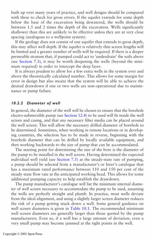
298 Deep well systems
built up over many years of practice, and well designs should be comparedwith these to check for gross errors. If the aquifer extends for some depthbelow the base of the excavation being dewatered, the wells should bebetween 1.5 and 2 times the depth of the excavation. Wells significantlyshallower than this are unlikely to be effective unless they are at very closespacing (analogous to a wellpoint system).
If the geology does not consist of one aquifer that extends to great depth,this may affect well depth. If the aquifer is relatively thin screen lengths willbe limited and a greater number of wells will be required. If there is a deeperpermeable stratum that, if pumped could act to ‘underdrain’ the soils above(see Section 7.3), it may be worth deepening the wells (beyond the mini-mum required) in order to intercept the deep layer.
It is always prudent to allow for a few extra wells in the system over andabove the theoretically calculated number. This allows for some margin forerror in design but also means that the system will be able to achieve thedesired drawdown if one or two wells are non-operational due to mainte-nance or pump failure.
10.2.2 Diameter of well
In general, the diameter of the well will be chosen to ensure that the boreholeelectro-submersible pump (see Section 12.4) to be used will fit inside the wellscreen and casing, and that any necessary filter media can be placed aroundthe well screen. This will allow the necessary drilled diameter of borehole tobe determined. Sometimes, when working in remote locations or in develop-ing countries, the selection has to be made in reverse, beginning with theborehole diameter that can be drilled by locally available equipment, andthen working backwards to the size of pump that can be accommodated.
The starting point for determining the size of the bore is the diameter ofthe pump to be installed in the well screen. Having determined the expectedindividual well yield (see Section 7.5) at the steady-state rate of pumping, a pump should be selected from a manufacturer’s or hirer’s catalogue thathas a maximum rated performance between 110 and 150 per cent of thesteady-state flow rate at the anticipated working head. This allows for someadditional pumping capacity to help establish the drawdown.
The pump manufacturer’s catalogue will list the minimum internal diame-ter of well screen necessary to accommodate the pump to be used, assumingthe wells are perfectly straight and plumb. In practice, most wells deviatefrom the ideal alignment, and using a slightly larger screen diameter reducesthe risk of a pump getting stuck down a well. Some general guidance onwell screen diameters is given in Table 10.1. The recommended minimumwell screen diameters are generally larger than those quoted by the pumpmanufacturers. Even so, if a well has a large amount of deviation, even avery small pump may become jammed at the tight points in the well.
Copyright © 2001 Spon Press
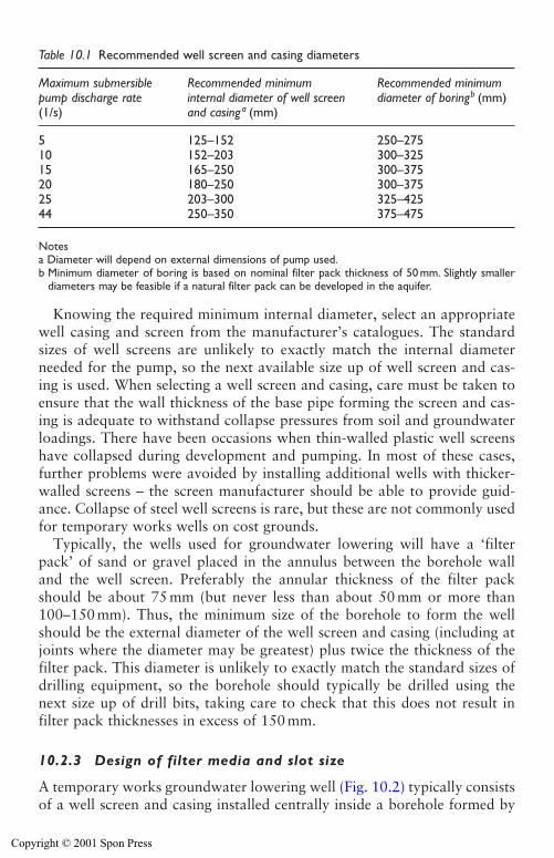
Deep well systems 299
Knowing the required minimum internal diameter, select an appropriatewell casing and screen from the manufacturer’s catalogues. The standardsizes of well screens are unlikely to exactly match the internal diameterneeded for the pump, so the next available size up of well screen and cas-ing is used. When selecting a well screen and casing, care must be taken toensure that the wall thickness of the base pipe forming the screen and cas-ing is adequate to withstand collapse pressures from soil and groundwaterloadings. There have been occasions when thin-walled plastic well screenshave collapsed during development and pumping. In most of these cases,further problems were avoided by installing additional wells with thicker-walled screens – the screen manufacturer should be able to provide guid-ance. Collapse of steel well screens is rare, but these are not commonly usedfor temporary works wells on cost grounds.
Typically, the wells used for groundwater lowering will have a ‘filterpack’ of sand or gravel placed in the annulus between the borehole wall and the well screen. Preferably the annular thickness of the filter packshould be about 75 mm (but never less than about 50 mm or more than100–150 mm). Thus, the minimum size of the borehole to form the wellshould be the external diameter of the well screen and casing (including atjoints where the diameter may be greatest) plus twice the thickness of thefilter pack. This diameter is unlikely to exactly match the standard sizes ofdrilling equipment, so the borehole should typically be drilled using thenext size up of drill bits, taking care to check that this does not result in filter pack thicknesses in excess of 150 mm.
10.2.3 Design of filter media and slot size
A temporary works groundwater lowering well (Fig. 10.2) typically consistsof a well screen and casing installed centrally inside a borehole formed by
Table 10.1 Recommended well screen and casing diameters
Maximum submersible Recommended minimum Recommended minimumpump discharge rate internal diameter of well screen diameter of boringb (mm)(1/s) and casinga (mm)
5 125–152 250–27510 152–203 300–32515 165–250 300–37520 180–250 300–37525 203–300 325–42544 250–350 375–475
Notesa Diameter will depend on external dimensions of pump used.b Minimum diameter of boring is based on nominal filter pack thickness of 50 mm. Slightly smaller
diameters may be feasible if a natural filter pack can be developed in the aquifer.
Copyright © 2001 Spon Press
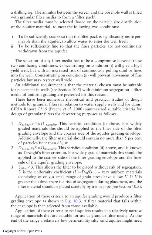
300 Deep well systems
a drilling rig. The annulus between the screen and the borehole wall is filledwith granular filter media to form a ‘filter pack’.
The filter media must be selected (based on the particle size distributionof the aquifer material) to meet the following two conditions:
i To be sufficiently coarse so that the filter pack is significantly more per-meable than the aquifer, to allow water to enter the well freely.
ii To be sufficiently fine so that the finer particles are not continuallywithdrawn from the aquifer.
The selection of any filter media has to be a compromise between thesetwo conflicting conditions. Concentrating on condition (i) will give a highyield well, but with an increased risk of continuously pulling sand or finesinto the well. Concentrating on condition (ii) will prevent movement of fineparticles but may restrict well yield.
An additional requirement is that the material chosen must be suitablefor placement in wells (see Section 10.5) with minimum segregation – filtermedia of uniform grading are preferred for this reason.
There have been numerous theoretical and practical studies of designmethods for granular filters in relation to water supply wells and for dams.CIRIA Report C515 (Preene et al. 2000) summarized suitable criteria fordesign of granular filters for dewatering purposes as follows:
1 D15filter�4�D15aquifer. This satisfies condition (i) above. For widelygraded materials this should be applied to the finer side of the filtergrading envelope and the coarser side of the aquifer grading envelope.Additionally, the filter material should contain no more than 5 per centof particles finer than 63 �m.
2 D15filter�5�D85aquifer. This satisfies condition (ii) above, and is knownas Terzaghi’s filter criterion. For widely graded materials this should beapplied to the coarser side of the filter grading envelope and the finerside of the aquifer grading envelope.
3 Ufilter�3. This allows the filter to be placed without risk of segregation.U is the uniformity coefficient (U�D60/D10) – very uniform materials(consisting of only a small range of grain sizes) have a low U. If U isgreater than three there is a risk of segregation during placement, and thefilter material should be placed carefully by tremie pipe (see Section 10.5).
Application of these criteria to an aquifer grading would produce a filtergrading envelope as shown in Fig. 10.3. A filter material that falls withinthe envelope is then selected from those available.
Application of these criteria to real aquifers results in a relatively narrowrange of materials that are suitable for use as granular filter media. At oneend of the range a relatively low permeability silty sand aquifer might need
Copyright © 2001 Spon Press
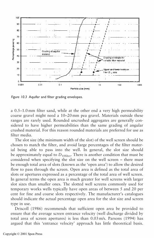
Deep well systems 301
a 0.5–1.0 mm filter sand, while at the other end a very high permeabilitycoarse gravel might need a 10–20 mm pea gravel. Materials outside theseranges are rarely used. Rounded uncrushed aggregates are generally con-sidered to have higher permeabilities than the same grading of angularcrushed material. For this reason rounded materials are preferred for use asfilter media.
The slot size (the minimum width of the slot) of the well screen should bechosen to match the filter, and avoid large percentages of the filter mater-ial being able to pass into the well. In general, the slot size should be approximately equal to D10filter. There is another condition that must beconsidered when specifying the slot size on the well screen – there must be enough total area of slots (known as the ‘open area’) to allow the desiredflow to pass through the screen. Open area is defined as the total area ofslots or apertures expressed as a percentage of the total area of well screen.In general terms the open area is much greater for well screens with largerslot sizes than smaller ones. The slotted well screens commonly used fortemporary works wells typically have open areas of between 5 and 20 percent for fine and coarse slots respectively. The manufacturer’s cataloguesshould indicate the actual percentage open area for the slot size and screentype in use.
Driscoll (1986) recommends that sufficient open area be provided toensure that the average screen entrance velocity (well discharge divided bytotal area of screen apertures) is less than 0.03 m/s. Parsons (1994) hasargued that this ‘entrance velocity’ approach has little theoretical basis.
Figure 10.3 Aquifer and filter grading envelopes.
Copyright © 2001 Spon Press
Nevertheless, it is an established rule of thumb which produces wells whichperform at least adequately in many situations.
When the filter is placed it may be relatively loose, and is likely to com-pact a little during development. Accordingly, the filter pack when placedmust extend to some height (normally at least 0.5–1 m) above the top of theslotted well screen to ensure that aquifer material does not come into directcontact with the well screen if the filter pack compacts. Sometimes perma-nent tremie tubes are left in place to allow the filter pack to be topped upby the addition of more material.
There are some types of granular soils when it is not necessary to intro-duce artificial filter media, but where it is possible to directly develop theaquifer, remove the finer particles and form a natural filter pack in theaquifer immediately outside the well screen. This method can be employedin coarse well graded soils such as sandy gravels. It can give cost savings byallowing a well borehole to be drilled at a smaller diameter for a given wellscreen size – the space for a filter pack is not needed, and the aquifer mate-rial is allowed to collapse directly onto the well screen. According to Clark(1988) soils may be appropriate for natural filters if D40aquifer�0.5 mm andUaquifer�3. Natural filters are not appropriate for uniform fine-grainedsoils, where there are not sufficient coarse particles in the soil to form aneffective filter structure. Slot size must be chosen carefully when proposingto use natural filters. CIRIA Report C515 (Preene et al. 2000) suggests aslot size of D40aquifer to D50aquifer is acceptable in most cases, but if the max-imum yield is required from very widely graded soils a slot size in the rangeD60aquifer to D70aquifer might be considered.
If wells are installed in weak rock (for example weathered chalk) whereflow is predominantly from fissures, a filter pack is not needed to preventmovement of fine particles. However, it is good practice to fill the annulusbetween the well screen and borehole wall with a coarse permeable filtergravel which acts as a formation stabilizer. The formation stabilizer pre-vents weaker blocks of aquifer rock from collapsing against and distortingthe well screen. Formation stabilizers should be highly permeable to allowfree passage of water; 10–20 mm pea gravel is often used.
In addition to conventional granular filter media placed during wellinstallation, pre-formed filters (fitted at manufacture) are also available.The two main types are:
1 Resin-bonded screens. Specific granular filter media are bonded directlyto the slotted well screen. The grading of the filter media appropriateto the aquifer is chosen in the normal way, and then applied to thescreen in the factory.
2 Geotextile screens. Geotextile mesh filter is wrapped around slottedbase pipe. The most hydraulically efficient designs provide a high openarea by placing a very coarse spacer mesh under the filter mesh itself to
302 Deep well systems
Copyright © 2001 Spon Press
allow water to flow around the outside of the base pipe beneath the filter mesh. Guidance for selection of the size of openings in the filtermesh can be obtained from the manufacturers. Once selected, the meshis normally applied to the screen in the factory. Granular filters or for-mation stabilizers may be used in conjunction with geotextile screens.
As discussed earlier, well filters are designed against two conflicting cri-teria – the need to be highly permeable and the need to prevent continuousmovement of fines. Add to this the problems that aquifers are variable andheterogeneous (a filter that works on one well may not work on one at theother end of the site) and that suitable filter materials may not be availablelocally, and it is obvious that experienced judgement is needed for filterdesign. The problem of aquifer variability can be addressed by carrying outa thorough site investigation. The problem of limited availability of suitablefilter material (especially on remote sites) may require less than ideal filtersto be used. In such cases, a series of trial wells using local materials may beappropriate. If the locally available material does not give acceptable wellperformance the use of pre-formed (e.g. geotextile or resin-bonded) filtersmight be considered, since shipping costs for these materials may be lessthan for bulky filter gravels.
10.3 Constructing deep wells
The methods used to construct wells for temporary works groundwaterlowering purposes have much in common with those used to form watersupply wells, but there are some differences in techniques and equipment.A general appreciation of well drilling methods can be gained from some ofthe publications in the water supply field (Stow 1962 and 1963; Cruse1986; Rowles 1995).
There are four main stages in forming a groundwater lowering well:
1 Drilling of borehole.2 Installation of materials (screen, casing, gravel, etc.).3 Development of well.4 Installation and operation of pump.
These are described in the following sections.
10.4 Drilling of well boreholes
Many methods are available for the formation of well boreholes. The tech-nique selected will depend upon the type of equipment available in the ter-ritory and the expertise of the well boring organization selected and the soiland groundwater conditions anticipated.
Deep well systems 303
Copyright © 2001 Spon Press
304 Deep well systems
There are three main methods used commonly to form well boreholes:
1 Cable tool percussion drilling and variations on this technique, gener-ally requiring the use of temporary boring casing to support the sidesof the borehole.
2 Wash boring or water jet drilling, sometimes with the addition of com-pressed air. This method is very similar to the installation of wellpointsby jetting using a holepuncher.
3 Rotary drilling, either by direct or reverse circulation. The drilling fluidmay be water or air with specialist additives which help support thesides of the borehole – this is typically employed when drilling driftdeposits.
For temporary works wells cable tool percussion drilling is limited to welldepths of about 20–35 m, but has been used down to 50 m depth on occa-sion – for water supply wells the method has been used to considerablygreater depths. Wash boring and holepuncher equipment have been used toinstall wells to about 35 m depths. Rotary drilling rigs can cope with sig-nificantly greater depths if necessary.
The wash boring and rotary drilling techniques, when used appropriately,generally provide more productive wells and require less development. Theeffectiveness (i.e. potential yield) of a rotary drilled hole depends greatly onthe properties of the drilling fluid used and the adequacy of the removal ofthe drilling residues on completion of the hole – this often gives rise to muchdebate between groundwater lowering specialists, drilling contractors anddrilling additive suppliers about the relative merits of the various marketeddrilling slurries. The merits of various types of drilling fluids and additivesare discussed by Driscoll (1986). Adequate development of the well on com-pletion is vital to ensure its best performance (see Section 10.6).
Throughout the well drilling operation, the arisings from the drill holeshould be observed and logged to determine if soil conditions are asexpected. If not, it may be prudent to determine whether the design of sub-sequent deep wells needs to be varied. For instance the arisings might revealan unexpected layer of impermeable soil within the wetted depth. However,do not ignore the fact that information gleaned from well boreholes israrely of as high quality as that obtained from dedicated site investigationholes. Any judgements made on the basis of observing the well boreholearisings can only be somewhat speculative.
Whatever drilling technique is used, it is essential that wells be relativelystraight and plumb otherwise there will be severe operational problemswith the submersible pumps. Water supply wells are typically required to bedrilled to a verticality tolerance of 1 in 300. This tolerance is probablyunnecessary for temporary works wells. Verticality requirements are oftennot explicitly specified for temporary works wells, but if they are then 1 in100 appears to be a more reasonable requirement.
Copyright © 2001 Spon Press
Deep well systems 305
10.4.1 Cable tool percussion drilling
The original cable percussion drilling rig made use of a reciprocating mech-anism known as a ‘spudding arm’ or ‘walking beam’ to repeatedly lift andlower a bit (or chisel) suspended on the end of a wire rope inside telescop-ing sizes of temporary boring casings. The action of the bit breaks up thesoil or rock at the base of the borehole to form a slurry with the ground-water entering the well. As the slurry builds up it deadens the percussiveaction of the bit; the bore has to be bailed periodically to remove the slurry.The largest rigs were powerful and progress could be made, albeit slowly,through even boulder and rock formations. Inevitably, the arisings are notmuch better than a mashed up slurry of mainly indistinguishable consis-tency. This type of rig is still in use by some drillers, and is especially preva-lent in developing countries.
Some time later there came a variation on this technique, the early tripodbored piling rig which also made use of temporary boring casings of tele-scoping sizes. The cable passes over a pulley at the top of the tripod and israised and lowered by a winch linked by a clutch to a small donkey engine.To make progress through granular formations a sand pump or shell is usedand to penetrate a clay stratum, a clay cutter is used; chisels are used if cob-bles or boulders are encountered. Tripod rigs became more mobile andtowable. Self erecting tripod rigs are commonly used for site investigationin the United Kingdom, where there are colloquially known as ‘shell andauger’ rigs, although they are more correctly known as light cable percus-sion rigs.
While light cable percussion rigs are most commonly used for 150–200 mm diameter site investigation boreholes, the larger models (of 2 and 3tonne winch capacity) are widely used to drill temporary works wells.Figure 10.4 shows a 2 tonne rig being used to drill a 300 mm diameter wellbore to a depth of approximately 25 m.
Whatever type of cable tool percussion rig is used, drilling will generallybe slower than by the rotary method. This is mainly due to the timerequired to install and remove the temporary casings. The cable tool per-cussion method is most suitable for drift deposits such as sands, gravels andclays. Progress can be very slow indeed if used to drill rock formations,although the method has been successfully used in some soft rocks such asweathered Chalk or highly weathered Triassic Sandstone.
When using temporary boring casing to penetrate a multi-layered soilstructure, there is risk of smearing of the side of the hole as the casing isbeing installed and withdrawn. This could mask or block the permeablestrata, especially if the individual soil layers are thin. Also, when using per-cussion boring methods there is some risk that the boring cuttings andslurry will clog the water-bearing formation, so subsequent well develop-ment should be carefully monitored and supervised (See section 10.6).
Copyright © 2001 Spon Press
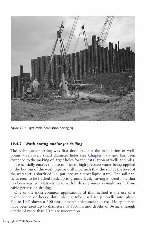
306 Deep well systems
10.4.2 Wash boring and/or jet drilling
The technique of jetting was first developed for the installation of well-points – relatively small diameter holes (see Chapter 9) – and has beenextended to the making of larger holes for the installation of wells and piles.
It essentially entails the use of a jet of high pressure water being appliedat the bottom of the wash pipe or drill pipe such that the soil at the level ofthe water jet is slurrified (i.e. put into an almost liquid state). The soil par-ticles tend to be flushed back up to ground level, leaving a bored hole thathas been washed relatively clean with little side smear as might result fromcable percussion drilling.
One of the most common applications of this method is the use of aholepuncher or heavy duty placing tube used to jet wells into place.Figure 10.5 shows a 300 mm diameter holepuncher in use. Holepunchershave been used up to diameters of 600 mm and depths of 36 m, althoughdepths of more than 20 m are uncommon.
Figure 10.4 Light cable percussion boring rig.
Copyright © 2001 Spon Press
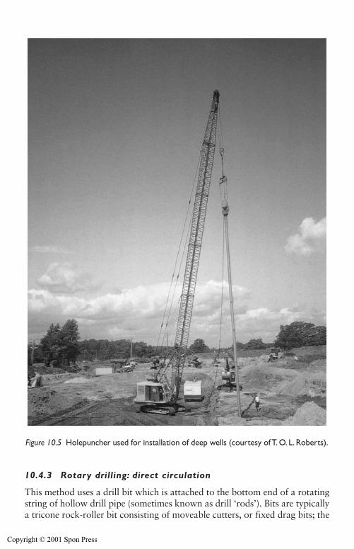
Deep well systems 307
10.4.3 Rotary drilling: direct circulation
This method uses a drill bit which is attached to the bottom end of a rotatingstring of hollow drill pipe (sometimes known as drill ‘rods’). Bits are typicallya tricone rock-roller bit consisting of moveable cutters, or fixed drag bits; the
Figure 10.5 Holepuncher used for installation of deep wells (courtesy of T. O. L. Roberts).
Copyright © 2001 Spon Press
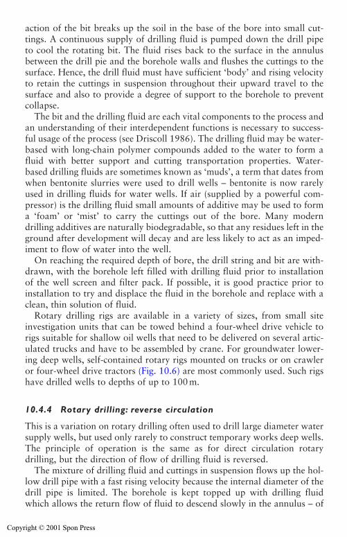
action of the bit breaks up the soil in the base of the bore into small cut-tings. A continuous supply of drilling fluid is pumped down the drill pipeto cool the rotating bit. The fluid rises back to the surface in the annulusbetween the drill pie and the borehole walls and flushes the cuttings to thesurface. Hence, the drill fluid must have sufficient ‘body’ and rising velocityto retain the cuttings in suspension throughout their upward travel to thesurface and also to provide a degree of support to the borehole to preventcollapse.
The bit and the drilling fluid are each vital components to the process andan understanding of their interdependent functions is necessary to success-ful usage of the process (see Driscoll 1986). The drilling fluid may be water-based with long-chain polymer compounds added to the water to form afluid with better support and cutting transportation properties. Water-based drilling fluids are sometimes known as ‘muds’, a term that dates fromwhen bentonite slurries were used to drill wells – bentonite is now rarelyused in drilling fluids for water wells. If air (supplied by a powerful com-pressor) is the drilling fluid small amounts of additive may be used to forma ‘foam’ or ‘mist’ to carry the cuttings out of the bore. Many moderndrilling additives are naturally biodegradable, so that any residues left in theground after development will decay and are less likely to act as an imped-iment to flow of water into the well.
On reaching the required depth of bore, the drill string and bit are with-drawn, with the borehole left filled with drilling fluid prior to installationof the well screen and filter pack. If possible, it is good practice prior toinstallation to try and displace the fluid in the borehole and replace with aclean, thin solution of fluid.
Rotary drilling rigs are available in a variety of sizes, from small siteinvestigation units that can be towed behind a four-wheel drive vehicle torigs suitable for shallow oil wells that need to be delivered on several artic-ulated trucks and have to be assembled by crane. For groundwater lower-ing deep wells, self-contained rotary rigs mounted on trucks or on crawleror four-wheel drive tractors (Fig. 10.6) are most commonly used. Such rigshave drilled wells to depths of up to 100 m.
10.4.4 Rotary drilling: reverse circulation
This is a variation on rotary drilling often used to drill large diameter watersupply wells, but used only rarely to construct temporary works deep wells.The principle of operation is the same as for direct circulation rotarydrilling, but the direction of flow of drilling fluid is reversed.
The mixture of drilling fluid and cuttings in suspension flows up the hol-low drill pipe with a fast rising velocity because the internal diameter of thedrill pipe is limited. The borehole is kept topped up with drilling fluidwhich allows the return flow of fluid to descend slowly in the annulus – of
308 Deep well systems
Copyright © 2001 Spon Press
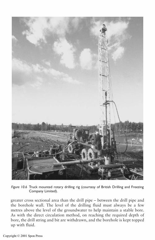
Deep well systems 309
greater cross sectional area than the drill pipe – between the drill pipe andthe borehole wall. The level of the drilling fluid must always be a fewmetres above the level of the groundwater to help maintain a stable bore.As with the direct circulation method, on reaching the required depth ofbore, the drill string and bit are withdrawn, and the borehole is kept toppedup with fluid.
Figure 10.6 Truck mounted rotary drilling rig (courtesy of British Drilling and FreezingCompany Limited).
Copyright © 2001 Spon Press
310 Deep well systems
10.5 Installation of well materials
Once the bore is complete the well casing and well screen are placed in thehole. The casing and screen consist of threaded pipe, typically of between 150and 300mm diameter, supplied in lengths of between 2.5 and 6m. The diam-eter of casing and screen required is determined as described in Section 10.2.The casing sections are plain (unperforated) and the screen sections are perfo-rated (generally by slotting) and for temporary works wells are typically madefrom uPVC or thermoplastic – steel screen and casing are used only rarely.
Prior to installation, the drilling crew should be instructed on the num-ber and sequence of casing and screen lengths to be installed to ensure thatthe screens are located within the water-bearing horizons. The screen andcasing is installed in sections by lowering into the borehole using the drillingrig’s winch. A bottom cap is fitted to the first length of screen or casingwhich is lowered into the bore, further sections are then added until thestring of screen and casing is installed to the required depth. It is often agood idea to place a few hundred millimetres of filter gravel in the base ofthe bore before commencing installation of screen and casing. This preventsthe bottom length sinking into any soft sediment or drilling residue remain-ing in the base of the hole.
When the screen and casing are in position the filter pack (see Section 10.2)must be placed in the annulus between the well screen and the borehole wall.The filter pack is formed from filter media generally consisting of uniformlysized gravels, although coarse sands are sometimes used. The filter materialmay be supplied in bags or in bulk loads. Ideally, to ensure correct place-ment, the gravel should be installed using one or more tremie pipes. Thetremie pipe would typically be of uPVC or steel sectional pipe of 50 mminternal bore (although sizes down to 32 mm bore have been used to placeuniform sands). The filter media are poured slowly into a hopper at the topof the tremie, perhaps washed down by a gentle flow of water. Patience isvital in this operation – adding the filter media too quickly will cause thetremie pipe to block or ‘bridge’. If this occurs the tube will have to beremoved and flushed clear, causing delays and inconvenience. The tremietube is raised slowly, keeping pace with the rising level of filter media.
It is sometimes acceptable to place the filter media without a tremie pipe,by pouring into the annulus from the surface. This is only acceptable pro-vided the filter media is very uniform and will not segregate as it falls downthe bore and if the wall of the borehole is very stable (e.g. if supported bytemporary casing). Again, care must be taken to ensure the filter media areadded slowly. If too much is added at once a blockage or ‘bridge’ mayoccur; these can be difficult to clear and may result in the screen and casinghaving to be removed and the complete installation recommenced.
If temporary drill casing is used to support the borehole, this must beremoved in sections as the filter media is added. The level of the filter mediashould not be allowed to rise significantly above the base of the temporary
Copyright © 2001 Spon Press
Deep well systems 311
casing, otherwise a ‘sand lock’ may occur between the temporary drill cas-ing and the well screen. This can cause the well screen to be pulled out whenthe temporary casing is withdrawn. The best practice is to alternately addsome filter media, pull the temporary drill casing out a little, add more fil-ter media, pull the drill casing further, and so on, monitoring the level ofthe filter media continuously. Boreholes drilled by rotary methods withouttemporary casing do not have this constraint, and filter media can be placedin one continuous, steady operation.
The filter pack is sometimes brought up to ground level, but increasingly,it is good practice to place a very low permeability grout seal above the fil-ter pack (see Fig. 10.2). This reduces the risk of aquifer contamination bysurface water (or water from other aquifers) passing down the filter packinto the aquifer (see Section 13.3). The grout may be neat cement orcement-bentonite (see Driscoll 1986 for guidance on grout mixes and place-ment). If the grout were placed directly on top of the filter pack, some groutmay be lost into the filter media, compromising its permeability. To avoidthis, a 1–2 m thick layer of bentonite pellets should be placed on top of thefilter pack, and allowed to swell before placing the grout.
10.6 Well development
Development is a process, carried out between completion of the well andinstallation of the pumps, with the aim of removing any drilling residue ordebris from the well, and maximizing the yield of clean sand-free water. Ifdevelopment is not carried out, not only might the yield be low, but also theborehole electro-submersible pump will be damaged as a result of pumpingsand-laden water.
The most commonly used forms of development are intended to inducetwo-way groundwater flow between the well and the aquifer to remove anyloose particles from the filter pack and aquifer immediately around thewell. This will increase the aquifer permeability locally and will remove anypotentially mobile soil particles that might damage the operational pumps.It is most important that the development generates two-way flow (alter-nately into and out of the well) to help dislodge mobile soil particles thatmay be loosely wedged in soil pores – this is much more effective than con-tinuous pumping. Development can only be effective in wells that haveappropriately designed and installed filter packs. No amount of develop-ment can correct a well with a filter pack that is too coarse or is discontin-uous due to installation problems.
There are a wide range of development techniques (see Driscoll 1986)used on water supply wells, but in practice most temporary works wells aredeveloped by one of three techniques:
(1) Airlift. Air from a compressor is used to lift water from the well up aneductor tube formed from plastic or steel pipe of 75–150 mm diameter
Copyright © 2001 Spon Press
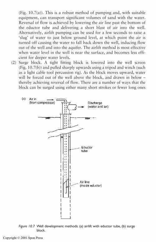
(Fig. 10.7(a)). This is a robust method of pumping and, with suitableequipment, can transport significant volumes of sand with the water.Reversal of flow is achieved by lowering the air line past the bottom ofthe eductor tube and delivering a short blast of air into the well.Alternatively, airlift pumping can be used for a few seconds to raise a‘slug’ of water to just below ground level, at which point the air isturned off causing the water to fall back down the well, inducing flowout of the well and into the aquifer. The airlift method is most effectivewhen water level in the well is near the surface, and becomes less effi-cient for deeper water levels.
(2) Surge block. A tight fitting block is lowered into the well screen (Fig. 10.7(b)) and pulled sharply upwards using a tripod and winch (suchas a light cable tool percussion rig). As the block moves upward, waterwill be forced out of the well above the block, and drawn in below –thereby achieving reversal of flow. There are a number of ways that theblock can be surged using either many short strokes or fewer long ones
312 Deep well systems
Figure 10.7 Well development methods. (a) airlift with eductor tube, (b) surgeblock.
Copyright © 2001 Spon Press
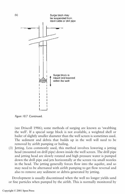
Deep well systems 313
(see Driscoll 1986); some methods of surging are known as ‘swabbingthe well’. If a special surge block is not available, a weighted shell orbailer of slightly smaller diameter than the well screen is sometimes used.The sediment and debris that builds up in the well will need to beremoved by airlift pumping or bailing.
(3) Jetting. Less commonly used, this method involves lowering a jettinghead (mounted on drill pipe) down inside the well screen. The drill pipeand jetting head are slowly rotated and high pressure water is pumpeddown the drill pipe and jets horizontally at the screen via small nozzlesin the head. The jetting generally forces flow into the aquifer, and somay need to be alternated with airlift pumping to get flow reversal andalso to remove any sediment or debris generated by jetting.
Development is usually discontinued when the well no longer yields sandor fine particles when pumped by the airlift. This is normally monitored by
Figure 10.7 Continued.
Copyright © 2001 Spon Press
observing the discharge water, which initially will appear very dirty or dis-coloured but will become clear as development proceeds. However, a noteof caution should be sounded. Sometimes, the discharge water may appearclear but still contain small but significant amounts of fine sand – enough tocause problems for the pump, and to create voids around the well. The bestway to check for this is to take a sample of water in a clean white plastic tub(of the sort used to hold soil samples). Any sand will be clearly visible in thebottom of the tub. A specialist sediment sampling container called an‘Imhoff cone’ can also be used to check for sediment in the water, but thisdevice is intended for much higher sediment loads, and in many ways inspec-tion of a sample in a white tub is a more sensitive method.
The question often asked is – how long should it take to develop a well?There is no simple answer to this, but experience suggests that many wellsin granular aquifers will take between 6 and 12 h to be effectively devel-oped. Certainly, if a well still yields copious amounts of sand after morethan 2 to 3 days (say 20 – 30 h development) the well is unlikely to improveand a replacement well (possibly with a different filter media) should beconsidered.
For wells drilled in carbonate rocks, such as chalk, wells may be devel-oped by acidisation. This is a technique commonly used in water supply wells(see Banks et al. 1993) where acid is introduced into the well to dissolve anydrilling slurry and to improve the well-aquifer connection by dissolvingaquifer material in fissures locally around the well. In practice, severaltonnes of concentrated acid are introduced into the well. The reactionbetween the acid and the carbonate rock generates large volumes of carbondioxide gas, which must be carefully controlled by fitting a gas tight headplate (equipped with specialist valves and pressure relief devices) to the topof the well. Acidisation is not a straightforward procedure and should beplanned and undertaken by experienced personnel, with particular empha-sis on ensuring that necessary health and safety measures are in place.Acidisation is not commonly used to develop temporary works wells, butthe method has been used on some deep groundwater lowering wells intothe chalk beneath London, including for the Jubilee Line Extension tunnelproject in the 1990s.
If wells are operated for long periods of time (several months or years)and are affected by encrustation or clogging well performance may deterio-rate. In such cases, well performance may be improved by periodic redevel-opment using one of the methods described above (including acidisation,which has been used on heavily encrusted wells).
10.7 Installation and operation of deep well pumps
Following development, the pumps can be installed. The following sectionsdeal exclusively with the procedures used with borehole electro-submersible
314 Deep well systems
Copyright © 2001 Spon Press
pumps (see Section 12.4), by far the most commonly used type in deep wellsystems.
10.7.1 Installation of borehole electro-submersible pumps
The pump is connected to the riser pipe, which is a steel or plastic pipe whichcarries the discharge from the pump up to ground level (see Fig. 10.2). Theriser pipe is typically between 50 and 150 mm diameter for the smallest andlargest pumps used for temporary works. The riser is supplied in sectionswith threaded or flanged joints – extra sections are added until the pumphas been lowered to the design level (see Fig. 12.6). The electrical powercable connected to the pump is also paid out as the pump is lowered intoposition. The cable should be kept reasonably taut and be taped or tied tothe riser pipe every few metres. If this is not done then any slack in the cablemay form ‘loops’ down the well, interfering with the subsequent installa-tion of dip tubes.
If steel riser pipe is used, it may be strong enough to support the weightof the pump, riser pipe and water column. Otherwise (and in any case ifplastic riser pipe is used) the weight must be supported by straining cablesor ropes from the pump, tied off at the wellhead. It is good practice toinstall a dip tube of 19–50 mm diameter to allow access for a dipmeter tobe used to monitor the water level in the well.
For groundwater lowering applications the pump is normally installednear the base of the well so that potential drawdown is maximized. Thebase of the pump should be at least 1 m above the base of the well to avoidthe pump becoming stuck in any sediment that may build up at the bottomof the well. When the pump is installed, a headworks arrangement – typi-cally including a control valve and pressure gauge – is attached to the topof the riser pipe and connected to the discharge pipework.
The best sort of valve for use at the wellhead is the gate valve. It is prefer-able because its slide plate is at right angles to the water flow and its posi-tion can be finely adjusted by its screw mechanism to regulate the flow. Itssensitivity of opening adjustment is good and when fully open it offers lessresistance to flow than any other type of valve. The other type of valvesometimes used for well output control is the butterfly valve. It is less costlythan the gate valve (size for size) but the sensitivity of opening control is lessthan that of the gate valve.
Most borehole electro-submersible pumps are powered by a three-phasesupply; if the phases are connected in the wrong order the pumps can run(or rotate) backwards (i.e. anticlockwise rather than clockwise). Pumpsrunning backwards move very little water, so on installation it is importantto ‘check the direction’ of each pump in turn. One method is to start thepump with the control valve fully closed and observe the pressure gauge.
Deep well systems 315
Copyright © 2001 Spon Press
If the needle indicates a high pressure (consult the pump manufacturer’sdata sheets for the expected value) the motor is running in the right direc-tion. But if the indicated pressure is low the motor may be running back-wards. Turn the pump off, isolate the pump switchgear; have an electricallycompetent person change over two of the phase wire connections andrestart the pump against a closed valve. The pressure gauge should registerfull pressure indicating that the motor is now running in the right direction.
10.7.2 Adjustment of electro-submersible pumps
For groundwater lowering projects the pumps generally run continuously,with the operating level in individual wells only a little above the level ofeach pump intake. Generally, the flow from each pump is adjusted toachieve this condition by manipulation of the control valve on each well-head. Partial closure of the valve will impose just sufficient back pressure(extra artificial head) to constrain the well output and maintain the opti-mum operating level.
If the well operating level is too close to the level of the pump intake, thepump will tend to ‘go on air’ from time to time – this is when the water levelin the well reaches the pump intake, and air is drawn into the pump. In thiscondition the pump will race when ‘on air’ and the riser pipe will tend tovibrate. This must not be allowed to continue in the long-term because undersuch conditions the pump motor will be damaged severely. The symptoms of‘going on air’ can be detected by observing the needle of the pressure gaugeat the wellhead sited upstream of the control valve (see Fig. 10.2), and byobserving vibration of the riser pipe. When the discharge flow contains someair (rather than water only) the gauge needle will repeatedly drop to zero. Ifthese erratic variations in pressure gauge readings are observed, close the con-trol valve gradually until the pressure gauge needle remains steady – a veryslight fluctuation in the needle position is acceptable. Alternatively, if thegauge needle remains steady, the well operating level may be above the designlevel. If this condition is suspected, gently open the control valve until the nee-dle starts to flicker and then close the control valve by a very small amount.
10.7.3 Use of deep wells on tidal sites
On sites where groundwater levels vary tidally, the pumped level in eachwell may vary too, although generally these variations will be small (lessthan a few metres). It is suggested that the control valve be adjusted for thelow tide condition only and not altered unless the amount of loweringrequired at the high tide condition is critical. If this is the case, frequentadjustment of all operating levels will be required. This is tedious and liableto be overlooked on occasions, especially during night shifts. If the maxi-mum lowering is required at high tides as well as at low tides, one possible
316 Deep well systems
Copyright © 2001 Spon Press
Deep well systems 317
solution is the installation of additional wells to be operated only for a fewhours either side of high tide.
10.7.4 Use of oversized pumps
Occasionally it may not be possible to equip a well with the appropriateoutput pump and so a pump rated at an output greater than necessary isinstalled in the well. Often, in such circumstances, the lack of sensitivity onthe control valve will make it difficult (sometimes even impossible) to adjustthe well output so that continuous pumping is practicable. There are twoalternative expedients that can be employed in such circumstances:
(a) At the wellhead fit an additional small bore pipe and valve to bypassthe main control valve. Operation involves closing the small by-passvalve completely and adjusting the main valve to achieve best possiblecoarse adjustment; then gradually opening the by-pass valve to makethe best fine adjustment. This mode of operation makes feasible con-tinuous pumping.
(b) Modify the pump controls for intermittent running with automaticstop/start. This requires sensing units in the pump electrical controlslinked to upper and lower level sensor electrodes in the well.
10.7.5 Level control switches
If the pumps are to be operated intermittently, sensor electrodes in the wellare used to trigger the pump to start when the water level is high, and stopwhen the water level is too low. Typically, the lower level electrode is set toswitch the pump motor off just before the water level is drawn down suffi-ciently to cause the pump to ‘go on air’. The upper sensor is set to switchthe pump on when the water level in the well has recovered to a predeter-mined level (which must obviously be below excavation formation level).The average level of lowering achievable by this mode of pumping will beapproximately the mean level between the two sensors. The distancebetween the upper and lower sensor electrodes should be the minimumpracticable to allow the best possible amount of lowering by intermittentpumping. The disadvantage of this is that it will cause more frequent startsof the pump motor, increasing the risk of motor failure.
10.7.6 Problems due to frequent start-up of motor
Most borehole electro-submersible pumps are operated using direct-on-lineelectrical starter controls. With this arrangement the starting current of anelectric submersible pump motor is greater than the running current byaround a factor of up to six. The heat generated on start up is significant.
Copyright © 2001 Spon Press
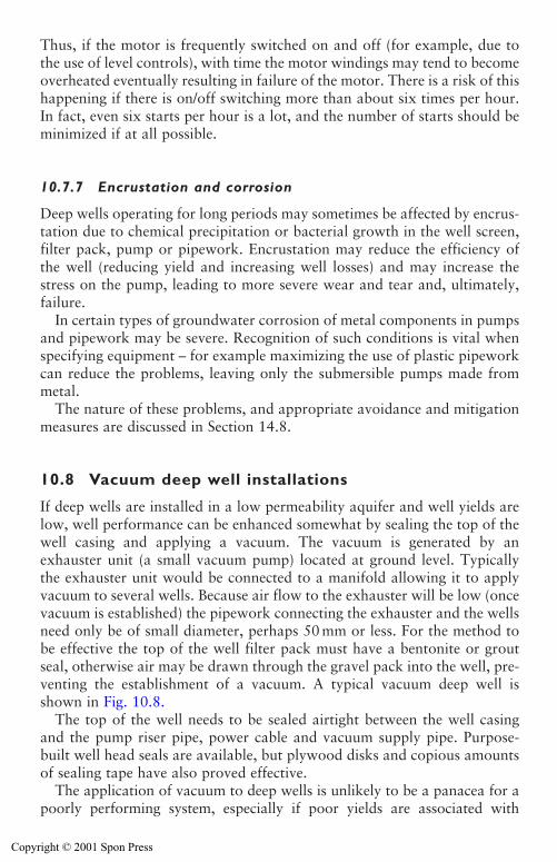
Thus, if the motor is frequently switched on and off (for example, due tothe use of level controls), with time the motor windings may tend to becomeoverheated eventually resulting in failure of the motor. There is a risk of thishappening if there is on/off switching more than about six times per hour.In fact, even six starts per hour is a lot, and the number of starts should beminimized if at all possible.
10.7.7 Encrustation and corrosion
Deep wells operating for long periods may sometimes be affected by encrus-tation due to chemical precipitation or bacterial growth in the well screen,filter pack, pump or pipework. Encrustation may reduce the efficiency ofthe well (reducing yield and increasing well losses) and may increase thestress on the pump, leading to more severe wear and tear and, ultimately,failure.
In certain types of groundwater corrosion of metal components in pumpsand pipework may be severe. Recognition of such conditions is vital whenspecifying equipment – for example maximizing the use of plastic pipeworkcan reduce the problems, leaving only the submersible pumps made frommetal.
The nature of these problems, and appropriate avoidance and mitigationmeasures are discussed in Section 14.8.
10.8 Vacuum deep well installations
If deep wells are installed in a low permeability aquifer and well yields arelow, well performance can be enhanced somewhat by sealing the top of thewell casing and applying a vacuum. The vacuum is generated by anexhauster unit (a small vacuum pump) located at ground level. Typicallythe exhauster unit would be connected to a manifold allowing it to applyvacuum to several wells. Because air flow to the exhauster will be low (oncevacuum is established) the pipework connecting the exhauster and the wellsneed only be of small diameter, perhaps 50 mm or less. For the method tobe effective the top of the well filter pack must have a bentonite or groutseal, otherwise air may be drawn through the gravel pack into the well, pre-venting the establishment of a vacuum. A typical vacuum deep well isshown in Fig. 10.8.
The top of the well needs to be sealed airtight between the well casingand the pump riser pipe, power cable and vacuum supply pipe. Purpose-built well head seals are available, but plywood disks and copious amountsof sealing tape have also proved effective.
The application of vacuum to deep wells is unlikely to be a panacea for apoorly performing system, especially if poor yields are associated with
318 Deep well systems
Copyright © 2001 Spon Press
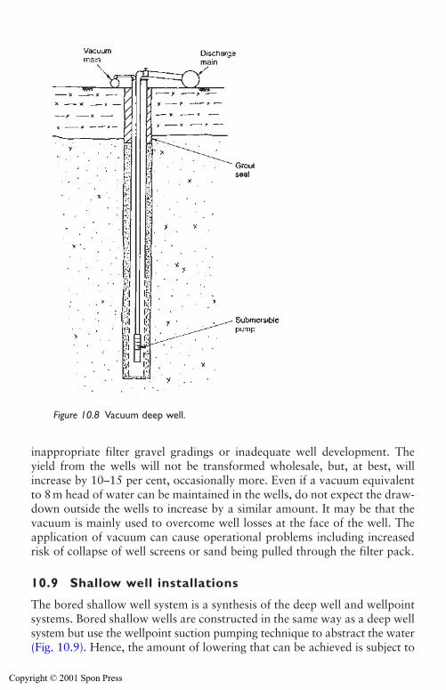
Deep well systems 319
inappropriate filter gravel gradings or inadequate well development. Theyield from the wells will not be transformed wholesale, but, at best, willincrease by 10–15 per cent, occasionally more. Even if a vacuum equivalentto 8 m head of water can be maintained in the wells, do not expect the draw-down outside the wells to increase by a similar amount. It may be that thevacuum is mainly used to overcome well losses at the face of the well. Theapplication of vacuum can cause operational problems including increasedrisk of collapse of well screens or sand being pulled through the filter pack.
10.9 Shallow well installations
The bored shallow well system is a synthesis of the deep well and wellpointsystems. Bored shallow wells are constructed in the same way as a deep wellsystem but use the wellpoint suction pumping technique to abstract the water(Fig. 10.9). Hence, the amount of lowering that can be achieved is subject to
Figure 10.8 Vacuum deep well.
Copyright © 2001 Spon Press
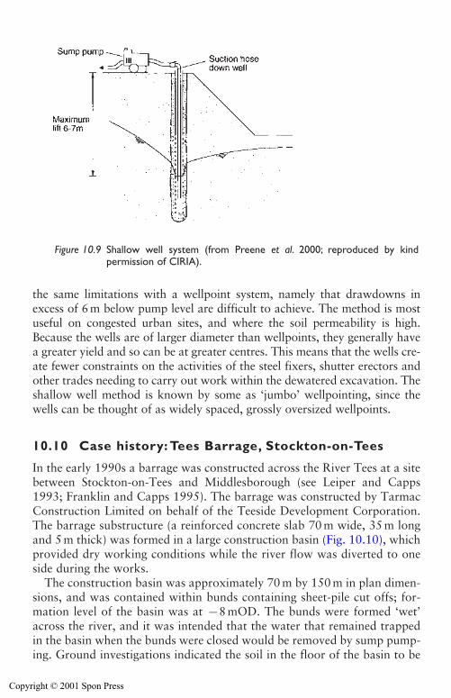
the same limitations with a wellpoint system, namely that drawdowns inexcess of 6 m below pump level are difficult to achieve. The method is mostuseful on congested urban sites, and where the soil permeability is high.Because the wells are of larger diameter than wellpoints, they generally havea greater yield and so can be at greater centres. This means that the wells cre-ate fewer constraints on the activities of the steel fixers, shutter erectors andother trades needing to carry out work within the dewatered excavation. Theshallow well method is known by some as ‘jumbo’ wellpointing, since thewells can be thought of as widely spaced, grossly oversized wellpoints.
10.10 Case history: Tees Barrage, Stockton-on-Tees
In the early 1990s a barrage was constructed across the River Tees at a sitebetween Stockton-on-Tees and Middlesborough (see Leiper and Capps1993; Franklin and Capps 1995). The barrage was constructed by TarmacConstruction Limited on behalf of the Teeside Development Corporation.The barrage substructure (a reinforced concrete slab 70 m wide, 35 m longand 5 m thick) was formed in a large construction basin (Fig. 10.10), whichprovided dry working conditions while the river flow was diverted to oneside during the works.
The construction basin was approximately 70 m by 150 m in plan dimen-sions, and was contained within bunds containing sheet-pile cut offs; for-mation level of the basin was at �8 mOD. The bunds were formed ‘wet’across the river, and it was intended that the water that remained trappedin the basin when the bunds were closed would be removed by sump pump-ing. Ground investigations indicated the soil in the floor of the basin to be
320 Deep well systems
Figure 10.9 Shallow well system (from Preene et al. 2000; reproduced by kind permission of CIRIA).
Copyright © 2001 Spon Press
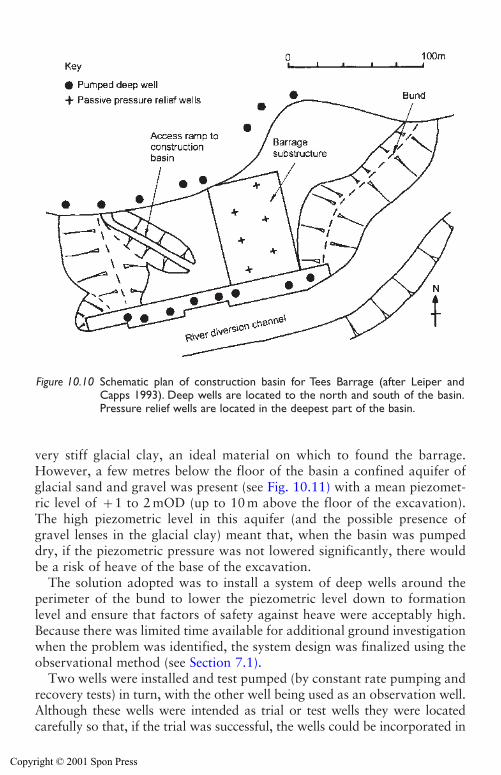
very stiff glacial clay, an ideal material on which to found the barrage.However, a few metres below the floor of the basin a confined aquifer ofglacial sand and gravel was present (see Fig. 10.11) with a mean piezomet-ric level of �1 to 2 mOD (up to 10 m above the floor of the excavation).The high piezometric level in this aquifer (and the possible presence ofgravel lenses in the glacial clay) meant that, when the basin was pumpeddry, if the piezometric pressure was not lowered significantly, there wouldbe a risk of heave of the base of the excavation.
The solution adopted was to install a system of deep wells around theperimeter of the bund to lower the piezometric level down to formationlevel and ensure that factors of safety against heave were acceptably high.Because there was limited time available for additional ground investigationwhen the problem was identified, the system design was finalized using theobservational method (see Section 7.1).
Two wells were installed and test pumped (by constant rate pumping andrecovery tests) in turn, with the other well being used as an observation well.Although these wells were intended as trial or test wells they were locatedcarefully so that, if the trial was successful, the wells could be incorporated in
Deep well systems 321
Figure 10.10 Schematic plan of construction basin for Tees Barrage (after Leiper andCapps 1993). Deep wells are located to the north and south of the basin.Pressure relief wells are located in the deepest part of the basin.
Copyright © 2001 Spon Press
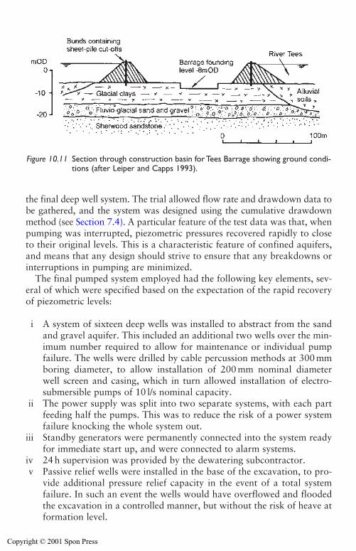
322 Deep well systems
the final deep well system. The trial allowed flow rate and drawdown data tobe gathered, and the system was designed using the cumulative drawdownmethod (see Section 7.4). A particular feature of the test data was that, whenpumping was interrupted, piezometric pressures recovered rapidly to closeto their original levels. This is a characteristic feature of confined aquifers,and means that any design should strive to ensure that any breakdowns orinterruptions in pumping are minimized.
The final pumped system employed had the following key elements, sev-eral of which were specified based on the expectation of the rapid recoveryof piezometric levels:
i A system of sixteen deep wells was installed to abstract from the sandand gravel aquifer. This included an additional two wells over the min-imum number required to allow for maintenance or individual pumpfailure. The wells were drilled by cable percussion methods at 300 mmboring diameter, to allow installation of 200 mm nominal diameterwell screen and casing, which in turn allowed installation of electro-submersible pumps of 10 l/s nominal capacity.
ii The power supply was split into two separate systems, with each partfeeding half the pumps. This was to reduce the risk of a power systemfailure knocking the whole system out.
iii Standby generators were permanently connected into the system readyfor immediate start up, and were connected to alarm systems.
iv 24 h supervision was provided by the dewatering subcontractor.v Passive relief wells were installed in the base of the excavation, to pro-
vide additional pressure relief capacity in the event of a total systemfailure. In such an event the wells would have overflowed and floodedthe excavation in a controlled manner, but without the risk of heave atformation level.
Figure 10.11 Section through construction basin for Tees Barrage showing ground condi-tions (after Leiper and Capps 1993).
Copyright © 2001 Spon Press
vi All piezometers, deep wells and pressure relief wells were monitoredregularly to ensure the system was operating satisfactorily. A positivemanagement system was established for the monitoring, with a properinspection record kept by an approved and suitably experienced andqualified individual.
The system produced a total yield of 95 l/s in steady state pumping (com-pared with a nominal installed pumping capacity of sixteen wells at 10 l/seach), and operated for the eleven month life of the basin. On completionthe pumps were removed and the deep wells and relief wells backfilled withgravel, bentonite and concrete.
References
Banks, D., Cosgrove, T., Harker, D., Howsam, P. J. and Thatcher, J. P. (1993).Acidisation: borehole development and rehabilitation. Quarterly Journal ofEngineering Geology, 26, 109–125.
Clark, L. J. (1988). The Field Guide to Water Wells and Boreholes. Open UniversityPress, Milton Keynes.
Cruse, P. K. (1986). Drilling and construction methods. Groundwater, Occurrence,Development and Protection (Brandon, T. W., ed.). Institution of WaterEngineers and Scientists, Water Practice Manual No. 5, London, pp 437–484.
Driscoll, F. G. (1986). Groundwater and Wells. Johnson Division. Saint Paul,Minnesota.
Franklin, J. B. and Capps, C. T. F. (1995). Tees Barrage – construction. Proceedingsof the Institution of Civil Engineers, Municipal Engineering, 109, 196–211.
Leiper, Q. J. and Capps, C. T. F. (1993). Temporary works bund design and con-struction for the Tees Barrage. Engineered Fills (Clarke, B. G., Jones, C. J. F. P.and Moffat, A. I. B., eds). Thomas Telford, London, pp 482–491.
Parsons, S. B. (1994). A re-evaluation of well design procedures. Quarterly Journalof Engineering Geology, 27, S31–S40.
Preene, M., Roberts, T. O. L., Powrie, W. and Dyer, M. R. (2000). GroundwaterControl – Design and Practice. Construction Industry Research and InformationAssociation, CIRIA Report C515, London.
Rowles, R. (1995). Drilling for Water: A Practical Manual, 2nd edition. Avebury,Aldershot.
Stow, G. R. S. (1962). Modern water well drilling techniques in use in the UnitedKingdom. Proceedings of the Institution of Civil Engineers, 23, 1–14.
Stow, G. R. S. (1963). Discussion of modern water well drilling techniques in use inthe United Kingdom. Proceedings of the Institution of Civil Engineers, 25,219–241.
Deep well systems 323
Copyright © 2001 Spon Press
Chapter 11
Other dewatering systems
11.0 Introduction
This chapter describes some other less commonly used dewatering andgroundwater control systems, and outlines conditions appropriate to their use.
The systems described in this chapter are:
i Ejector systems, appropriate to low permeability soils such as very siltysands or silts.
ii Horizontal wellpointing, mainly suitable for dealing with large trench-ing or pipeline projects of limited depth.
iii Pressure relief wells.iv Collector wells.v Electro-osmosis, applicable to very low permeability soils, or for
increasing the shear strength of very soft soils.vi Dewatering systems used in conjunction with exclusion systems.
Another specialized technique, artificial recharge of water back into theground is described in Chapter 13 in relation to control of the side effectsof groundwater lowering.
Some of the techniques described are specialized, and perhaps rather esoteric in nature. An engineer working in groundworks and excavationsmight spend a whole career in the field and never have to apply any of thesetechniques. Nevertheless it is important to be aware of the specialist meth-ods that may be of help when faced with difficult conditions.
11.1 Ejectors
The ejector system (also known as the eductor or jet-eductor system) is suit-able for pore water pressure reduction projects in low permeability soilssuch as very silty sands, silts, or clays with permeable fabric. In such soilsthe total flow rate will be small and some form of vacuum-assistance to aiddrainage is beneficial (see Section 5.4); the characteristics of ejectors are anideal match for these requirements.
Copyright © 2001 Spon Press
Other dewatering systems 325
Essentially, the ejector system involves an array of wells (which may beclosely spaced like wellpoints or widely spaced like deep wells), with eachwell pumped by a jet pump known as an ejector. Ejector dewatering wasdeveloped in North America in the 1950s and 1960s, when jet pumps usedin domestic supply wells were first applied to groundwater lowering prob-lems. Since then the technique has been applied in Europe, the Far East andthe former Soviet Union. Ejectors were not widely employed in the UnitedKingdom before the late 1980s; the A55 Conwy Crossing project was oneof the first UK projects to make large-scale use of ejectors (Powrie andRoberts 1990). Some applications of the ejector method in the UnitedKingdom are described by Preene and Powrie (1994) and Preene (1996).
11.1.1 Merits of ejector systems
The ejector system works by circulating high pressure water (from a tank andsupply pumps at ground level) down riser pipes and through a small-diameternozzle and venturi located in the ejector in each well. The water passesthrough the nozzle at high velocity, thereby creating a zone of low pressureand generating a vacuum of up to 9.5m of water at the level of the ejector.The vacuum draws groundwater into the well through the well screen, whereit joins the water passing through the nozzle and is piped back to ground levelvia a return riser pipe and thence back to the supply pump for recirculation.A schematic ejector well system is shown in Fig. 11.1. Two header mains areneeded. A supply main feeds high pressure water to each ejector well and areturn main collects the water coming out of the ejectors (consisting of thesupply water plus the groundwater drawn into the well). This large amount ofpipework is needed to allow the recirculation process to continue.
The most obvious advantage of an ejector system is that ejectors willpump both air and water; as a result if the ejectors are installed in a sealedwell in low permeability soil a vacuum will be developed in the well. Thisis one of the main reasons why ejectors are suited to use in low permeabil-ity soils, where the vacuum is needed to enhance drainage of soils into thewells. Another advantage is that the method is not constrained by the samesuction lift limit as a wellpoint system (see Chapter 9). Drawdowns of20–30 m below pump level can be achieved with commonly available equip-ment, and drawdowns in excess of 50 m have been achieved with systemscapable of operating at higher supply pressures.
These characteristics mean that ejector systems are generally applied inone of two ways:
i As a vacuum-assisted pore water pressure control method in low per-meability soils.
ii As a form of ‘deep wellpoint’ in soils of moderate permeability as analternative to a two-stage wellpoint system or a low flow rate deep wellsystem.
Copyright © 2001 Spon Press
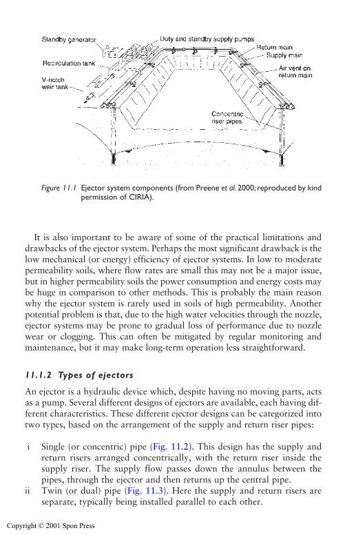
It is also important to be aware of some of the practical limitations anddrawbacks of the ejector system. Perhaps the most significant drawback is thelow mechanical (or energy) efficiency of ejector systems. In low to moderatepermeability soils, where flow rates are small this may not be a major issue,but in higher permeability soils the power consumption and energy costs maybe huge in comparison to other methods. This is probably the main reasonwhy the ejector system is rarely used in soils of high permeability. Anotherpotential problem is that, due to the high water velocities through the nozzle,ejector systems may be prone to gradual loss of performance due to nozzlewear or clogging. This can often be mitigated by regular monitoring andmaintenance, but it may make long-term operation less straightforward.
11.1.2 Types of ejectors
An ejector is a hydraulic device which, despite having no moving parts, actsas a pump. Several different designs of ejectors are available, each having dif-ferent characteristics. These different ejector designs can be categorized intotwo types, based on the arrangement of the supply and return riser pipes:
i Single (or concentric) pipe (Fig. 11.2). This design has the supply andreturn risers arranged concentrically, with the return riser inside thesupply riser. The supply flow passes down the annulus between thepipes, through the ejector and then returns up the central pipe.
ii Twin (or dual) pipe (Fig. 11.3). Here the supply and return risers areseparate, typically being installed parallel to each other.
326 Other dewatering systems
Figure 11.1 Ejector system components (from Preene et al. 2000; reproduced by kindpermission of CIRIA).
Copyright © 2001 Spon Press
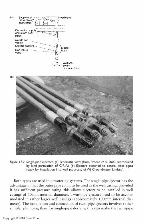
Both types are used in dewatering systems. The single-pipe ejector has theadvantage in that the outer pipe can also be used as the well casing, providedit has sufficient pressure rating; this allows ejectors to be installed in wellcasings of 50 mm internal diameter. Twin-pipe ejectors need to be accom-modated in rather larger well casings (approximately 100 mm internal dia-meter). The installation and connection of twin-pipe ejectors involves rathersimpler plumbing than for single-pipe designs; this can make the twin-pipe
Other dewatering systems 327
(b)
Figure 11.2 Single-pipe ejectors. (a) Schematic view (from Preene et al. 2000; reproducedby kind permission of CIRIA). (b) Ejectors attached to central riser pipesready for installation into well (courtesy of WJ Groundwater Limited).
Copyright © 2001 Spon Press
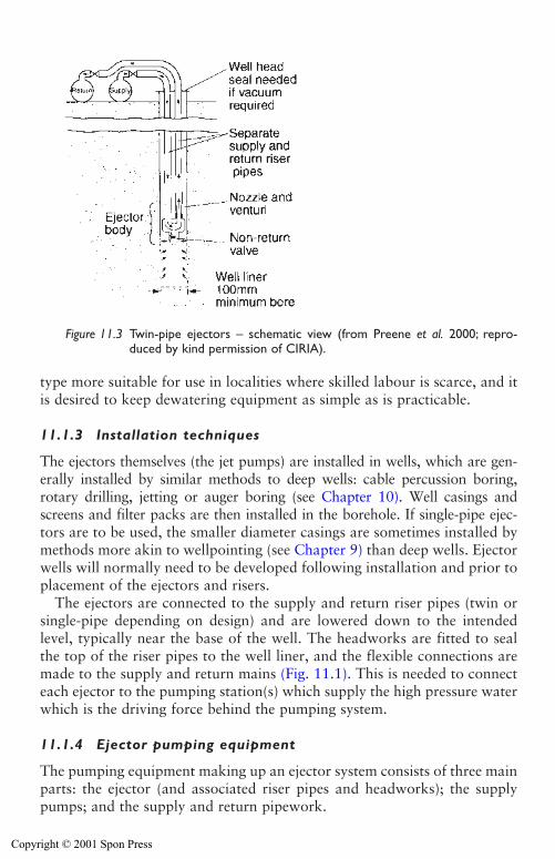
328 Other dewatering systems
type more suitable for use in localities where skilled labour is scarce, and itis desired to keep dewatering equipment as simple as is practicable.
11.1.3 Installation techniques
The ejectors themselves (the jet pumps) are installed in wells, which are gen-erally installed by similar methods to deep wells: cable percussion boring,rotary drilling, jetting or auger boring (see Chapter 10). Well casings andscreens and filter packs are then installed in the borehole. If single-pipe ejec-tors are to be used, the smaller diameter casings are sometimes installed bymethods more akin to wellpointing (see Chapter 9) than deep wells. Ejectorwells will normally need to be developed following installation and prior toplacement of the ejectors and risers.
The ejectors are connected to the supply and return riser pipes (twin orsingle-pipe depending on design) and are lowered down to the intendedlevel, typically near the base of the well. The headworks are fitted to sealthe top of the riser pipes to the well liner, and the flexible connections aremade to the supply and return mains (Fig. 11.1). This is needed to connecteach ejector to the pumping station(s) which supply the high pressure waterwhich is the driving force behind the pumping system.
11.1.4 Ejector pumping equipment
The pumping equipment making up an ejector system consists of three mainparts: the ejector (and associated riser pipes and headworks); the supplypumps; and the supply and return pipework.
Figure 11.3 Twin-pipe ejectors – schematic view (from Preene et al. 2000; repro-duced by kind permission of CIRIA).
Copyright © 2001 Spon Press
Other dewatering systems 329
Ejectors are a form of pump, and like any pump, their output will varywith discharge head. An additional complication is that, in order to func-tion, the ejector must be supplied with sufficient supply of water at ade-quate pressure (typically 750 to 1500 kPa measured at ground level). Eachdesign of ejector will have different operational characteristics, so perfor-mance curves will be needed for the model being used (Fig. 11.4). It isimportant that the performance curves are representative of the conditionsin a well (see Miller (1988) and Powrie and Preene (1994) for furtherdetails). At a given supply pressure and ejector setting depth, the pumpingcapacity (the induced flow rate) can be estimated from the performancecurves. If this is sufficient to deal with the anticipated well inflow, thenthe required supply flow per ejector (at the specified pressure) and the num-ber of ejectors to be fed by each pump can be used to select the supplypumps.
If the ejector induced flow rate is not large enough to deal with the pre-dicted well inflow, it may be possible to increase the capacity of the ejectorby increasing the supply pressure. However, Fig. 11.4 shows that, as thesupply pressure is increased, the induced flow rate of the ejector tends toplateau. This is caused by cavitation in the ejector, and additional increasesin supply pressure beyond that point do not give a corresponding increasein ejector capacity. With some ejector designs it is possible to increasecapacity by fitting a larger diameter nozzle and venturi. This gives anincreased induced flow rate at a given supply pressure, at the expense of anincrease in the required supply flow per ejector.
The supply pumps should be chosen to be able to supply the requiredtotal supply flow at the necessary pressure, taking into account frictionlosses in the system. Adequate standby pumping capacity should be provided.Supply pumps are typically high-speed single or multi-stage centrifugalpumps; the pump and motor may be either horizontally or vertically-coupled(Figure 11.5). Pumps are typically electrically powered, but units with dieselprime movers can be used in remote locations or for emergency projects. Ifthe system consists of relatively few ejectors, one pump may be used to sup-ply the whole system. However, large systems (more than fifteen to twenty-five ejectors) could be supplied by one large pump (Fig. 11.5(a)) or a bankof several smaller pumps connected in parallel (Fig. 11.5(b)). The use of sev-eral smaller pumps can allow a more flexible approach with additionalpumping capacity being easy to add as needed, and allows more economi-cal use of standby pumps.
The supply pipework is normally made of steel with the pipes and jointsrated to withstand the supply pressure. The return pipework does not need solarge a pressure rating, but may still be under considerable positive pressure,especially if the wells are drawing air into the system. Supply header pipesare typically 100 or 150 mm in diameter. Return header pipes are typically150 mm in diameter, although bigger diameters may be appropriate if large
Copyright © 2001 Spon Press
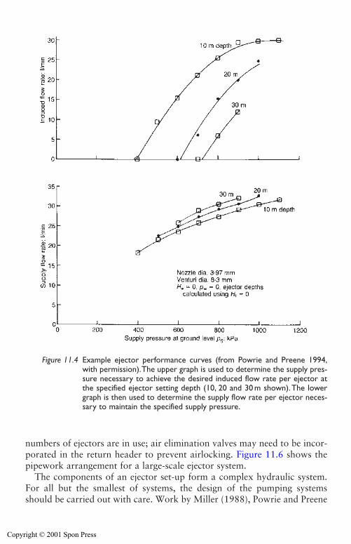
330 Other dewatering systems
numbers of ejectors are in use; air elimination valves may need to be incor-porated in the return header to prevent airlocking. Figure 11.6 shows thepipework arrangement for a large-scale ejector system.
The components of an ejector set-up form a complex hydraulic system.For all but the smallest of systems, the design of the pumping systemsshould be carried out with care. Work by Miller (1988), Powrie and Preene
Figure 11.4 Example ejector performance curves (from Powrie and Preene 1994,with permission).The upper graph is used to determine the supply pres-sure necessary to achieve the desired induced flow rate per ejector atthe specified ejector setting depth (10, 20 and 30 m shown).The lowergraph is then used to determine the supply flow rate per ejector neces-sary to maintain the specified supply pressure.
Copyright © 2001 Spon Press
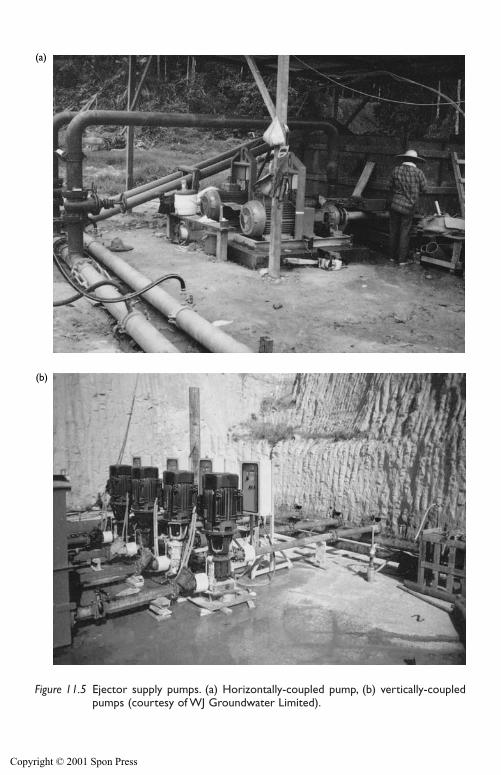
(a)
(b)
Figure 11.5 Ejector supply pumps. (a) Horizontally-coupled pump, (b) vertically-coupledpumps (courtesy of WJ Groundwater Limited).
Copyright © 2001 Spon Press
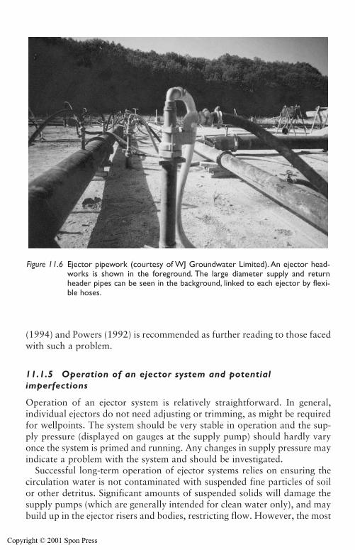
(1994) and Powers (1992) is recommended as further reading to those facedwith such a problem.
11.1.5 Operation of an ejector system and potentialimperfections
Operation of an ejector system is relatively straightforward. In general,individual ejectors do not need adjusting or trimming, as might be requiredfor wellpoints. The system should be very stable in operation and the sup-ply pressure (displayed on gauges at the supply pump) should hardly varyonce the system is primed and running. Any changes in supply pressure mayindicate a problem with the system and should be investigated.
Successful long-term operation of ejector systems relies on ensuring thecirculation water is not contaminated with suspended fine particles of soilor other detritus. Significant amounts of suspended solids will damage thesupply pumps (which are generally intended for clean water only), and maybuild up in the ejector risers and bodies, restricting flow. However, the most
332 Other dewatering systems
Figure 11.6 Ejector pipework (courtesy of WJ Groundwater Limited). An ejector head-works is shown in the foreground. The large diameter supply and returnheader pipes can be seen in the background, linked to each ejector by flexi-ble hoses.
Copyright © 2001 Spon Press
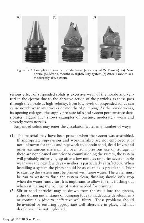
Other dewatering systems 333
serious effect of suspended solids is excessive wear of the nozzle and ven-turi in the ejector due to the abrasive action of the particles as these passthrough the nozzle at high velocity. Even low levels of suspended solids cancause nozzle wear over weeks or months of pumping. As the nozzle wears,its opening enlarges, the supply pressure falls and system performance dete-riorates. Figure 11.7 shows examples of pristine, moderately worn andseverely worn nozzles.
Suspended solids may enter the circulation water in a number of ways:
(1) The material may have been present when the system was assembled.If appropriate supervision and workmanship are not employed it isnot unknown for tanks and pipework to contain sand, dead leaves andother extraneous material left over from previous use or storage. Ifthese are not cleaned out prior to commissioning the system, the systemwill probably either clog up after a few minutes or suffer severe nozzlewear over the next few days – neither is particularly satisfactory. Wheninstalling a system the pipes should be as clean as is practicable. Priorto start up the system must be primed with clean water. The water mustbe run to waste to flush the system clean; flushing should only stopwhen the water runs clear. It is important to allow for this flushing outwhen estimating the volume of water needed for priming.
(2) Silt or sand particles may be drawn from the wells into the system,either during initial stages of pumping (due to inadequate development)or continually (due to ineffective well filters). These problems shouldbe avoided by ensuring appropriate well filters are in place, and thatdevelopment is not neglected.
(a) (b) (c)
Figure 11.7 Examples of ejector nozzle wear (courtesy of W. Powrie). (a) Newnozzle (b) After 6 months in slightly silty system (c) After 1 month in amoderately silty system.
Copyright © 2001 Spon Press
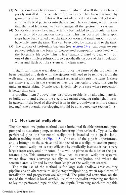
(3) Silt or sand may be drawn in from an individual well that may have apoorly installed filter or where the wellscreen has been fractured byground movement. If this well is not identified and switched off it willcontinually feed particles into the system. The circulating action meansthat the sand from one well can damage all the ejectors in a system.
(4) Soil or debris may have inadvertently been added to the circulation tankas a result of construction operations. This has occurred where spoilskips have been craned over the tank location and small amounts of soilhave fallen into the tank. This can be avoided by fitting a lid to the tank.
(5) The growth of biofouling bacteria (see Section 14.8) can generate sus-pended solids in the form of iron-related compounds associated withthe bacteria’s life cycle. This is less straightforward to deal with, butone of the simplest solutions is to periodically dispose of the circulationwater and flush out the system with clean water.
If significant nozzle wear does occur, once the cause of the problem hasbeen identified and dealt with, the ejectors will need to be removed from thewells and the worn nozzles and venturi replaced with pristine items. If thereare many ejectors in the system or they are particularly deep, this can bequite an undertaking. Nozzle wear is definitely one case where preventionis better than cure.
Biofouling (item 5 above) may also cause problems by allowing materialto build up in and around the ejectors, causing clogging rather than wear.In general, if the level of dissolved iron in the groundwater is more than afew mg/l, the potential for clogging should be considered (see Section 14.8).
11.2 Horizontal wellpoints
The horizontal wellpoint method uses a horizontal flexible perforated pipe,pumped by a suction pump, to effect lowering of water levels. Typically, theperforated pipe (the horizontal wellpoint) is installed by a special land-drain trenching machine (Fig. 11.8). One end of the pipe is unperforatedand is brought to the surface and connected to a wellpoint suction pump.A horizontal wellpoint is very efficient hydraulically because it has a verylarge screen area, and horizontal flow will be plane to the sides of the per-forated pipe. This contrasts with flow local to vertical wellpoint systems,where flow lines converge radially to each wellpoint, and where thescreened area is limited by the short length of the wellpoint screens.
The main use of the method is for large-scale shallow cross-countrypipelines as an alternative to single-stage wellpointing, when rapid rates ofinstallation and progression are required. The principal restriction on theuse of the method is local availability of the specialist trenching machinesto lay the perforated pipe at adequate depth. Trenching machines capable
334 Other dewatering systems
Copyright © 2001 Spon Press
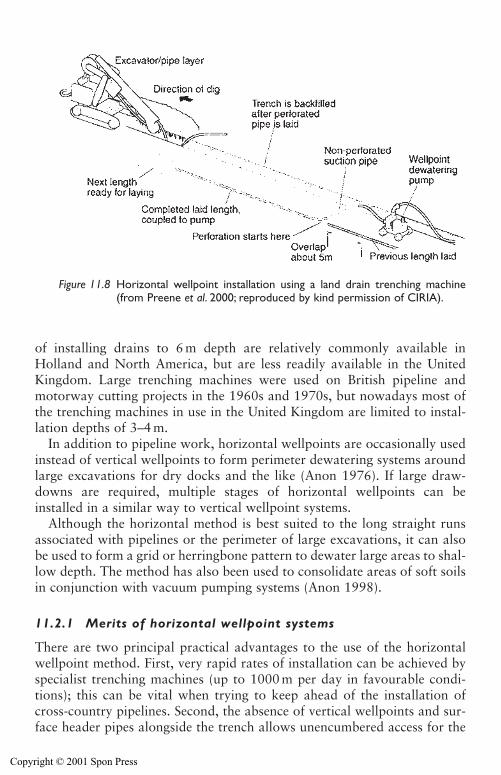
Other dewatering systems 335
of installing drains to 6 m depth are relatively commonly available inHolland and North America, but are less readily available in the UnitedKingdom. Large trenching machines were used on British pipeline andmotorway cutting projects in the 1960s and 1970s, but nowadays most ofthe trenching machines in use in the United Kingdom are limited to instal-lation depths of 3–4 m.
In addition to pipeline work, horizontal wellpoints are occasionally usedinstead of vertical wellpoints to form perimeter dewatering systems aroundlarge excavations for dry docks and the like (Anon 1976). If large draw-downs are required, multiple stages of horizontal wellpoints can beinstalled in a similar way to vertical wellpoint systems.
Although the horizontal method is best suited to the long straight runsassociated with pipelines or the perimeter of large excavations, it can alsobe used to form a grid or herringbone pattern to dewater large areas to shal-low depth. The method has also been used to consolidate areas of soft soilsin conjunction with vacuum pumping systems (Anon 1998).
11.2.1 Merits of horizontal wellpoint systems
There are two principal practical advantages to the use of the horizontalwellpoint method. First, very rapid rates of installation can be achieved byspecialist trenching machines (up to 1000 m per day in favourable condi-tions); this can be vital when trying to keep ahead of the installation ofcross-country pipelines. Second, the absence of vertical wellpoints and sur-face header pipes alongside the trench allows unencumbered access for the
Figure 11.8 Horizontal wellpoint installation using a land drain trenching machine(from Preene et al. 2000; reproduced by kind permission of CIRIA).
Copyright © 2001 Spon Press
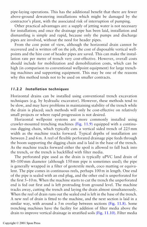
pipe-laying operations. This has the additional benefit that there are fewerabove-ground dewatering installations which might be damaged by thecontractor’s plant, with the associated risk of interruption of pumping.
Other practical advantages are: a supply of jetting water is not necessaryfor installation; and once the drainage pipe has been laid, installation anddismantling is simple and rapid, because only the pumps and dischargepipes are involved, without the need for header pipes.
From the cost point of view, although the horizontal drain cannot berecovered and is written off on the job, the cost of disposable vertical well-points and the hire cost of header pipes are saved. This can make the instal-lation rate per metre of trench very cost-effective. However, overall costsshould include for mobilization and demobilization costs, which can behigh (in comparison to conventional wellpoint equipment) for large trench-ing machines and supporting equipment. This may be one of the reasonswhy this method tends not to be used on smaller contracts.
11.2.2 Installation techniques
Horizontal drains can be installed using conventional trench excavationtechniques (e.g. by hydraulic excavator). However, these methods tend tobe slow, and may have problems in maintaining stability of the trench whilethe drain is placed; such methods will only be cost-effective on relativelysmall projects or where rapid progression is not desired.
Horizontal wellpoint systems are more commonly installed usingcrawler-mounted trenching machines (Fig. 11.9) equipped with a continu-ous digging chain, which typically cuts a vertical sided trench of 225 mmwidth as the machine tracks forward. Typical depths of installation arebetween 2 and 6 m. A reel of flexible perforated drainage pipe feeds throughthe boom supporting the digging chain and is laid in the base of the trench.As the machine tracks forward either the spoil is allowed to fall back intothe trench, or the trench is backfilled with filter media.
The perforated pipe used as the drain is typically uPVC land drain of80–100 mm diameter (although 150 mm pipe is sometimes used); the pipeis generally wrapped in a filter of geotextile mesh, coco matting or equiva-lent. The pipe comes in continuous reels, perhaps 100 m in length. One endof the pipe is sealed with an end plug, and the other end is unperforated forthe first 5–10 m. When the machine starts to cut the trench the unperforatedend is fed out first and is left protruding from ground level. The machinetracks away, cutting the trench and laying the drain almost simultaneously.When the reel of drain runs out the sealed end is left in the base of the trench.A new reel of drain is fitted to the machine, and the next section is laid in asimilar way, with around a 5m overlap between sections (Fig. 11.8). Sometrenching machines have the facility for addition of filter media above thedrain to improve vertical drainage in stratified soils (Fig. 11.10). Filter media
336 Other dewatering systems
Copyright © 2001 Spon Press
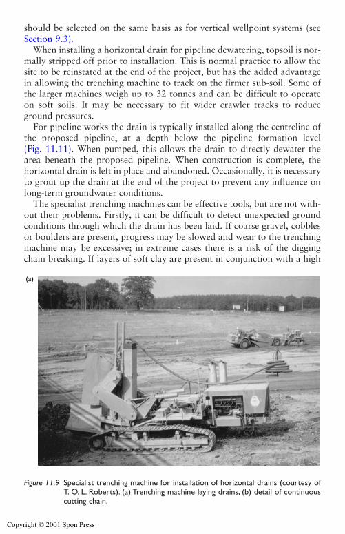
Other dewatering systems 337
should be selected on the same basis as for vertical wellpoint systems (seeSection 9.3).
When installing a horizontal drain for pipeline dewatering, topsoil is nor-mally stripped off prior to installation. This is normal practice to allow thesite to be reinstated at the end of the project, but has the added advantagein allowing the trenching machine to track on the firmer sub-soil. Some ofthe larger machines weigh up to 32 tonnes and can be difficult to operateon soft soils. It may be necessary to fit wider crawler tracks to reduceground pressures.
For pipeline works the drain is typically installed along the centreline ofthe proposed pipeline, at a depth below the pipeline formation level(Fig. 11.11). When pumped, this allows the drain to directly dewater thearea beneath the proposed pipeline. When construction is complete, thehorizontal drain is left in place and abandoned. Occasionally, it is necessaryto grout up the drain at the end of the project to prevent any influence onlong-term groundwater conditions.
The specialist trenching machines can be effective tools, but are not with-out their problems. Firstly, it can be difficult to detect unexpected groundconditions through which the drain has been laid. If coarse gravel, cobblesor boulders are present, progress may be slowed and wear to the trenchingmachine may be excessive; in extreme cases there is a risk of the diggingchain breaking. If layers of soft clay are present in conjunction with a high
(a)
Figure 11.9 Specialist trenching machine for installation of horizontal drains (courtesy ofT. O. L. Roberts). (a) Trenching machine laying drains, (b) detail of continuouscutting chain.
Copyright © 2001 Spon Press
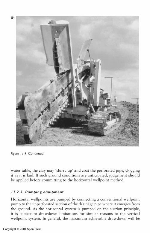
338 Other dewatering systems
water table, the clay may ‘slurry up’ and coat the perforated pipe, cloggingit as it is laid. If such ground conditions are anticipated, judgement shouldbe applied before committing to the horizontal wellpoint method.
11.2.3 Pumping equipment
Horizontal wellpoints are pumped by connecting a conventional wellpointpump to the unperforated section of the drainage pipe where it emerges fromthe ground. As the horizontal system is pumped on the suction principle,it is subject to drawdown limitations for similar reasons to the verticalwellpoint system. In general, the maximum achievable drawdown will be
(b)
Figure 11.9 Continued.
Copyright © 2001 Spon Press
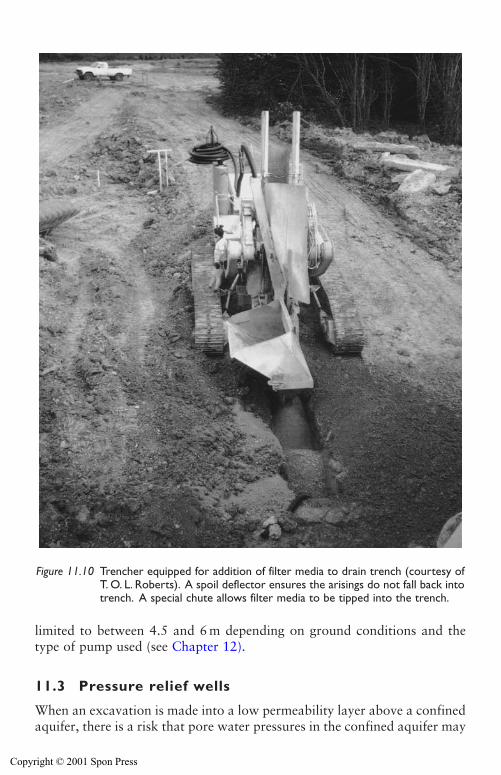
Other dewatering systems 339
limited to between 4.5 and 6 m depending on ground conditions and thetype of pump used (see Chapter 12).
11.3 Pressure relief wells
When an excavation is made into a low permeability layer above a confinedaquifer, there is a risk that pore water pressures in the confined aquifer may
Figure 11.10 Trencher equipped for addition of filter media to drain trench (courtesy ofT. O. L. Roberts). A spoil deflector ensures the arisings do not fall back intotrench. A special chute allows filter media to be tipped into the trench.
Copyright © 2001 Spon Press
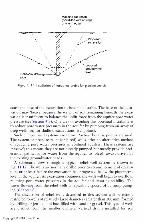
340 Other dewatering systems
cause the base of the excavation to become unstable. The base of the exca-vation may ‘heave’ because the weight of soil remaining beneath the exca-vation is insufficient to balance the uplift force from the aquifer pore waterpressure (see Section 4.3). One way of avoiding this potential instability isto reduce pore water pressures in the aquifer by pumping from an array ofdeep wells (or, for shallow excavations, wellpoints).
Such pumped well systems are termed ‘active’ because pumps are used.The system of pressure relief (or bleed) wells offer an alternative methodof reducing pore water pressures in confined aquifers. These systems are‘passive’; this means they are not directly pumped but merely provide pref-erential pathways for water from the aquifer to ‘bleed’ away, driven bythe existing groundwater heads.
A schematic view through a typical relief well system is shown inFig. 11.12. The wells are normally drilled prior to commencement of excava-tion, or at least before the excavation has progressed below the piezometriclevel in the aquifer. As excavation continues, the wells will begin to overflow,relieving pore water pressures in the aquifer and ensuring stability. Thewater flowing from the relief wells is typically disposed of by sump pump-ing (Chapter 8).
The discussion of relief wells described in this section will be mainlyrestricted to wells of relatively large diameter (greater than 100 mm) formedby drilling or jetting, and backfilled with sand or gravel. This type of wellsare distinct from the smaller diameter vertical drains installed for soil
Figure 11.11 Installation of horizontal drains for pipeline trench.
Copyright © 2001 Spon Press
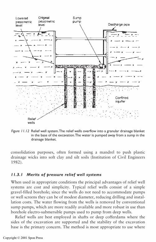
consolidation purposes, often formed using a mandrel to push plasticdrainage wicks into soft clay and silt soils (Institution of Civil Engineers1982).
11.3.1 Merits of pressure relief well systems
When used in appropriate conditions the principal advantages of relief wellsystems are cost and simplicity. Typical relief wells consist of a simplegravel-filled borehole; since the wells do not need to accommodate pumpsor well screens they can be of modest diameter, reducing drilling and instal-lation costs. The water flowing from the wells is removed by conventionalsump pumps, which are more readily available and more robust in use thanborehole electro-submersible pumps used to pump from deep wells.
Relief wells are best employed in shafts or deep cofferdams where thesides of the excavation are supported and the stability of the excavationbase is the primary concern. The method is most appropriate to use where
Other dewatering systems 341
Figure 11.12 Relief well system.The relief wells overflow into a granular drainage blanketin the base of the excavation.The water is pumped away from a sump in thedrainage blanket.
Copyright © 2001 Spon Press
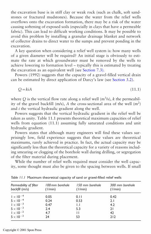
the excavation base is in stiff clay or weak rock (such as chalk, soft sand-stones or fractured mudstones). Because the water from the relief wellsoverflows onto the excavation formation, there may be a risk of the watercausing softening of exposed soils (especially in clays that have a permeablefabric). This can lead to difficult working conditions. It may be possible toavoid this problem by installing a granular drainage blanket and networkof collector drains to direct water to the sumps and prevent ponding in theexcavation.
A key question when considering a relief well system is: how many wellsof a given diameter will be required? An initial stage is obviously to esti-mate the rate at which groundwater must be removed by the wells toachieve lowering to formation level – typically this is estimated by treatingthe excavation as an equivalent well (see Section 7.3).
Powers (1992) suggests that the capacity of a gravel-filled vertical draincan be estimated by direct application of Darcy’s law (see Section 3.2).
Q�kiA (11.1)
where Q is the vertical flow rate along a relief well (m3/s), k the permeabil-ity of the gravel backfill (m/s), A the cross-sectional area of the well (m2)and i the vertical hydraulic gradient along the well.
Powers suggests that the vertical hydraulic gradient in the relief well betaken as unity. Table 11.1 presents theoretical maximum capacities of reliefwells from equation (11.1) assuming fully saturated conditions and unithydraulic gradient.
Powers states that although many engineers will find these values sur-prisingly low, field experience suggests that these values are theoreticalmaximums, rarely achieved in practice. In fact, the actual capacity may besignificantly less than the theoretical capacity for a variety of reasons includ-ing smearing or clogging of the borehole wall during drilling, or segregationof the filter material during placement.
While the number of relief wells required must consider the well capac-ity, some thought must also be given to the spacing between wells. If small
342 Other dewatering systems
Table 11.1 Maximum theoretical capacity of sand or gravel-filled relief wells
Permeability of filter 100 mm borehole 150 mm borehole 300 mm borehole backfill (m/s) (1/min) (1/min) (1/min)
1�10�4 0.05 0.11 0.425�10�4 0.24 0.53 2.11�10�3 0.47 1.1 4.25�10�3 2.4 5.3 211�10�2 4.7 11 425�10�2 24 53 212
Copyright © 2001 Spon Press
Other dewatering systems 343
flows are predicted only a few wells may be necessary to deal with the vol-ume of water. However, it may be prudent to install additional relief wellsto ensure the distance between wells is not excessive (say greater than5–10 m). If the wells are widely spaced and the ground conditions may bevariable (especially if the wells are installed into fissured rock), there is adanger that the wells may not adequately intercept sufficient permeablezones or fissures. This could lead to unrelieved pressures remaining, withthe possibility of local base heave in the areas between the wells.
11.3.2 Installation techniques
Relief wells are typically drilled by similar methods to deep wells: cable per-cussion boring, rotary drilling, jetting or auger boring (see Chapter 10). Theborehole is drilled to full depth, any drilling fluids used are flushed clearand then the filter media (sand or gravel) are added to backfill the bore upto the required level. The diameter of drilling is typically between 100 and450 mm.
The filter media may be placed in the well via a tremie pipe or may besimply poured in from ground level. This latter approach is acceptable pro-vided that the filter media has a very uniform grading so that there is littlerisk of segregation of the filter particles as they settle to the bottom of thebore. In practice, many relief wells installed in soft rocks, where the per-formance of the filter is not critical, are filled with uniform coarse gravel.Ideally, to permit maximum transmission of water the gravel should be ofthe rounded pea shingle type of 10–20 mm nominal size. However, onremote sites it may be necessary to use locally available material (whichmay consist of angular crushed aggregates), and accept some reduction inwell efficiency. In certain cases, where the long-term performance of therelief wells is critical, the gravel used may need to be designed to match soilconditions in a similar way to deep wells (see Section 10.2). If no wellscreen is installed, it is not normally possible to develop the relief well.
11.3.3 Relief wells – is a well casing and screen needed?
Previous sections have mainly discussed gravel-filled relief wells, but thereare cases when it is appropriate to install casings and screens (surroundedby a gravel pack) in relief wells. Although introducing additional cost andcomplexity, relief wells with screens can be used in the following cases:
(i) If the confined aquifer is of high permeability, a screened well willhave a greater vertical flow capacity than a purely gravel filled well. Use ofscreened wells may reduce the number of wells required.
(ii) If a pumping test is needed to confirm aquifer permeability and flow ratethe casing and screen will allow the test to be carried out using a submersible
Copyright © 2001 Spon Press
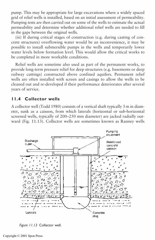
344 Other dewatering systems
pump. This may be appropriate for large excavations where a widely spacedgrid of relief wells is installed, based on an initial assessment of permeability.Pumping tests are then carried out on some of the wells to estimate the actualpermeability and determine whether additional relief wells are needed to fillin the gaps between the original wells.
(iii) If during critical stages of construction (e.g. during casting of con-crete structures) overflowing water would be an inconvenience, it may bepossible to install submersible pumps in the wells and temporarily lowerwater levels below formation level. This would allow the critical works tobe completed in more workable conditions.
Relief wells are sometime also used as part of the permanent works, toprovide long-term pressure relief for deep structures (e.g. basements or deeprailway cuttings) constructed above confined aquifers. Permanent reliefwells are often installed with screen and casings to allow the wells to becleaned out and re-developed if their performance deteriorates after severalyears of service.
11.4 Collector wells
A collector well (Todd 1980) consists of a vertical shaft typically 5 m in diam-eter, sunk as a caisson, from which laterals (horizontal or sub-horizontalscreened wells, typically of 200–250 mm diameter) are jacked radially out-ward (Fig. 11.13). Collector wells are sometimes known as Ranney wells
Figure 11.13 Collector well.
Copyright © 2001 Spon Press
Other dewatering systems 345
after a proprietary system (first developed by Leo Ranney in 1933) used toform this type of well (Drinkwater 1967).
A collector well is pumped by a submersible or lineshaft pump located inthe shaft, which lowers the water level in the well. This creates a pressuregradient along the laterals causing them to flow freely into the main shaft.This method is particularly suited to large capacity permanent water supplyinstallations in shallow sand and gravel aquifers, but is rarely used forgroundwater control operations. In general, the cost of constructing thecentral shaft and forming the laterals is likely to be prohibitive for tempo-rary works applications. Nevertheless, the method has occasionally beenused, for example to aid dewatering of tunnel crossings beneath roadsand railways where access to install conventional wells was restricted(Harding 1947).
11.5 Electro-osmosis
Electro-osmosis is suitable for use in very low permeability soils such as siltsor clays where groundwater movement under the influence of pumpingwould be excessively slow. Electro-osmosis causes groundwater movementsin such soils using electrical potential gradients, rather than hydraulic gra-dients. A direct current is passed through the soil between an array ofanodes and cathodes installed in the ground. The potential gradient causespositively charged ions and pore water around the soil particles to migratefrom the anode to the cathode, where the small volumes of water generatedcan be pumped away by wellpoints or ejectors (Fig. 11.14). The method canreduce the moisture content of the soil, thereby increasing its strength. Inmany ways, electro-osmosis is not so much a groundwater control methodas a ground improvement technique. One of the drawbacks of the methodis that it is a decelerating process, becoming slower as the moisture contentdecreases.
Electro-osmosis is a very specialized technique, and is used rarely, mainlywhen very soft clays or silts are required to be increased in strength.Casagrande (1952) describes the development of the method. Some rela-tively recent applications are given by Casagrande et al. (1981) and Doranet al. (1995). In some applications, electro-osmosis is used in conjunctionwith electro-chemical stabilization (see Bell and Cashman 1986), whenchemical stabilizers are added at the anodes to permanently increase thestrength of the soil.
In application the electrode arrangements are straightforward, typicallybeing installed in lines, with a spacing of 3–5m between electrodes.Anodes and cathodes are placed in the same line, in an alternatinganode–cathode–anode sequence (Fig. 11.14). Water is to be pumped from thecathodes, so these can be formed from steel wellpoints or steel well liners.
Copyright © 2001 Spon Press
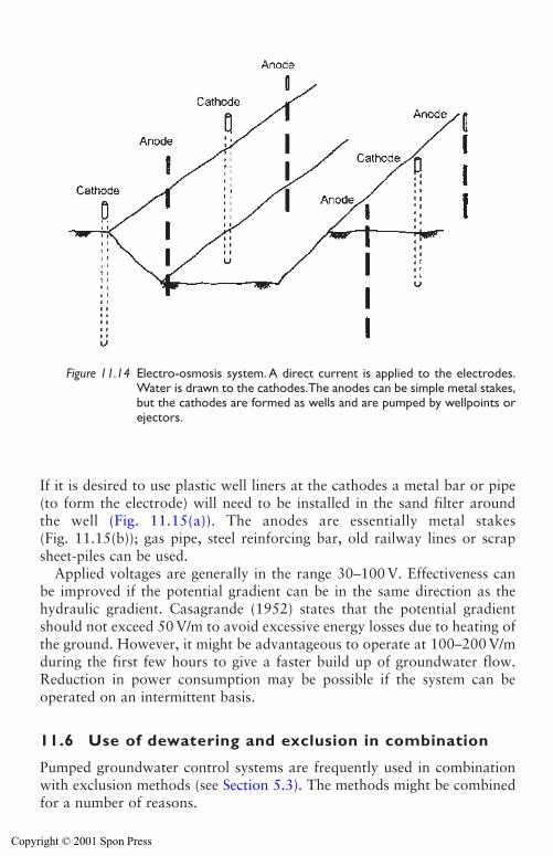
If it is desired to use plastic well liners at the cathodes a metal bar or pipe(to form the electrode) will need to be installed in the sand filter aroundthe well (Fig. 11.15(a)). The anodes are essentially metal stakes(Fig. 11.15(b)); gas pipe, steel reinforcing bar, old railway lines or scrapsheet-piles can be used.
Applied voltages are generally in the range 30–100 V. Effectiveness canbe improved if the potential gradient can be in the same direction as thehydraulic gradient. Casagrande (1952) states that the potential gradientshould not exceed 50 V/m to avoid excessive energy losses due to heating ofthe ground. However, it might be advantageous to operate at 100–200 V/mduring the first few hours to give a faster build up of groundwater flow.Reduction in power consumption may be possible if the system can beoperated on an intermittent basis.
11.6 Use of dewatering and exclusion in combination
Pumped groundwater control systems are frequently used in combinationwith exclusion methods (see Section 5.3). The methods might be combinedfor a number of reasons.
346 Other dewatering systems
Figure 11.14 Electro-osmosis system. A direct current is applied to the electrodes.Water is drawn to the cathodes.The anodes can be simple metal stakes,but the cathodes are formed as wells and are pumped by wellpoints orejectors.
Copyright © 2001 Spon Press
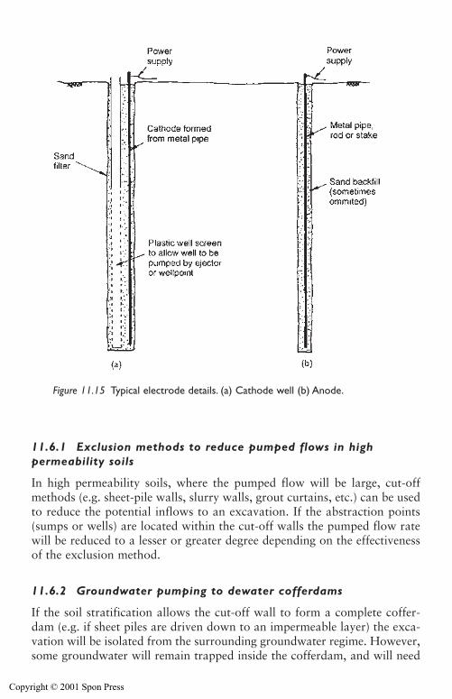
Other dewatering systems 347
11.6.1 Exclusion methods to reduce pumped flows in highpermeability soils
In high permeability soils, where the pumped flow will be large, cut-offmethods (e.g. sheet-pile walls, slurry walls, grout curtains, etc.) can be usedto reduce the potential inflows to an excavation. If the abstraction points(sumps or wells) are located within the cut-off walls the pumped flow ratewill be reduced to a lesser or greater degree depending on the effectivenessof the exclusion method.
11.6.2 Groundwater pumping to dewater cofferdams
If the soil stratification allows the cut-off wall to form a complete coffer-dam (e.g. if sheet piles are driven down to an impermeable layer) the exca-vation will be isolated from the surrounding groundwater regime. However,some groundwater will remain trapped inside the cofferdam, and will need
Figure 11.15 Typical electrode details. (a) Cathode well (b) Anode.
Copyright © 2001 Spon Press
to be pumped away. This is sometimes done by crude sump pumping asexcavation proceeds. However, this may result in loss of fines or looseningof the soils that lie beneath the formation of the structure under construc-tion. Sometimes wells or wellpoints are installed inside the cofferdam topre-drain water levels prior to excavation, thus reducing detrimental effectson the soil formation.
11.6.3 Groundwater lowering used to reduce loading oncut-off structures
If the sides of an excavation are temporarily supported by sheet-pile or con-crete pile walls, the stresses on the walls will arise partly from soil andpartly from groundwater loading. In some circumstances groundwater low-ering can be used to reduce the groundwater loading on a wall, to minimizetemporary propping requirements. This can be a highly effective expedient;fewer props in the construction area can allow work to proceed quicker andwith less obstruction.
However, a note of caution should be sounded. If pumping is interrupted(e.g. because of power or pump failure) the recovery of groundwater levelswill increase loading on the walls and props, leading to overstressing, dis-tortion and, in the worst case, collapse. Adequate standby facilities (per-haps arranged for automatic start-up) are essential. Alternatively, pressurerelief holes could be formed through the wall above formation level; ifwater levels rose these would relieve the pressure behind the wall, albeit atthe inconvenience of allowing the excavation to be flooded.
References
Anon. (1976). Dewatering for Andoc’s Hunterson platform site. GroundEngineering, 9(7), 42–43.
Anon. (1998). Vacuum packed: a new rapid and cost effective method of pre-consolidation is being used to combat the rapid settlement of soft, compressiblesoils in the Netherlands. Ground Engineering, 31(2), 18–19.
Bell, F. G. and Cashman, P. M. (1986). Groundwater control by groundwater low-ering. Groundwater in Engineering Geology (Cripps, J. C., Bell, F. G. andCulshaw, M. G., eds), Geological Society Engineering Geology SpecialPublication No. 3, London, pp 471–486.
Casagrande, L. (1952). Electro-osmotic stabilisation of soils. Journal of the BostonSociety of Civil Engineers, 39, pp 51–83.
Casagrande, L., Wade, N., Wakely, M. and Loughney, R. (1981). Electro-osmosisprojects, British Columbia, Canada. Proceedings of the 10th InternationalConference on Soil Mechanics and Foundation Engineering, Stockholm, Sweden,pp 607–610.
Doran, S. R., Hartwell, D. J., Roberti, P., Kofoed, N. and Warren, S. (1995).Storebælt Railway tunnel – Denmark: implementation of cross passage ground
348 Other dewatering systems
Copyright © 2001 Spon Press
treatment. Proceedings of the 11th European Conference on Soil Mechanics andFoundation Engineering, Copenhagen, Denmark.
Drinkwater, J. S. (1967). The Ranney method of abstracting water from aquifers.Water and Water Engineering, pp 267–274.
Harding, H. J. B. (1947). The choice of expedients in civil engineering construction.Journal of the Institution of Civil Engineers, Works Construction Paper No. 6.
Institution of Civil Engineers. (1982). Vertical Drains: Géotechnique Symposium inPrint. Thomas Telford, London.
Miller, E. (1988). The eductor dewatering system. Ground Engineering, 21(1),29–34.
Powers, J. P. (1992). Construction Dewatering: New Methods and Applications,2nd edition. Wiley, New York.
Powrie, W. and Preene, M. (1994). Performance of ejectors in construction dewa-tering systems. Proceedings of the Institution of Civil Engineers, GeotechnicalEngineering, 107, July, 143–154.
Powrie, W. and Roberts, T. O. L. (1990). Field trial of an ejector well dewateringsystem at Conwy, North Wales. Quarterly Journal of Engineering Geology, 23,169–185.
Preene, M. (1996). Ejector feat. Ground Engineering, 29(4), 16.Preene, M. and Powrie, W. (1994). Construction dewatering in low permeability
soils: some problems and solutions. Proceedings of the Institution of CivilEngineers, Geotechnical Engineering, 107, January, 17–26.
Preene, M., Roberts, T. O. L., Powrie, W. and Dyer, M. R. (2000). GroundwaterControl – Design and Practice. Construction Industry Research and InformationAssociation, CIRIA Report C515, London.
Todd, D. K. (1980). Groundwater Hydrology, 2nd edition. Wiley, New York,213–214.
Other dewatering systems 349
Copyright © 2001 Spon Press
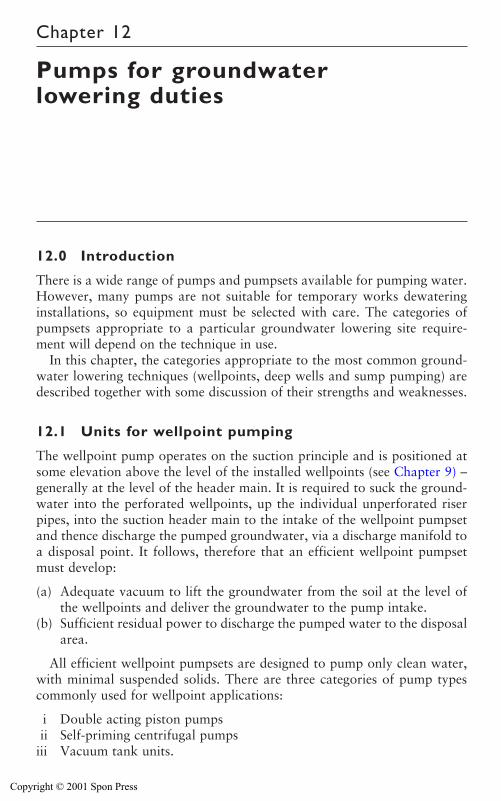
Chapter 12
Pumps for groundwaterlowering duties
12.0 Introduction
There is a wide range of pumps and pumpsets available for pumping water.However, many pumps are not suitable for temporary works dewateringinstallations, so equipment must be selected with care. The categories ofpumpsets appropriate to a particular groundwater lowering site require-ment will depend on the technique in use.
In this chapter, the categories appropriate to the most common ground-water lowering techniques (wellpoints, deep wells and sump pumping) aredescribed together with some discussion of their strengths and weaknesses.
12.1 Units for wellpoint pumping
The wellpoint pump operates on the suction principle and is positioned atsome elevation above the level of the installed wellpoints (see Chapter 9) –generally at the level of the header main. It is required to suck the ground-water into the perforated wellpoints, up the individual unperforated riserpipes, into the suction header main to the intake of the wellpoint pumpsetand thence discharge the pumped groundwater, via a discharge manifold toa disposal point. It follows, therefore that an efficient wellpoint pumpsetmust develop:
(a) Adequate vacuum to lift the groundwater from the soil at the level ofthe wellpoints and deliver the groundwater to the pump intake.
(b) Sufficient residual power to discharge the pumped water to the disposalarea.
All efficient wellpoint pumpsets are designed to pump only clean water,with minimal suspended solids. There are three categories of pump typescommonly used for wellpoint applications:
i Double acting piston pumpsii Self-priming centrifugal pumps
iii Vacuum tank units.
Copyright © 2001 Spon Press
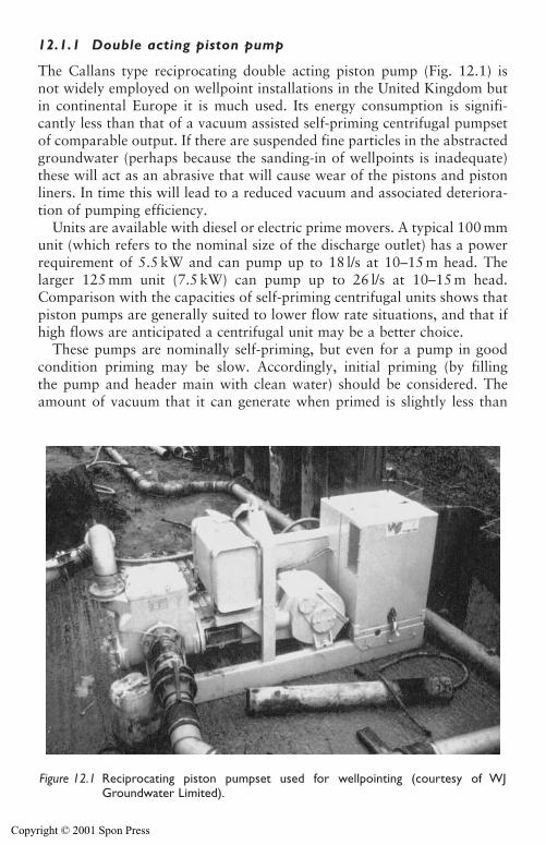
Pumps for groundwater lowering duties 351
12.1.1 Double acting piston pump
The Callans type reciprocating double acting piston pump (Fig. 12.1) is not widely employed on wellpoint installations in the United Kingdom butin continental Europe it is much used. Its energy consumption is signifi-cantly less than that of a vacuum assisted self-priming centrifugal pumpsetof comparable output. If there are suspended fine particles in the abstractedgroundwater (perhaps because the sanding-in of wellpoints is inadequate)these will act as an abrasive that will cause wear of the pistons and pistonliners. In time this will lead to a reduced vacuum and associated deteriora-tion of pumping efficiency.
Units are available with diesel or electric prime movers. A typical 100 mmunit (which refers to the nominal size of the discharge outlet) has a powerrequirement of 5.5 kW and can pump up to 18 l/s at 10–15 m head. Thelarger 125 mm unit (7.5 kW) can pump up to 26 l/s at 10–15 m head.Comparison with the capacities of self-priming centrifugal units shows thatpiston pumps are generally suited to lower flow rate situations, and that ifhigh flows are anticipated a centrifugal unit may be a better choice.
These pumps are nominally self-priming, but even for a pump in goodcondition priming may be slow. Accordingly, initial priming (by fillingthe pump and header main with clean water) should be considered. Theamount of vacuum that it can generate when primed is slightly less than
Figure 12.1 Reciprocating piston pumpset used for wellpointing (courtesy of WJGroundwater Limited).
Copyright © 2001 Spon Press
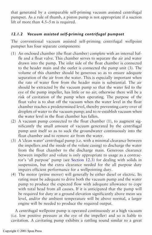
that generated by a comparable self-priming vacuum assisted centrifugalpumpset. As a rule of thumb, a piston pump is not appropriate if a suctionlift of more than 4.5–5 m is required.
12.1.2 Vacuum assisted self-priming centrifugal pumpset
The conventional vacuum assisted self-priming centrifugal wellpointpumpset has four separate components:
(1) An enclosed chamber (the float chamber) complete with an internal baf-fle and a float valve. This chamber serves to separate the air and waterdrawn into the pump. The inlet side of the float chamber is connectedto the header main and the outlet is connected the pump unit (3). Thevolume of this chamber should be generous so as to ensure adequateseparation of the air from the water. This is especially important whenthe rate of water flow from the header main is substantial. The airshould be extracted by the vacuum pump so that the water fed to theeye of the pump impeller, has little or no air; otherwise there will be arisk of cavitation of the pump when operating. The purpose of thefloat valve is to shut off the vacuum when the water level in the floatchamber reaches a predetermined level, thereby preventing carry-over ofdroplets of water to the vacuum pump; and to re-establish vacuum whenthe water level in the float chamber has fallen.
(2) A vacuum pump connected to the float chamber (1), to augment sig-nificantly the small amount of vacuum generated by the centrifugalpump unit itself so as to suck the groundwater continuously into thefloat chamber and to remove air from the water.
(3) A ‘clean water’ centrifugal pump (i.e. with a minimal clearance betweenthe impellers and the inside of the volute casing) to discharge the waterfrom the float chamber to the discharge main. Generous clearancebetween impeller and volute is only appropriate to usage as a contrac-tor’s ‘all purpose’ pump (see Section 12.3) for dealing with solids insuspension, but the extra clearance needed for the all purpose dutyimpairs efficient performance for a wellpointing duty.
(4) The motor (prime mover) will generally be either diesel or electric. Itsrating must be adequate to drive both the vacuum pump and the waterpump to produce the expected flow with adequate allowance to copewith total head from all causes. If it is anticipated that the pump willbe required for duty at a ground elevation significantly above mean sealevel, and/or the ambient temperature will be above normal, a largerengine will be needed to produce the required output.
A centrifugal wellpoint pump is operated continuously at a high vacuum(i.e. low positive pressure at the eye of the impeller) and so is liable tocavitation. A cavitating pump exhibits a rattling sound similar to a great
352 Pumps for groundwater lowering duties
Copyright © 2001 Spon Press
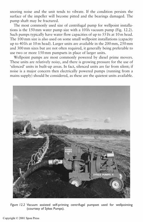
snoring noise and the unit tends to vibrate. If the condition persists the surface of the impeller will become pitted and the bearings damaged. Thepump shaft may be fractured.
The most commonly used size of centrifugal pump for wellpoint installa-tions is the 150mm water pump size with a 10 l/s vacuum pump (Fig. 12.2).Such pumps typically have water flow capacities of up to 55 l/s at 10 m head.The 100 mm size is also used on some small wellpoint installations (capacityup to 40 l/s at 10 m head). Larger units are available in the 200 mm, 250 mmand 300 mm sizes but are not often required, it generally being preferable touse two or more 150 mm pumpsets in place of larger units.
Wellpoint pumps are most commonly powered by diesel prime movers.These units are relatively noisy, and there is growing pressure for the use of‘silenced’ units in built-up areas. In fact, silenced units are far from silent; ifnoise is a major concern then electrically powered pumps (running from amains supply) should be considered, as these are the quietest units available.
Pumps for groundwater lowering duties 353
Figure 12.2 Vacuum assisted self-priming centrifugal pumpset used for wellpointing(courtesy of Sykes Pumps).
Copyright © 2001 Spon Press
354 Pumps for groundwater lowering duties
The vacuum assisted self-priming centrifugal pump may also be used forsump pumping of clean, filtered groundwater (see Chapter 8) and for oper-ating a bored shallow well system (see Chapter 10).
12.1.3 Vacuum pumps
The two types of rotary vacuum pumps most commonly fitted to centrifu-gal wellpoint pumpsets to assist priming are:
i The liquid ring or water recirculating vacuum pump.ii The flood lubricated or oil sealed vacuum pump.
The vacuum units for the wellpoint application are required to operatecontinuously over a wide range of air flow rates from the very high to thevery low. The service duty to be fulfilled is onerous. Generally, the vacuumpump is belt driven off the drive shaft of the prime mover. The energy con-sumption of the vacuum pump is of the order of 15 per cent of the total ofthe motor output. The heat that may be generated can be considerable sothe cooling arrangements must be reliable; this requirement is particularlypertinent to the oil sealed vacuum unit.
The liquid ring vacuum pump is better able to cope with low water flowconditions because the liquid ring pump recirculates some of the pumpedgroundwater, which is generally cool. Thus, the cooling requirements areless demanding than for the flood lubricated vacuum pump. However, if itis expected that the pumped water will have a detrimental effect (e.g. if thegroundwater is corrosive) special cooling modifications may be desirable,depending on the anticipated length of the pumping period and the chemi-cal characteristics of the water to be pumped.
The liquid ring type is simpler than the flood lubricated vacuum pumpbut the degree of vacuum that it can generate is slightly less (about 5 percent lower). It is more robust and can be made capable of handling high airflow rates. The air handling capacity of the liquid ring pump is in the range1.4–14 m3/min as compared to a capacity 1–3 m3/min of the flood lubri-cated pump – both at 0.85 bars and ambient temperatures and pressures.
Adequate separation of air from water in the float chamber is very impor-tant when a flood lubricated pump is used. If the air is not adequately sep-arated from the water, some water will be ‘carried over’ to the vacuumpump and cause emulsification of the oil that forms the vacuum seal; thiswill cause damage to the vacuum pump.
12.1.4 Vacuum tank unit
The vacuum tank unit (Fig. 12.3) is a variation on the float chamber but ofconsiderably greater volume (of the order of 5m3) and therefore more efficientat separating the air from the water. A continuous vacuum can be applied to
Copyright © 2001 Spon Press
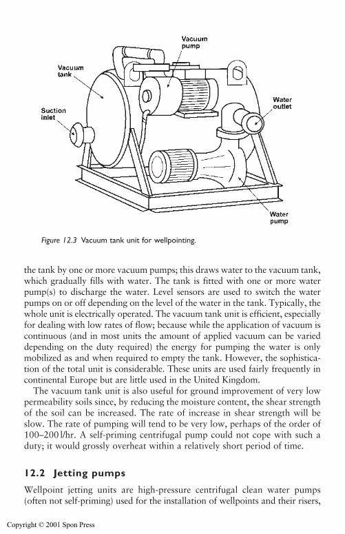
Pumps for groundwater lowering duties 355
the tank by one or more vacuum pumps; this draws water to the vacuum tank,which gradually fills with water. The tank is fitted with one or more waterpump(s) to discharge the water. Level sensors are used to switch the waterpumps on or off depending on the level of the water in the tank. Typically, thewhole unit is electrically operated. The vacuum tank unit is efficient, especiallyfor dealing with low rates of flow; because while the application of vacuum iscontinuous (and in most units the amount of applied vacuum can be varieddepending on the duty required) the energy for pumping the water is onlymobilized as and when required to empty the tank. However, the sophistica-tion of the total unit is considerable. These units are used fairly frequently incontinental Europe but are little used in the United Kingdom.
The vacuum tank unit is also useful for ground improvement of very lowpermeability soils since, by reducing the moisture content, the shear strengthof the soil can be increased. The rate of increase in shear strength will beslow. The rate of pumping will tend to be very low, perhaps of the order of100–200 l/hr. A self-priming centrifugal pump could not cope with such aduty; it would grossly overheat within a relatively short period of time.
12.2 Jetting pumps
Wellpoint jetting units are high-pressure centrifugal clean water pumps(often not self-priming) used for the installation of wellpoints and their risers,
Figure 12.3 Vacuum tank unit for wellpointing.
Copyright © 2001 Spon Press
placing tubes, etc. Their outputs are usually in the range of 12–200 l/s atpressures of 4–23 bars. The most commonly used jetting pump for theinstallation of wellpoints is rated to deliver about 20 l/s at a pressure ofabout 6–8 bars.
12.3 Units for sump pumping
Sump pumping (Chapter 8) is one of the most common pumping applica-tions on construction sites. Many types of pumps are used for sump pump-ing; some are suitable but some others are not. The sump pumping duty ismost frequently needed to deal with surface water run-off. Unfortunately,usually little or no consideration is given to filtering of the water to bepumped. Thus the units used for sump pumping must be able to cope withsome suspended solids in the pumped water.
12.3.1 Contractor’s submersible pump
A pump type commonly used for sump pumping is known as the contrac-tor’s submersible pump (Fig. 12.4). It is an electric submersible unit with asealed motor that usually runs in oil. The pump is of the bottom intake type(i.e. the water intake is beneath the motor). The pump is installed in a sump(Fig. 8.2); the pumped water flows around the outside of the motor casingand thereby helps to keep the motor cool. Most units can operate on inter-mittent ‘snore’ where the water level is drawn down to the pump invert andthe pump draws both air and water. It is prudent to suspend the unit so thatthe bottom of the pump intake is about 300 mm above the bottom of thesump; this allows for some accumulation of sediment in the sump. Theseunits are less mechanically efficient than some other types of pump. Whenhigh flows are involved the energy costs are significant.
The submersible pump does not operate on the suction principle, so thereis no limit to the possible drawdown, provided pumps of sufficient power andhead rating are used. Commonly used pumps range from 4.5 kW units with75 mm outlets (capable of pumping around 10 l/s at 10 m head) up to 40 kWunits with 200mm outlets (of capacity 100 l/s at 25 m head). Hydraulic sub-mersible pumps are also available, where the submersible pump is driven bya diesel hydraulic power pack located outside the sump at ground level.
12.3.2 All purpose self-priming centrifugal pump
These units are very similar to pumpsets used for wellpointing duties (seeSection 12.1), but adapted to be tolerant of some suspended solids in thepumped water. This requires the pump to be manufactured with generousclearance between the impeller and the volute casing, to allow fines to pass.However, by allowing for extra clearance in the pump internals, some
356 Pumps for groundwater lowering duties
Copyright © 2001 Spon Press
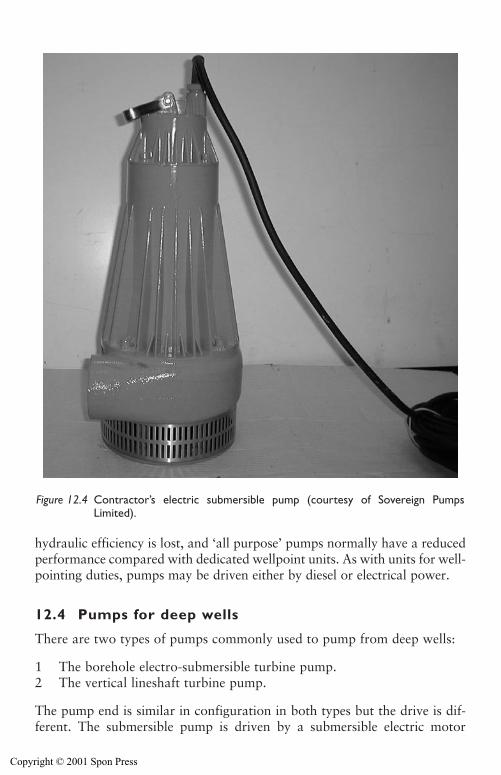
Pumps for groundwater lowering duties 357
hydraulic efficiency is lost, and ‘all purpose’ pumps normally have a reducedperformance compared with dedicated wellpoint units. As with units for well-pointing duties, pumps may be driven either by diesel or electrical power.
12.4 Pumps for deep wells
There are two types of pumps commonly used to pump from deep wells:
1 The borehole electro-submersible turbine pump.2 The vertical lineshaft turbine pump.
The pump end is similar in configuration in both types but the drive is dif-ferent. The submersible pump is driven by a submersible electric motor
Figure 12.4 Contractor’s electric submersible pump (courtesy of Sovereign PumpsLimited).
Copyright © 2001 Spon Press
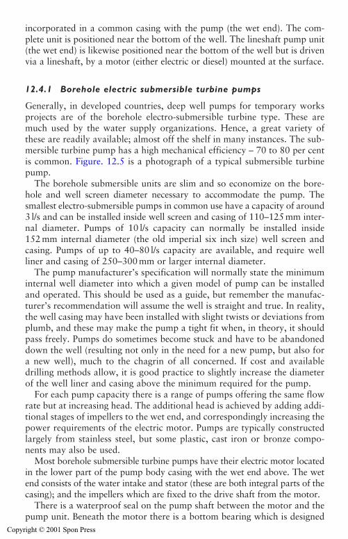
incorporated in a common casing with the pump (the wet end). The com-plete unit is positioned near the bottom of the well. The lineshaft pump unit(the wet end) is likewise positioned near the bottom of the well but is drivenvia a lineshaft, by a motor (either electric or diesel) mounted at the surface.
12.4.1 Borehole electric submersible turbine pumps
Generally, in developed countries, deep well pumps for temporary worksprojects are of the borehole electro-submersible turbine type. These aremuch used by the water supply organizations. Hence, a great variety ofthese are readily available; almost off the shelf in many instances. The sub-mersible turbine pump has a high mechanical efficiency – 70 to 80 per centis common. Figure. 12.5 is a photograph of a typical submersible turbinepump.
The borehole submersible units are slim and so economize on the bore-hole and well screen diameter necessary to accommodate the pump. Thesmallest electro-submersible pumps in common use have a capacity of around3 l/s and can be installed inside well screen and casing of 110–125 mm inter-nal diameter. Pumps of 10 l/s capacity can normally be installed inside152 mm internal diameter (the old imperial six inch size) well screen andcasing. Pumps of up to 40–80 l/s capacity are available, and require wellliner and casing of 250–300 mm or larger internal diameter.
The pump manufacturer’s specification will normally state the minimuminternal well diameter into which a given model of pump can be installedand operated. This should be used as a guide, but remember the manufac-turer’s recommendation will assume the well is straight and true. In reality,the well casing may have been installed with slight twists or deviations fromplumb, and these may make the pump a tight fit when, in theory, it shouldpass freely. Pumps do sometimes become stuck and have to be abandoneddown the well (resulting not only in the need for a new pump, but also fora new well), much to the chagrin of all concerned. If cost and availabledrilling methods allow, it is good practice to slightly increase the diameterof the well liner and casing above the minimum required for the pump.
For each pump capacity there is a range of pumps offering the same flowrate but at increasing head. The additional head is achieved by adding addi-tional stages of impellers to the wet end, and correspondingly increasing thepower requirements of the electric motor. Pumps are typically constructedlargely from stainless steel, but some plastic, cast iron or bronze compo-nents may also be used.
Most borehole submersible turbine pumps have their electric motor locatedin the lower part of the pump body casing with the wet end above. The wetend consists of the water intake and stator (these are both integral parts of thecasing); and the impellers which are fixed to the drive shaft from the motor.
There is a waterproof seal on the pump shaft between the motor and thepump unit. Beneath the motor there is a bottom bearing which is designed
358 Pumps for groundwater lowering duties
Copyright © 2001 Spon Press
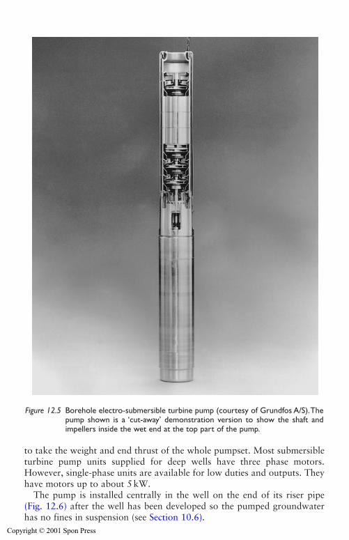
Pumps for groundwater lowering duties 359
to take the weight and end thrust of the whole pumpset. Most submersibleturbine pump units supplied for deep wells have three phase motors.However, single-phase units are available for low duties and outputs. Theyhave motors up to about 5 kW.
The pump is installed centrally in the well on the end of its riser pipe (Fig. 12.6) after the well has been developed so the pumped groundwaterhas no fines in suspension (see Section 10.6).
Figure 12.5 Borehole electro-submersible turbine pump (courtesy of Grundfos A/S).Thepump shown is a ‘cut-away’ demonstration version to show the shaft andimpellers inside the wet end at the top part of the pump.
Copyright © 2001 Spon Press
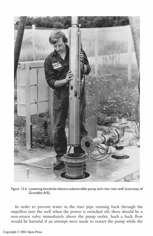
360 Pumps for groundwater lowering duties
In order to prevent water in the riser pipe running back through theimpellers into the well when the power is switched off, there should be anon-return valve immediately above the pump outlet. Such a back flowwould be harmful if an attempt were made to restart the pump while the
Figure 12.6 Lowering borehole electro-submersible pump and riser into well (courtesy ofGrundfos A/S).
Copyright © 2001 Spon Press
Pumps for groundwater lowering duties 361
water in the riser pipe was still running back; under such circumstances theadditional start up load could cause overloading. However, a non-return valvewill mean that the riser pipe will remain full of water when the pump isswitched off. This increases the weight to be lifted when the pump is removedfrom the well. It is acceptable to drill a 5mm diameter hole in the non-returnvalve to allow water to drain from the riser pipe sufficiently slowly.
12.4.2 Borehole electro-submersiblepumps – operational problems
There are three possible causes of motor failure:
(a) Wear of the seal between the motor and the impellers. In time wearwould allow water to enter the sealed motor thus causing failure of themotor windings.
(b) Uneven wear of the bottom thrust bearing. This will lead to unevenwear of the upper seal also – result as (a) above.
(c) Overheating of the motor. This will damage the windings of the motor.
Seal wearIn order to avoid failure due to seal wear, it is necessary to ensure that thewater pumped is clean. However, if the grading of the filter media aroundthe well screen is too coarse to retain the soil particles (or the well has notbeen adequately developed, see Section 10.6) the pumped water may con-tain fine particles in suspension. In time this will cause wear of the impellersand stator leading to reduced output. Also the seal between the impellersand the motor will be worn, eventually causing failure of the motor wind-ings. The rewinding of a pump motor is both costly and time consuming.
Bearing failureIt is important that the pumpset hangs vertically. Otherwise the thrust onthe bottom bearing pad will be uneven, leading to uneven wear of the sealbetween the motor and the impellers; eventually water will penetrate thewindings of the electric motor, causing it to fail.
Motor overheatingIn operation the pump casing is immersed in the groundwater and also themotor windings are surrounded by a jacket filled with oil or water basedemulsion coolant fluid. Overheating of the motor windings is unlikely, pro-vided the flow to the well is significant compared with the volume of watersurrounding the pump motor casing. However, if the rate of pumping of thewell is low (e.g. in a low permeability soil), the pump motor casing may bein ‘dead water’. The heat generated by the motor will gradually raise thetemperature of the dead water in the well sump above the generally cool
Copyright © 2001 Spon Press
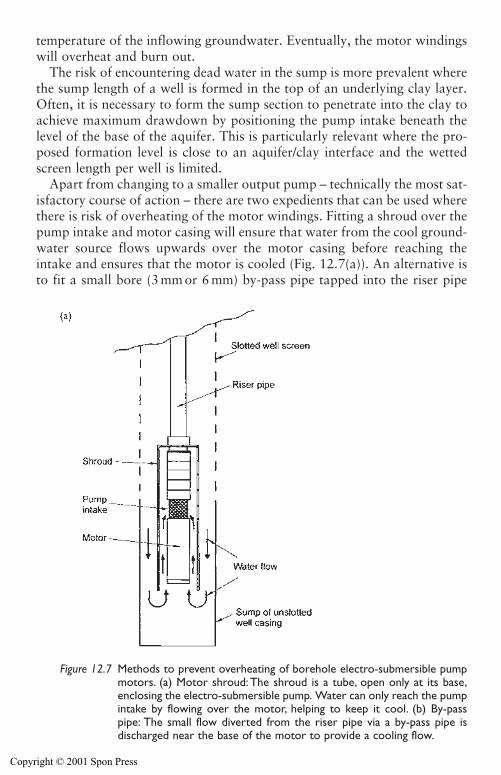
temperature of the inflowing groundwater. Eventually, the motor windingswill overheat and burn out.
The risk of encountering dead water in the sump is more prevalent wherethe sump length of a well is formed in the top of an underlying clay layer.Often, it is necessary to form the sump section to penetrate into the clay toachieve maximum drawdown by positioning the pump intake beneath thelevel of the base of the aquifer. This is particularly relevant where the pro-posed formation level is close to an aquifer/clay interface and the wettedscreen length per well is limited.
Apart from changing to a smaller output pump – technically the most sat-isfactory course of action – there are two expedients that can be used wherethere is risk of overheating of the motor windings. Fitting a shroud over thepump intake and motor casing will ensure that water from the cool ground-water source flows upwards over the motor casing before reaching theintake and ensures that the motor is cooled (Fig. 12.7(a)). An alternative isto fit a small bore (3 mm or 6 mm) by-pass pipe tapped into the riser pipe
362 Pumps for groundwater lowering duties
Figure 12.7 Methods to prevent overheating of borehole electro-submersible pumpmotors. (a) Motor shroud: The shroud is a tube, open only at its base,enclosing the electro-submersible pump. Water can only reach the pumpintake by flowing over the motor, helping to keep it cool. (b) By-passpipe: The small flow diverted from the riser pipe via a by-pass pipe isdischarged near the base of the motor to provide a cooling flow.
Copyright © 2001 Spon Press
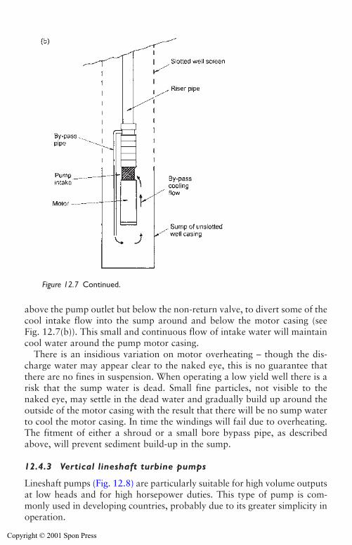
Pumps for groundwater lowering duties 363
above the pump outlet but below the non-return valve, to divert some of thecool intake flow into the sump around and below the motor casing (seeFig. 12.7(b)). This small and continuous flow of intake water will maintaincool water around the pump motor casing.
There is an insidious variation on motor overheating – though the dis-charge water may appear clear to the naked eye, this is no guarantee thatthere are no fines in suspension. When operating a low yield well there is arisk that the sump water is dead. Small fine particles, not visible to thenaked eye, may settle in the dead water and gradually build up around theoutside of the motor casing with the result that there will be no sump waterto cool the motor casing. In time the windings will fail due to overheating.The fitment of either a shroud or a small bore bypass pipe, as describedabove, will prevent sediment build-up in the sump.
12.4.3 Vertical lineshaft turbine pumps
Lineshaft pumps (Fig. 12.8) are particularly suitable for high volume outputsat low heads and for high horsepower duties. This type of pump is com-monly used in developing countries, probably due to its greater simplicity inoperation.
Figure 12.7 Continued.
Copyright © 2001 Spon Press
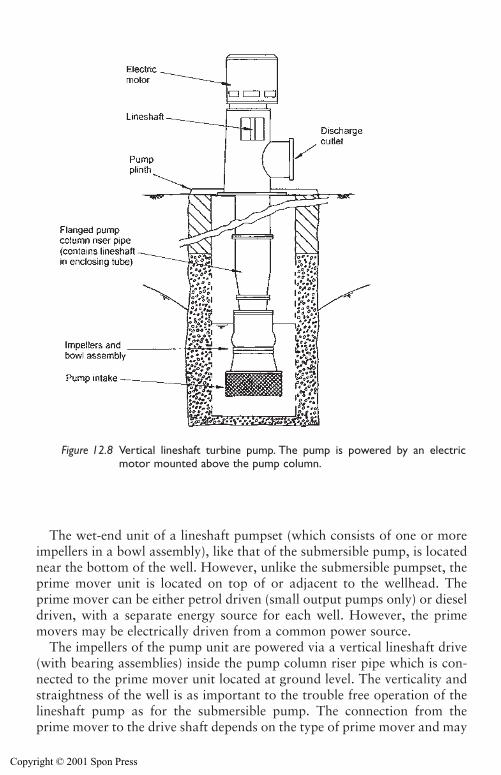
364 Pumps for groundwater lowering duties
The wet-end unit of a lineshaft pumpset (which consists of one or moreimpellers in a bowl assembly), like that of the submersible pump, is locatednear the bottom of the well. However, unlike the submersible pumpset, theprime mover unit is located on top of or adjacent to the wellhead. Theprime mover can be either petrol driven (small output pumps only) or dieseldriven, with a separate energy source for each well. However, the primemovers may be electrically driven from a common power source.
The impellers of the pump unit are powered via a vertical lineshaft drive(with bearing assemblies) inside the pump column riser pipe which is con-nected to the prime mover unit located at ground level. The verticality andstraightness of the well is as important to the trouble free operation of thelineshaft pump as for the submersible pump. The connection from theprime mover to the drive shaft depends on the type of prime mover and may
Figure 12.8 Vertical lineshaft turbine pump. The pump is powered by an electricmotor mounted above the pump column.
Copyright © 2001 Spon Press
Pumps for groundwater lowering duties 365
be a direct coupling, a belt drive, or right angle gear. As with a boreholeelectro-submersible pump, it is prudent to incorporate a non-return valve atthe pump outlet.
12.4.4 Lineshaft pumps – operational problems
If the pumped water contains fines in suspension (either because the well wasnot developed adequately or the grading of the filter media is too coarse) intime the impeller stages and casing will wear and the pump output willdecline. Otherwise, the lineshaft unit is generally trouble free and reliable inuse provided that the pump unit with its lineshaft assembly has been properlyinstalled in the well, though prime mover troubles there may be. All the fore-going assumes that the pump unit sizing is appropriate to the actual well yield.
12.4.5 Comparison of merits of lineshaft pumps vselectro-submersible pumps
The mechanical efficiency of lineshaft pumps tends to be slightly greaterthan that of submersible pumps. The initial cost of small output lineshaftpumps tends to be greater than a comparable sized submersible pump butthis is reversed for the large output units.
The installation procedures for lineshaft pumps are more onerous. Thewell must be plumb. Also, skilled personnel are required for installation.Separate connections have to be made to each drive shaft length and pumpcolumn riser pipe joint assemblies, as these are being installed in the well.The standard length of shaft components may not be the same as those ofthe riser pipes; this can cause tedium in installation of the riser pipe anddrive shaft in the well. In contrast, the installation of an electro-submersiblepump unit entails only the connections of the riser pipe; the electric powercable will be in one continuous length and is simply paid out as the pumpis lowered into the well. However, a considerably lesser standard of skillsare required for the maintenance and repair of lineshaft pumps as comparedto the submersible unit. Motor or prime mover repairs are particularly easyfor lineshaft pumps because of the above ground installation.
Each individual wellhead prime mover unit of a lineshaft pump installationshould to visited at regular intervals and performance and fuel requirementschecked. However, for a submersible pump installation, all the control switchgear, pump starters and associated process timers (for automatically restart-ing an individual pump if it trips out) and the change-over switchgearfrom mains power to standby generators (in case there is a failure of themains supply, for whatever cause) etc. can all be located inside a single switchhouse. This makes supervision of the running of a deep well submersiblepump installation easier and more straightforward as well as less labourintensive.
Copyright © 2001 Spon Press
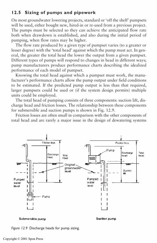
12.5 Sizing of pumps and pipework
On most groundwater lowering projects, standard or ‘off the shelf’ pumpsetswill be used, either bought new, hired-in or re-used from a previous project.The pumps must be selected so they can achieve the anticipated flow rateboth when drawdown is established, and also during the initial period ofpumping, when flow rates may be higher.
The flow rate produced by a given type of pumpset varies (to a greater orlesser degree) with the ‘total head’ against which the pump must act. In gen-eral, the greater the total head the lower the output from a given pumpset.Different types of pumps will respond to changes in head in different ways;pump manufacturers produce performance charts describing the idealizedperformance of each model of pumpset.
Knowing the total head against which a pumpset must work, the manu-facturer’s performance charts allow the pump output under field conditionsto be estimated. If the predicted pump output is less than that required,larger pumpsets could be used or (if the system design permits) multipleunits could be employed.
The total head of pumping consists of three components: suction lift, dis-charge head and friction losses. The relationship between these componentsfor submersible and suction pumps is shown in Fig. 12.9.
Friction losses are often small in comparison with the other components oftotal head and are rarely a major issue in the design of dewatering systems
366 Pumps for groundwater lowering duties
Figure 12.9 Discharge heads for pump sizing.
Copyright © 2001 Spon Press
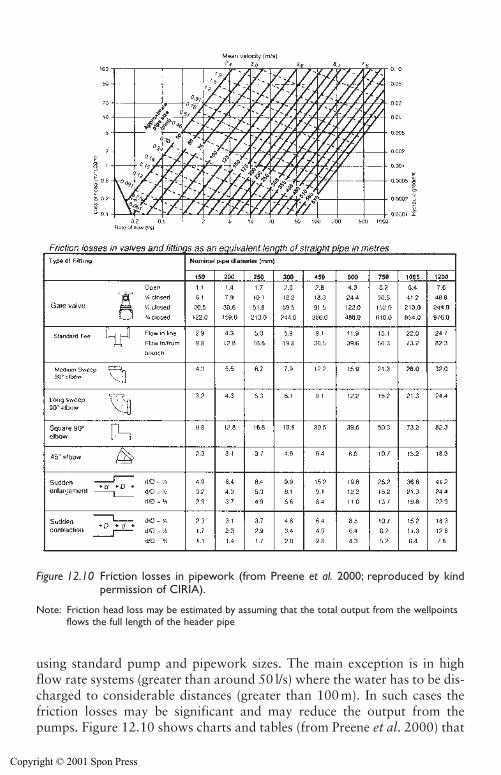
Figure 12.10 Friction losses in pipework (from Preene et al. 2000; reproduced by kindpermission of CIRIA).
Note: Friction head loss may be estimated by assuming that the total output from the wellpointsflows the full length of the header pipe
using standard pump and pipework sizes. The main exception is in highflow rate systems (greater than around 50 l/s) where the water has to be dis-charged to considerable distances (greater than 100 m). In such cases thefriction losses may be significant and may reduce the output from thepumps. Figure 12.10 shows charts and tables (from Preene et al. 2000) that
Copyright © 2001 Spon Press
allow friction losses to be estimated for commonly used pipe sizes andfittings.
If friction losses are perceived to be large enough to detrimentally effectpump outputs, then a number of remedial measures are possible.
i Replace the pump sets with units rated at higher heads.ii Provide additional pumpsets so that a greater number of pumps pro-
ducing a lower output can achieve the required total flow rate.iii Modify the discharge pipework by either: planning the pipework lay-
out carefully to avoid unnecessary bends, junctions or constrictions;using discharge pipework of larger diameter, if available; or, if largerpipework is not available, one or more additional lines of dischargepipework could be laid, reducing the flow rate taken by a individualpipe.
iv Reduce the distance that the discharge water must be pumped (e.g. bylocating an alternative discharge point).
v Provide ‘booster pumps’ between the dewatering pumps and the dis-charge point. This will reduce the total head on the dewatering pumps,increasing their output.
References
Preene, M., Roberts, T. O. L., Powrie, W. and Dyer, M. R. (2000). GroundwaterControl – Design and Practice. Construction Industry Research and InformationAssociation, CIRIA Report C515, London.
368 Pumps for groundwater lowering duties
Copyright © 2001 Spon Press
Chapter 13
Side effects of groundwaterlowering
13.0 Introduction
Groundwater lowering operations may affect water levels over a wide area,which can extend for some distance beyond the construction site itself. Inmany cases this will not cause problems, but there are some circumstanceswhen undesirable side effects may arise. This chapter outlines some potentialside effects of groundwater lowering, the conditions in which they may occurand possible mitigation measures, including artificial recharge systems.
The effects discussed in this chapter are:
i Settlement resulting from the instability of excavations when ground-water is not adequately controlled.
ii Ground settlements caused by loss of fines.iii Ground settlements induced by increases in effective stress, and associ-
ated structural damage or distress.iv Derogation or depletion of groundwater sources.v Changes in groundwater quality, including movement of contamina-
tion plumes and saline intrusion.vi The impact of discharge flows on the surface water environment.vii Other less common effects, including the drying out of timber piles and
the desiccation of wetlands and vegetation.
The use of artificial recharge systems to mitigate some of the side effects ofgroundwater lowering is described. Practical problems that may occur duringoperation of recharge systems are discussed, and a case history is presented.
13.1 Settlement due to groundwater lowering
Ground settlements are an inevitable consequence of every groundwater low-ering exercise. In the great majority of cases the settlements are so small thatno distortion or damage is apparent in nearby buildings. However, occasion-ally settlements may be large enough to cause damaging distortion or distressof structures, which can range from minor cracking of architectural finishes
Copyright © 2001 Spon Press
370 Side effects of groundwater lowering
to major structural damage. In extreme cases these effects have extendedseveral hundred metres from the construction site itself, and have affectedlarge numbers of structures.
If there is any concern that groundwater lowering (or any otherconstruction operation) may result in ground settlements beneath existingstructures it is essential that a pre-construction building condition surveybe carried out. This exercise (sometimes known as a dilapidation survey)involves recording the current state of any structures that may be affectedby settlement. This should provide a detailed record of any pre-existingdefects, so that if damage is alleged, there is a basis for judging the veracityof the claims. Unfortunately, for groundwater lowering projects, where theinfluence of the works may extend for several hundred metres from the site,the building condition survey area selected is often too small and does notcover all the structures that may be significantly affected. Ideally, the extentof the survey should be finalized following a risk assessment exercise.
Settlements caused by groundwater lowering may be generated by anumber of different mechanisms, some easily avoidable, some less so:
1 Settlement resulting from the instability of excavations when ground-water is not adequately controlled.
2 Settlement caused by loss of fines.3 Settlement induced by increases in effective stress.
13.1.1 Settlement due to poorly controlled groundwater
This book describes the philosophy and methods whereby groundwater canbe controlled to provide stable excavations for construction works. However,sometimes groundwater is not adequately controlled, leading to instabilityof excavation, uncontrolled seepages and perhaps a groundwater ‘blow’ (seeChapter 4). These problems may result from several causes, such as: failure toappreciate the need for groundwater control; a mis-directed desire to reducecosts by scaling down or deleting groundwater control from the temporaryworks; inadequate standby or back up facilities to prevent interruption inpumping; and ground or groundwater conditions not anticipated by the siteinvestigation or design, and not identified by construction monitoring.
Ideally, with adequate investigation and planning, most of these issuescan normally be avoided, especially the last one. Sadly, these problems stilloccur, leading to the failure of excavations and both significant additionalcosts and delays to the construction project (see Bauer et al. 1980 andGreenwood 1984 for case histories). If there is a sudden ‘blow’ or failure ofan excavation, soil material will be washed into the excavation. This cancreate large and unpredictable settlements around the excavation, muchlarger than the effective stress settlements associated with groundwatercontrol. Any buildings in the area where the uncontrolled settlements occurare likely to be severely damaged.
Copyright © 2001 Spon Press
13.1.2 Settlement due to loss of fines
Settlement can also occur if a groundwater lowering system continuallypumps ‘fines’ (silt and sand sized particles) in the discharge water – a prob-lem known as ‘loss of fines’. Most dewatering systems will pump fines inthe initial stages of pumping, as a more permeable zone is developed aroundthe well or sump (see well development, Section 10.6). However, if thepumping of fines continues for extended periods, the removal of particleswill loosen the soil and may create sub-surface erosion channels (sometimesknown as ‘pipes’). Compaction of the loosened soil or collapse of sucherosion channels may lead to ground movements and settlement.
Continuous pumping of fines is not normally a problem with wellpoints,deep wells or ejectors, provided that adequate filter packs have beeninstalled and monitored for fines in their discharge. Occasionally, a sandpumping well may be encountered, perhaps caused by a cracked screen orpoor installation techniques. Such wells should be taken out of serviceimmediately.
The method which most commonly causes loss of fines is sump pumping(see Chapter 8). This is because the installation of adequate filters aroundsumps is often neglected, allowing fine particles in the soil to becomemobile as groundwater is drawn towards the pump. Section 8.6 shows anexample of the problems this can cause. Powers (1985) lists soil types wherethe use of sump pumping is fraught with risk. These include:
� Uniform fine sands� Soft non-cohesive silts and soft clays� Soft rocks where fissures can erode and enlarge due to high water
velocities� Rocks where fissures are filled with silt, sand or soft clay, which may
be eroded� Sandstone with uncemented layers that may be washed out.
In these soil types, even the best-engineered sump pumping systems mayencounter problems. Serious consideration should be given to carrying outgroundwater lowering by a method using wells (wellpoints, deep wells orejectors) with correctly designed and installed filters.
13.1.3 Settlement due to increases in effective stress
Lowering of groundwater levels will naturally reduce pore water pressures,and hence increase effective stress (see Section 4.2). This will cause the soillayer to compress, leading to ground settlements. In practice however, forthe great majority of cases the effective stress settlements are so small thatno damage to nearby structures results.
Side effects of groundwater lowering 371
Copyright © 2001 Spon Press
The magnitude of effective stress settlements will depend on a number offactors:
i The presence and thickness of a highly compressible layer of soil belowthe groundwater level, which will be affected by the pore water pres-sure reduction. Examples include soft alluvial silts and clays or peatdeposits. The softer a soil layer (and the thicker it is), the greater thepotential settlement.
ii The amount of drawdown. The greater the drawdown of the ground-water level, the greater the resulting settlement.
iii The period of pumping. In general, at a given site, the longer thepumping is continued, the greater the settlement.
Powers (1992) states that the most significant of these factors is the pres-ence of a layer of highly compressible soil. It is certainly a truism that dam-aging settlements are unlikely to result from groundwater lowering on siteswhere highly compressible soils are absent. The corollary of this is that thepotential for damaging settlements should be investigated carefully on anysite where there is a significant thickness of highly compressible soils.
Effective stress settlements can be calculated using basic soil mechanics the-ory. The final (or ultimate) compression �ult of a soil layer of thickness D is:
�ult � (13.1)
where �u is the reduction in pore water pressure, and E0 is the stiffness ofthe soil in one-dimensional compression (which is equal to 1/mv, where mvis the coefficient of volume compressibility). E0 can be estimated usingseveral techniques; values used in calculations should be selected with care(see Preene et al. 2000).
Equation (13.1) is based on the assumption that total stress remains con-stant as the groundwater level is lowered. This is a reasonable simplifyingassumption, since the difference between the unit weight of most soils insaturated and unsaturated conditions is generally small and, given the uncer-tainties in other parameters, can be neglected without significant error.
To be useful in practice, equation (13.1) needs to be written in terms ofdrawdown s. This will be different for aquicludes, aquifers and aquitards(see Section 3.3).
1 Aquicludes. This type of strata is of very low permeability. During theperiod of pumping from an adjacent aquifer, no significant pore waterpressure reduction (and hence compression) will be generated.
2 Aquifers. This type of strata is normally of significant permeability andis pumped directly by the wells or wellpoints. Pore water pressurereductions will occur effectively at the same time as the drawdown. In
�uD�
E0
372 Side effects of groundwater lowering
Copyright © 2001 Spon Press
Side effects of groundwater lowering 373
practice, this means compression and settlement of aquifers occursinstantaneously once drawdown occurs. The rate at which drawdownoccurs, and the resulting pattern of drawdown around a groundwaterlowering system can be estimated using the methods given in Section 7.6.
3 Aquitards. These strata are at least one to two orders of magnitudeless permeable than aquifers, and are not generally pumped directly bywells or wellpoints. Aquitards drain vertically into the aquifer, at a ratecontrolled by the vertical permeability of the aquitard. In practice thismeans that, even if the drawdown and compression of the aquifer hasstabilized, water may still be draining slowly out of the aquitard, andwill continue to do so until the pore water pressures equilibrate withthose in the aquifer. The pore water pressure reductions and compres-sions of aquitard layers will tend to lag behind the aquifer, and maytake weeks, months or even years to reach their ultimate value. Ofcourse if the groundwater lowering system operates for only a shortperiod of time, the ultimate compression will not develop fully.
Figure 13.1 shows that, where aquifers and aquitards are present, thedistribution of pore water pressure reduction with depth will depend on thenature of the strata at the site, and will change with time. This should betaken into account when estimating ground settlements.
Settlements caused by groundwater lowering will generally increase withtime, and will be greatest at the end of the period of pumping. There aretwo separate time-dependent effects at work:
i Increasing aquifer drawdown with time. When groundwater is pumpedfrom an aquifer by a series of wells, a zone of drawdown propagatesaway from the system at a rate controlled by the pumping rate andaquifer properties. This means that at a given point, some distance fromthe system, drawdown in the aquifer will increase with time, as willcompression of the aquifer. For all practical purposes compression ofan aquifer occurs contemporaneously with drawdown.
ii Slow drainage from aquitards. When drawdown occurs in an aquifer,any adjacent aquitard will begin to drain vertically into the aquifer.This drainage may occur quite slowly. It follows that the compressionof aquitards will lag behind the drawdown in the aquifer.
For a simple case (Fig. 13.2) with wells fully penetrating a confined orsemi-confined aquifer, groundwater flow will be horizontal, �u will be con-stant with depth and �u��ws, where �w is the unit weight of water and s isthe drawdown of the piezometric layer, giving the ultimate compression ofa soil layer as:
�ult� (13.2)�wsD�
E0
Copyright © 2001 Spon Press
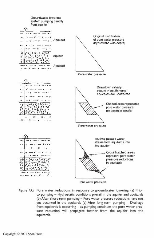
Figure 13.1 Pore water reductions in response to groundwater lowering. (a) Priorto pumping – Hydrostatic conditions prevail in the aquifer and aquitards(b) After short-term pumping – Pore water pressure reductions have notyet occurred in the aquitards (c) After long-term pumping – Drainagefrom aquitards is occurring – as pumping continues the pore water pres-sure reduction will propagate further from the aquifer into theaquitards.
Copyright © 2001 Spon Press
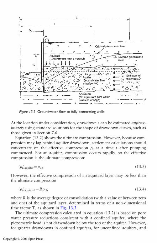
Side effects of groundwater lowering 375
At the location under consideration, drawdown s can be estimated approx-imately using standard solutions for the shape of drawdown curves, such asthose given in Section 7.6.
Equation (13.2) shows the ultimate compression. However, because com-pression may lag behind aquifer drawdown, settlement calculations shouldconcentrate on the effective compression �t at a time t after pumpingcommenced. For an aquifer, compression occurs rapidly, so the effectivecompression is the ultimate compression:
(�t)aquifer��ult (13.3)
However, the effective compression of an aquitard layer may be less thanthe ultimate compression
(�t)aquitard�R�ult (13.4)
where R is the average degree of consolidation (with a value of between zeroand one) of the aquitard layer, determined in terms of a non-dimensionaltime factor Tv as shown in Fig. 13.3.
The ultimate compression calculated in equation (13.2) is based on porewater pressure reductions consistent with a confined aquifer, where thepiezometric head is not drawndown below the top of the aquifer. However,for greater drawdowns in confined aquifers, for unconfined aquifers, and
Figure 13.2 Groundwater flow to fully penetrating wells.
Copyright © 2001 Spon Press
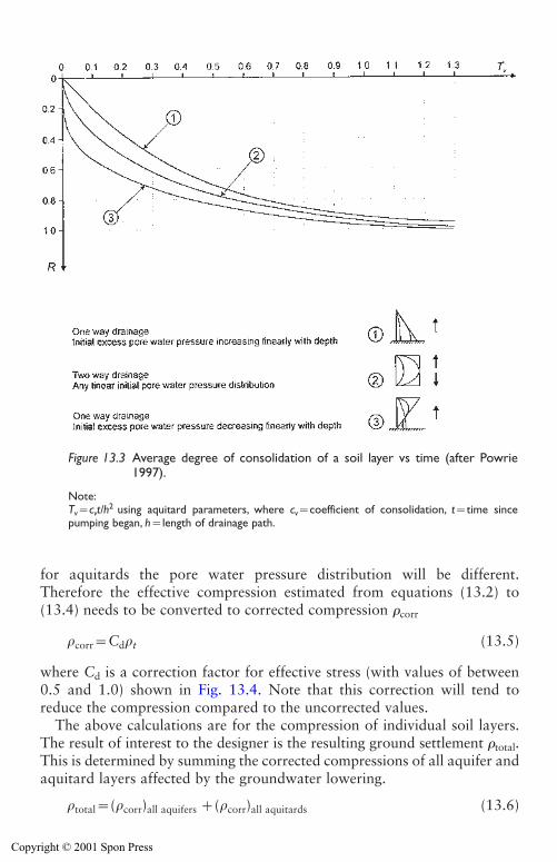
376 Side effects of groundwater lowering
for aquitards the pore water pressure distribution will be different.Therefore the effective compression estimated from equations (13.2) to(13.4) needs to be converted to corrected compression �corr
�corr�Cd�t (13.5)
where Cd is a correction factor for effective stress (with values of between0.5 and 1.0) shown in Fig. 13.4. Note that this correction will tend toreduce the compression compared to the uncorrected values.
The above calculations are for the compression of individual soil layers.The result of interest to the designer is the resulting ground settlement �total.This is determined by summing the corrected compressions of all aquifer andaquitard layers affected by the groundwater lowering.
�total�(�corr)all aquifers �(�corr)all aquitards (13.6)
Figure 13.3 Average degree of consolidation of a soil layer vs time (after Powrie1997).
Note:Tv�cvt/h2 using aquitard parameters, where cv�coefficient of consolidation, t�time sincepumping began, h�length of drainage path.
Copyright © 2001 Spon Press
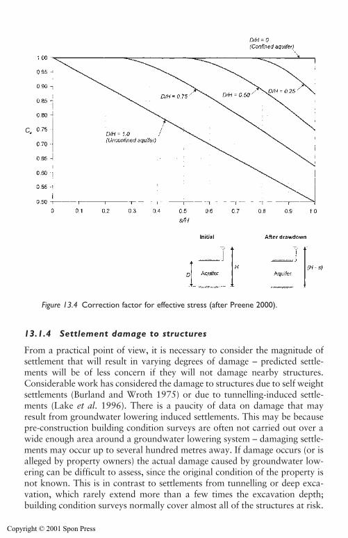
Side effects of groundwater lowering 377
13.1.4 Settlement damage to structures
From a practical point of view, it is necessary to consider the magnitude ofsettlement that will result in varying degrees of damage – predicted settle-ments will be of less concern if they will not damage nearby structures.Considerable work has considered the damage to structures due to self weightsettlements (Burland and Wroth 1975) or due to tunnelling-induced settle-ments (Lake et al. 1996). There is a paucity of data on damage that mayresult from groundwater lowering induced settlements. This may be becausepre-construction building condition surveys are often not carried out over awide enough area around a groundwater lowering system – damaging settle-ments may occur up to several hundred metres away. If damage occurs (or isalleged by property owners) the actual damage caused by groundwater low-ering can be difficult to assess, since the original condition of the property isnot known. This is in contrast to settlements from tunnelling or deep exca-vation, which rarely extend more than a few times the excavation depth;building condition surveys normally cover almost all of the structures at risk.
Figure 13.4 Correction factor for effective stress (after Preene 2000).
Copyright © 2001 Spon Press
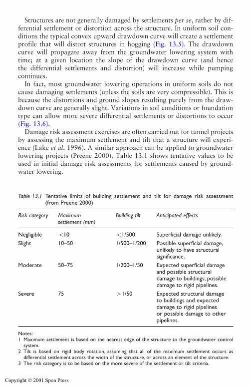
378 Side effects of groundwater lowering
Structures are not generally damaged by settlements per se, rather by dif-ferential settlement or distortion across the structure. In uniform soil con-ditions the typical convex upward drawdown curve will create a settlementprofile that will distort structures in hogging (Fig. 13.5). The drawdowncurve will propagate away from the groundwater lowering system withtime; at a given location the slope of the drawdown curve (and hencethe differential settlements and distortion) will increase while pumpingcontinues.
In fact, most groundwater lowering operations in uniform soils do notcause damaging settlements (unless the soils are very compressible). This isbecause the distortions and ground slopes resulting purely from the draw-down curve are generally slight. Variations in soil conditions or foundationtype can allow more severe differential settlements or distortions to occur(Fig. 13.6).
Damage risk assessment exercises are often carried out for tunnel projectsby assessing the maximum settlement and tilt that a structure will experi-ence (Lake et al. 1996). A similar approach can be applied to groundwaterlowering projects (Preene 2000). Table 13.1 shows tentative values to beused in initial damage risk assessments for settlements caused by ground-water lowering.
Table 13.1 Tentative limits of building settlement and tilt for damage risk assessment(from Preene 2000)
Risk category Maximum Building tilt Anticipated effectssettlement (mm)
Negligible �10 �1/500 Superficial damage unlikely.Slight 10–50 1/500–1/200 Possible superficial damage,
unlikely to have structuralsignificance.
Moderate 50–75 1/200–1/50 Expected superficial damage and possible structuraldamage to buildings; possibledamage to rigid pipelines.
Severe 75 �1/50 Expected structural damageto buildings and expecteddamage to rigid pipelines or possible damage to otherpipelines.
Notes:1 Maximum settlement is based on the nearest edge of the structure to the groundwater control
system.2 Tilt is based on rigid body rotation, assuming that all of the maximum settlement occurs as
differential settlement across the width of the structure, or across an element of the structure.3 The risk category is to be based on the more severe of the settlement or tilt criteria.
Copyright © 2001 Spon Press
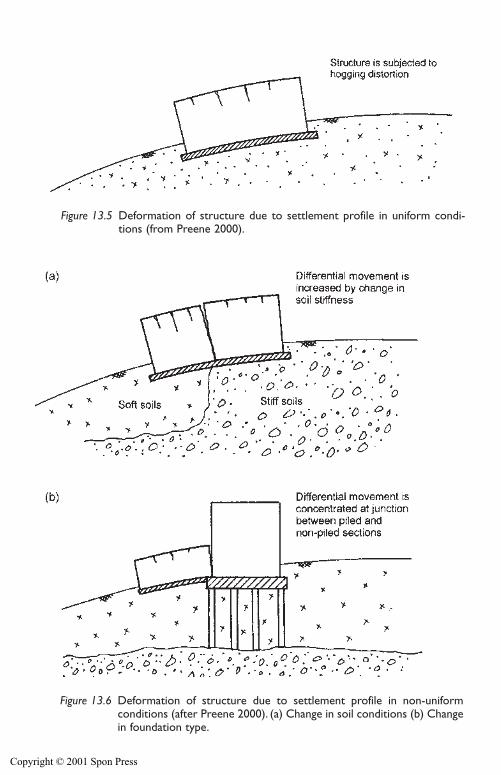
Figure 13.5 Deformation of structure due to settlement profile in uniform condi-tions (from Preene 2000).
Figure 13.6 Deformation of structure due to settlement profile in non-uniformconditions (after Preene 2000). (a) Change in soil conditions (b) Changein foundation type.
Copyright © 2001 Spon Press
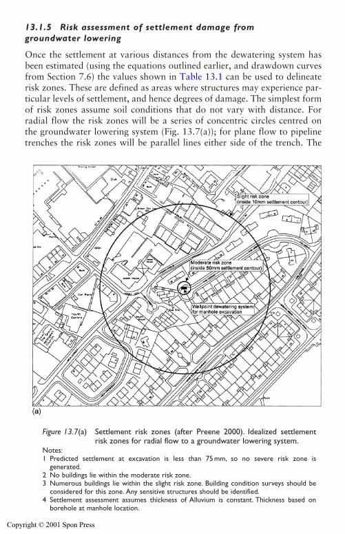
13.1.5 Risk assessment of settlement damage fromgroundwater lowering
Once the settlement at various distances from the dewatering system hasbeen estimated (using the equations outlined earlier, and drawdown curvesfrom Section 7.6) the values shown in Table 13.1 can be used to delineaterisk zones. These are defined as areas where structures may experience par-ticular levels of settlement, and hence degrees of damage. The simplest formof risk zones assume soil conditions that do not vary with distance. Forradial flow the risk zones will be a series of concentric circles centred onthe groundwater lowering system (Fig. 13.7(a)); for plane flow to pipelinetrenches the risk zones will be parallel lines either side of the trench. The
380 Side effects of groundwater lowering
Figure 13.7(a) Settlement risk zones (after Preene 2000). Idealized settlementrisk zones for radial flow to a groundwater lowering system.
Notes:1 Predicted settlement at excavation is less than 75 mm, so no severe risk zone is
generated.2 No buildings lie within the moderate risk zone.3 Numerous buildings lie within the slight risk zone. Building condition surveys should be
considered for this zone. Any sensitive structures should be identified.4 Settlement assessment assumes thickness of Alluvium is constant. Thickness based on
borehole at manhole location.
Copyright © 2001 Spon Press
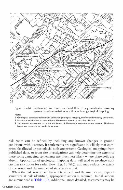
Side effects of groundwater lowering 381
Figure 13.7(b) Settlement risk zones for radial flow to a groundwater loweringsystem based on variation in soil type from geological mapping.
Notes1 Geological boundary taken from published geological mapping, confirmed by nearby boreholes.2 Predicted settlement in area where Alluvium is absent is less than 10 mm.3 Settlement assessment assumes thickness of Alluvium is constant when present.Thickness
based on borehole at manhole location.
risk zones can be refined by including any known changes in groundconditions with distance. If settlements are significant it is likely that com-pressible alluvial or post glacial soils are present. Geological mapping (frompublished data, or from site investigation) can help determine the extent ofthese soils; damaging settlements are much less likely where these soils areabsent. Application of geological mapping data will tend to produce non-circular risk zones for radial flow (Fig. 13.7(b)), and may reduce the extentof the zones and the number of structures at risk.
When the risk zones have been determined, and the number and type ofstructures at risk identified, appropriate action is required. Initial actionsare summarized in Table 13.2. Additional, more detailed, assessments may be
Copyright © 2001 Spon Press
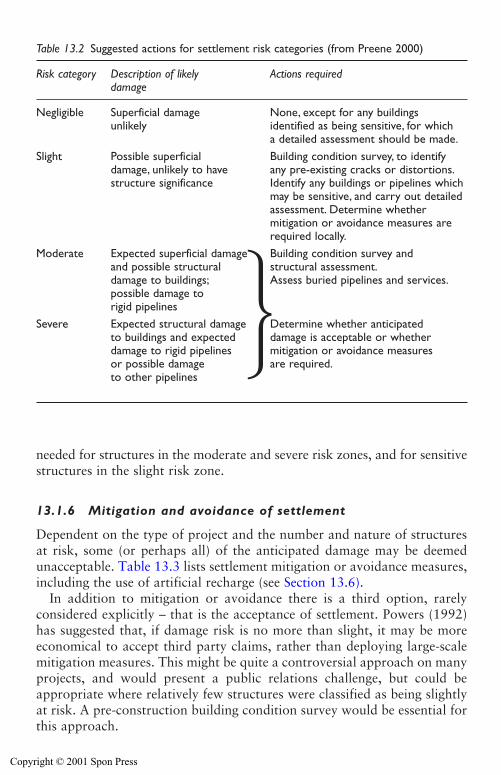
382 Side effects of groundwater lowering
needed for structures in the moderate and severe risk zones, and for sensitivestructures in the slight risk zone.
13.1.6 Mitigation and avoidance of settlement
Dependent on the type of project and the number and nature of structuresat risk, some (or perhaps all) of the anticipated damage may be deemedunacceptable. Table 13.3 lists settlement mitigation or avoidance measures,including the use of artificial recharge (see Section 13.6).
In addition to mitigation or avoidance there is a third option, rarelyconsidered explicitly – that is the acceptance of settlement. Powers (1992)has suggested that, if damage risk is no more than slight, it may be moreeconomical to accept third party claims, rather than deploying large-scalemitigation measures. This might be quite a controversial approach on manyprojects, and would present a public relations challenge, but could beappropriate where relatively few structures were classified as being slightlyat risk. A pre-construction building condition survey would be essential forthis approach.
Table 13.2 Suggested actions for settlement risk categories (from Preene 2000)
Risk category Description of likely Actions requireddamage
Negligible Superficial damage None, except for any buildings unlikely identified as being sensitive, for which
a detailed assessment should be made.Slight Possible superficial Building condition survey, to identify
damage, unlikely to have any pre-existing cracks or distortions.structure significance Identify any buildings or pipelines which
may be sensitive, and carry out detailedassessment. Determine whether mitigation or avoidance measures arerequired locally.
Moderate Expected superficial damage Building condition survey andand possible structural structural assessment.damage to buildings; Assess buried pipelines and services.possible damage torigid pipelines
Severe Expected structural damage Determine whether anticipatedto buildings and expected damage is acceptable or whetherdamage to rigid pipelines mitigation or avoidance measures or possible damage are required.to other pipelines
Copyright © 2001 Spon Press
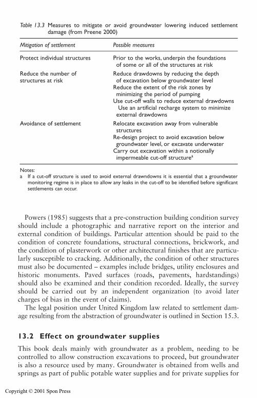
Side effects of groundwater lowering 383
Table 13.3 Measures to mitigate or avoid groundwater lowering induced settlementdamage (from Preene 2000)
Mitigation of settlement Possible measures
Protect individual structures Prior to the works, underpin the foundationsof some or all of the structures at risk
Reduce the number of Reduce drawdowns by reducing the depthstructures at risk of excavation below groundwater level
Reduce the extent of the risk zones byminimizing the period of pumping
Use cut-off walls to reduce external drawdownsUse an artificial recharge system to minimize
external drawdownsAvoidance of settlement Relocate excavation away from vulnerable
structuresRe-design project to avoid excavation belowgroundwater level, or excavate underwater
Carry out excavation within a notionallyimpermeable cut-off structurea
Notes:a If a cut-off structure is used to avoid external drawndowns it is essential that a groundwater
monitoring regime is in place to allow any leaks in the cut-off to be identified before significantsettlements can occur.
Powers (1985) suggests that a pre-construction building condition surveyshould include a photographic and narrative report on the interior andexternal condition of buildings. Particular attention should be paid to thecondition of concrete foundations, structural connections, brickwork, andthe condition of plasterwork or other architectural finishes that are particu-larly susceptible to cracking. Additionally, the condition of other structuresmust also be documented – examples include bridges, utility enclosures andhistoric monuments. Paved surfaces (roads, pavements, hardstandings)should also be examined and their condition recorded. Ideally, the surveyshould be carried out by an independent organization (to avoid latercharges of bias in the event of claims).
The legal position under United Kingdom law related to settlement dam-age resulting from the abstraction of groundwater is outlined in Section 15.3.
13.2 Effect on groundwater supplies
This book deals mainly with groundwater as a problem, needing to becontrolled to allow construction excavations to proceed, but groundwateris also a resource used by many. Groundwater is obtained from wells andsprings as part of public potable water supplies and for private supplies for
Copyright © 2001 Spon Press
384 Side effects of groundwater lowering
domestic dwellings and industrial users such as breweries, paper mills, etc.If temporary works groundwater lowering is carried out in the vicinity ofexisting well or spring abstractions, there is a risk that the abstractions willbe ‘derogated’ – in other words it will be harder for the user to abstractwater, and in extreme cases the source may even dry up completely. Theinteraction between groundwater supplies and civil engineering works isdiscussed further by Brassington (1986).
Occasionally water quality may deteriorate as a result of changes in thegroundwater flow direction. The effect is often temporary, and may ceasesoon after the end of temporary works pumping, but can cause consider-able inconvenience and cost to groundwater users. The legal issues mustalso be considered, since in England and Wales licensed groundwaterabstractors have a legal right to continue to obtain water (see Section 15.3).
13.2.1 Derogation of groundwater supplies
The primary effect on nearby abstractions is a general lowering of waterlevels, which will affect operating water levels in existing wells, with a cor-responding reduction in output. The magnitude of the reduction in outputwill depend on factors including:
1 Aquifer characteristics, including permeability and storage coefficient.2 Distance between groundwater lowering wells and supply wells, and
their location in relation to any existing hydraulic gradients in theaquifer.
3 The dewatering pumping rate and period of pumping (low flow rate andshort duration pumping systems will have less of an effect on supplywells).
4 The depth, design and condition of the supply wells.
Any rational assessment of the effect of groundwater lowering on supplywells will require some form of conceptual groundwater model to be devel-oped. This could then be used as the basis for a numerical model, or an ini-tial assessment could be made using the methods of Chapter 7, treating thegroundwater lowering system as an equivalent well.
If the estimated effects on the supply wells are small, this may be deemedacceptable with no further mitigation measures. However, if the effects aremore severe, Powers (1985) suggests the following mitigation measures:
1 If only a few low volume users are affected, and the dewatering periodis short, the lost supply might be replaced by a temporary tanker sup-ply.
2 If the supply well is deep but with the pump set at a fairly high level,it may be possible to install higher head pumps at greater depth in the
Copyright © 2001 Spon Press
Side effects of groundwater lowering 385
supply well. This would allow abstraction to continue even with theadditional drawdown generated by groundwater lowering.
3 If the supply wells are shallow, it may be necessary to deepen the wells,perhaps into another aquifer. Alternatively, for small diameter shallowwells it may be more economic to simply drill a new, deeper well.
4 A portion of the dewatering discharge may be piped to the affected userby temporary pipeline. Dependent on water quality, point of use treat-ment may need to be provided to ensure the water is suitable for use.
5 Public water mains may be extended into the affected area, giving apermanent benefit for the money spent.
Some of these measures have huge cost, time and public relation implica-tions, and clearly need to be compared with the alternative of constructingthe project without groundwater lowering, or even of relocating the projectaway from the supply wells.
If the effect on nearby groundwater abstractions are of real concern, it isessential that they are addressed early in the planning of a project, becauseit is unrealistic to expect the contractor to bear all the costs and risk of someof these measures. The project client will have to face up to the potentialneed for some of these measures, and perhaps allow for them when negoti-ating with landowners for wayleaves, etc. The mitigation measures mightbe included at the very start of site works as part of the enabling works.Alternatively, the supply wells may be monitored during the works, with acontingency in place that the mitigation measures will be applied if the wellis affected beyond a certain pre-defined level.
13.3 Effect on groundwater quality
Groundwater quality (i.e. the chemical composition of the water) variesfrom place to place and aquifer to aquifer (see Section 3.8). In some casesgroundwater is almost pure enough to be potable with only minimal treat-ment in the form of chlorination to destroy any harmful bacteria. In otherlocations the groundwater may contain considerable impurities whichcould be naturally occurring, or man-made. It is important to realize thatpumping from groundwater lowering systems changes natural groundwaterflow in aquifers, and may cause existing contamination plumes or zones tomigrate. Two of the most important cases to be considered are contami-nated groundwater, often left over from industrial land use, or intrusion ofsaline water in coastal areas.
13.3.1 Movement of contaminated groundwater
The study of groundwater contamination is a major field in itself, and thereader is commended to texts such as the one by Fetter (1993) to obtain
Copyright © 2001 Spon Press
the full background on the subject. Contaminants interacting with ground-water flow exist in one of three forms (or phases):
1 Dissolved (or aqueous) phase. A wide range of substances are solublein water, and so become part of the water itself, travelling with it.
2 Non-aqueous phase. This describes liquids which are immiscible withwater. They may have densities less than water (light non-aqueous phaseliquids or LNAPLs) and will float on top of the water table (examplesare petrol and diesel compounds). Dense non-aqueous phase liquids(DNAPLs) also exist, which are denser than water and tend to sinkbelow the water table until they meet a low permeability layer (exam-ples include chlorinated hydrocarbons such as trichloroethylene).
3 Vapour phase. Volatile compounds in the contaminant can move ingaseous form in the unsaturated zone above the water table.
Some contaminants (e.g. hydrocarbons such as petroleum products) maycreate all three phases when they reach groundwater.
Contamination may be caused by a variety of land uses:
� Industrial processes – mainly from spillages or leakages from storedmaterials. Sites of concern include manufacturing and chemical produc-tion sites, but also vehicle storage areas, airports and other locationswhere fuel and detergents are used.
� Landfilling and waste disposal – both from official and unofficialdisposals.
� Agricultural practices – such as fertilizer or pesticide use.� Urban use – including leaking sewers, fuel spills, etc.
The absence of active use of a site does not provide assurance that the siteis uncontaminated. A legacy of contamination may exist in the ground andgroundwater for years or decades after the pollution is stopped. A guide tothe types of pollution that can be expected from former industrial sites canbe found in CIRIA reports on contaminated land (Harris et al. 1995).A desk study (see Chapter 6) should investigate former uses of a site todetermine the risk of contaminants being present at problematic levels.
As described in Chapter 3, groundwater is constantly in motion, andwhere contamination exists that will tend to move too, gradually forminga plume stretching away from the original source of contamination. Therate and direction of movement of contamination depends on many factors,including hydraulic gradients, the geological structure of the aquifer, thenature of the contaminant and any chemical changes in the contaminant withtime. Detailed consideration of these factors is beyond the scope of thisbook, and the references cited earlier are recommended for further study.However, it is vital that anyone designing or carrying out a groundwaterlowering understands that pumping may change considerably the existing
386 Side effects of groundwater lowering
Copyright © 2001 Spon Press
Side effects of groundwater lowering 387
groundwater gradients and velocities, affecting both the magnitude (gener-ally increasing flow velocities) and direction. This means groundwaterlowering can cause the extent of a contamination plume to change, perhapsmuch more rapidly than previously. If movement of contamination is of realconcern, a thorough site investigation followed by development of a ground-water flow and contaminant transport model is essential, and specialistadvice should be obtained at an early stage.
When planning groundwater lowering on or near a contaminated site,there are two important issues to be addressed, in addition to the dewater-ing design itself:
1 How can the influence of groundwater lowering on the contaminationplume be minimized or controlled? The effect on contamination plumesis similar to settlement in that it is largely controlled by drawdown; themethods described in Section 13.1 can be used to minimize effects onexisting contamination. The use of physical cut-off barriers (Privettet al. 1996) to hydraulically separate the groundwater lowering systemfrom adjacent contaminated sites is a method often used.
2 How can the discharge be disposed of? The water pumped from the wellsmay contain problematic levels of contamination, preventing direct dis-charge to watercourses or sewers. On occasion it has been necessary toestablish a temporary water treatment plant on site to clean up the dis-charge water quality (see Section 13.4).
Because pumping of groundwater affects the extent of contaminant plumes,and can remove some of the contamination with the discharge water, meth-ods based on groundwater lowering technology can be used to help clean upsites. Pumping of groundwater and treatment of discharge prior to disposal,with the aim of reducing contamination levels, is known as the ‘pump andtreat’ method. This is a specialist method, and its effectiveness should be com-pared to other competing clean up techniques (see Holden et al. 1996).
13.3.2 Saline intrusion
Saline intrusion describes the way more mineralized water is drawn intofresh water aquifers under the influence of groundwater pumping. This is aparticular problem where large volumes of groundwater are abstracted forpotable supply, because if saline water reaches the well, it may have to beabandoned. Saline intrusion principally affects coastal aquifers, but salinewater can sometimes be found in inland aquifers, where the water hasbecome highly mineralized at depth.
Saline intrusion is a complex process affected by aquifer permeability, rateof recharge, natural groundwater gradients and the effect of any existingpumping wells. Any significant groundwater lowering operations will affect
Copyright © 2001 Spon Press
388 Side effects of groundwater lowering
the boundary between fresh and saline water. If saline water is drawn to thegroundwater lowering system that may not be a problem in itself (providedthat the water can be disposed of), but any saline water drawn towardnearby supply wells is of much greater concern. The risk of saline intrusionmay need to be investigated using hydrogeological modelling to assess theeffect on local and regional water resources; the reader is referred to hydro-geological texts such as Todd (1980) for further details.
13.3.3 Contamination via boreholes
One potential effect on groundwater quality that is sometimes overlookedis the conduit for contamination formed by wells, wellpoints, etc. (and to alesser extent by piles and some forms of ground improvement). It is nowrecognized that the vulnerability of aquifers to pollution resulting from sur-face sources (e.g. surface run-off, fuel spills, etc.) will depend on the aquifertype and structure. For example, a high permeability unconfined aquiferwill be much more vulnerable to contamination than a deep confinedaquifer overlain by a thick clay layer, which can act as a barrier to pollu-tion. In the United Kingdom, aquifer vulnerability maps have been pro-duced for many areas (Palmer and Lewis 1998).
The installation of wells (and possibly the construction excavation itself)may puncture low permeability layers, increasing the risk of surface pollu-tion finding its way down into the aquifer. If changes in aquifer vulnerabil-ity are of concern a number of measures should be considered:
1 The well design should include appropriate grout seals to prevent ver-tical seepage around the outside of the well casing.
2 The well casing should stand sufficiently proud of ground level to pre-vent surface waters being able to pass into the well casing (and thenceinto the aquifer) in the event of localized flooding around the well.
3 The top of the well casing should be capped when not in use, and sealedaround the pumping equipment when in use. This will reduce thechances of noxious substances being dropped or poured down the well,either maliciously or by accident.
4 The wells should be adequately capped or sealed on completion (seeSection 14.7).
13.4 The impact of discharge flows on thesurface water environment
Any system that lowers groundwater by pumping will produce a dischargeflow of water that must be disposed of. Poorly managed discharges mayhave adverse impacts on the environment. This section describes good prac-tice for discharges to the surface water environment. Disposal of discharge
Copyright © 2001 Spon Press
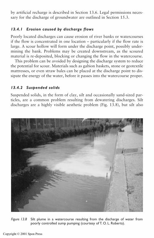
Side effects of groundwater lowering 389
by artificial recharge is described in Section 13.6. Legal permissions neces-sary for the discharge of groundwater are outlined in Section 15.3.
13.4.1 Erosion caused by discharge flows
Poorly located discharges can cause erosion of river banks or watercoursesif the flow is concentrated in one location – particularly if the flow rate islarge. A scour hollow will form under the discharge point, possibly under-mining the bank. Problems may be created downstream, as the scouredmaterial is re-deposited, blocking or changing the flow in the watercourse.
This problem can be avoided by designing the discharge system to reducethe potential for scour. Materials such as gabion baskets, stone or geotextilemattresses, or even straw bales can be placed at the discharge point to dis-sipate the energy of the water, before it passes into the watercourse proper.
13.4.2 Suspended solids
Suspended solids, in the form of clay, silt and occasionally sand-sized par-ticles, are a common problem resulting from dewatering discharges. Siltdischarges are a highly visible aesthetic problem (Fig. 13.8), but silt also
Figure 13.8 Silt plume in a watercourse resulting from the discharge of water frompoorly controlled sump pumping (courtesy of T. O. L. Roberts).
Copyright © 2001 Spon Press
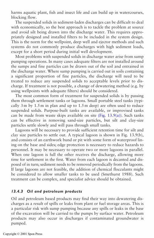
harms aquatic plant, fish and insect life and can build up in watercourses,blocking flow.
The suspended solids in sediment-laden discharges can be difficult to dealwith economically, so the best approach is to tackle the problem at sourceand avoid silt being drawn into the discharge water. This requires appro-priately designed and installed filters to be included in the system design.This is the norm for the wellpoint, deep well and ejector methods and suchsystems do not commonly produce discharges with high sediment loads,except for a short period during initial well development.
Most problems with suspended solids in discharge water arise from sumppumping operations. In many cases adequate filters are not installed aroundthe sumps and fine particles can be drawn out of the soil and entrained inthe discharge water. Where sump pumping is carried out in soils containinga significant proportion of fine particles, the discharge will need to betreated to reduce any suspended solids to acceptable levels prior to dis-charge. If treatment is not possible, a change of dewatering method (e.g. byusing wellpoints with adequate filters) should be considered.
The most common form of treatment for suspended solids is by passingthem through settlement tanks or lagoons. Small portable steel tanks (typi-cally 3 m by 1.5 m in plan and up to 1.5 m deep) are often used to reducesuspended solids. Purpose-built tanks are available, or improvised tankscan be made from waste skips available on site (Fig. 13.9(a)). Such tankscan be effective in removing sand-size particles, but silt and clay-sizeparticles settle slowly and will pass through small tanks.
Lagoons will be necessary to provide sufficient retention time for silt andclay size particles to settle out. A typical lagoon is shown in Fig. 13.9(b),and consists of an earthwork bund or pit with some form of waterproof lin-ing on the base and sides; edge protection is necessary to reduce hazards topersonnel. It may be necessary to operate two or more lagoons in parallel.When one lagoon is full the other receives the discharge, allowing moretime for settlement in the first. Water from each lagoon is decanted and dis-posed of in turn; sediment needs to be removed periodically from the lagoons.If large lagoons are not feasible, the addition of chemical flocculants mightbe considered to allow smaller tanks to be used (Smethurst 1988). Suchtreatment can be complex, and specialist advice should be obtained.
13.4.3 Oil and petroleum products
Oil and petroleum based products may find their way into dewatering dis-charges as a result of spills or leaks from plant or fuel storage areas. This isa particular risk with sump pumping because any spills or leaks in the baseof the excavation will be carried to the pumps by surface water. Petroleumproducts may also occur in discharges if contaminated groundwater ispumped.
390 Side effects of groundwater lowering
Copyright © 2001 Spon Press
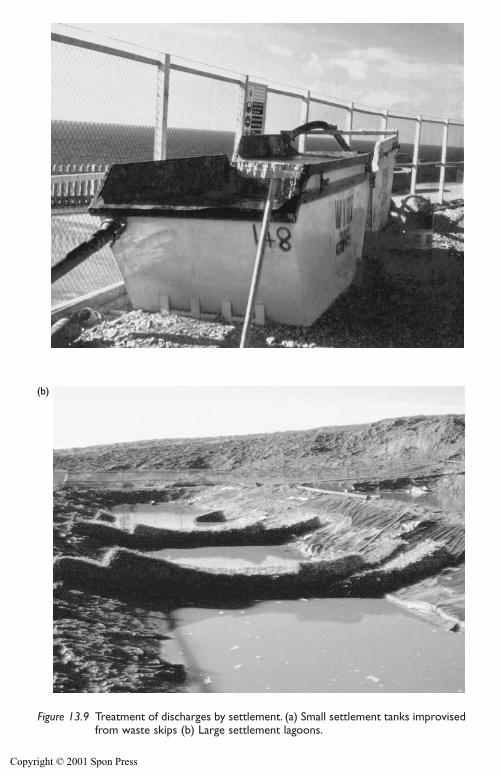
(a)
(b)
Figure 13.9 Treatment of discharges by settlement. (a) Small settlement tanks improvisedfrom waste skips (b) Large settlement lagoons.
Copyright © 2001 Spon Press
392 Side effects of groundwater lowering
Petroleum products are generally of lower density than water and do notmix well with it. They are known as light non-aqueous phase liquids(LNAPLs) and will tend to appear as floating films or layers on top of pondsor tanks of water. The petroleum products must be separated from the dis-charge before disposal. This can be accomplished by passing the dischargethrough proprietary ‘petrol interceptors’ or ‘phase separators’. The water isthen discharged as normal, and the product (which collects in the intercep-tor) is disposed of (e.g. to a waste oil company) at appropriate intervals.Very thin oil layers may be removed by the use of floating skimmer pumpsor sorbent booms or pillows placed in discharge tanks or lagoons.
13.4.4 Contaminated groundwater
If groundwater is pumped from a contaminated site, or from adjacent tosuch a site, the resulting dewatering discharge may itself be contaminated.Unless the flow is discharged to a sewage treatment works capable of deal-ing with the contaminants, some form of treatment will be required priorto discharge.
A wide range of treatment methods is available. Often, a given contami-nant could be treated by several quite different methods; the choice ofmethod will depend on the concentration of contaminants, the dischargeflow rate, the duration of pumping and the availability of treatment equip-ment and technologies. Some of the available technologies are described byNyer (1992) and Holden et al. (1996).
The scale of treatments used in practice varies greatly. Occasionally, onvery heavily contaminated sites with low pumped flow rates the dischargemay be pumped directly to special road tankers, for off-site disposal ata licensed facility. In other cases on-site treatment may be feasible. Thisranges from simple dosing with caustic soda for pH adjustment of acidicgroundwater, through to the construction of modular treatment plants onheavily contaminated sites.
A programme of chemical testing will be needed to monitor dischargewater quality, and the environmental authorities (see Section 15.3) will needto be kept fully informed. Often the targets for treatment of the dischargewill be set by the environmental regulators, based on a consideration of theenvironment impact of the discharge.
13.5 Other effects
Occasionally, other, less common, side effects may be of concern.
13.5.1 Damage to timber piles
It is sometimes considered that timber piles supporting older structuresmay be detrimentally affected by drawdown of water levels. Powers (1985)
Copyright © 2001 Spon Press
Side effects of groundwater lowering 393
states that the damage may result from fungi present in the timber thrivingin an aerobic environment created if water levels are drawn down, expos-ing the tops of the piles to air. However, Powers also states that the mostsevere cases of aerobic attack have been when piles were exposed in exca-vations, and that observed decay due to drawdown has been less severe.This is probably because the oxygen supply to the timber surface is notincreased substantially when the piles are in dense or fine-grained soils.
Nevertheless, a sensible approach is to proceed cautiously when workingin areas where older structures are founded on timber piles. Even if aerobicattack does not compromise pile stiffness, soil consolidation and pile down-drag due to negative skin friction should be considered. When groundwaterlowering has been used in Scandinavian cities where timber piling is com-monplace, artificial recharge systems have been used to reduce drawdowns,and minimize the effect on piles.
13.5.2 Vegetation and wetlands
It is rare for groundwater lowering systems to have a noticeable effect onvegetation. This is mainly due to the short-term nature of pumping, and thefact that plants generally draw their water from immediately below the sur-face, above the water table. This zone is much more likely to be affected bychanges in precipitation and infiltration, than by deeper pumping. Longerterm pumping (for certain types of quarries or open cast mines) may needto consider this issue further, and the services of an experienced ecologistcan be very useful in that regard.
Wetlands (areas of marsh, fen or peatland, or areas covered with shallowwater or poorly-drained areas subject to intermittent flooding) may some-times be affected by longer-term groundwater pumping. To assess each casethe interaction between the surface water and groundwater will need to beassessed. Some wetlands are directly supported by groundwater seepages,while others (if the soil is of low permeability) may receive little contributionfrom groundwater. Wetlands tend to vary with the seasons (and also fromyear to year), so the additional influence of groundwater pumping may ormay not be significant in comparison. Merritt (1994) gives a thoroughbackground to the creation and management of wetlands.
When assessing the potential impact on wetlands, specialist ecological andhydrological advice is likely to be required. It may be possible to reduceeffects on wetlands by constructing a groundwater cut-off barrier betweenthe dewatering system and the wetland. An alternative approach would beto use artificial recharge of groundwater or surface water or to pipe a por-tion of the discharge water directly to the wetland. If the latter approach isadopted, the temperature, chemistry and sediment content of the dischargewater must be assessed to ensure that there will not be adverse reactionswith the water and ecology of the wetlands; the risk of additional erosion
Copyright © 2001 Spon Press
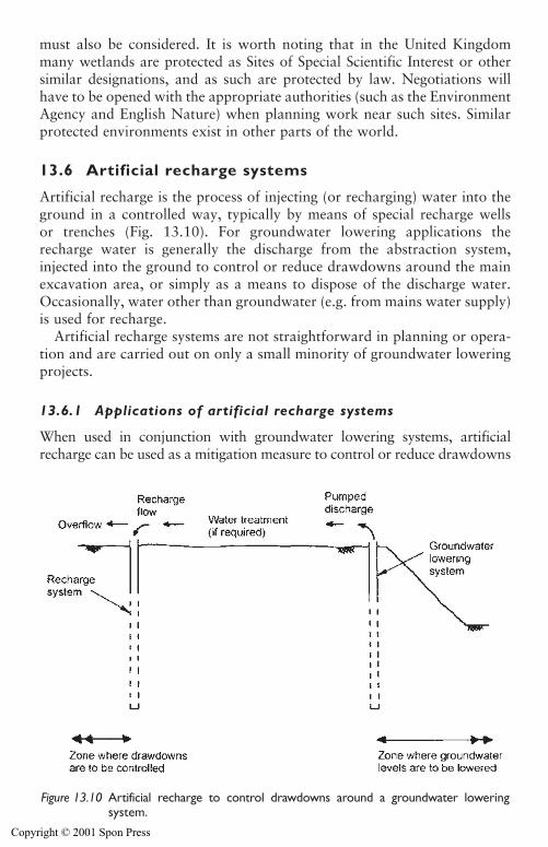
must also be considered. It is worth noting that in the United Kingdommany wetlands are protected as Sites of Special Scientific Interest or othersimilar designations, and as such are protected by law. Negotiations willhave to be opened with the appropriate authorities (such as the EnvironmentAgency and English Nature) when planning work near such sites. Similarprotected environments exist in other parts of the world.
13.6 Artificial recharge systems
Artificial recharge is the process of injecting (or recharging) water into theground in a controlled way, typically by means of special recharge wellsor trenches (Fig. 13.10). For groundwater lowering applications therecharge water is generally the discharge from the abstraction system,injected into the ground to control or reduce drawdowns around the mainexcavation area, or simply as a means to dispose of the discharge water.Occasionally, water other than groundwater (e.g. from mains water supply)is used for recharge.
Artificial recharge systems are not straightforward in planning or opera-tion and are carried out on only a small minority of groundwater loweringprojects.
13.6.1 Applications of artificial recharge systems
When used in conjunction with groundwater lowering systems, artificialrecharge can be used as a mitigation measure to control or reduce drawdowns
394 Side effects of groundwater lowering
Figure 13.10 Artificial recharge to control drawdowns around a groundwater loweringsystem.
Copyright © 2001 Spon Press
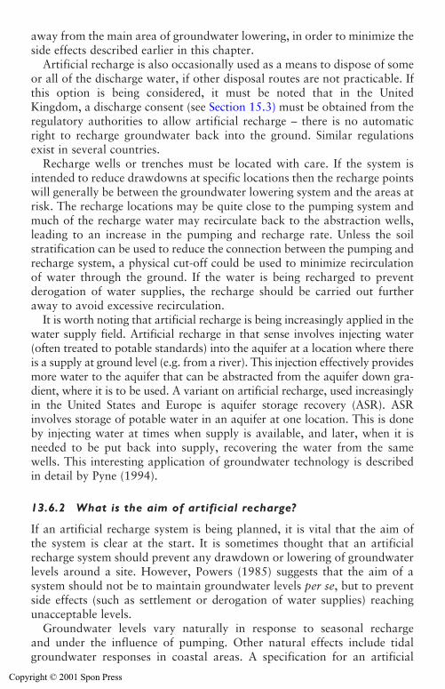
Side effects of groundwater lowering 395
away from the main area of groundwater lowering, in order to minimize theside effects described earlier in this chapter.
Artificial recharge is also occasionally used as a means to dispose of someor all of the discharge water, if other disposal routes are not practicable. Ifthis option is being considered, it must be noted that in the UnitedKingdom, a discharge consent (see Section 15.3) must be obtained from theregulatory authorities to allow artificial recharge – there is no automaticright to recharge groundwater back into the ground. Similar regulationsexist in several countries.
Recharge wells or trenches must be located with care. If the system isintended to reduce drawdowns at specific locations then the recharge pointswill generally be between the groundwater lowering system and the areas atrisk. The recharge locations may be quite close to the pumping system andmuch of the recharge water may recirculate back to the abstraction wells,leading to an increase in the pumping and recharge rate. Unless the soilstratification can be used to reduce the connection between the pumping andrecharge system, a physical cut-off could be used to minimize recirculationof water through the ground. If the water is being recharged to preventderogation of water supplies, the recharge should be carried out furtheraway to avoid excessive recirculation.
It is worth noting that artificial recharge is being increasingly applied in thewater supply field. Artificial recharge in that sense involves injecting water(often treated to potable standards) into the aquifer at a location where thereis a supply at ground level (e.g. from a river). This injection effectively providesmore water to the aquifer that can be abstracted from the aquifer down gra-dient, where it is to be used. A variant on artificial recharge, used increasinglyin the United States and Europe is aquifer storage recovery (ASR). ASRinvolves storage of potable water in an aquifer at one location. This is doneby injecting water at times when supply is available, and later, when it isneeded to be put back into supply, recovering the water from the samewells. This interesting application of groundwater technology is describedin detail by Pyne (1994).
13.6.2 What is the aim of artificial recharge?
If an artificial recharge system is being planned, it is vital that the aim ofthe system is clear at the start. It is sometimes thought that an artificialrecharge system should prevent any drawdown or lowering of groundwaterlevels around a site. However, Powers (1985) suggests that the aim of asystem should not be to maintain groundwater levels per se, but to preventside effects (such as settlement or derogation of water supplies) reachingunacceptable levels.
Groundwater levels vary naturally in response to seasonal rechargeand under the influence of pumping. Other natural effects include tidalgroundwater responses in coastal areas. A specification for an artificial
Copyright © 2001 Spon Press
396 Side effects of groundwater lowering
recharge system that required ‘zero drawdown’ would be not practicable. Itmay be more appropriate to set a target such that groundwater levels inselected observation piezometers shall not fall below defined levels (whichare likely to be different in different parts of the site).
Assuming that groundwater levels around a site vary naturally with time,and that this variation is not causing detrimental side effects, the lowestacceptable groundwater level in a monitoring well is often set as theseasonal minimum. Occasionally, if the groundwater lowering system isintended to generate very large drawdowns in relatively stiff aquifers, thelowest acceptable groundwater level is set rather lower, at a few metresbelow the seasonal minimum.
It is sometimes useful to specify maximum groundwater levels in selectedpiezometers. This reduces the temptation for overzealous recharging raisingthe groundwater levels above the seasonal maximum, which could lead toproblems with flooded basements and the like. By defining an allowableminimum and maximum groundwater level in each observation well (withat least 0.5 m between maximum and minimum levels), the system operatorhas a little leeway within which to adjust the system.
13.6.3 Recharge trenches
A simple method of recharge for shallow applications is the use of rechargetrenches (Fig. 13.11). These are excavated from the surface, and the de-watering discharge is fed into them from where the water infiltrates intothe ground.
Recharge trenches have been employed to good effect when pumpingfrom mineral workings (Cliff and Smart 1998), but are less effective in con-struction situations and are rarely used. Clogging of the trenches (by thegrowth and decay of vegetation or the build up of sediment) reducing infil-tration rates is often a problem. Trenches typically require periodic clean-ing out by excavator. It is difficult to control and measure the volumesentering the trenches, making this method less easy to adjust than a system
Figure 13.11 Recharge trench.
Copyright © 2001 Spon Press
of recharge wells. An overflow channel is normally required to preventovertopping of the trenches.
The recharge trench method is best suited to unconfined aquifers withwater tables near ground level, allowing shallow trenches to be used. Themethod is less practicable for recharging water where the water table isrelatively deep, or if the aquifer is confined by overlying clay layers.
13.6.4 Recharge wells
Recharge wells are generally superior to recharge trenches because the wellscan be designed to inject water into specific aquifers beneath a site; this canallow the stratification of soils at the site to be used to advantage in con-trolling drawdowns. Recharge wells also allow better control and monitor-ing of injection heads and flow rates than do trench systems. A rechargewell operates in a similar way to a pumping well, except that the directionof flow is reversed. A recharge well should allow water to flow into theaquifer with as little restriction as possible. However, recharge of water intothe ground is more difficult than pumping. A pumping well is effectivelyself-cleaning, in that any loose particles or debris will be removed from thewell by the flow. In contrast, a recharge well is effectively self-clogging –even if the water being recharged is of high quality, any suspended particlesor gas bubbles will be trapped in the well (or the aquifer immediatelyoutside) leading to clogging and loss of efficiency.
In broad terms, a recharge well should be designed, installed and devel-oped in the same way as a pumping well (see Chapter 10). The two keydifferences are:
1 To maximize hydraulic efficiency, the well filter media and slot size (seeSection 10.2) should be as coarse as possible, while still allowingthe well to be pumped without continuous removal of fines duringre-development.
2 Because a recharge well does not generally have to accommodate a sub-mersible pump, the well casing and screen can be of smaller diameterthan a pumping well. However, the well casing and screen must belarge enough to allow the well to be re-developed if necessary.
Figure 13.12 shows a typical recharge well. Key features are:
i Well casing and screen, surrounded by filter media, with a grout orconcrete seal around the well casing to prevent water short-circuitingup the filter pack to ground level. If the top of the well casing is alsosealed around the recharge pipework, this can allow recharge flowsto be fed by header tanks raised above ground level, to increase theinjection rate in each well.
Side effects of groundwater lowering 397
Copyright © 2001 Spon Press
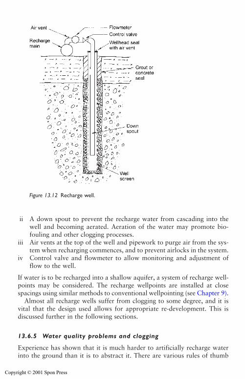
398 Side effects of groundwater lowering
ii A down spout to prevent the recharge water from cascading into thewell and becoming aerated. Aeration of the water may promote bio-fouling and other clogging processes.
iii Air vents at the top of the well and pipework to purge air from the sys-tem when recharging commences, and to prevent airlocks in the system.
iv Control valve and flowmeter to allow monitoring and adjustment offlow to the well.
If water is to be recharged into a shallow aquifer, a system of recharge well-points may be considered. The recharge wellpoints are installed at closespacings using similar methods to conventional wellpointing (see Chapter 9).
Almost all recharge wells suffer from clogging to some degree, and it isvital that the design used allows for appropriate re-development. This isdiscussed further in the following sections.
13.6.5 Water quality problems and clogging
Experience has shown that it is much harder to artificially recharge waterinto the ground than it is to abstract it. There are various rules of thumb
Figure 13.12 Recharge well.
Copyright © 2001 Spon Press
Side effects of groundwater lowering 399
which say that, to recharge water back into the aquifer from which it cametwo or three recharge wells will be needed for every abstraction well. Manyof the practical difficulties with artificial recharge arise from water qualityproblems leading to clogging. The designer and operator are being unreal-istic if they do not expect recharge wells or trenches to clog (to a lesser orgreater degree) in operation.
It is worthwhile considering the mechanisms that can lead to the cloggingof recharge wells (similar processes affect recharge trenches). Pyne (1994)has outlined five clogging processes:
(1) Entrained air and gas binding. Bubbles of vapour (such as air ormethane) present in the recharge water build up in the well, inhibitingflow of water through the filter pack into the aquifer. The gas bubblesmay result from the release of dissolved gases from the recharge water;from air drawn into the recharge pipework where changes in flow gen-erate negative pressures; or, if water is allowed to cascade into therecharge well, from air entrained into the water. Careful sealing ofpipework joints, and minimizing aeration of the recharge water canhelp avoid this problem. Degassing equipment can be installed onto thepipework to bleed off any gas before it reaches the recharge wells.
(2) Deposition of suspended solids from recharge water. Particles (colloidalor silt and sand-sized soil particles, biofouling detritus, algal matter,loose rust or scale from pipework, etc.) carried with the recharge waterwill build up in the well and filter pack, blocking flow. Control of thisproblem requires effective design and development of the abstractionwells to minimize suspended solids in the water; the discharge fromsump pumping is rarely suitable for recharge. For low flow rate systemsthe use of sand filter systems to clean up the water might be considered.
(3) Biological growth. Bacterial action in the recharge wells can result inclogging of the wells themselves. Additionally, biofouling of the abstrac-tion wells and pipework can release colloidal detritus (the result of thebacteria life cycle) into the water. The flow of water will carry these par-ticles inexorably into the recharge wells, leading to further clogging. Theseverity of any clogging will depend on several factors (see Section14.8). Since some of the problem bacteria are aerobic, minimizing anyaeration of the recharge water is advisable. Periodic dosing of the wellswith a dilute chlorine solution has been used to inhibit bacterial growth.
(4) Geochemical reactions. The recharge water can react with the naturalgroundwater or with the aquifer material. Such reactions are most likelyif the recharge water is not groundwater from the same aquifer (e.g. ifmains water is used for recharge, or water from one aquifer is rechargedback to another aquifer) or if the pumped groundwater is allowed tochange chemically prior to re-injection. Typical reactions include the
Copyright © 2001 Spon Press
deposition of calcium carbonate or iron/manganese oxide hydrates. Thepotential significance of these reactions can only be assessed followingstudy of the aquifer and groundwater chemistry, but are generallyreduced in severity if water pressure and temperature changes duringrecharge are minimized. Chemical dosing of the recharge water might beconsidered to inhibit particular reactions.
(5) Particle re-arrangement in the aquifer. Although not usually a signifi-cant effect, the permeability around the well may reduce due to looseparticles around the well being re-arranged by the flow of rechargewater out of the well. This effect can be minimized by effective devel-opment on completion and periodic re-development.
These clogging effects should be considered when designing and operatingan artificial recharge system. After all, a recharge system is not going toachieve its aims if it is unable to continue to inject water into the ground.
13.6.6 Operation of recharge systems
An artificial recharge scheme broadly consists of an abstraction system,a recharge system, and a transfer system (between the abstraction andrecharge points). The abstraction system should be straightforward inoperation and maintenance (see Chapter 14), but the transfer and rechargesystems may be more problematic. The crux of the issue is to manage therecharge water quality to limit the clogging of recharge wells to acceptablelevels that do not prevent the system from achieving its targets.
As has been stated previously, most artificial recharge systems will sufferfrom clogging. There are two approaches to dealing with this, often used incombination:
1 Prevention (or reduction) of clogging – principally by treatment of thedischarge water to remove suspended solids and retard cloggingprocesses such as bacterial growth.
2 Mitigation of clogging – accepting that clogging will occur, and thenplanning for it. This may involve providing spare recharge wells, to beused when efficiency is impaired, and implementing a programme ofregular re-development of clogged wells.
Measures to prevent clogging must focus on ensuring the recharge wateris of high quality and does not promote clogging processes. Possible mea-sures include:
� Removal of suspended solids by filtration or sedimentation.� Chemical dosing to precipitate out problematic carbonates or iron and
manganese compounds.� Intermittent or continuous chlorine dosing of the recharge water to
reduce bacterial action.
400 Side effects of groundwater lowering
Copyright © 2001 Spon Press
Side effects of groundwater lowering 401
� Prevention of aeration of water to reduce the risk of gas binding.� Use of mains water if the pumped groundwater cannot be rendered
suitable.� Careful management of the system on start-up to avoid slugs of
sediment-laden water entering the wells (the initial surge of water maypick up sediment deposited in the pipework and should be directed towaste, not to the recharge wells).
Measures to mitigate clogging include:
� Designing recharge well screens to have ample open area to acceptflow. Driscoll (1986) recommends that the average screen entrancevelocity (recharge flow divided by total area of screen apertures) is lessthan 0.15 m/s, approximately half the maximum velocity recommendedfor abstraction wells.
� Re-developing the recharge wells on a regular basis to rehabilitate thewells. This is most commonly done by airlift development (see Section10.6) that dislodges any sediment, loose particles, precipitates and bac-terial residues. Depending on the severity of clogging (see Section 14.8),wells in a system may be re-developed on a rolling programme, with anindividual well being re-developed every few weeks or months. Evenafter re-development wells may not return to their pre-clogging perfor-mance – if the system operates for very long periods, additionalrecharge wells may need to be installed after a few years to prevent theoverall system performance from dropping to unacceptable levels.
� Providing more than the minimum number of recharge wells necessary toaccept the recharge flow. In this way the flow can still be accepted if someof the wells are badly clogged, allowing more time for redevelopment.
Monitoring of artificial recharge systems follows good practice for abstrac-tion systems (see Chapter 14). For recharge wells the water level belowground level (by dipping) or pressure head above ground level (by pressuregauge) should be monitored. Ideally, flowmeters should be installed on eachwell to record recharge flow rates, but some designs may be affected byclogging. At the very least the overall recharge rate should be monitored,perhaps by V-notch weir.
13.6.7 Case history: Misr Bank, Cairo
An interesting application of recharge was carried out in the centre ofCairo, Egypt, described by Troughton (1987) and Cashman (1987). A two-storey basement was to be constructed for the new Bank Misr headquartersimmediately adjacent to the existing bank building. The basement was to beformed inside a sheet-piled cofferdam to a depth of 7.5 m below groundlevel, and approximately 4.5 m below original groundwater level.
Copyright © 2001 Spon Press
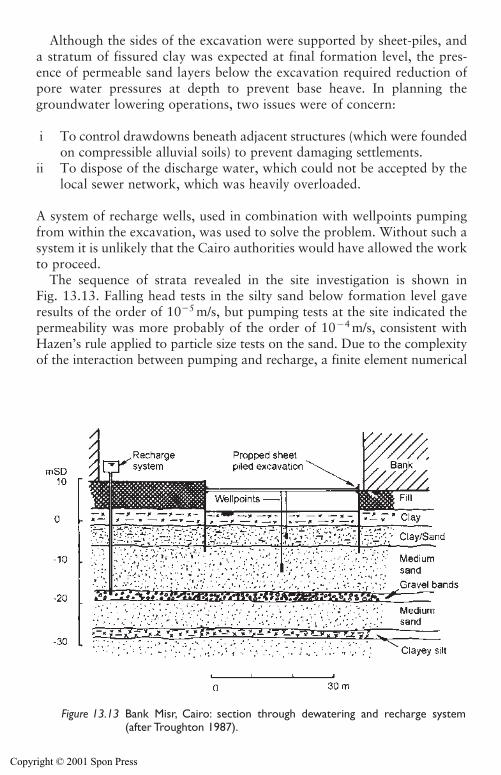
402 Side effects of groundwater lowering
Although the sides of the excavation were supported by sheet-piles, anda stratum of fissured clay was expected at final formation level, the pres-ence of permeable sand layers below the excavation required reduction ofpore water pressures at depth to prevent base heave. In planning thegroundwater lowering operations, two issues were of concern:
i To control drawdowns beneath adjacent structures (which were foundedon compressible alluvial soils) to prevent damaging settlements.
ii To dispose of the discharge water, which could not be accepted by thelocal sewer network, which was heavily overloaded.
A system of recharge wells, used in combination with wellpoints pumpingfrom within the excavation, was used to solve the problem. Without such asystem it is unlikely that the Cairo authorities would have allowed the workto proceed.
The sequence of strata revealed in the site investigation is shown inFig. 13.13. Falling head tests in the silty sand below formation level gaveresults of the order of 10�5 m/s, but pumping tests at the site indicated thepermeability was more probably of the order of 10�4 m/s, consistent withHazen’s rule applied to particle size tests on the sand. Due to the complexityof the interaction between pumping and recharge, a finite element numerical
Figure 13.13 Bank Misr, Cairo: section through dewatering and recharge system(after Troughton 1987).
Copyright © 2001 Spon Press
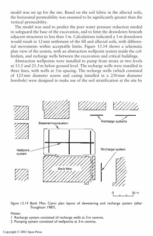
Side effects of groundwater lowering 403
model was set up for the site. Based on the soil fabric in the alluvial soils,the horizontal permeability was assumed to be significantly greater than thevertical permeability.
The model was used to predict the pore water pressure reduction neededto safeguard the base of the excavation, and to limit the drawdown beneathadjacent structures to less than 1 m. Calculations indicated a 1 m drawdownwould result in 12 mm settlement of the fill and alluvial soils, with differen-tial movements within acceptable limits. Figure 13.14 shows a schematicplan view of the system, with an abstraction wellpoint system inside the cof-ferdam, and recharge wells between the excavation and critical buildings.
Abstraction wellpoints were installed to pump from strata at two levelsat 13.5 and 21.5 m below ground level. The recharge wells were installed inthree lines, with wells at 3 m spacing. The recharge wells (which consistedof 125 mm diameter screen and casing installed in a 250 mm diameterborehole) were designed to make use of the soil stratification at the site by
Figure 13.14 Bank Misr, Cairo: plan layout of dewatering and recharge system (afterTroughton 1987).
Notes:1 Recharge system consisted of recharge wells at 3 m centres.2 Pumping system consisted of wellpoints at 3 m centres.
Copyright © 2001 Spon Press
404 Side effects of groundwater lowering
injecting water into the most permeable horizon present, a layer of gravelat 28 m below ground level. Water could be relatively easily injected intothis permeable layer, from where it would feed to the other soil layers –analogous to the underdrainage dewatering effect (see Section 7.3) inreverse. The discharge water was fed to the recharge wells from a headertank 2 m above ground level; total flow rate was in the range 25–40 l/s. Anarray of pneumatic piezometers was installed to monitor pore water pres-sure reductions in the compressible alluvial clays. Conventional standpipepiezometers were used in the sands.
In operation the maximum drawdowns observed below structures werelimited to 0.7 m, which resulted in settlements of 3 mm, around half thevalue predicted by calculation. As is often the case, the efficiency of therecharge wells reduced with time, and they had to be redeveloped by airlift-ing at monthly intervals to maintain performance. Two of the lines ofrecharge wells were located in a car park used during daytime businesshours – these had to be re-developed at night.
As mentioned earlier, one of the aims for the recharge system was to dis-pose of the discharge water without overloading the antiquated sewer system.However, as reported by Cashman (1987) the dewatering field supervisor didnot have a lot of faith in recharge and tapped into the sewer system with ahidden discharge pipe. So, in fact, much of the discharge water was actuallygoing down the sewer. Unfortunately, over the Christmas period one of themain Cairo pumping stations broke down, and everything flooded back. Thechairman of the main contractor received a telephone call from the Mayor ofCairo Municipality demanding his personal presence on site immediately. Hewas told that if this ever happened again, he, the chairman, would be imme-diately put in jail. This was a pretty convincing argument to ensure thingswere put right and the recharge system stayed in operation.
References
Brassington, F. C. (1986). The inter-relationship between changes in groundwaterconditions and civil engineering construction. Groundwater in EngineeringGeology (Cripps, J. C., Bell, F. G. and Culshaw, M. G., eds). Geological SocietyEngineering Geology Special Publication No. 3, London, pp 47–50.
Bauer, G. E., Scott, J. D., Shields, D. H. and Wilson, N. E. (1980). The hydraulicfailure of a cofferdam. Canadian Geotechnical Journal, 17, 574–583.
Burland, J. B. and Wroth, C. P. (1975). Settlement of buildings and associateddamage. Proceedings of the British Geotechnical Society Conference onSettlement of Structures, Cambridge, pp 611–654.
Cashman, P. M. (1987). Discussion. Groundwater Effects in GeotechnicalEngineering (Hanrahan, E. T., Orr, T. L. L. and Widdis, T. F., eds), Balkema,Rotterdam, p 1015.
Cliff, M. I. and Smart, P. C. (1998). The use of recharge trenches to maintaingroundwater levels. Quarterly Journal of Engineering Geology, 31, 137–145.
Copyright © 2001 Spon Press
Driscoll, F. G. (1986). Groundwater and Wells. Johnson Division. Saint Paul,Minnesota.
Fetter, C. W. (1993). Contaminant Hydrogeology. Macmillan, New York.Greenwood, D. A. (1984). Re-levelling a gas holder at Rhyl. Quarterly Journal of
Engineering Geology, 17, 319–326.Harris, M. R., Herbert, S. M. and Smith, M. A. (1995). Remedial Treatment
for Contaminated Land. Construction Industry Research and InformationAssociation, CIRIA Special Publications 101–112 (12 Volumes), London.
Holden, J. M. W., Jones, M. A., Fernando, M-W. and White, C. (1996). HydraulicMeasures for the Treatment and Control of Groundwater Pollution.Construction Industry Research and Information Association, CIRIA Funder’sReport FR/CP/26, London.
Lake, L. M., Rankin, W. J. and Hawley, J. (1996). Prediction and Effects ofGround Movements Caused by Tunnelling in Soft Ground Beneath UrbanAreas. Construction Industry Research and Information Association, CIRIAReport PR30, London.
Merritt, A. (1994). Wetlands, Industry & Wildlife: A Manual of Principles andPractices. Wildfowl & Wetlands Trust, Slimbridge, Gloucester.
Nyer, E. K. (1992). Groundwater Treatment Technology, 2nd edition. VanNostrand Reinhold, New York.
Palmer, R. C. and Lewis, M. A. (1998). Assessment of groundwater vulnerability inEngland and Wales. Groundwater Pollution, Aquifer Recharge and Vulnerability(Robins, N. S., ed.). Geological Society Special Publication 130, London,pp 191–198.
Powers, J. P. (1985). Dewatering – Avoiding its Unwanted Side Effects. AmericanSociety of Civil Engineers, New York.
Powers, J. P. (1992). Construction Dewatering: New Methods and Applications,2nd edition. Wiley, New York.
Powrie, W. (1997). Soil Mechanics: Concepts and Applications. Spon, London.Preene, M. (2000). Assessment of settlements caused by groundwater control.
Proceedings of the Institution of Civil Engineers, Geotechnical Engineering, 143,177–190.
Preene, M., Roberts, T. O. L., Powrie, W. and Dyer, M. R. (2000). GroundwaterControl – Design and Practice. Construction Industry Research and InformationAssociation, CIRIA Report C515, London.
Privett, K. D., Matthews, S. C. and Hodges, R. A. (1996). Barriers, Liners and CoverSystems for Containment and Control of Land Contamination. ConstructionIndustry Research and Information Association, CIRIA Special Publication 124,London.
Pyne, R. D. G. (1994). Groundwater Recharge and Wells: A Guide to AquiferStorage Recovery. Lewis Publishers, Boca Raton.
Smethurst, G. (1988). Basic Water Treatment, 2nd edition. Thomas Telford,London.
Todd, D. K. (1980). Groundwater Hydrology, 2nd edition. Wiley, New York.Troughton, V. M. (1987). Groundwater control by pressure relief and recharge.
Groundwater Effects in Geotechnical Engineering (Hanrahan, E. T., Orr, T. L. L.and Widdis, T. F., eds), Balkema, Rotterdam, pp 259–264.
Side effects of groundwater lowering 405
Copyright © 2001 Spon Press
Chapter 14
Monitoring and maintenanceof groundwater loweringsystems
14.0 Introduction
Any groundwater lowering system will need, to some degree, monitoring andmaintenance measures to ensure effective operation. This chapter describesthe methods commonly used for monitoring of groundwater lowering works,including the use of dataloggers and automatic control systems. Maintenanceissues are also discussed, as are methods of sealing boreholes on completion.The problems of corrosion, encrustation and biofouling, which sometimesresult in the gradual deterioration of system performance, are described.
14.1 The need for monitoring
Once in operation, a groundwater lowering system is the end result of a lotof effort by a lot of people. It is a complex system dependent on a diverserange of hydrogeological, hydraulic, chemical, mechanical and human fac-tors, but it will have a clear aim – to lower groundwater levels sufficientlyto allow the construction works to proceed. It would be silly, havinginvested so much time and money in a system, not to monitor it to checkthat initially, and on a continuing basis, these aims are achieved. Yet, manysystems are not adequately monitored, leading to poor performance, loss oftime and money, not to mention a stressful time for those concerned.
Groundwater lowering systems should have specific targets – maximumallowable groundwater levels at particular locations. They achieve thesetargets by pumping groundwater. The two most important parameters tobe monitored are water levels (see Section 14.2) and pumped flow rate or dis-charge (see Section 14.3). Other parameters may also need to be monitored(see Section 14.4).
Monitoring is important throughout the operational life of a system, butespecially so soon after the start up of pumping. There have been manycases where carefully designed systems have not initially achieved the targetwater levels. This potentially embarrassing eventuality may result fromsome very simple problems with the mechanics of the system or the way it is
Copyright © 2001 Spon Press
Monitoring and maintenance measures 407
operated. Occasionally, problems arise if ground and groundwater conditionsdiffer significantly from those indicated by the site investigation – so called‘unforeseen ground conditions’. Monitoring during the early stages ofpumping is vital to allow potential problems to be identified and solved.
In some cases, particularly on large projects or where site investigationinformation is limited, monitoring of system performance can be used aspart of the observational method of design (see Section 7.1). The observa-tional method involves developing an initial design based on the most prob-able conditions, plus contingency plans to allow modification of the systemin light of conditions actually encountered. Adoption of the observationalmethod can allow fine-tuning of the system in difficult ground conditions.There may be a temptation to install only the bare minimum pumpingcapacity or number of wells to achieve the drawdown. This temptationmust be resisted, and allowance made for standby equipment (see Section14.6), and long-term deterioration of the system (see Section 14.8).
Whatever monitoring is carried out, merely taking the readings is notenough. They need to be reviewed by personnel who can interpret themappropriately. Plotting of long-term trends of groundwater levels or dis-charge flow rates can aid the identification of problems or anomalies. Onmany projects this need not be done by a groundwater lowering specialistas such. The main contractor’s site engineer could review them – providedthey have been briefed by the system designer or installer as to what factorsare important, and if there are any particular targets that must be achieved.Whoever reviews the data, specialist advice should be sought if there is anyuncertainty about the effectiveness of system performance.
14.2 Monitoring of water levels
The most basic form of monitoring is the measurement of water levels inobservation wells, to determine whether groundwater levels have been low-ered to the target levels. The water level is most commonly measured usinga ‘dipmeter’ or ‘dipper’ (Fig. 14.1); the process is known as ‘taking dipreadings’. The dipmeter consists of a graduated cable or tape with a probeat its tip. The probe is lowered down the well until it touches the water sur-face; the water completes a low-voltage circuit and a buzzer or light is acti-vated on the dipmeter reel.
There is an art to obtaining reliable dip readings. It is best to just gentlylower the probe to the water surface (when the signal will activate), thenraise the probe a little (the signal should cease) and lower the probe backinto the water to confirm the reading. The graduated tape is used to deter-mine the depth to water. Commercially available dipmeters can be used inbores of 19 mm or greater internal diameter.
The most useful records of groundwater levels are taken from unpumpedwells or observation wells, not from pumped wells. This is because a pumped
Copyright © 2001 Spon Press
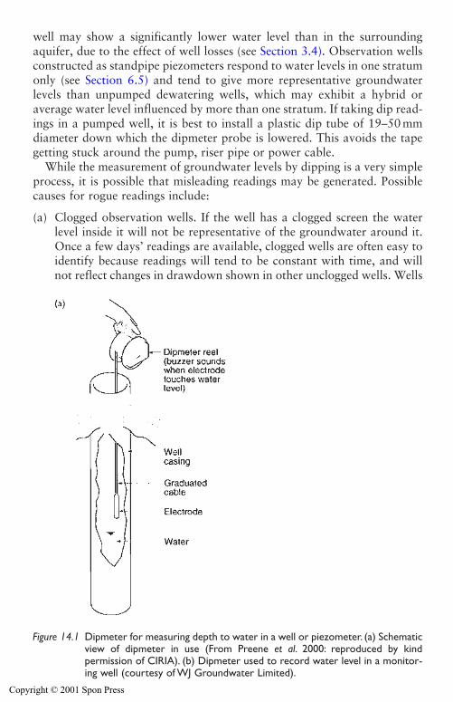
408 Monitoring and maintenance measures
well may show a significantly lower water level than in the surroundingaquifer, due to the effect of well losses (see Section 3.4). Observation wellsconstructed as standpipe piezometers respond to water levels in one stratumonly (see Section 6.5) and tend to give more representative groundwaterlevels than unpumped dewatering wells, which may exhibit a hybrid oraverage water level influenced by more than one stratum. If taking dip read-ings in a pumped well, it is best to install a plastic dip tube of 19–50 mmdiameter down which the dipmeter probe is lowered. This avoids the tapegetting stuck around the pump, riser pipe or power cable.
While the measurement of groundwater levels by dipping is a very simpleprocess, it is possible that misleading readings may be generated. Possiblecauses for rogue readings include:
(a) Clogged observation wells. If the well has a clogged screen the waterlevel inside it will not be representative of the groundwater around it.Once a few days’ readings are available, clogged wells are often easy toidentify because readings will tend to be constant with time, and willnot reflect changes in drawdown shown in other unclogged wells. Wells
Figure 14.1 Dipmeter for measuring depth to water in a well or piezometer. (a) Schematicview of dipmeter in use (From Preene et al. 2000: reproduced by kind permission of CIRIA). (b) Dipmeter used to record water level in a monitor-ing well (courtesy of WJ Groundwater Limited).
Copyright © 2001 Spon Press
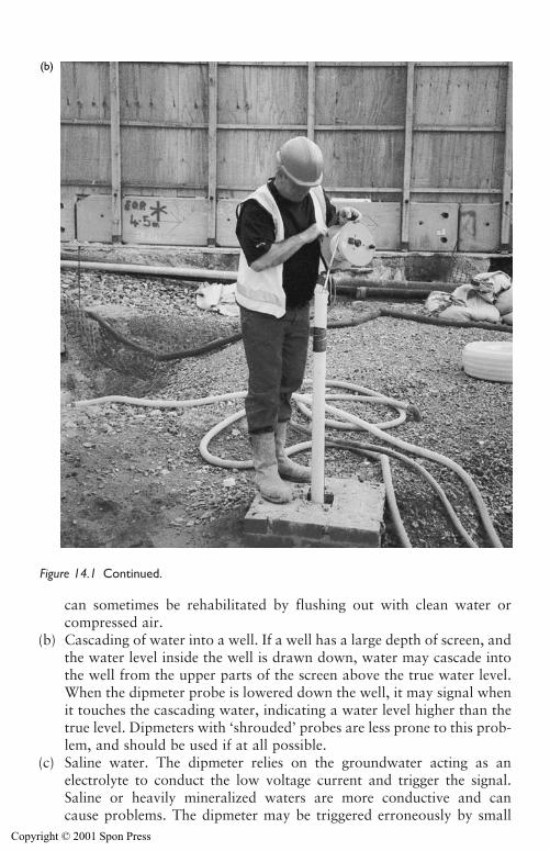
Monitoring and maintenance measures 409
can sometimes be rehabilitated by flushing out with clean water orcompressed air.
(b) Cascading of water into a well. If a well has a large depth of screen, andthe water level inside the well is drawn down, water may cascade intothe well from the upper parts of the screen above the true water level.When the dipmeter probe is lowered down the well, it may signal whenit touches the cascading water, indicating a water level higher than thetrue level. Dipmeters with ‘shrouded’ probes are less prone to this prob-lem, and should be used if at all possible.
(c) Saline water. The dipmeter relies on the groundwater acting as anelectrolyte to conduct the low voltage current and trigger the signal.Saline or heavily mineralized waters are more conductive and cancause problems. The dipmeter may be triggered erroneously by small
(b)
Figure 14.1 Continued.
Copyright © 2001 Spon Press
410 Monitoring and maintenance measures
moisture droplets on the side of the well casing or may signal continu-ously once water gets onto the probe. Obtaining reliable readings inthese conditions depends on the skill (and patience!) of the operator. Ithelps to dry the probe on a cloth between readings, and to repeat thereading at each well several times to be sure that a ‘true’ reading hasbeen obtained. Some dipmeters have an internal sensitivity adjustment.If this is turned to a minimum setting the dipmeter may be more reliablein saline wells. Occasionally, poorly conducting water (with a low TDS)may be encountered, where contact with the water does not completethe circuit and activate the dipmeter. This has been solved by the sim-ple expedient of adding a packet of salt to the observation well!
(d) Errors in recording readings. The person taking the readings may havemade an error. The graduated tape of a well-worn dipmeter can bedifficult to read when used in the field. It is not uncommon for thecentimetre part of the reading to be correct, but the metre part to be inerror by one metre. If the operator is recording all the readings on asheet or notebook this error may be repeated for subsequent readings.This is because the operator may expect each new reading to be similarto the last, and will copy the metre portion of the reading from onerecord to the next. When checking the data, any sudden one metrechanges in level may indicate this type of error.
(e) Malfunctioning dipmeters. Dipmeters sometimes malfunction. Adipmeter that does not work (perhaps because the battery is flat) is apractical problem, but does not generate false readings. A more subtleproblem is when the dipmeter tape is damaged and the conductors arebroken and exposed above the probe. The dipmeter will not signal whenthe probe touches water, but may do so when the exposed conductorreaches the water, indicating a lower water level than is actually present.
(f) Modified dipmeters. Dipmeters are sometimes repaired by shorteningthe graduated tape and re-jointing the probe. If the operator is notaware of this, the recorded water levels will be deeper than actuallevels, with the difference being equivalent to the shortening of the tape.It is not good practice to shorten dipmeter tapes; they should bereplaced with a new tape of the correct length.
It is not always that easy to spot rogue readings, but it becomes easier withexperience. If in doubt, treat the readings with caution and investigate howthey were taken. A lot of information can be gained by speaking directly tothe person who took the readings. If the long-term trends of water levels areplotted and compared with any changes in pumping, rogue readings areoften obvious.
In the field of hydrogeology for water supply water levels are often mea-sured at weekly or even monthly intervals (see Brassington 1998), which issufficient to identify long-term trends. For temporary works groundwater
Copyright © 2001 Spon Press
Monitoring and maintenance measures 411
lowering applications, water level monitoring is normally carried out muchmore frequently. This is because short-term effects (such as fluctuation indrawdowns resulting from pump failures) are of greater interest. Typically,groundwater levels in all observation wells or piezometers should berecorded at least once per day, on every day of operation. On sites wherethe groundwater lowering system is critical to the stability of the works,groundwater levels may be recorded more frequently, perhaps two or threetimes per shift. If very frequent monitoring is necessary (perhaps on siteswhere water levels vary due to tidal effects) consideration should be givento the use of automatic datalogging equipment (see Section 14.5).
14.3 Monitoring of discharge flow rate
The discharge flow rate pumped by the system is another vital measure ofperformance. The way the flow rate is measured depends on the pumpingmethod in use:
Wellpoint systems: total flow rate generally measured at common dischargepoint.Deep well systems: flow rate may be measured at common discharge point,or measured for individual wells and then added together.Ejector systems: flow rate may be measured at common discharge point, ormeasured for individual wells (calculated as the outflow from an ejectorminus the inflow) and then added together.
Discharge flow rate is commonly measured by one of three methods.
(i) Flowmeters. Proprietary flowmeters may be of the totalizing type (whichrecord total volumes of flow – flow rate is calculated from two readingsat known time intervals), or the transient type (which measure flow ratedirectly). The most commonly used devices are propeller or turbinemeters (where the flow rotates blades inside the meter) and magneticflow meters (where the water flows through a magnetic field, inducing avoltage proportional to the flow rate). All meters should be installed inthe pipework in accordance with the manufacturer’s recommendations.Flowmeters should generally be located away from valves and withadequate lengths of straight pipe either side (typical requirements are astraight length of ten pipe diameters upstream and five downstream).Flowmeters may require periodic maintenance or recalibration.
(ii) Weir tanks. This method is rugged and reliable in the field, and involvespassing the flow through a tank fitted with a V-notch (Fig. 14.2) orrectangular weir and measuring the depth of water over the weir.Calibration charts allow this measurement to be converted to flow rate.V-notch weirs are the most common type in use; calibration charts forthis type of weir are given in Appendix 14A. The method is suitable forroutine estimation of flow rate for monitoring purposes, but it can be
Copyright © 2001 Spon Press
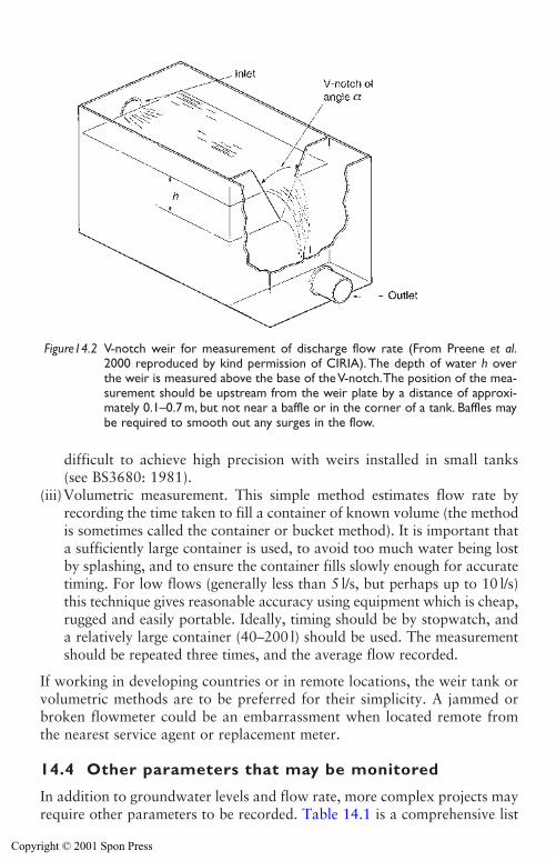
412 Monitoring and maintenance measures
difficult to achieve high precision with weirs installed in small tanks(see BS3680: 1981).
(iii)Volumetric measurement. This simple method estimates flow rate byrecording the time taken to fill a container of known volume (the methodis sometimes called the container or bucket method). It is important thata sufficiently large container is used, to avoid too much water being lostby splashing, and to ensure the container fills slowly enough for accuratetiming. For low flows (generally less than 5 l/s, but perhaps up to 10 l/s)this technique gives reasonable accuracy using equipment which is cheap,rugged and easily portable. Ideally, timing should be by stopwatch, anda relatively large container (40–200 l) should be used. The measurementshould be repeated three times, and the average flow recorded.
If working in developing countries or in remote locations, the weir tank orvolumetric methods are to be preferred for their simplicity. A jammed orbroken flowmeter could be an embarrassment when located remote fromthe nearest service agent or replacement meter.
14.4 Other parameters that may be monitored
In addition to groundwater levels and flow rate, more complex projects mayrequire other parameters to be recorded. Table 14.1 is a comprehensive list
Figure14.2 V-notch weir for measurement of discharge flow rate (From Preene et al.2000 reproduced by kind permission of CIRIA). The depth of water h overthe weir is measured above the base of the V-notch.The position of the mea-surement should be upstream from the weir plate by a distance of approxi-mately 0.1–0.7 m, but not near a baffle or in the corner of a tank. Baffles maybe required to smooth out any surges in the flow.
Copyright © 2001 Spon Press
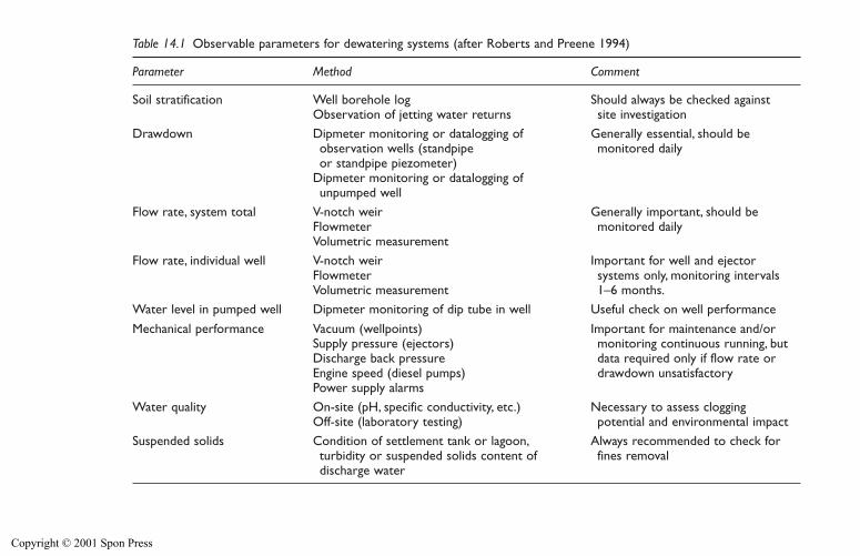
Table 14.1 Observable parameters for dewatering systems (after Roberts and Preene 1994)
Parameter Method Comment
Soil stratification Well borehole log Should always be checked againstObservation of jetting water returns site investigation
Drawdown Dipmeter monitoring or datalogging of Generally essential, should beobservation wells (standpipe monitored dailyor standpipe piezometer)
Dipmeter monitoring or datalogging ofunpumped well
Flow rate, system total V-notch weir Generally important, should beFlowmeter monitored dailyVolumetric measurement
Flow rate, individual well V-notch weir Important for well and ejectorFlowmeter systems only, monitoring intervalsVolumetric measurement 1–6 months.
Water level in pumped well Dipmeter monitoring of dip tube in well Useful check on well performance
Mechanical performance Vacuum (wellpoints) Important for maintenance and/orSupply pressure (ejectors) monitoring continuous running, but Discharge back pressure data required only if flow rate orEngine speed (diesel pumps) drawdown unsatisfactoryPower supply alarms
Water quality On-site (pH, specific conductivity, etc.) Necessary to assess cloggingOff-site (laboratory testing) potential and environmental impact
Suspended solids Condition of settlement tank or lagoon, Always recommended to check forturbidity or suspended solids content of fines removaldischarge water
Copyright © 2001 Spon Press
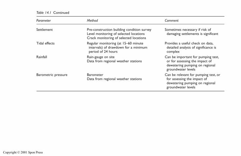
Table 14.1 Continued
Parameter Method Comment
Settlement Pre-construction building condition survey Sometimes necessary if risk ofLevel monitoring of selected locations damaging settlements is significantCrack monitoring of selected locations
Tidal effects Regular monitoring (at 15–60 minute Provides a useful check on data,intervals) of drawdown for a minimum detailed analysis of significance isperiod of 24 hours complex
Rainfall Rain-gauge on site Can be important for pumping test,Data from regional weather stations or for assessing the impact of
dewatering pumping on regionalgroundwater levels
Barometric pressure Barometer Can be relevant for pumping test, orData from regional weather stations for assessing the impact of
dewatering pumping on regionalgroundwater levels
Copyright © 2001 Spon Press

of parameters that can be observed; it is unlikely that the full list would bemonitored on a single project.
14.5 Datalogging systems
Collection of monitoring data is generally carried out by manually dippingwater levels, reading flowmeters, etc. and recording the results in notebooksor record sheets. This can be avoided by using electronic datalogging equip-ment, connected to appropriate sensing devices to record the required data.The datalogger stores the data until the operator collects (or downloads)the data for inspection and interpretation. As each year passes, availabledatalogging equipment is becoming cheaper, smaller and more versatile.Equipment that, only a few years ago, might have been suitable for large-scale projects only is now cost-effective on even simple schemes.
The use of dataloggers can reduce the number of personnel needed formonitoring, especially if regular monitoring during day and night shifts isrequired. By downloading the data directly, there is no need for someone tolaboriously key in manually recorded readings and the time and effortrequired to go from data gathering to plotting and analysis of data can beminimized. If e-mail communications are available, rapid dissemination ofcomplete datasets is possible.
The most common application of datalogging equipment is to recordgroundwater levels. An electronic pressure transducer is installed below thewater level in the well (Fig. 14.3). Such devices typically operate on thevibrating wire principle where the transducer contains a diaphragm inhydraulic connection with the groundwater. Changes in water pressuredeflect the diaphragm and an associated tensioned steel wire (the vibratingwire). The deflection changes the frequency response of the vibrating wirewhen excited (via a connecting cable) by a readout unit or datalogger. Someof the most useful dataloggers are ‘stand-alone’, that is, they have sufficientbattery power to operate for extended periods without an external powersupply. Dataloggers can be multiplex, serving several transducers, or singlestation, serving one transducer only.
The pressure transducer is lowered down to a significant depth below thelowest anticipated drawdown level; typically the transducer is suspended fromits own cable. The transducer records the pressure above its own level, so anon-site calibration is required to allow pressure readings to be converted towater levels. This may be done by accurately recording the depth at whichthe pressure transducer is suspended in the well. Alternatively, if the waterlevel is manually measured at the same time as the datalogger takes a read-ing, the effective transducer depth can be estimated by adding the dataloggedpressure head (measured by the transducer) to the observed depth to water.The datalogger should be installed and calibrated in accordance with themanufacturer’s guidelines; some types of pressure transducers are affected
Monitoring and maintenance measures 415
Copyright © 2001 Spon Press
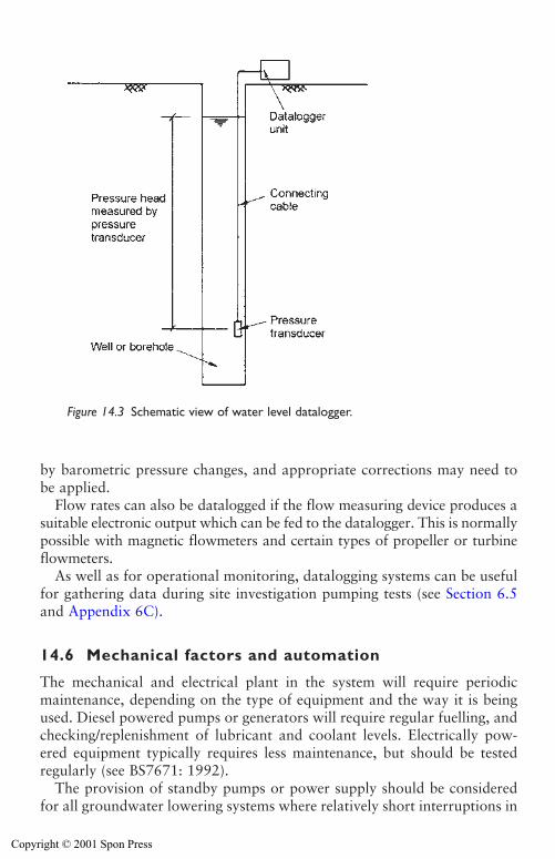
416 Monitoring and maintenance measures
by barometric pressure changes, and appropriate corrections may need tobe applied.
Flow rates can also be datalogged if the flow measuring device produces asuitable electronic output which can be fed to the datalogger. This is normallypossible with magnetic flowmeters and certain types of propeller or turbineflowmeters.
As well as for operational monitoring, datalogging systems can be usefulfor gathering data during site investigation pumping tests (see Section 6.5and Appendix 6C).
14.6 Mechanical factors and automation
The mechanical and electrical plant in the system will require periodicmaintenance, depending on the type of equipment and the way it is beingused. Diesel powered pumps or generators will require regular fuelling, andchecking/replenishment of lubricant and coolant levels. Electrically pow-ered equipment typically requires less maintenance, but should be testedregularly (see BS7671: 1992).
The provision of standby pumps or power supply should be consideredfor all groundwater lowering systems where relatively short interruptions in
Figure 14.3 Schematic view of water level datalogger.
Copyright © 2001 Spon Press
Monitoring and maintenance measures 417
pumping will cause instability or flooding of the excavation. Wellpoint andejector systems, which have relatively few running pumps, often havestandby pumps provided – one standby for every two duty pumps is typi-cal. Deep well systems, which may have many pumps, often do not havestandby pumps provided. This is acceptable, provided that the systemdesign has allowed for a few extra wells over and above the minimum num-ber required. In this way the failure of one or two submersible pumps willnot cause a problem while the pumps are replaced. Where systems are elec-trically powered (from mains or generator) a standby generator should beprovided as a back up.
Standby pumps and generators should be tested regularly (at leastweekly) by running on load. If possible it is good practice to use equipmentin rotation, whereby one week a unit is run as the duty unit, and next weekit acts as standby, and so on.
Electronic equipment is available to allow systems to be alarmed and, tosome degree, automated. Sensors, similar to those used in datalogging, can beused to monitor groundwater levels, pump vacuum, ejector supply pressure,or the failure of the power supply or of individual pumps. The output fromthese sensors can be linked to monitoring equipment, which can send analarm signal (which could be via a siren, flashing beacon, radio or telephonesignal) to warn staff of problems and alert them to the need for remedialaction. The remedial action might typically be to switch on the standbypumps or power supply and re-start the system. While this could be donemanually by someone called out to site, the next logical step is to automatethis process and allow the system to activate the standby plant in responseto the alarm signal. This is the basis of automatic mains failure (AMF) systems. Such systems are used on only a small minority of groundwaterlowering systems, but have been established practice on some of the largerwater supply wells since the 1980s. Electronics and computer technologyare advancing constantly; it is probable that in the near future automationand remote monitoring will be applied to a much greater proportion of sys-tems than at present.
14.7 Backfilling and sealing of wells on completion
On completion of the groundwater lowering works, after pumping equip-ment has been removed, wells may need to be backfilled and capped off.This is required to:
i Remove the safety hazard of having open holes.ii Prevent the well acting as a conduit for surface contamination to reach
the aquifer (this is especially important for wells penetrating aquifersused for public supply, see Section 13.3).
iii Prevent uncontrolled flow of groundwater between strata penetratedby the well.
Copyright © 2001 Spon Press
In some cases, particularly shallow wellpoint systems penetrating oneaquifer only on uncontaminated sites, the wells may be left unsealed, withthe wellpoint riser simply cut off below surface reinstatement level. In con-trast, almost all deep wells and many ejector wells will need to be sealed.
Sealing of wells first involves removing the pumps and any headworksfrom the wells. The well casing and screen are normally left in place but arecut off just below ground level. The well bore is then backfilled with appro-priate material. The materials used to backfill a well must be clean, inertand non-polluting. Suitable materials include clean sands and gravels, ben-tonite or cement grout (grouts should generally be placed via tremie pipes).It may be necessary to obtain agreement from the environmental regulatoryauthorities that the sealing methods proposed are adequate. In England andWales the Environment Agency (2000) has produced guidelines on bestpractice.
14.8 Encrustation, bifouling and corrosion
Wells pumping groundwater for extended periods of time may reduce inperformance (loss of yield or increase in drawdown in the well) graduallyduring operation. The loss of performance may result from clogging due toencrustation (precipitation of chemical compounds) or biofouling (bacterialgrowth and associated processes). Additionally, if the groundwater is salineor brackish, corrosion of metal components (such as pumps or pipework)may be of concern.
These effects have long been recognized in water supply wells, whichhave working lives of several decades. Such wells (and associated pumpsand pipework) are typically rehabilitated at periodic intervals to ensure per-formance does not reduce to unacceptable levels (see Howsam et al. 1995).Gradual reduction in performance is less of a problem for temporary worksgroundwater lowering systems, largely because of the shorter pumpingperiods involved. Nevertheless, there have been a number of instanceswhere systems operated for periods between several months and up to a fewyears have been affected. An understanding of the factors involved is usefulwhen planning for the maintenance of systems.
The following sections mainly discuss clogging effects in wells, but prob-lems can also occur with the encrustation or biofouling of pump internalcomponents, pipework and flowmeters.
14.8.1 Chemical encrustation
Groundwater contains, to varying degrees, chemical compounds in solution(see Section 3.8). These compounds may precipitate in and around the well,being deposited as insoluble compounds to form deposits of scale on wellscreens and pumps. The water experiences a drop in pressure, and may be
418 Monitoring and maintenance measures
Copyright © 2001 Spon Press
aerated by cascading, as it enters a well; these are ideal conditions for pre-cipitation.
The principal indicators of the encrustation of potential of groundwater(from Wilkinson 1986) are:
i pH greater than 8.0ii Total hardness greater than 330 mg/liii Total alkalinity greater than 300 mg/liv Iron content greater than 2 mg/l.
Common deposits include calcium and magnesium carbonates or iron ormanganese oxides. For temporary works applications, chemical encrusta-tion is rarely severe enough to affect operation. If groundwater analysessuggest it may be a problem, the wells should be designed to have as low ascreen entrance velocity (see Section 10.2) as possible. If encrustationbecomes a problem once the system is in operation, acidisation or chemicaltreatment of the wells, followed by airlifting or clearance pumping mayhelp loosen and remove deposits (see Howsam et al. 1995).
14.8.2 Bacterial growth and biofouling
Groundwater naturally contains bacteria; problems occur because the wellsand pipework forming a groundwater lowering system may offer an envi-ronment in which these bacteria can thrive. The most common, and hencemost problematic, bacteria are the iron-related species such as Gallionellaor Crenothrix. According to Howsam and Tyrrel (1990) these are sessilebacteria; this means that they attach themselves to surfaces. The action ofthe bacteria will cause a biofilm to develop on a surface. A biofilm consistsnot only of bacterial cells but also proportionately large volumes of extra-cellular slime. This can trap particulate matter and detritus from the waterflowing by and provides an environment for the precipitation of iron andmanganese oxides and oxyhydroxides. The most common form of biofilm(also known as biomass) is a thick red-brown gelatinous slime or pastewhich builds up in wells, pumps and pipework.
The practical result of this is that if conditions are favourable for bacte-rial growth a system may become biofouled. The biofilm can be surprisinglytenacious, and if not removed or controlled in some way may clog a system,dramatically reducing performance (Fig. 14.4). As biofouling deposits buildup the discharge flow rate will decrease. If no action is taken, the drawn-down groundwater levels will rise, and may result in instability or floodingof the excavation. Regular monitoring of flow rate and water levels isessential for diagnosis of these problems. A programme of periodic rehabil-itation of the system may be necessary to ensure continued satisfactoryoperation.
Monitoring and maintenance measures 419
Copyright © 2001 Spon Press
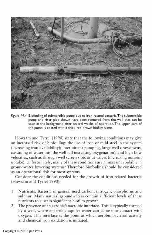
420 Monitoring and maintenance measures
Howsam and Tyrrel (1990) state that the following conditions may givean increased risk of biofouling: the use of iron or mild steel in the system(increasing iron availability); intermittent pumping, large well drawdowns,cascading of water into the well (all increasing oxygenation); and high flowvelocities, such as through well screen slots or at valves (increasing nutrientuptake). Unfortunately, many of these conditions are almost unavoidable ingroundwater lowering systems! Therefore biofouling should be consideredas an operational risk for most systems.
Consider the conditions needed for the growth of iron-related bacteria(Howsam and Tyrrel 1990):
1 Nutrients. Bacteria in general need carbon, nitrogen, phosphorus andsulphur. Many natural groundwaters contain sufficient levels of thesenutrients to sustain significant biofilm growth.
2 The presence of an aerobic/anaerobic interface. This is typically formedby a well, where anaerobic aquifer water can come into contact withoxygen. This interface is the point at which aerobic bacterial activityand chemical iron oxidation is initiated.
Figure 14.4 Biofouling of submersible pump due to iron-related bacteria.The submersiblepump and riser pipe shown have been removed from the well that can beseen in the background after several weeks of operation.The upper part ofthe pump is coated with a thick red-brown biofilm slime.
Copyright © 2001 Spon Press
3 The presence of iron in the groundwater. The presence of dissolved ironis necessary because the oxidation of the iron provides energy for thebacteria’s metabolism. This action precipitates the insoluble iron com-pounds, giving the characteristic red-brown colour to the biofilm.
4 Water flow. The flow of water transports nutrients to the biofilm. Thefaster the flow of water the more food is available for bacterial growth,and the faster the biofilm will grow. This is a key point, because it meansthat high flow wells may biofoul more quickly than low flow wells.
Conditions 1 and 2 will be present for most systems, so the likelihood ofbiofouling should be assessed from conditions 3 and 4, dissolved iron andrate of flow. Based on a number of case histories Powrie et al. (1990) produced Table 14.2 in terms of those two factors.
Table 14.2 shows that the risk of biofouling problems is also dependenton the type of system. Wellpoint systems (where much of the pipework isunder vacuum) do not provide a good environment for the growth of aero-bic bacteria, and are not especially prone to biofouling. Deep well systemsusing submersible pumps are prone to biomass building up on the outsideof the pump and riser pipe, inside the pump chambers and inside the riserpipe. Because the riser pipe is normally of relatively large diameter, cloggingof the riser pipe is only a problem in severe cases; biofouling inside thepump is more of a problem, often leading to pump damage if not removedby cleaning. Ejector systems are particularly susceptible to clogging frombiofouling; this is because the smaller diameter pipework generally used iseasily blocked by biomass. Artificial recharge systems are extremely vul-nerable to biofouling (see Section 13.6).
If biofouling occurs, and significant loss of performance has been identi-fied by regular monitoring of groundwater levels and discharge flow rates,the system may need to be rehabilitated. Possible methods include:
i Agitation, scrubbing or flushing out of the wells. Biomass may beremoved from the wells by development techniques (see Section 10.6)that surge and agitate the well, thereby loosening the clogging material.Airlift surging and pumping, water jetting (using fresh water or a chlo-rine solution), and scrubbing (using a tight fitting wire brush hauled upand down inside the well) have all proved effective.
ii Cleaning of pumps and pipework. Submersible pumps, ejectors and ris-ers can be removed from wells and cleaned at ground level by jet wash-ing or scrubbing. Pumps and ejectors may need to be dis-assembled toallow cleaning or replacement of internal components. Riser, header anddischarge pipes may be cleaned by jetting or the use of pipe cleaningmoles.
iii Chemical treatment of wells and pipework. This might involve dosingthe wells and rest of the system with a chlorine solution or other biocide
Monitoring and maintenance measures 421
Copyright © 2001 Spon Press
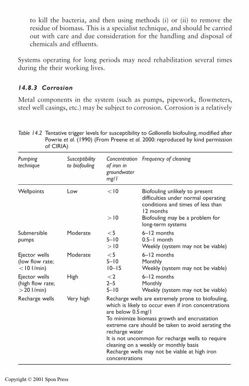
422 Monitoring and maintenance measures
to kill the bacteria, and then using methods (i) or (ii) to remove theresidue of biomass. This is a specialist technique, and should be carriedout with care and due consideration for the handling and disposal ofchemicals and effluents.
Systems operating for long periods may need rehabilitation several timesduring the their working lives.
14.8.3 Corrosion
Metal components in the system (such as pumps, pipework, flowmeters,steel well casings, etc.) may be subject to corrosion. Corrosion is a relatively
Table 14.2 Tentative trigger levels for susceptibility to Gallionella biofouling, modified afterPowrie et al. (1990) (From Preene et al. 2000: reproduced by kind permissionof CIRIA)
Pumping Susceptibility Concentration Frequency of cleaningtechnique to biofouling of iron in
groundwatermg/1
Wellpoints Low �10 Biofouling unlikely to presentdifficulties under normal operatingconditions and times of less than12 months
�10 Biofouling may be a problem forlong-term systems
Submersible Moderate �5 6–12 monthspumps 5–10 0.5–1 month
�10 Weekly (system may not be viable)Ejector wells Moderate �5 6–12 months(low flow rate; 5–10 Monthly�10 1/min) 10–15 Weekly (system may not be viable)Ejector wells High �2 6–12 months(high flow rate; 2–5 Monthly�20 1/min) 5–10 Weekly (system may not be viable)Recharge wells Very high Recharge wells are extremely prone to biofouling,
which is likely to occur even if iron concentrationsare below 0.5 mg/1To minimize biomass growth and encrustationextreme care should be taken to avoid aerating therecharge waterIt is not uncommon for recharge wells to requirecleaning on a weekly or monthly basisRecharge wells may not be viable at high ironconcentrations
Copyright © 2001 Spon Press
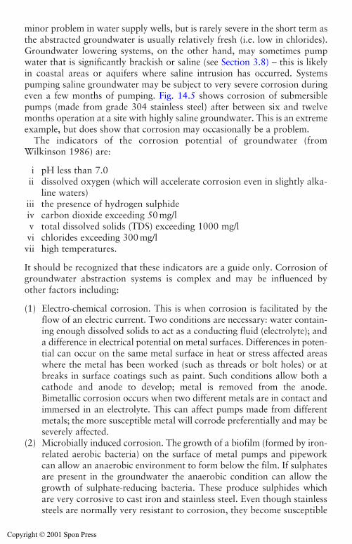
Monitoring and maintenance measures 423
minor problem in water supply wells, but is rarely severe in the short term asthe abstracted groundwater is usually relatively fresh (i.e. low in chlorides).Groundwater lowering systems, on the other hand, may sometimes pumpwater that is significantly brackish or saline (see Section 3.8) – this is likelyin coastal areas or aquifers where saline intrusion has occurred. Systemspumping saline groundwater may be subject to very severe corrosion duringeven a few months of pumping. Fig. 14.5 shows corrosion of submersiblepumps (made from grade 304 stainless steel) after between six and twelvemonths operation at a site with highly saline groundwater. This is an extremeexample, but does show that corrosion may occasionally be a problem.
The indicators of the corrosion potential of groundwater (fromWilkinson 1986) are:
i pH less than 7.0ii dissolved oxygen (which will accelerate corrosion even in slightly alka-
line waters)iii the presence of hydrogen sulphideiv carbon dioxide exceeding 50 mg/lv total dissolved solids (TDS) exceeding 1000 mg/lvi chlorides exceeding 300 mg/lvii high temperatures.
It should be recognized that these indicators are a guide only. Corrosion ofgroundwater abstraction systems is complex and may be influenced byother factors including:
(1) Electro-chemical corrosion. This is when corrosion is facilitated by theflow of an electric current. Two conditions are necessary: water contain-ing enough dissolved solids to act as a conducting fluid (electrolyte); anda difference in electrical potential on metal surfaces. Differences in poten-tial can occur on the same metal surface in heat or stress affected areaswhere the metal has been worked (such as threads or bolt holes) or atbreaks in surface coatings such as paint. Such conditions allow both acathode and anode to develop; metal is removed from the anode.Bimetallic corrosion occurs when two different metals are in contact andimmersed in an electrolyte. This can affect pumps made from differentmetals; the more susceptible metal will corrode preferentially and may beseverely affected.
(2) Microbially induced corrosion. The growth of a biofilm (formed by iron-related aerobic bacteria) on the surface of metal pumps and pipeworkcan allow an anaerobic environment to form below the film. If sulphatesare present in the groundwater the anaerobic condition can allow thegrowth of sulphate-reducing bacteria. These produce sulphides whichare very corrosive to cast iron and stainless steel. Even though stainlesssteels are normally very resistant to corrosion, they become susceptible
Copyright © 2001 Spon Press
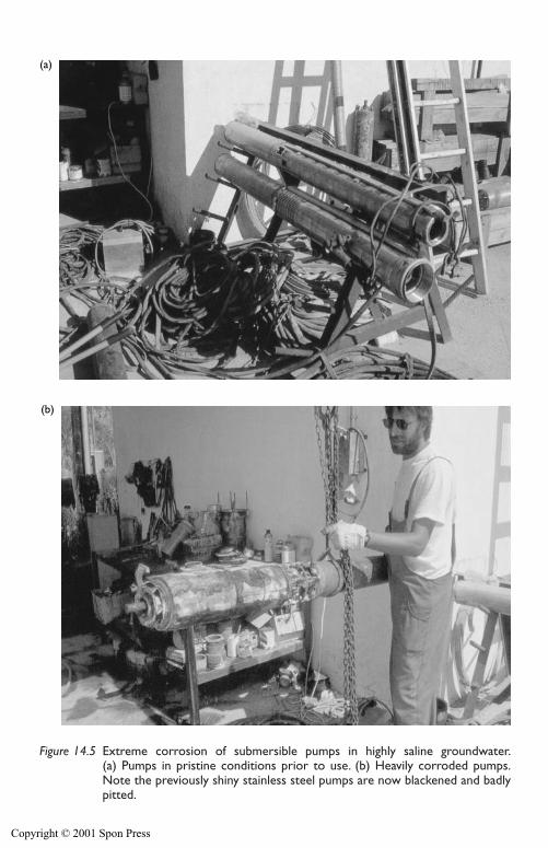
424 Monitoring and maintenance measures
(a)
(b)
Figure 14.5 Extreme corrosion of submersible pumps in highly saline groundwater.(a) Pumps in pristine conditions prior to use. (b) Heavily corroded pumps.Note the previously shiny stainless steel pumps are now blackened and badly pitted.
Copyright © 2001 Spon Press
Monitoring and maintenance measures 425
to attack by chloride ions under such conditions. The passive oxidelayer, which normally prevents corrosion, cannot re-form in the anaer-obic zone beneath the biofilm.
If corrosive conditions are anticipated, the materials used in the systemshould be chosen with care. Mild steel (as is commonly used for pipework)is very susceptible to corrosion, stainless steel (from which many sub-mersible pumps are made) is less so, and plastics are inert to corrosion. Toreduce corrosion risk, as much pipework (above ground discharge pipesand below ground riser pipes) should be made from plastic. Considerationshould be given to using pumps made from the more resistant grade 316stainless steel, rather than the more common grade 304. If microbiallyinduced corrosion is suspected, regular cleaning of the system to remove thebiofilm will remove the environment for this form of corrosion.
14.9 Fault finding and problem solving
Like any complex system, there may be times when a groundwater lower-ing scheme does not adequately achieve its desired aims when switched on,or if it does work effectively at first, its performance may deteriorate withtime. Identifying system problems and figuring out how to put them rightis a vital skill for any practical groundwater engineer. Most problems withgroundwater lowering systems will probably have a mechanical, hydrogeo-logical or geotechnical cause, but it is worth thinking about all the factorswhich can have an effect:
i The ground. The nature of the ground will clearly affect the way agroundwater lowering system performs.
ii The pump. An inappropriate or poorly performing pump may causeproblems.
iii The power supply. Every pump needs a power supply, generally dieselor electric. Unreliable or underpowered units may be the cause of diffi-culties.
iv The pipework. If the water cannot get to or from the pump, a systemwill perform poorly.
v The environment. External factors, such as changes in groundwater lev-els, bad weather, etc. may have an influence.
vi Human factors. Systems do not generally run themselves; the way theyare operated will affect their performance.
As with any daunting problem, the secret is to identify the possible causesand eliminate the irrelevant ones until you are left with those directly linkedto your woes. It requires a logical approach, and might even be enjoyable ifit was not invariably carried out under pressure to solve the problem assoon as possible and allow the excavation to proceed.
Copyright © 2001 Spon Press
426 Monitoring and maintenance measures
Typical operational problems requiring correction include:
During initial period of running:High flow problem. The flow rate is greater than the pump capacity, andthe target drawdown is not achieved.Low flow problem. The flow rate is less than the pump capacity and the tar-get drawdown is not achieved.Lack of dry conditions in excavation, when monitoring of groundwater lev-els indicates the target drawdown has been achieved.After extended running:Sudden loss of performance. The system operates satisfactorily, but aftersome time the flow rate or drawdown changes suddenly.Gradual loss of performance. The system operates satisfactorily at first, butperformance deteriorates gradually with time.
To diagnose any significant problem the raw material is monitoring data ofthe sort described in this chapter. If a system has not been adequately mon-itored, the first stage of any problem solving process will involve gatheringdata about the system performance. This will take time, probably taxing thepatience of all concerned – neglecting regular monitoring of groundwaterlowering systems is a false economy in terms of both time and money.
Appendix 14A: Estimation of flow rate usingV-notch weirs
V-notch weirs are a common method for estimation of discharge flow ratein the field.
V-notch weirs are a form of thin plate weir, where the area of flow is anotch cut in the shape of a ‘V’ with an internal angle of � (see Fig. 14A-1),normally installed in a tank. The flow rate over the weir is a function of thehead over the weir, the size and shape of the discharge area, and an experi-mentally determined discharge coefficient.
BS3680 (1981) provides formulae and discharge coefficients for V-notchweirs (and the less commonly used rectangular notch weirs). These formu-lae have been used to produce calibration charts for various standardV-notch angles; these charts are presented at the end of this appendix.
Knowing the angle of the V-notch, a measurement of the head of waterabove the base of the notch allows the flow rate to be estimated from theappropriate chart. The position of measurement should be upstream fromthe weir plate by a distance of approximately 1.1–0.7 m, but not near abaffle or in the corner of the tank. The tank should be positioned on a firmstable base, with timber packing used to ensure that the V-notch plate isvertical, and that the top of the notch is horizontal.
Copyright © 2001 Spon Press
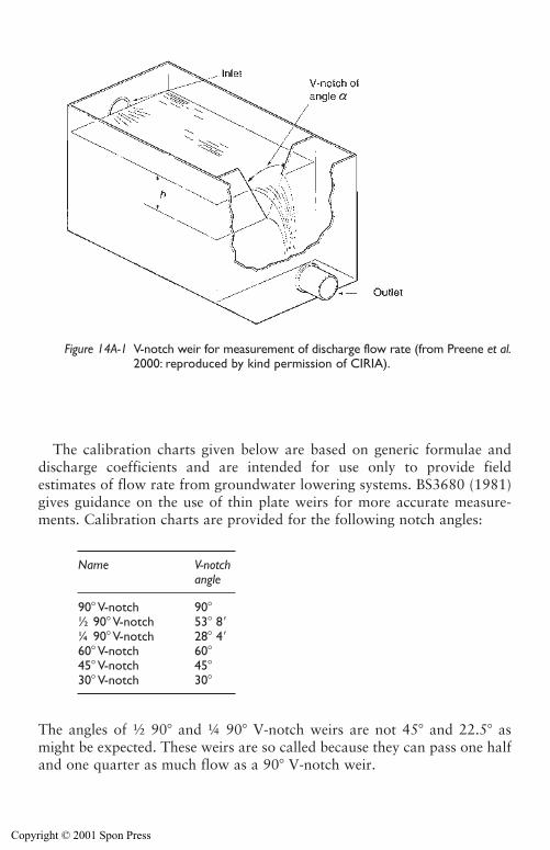
Monitoring and maintenance measures 427
The calibration charts given below are based on generic formulae anddischarge coefficients and are intended for use only to provide fieldestimates of flow rate from groundwater lowering systems. BS3680 (1981)gives guidance on the use of thin plate weirs for more accurate measure-ments. Calibration charts are provided for the following notch angles:
The angles of ½ 90� and ¼ 90� V-notch weirs are not 45� and 22.5� asmight be expected. These weirs are so called because they can pass one halfand one quarter as much flow as a 90� V-notch weir.
Name V-notchangle
90� V-notch 90�½ 90� V-notch 53� 8¼ 90� V-notch 28� 460� V-notch 60�45� V-notch 45�30� V-notch 30�
Figure 14A-1 V-notch weir for measurement of discharge flow rate (from Preene et al.2000: reproduced by kind permission of CIRIA).
Copyright © 2001 Spon Press
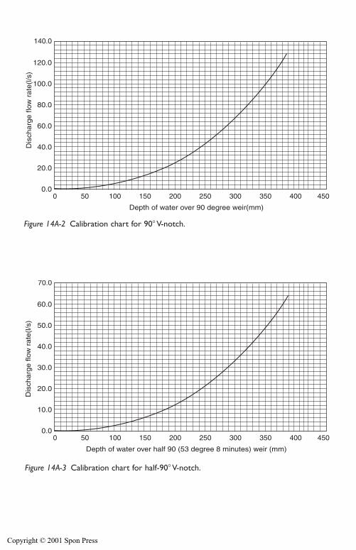
0 50 100 150 200 250 300 350 400 450
140.0
120.0
100.0
80.0
60.0
40.0
20.0
0.0
Dis
charg
e flo
w r
ate
(l/s
)
Depth of water over 90 degree weir(mm)
Figure 14A-2 Calibration chart for 90� V-notch.
0 50 100 150 200 250 300 350 400 450
70.0
60.0
50.0
40.0
30.0
20.0
10.0
0.0
Dis
charg
e flo
w r
ate
(l/s
)
Depth of water over half 90 (53 degree 8 minutes) weir (mm)
Figure 14A-3 Calibration chart for half-90� V-notch.
Copyright © 2001 Spon Press
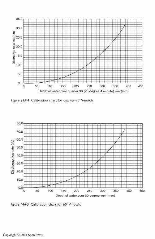
0 50 100 150 200 250 300 350 400 450
35.0
30.0
25.0
20.0
15.0
10.0
5.0
0.0
Dis
charg
e flo
w r
ate
(l/s
)
Depth of water over quarter 90 (28 degree 4 minute) weir(mm)
Figure 14A-4 Calibration chart for quarter-90� V-notch.
0 50 100 150 200 250 300 350 400 450
80.0
70.0
60.0
50.0
40.0
30.0
20.0
10.0
0.0
Dis
charg
e flo
w r
ate
(l/s
)
Depth of water over 60 degree weir (mm)
Figure 14A-5 Calibration chart for 60� V-notch.
Copyright © 2001 Spon Press
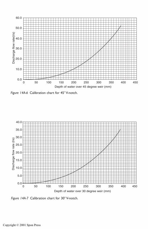
0 50 100 150 200 250 300 350 400 450
60.0
50.0
40.0
30.0
20.0
10.0
0.0
Dis
charg
e flo
w r
ate
(l/s
)
Depth of water over 45 degree weir (mm)
Figure 14A-6 Calibration chart for 45� V-notch.
0 50 100 150 200 250 300 350 400 450
40.0
35.0
30.0
25.0
20.0
15.0
10.0
5.0
0.0
Dis
charg
e flo
w r
ate
(l/s
)
Depth of water over 30 degree weir (mm)
Figure 14A-7 Calibration chart for 30� V-notch.
Copyright © 2001 Spon Press
References
BS3680 (1981). Measurement of Liquid Flow in Open Channels: Part 4A MethodUsing Thin Plate Weirs. British Standards Institution, London.
BS7671 (1992). Requirements for Electrical Installations: IEE Wiring Regulations,16th Edition. British Standards Institution, London.
Brassington, R. (1998). Field Hydrogeology, 2nd edition. Wiley, Chichester.Environment Agency (2000). Decommissioning Redundant Boreholes and Wells.
National Groundwater and Contaminated Land Centre, Solihull.Howsam, P., Misstear, B. and Jones, C. (1995). Monitoring, Maintenance and
Rehabilitation of Water Supply Boreholes. Construction Industry Research andInformation Association, CIRIA Report 137, London.
Howsam, P. and Tyrrel, S. F. (1990). Iron biofouling in groundwater abstractionsystems: why and how? Microbiology in Civil Engineering (Howsam, P., ed.).Spon, London, pp 192–197.
Powrie, W., Roberts, T. O. L., and Jefferis, S. A. (1990). Biofouling of site dewa-tering systems. Microbiology in Civil Engineering (Howsam, P., ed.). Spon,London, pp 341–352.
Preene, M., Roberts, T. O. L., Powrie, W. and Dyer, M. R. (2000). GroundwaterControl – Design and Practice. Construction Industry Research and InformationAssociation, CIRIA Report C515, London.
Roberts, T. O. L. and Preene, M. (1994). The design of groundwater control sys-tems using the observational method. Géotechnique, 44(4), 727–734.
Wilkinson, W. B. (1986). Design of boreholes and wells. Groundwater, Occurrence,Development and Protection (Brandon, T. W., ed.). Institution of WaterEngineers and Scientists, Water Practice Manual No. 5, London, pp 385–406.
Monitoring and maintenance measures 431
Copyright © 2001 Spon Press

Chapter 15
Safety, contracts and theenvironment
15.0 Introduction
Groundwater lowering is the means to an end – the excavation andconstruction of below ground works in stable and workable conditions. Itwill be one of many diverse activities carried out on a construction site dur-ing the life of a project. As such, dewatering must:
i Be carried out safely, and in such as way so as to minimize (as far as ispracticable) the risk of harm to the workers or others.
ii Have an appropriate contractual arrangement, so that adequate infor-mation is available to allow design and construction, and to ensure thatall parties are aware of their rights and responsibilities.
iii Be executed with a view to minimizing or controlling any adverse envi-ronmental impacts, and conforming to any specific legal restrictionsimposed by environmental regulators.
This chapter presents brief details of the health and safety legislation inforce in the United Kingdom, and outlines key issues relevant to dewater-ing works. Typical contractual arrangements used to procure and managegroundwater lowering works are outlined, including the traditional con-tractor sub-contractor relationship, as well as alternative forms of contract.Finally, the environmental law in relation to dewatering is discussed and thelegal implications of dewatering works are outlined.
15.1 Health and safety
In the United Kingdom it is a legal requirement that all company and sitemanagement personnel ensure that the construction operations carried outby their company conform with safe working conditions and noise abate-ment regulations.
Since the beginning of the century there has been concern over accidentsand working conditions on building works. In 1904 a Public Enquiry washeld but it was not till 1926 that the first Building Regulations were passed
Copyright © 2001 Spon Press

into law. From time to time since then building and construction regulationshave been augmented and strengthened by various specific laws. Currentlythe major legislation covering occupational health and safety of construc-tion works are:
(a) Health and Safety at Work Act 1974(b) Management of Health and Safety at Work Regulations 1992(c) Construction (Design and Management) Regulations 1994(d) Construction (Health, Safety and Welfare) Regulations 1996.
Legislation will change with time, as technology and working practicesevolve. This chapter provides only a brief overview of some significantissues. It is essential that the reader checks to see what legislation is current,consults the original regulations and obtains specialist advice. This legisla-tion applies to the United Kingdom. Naturally, this legislation is not applic-able in other countries but the legal duties of the various parties defined inthe Health and Safety at Work Act 1974 are reflected in the legal systemsof many other countries.
This section will deal specifically with health and safety issues particularto groundwater control works. Generic guidance on construction healthand safety can be found in various publications (see for example, Healthand Safety Executive 1996).
15.1.1 CDM regulations
The Construction (Design and Management) Regulations 1994 (known asthe CDM regulations) define the legal duties of the various parties to the con-struction process, including clients, their agents, designers and contractors. Insimple terms the regulations require health and safety to be considered atevery stage of a project from design through to construction, maintenanceand demolition. This is a change in focus from the traditional approach tohealth and safety, which concentrated on the construction phase and the roleof the contractor.
The CDM approach requires designers to consider whether it is reason-ably practicable to exclude or reduce potential hazards. The risk to healthand safety arising from a particular aspect of the design has to be weighedagainst the cost of excluding that feature by
� Designing to reduce foreseeable risks to health and safety.� Tackling the causes of risk at source.� Reducing and controlling risks by means that will protect anyone at work
(rather than just the individual at work) and so yield the greatest benefit.
The cost is based not just on financial considerations but also fitness for purpose, environmental impact and ‘buildability’. The purpose of the
Safety, contracts and the environment 433
Copyright © 2001 Spon Press
434 Safety, contracts and the environment
regulations is not only to reduce possible hazards and risks, but also toidentify and record those which are unavoidable, as a warning to subse-quent parties in the design/construction/maintenance/demolition process.
Detailed guidance on the application of the CDM regulations is given inthe Approved Code of Practice by the Health and Safety Executive (1995)and in CIRIA Report 166 (Ove Arup & Partners 1997). The application ofCDM to the design of groundwater lowering systems is discussed in Preeneet al. (2000).
In essence, the CDM regulations formalize what a good dewateringdesigner should be doing as a matter of course. Firstly, considering the fullrange of options for a design and then, so far as is practicable, designing sys-tems which will be effective but which can be installed without unnecessaryrisks to the workers or others. In other words to consider the ‘buildability’of a system.
When considering options the designer must look at detail – for exampleif a line of wellpoints requires the jetting crew to work next to an open deepcofferdam, could the line of wellpoints not be relocated to avoid the risk?The designer must also, however, look at the bigger picture. If a sheet-pilecofferdam is dewatered, but relies on continued dewatering for stability isthat too risky an option? What if the power supply fails? What if thestandby generator fails too? Such risks will need to be assessed against thefactors discussed earlier. In this case the options might be to avoid dewa-tering altogether and use a system based on groundwater exclusion. A mul-tiple redundant pumping and power supply system may increase the cost,but may produce a significant reduction in the risk of catastrophic failureof the excavation. These are the kind of questions that should be part of thedesign process.
15.1.2 COSHH regulations
The Control of Substances Hazardous to Health Regulations 1988 (knownas the COSHH regulations) lay down the requirements for the assessmentof risks from hazardous substances, and for the protection of peopleexposed to them.
The regulations cover almost all potentially harmful substances (althoughsome substances such as lead and asbestos are covered in separate legisla-tion). Suppliers of any chemical or hazardous substance must provide a datasheet to the purchaser, which must contain sufficient information to allowan assessment to be made of the risk to health from the use of the substance.Based on these assessments, employers have to ensure that, as far as is rea-sonably practicable, the exposure of employees to hazardous substances isprevented, or if this is not possible, then controlled. This may involve the useof personal protective equipment (gloves, eye protection, respirators, etc.)appropriate to the hazard.
Copyright © 2001 Spon Press
Safety, contracts and the environment 435
15.1.3 Use of electricity on site
The use of electrical equipment on site is controlled by:
� Electricity at Work Regulations 1989� Electrical Equipment (Safety) Regulations 1994.
Portable equipment used on construction sites is generally limited to110 V supply, arranged so that no part of the installation is at more than55 V (single phase) or 65 V (three phase) to earth. These voltage limits areintended to reduce the severity of injuries if electrocution occurs. Manydewatering systems are electrically powered (particularly deep well andejector systems) and use 415 V three phase systems, in which each phase isat 240 V to earth. In the event of electrocution, injuries will be much moresevere than with conventional equipment; unfortunately fatal incidents dostill occur in the construction industry.
Due to the high voltages involved most dewatering electrical systemsshould be treated as permanent installations and should comply with theInstitution of Electrical Engineers Wiring Regulations (which have beenissued as BS7671 (1992)). Electrical switchgear must be installed, commis-sioned and regularly tested by an ‘authorized person’ defined under theregulations.
Many injuries caused by electricity arise from equipment being workedon by inexperienced or unauthorized personnel, or by poor communicationbetween those working on the system. This can lead personnel to work insidepanels or switchgear which they believe to be safe but which are, in fact, live.A significant number of accidents occur in this way. It is imperative that thissituation is avoided by good communication, training and management.
15.1.4 Safety of excavations
A significant number of accidents occur in excavation works, particularly asa result of falls or resulting from collapses of poorly supported excavations.Legal requirements for safety in excavations are contained in theConstruction (Health, Safety and Welfare) Regulations 1996. A key require-ment is that a competent person is required to inspect the excavation at thestart of each shift while persons are working in the excavation. Additionalinspections are required after any event which may have affected thestrength and stability of the excavation.
Practical guidance on methods of work in trenches up to 6 m depth isgiven in Irvine and Smith (1992).
15.1.5 Noise
Pumps and dewatering plant are normally operational continuously dayand night, seven days a week. Any noise from the plant will be a potential
Copyright © 2001 Spon Press
436 Safety, contracts and the environment
health hazard to those working on site, and an annoyance to the publicaround the site.
The exposure of employees to noise is governed by the Noise at WorkRegulations 1989, which sets various action levels in relation to daily expo-sure to peak noise levels; noise levels need to be assessed in the workingarea. Noise should be reduced at source, but if this is not practicable thenappropriate hearing protection must be provided and worn.
The effect of noise on the public outside the site is covered by the Controlof Pollution Act 1974, which gives local authorities statutory powers to setnoise limits and allowable working hours.
Selection of dewatering plant has the greatest impact on ambient noiselevels.
(a) The quietest systems are those electrically-driven from mains power.Deep well systems thus powered will be almost silent (since the pumpsare below ground) and wellpoint or ejector systems will only generatea low ‘hum’ from the rotation of the pump and motor.
(b) If mains power is not available electrical plant should be run from super-silenced diesel-powered generators – modern equipment is very quiet.
(c) For wellpoint systems, diesel powered pumps are sometimes the onlypracticable option. Pumps with silenced or ‘hushed’ prime moversshould be used whenever possible, not only to reduce ambient noise,but also to reduce exposure to operatives. If pumps with unsilencedprime movers are used, noise levels should be reduced by reducing theengine revs as far as possible.
(d) Acoustic screens can also be constructed around pumps, but these cancause problems with ventilation and overheating of pumps that haveresulted, in extreme cases, in pumps catching fire. It is far better to startwith suitably silenced equipment in the first place.
15.1.6 Working with wells and boreholes
Many groundwater lowering works will involve the construction, commis-sioning, maintenance and, ultimately, decommissioning of wells. The haz-ards associated with wells and boreholes can broadly be subdivided intothree types:
i Hazards during drilling, relating to the drilling and construction worksthemselves. These include: crushing, penetration or impact injuriescaused by equipment breakages or inappropriate handling of casing,etc; and health issues arising from ingestion or dermal contact with soilor groundwater on potentially contaminated sites.
ii Hazards during operation. During operation pumps will be installed inmost wells, reducing the risk of falls into all but the largest diameter
Copyright © 2001 Spon Press
Safety, contracts and the environment 437
wells. However, if any relatively large diameter wells are left withoutpumps during part of the construction period they should be tem-porarily covered or capped off.
iii Hazards following decommissioning. These only arise if the wells arenot backfilled or capped off and secured at the end of the project asoutlined in Section 14.7. Larger diameter wells, if left uncovered,clearly present a hazard. Even the smaller diameter wells (typically of afew hundred millimetres open bore) common on dewatering projectsmay present a hazard to small children if they can gain access to thesite. It is essential that wells be decommissioned responsibly.
Guidance on safety during drilling works is given in publications byAssociation of Geotechnical and Geoenvironmental Specialists (1992a,b).Particular guidance on working with large diameter wells is given in Safetyin Wells and Boreholes (Institution of Civil Engineers 1972).
15.2 Contracts for groundwater control works
Groundwater lowering is a specialist process which, when measured in costor manpower terms, is often only a tiny part of the overall construction pro-ject. Despite this, groundwater (and its inadequate or inappropriate con-trol) has historically been the cause of many construction disputes. Suitablecontractual arrangements are an important part of managing dewateringworks for positive results. This section discusses the background to con-tractual issues and outlines some arrangements used in practice.
15.2.1 The need for contracts
As has been described throughout this book, groundwater control is highlydependent on the ground conditions, over which the designer has no control.It follows that groundwater control must run a greater risk of poor per-formance than, say, reinforced concrete construction (where the designercan specify and control the materials used). The dewatering designer mustgain his design information from the results of the site investigation (seeChapter 6). Sadly, it is still the case that not all investigations attain thestandards that designers would aspire to – see Inadequate Site Investigation(Institution of Civil Engineers 1991) and Without Investigation Ground isa Hazard (Site Investigation Steering Group 1993).
Because groundwater control works are often carried out at the very startof a construction project (e.g. for construction of foundations) any prob-lems or delays at that stage can have serious knock-on effects for the rest ofthe project. A review of cost overruns on groundwater lowering projects isgiven in Roberts and Deed (1994).
Copyright © 2001 Spon Press
438 Safety, contracts and the environment
The specialized and perceived ‘risky’ nature of groundwater loweringworks has led many clients and main contractors to view dewatering as a‘black art’ best left to the cognoscenti. Apart from on the very largest pro-jects, many contractors prefer to sub-contract dewatering works to special-ist organizations who provide the expertise, experience and equipment tocarry out such work. It is important that an appropriate contract existsbetween the various parties, and that the rights and responsibilities of eachare clearly identified.
15.2.2 Traditional contract arrangements
In the United Kingdom, the traditional form of construction contractinvolved the client appointing a client’s representative (called the Engineerunder some forms of contract) to administer and supervise the works.Traditionally, the client’s representative would also design the permanentworks, but not the temporary works, which were the remit of the contrac-tor. The client’s representative would, via a bidding or negotiation processof some sort, arrange for a contractor to undertake the works. The con-tractor would be employed directly by the client under a form of contractsuch as one of the editions of the Institution of Civil Engineers conditionsof contract (known as the ICE conditions).
Groundwater lowering works are almost always classed as temporaryworks and are the main contractor’s responsibility. These works are com-monly sub-contracted, and the contractor would employ a dewatering sub-contractor. The sub-contract between the dewatering company and themain contractor would typically be ‘back to back’, meaning that the rightsand responsibilities of each party applies to the other. In essence this meansthat the dewatering sub-contractor is effectively acting on behalf of the con-tractor and takes over their responsibilities relevant to the dewatering. Italso means that in the event of any changes or problems, the dewateringsub-contractor has the same rights as the contractor to apply for additionaltime or money via the clauses in the contract.
One of the most common type of serious disputes in traditional dewater-ing contracts occur when the groundwater lowering system does notachieve the target drawdown, and it is believed that the ground conditionsmay not be as represented in the site investigation data provided at tenderstage. The ICE conditions contain clause 12 (commonly known as the‘unforeseen ground conditions’ clause), which allows the sub-contractorand contractor to apply to the client’s representative for additional time orpayment. The ‘claims’ process is often protracted, whereby the contractorshave to demonstrate that the physical conditions or artificial obstructionsencountered could not reasonably have been foreseen by an experiencedcontractor. This process can sometimes distract from the real problem of
Copyright © 2001 Spon Press
Safety, contracts and the environment 439
trying finish the project and to deal with the conditions actually present inthe ground. Some claims cannot be quickly resolved and may go to courtand are finally resolved (one way or the other) several years after the end ofconstruction.
15.2.3 Alternative forms of contract
In the United Kingdom there are moves away from traditional contracts,which are viewed as being too adversarial and leading to too many costlyand time consuming ‘claims’. When construction problems occur promptand open sharing of information can be vital in developing solutions; thisdid not always happen under traditional contracts. Sometimes in the pastsuch contracts were applied in such a way that rather more effort was spenttrying to apportion blame than on solving the problem.
The nature of contracts is also changing as a result of increased use of so-called ‘design and build’ contracts. These involve the contractor designingthe permanent works as well as temporary works, and change the nature ofthe relationships between client, client’s representative and contractor.
Various non-adversarial forms of contract have been developed to tryand avoid some of these problems. A number of different schemes are pos-sible including:
(a) ‘Partnering’ – which implies the development of longer-term relation-ships between the various parties including client, permanent worksdesigner, contractor and specialist sub-contractors.
(b) ‘Open book’ contracts – where information is shared and all parties arekept informed of what is going on, and are able to have input into rel-evant decisions.
These forms of contract can allow the ‘risks’ of unforeseen ground con-ditions (or other factors) to be shared between the various parties in anopen and transparent way. Dispute resolution procedures exist within suchcontracts to allow problems to be quickly highlighted and examined with-out the need for claims or other confrontational procedures.
When these forms of contract are used the aim should be to control risksto the project. Any sub-contractor should be selected on the basis notmerely of cost, but also in terms of quality, health and safety, and ability tomeet the programme timescale. It is also important that, by involving all theparties, expertise and experience can be pooled to solve problems as quicklyas possible. The need to overcome problems in a timely manner cannot beover-emphasized – on modern construction projects many cost overrunsresult mainly from time delays, rather than changes in methods. The con-trol of risks in construction is discussed by Godfrey (1996).
Copyright © 2001 Spon Press
15.2.4 Dewatering costs
Because of the varied nature of groundwater lowering works, and the widevariety of ground and groundwater conditions, the development of genericcosts is not easy. It is not possible to estimate dewatering costs, even on anapproximate basis, from the quantity of water pumped, the volume of soildewatered or the depth of drawdown. Dewatering costs are more com-monly broken down on an ‘activity schedule’ basis. Some of the activitieswill be costed on a unit basis (e.g. per well, per metre of header pipe) whilethe costs during the pumping period – pump hire, fuel, supervision, etc. –will be time-related charges (e.g. per day or per week).
15.3 Environmental regulation of groundwater control
In relation to construction works groundwater is viewed primarily as a prob-lem, hence the need for groundwater control. In other contexts groundwateris a resource, used for public and private drinking water, and for industrialuse. In many countries environmental regulations or laws exist to help safe-guard groundwater resources. This section describes the environmental reg-ulatory regime applicable in England and Wales and the implications forthe planning of groundwater control works.
The person or organization responsible for the groundwater control hascertain legal obligations to ensure that consents and permissions areobtained from the regulators. Under the normal forms of contract the partyresponsible is either the contractor or the client. The dewatering sub-con-tractor or pump hirer is not normally responsible for the consents, but theyshould satisfy themselves, before work commences, that the necessary con-sents and permissions have been obtained.
There are two main facets to the legal requirements. The first deals withpumping of groundwater (termed abstraction) and is intended to make surethe regulators can control groundwater abstraction to ensure that ground-water lowering systems do not cause nearby groundwater users to lose theirsupplies. The second deals with disposal of groundwater (termed discharge)and is intended to ensure that the pumped water does not itself causepollution.
15.3.1 Groundwater protection
Groundwater protection is the collective term for the policy and practice ofsafeguarding the groundwater environment. This covers protection of bothgroundwater resources – the quantity of groundwater available for use – (toensure the aquifers do not ‘dry up’) and of groundwater quality (to ensurethat groundwater is not contaminated by man’s activities).
440 Safety, contracts and the environment
Copyright © 2001 Spon Press
The regulatory regime for groundwater protection in England and Walesis described in Policy and Practice for the Protection of Groundwater(Environment Agency 1998).
One way to protect groundwater resources is to require abstractors to belicensed. The licensing process allows the regulators (typically a govern-mental or quasi-governmental body) to scrutinize the applications and setlimits on flow rates, or perhaps even prohibit abstraction in certain areas.Licensing of abstractions is a relatively modern concept, dating from thesecond half of the twentieth century. The history of the chalk aquiferbeneath London, where unregulated abstraction in the late nineteenth andearly twentieth centuries resulted in large and widespread lowering of thepiezometric level, was described in Section 3.5. Such a situation would havebeen unlikely to occur had a system of regulation been in place at the time – modern regulators are, of course, left with the legacy of managingrising groundwater levels beneath London.
Over-abstraction of groundwater resources has occurred in several otherBritish cities and in other countries. In Thailand, for example, literally thou-sands of wells were drilled beneath Bangkok between the 1950s and the1990s. Abstraction lowered groundwater levels from almost ground leveldown to 50 m depth, depleting groundwater resources as well as causingconsiderable ground settlement (Eddleston 1996). This resulted in the Thaigovernment passing laws, for the first time, to regulate groundwater abstra-ctions. Similar regulations exist in many other countries.
The protection of groundwater quality is important because if ground-water becomes polluted it can be very difficult to rehabilitate. It is thereforebetter to avoid or reduce the risk of contamination than to deal with itsconsequences. Groundwater quality is protected by the imposition of con-trols on discharges to the water environment (groundwater and surfacewater). This approach sets allowable limits on the concentrations of manydissolved or suspended substances in discharge water.
15.3.2 Abstraction of groundwater
The abstraction of groundwater for beneficial use or supply in England andWales is restricted by law. The relevant legislation is the Water ResourcesAct 1991, which replaced earlier legislation dating from 1945 and 1963.This means that an abstraction licence is required if groundwater is to bepumped for subsequent use, for example by a farmer or by a factory(although low volume abstractions for domestic use do not require alicence). The licence will set limits on the quantity to be pumped, and therequirement to obtain a licence ensures that the regulator can keep recordsof total abstractions from particular aquifers.
The regulator responsible for the protection of groundwater resources inEngland and Wales, the Environment Agency (EA), considers the merits of
Safety, contracts and the environment 441
Copyright © 2001 Spon Press
the application in relation to groundwater resources in the area affected.Applications which raise significant environmental concerns, or which arein areas where groundwater resources are over utilized may be rejected.Abstractions in Scotland and Northern Ireland are not controlled by alicensing system and common law rights apply. These do not impose restric-tions on dewatering abstractions although they do not remove any existingliabilities for damages resulting from such pumping.
The water abstraction licensing system set out in the Water ResourcesAct 1991 provides a small number of exemptions, which can allow ground-water to be abstracted without the need for a licence or consent. Theseexemptions apply if the total abstracted volume is very low, or if the wateris being abstracted for one of the purposes exempt under the Act, such asdomestic use.
The Act (under Section 29) states that abstractions for dewatering purposesare, in principle, exempt from legal restrictions if pumping is necessary to
prevent interference with any mining, quarrying, engineering, buildingor other operations (whether underground or on the surface); or to pre-vent damage to works from any such operation.
The exemption from licensing does not generally extend to the use of theabstracted water for other purposes, such as for concrete production onsite. A licence is still required for any beneficial use of the abstracted water.
This exemption might suggest that the EA does not have powers to objectto proposed dewatering works, but that is not in fact the case. Section 30(1)of the Act requires that the EA be notified of any dewatering works priorto the installation of the first well or wellpoint. It is a criminal offence notto notify the authorities in advance of the works.
Once notified, the EA has an opportunity to serve a conservation noticeunder Section 30(2) of the Act. This is intended to avoid unregulated dewa-tering which could cause significant detrimental environmental impacts andmay significantly derogate private water users or otherwise affect the widergroundwater or surface water environment. A conservation notice requiresthe party responsible for the groundwater control to take ‘reasonable mea-sures for conserving water’; these measures will be specified in the noticeand are intended to monitor or mitigate some of the side effects of dewa-tering that are described in Chapter 13.
Another issue is that while dewatering abstractions are currentlyexempted from consents, site investigation well pumping tests and boreholesdrilled specifically to obtain groundwater information are not. The WaterResources Act 1991 requires prior consent for the construction of any wellor other works with the intention of abstracting groundwater to investigatethe presence, quantity or quality of groundwater. Hence, investigativepumping tests, whether for hydrogeological, geotechnical or environmental
442 Safety, contracts and the environment
Copyright © 2001 Spon Press
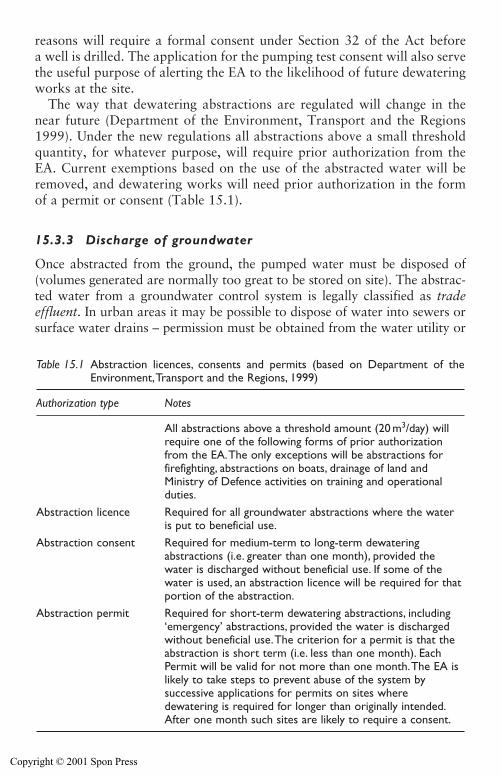
Safety, contracts and the environment 443
reasons will require a formal consent under Section 32 of the Act before a well is drilled. The application for the pumping test consent will also servethe useful purpose of alerting the EA to the likelihood of future dewateringworks at the site.
The way that dewatering abstractions are regulated will change in thenear future (Department of the Environment, Transport and the Regions1999). Under the new regulations all abstractions above a small thresholdquantity, for whatever purpose, will require prior authorization from theEA. Current exemptions based on the use of the abstracted water will beremoved, and dewatering works will need prior authorization in the formof a permit or consent (Table 15.1).
15.3.3 Discharge of groundwater
Once abstracted from the ground, the pumped water must be disposed of(volumes generated are normally too great to be stored on site). The abstrac-ted water from a groundwater control system is legally classified as tradeeffluent. In urban areas it may be possible to dispose of water into sewers orsurface water drains – permission must be obtained from the water utility or
Table 15.1 Abstraction licences, consents and permits (based on Department of theEnvironment,Transport and the Regions, 1999)
Authorization type Notes
All abstractions above a threshold amount (20 m3/day) will require one of the following forms of prior authorization from the EA.The only exceptions will be abstractions for firefighting, abstractions on boats, drainage of land and Ministry of Defence activities on training and operational duties.
Abstraction licence Required for all groundwater abstractions where the water is put to beneficial use.
Abstraction consent Required for medium-term to long-term dewateringabstractions (i.e. greater than one month), provided the water is discharged without beneficial use. If some of the water is used, an abstraction licence will be required for that portion of the abstraction.
Abstraction permit Required for short-term dewatering abstractions, including ‘emergency’ abstractions, provided the water is discharged without beneficial use.The criterion for a permit is that the abstraction is short term (i.e. less than one month). Each Permit will be valid for not more than one month.The EA is likely to take steps to prevent abuse of the system bysuccessive applications for permits on sites wheredewatering is required for longer than originally intended.After one month such sites are likely to require a consent.
Copyright © 2001 Spon Press
444 Safety, contracts and the environment
its agents before this can be done. Such permissions normally take the formof trade effluent licences, which may set limits on the quantity and quality ofwater that can be discharged. Charges (based on a cost per cubic metre) aregenerally levied for disposal of water in this way. For long duration dischargeof substantial quantities these charges may add up to considerable sums.
However, in many cases the abstracted water must be disposed of to sur-face water including rivers, lakes and the sea or to groundwater (via rechargewells or trenches). All surface and groundwater are legally classified as con-trolled waters under the Water Resources Act 1991. In these cases, even if thevolume of water to be disposed of is small and for a short duration, a dis-charge consent is still required under section 85 of the Act. Under this sectionit is a criminal offence to discharge poisonous, noxious or polluting materialinto any controlled waters, either deliberately or accidentally. Polluting mate-rials include silt, cement, concrete, oil, petroleum spirit, sewage or otherdebris and waste materials. Measures to prevent the discharge of pollutingmaterials are described in Section 13.4.
Even if the discharge flow is to be disposed of by artificial recharge (seeSection 13.6) back into the same aquifer a discharge consent is still required.This means that the recharge water quality will have to be monitored toensure it is within the quality limits set on the discharge consent.
15.3.4 Settlement resulting from the abstraction of groundwater
The lowering of groundwater levels resulting from the abstraction ofgroundwater will cause an increase in vertical effective stress in a soil. Thiswill inevitably lead to some ground settlement, possibly over a wide area.Occasionally, the settlements may be large enough to cause distortion ordamage of nearby structures or services. Engineering mitigation techniquesare available to minimize the extent and effects of these settlements.Chapter 13 describes these problems and their potential solutions.
There has been considerable litigation over many years regarding settle-ment damage that has been alleged to result from groundwater abstractionsfor water supply or dewatering purposes. The law related to ground settle-ments arising from groundwater abstraction is found in common lawrights, which are based on the precedents of judgements laid down in pre-vious cases in the civil courts.
According to a number of reviews of the legal issues (such as Akroyd1986; Powrie 1990) it is well established in common law that a landownerhas no right of support from the water percolating in undefined channelsbeneath his land. Groundwater in almost all aquifers is effectively flowingin undefined channels and is therefore considered by common law to be areservoir or source of supply, which is no one’s property, but from whicheveryone has the right to abstract as much as they wish, in so far as it isphysically possible to do so.
Copyright © 2001 Spon Press
The courts have found that if groundwater abstraction causes settlementdamage to a neighbour’s property there is no right of action against theabstractor. The courts have also found that since there is no duty of care toavoid damage resulting from groundwater abstraction, there is also nocause of action under the law of nuisance or negligence.
Possible conditions where groundwater would not be considered to be inundefined channels include well-established subterranean solution channelsknown to exist in karst aquifers or water flowing in abandoned mine work-ings. From a legal point of view if water is believed to be flowing in a definedunderground channel, the presence of the channel must be known. It is notnecessary for it to be revealed by excavation or exposure, but its presencemust be a reasonable inference from the available information.
This means that if dewatering abstractions pump clear groundwater (withno suspended solids) from most aquifers there is no legal liability if settle-ment damage occurs, even if mitigation measures could have been employedto prevent damage. This position is quite different from settlement damagearising from excavation or tunnelling, where the primary mechanism is theremoval of the support from the soil and a legal liability exists.
However, for dewatering schemes if the water pumped is not perfectlyclear and if it contains suspended silt or sand particles, the support of theground is being removed. A landowner does have the right to the support ofthe ground beneath his land. If the pumping of silt or sand led to settlementdamage, there would be a legal right of action against the abstractor. A con-sequence of this is that all wells and sumps must be equipped with effectivefilters to prevent the flow of groundwater removing fine particles from thesoil. In practice this is most likely to be a problem with sump pumping sys-tems, and these should be employed with caution if structures are presentnear the excavation.
Despite there being no legal liability for settlement damage resulting fromthe abstraction of groundwater, in the great majority of projects constructionmethods are designed to be sensitive to the risks of consequential damage. Ifthere is believed to be a significant risk of settlement damage the project clientor designer will generally require the use of settlement mitigation or avoid-ance measures (such as artificial recharge).
15.3.5 Environmental regulation of major projects
Very large projects are, in principle, subject to the same environmental con-straints as smaller projects. However, the sheer scale and high profile natureof the projects may result in a slightly different approach being taken. Thiscan be illustrated by the case history of the Medway Tunnel, constructed insouthern England in the 1990s (Lunniss 2000; Thorn 1996).
The tunnel was of immersed tube design and required significant dewater-ing to allow construction of a casting basin and cut-and-cover tunnel sections
Safety, contracts and the environment 445
Copyright © 2001 Spon Press
446 Safety, contracts and the environment
on either side of the river. At planning stage the dewatering was anticipatedto require extensive pumping from the chalk aquifer, which provided pub-lic water supply from a number of nearby wells. There was concern that thedewatering would derogate these sources, and that saline intrusion may bepromoted by river dredging during construction.
As with many large infrastructure projects, construction of the tunnelwas covered by a special Act of Parliament, in this case the Medway TunnelAct 1990. Such acts require concerned bodies to petition for their ‘rights’ inthe drawing up of the bill and request special protective provisions. Thethen National Rivers Authority (NRA) – the predecessors of the EA –obtained, via the act, protective measures as follows:
The wardens (of the scheme) … shall so design and construct the tunnelas to ensure by all reasonably practicable means that saline or othercontaminating intrusion into water resources in underground stratadoes not occur by reason of such construction
The construction contract gave the contractor the responsibility of devel-oping a dewatering and monitoring scheme acceptable to the NRA. Detailedliaison followed and a dewatering and monitoring strategy was developed;this strategy was robust enough to cope with an increase in anticipatedpumping rates from around 250 l/s up to 400 l/s. The monitoring exercisewas intensive. The data gathered in the initial stages of the project alloweda numerical model of the aquifer to be developed by the contractor to sup-port their proposals for the later stages of dewatering.
While the extent of monitoring and discussion with the NRA is consider-ably more extensive than is routine, this project highlights that any majordewatering works are likely to require significant ongoing liaison with theenvironmental regulators. It is not unusual for the planned dewateringworks to be varied in light of the regulator’s requirements.
References
Akroyd, D. S. (1986). The law relating to groundwater in the United Kingdom.Groundwater: Occurrence, Development and Protection, Water Practice ManualNo. 5, Institution of Water Engineers and Scientists. London, pp 591–607.
Association of Geotechnical and Geoenvironmental Specialists (1992a). SafetyAwareness on Investigation Sites. Association of Geotechnical and Geoenviron-mental Specialists, Beckenham, Kent.
Association of Geotechnical and Geoenvironmental Specialists (1992b). SafetyManual for Investigation Sites. Association of Geotechnical and Geoenvi-ronmental Specialists, Beckenham, Kent.
BS7671 (1992). Requirements for Electrical Installations: IEE Wiring Regulations16th Edition. British Standards Institution, London.
Copyright © 2001 Spon Press

Department of the Environment, Transport and the Regions (1999). Taking WaterResponsibly. HMSO, London.
Eddleston, M. (1996). Structural damage associated with land subsidence caused bydeep well pumping in Bangkok, Thailand. Quarterly Journal of EngineeringGeology, 29, 1–4.
Environment Agency (1998). Policy and Practice for the Protection ofGroundwater, 2nd edition. The Stationery Office, London.
Godfrey, P. S. (1996). Control of Risk: A Guide to the Management of Risk fromConstruction. Construction Industry Research and Information Association,CIRIA Special Publication 125, London.
Health and Safety Executive (1995). Managing construction for Health and Safety:Construction (Design and Management Regulations 1994), Approved Code ofPractice. HMSO, London.
Health and Safety Executive (1996). Health and Safety in Construction. HMSO,London.
Institution of Civil Engineers (1972). Safety in Boreholes and Wells. Institution ofCivil Engineers, London.
Institution of Civil Engineers (1991). Inadequate Site Investigation. ThomasTelford, London.
Irvine, D. J. and Smith, R. J. H. (1992). Trenching Practice. Construction IndustryResearch and Information Association, CIRIA Report 97, London.
Lunniss, R. C. (2000). Medway Tunnel – planning and contract administration.Proceedings of the Institution of Civil Engineers, Transport, 141, February, 1–8.
Ove Arup & Partners (1997). CDM Regulations – Work Sector Guidance forDesigners. Construction Industry Research and Information Association, CIRIAReport 166, London
Powrie, W. (1990). Legal Aspects of Construction Site Dewatering for TemporaryWorks. Unpublished MSc dissertation, Kings College, London.
Preene, M., Roberts, T. O. L., Powrie, W. and Dyer, M. R. (2000). GroundwaterControl – Design and Practice. Construction Industry Research and InformationAssociation, CIRIA Report C515, London.
Roberts, T. O. L. and Deed, M. E. R. (1994). Cost overruns in construction dewa-tering. Risk and Reliability in Ground Engineering (Skipp, B. O., ed.). ThomasTelford, London, pp 254–265.
Site Investigation Steering Group (1993). Site Investigation in Construction,Volume 1: Without Investigation Ground is a Hazard. Thomas Telford, London.
Thorn, B. (1996). Dewatering: Environmental Issues. Temporary Works:Dewatering and Stability, seminar notes, Institution of Civil Engineers, London,2nd July.
Safety, contracts and the environment 447
Copyright © 2001 Spon Press
Chapter 16
The futureby T. O. L. Roberts
16.0 Introduction
Imagine a world in which:
� All dewatering pumps, pipework and well screens are made of steelwith virtually no plastic components or flexible pipes.
� Most dewatering projects involve steel wellpoints installed manually,deep wells with submersible borehole pumps are at the cutting edge,and ejectors are only found in textbooks.
� There is little or no regulation or environmental constraints on abstrac-tion or discharge of groundwater.
� Monitoring of flow rates and drawdowns is an expensive luxury onlyappropriate for high-profile projects.
� Contracts and project management are deliberately confrontational;delayed payment and claims are commonplace.
This was the state of the dewatering industry in the United Kingdom inthe 1970s. The earlier chapters have shown that much has changed. Thischapter will look briefly at what further changes are likely in the firstdecades of the twenty first century.
16.1 Techniques
The basic laws of physics govern the mechanical performance of the prin-cipal groundwater lowering systems and it is difficult to see how there couldbe any fundamental improvement in these systems. However developmentsin materials, plant design and the application of information technology arebound to lead to some improvement in efficiency and reliability over time.Changes are likely to be incremental and should lead to a correspondingreduction in cost. These improvements are generally not driven by the needsof the construction dewatering industry. The components of dewateringsystems are largely borrowed from other industries and it is their needs that
Copyright © 2001 Spon Press
are driving the changes: the water supply industry for borehole pumps, wellscreens and ejectors; the piling and grouting industry for drilling systems;and process engineering for centrifugal pumps, exhausters, valves and pipesystems.
Efficiency and reliability improvements are important since groundwaterlowering techniques compete in the market place with other civil engineeringprocesses used to control groundwater, such as grouting and artificial groundfreezing. However, of greater interest are developments that offer the oppor-tunity to widen the scope and application of dewatering systems. The mainpotential must lie in the control of pore water pressure in fine-grained lowpermeability soils. These soils also present a challenge to other techniquessuch as grouting. The use of ejector systems in the United Kingdom over thelast ten years has extended the range of application of dewatering systems tofine-grained soils. There is some evidence from detailed monitoring of dewa-tering systems in fine-grained soils that there can be a significant variation inthe yield from individual wells, installed in a similar manner in apparentlysimilar ground conditions. It is not clear if this is due to some installationeffect or undetected variations in the soil fabric local to the wells, or both.There would be significant cost and performance benefits if a system could bedevised to ensure that all the wells in a system performed as efficiently as thebest performing well. Any solution will probably involve modification tosome or all of the current methods of well drilling, well installation, screenspecification, filter-pack specification and placement and well development.
Another approach to control of pore water pressure in fine-grained soilsis electro-osmosis (see Chapter 11). This was developed and used effectively,particularly in Canada, but is now rarely, if ever, used. Over the last fewyears there has been renewed interest in electro-osmosis for recovering heavymetal contaminants as a means of soil remediation. The technique is knownas electrokinetic or electro-chemical remediation. A practical application ofthe technique is described by Trombly (1999). Studies have also been madeinto the use of conductive geotextiles in conjunction with electro-osmosis.Innovations such as these could herald a renaissance in electro-osmosis.
Opportunities for widening the application of groundwater lowering sys-tems are also arising because of changes in the nature of the constructionindustry and changes in other construction processes. Recent examplesinclude:
� Access constraints. Construction of new and improved infrastructure incities must be carried out while minimizing disruption to existing ser-vices and infrastructure. The effect of this requirement is often to intro-duce significant access constraints; some can be overcome by installinginclined or horizontal wells or wells installed directly out of tunnels.Hartwell (2001) describes techniques for drilling wells from tunnels,but there remains significant room for improvement.
The future by T. O. L. Roberts 449
Copyright © 2001 Spon Press
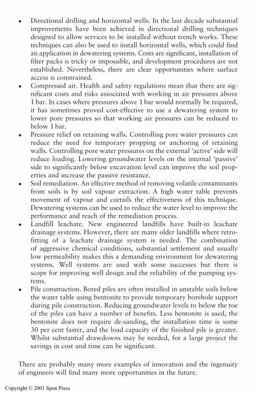
450 The future by T. O. L. Roberts
� Directional drilling and horizontal wells. In the last decade substantialimprovements have been achieved in directional drilling techniquesdesigned to allow services to be installed without trench works. Thesetechniques can also be used to install horizontal wells, which could findan application in dewatering systems. Costs are significant, installation offilter packs is tricky or impossible, and development procedures are notestablished. Nevertheless, there are clear opportunities where surfaceaccess is constrained.
� Compressed air. Health and safety regulations mean that there are sig-nificant costs and risks associated with working in air pressures above1 bar. In cases where pressures above 1 bar would normally be required,it has sometimes proved cost-effective to use a dewatering system tolower pore pressures so that working air pressures can be reduced tobelow 1 bar.
� Pressure relief on retaining walls. Controlling pore water pressures canreduce the need for temporary propping or anchoring of retainingwalls. Controlling pore water pressures on the external ‘active’ side willreduce loading. Lowering groundwater levels on the internal ‘passive’side to significantly below excavation level can improve the soil prop-erties and increase the passive resistance.
� Soil remediation. An effective method of removing volatile contaminantsfrom soils is by soil vapour extraction. A high water table preventsmovement of vapour and curtails the effectiveness of this technique.Dewatering systems can be used to reduce the water level to improve theperformance and reach of the remediation process.
� Landfill leachate. New engineered landfills have built-in leachatedrainage systems. However, there are many older landfills where retro-fitting of a leachate drainage system is needed. The combinationof aggressive chemical conditions, substantial settlement and usuallylow permeability makes this a demanding environment for dewateringsystems. Well systems are used with some successes but there isscope for improving well design and the reliability of the pumping sys-tems.
� Pile construction. Bored piles are often installed in unstable soils belowthe water table using bentonite to provide temporary borehole supportduring pile construction. Reducing groundwater levels to below the toeof the piles can have a number of benefits. Less bentonite is used, thebentonite does not require de-sanding, the installation time is some30 per cent faster, and the load capacity of the finished pile is greater.Whilst substantial drawdowns may be needed, for a large project thesavings in cost and time can be significant.
There are probably many more examples of innovation and the ingenuityof engineers will find many more opportunities in the future.
Copyright © 2001 Spon Press
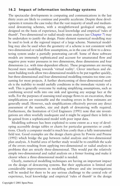
The future by T. O. L. Roberts 451
16.2 Impact of information technology systems
The spectacular developments in computing and communications in the lastthirty years are likely to continue and possibly accelerate. Despite these devel-opments it remains the case today that the vast majority of small and medium-sized dewatering schemes, with a straightforward geological setting, aredesigned on the basis of experience, local knowledge and empirical ‘rules ofthumb’. Two-dimensional or radial steady-state analyses (see Chapter 7) maybe undertaken to justify the design. Finite element numerical modelling maybe used to look at the regional impact of a large scheme. Numerical model-ling may also be used when the geometry of a scheme is not consistent withtwo-dimensional or radial-flow assumptions, as in the case of flow to a dewa-tering system under a partially penetrating cut-off. Some of these softwaremodels are immensely sophisticated and account for unsaturated flow andnegative pore water pressures in two dimensions, three dimensions and fourdimensions (i.e. with time-dependent effects). These programmes are movingbeyond mere modelling towards ‘virtual reality’. Clever interfaces and ele-ment building tools allow two-dimensional models to be put together quickly,but three-dimensional and four-dimensional modelling remains too time con-suming for most projects. A further shortcoming of three-dimensional mod-els is the inability to model usefully conditions in the immediate vicinity of awell. This is generally overcome by making simplifying assumptions, such ascombining several wells into one sink and ignoring any seepage face at thewells. For the purposes of assessing total seepage flows to an excavation, thesesimplifications are reasonable and the resulting errors in flow estimates aregenerally small. However, such simplifications effectively prevent any directassessment of the number, size and depth of dewatering wells required.Furthermore, the Institution of Civil Engineers (1991) note that site investi-gations are often woefully inadequate and it might be argued there is little tobe gained from a sophisticated model with poor input data.
Modelling software has been exploited to some extent as a way of devel-oping accessible design tables or charts for particular geometries or condi-tions. Clearly a computer model is much less costly than a fully instrumentedfield test. Good examples are the design charts given by Powrie and Preene(1992) which bridge the gap between radial analysis and two-dimensionalplan analysis. A fruitful area of further study would be to establish the scaleof the errors resulting from applying two-dimensional or radial analysis toproblems that are strictly three-dimensional. This would put the relativelysimple two-dimensional and radial analysis on a firmer footing and make itclearer where a three-dimensional model is needed.
Clearly, numerical modelling techniques are having an important impacton the design of dewatering systems. But their application is limited andconsiderable improvements in modelling software and site investigationswill be needed for there to be any serious challenge to the central role ofexperience, local knowledge and empirical ‘rules of thumb’ in the design
Copyright © 2001 Spon Press
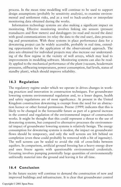
452 The future by T. O. L. Roberts
process. In the mean time modelling will continue to be used to supportdesign assumptions (probably by sensitivity analysis), to examine environ-mental and settlement risks, and as a tool to back-analyse or interpolatemonitoring data obtained during the works.
Information technology systems are also making a significant impact onmonitoring. Effective monitoring involves linking site sensors (pressuretransducers and flow meters) and dataloggers (to read and record the data)with good communications (to relay the data to the end user), data process-ing and presentation. With these systems in place performance data for adewatering project can be widely accessible, probably in real time, extend-ing opportunities for the application of the observational approach. Thedata sets obtained for individual projects may also increase our understand-ing of the flow regime in the vicinity of well arrays, which may lead toimprovements in modelling software. Monitoring systems can also be read-ily applied to the mechanical performance of the plant (vacuum, headermainpressures, oil/bearing temperatures, power consumption, fuel levels, status ofstandby plant), which should improve reliability.
16.3 Regulation
The regulatory regime under which we operate in drives changes in work-ing practices and innovation in construction techniques. For groundwaterlowering systems environmental regulation and, to a lesser degree, healthand safety regulations are of most significance. At present in the UnitedKingdom construction dewatering is exempt from the need for an abstrac-tion licence or other formal permission. Preene (1999) indicates that this islikely to be changed in the foreseeable future as part of a general increasein the control and regulation of the environmental impact of constructionworks. It might be thought that this could represent a threat to the use ofdewatering systems, but compared to alternative processes the environmen-tal impact of groundwater lowering systems is relatively benign. The energyconsumption for dewatering systems is modest, the impact on groundwaterflows should be temporary, and only the well screens are left behind oncompletion (even these could probably be removed with a bit of ingenuity).The well screens can be sealed to avoid the risk of cross-links betweenaquifers. In comparison, artificial ground freezing has a heavy energy drawand uses freeze agents with questionable environmental credentials.Grouting involves pumping potentially large quantities of environmentallyunfriendly material into the ground and leaving it for all time.
16.4 Conclusion
In the future society will continue to demand the construction of new andimproved buildings and infrastructure. It is clear that groundwater control
Copyright © 2001 Spon Press

The future by T. O. L. Roberts 453
systems will continue to have an important role to play in this process.There have been substantial advancements in groundwater lowering opera-tions in the last thirty years, and we may yet find ourselves surprised at thechanges in the industry in the next thirty years.
References
Hartwell, D. J. (2001). Getting rid of the water. Tunnels & Tunnelling International40–42.
Institution of Civil Engineers (1991). Inadequate Site Investigation. ThomasTelford, London.
Powrie, W. and Preene, M. (1992). Equivalent well analysis of construction dewa-tering systems. Géotechnique, 42(4), 635–639.
Preene, M. (1999). EA tightens up dewatering rules. Ground Engineering, 32(9),September, 25.
Trombly, J. (1994). Electrochemical remediation takes to the field. EnvironmentalScience and Technology, 28, 289–291.
Copyright © 2001 Spon Press
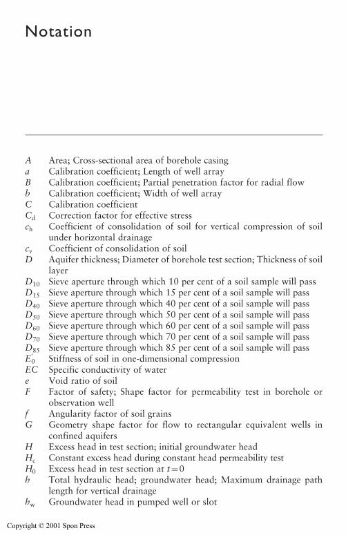
Notation
A Area; Cross-sectional area of borehole casinga Calibration coefficient; Length of well arrayB Calibration coefficient; Partial penetration factor for radial flowb Calibration coefficient; Width of well arrayC Calibration coefficientCd Correction factor for effective stressch Coefficient of consolidation of soil for vertical compression of soil
under horizontal drainagecv Coefficient of consolidation of soilD Aquifer thickness; Diameter of borehole test section; Thickness of soil
layerD10 Sieve aperture through which 10 per cent of a soil sample will passD15 Sieve aperture through which 15 per cent of a soil sample will passD40 Sieve aperture through which 40 per cent of a soil sample will passD50 Sieve aperture through which 50 per cent of a soil sample will passD60 Sieve aperture through which 60 per cent of a soil sample will passD70 Sieve aperture through which 70 per cent of a soil sample will passD85 Sieve aperture through which 85 per cent of a soil sample will passE
0 Stiffness of soil in one-dimensional compressionEC Specific conductivity of watere Void ratio of soilF Factor of safety; Shape factor for permeability test in borehole or
observation wellf Angularity factor of soil grainsG Geometry shape factor for flow to rectangular equivalent wells in
confined aquifersH Excess head in test section; initial groundwater headHc Constant excess head during constant head permeability testH0 Excess head in test section at t�0h Total hydraulic head; groundwater head; Maximum drainage path
length for vertical drainagehw Groundwater head in pumped well or slot
Copyright © 2001 Spon Press
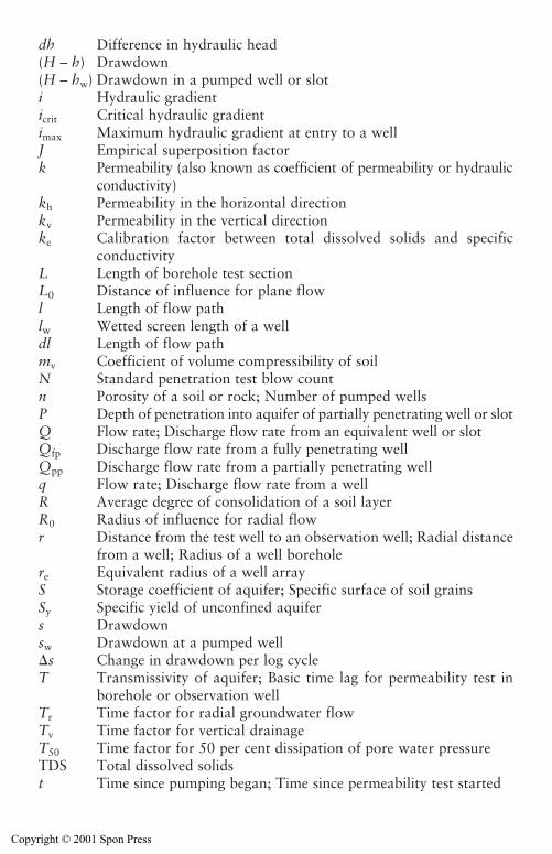
dh Difference in hydraulic head(H – h) Drawdown(H – hw) Drawdown in a pumped well or sloti Hydraulic gradienticrit Critical hydraulic gradientimax Maximum hydraulic gradient at entry to a wellJ Empirical superposition factork Permeability (also known as coefficient of permeability or hydraulic
conductivity)kh Permeability in the horizontal directionkv Permeability in the vertical directionke Calibration factor between total dissolved solids and specific
conductivityL Length of borehole test sectionL0 Distance of influence for plane flowl Length of flow pathlw Wetted screen length of a welldl Length of flow pathmv Coefficient of volume compressibility of soilN Standard penetration test blow countn Porosity of a soil or rock; Number of pumped wellsP Depth of penetration into aquifer of partially penetrating well or slotQ Flow rate; Discharge flow rate from an equivalent well or slotQfp Discharge flow rate from a fully penetrating wellQpp Discharge flow rate from a partially penetrating wellq Flow rate; Discharge flow rate from a wellR Average degree of consolidation of a soil layerR0 Radius of influence for radial flowr Distance from the test well to an observation well; Radial distance
from a well; Radius of a well boreholere Equivalent radius of a well arrayS Storage coefficient of aquifer; Specific surface of soil grainsSy Specific yield of unconfined aquifers Drawdownsw Drawdown at a pumped well�s Change in drawdown per log cycleT Transmissivity of aquifer; Basic time lag for permeability test in
borehole or observation wellTr Time factor for radial groundwater flowTv Time factor for vertical drainageT50 Time factor for 50 per cent dissipation of pore water pressureTDS Total dissolved solidst Time since pumping began; Time since permeability test started
Notation 455
Copyright © 2001 Spon Press
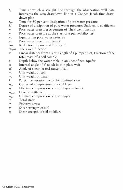
456 Notation
to Time at which a straight line through the observation well dataintercepts the zero drawdown line in a Cooper–Jacob time-draw-down plot
t50 Time for 50 per cent dissipation of pore water pressureU Degree of dissipation of pore water pressure; Uniformity coefficientu Pore water pressure; Argument of Theis well functionui Pore water pressure at the start of a permeability testuo Equilibrium pore water pressureut Pore water pressure at time t�u Reduction in pore water pressureW(u) Theis well functionx Linear distance from a slot; Length of a pumped slot; Fraction of the
total mass of a soil samplez Depth below the water table in an unconfined aquifer� Internal angle of V-notch in thin plate weir� Angle of shearing resistance of soil�s Unit weight of soil�w Unit weight of water� Partial penetration factor for confined slots�corr Corrected compression of a soil layer�t Effective compression of a soil layer at time t�total Ground settlement�ult Ultimate compression of a soil layer Total stress Effective stress� Shear strength of soil�f Shear strength of soil at failure
Copyright © 2001 Spon Press
Glossary
Abstraction The pumping or removal of groundwater (such as from awell or sump) or surface water (such as from a lake or river).
Air lift A means of pumping water from a well using compressed air toaerate the water so that the air-water mixture rises to the surface. Themethod is capable of pumping silt and sand with the water, and is oftenused as a method of well development.
Anisotropic Having one or more physical properties that vary with thedirection of measurement – the converse of isotropic.
Aquiclude Soil or rock forming a stratum, group of strata or part of stra-tum of very low permeability, which acts as an effective barrier togroundwater flow. This term is obsolete in American terminology,where confining bed is the equivalent term.
Aquifer Soil or rock forming a stratum, group of strata or part of stratumfrom which water in usable quantities can be abstracted. By definitionan aquifer will be water-bearing (i.e. saturated and permeable).
Aquitard Soil or rock forming a stratum, group of strata or part of stratumof intermediate to low permeability which yields only very small ground-water flows, or allows groundwater to pass through very slowly.
Artificial ground freezing The process of reducing the temperature ofthe ground sufficiently to form a very low permeability freezewall offrozen soil. The freezewall can be used as a cut-off and support struc-ture for below ground works.
Artificial recharge The deliberate re-injection of water (via pits, trenchesor wells) into aquifers or aquitards. Sometimes used as a means ofreducing drawdowns in the aquifer outside an excavation to minimizeconsolidation settlements.
Barrier boundary An aquifer boundary that is not a source of water.Base heave Uplift or heave of the floor of an excavation as a result of
unrelieved pore water pressures at depth.Biofouling The clogging or deterioration of performance of wells, pumps
and pipework as a result of bacterial growth.
Copyright © 2001 Spon Press
Boil The turbulent jet of soil and water that rises to the surface around aplacing tube when a wellpoint or well is installed by jetting. Also usedto describe an uncontrolled upward seepage into an excavation thatmay wash fines out of the soil, leading to instability.
Borehole Strictly, a borehole is a hole drilled into the ground for anypurpose, including site investigation boreholes. In groundwater termi-nology a borehole is often taken to mean a relatively small diameterwell, particularly one used for water supply.
Capillary saturated zone The zone immediately above the water table inan unconfined aquifer where the soil remains saturated at negative (i.e.less than atmospheric) pore water pressures. The water in this zone iscontinuous with the pore water below the water table. The height ofthe capillary saturated zone is greater in finer-grained soils than incoarse-grained soils. The zone rises or falls with any variations in thewater table.
Coefficient of permeability See permeability.Cofferdam A temporary retaining wall structure used to exclude ground-
water and surface water from an excavation.Cone of depression A depression in the water table or piezometric level
that, in theoretically idealized conditions, has the shape of an invertedcone and develops radially around a well from which water is beingabstracted. It defines the radius of influence of a well.
Confined aquifer An aquifer in which the groundwater is isolated fromthe atmosphere by an overlying (or confining) aquiclude, and where thepiezometric level is above the top of the aquifer. A confined aquifer issaturated throughout. Also known as an artesian or sub-artesianaquifer.
Consolidation settlements Ground settlements resulting from increasesin vertical effective stress when groundwater levels are lowered or porewater pressures are reduced.
Construction dewatering See dewatering.Controlled waters A definition used in environmental legislation in
England and Wales to describe all surface water, lakes, seas and allgroundwater.
Darcian velocity The mean flow velocity across a unit area as defined byDarcy’s law. When divided by the porosity, the mean groundwaterflow rate through the pores may be calculated.
Darcy’s law The expression, developed by Henri Darcy in 1856, relatingthe flow rate through a porous medium to the hydraulic gradient, cross-sectional area of flow, and the permeability of the medium.
Deep well A groundwater abstraction well for the purpose of ground-water lowering (as opposed to a well for the purpose of water supply,which is termed a borehole).
458 Glossary
Copyright © 2001 Spon Press
Derogation The reduction in yield or other adverse effect on a watersupply borehole or spring as a result of groundwater pumping by others.
Desk study The review of all available information (such as maps, aerialphotographs, historical records) as part of the site investigation process.
Development See well development.Dewatering A colloquialism for groundwater lowering that originated in
America and is now widely used in Europe.Dipmeter A portable device for measuring the depth to water in a well,
borehole, standpipe or piezometer. Also known as a dipper or waterlevel indicator.
Discharge The flow of water from a pump or a groundwater loweringsystem.
Drawdown The lowering of the water table (in unconfined aquifers) orthe piezometric level (in confined aquifers) as a result of the abstractionof groundwater. It is measured as the vertical distance between the orig-inal water table (or piezometric level) and the current level duringpumping.
Drift Geologically recent superficial strata of sand, gravel silt or clay (seealso soil). Excavations below the groundwater level in drift depositsmay be unstable without adequate groundwater control.
Eductor See ejector.Effective stress The difference between the total stress (due to self weight
and any external loading) and the pore water pressure at a point in asoil mass. The effective stress is a vital controlling factor in the strengthand compressibility behaviour of soils.
Ejector A water jet pump which pumps water (and air) via a nozzle andventuri arrangement. When used in low yielding wells a vacuum can bedeveloped if the top of the well casing is sealed.
Ejector well A small diameter groundwater lowering well pumped by anejector.
Electro-osmosis A rarely used method of pore water pressure controlapplicable to very low permeability soils such as silts and clays. An elec-tric potential is applied across the area of soil to induce groundwaterflow from the anode to the cathode.
Equivalent well A conceptual large well, used to represent a groundwa-ter lowering system that consists of a ring of many wells. By consider-ing the real system as an equivalent well, simpler and more accessiblemethods of analysis can be used.
Filter pack Sand or gravel placed around a well screen to act as a filter.This allows water to freely enter the well, while preventing movementof fines toward the well.
Fines The smaller particles in a soil stratum or analysis. Generally takento refer to clay, silt and fine sand-size particles. See loss of fines.
Glossary 459
Copyright © 2001 Spon Press
460 Glossary
Fissures Natural cracks, fractures, joints or discontinuities in rock thatallow groundwater to pass. The extent and characteristics of fissuresgreatly influences the permeability of most rocks.
Flow, steady-state The flow regime when the magnitude and direction ofthe groundwater flow rate are constant.
Flow, transient-state The flow regime when the magnitude or directionof the groundwater flow rate is changing with time.
Flowing artesian conditions A special case of confined aquifers, wherethe piezometric level of the aquifer is above ground level. A well drilledthrough the confining bed into the aquifer will overflow at ground levelwithout the need for pumping.
Formation level The final dig level of an excavation, after all digging andfilling, but before any concreting or construction.
Fully penetrating The case where a well penetrates the full thickness ofan aquifer – the converse of partially penetrating.
Ground investigation The physical investigation of a site as part of thesite investigation process. Ground investigation includes drilling andprobing, in-site tests and laboratory testing.
Groundwater Water contained in and flowing through the pores and fis-sures of soil and rock in the saturated zone. In this zone the water bodyis essentially continuous, except for an occasional bubble of air. In legaldocuments groundwater is sometimes described as water in under-ground strata.
Groundwater control Methods and techniques to control groundwaterto allow stable excavations to be formed for construction purposes.The two main approaches are groundwater exclusion and groundwaterlowering.
Groundwater exclusion The construction of artificial barriers to preventgroundwater from flowing into an excavation. The barriers can beformed from physical cut-off walls, or by reducing the permeability ofthe in-situ soil and rock. See also cofferdam.
Groundwater lowering The temporary reduction of groundwater levelsand pore water pressures around and below an excavation by someform of pumping, sufficient enough to enable excavation and founda-tion construction to be carried out safely and expeditiously in water-bearing ground.
Heterogeneous Non-uniform in structure or composition or composedof diverse elements – the converse of homogeneous.
Homogeneous Uniform in structure or composition – the converse ofheterogeneous.
Hydraulic conductivity The hydrogeological term for permeability. Ingeneral, engineering literature uses permeability, while hydrogeologicalreferences use hydraulic conductivity.
Copyright © 2001 Spon Press
Glossary 461
Hydraulic gradient The change in total hydraulic head between twopoints, divided by the length of flow path between the points.
Hydrogeology The study of groundwater or underground waters. Alsoknown as groundwater hydrology.
Hydrological cycle The interlinked processes by which water is circu-lated from the oceans to the atmosphere to the ground surface andthence returned to the oceans as surface water and groundwater flow.
Hydrology The study of water. In a civil engineering context, generallytaken to be the study of surface waters.
Isotropic Having the same physical properties in all directions – the con-verse of anisotropic.
Jetting A method used to install wellpoints and, less commonly, deepwells or ejectors. A jet of high pressure water is used to allow the pen-etration of a steel placing tube into the ground, within which the well-point or well is installed, following which the placing tube is removed.The jetting water returns to the surface as a boil, bringing with it thedisplaced soil.
Laminar flow A flow regime where flow is steady and continuous with-out any turbulence. It is characteristic of most groundwater flowthrough porous media and finely fissured rock formations – the con-verse of turbulent flow.
Leaky aquifer An aquifer confined by a low permeability aquitard. Whenpore water pressures in the aquifer are lowered by pumping, water willflow (or leak) from the aquitard and recharge the aquifer. Also knownas a semi-confined aquifer.
Loss of fines The uncontrolled movement of fines carried by groundwa-ter flow toward a well, sump or soil face where filters are inadequateor absent. Also used to describe the washing of fines from samplesrecovered from water filled boreholes during site investigation drilling.
Numerical model A method of analysing a groundwater conceptualmodel using computer software. The elements of the conceptual modelare expressed as the geometry, boundary conditions and numerical val-ues of the problem. The resulting equations are solved numerically(often by iteration) using the software, generally run on a desktopcomputer.
Observation well An instrument (a standpipe, piezometer or unpumpedwell) installed into the ground in a selected location for the purpose ofmeasuring the level of the water table, piezometric level or pore waterpressure.
Open area The proportion of the surface area of a well screen that is per-forated or slotted, and allows water to pass. Open area is normallyexpressed as a percentage.
Copyright © 2001 Spon Press
462 Glossary
Overbleed A commonly used colloquial term to describe residualgroundwater seepages into an excavation, as might occur when aperched water table is penetrated. Overbleed normally describes lowrates of seepage that are a nuisance, rather than causing significantflooding. Nevertheless, even at small rates of seepage, if fines are beingcontinuously transported by the seepage, this should be counteractedimmediately. The guiding principle is: do not try to stop the flow ofseepage water as this will cause a build up of pore pressures but do pre-vent continuous loss of fines, perhaps by placing a suitable filter.
Partially penetrating The case where a well does not penetrate the fullthickness of an aquifer – the converse of fully penetrating.
Particle size distribution The relative percentages by dry weight of thedifferent particle sizes of a soil sample, determined in the laboratory bymechanical analysis (e.g. by sieving). Also known as PSD, soil grading,sieve analysis.
Perched water table Water trapped (or ‘perched’) in an isolatedsaturated zone above the water table. Perched water tables may existnaturally or may be caused when groundwater levels are lowered bydewatering; very low permeability silt or clay layers will inhibit down-ward seepage of groundwater, trapping water above them. When anexcavation is dug through a perched water table, water will enter theexcavation as residual seepage or overbleed.
Permeability A measure of the ease with which water can flow throughsoil or rock. Also known as coefficient of permeability or hydraulicconductivity.
Phreatic level The level at which pore water pressure is zero (i.e. equalto atmospheric pressure), and thus is at the base of the capillary satu-rated zone.
Piezometer An instrument, installed into the ground to act as an obser-vation well to measure the pore water pressure or piezometric level ina specific stratum, layer or elevation. This is achieved by having onlythe relevant section of the borehole exposed to the ground, the remain-der of the borehole being sealed with grout.
Piezometric level The level representing the total hydraulic head ofgroundwater in a confined aquifer. Also known as potentiometricsurface.
Plane flow A two-dimensional flow regime in which flow occurs in aseries of parallel planes. This type of flow occurs toward a pumped slotor long line of closely spaced wellpoints, when the direction of flow isperpendicular to the slot or line of wellpoints.
Pore water pressure The pressure of groundwater in the pores of a soil,measured relative to atmospheric pressure. Positive and negative porewater pressures are greater and less than atmospheric respectively.
Copyright © 2001 Spon Press
Glossary 463
Pore water pressure control The application of groundwater loweringto low permeability soils. The fine-grained nature of such soils meansthat relatively little water drains from the pores, and desaturation doesnot occur. Nevertheless, pumping from vacuum-assisted wells canreduce pore water pressures, thereby controlling effective stress levelsand preventing instability.
Porosity The ratio of the volume of voids (or pore space) to the total vol-ume of a soil sample or mass.
Pre-drainage The methods which lower groundwater levels in advanceof excavation. Pre-drainage methods include wellpoints, deep wells andejectors. The converse of pre-drainage is sump pumping, where wateris allowed to enter the excavation, from whence it is removed.
Pumping test A method of in situ permeability testing involving con-trolled pumping from a well while the discharge flow rate and draw-down in the aquifer are recorded.
Radial flow A two-dimensional flow regime in which the flow occurs inplanes, which converge on an axis of radial symmetry. This type offlow occurs toward an individual well or sump, when flow lines con-verge as they approach the well.
Radius of influence The radial distance outward from the centre of thepumping well to the point where there is no lowering of the water tableor reduction of the piezometric level – the edge of the cone of depres-sion. Also known as the distance of influence.
Recharge Water which flows into an aquifer to increase or maintain thequantity of groundwater stored therein. Recharge may be from severalsources: infiltration from surface waters; precipitation; seepage fromother aquifers or aquitards; or artificial recharge.
Relief well A well installed within an excavation to act as a preferentialpathway for flow to relieve any pore water pressures trapped beneaththe excavation. As the excavation is deepened the well will overflow,relieving pressures. Also known as a bleed well.
Rock A geological deposit formed from mineral grains or crystalscemented together – this is distinct from uncemented soil or drift.
Running sand A colloquial term for the conditions when saturated gran-ular soils are so unstable that they are unable to support a cut faceor slope and become an almost liquid slurry. Running sand is not atype or property of the material, it is a condition in which a granularsoil can exist under unfavourable seepage conditions. Effective ground-water lowering can change running sand into a stable and workablematerial.
Saline intrusion The movement of saline water into a fresh water aquiferas a result of hydraulic gradients. Problems of saline intrusion can becreated or exacerbated as a result of pumping from wells.
Copyright © 2001 Spon Press
Saturated The condition when all the pores and fissures of a soil or rockare completely filled with water – the converse of unsaturated.
Saturated zone The zone of saturated soil or rock, all parts of which arein hydraulic connection with each other. In a confined aquifer the sat-urated zone comprises the entire aquifer. In an unconfined aquifer thesaturated zone is the area below the water table, plus the capillarysaturated zone above the water table.
Settlement lagoon A large lagoon or pit through which the pumped dis-charge is passed to settle out sand and silt-sized particles prior to dis-posal.
Settlement tank A small self-contained tank (often containing baffles)through which the pumped discharge is passed to settle out sand-sizedparticles prior to disposal. Such relatively small tanks are ineffective atsettling out silt-sized particles, due to the short retention time.
Shoestring A colloquial term used to describe a narrow, but perhapsextensive, lens of soil markedly different from the stratum of soil withinwhich it is encompassed. The term is usually applied to a lens of per-meability significantly greater than the surrounding soil.
Site investigation The overall process of obtaining all relevant informa-tion about a site, to allow the design and construction of a civil engi-neering or building project. Elements of site investigation include thedesk study and the ground investigation.
Slimes A mining term used to describe the residual waste productsremaining after washing mined mineral extracts. Sometimes referred toas washings or tailings.
Soil The term used in civil engineering to describe uncemented deposits ofmineral (and occasionally organic) particles such as gravel, sand, siltand clay – this is distinct from cemented rock. Excavations below thegroundwater level in soils may be unstable with adequate groundwatercontrol. See also drift.
Specific yield The storage coefficient in an unconfined aquifer.Spring A natural outflow of groundwater at the ground surface. In rural
areas springs may be used as water supplies.Standpipe An instrument, typically consisting of a perforated casing or
pipe, installed into the ground to act as an observation well. A stand-pipe is open to water inflows from all strata that it penetrates, and maygive a water level reading that is a hybrid of levels in different aquifers.A piezometer should be used to determine water levels or pore waterpressures in a specific stratum.
Storage coefficient The volume of water released by gravity drainagefrom a volume of aquifer. Normally expressed as a dimensionless ratioor percentage. Also known as storativity.
Storage release The release of water from storage in an aquifer. Duringthe early stages of pumping (the first few hours or days) storage release
464 Glossary
Copyright © 2001 Spon Press
can significantly increase the discharge flow rate above the steady-statevalue. Storage release is most significant in unconfined aquifers of highpermeability.
Stratum A geological term for a layer of any deposited soils or rock. Theplural of stratum is strata.
Sub-drain A perforated or open-jointed pipe sometimes found immedi-ately beneath sewers or pipelines that were laid in trenches. During con-struction the sub-drain is laid in the trench just ahead of the main pipe,to carry water away from the working area.
Submersible pump A pump designed to operate wholly or partly sub-merged in water. The most common forms of submersible pumps areelectrically powered. Special slimline submersible pumps are suitablefor use in wells or boreholes.
Sump A pit, usually located within an excavation, in which water collectsprior to being pumped away.
Sump pump A robust pump, capable of handling solids-laden water,used to pump groundwater and surface water from sumps.
Sump pumping A method of groundwater lowering that allows water toenter the excavation, from whence it is pumped away. In some circum-stances the flow of water into the excavation may have a destabilizingeffect, and the use of pre-drainage methods (in preference to sumppumping) may reduce the risk of instability.
Surface water Water contained in rivers, streams, lakes and ponds.
Total hydraulic head The potential energy of water due to its heightabove a given level. The total head controls the height to which waterwill rise in a piezometer. The total head at a given point is the sum ofthe elevation head (i.e. the height of the point above an arbitrarydatum) and the pressure head (i.e. the height of water above the pointrecorded in a standpipe piezometer). Also known as total head or totalhydraulic potential.
Transmissivity A term used in hydrogeology to describe the ease withwhich water can flow through the saturated thickness of the aquifer.Transmissivity is equal to the product of permeability and saturatedaquifer thickness.
Turbulent flow A flow regime where the flow lines are confused andheterogeneously mixed. It is typical of flow in some surface waterbodies – the converse of laminar flow.
Unconfined aquifer An aquifer whose upper surface is not confined byan overlying impermeable stratum and whose upper surface is directlyexposed to atmospheric pressure. Also known as a water table aquifer.
Underdrainage A method of groundwater lowering that uses soil layer-ing to advantage by pumping directly from a deeper, more permeablestratum, in preference to the overlying lower permeability layers.
Glossary 465
Copyright © 2001 Spon Press
Pumping from the deeper layer promotes vertical downward drainagefrom the lower permeability layer into the stratum being pumped.
Uniformly-graded Containing a narrow range of particle sizes, so thatmost of the particles are of similar size – the converse of well-graded.Also known as poorly-graded.
Unsaturated The condition when the pores and fissures of a soil or rockare not completely filled with water, and may contain some air or othergases – the converse of saturated.
Unsaturated zone The zone of unsaturated soil or rock. In an uncon-fined aquifer the saturated zone is the area above the capillary saturatedzone. Within the unsaturated zone the forces of surface tension renderthe water pressure negative (i.e. lower than atmospheric).
Vadose zone See unsaturated zone.Void ratio The ratio of the volume of voids to the volume of solids in a
soil mass.V-notch weir A thin plate weir where a V-shaped notch of a specified
angle is cut. Calibration charts allow the flow rate to be estimated frommeasurements of the height of water flowing over the weir.
Water table The level in an unconfined aquifer at which the pore waterpressure is zero (i.e. atmospheric). See also phreatic level.
Weir A structure used to control the flow of water, often so it can bemeasured. See also V-notch weir.
Well A hole sunk into the ground for the purposes of abstracting water.Wells for groundwater lowering purposes are generally categorized bytheir method of pumping as deep wells, ejector wells, or wellpoints. Inwater supply terminology, a well is often taken to mean a large diame-ter shaft, as may be dug by hand in developing countries. A smallerdiameter well, constructed by a drilling rig, is termed a borehole.
Well casing The unperforated section of the well liner, installed at depthswhere any groundwater present is to be excluded from the well (e.g. ifseveral aquifers exist, but drawdown is not required in all of them).Also known as plain casing or solid casing.
Well development Increasing or maximizing the yield of a well byremoving drilling residue and fine particles from the well and theaquifer immediately outside the well. Normally carried out followingwell construction, but prior to the installation of pumping equipment.
Well liner A generic term for well casing and well screen.Well loss The head loss (or additional drawdown inside the well) that
occurs when water flows from the aquifer, through the well screen andfilter pack and into the well itself.
Well screen The perforated or slotted section of the well liner installedto allow water to enter a well where it penetrates an aquifer. Alsoknown as perforated casing or slotted casing.
466 Glossary
Copyright © 2001 Spon Press
Well-graded Containing a wide range of particle sizes – the converse ofuniformly-graded. A soil formed from a mixture of various proportionsof gravel, sand, silt and clay-sized particles would be described as well-graded.
Wellpoint A small diameter shallow well for groundwater lowering pur-poses. Normally installed by jetting, and pumped by a suction pump ofsome kind.
Yield The discharge flow rate of a well. The yield is generally taken to becontrolled by the well, rather than the pump – a high yielding wellwould produce a low flow rate if an under-sized pump were installed.Also known as well yield.
Glossary 467
Copyright © 2001 Spon Press
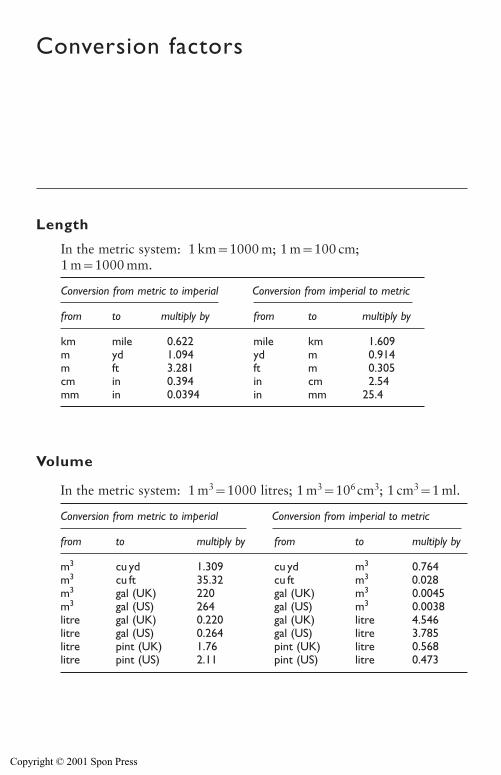
Conversion factors
Length
Volume
In the metric system: 1 km�1000 m; 1 m�100 cm;1 m�1000 mm.
Conversion from metric to imperial Conversion from imperial to metric
from to multiply by from to multiply by
km mile 0.622 mile km 1.609m yd 1.094 yd m 0.914m ft 3.281 ft m 0.305cm in 0.394 in cm 2.54mm in 0.0394 in mm 25.4
In the metric system: 1 m3�1000 litres; 1 m3�106cm3; 1 cm3�1 ml.
Conversion from metric to imperial Conversion from imperial to metric
from to multiply by from to multiply by
m3 cu yd 1.309 cu yd m3 0.764m3 cu ft 35.32 cu ft m3 0.028m3 gal (UK) 220 gal (UK) m3 0.0045m3 gal (US) 264 gal (US) m3 0.0038litre gal (UK) 0.220 gal (UK) litre 4.546litre gal (US) 0.264 gal (US) litre 3.785litre pint (UK) 1.76 pint (UK) litre 0.568litre pint (US) 2.11 pint (US) litre 0.473
Copyright © 2001 Spon Press
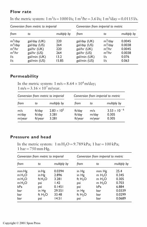
Conversion factors 469
Flow rate
Permeability
Pressure and head
In the metric system: 1 m3/s�1000 l/s; 1 m3/hr�3.6 l/s; 1 m3/day�0.0115 l/s.
Conversion from metric to imperial Conversion from imperial to metric
from to multiply by from to multiply by
m3/day gal/day (UK) 220 gal/day (UK) m3/day 0.0045m3/day gal/day (US) 264 gal/day (US) m3/day 0.0038m3/hr gal/hr (UK) 220 gal/hr (UK) m3/hr 0.0045m3/hr gal/hr (US) 264 gal/hr (US) m3/hr 0.0038l/s gal/min (UK) 13.2 gal/min (UK) l/s 0.076l/s gal/min (US) 15.85 gal/min (US) l/s 0.063
In the metric system: 1 m/s�8.64�104m/day;1 m/s�3.16�107m/year.
Conversion from metric to imperial Conversion from imperial to metric
from to multiply by from to multiply by
m/s ft/day 2.83�105 ft/day m/s 3.53�10�6
m/day ft/day 3.281 ft/day m/day 0.305m/year ft/year 3.281 ft/year m/year 0.305
In the metric system: 1 m H2O�9.789 kPa; 1 bar�100 kPa;1 bar�750 mm Hg.
Conversion from metric to imperial Conversion from imperial to metric
from to multiply by from to multiply by
mm Hg in Hg 0.0394 in Hg mm Hg 25.4m H2O in Hg 2.896 in Hg m H2O 0.345m H2O ft H2O 3.281 ft H2O m H2O 0.305m H2O psi 1.42 psi m H2O 0.703kPa psi 0.1451 psi kPa 6.884bar in Hg 29.551 in Hg bar 0.0339bar ft H2O 33.48 ft H2O bar 0.0299bar psi 14.51 psi bar 0.0689
Copyright © 2001 Spon Press
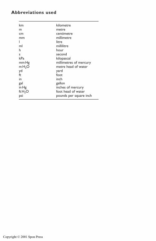
Abbreviations used
470 Conversion factors
km kilometrem metrecm centimetremm millimetrel litreml millilitreh hours secondkPa kilopascalmm Hg millimetres of mercurym H2O metre head of wateryd yardft footin inchgal gallonin Hg inches of mercuryft H2O foot head of waterpsi pounds per square inch
Copyright © 2001 Spon Press