ground stability of underground gateroad with 1 km burial
TRANSCRIPT

J. Cent. South Univ. (2018) 25: 1386−1398 DOI: https://doi.org/10.1007/s11771-018-3834-4
Ground stability of underground gateroad with 1 km burial depth: A case study from Xingdong coal mine, China
ZHANG Guang-chao(张广超)1, HE Fu-lian(何富连)2, LAI Yong-hui(来永辉)2, JIA Hong-guo(贾红果)1
1. College of Mining and Safety Engineering, Shandong University of Science and Technology, Qingdao 266590, China;
2. College of Resources and Safety Engineering, China University of Mining and Technology (Beijing), Beijing 100083, China
© Central South University Press and Springer-Verlag GmbH Germany, part of Springer Nature 2018
Abstract: This paper presents an integrated investigation of the ground stability of a deep gateroad with a 1 km burial depth based on a field test, case studies, and numerical modelling. In situ stress measurements and mechanical properties tests were first conducted in the test site. Then, the deformation behavior, stress and yield zone distributions, as well as the bolts load of the gateroad, were simulated using FLAC3D software. The model results demonstrated that the soft rock properties and high in situ stress were the main factors for the deep gateroad instability, and the shear slip failure induced by the high stress was the primary failure model for the deep rock mass. In addition, the unsuitable support patterns, especially the relatively short bolts/cables with low pre-tensions, the lack of high-strengthen secondary supports and the unsupported floor strata, also contributed to the gateroad instability. Subsequently, a new combined supporting strategy, incorporating longer bolts/cables, yielding ring supports, and grouting measures, was proposed for the deep gateroad, and its validity was verified via field monitoring. All these could be a reference for understanding the failure mechanism of the gateroad with 1 km burial depth. Key words: deep coal mine; soft rock; burial depth; failure mechanism; deformation behavior; support strategy Cite this article as: ZHANG Guang-chao, HE Fu-lian, LAI Yong-hui, JIA Hong-guo. Ground stability of underground gateroad with 1 km burial depth: A case study from Xingdong coal mine, China [J]. Journal of Central South University, 2018, 25(6): 1386–1398. DOI: https://doi.org/10.1007/s11771-018-3834-4.
1 Introduction
In recent years, with the increasing demand for coal and the increased efficiency of coal production, shallow-buried coal resources are becoming depleted. Thus, more and more Chinese coal mines (especially in the eastern region) are transferring their mining activities to deep coal mass [1]. Currently, extraction depths of 600 m or more are
becoming more common in China, and at least 20 coal mines have extended their extraction depths to 1000 m or more below the ground. According to official Chinese statistics, coal reserves with a burial depth over 1000 m now make up 53% of the national total, and the extraction depth of coal seams has increased at a rate of 3050 m/year in the past few years. Thus, it can be expected that more Chinese coal mines will extend to depths of 1000 m in the next few years [2].
Foundation item: Project(2017RCJJ011) supported by the Scientific Research Foundation of Shandong University of Science and
Technology for Recruited Talents, China; Projects(01CK03203, 02CK02302) supported by the Shandong Provincial First-Class Discipline Fundamental, China; Project(ZR2018QEE001) supported by the Natural Science Foundation of Shandong Province, China
Received date: 2016−10−03; Accepted date: 2017−03−01 Corresponding author: ZHANG Guang-chao, PhD, Lecturer; Tel: +86–18101392689; E-mail: [email protected]; ORCID: 0000-
0003-4008-052X

J. Cent. South Univ. (2018) 25: 1386–1398
1387
However, compared with shallow strata, a series of new geological characteristics presented themselves in deep coal strata, such as high in situ stresses, high geo-temperatures, and hyperosmosis, which contribute significantly to the relatively weak and significantly plastic properties of the rock mass [3]. Because of these properties, a gateroad undergoes large dilation and bulk deformation for a long time after it is excavated, which poses a high risk of various disasters, such as roof collapse, rib spalling, endangering workers and compromising the functionality of the gateroad. During the period from 2003 to 2013, accidents caused by deep excavation accounted for at least 40% of all underground accidents, and the resulting casualties accounted for 50% of the total; thereinto, gateroad roof accidents are responsible for the highest number of coal mine deaths [4]. In this regard, the failure mechanisms and ground stability of deep gateroads have become a pressing issue in deep coal seam exploitation.
In recent years, an increasing number of investigations of deep gateroad failures and the corresponding support designs have been conducted. SHREEDHARAN et al [5] presented a stability analysis of two tunnels with different shapes in a deep coal mine in China using 3DEC software. KANG et al [6] investigated the relationship between gateroad stability and various support patterns based on the entry convergence data collected from Xinwen Coalfield, in China. Based on the field data collected in UK coal mines, WHITTAKER et al [7] investigated the relationship between gateroad stability and yield pillar size. SHEN et al [8] presented a case study on the failure mechanism of a gateroad in an Australian underground coal mine using an integrated seismicity, stress, and displacement monitoring system. LI et al [9] investigated the stress changes and failure zone distributions in the clay/shale around deep underground opens using FLAC3D code. Based on the field data collected from Huainan coalfield, YUAN et al [10] investigated the effect of multi-field coupling on gateroad deformation and further proposed a corresponding control principle and measurements for such gateroads. In addition, various support patterns, technical points in installation, performance and improvement of deep gateroads were introduced by SHEN [11], CARRANZA-TORRES [12],
KUSHWAHA et al [13] and TAN et al [14]. All these studies afford us tremendous
assistance in understanding deep gateroad failure mechanisms and support design. However, after reviewing these studies, we found two major limitations. The first is that the failure mechanisms of deep roadways vary mainly depending on in situ stress and geological and geotechnical conditions. Generally, failure mechanisms can be divided into six types: beam failure, joint-controlled roof falls, roof sag, shearing failure, skin failure, and rib spalling [11]. Thus, for a specific deep gateroad with a 1 km burial depth, due to the diversity and complexity of the geological and geotechnical conditions, its failure mechanism should be determined based on the sufficient study of its surrounding properties, the magnitude and orientation of in situ stress, geological structures, support design, etc. The second is that the existing studies of gateroads with burial depths over 1 km remain few in number; in addition, a large number of field tests have shown the deformation and risk of failure of such gateroads to be many times larger than in normal gateroads [15]; although high-intensity support systems have been widely implemented in gateroads, stability control for the surrounding rock mass and its long-term maintenance remain a major issue. To sum up, for gateroads with a 1 km burial depth, studies of its failure mechanism and ground control technology remain working in progress, and further studies are needed to ensure a safe and stable gateroad condition for deep mining.
This work presents an investigation of the failure analysis of a gateroad with a burial depth of 1 km located in the Xingdong coal mine, Xingtai mining area, China. The paper is organized as follows. In Section 2, the deformation and failure characteristics of the deep gateroad are presented. In Section 3, the in situ stresses and mechanical properties of the surrounding rock are systematically investigated. In Section 4, the response of the surrounding rock after excavation was simulated using FLAC3D software to discuss the gateroad failure mechanism. In Section 5, a new combined support strategy, incorporating longer supports, yielding ring supports, and grouting measures, was determined and successfully applied to the field test. The failure mechanism and support strategy presented in this study can provide some

J. Cent. South Univ. (2018) 25: 1386–1398
1388
reference for the maintenance of the gateroad with 1 km burial depth. 2 Engineering background 2.1 Gateroad conditions
Xingdong coal mine, located in the Xingtai coal mining area, was a typical Chinese deep coal mine, with an excavation depth of almost 1200 m below the ground. The shaft station was buried at an average burial depth of 1020 m. The entry was a curved-wall-top-arch section with a width of 4.5 m and a height of 3.5 m. It was excavated along the roof line of the coal seam, with an average thickness of 3.9 m, which leaves the ribs and floor consisting of weak coal. The roof strata consisted of shaly sand, sandy mudstone, and sandstone, while the floor strata consisted of siltstone and sandy mudstone. In addition, it had been predicted that there were no unfavorable geological structures (faults or water-bearing strata, etc.) in the gateroad excavation areas.
During the previous mining operations, an original support scheme was implemented for the shaft station (see Figure 1). The bolts with 22 mm in diameter and 2400 mm in length were used for roof and ribs support. Roof and ribs bolts were installed with a spacing of 800 mm×800 mm and 600 mm× 800 mm, respectively. In some local areas, anchor cables with 21.8 mm in diameter and 6500 mm in length were used for reinforced support. The cables were installed with a spacing of 2000 mm×1600 mm. A steel bar ladder beam (14 mm in diameter), metal mesh (6 mm in diameter), and a concrete layer (100 mm in thickness) were used
for surface control. Note that only the end of the bolt/cable was anchored to the rock mass via resin chemicals, rather than the full length of the bolt/cable. 2.2 Deformation and failure characteristics of
gateroad Field observations found that severe entry
deformation and support system failure occurred about three months after the entry excavation (see Figure 2). Roof sag was very common in the field; the measured convergence of roof sag reached up to 537 m, which significantly increased the risk of roof collapse, endangering the safety of workers and equipment. In some areas, there were large- scale roof collapse accidents, as shown in Figure 2(a). Fortunately, there were no casualties. The coal mass of two ribs was fractured into massive loose fragments, resulting in severe extrusion deformation with a maximum convergence of 648 m in the middle-upper part of the ribs. This large deformation resulted in the conspicuous protuberances on the surface of the sidewalls and the failure of the steel mesh and beams (see Figure 2(b)). In addition, floor heave was also quite common, and the displacement induced by the floor heave reached up 326 mm, causing the floor concrete to crack and further compromising the efficiency of the underground transportation. As such, the entry exhibited a drastic reduction in cross-section due to severe roof sag, rib convexity, and floor heave; the effective space used for ventilation and coal-mine transportation was less than 5.8 m2, resulting in excessive labor and costs for entry rehabilitation.
Figure 1 Original support scheme and generalized stratigraphic column of shaft station

J. Cent. South Univ. (2018) 25: 1386–1398
1389
Figure 2 Field observations of deformation and failure:
(a) Roof collapse; (b) Severe coal rib convexity
3 In-situ stress and geology
The No. #2 main entry in the Xingdong coal mine has quite similar geological conditions as the one depicted above. They are quite near to one another. In order to supply sufficient and reliable data for the failure analysis and support design, in situ stress measurements and mechanical properties tests were conducted in the No. #2 main entry. 3.1 In situ stress measurement
In general, the horizontal stress is usually greater than vertical stress in the underground coal seams mining region due to the existence of a strong tectonic stress field. Also, the magnitude and orientation of the horizontal stress are major factors
for the deformation and failure of deep gateroads [16]. Thus, in situ stress measurements were performed in the No. #2 main entry by the coal mine. The results demonstrated that the maximum principal stress was along the horizontal direction, and the ratio between the maximum principal horizontal stress and vertical stress was in the range of 1.20 to 1.69. The maximum principal horizontal stress was approximately in the direction of North 48.1° East, while the axis of the No. #2 entry was in the direction of almost North 53° East. In other words, the gateroad was excavated along the direction of the maximum principal horizontal stress. As analyzed above, we can conclude that the No. #2 entry can be regarded as a typically high-in-situ-stress gateroad. 3.2 Stratigraphic characteristics and lithology
analysis In order to better understand the mechanical
properties of the rock mass surrounding the entry, laboratory tests were carried out on the coal and rock samples collected from the No. #2 main entry. These samples should be collected in the regions without obvious faults and structures, and transported to laboratory sealed with PVC bags packed. The tests were conducted on a servo- controlled testing system (TAW-2000) with a maximum axial load of 2000 kN, a maximum shear load of 500 kN, and a maximum lateral pressure of 500 kN. The uniaxial compressive strength, elastic modulus, and Poisson ratio were obtained by conducting uniaxial compression tests, while the cohesion and friction angle were estimated by conducting triaxial compression tests. For each specific geological unit, three specimens were tested. Based on the results of these tests, the mechanical parameters of each geological unit are shown in Table 1.
The coal seam was 3.9 m thick, very weak coal Table 1 Mechanical properties of coal-rock strata
Strata Lithology Ei/GPa σc/MPa σt/MPa υ C/MPa Φ/(°)
Roof
Fine sandstone 26.4 47.26 4.45 0.22 12.9 37
Sandy mudstone 16.5 36.97 3.23 0.25 7.8 30
Shaly-sand 10.6 15.27 1.46 0.28 6.2 28
Coal Coal 3.0 8.34 0.92 0.30 4.8 27
Floor Siltstone 11.4 25.46 3.07 0.27 7.1 30
Ei is the modulus of elasticity; σc is the uniaxial compressive strength; σt is the tensile strength; υ is Poisson ratio; C is the cohesion; Φ is the friction angle.

J. Cent. South Univ. (2018) 25: 1386–1398
1390
and contained large amounts of fossil plant fragments. Its UCS was only 8.34 MPa. Also, the seam tended to weather due to the ventilation air. In the coal mine, it was observed that the surface of the coal ribs was terribly fractured and its strength was almost lost.
The immediate roof was 2.6 m shaly sand containing thin coal interlayers, with a UCS of 15.27 MPa. It was overlain by 4.6 m sandy mudstone unit, with a UCS of 36.97 MPa and rich in joint development. Above that was 6.2 m strong, fine sandstone units with a UCS of 47.26 MPa. Due to the effect of the high in situ stress, these roof strata have exhibited significant creep properties in the field, resulting in entry deformation that lasted for more than three months.
The immediate floor was siltstone with a thickness of 3.2 m and a UCS of 25.46 MPa. Also, the analysis of the mineral components indicated that its components included 9% montmorillonite. Thus, it can be predicted that this stratum had water-swelling characteristics due to the existing of montmorillonite, which has a large specific surface area and strong physical chemical activity that results in rock disintegration during soaking [14]. It was also observed in the field that after almost one month of exposure, the floor strata exhibited substantial swelling deformation due to the effect of coal mine water.
As analyzed above, the No. #2 entry is a typical high in situ stress soft-rock gateroad with poor ground stability, and the original support pattern for the gateroad was not suitable to resisting the adverse geological conditions, such as high in situ stress and soft rocks. Thus, the investigation of the gateroad failure mechanism and a targeted support scheme are especially crucial for safe and stable gate road conditions in the future mining activity. 4 Predication of surrounding rock
response after excavation
To obtain a thorough understanding of the mechanical response of the surrounding rock mass after gateroad excavated, a numerical model was developed using FLAC3D based on the geological and geotechnical conditions of the No. #2 main entry. The deformation behavior, stress and yield zone distributions, and bolt load are acquired to
propose proper supporting measures. 4.1 Numerical model construction
The dimensions of the model were 50 m× 25 m×45 m (see Figure 3(a)), which were determined based on a model sensitivity analysis with regard to size and mesh density. A curved- wall-top-arch opening 4.5 m wide by 3.5 m high was excavated in the middle of the model to represent the targeted entry. In order to eliminate the boundary effect, the horizontal and vertical dimensions of the model were set to be at least five times the horizontal and vertical dimensions of the gateroad. The horizontal and bottom boundaries were set to be roller-constrained (see Figure 3(b)). Based on in situ stress measurement results, a vertical stress of 24.67 MPa was applied to the model upper boundary to simulate an overburden of weight, while the at-rest pressure coefficients along the x and y axes were set to 0.8 and 1.44, respectively. Considering the effect of the support on rock mass response, the bolt supports presented in Figure 1 were simulated by the cable structure element embedded in FLAC3D. Note that the cable support was neglected in the model because it was only used in some local areas. 4.2 Rock mass properties
The constitutive model selected for coal and rock mass modeling was a strain-softening model, in which the strength parameters are gradually decreased with increasing plastic strain until they ultimately reach their residual values [17]. A reliable estimation of the mechanical properties of the strain-softening model was essential to obtaining an acceptable result from the numerical study. In general, the input parameters required for the strain-softening model included materials properties and softening parameters.
For the material parameters, CAI et al [18] suggested that the elastic modulus, cohesion and tensile strength of the rock masses could be estimated as 0.1–0.25 of the laboratory testing results. Based on this, the material parameters in this study were estimated that the elastic modulus, cohesion, and tensile strength were 0.2 of the laboratory testing results and the Poisson ratio was 1.2 of the laboratory testing results. Regarding the softening parameters, following the work of HUANG et al [19], the final residual strength was

J. Cent. South Univ. (2018) 25: 1386–1398
1391
assumed to be a 90% drop in cohesion over 1% plastic strain. The mechanical properties determined for each stratum are listed in Table 2.
4.3 Modeling of various supports
The support pattern in the simulation is shown in Figure 3(a). The “cable” structure element embedded in FLAC3D was adopted to simulate the bolts/cables, while the concrete layer was simulated by the solid element. The mechanical and geometric parameters of the “cable” structure element are listed in Table 3. Thereinto, the length, diameter, elastic modulus and tensile yield strength are available from the handbooks, while the parameters Cg and Kg can be obtained by follows [20]:
g peak( 2 ) C = D t (1)
g2
10ln(1 2 / )
G
Kt D
(2)
where D is the diameter of bolts or cables; t is the annulus thickness; τpeak is the grout shear strength, which was set as 5 MPa in this case; G is the grout shear modulus, which was set as 3 GPa. The value for Cg and Kg are listed in Table 3.
In actual gateroad excavation practice in Chinese coal mines, the bolts were installed at a distance of almost 0.8 m behind the excavating face of the gateroad, which indicates that the bolts began taking effect before the full stress release occurred in the gateroad [11]. In order to properly simulate
Figure 3 Detailed configuration of FLAC3D model and its boundary conditions: (a) Model geometry and support pattern;
(b) Boundary conditions
Table 2 Rock mass properties used in numerical model
Rock strata Material parameter Softening parameter
K/GPa G/GPa Φm/(°) Cm/MPa σtm/MPa cr/MPa εp/%
Limestone 4.16 2.19 36 4.0 1.4 0.40 0.01
Fine sandstone 3.72 2.08 37 2.6 0.89 0.26 0.01
Sandy mudstone 2.75 1.27 30 1.6 0.64 0.16 0.01
Shaly-sand 2.15 0.79 28 1.2 0.29 0.12 0.01
#2 Coal seam 0.71 0.22 27 1.0 0.18 0.10 0.01
Siltstone 2.16 0.86 30 1.4 0.61 0.14 0.01
Mudstone 1.65 0.79 28 1.2 0.29 0.12 0.01
Sandstone 4.52 2.53 37 4.2 1.6 0.42 0.01
Concrete layer 10.6 7.9 34 1.5 1.0 - -
K is the bulk modulus; G is the shear modulus; Cm is the cohesion; Φm is the friction angle; σtm is the tensile strength; cr is the residual cohesion; εp is the plastic strain parameter at the residual strength.
Table 3 Mechanical and geometric parameters of cable structure element
Type L/mm D/mm E/GPa ρg/m Ft/N Cg/(Nꞏm–1) Kg/(Nꞏm–2)
Bolt 2400 22 200 8.79×10⁻² 1.6×10⁵ 4.7×10⁵ 5.6×10⁹
L is the length; D is the diameter; E is the elastic modulus; ρg is the grout exposed perimeter; Ft is the tensile yield strength; Cg is the grout cohesive strength per unit length; Kg is the grout stiffness per unit length.
J. Cent. South Univ. (2018) 25: 1386–1398
1392
this process, the model was first run approximately halfway to equilibrium after the gateroad was excavated; then, the bolts were installed. It should be noted that the pre-tensions applied to the bolts were approximately 20–30 kN in the field. This value was set to 30 kN in the simulation.
4.4 Model results
The model results are presented in Figures 4– 6.
The vertical and horizontal stress fields around the gateroad are shown in Figure 4. As can be seen, the shallow range of the gateroad was the main stress release zone. Also, the vertical stress increased gradually from the ribs surface, reaching a peak stress of 37.07 MPa at a depth of about
Figure 4 Distribution of stress field: (a) Vertical stress;
(b) Horizontal stress
Figure 5 Distribution of displacement field: (a) Vertical
displacement; (b) Horizontal displacement
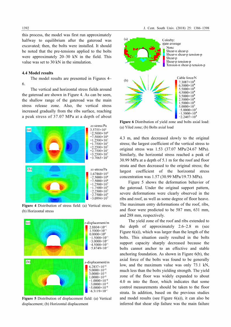
Figure 6 Distribution of yield zone and bolts axial load:
(a) Yiled zone; (b) Bolts axial load
4.3 m, and then decreased slowly to the original stress; the largest coefficient of the vertical stress to original stress was 1.53 (37.07 MPa/24.67 MPa). Similarly, the horizontal stress reached a peak of 30.99 MPa at a depth of 5.1 m for the roof and floor strata and then decreased to the original stress; the largest coefficient of the horizontal stress concentration was 1.57 (30.99 MPa/19.73 MPa).
Figure 5 shows the deformation behavior of the gateroad. Under the original support pattern, severe deformations were clearly observed in the ribs and roof, as well as some degree of floor heave. The maximum entry deformations of the roof, ribs, and floor were predicted to be 587 mm, 631 mm, and 288 mm, respectively.
The yield zone of the roof and ribs extended to the depth of approximately 2.6–2.8 m (see Figure 6(a)), which was larger than the length of the bolts. This situation easily resulted in the bolts support capacity sharply decreased because the bolts cannot anchor to an effective and stable anchoring foundation. As shown in Figure 6(b), the axial force of the bolts was found to be generally low, and the maximum value was only 73.1 kN, much less than the bolts yielding strength. The yield zone of the floor was widely expanded to about 4.0 m into the floor, which indicates that some control measurements should be taken to the floor strata. In addition, based on the previous studies and model results (see Figure 6(a)), it can also be inferred that shear slip failure was the main failure

J. Cent. South Univ. (2018) 25: 1386–1398
1393
model for the deep rock masses. 4.5 Failure mechanism of deep gateroad
Based on the field investigation and numerical analysis results, we can conclude that the high stress and soft rock characteristics were the main factors for the gateroad instability. The failure mechanism of the gateroad can be inferred as follows. 1) The gateroad excavation action led to stress redistribution, and the rock masses surrounding the gateroad were subjected to high stress. Due to the soft rock properties and induced high stress, the roof and two ribs underwent severe shear slip failure and eventually entered a yielding state, resulting in the loss of the self-bearing capacity of the rock mass; With a poor self-bearing capacity, the gateroad exhibited a large failure range even exceeding the bolts length (see Figure 6(a)). In this situation, the conventional bolts with the relatively short bolts length and low pre-tensions cannot give full play to its supporting potential. 2) Due to the significantly creep characteristics of surrounding rocks and the lack of high-strength secondary support measurements, the gateroad deformation continues to maintain a fairly rapid growth for a long time, which further expanded the failure range of the gateroad. 3) In addition, because of the lack of effective support and the water- swelling characteristics of the floor strata, the floor strata were severely damaged and then, further aggravated the roof and ribs deformation and failure. 5 Targeted support strategy and its field
application 5.1 Support principles
Based on the previous analysis of the failure mechanism and successful support experiences in many underground Chinese coal mines, the following support principles are proposed for the No. #2 main entry:
1) Apply fully grouted bolts with longer lengths. Due to the fact that the range of the yield zone of the gateroad is generally larger than the length of conventional bolts (see Figure 6(a)), bolts with longer lengths are necessary to ensure an effective and stable anchoring foundation. In addition, partially grouted bolts can easily lose their support function once anchor point failure occurs.
The best way to avoid this is to adopt fully grouted bolts; as for fully anchored bolts, theirs anchoring force was distributed along the full length of the bolts, hence, avoiding localized grout failures.
2) Adopt cables with high strength and pretension in the roof. The yield zone in the gateroad roof extended approximately 2.8 m, which makes it vulnerable to delamination, thus resulting in the risk of roof collapse. To avoid this occurring, high-strength cables with a longer length are necessary to clamp these unstable rock to the stable deep rock strata.
3) Increase the secondary support measures. Due to the significant creep properties of the deep rock masses, the gateroad deformation generally lasts for 3–5 months, even with intensive bolt/cable support. Based on this, a high-strength yielding support, which has increasing support capacity with increasing deformation, should be applied for the secondary support [21, 22].
4) Improve the intrinsic strength of the surrounding rock. The No. #2 main entry is a permanent roadway for the No. #2 coal mining. In order to ensure its overall stability during its service life, grouting measures are essential to improve the intrinsic strength of the surrounding rock masses. In addition, it can effectively combine the supporting components and surrounding rocks to form a stable bearing structure. 5.2 Support strategy
According to the support principles mentioned above, the following support strategies are presented and applied to the newly developed area of the No.#2 main entry. The detailed steps for performing control strategies are shown in Figure 7. The details of the bolt/cable arrangement in the entry cross-section are shown in Figure 8.
1) After the gateroad with 5.1 m width by 4.3 m height was excavated, the roof and coal ribs were first supported by the longer bolts/cables. The bolts were 22 mm in diameter and 3 m in length, while the inter-row spacing was set to 800 mm×800 mm. All the bolts were installed with steel mesh (6 mm in diameter) and steel ladder beams (14 mm in diameter) for surface control. Notably, the bolts were fully grouted using resin chemicals over the entire lengths. In addition, high-strength cables were also used for the roof support, with a spacing of 2000 mm×800 mm. The length of the cables was

J. Cent. South Univ. (2018) 25: 1386–1398
1394
Figure 7 Detailed steps for performing control strategies
Figure 8 Detailed support schemes in No. #2 main entry: (a) New design of gateroad support pattern (unit: mm);
(b) Gateroad profile in situ
set to 8.5 m so that the cables could strike roots in the hard fine-grained sandstone above the immediate roof. All bolts and cables were pre-tensioned with forces of 60 kN and 200 kN, respectively. This step can effectively improve the integrity of the superficial rock and fully utilize the self-supporting capability of the stable deep rock masses.
2) High-strength yielding ring supports were performed lagging behind the bolt/cable support at a distance of 4.8 m. This kind of support is composed of four segments (made of 36U profile steel), and the adjacent segments are linked by a clamp with a lapped length of 450 mm. The two
neighbouring supports along the gateroad axis are installed with a spacing of 800 mm and connected by three steel rods. Notably, the gap between the supports and its rear rock masses was filled up by the wooden lagging for the purpose of ensuring good contract. Compared with previous yielding supports, this kind of support plays two positive roles. First, it has a higher capacity to resist creep deformation and good yielding properties to guarantee support itself securely. Second, its closed ring structure can also help to resist floor heave.
3) After the heading face moved about 100 m, grouting measures were performed. A total of eight grouting holes were drilled around the gateroad (see

J. Cent. South Univ. (2018) 25: 1386–1398
1395
Figure 8(a)). The depths of the grouting boreholes were designed to 2, 3 and 8 m. Boreholes #1 and #2 (with length of 8 m) were drilled perpendicular to the roof and floor strata; boreholes #3 and #4 (with lengths of 3 m) were drilled perpendicular to the coal ribs; boreholes #5 and #6 (with lengths of 2 m) were drilled on the spandrel with an angle of 45° to the horizontal plane; boreholes #7 and #8 (with lengths of 2 m) were drilled on the bottom corner with an angle of 45° to the horizontal plane. The spacing of the grouting holes along the gateroad axis was set to 3.2 m. The grouting pressure exerted by grouting pump was set to 6.0 MPa for boreholes #1 and #2 and 2.5 MPa for the other boreholes. Under this grouting pressure, the cement slurry can fill up the existing fractures and bed separations, and thus, the failed rock masses can be consolidated via grouting and improved load-bearing capacity.
4) Considering the water-swelling characteristics of the surrounding rocks, a concrete lining with a thickness of 100 mm was applied for surface protection. In addition, a concrete foundation with a thickness of 400 mm was also built to prevent water from weakening the floor strata. 5.3 Field monitoring
To evaluate the performance of the surrounding rock mass and newly designed support
scheme, a series of field observations, including entry convergence and fracture zone development, was conducted in the No. #2 entry. The entry convergence was measured using a flexible tape and measuring lines, and the fracture zone development of the roof and ribs strata was measured using a YSZ(B) Panoramic borehole camera system (see Figure 9). Note that the exploratory borehole was 6 m deep with a diameter of 28 mm.
The detection results regarding fracture development are presented in Figure 10. As shown in Figure 10(a), for the roof strata, the rock masses were sharply damaged at a depth of 0–1.8 m down the borehole, while the fracture densities decreased gradually from a depth of 1.8 to 2.7 m; at depth of 2.7 m and deeper, the rock mass had only a few fractures. However, for the coal ribs, the fracture development depth was greater than the roof strata because of the low strength of the coal. The coal mass severely failed at a depth of 0 to 2.3 m down the borehole, and massive fractures are observed within this range (see Figure 10(b)); the fracture densities decreased gradually at depth of 2.3 to 3.0 m, and only tiny fractures were observed beyond a depth of 3.0 m. This monitoring result demonstrated that all the bolts were mainly installed in a comparatively stable rock mass, enabling the
Figure 9 Layout of measurement station: (a) Tapes, lines, and pegs; (b) YSZ(B) Panoramic borehole camera system

J. Cent. South Univ. (2018) 25: 1386–1398
1396
Figure 10 Fracture zone development of rock mass surrounding No.#2 entry: (a) Detection results at various depths in
roof strata; (b) Detection results at various depths in coal rib
bolts to maintain good working condition.
The observation results demonstrate a very satisfactory support effect and stability of the surrounding rocks after the excavation (see Figure 11). This implies that the use of longer supports, a yielding ring support, and grouting measures has provided greater stability for the deep gateroad with a 1 km burial depth.
Figure 11 Measured entry convergences in No. #2 entry
Notably, this study is based on the analysis of
the specific situation of a mine in Xingtai mining area. Different coal seams present great varieties in geological and production conditions, which lead to differences in the deformation and failure characteristics and failure mechanisms of the gateroad. However, the new combined support pattern presented in this study is necessary in the design of support system in other coal mines.
6 Conclusions
1) In situ stress measurements and mechanical properties tests of the coal-measuring rock masses demonstrate that the No. #2 entry is a typical high in situ stress, soft-rock gateroad with poor ground stability and that the adverse geological conditions, such as high in situ stress and soft rocks, are not beneficial in terms of ground stability control.
2) The deformation behavior, stress and yield zone distributions, and bolt load were simulated using FLAC3D software. The shear-slip failure induced by the high stress was the primary failure model for the deep rock masses. Due to the soft rock properties and high induced stress, the roof and two ribs underwent severe deformation and eventually entered a yielding state, resulting in the loss of the self-bearing capacity of the rock mass. The unsuitable support pattern, especially the relatively short bolts/cables, low pre-tensions and the unsupported floor strata, also contributed to the gateroad instability.
3) A new combined support strategy incorporating longer bolts/cables, yielding ring supports, and grouting measures was proposed for the deep gateroad. Field monitoring demonstrated that this support strategy has provided greater stability for the deep gateroad with a 1 km burial depth. In addition, this support strategy provides sufficient details to allow its application in other coal mines.

J. Cent. South Univ. (2018) 25: 1386–1398
1397
References
[1] HUANG Wan-peng, YUAN Qi, TAN Yun-liang, WANG
Jun, LIU Guo-lei, QU Guang-long, LI Chao. An innovative
support technology employing a concrete-filled steel tubular structure for a 1000-m-deep roadway in a high in situ stress
field [J]. Tunnelling and Underground Space Technology,
2018, 73: 26–36. DOI: 10.1016/j.tust. 2017.11.007. [2] ZHANG Guang-chao, HE Fu-lian, JIA Hong-guo, LAI
Yong-hui. Analysis of gateroad stability in relation to yield
pillar size: A case study [J]. Rock Mechanics and Rock Engineering, 2017, 50(5): 1–16. DOI: 10.1007/s00603-016-
1155-1.
[3] TAN Yun-liang, YU Feng-hai, NING Jian-guo, ZHAO Tong-bin. Design and construction of entry retaining wall
along a gob side under hard roof stratum [J]. International
Journal of Rock Mechanics and Mining Sciences, 2015, 77: 115–121. DOI: 10.1016/j.ijrmms.2015.03.025.
[4] ZHAO Tong-bin, GUO Wei-yao, TAN Yun-liang, YIN
Yan-chun, CAI Lai-sheng, PAN Jun-feng. Case studies of rock bursts under complicated geological conditions during
multi-seam mining at a depth of 800 m [J]. Rock Mechanics
and Rock Engineering, 2018, 51: 1539–1564. https:// doi.org/10.1007/s00603-018-1411-7.
[5] SHREEDHARAN S, KULATILAKE P H S W.
Discontinuum-equivalent continuum analysis of the stability of tunnels in a deep coal mine using the distinct element
method [J]. Rock Mechanics and Rock Engineering, 2016,
49(5): 1903–1922. DOI: 10.1007/s00603-015-0885-9. [6] KANG Hong-pu, LV Hua-wen, ZHANG Xiao, GAO
Fu-qiang, WU Zhi-gang, WANG Zhi-chao. Evaluation of the
ground response of a pre-driven longwall recovery room supported by concrete cribs [J]. Rock Mechanics & Rock
Engineering, 2016, 49(3): 1025–1040. DOI: 10.1007/s006
03-015-0782-2. [7] WHITTAKER B N, SINGH R N. Stability of longwall
mining gate in relation to rib pillar size [J]. International
Journal of Rock Mechanics and Mining Sciences, 1981, 18(4): 331–334. https://doi.org/10.1016/0148-9062(81)9119
7–9.
[8] SHEN Bao-tang, KING A, GUO H. Displacement, stress and seismicity in roadway roofs during mining-induced failure
[J]. International Journal of Rock Mechanics and Mining
Sciences, 2008, 45(5): 672–688. https://doi.org/10.1016/ j.ijrmms.2007.08.011.
[9] LI Shu-cai, Wang Hong-tao, Wang Qi, JIANG Bei, WANG
Fu-qi, GUO Nian-bo, LIU Wen-jiang, REN Yao-xi. Failure mechanism of bolting support and high-strength bolt-
grouting technology for deep and soft surrounding rock with
high stress [J]. Journal of Central south university, 2016, 23(2): 440–448. DOI: 10.1007/s11771-016-3089-x.
[10] YUAN Liang, XUE Jun-hua, LIU Quan-sheng, LIU Bin.
Surrounding rock stability control theory and support technique in deep rock roadway for coal mine [J]. Journal of
the China Coal Society, 2011, 36(4): 535–543. (in Chinese)
[11] SHEN Bao-tang. Coal mine roadway stability in soft rock: A
case study [J]. Rock Mechanics and Rock Engineering, 2014,
47(6): 2225–2238. DOI: 10.1007/s00603-013-0528-y.
[12] CARRANZA-TORRES C. Analytical and numerical study
of the mechanics of rockbolt reinforcement around tunnels in
rock masses [J]. Rock Mechanics and Rock Engineering,
2009, 42(2): 175–228. https://doi.org/10.1007/s00603-
009-0178-2.
[13] KUSHWAHA A, SINGH S K, TEWARI S, SINHA A.
empirical approach for designing of support system in
mechanized coal pillar mining [J]. International Journal of
Rock Mechanics and Mining Sciences, 2010, 47(7):
1063–1078. DOI: 10.1016/j.ijrmms.2010.06.001.
[14] TAN Yun-liang, LIU Xue-sheng, NING Jian-guo, LV
Yan-wei. In situ investigations on failure evolution of
overlying strata induced by mining multiple coal seams [J].
Geotechnical Testing Journal, 2017, 40(2): 244–257. DOI:
10.1520 /GTJ20160090.
[15] ZHANG Zhi-yi, SHIMADA H, QIAN De-yu, SASAOKA T.
Application of the retained gob-side gateroad in a deep
underground coalmine [J]. International Journal of Mining
Reclamation and Environment, 2015, 30(5): 371–379. DOI:
10.1080/17480930.2015.1093729.
[16] FENG Xiao-wei, ZHANG Nong, HE Feng-zhen, YANG Sen,
ZHENG Xi-gui. Implementation of a pre-tensioned, fully
bonded, bolting system and its failure mechanism based on
acoustic emission: A laboratorial and field study [J].
Geotechnical Testing Journal, 2017, 40(6): 978–999. DOI:
10.1520 /GTJ20160157.
[17] ZHAO Tong-bin, GUO Wei-yao, TAN Yun-Liang, LU
Cai-ping, WANG Cheng-wu. Case histories of rock bursts
under complicated geological conditions [J]. Bulletin of
Engineering Geology and the Environment, 2017. DOI:
10.1007/s10064-017-1014-7.
[18] CAI Mei-feng, HE Man-chao, LIU Dong-yan. Rock
mechanics and engineering [M]. Beijing: Science Press,
2013. (in Chinese)
[19] HUANG Wan-peng, LI Chao, ZHANG Li-wei, YUAN Qi,
ZHENG Yong-sheng, LIU Yang. In situ identification of
water-permeable fractured zone in overlying composite strata
[J]. International Journal of Rock Mechanics and Mining
Sciences, 2018, 105: 85–97. https://doi.org/ 10.1016/j.ijrmms.
2018.03.013.
[20] ZHANG Kai, ZHANG Gui-min, HOU Rong-bin, WU Yu,
ZHOU Hong-qi. Stress evolution in roadway rock bolts
during mining in a fully mechanized longwall face, and an
evaluation of rock bolt support design [J]. Rock Mechanics
and Rock Engineering, 2015, 48(1): 333–344. DOI:
10.1007/s00603-014-0546-4.
[21] ZHANG Guang-chao, LIANG Sai-jiang, TAN Yun-liang,
XIE Fu-xing, CHEN Shao-jie, JIA Hong-guo. Numerical
modeling for longwall pillar design: A case study from a
typical longwall panel in China [J]. Journal Geophysics and
Engineering, 2018, 15(1): 121–134. DOI: 10.1088/1742-
2140/aa9ca4.
[22] NING Jian-guo, WANG Jun, JIANG Jin-quan, HU
Shan-chao, JIANG Li-shuai, LIU Xue-sheng. Estimation of
crack initiation and propagation thresholds of confined brittle
coal specimens based on energy dissipation theory [J]. Rock
Mechanics and Rock Engineering, 2018, 51: 119–134. DOI:
10.1007/s00603-017-1317-9.
(Edited by YANG Hua)

J. Cent. South Univ. (2018) 25: 1386–1398
1398
中文导读
千米埋深煤矿巷道围岩稳定性研究 摘要:本文采用数值模拟、案例分析、现场试验相结合的综合研究方法分析千米埋深煤矿巷道围岩稳
定性。首先,在试验巷道进行了地应力监测与煤岩体力学性能测试;然后,通过 FLAC3D数值模拟软
件分析了试验巷道围岩位移场、应力场、塑性区与锚杆受力特征。研究结果表明,软岩特性与高地应
力是深部巷道失稳的主要因素,高应力引起的剪切滑移破坏是深部巷道围岩的主要破坏模式;不合理
的支护方式,特别是锚杆索长度短且预紧力低、缺少高强二次支护、底板无支护等亦是巷道失稳的原
因。基于上述研究,提出了集长锚杆索、可缩性环形支架、注浆加固于一体的联合加固措施,并通过
现场监测验证了支护方案的合理性。本文研究成果为深入理解千米深井巷道破坏机制提供了借鉴。 关键词:深部矿井;软岩;埋深;破坏机制;变形特性;支护方案