ground penetrating radar (georadar)
TRANSCRIPT
1
GROUND PENETRATING RADAR
(GEORADAR)
Abdullah M. Alamri
2
• Ground penetrating radar (georadar) uses short
pulses of ultra high frequency (UHF) radio to create
an echogram of the subsurface.
• It has several similarities to seismic reflection,
although the wave transmission is more complex and
the results more dependent on the survey conditions.
3
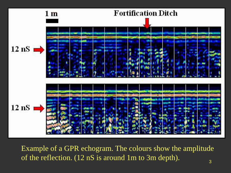
Example of a GPR echogram. The colours show the amplitude
of the reflection. (12 nS is around 1m to 3m depth).
4
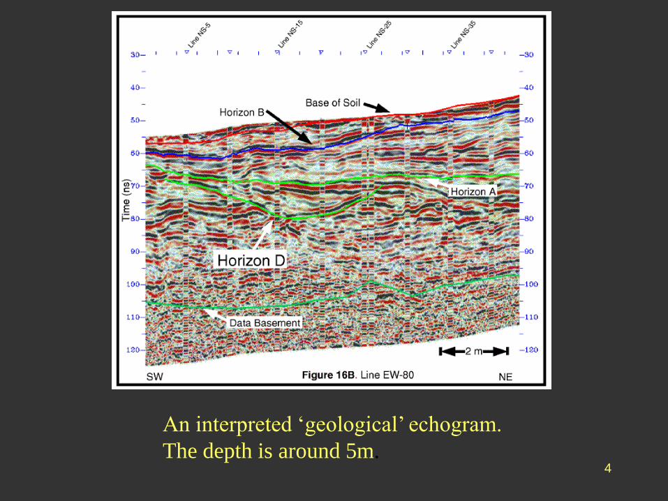
An interpreted ‘geological’ echogram.
The depth is around 5m.
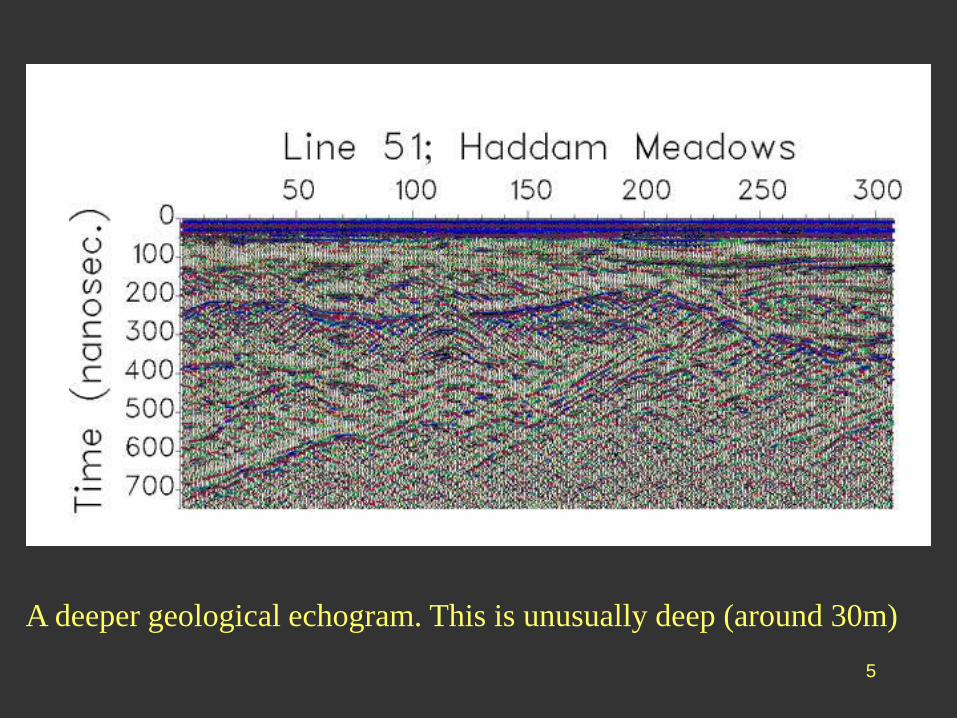
5
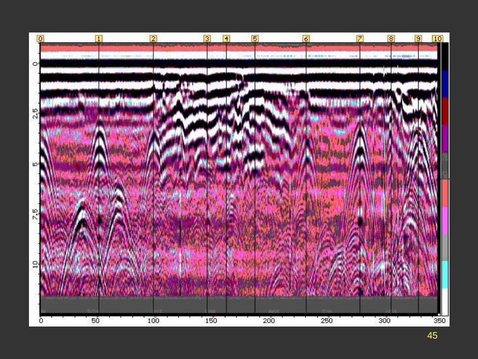
A deeper geological echogram. This is unusually deep (around 30m)
6
• The advantages of GPR lie in its speed, convenience
and potential detail. It has many applications in
geology, engineering SI, archaeology, to name some.
• GPR has several limitations. The most serious is the
effect of soil conditions on the transmission of the
electromagnetic pulse - this can render quantitative
intepretation very difficult or impossible.
7
8
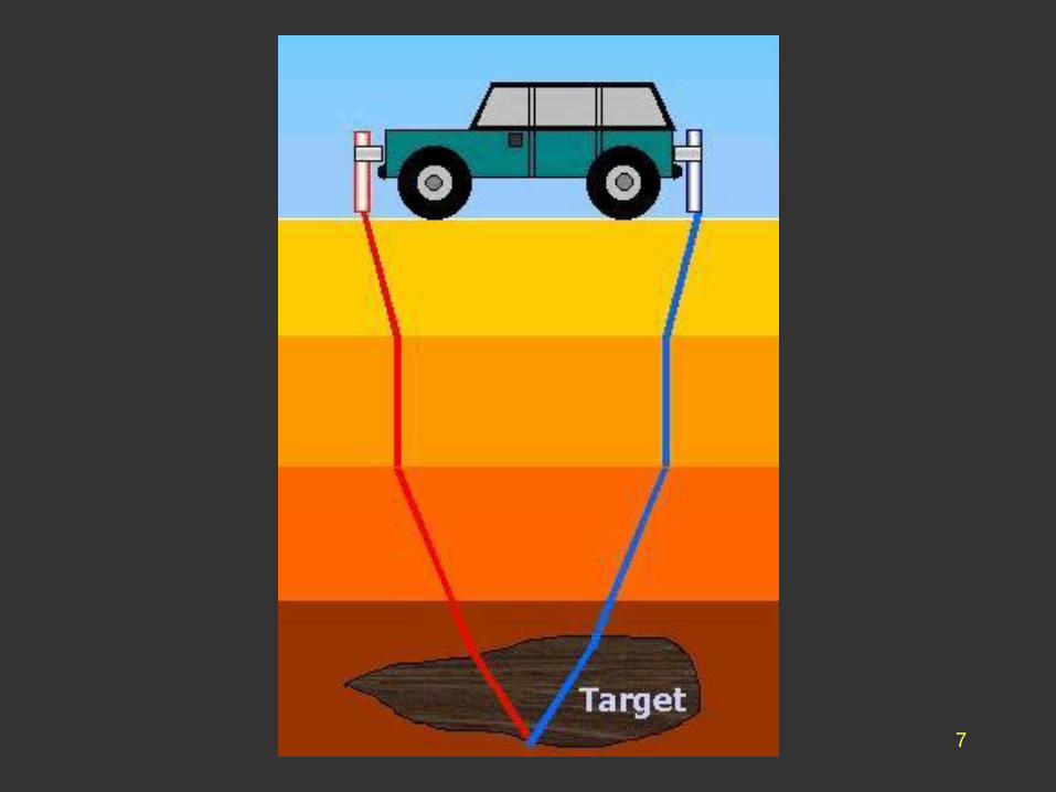
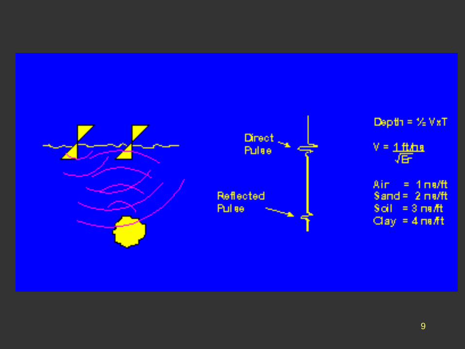
• GPR uses the reflections from a short pulse to build an
image of the subsurface.
• The basic principle is identical to that of the seismic
reflection method, except that:
– The energy is provided by a UHT pulse of around 200 MHz.
– The velocity is around 100,000 metres/mS or 0.1m/nS (about
100,000 times faster than a seismic wave)
– TWT is measured in 10s - 100s of nanoseconds
– Reflectors are defined by a contrast in their AC electrical
impedance, essentially a change in their dielectric constant
– Penetration depth is usually limited to a few metres
9
10
11
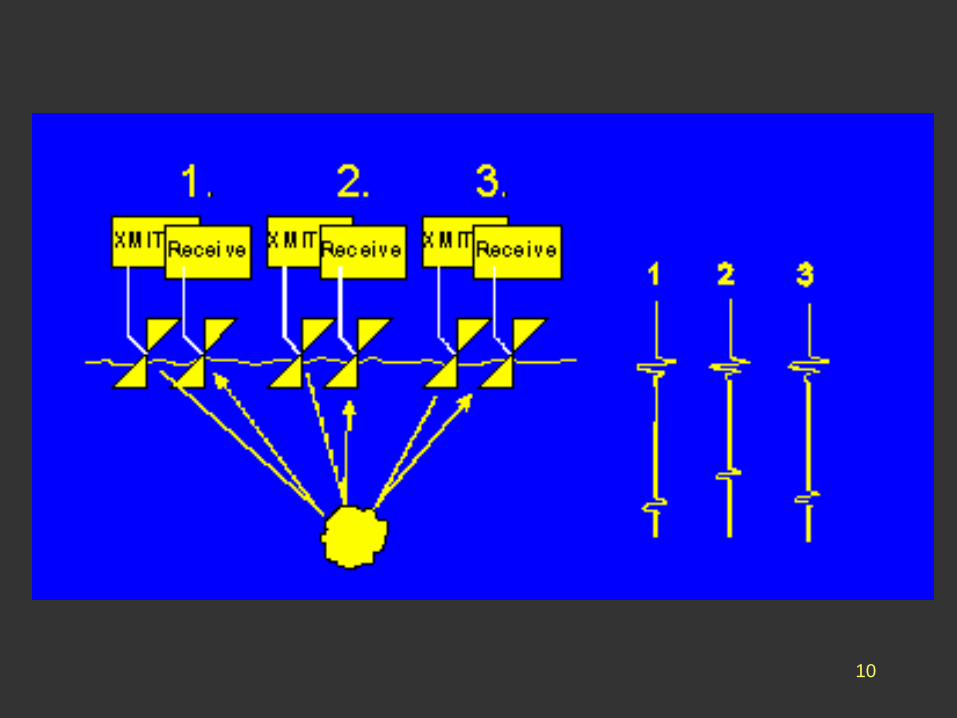
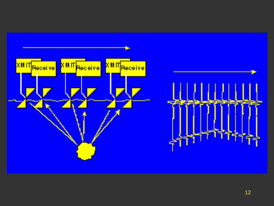
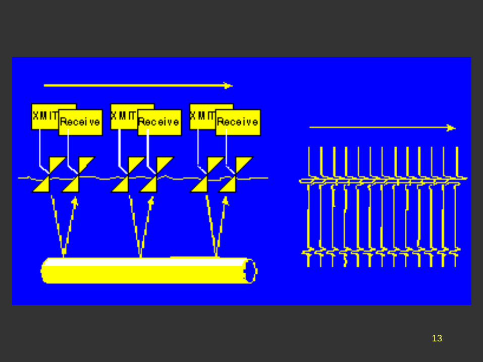
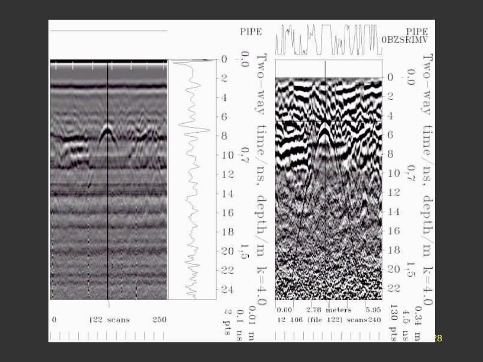
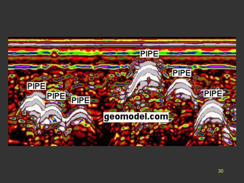
• Discrete objects give rise to hyperbolic reflections in
the same way as in reflection seismics.
• The image of a linear objects (eg a pipe) depends on
its direction relative to the survey line.
12
13
14
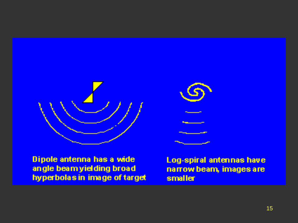
• Unlike seismic sources, GPR sources can be
focussed using different antenna designs.
• The success of a GPR survey can be very dependent
on the choice of antenna.
15
16
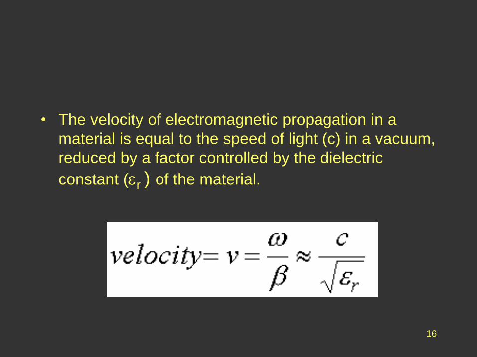
• The velocity of electromagnetic propagation in a
material is equal to the speed of light (c) in a vacuum,
reduced by a factor controlled by the dielectric
constant (r ) of the material.
17
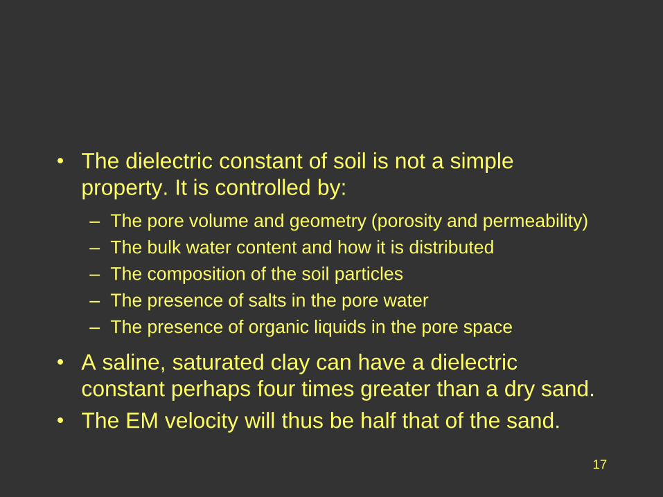
• The dielectric constant of soil is not a simple
property. It is controlled by:
– The pore volume and geometry (porosity and permeability)
– The bulk water content and how it is distributed
– The composition of the soil particles
– The presence of salts in the pore water
– The presence of organic liquids in the pore space
• A saline, saturated clay can have a dielectric
constant perhaps four times greater than a dry sand.
• The EM velocity will thus be half that of the sand.
18
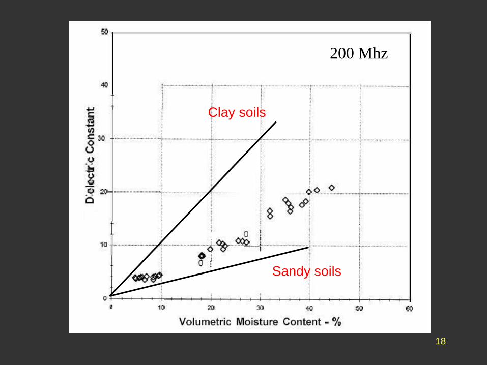
200 Mhz
Clay soils
Sandy soils
19
• In a similar way, the absorption of the EM signal is
very dependent on these factors. Thus in a clay soil
there can be a considerable signal loss and thus a
reduction in the depth of penetration.
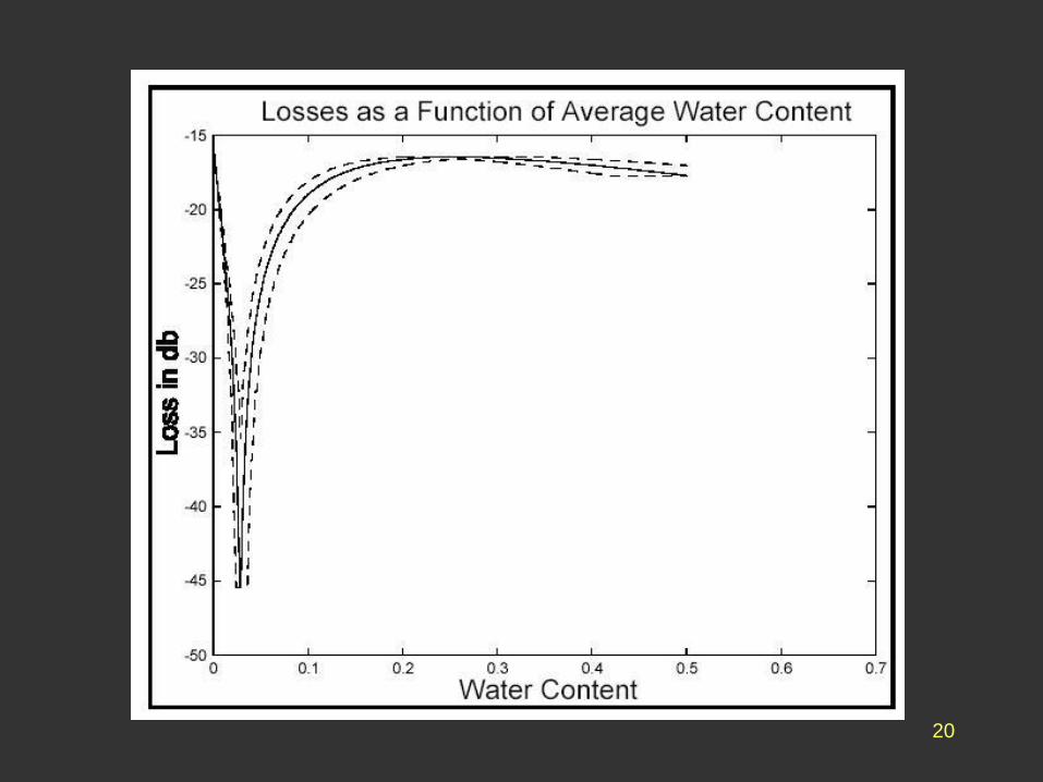
• This loss is not uniform but is concentrated at
particular values of the water content due to optimal
absorption in certain particle packings.
20
21
• Thus accurate depth interpretation can be very
difficult in some soils.
• Problems arise especially if the water content is
variable, if the clay content is variable or if there are
big changes in either between layers.
• Problems also arise in saline soils, which limits the
use of georadar in coastal situations.
22
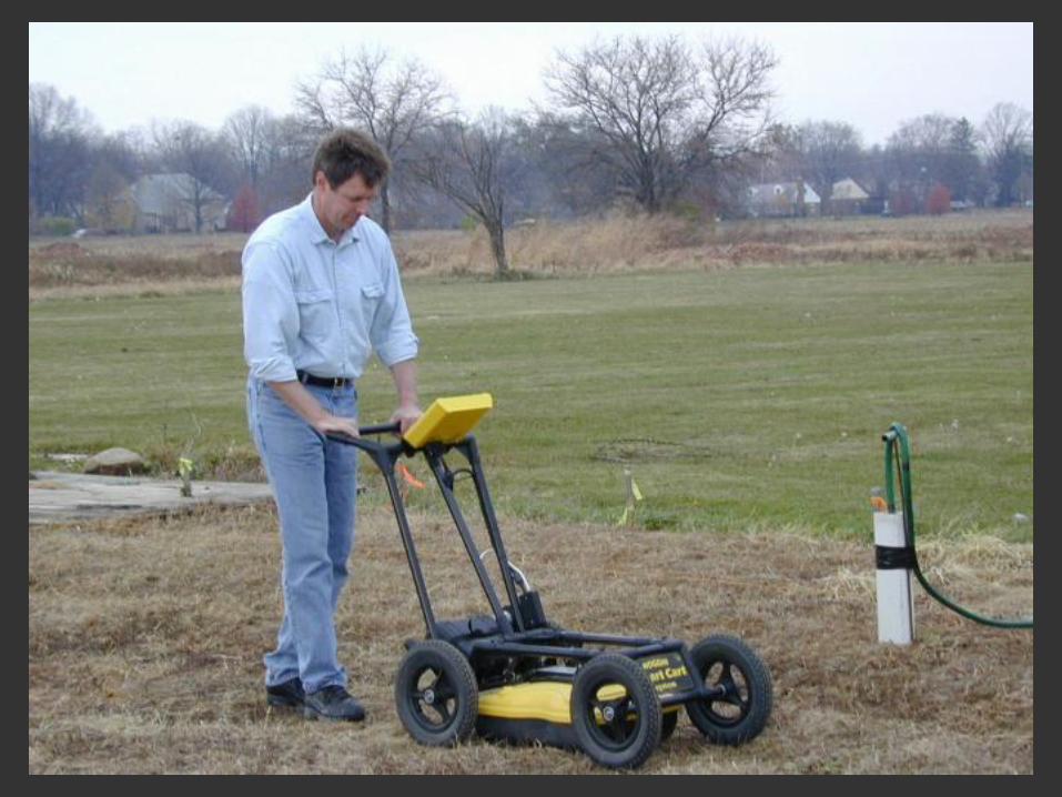
• Georadar surveys are non-contacting profile surveys,
in which the instrument is traversed along the desired
line.
• The output is shown immediately on the display and
is recorded either digitally or on paper, after internal
processing.
• The equipment is light and portable, designed for a
single operator. GPR surveys are thus relatively
cheap.
23
24
• The instrument size is determined by the antenna.
This in turn is controlled by the required frequency.
• The most common 200 Mhz sets use antennae about
0.5m long, aligned perpendicular to the profile. These
typically penetrate to 5m - 10m.
• Other frequencies in use include 50 MHz and 900
MHz, the latter being an adaption of a materials
testing instrument.
25
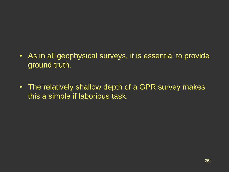
• As in all geophysical surveys, it is essential to provide
ground truth.
• The relatively shallow depth of a GPR survey makes
this a simple if laborious task.
26
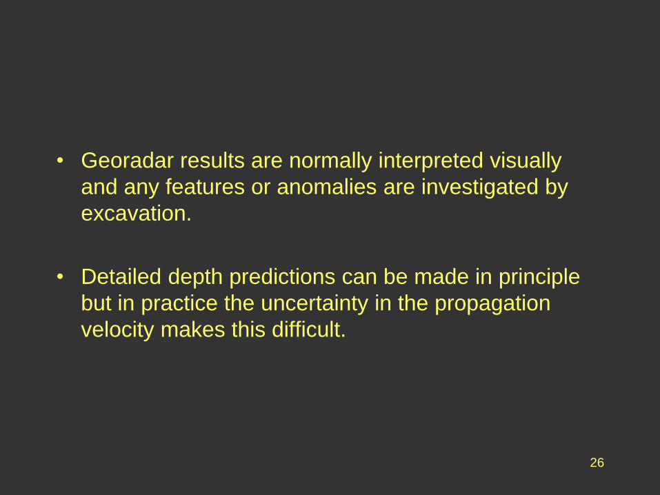
• Georadar results are normally interpreted visually
and any features or anomalies are investigated by
excavation.
• Detailed depth predictions can be made in principle
but in practice the uncertainty in the propagation
velocity makes this difficult.
27
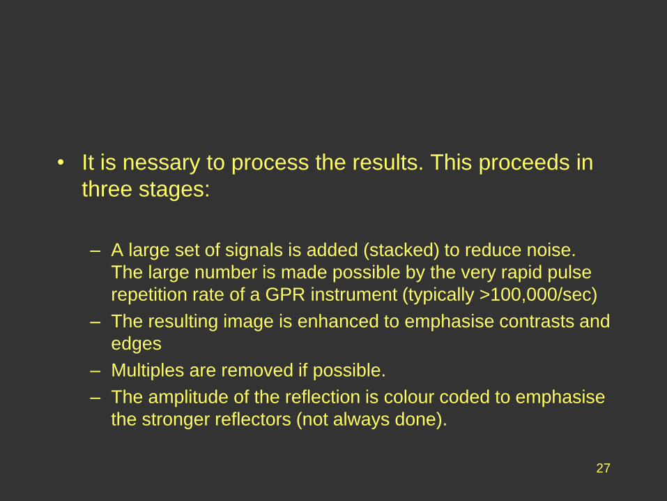
• It is nessary to process the results. This proceeds in
three stages:
– A large set of signals is added (stacked) to reduce noise.
The large number is made possible by the very rapid pulse
repetition rate of a GPR instrument (typically >100,000/sec)
– The resulting image is enhanced to emphasise contrasts and
edges
– Multiples are removed if possible.
– The amplitude of the reflection is colour coded to emphasise
the stronger reflectors (not always done).
28
29
• Interpretation then proceeds visually, with the
operator making allowance for the presence of
multiples, hyperbolic reflectors etc.
• It is possible to define radar facies in the same way
as seismic facies. This gives some indication of
lithology.
• However, due to the ease of excavation, this
approach is less critical than in seismic surveying.
30
31
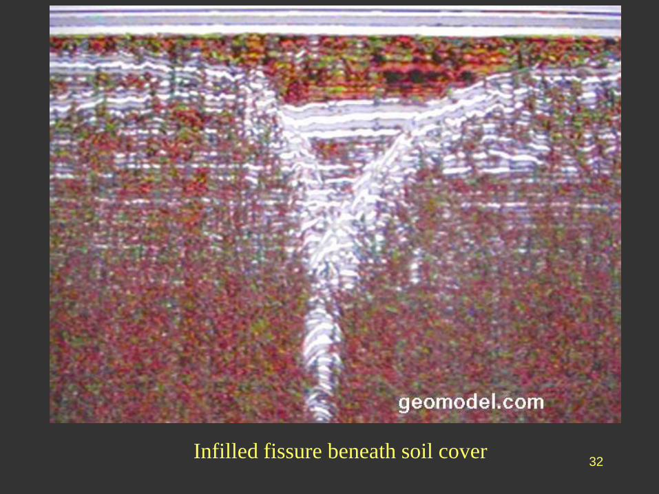
32Infilled fissure beneath soil cover
33
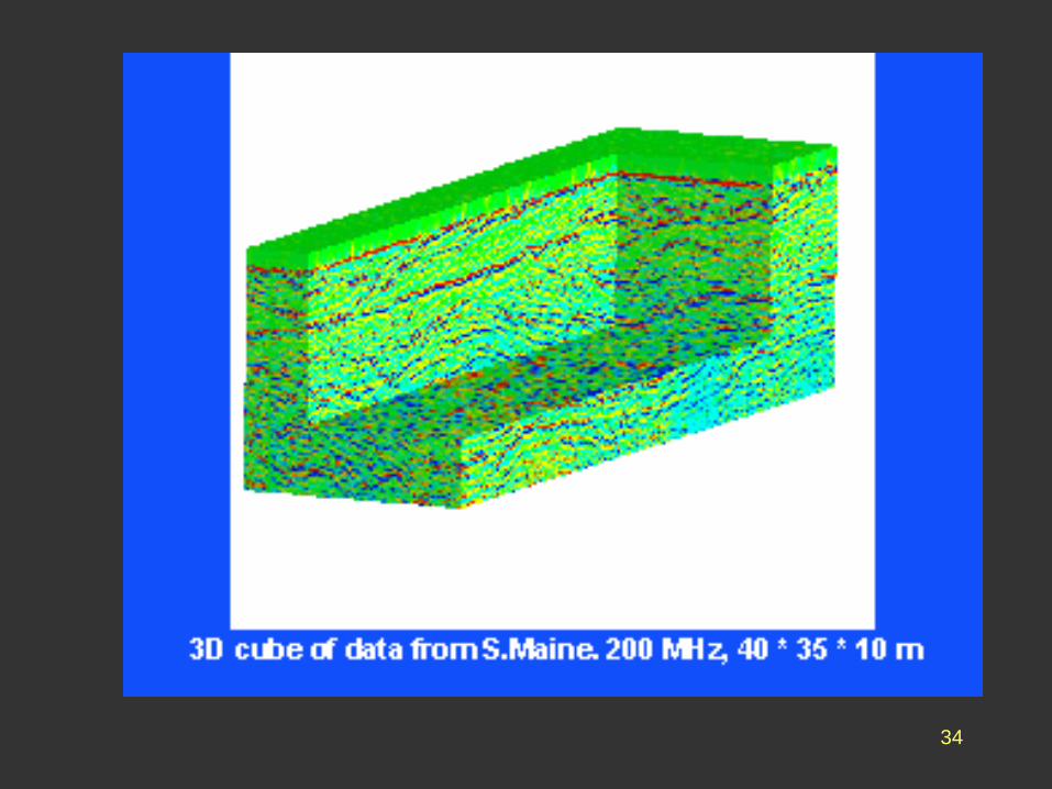
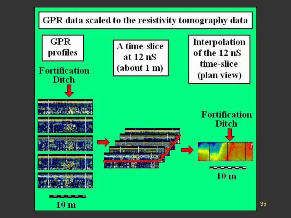
• More complex processing enables the stacks to be
integrated into a three dimensional model of the
ground.
• Individual layers can be extracted by time-slicing the
model and the results displayed separately to
produce a plan view of a particular level.
34
35
36
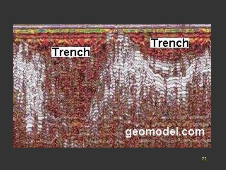
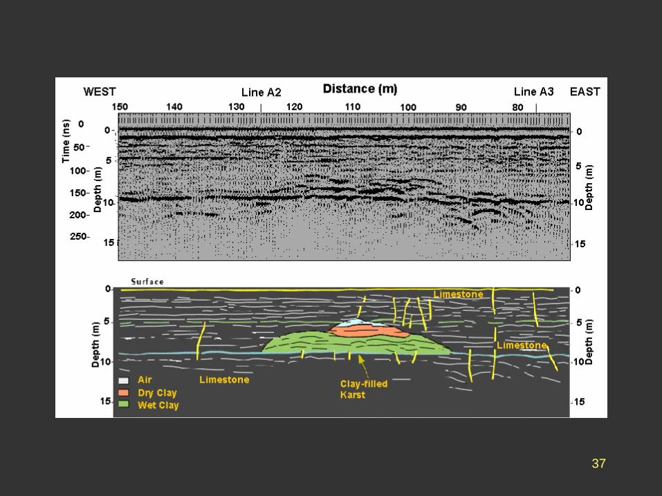
• The following examples show the range of problems
to which GPR can be applied.
1. Conventional engineering survey to determine the
presence of hazardous subsurface features, in this
case solution sink holes in limestone.
37
38
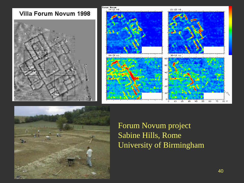
2. To determine the position and layout of shallow
archaeological features, usually either walls or infilled
excavations such as foundations or ditches.
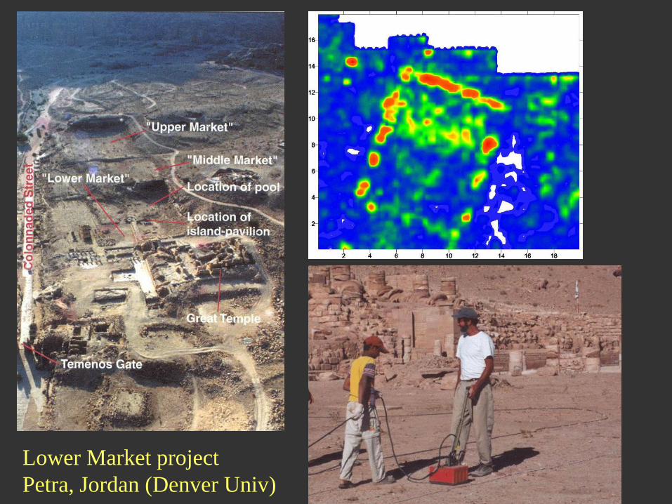
39Lower Market project
Petra, Jordan (Denver Univ)
40
Forum Novum project
Sabine Hills, Rome
University of Birmingham
41
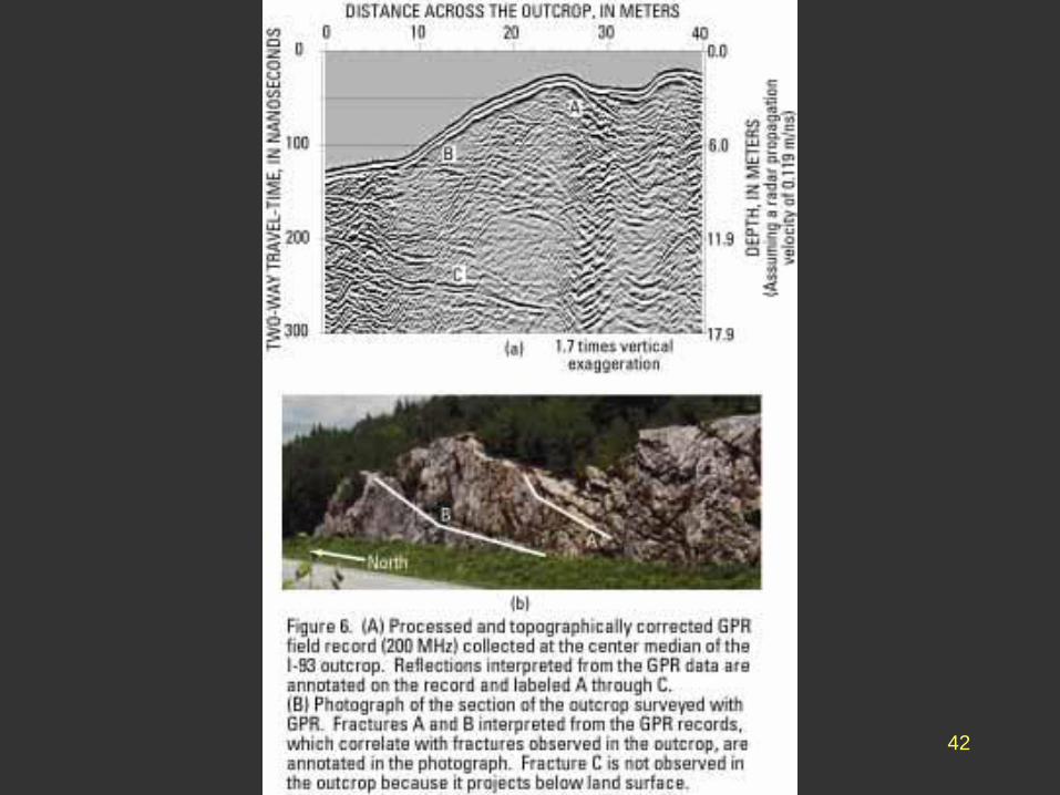
3. The presence and spacing of fissures in bedrock as
part of a hydrogeological resource survey. This is a
relatively difficult task.
The detection of the groundwater surface itself is
usually quite easy.
42
43
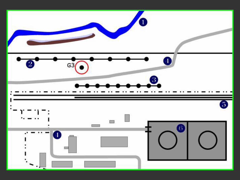
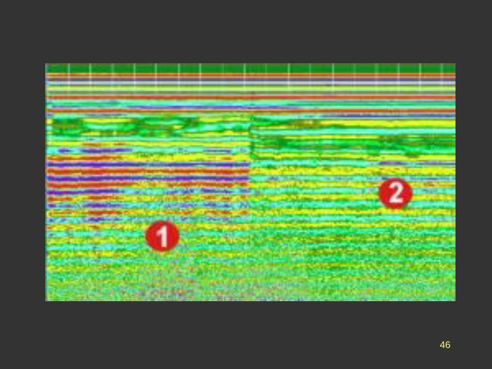
4. The detection of hydrocarbon pollution within
particular soil horizons, using the dielectric difference
between oil and water.
44
45
46