ground frames and shunters’ releases - rssb iss 1.pdf · rail industry ground frames and standard...
TRANSCRIPT

Rail Industry Standard
RIS-0077-CCS
Issue One
Date September 2017
Ground Frames and Shunter’s Releases
Synopsis
This document sets out the interface requirements for ground frames and shunters’ releases that may be operated by railway undertaking personnel.
Copyright in the Railway Group documents is owned by Rail Safety and Standards Board Limited. All rights are hereby reserved. No Railway Group document (in whole or in part) may be reproduced, stored in a retrieval system, or transmitted, in any form or means, without the prior written permission of Rail Safety and Standards Board Limited, or as expressly permitted by law.
RSSB members are granted copyright licence in accordance with the Constitution Agreement relating to Rail Safety and Standards Board Limited.
In circumstances where Rail Safety and Standards Board Limited has granted a particular person or organisation permission to copy extracts from Railway Group documents, Rail Safety and Standards Board Limited accepts no responsibility for, nor any liability in connection with, the use of such extracts, or any claims arising therefrom. This disclaimer applies to all forms of media in which extracts from Railway Group documents may be reproduced.
Published by: RSSB © Copyright 2017 Rail Safety and Standards Board Limited
RIS0077-CCS Page 1 of 70
Uncontrolled when printed Document supersedes GKRT0077 Iss 1 and GKGN0677 Iss 1 with effect from 02/09/2017

Rail Industry Standard
RIS-0077-CCS
Issue One
Date September 2017
Ground Frames and Shunter’s Releases
Issue record
Issue Date Comments
One September 2017 Replaces Railway Group Standard GKRT0077 Issue One as GKRT0077 could not be retained as a National Technical Rule and is therefore reclassified as a Rail Industry Standard. It also replaces GKGN0677, Issue One.
Superseded or replaced documents
The following Railway Group documents are superseded or replaced, either in whole or in part as indicated:
Superseded documents Sections superseded
Date when sections are superseded
GKRT0077 Ground Frames and Shunter’s Releases, Issue One
All 02 September 2017
GKGN0677 Guidance on Ground Frames and Shunter’s Releases, Issue One
All 02 September 2017
GKRT0077 issue one ceases to be in force as of 02 December 2017.
Supply
The authoritative version of this document is available at www.rssb.co.uk/railway-group-standards. Enquiries on this document can be forwarded to [email protected].
RIS0077-CCS Page 2 of 70
Uncontrolled when printed Document supersedes GKRT0077 Iss 1 and GKGN0677 Iss 1 with effect from 02/09/2017

Ground Frames and Shunter’s Releases
Rail Industry Standard
RIS-0077-CCS
Issue One
Date September 2017
Contents
Section Description Page
Part 1 Introduction 4 1.1 Purpose of this document 4 1.2 Application of this document 4 1.3 Health and safety responsibilities 4 1.4 Approval and authorisation of this document 4
Annexes Annex A Content of GKRT0077, Issue One 5 Annex B Content of GKGN0677, Issue One 24
Definitions and references 70
RIS0077-CCS Page 3 of 70
Uncontrolled when printed Document supersedes GKRT0077 Iss 1 and GKGN0677 Iss 1 with effect from 02/09/2017

Rail Industry Standard
RIS-0077-CCS
Issue One
Date September 2017
Ground Frames and Shunter’s Releases
Part 1 Introduction
1.1 Purpose of this document
1.2 Regulation (EU) 402/2013 on a common safety method for risk evaluation and assessment (CSM RA) requires Proposers to identify the hazards arising from planned changes and apply three risk acceptance principles to confirm that the risk arising from the hazards is controlled to an acceptable level.
1.3 RIS-0077-CCS can assist Proposers in applying the CSM RA before planned changes to ground frames and shunters’ releases are put into use.
1.4 This RIS can be adopted by IMs and RUs under their respective safety management system (SMS).
1.5 RIS-0077-CCS, which replaces GKRT0077 and GKGN0677, reproduces the text of GKRT0077 in its entirety in Annex A and GKGN0677 in Annex B.
1.6 Application of this document
1.6.1 Compliance requirements and dates have not been specified since these will be the subject of internal procedures or contract conditions.
1.6.2 The Standards Manual and RGS Code does not currently provide a formal process for deviating from RISs. However, a member of RSSB, having adopted a RIS and wishing to deviate from its requirements, may request a Standards Committee to provide observations and comments on their proposed alternative to the requirement in the RIS. Requests for observations and comments should be submitted to RSSB by e-mail to [email protected]. When formulating a request, consideration should be given to the advice set out in the ‘Guidance to applicants and members of Standards Committee on deviation applications’, available from RSSB’s website.
1.7 Health and safety responsibilities
1.7.1 Users of documents published by RSSB are reminded of the need to consider their own responsibilities to ensure health and safety at work and their own duties under health and safety legislation. RSSB does not warrant that compliance with all or any documents published by RSSB is sufficient in itself to ensure safe systems of work or operation or to satisfy such responsibilities or duties.
1.8 Approval and authorisation of this document
1.8.1 The content of this document was approved by Control Command and Signalling Standards Committee on 13 April 2017.
1.8.2 This document was authorised by RSSB on 31 July 2017.
RIS0077-CCS Page 4 of 70
Uncontrolled when printed Document supersedes GKRT0077 Iss 1 and GKGN0677 Iss 1 with effect from 02/09/2017

Ground Frames and Shunter’s Releases
Rail Industry Standard
RIS-0077-CCS
Issue One
Date September 2017
Annex A Content of GKRT0077, Issue One
RIS0077-CCS Page 5 of 70
Uncontrolled when printed Document supersedes GKRT0077 Iss 1 and GKGN0677 Iss 1 with effect from 02/09/2017
Railway Group Standard
GK/RT0077
Issue One
Date September 2013
Ground Frames and Shunters’ Releases
Synopsis
This document mandates the interface requirements for ground frames and shunters’ releases that may be operated by railway undertaking personnel.
Content approved by: Control Command and Signalling (CCS) Standards Committee on 08 April 2010 and reconfirmed on 13 June 2013
Authorised by RSSB on 29 July 2013
Copyright in the Railway Group Standards is owned by Rail Safety and Standards Board Limited. All rights are hereby reserved. No Railway Group Standard (in whole or in part) may be reproduced, stored in a retrieval system, or transmitted, in any form or means, without the prior written permission of Rail Safety and Standards Board Limited, or as expressly permitted by law.
RSSB Members are granted copyright licence in accordance with the Constitution Agreement relating to Rail Safety and Standards Board Limited.
In circumstances where Rail Safety and Standards Board Limited has granted a particular person or organisation permission to copy extracts from Railway Group Standards, Rail Safety and Standards Board Limited accepts no responsibility for, and excludes all liability in connection with, the use of such extracts, or any claims arising therefrom. This disclaimer applies to all forms of
media in which extracts from Railway Group Standards may be reproduced.
Published by RSSB Block 2 Angel Square 1 Torrens Street London EC1V 1NY © Copyright 2013 Rail Safety and Standards Board Limited
Uncontrolled when printed Document supersedes GKRT0077 Iss 1 and GKGN0677 Iss 1 with effect from 02/09/2017

Page 2 of 18 RSSB
Railway Group Standard
GK/RT0077
Issue One
Date September 2013
Ground Frames and Shunters’ Releases
Issue record
Issue Date Comments
One 07 September 2013 Original document
Superseded documents
Superseded documents Sections superseded Date when sections are superseded
GK/RT0039 issue one Semaphore and Mechanical Signalling
9.2, 6.1 sentence 2, 6.3 para 4;
Appendix A.5 para 3 BP3 and para 4 BP2; Appendix A.6 para 3; 5.6 paras 3 and 4; 6.5; 7.1 para 1 sentence 1 and 2, 7.2 para 1 BP2&4; 7.2 para 3; 7.3; 7.4; 8.2; 8.3
07 December 2013
GK/RT0041 issue one Track Circuit Block
B9 para 2 sentences 1, 3 & 4; B9 para 3 sentence 1; B9 para 4, 5 & 6 [excl. 9 para 4 BP3]
07 December 2013
GK/RT0042 issue one Absolute Block
B9 (see impact assessment for details)
07 December 2013
GK/RT0051 issue one Single Line Control
C9, D9, E9, F9, G9, H9 (see impact assessment for details)
07 December 2013
GK/RT0054 issue one Radio Electronic Token Block
B9 07 December 2013
GK/RT0060 issue four Interlocking Principles
C2.2c, C2.4b; C2.4d; C1.2a, b &,c; C4.3 para 1 & 2; C5.1.4 para 2 sentence 1
07 December 2013
GK/RT0061 issue two Shunters’ Releases, Ground Frames, Switch Panels and Gate Boxes
B1 to B5 and B7 (see impact assessment for details)
07 December 2013
GK/RT0063 issue one Approach Locking and Train Operated Route Release
4.2.2 para 1 & 2 07 December 2013
Other parts of GK/RT0041 issue one, GK/RT0042 issue one, GK/RT0051 issue one, GK/RT0054 issue one, GK/RT0060 issue four and GK/RT0063 issue one, are superseded by GK/RT0055 issue one, Block System Interface Requirements.
Remaining parts of the superseded documents are withdrawn and cease to be in force as of 07 December 2013.
Uncontrolled when printed Document supersedes GKRT0077 Iss 1 and GKGN0677 Iss 1 with effect from 02/09/2017

RSSB Page 3 of 18
Railway Group Standard
GK/RT0077
Issue One
Date September 2013
Ground Frames and Shunters’ Releases
Supply
The authoritative version of this document is available at www.rgsonline.co.uk. Uncontrolled copies of this document can be obtained from Communications, RSSB, Block 2, Angel Square, 1 Torrens Street, London EC1V 1NY, telephone 020 3142 5400 or e-mail [email protected]. Other Standards and associated documents can also be viewed at www.rgsonline.co.uk.
Uncontrolled when printed Document supersedes GKRT0077 Iss 1 and GKGN0677 Iss 1 with effect from 02/09/2017
Page 4 of 18 RSSB
Railway Group Standard
GK/RT0077
Issue One
Date September 2013
Ground Frames and Shunters’ Releases
Contents
Section Description Page
Part 1 Purpose and Introduction 5 1.1 Purpose 5 1.2 Introduction 5
Part 2 Requirements for Ground Frames and Shunters’ Releases 6 2.1 Compatibility requirements for ground frames and shunters’ releases 6 2.2 Release of ground frames 7 2.3 Control of infrastructure 9 2.4 Shunters’ releases 11
Part 3 Application of this Document 12 3.1 Application – infrastructure managers 12 3.2 Application – railway undertakings 13 3.3 Health and safety responsibilities 13
Appendices Appendix A Colours of Levers, Switches and Indications 14
Definitions 15
References 18
Tables Table A.1 The standard colours used for lever frames 14 Table A.2 The standard colours used for switch panels 14 Table A.3 The standard colours used for indications 14
Uncontrolled when printed Document supersedes GKRT0077 Iss 1 and GKGN0677 Iss 1 with effect from 02/09/2017

RSSB Page 5 of 18
Railway Group Standard
GK/RT0077
Issue One
Date September 2013
Ground Frames and Shunters’ Releases
Part 1 Purpose and Introduction
1.1 Purpose
1.1.1 This document mandates requirements for:
a) Ground frames, where control of a part of the railway infrastructure may be transferred between a signaller and a ground frame operator, who may be an employee of a railway undertaking, and
b) Shunters’ releases, where co-operation is required between the signaller and railway undertaking personnel to allow movements into and out of infrastructure controlled by a railway undertaking.
1.2 Introduction
1.2.1 Background
1.2.1.1 This document applies to:
a) Ground frames, and
b) Shunters’ releases.
1.2.1.2 This document does not include requirements for emergency panels, standby control centres or gate boxes, which are the responsibility of the infrastructure manager.
1.2.1.3 GK/RT0036 sets out the requirements for controlling the transition between lineside signalling conforming to Railway Group Standards and other methods of train control where delegated control may also apply.
1.2.2 Related requirements in other documents
1.2.2.1 The following Railway Group Standards contain requirements that are relevant to the scope of this document:
GE/RT8000 The Rule Book
GE/RT8270 Assessment of Compatibility of Rolling Stock and Infrastructure
GK/RT0036 Transitions Between Signalling Systems
GK/RT0045 Lineside Signals, Indicators and layout of Signals
GK/RT0055 Block Systems Interface Requirements
GO/RT3215 Requirements for the Weekly Operating Notice, Periodical Operating Notice and Sectional Appendix
1.2.2.2 Where co-operation is required by this document between the infrastructure manager and the railway undertakings in the design of new facilities such as ground frames, ground switch panels and shunters’ releases, the process for co-operation is set out in GE/RT8270 Assessment of Compatibility of Rolling Stock and Infrastructure.
1.2.3 Supporting document
1.2.3.1 The following Railway Group document supports this Railway Group Standard:
GK/GN0677 Guidance on Ground Frames and Shunters’ Releases
Uncontrolled when printed Document supersedes GKRT0077 Iss 1 and GKGN0677 Iss 1 with effect from 02/09/2017

Page 6 of 18 RSSB
Railway Group Standard
GK/RT0077
Issue One
Date September 2013
Ground Frames and Shunters’ Releases
Part 2 Requirements for Ground Frames and Shunters’ Releases
2.1 Compatibility requirements for ground frames and shunters’ releases
2.1.1 Before any new or changed infrastructure or rolling stock (including lineside and / or on-board control, command and signalling equipment) is brought into use, it is necessary to check that it is compatible with the infrastructure and rolling stock assets and operations on the routes on which it is to be used.
2.1.2 GE/RT8270 sets out the requirements and responsibilities for the assessment of compatibility between rolling stock and infrastructure assets, including control, command and signalling equipment and their operations. It sets out the arrangements by which the assessment of compatibility is undertaken and identifies those responsible for managing that assessment.
2.1.3 This document GK/RT0077 mandates the specific requirements for the assessment of compatibility for ground frames and shunters’ releases.
2.1.4 The assessment shall check that the provision of the ground frame or shunter’s release is compatible with:
a) The required documented operations, and
b) The access requirements.
2.1.5 The assessment shall check that the method of ground frame release is compatible with the block system.
2.1.6 The assessment shall check that the ground frame or shunter’s release functionality is compatible with:
a) The required train movements, and
b) The operational risk.
2.1.7 On lines worked by electric token block, no signaller token block, no signaller token block – remote or one-train system with staff (see also GK/RT0055), the assessment shall check that the method of issuing and returning the token at ground frames which have shutting-in facilities is compatible with ground frame operations, including either:
a) Provision of intermediate token instruments at the ground frame, or
b) Local operating instructions.
2.1.8 The assessment shall check that the signalling system is configured to prevent insertion of a ground frame key into the wrong release instrument or mechanical lock.
2.1.9 The assessment shall check that the provision of signals worked from the ground frame is compatible with the train movements required on the running lines and into sidings.
2.1.10 Where non-block signals on running lines are used to protect the ground frame, the assessment shall check that the ground frame operating instructions include a requirement to clear the signals before the release is normalised.
Uncontrolled when printed Document supersedes GKRT0077 Iss 1 and GKGN0677 Iss 1 with effect from 02/09/2017

RSSB Page 7 of 18
Railway Group Standard
GK/RT0077
Issue One
Date September 2013
Ground Frames and Shunters’ Releases
2.1.11 The assessment shall check that the communication facilities between the signal box and the ground frame are compatible with the requirement for:
a) Operating the ground frame release, and
b) Safely controlling train movements.
2.1.12 The assessment shall check that the train detection systems provided at ground frames are compatible with:
a) The maximum train lengths that will use the ground frame, and
b) The train movements required, including shunting where vehicles may be left on the running line.
2.1.13 The assessment shall check that the ground frame control system is compatible with the requirement for ground frame operators to control the infrastructure.
2.1.14 The assessment shall check that the ground frame indications are compatible with the requirements for the operator to:
a) Observe the operation of the infrastructure being controlled.
b) Determine the position and completeness of the train where this cannot be directly observed.
c) Correctly operate the ground frame controls.
2.2 Release of ground frames
2.2.1 Electrical release of ground frames from the signal box
2.2.1.1 The ground frame shall only be released when all of the following conditions are satisfied:
a) The ground frame release control is operated at the signal box.
b) All protecting stop signals are displaying the ‘ON’ aspect.
c) All conflicting signal routes are locked normal.
d) The signal or block section containing the ground frame is known to be either:
i) Clear, including the overlap, or
ii) Occupied by a stationary train at the ground frame.
2.2.1.2 The ground frame shall only be normalised when all of the following conditions are satisfied:
a) The infrastructure controlled from the ground frame is detected to be in the required position, and
b) The ground frame release controls have been normalised at the signal box and the ground frame.
Uncontrolled when printed Document supersedes GKRT0077 Iss 1 and GKGN0677 Iss 1 with effect from 02/09/2017

Page 8 of 18 RSSB
Railway Group Standard
GK/RT0077
Issue One
Date September 2013
Ground Frames and Shunters’ Releases
2.2.1.3 Where there is a shutting-in facility, a train detection system shall be provided at the ground frame, which shall extend between the following limits:
a) The maximum train length plus 100 m on the approach side of the ground frame points or associated clearance point.
b) To either:
i) The clearance point of the ground frame facing points, or
ii) 200 m beyond the switch toes of the ground frame trailing points.
2.2.1.4 The train detection systems shall be indicated in the controlling signal box.
2.2.2 Indirect release of ground frames from the signal box
2.2.2.1 The ground frame release shall be operated using one of the following:
a) The token or one-train staff applicable to the single line section containing the ground frame.
b) A ground frame release key permanently attached to the applicable token or one-train staff.
c) A ground frame key, normally kept in a suitable receptacle in the signal box, which is issued to the ground frame operator by the signaller at the controlling signal box.
2.2.2.2 Where a ground frame key is provided on a line that is worked by the one-train system without staff, the key shall be:
a) Permanently marked with the name of the ground frame to which it applies, and
b) Uniquely configured for the ground frames within the block section and the control area of the signal box associated with the ground frame.
2.2.2.3 The instruments and mechanical locks associated with the ground frame key shall prevent insertion of a key or other token belonging to an adjacent section.
2.2.2.4 The token, one-train staff or ground frame key shall be held captive in the ground frame release device at all times when the ground frame is in use.
2.2.2.5 Removal of the token, one-train staff or ground frame key from the ground frame release device shall require:
a) The ground frame release control normal, and
b) Where detection is provided, the points detected normal.
2.2.2.6 Where there is a shutting-in facility on lines worked by the electric token block, no signaller token block or no signaller token block – remote system, one of the following methods of issuing and returning the token shall be provided, either:
a) Using an auxiliary token instrument at the ground frame, or
b) In accordance with local operating instructions.
Uncontrolled when printed Document supersedes GKRT0077 Iss 1 and GKGN0677 Iss 1 with effect from 02/09/2017

RSSB Page 9 of 18
Railway Group Standard
GK/RT0077
Issue One
Date September 2013
Ground Frames and Shunters’ Releases
2.2.3 Release of ground frames on RETB lines
2.2.3.1 Any ground frame operated siding where shutting-in facilities are provided shall be designated as a token exchange point.
2.2.3.2 The electronic token shall only be returned when either:
a) The train is clear of the running line into the sidings and the ground frame has been normalised, or
b) The train has continued its journey under normal token exchange procedures.
2.2.3.3 A ground frame shall be released by an Annetts key. The Annetts key shall be kept in a steel cabinet, on the ground frame, which is fitted with a ‘Castell’ lock. The ground frame Annetts key shall be physically attached to the ground frame cabinet by a chain. The Castell key that opens the cabinet containing the Annetts key shall be physically attached to the CDU (KABA) key, so that it is not possible to release the Annetts key and operate the ground frame without withdrawing the KABA key from the CDU. This prevents the electronic token from being returned when the ground frame is in use.
2.3 Control of infrastructure
2.3.1 Control of signals protecting ground frames
2.3.1.1 Stop signals protecting ground frames shall only display an ‘OFF’ aspect when all of the following apply:
a) The ground frame release is locked normal.
b) The ground frame points are detected normal.
c) On lines worked by the one-train system without staff, the ground frame key is detected to be secured within its receptacle, key release instrument or mechanical release.
2.3.2 Control of infrastructure operated from the ground frame
2.3.2.1 The ground frame interlocking shall prevent the operation of points or signals
from the ground frame when the relevant release control is normal.
2.3.2.2 Where infrastructure is mechanically operated from a ground frame, the levers shall be interlocked so that:
a) Clearance of a signal requires the relevant point levers to be set in the required position and locked where necessary.
b) Operation of ground frame points requires the relevant signal levers normal and any route locking normal.
c) A signal lever or signal route can only be normalised after the approach locking, where fitted, has been released.
2.3.2.3 Except where directly opposing locking is omitted, the interlocking shall prevent clearance of opposing signals on the same line at the same time.
2.3.3 Requirements for ground frame control and indication systems
2.3.3.1 Except where the operator has a direct view of the infrastructure controlled from the ground frame, correct operation of the infrastructure equipment shall be indicated to the ground frame operator.
Uncontrolled when printed Document supersedes GKRT0077 Iss 1 and GKGN0677 Iss 1 with effect from 02/09/2017

Page 10 of 18 RSSB
Railway Group Standard
GK/RT0077
Issue One
Date September 2013
Ground Frames and Shunters’ Releases
2.3.3.2 The following controls shall be provided at each ground frame:
a) A release control to open and close the ground frame, and
b) Individual controls for each piece of infrastructure controlled.
2.3.3.3 Signals, where provided, shall exhibit their most restrictive aspect when the lever or switch is in the normal position.
2.3.3.4 Where a mechanical ground frame is provided:
a) The levers shall be arranged in a straight line and numbered consecutively from left to right when observed from the operating position.
b) A catch handle shall retain each lever in the required position.
c) The normal position of the levers shall be back in the frame.
d) The reverse position of the levers shall be pulled towards the operator.
e) Each lever shall be identified with its function, using:
i) An identification plate, and
ii) A function related lever colour (see Appendix A).
2.3.3.5 A lever identification plate shall be fitted to the front of each lever. The plate shall show:
a) The lever number.
b) A description of the lever function.
c) The identity of any levers required to be pulled in sequence before the lever to which the plate is affixed can be pulled.
2.3.3.6 Levers acting as electrical switches shall have shortened handles.
2.3.3.7 Where a ground switch panel is provided:
a) Each control switch shall only have a normal and reverse position, with the normal position on the left.
b) Each switch shall be securely retained in the operated position.
c) Each control switch shall be identified with its function.
2.3.3.8 The following indications shall be provided at each ground frame:
a) The state of the ground frame release from the controlling signal box.
b) The state of slots on signals.
c) Lever ‘free’ indications where levers are electrically locked.
d) Except where semaphore signals are directly visible from the ground frame, the signal lamp lit and the aspect displayed.
e) The position of power operated points.
Uncontrolled when printed Document supersedes GKRT0077 Iss 1 and GKGN0677 Iss 1 with effect from 02/09/2017

RSSB Page 11 of 18
Railway Group Standard
GK/RT0077
Issue One
Date September 2013
Ground Frames and Shunters’ Releases
f) The state of electrical detection on mechanical points, which shall include an indication of whether the facing point lock, where fitted, is engaged.
g) Train detection indications, where either:
i) The ground frame interlocking includes train detection controls, or
ii) The operator is required to determine the precise position of the train.
2.3.3.9 Where a ground frame diagram is provided, all of the following shall be included:
a) A diagrammatic representation of the area controlled, which is orientated in the correct relationship to the infrastructure controlled from the operating position when the ground frame is being operated.
b) The line names and normal direction of running movements, as set out in the Sectional Appendix.
c) The name of the signalling control centre that releases the ground frame.
d) The identity of each controlled function within the infrastructure.
2.4 Shunters’ releases
2.4.1 Requirements for shunters’ releases
2.4.1.1 Where provided, a shunter’s release facility shall require the signaller and shunter to cooperatively control movement authorities into a depot or yard by releasing either:
a) The points giving access to the depot or yard, or
b) The signals or routes leading into the depot or yard.
Uncontrolled when printed Document supersedes GKRT0077 Iss 1 and GKGN0677 Iss 1 with effect from 02/09/2017

Page 12 of 18 RSSB
Railway Group Standard
GK/RT0077
Issue One
Date September 2013
Ground Frames and Shunters’ Releases
Part 3 Application of this Document
3.1 Application – infrastructure managers
3.1.1 Scope
3.1.1.1 The requirements in Part 2 of this document apply to all work that affects ground frames and shunters’ releases, whether new or alteration, except that action to bring existing ground frames and shunters’ releases into compliance with this document is not required, provided that they were compliant with the standards applicable at the time that they were brought into service.
3.1.1.2 When it is known, or becomes known, that existing ground frames and shunters’ releases do not comply with the requirements of this document, action to bring them into compliance is required when the associated signalling system as a whole is upgraded. Otherwise it is permissible for the ground frames and / or shunters’ releases equipment to be renewed on a ‘like-for-like’ basis, commensurate with the standards that were in force at the time of their original installation.
3.1.1.3 It is permissible for the infrastructure manager to designate specific infrastructure projects, ongoing when this document comes into force, for which compliance with the requirements of this document applicable to the design, construction and commissioning of new or altered infrastructure is not mandatory. When designating such projects, the infrastructure manager shall consider:
a) Its responsibilities under its current safety authorisation.
b) The stage reached by the project at the time this document comes into force (for example, approval in principle).
c) Whether compliance is necessary to ensure compatibility with other parts of the infrastructure.
d) Whether compliance is necessary to facilitate safe interworking having regard to changes to related requirements mandated on another infrastructure manager or a railway undertaking.
e) The economic impact of compliance, but subject to its current safety authorisation in relation to the infrastructure in question.
3.1.1.4 Action to bring existing ground frames and shunters’ releases into compliance with the requirements of this document is not required.
3.1.2 Exclusions from scope
3.1.2.1 There are no exclusions from the scope specified in 3.1.1 for infrastructure managers.
3.1.3 General compliance date for infrastructure managers
3.1.3.1 This Railway Group Standard comes into force and is to be complied with from 07 December 2013.
3.1.3.2 After the compliance dates or the date by which compliance is achieved if earlier, infrastructure managers are to maintain compliance with the requirements set out in this Railway Group Standard. Where it is considered not reasonably practicable to comply with the requirements, authorisation not to comply should be sought in accordance with the Railway Group Standards Code.
3.1.4 Exceptions to general compliance date
3.1.4.1 There are no exceptions to the general compliance date specified in 3.1.3 for infrastructure managers.
Uncontrolled when printed Document supersedes GKRT0077 Iss 1 and GKGN0677 Iss 1 with effect from 02/09/2017

RSSB Page 13 of 18
Railway Group Standard
GK/RT0077
Issue One
Date September 2013
Ground Frames and Shunters’ Releases
3.2 Application – railway undertakings
3.2.1 There are no requirements applicable to railway undertakings.
3.3 Health and safety responsibilities
3.3.1 Users of documents published by RSSB are reminded of the need to consider their own responsibilities to ensure health and safety at work and their own duties under health and safety legislation. RSSB does not warrant that compliance with all or any documents published by RSSB is sufficient in itself to ensure safe systems of work or operation or to satisfy such responsibilities or duties.
Uncontrolled when printed Document supersedes GKRT0077 Iss 1 and GKGN0677 Iss 1 with effect from 02/09/2017
Page 14 of 18 RSSB
Railway Group Standard
GK/RT0077
Issue One
Date September 2013
Ground Frames and Shunters’ Releases
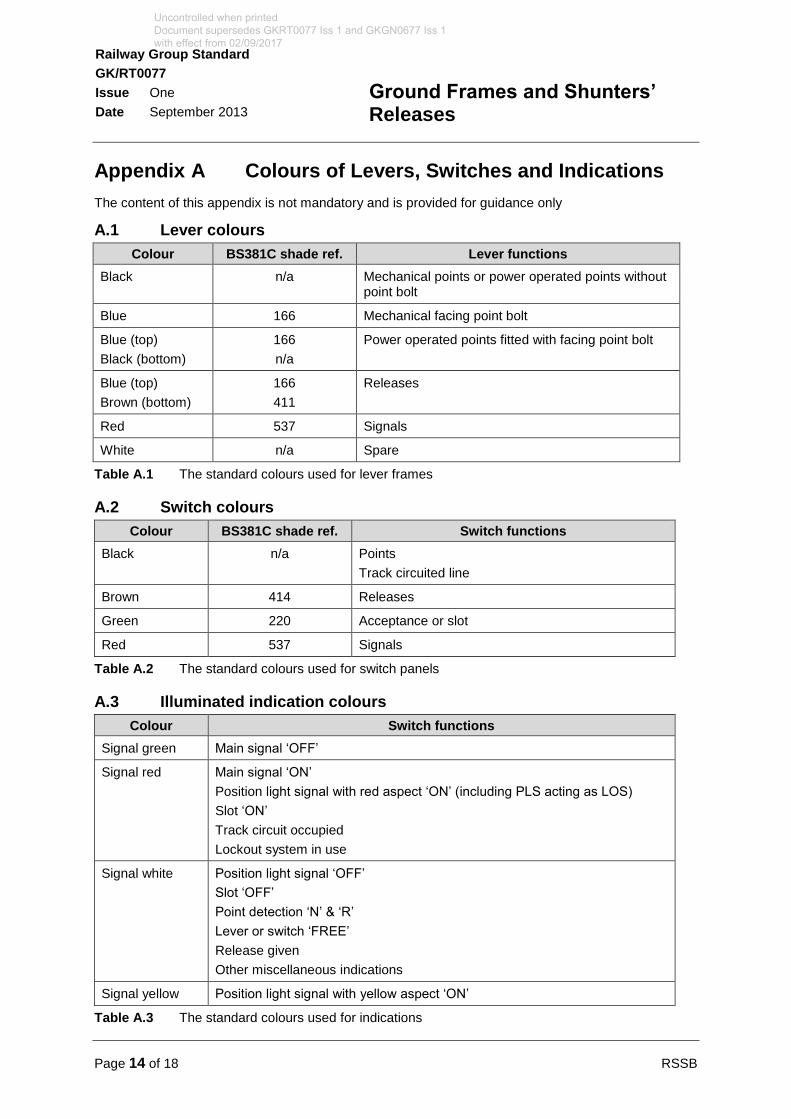
Appendix A Colours of Levers, Switches and Indications
The content of this appendix is not mandatory and is provided for guidance only
A.1 Lever colours
Colour BS381C shade ref. Lever functions
Black n/a Mechanical points or power operated points without point bolt
Blue 166 Mechanical facing point bolt
Blue (top)
Black (bottom)
166
n/a
Power operated points fitted with facing point bolt
Blue (top)
Brown (bottom)
166
411
Releases
Red 537 Signals
White n/a Spare
Table A.1 The standard colours used for lever frames
A.2 Switch colours
Colour BS381C shade ref. Switch functions
Black n/a Points
Track circuited line
Brown 414 Releases
Green 220 Acceptance or slot
Red 537 Signals
Table A.2 The standard colours used for switch panels
A.3 Illuminated indication colours
Colour Switch functions
Signal green Main signal ‘OFF’
Signal red Main signal ‘ON’
Position light signal with red aspect ‘ON’ (including PLS acting as LOS)
Slot ‘ON’
Track circuit occupied
Lockout system in use
Signal white Position light signal ‘OFF’
Slot ‘OFF’
Point detection ‘N’ & ‘R’
Lever or switch ‘FREE’
Release given
Other miscellaneous indications
Signal yellow Position light signal with yellow aspect ‘ON’
Table A.3 The standard colours used for indications
Uncontrolled when printed Document supersedes GKRT0077 Iss 1 and GKGN0677 Iss 1 with effect from 02/09/2017
RSSB Page 15 of 18
Railway Group Standard
GK/RT0077
Issue One
Date September 2013
Ground Frames and Shunters’ Releases
Definitions
Annetts key
A key used on RETB operated lines to enable the user of a ground frame to unlock a lever, to control the movements of points under local supervision.
Auxiliary token instrument
A supplementary token instrument located outside the signal box and used by railway undertaking personnel to facilitate prompt token exchange. An auxiliary token instrument located at a ground frame on single lines allows the token to be returned to the system when a train has been shut-in at the ground frame. This allows further tokens to be issued by the controlling signal boxes and hence trains to use the single line. Conversely, it allows a token to be withdrawn (with the co-operation of the signallers) to allow the ground frame to be operated and the previously shut-in train to depart.
Castell key
A key used on RETB operated lines to lock / unlock the cabinet, fitted to locally supervised ground frames, which houses the Annetts key.
Catch handle
A device attached to a lever which is used to secure the lever in either the normal or reverse positions.
CDU
Cab display unit (CDU). A device for use in the driving cabs of traction units, on board road vehicles and at the track side, which enables the user to receive and return coded electronic tokens. The CDU displays the electronic tokens issued to it.
Controlling signal box
The signal box which oversees the releasing of the ground frame.
Depot or yard
In the context of shunters’ releases, a set of one or more sidings controlled by a railway undertaking.
Detection
The proof (electrical or mechanical) that points or signals have responded correctly to any control command.
Diagram
A representation of the track layout and signals controlled from the ground frame to permit correct orientation of the operator to the equipment being controlled.
Directly opposing locking
Interlocking between two opposing signals.
Facing point lock
Equipment fitted to facing points on passenger lines to secure the points in the correct position for the passage of trains.
Free indication
A lamp or electrical indicator provided to show whether a lever is free to be operated by the ground frame operator.
Uncontrolled when printed Document supersedes GKRT0077 Iss 1 and GKGN0677 Iss 1 with effect from 02/09/2017

Page 16 of 18 RSSB
Railway Group Standard
GK/RT0077
Issue One
Date September 2013
Ground Frames and Shunters’ Releases
Ground frame
A control point comprising levers or switches to permit the local operation of points and, where provided, the associated signals. As applied to this document, the term ‘ground frame’ includes a ground switch panel.
Ground frame operator
A person employed by a railway undertaking, who is authorised to operate a ground frame.
Ground frame release
The method by which the ground frame is unlocked to allow its use either by an electrical release or a mechanical key.
Ground frame release device
A device provided to lock and unlock a ground frame and retain the release device (for example, a token) until the ground frame is restored to normal.
Ground frame release key
A key, either directly released from a release instrument or attached to a token or train staff, which is used to release a ground frame.
Interlocking
A method, either mechanical or electrical, which prevents the operation of signalling equipment when it is unsafe to do so, that is to say, prevents the movement of points while a signal reading over them is clear.
KABA key
The key used to activate a cab display unit used on RETB worked lines (see ‘RETB’ below).
Levers
A method of working a signalling system mechanically by using human effort.
Normal position
The position of a lever when it is back in the lever frame (away from the operator), also the position of a switch when it is turned to the left.
Opposing signals
Signals which protect the same piece of railway from opposite directions.
Receptacle or key release instrument
The place where the ground frame release key is secured when not in use.
Release lever
A lever that is subject to control from the supervising signalling centre and which, when operated, prevents the signalling centre from withdrawing the release. Where a switch is used instead of a lever, the releasing and backlocking function is carried out by relays.
Restore
The replacement of the ground frame to its normal state.
RETB
Radio electronic token block (RETB) is a method of protecting a single line of railway through the use of solid state interlocking and a radio link to the trains which use the line.
Uncontrolled when printed Document supersedes GKRT0077 Iss 1 and GKGN0677 Iss 1 with effect from 02/09/2017

RSSB Page 17 of 18
Railway Group Standard
GK/RT0077
Issue One
Date September 2013
Ground Frames and Shunters’ Releases
Reverse position
The position of a lever when it is pulled towards the operator and also the position of a switch when it is turned to the right.
Shunter’s release
A push button or switch that is controlled by a shunter which, when operated, allows points or a route to be operated by the supervising signalling centre.
Shutting-in facilities
A facility which permits a train to be shunted clear of a main line into a siding and then the ground frame normalised to permit normal train movements.
Signalled movement
A movement authority given by, and under the control of, the supervising signalling centre or by the ground frame on supervised lines or sidings.
Slots / slotting
In the context of ground frames, the control of a signalling function which requires co-operation between the signal box and a ground frame.
Supervised lines
Lines or sidings that are under the control of the ground frame operator.
Uncontrolled when printed Document supersedes GKRT0077 Iss 1 and GKGN0677 Iss 1 with effect from 02/09/2017
Page 18 of 18 RSSB
Railway Group Standard
GK/RT0077
Issue One
Date September 2013
Ground Frames and Shunters’ Releases
References
The Catalogue of Railway Group Standards gives the current issue number and status of documents published by RSSB. This information is also available from www.rgsonline.co.uk.
RGSC 01 Railway Group Standards Code
RGSC 02 Standards Manual
Railway Group Standards
GE/RT8000 The Rule Book
GE/RT8270 Assessment of Compatibility of Rolling Stock and Infrastructure
GK/RT0036 Transitions Between Signalling Systems
GK/RT0045 Lineside Signals, Indicators and Layout of Signals
GK/RT0055 Block Systems Interface Requirements
GO/RT3215 Requirements for the Weekly Operating Notice, Periodical Operating Notice and Sectional Appendix
RSSB documents
GK/GN0677 Guidance on Ground Frames and Shunters’ Releases
Uncontrolled when printed Document supersedes GKRT0077 Iss 1 and GKGN0677 Iss 1 with effect from 02/09/2017
Rail Industry Standard
RIS-0077-CCS
Issue One
Date September 2017
Ground Frames and Shunter’s Releases
Annex B – Content of GKGN0677
RIS-0077-CCS Page 24 of 70
Uncontrolled when printed Document supersedes GKRT0077 Iss 1 and GKGN0677 Iss 1 with effect from 02/09/2017
GN
GK
/GN
06
77
G
uid
an
ce o
n G
rou
nd
Fra
mes a
nd
Sh
un
ters
’ R
ele
ases
Is
su
e O
ne
: S
ep
tem
be
r 2
01
3
Ra
il I
nd
us
try G
uid
an
ce
No
te f
or
GK
/RT
0077
This document contains one or more pages which contain colour.
Published by: RSSB Block 2 Angel Square 1 Torrens Street London EC1V 1NY © Copyright 2013 Rail Safety and Standards Board Limited
Uncontrolled when printed Document supersedes GKRT0077 Iss 1 and GKGN0677 Iss 1 with effect from 02/09/2017
Page 2 of 45 RSSB GK/GN0677 Issue One: September 2013
Guidance on Ground Frames and Shunters’ Releases
Issue record
Issue Date Comments
One 07 September 2013 Original document.
Guidance to support GK/RT0077.
Superseded documents
This Rail Industry Guidance Note does not supersede any other Railway Group documents.
Supply
The authoritative version of this document is available at www.rgsonline.co.uk. Uncontrolled copies of this document can be obtained from Communications, RSSB, Block 2, Angel Square, 1 Torrens Street, London EC1V 1NY, telephone 020 3142 5400 or e-mail [email protected]. Other Standards and associated documents can also be viewed at www.rgsonline.co.uk.
Uncontrolled when printed Document supersedes GKRT0077 Iss 1 and GKGN0677 Iss 1 with effect from 02/09/2017
RSSB Page 3 of 45 GK/GN0677 Issue One: September 2013
Guidance on Ground Frames and Shunters’ Releases
Contents
Section Description Page
Part 1 Introduction 4 1.1 Purpose of this document 4 1.2 Copyright 4 1.3 Approval and authorisation of this document 4
Part 2 Guidance on Requirements for Ground Frames and Shunters’ Releases 6
2.1 Compatibility requirements for ground frames and shunters' releases 6 2.2 Release of ground frames 11 2.3 Control of infrastructure 16 2.4 Shunters' releases 23
Part 3 Application of this Document 24 3.1 Application – infrastructure managers 24 3.2 Application – railway undertakings 25 3.3 Health and safety responsibilities 25
Appendices 26 Appendix A Colours of Levers, Switches and Indications 26 Appendix B Symbols for use on Ground Frame Diagrams 28
Definitions 41
References 44
Tables Table A.1 The standard colours used for lever frames 26 Table A.2 The standard colours used for switch panels 26 Table A.3 The standard colours used for indications 26
Figures Figure 1 Example of the requirements mandated in 2.2.1.3b)i) 13 Figure 2 Example of the requirements mandated in 2.2.1.3b)ii) 13 Figure 3 Example of where the ground frame is permitted to control infrastructure while the release is normal 17 Figure 4 Example of a layout where the opposing locking could be omitted, if required 18 Figure 5 Example of a lever identification plate 19 Figure 6 Example of a ground switch panel control switch and identification 20 Figure 7 Example of the information that should be included on a diagram 22
Uncontrolled when printed Document supersedes GKRT0077 Iss 1 and GKGN0677 Iss 1 with effect from 02/09/2017

Page 4 of 45 RSSB GK/GN0677 Issue One: September 2013
Guidance on Ground Frames and Shunters’ Releases
Part 1 Introduction
1.1 Purpose of this document
This document gives guidance on interpreting the requirements of Railway Group Standard GK/RT0077 issue one Ground Frames and Shunters’ Releases. It does not constitute a recommended method of meeting any set of mandatory requirements.
All requirements in GK/RT0077 are reproduced in the sections that follow. Guidance is provided as a series of sequentially numbered clauses prefixed ‘GN’ immediately below the text to which it relates. Where there is no guidance given, this is stated.
Specific responsibilities and compliance requirements are laid down in the Railway Group Standard itself.
1.2 Copyright
Copyright in the Railway Group documents is owned by Rail Safety and Standards Board Limited. All rights are hereby reserved. No Railway Group document (in whole or in part) may be reproduced, stored in a retrieval system, or transmitted, in any form or means, without the prior written permission of Rail Safety and Standards Board Limited, or as expressly permitted by law.
Rail Safety and Standards Board (RSSB) members are granted copyright licence in accordance with the Constitution Agreement relating to Rail Safety and Standards Board Limited.
In circumstances where Rail Safety and Standards Board Limited has granted a particular person or organisation permission to copy extracts from Railway Group documents, Rail Safety and Standards Board Limited accepts no responsibility for, and excludes all liability in connection with, the use of such extracts, or any claims arising therefrom. This disclaimer applies to all forms of media in which extracts from Railway Group Standards may be reproduced.
1.3 Approval and authorisation of this document
The content of this document was approved by:
Control Command and Signalling (CCS) Standards Committee on 08 April 2010 and reconfirmed on 13 June 2013.
This document was authorised by RSSB on 29 July 2013.
Uncontrolled when printed Document supersedes GKRT0077 Iss 1 and GKGN0677 Iss 1 with effect from 02/09/2017
RSSB Page 5 of 45 GK/GN0677 Issue One: September 2013
Guidance on Ground Frames and Shunters’ Releases
Part 1 Purpose and Introduction
1.1 Purpose
1.1.1 This document mandates requirements for:
a) Ground frames, where control of a part of the railway infrastructure may be transferred between a signaller and a ground frame operator, who may be an employee of a railway undertaking, and
b) Shunters’ releases, where co-operation is required between the signaller and railway undertaking personnel to allow movements into and out of infrastructure controlled by a railway undertaking.
1.2 Introduction
1.2.1 Background
1.2.1.1 This document applies to:
a) Ground frames, and
b) Shunters’ releases.
1.2.1.2 This document does not include requirements for emergency panels, standby control centres or gate boxes, which are the responsibility of the infrastructure manager.
1.2.1.3 GK/RT0036 sets out the requirements for controlling the transition between lineside signalling conforming to Railway Group Standards and other methods of train control where delegated control may also apply.
1.2.2 Related requirements in other documents
1.2.2.1 The following Railway Group Standards contain requirements that are relevant to the scope of this document:
GE/RT8000 The Rule Book
GE/RT8270 Assessment of Compatibility of Rolling Stock and Infrastructure
GK/RT0036 Transitions Between Signalling Systems
GK/RT0045 Lineside Signals, Indicators and layout of Signals
GK/RT0055 Block Systems Interface Requirements
GO/RT3215 Requirements for the Weekly Operating Notice, Periodical Operating Notice and Sectional Appendix
1.2.2.2 Where co-operation is required by this document between the infrastructure manager and the railway undertakings in the design of new facilities such as ground frames, ground switch panels and shunters’ releases, the process for co-operation is set out in GE/RT8270 Assessment of Compatibility of Rolling Stock and Infrastructure.
1.2.3 Supporting documents
1.2.3.1 The following Railway Group documents support this Railway Group Standard:
GK/GN0677 Guidance on Ground Frames and Shunters’ Releases
GN1 There is no guidance associated with Part 1.
Uncontrolled when printed Document supersedes GKRT0077 Iss 1 and GKGN0677 Iss 1 with effect from 02/09/2017
Page 6 of 45 RSSB GK/GN0677 Issue One: September 2013
Guidance on Ground Frames and Shunters’ Releases
Part 2 Guidance on Requirements for Ground Frames and Shunters’ Releases
GN2 The requirements for ground frames are based on the following principles and assumptions:
a) The ground frame release function provides the secure means of transferring responsibility for controlling specific infrastructure between the infrastructure manager and the railway undertaking, so that potentially conflicting operations are prevented
b) Transfer of responsibility for controlling specific infrastructure between the infrastructure manager and the railway undertaking only takes place when both parties co-operate by operating the ground frame release control
c) The functional design of each ground frame and its associated infrastructure is compatible with local operation of specific moveable infrastructure and the requirement for the railway undertaking to control local shunting movements.
GN3 The functional design of each shunter’s release should be compatible with the requirement for the signaller and shunter to co-operatively control movement authorities across the boundary between a part of the railway controlled by Network Rail and a part of the railway controlled by a different infrastructure manager.
2.1 Compatibility requirements for ground frames and shunters’ releases
2.1.1 Before any new or changed infrastructure or rolling stock (including lineside and/or on-board control, command and signalling equipment) is brought into use, it is necessary to check that it is compatible with the infrastructure and rolling stock assets and operations on the routes on which it is to be used.
2.1.2 GE/RT8270 sets out the requirements and responsibilities for the assessment of compatibility between rolling stock and infrastructure assets, including control, command and signalling equipment and their operations. It sets out the arrangements by which the assessment of compatibility is undertaken and identifies those responsible for managing that assessment.
2.1.3 This document GK/RT0077 mandates the specific requirements for the assessment of compatibility for ground frames and shunters’ releases.
GN4 The generic process to be used for assessing operational compatibility between railway infrastructure and rolling stock is set out in GE/RT8270.
GN5 The assessment of compatibility should include participation from all parties affected by the proposed signalling arrangements.
2.1.4 The assessment shall check that the provision of the ground frame or shunter’s release is compatible with:
a) The required documented operations, and
b) The access requirements.
GN6 The assessment should check that the provision of a ground frame or shunter’s release is an appropriate solution for dealing with the traffic envisaged at that location.
Uncontrolled when printed Document supersedes GKRT0077 Iss 1 and GKGN0677 Iss 1 with effect from 02/09/2017
RSSB Page 7 of 45 GK/GN0677 Issue One: September 2013
Guidance on Ground Frames and Shunters’ Releases
GN7 When a ground frame is proposed, the assessment should check:
a) That control and indication facilities are compatible with the operations the infrastructure is to be used for, and
b) The arrangement for operator access to the ground frame, both from trains using the ground frame and also from an access point, where appropriate. Safe walking routes and security should be taken into account.
GN8 A ground frame may not be appropriate where either:
a) The expected traffic levels are high, unless the resultant work load on a signaller would be too high if the infrastructure were directly controlled, and / or
b) Train detection, when used, is unreliable owing to the very light use of the local infrastructure, and the consequence of train detection failure prevents operation of the ground frame.
GN9 The assessment should check that provision of a shunter’s release as a method of control for access into or out of a depot or sidings is compatible with the operation of trains into and out of that facility The following options are available:
a) A separate release for each movement authority, and / or
b) A release that permits multiple movement authorities. This will be the required option should train movements take place when staff are not on duty.
GN10 An assessment of risk should be undertaken to ensure that, if a multiple movement option is to be used, there are sufficient measures in place to ensure, as far as practicable, this can be done safely.
2.1.5 The assessment shall check that the method of ground frame release is compatible with the block system.
GN11 There are two distinct methods of releasing a ground frame:
a) Direct electrical release from the signal box (see 2.2.1), which is typically used on lines where the movement authority does not involve the handover of a token or one-train staff
b) Indirect release using a token or key (see 2.2.2 and 2.2.3).
GN12 The method chosen should be compatible and consistent with the block system in use, so that operational requirements are kept as simple as possible. For example:
a) A ground frame on a track circuit block line should use a direct electrical release, because the movement authority does not require the issue of a token or key, and
b) A ground frame on a single line operated using the electric token block system may be released indirectly, which is consistent with the issue of a single line token.
GN13 Where the block system does not include a token or staff, either direct or indirect release may be provided, taking account of consistency of operation.
2.1.6 The assessment shall check that the ground frame or shunter’s release functionality is compatible with:
a) The required train movements, and
b) The operational risk.
Uncontrolled when printed Document supersedes GKRT0077 Iss 1 and GKGN0677 Iss 1 with effect from 02/09/2017
Page 8 of 45 RSSB GK/GN0677 Issue One: September 2013
Guidance on Ground Frames and Shunters’ Releases
GN14 Incompatibility could be a causal factor leading to an operational incident. The operational risk being considered is whether provision of a ground frame or shunter’s release will permit the train service (both the booked passing train service and those trains booked to use the ground frame or sidings controlled by the shunter’s release) to run safely and without restriction.
GN15 The following options for the shunter’s release should be considered:
a) Release operated either for every train or for multiple trains, and
b) Release acting upon either signalled routes or points.
GN16 The assessment should check that:
a) The requirement to operate the shunter’s release is compatible with the availability of authorised staff, and
b) The release functionality is compatible with the requirement to operate trains over the infrastructure boundary.
GN17 The assessment should take account of signaller and shunter workload.
2.1.7 On lines worked by electric token block, no signaller token block, no signaller token block – remote or one-train system with staff (see also GK/RT0055), the assessment shall check that the method of issuing and returning the token at ground frames which have shutting-in facilities is compatible with ground frame operations, including either:
a) Provision of intermediate token instruments at the ground frame, or
b) Local operating instructions.
GN18 Because the movement authority includes a token or one-train staff, a method is required to exchange the token or one-train staff at the ground frame.
GN19 The assessment should check that arrangements for exchanging the token or staff at the ground frame is compatible with the requirement:
a) To check that the single line is clear when a train is shut in, and
b) To obtain a movement authority when a train is to leave the ground frame.
GN20 There are two possible options for normalising the block controls:
a) By the provision of an intermediate token instrument at the ground frame, or
b) If practical, requiring the electric token or staff to be returned to the nearest signal box or token station, in accordance with local instructions. If train detection is not provided, the operator of the ground frame should ensure that the single line is clear before returning the token or staff to a signal box or an intermediate instrument.
GN21 Shutting-in facilities are not permitted for ground frames on lines worked by the ‘one-train without staff’ system, because only one train is permitted on the single line at a time and the block system requires the train to complete its movement through the section before the section can be proved clear.
2.1.8 The assessment shall check that the signalling system is configured to prevent insertion of a ground frame key into the wrong release instrument or mechanical lock.
Uncontrolled when printed Document supersedes GKRT0077 Iss 1 and GKGN0677 Iss 1 with effect from 02/09/2017

RSSB Page 9 of 45 GK/GN0677 Issue One: September 2013
Guidance on Ground Frames and Shunters’ Releases
GN22 Except on lines worked by radio electronic token block (RETB), where a ground frame is indirectly released, the key, token or one-train staff should to be uniquely configured for the ground frame it is intended to release. This is to prevent operation of a ground frame for which a key or token has not been released.
GN23 On RETB lines, a single key should be common to the whole area worked using the RETB system, in order to reduce the number of keys attached to the CDU key.
2.1.9 The assessment shall check that the provision of signals worked from the ground frame is compatible with the train movements required on the running lines and into sidings.
GN24 Where a ground frame is provided, shunting movement authorities are issued by the ground frame operator.
GN25 If hand-signalling is compatible with the movements required, it is permissible not to provide signals.
GN26 The decision to provide signals operated from ground frames should take account of the required train movements and any hand-signalling arrangements at the same location. Inconsistency of operations using signals and hand-signals may be the causal factor in an operational incident.
GN27 Where access to a running line is provided through a ground frame worked connection, a signal shall be provided which shall be slotted from the controlling signal box unless the release conditions on the ground frame are such that a signal will provide no additional movement authority information beyond the release condition.
2.1.10 Where non-block signals on running lines are used to protect the ground frame, the assessment shall check that the ground frame operating instructions include a requirement to clear the signals before the release is normalised.
GN28 Non-block signals (where provided) are not interlocked with the block system or train detection system. They should only display the ON aspect after the ground frame has been released by the ground frame operator and, provided that the interlocking of the ground frame is correct, they should display the OFF aspect before the ground frame release control is normalised when the ground frame points are normal.
GN29 Where provided, a non-block signal should only be controlled to display the ON aspect after the ground frame has been released by the ground frame operator.
GN30 Failure to display a non-block signal OFF aspect after the ground frame has been normalised would mean that a subsequent train passing through the block section would be required to stop at the ground frame unnecessarily.
2.1.11 The assessment shall check that the communication facilities between the signal box and the ground frame are compatible with the requirement for:
a) Operating the ground frame release, and
b) Safely controlling train movements.
GN31 Voice communication facilities are provided so that the ground frame operator can contact the signaller to operate the ground frame release.
Uncontrolled when printed Document supersedes GKRT0077 Iss 1 and GKGN0677 Iss 1 with effect from 02/09/2017
Page 10 of 45 RSSB GK/GN0677 Issue One: September 2013
Guidance on Ground Frames and Shunters’ Releases
GN32 Whilst this should include a telephone at the ground frame, consideration should be given to additional facilities so that:
a) The signaller can contact the ground frame operator when not at the ground frame, and
b) The ground frame operator or shunter can contact the signaller more easily in an emergency.
2.1.12 The assessment shall check that the train detection systems provided at ground frames are compatible with:
a) The maximum train lengths that will use the ground frame, and
b) The train movements required, including shunting where vehicles may be left on the running line.
GN33 In some cases, a train detection system is provided at the ground frame. The train detection system may be used:
a) To prove that a train is at the ground frame before the release can be given, and
b) To prove that the line is clear after the train has been shut-in at the ground frame.
GN34 If the train is too long for the train detection sections, this may prevent the release being given to the ground frame and hence cause delay and add to the risk of errors being made in the operation of the ground frame.
GN35 Where train detection is provided on the infrastructure inside the ground frame, this too should be compatible with those train operations within the ground frame’s area of control.
2.1.13 The assessment shall check that the ground frame control system is compatible with the requirement for ground frame operators to control the infrastructure.
GN36 This checks that sufficient and appropriate operating control facilities are provided for the ground frame operator, taking into account the infrastructure and operating requirements at that location.
GN37 Ground frames may be provided using either lever frames or ground switch panels.
GN38 In deciding what type of control facilities should be provided, the following should be considered:
a) The method of obtaining the release, and
b) The number of signals and points that are to be controlled.
2.1.14 The assessment shall check that the ground frame indications are compatible with the requirements for the operator to:
a) Observe the operation of the infrastructure being controlled
b) Determine the position and completeness of the train where this cannot be directly observed
c) Correctly operate the ground frame controls.
Uncontrolled when printed Document supersedes GKRT0077 Iss 1 and GKGN0677 Iss 1 with effect from 02/09/2017

RSSB Page 11 of 45 GK/GN0677 Issue One: September 2013
Guidance on Ground Frames and Shunters’ Releases
GN39 Indications enable the ground frame operator to control and observe train movements and confirm correct operation of the infrastructure. Where this can be done by direct observation, indications may not be required.
2.2 Release of ground frames
2.2.1 Electrical release of ground frames from the signal box
2.2.1.1 The ground frame shall only be released when all of the following conditions are satisfied:
a) The ground frame release control is operated at the signal box
b) All protecting stop signals are displaying the ‘ON’ aspect
c) All conflicting signal routes are locked normal
d) The signal or block section containing the ground frame is known to be either:
i) Clear, including the overlap, or
ii) Occupied by a stationary train at the ground frame.
GN40 This prevents the ground frame from being operated until:
a) The signaller has operated the ground frame release control
b) The signalling system is in a state that is compatible with the local operation of the infrastructure using the ground frame
c) The train is in the required position for ground frame operation.
GN41 If the ground frame is either on a track circuit block line, tokenless block line or within station limits, the release should include the appropriate train detection controls.
GN42 If the ground frame is on a line worked by absolute block:
a) Protecting signals should be ‘ON’
b) The ground frame should be released by the signal box controlling the entrance to the block section
c) Where the ground frame forms a mid-section crossover there are two ways that this can be dealt with, either:
i) The signal boxes controlling the entrance to the section should each have a release for the ground frame. The interlocking at the ground frame would require both releases before the points can be operated, or
ii) Each signal box controlling the block section should have a release; one release would provide a release on the other signal boxes ground frame release lever, the second signal box will then provide the release to the ground frame
d) The block controls should include the following release conditions, either:
i) The block section proved clear, including any overlap and the block indicator at ‘LINE CLEAR’, or
ii) The train detected as stationary at the ground frame and the block indicator at ‘TRAIN ON LINE’.
Uncontrolled when printed Document supersedes GKRT0077 Iss 1 and GKGN0677 Iss 1 with effect from 02/09/2017
Page 12 of 45 RSSB GK/GN0677 Issue One: September 2013
Guidance on Ground Frames and Shunters’ Releases
GN43 If the ground frame is on a line worked by tokenless block:
a) Protecting signals should be ‘ON’, and
b) The block controls should include the following release conditions, either:
i) The block section proved clear, including any overlap and the block indicator at ‘TRAIN ACCEPTED’, or
ii) The train detected as stationary at the ground frame and the block indicator at ‘TRAIN IN SECTION’.
2.2.1.2 The ground frame shall only be normalised when all of the following conditions are satisfied:
a) The infrastructure controlled from the ground frame is detected to be in the required position, and
b) The ground frame release controls have been normalised at the signal box and the ground frame.
GN44 This prevents the ground frame from being normalised until:
a) The ground frame operator has operated the ground frame release control, and
b) The ground frame and its associated infrastructure is in a state that is compatible with the normal operation of the railway from the signal box.
2.2.1.3 Where there is a shutting-in facility, a train detection system shall be provided at the ground frame, which shall extend from between the following limits:
a) The maximum train length plus 100 m on the approach side of the ground frame points or associated clearance point
b) To either:
i) The clearance point of the ground frame facing points, or
ii) 200 m beyond the switch toes of the ground frame trailing points.
2.2.1.4 The train detection systems shall be indicated in the controlling signal box.
Uncontrolled when printed Document supersedes GKRT0077 Iss 1 and GKGN0677 Iss 1 with effect from 02/09/2017

RSSB Page 13 of 45 GK/GN0677 Issue One: September 2013
Guidance on Ground Frames and Shunters’ Releases
GN45 Where train detection is provided but is not continuous through the section, then the minimum distances required are shown in Figures 1 and 2:
Sidings
2
B
Release Lever No
2b22a
21
CP
Maximum train length + 100m
Figure 1 Example of the requirements mandated in 2.2.1.3b)i)
Sidings
2
B
Release Lever No
200 metres
2b22a
21
Maximum train length + 100 metres
Figure 2 Example of the requirements mandated in 2.2.1.3b)ii)
GN46 Track circuit block lines should be designed to provide the train detection functionality shown in Figures 1 or 2.
GN47 Where a ground frame on a non-track circuit block line does not have a shutting-in facility, a train detection system is not required because the signal section will remain occupied until the train has completed its work at the ground frame and has departed the block section.
GN48 Where a ground frame on a non-track circuit block line has a shutting-in facility, a train detection system is provided to:
a) Prevent the release of the ground frame before the train is correctly positioned at the ground frame, and
b) Indicate the presence of vehicles on the running line to the signaller.
GN49 The required train detection dimension on the approach side of the ground frame ensures that the whole of the train is detected when it arrives at the ground frame. This is to prevent a situation where vehicles are left undetected on the running line during shunting operations.
GN50 Where the ground frame points are trailing points, the train detection system is extended 200 m beyond the points, in order to detect when the train is present on the running line during ground frame operations. Where the ground frame points are facing points, the train detection system provided on the approach to the ground frame does this.
2.2.2 Indirect release of ground frames from the signal box
2.2.2.1 The ground frame release shall be operated using one of the following:
a) The token or one-train staff applicable to the single line section containing the ground frame
b) A ground frame release key permanently attached to the applicable token or one-train staff
Uncontrolled when printed Document supersedes GKRT0077 Iss 1 and GKGN0677 Iss 1 with effect from 02/09/2017

Page 14 of 45 RSSB GK/GN0677 Issue One: September 2013
Guidance on Ground Frames and Shunters’ Releases
c) A ground frame key, normally kept in a suitable receptacle in the signal box, which is issued to the ground frame operator by the signaller at the controlling signal box.
GN51 An indirect release prevents operation of the ground frame until the train at the ground frame is in possession of the movement authority associated with the ground frame.
GN52 Where either a token or one-train staff forms part of the movement authority, then that device may incorporate a key which is used to mechanically release a ground frame within that single line section. Alternatively, a separate key may be permanently attached to the token or one-train staff. In both cases, the issue of the token or one-train staff should include the authority to operate the ground frame, subject to operational requirements.
GN53 On a line that is worked by the one-train system without staff and where it is not appropriate to provide a direct electrical release, the ground frame should be released using a key which is retained at the local signal box, and only issued to train crew when a train requires to use the ground frame, subject to local instructions.
2.2.2.2 Where a ground frame key is provided on a line that is worked by the one-train system without staff, the key shall be:
a) Permanently marked with the name of the ground frame to which it applies, and
b) Uniquely configured for the ground frames within the block section and the control area of the signal box associated with the ground frame.
2.2.2.3 The instruments and mechanical locks associated with the ground frame key shall prevent insertion of a key or other token belonging to an adjacent section.
GN54 Because the signaller issues the key for a particular ground frame, the unique configuration of the ground frame locks, and keys prevent inadvertent operation of the wrong ground frame, which may arise due to operator error when either:
a) There is more than one ground frame in the section, or
b) A key has been inadvertently carried over from an adjacent section.
2.2.2.4 The token, one-train staff or ground frame key shall be held captive in the ground frame release device at all times when the ground frame is in use.
2.2.2.5 Removal of the token, one-train staff or ground frame key from the ground frame release device shall require:
a) The ground frame release control normal, and
b) Where detection is provided, the points detected normal.
2.2.2.6 Where there is a shutting-in facility on lines worked by the electric token block, no signaller token block or no signaller token block – remote system, one of the following methods of issuing and returning the token shall be provided, either:
a) Using an auxiliary token instrument at the ground frame, or
b) In accordance with local operating instructions.
Uncontrolled when printed Document supersedes GKRT0077 Iss 1 and GKGN0677 Iss 1 with effect from 02/09/2017
RSSB Page 15 of 45 GK/GN0677 Issue One: September 2013
Guidance on Ground Frames and Shunters’ Releases
GN55 By preventing the removal of the token, one-train staff or ground frame key from the release device, the ground frame controls ensure that the ground frame operator normalises the ground frame using the correct sequence of operations. This includes setting and locking the infrastructure in the required position before normalising the ground frame release.
2.2.3 Release of ground frames on RETB lines
2.2.3.1 Any ground frame operated siding where shutting-in facilities are provided shall be designated as a token exchange point.
GN56 Trains arriving at the ground frame should be in possession of an electronic token. In order to shut-inside at a ground frame, the electronic token should be returned to the signaller so that another token can be issued for a following train.
GN57 Trains departing the ground frame require an electronic token to be issued.
GN58 Electronic tokens can only be exchanged at a token exchange point.
2.2.3.2 The electronic token shall only be returned when either:
a) The train is clear of the running line into the sidings and the ground frame has been normalised, or
b) The train has continued its journey under normal token exchange procedures.
GN59 Where the train is not using the ground frame, normal token exchange procedures should apply.
2.2.3.3 A ground frame shall be released by an ‘Annetts’ key. The Annetts key shall be kept in a steel cabinet, on the ground frame, which is fitted with a ‘Castell’ lock. The ground frame Annetts key shall be physically attached to the ground frame cabinet by a chain. The Castell key that opens the cabinet containing the Annetts key shall be physically attached to the CDU (KABA) key, so that it is not possible to release the Annetts key and operate the ground frame without withdrawing the KABA key from the CDU. This prevents the electronic token from being returned when the ground frame is in use.
GN60 Because the Castell key that opens the Annetts key cabinet on the ground frame is permanently attached to the KABA key, it is necessary to remove the KABA key from the CDU to obtain the Annetts key and operate the ground frame. This provides the only interlocking between the ground frame release and the block system.
GN61 When the train is in possession of the electronic token, the driver can remove, from the CDU, the KABA key to which the Castell key for the Annetts key cabinet is attached. With the Castell key held captive in the ground frame Annetts key cabinet lock the attached KABA key cannot be inserted into the CDU which prevents the electronic token from being handed back.
Uncontrolled when printed Document supersedes GKRT0077 Iss 1 and GKGN0677 Iss 1 with effect from 02/09/2017

Page 16 of 45 RSSB GK/GN0677 Issue One: September 2013
Guidance on Ground Frames and Shunters’ Releases
2.3 Control of infrastructure
2.3.1 Control of signals protecting ground frames
2.3.1.1 Stop signals protecting ground frames shall only display an ‘OFF’ aspect when all of the following apply:
a) The ground frame release is locked normal
b) The ground frame points are detected normal
c) On lines worked by the one-train system without staff, the ground frame key is detected to be secured within its receptacle, key release instrument or mechanical release.
GN62 Interlocking is provided at ground frames to mitigate the potential risk arising from ground frame operator error, which could result in a collision or derailment.
GN63 The interlocking provided at the ground frame should achieve the same level of protection as would be provided if the infrastructure were directly controlled from a signal box.
GN64 At mechanical ground frames, the trap points protecting the main line should be detected normal and be proved in the ground frame normal indication circuit to the signal box. At power worked ground frames, all of the point ends should be continuously detected normal and be proved in the ground frame normal indication circuit to the signal box.
GN65 On a line worked by the one-train system without staff, the key release instrument should be provided at the signal box and be connected to a ‘Train in Section’ indication. The indication should be configured so that it does not show that the train has cleared the single line unless the key has been returned to the release instrument.
2.3.2 Control of infrastructure operated from the ground frame
2.3.2.1 The ground frame interlocking shall prevent the operation of points or signals
from the ground frame when the relevant release control is normal.
GN66 When the ground frame release is locked normal, it should not be possible for the ground frame operator to control infrastructure affecting operations on the running line (see Figure 3). This is because the authority for controlling the passage of trains past the ground frame is held by the signaller.
Uncontrolled when printed Document supersedes GKRT0077 Iss 1 and GKGN0677 Iss 1 with effect from 02/09/2017
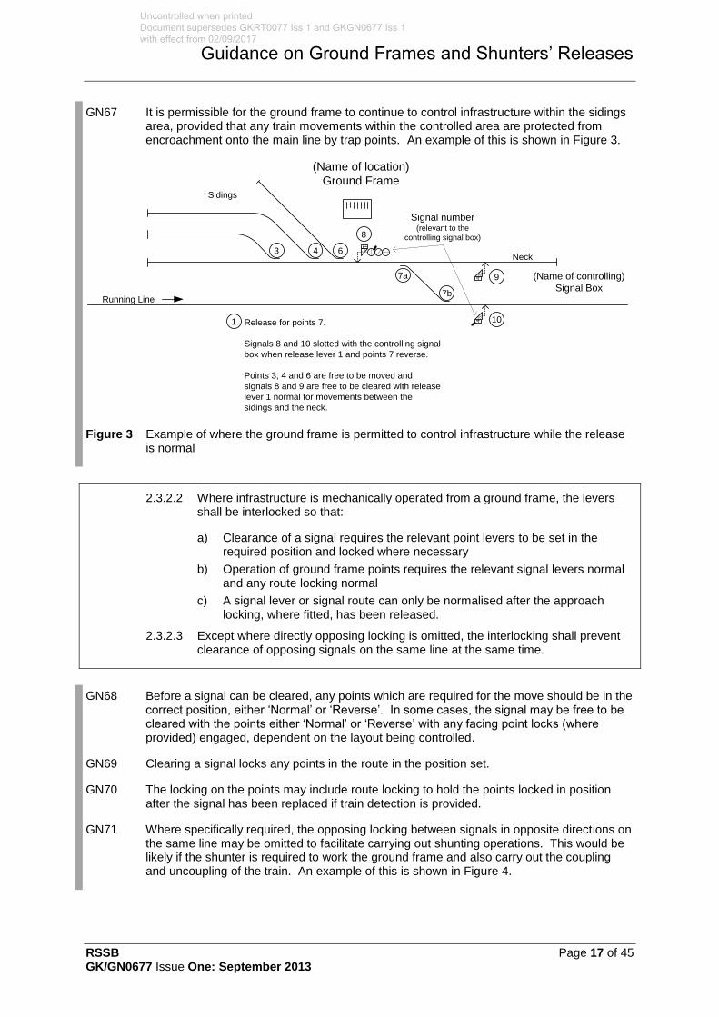
RSSB Page 17 of 45 GK/GN0677 Issue One: September 2013
Guidance on Ground Frames and Shunters’ Releases
GN67 It is permissible for the ground frame to continue to control infrastructure within the sidings area, provided that any train movements within the controlled area are protected from encroachment onto the main line by trap points. An example of this is shown in Figure 3.
Release for points 7.
Signals 8 and 10 slotted with the controlling signal
box when release lever 1 and points 7 reverse.
Points 3, 4 and 6 are free to be moved and
signals 8 and 9 are free to be cleared with release
lever 1 normal for movements between the
sidings and the neck.
Running Line
(Name of location)
Ground Frame
Neck
Sidings
(Name of controlling)
Signal Box
Signal number (relevant to the
controlling signal box)
1
44
3 4 6
8
7a
7b
9
101
Figure 3 Example of where the ground frame is permitted to control infrastructure while the release is normal
2.3.2.2 Where infrastructure is mechanically operated from a ground frame, the levers shall be interlocked so that:
a) Clearance of a signal requires the relevant point levers to be set in the required position and locked where necessary
b) Operation of ground frame points requires the relevant signal levers normal and any route locking normal
c) A signal lever or signal route can only be normalised after the approach locking, where fitted, has been released.
2.3.2.3 Except where directly opposing locking is omitted, the interlocking shall prevent clearance of opposing signals on the same line at the same time.
GN68 Before a signal can be cleared, any points which are required for the move should be in the correct position, either ‘Normal’ or ‘Reverse’. In some cases, the signal may be free to be cleared with the points either ‘Normal’ or ‘Reverse’ with any facing point locks (where provided) engaged, dependent on the layout being controlled.
GN69 Clearing a signal locks any points in the route in the position set.
GN70 The locking on the points may include route locking to hold the points locked in position after the signal has been replaced if train detection is provided.
GN71 Where specifically required, the opposing locking between signals in opposite directions on the same line may be omitted to facilitate carrying out shunting operations. This would be likely if the shunter is required to work the ground frame and also carry out the coupling and uncoupling of the train. An example of this is shown in Figure 4.
Uncontrolled when printed Document supersedes GKRT0077 Iss 1 and GKGN0677 Iss 1 with effect from 02/09/2017
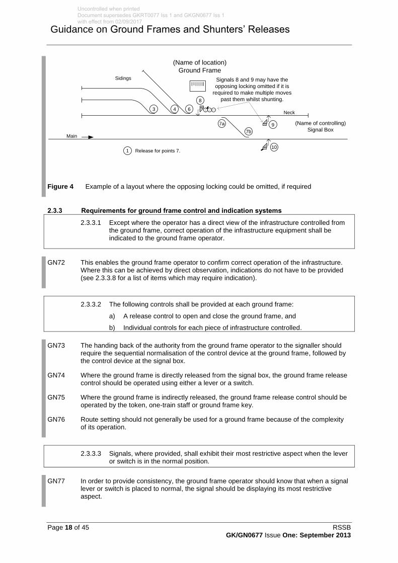
Page 18 of 45 RSSB GK/GN0677 Issue One: September 2013
Guidance on Ground Frames and Shunters’ Releases
Release for points 7.
Main
(Name of location)
Ground Frame
Neck
Sidings
(Name of controlling)
Signal Box
Signals 8 and 9 may have the
opposing locking omitted if it is
required to make multiple moves
past them whilst shunting.
1
22
43 6
8
9
101
7b
7a
Figure 4 Example of a layout where the opposing locking could be omitted, if required
2.3.3 Requirements for ground frame control and indication systems
2.3.3.1 Except where the operator has a direct view of the infrastructure controlled from the ground frame, correct operation of the infrastructure equipment shall be indicated to the ground frame operator.
GN72 This enables the ground frame operator to confirm correct operation of the infrastructure. Where this can be achieved by direct observation, indications do not have to be provided (see 2.3.3.8 for a list of items which may require indication).
2.3.3.2 The following controls shall be provided at each ground frame:
a) A release control to open and close the ground frame, and
b) Individual controls for each piece of infrastructure controlled.
GN73 The handing back of the authority from the ground frame operator to the signaller should require the sequential normalisation of the control device at the ground frame, followed by the control device at the signal box.
GN74 Where the ground frame is directly released from the signal box, the ground frame release control should be operated using either a lever or a switch.
GN75 Where the ground frame is indirectly released, the ground frame release control should be operated by the token, one-train staff or ground frame key.
GN76 Route setting should not generally be used for a ground frame because of the complexity of its operation.
2.3.3.3 Signals, where provided, shall exhibit their most restrictive aspect when the lever or switch is in the normal position.
GN77 In order to provide consistency, the ground frame operator should know that when a signal lever or switch is placed to normal, the signal should be displaying its most restrictive aspect.
Uncontrolled when printed Document supersedes GKRT0077 Iss 1 and GKGN0677 Iss 1 with effect from 02/09/2017

RSSB Page 19 of 45 GK/GN0677 Issue One: September 2013
Guidance on Ground Frames and Shunters’ Releases
2.3.3.4 Where a mechanical ground frame is provided:
a) The levers shall be arranged in a straight line and numbered consecutively from left to right when observed from the operating position
b) A catch handle shall retain each lever in the required position
c) The normal position of the levers shall be back in the frame
d) The reverse position of the levers shall be pulled towards the operator
e) Each lever shall be identified with its function, using:
i) An identification plate, and
ii) A function related lever colour (see Appendix A).
2.3.3.5 A lever identification plate shall be fitted to the front of each lever. The plate shall show:
a) The lever number
b) A description of the lever function
c) The identity of any levers required to be pulled in sequence before the lever to which the plate is affixed can be pulled.
GN78 These parameters describe the operator interface at mechanical ground frames and provide for:
a) Consistent equipment presentation and operation at each ground frame
b) Compatibility with the operational rules
c) Human factors.
GN79 An example of a lever identification plate is shown in Figure 5.
9Signal
Shunt From
Neck
1
or
1, 3
or
1, 4
or
1, 6
Figure 5 Example of a lever identification plate
Uncontrolled when printed Document supersedes GKRT0077 Iss 1 and GKGN0677 Iss 1 with effect from 02/09/2017
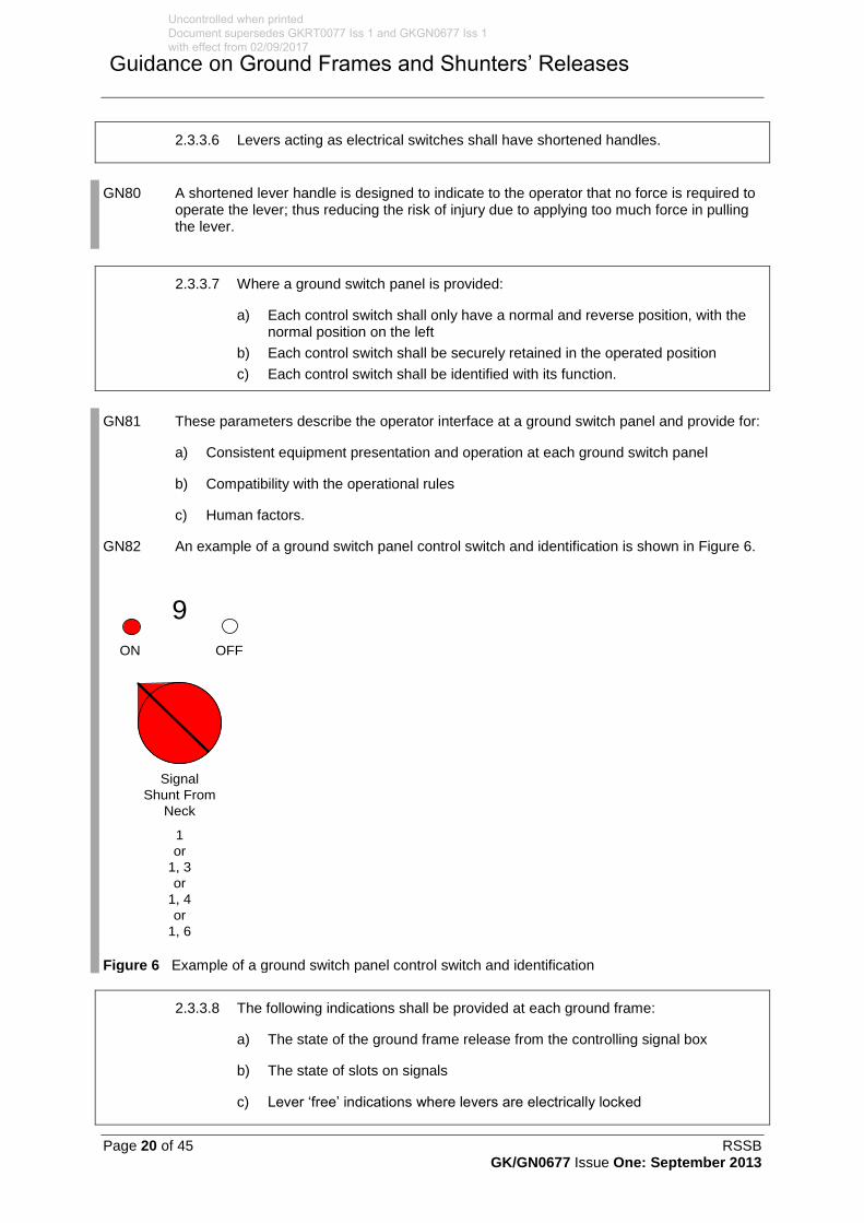
Page 20 of 45 RSSB GK/GN0677 Issue One: September 2013
Guidance on Ground Frames and Shunters’ Releases
2.3.3.6 Levers acting as electrical switches shall have shortened handles.
GN80 A shortened lever handle is designed to indicate to the operator that no force is required to operate the lever; thus reducing the risk of injury due to applying too much force in pulling the lever.
2.3.3.7 Where a ground switch panel is provided:
a) Each control switch shall only have a normal and reverse position, with the normal position on the left
b) Each control switch shall be securely retained in the operated position
c) Each control switch shall be identified with its function.
GN81 These parameters describe the operator interface at a ground switch panel and provide for:
a) Consistent equipment presentation and operation at each ground switch panel
b) Compatibility with the operational rules
c) Human factors.
GN82 An example of a ground switch panel control switch and identification is shown in Figure 6.
9
Signal
Shunt From
Neck
1
or
1, 3
or
1, 4
or
1, 6
ON OFF
Figure 6 Example of a ground switch panel control switch and identification
2.3.3.8 The following indications shall be provided at each ground frame:
a) The state of the ground frame release from the controlling signal box
b) The state of slots on signals
c) Lever ‘free’ indications where levers are electrically locked
Uncontrolled when printed Document supersedes GKRT0077 Iss 1 and GKGN0677 Iss 1 with effect from 02/09/2017
RSSB Page 21 of 45 GK/GN0677 Issue One: September 2013
Guidance on Ground Frames and Shunters’ Releases
d) Except where semaphore signals are directly visible from the ground frame, the signal lamp lit and the aspect displayed
e) The position of power operated points
f) The state of electrical detection on mechanical points, which shall include an indication of whether the facing point lock, where fitted, is engaged
g) Train detection indications, where either:
i) The ground frame interlocking includes train detection controls, or
ii) The operator is required to determine the precise position of the train.
GN83 Ground frame indications may be extinguished when the ground frame is normalised, with the exception of the ground frame release indication, which should always be indicated to the ground frame operator, who should not attempt to operate the ground frame until the release is available. This should be in the form of a visual indication adjacent to the release control device.
GN84 The ground frame release should always be indicated to the ground frame operator, because the ground frame operator should not attempt to operate the ground frame until the release is available. This should be in the form of a visual indication adjacent to the release control device.
GN85 Where a signal slot is provided, the signal only displays the ‘OFF’ aspect when both the signaller and the ground frame operator have operated the relevant controls. The slot indication is used by the ground frame operator to confirm that the signaller has operated the controls. For slots, the indications provided should be ‘SLOT ON’ and ‘SLOT OFF’.
GN86 Lever ‘FREE’ indications are provided to indicate to the ground frame operator when an electrical lock on a lever will allow the lever to be operated. The mechanical locking is indicated by the position of other levers and the information displayed on the lever identification plate.
GN87 For semaphore signals, the following indications may be provided:
a) The signal arm ‘ON’, ‘WRONG’ and ‘OFF’, and
b) A lamp in or out indication.
GN88 For colour light signals, the indications provided should be ‘ON’, ‘OFF’ and ‘LAMP OUT’.
GN89 The ground frame operator uses point detection indications to confirm that the points have operated to the correct position and are locked, where appropriate. For detected points, the indications provided should be ‘N’ and ‘R’. Where point detection indications are not provided, the ground frame operator is required to confirm the point positions by direct observation.
GN90 The ground frame operator uses train detection indications to confirm the position of the train during ground frame operations. Where a diagram is provided, the train detection indications should in the form of red lights illuminated when the track section is occupied. Otherwise, the indication should show ‘OCCUPIED’ and ‘CLEAR’. Where train detection indications are not provided, the ground frame operator is required to confirm the position of the train by direct observation.
Uncontrolled when printed Document supersedes GKRT0077 Iss 1 and GKGN0677 Iss 1 with effect from 02/09/2017

Page 22 of 45 RSSB GK/GN0677 Issue One: September 2013
Guidance on Ground Frames and Shunters’ Releases
2.3.3.9 Where a ground frame diagram is provided, all of the following shall be included:
a) A diagrammatic representation of the area controlled, which is orientated in the correct relationship to the infrastructure controlled from the operating position when the ground frame is being operated
b) The line names and normal direction of running movements, as set out in the Sectional Appendix
c) The name of the signalling control centre that releases the ground frame
d) The identity of each controlled function within the infrastructure.
GN91 A diagram may be omitted where the ground frame only controls a single set of points or one slot. However, before deciding not to provide a diagram, a check should first be made that the ground frame operator is able to operate the ground frame, and control train movements using direct observation alone.
GN92 Where a diagram is provided, it is used by the ground frame operator to identify which control function should be operated for each train movement. For this reason, the diagram should identify:
a) All of the infrastructure that may be operated from the ground frame for each train movement, including its function and identity
b) The running lines and sidings that may be associated with each train movement operated from the ground frame, including line identities and the normal direction of traffic
c) The information needed to support voice communication with the signaller, for example when a ground frame release is required.
GN93 Examples of the symbology to be used in a diagram are shown in Appendix B.
GN94 An example of what is intended by 2.3.3.9 is shown in Figure 7.
Release for 3, 4, 6, 8 & 9 with points X Normal
Release for 3, 4, 6, 8 & 10 with points X Reverse
Signals 8 and 10 slotted with the controlling signal
box when release lever 2 and points X reverse.
Lever Spare
Points worked from controlling signal box.
Track Circuits BB and BC only indicated when
points X reverse.
X
X
UP Main
UP Goods
(Name of location)
Ground Frame
Neck
Sidings
(Name of controlling)
Signal Box
Signal number (relevant to the
controlling signal box)
Signal number (relevant to the
controlling signal box)
1
22
43 6
8
9
101
2
7
X
AA AB AC AD
BB BC
Figure 7 Example of the information that should be included on a diagram
Uncontrolled when printed Document supersedes GKRT0077 Iss 1 and GKGN0677 Iss 1 with effect from 02/09/2017
RSSB Page 23 of 45 GK/GN0677 Issue One: September 2013
Guidance on Ground Frames and Shunters’ Releases
2.4 Shunters’ releases
2.4.1 Requirements for shunters’ releases
2.4.1.1 Where provided, a shunter’s release facility shall require the signaller and shunter to cooperatively control movement authorities into a depot or yard by releasing either:
a) The points giving access to the depot or yard, or
b) The signals or routes leading into the depot or yard.
GN95 When it is proposed to introduce a new yard or sidings which are to be operated by a railway undertaking, a method of working is required between the infrastructure manager and the railway undertaking. If it is decided that the method of operation requires controls be imposed to prevent trains entering and / or leaving the new yard or sidings without the authority of the person in charge, then a shunter’s release should be utilised.
GN96 The signaller has prime responsibility for controlling the movement authority and operates the signal control device. The shunter’s release provides a means for the shunter to prevent the issue of the movement authority when it is not safe for the train to move; however, the shunter cannot issue a signalled movement authority. The compatibility requirements associated with provision of a shunter’s release facility are set out in 2.1.6.
GN97 Shunters’ releases may be provided where movement authorities are issued across the boundary between two different infrastructure managers, for example, into and out of a rolling stock depot or freight terminal. The shunter’s release provides a co-operative control for each train movement, so that both parties are able to prevent train movements across the boundary when it is not safe to do so.
GN98 If the shunter’s release is applied to signals, the release may apply to arriving trains, departing trains or both.
GN99 If the shunter’s release is applied to the points giving access to the sidings or depot, this will require the release to be given for departing trains as well as arriving trains.
Uncontrolled when printed Document supersedes GKRT0077 Iss 1 and GKGN0677 Iss 1 with effect from 02/09/2017

Page 24 of 45 RSSB GK/GN0677 Issue One: September 2013
Guidance on Ground Frames and Shunters’ Releases
Part 3 Application of this Document
3.1 Application – infrastructure managers
3.1.1 Scope
3.1.1.1 The requirements in Part 2 of this document apply to all work that affects ground frames and shunters’ releases, whether new or alteration, except that action to bring existing ground frames and shunters’ releases into compliance with this standard is not required, provided that they were compliant with the standards applicable at the time that they were brought into service.
3.1.1.2 When it is known, or becomes known, that existing ground frames and shunters’ releases do not comply with the requirements of this document, action to bring them into compliance is required when the associated signalling system as a whole is upgraded. Otherwise it is permissible for the ground frames and/or shunters’ releases equipment to be renewed on a ‘like-for-like’ basis, commensurate with the standards that were in force at the time of their original installation
3.1.1.3 It is permissible for the infrastructure manager to designate specific infrastructure projects, ongoing when this document comes into force, for which compliance with the requirements of this document applicable to the design, construction and commissioning of new or altered infrastructure is not mandatory. When designating such projects, the infrastructure manager shall consider:
a) Its responsibilities under its current safety authorisation
b) The stage reached by the project at the time this document comes into force (for example, approval in principle)
c) Whether compliance is necessary to ensure compatibility with other parts of the infrastructure
d) Whether compliance is necessary to facilitate safe interworking having regard to changes to related requirements mandated on another infrastructure manager or a railway undertaking
e) The economic impact of compliance, but subject to its current safety authorisation in relation to the infrastructure in question.
3.1.1.4 Action to bring existing ground frames and shunters’ releases into compliance with the requirements of this document is not required.
3.1.2 Exclusions from scope
3.1.2.1 There are no exclusions from the scope specified in 3.1.1 for infrastructure managers.
3.1.3 General compliance date for infrastructure managers
3.1.3.1 This Railway Group Standard comes into force and is to be complied with from 07 December 2013.
3.1.3.2 After the compliance dates or the date by which compliance is achieved if earlier, infrastructure managers are to maintain compliance with the requirements set out in this Railway Group Standard. Where it is considered not reasonably practicable to comply with the requirements, authorisation not to comply should be sought in accordance with the Railway Group Standards Code.
3.1.4 Exceptions to general compliance date
3.1.4.1 There are no exceptions to the general compliance date specified in 3.1.3 for infrastructure managers.
Uncontrolled when printed Document supersedes GKRT0077 Iss 1 and GKGN0677 Iss 1 with effect from 02/09/2017
RSSB Page 25 of 45 GK/GN0677 Issue One: September 2013
Guidance on Ground Frames and Shunters’ Releases
3.2 Application – railway undertakings
3.2.1 There are no requirements applicable to railway undertakings.
3.3 Health and safety responsibilities
3.3.1 Users of documents published by RSSB are reminded of the need to consider their own responsibilities to ensure health and safety at work and their own duties under health and safety legislation. RSSB does not warrant that compliance with all or any documents published by RSSB is sufficient in itself to ensure safe systems of work or operation or to satisfy such responsibilities or duties.
GN100 There is no guidance associated with Part 3.
Uncontrolled when printed Document supersedes GKRT0077 Iss 1 and GKGN0677 Iss 1 with effect from 02/09/2017

Page 26 of 45 RSSB GK/GN0677 Issue One: September 2013
Guidance on Ground Frames and Shunters’ Releases
Appendix A Colours of Levers, Switches and Indications
The content of this appendix is not mandatory and is provided for guidance only
A.1 Lever colours
Colour BS381C shade ref. Lever functions
Black n/a Mechanical points or power operated points without point bolt
Blue 166 Mechanical facing point bolt
Blue (top)
Black (bottom)
166
n/a
Power operated points fitted with facing point bolt
Blue (top)
Brown (bottom)
166
411
Releases
Red 537 Signals
White n/a Spare
Table A.1 The standard colours used for lever frames
A.2 Switch colours
Colour BS381C shade ref. Switch functions
Black n/a Points
Brown 414 Releases
Green 220 Acceptance or slot
Red 537 Signals
Table A.2 The standard colours used for switch panels
A.3 Illuminated indication colours
Colour Switch functions
Signal green Main signal ‘OFF’
Signal red Main signal ‘ON’
Position light signal with red aspect ‘ON’ (including PLS acting as LOS)
Slot ‘ON’
Track circuit occupied
Lockout system in use
Colour Switch functions
Signal white Position light signal ‘OFF’
Slot ‘OFF’
Point detection ‘N’ & ‘R’
Lever or switch ‘FREE’
Release given
Other miscellaneous indications
Signal yellow Position light signal with yellow aspect ‘ON’
Table A.3 The standard colours used for indications
Uncontrolled when printed Document supersedes GKRT0077 Iss 1 and GKGN0677 Iss 1 with effect from 02/09/2017
RSSB Page 27 of 45 GK/GN0677 Issue One: September 2013
Guidance on Ground Frames and Shunters’ Releases
GN101 The indication colours refer to the use of incandescent lamps mounted behind coloured filters.
GN102 There is a general move towards the use of LED technology for indications, both for their reliability and lower current consumption. In the past there was a limited range of colours available; hence, yellow was frequently used in place of white. Yellow LED’s remain significantly cheaper than white ones, and it is permissible to continue their use in place of white, for indications such as points normal and reverse indications.
Uncontrolled when printed Document supersedes GKRT0077 Iss 1 and GKGN0677 Iss 1 with effect from 02/09/2017
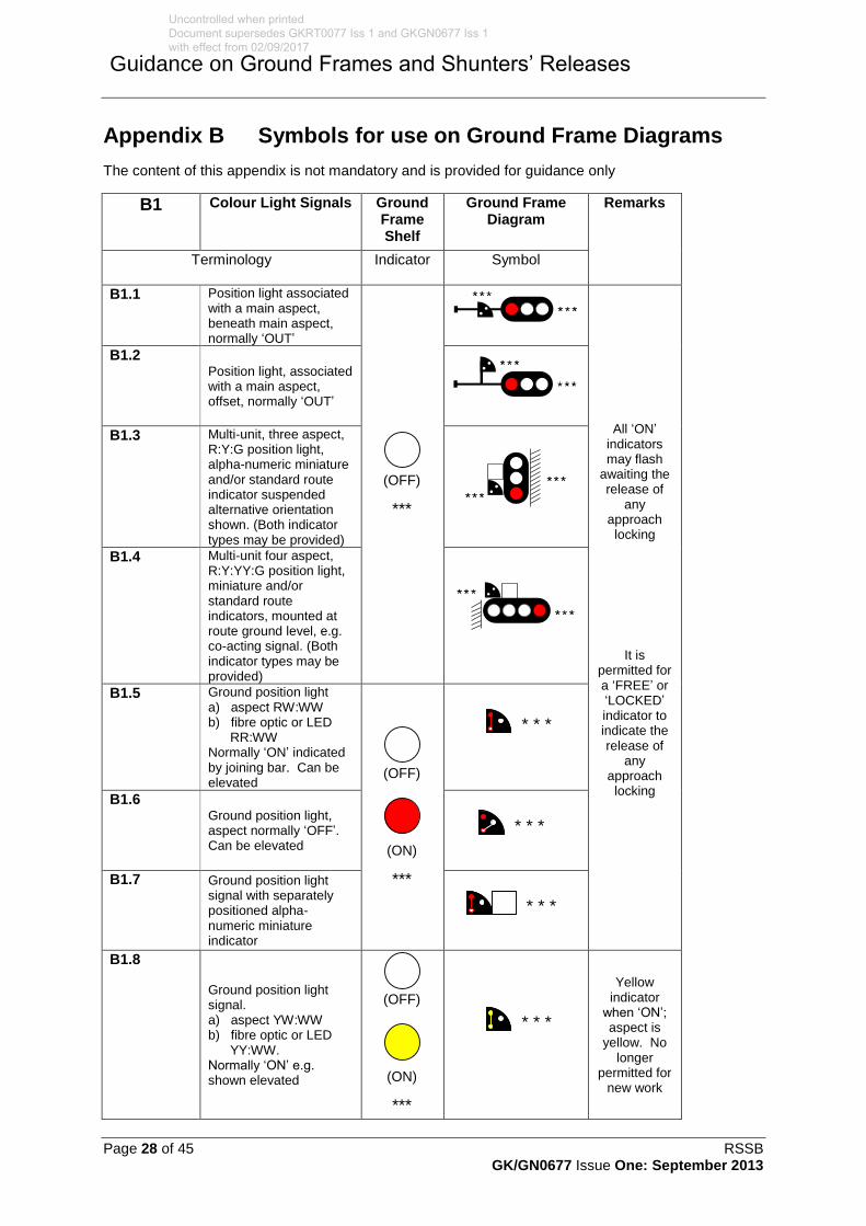
Page 28 of 45 RSSB GK/GN0677 Issue One: September 2013
Guidance on Ground Frames and Shunters’ Releases
Appendix B Symbols for use on Ground Frame Diagrams
The content of this appendix is not mandatory and is provided for guidance only
B1 Colour Light Signals Ground Frame Shelf
Ground Frame Diagram
Remarks
Terminology Indicator Symbol
B1.1 Position light associated with a main aspect, beneath main aspect, normally ‘OUT’
(OFF)
***
All ‘ON’ indicators may flash
awaiting the release of
any approach locking
It is permitted for a ‘FREE’ or ‘LOCKED’ indicator to indicate the release of
any approach locking
B1.2 Position light, associated with a main aspect, offset, normally ‘OUT’
B1.3 Multi-unit, three aspect, R:Y:G position light, alpha-numeric miniature and/or standard route indicator suspended alternative orientation shown. (Both indicator types may be provided)
B1.4 Multi-unit four aspect, R:Y:YY:G position light, miniature and/or standard route indicators, mounted at route ground level, e.g. co-acting signal. (Both indicator types may be provided)
B1.5 Ground position light a) aspect RW:WW b) fibre optic or LED RR:WW Normally ‘ON’ indicated by joining bar. Can be elevated
(ON)
***
(OFF)
* * *
B1.6 Ground position light, aspect normally ‘OFF’. Can be elevated
* * *
B1.7 Ground position light signal with separately positioned alpha-numeric miniature indicator
* * *
B1.8
Ground position light signal. a) aspect YW:WW b) fibre optic or LED YY:WW. Normally ‘ON’ e.g. shown elevated (ON)
***
(OFF)
* * *
Yellow indicator
when ‘ON’; aspect is
yellow. No longer
permitted for new work
Uncontrolled when printed Document supersedes GKRT0077 Iss 1 and GKGN0677 Iss 1 with effect from 02/09/2017

RSSB Page 29 of 45 GK/GN0677 Issue One: September 2013
Guidance on Ground Frames and Shunters’ Releases
B1 Colour Light Signals Ground Frame Shelf
Ground Frame Diagram
Remarks
Terminology Indicator Symbol
B1.9 Limit of shunt a) position lights aspects double red b) indicator, internally illuminated. All can be elevated.
* * *
The identification number or
‘LOS’ indicates
lamp lit only
B1.10 Shunting set back white signals. Normally ‘OUT’ W when ‘OFF’
Not applicable
Show only as required
B2 Semaphore Signals Ground Frame Shelf
Ground Frame Diagram
Remarks
Terminology Indicator Symbol
B2.1
Stop signal, generic symbol where no further information need to be conveyed
(ON)
***
(OFF)
It is permitted to include arm and lamp proving indicator with the signal
indication
‘ON’ indicators may flash
awaiting the release of
any approach locking
It is
permitted for a ‘FREE’ or ‘LOCKED’ indicator to indicate the release of
any approach locking
B2.2
Stop signal, power operated (all types)
B2.3 Stop signal, fixed
Lamp alight
indication may be provided
B2.4 Distant signal, fixed
Lamp alight
indication may be provided
MOTOR
OPERATED
FIXED
FIXED
Uncontrolled when printed Document supersedes GKRT0077 Iss 1 and GKGN0677 Iss 1 with effect from 02/09/2017

Page 30 of 45 RSSB GK/GN0677 Issue One: September 2013
Guidance on Ground Frames and Shunters’ Releases
B2 Semaphore Signals Ground Frame Shelf
Ground Frame Diagram
Remarks
Terminology Indicator Symbol
B2.5 Reflectorised stop board # supplementary legend to be shown Not
applicable
B2.6 Reflectorised distant board
B3 Semaphore Signals Ground Frame Shelf
Ground Frame Diagram
Remarks
Terminology Indicator Symbol
B3.1
Subsidiary signal, letter if displayed: ‘C’ = call on ‘S’ = shunt ahead
(ON)
***
(OFF)
It is permissible to include
shelf indications
with stencilled
letters C or S
Arm and
lamp indications
are permitted to be included
with the signal
indication
B3.2
Shunting signal, yellow arm, normally ‘ON’, can be shown elevated
(ON)
***
(OFF)
No longer permitted for
new work
B3.3 Shunting signal, single. Red arm, normally ‘ON’, can be shown elevated
(ON)
***
(OFF)
Arm and lamp proving indications
are permitted to be included
with the signal
indication
B3.4 Shunting signal, floodlit
B3.5 Shunting signal, power operated
B3.6 Shunting signals, multiple, e.g.: three arms, bottom signals shown normally ‘OFF’
Uncontrolled when printed Document supersedes GKRT0077 Iss 1 and GKGN0677 Iss 1 with effect from 02/09/2017

RSSB Page 31 of 45 GK/GN0677 Issue One: September 2013
Guidance on Ground Frames and Shunters’ Releases
B3 Semaphore Signals Ground Frame Shelf
Ground Frame Diagram
Remarks
Terminology Indicator Symbol
B3.7
Tall siding signals, miniature arms, eg: three arms, bottom signal shown normally ‘OFF’
(ON)
***
(OFF)
Arm and lamp proving indications
are permitted to be included
with the signal
indication
B4 Signals, Relationship to
Track
Ground Frame Shelf
Ground Frame Diagram
Remarks
Terminology Indicator Symbol
B4.1 Straight post, colour light signal, left of track for direction of running to which it applies
As appropriate
signal indicator
Relation to line is shown
B4.2 Straight post, semaphore signal, right of track for direction of running to which it applies
B4.3
Colour light signals, suspended from gantry
B4.4
Colour light signals, mounted above gantry
Uncontrolled when printed Document supersedes GKRT0077 Iss 1 and GKGN0677 Iss 1 with effect from 02/09/2017

Page 32 of 45 RSSB GK/GN0677 Issue One: September 2013
Guidance on Ground Frames and Shunters’ Releases
B5 Slots Received from Another Box
Ground Frame Shelf
Ground Frame Diagram
Remarks
Terminology Indicator Symbol
B5.1 Semaphore stop signal, slotted from another box
SLOT
OFF
***
It is permissible for arm and
lamp proving indications
to be included in addition to
the slot indication
B5.2 Slots multiple, add one additional arm for each control, e.g.: stop signal, numbering to be enclosed in a symbol (but not a square or rectangle)
B6 Slots Received from Another Box
Ground Frame Shelf
Ground Frame Diagram
Remarks
Terminology Indicator Symbol
B6.1 Slot a) semaphore shunting signal b) ground position light signal
SLOT
OFF
***
* * ** * *
B6.2 Slots main colour light signal and associated position light signal
B7 Slots Sent to Another Box
Ground Frame Shelf
Ground Frame Diagram
Remarks
Terminology Indicator Symbol
B7.1 Semaphore, stop signal, slotted at another box
ARM &
SLOT
ON
***
SLOT
OFF
Part 1 B7.2
Slots multiple, add one additional arm for each control, e.g.: stop signal. Numbering to be enclosed in a symbol (but not a square or a rectangle)
Uncontrolled when printed Document supersedes GKRT0077 Iss 1 and GKGN0677 Iss 1 with effect from 02/09/2017

RSSB Page 33 of 45 GK/GN0677 Issue One: September 2013
Guidance on Ground Frames and Shunters’ Releases
B7 Slots Sent to Another Box
Ground Frame Shelf
Ground Frame Diagram
Remarks
Terminology Indicator Symbol
B7.3
Slot a) semaphore shunting signal b) ground position light signal
ASPECT
& SLOT
ON
***
SLOT
OFF
* * ** * *
B7. B7.4 Slots, main colour light signal and associated position light signal
B8 Repeating Ground Frame Shelf
Ground Frame Diagram
Remarks
Terminology Indicator Symbol
B8.1
Banner repeater a) normally ‘ON’ b) normally ‘OFF’
ON
*** BR
OFF
Repeating included with associated
signal. Common indication, including lamp, arm
and banner, as
necessary
B8.2 Banner repeater, splitting e.g.: lower speed diverging main route to the left
B9 Signals, Controls /
Indicators
Ground Frame Shelf
Ground Frame Diagram
Remarks
Terminology Indicator Symbol
B9.1 Junction indicator, showing all possible diverging route indicators and their numbering.
Each control
lever may have its
own indicator
Show as applicable
where routes are
controlled by separate levers.
B9.2 Alpha-numeric standard route indicator, numeral indicates the number of route indications
Where route indicators
are controlled by
a) b)
BRBR
BR
BR
Uncontrolled when printed Document supersedes GKRT0077 Iss 1 and GKGN0677 Iss 1 with effect from 02/09/2017
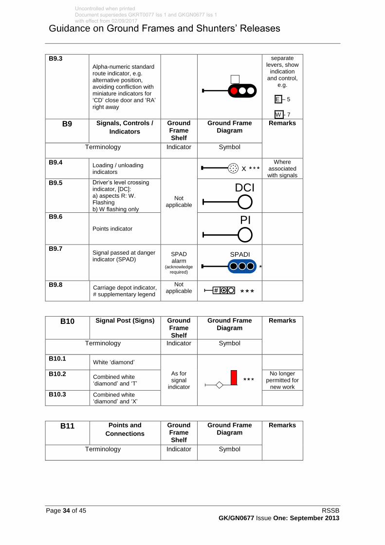
Page 34 of 45 RSSB GK/GN0677 Issue One: September 2013
Guidance on Ground Frames and Shunters’ Releases
B9.3
Alpha-numeric standard route indicator, e.g. alternative position, avoiding confliction with miniature indicators for ‘CD’ close door and ‘RA’ right away
separate levers, show
indication and control,
e.g.
E – 5
W - 7
B9 Signals, Controls /
Indicators
Ground Frame Shelf
Ground Frame Diagram
Remarks
Terminology Indicator Symbol
B9.4 Loading / unloading indicators
Not applicable
Where associated with signals
B9.5 Driver’s level crossing indicator, [DC]: a) aspects R: W. Flashing b) W flashing only
DCI
B9.6
Points indicator PI
B9.7 Signal passed at danger indicator (SPAD)
SPAD alarm
(acknowledge required)
B9.8 Carriage depot indicator, # supplementary legend
Not applicable
B10 Signal Post (Signs) Ground Frame Shelf
Ground Frame Diagram
Remarks
Terminology Indicator Symbol
B10.1 White ‘diamond’
As for signal
indicator
B10.2 Combined white ‘diamond’ and ‘T’
No longer permitted for
new work
B10.3 Combined white ‘diamond’ and ‘X’
B11 Points and
Connections
Ground Frame Shelf
Ground Frame Diagram
Remarks
Terminology Indicator Symbol
SPADI
Uncontrolled when printed Document supersedes GKRT0077 Iss 1 and GKGN0677 Iss 1 with effect from 02/09/2017

RSSB Page 35 of 45 GK/GN0677 Issue One: September 2013
Guidance on Ground Frames and Shunters’ Releases
B11.1
Lie of points, set for straight route, showing normal position
For indicator
see detection
(B14.1 and B15.1)
Colour symbol
where track circuited,
e.g. yellow
Uncontrolled when printed Document supersedes GKRT0077 Iss 1 and GKGN0677 Iss 1 with effect from 02/09/2017
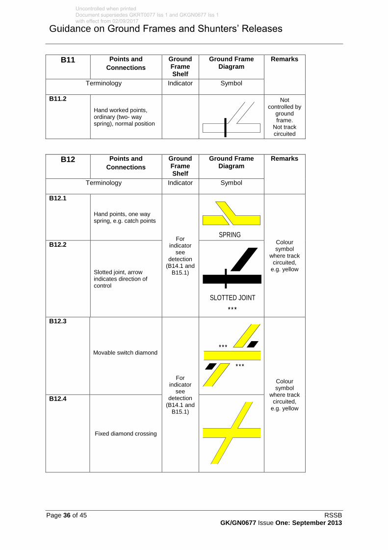
Page 36 of 45 RSSB GK/GN0677 Issue One: September 2013
Guidance on Ground Frames and Shunters’ Releases
B11 Points and
Connections
Ground Frame Shelf
Ground Frame Diagram
Remarks
Terminology Indicator Symbol
B11.2
Hand worked points, ordinary (two- way spring), normal position
Not controlled by
ground frame.
Not track circuited
B12 Points and
Connections
Ground Frame Shelf
Ground Frame Diagram
Remarks
Terminology Indicator Symbol
B12.1
Hand points, one way spring, e.g. catch points
For indicator
see detection
(B14.1 and B15.1)
Colour symbol
where track circuited,
e.g. yellow
B12.2
Slotted joint, arrow indicates direction of control
B12.3
Movable switch diamond
For indicator
see detection
(B14.1 and B15.1)
Colour symbol
where track circuited,
e.g. yellow
B12.4
Fixed diamond crossing
SPRING
SLOTTED JOINT
Uncontrolled when printed Document supersedes GKRT0077 Iss 1 and GKGN0677 Iss 1 with effect from 02/09/2017

RSSB Page 37 of 45 GK/GN0677 Issue One: September 2013
Guidance on Ground Frames and Shunters’ Releases
B12 Points and
Connections
Ground Frame Shelf
Ground Frame Diagram
Remarks
Terminology Indicator Symbol
B12.5
Single slip
For indicator
see detection
(B14.1 and B15.1)
B13 Points and Connections
Ground Frame Shelf
Ground Frame Diagram
Remarks
Terminology Indicator Symbol
B13.1
Double slip (worked by at least two levers)
For indicator
see detection
(B14.1 and B15.1)
Colour symbol
where track circuited,
e.g. yellow
B13.2 Trap points, double switch Trap points, single switch
B13.3
Derailer, arrow indicates direction of derailment
For indicator
see detection
(B14.1 and B15.1)
Colour symbol
where track circuited,
e.g. yellow
B13.4
Trap points, wide to gauge
Uncontrolled when printed Document supersedes GKRT0077 Iss 1 and GKGN0677 Iss 1 with effect from 02/09/2017

Page 38 of 45 RSSB GK/GN0677 Issue One: September 2013
Guidance on Ground Frames and Shunters’ Releases
B13 Points and Connections
Ground Frame Shelf
Ground Frame Diagram
Remarks
Terminology Indicator Symbol
B13.5
Swing nose crossing
For indicator
see detection
(B14.1 and B15.1)
B13.6 Points worked from signal box, function normal sets points for straight route. # Lever number and identification letter
For indicator
see detection
(B14.1 and B15.1)
B13.7 Points worked by ground frame, ground panel or shunting frame, all released from a controlling signal box. Number enclosed in a symbol (but not a square or a rectangle)
B14 Points and Connections
Ground Frame Shelf
Ground Frame Diagram
Remarks
Terminology Indicator Symbol
B14.1
Lie of mechanical points. Electrical detection shown ED. # lever number and identification letter
Not applicable
Indicator provided
only where electric
detection is provided.
It is permissible
for three position needle
indicators to be provided
21A
Uncontrolled when printed Document supersedes GKRT0077 Iss 1 and GKGN0677 Iss 1 with effect from 02/09/2017
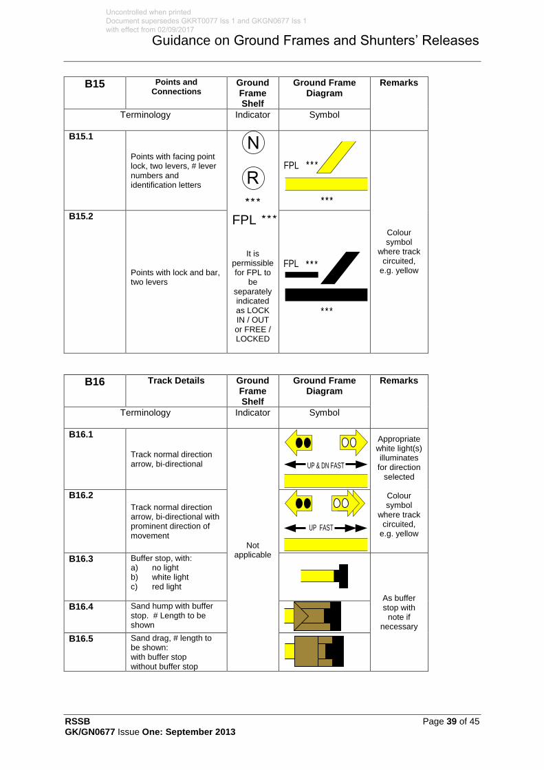
RSSB Page 39 of 45 GK/GN0677 Issue One: September 2013
Guidance on Ground Frames and Shunters’ Releases
B15 Points and Connections
Ground Frame Shelf
Ground Frame Diagram
Remarks
Terminology Indicator Symbol
B15.1
Points with facing point lock, two levers, # lever numbers and identification letters
It is permissible for FPL to
be separately indicated as LOCK IN / OUT or FREE / LOCKED
Colour symbol
where track circuited,
e.g. yellow
B15.2
Points with lock and bar, two levers
B16 Track Details Ground Frame Shelf
Ground Frame Diagram
Remarks
Terminology Indicator Symbol
B16.1
Track normal direction arrow, bi-directional
Not applicable
Appropriate white light(s) illuminates for direction
selected
Colour symbol
where track circuited,
e.g. yellow
B16.2
Track normal direction arrow, bi-directional with prominent direction of movement
B16.3 Buffer stop, with:
a) no light b) white light c) red light
As buffer stop with
note if necessary
B16.4 Sand hump with buffer stop. # Length to be shown
B16.5 Sand drag, # length to
be shown: with buffer stop without buffer stop
FPL
FPL
FPL
UP & DN FAST
UP FAST
Uncontrolled when printed Document supersedes GKRT0077 Iss 1 and GKGN0677 Iss 1 with effect from 02/09/2017

Page 40 of 45 RSSB GK/GN0677 Issue One: September 2013
Guidance on Ground Frames and Shunters’ Releases
B17 Track Details Track Circuits
Ground Frame Shelf
Ground Frame Diagram
Remarks
Terminology Indicator Symbol
B17.1 Scotch block
Not
applicable
B17.2
Insulating rail joint (IRJ), track circuit in both directions
Minimum of two lights per track
circuit and, where
practicable, at each
extremity
Red lights represent
track circuit occupied. No light (shown black)
represents track circuit
clear
Enhanced track
occupancy indications
(see GK/RT0044)
should be sectioned
and coloured as normal
track circuits
B17.3
Track circuit portion, an example of identification lettering
B17.4
Track circuit on left, none on right
AA
B17.5
Track circuit on right, none on left
AB
B17.6 Overlap for signal on left, also single overlap on bi-directional line, standard length
Not applicable
Extent of
phantom
overlap not
shown
B17.7 Overlap for signal to the right
B17.8 Non-standard length. Length not to be shown, #
B17.9 Overlap, bi-directional line, common for Opposing signals, e.g. dimensional and with signal numbers, length to be shown, #
AA AB AC
Uncontrolled when printed Document supersedes GKRT0077 Iss 1 and GKGN0677 Iss 1 with effect from 02/09/2017
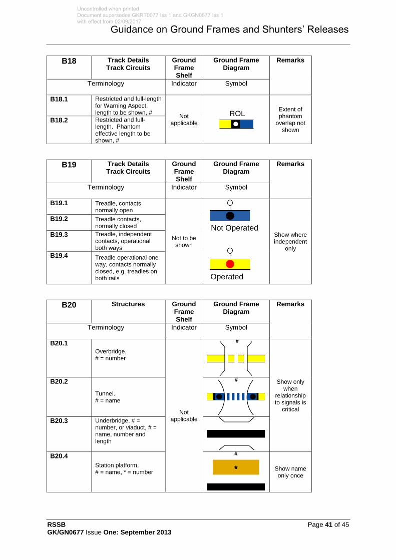
RSSB Page 41 of 45 GK/GN0677 Issue One: September 2013
Guidance on Ground Frames and Shunters’ Releases
B18 Track Details Track Circuits
Ground Frame Shelf
Ground Frame Diagram
Remarks
Terminology Indicator Symbol
B18.1 Restricted and full-length for Warning Aspect, length to be shown, #
Not applicable
Extent of phantom
overlap not shown
B18.2 Restricted and full-length. Phantom effective length to be shown, #
B19 Track Details Track Circuits
Ground Frame Shelf
Ground Frame Diagram
Remarks
Terminology Indicator Symbol
B19.1 Treadle, contacts normally open
Not to be shown
Not Operated
Operated
Show where independent
only
B19.2 Treadle contacts, normally closed
B19.3 Treadle, independent contacts, operational both ways
B19.4 Treadle operational one way, contacts normally closed, e.g. treadles on both rails
B20 Structures Ground Frame Shelf
Ground Frame Diagram
Remarks
Terminology Indicator Symbol
B20.1
Overbridge. # = number
Not applicable
Show only
when relationship to signals is
critical
B20.2
Tunnel. # = name
B20.3 Underbridge, # =
number, or viaduct, # = name, number and length
B20.4
Station platform, # = name, * = number
Show name only once
ROL
Uncontrolled when printed Document supersedes GKRT0077 Iss 1 and GKGN0677 Iss 1 with effect from 02/09/2017

Page 42 of 45 RSSB GK/GN0677 Issue One: September 2013
Guidance on Ground Frames and Shunters’ Releases
Definitions
Annetts key
A key used on RETB operated lines to enable the user of a ground frame to unlock a lever, to control the movements of points under local supervision.
Auxiliary token instrument
A supplementary token instrument located outside the signal box and used by railway undertaking personnel to facilitate prompt token exchange. An auxiliary token instrument located at a ground frame on single lines allows the token to be returned to the system when a train has been shut-in at the ground frame. This allows further tokens to be issued by the controlling signal boxes and hence trains to use the single line. Conversely, it allows a token to be withdrawn (with the co-operation of the signallers) to allow the ground frame to be operated and the previously shut-in train to depart.
Castell key
A key used on RETB operated lines to lock/unlock the cabinet, fitted to locally supervised ground frames, which houses the Annetts key.
Catch handle
A device attached to a lever which is used to secure the lever in either the normal or reverse positions.
CDU
Cab display unit (CDU). A device for use in the driving cabs of traction units, on board road vehicles and at the track side which enables the user to receive and return coded electronic tokens. The CDU displays the electronic tokens issued to it.
Controlling signal box
The signal box which oversees the releasing of the ground frame.
Depot or yard
In the context of shunters’ releases, a set of one or more sidings controlled by a railway undertaking.
Detection
The proof (electrical or mechanical) that points or signals have responded correctly to any control command.
Diagram
A representation of the track layout and signals controlled from the ground frame to permit correct orientation of the operator to the equipment being controlled.
Directly opposing locking
Interlocking between two opposing signals.
Facing point lock
Equipment fitted to facing points on passenger lines to secure the points in the correct position for the passage of trains.
Free indication
A lamp or electrical indicator provided to show whether a lever is free to be operated by the ground frame operator.
Ground frame
A control point comprising levers or switches to permit the local operation of points and, where provided, the associated signals. As applied to this document, the term ‘ground frame’ includes a ground switch panel.
Uncontrolled when printed Document supersedes GKRT0077 Iss 1 and GKGN0677 Iss 1 with effect from 02/09/2017

RSSB Page 43 of 45 GK/GN0677 Issue One: September 2013
Guidance on Ground Frames and Shunters’ Releases
Ground frame operator
A person employed by a railway undertaking, who is authorised to operate a ground frame.
Ground frame release
The method by which the ground frame is unlocked to allow its use either by an electrical release or a mechanical key.
Ground frame release device
A device provided to lock and unlock a ground frame and retain the release device (for example, a token) until the ground frame is restored to normal.
Ground frame release key
A key, either directly released from a release instrument or attached to a token or train staff, which is used to release a ground frame.
Interlocking
A method, either mechanical or electrical, which prevents the operation of signalling equipment when it is unsafe to do so, that is to say, prevents the movement of points while a signal reading over them is clear.
KABA key
A key used to activate a cab display unit used on RETB worked lines (see ‘RETB’ below).
Levers
A method of working a signalling system mechanically by using human effort.
Normal position
The position of a lever when it is back in the lever frame (away from the operator), also the position of a switch when it is turned to the left.
Opposing signals
Signals which protect the same piece of railway from opposite directions.
Receptacle or key release instrument
The place where the ground frame release key is secured when not in use.
Release lever
A lever that is subject to control from the supervising signalling centre and which, when operated, prevents the signalling centre from withdrawing the release. Where a switch is used instead of a lever, the releasing and backlocking function is carried out by relays.
Restore
The replacement of the ground frame to its normal state.
RETB
Radio electronic token block (RETB) is a method of protecting a single line of railway through the use of solid state interlocking and a radio link to the trains which use the line.
Reverse position
The position of a lever when it is pulled towards the operator and also the position of a switch when it is turned to the right.
Shunter’s release
A push button or switch that is controlled by a shunter which, when operated, allows points or a route to be operated by the supervising signalling centre.
Shutting-in facilities
A facility which permits a train to be shunted clear of a main line into a siding and then the ground frame normalised to permit normal train movements.
Uncontrolled when printed Document supersedes GKRT0077 Iss 1 and GKGN0677 Iss 1 with effect from 02/09/2017

Page 44 of 45 RSSB GK/GN0677 Issue One: September 2013
Guidance on Ground Frames and Shunters’ Releases
Signalled movement
A movement authority given by, and under the control of, the supervising signalling centre or by the ground frame on supervised lines or sidings.
Slots / slotting
In the context of ground frames, the control of a signalling function which requires co-operation between the signal box and a ground frame.
Supervised lines
Lines or sidings that are under the control of the ground frame operator.
Uncontrolled when printed Document supersedes GKRT0077 Iss 1 and GKGN0677 Iss 1 with effect from 02/09/2017

RSSB Page 45 of 45 GK/GN0677 Issue One: September 2013
Guidance on Ground Frames and Shunters’ Releases
References
The Catalogue of Railway Group Standards gives the current issue number and status of documents published by RSSB. This information is also available from www.rgsonline.co.uk.
RGSC 01 Railway Group Standards Code
RGSC 02 Standards Manual
Railway Group Standards
GE/RT8000 Rule Book
GE/RT8270 Assessment of Compatibility of Rolling Stock and Infrastructure
GK/RT0036 Transitions Between Signalling Systems
GK/RT0045 Lineside Signals, Indicators and layout of Signals
GK/RT0055 Block Systems Interface Requirements
GK/RT0077 Ground Frames and Shunters’ Releases
GO/RT3215 Requirements for the Weekly Operating Notice, Periodical Operating Notice and Sectional Appendix
Uncontrolled when printed Document supersedes GKRT0077 Iss 1 and GKGN0677 Iss 1 with effect from 02/09/2017
Rail Industry Standard
RIS-0077-CCS
Issue One
Date September 2017
Ground Frames and Shunter’s Releases
Definitions and References
Relevant definitions and references are given in Annexes A and B, and are not reproduced here.
RIS-0077-CCS Page 70 of 70
Uncontrolled when printed Document supersedes GKRT0077 Iss 1 and GKGN0677 Iss 1 with effect from 02/09/2017