ground equipment monitoring servicetm (gemstm
TRANSCRIPT

Date: June 2016
Ground Equipment Monitoring ServiceTM (GEMSTM)
Version 1.4
OMG Document Number: formal/2016-06-05
Normative Reference: http://www.omg.org/spec/GEMS/1.4
Associated Normative Machine Consumable Files:
http://www.omg.org/spec/GEMS/1.4/GEMS_base_type.xsdhttp://www.omg.org/spec/GEMS/1.4/GEMS_Device.xsdhttp://www.omg.org/spec/GEMS/1.4/GEMS_UpdatedGEMSSchema.xmi
O B J E C T M A N A G E M E N T G R O U P

Copyright © 2008-2015, AMERGINT Technologies, Inc.Copyright © 2008-2016, Object Management Group, Inc.Copyright © 2008-2015, RT Logic Inc
USE OF SPECIFICATION – TERMS, CONDITIONS & NOTICES
The material in this document details an Object Management Group specification in accordance with the terms, conditions and notices set forth below. This document does not represent a commitment to implement any portion of this specification in any company's products. The information contained in this document is subject to change without notice.
LICENSES
The companies listed above have granted to the Object Management Group, Inc. (OMG) a nonexclusive, royalty-free, paid up, worldwide license to copy and distribute this document and to modify this document and distribute copies of the modified version. Each of the copyright holders listed above has agreed that no person shall be deemed to have infringed the copyright in the included material of any such copyright holder by reason of having used the specificationset forth herein or having conformed any computer software to the specification.
Subject to all of the terms and conditions below, the owners of the copyright in this specification hereby grant you a fully-paid up, non-exclusive, nontransferable, perpetual, worldwide license (without the right to sublicense), to use this specification to create and distribute software and special purpose specifications that are based upon this specification, and to use, copy, and distribute this specification as provided under the Copyright Act; provided that: (1) both the copyright notice identified above and this permission notice appear on any copies of this specification; (2) the use of the specifications is for informational purposes and will not be copied or posted on any network computer or broadcast in any media and will not be otherwise resold or transferred for commercial purposes; and (3) no modifications are made to this specification. This limited permission automatically terminates without notice if you breach any of these terms or conditions. Upon termination, you will destroy immediately any copies of the specifications in your possessionor control.
PATENTS
The attention of adopters is directed to the possibility that compliance with or adoption of OMG specifications may require use of an invention covered by patent rights. OMG shall not be responsible for identifying patents for which a license may be required by any OMG specification, or for conducting legal inquiries into the legal validity or scope of those patents that are brought to its attention. OMG specifications are prospective and advisory only. Prospective users are responsible for protecting themselves against liability for infringement of patents.
GENERAL USE RESTRICTIONS
Any unauthorized use of this specification may violate copyright laws, trademark laws, and communications regulations and statutes. This document contains information which is protected by copyright. All Rights Reserved. No part of this work covered by copyright herein may be reproduced or used in any form or by any means--graphic, electronic, or mechanical, including photocopying, recording, taping, or information storage and retrieval systems--without permission of the copyright owner.
DISCLAIMER OF WARRANTY
WHILE THIS PUBLICATION IS BELIEVED TO BE ACCURATE, IT IS PROVIDED "AS IS" AND MAY CONTAIN ERRORS OR MISPRINTS. THE OBJECT MANAGEMENT GROUP AND THE COMPANIES LISTED ABOVE MAKE NO WARRANTY OF ANY KIND, EXPRESS OR IMPLIED, WITH REGARD TO THIS PUBLICATION, INCLUDING BUT NOT LIMITED TO ANY WARRANTY OF TITLE OR OWNERSHIP, IMPLIED
ii Ground Equipment Monitoring Service, v 1.4

WARRANTY OF MERCHANTABILITY OR WARRANTY OF FITNESS FOR A PARTICULAR PURPOSE OR USE.IN NO EVENT SHALL THE OBJECT MANAGEMENT GROUP OR ANY OF THE COMPANIES LISTED ABOVE BE LIABLE FOR ERRORS CONTAINED HEREIN OR FOR DIRECT, INDIRECT, INCIDENTAL, SPECIAL, CONSEQUENTIAL, RELIANCE OR COVER DAMAGES, INCLUDING LOSS OF PROFITS, REVENUE, DATA OR USE, INCURRED BY ANY USER OR ANY THIRD PARTY IN CONNECTION WITH THE FURNISHING, PERFORMANCE, OR USE OF THIS MATERIAL, EVEN IF ADVISED OF THE POSSIBILITY OF SUCH DAMAGES.
The entire risk as to the quality and performance of software developed using this specification is borne by you. This disclaimer of warranty constitutes an essential part of the license granted to you to use this specification.
RESTRICTED RIGHTS LEGEND
Use, duplication or disclosure by the U.S. Government is subject to the restrictions set forth in subparagraph (c) (1) (ii) of The Rights in Technical Data and Computer Software Clause at DFARS 252.227-7013 or in subparagraph (c)(1) and (2) of the Commercial Computer Software - Restricted Rights clauses at 48 C.F.R. 52.227-19 or as specified in 48 C.F.R. 227-7202-2 of the DoD F.A.R. Supplement and its successors, or as specified in 48 C.F.R. 12.212 of the Federal Acquisition Regulations and its successors, as applicable. The specification copyright owners are as indicated above andmay be contacted through the Object Management Group, 109 Highland Avenue, Needham, MA 02494, U.S.A.
TRADEMARKS
CORBA®, CORBA logos®, FIBO®, Financial Industry Business Ontology®, FINANCIAL INSTRUMENT GLOBAL IDENTIFIER®, IIOP®, IMM®, Model Driven Architecture®, MDA®, Object Management Group®, OMG®, OMG Logo®, SoaML®, SOAML®, SysML®, UAF®, Unified Modeling Language®, UML®, UML Cube Logo®, VSIPL®, and XMI® are registered trademarks of the Object Management Group, Inc.
For a complete list of trademarks, see: http://www.omg.org/legal/tm_list.htm. All other products or company names mentioned are used for identification purposes only, and may be trademarks of their respective owners.
COMPLIANCE
The copyright holders listed above acknowledge that the Object Management Group (acting itself or through its designees) is and shall at all times be the sole entity that may authorize developers, suppliers and sellers of computer software to use certification marks, trademarks or other special designations to indicate compliance with these materials.
Software developed under the terms of this license may claim compliance or conformance with this specification if and only if the software compliance is of a nature fully matching the applicable compliance points as stated in the specification. Software developed only partially matching the applicable compliance points may claim only that the software was based on this specification, but may not claim compliance or conformance with this specification. In the event that testing suites are implemented or approved by Object Management Group, Inc., software developed using thisspecification may claim compliance or conformance with the specification only if the software satisfactorily completes the testing suites.
Ground Equipment Monitoring Service (GEMS), v 1.4 iii

OMG’s Issue Reporting Procedure
All OMG specifications are subject to continuous review and improvement. As part of this process we encourage readers to report any ambiguities, inconsistencies, or inaccuracies they may find by completing the Issue Reporting Form listed on the main web page http://www.omg.org, under Documents, Report a Bug/Issue (http://issues.omg.org/issues/create-new-issue).
iv Ground Equipment Monitoring Service, v 1.4

Table of Contents
1 Scope...............................................................................................................................13
2 Conformance...................................................................................................................14
3 Normative References.....................................................................................................14
4 Terms and Definitions......................................................................................................14
5 Additional Information......................................................................................................145.1 Acknowledgements...............................................................................................................14
6 PIM...................................................................................................................................156.1 Overview...............................................................................................................................156.2 GEMS Use Cases.................................................................................................................15
6.2.1 GEMS User..................................................................................................................................... 166.2.2 Device Vendor................................................................................................................................. 166.2.3 Define GEMS Device....................................................................................................................... 166.2.4 Connect To Device.......................................................................................................................... 176.2.5 Send Directive................................................................................................................................. 176.2.6 Configure Device............................................................................................................................. 176.2.7 Obtain Configuration........................................................................................................................ 186.2.8 Save Configuration.......................................................................................................................... 186.2.9 Restore Configuration...................................................................................................................... 186.2.10 Obtain Device Information...............................................................................................................196.2.11 Asynchronous Status....................................................................................................................... 196.2.12 Proxy & Route GEMS Message......................................................................................................196.2.13 GEMS High Level Design................................................................................................................20
6.3 GEMS UML Design...............................................................................................................216.3.1 Parameters...................................................................................................................................... 226.3.2 Messages........................................................................................................................................ 246.3.3 Controlling and Monitoring Devices.................................................................................................27
6.4 Directives..............................................................................................................................336.4.1 DirectiveMessage............................................................................................................................ 356.4.2 DirectiveResponse.......................................................................................................................... 35
6.5 Asynchronous Status Messages...........................................................................................356.6 GEMS Security......................................................................................................................37
6.6.1 GEMS Authentication...................................................................................................................... 37
6.7 GEMS Internationalization.....................................................................................................386.8 Standard Devices..................................................................................................................386.9 Device Definitions.................................................................................................................38
6.9.1 Parameter Definitions...................................................................................................................... 386.9.2 Parameter Set Definitions................................................................................................................396.9.3 Directive Definitions......................................................................................................................... 39
7 PSM (XML)......................................................................................................................417.1 General.................................................................................................................................417.2 PIM To PSM Mapping............................................................................................................41
7.2.1 GEMS_base_types.xsd................................................................................................................... 41
Ground Equipment Monitoring Service (GEMS), v 1.4 v

7.3 XML Examples......................................................................................................................587.4 TCP/IP Message Structure....................................................................................................587.5 GEMS Device Definitions......................................................................................................59
7.5.1 Example Device Definition File........................................................................................................59
8 PIM (ASCII)......................................................................................................................618.1 General.................................................................................................................................618.2 PIM to PSM Mapping............................................................................................................61
8.2.1 Parameters...................................................................................................................................... 618.2.2 Reserved Words and Special Characters........................................................................................628.2.3 Message Header............................................................................................................................. 638.2.4 Message Trailer............................................................................................................................... 658.2.5 ConnectMessage and Response....................................................................................................658.2.6 DisconnectMessage........................................................................................................................ 668.2.7 GetConfig Message and Response.................................................................................................668.2.8 SetConfigMessage and Response..................................................................................................678.2.9 Save/LoadConfigMessage and Response......................................................................................688.2.10 GetConfigListMessage and Response............................................................................................698.2.11 DirectiveMessage and Response....................................................................................................708.2.12 AsyncStatusMessage...................................................................................................................... 71
8.3 ASCII Examples....................................................................................................................718.4 TCP/IP Message Structure....................................................................................................728.5 GEMS Device Definitions......................................................................................................72
vi Ground Equipment Monitoring Service, v 1.4

Table of Figures
Figure 1.1 – GEMS Overview 13Figure 6.1 – GEMS Use Cases 16Figure 6.2 – Connecting 17Figure 6.3 – Sending a directive 17Figure 6.4 – Configuring a device 18Figure 6.5 – Obtaining device configuration 18Figure 6.6 – Message routing 20Figure 6.7 – GEMS Package 21Figure 6.8 – GEMS UML 22Figure 6.9 – GEMS Standard types 22Figure 6.10 – GEMS Message classes 24Figure 6.11 – GEMS Message Base class 24Figure 6.12 – GEMS Response Messages 26Figure 6.13 – Set Configuration Sequence 28Figure 6.14 – Set Configuration Message classes 29Figure 6.15 – Get ConfigMessage classes 30Figure 6.16 – Save Config Message classes 31Figure 6.17 – Load Config Message classes 32Figure 6.18 – Get Config ListMessage classes 33Figure 6.19 – Directive Message Sequences 34Figure 6.20 – Directive Message classes 35Figure 6.21 – Asynchronous Status Message 36Figure 6.22 – AsyncStatusMessage class 37
Ground Equipment Monitoring Service (GEMS), v 1.4 vii

Table of Tables
Table 8.1 – Parameter Types and Formatting 61Table 8.2 – Standard Request Message Fields 63Table 8.3 – Response Message Fields 64Table 8.4 – Message Trailer Fields 65Table 8.5 – ConnectRequest Message 65Table 8.6 – Disconnect Message Request 66Table 8.7 – Get Configuration Request Message 66Table 8.8 – Get Configuration Response Message 67Table 8.9 – Set Configuration Request Message 67Table 8.10 – Set Configuration Response Message 68Table 8.11 – GetConfigList Request Message 69Table 8.12 – GetConfigListMessage Response 69Table 8.13 – Directive Request Message 70Table 8.14 – Asynchronous Status Message 71
viii Ground Equipment Monitoring Service, v 1.4

Preface
OMG
Founded in 1989, the Object Management Group, Inc. (OMG) is an open membership, not-for-profit computer industry standards consortium that produces and maintains computer industry specifications for interoperable, portable, and reusable enterprise applications in distributed, heterogeneous environments. Membership includes Information Technology vendors, end users, government agencies, and academia.
OMG member companies write, adopt, and maintain its specifications following a mature, open process. OMG’s specifications implement the Model Driven Architecture® (MDA®), maximizing ROI through a full-lifecycle approach to enterprise integration that covers multiple operating systems, programming languages, middleware and networking infrastructures, and software development environments. OMG’s specifications include: UML® (Unified Modeling Language®); CORBA® (Common Object Request Broker Architecture); CWM™ (Common Warehouse Metamodel™); and industry-specific standards for dozens of vertical markets.
More information on the OMG is available at http://www.omg.org/.
OMG Specifications
As noted, OMG specifications address middleware, modeling and vertical domain frameworks. All OMG Specifications are available from the OMG website at:
http://www.omg.org/spec
Specifications are organized by the following categories:
Business Modeling Specifications
Middleware Specifications
• CORBA/IIOP
• Data Distribution Services
• Specialized CORBA
IDL/Language Mapping Specifications
Modeling and Metadata Specifications
• UML, MOF, CWM, XMI
• UML Profiles
Modernization Specifications
Platform Independent Model (PIM), Platform Specific Model (PSM), Interface Specifications
• CORBAServices
• CORBAFacilities
OMG Domain Specifications
Ground Equipment Monitoring Service (GEMS), v 1.4 ix

CORBA Embedded Intelligence Specifications
CORBA Security Specifications
Signal and Image Processing Specifications
All of OMG’s formal specifications may be downloaded without charge from our website. (Products implementing OMG specifications are available from individual suppliers.) Copies of specifications, available in PostScript and PDF format, may be obtained from the Specifications Catalog cited above or by contacting the Object Management Group, Inc. at:
OMG Headquarters109 Highland AvenueNeedham, MA 02494USA
Tel: +1-781-444-0404Fax: +1-781-444-0320Email: [email protected]
Certain OMG specifications are also available as ISO standards. Please consult http://www.iso.org
Typographical ConventionsThe type styles shown below are used in this document to distinguish programming statements from ordinary English. However, these conventions are not used in tables or section headings where no distinction is necessary.
Times/Times New Roman/Liberation Serif – 10 pt.: Standard body text
Helvetica/Arial – 10 pt. Bold: OMG Interface Definition Language (OMG IDL) and syntax elements.
Courier – 10 pt. Bold: Programming language elements.
Helvetica/Arial – 10 pt: Exceptions
NOTE: Terms that appear in italics are defined in the glossary. Italic text also represents the name of a document, specification, or other publication.
IssuesThe reader is encouraged to report any technical or editing issues/problems with this specification via the report form at:
http://issues.omg.org/issues/create-new-issue
x Ground Equipment Monitoring Service, v 1.4

Introduction to SpecificationCommunication with space vehicles often requires a sophisticated suite of ground equipment ranging from network devices to antennas. These devices work together to create an end-to-end signal-processing suite. For example, an antenna, frequency converter, demodulator, bit synchronizer, decryption device, and frame synchronizer process a telemetry down-link signal before the end-user software receives the data. These devices must be configured to properly process the signal and provide status to user applications.
The Ground Equipment Monitoring Service (GEMS) specification defines a common messaging interface to do just this. The intent of GEMS is to define a lightweight, easy-to-use interface model suitable for control and status of nearly all types of devices within space related ground systems. In truth, these devices are not unique to space communications. Modern ground systems include many commercial devices such as networking devices and digital archive systems. While this specification focuses specifically on space applications, it is designed to apply to a broad range of devices.
User’s Perspective
To understand the GEMS design, it is useful to first look at it from a user’s perspective. Typically, high-level software, such as a TT&C (Telemetry, Tracking & Commanding) application, controls the ground system equipment. The main purpose of these types of applications is controlling the space vehicle – a complicated task in its own right. The ground system enables communication between the TT&C applications and the space vehicle by performing low-level signal and data processing functions. While the ground system is a significant part of the signal processing capabilities, if operating properly it should be transparent to the user. Only initial configuration and basic status is needed. This shouldbe simple and ideally use a standard model for all types of devices. That is where the GEMS model comes in. The GEMS model defines a simple, message-based interface suitable for controlling all types of devices using a variety of protocols and transport mechanisms. It allows system integrators to develop control and status applications that can easily interface with a wide range of device types.
Vendor’s Perspective
From a vendor’s perspective, a standard device control protocol should be relatively easy to implement and require limited resources. In addition, to ensure the widest possible range of integrations, the protocol should not require any specific third-party middleware implementation. Using GEMS, vendors achieve exactly this. The GEMS protocol is a lightweight protocol requiring only a TCP/IP connection. The Platform Independent Model (PIM) simply describes the messages and interactions necessary to configure and obtain status on a device. The Platform Specific Models (PSM) map the PIM to basic ASCII and XML messages. The ASCII PSM is intended for the most basic devices with limited processing capabilities. It is well suited for Serial (RS-232) and terminal style devices. The XML PSM incorporates the more sophisticated capabilities of XML such as XML Schemas and validation. While these capabilities require additional libraries, formatting and processing the messages is still quite simple.
The GEMS interface compliments other existing standards such as CCSDS SLE. The CCSDS SLE specification provides facility level interfaces but does not address the lower level device interfaces. It accomplishes this through a Service- Device mapping function. The GEMS specification enables a standard Service-Device mapping function to be created for a wide range of device types. The following figure depicts this interaction.
Ground Equipment Monitoring Service, v1.4 11

In this figure, the SLE Complex Management Service layers on top of the GEMS client to control the physical devices in the system.
12 Ground Equipment Monitoring Service (GEMS) v, 1.4

1 ScopeThe GEMS specification defines a lightweight standard for the control and status of typical ground equipment found in the space domain using a model driven approach. A conceptual model for the GEMS specification is shown below.
Figure 1.1 - GEMS Overview
The GEMS specification is most commonly used for the control of a single device. However, in more complicated systems, multiple devices may be controlled using a single container message (MessageSequence) combined with a GEMS Proxy.
The GEMS PIM defines the message structure and behavior standard to all GEMS Devices. In the case of GEMS, the platform is defined as the middleware, network protocol, or transport mechanism used to communicate with the device. By defining the platform at this level, the GEMS PIM focus is primarily on the necessary message content and behaviorand leaves the specifics of defining the message format and transporting that message to the PSMs.
Two GEMS PSMs are defined. The raw GEMS-ASCII PSM is a terse ASCII-based protocol well suited for serial or terminal based devices. The focus of this PSM is short, human-readable messages that are easily formatted and processed. These messages are transported directly across either a network or serial bus. The GEMS-XML PSM utilizesthe features of XML to provide message definition and validation. These messages use an HTML like header for transport across a network. Otherwise, GEMS-XML messages leverage the structure inherent in an XML document to define the content.
Many other platform specific mappings of the GEMS PIM are possible. These potentially include other standard middleware or protocol definitions such as CORBA, SNMP, or the GPIB-SCPI protocol. In fact, the large number of potential protocols used for device control further illustrates the need for the GEMS specification. By defining a specific mapping of each of these protocols to the GEMS PIM, automatic translation between these protocols is possible. This enables a device vendor to focus on the features and capabilities of the device without the need to support multiple protocols. Similarly, the device user can utilize a single protocol, with appropriate translators, to control numerous device.
Ground Equipment Monitoring Service, v1.4 13

2 ConformanceThe primary point of conformance is support of the PIM. Conformance to any defined PSM is optional, but if a definedplatform is used, such as XML and raw ASCII, the implementation must conform to the appropriate PSM. In the event that a PSM does not exist for a specific protocol, implementers are encouraged to define a PSM and submit it for standardization to the OMG.
3 Normative ReferencesThe following normative documents contain provisions which, through reference in this text, constitute provisions of this specification. For dated references, subsequent amendments to, or revisions of, any of these publications do not apply.
XML Tim Bray, Jean Paoli, C.M. Sperberg-McQueen, and Eve Maler, editors. Extensible Markup Language (XML) 1.0(Fourth Edition). World Wide Web Consortium, 2000. (See http://www.w3.org/TR/2006/REC-xml-20060816 .)
ASCII American National Standard for Information Systems – Coded Character Sets – 7 Bit American NationalStandard Code for Information Interchange (7-Bit ASCII), ANSI X3.4-1 986, American National Standards Institute, Inc., March 26, 1986
4 Terms and DefinitionsFor the purposes of this specification, the following terms and definitions apply.
TT&C: Telemetry Tracking & Commanding
CCSDS: Consultative Committee for Space Data Systems SLE: CCSDS Space Link Extensions
SNMP: Simple Network Management Protocol
GPIB: General Purpose Interface Bus
SCPI: Standard Commands for Programmable Instruments
5 Additional Information
5.1 AcknowledgementsThe following companies submitted this specification:
• AMERGINT Technologies, Inc.
• Real Time Logic, Inc.
The following companies supported this specification:
• Harris corp
• Boeing Corp
14 Ground Equipment Monitoring Service (GEMS) v, 1.4

6 PIM
6.1 OverviewThe GEMS specification defines a standard, platform independent model (PIM) for controlling a wide range of devices.The GEMS model does not presume or try to define a specific system level architecture. Instead, it defines generic concepts such as devices, parameters, and directives that are relatively simple to implement and provide system integrators common ways to control heterogeneous suites of space related ground equipment.
The central concept of GEMS is the GEMS device. GEMS devices have typed parameters, accept directives with typed arguments, and can optionally save and restore their configuration using persistent storage. Users utilize the GEMS interface within the device to configure and obtain status.
For more sophisticated systems with multiple devices, a GEMS proxy is deployed and routes message traffic to a system of devices. This allows for several devices to be configured in a single transaction. In addition, the proxy often supports the Save/Restore functionality, thus keeping the GEMS devices simple.
The GEMS PIM consists of message related classes that allow the user to send directives, configure devices, obtain configuration information and device status, save the configuration, and restore the configuration.
6.2 GEMS Use CasesThe following diagram depicts the GEMS use cases. These use cases define common interactions and activities associated with creating and using suites of devices.
Ground Equipment Monitoring Service, v1.4 15

Figure 6.1 - GEMS Use Cases
6.2.1 GEMS User
This actor represents a user of a GEMS device or system. The GEMS user commonly takes the form of a controlling software application that uses the GEMS interface to manipulate a device or system of devices.
6.2.2 Device Vendor
As the name indicates, the Device Vendor is the manufacturer of the device supporting the GEMS interface. The DeviceVendor’s role is to define the parameters and directives supported by the device and provide those along with the deviceto the System Integrator and/or GEMS User.
6.2.3 Define GEMS Device
This use case represents the activities necessary to define a GEMS device. These include defining the names, types, andranges for all device parameters as well as the directives and associated arguments.
16 Ground Equipment Monitoring Service (GEMS) v, 1.4

6.2.4 Connect To Device
The first action that a GEMS user must take to establish an interaction with a GEMS device is to connect to the device. In doing this, the GEMS user identifies whether control of the device or status only is requested. This is similar to requesting read/write access to a file. The GEMS device responds to a connection request by indicating whether or not the connection was successful and if successful, provides a token that the GEMS user will use in all future interactions with the device.
Figure 6.2 - Connecting
Authentication may optionally be performed by passing GEMS User credentials in the token field of the Connect Request. This is described in 6.6.1.
6.2.5 Send Directive
Figure 6.3 - Sending a directive
GEMS directives allow the user to manipulate the device or system in a scoped action. Common examples relating to ground system equipment are enabling modulation of a signal or sending a vehicle command. In this use case, the user formats a GEMS directive message and sends it to the GEMS device. The GEMS device performs the actions necessaryto fulfill the directive and then sends a reply message back to the user indicating the result of the directive. The response includes any return values appropriate for the directive.
6.2.6 Configure Device
A common use case is configuring a device. In this use case, the user sends a set of configuration parameters to the device. The device performs the appropriate validation of the parameters and then applies the values to its configuration. The GEMS device sends a response back to the user indicating success or failure. If successful, the response also includes the number of parameters affected.
Ground Equipment Monitoring Service, v1.4 17

Figure 6.4 - Configuring a device
6.2.7 Obtain Configuration
In this use case, the user wishes to obtain information about the device configuration. The user sends a message to the GEMS device requesting configuration information. The request can specify specific parameters that the user wishes information on. The GEMS device receives the request and populates a reply with the appropriate parameters.
Figure 6.5 - Obtaining device configuration
6.2.8 Save Configuration
A convenient use case in satellite operations is configuring the device for a specific space vehicle and then saving that configuration for later use. Often, configurations are saved for different missions. To accomplish this, the user sends a message requesting the GEMS device to save its configuration to local storage. The user specifies the name of the configuration for later recall.
This use case is optional since saving the configuration to persistent storage, such as a hard drive or Flash RAM, is not necessarily available on all types of devices. For these types of devices, it is expected that higher-level applications such as a GEMS router will provide this capability by first obtaining the device configuration and then writing it to persistent storage.
6.2.9 Restore Configuration
Once the user has saved a configuration to persistent storage, it can be recalled later. The user sends a restore configuration message to the GEMS device. The message includes the name of the configuration to restore. The GEMSdevice then loads that configuration and applies the values specified to the device. The response message indicates success or failure and the number of parameters modified.
18 Ground Equipment Monitoring Service (GEMS) v, 1.4

It is not required for the named configuration to contain all device parameters. Only the parameters specified are modified. This enables a useful approach to controlling a device. GEMS users can load full configuration followed by selected subsets.
Like saving the configuration, this use case is optional for devices that do not have a persistent storage capability. In these cases, it is expected that higher-level software applications such as a GEMS router store the configurations and then apply those configurations to the device.
6.2.10 Obtain Device Information
In this use case, the user obtains information about what directives and parameters the GEMS device accepts. The user sends a message to the GEMS device requesting service information. The reply contains descriptions of the directives (including argument name and type information) and the parameters (including name, type, and range information).
6.2.11 Asynchronous Status
In this use case, the user obtains asynchronous status messages containing the current values of various GEMS parameters. The user configures the frequency and type of update using parameters and directives on the GEMS device.Standardization of these parameters and directives are left for later versions of GEMS. The messages are “pushed” asynchronously and can be provided on either the current GEMS connection or an alternate out-of-band connection.
6.2.12 Proxy & Route GEMS Message
Typically, GEMS messages target a specific device. However, in more complex systems, it is convenient and sometimesrequired to manipulate multiple devices in a single transaction. In this case, multiple messages are combined into a message set and sent to a GEMS proxy for processing. The GEMS Proxy separates the messages and passes them to thedesignated targets sequentially.
This capability is not required of GEMS devices, though it can be used to offer sequential execution of messages. A GEMS proxy can also provide functions such as Save/Restore and message logging. These functions are not required ina GEMS proxy.
A GEMS proxy is considered to be a device and can be the target of messages such as the SetConfigMessage and GetConfigMessage. The specifics of any proxy parameters, directives, or other behavior is left to the implementor to define. At a minimum, in the event a GetConfigMessage is sent to a proxy, the resulting GetConfigResponse will contain at least one parameter named ‘targets.’ That parameter is an array of strings listing all of the targets handled by that specific proxy instance.
Ground Equipment Monitoring Service, v1.4 19

Figure 6.6 - Message routing
6.2.13 GEMS High Level Design
The GEMS protocol defines the basic message structure and interaction between a user and a GEMS device. It does notspecify the exact parameters, types, or ranges for any specific device or device type. That is beyond the scope of this specification. Instead, GEMS defines the approach to use when defining device specific parameters. The device vendor provides custom device information in a format compliant with the PIM and PSM used. To represent this interaction, GEMS defines two notional packages. These packages are not part of this specification. The Custom Devices package contains definitions of concrete devices. These devices meet the GEMS specification but are custom to a given vendor. The Standard Devices package contains definitions of standard devices, their parameters (names, types, and ranges) anddirectives. It is envisioned that this package eventually becomes an addendum to this specification.
20 Ground Equipment Monitoring Service (GEMS) v, 1.4

Figure 6.7 - GEMS Package
Typically, the device vendor defines and maintains the associated GEMS device definitions. The device definitions are either distributed manually by the vendor (e.g. incorporated in to product documentation or as a GEMS Device Definition file), or directly from the GEMS device as an electronic document. See 6.9 for more information on Device Definitions. By supporting a GEMS interface, the device vendor enables customers to easily control the device in a standard manner following the GEMS model. However, there is no guarantee that the parameter names, types, and ranges used will be interoperable with other similar devices produced by other vendors. For example, a common status parameter supported by receivers is signal lock. This parameter indicates when the receiver has locked on to the desiredsignal. One vendor might name that parameter LOCK_STATE while another vendor might name it SIGNAL_LOCK. To help standardize parameter choices a dictionary of device types and parameters will be developed.
6.3 GEMS UML Design The following class diagram shows the GEMS classes and their relationships. At the top are the message classes. These classes define the various types of messages available through the GEMS protocol. Each message class, with the exception of the Disconnect class, has an associated response message. In several cases, the message contains one or more parameters
Ground Equipment Monitoring Service, v1.4 21

Figure 6.8 - GEMS UML
These classes are described in detail in the following sections.
6.3.1 Parameters
Parameters represent the actual values used to configure and provide status on a given device. Each Parameter has a name, type, and a multiplicity. The name is a free text string and cannot contain any spaces. The multiplicity represents arrays of the same type. The specific implementation of the multiplicity is left to the PSM.
For completeness, the PIM defines both signed and unsigned types as well as a variety of integer sizes. If appropriate, these various integer types and precisions may be mapped to a single integer type within a PSM.
6.3.1.1 UML Diagram
This diagram shows the base parameter class and all of the specific types.
Figure 6.9 - GEMS Standard types
22 Ground Equipment Monitoring Service (GEMS) v, 1.4

6.3.1.2 boolean
Represents a boolean true/false value.
6.3.1.3 byte
Represents a single signed 8 bit byte or octet.
6.3.1.4 ubyte
Represents a single unsigned 8 bit byte or octet.
6.3.1.5 long
Represents a signed 8 byte value.
6.3.1.6 ulong
Represents an unsigned 8 byte value.
6.3.1.7 int
Represents a signed 4 byte value.
6.3.1.8 uint
Represents an unsigned 4 byte value.
6.3.1.9 short
Represents a signed 2 byte value.
6.3.1.10 ushort
Represents an unsigned 2 byte value.
6.3.1.11 double
Represents a double precision floating point number.
6.3.1.12 string
Represents a free text ASCII string of characters.
6.3.1.13 hex_value
Represents an ASCII representation of a hexadecimal value. The string optionally may be preceded by a ‘0x.’ The bit_length is used to specify the number of bits represented in the hex_value. See the PSM specific mapping for the format of this field.
6.3.1.14 time
Represents the number of seconds and nanoseconds elapsed since midnight UTC of January 1, 1970. The time value is represented by integer values for seconds and nanoseconds.
Ground Equipment Monitoring Service, v1.4 23

6.3.1.15 utime
Represents a time value as Coordinated Universal Time (UTC). This format allows for the representation of leap seconds within a time parameter.
6.3.1.16 Parameter Sets
Parameter sets allow for the creation of mixed-type structures of parameters or “complex types” using the composite design pattern. The intent is to offer device vendors an option for creating arbitrarily complex data structures.
6.3.2 Messages
GEMS defines a set of messages that allow parameters and directives to be sent between a GEMS client and GEMS device. These messages all have a common header and structure. Each message sent to the GEMS device has a corresponding response.
The following diagram depicts the GEMS message class structure.
Figure 6.10 - GEMS Message classes
6.3.2.1 Message Base Class
The Message base class defines the header information necessary to determine the target for the messages and other information such as the version number.
Figure 6.11 - GEMS Message Base class
24 Ground Equipment Monitoring Service (GEMS) v, 1.4

target
The target is a free text field containing the name of the target device. For a single device, the target is a word naming the device. If the device is part of a system hierarchy, the levels within the hierarchy are concatenated using ‘/’ characters similar to UNIX directory paths. This naming scheme allows GEMS proxies to properly route messages.
Example:
/SiteA/Modem/Modulator1
The target field is optional if the message is sent directly to the targeted device. For distributed systems that utilize a GEMS proxy, the proxy is responsible for mapping the target names to network addresses as necessary.
message_type
The message _type field is an alpha-numeric field containing a message identifier for a specific message type. The specific values are defined in the PSM.
token
The token field is a free-text field containing an ASCII token. The exact format and content of the token is dependent on the GEMS device. The GEMS device gives the token to the GEMS user as part of the initial connection. The token is then passed back to the GEMS device with every message.
While this specification does not define the use of the token field, it does offer recommendations. For example, if strict authentication is desired, a GEMS device can encode values in to the token that clearly identify the client and any privileges that client may have.
A common use of the message token is for limiting access to device control related features. When a client connect message is received, the message contains the type of access being requested (e.g., control or status). If there are currently no control clients connected, the GEMS device gives the control token to the new client. While this mechanism is not fool-proof, it does work well in controlled environments.
version
The version field contains the version of GEMS message being used. It provides backwards compatibility. Currently only version 1.0, 1.1, 1.2 are supported.
timestamp
The timestamp field provides useful debugging and message sorting information. The value in the field is the current time when the message is sent in UTC. The format of the field is defined in the PSM.
6.3.2.2 Response Messages
All GEMS response messages contain a result code and an optional free-text description. The result code indicates the success of failure of the original message. If a failure occurs, the specific result code can be inspected programmaticallyand the appropriate action taken. In the event an unrecognizable message is received, a generic base response message is returned with the result code set to indicate the error. Most commonly the result code for this type of error is MALFORMED_MESSAGE.
Ground Equipment Monitoring Service, v1.4 25

Figure 6.12 - GEMS Response Messages
The acceptable result codes are as follows:
SUCCESS
This result code indicates that the associated message or directive was successful. The result_description is optional.
INVALID_RANGE
This result code indicates that a parameter or argument within the associated message or directive was out of the acceptable range. In this error condition, the result_description should contain a free-text description of which parameter was in error.
INVALID_PARAMETER
This result code indicates that an unsupported or unknown parameter was named in the associated message. In this error condition, the result_description should contain a free-text description of which parameter was in error.
INVALID_STATE
This result code indicates that an invalid state was reached within the device or GEMS interface. Common reasons for this are attempts to set or get parameter values before a connection is established. In this error condition, the result_description should contain a free-text description of the error.
INVALID_VERSION
This result code indicates that the GEMS message version was unrecognized or unsupported by the device. In this errorcondition, the result_description should contain a list of the supported GEMS versions.
26 Ground Equipment Monitoring Service (GEMS) v, 1.4

INVALID_TARGET
This result code indicates that the target was unrecognized. In this error condition, the result_description should containthe provided (unrecognized) target.
UNSUPPORTED_MESSAGE
This result code indicates that the message type is not supported by the device. This applies to the optional save/restore messages. In this error condition, the result_description should contain a free-text description of the error.
MALFORMED_MESSAGE
This result code indicates that the message was malformed or otherwise unrecognized. In this error condition, the reply message header should reflect as much of the original message as possible. The result description should contain the malformed message with any necessary modification such that the reply is properly formed.
INTERNAL_ERROR
This result code indicates that the device or proxy experienced an internal error while processing the original message. In this error condition, the result_description should contain a free-text description of the error, if possible.
ACCESS_DENIED
This result code indicates that the GEMS user does not have appropriate access to invoke the action defined in the original message. This commonly is the result of a status-only client attempting to configure the device using either a SetMessage or LoadConfigMessage. In this error condition, the result_description should contain a free-text descriptionof the error.
CONFLICTING_PARAM ETERS
This result code indicates that the original message defined a set of parameters that conflicted with one another. For example, a device might have different ranges depending on the mode specified. In this error condition, the result_description should identify the conflicting parameters.
COMMUNICATION_ERROR
This result code indicates that a communication error occurred. This commonly occurs as a result of network socket errors, serial bus errors, or other transport mechanism errors. In this error condition, the result_description should contain a description of the error, if possible.
OTHER
This result code indicates that an error occurred not already defined in one of the other possible result codes. In this error condition, the result _description should contain a description of the error. If necessary, other non-standard error codings may be used within the result_description. However, it should be noted that these types of codings are not interoperable with other implementation and will be treated as free-text.
6.3.3 Controlling and Monitoring Devices
This section describes the process of controlling and monitoring GEMS devices.
6.3.3.1 Setting Configurations
To control a GEMS Device, the user sends a set of parameters. The parameters each have a name, type, and value as described in 6.3.1, Parameters. These parameters are applied in a transactional manner to the device. Validation checks are performed prior to changing the configuration of the device itself. If these checks fail (e.g., values out of range), thetransaction is cancelled. A description of the error is sent back to the GEMS user in the response message. If all values validate, the new parameter settings are applied to the device.
The following diagram depicts this sequence.
Ground Equipment Monitoring Service, v1.4 27

Figure 6.13 - Set Configuration Sequence
Errors found in steps 2 or 3 are immediately returned and no changes to the device configuration are made. In the eventthat an error occurs during step 4, the GEMS device attempts to return to the previous configuration if possible.
28 Ground Equipment Monitoring Service (GEMS) v, 1.4

Figure 6.14 - Set Configuration Message classes
SetConfigMessage
The SetConfigMessage contains the list of parameters to set. These parameters are applied to the device as a single transaction.
SetConfigResponse
The SetConfigResponse message indicates the result of the SetConfigMessage. This message has 1 parameter.
parameters_set
The parameters _set field indicates the number of parameters affected by the SetConfigMessage. This value provides the GEMS User feedback on the number of values actually modified. For example, a SetConfigMessage containing 20 parameter values might only change five parameters. From the perspective of the GEMS device, this is a valid request. However, the GEMS User might have expected to change 20 parameters.
6.3.3.2 Retrieving Configurations & Status
To obtain the current configuration of a device or monitor the runtime status of a device, the GEMS user sends a GetConfigMessage. The message can optionally contain the list of parameters desired. If specific parameters are specified, only those parameters are returned to the GEMS user. If no parameters are specified, then all device parameters are returned.
Ground Equipment Monitoring Service, v1.4 29

Figure 6.15 - GetConfigMessage classes
GetConfigMessage
The GetConfigMessage requests the current configuration from the GEMS device. The message can optionally contain a list of desired parameters.
GetConfigResponse
The GetConfigResponse message contains the device parameters requested.
6.3.3.3 Storing Configurations
To store a configuration, the GEMS User sends a SaveConfigMessage to the GEMS device. This message contains the desired name of the configuration. All device parameters are saved to this configuration. It is expected that multiple device configurations can be contained in a single named configuration. While the format of the persisted configurationis at the vendor’s discretion, it is recommended that it use a standard PSM. For example, if ASCII files are used to storeconfiguration information, an appropriate PSM such as XML should be used.
30 Ground Equipment Monitoring Service (GEMS) v, 1.4

Figure 6.16 - Save Config Message classes
SaveConfigMessage
The SaveConfigMessage contains the name of the configuration to save. The configuration name is a string containing a sequence of letters (A-Z) and/or numbers. Spaces are not allowed as they are not fully supported on all operating systems. The configuration name is case sensitive.
SaveConfig Response
The SaveConfigResponse contains the number of parameters saved if the save was successful. In the case of an error, the ResultCode indicates the type of error.
parameters_saved
The parameters_saved field indicates the number of parameters saved to the named configuration. This value provides the GEMS User feedback on the number of values actually saved. This value can be compared to a later restore configuration request as a means of ensuring expected behavior.
6.3.3.4 Restoring Configurations
To restore a named configuration to a GEMS device, the GEMS user sends a LoadConfigMessage. This message identifies the name of the configuration to load. The following diagram depicts the UML structure for these messages.
Ground Equipment Monitoring Service, v1.4 31

Figure 6.17 - Load Config Message classes
It is not required that the configuration contain a full set of parameter values.
6.3.3.5 LoadConfigMessage
The LoadConfigMes sage identifies the name of the configuration to load.
6.3.3.6 LoadConfigResponse
The LoadConfigResponse contains the number of parameters loaded. If an error occurred, it also indicates whether or not the device was left in a valid state.
6.3.3.7 parameters_loaded
The parameters_loaded field indicates the number of parameters affected by the LoadConfigMessage. This value provides the GEMS User feedback on the number of values actually modified. For example, a configuration containing 20 parameter values might only change five parameters. From the perspective of the GEMS device, this is a valid request. However, the GEMS User might have expected to change 20 parameters.
32 Ground Equipment Monitoring Service (GEMS) v, 1.4

6.3.3.8 Retrieving Available Configurations
In order to restore a named configuration to a GEMS device, the GEMS user needs to be provided a mechanism for retrieving all the configurations available. This message identifies the list of configuration names available to load. The following diagram depicts the UML structure for these messages.
Figure 6.18 - Get Config List Message classes
GetConfigListMessage
The GetConfigListMessage does not contain any additional information above and beyond the base message class.
GetConfigListResponse
configuration_name
The configuration_name field contains all of the available configuration names for the GEMS device. The format of thenames is dictated by the device developer.
6.3.3.9 Ping Message and Response
The ping message provides a simple mechanism for determining if the GEMS device is still responding to messages. The use of this message is optional. The response to the message is a Ping Response.
6.4 DirectivesDirectives allow the GEMS user to invoke a scoped action on the GEMS device. These actions typically involve the purpose of the device rather than the configuration. For example, a device that formats space vehicle commands might
Ground Equipment Monitoring Service, v1.4 33

have a send _vehicle _command directive. GEMS directives can have a list of parameters (or arguments) and can returnvalues in the response.
The supported directives and associated arguments are defined by the vendor as part of the device definition. The format of this definition is based on the PSM used.
The following diagram shows the sequence of directive messages.
Figure 6.19 - Directive Message Sequence
The DirectiveMessage contains the name of the directive and the list of arguments. The response contains the name of the directive and a list of return values. If an error occurs, the ResultCode indicates the reason for the error.
34 Ground Equipment Monitoring Service (GEMS) v, 1.4

Figure 6.20 - Directive Message classes
6.4.1 DirectiveMessage
The DirectiveMessage contains the name of the directive and a list of arguments.
6.4.2 DirectiveResponse
The DirectiveResponse contains the name of the directive and a list of return values. The name is provided to allow the GEMS user to correlate the response with the original directive.
6.5 Asynchronous Status MessagesAsynchronous status messages allow users to obtain parameter values through a push mechanism. These are normally provided either periodically, or on change. The messages are structure as ResponseMessages with a result_description and a ResultCode. The purpose of this structure is to allow the GEMS Device to communicate any non-nominal conditions to the GEMS user in the event that the periodic status update fails. It also allows GEMS user software to handle the message in a similar fashion to normal response messages.
The following diagram shows the sequence of an AsyncStatusMessage. The configuration of the message occurs using the SetConfigMessage. Then the GEMS device enters a polling loop in which it generates AsyncStatusMessages at the configured rate.
Ground Equipment Monitoring Service, v1.4 35

Figure 6.21 - Asynchronous Status Message
The AsyncStatusMessage contains a list of parameters. The list of parameters may be all or a subset of the parameters available on the GEMS Device. The structure of the message is similar to the GetConfigResponse. If an error occurred during the asynchronous status polling, it is reflected in the ResultCode and/or the result_description.
36 Ground Equipment Monitoring Service (GEMS) v, 1.4

Figure 6.22 - AsyncStatusMessage class
6.6 GEMS SecurityThe GEMS PIM defines only basic security concepts. GEMS Users connecting to a GEMS device are provided a token to use for all future interactions until a Disconnect message is sent or the connection is in some way broken (e.g., the socket is disconnected). In the basic GEMS model, the content of the token is left undefined. Implementers of GEMS devices are encouraged to use the token to identify the client and the connection type. The encoding of this information varies between PSMs and between vendors.
6.6.1 GEMS Authentication
Optionally, GEMS devices may use a lightweight authentication scheme that allows GEMS-Users to identify themselves to the server using a user name and password. This information is passed to the server in the token field of the original Connect Request. The GEMS PIM defines only the information to be passed. It is left to the PIM and transport layers to appropriately secure the information. This is often done using transports such as SSL/TLS.
6.6.1.1 Authentication
The GEMS-User sends a GEMS Connect Request message to the server. The connect message contains the username and password encoded as a string in the GEMS token field using the following format:
up:<username>:<password>
Ground Equipment Monitoring Service, v1.4 37

The prefix up indicates that a username:password pair follows. The intention is to allow other forms of credentials suchas a digital certificate encoded in base64 etc. Only the up form is currently defined.
The following provides an example authentication token with the user john and password John’sSecret#1
up:john:John’sSecret#1
6.6.1.2 Successful Authentication Response
If the username and password successfully authenticate, the a GEMS Connect Response is returned indicating success and providing the token to use for all subsequent transactions. The content of returned token is implementation specific.
6.6.1.3 Failed Authentication Response
If the authentication fails, the server responds with ACCESS_DENIED and the description: “Authentication failed”. Note that there is no additional information about why the authentication failed.
6.7 GEMS InternationalizationAt this time no consideration is provided for internationalization.
6.8 Standard DevicesIn future revisions this section will contain industry standard device definitions. The intent of these definitions is to offer a degree of interoperability across device vendors. This allows GEMS users to swap GEMS devices of like types with minimal impact to application software.
6.9 Device DefinitionsA GEMS Device may optionally provide a GEMS Device Definition to clients. The intent of the device definition is to describe the parameters and directives supported by a GEMS Device, including textual descriptions and any constraints, in a machine-readable format. The format, and mechanism for obtaining the information, is PSM specific. AGEMS Device Definition may contain more than one device if a logical grouping of devices exists within the system.
The GEMS Device Definition contains the following information:
A list of one or more devices, each containing:
• Device Target Name
• List of Parameter Definitions or Parameter Set Definitions
• List of Directive Definitions
The Device Target Name is the target name used in all GEMS messages when referencing the device.
6.9.1 Parameter Definitions
Parameter definitions are used to define an individual parameter on a GEMS device. Parameter Definitions contain the following:
• Parameter Name
• Parameter Type
• Description of the parameter (free text)
• A list of constraints, if any, restricting values of the parameter
38 Ground Equipment Monitoring Service (GEMS) v, 1.4

Parameter constraints may contain one or more of the following:
• maximum/minimum/fixed length (applies to strings)
• pattern as a regular expression (applies to strings)
• enumerated list of values (applies to strings)
• inclusive maximum/minimum values (applies to numeric and time values)
• exclusive maximum/minimum values (applies to numeric and time values)
• maximum/minimum number of nano seconds (applies to time values)
For parameter arrays (i.e. lists), the multiplicity attribute defines the number of items that the array can contain. For example, a multiplicity of 5 indicates that the array may contain between 0 and 5 elements. A multiplicity of -1 indicates that the array is unbounded.
6.9.2 Parameter Set Definitions
Parameter Set definitions contain the following:
• Name
• Description of the parameter set (free text)
• List of Parameter Definitions as defined in 6.9.1
6.9.3 Directive Definitions
Directive definitions are used to define the directives supported by a GEMS Device. Parameter Definitions are used to define the arguments and return values of the directive.
Each Directive Definition includes the following:
• Directive Name
• Description of the directive (free text)
• A list of arguments (represented as a list of Parameter or Parameter Set Definitions)
• A list of return values (represented as a list of Parameter or Parameter Set Definitions)
Ground Equipment Monitoring Service, v1.4 39

This page intentionally left blank.
40 Ground Equipment Monitoring Service (GEMS) v, 1.4

7 PSM (XML)
7.1 GeneralXML (Extensible Markup Language) is a W3C initiative that allows information and services to be encoded with meaningful structure and semantics that computers and humans can understand. XML is great for information exchange, and can easily be extended to include user-specified and industry-specified tags.
The GEMS PSM mapping for XML leverages these capabilities to define and transfer GEMS messages. XML schemas provide a concise language for defining messages, device parameters, and directives. These schemas also enable strict validation of the message contents all the way down to range values.
7.2 PIM To PSM MappingMost of the GEMS PIM TO PSM Mapping is captured in a single, standard XML schema file: GEMS_base_types.xsd. This file defines the message classes and parameters described in the PIM.
7.2.1 GEMS_base_types.xsd
The PIM to PSM mapping for GEMS is best described by working through the GEMS_base_types.xsd file itself. This file starts out with a standard XML header that defines the namespace and pulls in other standard XML schemas. These values are PSM specific and have no direct mapping to the GEMS PSM.
<?xml version="1.0" encoding="UTF-8"?>
<xsd:schema
xmlns:xsd="Error! Hyperlink reference not valid."
targetNamespace="http://www.omg.org/spec/gems/20110323/basetypes"
xmlns="http://www.omg.org/spec/gems/20110323/basetypes"
elementFormDefault="qualified"
attributeFormDefault="unqualified">
7.2.1.1 Parameter Types
GEMS parameters map to specific complex types.
String Type
The mapping of the GEMS string type is defined in the following XML Schema.
<xsd:complexType name="StringParameter">
<xsd:simpleContent>
<xsd:extension base= "xsd:string">
<xsd:attribute name="ParameterType" fixed="string" type="xsd:string"/>
</xsd:extension>
</xsd:simpleContent>
</xsd:complexType>
Ground Equipment Monitoring Service, v1.4 41

Boolean Type
The mapping of the GEMS boolean type is defined in the following XML Schema.
<xsd:complexType name="BooleanParameter">
<xsd:simpleContent>
<xsd:extension base="xsd:boolean">
<xsd:attribute name="ParameterType" fixed="boolean" type="xsd:string"/>
</xsd:extension>
</xsd:simpleContent>
</xsd:complexType>
Byte Type
The mapping of the GEMS byte type is defined in the following XML Schema.
<xsd:complexType name="ByteParameter">
<xsd:simpleContent>
<xsd:extension base="xsd:byte">
<xsd:attribute name="ParameterType" fixed="byte" type="xsd:string"/>
</xsd:extension>
</xsd:simpleContent>
</xsd:complexType>
Unsigned Byte Type
The mapping of the GEMS unsigned byte type is defined in the following XML Schema.
<xsd:complexType name="UnsignedByteParameter">
<xsd:simpleContent>
<xsd:extension base="xsd:unsignedByte ">
<xsd:attribute name="ParameterType" fixed="ubyte" type="xsd:string"/>
</xsd:extension>
</xsd:simpleContent>
</xsd:complexType>
Hex Value
The mapping of the GEMS hex_value type is defined in the following XML Schema. The xsd:hexBinary type requires an even number of hex characters (nibbles), therefore the hex parameter must contain full bytes. Odd bit lengths may bespecified by including an even number of hex characters and specifying the correct bit length. For example E0/4 represents 0xE.
<xsd:complexType name="HexParameter">
42 Ground Equipment Monitoring Service (GEMS) v, 1.4

<xsd:simpleContent>
<xsd:extension base="xsd:hexBinary">
<xsd:attribute name="ParameterType" fixed="hex" type="xsd:string"/>
<xsd:attribute name="bit_length" type="xsd:int" use="required"/>
</xsd:extension>
</xsd:simpleContent>
</xsd:complexType>
Double Type
The mapping of the GEMS double type is defined in the following XML Schema.
<xsd:complexType name="DoubleParameter">
<xsd:simpleContent>
<xsd:extension base="xsd:double">
<xsd:attribute name="ParameterType" fixed="double" type="xsd:string"/>
</xsd:extension>
</xsd:simpleContent>
</xsd:complexType>
Long Type
The mapping of the GEMS long type is defined in the following XML Schema.
<xsd:complexType name="LongParameter">
<xsd:simpleContent>
<xsd:extension base="xsd:long">
<xsd:attribute name="ParameterType" fixed="long" type="xsd:string"/>
</xsd:extension>
</xsd:simpleContent>
</xsd:complexType>
Unsigned Long Type
The mapping of the GEMS unsigned long type is defined in the following XML Schema.
<xsd:complexType name="UnsignedLongParameter">
<xsd:simpleContent>
<xsd:extension base="xsd:unsignedLong">
<xsd:attribute name="ParameterType" fixed="ulong" type="xsd:string"/>
</xsd:extension>
</xsd:simpleContent>
Ground Equipment Monitoring Service, v1.4 43

</xsd:complexType>
Integer Type
The mapping of the GEMS integer type is defined in the following XML Schema.
<xsd:complexType name="IntParameter">
<xsd:simpleContent>
<xsd:extension base="xsd:int">
<xsd:attribute name="ParameterType" fixed="int" type="xsd:string"/>
</xsd:extension>
</xsd:simpleContent>
</xsd:complexType>
Unsigned Integer Type
The mapping of the GEMS unsigned integer type is defined in the following XML Schema.
<xsd:complexType name="UnsignedIntParameter">
<xsd:simpleContent>
<xsd:extension base="xsd:unsignedInt">
<xsd:attribute name="ParameterType" fixed="uint" type="xsd:string"/>
</xsd:extension>
</xsd:simpleContent>
</xsd:complexType>
Short Integer Type
The mapping of the GEMS short integer type is defined in the following XML Schema.
<xsd:complexType name=" ShortParameter">
<xsd:simpleContent>
<xsd:extension base="xsd:short ">
<xsd:attribute name="ParameterType" fixed="short" type="xsd:string"/>
</xsd:extension>
</xsd:simpleContent>
</xsd:complexType>
Unsigned Short Integer Type
The mapping of the GEMS unsigned short integer type is defined in the following XML Schema.
<xsd:complexType name="UnsignedShortParameter">
<xsd:simpleContent>
44 Ground Equipment Monitoring Service (GEMS) v, 1.4

<xsd:extension base="xsd:unsignedShort">
<xsd:attribute name="ParameterType" fixed="ushort" type="xsd:string"/>
</xsd:extension>
</xsd:simpleContent>
</xsd:complexType>
Time Type
The mapping of the GEMS time type is defined in the following XML Schema.
<xsd:complexType name="TimeParameter">
<xsd:simpleContent>
<xsd:extension base="xsd:anySimpleType">
<xsd:attribute name="ParameterType" fixed="time" type="xsd:string"/>
<xsd:attribute name="seconds" type="xsd:int" use="required"/>
<xsd:attribute name="nanoseconds" type="xsd:int" use="optional"/>
</xsd:extension>
</xsd:simpleContent>
</xsd:complexType>
Utime Type
The mapping of the GEMS utime type is defined in the following XML Schema.
<xsd:complexType name="UtimeParameter">
<xsd:simpleContent>
<xsd:extension base="xsd:string">
<xsd:attribute name="ParameterType" fixed="utime" type="xsd:string"/>
</xsd:extension>
</xsd:simpleContent>
</xsd:complexType>
The format of the UTC string is as follows:
yyyy-dayThh:mm: ss[.nnnnnnnnn]Z
where: yyyy - four digits of year
day – day of the year
hh - hours (00 through 23)
mm - minutes (00 through 59)
ss[.nnnnnnnnn] – seconds.nanoseconds
Z - the character "Z" denotes Greenwich Mean Time (GMT).
Ground Equipment Monitoring Service, v1.4 45

For example, "2009-273T09:14:50.02Z" represents 9:14:50.02 AM GMT on 30 September 2009. The fractional portionof the seconds in this example represents 20 milliseconds.
7.2.1.2 Parameters
GEMS Parameters are named values with a specific type. GEMS-XML maps this to a Parameter element that contains asingle type element. The choice schema element constrains the parameter types to the available GEMS types. The multiplicity attribute is used only if the parameter is an array. The multiplicity then specifies the number of items. If no multiplicity attribute is specified, the parameter is a scalar.
<xsd:complexType name="Parameter">
<xsd:sequence>
<xsd:choice maxOccurs="unbounded" minOccurs="0"> <xsd:element name="string"
type="StringParameter"/>
<xsd:element name="boolean" type="BooleanParameter"/>
<xsd:element name="byte" type="ByteParameter"/>
<xsd:element name="ubyte" type="UnsignedByteParameter"/>
<xsd:element name="hex_value" type="HexParameter"/>
<xsd:element name="double" type="DoubleParameter"/>
<xsd:element name="long" type=“LongParameter”/>
<xsd:element name="ulong" type="UnsignedLongParameter"/>
<xsd:element name="int" type="IntParameter"/>
<xsd:element name="uint" type="UnsignedIntParameter" />
<xsd:element name="short" type="ShortParameter"/>
<xsd:element name="ushort" type="UnsignedShortParameter"/>
<xsd:element name="time" type="TimeParameter"/>
<xsd:element name="utime" type="UtimeParameter"/>
</xsd:choice>
</xsd:sequence>
<xsd:attribute name="name" type="xsd:string" use="required"/>
<xsd:attribute name="type" type="xsd:string" use="optional"/>
<xsd:attribute name="multiplicity" type="xsd:int" use="optional"/>
</xsd:complexType>
7.2.1.3 Parameter Sets
Parameter sets contain a heterogeneous grouping of parameters modeled after the Composite Design Pattern. The GEMSXML mapping represents ParameterSets as a sequence of Parameters and/or ParameterSets.
46 Ground Equipment Monitoring Service (GEMS) v, 1.4

If the multiplicity is set, indicating an array of ParameterSets, then the contained ParameterSet elements are entries in the array. The name and multiplicity attributes (if specified) are ignored. This is to ensure a consistent mapping with theequivalent GEMS-ASCII message.
<xsd:complexType name="ParameterSet">
<xsd:choice minOccurs=”0” maxOccurs=”unbounded”>
<xsd:element name="Parameter" type="Parameter" minOccurs="0"
maxOccurs="unbounded"/>
<xsd:element name="ParameterSet" type="ParameterSet" minOccurs="0"
maxOccurs="unbounded"/>
</xsd:choice>
<xsd:attribute name="name" type="xsd:string" use="optional"/>
<xsd:attribute name="type" type="xsd:string" use="optional"/>
<xsd:attribute name="multiplicity" type="xsd:int" use="optional"/>
</xsd:complexType>
7.2.1.4 Message
The GEMS-XML mapping for the GEMS message class is shown in the XML schema below. The Message element contains attributes for the version, token, target, transaction _id, and timestamp specified in UTC. The timestamp string format follows the format specified for the time type in the ASCII PSM which is “seconds.nanoseconds.” See Table 8.1.
<xsd:complexType name="MessageType">
<xsd:attribute name="gems_version" type="xsd:int" use="required"/>
<xsd:attribute name="token" type="xsd:string" use="optional"/>
<xsd:attribute name="target" type="xsd: string" use="optional "/>
<xsd:attribute name="transaction_id" type="xsd:long" use="optional"/>
<xsd:attribute name="timestamp" type="xsd:string" use="optional"/>
</xsd:complexType>
7.2.1.5 MessageSequence
The XML mapping for the GEMS MessageSequence is as follows:
<xsd:complexType name="MessageSequenceType">
<xsd:complexContent>
<xsd:restriction base="MessageType">
<xsd:sequence>
<xsd:element maxOccurs="unbounded" minOccurs="0" name="SetConfigMessage"
type="SetConf igMessageType"/>
Ground Equipment Monitoring Service, v1.4 47

<xsd:element maxOccurs="unbounded" minOccurs="0" name="GetConfigMessage"
type="GetConf igMessageType"/>
<xsd:element maxOccurs="unbounded" minOccurs="0" name="LoadConfigMessage"
type="LoadConfigMessageType"/>
<xsd:element maxOccurs="unbounded" minOccurs="0" name="SaveConfigMessage"
type="SaveConf igMessageType"/>
<xsd:element maxOccurs="unbounded" minOccurs="0" name="SetConfigResponse"
type="SetConf igResponseType" />
<xsd:element maxOccurs="unbounded" minOccurs="0" name="LoadConfigResponse"
type="LoadConf igResponseType"/>
<xsd:element maxOccurs="unbounded" minOccurs="0" name="SaveConfigResponse"
type="SaveConf igResponseType"/>
<xsd:element maxOccurs="unbounded" minOccurs="0" name="DirectiveMessage"
type="DirectiveMessageType"/>
<xsd:element maxOccurs="unbounded" minOccurs="0" name="UnknownResponse"
type="ResponseMessageType"/>
<xsd:element maxOccurs="unbounded" minOccurs="0" name="PingMessage"
type="PingMessageType"/>
<xsd:element maxOccurs="unbounded" minOccurs="0" name="PingResponse"
type="PingResponseType"/>
<xsd:element maxOccurs="unbounded" minOccurs="0" name="GetConfigResponse"
type="GetConfigResponseType"/>
<xsd:element maxOccurs="unbounded" minOccurs="0”
name="GetConfigListMessage" type="GetConfigListMessageType"/>
<xsd:element maxOccurs="unbounded" minOccurs="0"
name="GetConfigListResponse" type="GetConfigListResponseType"/>
<xsd:element maxOccurs="unbounded" minOccurs="0"
name="GetConfigListResponse" type="GetConfigListResponseType"/>
<xsd:element maxOccurs="unbounded" minOccurs="0"
name="ConnectionRequestMessage" type="ConnectionRequestMessageType"/>
<xsd:element maxOccurs="unbounded" minOccurs="0"
name="ConnectionRequestResponse" type="ConnectionRequestResponseType"/>
<xsd:element maxOccurs="unbounded" minOccurs="0" name="DisconnectMessage"
type="DisconnectMessageType"/>
</xsd:sequence>
48 Ground Equipment Monitoring Service (GEMS) v, 1.4

</xsd:restriction>
</xsd:complexContent>
</xsd:complexType>
<xsd:element name="MessageSequence" type="MessageSequenceType"/>
7.2.1.6 SetConfigMessage And GetConfigMessage
The XML mapping for GEMS uses the same schema definition for both SetConfigMessage and GetConfigMessage mappings.
<!-- Define a SetGetConfigMessageType -->
<xsd:complexType name="SetGetConfigMessageType">
<xsd:complexContent>
<xsd:restriction base="MessageType">
<xsd:sequence>
<xsd:element name="Parameter" type="Parameter" minOccurs="0"
maxOccurs="unbounded"/>
<!-- 0 or more Parameters -->
<xsd:element name="ParameterSet" type="ParameterSet" minOccurs="0"
maxOccurs="unbounded"/>
<!-- 0 or more ParameterSets -->
</xsd:sequence>
</xsd:restriction>
</xsd:complexContent>
</xsd:complexType>
<!-- Define a SetConfigMessage -->
<xsd:element name="SetConfigMessage" type="SetGetConfigMessageType"/>
<!-- Define a GetConfigMessage -->
<xsd:element name="GetConfigMessage" type="SetGetConfigMessageType"/>
7.2.1.7 LoadConfigMessage And SaveConfigMessage
The XML mapping for GEMS uses the same schema definition for both SetConfigMessage and GetConfigMessage mappings.
<!-- Define a LoadSaveConfigMessageType -->
<xsd:complexType name="LoadSaveConfigMessageType">
<xsd:complexContent>
<xsd:restriction base="MessageType">
<xsd:sequence>
Ground Equipment Monitoring Service, v1.4 49
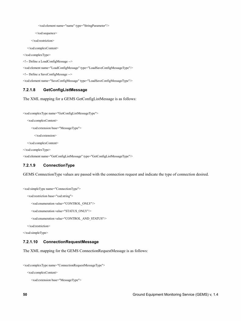
<xsd:element name="name" type="StringParameter"/>
</xsd:sequence>
</xsd:restriction>
</xsd:complexContent>
</xsd:complexType>
<!-- Define a LoadConfigMessage -->
<xsd:element name="LoadConfigMessage" type="LoadSaveConfigMessageType"/>
<!-- Define a SaveConfigMessage -->
<xsd:element name="SaveConfigMessage" type="LoadSaveConfigMessageType"/>
7.2.1.8 GetConfigListMessage
The XML mapping for a GEMS GetConfigListMessage is as follows:
<xsd:complexType name="GetConfigListMessageType">
<xsd:complexContent>
<xsd:extension base="MessageType">
</xsd:extension>
</xsd:complexContent>
</xsd:complexType>
<xsd:element name="GetConfigListMessage" type="GetConfigListMessageType"/>
7.2.1.9 ConnectionType
GEMS ConnectionType values are passed with the connection request and indicate the type of connection desired.
<xsd:simpleType name="ConnectionType">
<xsd:restriction base="xsd:string">
<xsd:enumeration value="CONTROL_ONLY"/>
<xsd:enumeration value="STATUS_ONLY"/>
<xsd:enumeration value="CONTROL_AND_STATUS"/>
</xsd:restriction>
</xsd:simpleType>
7.2.1.10 ConnectionRequestMessage
The XML mapping for the GEMS ConnectionRequestMessage is as follows:
<xsd:complexType name="ConnectionRequestMessageType">
<xsd:complexContent>
<xsd:extension base="MessageType">
50 Ground Equipment Monitoring Service (GEMS) v, 1.4

<xsd:sequence>
<xsd:element maxOccurs="1" minOccurs="1" name="type"
type="ConnectionType"/>
</xsd:sequence>
</xsd:extension>
</xsd:complexContent>
</xsd:complexType>
<xsd:element name="ConnectionRequestMessage" type="ConnectionRequestMessageType"/>
7.2.1.11 DisconnectReason
GEMS DisconnectReason values are passed with the disconnect message and indicate the reason for disconnecting.
<xsd:simpleType name="DisconnectReason">
<xsd:restriction base="xsd:string">
<xsd:enumeration value="NORMAL_TERMINATION"/>
<xsd:enumeration value="CONTROL_LOST"/>
<xsd:enumeration value="SERVICE_TERMINATED"/>
<xsd:enumeration value="OTHER"/>
</xsd:restriction>
</xsd:simpleType>
7.2.1.12 DisconnectMessage
The GEMS-XML mapping for the GEMS DisconnectMessage is as follows:
<xsd:complexType name="DisconnectMessageType">
<xsd:complexContent>
<xsd:extension base="MessageType">
<xsd:sequence>
<xsd:element maxOccurs="1" minOccurs="1" name="reason"
type="DisconnectReason" />
</xsd:sequence>
</xsd:extension>
</xsd:complexContent>
</xsd:complexType>
<xsd:element name="DisconnectMessage" type="DisconnectMessageType"/>
7.2.1.13 ResultCode
The GEMS-XML mapping for the ResultCode utilizes an XML enumeration.
Ground Equipment Monitoring Service, v1.4 51

<xsd:simpleType name="ResultCode">
<xsd:restriction base="xsd:string">
<xsd:enumeration value="SUCCESS"/>
<xsd:enumeration value="INVALID_RANGE"/>
<xsd:enumeration value="INVALID_PARAMETER"/>
<xsd:enumeration value="INVALID_STATE"/>
<xsd:enumeration value="INVALID_VERSION"/>
<xsd:enumeration value = "INVALID_TARGET"/>
<xsd:enumeration value="CONFLICTING_PARAMETER"/>
<xsd:enumeration value="UNSUPPORTED_MESSAGE"/>
<xsd:enumeration value="MALFORMED_MESSAGE"/>
<xsd:enumeration value="COMMUNICATION_ERROR"/>
<xsd:enumeration value="INTERNAL_ERROR"/>
<xsd:enumeration value="ACCESS_DENIED"/>
<xsd:enumeration value="OTHER"/>
</xsd:restriction>
</xsd:simpleType>
7.2.1.14 Response
The GEMS-XML mapping for the base ResponseMessage is as follows:
<xsd:complexType name="ResponseMessageType">
<xsd:complexContent>
<xsd:restriction base="MessageType">
<xsd:sequence>
<xsd:element minOccurs="1" maxOccurs="1" name="Result" type="ResultCode"/>
<xsd:element minOccurs="0" maxOccurs="1" name="description"
type="xsd:string"/>
</xsd:sequence>
</xsd:restriction>
</xsd:complexContent>
</xsd:complexType>
The GEMS-XML mapping for a generic error response message is as follows:
<xsd:element name="UnknownResponse" type="ResponseMessageType"/>
52 Ground Equipment Monitoring Service (GEMS) v, 1.4

7.2.1.15 LoadConfigResponse
The GEMS-XML mapping for the LoadConfigResponse is as follows:
<xsd:complexType name="LoadConfigResponseType">
<xsd:complexContent>
<xsd:extension base="ResponseMessageType">
<xsd:sequence>
<xsd:element maxOccurs="1" minOccurs="1" name="parameters_loaded"
type="xsd:int"/>
</xsd:sequence>
</xsd:extension>
</xsd:complexContent>
</xsd:complexType>
<xsd:element name="LoadConfigResponse" type="LoadConfigResponseType"/>
7.2.1.16 Save Config Response
The GEMS-XML mapping for the SaveConfigResponse message is as follows:
<xsd:complexType name="SaveConfigResponseType">
<xsd:complexContent>
<xsd:extension base="ResponseMessageType">
<xsd:sequence>
<xsd:element maxOccurs="1" minOccurs="1" name="parameters_saved"
type="xsd:int"/>
</xsd:sequence>
</xsd:extension>
</xsd:complexContent>
</xsd:complexType>
<xsd:element name="SaveConfigResponse" type="SaveConfigResponseType"/>
7.2.1.17 Get Config List Response
The GEMS-XML mapping for the GetConfigListResponse message is as follows:
<xsd:complexType name="GetConfigListResponseType">
<xsd:complexContent>
<xsd:extension base="ResponseMessageType">
<xsd:sequence>
Ground Equipment Monitoring Service, v1.4 53

<xsd:element minOccurs="0" maxOccurs="unbounded" name="ConfigurationName"
type="xsd:string"/>
</xsd:sequence>
</xsd:extension>
</xsd:complexContent>
</xsd:complexType>
<xsd:element name="GetConfigListResponse" type="GetConfigListResponseType"/>
7.2.1.18 SetConfigResponse
The GEMS-XML mapping for the SetConfigResponse message is as follows:
<xsd:complexType name="SetConfigResponseType">
<xsd:complexContent>
<xsd:extension base="ResponseMessageType">
<xsd:sequence>
<xsd:element maxOccurs="1" minOccurs="1" name="parameters_set"
type="xsd:int"/>
</xsd:sequence>
</xsd:extension>
</xsd:complexContent>
</xsd:complexType>
<xsd:element name="SetConfigResponse" type="SetConfigResponseType"/>
7.2.1.19 GetConfigResponse
The GEMS-XML mapping for the GetConfigResponse message is as follows:
<!-- Define a GetConfigResponseType -->
<xsd:complexType name="GetConfigResponseType">
<xsd:extension base=”ResponseMessageType”>
<xsd:choice minOccurs=”0” maxSelector=”unbounded”>
<xsd:element name="Parameter" type="Parameter" minOccurs="0"
maxOccurs="unbounded"/> <!-- 0 or more Parameters -->
<xsd:element name="ParameterSet" type="ParameterSet" minOccurs="0"
maxOccurs="unbounded"/> <!-- 0 or more ParameterSet -->
</xsd:choice>
</xsd:extension>
</xsd:complexType>
54 Ground Equipment Monitoring Service (GEMS) v, 1.4

<!-- Define a GetConfigResponse -->
<xsd:element name="GetConfigResponse" type="GetConfigResponseType"/>
7.2.1.20 ConnectionRequestResponse
The GEMS-XML mapping for the ConnectionRequestResponse message is as follows:
<!-- Define a ConnectionRequestResponse -->
<xsd:complexType name="ConnectionRequestResponseType">
<xsd:complexContent>
<xsd:extension base="ResponseMessageType"/>
</xsd:complexContent>
</xsd:complexType>
<xsd:element name="ConnectionRequestResponse" type="ConnectionRequestResponseType"/>
7.2.1.21 Directive Arguments
Directive arguments are represented in GEMS-XML as a sequence of Parameters.
<!--Define an ArgumentsType to be used by GEMS Directives -->
<xsd:complexType name="ArgumentsType">
<xsd:sequence>
<xsd:element maxOccurs="unbounded" minOccurs="0" name="Parameter"
type="Parameter"/>
</xsd: sequence>
<xsd:attribute name="directive_name" type="xsd:string" use="optional"/>
</xsd:complexType>
7.2.1.22 Directive Return Values
Directive return values are represented in GEMS-XML as a sequence of parameters.
<!— Define a ReturnValuesType to be used by GEMS Directive Responses -->
<xsd:complexType name="ReturnValuesType">
<xsd:choice minOccurs=”0” maxOccurs=”unbounded”>
<xsd:element maxOccurs="unbounded" minOccurs="0" name="Parameter"
type="Parameter"/>
<xsd:element maxOccurs="unbounded" minOccurs="0" name="ParameterSet"
type="ParameterSet"/>
</xsd:choice>
</xsd:complexType>
Ground Equipment Monitoring Service, v1.4 55

7.2.1.23 Directive Messages
The DirectiveMessage is the container for a directive. It is standard for all devices.
<!-- Define a DirectiveMessageType -->
<xsd:complexType name="DirectiveMessageType">
<xsd:complexContent>
<xsd:restriction base= "MessageType">
<xsd:sequence>
<xsd:element minOccurs="1" maxOccurs="1" name="directive_name"
type="xsd:string"/>
<xsd:element minOccurs="0" maxOccurs="1" name="arguments" type="ArgumentsType" />
</xsd: sequence>
</xsd:restriction>
</xsd : complexContent>
</xsd : complexType>
<!-- Define a directive message -->
<xsd: element name="DirectiveMessage" type="DirectiveMessageType"/>
7.2.1.24 Directive Response
The DirectiveResponse is the contain for a directive response. It is standard for all devices.
<!-- Define a DirectiveResponseType -->
<xsd : complexType name=" DirectiveResponseType">
<xsd: complexContent>
<xsd: extension base="ResponseMessageType">
<xsd: sequence>
<xsd: element minOccurs="1" maxOccurs="1" name="directive _name"
type="xsd: string"/>
<xsd: element minOccurs="0" maxOccurs="1" name="return _values"
type=" ReturnValuesType" />
</xsd: sequence>
</xsd : extension>
</xsd : complexContent>
</xsd: complexType>
<!-- Define a directive response -->
<xsd:element name="DirectiveResponse" type="DirectiveResponseType"/>
56 Ground Equipment Monitoring Service (GEMS) v, 1.4

7.2.1.25 Ping Message
The GEMS XML-Mapping for the PingMessage is as follows:
<xsd:complexType name="PingMessageType">
<xsd:complexContent>
<xsd:extension base="MessageType">
</xsd:extension>
</xsd:complexContent>
</xsd:complexType>
<xsd:element name="PingMessage" type="PingMessageType"/>
7.2.1.26 Ping Response Message
The GEMS XML-Mapping for the PingResponseMessage is as follows:
<!—Define a PingResponse -->
<xsd:complexType name="PingResponseType">
<xsd:complexContent>
<xsd:extension base="ResponseMessageType"/>
</xsd:complexContent>
</xsd:complexType>
<xsd:element name="PingResponse" type="PingResponseType"/>
7.2.1.27 AsyncStatusMessage
The GEMS-XML mapping for the AsyncStatusMessage message is as follows:
Ground Equipment Monitoring Service, v1.4 57

7.2.1.28 GEMS Scheme End
</xsd: schema>
7.3 XML ExamplesExamples of the GEMS XML messages are available on the OMG website at http://www.omg.org/space. Navigate to the GEMS specific page and look for GEMS Examples.
7.4 TCP/IP Message StructureTransfer of GEMS-XML messages across a network transport is done by writing the XML directly to the transport layer. If the transport layer includes the message length, the XML text is all that is required. This is the case with several commercially available message oriented middleware solutions. However, if the message length is not included,as is the case with normal TCP/IP sockets, then a standard HTTP header and the standard XML encoding pseudo-attribute is added to the message. This is done to simplify processing of the message on the other side.
The HTTP header format is as follows. Note that all lines must end in a carriage-control and line-feed. A blank line with a carriage-control and line feed is used to separate the HTTP header from the body.
POST /target HTTP/1.1User-Agent: OMG-GEMSContent-Type: text/xmlContent-Length: 646
Response messages use the standard HTTP response header.
HTTP/1.1 200 OKUser-Agent: OMG-GEMSContent-Type: text/xmlContent-Length: 616
The Content-Length specifies the number of bytes to read after the HTML header and includes any formatting characters (spaces, end-of-line etc.) Example:
POST /target HTTP/1.1User-Agent: OMG-GEMSContent-Type: text/xmlContent-Length: 346
<?xml version="1.0" ?><gems:PingMessage gems_version="1.2" target="System/Device1" timestamp="1410540242.29" token="" transaction_id="1" xmlns:gems=http://www.omg.org/spec/gems/20110323/basetypes xmlns:xsi="http://www.w3.org/2001/XMLSchema-instance" xsi:schemaLocation=http://www.omg.org/spec/gems/20110323/basetypes GEMS_base_types.xsd/>
When using client-side HTTP libraries, the GEMS connection requires a persistent socket connection. If the connection to the TCP socket is closed at some point during a connection, the GEMS device should automatically disconnect the GEMS User.
58 Ground Equipment Monitoring Service (GEMS) v, 1.4

7.5 GEMS Device DefinitionsThe GEMS-XML mapping of a Device Definition takes the form of an XML file. The schema for this file is defined in the normative GEMS_Device.xsd file, included as part of the GEMS-XML PSM. To avoid redundancy between documents, comments have been added in the schema file, describing the various portions of the schema.
The XML Device Definition file is either distributed manually by the device vendor as part of the system delivery, or automatically using an HTTP GET request. It is expected that the HTTP GET request is handled using standard HTTP protocols on port 80. However, alternate port number may be specified by the vendor.
If provided automatically using an HTTP GET request, the URL for the device definition file shall be as follows:
http://<hostname>/omg/gems/DeviceDefinitions.xml
where <hostname> is either the hostname or a valid IP address for the web server on the device.
7.5.1 Example Device Definition File
Examples of the GEMS Device Definition File are available on the OMG website at http://www.omg.org/space. Navigate to the GEMS specific page and look for GEMS Examples.
Ground Equipment Monitoring Service, v1.4 59

This page intentionally left blank.
60 Ground Equipment Monitoring Service (GEMS) v, 1.4

8 PIM (ASCII)
8.1 GeneralThe ASCII PSM defines a simple ASCII message protocol usable across a variety of transport mechanisms, including networks, serial lines and internal data buses such as PCI. The message structure is human-readable and easy to process.
8.2 PIM to PSM MappingFor the GEMS PIM TO PSM ASCII Mapping each supported message type is captured in a single table describing the message format. The message table defines the order of the fields within the message, the field tags placed within the message, and the field’s original range of values (ROVs).
All messages consist of a standard message header, followed by data in a message body consisting of fields uniquely associated with each type of message. Each message is terminated using a standard message trailer and is constructed from ASCII character fields.
8.2.1 Parameters
GEMS-ASCII parameters are represented within messages using a name, type, value triad as follows:
parameter_name:type=value
Multiplicity is represented using an array-like syntax common to many scripting languages. The values are specified using a comma separated list.
parameter_name[3]:type=value1,value2,value3
8.2.1.1 Parameter Types
The PSM ASCII Mapping supports all the parameter types defined by the GEMS PIM. The general format in ASCII forparameters is ‘parameter_name:parameter_type=parameter_value.’ Following is a table of example ASCII formats for all of the parameter types.
Table 8.1 - Parameter Types and Formatting
Parameter Type Example Format Comments
string param:string=abc
boolean param:bool=true ‘true’ and ‘false’ case insensitive
byte param:byte=127
ubyte param:ubyte=255
hex_value param:hex_value=faf320/22 param:hex_value=0xfaf320/22
The value of the bit length field follows the slash (/). Specify a zero length bit field with a 0/0.
double param:double=1 0.12
long param:long=-999999999
ulong param:ulong=9999999999
Ground Equipment Monitoring Service, v1.4 61

int param:int=-123
uint param:uint=123
short param:short=-1 2
ushort param:ushort=12
time param:time=111111111.222000000 Value is seconds.nanoseconds in UTC where nanoseconds are fractional.
utime 2009-273T09:14:50.02Z yyyy-dayThh:mm:ss[.nnnnnnnnn]Z yyy - four digits of year
day - day of the year
hh - hours (00 through 23)
mm - minutes (00 through 59)
ss[.nnnnnnnnn] - seconds.nanosecond
Z - the character “Z” denotes GreenwichMean Time (GMT).
8.2.1.2 Parameter Sets
In the PSM ASCII Mapping parameter sets may be defined by the additional use of semi-colons. For example a simple parameter set containing mixed parameters would be as follows:
mixed_set:set_type=param_1:int=1;param_2:boolean=true;param_3:string=a short string;
To represent an array of parameter sets use commas to separate the parameter sets.
setlist:set_type[2]=A:hex_value=FA/7;B:string[2]=text1,text2;,A:hex_value=2F/6;B:string[1]=text2;
Note: The final member of the parameter set is followed by a semi-colon. This allows for easy parsing when dealing with parameter set arrays.
8.2.2 Reserved Words and Special Characters
The following words are reserved and should not be used as parameter or target names: “|GEMS” and “|END|”
The following characters are special but can be escaped using the following escape sequences:
Character Escape Sequence
& &a
| &b
, &c
; &d
62 Ground Equipment Monitoring Service (GEMS) v, 1.4

These escape sequences were chosen for the ASCII PSM to allow for simple parsing. Notionally, implementations first tokenize on a vertical bar ‘|’ character. Then, for messages containing parameters, split the parameter fields on the first equal sign ‘=’. Escaped characters should only show up to the right of the equal sign in string parameters.
8.2.3 Message Header
The message header maps directly to the GEMS base message class. The first three fields are fixed length to simplify processing. After that, all fields are variable length and use the pipe symbol, |, as a delimiter.
The following diagram shows the message header and footer.
The following table defines each field, the expected field length and the range of values.
Table 8.2 - Standard Request Message Fields
Field Names Length (char)
Range of Values Comments
Field Delimiter 1 | Pipe character (ASCII 124)
Start of Message 4 GEMS Invariant
Field Delimiter 1 | Pipe character (ASCII 124)
GEMS Version 2 01 – 99 Message Format Version Mapping - For versions 1.2 and greater, ASCII code for version is version number with decimal removed
01 : 1.002 : 1.112 : 1.213 : 1.3 (etc.)
Field Delimiter 1 | Pipe character (ASCII 124)
Message Length 10 up to 9999999999 Total Length of the message (in bytes), including the start of message, standard header, message body and the end of message.
Ground Equipment Monitoring Service, v1.4 63

Field Delimiter 1 | Pipe character (ASCII 124)
Transaction ID Variable 0-999,999,999 Client specified transaction ID. The reply will reflect this number back to the client for message
correlation.Field Delimiter 1 | Pipe character (ASCII 124)
Token Variable Alphanumeric Token provided by the device or proxy in the connect response.
Field Delimiter 1 | Pipe character (ASCII 124)
Timestamp 19 111111111.222000000 Timestamp of when the message was sent in UTC. Uses the format of the time parameter specified in Table 8.1.
Field Delimiter 1 | Pipe character (ASCII 124)
Target Variable Alphanumeric The target field identifies the target of the message forthe initial request and the source of the message for the reply.
Field Delimiter 1 | Pipe character (ASCII 124)
Message Type Variable Alphanumeric The Message Type identifies the type of message being sent. These types map directly to the PIM message types and are listed in the following sections.
Field Delimiter 1 | Pipe character (ASCII 124)
Message Body Variable Alphanumeric Specific to each supported message type. See following sections for definitions and examples.
Field Delimiter 1 | Pipe character (ASCII 124)
End of Message 3 END Invariant
The message header for a response contains the same first 7 fields as the message plus an additional 2 fields providing result codes and descriptions.
Table 8.3 - Response Message Fields
Field Names Length (char)
Range of Values Comments
Standard Header Variable <See Table 9.2 >
Field Delimiter 1 | Pipe character (ASCII 124)
64 Ground Equipment Monitoring Service (GEMS) v, 1.4

Result Code Variable Alphanumeric One of the following GEMS PIM result codes: SUCCESS
INVALID_RANGE INVALID_PARAMETER
INVALID_TARGET INVALID_VERSION INVALID_STATE CONFLICTING_PARAMETER UNSUPPORTED_MESSAGE MALFORMED_MESSAGE COMMUNICATION_ERROR
INTERNAL_ERROR ACCESS_DENIED OTHER
Field Delimiter 1 | Pipe character (ASCII 124)
Result Description Variable Alphanumeric Free text device specific description of the corresponding result code.
The GEMS-ASCII mapping for a generic error response message is simply a standard response header and trailer with the message type set to UNK-R.
8.2.4 Message Trailer
The message trailer ends all request and response messages and is represented as follows. It is always separated from the message body by a ‘|’ character.
Table 8.4 - Message Trailer Fields
Field Names Length (char) Range of Values Comments
End of Message 3 END Invariant
8.2.5 ConnectMessage and Response
The following table describes the ConnectMessage body and response format.
8.2.5.1 ConnectMessage
Table 8.5 - Connect Request Message
Field Names Length (char) Range of Values Comments
Standard Header Variable <See Table 8.2 > Message Type Field = CON
Field Delimiter 1 | Pipe character (ASCII 124)
Connection Type Variable Alphanumeric Supported Values: CONTROL_ONLY CONTROL_AND_STATUS
STATUS_ONLY
Ground Equipment Monitoring Service, v1.4 65

Field Delimiter 1 | Pipe character (ASCII 124)
Standard Trailer 3 <See Table 8.4 >
8.2.5.2 ConnectMessage Response
The ConnectMessage Response nothing more than the standard response header and trailer with the message type set toCON-R. See 8.2.3 and 8.2.4.
8.2.6 DisconnectMessage
The following table describes the DisconnectMessage body. There is no corresponding response message.
Table 8.6 - Disconnect Message Request
Field Names Length (char) Range of Values
Standard Header Variable <See Table 8.2 >
1
Disconnect Reason Variable Alphanumeric
Field Delimiter 1
Standard Trailer 3 <See Table 8.4 >
8.2.7 GetConfig Message and Response
The following tables describe the message body for the GetConfigMessage and its corresponding response.
8.2.7.1 GetConfigMessage
Table 8.7 - Get Configuration Request Message
Field Names Length (char)
Range of Values Comments
Standard Header Variable <See Table 8.2 > Message Type Field = GET
Field Delimiter 1 | Pipe character (ASCII 124)
Number of Parameters Variable Numeric Number of parameters requested. A blank entry indicates the client desires all parameters available.
Field Delimiter 1 | Pipe character (ASCII 124)
Parameter Name 1 Variable Alphanumeric Name of first parameter value requested.
Only required if Number of Parameters field is greater than 0.
Field Delimiter 1 | Pipe character (ASCII 124)
66 Ground Equipment Monitoring Service (GEMS) v, 1.4

...
Parameter Name n Variable Alphanumeric Name of nth parameter requested.
Only required if Number of Parameters field is greater than n-1.
Field Delimiter 1 | Pipe character (ASCII 124)
Standard Trailer 3 <See Table 8.4 >
8.2.7.2 GetConfigMessage Response
Table 8.8 - Get Configuration Response Message
Field Names Length (char) Range of Values Comments
Standard Response Header
Variable <See Table 8.2 > Message Type = GET-R
Field Delimiter 1 | Pipe character (ASCII 124)
Number of Parameters Returned
Variable Numeric Number of parameters returned
Field Delimiter 1 | Pipe character (ASCII 124)
Parameter Value 1 Variable <See Table 8.1 > Value of first parameter requested
Field Delimiter 1 | Pipe character (ASCII 124)
Parameter Value n Variable <See Table 8.1 > Value of nth parameter requested
Field Delimiter 1 | Pipe character (ASCII 124)
Standard Trailer 3 <See Table 8.4 >
8.2.8 SetConfigMessage and Response
The following tables describe message body for the SetConfigMessage and its corresponding response.
8.2.8.1 SetConfigMessage
Table 8.9 - Set Configuration Request Message
Field Names Length (char)
Range of Values Comments
Standard Header Variable <See Table 8.2 > Message Type Field = SET
Field Delimiter 1 | Pipe character (ASCII 124)
Number of Parameters
Variable Numeric ( > 0 ) Number of parameters modified
Ground Equipment Monitoring Service, v1.4 67

Field Delimiter 1 | Pipe character (ASCII 124)
Parameter Value 1 Variable <See Table 8.1 > Value of first parameter
Field Delimiter 1 | Pipe character (ASCII 124)
Parameter Value n Variable <See Table 8.1 > Value of nth parameter
Field Delimiter 1 | Pipe character (ASCII 124)
Standard Trailer 3 <See Table 8.4 >
8.2.8.2 SetConfigMessage Response
Table 8.10 - Set Configuration Response Message
Field Names Length (char) Range of Values Comments
Standard Response Header
Variable <See Table 8.2 > Message Type = SET-R
Field Delimiter 1 | Pipe character (ASCII 124)
Number of Parameters Successfully Set
Variable Numeric ( >= 0 ) Number of parameters returned
Field Delimiter 1 | Pipe character (ASCII 124)
Field Delimiter 1 | Pipe character (ASCII 124)
Standard Trailer 3 <See Table 8.4 >
8.2.9 Save/LoadConfigMessage and Response
The following tables describe the message body and response for both the Save and LoadConfigMessages.
8.2.9.1 Save and LoadConfigMessage
Field Names Length (char) Range of Values Comments
Standard Header Variable <See Table 8.2 > Message Type Field = SAVE or LOAD
Field Delimiter 1 | Pipe character (ASCII 124)
File Name Variable Standard File Naming
Conventions
Name of file configuration is saved to or loaded from
Field Delimiter 1 | Pipe character (ASCII 124)
Standard Trailer 3 <See Table 8.4 >
68 Ground Equipment Monitoring Service (GEMS) v, 1.4

8.2.9.2 Save and LoadConfig Response
Field Names Length (char) Range of Values Comments
Standard Response Header
Variable <See Table 8.2 > Message Type = SAVE-R or LOAD-R
Field Delimiter 1 | Pipe character (ASCII 124)
Parameters Successfully Saved or Loaded
Variable Numeric ( >= 0 ) Number of parameters successfully saved to or loaded from file.
Field Delimiter 1 | Pipe character (ASCII 124)
Standard Trailer 3 <See Table 8.4 >
8.2.10 GetConfigListMessage and Response
The following tables describe the message body and response for the GetConfigListMessage.
8.2.10.1 GetConfigListMessage
Table 8.11 - GetConfigList Request Message
Field Names Length (char) Range of Values Comments
Standard Header Variable <See Table 8.2 > Message Type Field = GETL
Field Delimiter 1 | Pipe character (ASCII 124)
Standard Trailer 3 <See Table 8.4 >
8.2.10.2 GetConfig ListMessage Response
Table 8.12 - GetConfigListMessage Response
Field Names Length (char) Range of Values Comments
Standard Header Variable <See Table 8.2 > Message Type Field = GETL-R
Field Delimiter 1 | Pipe character (ASCII 124)
Number of Configuration Names
Variable Numeric ( >= 0 ) Number of configuration names available
Configuration Name 1 Variable Alphanumeric Name of 1st configuration available
Field Delimiter 1 | Pipe character (ASCII 124)
Configuration Name n Variable Alphanumeric Name of nth configuration available
Ground Equipment Monitoring Service, v1.4 69

Field Delimiter 1 | Pipe character (ASCII 124)
Standard Trailer 3 <See Table 8.4 >
8.2.11 DirectiveMessage and Response
The following tables describe the message body and response for the DirectiveMessage.
8.2.11.1 DirectiveMessage
Table 8.13 - Directive Request Message
Field Names Length (char)
Range of Values Comments
Standard Header Variable <See Table 8.2 > Message Type Field = DIR
Field Delimiter 1 | Pipe character (ASCII 124)
Directive Name Variable Alphanumeric Name of the directive to execute
Field Delimiter 1 | Pipe character (ASCII 124)
Number of Parameters
Variable Numeric ( >= 0 ) Number of parameters to be passed into directive
Field Delimiter 1 | Pipe character (ASCII 124)
Parameter 1 Variable <See Table 8.1 > 1st parameter of directive.
Only if Number of Parameters field is > 0.
Field Delimiter 1 | Pipe character (ASCII 124)
Parameter n Variable <See Table 8.1 > nth parameter of directive
Only if Directive Number of Parameters field is > n -1.
Field Delimiter 1 | Pipe character (ASCII 124)
Standard Trailer 3 <See Table 8.4 >
8.2.11.2 DirectiveMessage Response
Field Names Length (char)
Range of Values Comments
Standard Header Variable <See Table 8.2 > Message Type Field = DIR-R
Field Delimiter 1 | Pipe character (ASCII 124)
Directive Name Variable Alphanumeric Name of the directive
70 Ground Equipment Monitoring Service (GEMS) v, 1.4

Field Delimiter 1 | Pipe character (ASCII 124)
Number of Return Values
Variable Numeric ( >= 0 ) Number of returned values
Field Delimiter 1 | Pipe character (ASCII 124)
Return Value 1 Variable <See Table 8.1 > 1st return parameter.
Only if Number of Return Values field is > 0.
Field Delimiter 1 | Pipe character (ASCII 124)
...
Return Value n Variable <See Table 8.1 > nth return parameter
Only if Number of Return Values field is > n -1
Field Delimiter 1 | Pipe character (ASCII 124)
Standard Trailer 3 <See Table 8.4 >
8.2.12 AsyncStatusMessage
Table 8.14 – Asynchronous Status Message
Field Names Length (char) Range of Values Comments
Standard Response Header
Variable <See Table 8.2 > Message Type = ASYNC
Field Delimiter 1 | Pipe character (ASCII 124)
Number of Parameters Returned
Variable Numeric Number of parameters returned
Field Delimiter 1 | Pipe character (ASCII 124)
Parameter Value 1 Variable <See Table 8.1 > Value of first parameter requested
Field Delimiter 1 | Pipe character (ASCII 124)
Parameter Value n Variable <See Table 8.1 > Value of nth parameter requested
Field Delimiter 1 | Pipe character (ASCII 124)
Standard Trailer 3 <See Table 8.4 >
8.3 ASCII ExamplesExamples of the GEMS ASCII messages are available on the OMG website at http://www.omg.org/space. Navigate to the GEMS specific page and look for GEMS Examples.
Ground Equipment Monitoring Service, v1.4 71

8.4 TCP/IP Message StructureThe GEMS-ASCII messages contain all of the information necessary for transport across both networks and serial data buses. The messages are written directly to a socket or serial port. No additional header information is required.
When using TCP, the GEMS connection requires a persistent socket connection. If the connection to the TCP socket is closed at some point during a connection, the GEMS device should automatically disconnect.
8.5 GEMS Device DefinitionsThe GEMS-ASCII Device Definitions utilize the GEMS-XML Device Definition file as specified in 7.5. This file may be distributed manually by the device vendor or by using a locally hosted web server and an HTTP GET message similar to GEMS-XML.
72 Ground Equipment Monitoring Service (GEMS) v, 1.4